dynamic model based cross-coupled control of parallel manipulators
TRANSCRIPT
Dynamic Model based Cross-Coupled Control of Parallel Manipulators*
Weiwei Shang, Shuang Cong, and Yuan Ge Department of Automation, University of Science and Technology of China, Hefei, Anhui, 230027, P. R. China
{wwshang & scong}@ustc.edu.cn, [email protected]
* This work was supported by the National Natural Science Foundation of China with Grant No. 50905172, the Anhui Provincial Natural Science Foundation with Grant No.090412040, and the Fundamental Research Funds for the Central Universities.
Abstract - The dynamic model based cross-coupled control is developed to improve the coordination motion relation between multiple kinematic chains in parallel manipulators. According to the mechanism characteristic of the parallel manipulators, two different types of synchronization error of the kinematic chains are defined in the joint space of active joints and in the task space of end-effector, respectively. By using the synchronization error, the cross-coupled control law in the task space is designed based on the dynamic model. The trajectory tracking experiments of an actual planar parallel manipulator are carried out, and then the control performances between the cross-coupled controller and the augmented PD (APD) controller are compared.
Index Terms – parallel manipulator, cross-coupled control, synchronization error, task space
I. INTRODUCTION
A parallel manipulator is a mechanism where the motion of the end-effector is controlled by means of at least two kinematic chains. Parallel manipulators have been a very active field of research over the last 20 years in academia [1], mainly due to the fact that compared to serial robots, parallel manipulators have the followings advantages: high speed, accuracy in positioning and stiffness. In the actual application it is important to design controllers with good performance such that the parallel manipulators are able to follow the motion with accuracy. Due to the special structure of multiple kinematic chains, the kinematics and dynamics of parallel manipulator are tightly coupled and highly nonlinear [2]. The coordination manipulation of the end-effector with multiple kinematic chains makes the motion control of parallel manipulators a work full of challenge, which has aroused the interests of researchers in recent years.
To effectively control parallel manipulators for fast and precise performance, model-based control schemes need to be designed. The traditional dynamic controllers are the augmented PD (APD) controller and the computed torque (CT) controller [3], [4], which are designed by adding the dynamic compensation into the PD control. However, for the APD controller and the CT controller, the desirable control performances of parallel manipulators highly rely on the actual model parameters. In actual applications, due to the inevitable nonlinear friction, unknown dynamics, and changes of payload, the actual model parameters of parallel manipulator are always unequal to the values provided by the manufacturers [5], [6]. Thus, based on the APD or the CT scheme, some advanced control methods with performance
index have been designed, such as the adaptive control [7], [8], predictive control [9], and the robust adaptive control [10]. However, when these controllers are applied to the parallel manipulators, the mechanism structure characteristics of multiple kinematic chains are not taken into account. Thus the correlation between the kinematic chains is ignored, and the trajectory tracking accuracy of the parallel manipulators can not be satisfied [11], [12]. Especially at the high-speed, the constraint forces among the kinematic chains are magnified and the coordination motion can not be realized, even the mechanism of the parallel manipulators can be damaged [13]. In order to improve the coordination motion of the kinematic chains at the high-speed, it’s necessary to analyze the mechanism structure of parallel manipulators, and develop a control strategy according to the mechanism characteristic. In recent years, coordination motion control with the cross-coupled control technology has attracted many researchers in motion control field [14-16], as it can get coordination motion of complex systems with multi subsystems.
Parallel manipulators can be split into multiple kinematic chains with constraints, and the synchronization error between the chains can be defined in the task space, thus the cross-coupled control technology for the motion control systems including multiple axes can be used to the motion control of parallel manipulators. The main contribution of this paper is the development of dynamic model based cross-coupled control for a planar parallel manipulator. Each kinematic chain of the parallel manipulator can be considered as an independent subsystem, and then one can get a complex manipulator system with multi subsystems. The coordination motion of the parallel manipulator can be depicted by analyzing the motion of each subsystem and the synchronization relation between the neighboring subsystems. According to the characteristic of the mechanism structure of the parallel manipulator, two different types of synchronization error are developed in the joint space of active joints and in the task space of end-effector respectively. Based on the different synchronization error, the cross-coupled control strategy in the task space is proposed to realize the high-speed and high-precision motion control.
The paper is organized as follows. In section II, the dynamic model of a parallel manipulator with actuation redundancy is formulated in the task space. In section III, two types of the synchronization error are defined. In section IV, the cross-coupled controller is designed, and the stability of the
Proceedings of the 8th World Congress on Intelligent Control and Automation June 21-25 2011, Taipei, Taiwan
978-1-61284-700-9/11/$26.00 ©2011 IEEE
parallel manipulator system is proven. In section V, the trajectory tracking experiments of an actual parallel manipulator are carried out, and the experimental results are compared with the APD controller. In section VI, several remarks are concluded.
II. DYNAMIC MODELING
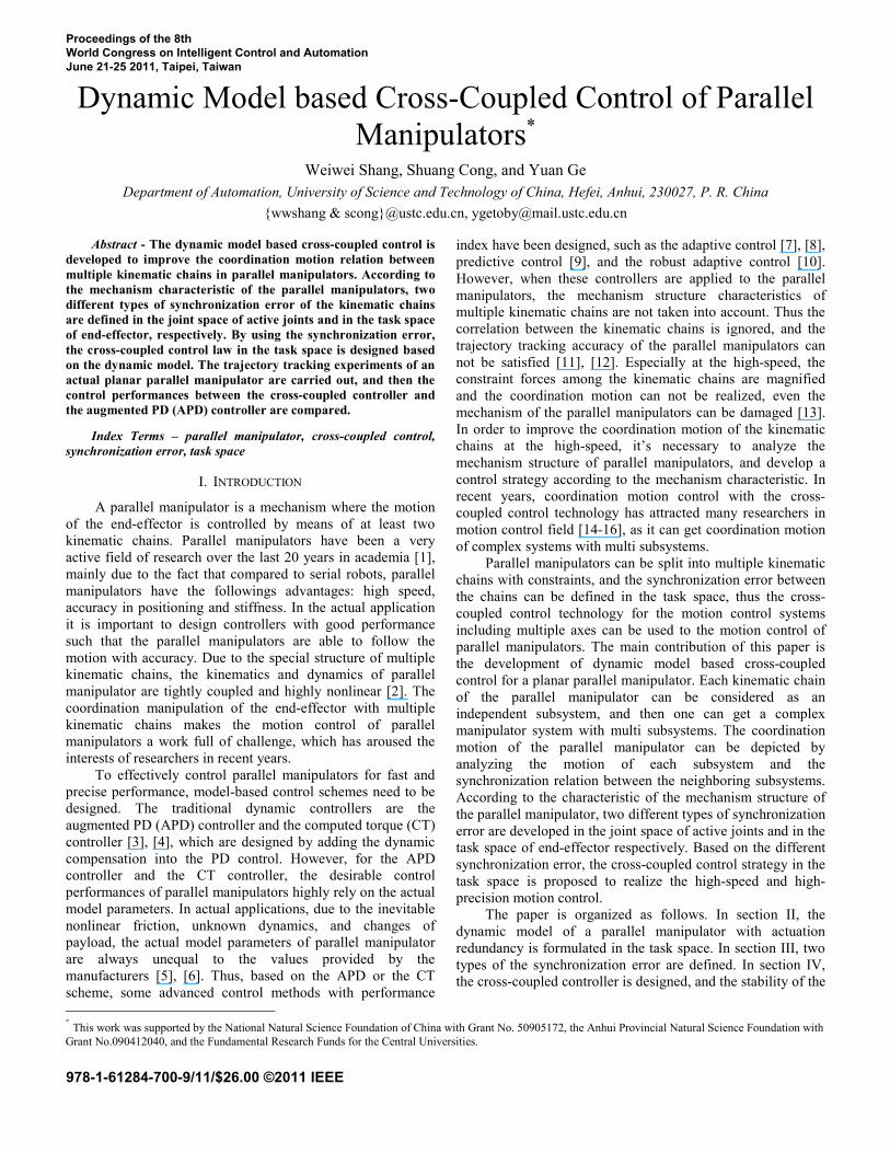
In this section, the dynamic model of a planar parallel manipulator will be formulated. As shown in Fig. 1, the parallel manipulator is actuated by three servo motors located at the base A1, A2, and A3. The joints B1, B2, and B3 are underactuated. Coordinates of the three bases are A1 (0, 0.25), A2 (0.433, 0), and A3 (0.433, 0.5), and all of the links have the same length 0.244l m= . The definitions of the joint angles are shown in Fig. 1, where 1aq , 2aq and 3aq refer to the active
joint angles; 1bq , 2bq and 3bq refer to the passive joint angles.
Splitting the parallel manipulator at the common point O in Fig. 1, one can have an open-chain system including three independent planar 2-DOF serial manipulators, each of which contains an active joint and a passive joint. According to [17], the dynamic model of each planar 2-DOF serial manipulator can be formulated as
i i i i i i+ + =M q C q f τ , (1)
where [ ]Ti ai biq q=q , aiq and biq are the active joint and
passive joint angle, respectively; iM is inertia matrix, and iC
is Coriolis and centrifugal force matrix [ ]Ti ai biτ τ=τ is joint
torque vector, where aiτ is the active joint torque, the passive
joint torque 0biτ = . [ ]Ti ai bif f=f is friction torque vector,
where aif and bif are the active joint friction and passive joint
friction, respectively. Compared with the active joints friction
aif , the passive joint friction bif is much smaller and it can be
neglected [18]. The active joint friction torque aif can be
formulated as [19]
( )ai ai ci vi aif sign q f f q= + (2)
where cif represents the Coulomb friction, and vif represents
the coefficient of the viscous friction. The dynamic model of the parallel manipulator equals to
the model of the open-chain system plus the closed-loop constraints, thus the dynamics of the parallel manipulator can be formulated in the task space by combining the dynamics of three serial manipulators under the constraints as follows [17]
T Te e e e a a+ + =M q C q J f J τ , (3)
where [ ]Te x y=q is the position coordinates of the end-
effector; aτ is the actuator torque vector of the active joints;
af is the friction torque vector of the active joints; J is the velocity Jacobian matrix between the end-effector and the three active joints of the parallel manipulator; eM is the inertia
b3
A2
A3
A1
B1
B2
B3
Oa1q
a2qb2q
q
Y a3qb1q
X Fig. 1. Coordinates of the planar parallel manipulator.
matrix in the task space, and eC is the Coriolis and centrifugal force matrix in the task space. The detailed definition of the above symbols can be found in [17].
III. SYNCHRONIZATION ERRORS
In order to design the cross-coupled control, the synchronization relation should be developed according to the characteristic of the mechanism structure of the parallel manipulator. On the assumption that the kinematic chains of the parallel manipulator were split at the common joint, the parallel manipulator can be transformed into a new system including multi serial manipulators, which are constrained by the synchronization relation. Considering the coordination motion relation of multi serial manipulators, the cross-coupled control can be formulated for the parallel manipulator. In this section, we will formulate the synchronization error of the active joints in the joint space and the synchronization error of the end-effector in the task space, respectively. A. Synchronization Error of the Active Joints
Considering the correlation of the neighboring kinematic chains of the parallel manipulator, the synchronization error in the joint space can be defined by using the tracking error of the neighboring active joints.
Let daiq be the desired trajectory of the ith active joint,
then the tracking error can be defined as d
ai ai aie q q= − (4) and the tracking error vector can be written as
[ ]1 2 3T
a a a ae e e=e . (5) In order to realize the cross-coupled control of the kinematic chains of the parallel manipulator, one should keep the tracking error ( ) 0aie t → as t → ∞ , and regulate the coordination relation between three active joints to the keep following equation satisfied
1 2 3lim lim lim 0a a at t te e e
→∞ →∞ →∞= = = . (6)
Equation (6) can be divided into three sub-goals as 1 2lim lima at t
e e→∞ →∞
= , 2 3lim lima at te e
→∞ →∞= , 3 1lim lima at t
e e→∞ →∞
= . (7)
Thus, the synchronization error between all possible pairs of two neighboring active joints can be defined as
1 1 2a a as e e= − , 2 2 3a a as e e= − 3 3 1a a as e e= − , (8)
where ais denotes the synchronization error of the active joint i . One can find that, the synchronization relation Eq. (7) of the three active joints can be satisfied when 0ais = . Unlike the traditional position tracking control considering the tracking error only, here the synchronization error between two neighboring active joints is also required so that Eq. (7) holds. Then the synchronization error vector can be written as
[ ]1 2 3T
a a a as s s=s . (9) Considering the dynamic model is formulated in the task
space, the synchronization error as in the joint space should be transformed into the task space as follows
1T
e a=s J s . (10) The synchronization error 1es of the active joints represents the coordination relation between the active joints and is not equivalent to the conventional tracking error. For the parallel manipulator, the synchronization error of each active joint contains the information from itself and the adjacent joints. Hence, the motions of all active joints are coordinated and the motion control accuracy of the end-effector is substantially smaller than that without using the synchronization error. B. Synchronization Error of the End-effector
The trajectory tracking performance in the task space of the parallel manipulator is equivalent to the motion system including multiple virtual motion axes. Considering the correlation of the multiple virtual motion axes, the estimated contour error of the trajectory can be defined as the synchronization error.
Let deq be the desired trajectory of the end-effector, and
the tracking error vector T
t tx tye e⎡ ⎤= ⎣ ⎦e can be defined as d
t e e= −e q q . (11) Then, the tracking velocity error vector te can be written as
dt e e= −e q q . (12)
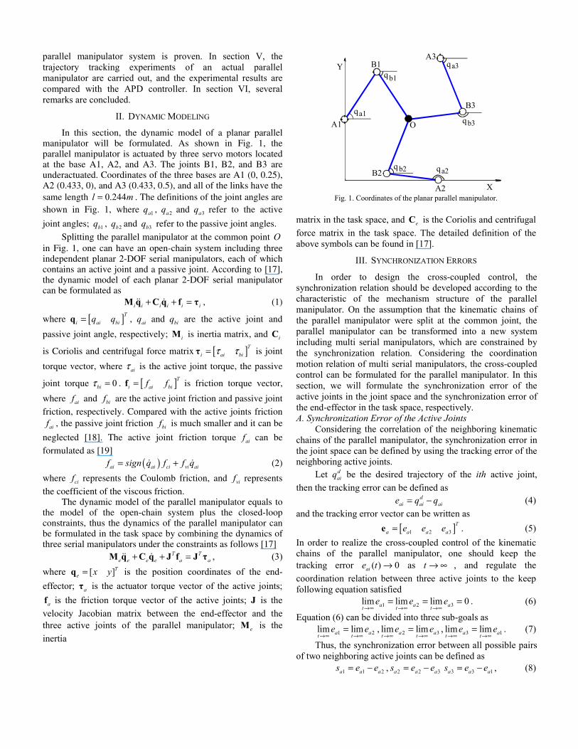
As shown in Fig.2, the contour error ce is defined as an error from the actual position to the nearest point on the desired trajectory. In practice, it’s difficult to calculate ce because of the unknown nearest point on the contour trajectory. Therefore, the estimated method is used to get the approximate value of
ce . The estimated contour error ˆce can be defined as the vector from the actual position to the nearest point on the line that passes through the desired position tangentially with direction. With the geometric relation in Fig.2, the estimated contour error vector ˆce can be calculated as
sin sin sinˆ ( sin cos )
cos cos cosT
c tx ty te eθ θ θ
θ θθ θ θ
−⎡ ⎤ ⎡ ⎤ ⎡ ⎤= − + =⎢ ⎥ ⎢ ⎥ ⎢ ⎥⎣ ⎦ ⎣ ⎦ ⎣ ⎦
e e , (13)
where θ is the tangent angle to the desired trajectory. From Fig.2, one can see that the actual position can close to the desired trajectory obviously by decreasing ˆce . Thus ˆce has great effect to the tacking accuracy in the trajectory tracking.
te
ce txecye
cxe
tye
θ
ce
Fig.2 Synchronization error of the end-effector.
So, the synchronization error 2es in the task space can be defined using the ˆce as
2
sin sinˆ
cos cosT
e c t
θ θθ θ
−⎡ ⎤ ⎡ ⎤= = ⎢ ⎥ ⎢ ⎥
⎣ ⎦ ⎣ ⎦s e e . (14)
There are two outstanding merits of 2es defined in Eq.(14). On the one hand, 2es contains the information of tracking error te , thus te will also decrease along with the reducing of 2es . On the other hand, θ includes the relation information between the X-direction and Y-direction, which is different from the definition of the tracking error. Thus 2es can adjust the coordination motion relation between multiple kinematic chains. So, 2es is very important in cross-coupled control design, which is such an error that has important impact on trajectory tracking accuracy.
IV. CROSS-COUPLED CONTROL
By using the developed synchronization error, the cross-coupled controller can be designed for the planar parallel manipulator. A. Cross-Coupled Controller Design
With the synchronization error vector es , the cross-coupled error vector cce can be defined as
0( )
t
cc t e w dw= + ∫e e R s , (15)
where ( ),diag r r=R is positive definite matrix with constant gains. es represent the synchronization error 1es or 2es , which are defined in Eq.(10) and Eq.(14), respectively. Then the cross-coupled velocity error vector cce can be written as
cc t e= +e e Rs . (16) With the cross-coupled error cce and cross-coupled velocity error cce , the combined error vector s can be defined as
cc cc= +s e Pe , (17) where ( ),diag p p=P is positive definite matrix with constant gains. Then the combined velocity error vector s can be expressed as
cc cc= +s e Pe . (18) The referenced tracking velocity r
eq and acceleration req
can be defined as r de e e e cc= + = + +q q s q Rs Pe , (19) r de e e e cc= + = + +q q s q Rs Pe . (20)
Compared with the desired velocity deq and the desired
acceleration deq , r
eq and req not only contain the desired
trajectory information, but also include the actual tracking error and synchronization error. Thus r
eq and req are more
suitable to the trajectory tracking control. Based on the APD control law [17], with the referenced
tracking trajectory req and r
eq , and the combined error s , the cross-coupled control law can be designed as
r r Te e e e e a d= + + +τ M q C q J f K s , (21)
where dK is a symmetric, positive definite matrix. From the definition of combined error s , the detailed expression of
dK s can be rewritten as ( )d d cc cc= +K s K e Pe
( )0R ( )
t
d t t e e w dw= + + + ∫K e Pe s R s . (22)
From Eq. (22), one can see that the error elimination term contains the information of the tracking error which is eliminated by the PD control, thus the parallel manipulator will get quick trajectory tracking ability. Moreover, in Eq. (22), one can find that the synchronization error is eliminated by the PI control, thus the parallel manipulator will get accurate coordination of multiple kinematic chains. B. Asymptotic Stability Proof Theorem: The proposed coordination control law Eq. (21) guarantees asymptotic convergence to zero both of the tracking error and synchronization error of the parallel manipulator system, i.e. ( ) 0t t →e and ( ) 0e t →s as t → ∞ . Proof: Choose the Lyapunov function candidate as
1( )2
TeV t = s M s . (23)
Differentiating ( )V t with respect to time yields 1( )2
T Te eV t = +s M s s M s . (24)
Considering the structural property of the dynamic model [8], then one can have ( 2 ) 0T
e e− =s M C s . Substitute 2T T
e es =s M s C s into Eq.(24), one can get ( ) ( )T
e eV t = +s M s C s . (25) Combing the dynamic model Eq.(3) and the coordination control law Eq.(21), one can get the closed-loop system equation as
0e e d+ + =M s C s K s . (26) Multiplying both sides of Eq. (26) by Ts , and then substituting the resulting equation into Eq. (25) yields
( ) TdV t = −s K s . (27)
Thus, s is bounded, and one knows that cce and cce are both bounded from Eq. (17), further te is bounded from Eq. (16). Considering the closed-loop system Eq. (26), one obtains
1( )e e d−= − +s M C s K s . (28)
Thus, s is bounded. From Eq. (28), one gets ( ) 2T T T
d d dV t = − − = −s K s s K s s K s . (29) Thus ( )V t is bounded, and ( )V t is uniformly continuous. With the Barbalat’s Lemma, 0→s as t → ∞ . Since 0→s as t → ∞ , 0cc →e and 0cc →e as t → ∞ from Eq. (17). Combining Eq.(16) and Eq.(14), one can get
2
sin sincos cos
Tcc t e t t
θ θθ θ
−⎡ ⎤ ⎡ ⎤= + = + ⎢ ⎥ ⎢ ⎥
⎣ ⎦ ⎣ ⎦e e Rs e R e . Since 0cc →e as
t → ∞ , one knows 0t →e as t → ∞ . Consider 0t →e as t → ∞ , one can find 0e →s as t → ∞ from Eq.(15). Hence, the proof is complete.
V. ACTUAL EXPERIMENTS
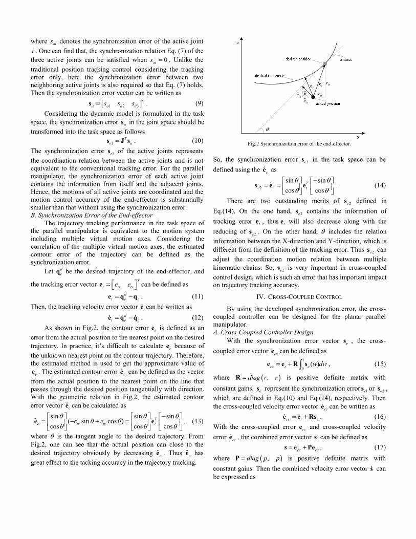
The actual experiment platform is a planar parallel manipulator. As shown in Fig.3, it is equipped with three permanent magnet synchronous motors with harmonic gear drives. The active joint angles are measured with the absolute optical-electrical encoders. The cross-coupled controller and the APD controller are programmed with the Visual C++. In the trajectory tracking experiments, the desired trajectory of the end-effector is a circle with constant speed of 0.5m/s. The center is (0.29, 0.25) and the starting point is (0.29, 0.31), thus the radius is 0.06m.
By using the trial-and-error method, the cross-coupled controller parameters are tuned as follows: the coupled parameter matrix ( )30, 30diag=R , the combined error
parameter matrix ( )100, 100diag=P , and the gain matrix
( )210, 210d diag=K . Moreover, to demonstrate that the coordination controller can improve the tracking accuracy of the parallel manipulator, as comparison, experiments of the APD controller have been implemented. This is because that the APD controller has similar dynamics compensation and friction compensation.
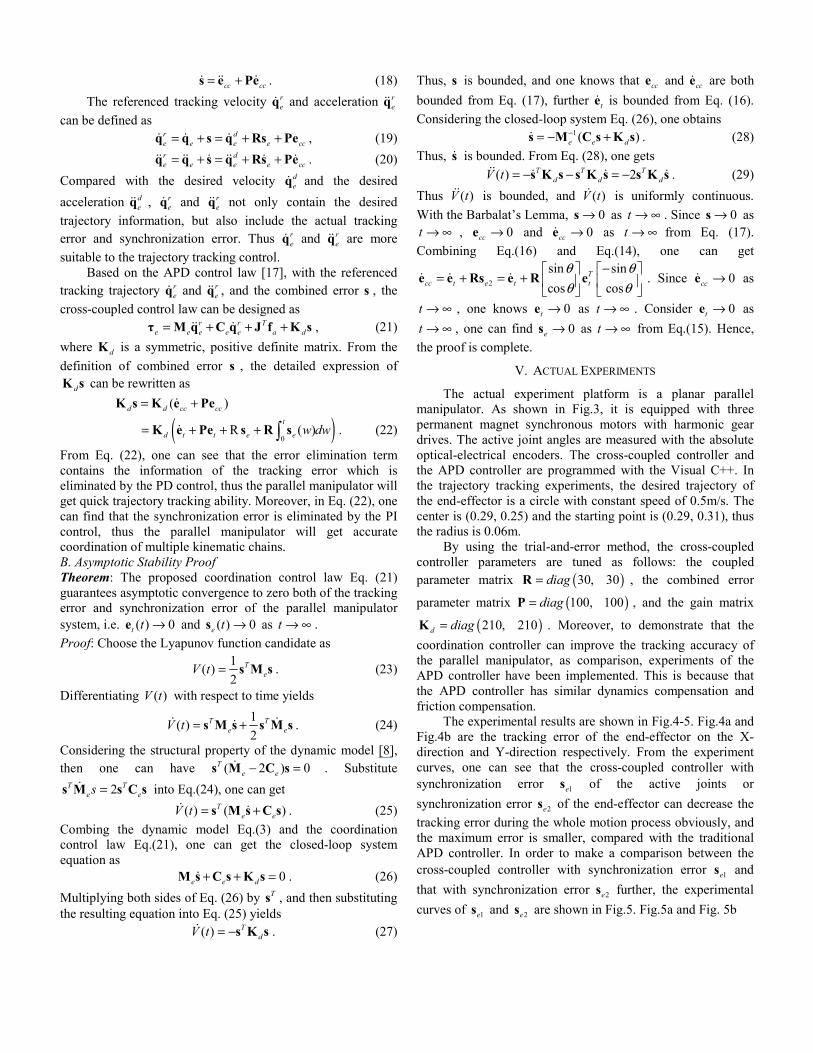
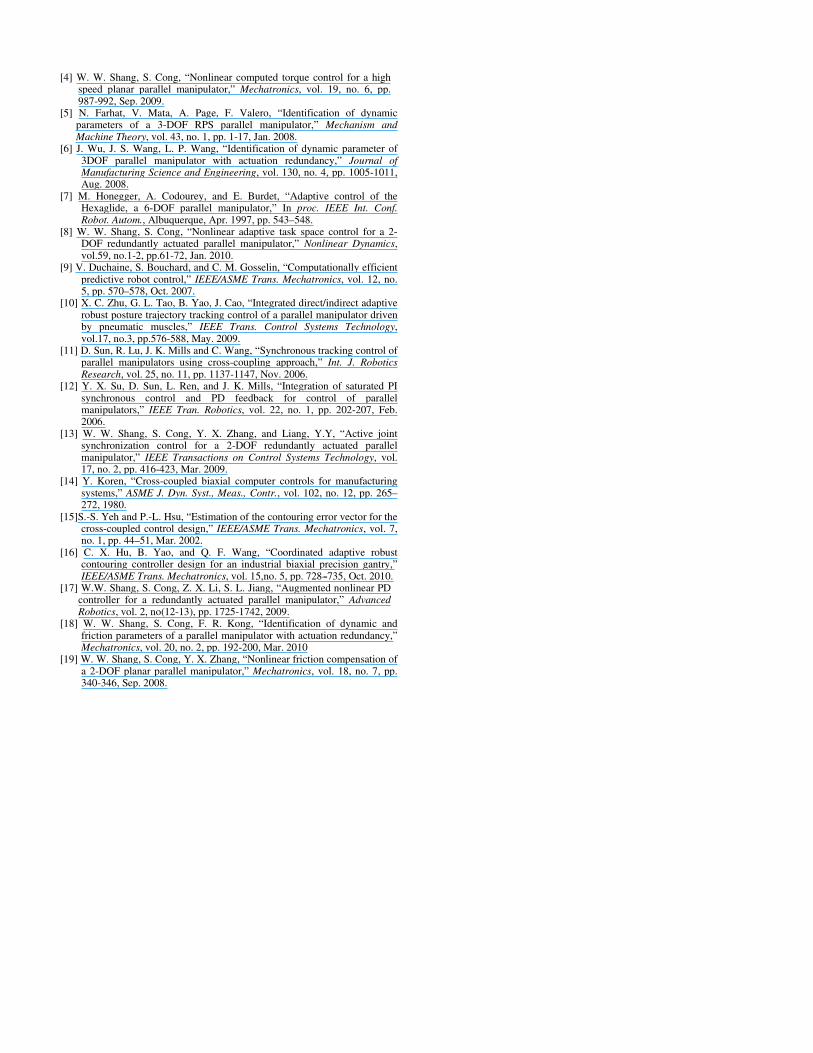
The experimental results are shown in Fig.4-5. Fig.4a and Fig.4b are the tracking error of the end-effector on the X-direction and Y-direction respectively. From the experiment curves, one can see that the cross-coupled controller with synchronization error 1es of the active joints or synchronization error 2es of the end-effector can decrease the tracking error during the whole motion process obviously, and the maximum error is smaller, compared with the traditional APD controller. In order to make a comparison between the cross-coupled controller with synchronization error 1es and that with synchronization error 2es further, the experimental curves of 1es and 2es are shown in Fig.5. Fig.5a and Fig. 5b
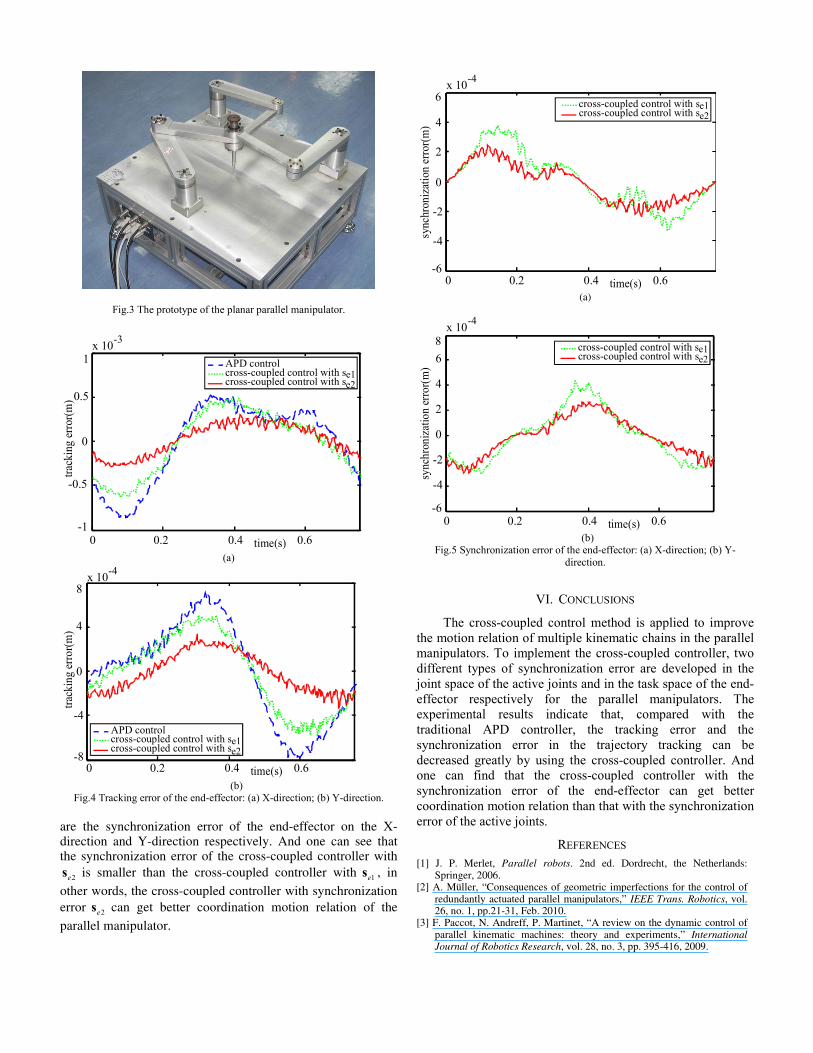
Fig.3 The prototype of the planar parallel manipulator.
-1
-0.5
0
0.5
1
trac
king
erro
r(m)
0 0.2 0.4 0.6time(s)
x 10-3
APD controle1cross-coupled control with s
cross-coupled control with se2
(a)
-8
-4
0
4
8
0 0.2 0.4 0.6time(s)
trac
king
erro
r(m)
x 10-4
APD controle1cross-coupled control with s
cross-coupled control with se2
(b)
Fig.4 Tracking error of the end-effector: (a) X-direction; (b) Y-direction. are the synchronization error of the end-effector on the X-direction and Y-direction respectively. And one can see that the synchronization error of the cross-coupled controller with
2es is smaller than the cross-coupled controller with 1es , in
other words, the cross-coupled controller with synchronization error 2es can get better coordination motion relation of the
parallel manipulator.
-4
-2
0
2
4
0 0.2 0.4 0.6time(s)
6
-6
x 10-4
sync
hron
izat
ion
erro
r(m)
e1cross-coupled control with scross-coupled control with se2
(a)
-4
-2
0
2
4
6
sync
hron
izat
ion
erro
r(m)
8
-6
x 10-4
0 0.2 0.4 0.6time(s)
e1cross-coupled control with scross-coupled control with se2
(b)
Fig.5 Synchronization error of the end-effector: (a) X-direction; (b) Y-direction.
VI. CONCLUSIONS
The cross-coupled control method is applied to improve the motion relation of multiple kinematic chains in the parallel manipulators. To implement the cross-coupled controller, two different types of synchronization error are developed in the joint space of the active joints and in the task space of the end-effector respectively for the parallel manipulators. The experimental results indicate that, compared with the traditional APD controller, the tracking error and the synchronization error in the trajectory tracking can be decreased greatly by using the cross-coupled controller. And one can find that the cross-coupled controller with the synchronization error of the end-effector can get better coordination motion relation than that with the synchronization error of the active joints.
REFERENCES [1] J. P. Merlet, Parallel robots. 2nd ed. Dordrecht, the Netherlands:
Springer, 2006. [2] A. Müller, “Consequences of geometric imperfections for the control of
redundantly actuated parallel manipulators,” IEEE Trans. Robotics, vol. 26, no. 1, pp.21-31, Feb. 2010.
[3] F. Paccot, N. Andreff, P. Martinet, “A review on the dynamic control of parallel kinematic machines: theory and experiments,” International Journal of Robotics Research, vol. 28, no. 3, pp. 395-416, 2009.
[4] W. W. Shang, S. Cong, “Nonlinear computed torque control for a high speed planar parallel manipulator,” Mechatronics, vol. 19, no. 6, pp. 987-992, Sep. 2009.
[5] N. Farhat, V. Mata, A. Page, F. Valero, “Identification of dynamic parameters of a 3-DOF RPS parallel manipulator,” Mechanism and Machine Theory, vol. 43, no. 1, pp. 1-17, Jan. 2008.
[6] J. Wu, J. S. Wang, L. P. Wang, “Identification of dynamic parameter of 3DOF parallel manipulator with actuation redundancy,” Journal of Manufacturing Science and Engineering, vol. 130, no. 4, pp. 1005-1011, Aug. 2008.
[7] M. Honegger, A. Codourey, and E. Burdet, “Adaptive control of the Hexaglide, a 6-DOF parallel manipulator,” In proc. IEEE Int. Conf. Robot. Autom., Albuquerque, Apr. 1997, pp. 543–548.
[8] W. W. Shang, S. Cong, “Nonlinear adaptive task space control for a 2-DOF redundantly actuated parallel manipulator,” Nonlinear Dynamics, vol.59, no.1-2, pp.61-72, Jan. 2010.
[9] V. Duchaine, S. Bouchard, and C. M. Gosselin, “Computationally efficient predictive robot control,” IEEE/ASME Trans. Mechatronics, vol. 12, no. 5, pp. 570–578, Oct. 2007.
[10] X. C. Zhu, G. L. Tao, B. Yao, J. Cao, “Integrated direct/indirect adaptive robust posture trajectory tracking control of a parallel manipulator driven by pneumatic muscles,” IEEE Trans. Control Systems Technology, vol.17, no.3, pp.576-588, May. 2009.
[11] D. Sun, R. Lu, J. K. Mills and C. Wang, “Synchronous tracking control of parallel manipulators using cross-coupling approach,” Int. J. Robotics Research, vol. 25, no. 11, pp. 1137-1147, Nov. 2006.
[12] Y. X. Su, D. Sun, L. Ren, and J. K. Mills, “Integration of saturated PI synchronous control and PD feedback for control of parallel manipulators,” IEEE Tran. Robotics, vol. 22, no. 1, pp. 202-207, Feb. 2006.
[13] W. W. Shang, S. Cong, Y. X. Zhang, and Liang, Y.Y, “Active joint synchronization control for a 2-DOF redundantly actuated parallel manipulator,” IEEE Transactions on Control Systems Technology, vol. 17, no. 2, pp. 416-423, Mar. 2009.
[14] Y. Koren, “Cross-coupled biaxial computer controls for manufacturing systems,” ASME J. Dyn. Syst., Meas., Contr., vol. 102, no. 12, pp. 265–272, 1980.
[15]S.-S. Yeh and P.-L. Hsu, “Estimation of the contouring error vector for the cross-coupled control design,” IEEE/ASME Trans. Mechatronics, vol. 7, no. 1, pp. 44–51, Mar. 2002.
[16] C. X. Hu, B. Yao, and Q. F. Wang, “Coordinated adaptive robust contouring controller design for an industrial biaxial precision gantry,” IEEE/ASME Trans. Mechatronics, vol. 15,no. 5, pp. 728---735, Oct. 2010.
[17] W.W. Shang, S. Cong, Z. X. Li, S. L. Jiang, “Augmented nonlinear PD controller for a redundantly actuated parallel manipulator,” Advanced Robotics, vol. 2, no(12-13), pp. 1725-1742, 2009.
[18] W. W. Shang, S. Cong, F. R. Kong, “Identification of dynamic and friction parameters of a parallel manipulator with actuation redundancy,” Mechatronics, vol. 20, no. 2, pp. 192-200, Mar. 2010
[19] W. W. Shang, S. Cong, Y. X. Zhang, “Nonlinear friction compensation of a 2-DOF planar parallel manipulator,” Mechatronics, vol. 18, no. 7, pp. 340-346, Sep. 2008.