dx8000 pc client software manual.pdf - ber-national
TRANSCRIPT
DX8000 Operations and Programming
O P E R A T I O N S / P R O G R A M M I N GC626M-C (3/06)
Client Application Software
DX8000 Series

ContentsClient Applications
Welcome to DX8000 Client Application . . . . . . . . . . . . . . . . . . . . . . . . . . . . . . . . . . . . . . . . . . . . . . . . . . . . . . . . . . . . . . . . . . . . . . . . . . . . . . 15DX8000 Client Emergency Agent . . . . . . . . . . . . . . . . . . . . . . . . . . . . . . . . . . . . . . . . . . . . . . . . . . . . . . . . . . . . . . . . . . . . . . . . . . . . . . . 15DX8000 Viewer . . . . . . . . . . . . . . . . . . . . . . . . . . . . . . . . . . . . . . . . . . . . . . . . . . . . . . . . . . . . . . . . . . . . . . . . . . . . . . . . . . . . . . . . . . . . . 15DX8000 Mobile Client . . . . . . . . . . . . . . . . . . . . . . . . . . . . . . . . . . . . . . . . . . . . . . . . . . . . . . . . . . . . . . . . . . . . . . . . . . . . . . . . . . . . . . . . 15DX8000 Web Client . . . . . . . . . . . . . . . . . . . . . . . . . . . . . . . . . . . . . . . . . . . . . . . . . . . . . . . . . . . . . . . . . . . . . . . . . . . . . . . . . . . . . . . . . 15
Getting Started with DX8000 Client Software . . . . . . . . . . . . . . . . . . . . . . . . . . . . . . . . . . . . . . . . . . . . . . . . . . . . . . . . . . . . . . . . . . . . . . . . . . . . . . 16Description of DX8000 Client Software . . . . . . . . . . . . . . . . . . . . . . . . . . . . . . . . . . . . . . . . . . . . . . . . . . . . . . . . . . . . . . . . . . . . . . . . . . . . . . 16Recommended System Requirements . . . . . . . . . . . . . . . . . . . . . . . . . . . . . . . . . . . . . . . . . . . . . . . . . . . . . . . . . . . . . . . . . . . . . . . . . . . . . . . . 16Windows XP Display Properties Configuration Requirements . . . . . . . . . . . . . . . . . . . . . . . . . . . . . . . . . . . . . . . . . . . . . . . . . . . . . . . . . . . . . 16Installing the Client Application . . . . . . . . . . . . . . . . . . . . . . . . . . . . . . . . . . . . . . . . . . . . . . . . . . . . . . . . . . . . . . . . . . . . . . . . . . . . . . . . . . . . 17Setting Up Security Services . . . . . . . . . . . . . . . . . . . . . . . . . . . . . . . . . . . . . . . . . . . . . . . . . . . . . . . . . . . . . . . . . . . . . . . . . . . . . . . . . . . . . . . 19
Enabling IPSec Security Services . . . . . . . . . . . . . . . . . . . . . . . . . . . . . . . . . . . . . . . . . . . . . . . . . . . . . . . . . . . . . . . . . . . . . . . . . . . . . . . 19Disabling IPSec Security Services . . . . . . . . . . . . . . . . . . . . . . . . . . . . . . . . . . . . . . . . . . . . . . . . . . . . . . . . . . . . . . . . . . . . . . . . . . . . . . 19
Starting the DX8000 Client Application . . . . . . . . . . . . . . . . . . . . . . . . . . . . . . . . . . . . . . . . . . . . . . . . . . . . . . . . . . . . . . . . . . . . . . . . . . . . . . 20Before You Start DX8000 Client Software . . . . . . . . . . . . . . . . . . . . . . . . . . . . . . . . . . . . . . . . . . . . . . . . . . . . . . . . . . . . . . . . . . . . . . . . 20Starting DX8000 Client Software . . . . . . . . . . . . . . . . . . . . . . . . . . . . . . . . . . . . . . . . . . . . . . . . . . . . . . . . . . . . . . . . . . . . . . . . . . . . . . . 20Automatic System Upgrade . . . . . . . . . . . . . . . . . . . . . . . . . . . . . . . . . . . . . . . . . . . . . . . . . . . . . . . . . . . . . . . . . . . . . . . . . . . . . . . . . . . 20
Logging In to the Client Application . . . . . . . . . . . . . . . . . . . . . . . . . . . . . . . . . . . . . . . . . . . . . . . . . . . . . . . . . . . . . . . . . . . . . . . . . . . . . . . . . . . . . . 21Changing the DX8000 Client Application Login Password . . . . . . . . . . . . . . . . . . . . . . . . . . . . . . . . . . . . . . . . . . . . . . . . . . . . . . . . . . . . . . . . 21Enabling DirectDraw Video Hardware Acceleration . . . . . . . . . . . . . . . . . . . . . . . . . . . . . . . . . . . . . . . . . . . . . . . . . . . . . . . . . . . . . . . . . . . . . 21
Connecting to DX8000 DVR Server Sites . . . . . . . . . . . . . . . . . . . . . . . . . . . . . . . . . . . . . . . . . . . . . . . . . . . . . . . . . . . . . . . . . . . . . . . . . . . . . . . . . . 22Adding a DX8000 DVR Server to the Connection List . . . . . . . . . . . . . . . . . . . . . . . . . . . . . . . . . . . . . . . . . . . . . . . . . . . . . . . . . . . . . . . . . . . . 22
Adding a Site with a Known IP Address . . . . . . . . . . . . . . . . . . . . . . . . . . . . . . . . . . . . . . . . . . . . . . . . . . . . . . . . . . . . . . . . . . . . . . . . . . 22Adding a Site with an Unknown IP Address . . . . . . . . . . . . . . . . . . . . . . . . . . . . . . . . . . . . . . . . . . . . . . . . . . . . . . . . . . . . . . . . . . . . . . . 23
Deleting a DX8000 DVR Server . . . . . . . . . . . . . . . . . . . . . . . . . . . . . . . . . . . . . . . . . . . . . . . . . . . . . . . . . . . . . . . . . . . . . . . . . . . . . . . . . . . . . 24Editing DX8000 Server Information from Connection List . . . . . . . . . . . . . . . . . . . . . . . . . . . . . . . . . . . . . . . . . . . . . . . . . . . . . . . . . . . . . . . . . 24Working with Remote Sites . . . . . . . . . . . . . . . . . . . . . . . . . . . . . . . . . . . . . . . . . . . . . . . . . . . . . . . . . . . . . . . . . . . . . . . . . . . . . . . . . . . . . . . . 25
Connecting to a Remote Site . . . . . . . . . . . . . . . . . . . . . . . . . . . . . . . . . . . . . . . . . . . . . . . . . . . . . . . . . . . . . . . . . . . . . . . . . . . . . . . . . . 25Automatically Connecting to a Remote Site . . . . . . . . . . . . . . . . . . . . . . . . . . . . . . . . . . . . . . . . . . . . . . . . . . . . . . . . . . . . . . . . . . . . . . 25Logging In to a Remote Site . . . . . . . . . . . . . . . . . . . . . . . . . . . . . . . . . . . . . . . . . . . . . . . . . . . . . . . . . . . . . . . . . . . . . . . . . . . . . . . . . . . 26Logging Out of a Remote Site . . . . . . . . . . . . . . . . . . . . . . . . . . . . . . . . . . . . . . . . . . . . . . . . . . . . . . . . . . . . . . . . . . . . . . . . . . . . . . . . . . 26Disconnecting from a Remote Site . . . . . . . . . . . . . . . . . . . . . . . . . . . . . . . . . . . . . . . . . . . . . . . . . . . . . . . . . . . . . . . . . . . . . . . . . . . . . . 26
Exiting the DX8000 Client Application . . . . . . . . . . . . . . . . . . . . . . . . . . . . . . . . . . . . . . . . . . . . . . . . . . . . . . . . . . . . . . . . . . . . . . . . . . . . . . . 26
Understanding the DX8000 Application Window . . . . . . . . . . . . . . . . . . . . . . . . . . . . . . . . . . . . . . . . . . . . . . . . . . . . . . . . . . . . . . . . . . . . . . . . . . . 27Description of the DX8000 Main Window . . . . . . . . . . . . . . . . . . . . . . . . . . . . . . . . . . . . . . . . . . . . . . . . . . . . . . . . . . . . . . . . . . . . . . . . . . . . 27
DX8000 Menu Bar . . . . . . . . . . . . . . . . . . . . . . . . . . . . . . . . . . . . . . . . . . . . . . . . . . . . . . . . . . . . . . . . . . . . . . . . . . . . . . . . . . . . . . . . . . . 30File Menu . . . . . . . . . . . . . . . . . . . . . . . . . . . . . . . . . . . . . . . . . . . . . . . . . . . . . . . . . . . . . . . . . . . . . . . . . . . . . . . . . . . . . . . . . . . . . 30Edit Menu . . . . . . . . . . . . . . . . . . . . . . . . . . . . . . . . . . . . . . . . . . . . . . . . . . . . . . . . . . . . . . . . . . . . . . . . . . . . . . . . . . . . . . . . . . . . . 30View Menu . . . . . . . . . . . . . . . . . . . . . . . . . . . . . . . . . . . . . . . . . . . . . . . . . . . . . . . . . . . . . . . . . . . . . . . . . . . . . . . . . . . . . . . . . . . . 30Export Menu . . . . . . . . . . . . . . . . . . . . . . . . . . . . . . . . . . . . . . . . . . . . . . . . . . . . . . . . . . . . . . . . . . . . . . . . . . . . . . . . . . . . . . . . . . . 32Favorite Menu . . . . . . . . . . . . . . . . . . . . . . . . . . . . . . . . . . . . . . . . . . . . . . . . . . . . . . . . . . . . . . . . . . . . . . . . . . . . . . . . . . . . . . . . . 32Help Menu . . . . . . . . . . . . . . . . . . . . . . . . . . . . . . . . . . . . . . . . . . . . . . . . . . . . . . . . . . . . . . . . . . . . . . . . . . . . . . . . . . . . . . . . . . . . 32
DX8000 Toolbar . . . . . . . . . . . . . . . . . . . . . . . . . . . . . . . . . . . . . . . . . . . . . . . . . . . . . . . . . . . . . . . . . . . . . . . . . . . . . . . . . . . . . . . . . . . . 33Displaying the DX8000 Window from a Page . . . . . . . . . . . . . . . . . . . . . . . . . . . . . . . . . . . . . . . . . . . . . . . . . . . . . . . . . . . . . . . . . . . . . 34Description of Operating Modes . . . . . . . . . . . . . . . . . . . . . . . . . . . . . . . . . . . . . . . . . . . . . . . . . . . . . . . . . . . . . . . . . . . . . . . . . . . . . . . 34
Understanding View Panes and Panels . . . . . . . . . . . . . . . . . . . . . . . . . . . . . . . . . . . . . . . . . . . . . . . . . . . . . . . . . . . . . . . . . . . . . . . . . . . . . . . 34Working with View Pane and Panel . . . . . . . . . . . . . . . . . . . . . . . . . . . . . . . . . . . . . . . . . . . . . . . . . . . . . . . . . . . . . . . . . . . . . . . . . . . . . 34Configuring View Panels . . . . . . . . . . . . . . . . . . . . . . . . . . . . . . . . . . . . . . . . . . . . . . . . . . . . . . . . . . . . . . . . . . . . . . . . . . . . . . . . . . . . . . 35Navigating View Panels . . . . . . . . . . . . . . . . . . . . . . . . . . . . . . . . . . . . . . . . . . . . . . . . . . . . . . . . . . . . . . . . . . . . . . . . . . . . . . . . . . . . . . 35
Navigating Between View Panels . . . . . . . . . . . . . . . . . . . . . . . . . . . . . . . . . . . . . . . . . . . . . . . . . . . . . . . . . . . . . . . . . . . . . . . . . . 35Expanding and Collapsing View Pane . . . . . . . . . . . . . . . . . . . . . . . . . . . . . . . . . . . . . . . . . . . . . . . . . . . . . . . . . . . . . . . . . . . . . . . 37Manually Cycling Through Hidden View Panels . . . . . . . . . . . . . . . . . . . . . . . . . . . . . . . . . . . . . . . . . . . . . . . . . . . . . . . . . . . . . . . 37Automatically Cycling Through View Windows . . . . . . . . . . . . . . . . . . . . . . . . . . . . . . . . . . . . . . . . . . . . . . . . . . . . . . . . . . . . . . . 37
Starting an Automatic Cycle View Mode . . . . . . . . . . . . . . . . . . . . . . . . . . . . . . . . . . . . . . . . . . . . . . . . . . . . . . . . . . . . . . . . 38
C626M-C (3/06) 3
Stopping an Automatic Cycle View Sequence . . . . . . . . . . . . . . . . . . . . . . . . . . . . . . . . . . . . . . . . . . . . . . . . . . . . . . . . . . . . 38Selecting User Groups to Set the Cycle View Dwell Time . . . . . . . . . . . . . . . . . . . . . . . . . . . . . . . . . . . . . . . . . . . . . . . . . . 38Selecting the Cycle View Dwell Time . . . . . . . . . . . . . . . . . . . . . . . . . . . . . . . . . . . . . . . . . . . . . . . . . . . . . . . . . . . . . . . . . . 38
Working with the Site tree . . . . . . . . . . . . . . . . . . . . . . . . . . . . . . . . . . . . . . . . . . . . . . . . . . . . . . . . . . . . . . . . . . . . . . . . . . . . . . . . . . . . . . . . 39Assigning Cameras to View Panes . . . . . . . . . . . . . . . . . . . . . . . . . . . . . . . . . . . . . . . . . . . . . . . . . . . . . . . . . . . . . . . . . . . . . . . . . . . . . . 40Setting Up Links . . . . . . . . . . . . . . . . . . . . . . . . . . . . . . . . . . . . . . . . . . . . . . . . . . . . . . . . . . . . . . . . . . . . . . . . . . . . . . . . . . . . . . . . . . . . 40
Manually Turning a Relay On and Off . . . . . . . . . . . . . . . . . . . . . . . . . . . . . . . . . . . . . . . . . . . . . . . . . . . . . . . . . . . . . . . . . . . . . . . 41Linking Alarm Inputs to a Camera . . . . . . . . . . . . . . . . . . . . . . . . . . . . . . . . . . . . . . . . . . . . . . . . . . . . . . . . . . . . . . . . . . . . . . . . . . 41Linking a Relay Output to a Camera . . . . . . . . . . . . . . . . . . . . . . . . . . . . . . . . . . . . . . . . . . . . . . . . . . . . . . . . . . . . . . . . . . . . . . . . 41Linking Relay Outputs to Alarm Inputs . . . . . . . . . . . . . . . . . . . . . . . . . . . . . . . . . . . . . . . . . . . . . . . . . . . . . . . . . . . . . . . . . . . . . . 41
Removing Links . . . . . . . . . . . . . . . . . . . . . . . . . . . . . . . . . . . . . . . . . . . . . . . . . . . . . . . . . . . . . . . . . . . . . . . . . . . . . . . . . . . . . . . . . . . . . 42Removing a Linked Alarm Input from a Camera . . . . . . . . . . . . . . . . . . . . . . . . . . . . . . . . . . . . . . . . . . . . . . . . . . . . . . . . . . . . . . . 42Removing a Linked Relay Output from a Camera . . . . . . . . . . . . . . . . . . . . . . . . . . . . . . . . . . . . . . . . . . . . . . . . . . . . . . . . . . . . . . 42Removing a Linked Relay Output from an Alarm Input . . . . . . . . . . . . . . . . . . . . . . . . . . . . . . . . . . . . . . . . . . . . . . . . . . . . . . . . . . 42
Working in Live View Mode . . . . . . . . . . . . . . . . . . . . . . . . . . . . . . . . . . . . . . . . . . . . . . . . . . . . . . . . . . . . . . . . . . . . . . . . . . . . . . . . . . . . . . . . . . . . 43Assigning Cameras to View Panes . . . . . . . . . . . . . . . . . . . . . . . . . . . . . . . . . . . . . . . . . . . . . . . . . . . . . . . . . . . . . . . . . . . . . . . . . . . . . . . . . . 43Setting Up Favorites . . . . . . . . . . . . . . . . . . . . . . . . . . . . . . . . . . . . . . . . . . . . . . . . . . . . . . . . . . . . . . . . . . . . . . . . . . . . . . . . . . . . . . . . . . . . . 43
Adding a Camera View to Favorites . . . . . . . . . . . . . . . . . . . . . . . . . . . . . . . . . . . . . . . . . . . . . . . . . . . . . . . . . . . . . . . . . . . . . . . . . . . . . 43Organizing Favorites in Folders . . . . . . . . . . . . . . . . . . . . . . . . . . . . . . . . . . . . . . . . . . . . . . . . . . . . . . . . . . . . . . . . . . . . . . . . . . . . . . . . . 44
Creating a Favorites Folder . . . . . . . . . . . . . . . . . . . . . . . . . . . . . . . . . . . . . . . . . . . . . . . . . . . . . . . . . . . . . . . . . . . . . . . . . . . . . . . 44Organizing Favorites in Folders . . . . . . . . . . . . . . . . . . . . . . . . . . . . . . . . . . . . . . . . . . . . . . . . . . . . . . . . . . . . . . . . . . . . . . . . . . . . 45
Live View On-Screen Display (OSD) . . . . . . . . . . . . . . . . . . . . . . . . . . . . . . . . . . . . . . . . . . . . . . . . . . . . . . . . . . . . . . . . . . . . . . . . . . . . . . . . . 46Customizing the On-Screen Display (OSD) . . . . . . . . . . . . . . . . . . . . . . . . . . . . . . . . . . . . . . . . . . . . . . . . . . . . . . . . . . . . . . . . . . . . . . . . . . . . 47Instant Recording . . . . . . . . . . . . . . . . . . . . . . . . . . . . . . . . . . . . . . . . . . . . . . . . . . . . . . . . . . . . . . . . . . . . . . . . . . . . . . . . . . . . . . . . . . . . . . . . 47
Enabling and Disabling Instant Recording . . . . . . . . . . . . . . . . . . . . . . . . . . . . . . . . . . . . . . . . . . . . . . . . . . . . . . . . . . . . . . . . . . . . . . . . 47Enabling Instant Recording . . . . . . . . . . . . . . . . . . . . . . . . . . . . . . . . . . . . . . . . . . . . . . . . . . . . . . . . . . . . . . . . . . . . . . . . . . . . . . . 48Disabling Instant Recording . . . . . . . . . . . . . . . . . . . . . . . . . . . . . . . . . . . . . . . . . . . . . . . . . . . . . . . . . . . . . . . . . . . . . . . . . . . . . . . 48
Adding Instant Recording to OSD . . . . . . . . . . . . . . . . . . . . . . . . . . . . . . . . . . . . . . . . . . . . . . . . . . . . . . . . . . . . . . . . . . . . . . . . . . . . . . . 48Starting and Stopping Instant Recording . . . . . . . . . . . . . . . . . . . . . . . . . . . . . . . . . . . . . . . . . . . . . . . . . . . . . . . . . . . . . . . . . . . . . . . . . 48
Starting Instant Recording . . . . . . . . . . . . . . . . . . . . . . . . . . . . . . . . . . . . . . . . . . . . . . . . . . . . . . . . . . . . . . . . . . . . . . . . . . . . . . . . 49Stopping Instant Recording . . . . . . . . . . . . . . . . . . . . . . . . . . . . . . . . . . . . . . . . . . . . . . . . . . . . . . . . . . . . . . . . . . . . . . . . . . . . . . . 49
Operating the On-Screen Pan, Tilt, and Zoom (PTZ) Controls . . . . . . . . . . . . . . . . . . . . . . . . . . . . . . . . . . . . . . . . . . . . . . . . . . . . . . . . . . . . . . 49Operating the PTZ Controls . . . . . . . . . . . . . . . . . . . . . . . . . . . . . . . . . . . . . . . . . . . . . . . . . . . . . . . . . . . . . . . . . . . . . . . . . . . . . . . . . . . . 49Adjusting the Camera Lens . . . . . . . . . . . . . . . . . . . . . . . . . . . . . . . . . . . . . . . . . . . . . . . . . . . . . . . . . . . . . . . . . . . . . . . . . . . . . . . . . . . . 51Adjusting the Camera Zoom . . . . . . . . . . . . . . . . . . . . . . . . . . . . . . . . . . . . . . . . . . . . . . . . . . . . . . . . . . . . . . . . . . . . . . . . . . . . . . . . . . . 52Using PC Keyboard Shortcuts to Operate PTZ and Lens Functions . . . . . . . . . . . . . . . . . . . . . . . . . . . . . . . . . . . . . . . . . . . . . . . . . . . . . 53
PTZ Presets . . . . . . . . . . . . . . . . . . . . . . . . . . . . . . . . . . . . . . . . . . . . . . . . . . . . . . . . . . . . . . . . . . . . . . . . . . . . . . . . . . . . . . . . . . . . . . . . . . . . 54Programming a Preset . . . . . . . . . . . . . . . . . . . . . . . . . . . . . . . . . . . . . . . . . . . . . . . . . . . . . . . . . . . . . . . . . . . . . . . . . . . . . . . . . . . . . . . . 54Activating a Preset . . . . . . . . . . . . . . . . . . . . . . . . . . . . . . . . . . . . . . . . . . . . . . . . . . . . . . . . . . . . . . . . . . . . . . . . . . . . . . . . . . . . . . . . . . 55Clearing a Preset . . . . . . . . . . . . . . . . . . . . . . . . . . . . . . . . . . . . . . . . . . . . . . . . . . . . . . . . . . . . . . . . . . . . . . . . . . . . . . . . . . . . . . . . . . . . 56
PTZ Patterns . . . . . . . . . . . . . . . . . . . . . . . . . . . . . . . . . . . . . . . . . . . . . . . . . . . . . . . . . . . . . . . . . . . . . . . . . . . . . . . . . . . . . . . . . . . . . . . . . . . . 56Programming a Pattern . . . . . . . . . . . . . . . . . . . . . . . . . . . . . . . . . . . . . . . . . . . . . . . . . . . . . . . . . . . . . . . . . . . . . . . . . . . . . . . . . . . . . . . 57Activating a Pattern . . . . . . . . . . . . . . . . . . . . . . . . . . . . . . . . . . . . . . . . . . . . . . . . . . . . . . . . . . . . . . . . . . . . . . . . . . . . . . . . . . . . . . . . . 58Clearing a Pattern . . . . . . . . . . . . . . . . . . . . . . . . . . . . . . . . . . . . . . . . . . . . . . . . . . . . . . . . . . . . . . . . . . . . . . . . . . . . . . . . . . . . . . . . . . . 58Accessing Programming Features of Remote Cameras . . . . . . . . . . . . . . . . . . . . . . . . . . . . . . . . . . . . . . . . . . . . . . . . . . . . . . . . . . . . . . 59
Using the PTZ OSD Menu Control . . . . . . . . . . . . . . . . . . . . . . . . . . . . . . . . . . . . . . . . . . . . . . . . . . . . . . . . . . . . . . . . . . . . . . . . . . 59Accessing a Remote Camera Programming Menu . . . . . . . . . . . . . . . . . . . . . . . . . . . . . . . . . . . . . . . . . . . . . . . . . . . . . . . . . . . . . 60
Sending Auxiliary Commands to a Device . . . . . . . . . . . . . . . . . . . . . . . . . . . . . . . . . . . . . . . . . . . . . . . . . . . . . . . . . . . . . . . . . . . . . . . . . . . . . 62Configuring Preset Tours . . . . . . . . . . . . . . . . . . . . . . . . . . . . . . . . . . . . . . . . . . . . . . . . . . . . . . . . . . . . . . . . . . . . . . . . . . . . . . . . . . . . . . . . . . 63
Programming a Preset Tour . . . . . . . . . . . . . . . . . . . . . . . . . . . . . . . . . . . . . . . . . . . . . . . . . . . . . . . . . . . . . . . . . . . . . . . . . . . . . . . . . . . 63Accessing a Preset Tour Group . . . . . . . . . . . . . . . . . . . . . . . . . . . . . . . . . . . . . . . . . . . . . . . . . . . . . . . . . . . . . . . . . . . . . . . . . . . . 63Adding Presets to a Tour . . . . . . . . . . . . . . . . . . . . . . . . . . . . . . . . . . . . . . . . . . . . . . . . . . . . . . . . . . . . . . . . . . . . . . . . . . . . . . . . . 64Deleting Presets from a Tour . . . . . . . . . . . . . . . . . . . . . . . . . . . . . . . . . . . . . . . . . . . . . . . . . . . . . . . . . . . . . . . . . . . . . . . . . . . . . . 65
Activating a Preset Tour . . . . . . . . . . . . . . . . . . . . . . . . . . . . . . . . . . . . . . . . . . . . . . . . . . . . . . . . . . . . . . . . . . . . . . . . . . . . . . . . . . . . . . 66Deactivating a Preset Tour . . . . . . . . . . . . . . . . . . . . . . . . . . . . . . . . . . . . . . . . . . . . . . . . . . . . . . . . . . . . . . . . . . . . . . . . . . . . . . . . . . . . 66
Working in Playback Mode . . . . . . . . . . . . . . . . . . . . . . . . . . . . . . . . . . . . . . . . . . . . . . . . . . . . . . . . . . . . . . . . . . . . . . . . . . . . . . . . . . . . . . . . . . . . . 67Accessing Playback Mode . . . . . . . . . . . . . . . . . . . . . . . . . . . . . . . . . . . . . . . . . . . . . . . . . . . . . . . . . . . . . . . . . . . . . . . . . . . . . . . . . . . . . . . . . 67Assigning Cameras to View Panels . . . . . . . . . . . . . . . . . . . . . . . . . . . . . . . . . . . . . . . . . . . . . . . . . . . . . . . . . . . . . . . . . . . . . . . . . . . . . . . . . . 67Playback On-Screen Display (OSD) . . . . . . . . . . . . . . . . . . . . . . . . . . . . . . . . . . . . . . . . . . . . . . . . . . . . . . . . . . . . . . . . . . . . . . . . . . . . . . . . . . 67Playback Controls . . . . . . . . . . . . . . . . . . . . . . . . . . . . . . . . . . . . . . . . . . . . . . . . . . . . . . . . . . . . . . . . . . . . . . . . . . . . . . . . . . . . . . . . . . . . . . . . 68
4 C626M-C (3/06)
Playback Timeline . . . . . . . . . . . . . . . . . . . . . . . . . . . . . . . . . . . . . . . . . . . . . . . . . . . . . . . . . . . . . . . . . . . . . . . . . . . . . . . . . . . . . . . . . . . . . . . 70Playing Back Video by Time . . . . . . . . . . . . . . . . . . . . . . . . . . . . . . . . . . . . . . . . . . . . . . . . . . . . . . . . . . . . . . . . . . . . . . . . . . . . . . . . . . . . . . . . 71
Starting Playback from a Specific Point in Time . . . . . . . . . . . . . . . . . . . . . . . . . . . . . . . . . . . . . . . . . . . . . . . . . . . . . . . . . . . . . . . . . . . 71Understanding Instant Playback . . . . . . . . . . . . . . . . . . . . . . . . . . . . . . . . . . . . . . . . . . . . . . . . . . . . . . . . . . . . . . . . . . . . . . . . . . . . . . . . 71
Playing Back Video by Event . . . . . . . . . . . . . . . . . . . . . . . . . . . . . . . . . . . . . . . . . . . . . . . . . . . . . . . . . . . . . . . . . . . . . . . . . . . . . . . . . . . . . . . 72Operating Playback Digital Zoom . . . . . . . . . . . . . . . . . . . . . . . . . . . . . . . . . . . . . . . . . . . . . . . . . . . . . . . . . . . . . . . . . . . . . . . . . . . . . . . . . . . 73
Zoom Using the Digital Zoom Control . . . . . . . . . . . . . . . . . . . . . . . . . . . . . . . . . . . . . . . . . . . . . . . . . . . . . . . . . . . . . . . . . . . . . . . . . . . 73Zoom Using the Mouse . . . . . . . . . . . . . . . . . . . . . . . . . . . . . . . . . . . . . . . . . . . . . . . . . . . . . . . . . . . . . . . . . . . . . . . . . . . . . . . . . . . . . . . 74Panning a Zoomed Image . . . . . . . . . . . . . . . . . . . . . . . . . . . . . . . . . . . . . . . . . . . . . . . . . . . . . . . . . . . . . . . . . . . . . . . . . . . . . . . . . . . . . 75
Working in Search Mode . . . . . . . . . . . . . . . . . . . . . . . . . . . . . . . . . . . . . . . . . . . . . . . . . . . . . . . . . . . . . . . . . . . . . . . . . . . . . . . . . . . . . . . . . . . . . . 76Search Window . . . . . . . . . . . . . . . . . . . . . . . . . . . . . . . . . . . . . . . . . . . . . . . . . . . . . . . . . . . . . . . . . . . . . . . . . . . . . . . . . . . . . . . . . . . . . . . . . 77Displaying a Deinterlaced Image in the Search Mode . . . . . . . . . . . . . . . . . . . . . . . . . . . . . . . . . . . . . . . . . . . . . . . . . . . . . . . . . . . . . . . . . . . 79Index Video Search . . . . . . . . . . . . . . . . . . . . . . . . . . . . . . . . . . . . . . . . . . . . . . . . . . . . . . . . . . . . . . . . . . . . . . . . . . . . . . . . . . . . . . . . . . . . . . 79Thumbnail Video Search . . . . . . . . . . . . . . . . . . . . . . . . . . . . . . . . . . . . . . . . . . . . . . . . . . . . . . . . . . . . . . . . . . . . . . . . . . . . . . . . . . . . . . . . . . 80POS Search . . . . . . . . . . . . . . . . . . . . . . . . . . . . . . . . . . . . . . . . . . . . . . . . . . . . . . . . . . . . . . . . . . . . . . . . . . . . . . . . . . . . . . . . . . . . . . . . . . . . 82
Understanding the POS Search View . . . . . . . . . . . . . . . . . . . . . . . . . . . . . . . . . . . . . . . . . . . . . . . . . . . . . . . . . . . . . . . . . . . . . . . . . . . . 83Searching and Displaying POS Data by Device Name . . . . . . . . . . . . . . . . . . . . . . . . . . . . . . . . . . . . . . . . . . . . . . . . . . . . . . . . . . . . . . . 86
Searching POS Data by Device Name . . . . . . . . . . . . . . . . . . . . . . . . . . . . . . . . . . . . . . . . . . . . . . . . . . . . . . . . . . . . . . . . . . . . . . . 86Displaying POS Data Discovered by Device Name . . . . . . . . . . . . . . . . . . . . . . . . . . . . . . . . . . . . . . . . . . . . . . . . . . . . . . . . . . . . . 87
Searching by POS Transaction Number . . . . . . . . . . . . . . . . . . . . . . . . . . . . . . . . . . . . . . . . . . . . . . . . . . . . . . . . . . . . . . . . . . . . . . . . . . 88Searching for All Transactions with Exceptions . . . . . . . . . . . . . . . . . . . . . . . . . . . . . . . . . . . . . . . . . . . . . . . . . . . . . . . . . . . . . . . . . . . . 89Searching for Transactions that Satisfy Specific Exceptions . . . . . . . . . . . . . . . . . . . . . . . . . . . . . . . . . . . . . . . . . . . . . . . . . . . . . . . . . . 90Searching for Transactions by Line Item . . . . . . . . . . . . . . . . . . . . . . . . . . . . . . . . . . . . . . . . . . . . . . . . . . . . . . . . . . . . . . . . . . . . . . . . . 91Searching for Transactions by Action Code . . . . . . . . . . . . . . . . . . . . . . . . . . . . . . . . . . . . . . . . . . . . . . . . . . . . . . . . . . . . . . . . . . . . . . . 92
Pixel Video Search . . . . . . . . . . . . . . . . . . . . . . . . . . . . . . . . . . . . . . . . . . . . . . . . . . . . . . . . . . . . . . . . . . . . . . . . . . . . . . . . . . . . . . . . . . . . . . . 93Searching Video Based on Changes in Screen Pixels . . . . . . . . . . . . . . . . . . . . . . . . . . . . . . . . . . . . . . . . . . . . . . . . . . . . . . . . . . . . . . . 93Viewing a Video Thumbnail . . . . . . . . . . . . . . . . . . . . . . . . . . . . . . . . . . . . . . . . . . . . . . . . . . . . . . . . . . . . . . . . . . . . . . . . . . . . . . . . . . . 95
Working with Special View and Search Methods . . . . . . . . . . . . . . . . . . . . . . . . . . . . . . . . . . . . . . . . . . . . . . . . . . . . . . . . . . . . . . . . . . . . . . 96Viewing Video in the Deinterlaced Mode . . . . . . . . . . . . . . . . . . . . . . . . . . . . . . . . . . . . . . . . . . . . . . . . . . . . . . . . . . . . . . . . . . . . . . . . 96Viewing Live and Playback Video Simultaneously . . . . . . . . . . . . . . . . . . . . . . . . . . . . . . . . . . . . . . . . . . . . . . . . . . . . . . . . . . . . . . . . . . 96
Exporting Video . . . . . . . . . . . . . . . . . . . . . . . . . . . . . . . . . . . . . . . . . . . . . . . . . . . . . . . . . . . . . . . . . . . . . . . . . . . . . . . . . . . . . . . . . . . . . . . . . . . . . . 97Exporting Bookmarked Video Regions . . . . . . . . . . . . . . . . . . . . . . . . . . . . . . . . . . . . . . . . . . . . . . . . . . . . . . . . . . . . . . . . . . . . . . . . . . . . . . . . 97
Creating Bookmarks . . . . . . . . . . . . . . . . . . . . . . . . . . . . . . . . . . . . . . . . . . . . . . . . . . . . . . . . . . . . . . . . . . . . . . . . . . . . . . . . . . . . . . . . . 98Clearing Bookmarks . . . . . . . . . . . . . . . . . . . . . . . . . . . . . . . . . . . . . . . . . . . . . . . . . . . . . . . . . . . . . . . . . . . . . . . . . . . . . . . . . . . . . . . . . 98
Clearing a Single Bookmark . . . . . . . . . . . . . . . . . . . . . . . . . . . . . . . . . . . . . . . . . . . . . . . . . . . . . . . . . . . . . . . . . . . . . . . . . . . . . . . 98Clearing All Bookmarks . . . . . . . . . . . . . . . . . . . . . . . . . . . . . . . . . . . . . . . . . . . . . . . . . . . . . . . . . . . . . . . . . . . . . . . . . . . . . . . . . . 99
Inserting and Removing a USB Flash Drive . . . . . . . . . . . . . . . . . . . . . . . . . . . . . . . . . . . . . . . . . . . . . . . . . . . . . . . . . . . . . . . . . . . . . . . . . . . . 99Installing a USB Flash Drive . . . . . . . . . . . . . . . . . . . . . . . . . . . . . . . . . . . . . . . . . . . . . . . . . . . . . . . . . . . . . . . . . . . . . . . . . . . . . . . . . . . 99Removing a USB Flash Drive . . . . . . . . . . . . . . . . . . . . . . . . . . . . . . . . . . . . . . . . . . . . . . . . . . . . . . . . . . . . . . . . . . . . . . . . . . . . . . . . . . 99
Enabling the Deinterlacing Filter . . . . . . . . . . . . . . . . . . . . . . . . . . . . . . . . . . . . . . . . . . . . . . . . . . . . . . . . . . . . . . . . . . . . . . . . . . . . . . . . . . . . 99Mapping and Disconnecting a Network Drive . . . . . . . . . . . . . . . . . . . . . . . . . . . . . . . . . . . . . . . . . . . . . . . . . . . . . . . . . . . . . . . . . . . . . . . . 100
Mapping a Network Drive . . . . . . . . . . . . . . . . . . . . . . . . . . . . . . . . . . . . . . . . . . . . . . . . . . . . . . . . . . . . . . . . . . . . . . . . . . . . . . . . . . . 100Disconnecting a Network Drive . . . . . . . . . . . . . . . . . . . . . . . . . . . . . . . . . . . . . . . . . . . . . . . . . . . . . . . . . . . . . . . . . . . . . . . . . . . . . . . 100
Performing the Export . . . . . . . . . . . . . . . . . . . . . . . . . . . . . . . . . . . . . . . . . . . . . . . . . . . . . . . . . . . . . . . . . . . . . . . . . . . . . . . . . . . . . . . . . . . 101Starting an Export Process . . . . . . . . . . . . . . . . . . . . . . . . . . . . . . . . . . . . . . . . . . . . . . . . . . . . . . . . . . . . . . . . . . . . . . . . . . . . . . . . . . . 101Changing a Bookmarked Time Range . . . . . . . . . . . . . . . . . . . . . . . . . . . . . . . . . . . . . . . . . . . . . . . . . . . . . . . . . . . . . . . . . . . . . . . . . . . 103Assigning a Custom Export Video File Name . . . . . . . . . . . . . . . . . . . . . . . . . . . . . . . . . . . . . . . . . . . . . . . . . . . . . . . . . . . . . . . . . . . . . 103Selecting the Export Format . . . . . . . . . . . . . . . . . . . . . . . . . . . . . . . . . . . . . . . . . . . . . . . . . . . . . . . . . . . . . . . . . . . . . . . . . . . . . . . . . . 104Exporting a Sequence of Still Images . . . . . . . . . . . . . . . . . . . . . . . . . . . . . . . . . . . . . . . . . . . . . . . . . . . . . . . . . . . . . . . . . . . . . . . . . . . 105Finalizing an Export Process . . . . . . . . . . . . . . . . . . . . . . . . . . . . . . . . . . . . . . . . . . . . . . . . . . . . . . . . . . . . . . . . . . . . . . . . . . . . . . . . . . 105Stopping an Export While in Process . . . . . . . . . . . . . . . . . . . . . . . . . . . . . . . . . . . . . . . . . . . . . . . . . . . . . . . . . . . . . . . . . . . . . . . . . . . 106
Retaining Video When Stopping an Export Process . . . . . . . . . . . . . . . . . . . . . . . . . . . . . . . . . . . . . . . . . . . . . . . . . . . . . . . . . . . 106Deleting Video Data When Stopping an Export Process . . . . . . . . . . . . . . . . . . . . . . . . . . . . . . . . . . . . . . . . . . . . . . . . . . . . . . . . 106
Working with DX8000 Backed-Up Video . . . . . . . . . . . . . . . . . . . . . . . . . . . . . . . . . . . . . . . . . . . . . . . . . . . . . . . . . . . . . . . . . . . . . . . . 106
Printing Images . . . . . . . . . . . . . . . . . . . . . . . . . . . . . . . . . . . . . . . . . . . . . . . . . . . . . . . . . . . . . . . . . . . . . . . . . . . . . . . . . . . . . . . . . . . . . . . . . . . . . 107Printing Images in the Deinterlaced Mode . . . . . . . . . . . . . . . . . . . . . . . . . . . . . . . . . . . . . . . . . . . . . . . . . . . . . . . . . . . . . . . . . . . . . . . . . . . 107
Setting Up the DX8000 . . . . . . . . . . . . . . . . . . . . . . . . . . . . . . . . . . . . . . . . . . . . . . . . . . . . . . . . . . . . . . . . . . . . . . . . . . . . . . . . . . . . . . . . . . . . . . . 108Accessing the Setup Mode . . . . . . . . . . . . . . . . . . . . . . . . . . . . . . . . . . . . . . . . . . . . . . . . . . . . . . . . . . . . . . . . . . . . . . . . . . . . . . . . . . . . . . . 108
C626M-C (3/06) 5
Understanding the Setup Dialog Box . . . . . . . . . . . . . . . . . . . . . . . . . . . . . . . . . . . . . . . . . . . . . . . . . . . . . . . . . . . . . . . . . . . . . . . . . . . . . . . 109Camera Setup . . . . . . . . . . . . . . . . . . . . . . . . . . . . . . . . . . . . . . . . . . . . . . . . . . . . . . . . . . . . . . . . . . . . . . . . . . . . . . . . . . . . . . . . . . . . . . . . . 111
Basic Camera Setup . . . . . . . . . . . . . . . . . . . . . . . . . . . . . . . . . . . . . . . . . . . . . . . . . . . . . . . . . . . . . . . . . . . . . . . . . . . . . . . . . . . . . . . . 111Motion Detection Setup . . . . . . . . . . . . . . . . . . . . . . . . . . . . . . . . . . . . . . . . . . . . . . . . . . . . . . . . . . . . . . . . . . . . . . . . . . . . . . . . . . . . . 113Audio Setup . . . . . . . . . . . . . . . . . . . . . . . . . . . . . . . . . . . . . . . . . . . . . . . . . . . . . . . . . . . . . . . . . . . . . . . . . . . . . . . . . . . . . . . . . . . . . . 114Listening to Live Audio . . . . . . . . . . . . . . . . . . . . . . . . . . . . . . . . . . . . . . . . . . . . . . . . . . . . . . . . . . . . . . . . . . . . . . . . . . . . . . . . . . . . . . 115
Listening to Live Audio at a Local Server . . . . . . . . . . . . . . . . . . . . . . . . . . . . . . . . . . . . . . . . . . . . . . . . . . . . . . . . . . . . . . . . . . . 115Listening to Live Audio from a Remote DX8000 System . . . . . . . . . . . . . . . . . . . . . . . . . . . . . . . . . . . . . . . . . . . . . . . . . . . . . . . . 115
Configuring Video Loss Detection . . . . . . . . . . . . . . . . . . . . . . . . . . . . . . . . . . . . . . . . . . . . . . . . . . . . . . . . . . . . . . . . . . . . . . . . . . . . . 116Applying Settings to all Cameras . . . . . . . . . . . . . . . . . . . . . . . . . . . . . . . . . . . . . . . . . . . . . . . . . . . . . . . . . . . . . . . . . . . . . . . . . . . . . . 117
Link Setup . . . . . . . . . . . . . . . . . . . . . . . . . . . . . . . . . . . . . . . . . . . . . . . . . . . . . . . . . . . . . . . . . . . . . . . . . . . . . . . . . . . . . . . . . . . . . . . . . . . . 117Configuring Basic Relay and Alarm Settings . . . . . . . . . . . . . . . . . . . . . . . . . . . . . . . . . . . . . . . . . . . . . . . . . . . . . . . . . . . . . . . . . . . . . 117
Understanding How Relays and Alarms React to a Power Outage . . . . . . . . . . . . . . . . . . . . . . . . . . . . . . . . . . . . . . . . . . . . . . . 117Configuring DX8000 Basic Relay and Alarm Settings . . . . . . . . . . . . . . . . . . . . . . . . . . . . . . . . . . . . . . . . . . . . . . . . . . . . . . . . . . 117Configuring Basic Relay Operating Properties . . . . . . . . . . . . . . . . . . . . . . . . . . . . . . . . . . . . . . . . . . . . . . . . . . . . . . . . . . . . . . . 118Configuring Basic Alarm Input Operating Properties . . . . . . . . . . . . . . . . . . . . . . . . . . . . . . . . . . . . . . . . . . . . . . . . . . . . . . . . . . 118
Linking Relay Outputs to External Events . . . . . . . . . . . . . . . . . . . . . . . . . . . . . . . . . . . . . . . . . . . . . . . . . . . . . . . . . . . . . . . . . . . . . . . . 119Linking Relay Outputs to Motion Events . . . . . . . . . . . . . . . . . . . . . . . . . . . . . . . . . . . . . . . . . . . . . . . . . . . . . . . . . . . . . . . . . . . . 119Linking Relay Outputs to Alarm Events . . . . . . . . . . . . . . . . . . . . . . . . . . . . . . . . . . . . . . . . . . . . . . . . . . . . . . . . . . . . . . . . . . . . . 120Linking Relay Outputs to ATM/POS Events . . . . . . . . . . . . . . . . . . . . . . . . . . . . . . . . . . . . . . . . . . . . . . . . . . . . . . . . . . . . . . . . . . 120Linking Relay Outputs to Video Loss Events . . . . . . . . . . . . . . . . . . . . . . . . . . . . . . . . . . . . . . . . . . . . . . . . . . . . . . . . . . . . . . . . . 121
Linking Cameras to Record in Response to External Events . . . . . . . . . . . . . . . . . . . . . . . . . . . . . . . . . . . . . . . . . . . . . . . . . . . . . . . . . 121Linking Cameras to Record in Response to Motion Events . . . . . . . . . . . . . . . . . . . . . . . . . . . . . . . . . . . . . . . . . . . . . . . . . . . . . . 122Linking Cameras to Record in Response to Alarm Events . . . . . . . . . . . . . . . . . . . . . . . . . . . . . . . . . . . . . . . . . . . . . . . . . . . . . . . 122Linking Cameras to Record in Response to ATM/POS Events . . . . . . . . . . . . . . . . . . . . . . . . . . . . . . . . . . . . . . . . . . . . . . . . . . . 123Linking Cameras to Record in Response to Video Loss Events . . . . . . . . . . . . . . . . . . . . . . . . . . . . . . . . . . . . . . . . . . . . . . . . . . . 123
Linking PTZ Presets and Patterns to External Events . . . . . . . . . . . . . . . . . . . . . . . . . . . . . . . . . . . . . . . . . . . . . . . . . . . . . . . . . . . . . . . 124Linking PTZ Presets and Patterns to Motion Events . . . . . . . . . . . . . . . . . . . . . . . . . . . . . . . . . . . . . . . . . . . . . . . . . . . . . . . . . . . 124Linking PTZ Presets and Patterns to Alarm Events . . . . . . . . . . . . . . . . . . . . . . . . . . . . . . . . . . . . . . . . . . . . . . . . . . . . . . . . . . . . 125Linking Presets and Patterns to ATM/POS Events . . . . . . . . . . . . . . . . . . . . . . . . . . . . . . . . . . . . . . . . . . . . . . . . . . . . . . . . . . . . 126Linking Presets and Patterns to Video Loss Events . . . . . . . . . . . . . . . . . . . . . . . . . . . . . . . . . . . . . . . . . . . . . . . . . . . . . . . . . . . . 127
Schedule Setup . . . . . . . . . . . . . . . . . . . . . . . . . . . . . . . . . . . . . . . . . . . . . . . . . . . . . . . . . . . . . . . . . . . . . . . . . . . . . . . . . . . . . . . . . . . . . . . . 128Accessing the Schedule . . . . . . . . . . . . . . . . . . . . . . . . . . . . . . . . . . . . . . . . . . . . . . . . . . . . . . . . . . . . . . . . . . . . . . . . . . . . . . . . . . . . . 128Setting Up the Camera Recording Mode . . . . . . . . . . . . . . . . . . . . . . . . . . . . . . . . . . . . . . . . . . . . . . . . . . . . . . . . . . . . . . . . . . . . . . . . 130
Scheduling a Record Mode . . . . . . . . . . . . . . . . . . . . . . . . . . . . . . . . . . . . . . . . . . . . . . . . . . . . . . . . . . . . . . . . . . . . . . . . . . . . . . 130Clearing a Scheduled Recording . . . . . . . . . . . . . . . . . . . . . . . . . . . . . . . . . . . . . . . . . . . . . . . . . . . . . . . . . . . . . . . . . . . . . . . . . . 131
Clearing Recording Times for a Specific Record Mode . . . . . . . . . . . . . . . . . . . . . . . . . . . . . . . . . . . . . . . . . . . . . . . . . . . . 131Clearing Recording Times for All Record Modes . . . . . . . . . . . . . . . . . . . . . . . . . . . . . . . . . . . . . . . . . . . . . . . . . . . . . . . . . 132
Creating Yearly Recording Schedules . . . . . . . . . . . . . . . . . . . . . . . . . . . . . . . . . . . . . . . . . . . . . . . . . . . . . . . . . . . . . . . . . . . . . . . . . . 132Creating a Yearly Recording Schedule . . . . . . . . . . . . . . . . . . . . . . . . . . . . . . . . . . . . . . . . . . . . . . . . . . . . . . . . . . . . . . . . . . . . . 132Scheduling Individual Days Using the Year View . . . . . . . . . . . . . . . . . . . . . . . . . . . . . . . . . . . . . . . . . . . . . . . . . . . . . . . . . . . . . 133Copying Schedule Attributes to a Different Day . . . . . . . . . . . . . . . . . . . . . . . . . . . . . . . . . . . . . . . . . . . . . . . . . . . . . . . . . . . . . . 133
Creating Monthly or Multiple-Day Recording Schedules . . . . . . . . . . . . . . . . . . . . . . . . . . . . . . . . . . . . . . . . . . . . . . . . . . . . . . . . . . . . 134Creating Multiple-Day Schedules . . . . . . . . . . . . . . . . . . . . . . . . . . . . . . . . . . . . . . . . . . . . . . . . . . . . . . . . . . . . . . . . . . . . . . . . . 134Creating Single-Day Schedules . . . . . . . . . . . . . . . . . . . . . . . . . . . . . . . . . . . . . . . . . . . . . . . . . . . . . . . . . . . . . . . . . . . . . . . . . . . 135
Working with Single-Day Schedules . . . . . . . . . . . . . . . . . . . . . . . . . . . . . . . . . . . . . . . . . . . . . . . . . . . . . . . . . . . . . . . . . . 135Copying and Applying Schedule Attributes . . . . . . . . . . . . . . . . . . . . . . . . . . . . . . . . . . . . . . . . . . . . . . . . . . . . . . . . . . . . . 136
Editing Schedules . . . . . . . . . . . . . . . . . . . . . . . . . . . . . . . . . . . . . . . . . . . . . . . . . . . . . . . . . . . . . . . . . . . . . . . . . . . . . . . . . . . . . . . . . . 137Changing an Existing Schedule Profile . . . . . . . . . . . . . . . . . . . . . . . . . . . . . . . . . . . . . . . . . . . . . . . . . . . . . . . . . . . . . . . . . . . . . 137Deleting an Existing Schedule Profile . . . . . . . . . . . . . . . . . . . . . . . . . . . . . . . . . . . . . . . . . . . . . . . . . . . . . . . . . . . . . . . . . . . . . . 138
Working with Custom Camera Settings . . . . . . . . . . . . . . . . . . . . . . . . . . . . . . . . . . . . . . . . . . . . . . . . . . . . . . . . . . . . . . . . . . . . . . . . . 139Configuring Custom Camera Settings . . . . . . . . . . . . . . . . . . . . . . . . . . . . . . . . . . . . . . . . . . . . . . . . . . . . . . . . . . . . . . . . . . . . . . 139Examples of Custom Camera Settings . . . . . . . . . . . . . . . . . . . . . . . . . . . . . . . . . . . . . . . . . . . . . . . . . . . . . . . . . . . . . . . . . . . . . 140
Configuring the Frame Rate . . . . . . . . . . . . . . . . . . . . . . . . . . . . . . . . . . . . . . . . . . . . . . . . . . . . . . . . . . . . . . . . . . . . . . . . . . . . . . . . . . 141Accessing the Frame Rate Configuration Dialog Box . . . . . . . . . . . . . . . . . . . . . . . . . . . . . . . . . . . . . . . . . . . . . . . . . . . . . . . . . . 141Setting the Basic Frame Rate . . . . . . . . . . . . . . . . . . . . . . . . . . . . . . . . . . . . . . . . . . . . . . . . . . . . . . . . . . . . . . . . . . . . . . . . . . . . 141Setting the Advanced Frame Rate . . . . . . . . . . . . . . . . . . . . . . . . . . . . . . . . . . . . . . . . . . . . . . . . . . . . . . . . . . . . . . . . . . . . . . . . . 142Understanding the DX8000 Frame Rate Calculations . . . . . . . . . . . . . . . . . . . . . . . . . . . . . . . . . . . . . . . . . . . . . . . . . . . . . . . . . . 144
Setting Up Advanced Relay Output . . . . . . . . . . . . . . . . . . . . . . . . . . . . . . . . . . . . . . . . . . . . . . . . . . . . . . . . . . . . . . . . . . . . . . . . . . . . 144Configuring Advanced Motion-Activated Relay Output . . . . . . . . . . . . . . . . . . . . . . . . . . . . . . . . . . . . . . . . . . . . . . . . . . . . . . . . 145Configuring Advanced Alarm-Activated Relay Output . . . . . . . . . . . . . . . . . . . . . . . . . . . . . . . . . . . . . . . . . . . . . . . . . . . . . . . . . 146Configuring Advanced ATM/POS-Activated Relay Output . . . . . . . . . . . . . . . . . . . . . . . . . . . . . . . . . . . . . . . . . . . . . . . . . . . . . . 147
6 C626M-C (3/06)
Configuring Advanced Video Loss-Activated Relay Output . . . . . . . . . . . . . . . . . . . . . . . . . . . . . . . . . . . . . . . . . . . . . . . . . . . . . 148Setting Up Network Properties . . . . . . . . . . . . . . . . . . . . . . . . . . . . . . . . . . . . . . . . . . . . . . . . . . . . . . . . . . . . . . . . . . . . . . . . . . . . . . . . . . . . 149Data Backup Setup . . . . . . . . . . . . . . . . . . . . . . . . . . . . . . . . . . . . . . . . . . . . . . . . . . . . . . . . . . . . . . . . . . . . . . . . . . . . . . . . . . . . . . . . . . . . . 149
Viewing and Searching Backed-Up Video . . . . . . . . . . . . . . . . . . . . . . . . . . . . . . . . . . . . . . . . . . . . . . . . . . . . . . . . . . . . . . . . . . . . . . . 149User Setup . . . . . . . . . . . . . . . . . . . . . . . . . . . . . . . . . . . . . . . . . . . . . . . . . . . . . . . . . . . . . . . . . . . . . . . . . . . . . . . . . . . . . . . . . . . . . . . . . . . . 151
Accessing the User Page . . . . . . . . . . . . . . . . . . . . . . . . . . . . . . . . . . . . . . . . . . . . . . . . . . . . . . . . . . . . . . . . . . . . . . . . . . . . . . . . . . . . 151Built-in User Accounts . . . . . . . . . . . . . . . . . . . . . . . . . . . . . . . . . . . . . . . . . . . . . . . . . . . . . . . . . . . . . . . . . . . . . . . . . . . . . . . . . . . . . . 153Definition of User Access Levels . . . . . . . . . . . . . . . . . . . . . . . . . . . . . . . . . . . . . . . . . . . . . . . . . . . . . . . . . . . . . . . . . . . . . . . . . . . . . . 153Definition of Camera Security Access . . . . . . . . . . . . . . . . . . . . . . . . . . . . . . . . . . . . . . . . . . . . . . . . . . . . . . . . . . . . . . . . . . . . . . . . . . 154Adding New Users . . . . . . . . . . . . . . . . . . . . . . . . . . . . . . . . . . . . . . . . . . . . . . . . . . . . . . . . . . . . . . . . . . . . . . . . . . . . . . . . . . . . . . . . . 154Modifying User Properties . . . . . . . . . . . . . . . . . . . . . . . . . . . . . . . . . . . . . . . . . . . . . . . . . . . . . . . . . . . . . . . . . . . . . . . . . . . . . . . . . . . 155Changing User Passwords . . . . . . . . . . . . . . . . . . . . . . . . . . . . . . . . . . . . . . . . . . . . . . . . . . . . . . . . . . . . . . . . . . . . . . . . . . . . . . . . . . . 155Changing a User’s Group Affiliation . . . . . . . . . . . . . . . . . . . . . . . . . . . . . . . . . . . . . . . . . . . . . . . . . . . . . . . . . . . . . . . . . . . . . . . . . . . . 156Deleting Existing Users . . . . . . . . . . . . . . . . . . . . . . . . . . . . . . . . . . . . . . . . . . . . . . . . . . . . . . . . . . . . . . . . . . . . . . . . . . . . . . . . . . . . . . 156Setting Login Timeout . . . . . . . . . . . . . . . . . . . . . . . . . . . . . . . . . . . . . . . . . . . . . . . . . . . . . . . . . . . . . . . . . . . . . . . . . . . . . . . . . . . . . . . 156Assigning Automatic Login Permission to a User . . . . . . . . . . . . . . . . . . . . . . . . . . . . . . . . . . . . . . . . . . . . . . . . . . . . . . . . . . . . . . . . . 157
Site Setup . . . . . . . . . . . . . . . . . . . . . . . . . . . . . . . . . . . . . . . . . . . . . . . . . . . . . . . . . . . . . . . . . . . . . . . . . . . . . . . . . . . . . . . . . . . . . . . . . . . . 157System Setup . . . . . . . . . . . . . . . . . . . . . . . . . . . . . . . . . . . . . . . . . . . . . . . . . . . . . . . . . . . . . . . . . . . . . . . . . . . . . . . . . . . . . . . . . . . . . . . . . . 158
Accessing the System Page . . . . . . . . . . . . . . . . . . . . . . . . . . . . . . . . . . . . . . . . . . . . . . . . . . . . . . . . . . . . . . . . . . . . . . . . . . . . . . . . . . 158Working with the Export Feature . . . . . . . . . . . . . . . . . . . . . . . . . . . . . . . . . . . . . . . . . . . . . . . . . . . . . . . . . . . . . . . . . . . . . . . . . . . . . . 158
Exporting Current DVR Settings . . . . . . . . . . . . . . . . . . . . . . . . . . . . . . . . . . . . . . . . . . . . . . . . . . . . . . . . . . . . . . . . . . . . . . . . . . . 158Using the Edit Menu to Perform an Export . . . . . . . . . . . . . . . . . . . . . . . . . . . . . . . . . . . . . . . . . . . . . . . . . . . . . . . . . . . . . . . . . . 159
Working with the Import Feature . . . . . . . . . . . . . . . . . . . . . . . . . . . . . . . . . . . . . . . . . . . . . . . . . . . . . . . . . . . . . . . . . . . . . . . . . . . . . . 160Importing DVR Settings . . . . . . . . . . . . . . . . . . . . . . . . . . . . . . . . . . . . . . . . . . . . . . . . . . . . . . . . . . . . . . . . . . . . . . . . . . . . . . . . . 160Using the Edit Menu to Perform an Import . . . . . . . . . . . . . . . . . . . . . . . . . . . . . . . . . . . . . . . . . . . . . . . . . . . . . . . . . . . . . . . . . . 160
Using System Logs . . . . . . . . . . . . . . . . . . . . . . . . . . . . . . . . . . . . . . . . . . . . . . . . . . . . . . . . . . . . . . . . . . . . . . . . . . . . . . . . . . . . . . . . . 161Viewing a Log File . . . . . . . . . . . . . . . . . . . . . . . . . . . . . . . . . . . . . . . . . . . . . . . . . . . . . . . . . . . . . . . . . . . . . . . . . . . . . . . . . . . . . 161Exporting Log Information . . . . . . . . . . . . . . . . . . . . . . . . . . . . . . . . . . . . . . . . . . . . . . . . . . . . . . . . . . . . . . . . . . . . . . . . . . . . . . . 162
External Monitor Setup . . . . . . . . . . . . . . . . . . . . . . . . . . . . . . . . . . . . . . . . . . . . . . . . . . . . . . . . . . . . . . . . . . . . . . . . . . . . . . . . . . . . . . . . . . 163Emergency Notification Setup . . . . . . . . . . . . . . . . . . . . . . . . . . . . . . . . . . . . . . . . . . . . . . . . . . . . . . . . . . . . . . . . . . . . . . . . . . . . . . . . . . . . . 163
Accessing the Emergency Agent Notification Setup . . . . . . . . . . . . . . . . . . . . . . . . . . . . . . . . . . . . . . . . . . . . . . . . . . . . . . . . . . . . . . . 163Adding Client Emergency Agents to be Notified . . . . . . . . . . . . . . . . . . . . . . . . . . . . . . . . . . . . . . . . . . . . . . . . . . . . . . . . . . . . . . . . . . 163Changing Client Emergency Agent Properties . . . . . . . . . . . . . . . . . . . . . . . . . . . . . . . . . . . . . . . . . . . . . . . . . . . . . . . . . . . . . . . . . . . . 164Deleting Clients from the Notification List . . . . . . . . . . . . . . . . . . . . . . . . . . . . . . . . . . . . . . . . . . . . . . . . . . . . . . . . . . . . . . . . . . . . . . . 164Linking Cameras to Client Emergency Agents . . . . . . . . . . . . . . . . . . . . . . . . . . . . . . . . . . . . . . . . . . . . . . . . . . . . . . . . . . . . . . . . . . . . 164Setting Server Event Transmission Time . . . . . . . . . . . . . . . . . . . . . . . . . . . . . . . . . . . . . . . . . . . . . . . . . . . . . . . . . . . . . . . . . . . . . . . . 165
Emergency E-Mail Notification Setup . . . . . . . . . . . . . . . . . . . . . . . . . . . . . . . . . . . . . . . . . . . . . . . . . . . . . . . . . . . . . . . . . . . . . . . . . . . . . . . 166Accessing the Emergency E-Mail Notification Setup . . . . . . . . . . . . . . . . . . . . . . . . . . . . . . . . . . . . . . . . . . . . . . . . . . . . . . . . . . . . . . 166Configuring Emergency E-Mail Notification . . . . . . . . . . . . . . . . . . . . . . . . . . . . . . . . . . . . . . . . . . . . . . . . . . . . . . . . . . . . . . . . . . . . . . 166
Enabling or Disabling E-Mail Notification . . . . . . . . . . . . . . . . . . . . . . . . . . . . . . . . . . . . . . . . . . . . . . . . . . . . . . . . . . . . . . . . . . . 166Setting Up the E-Mail Server . . . . . . . . . . . . . . . . . . . . . . . . . . . . . . . . . . . . . . . . . . . . . . . . . . . . . . . . . . . . . . . . . . . . . . . . . . . . . 167Testing E-Mail Notification . . . . . . . . . . . . . . . . . . . . . . . . . . . . . . . . . . . . . . . . . . . . . . . . . . . . . . . . . . . . . . . . . . . . . . . . . . . . . . 168
Setting Up the Time Period . . . . . . . . . . . . . . . . . . . . . . . . . . . . . . . . . . . . . . . . . . . . . . . . . . . . . . . . . . . . . . . . . . . . . . . . . . . . . . . . . . . 169Configuring E-Mail Notification Frequency . . . . . . . . . . . . . . . . . . . . . . . . . . . . . . . . . . . . . . . . . . . . . . . . . . . . . . . . . . . . . . . . . . 169Setting the Time of Day . . . . . . . . . . . . . . . . . . . . . . . . . . . . . . . . . . . . . . . . . . . . . . . . . . . . . . . . . . . . . . . . . . . . . . . . . . . . . . . . . 169Sending E-Mail Notifications In Response to Motion Events . . . . . . . . . . . . . . . . . . . . . . . . . . . . . . . . . . . . . . . . . . . . . . . . . . . . 170Sending E-Mail Notifications In Response to Alarm Events . . . . . . . . . . . . . . . . . . . . . . . . . . . . . . . . . . . . . . . . . . . . . . . . . . . . . 170Sending E-Mail Notifications In Response to Video Loss Events . . . . . . . . . . . . . . . . . . . . . . . . . . . . . . . . . . . . . . . . . . . . . . . . . 171
Setting Up E-Mail Notification Groups . . . . . . . . . . . . . . . . . . . . . . . . . . . . . . . . . . . . . . . . . . . . . . . . . . . . . . . . . . . . . . . . . . . . . . . . . . 171Adding an E-Mail Notification Group . . . . . . . . . . . . . . . . . . . . . . . . . . . . . . . . . . . . . . . . . . . . . . . . . . . . . . . . . . . . . . . . . . . . . . 171Modifying an E-Mail Group Name . . . . . . . . . . . . . . . . . . . . . . . . . . . . . . . . . . . . . . . . . . . . . . . . . . . . . . . . . . . . . . . . . . . . . . . . . 172Deleting an E-Mail Group . . . . . . . . . . . . . . . . . . . . . . . . . . . . . . . . . . . . . . . . . . . . . . . . . . . . . . . . . . . . . . . . . . . . . . . . . . . . . . . 172Adding Members to an E-Mail Group . . . . . . . . . . . . . . . . . . . . . . . . . . . . . . . . . . . . . . . . . . . . . . . . . . . . . . . . . . . . . . . . . . . . . . 172Deleting Members from an E-Mail Group . . . . . . . . . . . . . . . . . . . . . . . . . . . . . . . . . . . . . . . . . . . . . . . . . . . . . . . . . . . . . . . . . . . 173Modifying E-Mail Group Member Attributes . . . . . . . . . . . . . . . . . . . . . . . . . . . . . . . . . . . . . . . . . . . . . . . . . . . . . . . . . . . . . . . . 174
Sending E-Mail Notifications . . . . . . . . . . . . . . . . . . . . . . . . . . . . . . . . . . . . . . . . . . . . . . . . . . . . . . . . . . . . . . . . . . . . . . . . . . . . . . . . . 175Sending E-Mail Notifications to Individuals . . . . . . . . . . . . . . . . . . . . . . . . . . . . . . . . . . . . . . . . . . . . . . . . . . . . . . . . . . . . . . . . . 175Sending E-Mail Notifications to Groups . . . . . . . . . . . . . . . . . . . . . . . . . . . . . . . . . . . . . . . . . . . . . . . . . . . . . . . . . . . . . . . . . . . . 176
Setting Up and Using the Client Emergency Agent . . . . . . . . . . . . . . . . . . . . . . . . . . . . . . . . . . . . . . . . . . . . . . . . . . . . . . . . . . . . . . . . . . . . . . . . . 177Recommended System Requirements . . . . . . . . . . . . . . . . . . . . . . . . . . . . . . . . . . . . . . . . . . . . . . . . . . . . . . . . . . . . . . . . . . . . . . . . . . 177Installing the Client Emergency Agent Application . . . . . . . . . . . . . . . . . . . . . . . . . . . . . . . . . . . . . . . . . . . . . . . . . . . . . . . . . . . . . . . . 178
C626M-C (3/06) 7
Enabling IPSec Security Services . . . . . . . . . . . . . . . . . . . . . . . . . . . . . . . . . . . . . . . . . . . . . . . . . . . . . . . . . . . . . . . . . . . . . . . . . . . . . . 180Disabling IPSec Security Services . . . . . . . . . . . . . . . . . . . . . . . . . . . . . . . . . . . . . . . . . . . . . . . . . . . . . . . . . . . . . . . . . . . . . . . . . . . . . 180
Before You Begin . . . . . . . . . . . . . . . . . . . . . . . . . . . . . . . . . . . . . . . . . . . . . . . . . . . . . . . . . . . . . . . . . . . . . . . . . . . . . . . . . . . . . . . . . . . . . . . 181Starting the Client Emergency Agent . . . . . . . . . . . . . . . . . . . . . . . . . . . . . . . . . . . . . . . . . . . . . . . . . . . . . . . . . . . . . . . . . . . . . . . . . . . 181Real-Time Event Monitoring . . . . . . . . . . . . . . . . . . . . . . . . . . . . . . . . . . . . . . . . . . . . . . . . . . . . . . . . . . . . . . . . . . . . . . . . . . . . . . . . . . 182Setting the Client Emergency Agent Listen Port . . . . . . . . . . . . . . . . . . . . . . . . . . . . . . . . . . . . . . . . . . . . . . . . . . . . . . . . . . . . . . . . . . 182Viewing Previously Logged Events . . . . . . . . . . . . . . . . . . . . . . . . . . . . . . . . . . . . . . . . . . . . . . . . . . . . . . . . . . . . . . . . . . . . . . . . . . . . . 183Shutting Down the Client Emergency Agent . . . . . . . . . . . . . . . . . . . . . . . . . . . . . . . . . . . . . . . . . . . . . . . . . . . . . . . . . . . . . . . . . . . . . 183
Setting Up and Using the DX8000 Viewer . . . . . . . . . . . . . . . . . . . . . . . . . . . . . . . . . . . . . . . . . . . . . . . . . . . . . . . . . . . . . . . . . . . . . . . . . . . . . . . . 184Recommended System Requirements . . . . . . . . . . . . . . . . . . . . . . . . . . . . . . . . . . . . . . . . . . . . . . . . . . . . . . . . . . . . . . . . . . . . . . . . . . 184DX8000 Viewer Software Installation . . . . . . . . . . . . . . . . . . . . . . . . . . . . . . . . . . . . . . . . . . . . . . . . . . . . . . . . . . . . . . . . . . . . . . . . . . 185Starting the DX8000 Viewer . . . . . . . . . . . . . . . . . . . . . . . . . . . . . . . . . . . . . . . . . . . . . . . . . . . . . . . . . . . . . . . . . . . . . . . . . . . . . . . . . . 186Viewing Media files . . . . . . . . . . . . . . . . . . . . . . . . . . . . . . . . . . . . . . . . . . . . . . . . . . . . . . . . . . . . . . . . . . . . . . . . . . . . . . . . . . . . . . . . 188Playing Video . . . . . . . . . . . . . . . . . . . . . . . . . . . . . . . . . . . . . . . . . . . . . . . . . . . . . . . . . . . . . . . . . . . . . . . . . . . . . . . . . . . . . . . . . . . . . 189Saving Snapshots . . . . . . . . . . . . . . . . . . . . . . . . . . . . . . . . . . . . . . . . . . . . . . . . . . . . . . . . . . . . . . . . . . . . . . . . . . . . . . . . . . . . . . . . . . 189Printing Images . . . . . . . . . . . . . . . . . . . . . . . . . . . . . . . . . . . . . . . . . . . . . . . . . . . . . . . . . . . . . . . . . . . . . . . . . . . . . . . . . . . . . . . . . . . . 189
Working with the Playlist . . . . . . . . . . . . . . . . . . . . . . . . . . . . . . . . . . . . . . . . . . . . . . . . . . . . . . . . . . . . . . . . . . . . . . . . . . . . . . . . . . . . . . . . 190Accessing the Playlist . . . . . . . . . . . . . . . . . . . . . . . . . . . . . . . . . . . . . . . . . . . . . . . . . . . . . . . . . . . . . . . . . . . . . . . . . . . . . . . . . . . . . . . 190Adding Files to the Current List . . . . . . . . . . . . . . . . . . . . . . . . . . . . . . . . . . . . . . . . . . . . . . . . . . . . . . . . . . . . . . . . . . . . . . . . . . . . . . . 191Removing Media Files from the Current List . . . . . . . . . . . . . . . . . . . . . . . . . . . . . . . . . . . . . . . . . . . . . . . . . . . . . . . . . . . . . . . . . . . . . 191Playing a File from the Playlist . . . . . . . . . . . . . . . . . . . . . . . . . . . . . . . . . . . . . . . . . . . . . . . . . . . . . . . . . . . . . . . . . . . . . . . . . . . . . . . . 191Loading a Previously Saved Playlist . . . . . . . . . . . . . . . . . . . . . . . . . . . . . . . . . . . . . . . . . . . . . . . . . . . . . . . . . . . . . . . . . . . . . . . . . . . . 191Saving the Current Playlist . . . . . . . . . . . . . . . . . . . . . . . . . . . . . . . . . . . . . . . . . . . . . . . . . . . . . . . . . . . . . . . . . . . . . . . . . . . . . . . . . . . 191
Working with Viewer Configuration Tools . . . . . . . . . . . . . . . . . . . . . . . . . . . . . . . . . . . . . . . . . . . . . . . . . . . . . . . . . . . . . . . . . . . . . . . . . . . 192Accessing Viewer Configuration Tools . . . . . . . . . . . . . . . . . . . . . . . . . . . . . . . . . . . . . . . . . . . . . . . . . . . . . . . . . . . . . . . . . . . . . . . . . . 192Adjusting Picture Quality . . . . . . . . . . . . . . . . . . . . . . . . . . . . . . . . . . . . . . . . . . . . . . . . . . . . . . . . . . . . . . . . . . . . . . . . . . . . . . . . . . . . 192Changing the Snapshot Directory . . . . . . . . . . . . . . . . . . . . . . . . . . . . . . . . . . . . . . . . . . . . . . . . . . . . . . . . . . . . . . . . . . . . . . . . . . . . . . 193Changing the Language . . . . . . . . . . . . . . . . . . . . . . . . . . . . . . . . . . . . . . . . . . . . . . . . . . . . . . . . . . . . . . . . . . . . . . . . . . . . . . . . . . . . . 193Enabling/Disabling Filtered Image Display . . . . . . . . . . . . . . . . . . . . . . . . . . . . . . . . . . . . . . . . . . . . . . . . . . . . . . . . . . . . . . . . . . . . . . 193
Verifying the Watermark . . . . . . . . . . . . . . . . . . . . . . . . . . . . . . . . . . . . . . . . . . . . . . . . . . . . . . . . . . . . . . . . . . . . . . . . . . . . . . . . . . . . . . . . . 193Exiting the DX8000 Viewer Application . . . . . . . . . . . . . . . . . . . . . . . . . . . . . . . . . . . . . . . . . . . . . . . . . . . . . . . . . . . . . . . . . . . . . . . . . . . . . 193
Setting Up and Using the DX8000 Mobile Client . . . . . . . . . . . . . . . . . . . . . . . . . . . . . . . . . . . . . . . . . . . . . . . . . . . . . . . . . . . . . . . . . . . . . . . . . . . 194Mobile (PDA) Client Recommended System Requirements . . . . . . . . . . . . . . . . . . . . . . . . . . . . . . . . . . . . . . . . . . . . . . . . . . . . . . . . . . 194Mobile (PDA) Client Software Installation . . . . . . . . . . . . . . . . . . . . . . . . . . . . . . . . . . . . . . . . . . . . . . . . . . . . . . . . . . . . . . . . . . . . . . . 195Connecting Mobile Clients to a DX8000 Series DVR . . . . . . . . . . . . . . . . . . . . . . . . . . . . . . . . . . . . . . . . . . . . . . . . . . . . . . . . . . . . . . . 197Starting the DX8000 Mobile Client . . . . . . . . . . . . . . . . . . . . . . . . . . . . . . . . . . . . . . . . . . . . . . . . . . . . . . . . . . . . . . . . . . . . . . . . . . . . 198Exiting the DX8000 Mobile Client . . . . . . . . . . . . . . . . . . . . . . . . . . . . . . . . . . . . . . . . . . . . . . . . . . . . . . . . . . . . . . . . . . . . . . . . . . . . . 200
Setting Up User Security . . . . . . . . . . . . . . . . . . . . . . . . . . . . . . . . . . . . . . . . . . . . . . . . . . . . . . . . . . . . . . . . . . . . . . . . . . . . . . . . . . . . . . . . . 200Setting Up an Initial Password . . . . . . . . . . . . . . . . . . . . . . . . . . . . . . . . . . . . . . . . . . . . . . . . . . . . . . . . . . . . . . . . . . . . . . . . . . . . . . . . 200Changing an Existing Password . . . . . . . . . . . . . . . . . . . . . . . . . . . . . . . . . . . . . . . . . . . . . . . . . . . . . . . . . . . . . . . . . . . . . . . . . . . . . . . 201
Logging in to the Mobile Client application . . . . . . . . . . . . . . . . . . . . . . . . . . . . . . . . . . . . . . . . . . . . . . . . . . . . . . . . . . . . . . . . . . . . . . . . . . 202Working with Sites and Groups . . . . . . . . . . . . . . . . . . . . . . . . . . . . . . . . . . . . . . . . . . . . . . . . . . . . . . . . . . . . . . . . . . . . . . . . . . . . . . . . . . . . 203
Creating Site Groups . . . . . . . . . . . . . . . . . . . . . . . . . . . . . . . . . . . . . . . . . . . . . . . . . . . . . . . . . . . . . . . . . . . . . . . . . . . . . . . . . . . . . . . . 203Editing an Existing Group . . . . . . . . . . . . . . . . . . . . . . . . . . . . . . . . . . . . . . . . . . . . . . . . . . . . . . . . . . . . . . . . . . . . . . . . . . . . . . . . . . . . 205Deleting a Group . . . . . . . . . . . . . . . . . . . . . . . . . . . . . . . . . . . . . . . . . . . . . . . . . . . . . . . . . . . . . . . . . . . . . . . . . . . . . . . . . . . . . . . . . . . 206Adding a DX8000 Site to a Group . . . . . . . . . . . . . . . . . . . . . . . . . . . . . . . . . . . . . . . . . . . . . . . . . . . . . . . . . . . . . . . . . . . . . . . . . . . . . . 207Editing a DX8000 Site . . . . . . . . . . . . . . . . . . . . . . . . . . . . . . . . . . . . . . . . . . . . . . . . . . . . . . . . . . . . . . . . . . . . . . . . . . . . . . . . . . . . . . . 208Deleting a DX8000 Site . . . . . . . . . . . . . . . . . . . . . . . . . . . . . . . . . . . . . . . . . . . . . . . . . . . . . . . . . . . . . . . . . . . . . . . . . . . . . . . . . . . . . 209
Connecting to a DX8000 Site . . . . . . . . . . . . . . . . . . . . . . . . . . . . . . . . . . . . . . . . . . . . . . . . . . . . . . . . . . . . . . . . . . . . . . . . . . . . . . . . . . . . . . 210Disconnecting From a Server Site . . . . . . . . . . . . . . . . . . . . . . . . . . . . . . . . . . . . . . . . . . . . . . . . . . . . . . . . . . . . . . . . . . . . . . . . . . . . . . . . . . 210Viewing Live Video . . . . . . . . . . . . . . . . . . . . . . . . . . . . . . . . . . . . . . . . . . . . . . . . . . . . . . . . . . . . . . . . . . . . . . . . . . . . . . . . . . . . . . . . . . . . . 211Customizing the View Screen . . . . . . . . . . . . . . . . . . . . . . . . . . . . . . . . . . . . . . . . . . . . . . . . . . . . . . . . . . . . . . . . . . . . . . . . . . . . . . . . . . . . . 212
Changing Screen Size . . . . . . . . . . . . . . . . . . . . . . . . . . . . . . . . . . . . . . . . . . . . . . . . . . . . . . . . . . . . . . . . . . . . . . . . . . . . . . . . . . . . . . . 212Full-Screen Mode . . . . . . . . . . . . . . . . . . . . . . . . . . . . . . . . . . . . . . . . . . . . . . . . . . . . . . . . . . . . . . . . . . . . . . . . . . . . . . . . . . . . . . . . . . 213
Using the DX8000 Web Client . . . . . . . . . . . . . . . . . . . . . . . . . . . . . . . . . . . . . . . . . . . . . . . . . . . . . . . . . . . . . . . . . . . . . . . . . . . . . . . . . . . . . . . . . 214Description . . . . . . . . . . . . . . . . . . . . . . . . . . . . . . . . . . . . . . . . . . . . . . . . . . . . . . . . . . . . . . . . . . . . . . . . . . . . . . . . . . . . . . . . . . . . . . . . . . . . 214System Requirements . . . . . . . . . . . . . . . . . . . . . . . . . . . . . . . . . . . . . . . . . . . . . . . . . . . . . . . . . . . . . . . . . . . . . . . . . . . . . . . . . . . . . . . . . . . 214Installation . . . . . . . . . . . . . . . . . . . . . . . . . . . . . . . . . . . . . . . . . . . . . . . . . . . . . . . . . . . . . . . . . . . . . . . . . . . . . . . . . . . . . . . . . . . . . . . . . . . . 215Starting the DX8000 Web Client . . . . . . . . . . . . . . . . . . . . . . . . . . . . . . . . . . . . . . . . . . . . . . . . . . . . . . . . . . . . . . . . . . . . . . . . . . . . . . . . . . . 216
8 C626M-C (3/06)
Exiting the DX8000 Web Client . . . . . . . . . . . . . . . . . . . . . . . . . . . . . . . . . . . . . . . . . . . . . . . . . . . . . . . . . . . . . . . . . . . . . . . . . . . . . . . . . . . . 217Screen Layout . . . . . . . . . . . . . . . . . . . . . . . . . . . . . . . . . . . . . . . . . . . . . . . . . . . . . . . . . . . . . . . . . . . . . . . . . . . . . . . . . . . . . . . . . . . . . . . . . 217
Web Client Configuration . . . . . . . . . . . . . . . . . . . . . . . . . . . . . . . . . . . . . . . . . . . . . . . . . . . . . . . . . . . . . . . . . . . . . . . . . . . . . . . . . . . . . . . . . . . . . 219Working with the Connection List . . . . . . . . . . . . . . . . . . . . . . . . . . . . . . . . . . . . . . . . . . . . . . . . . . . . . . . . . . . . . . . . . . . . . . . . . . . . . . . . . . 219
Adding Sites to the Connection List . . . . . . . . . . . . . . . . . . . . . . . . . . . . . . . . . . . . . . . . . . . . . . . . . . . . . . . . . . . . . . . . . . . . . . . . . . . . 219Adding a DX8000 Site with a Known IP Address . . . . . . . . . . . . . . . . . . . . . . . . . . . . . . . . . . . . . . . . . . . . . . . . . . . . . . . . . . . . . 219Adding a DX8000 Site with a Unknown IP Address . . . . . . . . . . . . . . . . . . . . . . . . . . . . . . . . . . . . . . . . . . . . . . . . . . . . . . . . . . . 220
Grouping DX8000 Servers in the Connection List . . . . . . . . . . . . . . . . . . . . . . . . . . . . . . . . . . . . . . . . . . . . . . . . . . . . . . . . . . . . . . . . . 221Adding a Group to the Connection List . . . . . . . . . . . . . . . . . . . . . . . . . . . . . . . . . . . . . . . . . . . . . . . . . . . . . . . . . . . . . . . . . . . . . 221Adding a DX8000 Server with a Known IP Address to a Group . . . . . . . . . . . . . . . . . . . . . . . . . . . . . . . . . . . . . . . . . . . . . . . . . . 222Adding a DX8000 Server with an Unknown IP Address to a Group . . . . . . . . . . . . . . . . . . . . . . . . . . . . . . . . . . . . . . . . . . . . . . . 223
Modifying a Connection List . . . . . . . . . . . . . . . . . . . . . . . . . . . . . . . . . . . . . . . . . . . . . . . . . . . . . . . . . . . . . . . . . . . . . . . . . . . . . . . . . . 224Deleting a DX8000 DVR Server from the Connection List . . . . . . . . . . . . . . . . . . . . . . . . . . . . . . . . . . . . . . . . . . . . . . . . . . . . . . . 224Editing a DX8000 Server’s Information in the Connection list . . . . . . . . . . . . . . . . . . . . . . . . . . . . . . . . . . . . . . . . . . . . . . . . . . . 225
Working with Remote Sites . . . . . . . . . . . . . . . . . . . . . . . . . . . . . . . . . . . . . . . . . . . . . . . . . . . . . . . . . . . . . . . . . . . . . . . . . . . . . . . . . . . . . . . 226Connecting to a Remote Site . . . . . . . . . . . . . . . . . . . . . . . . . . . . . . . . . . . . . . . . . . . . . . . . . . . . . . . . . . . . . . . . . . . . . . . . . . . . . . . . . 226Logging In to a Remote Site . . . . . . . . . . . . . . . . . . . . . . . . . . . . . . . . . . . . . . . . . . . . . . . . . . . . . . . . . . . . . . . . . . . . . . . . . . . . . . . . . . 226Logging Out of a Remote Site . . . . . . . . . . . . . . . . . . . . . . . . . . . . . . . . . . . . . . . . . . . . . . . . . . . . . . . . . . . . . . . . . . . . . . . . . . . . . . . . . 227Disconnecting from a Remote Site . . . . . . . . . . . . . . . . . . . . . . . . . . . . . . . . . . . . . . . . . . . . . . . . . . . . . . . . . . . . . . . . . . . . . . . . . . . . . 227
Viewing Live Video . . . . . . . . . . . . . . . . . . . . . . . . . . . . . . . . . . . . . . . . . . . . . . . . . . . . . . . . . . . . . . . . . . . . . . . . . . . . . . . . . . . . . . . . . . . . . 228Configuring View Panels . . . . . . . . . . . . . . . . . . . . . . . . . . . . . . . . . . . . . . . . . . . . . . . . . . . . . . . . . . . . . . . . . . . . . . . . . . . . . . . . . . . . . 228Assigning Cameras to View Panels . . . . . . . . . . . . . . . . . . . . . . . . . . . . . . . . . . . . . . . . . . . . . . . . . . . . . . . . . . . . . . . . . . . . . . . . . . . . 229Operating the On-Screen Pan, Tilt, and Zoom (PTZ) Controls . . . . . . . . . . . . . . . . . . . . . . . . . . . . . . . . . . . . . . . . . . . . . . . . . . . . . . . . 230
Operating PTZ Controls . . . . . . . . . . . . . . . . . . . . . . . . . . . . . . . . . . . . . . . . . . . . . . . . . . . . . . . . . . . . . . . . . . . . . . . . . . . . . . . . . 230PTZ Presets . . . . . . . . . . . . . . . . . . . . . . . . . . . . . . . . . . . . . . . . . . . . . . . . . . . . . . . . . . . . . . . . . . . . . . . . . . . . . . . . . . . . . . . . . . 231Programming a Preset . . . . . . . . . . . . . . . . . . . . . . . . . . . . . . . . . . . . . . . . . . . . . . . . . . . . . . . . . . . . . . . . . . . . . . . . . . . . . . . . . . 231Activating a Preset . . . . . . . . . . . . . . . . . . . . . . . . . . . . . . . . . . . . . . . . . . . . . . . . . . . . . . . . . . . . . . . . . . . . . . . . . . . . . . . . . . . . . 233Clearing a Preset . . . . . . . . . . . . . . . . . . . . . . . . . . . . . . . . . . . . . . . . . . . . . . . . . . . . . . . . . . . . . . . . . . . . . . . . . . . . . . . . . . . . . . 234
PTZ Patterns . . . . . . . . . . . . . . . . . . . . . . . . . . . . . . . . . . . . . . . . . . . . . . . . . . . . . . . . . . . . . . . . . . . . . . . . . . . . . . . . . . . . . . . . . . . . . . 234Programming a Pattern . . . . . . . . . . . . . . . . . . . . . . . . . . . . . . . . . . . . . . . . . . . . . . . . . . . . . . . . . . . . . . . . . . . . . . . . . . . . . . . . . 234Activating a Pattern . . . . . . . . . . . . . . . . . . . . . . . . . . . . . . . . . . . . . . . . . . . . . . . . . . . . . . . . . . . . . . . . . . . . . . . . . . . . . . . . . . . . 235Clearing a Pattern . . . . . . . . . . . . . . . . . . . . . . . . . . . . . . . . . . . . . . . . . . . . . . . . . . . . . . . . . . . . . . . . . . . . . . . . . . . . . . . . . . . . . 235Accessing Programming Features of Remote Cameras . . . . . . . . . . . . . . . . . . . . . . . . . . . . . . . . . . . . . . . . . . . . . . . . . . . . . . . . 236
C626M-C (3/06) 9
List of Illustrations 1 Resource CD Screen: PC Client Installation Option . . . . . . . . . . . . . . . . . . . . . . . . . . . . . . . . . . . . . . . . . . . . . . . . . . . . . . . . . . . . . . . . . . . . . 17 2 DX8000 Security Setup Dialog Box . . . . . . . . . . . . . . . . . . . . . . . . . . . . . . . . . . . . . . . . . . . . . . . . . . . . . . . . . . . . . . . . . . . . . . . . . . . . . . . . . 17 3 DX8000 PC Client Setup Dialog Box. . . . . . . . . . . . . . . . . . . . . . . . . . . . . . . . . . . . . . . . . . . . . . . . . . . . . . . . . . . . . . . . . . . . . . . . . . . . . . . . . 18 4 Client Software License Agreement Dialog Box . . . . . . . . . . . . . . . . . . . . . . . . . . . . . . . . . . . . . . . . . . . . . . . . . . . . . . . . . . . . . . . . . . . . . . . 18 5 Client Select Installation Folder Dialog Box . . . . . . . . . . . . . . . . . . . . . . . . . . . . . . . . . . . . . . . . . . . . . . . . . . . . . . . . . . . . . . . . . . . . . . . . . . 18 6 Client Installation Finalization Dialog Box. . . . . . . . . . . . . . . . . . . . . . . . . . . . . . . . . . . . . . . . . . . . . . . . . . . . . . . . . . . . . . . . . . . . . . . . . . . . 19 7 Enabling IPSec Security for the Client Application . . . . . . . . . . . . . . . . . . . . . . . . . . . . . . . . . . . . . . . . . . . . . . . . . . . . . . . . . . . . . . . . . . . . . 19 8 Enabling IPSec Security for the Client Application . . . . . . . . . . . . . . . . . . . . . . . . . . . . . . . . . . . . . . . . . . . . . . . . . . . . . . . . . . . . . . . . . . . . . 19 9 DX8000 Client Icon on Desktop . . . . . . . . . . . . . . . . . . . . . . . . . . . . . . . . . . . . . . . . . . . . . . . . . . . . . . . . . . . . . . . . . . . . . . . . . . . . . . . . . . . . 20
10 Client Upgrade Notice . . . . . . . . . . . . . . . . . . . . . . . . . . . . . . . . . . . . . . . . . . . . . . . . . . . . . . . . . . . . . . . . . . . . . . . . . . . . . . . . . . . . . . . . . . . 20 11 DX8000 Client Password Dialog Box . . . . . . . . . . . . . . . . . . . . . . . . . . . . . . . . . . . . . . . . . . . . . . . . . . . . . . . . . . . . . . . . . . . . . . . . . . . . . . . . 21 12 Server Information Dialog Box . . . . . . . . . . . . . . . . . . . . . . . . . . . . . . . . . . . . . . . . . . . . . . . . . . . . . . . . . . . . . . . . . . . . . . . . . . . . . . . . . . . . . 23 13 DX8000 Scan Dialog Box . . . . . . . . . . . . . . . . . . . . . . . . . . . . . . . . . . . . . . . . . . . . . . . . . . . . . . . . . . . . . . . . . . . . . . . . . . . . . . . . . . . . . . . . . 23 14 Editing Server Information . . . . . . . . . . . . . . . . . . . . . . . . . . . . . . . . . . . . . . . . . . . . . . . . . . . . . . . . . . . . . . . . . . . . . . . . . . . . . . . . . . . . . . . . 24 15 DX8000 Client Password Dialog Box . . . . . . . . . . . . . . . . . . . . . . . . . . . . . . . . . . . . . . . . . . . . . . . . . . . . . . . . . . . . . . . . . . . . . . . . . . . . . . . . 25 16 DX8000 Client Application Main Window . . . . . . . . . . . . . . . . . . . . . . . . . . . . . . . . . . . . . . . . . . . . . . . . . . . . . . . . . . . . . . . . . . . . . . . . . . . . 28 17 View Panes and Panel for 4-Division Display. . . . . . . . . . . . . . . . . . . . . . . . . . . . . . . . . . . . . . . . . . . . . . . . . . . . . . . . . . . . . . . . . . . . . . . . . . 35 18 Example of Single, 4, 9, and 16 Division View Panels . . . . . . . . . . . . . . . . . . . . . . . . . . . . . . . . . . . . . . . . . . . . . . . . . . . . . . . . . . . . . . . . . . . 36 19 View Panel Identifier . . . . . . . . . . . . . . . . . . . . . . . . . . . . . . . . . . . . . . . . . . . . . . . . . . . . . . . . . . . . . . . . . . . . . . . . . . . . . . . . . . . . . . . . . . . . 37 20 Site tree Parts . . . . . . . . . . . . . . . . . . . . . . . . . . . . . . . . . . . . . . . . . . . . . . . . . . . . . . . . . . . . . . . . . . . . . . . . . . . . . . . . . . . . . . . . . . . . . . . . . . 39 21 Add to Favorites Dialog Box . . . . . . . . . . . . . . . . . . . . . . . . . . . . . . . . . . . . . . . . . . . . . . . . . . . . . . . . . . . . . . . . . . . . . . . . . . . . . . . . . . . . . . . 43 22 Favorites Menu List . . . . . . . . . . . . . . . . . . . . . . . . . . . . . . . . . . . . . . . . . . . . . . . . . . . . . . . . . . . . . . . . . . . . . . . . . . . . . . . . . . . . . . . . . . . . . 44 23 Organize Favorites Dialog Box . . . . . . . . . . . . . . . . . . . . . . . . . . . . . . . . . . . . . . . . . . . . . . . . . . . . . . . . . . . . . . . . . . . . . . . . . . . . . . . . . . . . . 44 24 Organize Favorites Dialog Box and List of Favorites and Folders . . . . . . . . . . . . . . . . . . . . . . . . . . . . . . . . . . . . . . . . . . . . . . . . . . . . . . . . . . 45 25 Move to Folders Dialog Box . . . . . . . . . . . . . . . . . . . . . . . . . . . . . . . . . . . . . . . . . . . . . . . . . . . . . . . . . . . . . . . . . . . . . . . . . . . . . . . . . . . . . . . 45 26 Live View OSD Pane . . . . . . . . . . . . . . . . . . . . . . . . . . . . . . . . . . . . . . . . . . . . . . . . . . . . . . . . . . . . . . . . . . . . . . . . . . . . . . . . . . . . . . . . . . . . . 46 27 Client OSD Menu Options . . . . . . . . . . . . . . . . . . . . . . . . . . . . . . . . . . . . . . . . . . . . . . . . . . . . . . . . . . . . . . . . . . . . . . . . . . . . . . . . . . . . . . . . 47 28 Activating Instant Recording . . . . . . . . . . . . . . . . . . . . . . . . . . . . . . . . . . . . . . . . . . . . . . . . . . . . . . . . . . . . . . . . . . . . . . . . . . . . . . . . . . . . . . 48 29 On-Screen PTZ Control . . . . . . . . . . . . . . . . . . . . . . . . . . . . . . . . . . . . . . . . . . . . . . . . . . . . . . . . . . . . . . . . . . . . . . . . . . . . . . . . . . . . . . . . . . . 50 30 On-Screen PTZ Movement . . . . . . . . . . . . . . . . . . . . . . . . . . . . . . . . . . . . . . . . . . . . . . . . . . . . . . . . . . . . . . . . . . . . . . . . . . . . . . . . . . . . . . . . 50 31 PTZ Keypad with Camera Lens Controls. . . . . . . . . . . . . . . . . . . . . . . . . . . . . . . . . . . . . . . . . . . . . . . . . . . . . . . . . . . . . . . . . . . . . . . . . . . . . . 51 32 Mouse Wheel Zoom . . . . . . . . . . . . . . . . . . . . . . . . . . . . . . . . . . . . . . . . . . . . . . . . . . . . . . . . . . . . . . . . . . . . . . . . . . . . . . . . . . . . . . . . . . . . . 52 33 Creating a Preset . . . . . . . . . . . . . . . . . . . . . . . . . . . . . . . . . . . . . . . . . . . . . . . . . . . . . . . . . . . . . . . . . . . . . . . . . . . . . . . . . . . . . . . . . . . . . . . 54 34 Programming a Preset. . . . . . . . . . . . . . . . . . . . . . . . . . . . . . . . . . . . . . . . . . . . . . . . . . . . . . . . . . . . . . . . . . . . . . . . . . . . . . . . . . . . . . . . . . . . 55 35 Activating a Preset . . . . . . . . . . . . . . . . . . . . . . . . . . . . . . . . . . . . . . . . . . . . . . . . . . . . . . . . . . . . . . . . . . . . . . . . . . . . . . . . . . . . . . . . . . . . . . 55 36 Clearing a Preset. . . . . . . . . . . . . . . . . . . . . . . . . . . . . . . . . . . . . . . . . . . . . . . . . . . . . . . . . . . . . . . . . . . . . . . . . . . . . . . . . . . . . . . . . . . . . . . . 56 37 Programming a Pattern . . . . . . . . . . . . . . . . . . . . . . . . . . . . . . . . . . . . . . . . . . . . . . . . . . . . . . . . . . . . . . . . . . . . . . . . . . . . . . . . . . . . . . . . . . . 57 38 Activating a Pattern . . . . . . . . . . . . . . . . . . . . . . . . . . . . . . . . . . . . . . . . . . . . . . . . . . . . . . . . . . . . . . . . . . . . . . . . . . . . . . . . . . . . . . . . . . . . . 58 39 Clearing a Pattern . . . . . . . . . . . . . . . . . . . . . . . . . . . . . . . . . . . . . . . . . . . . . . . . . . . . . . . . . . . . . . . . . . . . . . . . . . . . . . . . . . . . . . . . . . . . . . . 58 40 PTZ OSD Menu . . . . . . . . . . . . . . . . . . . . . . . . . . . . . . . . . . . . . . . . . . . . . . . . . . . . . . . . . . . . . . . . . . . . . . . . . . . . . . . . . . . . . . . . . . . . . . . . . 59 41 PTZ Control Panel . . . . . . . . . . . . . . . . . . . . . . . . . . . . . . . . . . . . . . . . . . . . . . . . . . . . . . . . . . . . . . . . . . . . . . . . . . . . . . . . . . . . . . . . . . . . . . . 60 42 Camera Setup Menu. . . . . . . . . . . . . . . . . . . . . . . . . . . . . . . . . . . . . . . . . . . . . . . . . . . . . . . . . . . . . . . . . . . . . . . . . . . . . . . . . . . . . . . . . . . . . 61 43 Auxiliary (Aux) Button . . . . . . . . . . . . . . . . . . . . . . . . . . . . . . . . . . . . . . . . . . . . . . . . . . . . . . . . . . . . . . . . . . . . . . . . . . . . . . . . . . . . . . . . . . . . 62 44 Keypad Buttons 1–4 are Available . . . . . . . . . . . . . . . . . . . . . . . . . . . . . . . . . . . . . . . . . . . . . . . . . . . . . . . . . . . . . . . . . . . . . . . . . . . . . . . . . . 62 45 Preset Tour Dialog Box . . . . . . . . . . . . . . . . . . . . . . . . . . . . . . . . . . . . . . . . . . . . . . . . . . . . . . . . . . . . . . . . . . . . . . . . . . . . . . . . . . . . . . . . . . . 63 46 Adding Preset to Tour . . . . . . . . . . . . . . . . . . . . . . . . . . . . . . . . . . . . . . . . . . . . . . . . . . . . . . . . . . . . . . . . . . . . . . . . . . . . . . . . . . . . . . . . . . . . 64 47 Deleting Preset from Tour . . . . . . . . . . . . . . . . . . . . . . . . . . . . . . . . . . . . . . . . . . . . . . . . . . . . . . . . . . . . . . . . . . . . . . . . . . . . . . . . . . . . . . . . . 65 48 Activating a Preset Tour . . . . . . . . . . . . . . . . . . . . . . . . . . . . . . . . . . . . . . . . . . . . . . . . . . . . . . . . . . . . . . . . . . . . . . . . . . . . . . . . . . . . . . . . . . 66 49 Playback OSD . . . . . . . . . . . . . . . . . . . . . . . . . . . . . . . . . . . . . . . . . . . . . . . . . . . . . . . . . . . . . . . . . . . . . . . . . . . . . . . . . . . . . . . . . . . . . . . . . . 67 50 Playback Controls . . . . . . . . . . . . . . . . . . . . . . . . . . . . . . . . . . . . . . . . . . . . . . . . . . . . . . . . . . . . . . . . . . . . . . . . . . . . . . . . . . . . . . . . . . . . . . . 68 51 Playback Speed and Volume Controls . . . . . . . . . . . . . . . . . . . . . . . . . . . . . . . . . . . . . . . . . . . . . . . . . . . . . . . . . . . . . . . . . . . . . . . . . . . . . . . 69 52 Playback Timeline . . . . . . . . . . . . . . . . . . . . . . . . . . . . . . . . . . . . . . . . . . . . . . . . . . . . . . . . . . . . . . . . . . . . . . . . . . . . . . . . . . . . . . . . . . . . . . . 70 53 Date Selection Drop-down Box . . . . . . . . . . . . . . . . . . . . . . . . . . . . . . . . . . . . . . . . . . . . . . . . . . . . . . . . . . . . . . . . . . . . . . . . . . . . . . . . . . . . 71 54 Event Type Drop-down Box. . . . . . . . . . . . . . . . . . . . . . . . . . . . . . . . . . . . . . . . . . . . . . . . . . . . . . . . . . . . . . . . . . . . . . . . . . . . . . . . . . . . . . . . 72 55 Playback Digital Zoom Control . . . . . . . . . . . . . . . . . . . . . . . . . . . . . . . . . . . . . . . . . . . . . . . . . . . . . . . . . . . . . . . . . . . . . . . . . . . . . . . . . . . . . 73 56 Zoom In Using Mouse. . . . . . . . . . . . . . . . . . . . . . . . . . . . . . . . . . . . . . . . . . . . . . . . . . . . . . . . . . . . . . . . . . . . . . . . . . . . . . . . . . . . . . . . . . . . 75 57 Zoom Out Using Mouse . . . . . . . . . . . . . . . . . . . . . . . . . . . . . . . . . . . . . . . . . . . . . . . . . . . . . . . . . . . . . . . . . . . . . . . . . . . . . . . . . . . . . . . . . . 75 58 Panning Zoomed Video with the Mouse . . . . . . . . . . . . . . . . . . . . . . . . . . . . . . . . . . . . . . . . . . . . . . . . . . . . . . . . . . . . . . . . . . . . . . . . . . . . . 75 59 DX8000 Client Search Mode Window . . . . . . . . . . . . . . . . . . . . . . . . . . . . . . . . . . . . . . . . . . . . . . . . . . . . . . . . . . . . . . . . . . . . . . . . . . . . . . . 77 60 DX8000 Client Index Search Screen. . . . . . . . . . . . . . . . . . . . . . . . . . . . . . . . . . . . . . . . . . . . . . . . . . . . . . . . . . . . . . . . . . . . . . . . . . . . . . . . . 80
10 C626M-C (3/06)
61 DX8000 Client Thumbnail Search Screen . . . . . . . . . . . . . . . . . . . . . . . . . . . . . . . . . . . . . . . . . . . . . . . . . . . . . . . . . . . . . . . . . . . . . . . . . . . . 81 62 POS Search View . . . . . . . . . . . . . . . . . . . . . . . . . . . . . . . . . . . . . . . . . . . . . . . . . . . . . . . . . . . . . . . . . . . . . . . . . . . . . . . . . . . . . . . . . . . . . . . 83 63 POS Transaction Search by Device Name . . . . . . . . . . . . . . . . . . . . . . . . . . . . . . . . . . . . . . . . . . . . . . . . . . . . . . . . . . . . . . . . . . . . . . . . . . . . 86 64 Display a POS Transaction Search by Device Name . . . . . . . . . . . . . . . . . . . . . . . . . . . . . . . . . . . . . . . . . . . . . . . . . . . . . . . . . . . . . . . . . . . . 87 65 Searching an POS Event by Transaction Number. . . . . . . . . . . . . . . . . . . . . . . . . . . . . . . . . . . . . . . . . . . . . . . . . . . . . . . . . . . . . . . . . . . . . . . 88 66 Searching for Transaction with Exception Only Events . . . . . . . . . . . . . . . . . . . . . . . . . . . . . . . . . . . . . . . . . . . . . . . . . . . . . . . . . . . . . . . . . . 89 67 Transactions that Satisfy Specific Exception Filters . . . . . . . . . . . . . . . . . . . . . . . . . . . . . . . . . . . . . . . . . . . . . . . . . . . . . . . . . . . . . . . . . . . . 90 68 Transactions that Contain a Unique Line Item . . . . . . . . . . . . . . . . . . . . . . . . . . . . . . . . . . . . . . . . . . . . . . . . . . . . . . . . . . . . . . . . . . . . . . . . . 92 69 Searching Transactions by Action Code . . . . . . . . . . . . . . . . . . . . . . . . . . . . . . . . . . . . . . . . . . . . . . . . . . . . . . . . . . . . . . . . . . . . . . . . . . . . . . 93 70 Pixel Search Screen . . . . . . . . . . . . . . . . . . . . . . . . . . . . . . . . . . . . . . . . . . . . . . . . . . . . . . . . . . . . . . . . . . . . . . . . . . . . . . . . . . . . . . . . . . . . . 94 71 Thumbnail Images Marking Pixel Changes . . . . . . . . . . . . . . . . . . . . . . . . . . . . . . . . . . . . . . . . . . . . . . . . . . . . . . . . . . . . . . . . . . . . . . . . . . . 95 72 Bookmark Controls . . . . . . . . . . . . . . . . . . . . . . . . . . . . . . . . . . . . . . . . . . . . . . . . . . . . . . . . . . . . . . . . . . . . . . . . . . . . . . . . . . . . . . . . . . . . . . 97 73 Setting a Starting Bookmark. . . . . . . . . . . . . . . . . . . . . . . . . . . . . . . . . . . . . . . . . . . . . . . . . . . . . . . . . . . . . . . . . . . . . . . . . . . . . . . . . . . . . . . 98 74 Removing a Single Bookmark . . . . . . . . . . . . . . . . . . . . . . . . . . . . . . . . . . . . . . . . . . . . . . . . . . . . . . . . . . . . . . . . . . . . . . . . . . . . . . . . . . . . . . 98 75 Enabling the Deinterfacing Filter from the Export Video Dialog Box . . . . . . . . . . . . . . . . . . . . . . . . . . . . . . . . . . . . . . . . . . . . . . . . . . . . . . . . 99 76 Export Video Dialog Box . . . . . . . . . . . . . . . . . . . . . . . . . . . . . . . . . . . . . . . . . . . . . . . . . . . . . . . . . . . . . . . . . . . . . . . . . . . . . . . . . . . . . . . . . 100 77 Exporting Selected Video . . . . . . . . . . . . . . . . . . . . . . . . . . . . . . . . . . . . . . . . . . . . . . . . . . . . . . . . . . . . . . . . . . . . . . . . . . . . . . . . . . . . . . . . 102 78 Export Time Range . . . . . . . . . . . . . . . . . . . . . . . . . . . . . . . . . . . . . . . . . . . . . . . . . . . . . . . . . . . . . . . . . . . . . . . . . . . . . . . . . . . . . . . . . . . . . 103 79 Default File Names . . . . . . . . . . . . . . . . . . . . . . . . . . . . . . . . . . . . . . . . . . . . . . . . . . . . . . . . . . . . . . . . . . . . . . . . . . . . . . . . . . . . . . . . . . . . . 103 80 Renaming Export Time Ranges . . . . . . . . . . . . . . . . . . . . . . . . . . . . . . . . . . . . . . . . . . . . . . . . . . . . . . . . . . . . . . . . . . . . . . . . . . . . . . . . . . . . 104 81 Still Image Export Formats . . . . . . . . . . . . . . . . . . . . . . . . . . . . . . . . . . . . . . . . . . . . . . . . . . . . . . . . . . . . . . . . . . . . . . . . . . . . . . . . . . . . . . . 105 82 Real Time Versus Non-Real Time Export . . . . . . . . . . . . . . . . . . . . . . . . . . . . . . . . . . . . . . . . . . . . . . . . . . . . . . . . . . . . . . . . . . . . . . . . . . . . 106 83 Parts of the DX8000 Setup Dialog Box. . . . . . . . . . . . . . . . . . . . . . . . . . . . . . . . . . . . . . . . . . . . . . . . . . . . . . . . . . . . . . . . . . . . . . . . . . . . . . 109 84 Camera Page. . . . . . . . . . . . . . . . . . . . . . . . . . . . . . . . . . . . . . . . . . . . . . . . . . . . . . . . . . . . . . . . . . . . . . . . . . . . . . . . . . . . . . . . . . . . . . . . . . 112 85 Camera Motion Detection Setup . . . . . . . . . . . . . . . . . . . . . . . . . . . . . . . . . . . . . . . . . . . . . . . . . . . . . . . . . . . . . . . . . . . . . . . . . . . . . . . . . . 113 86 Video Loss Detection . . . . . . . . . . . . . . . . . . . . . . . . . . . . . . . . . . . . . . . . . . . . . . . . . . . . . . . . . . . . . . . . . . . . . . . . . . . . . . . . . . . . . . . . . . . 116 87 Relay and Alarm Settings Page: Relay Settings Section . . . . . . . . . . . . . . . . . . . . . . . . . . . . . . . . . . . . . . . . . . . . . . . . . . . . . . . . . . . . . . . . 118 88 Relay and Alarm Settings Page: Alarm Settings Section. . . . . . . . . . . . . . . . . . . . . . . . . . . . . . . . . . . . . . . . . . . . . . . . . . . . . . . . . . . . . . . . 119 89 Event-Relay Link Settings: Motion Detection Link Settings Section . . . . . . . . . . . . . . . . . . . . . . . . . . . . . . . . . . . . . . . . . . . . . . . . . . . . . . . 119 90 Event-Relay Link Settings: Alarm Link Settings Section . . . . . . . . . . . . . . . . . . . . . . . . . . . . . . . . . . . . . . . . . . . . . . . . . . . . . . . . . . . . . . . . 120 91 Event-Relay Link Settings: ATM/POS Link Settings Section . . . . . . . . . . . . . . . . . . . . . . . . . . . . . . . . . . . . . . . . . . . . . . . . . . . . . . . . . . . . . 120 92 Event-Relay Link Settings: Video-Loss Link Settings Section . . . . . . . . . . . . . . . . . . . . . . . . . . . . . . . . . . . . . . . . . . . . . . . . . . . . . . . . . . . . 121 93 Event-Relay Link Settings: Video-Loss Link Settings Section . . . . . . . . . . . . . . . . . . . . . . . . . . . . . . . . . . . . . . . . . . . . . . . . . . . . . . . . . . . . 122 94 Event-Recording Link Settings: Alarm Record Link Settings Section. . . . . . . . . . . . . . . . . . . . . . . . . . . . . . . . . . . . . . . . . . . . . . . . . . . . . . . 122 95 Event-Recording Link Settings: ATM/POS Record Link Settings Section . . . . . . . . . . . . . . . . . . . . . . . . . . . . . . . . . . . . . . . . . . . . . . . . . . . 123 96 Event-Recording Link Settings: Video-Loss Record Link Settings Section. . . . . . . . . . . . . . . . . . . . . . . . . . . . . . . . . . . . . . . . . . . . . . . . . . . 123 97 Event-PTZ Link Settings: Linking Presets and Patterns to Motion Events . . . . . . . . . . . . . . . . . . . . . . . . . . . . . . . . . . . . . . . . . . . . . . . . . . . 124 98 Event-PTZ Link Settings: Linking Presets and Patterns to Alarm Events . . . . . . . . . . . . . . . . . . . . . . . . . . . . . . . . . . . . . . . . . . . . . . . . . . . . 125 99 Event-PTZ Link Settings: Linking Presets and Patterns to ATM/POS Events . . . . . . . . . . . . . . . . . . . . . . . . . . . . . . . . . . . . . . . . . . . . . . . . . 126
100 Event-PTZ Link Settings: Linking Presets and Patterns to Video Loss Events . . . . . . . . . . . . . . . . . . . . . . . . . . . . . . . . . . . . . . . . . . . . . . . . 127 101 Schedule Page . . . . . . . . . . . . . . . . . . . . . . . . . . . . . . . . . . . . . . . . . . . . . . . . . . . . . . . . . . . . . . . . . . . . . . . . . . . . . . . . . . . . . . . . . . . . . . . . 128 102 Filling In Recording Blocks in Schedule Grid . . . . . . . . . . . . . . . . . . . . . . . . . . . . . . . . . . . . . . . . . . . . . . . . . . . . . . . . . . . . . . . . . . . . . . . . . 130 103 Clearing Recording Times for a Specific Record Mode . . . . . . . . . . . . . . . . . . . . . . . . . . . . . . . . . . . . . . . . . . . . . . . . . . . . . . . . . . . . . . . . . 131 104 Clearing Recording Times for All Record Modes . . . . . . . . . . . . . . . . . . . . . . . . . . . . . . . . . . . . . . . . . . . . . . . . . . . . . . . . . . . . . . . . . . . . . . 132 105 Calendar Date Selection. . . . . . . . . . . . . . . . . . . . . . . . . . . . . . . . . . . . . . . . . . . . . . . . . . . . . . . . . . . . . . . . . . . . . . . . . . . . . . . . . . . . . . . . . 133 106 Year View Calendar Quick-Menu . . . . . . . . . . . . . . . . . . . . . . . . . . . . . . . . . . . . . . . . . . . . . . . . . . . . . . . . . . . . . . . . . . . . . . . . . . . . . . . . . . 133 107 Month View Page: Multi-Day Schedule . . . . . . . . . . . . . . . . . . . . . . . . . . . . . . . . . . . . . . . . . . . . . . . . . . . . . . . . . . . . . . . . . . . . . . . . . . . . . 134 108 Month View Page: Single-Day Schedule . . . . . . . . . . . . . . . . . . . . . . . . . . . . . . . . . . . . . . . . . . . . . . . . . . . . . . . . . . . . . . . . . . . . . . . . . . . . 136 109 Month View Calendar Quick-Menu . . . . . . . . . . . . . . . . . . . . . . . . . . . . . . . . . . . . . . . . . . . . . . . . . . . . . . . . . . . . . . . . . . . . . . . . . . . . . . . . 136 110 Month View Page . . . . . . . . . . . . . . . . . . . . . . . . . . . . . . . . . . . . . . . . . . . . . . . . . . . . . . . . . . . . . . . . . . . . . . . . . . . . . . . . . . . . . . . . . . . . . . 137 111 Month View Page . . . . . . . . . . . . . . . . . . . . . . . . . . . . . . . . . . . . . . . . . . . . . . . . . . . . . . . . . . . . . . . . . . . . . . . . . . . . . . . . . . . . . . . . . . . . . . 138 112 Custom Camera Settings Panel . . . . . . . . . . . . . . . . . . . . . . . . . . . . . . . . . . . . . . . . . . . . . . . . . . . . . . . . . . . . . . . . . . . . . . . . . . . . . . . . . . . 139 113 Examples of Custom Camera Settings . . . . . . . . . . . . . . . . . . . . . . . . . . . . . . . . . . . . . . . . . . . . . . . . . . . . . . . . . . . . . . . . . . . . . . . . . . . . . . 140 114 Frame Rate Configuration Dialog Box . . . . . . . . . . . . . . . . . . . . . . . . . . . . . . . . . . . . . . . . . . . . . . . . . . . . . . . . . . . . . . . . . . . . . . . . . . . . . . 142 115 Advanced Frame Rate Configuration Screen . . . . . . . . . . . . . . . . . . . . . . . . . . . . . . . . . . . . . . . . . . . . . . . . . . . . . . . . . . . . . . . . . . . . . . . . . 143 116 Example of Frame Rate Capacity . . . . . . . . . . . . . . . . . . . . . . . . . . . . . . . . . . . . . . . . . . . . . . . . . . . . . . . . . . . . . . . . . . . . . . . . . . . . . . . . . . 144 117 Linking Relays to Motion Detection . . . . . . . . . . . . . . . . . . . . . . . . . . . . . . . . . . . . . . . . . . . . . . . . . . . . . . . . . . . . . . . . . . . . . . . . . . . . . . . . 145 118 Linking Relays to Alarms . . . . . . . . . . . . . . . . . . . . . . . . . . . . . . . . . . . . . . . . . . . . . . . . . . . . . . . . . . . . . . . . . . . . . . . . . . . . . . . . . . . . . . . . 146 119 Linking Relays to ATM/POS . . . . . . . . . . . . . . . . . . . . . . . . . . . . . . . . . . . . . . . . . . . . . . . . . . . . . . . . . . . . . . . . . . . . . . . . . . . . . . . . . . . . . . 147 120 Linking Relays to Video Loss . . . . . . . . . . . . . . . . . . . . . . . . . . . . . . . . . . . . . . . . . . . . . . . . . . . . . . . . . . . . . . . . . . . . . . . . . . . . . . . . . . . . . 148 121 Backup Search Screen . . . . . . . . . . . . . . . . . . . . . . . . . . . . . . . . . . . . . . . . . . . . . . . . . . . . . . . . . . . . . . . . . . . . . . . . . . . . . . . . . . . . . . . . . . 149 122 Viewing Backed-Up Data . . . . . . . . . . . . . . . . . . . . . . . . . . . . . . . . . . . . . . . . . . . . . . . . . . . . . . . . . . . . . . . . . . . . . . . . . . . . . . . . . . . . . . . . 150 123 User Page . . . . . . . . . . . . . . . . . . . . . . . . . . . . . . . . . . . . . . . . . . . . . . . . . . . . . . . . . . . . . . . . . . . . . . . . . . . . . . . . . . . . . . . . . . . . . . . . . . . . 151
C626M-C (3/06) 11
124 Add New User Dialog Box . . . . . . . . . . . . . . . . . . . . . . . . . . . . . . . . . . . . . . . . . . . . . . . . . . . . . . . . . . . . . . . . . . . . . . . . . . . . . . . . . . . . . . . 155 125 Exporting DVR Settings. . . . . . . . . . . . . . . . . . . . . . . . . . . . . . . . . . . . . . . . . . . . . . . . . . . . . . . . . . . . . . . . . . . . . . . . . . . . . . . . . . . . . . . . . . 159 126 Import DX8000Configuration . . . . . . . . . . . . . . . . . . . . . . . . . . . . . . . . . . . . . . . . . . . . . . . . . . . . . . . . . . . . . . . . . . . . . . . . . . . . . . . . . . . . . 160 127 Viewing a Log File. . . . . . . . . . . . . . . . . . . . . . . . . . . . . . . . . . . . . . . . . . . . . . . . . . . . . . . . . . . . . . . . . . . . . . . . . . . . . . . . . . . . . . . . . . . . . . 161 128 Log View Dialog Box . . . . . . . . . . . . . . . . . . . . . . . . . . . . . . . . . . . . . . . . . . . . . . . . . . . . . . . . . . . . . . . . . . . . . . . . . . . . . . . . . . . . . . . . . . . . 161 129 Exporting a Log File. . . . . . . . . . . . . . . . . . . . . . . . . . . . . . . . . . . . . . . . . . . . . . . . . . . . . . . . . . . . . . . . . . . . . . . . . . . . . . . . . . . . . . . . . . . . . 162 130 Basic E-Mail Notification Setup . . . . . . . . . . . . . . . . . . . . . . . . . . . . . . . . . . . . . . . . . . . . . . . . . . . . . . . . . . . . . . . . . . . . . . . . . . . . . . . . . . . 167 131 E-Mail Test . . . . . . . . . . . . . . . . . . . . . . . . . . . . . . . . . . . . . . . . . . . . . . . . . . . . . . . . . . . . . . . . . . . . . . . . . . . . . . . . . . . . . . . . . . . . . . . . . . . 168 132 Add User to E-Mail Group. . . . . . . . . . . . . . . . . . . . . . . . . . . . . . . . . . . . . . . . . . . . . . . . . . . . . . . . . . . . . . . . . . . . . . . . . . . . . . . . . . . . . . . . 173 133 Remove User from E-mail Group . . . . . . . . . . . . . . . . . . . . . . . . . . . . . . . . . . . . . . . . . . . . . . . . . . . . . . . . . . . . . . . . . . . . . . . . . . . . . . . . . . 173 134 Modify Member Attributes. . . . . . . . . . . . . . . . . . . . . . . . . . . . . . . . . . . . . . . . . . . . . . . . . . . . . . . . . . . . . . . . . . . . . . . . . . . . . . . . . . . . . . . 174 135 Sending E-Mails to Individuals. . . . . . . . . . . . . . . . . . . . . . . . . . . . . . . . . . . . . . . . . . . . . . . . . . . . . . . . . . . . . . . . . . . . . . . . . . . . . . . . . . . . 175 136 Sending E-Mails to Groups. . . . . . . . . . . . . . . . . . . . . . . . . . . . . . . . . . . . . . . . . . . . . . . . . . . . . . . . . . . . . . . . . . . . . . . . . . . . . . . . . . . . . . . 176 137 Resource CD Screen: Emergency Agent Installation Option . . . . . . . . . . . . . . . . . . . . . . . . . . . . . . . . . . . . . . . . . . . . . . . . . . . . . . . . . . . . . 178 138 DX8000 Security Setup Dialog Box . . . . . . . . . . . . . . . . . . . . . . . . . . . . . . . . . . . . . . . . . . . . . . . . . . . . . . . . . . . . . . . . . . . . . . . . . . . . . . . . 178 139 DX8000 Emergency Agent Setup Dialog Box . . . . . . . . . . . . . . . . . . . . . . . . . . . . . . . . . . . . . . . . . . . . . . . . . . . . . . . . . . . . . . . . . . . . . . . . . 179 140 Emergency Agent Software License Agreement Dialog Box . . . . . . . . . . . . . . . . . . . . . . . . . . . . . . . . . . . . . . . . . . . . . . . . . . . . . . . . . . . . . 179 141 Client Select Installation Folder Dialog Box . . . . . . . . . . . . . . . . . . . . . . . . . . . . . . . . . . . . . . . . . . . . . . . . . . . . . . . . . . . . . . . . . . . . . . . . . 179 142 Client Installation Finalization Dialog Box. . . . . . . . . . . . . . . . . . . . . . . . . . . . . . . . . . . . . . . . . . . . . . . . . . . . . . . . . . . . . . . . . . . . . . . . . . . 180 143 Enabling IPSec Security for the Emergency Agent Application . . . . . . . . . . . . . . . . . . . . . . . . . . . . . . . . . . . . . . . . . . . . . . . . . . . . . . . . . . . 180 144 Disabling IPSec Security for the Emergency Agent Application . . . . . . . . . . . . . . . . . . . . . . . . . . . . . . . . . . . . . . . . . . . . . . . . . . . . . . . . . . 180 145 Emergency Agent Icon . . . . . . . . . . . . . . . . . . . . . . . . . . . . . . . . . . . . . . . . . . . . . . . . . . . . . . . . . . . . . . . . . . . . . . . . . . . . . . . . . . . . . . . . . . 181 146 Client Emergency Agent Dialog Box. . . . . . . . . . . . . . . . . . . . . . . . . . . . . . . . . . . . . . . . . . . . . . . . . . . . . . . . . . . . . . . . . . . . . . . . . . . . . . . . 181 147 Client Emergency Agent Pop-up Window . . . . . . . . . . . . . . . . . . . . . . . . . . . . . . . . . . . . . . . . . . . . . . . . . . . . . . . . . . . . . . . . . . . . . . . . . . . 182 148 Emergency Agent Listen Port Dialog Box . . . . . . . . . . . . . . . . . . . . . . . . . . . . . . . . . . . . . . . . . . . . . . . . . . . . . . . . . . . . . . . . . . . . . . . . . . . . 182 149 Client Emergency Agent Server List and Log . . . . . . . . . . . . . . . . . . . . . . . . . . . . . . . . . . . . . . . . . . . . . . . . . . . . . . . . . . . . . . . . . . . . . . . . . 183 150 Resource CD Screen: DX8000 Viewer Option . . . . . . . . . . . . . . . . . . . . . . . . . . . . . . . . . . . . . . . . . . . . . . . . . . . . . . . . . . . . . . . . . . . . . . . . 185 151 DX8000 Viewer Icon . . . . . . . . . . . . . . . . . . . . . . . . . . . . . . . . . . . . . . . . . . . . . . . . . . . . . . . . . . . . . . . . . . . . . . . . . . . . . . . . . . . . . . . . . . . . 186 152 DX8000 Viewer Main Screen . . . . . . . . . . . . . . . . . . . . . . . . . . . . . . . . . . . . . . . . . . . . . . . . . . . . . . . . . . . . . . . . . . . . . . . . . . . . . . . . . . . . . 186 153 Open Dialog Box . . . . . . . . . . . . . . . . . . . . . . . . . . . . . . . . . . . . . . . . . . . . . . . . . . . . . . . . . . . . . . . . . . . . . . . . . . . . . . . . . . . . . . . . . . . . . . . 188 154 View Panel Image . . . . . . . . . . . . . . . . . . . . . . . . . . . . . . . . . . . . . . . . . . . . . . . . . . . . . . . . . . . . . . . . . . . . . . . . . . . . . . . . . . . . . . . . . . . . . . 188 155 Viewer Playlist . . . . . . . . . . . . . . . . . . . . . . . . . . . . . . . . . . . . . . . . . . . . . . . . . . . . . . . . . . . . . . . . . . . . . . . . . . . . . . . . . . . . . . . . . . . . . . . . 190 156 Adding Files to a Play List. . . . . . . . . . . . . . . . . . . . . . . . . . . . . . . . . . . . . . . . . . . . . . . . . . . . . . . . . . . . . . . . . . . . . . . . . . . . . . . . . . . . . . . . 191 157 Viewer Configuration Tools. . . . . . . . . . . . . . . . . . . . . . . . . . . . . . . . . . . . . . . . . . . . . . . . . . . . . . . . . . . . . . . . . . . . . . . . . . . . . . . . . . . . . . . 192 158 PDA-to-PC Connection . . . . . . . . . . . . . . . . . . . . . . . . . . . . . . . . . . . . . . . . . . . . . . . . . . . . . . . . . . . . . . . . . . . . . . . . . . . . . . . . . . . . . . . . . . 195 159 Resource CD Screen: Mobile Client Installation Option . . . . . . . . . . . . . . . . . . . . . . . . . . . . . . . . . . . . . . . . . . . . . . . . . . . . . . . . . . . . . . . . 195 160 Pocket PC Installation Dialog Box. . . . . . . . . . . . . . . . . . . . . . . . . . . . . . . . . . . . . . . . . . . . . . . . . . . . . . . . . . . . . . . . . . . . . . . . . . . . . . . . . . 196 161 Mobile Client License Agreement Dialog Box . . . . . . . . . . . . . . . . . . . . . . . . . . . . . . . . . . . . . . . . . . . . . . . . . . . . . . . . . . . . . . . . . . . . . . . . 196 162 Installing Applications Dialog Box . . . . . . . . . . . . . . . . . . . . . . . . . . . . . . . . . . . . . . . . . . . . . . . . . . . . . . . . . . . . . . . . . . . . . . . . . . . . . . . . . 196 163 Application Downloading Complete Dialog Box . . . . . . . . . . . . . . . . . . . . . . . . . . . . . . . . . . . . . . . . . . . . . . . . . . . . . . . . . . . . . . . . . . . . . . 196 164 PDA-to-DVR Wireless Networking Example . . . . . . . . . . . . . . . . . . . . . . . . . . . . . . . . . . . . . . . . . . . . . . . . . . . . . . . . . . . . . . . . . . . . . . . . . 197 165 Main Screen . . . . . . . . . . . . . . . . . . . . . . . . . . . . . . . . . . . . . . . . . . . . . . . . . . . . . . . . . . . . . . . . . . . . . . . . . . . . . . . . . . . . . . . . . . . . . . . . . . 198 166 Exiting the Program. . . . . . . . . . . . . . . . . . . . . . . . . . . . . . . . . . . . . . . . . . . . . . . . . . . . . . . . . . . . . . . . . . . . . . . . . . . . . . . . . . . . . . . . . . . . . 200 167 DX8000 Menu Security Option . . . . . . . . . . . . . . . . . . . . . . . . . . . . . . . . . . . . . . . . . . . . . . . . . . . . . . . . . . . . . . . . . . . . . . . . . . . . . . . . . . . . 200 168 Entering a New Password . . . . . . . . . . . . . . . . . . . . . . . . . . . . . . . . . . . . . . . . . . . . . . . . . . . . . . . . . . . . . . . . . . . . . . . . . . . . . . . . . . . . . . . 201 169 Security Menu Option. . . . . . . . . . . . . . . . . . . . . . . . . . . . . . . . . . . . . . . . . . . . . . . . . . . . . . . . . . . . . . . . . . . . . . . . . . . . . . . . . . . . . . . . . . . 201 170 Changing a Password . . . . . . . . . . . . . . . . . . . . . . . . . . . . . . . . . . . . . . . . . . . . . . . . . . . . . . . . . . . . . . . . . . . . . . . . . . . . . . . . . . . . . . . . . . . 202 171 Mobile Client Log In Prompt . . . . . . . . . . . . . . . . . . . . . . . . . . . . . . . . . . . . . . . . . . . . . . . . . . . . . . . . . . . . . . . . . . . . . . . . . . . . . . . . . . . . . . 202 172 Connect Menu Option. . . . . . . . . . . . . . . . . . . . . . . . . . . . . . . . . . . . . . . . . . . . . . . . . . . . . . . . . . . . . . . . . . . . . . . . . . . . . . . . . . . . . . . . . . . 203 173 Connect Screen . . . . . . . . . . . . . . . . . . . . . . . . . . . . . . . . . . . . . . . . . . . . . . . . . . . . . . . . . . . . . . . . . . . . . . . . . . . . . . . . . . . . . . . . . . . . . . . 203 174 Creating a New Group . . . . . . . . . . . . . . . . . . . . . . . . . . . . . . . . . . . . . . . . . . . . . . . . . . . . . . . . . . . . . . . . . . . . . . . . . . . . . . . . . . . . . . . . . . 204 175 Entering a Name . . . . . . . . . . . . . . . . . . . . . . . . . . . . . . . . . . . . . . . . . . . . . . . . . . . . . . . . . . . . . . . . . . . . . . . . . . . . . . . . . . . . . . . . . . . . . . . 204 176 Finalizing New Group Creation. . . . . . . . . . . . . . . . . . . . . . . . . . . . . . . . . . . . . . . . . . . . . . . . . . . . . . . . . . . . . . . . . . . . . . . . . . . . . . . . . . . . 204 177 Editing a Group . . . . . . . . . . . . . . . . . . . . . . . . . . . . . . . . . . . . . . . . . . . . . . . . . . . . . . . . . . . . . . . . . . . . . . . . . . . . . . . . . . . . . . . . . . . . . . . . 205 178 Editing Group Information. . . . . . . . . . . . . . . . . . . . . . . . . . . . . . . . . . . . . . . . . . . . . . . . . . . . . . . . . . . . . . . . . . . . . . . . . . . . . . . . . . . . . . . . 205 179 Deleting a Group. . . . . . . . . . . . . . . . . . . . . . . . . . . . . . . . . . . . . . . . . . . . . . . . . . . . . . . . . . . . . . . . . . . . . . . . . . . . . . . . . . . . . . . . . . . . . . . 206 180 Finalizing Group Deletion . . . . . . . . . . . . . . . . . . . . . . . . . . . . . . . . . . . . . . . . . . . . . . . . . . . . . . . . . . . . . . . . . . . . . . . . . . . . . . . . . . . . . . . . 206 181 Adding a New DX8000 Site . . . . . . . . . . . . . . . . . . . . . . . . . . . . . . . . . . . . . . . . . . . . . . . . . . . . . . . . . . . . . . . . . . . . . . . . . . . . . . . . . . . . . . 207 182 Site Setup Screen . . . . . . . . . . . . . . . . . . . . . . . . . . . . . . . . . . . . . . . . . . . . . . . . . . . . . . . . . . . . . . . . . . . . . . . . . . . . . . . . . . . . . . . . . . . . . . 207 183 Entering New Site Information. . . . . . . . . . . . . . . . . . . . . . . . . . . . . . . . . . . . . . . . . . . . . . . . . . . . . . . . . . . . . . . . . . . . . . . . . . . . . . . . . . . . 208 184 New Site in Connect Window . . . . . . . . . . . . . . . . . . . . . . . . . . . . . . . . . . . . . . . . . . . . . . . . . . . . . . . . . . . . . . . . . . . . . . . . . . . . . . . . . . . . 208 185 Selecting a Site to Edit . . . . . . . . . . . . . . . . . . . . . . . . . . . . . . . . . . . . . . . . . . . . . . . . . . . . . . . . . . . . . . . . . . . . . . . . . . . . . . . . . . . . . . . . . . 208 186 Changing a Site’s Name and IP Address . . . . . . . . . . . . . . . . . . . . . . . . . . . . . . . . . . . . . . . . . . . . . . . . . . . . . . . . . . . . . . . . . . . . . . . . . . . . 209
12 C626M-C (3/06)
187 Deleting a Site . . . . . . . . . . . . . . . . . . . . . . . . . . . . . . . . . . . . . . . . . . . . . . . . . . . . . . . . . . . . . . . . . . . . . . . . . . . . . . . . . . . . . . . . . . . . . . . . 209 188 Connecting to a DVR Site . . . . . . . . . . . . . . . . . . . . . . . . . . . . . . . . . . . . . . . . . . . . . . . . . . . . . . . . . . . . . . . . . . . . . . . . . . . . . . . . . . . . . . . . 210 189 Disconnecting from a Site . . . . . . . . . . . . . . . . . . . . . . . . . . . . . . . . . . . . . . . . . . . . . . . . . . . . . . . . . . . . . . . . . . . . . . . . . . . . . . . . . . . . . . . 210 190 Viewing Live Video from the Main Screen . . . . . . . . . . . . . . . . . . . . . . . . . . . . . . . . . . . . . . . . . . . . . . . . . . . . . . . . . . . . . . . . . . . . . . . . . . . 211 191 Live Menu with Start and Stop Options . . . . . . . . . . . . . . . . . . . . . . . . . . . . . . . . . . . . . . . . . . . . . . . . . . . . . . . . . . . . . . . . . . . . . . . . . . . . . 211 192 DX8000 Menu and View Size Option . . . . . . . . . . . . . . . . . . . . . . . . . . . . . . . . . . . . . . . . . . . . . . . . . . . . . . . . . . . . . . . . . . . . . . . . . . . . . . . 212 193 Minimum Screen Size. . . . . . . . . . . . . . . . . . . . . . . . . . . . . . . . . . . . . . . . . . . . . . . . . . . . . . . . . . . . . . . . . . . . . . . . . . . . . . . . . . . . . . . . . . . 212 194 Medium Screen Size. . . . . . . . . . . . . . . . . . . . . . . . . . . . . . . . . . . . . . . . . . . . . . . . . . . . . . . . . . . . . . . . . . . . . . . . . . . . . . . . . . . . . . . . . . . . 212 195 Maximum Screen Size . . . . . . . . . . . . . . . . . . . . . . . . . . . . . . . . . . . . . . . . . . . . . . . . . . . . . . . . . . . . . . . . . . . . . . . . . . . . . . . . . . . . . . . . . . 212 196 Full-Screen View. . . . . . . . . . . . . . . . . . . . . . . . . . . . . . . . . . . . . . . . . . . . . . . . . . . . . . . . . . . . . . . . . . . . . . . . . . . . . . . . . . . . . . . . . . . . . . . 213 197 Live Menu and Full-Screen Option . . . . . . . . . . . . . . . . . . . . . . . . . . . . . . . . . . . . . . . . . . . . . . . . . . . . . . . . . . . . . . . . . . . . . . . . . . . . . . . . . 213 198 ActiveX Control Installation Dialog Box . . . . . . . . . . . . . . . . . . . . . . . . . . . . . . . . . . . . . . . . . . . . . . . . . . . . . . . . . . . . . . . . . . . . . . . . . . . . . 215 199 Entering a DX8000 Server User Name and Password . . . . . . . . . . . . . . . . . . . . . . . . . . . . . . . . . . . . . . . . . . . . . . . . . . . . . . . . . . . . . . . . . . 216 200 Web Browser File Menu. . . . . . . . . . . . . . . . . . . . . . . . . . . . . . . . . . . . . . . . . . . . . . . . . . . . . . . . . . . . . . . . . . . . . . . . . . . . . . . . . . . . . . . . . 217 201 Web Client Screen Layout . . . . . . . . . . . . . . . . . . . . . . . . . . . . . . . . . . . . . . . . . . . . . . . . . . . . . . . . . . . . . . . . . . . . . . . . . . . . . . . . . . . . . . . 217 202 Connection List Dialog Box. . . . . . . . . . . . . . . . . . . . . . . . . . . . . . . . . . . . . . . . . . . . . . . . . . . . . . . . . . . . . . . . . . . . . . . . . . . . . . . . . . . . . . . 219 203 Server Information Dialog Box . . . . . . . . . . . . . . . . . . . . . . . . . . . . . . . . . . . . . . . . . . . . . . . . . . . . . . . . . . . . . . . . . . . . . . . . . . . . . . . . . . . . 219 204 Connection List Dialog Box. . . . . . . . . . . . . . . . . . . . . . . . . . . . . . . . . . . . . . . . . . . . . . . . . . . . . . . . . . . . . . . . . . . . . . . . . . . . . . . . . . . . . . . 220 205 DX8000 Scan Dialog Box . . . . . . . . . . . . . . . . . . . . . . . . . . . . . . . . . . . . . . . . . . . . . . . . . . . . . . . . . . . . . . . . . . . . . . . . . . . . . . . . . . . . . . . . 220 206 Connection List Dialog Box. . . . . . . . . . . . . . . . . . . . . . . . . . . . . . . . . . . . . . . . . . . . . . . . . . . . . . . . . . . . . . . . . . . . . . . . . . . . . . . . . . . . . . . 221 207 Connection List Dialog Box. . . . . . . . . . . . . . . . . . . . . . . . . . . . . . . . . . . . . . . . . . . . . . . . . . . . . . . . . . . . . . . . . . . . . . . . . . . . . . . . . . . . . . . 222 208 Server Information Dialog Box . . . . . . . . . . . . . . . . . . . . . . . . . . . . . . . . . . . . . . . . . . . . . . . . . . . . . . . . . . . . . . . . . . . . . . . . . . . . . . . . . . . . 222 209 Connection List Dialog Box. . . . . . . . . . . . . . . . . . . . . . . . . . . . . . . . . . . . . . . . . . . . . . . . . . . . . . . . . . . . . . . . . . . . . . . . . . . . . . . . . . . . . . . 223 210 DX8000 Scan Dialog Box . . . . . . . . . . . . . . . . . . . . . . . . . . . . . . . . . . . . . . . . . . . . . . . . . . . . . . . . . . . . . . . . . . . . . . . . . . . . . . . . . . . . . . . . 223 211 Deleting a Site from the Connection List . . . . . . . . . . . . . . . . . . . . . . . . . . . . . . . . . . . . . . . . . . . . . . . . . . . . . . . . . . . . . . . . . . . . . . . . . . . . 224 212 Editing a Site from the Connection List . . . . . . . . . . . . . . . . . . . . . . . . . . . . . . . . . . . . . . . . . . . . . . . . . . . . . . . . . . . . . . . . . . . . . . . . . . . . . 225 213 Editing Server Information . . . . . . . . . . . . . . . . . . . . . . . . . . . . . . . . . . . . . . . . . . . . . . . . . . . . . . . . . . . . . . . . . . . . . . . . . . . . . . . . . . . . . . . 225 214 Remote Site Connection Quick-Menu . . . . . . . . . . . . . . . . . . . . . . . . . . . . . . . . . . . . . . . . . . . . . . . . . . . . . . . . . . . . . . . . . . . . . . . . . . . . . . 226 215 Selecting a Site. . . . . . . . . . . . . . . . . . . . . . . . . . . . . . . . . . . . . . . . . . . . . . . . . . . . . . . . . . . . . . . . . . . . . . . . . . . . . . . . . . . . . . . . . . . . . . . . 226 216 User Log-in Dialog Box . . . . . . . . . . . . . . . . . . . . . . . . . . . . . . . . . . . . . . . . . . . . . . . . . . . . . . . . . . . . . . . . . . . . . . . . . . . . . . . . . . . . . . . . . . 226 217 Quick-Menu Disconnect Option . . . . . . . . . . . . . . . . . . . . . . . . . . . . . . . . . . . . . . . . . . . . . . . . . . . . . . . . . . . . . . . . . . . . . . . . . . . . . . . . . . . 227 218 Dragging a Camera to a Web Client View Panel . . . . . . . . . . . . . . . . . . . . . . . . . . . . . . . . . . . . . . . . . . . . . . . . . . . . . . . . . . . . . . . . . . . . . . 229 219 Web Client On-Screen PTZ . . . . . . . . . . . . . . . . . . . . . . . . . . . . . . . . . . . . . . . . . . . . . . . . . . . . . . . . . . . . . . . . . . . . . . . . . . . . . . . . . . . . . . . 230 220 On-Screen PTZ Movement . . . . . . . . . . . . . . . . . . . . . . . . . . . . . . . . . . . . . . . . . . . . . . . . . . . . . . . . . . . . . . . . . . . . . . . . . . . . . . . . . . . . . . . 230 221 Web Client PTZ Lens Controls . . . . . . . . . . . . . . . . . . . . . . . . . . . . . . . . . . . . . . . . . . . . . . . . . . . . . . . . . . . . . . . . . . . . . . . . . . . . . . . . . . . . 231 222 Web View and PTZ Control Panel. . . . . . . . . . . . . . . . . . . . . . . . . . . . . . . . . . . . . . . . . . . . . . . . . . . . . . . . . . . . . . . . . . . . . . . . . . . . . . . . . . 232 223 Moving to a Preset Using Web Client . . . . . . . . . . . . . . . . . . . . . . . . . . . . . . . . . . . . . . . . . . . . . . . . . . . . . . . . . . . . . . . . . . . . . . . . . . . . . . 232 224 Programming a Preset Using Web Client . . . . . . . . . . . . . . . . . . . . . . . . . . . . . . . . . . . . . . . . . . . . . . . . . . . . . . . . . . . . . . . . . . . . . . . . . . . . 233 225 Activating a Preset Using Web Client . . . . . . . . . . . . . . . . . . . . . . . . . . . . . . . . . . . . . . . . . . . . . . . . . . . . . . . . . . . . . . . . . . . . . . . . . . . . . . 233 226 Clearing a Preset Using Web Client . . . . . . . . . . . . . . . . . . . . . . . . . . . . . . . . . . . . . . . . . . . . . . . . . . . . . . . . . . . . . . . . . . . . . . . . . . . . . . . . 234 227 Programming a Pattern Using Web Client . . . . . . . . . . . . . . . . . . . . . . . . . . . . . . . . . . . . . . . . . . . . . . . . . . . . . . . . . . . . . . . . . . . . . . . . . . . 235 228 Activating a Pattern Using Web Client. . . . . . . . . . . . . . . . . . . . . . . . . . . . . . . . . . . . . . . . . . . . . . . . . . . . . . . . . . . . . . . . . . . . . . . . . . . . . . 235 229 Clearing a Pattern Using Web Client . . . . . . . . . . . . . . . . . . . . . . . . . . . . . . . . . . . . . . . . . . . . . . . . . . . . . . . . . . . . . . . . . . . . . . . . . . . . . . . 236 230 Web Client View Panels . . . . . . . . . . . . . . . . . . . . . . . . . . . . . . . . . . . . . . . . . . . . . . . . . . . . . . . . . . . . . . . . . . . . . . . . . . . . . . . . . . . . . . . . . 236 231 PTZ Control Panel Using Web Client . . . . . . . . . . . . . . . . . . . . . . . . . . . . . . . . . . . . . . . . . . . . . . . . . . . . . . . . . . . . . . . . . . . . . . . . . . . . . . . 237 232 Camera Setup Menu. . . . . . . . . . . . . . . . . . . . . . . . . . . . . . . . . . . . . . . . . . . . . . . . . . . . . . . . . . . . . . . . . . . . . . . . . . . . . . . . . . . . . . . . . . . . 237
C626M-C (3/06) 13
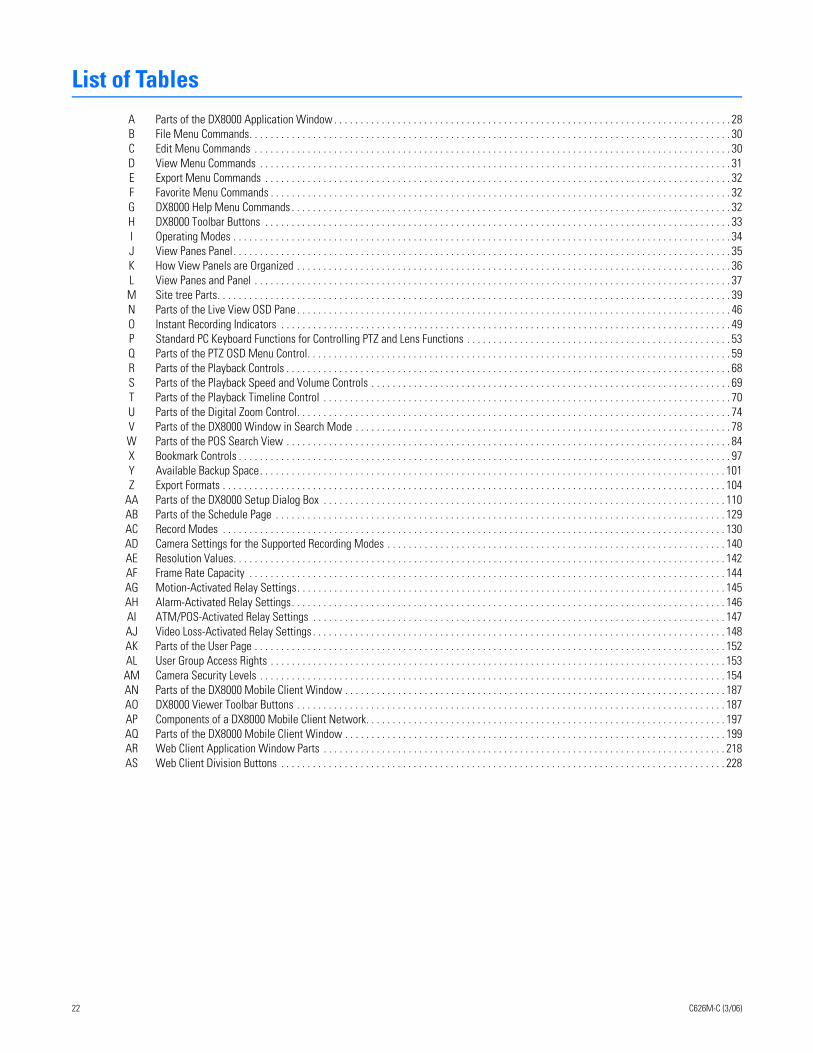
22 C626M-C (3/06)
List of TablesA Parts of the DX8000 Application Window . . . . . . . . . . . . . . . . . . . . . . . . . . . . . . . . . . . . . . . . . . . . . . . . . . . . . . . . . . . . . . . . . . . . . . . . . . . 28B File Menu Commands. . . . . . . . . . . . . . . . . . . . . . . . . . . . . . . . . . . . . . . . . . . . . . . . . . . . . . . . . . . . . . . . . . . . . . . . . . . . . . . . . . . . . . . . . . . 30C Edit Menu Commands . . . . . . . . . . . . . . . . . . . . . . . . . . . . . . . . . . . . . . . . . . . . . . . . . . . . . . . . . . . . . . . . . . . . . . . . . . . . . . . . . . . . . . . . . . 30D View Menu Commands . . . . . . . . . . . . . . . . . . . . . . . . . . . . . . . . . . . . . . . . . . . . . . . . . . . . . . . . . . . . . . . . . . . . . . . . . . . . . . . . . . . . . . . . . 31E Export Menu Commands . . . . . . . . . . . . . . . . . . . . . . . . . . . . . . . . . . . . . . . . . . . . . . . . . . . . . . . . . . . . . . . . . . . . . . . . . . . . . . . . . . . . . . . . 32F Favorite Menu Commands . . . . . . . . . . . . . . . . . . . . . . . . . . . . . . . . . . . . . . . . . . . . . . . . . . . . . . . . . . . . . . . . . . . . . . . . . . . . . . . . . . . . . . . 32G DX8000 Help Menu Commands . . . . . . . . . . . . . . . . . . . . . . . . . . . . . . . . . . . . . . . . . . . . . . . . . . . . . . . . . . . . . . . . . . . . . . . . . . . . . . . . . . . 32H DX8000 Toolbar Buttons . . . . . . . . . . . . . . . . . . . . . . . . . . . . . . . . . . . . . . . . . . . . . . . . . . . . . . . . . . . . . . . . . . . . . . . . . . . . . . . . . . . . . . . . 33I Operating Modes . . . . . . . . . . . . . . . . . . . . . . . . . . . . . . . . . . . . . . . . . . . . . . . . . . . . . . . . . . . . . . . . . . . . . . . . . . . . . . . . . . . . . . . . . . . . . . 34J View Panes Panel. . . . . . . . . . . . . . . . . . . . . . . . . . . . . . . . . . . . . . . . . . . . . . . . . . . . . . . . . . . . . . . . . . . . . . . . . . . . . . . . . . . . . . . . . . . . . . 35K How View Panels are Organized . . . . . . . . . . . . . . . . . . . . . . . . . . . . . . . . . . . . . . . . . . . . . . . . . . . . . . . . . . . . . . . . . . . . . . . . . . . . . . . . . . 36L View Panes and Panel . . . . . . . . . . . . . . . . . . . . . . . . . . . . . . . . . . . . . . . . . . . . . . . . . . . . . . . . . . . . . . . . . . . . . . . . . . . . . . . . . . . . . . . . . . 37M Site tree Parts. . . . . . . . . . . . . . . . . . . . . . . . . . . . . . . . . . . . . . . . . . . . . . . . . . . . . . . . . . . . . . . . . . . . . . . . . . . . . . . . . . . . . . . . . . . . . . . . . 39N Parts of the Live View OSD Pane . . . . . . . . . . . . . . . . . . . . . . . . . . . . . . . . . . . . . . . . . . . . . . . . . . . . . . . . . . . . . . . . . . . . . . . . . . . . . . . . . . 46O Instant Recording Indicators . . . . . . . . . . . . . . . . . . . . . . . . . . . . . . . . . . . . . . . . . . . . . . . . . . . . . . . . . . . . . . . . . . . . . . . . . . . . . . . . . . . . . 49P Standard PC Keyboard Functions for Controlling PTZ and Lens Functions . . . . . . . . . . . . . . . . . . . . . . . . . . . . . . . . . . . . . . . . . . . . . . . . . . 53Q Parts of the PTZ OSD Menu Control. . . . . . . . . . . . . . . . . . . . . . . . . . . . . . . . . . . . . . . . . . . . . . . . . . . . . . . . . . . . . . . . . . . . . . . . . . . . . . . . 59R Parts of the Playback Controls . . . . . . . . . . . . . . . . . . . . . . . . . . . . . . . . . . . . . . . . . . . . . . . . . . . . . . . . . . . . . . . . . . . . . . . . . . . . . . . . . . . . 68S Parts of the Playback Speed and Volume Controls . . . . . . . . . . . . . . . . . . . . . . . . . . . . . . . . . . . . . . . . . . . . . . . . . . . . . . . . . . . . . . . . . . . . 69T Parts of the Playback Timeline Control . . . . . . . . . . . . . . . . . . . . . . . . . . . . . . . . . . . . . . . . . . . . . . . . . . . . . . . . . . . . . . . . . . . . . . . . . . . . . 70U Parts of the Digital Zoom Control. . . . . . . . . . . . . . . . . . . . . . . . . . . . . . . . . . . . . . . . . . . . . . . . . . . . . . . . . . . . . . . . . . . . . . . . . . . . . . . . . . 74V Parts of the DX8000 Window in Search Mode . . . . . . . . . . . . . . . . . . . . . . . . . . . . . . . . . . . . . . . . . . . . . . . . . . . . . . . . . . . . . . . . . . . . . . . 78W Parts of the POS Search View . . . . . . . . . . . . . . . . . . . . . . . . . . . . . . . . . . . . . . . . . . . . . . . . . . . . . . . . . . . . . . . . . . . . . . . . . . . . . . . . . . . . 84X Bookmark Controls . . . . . . . . . . . . . . . . . . . . . . . . . . . . . . . . . . . . . . . . . . . . . . . . . . . . . . . . . . . . . . . . . . . . . . . . . . . . . . . . . . . . . . . . . . . . . 97Y Available Backup Space. . . . . . . . . . . . . . . . . . . . . . . . . . . . . . . . . . . . . . . . . . . . . . . . . . . . . . . . . . . . . . . . . . . . . . . . . . . . . . . . . . . . . . . . 101Z Export Formats . . . . . . . . . . . . . . . . . . . . . . . . . . . . . . . . . . . . . . . . . . . . . . . . . . . . . . . . . . . . . . . . . . . . . . . . . . . . . . . . . . . . . . . . . . . . . . . 104
AA Parts of the DX8000 Setup Dialog Box . . . . . . . . . . . . . . . . . . . . . . . . . . . . . . . . . . . . . . . . . . . . . . . . . . . . . . . . . . . . . . . . . . . . . . . . . . . . 110AB Parts of the Schedule Page . . . . . . . . . . . . . . . . . . . . . . . . . . . . . . . . . . . . . . . . . . . . . . . . . . . . . . . . . . . . . . . . . . . . . . . . . . . . . . . . . . . . . 129AC Record Modes . . . . . . . . . . . . . . . . . . . . . . . . . . . . . . . . . . . . . . . . . . . . . . . . . . . . . . . . . . . . . . . . . . . . . . . . . . . . . . . . . . . . . . . . . . . . . . . 130AD Camera Settings for the Supported Recording Modes . . . . . . . . . . . . . . . . . . . . . . . . . . . . . . . . . . . . . . . . . . . . . . . . . . . . . . . . . . . . . . . . 140AE Resolution Values. . . . . . . . . . . . . . . . . . . . . . . . . . . . . . . . . . . . . . . . . . . . . . . . . . . . . . . . . . . . . . . . . . . . . . . . . . . . . . . . . . . . . . . . . . . . . 142AF Frame Rate Capacity . . . . . . . . . . . . . . . . . . . . . . . . . . . . . . . . . . . . . . . . . . . . . . . . . . . . . . . . . . . . . . . . . . . . . . . . . . . . . . . . . . . . . . . . . . 144AG Motion-Activated Relay Settings. . . . . . . . . . . . . . . . . . . . . . . . . . . . . . . . . . . . . . . . . . . . . . . . . . . . . . . . . . . . . . . . . . . . . . . . . . . . . . . . . 145AH Alarm-Activated Relay Settings. . . . . . . . . . . . . . . . . . . . . . . . . . . . . . . . . . . . . . . . . . . . . . . . . . . . . . . . . . . . . . . . . . . . . . . . . . . . . . . . . . 146AI ATM/POS-Activated Relay Settings . . . . . . . . . . . . . . . . . . . . . . . . . . . . . . . . . . . . . . . . . . . . . . . . . . . . . . . . . . . . . . . . . . . . . . . . . . . . . . 147AJ Video Loss-Activated Relay Settings . . . . . . . . . . . . . . . . . . . . . . . . . . . . . . . . . . . . . . . . . . . . . . . . . . . . . . . . . . . . . . . . . . . . . . . . . . . . . . 148AK Parts of the User Page . . . . . . . . . . . . . . . . . . . . . . . . . . . . . . . . . . . . . . . . . . . . . . . . . . . . . . . . . . . . . . . . . . . . . . . . . . . . . . . . . . . . . . . . . 152AL User Group Access Rights . . . . . . . . . . . . . . . . . . . . . . . . . . . . . . . . . . . . . . . . . . . . . . . . . . . . . . . . . . . . . . . . . . . . . . . . . . . . . . . . . . . . . . 153AM Camera Security Levels . . . . . . . . . . . . . . . . . . . . . . . . . . . . . . . . . . . . . . . . . . . . . . . . . . . . . . . . . . . . . . . . . . . . . . . . . . . . . . . . . . . . . . . . 154AN Parts of the DX8000 Mobile Client Window . . . . . . . . . . . . . . . . . . . . . . . . . . . . . . . . . . . . . . . . . . . . . . . . . . . . . . . . . . . . . . . . . . . . . . . . 187AO DX8000 Viewer Toolbar Buttons . . . . . . . . . . . . . . . . . . . . . . . . . . . . . . . . . . . . . . . . . . . . . . . . . . . . . . . . . . . . . . . . . . . . . . . . . . . . . . . . . 187AP Components of a DX8000 Mobile Client Network. . . . . . . . . . . . . . . . . . . . . . . . . . . . . . . . . . . . . . . . . . . . . . . . . . . . . . . . . . . . . . . . . . . . 197AQ Parts of the DX8000 Mobile Client Window . . . . . . . . . . . . . . . . . . . . . . . . . . . . . . . . . . . . . . . . . . . . . . . . . . . . . . . . . . . . . . . . . . . . . . . . 199AR Web Client Application Window Parts . . . . . . . . . . . . . . . . . . . . . . . . . . . . . . . . . . . . . . . . . . . . . . . . . . . . . . . . . . . . . . . . . . . . . . . . . . . . 218AS Web Client Division Buttons . . . . . . . . . . . . . . . . . . . . . . . . . . . . . . . . . . . . . . . . . . . . . . . . . . . . . . . . . . . . . . . . . . . . . . . . . . . . . . . . . . . . 228
Client ApplicationYou are reading DX8000 Series digital video recorder (DVR) documentation. The information in this documentation describes how to configure and use the DX8000 system in your security application.
For a brief description of the DX8000 server and client applications, refer to Welcome to DX8000 Client Application on page 15.
WELCOME TO DX8000 CLIENT APPLICATIONWelcome to the DX8000 Client application. The DX8000 Client application is a high-performance, PC-based digital video recorder. It is an easy-to-operate digital video recorder (DVR) client application system. The DX8000 features multi-event recording, supporting continuous, motion detection, alarm, ATM/POS, and scheduled recording simultaneously. Models range from an eight-channel, single 80 GB hard disk drive (HDD) unit to a sixteen-channel unit with up to 1 TB of storage.
DX8000 software runs on two platforms:
• The DX8000 DVR server software runs on the DX8000 Series DVR.
• The DX8000 Client Application software runs on a personal computer (PC) and allows you to log in to and operate the DX8000 DVR server system from your local PC.
Fully implemented networking capabilities allow remote administration, playback, and export using the accompanying client application. Live viewing is supported on a variety of client platforms, including Internet browsers and pocket PC-compatible hand-held devices. Versatile high-speed search operations include time and date, event list, thumbnail, and intelligent pixel searching. Extensive scheduling features allow customizing of weekday, weekend, and special event recording.
The DX8000 provides a graphical user interface (GUI), allowing you quick and efficient access to all setup and operations functions. Scheduled or manual backup can be performed using a number of optical, external, and mapped network drive options.
An online Help system allows you quick access to information about how to configure and operate the DX8000 server and DX8000 client applica-tion.
The DX8000 also supports the following PC-based applications:
• DX8000 Client Emergency Agent on page 15
• DX8000 Viewer on page 15
• DX8000 Mobile Client on page 15
• DX8000 Web Client on page 15
DX8000 CLIENT EMERGENCY AGENTThe DX8000 Client Emergency Agent works with networked DX8000 Client applications to alert users when one or more particular channels detect a motion and/or alarm event. The Emergency Agent runs on a networked client PC.
DX8000 VIEWERThe DX8000 Viewer is capable of playing back a variety of video, still image, and audio media formats. It is designed to recognize and verify the digital watermark that is embedded in DX8000 Client application native video. Watermarking is used to authenticate the originality of a video file and to alert users of possible image tampering. The viewer application runs automatically each time a CD or DVD created by the DX8000’s export feature is inserted into a Windows-based PC. The software can also be installed on a PC and opened independently when necessary.
DX8000 MOBILE CLIENTThe DX8000 Mobile Client allow you to view live video remotely from multiple cameras and sites. Networking capabilities include local connec-tion using wire-bound or wireless LAN technologies or remote connection using the Internet. The DX8000 Mobile Client software runs on a stan-dard pocket PC-based Personal Digital Assistant (PDA) and can display a single channel of real-time video from any camera attached to any DX8000 DVR on the network. Features include hierarchical organization of multiple sites, built-in security through password protection, and an adjustable viewing area, including full-screen view.
DX8000 WEB CLIENTThe DX8000 Web Client allows you to view live video and operate pan, tilt, and zoom (PTZ) features of cameras attached to DX8000 DVRs. Using a standard web browser, you can remotely monitor up to 16 cameras from up to five DX8000 DVR servers simultaneously. Each DX8000 DVR can support up to 100 web clients either internally within an organization or externally through the Internet.
C626M-C (3/06) 15
Getting Started with DX8000 Client SoftwareThis section describes the system requirements, software installation, and working with security. This section includes the following topics:
• Description of DX8000 Client Software on page 16
• Recommended System Requirements on page 16
• Windows XP Display Properties Configuration Requirements on page 16
• Installing the Client Application on page 17
• Enabling IPSec Security Services on page 19
• Disabling IPSec Security Services on page 19
DESCRIPTION OF DX8000 CLIENT SOFTWAREThe DX8000 Client application allows operators and DVRs to be geographically dispersed. Up to five DVR servers can be actively viewed from a single PC client. Up to 100 DX8000 server sites can be added to the Connection List. For more information on the connection list, refer to Con-necting to the DX8000 DVR Server Sites on page 22.
The Client application facilitates
• Remote viewing of live and playback video
• Index, thumbnail, and pixel searching
• Exporting to a variety of media and formats
• Printing still images from video
• Limited remote control and administration
RECOMMENDED SYSTEM REQUIREMENTSMinimum recommended system requirements for the DX8000 Client, Emergency Agent, and DX8000 Viewer software applications include
• Processor: Intel® Pentium® III, or Pentium 4 with 800 MHz minimum processor speed
• Memory: 128 MB of RAM
• Video: AGP VGA card with minimum of 64 MB of video RAM, 1024 x 768 display resolution, 32-bit color, and DirectX® 8.1 or later hardware acceleration
• 500 MB of free disk space
• Monitor: SVGA or XGA with 1024 x 768 resolution, 32-bit color
• Operating system: Windows® 2000 (SP4) or Windows XP only
WINDOWS XP DISPLAY PROPERTIES CONFIGURATION REQUIREMENTSPelco recommends that the fade effect and shadow option for menus and tooltips be deselected if they are selected. Any time these display effects are active, the CPU usage increases and impacts system performance.
16 C626M-C (3/06)
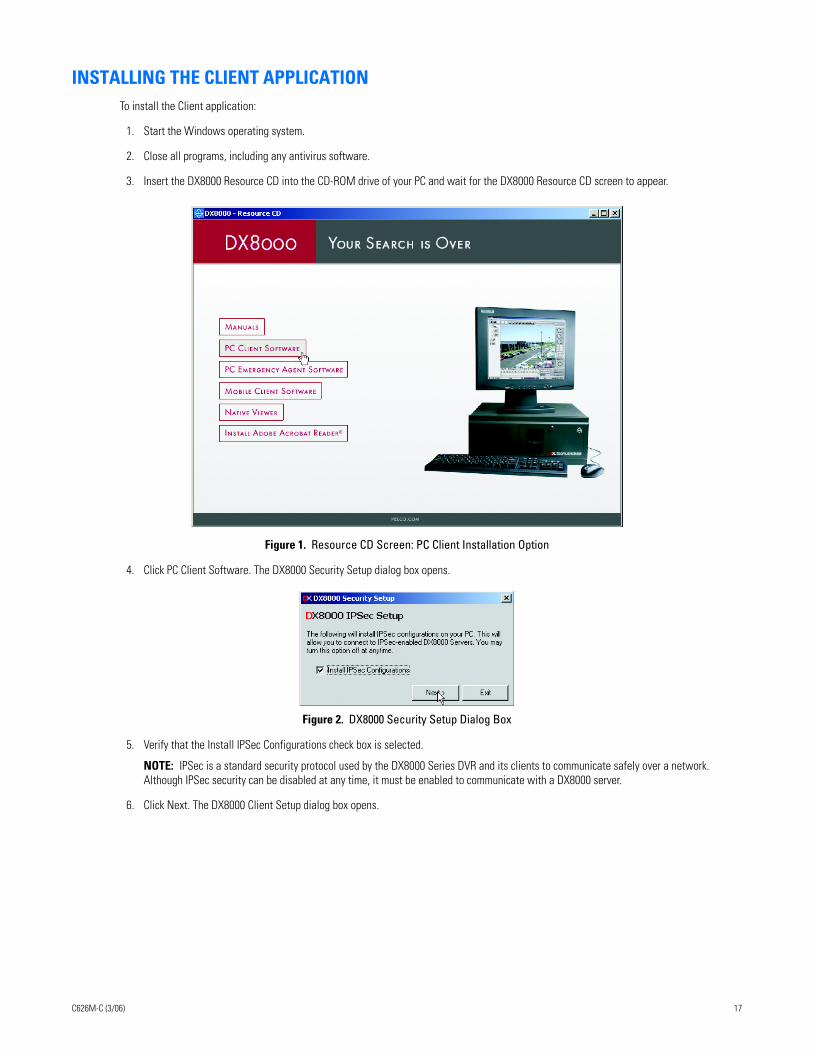
INSTALLING THE CLIENT APPLICATIONTo install the Client application:
1. Start the Windows operating system.
2. Close all programs, including any antivirus software.
3. Insert the DX8000 Resource CD into the CD-ROM drive of your PC and wait for the DX8000 Resource CD screen to appear.
Figure 1. Resource CD Screen: PC Client Installation Option
4. Click PC Client Software. The DX8000 Security Setup dialog box opens.
Figure 2. DX8000 Security Setup Dialog Box
5. Verify that the Install IPSec Configurations check box is selected.
NOTE: IPSec is a standard security protocol used by the DX8000 Series DVR and its clients to communicate safely over a network. Although IPSec security can be disabled at any time, it must be enabled to communicate with a DX8000 server.
6. Click Next. The DX8000 Client Setup dialog box opens.
C626M-C (3/06) 17
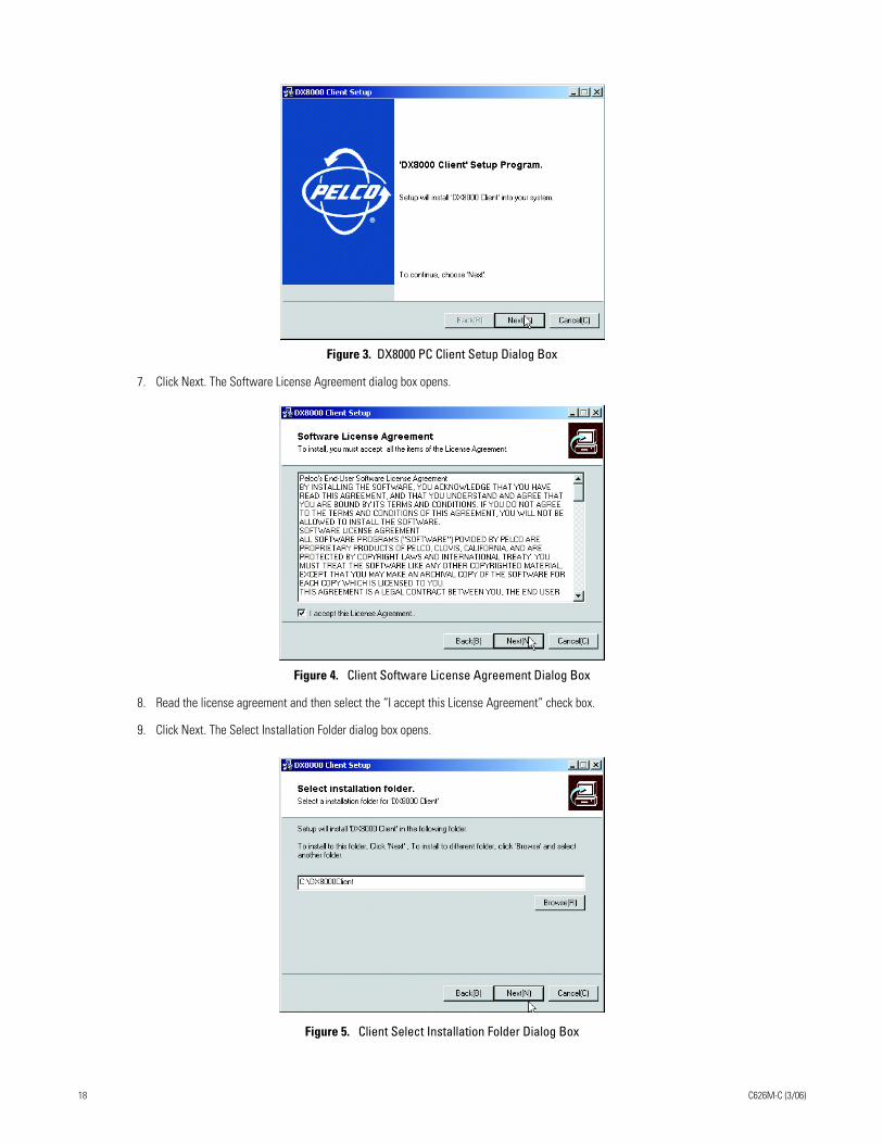
Figure 3. DX8000 PC Client Setup Dialog Box
7. Click Next. The Software License Agreement dialog box opens.
Figure 4. Client Software License Agreement Dialog Box
8. Read the license agreement and then select the “I accept this License Agreement” check box.
9. Click Next. The Select Installation Folder dialog box opens.
Figure 5. Client Select Installation Folder Dialog Box
18 C626M-C (3/06)
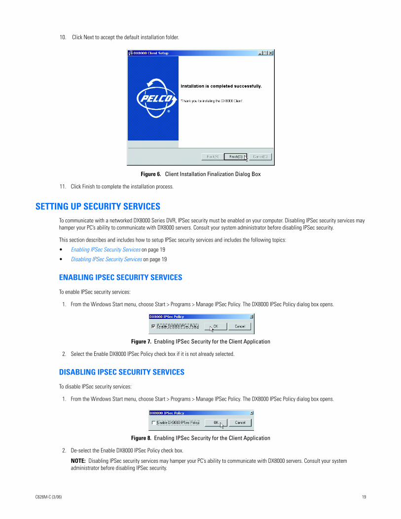
10. Click Next to accept the default installation folder.
Figure 6. Client Installation Finalization Dialog Box
11. Click Finish to complete the installation process.
SETTING UP SECURITY SERVICESTo communicate with a networked DX8000 Series DVR, IPSec security must be enabled on your computer. Disabling IPSec security services may hamper your PC’s ability to communicate with DX8000 servers. Consult your system administrator before disabling IPSec security.
This section describes and includes how to setup IPSec security services and includes the following topics:
• Enabling IPSec Security Services on page 19
• Disabling IPSec Security Services on page 19
ENABLING IPSEC SECURITY SERVICES
To enable IPSec security services:
1. From the Windows Start menu, choose Start > Programs > Manage IPSec Policy. The DX8000 IPSec Policy dialog box opens.
Figure 7. Enabling IPSec Security for the Client Application
2. Select the Enable DX8000 IPSec Policy check box if it is not already selected.
DISABLING IPSEC SECURITY SERVICES
To disable IPSec security services:
1. From the Windows Start menu, choose Start > Programs > Manage IPSec Policy. The DX8000 IPSec Policy dialog box opens.
Figure 8. Enabling IPSec Security for the Client Application
2. De-select the Enable DX8000 IPSec Policy check box.
NOTE: Disabling IPSec security services may hamper your PC’s ability to communicate with DX8000 servers. Consult your system administrator before disabling IPSec security.
C626M-C (3/06) 19
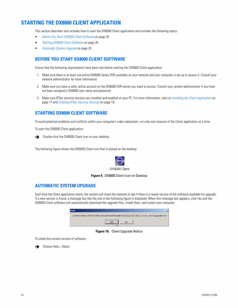
STARTING THE DX8000 CLIENT APPLICATIONThis section describes and includes how to start the DX8000 Client application and includes the following topics:
• Before You Start DX8000 Client Software on page 20
• Starting DX8000 Client Software on page 20
• Automatic System Upgrade on page 20
BEFORE YOU START DX8000 CLIENT SOFTWARE
Ensure that the following requirements have been met before starting the DX8000 Client application:
1. Make sure there is at least one active DX8000 Series DVR available on your network and your computer is set up to access it. Consult your network administrator for more information.
2. Make sure you have a valid, active account on the DX8000 DVR server you want to access. Consult your system administrator if you have not been assigned a DX8000 user name and password.
3. Make sure IPSec security services are installed and enabled on your PC. For more information, refer to Installing the Client Application on page 17 and Enabling IPSec Security Services on page 19.
STARTING DX8000 CLIENT SOFTWARE
To avoid potential problems and conflicts within your computer’s video subsystem, run only one instance of the Client application at a time.
To start the DX8000 Client application:
The following figure shows the DX8000 Client icon that is placed on the desktop..
Figure 9. DX8000 Client Icon on Desktop
AUTOMATIC SYSTEM UPGRADE
Each time the Client application starts, the system will check the network to see if there is a newer version of the software available for upgrade. If a new version is found, a message box like the one in the following figure is displayed. When this message box appears, click Yes and the DX8000 Client software will automatically download the upgrade files, install them, and restart your computer.
Figure 10. Client Upgrade Notice
To check the current version of software:
Double-click the DX8000 Client icon on your desktop.
Choose Help > About.
20 C626M-C (3/06)
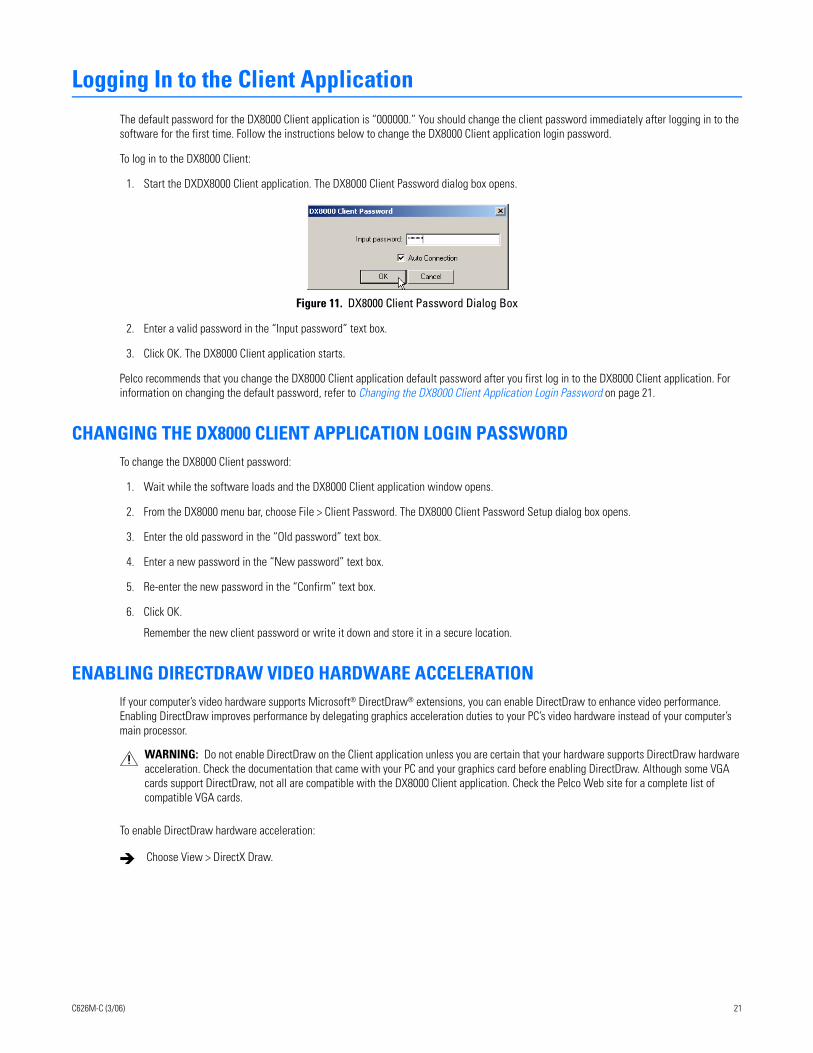
Logging In to the Client ApplicationThe default password for the DX8000 Client application is “000000.” You should change the client password immediately after logging in to the software for the first time. Follow the instructions below to change the DX8000 Client application login password.
To log in to the DX8000 Client:
1. Start the DXDX8000 Client application. The DX8000 Client Password dialog box opens.
Figure 11. DX8000 Client Password Dialog Box
2. Enter a valid password in the “Input password” text box.
3. Click OK. The DX8000 Client application starts.
Pelco recommends that you change the DX8000 Client application default password after you first log in to the DX8000 Client application. For information on changing the default password, refer to Changing the DX8000 Client Application Login Password on page 21.
CHANGING THE DX8000 CLIENT APPLICATION LOGIN PASSWORDTo change the DX8000 Client password:
1. Wait while the software loads and the DX8000 Client application window opens.
2. From the DX8000 menu bar, choose File > Client Password. The DX8000 Client Password Setup dialog box opens.
3. Enter the old password in the “Old password” text box.
4. Enter a new password in the “New password” text box.
5. Re-enter the new password in the “Confirm” text box.
6. Click OK.
Remember the new client password or write it down and store it in a secure location.
ENABLING DIRECTDRAW VIDEO HARDWARE ACCELERATIONIf your computer’s video hardware supports Microsoft® DirectDraw® extensions, you can enable DirectDraw to enhance video performance. Enabling DirectDraw improves performance by delegating graphics acceleration duties to your PC’s video hardware instead of your computer’s main processor.
To enable DirectDraw hardware acceleration:
WARNING: Do not enable DirectDraw on the Client application unless you are certain that your hardware supports DirectDraw hardware acceleration. Check the documentation that came with your PC and your graphics card before enabling DirectDraw. Although some VGA cards support DirectDraw, not all are compatible with the DX8000 Client application. Check the Pelco Web site for a complete list of compatible VGA cards.
Choose View > DirectX Draw.
C626M-C (3/06) 21
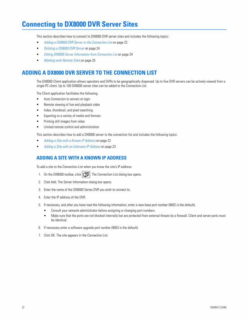
Connecting to DX8000 DVR Server SitesThis section describes how to connect to DX8000 DVR server sites and includes the following topics:
• Adding a DX8000 DVR Server to the Connection List on page 22
• Deleting a DX8000 DVR Server on page 24
• Editing DX8000 Server Information from Connection List on page 24
• Working with Remote Sites on page 25
ADDING A DX8000 DVR SERVER TO THE CONNECTION LISTThe DX8000 Client application allows operators and DVRs to be geographically dispersed. Up to five DVR servers can be actively viewed from a single PC client. Up to 100 DX8000 server sites can be added to the Connection List.
The Client application facilitates the following:
• Auto Connection to servers at login
• Remote viewing of live and playback video
• Index, thumbnail, and pixel searching
• Exporting to a variety of media and formats
• Printing still images from video
• Limited remote control and administration
This section describes how to add a DX8000 server to the connection list and includes the following topics:
• Adding a Site with a Known IP Address on page 22
• Adding a Site with an Unknown IP Address on page 23
ADDING A SITE WITH A KNOWN IP ADDRESS
To add a site to the Connection List when you know the site’s IP address:
1. On the DX8000 toolbar, click . The Connection List dialog box opens.
2. Click Add. The Server Information dialog box opens.
3. Enter the name of the DX8000 Series DVR you wish to connect to.
4. Enter the IP address of the DVR.
5. If necessary, and after you have read the following information, enter a new base port number (9002 is the default).
• Consult your network administrator before assigning or changing port numbers. • Make sure that the ports are not blocked internally but are protected from external threats by a firewall. Client and server ports must
be identical.
6. If necessary enter a software upgrade port number (9003 is the default).
7. Click OK. The site appears in the Connection List.
22 C626M-C (3/06)
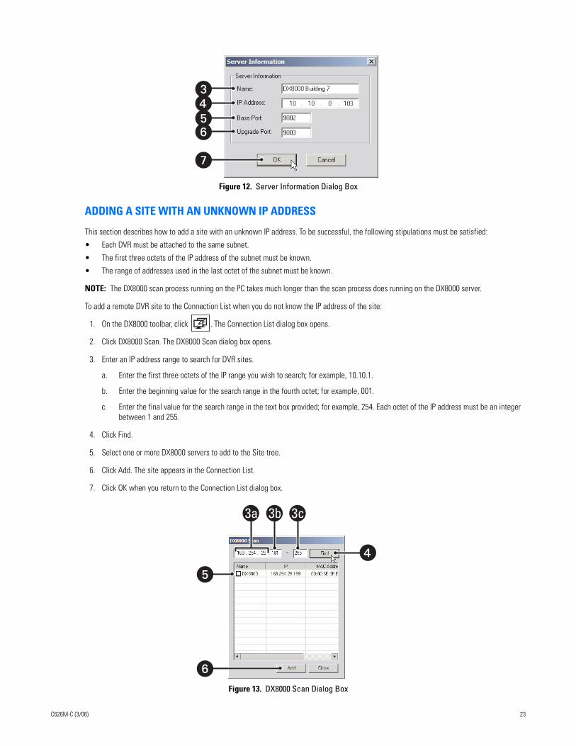
Figure 12. Server Information Dialog Box
ADDING A SITE WITH AN UNKNOWN IP ADDRESS
This section describes how to add a site with an unknown IP address. To be successful, the following stipulations must be satisfied:
• Each DVR must be attached to the same subnet.
• The first three octets of the IP address of the subnet must be known.
• The range of addresses used in the last octet of the subnet must be known.
NOTE: The DX8000 scan process running on the PC takes much longer than the scan process does running on the DX8000 server.
To add a remote DVR site to the Connection List when you do not know the IP address of the site:
1. On the DX8000 toolbar, click . The Connection List dialog box opens.
2. Click DX8000 Scan. The DX8000 Scan dialog box opens.
3. Enter an IP address range to search for DVR sites.
a. Enter the first three octets of the IP range you wish to search; for example, 10.10.1.
b. Enter the beginning value for the search range in the fourth octet; for example, 001.
c. Enter the final value for the search range in the text box provided; for example, 254. Each octet of the IP address must be an integer between 1 and 255.
4. Click Find.
5. Select one or more DX8000 servers to add to the Site tree.
6. Click Add. The site appears in the Connection List.
7. Click OK when you return to the Connection List dialog box.
Figure 13. DX8000 Scan Dialog Box
����
�
�
�
�
3a 3b 3c
C626M-C (3/06) 23
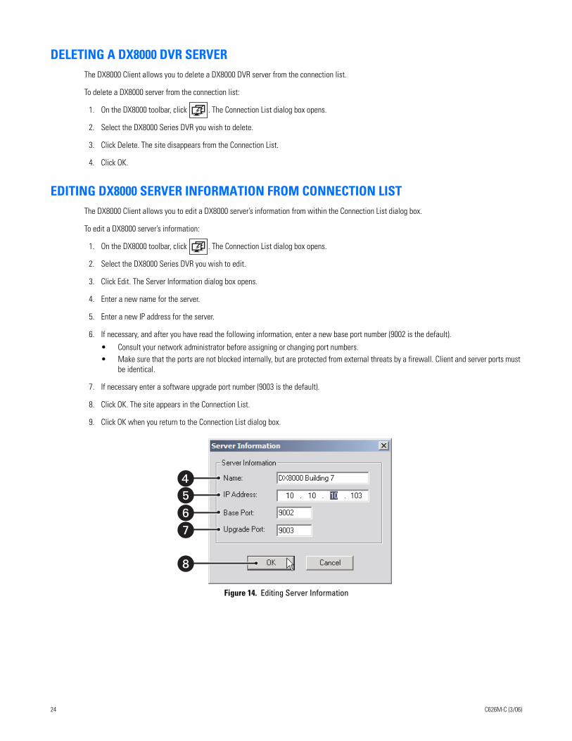
DELETING A DX8000 DVR SERVERThe DX8000 Client allows you to delete a DX8000 DVR server from the connection list.
To delete a DX8000 server from the connection list:
1. On the DX8000 toolbar, click . The Connection List dialog box opens.
2. Select the DX8000 Series DVR you wish to delete.
3. Click Delete. The site disappears from the Connection List.
4. Click OK.
EDITING DX8000 SERVER INFORMATION FROM CONNECTION LISTThe DX8000 Client allows you to edit a DX8000 server’s information from within the Connection List dialog box.
To edit a DX8000 server’s information:
1. On the DX8000 toolbar, click . The Connection List dialog box opens.
2. Select the DX8000 Series DVR you wish to edit.
3. Click Edit. The Server Information dialog box opens.
4. Enter a new name for the server.
5. Enter a new IP address for the server.
6. If necessary, and after you have read the following information, enter a new base port number (9002 is the default).
• Consult your network administrator before assigning or changing port numbers. • Make sure that the ports are not blocked internally, but are protected from external threats by a firewall. Client and server ports must
be identical.
7. If necessary enter a software upgrade port number (9003 is the default).
8. Click OK. The site appears in the Connection List.
9. Click OK when you return to the Connection List dialog box.
Figure 14. Editing Server Information
����
�
24 C626M-C (3/06)
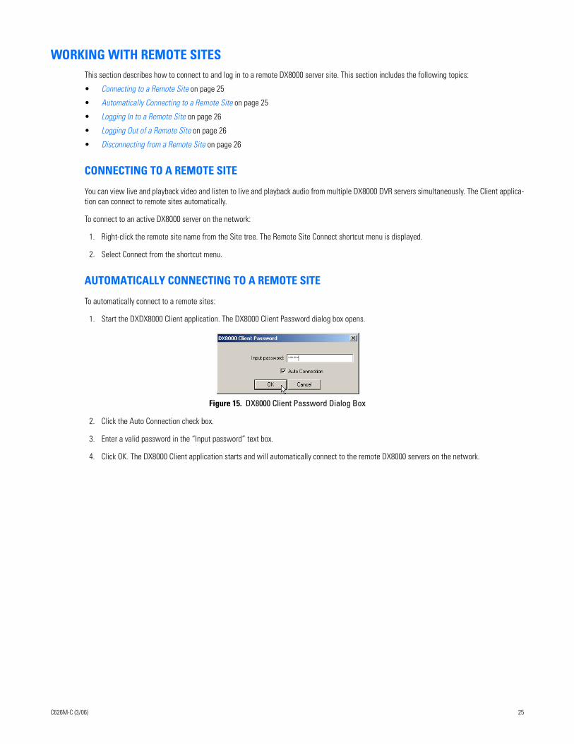
WORKING WITH REMOTE SITESThis section describes how to connect to and log in to a remote DX8000 server site. This section includes the following topics:
• Connecting to a Remote Site on page 25
• Automatically Connecting to a Remote Site on page 25
• Logging In to a Remote Site on page 26
• Logging Out of a Remote Site on page 26
• Disconnecting from a Remote Site on page 26
CONNECTING TO A REMOTE SITE
You can view live and playback video and listen to live and playback audio from multiple DX8000 DVR servers simultaneously. The Client applica-tion can connect to remote sites automatically.
To connect to an active DX8000 server on the network:
1. Right-click the remote site name from the Site tree. The Remote Site Connect shortcut menu is displayed.
2. Select Connect from the shortcut menu.
AUTOMATICALLY CONNECTING TO A REMOTE SITE
To automatically connect to a remote sites:
1. Start the DXDX8000 Client application. The DX8000 Client Password dialog box opens.
Figure 15. DX8000 Client Password Dialog Box
2. Click the Auto Connection check box.
3. Enter a valid password in the “Input password” text box.
4. Click OK. The DX8000 Client application starts and will automatically connect to the remote DX8000 servers on the network.
C626M-C (3/06) 25
LOGGING IN TO A REMOTE SITE
After a connection to a remote site has been established, to access the features of the DX8000 Series DVR, you must log in with a valid user name and password.
The DX8000 comes equipped with a built-in user account named “Guest.” Each time the unit is turned on, the Guest account is automatically activated. In addition to the Guest account, there are four other user access levels, or groups, that can be configured on the DX8000. The Guest user is granted only limited access to the system. The other four access levels range from the Administrator group, with the most rights and priv-ileges, to the Restricted group, with the least rights and privileges. For more information on the rights and permissions of the user group to which you have been assigned, refer to Definition of User Access Levels on page 153.
To operate and configure all but the most basic features of the DX8000, you must be assigned a user account other than Guest. If you have not been assigned a user account, contact your system administrator before proceeding.
To log in to a remote site:
1. Select a remote DX8000 Series DVR site from the Site tree.
2. From the DX8000 menu bar, choose File > User Log-in.
You can also log in to a remote site by right-clicking its site name and then selecting User Log-In from the shortcut menu.
3. Enter a valid user name in the User Name field and a valid password in the Password field.
4. Click OK.
LOGGING OUT OF A REMOTE SITE
You can only log out of one server at a time. If you are logged into multiple servers, you must log out of each server individually. Logging out of a remote DVR does not disconnect you from that system. Logging out will return you to the Guest account. To disconnect from a remote server, refer to Disconnecting from a Remote Site on page 26.
To log out of a remote DVR site:
1. Select the remote server from the Site tree.
2. From the DX8000 menu bar, choose File > User Log-Out.
You can also log out of a remote DVR by right-clicking its site name from the Site tree and selecting User Log-Out from the quick-menu.
DISCONNECTING FROM A REMOTE SITE
To terminate a connection with a remote DX8000 server:
1. Right-click the name of the remote site from the Site tree.
2. Select Disconnect from the quick-menu.
EXITING THE DX8000 CLIENT APPLICATIONTo exit the DX8000 Client application and return to the Windows operating system:
From the DX8000 Client menu bar, choose File > Exit.
26 C626M-C (3/06)
Understanding the DX8000 Application WindowThis section describes the DX8000 application window and its operation. The application window is the central control center from where you have access to the DX8000 features and functions.
• View both live and recorded video
• Exit to the Windows environment
• Access DX8000 setup features
• Control camera pan, tilt, and zoom functions
• Select cameras for viewing and recording
• Specify playback date and time
• Access playback controls
This section includes the following topics:
• Description of the DX8000 Main Window on page 27
• Understanding View Panes and Panels on page 34
• Working with the Site tree on page 39
DESCRIPTION OF THE DX8000 MAIN WINDOWThe application window is displayed after the DX8000 starts. The main window provides access to both live and recorded video.
This section describes the DX8000 main window and includes the following topics:
• DX8000 Menu Bar on page 30
• DX8000 Toolbar on page 33
• Displaying the DX8000 Window from a Page on page 34
• Description of Operating Modes on page 34
• Understanding View Panes and Panels on page 34
C626M-C (3/06) 27
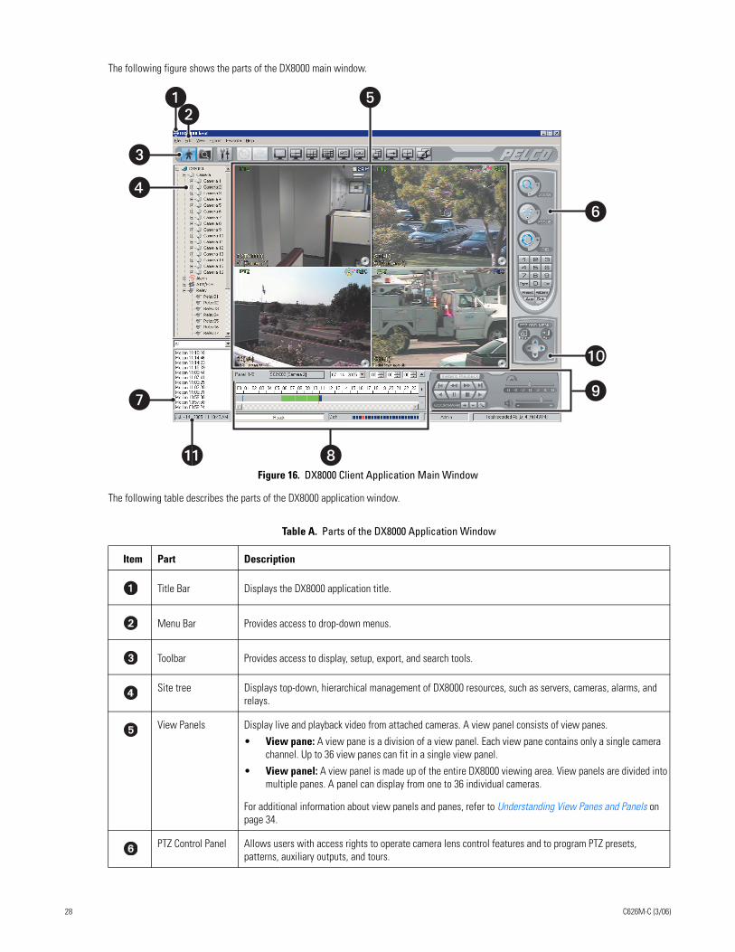
The following figure shows the parts of the DX8000 main window.
Figure 16. DX8000 Client Application Main Window
The following table describes the parts of the DX8000 application window.
Table A. Parts of the DX8000 Application Window
Item Part Description
Title Bar Displays the DX8000 application title.
Menu Bar Provides access to drop-down menus.
Toolbar Provides access to display, setup, export, and search tools.
Site tree Displays top-down, hierarchical management of DX8000 resources, such as servers, cameras, alarms, and relays.
View Panels Display live and playback video from attached cameras. A view panel consists of view panes.
• View pane: A view pane is a division of a view panel. Each view pane contains only a single camera channel. Up to 36 view panes can fit in a single view panel.
• View panel: A view panel is made up of the entire DX8000 viewing area. View panels are divided into multiple panes. A panel can display from one to 36 individual cameras.
For additional information about view panels and panes, refer to Understanding View Panes and Panels on page 34.
PTZ Control Panel Allows users with access rights to operate camera lens control features and to program PTZ presets, patterns, auxiliary outputs, and tours.
�
�
� �
�
� �
�
�
�
28 C626M-C (3/06)
Index View Panel Allows users with access rights to search motion and alarm events within a 24-hour period specified in the playback timeline.
Playback Timeline Displays a 24-hour timeline marked with color-coded video events. Allows users with Standard User access rights to select a date and time for playback.
Playback Control Panel
Provides buttons for users with access rights to control video playback. Includes forward and reverse playback and still image. It also provides controls for playback speed and volume.
PTZ OSD Menu or
Digital Zoom Control
This control provides two functions depending on which mode the DX8000 is operating: live view or playback:
• Live View Mode: In the Live View mode, provides users with access rights to operate PTZ OSD features. For information on using the PTZ OSD menu controls, refer to Using the PTZ OSD Menu Control on page 59.
• Playback Mode: In the Playback mode, provides users with access rights to operate digital zoom features.
Status Bar Displays current date and time, recorder processing status, disk status indicator, user name of currently logged-in user, and total amount of recorded video. NOTE: As the storage array of the DX8000 fills beyond its capacity, video is deleted in a first-in, first-out (FIFO) fashion. The disk status indicator on the status bar shows the amount of disk space used by recorded video. The red indicator marks the current recording position of the disk array, blue indicators mark parts of the array that are storing previously recorded video, and clear indicates that no video has been recorded in that area of the array.
Table A. Parts of the DX8000 Application Window (Continued)
Item Part Description
C626M-C (3/06) 29
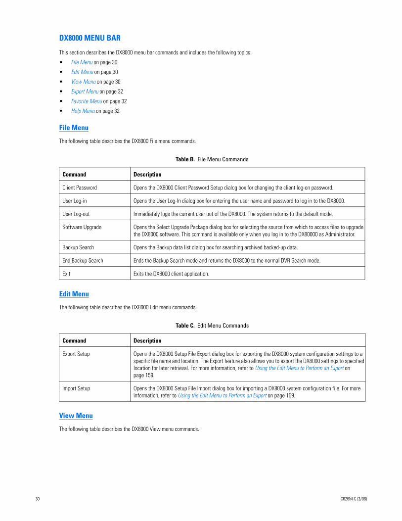
DX8000 MENU BAR
This section describes the DX8000 menu bar commands and includes the following topics:
• File Menu on page 30
• Edit Menu on page 30
• View Menu on page 30
• Export Menu on page 32
• Favorite Menu on page 32
• Help Menu on page 32
File Menu
The following table describes the DX8000 File menu commands.
Edit Menu
The following table describes the DX8000 Edit menu commands.
View Menu
The following table describes the DX8000 View menu commands.
Table B. File Menu Commands
Command Description
Client Password Opens the DX8000 Client Password Setup dialog box for changing the client log-on password.
User Log-in Opens the User Log-In dialog box for entering the user name and password to log in to the DX8000.
User Log-out Immediately logs the current user out of the DX8000. The system returns to the default mode.
Software Upgrade Opens the Select Upgrade Package dialog box for selecting the source from which to access files to upgrade the DX8000 software. This command is available only when you log in to the DX80000 as Administrator.
Backup Search Opens the Backup data list dialog box for searching archived backed-up data.
End Backup Search Ends the Backup Search mode and returns the DX8000 to the normal DVR Search mode.
Exit Exits the DX8000 client application.
Table C. Edit Menu Commands
Command Description
Export Setup Opens the DX8000 Setup File Export dialog box for exporting the DX8000 system configuration settings to a specific file name and location. The Export feature also allows you to export the DX8000 settings to specified location for later retrieval. For more information, refer to Using the Edit Menu to Perform an Export on page 159.
Import Setup Opens the DX8000 Setup File Import dialog box for importing a DX8000 system configuration file. For more information, refer to Using the Edit Menu to Perform an Export on page 159.
30 C626M-C (3/06)
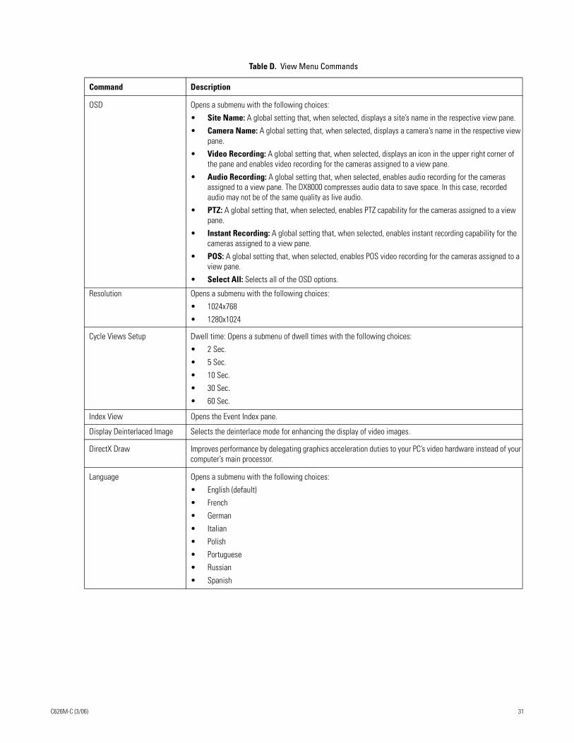
Table D. View Menu Commands
Command Description
OSD Opens a submenu with the following choices:
• Site Name: A global setting that, when selected, displays a site’s name in the respective view pane.
• Camera Name: A global setting that, when selected, displays a camera’s name in the respective view pane.
• Video Recording: A global setting that, when selected, displays an icon in the upper right corner of the pane and enables video recording for the cameras assigned to a view pane.
• Audio Recording: A global setting that, when selected, enables audio recording for the cameras assigned to a view pane. The DX8000 compresses audio data to save space. In this case, recorded audio may not be of the same quality as live audio.
• PTZ: A global setting that, when selected, enables PTZ capability for the cameras assigned to a view pane.
• Instant Recording: A global setting that, when selected, enables instant recording capability for the cameras assigned to a view pane.
• POS: A global setting that, when selected, enables POS video recording for the cameras assigned to a view pane.
• Select All: Selects all of the OSD options.
Resolution Opens a submenu with the following choices:
• 1024x768
• 1280x1024
Cycle Views Setup Dwell time: Opens a submenu of dwell times with the following choices:
• 2 Sec.
• 5 Sec.
• 10 Sec.
• 30 Sec.
• 60 Sec.
Index View Opens the Event Index pane.
Display Deinterlaced Image Selects the deinterlace mode for enhancing the display of video images.
DirectX Draw Improves performance by delegating graphics acceleration duties to your PC’s video hardware instead of your computer’s main processor.
Language Opens a submenu with the following choices:
• English (default)
• French
• German
• Italian
• Polish
• Portuguese
• Russian
• Spanish
C626M-C (3/06) 31
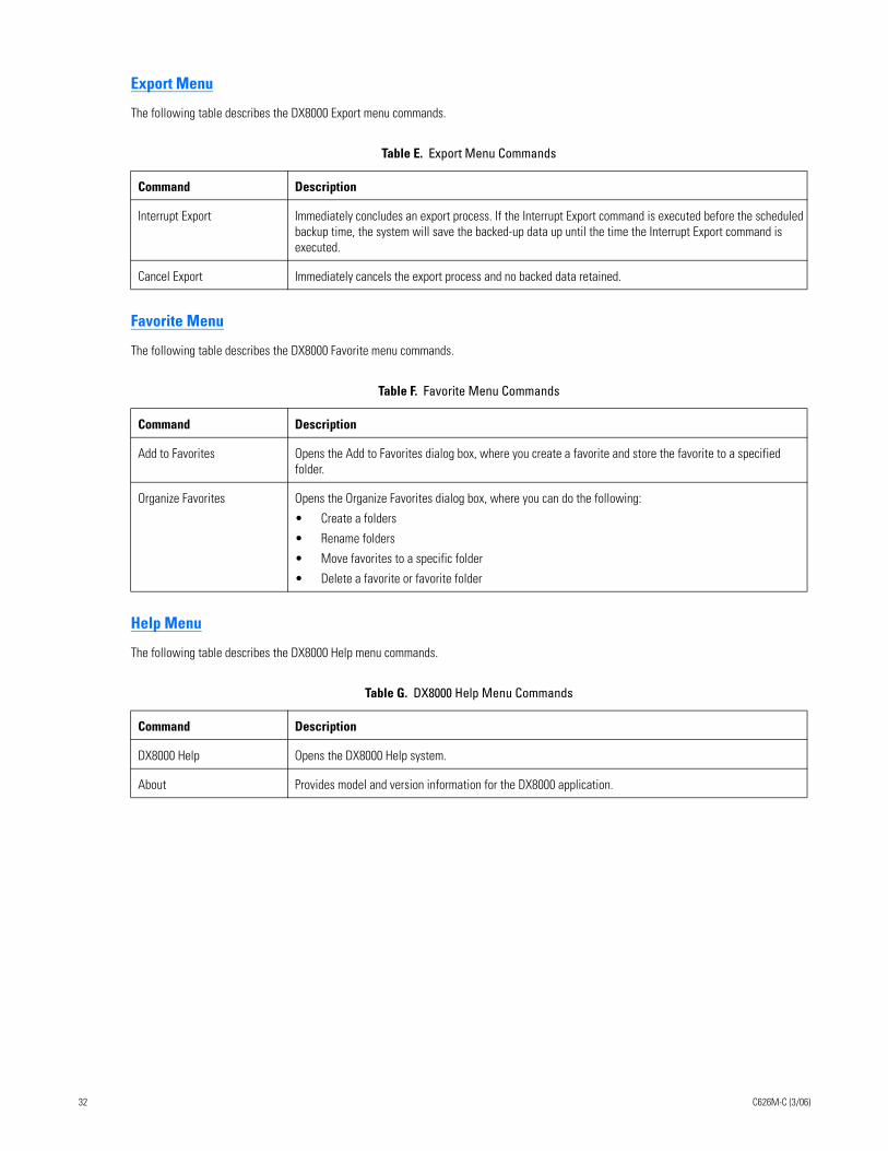
Export Menu
The following table describes the DX8000 Export menu commands.
Favorite Menu
The following table describes the DX8000 Favorite menu commands.
Help Menu
The following table describes the DX8000 Help menu commands.
Table E. Export Menu Commands
Command Description
Interrupt Export Immediately concludes an export process. If the Interrupt Export command is executed before the scheduled backup time, the system will save the backed-up data up until the time the Interrupt Export command is executed.
Cancel Export Immediately cancels the export process and no backed data retained.
Table F. Favorite Menu Commands
Command Description
Add to Favorites Opens the Add to Favorites dialog box, where you create a favorite and store the favorite to a specified folder.
Organize Favorites Opens the Organize Favorites dialog box, where you can do the following:
• Create a folders
• Rename folders
• Move favorites to a specific folder
• Delete a favorite or favorite folder
Table G. DX8000 Help Menu Commands
Command Description
DX8000 Help Opens the DX8000 Help system.
About Provides model and version information for the DX8000 application.
32 C626M-C (3/06)
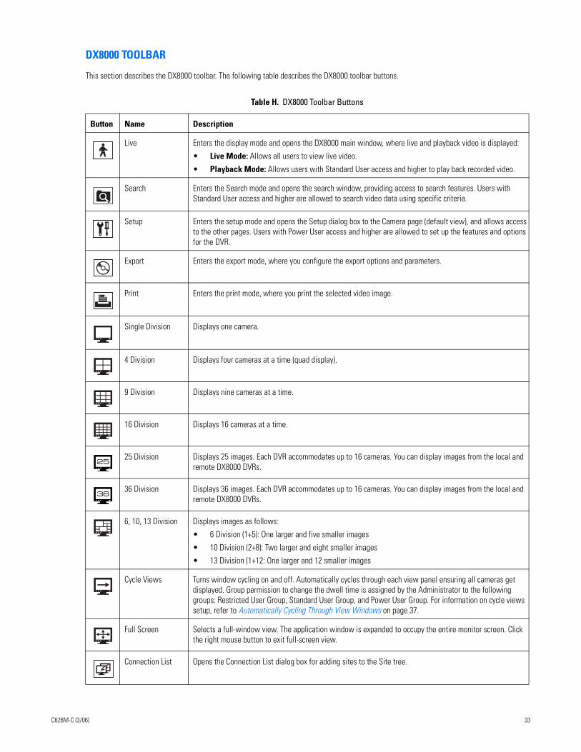
DX8000 TOOLBAR
This section describes the DX8000 toolbar. The following table describes the DX8000 toolbar buttons.
Table H. DX8000 Toolbar Buttons
Button Name Description
Live Enters the display mode and opens the DX8000 main window, where live and playback video is displayed:
• Live Mode: Allows all users to view live video.
• Playback Mode: Allows users with Standard User access and higher to play back recorded video.
Search Enters the Search mode and opens the search window, providing access to search features. Users with Standard User access and higher are allowed to search video data using specific criteria.
Setup Enters the setup mode and opens the Setup dialog box to the Camera page (default view), and allows access to the other pages. Users with Power User access and higher are allowed to set up the features and options for the DVR.
Export Enters the export mode, where you configure the export options and parameters.
Print Enters the print mode, where you print the selected video image.
Single Division Displays one camera.
4 Division Displays four cameras at a time (quad display).
9 Division Displays nine cameras at a time.
16 Division Displays 16 cameras at a time.
25 Division Displays 25 images. Each DVR accommodates up to 16 cameras. You can display images from the local and remote DX8000 DVRs.
36 Division Displays 36 images. Each DVR accommodates up to 16 cameras. You can display images from the local and remote DX8000 DVRs.
6, 10, 13 Division Displays images as follows:
• 6 Division (1+5): One larger and five smaller images
• 10 Division (2+8): Two larger and eight smaller images
• 13 Division (1+12: One larger and 12 smaller images
Cycle Views Turns window cycling on and off. Automatically cycles through each view panel ensuring all cameras get displayed. Group permission to change the dwell time is assigned by the Administrator to the following groups: Restricted User Group, Standard User Group, and Power User Group. For information on cycle views setup, refer to Automatically Cycling Through View Windows on page 37.
Full Screen Selects a full-window view. The application window is expanded to occupy the entire monitor screen. Click the right mouse button to exit full-screen view.
Connection List Opens the Connection List dialog box for adding sites to the Site tree.
C626M-C (3/06) 33
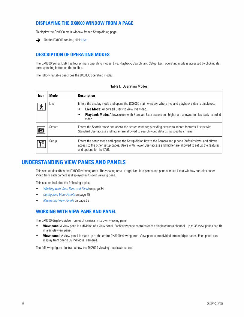
DISPLAYING THE DX8000 WINDOW FROM A PAGE
To display the DX8000 main window from a Setup dialog page:
DESCRIPTION OF OPERATING MODES
The DX8000 Series DVR has four primary operating modes: Live, Playback, Search, and Setup. Each operating mode is accessed by clicking its corresponding button on the toolbar.
The following table describes the DX8000 operating modes.
UNDERSTANDING VIEW PANES AND PANELSThis section describes the DX8000 viewing area. The viewing area is organized into panes and panels, much like a window contains panes. Video from each camera is displayed in its own viewing pane.
This section includes the following topics:
• Working with View Pane and Panel on page 34
• Configuring View Panels on page 35
• Navigating View Panels on page 35
WORKING WITH VIEW PANE AND PANEL
The DX8000 displays video from each camera in its own viewing pane.
• View pane: A view pane is a division of a view panel. Each view pane contains only a single camera channel. Up to 36 view panes can fit in a single view panel.
• View panel: A view panel is made up of the entire DX8000 viewing area. View panels are divided into multiple panes. Each panel can display from one to 36 individual cameras.
The following figure illustrates how the DX8000 viewing area is structured.
On the DX8000 toolbar, click Live.
Table I. Operating Modes
Icon Mode Description
Live Enters the display mode and opens the DX8000 main window, where live and playback video is displayed:
• Live Mode: Allows all users to view live video.
• Playback Mode: Allows users with Standard User access and higher are allowed to play back recorded video.
Search Enters the Search mode and opens the search window, providing access to search features. Users with Standard User access and higher are allowed to search video data using specific criteria.
Setup Enters the setup mode and opens the Setup dialog box to the Camera setup page (default view), and allows access to the other setup pages. Users with Power User access and higher are allowed to set up the features and options for the DVR.
34 C626M-C (3/06)
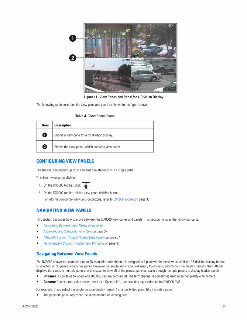
Figure 17. View Panes and Panel for 4-Division Display
The following table describes the view pane and panel as shown in the figure above.
CONFIGURING VIEW PANELS
The DX8000 can display up to 36 cameras simultaneously in a single panel.
To select a view panel division:
1. On the DX8000 toolbar, click .
2. On the DX8000 toolbar, click a view panel division button.
For information on the view division buttons, refer to DX8000 Toolbar on page 33.
NAVIGATING VIEW PANELS
This section describes how to move between the DX8000 view panes and panels. This section includes the following topics:
• Navigating Between View Panels on page 35
• Expanding and Collapsing View Pane on page 37
• Manually Cycling Through Hidden View Panels on page 37
• Automatically Cycling Through View Windows on page 37
Navigating Between View Panels
The DX8000 allows you to monitor up to 36 channels: each channel is assigned to 1 pane within the view panel. If the 36-division display format is selected, all 36 panes occupy one panel. However, for single, 4-division, 9-division, 16-division, and 25-division display formats, the DX8000 displays the panes in multiple panels. In this case, to view all of the panes, you must cycle through multiple panels to display hidden panels.
• Channel: As pertains to video, one DX8000 camera port (input). The term channel is sometimes used interchangeably with camera.
• Camera: One external video device, such as a Spectra III™, that provides input video to the DX8000 DVR.
For example, if you select the single-division display format, 1 channel (video pane) fills the entire panel.
• The pane and panel represent the same amount of viewing area.
Table J. View Panes Panel
Item Description
Shows a view pane for a for division display.
Shows the view panel, which contains view panes.
�
C626M-C (3/06) 35
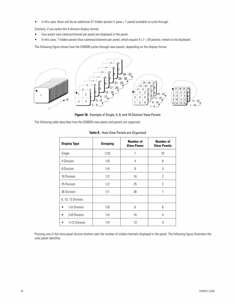
• In this case, there will be an additional 31 hidden panels (1 pane = 1 panel) available to cycle through.
Similarly, if you select the 4-division display format:
• Four panes (one camera/channel per pane) are displayed in the panel.
• In this case, 7 hidden panels (four cameras/channels per panel, which equals 4 x 7 = 28 panels), remain to be displayed.
The following figure shows how the DX8000 cycles through view panels, depending on the display format.
Figure 18. Example of Single, 4, 9, and 16 Division View Panels
The following table describes how the DX8000 view panes and panels are organized.
Pressing one of the view panel division buttons sets the number of visible channels displayed in the panel. The following figure illustrates the view panel identifier.
Table K. How View Panels are Organized
Display Type Grouping Number of View Panes
Number of View Panels
Single 1/32 1 32
4 Division 1/8 4 8
9 Division 1/4 9 4
16 Division 1/2 16 2
25 Division 1/2 25 2
36 Division 1/1 36 1
6, 10, 13 Division:
• 1+5 Division 1/6 6 6
• 2+8 Division 1/4 10 4
• 1+12 Division 1/4 13 4
17 18 19 2021 22 23 2425 26 2829
2730 3231
1 2 3 45 6 7 89 10 12
1311
14 161532
1
132 31 32
28 29 30
25 26 27
23 24 25
17 18 19
20 21 228 9 10
11 12 13
14 15 16
1 2 3
7 8 9
4 5 6
29 30
31 3225 26
27 2821 22
23 2417 18
19 2013 14
15 169 10
11 125 6
7 81 2
3 41 - 4
5 - 89 - 12
13 - 1617 - 20
21 - 2426 - 28
29 - 32
1 - 98 - 16
17 - 2525 - 32
1 - 1617 - 32
36 C626M-C (3/06)
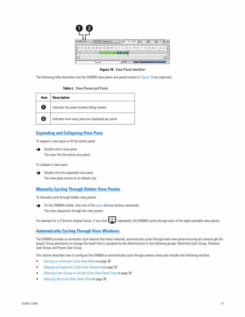
Figure 19. View Panel Identifier
The following table describes how the DX8000 view panes and panels shown in Figure 18 are organized.
Expanding and Collapsing View Pane
To expand a view pane to fill the entire panel:
To collapse a view pane:
Manually Cycling Through Hidden View Panels
To manually cycle through hidden view panels:
For example for a 4 Division display format, if you click repeatedly, the DX8000 cycles through each of the eight available view panels.
Automatically Cycling Through View Windows
The DX8000 provides an automatic cycle feature that when selected, automatically cycles through each view panel ensuring all cameras get dis-played. Group permission to change the dwell time is assigned by the Administrator to the following groups: Restricted User Group, Standard User Group, and Power User Group.
This section describes how to configure the DX8000 to automatically cycle through camera views and includes the following sections:
• Starting an Automatic Cycle View Mode on page 38
• Stopping an Automatic Cycle View Sequence on page 38
• Selecting User Groups to Set the Cycle View Dwell Time on page 38
• Selecting the Cycle View Dwell Time on page 38
Table L. View Panes and Panel
Item Description
Indicates the panel number being viewed.
Indicates how many pane are displayed per panel.
Double-click a view pane.
The view fills the entire view panel.
Double-click the expanded view pane.
The view pane returns to its default size.
On the DX8000 toolbar, click one of the panel division buttons repeatedly.
The view sequences through the view panels.
�
C626M-C (3/06) 37
Starting an Automatic Cycle View Mode
To start the automatic cycle view mode:
For example, if you, click , the automatic cycle view process starts.
Stopping an Automatic Cycle View Sequence
To stop the automatic cycle view mode:
Selecting User Groups to Set the Cycle View Dwell Time
The DX8000 allows the Administrator to control which user group can change the cycle view dwell time. In this case, anyone that belongs to a selected user group can change the cycle view dwell time.
To select a user group to have permission to change the cycle view dwell time:
1. On the DX8000 toolbar, click .
2. From the DX8000 menu bar, choose View > Cycle Views Setup > Dwell time change.
3. From the Dwell time change submenu, choose a user group.
Selecting the Cycle View Dwell Time
To configure the cycle period:
1. On the DX8000 toolbar, click .
2. From the DX8000 menu bar, choose View > Cycle Views Setup > Dwell time.
3. From the Dwell time submenu, choose a time period.
On the DX8000 toolbar, click Cycle Views.
The Cycle Views icon turns blue, indicating that the DX8000 is in the automatic cycle view mode. The system will cycle through each panel, displaying each pane for the configured cycle view dwell time.
On the DX8000 toolbar, click Cycle Views.
The DX8000 stops the automatic cycle view mode.
38 C626M-C (3/06)
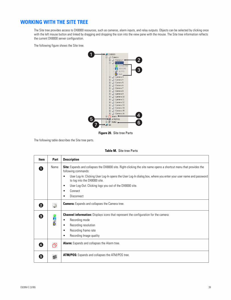
WORKING WITH THE SITE TREEThe Site tree provides access to DX8000 resources, such as cameras, alarm inputs, and relay outputs. Objects can be selected by clicking once with the left mouse button and linked by dragging and dropping the icon into the view pane with the mouse. The Site tree information reflects the current DX8000 server configuration.
The following figure shows the Site tree.
Figure 20. Site tree Parts
The following table describes the Site tree parts.
Table M. Site tree Parts
Item Part Description
Name Site: Expands and collapses the DX8000 site. Right-clicking the site name opens a shortcut menu that provides the following commands:
• User Log-In: Clicking User Log-In opens the User Log-In dialog box, where you enter your user name and password to log into the DX8000 site.
• User Log-Out: Clicking logs you out of the DX8000 site.
• Connect
• Disconnect
Camera: Expands and collapses the Camera tree.
Channel information: Displays icons that represent the configuration for the camera:
• Recording mode
• Recording resolution
• Recording frame rate
• Recording Image quality
Alarm: Expands and collapses the Alarm tree.
ATM/POS: Expands and collapses the ATM/POS tree.
�
C626M-C (3/06) 39
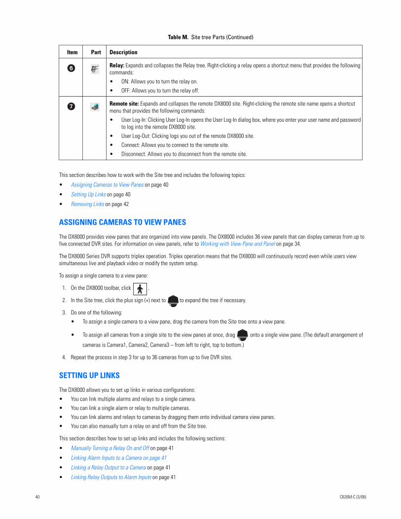
This section describes how to work with the Site tree and includes the following topics:
• Assigning Cameras to View Panes on page 40
• Setting Up Links on page 40
• Removing Links on page 42
ASSIGNING CAMERAS TO VIEW PANES
The DX8000 provides view panes that are organized into view panels. The DX8000 includes 36 view panels that can display cameras from up to five connected DVR sites. For information on view panels, refer to Working with View Pane and Panel on page 34.
The DX8000 Series DVR supports triplex operation. Triplex operation means that the DX8000 will continuously record even while users view simultaneous live and playback video or modify the system setup.
To assign a single camera to a view pane:
1. On the DX8000 toolbar, click .
2. In the Site tree, click the plus sign (+) next to to expand the tree if necessary.
3. Do one of the following:
• To assign a single camera to a view pane, drag the camera from the Site tree onto a view pane.
• To assign all cameras from a single site to the view panes at once, drag onto a single view pane. (The default arrangement of
cameras is Camera1, Camera2, Camera3 – from left to right, top to bottom.)
4. Repeat the process in step 3 for up to 36 cameras from up to five DVR sites.
SETTING UP LINKS
The DX8000 allows you to set up links in various configurations:
• You can link multiple alarms and relays to a single camera.
• You can link a single alarm or relay to multiple cameras.
• You can link alarms and relays to cameras by dragging them onto individual camera view panes.
• You can also manually turn a relay on and off from the Site tree.
This section describes how to set up links and includes the following sections:
• Manually Turning a Relay On and Off on page 41
• Linking Alarm Inputs to a Camera on page 41
• Linking a Relay Output to a Camera on page 41
• Linking Relay Outputs to Alarm Inputs on page 41
Relay: Expands and collapses the Relay tree. Right-clicking a relay opens a shortcut menu that provides the following commands:
• ON: Allows you to turn the relay on.
• OFF: Allows you to turn the relay off.
Remote site: Expands and collapses the remote DX8000 site. Right-clicking the remote site name opens a shortcut menu that provides the following commands:
• User Log-In: Clicking User Log-In opens the User Log-In dialog box, where you enter your user name and password to log into the remote DX8000 site.
• User Log-Out: Clicking logs you out of the remote DX8000 site.
• Connect: Allows you to connect to the remote site.
• Disconnect: Allows you to disconnect from the remote site.
Table M. Site tree Parts (Continued)
Item Part Description
40 C626M-C (3/06)
Manually Turning a Relay On and Off
To manually turn a relay on and off:
1. Right click a relay. The shortcut menu opens.
2. Click ON or OFF to turn the relay OFF if it is on or ON if it is off.
Linking Alarm Inputs to a Camera
The DX8000 allows you link alarm inputs to a camera.
• You can link multiple alarm inputs to a single camera.
• You can also link a single alarm input to multiple cameras.
The DX8000 allows you link alarms to cameras by dragging them onto individual camera view panes.
To link an alarm input to a camera:
1. On the DX8000 toolbar, click .
2. In the Site tree, click the plus sign (+) next to the camera to which you want to link alarms.
3. Click the plus sign (+) next to the to see the list of alarm inputs.
4. Drag an alarm input onto a camera.
Linking a Relay Output to a Camera
The DX8000 allows you link relays to a camera.
• You can link multiple relays a single camera.
• You can also link a single relay to multiple cameras.
The DX8000 allows you link relays to cameras by dragging them onto individual camera view panes.
To link a relay output to a camera:
1. On the DX8000 toolbar, click .
2. In the Site tree, click the plus sign (+) next to the camera to which you want to link relays.
3. Click the plus sign (+) next to to see the list of relay outputs.
4. Drag a relay onto a camera.
Linking Relay Outputs to Alarm InputsTo link a relay output to an alarm input:
1. On the DX8000 toolbar, click .
2. In the Site tree, click the plus sign (+) next to to expand the Alarm tree if needed.
Relays can also be linked to cameras and alarms on the Link settings page. For more information, refer to Configuring Basic Relay and Alarm Settings on page 117.
3. Click the plus sign (+) next to to expand the Relay tree if needed.
4. Drag a relay output onto an alarm input.
C626M-C (3/06) 41
REMOVING LINKS
This section describes how to remove links and includes the following sections:
• Removing a Linked Alarm Input from a Camera on page 42
• Removing a Linked Relay Output from a Camera on page 42
• Removing a Linked Relay Output from an Alarm Input on page 42
Removing a Linked Alarm Input from a CameraTo unlink an alarm from a camera:
1. On the DX8000 toolbar, click .
2. In the Site tree, click the plus sign (+) next to the camera from which you want to remove an alarm input.
3. Drag the alarm outside the Site tree panel, and then release the mouse button.
4. Repeat the above process for each alarm you want to remove.
Removing a Linked Relay Output from a CameraTo unlink a relay from a camera:
1. On the DX8000 toolbar, click .
2. In the Site tree, click the plus sign (+) next to the camera from which you want to remove the relay output.
3. Drag the relay outside the Site tree panel to the DX8000 toolbar or panel (above or below the Site tree panel), and then release the mouse button.
4. Repeat the above process for each relay you want to remove.
Removing a Linked Relay Output from an Alarm InputTo unlink a relay from an alarm:
1. On the DX8000 toolbar, click .
2. In the Site tree, click the plus sign (+) next to the alarm input from which you want to remove the relay output.
3. Drag the relay outside the Site tree panel, and then release the mouse button.
4. Repeat the above process for each relay you want to remove.
42 C626M-C (3/06)
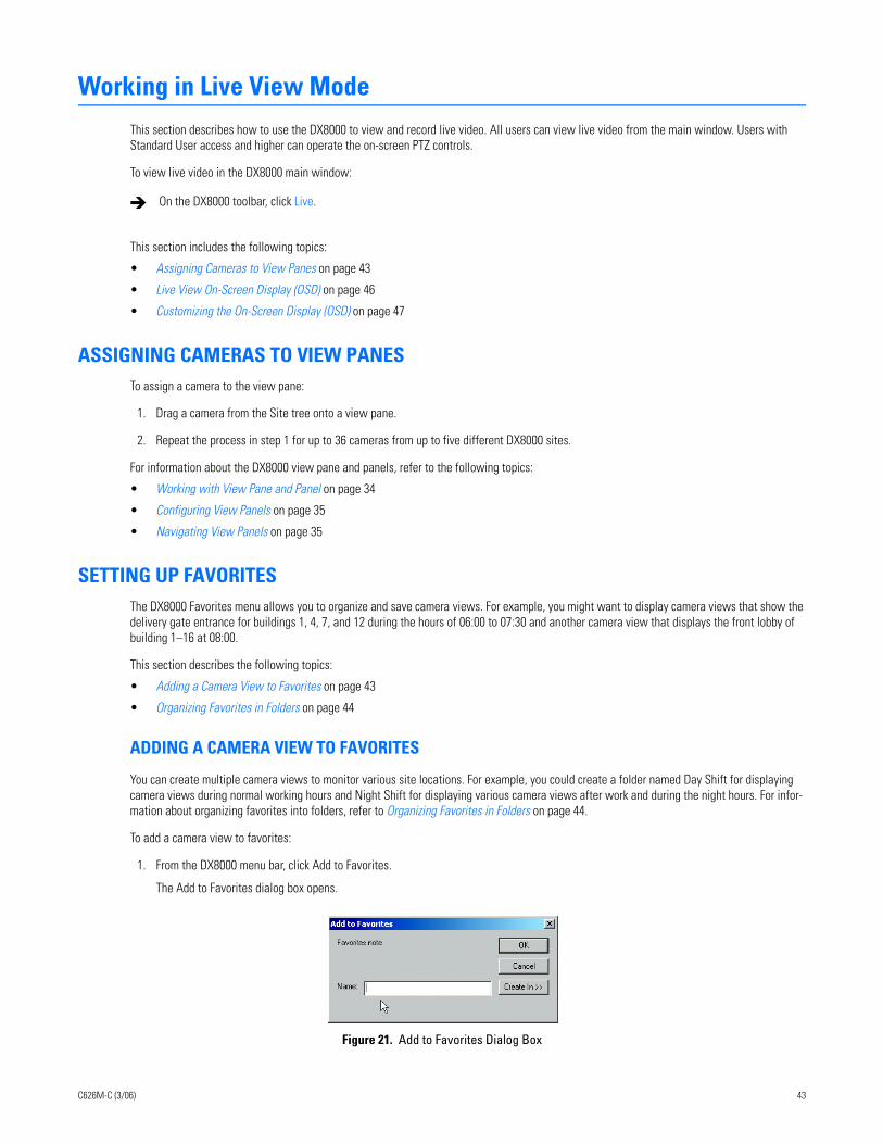
Working in Live View ModeThis section describes how to use the DX8000 to view and record live video. All users can view live video from the main window. Users with Standard User access and higher can operate the on-screen PTZ controls.
To view live video in the DX8000 main window:
This section includes the following topics:
• Assigning Cameras to View Panes on page 43
• Live View On-Screen Display (OSD) on page 46
• Customizing the On-Screen Display (OSD) on page 47
ASSIGNING CAMERAS TO VIEW PANESTo assign a camera to the view pane:
1. Drag a camera from the Site tree onto a view pane.
2. Repeat the process in step 1 for up to 36 cameras from up to five different DX8000 sites.
For information about the DX8000 view pane and panels, refer to the following topics:
• Working with View Pane and Panel on page 34
• Configuring View Panels on page 35
• Navigating View Panels on page 35
SETTING UP FAVORITESThe DX8000 Favorites menu allows you to organize and save camera views. For example, you might want to display camera views that show the delivery gate entrance for buildings 1, 4, 7, and 12 during the hours of 06:00 to 07:30 and another camera view that displays the front lobby of building 1–16 at 08:00.
This section describes the following topics:
• Adding a Camera View to Favorites on page 43
• Organizing Favorites in Folders on page 44
ADDING A CAMERA VIEW TO FAVORITES
You can create multiple camera views to monitor various site locations. For example, you could create a folder named Day Shift for displaying camera views during normal working hours and Night Shift for displaying various camera views after work and during the night hours. For infor-mation about organizing favorites into folders, refer to Organizing Favorites in Folders on page 44.
To add a camera view to favorites:
1. From the DX8000 menu bar, click Add to Favorites.
The Add to Favorites dialog box opens.
Figure 21. Add to Favorites Dialog Box
On the DX8000 toolbar, click Live.
C626M-C (3/06) 43
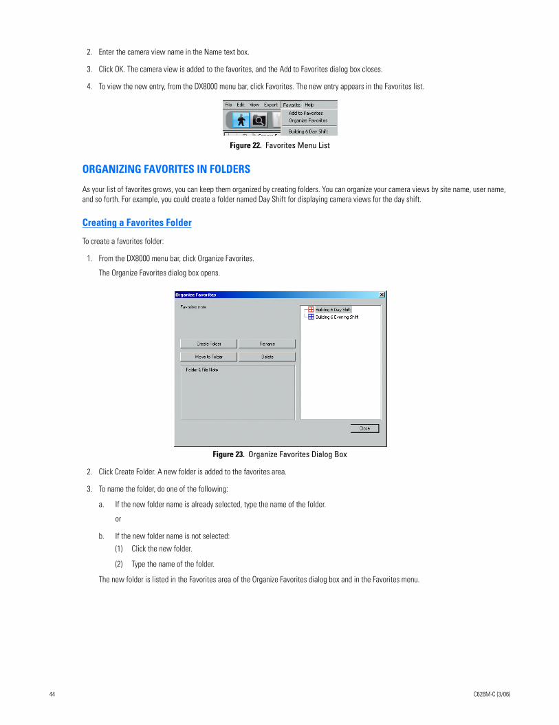
2. Enter the camera view name in the Name text box.
3. Click OK. The camera view is added to the favorites, and the Add to Favorites dialog box closes.
4. To view the new entry, from the DX8000 menu bar, click Favorites. The new entry appears in the Favorites list.
Figure 22. Favorites Menu List
ORGANIZING FAVORITES IN FOLDERS
As your list of favorites grows, you can keep them organized by creating folders. You can organize your camera views by site name, user name, and so forth. For example, you could create a folder named Day Shift for displaying camera views for the day shift.
Creating a Favorites Folder
To create a favorites folder:
1. From the DX8000 menu bar, click Organize Favorites.
The Organize Favorites dialog box opens.
Figure 23. Organize Favorites Dialog Box
2. Click Create Folder. A new folder is added to the favorites area.
3. To name the folder, do one of the following:
a. If the new folder name is already selected, type the name of the folder.
or
b. If the new folder name is not selected:
(1) Click the new folder.
(2) Type the name of the folder.
The new folder is listed in the Favorites area of the Organize Favorites dialog box and in the Favorites menu.
44 C626M-C (3/06)
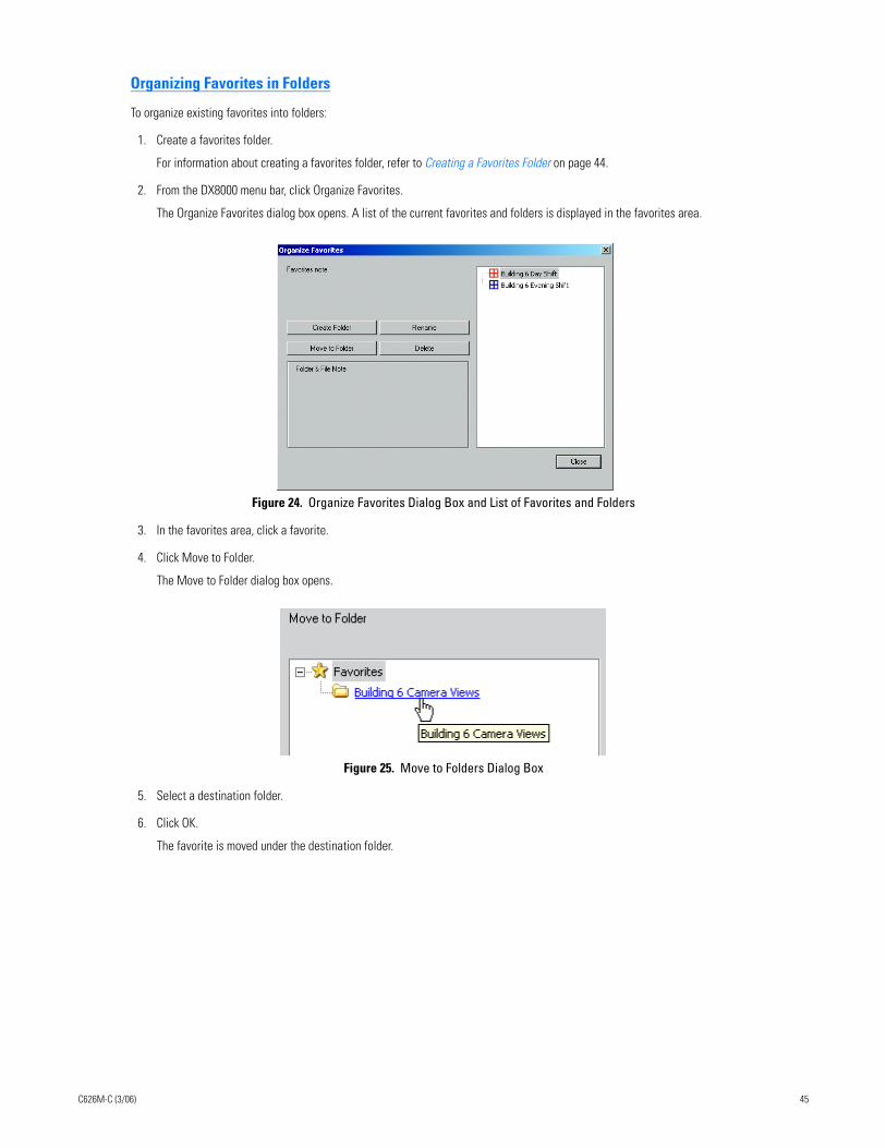
Organizing Favorites in Folders
To organize existing favorites into folders:
1. Create a favorites folder.
For information about creating a favorites folder, refer to Creating a Favorites Folder on page 44.
2. From the DX8000 menu bar, click Organize Favorites.
The Organize Favorites dialog box opens. A list of the current favorites and folders is displayed in the favorites area.
Figure 24. Organize Favorites Dialog Box and List of Favorites and Folders
3. In the favorites area, click a favorite.
4. Click Move to Folder.
The Move to Folder dialog box opens.
Figure 25. Move to Folders Dialog Box
5. Select a destination folder.
6. Click OK.
The favorite is moved under the destination folder.
C626M-C (3/06) 45
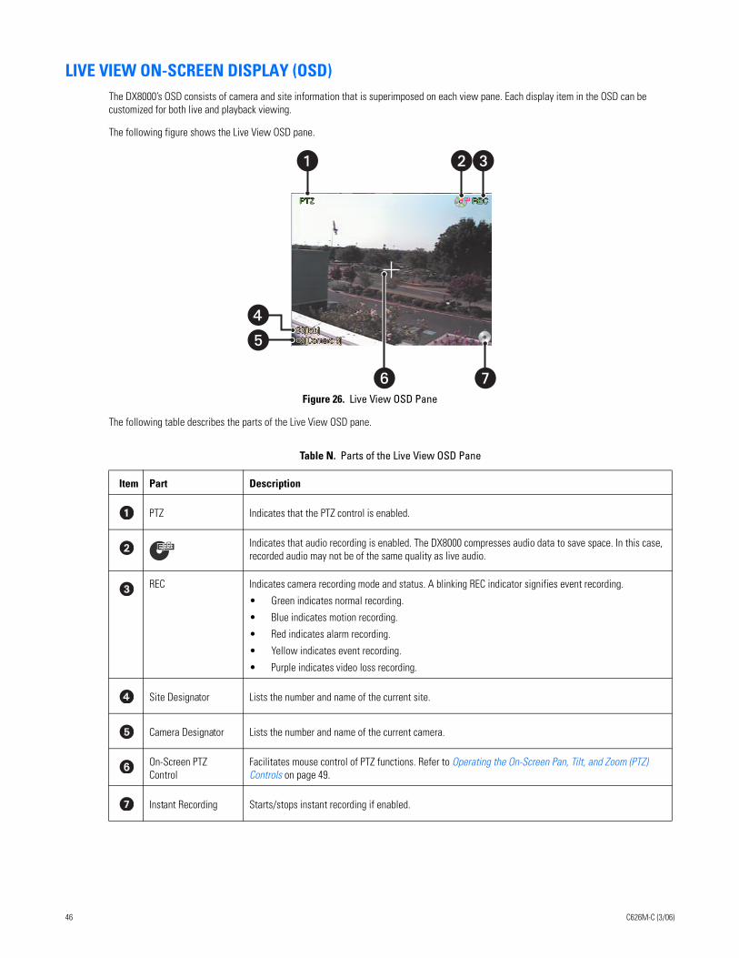
LIVE VIEW ON-SCREEN DISPLAY (OSD)The DX8000’s OSD consists of camera and site information that is superimposed on each view pane. Each display item in the OSD can be customized for both live and playback viewing.
The following figure shows the Live View OSD pane.
Figure 26. Live View OSD Pane
The following table describes the parts of the Live View OSD pane.
Table N. Parts of the Live View OSD Pane
Item Part Description
PTZ Indicates that the PTZ control is enabled.
Indicates that audio recording is enabled. The DX8000 compresses audio data to save space. In this case, recorded audio may not be of the same quality as live audio.
REC Indicates camera recording mode and status. A blinking REC indicator signifies event recording.
• Green indicates normal recording.
• Blue indicates motion recording.
• Red indicates alarm recording.
• Yellow indicates event recording.
• Purple indicates video loss recording.
Site Designator Lists the number and name of the current site.
Camera Designator Lists the number and name of the current camera.
On-Screen PTZ Control
Facilitates mouse control of PTZ functions. Refer to Operating the On-Screen Pan, Tilt, and Zoom (PTZ) Controls on page 49.
Instant Recording Starts/stops instant recording if enabled.
��
� �
��
46 C626M-C (3/06)
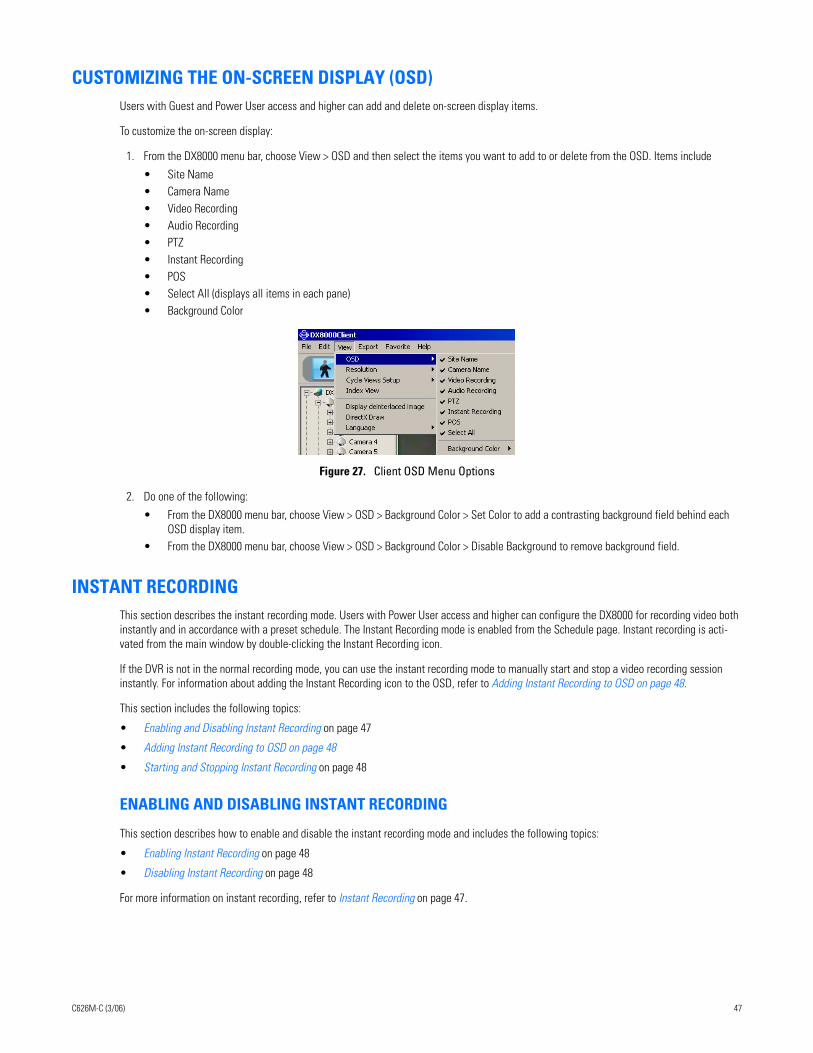
CUSTOMIZING THE ON-SCREEN DISPLAY (OSD)Users with Guest and Power User access and higher can add and delete on-screen display items.
To customize the on-screen display:
1. From the DX8000 menu bar, choose View > OSD and then select the items you want to add to or delete from the OSD. Items include
• Site Name• Camera Name• Video Recording• Audio Recording• PTZ• Instant Recording• POS• Select All (displays all items in each pane)• Background Color
Figure 27. Client OSD Menu Options
2. Do one of the following:
• From the DX8000 menu bar, choose View > OSD > Background Color > Set Color to add a contrasting background field behind each OSD display item.
• From the DX8000 menu bar, choose View > OSD > Background Color > Disable Background to remove background field.
INSTANT RECORDINGThis section describes the instant recording mode. Users with Power User access and higher can configure the DX8000 for recording video both instantly and in accordance with a preset schedule. The Instant Recording mode is enabled from the Schedule page. Instant recording is acti-vated from the main window by double-clicking the Instant Recording icon.
If the DVR is not in the normal recording mode, you can use the instant recording mode to manually start and stop a video recording session instantly. For information about adding the Instant Recording icon to the OSD, refer to Adding Instant Recording to OSD on page 48.
This section includes the following topics:
• Enabling and Disabling Instant Recording on page 47
• Adding Instant Recording to OSD on page 48
• Starting and Stopping Instant Recording on page 48
ENABLING AND DISABLING INSTANT RECORDING
This section describes how to enable and disable the instant recording mode and includes the following topics:
• Enabling Instant Recording on page 48
• Disabling Instant Recording on page 48
For more information on instant recording, refer to Instant Recording on page 47.
new
C626M-C (3/06) 47
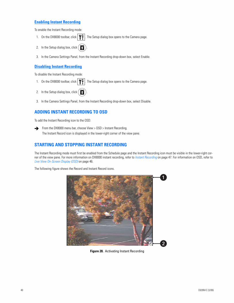
Enabling Instant Recording
To enable the Instant Recording mode:
1. On the DX8000 toolbar, click . The Setup dialog box opens to the Camera page.
2. In the Setup dialog box, click .
3. In the Camera Settings Panel, from the Instant Recording drop-down box, select Enable.
Disabling Instant Recording
To disable the Instant Recording mode:
1. On the DX8000 toolbar, click . The Setup dialog box opens to the Camera page.
2. In the Setup dialog box, click .
3. In the Camera Settings Panel, from the Instant Recording drop-down box, select Disable.
ADDING INSTANT RECORDING TO OSD
To add the Instant Recording icon to the OSD:
STARTING AND STOPPING INSTANT RECORDING
The Instant Recording mode must first be enabled from the Schedule page and the Instant Recording icon must be visible in the lower-right cor-ner of the view pane. For more information on DX8000 instant recording, refer to Instant Recording on page 47. For information on OSD, refer to Live View On-Screen Display (OSD) on page 46.
The following figure shows the Record and Instant Record icons.
Figure 28. Activating Instant Recording
From the DX8000 menu bar, choose View > OSD > Instant Recording.
The Instant Record icon is displayed in the lower-right corner of the view pane.
�
48 C626M-C (3/06)
The following table describes the instant recording indicators.
This section describes how to start and stop instant recording and includes the following topics:
• Starting Instant Recording on page 49
• Stopping Instant Recording on page 49
Starting Instant Recording
To start instant recording:
Stopping Instant Recording
To deactivate instant recording:
OPERATING THE ON-SCREEN PAN, TILT, AND ZOOM (PTZ) CONTROLSUsers with Standard User access and higher may operate pan, tilt, and zoom lens functions of cameras that support such features. PTZ functions can be controlled on-screen in Live mode using the mouse.
PTZ control is available only for cameras that support PTZ functions using Pelco’s P, D, or Coaxitron® protocols. For more information about config-uring PTZ ports, refer to Setting Up COM1 and COM2 Port Properties in the DX8000 server Help system or the Operation and Programming man-ual. In addition, the PTZ option must be enabled and a protocol must be assigned to the camera channel. For more information, refer to Camera Setup in the DX8000 server Help system or the Operation and Programming manual.
This section describes how to use the PTZ controls and includes the following topics:
• Operating the PTZ Controls on page 49
• Adjusting the Camera Lens on page 51
• Adjusting the Camera Zoom on page 52
• Using PC Keyboard Shortcuts to Operate PTZ and Lens Functions on page 53
OPERATING THE PTZ CONTROLS
To operate the on-screen PTZ controls:
1. On the DX8000 toolbar, click .
2. Select a PTZ-enabled camera from the Site tree.
Table O. Instant Recording Indicators
Item Icon Description
REC Indicates camera recording mode and status. A blinking REC indicator signifies event recording.
• Green indicates normal recording.
• Blue indicates motion recording.
• Red indicates alarm recording.
• Yellow indicates ATM/POS recording.
Instant Recording Starts/stops instant recording if enabled. Changes from silver to blue to indicate that instant recording is activated.
Double-click the Instant Recording icon located in the lower-right corner of the view pane.
• The Instant Recording icon changes from silver to blue, indicating that instant recording is activated.
• If video recording is enabled, verify that REC is highlighted white. If video recording is not enabled, REC is not displayed.
In the view pane, double-click the Instant Recording icon.
C626M-C (3/06) 49
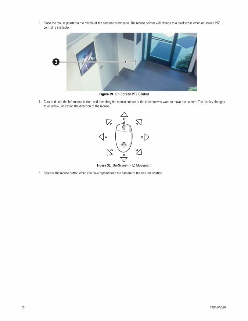
3. Place the mouse pointer in the middle of the camera’s view pane. The mouse pointer will change to a black cross when on-screen PTZ control is available.
Figure 29. On-Screen PTZ Control
4. Click and hold the left mouse button, and then drag the mouse pointer in the direction you want to move the camera. The display changes to an arrow, indicating the direction of the mouse.
Figure 30. On-Screen PTZ Movement
5. Release the mouse button when you have repositioned the camera to the desired location.
�
50 C626M-C (3/06)
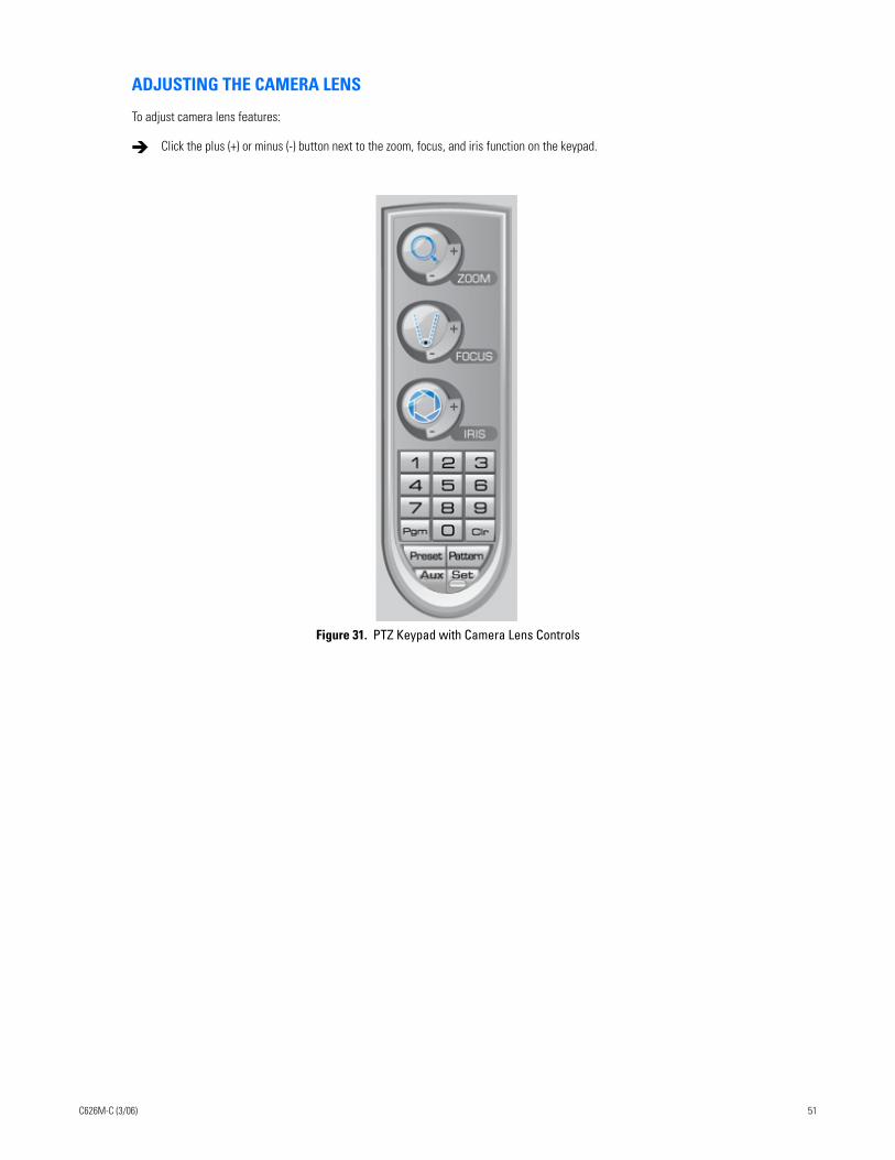
ADJUSTING THE CAMERA LENS
To adjust camera lens features:
Figure 31. PTZ Keypad with Camera Lens Controls
Click the plus (+) or minus (-) button next to the zoom, focus, and iris function on the keypad.
C626M-C (3/06) 51
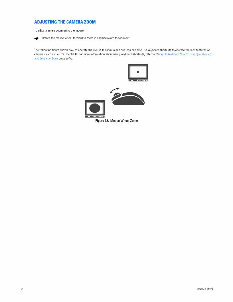
ADJUSTING THE CAMERA ZOOM
To adjust camera zoom using the mouse:
The following figure shows how to operate the mouse to zoom in and out. You can also use keyboard shortcuts to operate the lens features of cameras such as Pelco’s Spectra III. For more information about using keyboard shortcuts, refer to Using PC Keyboard Shortcuts to Operate PTZ and Lens Functions on page 53.
Figure 32. Mouse Wheel Zoom
Rotate the mouse wheel forward to zoom in and backward to zoom out.
52 C626M-C (3/06)
USING PC KEYBOARD SHORTCUTS TO OPERATE PTZ AND LENS FUNCTIONS
Users with Standard User access and higher may use a PC keyboard to operate PTZ and lens functions of cameras that support such features. PTZ and lens functions can be controlled in Live mode using the keyboard.
The following table describes the keyboard buttons that you use to control PTZ and lens functions.
To use the keyboard (+) and (-) keys to control camera pan and tilt speed:
1. On the DX8000 toolbar, click .
2. Select a PTZ-enabled camera from the Site tree.
3. Click the mouse pointer in the camera’s view panel.
4. Press and hold the up/down and left/right arrows to pan and tilt the camera.
5. Press the plus (+) key once or more to increase the pan and tilt speed. Press the minus (-) key once or more to decrease the pan and tilt speed.
Table P. Standard PC Keyboard Functions for Controlling PTZ and Lens Functions
Key Description
Insert and Delete These keys provide the following functionality:
• On-screen display, preset and pattern modes: Insert increases and Delete decreases focus, performing the same actions as the focus control on the PTZ keypad.
• Remote camera programming mode: Insert and Delete perform the same actions as the PTZ keypad focus (+) and (-) buttons, navigating up and down the camera menu choices.
Home and End These keys provide the following functionality:
• On-screen display, preset and pattern modes: The Home key opens and the End key closes the iris, performing the same actions as the PTZ keypad iris (+) and (-) buttons.
• Remote camera programming mode: The Home key selects an option from the camera’s on-screen menu. The End key cancels an option or exit a menu. These keys perform the same actions as the PTZ keypad iris (+) and (-) buttons.
Page Up and Page Down These keys perform the same functionality in the on-screen display and the preset and pattern modes as the PTZ keypad zoom (+) and (-) buttons. Page Up zooms in; Page Down zooms out.
Up and Down Arrows These keys provide the following functionality:
• On-screen display, preset and pattern modes: The up arrow key raises the camera and the down arrow key lowers the camera. The keys perform the same actions as the mouse to move the camera.
• Remote camera programming mode: The arrow keys navigate up and down the camera menu choices. The keys perform the same actions as the PTZ keypad focus (+) and (-) buttons.
Left and Right Arrows These keys provide the same actions as using the mouse to move the camera. The left arrow key pans the camera to the left and the right arrow key pans the camera to the right.
+ and - These keys perform similar actions as using the mouse to change the speed of camera movement. The plus (+) key, pressed once increases the camera’s pan and tilt speed. The minus (-) key pressed once decreases the camera’s pan and tilt speed. Each time the plus (+) key is pressed the pan and tilt speed is increased toward the maximum speed. Each time the minus (-) key is pressed, the pan and tilt speed is decreased toward the minimum speed.
C626M-C (3/06) 53
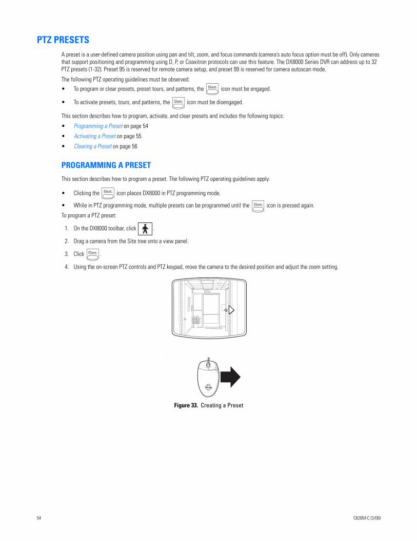
PTZ PRESETSA preset is a user-defined camera position using pan and tilt, zoom, and focus commands (camera’s auto focus option must be off). Only cameras that support positioning and programming using D, P, or Coaxitron protocols can use this feature. The DX8000 Series DVR can address up to 32 PTZ presets (1-32). Preset 95 is reserved for remote camera setup, and preset 99 is reserved for camera autoscan mode.
The following PTZ operating guidelines must be observed:
• To program or clear presets, preset tours, and patterns, the icon must be engaged.
• To activate presets, tours, and patterns, the icon must be disengaged.
This section describes how to program, activate, and clear presets and includes the following topics:
• Programming a Preset on page 54
• Activating a Preset on page 55
• Clearing a Preset on page 56
PROGRAMMING A PRESET
This section describes how to program a preset. The following PTZ operating guidelines apply:
• Clicking the icon places DX8000 in PTZ programming mode.
• While in PTZ programming mode, multiple presets can be programmed until the icon is pressed again.
To program a PTZ preset:
1. On the DX8000 toolbar, click .
2. Drag a camera from the Site tree onto a view panel.
3. Click .
4. Using the on-screen PTZ controls and PTZ keypad, move the camera to the desired position and adjust the zoom setting.
Figure 33. Creating a Preset
EXIT
54 C626M-C (3/06)
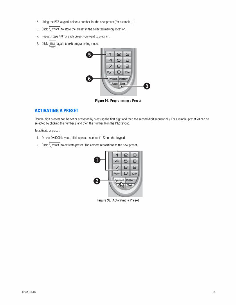
5. Using the PTZ keypad, select a number for the new preset (for example, 1).
6. Click to store the preset in the selected memory location.
7. Repeat steps 4-6 for each preset you want to program.
8. Click again to exit programming mode.
Figure 34. Programming a Preset
ACTIVATING A PRESET
Double-digit presets can be set or activated by pressing the first digit and then the second digit sequentially. For example, preset 20 can be selected by clicking the number 2 and then the number 0 on the PTZ keypad.
To activate a preset:
1. On the DX8000 keypad, click a preset number (1-32) on the keypad.
2. Click to activate preset. The camera repositions to the new preset.
Figure 35. Activating a Preset
�
�
�
�
C626M-C (3/06) 55
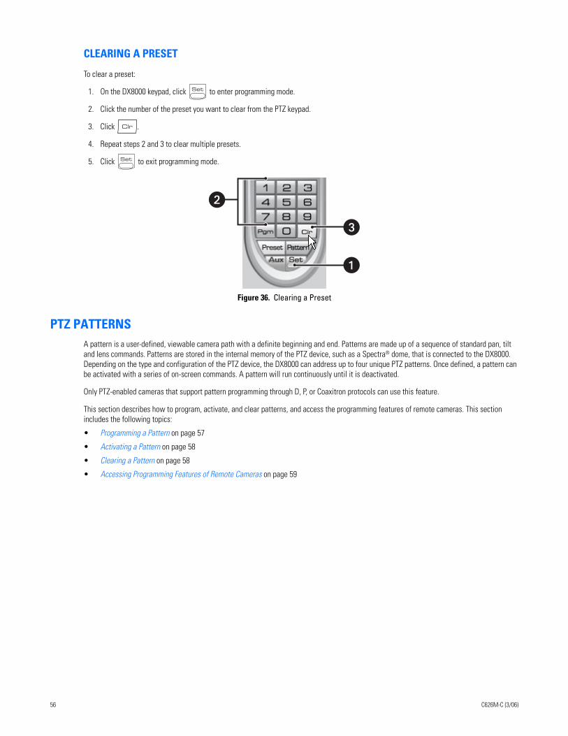
CLEARING A PRESET
To clear a preset:
1. On the DX8000 keypad, click to enter programming mode.
2. Click the number of the preset you want to clear from the PTZ keypad.
3. Click .
4. Repeat steps 2 and 3 to clear multiple presets.
5. Click to exit programming mode.
Figure 36. Clearing a Preset
PTZ PATTERNSA pattern is a user-defined, viewable camera path with a definite beginning and end. Patterns are made up of a sequence of standard pan, tilt and lens commands. Patterns are stored in the internal memory of the PTZ device, such as a Spectra® dome, that is connected to the DX8000. Depending on the type and configuration of the PTZ device, the DX8000 can address up to four unique PTZ patterns. Once defined, a pattern can be activated with a series of on-screen commands. A pattern will run continuously until it is deactivated.
Only PTZ-enabled cameras that support pattern programming through D, P, or Coaxitron protocols can use this feature.
This section describes how to program, activate, and clear patterns, and access the programming features of remote cameras. This section includes the following topics:
• Programming a Pattern on page 57
• Activating a Pattern on page 58
• Clearing a Pattern on page 58
• Accessing Programming Features of Remote Cameras on page 59
�
�
56 C626M-C (3/06)
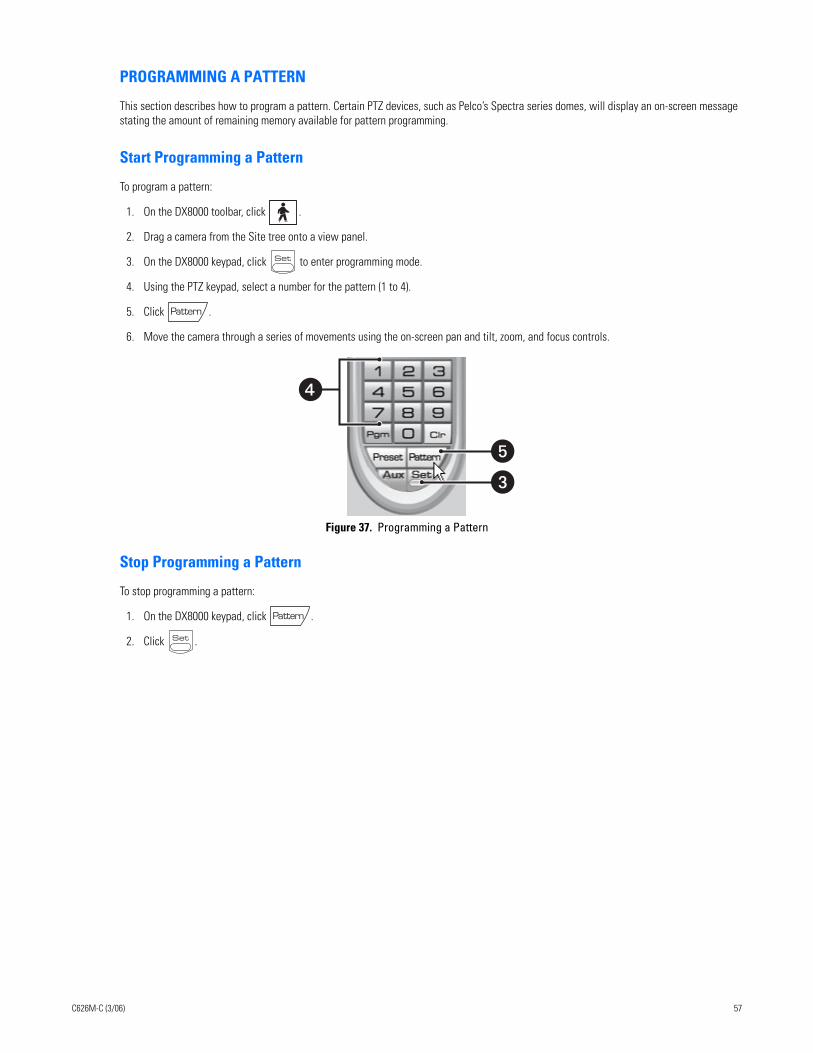
PROGRAMMING A PATTERN
This section describes how to program a pattern. Certain PTZ devices, such as Pelco’s Spectra series domes, will display an on-screen message stating the amount of remaining memory available for pattern programming.
Start Programming a Pattern
To program a pattern:
1. On the DX8000 toolbar, click .
2. Drag a camera from the Site tree onto a view panel.
3. On the DX8000 keypad, click to enter programming mode.
4. Using the PTZ keypad, select a number for the pattern (1 to 4).
5. Click .
6. Move the camera through a series of movements using the on-screen pan and tilt, zoom, and focus controls.
Figure 37. Programming a Pattern
Stop Programming a Pattern
To stop programming a pattern:
1. On the DX8000 keypad, click .
2. Click .
�
�
�
C626M-C (3/06) 57
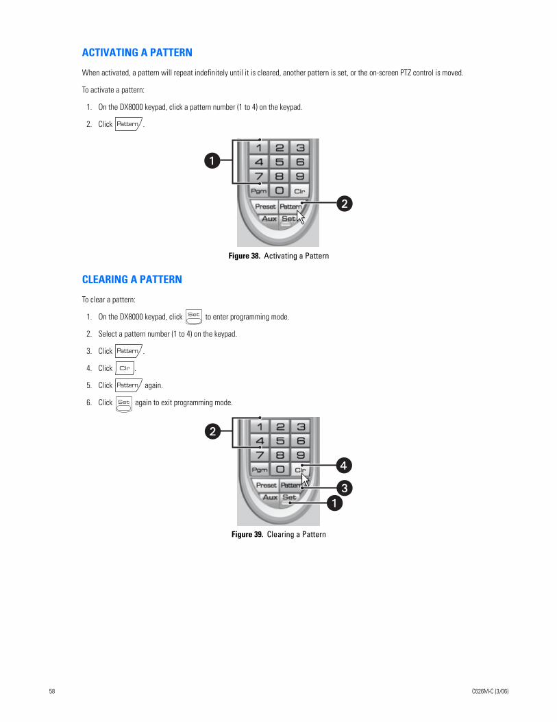
ACTIVATING A PATTERN
When activated, a pattern will repeat indefinitely until it is cleared, another pattern is set, or the on-screen PTZ control is moved.
To activate a pattern:
1. On the DX8000 keypad, click a pattern number (1 to 4) on the keypad.
2. Click .
Figure 38. Activating a Pattern
CLEARING A PATTERN
To clear a pattern:
1. On the DX8000 keypad, click to enter programming mode.
2. Select a pattern number (1 to 4) on the keypad.
3. Click .
4. Click .
5. Click again.
6. Click again to exit programming mode.
Figure 39. Clearing a Pattern
�
�
�
�
58 C626M-C (3/06)
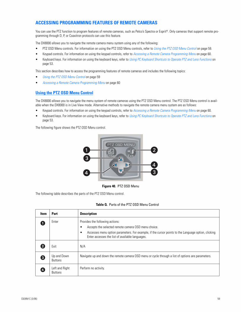
ACCESSING PROGRAMMING FEATURES OF REMOTE CAMERAS
You can use the PTZ function to program features of remote cameras, such as Pelco’s Spectra or Esprit®. Only cameras that support remote pro-gramming through D, P, or Coaxitron protocols can use this feature.
The DX8000 allows you to navigate the remote camera menu system using any of the following:
• PTZ OSD Menu controls. For information on using the PTZ OSD Menu controls, refer to Using the PTZ OSD Menu Control on page 59.
• Keypad controls. For information on using the keypad controls, refer to Accessing a Remote Camera Programming Menu on page 60.
• Keyboard keys. For information on using the keyboard keys, refer to Using PC Keyboard Shortcuts to Operate PTZ and Lens Functions on page 53.
This section describes how to access the programming features of remote cameras and includes the following topics:
• Using the PTZ OSD Menu Control on page 59
• Accessing a Remote Camera Programming Menu on page 60
Using the PTZ OSD Menu Control
The DX8000 allows you to navigate the menu system of remote cameras using the PTZ OSD Menu control. The PTZ OSD Menu control is avail-able when the DX8000 is in Live View mode. Alternative methods to navigate the remote camera menu system are as follows:
• Keypad controls. For information on using the keypad controls, refer to Accessing a Remote Camera Programming Menu on page 60.
• Keyboard keys. For information on using the keyboard keys, refer to Using PC Keyboard Shortcuts to Operate PTZ and Lens Functions on page 53.
The following figure shows the PTZ OSD Menu control.
Figure 40. PTZ OSD Menu
The following table describes the parts of the PTZ OSD Menu control.
Table Q. Parts of the PTZ OSD Menu Control
Item Part Description
Enter Provides the following actions:
• Accepts the selected remote camera OSD menu choice.
• Accesses menu option parameters. For example, if the cursor points to the Language option, clicking Enter accesses the list of available languages.
Exit N/A
Up and Down Buttons
Navigate up and down the remote camera OSD menu or cycle through a list of options are parameters.
Left and Right Buttons
Perform no activity.
�
�
���
C626M-C (3/06) 59
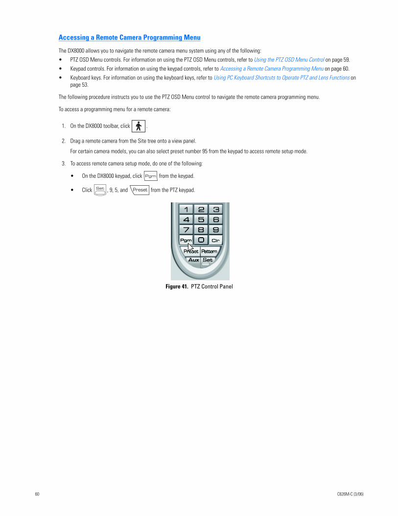
Accessing a Remote Camera Programming Menu
The DX8000 allows you to navigate the remote camera menu system using any of the following:
• PTZ OSD Menu controls. For information on using the PTZ OSD Menu controls, refer to Using the PTZ OSD Menu Control on page 59.
• Keypad controls. For information on using the keypad controls, refer to Accessing a Remote Camera Programming Menu on page 60.
• Keyboard keys. For information on using the keyboard keys, refer to Using PC Keyboard Shortcuts to Operate PTZ and Lens Functions on page 53.
The following procedure instructs you to use the PTZ OSD Menu control to navigate the remote camera programming menu.
To access a programming menu for a remote camera:
1. On the DX8000 toolbar, click .
2. Drag a remote camera from the Site tree onto a view panel.
For certain camera models, you can also select preset number 95 from the keypad to access remote setup mode.
3. To access remote camera setup mode, do one of the following:
• On the DX8000 keypad, click from the keypad.
• Click , 9, 5, and from the PTZ keypad.
Figure 41. PTZ Control Panel
60 C626M-C (3/06)
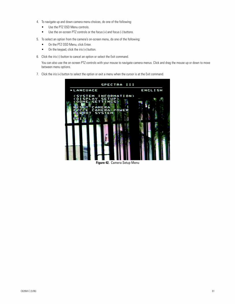
4. To navigate up and down camera menu choices, do one of the following:
• Use the PTZ OSD Menu controls. • Use the on-screen PTZ controls or the focus (+) and focus (-) buttons.
5. To select an option from the camera’s on-screen menu, do one of the following:
• On the PTZ OSD Menu, click Enter.• On the keypad, click the iris (+) button.
6. Click the iris (-) button to cancel an option or select the Exit command.
You can also use the on-screen PTZ controls with your mouse to navigate camera menus. Click and drag the mouse up or down to move between menu options.
7. Click the iris (+) button to select the option or exit a menu when the cursor is at the Exit command.
Figure 42. Camera Setup Menu
C626M-C (3/06) 61
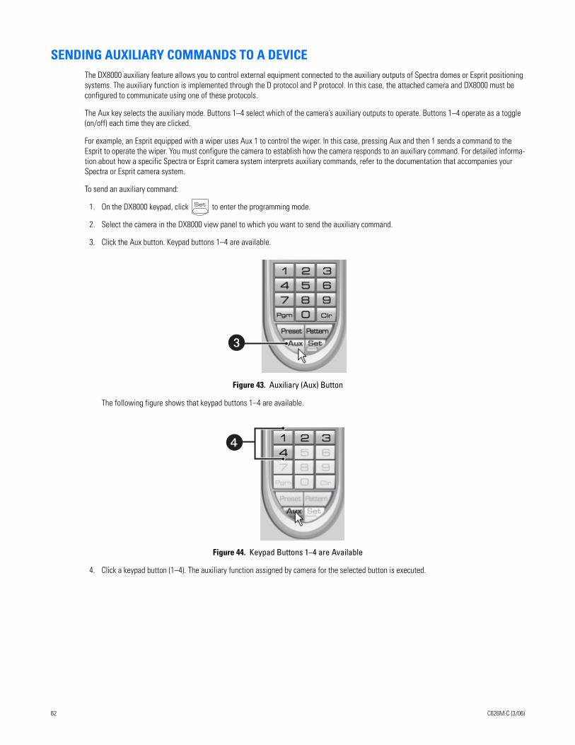
SENDING AUXILIARY COMMANDS TO A DEVICEThe DX8000 auxiliary feature allows you to control external equipment connected to the auxiliary outputs of Spectra domes or Esprit positioning systems. The auxiliary function is implemented through the D protocol and P protocol. In this case, the attached camera and DX8000 must be configured to communicate using one of these protocols.
The Aux key selects the auxiliary mode. Buttons 1–4 select which of the camera’s auxiliary outputs to operate. Buttons 1–4 operate as a toggle (on/off) each time they are clicked.
For example, an Esprit equipped with a wiper uses Aux 1 to control the wiper. In this case, pressing Aux and then 1 sends a command to the Esprit to operate the wiper. You must configure the camera to establish how the camera responds to an auxiliary command. For detailed informa-tion about how a specific Spectra or Esprit camera system interprets auxiliary commands, refer to the documentation that accompanies your Spectra or Esprit camera system.
To send an auxiliary command:
1. On the DX8000 keypad, click to enter the programming mode.
2. Select the camera in the DX8000 view panel to which you want to send the auxiliary command.
3. Click the Aux button. Keypad buttons 1–4 are available.
Figure 43. Auxiliary (Aux) Button
The following figure shows that keypad buttons 1–4 are available.
Figure 44. Keypad Buttons 1–4 are Available
4. Click a keypad button (1–4). The auxiliary function assigned by camera for the selected button is executed.
�
�
62 C626M-C (3/06)
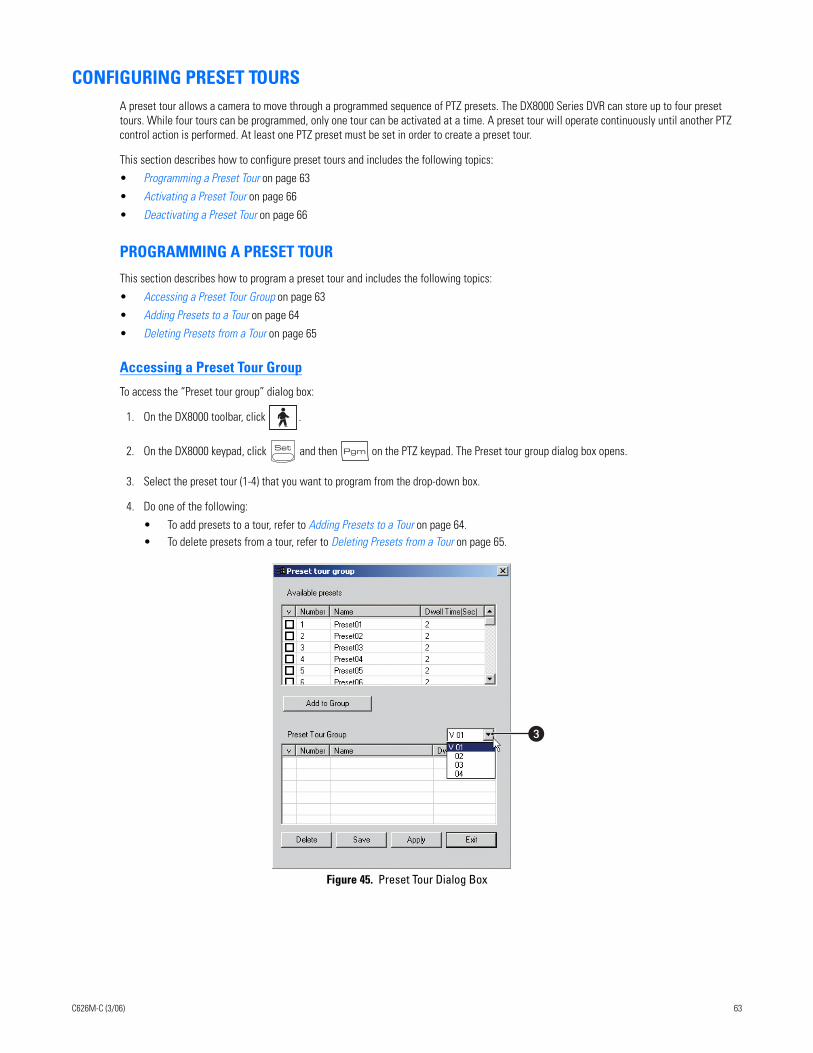
CONFIGURING PRESET TOURSA preset tour allows a camera to move through a programmed sequence of PTZ presets. The DX8000 Series DVR can store up to four preset tours. While four tours can be programmed, only one tour can be activated at a time. A preset tour will operate continuously until another PTZ control action is performed. At least one PTZ preset must be set in order to create a preset tour.
This section describes how to configure preset tours and includes the following topics:
• Programming a Preset Tour on page 63
• Activating a Preset Tour on page 66
• Deactivating a Preset Tour on page 66
PROGRAMMING A PRESET TOUR
This section describes how to program a preset tour and includes the following topics:
• Accessing a Preset Tour Group on page 63
• Adding Presets to a Tour on page 64
• Deleting Presets from a Tour on page 65
Accessing a Preset Tour Group
To access the “Preset tour group” dialog box:
1. On the DX8000 toolbar, click .
2. On the DX8000 keypad, click and then on the PTZ keypad. The Preset tour group dialog box opens.
3. Select the preset tour (1-4) that you want to program from the drop-down box.
4. Do one of the following:
• To add presets to a tour, refer to Adding Presets to a Tour on page 64.• To delete presets from a tour, refer to Deleting Presets from a Tour on page 65.
Figure 45. Preset Tour Dialog Box
�
C626M-C (3/06) 63
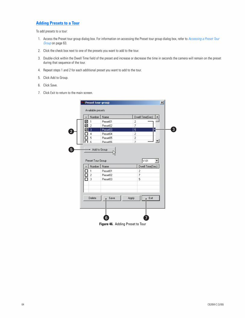
Adding Presets to a Tour
To add presets to a tour:
1. Access the Preset tour group dialog box. For information on accessing the Preset tour group dialog box, refer to Accessing a Preset Tour Group on page 63.
2. Click the check box next to one of the presets you want to add to the tour.
3. Double-click within the Dwell Time field of the preset and increase or decrease the time in seconds the camera will remain on the preset during that sequence of the tour.
4. Repeat steps 1 and 2 for each additional preset you want to add to the tour.
5. Click Add to Group.
6. Click Save.
7. Click Exit to return to the main screen.
Figure 46. Adding Preset to Tour
� �
�
� �
64 C626M-C (3/06)
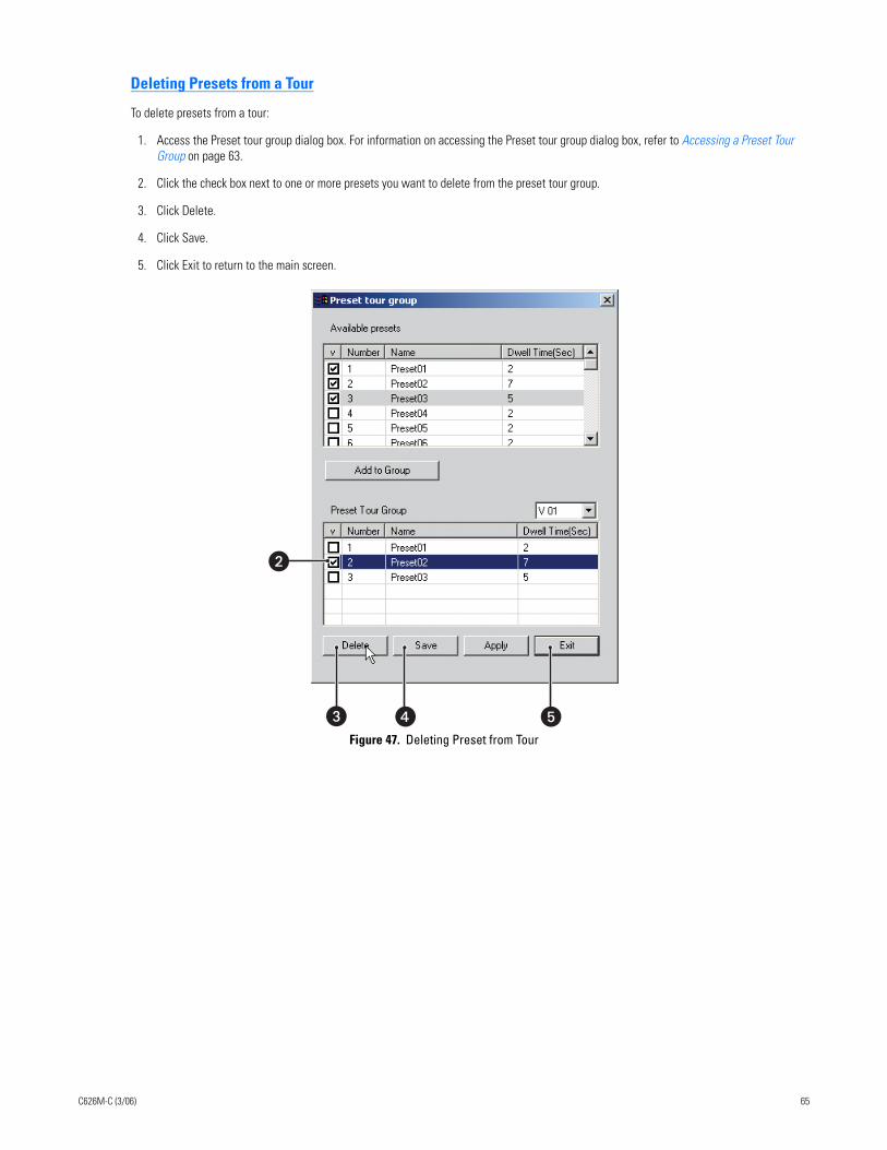
Deleting Presets from a Tour
To delete presets from a tour:
1. Access the Preset tour group dialog box. For information on accessing the Preset tour group dialog box, refer to Accessing a Preset Tour Group on page 63.
2. Click the check box next to one or more presets you want to delete from the preset tour group.
3. Click Delete.
4. Click Save.
5. Click Exit to return to the main screen.
Figure 47. Deleting Preset from Tour
� �
�
�
C626M-C (3/06) 65
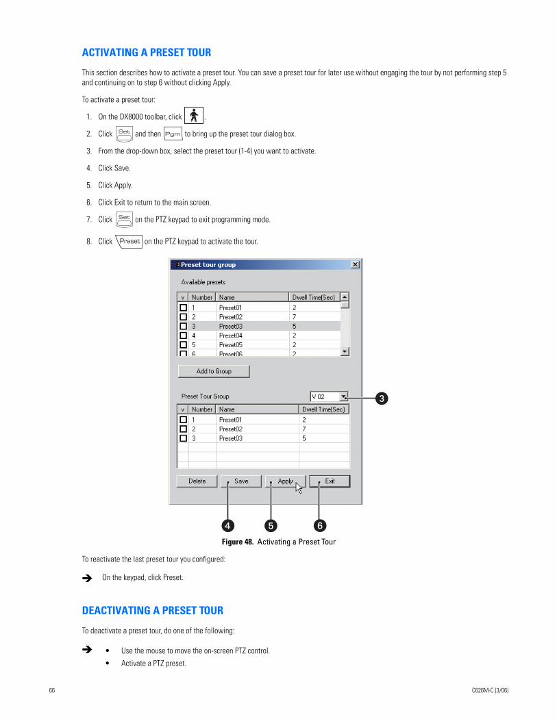
ACTIVATING A PRESET TOUR
This section describes how to activate a preset tour. You can save a preset tour for later use without engaging the tour by not performing step 5 and continuing on to step 6 without clicking Apply.
To activate a preset tour:
1. On the DX8000 toolbar, click .
2. Click and then to bring up the preset tour dialog box.
3. From the drop-down box, select the preset tour (1-4) you want to activate.
4. Click Save.
5. Click Apply.
6. Click Exit to return to the main screen.
7. Click on the PTZ keypad to exit programming mode.
8. Click on the PTZ keypad to activate the tour.
Figure 48. Activating a Preset Tour
To reactivate the last preset tour you configured:
DEACTIVATING A PRESET TOUR
To deactivate a preset tour, do one of the following:
On the keypad, click Preset.
• Use the mouse to move the on-screen PTZ control.
• Activate a PTZ preset.
�
�
� �
66 C626M-C (3/06)
Working in Playback ModeRecorded video can be played back one channel at a time on the DX8000. Like live video, recorded video is viewed from the camera view panels on the main screen. Refer to Understanding View Panes and Panels on page 34 for information on view panels. Only users with Standard User access and higher are allowed to view recorded video.
This section describes how use the Playback mode and includes the following topics:
• Accessing Playback Mode on page 67
• Assigning Cameras to View Panels on page 67
• Playback On-Screen Display (OSD) on page 67
• Playback Controls on page 68
• Playback Timeline on page 70
• Playing Back Video by Time on page 71
• Playing Back Video by Event on page 72
• Operating Playback Digital Zoom on page 73
• Viewing Video in the Deinterlaced Mode on page 96
• Viewing Live and Playback Video Simultaneously on page 96
ACCESSING PLAYBACK MODETo access the Playback mode:
ASSIGNING CAMERAS TO VIEW PANELSTo assign a camera to a view panel:
1. Drag a camera from the Site tree onto a camera view pane.
2. Repeat this process for up to 36 cameras.
PLAYBACK ON-SCREEN DISPLAY (OSD)The on-screen display for playback is identical to live view with the exception of a date/time field in place of the PTZ designator.
Figure 49. Playback OSD
On the DX8000 toolbar, click Live.
C626M-C (3/06) 67
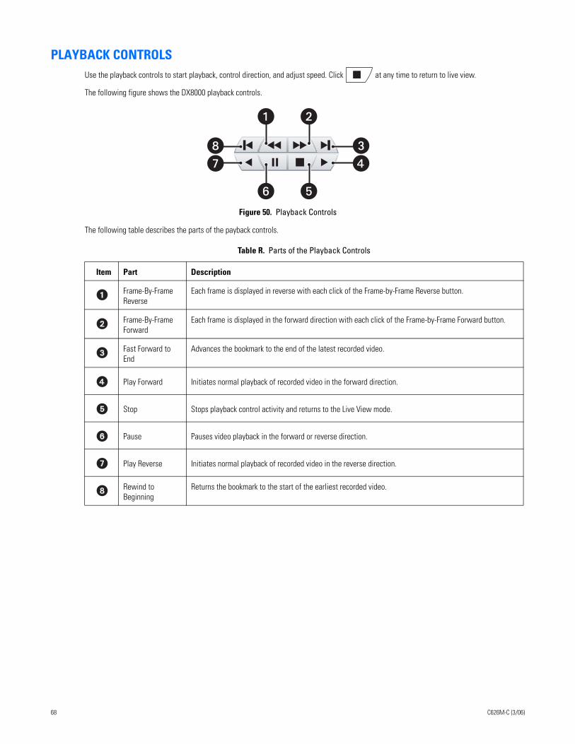
PLAYBACK CONTROLSUse the playback controls to start playback, control direction, and adjust speed. Click at any time to return to live view.
The following figure shows the DX8000 playback controls.
Figure 50. Playback Controls
The following table describes the parts of the payback controls.
Table R. Parts of the Playback Controls
Item Part Description
Frame-By-Frame Reverse
Each frame is displayed in reverse with each click of the Frame-by-Frame Reverse button.
Frame-By-Frame Forward
Each frame is displayed in the forward direction with each click of the Frame-by-Frame Forward button.
Fast Forward to End
Advances the bookmark to the end of the latest recorded video.
Play Forward Initiates normal playback of recorded video in the forward direction.
Stop Stops playback control activity and returns to the Live View mode.
Pause Pauses video playback in the forward or reverse direction.
Play Reverse Initiates normal playback of recorded video in the reverse direction.
Rewind to Beginning
Returns the bookmark to the start of the earliest recorded video.
�
� �
��
��
68 C626M-C (3/06)
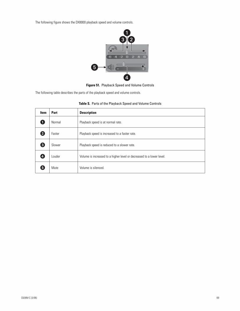
The following figure shows the DX8000 playback speed and volume controls.
Figure 51. Playback Speed and Volume Controls
The following table describes the parts of the playback speed and volume controls.
Table S. Parts of the Playback Speed and Volume Controls
Item Part Description
Normal Playback speed is at normal rate.
Faster Playback speed is increased to a faster rate.
Slower Playback speed is reduced to a slower rate.
Louder Volume is increased to a higher level or decreased to a lower level.
Mute Volume is silenced.
��
�
�
C626M-C (3/06) 69
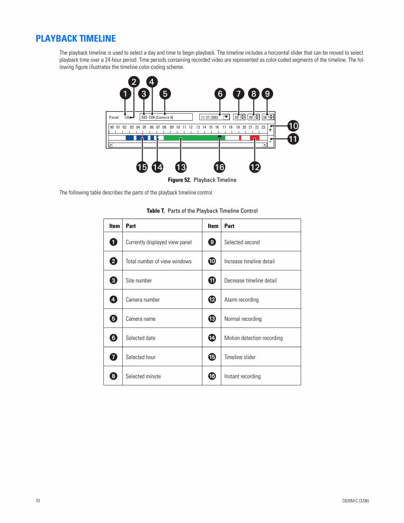
PLAYBACK TIMELINEThe playback timeline is used to select a day and time to begin playback. The timeline includes a horizontal slider that can be moved to select playback time over a 24-hour period. Time periods containing recorded video are represented as color-coded segments of the timeline. The fol-lowing figure illustrates the timeline color-coding scheme.
Figure 52. Playback Timeline
The following table describes the parts of the playback timeline control.
Table T. Parts of the Playback Timeline Control
Item Part Item Part
Currently displayed view panel Selected second
Total number of view windows Increase timeline detail
Site number Decrease timeline detail
Camera number Alarm recording
Camera name Normal recording
Selected date Motion detection recording
Selected hour Timeline slider
Selected minute Instant recording
00 01 02 03 04 05 06 07 08 09 10 11 12 13 14 15 16 17 18 19 20 21 22 23
Panel: 1/8 S03 C09 [Camera 9] 11-27-2003 05 00 56
��
��
� � ��
� �
����������
70 C626M-C (3/06)
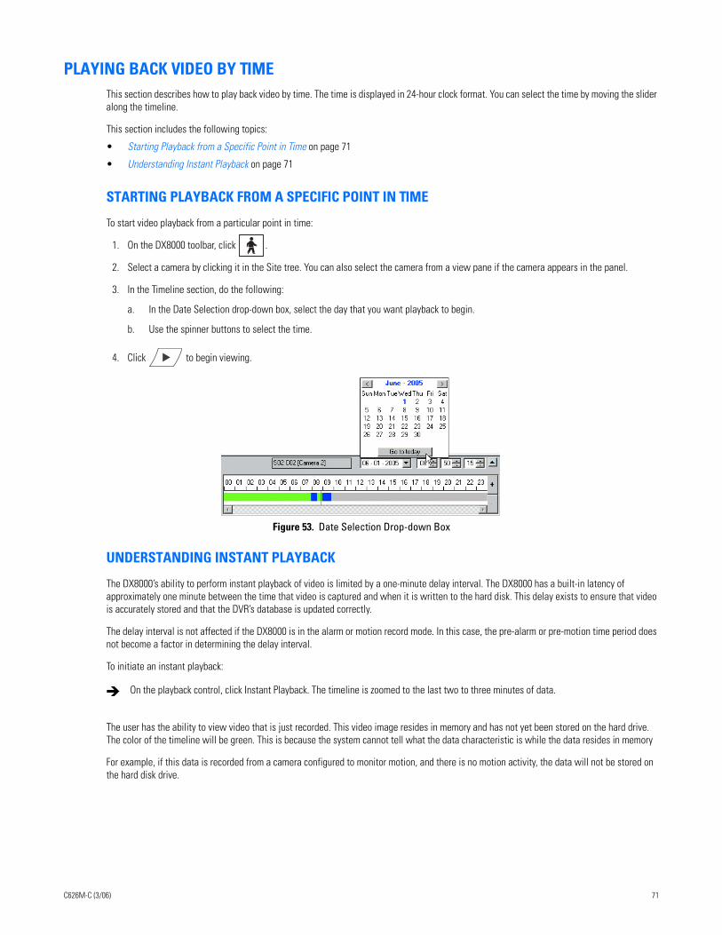
PLAYING BACK VIDEO BY TIMEThis section describes how to play back video by time. The time is displayed in 24-hour clock format. You can select the time by moving the slider along the timeline.
This section includes the following topics:
• Starting Playback from a Specific Point in Time on page 71
• Understanding Instant Playback on page 71
STARTING PLAYBACK FROM A SPECIFIC POINT IN TIME
To start video playback from a particular point in time:
1. On the DX8000 toolbar, click .
2. Select a camera by clicking it in the Site tree. You can also select the camera from a view pane if the camera appears in the panel.
3. In the Timeline section, do the following:
a. In the Date Selection drop-down box, select the day that you want playback to begin.
b. Use the spinner buttons to select the time.
4. Click to begin viewing.
Figure 53. Date Selection Drop-down Box
UNDERSTANDING INSTANT PLAYBACK
The DX8000’s ability to perform instant playback of video is limited by a one-minute delay interval. The DX8000 has a built-in latency of approximately one minute between the time that video is captured and when it is written to the hard disk. This delay exists to ensure that video is accurately stored and that the DVR’s database is updated correctly.
The delay interval is not affected if the DX8000 is in the alarm or motion record mode. In this case, the pre-alarm or pre-motion time period does not become a factor in determining the delay interval.
To initiate an instant playback:
The user has the ability to view video that is just recorded. This video image resides in memory and has not yet been stored on the hard drive. The color of the timeline will be green. This is because the system cannot tell what the data characteristic is while the data resides in memory
For example, if this data is recorded from a camera configured to monitor motion, and there is no motion activity, the data will not be stored on the hard disk drive.
On the playback control, click Instant Playback. The timeline is zoomed to the last two to three minutes of data.
C626M-C (3/06) 71
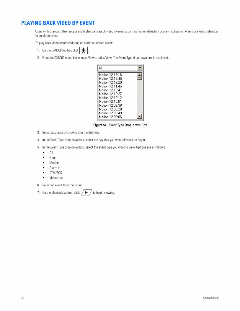
PLAYING BACK VIDEO BY EVENTUsers with Standard User access and higher can search video by events, such as motion detection or alarm activation. A sensor event is identical to an alarm event.
To play back video recorded during an alarm or motion event:
1. On the DX8000 toolbar, click .
2. From the DX8000 menu bar, choose View > Index View. The Event Type drop-down box is displayed.
Figure 54. Event Type Drop-down Box
3. Select a camera by clicking it in the Site tree.
4. In the Event Type drop-down box, select the day that you want playback to begin.
5. In the Event Type drop-down box, select the event type you want to view. Options are as follows:
• All• None• Motion• Alarm in• ATM/POS• Video Loss
6. Select an event from the listing.
7. On the playback control, click to begin viewing.
72 C626M-C (3/06)
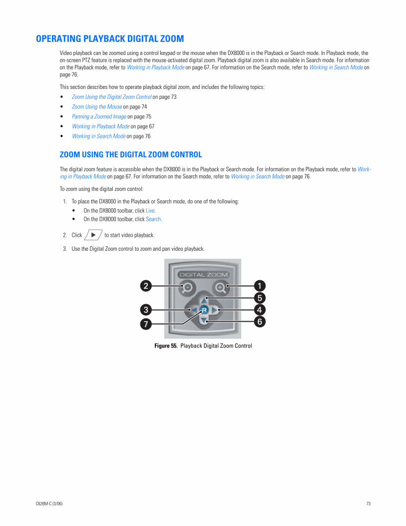
OPERATING PLAYBACK DIGITAL ZOOMVideo playback can be zoomed using a control keypad or the mouse when the DX8000 is in the Playback or Search mode. In Playback mode, the on-screen PTZ feature is replaced with the mouse-activated digital zoom. Playback digital zoom is also available in Search mode. For information on the Playback mode, refer to Working in Playback Mode on page 67. For information on the Search mode, refer to Working in Search Mode on page 76.
This section describes how to operate playback digital zoom, and includes the following topics:
• Zoom Using the Digital Zoom Control on page 73
• Zoom Using the Mouse on page 74
• Panning a Zoomed Image on page 75
• Working in Playback Mode on page 67
• Working in Search Mode on page 76
ZOOM USING THE DIGITAL ZOOM CONTROL
The digital zoom feature is accessible when the DX8000 is in the Playback or Search mode. For information on the Playback mode, refer to Work-ing in Playback Mode on page 67. For information on the Search mode, refer to Working in Search Mode on page 76.
To zoom using the digital zoom control:
1. To place the DX8000 in the Playback or Search mode, do one of the following:
• On the DX8000 toolbar, click Live. • On the DX8000 toolbar, click Search.
2. Click to start video playback.
3. Use the Digital Zoom control to zoom and pan video playback.
Figure 55. Playback Digital Zoom Control
�
��
���
C626M-C (3/06) 73
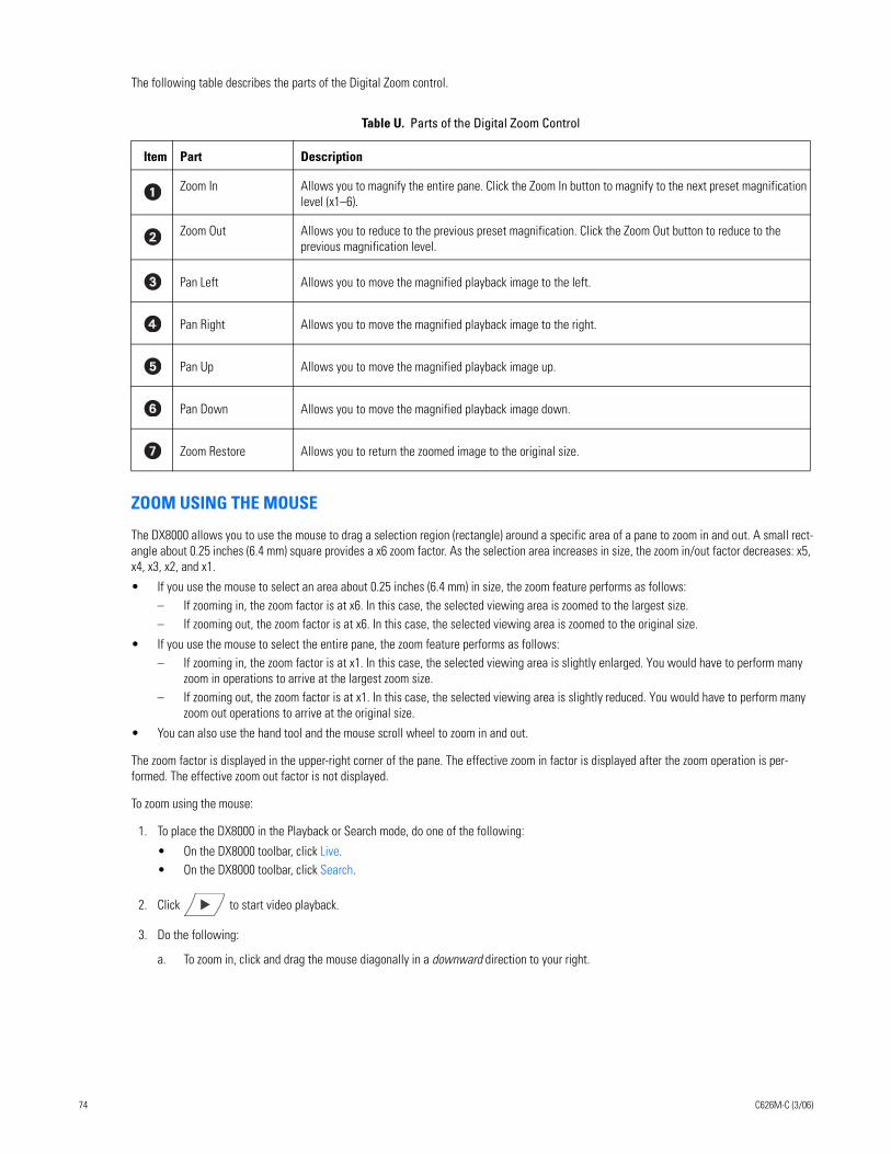
The following table describes the parts of the Digital Zoom control.
ZOOM USING THE MOUSE
The DX8000 allows you to use the mouse to drag a selection region (rectangle) around a specific area of a pane to zoom in and out. A small rect-angle about 0.25 inches (6.4 mm) square provides a x6 zoom factor. As the selection area increases in size, the zoom in/out factor decreases: x5, x4, x3, x2, and x1.
• If you use the mouse to select an area about 0.25 inches (6.4 mm) in size, the zoom feature performs as follows: – If zooming in, the zoom factor is at x6. In this case, the selected viewing area is zoomed to the largest size.– If zooming out, the zoom factor is at x6. In this case, the selected viewing area is zoomed to the original size.
• If you use the mouse to select the entire pane, the zoom feature performs as follows: – If zooming in, the zoom factor is at x1. In this case, the selected viewing area is slightly enlarged. You would have to perform many
zoom in operations to arrive at the largest zoom size.– If zooming out, the zoom factor is at x1. In this case, the selected viewing area is slightly reduced. You would have to perform many
zoom out operations to arrive at the original size.
• You can also use the hand tool and the mouse scroll wheel to zoom in and out.
The zoom factor is displayed in the upper-right corner of the pane. The effective zoom in factor is displayed after the zoom operation is per-formed. The effective zoom out factor is not displayed.
To zoom using the mouse:
1. To place the DX8000 in the Playback or Search mode, do one of the following:
• On the DX8000 toolbar, click Live. • On the DX8000 toolbar, click Search.
2. Click to start video playback.
3. Do the following:
a. To zoom in, click and drag the mouse diagonally in a downward direction to your right.
Table U. Parts of the Digital Zoom Control
Item Part Description
Zoom In Allows you to magnify the entire pane. Click the Zoom In button to magnify to the next preset magnification level (x1–6).
Zoom Out Allows you to reduce to the previous preset magnification. Click the Zoom Out button to reduce to the previous magnification level.
Pan Left Allows you to move the magnified playback image to the left.
Pan Right Allows you to move the magnified playback image to the right.
Pan Up Allows you to move the magnified playback image up.
Pan Down Allows you to move the magnified playback image down.
Zoom Restore Allows you to return the zoomed image to the original size.
74 C626M-C (3/06)
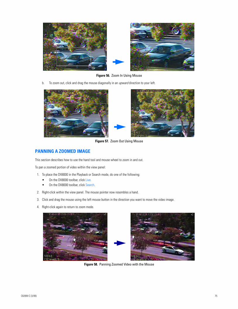
.
Figure 56. Zoom In Using Mouse
b. To zoom out, click and drag the mouse diagonally in an upward direction to your left.
Figure 57. Zoom Out Using Mouse
PANNING A ZOOMED IMAGE
This section describes how to use the hand tool and mouse wheel to zoom in and out.
To pan a zoomed portion of video within the view panel:
1. To place the DX8000 in the Playback or Search mode, do one of the following:
• On the DX8000 toolbar, click Live. • On the DX8000 toolbar, click Search.
2. Right-click within the view panel. The mouse pointer now resembles a hand.
3. Click and drag the mouse using the left mouse button in the direction you want to move the video image.
4. Right-click again to return to zoom mode.
Figure 58. Panning Zoomed Video with the Mouse
C626M-C (3/06) 75
Working in Search ModeThe DX8000 Series DVR supports four video search methods: index, thumbnail, POS, and pixel. For information about the user access level required to search video data, refer to Definition of User Access Levels on page 153.
To enter the Search mode:
This section describes how to use the Search mode and includes the following topics:
• Search Window on page 77
• Displaying a Deinterlaced Image in the Search Mode on page 79
• Index Video Search on page 79
• Thumbnail Video Search on page 80
• POS Search on page 82
• Pixel Video Search on page 93
• Working with Special View and Search Methods on page 96
On the DX8000 toolbar, click Search.
76 C626M-C (3/06)
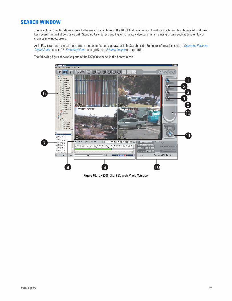
SEARCH WINDOWThe search window facilitates access to the search capabilities of the DX8000. Available search methods include index, thumbnail, and pixel. Each search method allows users with Standard User access and higher to locate video data instantly using criteria such as time of day or changes in window pixels.
As in Playback mode, digital zoom, export, and print features are available in Search mode. For more information, refer to Operating Playback Digital Zoom on page 73, Exporting Video on page 97, and Printing Images on page 107.
The following figure shows the parts of the DX8000 window in the Search mode.
Figure 59. DX8000 Client Search Mode Window
�
�
� � �
�
�
�
���
�
C626M-C (3/06) 77
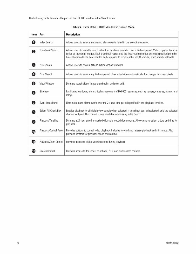
The following table describes the parts of the DX8000 window in the Search mode.
Table V. Parts of the DX8000 Window in Search Mode
Item Part Description
Index Search Allows users to search motion and alarm events listed in the event index panel.
Thumbnail Search Allows users to visually search video that has been recorded over a 24-hour period. Video is presented as a series of thumbnail images. Each thumbnail represents the first image recorded during a specified period of time. Thumbnails can be expanded and collapsed to represent hourly, 10-minute, and 1-minute intervals.
POS Search Allows users to search ATM/POS transaction text data.
Pixel Search Allows users to search any 24-hour period of recorded video automatically for changes in screen pixels.
View Window Displays search video, image thumbnails, and pixel grid.
Site tree Facilitates top-down, hierarchical management of DX8000 resources, such as servers, cameras, alarms, and relays.
Event Index Panel Lists motion and alarm events over the 24-hour time period specified in the playback timeline.
Select All Check Box Enables playback for all visible view panels when selected. If this check box is deselected, only the selected channel will play. This control is only available while using Index Search.
Playback Timeline Displays a 24-hour timeline marked with color-coded video events. Allows user to select a date and time for playback.
Playback Control Panel Provides buttons to control video playback. Includes forward and reverse playback and still image. Also provides controls for playback speed and volume.
Playback Zoom Control Provides access to digital zoom features during playback.
Search Control Provides access to the index, thumbnail, POS, and pixel search controls.
78 C626M-C (3/06)
DISPLAYING A DEINTERLACED IMAGE IN THE SEARCH MODEIf you are searching for an image that is recorded at 4CIF at a low frame rate per second, the viewed image might move or tear. The View menu’s Deinterlaced Image option is used to enhance the image during a search activity.
To search video using the deinterlaced option:
1. On the menu bar, click View > Display deinterlaced image.
2. On the DX8000 toolbar, click . The DX8000 is placed in the Search mode.
INDEX VIDEO SEARCHIndex search allows a user to search video by events, such as motion detection or alarm activation. Events are listed chronologically and by type. To ensure that the proper camera channel is selected, check the camera information box above the playback timeline or verify that the desired view panel is framed with a thin red outline.
To search video by motion or alarm events:
1. On the DX8000 toolbar, click .
2. On the DX8000 Search control, click .
3. On the DX8000 toolbar, click a view panel division button.
4. From the Site tree, drag the camera channel you want to search onto one of the view panels.
5. Click the view panel of the channel you want to search.
6. From the drop-down box on the playback timeline, select the day you want playback to begin.
7. Select the event type you want to view from the event type drop-down box.
Only events recorded for the selected camera are listed in the index. A sensor event is identical to an alarm event. Options are as follows:
• All• None• Motion• Alarm in• ATM/POS• Video Loss
8. Select an event from the index.
9. Verify that the “Select all” check box is selected. Deselecting the “Select all” check box will disable playback for all view panels except the channel being searched.
The DX8000 allows you to view playback on multiple cameras in addition to the camera being searched. This feature is valuable if you want to examine a variety of views recorded at the time a certain event was detected.
10. Click to begin viewing.
C626M-C (3/06) 79
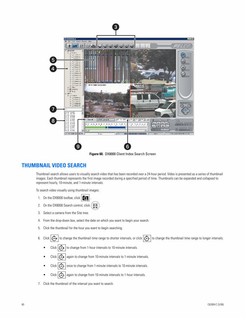
Figure 60. DX8000 Client Index Search Screen
THUMBNAIL VIDEO SEARCHThumbnail search allows users to visually search video that has been recorded over a 24-hour period. Video is presented as a series of thumbnail images. Each thumbnail represents the first image recorded during a specified period of time. Thumbnails can be expanded and collapsed to represent hourly, 10-minute, and 1-minute intervals.
To search video visually using thumbnail images:
1. On the DX8000 toolbar, click .
2. On the DX8000 Search control, click .
3. Select a camera from the Site tree.
4. From the drop-down box, select the date on which you want to begin your search.
5. Click the thumbnail for the hour you want to begin searching.
6. Click to change the thumbnail time range to shorter intervals, or click to change the thumbnail time range to longer intervals.
• Click to change from 1-hour intervals to 10-minute intervals.
• Click again to change from 10-minute intervals to 1-minute intervals.
• Click once to change from 1-minute intervals to 10-minute intervals.
• Click again to change from 10-minute intervals to 1-hour intervals.
7. Click the thumbnail of the interval you want to search.
��
�
�
�
� �
80 C626M-C (3/06)
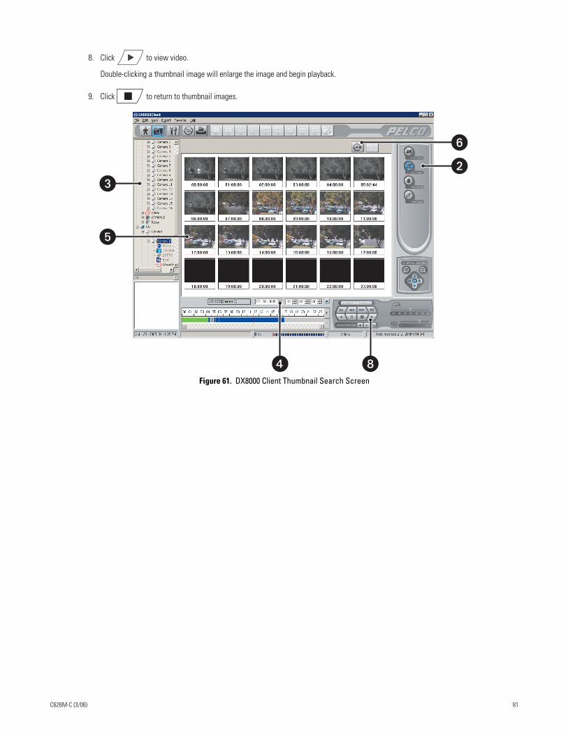
8. Click to view video.
Double-clicking a thumbnail image will enlarge the image and begin playback.
9. Click to return to thumbnail images.
Figure 61. DX8000 Client Thumbnail Search Screen
�
�
� �
�
�
C626M-C (3/06) 81
POS SEARCHThe DX8000 allows a user to search any 24-hour period of recorded POS video and data. To record ATM/POS video and data, the ATM/POS devices and DX8000 must first be connected and configured as follows:
• Physically connect the ATM/POS devices to the DX8000.
• Set up camera-to-ATM/POS device linking.
• Configure the DX8000 ATM/POS settings for each attached ATM/POS device.
• Start an ATM/POS transmittal and verify that the DX8000 is receiving the ATM/POS video and data.
For information about setting up the DX8000 for ATM/POS applications, refer to the following sections in the DX8000 Operations and Program-ming manual:
• Linking Relay Outputs to ATM/POS Events
• Linking Cameras to Record in Response to ATM/POS Events
• Linking Presets and Patterns to ATM/POS Events
• Setting Up ATM/POS Device Communication Ports
• Setting UP ATM/POS Device Properties
This section describes how to use the POS search feature and includes the following topics:
• Understanding the POS Search View on page 83
• Searching and Displaying POS Data by Device Name on page 86
• Searching by POS Transaction Number on page 88
• Searching for All Transactions with Exceptions on page 89
• Searching for Transactions that Satisfy Specific Exceptions on page 90
• Searching for Transactions by Line Item on page 91
• Searching for Transactions by Action Code on page 92
82 C626M-C (3/06)
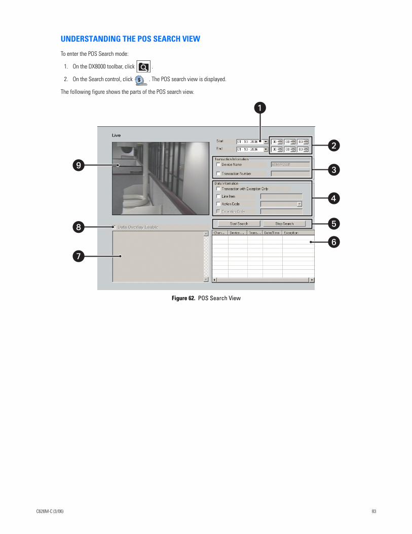
UNDERSTANDING THE POS SEARCH VIEW
To enter the POS Search mode:
1. On the DX8000 toolbar, click .
2. On the Search control, click . The POS search view is displayed.
The following figure shows the parts of the POS search view.
Figure 62. POS Search View
�
�
�
�
�
�
�
�
C626M-C (3/06) 83
The following table describes the parts of the POS search view.
Table W. Parts of the POS Search View
Item Part Description
Date Date range for which to search the video and data.
Time Time range based on a 24-hour time period for searching POS events.
Transaction Information
Allows POS search by transaction information options as follows:
• Device Name: The ATM/POS device linked to a specific camera. In this case, selecting a camera linked to an ATM/POS device automatically inserts the name of the ATM/POS device in the Device Name box.
• Transaction Number: A number assigned by the ATM/POS device that is printed on the sales are transaction receipt.
Data Information Allows POS search by data information options as follows:
• Transaction with Exception Only: Finds all transactions for which an exception is defined.
• Line Item: Allows you to search POS data by a specific transaction line item, based on the following guidelines:
– Line item entries are not case sensitive. Enter lower or uppercase characters. – Specify the asterisk (*) wildcard. – Search by a single word or multiple words appearing in a transaction line. – Enter the first few characters of the first word appearing in the transaction and the
wildcard. As an example, for a line item containing the entry “small orange juice,” enter sma*. The search returns all transactions that contain the word “small.”
– Enter the first few characters of the second word in a transaction and the wildcard. As an example, for a line item containing the entry “small orange juice,” enter: ora*. The search returns all transactions that contain the word “orange.”
– Search by abbreviation. An example, for a line item containing the entry “Soda 6-pk,” enter 6-pk. The search returns all transactions that contain the abbreviation “6-pk.”
• Action Code: A two-letter abbreviation designating a specific action code. For information about action codes, refer to the Setting Up ATM/POS Device Properties section in the Operations and Programming manual.
• Exception Code: A predefined transaction filter used to detect a specific data structure within the ATM/POS transaction data. For information about exceptions, refer to the Setting Up ATM/POS Exceptions section in the Operations and Programming manual.
Start and Stop Start: Initiates a search event.
Stop: Ends a search event.
84 C626M-C (3/06)
POS Search Table Lists the data discovered in response to the POS options selected for the transaction and data information.
• Channel Number: From 1–16.
• Device Name: By default, ATM/POS01 to ATM/POS16. The device name can be changed.
• Transaction Number: Number assigned by the ATM/POS device to the transaction data.
• Date/Time: Date and time transaction is recorded.
• Exception: Yes if an exception filter is active for the transaction data has an exception. No if the transaction does not have an exception filter.
The transaction and data information are based on the ATM/POS configuration settings derived from the following:
• Data format
• ATM/POS exceptions
• Exception action codes
For information about setting up ATM/POS transaction and data options, refer to the Setting Up ATM/POS Device Properties section in the Operations and Programming manual.
Data Window Area where recorded transaction data is displayed.
Data Overlay Box The function is not supported at this time.
Video Window Area where live and playback (recorded) video is viewed. Playback video is started at the date and time specified for the respective transaction data as shown in the POS Search table. The DX8000 playback controls are used to view playback video.
Table W. Parts of the POS Search View (Continued)
Item Part Description
C626M-C (3/06) 85
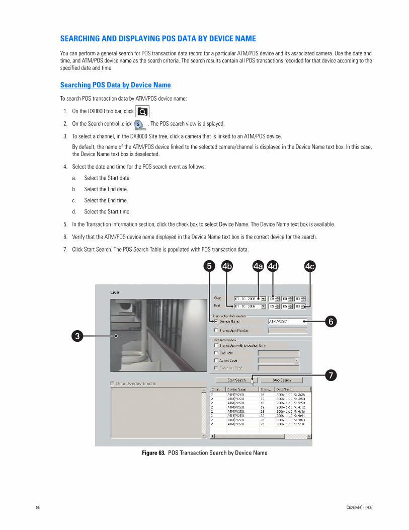
SEARCHING AND DISPLAYING POS DATA BY DEVICE NAME
You can perform a general search for POS transaction data record for a particular ATM/POS device and its associated camera. Use the date and time, and ATM/POS device name as the search criteria. The search results contain all POS transactions recorded for that device according to the specified date and time.
Searching POS Data by Device Name
To search POS transaction data by ATM/POS device name:
1. On the DX8000 toolbar, click .
2. On the Search control, click . The POS search view is displayed.
3. To select a channel, in the DX8000 Site tree, click a camera that is linked to an ATM/POS device.
By default, the name of the ATM/POS device linked to the selected camera/channel is displayed in the Device Name text box. In this case, the Device Name text box is deselected.
4. Select the date and time for the POS search event as follows:
a. Select the Start date.
b. Select the End date.
c. Select the End time.
d. Select the Start time.
5. In the Transaction Information section, click the check box to select Device Name. The Device Name text box is available.
6. Verify that the ATM/POS device name displayed in the Device Name text box is the correct device for the search.
7. Click Start Search. The POS Search Table is populated with POS transaction data.
Figure 63. POS Transaction Search by Device Name
��
4c4c� 4b 4a4a 4d
�
86 C626M-C (3/06)
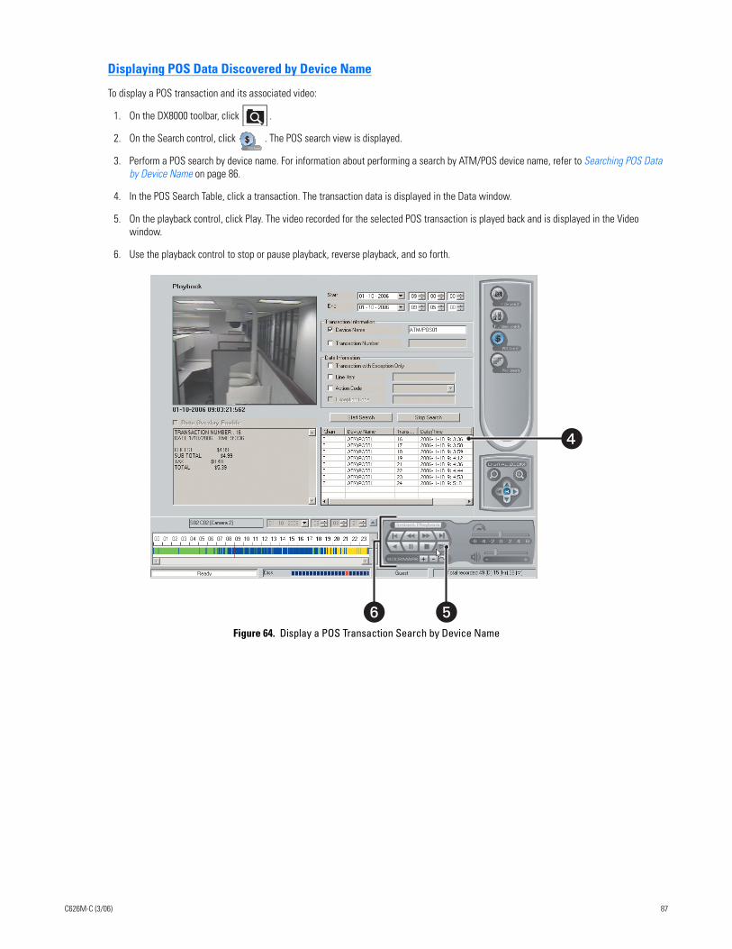
Displaying POS Data Discovered by Device Name
To display a POS transaction and its associated video:
1. On the DX8000 toolbar, click .
2. On the Search control, click . The POS search view is displayed.
3. Perform a POS search by device name. For information about performing a search by ATM/POS device name, refer to Searching POS Data by Device Name on page 86.
4. In the POS Search Table, click a transaction. The transaction data is displayed in the Data window.
5. On the playback control, click Play. The video recorded for the selected POS transaction is played back and is displayed in the Video window.
6. Use the playback control to stop or pause playback, reverse playback, and so forth.
Figure 64. Display a POS Transaction Search by Device Name
�
��
C626M-C (3/06) 87
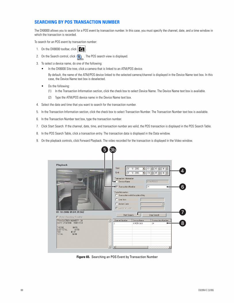
SEARCHING BY POS TRANSACTION NUMBER
The DX8000 allows you to search for a POS event by transaction number. In this case, you must specify the channel, date, and a time window in which the transaction is recorded.
To search for an POS event by transaction number:
1. On the DX8000 toolbar, click .
2. On the Search control, click . The POS search view is displayed.
3. To select a device name, do one of the following:
• In the DX8000 Site tree, click a camera that is linked to an ATM/POS device.
By default, the name of the ATM/POS device linked to the selected camera/channel is displayed in the Device Name text box. In this case, the Device Name text box is deselected.
• Do the following:(1) In the Transaction Information section, click the check box to select Device Name. The Device Name text box is available.
(2) Type the ATM/POS device name in the Device Name text box.
4. Select the date and time that you want to search for the transaction number.
5. In the Transaction Information section, click the check box to select Transaction Number. The Transaction Number text box is available.
6. In the Transaction Number text box, type the transaction number.
7. Click Start Search. If the channel, date, time, and transaction number are valid, the POS transaction is displayed in the POS Search Table.
8. In the POS Search Table, click a transaction entry. The transaction data is displayed in the Data window.
9. On the playback controls, click Forward Playback. The video recorded for the transaction is displayed in the Video window.
Figure 65. Searching an POS Event by Transaction Number
�
�
�
� 3b
�
88 C626M-C (3/06)
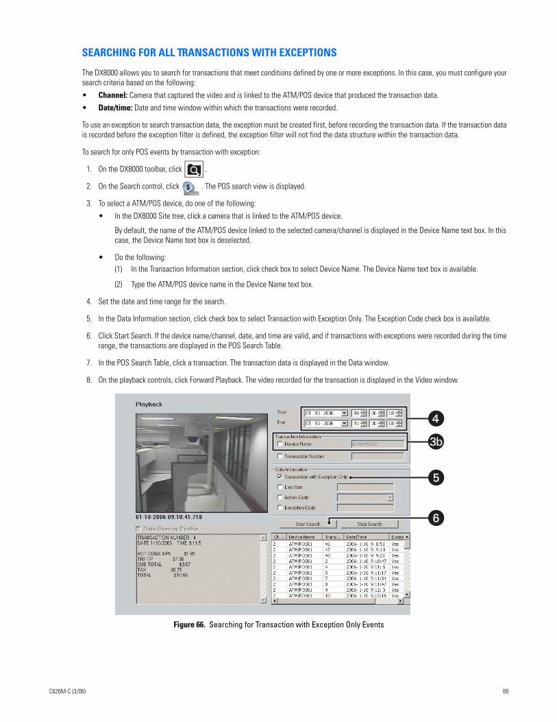
SEARCHING FOR ALL TRANSACTIONS WITH EXCEPTIONS
The DX8000 allows you to search for transactions that meet conditions defined by one or more exceptions. In this case, you must configure your search criteria based on the following:
• Channel: Camera that captured the video and is linked to the ATM/POS device that produced the transaction data.
• Date/time: Date and time window within which the transactions were recorded.
To use an exception to search transaction data, the exception must be created first, before recording the transaction data. If the transaction data is recorded before the exception filter is defined, the exception filter will not find the data structure within the transaction data.
To search for only POS events by transaction with exception:
1. On the DX8000 toolbar, click .
2. On the Search control, click . The POS search view is displayed.
3. To select a ATM/POS device, do one of the following:
• In the DX8000 Site tree, click a camera that is linked to the ATM/POS device.
By default, the name of the ATM/POS device linked to the selected camera/channel is displayed in the Device Name text box. In this case, the Device Name text box is deselected.
• Do the following:(1) In the Transaction Information section, click check box to select Device Name. The Device Name text box is available.
(2) Type the ATM/POS device name in the Device Name text box.
4. Set the date and time range for the search.
5. In the Data Information section, click check box to select Transaction with Exception Only. The Exception Code check box is available.
6. Click Start Search. If the device name/channel, date, and time are valid, and if transactions with exceptions were recorded during the time range, the transactions are displayed in the POS Search Table.
7. In the POS Search Table, click a transaction. The transaction data is displayed in the Data window.
8. On the playback controls, click Forward Playback. The video recorded for the transaction is displayed in the Video window.
Figure 66. Searching for Transaction with Exception Only Events
�
�
�
3b
C626M-C (3/06) 89
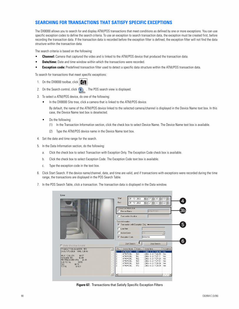
SEARCHING FOR TRANSACTIONS THAT SATISFY SPECIFIC EXCEPTIONS
The DX8000 allows you to search for and display ATM/POS transactions that meet conditions as defined by one or more exceptions. You can use specific exception codes to define the search criteria. To use an exception to search transaction data, the exception must be created first, before recording the transaction data. If the transaction data is recorded before the exception filter is defined, the exception filter will not find the data structure within the transaction data.
The search criteria is based on the following:
• Channel: Camera that captured the video and is linked to the ATM/POS device that produced the transaction data.
• Date/time: Date and time window within which the transactions were recorded.
• Exception code: Predefined transaction filter used to detect a specific data structure within the ATM/POS transaction data.
To search for transactions that meet specific exceptions:
1. On the DX8000 toolbar, click .
2. On the Search control, click . The POS search view is displayed.
3. To select a ATM/POS device, do one of the following:
• In the DX8000 Site tree, click a camera that is linked to the ATM/POS device.
By default, the name of the ATM/POS device linked to the selected camera/channel is displayed in the Device Name text box. In this case, the Device Name text box is deselected.
• Do the following:(1) In the Transaction Information section, click the check box to select Device Name. The Device Name text box is available.
(2) Type the ATM/POS device name in the Device Name text box.
4. Set the date and time range for the search.
5. In the Data Information section, do the following:
a. Click the check box to select Transaction with Exception Only. The Exception Code check box is available.
b. Click the check box to select Exception Code. The Exception Code text box is available.
c. Type the exception code in the text box.
6. Click Start Search. If the device name/channel, date, and time are valid, and if transactions with exceptions were recorded during the time range, the transactions are displayed in the POS Search Table.
7. In the POS Search Table, click a transaction. The transaction data is displayed in the Data window.
Figure 67. Transactions that Satisfy Specific Exception Filters
�
�
�
3b
90 C626M-C (3/06)
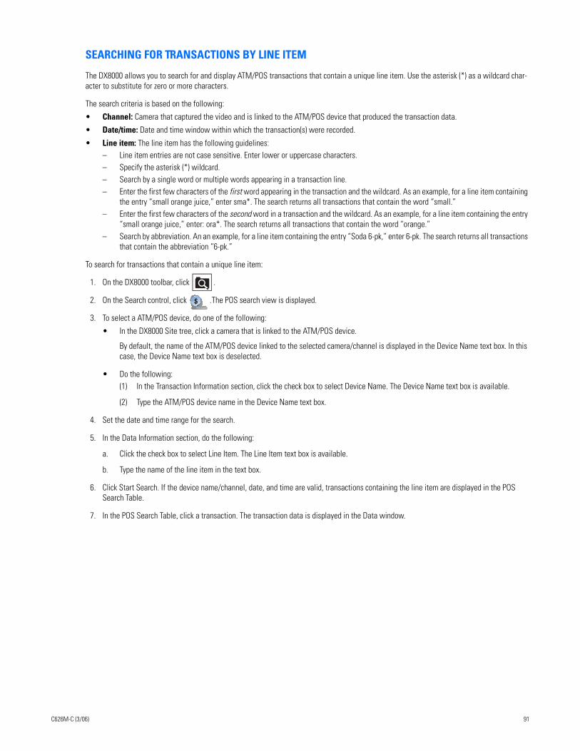
SEARCHING FOR TRANSACTIONS BY LINE ITEM
The DX8000 allows you to search for and display ATM/POS transactions that contain a unique line item. Use the asterisk (*) as a wildcard char-acter to substitute for zero or more characters.
The search criteria is based on the following:
• Channel: Camera that captured the video and is linked to the ATM/POS device that produced the transaction data.
• Date/time: Date and time window within which the transaction(s) were recorded.
• Line item: The line item has the following guidelines:– Line item entries are not case sensitive. Enter lower or uppercase characters. – Specify the asterisk (*) wildcard. – Search by a single word or multiple words appearing in a transaction line. – Enter the first few characters of the first word appearing in the transaction and the wildcard. As an example, for a line item containing
the entry “small orange juice,” enter sma*. The search returns all transactions that contain the word “small.”– Enter the first few characters of the second word in a transaction and the wildcard. As an example, for a line item containing the entry
“small orange juice,” enter: ora*. The search returns all transactions that contain the word “orange.”– Search by abbreviation. An an example, for a line item containing the entry “Soda 6-pk,” enter 6-pk. The search returns all transactions
that contain the abbreviation “6-pk.”
To search for transactions that contain a unique line item:
1. On the DX8000 toolbar, click .
2. On the Search control, click .The POS search view is displayed.
3. To select a ATM/POS device, do one of the following:
• In the DX8000 Site tree, click a camera that is linked to the ATM/POS device.
By default, the name of the ATM/POS device linked to the selected camera/channel is displayed in the Device Name text box. In this case, the Device Name text box is deselected.
• Do the following:(1) In the Transaction Information section, click the check box to select Device Name. The Device Name text box is available.
(2) Type the ATM/POS device name in the Device Name text box.
4. Set the date and time range for the search.
5. In the Data Information section, do the following:
a. Click the check box to select Line Item. The Line Item text box is available.
b. Type the name of the line item in the text box.
6. Click Start Search. If the device name/channel, date, and time are valid, transactions containing the line item are displayed in the POS Search Table.
7. In the POS Search Table, click a transaction. The transaction data is displayed in the Data window.
C626M-C (3/06) 91

Figure 68. Transactions that Contain a Unique Line Item
SEARCHING FOR TRANSACTIONS BY ACTION CODE
The DX8000 allows you to search for and display ATM/POS transactions by action code. To use an action code to search transaction data, the action code must be created first, before recording the transaction data. If the transaction data is recorded before the action code is defined, the action code will not find the data structure within the transaction data.
The search criteria is based on the following:
• Channel: Camera that captured the video and is linked to the ATM/POS device that produced the transaction data.
• Date/time: Date and time window within which the transaction(s) were recorded.
• Action code: Special two-character filter that defines a specific transaction event.
To search for transactions by action code:
1. On the DX8000 toolbar, click .
2. On the Search control, click . The POS search view is displayed.
3. To select a ATM/POS device, do one of the following:
a. In the DX8000 Site tree, click a camera that is linked to the ATM/POS device.
By default, the name of the ATM/POS device linked to the selected camera/channel is displayed in the Device Name text box. In this case, the Device Name text box is deselected.
or
b. Do the following:
(1) In the Transaction Information section, click the check box to select Device Name. The Device Name text box is available.
(2) Type the ATM/POS device name in the Device Name text box.
4. Set the date and time range for the search.
5. In the Data Information section, do the following:
a. Click the check box to select Action Code. The Action Code drop-down box is available.
b. In the Action Code drop-down box, select an action code. For information about action codes, refer to the Using Action Codes section in the Operations and Programming manual.
�
�
�
3b
5a5a
5b5b
92 C626M-C (3/06)
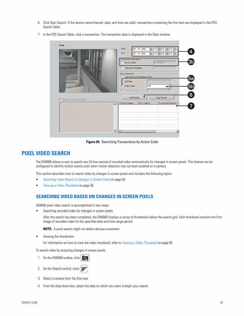
6. Click Start Search. If the device name/channel, date, and time are valid, transactions containing the line item are displayed in the POS Search Table.
7. In the POS Search Table, click a transaction. The transaction data is displayed in the Data window.
Figure 69. Searching Transactions by Action Code
PIXEL VIDEO SEARCHThe DX8000 allows a user to search any 24-hour period of recorded video automatically for changes in screen pixels. This feature can be configured to identify motion events even when motion detection has not been enabled on a camera.
This section describes how to search video by changes in screen pixels and includes the following topics:
• Searching Video Based on Changes in Screen Pixels on page 93
• Viewing a Video Thumbnail on page 95
SEARCHING VIDEO BASED ON CHANGES IN SCREEN PIXELS
DX8000 pixel video search is accomplished in two steps:
• Searching recorded video for changes in screen pixels.
After the search has been completed, the DX8000 displays a series of thumbnails below the search grid. Each thumbnail contains the first image of recorded video for the specified date and time range period.
NOTE: A pixel search might not detect obvious movement.
• Viewing the thumbnails.
For information on how to view the video thumbnail, refer to Viewing a Video Thumbnail on page 95.
To search video by analyzing changes in screen pixels:
1. On the DX8000 toolbar, click .
2. On the Search control, click .
3. Select a camera from the Site tree.
4. From the drop-down box, select the date on which you want to begin your search.
�
�
�
3b
5a5a
5b5b
C626M-C (3/06) 93
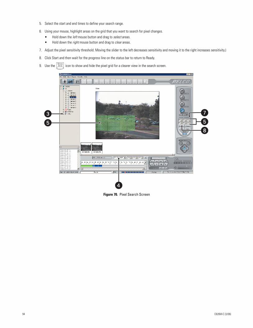
5. Select the start and end times to define your search range.
6. Using your mouse, highlight areas on the grid that you want to search for pixel changes.
• Hold down the left mouse button and drag to select areas.• Hold down the right mouse button and drag to clear areas.
7. Adjust the pixel sensitivity threshold. Moving the slider to the left decreases sensitivity and moving it to the right increases sensitivity.)
8. Click Start and then wait for the progress line on the status bar to return to Ready.
9. Use the icon to show and hide the pixel grid for a clearer view in the search screen.
Figure 70. Pixel Search Screen
��
�
���
94 C626M-C (3/06)
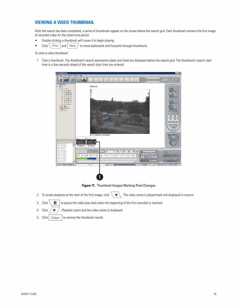
VIEWING A VIDEO THUMBNAIL
After the search has been completed, a series of thumbnails appear on the screen below the search grid. Each thumbnail contains the first image of recorded video for the listed time period.
• Double-clicking a thumbnail will cause it to begin playing.
• Click and to move backwards and forwards through thumbnails.
To view a video thumbnail:
1. Click a thumbnail. The thumbnail’s search parameters (date and time) are displayed below the search grid. The thumbnail’s search start time is a few seconds ahead of the search start time you entered.
Figure 71. Thumbnail Images Marking Pixel Changes
2. To locate playback at the start of the first image, click . The video scene is played back and displayed in reverse.
3. Click to pause the video play back when the beginning of the first recorded is reached.
4. Click . Playback starts and the video scene is displayed.
5. Click to remove the thumbnail results.
C626M-C (3/06) 95
WORKING WITH SPECIAL VIEW AND SEARCH METHODSThe DX8000 allows you to do the following:
• View video in the deinterlaced mode.
• View live and playback video simultaneously.
• View and search backed-up video.
This section describes how to use special view and search methods and includes the following topics:
• Viewing Video in the Deinterlaced Mode on page 96
• Viewing Live and Playback Video Simultaneously on page 96
• Viewing and Searching Backed-Up Video on page 149
VIEWING VIDEO IN THE DEINTERLACED MODE
Images recorded at 4CIF at a low frame rate per second might move or tear. In this case, you can use the View menu’s Deinterlaced Image option to enhance the displayed image. In the deinterlaced mode, the DX8000 converts the recorded image and displays it at 2CIF resolution. The process removes one of the 4CIF interlaced fields (even or odd) from the 4CIF recorded image to arrive at 2CIF resolution for the displayed image. The original image is retained at the recorded 4CIF resolution.
For exported images, the DX8000 provides a global option for enabling a deinterlacing filter. In this case, the selected channel’s image is exported at 2CIF resolution. This setting is effective for all channels and cannot be set for individual channels. For more information about enabling the denaturalizing filter, refer to Enabling the Deinterlacing Filter on page 99.
To view video using the deinterlaced option:
1. Click to start video playback.
2. On the menu bar, click View > Display deinterlaced image.
VIEWING LIVE AND PLAYBACK VIDEO SIMULTANEOUSLY
The DX8000 allows simultaneous viewing of live and playback video from a single camera source.
To view live and playback video from the same camera:
1. On the DX8000 toolbar, click .
2. Drag a camera from the Site tree to a view panel.
3. Click to begin playback.
4. Drag the same camera from the Site tree onto a different view panel while video is playing.
96 C626M-C (3/06)
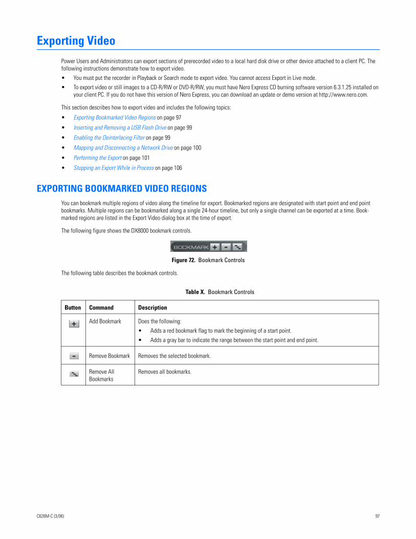
Exporting VideoPower Users and Administrators can export sections of prerecorded video to a local hard disk drive or other device attached to a client PC. The following instructions demonstrate how to export video.
• You must put the recorder in Playback or Search mode to export video. You cannot access Export in Live mode.
• To export video or still images to a CD-R/RW or DVD-R/RW, you must have Nero Express CD burning software version 6.3.1.25 installed on your client PC. If you do not have this version of Nero Express, you can download an update or demo version at http://www.nero.com.
This section describes how to export video and includes the following topics:
• Exporting Bookmarked Video Regions on page 97
• Inserting and Removing a USB Flash Drive on page 99
• Enabling the Deinterlacing Filter on page 99
• Mapping and Disconnecting a Network Drive on page 100
• Performing the Export on page 101
• Stopping an Export While in Process on page 106
EXPORTING BOOKMARKED VIDEO REGIONSYou can bookmark multiple regions of video along the timeline for export. Bookmarked regions are designated with start point and end point bookmarks. Multiple regions can be bookmarked along a single 24-hour timeline, but only a single channel can be exported at a time. Book-marked regions are listed in the Export Video dialog box at the time of export.
The following figure shows the DX8000 bookmark controls.
Figure 72. Bookmark Controls
The following table describes the bookmark controls.
Table X. Bookmark Controls
Button Command Description
Add Bookmark Does the following:
• Adds a red bookmark flag to mark the beginning of a start point.
• Adds a gray bar to indicate the range between the start point and end point.
Remove Bookmark Removes the selected bookmark.
Remove All Bookmarks
Removes all bookmarks.
C626M-C (3/06) 97
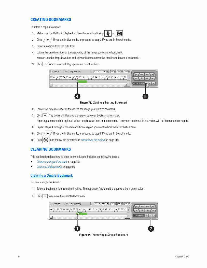
CREATING BOOKMARKS
To select a region to export:
1. Make sure the DVR is in Playback or Search mode by clicking or .
2. Click if you are in Live mode, or proceed to step 3 if you are in Search mode.
3. Select a camera from the Site tree.
4. Locate the timeline slider at the beginning of the range you want to bookmark.
You can use the drop-down box and spinner buttons above the timeline to locate a bookmark.
5. Click . A red bookmark flag appears on the timeline.
Figure 73. Setting a Starting Bookmark
6. Locate the timeline slider at the end of the range you want to bookmark.
7. Click . The bookmark flag and the region between bookmarks turn gray.
Exporting a bookmarked region of video requires start and end bookmarks. If only one bookmark is set, video will not be marked for export.
8. Repeat steps 4 through 7 for each additional region you want to bookmark for that camera.
9. Click if you are in Live mode, or proceed to step 8 if you are in Search mode.
10. Click and follow the directions in Performing the Export on page 101.
CLEARING BOOKMARKS
This section describes how to clear bookmarks and includes the following topics:
• Clearing a Single Bookmark on page 98
• Clearing All Bookmarks on page 99
Clearing a Single Bookmark
To clear a single bookmark:
1. Select a bookmark flag from the timeline. The bookmark flag should change to a light green color.
2. Click to remove the selected bookmark.
Figure 74. Removing a Single Bookmark
� �
�
98 C626M-C (3/06)
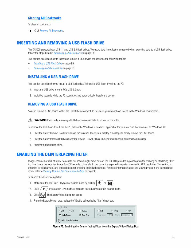
Clearing All Bookmarks
To clear all bookmarks:
INSERTING AND REMOVING A USB FLASH DRIVEThe DX8000 supports both USB 1.1 and USB 2.0 flash drives. To ensure data is not lost or corrupted when exporting data to a USB flash drive, follow the steps listed in Removing a USB Flash Drive on page 99.
This section describes how to insert and remove a USB device and includes the following topics:
• Installing a USB Flash Drive on page 99
• Removing a USB Flash Drive on page 99
INSTALLING A USB FLASH DRIVE
This section describes how to install a USB flash drive. To install a USB flash drive into the PC:
1. Insert the USB drive into the PC’s USB 2.0 port.
2. Wait five seconds while the PC recognizes and automatically installs the device.
REMOVING A USB FLASH DRIVE
You can remove a USB device within the DX8000 environment. In this case, you do not have to exit to the Windows environment.
To remove the USB flash drive from the PC, follow the Windows instructions applicable for your machine. For example, for Windows XP:
1. Click the Safely Remove Hardware icon in the task bar. The system display a message to safely remove the USB device.
2. Click the Safely remove USB Mass Storage Device - Drive(G:) box. The system displays a confirmation message.
3. Remove the USB flash drive.
ENABLING THE DEINTERLACING FILTERImages recorded at 4CIF at a low frame rate per second might move or tear. The DX8000 provides a global option for enabling deinterlacing filter-ing to enhance the exported image for 4CIF recorded channels. In this case, the exported image is converted to 2CIF resolution. This setting is effective for all channels, and cannot be set for enabling individual channels. For more information about the viewing video in the deinterlaced mode, refer to Viewing Video in the Deinterlaced Mode on page 96.
To enable the deinterlacing filter:
1. Make sure the DVR is in Playback or Search mode by clicking or .
2. Click if you are in Live mode, or proceed to step 3 if you are in Search mode.
3. Click . The Export Video dialog box opens.
4. From the Export Format area, select the “Enable deinterlacing filter” check box..
Figure 75. Enabling the Deinterfacing Filter from the Export Video Dialog Box
Click Remove All Bookmarks.
WARNING:Improperly removing a USB drive can cause data to be lost or corrupted.
C626M-C (3/06) 99
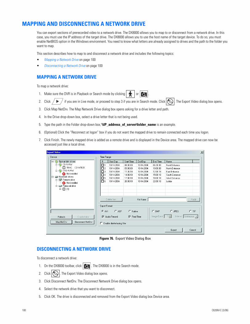
MAPPING AND DISCONNECTING A NETWORK DRIVEYou can export sections of prerecorded video to a network drive. The DX8000 allows you to map to or disconnect from a network drive. In this case, you must use the IP address of the target drive. The DX8000 allows you to use the host name of the target device. To do so, you must enable NetBIOS option in the Windows environment. You need to know what letters are already assigned to drives and the path to the folder you want to map.
This section describes how to map to and disconnect a network drive and includes the following topics:
• Mapping a Network Drive on page 100
• Disconnecting a Network Drive on page 100
MAPPING A NETWORK DRIVE
To map a network drive:
1. Make sure the DVR is in Playback or Search mode by clicking or .
2. Click if you are in Live mode, or proceed to step 3 if you are in Search mode. Click . The Export Video dialog box opens.
3. Click Map NetDrv. The Map Network Drive dialog box opens asking for a drive letter and path.
4. In the Drive drop-down box, select a drive letter that is not being used.
5. Type the path in the Folder drop-down box; \\IP_address_of_server\folder_name is an example.
6. (Optional) Click the “Reconnect at logon” box if you do not want the mapped drive to remain connected each time you logon.
7. Click Finish. The newly mapped drive is added as a remote drive and is displayed in the Device area. The mapped drive can now be accessed just like a local drive.
Figure 76. Export Video Dialog Box
DISCONNECTING A NETWORK DRIVE
To disconnect a network drive:
1. On the DX8000 toolbar, click . The DX8000 is in the Search mode.
2. Click . The Export Video dialog box opens.
3. Click Disconnect NetDrv. The Disconnect Network Drive dialog box opens.
4. Select the network drive that you want to disconnect.
5. Click OK. The drive is disconnected and removed from the Export Video dialog box Device area.
100 C626M-C (3/06)
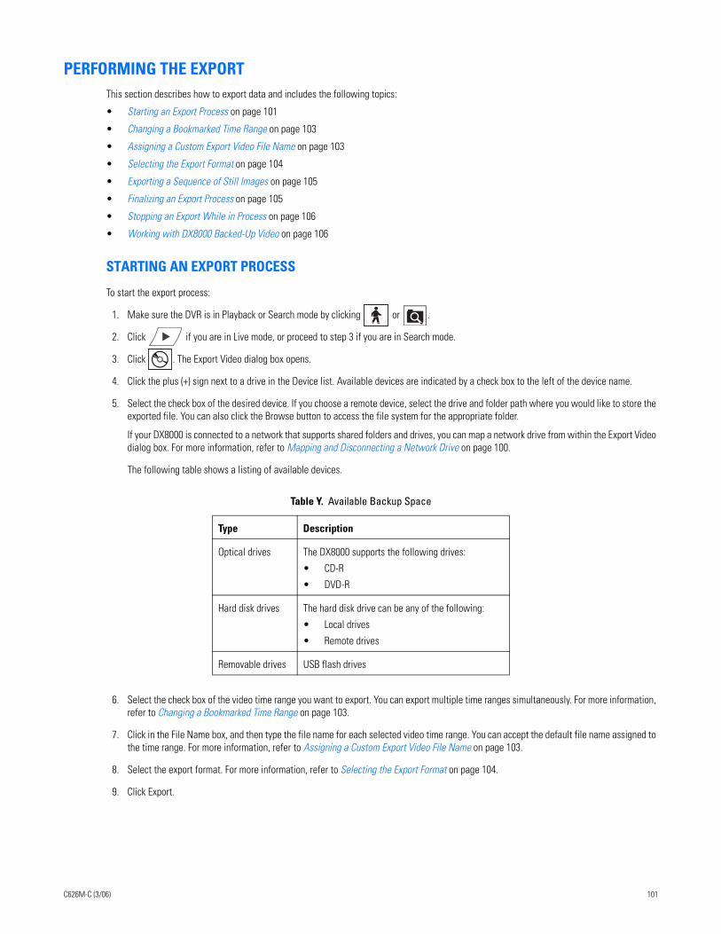
PERFORMING THE EXPORTThis section describes how to export data and includes the following topics:
• Starting an Export Process on page 101
• Changing a Bookmarked Time Range on page 103
• Assigning a Custom Export Video File Name on page 103
• Selecting the Export Format on page 104
• Exporting a Sequence of Still Images on page 105
• Finalizing an Export Process on page 105
• Stopping an Export While in Process on page 106
• Working with DX8000 Backed-Up Video on page 106
STARTING AN EXPORT PROCESS
To start the export process:
1. Make sure the DVR is in Playback or Search mode by clicking or .
2. Click if you are in Live mode, or proceed to step 3 if you are in Search mode.
3. Click . The Export Video dialog box opens.
4. Click the plus (+) sign next to a drive in the Device list. Available devices are indicated by a check box to the left of the device name.
5. Select the check box of the desired device. If you choose a remote device, select the drive and folder path where you would like to store the exported file. You can also click the Browse button to access the file system for the appropriate folder.
If your DX8000 is connected to a network that supports shared folders and drives, you can map a network drive from within the Export Video dialog box. For more information, refer to Mapping and Disconnecting a Network Drive on page 100.
The following table shows a listing of available devices.
6. Select the check box of the video time range you want to export. You can export multiple time ranges simultaneously. For more information, refer to Changing a Bookmarked Time Range on page 103.
7. Click in the File Name box, and then type the file name for each selected video time range. You can accept the default file name assigned to the time range. For more information, refer to Assigning a Custom Export Video File Name on page 103.
8. Select the export format. For more information, refer to Selecting the Export Format on page 104.
9. Click Export.
Table Y. Available Backup Space
Type Description
Optical drives The DX8000 supports the following drives:
• CD-R
• DVD-R
Hard disk drives The hard disk drive can be any of the following:
• Local drives
• Remote drives
Removable drives USB flash drives
C626M-C (3/06) 101
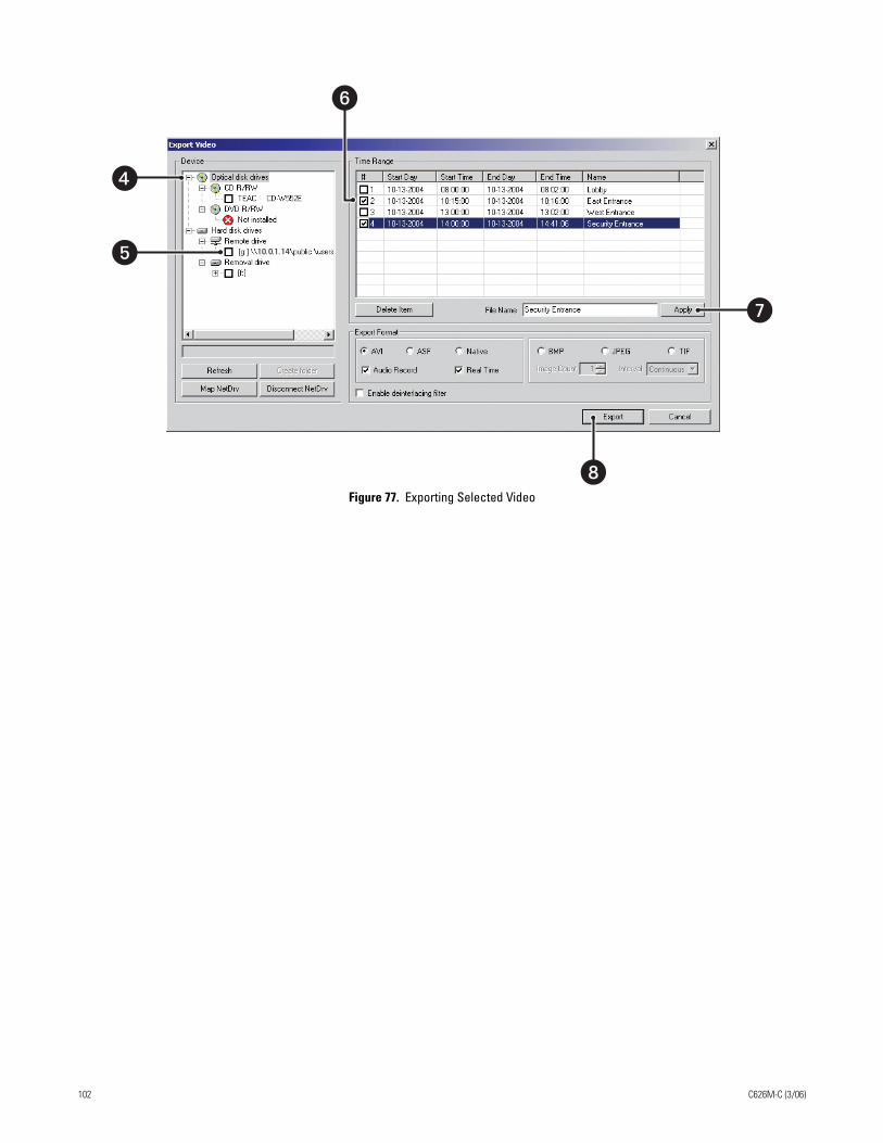
Figure 77. Exporting Selected Video
10.0.1.14
�
�
�
�
�
102 C626M-C (3/06)
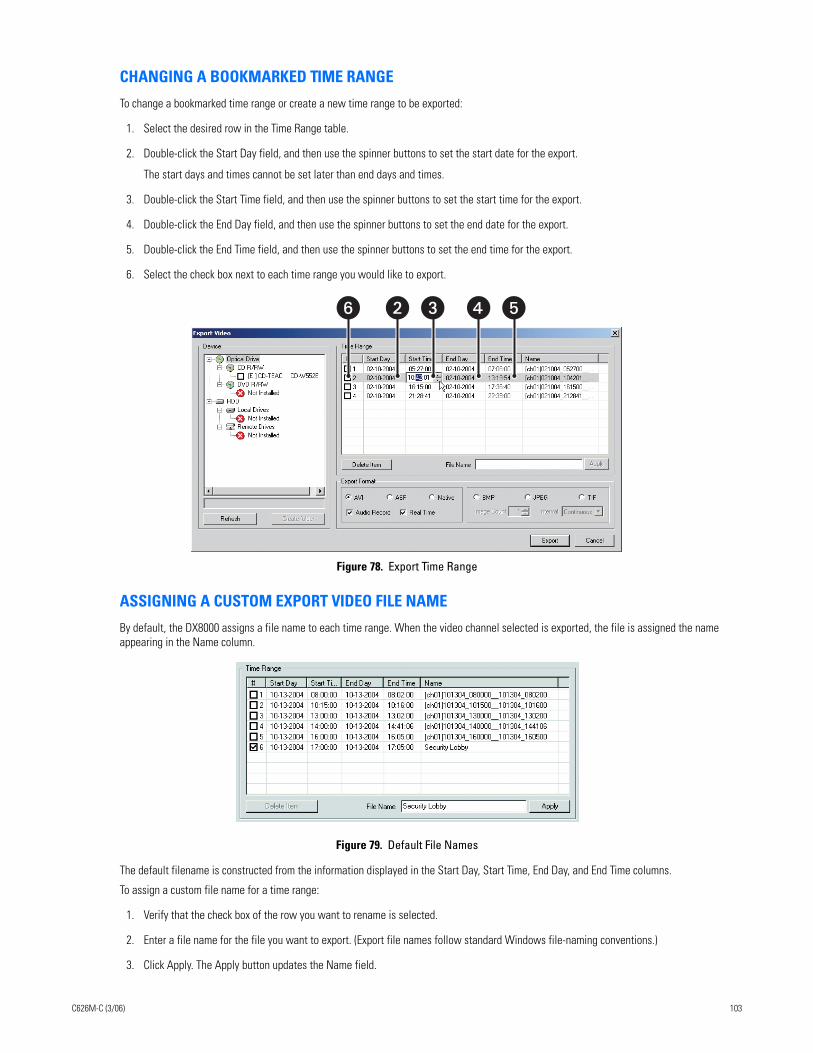
CHANGING A BOOKMARKED TIME RANGE
To change a bookmarked time range or create a new time range to be exported:
1. Select the desired row in the Time Range table.
2. Double-click the Start Day field, and then use the spinner buttons to set the start date for the export.
The start days and times cannot be set later than end days and times.
3. Double-click the Start Time field, and then use the spinner buttons to set the start time for the export.
4. Double-click the End Day field, and then use the spinner buttons to set the end date for the export.
5. Double-click the End Time field, and then use the spinner buttons to set the end time for the export.
6. Select the check box next to each time range you would like to export.
Figure 78. Export Time Range
ASSIGNING A CUSTOM EXPORT VIDEO FILE NAME
By default, the DX8000 assigns a file name to each time range. When the video channel selected is exported, the file is assigned the name appearing in the Name column.
Figure 79. Default File Names
The default filename is constructed from the information displayed in the Start Day, Start Time, End Day, and End Time columns.
To assign a custom file name for a time range:
1. Verify that the check box of the row you want to rename is selected.
2. Enter a file name for the file you want to export. (Export file names follow standard Windows file-naming conventions.)
3. Click Apply. The Apply button updates the Name field.
�� � � �
C626M-C (3/06) 103
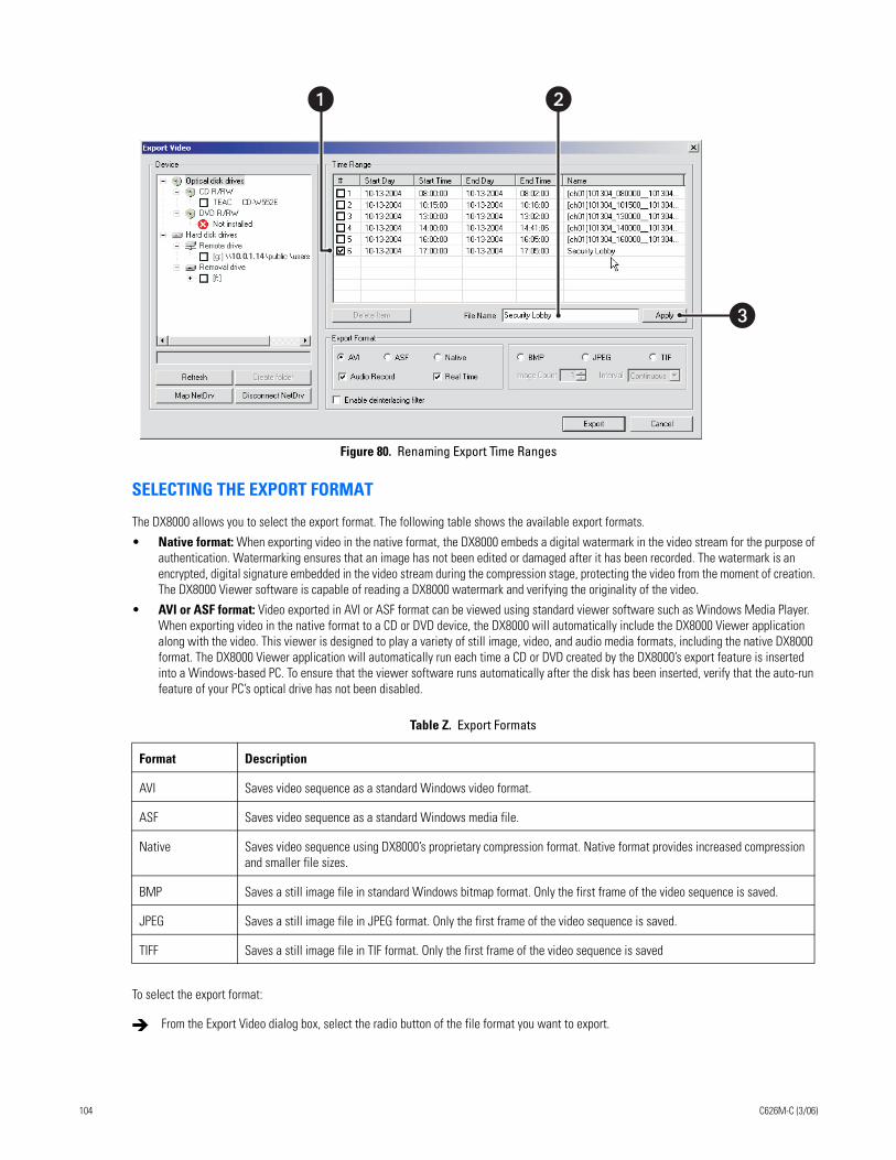
Figure 80. Renaming Export Time Ranges
SELECTING THE EXPORT FORMAT
The DX8000 allows you to select the export format. The following table shows the available export formats.
• Native format: When exporting video in the native format, the DX8000 embeds a digital watermark in the video stream for the purpose of authentication. Watermarking ensures that an image has not been edited or damaged after it has been recorded. The watermark is an encrypted, digital signature embedded in the video stream during the compression stage, protecting the video from the moment of creation. The DX8000 Viewer software is capable of reading a DX8000 watermark and verifying the originality of the video.
• AVI or ASF format: Video exported in AVI or ASF format can be viewed using standard viewer software such as Windows Media Player. When exporting video in the native format to a CD or DVD device, the DX8000 will automatically include the DX8000 Viewer application along with the video. This viewer is designed to play a variety of still image, video, and audio media formats, including the native DX8000 format. The DX8000 Viewer application will automatically run each time a CD or DVD created by the DX8000’s export feature is inserted into a Windows-based PC. To ensure that the viewer software runs automatically after the disk has been inserted, verify that the auto-run feature of your PC’s optical drive has not been disabled.
To select the export format:
Table Z. Export Formats
Format Description
AVI Saves video sequence as a standard Windows video format.
ASF Saves video sequence as a standard Windows media file.
Native Saves video sequence using DX8000’s proprietary compression format. Native format provides increased compression and smaller file sizes.
BMP Saves a still image file in standard Windows bitmap format. Only the first frame of the video sequence is saved.
JPEG Saves a still image file in JPEG format. Only the first frame of the video sequence is saved.
TIFF Saves a still image file in TIF format. Only the first frame of the video sequence is saved
From the Export Video dialog box, select the radio button of the file format you want to export.
10.0.1.14
�
�
104 C626M-C (3/06)
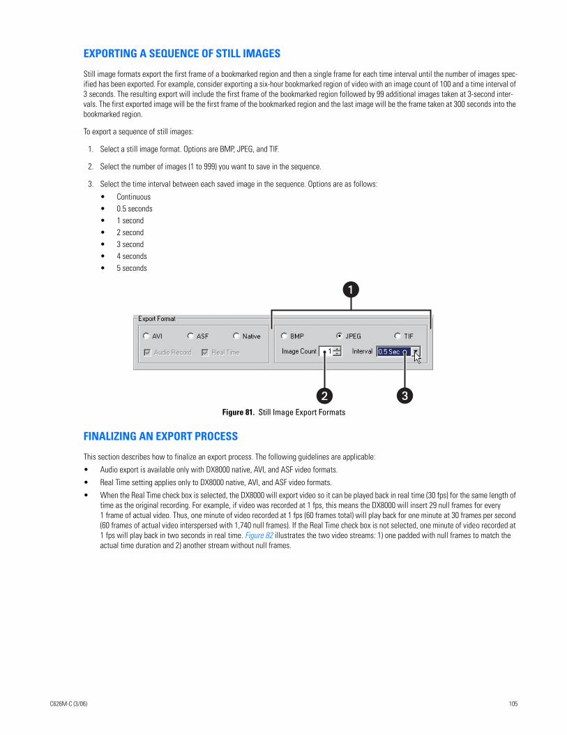
EXPORTING A SEQUENCE OF STILL IMAGES
Still image formats export the first frame of a bookmarked region and then a single frame for each time interval until the number of images spec-ified has been exported. For example, consider exporting a six-hour bookmarked region of video with an image count of 100 and a time interval of 3 seconds. The resulting export will include the first frame of the bookmarked region followed by 99 additional images taken at 3-second inter-vals. The first exported image will be the first frame of the bookmarked region and the last image will be the frame taken at 300 seconds into the bookmarked region.
To export a sequence of still images:
1. Select a still image format. Options are BMP, JPEG, and TIF.
2. Select the number of images (1 to 999) you want to save in the sequence.
3. Select the time interval between each saved image in the sequence. Options are as follows:
• Continuous• 0.5 seconds• 1 second• 2 second• 3 second• 4 seconds• 5 seconds
Figure 81. Still Image Export Formats
FINALIZING AN EXPORT PROCESS
This section describes how to finalize an export process. The following guidelines are applicable:
• Audio export is available only with DX8000 native, AVI, and ASF video formats.
• Real Time setting applies only to DX8000 native, AVI, and ASF video formats.
• When the Real Time check box is selected, the DX8000 will export video so it can be played back in real time (30 fps) for the same length of time as the original recording. For example, if video was recorded at 1 fps, this means the DX8000 will insert 29 null frames for every 1 frame of actual video. Thus, one minute of video recorded at 1 fps (60 frames total) will play back for one minute at 30 frames per second (60 frames of actual video interspersed with 1,740 null frames). If the Real Time check box is not selected, one minute of video recorded at 1 fps will play back in two seconds in real time. Figure 82 illustrates the two video streams: 1) one padded with null frames to match the actual time duration and 2) another stream without null frames.
� �
C626M-C (3/06) 105
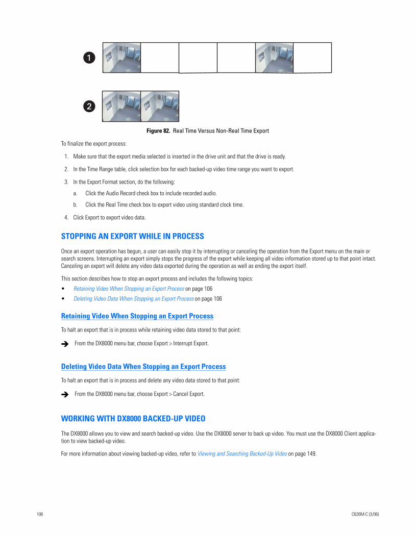
Figure 82. Real Time Versus Non-Real Time Export
To finalize the export process:
1. Make sure that the export media selected is inserted in the drive unit and that the drive is ready.
2. In the Time Range table, click selection box for each backed-up video time range you want to export.
3. In the Export Format section, do the following:
a. Click the Audio Record check box to include recorded audio.
b. Click the Real Time check box to export video using standard clock time.
4. Click Export to export video data.
STOPPING AN EXPORT WHILE IN PROCESS
Once an export operation has begun, a user can easily stop it by interrupting or canceling the operation from the Export menu on the main or search screens. Interrupting an export simply stops the progress of the export while keeping all video information stored up to that point intact. Canceling an export will delete any video data exported during the operation as well as ending the export itself.
This section describes how to stop an export process and includes the following topics:
• Retaining Video When Stopping an Export Process on page 106
• Deleting Video Data When Stopping an Export Process on page 106
Retaining Video When Stopping an Export Process
To halt an export that is in process while retaining video data stored to that point:
Deleting Video Data When Stopping an Export Process
To halt an export that is in process and delete any video data stored to that point:
WORKING WITH DX8000 BACKED-UP VIDEO
The DX8000 allows you to view and search backed-up video. Use the DX8000 server to back up video. You must use the DX8000 Client applica-tion to view backed-up video.
For more information about viewing backed-up video, refer to Viewing and Searching Backed-Up Video on page 149.
From the DX8000 menu bar, choose Export > Interrupt Export.
From the DX8000 menu bar, choose Export > Cancel Export.
�
106 C626M-C (3/06)
Printing ImagesThe printing feature of the DX8000 produces a hard copy of the current on-screen image. A Windows-compatible printer must be installed to take advantage of the DX8000’s print feature. For information on installing a printer, refer to the installation manual that came with your unit.
The DVR must be placed in Playback or Search mode to use the print feature. Playback is paused once the print button is pressed.
To print an image displayed in a pane:
1. Click or .
2. Locate the video image you want to print. For more information on locating video, refer to Working in Playback Mode on page 67 and Working in Search Mode on page 76.
3. Click .
4. Click to freeze the image for printing.
5. Click .
6. Click OK.
PRINTING IMAGES IN THE DEINTERLACED MODEIf you are printing images recorded at 4CIF at a low frame rate per second, the viewed image might move or tear. The View menu’s Deinterlaced Image option is used to enhance the image for printing.
To print an image using the deinterlaced option:
1. Click or .
2. Locate the video image you want to print. Refer to Working in Playback Mode on page 67 and Working in Search Mode on page 76 for information on locating video.
3. Click .
4. Click to freeze the image for printing.
5. Click to print the image to a designated printer.
C626M-C (3/06) 107
Setting Up the DX8000Only a single user with Administrator or Power User access is allowed to access a DX8000’s Setup mode box at one time. When connected to a network supporting multiple DVRs and/or clients, users with Administrator access override and block Power Users. If two users with the same access level attempt to enter Setup mode simultaneously, the DX8000 will allow access to setup features on a first-come, first-served basis. Unavailable setup options will be grayed-out.
This section describes the Setup Mode and includes the following topics:
• Accessing the Setup Mode on page 108
• Understanding the Setup Dialog Box on page 109
• Camera Setup on page 111
• Link Setup on page 117
• Schedule Setup on page 128
• Setting Up Network Properties on page 149
• Data Backup Setup on page 149
• User Setup on page 151
• Site Setup on page 157
• System Setup on page 158
• External Monitor Setup on page 163
• Emergency Notification Setup on page 163
• Emergency E-Mail Notification Setup on page 166
ACCESSING THE SETUP MODEThe Setup Mode is accessed from the DX8000 toolbar by clicking the Setup icon. When clicked, the Setup icon opens the Setup dialog box in the DX8000 view panel. The major configuration categories are displayed on individual tabbed pages. Each configuration page contains all of the options and parameters for the respective function, that allow you to customize how the DX8000 operates for your particular application. Access a setup page by clicking its icon that is displayed on the right side of the view panel.
The Setup dialog box allows Administrators and Power Users access to the DX8000’s setup functions. However, only Administrators can define user names and passwords for new users.
To access the Setup Mode:
On the DX8000 toolbar, click Setup.
The Setup dialog box opens to the default Camera page.
108 C626M-C (3/06)
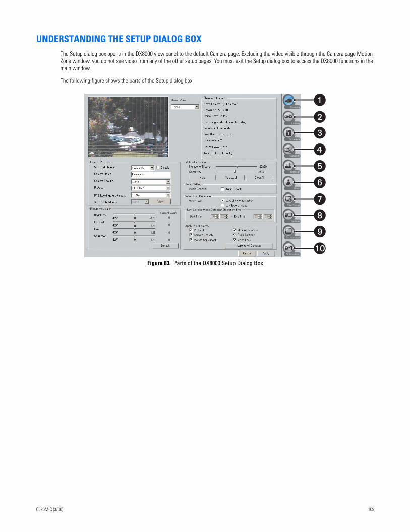
UNDERSTANDING THE SETUP DIALOG BOXThe Setup dialog box opens in the DX8000 view panel to the default Camera page. Excluding the video visible through the Camera page Motion Zone window, you do not see video from any of the other setup pages. You must exit the Setup dialog box to access the DX8000 functions in the main window.
The following figure shows the parts of the Setup dialog box.
Figure 83. Parts of the DX8000 Setup Dialog Box
�
�
�
�
�
�
�
�
�
C626M-C (3/06) 109
The following table describes the parts of the Setup dialog box.
Table AA. Parts of the DX8000 Setup Dialog Box
Item Button Part Description
Camera Click the Camera icon to configure cameras. Available options are PTZ functions, motion detection, picture adjustment, audio, and video loss detection settings.
Linking Click the Linking icon to configure relays and alarms, associate relays and alarms with cameras, link relays to alarms, and link cameras to other cameras.
Schedule Click the Schedule icon to build custom recording schedules, set image resolution, frame rate, and image quality, and configure relay settings.
Network Click the Network icon to set up the network configuration and communication port settings.
Backup Click the Backup icon to configure and perform backups.
User Click the User icon to add, delete, or change user accounts.
Site Click the Site Setup icon to add, delete, and configure additional DX8000 Series DVRs.
System Click the System icon to set up additional system options.
Ext. Monitor Click the Ext. Monitor icon to configure an additional display monitor. (This icon appears only if the optional display card has been installed.)
Notification Click the Notification icon to configure emergency agent and e-mail notification options.
110 C626M-C (3/06)
CAMERA SETUPDepending on your system’s current configuration, up to 16 video cameras can be connected to a single DX8000. The following section illustrates basic camera configuration. You must be logged in as an Administrator or Power User to configure cameras.
This section describes how to setup the camera and includes the following topics:
• Basic Camera Setup on page 111
• Motion Detection Setup on page 113
• Audio Setup on page 114
• Applying Settings to all Cameras on page 117
BASIC CAMERA SETUP
To set up camera picture and pan, tilt, and zoom (PTZ) options:
1. Do one of the following:
• On the DX8000 toolbar, click . The Setup dialog opens to the Camera page.
• If the Setup dialog box is already open, click . The Camera page is displayed.
2. In the Camera Properties section, do the following:
a. Select a camera from the drop-down box. (You can also select a camera from the Site tree by clicking on it.)
b. Select the Disable check box if you want to disable the camera.
c. Enter an optional new name for the camera. Camera names can be up to 32 characters long and can include spaces and special characters.
d. Set camera security level. Available security levels are as follows:
• None: Camera can be viewed by all users.• Low: Camera can be viewed by all users except the Guest account.• Medium: Camera can be viewed by users with Standard User access and higher.• High: Camera can be viewed by users with Power User access and higher.
e. In the Protocol drop-down box, select the appropriate PTZ protocol for the camera, or select No PTZ if the selected camera does not support PTZ functions. Some of the supported protocol options are as follows:
• NO PTZ: Disables all PTZ functions for the current camera • PELCO-C: Coaxitron• PELCO-D: Pelco proprietary• PELCO-P: Pelco proprietary• SAMSUNG (V2.0)• PANASONIC• VICON• KALATEL
You must configure one of the RS-422/RS-485 PTZ ports for Spectra for Coaxitron to function. For more information, refer to the DX8000 server Operations and Programming manual.
f. In the PTZ Locking Auto-timeout drop-down box, select an appropriate timeout value. Time out values can be set between 5 and 60 seconds. The default value is 10 seconds.
Because the DX8000 Series DVR is designed to operate in a networked environment, it is possible that multiple users may attempt to simultaneously control the PTZ features of a single camera. To minimize potential conflicts, only one user at a time is allowed to control the PTZ features of a camera. PTZ control is made available on a first-come, first-served basis. Once a user gains control of a camera’s PTZ features, all other users are locked out and must wait until the controls for that device have been left idle for the amount of time configured for that camera as specified in the PTZ Locking Auto-timeout drop-down box.
C626M-C (3/06) 111
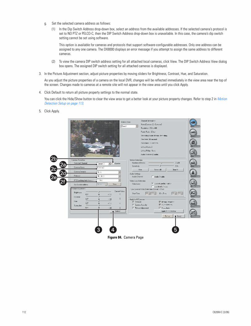
g. Set the selected camera address as follows:
(1) In the Dip Switch Address drop-down box, select an address from the available addresses. If the selected camera’s protocol is set to NO PTZ or PELCO-C, then the DIP Switch Address drop-down box is unavailable. In this case, the camera’s dip switch setting cannot be set using software.
This option is available for cameras and protocols that support software-configurable addresses. Only one address can be assigned to any one camera. The DX8000 displays an error message if you attempt to assign the same address to different cameras.
(2) To view the camera DIP switch address setting for all attached local cameras, click View. The DIP Switch Address View dialog box opens. The assigned DIP switch setting for all attached cameras is displayed.
3. In the Picture Adjustment section, adjust picture properties by moving sliders for Brightness, Contrast, Hue, and Saturation.
As you adjust the picture properties of a camera on the local DVR, changes will be reflected immediately in the view area near the top of the screen. Changes made to cameras at a remote site will not appear in the view area until you click Apply.
4. Click Default to return all picture property settings to the normal state.
You can click the Hide/Show button to clear the view area to get a better look at your picture property changes. Refer to step 2 in Motion Detection Setup on page 113.
5. Click Apply.
Figure 84. Camera Page
���
2b
2c2c
2e2e
2a2a
2f
2d
112 C626M-C (3/06)
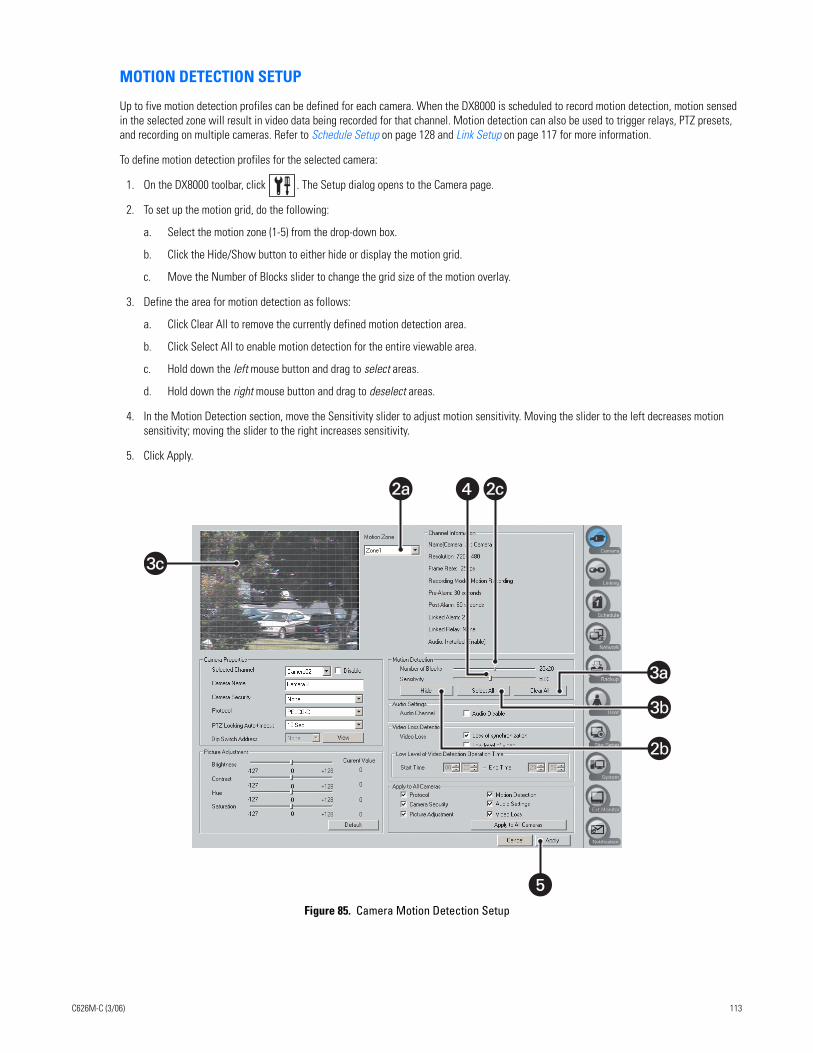
MOTION DETECTION SETUP
Up to five motion detection profiles can be defined for each camera. When the DX8000 is scheduled to record motion detection, motion sensed in the selected zone will result in video data being recorded for that channel. Motion detection can also be used to trigger relays, PTZ presets, and recording on multiple cameras. Refer to Schedule Setup on page 128 and Link Setup on page 117 for more information.
To define motion detection profiles for the selected camera:
1. On the DX8000 toolbar, click . The Setup dialog opens to the Camera page.
2. To set up the motion grid, do the following:
a. Select the motion zone (1-5) from the drop-down box.
b. Click the Hide/Show button to either hide or display the motion grid.
c. Move the Number of Blocks slider to change the grid size of the motion overlay.
3. Define the area for motion detection as follows:
a. Click Clear All to remove the currently defined motion detection area.
b. Click Select All to enable motion detection for the entire viewable area.
c. Hold down the left mouse button and drag to select areas.
d. Hold down the right mouse button and drag to deselect areas.
4. In the Motion Detection section, move the Sensitivity slider to adjust motion sensitivity. Moving the slider to the left decreases motion sensitivity; moving the slider to the right increases sensitivity.
5. Click Apply.
Figure 85. Camera Motion Detection Setup
�
3c3c
2a2a 2c2c�
3a3a
3b
2b
C626M-C (3/06) 113
AUDIO SETUP
The DX8000 audio feature allows you to configure individual camera channels to listen to and record live audio. You can monitor live audio at a local server or listen to live audio from a remote DX8000 server or client system. You can play back audio recorded by a camera channel.
To use the DX8000’s audio features, the optional DX8000-AUD audio card must be installed. You can determine if the audio card is installed by checking the Audio option status in the Channel Information section of the Camera page. The Audio status is one of the following:
• Not installed
• Installed (enabled)
The DX8000 compresses audio data to save space. In this case, recorded audio may not be of the same quality as live audio. Consult your Pelco sales representative for more information regarding the DX8000-AUD option.
To set up audio for a camera:
1. Do the following:
a. Install the optional DX8000-AUD audio card if necessary. For information about installing the optional DX8000-AUD audio card, refer to the DX8000 Installation manual.
b. Connect an audio input device (microphone) to the numbered DX8000-AUD audio card input for the camera channel being configured for live audio recording.
c. To hear live audio at the local server, connect head phones to the DX8000 audio output connector.
2. On the DX8000 toolbar, click Setup. The Setup dialog box opens to the Camera page.
3. Check the Channel Information section to verify that the audio option is installed and available.
4. In the Camera Properties section, select the camera channel you want to configure for live audio recording.
5. In the Audio Settings section, verify that the Audio Disable check box is not selected.
6. Click Apply.
7. Verify that you can hear sound from the DX8000 audio output.
114 C626M-C (3/06)
LISTENING TO LIVE AUDIO
The DX8000 audio feature allows you to listen to live audio at a local server or listen to live audio from a remote DX8000 server or client system. For information about setting up the DX8000 server to record and listen to live audio, refer to Audio Setup on page 114.
This section describes how to listen to live audio and includes the following topics:
• Listening to Live Audio at a Local Server on page 115
• Listening to Live Audio from a Remote DX8000 System on page 115
Listening to Live Audio at a Local Server
To listen to live audio at the local server:
1. Connect head phones to the DX8000 audio output connector. For information about setting up the DX8000 server to record and listen to live audio, refer to Audio Setup on page 114
2. On the DX8000 toolbar, click Setup. The Setup dialog box opens to the Camera page.
3. Check the Channel Information section to verify that the audio option is installed and available.
4. In the Camera Properties section, select the camera channel that is configured for live audio recording.
5. In the Audio Settings section, verify that the Audio Disable check box is not selected.
6. Click Apply.
7. Verify that you can hear sound from the DX8000 audio output.
8. On the DX8000 toolbar, click .
9. Drag a camera configured to record live audio from the Site tree onto a view pane.
10. Verify that you can hear live audio.
Listening to Live Audio from a Remote DX8000 System
To listen to live audio at a remote DX8000 server or client system:
1. On the DX8000 toolbar, click Setup. The Setup dialog box opens to the Camera page.
2. Check the Channel Information section to verify that the audio option is installed and available. For information about setting up the DX8000 server to record and listen to live audio, refer to Audio Setup on page 114
3. In the Camera Properties section, select the camera channel that is configured for live audio recording.
4. In the Audio Settings section, verify that the Audio Disable check box is not selected.
5. Click Apply.
6. Verify that you can hear live audio.
7. On the DX8000 toolbar, click .
8. Drag a camera configured to record live audio from the Site tree onto a view pane.
9. Verify that you can hear live audio.
C626M-C (3/06) 115
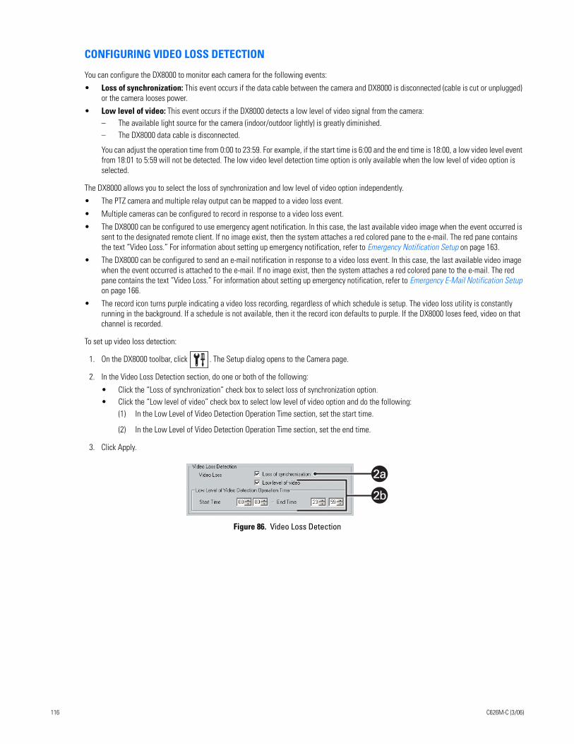
CONFIGURING VIDEO LOSS DETECTION
You can configure the DX8000 to monitor each camera for the following events:
• Loss of synchronization: This event occurs if the data cable between the camera and DX8000 is disconnected (cable is cut or unplugged) or the camera looses power.
• Low level of video: This event occurs if the DX8000 detects a low level of video signal from the camera:– The available light source for the camera (indoor/outdoor lightly) is greatly diminished. – The DX8000 data cable is disconnected.
You can adjust the operation time from 0:00 to 23:59. For example, if the start time is 6:00 and the end time is 18:00, a low video level event from 18:01 to 5:59 will not be detected. The low video level detection time option is only available when the low level of video option is selected.
The DX8000 allows you to select the loss of synchronization and low level of video option independently.
• The PTZ camera and multiple relay output can be mapped to a video loss event.
• Multiple cameras can be configured to record in response to a video loss event.
• The DX8000 can be configured to use emergency agent notification. In this case, the last available video image when the event occurred is sent to the designated remote client. If no image exist, then the system attaches a red colored pane to the e-mail. The red pane contains the text “Video Loss.” For information about setting up emergency notification, refer to Emergency Notification Setup on page 163.
• The DX8000 can be configured to send an e-mail notification in response to a video loss event. In this case, the last available video image when the event occurred is attached to the e-mail. If no image exist, then the system attaches a red colored pane to the e-mail. The red pane contains the text “Video Loss.” For information about setting up emergency notification, refer to Emergency E-Mail Notification Setup on page 166.
• The record icon turns purple indicating a video loss recording, regardless of which schedule is setup. The video loss utility is constantly running in the background. If a schedule is not available, then it the record icon defaults to purple. If the DX8000 loses feed, video on that channel is recorded.
To set up video loss detection:
1. On the DX8000 toolbar, click . The Setup dialog opens to the Camera page.
2. In the Video Loss Detection section, do one or both of the following:
• Click the “Loss of synchronization” check box to select loss of synchronization option.• Click the “Low level of video” check box to select low level of video option and do the following:
(1) In the Low Level of Video Detection Operation Time section, set the start time.
(2) In the Low Level of Video Detection Operation Time section, set the end time.
3. Click Apply.
Figure 86. Video Loss Detection
2a2a
2b
116 C626M-C (3/06)
APPLYING SETTINGS TO ALL CAMERAS
If you want to keep the changes you made to options and parameters on the Camera page, you must click Apply. If you attempt to leave the Camera page, the system will display a message box, prompting you to apply, not apply, or cancel the changes.
To apply camera configuration options to all attached cameras:
1. On the DX8000 toolbar, click . The Setup dialog opens to the Camera page.
2. Perform the camera configuration.
3. In the Apply to All Cameras section, select the check boxes for Protocol, Camera Security, Picture Adjustment, Motion Detection, Audio Settings, and Video Loss that you want to apply to all cameras.
4. Click Apply to All Cameras.
5. Click Apply.
LINK SETUPThis section describes how to use the Link page to set up the following:
• Relay and alarm settings
• Event-relay link settings
• Event-recording link settings
• Event-PTZ link settings
This section includes the following topics:
• Configuring Basic Relay and Alarm Settings on page 117
• Linking Relay Outputs to External Events on page 119
• Linking PTZ Presets and Patterns to External Events on page 124
• Linking Cameras to Record in Response to External Events on page 121
CONFIGURING BASIC RELAY AND ALARM SETTINGS
The DX8000 can support up to 16 alarm inputs and relay outputs. Eight-channel DVRs include 8 alarm and 8 relay terminals while sixteen-channel DVRs include 16 of each.
This section describes how to configure basic relay and alarm settings, and includes the following topics:
• Understanding How Relays and Alarms React to a Power Outage on page 117
• Configuring DX8000 Basic Relay and Alarm Settings on page 117
• Configuring Basic Relay Operating Properties on page 118
• Configuring Basic Alarm Input Operating Properties on page 118
Understanding How Relays and Alarms React to a Power Outage
The DX8000 server might experience an external AC power outage and impact how the DX8000 relay and alarm features function.
• Power outage: Relays configured as NO are closed if the DX8000 is server is shut down by a power outage or if the AC cord is unplugged.
• Power button: Relays configured as NO are closed if the DX8000 power button is pressed and held down.
In the scenarios above, a relay will remain closed as long as the DX8000 is powered down. In this case, alarms or sirens connected to the relays might produce a false alert.
Configuring DX8000 Basic Relay and Alarm Settings
To access the Link page to program alarms and relays:
1. On the DX8000 toolbar, click . The Setup dialog opens to the Camera setup page.
2. Click . The Link page is displayed.
C626M-C (3/06) 117
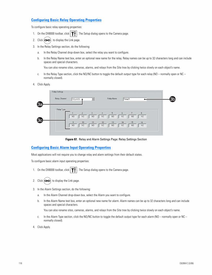
Configuring Basic Relay Operating Properties
To configure basic relay operating properties:
1. On the DX8000 toolbar, click . The Setup dialog opens to the Camera page.
2. Click . to display the Link page.
3. In the Relay Settings section, do the following:
a. In the Relay Channel drop-down box, select the relay you want to configure.
b. In the Relay Name text box, enter an optional new name for the relay. Relay names can be up to 32 characters long and can include spaces and special characters.
You can also rename sites, cameras, alarms, and relays from the Site tree by clicking twice slowly on each object’s name.
c. In the Relay Type section, click the NO/NC button to toggle the default output type for each relay (NO – normally open or NC – normally closed).
4. Click Apply.
Figure 87. Relay and Alarm Settings Page: Relay Settings Section
Configuring Basic Alarm Input Operating Properties
Most applications will not require you to change relay and alarm settings from their default states.
To configure basic alarm input operating properties:
1. On the DX8000 toolbar, click . The Setup dialog opens to the Camera page.
2. Click to display the Link page.
3. In the Alarm Settings section, do the following:
a. In the Alarm Channel drop-down box, select the Alarm you want to configure.
b. In the Alarm Name text box, enter an optional new name for alarm. Alarm names can be up to 32 characters long and can include spaces and special characters.
You can also rename sites, cameras, alarms, and relays from the Site tree by clicking twice slowly on each object’s name.
c. In the Alarm Type section, click the NO/NC button to toggle the default output type for each alarm (NO – normally open or NC – normally closed).
4. Click Apply.
3b
3c
3a
118 C626M-C (3/06)
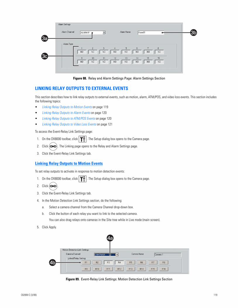
Figure 88. Relay and Alarm Settings Page: Alarm Settings Section
LINKING RELAY OUTPUTS TO EXTERNAL EVENTS
This section describes how to link relay outputs to external events, such as motion, alarm, ATM/POS, and video loss events. This section includes the following topics:
• Linking Relay Outputs to Motion Events on page 119
• Linking Relay Outputs to Alarm Events on page 120
• Linking Relay Outputs to ATM/POS Events on page 120
• Linking Relay Outputs to Video Loss Events on page 121
To access the Event-Relay Link Settings page:
1. On the DX8000 toolbar, click . The Setup dialog box opens to the Camera page.
2. Click . The Linking page opens to the Relay and Alarm Settings page.
3. Click the Event-Relay Link Settings tab.
Linking Relay Outputs to Motion Events
To set relay outputs to activate in response to motion detection events:
1. On the DX8000 toolbar, click . The Setup dialog box opens to the Camera page.
2. Click .
3. Click the Event-Relay Link Settings tab.
4. In the Motion Detection Link Settings section, do the following:
a. Select a camera channel from the Camera Channel drop-down box.
b. Click the button of each relay you want to link to the selected camera.
You can also drag relays onto cameras in the Site tree while in Live mode (main screen).
5. Click Apply.
Figure 89. Event-Relay Link Settings: Motion Detection Link Settings Section
3b
3c
3a
4b
4a
C626M-C (3/06) 119
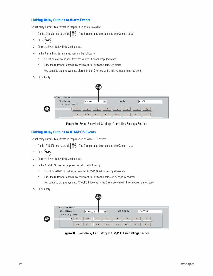
Linking Relay Outputs to Alarm Events
To set relay outputs to activate in response to an alarm event:
1. On the DX8000 toolbar, click . The Setup dialog box opens to the Camera page.
2. Click .
3. Click the Event-Relay Link Settings tab.
4. In the Alarm Link Settings section, do the following:
a. Select an alarm channel from the Alarm Channel drop-down box.
b. Click the button for each relay you want to link to the selected alarm.
You can also drag relays onto alarms in the Site tree while in Live mode (main screen).
5. Click Apply.
Figure 90. Event-Relay Link Settings: Alarm Link Settings Section
Linking Relay Outputs to ATM/POS Events
To set relay outputs to activate in response to an ATM/POS event:
1. On the DX8000 toolbar, click . The Setup dialog box opens to the Camera page.
2. Click .
3. Click the Event-Relay Link Settings tab.
4. In the ATM/POS Link Settings section, do the following:
a. Select an ATM/POS address from the ATM/POS Address drop-down box.
b. Click the button for each relay you want to link to the selected ATM/POS address.
You can also drag relays onto ATM/POS devices in the Site tree while in Live mode (main screen).
5. Click Apply.
Figure 91. Event-Relay Link Settings: ATM/POS Link Settings Section
4b
4a
4b
4a
120 C626M-C (3/06)
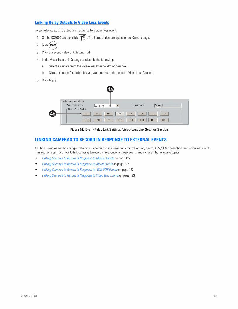
Linking Relay Outputs to Video Loss Events
To set relay outputs to activate in response to a video loss event:
1. On the DX8000 toolbar, click . The Setup dialog box opens to the Camera page.
2. Click .
3. Click the Event-Relay Link Settings tab.
4. In the Video-Loss Link Settings section, do the following:
a. Select a camera from the Video-Loss Channel drop-down box.
b. Click the button for each relay you want to link to the selected Video-Loss Channel.
5. Click Apply.
Figure 92. Event-Relay Link Settings: Video-Loss Link Settings Section
LINKING CAMERAS TO RECORD IN RESPONSE TO EXTERNAL EVENTS
Multiple cameras can be configured to begin recording in response to detected motion, alarm, ATM/POS transaction, and video loss events. This section describes how to link cameras to record in response to these events and includes the following topics:
• Linking Cameras to Record in Response to Motion Events on page 122
• Linking Cameras to Record in Response to Alarm Events on page 122
• Linking Cameras to Record in Response to ATM/POS Events on page 123
• Linking Cameras to Record in Response to Video Loss Events on page 123
4b
4a
C626M-C (3/06) 121
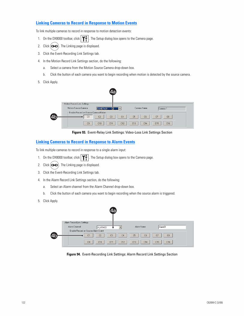
Linking Cameras to Record in Response to Motion Events
To link multiple cameras to record in response to motion detection events:
1. On the DX8000 toolbar, click . The Setup dialog box opens to the Camera page.
2. Click . The Linking page is displayed.
3. Click the Event-Recording Link Settings tab.
4. In the Motion Record Link Settings section, do the following:
a. Select a camera from the Motion Source Camera drop-down box.
b. Click the button of each camera you want to begin recording when motion is detected by the source camera.
5. Click Apply.
Figure 93. Event-Relay Link Settings: Video-Loss Link Settings Section
Linking Cameras to Record in Response to Alarm Events
To link multiple cameras to record in response to a single alarm input:
1. On the DX8000 toolbar, click . The Setup dialog box opens to the Camera page.
2. Click . The Linking page is displayed.
3. Click the Event-Recording Link Settings tab.
4. In the Alarm Record Link Settings section, do the following:
a. Select an Alarm channel from the Alarm Channel drop-down box.
b. Click the button of each camera you want to begin recording when the source alarm is triggered.
5. Click Apply.
Figure 94. Event-Recording Link Settings: Alarm Record Link Settings Section
4b
4a
4b
4a
122 C626M-C (3/06)
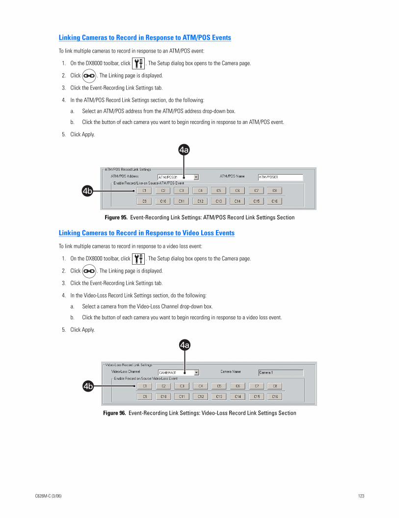
Linking Cameras to Record in Response to ATM/POS Events
To link multiple cameras to record in response to an ATM/POS event:
1. On the DX8000 toolbar, click . The Setup dialog box opens to the Camera page.
2. Click . The Linking page is displayed.
3. Click the Event-Recording Link Settings tab.
4. In the ATM/POS Record Link Settings section, do the following:
a. Select an ATM/POS address from the ATM/POS address drop-down box.
b. Click the button of each camera you want to begin recording in response to an ATM/POS event.
5. Click Apply.
Figure 95. Event-Recording Link Settings: ATM/POS Record Link Settings Section
Linking Cameras to Record in Response to Video Loss Events
To link multiple cameras to record in response to a video loss event:
1. On the DX8000 toolbar, click . The Setup dialog box opens to the Camera page.
2. Click . The Linking page is displayed.
3. Click the Event-Recording Link Settings tab.
4. In the Video-Loss Record Link Settings section, do the following:
a. Select a camera from the Video-Loss Channel drop-down box.
b. Click the button of each camera you want to begin recording in response to a video loss event.
5. Click Apply.
Figure 96. Event-Recording Link Settings: Video-Loss Record Link Settings Section
4b
4a
4b
4a
C626M-C (3/06) 123
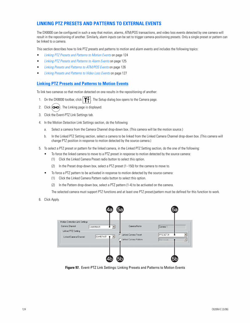
LINKING PTZ PRESETS AND PATTERNS TO EXTERNAL EVENTS
The DX8000 can be configured in such a way that motion, alarms, ATM/POS transactions, and video loss events detected by one camera will result in the repositioning of another. Similarly, alarm inputs can be set to trigger camera-positioning presets. Only a single preset or pattern can be linked to a camera.
This section describes how to link PTZ presets and patterns to motion and alarm events and includes the following topics:
• Linking PTZ Presets and Patterns to Motion Events on page 124
• Linking PTZ Presets and Patterns to Alarm Events on page 125
• Linking Presets and Patterns to ATM/POS Events on page 126
• Linking Presets and Patterns to Video Loss Events on page 127
Linking PTZ Presets and Patterns to Motion Events
To link two cameras so that motion detected on one results in the repositioning of another:
1. On the DX8000 toolbar, click . The Setup dialog box opens to the Camera page.
2. Click . The Linking page is displayed.
3. Click the Event-PTZ Link Settings tab.
4. In the Motion Detection Link Settings section, do the following:
a. Select a camera from the Camera Channel drop-down box. (This camera will be the motion source.)
b. In the Linked PTZ Setting section, select a camera to be linked from the Linked Camera Channel drop-down box. (This camera will change PTZ position in response to motion detected by the source camera.)
5. To select a PTZ preset or pattern for the linked camera, in the Linked PTZ Setting section, do the one of the following:
• To force the linked camera to move to a PTZ preset in response to motion detected by the source camera:(1) Click the Linked Camera Preset radio button to select this option.
(2) In the Preset drop-down box, select a PTZ preset (1–150) for the camera to move to.
• To force a PTZ pattern to be activated in response to motion detected by the source camera:(1) Click the Linked Camera Pattern radio button to select this option.
(2) In the Pattern drop-down box, select a PTZ pattern (1-4) to be activated on the camera.
The selected camera must support PTZ functions and at least one PTZ preset/pattern must be defined for this function to work.
6. Click Apply.
Figure 97. Event-PTZ Link Settings: Linking Presets and Patterns to Motion Events
4a4a 5a5a 5a5a
5b4b 5b
124 C626M-C (3/06)
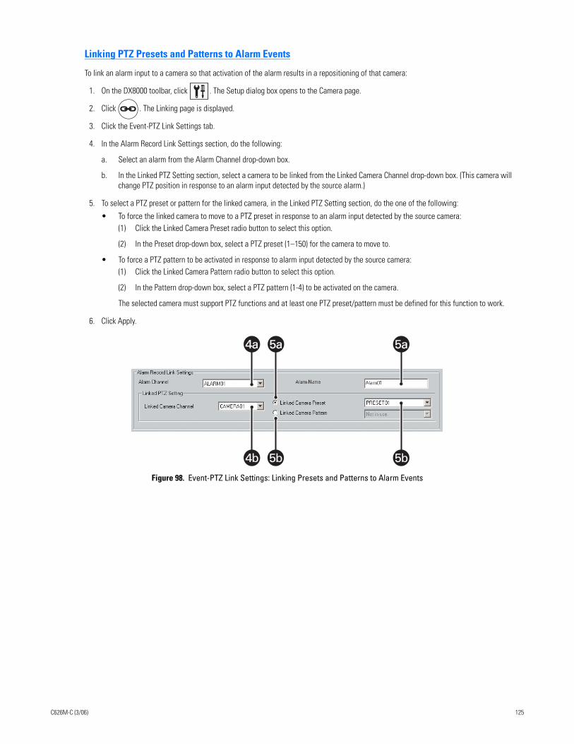
Linking PTZ Presets and Patterns to Alarm Events
To link an alarm input to a camera so that activation of the alarm results in a repositioning of that camera:
1. On the DX8000 toolbar, click . The Setup dialog box opens to the Camera page.
2. Click . The Linking page is displayed.
3. Click the Event-PTZ Link Settings tab.
4. In the Alarm Record Link Settings section, do the following:
a. Select an alarm from the Alarm Channel drop-down box.
b. In the Linked PTZ Setting section, select a camera to be linked from the Linked Camera Channel drop-down box. (This camera will change PTZ position in response to an alarm input detected by the source alarm.)
5. To select a PTZ preset or pattern for the linked camera, in the Linked PTZ Setting section, do the one of the following:
• To force the linked camera to move to a PTZ preset in response to an alarm input detected by the source camera:(1) Click the Linked Camera Preset radio button to select this option.
(2) In the Preset drop-down box, select a PTZ preset (1–150) for the camera to move to.
• To force a PTZ pattern to be activated in response to alarm input detected by the source camera:(1) Click the Linked Camera Pattern radio button to select this option.
(2) In the Pattern drop-down box, select a PTZ pattern (1-4) to be activated on the camera.
The selected camera must support PTZ functions and at least one PTZ preset/pattern must be defined for this function to work.
6. Click Apply.
Figure 98. Event-PTZ Link Settings: Linking Presets and Patterns to Alarm Events
4a4a 5a5a 5a5a
5b 5b4b
C626M-C (3/06) 125
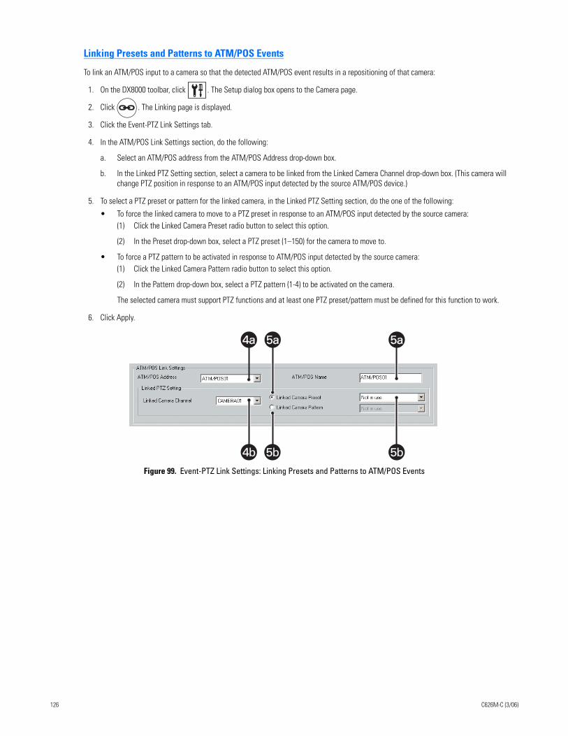
Linking Presets and Patterns to ATM/POS Events
To link an ATM/POS input to a camera so that the detected ATM/POS event results in a repositioning of that camera:
1. On the DX8000 toolbar, click . The Setup dialog box opens to the Camera page.
2. Click . The Linking page is displayed.
3. Click the Event-PTZ Link Settings tab.
4. In the ATM/POS Link Settings section, do the following:
a. Select an ATM/POS address from the ATM/POS Address drop-down box.
b. In the Linked PTZ Setting section, select a camera to be linked from the Linked Camera Channel drop-down box. (This camera will change PTZ position in response to an ATM/POS input detected by the source ATM/POS device.)
5. To select a PTZ preset or pattern for the linked camera, in the Linked PTZ Setting section, do the one of the following:
• To force the linked camera to move to a PTZ preset in response to an ATM/POS input detected by the source camera:(1) Click the Linked Camera Preset radio button to select this option.
(2) In the Preset drop-down box, select a PTZ preset (1–150) for the camera to move to.
• To force a PTZ pattern to be activated in response to ATM/POS input detected by the source camera:(1) Click the Linked Camera Pattern radio button to select this option.
(2) In the Pattern drop-down box, select a PTZ pattern (1-4) to be activated on the camera.
The selected camera must support PTZ functions and at least one PTZ preset/pattern must be defined for this function to work.
6. Click Apply.
Figure 99. Event-PTZ Link Settings: Linking Presets and Patterns to ATM/POS Events
4a4a 5a5a 5a5a
5b4b 5b
126 C626M-C (3/06)
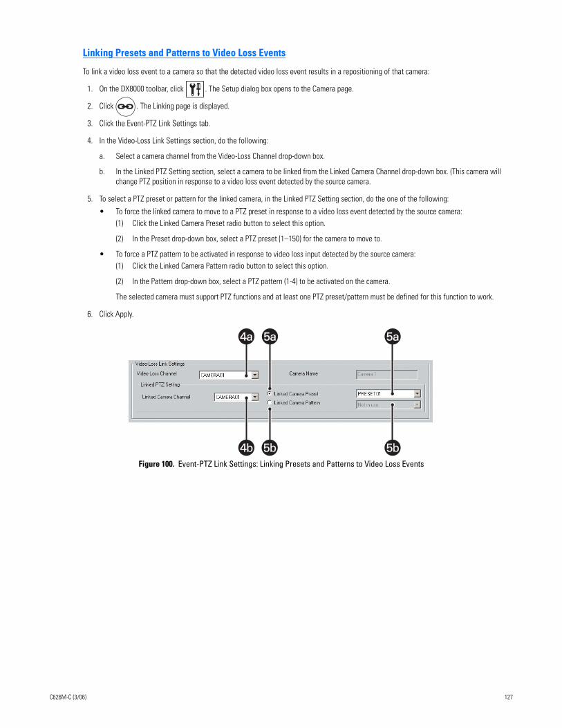
Linking Presets and Patterns to Video Loss Events
To link a video loss event to a camera so that the detected video loss event results in a repositioning of that camera:
1. On the DX8000 toolbar, click . The Setup dialog box opens to the Camera page.
2. Click . The Linking page is displayed.
3. Click the Event-PTZ Link Settings tab.
4. In the Video-Loss Link Settings section, do the following:
a. Select a camera channel from the Video-Loss Channel drop-down box.
b. In the Linked PTZ Setting section, select a camera to be linked from the Linked Camera Channel drop-down box. (This camera will change PTZ position in response to a video loss event detected by the source camera.
5. To select a PTZ preset or pattern for the linked camera, in the Linked PTZ Setting section, do the one of the following:
• To force the linked camera to move to a PTZ preset in response to a video loss event detected by the source camera:(1) Click the Linked Camera Preset radio button to select this option.
(2) In the Preset drop-down box, select a PTZ preset (1–150) for the camera to move to.
• To force a PTZ pattern to be activated in response to video loss input detected by the source camera:(1) Click the Linked Camera Pattern radio button to select this option.
(2) In the Pattern drop-down box, select a PTZ pattern (1-4) to be activated on the camera.
The selected camera must support PTZ functions and at least one PTZ preset/pattern must be defined for this function to work.
6. Click Apply.
Figure 100. Event-PTZ Link Settings: Linking Presets and Patterns to Video Loss Events
4a4a 5a5a 5a5a
5b 5b4b
C626M-C (3/06) 127
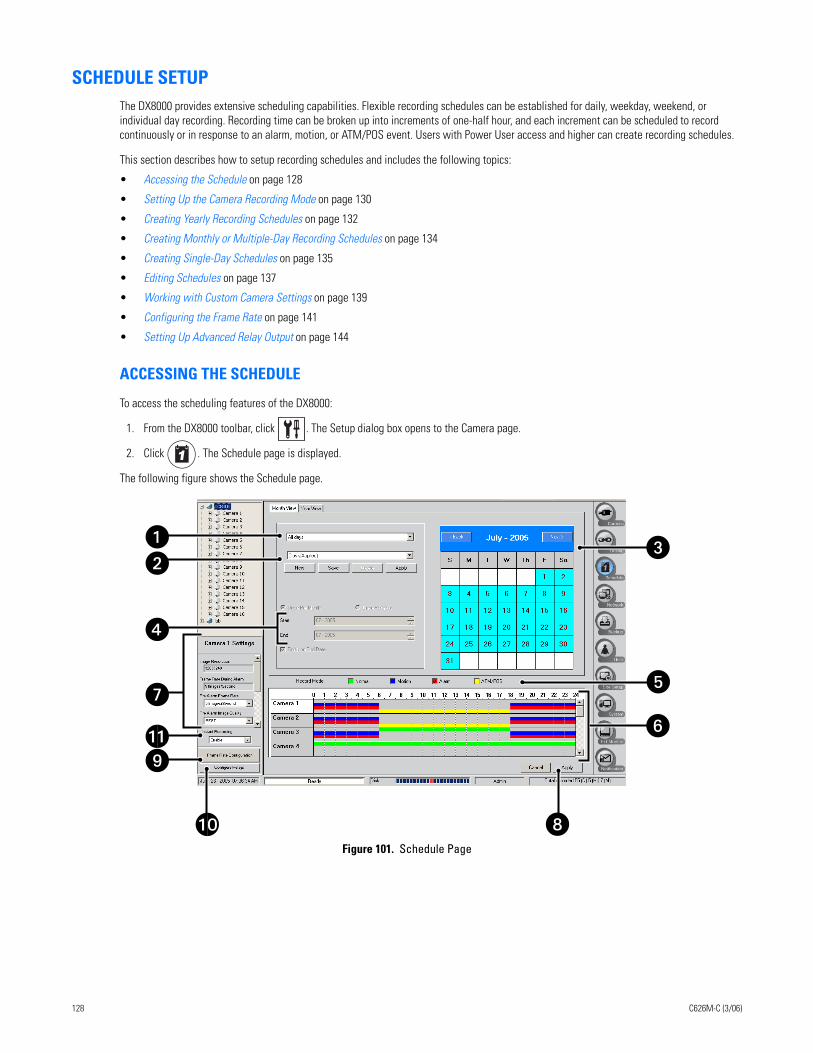
SCHEDULE SETUPThe DX8000 provides extensive scheduling capabilities. Flexible recording schedules can be established for daily, weekday, weekend, or individual day recording. Recording time can be broken up into increments of one-half hour, and each increment can be scheduled to record continuously or in response to an alarm, motion, or ATM/POS event. Users with Power User access and higher can create recording schedules.
This section describes how to setup recording schedules and includes the following topics:
• Accessing the Schedule on page 128
• Setting Up the Camera Recording Mode on page 130
• Creating Yearly Recording Schedules on page 132
• Creating Monthly or Multiple-Day Recording Schedules on page 134
• Creating Single-Day Schedules on page 135
• Editing Schedules on page 137
• Working with Custom Camera Settings on page 139
• Configuring the Frame Rate on page 141
• Setting Up Advanced Relay Output on page 144
ACCESSING THE SCHEDULE
To access the scheduling features of the DX8000:
1. From the DX8000 toolbar, click . The Setup dialog box opens to the Camera page.
2. Click . The Schedule page is displayed.
The following figure shows the Schedule page.
Figure 101. Schedule Page
�
�
�
�
�
��
�
�
�
128 C626M-C (3/06)
The following table describes the parts of the Schedule page.
Table AB. Parts of the Schedule Page
Item Part Description
Schedule Type Drop-down Box
Selects the type of schedule. Options are as follows:
• All days – Seven days a week
• Weekdays – Monday through Friday, with the exception of any day assigned in Custom mode
• Weekends – Saturday and Sunday, with the exception of any day assigned in Custom mode
• Custom Mode – Any day, such as a holiday
Recording Schedule Profile
Allows you to do the following:
• Select and apply an existing schedule profile.
• Create and save a new profile.
• Change an existing profile.
• Delete an existing profile.
Calendar Displays current schedule profile in accordance with the schedule type selected (All Days, Weekdays, Weekends, or Custom Mode).
Start and End Date Markers
Sets the start and end dates for a custom schedule.
Record Mode Selects a recording mode to be applied to a camera. Options are as follows:
• Normal
• Motion
• Alarm
• ATM/POS
Channel Scheduling Panel
Allows the assignment of recording modes across individual camera channels over a 24-hour period.
Camera Settings Panel
Allows custom settings to be applied to individual cameras for each recording mode.
Apply Saves current schedule.
Frame Rate Configuration
Allows configuration of channel resolution and frame rates.
Configure Relays Allows configuration of relays that have been linked to cameras and alarms.
Instant Recording Enables or disables selection of instant recording from the View menu.
C626M-C (3/06) 129
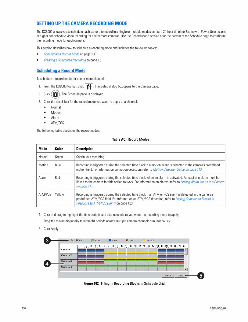
SETTING UP THE CAMERA RECORDING MODE
The DX8000 allows you to schedule each camera to record in a single or multiple modes across a 24-hour timeline. Users with Power User access or higher can schedule video recording for one or more cameras. Use the Record Mode section near the bottom of the Schedule page to configure the recording mode for each camera.
This section describes how to schedule a recording mode and includes the following topics:
• Scheduling a Record Mode on page 130
• Clearing a Scheduled Recording on page 131
Scheduling a Record Mode
To schedule a record mode for one or more channels:
1. From the DX8000 toolbar, click . The Setup dialog box opens to the Camera page.
2. Click . The Schedule page is displayed.
3. Click the check box for the record mode you want to apply to a channel.
• Normal • Motion• Alarm• ATM/POS
The following table describes the record modes.
4. Click and drag to highlight the time periods and channels where you want the recording mode to apply.
Drag the mouse diagonally to highlight periods across multiple camera channels simultaneously.
5. Click Apply.
Figure 102. Filling In Recording Blocks in Schedule Grid
Table AC. Record Modes
Mode Color Description
Normal Green Continuous recording.
Motion Blue Recording is triggered during the selected time block if a motion event is detected in the camera’s predefined motion field. For information on motion detection, refer to Motion Detection Setup on page 113.
Alarm Red Recording is triggered during the selected time block when an alarm is activated. At least one alarm must be linked to the camera for this option to work. For information on alarms, refer to Linking Alarm Inputs to a Camera on page 41.
ATM/POS Yellow Recording is triggered during the selected time block if an ATM or POS event is detected in the camera’s predefined ATM/POS field. For information on ATM/POS detection, refer to Linking Cameras to Record in Response to ATM/POS Events on page 123.
�
�
�
130 C626M-C (3/06)
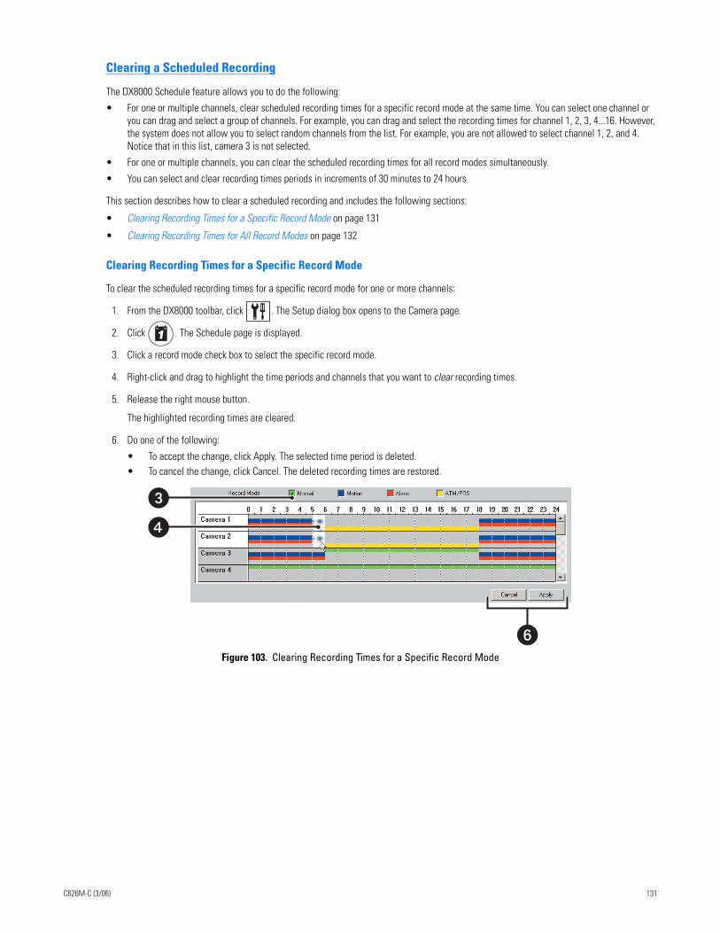
Clearing a Scheduled Recording
The DX8000 Schedule feature allows you to do the following:
• For one or multiple channels, clear scheduled recording times for a specific record mode at the same time. You can select one channel or you can drag and select a group of channels. For example, you can drag and select the recording times for channel 1, 2, 3, 4...16. However, the system does not allow you to select random channels from the list. For example, you are not allowed to select channel 1, 2, and 4. Notice that in this list, camera 3 is not selected.
• For one or multiple channels, you can clear the scheduled recording times for all record modes simultaneously.
• You can select and clear recording times periods in increments of 30 minutes to 24 hours.
This section describes how to clear a scheduled recording and includes the following sections:
• Clearing Recording Times for a Specific Record Mode on page 131
• Clearing Recording Times for All Record Modes on page 132
Clearing Recording Times for a Specific Record Mode
To clear the scheduled recording times for a specific record mode for one or more channels:
1. From the DX8000 toolbar, click . The Setup dialog box opens to the Camera page.
2. Click . The Schedule page is displayed.
3. Click a record mode check box to select the specific record mode.
4. Right-click and drag to highlight the time periods and channels that you want to clear recording times.
5. Release the right mouse button.
The highlighted recording times are cleared.
6. Do one of the following:
• To accept the change, click Apply. The selected time period is deleted.• To cancel the change, click Cancel. The deleted recording times are restored.
Figure 103. Clearing Recording Times for a Specific Record Mode
�
�
�
C626M-C (3/06) 131
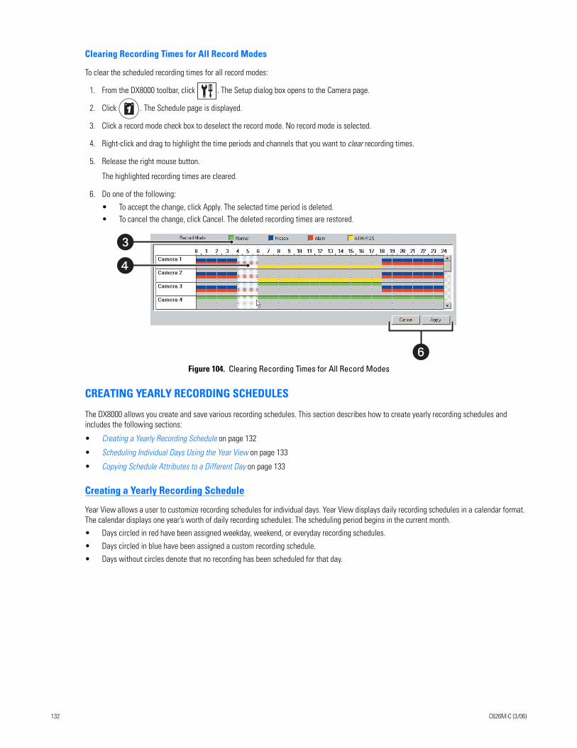
Clearing Recording Times for All Record Modes
To clear the scheduled recording times for all record modes:
1. From the DX8000 toolbar, click . The Setup dialog box opens to the Camera page.
2. Click . The Schedule page is displayed.
3. Click a record mode check box to deselect the record mode. No record mode is selected.
4. Right-click and drag to highlight the time periods and channels that you want to clear recording times.
5. Release the right mouse button.
The highlighted recording times are cleared.
6. Do one of the following:
• To accept the change, click Apply. The selected time period is deleted.• To cancel the change, click Cancel. The deleted recording times are restored.
Figure 104. Clearing Recording Times for All Record Modes
CREATING YEARLY RECORDING SCHEDULES
The DX8000 allows you create and save various recording schedules. This section describes how to create yearly recording schedules and includes the following sections:
• Creating a Yearly Recording Schedule on page 132
• Scheduling Individual Days Using the Year View on page 133
• Copying Schedule Attributes to a Different Day on page 133
Creating a Yearly Recording Schedule
Year View allows a user to customize recording schedules for individual days. Year View displays daily recording schedules in a calendar format. The calendar displays one year’s worth of daily recording schedules. The scheduling period begins in the current month.
• Days circled in red have been assigned weekday, weekend, or everyday recording schedules.
• Days circled in blue have been assigned a custom recording schedule.
• Days without circles denote that no recording has been scheduled for that day.
�
�
�
132 C626M-C (3/06)
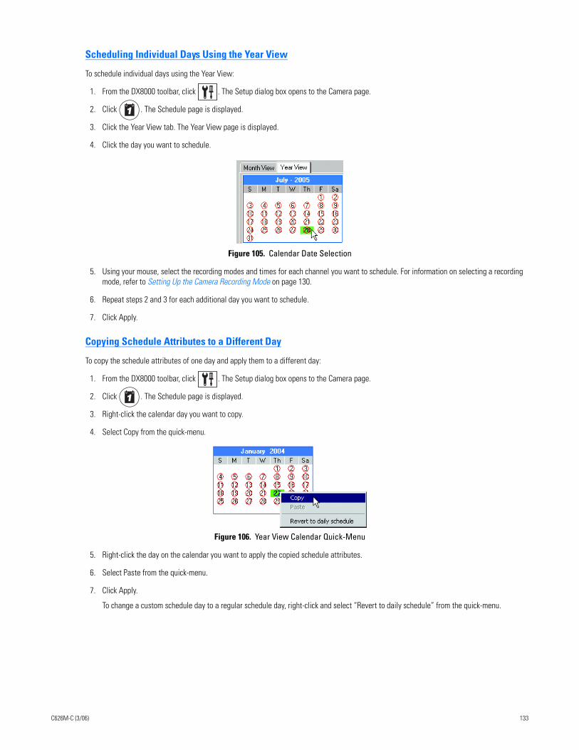
Scheduling Individual Days Using the Year View
To schedule individual days using the Year View:
1. From the DX8000 toolbar, click . The Setup dialog box opens to the Camera page.
2. Click . The Schedule page is displayed.
3. Click the Year View tab. The Year View page is displayed.
4. Click the day you want to schedule.
Figure 105. Calendar Date Selection
5. Using your mouse, select the recording modes and times for each channel you want to schedule. For information on selecting a recording mode, refer to Setting Up the Camera Recording Mode on page 130.
6. Repeat steps 2 and 3 for each additional day you want to schedule.
7. Click Apply.
Copying Schedule Attributes to a Different Day
To copy the schedule attributes of one day and apply them to a different day:
1. From the DX8000 toolbar, click . The Setup dialog box opens to the Camera page.
2. Click . The Schedule page is displayed.
3. Right-click the calendar day you want to copy.
4. Select Copy from the quick-menu.
Figure 106. Year View Calendar Quick-Menu
5. Right-click the day on the calendar you want to apply the copied schedule attributes.
6. Select Paste from the quick-menu.
7. Click Apply.
To change a custom schedule day to a regular schedule day, right-click and select “Revert to daily schedule” from the quick-menu.
C626M-C (3/06) 133
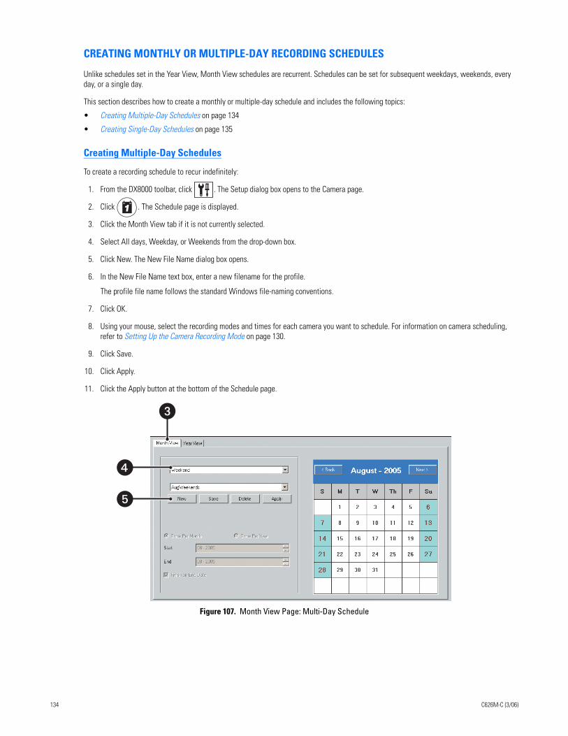
CREATING MONTHLY OR MULTIPLE-DAY RECORDING SCHEDULES
Unlike schedules set in the Year View, Month View schedules are recurrent. Schedules can be set for subsequent weekdays, weekends, every day, or a single day.
This section describes how to create a monthly or multiple-day schedule and includes the following topics:
• Creating Multiple-Day Schedules on page 134
• Creating Single-Day Schedules on page 135
Creating Multiple-Day Schedules
To create a recording schedule to recur indefinitely:
1. From the DX8000 toolbar, click . The Setup dialog box opens to the Camera page.
2. Click . The Schedule page is displayed.
3. Click the Month View tab if it is not currently selected.
4. Select All days, Weekday, or Weekends from the drop-down box.
5. Click New. The New File Name dialog box opens.
6. In the New File Name text box, enter a new filename for the profile.
The profile file name follows the standard Windows file-naming conventions.
7. Click OK.
8. Using your mouse, select the recording modes and times for each camera you want to schedule. For information on camera scheduling, refer to Setting Up the Camera Recording Mode on page 130.
9. Click Save.
10. Click Apply.
11. Click the Apply button at the bottom of the Schedule page.
Figure 107. Month View Page: Multi-Day Schedule
�
�
�
134 C626M-C (3/06)
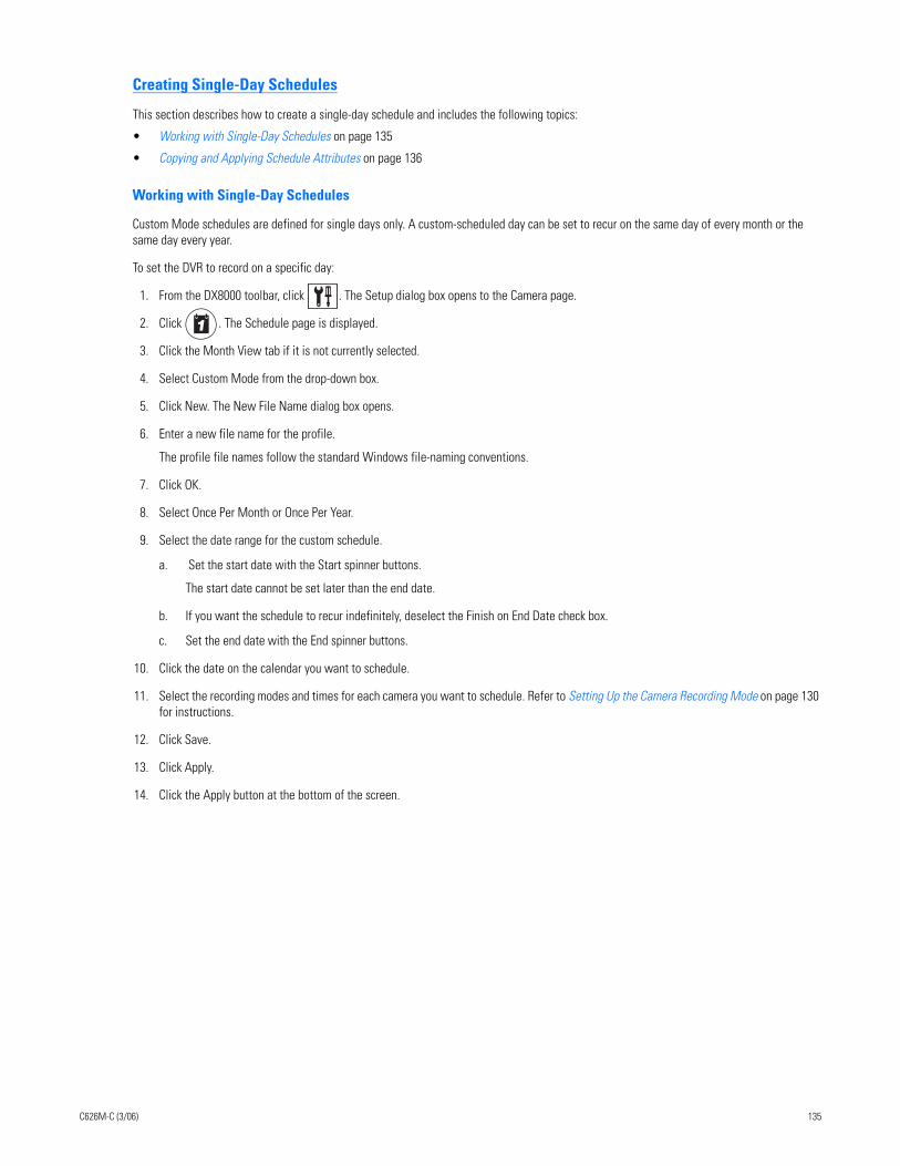
Creating Single-Day Schedules
This section describes how to create a single-day schedule and includes the following topics:
• Working with Single-Day Schedules on page 135
• Copying and Applying Schedule Attributes on page 136
Working with Single-Day Schedules
Custom Mode schedules are defined for single days only. A custom-scheduled day can be set to recur on the same day of every month or the same day every year.
To set the DVR to record on a specific day:
1. From the DX8000 toolbar, click . The Setup dialog box opens to the Camera page.
2. Click . The Schedule page is displayed.
3. Click the Month View tab if it is not currently selected.
4. Select Custom Mode from the drop-down box.
5. Click New. The New File Name dialog box opens.
6. Enter a new file name for the profile.
The profile file names follow the standard Windows file-naming conventions.
7. Click OK.
8. Select Once Per Month or Once Per Year.
9. Select the date range for the custom schedule.
a. Set the start date with the Start spinner buttons.
The start date cannot be set later than the end date.
b. If you want the schedule to recur indefinitely, deselect the Finish on End Date check box.
c. Set the end date with the End spinner buttons.
10. Click the date on the calendar you want to schedule.
11. Select the recording modes and times for each camera you want to schedule. Refer to Setting Up the Camera Recording Mode on page 130 for instructions.
12. Click Save.
13. Click Apply.
14. Click the Apply button at the bottom of the screen.
C626M-C (3/06) 135
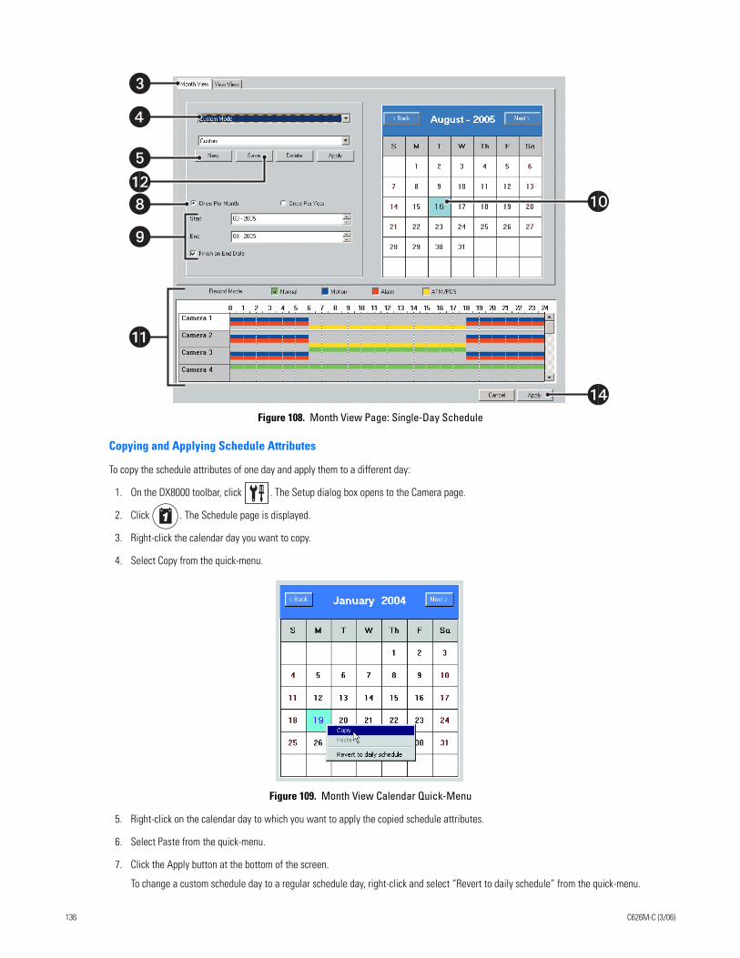
Figure 108. Month View Page: Single-Day Schedule
Copying and Applying Schedule Attributes
To copy the schedule attributes of one day and apply them to a different day:
1. On the DX8000 toolbar, click . The Setup dialog box opens to the Camera page.
2. Click . The Schedule page is displayed.
3. Right-click the calendar day you want to copy.
4. Select Copy from the quick-menu.
Figure 109. Month View Calendar Quick-Menu
5. Right-click on the calendar day to which you want to apply the copied schedule attributes.
6. Select Paste from the quick-menu.
7. Click the Apply button at the bottom of the screen.
To change a custom schedule day to a regular schedule day, right-click and select “Revert to daily schedule” from the quick-menu.
�
�
�
�
��
�
�
��
�
136 C626M-C (3/06)
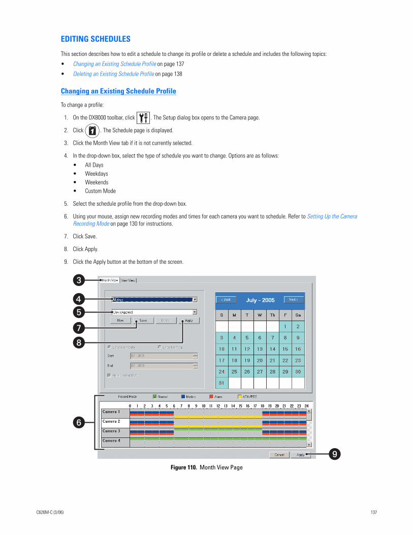
EDITING SCHEDULES
This section describes how to edit a schedule to change its profile or delete a schedule and includes the following topics:
• Changing an Existing Schedule Profile on page 137
• Deleting an Existing Schedule Profile on page 138
Changing an Existing Schedule Profile
To change a profile:
1. On the DX8000 toolbar, click . The Setup dialog box opens to the Camera page.
2. Click . The Schedule page is displayed.
3. Click the Month View tab if it is not currently selected.
4. In the drop-down box, select the type of schedule you want to change. Options are as follows:
• All Days• Weekdays• Weekends• Custom Mode
5. Select the schedule profile from the drop-down box.
6. Using your mouse, assign new recording modes and times for each camera you want to schedule. Refer to Setting Up the Camera Recording Mode on page 130 for instructions.
7. Click Save.
8. Click Apply.
9. Click the Apply button at the bottom of the screen.
Figure 110. Month View Page
�
�
�
��
�
�
C626M-C (3/06) 137
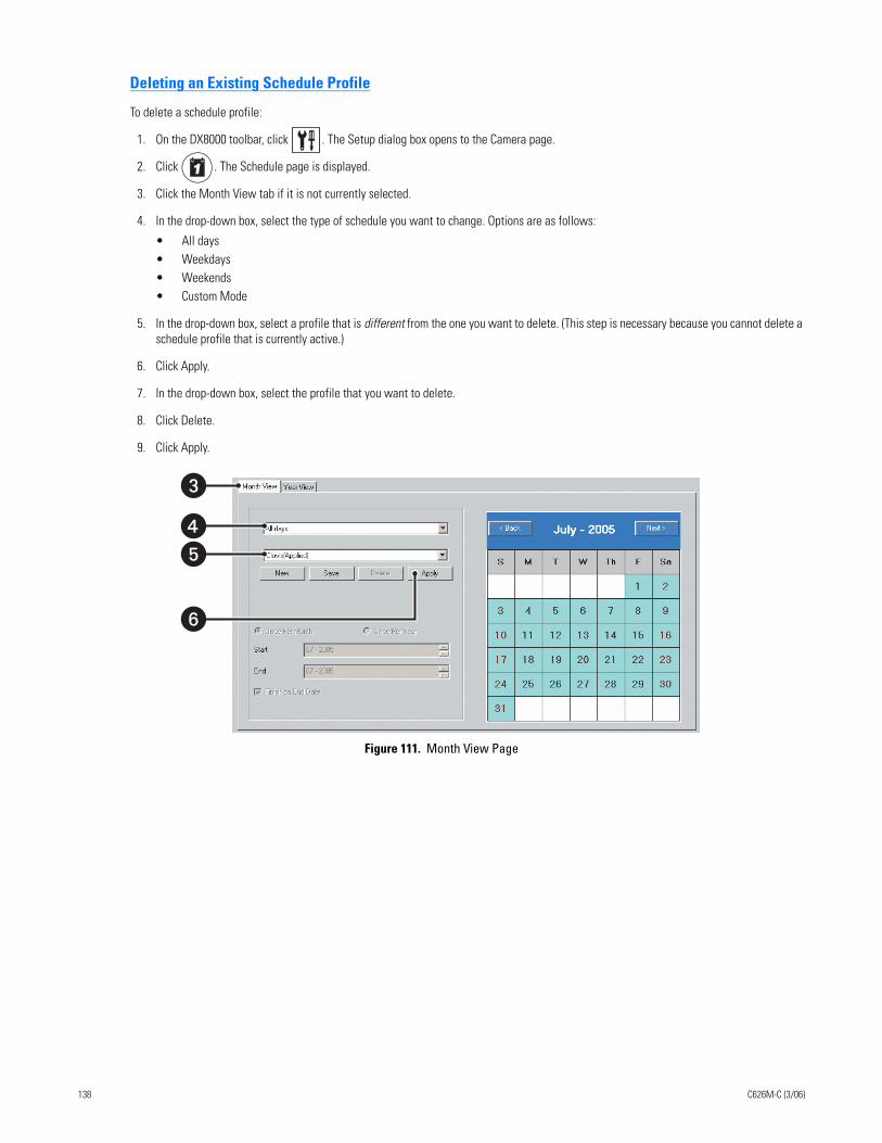
Deleting an Existing Schedule Profile
To delete a schedule profile:
1. On the DX8000 toolbar, click . The Setup dialog box opens to the Camera page.
2. Click . The Schedule page is displayed.
3. Click the Month View tab if it is not currently selected.
4. In the drop-down box, select the type of schedule you want to change. Options are as follows:
• All days • Weekdays• Weekends• Custom Mode
5. In the drop-down box, select a profile that is different from the one you want to delete. (This step is necessary because you cannot delete a schedule profile that is currently active.)
6. Click Apply.
7. In the drop-down box, select the profile that you want to delete.
8. Click Delete.
9. Click Apply.
Figure 111. Month View Page
�
�
�
�
138 C626M-C (3/06)
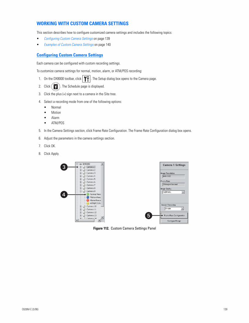
WORKING WITH CUSTOM CAMERA SETTINGS
This section describes how to configure customized camera settings and includes the following topics:
• Configuring Custom Camera Settings on page 139
• Examples of Custom Camera Settings on page 140
Configuring Custom Camera Settings
Each camera can be configured with custom recording settings.
To customize camera settings for normal, motion, alarm, or ATM/POS recording:
1. On the DX8000 toolbar, click . The Setup dialog box opens to the Camera page.
2. Click . The Schedule page is displayed.
3. Click the plus (+) sign next to a camera in the Site tree.
4. Select a recording mode from one of the following options:
• Normal• Motion• Alarm• ATM/POS
5. In the Camera Settings section, click Frame Rate Configuration. The Frame Rate Configuration dialog box opens.
6. Adjust the parameters in the camera settings section.
7. Click OK.
8. Click Apply.
Figure 112. Custom Camera Settings Panel
�
�
�
C626M-C (3/06) 139
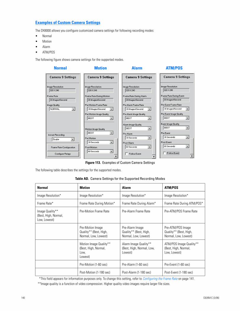
Examples of Custom Camera Settings
The DX8000 allows you configure customized camera settings for following recording modes:
• Normal
• Motion
• Alarm
• ATM/POS
The following figure shows camera settings for the supported modes.
Figure 113. Examples of Custom Camera Settings
The following table describes the settings for the supported modes.
Table AD. Camera Settings for the Supported Recording Modes
Normal Motion Alarm ATM/POS
Image Resolution* Image Resolution* Image Resolution* Image Resolution*
Frame Rate* Frame Rate During Motion* Frame Rate During Alarm* Frame Rate During ATM/POS*
Image Quality** (Best, High, Normal, Low, Lowest)
Pre-Motion Frame Rate Pre-Alarm Frame Rate Pre-ATM/POS Frame Rate
Pre-Motion Image Quality** (Best, High, Normal, Low, Lowest)
Pre-Alarm Image Quality** (Best, High, Normal, Low, Lowest)
Pre-ATM/POS Image Quality** (Best, High, Normal, Low, Lowest)
Motion Image Quality** (Best, High, Normal, Low, Lowest)
Alarm Image Quality** (Best, High, Normal, Low, Lowest)
ATM/POS Image Quality** (Best, High, Normal, Low, Lowest)
Pre-Motion (1-60 sec) Pre-Alarm (1-60 sec) Pre-Event (1-60 sec)
Post-Motion (1-180 sec) Post-Alarm (1-180 sec) Post-Event (1-180 sec)
*This field appears for information purposes only. To change this setting, refer to Configuring the Frame Rate on page 141.**Image quality is a function of video compression. Higher quality video images require larger file sizes.
Normal Motion Alarm ATM/POS
140 C626M-C (3/06)
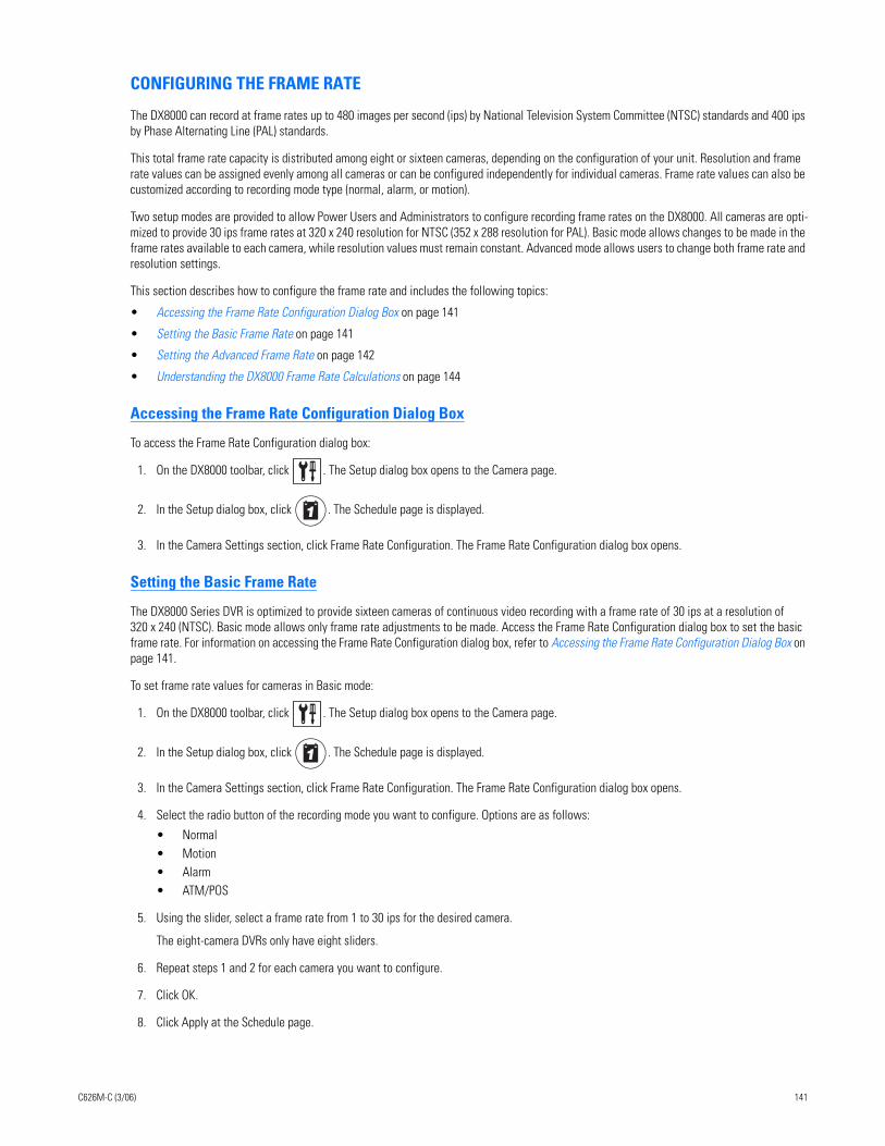
CONFIGURING THE FRAME RATE
The DX8000 can record at frame rates up to 480 images per second (ips) by National Television System Committee (NTSC) standards and 400 ips by Phase Alternating Line (PAL) standards.
This total frame rate capacity is distributed among eight or sixteen cameras, depending on the configuration of your unit. Resolution and frame rate values can be assigned evenly among all cameras or can be configured independently for individual cameras. Frame rate values can also be customized according to recording mode type (normal, alarm, or motion).
Two setup modes are provided to allow Power Users and Administrators to configure recording frame rates on the DX8000. All cameras are opti-mized to provide 30 ips frame rates at 320 x 240 resolution for NTSC (352 x 288 resolution for PAL). Basic mode allows changes to be made in the frame rates available to each camera, while resolution values must remain constant. Advanced mode allows users to change both frame rate and resolution settings.
This section describes how to configure the frame rate and includes the following topics:
• Accessing the Frame Rate Configuration Dialog Box on page 141
• Setting the Basic Frame Rate on page 141
• Setting the Advanced Frame Rate on page 142
• Understanding the DX8000 Frame Rate Calculations on page 144
Accessing the Frame Rate Configuration Dialog Box
To access the Frame Rate Configuration dialog box:
1. On the DX8000 toolbar, click . The Setup dialog box opens to the Camera page.
2. In the Setup dialog box, click . The Schedule page is displayed.
3. In the Camera Settings section, click Frame Rate Configuration. The Frame Rate Configuration dialog box opens.
Setting the Basic Frame Rate
The DX8000 Series DVR is optimized to provide sixteen cameras of continuous video recording with a frame rate of 30 ips at a resolution of 320 x 240 (NTSC). Basic mode allows only frame rate adjustments to be made. Access the Frame Rate Configuration dialog box to set the basic frame rate. For information on accessing the Frame Rate Configuration dialog box, refer to Accessing the Frame Rate Configuration Dialog Box on page 141.
To set frame rate values for cameras in Basic mode:
1. On the DX8000 toolbar, click . The Setup dialog box opens to the Camera page.
2. In the Setup dialog box, click . The Schedule page is displayed.
3. In the Camera Settings section, click Frame Rate Configuration. The Frame Rate Configuration dialog box opens.
4. Select the radio button of the recording mode you want to configure. Options are as follows:
• Normal• Motion• Alarm• ATM/POS
5. Using the slider, select a frame rate from 1 to 30 ips for the desired camera.
The eight-camera DVRs only have eight sliders.
6. Repeat steps 1 and 2 for each camera you want to configure.
7. Click OK.
8. Click Apply at the Schedule page.
C626M-C (3/06) 141
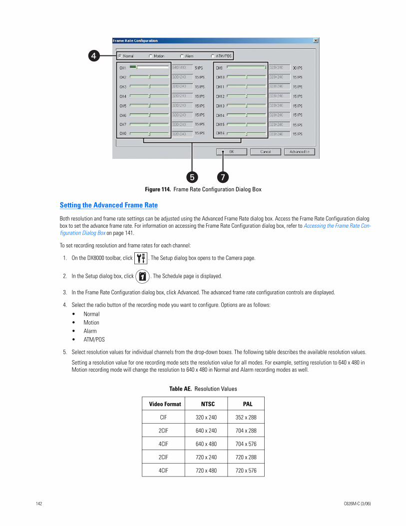
Figure 114. Frame Rate Configuration Dialog Box
Setting the Advanced Frame Rate
Both resolution and frame rate settings can be adjusted using the Advanced Frame Rate dialog box. Access the Frame Rate Configuration dialog box to set the advance frame rate. For information on accessing the Frame Rate Configuration dialog box, refer to Accessing the Frame Rate Con-figuration Dialog Box on page 141.
To set recording resolution and frame rates for each channel:
1. On the DX8000 toolbar, click . The Setup dialog box opens to the Camera page.
2. In the Setup dialog box, click . The Schedule page is displayed.
3. In the Frame Rate Configuration dialog box, click Advanced. The advanced frame rate configuration controls are displayed.
4. Select the radio button of the recording mode you want to configure. Options are as follows:
• Normal• Motion• Alarm• ATM/POS
5. Select resolution values for individual channels from the drop-down boxes. The following table describes the available resolution values.
Setting a resolution value for one recording mode sets the resolution value for all modes. For example, setting resolution to 640 x 480 in Motion recording mode will change the resolution to 640 x 480 in Normal and Alarm recording modes as well.
Table AE. Resolution Values
Video Format NTSC PAL
CIF 320 x 240 352 x 288
2CIF 640 x 240 704 x 288
4CIF 640 x 480 704 x 576
2CIF 720 x 240 720 x 288
4CIF 720 x 480 720 x 576
��
�
142 C626M-C (3/06)
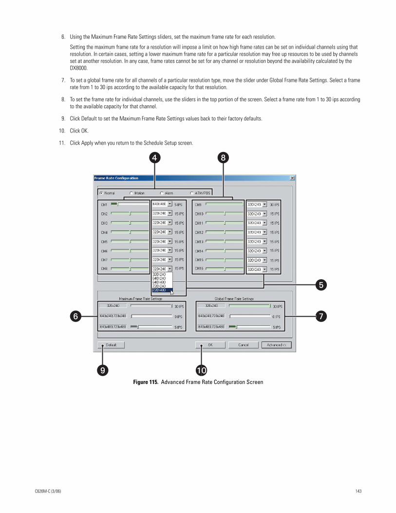
6. Using the Maximum Frame Rate Settings sliders, set the maximum frame rate for each resolution.
Setting the maximum frame rate for a resolution will impose a limit on how high frame rates can be set on individual channels using that resolution. In certain cases, setting a lower maximum frame rate for a particular resolution may free up resources to be used by channels set at another resolution. In any case, frame rates cannot be set for any channel or resolution beyond the availability calculated by the DX8000.
7. To set a global frame rate for all channels of a particular resolution type, move the slider under Global Frame Rate Settings. Select a frame rate from 1 to 30 ips according to the available capacity for that resolution.
8. To set the frame rate for individual channels, use the sliders in the top portion of the screen. Select a frame rate from 1 to 30 ips according to the available capacity for that channel.
9. Click Default to set the Maximum Frame Rate Settings values back to their factory defaults.
10. Click OK.
11. Click Apply when you return to the Schedule Setup screen.
Figure 115. Advanced Frame Rate Configuration Screen
� �
�
�
� �
�
C626M-C (3/06) 143
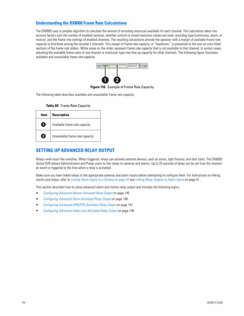
Understanding the DX8000 Frame Rate Calculations
The DX8000 uses a complex algorithm to calculate the amount of recording resources available for each channel. This calculation takes into account factors such the number of enabled cameras, whether uniform or mixed resolution values are used, recording type (continuous, alarm, or motion), and the frame rate settings of enabled channels. The resulting calculations provide the operator with a margin of available frame rate capacity to distribute among the recorder’s channels. This margin of frame rate capacity, or “headroom,” is presented to the user as color-filled sections of the frame rate sliders. White areas on the slider represent frame rate capacity that is not available to that channel. In certain cases, adjusting the available frame rates of one channel or resolution type may free up capacity for other channels. The following figure illustrates available and unavailable frame rate capacity.
Figure 116. Example of Frame Rate Capacity
The following table describes available and unavailable frame rate capacity.
SETTING UP ADVANCED RELAY OUTPUT
Relays work much like switches. When triggered, relays can activate external devices, such as sirens, light fixtures, and door locks. The DX8000 Series DVR allows Administrators and Power users to link relays to cameras and alarms. Up to 20 seconds of delay can be set from the moment an event is triggered to the time when a relay is activated.
Make sure you have linked relays to the appropriate cameras and alarm inputs before attempting to configure them. For instructions on linking alarms and relays, refer to Linking Alarm Inputs to a Camera on page 41 and Linking Relay Outputs to Alarm Inputs on page 41.
This section describes how to setup advanced alarm and motion relay output and includes the following topics:
• Configuring Advanced Motion-Activated Relay Output on page 145
• Configuring Advanced Alarm-Activated Relay Output on page 146
• Configuring Advanced ATM/POS-Activated Relay Output on page 147
• Configuring Advanced Video Loss-Activated Relay Output on page 148
Table AF. Frame Rate Capacity
Item Description
Available frame rate capacity
Unavailable frame rate capacity
�
144 C626M-C (3/06)
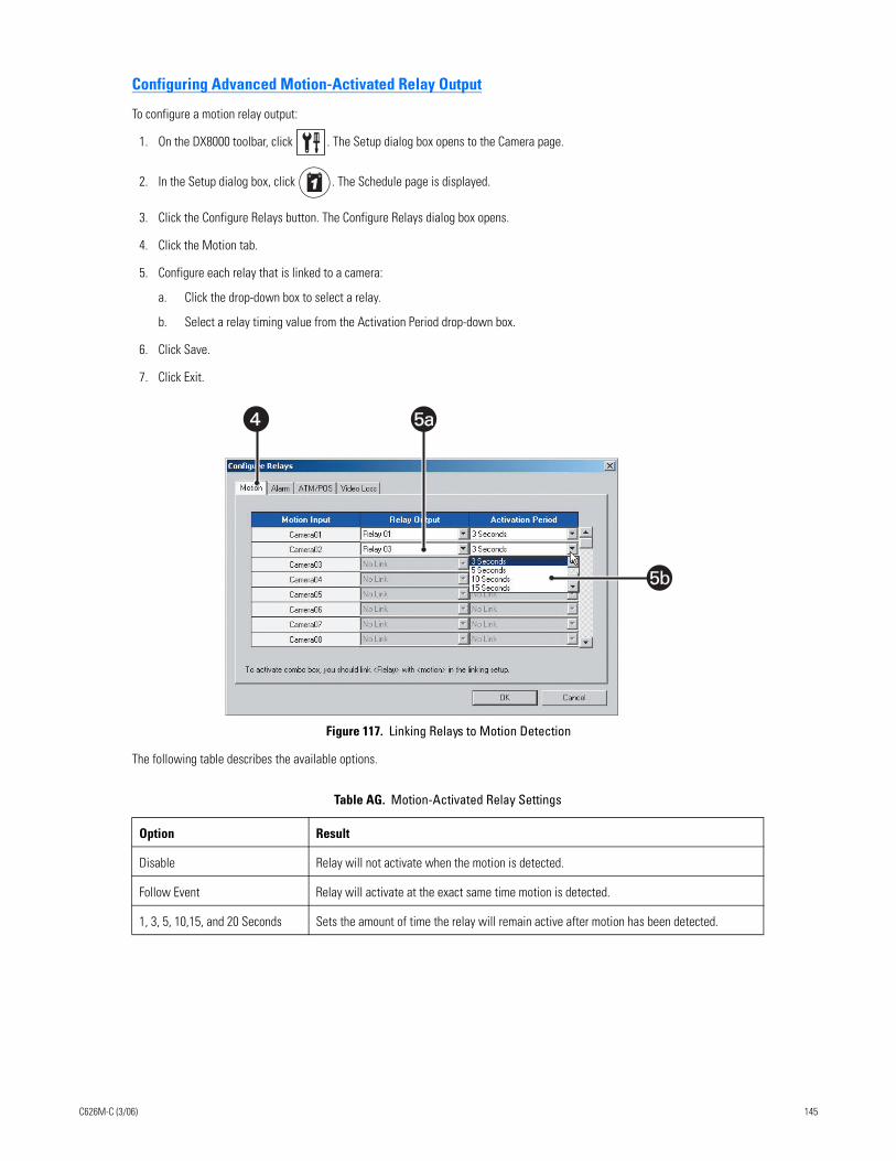
Configuring Advanced Motion-Activated Relay Output
To configure a motion relay output:
1. On the DX8000 toolbar, click . The Setup dialog box opens to the Camera page.
2. In the Setup dialog box, click . The Schedule page is displayed.
3. Click the Configure Relays button. The Configure Relays dialog box opens.
4. Click the Motion tab.
5. Configure each relay that is linked to a camera:
a. Click the drop-down box to select a relay.
b. Select a relay timing value from the Activation Period drop-down box.
6. Click Save.
7. Click Exit.
Figure 117. Linking Relays to Motion Detection
The following table describes the available options.
Table AG. Motion-Activated Relay Settings
Option Result
Disable Relay will not activate when the motion is detected.
Follow Event Relay will activate at the exact same time motion is detected.
1, 3, 5, 10,15, and 20 Seconds Sets the amount of time the relay will remain active after motion has been detected.
� 5a5a
5b
C626M-C (3/06) 145
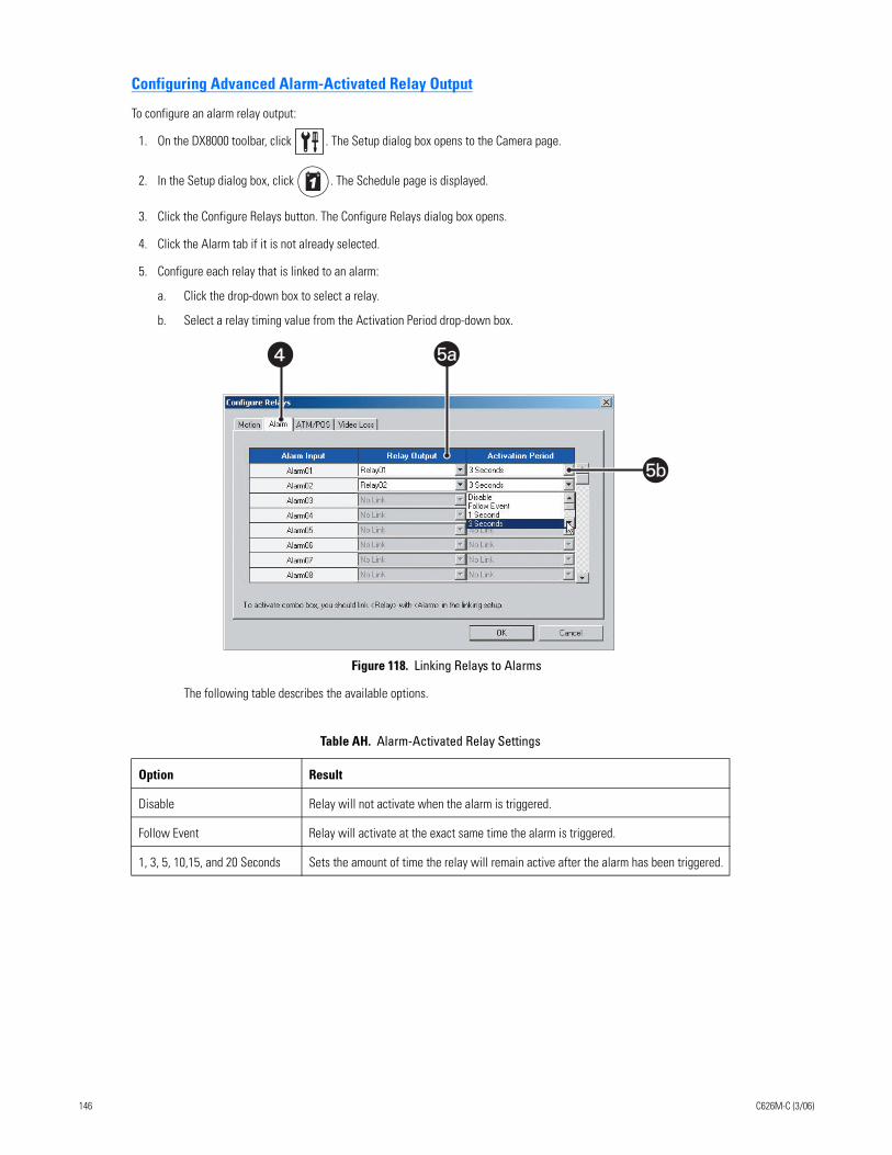
Configuring Advanced Alarm-Activated Relay Output
To configure an alarm relay output:
1. On the DX8000 toolbar, click . The Setup dialog box opens to the Camera page.
2. In the Setup dialog box, click . The Schedule page is displayed.
3. Click the Configure Relays button. The Configure Relays dialog box opens.
4. Click the Alarm tab if it is not already selected.
5. Configure each relay that is linked to an alarm:
a. Click the drop-down box to select a relay.
b. Select a relay timing value from the Activation Period drop-down box.
Figure 118. Linking Relays to Alarms
The following table describes the available options.
Table AH. Alarm-Activated Relay Settings
Option Result
Disable Relay will not activate when the alarm is triggered.
Follow Event Relay will activate at the exact same time the alarm is triggered.
1, 3, 5, 10,15, and 20 Seconds Sets the amount of time the relay will remain active after the alarm has been triggered.
� 5a
5b
146 C626M-C (3/06)
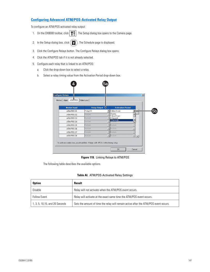
Configuring Advanced ATM/POS-Activated Relay Output
To configure an ATM/POS-activated relay output:
1. On the DX8000 toolbar, click . The Setup dialog box opens to the Camera page.
2. In the Setup dialog box, click . The Schedule page is displayed.
3. Click the Configure Relays button. The Configure Relays dialog box opens.
4. Click the ATM/POS tab if it is not already selected.
5. Configure each relay that is linked to an ATM/POS:
a. Click the drop-down box to select a relay.
b. Select a relay timing value from the Activation Period drop-down box.
Figure 119. Linking Relays to ATM/POS
The following table describes the available options.
Table AI. ATM/POS-Activated Relay Settings
Option Result
Disable Relay will not activate when the ATM/POS event occurs.
Follow Event Relay will activate at the exact same time the ATM/POS event occurs.
1, 3, 5, 10,15, and 20 Seconds Sets the amount of time the relay will remain active after the ATM/POS event occurs.
� 5a5a
5b
C626M-C (3/06) 147
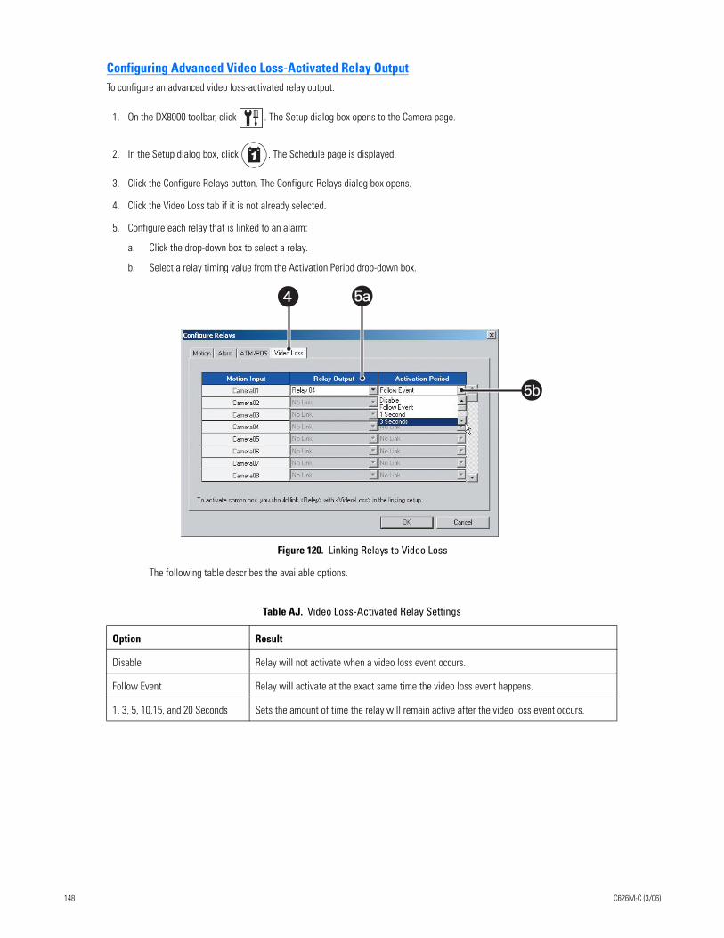
Configuring Advanced Video Loss-Activated Relay OutputTo configure an advanced video loss-activated relay output:
1. On the DX8000 toolbar, click . The Setup dialog box opens to the Camera page.
2. In the Setup dialog box, click . The Schedule page is displayed.
3. Click the Configure Relays button. The Configure Relays dialog box opens.
4. Click the Video Loss tab if it is not already selected.
5. Configure each relay that is linked to an alarm:
a. Click the drop-down box to select a relay.
b. Select a relay timing value from the Activation Period drop-down box.
Figure 120. Linking Relays to Video Loss
The following table describes the available options.
Table AJ. Video Loss-Activated Relay Settings
Option Result
Disable Relay will not activate when a video loss event occurs.
Follow Event Relay will activate at the exact same time the video loss event happens.
1, 3, 5, 10,15, and 20 Seconds Sets the amount of time the relay will remain active after the video loss event occurs.
� 5a5a
5b
148 C626M-C (3/06)
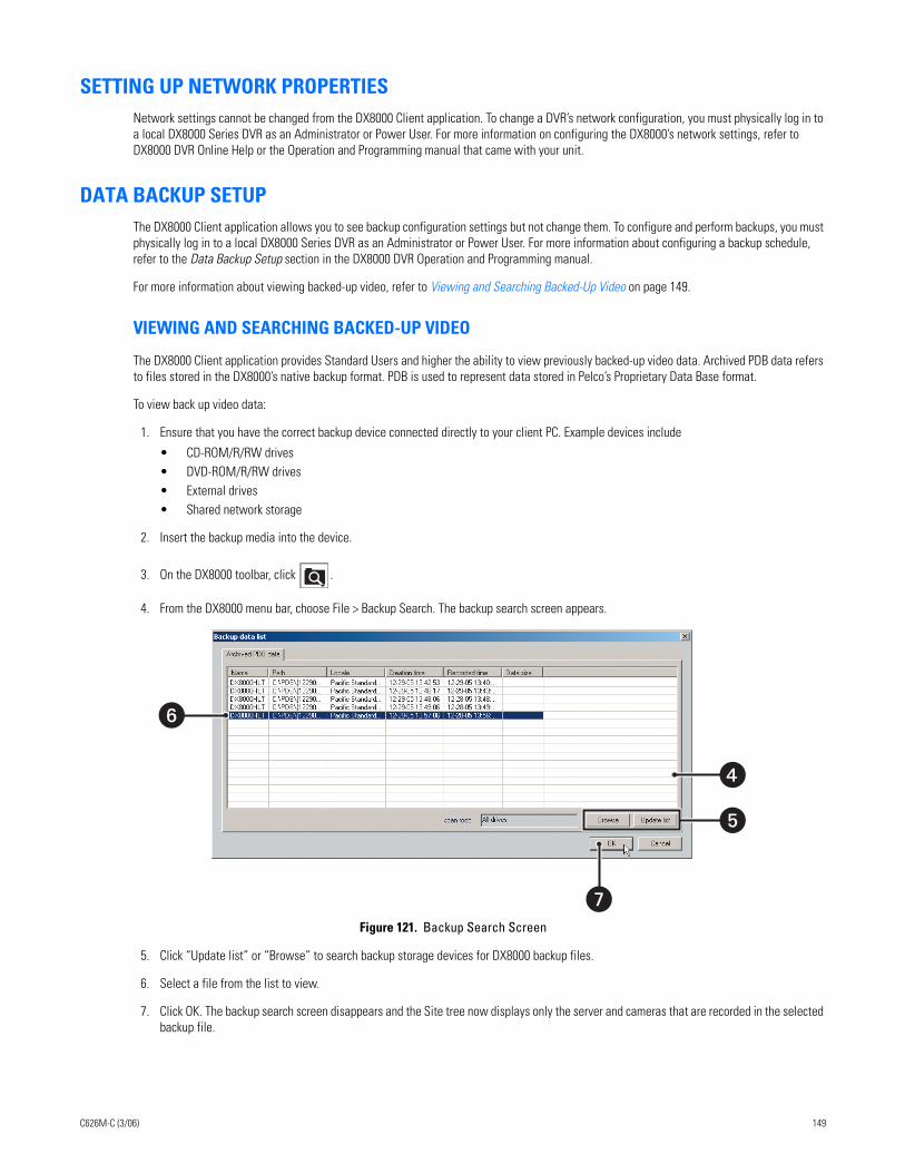
SETTING UP NETWORK PROPERTIESNetwork settings cannot be changed from the DX8000 Client application. To change a DVR’s network configuration, you must physically log in to a local DX8000 Series DVR as an Administrator or Power User. For more information on configuring the DX8000’s network settings, refer to DX8000 DVR Online Help or the Operation and Programming manual that came with your unit.
DATA BACKUP SETUPThe DX8000 Client application allows you to see backup configuration settings but not change them. To configure and perform backups, you must physically log in to a local DX8000 Series DVR as an Administrator or Power User. For more information about configuring a backup schedule, refer to the Data Backup Setup section in the DX8000 DVR Operation and Programming manual.
For more information about viewing backed-up video, refer to Viewing and Searching Backed-Up Video on page 149.
VIEWING AND SEARCHING BACKED-UP VIDEO
The DX8000 Client application provides Standard Users and higher the ability to view previously backed-up video data. Archived PDB data refers to files stored in the DX8000’s native backup format. PDB is used to represent data stored in Pelco’s Proprietary Data Base format.
To view back up video data:
1. Ensure that you have the correct backup device connected directly to your client PC. Example devices include
• CD-ROM/R/RW drives• DVD-ROM/R/RW drives• External drives• Shared network storage
2. Insert the backup media into the device.
3. On the DX8000 toolbar, click .
4. From the DX8000 menu bar, choose File > Backup Search. The backup search screen appears.
Figure 121. Backup Search Screen
5. Click “Update list” or “Browse” to search backup storage devices for DX8000 backup files.
6. Select a file from the list to view.
7. Click OK. The backup search screen disappears and the Site tree now displays only the server and cameras that are recorded in the selected backup file.
�
�
�
�
C626M-C (3/06) 149
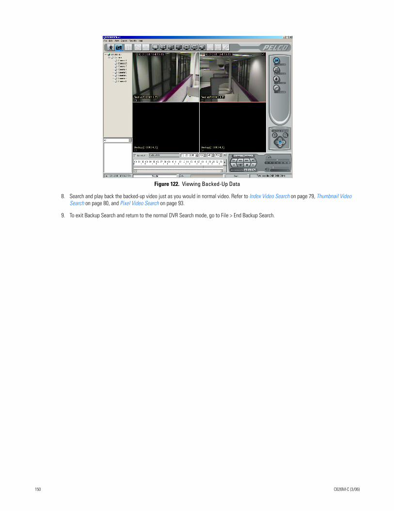
Figure 122. Viewing Backed-Up Data
8. Search and play back the backed-up video just as you would in normal video. Refer to Index Video Search on page 79, Thumbnail Video Search on page 80, and Pixel Video Search on page 93.
9. To exit Backup Search and return to the normal DVR Search mode, go to File > End Backup Search.
150 C626M-C (3/06)
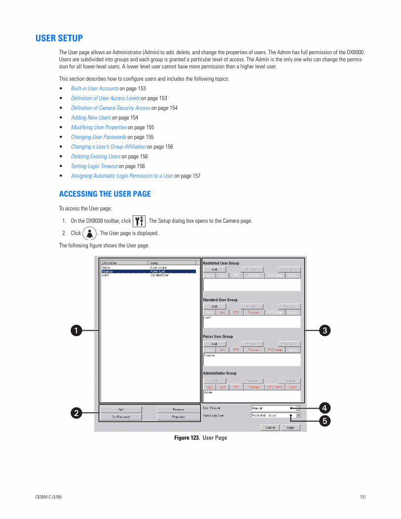
USER SETUPThe User page allows an Administrator (Admin) to add, delete, and change the properties of users. The Admin has full permission of the DX8000. Users are subdivided into groups and each group is granted a particular level of access. The Admin is the only one who can change the permis-sion for all lower-level users. A lower level user cannot have more permission than a higher level user.
This section describes how to configure users and includes the following topics:
• Built-in User Accounts on page 153
• Definition of User Access Levels on page 153
• Definition of Camera Security Access on page 154
• Adding New Users on page 154
• Modifying User Properties on page 155
• Changing User Passwords on page 155
• Changing a User’s Group Affiliation on page 156
• Deleting Existing Users on page 156
• Setting Login Timeout on page 156
• Assigning Automatic Login Permission to a User on page 157
ACCESSING THE USER PAGE
To access the User page:
1. On the DX8000 toolbar, click . The Setup dialog box opens to the Camera page.
2. Click . The User page is displayed.
The following figure shows the User page.
Figure 123. User Page
�
��
�
C626M-C (3/06) 151
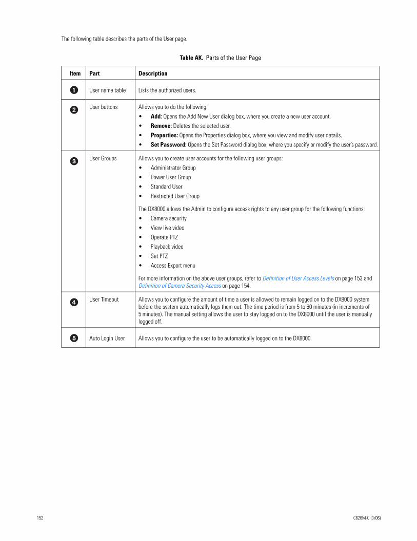
The following table describes the parts of the User page.
Table AK. Parts of the User Page
Item Part Description
User name table Lists the authorized users.
User buttons Allows you to do the following:
• Add: Opens the Add New User dialog box, where you create a new user account.
• Remove: Deletes the selected user.
• Properties: Opens the Properties dialog box, where you view and modify user details.
• Set Password: Opens the Set Password dialog box, where you specify or modify the user’s password.
User Groups Allows you to create user accounts for the following user groups:
• Administrator Group
• Power User Group
• Standard User
• Restricted User Group
The DX8000 allows the Admin to configure access rights to any user group for the following functions:
• Camera security
• View live video
• Operate PTZ
• Playback video
• Set PTZ
• Access Export menu
For more information on the above user groups, refer to Definition of User Access Levels on page 153 and Definition of Camera Security Access on page 154.
User Timeout Allows you to configure the amount of time a user is allowed to remain logged on to the DX8000 system before the system automatically logs them out. The time period is from 5 to 60 minutes (in increments of 5 minutes). The manual setting allows the user to stay logged on to the DX8000 until the user is manually logged off.
Auto Login User Allows you to configure the user to be automatically logged on to the DX8000.
152 C626M-C (3/06)
BUILT-IN USER ACCOUNTS
There are two built-in user accounts that come preconfigured on the DX8000, and they cannot be deleted or changed.
• Guest: The Guest account provides limited access to the system. The Guest user can view live video but cannot play back recorded video or access system configuration functions. The Guest account automatically becomes active when the system is first started and each time a user logs out. The Guest user is not a member of any group; however, Guest retains all of the rights and privileges of the Restricted Users group with the exception of the ability to view low security cameras.
• Admin: The Admin account has full access to the system. The Admin user can view live and play back video, access all configuration settings, add and modify users, and can perform searches and backups. The Admin user is a member of the Administrators group and cannot be removed.
DEFINITION OF USER ACCESS LEVELS
There are four predefined user access levels or groups. User access levels range from the Administrator group to the Restricted group. By default, the system starts up with a default Guest account. The Admin can assign automatic login for a specified user. For information about setting up auto login, refer to Assigning Automatic Login Permission to a User on page 157.
The Guest account has Restricted user access. The following table describes the user group’s access rights.
Table AL. User Group Access Rights
User GroupsView Live
Video
View Recorded
Video
Operate PTZ
Search Video
Backup Video
System Setup
Shut Down
System
Add/Remove
Users
Change User/Group Properties
Exit to Windows
Administrators
Power Users
Standard Users
Restricted Users
Guest Users
C626M-C (3/06) 153
DEFINITION OF CAMERA SECURITY ACCESS
Users are limited by the Admin to the cameras they are allowed to view. Access to a camera is determined by its security designation. The Admin can configure access rights to any user group for any of the following functions:
• Camera security
• View live video
• Operate PTZ
• Playback video
• Set PTZ
• Access Export menu
Only users with High Security access can view cameras designated as High Security. Medium Security cameras can be viewed by users with Medium Security access and higher. All users except Guest can view Low Security cameras. All users can view No Security cameras.
The following table summarizes camera security levels and user access.
ADDING NEW USERS
Administrators can create new user accounts and modify existing users locally on the DX8000 server or remotely from the DX8000 Client Appli-cation.
User names and passwords have the following requirements:
• User names can be between 4 and 20 alphanumeric characters in length.
• User passwords can be between 4 and 10 alphanumeric characters in length.
• User names cannot contain spaces and special characters.
• User names and passwords are case sensitive.
To add a new user:
1. On the DX8000 toolbar, click . The Setup dialog box opens to the Camera page.
2. Click . The User page is displayed.
3. Click Add. The Add New User dialog box opens.
4. Do the following:
a. Enter a login name for the user.
b. Enter the user’s full name.
c. Enter a brief description for the user. For example, enter Building 6 Security Guard.
d. Enter a password for the user. (Passwords must be between 4 and 10 characters in length and cannot contain spaces and special characters.)
e. Re-enter the same password to confirm its validity.
Table AM. Camera Security Levels
Groups No Security Cameras
Low Security Cameras
Medium Security Cameras
High Security Cameras
Administrators
Power Users
Standard Users
Restricted Users
Guest Users
154 C626M-C (3/06)
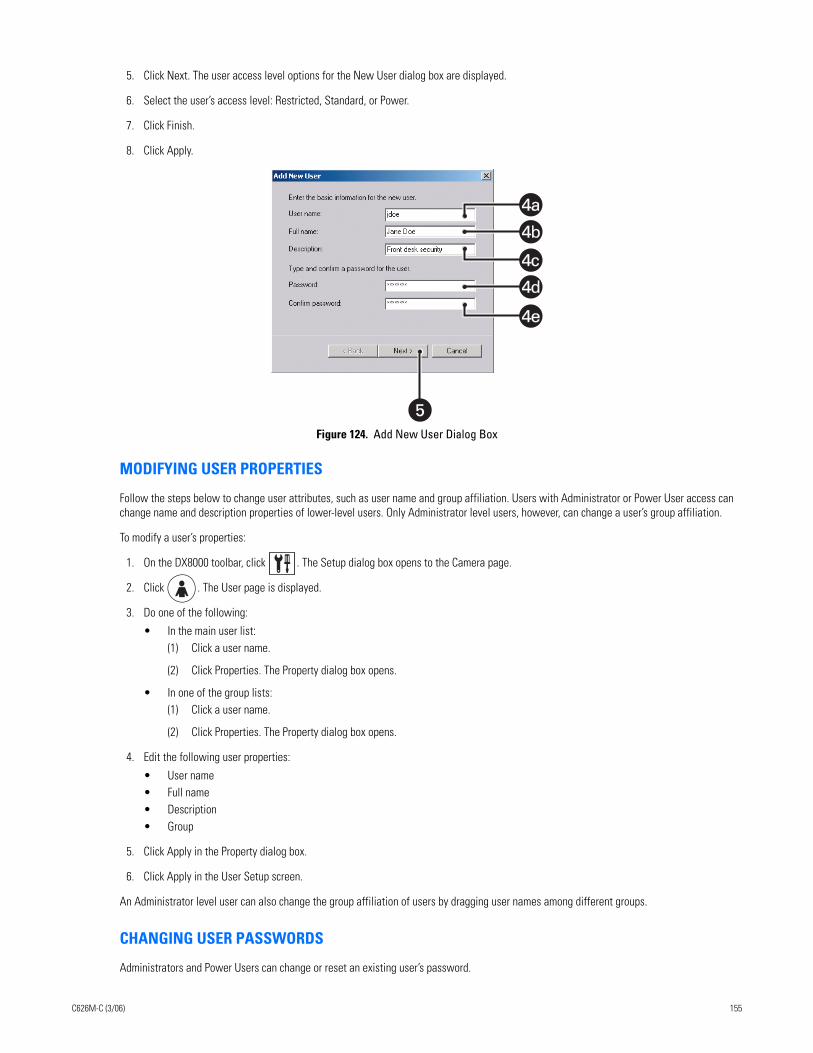
5. Click Next. The user access level options for the New User dialog box are displayed.
6. Select the user’s access level: Restricted, Standard, or Power.
7. Click Finish.
8. Click Apply.
Figure 124. Add New User Dialog Box
MODIFYING USER PROPERTIES
Follow the steps below to change user attributes, such as user name and group affiliation. Users with Administrator or Power User access can change name and description properties of lower-level users. Only Administrator level users, however, can change a user’s group affiliation.
To modify a user’s properties:
1. On the DX8000 toolbar, click . The Setup dialog box opens to the Camera page.
2. Click . The User page is displayed.
3. Do one of the following:
• In the main user list:(1) Click a user name.
(2) Click Properties. The Property dialog box opens.
• In one of the group lists:(1) Click a user name.
(2) Click Properties. The Property dialog box opens.
4. Edit the following user properties:
• User name• Full name• Description• Group
5. Click Apply in the Property dialog box.
6. Click Apply in the User Setup screen.
An Administrator level user can also change the group affiliation of users by dragging user names among different groups.
CHANGING USER PASSWORDS
Administrators and Power Users can change or reset an existing user’s password.
�
4b
4d
4a
4c
4e
C626M-C (3/06) 155
To change a user’s password:
1. On the DX8000 toolbar, click . The Setup dialog box opens to the Camera page.
2. Click . The User page is displayed.
3. Click a user name in the main user list.
4. Click Set Password. The Set Password dialog box opens.
5. Enter a new password in the “New password” field.
6. Retype the password again in the “Confirm new password” field.
7. Click Apply in the Set Password dialog box.
8. Click Apply in the User Setup screen.
CHANGING A USER’S GROUP AFFILIATION
An Administrator level user can also change the group affiliation of users by dragging user names among different groups.
To change a user's group affiliation:
DELETING EXISTING USERS
Administrators can delete existing users.
To delete a user’s account:
1. On the DX8000 toolbar, click . The Setup dialog box opens to the Camera page.
2. Click . The User page is displayed.
3. Click the user name of the user you want to delete from the main user list.
4. Click Remove. The Remove User dialog box opens.
5. Click Yes to confirm the deletion or No to cancel and return to the User Setup screen.
6. Click the Apply button at the bottom of the screen.
SETTING LOGIN TIMEOUT
Administrators can define the amount of time a user’s account can remain idle before having to log in again. This setting applies to all users, regardless of access level.
To set login timeout:
1. On the DX8000 toolbar, click . The Setup dialog box opens to the Camera page.
2. Click . The User page is displayed.
3. Select a time limit from the User Timeout drop-down box.
• Time limits range from five minutes to one hour, in five-minute increments.• Selecting Manual from the drop-down box will suspend the automatic logout feature. (A user will remain logged in until the user logs
out or another user logs in.)
4. Click Apply.
In the User name column of the User page, click the user's name and drag it in a group.
156 C626M-C (3/06)
ASSIGNING AUTOMATIC LOGIN PERMISSION TO A USER
The DX8000 allows one user to be able to automatically log in to the DX8000 application. The administrator must assign automatic login permis-sion to the user. Once automatic login permission is assigned to the user, the user will be automatically logged in to the DX8000 application. In this case, the assigned user does not have to enter the user name and password.
NOTE: Automatic login user permission makes the DX8000 more vulnerable because a higher level of user is logged in every time.
To assign automatic login permission:
1. On the DX8000 toolbar, click . The Setup dialog box opens to the Camera page.
2. Click . The User page is displayed.
3. In the Auto Login User drop-down selection box, select a user.
4. Click Apply.
The next time the DX8000 application is started, the assigned user is logged in automatically.
SITE SETUPThe DX8000 Client application does not allow you to access the Site page to configure remote sites. You must physically log in to the local DX8000 Series DVR as an Administrator or Power User to configure remote sites. For more information on configuring remote sites, refer to the DX8000 DVR server online Help or Operation and Programming manual that came with your unit.
C626M-C (3/06) 157
SYSTEM SETUPMany of the options presented in the System page cannot be configured from the DX8000 Client application. Administrators and Power Users are allowed to import and export system configuration files and to view and export system logs. To modify other system setup options, you must physically log in to the local DX8000 Series DVR as an Administrator or Power User. For more information, refer to the DX8000 DVR online Help or Operation and Programming manual that came with your unit.
This section describes how to configure system options and parameters and includes the following topics:
• Accessing the System Page on page 158
• Working with the Export Feature on page 158
• Working with the Import Feature on page 160
• Using System Logs on page 161
ACCESSING THE SYSTEM PAGE
To access the System page:
1. On the DX8000 toolbar, click . The Setup dialog box opens to the Camera page.
2. Click . The System page is displayed.
WORKING WITH THE EXPORT FEATURE
The DX8000 provides an import and export feature that allows you to save and reload DX8000 configuration settings. You can save your DX8000 DVR configuration settings by exporting them to a specific storage media and location. You can reload a specific configurations profile by import-ing its configuration file.
This sections describes how to use the import and export feature and includes the following topics:
• Exporting Current DVR Settings on page 158
• Using the Edit Menu to Perform an Export on page 159
Exporting Current DVR Settings
To save current DVR configuration settings:
1. On the DX8000 toolbar, click . The Setup dialog box opens to the Camera page.
2. Click . The System page is displayed.
3. Select the Export radio button.
4. Select the check boxes of each configuration item you want to back up, or click Select All to export all settings.
158 C626M-C (3/06)
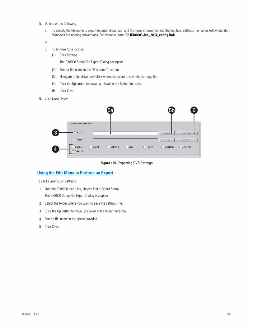
5. Do one of the following:
a. To specify the file name to export to, enter drive, path and file name information into the text box. Settings file names follow standard Windows file-naming conventions. For example, enter C:\ DX8000 \ Jan_2004_config.bak.
or
b. To browse for a location:
(1) Click Browse.
The DX8000 Setup File Export Dialog box opens.
(2) Enter a file name in the “File name” text box.
(3) Navigate to the drive and folder where you want to save the settings file.
(4) Click the Up button to move up a level in the folder hierarchy.
(5) Click Save.
6. Click Export Now.
Figure 125. Exporting DVR Settings
Using the Edit Menu to Perform an Export
To save current DVR settings:
1. From the DX8000 menu bar, choose Edit > Export Setup.
The DX8000 Setup File Export Dialog box opens.
2. Select the folder where you want to save the settings file.
3. Click the Up button to move up a level in the folder hierarchy.
4. Enter a file name in the space provided.
5. Click Save.
�
�
5a 5b �
C626M-C (3/06) 159
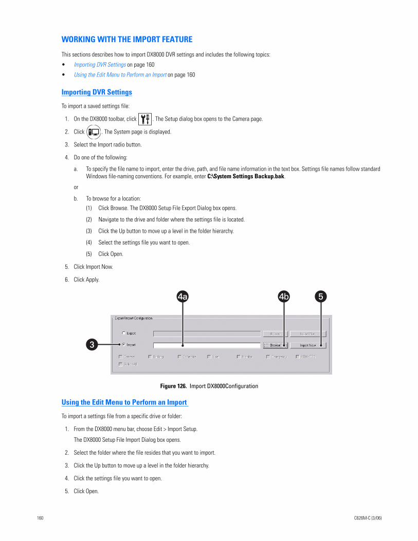
WORKING WITH THE IMPORT FEATURE
This sections describes how to import DX8000 DVR settings and includes the following topics:
• Importing DVR Settings on page 160
• Using the Edit Menu to Perform an Import on page 160
Importing DVR Settings
To import a saved settings file:
1. On the DX8000 toolbar, click . The Setup dialog box opens to the Camera page.
2. Click . The System page is displayed.
3. Select the Import radio button.
4. Do one of the following:
a. To specify the file name to import, enter the drive, path, and file name information in the text box. Settings file names follow standard Windows file-naming conventions. For example, enter C:\System Settings Backup.bak.
or
b. To browse for a location:
(1) Click Browse. The DX8000 Setup File Export Dialog box opens.
(2) Navigate to the drive and folder where the settings file is located.
(3) Click the Up button to move up a level in the folder hierarchy.
(4) Select the settings file you want to open.
(5) Click Open.
5. Click Import Now.
6. Click Apply.
Figure 126. Import DX8000Configuration
Using the Edit Menu to Perform an Import
To import a settings file from a specific drive or folder:
1. From the DX8000 menu bar, choose Edit > Import Setup.
The DX8000 Setup File Import Dialog box opens.
2. Select the folder where the file resides that you want to import.
3. Click the Up button to move up a level in the folder hierarchy.
4. Click the settings file you want to open.
5. Click Open.
�
4a4a 4b �
160 C626M-C (3/06)
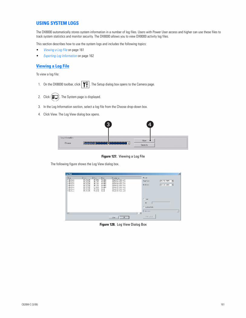
USING SYSTEM LOGS
The DX8000 automatically stores system information in a number of log files. Users with Power User access and higher can use these files to track system statistics and monitor security. The DX8000 allows you to view DX8000 activity log files.
This section describes how to use the system logs and includes the following topics:
• Viewing a Log File on page 161
• Exporting Log Information on page 162
Viewing a Log File
To view a log file:
1. On the DX8000 toolbar, click . The Setup dialog box opens to the Camera page.
2. Click . The System page is displayed.
3. In the Log Information section, select a log file from the Choose drop-down box.
4. Click View. The Log View dialog box opens.
Figure 127. Viewing a Log File
The following figure shows the Log View dialog box.
Figure 128. Log View Dialog Box
��
C626M-C (3/06) 161
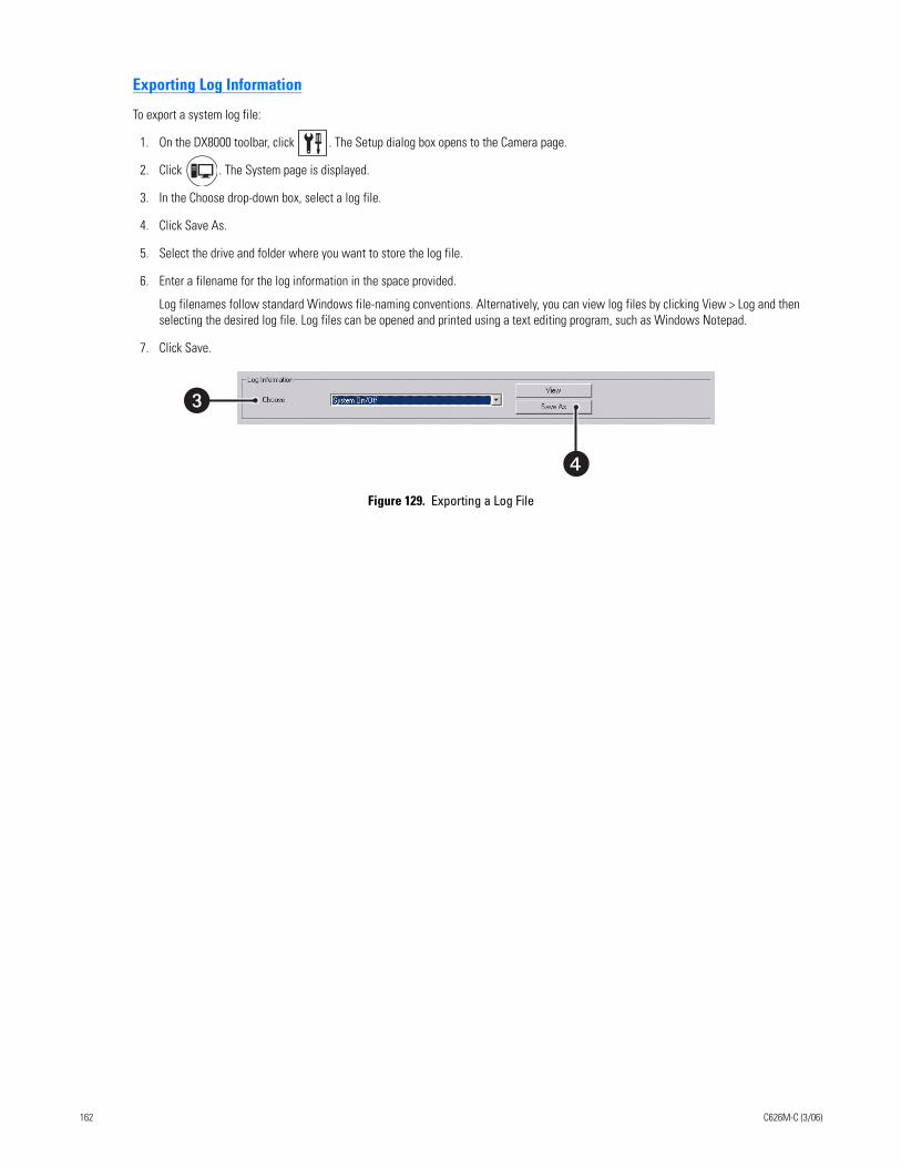
Exporting Log Information
To export a system log file:
1. On the DX8000 toolbar, click . The Setup dialog box opens to the Camera page.
2. Click . The System page is displayed.
3. In the Choose drop-down box, select a log file.
4. Click Save As.
5. Select the drive and folder where you want to store the log file.
6. Enter a filename for the log information in the space provided.
Log filenames follow standard Windows file-naming conventions. Alternatively, you can view log files by clicking View > Log and then selecting the desired log file. Log files can be opened and printed using a text editing program, such as Windows Notepad.
7. Click Save.
Figure 129. Exporting a Log File
�
�
162 C626M-C (3/06)
EXTERNAL MONITOR SETUPThe external monitor settings of a remote DVR cannot be changed from the DX8000 Client application. To change a DVR’s analog monitor configuration, you must physically log in to a local DX8000 Series DVR as an Administrator or Power User. For more information on configuring the DX8000’s optional analog monitor outputs, refer to the DX8000 DVR online Help or Operation and Programming manual that came with your unit.
EMERGENCY NOTIFICATION SETUPThe Emergency Agent Notification alerts selected clients of motion, alarm and video loss events detected by DX8000 server sites. When a motion, alarm or video loss event is triggered, a pop-up window opens on the monitor of the remote site client. The window displays one or more still images taken during the event.
Users with Power User access and higher can configure the emergency agent notification system. The first step in the setup process requires that clients be added to the emergency agent notification list. To complete this step, you must provide a valid name and the IP address of each client PC. After clients have been added they can be linked to one or more cameras. Finally, the amount of time a server sends images after an event occurs and the interval between sending each image must be set.
NOTE: Before configuring the Emergency Agent Notification, make sure the Emergency Agent Client utility is installed on one or more client PCs. For information on installing the Emergency Agent Client utility, refer to Installing the Client Emergency Agent Application in this manual.
This section describes how to setup emergency notification and includes the following topics:
• Accessing the Emergency Agent Notification Setup on page 163
• Adding Client Emergency Agents to be Notified on page 163
• Changing Client Emergency Agent Properties on page 164
• Deleting Clients from the Notification List on page 164
• Linking Cameras to Client Emergency Agents on page 164
• Setting Server Event Transmission Time on page 165
ACCESSING THE EMERGENCY AGENT NOTIFICATION SETUP
To access the Emergency Agent Notification setup:
1. On the DX8000 toolbar, click . The Setup dialog box opens to the Camera page.
2. Click . The Notification page is displayed.
ADDING CLIENT EMERGENCY AGENTS TO BE NOTIFIED
After clients have been added, cameras must be configured to notify individual clients of an event. A single camera can be linked to one or more client emergency agents. For information on linking cameras to client emergency agents, refer to Linking Cameras to Client Emergency Agents on page 164.
To add clients to the Emergency Agent Notification list:
1. On the DX8000 toolbar, click . The Setup dialog box opens to the Camera page.
2. Click . The Notification page is displayed.
3. Click Add. The Agent Setup dialog box opens.
4. Do the following:
a. Enter a name for the client. (Client names can be up to 63 characters and can include spaces, but not special characters.
b. Enter the client’s IP address.
c. If necessary, enter a port number in the Agent Port text box. (The default port number is 9004.)
Unless there is a conflict on your network, you should not change the Emergency Agent port number from its default of 9004. Make sure any changes to port numbers are made consistently across all DX8000 servers and clients on a network. Client and server ports must be identical.
C626M-C (3/06) 163
5. Click OK.
6. Click the Apply button at the bottom of the screen.
CHANGING CLIENT EMERGENCY AGENT PROPERTIES
To change an existing client’s information in the emergency notification list:
1. On the DX8000 toolbar, click . The Setup dialog box opens to the Camera page.
2. Click . The Notification page is displayed.
3. Do the following:
a. In the Emergency Agent Setup section, select a client from the list.
b. Click Edit. The Agent Setup dialog box opens.
c. Enter a new name for the client. (Client names can be up to 63 characters long and can include spaces, but not special characters.)
d. Enter a new IP address for the client.
e. If necessary, enter a port number in the Agent Port text box. (The default port number is 9004.)
Unless there is a conflict on your network, you should not change the Emergency Agent port number from its default of 9004. Make sure any changes to port numbers are made consistently across all DX8000 servers and clients on a network. Client and server ports must be identical.
4. Click OK.
5. Click the Apply button at the bottom of the screen.
DELETING CLIENTS FROM THE NOTIFICATION LIST
To delete a client from the emergency notification list:
1. On the DX8000 toolbar, click . The Setup dialog box opens to the Camera page.
2. Click . The Notification page is displayed.
3. Do the following:
a. In the Emergency Agent Setup section, select a client from the list.
b. Click Delete. The selected client is deleted.
4. Click Apply.
LINKING CAMERAS TO CLIENT EMERGENCY AGENTS
After clients have been added, cameras must be configured to notify individual clients of an event. A single camera can be linked to one or more client emergency agents.
Up to 32 IP addresses can be assigned to each camera. The DX8000 can transmit images up to 10 IP addresses simultaneously.
To link a camera to one or more clients:
1. On the DX8000 toolbar, click . The Setup dialog box opens to the Camera page.
2. Click . The Notification page is displayed.
3. In the Camera Setup section, click a camera button (Camera 1 to Camera 16). The Emergency Agent Selection dialog box opens.
4. Click the check box to select the name of the client site you want to notify when a motion, alarm, or video loss event is detected by this camera.
5. Repeat steps 1 and 2 for up to sixteen cameras on the current site.
6. Click the Apply button at the bottom of the screen.
164 C626M-C (3/06)
7. Configure the server event transmission time. For information on setting the duration and transmission interval, refer to Setting Server Event Transmission Time on page 165.
SETTING SERVER EVENT TRANSMISSION TIME
After clients have been added and linked to cameras, you must set the amount of time a server sends images after an event occurs and the interval between sending each image. Set the duration for sending images and the transmission interval after clients have been added and cam-eras are linked to one or more clients. For information on adding clients, refer to Adding Client Emergency Agents to be Notified on page 163. For information on linking cameras, refer to Linking Cameras to Client Emergency Agents on page 164.
To set the duration for sending images and the transmission interval:
1. On the DX8000 toolbar, click . The Setup dialog box opens to the Camera page.
2. Click . The Notification page is displayed.
3. In the Option section of the Emergency Agent page, enter the amount of time in seconds that you want the DX8000 to continue sending still images after an alarm, motion, or video loss event has been detected.
4. Enter the time interval in seconds that you want the DX8000 to wait between sending each still image.
5. Click Apply.
C626M-C (3/06) 165
EMERGENCY E-MAIL NOTIFICATION SETUPThe DX8000 can be configured to send e-mail notifications alerting users of motion, alarm, and video loss events. Users with Power User access and higher can configure e-mail notification. Notifications can be sent to a single e-mail address or a group of addresses either immediately after an event occurs or periodically according to a predefined schedule. You can configure up to 32 e-mail groups. Up to 32 members can be assigned to each e-mail group.
Before sending notifications, you must provide information about your e-mail server and establish what events—motion, alarm, and video loss that you want to include in the e-mail message. Timing and frequency of the e-mail notifications must also be set. You should test the e-mail notification function immediately after configuration to ensure your system is set up correctly.
NOTES:
• To use emergency e-mail notification, the DX8000 Series DVR must be connected to a local area network (LAN) that maintains an SMTP mail server. The network must also be connected to either an intranet or the Internet depending on the location of the e-mail accounts to which you want to send notifications. Consult your network administrator for information on configuring e-mail notification on your local network.
• DX8000 version 2.0 does not support Google Gmail.
This section describes how to set up emergency e-mail notification and includes the following topics:
• Accessing the Emergency Agent Notification Setup on page 163
• Configuring Emergency E-Mail Notification on page 166
• Setting Up the Time Period on page 169
• Sending E-Mail Notifications on page 175
ACCESSING THE EMERGENCY E-MAIL NOTIFICATION SETUP
To access the emergency e-mail notification setup:
1. On the DX8000 toolbar, click . The Setup dialog box opens to the Camera page.
2. Click . The Notification page is displayed.
3. Click the Emergency E-mail Notification Setup tab.
CONFIGURING EMERGENCY E-MAIL NOTIFICATION
This section describes how to set up emergency e-mail notification and includes the following topics:
• Enabling or Disabling E-Mail Notification on page 166
• Setting Up the E-Mail Server on page 167
• Testing E-Mail Notification on page 168
Enabling or Disabling E-Mail Notification
To enable or disable emergency e-mail notification:
1. On the DX8000 toolbar, click . The Setup dialog box opens to the Camera page.
2. Click . The Notification page is displayed.
3. Click the Emergency E-mail Notification Setup tab.
4. In the Emergency E-mail Notification page, do one of the following:
• Click the Enable Notification radio button to enable e-mail notification.• Click the Disable Notification radio button to disable e-mail notification.
166 C626M-C (3/06)
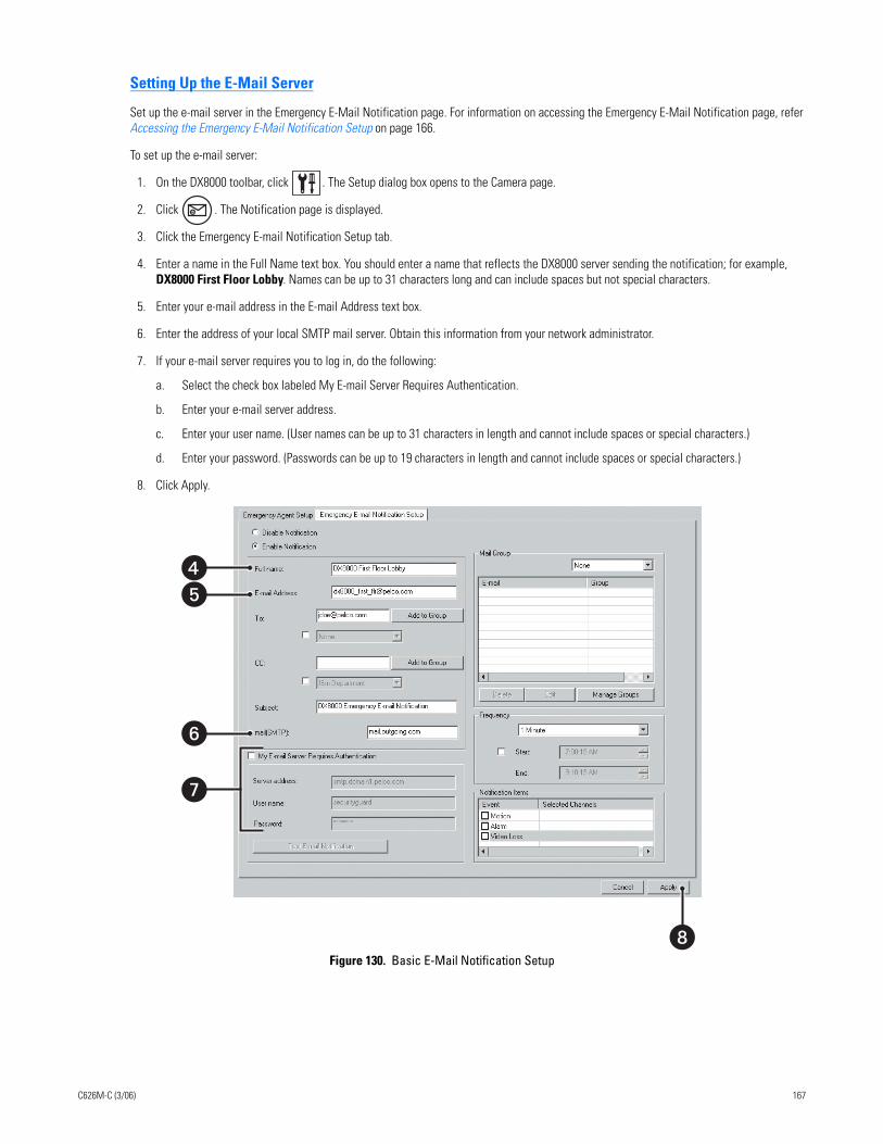
Setting Up the E-Mail Server
Set up the e-mail server in the Emergency E-Mail Notification page. For information on accessing the Emergency E-Mail Notification page, refer Accessing the Emergency E-Mail Notification Setup on page 166.
To set up the e-mail server:
1. On the DX8000 toolbar, click . The Setup dialog box opens to the Camera page.
2. Click . The Notification page is displayed.
3. Click the Emergency E-mail Notification Setup tab.
4. Enter a name in the Full Name text box. You should enter a name that reflects the DX8000 server sending the notification; for example, DX8000 First Floor Lobby. Names can be up to 31 characters long and can include spaces but not special characters.
5. Enter your e-mail address in the E-mail Address text box.
6. Enter the address of your local SMTP mail server. Obtain this information from your network administrator.
7. If your e-mail server requires you to log in, do the following:
a. Select the check box labeled My E-mail Server Requires Authentication.
b. Enter your e-mail server address.
c. Enter your user name. (User names can be up to 31 characters in length and cannot include spaces or special characters.)
d. Enter your password. (Passwords can be up to 19 characters in length and cannot include spaces or special characters.)
8. Click Apply.
Figure 130. Basic E-Mail Notification Setup
�
�
�
��
C626M-C (3/06) 167
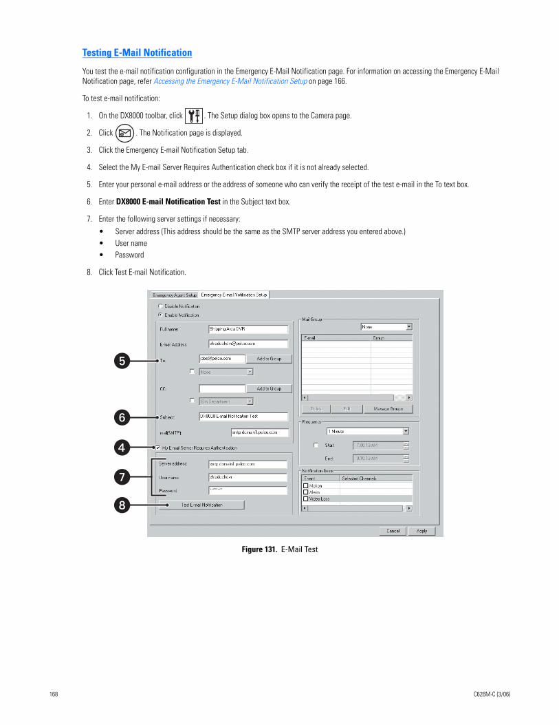
Testing E-Mail Notification
You test the e-mail notification configuration in the Emergency E-Mail Notification page. For information on accessing the Emergency E-Mail Notification page, refer Accessing the Emergency E-Mail Notification Setup on page 166.
To test e-mail notification:
1. On the DX8000 toolbar, click . The Setup dialog box opens to the Camera page.
2. Click . The Notification page is displayed.
3. Click the Emergency E-mail Notification Setup tab.
4. Select the My E-mail Server Requires Authentication check box if it is not already selected.
5. Enter your personal e-mail address or the address of someone who can verify the receipt of the test e-mail in the To text box.
6. Enter DX8000 E-mail Notification Test in the Subject text box.
7. Enter the following server settings if necessary:
• Server address (This address should be the same as the SMTP server address you entered above.)• User name• Password
8. Click Test E-mail Notification.
Figure 131. E-Mail Test
�
�
�
�
�
168 C626M-C (3/06)
SETTING UP THE TIME PERIOD
The DX8000 can be configured to send e-mail notifications on a periodic basis, such as once every ten minutes. This sections describes how to set up the time period and includes the following topics:
• Configuring E-Mail Notification Frequency on page 169
• Setting the Time of Day on page 169
• Sending E-Mail Notifications In Response to Motion Events on page 170
• Sending E-Mail Notifications In Response to Alarm Events on page 170
• Sending E-Mail Notifications In Response to Video Loss Events on page 171
Configuring E-Mail Notification Frequency
Depending on the volume of motion, alarm, or video loss events that are detected by the DX8000, the number of e-mail notifications can be far too many to manage effectively. To keep the number of e-mails sent by the DX8000 at a manageable level, the e-mail notification frequency can be adjusted. When events have been detected, e-mail notifications can be sent out in intervals from once per minute up to once every six hours. If no events have been detected during the specified frequency interval, no notification will be sent. Each e-mail notification will include information about the first event detected during the interval, the last event detected during the interval, and a still image (in JPEG format) of the last event.
To configure notification frequency:
1. On the DX8000 toolbar, click . The Setup dialog box opens to the Camera page.
2. Click . The Notification page is display.
3. Click the Emergency E-mail Notification Setup tab.
4. In the Frequency section, select the frequency interval from the drop-down box. Options are sending an e-mail notification once every
• 1 minute• 10 minutes• 30 minutes• 1 hour• 3 hours• 6 hours
Setting the Time of Day
To set the time of day during which e-mail notifications will be sent:
1. On the DX8000 toolbar, click . The Setup dialog box opens to the Camera page.
2. Click . The Notification page is display.
3. Click the Emergency E-mail Notification Setup tab.
4. In the Frequency section, do the following:
a. Click the Start check box to use the spinner buttons or type the earliest time of day you want e-mail notifications to be sent (for example, 7:30 AM).
b. Click the End check box to use the spinner buttons or type the latest time of day you want e-mail notifications to be sent (for example, 6:00 PM).
5. Click Apply.
C626M-C (3/06) 169
Sending E-Mail Notifications In Response to Motion Events
E-mail notifications can be sent whenever a camera attached to a DX8000 detects motion.
To cause e-mail notifications to be sent in response to motion events:
1. On the DX8000 toolbar, click . The Setup dialog box opens to the Camera page.
2. Click . The Notification page is display.
3. Click the Emergency E-mail Notification Setup tab.
4. In the Notification Items section, do the following:
a. Click the Motion check box.
b. Click once in the Selected Channels field to the right of the word Motion. The Selected Channels dialog box opens.
c. Do one of the following:
• Click the check box of each channel you want to monitor for motion detection events.• Click Select All to monitor all channels for motion detection. • Click Deselect All to deselect all channels.
5. Click OK.
6. Click Apply.
Sending E-Mail Notifications In Response to Alarm Events
E-mail notifications can be sent whenever an alarm input is activated.
To cause e-mail notifications to be sent in response to whenever an alarm input is activated:
1. On the DX8000 toolbar, click . The Setup dialog box opens to the Camera page.
2. Click . The Notification page is display.
3. Click the Emergency E-mail Notification Setup tab.
4. In the Notification Items section, do the following:
a. Click the Alarm check box.
b. Click once in the Selected Channels field to the right of the word Alarm. The Selected Channels dialog box opens.
c. Do one of the following:
• Click the check box of each channel you want to monitor for alarm detection events.• Click Select All to monitor all channels for alarm detection. • Click Deselect All to deselect all channels.
5. Click OK.
6. Click Apply.
170 C626M-C (3/06)
Sending E-Mail Notifications In Response to Video Loss Events
E-mail notifications can be sent whenever a camera attached to a DX8000 experiences a video loss event.
To cause e-mail notifications to be sent in response to video loss events:
1. On the DX8000 toolbar, click . The Setup dialog box opens to the Camera page.
2. Click . The Notification page is display.
3. Click the Emergency E-mail Notification Setup tab.
4. In the Notification Items section, do the following:
a. Click the Video Loss check box.
b. Click once in the Selected Channels field to the right of the words Video Loss. The Selected Channels dialog box opens.
c. Do one of the following:
• Click the check box of each channel you want to monitor for video loss detection events.• Click Select All to monitor all channels for video loss detection. • Click Deselect All to deselect all channels.
5. Click OK.
6. Click Apply.
SETTING UP E-MAIL NOTIFICATION GROUPS
The DX8000 allows you to set up groups, to send an emergency notification to multiple users. The DX8000 supports the following:
• You can create up to 32 e-mail notification groups.
• Up to 32 members can be assigned to each e-mail group.
• A group can be notified in response to an alarm or motion detection event.
This section describes how to set up e-mail notification groups and includes the following topics:
• Adding an E-Mail Notification Group on page 171
• Modifying an E-Mail Group Name on page 172
• Deleting an E-Mail Group on page 172
• Adding Members to an E-Mail Group on page 172
• Deleting Members from an E-Mail Group on page 173
• Modifying E-Mail Group Member Attributes on page 174
Adding an E-Mail Notification Group
To add an e-mail notification group:
1. On the DX8000 toolbar, click . The Setup dialog box opens to the Camera page.
2. Click . The Notification page is displayed.
3. Click the Emergency E-mail Notification Setup tab.
4. In the Mail Group area, do the following:
a. Click Manage Groups. The Group Management dialog box opens.
b. Click Add Group. The Manage Groups dialog box opens.
c. Enter the name of the group. (Group names can be up to 32 characters in length and can include spaces but not special characters.)
5. Click OK.
6. Click Close.
7. Click Apply.
C626M-C (3/06) 171
Modifying an E-Mail Group Name
To modify a group name:
1. On the DX8000 toolbar, click . The Setup dialog box opens to the Camera page.
2. Click . The Notification page is displayed.
3. Click the Emergency E-mail Notification Setup tab.
4. In the Mail Group area, do the following:
a. Click Manage Groups. The Group Management dialog box opens.
b. In the Group Name table, select a group.
c. Click Edit Group. The Manage Groups dialog box opens.
d. Edit the existing name or enter a new name for the group.
5. Click OK.
6. Click Close.
7. Click Apply.
Deleting an E-Mail Group
To delete a group:
1. On the DX8000 toolbar, click . The Setup dialog box opens to the Camera page.
2. Click . The Notification page is displayed.
3. Click the Emergency E-mail Notification Setup tab.
4. In the Mail Group area, do the following:
a. Click Manage Groups. The Group Management dialog box opens.
b. In the Group Name table, select a group.
c. Click Delete.
5. Click Close.
6. Click Apply.
Adding Members to an E-Mail Group
Up to 32 members can be assigned to each e-mail group.
To add e-mail addresses to a group:
1. On the DX8000 toolbar, click . The Setup dialog box opens to the Camera page.
2. Click . The Notification page is displayed.
3. Click the Emergency E-mail Notification Setup tab.
4. Do the following:
a. In the Mail Group section, select a group name from the drop-down box.
b. Ensure that the group check boxes under To and CC are unchecked.
c. Enter an e-mail address in the To or CC text boxes.
d. Click Add to Group.
5. Click Apply.
172 C626M-C (3/06)
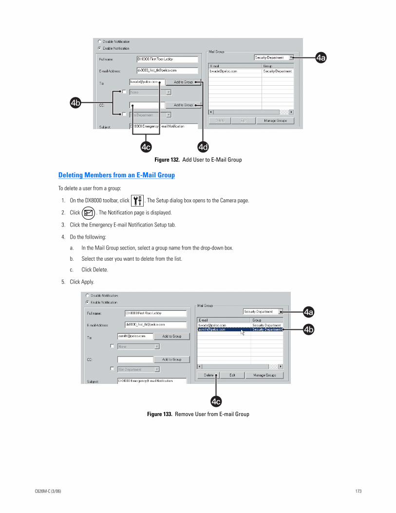
Figure 132. Add User to E-Mail Group
Deleting Members from an E-Mail Group
To delete a user from a group:
1. On the DX8000 toolbar, click . The Setup dialog box opens to the Camera page.
2. Click . The Notification page is displayed.
3. Click the Emergency E-mail Notification Setup tab.
4. Do the following:
a. In the Mail Group section, select a group name from the drop-down box.
b. Select the user you want to delete from the list.
c. Click Delete.
5. Click Apply.
Figure 133. Remove User from E-mail Group
4c4c 4d
4a4a
4b
4c4c
4a4a
4b
C626M-C (3/06) 173
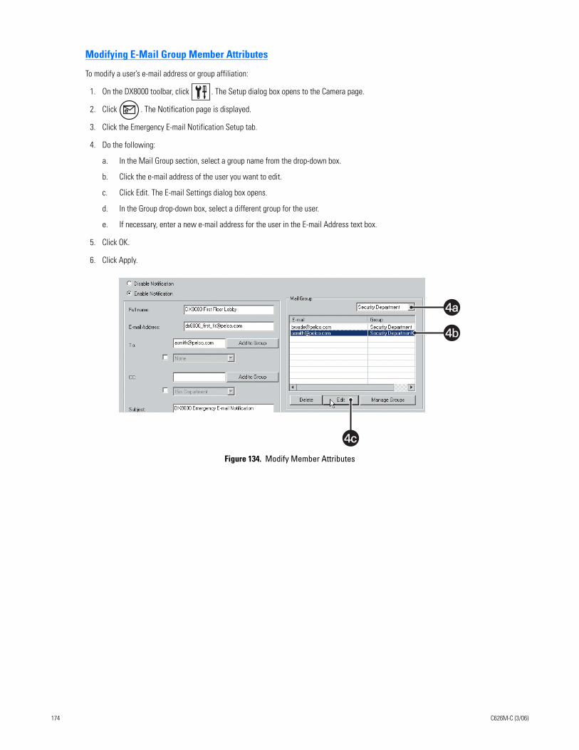
Modifying E-Mail Group Member Attributes
To modify a user’s e-mail address or group affiliation:
1. On the DX8000 toolbar, click . The Setup dialog box opens to the Camera page.
2. Click . The Notification page is displayed.
3. Click the Emergency E-mail Notification Setup tab.
4. Do the following:
a. In the Mail Group section, select a group name from the drop-down box.
b. Click the e-mail address of the user you want to edit.
c. Click Edit. The E-mail Settings dialog box opens.
d. In the Group drop-down box, select a different group for the user.
e. If necessary, enter a new e-mail address for the user in the E-mail Address text box.
5. Click OK.
6. Click Apply.
Figure 134. Modify Member Attributes
4c4c
4a4a
4b
174 C626M-C (3/06)
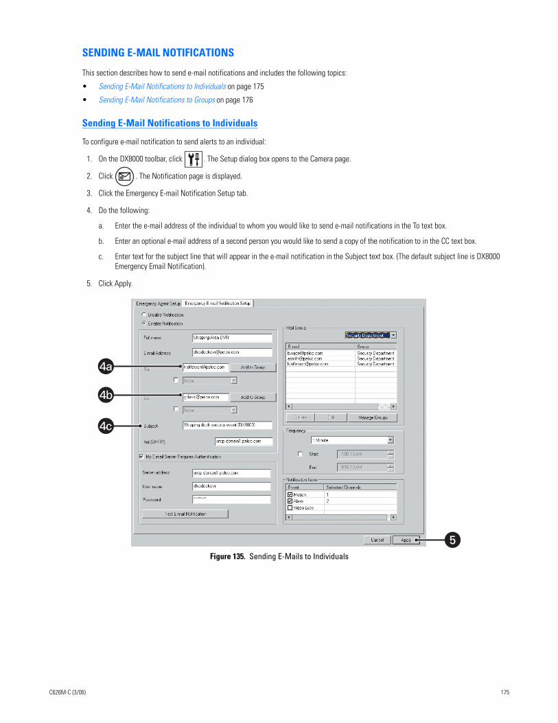
SENDING E-MAIL NOTIFICATIONS
This section describes how to send e-mail notifications and includes the following topics:
• Sending E-Mail Notifications to Individuals on page 175
• Sending E-Mail Notifications to Groups on page 176
Sending E-Mail Notifications to Individuals
To configure e-mail notification to send alerts to an individual:
1. On the DX8000 toolbar, click . The Setup dialog box opens to the Camera page.
2. Click . The Notification page is displayed.
3. Click the Emergency E-mail Notification Setup tab.
4. Do the following:
a. Enter the e-mail address of the individual to whom you would like to send e-mail notifications in the To text box.
b. Enter an optional e-mail address of a second person you would like to send a copy of the notification to in the CC text box.
c. Enter text for the subject line that will appear in the e-mail notification in the Subject text box. (The default subject line is DX8000 Emergency Email Notification).
5. Click Apply.
Figure 135. Sending E-Mails to Individuals
�
4a
4b
4c
C626M-C (3/06) 175
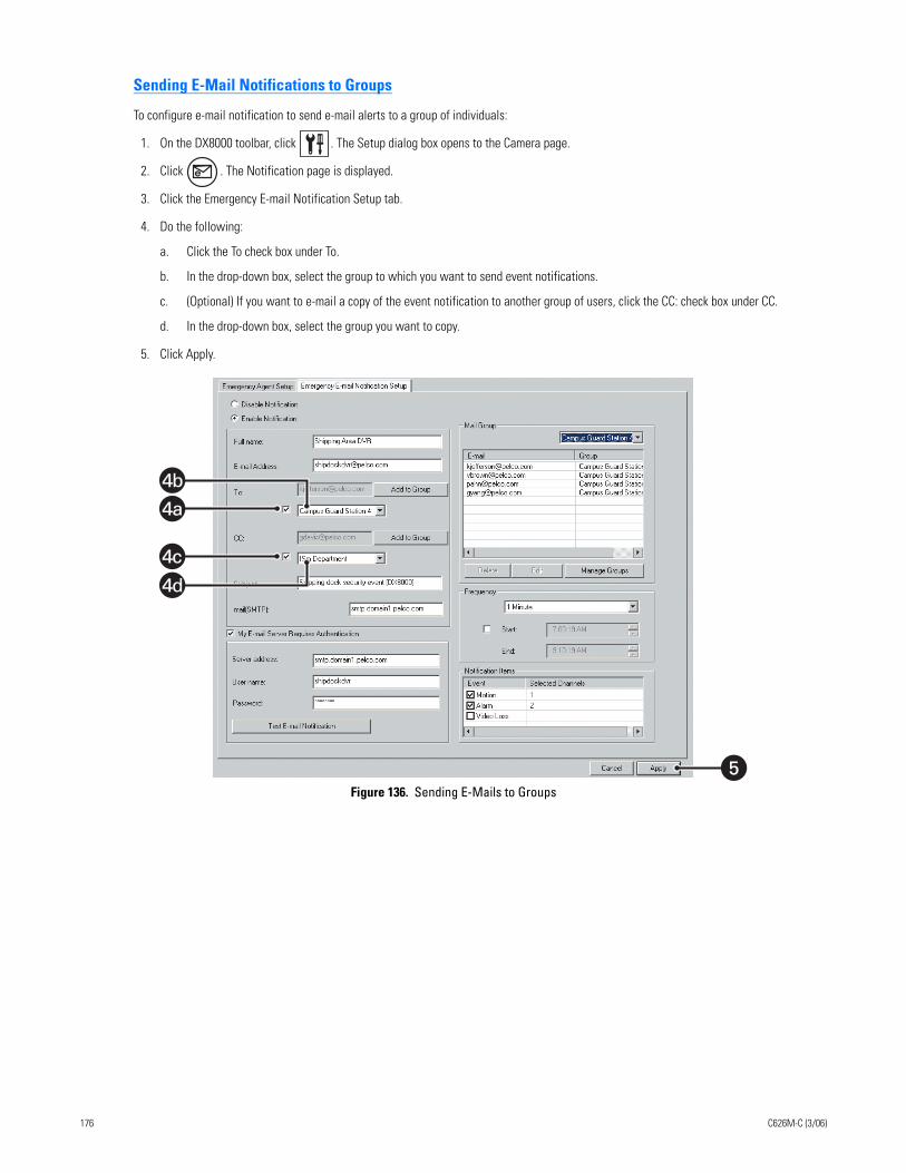
Sending E-Mail Notifications to Groups
To configure e-mail notification to send e-mail alerts to a group of individuals:
1. On the DX8000 toolbar, click . The Setup dialog box opens to the Camera page.
2. Click . The Notification page is displayed.
3. Click the Emergency E-mail Notification Setup tab.
4. Do the following:
a. Click the To check box under To.
b. In the drop-down box, select the group to which you want to send event notifications.
c. (Optional) If you want to e-mail a copy of the event notification to another group of users, click the CC: check box under CC.
d. In the drop-down box, select the group you want to copy.
5. Click Apply.
Figure 136. Sending E-Mails to Groups
�
4a
4b
4c
4d
176 C626M-C (3/06)
DX8000 Client Emergency Agent
Welcome to the DX8000 Client Emergency Agent application. The DX8000 Client Emergency Agent works with networked DVRs to alert users when one or more particular channels detect a motion, alarm, or video loss event. The Emergency Agent runs on a networked client PC.
This section describes how to install, set up, and use the DX8000 Client Emergency Agent and includes the following topics:
• Setting Up and Using the Client Emergency Agent on page 177
• Recommended System Requirements on page 177
• Installing the Client Emergency Agent Application on page 178
• Enabling IPSec Security Services on page 180
• Disabling IPSec Security Services on page 180
Setting Up and Using the Client Emergency AgentThe following steps must be completed in sequence before the Emergency Agent can receive event notifications:
1. You must install the Client Emergency Agent software on your client PC before you can use it. Refer to the installation manual for instructions on installing the Client Emergency Agent utility.
2. The DX8000 server must be turned on and operating.
3. Both the DX8000 server and client must be connected to the same network.
4. The Emergency Agent Notification system must be operating on the DX8000 server.
5. The client PC must be listed in the emergency agent notification list of the DX8000 server, and at least one camera must be linked to the client. For more information, refer to Emergency Notification Setup on page 163.
6. The Client Emergency Agent must be configured and activated on the client PC.
RECOMMENDED SYSTEM REQUIREMENTS
The DX8000 Emergency Agent recommended minimum system requirements include the following:
• Processor: Intel® Pentium® III, or Pentium 4 with 800 MHz minimum processor speed
• Memory: 128 MB of RAM
• Video: AGP VGA card with minimum of 64 MB of video RAM, 1024 x 768 display resolution, 32-bit color, and DirectX® 8.1 or later hardware acceleration
• 2.5 MB of free disk space for the full application and additional space to store images
• Monitor: SVGA or XGA with 1024 x 768 resolution, 32-bit color
• Operating system: Windows® 2000 (SP4) or Windows XP only
C626M-C (3/06) 177
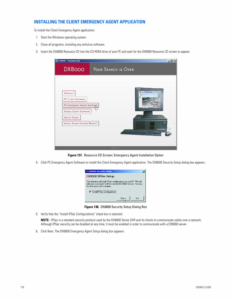
INSTALLING THE CLIENT EMERGENCY AGENT APPLICATION
To install the Client Emergency Agent application:
1. Start the Windows operating system.
2. Close all programs, including any antivirus software.
3. Insert the DX8000 Resource CD into the CD-ROM drive of your PC and wait for the DX8000 Resource CD screen to appear.
Figure 137. Resource CD Screen: Emergency Agent Installation Option
4. Click PC Emergency Agent Software to install the Client Emergency Agent application. The DX8000 Security Setup dialog box appears.
Figure 138. DX8000 Security Setup Dialog Box
5. Verify that the “Install IPSec Configurations” check box is selected.
NOTE: IPSec is a standard security protocol used by the DX8000 Series DVR and its clients to communicate safely over a network. Although IPSec security can be disabled at any time, it must be enabled in order to communicate with a DX8000 server.
6. Click Next. The DX8000 Emergency Agent Setup dialog box appears.
178 C626M-C (3/06)
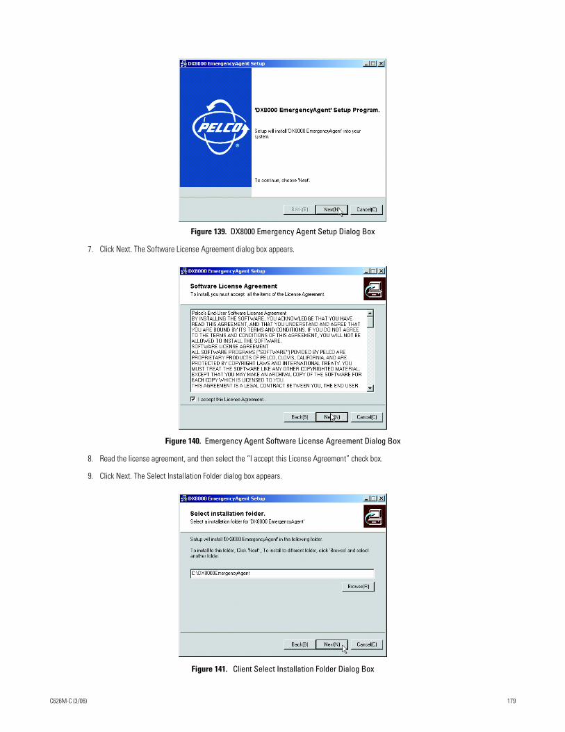
Figure 139. DX8000 Emergency Agent Setup Dialog Box
7. Click Next. The Software License Agreement dialog box appears.
Figure 140. Emergency Agent Software License Agreement Dialog Box
8. Read the license agreement, and then select the “I accept this License Agreement” check box.
9. Click Next. The Select Installation Folder dialog box appears.
Figure 141. Client Select Installation Folder Dialog Box
C626M-C (3/06) 179
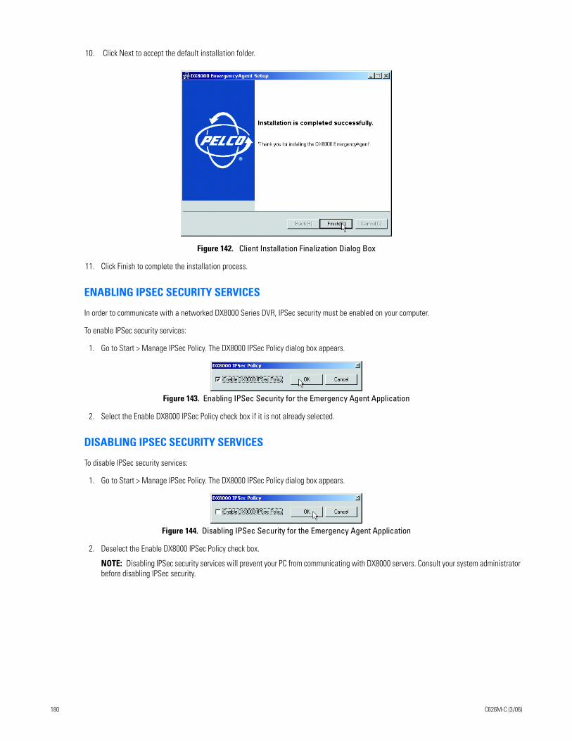
10. Click Next to accept the default installation folder.
Figure 142. Client Installation Finalization Dialog Box
11. Click Finish to complete the installation process.
ENABLING IPSEC SECURITY SERVICES
In order to communicate with a networked DX8000 Series DVR, IPSec security must be enabled on your computer.
To enable IPSec security services:
1. Go to Start > Manage IPSec Policy. The DX8000 IPSec Policy dialog box appears.
Figure 143. Enabling IPSec Security for the Emergency Agent Application
2. Select the Enable DX8000 IPSec Policy check box if it is not already selected.
DISABLING IPSEC SECURITY SERVICES
To disable IPSec security services:
1. Go to Start > Manage IPSec Policy. The DX8000 IPSec Policy dialog box appears.
Figure 144. Disabling IPSec Security for the Emergency Agent Application
2. Deselect the Enable DX8000 IPSec Policy check box.
NOTE: Disabling IPSec security services will prevent your PC from communicating with DX8000 servers. Consult your system administrator before disabling IPSec security.
180 C626M-C (3/06)
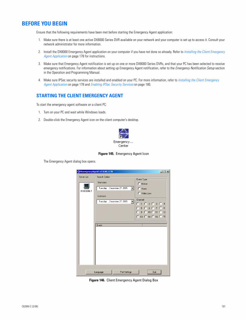
BEFORE YOU BEGINEnsure that the following requirements have been met before starting the Emergency Agent application:
1. Make sure there is at least one active DX8000 Series DVR available on your network and your computer is set up to access it. Consult your network administrator for more information.
2. Install the DX8000 Emergency Agent application on your computer if you have not done so already. Refer to Installing the Client Emergency Agent Application on page 178 for instructions.
3. Make sure that Emergency Agent notification is set up on one or more DX8000 Series DVRs, and that your PC has been selected to receive emergency notifications. For information about setting up Emergency Agent notification, refer to the Emergency Notification Setup section in the Operation and Programming Manual.
4. Make sure IPSec security services are installed and enabled on your PC. For more information, refer to Installing the Client Emergency Agent Application on page 178 and Enabling IPSec Security Services on page 180.
STARTING THE CLIENT EMERGENCY AGENT
To start the emergency agent software on a client PC:
1. Turn on your PC and wait while Windows loads.
2. Double-click the Emergency Agent icon on the client computer’s desktop.
Figure 145. Emergency Agent Icon
The Emergency Agent dialog box opens.
Figure 146. Client Emergency Agent Dialog Box
C626M-C (3/06) 181
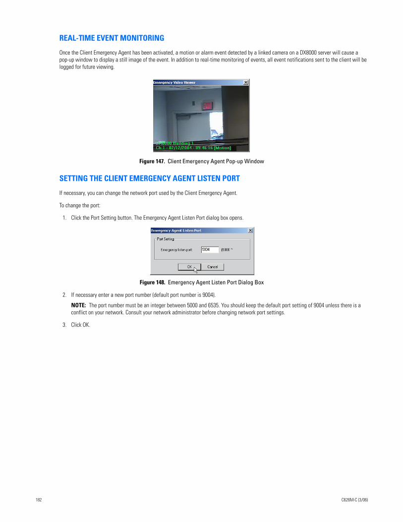
REAL-TIME EVENT MONITORING
Once the Client Emergency Agent has been activated, a motion or alarm event detected by a linked camera on a DX8000 server will cause a pop-up window to display a still image of the event. In addition to real-time monitoring of events, all event notifications sent to the client will be logged for future viewing.
Figure 147. Client Emergency Agent Pop-up Window
SETTING THE CLIENT EMERGENCY AGENT LISTEN PORT
If necessary, you can change the network port used by the Client Emergency Agent.
To change the port:
1. Click the Port Setting button. The Emergency Agent Listen Port dialog box opens.
Figure 148. Emergency Agent Listen Port Dialog Box
2. If necessary enter a new port number (default port number is 9004).
NOTE: The port number must be an integer between 5000 and 6535. You should keep the default port setting of 9004 unless there is a conflict on your network. Consult your network administrator before changing network port settings.
3. Click OK.
182 C626M-C (3/06)
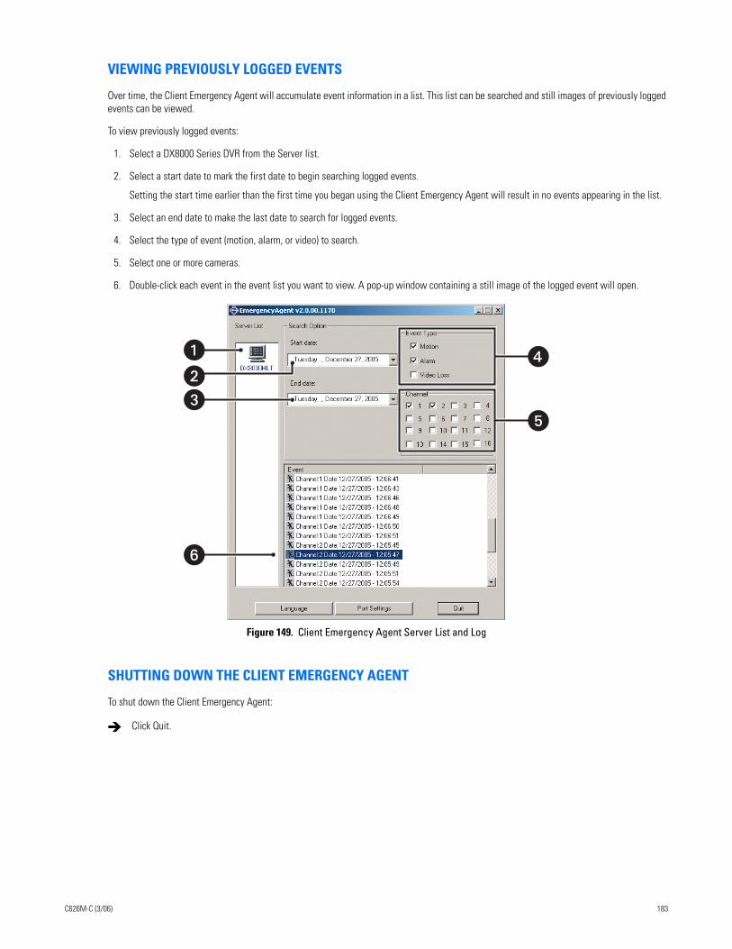
VIEWING PREVIOUSLY LOGGED EVENTS
Over time, the Client Emergency Agent will accumulate event information in a list. This list can be searched and still images of previously logged events can be viewed.
To view previously logged events:
1. Select a DX8000 Series DVR from the Server list.
2. Select a start date to mark the first date to begin searching logged events.
Setting the start time earlier than the first time you began using the Client Emergency Agent will result in no events appearing in the list.
3. Select an end date to make the last date to search for logged events.
4. Select the type of event (motion, alarm, or video) to search.
5. Select one or more cameras.
6. Double-click each event in the event list you want to view. A pop-up window containing a still image of the logged event will open.
Figure 149. Client Emergency Agent Server List and Log
SHUTTING DOWN THE CLIENT EMERGENCY AGENT
To shut down the Client Emergency Agent:
Click Quit.
�
�
�
�
�
C626M-C (3/06) 183
DX8000 Viewer
Welcome to the DX8000 Viewer application. The DX8000 Viewer is capable of playing back a variety of video, still image and audio media for-mats. It is designed to recognize and verify the digital watermark that is embedded in DX8000 native video. Watermarking is used to authenti-cate the originality of a video file and to alert users of possible image tampering. The viewer application runs automatically each time a CD or DVD created by the DX8000’s export feature is inserted into a Windows-based PC. The software can also be installed on a PC and opened inde-pendently when necessary.
This section describes how to install, set up, and use the DX8000 Client Viewer, and includes the following topics:
• Setting Up and Using the DX8000 Viewer on page 184
• Working with the Playlist on page 190
• Working with Viewer Configuration Tools on page 192
• Exiting the DX8000 Viewer Application on page 193
Setting Up and Using the DX8000 ViewerThis section describes how to use the DX8000 Viewer application and includes the following topics:
• Recommended System Requirements on page 184
• DX8000 Viewer Software Installation on page 185
• Starting the DX8000 Viewer on page 186
• Viewing Media files on page 188
• Playing Video on page 189
• Saving Snapshots on page 189
• Printing Images on page 189
• Working with the Playlist on page 190
RECOMMENDED SYSTEM REQUIREMENTS
The DX8000 Viewer recommended minimum system requirements include the following:
• Processor: Intel Pentium III, or Pentium 4 with 800 MHz minimum processor speed
• Memory: 128 MB of RAM
• Video: AGP VGA card with minimum of 64 MB of video RAM, 1024 x 768 display resolution, 32-bit color, and DirectX 8.1 or later hardware acceleration
• 4.5 MB of free disk space
• Monitor: SVGA or XGA with 1024 x 768 resolution, 32-bit color
• Operating system: Windows 2000 (SP4) or Windows XP only
184 C626M-C (3/06)
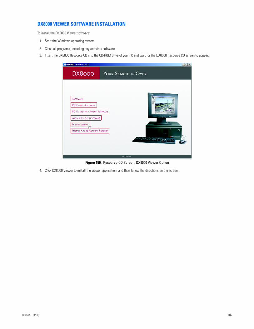
DX8000 VIEWER SOFTWARE INSTALLATION
To install the DX8000 Viewer software:
1. Start the Windows operating system.
2. Close all programs, including any antivirus software.
3. Insert the DX8000 Resource CD into the CD-ROM drive of your PC and wait for the DX8000 Resource CD screen to appear.
Figure 150. Resource CD Screen: DX8000 Viewer Option
4. Click DX8000 Viewer to install the viewer application, and then follow the directions on the screen.
C626M-C (3/06) 185
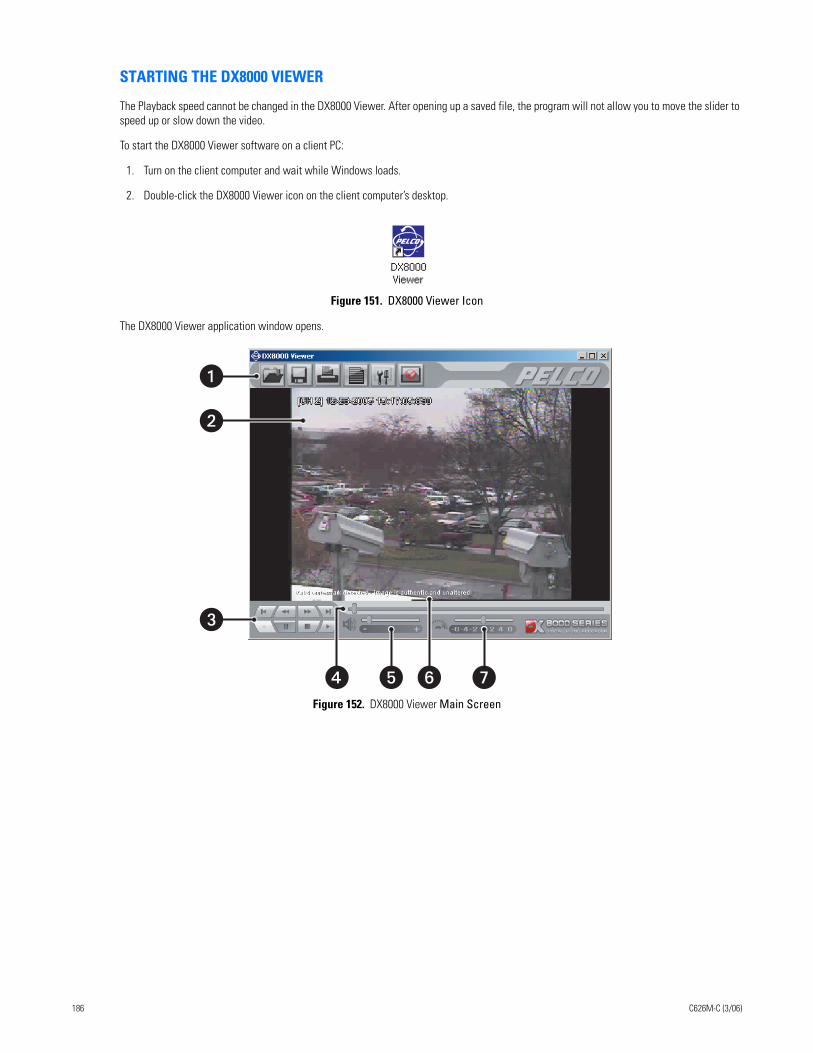
STARTING THE DX8000 VIEWER
The Playback speed cannot be changed in the DX8000 Viewer. After opening up a saved file, the program will not allow you to move the slider to speed up or slow down the video.
To start the DX8000 Viewer software on a client PC:
1. Turn on the client computer and wait while Windows loads.
2. Double-click the DX8000 Viewer icon on the client computer’s desktop.
Figure 151. DX8000 Viewer Icon
The DX8000 Viewer application window opens.
Figure 152. DX8000 Viewer Main Screen
�
�
� � � �
186 C626M-C (3/06)
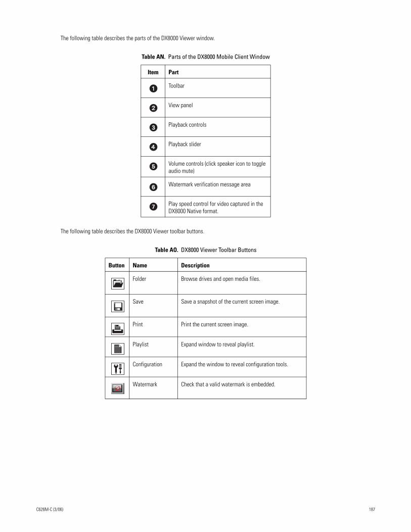
The following table describes the parts of the DX8000 Viewer window.
The following table describes the DX8000 Viewer toolbar buttons.
Table AN. Parts of the DX8000 Mobile Client Window
Item Part
Toolbar
View panel
Playback controls
Playback slider
Volume controls (click speaker icon to toggle audio mute)
Watermark verification message area
Play speed control for video captured in the DX8000 Native format.
Table AO. DX8000 Viewer Toolbar Buttons
Button Name Description
Folder Browse drives and open media files.
Save Save a snapshot of the current screen image.
Print Print the current screen image.
Playlist Expand window to reveal playlist.
Configuration Expand the window to reveal configuration tools.
Watermark Check that a valid watermark is embedded.
C626M-C (3/06) 187
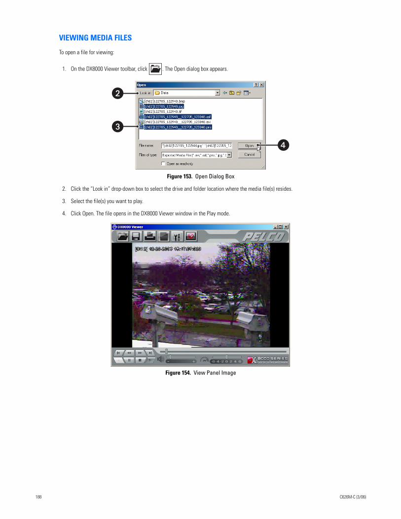
VIEWING MEDIA FILES
To open a file for viewing:
1. On the DX8000 Viewer toolbar, click . The Open dialog box appears.
Figure 153. Open Dialog Box
2. Click the “Look in” drop-down box to select the drive and folder location where the media file(s) resides.
3. Select the file(s) you want to play.
4. Click Open. The file opens in the DX8000 Viewer window in the Play mode.
Figure 154. View Panel Image
�
�
�
188 C626M-C (3/06)
PLAYING VIDEO
You can play video files in the DX8000 Viewer after they have been opened. The DX8000 Viewer provides a speed control that allows you to speed up playback of video exported in the Native format.
To begin playback of a an exported DX8000 video file:
1. On the DX8000 Viewer toolbar, click .
2. Use the playback controls and playback slider to move through a video file.
3. Do the following:
a. Use the audio controls to increase, decrease, or mute playback volume.
b. Use the speed control to increase or decrease the playback of video exported in the Native format.
SAVING SNAPSHOTS
You can take snapshots of still images that appear in the view panel. Use the playback controls to pause a video file on a specific still image. Snapshots are stored in a folder for later retrieval or viewing. For information on changing the location of the snapshot folder, refer to Working with Viewer Configuration Tools on page 192.
To save a snapshot of a still image appearing on the screen:
For example, click .
PRINTING IMAGES
You can print still images that appear in the view panel. Use the playback controls to pause a video file on a specific still image.
To print a still image:
For example, click .
On the DX8000 Viewer toolbar, click Save.
On the DX8000 Viewer toolbar, click Print.
C626M-C (3/06) 189
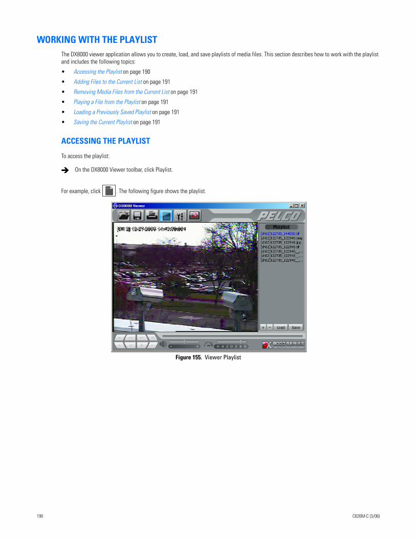
WORKING WITH THE PLAYLISTThe DX8000 viewer application allows you to create, load, and save playlists of media files. This section describes how to work with the playlist and includes the following topics:
• Accessing the Playlist on page 190
• Adding Files to the Current List on page 191
• Removing Media Files from the Current List on page 191
• Playing a File from the Playlist on page 191
• Loading a Previously Saved Playlist on page 191
• Saving the Current Playlist on page 191
ACCESSING THE PLAYLIST
To access the playlist:
For example, click . The following figure shows the playlist.
Figure 155. Viewer Playlist
On the DX8000 Viewer toolbar, click Playlist.
190 C626M-C (3/06)
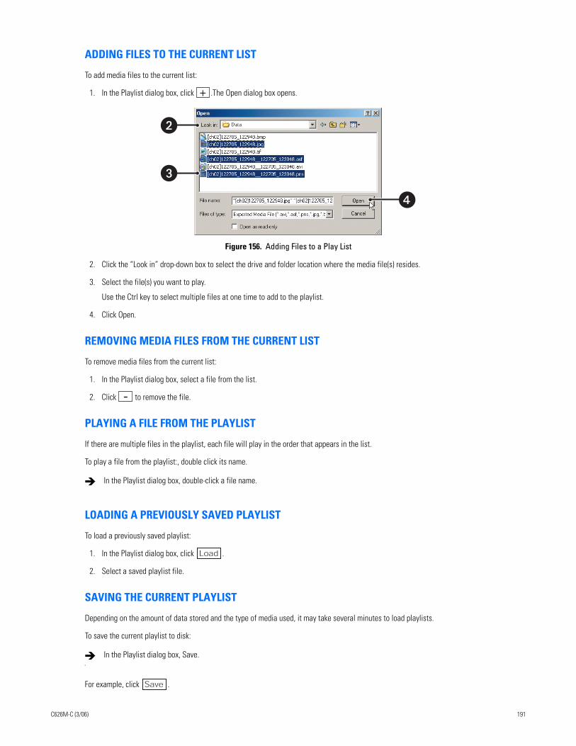
ADDING FILES TO THE CURRENT LIST
To add media files to the current list:
1. In the Playlist dialog box, click .The Open dialog box opens.
Figure 156. Adding Files to a Play List
2. Click the “Look in” drop-down box to select the drive and folder location where the media file(s) resides.
3. Select the file(s) you want to play.
Use the Ctrl key to select multiple files at one time to add to the playlist.
4. Click Open.
REMOVING MEDIA FILES FROM THE CURRENT LIST
To remove media files from the current list:
1. In the Playlist dialog box, select a file from the list.
2. Click to remove the file.
PLAYING A FILE FROM THE PLAYLIST
If there are multiple files in the playlist, each file will play in the order that appears in the list.
To play a file from the playlist:, double click its name.
LOADING A PREVIOUSLY SAVED PLAYLIST
To load a previously saved playlist:
1. In the Playlist dialog box, click .
2. Select a saved playlist file.
SAVING THE CURRENT PLAYLIST
Depending on the amount of data stored and the type of media used, it may take several minutes to load playlists.
To save the current playlist to disk:
For example, click Save .
In the Playlist dialog box, double-click a file name.
C
In the Playlist dialog box, Save.
�
�
�
Load
C626M-C (3/06) 191
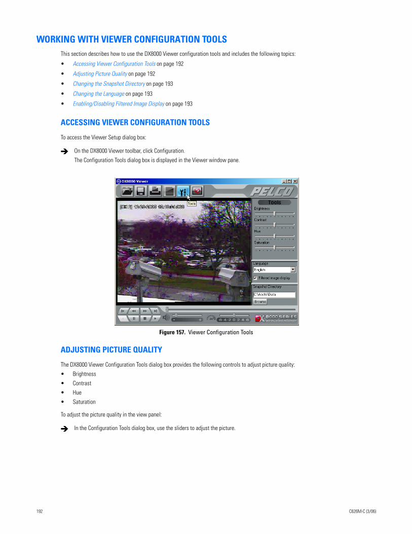
WORKING WITH VIEWER CONFIGURATION TOOLSThis section describes how to use the DX8000 Viewer configuration tools and includes the following topics:
• Accessing Viewer Configuration Tools on page 192
• Adjusting Picture Quality on page 192
• Changing the Snapshot Directory on page 193
• Changing the Language on page 193
• Enabling/Disabling Filtered Image Display on page 193
ACCESSING VIEWER CONFIGURATION TOOLS
To access the Viewer Setup dialog box:
Figure 157. Viewer Configuration Tools
ADJUSTING PICTURE QUALITY
The DX8000 Viewer Configuration Tools dialog box provides the following controls to adjust picture quality:
• Brightness
• Contrast
• Hue
• Saturation
To adjust the picture quality in the view panel:
On the DX8000 Viewer toolbar, click Configuration.
The Configuration Tools dialog box is displayed in the Viewer window pane.
In the Configuration Tools dialog box, use the sliders to adjust the picture.
192 C626M-C (3/06)
CHANGING THE SNAPSHOT DIRECTORY
To change the default directory where snapshots are stored:
For example, click Browse .
CHANGING THE LANGUAGE
To change the language:
1. On the DX8000 Viewer toolbar, click Tools. The menu is displayed.
2. In the Language section, select a language.
3. Close the DX8000 Viewer application.
4. Restart the DX8000 Viewer application.
ENABLING/DISABLING FILTERED IMAGE DISPLAY
To enable/disable filtered image display:
1. On the DX8000 Viewer toolbar, click Tools. The menu is displayed.
2. Do one of the following:
• To enable filtered image display, click the check box in the Language section to select the Filtered Image display box.• To disable filtered image display, click the check box in the Language section to deselect the Filtered Image display box.
VERIFYING THE WATERMARKWatermarking is used to authenticate the originality of a video file and to alert users of possible image tampering.
To verify the watermark:
1. Open an exported video image.
1. On the DX8000 Viewer toolbar, click . The Watermark Viewer dialog box opens.
2. Click Watermark Check. The DX8000 Viewer performs a check to verify if the watermark is authentic and displays the result in the Watermark Viewer dialog box and the video image.
EXITING THE DX8000 VIEWER APPLICATIONTo exit the DX8000 viewer application:
For example, click X .
In the Configuration Tools dialog box, click Browse and navigate to a directory.
Click the Close button in the top-right corner of the viewer window.
C626M-C (3/06) 193
DX8000 Mobile Client
Welcome to the DX8000 Mobile Client application. The DX8000 Mobile Client allows you to view live video remotely from multiple cameras and sites. Networking capabilities include local connection using wire-bound or wireless LAN technologies or remote connection using the Internet. The DX8000 Mobile Client software runs on a standard pocket PC-based PDA and can display a single channel of real-time video from any cam-era attached to any DX8000 DVR on the network. Features include hierarchical organization of multiple sites, built-in security through password protection, and an adjustable viewing area, including full-screen view.
Setting Up and Using the DX8000 Mobile ClientThis section describes how to install, set up and use the DX8000 Mobile Client, and includes the following topics:
• Mobile (PDA) Client Recommended System Requirements on page 194
• Mobile (PDA) Client Software Installation on page 195
• Connecting Mobile Clients to a DX8000 Series DVR on page 197
• Starting the DX8000 Mobile Client on page 198
• Exiting the DX8000 Mobile Client on page 200
• Setting Up User Security on page 200
• Logging in to the Mobile Client application on page 202
• Working with Sites and Groups on page 203
• Connecting to a DX8000 Site on page 210
• Disconnecting From a Server Site on page 210
• Viewing Live Video on page 211
• Customizing the View Screen on page 212
MOBILE (PDA) CLIENT RECOMMENDED SYSTEM REQUIREMENTS
The DX8000 Mobile Client PDA recommended minimum system requirements includes the following:
• PDA Hardware: A pocket PC-compatible handheld device.
• Processor: Intel XScale® compatible with a minimum processor speed of 400 MHz
• Memory: 64 MB of RAM
• Video: TFT liquid crystal display with minimum 240 x 320 display resolution, 64K colors
• Operating System: Microsoft pocket PC 2002 or later
• A PC with Windows operating system and Microsoft ActiveSync® version 3.5 or later installed
• Wired or wireless networking capability
194 C626M-C (3/06)
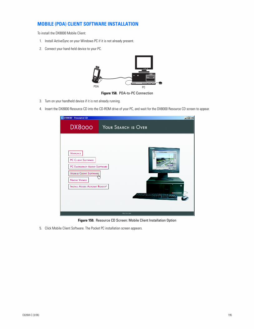
MOBILE (PDA) CLIENT SOFTWARE INSTALLATION
To install the DX8000 Mobile Client:
1. Install ActiveSync on your Windows PC if it is not already present.
2. Connect your hand-held device to your PC.
Figure 158. PDA-to-PC Connection
3. Turn on your handheld device if it is not already running.
4. Insert the DX8000 Resource CD into the CD-ROM drive of your PC, and wait for the DX8000 Resource CD screen to appear.
Figure 159. Resource CD Screen: Mobile Client Installation Option
5. Click Mobile Client Software. The Pocket PC installation screen appears.
PCPDA
C626M-C (3/06) 195
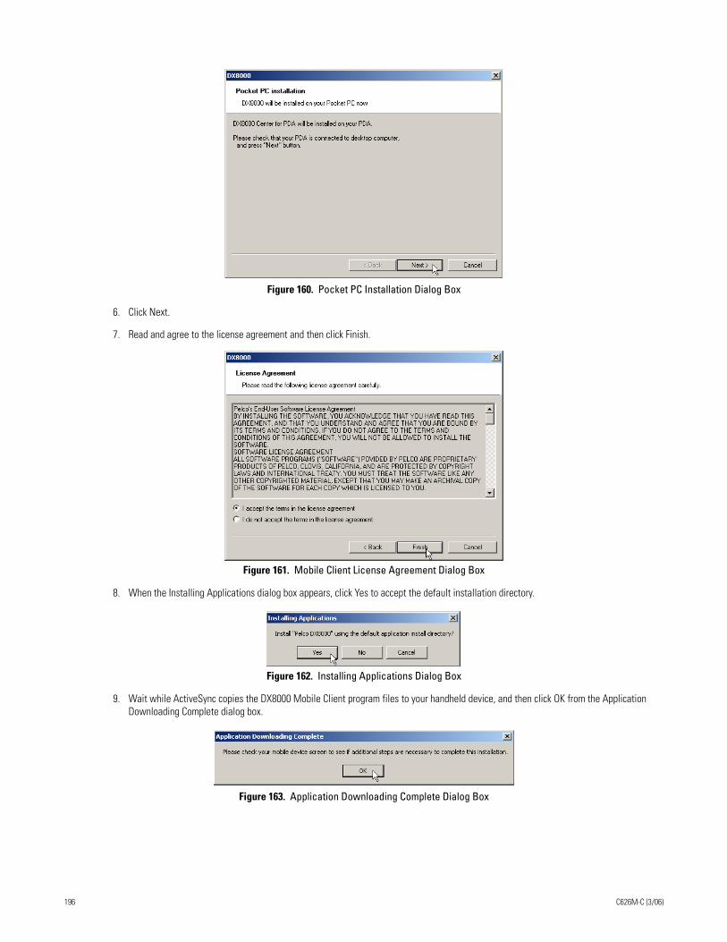
Figure 160. Pocket PC Installation Dialog Box
6. Click Next.
7. Read and agree to the license agreement and then click Finish.
Figure 161. Mobile Client License Agreement Dialog Box
8. When the Installing Applications dialog box appears, click Yes to accept the default installation directory.
Figure 162. Installing Applications Dialog Box
9. Wait while ActiveSync copies the DX8000 Mobile Client program files to your handheld device, and then click OK from the Application Downloading Complete dialog box.
Figure 163. Application Downloading Complete Dialog Box
196 C626M-C (3/06)
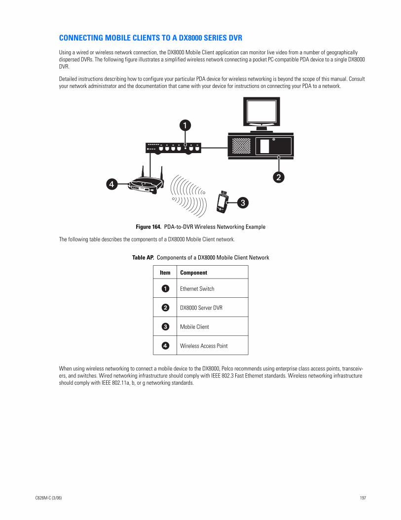
CONNECTING MOBILE CLIENTS TO A DX8000 SERIES DVR
Using a wired or wireless network connection, the DX8000 Mobile Client application can monitor live video from a number of geographically dispersed DVRs. The following figure illustrates a simplified wireless network connecting a pocket PC-compatible PDA device to a single DX8000 DVR.
Detailed instructions describing how to configure your particular PDA device for wireless networking is beyond the scope of this manual. Consult your network administrator and the documentation that came with your device for instructions on connecting your PDA to a network.
Figure 164. PDA-to-DVR Wireless Networking Example
The following table describes the components of a DX8000 Mobile Client network.
When using wireless networking to connect a mobile device to the DX8000, Pelco recommends using enterprise class access points, transceiv-ers, and switches. Wired networking infrastructure should comply with IEEE 802.3 Fast Ethernet standards. Wireless networking infrastructure should comply with IEEE 802.11a, b, or g networking standards.
Table AP. Components of a DX8000 Mobile Client Network
Item Component
Ethernet Switch
DX8000 Server DVR
Mobile Client
Wireless Access Point
��
�
C626M-C (3/06) 197
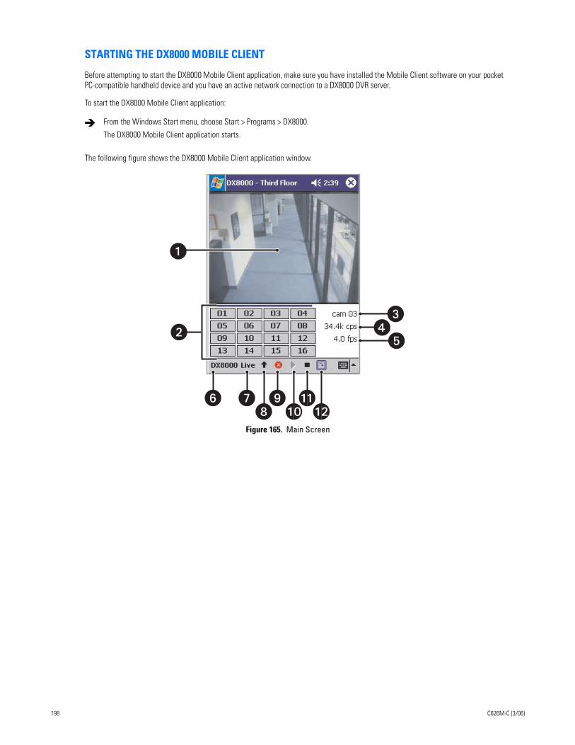
STARTING THE DX8000 MOBILE CLIENT
Before attempting to start the DX8000 Mobile Client application, make sure you have installed the Mobile Client software on your pocket PC-compatible handheld device and you have an active network connection to a DX8000 DVR server.
To start the DX8000 Mobile Client application:
The following figure shows the DX8000 Mobile Client application window.
Figure 165. Main Screen
From the Windows Start menu, choose Start > Programs > DX8000.
The DX8000 Mobile Client application starts.
�
� ��
� ����
��
�
198 C626M-C (3/06)
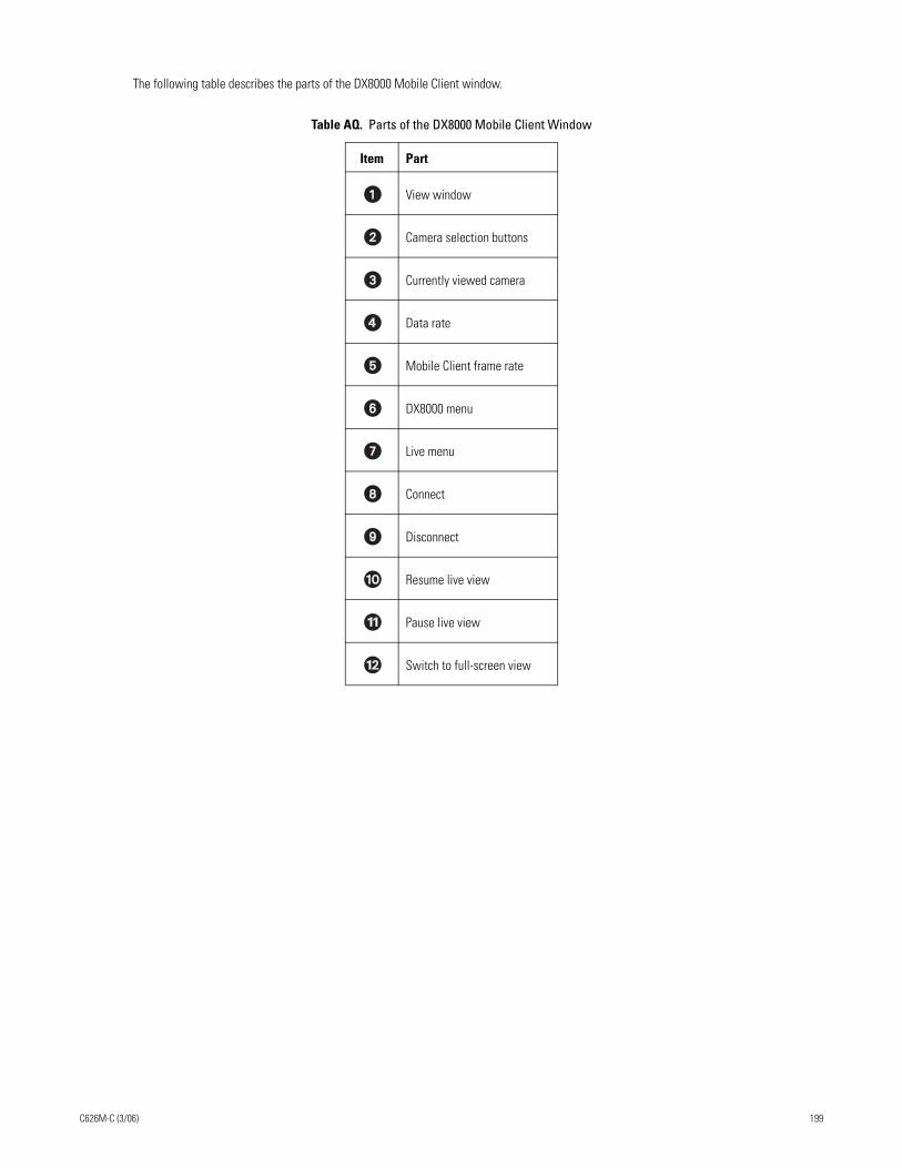
The following table describes the parts of the DX8000 Mobile Client window.
Table AQ. Parts of the DX8000 Mobile Client Window
Item Part
View window
Camera selection buttons
Currently viewed camera
Data rate
Mobile Client frame rate
DX8000 menu
Live menu
Connect
Disconnect
Resume live view
Pause live view
Switch to full-screen view
C626M-C (3/06) 199
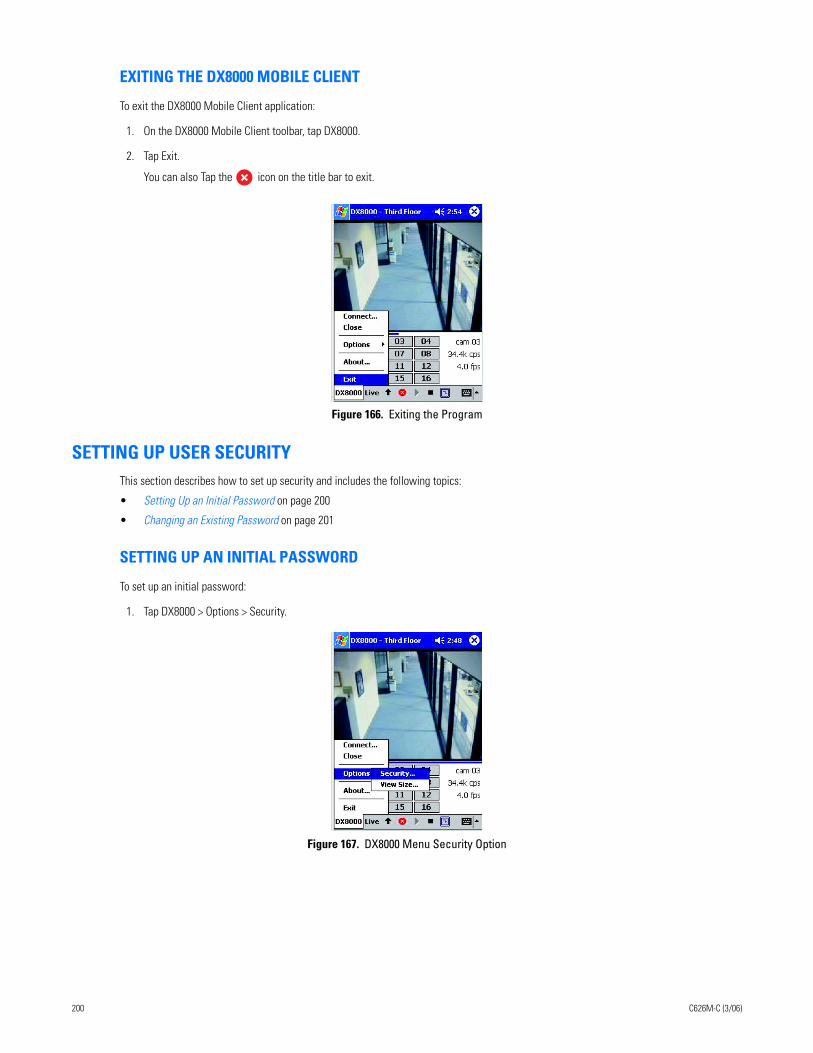
EXITING THE DX8000 MOBILE CLIENT
To exit the DX8000 Mobile Client application:
1. On the DX8000 Mobile Client toolbar, tap DX8000.
2. Tap Exit.
You can also Tap the icon on the title bar to exit.
Figure 166. Exiting the Program
SETTING UP USER SECURITYThis section describes how to set up security and includes the following topics:
• Setting Up an Initial Password on page 200
• Changing an Existing Password on page 201
SETTING UP AN INITIAL PASSWORD
To set up an initial password:
1. Tap DX8000 > Options > Security.
Figure 167. DX8000 Menu Security Option
200 C626M-C (3/06)
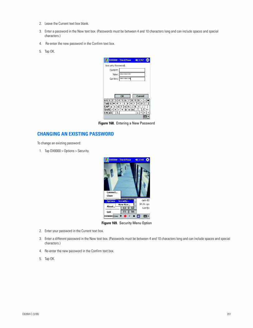
2. Leave the Current text box blank.
3. Enter a password in the New text box. (Passwords must be between 4 and 10 characters long and can include spaces and special characters.)
4. Re-enter the new password in the Confirm text box.
5. Tap OK.
Figure 168. Entering a New Password
CHANGING AN EXISTING PASSWORD
To change an existing password:
1. Tap DX8000 > Options > Security.
Figure 169. Security Menu Option
2. Enter your password in the Current text box.
3. Enter a different password in the New text box. (Passwords must be between 4 and 10 characters long and can include spaces and special characters.)
4. Re-enter the new password in the Confirm text box.
5. Tap OK.
C626M-C (3/06) 201
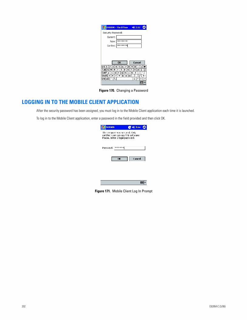
Figure 170. Changing a Password
LOGGING IN TO THE MOBILE CLIENT APPLICATIONAfter the security password has been assigned, you must log in to the Mobile Client application each time it is launched.
To log in to the Mobile Client application, enter a password in the field provided and then click OK.
Figure 171. Mobile Client Log In Prompt
202 C626M-C (3/06)
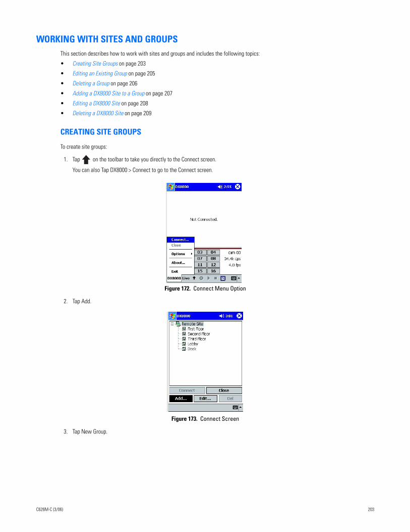
WORKING WITH SITES AND GROUPSThis section describes how to work with sites and groups and includes the following topics:
• Creating Site Groups on page 203
• Editing an Existing Group on page 205
• Deleting a Group on page 206
• Adding a DX8000 Site to a Group on page 207
• Editing a DX8000 Site on page 208
• Deleting a DX8000 Site on page 209
CREATING SITE GROUPS
To create site groups:
1. Tap on the toolbar to take you directly to the Connect screen.
You can also Tap DX8000 > Connect to go to the Connect screen.
Figure 172. Connect Menu Option
2. Tap Add.
Figure 173. Connect Screen
3. Tap New Group.
C626M-C (3/06) 203
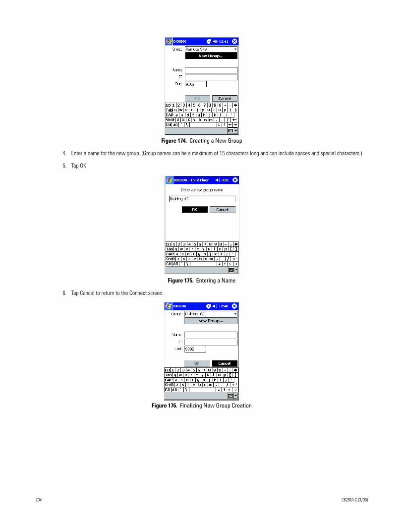
Figure 174. Creating a New Group
4. Enter a name for the new group. (Group names can be a maximum of 15 characters long and can include spaces and special characters.)
5. Tap OK.
Figure 175. Entering a Name
6. Tap Cancel to return to the Connect screen.
Figure 176. Finalizing New Group Creation
204 C626M-C (3/06)
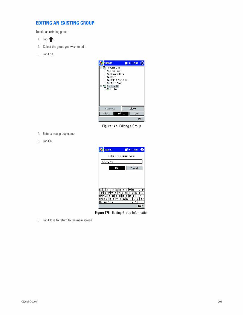
EDITING AN EXISTING GROUP
To edit an existing group:
1. Tap .
2. Select the group you wish to edit.
3. Tap Edit.
Figure 177. Editing a Group
4. Enter a new group name.
5. Tap OK.
Figure 178. Editing Group Information
6. Tap Close to return to the main screen.
C626M-C (3/06) 205
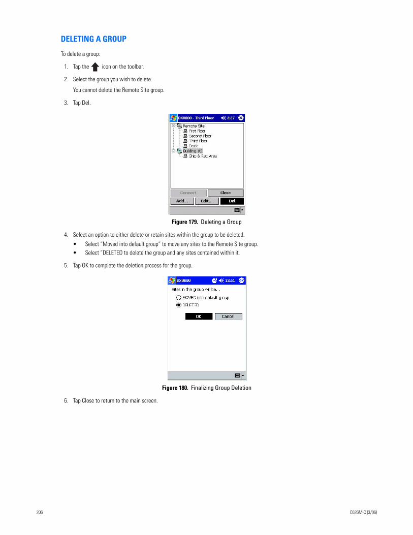
DELETING A GROUP
To delete a group:
1. Tap the icon on the toolbar.
2. Select the group you wish to delete.
You cannot delete the Remote Site group.
3. Tap Del.
Figure 179. Deleting a Group
4. Select an option to either delete or retain sites within the group to be deleted.
• Select “Moved into default group” to move any sites to the Remote Site group.• Select “DELETED to delete the group and any sites contained within it.
5. Tap OK to complete the deletion process for the group.
Figure 180. Finalizing Group Deletion
6. Tap Close to return to the main screen.
206 C626M-C (3/06)
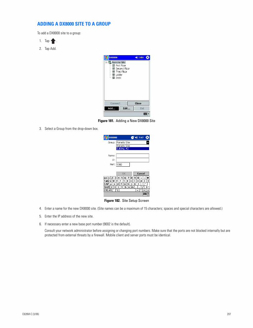
ADDING A DX8000 SITE TO A GROUP
To add a DX8000 site to a group:
1. Tap .
2. Tap Add.
Figure 181. Adding a New DX8000 Site
3. Select a Group from the drop-down box.
Figure 182. Site Setup Screen
4. Enter a name for the new DX8000 site. (Site names can be a maximum of 15 characters; spaces and special characters are allowed.)
5. Enter the IP address of the new site.
6. If necessary enter a new base port number (9002 is the default).
Consult your network administrator before assigning or changing port numbers. Make sure that the ports are not blocked internally but are protected from external threats by a firewall. Mobile client and server ports must be identical.
C626M-C (3/06) 207
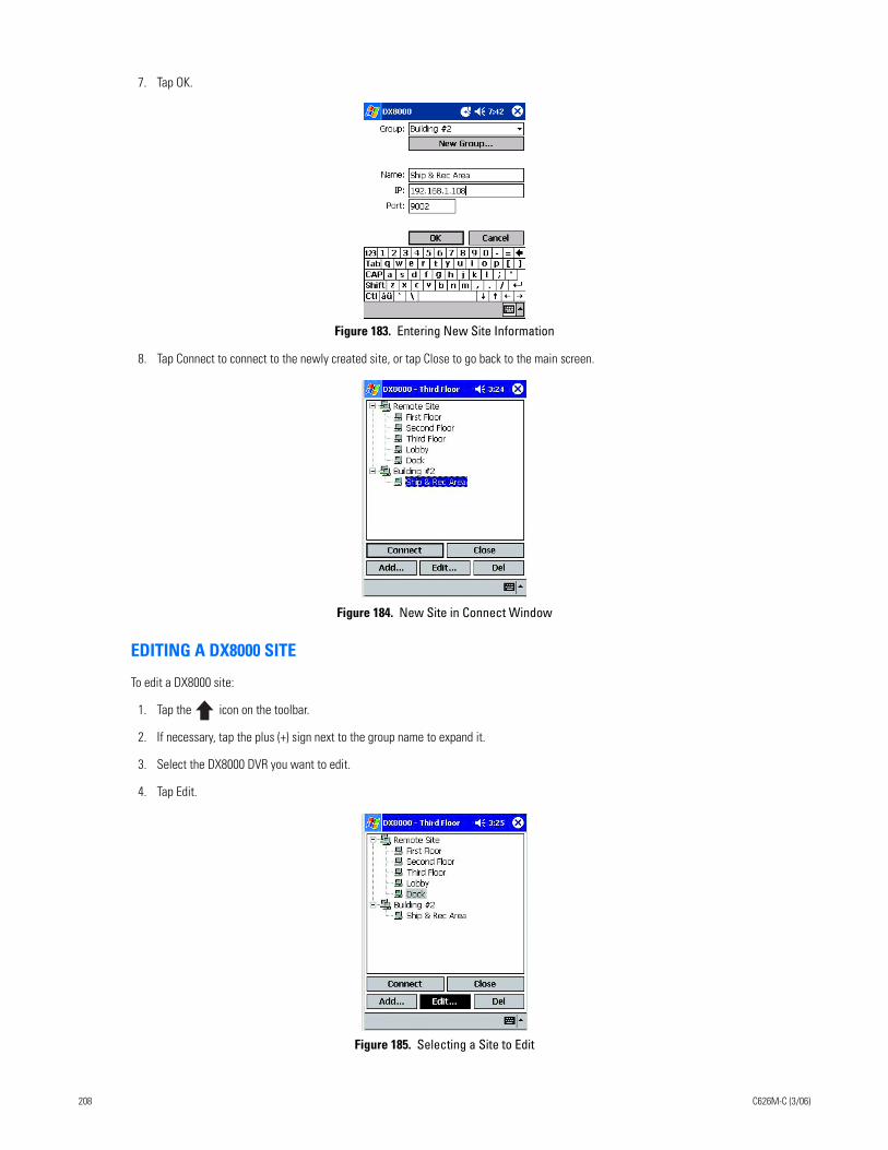
7. Tap OK.
Figure 183. Entering New Site Information
8. Tap Connect to connect to the newly created site, or tap Close to go back to the main screen.
Figure 184. New Site in Connect Window
EDITING A DX8000 SITE
To edit a DX8000 site:
1. Tap the icon on the toolbar.
2. If necessary, tap the plus (+) sign next to the group name to expand it.
3. Select the DX8000 DVR you want to edit.
4. Tap Edit.
Figure 185. Selecting a Site to Edit
208 C626M-C (3/06)
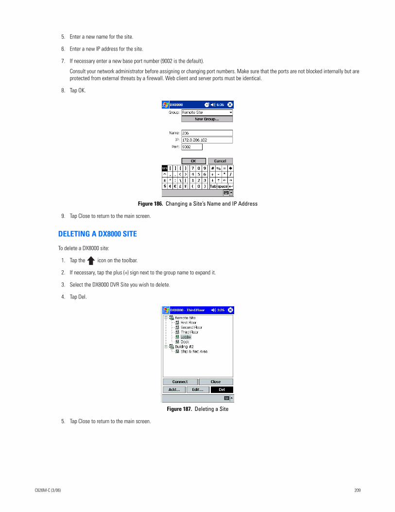
5. Enter a new name for the site.
6. Enter a new IP address for the site.
7. If necessary enter a new base port number (9002 is the default).
Consult your network administrator before assigning or changing port numbers. Make sure that the ports are not blocked internally but are protected from external threats by a firewall. Web client and server ports must be identical.
8. Tap OK.
Figure 186. Changing a Site’s Name and IP Address
9. Tap Close to return to the main screen.
DELETING A DX8000 SITE
To delete a DX8000 site:
1. Tap the icon on the toolbar.
2. If necessary, tap the plus (+) sign next to the group name to expand it.
3. Select the DX8000 DVR Site you wish to delete.
4. Tap Del.
Figure 187. Deleting a Site
5. Tap Close to return to the main screen.
C626M-C (3/06) 209
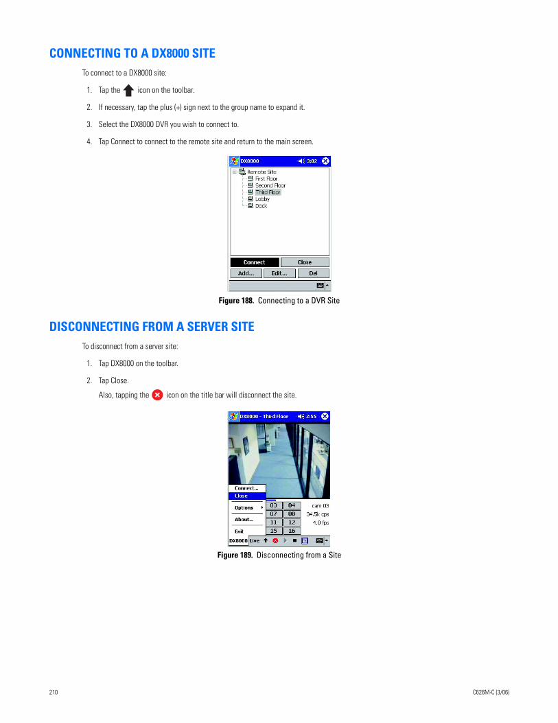
CONNECTING TO A DX8000 SITETo connect to a DX8000 site:
1. Tap the icon on the toolbar.
2. If necessary, tap the plus (+) sign next to the group name to expand it.
3. Select the DX8000 DVR you wish to connect to.
4. Tap Connect to connect to the remote site and return to the main screen.
Figure 188. Connecting to a DVR Site
DISCONNECTING FROM A SERVER SITETo disconnect from a server site:
1. Tap DX8000 on the toolbar.
2. Tap Close.
Also, tapping the icon on the title bar will disconnect the site.
Figure 189. Disconnecting from a Site
210 C626M-C (3/06)
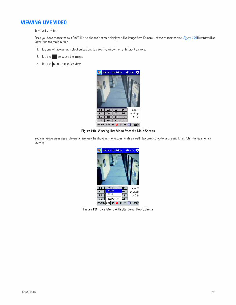
VIEWING LIVE VIDEOTo view live video:
Once you have connected to a DX8000 site, the main screen displays a live image from Camera 1 of the connected site. Figure 190 illustrates live view from the main screen.
1. Tap one of the camera selection buttons to view live video from a different camera.
2. Tap the to pause the image.
3. Tap the to resume live view.
Figure 190. Viewing Live Video from the Main Screen
You can pause an image and resume live view by choosing menu commands as well. Tap Live > Stop to pause and Live > Start to resume live viewing.
Figure 191. Live Menu with Start and Stop Options
C626M-C (3/06) 211
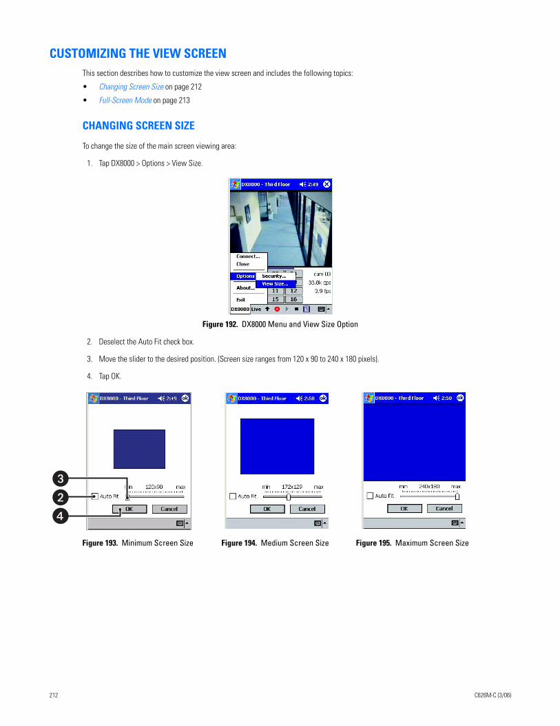
CUSTOMIZING THE VIEW SCREENThis section describes how to customize the view screen and includes the following topics:
• Changing Screen Size on page 212
• Full-Screen Mode on page 213
CHANGING SCREEN SIZE
To change the size of the main screen viewing area:
1. Tap DX8000 > Options > View Size.
Figure 192. DX8000 Menu and View Size Option
2. Deselect the Auto Fit check box.
3. Move the slider to the desired position. (Screen size ranges from 120 x 90 to 240 x 180 pixels).
4. Tap OK..
Figure 193. Minimum Screen Size Figure 194. Medium Screen Size Figure 195. Maximum Screen Size
��
�
212 C626M-C (3/06)
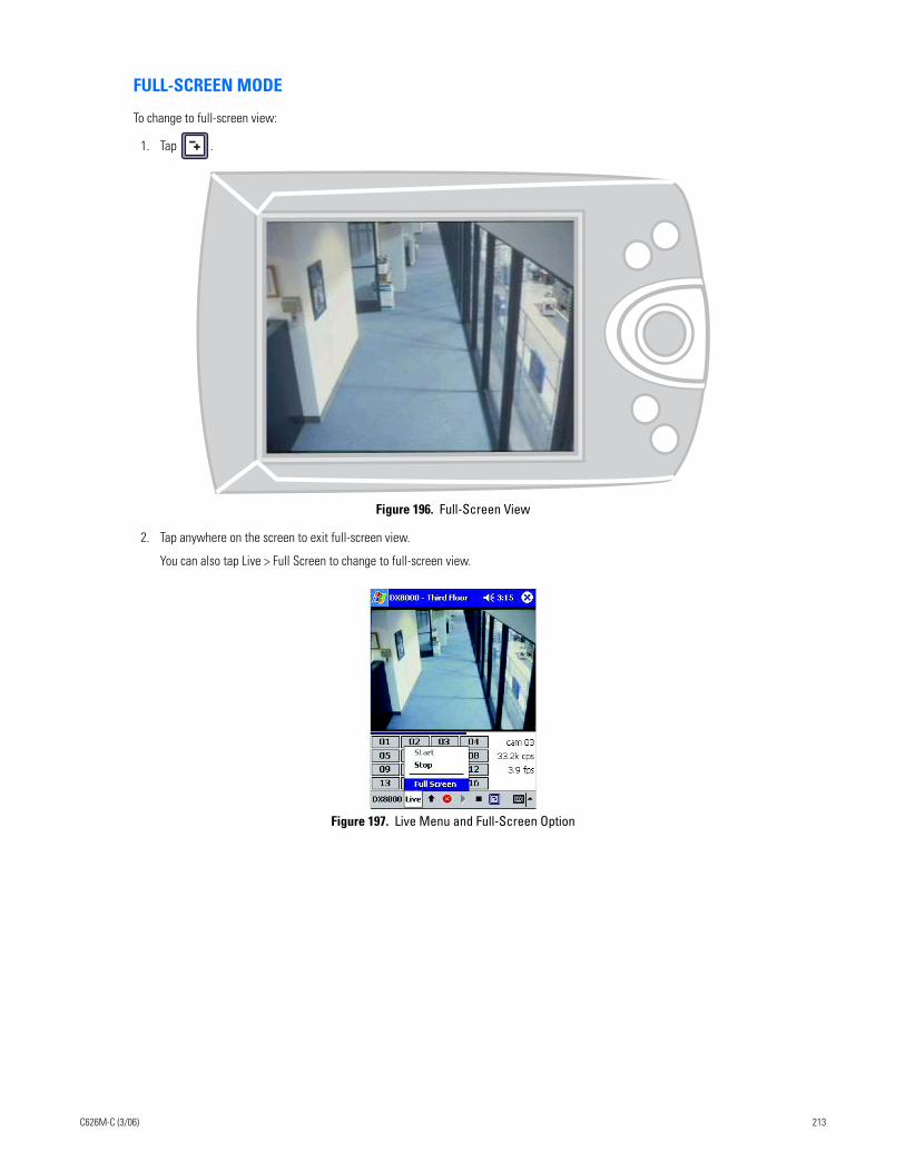
FULL-SCREEN MODE
To change to full-screen view:
1. Tap .
Figure 196. Full-Screen View
2. Tap anywhere on the screen to exit full-screen view.
You can also tap Live > Full Screen to change to full-screen view.
Figure 197. Live Menu and Full-Screen Option
C626M-C (3/06) 213
DX8000 Web Client
Welcome to the DX8000 Web Client application. This section describes how to use the DX8000 Web Client application and includes the follow-ing topics:
• Using the DX8000 Web Client on page 214
• Web Client Configuration on page 219
• Viewing Live Video on page 228
Using the DX8000 Web Client
DESCRIPTIONThe DX8000 Web Client allows you to view live video and operate PTZ features of cameras attached to DX8000 Series DVRs. Using a standard web browser, you can remotely monitor up to 16 cameras from up to five DX8000 servers simultaneously. Each DX8000 DVR can support up to 100 web clients either internally within an organization or externally through the Internet.
Features:
• Live viewing of up to 16 cameras simultaneously
• Ability to monitor cameras from multiple DX8000 sites
• Multiple screen division options, including single, quad, and sixteen panel views
• Full PTZ control
• Runs on multiple platforms using a standard web browser
SYSTEM REQUIREMENTSThe DX8000 Web Client recommended minimum system requirements include the following:
• Processor: Intel® Pentium® III, or Pentium 4 with 800 MHz minimum processor speed
• Memory: 128 MB of RAM
• Video: AGP VGA card with minimum of 64 MB of video RAM, 1024 x 768 display resolution, 32-bit color, and DirectX® 8.1 or later hardware acceleration
• 4.5 MB of free disk space
• Monitor: SVGA or XGA with 1024 x 768 resolution, 32-bit color
• Operating system: Windows® 2000 (SP4) or Windows XP only
NOTE: The DX8000 Web Client is only compatible with Internet Explorer®.
214 C626M-C (3/06)
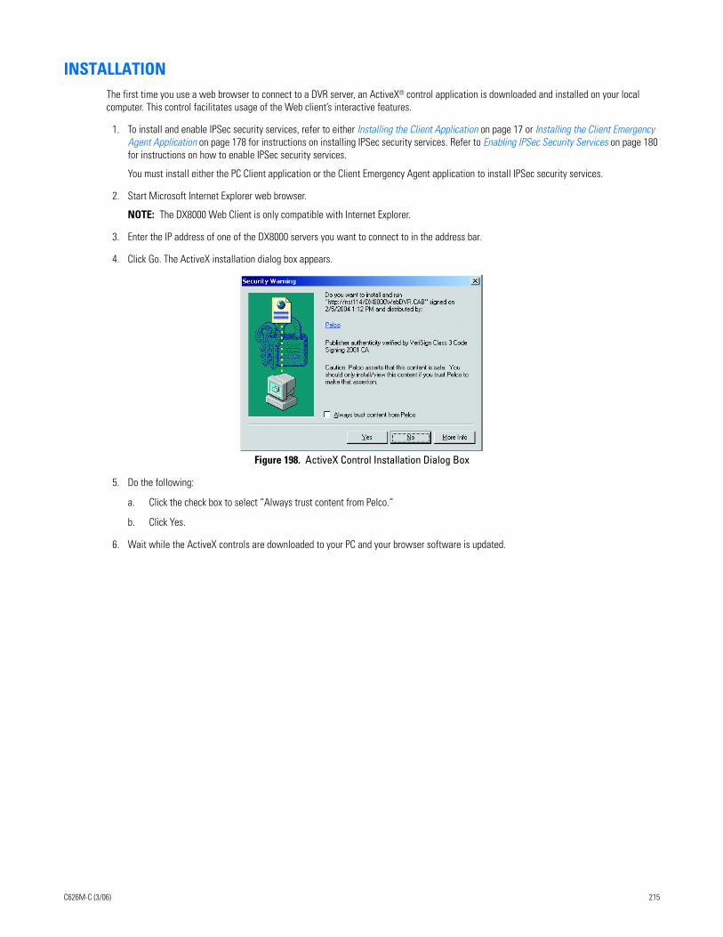
INSTALLATIONThe first time you use a web browser to connect to a DVR server, an ActiveX® control application is downloaded and installed on your local computer. This control facilitates usage of the Web client’s interactive features.
1. To install and enable IPSec security services, refer to either Installing the Client Application on page 17 or Installing the Client Emergency Agent Application on page 178 for instructions on installing IPSec security services. Refer to Enabling IPSec Security Services on page 180 for instructions on how to enable IPSec security services.
You must install either the PC Client application or the Client Emergency Agent application to install IPSec security services.
2. Start Microsoft Internet Explorer web browser.
NOTE: The DX8000 Web Client is only compatible with Internet Explorer.
3. Enter the IP address of one of the DX8000 servers you want to connect to in the address bar.
4. Click Go. The ActiveX installation dialog box appears.
Figure 198. ActiveX Control Installation Dialog Box
5. Do the following:
a. Click the check box to select “Always trust content from Pelco.”
b. Click Yes.
6. Wait while the ActiveX controls are downloaded to your PC and your browser software is updated.
C626M-C (3/06) 215
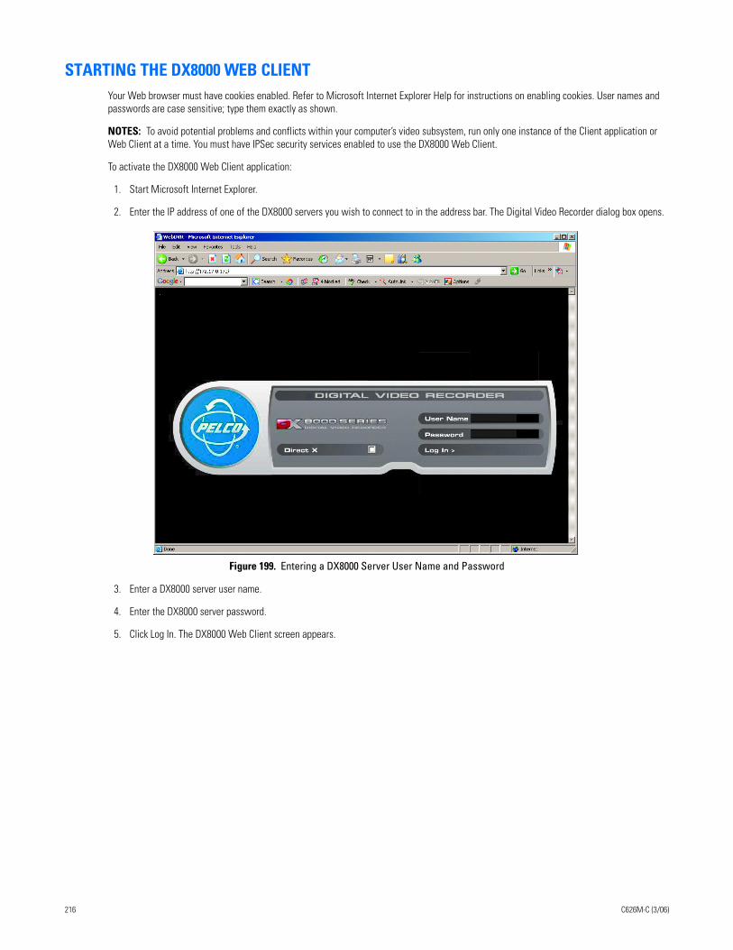
STARTING THE DX8000 WEB CLIENTYour Web browser must have cookies enabled. Refer to Microsoft Internet Explorer Help for instructions on enabling cookies. User names and passwords are case sensitive; type them exactly as shown.
NOTES: To avoid potential problems and conflicts within your computer’s video subsystem, run only one instance of the Client application or Web Client at a time. You must have IPSec security services enabled to use the DX8000 Web Client.
To activate the DX8000 Web Client application:
1. Start Microsoft Internet Explorer.
2. Enter the IP address of one of the DX8000 servers you wish to connect to in the address bar. The Digital Video Recorder dialog box opens.
Figure 199. Entering a DX8000 Server User Name and Password
3. Enter a DX8000 server user name.
4. Enter the DX8000 server password.
5. Click Log In. The DX8000 Web Client screen appears.
216 C626M-C (3/06)
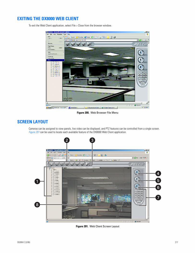
EXITING THE DX8000 WEB CLIENTTo exit the Web Client application, select File > Close from the browser window.
Figure 200. Web Browser File Menu
SCREEN LAYOUTCameras can be assigned to view panels, live video can be displayed, and PTZ features can be controlled from a single screen. Figure 201 can be used to locate each available feature of the DX8000 Web Client application.
Figure 201. Web Client Screen Layout
�
�
��
�
� �
C626M-C (3/06) 217
The following table describes the Web Client application window.
Table AR. Web Client Application Window Parts
Item Description
Site tree
Screen division buttons
Remote site connection button
PTZ zoom control
PTZ focus control
PTZ iris control
PTZ keypad
View pane or view panel
218 C626M-C (3/06)
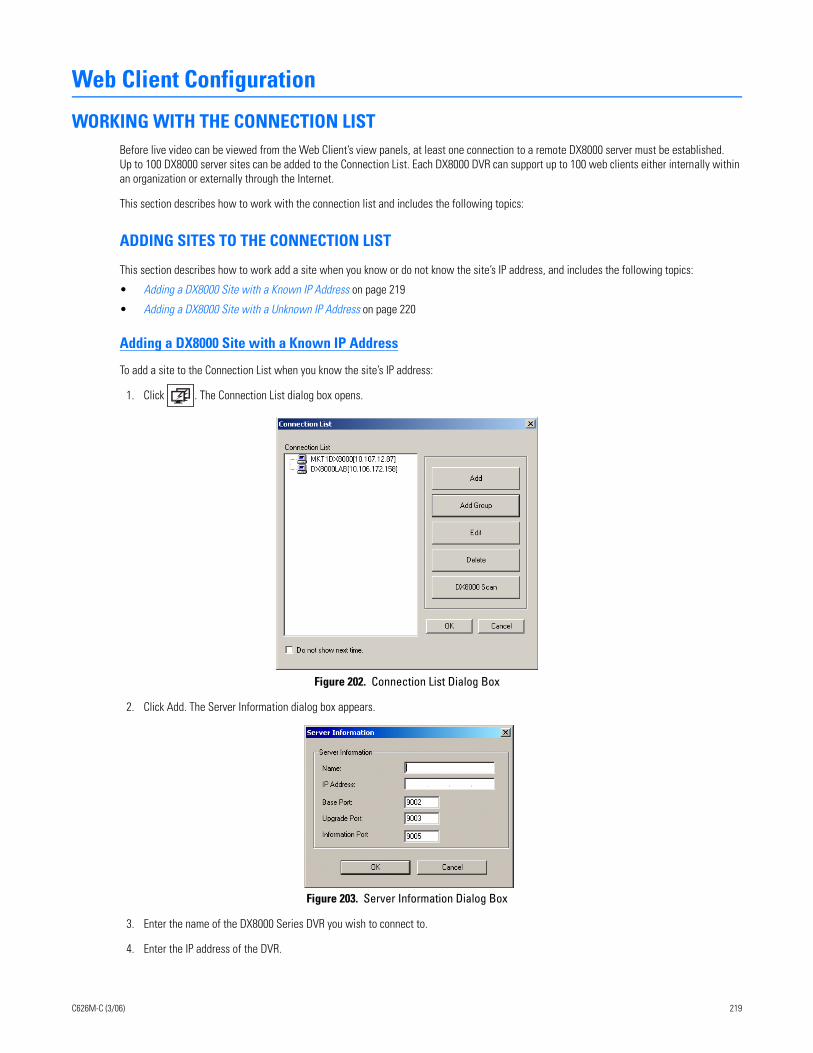
Web Client Configuration
WORKING WITH THE CONNECTION LISTBefore live video can be viewed from the Web Client’s view panels, at least one connection to a remote DX8000 server must be established. Up to 100 DX8000 server sites can be added to the Connection List. Each DX8000 DVR can support up to 100 web clients either internally within an organization or externally through the Internet.
This section describes how to work with the connection list and includes the following topics:
ADDING SITES TO THE CONNECTION LIST
This section describes how to work add a site when you know or do not know the site’s IP address, and includes the following topics:
• Adding a DX8000 Site with a Known IP Address on page 219
• Adding a DX8000 Site with a Unknown IP Address on page 220
Adding a DX8000 Site with a Known IP Address
To add a site to the Connection List when you know the site’s IP address:
1. Click . The Connection List dialog box opens.
Figure 202. Connection List Dialog Box
2. Click Add. The Server Information dialog box appears.
Figure 203. Server Information Dialog Box
3. Enter the name of the DX8000 Series DVR you wish to connect to.
4. Enter the IP address of the DVR.
C626M-C (3/06) 219
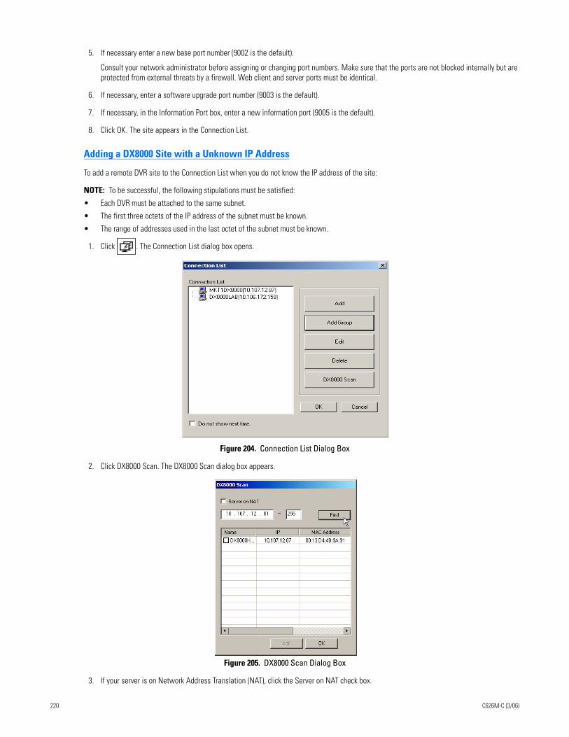
5. If necessary enter a new base port number (9002 is the default).
Consult your network administrator before assigning or changing port numbers. Make sure that the ports are not blocked internally but are protected from external threats by a firewall. Web client and server ports must be identical.
6. If necessary, enter a software upgrade port number (9003 is the default).
7. If necessary, in the Information Port box, enter a new information port (9005 is the default).
8. Click OK. The site appears in the Connection List.
Adding a DX8000 Site with a Unknown IP Address
To add a remote DVR site to the Connection List when you do not know the IP address of the site:
NOTE: To be successful, the following stipulations must be satisfied:
• Each DVR must be attached to the same subnet.
• The first three octets of the IP address of the subnet must be known.
• The range of addresses used in the last octet of the subnet must be known.
1. Click . The Connection List dialog box opens.
Figure 204. Connection List Dialog Box
2. Click DX8000 Scan. The DX8000 Scan dialog box appears.
Figure 205. DX8000 Scan Dialog Box
3. If your server is on Network Address Translation (NAT), click the Server on NAT check box.
220 C626M-C (3/06)
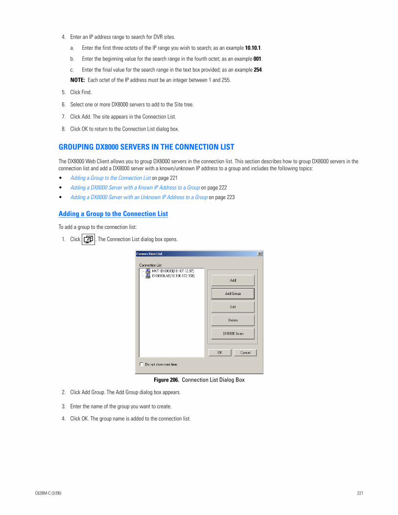
4. Enter an IP address range to search for DVR sites.
a. Enter the first three octets of the IP range you wish to search; as an example 10.10.1.
b. Enter the beginning value for the search range in the fourth octet; as an example 001.
c. Enter the final value for the search range in the text box provided; as an example 254.
NOTE: Each octet of the IP address must be an integer between 1 and 255.
5. Click Find.
6. Select one or more DX8000 servers to add to the Site tree.
7. Click Add. The site appears in the Connection List.
8. Click OK to return to the Connection List dialog box.
GROUPING DX8000 SERVERS IN THE CONNECTION LIST
The DX8000 Web Client allows you to group DX8000 servers in the connection list. This section describes how to group DX8000 servers in the connection list and add a DX8000 server with a known/unknown IP address to a group and includes the following topics:
• Adding a Group to the Connection List on page 221
• Adding a DX8000 Server with a Known IP Address to a Group on page 222
• Adding a DX8000 Server with an Unknown IP Address to a Group on page 223
Adding a Group to the Connection List
To add a group to the connection list:
1. Click . The Connection List dialog box opens.
Figure 206. Connection List Dialog Box
2. Click Add Group. The Add Group dialog box appears.
3. Enter the name of the group you want to create.
4. Click OK. The group name is added to the connection list.
C626M-C (3/06) 221
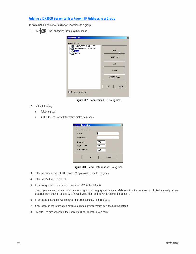
Adding a DX8000 Server with a Known IP Address to a Group
To add a DX8000 server with a known IP address to a group:
1. Click . The Connection List dialog box opens.
Figure 207. Connection List Dialog Box
2. Do the following:
a. Select a group.
b. Click Add. The Server Information dialog box opens.
Figure 208. Server Information Dialog Box
3. Enter the name of the DX8000 Series DVR you wish to add to the group.
4. Enter the IP address of the DVR.
5. If necessary enter a new base port number (9002 is the default).
Consult your network administrator before assigning or changing port numbers. Make sure that the ports are not blocked internally but are protected from external threats by a firewall. Web client and server ports must be identical.
6. If necessary, enter a software upgrade port number (9003 is the default).
7. If necessary, in the Information Port box, enter a new information port (9005 is the default).
8. Click OK. The site appears in the Connection List under the group name.
222 C626M-C (3/06)
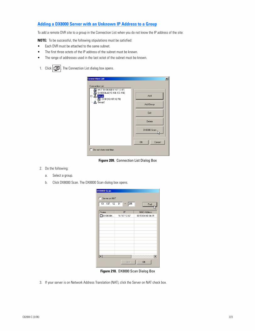
Adding a DX8000 Server with an Unknown IP Address to a Group
To add a remote DVR site to a group in the Connection List when you do not know the IP address of the site:
NOTE: To be successful, the following stipulations must be satisfied:
• Each DVR must be attached to the same subnet.
• The first three octets of the IP address of the subnet must be known.
• The range of addresses used in the last octet of the subnet must be known.
1. Click . The Connection List dialog box opens.
Figure 209. Connection List Dialog Box
2. Do the following:
a. Select a group.
b. Click DX8000 Scan. The DX8000 Scan dialog box opens.
Figure 210. DX8000 Scan Dialog Box
3. If your server is on Network Address Translation (NAT), click the Server on NAT check box.
C626M-C (3/06) 223
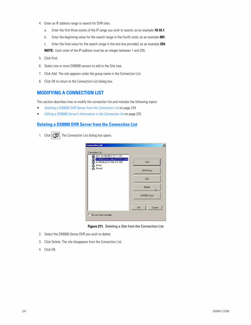
4. Enter an IP address range to search for DVR sites.
a. Enter the first three octets of the IP range you wish to search; as an example 10.10.1.
b. Enter the beginning value for the search range in the fourth octet; as an example 001.
c. Enter the final value for the search range in the text box provided; as an example 254.
NOTE: Each octet of the IP address must be an integer between 1 and 255.
5. Click Find.
6. Select one or more DX8000 servers to add to the Site tree.
7. Click Add. The site appears under the group name in the Connection List.
8. Click OK to return to the Connection List dialog box.
MODIFYING A CONNECTION LIST
This section describes how to modify the connection list and includes the following topics:
• Deleting a DX8000 DVR Server from the Connection List on page 224
• Editing a DX8000 Server’s Information in the Connection list on page 225
Deleting a DX8000 DVR Server from the Connection List
1. Click . The Connection List dialog box opens.
Figure 211. Deleting a Site from the Connection List
2. Select the DX8000 Series DVR you wish to delete.
3. Click Delete. The site disappears from the Connection List.
4. Click OK.
224 C626M-C (3/06)
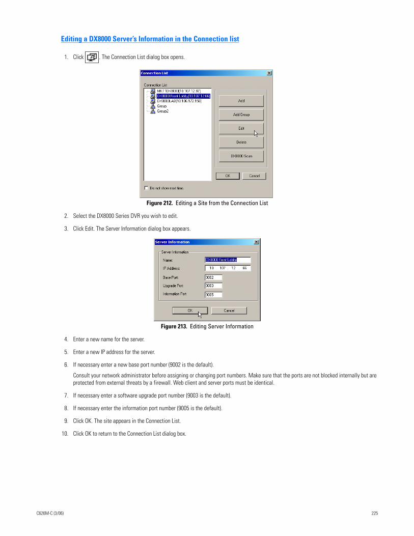
Editing a DX8000 Server’s Information in the Connection list
1. Click . The Connection List dialog box opens.
Figure 212. Editing a Site from the Connection List
2. Select the DX8000 Series DVR you wish to edit.
3. Click Edit. The Server Information dialog box appears.
Figure 213. Editing Server Information
4. Enter a new name for the server.
5. Enter a new IP address for the server.
6. If necessary enter a new base port number (9002 is the default).
Consult your network administrator before assigning or changing port numbers. Make sure that the ports are not blocked internally but are protected from external threats by a firewall. Web client and server ports must be identical.
7. If necessary enter a software upgrade port number (9003 is the default).
8. If necessary enter the information port number (9005 is the default).
9. Click OK. The site appears in the Connection List.
10. Click OK to return to the Connection List dialog box.
C626M-C (3/06) 225
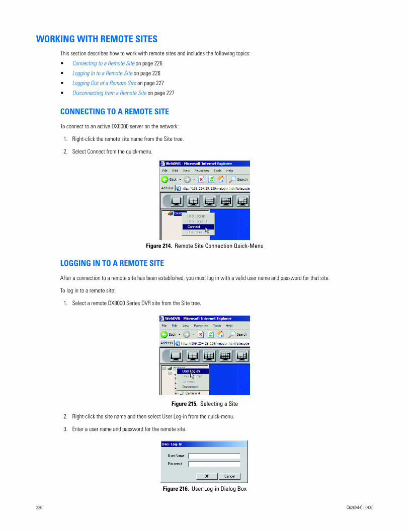
WORKING WITH REMOTE SITESThis section describes how to work with remote sites and includes the following topics:
• Connecting to a Remote Site on page 226
• Logging In to a Remote Site on page 226
• Logging Out of a Remote Site on page 227
• Disconnecting from a Remote Site on page 227
CONNECTING TO A REMOTE SITE
To connect to an active DX8000 server on the network:
1. Right-click the remote site name from the Site tree.
2. Select Connect from the quick-menu.
Figure 214. Remote Site Connection Quick-Menu
LOGGING IN TO A REMOTE SITE
After a connection to a remote site has been established, you must log in with a valid user name and password for that site.
To log in to a remote site:
1. Select a remote DX8000 Series DVR site from the Site tree.
Figure 215. Selecting a Site
2. Right-click the site name and then select User Log-in from the quick-menu.
3. Enter a user name and password for the remote site.
Figure 216. User Log-in Dialog Box
226 C626M-C (3/06)
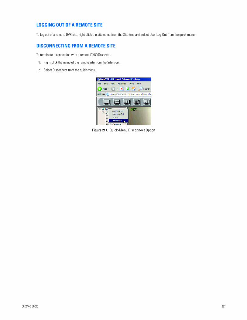
LOGGING OUT OF A REMOTE SITE
To log out of a remote DVR site, right-click the site name from the Site tree and select User Log-Out from the quick-menu.
DISCONNECTING FROM A REMOTE SITE
To terminate a connection with a remote DX8000 server:
1. Right-click the name of the remote site from the Site tree.
2. Select Disconnect from the quick-menu.
Figure 217. Quick-Menu Disconnect Option
C626M-C (3/06) 227
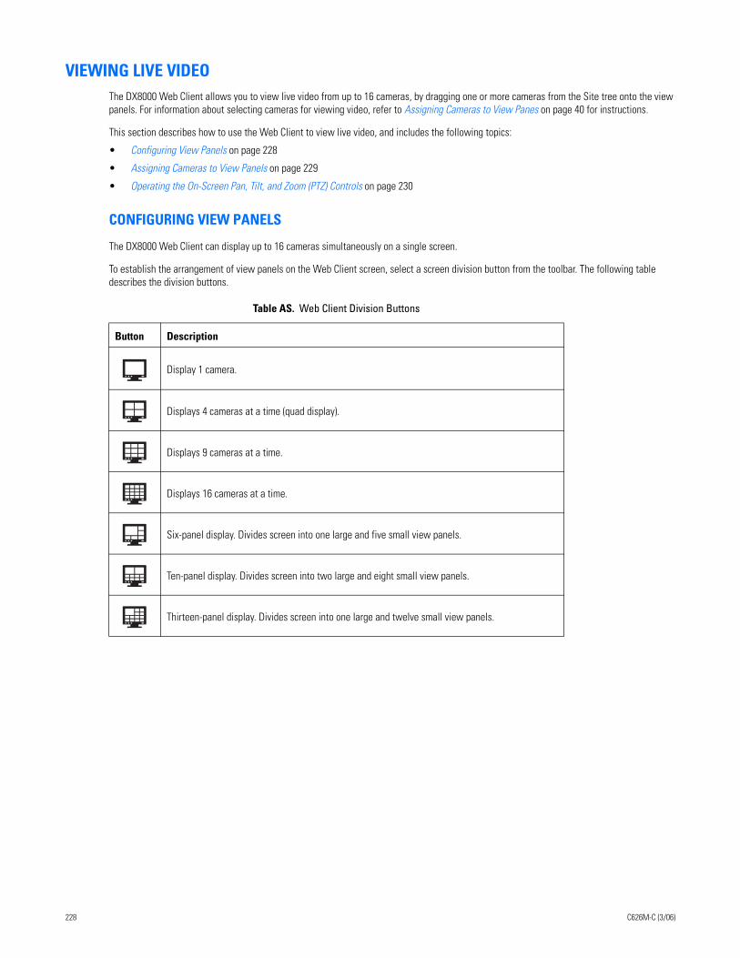
VIEWING LIVE VIDEOThe DX8000 Web Client allows you to view live video from up to 16 cameras, by dragging one or more cameras from the Site tree onto the view panels. For information about selecting cameras for viewing video, refer to Assigning Cameras to View Panes on page 40 for instructions.
This section describes how to use the Web Client to view live video, and includes the following topics:
• Configuring View Panels on page 228
• Assigning Cameras to View Panels on page 229
• Operating the On-Screen Pan, Tilt, and Zoom (PTZ) Controls on page 230
CONFIGURING VIEW PANELS
The DX8000 Web Client can display up to 16 cameras simultaneously on a single screen.
To establish the arrangement of view panels on the Web Client screen, select a screen division button from the toolbar. The following table describes the division buttons.
Table AS. Web Client Division Buttons
Button Description
Display 1 camera.
Displays 4 cameras at a time (quad display).
Displays 9 cameras at a time.
Displays 16 cameras at a time.
Six-panel display. Divides screen into one large and five small view panels.
Ten-panel display. Divides screen into two large and eight small view panels.
Thirteen-panel display. Divides screen into one large and twelve small view panels.
228 C626M-C (3/06)
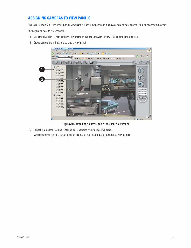
ASSIGNING CAMERAS TO VIEW PANELS
The DX8000 Web Client includes up to 16 view panels. Each view panel can display a single camera channel from any connected server.
To assign a camera to a view panel:
1. Click the plus sign (+) next to the word Camera on the site you wish to view. This expands the Site tree.
2. Drag a camera from the Site tree onto a view panel.
Figure 218. Dragging a Camera to a Web Client View Panel
3. Repeat the process in steps 1-2 for up to 16 cameras from various DVR sites.
When changing from one screen division to another you must reassign cameras to view panels.
�
C626M-C (3/06) 229
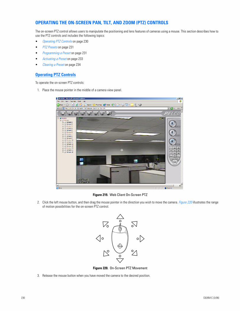
OPERATING THE ON-SCREEN PAN, TILT, AND ZOOM (PTZ) CONTROLS
The on-screen PTZ control allows users to manipulate the positioning and lens features of cameras using a mouse. This section describes how to use the PTZ controls and includes the following topics:
• Operating PTZ Controls on page 230
• PTZ Presets on page 231
• Programming a Preset on page 231
• Activating a Preset on page 233
• Clearing a Preset on page 234
Operating PTZ Controls
To operate the on-screen PTZ controls:
1. Place the mouse pointer in the middle of a camera view panel.
Figure 219. Web Client On-Screen PTZ
2. Click the left mouse button, and then drag the mouse pointer in the direction you wish to move the camera. Figure 220 illustrates the range of motion possibilities for the on-screen PTZ control.
Figure 220. On-Screen PTZ Movement
3. Release the mouse button when you have moved the camera to the desired position.
230 C626M-C (3/06)
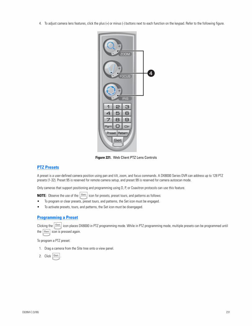
4. To adjust camera lens features, click the plus (+) or minus (-) buttons next to each function on the keypad. Refer to the following figure.
Figure 221. Web Client PTZ Lens Controls
PTZ Presets
A preset is a user-defined camera position using pan and tilt, zoom, and focus commands. A DX8000 Series DVR can address up to 128 PTZ presets (1-32). Preset 95 is reserved for remote camera setup, and preset 99 is reserved for camera autoscan mode.
Only cameras that support positioning and programming using D, P, or Coaxitron protocols can use this feature.
NOTE: Observe the use of the icon for presets, preset tours, and patterns as follows:
• To program or clear presets, preset tours, and patterns, the Set icon must be engaged.
• To activate presets, tours, and patterns, the Set icon must be disengaged.
Programming a Preset
Clicking the icon places DX8000 in PTZ programming mode. While in PTZ programming mode, multiple presets can be programmed until
the icon is pressed again.
To program a PTZ preset:
1. Drag a camera from the Site tree onto a view panel.
2. Click .
�
C626M-C (3/06) 231
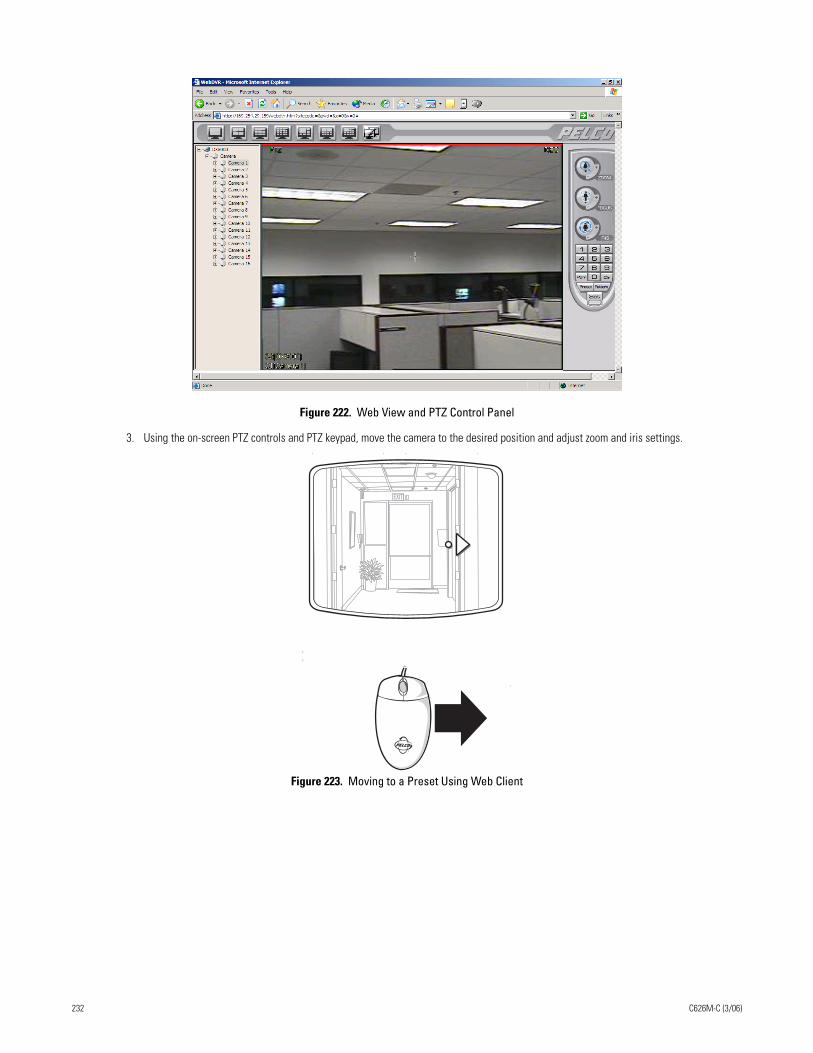
Figure 222. Web View and PTZ Control Panel
3. Using the on-screen PTZ controls and PTZ keypad, move the camera to the desired position and adjust zoom and iris settings.
Figure 223. Moving to a Preset Using Web Client
EXIT
232 C626M-C (3/06)
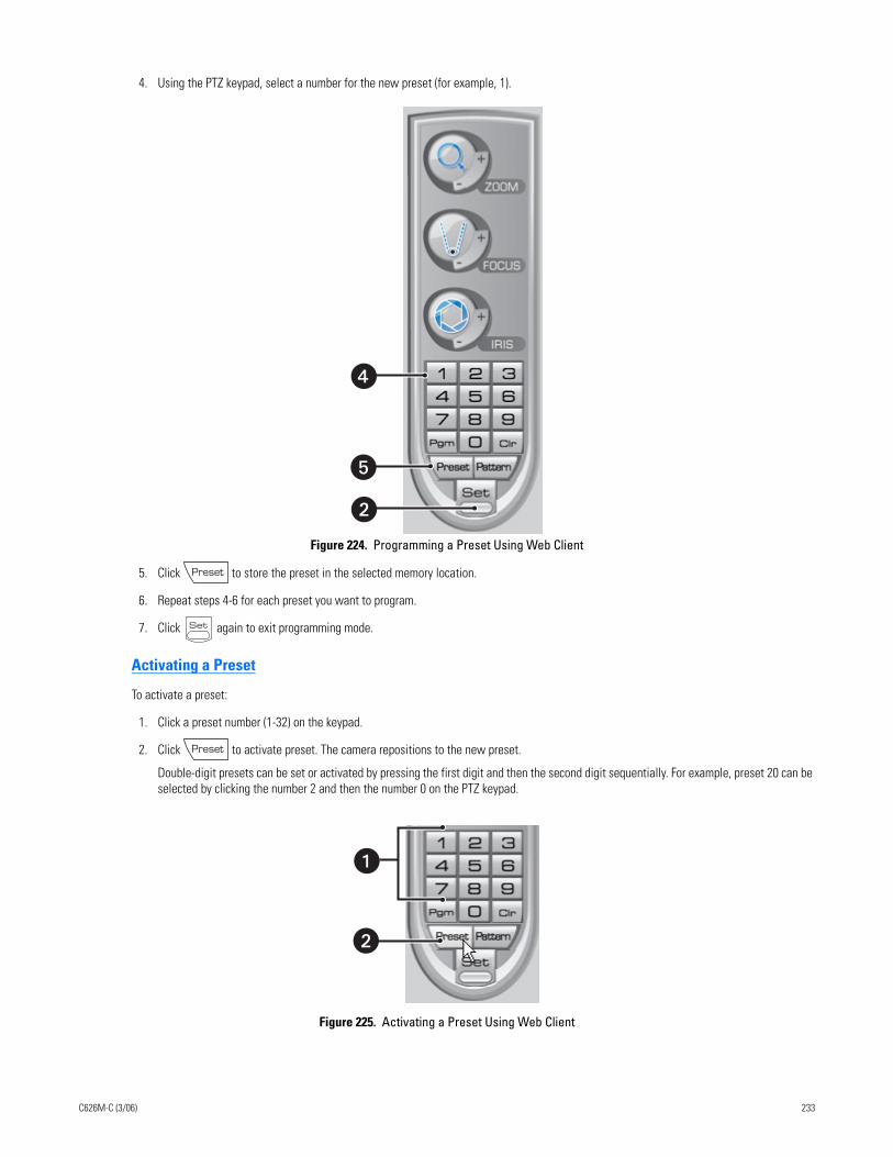
4. Using the PTZ keypad, select a number for the new preset (for example, 1).
Figure 224. Programming a Preset Using Web Client
5. Click to store the preset in the selected memory location.
6. Repeat steps 4-6 for each preset you want to program.
7. Click again to exit programming mode.
Activating a Preset
To activate a preset:
1. Click a preset number (1-32) on the keypad.
2. Click to activate preset. The camera repositions to the new preset.
Double-digit presets can be set or activated by pressing the first digit and then the second digit sequentially. For example, preset 20 can be selected by clicking the number 2 and then the number 0 on the PTZ keypad.
Figure 225. Activating a Preset Using Web Client
�
�
�
�
C626M-C (3/06) 233
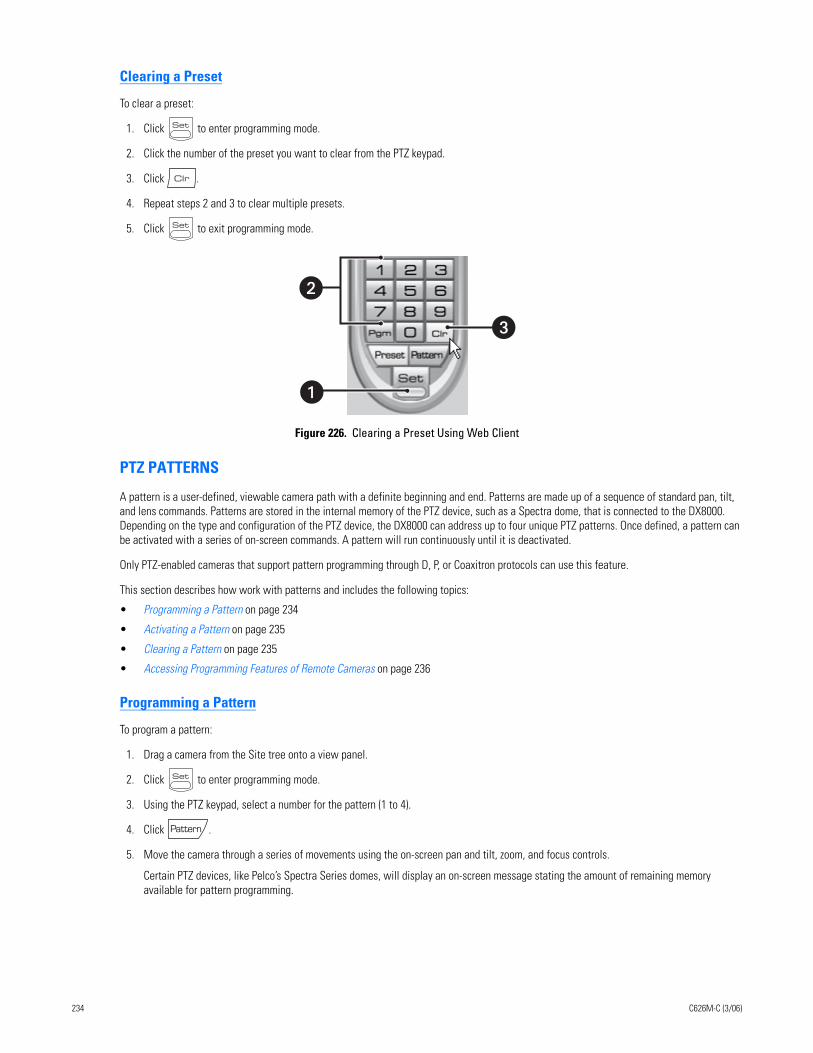
Clearing a Preset
To clear a preset:
1. Click to enter programming mode.
2. Click the number of the preset you want to clear from the PTZ keypad.
3. Click .
4. Repeat steps 2 and 3 to clear multiple presets.
5. Click to exit programming mode.
Figure 226. Clearing a Preset Using Web Client
PTZ PATTERNS
A pattern is a user-defined, viewable camera path with a definite beginning and end. Patterns are made up of a sequence of standard pan, tilt, and lens commands. Patterns are stored in the internal memory of the PTZ device, such as a Spectra dome, that is connected to the DX8000. Depending on the type and configuration of the PTZ device, the DX8000 can address up to four unique PTZ patterns. Once defined, a pattern can be activated with a series of on-screen commands. A pattern will run continuously until it is deactivated.
Only PTZ-enabled cameras that support pattern programming through D, P, or Coaxitron protocols can use this feature.
This section describes how work with patterns and includes the following topics:
• Programming a Pattern on page 234
• Activating a Pattern on page 235
• Clearing a Pattern on page 235
• Accessing Programming Features of Remote Cameras on page 236
Programming a Pattern
To program a pattern:
1. Drag a camera from the Site tree onto a view panel.
2. Click to enter programming mode.
3. Using the PTZ keypad, select a number for the pattern (1 to 4).
4. Click .
5. Move the camera through a series of movements using the on-screen pan and tilt, zoom, and focus controls.
Certain PTZ devices, like Pelco’s Spectra Series domes, will display an on-screen message stating the amount of remaining memory available for pattern programming.
�
�
234 C626M-C (3/06)
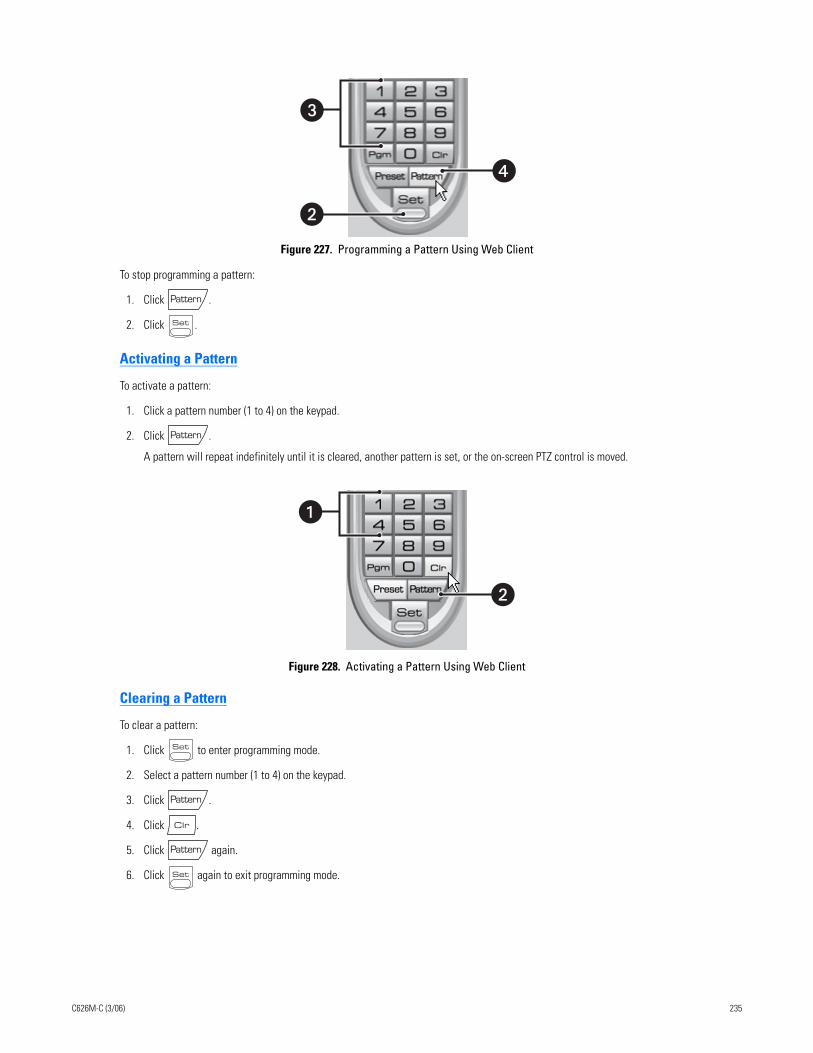
Figure 227. Programming a Pattern Using Web Client
To stop programming a pattern:
1. Click .
2. Click .
Activating a Pattern
To activate a pattern:
1. Click a pattern number (1 to 4) on the keypad.
2. Click .
A pattern will repeat indefinitely until it is cleared, another pattern is set, or the on-screen PTZ control is moved.
Figure 228. Activating a Pattern Using Web Client
Clearing a Pattern
To clear a pattern:
1. Click to enter programming mode.
2. Select a pattern number (1 to 4) on the keypad.
3. Click .
4. Click .
5. Click again.
6. Click again to exit programming mode.
�
�
�
�
C626M-C (3/06) 235
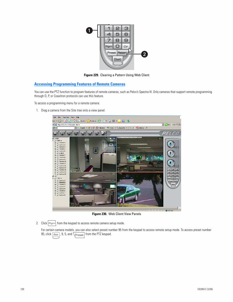
Figure 229. Clearing a Pattern Using Web Client
Accessing Programming Features of Remote Cameras
You can use the PTZ function to program features of remote cameras, such as Pelco’s Spectra III. Only cameras that support remote programming through D, P, or Coaxitron protocols can use this feature.
To access a programming menu for a remote camera:
1. Drag a camera from the Site tree onto a view panel.
Figure 230. Web Client View Panels
2. Click from the keypad to access remote camera setup mode.
For certain camera models, you can also select preset number 95 from the keypad to access remote setup mode. To access preset number 95, click , 9, 5, and from the PTZ keypad.
�
236 C626M-C (3/06)
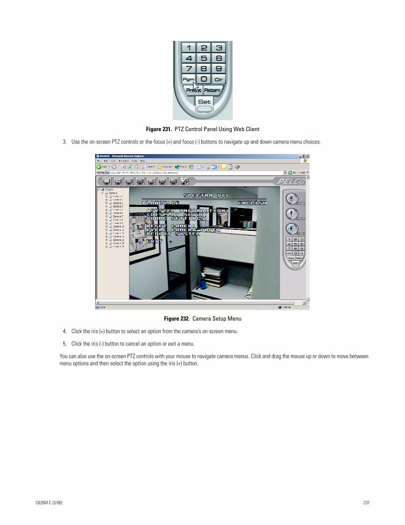
Figure 231. PTZ Control Panel Using Web Client
3. Use the on-screen PTZ controls or the focus (+) and focus (-) buttons to navigate up and down camera menu choices.
Figure 232. Camera Setup Menu
4. Click the iris (+) button to select an option from the camera’s on-screen menu.
5. Click the iris (-) button to cancel an option or exit a menu.
You can also use the on-screen PTZ controls with your mouse to navigate camera menus. Click and drag the mouse up or down to move between menu options and then select the option using the iris (+) button.
C626M-C (3/06) 237

238 C626M-C (3/06)
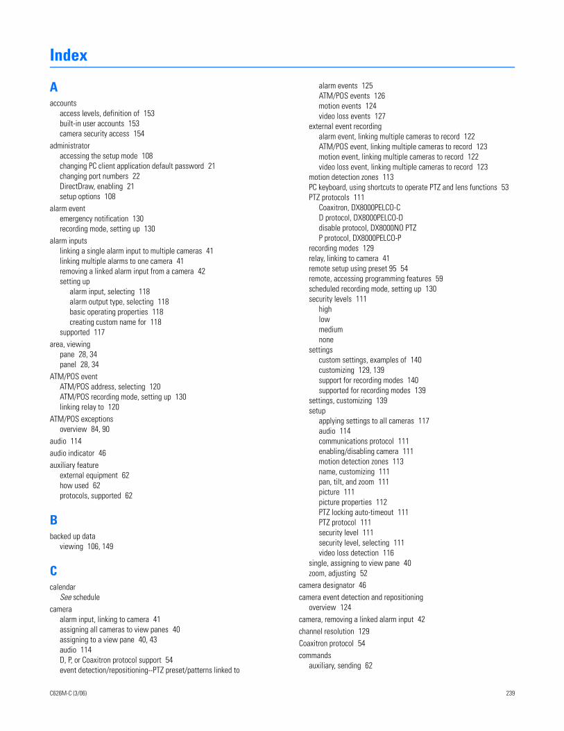
Index
Aaccounts
access levels, definition of 153built-in user accounts 153camera security access 154
administratoraccessing the setup mode 108changing PC client application default password 21changing port numbers 22DirectDraw, enabling 21setup options 108
alarm eventemergency notification 130recording mode, setting up 130
alarm inputslinking a single alarm input to multiple cameras 41linking multiple alarms to one camera 41removing a linked alarm input from a camera 42setting up
alarm input, selecting 118alarm output type, selecting 118basic operating properties 118creating custom name for 118
supported 117area, viewing
pane 28, 34panel 28, 34
ATM/POS eventATM/POS address, selecting 120ATM/POS recording mode, setting up 130linking relay to 120
ATM/POS exceptionsoverview 84, 90
audio 114audio indicator 46auxiliary feature
external equipment 62how used 62protocols, supported 62
Bbacked up data
viewing 106, 149
Ccalendar
See schedulecamera
alarm input, linking to camera 41assigning all cameras to view panes 40assigning to a view pane 40, 43audio 114D, P, or Coaxitron protocol support 54event detection/repositioning--PTZ preset/patterns linked to
C626M-C (3/06)
alarm events 125ATM/POS events 126motion events 124video loss events 127
external event recordingalarm event, linking multiple cameras to record 122ATM/POS event, linking multiple cameras to record 123motion event, linking multiple cameras to record 122video loss event, linking multiple cameras to record 123
motion detection zones 113PC keyboard, using shortcuts to operate PTZ and lens functions 53PTZ protocols 111
Coaxitron, DX8000PELCO-CD protocol, DX8000PELCO-Ddisable protocol, DX8000NO PTZP protocol, DX8000PELCO-P
recording modes 129relay, linking to camera 41remote setup using preset 95 54remote, accessing programming features 59scheduled recording mode, setting up 130security levels 111
highlowmediumnone
settingscustom settings, examples of 140customizing 129, 139support for recording modes 140supported for recording modes 139
settings, customizing 139setup
applying settings to all cameras 117audio 114communications protocol 111enabling/disabling camera 111motion detection zones 113name, customizing 111pan, tilt, and zoom 111picture 111picture properties 112PTZ locking auto-timeout 111PTZ protocol 111security level 111security level, selecting 111video loss detection 116
single, assigning to view pane 40zoom, adjusting 52
camera designator 46camera event detection and repositioning
overview 124camera, removing a linked alarm input 42channel resolution 129Coaxitron protocol 54commands
auxiliary, sending 62
239
compression, video 140connecting DX8000 DVRs 108connection list
adding servers to 22adding site with unknown IP address 23adding sites with know IP address 22deleting a DX8000 server 24editing DX8000 server information 24
DD protocol 54designators
camera 46site 46
digital zoom control 29DirectDraw
enabling 21hardware acceleration 21
disk space 29disk status indicator 29display mode
Live video 34playback video 34See pane/panel
DX8000command descriptions 30overview of application window 27
DX8000 application windowpanels 34panes 34
DX8000, setting up 108
Ee-mail notification
overview 175sending to groups 176sending to individuals 175video loss event, sending in response to 116
e-mail server 166emergency agent notification 116
accessing Emergency Agent Setup page 163camera, linking to client emergency agents 164clients
adding 163changing emergency agent properties 164deleting from notification list 164
Emergency Agent Client utility, required 163overview 163server event transmission time, setting 165
emergency e-mail notificationaccessing Emergency E-mail Notification page 166alarm 166alarm events, sent in response to 170e-mail groups 166e-mail server, configuring 167enabling/disabling 166group
240
adding 171adding members 172deleting 172deleting members from group 173modifying 172modifying member attributes 174overview 171
local area network (LAN), 166motion events, sent in response to 170overview 166setting up 166testing configuration 168time period
notification frequency, setting up 169overview 169setting the time of day 169
video loss events, sent in response to 171events
alarm 117ATM/POS 119motion detection 113recording modes 130video loss detection 116
export setup 30Ext. monitor
overview 163external events 119
Ffile size
video image 140frame rate
about calculating 144advanced, configuring 142basic, configuring 141maximum, setting 143overview 129, 141range of 141resolution value 142
Ggraphics card 21
Hhardware
DX8000-AUD audio card 114external equipment 62
Iimport setup 30index view panel 29indicators
audio 46camera 46instant recording 46on-screen PTZ control 46pan, tilt, and zoom 46
C626M-C (3/06)
record 46site 46
instant recording indicator 46instant recording mode 47IPSec
disabling 19enabling 19network communications, required 19
Llanguage
supported 31English (default)FrenchGermanItalianPolishPortugueseRussianSpanish
linkingalarm input, removing from camera 42alarm inputs, linking to cameras 41link setup options 117
event-PTZ link settingsevent-recording link settingsevent-relay link settingsrelay and alarm settings
relays, linking to cameras 41removing 42setting up 40
linking and event recording setup 117live audio 31, 46, 114Live View mode 59local area network (LAN) 166
Mmenu bar 28menus
Edit 30Export 32Favorite 32File 30file 29Help 32View 30
menus, shortcutlocal site 39relay 40remote site 40
modeinstant record, starting 49instant record, starting and stopping 48instant record, stopping 49instant recording 47live recording 49Live View mode, working in 59live view, working in 43
C626M-C (3/06)
normal recording 47recording modes, scheduled 129
See recording modemotion
detection of 119, 130See also relays
detection zones 113emergency e-mail notification 166emergency notification 163motion event recording mode, setting up 130
multiple event recording 130
NNational Television System Committee (NTSC) 141network requirements
DX8000 attached to same subnet 23IPSec 17, 19
normal recording mode 47notification
e-mail 116emergency agent 116
Notification page 163
Oon-screen display
add instant record icon to OSD 48customizing 47overview 31, 46selections 47
Audio RecordingBackground ColorCamera NameInstant RecordingPOSPTZSelect AllSite NameVideo Recording
operating modesfunction 34
DisplaySearchSetup
instant record, starting and stopping 48instant recording 47live recording 49
overriding other users 108
PP protocol 54pan, tilt, and zoom (PTZ) control panel 28pan, tilt, and zoom control
enabling 46focus command, using 54operating 49preset, programming 54programming guidelines 54
241
pan, tilt, and zoom indicator 46pane/panel
channel/camera assignment to 35configuring 35division display format 35division, selection of 35hidden panels, automatically cycling through 37hidden panels, manually cycling through 37live/playback video, display of 28navigating between 35overview 34pane, expanding and collapsing 37site name displayed in 31video, viewing 109
patternactivating 54, 56, 58clearing 54, 58overview 56programming 54, 57programming, starting 57programming, stopping 57protocols, PTZ-enabled cameras 56
PC client applicationautomatic system upgrade 20changing default client password 21changing default password 21getting started with 16how to run 20installing 17IPSec security services 20license agreement 18logging into 21requirements 20starting 20system requirements 16viewing backed up data, required 149viewing backed up data, requirement 149viewing remote DX8000 servers 16working with 22
Phase Alternating Line (PAL) 141playback control panel 29playback timeline 29port
blocked internally 22changing port number 22PC client and server matching 22
presetactivating 54, 55clearing 54, 56guidelines 54Preset 95 54Preset 99 54programming 54
preset touraccessing a preset tour group 63adding presets to a tour 63, 64configuring 63delete presets from a tour 63deleting presets from a tour 65programming 63
242
protocolsD, P, Coaxitron 54
PTZ OSD menu control 59PTZ presets and patterns
alarm events, linking to 125ATM/POS events, linking to 126motion events, linking to 124video loss events, linking to 127
Rrecord indicator 46recording mode
alarm, camera settings supportedalarm image quality 140frame rate during alarm 140image resolution 140post-motion 140pre-alarm 140pre-alarm frame rate 140pre-alarm image quality 140
ATM/POS, camera settings supportedATM/POS image quality 140frame rate during ATM/POS 140image resolution 140post-ATM/POS 140pre-ATM/POS 140pre-ATM/POS frame rate 140pre-ATM/POS image quality 140
instant 47instant, disabling 48instant, enabling 48motion, camera settings supported
frame rate during motion 140image resolution 140motion image quality 140post-motion 140pre-motion 140pre-motion frame rate 140pre-motion image quality 140
normal 47normal, camera settings supported
frame rate 140image quality 140image resolution 140
recording schedule profile 129scheduled modes 129, 130
alarmATM/POSmotionnormal
recording modes 130recording schedule 128relays
Event-Relay Link Settings page, accessing 119linked relay output
removing from a camera 42removing from an alarm input 42
manually turning On and Off 40multiple relays, linking to one camera 41relay output
C626M-C (3/06)
alarm event, linking to 41, 120ATM/POS event, linking to 120motion event, linking to 119number supported 117video loss event, linking to 121
setting upadvanced relay output 144basic operating properties 118creating custom name for 118relay output type, selecting 118relay, selecting 118
single relay, linking to multiple cameras 41remote camera
menu system, navigating usingKeypad controls 59, 60PC keyboard keys 59, 60PTZ OSD menu control 59PTZ OSD menu controls 59, 60
programming features, accessing 59protocol support 59
remote sitelogging into 25overview 157
remote sitesoverview 157
resolutionresolution value, setting for recording 142screen 31
Sschedule
accessing 128all record modes, clearing schedule 132clearing a recording schedule 131copying attributes 133, 136custom settings 129deleting a schedule 138editing a profile 137individual days, scheduling 133multi-day schedule, creating 134record mode 128setting up 130single day, creating 135types of 129yearly recording schedule, creating 132
screen resolution 31search mode 34security protocols
IPSec 17server properties
changing base port default value 24changing upgrade port default value 24
server sites 22connecting to DX8000 server sites 22, 157
server, e-mail 166Setup dialog box 108setup mode
accessing 108alarm properties, setting up 118
C626M-C (3/06)
See also alarm inputscamera setup 111, 139
See also cameracommands, listing of 110
BackupCameraExt. MonitorLinkingNetworkNotificationScheduleSiteSystemUser
how to open Setup dialog box 34multiple cameras
alarm events, linking cameras to record 122ATM/POS events, linking cameras to record 123motion events, linking cameras to record 122video loss events, linking cameras to record 123
overview 108PTZ presets and patterns
alarm events, linking to 125ATM/POS events, linking to 126linking to external events 124motion events, linking to 124video loss events, linking to 127
relay outputadvanced alarm-activated, configuring 146advanced ATM/POS-activated, configuring 147advanced motion-activated, configuring 145advanced video loss-activated, configuring 148alarm event (external), linking to 120ATM/POS event (external), linking to 120motion event (external), linking to 119See also relaysvideo loss event (external), linking to 121
relay properties, setting up 118See also relays
schedule setupframe rate, basic, configuring 141frame rate, configuring 141record mode 128, 130
system setup 158user access 151
setup pagesCamera page 109Linking page 117Schedule page 128Site page 157System page 158User page 151
shortcut keysPC keyboard 53
Home and EndInsert and DeleteLeft and Right ArrowPage Up and Page DownPlus (+) and Minus (-)Up and Down arrow
using to operate PTZ and lens functions 52, 53
243
shortcut menuslocal site shortcut menu 39relay shortcut menu 40remote site shortcut menu 40
site designator 46site tree
all cameras, assigning from 40how organized 28local, expanding and collapsing 39overview 39remote, expanding and collapsing 40single camera, assigning from 40
softwareinstalling on PC client 21license agreement 18PC client 16upgrade port number 22
port 22status bar 29synchronization, loss of 116system setup
accessing the System page 158DVR settings
exporting 158importing 160
Edit menuexporting from 159importing from 160
export feature 158import feature 160log files
exporting 162overview 161viewing a log file 161
overview 158
Ttitle bar 28toolbar 28, 33tour, preset 54, 63transaction filter, predefined 84, 90
Uupgrade port 22user security level 151
accessing remote sites 26accessing user setup page 151Administrator 108, 153camera security access 154dwell time, changing 37DX8000, accessing 108pan, tilt, and zoom control, operating 49Power User 47, 108, 153Restricted User 37, 152, 153Standard User account 29, 153user access levels 153user accounts
adding new users 154
244
existing users, deleting 156log-in timeout, setting 156modifying 155password, changing 155user’s group affiliation, changing 156
user accounts, default 153
Vvideo
live, viewing 27video compression 140video loss
detection of 116emergency notification 163relay output, linking to 121synchronization, loss of 116video level, low 116
video, low level 116view
cycle view setup 31pane/panel. See pane/panelviewing area. See pane/panel
Wwildcard character 91wildcard, character 91wiper, operating 62
Zzones, motion detection 113zoom, adjusting camera 52
C626M-C (3/06)
PRODUCT WARRANTY AND RETURN INFORMATION
WARRANTYPelco will repair or replace, without charge, any merchandise proved defective in material or workmanship for a period of one year after the date of shipment.
Exceptions to this warranty are as noted below:
• Five years on FR/FT/FS Series fiber optic products and TW3000 Series unshielded twisted pair transmission products.
• Three years on Genex® Series products (multiplexers, server, and keyboard).
• Three years on Camclosure® and fixed camera models, except the CC3701H-2, CC3701H-2X, CC3751H-2, CC3651H-2X, MC3651H-2, and MC3651H-2X camera models, which have a five-year warranty.
• Three years on PMCL200/300/400 Series LCD monitors.
• Two years on standard motorized or fixed focal length lenses.
• Two years on Legacy®, CM6700/CM6800/CM9700 Series matrix, and DF5/DF8 Series fixed dome products.
• Two years on Spectra®, Esprit®, ExSite™, and PS20 scanners, including when used in continuous motion applications.
• Two years on Esprit® and WW5700 Series window wiper (excluding wiper blades).
• Two years (except lamp and color wheel) on Digital Light Processing (DLP®) displays. The lamp and color wheel will be covered for a period of 90 days. The air filter is not covered under warranty.
• Eighteen months on DX Series digital video recorders, NVR300 Series network video recorders, and Endura™ Series distributed network-based video products.
• One year (except video heads) on video cassette recorders (VCRs). Video heads will be covered for a period of six months.
• Six months on all pan and tilts, scanners or preset lenses used in continuous motion applications (that is, preset scan, tour and auto scan modes).
Pelco will warrant all replacement parts and repairs for 90 days from the date of Pelco shipment. All goods requiring warranty repair shall be sent freight prepaid to Pelco, Clovis, California. Repairs made necessary by reason of misuse, alteration, normal wear, or accident are not covered under this warranty.
Pelco assumes no risk and shall be subject to no liability for damages or loss resulting from the specific use or application made of the Products. Pelco’s liability for any claim, whether based on breach of contract, negligence, infringement of any rights of any party or product lia-bility, relating to the Products shall not exceed the price paid by the Dealer to Pelco for such Products. In no event will Pelco be liable for any special, incidental or consequential damages (including loss of use, loss of profit and claims of third parties) however caused, whether by the negligence of Pelco or otherwise.
The above warranty provides the Dealer with specific legal rights. The Dealer may also have additional rights, which are subject to variation from state to state.
If a warranty repair is required, the Dealer must contact Pelco at (800)þ289-9100 or (559) 292-1981 to obtain a Repair Authorization number (RA), and provide the following information:1. Model and serial number2. Date of shipment, P.O. number, Sales Order number, or Pelco invoice number3. Details of the defect or problem
If there is a dispute regarding the warranty of a product which does not fall under the warranty conditions stated above, please include a written explanation with the product when returned.
Method of return shipment shall be the same or equal to the method by which the item was received by Pelco.
RETURNSIn order to expedite parts returned to the factory for repair or credit, please call the factory at (800) 289-9100 or (559) 292-1981 to obtain an authorization number (CA number if returned for credit, and RA number if returned for repair).
All merchandise returned for credit may be subject to a 20% restocking and refurbishing charge.
Goods returned for repair or credit should be clearly identified with the assigned CA or RA number and freight should be prepaid. Ship to the appropriate address below.
If you are located within the continental U.S., Alaska, Hawaii or Puerto Rico, send goods to:Service Department Pelco 3500 Pelco Way Clovis, CA 93612-5699
If you are located outside the continental U.S., Alaska, Hawaii or Puerto Rico and are instructed to return goods to the USA, you may do one of the following:
If the goods are to be sent by a COURIER SERVICE, send the goods to:Pelco 3500 Pelco Way Clovis, CA 93612-5699 USA
If the goods are to be sent by a FREIGHT FORWARDER, send the goods to:Pelco c/o Expeditors 473 Eccles Avenue South San Francisco, CA 94080 USA Phone: 650-737-1700 Fax: 650-737-0933
REVISION HISTORY
Manual # Date CommentsC626M 3/04 Original version.C626M-A 12/04 Added information about cursor control keys, export function, enabling/disabling instant record, multilanguage support, and backup feature.C626M-B 3/05 Revised the web client installation procedure.C626M-C 3/06 Added new features: KBD300A keyboard support, third-party dome support, ATM/POS scheduled recording, 36-camera view, online Help, ATM/POS interface
support, making up to 100 simultaneous client-to-server connections, instant playback, quick menu to turn relays, on/off, live audio over the network, and video loss event linked to an alarm.
Pelco, the Pelco logo, Camclosure, Coaxitron, Esprit, Genex, Legacy, and Spectra are registered trademarks of Pelco. ©Copyright 2006, Pelco. All rights reserved.Endura, ExSite, and Spectra III are trademarks of Pelco.Microsoft, Windows, DirectDraw, DirectX, ActiveSync, and ActiveX are registered trademarks of Microsoft Corporation. Intel, Pentium, and XScale are registered trademarks of Intel Corporation.Nero is a registered trademark of Nero AG.DLP is a registered trademark of Texas Instruments, Inc.

United States | Canada | United Kingdom | The Netherlands | Singapore | Spain | Scandinavia | France | Middle East
Worldwide Headquarters3500 Pelco Way
Clovis, California 93612 USA
USA & CanadaTel: 800/289-9100Fax: 800/289-9150
InternationalTel: 1-559/292-1981Fax: 1-559/348-1120
www.pelco.com
ISO9001