dual-band low-profile corrugated feeder antenna
TRANSCRIPT
340 IEEE TRANSACTIONS ON ANTENNAS AND PROPAGATION, VOL. 54, NO. 2, FEBRUARY 2006
Dual-Band Low-Profile Corrugated Feeder AntennaMiguel Beruete Díaz, I. Campillo, J. S. Dolado, J. E. Rodríguez-Seco, E. Perea, Francisco Falcone, Member, IEEE,
and Mario Sorolla Ayza, Senior Member, IEEE
Abstract—A dual-operating-band planar horn antenna havingvery low profile is presented in this paper. By opening a subwave-length aperture into a corrugated conducting plate, good returnlosses and a narrow radiated beam in each of the two desired op-erating frequency bands can be measured. This behavior is verysimilar to that observed in optical wavelengths where enhancedtransmission was measured through apertures etched in metalliccorrugated plates. Here, the double-corrugated structure has beenscaled into the microwave frequency range and the excitation hasbeen done by a conventional closed metallic waveguide placed inthe rear part of the structure. In this way, a new concept of a verylow profile feeder is proposed with potential wireless applications.
Index Terms—Double-periodic corrugated plate, dual-band,subwavelength aperture, very low profile feeder.
I. INTRODUCTION
THE increasing use of wireless local area networks (WLAN)is partly being possible due to the availability of miniatur-
ized devices. Low-profile miniaturized antennas are required forintegration in laptop computers and other hardware. To this end,much research effort has been driven, searching for the designof miniaturized antennas by using different methods [1], [2].
At millimeter wavelengths, conventional horn antennas are acheap solution. However, they need long structures in order toreach good efficiency. Several approaches have been developedduring many years for compacting horn antennas. For example,the depth of the horn can be reduced by using a dielectric fillor lens to correct the aperture phase distortion that accompaniesa wide flare angle. However, if lower focal lengths are needed,the lens depth increases and limits the maximum flare angle.Stepping the lens can partially solve this problem [3].
Enhanced transmission phenomena at optical wavelengthsthrough hole arrays drilled in metallic plates and through sub-wavelength apertures perforated on corrugated metallic filmsopened new research frontiers [4]–[6].
Subsequently, microwave transmission through a single slitsurrounded with one groove at each side and illuminated by aplane wave has been reported in [7] and for many corrugations in[8]. In fact, corrugated planes have been used by antenna engi-neers in many applications, but never for enhanced transmissionand beaming. New potential applications of these phenomenaare envisaged.
Manuscript received January 14, 2005; revised August 26, 2005. This workwas supported by CICYT and E.U. FEDER under Contracts TEC2005-06923-C03-01 and TEC2005-06923-C03-02.
M. B. Díaz, F. Falcone, and M. S. Ayza are with the Departamento de Inge-niería Eléctrica y Electrónica, Universidad Pública de Navarra, E-31006 Pam-plona, Spain (e-mail: mario.unavarra.es).
I. Campillo, J. S. Dolado, J. E. Rodríguez-Seco, and E. Perea are with LabeinCentro Tecnológico, Parque Tecnológico de Bizkaia, 48160-Derio, Spain.
Digital Object Identifier 10.1109/TAP.2005.863380
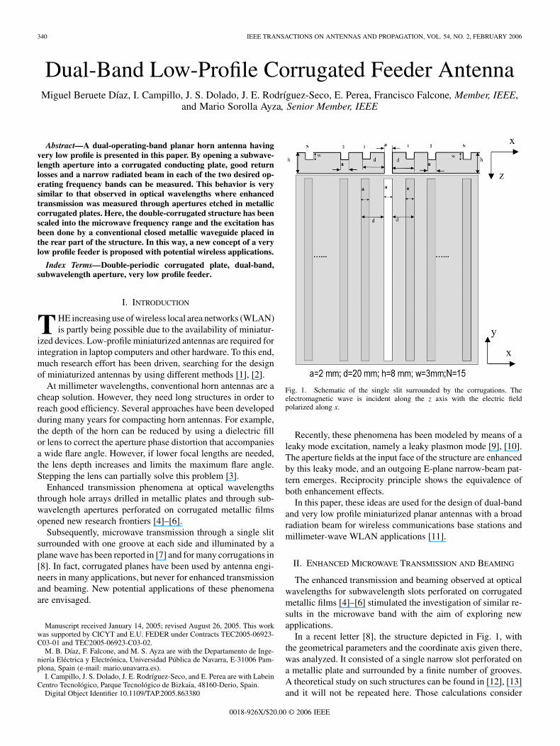
Fig. 1. Schematic of the single slit surrounded by the corrugations. Theelectromagnetic wave is incident along the z axis with the electric fieldpolarized along x.
Recently, these phenomena has been modeled by means of aleaky mode excitation, namely a leaky plasmon mode [9], [10].The aperture fields at the input face of the structure are enhancedby this leaky mode, and an outgoing E-plane narrow-beam pat-tern emerges. Reciprocity principle shows the equivalence ofboth enhancement effects.
In this paper, these ideas are used for the design of dual-bandand very low profile miniaturized planar antennas with a broadradiation beam for wireless communications base stations andmillimeter-wave WLAN applications [11].
II. ENHANCED MICROWAVE TRANSMISSION AND BEAMING
The enhanced transmission and beaming observed at opticalwavelengths for subwavelength slots perforated on corrugatedmetallic films [4]–[6] stimulated the investigation of similar re-sults in the microwave band with the aim of exploring newapplications.
In a recent letter [8], the structure depicted in Fig. 1, withthe geometrical parameters and the coordinate axis given there,was analyzed. It consisted of a single narrow slot perforated ona metallic plate and surrounded by a finite number of grooves.A theoretical study on such structures can be found in [12], [13]and it will not be repeated here. Those calculations consider
0018-926X/$20.00 © 2006 IEEE
DÍAZ et al.: CORRUGATED FEEDER ANTENNA 341
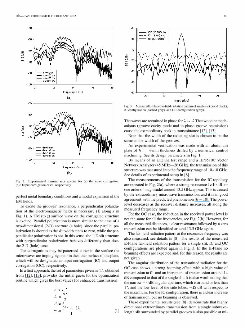
Fig. 2. Experimental transmittance spectra for (a) the input corrugation.(b) Output corrugation cases, respectively.
perfect metal boundary conditions and a modal expansion of theEM fields.
To excite the grooves’ resonance, a perpendicular polariza-tion of the electromagnetic fields is necessary (E along x inFig. 1). A TM (to z) surface wave on the corrugated structureis excited. Parallel polarization is more similar to the case of atwo-dimensional (2-D) aperture (a hole), since the parallel po-larization is shorted as the slit width tends to zero, while the per-pendicular polarization is not. In this sense, the 1-D slit structurewith perpendicular polarization behaves differently than doesthe 2-D (hole) case.
The corrugations may be patterned either in the surface themicrowaves are impinging on or in the other surface of the plate,which will be designated as input corrugation (IC) and outputcorrugation (OC), respectively.
In a first approach, the set of parameters given in (1), obtainedfrom [12], [13], provides the initial guess for the optimizationroutine which gives the best values for enhanced transmission
(1)
Fig. 3. Measured E-Plane far-field radiation pattern of single slot (solid black),IC configuration (dashed gray), and OC configuration (gray).
The waves are reemitted in phase for . The two joint mech-anisms (groove cavity mode and in-phase groove reemission)cause the extraordinary peak in transmittance [12], [13].
Note that the width of the radiating slot is chosen to be thesame as the width of the grooves.
An experimental verification was made with an aluminumplate of -mm thickness drilled by a numerical controlmachining. See its design parameters in Fig. 1.
By means of an antenna test range and a HP8510C VectorNetwork Analyzer (45 MHz—26 GHz), the transmission of thisstructure was measured into the frequency range of 10–18 GHz.See details of experimental setup in [8].
The measurements of the transmission for the IC topologyare repeated in Fig. 2(a), where a strong resonance ( dB, orone order of magnitude) around 13.5 GHz appear. This is causedby the extraordinary microwave transmission, and it is in goodagreement with the predicted phenomenon [6]–[10]. The powerlevel decreases as the receiver distance increases, all along themeasured frequency range.
For the OC case, the reduction in the received power level isnot the same for all the frequencies, see Fig. 2(b). However, forall the measured distances, a clear resonance followed by a zerotransmission can be identified around 13.5 GHz again.
The far-field radiation pattern at the resonance frequency wasalso measured, see details in [8]. The results of the measuredE-Plane far-field radiation pattern for a single slit, IC and OCconfigurations are plotted again in Fig. 3. In the H-Plane nobeaming effects are expected and, for this reason, the results arenot given.
The angular distribution of the transmitted radiation for theOC case shows a strong beaming effect with a high value oftransmission at 0 and an increment of transmission around 14dB compared to that of the single slit. It is also worth noting thatthe narrow -dB angular aperture, which is around or less than1 , and the low level of the side lobes: dB with respect tothe maximum. For the IC configuration, there is a clear increaseof transmission, but no beaming is observed.
These experimental results (see [8]) demonstrate that highlydirectional extraordinary transmission from a single subwave-length slit surrounded by parallel grooves is also possible at mi-
342 IEEE TRANSACTIONS ON ANTENNAS AND PROPAGATION, VOL. 54, NO. 2, FEBRUARY 2006
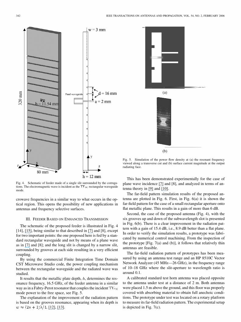
Fig. 4. Schematic of feeder made of a single slit surrounded by the corruga-tions. The electromagnetic wave is incident as theTE rectangular waveguidemode.
crowave frequencies in a similar way to what occurs in the op-tical region. This opens the possibility of new applications inantennas and frequency selective surfaces.
III. FEEDER BASED ON ENHANCED TRANSMISSION
The schematic of the proposed feeder is illustrated in Fig. 4[14], [15], being similar to that described in [7] and [8], exceptfor two important points: the one proposed here is fed by a stan-dard rectangular waveguide and not by means of a plane waveas in [7] and [8]; and the long slit is changed by a narrow slit,surrounded by grooves at each side resulting in a very efficientcoupling.
By using the commercial Finite Integration Time DomainCST Microwave Studio code, the power coupling mechanismbetween the rectangular waveguide and the radiated wave wasstudied.
It results that the metallic plate depth, , determines the res-onance frequency, 16.5 GHz, of the feeder antenna in a similarway as in a Fabry-Perot resonator that couples the incidentmode power to the free space, see Fig. 5.
The explanation of the improvement of the radiation patternis based on the grooves resonance, appearing when its depth is
, [12], [13].
Fig. 5. Simulation of the power flow density at (a) the resonant frequencyviewed along a transverse cut and (b) surface current magnitude at the outputradiating face.
This has been demonstrated experimentally for the case ofplane wave incidence [7] and [8], and analyzed in terms of an-tenna theory in [9] and [10].
The far-field pattern simulation results of the proposed an-tenna are plotted in Fig. 6. First, in Fig. 6(a) it is shown thefar-field pattern for the case of a small rectangular aperture ontoflat metallic plane. This results in a gain of more than 6 dB.
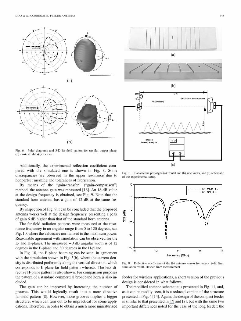
Second, the case of the proposed antenna (Fig. 4), with thesix grooves up and down of the subwavelength slot is presentedin Fig. 6(b). There is a clear improvement in the radiation pat-tern with a gain of 15.4 dB, i.e., 8.9 dB better than a flat plane.In order to verify the simulation results, a prototype was fabri-cated by numerical control machining. From the inspection ofthe prototype [Fig. 7(a) and (b)], it follows that relatively thinantennas are feasible.
The far-field radiation pattern of prototypes has been mea-sured by using an antenna test range and an HP 8510C VectorNetwork Analyzer (45 MHz—26 GHz), in the frequency rangeof 10–18 GHz where the slit-aperture to wavelength ratio isaround 0.1.
A calibrated standard test horn antenna was placed oppositeto the antenna under test at a distance of 2 m. Both antennaswere placed 1.5 m above the ground, and this floor was properlycovered with absorbing material to obtain full anechoic condi-tions. The prototype under test was located on a rotary platformto measure its far-field radiation pattern. The experimental setupis depicted in Fig. 7(c).
DÍAZ et al.: CORRUGATED FEEDER ANTENNA 343
Fig. 6. Polar diagrams and 3-D far-field pattern for (a) flat output plane.(b) central slit + grooves.
Additionally, the experimental reflection coefficient com-pared with the simulated one is shown in Fig. 8. Somediscrepancies are observed in the upper resonance due tononperfect meshing and tolerances of fabrication.
By means of the “gain-transfer” (“gain-comparison”)method, the antenna gain was measured [16]. An 18-dB valueat the design frequency is obtained, see Fig. 9. Note that thestandard horn antenna has a gain of 12 dB at the same fre-quency.
By inspection of Fig. 9 it can be concluded that the proposedantenna works well at the design frequency, presenting a peakof gain 6 dB higher than that of the standard horn antenna.
The far-field radiation patterns were measured at the reso-nance frequency in an angular range from 0 to 120 degrees, seeFig. 10, where the values are normalized to the maximum power.Reasonable agreement with simulation can be observed for theE- and H-planes. The measured dB angular width is of 12degrees in the E-plane and 30 degrees in the H-plane.
In Fig. 10, the E-plane beaming can be seen, in agreementwith the simulation shown in Fig. 5(b), where the current den-sity is distributed preferently along the vertical direction, whichcorresponds to E-plane far field pattern whereas. The less di-rective H-plane pattern is also shown. For comparison purposesthe pattern of a standard commercial broadband horn is also in-cluded.
The gain can be improved by increasing the number ofgrooves. This would logically result into a more directivefar-field pattern [8]. However, more grooves implies a biggerstructure, which can turn out to be impractical for some appli-cations. Therefore, in order to obtain a much more miniaturized
Fig. 7. Flat antenna prototype (a) frontal and (b) side views, and (c) schematicof the experimental setup.
Fig. 8. Reflection coefficient of the flat antenna versus frequency. Solid line:simulation result. Dashed line: measurement.
feeder for wireless applications, a short version of the previousdesign is considered in what follows.
The modified antenna schematic is presented in Fig. 11, and,as it can be readily seen, it is a reduced version of the structurepresented in Fig. 4 [14]. Again, the design of the compact feederis similar to that presented in [7] and [8], but with the same twoimportant differences noted for the case of the long feeder: the
344 IEEE TRANSACTIONS ON ANTENNAS AND PROPAGATION, VOL. 54, NO. 2, FEBRUARY 2006
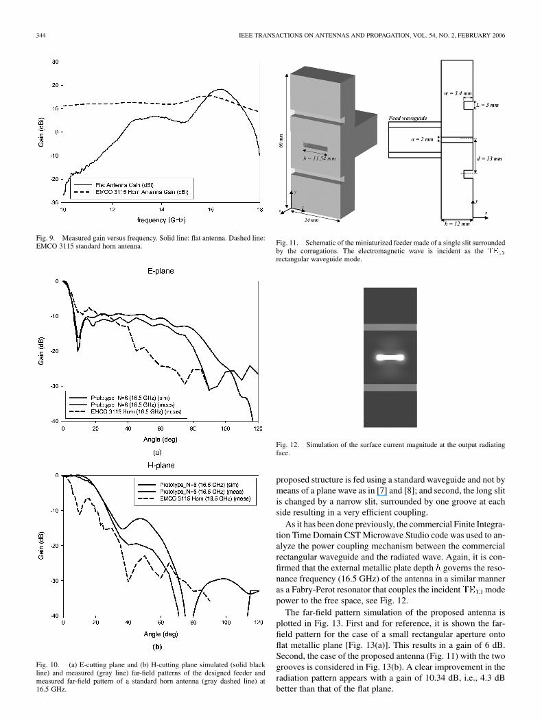
Fig. 9. Measured gain versus frequency. Solid line: flat antenna. Dashed line:EMCO 3115 standard horn antenna.
Fig. 10. (a) E-cutting plane and (b) H-cutting plane simulated (solid blackline) and measured (gray line) far-field patterns of the designed feeder andmeasured far-field pattern of a standard horn antenna (gray dashed line) at16.5 GHz.
Fig. 11. Schematic of the miniaturized feeder made of a single slit surroundedby the corrugations. The electromagnetic wave is incident as the TE
rectangular waveguide mode.
Fig. 12. Simulation of the surface current magnitude at the output radiatingface.
proposed structure is fed using a standard waveguide and not bymeans of a plane wave as in [7] and [8]; and second, the long slitis changed by a narrow slit, surrounded by one groove at eachside resulting in a very efficient coupling.
As it has been done previously, the commercial Finite Integra-tion Time Domain CST Microwave Studio code was used to an-alyze the power coupling mechanism between the commercialrectangular waveguide and the radiated wave. Again, it is con-firmed that the external metallic plate depth governs the reso-nance frequency (16.5 GHz) of the antenna in a similar manneras a Fabry-Perot resonator that couples the incident modepower to the free space, see Fig. 12.
The far-field pattern simulation of the proposed antenna isplotted in Fig. 13. First and for reference, it is shown the far-field pattern for the case of a small rectangular aperture ontoflat metallic plane [Fig. 13(a)]. This results in a gain of 6 dB.Second, the case of the proposed antenna (Fig. 11) with the twogrooves is considered in Fig. 13(b). A clear improvement in theradiation pattern appears with a gain of 10.34 dB, i.e., 4.3 dBbetter than that of the flat plane.
DÍAZ et al.: CORRUGATED FEEDER ANTENNA 345
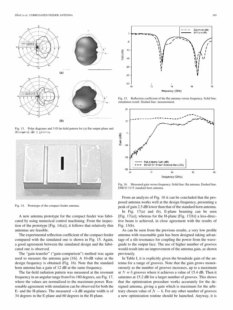
Fig. 13. Polar diagrams and 3-D far-field pattern for (a) flat output plane and(b) central slit + grooves.
Fig. 14. Prototype of the compact feeder antenna.
A new antenna prototype for the compact feeder was fabri-cated by using numerical control machining. From the inspec-tion of the prototype [Fig. 14(a)], it follows that relatively thinantennas are feasible.
The experimental reflection coefficient of the compact feedercompared with the simulated one is shown in Fig. 15. Again,a good agreement between the simulated design and the fabri-cated one is observed.
The “gain-transfer” (“gain-comparison”) method was againused to measure the antenna gain [16]. A 10-dB value at thedesign frequency is obtained (Fig. 16). Note that the standardhorn antenna has a gain of 12 dB at the same frequency.
The far-field radiation pattern was measured at the resonantfrequency in an angular range from 0 to 180 degrees, see Fig. 17,where the values are normalized to the maximum power. Rea-sonable agreement with simulation can be observed for both theE- and the H-planes. The measured dB angular width is of34 degrees in the E-plane and 60 degrees in the H-plane.
Fig. 15. Reflection coefficient of the flat antenna versus frequency. Solid line:simulation result. Dashed line: measurement.
Fig. 16. Measured gain versus frequency. Solid line: flat antenna. Dashed line:EMCO 3115 standard horn antenna.
From an analysis of Fig. 16 it can be concluded that the pro-posed antenna works well at the design frequency, presenting apeak of gain 2.5 dB lower than that of the standard horn antenna.
In Fig. 17(a) and (b), E-plane beaming can be seen[Fig. 17(a)], whereas for the H-plane [Fig. 17(b)] a less-direc-tive beam is achieved, in close agreement with the results ofFig. 13(b).
As can be seen from the previous results, a very low profileantenna with reasonable gain has been designed taking advan-tage of a slit resonance for coupling the power from the wave-guide to the output face. The use of higher number of grooveswould result into an improvement of the antenna gain, as shownpreviously.
In Table I, it is explicitly given the broadside gain of the an-tenna for a range of grooves. Note that the gain grows monot-onously as the number of grooves increases, up to a maximumat grooves where it achieves a value of 15.4 dB. Then itsaturates at 15.2 dB for a larger number of grooves. This showsthat the optimization procedure works accurately for the de-signed antenna, giving a gain which is maximum for the arbi-trary chosen value of . For any other number of groovesa new optimization routine should be launched. Anyway, it is
346 IEEE TRANSACTIONS ON ANTENNAS AND PROPAGATION, VOL. 54, NO. 2, FEBRUARY 2006
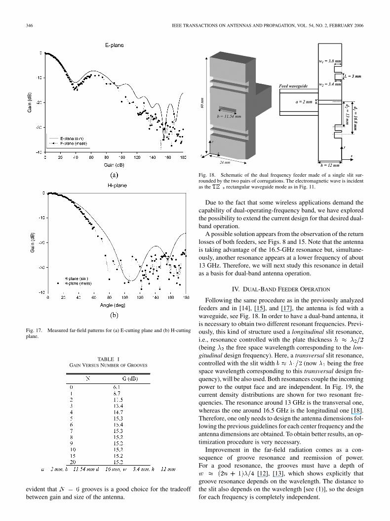
Fig. 17. Measured far-field patterns for (a) E-cutting plane and (b) H-cuttingplane.
TABLE IGAIN VERSUS NUMBER OF GROOVES
evident that grooves is a good choice for the tradeoffbetween gain and size of the antenna.
Fig. 18. Schematic of the dual frequency feeder made of a single slit sur-rounded by the two pairs of corrugations. The electromagnetic wave is incidentas the TE rectangular waveguide mode as in Fig. 11.
Due to the fact that some wireless applications demand thecapability of dual-operating-frequency band, we have exploredthe possibility to extend the current design for that desired dual-band operation.
A possible solution appears from the observation of the returnlosses of both feeders, see Figs. 8 and 15. Note that the antennais taking advantage of the 16.5-GHz resonance but, simultane-ously, another resonance appears at a lower frequency of about13 GHz. Therefore, we will next study this resonance in detailas a basis for dual-band antenna operation.
IV. DUAL-BAND FEEDER OPERATION
Following the same procedure as in the previously analyzedfeeders and in [14], [15], and [17], the antenna is fed with awaveguide, see Fig. 18. In order to have a dual-band antenna, itis necessary to obtain two different resonant frequencies. Previ-ously, this kind of structure used a longitudinal slit resonance,i.e., resonance controlled with the plate thickness(being the free space wavelength corresponding to the lon-gitudinal design frequency). Here, a transversal slit resonance,controlled with the slit width (now being the freespace wavelength corresponding to this transversal design fre-quency), will be also used. Both resonances couple the incomingpower to the output face and are independent. In Fig. 19, thecurrent density distributions are shown for two resonant fre-quencies. The resonance around 13 GHz is the transversal one,whereas the one around 16.5 GHz is the longitudinal one [18].Therefore, one only needs to design the antenna dimensions fol-lowing the previous guidelines for each center frequency and theantenna dimensions are obtained. To obtain better results, an op-timization procedure is very necessary.
Improvement in the far-field radiation comes as a con-sequence of groove resonance and reemission of power.For a good resonance, the grooves must have a depth of
[12], [13], which shows explicitly thatgroove resonance depends on the wavelength. The distance tothe slit also depends on the wavelength [see (1)], so the designfor each frequency is completely independent.
DÍAZ et al.: CORRUGATED FEEDER ANTENNA 347
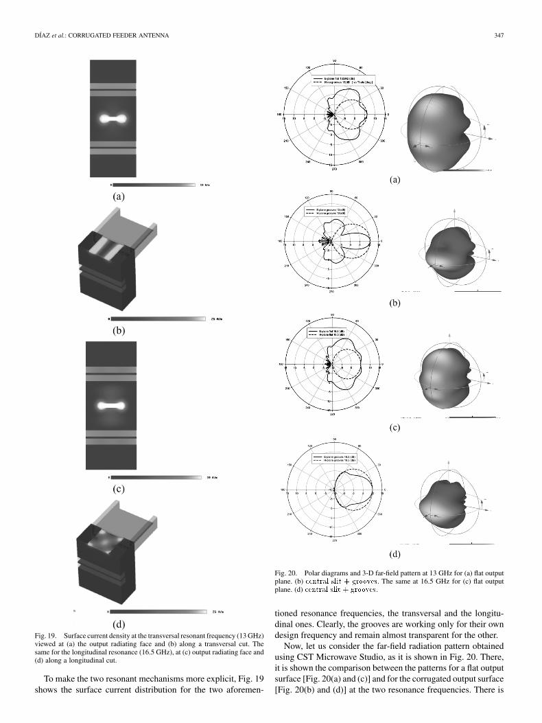
Fig. 19. Surface current density at the transversal resonant frequency (13 GHz)viewed at (a) the output radiating face and (b) along a transversal cut. Thesame for the longitudinal resonance (16.5 GHz), at (c) output radiating face and(d) along a longitudinal cut.
To make the two resonant mechanisms more explicit, Fig. 19shows the surface current distribution for the two aforemen-
Fig. 20. Polar diagrams and 3-D far-field pattern at 13 GHz for (a) flat outputplane. (b) central slit + grooves. The same at 16.5 GHz for (c) flat outputplane. (d) central slit + grooves.
tioned resonance frequencies, the transversal and the longitu-dinal ones. Clearly, the grooves are working only for their owndesign frequency and remain almost transparent for the other.
Now, let us consider the far-field radiation pattern obtainedusing CST Microwave Studio, as it is shown in Fig. 20. There,it is shown the comparison between the patterns for a flat outputsurface [Fig. 20(a) and (c)] and for the corrugated output surface[Fig. 20(b) and (d)] at the two resonance frequencies. There is
348 IEEE TRANSACTIONS ON ANTENNAS AND PROPAGATION, VOL. 54, NO. 2, FEBRUARY 2006
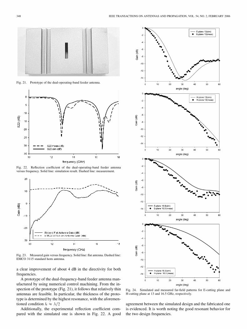
Fig. 21. Prototype of the dual-operating-band feeder antenna.
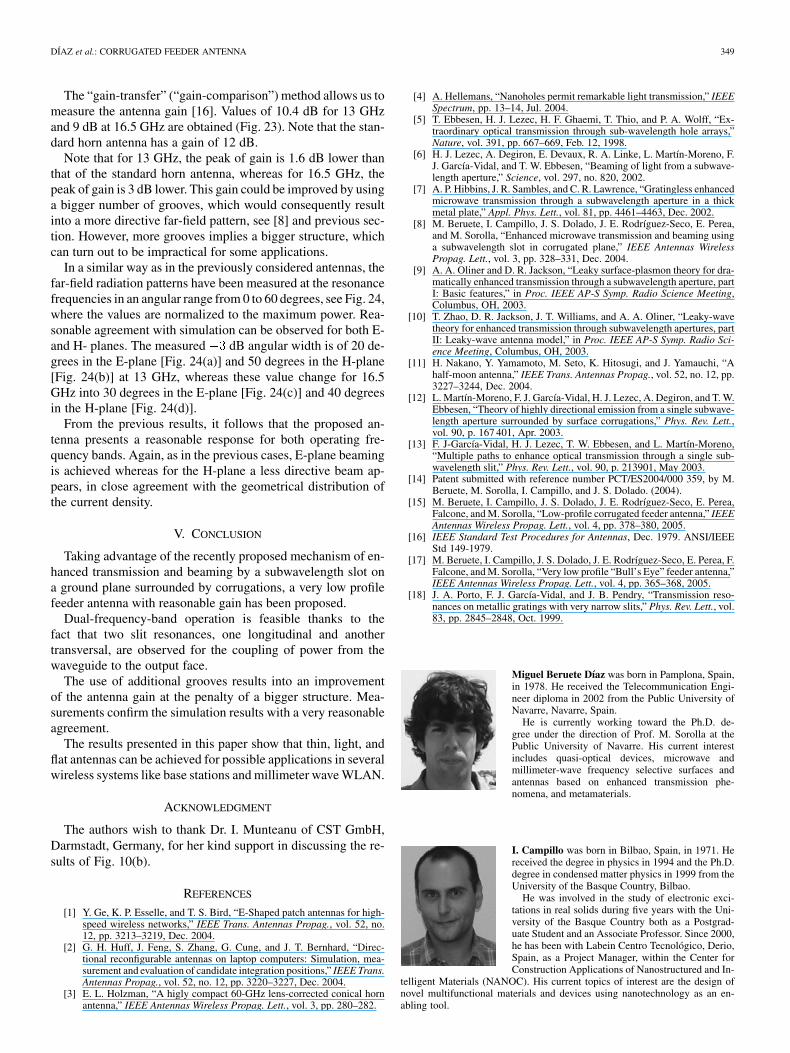
Fig. 22. Reflection coefficient of the dual-operating-band feeder antennaversus frequency. Solid line: simulation result. Dashed line: measurement.
Fig. 23. Measured gain versus frequency. Solid line: flat antenna. Dashed line:EMCO 3115 standard horn antenna.
a clear improvement of about 4 dB in the directivity for bothfrequencies.
A prototype of the dual-frequency-band feeder antenna man-ufactured by using numerical control machining. From the in-spection of the prototype (Fig. 21), it follows that relatively thinantennas are feasible. In particular, the thickness of the proto-type is determined by the highest resonance, with the aforemen-tioned condition
Additionally, the experimental reflection coefficient com-pared with the simulated one is shown in Fig. 22. A good
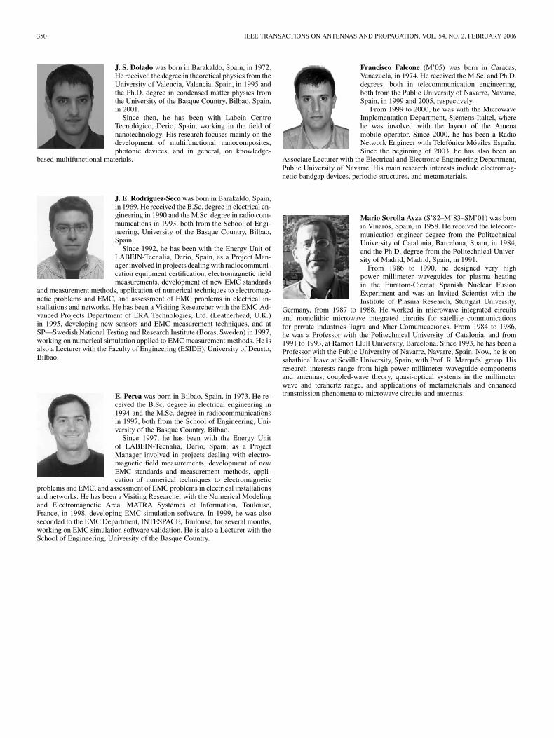
Fig. 24. Simulated and measured far-field patterns for E-cutting plane andH-cutting plane at 13 and 16.5 GHz, respectively.
agreement between the simulated design and the fabricated oneis evidenced. It is worth noting the good resonant behavior forthe two design frequencies.
DÍAZ et al.: CORRUGATED FEEDER ANTENNA 349
The “gain-transfer” (“gain-comparison”) method allows us tomeasure the antenna gain [16]. Values of 10.4 dB for 13 GHzand 9 dB at 16.5 GHz are obtained (Fig. 23). Note that the stan-dard horn antenna has a gain of 12 dB.
Note that for 13 GHz, the peak of gain is 1.6 dB lower thanthat of the standard horn antenna, whereas for 16.5 GHz, thepeak of gain is 3 dB lower. This gain could be improved by usinga bigger number of grooves, which would consequently resultinto a more directive far-field pattern, see [8] and previous sec-tion. However, more grooves implies a bigger structure, whichcan turn out to be impractical for some applications.
In a similar way as in the previously considered antennas, thefar-field radiation patterns have been measured at the resonancefrequencies in an angular range from 0 to 60 degrees, see Fig. 24,where the values are normalized to the maximum power. Rea-sonable agreement with simulation can be observed for both E-and H- planes. The measured dB angular width is of 20 de-grees in the E-plane [Fig. 24(a)] and 50 degrees in the H-plane[Fig. 24(b)] at 13 GHz, whereas these value change for 16.5GHz into 30 degrees in the E-plane [Fig. 24(c)] and 40 degreesin the H-plane [Fig. 24(d)].
From the previous results, it follows that the proposed an-tenna presents a reasonable response for both operating fre-quency bands. Again, as in the previous cases, E-plane beamingis achieved whereas for the H-plane a less directive beam ap-pears, in close agreement with the geometrical distribution ofthe current density.
V. CONCLUSION
Taking advantage of the recently proposed mechanism of en-hanced transmission and beaming by a subwavelength slot ona ground plane surrounded by corrugations, a very low profilefeeder antenna with reasonable gain has been proposed.
Dual-frequency-band operation is feasible thanks to thefact that two slit resonances, one longitudinal and anothertransversal, are observed for the coupling of power from thewaveguide to the output face.
The use of additional grooves results into an improvementof the antenna gain at the penalty of a bigger structure. Mea-surements confirm the simulation results with a very reasonableagreement.
The results presented in this paper show that thin, light, andflat antennas can be achieved for possible applications in severalwireless systems like base stations and millimeter wave WLAN.
ACKNOWLEDGMENT
The authors wish to thank Dr. I. Munteanu of CST GmbH,Darmstadt, Germany, for her kind support in discussing the re-sults of Fig. 10(b).
REFERENCES
[1] Y. Ge, K. P. Esselle, and T. S. Bird, “E-Shaped patch antennas for high-speed wireless networks,” IEEE Trans. Antennas Propag., vol. 52, no.12, pp. 3213–3219, Dec. 2004.
[2] G. H. Huff, J. Feng, S. Zhang, G. Cung, and J. T. Bernhard, “Direc-tional reconfigurable antennas on laptop computers: Simulation, mea-surement and evaluation of candidate integration positions,” IEEE Trans.Antennas Propag., vol. 52, no. 12, pp. 3220–3227, Dec. 2004.
[3] E. L. Holzman, “A higly compact 60-GHz lens-corrected conical hornantenna,” IEEE Antennas Wireless Propag. Lett., vol. 3, pp. 280–282.
[4] A. Hellemans, “Nanoholes permit remarkable light transmission,” IEEESpectrum, pp. 13–14, Jul. 2004.
[5] T. Ebbesen, H. J. Lezec, H. F. Ghaemi, T. Thio, and P. A. Wolff, “Ex-traordinary optical transmission through sub-wavelength hole arrays,”Nature, vol. 391, pp. 667–669, Feb. 12, 1998.
[6] H. J. Lezec, A. Degiron, E. Devaux, R. A. Linke, L. Martín-Moreno, F.J. García-Vidal, and T. W. Ebbesen, “Beaming of light from a subwave-length aperture,” Science, vol. 297, no. 820, 2002.
[7] A. P. Hibbins, J. R. Sambles, and C. R. Lawrence, “Gratingless enhancedmicrowave transmission through a subwavelength aperture in a thickmetal plate,” Appl. Phys. Lett., vol. 81, pp. 4461–4463, Dec. 2002.
[8] M. Beruete, I. Campillo, J. S. Dolado, J. E. Rodríguez-Seco, E. Perea,and M. Sorolla, “Enhanced microwave transmission and beaming usinga subwavelength slot in corrugated plane,” IEEE Antennas WirelessPropag. Lett., vol. 3, pp. 328–331, Dec. 2004.
[9] A. A. Oliner and D. R. Jackson, “Leaky surface-plasmon theory for dra-matically enhanced transmission through a subwavelength aperture, partI: Basic features,” in Proc. IEEE AP-S Symp. Radio Science Meeting,Columbus, OH, 2003.
[10] T. Zhao, D. R. Jackson, J. T. Williams, and A. A. Oliner, “Leaky-wavetheory for enhanced transmission through subwavelength apertures, partII: Leaky-wave antenna model,” in Proc. IEEE AP-S Symp. Radio Sci-ence Meeting, Columbus, OH, 2003.
[11] H. Nakano, Y. Yamamoto, M. Seto, K. Hitosugi, and J. Yamauchi, “Ahalf-moon antenna,” IEEE Trans. Antennas Propag., vol. 52, no. 12, pp.3227–3244, Dec. 2004.
[12] L. Martín-Moreno, F. J. García-Vidal, H. J. Lezec, A. Degiron, and T. W.Ebbesen, “Theory of highly directional emission from a single subwave-length aperture surrounded by surface corrugations,” Phys. Rev. Lett.,vol. 90, p. 167 401, Apr. 2003.
[13] F. J-García-Vidal, H. J. Lezec, T. W. Ebbesen, and L. Martín-Moreno,“Multiple paths to enhance optical transmission through a single sub-wavelength slit,” Phys. Rev. Lett., vol. 90, p. 213901, May 2003.
[14] Patent submitted with reference number PCT/ES2004/000 359, by M.Beruete, M. Sorolla, I. Campillo, and J. S. Dolado. (2004).
[15] M. Beruete, I. Campillo, J. S. Dolado, J. E. Rodríguez-Seco, E. Perea,Falcone, and M. Sorolla, “Low-profile corrugated feeder antenna,” IEEEAntennas Wireless Propag. Lett., vol. 4, pp. 378–380, 2005.
[16] IEEE Standard Test Procedures for Antennas, Dec. 1979. ANSI/IEEEStd 149-1979.
[17] M. Beruete, I. Campillo, J. S. Dolado, J. E. Rodríguez-Seco, E. Perea, F.Falcone, and M. Sorolla, “Very low profile “Bull’s Eye” feeder antenna,”IEEE Antennas Wireless Propag. Lett., vol. 4, pp. 365–368, 2005.
[18] J. A. Porto, F. J. García-Vidal, and J. B. Pendry, “Transmission reso-nances on metallic gratings with very narrow slits,” Phys. Rev. Lett., vol.83, pp. 2845–2848, Oct. 1999.
Miguel Beruete Díaz was born in Pamplona, Spain,in 1978. He received the Telecommunication Engi-neer diploma in 2002 from the Public University ofNavarre, Navarre, Spain.
He is currently working toward the Ph.D. de-gree under the direction of Prof. M. Sorolla at thePublic University of Navarre. His current interestincludes quasi-optical devices, microwave andmillimeter-wave frequency selective surfaces andantennas based on enhanced transmission phe-nomena, and metamaterials.
I. Campillo was born in Bilbao, Spain, in 1971. Hereceived the degree in physics in 1994 and the Ph.D.degree in condensed matter physics in 1999 from theUniversity of the Basque Country, Bilbao.
He was involved in the study of electronic exci-tations in real solids during five years with the Uni-versity of the Basque Country both as a Postgrad-uate Student and an Associate Professor. Since 2000,he has been with Labein Centro Tecnológico, Derio,Spain, as a Project Manager, within the Center forConstruction Applications of Nanostructured and In-
telligent Materials (NANOC). His current topics of interest are the design ofnovel multifunctional materials and devices using nanotechnology as an en-abling tool.
350 IEEE TRANSACTIONS ON ANTENNAS AND PROPAGATION, VOL. 54, NO. 2, FEBRUARY 2006
J. S. Dolado was born in Barakaldo, Spain, in 1972.He received the degree in theoretical physics from theUniversity of Valencia, Valencia, Spain, in 1995 andthe Ph.D. degree in condensed matter physics fromthe University of the Basque Country, Bilbao, Spain,in 2001.
Since then, he has been with Labein CentroTecnológico, Derio, Spain, working in the field ofnanotechnology. His research focuses mainly on thedevelopment of multifunctional nanocomposites,photonic devices, and in general, on knowledge-
based multifunctional materials.
J. E. Rodríguez-Seco was born in Barakaldo, Spain,in 1969. He received the B.Sc. degree in electrical en-gineering in 1990 and the M.Sc. degree in radio com-munications in 1993, both from the School of Engi-neering, University of the Basque Country, Bilbao,Spain.
Since 1992, he has been with the Energy Unit ofLABEIN-Tecnalia, Derio, Spain, as a Project Man-ager involved in projects dealing with radiocommuni-cation equipment certification, electromagnetic fieldmeasurements, development of new EMC standards
and measurement methods, application of numerical techniques to electromag-netic problems and EMC, and assessment of EMC problems in electrical in-stallations and networks. He has been a Visiting Researcher with the EMC Ad-vanced Projects Department of ERA Technologies, Ltd. (Leatherhead, U.K.)in 1995, developing new sensors and EMC measurement techniques, and atSP—Swedish National Testing and Research Institute (Boras, Sweden) in 1997,working on numerical simulation applied to EMC measurement methods. He isalso a Lecturer with the Faculty of Engineering (ESIDE), University of Deusto,Bilbao.
E. Perea was born in Bilbao, Spain, in 1973. He re-ceived the B.Sc. degree in electrical engineering in1994 and the M.Sc. degree in radiocommunicationsin 1997, both from the School of Engineering, Uni-versity of the Basque Country, Bilbao.
Since 1997, he has been with the Energy Unitof LABEIN-Tecnalia, Derio, Spain, as a ProjectManager involved in projects dealing with electro-magnetic field measurements, development of newEMC standards and measurement methods, appli-cation of numerical techniques to electromagnetic
problems and EMC, and assessment of EMC problems in electrical installationsand networks. He has been a Visiting Researcher with the Numerical Modelingand Electromagnetic Area, MATRA Systémes et Information, Toulouse,France, in 1998, developing EMC simulation software. In 1999, he was alsoseconded to the EMC Department, INTESPACE, Toulouse, for several months,working on EMC simulation software validation. He is also a Lecturer with theSchool of Engineering, University of the Basque Country.
Francisco Falcone (M’05) was born in Caracas,Venezuela, in 1974. He received the M.Sc. and Ph.D.degrees, both in telecommunication engineering,both from the Public University of Navarre, Navarre,Spain, in 1999 and 2005, respectively.
From 1999 to 2000, he was with the MicrowaveImplementation Department, Siemens-Italtel, wherehe was involved with the layout of the Amenamobile operator. Since 2000, he has been a RadioNetwork Engineer with Telefónica Móviles España.Since the beginning of 2003, he has also been an
Associate Lecturer with the Electrical and Electronic Engineering Department,Public University of Navarre. His main research interests include electromag-netic-bandgap devices, periodic structures, and metamaterials.
Mario Sorolla Ayza (S’82–M’83–SM’01) was bornin Vinaròs, Spain, in 1958. He received the telecom-munication engineer degree from the PolitechnicalUniversity of Catalonia, Barcelona, Spain, in 1984,and the Ph.D. degree from the Politechnical Univer-sity of Madrid, Madrid, Spain, in 1991.
From 1986 to 1990, he designed very highpower millimeter waveguides for plasma heatingin the Euratom-Ciemat Spanish Nuclear FusionExperiment and was an Invited Scientist with theInstitute of Plasma Research, Stuttgart University,
Germany, from 1987 to 1988. He worked in microwave integrated circuitsand monolithic microwave integrated circuits for satellite communicationsfor private industries Tagra and Mier Comunicaciones. From 1984 to 1986,he was a Professor with the Politechnical University of Catalonia, and from1991 to 1993, at Ramon Llull University, Barcelona. Since 1993, he has been aProfessor with the Public University of Navarre, Navarre, Spain. Now, he is onsabathical leave at Seville University, Spain, with Prof. R. Marqués’ group. Hisresearch interests range from high-power millimeter waveguide componentsand antennas, coupled-wave theory, quasi-optical systems in the millimeterwave and terahertz range, and applications of metamaterials and enhancedtransmission phenomena to microwave circuits and antennas.