antenna calibration methods for antenna factor measurements
TRANSCRIPT

International Journal of Measurement Technologies and Instrumentation Engineering, 2(4), 43-59, October-December 2012 43
Copyright © 2012, IGI Global. Copying or distributing in print or electronic forms without written permission of IGI Global is prohibited.
ABSTRACTIn the fields of electromagnetic interference and electromagnetic compatibility, it is important to measure the strength of the electric field originating from electric devices. For this purpose, knowledge of the antenna factor of a receiving antenna is necessary. According to international standards, the accurate measurement of the antenna factor involves the use of calibration test sites characterized by very large sizes of both the ground plane and the empty space volume above it. As a consequence, these setup conditions make the antenna factor measurements quite expensive for the customer. In this paper, the authors discuss the well know antenna-based and site-based methods as well as recently measurement method called Antenna Impedance Method as able to obtain the free-space antenna factor. Moreover, the authors investigate on the suitability of semi-anechoic chamber for reliable antenna factor calibrations. In particular, the experimental measurements of the antenna factor obtained by using the antenna impedance method were compared with Standard Field Method and the data provided by the manufacturer of three antennas (Biconical, Log-periodic and Horn antenna) founding an agreement with the international standard ANSI C63.5-2006.
Antenna Calibration Methods for Antenna Factor MeasurementsL. Mescia, DEI-Dipartimento di Ingegneria Elettrica e dell’Informazione, Polytechnic
University of Bari, Bari, Italy
O. Losito, DEI-Dipartimento di Ingegneria Elettrica e dell’Informazione, Polytechnic University of Bari, Bari, Italy
V. Castrovilla, ITEL Telecomunicazioni S.r.l., Ruvo di Puglia, Italy
P. Bia, DEI-Dipartimento di Ingegneria Elettrica e dell’Informazione, Polytechnic University of Bari, Bari, Italy
F. Prudenzano, DEI-Dipartimento di Ingegneria Elettrica e dell’Informazione, Polytechnic University of Bari, Bari, Italy
Keywords: Antenna Factor, Electric Field, Electromagnetic Compatibility (EMC), Electromagnetic Interference (EMI), Ultra-Wideband (UWB)
INTRODUCTION
In recent years, wideband and ultra-wideband (UWB) technologies have gained notable progress. As a consequence, wideband systems are now essential parts of modern commercial,
transportation, and military applications includ-ing airplanes, communication, traffic manage-ment or safety systems.
By considering that failure in electronic equipment could cause major accidents or eco-nomic disasters, the need to improve their elec-
DOI: 10.4018/ijmtie.2012100104

Copyright © 2012, IGI Global. Copying or distributing in print or electronic forms without written permission of IGI Global is prohibited.
44 International Journal of Measurement Technologies and Instrumentation Engineering, 2(4), 43-59, October-December 2012
tromagnetic interference (EMI) performance and to establish standards for electromagnetic compatibility (EMC) is an essential claim to satisfy. In fact, any new electronic product that is designed and manufactured today in Europe needs to undergo EMI/EMC testing to ensure that they meet the required EMC conformity declarations. To this aim, all manufacturers of electrical and electronic products in Eu-rope use established standards describing the EMC requirements, measurement procedures, maximum emission and susceptibility limits of electronic systems and modules.
In EMI/EMC tests, broadband antennas are widely used for radiated emission and suscepti-bility measurements, radiated immunity testing, site qualification testing and human exposure tests. As a consequence, the accurate knowledge of the technical parameters associated with an-tennas is a fundamental requirement especially when calibrated antennas are required as probes for high-precision field strength measurements and as sources for the generation of specific elec-tromagnetic field. Moreover, advantages in the antenna calibration methods make possible the reduction of uncertainty of EMC measurements, enabling saving in the design and manufacture of products as well as to achieve the required EMC protection.
In EMI testing, electric field measure-ments are necessary for determining compli-ance with most electromagnetic interference requirements, such as FCC Part 15, CISPR 22, CISPR 16, EN 55022, etc. In particular, with reference to the radiated emissions the electric field strength is measured by using a suitable receiving antenna connected to a receiver, such as spectrum analyzer, providing a volt-age proportional to the incident electric field. A coaxial shielded cable is used for connecting the measurement instrument to the antenna. As result, to evaluate the electric field strength by using receiver readings (voltage), the antenna manufacturer has to provide the antenna fac-tor versus frequency for both horizontal and vertical polarizations. The antenna factor value and the related uncertainty are the most critical parameters to be evaluated. Moreover,
suitable setups and measurement procedures involving relatively high-cost instrumentation and specific test sites have to be used for an ac-curate evaluation of antenna factor. The antenna factor calibration of antennas used for radiated emission measurements of EMI from 9 kHz to 40 GHz is the subject of existing ANSI C63.5-2006 (ANSI C63.5-2006, 2006) international standard. In particular, it describes three main methods: the Standard Site Method (SSM), the Reference Antenna Method (RAM), the Equivalent Capacitance Substitution Method (ECSM). Additional methods are the Standard Field Method (SFM), the Standard Antenna Method (SAM), the Standard Transmitting Loop Method (STLM) and the near field three-antenna method (NF-TAM).
In the SFM and SAM the antenna is exposed to a known field at a given point in the space. For the SFM, this field strength can be calcu-lated in terms of type, dimensions, net power delivered, and gain of the transmitting antenna, as well as the distance between the transmitting antenna and the field point, the effects of ground reflections or reflections from the walls of an anechoic chamber (Nahman, Kanda, Larsen, & Crawford, 1985; Smith Jr., 1982; IEEE Std 291-1991, 1991). The SAM requires a set of specially designed receiving antennas having known dimension, shape and gain. In this way, the field strength value can be calculated in terms of the induced voltage or current in the receiving antenna and the antenna factor is calculated as the ratio of the field strength to the induced voltage (Nahman, Kanda, Larsen, & Crawford, 1985; Smith Jr., 1982; IEEE Std 291-1991, 1991). The SSM (the most commonly used method for antenna calibration) requires neither the availability of a standard antenna nor the generation of a standard field. In particular, unlike SAM, this method does not need voltage or field-strength measurements, and, unlike SFM, it does not involve the knowledge of the absolute level of the signal source. The SSM requires a calibrated test site and three pairs of site attenuation measurements, under identical geometries, involving three different antennas. In the SSM, the antenna factor was derived, at

Copyright © 2012, IGI Global. Copying or distributing in print or electronic forms without written permission of IGI Global is prohibited.
International Journal of Measurement Technologies and Instrumentation Engineering, 2(4), 43-59, October-December 2012 45
a particular antenna height above the ground plane, by considering the attenuation levels. However, because the far-field measurement, the accuracy and uncertainty of such antenna calibration method depend on the quality of the measuring test site in terms of how closely the measuring site conforms to a standard site. As a consequence, a near-ideal open-field site, a large antenna separations and conducting ground plane are recommended (Smith Jr., 1982).
Usually in low frequency band (lower than 30 MHz) it is difficult to obtain antenna factors of electrically short monopole antenna using a general three-antenna method like SSM. To this aim, in order to reduce the effect of the measure-ment site and background noises, the NF-TAM was developed to measure the antenna factor of such antennas (Ishigami, Iida, & Iwasaki, 1996). In this method, the averaged electric field strength, estimated on the basis of the mutual impedance between two monopole antenna elements, is considered. However, the ECSM is more commonly used to calibrate monopole antennas from 9 kHz to 30 MHz (ANSI C63.5-2006, 2006). It is a very simple measurement method and it not requires the generation of an electromagnetic field in an open region.
Generally, SSM, SFM, and SAM i) are absolute calibration methods, ii) are not easy to implement in antenna calibration laborato-ries or companies, iii) require more efforts to maintain complicated calibration systems and establish the traceability to the standards. On the other hand, reference calibration methods can establish traceability to the standard of the antenna factor. In particular, RAM is one of the reference calibration methods used for the cali-bration of dipole antennas, bi-conical antennas, horn antennas, etc. (ANSI C63.5-2006, 2006).
By considering that the measurements performed by means of the methods above recalled strongly depend on the electromag-netic waves reflected at the ground plane, the antenna factor estimation varies with the antenna height at the test site. Moreover, both SSM and SAM use a transmitting antenna, a signal generator and a measuring receiver to estimate transmission loss between antenna
pairs. In order to overcome these drawbacks, in particular ground reflections, and to accurately estimate the free-space antenna factor a new antenna calibration method, named Antenna Impedance Method (AIM), has been proposed (Kaketa, Fujii, Sugiura, Matusmoto, Yamanaka, 2003a; Kaketa, Fujii, Sugiura, Matsumoto, & Yamanaka, 2003b; Tsushima, Fujii, Sugi-ura, Matsumoto, & Yamanaka, 2003; Ishii & Komiyama, 2007; Fujii, Kaketa, Matsumoto, & Sugiura, 2002; Fujii, Kaketa, Sugiura, Mat-sumoto, & Yamanaka, 2004; Sevgi, Cakir, & Cakir, 2008). This method, allows the accurate estimation of the antenna factor from only input impedance measurements on the antenna under calibration above a ground plane.
In this paper, we present a brief overview of the current status of the main antenna calibration methods with particular focus on the antenna impedance method. We also show experimental measurements performed in a semi-anechoic chamber regarding the antenna factor of three different antennas. In particular, the antenna factors obtained by using both the calibration methods SFM and AIM are compared between them as well as they are compared with data provided by the manufactured of the antennas under calibration.
STANDARD SITE METHOD
The standard site method allows the evaluation of the near free-space antenna factor by using the site attenuation measurements made on a standard antenna calibration site, i.e. site having a large metallic ground plane and comprising a flat open-area without nearby scatterers such as trees, power lines, and fences. This method, provides near-free-space antenna factors for many antennas, including biconical and tuned dipoles, log-periodic dipole arrays, and linearly polarized hybrid arrays (Askri, Vollaire, Nico-las, & Prebet, 2002). Moreover, it is usually preferred for routine calibrations because it can be applied to broadband antennas in swept-frequency techniques.

Copyright © 2012, IGI Global. Copying or distributing in print or electronic forms without written permission of IGI Global is prohibited.
46 International Journal of Measurement Technologies and Instrumentation Engineering, 2(4), 43-59, October-December 2012
By considering a pair of antennas sepa-rated by a distance d and placed at the height h1 (for the transmitting antenna) and h2 (for the receiving antenna) above the ground plane (see Figure 1) the measured site attenuation could be expressed in terms of antennas factors of receiving, AFR, and transmitting, AFT, antennas (Garn, Buchmayr, Mullner, & Rasinger, 1997):
AV
V
AF AF
f ET
R
T R
M R
= =79 58 49 2
2
. .max
(1)
where VT is the output voltage of the signal generator driving the transmitting antenna, VR is the output voltage measured at the end of the receiving antenna, fM is the frequency in MHz, ERmax is the electric field strength, in μV/m, in
the receiving antenna calculated when the height h2 is scanned until a maximum output voltage VR is measured. The antenna factor is defined as the ratio of the electric field strength E of the plane wave and the voltage inducted at the antenna output. Typical values of antenna separation distance d, transmitting antenna height h1 and receiving antenna scanning range are provided in ANSI C63.5-2006 (2006).
The SSM is widely used in the form of the three antenna method in which the site attenu-ation (Ai i=1,2,3), under identical geometries (h1, h2, d), of the combinations of three pairs of three antennas is measured. The method relies on solving a system of equations with three unknown antenna factors which are determined using three independent measurements. In particular, the three equations associated with the measurements Ai (in dB) and E
Rmax (in
dBµVm-1) are:
AF AF f E AM R1 2 1
20 48 92+ = − + +log . max
(2)
AF AF f E AM R1 3 2
20 48 92+ = − + +log . max
(3)
AF AF f E AM R2 3 3
20 48 92+ = − + +log . max
(4)
Rearranging the Equations 2, 3, and 4, it is possible to express the antenna factor Ai in terms of field strength and measured site attenuation:
Figure 1. Antenna arrangement for site attenuation measurements

Copyright © 2012, IGI Global. Copying or distributing in print or electronic forms without written permission of IGI Global is prohibited.
International Journal of Measurement Technologies and Instrumentation Engineering, 2(4), 43-59, October-December 2012 47
AF fE A A A
MR
11 2 310 24 462
= − ++ + −
log .max
(5)
AF fE A A A
MR
21 3 210 24 462
= − ++ + −
log .max
(6)
AF fE A A A
MR
31 3 210 24 462
= − ++ + −
log .max
(7)
Moreover, if two identical antennas have to be calibrated, their antenna factor can be obtained from a single site-attenuation measure-ment using the following expression (Smith Jr., 1982):
AF fE A
MR= − ++
10 24 462
log .max
(8)
Horizontal polarization is preferred for antenna calibration because:
• Mutual coupling between the cable and the antenna is negligible;
• Scattering from the cable is negligible;• Ground-screen edge reflections are smaller
for horizontal polarization;• Horizontally polarized ground reflection is
less sensitive to differences in the ground plane conductivity and permittivity.
The interaction between the antenna and its environment complicates the measurement procedure. In fact, environmental influences are generally difficult to determine mathematically and, consequently, difficult to correct. For this reason, in the SSM the following approxima-tions are included:
• The antennas under test have the same ra-diation pattern as those from a short dipole;
• Mutual couplings between antennas and between antennas and ground planes are negligible;
• The antennas are in far field so that the near field effects and the physical size are negligible;
• Antennas are immersed in a uniform field;• Antenna separation distance is measured
from the geometrical center-points of the antennas.
Despite these assumptions, the theoreti-cal model has proved to work rather well in a near free-space geometry, introducing errors in the antenna factors up to 0.5 dB. However, the SSM theoretical model was shown to be inadequate for other site validation geometries. In this cases, the errors can be higher than 4 dB for a pair of typical size biconical antennas (Garn, Buchmayr, Mullner, & Rasinger, 1997). Practical experience has shown that correction factors shall be applied for product accurate and reliable measurements. To this aim, many research efforts were addressed to precisely analyze the assumptions and evaluate uncertain-ties due to imperfect methods introduced by the ANSI (Garn, Buchmayr, Mullner, & Rasinger, 1997; Alexander, Salter, Gentle, & Holland, 1994; Fujii, Harada, Sugiura, Matsumoto, & Yamanaka, 2005; Sugiura, Morikawa, Koike, & Harima, 1995). Other researches proposed standard method modifications and novel an-tenna factor calibration methods (Fujii, Harada, Sugiura, Matsumoto, & Yamanaka, 2005; Sugi-ura, Morikawa, Koike, & Harima, 1995; Mat-sumoto, Umeda, Nishikata, Fujii, Yamanaka, & Sugiura, 2003; Joseph & Martens, 2005; Sugiura, 1990). However, the ANSI C63.5-2006 provide several procedures to quantify several correction factors.
STANDARD FIELD METHOD
It is well known that radiated emissions testing for EMC applications requires the measurement of electric field (E-field) strength, which is com-pared with a limit level. The output voltage of
Copyright © 2012, IGI Global. Copying or distributing in print or electronic forms without written permission of IGI Global is prohibited.
48 International Journal of Measurement Technologies and Instrumentation Engineering, 2(4), 43-59, October-December 2012
an antenna is converted to E-field strength via its antenna factor, the measurement of which have to include the major source of uncertainties associated with the antenna calibration, taking into account the environment where the antenna is tested. The standard field method is certainly the most natural calibration method, because it can be derived directly from the defining equation of the antenna factor mentioned in Equation 9:
AFE
VAF E V
dB dB V m dB V= ⇒ = −µ µ/
(9)
The SFM involves generation of a known standard field intensity created at a specified location. The tested antenna is put in the standard field and the received voltage is measured by the test receiver. The magnitude of the standard field depends on the dimensions of the transmitting antenna, its current distribution, the distance between the transmitting and receiving antenna, and effect of the ground plane. Standard fields can be generated in otherwise free space as well as in shielded or unshielded spaces.
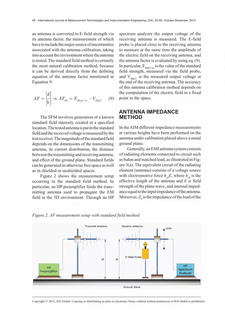
Figure 2 shows the measurement setup occurring in the standard field method. In particular, an HP preamplifier feeds the trans-mitting antenna used to propagate the EM field in the 3D environment. Through an HP
spectrum analyzer the output voltage of the receiving antenna is measured. The E-field probe is placed close to the receiving antenna to measure at the same time the amplitude of the electric field on the receiving antenna, and the antenna factor is evaluated by using eq. (9). In particular, EdBµV/m is the value of the standard field strength, measured via the field probe, and VdBµV is the measured output voltage at the end of the receiving antenna. The accuracy of this antenna calibration method depends on the computation of the electric field in a fixed point in the space.
ANTENNA IMPEDANCE METHOD
In the AIM different impedance measurements at various heights have been performed on the antenna under calibration placed above a metal ground plane.
Generally, an EMI antenna system consists of radiating elements connected to circuit such as balun and matched load, as illustrated in Fig-ure 3(a). The equivalent circuit of the radiating element (antenna) consists of a voltage source with electromotive force he0E, where he0 is the effective length of the antenna and E is field strength of the plane wave, and internal imped-ance equal to the input impedance of the antenna. Moreover, Z0 is the impedance of the load of the
Figure 2. AF measurement setup with standard field method

Copyright © 2012, IGI Global. Copying or distributing in print or electronic forms without written permission of IGI Global is prohibited.
International Journal of Measurement Technologies and Instrumentation Engineering, 2(4), 43-59, October-December 2012 49
antenna (usually a measuring receiver with an input impedance of 50 Ω) and V is the voltage induced at the antenna output. If Zin is the input impedance, the overall antenna system can be analyzed by considering the equivalent circuit depicted in Figure 3(b). In particular, because the antenna is placed above the metal ground plane at the height h, the input impedance and the effective length of the antenna are height-dependent and can be formulated in terms of the impedance (Za(h)) and effective length (he0) of the radiating element (Kaketa, Fujii, Sugiura, Matusmoto, Yamanaka, 2003a; Kaketa, Fujii, Sugiura, Matsumoto, & Yamanaka, 2003b; Tsushima, Fujii, Sugi ura, Matsumoto, & Ya-manaka, 2003; Ishii & Komiyama, 2007; Fujii, Kaketa, Matsumoto, & Sugiura, 2002; Fujii, Kaketa, Sugiura, Mat sumoto, & Yamanaka, 2004; Sevgi, Cakir, & Cakir, 2008):
Z hZ h D B
Z h C Aina
a
( )( )
( )=
+
+ (10)
and:
h hh
Z h C Aee
a
( )( )
=+
0 (11)
where the various connected circuits are expressed in terms of a transmission matrix (A,B,C,D). Thus, if the load Z0 is perfectly matched, the voltage induced at the antenna output can be expressed by the equation:
VZ
Z h Zh h E
in
e=
( )+ ( )0
0
(12)
and the antenna factor can be rewritten in the form:
AF hh h
Z h Z
Ze
in( ) = +1 0
0( )
( ) (13)
where it can be observed that the antenna fac-tor depend not only on the characteristics of the radiating element but also on those of the connected circuits.
Figure 3. Equivalent circuit of EMI antenna

Copyright © 2012, IGI Global. Copying or distributing in print or electronic forms without written permission of IGI Global is prohibited.
50 International Journal of Measurement Technologies and Instrumentation Engineering, 2(4), 43-59, October-December 2012
When an antenna is placed horizontally above a metal plane, as shown in Figure 4, the antenna impedance Za(h) can be expressed as the sum of a free-space, Z
a0, and ground-re-
flection, Z(h), components:
Z h Z Z ha a( )= − ( )
0 (14)
Substituting of Equation 14 into Equations 10, 11, 12, and 13 reveals that the antenna fac-tor generally changes in magnitude with the antenna height.
If the antenna is placed at a high of about a wavelength λ or more, ground reflection components of the input impedance, Z h( ) , can be approximated as:
Z h j he
he
jk h
( )( )
≅−60
20
22π
λ (15)
where k = 2π λ/ is the wave number. As result, Equation 14 can be rewritten as:
Z h Z jehh Z K h ha a
jk h
e a e( ) ( )( )
≅ −
= −
−
0 0 0 0
602
22 2π
λ (16)
where:
K h je
h
jk h
( ) =−60
2
2πλ
( )
(17)
Equations 16, 17 yield the following for-mula for the height-dependent input impedance:
Z hZ K h h D B
Z K h h C Ain
a e
a e
( )( )
( )=
−
+
−
+
0 0
0 0
2
2 (18)
and from Equation 18 the following equation can be derived:
C Z h C K h Z h C K hin in1 2 3
1( ) ( ) ( ) ( )+ + = − (19)
where:
Figure 4. Measurement setup of antenna impedances

Copyright © 2012, IGI Global. Copying or distributing in print or electronic forms without written permission of IGI Global is prohibited.
International Journal of Measurement Technologies and Instrumentation Engineering, 2(4), 43-59, October-December 2012 51
CZ C A
Z D B
CCh
Z D B
CDh
Z D B
a
a
e
a
e
a
1
2
2
3
2
0
0
0
0
0
0
= −+
+
=+
= −+
(20)
are unknown constants. Moreover, by consid-ering the aforesaid equations, the formula for the height-dependent antenna factor can be rewritten as:
AF hDZ B Z CZ A
Z h
D Z C
Z hZ h
a a
e e
( ) =+ + +( )
−+ ( )0 0
0 0
0
0
0
0
(21)
The free-space value of the antenna fac-tor can be calculated by equating the ground reflection component Z(h)=0 in Equation 22:
AF hDZ B Z CZ A
Z hfree
a a
e
( ) =+ + +( )
0 0
0
0
0
(22)
or equivalently:
AFC Z
Zfree=
−1 0
0
1
∆ (23)
where:
∆2 1 2
31
=−
−C C
C (24)
It can be observed that the antenna factor, expressed by Equation 23, approach the free space antenna factor as the antenna height h increases. As result of the proposed theory, the
antenna impedance method can be organized in the following three steps:
1. Antenna impedance measurements on an antenna under calibration placed at various heights above a metal ground plane;
2. Estimation of the unknown constants C1, C2, C3 using Equation 19 and the imped-ance data of the step 1;
3. Evaluation of the free-space antenna factor using Equation 23.
Regarding the step 2, it worthwhile to note that the solution of the corresponding linear system is solved by means of the least square method. In fact, in order to improve the method reliability, it is suitable to perform more than of three impedance measurements. As result, the linear system to solve has more equations than unknowns and the least square method allows to find the overall solution minimizing the errors made in the results of every single equation.
SIMULATION AND EXPERIMENTAL RESULTS
Some experiments have been carried out to evaluate the antenna factor by means of the Antenna Impedance Method. In detail, the input impedance of antenna under calibration was measured in the semi-anechoic chamber of ITEL Telecomunicazioni srl EMC Test Lab. The semi-anechoic chamber is equipped with inno-vative pyramidal-type wave absorbers. Figure 5(a)-(c) shows some details of the semi-anechoic chamber and wave absorber, respectively. The antenna test setup has been placed in a offset position respect the center of the semi-anechoic chamber. In this way, the incident electromag-netic wave on the absorber is strongly absorbed because it is affected by an higher number of reflections. For each antenna under calibra-tion, the antenna factor values, carried out by using both standard field method and antenna impedance method, have been compared with the calibrated data provided by the antenna

Copyright © 2012, IGI Global. Copying or distributing in print or electronic forms without written permission of IGI Global is prohibited.
52 International Journal of Measurement Technologies and Instrumentation Engineering, 2(4), 43-59, October-December 2012
manufacturer. Instrumentation consisted on an HP 8753C vector network analyzer, operating in the frequency range from 300 kHz to 6 GHz, and an HP 85032B calibration kit. Moreover, a mobile stand has been used to perform the antenna measurements at different heights.
The antennas under calibration are the Biconical antenna, the Log-periodic antenna and the Double Ridge Guide Horn Antenna. In particular, seven antenna heights with step equal to 50 cm and 26 frequency points have been taken into account during the antenna test. Table 1 summarizes the main characteristics regarding the considered antennas. Moreover, in order to minimize the interference effects a ferrite clamp has been placed on the RF cable linking the antenna with the vector network analyzer.
In order to calculate the antenna factor via the AIM and by considering the experimental measurements of the antenna impedance, a
numerical code solving Equations 14 through 24 was developed. In the code, the input data are the frequency, the antenna impedance mea-surements and the antenna heights above the metal ground plane.
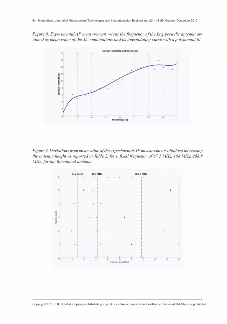
The values of the free-space antenna factor are obtained solving the liner system (19). To obtain a better accuracy of the antenna factor value, the free-space antenna factor has been evaluated for all the 3-combinations (three different heights) from a given set of 7 ele-ments (seven considered antenna heights). In particular, the mean value of the 35 combina-tions was considered as the correct antenna factor for a fixed frequency. The curves of these values, for a properly frequency range of the antennas reported in Figures 6, 7, and 8, have been obtained as the interpolating curve of the experimental data versus the frequency by using a polynomial fit.
Figure 5. Experimental measurement setup of antenna impedances in ITEL Telecomunicazioni srl semi-anechoic chamber
Table 1. Main characteristics of the antennas under calibration
Antenna Type Model Polarization Frequency Range Scanning Heights Range
Biconic ARA BCH 2030/A H 20 MHz÷300 MHz 1.3 m÷4.3 m
Log-periodic EMCO 3146 V 200 MHz÷1 GHz 1 m÷4 m
Horn SAS-571 V 700 MHz÷3 GHz 1 m÷4 m

Copyright © 2012, IGI Global. Copying or distributing in print or electronic forms without written permission of IGI Global is prohibited.
International Journal of Measurement Technologies and Instrumentation Engineering, 2(4), 43-59, October-December 2012 53
It is also interesting to consider the devia-tions from the mean value of the antenna fac-tor when the height of the antenna under test increases, for a fixed frequency value. Figures 9, 10, and 11 show the deviations of the mean antenna factor from the free-space antenna factors obtained solving the liner system (19) in which the three different heights of antenna have been chosen as reported in Table 2.
Figures 12, 13, and 14, show the measured antenna factor versus the frequency for biconical
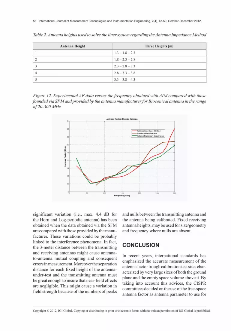
antenna, double ridge guide horn antenna and log-periodic antenna, respectively. In particular, the comparison between the values obtained by AIM and SFM with those provided by antenna manufacturer is illustrated. It worthwhile to note that the variation of the antenna factor, evaluated by means of the antenna impedance method, in comparison to the data provided by the manufacturer is within ±2.2 dB for Log-periodic and biconical antennas and within ±3.8 dB for Horn antenna. However, a quite
Figure 6. Experimental AF measurement versus the frequency of the Bioconical antenna obtained as mean value of the 35 combinations and its interpolating curve with a polynomial fit
Figure 7. Experimental AF measurement versus the frequency of the Horn antenna obtained as mean value of the 35 combinations and its interpolating curve with a polynomial fit
Copyright © 2012, IGI Global. Copying or distributing in print or electronic forms without written permission of IGI Global is prohibited.
54 International Journal of Measurement Technologies and Instrumentation Engineering, 2(4), 43-59, October-December 2012
Figure 9. Deviations from mean value of the experimental AF measurements obtained increasing the antenna height as reported in Table 2, for a fixed frequency of 87.2 MHz, 188 MHz, 288.8 MHz, for the Bioconical antenna
Figure 8. Experimental AF measurement versus the frequency of the Log periodic antenna ob-tained as mean value of the 35 combinations and its interpolating curve with a polynomial fit

Copyright © 2012, IGI Global. Copying or distributing in print or electronic forms without written permission of IGI Global is prohibited.
International Journal of Measurement Technologies and Instrumentation Engineering, 2(4), 43-59, October-December 2012 55
Figure 11. Deviations from mean value of the experimental AF measurements obtained increasing the antenna height as reported in Table 2, for a fixed frequency of 200 MHz, 520 MHz, 968.8 MHz, for the Log periodic antenna
Figure 10. Deviations from mean value of the experimental AF measurements obtained increasing the antenna height as reported in Table 2, for a fixed frequency of 700 MHz, 1712 MHz, 3000 MHz, for the Horn antenna
Copyright © 2012, IGI Global. Copying or distributing in print or electronic forms without written permission of IGI Global is prohibited.
56 International Journal of Measurement Technologies and Instrumentation Engineering, 2(4), 43-59, October-December 2012
significant variation (i.e., max. 4.4 dB for the Horn and Log-periodic antenna) has been obtained when the data obtained via the SFM are compared with those provided by the manu-facturer. These variations could be probably linked to the interference phenomena. In fact, the 3-meter distance between the transmitting and receiving antennas might cause antenna-to-antenna mutual coupling and consequent errors in measurement. Moreover the separation distance for each fixed height of the antenna-under-test and the transmitting antenna must be great enough to insure that near-field effects are negligible. This might cause a variation in field strength because of the numbers of peaks
and nulls between the transmitting antenna and the antenna being calibrated. Fixed receiving antenna heights, may be used for size/geometry and frequency where nulls are absent.
CONCLUSION
In recent years, international standards has emphasized the accurate measurement of the antenna factor trough calibration test sites char-acterized by very large sizes of both the ground plane and the empty space volume above it. By taking into account this advices, the CISPR committees decided on the use of the free-space antenna factor as antenna parameter to use for
Figure 12. Experimental AF data versus the frequency obtained with AIM compared with those founded via SFM and provided by the antenna manufacturer for Bioconical antenna in the range of 20-300 MHz
Table 2. Antenna heights used to solve the liner system regarding the Antenna Impedance Method
Antenna Height Three Heights [m]
1 1.3 – 1.8 – 2.3
2 1.8 – 2.3 – 2.8
3 2.3 – 2.8 – 3.3
4 2.8 – 3.3 – 3.8
5 3.3 – 3.8 – 4.3

Copyright © 2012, IGI Global. Copying or distributing in print or electronic forms without written permission of IGI Global is prohibited.
International Journal of Measurement Technologies and Instrumentation Engineering, 2(4), 43-59, October-December 2012 57
EMI/EMC tests. In response to this, theoreti-cal and experimental investigations as well as simple and accurate calibration methods have been developed to obtain the free-space antenna factor. In this paper, we briefly illustrate the well
know antenna-based and site-based methods. In particular, a numerical method called Antenna Impedance Method has been discussed as a new calibration method for estimating the free-space antenna factor in the frequency range from 20
Figure 14. Experimental AF data versus frequency obtained with AIM compared with those founded via SFM and provided by the antenna manufacturer for Log periodic antenna in the range of 200-1000 MHz
Figure 13. Experimental AF data versus the frequency obtained with AIM compared with those founded via SFM and provided by the antenna manufacturer for Horn antenna in the range of 700-3000 MHz
Copyright © 2012, IGI Global. Copying or distributing in print or electronic forms without written permission of IGI Global is prohibited.
58 International Journal of Measurement Technologies and Instrumentation Engineering, 2(4), 43-59, October-December 2012
MHz to 3000 MHz. This calibration method requires only antenna-impedance measure-ments on an antenna under calibration above a metal ground plane at various antenna heights. In the paper, we briefly reviewed and discussed the theoretical basis of the method and the experimental results obtained by this method. Three different kinds of antenna, biconical, log-periodic and horn antenna, have been calibrated by using this method. The experimental data has been compared with those obtained by means the standard field method and with the data pro-vided by the antenna manufacturer. The obtained antenna factor values show a variations within 2.2÷4.4 dB range. These results indicate that the Antenna Impedance Method is applicable for the measurements of antenna factor. The ac-curacy of the proposed estimation method was investigated by taking into account the possible errors associated with the conventional antenna calibration method. The obtained results high-light that the antenna impedance method could provide an estimation of the free-space antenna factor in good agreement with the international standard ANSI C63.5-2006.
REFERENCES
Alexander, M. J., Salter, M. J., Gentle, D. G., & Holland, K. P. (1994). Advances in measurement methods and reduction of measurement uncertainties associated with antenna calibration. IEE Proceed-ings. Science Measurement and Technology, 141, 283–286. doi:10.1049/ip-smt:19941284.
ANSI C63.5-2006. (2006). American national standard for electromagnetic compatibility–radi-ated emission measurements in electromagnetic interference (EMI) control–calibration of antennas (9 kHz to 40 GHz).
Askri, A., Vollaire, C., Nicolas, L., & Prebet, D. (2002). Normalized site attenuation standard correc-tion from numerical computing. IEEE Transactions on Magnetics, 38, 693–696. doi:10.1109/20.996180.
Fujii, K., Harada, S., Sugiura, A., Matsumoto, Y., & Yamanaka, Y. (2005). An estimation method for the free-space antenna factor of VHF EMI antennas. IEEE Transactions on Electromagnetic Compatibil-ity, 47, 627–634. doi:10.1109/TEMC.2005.850689.
Fujii, K., Kaketa, S., Matsumoto, Y., & Sugiura, A. (2002). Determination of the EMI antenna factor with antenna impedance measurements. In Proceedings of the 2002 International Conference on Electro-magn. Compat. (ICEMC2002), Bangkok, Thailand (pp. 334–337).
Fujii, K., Kaketa, S., Sugiura, A., Matsumoto, Y., & Yamanaka, Y. (2004). Calibration of EMI antennas in the VHF band with antenna impedance measure-ments. In Proceedings of the 2004 International Sym-posium on Electromagnetic Compatibility (EMC’04/Sendai), Sendai, Japan (2C1-3, pp. 361–364).
Garn, H., Buchmayr, M., Mullner, W., & Rasinger, J. (1997). Primary standards for antenna factor calibration in the frequency range of (30 to 1000) MHz. IEEE Transactions on Instrumentation and Measurement, 46, 544–548. doi:10.1109/19.571906.
Ishigami, S., Iida, H., & Iwasaki, T. (1996). Measurements of complex antenna factor by the near-field 3-antenna method. IEEE Transactions on Electromagnetic Compatibility, 38, 424–432. doi:10.1109/15.536072.
Ishii, M., & Komiyama, K. (2007). Impedance method for a shielded standard loop antenna. IEEE Transactions on Instrumentation and Measurement, 56, 422–425. doi:10.1109/TIM.2007.890794.
Joseph, W., & Martens, L. (2005). An improved method to determine the antenna factor. IEEE Trans-actions on Instrumentation and Measurement, 54, 252–257. doi:10.1109/TIM.2004.838116.
Kaketa, S., Fujii, K., Sugiura, A., Matsumoto, Y., & Yamanaka, Y. (2003). EMI antenna calibration using the antenna impedance measurement. In Proceedings 2003 6th International Symposium on Antennas, Propagation and EM Theory (pp. 792-795).
Kaketa, S., Fujii, K., Sugiura, A., Matsumoto, Y., & Yamanaka, Y. (2003). A novel method for EMI antenna calibration on a metal ground plane. In Proceedings of the IEEE International Symposium on Electromagnetic Compatibility (EMC ‘03) (pp. 66-69).

Copyright © 2012, IGI Global. Copying or distributing in print or electronic forms without written permission of IGI Global is prohibited.
International Journal of Measurement Technologies and Instrumentation Engineering, 2(4), 43-59, October-December 2012 59
Matsumoto, Y., Umeda, T., Nishikata, A., Fujii, K., Yamanaka, Y., & Sugiura, A. (2003). EMI antenna calibration on an absorber-lined ground plane to determine free-space antenna factor. IEEE Transac-tions on Electromagnetic Compatibility, 45, 656–660. doi:10.1109/TEMC.2003.819066.
Nahman, N. S., Kanda, M., Larsen, E. B., & Crawford, M. L. (1985). Methodology for standard electro-magnetic field measurements. IEEE Transactions on Instrumentation and Measurement, 34, 490–503. doi:10.1109/TIM.1985.4315390.
Sevgi, L., Cakir, S., & Cakir, G. (2008). Antenna calibration for emc tests and measurements. IEEE Antennas and Propagation Magazine, 50, 215–224. doi:10.1109/MAP.2008.4563616.
Smith, A. A. Jr. (1982). Standard-site method for determining antenna factors. IEEE Transactions on Electromagnetic Compatibility, EMC-24, 316–322. doi:10.1109/TEMC.1982.304042.
IEEE Std 291-1991. (1991). IEEE standard meth-ods for measuring electromagnetic field strength of sinusoidal continuous waves, 30 Hz to 30 GHz.
Sugiura, A., Morikawa, T., Koike, K., & Harima, K. (1995). An improvement in the standard site method for accurate EMI antenna calibration. IEICE Trans. Commun. E (Norwalk, Conn.), 78-B, 1229–1237.
Sugiura, H. (1990). Formulation of normalized site attenuation in terms of antenna impedances. IEEE Transactions on Electromagnetic Compatibility, 32, 257–263. doi:10.1109/15.59884.
Tsushima, S., Fujii, K., Sugiura, A., Matsumoto, Y., & Yamanaka, Y. (2004). Determination of the antenna factor of microwave antennas using the antenna impedance measurement. In Proceedings of Radio Science Conference (pp. 506-507).