drinking water fluoridation engineer's report
TRANSCRIPT

Town of Yorktown New York
Consolidated Water District
CATSKILL AQUEDUCT WATER SUPPLY
DRINKING WATER FLUORIDATION ENGINEERS REPORT
New York State Department Of Health Grants Gateway DOH01-
DWF1R2-2016 Component 1 Planning Projects
JUNE 2019
DRINKING WATER FLUORIDATION ENGINEERS REPORT
arcadiscom arcadis-uscomofficedataWhitePlains-NYWHI_ENGProjects202328008000070 DESIGN702 Preliminary Design70204 ReportDrinking Water Fluoridation_Engineers
Report_UPDATED_DRAFT_61119docx i
CONTENTS
1 Introduction 1
11 Project Intent 1
12 Drinking Water System Information 1
13 Fluoridation History of Catskill Transmission Line 2
14 Project Justification 3
15 Site Considerations 3
2 Design criteria 4
21 Drinking Water System Data 4
22 Fluoride Dose 4
3 Summary of Proposed Work 5
31 Process Mechanical 5
311 Bulk Storage Tank 5
312 Day Tank 6
313 Transfer Pump 6
314 Chemical Metering Pumps 6
315 Fluoride Analyzer 7
316 Chemical Systems Equipment Redundancy 7
317 Piping 8
318 Secondary Containment 8
319 Chemical Delivery 9
3110 Personal Protection Equipment 9
3111 Standby Generator 9
32 Structural and Architectural 9
33 Electrical 9
34 Instrumentation and Controls 9
35 HVAC 11
36 Plumbing 11
37 Site Work 11
38 Security amp Fire Protection 11
DRINKING WATER FLUORIDATION ENGINEERS REPORT
arcadiscom arcadis-uscomofficedataWhitePlains-NYWHI_ENGProjects202328008000070 DESIGN702 Preliminary Design70204 ReportDrinking Water Fluoridation_Engineers
Report_UPDATED_DRAFT_61119docx ii
39 Permitting Considerations 11
4 Cost estimate 12
5 schedule 12
6 Statement of Measures and means A
TABLES
Table 1-1 Population Served by the Water Districtrsquos Catskill Transmission Line 2
Table 2-1 Catskill Fluoride System Design Criteria 4
Table 2-2 Catskill Fluoride System Dosing 5
Table 3-1 Bulk Storage Tank Selection 6
Table 3-2 Day Tank Selection 6
Table 3-3 Transfer Pump Selection 6
Table 3-4 Chemical Metering Pump Selection 7
Table 3-5 Fluoride Analyzer Selection 7
Table 4-1 Opinion of Probable Construction Cost 12
Table 4-2 Opinion of Probable Project Cost 12
Table 5-1 Preliminary Schedule 12
APPENDICES
Appendix A Chemical Dosing Calculations
Appendix B Safety Data Sheet for Hydrofluorosilicic Acid
Appendix C Equipment Data Sheets and Information
Appendix D Material Compatibility Chart for Hydrofluorosilicic Acid
Appendix E State Environmental Quality Review Act Type II Action Declaration
DRINKING WATER FLUORIDATION ENGINEERS REPORT
arcadiscom arcadis-uscomofficedataWhitePlains-NYWHI_ENGProjects202328008000070 DESIGN702 Preliminary Design70204 ReportDrinking Water Fluoridation_Engineers
Report_UPDATED_DRAFT_61119docx 1
1 INTRODUCTION
11 Project Summary
In August 2016 the Town of Yorktown (Town) applied to the New York State (NYS) Grants Gateway
Drinking Water Fluoridation Component 1 grant opportunity (grant) which is administered by the NYS
Department of Health for funding towards fluoridation project planning The Town was awarded the grant
in November 2016 Pursuant to the grant requirements the Town developed an Engineerrsquos Report
evaluating the technical feasibility of reinstating fluoridation of their drinking water system The Town
contracted with Arcadis of New York Inc (Arcadis) in February 2017 to provide engineering services
related to development of the Engineerrsquos Report and the Engineerrsquos Report was finalized in October
2017 That report focused on locating a new Fluoride Facility in the Town of Cortlandt at a proposed
interconnection site
In November 2017 the Town applied for a subsequent grant through the NYS Grants Gateway Drinking
Water Fluoridation Component 2 opportunity to fund the design and construction of the Fluoride Feed
Facility The Town of Yorktown was successful in obtaining the grant The location of the Fluoridation
Facility will be at the Catherine Street Pump Station in lieu of the Cortlandt interconnection site previously
identified as further discussed in this document
The purpose of this report is to summarize the key design elements to be considered and included in the
drinking water fluoridation system implementation at the Catherine Street Pump Station for the Catskill
Aqueduct Water Supply
12 Drinking Water System Information
The Town is a member of the Northern Westchester Joint Water Works (NWJWW) which in addition to
the Town includes the Towns of Somers and Cortlandt and the Montrose Improvement District
The Yorktown Consolidated Water Districtrsquos (Water District) two main water sources are the Amawalk
Reservoir in the Town of Somers and the Catskill Aqueduct in the Town of Cortlandt The water is treated
prior to distribution at the Amawalk and Catskill Aqueduct Water Treatment Plant (WTP) respectively
The Water District has a 24-inch transmission line leaving the Catskill WTP which serves 42500 people
throughout the Town of Yorktown and a portion of the Towns of Somers Putnam Valley and Cortlandt
through interconnections
DRINKING WATER FLUORIDATION ENGINEERS REPORT
arcadiscom arcadis-uscomofficedataWhitePlains-NYWHI_ENGProjects202328008000070 DESIGN702 Preliminary Design70204 ReportDrinking Water Fluoridation_Engineers
Report_UPDATED_DRAFT_61119docx 2
Table 1-1 Population Served by the Water Districtrsquos Catskill Transmission Line
Municipality Population
Served
Town of Yorktown 36000
Town of Somers (partial distribution) 5300
Town of Putnam Valley
(partial distribution to Mill Pond neighborhood and Putnam Valley High School) 775
Town of Cortlandt
(partial distribution to Quarry Acres neighborhood) 350
In 2018 an interconnect for the Town of Cortlandt was installed at the 24-inch transmission main and
located between the Catskill WTP and Catherine Street Pump Station near Cortlandt Lanes The
Cortlandt Lanes interconnect line has a dedicated flow meter to measure the draw from the 24-inch
transmission main
The minimum average and maximum flows delivered to the Water District from the Catskill WTP are
approximately 10 21 and 40 million gallons per day (mgd) respectively
The Catskill and Amawalk WTPrsquos 24-inch water transmission lines are connected and provide water to
the distribution system from two different sides and therefore the water from both supply sources is
mixed and distributed via service mains throughout the Water District During normal operation and when
both WTPs are in service the distribution water source ratio is typically 60 from the Amawalk WTP and
40 from the Catskill WTP In recent years the Amawalk WTP has been removed from service during
the winter and only water from the Catskill WTP is distributed to the Water District
13 Fluoridation History of Catskill Transmission Line
Prior to 2000 the Water District drew water directly from the Catskill Aqueduct via the Catskill Aqueduct
Pump Station also known as the Catherine Street Pump Station (Catherine Street PS) located in Town
The water received fluoridation prior to conveyance to a nearby 24-inch transmission line Due to Federal
requirements of the Clean Water Act requiring enhanced filtration of surface water the Town suspended
use of the Catskill Pump Station
In 2000 the Town joined the Northern Westchester Joint Water Works (NWJWW) which constructed the
Catskill WTP to treat water withdrawn from the Catskill Aqueduct which is owned and operated by New
York City Between 2000 and 2010 fluoride was added to the Water Districtrsquos transmission line at the
Catskill WTP by the NWJWW
In 2010 the fluoride feed equipment at the Catskill WTP was decommissioned due to deteriorated
condition A report was prepared in January 2016 outlining requirements for an upgrade to the fluoride
system at the Catskill WTP To avoid partial and inconsistent distribution of fluoridated water to Water
District residents fluoride addition at the Amawalk WTP was suspended in October 2017 Once the
DRINKING WATER FLUORIDATION ENGINEERS REPORT
arcadiscom arcadis-uscomofficedataWhitePlains-NYWHI_ENGProjects202328008000070 DESIGN702 Preliminary Design70204 ReportDrinking Water Fluoridation_Engineers
Report_UPDATED_DRAFT_61119docx 3
Catherine Street Facility is online then the Amawalk WTP will resume fluoridation of the Amawalk
Reservoir water supply to the Water District
NWJWW has noted that relocation of the fluoride feed equipment is desired in lieu of replacement within
the Catskill WTP The other entities served by NWJWW do not fluoridate and moving the fluoride feed
system to an alternate location would enable flexibility in the distribution of water
14 Project Justification
The community served by the Water District is not receiving fluoride as recommended by the US
Department of Health and Human Services
The Water Districtrsquos community is in support of fluoridation and a fluoridation ordinance is already
established Town Code Section 280-1 states that in connection with the Townrsquos water supply a fluoride
compound of a type and manner approved by the Commissioner of Health of the Westchester County
Health District shall be added to the public water supply to provide a concentration of approximately 10
parts per million of the fluoride ion provided however that the concentration of such ion shall not exceed
15 parts per million
15 Site Considerations
When the grant was submitted in August 2016 the Town was proposing to utilize the out-of-service
Catherine Street PS as a site to install a new system to introduce fluoride into the Catskill WTP
transmission main
After the grant was awarded in November 2016 the Town was made aware of another project site by the
NWJWW at a new interconnection currently under design by the Town of Cortlandt
As part of the previous Engineerrsquos Report prepared three potential sites for the new Water Districtrsquos
Catskill Supply fluoride storage and feed system (Catskill fluoride system) were evaluated
bull Existing decommissioned fluoride room at the Catskill WTP
bull Catherine Street PS
bull Cortlandt project site (Maple Row and Croton Avenue)
As noted previously NWJWW has indicated that relocation of the fluoride feed equipment is desired in
lieu of replacement within the Catskill WTP Through discussions with the Town of Cortlandt it was
determined that the interconnection project schedule did not align with the Fluoridation schedule and
thus the Catherine Street PS location was agreed upon as the preferred option
Due to the age of the Catherine Street PS hazardous materials testing was performed to check for the
presence of Asbestos Lead and Polychlorinated biphenyl (PCB) in the building materials No soil
sampling or testing was conducted The results identified that while there are a few locations where
detectable levels of hazardous materials are present the levels are low enough that special disposal of
removed materials is not required However the contractor(s) performing demolition will be required to
have hazardous materials awareness training according to Occupational Safety and Health
DRINKING WATER FLUORIDATION ENGINEERS REPORT
arcadiscom arcadis-uscomofficedataWhitePlains-NYWHI_ENGProjects202328008000070 DESIGN702 Preliminary Design70204 ReportDrinking Water Fluoridation_Engineers
Report_UPDATED_DRAFT_61119docx 4
Administration (OSHA) The Hazardous Materials Testing report will be included within the bid documents
as reference material
2 DESIGN CRITERIA
The flow requirements and operation conditions for the Catherine Street Facility system are presented
herein Design criteria was developed based upon supplied flow data and discussions with the Town
Water District and NWJWW personnel
NWJWW indicated that operation of the new Catherine Street Facility including acceptance of chemical
delivery would be managed by NWJWW Therefore where possible design considerations were made
for the new Catherine Street Facility system based upon the existing Amawalk WTP fluoride system
All proposed work for the Catherine Street Facility system is consistent with the guidelines of the
Westchester County Water Supply Program the 2012 Ten States Standards and other relevant
municipal state and federal guidelines
21 Drinking Water System Data
Based upon information supplied by the NWJWW the Catskill WTP pumps can deliver a flow range of 10
to 40 mgd to meet the full Water Districtrsquos demand and the average flow in 2015 and 2016 was 210 and
188 mgd respectively The Water Districtrsquos Catskill WTP transmission line pressure normally ranges
from 170 to 180 psi
The design flow demands for the Catskill fluoride system are listed in Table 2-1
Table 2-1 Catskill Fluoride System Design Criteria
Condtion Design Criteria
Minimum 10 mgd
Average 21 mgd
Maximum 40 mgd
Operating Pressure 170 to 180 psi
22 Fluoride Dose
Fluoride has historically been added to the Water Districtrsquos drinking water in the form of hydrofluorosilicic
acid When the Water Districtrsquos transmission line from the Catskill WTP was receiving fluoridation the
NWJWW utilized 25 hydrofluorosilicic acid to provide a residual fluoride dosage of 10 mgL At
Amawalk WTP the NWJWW utilized 23 to 25 hydrofluorosilicic acid
Hydrofluorosilicic acid is available as a 20 to 35 aqueous solution with 23 to 25 being the most
common concentration used for drinking water treatment Refer to Appendix B for a Safety Data Sheet for
the 23 to 25 hydrofluorosilicic acid solution previously used at Amawalk WTP
DRINKING WATER FLUORIDATION ENGINEERS REPORT
arcadiscom arcadis-uscomofficedataWhitePlains-NYWHI_ENGProjects202328008000070 DESIGN702 Preliminary Design70204 ReportDrinking Water Fluoridation_Engineers
Report_UPDATED_DRAFT_61119docx 5
The Townrsquos ordinance on fluoridation is outlined in Chapter 280 Article 1 and states that the fluoride
residual shall be approximately 10 mgL but shall not exceed 15 mgL In 2015 the US Department of
Health and Human Services (USDHHS) recommended an optimal fluoride concentration of 07 mgl
Based upon the Town ordinance appropriate design practices for fluoride dosing and recent USDHHS
recommendations the Catskill fluoride system has been designed to maintain an average concentration
of 10 mgL utilizing 23 hydrofluorosilicic acid with a minimum and maximum range of 07 to 15 mgL
Table 2-2 Catskill Fluoride System Dosing
Condition Flow
(mgd)
Target
Concentration
(mgL)
Minimum 10 07
Average 21 10
Maximum 40 15
3 SUMMARY OF PROPOSED WORK
The Catherine Street PS building will be provided with all components to install a new fluoridation system
including bulk and day tanks fluoride feed pumps piping and a fluoride residual analyzer Since the
building has been decommissioned for approximately 20 years some building stabilization work is
required which is discussed further in Section 32 Throughout detailed design coordination was done
with NWJWW to provide consistency and standardization with Amawalk WTP fluoride storage and dosing
equipment as applicable and feasible Refer to Appendix A for the chemical dosing calculations
Appendix B for the Safety Data Sheet for Hydrofluorosilicic Acid and Appendix C for the equipment data
sheets
31 Process Mechanical
311 Bulk Storage Tank
Per the Ten State Standards a chemical supply of at least 30 days is required In order to achieve the
minimum required storage approximately 280 gallons of 23 hydrofluorosilicic acid is needed to provide
a 10 mgL fluoride dose at average flow rate conditions of 21 mgd
Chemical deliveries are typically provided at a minimum of 100 gallons so the bulk storage tank shall be
sized for 300 gallons to meet the minimum 30-day storage requirement of 280 gallons
A bulk storage tank will be provided and constructed of cross-linked polyethylene in accordance with
AWWA recommendations The tank will be equipped with openings to accommodate chemical delivery
sight glass level sensor overflow pipe fill line to day tank and valved drain The bulk storage tank will
be vented to the atmosphere through a penetration in the roof The bulk tank will be elevated
DRINKING WATER FLUORIDATION ENGINEERS REPORT
arcadiscom arcadis-uscomofficedataWhitePlains-NYWHI_ENGProjects202328008000070 DESIGN702 Preliminary Design70204 ReportDrinking Water Fluoridation_Engineers
Report_UPDATED_DRAFT_61119docx 6
approximately 25-feet to allow for gravity filling of the day tank via a manually valved fill line Amawalk
WTP utilizes gravity filling of the fluoride day tank from the bulk tank
Table 3-1 Bulk Storage Tank Selection
Equipment Description
Number of Tanks 1
Minimum Required Storage Volume 280 gallons
Tank Volume 300 gallons
Dimensions 46rdquo diameter x 51rdquo high
Tank Material Cross-linked polyethylene
312 Day Tank
In order to provide 24-hours storage of 23 hydrofluorosilicic acid at the maximum fluoride dose of 15
mgL and flow rate of 40 mgd the day tank storage capacity is required to be approximately 27 gallons
Based upon tank size availability a 35-gallon day tank shall be utilized for the Catskill fluoride system
The day tank will be constructed of cross-linked polyethylene in accordance with AWWA
recommendations The tank will be equipped with openings for the fill line from the bulk tank sight glass
level sensor overflow pipe and valved drain The transfer of chemical from the bulk to the day tank will
be accomplished via a manually valved gravity line connection The day tank will be vented to the
atmosphere through a penetration in the building roof
Table 3-2 Day Tank Selection
Equipment Description
Number of Tanks 1
Minimum Recommended Storage Volume 27 gallons
Tank Volume 35 gallons
Dimensions 18rdquo diameter x 335rdquo high
Tank Material Cross-linked polyethylene
313 Chemical Metering Pumps
Fluoride will be injected into the Water Districtrsquos 24-inch transmission main from the Catskill WTP using a
positive displacement chemical metering (feed) pump as recommended by the Ten State Standards The
feed pump has been sized to operate for the flow rate and fluoride residual range according to the design
criteria provided in Table 22 The metering pump system and sizing information is included in Table 34
DRINKING WATER FLUORIDATION ENGINEERS REPORT
arcadiscom arcadis-uscomofficedataWhitePlains-NYWHI_ENGProjects202328008000070 DESIGN702 Preliminary Design70204 ReportDrinking Water Fluoridation_Engineers
Report_UPDATED_DRAFT_61119docx 7
Accessories on the pump discharge assembly include diaphragm operated anti-siphon device
backpressure valve pressure relief valve and pressure release valve In addition a calibration tube for
direct physical feed rate measurement will be provided All materials of construction will be compatible
with hydrofluorosilicic acid Reference Appendix D for Material Compatibility Chart for hydrofluorosilicic
acid An uninstalled spare metering pump will be provided and located on site
Table 3-4 Chemical Metering Pump Selection
Equipment Description
Flow Range 013 to 111 gph
System Operating Pressure 170 to 180 psi
Metering Pump LMI Model C901-499SI or equal
Rated Flow Range 0001 to 13 gph
Rated Pressure 250 psi
Power Input 44 watts
314 Fluoride Analyzer
A fluoride monitoring system will be provided to indicate the concentration of the fluoride residual in the
Water Districtrsquos 24-inch transmission main The fluoride analyzer will be Hach CA610
Table 3-5 Fluoride Analyzer Selection
Equipment Description
Fluoride Analyzer Hach CA610
Sample Range 01 to 100 mgL
Sample Cycle Time Every 42 minutes
315 Grinder Pump
The existing floor drain at the Catherine Street PS is connected to a storm drain line outside the building
Per the Town of Yorktownrsquos Town Code the floor drain cannot be connected to the storm drainage
system The existing floor drain will be disconnected on the exterior of the building and routed to a
grinder pump packaged system which will pump flow to a low-pressure sanitary sewer force main located
on Garden Lane at Arthur Avenue The existing tile drain will remain connected to the storm drain line
The grinder pump station assembly includes a fiberglass basin and cover float control system control
panel check valve and isolation valve A check and isolation valve box assembly will be installed
upstream of the grinder pump discharge connection to the low-pressure sanitary sewer force main
DRINKING WATER FLUORIDATION ENGINEERS REPORT
arcadiscom arcadis-uscomofficedataWhitePlains-NYWHI_ENGProjects202328008000070 DESIGN702 Preliminary Design70204 ReportDrinking Water Fluoridation_Engineers
Report_UPDATED_DRAFT_61119docx 8
Table 3-5 Grinder Pump Selection
Equipment Description
Grinder Pump System
Flygt Model MF-3068
24rdquo simplex fiberglass basin assembly
or equal
Rated Flow Range 8 to 15 gpm
Rated Discharge Pressure 6 to 88 psi
Rated Power 17 HP
316 Chemical Systems Equipment Redundancy
Redundancy of the chemical metering system is not required as fluoride is not necessary for the
protection of the drinking water supply However a second chemical metering pump will be provided but
not installed or connected to the Catskill fluoride system This will allow for minimal fluoride feed
interruption to the Townrsquos drinking water supply as the back-up chemical metering pump will already be
available
317 Piping
Polyethylene tubing and polyvinyl chloride (PVC) piping will be provided and designed to minimize or
contain chemical spills in the event of pipe ruptures 2-inch PVC pipe will be provided from the chemical
fill station to the bulk storage tank 1-inch PVC pipe will be provided between the bulk and day tanks for
manual chemical transfer The metering pump suction line from the day tank will be 12-inch PVC
Polyethylene tubing (14-inch) will be provided on the discharge side of the metering pump to the injection
point in the 24-inch transmission main The fluoride feed tubing located outside of the containment curb
will be in clear containment piping with a leak detection tee at a low point Also polyethylene tubing (12-
inch) will be provided from the sampling point at the 24-inch transmission main to inside the building then
will transition to 12-inch PVC pipe then back to 14-inch polyethylene tubing for connection to the
fluoride analyzer
The chemical injection and sampling points will be accessible via manholes outside of the facility
318 Secondary Containment
Hydrofluorosilicic acid is not a regulated chemical through New York State Department of Environmental
Conservationrsquos ChemicalPetroleum Bulk Storage Program However per Ten State Standards
recommendations a secondary containment system will be provided A 5-inch high curb will be provided
around the chemical tanks and piping which will provide 110 containment of all stored chemicals
DRINKING WATER FLUORIDATION ENGINEERS REPORT
arcadiscom arcadis-uscomofficedataWhitePlains-NYWHI_ENGProjects202328008000070 DESIGN702 Preliminary Design70204 ReportDrinking Water Fluoridation_Engineers
Report_UPDATED_DRAFT_61119docx 9
319 Chemical Delivery
The hydrofluorosilicic acid will be delivered to the Catherine Street Facility in bulk shipment The Catskill
Fluoride Facility will be provided with an exterior chemical fill station with piping routed from the chemical
fill station through an existing wall opening and into the bulk storage tank A liquid level indicator and
alarm panel will be provided to notify the chemical delivery operator when the bulk storage tank is
reaching capacity
As hydrofluorosilicic acid is not a regulated chemical through New York State Department of
Environmental Conservationrsquos ChemicalPetroleum Bulk Storage Program truck containment is not
required
Signage will be provided as required to facilitate chemical deliveries and indicate hazards
3110 Personal Protection Equipment
Personal protective equipment will be provided as required including an eye wash station and deluge
shower in the Catherine Street Facility Metering Room
32 Structural and Architectural
The existing Catherine Street PS is constructed of cast-in-place concrete and Concrete Masonry Units
(CMU) Based upon the existing structural condition of the Catherine Street PS and the funding available
within the grant it was agreed with the Town that a stabilization approach would be taken to enable reuse
of the building as part of the Fluoride Project In addition to replacing the roof stabilization will include
grouting all concrete masonry unit (CMU) cells and a repair to the building corners With the stabilization
approach no new wall penetrations or tie-ins will be made to the existing walls As a building reuse and
stabilization approach is being followed for this project a complete Building Code review has not been
performed
33 Electrical
The existing electrical service at Catherine Street Facility is 480-volt Based upon sizing of the fluoride
equipment the existing electrical service is oversized and not required Electrical service for the new
fluoride system at the Catherine Street Facility will be provided from the existing overhead lines in the
street to a new utility meter installed on the exterior wall of the building The electrical conduit will be
buried
A main circuit breaker and lighting panel will be provided in the Metering Room
Switch operated interior and exterior lighting will be provided All electrical work will conform to the
requirements of the National Electrical Code or to the relevant local and state codes
34 Instrumentation and Controls
A broadband cable connection will be utilized for communication between the Catherine Street Facility
and Catskill WTP so that the SCADA system can remotely monitor alarm and allow secure selected
DRINKING WATER FLUORIDATION ENGINEERS REPORT
arcadiscom arcadis-uscomofficedataWhitePlains-NYWHI_ENGProjects202328008000070 DESIGN702 Preliminary Design70204 ReportDrinking Water Fluoridation_Engineers
Report_UPDATED_DRAFT_61119docx 10
control functions of the Catherine Street Facility fluoride system A main control panel will be installed at
Catherine Street Facility to monitor control and alarm the fluoride system Adjustment of setpoints and
constants in the automatic equation will be possible at SCADA
The following IO points are proposed for the Catherine Street Facility fluoride system
bull Fluoride Day Tank ndash liquid level low and high liquid level alarm
bull Fluoride Bulk Storage Tank ndash liquid level low and high liquid level alarm
bull Fluoride Feed Pump ndash startstop control in remote speed control
bull Fluoride Analyzer ndash fluoride residual low and high fluoride residual alarm
bull Communication - fail alarm
bull Grinder Pump ndash fault high level alarm
bull Door Contact - opened alarm
bull EyewashShower Station ndash activation alarm
bull Chemical Containment Area ndash leak detection alarm
bull Water Line Pressure Transmitter ndash pressure
Due to the constraints of installing a dedicated flow meter at the Catherine Street Facility it was
discussed and agreed upon with the Town and NWJWW that a calculated flow rate will be utilized to pace
the fluoride feed pump The flow will be calculated based on the Townrsquos 24-inch transmission main flow
meter reading at Catskill WTP minus the Cortlandt Lanes interconnect flow meter reading Per NWJWW
there are no other interconnects on the Townrsquos 24-inch transmission main between Cortlandt Lanes and
Catherine Street Facility
While in automatic fluoride dosage will be controlled by utilizing the calculated flow as the flow-paced
component The metering pump can be controlled both manually and remotely
The day and bulk storage tanks will be provided with level sensors for high and low level alarms
Continuous level of the bulk storage tank will also be monitored The low level alarm for the bulk storage
tank is provided to alert operators to place an order for chemical delivery while the low level alarm for the
day tank is to notify operators to transfer chemical solution to the day tank The high level alarm for the
bulk storage tank will be provided as a control measure to prevent overflow of the tank during chemical
delivery The high level alarm switch will be wired to activate a horn at the exterior chemical fill station In
addition to the alarm at the chemical fill station a liquid level indicator for the bulk storage tank will also
be provided
The fluoride analyzer is provided with high and low sample concentration level alarms and system error
alarm The system alarm shall activate for major variation in analyzer performance and shall shut down
the analyzer until corrective action is taken
DRINKING WATER FLUORIDATION ENGINEERS REPORT
arcadiscom arcadis-uscomofficedataWhitePlains-NYWHI_ENGProjects202328008000070 DESIGN702 Preliminary Design70204 ReportDrinking Water Fluoridation_Engineers
Report_UPDATED_DRAFT_61119docx 11
35 HVAC
The Metering Room in the Catherine Street Facility will be provided with ventilation and
heating Ventilation will be accomplished via a roof mounted intake hood and wall exhaust fan with
motorized damper Two electric heating units will be used to maintain a temperature of 60degF throughout
the facility during winter
36 Plumbing
The existing building has a frac34 inch connection to 24-inch transmission main A backflow preventer will be
provided on the existing line An electric hot water heater will be installed to provide tepid water to the
emergency eyewash station deluge shower and service sink located in the Metering Room
37 Site Work
The existing capped 8- and 12-inch suction and discharge lines to the building will be used as a conduit
to run the fluoride dosing and sampling tubing tofrom the 24-inch transmission main The existing
suction and discharge lines are capped prior to the 24-inch transmission main therefore excavation will
be required Approximately 5 linear feet of piping and a new doghouse manhole will be provided at both
the injection and sampling point at the 24-inch transmission main
The grinder pump discharge piping will be routed down Garden Lane and connected to the low-pressure
sanitary sewer force main near Garden Lane at Arthur Lane The pipe length will be approximately 400
linear feet The pipe depth will be a minimum of 42-inches below grade
No modifications to the existing stormwater conveyance system is proposed
To provide power and communication to the fluoride facility the cables will be direct buried from the
existing utility pole to the building
38 Security amp Fire Protection
A switch operated exterior LED light will be provided in accordance with local and state codes A self-
illuminated exit sign will be located in the Metering Room In addition a door contact will be provided
which shall alarm Catskill WTP when the door is opened and will be deactivated via key pad at the main
control panel
Based upon the volume of chemicals stored onsite and that it is an unoccupied facility fire protection is
not required
39 Permitting Considerations
As the Catherine Street PS has historically been used for the purpose of chemical addition specifically
fluoride the current project has been reviewed and determined by the Town to be a Type II Action under
the State Environmental Quality Review Act Documentation of the Town review is included in Appendix
E
DRINKING WATER FLUORIDATION ENGINEERS REPORT
arcadiscom arcadis-uscomofficedataWhitePlains-NYWHI_ENGProjects202328008000070 DESIGN702 Preliminary Design70204 ReportDrinking Water Fluoridation_Engineers
Report_UPDATED_DRAFT_61119docx 12
The Facility is located on land owned by the New York City Department of Environmental Protection
(NYCDEP) and as such there is a Land Use Permit in place for Catherine Street The Town is working
with the NYCDEP on a renewal of the permit for the current activity
APPENDIX A
Chemical Dosing Calculations
Client Town of Yorktown By LAM Date 2192019
Project Drinking Water Fluoridation Engineers Report Checked Date
Description Fluoride System Calculations
Design Criteria
Flow
Average 21 mgd (As indicated in email from NWJWW dated 3317 (2015 data) and subsequent discussions)
Maximum 40 mgd (Maxcapacity of Catskill WTP pumps as noted in Hazen report Actual observed max is 347 mgd 2015 data)
Minimum 10 mgd (As indicated in follow-up email from NWJWW dated 4417)
Minimum (Worst Case) 03 mgd (As indicated in email from NWJWW dated 3317 (2016 data) and subsequent discussions)
2015 and 2016 flow data from NWJWW
Chemical Details
Fluorosilicic Acid H2F6Si
Strength 23
Specific Gravity 123
Density 1026 lbgal
Molecular Weight of Solution 144
Molecular Weight of Active Chem 114 (Fluoride Ion)
Available Active Ions 79
Activity 187 lbgal
Target Fluoride Concentrations
Average 10 mgL Based on Town Ordinance
Maximum 15 mgL Based on Town Ordinance
Minimum 07 mgL Based upon appropriate design practice for Fluoride Dosing
Chemical Feed Rates
Average 94 gpd
Maximum 268 gpd
Minimum 31 gpd
Minimum (Worst Case) 10 gpd
Average 039 gph
Maximum 111 gph
Minimum 013 gph
Minimum (Worst Case) 004 gph
Requirements for Chemical Storage
Number of Day Tanks 1
Required Volume of Day Tank 27 gal (24 hours at Maximum Conditions)
Available Day Tank Size (Std) 35 gal
Hours of Storage Max Condition 31 hrs Per Ten State Standards no more than 30 hours
Required Volume of Bulk Tank 281 gal (For 30 days of Chemical Storage at Average Condition)
Activity
LmgionConcentratmgdFlow 348)()(
ZWHI_ENGProjects202328008000070 DESIGN702 Preliminary Design70202 CalculationsYorktown Fluoride Calcs_21919xls
APPENDIX B
Safety Data Sheet for Hydrofluorosilicic Acid
Fluorosilicic Acid (FSA) Safety Data Sheet according to Federal Register Vol 77 No 58 Monday March 26 2012 Rules and Regulations
06052015 EN (English) Page 1
SECTION 1 Identification of the substancemixture and of the companyundertaking 11 Product identifier Product form Substance Substance name Fluorosilicic Acid (FSA) Chemical name Hydro Fluorosilicic Acid (HSA) Product code M17200 12 Relevant identified uses of the substance or mixture and uses advised against 13 Details of the supplier of the safety data sheet JR Simplot Company PO Box 70013 Boise ID 83707 T 1-208-336-2110 14 Emergency telephone number Emergency number CHEMTREC 1-800-424-9300 SECTION 2 Hazards identification 21 Classification of the substance or mixture GHS-US classification Met Corr 1 H290 Acute Tox 4 (Oral) H302 Skin Corr 1A H314 Full text of H-phrases see section 16
22 Label elements GHS-US labelling Hazard pictograms (GHS-US)
GHS05
GHS07
Signal word (GHS-US) Danger Hazard statements (GHS-US) H290 - May be corrosive to metals
H302 - Harmful if swallowed H314 - Causes severe skin burns and eye damage
Precautionary statements (GHS-US) P234 - Keep only in original container P260 - Do not breathe dustfumegasmistvapoursspray P264 - Wash thoroughly after handling P270 - Do not eat drink or smoke when using this product P280 - Wear protective glovesprotective clothingeye protectionface protection P301+P312 - P301+P330+P331 - If swallowed rinse mouth Do NOT induce vomiting P303+P361+P353 - If on skin (or hair) Take off immediately all contaminated clothing Rinse skin with watershower P304+P340 - If inhaled Remove person to fresh air and keep comfortable for breathing P305+P351+P338 - If in eyes Rinse cautiously with water for several minutes Remove contact lenses if present and easy to do Continue rinsing P310 - P321 - Specific treatment (see on this label) P330 - Rinse mouth P363 - Wash contaminated clothing before reuse P390 - Absorb spillage to prevent material damage P405 - Store locked up P406 - P501 - Dispose of contentscontainer to
Fluorosilicic Acid (FSA) Safety Data Sheet according to Federal Register Vol 77 No 58 Monday March 26 2012 Rules and Regulations
06052015 EN (English) 21
23 Other hazards No additional information available 24 Unknown acute toxicity (GHS-US) Not applicable SECTION 3 Compositioninformation on ingredients 31 Substance Name Fluorosilicic Acid (FSA)
Name Product identifier GHS-US classification hexafluorosilicic acid conc=25 aqueous solution (CAS No) 16961-83-4 100 Skin Corr 1B H314
Full text of H-phrases see section 16 32 Mixture Not applicable SECTION 4 First aid measures 41 Description of first aid measures First-aid measures general Never give anything by mouth to an unconscious person If you feel unwell seek medical
advice (show the label where possible) First-aid measures after inhalation Remove victim to fresh air and keep at rest in a position comfortable for breathing Immediately
call a POISON CENTER or doctorphysician First-aid measures after skin contact RemoveTake off immediately all contaminated clothing Rinse skin with watershower Immediately call a POISON CENTER or doctorphysician First-aid measures after eye contact Rinse cautiously with water for several minutes Remove contact lenses if present and easy to
do Continue rinsing Immediately call a POISON CENTER or doctorphysician First-aid measures after ingestion Rinse mouth Do NOT induce vomiting Call a POISON CENTER or doctorphysician if you feel
unwell Immediately call a POISON CENTER or doctorphysician 42 Most important symptoms and effects both acute and delayed Symptomsinjuries Causes severe skin burns and eye damage Symptomsinjuries after ingestion Swallowing a small quantity of this material will result in serious health hazard 43 Indication of any immediate medical attention and special treatment needed No additional information available SECTION 5 Firefighting measures 51 Extinguishing media Suitable extinguishing media Foam Dry powder Carbon dioxide Water spray Sand Unsuitable extinguishing media Do not use a heavy water stream 52 Special hazards arising from the substance or mixture No additional information available 53 Advice for firefighters Firefighting instructions Use water spray or fog for cooling exposed containers Exercise caution when fighting any
chemical fire Prevent fire-fighting water from entering environment Protection during firefighting Do not enter fire area without proper protective equipment including respiratory protection SECTION 6 Accidental release measures 61 Personal precautions protective equipment and emergency procedures 611 For non-emergency personnel Emergency procedures Evacuate unnecessary personnel 612 For emergency responders Protective equipment Equip cleanup crew with proper protection Emergency procedures Ventilate area 62 Environmental precautions Prevent entry to sewers and public waters Notify authorities if liquid enters sewers or public waters 63 Methods and material for containment and cleaning up Methods for cleaning up Soak up spills with inert solids such as clay or diatomaceous earth as soon as possible Collect
spillage Store away from other materials Absorb spillage to prevent material damage
Fluorosilicic Acid (FSA) Safety Data Sheet according to Federal Register Vol 77 No 58 Monday March 26 2012 Rules and Regulations
06052015 EN (English) 31
64 Reference to other sections See Heading 8 Exposure controls and personal protection SECTION 7 Handling and storage 71 Precautions for safe handling Additional hazards when processed May be corrosive to metals Precautions for safe handling Wash hands and other exposed areas with mild soap and water before eating drinking or
smoking and when leaving work Provide good ventilation in process area to prevent formation of vapour Do not breathe dustfumegasmistvapoursspray Avoid contact during pregnancywhile nursing
Hygiene measures Do not eat drink or smoke when using this product Wash thoroughly after handling 72 Conditions for safe storage including any incompatibilities Technical measures Comply with applicable regulations Storage conditions Keep only in the original container in a cool well ventilated place away from Keep container
closed when not in use Incompatible products Strong bases Strong acids Incompatible materials Sources of ignition Direct sunlight Packaging materials inner liner 73 Specific end use(s) No additional information available SECTION 8 Exposure controlspersonal protection 81 Control parameters
Fluorosilicic Acid (FSA) ACGIH Not applicable OSHA Not applicable hexafluorosilicic acid conc=25 aqueous solution (16961-83-4) ACGIH ACGIH TWA (mgmsup3) 25 mgmsup3 OSHA Not applicable
82 Exposure controls Personal protective equipment Avoid all unnecessary exposure
Hand protection Wear protective gloves Eye protection Chemical goggles or face shield Skin and body protection Wear suitable protective clothing Respiratory protection Wear appropriate mask Other information Do not eat drink or smoke during use SECTION 9 Physical and chemical properties 91 Information on basic physical and chemical properties Physical state Liquid
Appearance Clear colorless to pale straw liquid Colour Colourless
Odour characteristic Odour threshold No data available pH 1 Melting point No data available Freezing point No data available Boiling point 105 degC Flash point No data available Relative evaporation rate (butylacetate=1) No data available Flammability (solid gas) No data available Explosive limits No data available
Fluorosilicic Acid (FSA) Safety Data Sheet according to Federal Register Vol 77 No 58 Monday March 26 2012 Rules and Regulations
06052015 EN (English) 41
Explosive properties No data available Oxidising properties No data available Vapour pressure No data available Relative density No data available Relative vapour density at 20 degC No data available Solubility Soluble Water Solubility in water of component(s) of the mixture Log Pow No data available Log Kow No data available Auto-ignition temperature No data available Decomposition temperature No data available Viscosity No data available Viscosity kinematic No data available Viscosity dynamic No data available
92 Other information No additional information available SECTION 10 Stability and reactivity 101 Reactivity No additional information available 102 Chemical stability Stable 103 Possibility of hazardous reactions Not established 104 Conditions to avoid Extremely high temperatures Direct sunlight Extremely high or low temperatures 105 Incompatible materials Alkalis Chlorites Combustible solids and organic peroxides Strong acids Strong bases metals May be corrosive to metals 106 Hazardous decomposition products Corrosive fumes of fluorides fume Carbon monoxide Carbon dioxide Thermal decomposition generates Corrosive vapours SECTION 11 Toxicological information 111 Information on toxicological effects
Acute toxicity Oral Harmful if swallowed Fluorosilicic Acid (FSA) LD50 oral rat 430 mgkg ATE US (oral) 430000 mgkg bodyweight
Skin corrosionirritation Causes severe skin burns and eye damage pH 1
Serious eye damageirritation Not classified pH 1
Respiratory or skin sensitisation Not classified Germ cell mutagenicity Not classified
Based on available data the classification criteria are not met Carcinogenicity Not classified
hexafluorosilicic acid conc=25 aqueous solution (16961-83-4) IARC group 3 - Not classifiable
Reproductive toxicity Not classified Based on available data the classification criteria are not met
Specific target organ toxicity (single exposure) Not classified
Fluorosilicic Acid (FSA) Safety Data Sheet according to Federal Register Vol 77 No 58 Monday March 26 2012 Rules and Regulations
06052015 EN (English) 51
Specific target organ toxicity (repeated exposure)
Not classified
Aspiration hazard Not classified Potential adverse human health effects and symptoms
Based on available data the classification criteria are not met Harmful if swallowed Symptomsinjuries after ingestion Swallowing a small quantity of this material will result in serious health hazard SECTION 12 Ecological information 121 Toxicity
hexafluorosilicic acid conc=25 aqueous solution (16961-83-4) LC50 fish 1 gt 10 mgl (96 h Brachydanio rerio) Threshold limit algae 1 10 mgl (96 h Scenedesmus quadricauda Cell numbers)
122 Persistence and degradability Fluorosilicic Acid (FSA) Persistence and degradability Not established hexafluorosilicic acid conc=25 aqueous solution (16961-83-4) Persistence and degradability Biodegradability not applicable Reacts with water release of toxicharmful substances No
(test)data on mobility of the components available Not established Biochemical oxygen demand (BOD) Not applicable Chemical oxygen demand (COD) Not applicable ThOD Not applicable BOD ( of ThOD) Not applicable
123 Bioaccumulative potential Fluorosilicic Acid (FSA) Bioaccumulative potential Not established hexafluorosilicic acid conc=25 aqueous solution (16961-83-4) Bioaccumulative potential Not bioaccumulative Not established
124 Mobility in soil No additional information available 125 Other adverse effects Effect on the global warming No known ecological damage caused by this product Other information Avoid release to the environment SECTION 13 Disposal considerations 131 Waste treatment methods Waste disposal recommendations Dispose in a safe manner in accordance with localnational regulations Dispose of contentscontainer to Ecology - waste materials Avoid release to the environment SECTION 14 Transport information Department of Transportation (DOT) In accordance with DOT Transport document description UN1778 Fluorosilicic acid 8 II UN-No(DOT) UN1778 Proper Shipping Name (DOT) Fluorosilicic acid Transport hazard class(es) (DOT) 8 - Class 8 - Corrosive material 49 CFR 173136
Fluorosilicic Acid (FSA) Safety Data Sheet according to Federal Register Vol 77 No 58 Monday March 26 2012 Rules and Regulations
06052015 EN (English) 61
Hazard labels (DOT) 8 - Corrosive
Packing group (DOT) II - Medium Danger DOT Packaging Non Bulk (49 CFR 173xxx) 202 DOT Packaging Bulk (49 CFR 173xxx) 242 DOT Special Provisions (49 CFR 172102) A6 - For combination packagings if plastic inner packagings are used they must be packed in
tightly closed metal receptacles before packing in outer packagings A7 - Steel packagings must be corrosion-resistant or have protection against corrosion B2 - MC 300 MC 301 MC 302 MC 303 MC 305 and MC 306 and DOT 406 cargo tanks are not authorized B15 - Packagings must be protected with non-metallic linings impervious to the lading or have a suitable corrosion allowance IB2 - Authorized IBCs Metal (31A 31B and 31N) Rigid plastics (31H1 and 31H2) Composite (31HZ1) Additional Requirement Only liquids with a vapor pressure less than or equal to 110 kPa at 50 C (11 bar at 122 F) or 130 kPa at 55 C (13 bar at 131 F) are authorized N3 - Glass inner packagings are permitted in combination or composite packagings only if the hazardous material is free from hydrofluoric acid N34 - Aluminum construction materials are not authorized for any part of a packaging which is normally in contact with the hazardous material T8 - 4 178274(d)(2) Normal Prohibited TP2 - a The maximum degree of filling must not exceed the degree of filling determined by the following (image) Where tr is the maximum mean bulk temperature during transport tf is the temperature in degrees celsius of the liquid during filling and a is the mean coefficient of cubical expansion of the liquid between the mean temperature of the liquid during filling (tf) and the maximum mean bulk temperature during transportation (tr) both in degrees celsius b For liquids transported under ambient conditions may be calculated using the formula (image) Where d15 and d50 are the densities (in units of mass per unit volume) of the liquid at 15 C (59 F) and 50 C (122 F) respectively TP12 - This material is considered highly corrosive to steel
DOT Packaging Exceptions (49 CFR 173xxx) None DOT Quantity Limitations Passenger aircraftrail (49 CFR 17327)
1 L DOT Quantity Limitations Cargo aircraft only (49 CFR 17575)
30 L DOT Vessel Stowage Location A - passenger vessel Additional information Other information No supplementary information available
ADR No additional information available Transport by sea No additional information available Air transport No additional information available SECTION 15 Regulatory information 151 US Federal regulations
Fluorosilicic Acid (FSA) Not listed on the United States TSCA (Toxic Substances Control Act) inventory hexafluorosilicic acid conc=25 aqueous solution (16961-83-4) Listed on the United States TSCA (Toxic Substances Control Act) inventory
152 International regulations CANADA No additional information available
Fluorosilicic Acid (FSA) Safety Data Sheet according to Federal Register Vol 77 No 58 Monday March 26 2012 Rules and Regulations
06052015 EN (English) 71
EU-Regulations No additional information available Classification according to Regulation (EC) No 12722008 [CLP] Not classified
Classification according to Directive 67548EEC [DSD] or 199945EC [DPD] Not classified
National regulations No additional information available 153 US State regulations
hexafluorosilicic acid conc=25 aqueous solution (16961-83-4) US - New Jersey - Right to Know Hazardous Substance List
SECTION 16 Other information Other information None Full text of H-phrases ------ Acute Tox 4 (Oral) Acute toxicity (oral) Category 4 ------ Met Corr 1 Corrosive to metals Category 1 ------ Skin Corr 1A Skin corrosionirritation Category 1A ------ Skin Corr 1B Skin corrosionirritation Category 1B ------ H290 May be corrosive to metals ------ H302 Harmful if swallowed ------ H314 Causes severe skin burns and eye damage
SDS US (GHS HazCom 2012) Disclaimer This information relates to the specific material designated and may not be valid for such material used in combination with any other materials or in any process Such information is to the best of our knowledge and belief accurate and reliable as of the date compiled However no representation warranty or guarantee is made as to its accuracy reliability or completeness NO WARRANTY OF MERCHANTABILITY FITNESS FOR ANY PARTICULAR PURPOSE OR ANY OTHER WARRANTY EXPRESS OR IMPLIED IS MADE CONCERNING THE INFORMATION HEREIN PROVIDED It is the users responsibility to satisfy himself as to the suitability and completeness of such information for his own particular use We do not accept liability for any loss or damage that may occur from the use of this information nor do we offer warranty against patent infringement
APPENDIX C
Equipment Data Sheets and Information
ALL EXTERNAL PIPING MUST BE INDEPENDENTLY SUPPORTEDONLY BASE FITTINGS TO BE LEFT INSTALLED AT TIME OF SHIPMENT PER SII PROCEDUREConsult Snyders Guidelines for Use and Installation prior to delivery Available on-line at httpwwwsnyderindustriestankscomTechnical
357
218
180
335
295
GALLONLITER MARKS 270deg
6 PE THREADEDVENTED CAP W 45 ACCESS
55
0deg
90deg
180deg
270deg
NOTEGALLONAGE MARKS MAY BE REMOVED FOR FITTING PLACEMENT AS NEEDED
PART NO
IGG
DRAWN BYDO NOT SCALE TITLE
ENG ID
1 OF 1
REVISION
ASM TK 35VFT X 18 NECK
SHEETcopy SNYDER INDUSTRIES INC 2019
ALL DIMENSIONS DESIGNS AND INFORMATION ON THIS PRINT MUST BE CONSIDERED PROPRIETARY TO SNYDER INDUSTRIES INC AND MAY NOT BE USED COPIED OR DISTRIBUTED WITHOUT WRITTEN PERMISSION OF AN OFFICER (OR HIS AGENT) OF THE FIRM
STATUS Released
D0042701000110N___01ALL DIMENSIONS ARE IN INCHES NOMINAL amp SUBJECT TO CHANGE WITHOUT NOTICEALL DIMENSIONS ON ROTATIONAL MOLDED PARTS ARE SUBJECT TO A 3 TOLERANCE
(402) 467-5221wwwsnydernetcom
A
Position Statement
Hydrofluosilicic Acid (H2SiF6) le26 Storage Tanks Tank HDLPE 19 SpGr rating (ASTM D-1998 - 600 psi hoop stress design) or HDXLPE 19 SpGr rating (ASTM D-1998 - 600 psi hoop stress design) Note chemical may cause XLPE tank material to discolor Full Drain Option SUMOtrade (Snyder Unitized Molded Outlet) bull Available on single wall vertical tanks 2000 to 12500 gallons bull Encapsulated Hastelloy threaded ring with PVC adapter Double Wall Tanks Mini-Captortrade and CAPTORtrade Containment Systems (CCS) ndash 35 to 12500 gallons bull Primary Tank bull HDLPE 19 SpGr rating (ASTM D-1998 - 600 psi hoop stress design) or bull HDXLPE 19 SpGr rating (ASTM D-1998 - 600 psi hoop stress design) Note chemical may cause XLPE tank material to discolor bull Secondary Containment Tank bull HDLPE 15 SpGr Natural color Fittings Material of Construction bull Fitting PVC (schedule 80) or PP bull Gasket Viton bull Bolt Hastelloy Plumbing to the tank Required use of flexible connections with fittings bull Allows for 4 lateral and vertical expansion and contraction of the tank bull Reduces pump and piping vibration stress on the tank fittings and gaskets bull Flexible connections piping and valves must have structural support independent of tank sidewall and dome Venting Tanks are designed for use at atmospheric pressure Pressure or vacuum situation can cause excessive deformation or damage to the tanks and void warranty Venting equipment should be sized to limit pressure or vacuum in the tank to a maximum of frac12rdquo water column (0018 PSI) If the tank will be pneumatically filled (through tanker discharge) additional pressure relief may be required Hydrofluosilicic acid is a volatile liquid and will start fuming at ambient temperatures These fumes can be corrosive to the environment around the tank For this reason a bolted and sealed (fume tight) manway should be considered for hydrofluosilicic acid tanks and special considerations should be taken for venting the tank to a scrubber system Foundation and Restraints Tanks should be positioned on a smooth concrete or asphalt pad providing adequate support The pad should be clean smooth and level so it fully supports the entire tank bottom with no deflection If a seismic restraint system is used the pad must be adequate in size for anchor plate attachments per the seismic code Temperature Product should not exceed 100 degrees F at delivery or during storage January 1 2013
Data
Replaces same of RevK 22012 1712L 112014
201 Ivyland RoadIvyland PA 18974 USA
TEL (215) 293-0401FAX (215) 293-0445
httpwwwlmipumpscom
Polyprel is a registered trademark of Milton Roy LLC Flourofilm and Liquifram are trademarks of Milton Roy LLCcopy 2005 2012 2014 Milton Roy LLC - All Rights Reserved
Data SheetSeries C
Electronic Metering PumpsConfiguration Data
Model C92 1 - 363SI
Control amp Output Code with Standard Liquid End
Manual ControlSpeed (stroking frequency) and stroke length manually adjustableC10C11C12C13C14
----------
13 GPH25 GPH40 GPH80 GPH20 GPH
(49 lh)(95 lh)
(151 lh)(30 lh)(76 lh)
300 psi
150 psi
100 psi
60 psi
25 psi
(207 Bar)(103 Bar)(69 Bar)(41 Bar)(17 Bar)
Instrument ResponsiveManual ControlManual adjustment features of C1 Series plus switch conversion to external control for automatic systemsC70C71C72C73C74C76C77C78C90C91C92C93C94
--------------------------
13 GPH25 GPH40 GPH80 GPH20 GPH40 GPH10 GPH25 GPH13 GPH25 GPH40 GPH80 GPH20 GPH
(49 lh)(95 lh)
(151 lh)(30 lh)(76 lh)
(151 lh)(38 lh)(95 lh)(49 lh)(95 lh)
(151 lh)(30 lh)(76 lh)
300 psi
150 psi
100 psi
60 psi
25 psi
175 psi
80 psi
30 psi
300 psi
150 psi
100 psi
60 psi
25 psi
(207 Bar)(103 Bar)(69 Bar)(41 Bar)(17 Bar)
(121 Bar)(55 Bar)
(207 Bar)(207 Bar)(103 Bar)(69 Bar)(41 Bar)(17 Bar)
Voltage Code1 ------ 120 VAC US Plug2 ------ 240 VAC US Plug3 ------ 220-240 VAC DIN Plug5 ------ 240-250 VAC UK Plug6 ------ 240-250 VAC AUSTNZ Plug7 ------ 220-240 VAC SWISS Plug
Liquid EndSee next page for complete liquid end specifications and selection
Specifications
Series
Strokes Per Minute
(Adjustable) Min Max
Stroke Length (Adjustable)
Recommended Minimum
Average Input Power Max Speed
ShippingWeight
C10 C70 C90 C11 C71 C91 C12 C72 C92 C13 C73 C93 C14 C74 C94
1 100 10 44 watts 20 lbs (91 kg)
C76 C77 C78
1 100 10 87 watts 28 lbs (127 kg)
Not UL or CUL Approved
Dimensions
Certified to NSFANSI Standard 50
Standard Liquid End Configuration Data amp Materials of ConstructionDrive
AssemblyLiquid
End NoMaterials of Construction
AccessoryTubing amp Connections Discharge SuctionSize Code Head amp Fittings Balls Liquiframtrade Check Valve
C90 C70 -C10 -
498SP 09 PVC Ceramic Fluorofilmtrade PVDFPTFE 4FV Pipe 12 NPT M297 09 316 SS 316 SS Fluorofilmtrade 316 SS Pipe 14 NPT M
C92 -C91 -C72 -C71 -C12 -C11 -
468SIdagger 18 PVCPVC Ceramic Fluorofilmtrade PVDFPolyprelreg 4FV PE 375 OD460SIdagger 18 AcrylicPVC Ceramic Fluorofilmtrade PVDFPolyprelreg 4FV PE 375 OD469SIdagger 18 AcrylicPVDF PTFE Fluorofilmtrade PVDFPolyprelreg 4FV PE 375 OD368SIdagger 18 PVCPVC Ceramic Fluorofilmtrade PVDFPolyprelreg 4FV PE 375 OD362SIdagger 18 PVDFPVDF Ceramic Fluorofilmtrade PVDFPolyprelreg 4FV PE 375 OD363SIdagger 18 PVDFPVDF Ceramic Fluorofilmtrade PVDFPTFE 4FV PE 375 OD465SIdagger 18 Polypropylene Ceramic Fluorofilmtrade PVDFPTFE 4FV PE 375 OD75HV 18 Polypropylene 316 SS Fluorofilmtrade PTFE PE 5 OD Vinyl 938 OD76HV 18 AcrylicPP 316 SS Fluorofilmtrade Vitonreg PE 5 OD Vinyl 938 OD277 18 316 SS 316 SS Fluorofilmtrade 316 SS Pipe 14 NPT M
C93 -C73 -C13 -
312SIdagger 30 PVDFPVDF Ceramic Fluorofilmtrade PVDFPolyprelreg 4FV PE 5 OD313SIdagger 30 PVDFPVDF Ceramic Fluorofilmtrade PVDFPTFE 4FV PE 5 OD318SIdagger 30 PVCPVC Ceramic Fluorofilmtrade PVDFPolyprelreg 4FV PE 5 OD410SIdagger 30 AcrylicPVC Ceramic Fluorofilmtrade PVDFPolyprelreg 4FV PE 5 OD415SIdagger 30 Polypropylene Ceramic Fluorofilmtrade PVDFPTFE 4FV PE 5 OD418SIdagger 30 PVCPVC Ceramic Fluorofilmtrade PVDFPolyprelreg 4FV PE 5 OD419SIdagger 30 AcrylicPVDF PTFE Fluorofilmtrade PVDFPolyprelreg 4FV PE 5 OD20 30 AcrylicPVC Ceramic Fluorofilmtrade Vitonreg PE 5 OD20HV 30 AcrylicPP 316 SS Fluorofilmtrade Vitonreg PE 5 OD Vinyl 938 OD20S 30 AcrylicPVC Ceramic Fluorofilmtrade Vitonreg 4FV PE 5 OD Vinyl 5 OD24 30 PVC Ceramic Fluorofilmtrade PTFE Pipe 12 NPT M25HV 30 Polypropylene 316 SS Fluorofilmtrade PTFE PE 5 OD Vinyl 938 OD26 30 PVC Ceramic Fluorofilmtrade Vitonreg PE 5 OD26S 30 PVC Ceramic Fluorofilmtrade Vitonreg 4FV PE 5 OD27 30 316 SS 316 SS Fluorofilmtrade PTFE Pipe 12 NPT M29 30 UHMW PE Ceramic Fluorofilmtrade Vitonreg PE 5 OD
C94 -C78 -C74 -C14 -
30 60 AcrylicPVC Ceramic Fluorofilmtrade PTFE PE 5 OD Vinyl 5 OD34 60 PVC Ceramic Fluorofilmtrade PTFE Pipe 12 NPT M35P 60 Polypropylene Ceramic Fluorofilmtrade PTFE Pipe 12 NPT M35T 60 Polypropylene Ceramic Fluorofilmtrade PTFE PE 5 OD36 60 PVC Ceramic Fluorofilmtrade PTFE PE 5 OD37 60 316 SS 316 SS Fluorofilmtrade PTFE Pipe 12 NPT M
C76 -468SP 18 PVCPVC Ceramic Fluorofilmtrade PVDFPolyprelreg 4FV Pipe 12 NPT M74S 18 PVC Ceramic Fluorofilmtrade PTFE 4FV Pipe 14 NPT M277 18 316 SS 316 SS Fluorofilmtrade 316 SS Pipe 14 NPT M20 30 AcrylicPVC Ceramic Fluorofilmtrade Vitonreg PE 5 OD
C77 -
20HV 30 AcrylicPP 316 SS Fluorofilmtrade Vitonreg PE 5 OD Vinyl 938 OD20S 30 AcrylicPVC Ceramic Fluorofilmtrade Vitonreg 4FV PE 5 OD Vinyl 5 OD24 30 PVC Ceramic Fluorofilmtrade PTFE Pipe 12 NPT M25HV 30 Polypropylene 316 SS Fluorofilmtrade PTFE PE 5 OD Vinyl 938 OD25P 30 Polypropylene Ceramic Fluorofilmtrade PTFE Pipe 12 NPT M25T 30 Polypropylene Ceramic Fluorofilmtrade PTFE PE 5 OD26S 30 PVC Ceramic Fluorofilmtrade Vitonreg 4FV PE 5 OD27 30 316 SS 316 SS Fluorofilmtrade PTFE Pipe 12 NPT M29 30 UHMW PE Ceramic Fluorofilmtrade Vitonreg PE 5 OD
Output Information with Standard Liquid End
SeriesGallons per Hour
Min MaxLiters per Hour Min Max
mLcc per Minute Min Max
mLcc per Stroke Min Max
Maximum Injection Pressure
C10 C70 C90 0001 13 0005 49 008 82 008 082 300 psi (207 Bar)C11 C71 C91 0003 25 0010 95 016 158 016 158 150 psi (103 Bar)C12 C72 C92 0004 40 0015 151 025 252 025 252 100 psi (69 Bar)C13 C73 C93 0008 80 0030 300 051 505 051 505 60 psi (41 Bar)C14 C74 C94 0020 200 0076 760 126 1262 126 1262 25 psi (17 Bar)C76 0004 40 0015 151 025 252 025 252 175 psi (121 Bar)C77 0010 100 0038 380 063 631 063 631 80psi (55 Bar)C78 0025 250 0095 950 158 1577 158 1577 30 psi (207 Bar)
Minimum output is based on 1 stroke per minute and 10 stroke setting minimum output can be reduced further in external mode Series C9 pumps may be programmed for strokes per hour for lower outputs
AutoPrimeTM Liquid End Configuration Data amp Materials of ConstructionDrive
AssemblyLiquid
End NoSize Code Head amp Fittings Balls Liquiframtrade Check Valve Accessory Tubing amp Connections
C11 C71 C91 C12 C72 C92
D60HI 18 AcrylicPVC Ceramic Fluorofilmtrade PVDFPolyprelreg 4FV PE 375 ODD68HI 18 PVCPVC Ceramic Fluorofilmtrade PVDFPolyprelreg 4FV PE 375 OD
C13 C73 C93 D10HI 30 AcrylicPVC Ceramic Fluorofilmtrade PVDFPolyprelreg 4FV PE 5 ODD18HI 30 PVCPVC Ceramic Fluorofilmtrade PVDFPolyprelreg 4FV PE 5 OD
Output Information ndash AutoPrimeTM Liquid Ends (Liquid end models beginning with ldquoDrdquo)
SeriesMaximum Output Maximum Pressure
GPH Litershr mLcc per minute mLcc per stroke PSI BarC11 C71 C91 23 87 1451 145 150 psi 103C12 C72 C92 38 144 2398 240 100 psi 69C13 C73 C93 78 295 4922 492 60 psi 41
AutoPrimeTM liquid ends have 3 check valves suction on the bottom discharge on the front and autoprime bleed on the top By design a repeatable portion of the process fluid continuously bleeds through the top check valve to be returned to the chemical supply The result is the assurance that any gas in the head is automatically relieved thus eliminating air-binding The maximum output per the tables above is reduced to account for the continuous bleed
See front page for voltage code specifications Plastic heads with tubing connection include frac12 NPT and frac12 BSP
These Liquid Ends are available without a 4FV simply drop the lsquoSrsquo at the end of the Liquid End number to order the model without a 4FV
These liquid ends use 38 diameter balls Pump output may be reduced in some applications
dagger To specify frac14 NPT male change lsquoIrsquo to lsquoPrsquo To specify black UV resistant tubing change lsquoIrsquo to lsquoUrsquo To specify 3FV change lsquoSrsquo to lsquoTrsquo
3FV indicates that the pump is equipped with an LMI Three Function Valve (pressure relief priming aid line drain)
4FV indicates that the pump is equipped with an LMI Four Function Valve This diaphragm type anti-syphonpressure relief valve is installed on the pump head It provides anti-syphon protection and aids priming even under pressure
Fluorofilmtrade is a copolymer of PTFE and PFA Polyprelreg is an elastomeric PTFE copolymer
Polyprel is a registered trademark of Milton Roy LLC
Fluorofilm and Liquifram are trademarks of Milton Roy LLC Vitonreg is a registered trademark of DuPont
Liquid End Sheet
2029A 32010
201 Ivyland RoadIvyland PA 18974 USA
TEL (215) 293-0401FAX (215) 293-0445
httpwwwlmipumpscom
A INSTALLING INJECTION CHECK VALVE (FIGURE 1)1 The Injection Check Valve prevents backflow from a treated line
Install the injection check valve at the location where chemical is being injected into the system
2 Any size Female NPT fitting or pipe tee with a reducing bushing to frac12 Female NPT will accept the injection check valve PTFE tape should only be used on threads that are connected with pipes
3 When installing the Injection Check Valve be sure to position it so that the valve enters the bottom of your pipe in a vertical position Variations 40deg left and right are acceptable
FIGURE 1B CONNECTING DISCHARGE TUBING (FIGURE 2)
Note Cut tubing to length needed for discharge line1 Route tubing from the injection check valve to the metering pump
making sure it does not touch hot or sharp surfaces or is bent so sharply that it kinks
2 Put coupling nut over tubing
3 Position female Ferrule about one inch (25 mm) from end of tubing
4 For frac14 or 6 mm OD tubing cut tubing so that frac14 to sup3∕8 (5-10 mm) protrudes from the female Ferrule For all other tubing push the tube to the bottom of the groove in the male Ferrule Then slide the female Ferrule down into the male Ferrule
5 Firmly hand tighten the coupling nut onto the fitting
FIGURE 2DO NOT USE CLEAR VINYL TUBING ON THE DISCHARGE SIDE OF THE PUMP The pressure created by the pump can rupture vinyl tubing which is only for suction connections on certain liquid endsDO NOT USE PLIERS OR PIPE WRENCH ON COUPLING NUTS OR FITTINGS USE ONLY LMI TUBINGmdashALWAYS use LMI supplied tubing with your pump as the tubing is specifically designed for use with the pump fittings
C CONNECTING SUCTION TUBING1 Cut suction tubing to a length so that the foot valve hangs
just above the bottom of the solution container Maximum recommended vertical suction lift is 5 ft (15m)
2 Follow same procedure in connecting suction tubing to suction valve and foot valve (see B Connecting Discharge Tubing)
LE-4X9SXWhen pumping solutions make certain that all tubing is securely attached to the fittings It is recommended that tubing or pipe lines be shielded to prevent
possible injury in case of rupture or accidental damage Always wear protective clothing and face shield when working on or near your metering pump
Note See parts list for materials of construction
LE-4X9SX
Key Number Description Part
NumberQUANTITY
419SX 459SX 469SX 499SX
10 Pump Head
38578 1
38561 1
38595 1
36159 1
40 O-Ring 48349 5 5 5 5
100 O-Ring 36103 4 4 4 4
190 Liquiframtrade
30916 1
30917 1
31420 1
31419 1
230 Injection Valve Body 48618 1 1 1 1
250 Tubing Straightener 32293 1 1 1 1
260 Foot Valve Coupling 36204 1 1 1 1
270 Foot Valve Strainer 10123 1 1 1 1
350
Tubing Suction amp Discharge 4XXSI ONLY
25636-16 1
10342-16 1 1
10142-16 1
Tubing Suction amp Discharge 4XXSU ONLY
28636-16 1
27342-16 1 1
27142-16 1
354 Tubing 4FV 25636-06 1 1 1 1
440 Bleed Nut 48622 1 1 1 1
602 Suction Check Valve 49093 1
49094 1 1 1
603 Cartridge Valve 37858 4
37859 4 4 4
606 Liquid End Hardware49109 1 1 1
49110 1
607 Foot Valve49105 1
49106 1 1 1
608 Injection Valve 48730 1 1 1 1
613
Tubing Connection Kit 4XXSI and 4XXSU
77382 4
77383 4 4
77384 4
Tubing Connection Kit 4XXSM ONLY
77378 4
77379 4 4
77380 4
615 Check Valve Fitting 48788 3 3 3 3
617 Injection Valve Cartridge 48796 1 1 1 1
620 4FV Assembly48799 1
48754 1 1 1
621 4FV Fitting Assembly 49255 1 1 1 1
LE-4X9SX
REFER TO YOUR ELECTRONIC METERING PUMP INSTRUCTION MANUAL FOR ADDITIONAL INSTRUCTIONS AND PRECAUTIONS You may contact your local LMI Distributor for additional information or visit LMI on the web at wwwlmipumpscom
copy 2010 Milton Roy CompanyndashAll Rights ReservedPrinted in USASpecifications subject to change without notice
D PRIMING WITH 4-FUNCTION VALVE1 Connect pressure relief tubing to the pressure relief port
(FIGURE 3) Route tubing to the solution tank This tubing must not be submerged in the solution
When all precautionary steps have been taken the pump is mounted and the tubing is securely attached you may now start priming the pump2 Turn black knob about sup1∕8 turn CCW to stop point to open
bypass port
3 Set pump at 100 speed and 100 stroke length Start pump When fluid has been flowing through the bypass port tubing for 10-20 seconds the pump is primed
4 Stop pump and return black knob to normal position
Note The pumps are normally self priming if suction lift is less than 5 feet (15 meters) check valves are wet (there is usually water in the pump head when shipped from the factory) and the steps above are followed If the pump does not self prime you can choose one of 2 ways to help prime
1 Remove the 4-function valve and cartridges and slowly pour water or solution into the pump head until it is filled Replace cartridges and 4-function valve and repeat steps above
2 Temporarily improve suction conditions by pumping from a container closer to or above pump
4-FunctionValve
PressureRelief Port
SuctionValve
FIGURE 3Note The head drawing is for reference only
actual appearance may differ
E DEPRESSURIZING THE DISCHARGE LINE AlwAyS wear protective clothing face shield safety glasses and gloves when performing any maintenance or replacement on your pump
When preparing to maintain the pump or any component in the discharge line the 4-function valve is used to depressurize the line Be sure an injection check valve is properly installed and is operating and that all tubing connections on the 4-function valve are secureBe sure your relief tubing is connected to your pressure relief port on the 4-function valve and runs back to your solution drum or tank
1 Turn off the pump2 If any valves have been installed downstream of the pump close them3 If the supply tank for the pump is higher than the pump head fluid
will flow through unless a suction line valve is closed4 Turn the black knob on the 4-function valve about sup1∕8 turn CCW to
its open position This relieves pressure between the pump and the 4-function valve
5 To release line pressure while the black knob is in the open position turn the yellow knob and hold open until fluid flow though the bypass port stops
When tubing connections are loosened chemical will drain from the line Use appropriate safety precautions to avoid contact with chemical
DW = drinking water WW = wastewater municipal PW = pure water power
IW = industrial water E = environmental C = collections FB = food and beverage
FluorideDATA SHEET
CA610Fluoride Analyzer
Features and Benefits
Reliable Full-time Fluoride MonitoringThe CA610 Fluoride Analyzer uses advanced ion-selectiveelectrode (ISE) technology for continuous monitoring offluoride concentration in drinking water effluent Accuracy isensured with precise control of temperature ionic strengthand pH Interferences that can bias measurements arevirtually eliminated with this electrode
Patented Electrode Design with Replaceable TipThe proven ISE technology ofthe electrode is enhanced bya patented design andmanufacturing processThe lanthanum crystal at the tipof the probe is molded into aone-piece monolithic tip that isthreaded for easy removal Thisprevents errors and prematurefailures Electrodes are equipped
with BNC connectors so that they can be independentlychecked with laboratory electrochemical meters
Cost Effective OperationThe electrode of the CA610 analyzer is made with a moldedfluoride crystal tip The working life of the electrode isapproximately one year The specially designed tip of theelectrode should be replaced every six months Reagentconsumption is very low and maintenance is simple
Method of AnalysisThe ISE system of the CA610 analyzer includes a referencepH electrode and a working electrode Three reagents areusedmdashTotal Ionic Strength Adjustment Buffer (TISAB)solution and two fluoride standards The TISAB is used forthe following purposes
bull Ionic strength adjustment lets the electrode respond toconcentration instead of activity
bull pH control ensures fluoride is present in its ionic state
bull Weak complexes formed by certain metals (for examplealuminum) are ldquobroken uprdquo by TISAB and chelatespotential interferents for accurate fluoride measurement
Automatic CalibrationTwo calibration standards are fully enclosed in the CA610analyzerrsquos case The instrument performs a 2-pointcalibration at 05 and 50 mgL fluoride at user-selected timeintervals Automatic calibration intervals can be set for 1 dayto 1 month Readings and calculations of the most recentcalibration is stored in the instrument
ApplicationsDrinking Water PlantsmdashThe CA610 analyzer accuratelymeasures fluoride concentration regardless of the form influoride is addedmdashliquid fluorosilicic acid (H2SiF6) sodiumsilicofluoride (Na2SiF6) or sodium fluoride (NaF)
Remote LocationsmdashBecause it produces only a smallamount of waste and requires minimal maintenance it iswell-suited for remote locations
Industrial LocationsmdashFluoride may occur naturally in wateror it may be the result of fertilizer run-off or discharge fromaluminum factories The CA610 analyzer is an effective toolto monitor either influent or effluent stream
US patent number 5393402
The Hach CA610 Fluoride Analyzer offers economicalanalysis using just 500 mL of reagent per month
Calibration is automatic and sample conditioning is built-inElectrode maintenance is easy and economical
mdashjust replace the tip of the sensor
DW
IW
Range01 to 10 mgL fluoride
Accuracyplusmn10 or plusmn010 ppm whichever is greater
Precisionplusmn7 or plusmn007 ppm whichever is greater
Minimum Detection Limit010 mgL
Cycle Time42 minutes
Sample Conditioning Inlet Pressure1 to 10 psig (use sample restriction deviceto reduce higher pressure samples)
Sample Flow Rate200 to 500 mLminute(200 mLmin minimum required)
Sample Temperature5 to 40degC (41 to 104degF)
Operating Temperature5 to 40degC (41 to 104degF)
Operating Humidity90 at 40degC (90 at 104degF) maximum
Storage Temperature-40 to 60degC (-40 to 140degF)(without reagents)
Sample Inlet Connection14-inch OD polyethylene tubingquick-disconnect fitting
Drain Connection12-inch ID flexible hose
Air Purge (optional)01 cfm instrument quality air at 20 psigmaximum 14-inch OD tubingquick-disconnect fitting
ReagentStandard RequirementsMaximum Reagent Usage 500mLmonth for each of two standardsand one reagent TISAB
Containers High-density polyethylene(3) 500 mL bottles
Containment Reagent bottle containedinside analyzer enclosure ventedexternally
Calibration MethodTwo-point loglinear using 05 mgL and50 mgL fluoride standards
DisplayLCD 3-12-digit measurement readoutand six-character alphanumeric scrollingtext line
AlarmsTwo SPDT relays (unpowered) 5Aresistive load at 240 Vac Suitable forsample set point alarms (high or low)or system warning indicator or systemalarm indicator
Recorder OutputOne isolated recorder output 4ndash20 mA(can be adjusted to 0ndash20 mA) maximumimpedance 500 ohm 130 V isolationfrom earth ground Output span isprogrammable over any portion of themeasurement range
Optional External OutputsHach AquaTrendreg Network Interface
Power Requirement100 to 115230 Vac selectable 90 VAmaximum 5060 Hz 25 Amp fuse
Power ConnectionThree-wire barrier terminal block through12-inch conduit hole in case wirerange 12 to 18 AWG
ComplianceCertificationCE approved ETL listed to UL 1262ETL certified to CSA 222 No 142
EnclosureMolded ABS plastic IP62-rated (dustand drip tight) with gasketed doorlatched Suitable for indoor applications
MountingWall mount
InstallationCategory II
Dimensions343 x 419 x 191 cm(135 x 165 x 75 in)
Shipping Weight113 kg (25 lb)
Specifications
Specifications subject to change without notice
2
1 The fluoride analyzer shall employ anion-selective electrode method ofmeasurement using TISAB reagentand be capable of measuringfluoride every 42 minutes
2 A three digit LCD readout in therange of 01 to 10 mgL shall displaythe results
3 The analyzer shall be designed for30 days unattended operation anduse only 500 mL of each standardevery two months when thecalibration interval is set for 24hours
4 Operating with a lanthanum fluoridecrystal the working electrode shallemploy a removable sensor for easyreplacement
5 The instrument shall be constructedwith a temperature controlled wall-jet flow cell to guide the sampledirectly toward the surface of theelectrode to assure fast wash out
6 The instrument shall provideresolution of 01 mgL repeatabilitywithin plusmn007 mgL and accuracybetter than plusmn10 of reading orplusmn010 mgL whichever is greater
7 The analyzer shall bemicroprocessor-controlled andprovide a 4-20 mA recorder outputas well as 2 alarms
8 Each alarm shall be user-selectablefor sample concentration alarms(high or low) analyzer systemwarnings or analyzer system errors
a The sample concentration alarmsshall be fully adjustable throughthe entire range
b The system warning shall activatefor minor variations in analyzerperformance
c The system alarm shall activatefor major variations in analyzerperformance and it shall shutdown the analyzer until correctiveaction is taken
9 The microprocessor shall provideself-diagnostic functions accessiblethrough an alphanumeric menu-driven keyboard
10 Two SPDT normally opennormallyclosed dry contact relays rated at 5A resistive load at 230 Vac shall beprovided
Engineering Specifications
Dimensions
Air Purge Quick Connect1325 OD Polyethylene Tubing13(Cat No 47438-00)
RelayAlarm13Contact13Connections
Network and134-20 mA13Connections
Power13Connections
409
13(1
0388
mm
)26
613
(675
5mm
)
561
(142
48m
m)
40213(10217 mm)
43813(11112 mm)
15613(3968 mm)
106 (2699 mm)
1788
(45
405m
m)M
ount
ing
Patte
rn
Four 14 Mounting Bolts
750 (19050 mm)13Mounting Pattern
Chlorine
mgL
Alarm
microgL
Chlorine
mgL
Alarm
microgL
Sample Inlet Quick Connect1325 OD Polyethylene Tubing13(Cat No 47438-00)
50 ID Drain Tube Sample
Overflow Drain13Recommended13
50 ID Tubing
1521 (38630 mm)
006 (159 mm)13Clearance13For Vents
70613(17939 mm)
199513(50678 mm)
R 1489(37818 mm)
The CA610 analyzer is designed to be wall-mounted with four 14-inch screws Adequate clearance must be left at the sides andbottom of the case for plumbing and electrical connections The sample inlet connection is 14-inch quick-disconnect fitting andthe drain connection is 12-inch ID flexible hose Electrical connections are inside the instrument case Holes for three 12-inchconduit fittings are provided
3
11 Recorder outputs shall be 4-20 mARecorder span minimum andmaximum values shall be operatorprogrammable at the menu-drivenkeypad over the entire operatingrange
12 The fluoride analyzer shall be housedin an IP62-rated ABS plasticenclosure designed for wallmounting
13 The enclosure shall have two clearpolycarbonate windows for viewingthe measurement readout andreagent levels
14 Power requirements shall be 100 to115230 Vac 5060 Hz switchselectable 90 VA maximum
15 The fluoride analyzer shall be HachCompany model CA610 FluorideAnalyzer
Engineering Specifications continued
LIT4540 Rev 2F12 Printed in USAcopyHach Company 2012 All rights reservedIn the interest of improving and updating its equipment Hach Company reserves the right to alter specifications to equipment at any time
For current price informationtechnical support and orderingassistance contact the Hachoffice or distributor servingyour area
In the United States contact
HACH COMPANY World HeadquartersPO Box 389Loveland Colorado 80539-0389USATelephone 800-227-4224Fax 970-669-2932E-mail ordershachcomwwwhachcom
US exporters and customers in CanadaLatin America sub-Saharan Africa Asiaand AustraliaNew Zealand contact
HACH COMPANY World HeadquartersPO Box 389Loveland Colorado 80539-0389USATelephone 970-669-3050Fax 970-461-3939E-mail intlhachcomwwwhachcom
In Europe the Middle East andMediterranean Africa contact
HACH LANGE GmbHWillstaumltterstraszlige 11D-40549 DuumlsseldorfGERMANYTel +49 (0) 211 5288-0Fax +49 (0) 211 5288-143E-mail infohach-langedewwwhach-langecom
At Hach itrsquos about learningfrom our customers andproviding the right answersItrsquos more than ensuring thequality of watermdashitrsquos aboutensuring the quality of lifeWhen it comes to the thingsthat touch our lives
Keep it pure
Make it simple
Be right
4
CA610 Fluoride Analyzers are shipped with one-month supply of regentsmaintenance kit wall mounting kit and manual Power cord is ordered separately
5740001 Model CA610 Fluoride Analyzer
5740002 Model CA610 Fluoride Analyzer with AquaTrend Network
For European customers
5740011 CA610 unit Reagents Set Installation amp Maintenance KitsEU Basic User Manual
5740005 CA610 unit Installation amp Maintenance Kits EU Basic User Manualndash NO REAGENTS
Accessories
5448800 Power Cord 115V 10A 183 m (6 ft) North American plug
5448900 Power Cord 230V 10A 183 m (6 ft) Continental European plug
4643600 Flow Meter with 14-inch OD tubing
Replacement Items
5742100 Maintenance Kit (See Note 1)
5744400 Pump Tubing Set
5742700 Instrument Tubing Set
5744800 Electrode Kit (See Note 2)
5528100 Electrode pH reference
5527700 Electrode Body ISE
5745100 Electrode Tip fluoride lanthanum crystal 2pkg
Additional Reagents
One unit of each standard solution is sufficient for two months operation at a24-hour calibration interval One unit of Reagent 1 TISAB is sufficient for a 30-dayoperating period
2816900 Reagent Set CA610 fluoride analyzer (includes reagent 1 TISABstandard 1 and standard 2)
2812811 Reagent 1 TISAB 473 mL
2743811 Standard 1 05 mgL as F 473 mL
2797111 Standard 2 50 mgL as F 473 mL
4450126 Inner Fill Solution fluoride 50 mL
Ordering Information
NOTES
1 Kit includes instrument and pump tubing sets (1 year supply) replacement filterscreen and spare fittings
2 Kit includes ISE and pH electrodes electrode tips syringe and inner fill solution
Submersible progress cav ity pump with grinder cutter dev ice f orliquidscontaining solids or f ibres
Head
450 38mm
252 Eff
05
101520
25303540455055606570758085
9095
100105110115120125130135140145150155
160165170175180185190195200
205210215220225[ft]
70 80 90 100 110 120 130 140 150 [US gpm]
Impeller
Frequency
Motor
Rated v oltage
-
Rated power
Rated speed
Number of poles
Rated current
230 V60 Hz
17 hp
4
1730 rpm
81 A
MF 3068 HT 1~ 450
Motor
1~
Suction Flange Diameter
OIL
c a leS
D r a w n
R e g n o
D a t eb yC h e c k e d
b y
DRAW I NGAUTO CAD
D e n o m in a t io n
Di m e n s i o n a l d rwgM F 3 0 6 8 1 7 5 HT
1-11 NPT
To t a l in c l s t a n d( lbs)Weight
85
7074900 2
5399
080829NK
Oslash 1
M6 3x
263 4233 8
11 14
5 12
127 8
3 8
4 38
23 8
43 8
43 8
4 38
Oslash6 78
60Acircdeg
21
Impeller diameter 38 mmNumber of blades 1
M3068175 13-10-4BB-W 17hp
Stator v ariant 3
Phases
Starting current 37 A
Technical specification
Note Picture might not correspond to the current configuration
Power f actor
Motor ef f iciency
11 Load34 Load12 Load
11 Load34 Load12 Load
099099098
685 638 544
1 inchCurve ISO
F - Free standing Semi permanent WetInstallation
Configuration
Impeller material
General
Discharge Flange Diameter 1 inch
Water pure
Standard
Last updateCreated on
382019
Created byProject IDProject
Head
Pump Efficiency
Overall Eff iciency
Pow er input P1
Shaft pow er P2
450 38mm
252 Eff
450 38mm
450 38mm
450 38mm (P2)
450 38mm (P1)
0102030405060708090
100110120130140150160170180190200210220[ft]
0
4
8
12
16
20
[]
00
04
08
12
16
20
[hp]
70 75 80 85 90 95 100 105 110 115 120 125 130 135 140 145 150 155 [US gpm]
70 75 80 85 90 95 100 105 110 115 120 125 130 135 140 145 150 155 [US gpm]
Motor
60 Hz
Phases 1~
230 VNumber of poles 4
Rated power 17 hp
Starting currentRated current 81 A
Rated speed 1730 rpm
M3068175 13-10-4BB-W 17hp
Stator variantNumber of blades 1
Power factor
MF 3068 HT 1~ 450
Suction Flange Diameter
Performance curve
Pump
Impeller diameter 112
Motor
Rated voltage
37 A
Motor efficiency
11 Load34 Load12 Load
11 Load34 Load12 Load
Frequency3
099
685
099098
638 544
25 mm
Curve ISO
Discharge Flange Diameter 1 inch
Water pure
Last updateCreated on
382019
Created byProject IDProject
APPENDIX D
Material Compatibility Chart for Hydrofluorosilicic Acid
Home Product Support Chemical Compatibility Database
ABS plastic NA
Acetal (Delrinreg) B - Good
Aluminum D - Poor
Brass NA
Bronze B - Good
Buna N (Nitrile) A - Excellent
Carbon graphite A - Excellent
Carbon Steel D - Poor
Carpenter 20 D - Poor
Cast iron B - Good
Ceramic Al203 NA
Ceramic magnet NA
ChemRaz (FFKM) A - Excellent
Copper B - Good
Ratings - Chemical Effect
A - Excellent
B - Good Minor Effect slight corrosion
or discoloration
C - Fair Moderate Effect not
recommended for continuous use
Softening or loss of strength and
swelling may occur
D - Severe Effect Not recommended for
any use
E - Information not available
Explanation of Footnotes
1-Satisfactory to 72oF (22oC)
2-Satisfactory to 120oF (48oC)
Chemical Compatibility Database
SHARE PRINTCHEMICAL SELECTED Hydro uosilicic Acid 20
MATERIAL COMPATIBILITY
2
CPVC A - Excellent
EPDM A - Excellent
Epoxy C - Fair
Fluorocarbon (FKM) A - Excellent
Hastelloy-Creg B - Good
Hypalonreg B - Good
Hytrelreg NA
Kalrez A - Excellent
Kel-Freg A - Excellent
LDPE B - Good
Natural rubber A - Excellent
Neoprene B - Good
NORYLreg B - Good
Nylon D - Poor
Polycarbonate NA
Polyetherether Ketone (PEEK) NA
Polypropylene A - Excellent
Polyurethane D - Poor
PPS (Rytonreg) A - Excellent
PTFE A - Excellent
1
2
2
WARNINGThe information in this chart has been supplied to Cole-Parmer by
other reputable sources and is to be used ONLY as a guide in
selecting equipment for appropriate chemical compatibility Before
permanent installation test the equipment with the chemicals and
under the speci c conditions of your application
Ratings of chemical behavior listed in this chart apply at a 48-hr
exposure period Cole-Parmer has no knowledge of possible effects
beyond this period Cole-Parmer does not warrant (neither express
nor implied) that the information in this chart is accurate or
complete or that any material is suitable for any purpose
DANGERVariations in chemical behavior during handling due to factors such
as temperature pressure and concentrations can cause equipment
to fail even though it passed an initial test
SERIOUS INJURY MAY RESULTUse suitable guards andor personal protections when handling
chemicals
PVC A - Excellent
PVDF (Kynarreg) A - Excellent
Silicone D - Poor
stainless steel - 304 C - Fair
stainless steel - 316 B - Good
Titanium D - Poor
Tygonreg A - Excellent
Vitonreg A - Excellent
2
2
1
Shop our Popular Chemicals
Sodium Hydroxide Sulfuric Acid Hydrochloric Acid
Isopropanol
Cole-Parmer | 625 East Bunker Ct Vernon Hills IL 60061 United States
Telephone 1-800-323-4340 1-847-549-7600 | Fax 1-847-247-2929 | Email salescoleparmercom
copy 2017 Cole-Parmer Instrument Company LLC All Rights Reserved
APPENDIX E
State Environmental Quality Review Act Type II Action Declaration
Diana L Quast Town Clerk ofYot Registrar of Vital Statistics
dquastyorktownnyorg o Telephone (914) 962- 5722 x 208
1788
ti Fax (914) 962 6591
TOWN OF YORKTOWN
363 Underhill Avenue PO Box 703
Yorktown Heights NY 10598
This is a resolution adopted by the Town Board of the Town of Yorktown at its regular meetingheld on Tuesday March 12 2019
WHEREAS
1 This notice is issued pursuant to Part 617 of the implementing regulations pertaining to Article8 of the State Environmental Quality Review Act ( SEQRA) of the Environmental
Conservation Law
2 The Town of Yorktown desires to comply with SEQRA regulations adopted pursuant theretoby the Department ofEnvironmental Conservation of the State ofNew York being 6 NYCRRPart 617 as amended( the Regulations) with respect to the Proposed Action
3 Proposed Action The Town is working on a project to install chemical feed equipment andchemical storage for the purposes of fluoridating the drinking water supply to the YorktownConsolidated Water District The new equipment and storage systems will be located within
an existing Town structure located on Catherine Street within property limits owned by theNew York City Department of Environmental Protection (NYCDEP) The use and operation
of the structure on NYCDEP-owned lands are covered under a land-use permit previouslygranted to the Town of Yorktown
4 Under SEQRA regulations a Type II Action may be declared where ( 2) replacement
rehabilitation or reconstruction of a structure or facility in kind on the same site includingupgrading buildings to meet building energy or fire codes unless such action meets or exceedsany of the thresholds in section 6174 of this Part
5 The Project is not subject to further review under SEQRA since this is a Type II Action
under 6 NYCRR sect 617 5( c)( 25)
NOW THEREFORE BE IT RESOLVED that the Town Board of the Town of Yorktown
declares that the Project constitutes a Type II Action under 6 NYCRR sect 6175( c)( 25) and that
no further action under the SEQR Act and the Regulations is required and BE IT FURTHER
RESOLVED that this resolution shall take effect immediately
z QctDiana L Quast RMC CMC
Town Clerk
Date March 13 2019
To Ilan D Gilbert Town Suprvisor
cc Richard Abbate Town AttorneyMichael Quinn Town Engineer
file
Arcadis of New York Inc
44 South Broadway
9th Floor
White Plains New York 10601
Tel 914 694 2100
Fax 914 694 9286
wwwarcadiscom
- 2_D004270PDF
-
- Sheet1
-
- Drawing View1
- Drawing View2
-

DRINKING WATER FLUORIDATION ENGINEERS REPORT
arcadiscom arcadis-uscomofficedataWhitePlains-NYWHI_ENGProjects202328008000070 DESIGN702 Preliminary Design70204 ReportDrinking Water Fluoridation_Engineers
Report_UPDATED_DRAFT_61119docx 5
The Townrsquos ordinance on fluoridation is outlined in Chapter 280 Article 1 and states that the fluoride
residual shall be approximately 10 mgL but shall not exceed 15 mgL In 2015 the US Department of
Health and Human Services (USDHHS) recommended an optimal fluoride concentration of 07 mgl
Based upon the Town ordinance appropriate design practices for fluoride dosing and recent USDHHS
recommendations the Catskill fluoride system has been designed to maintain an average concentration
of 10 mgL utilizing 23 hydrofluorosilicic acid with a minimum and maximum range of 07 to 15 mgL
Table 2-2 Catskill Fluoride System Dosing
Condition Flow
(mgd)
Target
Concentration
(mgL)
Minimum 10 07
Average 21 10
Maximum 40 15
3 SUMMARY OF PROPOSED WORK
The Catherine Street PS building will be provided with all components to install a new fluoridation system
including bulk and day tanks fluoride feed pumps piping and a fluoride residual analyzer Since the
building has been decommissioned for approximately 20 years some building stabilization work is
required which is discussed further in Section 32 Throughout detailed design coordination was done
with NWJWW to provide consistency and standardization with Amawalk WTP fluoride storage and dosing
equipment as applicable and feasible Refer to Appendix A for the chemical dosing calculations
Appendix B for the Safety Data Sheet for Hydrofluorosilicic Acid and Appendix C for the equipment data
sheets
31 Process Mechanical
311 Bulk Storage Tank
Per the Ten State Standards a chemical supply of at least 30 days is required In order to achieve the
minimum required storage approximately 280 gallons of 23 hydrofluorosilicic acid is needed to provide
a 10 mgL fluoride dose at average flow rate conditions of 21 mgd
Chemical deliveries are typically provided at a minimum of 100 gallons so the bulk storage tank shall be
sized for 300 gallons to meet the minimum 30-day storage requirement of 280 gallons
A bulk storage tank will be provided and constructed of cross-linked polyethylene in accordance with
AWWA recommendations The tank will be equipped with openings to accommodate chemical delivery
sight glass level sensor overflow pipe fill line to day tank and valved drain The bulk storage tank will
be vented to the atmosphere through a penetration in the roof The bulk tank will be elevated
DRINKING WATER FLUORIDATION ENGINEERS REPORT
arcadiscom arcadis-uscomofficedataWhitePlains-NYWHI_ENGProjects202328008000070 DESIGN702 Preliminary Design70204 ReportDrinking Water Fluoridation_Engineers
Report_UPDATED_DRAFT_61119docx 6
approximately 25-feet to allow for gravity filling of the day tank via a manually valved fill line Amawalk
WTP utilizes gravity filling of the fluoride day tank from the bulk tank
Table 3-1 Bulk Storage Tank Selection
Equipment Description
Number of Tanks 1
Minimum Required Storage Volume 280 gallons
Tank Volume 300 gallons
Dimensions 46rdquo diameter x 51rdquo high
Tank Material Cross-linked polyethylene
312 Day Tank
In order to provide 24-hours storage of 23 hydrofluorosilicic acid at the maximum fluoride dose of 15
mgL and flow rate of 40 mgd the day tank storage capacity is required to be approximately 27 gallons
Based upon tank size availability a 35-gallon day tank shall be utilized for the Catskill fluoride system
The day tank will be constructed of cross-linked polyethylene in accordance with AWWA
recommendations The tank will be equipped with openings for the fill line from the bulk tank sight glass
level sensor overflow pipe and valved drain The transfer of chemical from the bulk to the day tank will
be accomplished via a manually valved gravity line connection The day tank will be vented to the
atmosphere through a penetration in the building roof
Table 3-2 Day Tank Selection
Equipment Description
Number of Tanks 1
Minimum Recommended Storage Volume 27 gallons
Tank Volume 35 gallons
Dimensions 18rdquo diameter x 335rdquo high
Tank Material Cross-linked polyethylene
313 Chemical Metering Pumps
Fluoride will be injected into the Water Districtrsquos 24-inch transmission main from the Catskill WTP using a
positive displacement chemical metering (feed) pump as recommended by the Ten State Standards The
feed pump has been sized to operate for the flow rate and fluoride residual range according to the design
criteria provided in Table 22 The metering pump system and sizing information is included in Table 34
DRINKING WATER FLUORIDATION ENGINEERS REPORT
arcadiscom arcadis-uscomofficedataWhitePlains-NYWHI_ENGProjects202328008000070 DESIGN702 Preliminary Design70204 ReportDrinking Water Fluoridation_Engineers
Report_UPDATED_DRAFT_61119docx 7
Accessories on the pump discharge assembly include diaphragm operated anti-siphon device
backpressure valve pressure relief valve and pressure release valve In addition a calibration tube for
direct physical feed rate measurement will be provided All materials of construction will be compatible
with hydrofluorosilicic acid Reference Appendix D for Material Compatibility Chart for hydrofluorosilicic
acid An uninstalled spare metering pump will be provided and located on site
Table 3-4 Chemical Metering Pump Selection
Equipment Description
Flow Range 013 to 111 gph
System Operating Pressure 170 to 180 psi
Metering Pump LMI Model C901-499SI or equal
Rated Flow Range 0001 to 13 gph
Rated Pressure 250 psi
Power Input 44 watts
314 Fluoride Analyzer
A fluoride monitoring system will be provided to indicate the concentration of the fluoride residual in the
Water Districtrsquos 24-inch transmission main The fluoride analyzer will be Hach CA610
Table 3-5 Fluoride Analyzer Selection
Equipment Description
Fluoride Analyzer Hach CA610
Sample Range 01 to 100 mgL
Sample Cycle Time Every 42 minutes
315 Grinder Pump
The existing floor drain at the Catherine Street PS is connected to a storm drain line outside the building
Per the Town of Yorktownrsquos Town Code the floor drain cannot be connected to the storm drainage
system The existing floor drain will be disconnected on the exterior of the building and routed to a
grinder pump packaged system which will pump flow to a low-pressure sanitary sewer force main located
on Garden Lane at Arthur Avenue The existing tile drain will remain connected to the storm drain line
The grinder pump station assembly includes a fiberglass basin and cover float control system control
panel check valve and isolation valve A check and isolation valve box assembly will be installed
upstream of the grinder pump discharge connection to the low-pressure sanitary sewer force main
DRINKING WATER FLUORIDATION ENGINEERS REPORT
arcadiscom arcadis-uscomofficedataWhitePlains-NYWHI_ENGProjects202328008000070 DESIGN702 Preliminary Design70204 ReportDrinking Water Fluoridation_Engineers
Report_UPDATED_DRAFT_61119docx 8
Table 3-5 Grinder Pump Selection
Equipment Description
Grinder Pump System
Flygt Model MF-3068
24rdquo simplex fiberglass basin assembly
or equal
Rated Flow Range 8 to 15 gpm
Rated Discharge Pressure 6 to 88 psi
Rated Power 17 HP
316 Chemical Systems Equipment Redundancy
Redundancy of the chemical metering system is not required as fluoride is not necessary for the
protection of the drinking water supply However a second chemical metering pump will be provided but
not installed or connected to the Catskill fluoride system This will allow for minimal fluoride feed
interruption to the Townrsquos drinking water supply as the back-up chemical metering pump will already be
available
317 Piping
Polyethylene tubing and polyvinyl chloride (PVC) piping will be provided and designed to minimize or
contain chemical spills in the event of pipe ruptures 2-inch PVC pipe will be provided from the chemical
fill station to the bulk storage tank 1-inch PVC pipe will be provided between the bulk and day tanks for
manual chemical transfer The metering pump suction line from the day tank will be 12-inch PVC
Polyethylene tubing (14-inch) will be provided on the discharge side of the metering pump to the injection
point in the 24-inch transmission main The fluoride feed tubing located outside of the containment curb
will be in clear containment piping with a leak detection tee at a low point Also polyethylene tubing (12-
inch) will be provided from the sampling point at the 24-inch transmission main to inside the building then
will transition to 12-inch PVC pipe then back to 14-inch polyethylene tubing for connection to the
fluoride analyzer
The chemical injection and sampling points will be accessible via manholes outside of the facility
318 Secondary Containment
Hydrofluorosilicic acid is not a regulated chemical through New York State Department of Environmental
Conservationrsquos ChemicalPetroleum Bulk Storage Program However per Ten State Standards
recommendations a secondary containment system will be provided A 5-inch high curb will be provided
around the chemical tanks and piping which will provide 110 containment of all stored chemicals
DRINKING WATER FLUORIDATION ENGINEERS REPORT
arcadiscom arcadis-uscomofficedataWhitePlains-NYWHI_ENGProjects202328008000070 DESIGN702 Preliminary Design70204 ReportDrinking Water Fluoridation_Engineers
Report_UPDATED_DRAFT_61119docx 9
319 Chemical Delivery
The hydrofluorosilicic acid will be delivered to the Catherine Street Facility in bulk shipment The Catskill
Fluoride Facility will be provided with an exterior chemical fill station with piping routed from the chemical
fill station through an existing wall opening and into the bulk storage tank A liquid level indicator and
alarm panel will be provided to notify the chemical delivery operator when the bulk storage tank is
reaching capacity
As hydrofluorosilicic acid is not a regulated chemical through New York State Department of
Environmental Conservationrsquos ChemicalPetroleum Bulk Storage Program truck containment is not
required
Signage will be provided as required to facilitate chemical deliveries and indicate hazards
3110 Personal Protection Equipment
Personal protective equipment will be provided as required including an eye wash station and deluge
shower in the Catherine Street Facility Metering Room
32 Structural and Architectural
The existing Catherine Street PS is constructed of cast-in-place concrete and Concrete Masonry Units
(CMU) Based upon the existing structural condition of the Catherine Street PS and the funding available
within the grant it was agreed with the Town that a stabilization approach would be taken to enable reuse
of the building as part of the Fluoride Project In addition to replacing the roof stabilization will include
grouting all concrete masonry unit (CMU) cells and a repair to the building corners With the stabilization
approach no new wall penetrations or tie-ins will be made to the existing walls As a building reuse and
stabilization approach is being followed for this project a complete Building Code review has not been
performed
33 Electrical
The existing electrical service at Catherine Street Facility is 480-volt Based upon sizing of the fluoride
equipment the existing electrical service is oversized and not required Electrical service for the new
fluoride system at the Catherine Street Facility will be provided from the existing overhead lines in the
street to a new utility meter installed on the exterior wall of the building The electrical conduit will be
buried
A main circuit breaker and lighting panel will be provided in the Metering Room
Switch operated interior and exterior lighting will be provided All electrical work will conform to the
requirements of the National Electrical Code or to the relevant local and state codes
34 Instrumentation and Controls
A broadband cable connection will be utilized for communication between the Catherine Street Facility
and Catskill WTP so that the SCADA system can remotely monitor alarm and allow secure selected
DRINKING WATER FLUORIDATION ENGINEERS REPORT
arcadiscom arcadis-uscomofficedataWhitePlains-NYWHI_ENGProjects202328008000070 DESIGN702 Preliminary Design70204 ReportDrinking Water Fluoridation_Engineers
Report_UPDATED_DRAFT_61119docx 10
control functions of the Catherine Street Facility fluoride system A main control panel will be installed at
Catherine Street Facility to monitor control and alarm the fluoride system Adjustment of setpoints and
constants in the automatic equation will be possible at SCADA
The following IO points are proposed for the Catherine Street Facility fluoride system
bull Fluoride Day Tank ndash liquid level low and high liquid level alarm
bull Fluoride Bulk Storage Tank ndash liquid level low and high liquid level alarm
bull Fluoride Feed Pump ndash startstop control in remote speed control
bull Fluoride Analyzer ndash fluoride residual low and high fluoride residual alarm
bull Communication - fail alarm
bull Grinder Pump ndash fault high level alarm
bull Door Contact - opened alarm
bull EyewashShower Station ndash activation alarm
bull Chemical Containment Area ndash leak detection alarm
bull Water Line Pressure Transmitter ndash pressure
Due to the constraints of installing a dedicated flow meter at the Catherine Street Facility it was
discussed and agreed upon with the Town and NWJWW that a calculated flow rate will be utilized to pace
the fluoride feed pump The flow will be calculated based on the Townrsquos 24-inch transmission main flow
meter reading at Catskill WTP minus the Cortlandt Lanes interconnect flow meter reading Per NWJWW
there are no other interconnects on the Townrsquos 24-inch transmission main between Cortlandt Lanes and
Catherine Street Facility
While in automatic fluoride dosage will be controlled by utilizing the calculated flow as the flow-paced
component The metering pump can be controlled both manually and remotely
The day and bulk storage tanks will be provided with level sensors for high and low level alarms
Continuous level of the bulk storage tank will also be monitored The low level alarm for the bulk storage
tank is provided to alert operators to place an order for chemical delivery while the low level alarm for the
day tank is to notify operators to transfer chemical solution to the day tank The high level alarm for the
bulk storage tank will be provided as a control measure to prevent overflow of the tank during chemical
delivery The high level alarm switch will be wired to activate a horn at the exterior chemical fill station In
addition to the alarm at the chemical fill station a liquid level indicator for the bulk storage tank will also
be provided
The fluoride analyzer is provided with high and low sample concentration level alarms and system error
alarm The system alarm shall activate for major variation in analyzer performance and shall shut down
the analyzer until corrective action is taken
DRINKING WATER FLUORIDATION ENGINEERS REPORT
arcadiscom arcadis-uscomofficedataWhitePlains-NYWHI_ENGProjects202328008000070 DESIGN702 Preliminary Design70204 ReportDrinking Water Fluoridation_Engineers
Report_UPDATED_DRAFT_61119docx 11
35 HVAC
The Metering Room in the Catherine Street Facility will be provided with ventilation and
heating Ventilation will be accomplished via a roof mounted intake hood and wall exhaust fan with
motorized damper Two electric heating units will be used to maintain a temperature of 60degF throughout
the facility during winter
36 Plumbing
The existing building has a frac34 inch connection to 24-inch transmission main A backflow preventer will be
provided on the existing line An electric hot water heater will be installed to provide tepid water to the
emergency eyewash station deluge shower and service sink located in the Metering Room
37 Site Work
The existing capped 8- and 12-inch suction and discharge lines to the building will be used as a conduit
to run the fluoride dosing and sampling tubing tofrom the 24-inch transmission main The existing
suction and discharge lines are capped prior to the 24-inch transmission main therefore excavation will
be required Approximately 5 linear feet of piping and a new doghouse manhole will be provided at both
the injection and sampling point at the 24-inch transmission main
The grinder pump discharge piping will be routed down Garden Lane and connected to the low-pressure
sanitary sewer force main near Garden Lane at Arthur Lane The pipe length will be approximately 400
linear feet The pipe depth will be a minimum of 42-inches below grade
No modifications to the existing stormwater conveyance system is proposed
To provide power and communication to the fluoride facility the cables will be direct buried from the
existing utility pole to the building
38 Security amp Fire Protection
A switch operated exterior LED light will be provided in accordance with local and state codes A self-
illuminated exit sign will be located in the Metering Room In addition a door contact will be provided
which shall alarm Catskill WTP when the door is opened and will be deactivated via key pad at the main
control panel
Based upon the volume of chemicals stored onsite and that it is an unoccupied facility fire protection is
not required
39 Permitting Considerations
As the Catherine Street PS has historically been used for the purpose of chemical addition specifically
fluoride the current project has been reviewed and determined by the Town to be a Type II Action under
the State Environmental Quality Review Act Documentation of the Town review is included in Appendix
E
DRINKING WATER FLUORIDATION ENGINEERS REPORT
arcadiscom arcadis-uscomofficedataWhitePlains-NYWHI_ENGProjects202328008000070 DESIGN702 Preliminary Design70204 ReportDrinking Water Fluoridation_Engineers
Report_UPDATED_DRAFT_61119docx 12
The Facility is located on land owned by the New York City Department of Environmental Protection
(NYCDEP) and as such there is a Land Use Permit in place for Catherine Street The Town is working
with the NYCDEP on a renewal of the permit for the current activity
APPENDIX A
Chemical Dosing Calculations
Client Town of Yorktown By LAM Date 2192019
Project Drinking Water Fluoridation Engineers Report Checked Date
Description Fluoride System Calculations
Design Criteria
Flow
Average 21 mgd (As indicated in email from NWJWW dated 3317 (2015 data) and subsequent discussions)
Maximum 40 mgd (Maxcapacity of Catskill WTP pumps as noted in Hazen report Actual observed max is 347 mgd 2015 data)
Minimum 10 mgd (As indicated in follow-up email from NWJWW dated 4417)
Minimum (Worst Case) 03 mgd (As indicated in email from NWJWW dated 3317 (2016 data) and subsequent discussions)
2015 and 2016 flow data from NWJWW
Chemical Details
Fluorosilicic Acid H2F6Si
Strength 23
Specific Gravity 123
Density 1026 lbgal
Molecular Weight of Solution 144
Molecular Weight of Active Chem 114 (Fluoride Ion)
Available Active Ions 79
Activity 187 lbgal
Target Fluoride Concentrations
Average 10 mgL Based on Town Ordinance
Maximum 15 mgL Based on Town Ordinance
Minimum 07 mgL Based upon appropriate design practice for Fluoride Dosing
Chemical Feed Rates
Average 94 gpd
Maximum 268 gpd
Minimum 31 gpd
Minimum (Worst Case) 10 gpd
Average 039 gph
Maximum 111 gph
Minimum 013 gph
Minimum (Worst Case) 004 gph
Requirements for Chemical Storage
Number of Day Tanks 1
Required Volume of Day Tank 27 gal (24 hours at Maximum Conditions)
Available Day Tank Size (Std) 35 gal
Hours of Storage Max Condition 31 hrs Per Ten State Standards no more than 30 hours
Required Volume of Bulk Tank 281 gal (For 30 days of Chemical Storage at Average Condition)
Activity
LmgionConcentratmgdFlow 348)()(
ZWHI_ENGProjects202328008000070 DESIGN702 Preliminary Design70202 CalculationsYorktown Fluoride Calcs_21919xls
APPENDIX B
Safety Data Sheet for Hydrofluorosilicic Acid
Fluorosilicic Acid (FSA) Safety Data Sheet according to Federal Register Vol 77 No 58 Monday March 26 2012 Rules and Regulations
06052015 EN (English) Page 1
SECTION 1 Identification of the substancemixture and of the companyundertaking 11 Product identifier Product form Substance Substance name Fluorosilicic Acid (FSA) Chemical name Hydro Fluorosilicic Acid (HSA) Product code M17200 12 Relevant identified uses of the substance or mixture and uses advised against 13 Details of the supplier of the safety data sheet JR Simplot Company PO Box 70013 Boise ID 83707 T 1-208-336-2110 14 Emergency telephone number Emergency number CHEMTREC 1-800-424-9300 SECTION 2 Hazards identification 21 Classification of the substance or mixture GHS-US classification Met Corr 1 H290 Acute Tox 4 (Oral) H302 Skin Corr 1A H314 Full text of H-phrases see section 16
22 Label elements GHS-US labelling Hazard pictograms (GHS-US)
GHS05
GHS07
Signal word (GHS-US) Danger Hazard statements (GHS-US) H290 - May be corrosive to metals
H302 - Harmful if swallowed H314 - Causes severe skin burns and eye damage
Precautionary statements (GHS-US) P234 - Keep only in original container P260 - Do not breathe dustfumegasmistvapoursspray P264 - Wash thoroughly after handling P270 - Do not eat drink or smoke when using this product P280 - Wear protective glovesprotective clothingeye protectionface protection P301+P312 - P301+P330+P331 - If swallowed rinse mouth Do NOT induce vomiting P303+P361+P353 - If on skin (or hair) Take off immediately all contaminated clothing Rinse skin with watershower P304+P340 - If inhaled Remove person to fresh air and keep comfortable for breathing P305+P351+P338 - If in eyes Rinse cautiously with water for several minutes Remove contact lenses if present and easy to do Continue rinsing P310 - P321 - Specific treatment (see on this label) P330 - Rinse mouth P363 - Wash contaminated clothing before reuse P390 - Absorb spillage to prevent material damage P405 - Store locked up P406 - P501 - Dispose of contentscontainer to
Fluorosilicic Acid (FSA) Safety Data Sheet according to Federal Register Vol 77 No 58 Monday March 26 2012 Rules and Regulations
06052015 EN (English) 21
23 Other hazards No additional information available 24 Unknown acute toxicity (GHS-US) Not applicable SECTION 3 Compositioninformation on ingredients 31 Substance Name Fluorosilicic Acid (FSA)
Name Product identifier GHS-US classification hexafluorosilicic acid conc=25 aqueous solution (CAS No) 16961-83-4 100 Skin Corr 1B H314
Full text of H-phrases see section 16 32 Mixture Not applicable SECTION 4 First aid measures 41 Description of first aid measures First-aid measures general Never give anything by mouth to an unconscious person If you feel unwell seek medical
advice (show the label where possible) First-aid measures after inhalation Remove victim to fresh air and keep at rest in a position comfortable for breathing Immediately
call a POISON CENTER or doctorphysician First-aid measures after skin contact RemoveTake off immediately all contaminated clothing Rinse skin with watershower Immediately call a POISON CENTER or doctorphysician First-aid measures after eye contact Rinse cautiously with water for several minutes Remove contact lenses if present and easy to
do Continue rinsing Immediately call a POISON CENTER or doctorphysician First-aid measures after ingestion Rinse mouth Do NOT induce vomiting Call a POISON CENTER or doctorphysician if you feel
unwell Immediately call a POISON CENTER or doctorphysician 42 Most important symptoms and effects both acute and delayed Symptomsinjuries Causes severe skin burns and eye damage Symptomsinjuries after ingestion Swallowing a small quantity of this material will result in serious health hazard 43 Indication of any immediate medical attention and special treatment needed No additional information available SECTION 5 Firefighting measures 51 Extinguishing media Suitable extinguishing media Foam Dry powder Carbon dioxide Water spray Sand Unsuitable extinguishing media Do not use a heavy water stream 52 Special hazards arising from the substance or mixture No additional information available 53 Advice for firefighters Firefighting instructions Use water spray or fog for cooling exposed containers Exercise caution when fighting any
chemical fire Prevent fire-fighting water from entering environment Protection during firefighting Do not enter fire area without proper protective equipment including respiratory protection SECTION 6 Accidental release measures 61 Personal precautions protective equipment and emergency procedures 611 For non-emergency personnel Emergency procedures Evacuate unnecessary personnel 612 For emergency responders Protective equipment Equip cleanup crew with proper protection Emergency procedures Ventilate area 62 Environmental precautions Prevent entry to sewers and public waters Notify authorities if liquid enters sewers or public waters 63 Methods and material for containment and cleaning up Methods for cleaning up Soak up spills with inert solids such as clay or diatomaceous earth as soon as possible Collect
spillage Store away from other materials Absorb spillage to prevent material damage
Fluorosilicic Acid (FSA) Safety Data Sheet according to Federal Register Vol 77 No 58 Monday March 26 2012 Rules and Regulations
06052015 EN (English) 31
64 Reference to other sections See Heading 8 Exposure controls and personal protection SECTION 7 Handling and storage 71 Precautions for safe handling Additional hazards when processed May be corrosive to metals Precautions for safe handling Wash hands and other exposed areas with mild soap and water before eating drinking or
smoking and when leaving work Provide good ventilation in process area to prevent formation of vapour Do not breathe dustfumegasmistvapoursspray Avoid contact during pregnancywhile nursing
Hygiene measures Do not eat drink or smoke when using this product Wash thoroughly after handling 72 Conditions for safe storage including any incompatibilities Technical measures Comply with applicable regulations Storage conditions Keep only in the original container in a cool well ventilated place away from Keep container
closed when not in use Incompatible products Strong bases Strong acids Incompatible materials Sources of ignition Direct sunlight Packaging materials inner liner 73 Specific end use(s) No additional information available SECTION 8 Exposure controlspersonal protection 81 Control parameters
Fluorosilicic Acid (FSA) ACGIH Not applicable OSHA Not applicable hexafluorosilicic acid conc=25 aqueous solution (16961-83-4) ACGIH ACGIH TWA (mgmsup3) 25 mgmsup3 OSHA Not applicable
82 Exposure controls Personal protective equipment Avoid all unnecessary exposure
Hand protection Wear protective gloves Eye protection Chemical goggles or face shield Skin and body protection Wear suitable protective clothing Respiratory protection Wear appropriate mask Other information Do not eat drink or smoke during use SECTION 9 Physical and chemical properties 91 Information on basic physical and chemical properties Physical state Liquid
Appearance Clear colorless to pale straw liquid Colour Colourless
Odour characteristic Odour threshold No data available pH 1 Melting point No data available Freezing point No data available Boiling point 105 degC Flash point No data available Relative evaporation rate (butylacetate=1) No data available Flammability (solid gas) No data available Explosive limits No data available
Fluorosilicic Acid (FSA) Safety Data Sheet according to Federal Register Vol 77 No 58 Monday March 26 2012 Rules and Regulations
06052015 EN (English) 41
Explosive properties No data available Oxidising properties No data available Vapour pressure No data available Relative density No data available Relative vapour density at 20 degC No data available Solubility Soluble Water Solubility in water of component(s) of the mixture Log Pow No data available Log Kow No data available Auto-ignition temperature No data available Decomposition temperature No data available Viscosity No data available Viscosity kinematic No data available Viscosity dynamic No data available
92 Other information No additional information available SECTION 10 Stability and reactivity 101 Reactivity No additional information available 102 Chemical stability Stable 103 Possibility of hazardous reactions Not established 104 Conditions to avoid Extremely high temperatures Direct sunlight Extremely high or low temperatures 105 Incompatible materials Alkalis Chlorites Combustible solids and organic peroxides Strong acids Strong bases metals May be corrosive to metals 106 Hazardous decomposition products Corrosive fumes of fluorides fume Carbon monoxide Carbon dioxide Thermal decomposition generates Corrosive vapours SECTION 11 Toxicological information 111 Information on toxicological effects
Acute toxicity Oral Harmful if swallowed Fluorosilicic Acid (FSA) LD50 oral rat 430 mgkg ATE US (oral) 430000 mgkg bodyweight
Skin corrosionirritation Causes severe skin burns and eye damage pH 1
Serious eye damageirritation Not classified pH 1
Respiratory or skin sensitisation Not classified Germ cell mutagenicity Not classified
Based on available data the classification criteria are not met Carcinogenicity Not classified
hexafluorosilicic acid conc=25 aqueous solution (16961-83-4) IARC group 3 - Not classifiable
Reproductive toxicity Not classified Based on available data the classification criteria are not met
Specific target organ toxicity (single exposure) Not classified
Fluorosilicic Acid (FSA) Safety Data Sheet according to Federal Register Vol 77 No 58 Monday March 26 2012 Rules and Regulations
06052015 EN (English) 51
Specific target organ toxicity (repeated exposure)
Not classified
Aspiration hazard Not classified Potential adverse human health effects and symptoms
Based on available data the classification criteria are not met Harmful if swallowed Symptomsinjuries after ingestion Swallowing a small quantity of this material will result in serious health hazard SECTION 12 Ecological information 121 Toxicity
hexafluorosilicic acid conc=25 aqueous solution (16961-83-4) LC50 fish 1 gt 10 mgl (96 h Brachydanio rerio) Threshold limit algae 1 10 mgl (96 h Scenedesmus quadricauda Cell numbers)
122 Persistence and degradability Fluorosilicic Acid (FSA) Persistence and degradability Not established hexafluorosilicic acid conc=25 aqueous solution (16961-83-4) Persistence and degradability Biodegradability not applicable Reacts with water release of toxicharmful substances No
(test)data on mobility of the components available Not established Biochemical oxygen demand (BOD) Not applicable Chemical oxygen demand (COD) Not applicable ThOD Not applicable BOD ( of ThOD) Not applicable
123 Bioaccumulative potential Fluorosilicic Acid (FSA) Bioaccumulative potential Not established hexafluorosilicic acid conc=25 aqueous solution (16961-83-4) Bioaccumulative potential Not bioaccumulative Not established
124 Mobility in soil No additional information available 125 Other adverse effects Effect on the global warming No known ecological damage caused by this product Other information Avoid release to the environment SECTION 13 Disposal considerations 131 Waste treatment methods Waste disposal recommendations Dispose in a safe manner in accordance with localnational regulations Dispose of contentscontainer to Ecology - waste materials Avoid release to the environment SECTION 14 Transport information Department of Transportation (DOT) In accordance with DOT Transport document description UN1778 Fluorosilicic acid 8 II UN-No(DOT) UN1778 Proper Shipping Name (DOT) Fluorosilicic acid Transport hazard class(es) (DOT) 8 - Class 8 - Corrosive material 49 CFR 173136
Fluorosilicic Acid (FSA) Safety Data Sheet according to Federal Register Vol 77 No 58 Monday March 26 2012 Rules and Regulations
06052015 EN (English) 61
Hazard labels (DOT) 8 - Corrosive
Packing group (DOT) II - Medium Danger DOT Packaging Non Bulk (49 CFR 173xxx) 202 DOT Packaging Bulk (49 CFR 173xxx) 242 DOT Special Provisions (49 CFR 172102) A6 - For combination packagings if plastic inner packagings are used they must be packed in
tightly closed metal receptacles before packing in outer packagings A7 - Steel packagings must be corrosion-resistant or have protection against corrosion B2 - MC 300 MC 301 MC 302 MC 303 MC 305 and MC 306 and DOT 406 cargo tanks are not authorized B15 - Packagings must be protected with non-metallic linings impervious to the lading or have a suitable corrosion allowance IB2 - Authorized IBCs Metal (31A 31B and 31N) Rigid plastics (31H1 and 31H2) Composite (31HZ1) Additional Requirement Only liquids with a vapor pressure less than or equal to 110 kPa at 50 C (11 bar at 122 F) or 130 kPa at 55 C (13 bar at 131 F) are authorized N3 - Glass inner packagings are permitted in combination or composite packagings only if the hazardous material is free from hydrofluoric acid N34 - Aluminum construction materials are not authorized for any part of a packaging which is normally in contact with the hazardous material T8 - 4 178274(d)(2) Normal Prohibited TP2 - a The maximum degree of filling must not exceed the degree of filling determined by the following (image) Where tr is the maximum mean bulk temperature during transport tf is the temperature in degrees celsius of the liquid during filling and a is the mean coefficient of cubical expansion of the liquid between the mean temperature of the liquid during filling (tf) and the maximum mean bulk temperature during transportation (tr) both in degrees celsius b For liquids transported under ambient conditions may be calculated using the formula (image) Where d15 and d50 are the densities (in units of mass per unit volume) of the liquid at 15 C (59 F) and 50 C (122 F) respectively TP12 - This material is considered highly corrosive to steel
DOT Packaging Exceptions (49 CFR 173xxx) None DOT Quantity Limitations Passenger aircraftrail (49 CFR 17327)
1 L DOT Quantity Limitations Cargo aircraft only (49 CFR 17575)
30 L DOT Vessel Stowage Location A - passenger vessel Additional information Other information No supplementary information available
ADR No additional information available Transport by sea No additional information available Air transport No additional information available SECTION 15 Regulatory information 151 US Federal regulations
Fluorosilicic Acid (FSA) Not listed on the United States TSCA (Toxic Substances Control Act) inventory hexafluorosilicic acid conc=25 aqueous solution (16961-83-4) Listed on the United States TSCA (Toxic Substances Control Act) inventory
152 International regulations CANADA No additional information available
Fluorosilicic Acid (FSA) Safety Data Sheet according to Federal Register Vol 77 No 58 Monday March 26 2012 Rules and Regulations
06052015 EN (English) 71
EU-Regulations No additional information available Classification according to Regulation (EC) No 12722008 [CLP] Not classified
Classification according to Directive 67548EEC [DSD] or 199945EC [DPD] Not classified
National regulations No additional information available 153 US State regulations
hexafluorosilicic acid conc=25 aqueous solution (16961-83-4) US - New Jersey - Right to Know Hazardous Substance List
SECTION 16 Other information Other information None Full text of H-phrases ------ Acute Tox 4 (Oral) Acute toxicity (oral) Category 4 ------ Met Corr 1 Corrosive to metals Category 1 ------ Skin Corr 1A Skin corrosionirritation Category 1A ------ Skin Corr 1B Skin corrosionirritation Category 1B ------ H290 May be corrosive to metals ------ H302 Harmful if swallowed ------ H314 Causes severe skin burns and eye damage
SDS US (GHS HazCom 2012) Disclaimer This information relates to the specific material designated and may not be valid for such material used in combination with any other materials or in any process Such information is to the best of our knowledge and belief accurate and reliable as of the date compiled However no representation warranty or guarantee is made as to its accuracy reliability or completeness NO WARRANTY OF MERCHANTABILITY FITNESS FOR ANY PARTICULAR PURPOSE OR ANY OTHER WARRANTY EXPRESS OR IMPLIED IS MADE CONCERNING THE INFORMATION HEREIN PROVIDED It is the users responsibility to satisfy himself as to the suitability and completeness of such information for his own particular use We do not accept liability for any loss or damage that may occur from the use of this information nor do we offer warranty against patent infringement
APPENDIX C
Equipment Data Sheets and Information
ALL EXTERNAL PIPING MUST BE INDEPENDENTLY SUPPORTEDONLY BASE FITTINGS TO BE LEFT INSTALLED AT TIME OF SHIPMENT PER SII PROCEDUREConsult Snyders Guidelines for Use and Installation prior to delivery Available on-line at httpwwwsnyderindustriestankscomTechnical
357
218
180
335
295
GALLONLITER MARKS 270deg
6 PE THREADEDVENTED CAP W 45 ACCESS
55
0deg
90deg
180deg
270deg
NOTEGALLONAGE MARKS MAY BE REMOVED FOR FITTING PLACEMENT AS NEEDED
PART NO
IGG
DRAWN BYDO NOT SCALE TITLE
ENG ID
1 OF 1
REVISION
ASM TK 35VFT X 18 NECK
SHEETcopy SNYDER INDUSTRIES INC 2019
ALL DIMENSIONS DESIGNS AND INFORMATION ON THIS PRINT MUST BE CONSIDERED PROPRIETARY TO SNYDER INDUSTRIES INC AND MAY NOT BE USED COPIED OR DISTRIBUTED WITHOUT WRITTEN PERMISSION OF AN OFFICER (OR HIS AGENT) OF THE FIRM
STATUS Released
D0042701000110N___01ALL DIMENSIONS ARE IN INCHES NOMINAL amp SUBJECT TO CHANGE WITHOUT NOTICEALL DIMENSIONS ON ROTATIONAL MOLDED PARTS ARE SUBJECT TO A 3 TOLERANCE
(402) 467-5221wwwsnydernetcom
A
Position Statement
Hydrofluosilicic Acid (H2SiF6) le26 Storage Tanks Tank HDLPE 19 SpGr rating (ASTM D-1998 - 600 psi hoop stress design) or HDXLPE 19 SpGr rating (ASTM D-1998 - 600 psi hoop stress design) Note chemical may cause XLPE tank material to discolor Full Drain Option SUMOtrade (Snyder Unitized Molded Outlet) bull Available on single wall vertical tanks 2000 to 12500 gallons bull Encapsulated Hastelloy threaded ring with PVC adapter Double Wall Tanks Mini-Captortrade and CAPTORtrade Containment Systems (CCS) ndash 35 to 12500 gallons bull Primary Tank bull HDLPE 19 SpGr rating (ASTM D-1998 - 600 psi hoop stress design) or bull HDXLPE 19 SpGr rating (ASTM D-1998 - 600 psi hoop stress design) Note chemical may cause XLPE tank material to discolor bull Secondary Containment Tank bull HDLPE 15 SpGr Natural color Fittings Material of Construction bull Fitting PVC (schedule 80) or PP bull Gasket Viton bull Bolt Hastelloy Plumbing to the tank Required use of flexible connections with fittings bull Allows for 4 lateral and vertical expansion and contraction of the tank bull Reduces pump and piping vibration stress on the tank fittings and gaskets bull Flexible connections piping and valves must have structural support independent of tank sidewall and dome Venting Tanks are designed for use at atmospheric pressure Pressure or vacuum situation can cause excessive deformation or damage to the tanks and void warranty Venting equipment should be sized to limit pressure or vacuum in the tank to a maximum of frac12rdquo water column (0018 PSI) If the tank will be pneumatically filled (through tanker discharge) additional pressure relief may be required Hydrofluosilicic acid is a volatile liquid and will start fuming at ambient temperatures These fumes can be corrosive to the environment around the tank For this reason a bolted and sealed (fume tight) manway should be considered for hydrofluosilicic acid tanks and special considerations should be taken for venting the tank to a scrubber system Foundation and Restraints Tanks should be positioned on a smooth concrete or asphalt pad providing adequate support The pad should be clean smooth and level so it fully supports the entire tank bottom with no deflection If a seismic restraint system is used the pad must be adequate in size for anchor plate attachments per the seismic code Temperature Product should not exceed 100 degrees F at delivery or during storage January 1 2013
Data
Replaces same of RevK 22012 1712L 112014
201 Ivyland RoadIvyland PA 18974 USA
TEL (215) 293-0401FAX (215) 293-0445
httpwwwlmipumpscom
Polyprel is a registered trademark of Milton Roy LLC Flourofilm and Liquifram are trademarks of Milton Roy LLCcopy 2005 2012 2014 Milton Roy LLC - All Rights Reserved
Data SheetSeries C
Electronic Metering PumpsConfiguration Data
Model C92 1 - 363SI
Control amp Output Code with Standard Liquid End
Manual ControlSpeed (stroking frequency) and stroke length manually adjustableC10C11C12C13C14
----------
13 GPH25 GPH40 GPH80 GPH20 GPH
(49 lh)(95 lh)
(151 lh)(30 lh)(76 lh)
300 psi
150 psi
100 psi
60 psi
25 psi
(207 Bar)(103 Bar)(69 Bar)(41 Bar)(17 Bar)
Instrument ResponsiveManual ControlManual adjustment features of C1 Series plus switch conversion to external control for automatic systemsC70C71C72C73C74C76C77C78C90C91C92C93C94
--------------------------
13 GPH25 GPH40 GPH80 GPH20 GPH40 GPH10 GPH25 GPH13 GPH25 GPH40 GPH80 GPH20 GPH
(49 lh)(95 lh)
(151 lh)(30 lh)(76 lh)
(151 lh)(38 lh)(95 lh)(49 lh)(95 lh)
(151 lh)(30 lh)(76 lh)
300 psi
150 psi
100 psi
60 psi
25 psi
175 psi
80 psi
30 psi
300 psi
150 psi
100 psi
60 psi
25 psi
(207 Bar)(103 Bar)(69 Bar)(41 Bar)(17 Bar)
(121 Bar)(55 Bar)
(207 Bar)(207 Bar)(103 Bar)(69 Bar)(41 Bar)(17 Bar)
Voltage Code1 ------ 120 VAC US Plug2 ------ 240 VAC US Plug3 ------ 220-240 VAC DIN Plug5 ------ 240-250 VAC UK Plug6 ------ 240-250 VAC AUSTNZ Plug7 ------ 220-240 VAC SWISS Plug
Liquid EndSee next page for complete liquid end specifications and selection
Specifications
Series
Strokes Per Minute
(Adjustable) Min Max
Stroke Length (Adjustable)
Recommended Minimum
Average Input Power Max Speed
ShippingWeight
C10 C70 C90 C11 C71 C91 C12 C72 C92 C13 C73 C93 C14 C74 C94
1 100 10 44 watts 20 lbs (91 kg)
C76 C77 C78
1 100 10 87 watts 28 lbs (127 kg)
Not UL or CUL Approved
Dimensions
Certified to NSFANSI Standard 50
Standard Liquid End Configuration Data amp Materials of ConstructionDrive
AssemblyLiquid
End NoMaterials of Construction
AccessoryTubing amp Connections Discharge SuctionSize Code Head amp Fittings Balls Liquiframtrade Check Valve
C90 C70 -C10 -
498SP 09 PVC Ceramic Fluorofilmtrade PVDFPTFE 4FV Pipe 12 NPT M297 09 316 SS 316 SS Fluorofilmtrade 316 SS Pipe 14 NPT M
C92 -C91 -C72 -C71 -C12 -C11 -
468SIdagger 18 PVCPVC Ceramic Fluorofilmtrade PVDFPolyprelreg 4FV PE 375 OD460SIdagger 18 AcrylicPVC Ceramic Fluorofilmtrade PVDFPolyprelreg 4FV PE 375 OD469SIdagger 18 AcrylicPVDF PTFE Fluorofilmtrade PVDFPolyprelreg 4FV PE 375 OD368SIdagger 18 PVCPVC Ceramic Fluorofilmtrade PVDFPolyprelreg 4FV PE 375 OD362SIdagger 18 PVDFPVDF Ceramic Fluorofilmtrade PVDFPolyprelreg 4FV PE 375 OD363SIdagger 18 PVDFPVDF Ceramic Fluorofilmtrade PVDFPTFE 4FV PE 375 OD465SIdagger 18 Polypropylene Ceramic Fluorofilmtrade PVDFPTFE 4FV PE 375 OD75HV 18 Polypropylene 316 SS Fluorofilmtrade PTFE PE 5 OD Vinyl 938 OD76HV 18 AcrylicPP 316 SS Fluorofilmtrade Vitonreg PE 5 OD Vinyl 938 OD277 18 316 SS 316 SS Fluorofilmtrade 316 SS Pipe 14 NPT M
C93 -C73 -C13 -
312SIdagger 30 PVDFPVDF Ceramic Fluorofilmtrade PVDFPolyprelreg 4FV PE 5 OD313SIdagger 30 PVDFPVDF Ceramic Fluorofilmtrade PVDFPTFE 4FV PE 5 OD318SIdagger 30 PVCPVC Ceramic Fluorofilmtrade PVDFPolyprelreg 4FV PE 5 OD410SIdagger 30 AcrylicPVC Ceramic Fluorofilmtrade PVDFPolyprelreg 4FV PE 5 OD415SIdagger 30 Polypropylene Ceramic Fluorofilmtrade PVDFPTFE 4FV PE 5 OD418SIdagger 30 PVCPVC Ceramic Fluorofilmtrade PVDFPolyprelreg 4FV PE 5 OD419SIdagger 30 AcrylicPVDF PTFE Fluorofilmtrade PVDFPolyprelreg 4FV PE 5 OD20 30 AcrylicPVC Ceramic Fluorofilmtrade Vitonreg PE 5 OD20HV 30 AcrylicPP 316 SS Fluorofilmtrade Vitonreg PE 5 OD Vinyl 938 OD20S 30 AcrylicPVC Ceramic Fluorofilmtrade Vitonreg 4FV PE 5 OD Vinyl 5 OD24 30 PVC Ceramic Fluorofilmtrade PTFE Pipe 12 NPT M25HV 30 Polypropylene 316 SS Fluorofilmtrade PTFE PE 5 OD Vinyl 938 OD26 30 PVC Ceramic Fluorofilmtrade Vitonreg PE 5 OD26S 30 PVC Ceramic Fluorofilmtrade Vitonreg 4FV PE 5 OD27 30 316 SS 316 SS Fluorofilmtrade PTFE Pipe 12 NPT M29 30 UHMW PE Ceramic Fluorofilmtrade Vitonreg PE 5 OD
C94 -C78 -C74 -C14 -
30 60 AcrylicPVC Ceramic Fluorofilmtrade PTFE PE 5 OD Vinyl 5 OD34 60 PVC Ceramic Fluorofilmtrade PTFE Pipe 12 NPT M35P 60 Polypropylene Ceramic Fluorofilmtrade PTFE Pipe 12 NPT M35T 60 Polypropylene Ceramic Fluorofilmtrade PTFE PE 5 OD36 60 PVC Ceramic Fluorofilmtrade PTFE PE 5 OD37 60 316 SS 316 SS Fluorofilmtrade PTFE Pipe 12 NPT M
C76 -468SP 18 PVCPVC Ceramic Fluorofilmtrade PVDFPolyprelreg 4FV Pipe 12 NPT M74S 18 PVC Ceramic Fluorofilmtrade PTFE 4FV Pipe 14 NPT M277 18 316 SS 316 SS Fluorofilmtrade 316 SS Pipe 14 NPT M20 30 AcrylicPVC Ceramic Fluorofilmtrade Vitonreg PE 5 OD
C77 -
20HV 30 AcrylicPP 316 SS Fluorofilmtrade Vitonreg PE 5 OD Vinyl 938 OD20S 30 AcrylicPVC Ceramic Fluorofilmtrade Vitonreg 4FV PE 5 OD Vinyl 5 OD24 30 PVC Ceramic Fluorofilmtrade PTFE Pipe 12 NPT M25HV 30 Polypropylene 316 SS Fluorofilmtrade PTFE PE 5 OD Vinyl 938 OD25P 30 Polypropylene Ceramic Fluorofilmtrade PTFE Pipe 12 NPT M25T 30 Polypropylene Ceramic Fluorofilmtrade PTFE PE 5 OD26S 30 PVC Ceramic Fluorofilmtrade Vitonreg 4FV PE 5 OD27 30 316 SS 316 SS Fluorofilmtrade PTFE Pipe 12 NPT M29 30 UHMW PE Ceramic Fluorofilmtrade Vitonreg PE 5 OD
Output Information with Standard Liquid End
SeriesGallons per Hour
Min MaxLiters per Hour Min Max
mLcc per Minute Min Max
mLcc per Stroke Min Max
Maximum Injection Pressure
C10 C70 C90 0001 13 0005 49 008 82 008 082 300 psi (207 Bar)C11 C71 C91 0003 25 0010 95 016 158 016 158 150 psi (103 Bar)C12 C72 C92 0004 40 0015 151 025 252 025 252 100 psi (69 Bar)C13 C73 C93 0008 80 0030 300 051 505 051 505 60 psi (41 Bar)C14 C74 C94 0020 200 0076 760 126 1262 126 1262 25 psi (17 Bar)C76 0004 40 0015 151 025 252 025 252 175 psi (121 Bar)C77 0010 100 0038 380 063 631 063 631 80psi (55 Bar)C78 0025 250 0095 950 158 1577 158 1577 30 psi (207 Bar)
Minimum output is based on 1 stroke per minute and 10 stroke setting minimum output can be reduced further in external mode Series C9 pumps may be programmed for strokes per hour for lower outputs
AutoPrimeTM Liquid End Configuration Data amp Materials of ConstructionDrive
AssemblyLiquid
End NoSize Code Head amp Fittings Balls Liquiframtrade Check Valve Accessory Tubing amp Connections
C11 C71 C91 C12 C72 C92
D60HI 18 AcrylicPVC Ceramic Fluorofilmtrade PVDFPolyprelreg 4FV PE 375 ODD68HI 18 PVCPVC Ceramic Fluorofilmtrade PVDFPolyprelreg 4FV PE 375 OD
C13 C73 C93 D10HI 30 AcrylicPVC Ceramic Fluorofilmtrade PVDFPolyprelreg 4FV PE 5 ODD18HI 30 PVCPVC Ceramic Fluorofilmtrade PVDFPolyprelreg 4FV PE 5 OD
Output Information ndash AutoPrimeTM Liquid Ends (Liquid end models beginning with ldquoDrdquo)
SeriesMaximum Output Maximum Pressure
GPH Litershr mLcc per minute mLcc per stroke PSI BarC11 C71 C91 23 87 1451 145 150 psi 103C12 C72 C92 38 144 2398 240 100 psi 69C13 C73 C93 78 295 4922 492 60 psi 41
AutoPrimeTM liquid ends have 3 check valves suction on the bottom discharge on the front and autoprime bleed on the top By design a repeatable portion of the process fluid continuously bleeds through the top check valve to be returned to the chemical supply The result is the assurance that any gas in the head is automatically relieved thus eliminating air-binding The maximum output per the tables above is reduced to account for the continuous bleed
See front page for voltage code specifications Plastic heads with tubing connection include frac12 NPT and frac12 BSP
These Liquid Ends are available without a 4FV simply drop the lsquoSrsquo at the end of the Liquid End number to order the model without a 4FV
These liquid ends use 38 diameter balls Pump output may be reduced in some applications
dagger To specify frac14 NPT male change lsquoIrsquo to lsquoPrsquo To specify black UV resistant tubing change lsquoIrsquo to lsquoUrsquo To specify 3FV change lsquoSrsquo to lsquoTrsquo
3FV indicates that the pump is equipped with an LMI Three Function Valve (pressure relief priming aid line drain)
4FV indicates that the pump is equipped with an LMI Four Function Valve This diaphragm type anti-syphonpressure relief valve is installed on the pump head It provides anti-syphon protection and aids priming even under pressure
Fluorofilmtrade is a copolymer of PTFE and PFA Polyprelreg is an elastomeric PTFE copolymer
Polyprel is a registered trademark of Milton Roy LLC
Fluorofilm and Liquifram are trademarks of Milton Roy LLC Vitonreg is a registered trademark of DuPont
Liquid End Sheet
2029A 32010
201 Ivyland RoadIvyland PA 18974 USA
TEL (215) 293-0401FAX (215) 293-0445
httpwwwlmipumpscom
A INSTALLING INJECTION CHECK VALVE (FIGURE 1)1 The Injection Check Valve prevents backflow from a treated line
Install the injection check valve at the location where chemical is being injected into the system
2 Any size Female NPT fitting or pipe tee with a reducing bushing to frac12 Female NPT will accept the injection check valve PTFE tape should only be used on threads that are connected with pipes
3 When installing the Injection Check Valve be sure to position it so that the valve enters the bottom of your pipe in a vertical position Variations 40deg left and right are acceptable
FIGURE 1B CONNECTING DISCHARGE TUBING (FIGURE 2)
Note Cut tubing to length needed for discharge line1 Route tubing from the injection check valve to the metering pump
making sure it does not touch hot or sharp surfaces or is bent so sharply that it kinks
2 Put coupling nut over tubing
3 Position female Ferrule about one inch (25 mm) from end of tubing
4 For frac14 or 6 mm OD tubing cut tubing so that frac14 to sup3∕8 (5-10 mm) protrudes from the female Ferrule For all other tubing push the tube to the bottom of the groove in the male Ferrule Then slide the female Ferrule down into the male Ferrule
5 Firmly hand tighten the coupling nut onto the fitting
FIGURE 2DO NOT USE CLEAR VINYL TUBING ON THE DISCHARGE SIDE OF THE PUMP The pressure created by the pump can rupture vinyl tubing which is only for suction connections on certain liquid endsDO NOT USE PLIERS OR PIPE WRENCH ON COUPLING NUTS OR FITTINGS USE ONLY LMI TUBINGmdashALWAYS use LMI supplied tubing with your pump as the tubing is specifically designed for use with the pump fittings
C CONNECTING SUCTION TUBING1 Cut suction tubing to a length so that the foot valve hangs
just above the bottom of the solution container Maximum recommended vertical suction lift is 5 ft (15m)
2 Follow same procedure in connecting suction tubing to suction valve and foot valve (see B Connecting Discharge Tubing)
LE-4X9SXWhen pumping solutions make certain that all tubing is securely attached to the fittings It is recommended that tubing or pipe lines be shielded to prevent
possible injury in case of rupture or accidental damage Always wear protective clothing and face shield when working on or near your metering pump
Note See parts list for materials of construction
LE-4X9SX
Key Number Description Part
NumberQUANTITY
419SX 459SX 469SX 499SX
10 Pump Head
38578 1
38561 1
38595 1
36159 1
40 O-Ring 48349 5 5 5 5
100 O-Ring 36103 4 4 4 4
190 Liquiframtrade
30916 1
30917 1
31420 1
31419 1
230 Injection Valve Body 48618 1 1 1 1
250 Tubing Straightener 32293 1 1 1 1
260 Foot Valve Coupling 36204 1 1 1 1
270 Foot Valve Strainer 10123 1 1 1 1
350
Tubing Suction amp Discharge 4XXSI ONLY
25636-16 1
10342-16 1 1
10142-16 1
Tubing Suction amp Discharge 4XXSU ONLY
28636-16 1
27342-16 1 1
27142-16 1
354 Tubing 4FV 25636-06 1 1 1 1
440 Bleed Nut 48622 1 1 1 1
602 Suction Check Valve 49093 1
49094 1 1 1
603 Cartridge Valve 37858 4
37859 4 4 4
606 Liquid End Hardware49109 1 1 1
49110 1
607 Foot Valve49105 1
49106 1 1 1
608 Injection Valve 48730 1 1 1 1
613
Tubing Connection Kit 4XXSI and 4XXSU
77382 4
77383 4 4
77384 4
Tubing Connection Kit 4XXSM ONLY
77378 4
77379 4 4
77380 4
615 Check Valve Fitting 48788 3 3 3 3
617 Injection Valve Cartridge 48796 1 1 1 1
620 4FV Assembly48799 1
48754 1 1 1
621 4FV Fitting Assembly 49255 1 1 1 1
LE-4X9SX
REFER TO YOUR ELECTRONIC METERING PUMP INSTRUCTION MANUAL FOR ADDITIONAL INSTRUCTIONS AND PRECAUTIONS You may contact your local LMI Distributor for additional information or visit LMI on the web at wwwlmipumpscom
copy 2010 Milton Roy CompanyndashAll Rights ReservedPrinted in USASpecifications subject to change without notice
D PRIMING WITH 4-FUNCTION VALVE1 Connect pressure relief tubing to the pressure relief port
(FIGURE 3) Route tubing to the solution tank This tubing must not be submerged in the solution
When all precautionary steps have been taken the pump is mounted and the tubing is securely attached you may now start priming the pump2 Turn black knob about sup1∕8 turn CCW to stop point to open
bypass port
3 Set pump at 100 speed and 100 stroke length Start pump When fluid has been flowing through the bypass port tubing for 10-20 seconds the pump is primed
4 Stop pump and return black knob to normal position
Note The pumps are normally self priming if suction lift is less than 5 feet (15 meters) check valves are wet (there is usually water in the pump head when shipped from the factory) and the steps above are followed If the pump does not self prime you can choose one of 2 ways to help prime
1 Remove the 4-function valve and cartridges and slowly pour water or solution into the pump head until it is filled Replace cartridges and 4-function valve and repeat steps above
2 Temporarily improve suction conditions by pumping from a container closer to or above pump
4-FunctionValve
PressureRelief Port
SuctionValve
FIGURE 3Note The head drawing is for reference only
actual appearance may differ
E DEPRESSURIZING THE DISCHARGE LINE AlwAyS wear protective clothing face shield safety glasses and gloves when performing any maintenance or replacement on your pump
When preparing to maintain the pump or any component in the discharge line the 4-function valve is used to depressurize the line Be sure an injection check valve is properly installed and is operating and that all tubing connections on the 4-function valve are secureBe sure your relief tubing is connected to your pressure relief port on the 4-function valve and runs back to your solution drum or tank
1 Turn off the pump2 If any valves have been installed downstream of the pump close them3 If the supply tank for the pump is higher than the pump head fluid
will flow through unless a suction line valve is closed4 Turn the black knob on the 4-function valve about sup1∕8 turn CCW to
its open position This relieves pressure between the pump and the 4-function valve
5 To release line pressure while the black knob is in the open position turn the yellow knob and hold open until fluid flow though the bypass port stops
When tubing connections are loosened chemical will drain from the line Use appropriate safety precautions to avoid contact with chemical
DW = drinking water WW = wastewater municipal PW = pure water power
IW = industrial water E = environmental C = collections FB = food and beverage
FluorideDATA SHEET
CA610Fluoride Analyzer
Features and Benefits
Reliable Full-time Fluoride MonitoringThe CA610 Fluoride Analyzer uses advanced ion-selectiveelectrode (ISE) technology for continuous monitoring offluoride concentration in drinking water effluent Accuracy isensured with precise control of temperature ionic strengthand pH Interferences that can bias measurements arevirtually eliminated with this electrode
Patented Electrode Design with Replaceable TipThe proven ISE technology ofthe electrode is enhanced bya patented design andmanufacturing processThe lanthanum crystal at the tipof the probe is molded into aone-piece monolithic tip that isthreaded for easy removal Thisprevents errors and prematurefailures Electrodes are equipped
with BNC connectors so that they can be independentlychecked with laboratory electrochemical meters
Cost Effective OperationThe electrode of the CA610 analyzer is made with a moldedfluoride crystal tip The working life of the electrode isapproximately one year The specially designed tip of theelectrode should be replaced every six months Reagentconsumption is very low and maintenance is simple
Method of AnalysisThe ISE system of the CA610 analyzer includes a referencepH electrode and a working electrode Three reagents areusedmdashTotal Ionic Strength Adjustment Buffer (TISAB)solution and two fluoride standards The TISAB is used forthe following purposes
bull Ionic strength adjustment lets the electrode respond toconcentration instead of activity
bull pH control ensures fluoride is present in its ionic state
bull Weak complexes formed by certain metals (for examplealuminum) are ldquobroken uprdquo by TISAB and chelatespotential interferents for accurate fluoride measurement
Automatic CalibrationTwo calibration standards are fully enclosed in the CA610analyzerrsquos case The instrument performs a 2-pointcalibration at 05 and 50 mgL fluoride at user-selected timeintervals Automatic calibration intervals can be set for 1 dayto 1 month Readings and calculations of the most recentcalibration is stored in the instrument
ApplicationsDrinking Water PlantsmdashThe CA610 analyzer accuratelymeasures fluoride concentration regardless of the form influoride is addedmdashliquid fluorosilicic acid (H2SiF6) sodiumsilicofluoride (Na2SiF6) or sodium fluoride (NaF)
Remote LocationsmdashBecause it produces only a smallamount of waste and requires minimal maintenance it iswell-suited for remote locations
Industrial LocationsmdashFluoride may occur naturally in wateror it may be the result of fertilizer run-off or discharge fromaluminum factories The CA610 analyzer is an effective toolto monitor either influent or effluent stream
US patent number 5393402
The Hach CA610 Fluoride Analyzer offers economicalanalysis using just 500 mL of reagent per month
Calibration is automatic and sample conditioning is built-inElectrode maintenance is easy and economical
mdashjust replace the tip of the sensor
DW
IW
Range01 to 10 mgL fluoride
Accuracyplusmn10 or plusmn010 ppm whichever is greater
Precisionplusmn7 or plusmn007 ppm whichever is greater
Minimum Detection Limit010 mgL
Cycle Time42 minutes
Sample Conditioning Inlet Pressure1 to 10 psig (use sample restriction deviceto reduce higher pressure samples)
Sample Flow Rate200 to 500 mLminute(200 mLmin minimum required)
Sample Temperature5 to 40degC (41 to 104degF)
Operating Temperature5 to 40degC (41 to 104degF)
Operating Humidity90 at 40degC (90 at 104degF) maximum
Storage Temperature-40 to 60degC (-40 to 140degF)(without reagents)
Sample Inlet Connection14-inch OD polyethylene tubingquick-disconnect fitting
Drain Connection12-inch ID flexible hose
Air Purge (optional)01 cfm instrument quality air at 20 psigmaximum 14-inch OD tubingquick-disconnect fitting
ReagentStandard RequirementsMaximum Reagent Usage 500mLmonth for each of two standardsand one reagent TISAB
Containers High-density polyethylene(3) 500 mL bottles
Containment Reagent bottle containedinside analyzer enclosure ventedexternally
Calibration MethodTwo-point loglinear using 05 mgL and50 mgL fluoride standards
DisplayLCD 3-12-digit measurement readoutand six-character alphanumeric scrollingtext line
AlarmsTwo SPDT relays (unpowered) 5Aresistive load at 240 Vac Suitable forsample set point alarms (high or low)or system warning indicator or systemalarm indicator
Recorder OutputOne isolated recorder output 4ndash20 mA(can be adjusted to 0ndash20 mA) maximumimpedance 500 ohm 130 V isolationfrom earth ground Output span isprogrammable over any portion of themeasurement range
Optional External OutputsHach AquaTrendreg Network Interface
Power Requirement100 to 115230 Vac selectable 90 VAmaximum 5060 Hz 25 Amp fuse
Power ConnectionThree-wire barrier terminal block through12-inch conduit hole in case wirerange 12 to 18 AWG
ComplianceCertificationCE approved ETL listed to UL 1262ETL certified to CSA 222 No 142
EnclosureMolded ABS plastic IP62-rated (dustand drip tight) with gasketed doorlatched Suitable for indoor applications
MountingWall mount
InstallationCategory II
Dimensions343 x 419 x 191 cm(135 x 165 x 75 in)
Shipping Weight113 kg (25 lb)
Specifications
Specifications subject to change without notice
2
1 The fluoride analyzer shall employ anion-selective electrode method ofmeasurement using TISAB reagentand be capable of measuringfluoride every 42 minutes
2 A three digit LCD readout in therange of 01 to 10 mgL shall displaythe results
3 The analyzer shall be designed for30 days unattended operation anduse only 500 mL of each standardevery two months when thecalibration interval is set for 24hours
4 Operating with a lanthanum fluoridecrystal the working electrode shallemploy a removable sensor for easyreplacement
5 The instrument shall be constructedwith a temperature controlled wall-jet flow cell to guide the sampledirectly toward the surface of theelectrode to assure fast wash out
6 The instrument shall provideresolution of 01 mgL repeatabilitywithin plusmn007 mgL and accuracybetter than plusmn10 of reading orplusmn010 mgL whichever is greater
7 The analyzer shall bemicroprocessor-controlled andprovide a 4-20 mA recorder outputas well as 2 alarms
8 Each alarm shall be user-selectablefor sample concentration alarms(high or low) analyzer systemwarnings or analyzer system errors
a The sample concentration alarmsshall be fully adjustable throughthe entire range
b The system warning shall activatefor minor variations in analyzerperformance
c The system alarm shall activatefor major variations in analyzerperformance and it shall shutdown the analyzer until correctiveaction is taken
9 The microprocessor shall provideself-diagnostic functions accessiblethrough an alphanumeric menu-driven keyboard
10 Two SPDT normally opennormallyclosed dry contact relays rated at 5A resistive load at 230 Vac shall beprovided
Engineering Specifications
Dimensions
Air Purge Quick Connect1325 OD Polyethylene Tubing13(Cat No 47438-00)
RelayAlarm13Contact13Connections
Network and134-20 mA13Connections
Power13Connections
409
13(1
0388
mm
)26
613
(675
5mm
)
561
(142
48m
m)
40213(10217 mm)
43813(11112 mm)
15613(3968 mm)
106 (2699 mm)
1788
(45
405m
m)M
ount
ing
Patte
rn
Four 14 Mounting Bolts
750 (19050 mm)13Mounting Pattern
Chlorine
mgL
Alarm
microgL
Chlorine
mgL
Alarm
microgL
Sample Inlet Quick Connect1325 OD Polyethylene Tubing13(Cat No 47438-00)
50 ID Drain Tube Sample
Overflow Drain13Recommended13
50 ID Tubing
1521 (38630 mm)
006 (159 mm)13Clearance13For Vents
70613(17939 mm)
199513(50678 mm)
R 1489(37818 mm)
The CA610 analyzer is designed to be wall-mounted with four 14-inch screws Adequate clearance must be left at the sides andbottom of the case for plumbing and electrical connections The sample inlet connection is 14-inch quick-disconnect fitting andthe drain connection is 12-inch ID flexible hose Electrical connections are inside the instrument case Holes for three 12-inchconduit fittings are provided
3
11 Recorder outputs shall be 4-20 mARecorder span minimum andmaximum values shall be operatorprogrammable at the menu-drivenkeypad over the entire operatingrange
12 The fluoride analyzer shall be housedin an IP62-rated ABS plasticenclosure designed for wallmounting
13 The enclosure shall have two clearpolycarbonate windows for viewingthe measurement readout andreagent levels
14 Power requirements shall be 100 to115230 Vac 5060 Hz switchselectable 90 VA maximum
15 The fluoride analyzer shall be HachCompany model CA610 FluorideAnalyzer
Engineering Specifications continued
LIT4540 Rev 2F12 Printed in USAcopyHach Company 2012 All rights reservedIn the interest of improving and updating its equipment Hach Company reserves the right to alter specifications to equipment at any time
For current price informationtechnical support and orderingassistance contact the Hachoffice or distributor servingyour area
In the United States contact
HACH COMPANY World HeadquartersPO Box 389Loveland Colorado 80539-0389USATelephone 800-227-4224Fax 970-669-2932E-mail ordershachcomwwwhachcom
US exporters and customers in CanadaLatin America sub-Saharan Africa Asiaand AustraliaNew Zealand contact
HACH COMPANY World HeadquartersPO Box 389Loveland Colorado 80539-0389USATelephone 970-669-3050Fax 970-461-3939E-mail intlhachcomwwwhachcom
In Europe the Middle East andMediterranean Africa contact
HACH LANGE GmbHWillstaumltterstraszlige 11D-40549 DuumlsseldorfGERMANYTel +49 (0) 211 5288-0Fax +49 (0) 211 5288-143E-mail infohach-langedewwwhach-langecom
At Hach itrsquos about learningfrom our customers andproviding the right answersItrsquos more than ensuring thequality of watermdashitrsquos aboutensuring the quality of lifeWhen it comes to the thingsthat touch our lives
Keep it pure
Make it simple
Be right
4
CA610 Fluoride Analyzers are shipped with one-month supply of regentsmaintenance kit wall mounting kit and manual Power cord is ordered separately
5740001 Model CA610 Fluoride Analyzer
5740002 Model CA610 Fluoride Analyzer with AquaTrend Network
For European customers
5740011 CA610 unit Reagents Set Installation amp Maintenance KitsEU Basic User Manual
5740005 CA610 unit Installation amp Maintenance Kits EU Basic User Manualndash NO REAGENTS
Accessories
5448800 Power Cord 115V 10A 183 m (6 ft) North American plug
5448900 Power Cord 230V 10A 183 m (6 ft) Continental European plug
4643600 Flow Meter with 14-inch OD tubing
Replacement Items
5742100 Maintenance Kit (See Note 1)
5744400 Pump Tubing Set
5742700 Instrument Tubing Set
5744800 Electrode Kit (See Note 2)
5528100 Electrode pH reference
5527700 Electrode Body ISE
5745100 Electrode Tip fluoride lanthanum crystal 2pkg
Additional Reagents
One unit of each standard solution is sufficient for two months operation at a24-hour calibration interval One unit of Reagent 1 TISAB is sufficient for a 30-dayoperating period
2816900 Reagent Set CA610 fluoride analyzer (includes reagent 1 TISABstandard 1 and standard 2)
2812811 Reagent 1 TISAB 473 mL
2743811 Standard 1 05 mgL as F 473 mL
2797111 Standard 2 50 mgL as F 473 mL
4450126 Inner Fill Solution fluoride 50 mL
Ordering Information
NOTES
1 Kit includes instrument and pump tubing sets (1 year supply) replacement filterscreen and spare fittings
2 Kit includes ISE and pH electrodes electrode tips syringe and inner fill solution
Submersible progress cav ity pump with grinder cutter dev ice f orliquidscontaining solids or f ibres
Head
450 38mm
252 Eff
05
101520
25303540455055606570758085
9095
100105110115120125130135140145150155
160165170175180185190195200
205210215220225[ft]
70 80 90 100 110 120 130 140 150 [US gpm]
Impeller
Frequency
Motor
Rated v oltage
-
Rated power
Rated speed
Number of poles
Rated current
230 V60 Hz
17 hp
4
1730 rpm
81 A
MF 3068 HT 1~ 450
Motor
1~
Suction Flange Diameter
OIL
c a leS
D r a w n
R e g n o
D a t eb yC h e c k e d
b y
DRAW I NGAUTO CAD
D e n o m in a t io n
Di m e n s i o n a l d rwgM F 3 0 6 8 1 7 5 HT
1-11 NPT
To t a l in c l s t a n d( lbs)Weight
85
7074900 2
5399
080829NK
Oslash 1
M6 3x
263 4233 8
11 14
5 12
127 8
3 8
4 38
23 8
43 8
43 8
4 38
Oslash6 78
60Acircdeg
21
Impeller diameter 38 mmNumber of blades 1
M3068175 13-10-4BB-W 17hp
Stator v ariant 3
Phases
Starting current 37 A
Technical specification
Note Picture might not correspond to the current configuration
Power f actor
Motor ef f iciency
11 Load34 Load12 Load
11 Load34 Load12 Load
099099098
685 638 544
1 inchCurve ISO
F - Free standing Semi permanent WetInstallation
Configuration
Impeller material
General
Discharge Flange Diameter 1 inch
Water pure
Standard
Last updateCreated on
382019
Created byProject IDProject
Head
Pump Efficiency
Overall Eff iciency
Pow er input P1
Shaft pow er P2
450 38mm
252 Eff
450 38mm
450 38mm
450 38mm (P2)
450 38mm (P1)
0102030405060708090
100110120130140150160170180190200210220[ft]
0
4
8
12
16
20
[]
00
04
08
12
16
20
[hp]
70 75 80 85 90 95 100 105 110 115 120 125 130 135 140 145 150 155 [US gpm]
70 75 80 85 90 95 100 105 110 115 120 125 130 135 140 145 150 155 [US gpm]
Motor
60 Hz
Phases 1~
230 VNumber of poles 4
Rated power 17 hp
Starting currentRated current 81 A
Rated speed 1730 rpm
M3068175 13-10-4BB-W 17hp
Stator variantNumber of blades 1
Power factor
MF 3068 HT 1~ 450
Suction Flange Diameter
Performance curve
Pump
Impeller diameter 112
Motor
Rated voltage
37 A
Motor efficiency
11 Load34 Load12 Load
11 Load34 Load12 Load
Frequency3
099
685
099098
638 544
25 mm
Curve ISO
Discharge Flange Diameter 1 inch
Water pure
Last updateCreated on
382019
Created byProject IDProject
APPENDIX D
Material Compatibility Chart for Hydrofluorosilicic Acid
Home Product Support Chemical Compatibility Database
ABS plastic NA
Acetal (Delrinreg) B - Good
Aluminum D - Poor
Brass NA
Bronze B - Good
Buna N (Nitrile) A - Excellent
Carbon graphite A - Excellent
Carbon Steel D - Poor
Carpenter 20 D - Poor
Cast iron B - Good
Ceramic Al203 NA
Ceramic magnet NA
ChemRaz (FFKM) A - Excellent
Copper B - Good
Ratings - Chemical Effect
A - Excellent
B - Good Minor Effect slight corrosion
or discoloration
C - Fair Moderate Effect not
recommended for continuous use
Softening or loss of strength and
swelling may occur
D - Severe Effect Not recommended for
any use
E - Information not available
Explanation of Footnotes
1-Satisfactory to 72oF (22oC)
2-Satisfactory to 120oF (48oC)
Chemical Compatibility Database
SHARE PRINTCHEMICAL SELECTED Hydro uosilicic Acid 20
MATERIAL COMPATIBILITY
2
CPVC A - Excellent
EPDM A - Excellent
Epoxy C - Fair
Fluorocarbon (FKM) A - Excellent
Hastelloy-Creg B - Good
Hypalonreg B - Good
Hytrelreg NA
Kalrez A - Excellent
Kel-Freg A - Excellent
LDPE B - Good
Natural rubber A - Excellent
Neoprene B - Good
NORYLreg B - Good
Nylon D - Poor
Polycarbonate NA
Polyetherether Ketone (PEEK) NA
Polypropylene A - Excellent
Polyurethane D - Poor
PPS (Rytonreg) A - Excellent
PTFE A - Excellent
1
2
2
WARNINGThe information in this chart has been supplied to Cole-Parmer by
other reputable sources and is to be used ONLY as a guide in
selecting equipment for appropriate chemical compatibility Before
permanent installation test the equipment with the chemicals and
under the speci c conditions of your application
Ratings of chemical behavior listed in this chart apply at a 48-hr
exposure period Cole-Parmer has no knowledge of possible effects
beyond this period Cole-Parmer does not warrant (neither express
nor implied) that the information in this chart is accurate or
complete or that any material is suitable for any purpose
DANGERVariations in chemical behavior during handling due to factors such
as temperature pressure and concentrations can cause equipment
to fail even though it passed an initial test
SERIOUS INJURY MAY RESULTUse suitable guards andor personal protections when handling
chemicals
PVC A - Excellent
PVDF (Kynarreg) A - Excellent
Silicone D - Poor
stainless steel - 304 C - Fair
stainless steel - 316 B - Good
Titanium D - Poor
Tygonreg A - Excellent
Vitonreg A - Excellent
2
2
1
Shop our Popular Chemicals
Sodium Hydroxide Sulfuric Acid Hydrochloric Acid
Isopropanol
Cole-Parmer | 625 East Bunker Ct Vernon Hills IL 60061 United States
Telephone 1-800-323-4340 1-847-549-7600 | Fax 1-847-247-2929 | Email salescoleparmercom
copy 2017 Cole-Parmer Instrument Company LLC All Rights Reserved
APPENDIX E
State Environmental Quality Review Act Type II Action Declaration
Diana L Quast Town Clerk ofYot Registrar of Vital Statistics
dquastyorktownnyorg o Telephone (914) 962- 5722 x 208
1788
ti Fax (914) 962 6591
TOWN OF YORKTOWN
363 Underhill Avenue PO Box 703
Yorktown Heights NY 10598
This is a resolution adopted by the Town Board of the Town of Yorktown at its regular meetingheld on Tuesday March 12 2019
WHEREAS
1 This notice is issued pursuant to Part 617 of the implementing regulations pertaining to Article8 of the State Environmental Quality Review Act ( SEQRA) of the Environmental
Conservation Law
2 The Town of Yorktown desires to comply with SEQRA regulations adopted pursuant theretoby the Department ofEnvironmental Conservation of the State ofNew York being 6 NYCRRPart 617 as amended( the Regulations) with respect to the Proposed Action
3 Proposed Action The Town is working on a project to install chemical feed equipment andchemical storage for the purposes of fluoridating the drinking water supply to the YorktownConsolidated Water District The new equipment and storage systems will be located within
an existing Town structure located on Catherine Street within property limits owned by theNew York City Department of Environmental Protection (NYCDEP) The use and operation
of the structure on NYCDEP-owned lands are covered under a land-use permit previouslygranted to the Town of Yorktown
4 Under SEQRA regulations a Type II Action may be declared where ( 2) replacement
rehabilitation or reconstruction of a structure or facility in kind on the same site includingupgrading buildings to meet building energy or fire codes unless such action meets or exceedsany of the thresholds in section 6174 of this Part
5 The Project is not subject to further review under SEQRA since this is a Type II Action
under 6 NYCRR sect 617 5( c)( 25)
NOW THEREFORE BE IT RESOLVED that the Town Board of the Town of Yorktown
declares that the Project constitutes a Type II Action under 6 NYCRR sect 6175( c)( 25) and that
no further action under the SEQR Act and the Regulations is required and BE IT FURTHER
RESOLVED that this resolution shall take effect immediately
z QctDiana L Quast RMC CMC
Town Clerk
Date March 13 2019
To Ilan D Gilbert Town Suprvisor
cc Richard Abbate Town AttorneyMichael Quinn Town Engineer
file
Arcadis of New York Inc
44 South Broadway
9th Floor
White Plains New York 10601
Tel 914 694 2100
Fax 914 694 9286
wwwarcadiscom
- 2_D004270PDF
-
- Sheet1
-
- Drawing View1
- Drawing View2
-
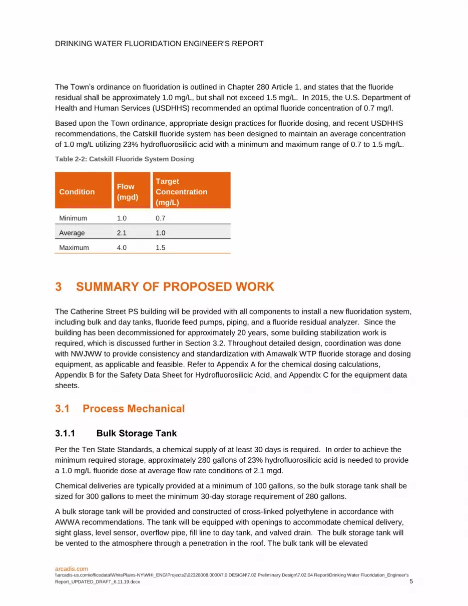
DRINKING WATER FLUORIDATION ENGINEERS REPORT
arcadiscom arcadis-uscomofficedataWhitePlains-NYWHI_ENGProjects202328008000070 DESIGN702 Preliminary Design70204 ReportDrinking Water Fluoridation_Engineers
Report_UPDATED_DRAFT_61119docx 12
The Facility is located on land owned by the New York City Department of Environmental Protection
(NYCDEP) and as such there is a Land Use Permit in place for Catherine Street The Town is working
with the NYCDEP on a renewal of the permit for the current activity
APPENDIX A
Chemical Dosing Calculations
Client Town of Yorktown By LAM Date 2192019
Project Drinking Water Fluoridation Engineers Report Checked Date
Description Fluoride System Calculations
Design Criteria
Flow
Average 21 mgd (As indicated in email from NWJWW dated 3317 (2015 data) and subsequent discussions)
Maximum 40 mgd (Maxcapacity of Catskill WTP pumps as noted in Hazen report Actual observed max is 347 mgd 2015 data)
Minimum 10 mgd (As indicated in follow-up email from NWJWW dated 4417)
Minimum (Worst Case) 03 mgd (As indicated in email from NWJWW dated 3317 (2016 data) and subsequent discussions)
2015 and 2016 flow data from NWJWW
Chemical Details
Fluorosilicic Acid H2F6Si
Strength 23
Specific Gravity 123
Density 1026 lbgal
Molecular Weight of Solution 144
Molecular Weight of Active Chem 114 (Fluoride Ion)
Available Active Ions 79
Activity 187 lbgal
Target Fluoride Concentrations
Average 10 mgL Based on Town Ordinance
Maximum 15 mgL Based on Town Ordinance
Minimum 07 mgL Based upon appropriate design practice for Fluoride Dosing
Chemical Feed Rates
Average 94 gpd
Maximum 268 gpd
Minimum 31 gpd
Minimum (Worst Case) 10 gpd
Average 039 gph
Maximum 111 gph
Minimum 013 gph
Minimum (Worst Case) 004 gph
Requirements for Chemical Storage
Number of Day Tanks 1
Required Volume of Day Tank 27 gal (24 hours at Maximum Conditions)
Available Day Tank Size (Std) 35 gal
Hours of Storage Max Condition 31 hrs Per Ten State Standards no more than 30 hours
Required Volume of Bulk Tank 281 gal (For 30 days of Chemical Storage at Average Condition)
Activity
LmgionConcentratmgdFlow 348)()(
ZWHI_ENGProjects202328008000070 DESIGN702 Preliminary Design70202 CalculationsYorktown Fluoride Calcs_21919xls
APPENDIX B
Safety Data Sheet for Hydrofluorosilicic Acid
Fluorosilicic Acid (FSA) Safety Data Sheet according to Federal Register Vol 77 No 58 Monday March 26 2012 Rules and Regulations
06052015 EN (English) Page 1
SECTION 1 Identification of the substancemixture and of the companyundertaking 11 Product identifier Product form Substance Substance name Fluorosilicic Acid (FSA) Chemical name Hydro Fluorosilicic Acid (HSA) Product code M17200 12 Relevant identified uses of the substance or mixture and uses advised against 13 Details of the supplier of the safety data sheet JR Simplot Company PO Box 70013 Boise ID 83707 T 1-208-336-2110 14 Emergency telephone number Emergency number CHEMTREC 1-800-424-9300 SECTION 2 Hazards identification 21 Classification of the substance or mixture GHS-US classification Met Corr 1 H290 Acute Tox 4 (Oral) H302 Skin Corr 1A H314 Full text of H-phrases see section 16
22 Label elements GHS-US labelling Hazard pictograms (GHS-US)
GHS05
GHS07
Signal word (GHS-US) Danger Hazard statements (GHS-US) H290 - May be corrosive to metals
H302 - Harmful if swallowed H314 - Causes severe skin burns and eye damage
Precautionary statements (GHS-US) P234 - Keep only in original container P260 - Do not breathe dustfumegasmistvapoursspray P264 - Wash thoroughly after handling P270 - Do not eat drink or smoke when using this product P280 - Wear protective glovesprotective clothingeye protectionface protection P301+P312 - P301+P330+P331 - If swallowed rinse mouth Do NOT induce vomiting P303+P361+P353 - If on skin (or hair) Take off immediately all contaminated clothing Rinse skin with watershower P304+P340 - If inhaled Remove person to fresh air and keep comfortable for breathing P305+P351+P338 - If in eyes Rinse cautiously with water for several minutes Remove contact lenses if present and easy to do Continue rinsing P310 - P321 - Specific treatment (see on this label) P330 - Rinse mouth P363 - Wash contaminated clothing before reuse P390 - Absorb spillage to prevent material damage P405 - Store locked up P406 - P501 - Dispose of contentscontainer to
Fluorosilicic Acid (FSA) Safety Data Sheet according to Federal Register Vol 77 No 58 Monday March 26 2012 Rules and Regulations
06052015 EN (English) 21
23 Other hazards No additional information available 24 Unknown acute toxicity (GHS-US) Not applicable SECTION 3 Compositioninformation on ingredients 31 Substance Name Fluorosilicic Acid (FSA)
Name Product identifier GHS-US classification hexafluorosilicic acid conc=25 aqueous solution (CAS No) 16961-83-4 100 Skin Corr 1B H314
Full text of H-phrases see section 16 32 Mixture Not applicable SECTION 4 First aid measures 41 Description of first aid measures First-aid measures general Never give anything by mouth to an unconscious person If you feel unwell seek medical
advice (show the label where possible) First-aid measures after inhalation Remove victim to fresh air and keep at rest in a position comfortable for breathing Immediately
call a POISON CENTER or doctorphysician First-aid measures after skin contact RemoveTake off immediately all contaminated clothing Rinse skin with watershower Immediately call a POISON CENTER or doctorphysician First-aid measures after eye contact Rinse cautiously with water for several minutes Remove contact lenses if present and easy to
do Continue rinsing Immediately call a POISON CENTER or doctorphysician First-aid measures after ingestion Rinse mouth Do NOT induce vomiting Call a POISON CENTER or doctorphysician if you feel
unwell Immediately call a POISON CENTER or doctorphysician 42 Most important symptoms and effects both acute and delayed Symptomsinjuries Causes severe skin burns and eye damage Symptomsinjuries after ingestion Swallowing a small quantity of this material will result in serious health hazard 43 Indication of any immediate medical attention and special treatment needed No additional information available SECTION 5 Firefighting measures 51 Extinguishing media Suitable extinguishing media Foam Dry powder Carbon dioxide Water spray Sand Unsuitable extinguishing media Do not use a heavy water stream 52 Special hazards arising from the substance or mixture No additional information available 53 Advice for firefighters Firefighting instructions Use water spray or fog for cooling exposed containers Exercise caution when fighting any
chemical fire Prevent fire-fighting water from entering environment Protection during firefighting Do not enter fire area without proper protective equipment including respiratory protection SECTION 6 Accidental release measures 61 Personal precautions protective equipment and emergency procedures 611 For non-emergency personnel Emergency procedures Evacuate unnecessary personnel 612 For emergency responders Protective equipment Equip cleanup crew with proper protection Emergency procedures Ventilate area 62 Environmental precautions Prevent entry to sewers and public waters Notify authorities if liquid enters sewers or public waters 63 Methods and material for containment and cleaning up Methods for cleaning up Soak up spills with inert solids such as clay or diatomaceous earth as soon as possible Collect
spillage Store away from other materials Absorb spillage to prevent material damage
Fluorosilicic Acid (FSA) Safety Data Sheet according to Federal Register Vol 77 No 58 Monday March 26 2012 Rules and Regulations
06052015 EN (English) 31
64 Reference to other sections See Heading 8 Exposure controls and personal protection SECTION 7 Handling and storage 71 Precautions for safe handling Additional hazards when processed May be corrosive to metals Precautions for safe handling Wash hands and other exposed areas with mild soap and water before eating drinking or
smoking and when leaving work Provide good ventilation in process area to prevent formation of vapour Do not breathe dustfumegasmistvapoursspray Avoid contact during pregnancywhile nursing
Hygiene measures Do not eat drink or smoke when using this product Wash thoroughly after handling 72 Conditions for safe storage including any incompatibilities Technical measures Comply with applicable regulations Storage conditions Keep only in the original container in a cool well ventilated place away from Keep container
closed when not in use Incompatible products Strong bases Strong acids Incompatible materials Sources of ignition Direct sunlight Packaging materials inner liner 73 Specific end use(s) No additional information available SECTION 8 Exposure controlspersonal protection 81 Control parameters
Fluorosilicic Acid (FSA) ACGIH Not applicable OSHA Not applicable hexafluorosilicic acid conc=25 aqueous solution (16961-83-4) ACGIH ACGIH TWA (mgmsup3) 25 mgmsup3 OSHA Not applicable
82 Exposure controls Personal protective equipment Avoid all unnecessary exposure
Hand protection Wear protective gloves Eye protection Chemical goggles or face shield Skin and body protection Wear suitable protective clothing Respiratory protection Wear appropriate mask Other information Do not eat drink or smoke during use SECTION 9 Physical and chemical properties 91 Information on basic physical and chemical properties Physical state Liquid
Appearance Clear colorless to pale straw liquid Colour Colourless
Odour characteristic Odour threshold No data available pH 1 Melting point No data available Freezing point No data available Boiling point 105 degC Flash point No data available Relative evaporation rate (butylacetate=1) No data available Flammability (solid gas) No data available Explosive limits No data available
Fluorosilicic Acid (FSA) Safety Data Sheet according to Federal Register Vol 77 No 58 Monday March 26 2012 Rules and Regulations
06052015 EN (English) 41
Explosive properties No data available Oxidising properties No data available Vapour pressure No data available Relative density No data available Relative vapour density at 20 degC No data available Solubility Soluble Water Solubility in water of component(s) of the mixture Log Pow No data available Log Kow No data available Auto-ignition temperature No data available Decomposition temperature No data available Viscosity No data available Viscosity kinematic No data available Viscosity dynamic No data available
92 Other information No additional information available SECTION 10 Stability and reactivity 101 Reactivity No additional information available 102 Chemical stability Stable 103 Possibility of hazardous reactions Not established 104 Conditions to avoid Extremely high temperatures Direct sunlight Extremely high or low temperatures 105 Incompatible materials Alkalis Chlorites Combustible solids and organic peroxides Strong acids Strong bases metals May be corrosive to metals 106 Hazardous decomposition products Corrosive fumes of fluorides fume Carbon monoxide Carbon dioxide Thermal decomposition generates Corrosive vapours SECTION 11 Toxicological information 111 Information on toxicological effects
Acute toxicity Oral Harmful if swallowed Fluorosilicic Acid (FSA) LD50 oral rat 430 mgkg ATE US (oral) 430000 mgkg bodyweight
Skin corrosionirritation Causes severe skin burns and eye damage pH 1
Serious eye damageirritation Not classified pH 1
Respiratory or skin sensitisation Not classified Germ cell mutagenicity Not classified
Based on available data the classification criteria are not met Carcinogenicity Not classified
hexafluorosilicic acid conc=25 aqueous solution (16961-83-4) IARC group 3 - Not classifiable
Reproductive toxicity Not classified Based on available data the classification criteria are not met
Specific target organ toxicity (single exposure) Not classified
Fluorosilicic Acid (FSA) Safety Data Sheet according to Federal Register Vol 77 No 58 Monday March 26 2012 Rules and Regulations
06052015 EN (English) 51
Specific target organ toxicity (repeated exposure)
Not classified
Aspiration hazard Not classified Potential adverse human health effects and symptoms
Based on available data the classification criteria are not met Harmful if swallowed Symptomsinjuries after ingestion Swallowing a small quantity of this material will result in serious health hazard SECTION 12 Ecological information 121 Toxicity
hexafluorosilicic acid conc=25 aqueous solution (16961-83-4) LC50 fish 1 gt 10 mgl (96 h Brachydanio rerio) Threshold limit algae 1 10 mgl (96 h Scenedesmus quadricauda Cell numbers)
122 Persistence and degradability Fluorosilicic Acid (FSA) Persistence and degradability Not established hexafluorosilicic acid conc=25 aqueous solution (16961-83-4) Persistence and degradability Biodegradability not applicable Reacts with water release of toxicharmful substances No
(test)data on mobility of the components available Not established Biochemical oxygen demand (BOD) Not applicable Chemical oxygen demand (COD) Not applicable ThOD Not applicable BOD ( of ThOD) Not applicable
123 Bioaccumulative potential Fluorosilicic Acid (FSA) Bioaccumulative potential Not established hexafluorosilicic acid conc=25 aqueous solution (16961-83-4) Bioaccumulative potential Not bioaccumulative Not established
124 Mobility in soil No additional information available 125 Other adverse effects Effect on the global warming No known ecological damage caused by this product Other information Avoid release to the environment SECTION 13 Disposal considerations 131 Waste treatment methods Waste disposal recommendations Dispose in a safe manner in accordance with localnational regulations Dispose of contentscontainer to Ecology - waste materials Avoid release to the environment SECTION 14 Transport information Department of Transportation (DOT) In accordance with DOT Transport document description UN1778 Fluorosilicic acid 8 II UN-No(DOT) UN1778 Proper Shipping Name (DOT) Fluorosilicic acid Transport hazard class(es) (DOT) 8 - Class 8 - Corrosive material 49 CFR 173136
Fluorosilicic Acid (FSA) Safety Data Sheet according to Federal Register Vol 77 No 58 Monday March 26 2012 Rules and Regulations
06052015 EN (English) 61
Hazard labels (DOT) 8 - Corrosive
Packing group (DOT) II - Medium Danger DOT Packaging Non Bulk (49 CFR 173xxx) 202 DOT Packaging Bulk (49 CFR 173xxx) 242 DOT Special Provisions (49 CFR 172102) A6 - For combination packagings if plastic inner packagings are used they must be packed in
tightly closed metal receptacles before packing in outer packagings A7 - Steel packagings must be corrosion-resistant or have protection against corrosion B2 - MC 300 MC 301 MC 302 MC 303 MC 305 and MC 306 and DOT 406 cargo tanks are not authorized B15 - Packagings must be protected with non-metallic linings impervious to the lading or have a suitable corrosion allowance IB2 - Authorized IBCs Metal (31A 31B and 31N) Rigid plastics (31H1 and 31H2) Composite (31HZ1) Additional Requirement Only liquids with a vapor pressure less than or equal to 110 kPa at 50 C (11 bar at 122 F) or 130 kPa at 55 C (13 bar at 131 F) are authorized N3 - Glass inner packagings are permitted in combination or composite packagings only if the hazardous material is free from hydrofluoric acid N34 - Aluminum construction materials are not authorized for any part of a packaging which is normally in contact with the hazardous material T8 - 4 178274(d)(2) Normal Prohibited TP2 - a The maximum degree of filling must not exceed the degree of filling determined by the following (image) Where tr is the maximum mean bulk temperature during transport tf is the temperature in degrees celsius of the liquid during filling and a is the mean coefficient of cubical expansion of the liquid between the mean temperature of the liquid during filling (tf) and the maximum mean bulk temperature during transportation (tr) both in degrees celsius b For liquids transported under ambient conditions may be calculated using the formula (image) Where d15 and d50 are the densities (in units of mass per unit volume) of the liquid at 15 C (59 F) and 50 C (122 F) respectively TP12 - This material is considered highly corrosive to steel
DOT Packaging Exceptions (49 CFR 173xxx) None DOT Quantity Limitations Passenger aircraftrail (49 CFR 17327)
1 L DOT Quantity Limitations Cargo aircraft only (49 CFR 17575)
30 L DOT Vessel Stowage Location A - passenger vessel Additional information Other information No supplementary information available
ADR No additional information available Transport by sea No additional information available Air transport No additional information available SECTION 15 Regulatory information 151 US Federal regulations
Fluorosilicic Acid (FSA) Not listed on the United States TSCA (Toxic Substances Control Act) inventory hexafluorosilicic acid conc=25 aqueous solution (16961-83-4) Listed on the United States TSCA (Toxic Substances Control Act) inventory
152 International regulations CANADA No additional information available
Fluorosilicic Acid (FSA) Safety Data Sheet according to Federal Register Vol 77 No 58 Monday March 26 2012 Rules and Regulations
06052015 EN (English) 71
EU-Regulations No additional information available Classification according to Regulation (EC) No 12722008 [CLP] Not classified
Classification according to Directive 67548EEC [DSD] or 199945EC [DPD] Not classified
National regulations No additional information available 153 US State regulations
hexafluorosilicic acid conc=25 aqueous solution (16961-83-4) US - New Jersey - Right to Know Hazardous Substance List
SECTION 16 Other information Other information None Full text of H-phrases ------ Acute Tox 4 (Oral) Acute toxicity (oral) Category 4 ------ Met Corr 1 Corrosive to metals Category 1 ------ Skin Corr 1A Skin corrosionirritation Category 1A ------ Skin Corr 1B Skin corrosionirritation Category 1B ------ H290 May be corrosive to metals ------ H302 Harmful if swallowed ------ H314 Causes severe skin burns and eye damage
SDS US (GHS HazCom 2012) Disclaimer This information relates to the specific material designated and may not be valid for such material used in combination with any other materials or in any process Such information is to the best of our knowledge and belief accurate and reliable as of the date compiled However no representation warranty or guarantee is made as to its accuracy reliability or completeness NO WARRANTY OF MERCHANTABILITY FITNESS FOR ANY PARTICULAR PURPOSE OR ANY OTHER WARRANTY EXPRESS OR IMPLIED IS MADE CONCERNING THE INFORMATION HEREIN PROVIDED It is the users responsibility to satisfy himself as to the suitability and completeness of such information for his own particular use We do not accept liability for any loss or damage that may occur from the use of this information nor do we offer warranty against patent infringement
APPENDIX C
Equipment Data Sheets and Information
ALL EXTERNAL PIPING MUST BE INDEPENDENTLY SUPPORTEDONLY BASE FITTINGS TO BE LEFT INSTALLED AT TIME OF SHIPMENT PER SII PROCEDUREConsult Snyders Guidelines for Use and Installation prior to delivery Available on-line at httpwwwsnyderindustriestankscomTechnical
357
218
180
335
295
GALLONLITER MARKS 270deg
6 PE THREADEDVENTED CAP W 45 ACCESS
55
0deg
90deg
180deg
270deg
NOTEGALLONAGE MARKS MAY BE REMOVED FOR FITTING PLACEMENT AS NEEDED
PART NO
IGG
DRAWN BYDO NOT SCALE TITLE
ENG ID
1 OF 1
REVISION
ASM TK 35VFT X 18 NECK
SHEETcopy SNYDER INDUSTRIES INC 2019
ALL DIMENSIONS DESIGNS AND INFORMATION ON THIS PRINT MUST BE CONSIDERED PROPRIETARY TO SNYDER INDUSTRIES INC AND MAY NOT BE USED COPIED OR DISTRIBUTED WITHOUT WRITTEN PERMISSION OF AN OFFICER (OR HIS AGENT) OF THE FIRM
STATUS Released
D0042701000110N___01ALL DIMENSIONS ARE IN INCHES NOMINAL amp SUBJECT TO CHANGE WITHOUT NOTICEALL DIMENSIONS ON ROTATIONAL MOLDED PARTS ARE SUBJECT TO A 3 TOLERANCE
(402) 467-5221wwwsnydernetcom
A
Position Statement
Hydrofluosilicic Acid (H2SiF6) le26 Storage Tanks Tank HDLPE 19 SpGr rating (ASTM D-1998 - 600 psi hoop stress design) or HDXLPE 19 SpGr rating (ASTM D-1998 - 600 psi hoop stress design) Note chemical may cause XLPE tank material to discolor Full Drain Option SUMOtrade (Snyder Unitized Molded Outlet) bull Available on single wall vertical tanks 2000 to 12500 gallons bull Encapsulated Hastelloy threaded ring with PVC adapter Double Wall Tanks Mini-Captortrade and CAPTORtrade Containment Systems (CCS) ndash 35 to 12500 gallons bull Primary Tank bull HDLPE 19 SpGr rating (ASTM D-1998 - 600 psi hoop stress design) or bull HDXLPE 19 SpGr rating (ASTM D-1998 - 600 psi hoop stress design) Note chemical may cause XLPE tank material to discolor bull Secondary Containment Tank bull HDLPE 15 SpGr Natural color Fittings Material of Construction bull Fitting PVC (schedule 80) or PP bull Gasket Viton bull Bolt Hastelloy Plumbing to the tank Required use of flexible connections with fittings bull Allows for 4 lateral and vertical expansion and contraction of the tank bull Reduces pump and piping vibration stress on the tank fittings and gaskets bull Flexible connections piping and valves must have structural support independent of tank sidewall and dome Venting Tanks are designed for use at atmospheric pressure Pressure or vacuum situation can cause excessive deformation or damage to the tanks and void warranty Venting equipment should be sized to limit pressure or vacuum in the tank to a maximum of frac12rdquo water column (0018 PSI) If the tank will be pneumatically filled (through tanker discharge) additional pressure relief may be required Hydrofluosilicic acid is a volatile liquid and will start fuming at ambient temperatures These fumes can be corrosive to the environment around the tank For this reason a bolted and sealed (fume tight) manway should be considered for hydrofluosilicic acid tanks and special considerations should be taken for venting the tank to a scrubber system Foundation and Restraints Tanks should be positioned on a smooth concrete or asphalt pad providing adequate support The pad should be clean smooth and level so it fully supports the entire tank bottom with no deflection If a seismic restraint system is used the pad must be adequate in size for anchor plate attachments per the seismic code Temperature Product should not exceed 100 degrees F at delivery or during storage January 1 2013
Data
Replaces same of RevK 22012 1712L 112014
201 Ivyland RoadIvyland PA 18974 USA
TEL (215) 293-0401FAX (215) 293-0445
httpwwwlmipumpscom
Polyprel is a registered trademark of Milton Roy LLC Flourofilm and Liquifram are trademarks of Milton Roy LLCcopy 2005 2012 2014 Milton Roy LLC - All Rights Reserved
Data SheetSeries C
Electronic Metering PumpsConfiguration Data
Model C92 1 - 363SI
Control amp Output Code with Standard Liquid End
Manual ControlSpeed (stroking frequency) and stroke length manually adjustableC10C11C12C13C14
----------
13 GPH25 GPH40 GPH80 GPH20 GPH
(49 lh)(95 lh)
(151 lh)(30 lh)(76 lh)
300 psi
150 psi
100 psi
60 psi
25 psi
(207 Bar)(103 Bar)(69 Bar)(41 Bar)(17 Bar)
Instrument ResponsiveManual ControlManual adjustment features of C1 Series plus switch conversion to external control for automatic systemsC70C71C72C73C74C76C77C78C90C91C92C93C94
--------------------------
13 GPH25 GPH40 GPH80 GPH20 GPH40 GPH10 GPH25 GPH13 GPH25 GPH40 GPH80 GPH20 GPH
(49 lh)(95 lh)
(151 lh)(30 lh)(76 lh)
(151 lh)(38 lh)(95 lh)(49 lh)(95 lh)
(151 lh)(30 lh)(76 lh)
300 psi
150 psi
100 psi
60 psi
25 psi
175 psi
80 psi
30 psi
300 psi
150 psi
100 psi
60 psi
25 psi
(207 Bar)(103 Bar)(69 Bar)(41 Bar)(17 Bar)
(121 Bar)(55 Bar)
(207 Bar)(207 Bar)(103 Bar)(69 Bar)(41 Bar)(17 Bar)
Voltage Code1 ------ 120 VAC US Plug2 ------ 240 VAC US Plug3 ------ 220-240 VAC DIN Plug5 ------ 240-250 VAC UK Plug6 ------ 240-250 VAC AUSTNZ Plug7 ------ 220-240 VAC SWISS Plug
Liquid EndSee next page for complete liquid end specifications and selection
Specifications
Series
Strokes Per Minute
(Adjustable) Min Max
Stroke Length (Adjustable)
Recommended Minimum
Average Input Power Max Speed
ShippingWeight
C10 C70 C90 C11 C71 C91 C12 C72 C92 C13 C73 C93 C14 C74 C94
1 100 10 44 watts 20 lbs (91 kg)
C76 C77 C78
1 100 10 87 watts 28 lbs (127 kg)
Not UL or CUL Approved
Dimensions
Certified to NSFANSI Standard 50
Standard Liquid End Configuration Data amp Materials of ConstructionDrive
AssemblyLiquid
End NoMaterials of Construction
AccessoryTubing amp Connections Discharge SuctionSize Code Head amp Fittings Balls Liquiframtrade Check Valve
C90 C70 -C10 -
498SP 09 PVC Ceramic Fluorofilmtrade PVDFPTFE 4FV Pipe 12 NPT M297 09 316 SS 316 SS Fluorofilmtrade 316 SS Pipe 14 NPT M
C92 -C91 -C72 -C71 -C12 -C11 -
468SIdagger 18 PVCPVC Ceramic Fluorofilmtrade PVDFPolyprelreg 4FV PE 375 OD460SIdagger 18 AcrylicPVC Ceramic Fluorofilmtrade PVDFPolyprelreg 4FV PE 375 OD469SIdagger 18 AcrylicPVDF PTFE Fluorofilmtrade PVDFPolyprelreg 4FV PE 375 OD368SIdagger 18 PVCPVC Ceramic Fluorofilmtrade PVDFPolyprelreg 4FV PE 375 OD362SIdagger 18 PVDFPVDF Ceramic Fluorofilmtrade PVDFPolyprelreg 4FV PE 375 OD363SIdagger 18 PVDFPVDF Ceramic Fluorofilmtrade PVDFPTFE 4FV PE 375 OD465SIdagger 18 Polypropylene Ceramic Fluorofilmtrade PVDFPTFE 4FV PE 375 OD75HV 18 Polypropylene 316 SS Fluorofilmtrade PTFE PE 5 OD Vinyl 938 OD76HV 18 AcrylicPP 316 SS Fluorofilmtrade Vitonreg PE 5 OD Vinyl 938 OD277 18 316 SS 316 SS Fluorofilmtrade 316 SS Pipe 14 NPT M
C93 -C73 -C13 -
312SIdagger 30 PVDFPVDF Ceramic Fluorofilmtrade PVDFPolyprelreg 4FV PE 5 OD313SIdagger 30 PVDFPVDF Ceramic Fluorofilmtrade PVDFPTFE 4FV PE 5 OD318SIdagger 30 PVCPVC Ceramic Fluorofilmtrade PVDFPolyprelreg 4FV PE 5 OD410SIdagger 30 AcrylicPVC Ceramic Fluorofilmtrade PVDFPolyprelreg 4FV PE 5 OD415SIdagger 30 Polypropylene Ceramic Fluorofilmtrade PVDFPTFE 4FV PE 5 OD418SIdagger 30 PVCPVC Ceramic Fluorofilmtrade PVDFPolyprelreg 4FV PE 5 OD419SIdagger 30 AcrylicPVDF PTFE Fluorofilmtrade PVDFPolyprelreg 4FV PE 5 OD20 30 AcrylicPVC Ceramic Fluorofilmtrade Vitonreg PE 5 OD20HV 30 AcrylicPP 316 SS Fluorofilmtrade Vitonreg PE 5 OD Vinyl 938 OD20S 30 AcrylicPVC Ceramic Fluorofilmtrade Vitonreg 4FV PE 5 OD Vinyl 5 OD24 30 PVC Ceramic Fluorofilmtrade PTFE Pipe 12 NPT M25HV 30 Polypropylene 316 SS Fluorofilmtrade PTFE PE 5 OD Vinyl 938 OD26 30 PVC Ceramic Fluorofilmtrade Vitonreg PE 5 OD26S 30 PVC Ceramic Fluorofilmtrade Vitonreg 4FV PE 5 OD27 30 316 SS 316 SS Fluorofilmtrade PTFE Pipe 12 NPT M29 30 UHMW PE Ceramic Fluorofilmtrade Vitonreg PE 5 OD
C94 -C78 -C74 -C14 -
30 60 AcrylicPVC Ceramic Fluorofilmtrade PTFE PE 5 OD Vinyl 5 OD34 60 PVC Ceramic Fluorofilmtrade PTFE Pipe 12 NPT M35P 60 Polypropylene Ceramic Fluorofilmtrade PTFE Pipe 12 NPT M35T 60 Polypropylene Ceramic Fluorofilmtrade PTFE PE 5 OD36 60 PVC Ceramic Fluorofilmtrade PTFE PE 5 OD37 60 316 SS 316 SS Fluorofilmtrade PTFE Pipe 12 NPT M
C76 -468SP 18 PVCPVC Ceramic Fluorofilmtrade PVDFPolyprelreg 4FV Pipe 12 NPT M74S 18 PVC Ceramic Fluorofilmtrade PTFE 4FV Pipe 14 NPT M277 18 316 SS 316 SS Fluorofilmtrade 316 SS Pipe 14 NPT M20 30 AcrylicPVC Ceramic Fluorofilmtrade Vitonreg PE 5 OD
C77 -
20HV 30 AcrylicPP 316 SS Fluorofilmtrade Vitonreg PE 5 OD Vinyl 938 OD20S 30 AcrylicPVC Ceramic Fluorofilmtrade Vitonreg 4FV PE 5 OD Vinyl 5 OD24 30 PVC Ceramic Fluorofilmtrade PTFE Pipe 12 NPT M25HV 30 Polypropylene 316 SS Fluorofilmtrade PTFE PE 5 OD Vinyl 938 OD25P 30 Polypropylene Ceramic Fluorofilmtrade PTFE Pipe 12 NPT M25T 30 Polypropylene Ceramic Fluorofilmtrade PTFE PE 5 OD26S 30 PVC Ceramic Fluorofilmtrade Vitonreg 4FV PE 5 OD27 30 316 SS 316 SS Fluorofilmtrade PTFE Pipe 12 NPT M29 30 UHMW PE Ceramic Fluorofilmtrade Vitonreg PE 5 OD
Output Information with Standard Liquid End
SeriesGallons per Hour
Min MaxLiters per Hour Min Max
mLcc per Minute Min Max
mLcc per Stroke Min Max
Maximum Injection Pressure
C10 C70 C90 0001 13 0005 49 008 82 008 082 300 psi (207 Bar)C11 C71 C91 0003 25 0010 95 016 158 016 158 150 psi (103 Bar)C12 C72 C92 0004 40 0015 151 025 252 025 252 100 psi (69 Bar)C13 C73 C93 0008 80 0030 300 051 505 051 505 60 psi (41 Bar)C14 C74 C94 0020 200 0076 760 126 1262 126 1262 25 psi (17 Bar)C76 0004 40 0015 151 025 252 025 252 175 psi (121 Bar)C77 0010 100 0038 380 063 631 063 631 80psi (55 Bar)C78 0025 250 0095 950 158 1577 158 1577 30 psi (207 Bar)
Minimum output is based on 1 stroke per minute and 10 stroke setting minimum output can be reduced further in external mode Series C9 pumps may be programmed for strokes per hour for lower outputs
AutoPrimeTM Liquid End Configuration Data amp Materials of ConstructionDrive
AssemblyLiquid
End NoSize Code Head amp Fittings Balls Liquiframtrade Check Valve Accessory Tubing amp Connections
C11 C71 C91 C12 C72 C92
D60HI 18 AcrylicPVC Ceramic Fluorofilmtrade PVDFPolyprelreg 4FV PE 375 ODD68HI 18 PVCPVC Ceramic Fluorofilmtrade PVDFPolyprelreg 4FV PE 375 OD
C13 C73 C93 D10HI 30 AcrylicPVC Ceramic Fluorofilmtrade PVDFPolyprelreg 4FV PE 5 ODD18HI 30 PVCPVC Ceramic Fluorofilmtrade PVDFPolyprelreg 4FV PE 5 OD
Output Information ndash AutoPrimeTM Liquid Ends (Liquid end models beginning with ldquoDrdquo)
SeriesMaximum Output Maximum Pressure
GPH Litershr mLcc per minute mLcc per stroke PSI BarC11 C71 C91 23 87 1451 145 150 psi 103C12 C72 C92 38 144 2398 240 100 psi 69C13 C73 C93 78 295 4922 492 60 psi 41
AutoPrimeTM liquid ends have 3 check valves suction on the bottom discharge on the front and autoprime bleed on the top By design a repeatable portion of the process fluid continuously bleeds through the top check valve to be returned to the chemical supply The result is the assurance that any gas in the head is automatically relieved thus eliminating air-binding The maximum output per the tables above is reduced to account for the continuous bleed
See front page for voltage code specifications Plastic heads with tubing connection include frac12 NPT and frac12 BSP
These Liquid Ends are available without a 4FV simply drop the lsquoSrsquo at the end of the Liquid End number to order the model without a 4FV
These liquid ends use 38 diameter balls Pump output may be reduced in some applications
dagger To specify frac14 NPT male change lsquoIrsquo to lsquoPrsquo To specify black UV resistant tubing change lsquoIrsquo to lsquoUrsquo To specify 3FV change lsquoSrsquo to lsquoTrsquo
3FV indicates that the pump is equipped with an LMI Three Function Valve (pressure relief priming aid line drain)
4FV indicates that the pump is equipped with an LMI Four Function Valve This diaphragm type anti-syphonpressure relief valve is installed on the pump head It provides anti-syphon protection and aids priming even under pressure
Fluorofilmtrade is a copolymer of PTFE and PFA Polyprelreg is an elastomeric PTFE copolymer
Polyprel is a registered trademark of Milton Roy LLC
Fluorofilm and Liquifram are trademarks of Milton Roy LLC Vitonreg is a registered trademark of DuPont
Liquid End Sheet
2029A 32010
201 Ivyland RoadIvyland PA 18974 USA
TEL (215) 293-0401FAX (215) 293-0445
httpwwwlmipumpscom
A INSTALLING INJECTION CHECK VALVE (FIGURE 1)1 The Injection Check Valve prevents backflow from a treated line
Install the injection check valve at the location where chemical is being injected into the system
2 Any size Female NPT fitting or pipe tee with a reducing bushing to frac12 Female NPT will accept the injection check valve PTFE tape should only be used on threads that are connected with pipes
3 When installing the Injection Check Valve be sure to position it so that the valve enters the bottom of your pipe in a vertical position Variations 40deg left and right are acceptable
FIGURE 1B CONNECTING DISCHARGE TUBING (FIGURE 2)
Note Cut tubing to length needed for discharge line1 Route tubing from the injection check valve to the metering pump
making sure it does not touch hot or sharp surfaces or is bent so sharply that it kinks
2 Put coupling nut over tubing
3 Position female Ferrule about one inch (25 mm) from end of tubing
4 For frac14 or 6 mm OD tubing cut tubing so that frac14 to sup3∕8 (5-10 mm) protrudes from the female Ferrule For all other tubing push the tube to the bottom of the groove in the male Ferrule Then slide the female Ferrule down into the male Ferrule
5 Firmly hand tighten the coupling nut onto the fitting
FIGURE 2DO NOT USE CLEAR VINYL TUBING ON THE DISCHARGE SIDE OF THE PUMP The pressure created by the pump can rupture vinyl tubing which is only for suction connections on certain liquid endsDO NOT USE PLIERS OR PIPE WRENCH ON COUPLING NUTS OR FITTINGS USE ONLY LMI TUBINGmdashALWAYS use LMI supplied tubing with your pump as the tubing is specifically designed for use with the pump fittings
C CONNECTING SUCTION TUBING1 Cut suction tubing to a length so that the foot valve hangs
just above the bottom of the solution container Maximum recommended vertical suction lift is 5 ft (15m)
2 Follow same procedure in connecting suction tubing to suction valve and foot valve (see B Connecting Discharge Tubing)
LE-4X9SXWhen pumping solutions make certain that all tubing is securely attached to the fittings It is recommended that tubing or pipe lines be shielded to prevent
possible injury in case of rupture or accidental damage Always wear protective clothing and face shield when working on or near your metering pump
Note See parts list for materials of construction
LE-4X9SX
Key Number Description Part
NumberQUANTITY
419SX 459SX 469SX 499SX
10 Pump Head
38578 1
38561 1
38595 1
36159 1
40 O-Ring 48349 5 5 5 5
100 O-Ring 36103 4 4 4 4
190 Liquiframtrade
30916 1
30917 1
31420 1
31419 1
230 Injection Valve Body 48618 1 1 1 1
250 Tubing Straightener 32293 1 1 1 1
260 Foot Valve Coupling 36204 1 1 1 1
270 Foot Valve Strainer 10123 1 1 1 1
350
Tubing Suction amp Discharge 4XXSI ONLY
25636-16 1
10342-16 1 1
10142-16 1
Tubing Suction amp Discharge 4XXSU ONLY
28636-16 1
27342-16 1 1
27142-16 1
354 Tubing 4FV 25636-06 1 1 1 1
440 Bleed Nut 48622 1 1 1 1
602 Suction Check Valve 49093 1
49094 1 1 1
603 Cartridge Valve 37858 4
37859 4 4 4
606 Liquid End Hardware49109 1 1 1
49110 1
607 Foot Valve49105 1
49106 1 1 1
608 Injection Valve 48730 1 1 1 1
613
Tubing Connection Kit 4XXSI and 4XXSU
77382 4
77383 4 4
77384 4
Tubing Connection Kit 4XXSM ONLY
77378 4
77379 4 4
77380 4
615 Check Valve Fitting 48788 3 3 3 3
617 Injection Valve Cartridge 48796 1 1 1 1
620 4FV Assembly48799 1
48754 1 1 1
621 4FV Fitting Assembly 49255 1 1 1 1
LE-4X9SX
REFER TO YOUR ELECTRONIC METERING PUMP INSTRUCTION MANUAL FOR ADDITIONAL INSTRUCTIONS AND PRECAUTIONS You may contact your local LMI Distributor for additional information or visit LMI on the web at wwwlmipumpscom
copy 2010 Milton Roy CompanyndashAll Rights ReservedPrinted in USASpecifications subject to change without notice
D PRIMING WITH 4-FUNCTION VALVE1 Connect pressure relief tubing to the pressure relief port
(FIGURE 3) Route tubing to the solution tank This tubing must not be submerged in the solution
When all precautionary steps have been taken the pump is mounted and the tubing is securely attached you may now start priming the pump2 Turn black knob about sup1∕8 turn CCW to stop point to open
bypass port
3 Set pump at 100 speed and 100 stroke length Start pump When fluid has been flowing through the bypass port tubing for 10-20 seconds the pump is primed
4 Stop pump and return black knob to normal position
Note The pumps are normally self priming if suction lift is less than 5 feet (15 meters) check valves are wet (there is usually water in the pump head when shipped from the factory) and the steps above are followed If the pump does not self prime you can choose one of 2 ways to help prime
1 Remove the 4-function valve and cartridges and slowly pour water or solution into the pump head until it is filled Replace cartridges and 4-function valve and repeat steps above
2 Temporarily improve suction conditions by pumping from a container closer to or above pump
4-FunctionValve
PressureRelief Port
SuctionValve
FIGURE 3Note The head drawing is for reference only
actual appearance may differ
E DEPRESSURIZING THE DISCHARGE LINE AlwAyS wear protective clothing face shield safety glasses and gloves when performing any maintenance or replacement on your pump
When preparing to maintain the pump or any component in the discharge line the 4-function valve is used to depressurize the line Be sure an injection check valve is properly installed and is operating and that all tubing connections on the 4-function valve are secureBe sure your relief tubing is connected to your pressure relief port on the 4-function valve and runs back to your solution drum or tank
1 Turn off the pump2 If any valves have been installed downstream of the pump close them3 If the supply tank for the pump is higher than the pump head fluid
will flow through unless a suction line valve is closed4 Turn the black knob on the 4-function valve about sup1∕8 turn CCW to
its open position This relieves pressure between the pump and the 4-function valve
5 To release line pressure while the black knob is in the open position turn the yellow knob and hold open until fluid flow though the bypass port stops
When tubing connections are loosened chemical will drain from the line Use appropriate safety precautions to avoid contact with chemical
DW = drinking water WW = wastewater municipal PW = pure water power
IW = industrial water E = environmental C = collections FB = food and beverage
FluorideDATA SHEET
CA610Fluoride Analyzer
Features and Benefits
Reliable Full-time Fluoride MonitoringThe CA610 Fluoride Analyzer uses advanced ion-selectiveelectrode (ISE) technology for continuous monitoring offluoride concentration in drinking water effluent Accuracy isensured with precise control of temperature ionic strengthand pH Interferences that can bias measurements arevirtually eliminated with this electrode
Patented Electrode Design with Replaceable TipThe proven ISE technology ofthe electrode is enhanced bya patented design andmanufacturing processThe lanthanum crystal at the tipof the probe is molded into aone-piece monolithic tip that isthreaded for easy removal Thisprevents errors and prematurefailures Electrodes are equipped
with BNC connectors so that they can be independentlychecked with laboratory electrochemical meters
Cost Effective OperationThe electrode of the CA610 analyzer is made with a moldedfluoride crystal tip The working life of the electrode isapproximately one year The specially designed tip of theelectrode should be replaced every six months Reagentconsumption is very low and maintenance is simple
Method of AnalysisThe ISE system of the CA610 analyzer includes a referencepH electrode and a working electrode Three reagents areusedmdashTotal Ionic Strength Adjustment Buffer (TISAB)solution and two fluoride standards The TISAB is used forthe following purposes
bull Ionic strength adjustment lets the electrode respond toconcentration instead of activity
bull pH control ensures fluoride is present in its ionic state
bull Weak complexes formed by certain metals (for examplealuminum) are ldquobroken uprdquo by TISAB and chelatespotential interferents for accurate fluoride measurement
Automatic CalibrationTwo calibration standards are fully enclosed in the CA610analyzerrsquos case The instrument performs a 2-pointcalibration at 05 and 50 mgL fluoride at user-selected timeintervals Automatic calibration intervals can be set for 1 dayto 1 month Readings and calculations of the most recentcalibration is stored in the instrument
ApplicationsDrinking Water PlantsmdashThe CA610 analyzer accuratelymeasures fluoride concentration regardless of the form influoride is addedmdashliquid fluorosilicic acid (H2SiF6) sodiumsilicofluoride (Na2SiF6) or sodium fluoride (NaF)
Remote LocationsmdashBecause it produces only a smallamount of waste and requires minimal maintenance it iswell-suited for remote locations
Industrial LocationsmdashFluoride may occur naturally in wateror it may be the result of fertilizer run-off or discharge fromaluminum factories The CA610 analyzer is an effective toolto monitor either influent or effluent stream
US patent number 5393402
The Hach CA610 Fluoride Analyzer offers economicalanalysis using just 500 mL of reagent per month
Calibration is automatic and sample conditioning is built-inElectrode maintenance is easy and economical
mdashjust replace the tip of the sensor
DW
IW
Range01 to 10 mgL fluoride
Accuracyplusmn10 or plusmn010 ppm whichever is greater
Precisionplusmn7 or plusmn007 ppm whichever is greater
Minimum Detection Limit010 mgL
Cycle Time42 minutes
Sample Conditioning Inlet Pressure1 to 10 psig (use sample restriction deviceto reduce higher pressure samples)
Sample Flow Rate200 to 500 mLminute(200 mLmin minimum required)
Sample Temperature5 to 40degC (41 to 104degF)
Operating Temperature5 to 40degC (41 to 104degF)
Operating Humidity90 at 40degC (90 at 104degF) maximum
Storage Temperature-40 to 60degC (-40 to 140degF)(without reagents)
Sample Inlet Connection14-inch OD polyethylene tubingquick-disconnect fitting
Drain Connection12-inch ID flexible hose
Air Purge (optional)01 cfm instrument quality air at 20 psigmaximum 14-inch OD tubingquick-disconnect fitting
ReagentStandard RequirementsMaximum Reagent Usage 500mLmonth for each of two standardsand one reagent TISAB
Containers High-density polyethylene(3) 500 mL bottles
Containment Reagent bottle containedinside analyzer enclosure ventedexternally
Calibration MethodTwo-point loglinear using 05 mgL and50 mgL fluoride standards
DisplayLCD 3-12-digit measurement readoutand six-character alphanumeric scrollingtext line
AlarmsTwo SPDT relays (unpowered) 5Aresistive load at 240 Vac Suitable forsample set point alarms (high or low)or system warning indicator or systemalarm indicator
Recorder OutputOne isolated recorder output 4ndash20 mA(can be adjusted to 0ndash20 mA) maximumimpedance 500 ohm 130 V isolationfrom earth ground Output span isprogrammable over any portion of themeasurement range
Optional External OutputsHach AquaTrendreg Network Interface
Power Requirement100 to 115230 Vac selectable 90 VAmaximum 5060 Hz 25 Amp fuse
Power ConnectionThree-wire barrier terminal block through12-inch conduit hole in case wirerange 12 to 18 AWG
ComplianceCertificationCE approved ETL listed to UL 1262ETL certified to CSA 222 No 142
EnclosureMolded ABS plastic IP62-rated (dustand drip tight) with gasketed doorlatched Suitable for indoor applications
MountingWall mount
InstallationCategory II
Dimensions343 x 419 x 191 cm(135 x 165 x 75 in)
Shipping Weight113 kg (25 lb)
Specifications
Specifications subject to change without notice
2
1 The fluoride analyzer shall employ anion-selective electrode method ofmeasurement using TISAB reagentand be capable of measuringfluoride every 42 minutes
2 A three digit LCD readout in therange of 01 to 10 mgL shall displaythe results
3 The analyzer shall be designed for30 days unattended operation anduse only 500 mL of each standardevery two months when thecalibration interval is set for 24hours
4 Operating with a lanthanum fluoridecrystal the working electrode shallemploy a removable sensor for easyreplacement
5 The instrument shall be constructedwith a temperature controlled wall-jet flow cell to guide the sampledirectly toward the surface of theelectrode to assure fast wash out
6 The instrument shall provideresolution of 01 mgL repeatabilitywithin plusmn007 mgL and accuracybetter than plusmn10 of reading orplusmn010 mgL whichever is greater
7 The analyzer shall bemicroprocessor-controlled andprovide a 4-20 mA recorder outputas well as 2 alarms
8 Each alarm shall be user-selectablefor sample concentration alarms(high or low) analyzer systemwarnings or analyzer system errors
a The sample concentration alarmsshall be fully adjustable throughthe entire range
b The system warning shall activatefor minor variations in analyzerperformance
c The system alarm shall activatefor major variations in analyzerperformance and it shall shutdown the analyzer until correctiveaction is taken
9 The microprocessor shall provideself-diagnostic functions accessiblethrough an alphanumeric menu-driven keyboard
10 Two SPDT normally opennormallyclosed dry contact relays rated at 5A resistive load at 230 Vac shall beprovided
Engineering Specifications
Dimensions
Air Purge Quick Connect1325 OD Polyethylene Tubing13(Cat No 47438-00)
RelayAlarm13Contact13Connections
Network and134-20 mA13Connections
Power13Connections
409
13(1
0388
mm
)26
613
(675
5mm
)
561
(142
48m
m)
40213(10217 mm)
43813(11112 mm)
15613(3968 mm)
106 (2699 mm)
1788
(45
405m
m)M
ount
ing
Patte
rn
Four 14 Mounting Bolts
750 (19050 mm)13Mounting Pattern
Chlorine
mgL
Alarm
microgL
Chlorine
mgL
Alarm
microgL
Sample Inlet Quick Connect1325 OD Polyethylene Tubing13(Cat No 47438-00)
50 ID Drain Tube Sample
Overflow Drain13Recommended13
50 ID Tubing
1521 (38630 mm)
006 (159 mm)13Clearance13For Vents
70613(17939 mm)
199513(50678 mm)
R 1489(37818 mm)
The CA610 analyzer is designed to be wall-mounted with four 14-inch screws Adequate clearance must be left at the sides andbottom of the case for plumbing and electrical connections The sample inlet connection is 14-inch quick-disconnect fitting andthe drain connection is 12-inch ID flexible hose Electrical connections are inside the instrument case Holes for three 12-inchconduit fittings are provided
3
11 Recorder outputs shall be 4-20 mARecorder span minimum andmaximum values shall be operatorprogrammable at the menu-drivenkeypad over the entire operatingrange
12 The fluoride analyzer shall be housedin an IP62-rated ABS plasticenclosure designed for wallmounting
13 The enclosure shall have two clearpolycarbonate windows for viewingthe measurement readout andreagent levels
14 Power requirements shall be 100 to115230 Vac 5060 Hz switchselectable 90 VA maximum
15 The fluoride analyzer shall be HachCompany model CA610 FluorideAnalyzer
Engineering Specifications continued
LIT4540 Rev 2F12 Printed in USAcopyHach Company 2012 All rights reservedIn the interest of improving and updating its equipment Hach Company reserves the right to alter specifications to equipment at any time
For current price informationtechnical support and orderingassistance contact the Hachoffice or distributor servingyour area
In the United States contact
HACH COMPANY World HeadquartersPO Box 389Loveland Colorado 80539-0389USATelephone 800-227-4224Fax 970-669-2932E-mail ordershachcomwwwhachcom
US exporters and customers in CanadaLatin America sub-Saharan Africa Asiaand AustraliaNew Zealand contact
HACH COMPANY World HeadquartersPO Box 389Loveland Colorado 80539-0389USATelephone 970-669-3050Fax 970-461-3939E-mail intlhachcomwwwhachcom
In Europe the Middle East andMediterranean Africa contact
HACH LANGE GmbHWillstaumltterstraszlige 11D-40549 DuumlsseldorfGERMANYTel +49 (0) 211 5288-0Fax +49 (0) 211 5288-143E-mail infohach-langedewwwhach-langecom
At Hach itrsquos about learningfrom our customers andproviding the right answersItrsquos more than ensuring thequality of watermdashitrsquos aboutensuring the quality of lifeWhen it comes to the thingsthat touch our lives
Keep it pure
Make it simple
Be right
4
CA610 Fluoride Analyzers are shipped with one-month supply of regentsmaintenance kit wall mounting kit and manual Power cord is ordered separately
5740001 Model CA610 Fluoride Analyzer
5740002 Model CA610 Fluoride Analyzer with AquaTrend Network
For European customers
5740011 CA610 unit Reagents Set Installation amp Maintenance KitsEU Basic User Manual
5740005 CA610 unit Installation amp Maintenance Kits EU Basic User Manualndash NO REAGENTS
Accessories
5448800 Power Cord 115V 10A 183 m (6 ft) North American plug
5448900 Power Cord 230V 10A 183 m (6 ft) Continental European plug
4643600 Flow Meter with 14-inch OD tubing
Replacement Items
5742100 Maintenance Kit (See Note 1)
5744400 Pump Tubing Set
5742700 Instrument Tubing Set
5744800 Electrode Kit (See Note 2)
5528100 Electrode pH reference
5527700 Electrode Body ISE
5745100 Electrode Tip fluoride lanthanum crystal 2pkg
Additional Reagents
One unit of each standard solution is sufficient for two months operation at a24-hour calibration interval One unit of Reagent 1 TISAB is sufficient for a 30-dayoperating period
2816900 Reagent Set CA610 fluoride analyzer (includes reagent 1 TISABstandard 1 and standard 2)
2812811 Reagent 1 TISAB 473 mL
2743811 Standard 1 05 mgL as F 473 mL
2797111 Standard 2 50 mgL as F 473 mL
4450126 Inner Fill Solution fluoride 50 mL
Ordering Information
NOTES
1 Kit includes instrument and pump tubing sets (1 year supply) replacement filterscreen and spare fittings
2 Kit includes ISE and pH electrodes electrode tips syringe and inner fill solution
Submersible progress cav ity pump with grinder cutter dev ice f orliquidscontaining solids or f ibres
Head
450 38mm
252 Eff
05
101520
25303540455055606570758085
9095
100105110115120125130135140145150155
160165170175180185190195200
205210215220225[ft]
70 80 90 100 110 120 130 140 150 [US gpm]
Impeller
Frequency
Motor
Rated v oltage
-
Rated power
Rated speed
Number of poles
Rated current
230 V60 Hz
17 hp
4
1730 rpm
81 A
MF 3068 HT 1~ 450
Motor
1~
Suction Flange Diameter
OIL
c a leS
D r a w n
R e g n o
D a t eb yC h e c k e d
b y
DRAW I NGAUTO CAD
D e n o m in a t io n
Di m e n s i o n a l d rwgM F 3 0 6 8 1 7 5 HT
1-11 NPT
To t a l in c l s t a n d( lbs)Weight
85
7074900 2
5399
080829NK
Oslash 1
M6 3x
263 4233 8
11 14
5 12
127 8
3 8
4 38
23 8
43 8
43 8
4 38
Oslash6 78
60Acircdeg
21
Impeller diameter 38 mmNumber of blades 1
M3068175 13-10-4BB-W 17hp
Stator v ariant 3
Phases
Starting current 37 A
Technical specification
Note Picture might not correspond to the current configuration
Power f actor
Motor ef f iciency
11 Load34 Load12 Load
11 Load34 Load12 Load
099099098
685 638 544
1 inchCurve ISO
F - Free standing Semi permanent WetInstallation
Configuration
Impeller material
General
Discharge Flange Diameter 1 inch
Water pure
Standard
Last updateCreated on
382019
Created byProject IDProject
Head
Pump Efficiency
Overall Eff iciency
Pow er input P1
Shaft pow er P2
450 38mm
252 Eff
450 38mm
450 38mm
450 38mm (P2)
450 38mm (P1)
0102030405060708090
100110120130140150160170180190200210220[ft]
0
4
8
12
16
20
[]
00
04
08
12
16
20
[hp]
70 75 80 85 90 95 100 105 110 115 120 125 130 135 140 145 150 155 [US gpm]
70 75 80 85 90 95 100 105 110 115 120 125 130 135 140 145 150 155 [US gpm]
Motor
60 Hz
Phases 1~
230 VNumber of poles 4
Rated power 17 hp
Starting currentRated current 81 A
Rated speed 1730 rpm
M3068175 13-10-4BB-W 17hp
Stator variantNumber of blades 1
Power factor
MF 3068 HT 1~ 450
Suction Flange Diameter
Performance curve
Pump
Impeller diameter 112
Motor
Rated voltage
37 A
Motor efficiency
11 Load34 Load12 Load
11 Load34 Load12 Load
Frequency3
099
685
099098
638 544
25 mm
Curve ISO
Discharge Flange Diameter 1 inch
Water pure
Last updateCreated on
382019
Created byProject IDProject
APPENDIX D
Material Compatibility Chart for Hydrofluorosilicic Acid
Home Product Support Chemical Compatibility Database
ABS plastic NA
Acetal (Delrinreg) B - Good
Aluminum D - Poor
Brass NA
Bronze B - Good
Buna N (Nitrile) A - Excellent
Carbon graphite A - Excellent
Carbon Steel D - Poor
Carpenter 20 D - Poor
Cast iron B - Good
Ceramic Al203 NA
Ceramic magnet NA
ChemRaz (FFKM) A - Excellent
Copper B - Good
Ratings - Chemical Effect
A - Excellent
B - Good Minor Effect slight corrosion
or discoloration
C - Fair Moderate Effect not
recommended for continuous use
Softening or loss of strength and
swelling may occur
D - Severe Effect Not recommended for
any use
E - Information not available
Explanation of Footnotes
1-Satisfactory to 72oF (22oC)
2-Satisfactory to 120oF (48oC)
Chemical Compatibility Database
SHARE PRINTCHEMICAL SELECTED Hydro uosilicic Acid 20
MATERIAL COMPATIBILITY
2
CPVC A - Excellent
EPDM A - Excellent
Epoxy C - Fair
Fluorocarbon (FKM) A - Excellent
Hastelloy-Creg B - Good
Hypalonreg B - Good
Hytrelreg NA
Kalrez A - Excellent
Kel-Freg A - Excellent
LDPE B - Good
Natural rubber A - Excellent
Neoprene B - Good
NORYLreg B - Good
Nylon D - Poor
Polycarbonate NA
Polyetherether Ketone (PEEK) NA
Polypropylene A - Excellent
Polyurethane D - Poor
PPS (Rytonreg) A - Excellent
PTFE A - Excellent
1
2
2
WARNINGThe information in this chart has been supplied to Cole-Parmer by
other reputable sources and is to be used ONLY as a guide in
selecting equipment for appropriate chemical compatibility Before
permanent installation test the equipment with the chemicals and
under the speci c conditions of your application
Ratings of chemical behavior listed in this chart apply at a 48-hr
exposure period Cole-Parmer has no knowledge of possible effects
beyond this period Cole-Parmer does not warrant (neither express
nor implied) that the information in this chart is accurate or
complete or that any material is suitable for any purpose
DANGERVariations in chemical behavior during handling due to factors such
as temperature pressure and concentrations can cause equipment
to fail even though it passed an initial test
SERIOUS INJURY MAY RESULTUse suitable guards andor personal protections when handling
chemicals
PVC A - Excellent
PVDF (Kynarreg) A - Excellent
Silicone D - Poor
stainless steel - 304 C - Fair
stainless steel - 316 B - Good
Titanium D - Poor
Tygonreg A - Excellent
Vitonreg A - Excellent
2
2
1
Shop our Popular Chemicals
Sodium Hydroxide Sulfuric Acid Hydrochloric Acid
Isopropanol
Cole-Parmer | 625 East Bunker Ct Vernon Hills IL 60061 United States
Telephone 1-800-323-4340 1-847-549-7600 | Fax 1-847-247-2929 | Email salescoleparmercom
copy 2017 Cole-Parmer Instrument Company LLC All Rights Reserved
APPENDIX E
State Environmental Quality Review Act Type II Action Declaration
Diana L Quast Town Clerk ofYot Registrar of Vital Statistics
dquastyorktownnyorg o Telephone (914) 962- 5722 x 208
1788
ti Fax (914) 962 6591
TOWN OF YORKTOWN
363 Underhill Avenue PO Box 703
Yorktown Heights NY 10598
This is a resolution adopted by the Town Board of the Town of Yorktown at its regular meetingheld on Tuesday March 12 2019
WHEREAS
1 This notice is issued pursuant to Part 617 of the implementing regulations pertaining to Article8 of the State Environmental Quality Review Act ( SEQRA) of the Environmental
Conservation Law
2 The Town of Yorktown desires to comply with SEQRA regulations adopted pursuant theretoby the Department ofEnvironmental Conservation of the State ofNew York being 6 NYCRRPart 617 as amended( the Regulations) with respect to the Proposed Action
3 Proposed Action The Town is working on a project to install chemical feed equipment andchemical storage for the purposes of fluoridating the drinking water supply to the YorktownConsolidated Water District The new equipment and storage systems will be located within
an existing Town structure located on Catherine Street within property limits owned by theNew York City Department of Environmental Protection (NYCDEP) The use and operation
of the structure on NYCDEP-owned lands are covered under a land-use permit previouslygranted to the Town of Yorktown
4 Under SEQRA regulations a Type II Action may be declared where ( 2) replacement
rehabilitation or reconstruction of a structure or facility in kind on the same site includingupgrading buildings to meet building energy or fire codes unless such action meets or exceedsany of the thresholds in section 6174 of this Part
5 The Project is not subject to further review under SEQRA since this is a Type II Action
under 6 NYCRR sect 617 5( c)( 25)
NOW THEREFORE BE IT RESOLVED that the Town Board of the Town of Yorktown
declares that the Project constitutes a Type II Action under 6 NYCRR sect 6175( c)( 25) and that
no further action under the SEQR Act and the Regulations is required and BE IT FURTHER
RESOLVED that this resolution shall take effect immediately
z QctDiana L Quast RMC CMC
Town Clerk
Date March 13 2019
To Ilan D Gilbert Town Suprvisor
cc Richard Abbate Town AttorneyMichael Quinn Town Engineer
file
Arcadis of New York Inc
44 South Broadway
9th Floor
White Plains New York 10601
Tel 914 694 2100
Fax 914 694 9286
wwwarcadiscom
- 2_D004270PDF
-
- Sheet1
-
- Drawing View1
- Drawing View2
-

Fluorosilicic Acid (FSA) Safety Data Sheet according to Federal Register Vol 77 No 58 Monday March 26 2012 Rules and Regulations
06052015 EN (English) 41
Explosive properties No data available Oxidising properties No data available Vapour pressure No data available Relative density No data available Relative vapour density at 20 degC No data available Solubility Soluble Water Solubility in water of component(s) of the mixture Log Pow No data available Log Kow No data available Auto-ignition temperature No data available Decomposition temperature No data available Viscosity No data available Viscosity kinematic No data available Viscosity dynamic No data available
92 Other information No additional information available SECTION 10 Stability and reactivity 101 Reactivity No additional information available 102 Chemical stability Stable 103 Possibility of hazardous reactions Not established 104 Conditions to avoid Extremely high temperatures Direct sunlight Extremely high or low temperatures 105 Incompatible materials Alkalis Chlorites Combustible solids and organic peroxides Strong acids Strong bases metals May be corrosive to metals 106 Hazardous decomposition products Corrosive fumes of fluorides fume Carbon monoxide Carbon dioxide Thermal decomposition generates Corrosive vapours SECTION 11 Toxicological information 111 Information on toxicological effects
Acute toxicity Oral Harmful if swallowed Fluorosilicic Acid (FSA) LD50 oral rat 430 mgkg ATE US (oral) 430000 mgkg bodyweight
Skin corrosionirritation Causes severe skin burns and eye damage pH 1
Serious eye damageirritation Not classified pH 1
Respiratory or skin sensitisation Not classified Germ cell mutagenicity Not classified
Based on available data the classification criteria are not met Carcinogenicity Not classified
hexafluorosilicic acid conc=25 aqueous solution (16961-83-4) IARC group 3 - Not classifiable
Reproductive toxicity Not classified Based on available data the classification criteria are not met
Specific target organ toxicity (single exposure) Not classified
Fluorosilicic Acid (FSA) Safety Data Sheet according to Federal Register Vol 77 No 58 Monday March 26 2012 Rules and Regulations
06052015 EN (English) 51
Specific target organ toxicity (repeated exposure)
Not classified
Aspiration hazard Not classified Potential adverse human health effects and symptoms
Based on available data the classification criteria are not met Harmful if swallowed Symptomsinjuries after ingestion Swallowing a small quantity of this material will result in serious health hazard SECTION 12 Ecological information 121 Toxicity
hexafluorosilicic acid conc=25 aqueous solution (16961-83-4) LC50 fish 1 gt 10 mgl (96 h Brachydanio rerio) Threshold limit algae 1 10 mgl (96 h Scenedesmus quadricauda Cell numbers)
122 Persistence and degradability Fluorosilicic Acid (FSA) Persistence and degradability Not established hexafluorosilicic acid conc=25 aqueous solution (16961-83-4) Persistence and degradability Biodegradability not applicable Reacts with water release of toxicharmful substances No
(test)data on mobility of the components available Not established Biochemical oxygen demand (BOD) Not applicable Chemical oxygen demand (COD) Not applicable ThOD Not applicable BOD ( of ThOD) Not applicable
123 Bioaccumulative potential Fluorosilicic Acid (FSA) Bioaccumulative potential Not established hexafluorosilicic acid conc=25 aqueous solution (16961-83-4) Bioaccumulative potential Not bioaccumulative Not established
124 Mobility in soil No additional information available 125 Other adverse effects Effect on the global warming No known ecological damage caused by this product Other information Avoid release to the environment SECTION 13 Disposal considerations 131 Waste treatment methods Waste disposal recommendations Dispose in a safe manner in accordance with localnational regulations Dispose of contentscontainer to Ecology - waste materials Avoid release to the environment SECTION 14 Transport information Department of Transportation (DOT) In accordance with DOT Transport document description UN1778 Fluorosilicic acid 8 II UN-No(DOT) UN1778 Proper Shipping Name (DOT) Fluorosilicic acid Transport hazard class(es) (DOT) 8 - Class 8 - Corrosive material 49 CFR 173136
Fluorosilicic Acid (FSA) Safety Data Sheet according to Federal Register Vol 77 No 58 Monday March 26 2012 Rules and Regulations
06052015 EN (English) 61
Hazard labels (DOT) 8 - Corrosive
Packing group (DOT) II - Medium Danger DOT Packaging Non Bulk (49 CFR 173xxx) 202 DOT Packaging Bulk (49 CFR 173xxx) 242 DOT Special Provisions (49 CFR 172102) A6 - For combination packagings if plastic inner packagings are used they must be packed in
tightly closed metal receptacles before packing in outer packagings A7 - Steel packagings must be corrosion-resistant or have protection against corrosion B2 - MC 300 MC 301 MC 302 MC 303 MC 305 and MC 306 and DOT 406 cargo tanks are not authorized B15 - Packagings must be protected with non-metallic linings impervious to the lading or have a suitable corrosion allowance IB2 - Authorized IBCs Metal (31A 31B and 31N) Rigid plastics (31H1 and 31H2) Composite (31HZ1) Additional Requirement Only liquids with a vapor pressure less than or equal to 110 kPa at 50 C (11 bar at 122 F) or 130 kPa at 55 C (13 bar at 131 F) are authorized N3 - Glass inner packagings are permitted in combination or composite packagings only if the hazardous material is free from hydrofluoric acid N34 - Aluminum construction materials are not authorized for any part of a packaging which is normally in contact with the hazardous material T8 - 4 178274(d)(2) Normal Prohibited TP2 - a The maximum degree of filling must not exceed the degree of filling determined by the following (image) Where tr is the maximum mean bulk temperature during transport tf is the temperature in degrees celsius of the liquid during filling and a is the mean coefficient of cubical expansion of the liquid between the mean temperature of the liquid during filling (tf) and the maximum mean bulk temperature during transportation (tr) both in degrees celsius b For liquids transported under ambient conditions may be calculated using the formula (image) Where d15 and d50 are the densities (in units of mass per unit volume) of the liquid at 15 C (59 F) and 50 C (122 F) respectively TP12 - This material is considered highly corrosive to steel
DOT Packaging Exceptions (49 CFR 173xxx) None DOT Quantity Limitations Passenger aircraftrail (49 CFR 17327)
1 L DOT Quantity Limitations Cargo aircraft only (49 CFR 17575)
30 L DOT Vessel Stowage Location A - passenger vessel Additional information Other information No supplementary information available
ADR No additional information available Transport by sea No additional information available Air transport No additional information available SECTION 15 Regulatory information 151 US Federal regulations
Fluorosilicic Acid (FSA) Not listed on the United States TSCA (Toxic Substances Control Act) inventory hexafluorosilicic acid conc=25 aqueous solution (16961-83-4) Listed on the United States TSCA (Toxic Substances Control Act) inventory
152 International regulations CANADA No additional information available
Fluorosilicic Acid (FSA) Safety Data Sheet according to Federal Register Vol 77 No 58 Monday March 26 2012 Rules and Regulations
06052015 EN (English) 71
EU-Regulations No additional information available Classification according to Regulation (EC) No 12722008 [CLP] Not classified
Classification according to Directive 67548EEC [DSD] or 199945EC [DPD] Not classified
National regulations No additional information available 153 US State regulations
hexafluorosilicic acid conc=25 aqueous solution (16961-83-4) US - New Jersey - Right to Know Hazardous Substance List
SECTION 16 Other information Other information None Full text of H-phrases ------ Acute Tox 4 (Oral) Acute toxicity (oral) Category 4 ------ Met Corr 1 Corrosive to metals Category 1 ------ Skin Corr 1A Skin corrosionirritation Category 1A ------ Skin Corr 1B Skin corrosionirritation Category 1B ------ H290 May be corrosive to metals ------ H302 Harmful if swallowed ------ H314 Causes severe skin burns and eye damage
SDS US (GHS HazCom 2012) Disclaimer This information relates to the specific material designated and may not be valid for such material used in combination with any other materials or in any process Such information is to the best of our knowledge and belief accurate and reliable as of the date compiled However no representation warranty or guarantee is made as to its accuracy reliability or completeness NO WARRANTY OF MERCHANTABILITY FITNESS FOR ANY PARTICULAR PURPOSE OR ANY OTHER WARRANTY EXPRESS OR IMPLIED IS MADE CONCERNING THE INFORMATION HEREIN PROVIDED It is the users responsibility to satisfy himself as to the suitability and completeness of such information for his own particular use We do not accept liability for any loss or damage that may occur from the use of this information nor do we offer warranty against patent infringement
APPENDIX C
Equipment Data Sheets and Information
ALL EXTERNAL PIPING MUST BE INDEPENDENTLY SUPPORTEDONLY BASE FITTINGS TO BE LEFT INSTALLED AT TIME OF SHIPMENT PER SII PROCEDUREConsult Snyders Guidelines for Use and Installation prior to delivery Available on-line at httpwwwsnyderindustriestankscomTechnical
357
218
180
335
295
GALLONLITER MARKS 270deg
6 PE THREADEDVENTED CAP W 45 ACCESS
55
0deg
90deg
180deg
270deg
NOTEGALLONAGE MARKS MAY BE REMOVED FOR FITTING PLACEMENT AS NEEDED
PART NO
IGG
DRAWN BYDO NOT SCALE TITLE
ENG ID
1 OF 1
REVISION
ASM TK 35VFT X 18 NECK
SHEETcopy SNYDER INDUSTRIES INC 2019
ALL DIMENSIONS DESIGNS AND INFORMATION ON THIS PRINT MUST BE CONSIDERED PROPRIETARY TO SNYDER INDUSTRIES INC AND MAY NOT BE USED COPIED OR DISTRIBUTED WITHOUT WRITTEN PERMISSION OF AN OFFICER (OR HIS AGENT) OF THE FIRM
STATUS Released
D0042701000110N___01ALL DIMENSIONS ARE IN INCHES NOMINAL amp SUBJECT TO CHANGE WITHOUT NOTICEALL DIMENSIONS ON ROTATIONAL MOLDED PARTS ARE SUBJECT TO A 3 TOLERANCE
(402) 467-5221wwwsnydernetcom
A
Position Statement
Hydrofluosilicic Acid (H2SiF6) le26 Storage Tanks Tank HDLPE 19 SpGr rating (ASTM D-1998 - 600 psi hoop stress design) or HDXLPE 19 SpGr rating (ASTM D-1998 - 600 psi hoop stress design) Note chemical may cause XLPE tank material to discolor Full Drain Option SUMOtrade (Snyder Unitized Molded Outlet) bull Available on single wall vertical tanks 2000 to 12500 gallons bull Encapsulated Hastelloy threaded ring with PVC adapter Double Wall Tanks Mini-Captortrade and CAPTORtrade Containment Systems (CCS) ndash 35 to 12500 gallons bull Primary Tank bull HDLPE 19 SpGr rating (ASTM D-1998 - 600 psi hoop stress design) or bull HDXLPE 19 SpGr rating (ASTM D-1998 - 600 psi hoop stress design) Note chemical may cause XLPE tank material to discolor bull Secondary Containment Tank bull HDLPE 15 SpGr Natural color Fittings Material of Construction bull Fitting PVC (schedule 80) or PP bull Gasket Viton bull Bolt Hastelloy Plumbing to the tank Required use of flexible connections with fittings bull Allows for 4 lateral and vertical expansion and contraction of the tank bull Reduces pump and piping vibration stress on the tank fittings and gaskets bull Flexible connections piping and valves must have structural support independent of tank sidewall and dome Venting Tanks are designed for use at atmospheric pressure Pressure or vacuum situation can cause excessive deformation or damage to the tanks and void warranty Venting equipment should be sized to limit pressure or vacuum in the tank to a maximum of frac12rdquo water column (0018 PSI) If the tank will be pneumatically filled (through tanker discharge) additional pressure relief may be required Hydrofluosilicic acid is a volatile liquid and will start fuming at ambient temperatures These fumes can be corrosive to the environment around the tank For this reason a bolted and sealed (fume tight) manway should be considered for hydrofluosilicic acid tanks and special considerations should be taken for venting the tank to a scrubber system Foundation and Restraints Tanks should be positioned on a smooth concrete or asphalt pad providing adequate support The pad should be clean smooth and level so it fully supports the entire tank bottom with no deflection If a seismic restraint system is used the pad must be adequate in size for anchor plate attachments per the seismic code Temperature Product should not exceed 100 degrees F at delivery or during storage January 1 2013
Data
Replaces same of RevK 22012 1712L 112014
201 Ivyland RoadIvyland PA 18974 USA
TEL (215) 293-0401FAX (215) 293-0445
httpwwwlmipumpscom
Polyprel is a registered trademark of Milton Roy LLC Flourofilm and Liquifram are trademarks of Milton Roy LLCcopy 2005 2012 2014 Milton Roy LLC - All Rights Reserved
Data SheetSeries C
Electronic Metering PumpsConfiguration Data
Model C92 1 - 363SI
Control amp Output Code with Standard Liquid End
Manual ControlSpeed (stroking frequency) and stroke length manually adjustableC10C11C12C13C14
----------
13 GPH25 GPH40 GPH80 GPH20 GPH
(49 lh)(95 lh)
(151 lh)(30 lh)(76 lh)
300 psi
150 psi
100 psi
60 psi
25 psi
(207 Bar)(103 Bar)(69 Bar)(41 Bar)(17 Bar)
Instrument ResponsiveManual ControlManual adjustment features of C1 Series plus switch conversion to external control for automatic systemsC70C71C72C73C74C76C77C78C90C91C92C93C94
--------------------------
13 GPH25 GPH40 GPH80 GPH20 GPH40 GPH10 GPH25 GPH13 GPH25 GPH40 GPH80 GPH20 GPH
(49 lh)(95 lh)
(151 lh)(30 lh)(76 lh)
(151 lh)(38 lh)(95 lh)(49 lh)(95 lh)
(151 lh)(30 lh)(76 lh)
300 psi
150 psi
100 psi
60 psi
25 psi
175 psi
80 psi
30 psi
300 psi
150 psi
100 psi
60 psi
25 psi
(207 Bar)(103 Bar)(69 Bar)(41 Bar)(17 Bar)
(121 Bar)(55 Bar)
(207 Bar)(207 Bar)(103 Bar)(69 Bar)(41 Bar)(17 Bar)
Voltage Code1 ------ 120 VAC US Plug2 ------ 240 VAC US Plug3 ------ 220-240 VAC DIN Plug5 ------ 240-250 VAC UK Plug6 ------ 240-250 VAC AUSTNZ Plug7 ------ 220-240 VAC SWISS Plug
Liquid EndSee next page for complete liquid end specifications and selection
Specifications
Series
Strokes Per Minute
(Adjustable) Min Max
Stroke Length (Adjustable)
Recommended Minimum
Average Input Power Max Speed
ShippingWeight
C10 C70 C90 C11 C71 C91 C12 C72 C92 C13 C73 C93 C14 C74 C94
1 100 10 44 watts 20 lbs (91 kg)
C76 C77 C78
1 100 10 87 watts 28 lbs (127 kg)
Not UL or CUL Approved
Dimensions
Certified to NSFANSI Standard 50
Standard Liquid End Configuration Data amp Materials of ConstructionDrive
AssemblyLiquid
End NoMaterials of Construction
AccessoryTubing amp Connections Discharge SuctionSize Code Head amp Fittings Balls Liquiframtrade Check Valve
C90 C70 -C10 -
498SP 09 PVC Ceramic Fluorofilmtrade PVDFPTFE 4FV Pipe 12 NPT M297 09 316 SS 316 SS Fluorofilmtrade 316 SS Pipe 14 NPT M
C92 -C91 -C72 -C71 -C12 -C11 -
468SIdagger 18 PVCPVC Ceramic Fluorofilmtrade PVDFPolyprelreg 4FV PE 375 OD460SIdagger 18 AcrylicPVC Ceramic Fluorofilmtrade PVDFPolyprelreg 4FV PE 375 OD469SIdagger 18 AcrylicPVDF PTFE Fluorofilmtrade PVDFPolyprelreg 4FV PE 375 OD368SIdagger 18 PVCPVC Ceramic Fluorofilmtrade PVDFPolyprelreg 4FV PE 375 OD362SIdagger 18 PVDFPVDF Ceramic Fluorofilmtrade PVDFPolyprelreg 4FV PE 375 OD363SIdagger 18 PVDFPVDF Ceramic Fluorofilmtrade PVDFPTFE 4FV PE 375 OD465SIdagger 18 Polypropylene Ceramic Fluorofilmtrade PVDFPTFE 4FV PE 375 OD75HV 18 Polypropylene 316 SS Fluorofilmtrade PTFE PE 5 OD Vinyl 938 OD76HV 18 AcrylicPP 316 SS Fluorofilmtrade Vitonreg PE 5 OD Vinyl 938 OD277 18 316 SS 316 SS Fluorofilmtrade 316 SS Pipe 14 NPT M
C93 -C73 -C13 -
312SIdagger 30 PVDFPVDF Ceramic Fluorofilmtrade PVDFPolyprelreg 4FV PE 5 OD313SIdagger 30 PVDFPVDF Ceramic Fluorofilmtrade PVDFPTFE 4FV PE 5 OD318SIdagger 30 PVCPVC Ceramic Fluorofilmtrade PVDFPolyprelreg 4FV PE 5 OD410SIdagger 30 AcrylicPVC Ceramic Fluorofilmtrade PVDFPolyprelreg 4FV PE 5 OD415SIdagger 30 Polypropylene Ceramic Fluorofilmtrade PVDFPTFE 4FV PE 5 OD418SIdagger 30 PVCPVC Ceramic Fluorofilmtrade PVDFPolyprelreg 4FV PE 5 OD419SIdagger 30 AcrylicPVDF PTFE Fluorofilmtrade PVDFPolyprelreg 4FV PE 5 OD20 30 AcrylicPVC Ceramic Fluorofilmtrade Vitonreg PE 5 OD20HV 30 AcrylicPP 316 SS Fluorofilmtrade Vitonreg PE 5 OD Vinyl 938 OD20S 30 AcrylicPVC Ceramic Fluorofilmtrade Vitonreg 4FV PE 5 OD Vinyl 5 OD24 30 PVC Ceramic Fluorofilmtrade PTFE Pipe 12 NPT M25HV 30 Polypropylene 316 SS Fluorofilmtrade PTFE PE 5 OD Vinyl 938 OD26 30 PVC Ceramic Fluorofilmtrade Vitonreg PE 5 OD26S 30 PVC Ceramic Fluorofilmtrade Vitonreg 4FV PE 5 OD27 30 316 SS 316 SS Fluorofilmtrade PTFE Pipe 12 NPT M29 30 UHMW PE Ceramic Fluorofilmtrade Vitonreg PE 5 OD
C94 -C78 -C74 -C14 -
30 60 AcrylicPVC Ceramic Fluorofilmtrade PTFE PE 5 OD Vinyl 5 OD34 60 PVC Ceramic Fluorofilmtrade PTFE Pipe 12 NPT M35P 60 Polypropylene Ceramic Fluorofilmtrade PTFE Pipe 12 NPT M35T 60 Polypropylene Ceramic Fluorofilmtrade PTFE PE 5 OD36 60 PVC Ceramic Fluorofilmtrade PTFE PE 5 OD37 60 316 SS 316 SS Fluorofilmtrade PTFE Pipe 12 NPT M
C76 -468SP 18 PVCPVC Ceramic Fluorofilmtrade PVDFPolyprelreg 4FV Pipe 12 NPT M74S 18 PVC Ceramic Fluorofilmtrade PTFE 4FV Pipe 14 NPT M277 18 316 SS 316 SS Fluorofilmtrade 316 SS Pipe 14 NPT M20 30 AcrylicPVC Ceramic Fluorofilmtrade Vitonreg PE 5 OD
C77 -
20HV 30 AcrylicPP 316 SS Fluorofilmtrade Vitonreg PE 5 OD Vinyl 938 OD20S 30 AcrylicPVC Ceramic Fluorofilmtrade Vitonreg 4FV PE 5 OD Vinyl 5 OD24 30 PVC Ceramic Fluorofilmtrade PTFE Pipe 12 NPT M25HV 30 Polypropylene 316 SS Fluorofilmtrade PTFE PE 5 OD Vinyl 938 OD25P 30 Polypropylene Ceramic Fluorofilmtrade PTFE Pipe 12 NPT M25T 30 Polypropylene Ceramic Fluorofilmtrade PTFE PE 5 OD26S 30 PVC Ceramic Fluorofilmtrade Vitonreg 4FV PE 5 OD27 30 316 SS 316 SS Fluorofilmtrade PTFE Pipe 12 NPT M29 30 UHMW PE Ceramic Fluorofilmtrade Vitonreg PE 5 OD
Output Information with Standard Liquid End
SeriesGallons per Hour
Min MaxLiters per Hour Min Max
mLcc per Minute Min Max
mLcc per Stroke Min Max
Maximum Injection Pressure
C10 C70 C90 0001 13 0005 49 008 82 008 082 300 psi (207 Bar)C11 C71 C91 0003 25 0010 95 016 158 016 158 150 psi (103 Bar)C12 C72 C92 0004 40 0015 151 025 252 025 252 100 psi (69 Bar)C13 C73 C93 0008 80 0030 300 051 505 051 505 60 psi (41 Bar)C14 C74 C94 0020 200 0076 760 126 1262 126 1262 25 psi (17 Bar)C76 0004 40 0015 151 025 252 025 252 175 psi (121 Bar)C77 0010 100 0038 380 063 631 063 631 80psi (55 Bar)C78 0025 250 0095 950 158 1577 158 1577 30 psi (207 Bar)
Minimum output is based on 1 stroke per minute and 10 stroke setting minimum output can be reduced further in external mode Series C9 pumps may be programmed for strokes per hour for lower outputs
AutoPrimeTM Liquid End Configuration Data amp Materials of ConstructionDrive
AssemblyLiquid
End NoSize Code Head amp Fittings Balls Liquiframtrade Check Valve Accessory Tubing amp Connections
C11 C71 C91 C12 C72 C92
D60HI 18 AcrylicPVC Ceramic Fluorofilmtrade PVDFPolyprelreg 4FV PE 375 ODD68HI 18 PVCPVC Ceramic Fluorofilmtrade PVDFPolyprelreg 4FV PE 375 OD
C13 C73 C93 D10HI 30 AcrylicPVC Ceramic Fluorofilmtrade PVDFPolyprelreg 4FV PE 5 ODD18HI 30 PVCPVC Ceramic Fluorofilmtrade PVDFPolyprelreg 4FV PE 5 OD
Output Information ndash AutoPrimeTM Liquid Ends (Liquid end models beginning with ldquoDrdquo)
SeriesMaximum Output Maximum Pressure
GPH Litershr mLcc per minute mLcc per stroke PSI BarC11 C71 C91 23 87 1451 145 150 psi 103C12 C72 C92 38 144 2398 240 100 psi 69C13 C73 C93 78 295 4922 492 60 psi 41
AutoPrimeTM liquid ends have 3 check valves suction on the bottom discharge on the front and autoprime bleed on the top By design a repeatable portion of the process fluid continuously bleeds through the top check valve to be returned to the chemical supply The result is the assurance that any gas in the head is automatically relieved thus eliminating air-binding The maximum output per the tables above is reduced to account for the continuous bleed
See front page for voltage code specifications Plastic heads with tubing connection include frac12 NPT and frac12 BSP
These Liquid Ends are available without a 4FV simply drop the lsquoSrsquo at the end of the Liquid End number to order the model without a 4FV
These liquid ends use 38 diameter balls Pump output may be reduced in some applications
dagger To specify frac14 NPT male change lsquoIrsquo to lsquoPrsquo To specify black UV resistant tubing change lsquoIrsquo to lsquoUrsquo To specify 3FV change lsquoSrsquo to lsquoTrsquo
3FV indicates that the pump is equipped with an LMI Three Function Valve (pressure relief priming aid line drain)
4FV indicates that the pump is equipped with an LMI Four Function Valve This diaphragm type anti-syphonpressure relief valve is installed on the pump head It provides anti-syphon protection and aids priming even under pressure
Fluorofilmtrade is a copolymer of PTFE and PFA Polyprelreg is an elastomeric PTFE copolymer
Polyprel is a registered trademark of Milton Roy LLC
Fluorofilm and Liquifram are trademarks of Milton Roy LLC Vitonreg is a registered trademark of DuPont
Liquid End Sheet
2029A 32010
201 Ivyland RoadIvyland PA 18974 USA
TEL (215) 293-0401FAX (215) 293-0445
httpwwwlmipumpscom
A INSTALLING INJECTION CHECK VALVE (FIGURE 1)1 The Injection Check Valve prevents backflow from a treated line
Install the injection check valve at the location where chemical is being injected into the system
2 Any size Female NPT fitting or pipe tee with a reducing bushing to frac12 Female NPT will accept the injection check valve PTFE tape should only be used on threads that are connected with pipes
3 When installing the Injection Check Valve be sure to position it so that the valve enters the bottom of your pipe in a vertical position Variations 40deg left and right are acceptable
FIGURE 1B CONNECTING DISCHARGE TUBING (FIGURE 2)
Note Cut tubing to length needed for discharge line1 Route tubing from the injection check valve to the metering pump
making sure it does not touch hot or sharp surfaces or is bent so sharply that it kinks
2 Put coupling nut over tubing
3 Position female Ferrule about one inch (25 mm) from end of tubing
4 For frac14 or 6 mm OD tubing cut tubing so that frac14 to sup3∕8 (5-10 mm) protrudes from the female Ferrule For all other tubing push the tube to the bottom of the groove in the male Ferrule Then slide the female Ferrule down into the male Ferrule
5 Firmly hand tighten the coupling nut onto the fitting
FIGURE 2DO NOT USE CLEAR VINYL TUBING ON THE DISCHARGE SIDE OF THE PUMP The pressure created by the pump can rupture vinyl tubing which is only for suction connections on certain liquid endsDO NOT USE PLIERS OR PIPE WRENCH ON COUPLING NUTS OR FITTINGS USE ONLY LMI TUBINGmdashALWAYS use LMI supplied tubing with your pump as the tubing is specifically designed for use with the pump fittings
C CONNECTING SUCTION TUBING1 Cut suction tubing to a length so that the foot valve hangs
just above the bottom of the solution container Maximum recommended vertical suction lift is 5 ft (15m)
2 Follow same procedure in connecting suction tubing to suction valve and foot valve (see B Connecting Discharge Tubing)
LE-4X9SXWhen pumping solutions make certain that all tubing is securely attached to the fittings It is recommended that tubing or pipe lines be shielded to prevent
possible injury in case of rupture or accidental damage Always wear protective clothing and face shield when working on or near your metering pump
Note See parts list for materials of construction
LE-4X9SX
Key Number Description Part
NumberQUANTITY
419SX 459SX 469SX 499SX
10 Pump Head
38578 1
38561 1
38595 1
36159 1
40 O-Ring 48349 5 5 5 5
100 O-Ring 36103 4 4 4 4
190 Liquiframtrade
30916 1
30917 1
31420 1
31419 1
230 Injection Valve Body 48618 1 1 1 1
250 Tubing Straightener 32293 1 1 1 1
260 Foot Valve Coupling 36204 1 1 1 1
270 Foot Valve Strainer 10123 1 1 1 1
350
Tubing Suction amp Discharge 4XXSI ONLY
25636-16 1
10342-16 1 1
10142-16 1
Tubing Suction amp Discharge 4XXSU ONLY
28636-16 1
27342-16 1 1
27142-16 1
354 Tubing 4FV 25636-06 1 1 1 1
440 Bleed Nut 48622 1 1 1 1
602 Suction Check Valve 49093 1
49094 1 1 1
603 Cartridge Valve 37858 4
37859 4 4 4
606 Liquid End Hardware49109 1 1 1
49110 1
607 Foot Valve49105 1
49106 1 1 1
608 Injection Valve 48730 1 1 1 1
613
Tubing Connection Kit 4XXSI and 4XXSU
77382 4
77383 4 4
77384 4
Tubing Connection Kit 4XXSM ONLY
77378 4
77379 4 4
77380 4
615 Check Valve Fitting 48788 3 3 3 3
617 Injection Valve Cartridge 48796 1 1 1 1
620 4FV Assembly48799 1
48754 1 1 1
621 4FV Fitting Assembly 49255 1 1 1 1
LE-4X9SX
REFER TO YOUR ELECTRONIC METERING PUMP INSTRUCTION MANUAL FOR ADDITIONAL INSTRUCTIONS AND PRECAUTIONS You may contact your local LMI Distributor for additional information or visit LMI on the web at wwwlmipumpscom
copy 2010 Milton Roy CompanyndashAll Rights ReservedPrinted in USASpecifications subject to change without notice
D PRIMING WITH 4-FUNCTION VALVE1 Connect pressure relief tubing to the pressure relief port
(FIGURE 3) Route tubing to the solution tank This tubing must not be submerged in the solution
When all precautionary steps have been taken the pump is mounted and the tubing is securely attached you may now start priming the pump2 Turn black knob about sup1∕8 turn CCW to stop point to open
bypass port
3 Set pump at 100 speed and 100 stroke length Start pump When fluid has been flowing through the bypass port tubing for 10-20 seconds the pump is primed
4 Stop pump and return black knob to normal position
Note The pumps are normally self priming if suction lift is less than 5 feet (15 meters) check valves are wet (there is usually water in the pump head when shipped from the factory) and the steps above are followed If the pump does not self prime you can choose one of 2 ways to help prime
1 Remove the 4-function valve and cartridges and slowly pour water or solution into the pump head until it is filled Replace cartridges and 4-function valve and repeat steps above
2 Temporarily improve suction conditions by pumping from a container closer to or above pump
4-FunctionValve
PressureRelief Port
SuctionValve
FIGURE 3Note The head drawing is for reference only
actual appearance may differ
E DEPRESSURIZING THE DISCHARGE LINE AlwAyS wear protective clothing face shield safety glasses and gloves when performing any maintenance or replacement on your pump
When preparing to maintain the pump or any component in the discharge line the 4-function valve is used to depressurize the line Be sure an injection check valve is properly installed and is operating and that all tubing connections on the 4-function valve are secureBe sure your relief tubing is connected to your pressure relief port on the 4-function valve and runs back to your solution drum or tank
1 Turn off the pump2 If any valves have been installed downstream of the pump close them3 If the supply tank for the pump is higher than the pump head fluid
will flow through unless a suction line valve is closed4 Turn the black knob on the 4-function valve about sup1∕8 turn CCW to
its open position This relieves pressure between the pump and the 4-function valve
5 To release line pressure while the black knob is in the open position turn the yellow knob and hold open until fluid flow though the bypass port stops
When tubing connections are loosened chemical will drain from the line Use appropriate safety precautions to avoid contact with chemical
DW = drinking water WW = wastewater municipal PW = pure water power
IW = industrial water E = environmental C = collections FB = food and beverage
FluorideDATA SHEET
CA610Fluoride Analyzer
Features and Benefits
Reliable Full-time Fluoride MonitoringThe CA610 Fluoride Analyzer uses advanced ion-selectiveelectrode (ISE) technology for continuous monitoring offluoride concentration in drinking water effluent Accuracy isensured with precise control of temperature ionic strengthand pH Interferences that can bias measurements arevirtually eliminated with this electrode
Patented Electrode Design with Replaceable TipThe proven ISE technology ofthe electrode is enhanced bya patented design andmanufacturing processThe lanthanum crystal at the tipof the probe is molded into aone-piece monolithic tip that isthreaded for easy removal Thisprevents errors and prematurefailures Electrodes are equipped
with BNC connectors so that they can be independentlychecked with laboratory electrochemical meters
Cost Effective OperationThe electrode of the CA610 analyzer is made with a moldedfluoride crystal tip The working life of the electrode isapproximately one year The specially designed tip of theelectrode should be replaced every six months Reagentconsumption is very low and maintenance is simple
Method of AnalysisThe ISE system of the CA610 analyzer includes a referencepH electrode and a working electrode Three reagents areusedmdashTotal Ionic Strength Adjustment Buffer (TISAB)solution and two fluoride standards The TISAB is used forthe following purposes
bull Ionic strength adjustment lets the electrode respond toconcentration instead of activity
bull pH control ensures fluoride is present in its ionic state
bull Weak complexes formed by certain metals (for examplealuminum) are ldquobroken uprdquo by TISAB and chelatespotential interferents for accurate fluoride measurement
Automatic CalibrationTwo calibration standards are fully enclosed in the CA610analyzerrsquos case The instrument performs a 2-pointcalibration at 05 and 50 mgL fluoride at user-selected timeintervals Automatic calibration intervals can be set for 1 dayto 1 month Readings and calculations of the most recentcalibration is stored in the instrument
ApplicationsDrinking Water PlantsmdashThe CA610 analyzer accuratelymeasures fluoride concentration regardless of the form influoride is addedmdashliquid fluorosilicic acid (H2SiF6) sodiumsilicofluoride (Na2SiF6) or sodium fluoride (NaF)
Remote LocationsmdashBecause it produces only a smallamount of waste and requires minimal maintenance it iswell-suited for remote locations
Industrial LocationsmdashFluoride may occur naturally in wateror it may be the result of fertilizer run-off or discharge fromaluminum factories The CA610 analyzer is an effective toolto monitor either influent or effluent stream
US patent number 5393402
The Hach CA610 Fluoride Analyzer offers economicalanalysis using just 500 mL of reagent per month
Calibration is automatic and sample conditioning is built-inElectrode maintenance is easy and economical
mdashjust replace the tip of the sensor
DW
IW
Range01 to 10 mgL fluoride
Accuracyplusmn10 or plusmn010 ppm whichever is greater
Precisionplusmn7 or plusmn007 ppm whichever is greater
Minimum Detection Limit010 mgL
Cycle Time42 minutes
Sample Conditioning Inlet Pressure1 to 10 psig (use sample restriction deviceto reduce higher pressure samples)
Sample Flow Rate200 to 500 mLminute(200 mLmin minimum required)
Sample Temperature5 to 40degC (41 to 104degF)
Operating Temperature5 to 40degC (41 to 104degF)
Operating Humidity90 at 40degC (90 at 104degF) maximum
Storage Temperature-40 to 60degC (-40 to 140degF)(without reagents)
Sample Inlet Connection14-inch OD polyethylene tubingquick-disconnect fitting
Drain Connection12-inch ID flexible hose
Air Purge (optional)01 cfm instrument quality air at 20 psigmaximum 14-inch OD tubingquick-disconnect fitting
ReagentStandard RequirementsMaximum Reagent Usage 500mLmonth for each of two standardsand one reagent TISAB
Containers High-density polyethylene(3) 500 mL bottles
Containment Reagent bottle containedinside analyzer enclosure ventedexternally
Calibration MethodTwo-point loglinear using 05 mgL and50 mgL fluoride standards
DisplayLCD 3-12-digit measurement readoutand six-character alphanumeric scrollingtext line
AlarmsTwo SPDT relays (unpowered) 5Aresistive load at 240 Vac Suitable forsample set point alarms (high or low)or system warning indicator or systemalarm indicator
Recorder OutputOne isolated recorder output 4ndash20 mA(can be adjusted to 0ndash20 mA) maximumimpedance 500 ohm 130 V isolationfrom earth ground Output span isprogrammable over any portion of themeasurement range
Optional External OutputsHach AquaTrendreg Network Interface
Power Requirement100 to 115230 Vac selectable 90 VAmaximum 5060 Hz 25 Amp fuse
Power ConnectionThree-wire barrier terminal block through12-inch conduit hole in case wirerange 12 to 18 AWG
ComplianceCertificationCE approved ETL listed to UL 1262ETL certified to CSA 222 No 142
EnclosureMolded ABS plastic IP62-rated (dustand drip tight) with gasketed doorlatched Suitable for indoor applications
MountingWall mount
InstallationCategory II
Dimensions343 x 419 x 191 cm(135 x 165 x 75 in)
Shipping Weight113 kg (25 lb)
Specifications
Specifications subject to change without notice
2
1 The fluoride analyzer shall employ anion-selective electrode method ofmeasurement using TISAB reagentand be capable of measuringfluoride every 42 minutes
2 A three digit LCD readout in therange of 01 to 10 mgL shall displaythe results
3 The analyzer shall be designed for30 days unattended operation anduse only 500 mL of each standardevery two months when thecalibration interval is set for 24hours
4 Operating with a lanthanum fluoridecrystal the working electrode shallemploy a removable sensor for easyreplacement
5 The instrument shall be constructedwith a temperature controlled wall-jet flow cell to guide the sampledirectly toward the surface of theelectrode to assure fast wash out
6 The instrument shall provideresolution of 01 mgL repeatabilitywithin plusmn007 mgL and accuracybetter than plusmn10 of reading orplusmn010 mgL whichever is greater
7 The analyzer shall bemicroprocessor-controlled andprovide a 4-20 mA recorder outputas well as 2 alarms
8 Each alarm shall be user-selectablefor sample concentration alarms(high or low) analyzer systemwarnings or analyzer system errors
a The sample concentration alarmsshall be fully adjustable throughthe entire range
b The system warning shall activatefor minor variations in analyzerperformance
c The system alarm shall activatefor major variations in analyzerperformance and it shall shutdown the analyzer until correctiveaction is taken
9 The microprocessor shall provideself-diagnostic functions accessiblethrough an alphanumeric menu-driven keyboard
10 Two SPDT normally opennormallyclosed dry contact relays rated at 5A resistive load at 230 Vac shall beprovided
Engineering Specifications
Dimensions
Air Purge Quick Connect1325 OD Polyethylene Tubing13(Cat No 47438-00)
RelayAlarm13Contact13Connections
Network and134-20 mA13Connections
Power13Connections
409
13(1
0388
mm
)26
613
(675
5mm
)
561
(142
48m
m)
40213(10217 mm)
43813(11112 mm)
15613(3968 mm)
106 (2699 mm)
1788
(45
405m
m)M
ount
ing
Patte
rn
Four 14 Mounting Bolts
750 (19050 mm)13Mounting Pattern
Chlorine
mgL
Alarm
microgL
Chlorine
mgL
Alarm
microgL
Sample Inlet Quick Connect1325 OD Polyethylene Tubing13(Cat No 47438-00)
50 ID Drain Tube Sample
Overflow Drain13Recommended13
50 ID Tubing
1521 (38630 mm)
006 (159 mm)13Clearance13For Vents
70613(17939 mm)
199513(50678 mm)
R 1489(37818 mm)
The CA610 analyzer is designed to be wall-mounted with four 14-inch screws Adequate clearance must be left at the sides andbottom of the case for plumbing and electrical connections The sample inlet connection is 14-inch quick-disconnect fitting andthe drain connection is 12-inch ID flexible hose Electrical connections are inside the instrument case Holes for three 12-inchconduit fittings are provided
3
11 Recorder outputs shall be 4-20 mARecorder span minimum andmaximum values shall be operatorprogrammable at the menu-drivenkeypad over the entire operatingrange
12 The fluoride analyzer shall be housedin an IP62-rated ABS plasticenclosure designed for wallmounting
13 The enclosure shall have two clearpolycarbonate windows for viewingthe measurement readout andreagent levels
14 Power requirements shall be 100 to115230 Vac 5060 Hz switchselectable 90 VA maximum
15 The fluoride analyzer shall be HachCompany model CA610 FluorideAnalyzer
Engineering Specifications continued
LIT4540 Rev 2F12 Printed in USAcopyHach Company 2012 All rights reservedIn the interest of improving and updating its equipment Hach Company reserves the right to alter specifications to equipment at any time
For current price informationtechnical support and orderingassistance contact the Hachoffice or distributor servingyour area
In the United States contact
HACH COMPANY World HeadquartersPO Box 389Loveland Colorado 80539-0389USATelephone 800-227-4224Fax 970-669-2932E-mail ordershachcomwwwhachcom
US exporters and customers in CanadaLatin America sub-Saharan Africa Asiaand AustraliaNew Zealand contact
HACH COMPANY World HeadquartersPO Box 389Loveland Colorado 80539-0389USATelephone 970-669-3050Fax 970-461-3939E-mail intlhachcomwwwhachcom
In Europe the Middle East andMediterranean Africa contact
HACH LANGE GmbHWillstaumltterstraszlige 11D-40549 DuumlsseldorfGERMANYTel +49 (0) 211 5288-0Fax +49 (0) 211 5288-143E-mail infohach-langedewwwhach-langecom
At Hach itrsquos about learningfrom our customers andproviding the right answersItrsquos more than ensuring thequality of watermdashitrsquos aboutensuring the quality of lifeWhen it comes to the thingsthat touch our lives
Keep it pure
Make it simple
Be right
4
CA610 Fluoride Analyzers are shipped with one-month supply of regentsmaintenance kit wall mounting kit and manual Power cord is ordered separately
5740001 Model CA610 Fluoride Analyzer
5740002 Model CA610 Fluoride Analyzer with AquaTrend Network
For European customers
5740011 CA610 unit Reagents Set Installation amp Maintenance KitsEU Basic User Manual
5740005 CA610 unit Installation amp Maintenance Kits EU Basic User Manualndash NO REAGENTS
Accessories
5448800 Power Cord 115V 10A 183 m (6 ft) North American plug
5448900 Power Cord 230V 10A 183 m (6 ft) Continental European plug
4643600 Flow Meter with 14-inch OD tubing
Replacement Items
5742100 Maintenance Kit (See Note 1)
5744400 Pump Tubing Set
5742700 Instrument Tubing Set
5744800 Electrode Kit (See Note 2)
5528100 Electrode pH reference
5527700 Electrode Body ISE
5745100 Electrode Tip fluoride lanthanum crystal 2pkg
Additional Reagents
One unit of each standard solution is sufficient for two months operation at a24-hour calibration interval One unit of Reagent 1 TISAB is sufficient for a 30-dayoperating period
2816900 Reagent Set CA610 fluoride analyzer (includes reagent 1 TISABstandard 1 and standard 2)
2812811 Reagent 1 TISAB 473 mL
2743811 Standard 1 05 mgL as F 473 mL
2797111 Standard 2 50 mgL as F 473 mL
4450126 Inner Fill Solution fluoride 50 mL
Ordering Information
NOTES
1 Kit includes instrument and pump tubing sets (1 year supply) replacement filterscreen and spare fittings
2 Kit includes ISE and pH electrodes electrode tips syringe and inner fill solution
Submersible progress cav ity pump with grinder cutter dev ice f orliquidscontaining solids or f ibres
Head
450 38mm
252 Eff
05
101520
25303540455055606570758085
9095
100105110115120125130135140145150155
160165170175180185190195200
205210215220225[ft]
70 80 90 100 110 120 130 140 150 [US gpm]
Impeller
Frequency
Motor
Rated v oltage
-
Rated power
Rated speed
Number of poles
Rated current
230 V60 Hz
17 hp
4
1730 rpm
81 A
MF 3068 HT 1~ 450
Motor
1~
Suction Flange Diameter
OIL
c a leS
D r a w n
R e g n o
D a t eb yC h e c k e d
b y
DRAW I NGAUTO CAD
D e n o m in a t io n
Di m e n s i o n a l d rwgM F 3 0 6 8 1 7 5 HT
1-11 NPT
To t a l in c l s t a n d( lbs)Weight
85
7074900 2
5399
080829NK
Oslash 1
M6 3x
263 4233 8
11 14
5 12
127 8
3 8
4 38
23 8
43 8
43 8
4 38
Oslash6 78
60Acircdeg
21
Impeller diameter 38 mmNumber of blades 1
M3068175 13-10-4BB-W 17hp
Stator v ariant 3
Phases
Starting current 37 A
Technical specification
Note Picture might not correspond to the current configuration
Power f actor
Motor ef f iciency
11 Load34 Load12 Load
11 Load34 Load12 Load
099099098
685 638 544
1 inchCurve ISO
F - Free standing Semi permanent WetInstallation
Configuration
Impeller material
General
Discharge Flange Diameter 1 inch
Water pure
Standard
Last updateCreated on
382019
Created byProject IDProject
Head
Pump Efficiency
Overall Eff iciency
Pow er input P1
Shaft pow er P2
450 38mm
252 Eff
450 38mm
450 38mm
450 38mm (P2)
450 38mm (P1)
0102030405060708090
100110120130140150160170180190200210220[ft]
0
4
8
12
16
20
[]
00
04
08
12
16
20
[hp]
70 75 80 85 90 95 100 105 110 115 120 125 130 135 140 145 150 155 [US gpm]
70 75 80 85 90 95 100 105 110 115 120 125 130 135 140 145 150 155 [US gpm]
Motor
60 Hz
Phases 1~
230 VNumber of poles 4
Rated power 17 hp
Starting currentRated current 81 A
Rated speed 1730 rpm
M3068175 13-10-4BB-W 17hp
Stator variantNumber of blades 1
Power factor
MF 3068 HT 1~ 450
Suction Flange Diameter
Performance curve
Pump
Impeller diameter 112
Motor
Rated voltage
37 A
Motor efficiency
11 Load34 Load12 Load
11 Load34 Load12 Load
Frequency3
099
685
099098
638 544
25 mm
Curve ISO
Discharge Flange Diameter 1 inch
Water pure
Last updateCreated on
382019
Created byProject IDProject
APPENDIX D
Material Compatibility Chart for Hydrofluorosilicic Acid
Home Product Support Chemical Compatibility Database
ABS plastic NA
Acetal (Delrinreg) B - Good
Aluminum D - Poor
Brass NA
Bronze B - Good
Buna N (Nitrile) A - Excellent
Carbon graphite A - Excellent
Carbon Steel D - Poor
Carpenter 20 D - Poor
Cast iron B - Good
Ceramic Al203 NA
Ceramic magnet NA
ChemRaz (FFKM) A - Excellent
Copper B - Good
Ratings - Chemical Effect
A - Excellent
B - Good Minor Effect slight corrosion
or discoloration
C - Fair Moderate Effect not
recommended for continuous use
Softening or loss of strength and
swelling may occur
D - Severe Effect Not recommended for
any use
E - Information not available
Explanation of Footnotes
1-Satisfactory to 72oF (22oC)
2-Satisfactory to 120oF (48oC)
Chemical Compatibility Database
SHARE PRINTCHEMICAL SELECTED Hydro uosilicic Acid 20
MATERIAL COMPATIBILITY
2
CPVC A - Excellent
EPDM A - Excellent
Epoxy C - Fair
Fluorocarbon (FKM) A - Excellent
Hastelloy-Creg B - Good
Hypalonreg B - Good
Hytrelreg NA
Kalrez A - Excellent
Kel-Freg A - Excellent
LDPE B - Good
Natural rubber A - Excellent
Neoprene B - Good
NORYLreg B - Good
Nylon D - Poor
Polycarbonate NA
Polyetherether Ketone (PEEK) NA
Polypropylene A - Excellent
Polyurethane D - Poor
PPS (Rytonreg) A - Excellent
PTFE A - Excellent
1
2
2
WARNINGThe information in this chart has been supplied to Cole-Parmer by
other reputable sources and is to be used ONLY as a guide in
selecting equipment for appropriate chemical compatibility Before
permanent installation test the equipment with the chemicals and
under the speci c conditions of your application
Ratings of chemical behavior listed in this chart apply at a 48-hr
exposure period Cole-Parmer has no knowledge of possible effects
beyond this period Cole-Parmer does not warrant (neither express
nor implied) that the information in this chart is accurate or
complete or that any material is suitable for any purpose
DANGERVariations in chemical behavior during handling due to factors such
as temperature pressure and concentrations can cause equipment
to fail even though it passed an initial test
SERIOUS INJURY MAY RESULTUse suitable guards andor personal protections when handling
chemicals
PVC A - Excellent
PVDF (Kynarreg) A - Excellent
Silicone D - Poor
stainless steel - 304 C - Fair
stainless steel - 316 B - Good
Titanium D - Poor
Tygonreg A - Excellent
Vitonreg A - Excellent
2
2
1
Shop our Popular Chemicals
Sodium Hydroxide Sulfuric Acid Hydrochloric Acid
Isopropanol
Cole-Parmer | 625 East Bunker Ct Vernon Hills IL 60061 United States
Telephone 1-800-323-4340 1-847-549-7600 | Fax 1-847-247-2929 | Email salescoleparmercom
copy 2017 Cole-Parmer Instrument Company LLC All Rights Reserved
APPENDIX E
State Environmental Quality Review Act Type II Action Declaration
Diana L Quast Town Clerk ofYot Registrar of Vital Statistics
dquastyorktownnyorg o Telephone (914) 962- 5722 x 208
1788
ti Fax (914) 962 6591
TOWN OF YORKTOWN
363 Underhill Avenue PO Box 703
Yorktown Heights NY 10598
This is a resolution adopted by the Town Board of the Town of Yorktown at its regular meetingheld on Tuesday March 12 2019
WHEREAS
1 This notice is issued pursuant to Part 617 of the implementing regulations pertaining to Article8 of the State Environmental Quality Review Act ( SEQRA) of the Environmental
Conservation Law
2 The Town of Yorktown desires to comply with SEQRA regulations adopted pursuant theretoby the Department ofEnvironmental Conservation of the State ofNew York being 6 NYCRRPart 617 as amended( the Regulations) with respect to the Proposed Action
3 Proposed Action The Town is working on a project to install chemical feed equipment andchemical storage for the purposes of fluoridating the drinking water supply to the YorktownConsolidated Water District The new equipment and storage systems will be located within
an existing Town structure located on Catherine Street within property limits owned by theNew York City Department of Environmental Protection (NYCDEP) The use and operation
of the structure on NYCDEP-owned lands are covered under a land-use permit previouslygranted to the Town of Yorktown
4 Under SEQRA regulations a Type II Action may be declared where ( 2) replacement
rehabilitation or reconstruction of a structure or facility in kind on the same site includingupgrading buildings to meet building energy or fire codes unless such action meets or exceedsany of the thresholds in section 6174 of this Part
5 The Project is not subject to further review under SEQRA since this is a Type II Action
under 6 NYCRR sect 617 5( c)( 25)
NOW THEREFORE BE IT RESOLVED that the Town Board of the Town of Yorktown
declares that the Project constitutes a Type II Action under 6 NYCRR sect 6175( c)( 25) and that
no further action under the SEQR Act and the Regulations is required and BE IT FURTHER
RESOLVED that this resolution shall take effect immediately
z QctDiana L Quast RMC CMC
Town Clerk
Date March 13 2019
To Ilan D Gilbert Town Suprvisor
cc Richard Abbate Town AttorneyMichael Quinn Town Engineer
file
Arcadis of New York Inc
44 South Broadway
9th Floor
White Plains New York 10601
Tel 914 694 2100
Fax 914 694 9286
wwwarcadiscom
- 2_D004270PDF
-
- Sheet1
-
- Drawing View1
- Drawing View2
-
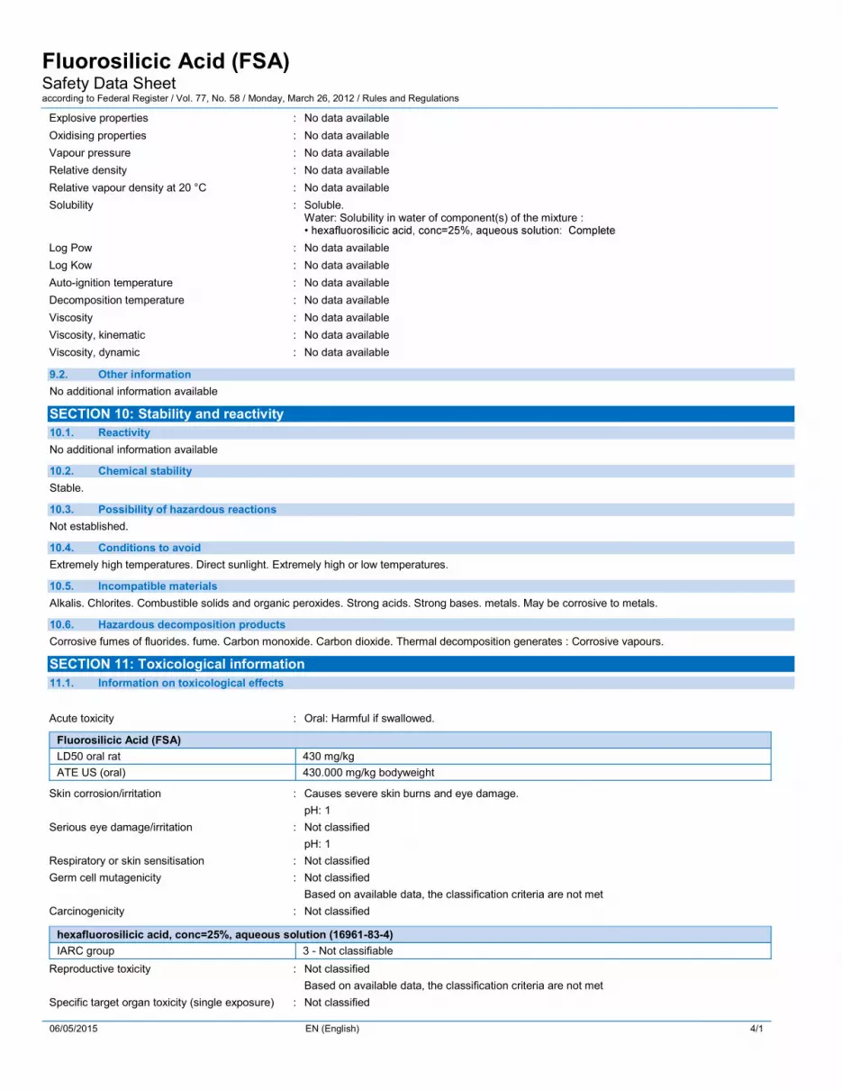
Fluorosilicic Acid (FSA) Safety Data Sheet according to Federal Register Vol 77 No 58 Monday March 26 2012 Rules and Regulations
06052015 EN (English) 71
EU-Regulations No additional information available Classification according to Regulation (EC) No 12722008 [CLP] Not classified
Classification according to Directive 67548EEC [DSD] or 199945EC [DPD] Not classified
National regulations No additional information available 153 US State regulations
hexafluorosilicic acid conc=25 aqueous solution (16961-83-4) US - New Jersey - Right to Know Hazardous Substance List
SECTION 16 Other information Other information None Full text of H-phrases ------ Acute Tox 4 (Oral) Acute toxicity (oral) Category 4 ------ Met Corr 1 Corrosive to metals Category 1 ------ Skin Corr 1A Skin corrosionirritation Category 1A ------ Skin Corr 1B Skin corrosionirritation Category 1B ------ H290 May be corrosive to metals ------ H302 Harmful if swallowed ------ H314 Causes severe skin burns and eye damage
SDS US (GHS HazCom 2012) Disclaimer This information relates to the specific material designated and may not be valid for such material used in combination with any other materials or in any process Such information is to the best of our knowledge and belief accurate and reliable as of the date compiled However no representation warranty or guarantee is made as to its accuracy reliability or completeness NO WARRANTY OF MERCHANTABILITY FITNESS FOR ANY PARTICULAR PURPOSE OR ANY OTHER WARRANTY EXPRESS OR IMPLIED IS MADE CONCERNING THE INFORMATION HEREIN PROVIDED It is the users responsibility to satisfy himself as to the suitability and completeness of such information for his own particular use We do not accept liability for any loss or damage that may occur from the use of this information nor do we offer warranty against patent infringement
APPENDIX C
Equipment Data Sheets and Information
ALL EXTERNAL PIPING MUST BE INDEPENDENTLY SUPPORTEDONLY BASE FITTINGS TO BE LEFT INSTALLED AT TIME OF SHIPMENT PER SII PROCEDUREConsult Snyders Guidelines for Use and Installation prior to delivery Available on-line at httpwwwsnyderindustriestankscomTechnical
357
218
180
335
295
GALLONLITER MARKS 270deg
6 PE THREADEDVENTED CAP W 45 ACCESS
55
0deg
90deg
180deg
270deg
NOTEGALLONAGE MARKS MAY BE REMOVED FOR FITTING PLACEMENT AS NEEDED
PART NO
IGG
DRAWN BYDO NOT SCALE TITLE
ENG ID
1 OF 1
REVISION
ASM TK 35VFT X 18 NECK
SHEETcopy SNYDER INDUSTRIES INC 2019
ALL DIMENSIONS DESIGNS AND INFORMATION ON THIS PRINT MUST BE CONSIDERED PROPRIETARY TO SNYDER INDUSTRIES INC AND MAY NOT BE USED COPIED OR DISTRIBUTED WITHOUT WRITTEN PERMISSION OF AN OFFICER (OR HIS AGENT) OF THE FIRM
STATUS Released
D0042701000110N___01ALL DIMENSIONS ARE IN INCHES NOMINAL amp SUBJECT TO CHANGE WITHOUT NOTICEALL DIMENSIONS ON ROTATIONAL MOLDED PARTS ARE SUBJECT TO A 3 TOLERANCE
(402) 467-5221wwwsnydernetcom
A
Position Statement
Hydrofluosilicic Acid (H2SiF6) le26 Storage Tanks Tank HDLPE 19 SpGr rating (ASTM D-1998 - 600 psi hoop stress design) or HDXLPE 19 SpGr rating (ASTM D-1998 - 600 psi hoop stress design) Note chemical may cause XLPE tank material to discolor Full Drain Option SUMOtrade (Snyder Unitized Molded Outlet) bull Available on single wall vertical tanks 2000 to 12500 gallons bull Encapsulated Hastelloy threaded ring with PVC adapter Double Wall Tanks Mini-Captortrade and CAPTORtrade Containment Systems (CCS) ndash 35 to 12500 gallons bull Primary Tank bull HDLPE 19 SpGr rating (ASTM D-1998 - 600 psi hoop stress design) or bull HDXLPE 19 SpGr rating (ASTM D-1998 - 600 psi hoop stress design) Note chemical may cause XLPE tank material to discolor bull Secondary Containment Tank bull HDLPE 15 SpGr Natural color Fittings Material of Construction bull Fitting PVC (schedule 80) or PP bull Gasket Viton bull Bolt Hastelloy Plumbing to the tank Required use of flexible connections with fittings bull Allows for 4 lateral and vertical expansion and contraction of the tank bull Reduces pump and piping vibration stress on the tank fittings and gaskets bull Flexible connections piping and valves must have structural support independent of tank sidewall and dome Venting Tanks are designed for use at atmospheric pressure Pressure or vacuum situation can cause excessive deformation or damage to the tanks and void warranty Venting equipment should be sized to limit pressure or vacuum in the tank to a maximum of frac12rdquo water column (0018 PSI) If the tank will be pneumatically filled (through tanker discharge) additional pressure relief may be required Hydrofluosilicic acid is a volatile liquid and will start fuming at ambient temperatures These fumes can be corrosive to the environment around the tank For this reason a bolted and sealed (fume tight) manway should be considered for hydrofluosilicic acid tanks and special considerations should be taken for venting the tank to a scrubber system Foundation and Restraints Tanks should be positioned on a smooth concrete or asphalt pad providing adequate support The pad should be clean smooth and level so it fully supports the entire tank bottom with no deflection If a seismic restraint system is used the pad must be adequate in size for anchor plate attachments per the seismic code Temperature Product should not exceed 100 degrees F at delivery or during storage January 1 2013
Data
Replaces same of RevK 22012 1712L 112014
201 Ivyland RoadIvyland PA 18974 USA
TEL (215) 293-0401FAX (215) 293-0445
httpwwwlmipumpscom
Polyprel is a registered trademark of Milton Roy LLC Flourofilm and Liquifram are trademarks of Milton Roy LLCcopy 2005 2012 2014 Milton Roy LLC - All Rights Reserved
Data SheetSeries C
Electronic Metering PumpsConfiguration Data
Model C92 1 - 363SI
Control amp Output Code with Standard Liquid End
Manual ControlSpeed (stroking frequency) and stroke length manually adjustableC10C11C12C13C14
----------
13 GPH25 GPH40 GPH80 GPH20 GPH
(49 lh)(95 lh)
(151 lh)(30 lh)(76 lh)
300 psi
150 psi
100 psi
60 psi
25 psi
(207 Bar)(103 Bar)(69 Bar)(41 Bar)(17 Bar)
Instrument ResponsiveManual ControlManual adjustment features of C1 Series plus switch conversion to external control for automatic systemsC70C71C72C73C74C76C77C78C90C91C92C93C94
--------------------------
13 GPH25 GPH40 GPH80 GPH20 GPH40 GPH10 GPH25 GPH13 GPH25 GPH40 GPH80 GPH20 GPH
(49 lh)(95 lh)
(151 lh)(30 lh)(76 lh)
(151 lh)(38 lh)(95 lh)(49 lh)(95 lh)
(151 lh)(30 lh)(76 lh)
300 psi
150 psi
100 psi
60 psi
25 psi
175 psi
80 psi
30 psi
300 psi
150 psi
100 psi
60 psi
25 psi
(207 Bar)(103 Bar)(69 Bar)(41 Bar)(17 Bar)
(121 Bar)(55 Bar)
(207 Bar)(207 Bar)(103 Bar)(69 Bar)(41 Bar)(17 Bar)
Voltage Code1 ------ 120 VAC US Plug2 ------ 240 VAC US Plug3 ------ 220-240 VAC DIN Plug5 ------ 240-250 VAC UK Plug6 ------ 240-250 VAC AUSTNZ Plug7 ------ 220-240 VAC SWISS Plug
Liquid EndSee next page for complete liquid end specifications and selection
Specifications
Series
Strokes Per Minute
(Adjustable) Min Max
Stroke Length (Adjustable)
Recommended Minimum
Average Input Power Max Speed
ShippingWeight
C10 C70 C90 C11 C71 C91 C12 C72 C92 C13 C73 C93 C14 C74 C94
1 100 10 44 watts 20 lbs (91 kg)
C76 C77 C78
1 100 10 87 watts 28 lbs (127 kg)
Not UL or CUL Approved
Dimensions
Certified to NSFANSI Standard 50
Standard Liquid End Configuration Data amp Materials of ConstructionDrive
AssemblyLiquid
End NoMaterials of Construction
AccessoryTubing amp Connections Discharge SuctionSize Code Head amp Fittings Balls Liquiframtrade Check Valve
C90 C70 -C10 -
498SP 09 PVC Ceramic Fluorofilmtrade PVDFPTFE 4FV Pipe 12 NPT M297 09 316 SS 316 SS Fluorofilmtrade 316 SS Pipe 14 NPT M
C92 -C91 -C72 -C71 -C12 -C11 -
468SIdagger 18 PVCPVC Ceramic Fluorofilmtrade PVDFPolyprelreg 4FV PE 375 OD460SIdagger 18 AcrylicPVC Ceramic Fluorofilmtrade PVDFPolyprelreg 4FV PE 375 OD469SIdagger 18 AcrylicPVDF PTFE Fluorofilmtrade PVDFPolyprelreg 4FV PE 375 OD368SIdagger 18 PVCPVC Ceramic Fluorofilmtrade PVDFPolyprelreg 4FV PE 375 OD362SIdagger 18 PVDFPVDF Ceramic Fluorofilmtrade PVDFPolyprelreg 4FV PE 375 OD363SIdagger 18 PVDFPVDF Ceramic Fluorofilmtrade PVDFPTFE 4FV PE 375 OD465SIdagger 18 Polypropylene Ceramic Fluorofilmtrade PVDFPTFE 4FV PE 375 OD75HV 18 Polypropylene 316 SS Fluorofilmtrade PTFE PE 5 OD Vinyl 938 OD76HV 18 AcrylicPP 316 SS Fluorofilmtrade Vitonreg PE 5 OD Vinyl 938 OD277 18 316 SS 316 SS Fluorofilmtrade 316 SS Pipe 14 NPT M
C93 -C73 -C13 -
312SIdagger 30 PVDFPVDF Ceramic Fluorofilmtrade PVDFPolyprelreg 4FV PE 5 OD313SIdagger 30 PVDFPVDF Ceramic Fluorofilmtrade PVDFPTFE 4FV PE 5 OD318SIdagger 30 PVCPVC Ceramic Fluorofilmtrade PVDFPolyprelreg 4FV PE 5 OD410SIdagger 30 AcrylicPVC Ceramic Fluorofilmtrade PVDFPolyprelreg 4FV PE 5 OD415SIdagger 30 Polypropylene Ceramic Fluorofilmtrade PVDFPTFE 4FV PE 5 OD418SIdagger 30 PVCPVC Ceramic Fluorofilmtrade PVDFPolyprelreg 4FV PE 5 OD419SIdagger 30 AcrylicPVDF PTFE Fluorofilmtrade PVDFPolyprelreg 4FV PE 5 OD20 30 AcrylicPVC Ceramic Fluorofilmtrade Vitonreg PE 5 OD20HV 30 AcrylicPP 316 SS Fluorofilmtrade Vitonreg PE 5 OD Vinyl 938 OD20S 30 AcrylicPVC Ceramic Fluorofilmtrade Vitonreg 4FV PE 5 OD Vinyl 5 OD24 30 PVC Ceramic Fluorofilmtrade PTFE Pipe 12 NPT M25HV 30 Polypropylene 316 SS Fluorofilmtrade PTFE PE 5 OD Vinyl 938 OD26 30 PVC Ceramic Fluorofilmtrade Vitonreg PE 5 OD26S 30 PVC Ceramic Fluorofilmtrade Vitonreg 4FV PE 5 OD27 30 316 SS 316 SS Fluorofilmtrade PTFE Pipe 12 NPT M29 30 UHMW PE Ceramic Fluorofilmtrade Vitonreg PE 5 OD
C94 -C78 -C74 -C14 -
30 60 AcrylicPVC Ceramic Fluorofilmtrade PTFE PE 5 OD Vinyl 5 OD34 60 PVC Ceramic Fluorofilmtrade PTFE Pipe 12 NPT M35P 60 Polypropylene Ceramic Fluorofilmtrade PTFE Pipe 12 NPT M35T 60 Polypropylene Ceramic Fluorofilmtrade PTFE PE 5 OD36 60 PVC Ceramic Fluorofilmtrade PTFE PE 5 OD37 60 316 SS 316 SS Fluorofilmtrade PTFE Pipe 12 NPT M
C76 -468SP 18 PVCPVC Ceramic Fluorofilmtrade PVDFPolyprelreg 4FV Pipe 12 NPT M74S 18 PVC Ceramic Fluorofilmtrade PTFE 4FV Pipe 14 NPT M277 18 316 SS 316 SS Fluorofilmtrade 316 SS Pipe 14 NPT M20 30 AcrylicPVC Ceramic Fluorofilmtrade Vitonreg PE 5 OD
C77 -
20HV 30 AcrylicPP 316 SS Fluorofilmtrade Vitonreg PE 5 OD Vinyl 938 OD20S 30 AcrylicPVC Ceramic Fluorofilmtrade Vitonreg 4FV PE 5 OD Vinyl 5 OD24 30 PVC Ceramic Fluorofilmtrade PTFE Pipe 12 NPT M25HV 30 Polypropylene 316 SS Fluorofilmtrade PTFE PE 5 OD Vinyl 938 OD25P 30 Polypropylene Ceramic Fluorofilmtrade PTFE Pipe 12 NPT M25T 30 Polypropylene Ceramic Fluorofilmtrade PTFE PE 5 OD26S 30 PVC Ceramic Fluorofilmtrade Vitonreg 4FV PE 5 OD27 30 316 SS 316 SS Fluorofilmtrade PTFE Pipe 12 NPT M29 30 UHMW PE Ceramic Fluorofilmtrade Vitonreg PE 5 OD
Output Information with Standard Liquid End
SeriesGallons per Hour
Min MaxLiters per Hour Min Max
mLcc per Minute Min Max
mLcc per Stroke Min Max
Maximum Injection Pressure
C10 C70 C90 0001 13 0005 49 008 82 008 082 300 psi (207 Bar)C11 C71 C91 0003 25 0010 95 016 158 016 158 150 psi (103 Bar)C12 C72 C92 0004 40 0015 151 025 252 025 252 100 psi (69 Bar)C13 C73 C93 0008 80 0030 300 051 505 051 505 60 psi (41 Bar)C14 C74 C94 0020 200 0076 760 126 1262 126 1262 25 psi (17 Bar)C76 0004 40 0015 151 025 252 025 252 175 psi (121 Bar)C77 0010 100 0038 380 063 631 063 631 80psi (55 Bar)C78 0025 250 0095 950 158 1577 158 1577 30 psi (207 Bar)
Minimum output is based on 1 stroke per minute and 10 stroke setting minimum output can be reduced further in external mode Series C9 pumps may be programmed for strokes per hour for lower outputs
AutoPrimeTM Liquid End Configuration Data amp Materials of ConstructionDrive
AssemblyLiquid
End NoSize Code Head amp Fittings Balls Liquiframtrade Check Valve Accessory Tubing amp Connections
C11 C71 C91 C12 C72 C92
D60HI 18 AcrylicPVC Ceramic Fluorofilmtrade PVDFPolyprelreg 4FV PE 375 ODD68HI 18 PVCPVC Ceramic Fluorofilmtrade PVDFPolyprelreg 4FV PE 375 OD
C13 C73 C93 D10HI 30 AcrylicPVC Ceramic Fluorofilmtrade PVDFPolyprelreg 4FV PE 5 ODD18HI 30 PVCPVC Ceramic Fluorofilmtrade PVDFPolyprelreg 4FV PE 5 OD
Output Information ndash AutoPrimeTM Liquid Ends (Liquid end models beginning with ldquoDrdquo)
SeriesMaximum Output Maximum Pressure
GPH Litershr mLcc per minute mLcc per stroke PSI BarC11 C71 C91 23 87 1451 145 150 psi 103C12 C72 C92 38 144 2398 240 100 psi 69C13 C73 C93 78 295 4922 492 60 psi 41
AutoPrimeTM liquid ends have 3 check valves suction on the bottom discharge on the front and autoprime bleed on the top By design a repeatable portion of the process fluid continuously bleeds through the top check valve to be returned to the chemical supply The result is the assurance that any gas in the head is automatically relieved thus eliminating air-binding The maximum output per the tables above is reduced to account for the continuous bleed
See front page for voltage code specifications Plastic heads with tubing connection include frac12 NPT and frac12 BSP
These Liquid Ends are available without a 4FV simply drop the lsquoSrsquo at the end of the Liquid End number to order the model without a 4FV
These liquid ends use 38 diameter balls Pump output may be reduced in some applications
dagger To specify frac14 NPT male change lsquoIrsquo to lsquoPrsquo To specify black UV resistant tubing change lsquoIrsquo to lsquoUrsquo To specify 3FV change lsquoSrsquo to lsquoTrsquo
3FV indicates that the pump is equipped with an LMI Three Function Valve (pressure relief priming aid line drain)
4FV indicates that the pump is equipped with an LMI Four Function Valve This diaphragm type anti-syphonpressure relief valve is installed on the pump head It provides anti-syphon protection and aids priming even under pressure
Fluorofilmtrade is a copolymer of PTFE and PFA Polyprelreg is an elastomeric PTFE copolymer
Polyprel is a registered trademark of Milton Roy LLC
Fluorofilm and Liquifram are trademarks of Milton Roy LLC Vitonreg is a registered trademark of DuPont
Liquid End Sheet
2029A 32010
201 Ivyland RoadIvyland PA 18974 USA
TEL (215) 293-0401FAX (215) 293-0445
httpwwwlmipumpscom
A INSTALLING INJECTION CHECK VALVE (FIGURE 1)1 The Injection Check Valve prevents backflow from a treated line
Install the injection check valve at the location where chemical is being injected into the system
2 Any size Female NPT fitting or pipe tee with a reducing bushing to frac12 Female NPT will accept the injection check valve PTFE tape should only be used on threads that are connected with pipes
3 When installing the Injection Check Valve be sure to position it so that the valve enters the bottom of your pipe in a vertical position Variations 40deg left and right are acceptable
FIGURE 1B CONNECTING DISCHARGE TUBING (FIGURE 2)
Note Cut tubing to length needed for discharge line1 Route tubing from the injection check valve to the metering pump
making sure it does not touch hot or sharp surfaces or is bent so sharply that it kinks
2 Put coupling nut over tubing
3 Position female Ferrule about one inch (25 mm) from end of tubing
4 For frac14 or 6 mm OD tubing cut tubing so that frac14 to sup3∕8 (5-10 mm) protrudes from the female Ferrule For all other tubing push the tube to the bottom of the groove in the male Ferrule Then slide the female Ferrule down into the male Ferrule
5 Firmly hand tighten the coupling nut onto the fitting
FIGURE 2DO NOT USE CLEAR VINYL TUBING ON THE DISCHARGE SIDE OF THE PUMP The pressure created by the pump can rupture vinyl tubing which is only for suction connections on certain liquid endsDO NOT USE PLIERS OR PIPE WRENCH ON COUPLING NUTS OR FITTINGS USE ONLY LMI TUBINGmdashALWAYS use LMI supplied tubing with your pump as the tubing is specifically designed for use with the pump fittings
C CONNECTING SUCTION TUBING1 Cut suction tubing to a length so that the foot valve hangs
just above the bottom of the solution container Maximum recommended vertical suction lift is 5 ft (15m)
2 Follow same procedure in connecting suction tubing to suction valve and foot valve (see B Connecting Discharge Tubing)
LE-4X9SXWhen pumping solutions make certain that all tubing is securely attached to the fittings It is recommended that tubing or pipe lines be shielded to prevent
possible injury in case of rupture or accidental damage Always wear protective clothing and face shield when working on or near your metering pump
Note See parts list for materials of construction
LE-4X9SX
Key Number Description Part
NumberQUANTITY
419SX 459SX 469SX 499SX
10 Pump Head
38578 1
38561 1
38595 1
36159 1
40 O-Ring 48349 5 5 5 5
100 O-Ring 36103 4 4 4 4
190 Liquiframtrade
30916 1
30917 1
31420 1
31419 1
230 Injection Valve Body 48618 1 1 1 1
250 Tubing Straightener 32293 1 1 1 1
260 Foot Valve Coupling 36204 1 1 1 1
270 Foot Valve Strainer 10123 1 1 1 1
350
Tubing Suction amp Discharge 4XXSI ONLY
25636-16 1
10342-16 1 1
10142-16 1
Tubing Suction amp Discharge 4XXSU ONLY
28636-16 1
27342-16 1 1
27142-16 1
354 Tubing 4FV 25636-06 1 1 1 1
440 Bleed Nut 48622 1 1 1 1
602 Suction Check Valve 49093 1
49094 1 1 1
603 Cartridge Valve 37858 4
37859 4 4 4
606 Liquid End Hardware49109 1 1 1
49110 1
607 Foot Valve49105 1
49106 1 1 1
608 Injection Valve 48730 1 1 1 1
613
Tubing Connection Kit 4XXSI and 4XXSU
77382 4
77383 4 4
77384 4
Tubing Connection Kit 4XXSM ONLY
77378 4
77379 4 4
77380 4
615 Check Valve Fitting 48788 3 3 3 3
617 Injection Valve Cartridge 48796 1 1 1 1
620 4FV Assembly48799 1
48754 1 1 1
621 4FV Fitting Assembly 49255 1 1 1 1
LE-4X9SX
REFER TO YOUR ELECTRONIC METERING PUMP INSTRUCTION MANUAL FOR ADDITIONAL INSTRUCTIONS AND PRECAUTIONS You may contact your local LMI Distributor for additional information or visit LMI on the web at wwwlmipumpscom
copy 2010 Milton Roy CompanyndashAll Rights ReservedPrinted in USASpecifications subject to change without notice
D PRIMING WITH 4-FUNCTION VALVE1 Connect pressure relief tubing to the pressure relief port
(FIGURE 3) Route tubing to the solution tank This tubing must not be submerged in the solution
When all precautionary steps have been taken the pump is mounted and the tubing is securely attached you may now start priming the pump2 Turn black knob about sup1∕8 turn CCW to stop point to open
bypass port
3 Set pump at 100 speed and 100 stroke length Start pump When fluid has been flowing through the bypass port tubing for 10-20 seconds the pump is primed
4 Stop pump and return black knob to normal position
Note The pumps are normally self priming if suction lift is less than 5 feet (15 meters) check valves are wet (there is usually water in the pump head when shipped from the factory) and the steps above are followed If the pump does not self prime you can choose one of 2 ways to help prime
1 Remove the 4-function valve and cartridges and slowly pour water or solution into the pump head until it is filled Replace cartridges and 4-function valve and repeat steps above
2 Temporarily improve suction conditions by pumping from a container closer to or above pump
4-FunctionValve
PressureRelief Port
SuctionValve
FIGURE 3Note The head drawing is for reference only
actual appearance may differ
E DEPRESSURIZING THE DISCHARGE LINE AlwAyS wear protective clothing face shield safety glasses and gloves when performing any maintenance or replacement on your pump
When preparing to maintain the pump or any component in the discharge line the 4-function valve is used to depressurize the line Be sure an injection check valve is properly installed and is operating and that all tubing connections on the 4-function valve are secureBe sure your relief tubing is connected to your pressure relief port on the 4-function valve and runs back to your solution drum or tank
1 Turn off the pump2 If any valves have been installed downstream of the pump close them3 If the supply tank for the pump is higher than the pump head fluid
will flow through unless a suction line valve is closed4 Turn the black knob on the 4-function valve about sup1∕8 turn CCW to
its open position This relieves pressure between the pump and the 4-function valve
5 To release line pressure while the black knob is in the open position turn the yellow knob and hold open until fluid flow though the bypass port stops
When tubing connections are loosened chemical will drain from the line Use appropriate safety precautions to avoid contact with chemical
DW = drinking water WW = wastewater municipal PW = pure water power
IW = industrial water E = environmental C = collections FB = food and beverage
FluorideDATA SHEET
CA610Fluoride Analyzer
Features and Benefits
Reliable Full-time Fluoride MonitoringThe CA610 Fluoride Analyzer uses advanced ion-selectiveelectrode (ISE) technology for continuous monitoring offluoride concentration in drinking water effluent Accuracy isensured with precise control of temperature ionic strengthand pH Interferences that can bias measurements arevirtually eliminated with this electrode
Patented Electrode Design with Replaceable TipThe proven ISE technology ofthe electrode is enhanced bya patented design andmanufacturing processThe lanthanum crystal at the tipof the probe is molded into aone-piece monolithic tip that isthreaded for easy removal Thisprevents errors and prematurefailures Electrodes are equipped
with BNC connectors so that they can be independentlychecked with laboratory electrochemical meters
Cost Effective OperationThe electrode of the CA610 analyzer is made with a moldedfluoride crystal tip The working life of the electrode isapproximately one year The specially designed tip of theelectrode should be replaced every six months Reagentconsumption is very low and maintenance is simple
Method of AnalysisThe ISE system of the CA610 analyzer includes a referencepH electrode and a working electrode Three reagents areusedmdashTotal Ionic Strength Adjustment Buffer (TISAB)solution and two fluoride standards The TISAB is used forthe following purposes
bull Ionic strength adjustment lets the electrode respond toconcentration instead of activity
bull pH control ensures fluoride is present in its ionic state
bull Weak complexes formed by certain metals (for examplealuminum) are ldquobroken uprdquo by TISAB and chelatespotential interferents for accurate fluoride measurement
Automatic CalibrationTwo calibration standards are fully enclosed in the CA610analyzerrsquos case The instrument performs a 2-pointcalibration at 05 and 50 mgL fluoride at user-selected timeintervals Automatic calibration intervals can be set for 1 dayto 1 month Readings and calculations of the most recentcalibration is stored in the instrument
ApplicationsDrinking Water PlantsmdashThe CA610 analyzer accuratelymeasures fluoride concentration regardless of the form influoride is addedmdashliquid fluorosilicic acid (H2SiF6) sodiumsilicofluoride (Na2SiF6) or sodium fluoride (NaF)
Remote LocationsmdashBecause it produces only a smallamount of waste and requires minimal maintenance it iswell-suited for remote locations
Industrial LocationsmdashFluoride may occur naturally in wateror it may be the result of fertilizer run-off or discharge fromaluminum factories The CA610 analyzer is an effective toolto monitor either influent or effluent stream
US patent number 5393402
The Hach CA610 Fluoride Analyzer offers economicalanalysis using just 500 mL of reagent per month
Calibration is automatic and sample conditioning is built-inElectrode maintenance is easy and economical
mdashjust replace the tip of the sensor
DW
IW
Range01 to 10 mgL fluoride
Accuracyplusmn10 or plusmn010 ppm whichever is greater
Precisionplusmn7 or plusmn007 ppm whichever is greater
Minimum Detection Limit010 mgL
Cycle Time42 minutes
Sample Conditioning Inlet Pressure1 to 10 psig (use sample restriction deviceto reduce higher pressure samples)
Sample Flow Rate200 to 500 mLminute(200 mLmin minimum required)
Sample Temperature5 to 40degC (41 to 104degF)
Operating Temperature5 to 40degC (41 to 104degF)
Operating Humidity90 at 40degC (90 at 104degF) maximum
Storage Temperature-40 to 60degC (-40 to 140degF)(without reagents)
Sample Inlet Connection14-inch OD polyethylene tubingquick-disconnect fitting
Drain Connection12-inch ID flexible hose
Air Purge (optional)01 cfm instrument quality air at 20 psigmaximum 14-inch OD tubingquick-disconnect fitting
ReagentStandard RequirementsMaximum Reagent Usage 500mLmonth for each of two standardsand one reagent TISAB
Containers High-density polyethylene(3) 500 mL bottles
Containment Reagent bottle containedinside analyzer enclosure ventedexternally
Calibration MethodTwo-point loglinear using 05 mgL and50 mgL fluoride standards
DisplayLCD 3-12-digit measurement readoutand six-character alphanumeric scrollingtext line
AlarmsTwo SPDT relays (unpowered) 5Aresistive load at 240 Vac Suitable forsample set point alarms (high or low)or system warning indicator or systemalarm indicator
Recorder OutputOne isolated recorder output 4ndash20 mA(can be adjusted to 0ndash20 mA) maximumimpedance 500 ohm 130 V isolationfrom earth ground Output span isprogrammable over any portion of themeasurement range
Optional External OutputsHach AquaTrendreg Network Interface
Power Requirement100 to 115230 Vac selectable 90 VAmaximum 5060 Hz 25 Amp fuse
Power ConnectionThree-wire barrier terminal block through12-inch conduit hole in case wirerange 12 to 18 AWG
ComplianceCertificationCE approved ETL listed to UL 1262ETL certified to CSA 222 No 142
EnclosureMolded ABS plastic IP62-rated (dustand drip tight) with gasketed doorlatched Suitable for indoor applications
MountingWall mount
InstallationCategory II
Dimensions343 x 419 x 191 cm(135 x 165 x 75 in)
Shipping Weight113 kg (25 lb)
Specifications
Specifications subject to change without notice
2
1 The fluoride analyzer shall employ anion-selective electrode method ofmeasurement using TISAB reagentand be capable of measuringfluoride every 42 minutes
2 A three digit LCD readout in therange of 01 to 10 mgL shall displaythe results
3 The analyzer shall be designed for30 days unattended operation anduse only 500 mL of each standardevery two months when thecalibration interval is set for 24hours
4 Operating with a lanthanum fluoridecrystal the working electrode shallemploy a removable sensor for easyreplacement
5 The instrument shall be constructedwith a temperature controlled wall-jet flow cell to guide the sampledirectly toward the surface of theelectrode to assure fast wash out
6 The instrument shall provideresolution of 01 mgL repeatabilitywithin plusmn007 mgL and accuracybetter than plusmn10 of reading orplusmn010 mgL whichever is greater
7 The analyzer shall bemicroprocessor-controlled andprovide a 4-20 mA recorder outputas well as 2 alarms
8 Each alarm shall be user-selectablefor sample concentration alarms(high or low) analyzer systemwarnings or analyzer system errors
a The sample concentration alarmsshall be fully adjustable throughthe entire range
b The system warning shall activatefor minor variations in analyzerperformance
c The system alarm shall activatefor major variations in analyzerperformance and it shall shutdown the analyzer until correctiveaction is taken
9 The microprocessor shall provideself-diagnostic functions accessiblethrough an alphanumeric menu-driven keyboard
10 Two SPDT normally opennormallyclosed dry contact relays rated at 5A resistive load at 230 Vac shall beprovided
Engineering Specifications
Dimensions
Air Purge Quick Connect1325 OD Polyethylene Tubing13(Cat No 47438-00)
RelayAlarm13Contact13Connections
Network and134-20 mA13Connections
Power13Connections
409
13(1
0388
mm
)26
613
(675
5mm
)
561
(142
48m
m)
40213(10217 mm)
43813(11112 mm)
15613(3968 mm)
106 (2699 mm)
1788
(45
405m
m)M
ount
ing
Patte
rn
Four 14 Mounting Bolts
750 (19050 mm)13Mounting Pattern
Chlorine
mgL
Alarm
microgL
Chlorine
mgL
Alarm
microgL
Sample Inlet Quick Connect1325 OD Polyethylene Tubing13(Cat No 47438-00)
50 ID Drain Tube Sample
Overflow Drain13Recommended13
50 ID Tubing
1521 (38630 mm)
006 (159 mm)13Clearance13For Vents
70613(17939 mm)
199513(50678 mm)
R 1489(37818 mm)
The CA610 analyzer is designed to be wall-mounted with four 14-inch screws Adequate clearance must be left at the sides andbottom of the case for plumbing and electrical connections The sample inlet connection is 14-inch quick-disconnect fitting andthe drain connection is 12-inch ID flexible hose Electrical connections are inside the instrument case Holes for three 12-inchconduit fittings are provided
3
11 Recorder outputs shall be 4-20 mARecorder span minimum andmaximum values shall be operatorprogrammable at the menu-drivenkeypad over the entire operatingrange
12 The fluoride analyzer shall be housedin an IP62-rated ABS plasticenclosure designed for wallmounting
13 The enclosure shall have two clearpolycarbonate windows for viewingthe measurement readout andreagent levels
14 Power requirements shall be 100 to115230 Vac 5060 Hz switchselectable 90 VA maximum
15 The fluoride analyzer shall be HachCompany model CA610 FluorideAnalyzer
Engineering Specifications continued
LIT4540 Rev 2F12 Printed in USAcopyHach Company 2012 All rights reservedIn the interest of improving and updating its equipment Hach Company reserves the right to alter specifications to equipment at any time
For current price informationtechnical support and orderingassistance contact the Hachoffice or distributor servingyour area
In the United States contact
HACH COMPANY World HeadquartersPO Box 389Loveland Colorado 80539-0389USATelephone 800-227-4224Fax 970-669-2932E-mail ordershachcomwwwhachcom
US exporters and customers in CanadaLatin America sub-Saharan Africa Asiaand AustraliaNew Zealand contact
HACH COMPANY World HeadquartersPO Box 389Loveland Colorado 80539-0389USATelephone 970-669-3050Fax 970-461-3939E-mail intlhachcomwwwhachcom
In Europe the Middle East andMediterranean Africa contact
HACH LANGE GmbHWillstaumltterstraszlige 11D-40549 DuumlsseldorfGERMANYTel +49 (0) 211 5288-0Fax +49 (0) 211 5288-143E-mail infohach-langedewwwhach-langecom
At Hach itrsquos about learningfrom our customers andproviding the right answersItrsquos more than ensuring thequality of watermdashitrsquos aboutensuring the quality of lifeWhen it comes to the thingsthat touch our lives
Keep it pure
Make it simple
Be right
4
CA610 Fluoride Analyzers are shipped with one-month supply of regentsmaintenance kit wall mounting kit and manual Power cord is ordered separately
5740001 Model CA610 Fluoride Analyzer
5740002 Model CA610 Fluoride Analyzer with AquaTrend Network
For European customers
5740011 CA610 unit Reagents Set Installation amp Maintenance KitsEU Basic User Manual
5740005 CA610 unit Installation amp Maintenance Kits EU Basic User Manualndash NO REAGENTS
Accessories
5448800 Power Cord 115V 10A 183 m (6 ft) North American plug
5448900 Power Cord 230V 10A 183 m (6 ft) Continental European plug
4643600 Flow Meter with 14-inch OD tubing
Replacement Items
5742100 Maintenance Kit (See Note 1)
5744400 Pump Tubing Set
5742700 Instrument Tubing Set
5744800 Electrode Kit (See Note 2)
5528100 Electrode pH reference
5527700 Electrode Body ISE
5745100 Electrode Tip fluoride lanthanum crystal 2pkg
Additional Reagents
One unit of each standard solution is sufficient for two months operation at a24-hour calibration interval One unit of Reagent 1 TISAB is sufficient for a 30-dayoperating period
2816900 Reagent Set CA610 fluoride analyzer (includes reagent 1 TISABstandard 1 and standard 2)
2812811 Reagent 1 TISAB 473 mL
2743811 Standard 1 05 mgL as F 473 mL
2797111 Standard 2 50 mgL as F 473 mL
4450126 Inner Fill Solution fluoride 50 mL
Ordering Information
NOTES
1 Kit includes instrument and pump tubing sets (1 year supply) replacement filterscreen and spare fittings
2 Kit includes ISE and pH electrodes electrode tips syringe and inner fill solution
Submersible progress cav ity pump with grinder cutter dev ice f orliquidscontaining solids or f ibres
Head
450 38mm
252 Eff
05
101520
25303540455055606570758085
9095
100105110115120125130135140145150155
160165170175180185190195200
205210215220225[ft]
70 80 90 100 110 120 130 140 150 [US gpm]
Impeller
Frequency
Motor
Rated v oltage
-
Rated power
Rated speed
Number of poles
Rated current
230 V60 Hz
17 hp
4
1730 rpm
81 A
MF 3068 HT 1~ 450
Motor
1~
Suction Flange Diameter
OIL
c a leS
D r a w n
R e g n o
D a t eb yC h e c k e d
b y
DRAW I NGAUTO CAD
D e n o m in a t io n
Di m e n s i o n a l d rwgM F 3 0 6 8 1 7 5 HT
1-11 NPT
To t a l in c l s t a n d( lbs)Weight
85
7074900 2
5399
080829NK
Oslash 1
M6 3x
263 4233 8
11 14
5 12
127 8
3 8
4 38
23 8
43 8
43 8
4 38
Oslash6 78
60Acircdeg
21
Impeller diameter 38 mmNumber of blades 1
M3068175 13-10-4BB-W 17hp
Stator v ariant 3
Phases
Starting current 37 A
Technical specification
Note Picture might not correspond to the current configuration
Power f actor
Motor ef f iciency
11 Load34 Load12 Load
11 Load34 Load12 Load
099099098
685 638 544
1 inchCurve ISO
F - Free standing Semi permanent WetInstallation
Configuration
Impeller material
General
Discharge Flange Diameter 1 inch
Water pure
Standard
Last updateCreated on
382019
Created byProject IDProject
Head
Pump Efficiency
Overall Eff iciency
Pow er input P1
Shaft pow er P2
450 38mm
252 Eff
450 38mm
450 38mm
450 38mm (P2)
450 38mm (P1)
0102030405060708090
100110120130140150160170180190200210220[ft]
0
4
8
12
16
20
[]
00
04
08
12
16
20
[hp]
70 75 80 85 90 95 100 105 110 115 120 125 130 135 140 145 150 155 [US gpm]
70 75 80 85 90 95 100 105 110 115 120 125 130 135 140 145 150 155 [US gpm]
Motor
60 Hz
Phases 1~
230 VNumber of poles 4
Rated power 17 hp
Starting currentRated current 81 A
Rated speed 1730 rpm
M3068175 13-10-4BB-W 17hp
Stator variantNumber of blades 1
Power factor
MF 3068 HT 1~ 450
Suction Flange Diameter
Performance curve
Pump
Impeller diameter 112
Motor
Rated voltage
37 A
Motor efficiency
11 Load34 Load12 Load
11 Load34 Load12 Load
Frequency3
099
685
099098
638 544
25 mm
Curve ISO
Discharge Flange Diameter 1 inch
Water pure
Last updateCreated on
382019
Created byProject IDProject
APPENDIX D
Material Compatibility Chart for Hydrofluorosilicic Acid
Home Product Support Chemical Compatibility Database
ABS plastic NA
Acetal (Delrinreg) B - Good
Aluminum D - Poor
Brass NA
Bronze B - Good
Buna N (Nitrile) A - Excellent
Carbon graphite A - Excellent
Carbon Steel D - Poor
Carpenter 20 D - Poor
Cast iron B - Good
Ceramic Al203 NA
Ceramic magnet NA
ChemRaz (FFKM) A - Excellent
Copper B - Good
Ratings - Chemical Effect
A - Excellent
B - Good Minor Effect slight corrosion
or discoloration
C - Fair Moderate Effect not
recommended for continuous use
Softening or loss of strength and
swelling may occur
D - Severe Effect Not recommended for
any use
E - Information not available
Explanation of Footnotes
1-Satisfactory to 72oF (22oC)
2-Satisfactory to 120oF (48oC)
Chemical Compatibility Database
SHARE PRINTCHEMICAL SELECTED Hydro uosilicic Acid 20
MATERIAL COMPATIBILITY
2
CPVC A - Excellent
EPDM A - Excellent
Epoxy C - Fair
Fluorocarbon (FKM) A - Excellent
Hastelloy-Creg B - Good
Hypalonreg B - Good
Hytrelreg NA
Kalrez A - Excellent
Kel-Freg A - Excellent
LDPE B - Good
Natural rubber A - Excellent
Neoprene B - Good
NORYLreg B - Good
Nylon D - Poor
Polycarbonate NA
Polyetherether Ketone (PEEK) NA
Polypropylene A - Excellent
Polyurethane D - Poor
PPS (Rytonreg) A - Excellent
PTFE A - Excellent
1
2
2
WARNINGThe information in this chart has been supplied to Cole-Parmer by
other reputable sources and is to be used ONLY as a guide in
selecting equipment for appropriate chemical compatibility Before
permanent installation test the equipment with the chemicals and
under the speci c conditions of your application
Ratings of chemical behavior listed in this chart apply at a 48-hr
exposure period Cole-Parmer has no knowledge of possible effects
beyond this period Cole-Parmer does not warrant (neither express
nor implied) that the information in this chart is accurate or
complete or that any material is suitable for any purpose
DANGERVariations in chemical behavior during handling due to factors such
as temperature pressure and concentrations can cause equipment
to fail even though it passed an initial test
SERIOUS INJURY MAY RESULTUse suitable guards andor personal protections when handling
chemicals
PVC A - Excellent
PVDF (Kynarreg) A - Excellent
Silicone D - Poor
stainless steel - 304 C - Fair
stainless steel - 316 B - Good
Titanium D - Poor
Tygonreg A - Excellent
Vitonreg A - Excellent
2
2
1
Shop our Popular Chemicals
Sodium Hydroxide Sulfuric Acid Hydrochloric Acid
Isopropanol
Cole-Parmer | 625 East Bunker Ct Vernon Hills IL 60061 United States
Telephone 1-800-323-4340 1-847-549-7600 | Fax 1-847-247-2929 | Email salescoleparmercom
copy 2017 Cole-Parmer Instrument Company LLC All Rights Reserved
APPENDIX E
State Environmental Quality Review Act Type II Action Declaration
Diana L Quast Town Clerk ofYot Registrar of Vital Statistics
dquastyorktownnyorg o Telephone (914) 962- 5722 x 208
1788
ti Fax (914) 962 6591
TOWN OF YORKTOWN
363 Underhill Avenue PO Box 703
Yorktown Heights NY 10598
This is a resolution adopted by the Town Board of the Town of Yorktown at its regular meetingheld on Tuesday March 12 2019
WHEREAS
1 This notice is issued pursuant to Part 617 of the implementing regulations pertaining to Article8 of the State Environmental Quality Review Act ( SEQRA) of the Environmental
Conservation Law
2 The Town of Yorktown desires to comply with SEQRA regulations adopted pursuant theretoby the Department ofEnvironmental Conservation of the State ofNew York being 6 NYCRRPart 617 as amended( the Regulations) with respect to the Proposed Action
3 Proposed Action The Town is working on a project to install chemical feed equipment andchemical storage for the purposes of fluoridating the drinking water supply to the YorktownConsolidated Water District The new equipment and storage systems will be located within
an existing Town structure located on Catherine Street within property limits owned by theNew York City Department of Environmental Protection (NYCDEP) The use and operation
of the structure on NYCDEP-owned lands are covered under a land-use permit previouslygranted to the Town of Yorktown
4 Under SEQRA regulations a Type II Action may be declared where ( 2) replacement
rehabilitation or reconstruction of a structure or facility in kind on the same site includingupgrading buildings to meet building energy or fire codes unless such action meets or exceedsany of the thresholds in section 6174 of this Part
5 The Project is not subject to further review under SEQRA since this is a Type II Action
under 6 NYCRR sect 617 5( c)( 25)
NOW THEREFORE BE IT RESOLVED that the Town Board of the Town of Yorktown
declares that the Project constitutes a Type II Action under 6 NYCRR sect 6175( c)( 25) and that
no further action under the SEQR Act and the Regulations is required and BE IT FURTHER
RESOLVED that this resolution shall take effect immediately
z QctDiana L Quast RMC CMC
Town Clerk
Date March 13 2019
To Ilan D Gilbert Town Suprvisor
cc Richard Abbate Town AttorneyMichael Quinn Town Engineer
file
Arcadis of New York Inc
44 South Broadway
9th Floor
White Plains New York 10601
Tel 914 694 2100
Fax 914 694 9286
wwwarcadiscom
- 2_D004270PDF
-
- Sheet1
-
- Drawing View1
- Drawing View2
-

LE-4X9SX
REFER TO YOUR ELECTRONIC METERING PUMP INSTRUCTION MANUAL FOR ADDITIONAL INSTRUCTIONS AND PRECAUTIONS You may contact your local LMI Distributor for additional information or visit LMI on the web at wwwlmipumpscom
copy 2010 Milton Roy CompanyndashAll Rights ReservedPrinted in USASpecifications subject to change without notice
D PRIMING WITH 4-FUNCTION VALVE1 Connect pressure relief tubing to the pressure relief port
(FIGURE 3) Route tubing to the solution tank This tubing must not be submerged in the solution
When all precautionary steps have been taken the pump is mounted and the tubing is securely attached you may now start priming the pump2 Turn black knob about sup1∕8 turn CCW to stop point to open
bypass port
3 Set pump at 100 speed and 100 stroke length Start pump When fluid has been flowing through the bypass port tubing for 10-20 seconds the pump is primed
4 Stop pump and return black knob to normal position
Note The pumps are normally self priming if suction lift is less than 5 feet (15 meters) check valves are wet (there is usually water in the pump head when shipped from the factory) and the steps above are followed If the pump does not self prime you can choose one of 2 ways to help prime
1 Remove the 4-function valve and cartridges and slowly pour water or solution into the pump head until it is filled Replace cartridges and 4-function valve and repeat steps above
2 Temporarily improve suction conditions by pumping from a container closer to or above pump
4-FunctionValve
PressureRelief Port
SuctionValve
FIGURE 3Note The head drawing is for reference only
actual appearance may differ
E DEPRESSURIZING THE DISCHARGE LINE AlwAyS wear protective clothing face shield safety glasses and gloves when performing any maintenance or replacement on your pump
When preparing to maintain the pump or any component in the discharge line the 4-function valve is used to depressurize the line Be sure an injection check valve is properly installed and is operating and that all tubing connections on the 4-function valve are secureBe sure your relief tubing is connected to your pressure relief port on the 4-function valve and runs back to your solution drum or tank
1 Turn off the pump2 If any valves have been installed downstream of the pump close them3 If the supply tank for the pump is higher than the pump head fluid
will flow through unless a suction line valve is closed4 Turn the black knob on the 4-function valve about sup1∕8 turn CCW to
its open position This relieves pressure between the pump and the 4-function valve
5 To release line pressure while the black knob is in the open position turn the yellow knob and hold open until fluid flow though the bypass port stops
When tubing connections are loosened chemical will drain from the line Use appropriate safety precautions to avoid contact with chemical
DW = drinking water WW = wastewater municipal PW = pure water power
IW = industrial water E = environmental C = collections FB = food and beverage
FluorideDATA SHEET
CA610Fluoride Analyzer
Features and Benefits
Reliable Full-time Fluoride MonitoringThe CA610 Fluoride Analyzer uses advanced ion-selectiveelectrode (ISE) technology for continuous monitoring offluoride concentration in drinking water effluent Accuracy isensured with precise control of temperature ionic strengthand pH Interferences that can bias measurements arevirtually eliminated with this electrode
Patented Electrode Design with Replaceable TipThe proven ISE technology ofthe electrode is enhanced bya patented design andmanufacturing processThe lanthanum crystal at the tipof the probe is molded into aone-piece monolithic tip that isthreaded for easy removal Thisprevents errors and prematurefailures Electrodes are equipped
with BNC connectors so that they can be independentlychecked with laboratory electrochemical meters
Cost Effective OperationThe electrode of the CA610 analyzer is made with a moldedfluoride crystal tip The working life of the electrode isapproximately one year The specially designed tip of theelectrode should be replaced every six months Reagentconsumption is very low and maintenance is simple
Method of AnalysisThe ISE system of the CA610 analyzer includes a referencepH electrode and a working electrode Three reagents areusedmdashTotal Ionic Strength Adjustment Buffer (TISAB)solution and two fluoride standards The TISAB is used forthe following purposes
bull Ionic strength adjustment lets the electrode respond toconcentration instead of activity
bull pH control ensures fluoride is present in its ionic state
bull Weak complexes formed by certain metals (for examplealuminum) are ldquobroken uprdquo by TISAB and chelatespotential interferents for accurate fluoride measurement
Automatic CalibrationTwo calibration standards are fully enclosed in the CA610analyzerrsquos case The instrument performs a 2-pointcalibration at 05 and 50 mgL fluoride at user-selected timeintervals Automatic calibration intervals can be set for 1 dayto 1 month Readings and calculations of the most recentcalibration is stored in the instrument
ApplicationsDrinking Water PlantsmdashThe CA610 analyzer accuratelymeasures fluoride concentration regardless of the form influoride is addedmdashliquid fluorosilicic acid (H2SiF6) sodiumsilicofluoride (Na2SiF6) or sodium fluoride (NaF)
Remote LocationsmdashBecause it produces only a smallamount of waste and requires minimal maintenance it iswell-suited for remote locations
Industrial LocationsmdashFluoride may occur naturally in wateror it may be the result of fertilizer run-off or discharge fromaluminum factories The CA610 analyzer is an effective toolto monitor either influent or effluent stream
US patent number 5393402
The Hach CA610 Fluoride Analyzer offers economicalanalysis using just 500 mL of reagent per month
Calibration is automatic and sample conditioning is built-inElectrode maintenance is easy and economical
mdashjust replace the tip of the sensor
DW
IW
Range01 to 10 mgL fluoride
Accuracyplusmn10 or plusmn010 ppm whichever is greater
Precisionplusmn7 or plusmn007 ppm whichever is greater
Minimum Detection Limit010 mgL
Cycle Time42 minutes
Sample Conditioning Inlet Pressure1 to 10 psig (use sample restriction deviceto reduce higher pressure samples)
Sample Flow Rate200 to 500 mLminute(200 mLmin minimum required)
Sample Temperature5 to 40degC (41 to 104degF)
Operating Temperature5 to 40degC (41 to 104degF)
Operating Humidity90 at 40degC (90 at 104degF) maximum
Storage Temperature-40 to 60degC (-40 to 140degF)(without reagents)
Sample Inlet Connection14-inch OD polyethylene tubingquick-disconnect fitting
Drain Connection12-inch ID flexible hose
Air Purge (optional)01 cfm instrument quality air at 20 psigmaximum 14-inch OD tubingquick-disconnect fitting
ReagentStandard RequirementsMaximum Reagent Usage 500mLmonth for each of two standardsand one reagent TISAB
Containers High-density polyethylene(3) 500 mL bottles
Containment Reagent bottle containedinside analyzer enclosure ventedexternally
Calibration MethodTwo-point loglinear using 05 mgL and50 mgL fluoride standards
DisplayLCD 3-12-digit measurement readoutand six-character alphanumeric scrollingtext line
AlarmsTwo SPDT relays (unpowered) 5Aresistive load at 240 Vac Suitable forsample set point alarms (high or low)or system warning indicator or systemalarm indicator
Recorder OutputOne isolated recorder output 4ndash20 mA(can be adjusted to 0ndash20 mA) maximumimpedance 500 ohm 130 V isolationfrom earth ground Output span isprogrammable over any portion of themeasurement range
Optional External OutputsHach AquaTrendreg Network Interface
Power Requirement100 to 115230 Vac selectable 90 VAmaximum 5060 Hz 25 Amp fuse
Power ConnectionThree-wire barrier terminal block through12-inch conduit hole in case wirerange 12 to 18 AWG
ComplianceCertificationCE approved ETL listed to UL 1262ETL certified to CSA 222 No 142
EnclosureMolded ABS plastic IP62-rated (dustand drip tight) with gasketed doorlatched Suitable for indoor applications
MountingWall mount
InstallationCategory II
Dimensions343 x 419 x 191 cm(135 x 165 x 75 in)
Shipping Weight113 kg (25 lb)
Specifications
Specifications subject to change without notice
2
1 The fluoride analyzer shall employ anion-selective electrode method ofmeasurement using TISAB reagentand be capable of measuringfluoride every 42 minutes
2 A three digit LCD readout in therange of 01 to 10 mgL shall displaythe results
3 The analyzer shall be designed for30 days unattended operation anduse only 500 mL of each standardevery two months when thecalibration interval is set for 24hours
4 Operating with a lanthanum fluoridecrystal the working electrode shallemploy a removable sensor for easyreplacement
5 The instrument shall be constructedwith a temperature controlled wall-jet flow cell to guide the sampledirectly toward the surface of theelectrode to assure fast wash out
6 The instrument shall provideresolution of 01 mgL repeatabilitywithin plusmn007 mgL and accuracybetter than plusmn10 of reading orplusmn010 mgL whichever is greater
7 The analyzer shall bemicroprocessor-controlled andprovide a 4-20 mA recorder outputas well as 2 alarms
8 Each alarm shall be user-selectablefor sample concentration alarms(high or low) analyzer systemwarnings or analyzer system errors
a The sample concentration alarmsshall be fully adjustable throughthe entire range
b The system warning shall activatefor minor variations in analyzerperformance
c The system alarm shall activatefor major variations in analyzerperformance and it shall shutdown the analyzer until correctiveaction is taken
9 The microprocessor shall provideself-diagnostic functions accessiblethrough an alphanumeric menu-driven keyboard
10 Two SPDT normally opennormallyclosed dry contact relays rated at 5A resistive load at 230 Vac shall beprovided
Engineering Specifications
Dimensions
Air Purge Quick Connect1325 OD Polyethylene Tubing13(Cat No 47438-00)
RelayAlarm13Contact13Connections
Network and134-20 mA13Connections
Power13Connections
409
13(1
0388
mm
)26
613
(675
5mm
)
561
(142
48m
m)
40213(10217 mm)
43813(11112 mm)
15613(3968 mm)
106 (2699 mm)
1788
(45
405m
m)M
ount
ing
Patte
rn
Four 14 Mounting Bolts
750 (19050 mm)13Mounting Pattern
Chlorine
mgL
Alarm
microgL
Chlorine
mgL
Alarm
microgL
Sample Inlet Quick Connect1325 OD Polyethylene Tubing13(Cat No 47438-00)
50 ID Drain Tube Sample
Overflow Drain13Recommended13
50 ID Tubing
1521 (38630 mm)
006 (159 mm)13Clearance13For Vents
70613(17939 mm)
199513(50678 mm)
R 1489(37818 mm)
The CA610 analyzer is designed to be wall-mounted with four 14-inch screws Adequate clearance must be left at the sides andbottom of the case for plumbing and electrical connections The sample inlet connection is 14-inch quick-disconnect fitting andthe drain connection is 12-inch ID flexible hose Electrical connections are inside the instrument case Holes for three 12-inchconduit fittings are provided
3
11 Recorder outputs shall be 4-20 mARecorder span minimum andmaximum values shall be operatorprogrammable at the menu-drivenkeypad over the entire operatingrange
12 The fluoride analyzer shall be housedin an IP62-rated ABS plasticenclosure designed for wallmounting
13 The enclosure shall have two clearpolycarbonate windows for viewingthe measurement readout andreagent levels
14 Power requirements shall be 100 to115230 Vac 5060 Hz switchselectable 90 VA maximum
15 The fluoride analyzer shall be HachCompany model CA610 FluorideAnalyzer
Engineering Specifications continued
LIT4540 Rev 2F12 Printed in USAcopyHach Company 2012 All rights reservedIn the interest of improving and updating its equipment Hach Company reserves the right to alter specifications to equipment at any time
For current price informationtechnical support and orderingassistance contact the Hachoffice or distributor servingyour area
In the United States contact
HACH COMPANY World HeadquartersPO Box 389Loveland Colorado 80539-0389USATelephone 800-227-4224Fax 970-669-2932E-mail ordershachcomwwwhachcom
US exporters and customers in CanadaLatin America sub-Saharan Africa Asiaand AustraliaNew Zealand contact
HACH COMPANY World HeadquartersPO Box 389Loveland Colorado 80539-0389USATelephone 970-669-3050Fax 970-461-3939E-mail intlhachcomwwwhachcom
In Europe the Middle East andMediterranean Africa contact
HACH LANGE GmbHWillstaumltterstraszlige 11D-40549 DuumlsseldorfGERMANYTel +49 (0) 211 5288-0Fax +49 (0) 211 5288-143E-mail infohach-langedewwwhach-langecom
At Hach itrsquos about learningfrom our customers andproviding the right answersItrsquos more than ensuring thequality of watermdashitrsquos aboutensuring the quality of lifeWhen it comes to the thingsthat touch our lives
Keep it pure
Make it simple
Be right
4
CA610 Fluoride Analyzers are shipped with one-month supply of regentsmaintenance kit wall mounting kit and manual Power cord is ordered separately
5740001 Model CA610 Fluoride Analyzer
5740002 Model CA610 Fluoride Analyzer with AquaTrend Network
For European customers
5740011 CA610 unit Reagents Set Installation amp Maintenance KitsEU Basic User Manual
5740005 CA610 unit Installation amp Maintenance Kits EU Basic User Manualndash NO REAGENTS
Accessories
5448800 Power Cord 115V 10A 183 m (6 ft) North American plug
5448900 Power Cord 230V 10A 183 m (6 ft) Continental European plug
4643600 Flow Meter with 14-inch OD tubing
Replacement Items
5742100 Maintenance Kit (See Note 1)
5744400 Pump Tubing Set
5742700 Instrument Tubing Set
5744800 Electrode Kit (See Note 2)
5528100 Electrode pH reference
5527700 Electrode Body ISE
5745100 Electrode Tip fluoride lanthanum crystal 2pkg
Additional Reagents
One unit of each standard solution is sufficient for two months operation at a24-hour calibration interval One unit of Reagent 1 TISAB is sufficient for a 30-dayoperating period
2816900 Reagent Set CA610 fluoride analyzer (includes reagent 1 TISABstandard 1 and standard 2)
2812811 Reagent 1 TISAB 473 mL
2743811 Standard 1 05 mgL as F 473 mL
2797111 Standard 2 50 mgL as F 473 mL
4450126 Inner Fill Solution fluoride 50 mL
Ordering Information
NOTES
1 Kit includes instrument and pump tubing sets (1 year supply) replacement filterscreen and spare fittings
2 Kit includes ISE and pH electrodes electrode tips syringe and inner fill solution
Submersible progress cav ity pump with grinder cutter dev ice f orliquidscontaining solids or f ibres
Head
450 38mm
252 Eff
05
101520
25303540455055606570758085
9095
100105110115120125130135140145150155
160165170175180185190195200
205210215220225[ft]
70 80 90 100 110 120 130 140 150 [US gpm]
Impeller
Frequency
Motor
Rated v oltage
-
Rated power
Rated speed
Number of poles
Rated current
230 V60 Hz
17 hp
4
1730 rpm
81 A
MF 3068 HT 1~ 450
Motor
1~
Suction Flange Diameter
OIL
c a leS
D r a w n
R e g n o
D a t eb yC h e c k e d
b y
DRAW I NGAUTO CAD
D e n o m in a t io n
Di m e n s i o n a l d rwgM F 3 0 6 8 1 7 5 HT
1-11 NPT
To t a l in c l s t a n d( lbs)Weight
85
7074900 2
5399
080829NK
Oslash 1
M6 3x
263 4233 8
11 14
5 12
127 8
3 8
4 38
23 8
43 8
43 8
4 38
Oslash6 78
60Acircdeg
21
Impeller diameter 38 mmNumber of blades 1
M3068175 13-10-4BB-W 17hp
Stator v ariant 3
Phases
Starting current 37 A
Technical specification
Note Picture might not correspond to the current configuration
Power f actor
Motor ef f iciency
11 Load34 Load12 Load
11 Load34 Load12 Load
099099098
685 638 544
1 inchCurve ISO
F - Free standing Semi permanent WetInstallation
Configuration
Impeller material
General
Discharge Flange Diameter 1 inch
Water pure
Standard
Last updateCreated on
382019
Created byProject IDProject
Head
Pump Efficiency
Overall Eff iciency
Pow er input P1
Shaft pow er P2
450 38mm
252 Eff
450 38mm
450 38mm
450 38mm (P2)
450 38mm (P1)
0102030405060708090
100110120130140150160170180190200210220[ft]
0
4
8
12
16
20
[]
00
04
08
12
16
20
[hp]
70 75 80 85 90 95 100 105 110 115 120 125 130 135 140 145 150 155 [US gpm]
70 75 80 85 90 95 100 105 110 115 120 125 130 135 140 145 150 155 [US gpm]
Motor
60 Hz
Phases 1~
230 VNumber of poles 4
Rated power 17 hp
Starting currentRated current 81 A
Rated speed 1730 rpm
M3068175 13-10-4BB-W 17hp
Stator variantNumber of blades 1
Power factor
MF 3068 HT 1~ 450
Suction Flange Diameter
Performance curve
Pump
Impeller diameter 112
Motor
Rated voltage
37 A
Motor efficiency
11 Load34 Load12 Load
11 Load34 Load12 Load
Frequency3
099
685
099098
638 544
25 mm
Curve ISO
Discharge Flange Diameter 1 inch
Water pure
Last updateCreated on
382019
Created byProject IDProject
APPENDIX D
Material Compatibility Chart for Hydrofluorosilicic Acid
Home Product Support Chemical Compatibility Database
ABS plastic NA
Acetal (Delrinreg) B - Good
Aluminum D - Poor
Brass NA
Bronze B - Good
Buna N (Nitrile) A - Excellent
Carbon graphite A - Excellent
Carbon Steel D - Poor
Carpenter 20 D - Poor
Cast iron B - Good
Ceramic Al203 NA
Ceramic magnet NA
ChemRaz (FFKM) A - Excellent
Copper B - Good
Ratings - Chemical Effect
A - Excellent
B - Good Minor Effect slight corrosion
or discoloration
C - Fair Moderate Effect not
recommended for continuous use
Softening or loss of strength and
swelling may occur
D - Severe Effect Not recommended for
any use
E - Information not available
Explanation of Footnotes
1-Satisfactory to 72oF (22oC)
2-Satisfactory to 120oF (48oC)
Chemical Compatibility Database
SHARE PRINTCHEMICAL SELECTED Hydro uosilicic Acid 20
MATERIAL COMPATIBILITY
2
CPVC A - Excellent
EPDM A - Excellent
Epoxy C - Fair
Fluorocarbon (FKM) A - Excellent
Hastelloy-Creg B - Good
Hypalonreg B - Good
Hytrelreg NA
Kalrez A - Excellent
Kel-Freg A - Excellent
LDPE B - Good
Natural rubber A - Excellent
Neoprene B - Good
NORYLreg B - Good
Nylon D - Poor
Polycarbonate NA
Polyetherether Ketone (PEEK) NA
Polypropylene A - Excellent
Polyurethane D - Poor
PPS (Rytonreg) A - Excellent
PTFE A - Excellent
1
2
2
WARNINGThe information in this chart has been supplied to Cole-Parmer by
other reputable sources and is to be used ONLY as a guide in
selecting equipment for appropriate chemical compatibility Before
permanent installation test the equipment with the chemicals and
under the speci c conditions of your application
Ratings of chemical behavior listed in this chart apply at a 48-hr
exposure period Cole-Parmer has no knowledge of possible effects
beyond this period Cole-Parmer does not warrant (neither express
nor implied) that the information in this chart is accurate or
complete or that any material is suitable for any purpose
DANGERVariations in chemical behavior during handling due to factors such
as temperature pressure and concentrations can cause equipment
to fail even though it passed an initial test
SERIOUS INJURY MAY RESULTUse suitable guards andor personal protections when handling
chemicals
PVC A - Excellent
PVDF (Kynarreg) A - Excellent
Silicone D - Poor
stainless steel - 304 C - Fair
stainless steel - 316 B - Good
Titanium D - Poor
Tygonreg A - Excellent
Vitonreg A - Excellent
2
2
1
Shop our Popular Chemicals
Sodium Hydroxide Sulfuric Acid Hydrochloric Acid
Isopropanol
Cole-Parmer | 625 East Bunker Ct Vernon Hills IL 60061 United States
Telephone 1-800-323-4340 1-847-549-7600 | Fax 1-847-247-2929 | Email salescoleparmercom
copy 2017 Cole-Parmer Instrument Company LLC All Rights Reserved
APPENDIX E
State Environmental Quality Review Act Type II Action Declaration
Diana L Quast Town Clerk ofYot Registrar of Vital Statistics
dquastyorktownnyorg o Telephone (914) 962- 5722 x 208
1788
ti Fax (914) 962 6591
TOWN OF YORKTOWN
363 Underhill Avenue PO Box 703
Yorktown Heights NY 10598
This is a resolution adopted by the Town Board of the Town of Yorktown at its regular meetingheld on Tuesday March 12 2019
WHEREAS
1 This notice is issued pursuant to Part 617 of the implementing regulations pertaining to Article8 of the State Environmental Quality Review Act ( SEQRA) of the Environmental
Conservation Law
2 The Town of Yorktown desires to comply with SEQRA regulations adopted pursuant theretoby the Department ofEnvironmental Conservation of the State ofNew York being 6 NYCRRPart 617 as amended( the Regulations) with respect to the Proposed Action
3 Proposed Action The Town is working on a project to install chemical feed equipment andchemical storage for the purposes of fluoridating the drinking water supply to the YorktownConsolidated Water District The new equipment and storage systems will be located within
an existing Town structure located on Catherine Street within property limits owned by theNew York City Department of Environmental Protection (NYCDEP) The use and operation
of the structure on NYCDEP-owned lands are covered under a land-use permit previouslygranted to the Town of Yorktown
4 Under SEQRA regulations a Type II Action may be declared where ( 2) replacement
rehabilitation or reconstruction of a structure or facility in kind on the same site includingupgrading buildings to meet building energy or fire codes unless such action meets or exceedsany of the thresholds in section 6174 of this Part
5 The Project is not subject to further review under SEQRA since this is a Type II Action
under 6 NYCRR sect 617 5( c)( 25)
NOW THEREFORE BE IT RESOLVED that the Town Board of the Town of Yorktown
declares that the Project constitutes a Type II Action under 6 NYCRR sect 6175( c)( 25) and that
no further action under the SEQR Act and the Regulations is required and BE IT FURTHER
RESOLVED that this resolution shall take effect immediately
z QctDiana L Quast RMC CMC
Town Clerk
Date March 13 2019
To Ilan D Gilbert Town Suprvisor
cc Richard Abbate Town AttorneyMichael Quinn Town Engineer
file
Arcadis of New York Inc
44 South Broadway
9th Floor
White Plains New York 10601
Tel 914 694 2100
Fax 914 694 9286
wwwarcadiscom
- 2_D004270PDF
-
- Sheet1
-
- Drawing View1
- Drawing View2
-
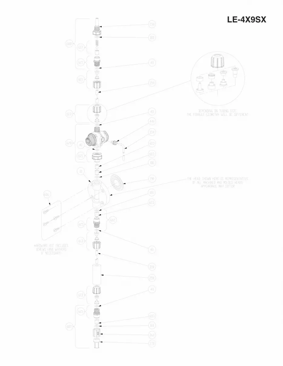
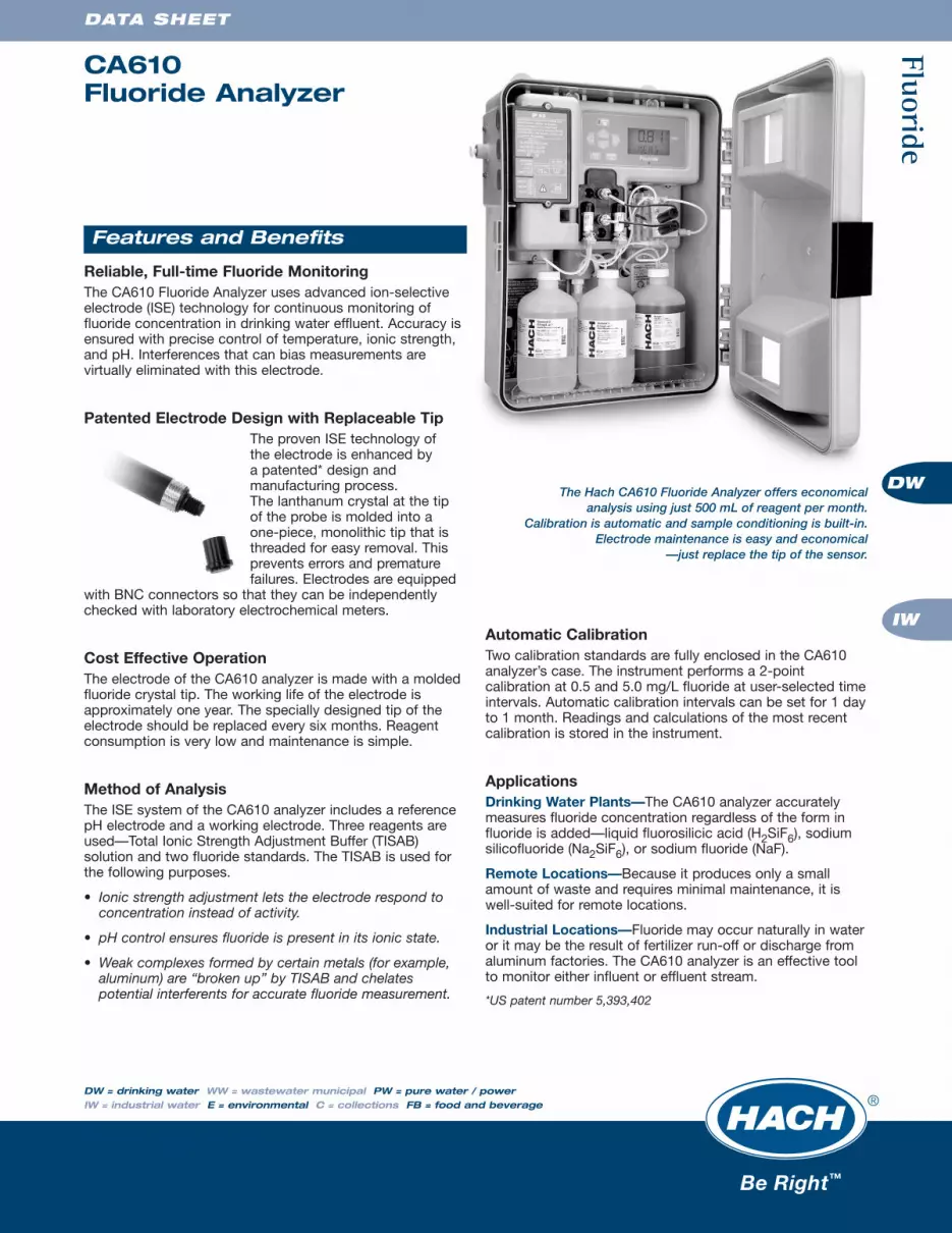
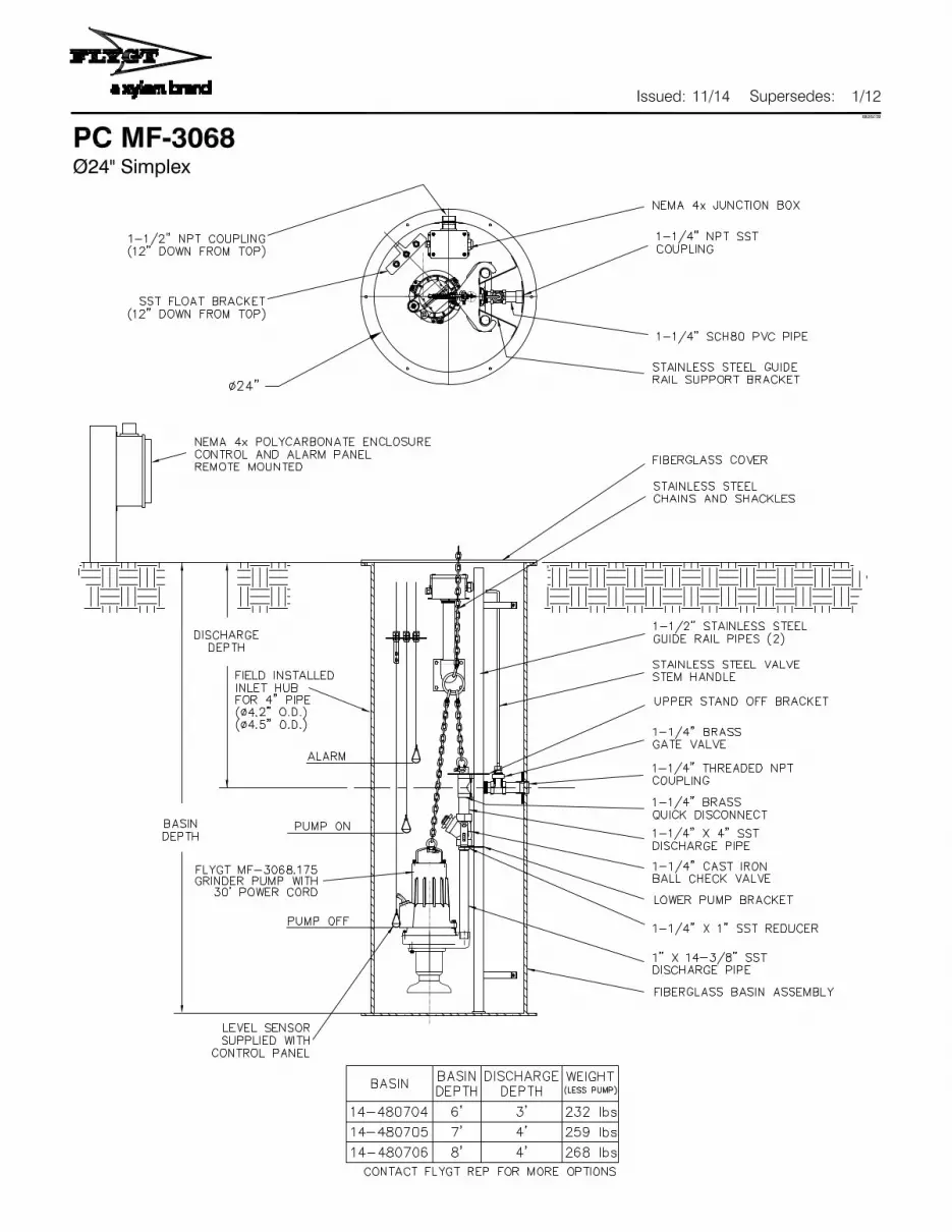
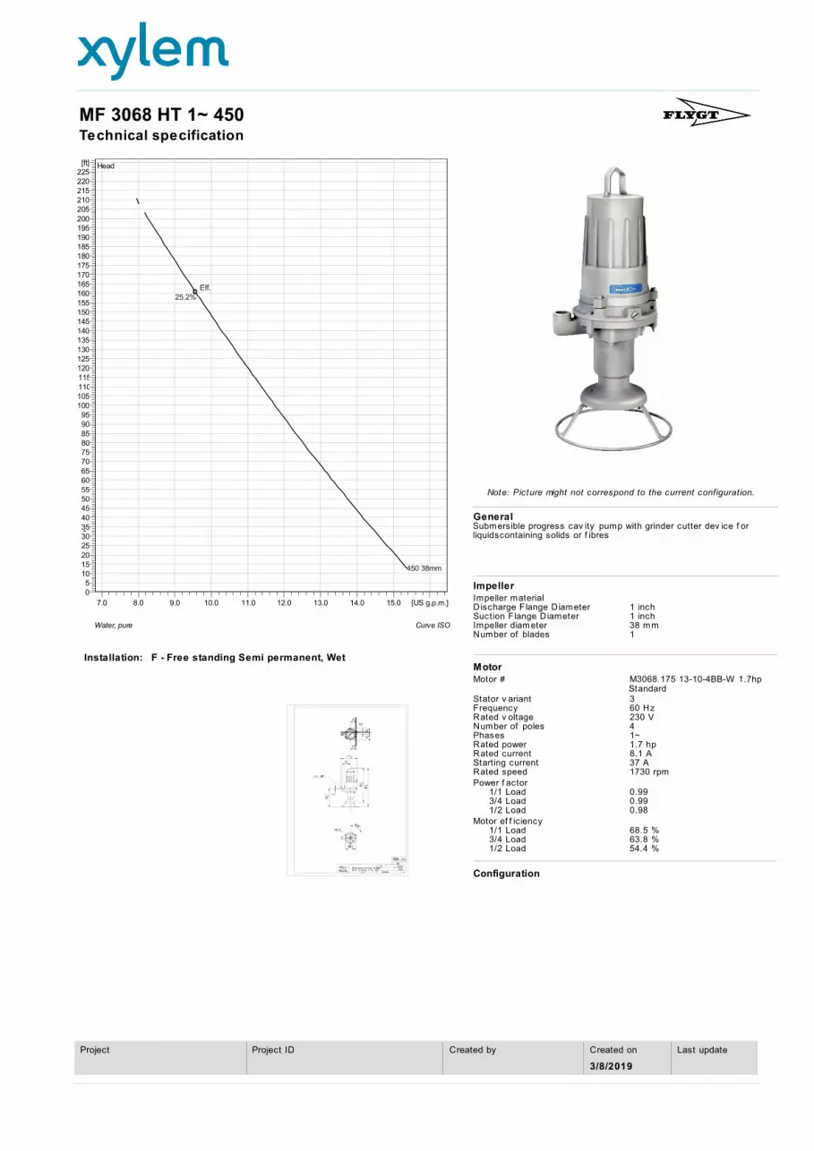

Arcadis of New York Inc
44 South Broadway
9th Floor
White Plains New York 10601
Tel 914 694 2100
Fax 914 694 9286
wwwarcadiscom
- 2_D004270PDF
-
- Sheet1
-
- Drawing View1
- Drawing View2
-