dl-301/dl-302/dl-303 - icpdas-europe
TRANSCRIPT
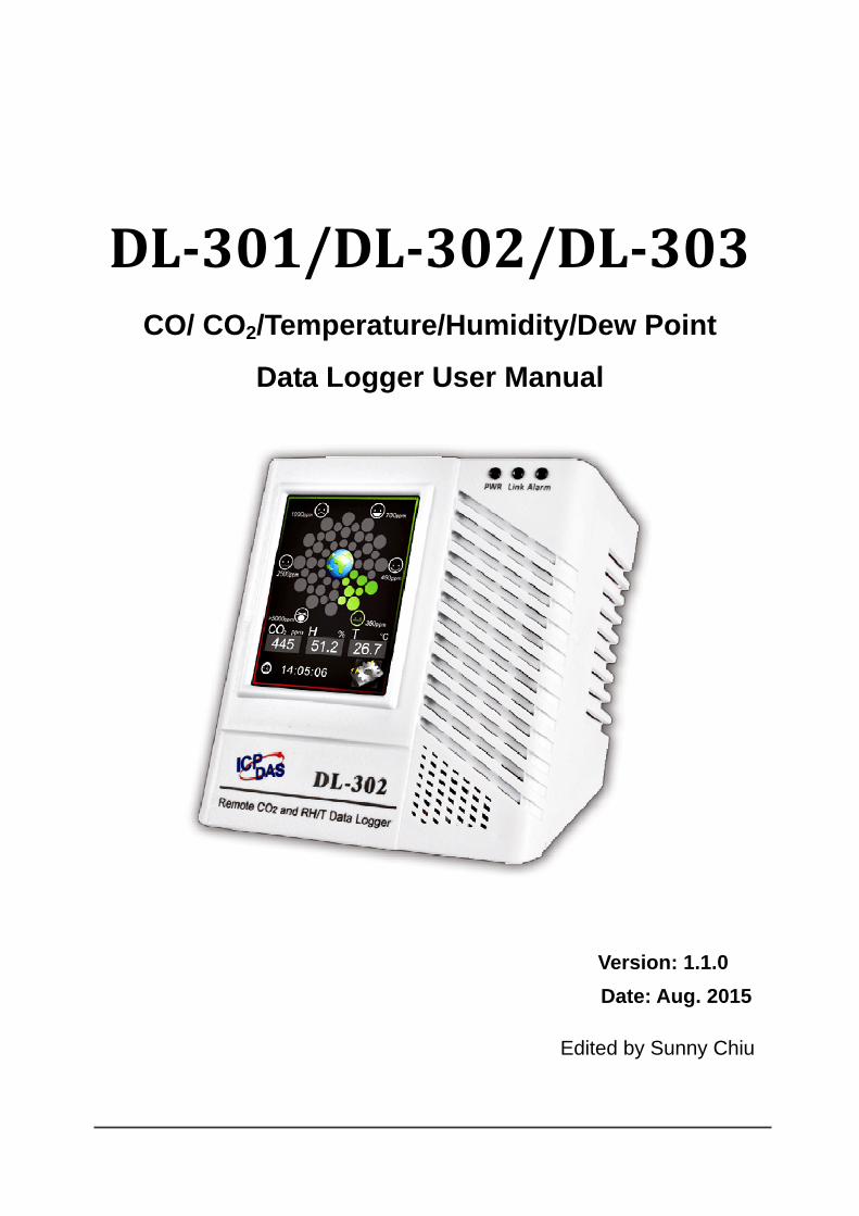
DL301/DL302/DL303 CO/ CO2/Temperature/Humidity/Dew Point
Data Logger User Manual Version: 1.1.0 Date: Aug. 2015 Edited by Sunny Chiu

Warranty All products manufactured by ICP DAS are warranted against defective materials for a period of one year from the date of delivery to the original purchaser. Warning ICP DAS assumes no liability for damages consequent to the use of this product. ICP DAS reserves the right to change this manual at any time without notice. The information furnished by ICP DAS is believed to be accurate and reliable. However, no responsibility is assumed by ICP DAS for its use, nor for any infringements of patents or other rights of third parties resulting from its use. Copyright Copyright © 2015 by ICP DAS. All rights are reserved. Contact Us If you have any questions, please feel free to contact us via email at: [email protected] [email protected]

Contents 1. Introduction ................................................................................................................1 2. Hardware ...................................................................................................................6
2.1 Specifications....................................................................................................6 2.2 Appearance.......................................................................................................8 2.3 Dimensions (unit: mm) ....................................................................................12 2.4 Cabling for Power and Network ......................................................................13
3. Configuration via Touch Screen ...............................................................................15 3.1 Alarm &Temperature .......................................................................................17 3.2 DO & LCD.......................................................................................................19 3.3 Date & Time ....................................................................................................21 3.4 Data Logger ....................................................................................................22 3.5 Ethernet ..........................................................................................................23 3.6 RS-485............................................................................................................25
4. Configuration via Web Browser................................................................................26 4.1 Search the DL-300 logger...............................................................................26 4.2 Logging into the DL-300..................................................................................27 4.3 Home ..............................................................................................................28 4.4 Network...........................................................................................................30 4.5 MQTT..............................................................................................................32 4.6 I/O Settings .....................................................................................................36 4.7 Message .........................................................................................................41 4.8 Accessible IP...................................................................................................43 4.9 Change Password...........................................................................................44 4.10 Logout...........................................................................................................46
5. Configuration via RS-485 .........................................................................................47 6. Monitoring via Mobile Devices .................................................................................56 7. Utility to Get/Manage Data Log ................................................................................57 8. FAQ..........................................................................................................................68
Q1: What is ABC (Automatic Baseline Correction)?..............................................68 Q2: Why I need to enable the ABC? .....................................................................68 Q3: Does the DL-302/DL-303 enable the ABC as the factory default setting?......68 Q4: What to do when the ABC is no work? ...........................................................68 Q5: How to set the touch password? ....................................................................69 Q6: How to cancel the touch password?...............................................................70 Q7: How to set the Accessible IP?........................................................................70

Q8: How to delete the Accessible IP settings?......................................................71 Q9: How to clear the data logged in a DL-300 module? .......................................71 Q10: How to calibrate the touch screen? ..............................................................72 Q11: How to download firmware into a DL-300 module? ......................................73 Q12: How to display message on the DL-300 with Modbus command? ...............75
Appendix A: DCON Command Sets.............................................................................78 A-1. DL-301 DCON Command Sets .....................................................................78 A-2. DL-302 DCON Command Sets .....................................................................84 A-3. DL-303 DCON Command Sets .....................................................................90
Appendix B: ModbusMasterToolPC .............................................................................96 Appendix C: Modbus Address Table ..........................................................................100
C-1. DL-301 Modbus Address Mappings (Base 1)..............................................100 C-2. DL-302 Modbus Address Mappings (Base 1)..............................................107 C-3. DL-303 Modbus Address Mappings (Base 1).............................................. 113
Revision History .........................................................................................................120

DL-300 Data Logger User Manual Version 1.1.0 Aug. 2015 - 1 -
1. Introduction The DL-300 series is a data logger designed to accurately measure and record the concentration of carbon monoxide/carbon dioxide in the atmosphere, temperature and humidity. It can display the real-time data and log the concentration of CO, CO2, temperature and humidity with a date and time stamp for downloading later. The logging interval is programmable and up to 450,000 data points can be stored in built-in, non-volatile memory.
Users can configure a DL-300 module from the touch screen or via a regular web browser when the module and PC are both connected to the same switch or Ethernet segment. With free iAir app on users’ iOS or Android phones or tablets, they can get the real data over a Wi-Fi network anytime and anywhere. The free DL300 Utility is a convenient software tool to get the real-time data, show run charts and download data from multiple devices running on Windows platform.
The DL-300 series contains RS-485, Ethernet and PoE communication interfaces, the most common communication interfaces in industrial network. It supports a wide operating temperature range of 0 ~ 50°C and easy to be installed by placing on a horizontal surface such as a desktop, mounted on a DIN-rail, or mounted on the wall.

DL-300 Data Logger User Manual Version 1.1.0 Aug. 2015 - 2 -
Characteristics
Simultaneous display for CO/CO2 level, temperature, humidity and dew point
CO measurement range: 0 ~ 1000 ppm
CO2 measurement range: 0 ~ 9999 ppm
Nondispersive Infrared (NDIR) sensor with Automatic Baseline Correction algorithm for CO2 measurement
Able to store up to 450,000 records
2.8" LCD touch screen with resolution of 240 x 320 x 16
Supports displaying multilingual messages
Remote control with a standard web-browser
iAir App for iOS or Android mobile devices to monitor on-line data
Supports the DCON, Modbus RTU, Modbus TCP and MQTT protocols
One relay output for turning on/off alarm light/buzzer or IAQ control devices
Includes RS-485/Ethernet/PoE communication interfaces
Desktop, DIN-Rail or wall mounting
Wide operating temperature range of 0 ~ 50°C
RoHS compliant with no Halogen

DL-300 Data Logger User Manual Version 1.1.0 Aug. 2015 - 3 -
Features
NDIR Sensor NDIR (Non-Dispersion Infrared) is based on one of the natural properties of CO2 molecules: CO2 molecules absorb light at a specific wavelength of 4.26 µm. This wavelength is in the infrared (IR) range. High concentrations of CO2 molecules absorb more light than low concentrations. NDIR sensor can detect fast and accurately in a wide range of CO2 concentration.
Built-in Web Server
With the built-in Web server, users can easily log in to the DL-300 module via a standard web browser to monitor the data and configure the settings without install any software in the terminal.
Get Real-time Data Anywhere and Anytime iAir App for iOS or Android Phones or Tablets is free and easy to install, it can obtain the real-time data from DL-300 modules over a Wi-Fi network anytime and anywhere. The iAir App can link to the DL-300 modules by specifying IP addresses or by searching all the modules connected to the same Ethernet segment.

DL-300 Data Logger User Manual Version 1.1.0 Aug. 2015 - 4 -
Data Logging Software The DL300 Utility can be used to configure the modules, monitor real-time data and show the run chart, log alarm events, group DL-300 modules so that the status of distribution groups can be viewed and managed. The utility also allows the log data to be downloaded and exported to a .CSV file that can then be imported into any industry-standard software or spread sheet for analysis.
Easy integration with SCADA software Modbus is one of the most popular protocols used in the industrial world. Supporting traditional serial protocols of RS-485 and Ethernet protocols allow the DL-300 series well-integrated into the HMI/SCADA systems.
Alarm DL-300 series allows users to set high alarm level for CO/CO2/ Temperature/Humidity/Dew Point and low alarm level for Temperature/Humidity/Dew Point, and to enable/disable the alarm functions. An Alarm LED indicator on the front of the DL-300 module will flash when an alarm event is activated, and a relay output related to all alarm events can be use to tap an alarm light/sound or control the IAQ devices such as ventilators, air cleaners, and filters. Beep alarm is available when the CO/CO2 high level alarm occurs. .

DL-300 Data Logger User Manual Version 1.1.0 Aug. 2015 - 5 -
Screen Lock Users can secure a DL-300 module by setting a screen lock via the web interface. If the lock is set, users need to enter the correct password when they would like to configure the DL-300 module.
Automatic Baseline Correction The built-in ABC algorithm makes the CO2 sensor on the DL-302 and DL-303 maintenance-free. In most indoor applications, the carbon dioxide level drops to nearly outside air - 400 ppm, and then the ABC algorithm constantly keeps track of the lowest reading and slowly corrects it as the expected fresh air value of 400 ppm.
The ABC algorithm can not apply for the places where are no periods that the CO2 concentration drops to background level such as greenhouses, hospitals, 24-hour operation factories or stories. The ABC function needs be disabled where the spaces the CO2 concentration may be elevated at all times.
Easy Wiring Support for RS-485, Ethernet and Power over Ethernet (PoE) interfaces for users to choose the appropriate one to meet the field requirements.
Power over Ethernet (PoE) The DL-300 series features true IEEE802.3af-compliant (classification, Class 1) PoE technology that allows both power and data to be carried over a single Ethernet cable. PoE provides a unified power system, as well as backup provisions for critical building functions, without any additional cables, outlets or connections. It can reduce the power supply wiring and maintenance costs, and improve system scalability.
Support for MQTT protocol
MQTT is a protocol designed for the efficient exchange of real-time data with sensor and mobile devices. It runs over TCP/IP and is in widest use on the "machine-to-machine" (M2M) and "Internet of Things" applications today
Smartphone
MQTT Broker
DL-301
DL-302
Mobile Tablet
Subscriber

DL-300 Data Logger User Manual Version 1.1.0 Aug. 2015 - 6 -
Display Multilingual Messages on Screen
2. Hardware
2.1 Specifications
Model DL-301 DL-302 DL-303
CO Measurement
Range 0 to 1000 ppm (Electrochemical) -
0 to 1000 ppm (Electrochemical)
Resolution 1 ppm - 1 ppm
Accuracy ±5% of measured value - ±5% of measured
value Response Time 30 seconds - 30 seconds
Warm-up Time 60 seconds - 60 seconds
CO2 Measurement
Range - 0 ~ 9999 ppm
Resolution - 1 ppm
Accuracy - ±30 ppm ±3%
Response Time - 20 seconds
Warm-up Time - 60 seconds
The display message function supports multilingual character sets in UTF-8 encoding. Users can remotely display pre-saved messages or dynamic messages by Modbus commands, or send a dynamic message through the web interface. A message is limited to six lines maximum and 14 half-width characters or 7 full-width characters maximum each line.

DL-300 Data Logger User Manual Version 1.1.0 Aug. 2015 - 7 -
Temperature Measurement Range -10 ~ +50°C Resolution 0.1°C Accuracy ±0.6°C
Relative Humidity Measurement Range 0 ~ 100% RH, Non-condensing Resolution 0.1% RH, Non-condensing Accuracy ±5% RH, Non-condensing
Dew Point Range Calculated using temperature and relative humidity Resolution 0.1°C
System
CO Alarm Yes - Yes CO2 Alarm - Yes Yes Real Time Clock Yes Data Logger Yes, 450,000 Records
Alarm Relay Output Form A×1, SPST. 30 VDC @ 16 A or 250 VAC @ 16 A 30 VDC @ 16 A or 250 VAC @ 16 A
Network Interface RS-485/Ethernet/PoE
Main Machine Interface
Touch Screen 2.8” TFT (Resolution: 240 x 320 x 16), Defective Pixels <= 3
Backlight Life 20,000 hours Brightness 160 cd/m2
Electrical Powered via Terminal Block +12 ~ +48 VDC
Powered via PoE IEEE 802.3af, Class 1 (require a PoE switch or injector)
PoE 1.84 W (Max.) 2.65 W (Max.) 2.83 W (Max.) Power Consumption
Non-PoE 1.74 W (Max.) 2.14 W (Max.) 2.24 W (Max.)
Mechanical Dimensions (W x L x H) 106 mm x 114 mm x 56 mm Installation Desktop, DIN-Rail or Wall Mounting
Environment Operating Temperature 0 ~ +50°C Storage Temperature -30 ~ +75°C Humidity 10 ~ 90% RH, Non-condensing

DL-300 Data Logger User Manual Version 1.1.0 Aug. 2015 - 8 -
2.2 Appearance
2.8” LCD Touch Screen
LED Indicators: Power Ethernet Link Alarm
DIP Switch
USB (only used to update Firmware)
PoE/Non-PoE Ethernet Port
Holes for Wall-mounting
Buzzer
Connectors: Power Frame Ground RS-485 Alarm Relay Output
DIN-Rail Mounting
DL-300 Data Logger User Manual Version 1.1.0 Aug. 2015 - 9 -
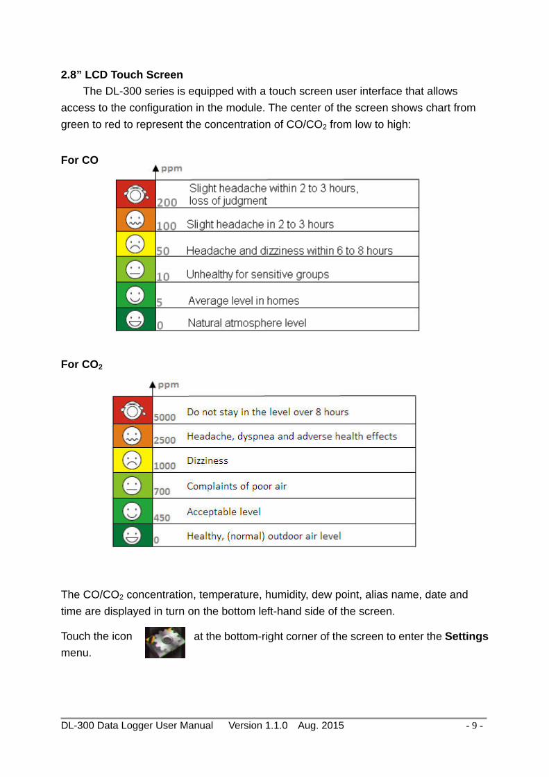
2.8” LCD Touch Screen The DL-300 series is equipped with a touch screen user interface that allows access to the configuration in the module. The center of the screen shows chart from green to red to represent the concentration of CO/CO2 from low to high:
For CO
For CO2
The CO/CO2 concentration, temperature, humidity, dew point, alias name, date and time are displayed in turn on the bottom left-hand side of the screen.
Touch the icon at the bottom-right corner of the screen to enter the Settings menu.

DL-300 Data Logger User Manual Version 1.1.0 Aug. 2015 - 10 -
LED Indicators The three LED indicators from left to right are:
PWR: green for normal operation. The PWR LED indicator flashes when the module is searched in the list of iAir App and the icon is tapped for easier checking which module is the one in the list.
Link: green for the Ethernet linked. Alarm: red for alarm condition.
DIP Switch USB The USB port is used to update firmware only. PoE/ non-PoE Ethernet port The Ethernet port can be used to connect to a PoE switch or a non-PoE switch.
The functions are printed on the top beside the SW1 DIP switch. All the 4 dip switches need be turned to the off position for normal operation.
1. Reserved 2. FW Update: ON for updating firmware. 3. Touch Calib: ON for touch screen calibration. 4. INIT: ON for using the factory default settings for communication

DL-300 Data Logger User Manual Version 1.1.0 Aug. 2015 - 11 -
Connector for Power/ Frame Ground / RS-485/ Alarm Relay Output Relay Output Wire Connection
The Push-in connector can easily connect and detach solid wires or wires with wire-end ferrules without using tools. Just push in the solid wire to lock it and press the white button to release the wire.
Wire requirement: Stripping length: 8 ~ 10 mm 0.20 - 1.5 mm² (IEC) / 28 - 16 AWG (UL)

DL-300 Data Logger User Manual Version 1.1.0 Aug. 2015 - 12 -
2.3 Dimensions (unit: mm)

DL-300 Data Logger User Manual Version 1.1.0 Aug. 2015 - 13 -
2.4 Cabling for Power and Network
Note
Do not install the DL-300 module near a vent, a ventilation fan or a door where the air flows faster. Also avoid putting the module on a desktop below the nose and mouth to prevent incorrect measurement.
Avoid installing in locations where the temperature is below 0°C or above 50°C. Avoid installing in locations near a strong electromagnetic field.
For connecting with a PC or a Android device
The DL-300 logger can connect to a PoE network without a power source or connect to a non-PoE network. When using the Search function in iAir App on Android or iOS mobile devices, mobile devices need to connect to the same subnet that the DL-300 connected to over Wi-Fi. Similarly to using the Search function in DL-300 Utility running on Windows, the module and the host PC need to connect on the same subnet, too.

DL-300 Data Logger User Manual Version 1.1.0 Aug. 2015 - 14 -
The iAir App and DL-300 Utility search the logger by broadcast, therefore only the devices on the same subnet can be searched out. It means that the host PC, Android devices and the logger must have the same broadcast address. The broadcast address for an IPv4 device can be obtained by performing a bitwise OR operation between the bit complement of the subnet mask and the IP address for a device. In other words, take the device's IP address, and set to '1' any bit positions which hold a '0' in the subnet mask.
For example, in an entire IPv4 subnet, the host PC or the Android device uses the private IP address space 172.16.0.0/12 and subnet mask address 255.240.0.0, the broadcast address is 172.16.0.0 | 0.15.255.255 = 172.31.255.255. Only the loggers which have the same broadcast address could be searched out in the iAir App or DL-300 Utility. Please contact with your network administrator to make sure the DL-300 logger is connected to the same sub-network that your Android devices or PC is connected to. For connecting with PC via RS-485 network
The DL-300 logger can connect to the PC through a RS-485 network with power input requirement of +12 ~ +48 VDC.
RS485 Network
DL302
Power Supply
USB/RS485Converter
I7561 DL302

DL-300 Data Logger User Manual Version 1.1.0 Aug. 2015 - 15 -
3. Configuration via Touch Screen Home screen of DL-300 logger: CO/CO2
According to the concentration of CO/CO2 in the air from low to high, the illustration at the center of screen shows from green to red:

DL-300 Data Logger User Manual Version 1.1.0 Aug. 2015 - 16 -
Touch the icon in the bottom-right corner of screen to enter the Settings menu About:Information about the unit
The information including: - Model Name: DL-301/DL-302/DL-303 - Alias Name: The user-defined name for identifying a DL-300 more easily. - Firmware Version: The data and version for the firmware - IP Address: The IP address for the logger - MAC Address: The MAC address for the logger
Back:Back to Home Screen

DL-300 Data Logger User Manual Version 1.1.0 Aug. 2015 - 17 -
Note The DL-300 logger comes with a resistive touch screen which senses input from
contact with nearly any object such as finger, stylus/pen or hand with gloves.
Touching the < or > symbol beside a value can increase or decrease the value by one. Long-pressing the < or > symbol beside a value can change the value more quickly. Similarly touching the << or >> symbol beside a value can increase or decrease the value by 100.
3.1 Alarm &Temperature
Tap the Alarm &Temperature item in the Settings menu to enter the sub-menu.

DL-300 Data Logger User Manual Version 1.1.0 Aug. 2015 - 18 -
Temperature Scale:
- °C (default) - °F
CO2 ABC: (for DL-302/DL-303 only)
- Disabled: disables the CO2 ABC function (default) - Enabled: enables the CO2 ABC function
CO/CO2 Alarm Mode:
- Disabled: disables the alarm function (default)
- Momentary: When the CO/CO2 level goes higher than the value set in CO/CO2 Alarm
Limit, the Alarm LED lights red, the buzzer beeps as the setting in Beep on Alarm(s), and the relay outputs ON signal which can be used to turn on the user’s alarm device.
When the CO/CO2 level turns to lower than the value set in CO/CO2 Alarm Limit, the Alarm LED turns off; the relay outputs OFF signal.
- Latched: When the CO/CO2 level goes higher than the value set in CO/CO2 Alarm
Limit, the Alarm LED lights red, the buzzer beeps as the setting in Beep on Alarm, and the relay outputs ON signal which can be used to turn on the user’s alarm device.
When the CO/CO2 level turns to lower than the value set in CO/CO2 Alarm Limit, the Alarm LED keeps red and the relay keeps ON till the alarm status is cleared manually.
CO/CO2 Alarm Limit: Sets the high alarm level limit of CO/CO2 concentration
- CO Alarm Limit Default: 50 ppm Range: 0 ~ 1000 ppm
- CO2 Alarm Limit Default: 1000 ppm Range: 0 ~ 10000 ppm
Beep on Alarm: the alarm keeps beeping with setting for Beep on Alarm(s) in seconds.The beep alarm is for High CO/CO2 alarm only.
- Continuously: continues beeping without stop (default) - Disabled: disables the beep alarm - 1~250: sets the time for beep alarm in seconds.

DL-300 Data Logger User Manual Version 1.1.0 Aug. 2015 - 19 -
Other Alarm Settings: Displays the alarm mode and high/low alarm limit settings for Humidity, Temperature and Dew Point. Parameters on this page can be set through web interface or Modbus/DCON commands.
- Alarm: Alarm mode, disabled by default. - Low: low alarm limit settings - High: high alarm limit settings
Save: Saves the modification and returns to the Settings menu. All the changes take effect immediately after saving changes. Skip: Returns to the Settings menu without saving any changes.
3.2 DO & LCD
Tap the DO & LCD item in the Settings menu to enter the sub-menu.

DL-300 Data Logger User Manual Version 1.1.0 Aug. 2015 - 20 -
DO0 Power On Value: Sets the relay output status when the DL-300 is powered on.
It is invalid when the any one alarm mode for CO/CO2/Humidity/Temperature/Dew Point in Alarm &Temperature sub-menu is not disabled.
Default: Off
DO0 Safe Value: Sets the status of relay output when the Ethernet HWDT or RS-485 HWDT timeout occurs. The default setting is that a user needs to clear the timeout status and then he can control the DO again; alternatively it can be set to control the DO again without clear the timeout status by Modbus command. (Address: 00260)
It is invalid when the any one alarm mode for CO/CO2/Humidity/Temperature/Dew Point in Alarm &Temperature sub-menu is not disabled.
Default: Off Ethernet HWDT: Enables/Disables the Ethernet Host Watchdog Timer.
The Ethernet HWDT timeout will occur if the host does not visit the DL-300 through the Ethernet network in the time period of setting for Ethernet HWDT, then the DO0 will output the safe value.
The DO0 save value is invalid when the any one alarm mode for CO/CO2/Humidity/Temperature/Dew Point in Alarm &Temperature sub-menu is not disabled.
Default: Disabled Range: 5 ~ 65535 (unit: seconds)
RS-485 HWDT: Enables/Disables the RS-485 Host Watchdog Timer. The RS-485 HWDT timeout will occur and DO0 will output the safe value if the host does not communicate with the DL-300 through the RS-485 network in the time period of setting for RS-485 HWDT.
It is invalid when the any one alarm mode for CO/CO2/Humidity/Temperature/Dew Point in Alarm &Temperature sub-menu is not disabled.
Default: Disabled Range: 0.1 ~ 25.5 (unit: second)
LCD Settings: Sets the brightness of back light and the lapse time for screen saver operation.
Backlight: Default: 180 Range: 0 ~ 255
Screen Save Time (s) Default: 30 Range: 0 ~ 65535 (unit: second), 0 = disables screen saver.

DL-300 Data Logger User Manual Version 1.1.0 Aug. 2015 - 21 -
3.3 Date & Time
Tap the Date & Time item in the Settings menu to enter the sub-menu. Y: Sets the year from 2000 to 2159 M: Sets the month from 1 to 12 D: Sets the data from 1 to 31 H: Sets the hour from 0 to 23 M: Sets the minute from 0 to 59 S: Sets the second from 0 to 59 Save: Saves the modification and returns to the Settings menu.
All the changes take effect immediately after saving changes. Skip: Returns to the Settings menu without saving any changes.

DL-300 Data Logger User Manual Version 1.1.0 Aug. 2015 - 22 -
3.4 Data Logger
Tap the Data Logger item in the Settings menu to enter the sub-menu.

DL-300 Data Logger User Manual Version 1.1.0 Aug. 2015 - 23 -
Change Logging: Sets the mode for data logger - Stop: stops logging data (default)
- Run: logs data continuously - Period: logs data in the period of specified time
Overwrite on Full: Sets whether to overwrite old data by new ones when the memory for data storage is full. (Over the upper limit of 450,000.)
- No: discards the new data (default) - Yes: overwrites the old data by new ones
Sampling Interval: Sets the time interval for logging data. It is valid for both Run mode and Period mode. Tap the Sampling Interval to enter the sub-menu.
Default: 10 (unit: seconds) Period Start: Sets the start time for Period mode
Default: date: 2014/06/01, time: 00: 00 : 00 Period End: Sets the stop time for Period mode
Default: date: 2014/06/02, time: 00: 00 : 00 Save: Saves the modification and returns to the Settings menu.
All the changes take effect immediately after saving changes. Skip: Returns to the Settings menu without saving any changes.
3.5 Ethernet
Tap the Ethernet item in the Settings menu to enter the sub-menu.

DL-300 Data Logger User Manual Version 1.1.0 Aug. 2015 - 24 -
IP Setting: Taps the IP Setting item to enter the sub-menu.
Address Type: Static (default) Static IP: 192.168.255.1 (default) Subnet Mask: 255.255.0.0 (default) Default Gateway: 192.168.0.1 (default)
Modbus TCP Port: Sets the port number for Modbus TCP communication Default: 502
Modbus ID: Sets the ID for Modbus TCP communication Default: 1
System Timeout: Sets the timeout for rebooting a DL-300 which is abnormal or failure to communicate.
Default: 0 (unit: seconds)
TCP Timeout: Sets the timeout for TCP/IP communication. If there is no data received from Ethernet port over the time period of setting for TCP timeout, the established TCP/IP connections will be disconnected automatically.
Default: 180 (unit: seconds)
Save: Saves the modification and returns to the Settings menu. All the changes take effect immediately after saving changes.
Skip: Returns to the Settings menu without saving any changes.

DL-300 Data Logger User Manual Version 1.1.0 Aug. 2015 - 25 -
3.6 RS-485
Tap the RS-485 item in the Settings menu to enter the sub-menu. Address: Sets the address for a module.
Default: 1 Range: 0 ~ 255
Protocol: Sets the communication protocol.
- ModbusRTU (default) - DCON - DCONChkSum: uses DCON protocol and enables checksum
validation feature
Baud Rate
Default: 9600 Support Baud Rate: 1200/ 2400/ 4800/ 9600/ 19200/ 38400/ 57600/
115200 (unit: bps) Parity
Default: N,8,1 Support format: N81, N82, E81, O81
Response Delay (ms): Sets the delay time between receiving the command and sending the data.
Default: 0 ms Range: 0 ~ 30 (unit: ms)
Save: Saves the modification and returns to the Settings menu. All the changes take effect immediately after saving changes.
Skip: Returns to the Settings menu without saving any changes.

DL-300 Data Logger User Manual Version 1.1.0 Aug. 2015 - 26 -
4. Configuration via Web Browser DL-300 logger has a built-in web server that provides simple web pages for remote monitoring real-time data and configuring the logger with a standard browser. For opening the web page in DL-300, the factory default IP address (192.168.255.1), Subnet Mask (255.255.0.0) and Gateway (192.168.0.1) need be set to available IP/Subnet Mask/Gateway addresses in your Ethernet environment. The Ethernet configuration can be set by entering the Settings menu from the touch screen or by web pages.
4.1 Search the DL-300 logger
eSearch is designed to search out the DL-300 logger connected on the same Ethernet network, it supports for Linux and Windows and is needless to install. The eSearch can be downloaded from CD:\Napdos\dl-300\utility\esearch\ http://ftp.icpdas.com/pub/cd/usbcd/napdos/dl-300/utility/esearch/ Before running eSearch, turn off firewall on computer, and connect the computer and DL-300 logger to Ethernet network.
1. Launch eSearch, click the Search Servers button to search the DL-300 modules connected to the network, the modules searched out will be listed as below.
2. Double click the module name searched in the list.

DL-300 Data Logger User Manual Version 1.1.0 Aug. 2015 - 27 -
3. Set available IP Address, Sub-net Mask, Gateway (designated by your network administrator) and alias and click the OK button. The Alias for easy to identify each item will be shown at the bottom-left corner of the DL-300 screen.
4.2 Logging into the DL-300
1. Enter the IP address for your DL-300 in the address bar of a web browser. (sec. 4.1). (The IP address could be obtained by going to the Settings >> About menu from the touch screen.)
2. Type the Login password, and click the Submit button. (The default Login password is Admin, case sensitive.)
1
2

DL-300 Data Logger User Manual Version 1.1.0 Aug. 2015 - 28 -
4.3 Home
The first page displayed is Home, it shows the based configuration of the DL-300 module and the real-time data as below:
In the Sensor Readings field is the real-time data of CO/CO2 concentration, temperature, humidity and dew point, the minimum value (Low Latched) and maximum value (High Latched) logged. Clicking on the Clear Low Latched button and the Clear High Latched button can reset the latched data to current value and latch new minimum or maximum value.

DL-300 Data Logger User Manual Version 1.1.0 Aug. 2015 - 29 -
The Alarm table displays the settings of alarm mode, high alarm limit for CO/CO2
concentration, temperature, humidity and dew point, low alarm limit for temperature, humidity and dew point, and the alarm status for each. Clicking on the Clear Latched Alarm button can clear the activated alarm status.
The Digital Output table shows the status of the relay output and the control button Set Digital Output to change the relay output status. The control function is invalid when any of the alarm modes is not disabled. If one of the alarm modes is enabled, the relay is linked to the alarm status for tapping audible/visual alarm. At the end of the page are the data, time and device online time since powered on.

DL-300 Data Logger User Manual Version 1.1.0 Aug. 2015 - 30 -
4.4 Network
The networks parameters are set on this page including DHCP enabled/disabled, IP/Subnet Mask/Gateway addresses, the port number and the NetID for Modbus TCP communication. Remember to click on the Update Settings button to update new parameters.
Item Description Default System Timeout (Network Watchdog)
Sets the timeout for rebooting a DL-300 logger when it is abnormal or failure to communicate. Range: 30 ~ 65535 (unit: second) 0 = Disable
0 (Disable)
TCP Timeout Sets the timeout for disconnecting a TCP connection when a DL-300 does not receive data coming from the Ethernet port. Range: 5 ~ 65535 (unit: second) 0 = Disable
180

DL-300 Data Logger User Manual Version 1.1.0 Aug. 2015 - 31 -
Web Auto-logout
Sets the timeout for logout the web server in a logger when there is no any operation from the web browser interface. Range: 1 ~ 65535 (unit: minute) 0 = Disable
10
Alias Name Sets an alias name for easy to identify a DL-300. The maximum length is 18 characters.
EtherIO
The Reboot button is used to reboot the DL-300. After pressing the button, a user needs to login the DL-300 logger again to using the web interface. The Restore Defaults button can be used to restore the following settings to factory default values.
Item Factory Default IP address type Static IP Static IP 192.168.255.1 Default gateway 192.168.0.1 Subnet Mask 255.255.0.0 MAC address Factory MAC address Modbus TCP port 502 Modbus TCP NetID 1 Modbus TCP NetID Enabled System Timeout 0 (disabled) TCP Timeout 180 seconds Web auto logout 10 minutes Alias name EtherIO Accessible IP Disabled

DL-300 Data Logger User Manual Version 1.1.0 Aug. 2015 - 32 -
4.5 MQTT
MQTT stands for MQ Telemetry Transport, it is a publish/subscribe, extremely simple and lightweight messaging protocol, designed for constrained devices and low-bandwidth, high-latency or unreliable networks. The Publish-Subscribe messaging pattern requires a message broker. The broker is responsible for distributing messages to interested clients based on the topic of a message. Now the MQTT Version 3.1.1 becomes an OASIS standard, it is an ideal protocol for communicating with connected devices in the emerging "machine-to-machine" (M2M) and "Internet of Things" applications, and for mobile applications where bandwidth and battery power are at a premium.
Input the IP address and port number for the MQTT broker and click on the Update Settings button to save the parameters.

DL-300 Data Logger User Manual Version 1.1.0 Aug. 2015 - 33 -
- Cycle: sets the time period for update the publish messages in millisecond. - Module Topic Name: sets the module topic name. - CO/CO2/ Relative Humidity/ Temperature (°C)/ Temperature (°F)/ Dew Point (°C)/ Dew Point (°F) Sub Topic Name: sets the sub topic name for each item.
A MQTT client subscribes the messages form a MQTT broker by specifying the topic
name as
Module Topic Name + Sub Topic Name
For example, to subscribe the CO2 level in this case, a MQTT client subscribes the topic name from a MQTT broker as
EtherIO/CO2
Input the Message Attribute Sub Topic Name and Message Sub Topic Name, and then click on the Update Settings button to save the parameters. Users can remotely display message or set the message attribute by publishing MQTT messages to the topic name of [Module Topic Name + Message Sub Topic Name] or [Module Topic Name + Message Attribute Sub Topic Name] - Message Attribute Sub Topic Name: sets the sub topic name for message attribute. If a MQTT message is published to topic name: “Module Topic Name + Message Attribute Sub Topic Name” for a DL-300 logger, the logger will follow the MQTT message described to set the attribute for displaying a message on the screen.
Note: the message attribute needs be passed before the message published to take
the settings effect.

DL-300 Data Logger User Manual Version 1.1.0 Aug. 2015 - 34 -
The Attribute message contains 16 hexadecimal numbers separated with comma characters. The following table lists the description of the attribute message. Data Number
Description
1 Sets if the buzzer sounds when displaying message. 0: No, 1: Yes.
2 Sets if the acknowledge button shows for manually closing message. 0: No, 1: Yes.
3 Sets the time for displaying message, ranged from 0 to FFFF, in seconds. 0: displaying message without time limit.
4 Sets the background color in RGB triplet, a hexadecimal number ranged from 0 to FFFFFF in the following order: Red value (0 ~FF)/Green value (0 ~FF)/Blue value (0 ~FF). For example, 0 is black, FF0000 is bright red, FF00 is bright green, FF is bright blue, and FFFFFF is white.
5 Sets the text alignment for the first line. 0: left-aligned, 1: centered, 2: right-aligned.
6 Sets the text color for the first line, ranged from 0 to FFFFFF in RGB triplet.7 Sets the text alignment for the second line.
0: left-aligned, 1: centered, 2: right-aligned. 8 Sets the text color for the second line, ranged from 0 to FFFFFF in RGB
triplet. 9 Sets the text alignment for the third line.
0: left-aligned, 1: centered, 2: right-aligned. 10 Sets the text color for the third line, ranged from 0 to FFFFFF in RGB triplet.11 Sets the text alignment for the fourth line.
0: left-aligned, 1: centered, 2: right-aligned. 12 Sets the text color for the fourth line ranged from 0 to FFFFFF in RGB triplet13 Sets the text alignment for the fifth line.
0: left-aligned, 1: centered, 2: right-aligned. 14 Sets the text color for the fifth line, ranged from 0 to FFFFFF in RGB triplet15 Sets the text alignment for the sixth line.
0: left-aligned, 1: centered, 2: right-aligned. 16 Sets the text color for the sixth line, ranged from 0 to FFFFFF in RGB triplet

DL-300 Data Logger User Manual Version 1.1.0 Aug. 2015 - 35 -
For example, to set the attribute for displaying message by publishing a MQTT message: 1. Topic name: EtherIO/Attr (Module Topic Name + Message Attribute Sub Topic Name)
2. Message content: 0, 0, 0, 8394, 0, FFFFFF, 0, FFFFFF, 0, FFFFFF, 0, FFFFFF, 0, FFFFFF, 0, FFFFFF
It sets the attributes for displaying message with no beep sound, no acknowledge button, no time limit, background , all the lines are left-aligned and white text color.
Note: the message attribute needs be passed before the message published to take
the settings effect.
- Message Sub Topic Name: sets the sub topic name for the message displayed on the screen. When a MQTT message published to “Module Topic Name + Message Sub Topic Name” for a DL-300 logger, the logger will displayed the message.
Note: A message can have a maximum of 6 lines and 14 half-width characters or 7 full-width characters maximum each line. “\r” (0Dh) is used to do a new line.
The example for publishing a MQTT message to display on the DL-300: 1. Topic name: EtherIO/Msg (Module Topic Name + Message Sub Topic Name) 2. Message content: Turn on the ventilation fan.

DL-300 Data Logger User Manual Version 1.1.0 Aug. 2015 - 36 -
4.6 I/O Settings
Users can change the temperature unit to Fahrenheit or Celsius in this field.
To Enable/Disable the CO2 Automatic Baseline Correction function. It is supported on the DL-302 and DL-303 only. Q & A Q: What is ABC (Automatic Baseline Correction)? A: ABC stands for the Automatic Baseline Correction which is used to adjust a shifted
baseline to the carbon dioxide level in fresh air. In case of normal indoor application, the carbon dioxide level drops to nearly outside air where there are no human, green plants or anything to elevate the carbon dioxide levels on weekday evenings or weekends, the ABC algorithm constantly keeps track of the lowest reading and slowly corrects it as the expected value in fresh air typically around 400 ppm.
Q: Why I need to enable the ABC? A: When the CO2 concentration detected in a period time of unoccupied space is
greater than the base value of 400ppm, enable the ABC function to adjust the baseline. Be careful that the ABC will not work if a space is constantly occupied such as a hospital, 24-hr factory, 24-hr store, green house or other applications where CO2 levels may be elevated at all times.

DL-300 Data Logger User Manual Version 1.1.0 Aug. 2015 - 37 -
All the settings take effect after clicking the Update Settings button.
Item Description Default Alarm Mode - Disabled:
Disables alarm function. - Momentary: If a measurement value higher than the High Alarm Limit or lower than the Low Alarm Limit, the alarm occurs until the measurement value is within a range from Low Alarm Limit to High Alarm Limit. (For CO/CO2 level, until the measurement value is lower than the High Alarm Limit.) The Alarm LED turns red, and the relay turns to on for every alarm event, and a sound alarm beeps as the setting in Beep on Alarm Time for CO/CO2 high limit alarm events during the alarm stage. - Latched: If a measurement value higher than the High Alarm Limit or lower than the Low Alarm Limit, the alarm occurs. The Alarm LED turns red, the relay turns to on for every alarm event, and a sound alarm beeps as the setting in Beep on Alarm Time for CO/CO2 high limit alarm events. Even though the alarm event is not presented, the alarm status is latched; the Alarm LED keeps red, and the relay keeps on and the sound alarm keeps beeping if it is set to beeping continuously.
Disabled

DL-300 Data Logger User Manual Version 1.1.0 Aug. 2015 - 38 -
Low Alarm Limit
Sets the Low alarm limit conditions for Relative Humidity/ Temperature/ Dew Point.
High Alarm Limit
Sets the High alarm limit conditions for CO/CO2/Relative Humidity/ Temperature/ Dew Point.
Beep On CO And CO2 Alarm Time
Sets the time for beeping alarm. It is valid when the high limit alarm for CO/CO2 occurs. Range: 1 ~ 250 (unit: second) 0 = disable the beeping alarm 251 = continue the beeping alarm without stop
251
Set the Power On Value and Safe Value for the relay output, and the Host Watchdog Timeout timer for RS-485 communication; if a host does not send a command over the setting time, the Host Watchdog timeout occurs and the relay outputs the status set for Safe value. The settings for Power On Value and Safe Value are unavailable when any one setting in the Alarm Mode is enabled.
All the settings take effect after clicking the Update Settings button.

DL-300 Data Logger User Manual Version 1.1.0 Aug. 2015 - 39 -
In this table it shows the settings for data logger. All the settings take effect after clicking the Update Settings button. Item Description Default Status - Running: the data logger is running
- Stopped: the data logger is stopped
Change Logging
Sets the mode for data logger
- Stop: stops the data logger - Run: continues logging data - Period: logs data in the specified period time
Stop
Overwrite on Full
Sets whether to overwrite old data by new ones when the memory for data storage is full. (Over the upper limit of
No

DL-300 Data Logger User Manual Version 1.1.0 Aug. 2015 - 40 -
450,000.)
- No: discards the new data (default) - Yes: overwrites the old data by new ones
Sampling Interval
Sets the time interval for logging data. It is valid for both Run mode and Period mode. - Sampling Interval – Hour: sets the hour for log interval - Sampling Interval – Minute: set the minute for log interval - Sampling Interval – Second: sets the second for log interval
10 (s)
Period Start
Sets the start time for Period mode.
Period End Sets the stop time for Period mode
Click the Reset Data Logger button to clear the data in data storage memory.
Set the LCD back light and screen saver time and click on the Update Settings button to take the settings effect. Back Light Settng is ranged from 0 to 255 to control the back light from the darkest black to brightest, default is 180. Screen Saver Time specifies the user idle time before the screen saver is launched. If set to zero, the screen saver will not launch. Default is 30 seconds.

DL-300 Data Logger User Manual Version 1.1.0 Aug. 2015 - 41 -
4.7 Message
In the Message Settings table, users can set the message properties such as beeping or not, displaying acknowledge button or not, time for message displayed, background color, line color and align. The properties need be updated before showing the messages.
Acknowledge Button to close message manually.

DL-300 Data Logger User Manual Version 1.1.0 Aug. 2015 - 42 -
After updating the Message Settings, input the message content in the Message table. A message is limited to six lines maximum and 14 half-width characters or 7 full-width characters maximum each line.
DL-300 Data Logger User Manual Version 1.1.0 Aug. 2015 - 43 -
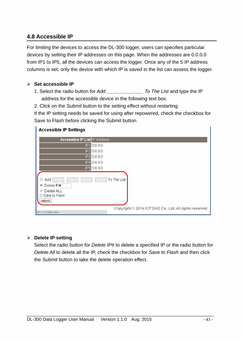
4.8 Accessible IP
For limiting the devices to access the DL-300 logger, users can specifies particular devices by setting their IP addresses on this page. When the addresses are 0.0.0.0 from IP1 to IP5, all the devices can access the logger. Once any of the 5 IP address columns is set, only the device with which IP is saved in the list can assess the logger.
Set accessible IP 1. Select the radio button for Add ___.___.___.___ To The List and type the IP
address for the accessible device in the following text box. 2. Click on the Submit button to the setting effect without restarting. If the IP setting needs be saved for using after repowered, check the checkbox for Save to Flash before clicking the Submit button.
Delete IP setting Select the radio button for Delete IP# to delete a specified IP or the radio button for Delete All to delete all the IP, check the checkbox for Save to Flash and then click the Submit button to take the delete operation effect.

DL-300 Data Logger User Manual Version 1.1.0 Aug. 2015 - 44 -
4.9 Change Password
On this page users can change the passwords for login the logger and locking the touch screen. The factory default for the DL-300 touch screen has no password protection. After setting the password for touch screen, each time whoever wants to change to settings from the touch screed, the password will be requested.
Change Web Password
The password for logging into the web page is Admin and can be changed in the Change Web Password field. The password can be alphabetic characters or numbers and up to 12 characters (case sensitive).
To change the password, uses need enter the Current password, New password, and Confirm new password columns and click the Submit button for Change Web Password to take the setting effect.

DL-300 Data Logger User Manual Version 1.1.0 Aug. 2015 - 45 -
Change Touch Password
It is recommended to set the Touch Password to protect the logger from unexpected operation. Once the password is set, the password will be requested when entering the setting menu from the touch screen.
The Touch password is numbers from 0 to 9 and up to 8 digits. Enter your password in New password and Confirm new password and then click the Submit button for changing touch password to take the setting effect. If the password contains non-number characters, the Parameter Error will be displayed as below.
Cancel Touch Password
Empty the text columns for New password and Confirm new password and then clicking the Submit button for changing touch password.

DL-300 Data Logger User Manual Version 1.1.0 Aug. 2015 - 46 -
4.10 Logout
Click the Logout on any page to logout the DL-300.
DL-300 Data Logger User Manual Version 1.1.0 Aug. 2015 - 47 -
5. Configuration via RS-485
The factory default settings for RS-485 communication Address: 1 Protocol: Modbus/RTU Baudrate: 9600 Parity: N,8,1 Response Delay (ms): 0
Note
If there are multiple DL-300 loggers connected to the same RS-485 network, each logger needs be set with a unique RS-485 address. More than one module having the same address will cause communication failure
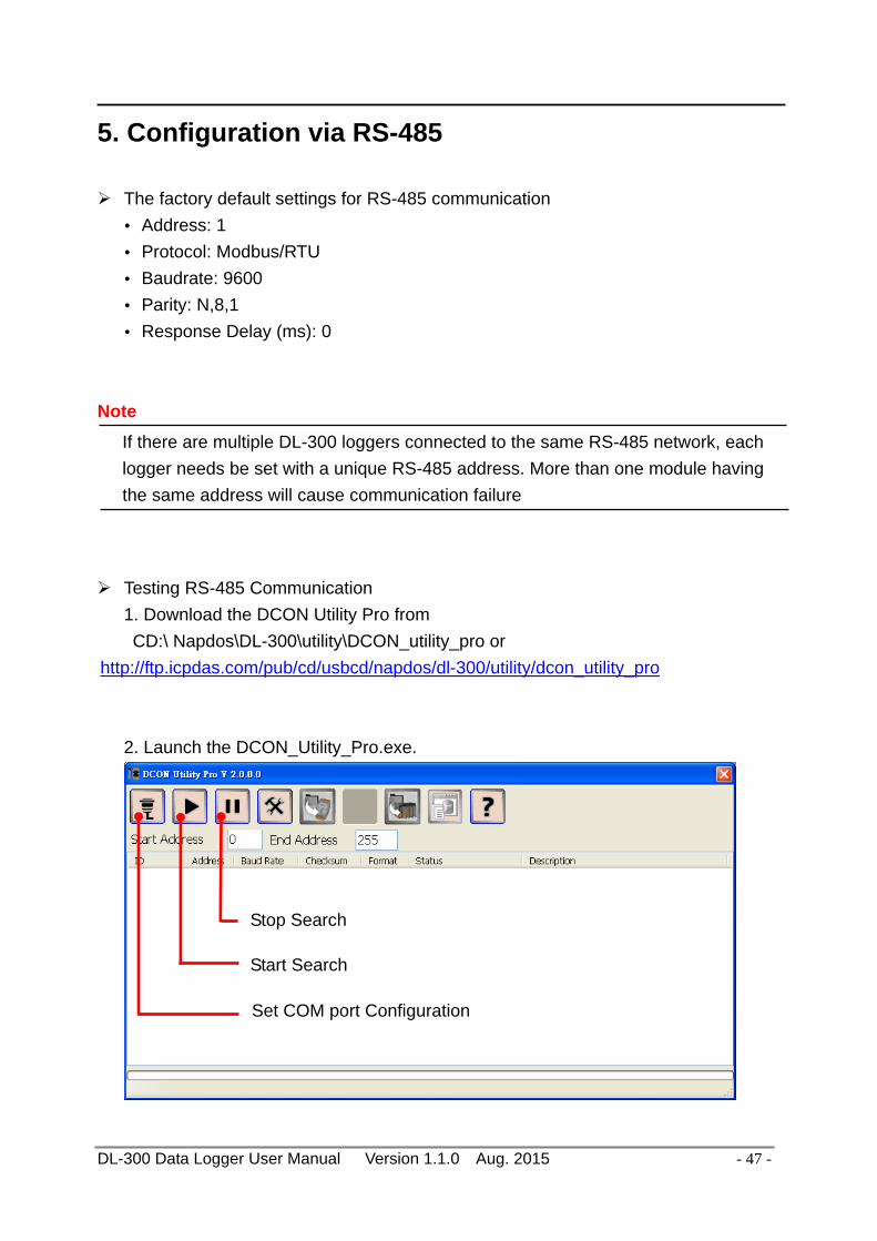
Testing RS-485 Communication 1. Download the DCON Utility Pro from
CD:\ Napdos\DL-300\utility\DCON_utility_pro or http://ftp.icpdas.com/pub/cd/usbcd/napdos/dl-300/utility/dcon_utility_pro
2. Launch the DCON_Utility_Pro.exe.
Set COM port Configuration
Start Search
Stop Search

DL-300 Data Logger User Manual Version 1.1.0 Aug. 2015 - 48 -
3. Click the icon to configure the COM port.
4. Select the COM Port number used to connect the DL-300 logger.
5. The Baud Rate is factory default to 9600 bps, make sure the baud rate setting in
the logger is checked in the Comport Option dialog box.

DL-300 Data Logger User Manual Version 1.1.0 Aug. 2015 - 49 -
6. Select the Protocol tab and check the protocol that set in the logger.
7. Select the Format tab and check the parity that set in the logger.

DL-300 Data Logger User Manual Version 1.1.0 Aug. 2015 - 50 -
8. Click the Start Search icon.
9. The DL-300 logger searched out will be listed as below.
10. Click the module name to configure the logger.
Note
The Protocol/Baud Rate/Parity/Checksum items marked with ”(INIT*)” means that when any of those items needs be modified, the pin 4.INIT needs to be set in ON position and power cycle the logger, then the item can be modified. After complete setting, set the pin 4.INIT back to OFF position and power cycle the logger again to take the setting effect.

DL-300 Data Logger User Manual Version 1.1.0 Aug. 2015 - 51 -
AI tab
CO/CO2 level
Alarm Status
Humidity Adjust the humidity offset
Set alarm mode/ High alarm limit/ beep alarm time
Temperature and Dew point temperature
Adjust the temperature offset (°C)

DL-300 Data Logger User Manual Version 1.1.0 Aug. 2015 - 52 -
DO tab On this DO tab, users can control the relay to output ON or OFF status, and set the power on value and safe value for the relay output. When any one of the high/low limit alarm for CO/CO2 concentration, temperature, humidity and dew point is enabled, the functions on this tab are all disabled as below.
If all the alarm events are disabled, the functions are available as below:
The checkbox can be used to control and display the DO status. Check/Uncheck the checkbox can control the relay output. Checked/Unchecked symbol also means the DO status
Select one of the radio button and the checkbox next to DO will display the setting for selected item.
When the buttons are clicked, the DO status will be set as the Power On value or Safe value.

DL-300 Data Logger User Manual Version 1.1.0 Aug. 2015 - 53 -
Host Watchdog
Host Watchdog is used to monitor the RS-485 communication status; if the host (PC) does not send command “~**” in the time period of WDT Timeout setting, the enabled Host Watchdog will announce the timeout error and turn the relay output to Safe value to avoid an unsafe act. Users can not control the relay until the command “~AA1” is sent to clear the WDT timeout status.
On this tab: 1. Set the time period for WDT timeout, check the checkbox next to Enable WDT
and click the Set WDT button to enable the Host watchdog. 2. Check the checkbox next to Send Host OK to send the “~**” command. 3. Uncheck the checkbox next to Send Host OK to stop sending ~** command, the
Host watchdog timeout will occur and relay will turn to Safe value. 4. Click the Reset WDT button to clear the Host watchdog timeout status. 5. Uncheck the checkbox next to Enable WDT and click the Set WDT button to
disable the Host watchdog.
Note The relay will not turn to Safe value when any one of the alarm for CO/CO2
concentration, temperature, humidity and dew point is enabled. If any one alarm is enabled, the relay will be linked to the Alarm status. In case an Alarm occurs, the relay turns ON, it can be used to turn on the user’s alarm light or beeping alarm or other device.

DL-300 Data Logger User Manual Version 1.1.0 Aug. 2015 - 54 -
System Tab
Click the Edit button to enable settings on this tab.
Check/Uncheck the item to Enable/Disable ABC function (For DL-302 and DL-303 only)
Set the LCD Back Light
Set Date and Time Click the Apply button to save settings.

DL-300 Data Logger User Manual Version 1.1.0 Aug. 2015 - 55 -
INIT In case of the following situations, users have to set the pin 4.INIT on SW1 in the ON position and power-cycle the DL-300 module: - Change protocol from PC - Change DCON configuration such as baudrate, parity and checksum - Communication failure with a DL-300 module.
When a DL-300 module is powered-on with the pin 4.INIT in ON position, the protocol is DCON, address is 0, Baud Rate is 9600 bps, Parity is set to N/8/1 and Checksum is disabled.
After configuring the communication parameters, click the Set Module Configurations button, set the INIT to OFF position and power-cycle the DL-300 to take the settings effect. Note
The INIT switch does not need to be set in the ON position when changing the address, baudrate and parity for ModbusRTU communication; users only have to power-cycle the module after complete configuration.

DL-300 Data Logger User Manual Version 1.1.0 Aug. 2015 - 56 -
6. Monitoring via Mobile Devices The iAir App can be used to monitor real-time data of CO/CO2 level, temperature and humidity anywhere and anytime without any complicated configuration. The DL-300 modules and your mobile devices such as smart phones or tablets need be addressed on the same network, and then you can get the real-time data from DL-300 loggers by entering a specific IP address, or by performing an automatic search for available devices. If a DL-300 can not be searched in the iAir App, please contact with the network administrator to make sure the module and your mobile devices are addressed on the same sub-network. It means that they have the same broadcast address.
The iAir app is available to free download in Google Play and App Store. Search “iAir” in or search “iAir”, “ICPDAS” in App Store and tap on install.
The iAir user manual can be obtained from http://ftp.icpdas.com/pub/cd/usbcd/napdos/dl-300/document/

DL-300 Data Logger User Manual Version 1.1.0 Aug. 2015 - 57 -
7. Utility to Get/Manage Data Log DL-300 Utility is a convenient, easy-to-use management utility running on Windows platform that allows users to monitor the real-time data and trend chart from DL-300 modules on the Ethernet, it can group the DL-300 modules for group view management, log alarm events with timestamp, download the logged data from a DL-300 logger and export the data to *.csv files for performing statistical analysis in Excel. The DL-300 Utility can be obtained from: CD:\Napdos\DL-300\utility\DL300_utility http://ftp.icpdas.com/pub/cd/usbcd/napdos/dl-300/utility/dl300_utility 1. Run the DL300_utility_setup_yyyymmdd.exe, the default install location is C:\ICPDAS\DL300_Utility\DL-300 Utility 2. Open the DL-300 Utility by double
clicking on the DL-300 Utility shortcut on desktop.
3. Search out a DL-300 module on the Ethernet and set the configuration.
3-1. Select the Device Settings on the Settings menu.
DL-300 Data Logger User Manual Version 1.1.0 Aug. 2015 - 58 -
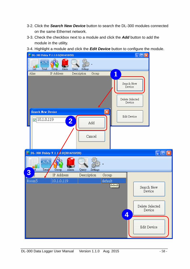
3-2. Click the Search New Device button to search the DL-300 modules connected on the same Ethernet network.
3-3. Check the checkbox next to a module and click the Add button to add the module in the utility.
3-4. Highlight a module and click the Edit Device button to configure the module.
1
2
3
4

DL-300 Data Logger User Manual Version 1.1.0 Aug. 2015 - 59 -
3-5. Set the configuration, and click on the OK button. Note Consult your network administrator before making changes to IP Address/ Mask Address/ Gateway
4. Get real-time data, trend chart and alarm event.
4-1. Click the List icon to obtain the real-time data. It also lists the connect status, group information and IP address for every DL-300 logger.
5

DL-300 Data Logger User Manual Version 1.1.0 Aug. 2015 - 60 -
4-2. Click the Trend icon to display the trend chart. Users can select the radio button for CO/CO2 level, Temperature or Humidity to access the trend chart for those real-time data, check the checkbox next to each DL-300 logger to display its trend chart or uncheck it to cancel display. Drag and drop the trend chart can move it to see the data not be displayed in the chart.
4-3. Click the Alarm icon to review the alarm events.

DL-300 Data Logger User Manual Version 1.1.0 Aug. 2015 - 61 -
4-4. Modify the event condition.
Select the System Settings on the Settings menu.
Set the CO/CO2 Alert Value, CO/CO2 Alarm Value (If it is supported in the logger), Temperature Alert Value and Temperature Alarm Value for trigger events. Check the checkbox next to The Record Time Everyday can schedule auto generate report everyday at the time set in the dropdown menu. Click on the OK button to complete the settings.
1
2

DL-300 Data Logger User Manual Version 1.1.0 Aug. 2015 - 62 -
5. Download data in a DL-300 logger and export the data 5.1. Select Update Database on the Settings menu 5.2. Click the Start button to download the data in DL-300 modules. 5.3. Click the close icon to exit the download procedure when all data are
downloaded.
2
3
1

DL-300 Data Logger User Manual Version 1.1.0 Aug. 2015 - 63 -
5.4. Click the Query icon. 5.5. Highlight the desired module, set the Start Time and End Time, and then click
the Search button. The data in the time period will be listed as below.
4
5

DL-300 Data Logger User Manual Version 1.1.0 Aug. 2015 - 64 -
5.6. Click the Export button to export the searched data in *.csv files for performing statistical analysis in Excel.
6

DL-300 Data Logger User Manual Version 1.1.0 Aug. 2015 - 65 -
6. Group the devices by location or users 6.1. Select Group Settings on the Settings menu.
6.2 Click the New button, enter the group name and click the OK button in the
pop-up box, and then click the OK button in the Group Settings box.
2
1
3

DL-300 Data Logger User Manual Version 1.1.0 Aug. 2015 - 66 -
6-3. Select Device Settings on the Settings menu; highlight the desired device and click the Edit Device button, select the group name for the module and click the OK button in the pop-up Device Property box to complete the setting.
1
2
3

DL-300 Data Logger User Manual Version 1.1.0 Aug. 2015 - 67 -
6-4. Monitor the group data by clicking the Group icon and then highlighting the group name.
DL-300 Data Logger User Manual Version 1.1.0 Aug. 2015 - 68 -
8. FAQ
Q1: What is ABC (Automatic Baseline Correction)?
A: ABC stands for the Automatic Baseline Correction which is used to adjust a shifted baseline to the carbon dioxide level in fresh air. In case of normal indoor application, the carbon dioxide level drops to nearly outside air where there are no human, green plants or anything to elevate the carbon dioxide levels on weekday evenings or weekends, the ABC algorithm constantly keeps track of the lowest reading and slowly corrects it as the expected value in fresh air typically around 400 ppm.
Q2: Why I need to enable the ABC?
A: When the CO2 concentration detected in a period time of unoccupied space is greater than the base value of 400ppm, enable the ABC function to adjust the baseline. Be careful that the ABC will not work if a space is constantly occupied such as a hospital, 24-hr factory, 24-hr store, green house or other applications where CO2 levels may be elevated at all times.
Q3: Does the DL-302/DL-303 enable the ABC as the factory default setting?
A3: No, the ABC is default disabled in a DL-302/DL-303 logger to prevent the baseline from being adjusted to an incorrect value in case of using in a constantly occupied space.
Q4: What to do when the ABC is no work?
A4: When the ABC is no work regarding baseline correction, the DL-302/DL-303 needs be returned to ICP DAS.

DL-300 Data Logger User Manual Version 1.1.0 Aug. 2015 - 69 -
Q5: How to set the touch password?
A5: Enter the IP address for your DL-300 logger in the address bar of a web browser and go to the Change Password page, enter the password in the New password and Confirm new password in the Change Touch Password field and then press the Submit button for change touch password. The password is numbers from 0 to 9 and up to 8 digits.
Once the password is set, the password will be requested whenever users want to enter the setting menu from the touch screen.

DL-300 Data Logger User Manual Version 1.1.0 Aug. 2015 - 70 -
Q6: How to cancel the touch password?
A6: Enter the IP address for your logger in the address bar of a web browser and go to the Change Password page, keep the New password and Confirm new password in Change Touch Password field empty and then press the Submit button for change touch password.
Q7: How to set the Accessible IP?
A7: Enter the IP address for your logger in the address bar of a web browser and go to the Accessible IP Settings page, select the radio button next to Add ___.___.___.___ To The List and key in the IP for a device which is allowed to access the DL-300, and then click the submit button. Check the checkbox next to the Save to Flash before clicking the submit button to save the IP setting and use after repowering. Once any of those in the list is set, only the device for which the IP address is saved in the list can assess the DL-300.

DL-300 Data Logger User Manual Version 1.1.0 Aug. 2015 - 71 -
Q8: How to delete the Accessible IP settings?
A8: Enter the IP address for your logger in the address bar of a web browser and go to the Accessible IP Settings page, select the radio button next to Delete IP# to delete a IP by the IP number or select the radio button next tot Delete All and then click the submit button.
Check the checkbox next to the Save to Flash before clicking the submit button to save the IP setting and use after repowering.
Q9: How to clear the data logged in a DL-300 module?
A9: Enter the IP address for the module in the address bar of a web browser and go to the I/O Settings page, click the Reset Data Logger button at the bottom of the page.

DL-300 Data Logger User Manual Version 1.1.0 Aug. 2015 - 72 -
Q10: How to calibrate the touch screen?
A10: 1. Set the pin 3. Touch Calib in ON position and others in OFF position on SW1. 2. Power on the DL-300 module 3. Touch the white boxes displayed in turn. 4. Touch one blue box, till the module senses the touch input and sounds. Then touch the next box one by one till the 5 five boxes are sensed.
1
3
2
Note:
After the 5 boxes are sensed, the screen turns to homescreen and calibration is complete. Please note to set pin 3. Touch Calib in OFF position and reboot the module. If the calibration is failed and the screen does not turn to homescreen, re-power-cycle the module and restart calibration process.
DL-300 Data Logger User Manual Version 1.1.0 Aug. 2015 - 73 -
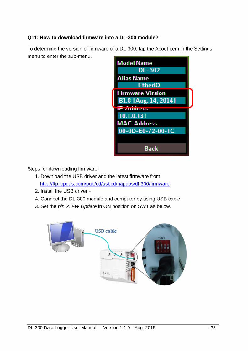
Q11: How to download firmware into a DL-300 module?
To determine the version of firmware of a DL-300, tap the About item in the Settings menu to enter the sub-menu. Steps for downloading firmware:
1. Download the USB driver and the latest firmware from http://ftp.icpdas.com/pub/cd/usbcd/napdos/dl-300/firmware
2. Install the USB driver。 4. Connect the DL-300 module and computer by using USB cable. 3. Set the pin 2. FW Update in ON position on SW1 as below.
USB cable

DL-300 Data Logger User Manual Version 1.1.0 Aug. 2015 - 74 -
5. Power on the DL-300, it will show white screen. 6. Run DL-302_Bxx.bat (Bxx is the version of firmware), wait the process finish (for
example, from 1/238 to 238/238), and then close the cmd.exe window.
7. Set the pin 2. FW Update in OFF position on SW1, remove the USB cable and repower on the module.
8. Go to the About sub-menu in the module to make sure the firmware version.

DL-300 Data Logger User Manual Version 1.1.0 Aug. 2015 - 75 -
Q12: How to display message on the DL-300 with Modbus command?
A12: The message can be pre-saved in the DL-300 or directly displayed on the screen. Writing the index number for a pre-saved message to Modbus address 40861 (based 1) can display the message. The time for display message is set in the address 40859, ranged from 1 to 65535 in seconds.
Setting the display time
Holding Register (4xxxx, base 1) Address Description Attribute
40859 Sets the time for displaying message, ranged from 1 to 65535 in seconds. 0 = displays message until a stop command received
R/W
Displaying a pre-saved message
The DL-300 is able to save a maximum of 20 messages with an individual index. Write the index to address 40861 to display the message and write 65535 to stop the display and return to the home screen.
Holding Register (4xxxx, base 1) Address Description Attribute
40861 Write the index to display a pre-saved message. 0 ~ 19: the message index, 65535: stop displaying message.
R/W
The display-message-on-screen function supports multiple language character sets based on UTF-8 encoding. A message can have a maximum of 6 lines and 14 half-width characters or 7 full-width characters maximum each line.
The background color, text color, text alignment, buzzer prompt sound, and acknowledge button are configurable for users' requirements.
.

DL-300 Data Logger User Manual Version 1.1.0 Aug. 2015 - 76 -
Saving a message or displaying a dynamic message
Modbus commad: Write Multiple Registers (10h) Modbus address: 450302 (C47Dh, base 1) Data format: 'IM' + Message Index + Message String + Message Settings
Byte 0 1 2 3 4 N-1 N N+1
Delimiter Index Message String
Message Settings
Data I (0x49)
M (0x4D)
0 ~ 20 T u 0 M (0x4D)
I (0x49)
1. Delimiter characters: IM 2. Index
The message with the index in the range of 0 to 19 will be saved in the DL-300. If the index is assigned to 20, the followed message with be directly displayed and will not be saved.
3. Message String
A message can have a maximum of 6 lines and 14 half-width characters or 7 full-width characters maximum each line. “\r” (0x0D) is used to do a new line. If the length of a message string is odd, an end character “0” must be added.
4. Message Settings The Message Settings is optional; at least one zero character must be added between the message string and message settings.
Byte N N+1 N+2 N+3 N+4 N+5 Delimiter 0 0 0 0 0 0 X Y Background Color Data M (0x4D)
I (0x49)
Y: Beep, 0: OFF,1: ON X: Exit button, 0: Hide,1: Display
Red 0~255
Green 0~255
Blue 0~255
Delimiter Characters: MI N+2: Sets whether to use beep prompt sound and exit button. Background Color and Text Color: the color is expressed as a 24-bit RGB triplet, each component of which can vary from 0 to 255.
LSB MSB

DL-300 Data Logger User Manual Version 1.1.0 Aug. 2015 - 77 -
Byte N+6 N+7 N+8 N+9 N+10 N+11 N+12 N+13 The text color and alignment for the first line
The text color and alignment for the second line
Data
0: left 1: center 2: right
Red 0~255
Green 0~255
Blue 0~255
0: left 1: center 2: right
Red 0~255
Green 0~255
Blue 0~255
Byte N+14 N+15 N+16 N+17 N+18 N+19 N+20 N+21
The text color and alignment for the third line
The text color and alignment for the fourth line
Data
0: left 1: center 2: right
Red 0~255
Green 0~255
Blue 0~255
0: left 1: center 2: right
Red 0~255
Green 0~255
Blue 0~255
Byte N+22 N+23 N+24 N+25 N+26 N+27 N+28 N+29
The text color and alignment for the fifth line
The text color and alignment for the sixth line
Data
0: left 1: center 2: right
Red 0~255
Green 0~255
Blue 0~255
0: left 1: center 2: right
Red 0~255
Green 0~255
Blue 0~255
Example: 1. Modbus function: Write Multiple Registers (10h) 2. Modbus address: 450302 (C47Dh, base 1) 3. Description: save the message with Index=0, message content “Hello, world!”, buzzer
prompt sound ON, Exit button displayed, background color: (RGB triplet : 008394h), all lines are text color white and left-aligned.
Byte 0 1 2 3 4 5 6 7 8 Data I M 0 H e l l o , Byte 9 10 11 12 13 14 15 16 17 Data w o r l d ! 0 M I Byte 18 19 20 21 22 23 24 25 26 Data 3 0 131 148 0 255 255 255 0 Byte 27 28 29 30 31 32 33 34 35 Data 255 255 255 0 255 255 255 0 255 Byte 36 37 38 39 40 41 Data 255 255 0 255 255 255

A-1. DL-301 DCON Command Sets - 78 -
Appendix A: DCON Command Sets
A-1. DL-301 DCON Command Sets
Command Description $AAF Reads firmware version, AA is the RS-485 address (hex). $AAI Reads INIT status, AA is the RS-485 address (hex).
response: !AA0 -> INIT short to GND !AA1 -> else
$AAM Reads module name, AA is the RS-485 address (hex). $AAP Reads Modbus RTU/DCON protocol.
response: !AA0 -> DCON !AA1 -> Modbus RTU
$AAPN Sets Modbus RTU/DCON protocol N-> 0: DCON, 1: Modbus RTU
$AA2 Reads configuration, AA is the RS-485 address (hex). $AA5 Reads reset status
!AA1 first after power on, !AA0 others #AA Read All Analog Inputs
response >(CO in 1 ppm)(relative humidity in 0.01%)(temperature in
0.01°C)(temperature in 0.01°F) (dew point temperature in 0.01°C)(dew point temperature in 0.01°F)
#AAN Reads Channel Analog Input N = 0 for CO in 1 ppm, 1 for relative humidity in 0.01%, 2 for temperature in 0.01°C, 3 for temperature in 0.01°F, 4 for dew point temperature in 0.01°C, 5 for dew point temperature in 0.01°F
%AANNTTCCFF Sets configuration, AA: current address NN: new address, TT = 00,

A-1. DL-301 DCON Command Sets - 79 -
CC: new baud rate Bits 5:0 Baud rate, 0x03 ~ 0x0A
Code 0x03 0x04 0x05 0x06 Baud 1200 2400 4800 9600 Code 0x07 0x08 0x09 0x0A Baud 19200 38400 57600 115200
Bits 7:6 00: no parity, 1 stop bit (N,8,1) 01: no parity, 2 stop bits (N,8,2) 10: even parity, 1 stop bit (E,8,1) 11: odd parity, 1 stop bit (O,8,1) FF: data format Bit 6 0: checksum disabled 1: checksum enabled
@AABA Read beep on alarm time response
!AAHH, HH in hex, 0: disabled, 1 ~ 250: beep on alarm time in seconds, 251: beep on alarm continuously
@AABAHH Set beep on alarm, HH in hex, 0: disabled, 1 ~ 250: beep on alarm time in seconds, 251: beep on alarm continuously
@AABL Read LCD back light response !AAHH, HH: 00 ~ FF in hex
@AABLHH Set LCD back light, HH: 00 ~ FF in hex @AACH Clear all high latched analog inputs to the current values

A-1. DL-301 DCON Command Sets - 80 -
Command Description @AACHN Clear channel high latched analog input to the current value
N = 0 for CO, 1 for relative humidity, 2 for temperature in 0.01°C, 3 for temperature in 0.01°F, 4 for dew point temperature in 0.01°C, 5 for dew point temperature in 0.01°F
@AACHCN Clear high latched alarm of a channel, N = 0 for CO, 1 for relative humidity, 2 for temperature in 0.01°C, 3 for temperature in 0.01°F, 4 for dew point temperature in 0.01°C, 5 for dew point temperature in 0.01°F
@AACL Clear all low latched analog inputs to the current values @AACLN Clear channel low latched analog input to the current value
N = 0 for CO, 1 for relative humidity, 2 for temperature in 0.01°C, 3 for temperature in 0.01°F, 4 for dew point temperature in 0.01°C, 5 for dew point temperature in 0.01°F
@AACLCN Clear low latched alarm of a channel, N = 1 for relative humidity, 2 for temperature in 0.01°C, 3 for temperature in 0.01°F, 4 for dew point temperature in 0.01°C, 5 for dew point temperature in 0.01°F
@AADACN Disable AI alarm of a channel, N = 0 for CO, 1 for relative humidity, 2 for temperature in 0.01°C, 3 for temperature in 0.01°F, 4 for dew point temperature in 0.01°C, 5 for dew point temperature in 0.01°F
@AADI read DO

A-1. DL-301 DCON Command Sets - 81 -
response !AA00O00
@AADO0V set DO, V-> 0: off, 1: on @AAEATCN Enable AI alarm of a channel,
N = 0 for CO, 1 for relative humidity, 2 for temperature in 0.01°C, 3 for temperature in 0.01°F, 4 for dew point temperature in 0.01°C, 5 for dew point temperature in 0.01°F T->M: momentary alarm mode, L: latched alarm mode
@AAHI(data)CN Set high alarm limit of an AI channel, N = 0 for CO in 1ppm, 1 for relative humidity in 0.01%, 2 for temperature in 0.01°C, 3 for temperature in 0.01°F, 4 for dew point temperature in 0.01°C, 5 for dew point temperature in 0.01°F
@AAHO Read humidity offset @AAHO(data) Set humidity offset, data in format of -100.00 ~ +100.00 @AALO(data)CN Set low alarm limit of an AI channel,
N = 1 for relative humidity in 0.01%, 2 for temperature in 0.01°C, 3 for temperature in 0.01°F, 4 for dew point temperature in 0.01°C, 5 for dew point temperature in 0.01°F
@AARACN Read AI alarm enabled/disabled status of a channel response !AAN, N->0: disabled, 1: momentary, 2: latched

A-1. DL-301 DCON Command Sets - 82 -
Command Description @AARAO Read AI alarm status
response !AAHHLL
@AARH Read all high latched values of analog input channels response >(CO in 1 ppm)(relative humidity in 0.01%)(temperature in
0.01°C)(temperature in 0.01°F)(dew point temperature in 0.01°C)(dew point temperature in 0.01°F)
@AARHN Read channel high latched value of analog input N = 0 for CO in 1 ppm, 1 for relative humidity in 0.01%, 2 for temperature in 0.01°C, 3 for temperature in 0.01°F, 4 for dew point temperature in 0.01°C, 5 for dew point temperature in 0.01°F
@AARHCN Read high alarm limit of an AI channel N = 0 for CO in 1 ppm, 1 for relative humidity in 0.01%, 2 for temperature in 0.01°C, 3 for temperature in 0.01°F, 4 for dew point temperature in 0.01°C, 5 for dew point temperature in 0.01°F
@AARL Read all low latched values of analog input channels response >(CO in 1 ppm)(relative humidity in 0.01%)(temperature in
0.01°C)(temperature in 0.01°F)(dew point temperature in 0.01°C)(dew point temperature in 0.01°F)
@AARLN Read channel low latched value of analog input N = 0 for CO in 1 ppm, 1 for relative humidity in 0.01%, 2 for temperature in 0.01°C, 3 for temperature in 0.01°F, 4 for dew point temperature in 0.01°C, 5 for dew point temperature in 0.01°F
@AARLCN Read low alarm limit of an AI channel N = 1 for relative humidity in 0.01%, 2 for temperature in 0.01°C,

A-1. DL-301 DCON Command Sets - 83 -
3 for temperature in 0.01°F, 4 for dew point temperature in 0.01°C, 5 for dew point temperature in 0.01°F
@AART Read RTC data @AARTYYMMDDHHMMSS
Set RTC data
@AASS Read screen saver time @AASSHHHH Set screen saver time in seconds in hex format, 0000h to FFFFh,
0000 to disable @AATO Read temperature offset in 0.01°C @AATO(data) Set temperature offset in 0.01°C, -100.00 ~ +100.00 ~** clear host watchdog timeout counter ~AA0 read host watchdog status ~AA1 clear host watchdog timeout status ~AA2 read host watchdog enable/disable status and timeout value ~AA3ETT enable/disable host watchdog and set timeout value
E-> 0: disable host watchdog, 1: enable host watchdog TT: host watchdog timeout in 0.1s in hex format
~AA4 read DO power on and safe value ~AA50P0S set DO power on and safe value
P-> 0: power on value off, 1: power on value on S-> 0: safe value off, 1: safe value on
~AARD read response delay time in ms in hex format ~AARDVV set response delay time in ms, VV in hex format, 00 - 1E

A-2. DL-302 DCON Command Sets - 84 -
A-2. DL-302 DCON Command Sets
Command Description
$AAF read firmware version $AAI read INIT status
response: !AA0 -> INIT short to GND !AA1 -> else
$AAM read module name $AAP Read Modbus RTU/DCON protocol
response: !AA0 -> DCON !AA1 -> Modbus RTU
$AAPN Set Modbus RTU/DCON protocol N-> 0: DCON, 1: Modbus RTU
$AA2 read configuration $AA5 read reset status
!AA1 first after power on, !AA0 others #AA Read All Analog Inputs
response >(CO2 in 1 ppm)(relative humidity in 0.01%)(temperature in
0.01°C)(temperature in 0.01°F) (dew point temperature in 0.01°C)(dew point temperature in 0.01°F)
#AAN Read Channel Analog Input N = 0 for CO2 in 1 ppm, 1 for relative humidity in 0.01%, 2 for temperature in 0.01°C, 3 for temperature in 0.01°F, 4 for dew point temperature in 0.01°C, 5 for dew point temperature in 0.01°F
%AANNTTCCFF set configuration, AA: current address, NN: new address, TT = 00,

A-2. DL-302 DCON Command Sets - 85 -
CC: new baud rate
Bits 5:0 : Baud rate, 0x03 ~ 0x0A
Code 0x03 0x04 0x05 0x06
Baud 1200 2400 4800 9600
Code 0x07 0x08 0x09 0x0A
Baud 19200 38400 57600 115200
Bits 7:6 00: no parity, 1 stop bit (N,8,1) 01: no parity, 2 stop bits (N,8,2) 10: even parity, 1 stop bit (E,8,1) 11: odd parity, 1 stop bit (O,8,1) FF: data format Bit 6 0: checksum disabled 1: checksum enabled
@AAABC Read status of the automatic baseline correction response !AAN, N=0: disabled, 1: enabled
@AAABCN Set the automatic baseline correction N->0: disabled, 1: enabled
@AABA Read beep on alarm time response
!AAHH, HH in hex, 0: disabled, 1 ~ 250: beep on alarm time in seconds, 251: beep on alarm continuously
@AABAHH Set beep on alarm, HH in hex, 0: disabled, 1 ~ 250: beep on alarm time in seconds, 251: beep on alarm continuously
@AABL Read LCD back light response !AAHH, HH: 00 ~ FF in hex
@AABLHH Set LCD back light, HH: 00 ~ FF in hex @AACH Clear all high latched analog inputs to the current values

A-2. DL-302 DCON Command Sets - 86 -
Command Description
@AACHN Clear channel high latched analog input to the current value N = 0 for CO2, 1 for relative humidity, 2 for temperature in 0.01°C, 3 for temperature in 0.01°F, 4 for dew point temperature in 0.01°C, 5 for dew point temperature in 0.01°F
@AACHCN Clear high latched alarm of a channel, N = 0 for CO2, 1 for relative humidity, 2 for temperature in 0.01°C, 3 for temperature in 0.01°F, 4 for dew point temperature in 0.01°C, 5 for dew point temperature in 0.01°F
@AACL Clear all low latched analog inputs to the current values @AACLN Clear channel low latched analog input to the current value
N = 0 for CO2, 1 for relative humidity, 2 for temperature in 0.01°C, 3 for temperature in 0.01°F, 4 for dew point temperature in 0.01°C, 5 for dew point temperature in 0.01°F
@AACLCN Clear low latched alarm of a channel, N = 1 for relative humidity, 2 for temperature in 0.01°C, 3 for temperature in 0.01°F, 4 for dew point temperature in 0.01°C, 5 for dew point temperature in 0.01°F
@AADACN Disable AI alarm of a channel, N = 0 for CO2, 1 for relative humidity, 2 for temperature in 0.01°C, 3 for temperature in 0.01°F, 4 for dew point temperature in 0.01°C, 5 for dew point temperature in 0.01°F

A-2. DL-302 DCON Command Sets - 87 -
@AADI read DO response !AA00O00
@AADO0V set DO, V-> 0: off, 1: on @AAEATCN Enable AI alarm of a channel,
N = 0 for CO2, 1 for relative humidity, 2 for temperature in 0.01°C, 3 for temperature in 0.01°F, 4 for dew point temperature in 0.01°C, 5 for dew point temperature in 0.01°F T = M for momentary alarm, L for latched alarm
@AAHI(data)CN Set high alarm limit of an AI channel, N = 0 for CO2 in 1ppm, 1 for relative humidity in 0.01%, 2 for temperature in 0.01°C, 3 for temperature in 0.01°F, 4 for dew point temperature in 0.01°C, 5 for dew point temperature in 0.01°F
@AAHO Read humidity offset @AAHO(data) Set humidity offset, data in format of -100.00 ~ +100.00 @AALO(data)CN Set low alarm limit of an AI channel,
N = 1 for relative humidity in 0.01%, 2 for temperature in 0.01°C, 3 for temperature in 0.01°F, 4 for dew point temperature in 0.01°C, 5 for dew point temperature in 0.01°F
@AARACN Read AI alarm enabled/disabled status of a channel response !AAN, N->0: disabled, 1: momentary, 2: latched

A-2. DL-302 DCON Command Sets - 88 -
Command Description
@AARAO Read AI alarm status response !AAHHLL
@AARH Read all high latched values of analog input channels response >(CO2 in 1 ppm)(relative humidity in 0.01%)(temperature in
0.01°C)(temperature in 0.01°F) (dew point temperature in 0.01°C)(dew point temperature in 0.01°F)
@AARHN Read channel high latched value of analog input N = 0 for CO2 in 1 ppm, 1 for relative humidity in 0.01%, 2 for temperature in 0.01°C, 3 for temperature in 0.01°F, 4 for dew point temperature in 0.01°C, 5 for dew point temperature in 0.01°F
@AARHCN Read high alarm limit of an AI channel N = 0 for CO2 in 1 ppm, 1 for relative humidity in 0.01%, 2 for temperature in 0.01°C, 3 for temperature in 0.01°F, 4 for dew point temperature in 0.01°C, 5 for dew point temperature in 0.01°F
@AARL Read all low latched values of analog input channels response >(CO2 in 1 ppm)(relative humidity in 0.01%)(temperature in
0.01°C)(temperature in 0.01°F) (dew point temperature in 0.01°C)(dew point temperature in 0.01°F)
@AARLN Read channel low latched value of analog input N = 0 for CO2 in 1 ppm, 1 for relative humidity in 0.01%, 2 for temperature in 0.01°C, 3 for temperature in 0.01°F, 4 for dew point temperature in 0.01°C, 5 for dew point temperature in 0.01°F
@AARLCN Read low alarm limit of an AI channel N = 1 for relative humidity in 0.01%,

A-2. DL-302 DCON Command Sets - 89 -
2 for temperature in 0.01°C, 3 for temperature in 0.01°F, 4 for dew point temperature in 0.01°C, 5 for dew point temperature in 0.01°F
@AART Read RTC data @AARTYYMMDDHHMMSS
Set RTC data
@AASS Read screen saver time @AASSHHHH Set screen saver time in seconds in hex format, 0000h to FFFFh,
0000 to disable @AATO Read temperature offset in 0.01°C @AATO(data) Set temperature offset in 0.01°C, -100.00 ~ +100.00 ~** clear host watchdog timeout counter ~AA0 read host watchdog status ~AA1 clear host watchdog timeout status ~AA2 read host watchdog enable/disable status and timeout value ~AA3ETT enable/disable host watchdog and set timeout value
E-> 0: disable host watchdog, 1: enable host watchdog TT: host watchdog timeout in 0.1s in hex format
~AA4 read DO power on and safe value ~AA50P0S set DO power on and safe value
P-> 0: power on value off, 1: power on value on S-> 0: safe value off, 1: safe value on
~AARD read response delay time in ms in hex format ~AARDVV set response delay time in ms, VV in hex format, 00 - 1E

A-3. DL-303 DCON Command Sets - 90 -
A-3. DL-303 DCON Command Sets
Command Description $AAF reads firmware version $AAI reads INIT status
response: !AA0 -> INIT short to GND !AA1 -> else
$AAM reads module name $AAP read Modbus RTU/DCON protocol
response: !AA0 -> DCON !AA1 -> Modbus RTU
$AAPN sets Modbus RTU/DCON protocol N-> 0: DCON, 1: Modbus RTU
$AA2 reads configuration $AA5 reads reset status
!AA1 first after power on, !AA0 others #AA reads All Analog Inputs
response >(CO in 1 ppm) (CO2 in 1 ppm) (relative humidity in
0.01%)(temperature in 0.01°C)(temperature in 0.01°F) (dew point temperature in 0.01°C)(dew point temperature in 0.01°F)
#AAN reads Channel Analog Input N = 0 for CO in 1 ppm, 1 for CO2 in 1 ppm, 2 for relative humidity in 0.01%, 3 for temperature in 0.01°C, 4 for temperature in 0.01°F, 5 for dew point temperature in 0.01°C, 6 for dew point temperature in 0.01°F
%AANNTTCCFF sets configuration, AA: current address, NN: new address, TT = 00,

A-3. DL-303 DCON Command Sets - 91 -
CC: new baud rate
Bits 5:0 : Baud rate, 0x03 ~ 0x0A
Code 0x03 0x04 0x05 0x06
Baud 1200 2400 4800 9600
Code 0x07 0x08 0x09 0x0A
Baud 19200 38400 57600 115200
Bits 7:6 00: no parity, 1 stop bit (N,8,1) 01: no parity, 2 stop bits (N,8,2) 10: even parity, 1 stop bit (E,8,1) 11: odd parity, 1 stop bit (O,8,1) FF: data format Bit 6 0: checksum disabled 1: checksum enabled
@AAABC reads status of the automatic baseline correction response !AAN, N=0: disabled, 1: enabled
@AAABCN sets the automatic baseline correction N->0: disabled, 1: enabled
@AABA reads beep on alarm time response
!AAHH, HH in hex, 0: disabled, 1 ~ 250: beep on alarm time in seconds, 251: beep on alarm continuously
@AABAHH sets beep on alarm HH in hex, 0: disabled, 1 ~ 250: beep on alarm time in seconds, 251: beep on alarm continuously
@AABL reads LCD back light response !AAHH, HH: 00 ~ FF in hex
@AABLHH sets LCD back light, HH: 00 ~ FF in hex @AACH clears all high latched analog inputs to the current values

A-3. DL-303 DCON Command Sets - 92 -
Command Description @AACHN clears channel high latched analog input to the current value,
N = 0 for CO, 1 for CO2, 2 for relative humidity, 3 for temperature in 0.01°C, 4 for temperature in 0.01°F, 5 for dew point temperature in 0.01°C, 6 for dew point temperature in 0.01°F
@AACHCN clears high latched alarm of a channel, N = 0 for CO, 1 for CO2, 2 for relative humidity, 3 for temperature in 0.01°C, 4 for temperature in 0.01°F, 5 for dew point temperature in 0.01°C, 6 for dew point temperature in 0.01°F
@AACL clears all low latched analog inputs to the current values @AACLN clears channel low latched analog input to the current value,
N = 0 for CO, 1 for CO2, 2 for relative humidity, 3 for temperature in 0.01°C, 4 for temperature in 0.01°F, 5 for dew point temperature in 0.01°C, 6 for dew point temperature in 0.01°F
@AACLCN clears low latched alarm of a channel, N = 2 for relative humidity, 3 for temperature in 0.01°C, 4 for temperature in 0.01°F, 5 for dew point temperature in 0.01°C, 6 for dew point temperature in 0.01°F
@AADACN disables AI alarm of a channel, N = 0 for CO, 1 for CO2, 2 for relative humidity, 3 for temperature in 0.01°C, 4 for temperature in 0.01°F,

A-3. DL-303 DCON Command Sets - 93 -
5 for dew point temperature in 0.01°C, 6 for dew point temperature in 0.01°F
@AADI reads DO response !AA00O00
@AADO0V sets DO, V-> 0: off, 1: on @AAEATCN enables AI alarm of a channel,
N = 0 for CO, 1 for CO2, 2 for relative humidity, 3 for temperature in 0.01°C, 4 for temperature in 0.01°F, 5 for dew point temperature in 0.01°C, 6 for dew point temperature in 0.01°F T->M: momentary alarm, L: latched alarm
@AAHI(data)CN sets high alarm limit of an AI channel, N = 0 for CO in 1ppm, 1 for CO2 in 1ppm, 2 for relative humidity in 0.01%, 3 for temperature in 0.01°C, 4 for temperature in 0.01°F, 5 for dew point temperature in 0.01°C, 6 for dew point temperature in 0.01°F
@AAHO reads humidity offset @AAHO(data) sets humidity offset, data in format of -100.00 ~ +100.00 @AALO(data)CN sets low alarm limit of an AI channel,
N = 2 for relative humidity in 0.01%, 3 for temperature in 0.01°C, 4 for temperature in 0.01°F, 5 for dew point temperature in 0.01°C, 6 for dew point temperature in 0.01°F
@AARACN reads AI alarm enabled/disabled status of a channel response !AAN, N->0: disabled, 1: momentary, 2: latched

A-3. DL-303 DCON Command Sets - 94 -
Command Description @AARAO reads AI alarm status
response !AAHHLL
@AARH reads all high latched values of analog input channels response >(CO in 1 ppm) (CO2 in 1 ppm) (relative humidity in
0.01%)(temperature in 0.01°C)(temperature in 0.01°F) (dew point temperature in 0.01°C)(dew point temperature in 0.01°F)
@AARHN reads channel high latched value of analog input N = 0 for CO in 1 ppm, 1 for CO2 in 1 ppm, 2 for relative humidity in 0.01%, 3 for temperature in 0.01°C, 4 for temperature in 0.01°F, 5 for dew point temperature in 0.01°C, 6 for dew point temperature in 0.01°F
@AARHCN reads high alarm limit of an AI channel N = 0 for CO in 1 ppm, 1 for CO2 in 1 ppm, 2 for relative humidity in 0.01%, 3 for temperature in 0.01°C, 4 for temperature in 0.01°F, 5 for dew point temperature in 0.01°C, 6 for dew point temperature in 0.01°F
@AARL reads all low latched values of analog input channels response
>(CO in 1 ppm) (CO2 in 1 ppm) (relative humidity in 0.01%)(temperature in 0.01°C)(temperature in 0.01°F) (dew point temperature in 0.01°C)(dew point temperature in 0.01°F)
@AARLN reads channel low latched value of analog input N = 0 for CO in 1 ppm, 1 for CO2 in 1 ppm, 2 for relative humidity in 0.01%, 3 for temperature in 0.01°C, 4 for temperature in 0.01°F, 5 for dew point temperature in 0.01°C, 6 for dew point temperature in 0.01°F

A-3. DL-303 DCON Command Sets - 95 -
@AARLCN reads low alarm limit of an AI channel N = 2 for relative humidity in 0.01%, 3 for temperature in 0.01°C, 4 for temperature in 0.01°F, 5 for dew point temperature in 0.01°C, 6 for dew point temperature in 0.01°F
@AART reads RTC data @AARTYYMMDDHHMMSS
sets RTC data
@AASS reads screen saver time @AASSHHHH sets screen saver time in seconds in hex format, 0000h to FFFFh,
0000 to disable @AATO reads temperature offset in 0.01°C @AATO(data) sets temperature offset in 0.01°C, -100.00 ~ +100.00 ~** clears host watchdog timeout counter ~AA0 reads host watchdog status ~AA1 clears host watchdog timeout status ~AA2 reads host watchdog enable/disable status and timeout value ~AA3ETT enables/disables host watchdog and set timeout value
E-> 0: disable host watchdog, 1: enable host watchdog TT: host watchdog timeout in 0.1s in hex format
~AA4 reads DO power on and safe value ~AA50P0S sets DO power on and safe value
P-> 0: power on value off, 1: power on value on S-> 0: safe value off, 1: safe value on
~AARD reads response delay time in ms in hex format ~AARDVV sets response delay time in ms, VV in hex format, 00 - 1E

B: ModbusMasterToolPC - 96 -
Appendix B: ModbusMasterToolPC
ModbusMasterToolPC is a free, easy-to-use tool for Modbus communication and diagnosing the wiring. It is located in the company CD:
CD:\ Napdos\DL-300\utility\ and needless to install
This section intends to guide the steps for creating the Modbus communication with DL-300 logger.
1. Launch the ModbusMasterToolPC.exe.
2. Select New in the File menu.
3. Input the file name and click on the Save button.

B: ModbusMasterToolPC - 97 -
4. Select Connect in the Connection menu.
5. Select the communication interface. When using TCP/IP as the interface, input the IP for your logger and click on the OK button.
When using RS-485 as the interface, select the COM port, check the RTU mode and click on the OK button.

B: ModbusMasterToolPC - 98 -
6. Select Definition in the Setup menu.
7. Select the Modbus function code, input the start address and length, and click on the OK button.
8. Read data.

B: ModbusMasterToolPC - 99 -
9. Write data to Holding Register or Coil Status 1. Highlight the Modbus address in the Holding Register or Coil Status list 2. Select Set Value in the Setup menu. 3. Input the data in the Value box and click on the OK button
2
3

C-1. DL-301 Modbus Address Mappings (Base 1) - 100 -
Appendix C: Modbus Address Table
C-1. DL-301 Modbus Address Mappings (Base 1)
Address Description Attribute30001 ~ 30006 40001 ~ 40006
Analog input value of channel 0 to 5. channel 0: CO in 1ppm, channel 1: relative humidity in 0.01%, channel 2: temperature in 0.01°C, channel 3:temperature in 0.01°F, channel 4: dew point temperature in 0.01°C, channel 5: dew point temperature in 0.01°F
R
40225 ~ 40230
High alarm limit of channel 0 to 5, channel 0: CO in 1ppm, channel 1: relative humidity in 0.01%, channel 2: temperature in 0.01°C, channel 3:temperature in 0.01°F, channel 4: dew point temperature in 0.01°C, channel 5: dew point temperature in 0.01°F
R/W
40234 ~ 40238
Low alarm limit of channel 1 to 5, channel 1: relative humidity in 0.01%, channel 2: temperature in 0.01°C, channel 3:temperature in 0.01°F, channel 4: dew point temperature in 0.01°C, channel 5: dew point temperature in 0.01°F
R/W
40272 Modbus NetID Only for Modbus TCP protocol
R/W
30301 40301
Number of the digital input channels Only for Modbus TCP protocol
R
30311 40311
Number of the digital output channels Only for Modbus TCP protocol
R
30321 40321
Number of the analog input channels Only for Modbus TCP protocol
R

C-1. DL-301 Modbus Address Mappings (Base 1) - 101 -
Address Description Attribute30331 40331
Number of the analog output channels Only for Modbus TCP protocol
R
30352 40352
Firmware version in hex format Only for Modbus TCP protocol
R
40450 Relative humidity offset in 0.01% R/W 40451 Temperature offset in 0.01°C R/W 40481 Firmware version (low word) R 40482 Firmware version (high word) R 40483 Module name (low word), 0x0301 R 40484 Module name (high word), 0x444C R 40485 RS-485 module address, 1 to 247
Only for Modbus RTU protocol R/W
40486 RS-485 baud rate and parity settings Bits 5:0
Baud rate, valid range: 3 ~ 10
Code 0x03 0x04 0x05 0x06
Baud 1200 2400 4800 9600
Code 0x07 0x08 0x09 0x0A
Baud 19200 38400 57600 115200
Bits 7:6 00: no parity, 1 stop bit (N,8,1) 01: no parity, 2 stop bits (N,8,2) 10: even parity, 1 stop bit (E,8,1) 11: odd parity, 1 stop bit (O,8,1) Only for Modbus RTU protocol
R/W
40488 RS-485 response delay time in ms, valid range, 0 ~ 30 Only for Modbus RTU protocol
R/W
40489 RS-485 host watchdog timeout value, 0 ~ 255, in 0.1s Only for Modbus RTU protocol
R/W
40492 RS-485 host watchdog timeout count, write 0 to clear Only for Modbus RTU protocol
R/W
40495 LCD back light setting, 0 to 255 R/W

C-1. DL-301 Modbus Address Mappings (Base 1) - 102 -
Address Description Attribute40497 Beep on alarm,
0: disable, 1 to 250: beep on alarm time in seconds, 251: beep on alarm continuously
R/W
40498 Screen saver time in seconds, 0 to 65535, 0: disable R/W 30513 ~ 30518 40513 ~ 40518
High latched analog input value of channel 0 to 5 channel 0: CO in 1ppm, channel 1: relative humidity in 0.01%, channel 2: temperature in 0.01°C, channel 3:temperature in 0.01°F, channel 4: dew point temperature in 0.01°C,
channel 5: dew point temperature in 0.01°F
R
30545 ~ 30550 40545 ~ 40550
Low latched analog input value of channel 0 to 5 channel 0: CO in 1ppm, channel 1: relative humidity in 0.01%, channel 2: temperature in 0.01°C, channel 3:temperature in 0.01°F, channel 4: dew point temperature in 0.01°C,
channel 5: dew point temperature in 0.01°F
R
30556 40556
Module reset status, 1: power-on, 2: watchdog, 3: software reset command Only for Modbus TCP protocol
R
40558 Ethernet host watchdog timeout value, 5 to 65535, in second, 0 to disable. Only for Modbus TCP protocol
R/W
30559 40559
Ethernet host watchdog timeout count. Only for Modbus TCP protocol
R
30560 40560
Module name, 0x0301 Only for Modbus TCP protocol
R
40564 TCP disconnection timeout value, 5 to 65535, in second, 0 to disable. Only for Modbus TCP protocol
R/W
40565 Module reset timeout value, 30 to 65535, in second, 0 to disable. Only for Modbus TCP protocol
R/W
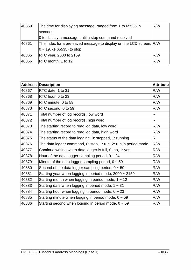
C-1. DL-301 Modbus Address Mappings (Base 1) - 103 -
40859
The time for displaying message, ranged from 1 to 65535 in seconds. 0 to display a message until a stop command received
R/W
40861 The index for a pre-saved message to display on the LCD screen, 0 ~ 19, -1(65535) to stop
R/W
40865 RTC year, 2000 to 2159 R/W 40866 RTC month, 1 to 12 R/W Address Description Attribute40867 RTC date, 1 to 31 R/W 40868 RTC hour, 0 to 23 R/W 40869 RTC minute, 0 to 59 R/W 40870 RTC second, 0 to 59 R/W 40871 Total number of log records, low word R 40872 Total number of log records, high word R 40873 The starting record to read log data, low word R/W 40874 The starting record to read log data, high word R/W 40875 The status of the data logging, 0: stopped, 1: running R 40876 The data logger command, 0: stop, 1: run, 2: run in period mode R/W 40877 Continue writing when data logger is full, 0: no, 1: yes R/W 40878 Hour of the data logger sampling period, 0 ~ 24 R/W 40879 Minute of the data logger sampling period, 0 ~ 59 R/W 40880 Second of the data logger sampling period, 0 ~ 59 R/W 40881 Starting year when logging in period mode, 2000 ~ 2159 R/W 40882 Starting month when logging in period mode, 1 ~ 12 R/W 40883 Starting date when logging in period mode, 1 ~ 31 R/W 40884 Starting hour when logging in period mode, 0 ~ 23 R/W 40885 Starting minute when logging in period mode, 0 ~ 59 R/W 40886 Starting second when logging in period mode, 0 ~ 59 R/W

C-1. DL-301 Modbus Address Mappings (Base 1) - 104 -
Address Description Attribute40887 Ending year when logging in period mode, 2000 ~ 2159 R/W 40888 Ending month when logging in period mode, 1 ~ 12 R/W 40889 Ending date when logging in period mode, 1 ~ 31 R/W 40890 Ending hour when logging in period mode, 0 ~ 23 R/W 40891 Ending minute when logging in period mode, 0 ~ 59 R/W 40892 Ending second when logging in period mode, 0 ~ 59 R/W 450302 Saves or shows message, by Modbus function 16 only.
Refer to Q12 in section FAQ (page 75) for more information. W
00001 Digital output value of channel 0 R/W 00129 Safe value of digital output channel 0 R/W 00161 Power on value of digital output channel 0 R/W 00227 Write 1 to reload default TCP settings
Only for Modbus TCP protocol W
00234 Write 1 to reboot module Only for Modbus TCP protocol
W
00257 RS-485 Protocol, 0: DCON, 1: Modbus RTU Only for Modbus RTU protocol
R/W
Address Description Attribute00260 Modbus RTU host watchdog mode
0: same as I-7000 1: can use AO and DO command to clear host watchdog timeout status Only for Modbus RTU protocol
R/W
00261 RS-485 host watchdog mode, 1: enable, 0: disable. Only for Modbus RTU protocol
R/W
00262 Write 1 to play notification sound W 00270 Host watch dog timeout status, write 1 to clear host watch dog
timeout status Only for Modbus RTU protocol
R/W
00273 Reset status, 1: first read after powered on, 0: not the first read after powered on
R
00280 Write 1 to clear all high latched analog input values W 00281 Write 1 to clear all low latched analog input values W 00290 ~ Low alarm status of channel 1 to 5. Write 1 to clear low latched R/W

C-1. DL-301 Modbus Address Mappings (Base 1) - 105 -
00294 alarm. channel 1: relative humidity, channel 2: temperature in 0.01°C, channel 3:temperature in 0.01°F, channel 4: dew point temperature in 0.01°C,
channel 5: dew point temperature in 0.01°F 00305 ~ 00310
High alarm status of channel 0 to 5. Write 1 to clear high latched alarm. channel 0: CO, channel 1: relative humidity, channel 2: temperature in 0.01°C, channel 3:temperature in 0.01°F, channel 4: dew point temperature in 0.01°C,
channel 5: dew point temperature in 0.01°F
R/W
00321 ~ 00326
Enable/disable alarm of channel 0 to 5, write 0 to disable alarm ; write 1 to enable alarm. channel 0: CO, channel 1: relative humidity, channel 2: temperature in 0.01°C, channel 3:temperature in 0.01°F, channel 4: dew point temperature in 0.01°C,
channel 5: dew point temperature in 0.01°F
R/W
00337 ~ 00342
Alarm type, momentary or latched, of channel 0 to 5, write 0 to enable momentary alarm mode; write 1 to enable latched alarm mode. channel 0: CO, channel 1: relative humidity in, channel 2: temperature in 0.01°C, channel 3:temperature in 0.01°F, channel 4: dew point temperature in 0.01°C,
channel 5: dew point temperature in 0.01°F
R/W
00385 ~ 00390
Write 1 to clear high latched analog input value of channel 0 to 5, channel 0: CO channel 1: relative humidity, channel 2: temperature in 0.01°C, channel 3:temperature in 0.01°F, channel 4: dew point temperature in 0.01°C,
channel 5: dew point temperature in 0.01°F
W

C-1. DL-301 Modbus Address Mappings (Base 1) - 106 -
00417 ~ 00422
Write 1 to clear low latched analog input value of channel 0 to 5 channel 0: CO, channel 1: relative humidity, channel 2: temperature in 0.01°C, channel 3:temperature in 0.01°F, channel 4: dew point temperature in 0.01°C,
channel 5: dew point temperature in 0.01°F
W

C-2. DL-302 Modbus Address Mappings (Base 1) - 107 -
C-2. DL-302 Modbus Address Mappings (Base 1)
Address Description Attribute
30001 ~ 30006 40001 ~ 40006
Analog input value of channel 0 to 5. channel 0: CO2 in 1ppm, channel 1: relative humidity in 0.01%, channel 2: temperature in 0.01°C, channel 3:temperature in 0.01°F, channel 4: dew point temperature in 0.01°C, channel 5: dew point temperature in 0.01°F
R
40225 ~ 40230
High alarm limit of channel 0 to 5, channel 0: CO2 in 1ppm, channel 1: relative humidity in 0.01%, channel 2: temperature in 0.01°C, channel 3:temperature in 0.01°F, channel 4: dew point temperature in 0.01°C, channel 5: dew point temperature in 0.01°F
R/W
40234 ~ 40238
Low alarm limit of channel 1 to 5, channel 1: relative humidity in 0.01%, channel 2: temperature in 0.01°C, channel 3:temperature in 0.01°F, channel 4: dew point temperature in 0.01°C, channel 5: dew point temperature in 0.01°F
R/W
40272 Modbus NetID Only for Modbus TCP protocol
R/W
30301 40301
Number of the digital input channels Only for Modbus TCP protocol
R
30311 40311
Number of the digital output channels Only for Modbus TCP protocol
R
30321 40321
Number of the analog input channels Only for Modbus TCP protocol
R

C-2. DL-302 Modbus Address Mappings (Base 1) - 108 -
Address Description Attribute
30331 40331
Number of the analog output channels Only for Modbus TCP protocol
R
30352 40352
Firmware version in hex format Only for Modbus TCP protocol
R
40450 Relative humidity offset in 0.01% R/W 40451 Temperature offset in 0.01°C R/W 40481 Firmware version (low word) R 40482 Firmware version (high word) R 40483 Module name (low word), 0x0302 R 40484 Module name (high word), 0x444C R 40485 RS-485 module address, 1 to 247
Only for Modbus RTU protocol R/W
40486 RS-485 baud rate and parity settings Bits 5:0
Baud rate, valid range: 3 ~ 10
Code 0x03 0x04 0x05 0x06
Baud 1200 2400 4800 9600
Code 0x07 0x08 0x09 0x0A
Baud 19200 38400 57600 115200
Bits 7:6 00: no parity, 1 stop bit (N,8,1) 01: no parity, 2 stop bit (N,8,2) 10: even parity, 1 stop bit (E,8,1) 11: odd parity , 1 stop bit (O,8,1) Only for Modbus RTU protocol
R/W
40488 RS-485 response delay time in ms, valid range, 0 ~ 30 Only for Modbus RTU protocol
R/W
40489 RS-485 host watchdog timeout value, 0 ~ 255, in 0.1s Only for Modbus RTU protocol
R/W
40492 RS-485 host watchdog timeout count, write 0 to clear Only for Modbus RTU protocol
R/W
40495 LCD back light setting, 0 to 255 R/W 40496 Automatic baseline correction for CO2 measurement.
0: disable, 1:enable R/W

C-2. DL-302 Modbus Address Mappings (Base 1) - 109 -
Address Description Attribute
40497 Beep on alarm, 0: disable, 1 to 250: beep on alarm time in seconds, 251: beep on alarm continuously
R/W
40498 Screen saver time in seconds, 0 to 65535, 0: disable R/W 30513 ~ 30518 40513 ~ 40518
High latched analog input value of channel 0 to 5 channel 0: CO2 in 1ppm, channel 1: relative humidity in 0.01%, channel 2: temperature in 0.01°C, channel 3:temperature in 0.01°F, channel 4: dew point temperature in 0.01°C,
channel 5: dew point temperature in 0.01°F
R
30545 ~ 30550 40545 ~ 40550
Low latched analog input value of channel 0 to 5 channel 0: CO2 in 1ppm, channel 1: relative humidity in 0.01%, channel 2: temperature in 0.01°C, channel 3:temperature in 0.01°F, channel 4: dew point temperature in 0.01°C,
channel 5: dew point temperature in 0.01°F
R
30556 40556
Module reset status, 1: power-on, 2: watchdog, 3: software reset command Only for Modbus TCP protocol
R
40558 Ethernet host watchdog timeout value, 5 to 65535, in second, 0 to disable. Only for Modbus TCP protocol
R/W
30559 40559
Ethernet host watchdog timeout count. Only for Modbus TCP protocol
R
30560 40560
Module name, 0x0302 Only for Modbus TCP protocol
R
40564 TCP disconnection timeout value, 5 to 65535, in second, 0 to disable. Only for Modbus TCP protocol
R/W
40565 Module reset timeout value, 30 to 65535, in second, 0 to disable. Only for Modbus TCP protocol
R/W

C-2. DL-302 Modbus Address Mappings (Base 1) - 110 -
40859
The time for displaying message, ranged from 1 to 65535 in seconds. 0 to display a message until a stop command received
R/W
40861 The index for a pre-saved message to display on the LCD screen, 0 ~ 19, -1(65535) to stop
R/W
40865 RTC year, 2000 to 2159 R/W 40866 RTC month, 1 to 12 R/W
Address Description Attribute40867 RTC date, 1 to 31 R/W 40868 RTC hour, 0 to 23 R/W 40869 RTC minute, 0 to 59 R/W 40870 RTC second, 0 to 59 R/W 40871 Total number of log records, low word R 40872 Total number of log records, high word R 40873 The starting record to read log data, low word R/W 40874 The starting record to read log data, high word R/W 40875 The status of the data logging,
0: stopped, 1: running R
40876 The data logger command, 0: stop, 1: run, 2: run in period mode
R/W
40877 Continue writing when data logger is full, 0: no, 1: yes R/W 40878 Hour of the data logger sampling period, 0 ~ 24 R/W 40879 Minute of the data logger sampling period, 0 ~ 59 R/W 40880 Second of the data logger sampling period, 0 ~ 59 R/W 40881 Starting year when logging in period mode, 2000 ~ 2159 R/W 40882 Starting month when logging in period mode, 1 ~ 12 R/W 40883 Starting date when logging in period mode, 1 ~ 31 R/W 40884 Starting hour when logging in period mode, 0 ~ 23 R/W 40885 Starting minute when logging in period mode, 0 ~ 59 R/W 40886 Starting second when logging in period mode, 0 ~ 59 R/W

C-2. DL-302 Modbus Address Mappings (Base 1) - 111 -
Address Description Attribute
40887 Ending year when logging in period mode, 2000 ~ 2159 R/W 40888 Ending month when logging in period mode, 1 ~ 12 R/W 40889 Ending date when logging in period mode, 1 ~ 31 R/W 40890 Ending hour when logging in period mode, 0 ~ 23 R/W 40891 Ending minute when logging in period mode, 0 ~ 59 R/W 40892 Ending second when logging in period mode, 0 ~ 59 R/W 450302 Saves or shows message, by Modbus function 16 only.
Refer to Q12 in section FAQ (page 75) for more information. W
00001 Digital output value of channel 0 R/W 00129 Safe value of digital output channel 0 R/W 00161 Power on value of digital output channel 0 R/W 00227 Write 1 to reload default TCP settings
Only for Modbus TCP protocol W
00234 Write 1 to reboot module Only for Modbus TCP protocol
W
00257 RS-485 Protocol, 0: DCON, 1: Modbus RTU Only for Modbus RTU protocol
R/W
Address Description Attribute00260 Modbus RTU host watchdog mode
0: same as I-7000 1: can use AO and DO command to clear host watchdog timeout status Only for Modbus RTU protocol
R/W
00261 RS-485 host watchdog mode, 1: enabled, 0: disabled. Only for Modbus RTU protocol
R/W
00262 Write 1 to play notification sound W 00270 Host watch dog timeout status, write 1 to clear host watch dog
timeout status Only for Modbus RTU protocol
R/W
00273 Reset status, 1: first read after powered on, 0: not the first read after powered on
R
00280 Write 1 to clear all high latched analog input values W 00281 Write 1 to clear all low latched analog input values W 00290 ~ Low alarm status of channel 1 to 5. Write 1 to clear low latched R/W

C-2. DL-302 Modbus Address Mappings (Base 1) - 112 -
00294 alarm. channel 1: relative humidity channel 2: temperature in 0.01°C, channel 3:temperature in 0.01°F, channel 4: dew point temperature in 0.01°C,
channel 5: dew point temperature in 0.01°F 00305 ~ 00310
High alarm status of channel 0 to 5. Write 1 to clear high latched alarm. channel 0: CO2 channel 1: relative humidity channel 2: temperature in 0.01°C, channel 3:temperature in 0.01°F, channel 4: dew point temperature in 0.01°C,
channel 5: dew point temperature in 0.01°F
R/W
00321 ~ 00326
Enable/disable alarm of channel 0 to 5; write 0 to disable alarm or write 1 to enable alarm. channel 0: CO2 channel 1: relative humidity channel 2: temperature in 0.01°C, channel 3:temperature in 0.01°F, channel 4: dew point temperature in 0.01°C,
channel 5: dew point temperature in 0.01°F
R/W
00337 ~ 00342
Alarm mode, momentary or latched, of channel 0 to 5; write 0 to enable momentary alarm mode or write 1 to enable latched alarm mode. channel 0: CO2 channel 1: relative humidity channel 2: temperature in 0.01°C, channel 3:temperature in 0.01°F, channel 4: dew point temperature in 0.01°C,
channel 5: dew point temperature in 0.01°F
R/W
00385 ~ 00390
Write 1 to clear high latched analog input value of channel 0 to 5 W
00417 ~ 00422
Write 1 to clear low latched analog input value of channel 0 to 5 W

C-3. DL-303 Modbus Address Mappings (Base 1) - 113 -
C-3. DL-303 Modbus Address Mappings (Base 1)
Address Description Attribute30001 ~ 30007 40001 ~ 40007
Analog input value of channel 0 to 6. channel 0: CO in 1ppm, channel 1: CO2 in 1ppm, channel 2: relative humidity in 0.01%, channel 3: temperature in 0.01°C, channel 4:temperature in 0.01°F, channel 5: dew point temperature in 0.01°C, channel 6: dew point temperature in 0.01°F
R
40225 ~ 40231
High alarm limit of channel 0 to 6, channel 0: CO in 1ppm, channel 1: CO2 in 1ppm, channel 2: relative humidity in 0.01%, channel 3: temperature in 0.01°C, channel 4:temperature in 0.01°F, channel 5: dew point temperature in 0.01°C, channel 6: dew point temperature in 0.01°F
R/W
40234 ~ 40239
Low alarm limit of channel 2 to 6, channel 2: relative humidity in 0.01%, channel 3: temperature in 0.01°C, channel 4:temperature in 0.01°F, channel 5: dew point temperature in 0.01°C, channel 6: dew point temperature in 0.01°F
R/W
40272 Modbus NetID Only for Modbus TCP protocol
R/W
30301 40301
Number of the digital input channels Only for Modbus TCP protocol
R
30311 40311
Number of the digital output channels Only for Modbus TCP protocol
R

C-3. DL-303 Modbus Address Mappings (Base 1) - 114 -
Address Description Attribute30321 40321
Number of the analog input channels Only for Modbus TCP protocol
30331 40331
Number of the analog output channels Only for Modbus TCP protocol
R
30352 40352
Firmware version in hex format Only for Modbus TCP protocol
R
40450 Relative humidity offset in 0.01% R/W 40451 Temperature offset in 0.01°C R/W 40481 Firmware version (low word) R 40482 Firmware version (high word) R 40483 Module name (low word), 0x0303 R 40484 Module name (high word), 0x444C R 40485 RS-485 module address, 1 to 247
Only for Modbus RTU protocol R/W
40486 RS-485 baud rate and parity settings Bits 5:0
Baud rate, valid range: 3 ~ 10
Code 0x03 0x04 0x05 0x06
Baud 1200 2400 4800 9600
Code 0x07 0x08 0x09 0x0A
Baud 19200 38400 57600 115200
Bits 7:6 00: no parity, 1 stop bit (N,8,1) 01: no parity, 2 stop bit (N,8,2) 10: even parity, 1 stop bit (E,8,1) 11: odd parity , 1 stop bit (O,8,1) Only for Modbus RTU protocol
R/W
40488 RS-485 response delay time in ms, valid range, 0 ~ 30 Only for Modbus RTU protocol
R/W
40489 RS-485 host watchdog timeout value, 0 ~ 255, in 0.1s Only for Modbus RTU protocol
R/W
40492 RS-485 host watchdog timeout count, write 0 to clear Only for Modbus RTU protocol
R/W
40495 LCD back light setting, 0 to 255 R/W 40496 Automatic baseline correction for CO2 measurement,
0: disable, 1:enable R/W

C-3. DL-303 Modbus Address Mappings (Base 1) - 115 -
Address Description Attribute40497 Beep on alarm,
0: disable, 1 to 250: beep on alarm time in seconds, 251: beep on alarm continuously
R/W
40498 Screen saver time in seconds, 0 to 65535, 0: disable R/W 30513 ~ 30519 40513 ~ 40519
High latched analog input value of channel 0 to 6 channel 0: CO in 1ppm, channel 1: CO2 in 1ppm, channel 2: relative humidity in 0.01%, channel 3: temperature in 0.01°C, channel 4:temperature in 0.01°F, channel 5: dew point temperature in 0.01°C,
channel 6: dew point temperature in 0.01°F
R
30545 ~ 30551 40545 ~ 40551
Low latched analog input value of channel 0 to 6 channel 0: CO in 1ppm, channel 1: CO2 in 1ppm, channel 2: relative humidity in 0.01%, channel 3: temperature in 0.01°C, channel 4:temperature in 0.01°F, channel 5: dew point temperature in 0.01°C,
channel 6: dew point temperature in 0.01°F
R
30556 40556
Module reset status, 1: power-on, 2: watchdog, 3: software reset command Only for Modbus TCP protocol
R
40558 Ethernet host watchdog timeout value, 5 to 65535, in second, 0 to disable. Only for Modbus TCP protocol
R/W
30559 40559
Ethernet host watchdog timeout count. Only for Modbus TCP protocol
R
30560 40560
Module name, 0x0303 Only for Modbus TCP protocol
R
40564 TCP disconnection timeout value, 5 to 65535, in second, 0 to disable. Only for Modbus TCP protocol
R/W

C-3. DL-303 Modbus Address Mappings (Base 1) - 116 -
40565 Module reset timeout value, 30 to 65535, in second, 0 to disable. Only for Modbus TCP protocol
R/W
40859
The time for displaying message, ranged from 1 to 65535 in seconds. 0 to display a message until a stop command received
R/W
40861 The index for a pre-saved message to display on the LCD screen, 0 ~ 19, -1(65535) to stop
R/W
Address Description Attribute40865 RTC year, 2000 to 2159 R/W 40866 RTC month, 1 to 12 R/W 40867 RTC date, 1 to 31 R/W 40868 RTC hour, 0 to 23 R/W 40869 RTC minute, 0 to 59 R/W 40870 RTC second, 0 to 59 R/W 40871 Total number of log records, low word R 40872 Total number of log records, high word R 40873 The starting record to read log data, low word R/W 40874 The starting record to read log data, high word R/W 40875 The status of the data logging, 0: stopped, 1: running R 40876 The data logger command, 0: stop, 1: run, 2: run in period mode R/W 40877 Continue writing when data logger is full, 0: no, 1: yes R/W 40878 Hour of the data logger sampling period, 0 ~ 24 R/W 40879 Minute of the data logger sampling period, 0 ~ 59 R/W 40880 Second of the data logger sampling period, 0 ~ 59 R/W 40881 Starting year when logging in period mode, 2000 ~ 2159 R/W 40882 Starting month when logging in period mode, 1 ~ 12 R/W 40883 Starting date when logging in period mode, 1 ~ 31 R/W 40884 Starting hour when logging in period mode, 0 ~ 23 R/W 40885 Starting minute when logging in period mode, 0 ~ 59 R/W

C-3. DL-303 Modbus Address Mappings (Base 1) - 117 -
Address Description Attribute40886 Starting second when logging in period mode, 0 ~ 59 R/W 40887 Ending year when logging in period mode, 2000 ~ 2159 R/W 40888 Ending month when logging in period mode, 1 ~ 12 R/W 40889 Ending date when logging in period mode, 1 ~ 31 R/W 40890 Ending hour when logging in period mode, 0 ~ 23 R/W 40891 Ending minute when logging in period mode, 0 ~ 59 R/W 40892 Ending second when logging in period mode, 0 ~ 59 R/W 450302 Saves or shows message, by Modbus function 16 only.
Refer to Q12 in section FAQ (page 75) for more information. W
00001 Digital output value of channel 0 R/W 00129 Safe value of digital output channel 0 R/W 00161 Power on value of digital output channel 0 R/W 00227 Write 1 to reload default TCP settings
Only for Modbus TCP protocol W
00234 Write 1 to reboot module Only for Modbus TCP protocol
W
00257 RS-485 Protocol, 0: DCON, 1: Modbus RTU Only for Modbus RTU protocol
R/W
Address Description Attribute00260 Modbus RTU host watchdog mode
0: same as I-7000 1: can use AO and DO command to clear host watchdog timeout status Only for Modbus RTU protocol
R/W
00261 RS-485 host watchdog mode, 1: enable, 0: disable. Only for Modbus RTU protocol
R/W
00262 Write 1 to play notification sound W 00270 Host watch dog timeout status, write 1 to clear host watch dog
timeout status Only for Modbus RTU protocol
R/W
00273 Reset status, 1: first read after powered on, 0: not the first read after powered on
R
00280 Write 1 to clear all high latched analog input values W 00281 Write 1 to clear all low latched analog input values W

C-3. DL-303 Modbus Address Mappings (Base 1) - 118 -
00291 ~ 00295
Low alarm status of channel 2 to 6. Write 1 to clear low latched alarm. channel 2: relative humidity, channel 3: temperature in 0.01°C, channel 4:temperature in 0.01°F, channel 5: dew point temperature in 0.01°C,
channel 6: dew point temperature in 0.01°F
R/W
00305 ~ 00311
High alarm status of channel 0 to 6. Write 1 to clear high latched alarm. channel 0: CO, channel 1: CO2, channel 2: relative humidity, channel 3: temperature in 0.01°C, channel 4:temperature in 0.01°F, channel 5: dew point temperature in 0.01°C,
channel 6: dew point temperature in 0.01°F
R/W
00321 ~ 00327
Enable/disable alarm of channel 0 to 6, write 0 to disable alarm; write 1 to enable alarm. channel 0: CO, channel 1: CO2, channel 2: relative humidity, channel 3: temperature in 0.01°C, channel 4:temperature in 0.01°F, channel 5: dew point temperature in 0.01°C,
channel 6: dew point temperature in 0.01°F
R/W
00337 ~ 00343
Alarm type, momentary or latched, of channel 0 to 6, write 0 to enable momentary alarm mode; write 1 to enable latched alarm mode. channel 0: CO, channel 1: CO2, channel 2: relative humidity, channel 3: temperature in 0.01°C, channel 4:temperature in 0.01°F, channel 5: dew point temperature in 0.01°C,
channel 6: dew point temperature in 0.01°F
R/W
00385 ~ 00391
Write 1 to clear high latched analog input value of channel 0 to 6 channel 0: CO,
W

C-3. DL-303 Modbus Address Mappings (Base 1) - 119 -
channel 1: CO2, channel 2: relative humidity, channel 3: temperature in 0.01°C, channel 4:temperature in 0.01°F, channel 5: dew point temperature in 0.01°C,
channel 6: dew point temperature in 0.01°F 00417 ~ 00423
Write 1 to clear low latched analog input value of channel 0 to 6 channel 0: CO, channel 1: CO2, channel 2: relative humidity, channel 3: temperature in 0.01°C, channel 4:temperature in 0.01°F, channel 5: dew point temperature in 0.01°C,
channel 6: dew point temperature in 0.01°F
W
- 120 -
Revision History Revision Date Description
1.0.0 2015/07 First released
1.1.0 2015/08 Added DL‐301/DL‐303/MQTT/Message information