dislocation structure and stick–slip phenomenon
TRANSCRIPT

1 23
Tribology Letters ISSN 1023-8883Volume 55Number 2 Tribol Lett (2014) 55:295-301DOI 10.1007/s11249-014-0358-4
Dislocation Structure and Stick–SlipPhenomenon
V. Perfilyev, A. Moshkovich, I. Lapsker,A. Laikhtman & L. Rapoport
1 23
Your article is protected by copyright and all
rights are held exclusively by Springer Science
+Business Media New York. This e-offprint is
for personal use only and shall not be self-
archived in electronic repositories. If you wish
to self-archive your article, please use the
accepted manuscript version for posting on
your own website. You may further deposit
the accepted manuscript version in any
repository, provided it is only made publicly
available 12 months after official publication
or later and provided acknowledgement is
given to the original source of publication
and a link is inserted to the published article
on Springer's website. The link must be
accompanied by the following text: "The final
publication is available at link.springer.com”.

ORIGINAL PAPER
Dislocation Structure and Stick–Slip Phenomenon
V. Perfilyev • A. Moshkovich • I. Lapsker •
A. Laikhtman • L. Rapoport
Received: 24 March 2014 / Accepted: 4 June 2014 / Published online: 18 June 2014
� Springer Science+Business Media New York 2014
Abstract Friction is a complex process involving multi-
scale asperity contact and large plastic deformation asso-
ciated with the development of a dislocation structure.
Friction is closely associated with the stick–slip phenom-
enon. In spite of the large number of papers, dedicated to
stick–slip effects, little effort has been directed toward
elucidating the development of the dislocation structure
during stick–slip phenomena. Here, we report some new
systematic investigations into the dislocation nature of
stick–slips during low-velocity friction of a lithium fluoride
single crystal rubbed against a spherical diamond indenter.
It is shown that the average velocity of the indenter in the
stick phase is about 300 times lower than the maximal
velocity in the slip. This difference in velocities leads to
entirely different dislocation behavior and damage devel-
opment in the stick and slips phases. The stick phase is
mainly determined by time-dependent strain (creep)
wherein, as in metals and alloys, three stages of creep are
observed. Based on the analysis of the dislocation struc-
ture, a model of the dislocation distribution in the regions
of stick (creep) and slip is proposed.
Keywords Stick–slip � Friction � Lithium fluoride (LiF)
single crystal � Dislocations � Creep � Plastic deformation
1 Highlights
• The first experimental evidence showing the interaction
between stick–slips and the dislocation structure during
the low-velocity friction of lithium fluoride (LiF) single
crystals is presented.
• The velocity of the indenter during the slip phase was
about 300 times higher than in the stick phase.
Variation of the velocity of the indenter is accompanied
by a change of the dislocation mobility around the
stick–slip regions.
• A model of the dislocation distribution around the
stick–slip regions is proposed.
2 Introduction
Friction plays a crucial role in various systems from the
macro to the nanoscale [1–4]. Contact interaction during
low-velocity friction is usually characterized by stick–slip
phenomena. Stick–slips as a part of solid friction have been
observed over a wide range of length scales: from earth-
quakes to articular joints and nano-devices [5–7]. The
fundamental laws of stick–slip phenomena based on dry-
friction dynamics have been promulgated in the pioneering
experiments of Rabinovicz [8] and in the works of Ba-
umberger et al. [9–11]. Based on these experiments, it was
concluded [8, 9] that:
• The static friction, ls increases slowly with the duration
of stationary contact prior to dragging.
• It is no longer possible to speak of a truly motionless
‘‘stick state,’’ but rather, of stress-induced creep.
• The solid–solid contacts usually referred to as the
memory effect are characterized by length.
V. Perfilyev � A. Moshkovich � I. Lapsker � A. Laikhtman �L. Rapoport (&)
Department of Science, Holon Institute of Technology,
Golomb St. 52, P.O. Box 305, 5810201 Holon, Israel
e-mail: [email protected]
123
Tribol Lett (2014) 55:295–301
DOI 10.1007/s11249-014-0358-4
Author's personal copy

These three basic concepts were then developed in the
analysis of low-velocity friction. Some classes of solids
were extensively studied, and it was shown that bulk
microscopic structure and plastic properties are necessary
conditions for a definite variation of friction threshold from
dynamic to static and the creep phenomenon.
Different models are used for the description of stick–
slip phenomenon. A spring-block model is widely used to
represent stick–slip of rubbed bodies [12]. During the
stick phase, the block is fixed and the spring elongates
with the storage of elastic energy. When the shear stress
in the system block counterface reaches the contact
strength, a sudden slip occurs. Recently, the stick–slip
phenomena have been analyzed by molecular dynamics
simulation [13, 14]. Atomic scale stick–slip was associ-
ated with dislocation nucleation and propagation [13]. It
is assumed that the stick phase is related to the elastic
deformation of the substrate atoms on the atomic scale
[13]. A model based on the cooperative formation and
rupture of the bonds between two plates has been
developed [15]. It was assumed that low-velocity friction
is accompanied by strong pinning in the interface leading
to an increase in the friction (static friction force).
Developing rate and state models of static friction, Muser
[16], Yang et al. [17] confirmed that the static friction
may not even be static and that creep-like motion can
take place before the rapid slip event. Models of the
dislocation structure activated by friction and based on
the fundamental theory of dislocations have been pro-
posed [18–21]. Hurtado and Kim [18, 19] proposed a
model of slip assisted by the nucleation and gliding of a
dislocation loop and then developed a model for multiple-
dislocation-cooperated slip. Analyzing dislocation plas-
ticity in static friction, Deshpande et al. [20] showed that
the shear stress needed to initiate sliding is a function of
contact size; for large contacts, sliding initiates at a value
approximately equal to the tensile yield strength, while
for small contacts, sliding initiates at the cohesive
strength. Considering briefly the model of work hardening
and stick–slip, Merkle and Marks [21] assumed that the
motion of dislocations due to surface steps and surface
impurities increases the density of dislocation and the
stress leading to a different path for sliding and stick–slip.
Later, M’ndange-Pfupfu and Marks [22] described a
model for the nanoscale processes of shear and plowing
friction. The authors showed that the interfacial shear
component can be modeled via dislocation drag at the
interface, and the plowing can be considered in terms of
power-law creep. For the description of plowing, the
semi-empirical high-temperature, power-law creep rela-
tionship was used.
At present, little is known about the interaction between
the dislocation structure of materials and stick–slips events
in low-velocity friction. It is therefore useful to study the
effect of the velocity of the slider on stick–slip events and
the dislocation structure during stick, creep, and slip.
Single crystals are widely used for the analysis of the
dislocation structure. For instance, the effect of friction on
the dislocation structure of LiF single crystals has been
previously studied [23, 24]. In the present work, we studied
the interaction between the parameters of scratching and
the dislocation structure developed during low-velocity
friction. For the first time, the mobility of the dislocation
during stick–slip regimes is described.
Scratching of a LiF single crystal by a diamond indenter
was selected due to its highly reproducible behavior in the
stick–slip regime and for the potential of analyzing the
dislocation structure.
3 Experimental Procedure
Scratching of LiF single crystals was conducted using a
diamond indenter (R = 0.2 mm). The lower (fixed) LiF
sample was glued onto the surface of a table. The main
experiments were performed at sliding velocities,
V = 1 lm s-1 and with a soft spring, k = 15 N m-1.
However, for the analysis of the effect of the driving
velocity on the dislocation structure, tests with a sliding
velocity, V = 1, 10 and 1,000 lm s-1 using a stiff spring,
k = 2,400 N m-1, were also carried out. To provide this
range of V’s, an M-110 compact microtranslation stage
(Physik Instrumente, PI, Germany) was used. Depending
on the range of V’s studied, track lengths of 2–6 mm were
used. The friction force and the displacement of the
indenter in relation to the LiF plate were measured during
one pass of the indenter. A constant load of 0.07 N was
applied. The scratching was measured in the 100h i sliding
Fig. 1 Typical curves of the friction force and displacement of
indenter versus time. Sliding velocity, V = 1 lm s-1. Load,
P = 0.07 N. Single stick–slip event is shown by arrows
296 Tribol Lett (2014) 55:295–301
123
Author's personal copy
direction and {001} cleavage of the LiF crystal. Average
dislocation density was determined by counting the number
of pits in a series of optical and electron photomicrographs.
The density of dislocations was determined at a defined
distance from the scratching tracks. The virgin density of
dislocation was 8 9 108 m-2. To reveal the effect of fresh
dislocations associated with the plastic deformation, the
samples were etched before and after friction. The surfaces
after friction were analyzed using optical and scanning
electron microscopy (SEM) and atomic force microscopy
(AFM) techniques.
4 Results
Representative plots of the stick–slips and the displacement
of the indenter in relation to the LiF crystal are shown in
Fig. 1.
As can be seen, the friction force increases with the
duration of practically stationary contact prior to pinning.
The transition from stick to slip, marked by arrows in
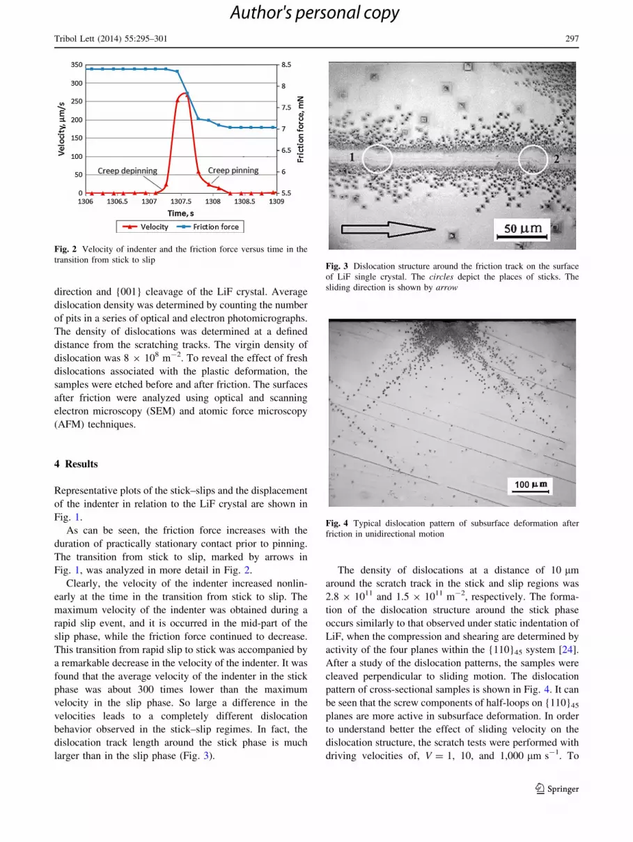
Fig. 1, was analyzed in more detail in Fig. 2.
Clearly, the velocity of the indenter increased nonlin-
early at the time in the transition from stick to slip. The
maximum velocity of the indenter was obtained during a
rapid slip event, and it is occurred in the mid-part of the
slip phase, while the friction force continued to decrease.
This transition from rapid slip to stick was accompanied by
a remarkable decrease in the velocity of the indenter. It was
found that the average velocity of the indenter in the stick
phase was about 300 times lower than the maximum
velocity in the slip phase. So large a difference in the
velocities leads to a completely different dislocation
behavior observed in the stick–slip regimes. In fact, the
dislocation track length around the stick phase is much
larger than in the slip phase (Fig. 3).
The density of dislocations at a distance of 10 lm
around the scratch track in the stick and slip regions was
2.8 9 1011 and 1.5 9 1011 m-2, respectively. The forma-
tion of the dislocation structure around the stick phase
occurs similarly to that observed under static indentation of
LiF, when the compression and shearing are determined by
activity of the four planes within the {110}45 system [24].
After a study of the dislocation patterns, the samples were
cleaved perpendicular to sliding motion. The dislocation
pattern of cross-sectional samples is shown in Fig. 4. It can
be seen that the screw components of half-loops on {110}45
planes are more active in subsurface deformation. In order
to understand better the effect of sliding velocity on the
dislocation structure, the scratch tests were performed with
driving velocities of, V = 1, 10, and 1,000 lm s-1. To
Fig. 2 Velocity of indenter and the friction force versus time in the
transition from stick to slipFig. 3 Dislocation structure around the friction track on the surface
of LiF single crystal. The circles depict the places of sticks. The
sliding direction is shown by arrow
Fig. 4 Typical dislocation pattern of subsurface deformation after
friction in unidirectional motion
Tribol Lett (2014) 55:295–301 297
123
Author's personal copy

avoid the sticks, a stiff spring, k = 2,400 N m-1, was used.
SEM images of the scratch and dislocation tracks after
scratching with sliding velocity, V = 1 lm s-1 (a) and
V = 1,000 lm s-1, are shown in Fig. 5.
A completely different behavior was observed along
low-velocity track in comparison with scratching with high
velocity. The width of the dislocation track increases
remarkably during sliding with low velocity in comparison
with high velocity (100 and 70 lm, respectively). More-
over, the width of the scratched track also increased (21
and 16 lm, respectively). Scratching with low driving
velocity is also accompanied by a plowing of surface layers
and a formation of wear particles, whereas a relatively
smooth surface appeared after scratching with high veloc-
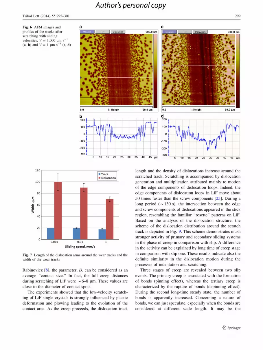
ity. The AFM images confirmed the results obtained by
SEM analysis (Fig. 6). The depth of plowing under
scratching with low driving velocity is increased.
The length of dislocation arms around the wear track
and the width of the wear tracks are shown in Fig. 7.
A definite correlation is observed between the length of
dislocation arms and width of wear tracks. Our measure-
ments show that the dislocation behavior in the slip phase
is determined mainly by the velocity of the indenter, while
a time-dependent loading is responsible for dislocation
motion and plowing in the stick phase. The time-dependent
displacement of the indenter in the stick (creep) region was
analyzed in more detail. Typical creep curves for two slip
events are shown in Fig. 8.
The time of creep is *130 s, whereas the slip time is
*1 s. The creep curve exhibits three phases as is generally
observed for base metals and alloys [25]: The primary
creep regime after slip phase (1) followed by ‘‘full’’ stick in
steady state (2) and an accelerating tertiary creep regime in
the transition to slip (3). As can be seen, the displacement
of the indenter in the primary and tertiary phases of creep is
described by a power-law relationship. In the primary
creep, a growth of the dislocation motion and the plowing
raises the shear stress during the pinning phase. The dis-
location loops expanded during a long time in creep regime
jump at a long distance from the scratch track; the number
of contact bonds is increased. In the steady state (‘‘full’’
stick), the measured displacement of indenter was below
the detection limit of our equipment (B0.05 lm s-1).
Therefore, we cannot unambiguously draw conclusions
about the shearing in the ‘‘full’’ stick phase. A rupture of
the bonds (depinning effect) characterizes the tertiary creep
in the stick phase. The time of creep depinning is signifi-
cantly larger than the time of pinning (45 and 15 s,
respectively) (Fig. 2). Displacement of the indenter in the
primary creep is 1.5 lm, whereas in tertiary creep it is two
times larger, 3 lm.
5 Discussion
The stick–slip experiments showed that the static threshold,
ls, depends on the stick time, sstick. The time scales for
stick and slip processes are distinct (sstick � sslip). The
velocity of the indenter in the stick phase is 300 times
lower than in the slip phase. Major differences between the
velocity of the indenter in the stick and slip phases deter-
mine the dislocation modification of structure and plowing
in the scratch track. We have demonstrated for the first
time that the dislocations jump over much longer distances
than those that occur under low driving velocity. Low-
velocity friction is accompanied by deep plowing, while a
smooth surface of track is observed under scratching with
high velocity.
In accordance with Heslot et al. [9], the displacement
during creep can be considered as the average shearing
displacement necessary to break a typical contact, D0. We
define here two creep lengths: D1 = 1.5–2 lm as the dis-
placement of the indenter after slipping (pinning phase)
and D2 = 3–4 lm after creep but before slipping (depin-
ning phase). Following the works of Scholz [5] and
Fig. 5 SEM images of the scratch and dislocation tracks after friction
with sliding velocity, V = 1 lm s-1 (a) and V = 1,000 lm s-1 (b).
Stiff spring, k = 2,400 N m-1
298 Tribol Lett (2014) 55:295–301
123
Author's personal copy
Rabinovicz [8], the parameter, D, can be considered as an
average ‘‘contact size.’’ In fact, the full creep distances
during scratching of LiF were *6–8 lm. These values are
close to the diameter of contact spots.
The experiments showed that the low-velocity scratch-
ing of LiF single crystals is strongly influenced by plastic
deformation and plowing leading to the evolution of the
contact area. As the creep proceeds, the dislocation track
length and the density of dislocations increase around the
scratched track. Scratching is accompanied by dislocation
generation and multiplication attributed mainly to motion
of the edge components of dislocation loops. Indeed, the
edge components of dislocation loops in LiF move about
50 times faster than the screw components [25]. During a
long period (*130 s), the intersection between the edge
and screw components of dislocations appeared in the stick
region, resembling the familiar ‘‘rosette’’ patterns on LiF.
Based on the analysis of the dislocation structure, the
scheme of the dislocation distribution around the scratch
track is depicted in Fig. 9. This scheme demonstrates mush
stronger activity of primary and secondary sliding systems
in the phase of creep in comparison with slip. A difference
in the activity can be explained by long time of creep stage
in comparison with slip one. These results indicate also the
definite similarity in the dislocation motion during the
processes of indentation and scratching.
Three stages of creep are revealed between two slip
events. The primary creep is associated with the formation
of bonds (pinning effect), whereas the tertiary creep is
characterized by the rupture of bonds (depinning effect).
During the second long-time steady state, the number of
bonds is apparently increased. Concerning a nature of
bonds, we can just speculate, especially when the bonds are
considered at different scale length. It may be the
Fig. 6 AFM images and
profiles of the tracks after
scratching with sliding
velocities, V = 1,000 lm s-1
(a, b) and V = 1 lm s-1 (c, d)
Fig. 7 Length of the dislocation arms around the wear tracks and the
width of the wear tracks
Tribol Lett (2014) 55:295–301 299
123
Author's personal copy

dislocation interaction or molecular bonds in atomic scale
or adhesion bonds in macroscale. Here, for the sake of
simplicity, we assumed that the pinning (depinning) effects
to be the interaction (rupture) of the molecular or
mechanical bonds. The formation of bonds in the primary
creep is attributed to the plastic deformation and plowing
of surface layers. As a result, the shear stresses, rs, are
increased. The shear stress can be calculated as, rs = lH,
where l is the friction coefficient and H is the hardness
after deformation. The calculated value in the onset of
pinning for LiF is rs1 = 110 MPa. This value is high
enough in order to activate nonconservative slip of dislo-
cations in a LiF single crystal [25]. The plastic deformation
is accompanied by the penetration of the indenter into the
surface layers leading finally to an increase of the contact
area and retardation in the displacement of the indenter. At
the steady state, small shearing is possible. However, our
threshold of the observability of the indenter’s displace-
ment is limited. The steady state is attributed to the
dynamic equilibrium between the dislocation motion and
their annihilation. At this state, the number of bonds is
increased during a long period, *100 s. An increase in the
number of bonds leads to a rise in the shear stress needed
for the rupture (depinning) of these bonds. The calculated
value of the shear stress at the end of the steady state is
close to 160 MPa. The tertiary creep is associated with the
rupture of the typical contact bonds due to movement and
annihilation of dislocation and plowing. Plowing during
pinning and depinning results from the same physical
process, namely creep of the contact spots.
Creep of metals and alloys as well as creep in low-
velocity scratching is a thermally activated process [e.g. 9,
26]. The creep during stick event is defined using power-
law equations of steady state creep at high temperature. We
suggest that the creep and plowing of a complex nonlinear
dynamic friction system in low-velocity sliding cannot be
described by the power-law equations of steady state creep
only. Stick events in low-velocity friction are characterized
by creep, aging of contact, and memory length (the average
shearing displacement). For instance, an increase in aging
leads to an increasing the number of contact bonds and thus
raises the stress for depinning of bonds. On the other hand,
the aging depends on the stiffness of the dynamic friction
system.
6 Conclusion
The stick–slip phenomenon has been studied by scratching
LiF single crystals with a diamond indenter. The
Fig. 8 Real displacement of the
indenter during stick (creep)
events occurring between two
slips: 1 primary creep, 2 steady
state ‘‘stick,’’ 3 tertiary creep
Fig. 9 Schematic summary of the dislocation activity around the
scratch track during stick (creep) and slip events
300 Tribol Lett (2014) 55:295–301
123
Author's personal copy

dislocation structure around the scratch track has been
analyzed. Maximum velocity of the indenter in the slip
phase is about 300 times larger than in the stick phase.
Large difference in the velocities of the indenter in stick
and slip leads to a totally different dislocation behavior:
The dislocation mobility around the stick phase is much
larger than in the slip phase. These results were confirmed
by a special experiment where the dislocation structure has
been studied after scratching with the velocity of machine,
V = 1, 10 and 1,000 l s-1, using a stiff spring. Time-
dependent deformation in the stick phase is considered as
three-staged creep: Primary creep regime (pinning) fol-
lowed by ‘‘full’’ stick in a steady state and an accelerating
tertiary creep regime (depinning). We have shown that the
analysis of the dislocation structure during stick–slip
events is of great significance for understanding the
mechanism of plastic deformation and damage develop-
ment during friction with stick–slips.
References
1. Bowden, F., Tabor, D.: The Friction and Lubrication of Solids.
Clarendon, Oxford (1950)
2. Rabinowicz, E.: The nature of the static and kinetic coefficients
of friction. J. Appl. Phys. 22, 1373–1379 (1958)
3. Persson, B.: Sliding Friction: Physical Principles and Applica-
tions. Springer, Heidelberg (1998)
4. Rapoport, L., Bilik, Y., Feldman, Y., et al.: Hollow nanoparticles
of WS2 as potential solid-state lubricants. Nature 387, 791–793
(1997)
5. Scholz, C.: The Mechanics of Earthquakes and Faulting. Cam-
bridge University Press, Cambridge (1990)
6. Lee, D., Banquy, X., Israelachvili, J.: Stick–slip friction and wear
of articular joints. Proc. Natl. Acad. Sci. 28, E567–E574 (2013)
7. Urbakh, M., Klafter, J., Gourdon, D., Israelachvili, J.: The non-
linear nature of friction. Nature 430, 525–528 (2004)
8. Rabinovicz, E.: The intrinsic variables affecting the stick–slip
process. Proc. Phys. Soc. Lond. 71, 668–675 (1958)
9. Heslot, F., Baumberger, T., Perrin, B., Caroli, B., Caroli, C.:
Creep, stick–slip, and dry friction dynamics: experiments and a
heuristic model. Phys. Rev. E 49, 4973–4988 (1994)
10. Baumberger, T., Heslot, F., Perrin, B.: Crossover from creep to
inertial motion in friction dynamics. Nature 367, 544–546 (1994)
11. Baumberger, T., Gauthier, L.: Creeplike relaxation at the inter-
face between rough solids under shear. J. Phys. 6, 1021–1030
(1996)
12. Rabinowicz, E.: Friction and Wear of Materials. Wiley, New
York (1995)
13. Cho, M., Kim, S., Lim, D., Jang, H.: Atomic scale stick–slip
caused by dislocation nucleation and propagation during
scratching of a Cu substrate with a nanoindenter: a molecular
dynamics simulation. Wear 259, 1392–1399 (2005)
14. Smith, R., Mulliah, D., Kenny, S., et al.: Stick slip and wear on
metal surfaces. Wear 259, 459–466 (2005)
15. Filippov, A., Klafter, J., Urbakh, M.: Friction through dynamical
formation and rupture of molecular bonds. Phys. Rev. Lett. 92,
135503-1–135503-4 (2004)
16. Muser, M.: How static is static friction? Proc. Natl. Acad. Sci.
105, 13187–13188 (2008)
17. Yang, Z., Zhang, H., Marder, M.: Dynamics of static friction.
Proc. Natl. Acad. Sci. 105, 13264–13268 (2008)
18. Hurtado, J., Kim, K.: Scale effects in friction of single-asperity
contacts. I. From concurrent slip to single-dislocation-assisted
slip. Proc. R. Soc. Lond. A 455, 3363–3384 (1999)
19. Hurtado, J., Kim, K.: Scale effects in friction of single-asperity
contacts. II. Multiple-dislocation-cooperated slip. Proc. R. Soc.
Lond. A 455, 3385–3400 (1999)
20. Deshpande, V., Needleman, A., Van der Giessen, E.: Discrete
dislocation plasticity analysis of static friction. Acta Mater. 52,
3135–3149 (2004)
21. Merkle, A., Marks, L.: A predictive analytical friction model
from basic theories of interfaces, contacts and dislocations. Tri-
bol. Lett. 26, 73–84 (2007)
22. M’ndange-Pfupfu, A., Marks, L.: A dislocation-based analytical
model for the nanoscale processes of shear and plowing friction.
Tribol. Lett. 39, 163–167 (2010)
23. Rapoport, L.: Peculiarities of LiF single-crystal deformation in
vaseline oil at elevated temperatures. Wear 161, 23–28 (1993)
24. Harea, E., Lapsker, I., Laikhtman, A., Rapoport, L.: Bauschin-
ger’s effect and dislocation structure under friction of LiF single
crystals. Tribol. Lett. 52, 205–212 (2013)
25. Gilman, J., Johnston W.: Dislocations and mechanical properties
of crystals. In: Fisher, J., Johnston, W., Thomson, R., Vreeland,
T. (eds.), p. 116. Willey, New York (1957)
26. Kassner, M., Perez-Prado, M.: Fundamentals of Creep in Metals
and Alloys. Elsevier, Oxford (2009)
Tribol Lett (2014) 55:295–301 301
123
Author's personal copy