differential pressure transmitter model dpt-10 - wika
TRANSCRIPT

Pressure
WIKA data sheet PE 86.21
Page 1 of 16
Differential pressure transmitterModel DPT-10
Data sheets showing similar products and accessories:Process transmitter; model UPT-20, standard version; see data sheet PE 86.05Process transmitter with welded metal measuring cell; model IPT-20, standard version; see data sheet PE 86.06Process transmitter with capacitive ceramic measuring cell; model CPT-20, standard version; see data sheet PE 86.07Valve manifold for differential pressure measuring instruments; see data sheet AC 09.23
Differential pressure transmitter model DPT-10
Applications
■ Process engineering ■ Chemical industry ■ Petrochemical industry ■ Food and beverage industry ■ Machine building and plant construction
Special features
■ High measurement accuracy ■ Freely scalable measuring ranges ■ Various Ex approvals ■ Seven different case variants ■ Configuration via DTM (Device Type Manager) in accordance
with the FDT (Field Device Tool) concept (e.g. PACTware)
Description
The DPT-10, with its 4 ... 20 mA, 4 ... 20 mA HART® or PROFIBUS® PA output signals, combined with the intrinsically safe or flameproof enclosure ignition protection type, is ideally suited for application in appropriate systems. The electronics of all of these transmitters, even for the flameproof variant, are intrinsically safe. Thus it is possible to make adjustments on the instrument in Ex areas while the instrument is live.
Versatile in applicationThe DTP-10 is suitable for many industrial measuring requirements, such as flow measurement using differential pressure transducers, level measurement or filter and pump monitoring. With mounted diaphragm seals, the DTP-10 is also suitable for harsh process conditions. As a result of the available measuring ranges from -10 ... +10 mbar [-0.15 ... +0.15 psi] to -40 ... +40 bar [-600 ... +600 psi] and a static pressure limitation of up to 420 bar [6,300 psi], the instrument can be used in almost any application. The internal digital signal processing, combined with proven sensors, guarantees high accuracy and the best long-term stability.
There are seven different case variants available, and thus it is possible to select a variant suited to every operating environment. The case itself can be rotated through 330° and is available in plastic, aluminium and stainless steel.An electropolished stainless steel case (316L) is available to meet the high demands of the food and pharmaceutical industries.
Easy configuration and operationService and configuration at the instrument is carried out using the optional display and operating module, which can be fitted in four positions. The operating menu has a simple and self-explanatory structure and has nine selectable languages. Alternatively, the operating parameters can be set using the PACTware™ free and non-proprietary configuration software. An instrument-specific DTM enables easy integration into corresponding process control systems.
WIKA data sheet PE 86.21 ∙ 08/2020
for further approvals see page Seite 10
WIKA data sheet PE 86.21 ∙ 08/2020 Page 2 of 16
Specifications
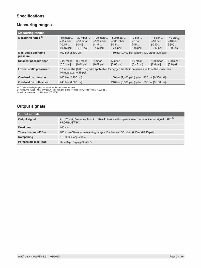
Measuring ranges
Measuring rangesMeasuring range 1) -10 mbar ...
+10 mbar[-0.15 ... +0.15 psi]
-30 mbar ... +30 mbar[-0.45 ... +0.45 psi]
-100 mbar ... +100 mbar[-1.5 ... +1.5 psi]
-500 mbar ... +500 mbar[-7.5 ... +7.5 psi]
-3 bar ... +3 bar[-45 ... +45 psi]
-16 bar ... +16 bar[-240 ... +240 psi]
-40 bar ... +40 bar 2)
[-600 ... +600 psi]
Max. static operating pressure
160 bar [2,400 psi] 160 bar [2,400 psi] (option: 420 bar [6,300 psi])
Smallest possible span 0.25 mbar [0.01 psi]
0.3 mbar [0.01 psi]
1 mbar [0.02 psi]
5 mbar [0.08 psi]
30 mbar [0.45 psi]
160 mbar [2.4 psi]
400 mbar [5.8 psi]
Lowest static pressure 3) 0.1 mbar abs. [0.001psi], with application for oxygen the static pressure should not be lower than 10 mbar abs. [0.15 psi]
Overload on one side 160 bar [2,400 psi] 160 bar [2,400 psi] (option: 420 bar [6,300 psi])Overload on both sides 240 bar [6,300 psi] 240 bar [6,300 psi] (option: 630 bar [9,100 psi])
1) Other measuring ranges can be set via the respective turndown.2) Measuring range 40 bar [600 psi], “-” side with one-sided overload safety up to 100 bar [1,500 psi].3) Valid at reference conditions per IEC 62828.
Output signals
Output signalsOutput signal 4 … 20 mA, 2-wire, (option: 4 ... 20 mA, 2-wire with superimposed communication signal HART®,
PROFIBUS® PA)Dead time 100 msTime constant (63 %) 180 ms (450 ms for measuring ranges 10 mbar and 30 mbar [0.15 and 0.45 psi])Dampening 0 … 999 s, adjustablePermissible max. load RA = (UB – UBmin)/0.023 A
WIKA data sheet PE 86.21 ∙ 08/2020 Page 3 of 16
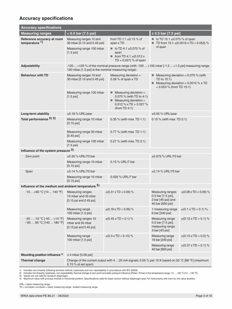
Accuracy specifications
Accuracy specificationsMeasuring ranges < 0.5 bar [7.5 psi] ≥ 0.5 bar [7.5 psi]Reference accuracy at room temperature 1)
Measuring ranges 10 and 30 mbar [0.15 and 0.45 psi]
from TD 1:1 ±0.15 % of span x TD
■ to TD 15:1 ±0.075 % of span ■ TD from 15:1 ±(0.0015 x TD + 0.053) %
of spanMeasuring range 100 mbar [1.5 psi]
■ to TD 4:1 ±0.075 % of span
■ from TD 4:1 ±(0.012 x TD + 0.027) % of span
Adjustability -120 ... +120 % of the nominal pressure range (with -100 ... +100 mbar [-1.5 ... +1.5 psi] measuring range, 100 mbar [1.5 psi] is the nominal measuring range)
Behaviour with TD Measuring ranges 10 and 30 mbar [0.15 and 0.45 psi]
Measuring deviation = 0.09 % of span x TD
■ Measuring deviation = 0.075 % (with TD to 15:1)
■ Measuring deviation = 0.0015 % x TD + 0.053 % (from TD 15:1)
Measuring range 100 mbar [1.5 psi]
■ Measuring deviation = 0.075 % (with TD to 4:1)
■ Measuring deviation = 0.012 % x TD + 0.027 % (from TD 4:1)
Long-term stability ±0.18 % URL/year ±0.05 % URL/yearTotal performance 2) 3) Measuring range 10 mbar
[0.15 psi]0.35 % (with max. TD 1:1) 0.15 % (with max. TD 2:1)
Measuring range 30 mbar [0.45 psi]
0.77 % (with max. TD 1:1)
Measuring range 100 mbar [1.5 psi]
0.27 % (with max. TD 2:1)
Influence of the system pressure 3)
Zero point ±0.35 % URL/70 bar ±0.075 % URL/70 barMeasuring range 10 mbar [0.15 psi]
0.15 % URL/7 bar
Span ±0.14 % URL/70 bar ±0.14 % URL/70 barMeasuring range 10 mbar [0.15 psi]
0.035 % URL/7 bar
Influence of the medium and ambient temperature 3)
-10 ... +60 °C [14 ... 140 °F] Measuring ranges 10 mbar and 30 mbar [0.15 psi and 0.45 psi]
±(0.31 x TD + 0.06) % Measuring ranges 0.5 bar [7.5 psi], 3 bar [45 psi] and 40 bar [600 psi]
±(0.08 x TD + 0.05) %
Measuring range 100 mbar [1.5 psi]
±(0.18 x TD + 0.06) % 1 measuring range 6 bar [240 psi]
±(0.1 x TD + 0.1) %
-40 … -10 °C [-40 ... +14 °F] / 60 … 85 °C [140 ... 185 °F]
Measuring ranges 10 mbar and 30 mbar[0.15 psi and 0.45 psi]
±(0.45 x TD + 0.1) % Measuring range 0.5 bar [7.5 psi], measuring range 3 bar [45 psi]
±(0.12 x TD + 0.1) %
Measuring range 100 mbar [1.5 psi]
±(0.3 x TD + 0.15) % Measuring range 16 bar [240 psi]
±(0.15 x TD + 0.2) %
Measuring range 40 bar [600 psi]
±(0.37 x TD + 0.1) %
Mounting position influence 4) ≤ 4 mbar [0.06 psi]Thermal change Change of the current output with 4 ... 20 mA signals: 0.05 % per 10 K based on 20 °C [68 °F] (maximum
0.15 % at set span)
1) Includes non-linearity following terminal method, hysteresis and non-repeatability in accordance with IEC 62828.2) Includes non-linearity, hysteresis, non-repeatability, thermal change of zero point and static pressure influence (Pstat= 70 bar) in the temperature range -10 … +60 °C [14 ... 140 °F].3) Values are not valid for tantalum diaphragm.4) Maximum value with process module in horizontal position. Specifications valid for basic version without diaphragm seal. For instruments with inert oil, the value doubles.
URL = basic measuring rangeTD = turndown; turndown = basic measuring range : scaled measuring range
WIKA data sheet PE 86.21 ∙ 08/2020 Page 4 of 16
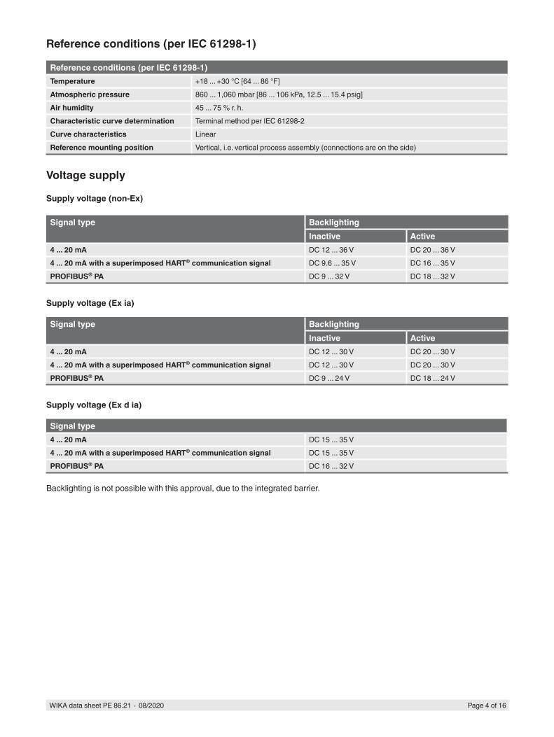
Reference conditions (per IEC 61298-1)
Reference conditions (per IEC 61298-1)Temperature +18 ... +30 °C [64 ... 86 °F]Atmospheric pressure 860 ... 1,060 mbar [86 ... 106 kPa, 12.5 ... 15.4 psig]Air humidity 45 ... 75 % r. h.Characteristic curve determination Terminal method per IEC 61298-2Curve characteristics LinearReference mounting position Vertical, i.e. vertical process assembly (connections are on the side)
Voltage supply
Supply voltage (non-Ex)
Signal type BacklightingInactive Active
4 ... 20 mA DC 12 ... 36 V DC 20 ... 36 V4 ... 20 mA with a superimposed HART® communication signal DC 9.6 ... 35 V DC 16 ... 35 VPROFIBUS® PA DC 9 ... 32 V DC 18 ... 32 V
Supply voltage (Ex ia)
Signal type BacklightingInactive Active
4 ... 20 mA DC 12 ... 30 V DC 20 ... 30 V4 ... 20 mA with a superimposed HART® communication signal DC 12 ... 30 V DC 20 ... 30 VPROFIBUS® PA DC 9 ... 24 V DC 18 ... 24 V
Supply voltage (Ex d ia)
Signal type4 ... 20 mA DC 15 ... 35 V4 ... 20 mA with a superimposed HART® communication signal DC 15 ... 35 VPROFIBUS® PA DC 16 ... 32 V
Backlighting is not possible with this approval, due to the integrated barrier.
WIKA data sheet PE 86.21 ∙ 08/2020 Page 5 of 16
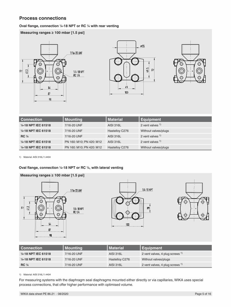
Process connectionsOval flange, connection ¼-18 NPT or RC ¼ with rear venting
Connection Mounting Material Equipment¼-18 NPT IEC 61518 7/16-20 UNF AISI 316L 2 vent valves 1)
¼-18 NPT IEC 61518 7/16-20 UNF Hastelloy C276 Without valves/plugsRC ¼ 7/16-20 UNF AISI 316L 2 vent valves 1)
¼-18 NPT IEC 61518 PN 160: M10; PN 420: M12 AISI 316L 2 vent valves 1)
¼-18 NPT IEC 61518 PN 160: M10; PN 420: M12 Hastelloy C276 Without valves/plugs
1) Material: AISI 316L/1.4404
Measuring ranges ≥ 100 mbar [1.5 psi]
Connection Mounting Material Equipment¼-18 NPT IEC 61518 7/16-20 UNF AISI 316L 2 vent valves, 4 plug screws 1)
¼-18 NPT IEC 61518 7/16-20 UNF Hastelloy C276 Without valves/plugsRC ¼ 7/16-20 UNF AISI 316L 2 vent valves, 4 plug screws 1)
1) Material: AISI 316L/1.4404
For measuring systems with the diaphragm seal diaphragms mounted either directly or via capillaries, WIKA uses special process connections, that offer higher performance with optimised volume.
Oval flange, connection ¼-18 NPT or RC ¼, with lateral venting
Measuring ranges ≥ 100 mbar [1.5 psi]
WIKA data sheet PE 86.21 ∙ 08/2020 Page 6 of 16
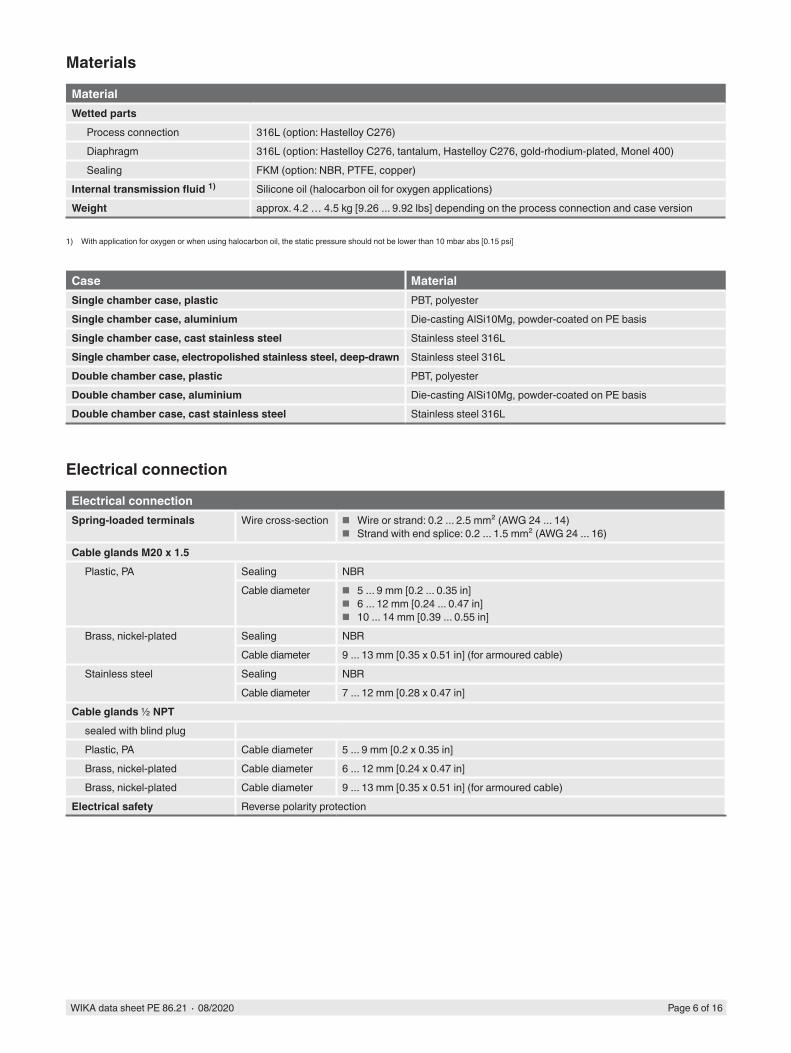
Materials
MaterialWetted parts
Process connection 316L (option: Hastelloy C276)Diaphragm 316L (option: Hastelloy C276, tantalum, Hastelloy C276, gold-rhodium-plated, Monel 400)Sealing FKM (option: NBR, PTFE, copper)
Internal transmission fluid 1) Silicone oil (halocarbon oil for oxygen applications)Weight approx. 4.2 … 4.5 kg [9.26 ... 9.92 lbs] depending on the process connection and case version
1) With application for oxygen or when using halocarbon oil, the static pressure should not be lower than 10 mbar abs [0.15 psi]
Case MaterialSingle chamber case, plastic PBT, polyesterSingle chamber case, aluminium Die-casting AlSi10Mg, powder-coated on PE basisSingle chamber case, cast stainless steel Stainless steel 316LSingle chamber case, electropolished stainless steel, deep-drawn Stainless steel 316LDouble chamber case, plastic PBT, polyesterDouble chamber case, aluminium Die-casting AlSi10Mg, powder-coated on PE basisDouble chamber case, cast stainless steel Stainless steel 316L
Electrical connection
Electrical connectionSpring-loaded terminals Wire cross-section ■ Wire or strand: 0.2 ... 2.5 mm² (AWG 24 ... 14)
■ Strand with end splice: 0.2 ... 1.5 mm² (AWG 24 ... 16)Cable glands M20 x 1.5
Plastic, PA Sealing NBRCable diameter ■ 5 ... 9 mm [0.2 ... 0.35 in]
■ 6 ... 12 mm [0.24 ... 0.47 in] ■ 10 ... 14 mm [0.39 ... 0.55 in]
Brass, nickel-plated Sealing NBRCable diameter 9 ... 13 mm [0.35 x 0.51 in] (for armoured cable)
Stainless steel Sealing NBRCable diameter 7 ... 12 mm [0.28 x 0.47 in]
Cable glands ½ NPTsealed with blind plugPlastic, PA Cable diameter 5 ... 9 mm [0.2 x 0.35 in]Brass, nickel-plated Cable diameter 6 ... 12 mm [0.24 x 0.47 in]Brass, nickel-plated Cable diameter 9 ... 13 mm [0.35 x 0.51 in] (for armoured cable)
Electrical safety Reverse polarity protection
WIKA data sheet PE 86.21 ∙ 08/2020 Page 7 of 16
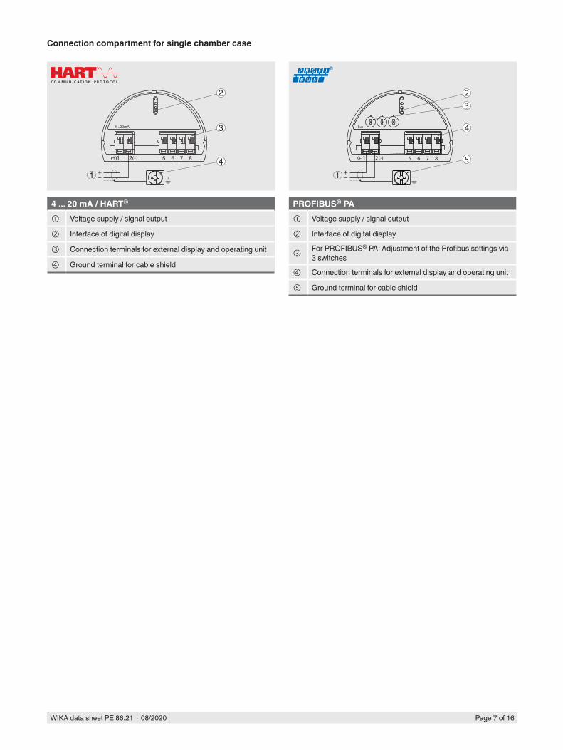
Connection compartment for single chamber case
51 2+( ) (-) 6 7 8
4...20mA
2
3
41
1 2( ) (-)
1
5+ 6 7 8
Bus
23
4
5
4 ... 20 mA / HART
Voltage supply / signal output
Interface of digital display
Connection terminals for external display and operating unit
Ground terminal for cable shield
PROFIBUS® PA
Voltage supply / signal output
Interface of digital display
For PROFIBUS® PA: Adjustment of the Profibus settings via 3 switches
Connection terminals for external display and operating unit
Ground terminal for cable shield
WIKA data sheet PE 86.21 ∙ 08/2020 Page 8 of 16
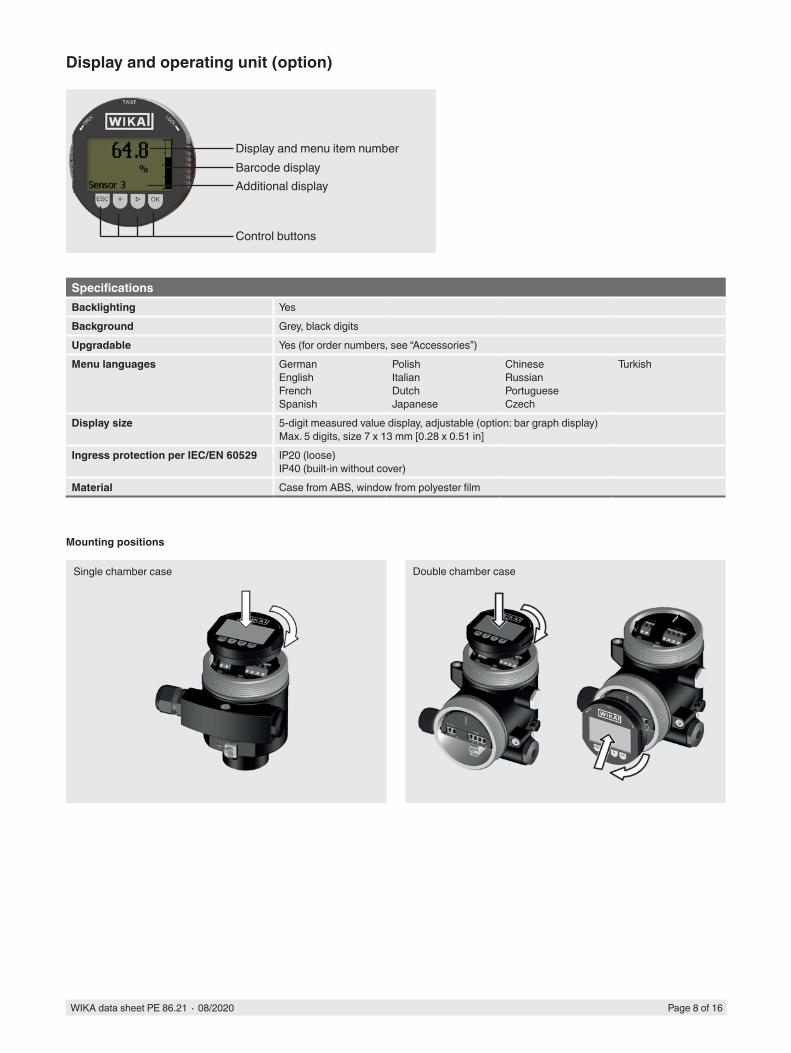
Display and operating unit (option)
SpecificationsBacklighting YesBackground Grey, black digitsUpgradable Yes (for order numbers, see “Accessories”)Menu languages German
EnglishFrenchSpanish
PolishItalianDutchJapanese
ChineseRussianPortugueseCzech
Turkish
Display size 5-digit measured value display, adjustable (option: bar graph display)Max. 5 digits, size 7 x 13 mm [0.28 x 0.51 in]
Ingress protection per IEC/EN 60529 IP20 (loose)IP40 (built-in without cover)
Material Case from ABS, window from polyester film
Mounting positions
Single chamber case Double chamber case
Display and menu item number
Additional display
Control buttons
Barcode display

WIKA data sheet PE 86.21 ∙ 08/2020 Page 9 of 16
Operating conditions
Operating conditionsPermissible temperature ranges
Ambient ■ -40 … +80 °C [-40 ... +176 °F] (without display) ■ -20 … +70 °C [-4 ... +158 °F] (with display)
Storage and transport -40 … +80 °C [-40 ... +176 °F]Restrictions to medium temperature due to sealing material
FKM/NBR -20 … +85 °C [-4 ... +185 °F]PTFE, copper -40 … +85 °C [-40 ... +185 °F]FKM, oil and grease free -10 … +85 °C [14 ... 185 °F]For oxygen applications (max. static pressure: 160 bar [2,400 psi])
Copper, PTFE -20 … +60 °C [-4 ... +140 °F]
FKM -10 … +60 °C [14 ... 140 °F]
Temperature limits With differential pressure lines longer than 100 mm [3.94 in]: -40 … +120 °C [-40 ... 248 °F]Vibration resistance 1) 4 g (5 … 100 Hz)Shock resistance 100 g per IEC 60068-2-27 (mechanical shock)Instrument safety
Ingress protection per IEC/EN 60529
IP66/67 (standard case)
Electrical safety Overvoltage category III, protection class II
1) Tested in accordance with the directive GL, characteristic curve 2 (not for double chamber cases from stainless steel)

WIKA data sheet PE 86.21 ∙ 08/2020 Page 10 of 16
Approvals (option)
Logo Description CountryEU declaration of conformity European UnionEMC directive, interference emission (group 1, class B) and immunity per EN 61326-1:2013 (industrial application), EN 61326-2-3:2013 1)
Pressure equipment directiveRoHS directiveATEX directive- Ex i Zone 0 gas II 1G Ex ia IIC T6...T1 Ga
Zone 1 mounting to zone 0 gas II 1/2G Ex ia IIC T6...T1 Ga/GbZone 1 gas II 2G Ex ia IIC T6...T1 Gb
- Ex d Zone 1 mounting to zone 0 gas II 1/2G Ex db ia IIC T6 Ga/GbZone 1 gas II 2G Ex db ia IIC T6 Gb
IECExHazardous areas- Ex i Zone 0 gas Ex ia IIC T6...T1 Ga
Zone 1 mounting to zone 0 gas Ex ia IIC T6...T1 Ga/GbZone 1 gas Ex ia IIC T6...T1 Gb
- Ex d Zone 1 mounting to zone 0 Gas Ex db ia IIC T6 Ga/GbZone 1 gas Ex db ia IIC T6 Gb
International
EAC ■ Pressure equipment directive ■ Electromagnetic compatibility ■ Hazardous areas
- Ex i Zone 0 gas 0 Ex ia IIC T6...T1 XZone 1 gas 1 Ex ia IIC T6...T1 X
- Ex d Zone 1 gas 1 Ex d ia IIC T6...T1 X
Eurasian Economic Community
GOSTMetrology, measurement technology
Russia
KazInMetrMetrology, measurement technology
Kazakhstan
- MTSCHSPermission for commissioning
Kazakhstan
BelGIMMetrology, measurement technology
Belarus
UkrSEPROMetrology, measurement technology
Ukraine
DNOP_MakNII ■ Mining ■ Hazardous areas
- Ex i Zone 0 gas II 1G II 1/2G II 2 GEx ia IIC T6...T1
Ukraine
UzstandardMetrology, measurement technology
Uzbekistan
1) With electrostatic discharge, a short-term, increased error of up to 1 % of the nominal measuring range can occur. This also applies to NAMUR NE21.
WIKA data sheet PE 86.21 ∙ 08/2020 Page 11 of 16
Manufacturer’s information and certificates
NAMUR recommendationsNAMUR is the automation technology interest group for the process industry in Germany. The published NAMUR recommendations are considered standards in field instrumentation, and also have the character of international standards.
The instrument fulfils the requirements of the following NAMUR recommendations: ■ NE21 - Electromagnetic compatibility of equipment ■ NE43 - Signal level for failure information for transmitters ■ NE53 - Compatibility of field instruments and display and operating components
For further information, see www.namur.net/en
NACENACE is a term for an organisation (National Association of Corrosion Engineers) concerned with the topic of corrosion. The results of this organisation are published as NACE standards and regularly updated.The instruments and, in particular, the weld seams fulfil:
■ NACE MR0175 - Oil extraction and processing
Certificates (option)
■ Test certificate for the measurement accuracy included in delivery (5 measuring points in the nominal measuring range) ■ 2.2 test report ■ 3.1 inspection certificate ■ DKD/DAkkS calibration per IEC 17025
→ Approvals and certificates, see website
WIKA data sheet PE 86.21 ∙ 08/2020 Page 12 of 16
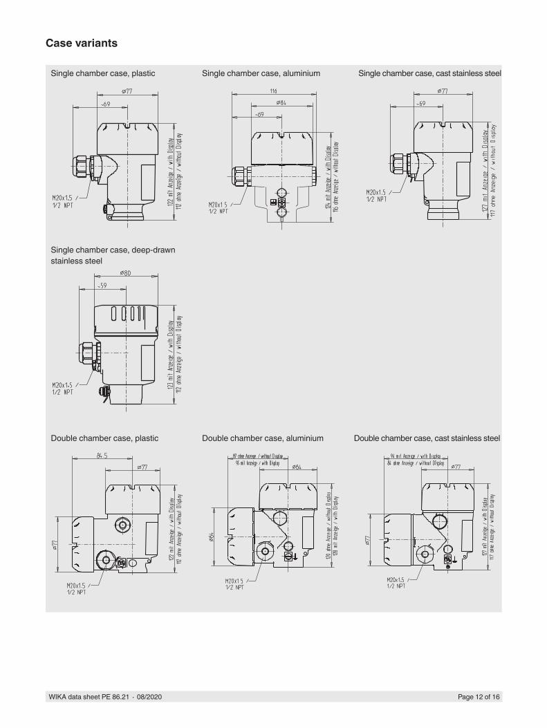
Case variants
Single chamber case, plastic
Double chamber case, plastic
Single chamber case, aluminium
Double chamber case, aluminium
Single chamber case, cast stainless steel
Single chamber case, deep-drawn stainless steel
Double chamber case, cast stainless steel

WIKA data sheet PE 86.21 ∙ 08/2020 Page 13 of 16
With upstream pressure compensating valves it is possible to avoid one-sided overpressure loading during both start-up and operation, and also to enable zero point checks during operation. Furthermore, they enable the isolation of the process lines without interference to the running process.
Furthermore, these pressure compensating valves (with integrated shut-off, purge and vent valves) enable the pressure gauge to be vented on one or both sides and the supply line to be purged.
By using diaphragm seals, it is possible to adapt the model DPT-10 differential pressure transmitter to even the most difficult of conditions in the process industry. The transmitters can thus be used at extreme temperatures, and with aggressive, corrosive, heterogeneous, abrasive, highly viscous or toxic media. As a result of the wide variety of aseptic connections, such as clamp, threaded pipe or DIN 11864 aseptic connections, measuring assemblies meet the high demands of sterile process engineering.
Primary flow elements for flow measurement are available as accessories. Depending on the application, the differential pressure transducers are designed as simple orifice plates, orifice flanges or complete meter runs.
Mounting variants
3-valve manifolds 5-valve manifolds
Diaphragm seal Primary flow elements
WIKA data sheet PE 86.21 ∙ 08/2020 Page 14 of 16
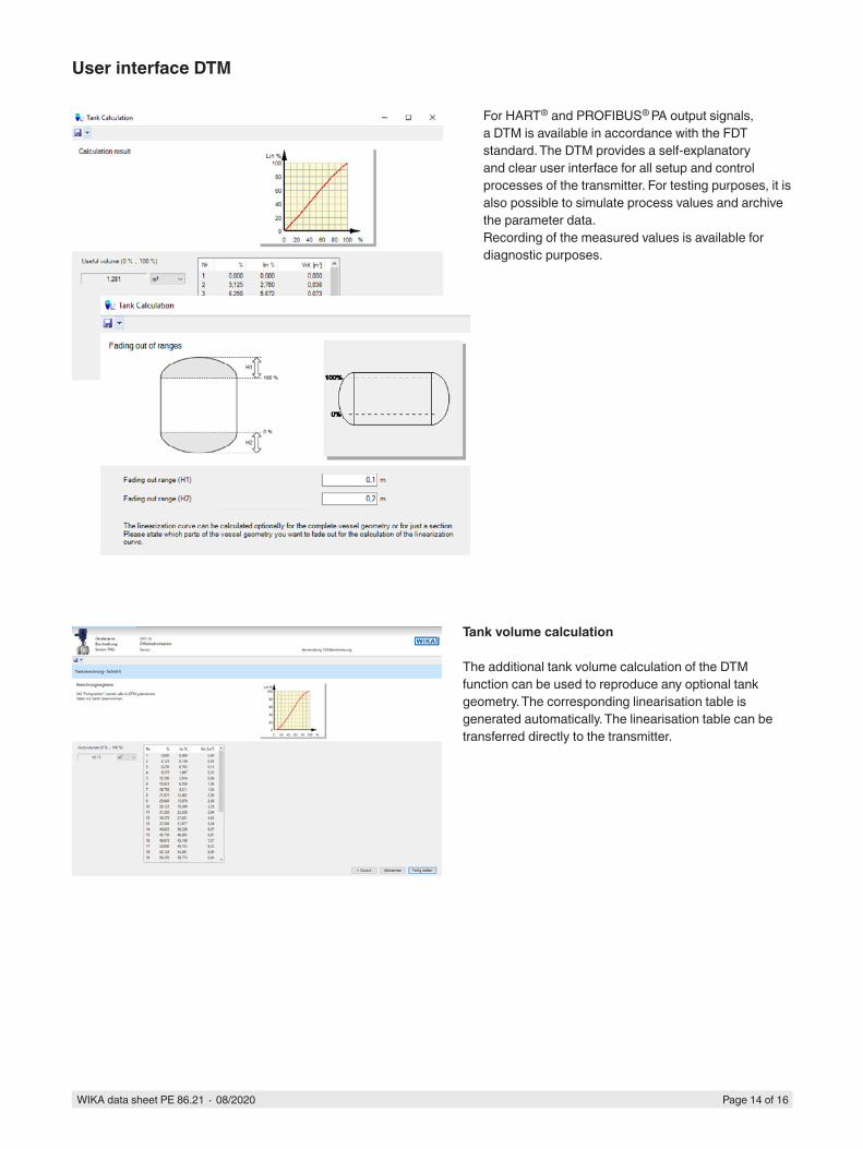
User interface DTM
For HART® and PROFIBUS® PA output signals, a DTM is available in accordance with the FDT standard. The DTM provides a self-explanatory and clear user interface for all setup and control processes of the transmitter. For testing purposes, it is also possible to simulate process values and archive the parameter data.Recording of the measured values is available for diagnostic purposes.
Tank volume calculation
The additional tank volume calculation of the DTM function can be used to reproduce any optional tank geometry. The corresponding linearisation table is generated automatically. The linearisation table can be transferred directly to the transmitter.

WIKA data sheet PE 86.21 ∙ 08/2020 Page 15 of 16
Accessories
Description Order numberDisplay module, model DIH52-F5-digit display, 20-segment bar graph, without separate power supply, with additional HART® functionality. Automatic adjustment of measuring range and span.Secondary-master functionality: Setting the measuring range and unit of the connected transmitter using HART® standard commands possible.Optional: Explosion protection per ATEX
on request
HART® modem for USB interface, specifically designed for use with notebooks (model 010031)
11025166
HART® modem for RS-232 interface (model 010001) 7957522HART® modem for Bluetooth interface Ex ia IIC (model 010041) 11364254PowerXpress HART® modem, with optional power supply (model 010031P) 141332343-valve manifold, form A, ½ NPT female (IEC 61518-A)Stainless steel, PN 420, form A, NACE compliant, 3.1 material certificate
13382498
3-valve manifold, form A, 1/4 NPT female (IEC 61518-A)Stainless steel, PN 420, form A, NACE compliant, 3.1 material certificate
13382510
5-valve manifold, form A, ½ NPT female (IEC 61518-A)Stainless steel, PN 420, form A, NACE compliant, 3.1 material certificate
13382552
5-valve manifold, form A, 1/4 NPT female (IEC 61518-A)Stainless steel, PN 420, form A, NACE compliant, 3.1 material certificate
13382561
Oval flange, 1/4 NPT, stainless steel (2 pieces)Stainless steel, PN 420, form A, NACE compliant, 3.1 material certificate
13382609
Oval flange, ½ NPT, stainless steel (2 pieces)Stainless steel, PN 420, form A, NACE compliant, 3.1 material certificate
13382595
Set of sealing plugs, 1/4 NPT, 316L (2 pieces)for the vents at the differential pressure sensorIncluded in delivery with lateral venting, except for process connection from Hastelloy
14035620
Set of vent valves, 1/4 NPT, 316L (2 pieces)for the vents at the differential pressure sensorIncluded in delivery, except for process connection from Hastelloy
14368975
Instrument mounting bracket for wall or pipe mounting with mounting bracket and screws, stainless steel
11553945
Overvoltage protectionfor transmitters, 4 ... 20 mA, M20 x 1.5, series connection 14002489for transmitters, PROFIBUS® PA, M20 x 1.5, series connection 14013659Model DI-PT-R display and operating module, case cover aluminium with window 12298884
Model DI-PT-R display and operating module, case cover electropolished cast stainless steel with safety window
13315269
Model DI-PT-R display and operating module, case cover plastic with window 13315277
Model DI-PT-R display and operating module, case cover cast stainless steel with window for single chamber case
12298906
Model DI-PT-R display and operating module, case cover cast stainless steel with window for double chamber case
14045598
Model DI-PT-E external display and operating module, aluminium case 12354954
Model DI-PT-E external display and operating module, cast stainless steel case 12355101Model DI-PT-E external display and operating module, plastic case 14134247
WIKA data sheet PE 86.21 ∙ 08/2020 Page 16 of 16
© 04/2010 WIKA Alexander Wiegand SE & Co. KG, all rights reserved.The specifications given in this document represent the state of engineering at the time of publishing.We reserve the right to make modifications to the specifications and materials.
08/2
020
EN
WIKA Alexander Wiegand SE & Co. KGAlexander-Wiegand-Straße 3063911 Klingenberg/GermanyTel. +49 9372 132-0Fax +49 9372 [email protected]
Ordering informationApproval / Output signal / Static pressure / Differential pressure measuring range / Process connection / Sealing / Process temperature / Case / Electrical connection / Display / Mounting / Additional equipment / Certificates / Configuration