developing world model data specifications as metrics for sensory processing for on-road driving...
TRANSCRIPT
Developing World Model Data Specifications as Metrics for Sensory Processing for On-Road Driving Tasks
Anthony Barbera*, John Horst*, Craig Schlenoff*, Evan Wallace*, David Aha#
*National Institute of Standards and Technology
Gaithersburg, MD
#Naval Research Laboratories Washington, D.C.
ABSTRACT
The building of knowledge-intensive real-time intelligent control systems is one of the most difficult tasks humans attempt. It is motivated by the desire to create an artificial reasoning system that is capable of intelligent behavior, i.e. replicating the ability to act upon the world and to successfully accomplish activities that are only possible with the levels of knowledge processing exhibited by human beings. A critical question to be answered is how is the success of this effort is to be measured and evaluated. Measurement of the outward observable system behavior, while somewhat indicative does not really measure the correctness or quality of the system’s capabilities. This is especially true in complex real-time control systems such as autonomous on-road driving.
This paper describes an on-going effort at NIST, funded by the Defense Advanced Research Project Agency (DARPA) Mobile Autonomous Robot Software (MARS) On-Road Driving Project, to do task analysis and develop performance metrics for autonomous on-road driving.
This project uses the NIST Real-time Control System (RCS, now referred to as 4D/RCS) [1] design methodology and reference architecture to develop a task decomposition representational format for the on-road driving task knowledge. This task decomposition representation is used as the framework to further specify the world model entities, attributes, features, and events required for proper reasoning about each of the subtask activities. These world model specifications, in turn, are used as the requirements for the sensory processing system. These requirements identify those things that have to be measured in the environment, including their resolutions, accuracy tolerances, detection timing, and detection distances for each subtask activity. From these can be developed a set of performance metrics that allow validation of sensory processing by evaluating the world model representations it produces for each individual component subtask activity. In this way, taxonomies of autonomous capabilities can be developed and tested against these sensory processing and world model building performance metrics. Additional metrics can be developed to measure the performance characteristics of the behavior generation component with its planning and value judgment operations, but these additional metrics are not the topic of this paper
KEYWORDS: on-road driving, performance metrics, sensory processing, task decomposition, finite state machines
1. INTRODUCTION NIST has been involved with the development of autonomous intelligent vehicle control systems for a number of years. These efforts support both off-road and on-road driving tasks. This work, which has as its goal to approach human levels of performance in autonomous driving, has identified significant research and development areas. There is the behavior generation component that involves reasoning from real-time world model representations to carry out strategic and tactical behaviors for both off-road military missions and on-road civilian driving tasks. This includes the planning of alternate courses of action as well as the planning of alternate paths, evaluation of these plans and selection of the most appropriate action through some type of value judgment. Much work is presently expended in this area of reasoning, planning, and decision-making. Presently, however, the more significant impediment and therefore the area requiring major work is in the area of sensors and sensory processing algorithms to generate accurate, registered world maps and the recognition and classification of entities at sufficient resolution to populate a world model representation from which the behavior generation can work.
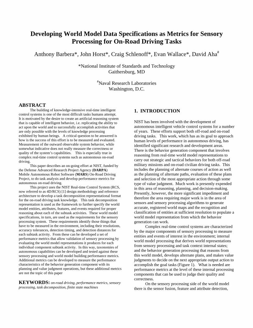
Complex real-time control systems are characterized by the major components of sensory processing to measure entities and events of interest in the environment; internal world model processing that derives world representations from sensory processing and task context internal states; and the behavior generation processing that reasons from this world model, develops alternate plans, and makes value judgments to decide on the next appropriate output action to accomplish the goal tasks (Figure 1). What is needed are performance metrics at the level of these internal processing components that can be used to judge their quality and correctness.
On the sensory processing side of the world model there is the sensor fusion, feature and attribute detection,
Report Documentation Page Form ApprovedOMB No. 0704-0188
Public reporting burden for the collection of information is estimated to average 1 hour per response, including the time for reviewing instructions, searching existing data sources, gathering andmaintaining the data needed, and completing and reviewing the collection of information. Send comments regarding this burden estimate or any other aspect of this collection of information,including suggestions for reducing this burden, to Washington Headquarters Services, Directorate for Information Operations and Reports, 1215 Jefferson Davis Highway, Suite 1204, ArlingtonVA 22202-4302. Respondents should be aware that notwithstanding any other provision of law, no person shall be subject to a penalty for failing to comply with a collection of information if itdoes not display a currently valid OMB control number.
1. REPORT DATE SEP 2003 2. REPORT TYPE
3. DATES COVERED 00-00-2003 to 00-00-2003
4. TITLE AND SUBTITLE Developing World Model Data Specifications as Metrics for SensoryProcessing for On-Road Driving Tasks
5a. CONTRACT NUMBER
5b. GRANT NUMBER
5c. PROGRAM ELEMENT NUMBER
6. AUTHOR(S) 5d. PROJECT NUMBER
5e. TASK NUMBER
5f. WORK UNIT NUMBER
7. PERFORMING ORGANIZATION NAME(S) AND ADDRESS(ES) National Institute of Standards and Technology (NIST),100 Bureau Drive,Gaithersburg,MD,20899
8. PERFORMING ORGANIZATIONREPORT NUMBER
9. SPONSORING/MONITORING AGENCY NAME(S) AND ADDRESS(ES) 10. SPONSOR/MONITOR’S ACRONYM(S)
11. SPONSOR/MONITOR’S REPORT NUMBER(S)
12. DISTRIBUTION/AVAILABILITY STATEMENT Approved for public release; distribution unlimited
13. SUPPLEMENTARY NOTES PerMIS?03, Performance Metrics for Intelligent Systems, 16-18 Sep 2003, Gaithersburg, MD
14. ABSTRACT see report
15. SUBJECT TERMS
16. SECURITY CLASSIFICATION OF: 17. LIMITATION OF ABSTRACT Same as
Report (SAR)
18. NUMBEROF PAGES
9
19a. NAME OFRESPONSIBLE PERSON
a. REPORT unclassified
b. ABSTRACT unclassified
c. THIS PAGE unclassified
Standard Form 298 (Rev. 8-98) Prescribed by ANSI Std Z39-18
S E N S O R YP R O C E S S I N G
W O R L D M O D E L I N GV A L U E J U D G M E N T
K N O W L E D G E
I m a g e s
M a p s E n tit ie s
S e n s o r s A c tu a to r sW o r ld
C la s s if ic a t io nE s tim a tio nC o m p u ta tio nG r o u p in gW in d o w in g
M is s io n (G o a l)
in te rn a le x te rn a l
E v e n tsP la n n e r sE x e c u to r s
T a s kK n o w le d g e
B E H A V I O RG E N E R A T IO N
Figure 1. The basic internal structure of a 4D/RCS control loop. Sensory processing performs the functions of windowing, grouping, computation, estimation, and classification on input from sensors. World modeling maintains knowledge in the form of images, maps, entities, and events with states, attributes, and values. Relationships between images, maps, entities, and events are defined by pointers. These relationships include class membership, ontologies, situations, and inheritance. Value judgment provides criteria for decision making. Behavior generation is responsible for planning and execution of behaviors.
object classification, map building etc. – all in the context of the present task activities. On the behavior side of the world model there is the planning and value judgment along with the plan selection and execution.
It is in support of the development of this sensory processing to world model data specification that the present work is addressed. The sensory processing requirements of different driving tasks have significantly different resolutions, identification, and classification requirements which suggests that performance metrics should be defined on a task-by-task basis. As an example, for the task of the vehicle driving down a highway, the sensor system has to be able to identify large objects moving nearby, their direction, speed and acceleration, their positions in the lanes (which means the sensory processing system has to be able to identify the lanes on the road) and state of brake and turn signal indicator lights on these objects. There is little requirement for detailed recognition of the type of objects or the need to see them at a distance or to read signs along side or overhead of the road.
If, however, our autonomous vehicle wants to pass a vehicle on an undivided two lane road, then an extraordinarily detailed representation of the world has to be sensed that identifies additional entities such as upcoming intersections, rail road crossings, vehicles in the oncoming lane out to very large distances, lane marking types, roadside signs etc. This level of sensor capability and sensor data to world model processing probably does not exist today.
Thus, we see that the sensor requirements and sensory-world model processing performance metrics are highly dependent on the particular driving task that we are
trying to accomplish and should therefore be specified according to the list of different driving tasks. It is the goal of this work to first develop this list of driving tasks, and then to identify the detailed world model entities, features, attributes, resolutions, recognition distances, minimum data update times, and timing for task stability for each of these decomposed subtask activities. This will be the set of specifications that allow us to determine if particular sensor systems and particular sensor processing algorithms are sufficient to support particular driving tasks. Conversely, if the goal is to be able to accomplish a particular set of driving tasks, this specification can be used to select the appropriate sensors and specify the sensor processing requirements needed to support this particular set of driving tasks.
If we define in great detail the features, attributes, and classifications of entities required in the world model in order to reason about and generate specific driving tasks, we will have a specification that can be used to not only identify the requirements to the sensory processing researchers but can also be used as testing performance metrics to evaluate the capabilities of various sensors and sensory processing algorithms. 2. TASK DECOMPOSITION KNOWLEDGE One of the NIST efforts of the DARPA MARS project is to provide a task analysis for autonomous on-road driving which can, among other things, serve as the basis for development of a number of performance metrics. This task analysis is based
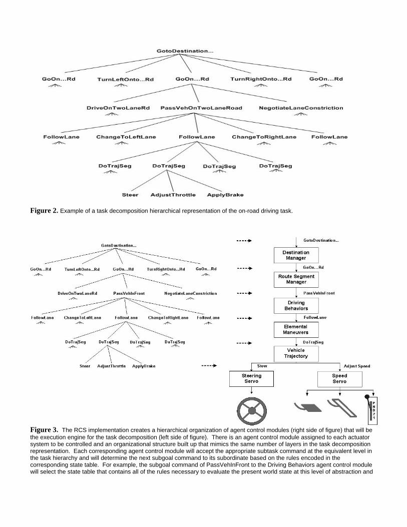
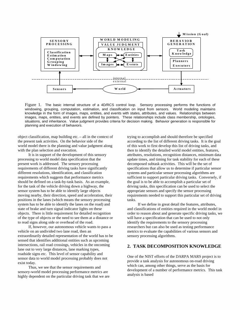
Figure 2. Example of a task decomposition hierarchical representation of the on-road driving task.
Figure 3. The RCS implementation creates a hierarchical organization of agent control modules (right side of figure) that will be the execution engine for the task decomposition (left side of figure). There is an agent control module assigned to each actuator system to be controlled and an organizational structure built up that mimics the same number of layers in the task decomposition representation. Each corresponding agent control module will accept the appropriate subtask command at the equivalent level in the task hierarchy and will determine the next subgoal command to its subordinate based on the rules encoded in the corresponding state table. For example, the subgoal command of PassVehInFront to the Driving Behaviors agent control module will select the state table that contains all of the rules necessary to evaluate the present world state at this level of abstraction and
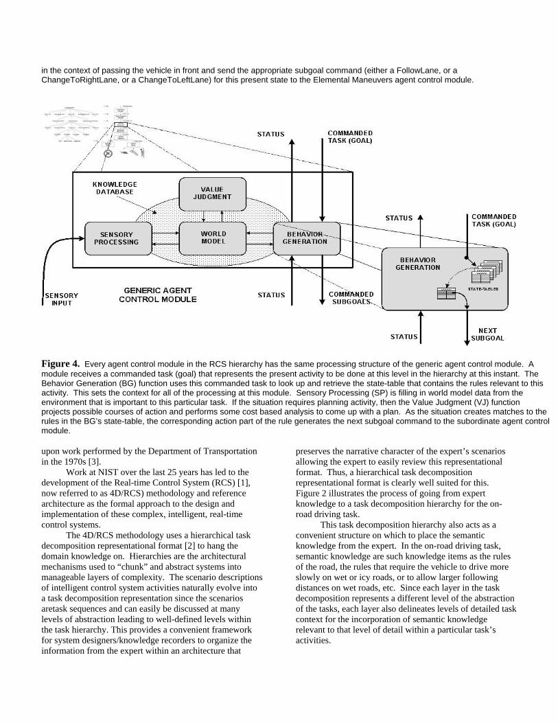
in the context of passing the vehicle in front and send the appropriate subgoal command (either a FollowLane, or a ChangeToRightLane, or a ChangeToLeftLane) for this present state to the Elemental Maneuvers agent control module.
Figure 4. Every agent control module in the RCS hierarchy has the same processing structure of the generic agent control module. A module receives a commanded task (goal) that represents the present activity to be done at this level in the hierarchy at this instant. The Behavior Generation (BG) function uses this commanded task to look up and retrieve the state-table that contains the rules relevant to this activity. This sets the context for all of the processing at this module. Sensory Processing (SP) is filling in world model data from the environment that is important to this particular task. If the situation requires planning activity, then the Value Judgment (VJ) function projects possible courses of action and performs some cost based analysis to come up with a plan. As the situation creates matches to the rules in the BG’s state-table, the corresponding action part of the rule generates the next subgoal command to the subordinate agent control module. upon work performed by the Department of Transportation in the 1970s [3].
Work at NIST over the last 25 years has led to the development of the Real-time Control System (RCS) [1], now referred to as 4D/RCS) methodology and reference architecture as the formal approach to the design and implementation of these complex, intelligent, real-time control systems.
The 4D/RCS methodology uses a hierarchical task decomposition representational format [2] to hang the domain knowledge on. Hierarchies are the architectural mechanisms used to “chunk” and abstract systems into manageable layers of complexity. The scenario descriptions of intelligent control system activities naturally evolve into a task decomposition representation since the scenarios aretask sequences and can easily be discussed at many levels of abstraction leading to well-defined levels within the task hierarchy. This provides a convenient framework for system designers/knowledge recorders to organize the information from the expert within an architecture that
preserves the narrative character of the expert’s scenarios allowing the expert to easily review this representational format. Thus, a hierarchical task decomposition representational format is clearly well suited for this. Figure 2 illustrates the process of going from expert knowledge to a task decomposition hierarchy for the on-road driving task.
This task decomposition hierarchy also acts as a convenient structure on which to place the semantic knowledge from the expert. In the on-road driving task, semantic knowledge are such knowledge items as the rules of the road, the rules that require the vehicle to drive more slowly on wet or icy roads, or to allow larger following distances on wet roads, etc. Since each layer in the task decomposition represents a different level of the abstraction of the tasks, each layer also delineates levels of detailed task context for the incorporation of semantic knowledge relevant to that level of detail within a particular task’s activities.
We will take advantage of this very organized layering of the task knowledge into different levels of abstraction and task responsibility to aid us in doing a detailed analysis of the knowledge associated with finely partitioned task activities for the on-road driving activities.
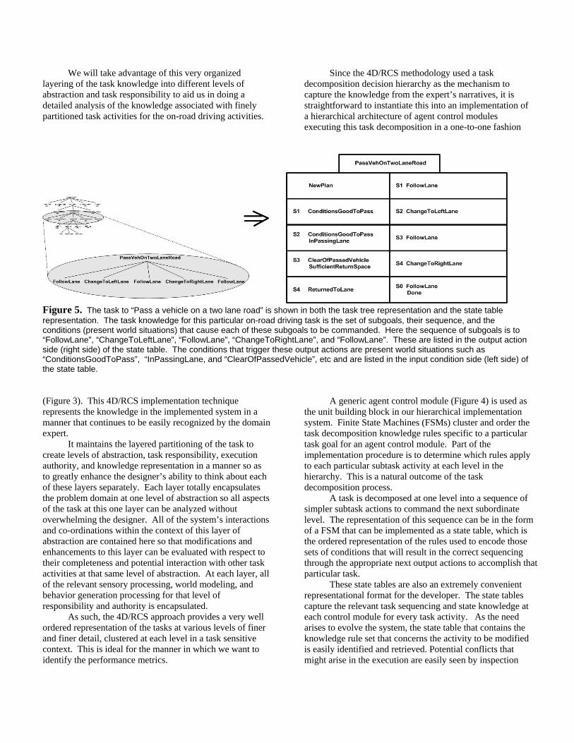
Since the 4D/RCS methodology used a task decomposition decision hierarchy as the mechanism to capture the knowledge from the expert’s narratives, it is straightforward to instantiate this into an implementation of a hierarchical architecture of agent control modules executing this task decomposition in a one-to-one fashion
Figure 5. The task to “Pass a vehicle on a two lane road” is shown in both the task tree representation and the state table representation. The task knowledge for this particular on-road driving task is the set of subgoals, their sequence, and the conditions (present world situations) that cause each of these subgoals to be commanded. Here the sequence of subgoals is to “FollowLane”, “ChangeToLeftLane”, “FollowLane”, “ChangeToRightLane”, and “FollowLane”. These are listed in the output action side (right side) of the state table. The conditions that trigger these output actions are present world situations such as “ConditionsGoodToPass”, “InPassingLane, and “ClearOfPassedVehicle”, etc and are listed in the input condition side (left side) of the state table.
(Figure 3). This 4D/RCS implementation technique represents the knowledge in the implemented system in a manner that continues to be easily recognized by the domain expert.
It maintains the layered partitioning of the task to create levels of abstraction, task responsibility, execution authority, and knowledge representation in a manner so as to greatly enhance the designer’s ability to think about each of these layers separately. Each layer totally encapsulates the problem domain at one level of abstraction so all aspects of the task at this one layer can be analyzed without overwhelming the designer. All of the system’s interactions and co-ordinations within the context of this layer of abstraction are contained here so that modifications and enhancements to this layer can be evaluated with respect to their completeness and potential interaction with other task activities at that same level of abstraction. At each layer, all of the relevant sensory processing, world modeling, and behavior generation processing for that level of responsibility and authority is encapsulated.
As such, the 4D/RCS approach provides a very well ordered representation of the tasks at various levels of finer and finer detail, clustered at each level in a task sensitive context. This is ideal for the manner in which we want to identify the performance metrics.
A generic agent control module (Figure 4) is used as the unit building block in our hierarchical implementation system. Finite State Machines (FSMs) cluster and order the task decomposition knowledge rules specific to a particular task goal for an agent control module. Part of the implementation procedure is to determine which rules apply to each particular subtask activity at each level in the hierarchy. This is a natural outcome of the task decomposition process.
A task is decomposed at one level into a sequence of simpler subtask actions to command the next subordinate level. The representation of this sequence can be in the form of a FSM that can be implemented as a state table, which is the ordered representation of the rules used to encode those sets of conditions that will result in the correct sequencing through the appropriate next output actions to accomplish that particular task.
These state tables are also an extremely convenient representational format for the developer. The state tables capture the relevant task sequencing and state knowledge at each control module for every task activity. As the need arises to evolve the system, the state table that contains the knowledge rule set that concerns the activity to be modified is easily identified and retrieved. Potential conflicts that might arise in the execution are easily seen by inspection
(since this is such a small set of rules) and avoided by the ordering of the rules that is done by the use of additional state variables. In this manner, the expert can provide additional task knowledge to the resolution of the potential conflict in specific task activities rather than the system designer devising some arbitrary conflict resolution mechanism to be applied generally. An example of the
mapping of the task decomposition knowledge into a state table is shown in Figure 5. 3. WORLD MODEL KNOWLEDGE The FSMs described above are used to encode the task decomposition knowledge. Each line of each state table
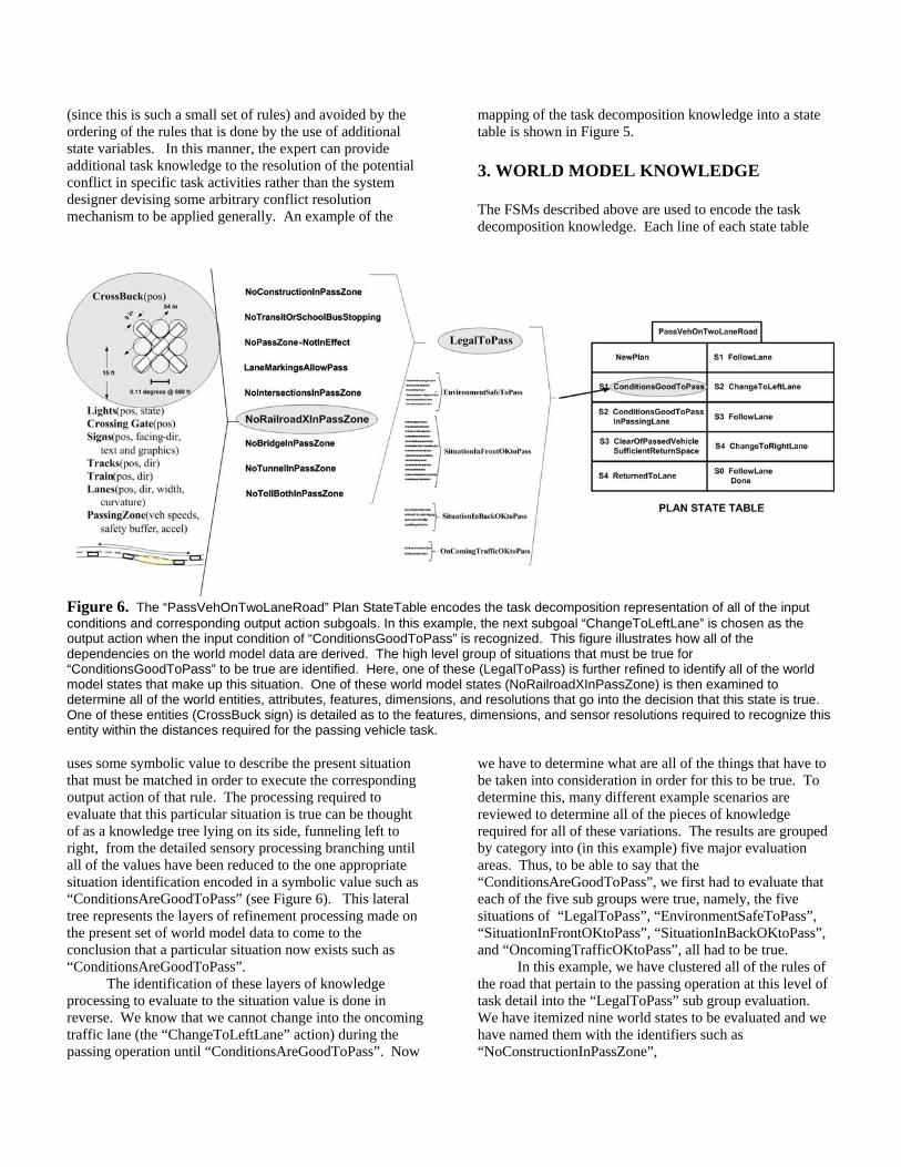
Figure 6. The “PassVehOnTwoLaneRoad” Plan StateTable encodes the task decomposition representation of all of the input conditions and corresponding output action subgoals. In this example, the next subgoal “ChangeToLeftLane” is chosen as the output action when the input condition of “ConditionsGoodToPass” is recognized. This figure illustrates how all of the dependencies on the world model data are derived. The high level group of situations that must be true for “ConditionsGoodToPass” to be true are identified. Here, one of these (LegalToPass) is further refined to identify all of the world model states that make up this situation. One of these world model states (NoRailroadXInPassZone) is then examined to determine all of the world entities, attributes, features, dimensions, and resolutions that go into the decision that this state is true. One of these entities (CrossBuck sign) is detailed as to the features, dimensions, and sensor resolutions required to recognize this entity within the distances required for the passing vehicle task. uses some symbolic value to describe the present situation that must be matched in order to execute the corresponding output action of that rule. The processing required to evaluate that this particular situation is true can be thought of as a knowledge tree lying on its side, funneling left to right, from the detailed sensory processing branching until all of the values have been reduced to the one appropriate situation identification encoded in a symbolic value such as “ConditionsAreGoodToPass” (see Figure 6). This lateral tree represents the layers of refinement processing made on the present set of world model data to come to the conclusion that a particular situation now exists such as “ConditionsAreGoodToPass”.
The identification of these layers of knowledge processing to evaluate to the situation value is done in reverse. We know that we cannot change into the oncoming traffic lane (the “ChangeToLeftLane” action) during the passing operation until “ConditionsAreGoodToPass”. Now
we have to determine what are all of the things that have to be taken into consideration in order for this to be true. To determine this, many different example scenarios are reviewed to determine all of the pieces of knowledge required for all of these variations. The results are grouped by category into (in this example) five major evaluation areas. Thus, to be able to say that the “ConditionsAreGoodToPass”, we first had to evaluate that each of the five sub groups were true, namely, the five situations of “LegalToPass”, “EnvironmentSafeToPass”, “SituationInFrontOKtoPass”, “SituationInBackOKtoPass”, and “OncomingTrafficOKtoPass”, all had to be true.
In this example, we have clustered all of the rules of the road that pertain to the passing operation at this level of task detail into the “LegalToPass” sub group evaluation. We have itemized nine world states to be evaluated and we have named them with the identifiers such as “NoConstructionInPassZone”,
“NoTransitOrSchoolBusStopping”, “NoPassZone-NotInEffect”, “LaneMarkingsAllowPass”, “NoIntersectionsInPassZone”, “NoRailroadXInPassZone”, etc.
These world states can now be further broken into the primitive world model elements we need to be able to measure (such as vehicles, their speed, direction, location, lane markings, signs, railroad tracks, etc.) in order to determine that these world states exist. These primitive world model elements then set the requirements for the sensory processing system we need to build to support these control tasks. Everything has been determined in the context of individual tasks we want the system to be able to do. 4. APPLICATION EXAMPLE In this section, we summarize the RCS methodology, and elaborate on an example mentioned throughout the paper pertaining to passing another vehicle on a two-lane undivided road. Domain experts are consulted and play an integral part throughout this entire process. In the case of on-road driving, we are all domain experts, though many of the conditions we look for and the actions we take are determined subconsciously. 1) Scenario development with a domain expert - For
any task in on-road driving, we walk through detailed scenarios with domain experts to deeply understand the actions they take in certain situations, what conditions spawned those actions, and why they felt the actions were most appropriate in that situation. If possible, we try to immerse the domain expert in similar situations and have them talk through their behaviors. In the case of passing on a two-lane undivided road, it is often beneficial to drive in a vehicle with the domain expert and to have them speak through their process of determining when it was appropriate to pass. These specific conditions that spawn behaviors often change slightly depending on the personality and aggressively of the driver, but we try to generalize the behavior to its fundamental components when encoding it in the control system.
2) Develop the task decomposition hierarchy - Before we can encode the knowledge needed to pass on a two-lane undivided road, we must understand and build an initial, overall task decomposition hierarchy for on-road driving. This is an iterative process, and the task decomposition hierarchy often changes as new on-road driving scenarios are explored. Changes in the task decomposition hierarchy are much more frequent in the beginning, and gradually slow down as more and more scenarios are explored. The passing scenario is one of many scenarios that is used to develop this task decomposition hierarchy.
3) Determine the conditions that cause you to perform an action and the sub-actions that are needed to perform that action - In the case of passing, the actions that need to be performed are fairly straightforward; namely, change to left lane, follow left lane for some period of time, and change to right lane. This is shown in Figure 5. However, the conditions of when you start this sequence of actions and when you progress from one action to the next is much more difficult to understand. Let’s look at the conditions when one would initiate a passing operation. In speaking with domain experts, one could break down these conditions that must be true to pass into two categories: namely, that our vehicle desires to pass and that the conditions are good to pass. Only when both of these conditions are true do we initiate the passing operation. Through continued interrogation and “what-if” scenarios, we determine five conditions that dictate that conditions are good to pass. So the next logical question to the domain expert would be “When are the conditions good to pass?” Through a series of continued interrogations and “what-if” scenarios, one finds that five sub-conditions must be true for conditions to be good to pass: 1) it is legal to pass, 2) the environmental weather and visibility conditions are conducive to passing (often related to weather conditions), 3) the situation in front of our vehicle is OK to pass (other vehicles, pedestrians, and objects in front of us do not hinder our ability to pass), 4) the situation in back of our vehicle is OK to pass (the vehicle behind us is not passing or tailgating us), and 5) oncoming traffic allows us to pass safely (we have time to get around the vehicle in front of us). Each of these five sub-conditions would continue to be broken further down into sub-conditions until we get to the point where we have identified the objects in the environment, and their pertinent attributes, that we are concerned with to perform this passing action.
4) Use the previous step to define the concepts that must be captured in the system’s underlying knowledge base, and structure the knowledge base to ensure maximum efficiency for the application - The objects and attributes discovered in the previous step sets the requirements for the knowledge base that underlies the system. Following through with the scenario of passing on a two-lane undivided road, in order to evaluate the conditions mentioned in the previous step, the knowledge base must contain concepts such as: • other vehicles, including their speed, direction,
location, and possibly intention; • pedestrians, including the speed, direction,
location, and possibly intention; • lane markings, along with the type of lane
marking; • weather conditions and visibility;
• signs, including the text on the sign. Once these concepts are captured in the knowledge base, they can be structured in such a way to ensure maximum efficiency of the system.
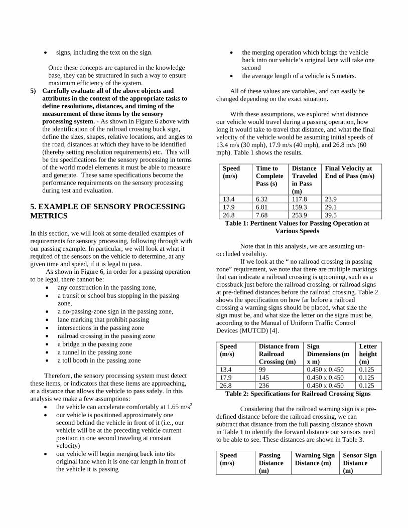
5) Carefully evaluate all of the above objects and attributes in the context of the appropriate tasks to define resolutions, distances, and timing of the measurement of these items by the sensory processing system. - As shown in Figure 6 above with the identification of the railroad crossing buck sign, define the sizes, shapes, relative locations, and angles to the road, distances at which they have to be identified (thereby setting resolution requirements) etc. This will be the specifications for the sensory processing in terms of the world model elements it must be able to measure and generate. These same specifications become the performance requirements on the sensory processing during test and evaluation.
5. EXAMPLE OF SENSORY PROCESSING METRICS In this section, we will look at some detailed examples of requirements for sensory processing, following through with our passing example. In particular, we will look at what it required of the sensors on the vehicle to determine, at any given time and speed, if it is legal to pass.
As shown in Figure 6, in order for a passing operation to be legal, there cannot be:
• any construction in the passing zone, • a transit or school bus stopping in the passing
zone, • a no-passing-zone sign in the passing zone, • lane marking that prohibit passing • intersections in the passing zone • railroad crossing in the passing zone • a bridge in the passing zone • a tunnel in the passing zone • a toll booth in the passing zone
Therefore, the sensory processing system must detect
these items, or indicators that these items are approaching, at a distance that allows the vehicle to pass safely. In this analysis we make a few assumptions:
• the vehicle can accelerate comfortably at 1.65 m/s2 • our vehicle is positioned approximately one
second behind the vehicle in front of it (i.e., our vehicle will be at the preceding vehicle current position in one second traveling at constant velocity)
• our vehicle will begin merging back into tits original lane when it is one car length in front of the vehicle it is passing
• the merging operation which brings the vehicle back into our vehicle’s original lane will take one second
• the average length of a vehicle is 5 meters.
All of these values are variables, and can easily be changed depending on the exact situation.
With these assumptions, we explored what distance our vehicle would travel during a passing operation, how long it would take to travel that distance, and what the final velocity of the vehicle would be assuming initial speeds of 13.4 m/s (30 mph), 17.9 m/s (40 mph), and 26.8 m/s (60 mph). Table 1 shows the results.
Speed (m/s)
Time to Complete Pass (s)
Distance Traveled in Pass (m)
Final Velocity at End of Pass (m/s)
13.4 6.32 117.8 23.9 17.9 6.81 159.3 29.1 26.8 7.68 253.9 39.5 Table 1: Pertinent Values for Passing Operation at
Various Speeds
Note that in this analysis, we are assuming un-occluded visibility.
If we look at the “ no railroad crossing in passing zone” requirement, we note that there are multiple markings that can indicate a railroad crossing is upcoming, such as a crossbuck just before the railroad crossing, or railroad signs at pre-defined distances before the railroad crossing. Table 2 shows the specification on how far before a railroad crossing a warning signs should be placed, what size the sign must be, and what size the letter on the signs must be, according to the Manual of Uniform Traffic Control Devices (MUTCD) [4]. Speed (m/s)
Distance from Railroad Crossing (m)
Sign Dimensions (m x m)
Letter height (m)
13.4 99 0.450 x 0.450 0.125 17.9 145 0.450 x 0.450 0.125 26.8 236 0.450 x 0.450 0.125
Table 2: Specifications for Railroad Crossing Signs
Considering that the railroad warning sign is a pre-defined distance before the railroad crossing, we can subtract that distance from the full passing distance shown in Table 1 to identify the forward distance our sensors need to be able to see. These distances are shown in Table 3. Speed (m/s)
Passing Distance (m)
Warning Sign Distance (m)
Sensor Sign Distance (m)

13.4 117.8 99 18.8 17.9 159.3 145 14.3 26.8 253.9 236 17.9
Table 3: Sight Distance for Railroad Warning Sign
This sets the specification for how far a sensor must be able to “see” to determine if there is a railroad crossing sign in the passing zone. However, we can take this one step further and determine what the resolution of the sensors must be to read the sign. The following couple of paragraphs look at the requirements of the sensor itself. We ignore the software that performs the character and object recognition in this discussion, though we recognize that it is at least as important as the specifications for the sensors.
If we assume that the sign needs to be read (e.g., we do not know what the sign indicates based on its shape and/or color), and that for each letter in the sign, we need a 20x20 array of pixels hits on that letter to be able to recognize the letter, assuming the set of letters can be described in a 10x10 dot matrix and we double this to approximate the Nyquist criteria. Using simple trigonometry based upon the distance to the sign and the size of the letters on the size as shown in Table 2, we can show that we need a camera that has resolutions of about 0.02 degrees for all three cases above.
In some cases, a warning sign is not present and the sensors must rely on recognizing a crossbuck that is immediately before the railroad crossing. In this case, we assume that we need an array of 5 x 5 pixel hits on the crossbuck to recognize it by shape, and that the size of the crossbuck is the standard 900 x 900 mm total dimensions, as specified by the MUTCD manual. Based on this information, we would need a sensor with a resolution as shown in Table 4 below.
Speed (m/s)
Sensor Resolution (degrees)
13.4 0.1042 17.9 0.0711 26.8 0.0406
Table 4: Sensor Sight Distance for Crossbuck
Similar calculations could be performed for all other items the sensor would need to sense when determining if it is legal to pass at any given time and speed. 6. SUMMARY The goal of this work is to produce both a taxonomy of on-road driving behaviors and the set of specifications that identify the world model entities, features, attributes, resolutions, recognition distances, and locations for each separate driving task which can be used for the basis of performance metrics for sensory processing world model
building. This requires the representation of two sets of domain knowledge. One is the task decomposition knowledge that defines the sequences of subtask activities for every aspect of every type of driving task. This task decomposition knowledge is encoded into ordered sets of production rules clustered by the context of the individual driving tasks. These rules consist of input conditions (present world situations) that when matched cause the output of the appropriate sub task goals. The second set of domain knowledge is the detailed world state descriptions and evaluation functions required to produce the world situation symbolic values that are used as the input conditions by the task decomposition rules.
We described how the 4D/RCS methodology and reference architecture was used to define the task decomposition and the resulting state tables of production rules. Then we described how the input conditions of these rules were further evaluated to derive all of their dependencies on all of the corresponding world model states and primitive world entities, features, and attributes. Still using the context of the individual driving tasks, the appropriate recognition distances were factored in to reach a specification of the requirements for the sensory and world model processing necessary for each separate driving task behavior. These requirements now serve as both a requirements list for the development of the sensory and world model processing for different on-road driving tasks as well as the performance metrics against which they can be measured as to the correctness of their operations.
References 1. Albus, J. and et.al., "4D/RCS Version 2.0: A
Reference Model Architecture for Unmanned Vehicle Systems," NISTIR 6910, National Institute of Standards and Technology, Gaithersburg, MD, 2002.
2. Albus, J. and Meystel, A., Engineering of Mind, John Wiley & Sons, Inc. 2001.
3. McKnight, J. and Adams, B., Driver Education Task Analysis. Volume 1. Task Descriptions, Human Resource Research Organization, Department of Transportation, National Highway Safety Bureau 1970.
4. U.S.Department of Transportation, F. H. A., Manual on Uniform Trarffic Control Devices (MUTCD 2000) Millenium Edition 2000.