designing, debugging, and deploying configurable - citeseerx
TRANSCRIPT

DESIGNING, DEBUGGING, AND DEPLOYING CONFIGURABLE
COMPUTING MACHINE-BASED APPLICATIONS USING
RECONFIGURABLE COMPUTING APPLICATION FRAMEWORKS
by
Anthony Lynn Slade
A thesis submitted to the faculty of
Brigham Young University
in partial fulfillment of the requirements for the degree of
Master of Science
Department of Electrical and Computer Engineering
Brigham Young University
April 2003

Copyright c© 2003 Anthony Lynn Slade
All Rights Reserved

BRIGHAM YOUNG UNIVERSITY
GRADUATE COMMITTEE APPROVAL
of a thesis submitted by
Anthony Lynn Slade
This thesis has been read by each member of the following graduate committee and bymajority vote has been found to be satisfactory.
Date Brent E. Nelson, Chair
Date Dan R. Olsen, Jr.
Date Michael J. Wirthlin
BRIGHAM YOUNG UNIVERSITY
As chair of the candidate’s graduate committee, I have read the thesis of Anthony LynnSlade in its final form and have found that (1) its format, citations, and bibliographical styleare consistent and acceptable and fulfill university and department style requirements; (2)its illustrative materials including figures, tables, and charts are in place; and (3) the finalmanuscript is satisfactory to the graduate committee and is ready for submission to theuniversity library.
Date Brent E. NelsonChair, Graduate Committee
Accepted for the Department
A. Lee SwindlehurstGraduate Coordinator
Accepted for the College
Douglas M. ChabriesDean, College of Engineering and Technology

ABSTRACT
DESIGNING, DEBUGGING, AND DEPLOYING CONFIGURABLE COMPUTING
MACHINE-BASED APPLICATIONS USING RECONFIGURABLE COMPUTING
APPLICATION FRAMEWORKS
Anthony Lynn Slade
Department of Electrical and Computer Engineering
Master of Science
Configurable computing machines (CCMs) offer high-performance application ac-
celeration with custom hardware. They are also dynamically reconfigurable and give sig-
nificant internal visibility. Such features are useful throughout the design, debug, and de-
ploy stages of CCM-based application development. However traditional, monolithic de-
sign tools do not offer adequate support for all of these development stages. This thesis
describes a specification for a reconfigurable computing application framework (RCAF)
which is more suitable for CCM application development. It also describes an implemen-
tation of such an RCAF. This RCAF improves the efficiency of application design and
debugging. It also establishes an application architecture framework which helps to build
up not only the hardware design, but also the application software and user interface. Ap-
plications built using this small, deployable RCAF may also perform significantly better
due to the dynamic hardware reconfiguration features included with the RCAF.

ACKNOWLEDGMENTS
There are many people without whom I could not have completed this work. There
is so much I would like to do for all of them to show my gratitude. This list of acknowl-
edgments is but a beginning of that process.
First and foremost, I express my love and appreciation for my family members,
Noni Rae, RaeLynn, and Joseph. Their love and devotion, and especially patience, are
invaluable in all of my endeavors. Thank you, Rae, I love you. I also express my thanks to
my parents, James and Karin Slade.
Much thanks goes to those who have helped me directly on this thesis. They include
my thesis advisory committee members, Brent E. Nelson, Dan R. Olsen, Jr., and Michael
J. Wirthlin. Others who have given great amounts of direct support and advice include
M. Ryan Byrd, Adrian Evans, K. Scott Hemmert, Clint Hilton, Preston Jackson, Brian
McMurtrey, Eric Roesler, K. Ann Tanner, Justin Tripp, and Robyn Voelckers.
Of course I cannot forget the extensive support of the many members of Brigham
Young University’s Configurable Computing Laboratory with whom I have worked. They
include Brad Hutchings, Brent Nelson, Michael Wirthlin, Greg Ahlquist, Dan Baker, Pe-
ter Bellows, Eric Blake, Ben Bullough, Ryan Byrd, Dan Carver, Rob Franklin, Russell
Fredrickson, Paul Graham, Mike Halcrow, Scott Hemmert, Clint Hilton, Preston Jack-
son, Eric Johnson, Nathan Kitchen, Matthew Koecher, Wes Landaker, Anshul Malvi, Jared
Martin, Brian McMurtrey, Steve Morrison, Devin Pratt, Eric Quist, Curtis Randall, Nathan
Rollins, Eric Roesler, Michael Rytting, Aaron Stewart, Navanee Sundaramoorthy, Justin
Tripp, Trent VanDenBerghe, Isaac Wagner, Tim Wheeler, Brett Williams, and Matt Young.

Contents
Acknowledgments vi
List of Tables xi
List of Figures xiv
1 Introduction & Motivation 1
1.1 Application Acceleration Using FPGA-based CCMs . . . . . . . . . . . . 1
1.2 CCM Application Production Stages . . . . . . . . . . . . . . . . . . . . . 2
1.2.1 The Design Stage . . . . . . . . . . . . . . . . . . . . . . . . . . . 3
1.2.2 The Debug Stage . . . . . . . . . . . . . . . . . . . . . . . . . . . 3
1.2.3 The Deploy Stage . . . . . . . . . . . . . . . . . . . . . . . . . . . 3
1.3 Limitations of Current CAD Tools for CCM Application Development . . . 4
1.3.1 ASIC-oriented History of CAD Tools . . . . . . . . . . . . . . . . 4
1.3.2 Limitations Imposed by the ASIC-oriented Nature of CAD Tools . 5
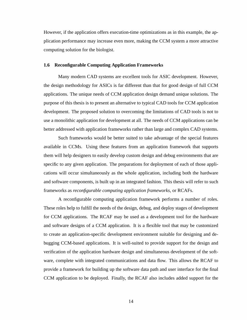
1.4 Features of CCM Systems Improve the Production of Applications . . . . . 7
1.4.1 CCM Features Improve Application Debugging . . . . . . . . . . . 7
1.4.2 CCM Features Permit More Design Exploration . . . . . . . . . . . 9
1.4.3 CCM Features Improve Application Performance . . . . . . . . . . 9
1.5 The Significance of the Deploy Stage . . . . . . . . . . . . . . . . . . . . 11
1.6 Reconfigurable Computing Application Frameworks . . . . . . . . . . . . 14
2 Reconfigurable Computing Application Frameworks 17
2.1 RCAF Interface Between CCM Hardware and CCM Software . . . . . . . 19
2.2 RCAF API For Application Interfaces . . . . . . . . . . . . . . . . . . . . 20
vii
2.3 RCAF Support for (Dynamic) Circuit Design . . . . . . . . . . . . . . . . 21
2.4 Designing, Debugging, and Deploying CCM Applications . . . . . . . . . 21
3 JHDL: A Basis for a Reconfigurable Computing Application Framework 23
3.1 JHDL Design Fundamentals . . . . . . . . . . . . . . . . . . . . . . . . . 23
3.1.1 The JHDL Design Data Model . . . . . . . . . . . . . . . . . . . . 23
3.1.2 JHDL Application Programming Interface . . . . . . . . . . . . . . 25
3.2 Hardware Support in JHDL . . . . . . . . . . . . . . . . . . . . . . . . . . 33
3.3 JAB: The JHDL Circuit Browser . . . . . . . . . . . . . . . . . . . . . . . 35
3.3.1 Interactive Circuit Visualization . . . . . . . . . . . . . . . . . . . 35
3.3.2 Simulation and Execution Control . . . . . . . . . . . . . . . . . . 36
3.3.3 JAB Customizability . . . . . . . . . . . . . . . . . . . . . . . . . 39
3.4 JHDL and JAB: A Precursor to an RCAF System . . . . . . . . . . . . . . 41
3.4.1 Drawbacks to the JHDL and JAB System . . . . . . . . . . . . . . 41
3.4.2 Lessons From JAB . . . . . . . . . . . . . . . . . . . . . . . . . . 42
4 Circuit Visualization Tool (CVT) 43
4.1 CVT Architecture . . . . . . . . . . . . . . . . . . . . . . . . . . . . . . . 43
4.1.1 The CVT Model . . . . . . . . . . . . . . . . . . . . . . . . . . . 44
4.1.2 The CVT Controller . . . . . . . . . . . . . . . . . . . . . . . . . 44
4.1.3 The CVT View . . . . . . . . . . . . . . . . . . . . . . . . . . . . 46
4.1.4 Integrating CVT Model, View, and Controller . . . . . . . . . . . . 46
4.2 Generic Circuit Verification Tool . . . . . . . . . . . . . . . . . . . . . . . 48
4.3 Custom Circuit Interaction Components . . . . . . . . . . . . . . . . . . . 49
4.4 Creating Full Custom CCM Applications by Extending CVT . . . . . . . . 51
4.4.1 Custom CCM Application Model Component . . . . . . . . . . . . 51
4.4.2 Custom CCM Application View Components . . . . . . . . . . . . 51
4.4.3 Custom CCM Application Controller Component . . . . . . . . . . 53
4.5 Application Deployment . . . . . . . . . . . . . . . . . . . . . . . . . . . 53
4.6 Tradeoffs and Considerations in Application Deployment . . . . . . . . . . 54
4.6.1 Framework and Application Code Execution . . . . . . . . . . . . 55
viii
4.6.2 CCM Board Support . . . . . . . . . . . . . . . . . . . . . . . . . 55
4.6.3 Execution-time Hardware Design Modifications . . . . . . . . . . . 56
4.6.4 Deployment Considerations Conclusion . . . . . . . . . . . . . . . 58
5 Example Applications 59
5.1 Audio Processing Application . . . . . . . . . . . . . . . . . . . . . . . . 59
5.2 Edit Distance Application . . . . . . . . . . . . . . . . . . . . . . . . . . . 61
5.2.1 Edit Distance Application Model . . . . . . . . . . . . . . . . . . . 62
5.2.2 Edit Distance Application View . . . . . . . . . . . . . . . . . . . 64
5.2.3 Edit Distance Application Controller . . . . . . . . . . . . . . . . . 65
5.2.4 Completing the Edit Distance Application . . . . . . . . . . . . . . 65
5.3 Guessing Game Application . . . . . . . . . . . . . . . . . . . . . . . . . 66
5.3.1 Guessing Game Application Model . . . . . . . . . . . . . . . . . 67
5.3.2 Guessing Game Application View . . . . . . . . . . . . . . . . . . 68
5.3.3 Guessing Game Application Controller . . . . . . . . . . . . . . . 69
5.4 Quantitative Analysis . . . . . . . . . . . . . . . . . . . . . . . . . . . . . 70
5.5 Additional Examples . . . . . . . . . . . . . . . . . . . . . . . . . . . . . 72
6 Conclusions and Future Work 77
6.1 Contributions of this Research . . . . . . . . . . . . . . . . . . . . . . . . 78
6.2 Future Work . . . . . . . . . . . . . . . . . . . . . . . . . . . . . . . . . . 80
A CVT Component APIs 85
A.1 CVT Controller APIs . . . . . . . . . . . . . . . . . . . . . . . . . . . . . 85
A.2 CVT View APIs . . . . . . . . . . . . . . . . . . . . . . . . . . . . . . . . 89
B CVT Component Sizes 99
C Example Source Code 101
C.1 Custom Visualization Using JAB . . . . . . . . . . . . . . . . . . . . . . . 101
C.2 Example Application: Audio Processing . . . . . . . . . . . . . . . . . . . 105
C.2.1 Audio Processing Application Model . . . . . . . . . . . . . . . . 105
ix
C.2.2 Audio Processing Application View . . . . . . . . . . . . . . . . . 127
C.2.3 Audio Processing Application Data Stream Simulation . . . . . . . 138
C.3 Example Application: Edit Distance . . . . . . . . . . . . . . . . . . . . . 148
C.3.1 Edit Distance Application Model . . . . . . . . . . . . . . . . . . . 148
C.3.2 Edit Distance Application View . . . . . . . . . . . . . . . . . . . 162
C.3.3 Edit Distance Application Controller . . . . . . . . . . . . . . . . . 173
C.4 Example Application: Guessing Game . . . . . . . . . . . . . . . . . . . . 175
C.4.1 Guessing Game Application Model . . . . . . . . . . . . . . . . . 175
C.4.2 Guessing Game Application View . . . . . . . . . . . . . . . . . . 208
C.4.3 Guessing Game Application Controller . . . . . . . . . . . . . . . 220
Bibliography 232
x

List of Tables
3.1 HWSystemmethods for accessing circuit design cells . . . . . . . . . . . . 27
3.2 JHDLCell methods for accessing circuit design structure . . . . . . . . . 27
3.3 Wire class methods for accessing circuit design structure . . . . . . . . . . 28
3.4 JHDLTechMapper methods for writing a netlist file . . . . . . . . . . . 29
3.5 HWSystemmethods for simulation control and feedback . . . . . . . . . . 30
3.6 TheSimulatorCallback interface for simulator feedback . . . . . . . 30
3.7 Wire class methods for stimulating wire objects . . . . . . . . . . . . . . 31
3.8 JHDLWire methods for accessing circuit state . . . . . . . . . . . . . . . 32
3.9 JHDLMemoryInterface methods . . . . . . . . . . . . . . . . . . . . 33
3.10 TheUserDefinedSchematic interface for custom schematic nodes . . 39
4.1 Broker methods for extending the CVT system . . . . . . . . . . . . . . 53
5.1 ColorPlacementListener method for obtaining guess events from
the guessing game viewer . . . . . . . . . . . . . . . . . . . . . . . . . . . 69
5.2 Sizes of sample CVT-based applications. . . . . . . . . . . . . . . . . . . . 72
B.1 Sizes of the CVT RCAF and its subcomponents . . . . . . . . . . . . . . . 99
B.2 Sizes of various technology-specific libraries . . . . . . . . . . . . . . . . 100
B.3 Sizes of additional CVT components . . . . . . . . . . . . . . . . . . . . . 100
B.4 Total size of all components listed in previous tables . . . . . . . . . . . . . 100
xi

xii

List of Figures
1.1 Configurable Computing Machine (CCM) Block Diagram. . . . . . . . . . 2
1.2 Stages of CCM application production . . . . . . . . . . . . . . . . . . . . 2
1.3 CCM application production stages are typically split between hardware
and software development . . . . . . . . . . . . . . . . . . . . . . . . . . 6
1.4 Features of FPGA-based CCMs . . . . . . . . . . . . . . . . . . . . . . . 8
1.5 FPGA LUT-based general-purpose comparator. . . . . . . . . . . . . . . . 11
1.6 FPGA LUT-based constant comparator. . . . . . . . . . . . . . . . . . . . 11
2.1 CCM benefits leveraged by RCAFs to improve application development . . 17
2.2 The RCAF interfaces between the CCM hardware and application software 18
2.3 The RCAF provides a mapping between the hardware design and the phys-
ical CCM hardware . . . . . . . . . . . . . . . . . . . . . . . . . . . . . . 20
3.1 Inheritance structure of JHDL’s base classes. . . . . . . . . . . . . . . . . . 24
3.2 Hierarchy of the JHDL system. . . . . . . . . . . . . . . . . . . . . . . . . 25
3.3 JHDL’s hardware systems exposes three types of APIs to external systems. . 26
3.4 A design model of an FPGA-based circuit. . . . . . . . . . . . . . . . . . . 34
3.5 Representation of the physical implementation of an FPGA-based circuit. . 34
3.6 JAB’s circuit hierarchy browser. . . . . . . . . . . . . . . . . . . . . . . . 36
3.7 JAB’s design schematic viewer. . . . . . . . . . . . . . . . . . . . . . . . . 37
3.8 JAB’s memory viewer. . . . . . . . . . . . . . . . . . . . . . . . . . . . . 37
3.9 JAB’s waveform viewer. . . . . . . . . . . . . . . . . . . . . . . . . . . . 37
3.10 JAB’s command line console. . . . . . . . . . . . . . . . . . . . . . . . . . 38
3.11 Customizing JAB schematics with user-defined schematic nodes. . . . . . . 39
3.12 An example custom circuit visualization component using theSimula-
torCallback interface. . . . . . . . . . . . . . . . . . . . . . . . . . . 40
xiii
4.1 The model-view-controller architecture for user interfaces. . . . . . . . . . 44
4.2 CVT Architecture. . . . . . . . . . . . . . . . . . . . . . . . . . . . . . . 45
4.3 Example communication in the CVT model-view-controller architecture. . 47
4.4 CVT’s main circuit view. . . . . . . . . . . . . . . . . . . . . . . . . . . . 48
4.5 CVT provides several default viewers with intuitive interfaces. . . . . . . . 50
4.6 Communications to and from CVT viewers. . . . . . . . . . . . . . . . . . 52
5.1 Custom viewer for an audio processing application. . . . . . . . . . . . . . 60
5.2 TheEditDistance class creates the circuit model for the edit distance
application. . . . . . . . . . . . . . . . . . . . . . . . . . . . . . . . . . . 63
5.3 The graphical user interface for an edit distance application. . . . . . . . . 64
5.4 TheEDBroker class extends the default RCAF controller for the edit dis-
tance application. . . . . . . . . . . . . . . . . . . . . . . . . . . . . . . . 66
5.5 ThetbEditDistance class creates and integrates the various applica-
tion components. . . . . . . . . . . . . . . . . . . . . . . . . . . . . . . . 67
5.6 The graphical user interface for a guessing game application. . . . . . . . . 68
5.7 TheEDBroker class extends the default RCAF controller for the edit dis-
tance application. . . . . . . . . . . . . . . . . . . . . . . . . . . . . . . . 70
5.8 Hybrid CPU/FPGA system debugger. . . . . . . . . . . . . . . . . . . . . 74
5.9 Debugger for hardware synthesized from high-level code. . . . . . . . . . . 75
xiv
Chapter 1
Introduction & Motivation
1.1 Application Acceleration Using FPGA-based CCMs
Field-programmable gate arrays (FPGAs) are reconfigurable, general-purpose hard-
ware devices. It is somewhat common to use FPGAs as replacements for very large and
complex glue logic in digital systems. FPGAs are also useful for creating hardware proto-
types of ASIC (application-specific integrated circuit) designs. FPGAs can help decrease
development time by providing a hardware platform in which ASIC designs may be veri-
fied. Where a very quick time to market is required for the success of new digital hardware
systems, FPGAs can even be easy and economical replacements for ASICs altogether[1].
Most recently, FPGAs have been seen as viable core technologies for serious com-
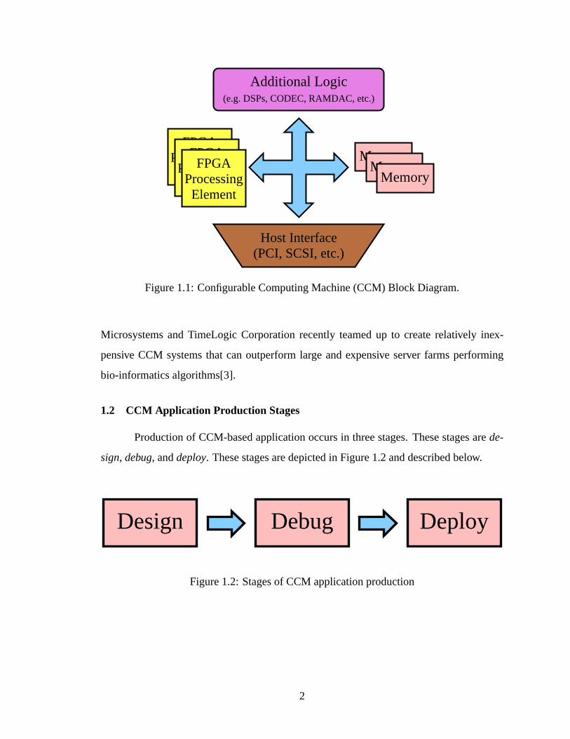
puting applications. Configurable computing machines (CCMs) are FPGA-based process-
ing and computing platforms. Figure 1.1 shows the components of a typical CCM archi-
tecture. CCMs provide a versatile and powerful computing platform that may be integrated
with a host system. The FPGAs in a CCM can be configured by the host system to perform
virtually any type of computation or process. This makes CCMs attractive computing plat-
forms with flexibility comparable to that of microprocessor-based systems and performance
comparable to that of ASIC designs[2].
Because CCM computation and processing occurs in hardware, applications tar-
geted to CCMs may be able to run several times faster than if they were executed in soft-
ware running on a processor. In some cases, CCM-based applications may be as much
as an order of magnitude faster than alternative implementations[2]. CCMs are also capa-
ble of improving the performance-to-price ratio in many applications. For example, Sun
1
FPGAProcessing
Element
Additional Logic(e.g. DSPs, CODEC, RAMDAC, etc.)
FPGAProcessing
Element
MemoryMemory
Memory
Host Interface(PCI, SCSI, etc.)
FPGAProcessing
Element
Figure 1.1: Configurable Computing Machine (CCM) Block Diagram.
Microsystems and TimeLogic Corporation recently teamed up to create relatively inex-
pensive CCM systems that can outperform large and expensive server farms performing
bio-informatics algorithms[3].
1.2 CCM Application Production Stages
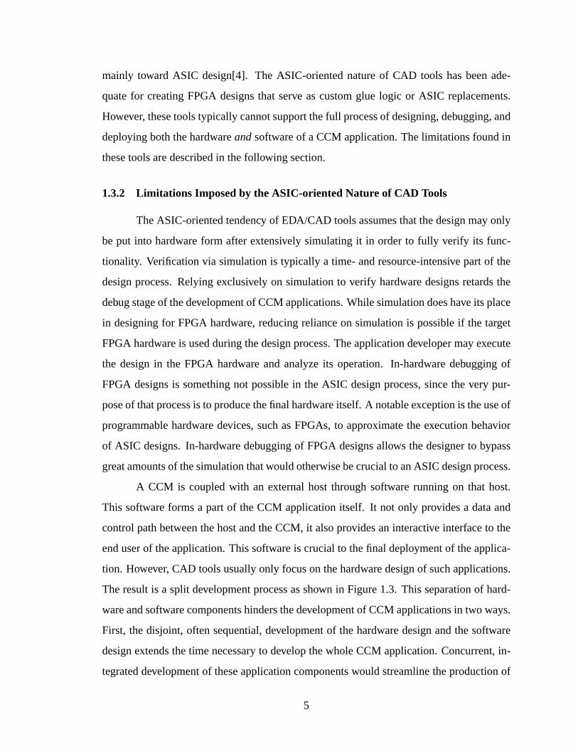
Production of CCM-based application occurs in three stages. These stages arede-
sign, debug, anddeploy. These stages are depicted in Figure 1.2 and described below.
DebugDesign Deploy
Figure 1.2: Stages of CCM application production
2

1.2.1 The Design Stage
The design stage of CCM application development includes the processes required
to specify the application features. It also includes the process of actually implementing
the application. A major part of the design involves creating a structural or behavioral
description of the application hardware configuration. The application also includes soft-
ware that supports the hardware and acts as an interface to the user or to other external
systems. In some cases, this software component may be just as significant as the hardware
configuration design.
1.2.2 The Debug Stage
The debug stage takes the design and exercises it to verify that it functions correctly.
Traditional FPGA debugging uses a simulation model created by a hardware synthesizer.
This model approximates or emulate the execution behavior of the FPGA hardware as if it
were configured with the hardware design. The debugging process may expose errors or
weaknesses in the design. Developers may use this information to revisit portions of the
design stage to modify the application design in order to remove the problems or minimize
their effects. This is often an iterative process between the design and debug stages.
1.2.3 The Deploy Stage
The CCM application is prepared for use by the end user in the deploy stage. This
process may involve finalizing the integration of the hardware and software components of
the application. The result of the deploy stage is an application that is in a form which may
be distributed to end users.
An important part of the deploy stage is preparing a system that will enable the
application to execute on the final target system. This includes establishing an application
infrastructure and runtime environment. This may involve specifying drivers and other
tools that the user must have in order to execute the application properly. In some cases,
these tools may actually accompany or be integrated with the application itself.
3

1.3 Limitations of Current CAD Tools for CCM Application Development
State-of-the-art computer-aided design (CAD) tools for developing CCM-based ap-
plications are inadequate to support all of the stages of development described in Sec-
tion 1.2. These CAD tools tend to be very good for the design stage. However, their
support for the debug stage of CCM applications is usually only marginal. And in general,
these CAD tools do not support the deployment stage of CCM application development at
all. Even the design support provided by these tools is only useful for the hardware por-
tion of the whole CCM application; it ignores the application software development needs
altogether.
1.3.1 ASIC-oriented History of CAD Tools
Hardware design that targets FPGAs has long been constrained by a design flow
that was originally developed for the production of ASICs. This ASIC-oriented tendency
is the natural product of the history of the development of the FPGA market. In order to
quickly generate a new market for their products, FPGA manufacturers have relied heavily
on an existing electronic design automation (EDA) and CAD tool infrastructure. Rather
than build a new set of tools to support design creation, synthesis, and simulation of FPGA
designs, these manufacturers have leveraged the capabilities of existing software to support
their products. FPGA manufacturers have done this in two ways: providing libraries for use
with major CAD tools, or by providing sufficient information and specifications to enable
others to more easily provide such libraries. These libraries contain information about the
various primitive cells supported by the back-end synthesis tools that are used to generate
configuration images for specific FPGA devices. Designers could then use their favorite
EDA/CAD tools to create designs that target these libraries in order to synthesize them to
the FPGA device of choice.
The strategy of supporting existing EDA/CAD tools has assisted FPGA manufactur-
ers in successfully building up a large market for their products. However, this success has
come at a fairly significant cost for the development of configurable computing machine-
based applications. At issue is the nature of the existing EDA/CAD tools used to target
FPGAs. For the most part, these tools (e.g. Mentor, Cadence, PowerView, etc.) are geared
4
mainly toward ASIC design[4]. The ASIC-oriented nature of CAD tools has been ade-
quate for creating FPGA designs that serve as custom glue logic or ASIC replacements.
However, these tools typically cannot support the full process of designing, debugging, and
deploying both the hardwareandsoftware of a CCM application. The limitations found in
these tools are described in the following section.
1.3.2 Limitations Imposed by the ASIC-oriented Nature of CAD Tools
The ASIC-oriented tendency of EDA/CAD tools assumes that the design may only
be put into hardware form after extensively simulating it in order to fully verify its func-
tionality. Verification via simulation is typically a time- and resource-intensive part of the
design process. Relying exclusively on simulation to verify hardware designs retards the
debug stage of the development of CCM applications. While simulation does have its place
in designing for FPGA hardware, reducing reliance on simulation is possible if the target
FPGA hardware is used during the design process. The application developer may execute
the design in the FPGA hardware and analyze its operation. In-hardware debugging of
FPGA designs is something not possible in the ASIC design process, since the very pur-
pose of that process is to produce the final hardware itself. A notable exception is the use of
programmable hardware devices, such as FPGAs, to approximate the execution behavior
of ASIC designs. In-hardware debugging of FPGA designs allows the designer to bypass
great amounts of the simulation that would otherwise be crucial to an ASIC design process.
A CCM is coupled with an external host through software running on that host.
This software forms a part of the CCM application itself. It not only provides a data and
control path between the host and the CCM, it also provides an interactive interface to the
end user of the application. This software is crucial to the final deployment of the applica-
tion. However, CAD tools usually only focus on the hardware design of such applications.
The result is a split development process as shown in Figure 1.3. This separation of hard-
ware and software components hinders the development of CCM applications in two ways.
First, the disjoint, often sequential, development of the hardware design and the software
design extends the time necessary to develop the whole CCM application. Concurrent, in-
tegrated development of these application components would streamline the production of
5
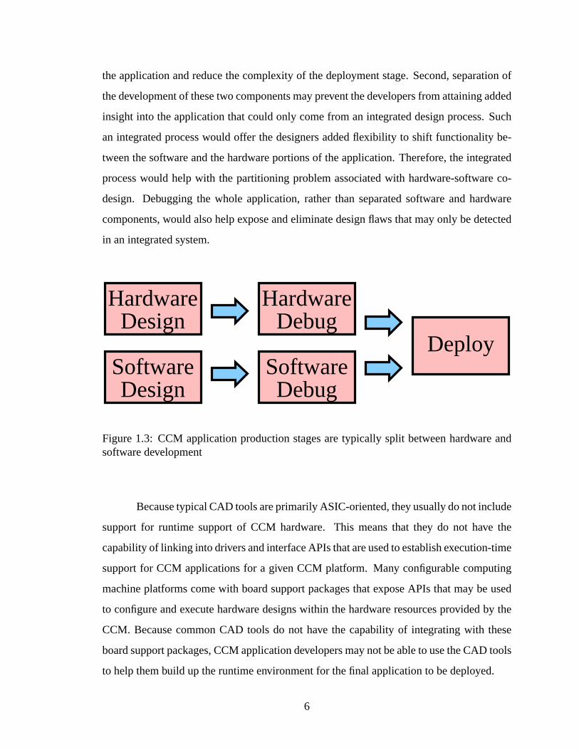
the application and reduce the complexity of the deployment stage. Second, separation of
the development of these two components may prevent the developers from attaining added
insight into the application that could only come from an integrated design process. Such
an integrated process would offer the designers added flexibility to shift functionality be-
tween the software and the hardware portions of the application. Therefore, the integrated
process would help with the partitioning problem associated with hardware-software co-
design. Debugging the whole application, rather than separated software and hardware
components, would also help expose and eliminate design flaws that may only be detected
in an integrated system.
Deploy
DebugSoftware
DebugHardware
DesignHardware
DesignSoftware
Figure 1.3: CCM application production stages are typically split between hardware andsoftware development
Because typical CAD tools are primarily ASIC-oriented, they usually do not include
support for runtime support of CCM hardware. This means that they do not have the
capability of linking into drivers and interface APIs that are used to establish execution-time
support for CCM applications for a given CCM platform. Many configurable computing
machine platforms come with board support packages that expose APIs that may be used
to configure and execute hardware designs within the hardware resources provided by the
CCM. Because common CAD tools do not have the capability of integrating with these
board support packages, CCM application developers may not be able to use the CAD tools
to help them build up the runtime environment for the final application to be deployed.
6

In summary, traditional EDA/CAD tools typically have three main weaknesses re-
lated to CCM application development. First, the use of these tools hinders the progress of
application development by relying exclusively on slow simulation for debugging. Second,
they unnecessarily separate the development of the hardware and software components of
the CCM application, thereby extending and complicating the development process. Fi-
nally, modern CAD tools lack flexible hardware and software development environments
to support the complete deployment of CCM applications.
1.4 Features of CCM Systems Improve the Production of Applications
Development of CCM applications may be improved by leveraging the features of
FPGAs and FPGA-based CCM platforms. As noted by Hutchings and Nelson[5], three
major features of CCMs are:
• Availability of the hardware at design time
• Programmability and re-programmability of the hardware
• Visibility into the hardware
To this list, Graham[6] adds the following:
• Controllability of the hardware state
• System execution controllability
These features are listed again in Figure 1.4, except that the two controllability items are
combined into one generic controllability feature. Two major benefits come as a result of
these features of CCM systems: a reduction in the need for simulation for hardware design
verification, and tighter integration of the software and the hardware components of CCM
applications.
1.4.1 CCM Features Improve Application Debugging
CCM features listed in Figure 1.4 allow for significant improvements to the debug
stage of application development. The ASIC design approach must rely solely on simula-
tion to verify the design. Software-based simulation of hardware designs can easily become
7

• Availability of the hardware at design time
• Programmability and re-programmability of the hardware
• Visibility into the hardware
• Controllability of the hardware
Figure 1.4: Features of FPGA-based CCMs
a bottleneck in the hardware design process. But the same hardware that is meant to ac-
celerate the operation of the final application can also be used to accelerate the verification
and debugging of the application design itself. In-hardware execution and analysis of the
design, made possible by the availability of the hardware even before the hardware con-
figuration design is complete, can reduce or eliminate the reliance on simulation. Because
FPGA hardware is re-programmable, the designer may use a design cycle that involves
design, compilation, and hardware execution and test. This design cycle, which parallels
exactly the process of producing software applications, may be repeated as often as nec-
essary until the design is completed. Using FPGA target hardware as a replacement for
full simulation is possible due to the extraordinary internal visibility made available by the
hardware.1
A knowledgeable designer may manually make use of these features even without
specific support for their utilization from within the principle development tools of the
design. However, using these features in a disjoint combination may still not lead to a
more effective design process. An EDA tool that integrates the use of available FPGA
hardware during the design process will improve the efficiency of that process by allowing
the designer to concentrate design efforts on just one tool or development environment.
The result is an integrated development environment (IDE) that may closely resemble IDEs
found in the software development community. Such systems have long been seen as useful
development tools for software engineers. They are beneficial in improving the cyclic
process of designing and debugging software applications. The programmer may use an
1 For example, Xilinx FPGAs offer a “readback” capability that gives the current state of all register andmemory elements in the FPGA device.
8
IDE to create a software program and then execute it in an integrated debugger that reveals
the program state at each line of executed code. The analogy extends to hardware design
when a debugging environment is able to back annotate the design or a representation of
the design (perhaps a schematic or other view of the circuits) to then give the designer a
view of the hardware at each significant execution state.
1.4.2 CCM Features Permit More Design Exploration
It is difficult to overemphasize the significance of the potential benefits of utilizing
available target hardware during the design process for FPGA-based designs. In-hardware
execution is typically several orders of magnitude faster than simulation[6]. Integrating the
information from in-hardware execution of incremental and final builds of the hardware
design within the development environment allows the designer to verify the design in less
time[5]. It may also give the designer superior insights into the operation of the design.
The designer may, with improved efficiency, build up and instrument the design in various
fashions to test alternate implementations. Therefore, leveraging the benefits of the pres-
ence of target hardware during design may help to reduce the amount of time required to
develop the design as well as help produce a more optimized design than might be possible
using only design methods used in ASIC design.
The integration of CCM hardware with the design environment may also benefit
application developers during the deployment stage of application production. The pro-
grammability, visibility, and controllability features of CCMs allow designers to treat the
CCM platforms as if they were extensions to the software part of the application. Concur-
rent and integrated development of the software and hardware portions of the application
gives a more useful view of the CCM application as a whole computing system, rather than
two separate pieces. This enables further design exploration that helps to determine the
optimal partition between the hardware and software components of the application.
1.4.3 CCM Features Improve Application Performance
Perhaps one of the greatest benefits of an integrated design process is the potential
for improved application performance. Performance enhancements in a CCM application
9

are often made by embedding specific data from the problem being solved by the applica-
tion into the hardware design. This concept is similar to constant folding, which is often
performed in the compilation of software systems. Constant folding improves the perfor-
mance of software by embedding constant values in the assembled machine code of the
software. This approach avoids the extra overhead that comes from treating constants like
any other variables that must be stored into and loaded from memory. Besides reducing
memory accesses, constant folding can speed up the execution of software by utilizing
optimized ways of executing operations. For example, division or multiplication by a con-
stant value that is a power of two may be replaced by much faster logical shifts. Smart
compilers may favor such optimizations over more processor-intensive ways of executing
the code. The added complexity of the compiler may be easily made up in performance of
the software, especially when the optimization is made in an inner loop of code that is exe-
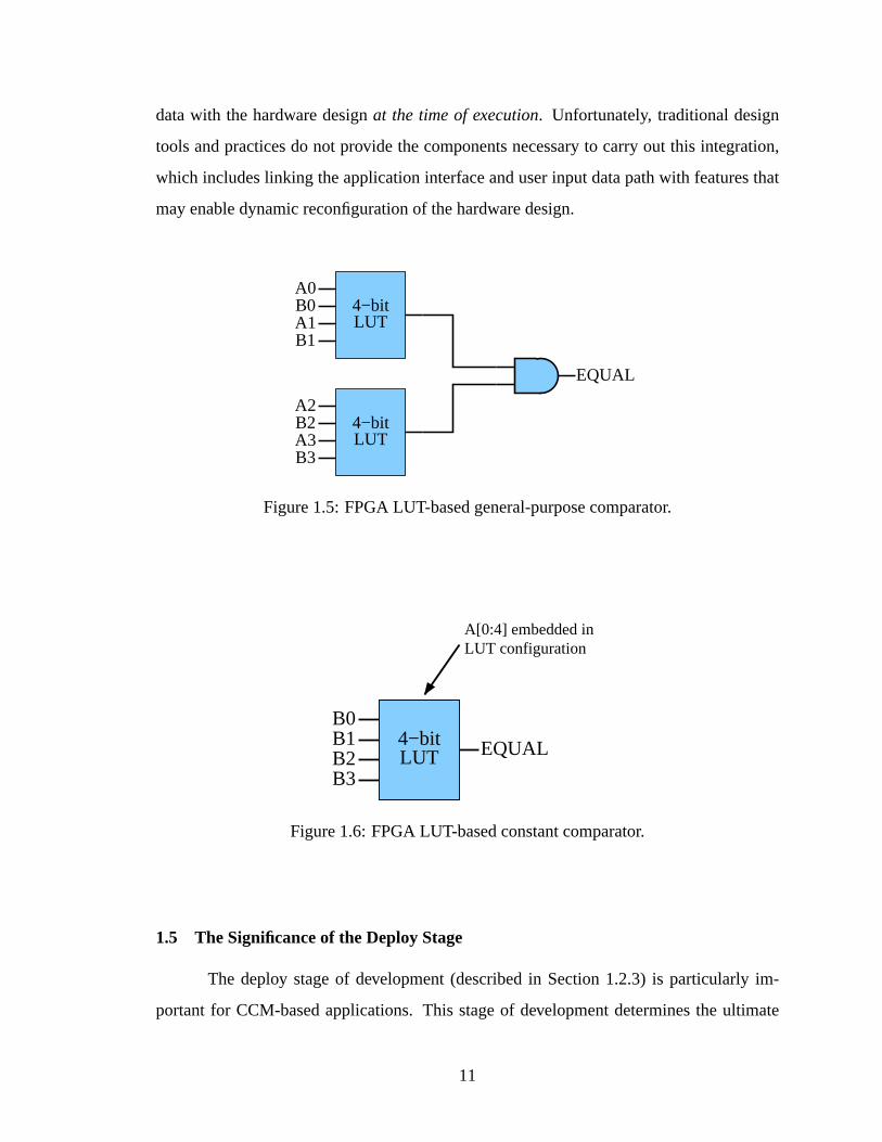
cuted many times. Corresponding optimizations for hardware design have been called data
folding[7] or constant propagation[8]. Some examples of hardware constant propagation
include:
• replacing complex combinational logic with faster lookup tables
• instead of large, slow, general-purpose multipliers, using more efficient constant-
coefficient multipliers
• creating a custom state flow for controllers made with finite state machines
• etc.
For a graphical example of constant propagation, see Figure 1.5 and Figure 1.6.
Figure 1.5 shows a four-bit comparator implemented with two FPGA lookup tables (LUTs)
and anAND gate. Figure 1.6 shows a four-bit comparator with one of the values, a known
constant, embedded in the configuration of the LUT. The constant comparator is more
efficient in both area and latency.
With high-performance CCM applications, when the data changes, so does the
problem to be solved. Integrating the development of the application interface software
with the development of the hardware design makes it possible to integrate user-provided
10
data with the hardware designat the time of execution. Unfortunately, traditional design
tools and practices do not provide the components necessary to carry out this integration,
which includes linking the application interface and user input data path with features that
may enable dynamic reconfiguration of the hardware design.
EQUAL
A1B0
B1
A0
A2B2A3B3
4−bitLUT
4−bitLUT
Figure 1.5: FPGA LUT-based general-purpose comparator.
B0B1B2B3
EQUAL
A[0:4] embedded inLUT configuration
4−bitLUT
Figure 1.6: FPGA LUT-based constant comparator.
1.5 The Significance of the Deploy Stage
The deploy stage of development (described in Section 1.2.3) is particularly im-
portant for CCM-based applications. This stage of development determines the ultimate
11
characteristics of the application as it is used by the end user. These characteristics may or
may not fully take advantage of the features of FPGA-based CCMs, which are described in
Section 1.4, particularly the features described in Section 1.4.3.
In traditional digital logic design, including FPGA and CCM design, the CAD/EDA
tool does not play a role in the application development past the debug stage. However, the
EDA tool is typically they only means of realizing significant modifications to the hardware
configuration design. Even if a CAD/EDA tooldid contain specialized features to support
hardware-enhanced design and debugging, as introduced in Sections 1.4.1 and 1.4.2, those
unique and powerful capabilities would normally be thrown away once the hardware de-
sign is complete and the deployment stage of development begins. Removing the CAD
tool from the application after the debug stage inhibits the application’s ability to offer
flexibility and performance advantages to the end user. For example, hardware optimiza-
tions based on input from the user, as introduced in Section 1.4.3, are not feasible under
traditional application development processes as dictated by the nature of the CAD/EDA
tools themselves.
Consider, for example, an application that compares two strings of characters to
identify similarities or differences between them. Such an example will also be presented
in greater detail in Section 5.2. This application uses comparators like the comparator
shown in Figure 1.6. An electronic design automation tool is used to determine the con-
figuration of the LUT in order to embed the information for a specific target string into the
configuration of the hardware design. The typical configuration process requires the EDA
tool to generate a circuit netlist This netlist is then interpreted by placement and routing
tools specific to the FPGAs in the target CCM. However, without the availability of the
EDA tool, the configuration for the comparators must remain static. This means that the
design must either remain applicable to only one set of data, or that it must regress to use
general-purpose comparators like the comparator shown in Figure 1.5.
This example application shows how traditional ASIC development methods inhibit
the potential that CCM-based applications may have. What such applications need is a
way to continue to enable the dynamic capabilities of the underlying FGPA hardware in
the deploy stage and beyond. The FPGAs by themselves are powerless to provides this
12

dynamic capability. They rely on external, usually software-based systems to determine
their configurations. If a CCM-based application is to maintain dynamic characteristics to
offer application flexibility or increased performance, then all or part of the capabilities of
the CAD/EDA tools used in the design and debug stages of development must continue to
be a part of the application software in the deploy stage and beyond.
To demonstrate the importance of retaining the CAD tool capabilities beyond the
debug stage, consider the way in which the above example application might be executed by
the final user. The end user might not be a hardware designer at all. For example, suppose
the string pattern matching application is used by a biologist who analyzes the patterns in
large database of DNA (deoxyribonucleic acid) or protein information. The string compar-
ison application may provide an interface that allows the biologist to key in a target string
for comparison. Then the biologist may tell the application to configure itself for compar-
isons with that string. The interface which the biologist uses simply appears like any other
software application on a typical workstation. The application does not need to reveal that
the underlying computation will be performed in custom-configured hardware. The appli-
cation will produce a custom netlist of the hardware design, complete with the data of the
target string embedded in the hardware design so that comparisons are optimized for it.
Placement and routing tools specific to the FPGA hardware in the CCM then process that
netlist to generate a configuration image for the FPGAs. This process may take anywhere
from several minutes to a few hours. At this point, the hardware configuration is verified
to ensure that it fits within the timing and resource constraints of the given CCM system.
Once the configuration is verified and loaded into the FPGAs, the software portions of the
application may then proceed to obtain values from biologist’s database and pass them to
the CCM hardware to perform the comparisons. Simultaneously, the application software
collects the output from the hardware and either passes it on to another system for analysis
or stores it in a separate database for deferred analysis. Therefore, although the biologist
does not necessarily have experience with digital hardware design, he or she may benefit
from an application that speeds up the database comparisons so that they may finish in just
a few hours instead of several months. Much of the application speedup was due to the
inherit speed advantage that the hardware has over alternative software implementations.
13
However, if the application offers execution-time optimizations as in this example, the ap-
plication performance may increase even more, making the CCM system a more attractive
computing solution for the biologist.
1.6 Reconfigurable Computing Application Frameworks
Many modern CAD systems are excellent tools for ASIC development. However,
the design methodology for ASICs is far different than that for good design of full CCM
applications. The unique needs of CCM application design demand unique solutions. The
purpose of this thesis is to present an alternative to typical CAD tools for CCM application
development. The proposed solution to overcoming the limitations of CAD tools is not to
use a monolithic application for development at all. The needs of CCM applications can be
better addressed with application frameworks rather than large and complex CAD systems.
Such frameworks would be better suited to take advantage of the special features
available in CCMs. Using these features from an application framework that supports
them will help designers to easily develop custom design and debug environments that are
specific to any given application. The preparations for deployment of each of those appli-
cations will occur simultaneously as the whole application, including both the hardware
and software components, is built up in an integrated fashion. This thesis will refer to such
frameworks asreconfigurable computing application frameworks, or RCAFs.
A reconfigurable computing application framework performs a number of roles.
These roles help to fulfill the needs of the design, debug, and deploy stages of development
for CCM applications. The RCAF may be used as a development tool for the hardware
and software designs of a CCM application. It is a flexible tool that may be customized
to create an application-specific development environment suitable for designing and de-
bugging CCM-based applications. It is well-suited to provide support for the design and
verification of the application hardware design and simultaneous development of the soft-
ware, complete with integrated communications and data flow. This allows the RCAF to
provide a framework for building up the software data path and user interface for the final
CCM application to be deployed. Finally, the RCAF also includes added support for the
14
deploy stage of application development by establishing a framework for runtime execution
support, including dynamic hardware configuration, as described in Section 1.5.
This thesis establishes a high-level specification for a reconfigurable computing
application framework. This specification, given in Chapter 2, outlines the general features
of the architecture and composition of an RCAF. Chapter 2 also give the justification for
the design decisions in that architecture based on the needs of application development and
the features of CCMs. Research associated with this thesis led to the implementation of
such an RCAF. Chapter 3 describes the pre-existing foundation for that implementation:
JHDL, an object-oriented hardware description language for FPGA design. JHDL acts
as the principle hardware model and hardware interface for the other components in the
RCAF implementation. Chapter 4 describes the RCAF implementation, called CVT, as
well as the role that JHDL plays in it. Chapter 4 also contains details about the ways in
which the CVT implementation of an RCAF supports the complete deployment of a CCM-
based application. Chapter 5 contains a number of example applications built using this
RCAF implementation. Finally, conclusions and recommendations based on this research
are outlined in Chapter 6.
15

16
Chapter 2
Reconfigurable Computing Application Frameworks
The custom hardware configuration of ASIC designs enables them to perform spe-
cific tasks at very high speeds. However their functionality is limited to the purposes for
which they are designed. Even ASIC-like FPGA designs are configured with “firmware”
that is usually left untouched once the design is completed. Updating the firmware of such
designs is often relatively difficult, if it is possible at all.
Contrasting with ASIC and ASIC-like FPGA designs, configurable computing ma-
chines are general-purpose computing platforms that may be used as the processing cores
for a wide variety of applications. Loading a new hardware configuration into the FPGAs
of a CCM changes its functionality.1 Configuring the FPGA hardware of a CCM is much
like loading in a new software program on a microprocessor-based machine. And much
like software loading, CCM configuration and reconfiguration can be dynamic and interac-
tive. This is made possible by the unique features of CCM hardware. These features were
introduced in Chapter 1 and are repeated in Figure 2.1.
• Availability of the hardware at design time
• Programmability and re-programmability of the hardware
• Visibility into the hardware
• Controllability of the hardware
Figure 2.1: CCM benefits leveraged by RCAFs to improve application development
1 Some CCMs even support partial hardware reconfiguration. Partial reconfiguration only changes thefunctionality of parts of the FPGA or FPGAs, leaving the rest of the hardware configuration intact.
17

CCM−specificHardware
DriverApplication
CCMRCAF
Figure 2.2: The RCAF interfaces between the CCM hardware and application software
An Reconfigurable computing application framework(RCAF) performs the follow-
ing roles:
• It is a bridge between the CCM hardware and the CCM application software running
on the host system. This relationship is demonstrated in Figure 2.2.
• The RCAF is a foundation and framework for both the hardware and software designs
of CCM-based applications. That is, the RCAF is a source of reusable code and
essential APIs to simplify building up significant CCM-based applications.
• The RCAF establishes a communications architecture foundation for the various
components of CCM applications.
• The RCAF enables dynamic circuit configuration beyond the design and debug stages
of application development. Even the final application deployed to the end user may
retain the ability to adapt to user-provided data to optimize performance.
RCAFs support the dynamic, software-like features and operation of CCMs. Ap-
plications based on the RCAF may offer custom interfaces that match the needs of the
individual applications, rather than the abilities or limitations of the the CAD tool. These
applications may also remain dynamic and flexible to adapt to the changing needs of the
end user. The RCAF interface model for interactions between CCM hardware and software
enables a new type of development process for CCM applications. Because this design
process is intended to enable developers to quickly design, debug, and deploy whole CCM
18
applications, it is more suitable to CCM application design than the process made possible
by traditional CAD tools for FPGA design. A given application may customize and ex-
tend the RCAF architecture framework to quickly and easily build up the full application,
including the hardware configuration, the supporting software data path, and the software
user interface.
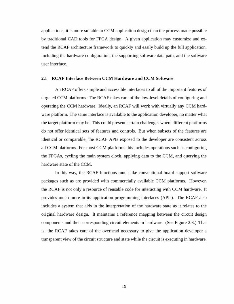
2.1 RCAF Interface Between CCM Hardware and CCM Software
An RCAF offers simple and accessible interfaces to all of the important features of
targeted CCM platforms. The RCAF takes care of the low-level details of configuring and
operating the CCM hardware. Ideally, an RCAF will work with virtually any CCM hard-
ware platform. The same interface is available to the application developer, no matter what
the target platform may be. This could present certain challenges where different platforms
do not offer identical sets of features and controls. But when subsets of the features are
identical or comparable, the RCAF APIs exposed to the developer are consistent across
all CCM platforms. For most CCM platforms this includes operations such as configuring
the FPGAs, cycling the main system clock, applying data to the CCM, and querying the
hardware state of the CCM.
In this way, the RCAF functions much like conventional board-support software
packages such as are provided with commercially available CCM platforms. However,
the RCAF is not only a resource of reusable code for interacting with CCM hardware. It
provides much more in its application programming interfaces (APIs). The RCAF also
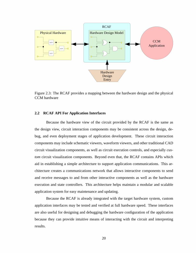
includes a system that aids in the interpretation of the hardware state as it relates to the
original hardware design. It maintains a reference mapping between the circuit design
components and their corresponding circuit elements in hardware. (See Figure 2.3.) That
is, the RCAF takes care of the overhead necessary to give the application developer a
transparent view of the circuit structure and state while the circuit is executing in hardware.
19
LUT
LUT
LUT
EntryDesign
Hardware
CCMApplication
Physical Hardware Hardware Design Model
RCAF
Figure 2.3: The RCAF provides a mapping between the hardware design and the physicalCCM hardware
2.2 RCAF API For Application Interfaces
Because the hardware view of the circuit provided by the RCAF is the same as
the design view, circuit interaction components may be consistent across the design, de-
bug, and even deployment stages of application development. These circuit interaction
components may include schematic viewers, waveform viewers, and other traditional CAD
circuit visualization components, as well as circuit execution controls, and especiallycus-
tom circuit visualization components. Beyond even that, the RCAF contains APIs which
aid in establishing a simple architecture to support application communications. This ar-
chitecture creates a communications network that allows interactive components to send
and receive messages to and from other interactive components as well as the hardware
execution and state controllers. This architecture helps maintain a modular and scalable
application system for easy maintenance and updating.
Because the RCAF is already integrated with the target hardware system, custom
application interfaces may be tested and verified at full hardware speed. These interfaces
are also useful for designing and debugging the hardware configuration of the application
because they can provide intuitive means of interacting with the circuit and interpreting
results.
20
2.3 RCAF Support for (Dynamic) Circuit Design
The RCAF is more than just an interface layer in a CCM-based application. It is
also a circuit design tool for the CCM hardware configuration. The circuit design is built
up programmatically and then translated into a format that can be accepted by technology-
specific tools that prepare it to configure the CCM hardware.
The RCAF also has the ability to receive directives from the application to dynam-
ically create a custom version of the CCM hardware configuration design. As explained in
section 1.4, this enables CCM applications to optimize the hardware configuration of the
CCM based on parameters and data supplied by the user. The RCAF itself is deployed with
the final application. This gives even the end user access to dynamic, interactive circuit
creation capabilities to significantly improve the performance of the application.
As mentioned in Section 2.1, the RCAF maintains a design entry-level model of
the hardware configuration. The same RCAF model serves the purposes of design entry,
hardware configuration, and hardware execution and simulation. This means that the dy-
namically established hardware design and the application interface software can maintain
a consistent relationship through the APIs exposed by the hardware design model. This
helps minimize the amount of code required to establish relationships between the hard-
ware design and the software interfaces. This is a tremendous improvement over traditional
CAD tools which usually convert a design-entry model into entirely different models for
simulation and hardware configuration.
2.4 Designing, Debugging, and Deploying CCM Applications
RCAF features allow designers to improve the process of designing, debugging,
and deploying CCM-based applications. Application development stages proceed within
the same environment; the RCAF is an integral part of the application from design to debug
to deployment. The final application also remains in the same environment. This continuity
reduces the risk of having to restart the development process at various stages, as might
occur when transferring a development project from one tool to another. This is because
the application behaves the same across all boundaries between development stages. In
21

general, projects created using an RCAF are easier to develop and maintain than projects
created with multiple development tools and environments.
22
Chapter 3
JHDL: A Basis for a Reconfigurable Computing Application Frame-
work
The initial motivation for the creation of a reconfigurable computing application
framework was based on the need to update and improve an existing circuit design tool.
This tool, JHDL, already contained precursors of many features of an RCAF, such as those
described in Chapter 2. However, as a continuing work in progress, JHDL had a few
shortcomings, and JHDL was not previously viewed or utilized in an RCAF context. Goals
and plans to correct JHDL’s shortcomings quickly evolved into an RCAF development
project. This chapter describes the state of JHDL before the RCAF project began.1
3.1 JHDL Design Fundamentals
3.1.1 The JHDL Design Data Model
JHDL’s data model is a Java-based structural representation of digital logic circuits.
Although several different languages could have been used to help build up JHDL data
models, the Java programming language offered a number of features that made it a good
choice. Among those features are an object-oriented architecture that does not require the
designer to be concerned with memory management, and Java reflection, which allows for
dynamic creation, modification, and analysis of object classes. At the low level, a JHDL
design is made up of instances of Java objects which represent primitive logic cells avail-
able in typical FPGA technologies. These primitive JHDL cells have behavioral models
for simulation purposes. JHDL cell objects are subclasses of theNode or Cell classes
1 For more information on JHDL and developments related to it, see [9, 10, 11, 5, 6].
23
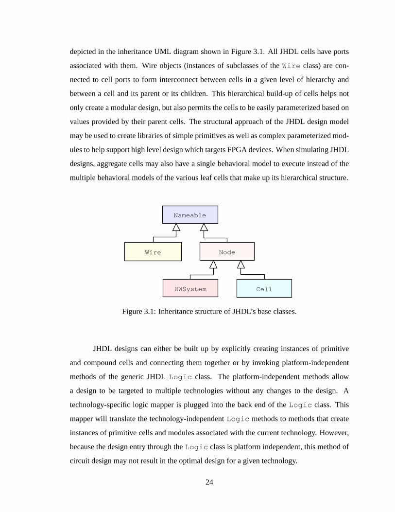
depicted in the inheritance UML diagram shown in Figure 3.1. All JHDL cells have ports
associated with them. Wire objects (instances of subclasses of theWire class) are con-
nected to cell ports to form interconnect between cells in a given level of hierarchy and
between a cell and its parent or its children. This hierarchical build-up of cells helps not
only create a modular design, but also permits the cells to be easily parameterized based on
values provided by their parent cells. The structural approach of the JHDL design model
may be used to create libraries of simple primitives as well as complex parameterized mod-
ules to help support high level design which targets FPGA devices. When simulating JHDL
designs, aggregate cells may also have a single behavioral model to execute instead of the
multiple behavioral models of the various leaf cells that make up its hierarchical structure.
Nameable
Wire Node
CellHWSystem
Figure 3.1: Inheritance structure of JHDL’s base classes.
JHDL designs can either be built up by explicitly creating instances of primitive
and compound cells and connecting them together or by invoking platform-independent
methods of the generic JHDLLogic class. The platform-independent methods allow
a design to be targeted to multiple technologies without any changes to the design. A
technology-specific logic mapper is plugged into the back end of theLogic class. This
mapper will translate the technology-independentLogic methods to methods that create
instances of primitive cells and modules associated with the current technology. However,
because the design entry through theLogic class is platform independent, this method of
circuit design may not result in the optimal design for a given technology.
24

A JHDL design is created from within a JHDL testbench.2 The testbench typically
determines the target technology of any technology-independent components of the circuit
design. The testbench is contained within the JHDL hardware system. (JHDL’s hardware
system is represented by theHWSystemclass.) The hardware system acts as the gateway
for all access to the circuit hierarchy, circuit state, and circuit control. It also creates a
circuit simulator and establishes a relationship between the simulator and the JHDL circuit
design. The relationships between the various components of the JHDL system are shown
in Figure 3.2.
JHDL Hardware System
SimulatorJHDL TestBench
Circuit
State
Import/
Export
Runtime
Control
Platform
Control
MachineComputing
Configurable
JHDL Circuit Design
Figure 3.2: Hierarchy of the JHDL system.
3.1.2 JHDL Application Programming Interface
The hierarchy and relationships shown in Figure 3.2 are typically self-contained.
However, the JHDL hardware system also exposes a simple application programming in-
terface (API) that gives access to the circuit design, as depicted in Figure 3.3. JHDL designs
are created using a general purpose programming language (as opposed to a closed hard-
ware description language meant only for creating simulation models and netlists). Because
of this, components external to the base JHDL system may easily be integrated with JHDL
2 The use of the name testbench comes from a historical context. In some situations, i.e. when a JHDLdesign is in final form and executing in hardware, the name testbench is a misnomer.
25

through the API exposed by JHDL’s hardware system. These APIs are described in more
detail below.
Circuit Structure API Circuit State API Simulator API
JHDL Hardware System
JHDL TestBench
JHDL Circuit Design Simulator
Figure 3.3: JHDL’s hardware systems exposes three types of APIs to external systems.
JHDL’s Circuit Structure API
The HWSystem class offers methods to access its child cell, as well as any arbi-
trary subcomponent in the circuit design. These methods are shown in Table 3.1. The
getTestBench method simply returns a reference to the only design element child
of the hardware system: the testbench. ThefindNamed method has a return type of
Nameable . TheNameable class is the super class for all nodes and wires in a JHDL
circuit design. ThefindNamed method may be used to acquire a pointer to any wire or
cell of the design, even if it doesn’t happen to be explicitly connected into the circuit. The
Nameable class ensures that all JHDL nodes have unique identifiers, or names, that can
be used to obtain a pointer to them through thefindNamed method.
26

Table 3.1:HWSystemmethods for accessing circuit design cells
Method Name Arguments Return TypegetTestBench Cell
findNamed String name Nameable
JHDL cells in general also have a set of methods that can be used to access the
circuit structure of the design. These methods are shown in Table 3.2. The methodsget-
Parent , getChildren , andgetDescendents , may be used to obtain hierarchy in-
formation (but not connectivity and port information) about the JHDL design. The methods
getPortRecords , getPortRecord , getAttachedPort , getAttachedWire ,
getSinkWires , andgetSourceWires , can be used to determine information about
the wires connected to the cell at the ports. The methodsgetWires , getCellNetlist ,
andgetFlatNetlist can be used to obtain pointers to the wires that connect the chil-
dren cells of a given cell. Finally, the methodgetSystem provides a convenient method
of obtaining a pointer to the top-level JHDL system from any cell.
Table 3.2: JHDLCell methods for accessing circuit design structure
Method Name Arguments Return TypegetParent Node
getChildren NodeListgetDescendents CellListgetPortRecords PortRecordListgetPortRecord String portName PortRecord
getAttachedPort Wire w StringgetAttachedWire String portName Wire
getSinkWires WireListgetSourceWires WireList
getWires WireListgetCellNetlist NetlistgetFlatNetlist Netlist
getSystem HWSystem
27

TheWire class also has a set of methods that may be used to obtain circuit structure
information from a JHDL design. These methods are shown in Table 3.3. The first six
methods return references to the sink or source cells of a given wire object. Theget-
Width method returns the number of bits that make up a given wire object. ThegetWire
andrange methods offer convenient means of obtaining references to one or multiple bits
of a multi-bit wire. ThegetParent method may be used to determine the owner of a
given wire. ThegetSystem method of theWire class is another convenience method
for obtaining a reference to the top-level system object for the JHDL design.
Table 3.3:Wire class methods for accessing circuit design structure
Method Name Arguments Return TypegetSinkCell Cell
getSinkCells CellListgetAllSinkCells CellList
getSourceCell CellgetSourceCells CellList
getAllSourceCells CellListgetWidth intgetWire int index Wire
range int highInd,int lowInd WiregetParent NodegetSystem HWSystem
The subclasses of the abstractTechMapper class can write the structure of a de-
sign to a netlist file. Table 3.4 shows the methods to generate these netlists. The output
format depends on the particularTechMapper used. For example, theTechMapper
classes for the Xilinx FPGAs generate EDIF (electronic design interchange format) netlists
for use by the Xilinx back-end synthesis tools.TechMapper classes also exist to create
netlists in VHDL format (very high-speed integrated circuit hardware description language)
and Opt format (used for the Teramac CCM produced by Hewlett-Packard).
28

Table 3.4: JHDLTechMapper methods for writing a netlist file
Method Name Argumentsnetlist Cell cell, boolean flat, NetlistWriter nwnetlist Cell cell, boolean flat, String filenamenetlist Cell cell, String filename
JHDL’s Simulation API
JHDL simulation is set up and managed by the JHDL hardware system and its
corresponding simulator. The default simulator is a statically-scheduled simulator. This
makes simulation significantly faster than what is possible with an event-driven simulator.
However, it has the disadvantage of limiting the types of circuits that may be simulated;
specifically, circuits that contain asynchronous loops may not be simulated with JHDL’s
default simulator. JHDL simulation is simply performed by executing the code that makes
up the circuit design. Each circuit element contains simulation code within either aclock
or propagate method. The cell objects themselves determine their own behavior when
these methods are invoked by the simulator. Typically, each cell will read the values on
its input wires and make decisions about what values to put on its output wires. The order
of execution of simulation code is determined up front by the simulator schedule. The
simulator schedule is divided into steps. The number of steps depends on the number of
clocks in the circuit design, as well as their duty cycles and relative frequencies. A full
simulation schedule, or complete set of steps, is a simulation cycle.
The JHDL hardware system makes a simulation execution control API available.
This API allows the simulator to be “stepped” and “cycled.” The relevant methods (cycle ,
step , andskip ) are shown in Table 3.5. Table 3.5 also shows the simulator callback
methods in the hardware system. These methods allow any class which implements JHDL’s
SimulatorCallback interface, shown in Table 3.6, to receive feedback from the sim-
ulator. The feedback comes in the form of notification of the completion of significant sim-
ulator events. ThesimulatorReset method of all registeredSimulatorCallback
objects will be invoked whenever the simulator is reset. ThesimulatorUpdate method
will be invoked after each step of the simulator. The user or testbench may tell the simulator
29
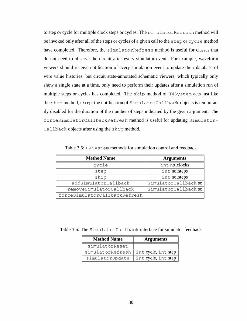
to step or cycle for multiple clock steps or cycles. ThesimulatorRefresh method will
be invoked only after all of the steps or cycles of a given call to thestep or cycle method
have completed. Therefore, thesimulatorRefresh method is useful for classes that
do not need to observe the circuit after every simulator event. For example, waveform
viewers should receive notification of every simulation event to update their database of
wire value histories, but circuit state-annotated schematic viewers, which typically only
show a single state at a time, only need to perform their updates after a simulation run of
multiple steps or cycles has completed. Theskip method ofHWSystem acts just like
thestep method, except the notification ofSimulatorCallback objects is temporar-
ily disabled for the duration of the number of steps indicated by the given argument. The
forceSimulatorCallbackRefresh method is useful for updatingSimulator-
Callback objects after using theskip method.
Table 3.5:HWSystemmethods for simulation control and feedback
Method Name Argumentscycle int no clocksstep int no stepsskip int no steps
addSimulatorCallback SimulatorCallback scremoveSimulatorCallback SimulatorCallback sc
forceSimulatorCallbackRefresh
Table 3.6: TheSimulatorCallback interface for simulator feedback
Method Name ArgumentssimulatorReset
simulatorRefresh int cycle,int stepsimulatorUpdate int cycle,int step
30
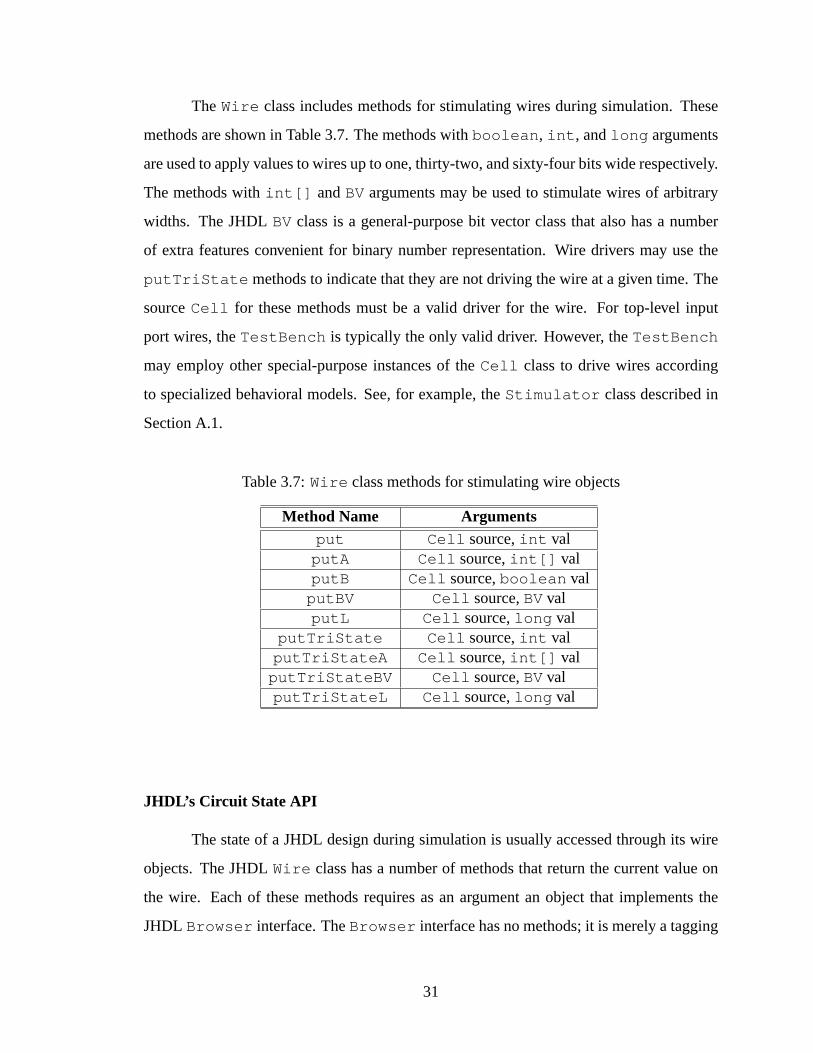
TheWire class includes methods for stimulating wires during simulation. These
methods are shown in Table 3.7. The methods withboolean , int , andlong arguments
are used to apply values to wires up to one, thirty-two, and sixty-four bits wide respectively.
The methods withint[] andBV arguments may be used to stimulate wires of arbitrary
widths. The JHDLBV class is a general-purpose bit vector class that also has a number
of extra features convenient for binary number representation. Wire drivers may use the
putTriState methods to indicate that they are not driving the wire at a given time. The
sourceCell for these methods must be a valid driver for the wire. For top-level input
port wires, theTestBench is typically the only valid driver. However, theTestBench
may employ other special-purpose instances of theCell class to drive wires according
to specialized behavioral models. See, for example, theStimulator class described in
Section A.1.
Table 3.7:Wire class methods for stimulating wire objects
Method Name Argumentsput Cell source,int val
putA Cell source,int[] valputB Cell source,boolean val
putBV Cell source,BVvalputL Cell source,long val
putTriState Cell source,int valputTriStateA Cell source,int[] val
putTriStateBV Cell source,BVvalputTriStateL Cell source,long val
JHDL’s Circuit State API
The state of a JHDL design during simulation is usually accessed through its wire
objects. The JHDLWire class has a number of methods that return the current value on
the wire. Each of these methods requires as an argument an object that implements the
JHDL Browser interface. TheBrowser interface has no methods; it is merely a tagging
31
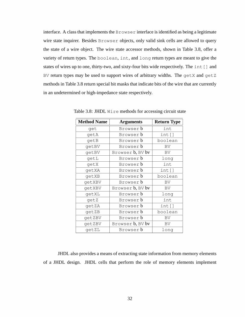
interface. A class that implements theBrowser interface is identified as being a legitimate
wire state inquirer. BesidesBrowser objects, only valid sink cells are allowed to query
the state of a wire object. The wire state accessor methods, shown in Table 3.8, offer a
variety of return types. Theboolean , int , andlong return types are meant to give the
states of wires up to one, thirty-two, and sixty-four bits wide respectively. Theint[] and
BV return types may be used to support wires of arbitrary widths. ThegetX andgetZ
methods in Table 3.8 return special bit masks that indicate bits of the wire that are currently
in an undetermined or high-impedance state respectively.
Table 3.8: JHDLWire methods for accessing circuit state
Method Name Arguments Return Typeget Browser b int
getA Browser b int[]getB Browser b boolean
getBV Browser b BVgetBV Browser b, BVbv BVgetL Browser b longgetX Browser b int
getXA Browser b int[]getXB Browser b boolean
getXBV Browser b BVgetXBV Browser b, BVbv BVgetXL Browser b longgetZ Browser b int
getZA Browser b int[]getZB Browser b boolean
getZBV Browser b BVgetZBV Browser b, BVbv BVgetZL Browser b long
JHDL also provides a means of extracting state information from memory elements
of a JHDL design. JHDL cells that perform the role of memory elements implement
32
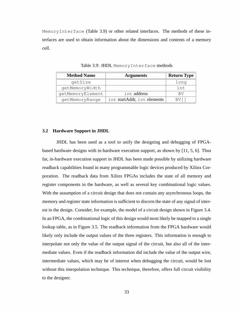
MemoryInterface (Table 3.9) or other related interfaces. The methods of these in-
terfaces are used to obtain information about the dimensions and contents of a memory
cell.
Table 3.9: JHDLMemoryInterface methods
Method Name Arguments Return TypegetSize long
getMemoryWidth intgetMemoryElement int address BV
getMemoryRange int startAddr,int elements BV[]
3.2 Hardware Support in JHDL
JHDL has been used as a tool to unify the designing and debugging of FPGA-
based hardware designs with in-hardware execution support, as shown by [11, 5, 6]. Thus
far, in-hardware execution support in JHDL has been made possible by utilizing hardware
readback capabilities found in many programmable logic devices produced by Xilinx Cor-
poration. The readback data from Xilinx FPGAs includes the state of all memory and
register components in the hardware, as well as several key combinational logic values.
With the assumption of a circuit design that does not contain any asynchronous loops, the
memory and register state information is sufficient to discern the state of any signal of inter-
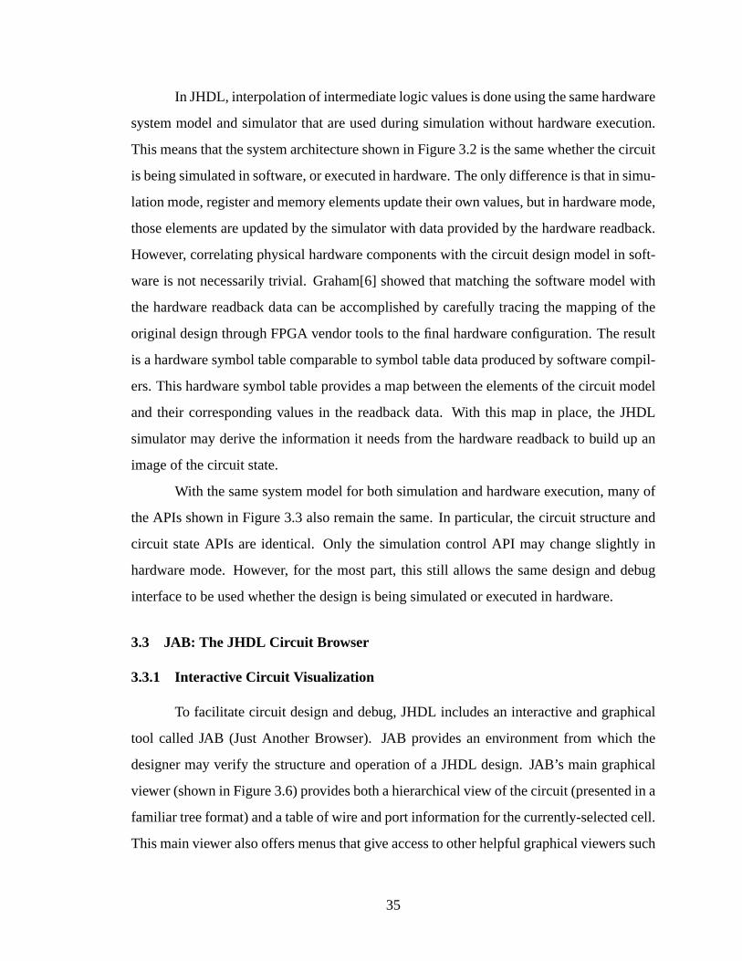
est in the design. Consider, for example, the model of a circuit design shown in Figure 3.4.
In an FPGA, the combinational logic of this design would most likely be mapped to a single
lookup table, as in Figure 3.5. The readback information from the FPGA hardware would
likely only include the output values of the three registers. This information is enough to
interpolate not only the value of the output signal of the circuit, but also all of the inter-
mediate values. Even if the readback information did include the value of the output wire,
intermediate values, which may be of interest when debugging the circuit, would be lost
without this interpolation technique. This technique, therefore, offers full circuit visibility
to the designer.
33
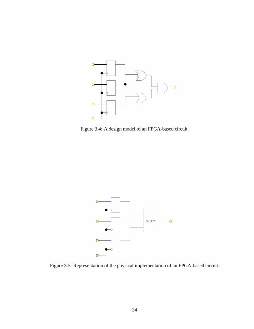
Figure 3.4: A design model of an FPGA-based circuit.
3−LUT
Figure 3.5: Representation of the physical implementation of an FPGA-based circuit.
34
In JHDL, interpolation of intermediate logic values is done using the same hardware
system model and simulator that are used during simulation without hardware execution.
This means that the system architecture shown in Figure 3.2 is the same whether the circuit
is being simulated in software, or executed in hardware. The only difference is that in simu-
lation mode, register and memory elements update their own values, but in hardware mode,
those elements are updated by the simulator with data provided by the hardware readback.
However, correlating physical hardware components with the circuit design model in soft-
ware is not necessarily trivial. Graham[6] showed that matching the software model with
the hardware readback data can be accomplished by carefully tracing the mapping of the
original design through FPGA vendor tools to the final hardware configuration. The result
is a hardware symbol table comparable to symbol table data produced by software compil-
ers. This hardware symbol table provides a map between the elements of the circuit model
and their corresponding values in the readback data. With this map in place, the JHDL
simulator may derive the information it needs from the hardware readback to build up an
image of the circuit state.
With the same system model for both simulation and hardware execution, many of
the APIs shown in Figure 3.3 also remain the same. In particular, the circuit structure and
circuit state APIs are identical. Only the simulation control API may change slightly in
hardware mode. However, for the most part, this still allows the same design and debug
interface to be used whether the design is being simulated or executed in hardware.
3.3 JAB: The JHDL Circuit Browser
3.3.1 Interactive Circuit Visualization
To facilitate circuit design and debug, JHDL includes an interactive and graphical
tool called JAB (Just Another Browser). JAB provides an environment from which the
designer may verify the structure and operation of a JHDL design. JAB’s main graphical
viewer (shown in Figure 3.6) provides both a hierarchical view of the circuit (presented in a
familiar tree format) and a table of wire and port information for the currently-selected cell.
This main viewer also offers menus that give access to other helpful graphical viewers such
35

as schematic viewers (Figure 3.7), memory viewers (Figure 3.8), and waveform viewers
(Figure 3.9).
Figure 3.6: JAB’s circuit hierarchy browser.
To furnish a system layer from which input to the design may be provided and out-
put analyzed, all JHDL designs must be contained in a testbench. To ease the designer’s
burden of having to provide a testbench for all designs, especially for small and simple
designs, JAB provides a dynamic testbench that can be used as the parent of most de-
signs. This testbench, called Tbone, can be used to create top-level wires for the design
and provide stimuli for the design inputs and basic output verification. Although it has
some limitations, Tbone provides a convenient means of quickly and easily verifying the
operation of most small JHDL designs.
3.3.2 Simulation and Execution Control
JAB also includes a command-line interpreter for executing commands that per-
form operations not offered by the graphical viewers as well as a few commands that are
36

Figure 3.7: JAB’s design schematic viewer.
Figure 3.8: JAB’s memory viewer.
Figure 3.9: JAB’s waveform viewer.
37

found in the viewers. The JAB console (shown in Figure 3.10) shows the history and feed-
back of commands. Textual commands may be stored in and executed from log files for
convenience in scripting repetitive simulation actions.
Figure 3.10: JAB’s command line console.
Simulation control in JAB is achieved with both textual commands and graphical
controls. Specifically, cycle and step commands are accessible from both the graphical
viewers (typically as buttons) and the command line interpreter. When using Tbone as the
design testbench, additional text commands may be used to control the input values to the
circuit design.
38
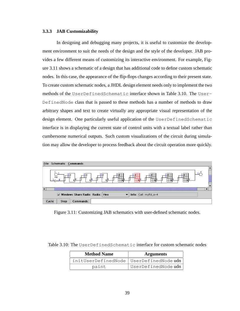
3.3.3 JAB Customizability
In designing and debugging many projects, it is useful to customize the develop-
ment environment to suit the needs of the design and the style of the developer. JAB pro-
vides a few different means of customizing its interactive environment. For example, Fig-
ure 3.11 shows a schematic of a design that has additional code to define custom schematic
nodes. In this case, the appearance of the flip-flops changes according to their present state.
To create custom schematic nodes, a JHDL design element needs only to implement the two
methods of theUserDefinedSchematic interface shown in Table 3.10. TheUser-
DefinedNode class that is passed to these methods has a number of methods to draw
arbitrary shapes and text to create virtually any appropriate visual representation of the
design element. One particularly useful application of theUserDefinedSchematic
interface is in displaying the current state of control units with a textual label rather than
cumbersome numerical outputs. Such custom visualizations of the circuit during simula-
tion may allow the developer to process feedback about the circuit operation more quickly.
Figure 3.11: Customizing JAB schematics with user-defined schematic nodes.
Table 3.10: TheUserDefinedSchematic interface for custom schematic nodes
Method Name ArgumentsinitUserDefinedNode UserDefinedNode udn
paint UserDefinedNode udn
39
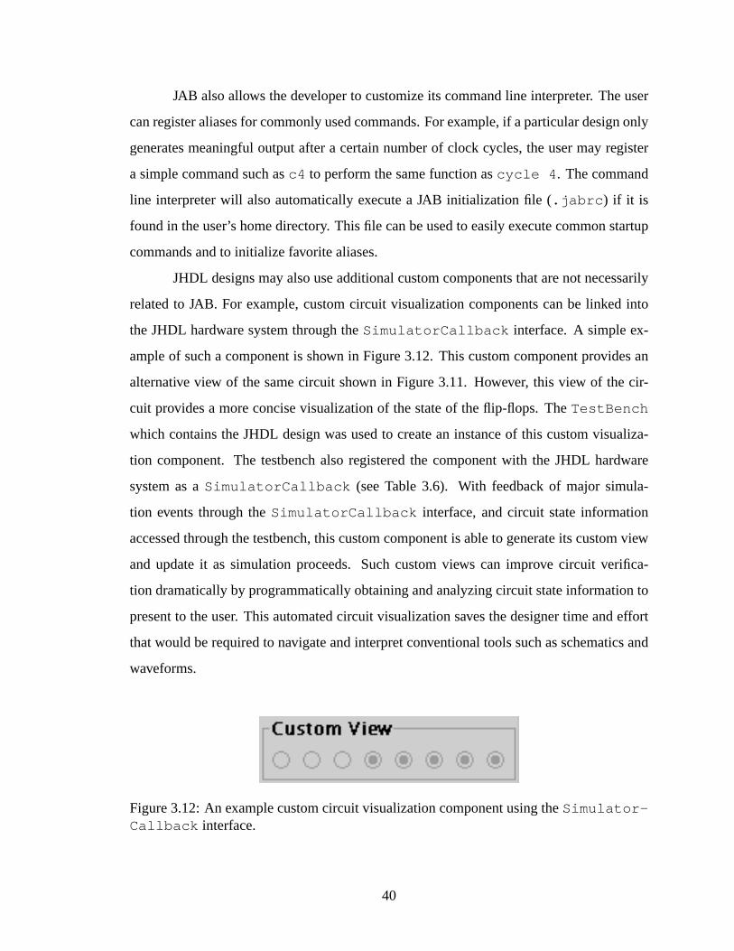
JAB also allows the developer to customize its command line interpreter. The user
can register aliases for commonly used commands. For example, if a particular design only
generates meaningful output after a certain number of clock cycles, the user may register
a simple command such asc4 to perform the same function ascycle 4 . The command
line interpreter will also automatically execute a JAB initialization file (.jabrc ) if it is
found in the user’s home directory. This file can be used to easily execute common startup
commands and to initialize favorite aliases.
JHDL designs may also use additional custom components that are not necessarily
related to JAB. For example, custom circuit visualization components can be linked into
the JHDL hardware system through theSimulatorCallback interface. A simple ex-
ample of such a component is shown in Figure 3.12. This custom component provides an
alternative view of the same circuit shown in Figure 3.11. However, this view of the cir-
cuit provides a more concise visualization of the state of the flip-flops. TheTestBench
which contains the JHDL design was used to create an instance of this custom visualiza-
tion component. The testbench also registered the component with the JHDL hardware
system as aSimulatorCallback (see Table 3.6). With feedback of major simula-
tion events through theSimulatorCallback interface, and circuit state information
accessed through the testbench, this custom component is able to generate its custom view
and update it as simulation proceeds. Such custom views can improve circuit verifica-
tion dramatically by programmatically obtaining and analyzing circuit state information to
present to the user. This automated circuit visualization saves the designer time and effort
that would be required to navigate and interpret conventional tools such as schematics and
waveforms.
Figure 3.12: An example custom circuit visualization component using theSimulator-Callback interface.
40

Other means of customizing the circuit verification of JHDL designs can be done
through the testbench. Because the testbench is also written in the same general-purpose
programming language as the design itself, it is natural and straightforward to implement
custom components to interact with the simulation process. For example, custom compo-
nents created by the testbench could manipulate the inputs to a circuit design. This could
be done programmatically or interactively.
3.4 JHDL and JAB: A Precursor to an RCAF System
Features of JHDL and JAB described above created the original inspiration for the
notion of reconfigurable computing application frameworks. Indeed, many of the charac-
teristics of an RCAF described in Chapter 2 were already present in JHDL and JAB. In
particular, JHDL and JAB can offer an interface between the hardware design model and
the actual hardware, relatively simple circuit execution control and feedback, and dynamic
circuit design and creation.
3.4.1 Drawbacks to the JHDL and JAB System
However, the JHDL/JAB system has a few characteristics and shortcomings that
prevent it from being used as a good RCAF. JHDL itself works well as a base design
model. However, to use JHDL alone would still require building up an entirely new system
on top of it for every new application.
JAB is an inappropriate framework for the following reasons. JAB is generally a
monolithic software system, and as such does not scale well as would be required by a good
application framework. JAB was developed with an ad hoc style that created an extensive
set of interdependences between its subcomponents. This makes JAB less modular and
more difficult to maintain and update. JAB is also mostly a closed system. Outside of the
few customizability features presented in Section 3.3.3, JAB offers no means of directly
linking in extra components to offer custom application features and interactive elements.
Using JAB with JHDL is an excellent means of designing and debugging hardware
configurations for FPGAs and CCMs. However, it is not adequate to perform the role of an
RCAF in desiging, debugging, anddeployingcomplete CCM-based applications. That is
41
because JAB is basically a stand-alone application with minimal support for customizing
it. Also, JAB is a large, monolithic tool that would require a great deal of unnecessary
overhead for most applications.
3.4.2 Lessons From JAB
Despite its shortcomings, JAB provided a number of lessons in the creation of an
RCAF. With its network of internal component dependences, JAB was difficult to maintain.
Updating, adding, or removing any one component was difficult to do without upsetting
several other parts of the system. JAB also lacked a centralized control unit; instead, com-
ponents simply acted individually and inconsistently to accomplish tasks and communicate
with each other.
The difficulty in maintaining JAB as well as the lack of a centralized control unit for
the system highlighted the necessity of creating a simpler and more modular architecture.
The new architecture should be scalable to fit a variety of applications. It should also
allow for simpler integration of a wide variety of custom circuit and application interaction
components. Finally, the new architecture should be flexible and small enough to easily be
deployed along with complete CCM applications.
42
Chapter 4
Circuit Visualization Tool (CVT)
The JHDL-based implementation of areconfigurable computing application frame-
work is calledCircuit Visualization Tool , orCVT . CVT borrows a great deal of code from
the JAB tool. However, because the CVT architecture and its usage model are radically dif-
ferent from those of JAB, it is a distinct and unique tool with unique features that constitute
not only a significant improvement over JAB, but also over current tools for CCM applica-
tion development in general.
4.1 CVT Architecture
The CVT architecture is based on sound principles of user interface design such as
those described by Olsen[12] and used in significant user interface toolkits such as Java
Swing[13]. This user interface architecture is based on distinct components that act as the
model, view, and controller of the user interface. Themodelis the fundamental data being
manipulated by the system or the computation being performed. Theview is the system
component that determines how data is presented to the user. Thecontroller is the portion
of the system that receives user input and interprets it to perform system tasks. These
tasks may perform manipulations of the data or they may change the way in which the
view displays information about the data. The model-view-controller architecture, shown
in Figure 4.1, divides the functionality of a system along boundaries that allow for simple
system production and maintenance.
The model-view-controller architecture also establishes a natural communications
network between its three components. The implementation for the CVT internal com-
munication network is patterned after the listener model commonly used in user interface
43

Controller
������������������������������������������������������������������������������������������������������������������������������������������������������������������������������������������������������������������������������������������������������������������������������������������������������������������������������������������������������
������������������������������������������������������������������������������������������������������������������������������������������������������������������������������������������������������������������������������������������������������������������������������������������������������������������������������������������������������
Model���������������������������������������������������������������������������������
���������������������������������������������������������������������������������View
Figure 4.1: The model-view-controller architecture for user interfaces.
architectures, notably in the Java Swing classes. The CVT version of the model-view-
controller architecture is shown in Figure 4.2. The following three sections describe how
the components in this figure relate to the model-view-controller architecture.
4.1.1 The CVT Model
The underlyingmodelfor CVT is implemented by JHDL. The CVT RCAF simply
uses the default JHDL system without any modifications. The various APIs described in
Section 3.1 and depicted in Figure 3.3 offer sufficient access to information about the model
in order to support the model view and the controller. Manipulations to the model come in
the form of stepping the circuit clock and applying values to the circuit inputs.
4.1.2 The CVT Controller
To receive and interpret user input and execute corresponding system-wide tasks,
CVT has a centralizedcontroller. The CVT controller is contained in a class named
Broker . TheBroker class gets its name from its role as an intermediary between the
other major components of the CVT RCAF. TheBroker is the only RCAF component
with a system-wide view of all the other components. This centralized location of system
44

JHDL Hardware System
Simulator
JHDL TestBench
Viewer
Viewer
Viewer
Viewer
ListenerListener
ListenerListener
MachineComputing
Configurable
Broker
InterpreterCommand
JHDL Circuit Design
Figure 4.2: CVT Architecture.
information is an improvement over the network of component references found in the JAB
system described in Section 3.3. This system simplifies CVT and makes it easier to main-
tain. This also makes CVT modular and scalable. That is because only one class needs
to be modified to change the set of features and components included in CVT to support a
given application.
TheBroker class contains all of the methods to perform major system tasks. Such
tasks include creating and disposing viewers and managing communication between view-
ers. TheBroker also performs manipulations to the application model; i.e. it invokes
the reset, step, and cycle commands to control circuit execution and it applies values to the
circuit inputs.
TheBroker class works closely with a command interpreter. The command inter-
preter accepts and processes textual commands from the application user. The result is the
invocation of corresponding methods of theBroker class. The set of commands available
is therefore determined by theBroker class. In graphical environments, theBroker
creates listeners which translate low-level events from the viewers (e.g. button presses,
mouse clicks, and key strokes) into text commands to give to the command interpreter. All
executed text commands are stored in a history log. This log may be retained, modified as
45
necessary, and executed again later, making CVT scriptable. The system of textual com-
mands also helps make CVT modular and extensible. The textual commands separate the
Broker from any specific application interface element. A given interface element may
be exchanged for any other element that happens to be able to generate the same types of
text commands. This helps to minimize the maintenance required for theBroker class.
4.1.3 The CVT View
CVT viewersoffer application-specific presentations of the circuit design. They
also offer a portal through which the user may apply inputs to be passed to the CVT con-
troller. A default CVT configuration for general-purpose circuit visualization includes a
standard set of viewers (e.g. schematic viewers, circuit hierarchy viewers, memory view-
ers, etc.) Each unique CCM application may easily add to or remove from this default set
of viewers as appropriate for the application. Each custom viewer merely needs to fol-
low CVT’s method for generating events to work with theBroker ’s listener model for
communication. Each viewer should provide a listener interface for these events. Imple-
mentations of the listener interface may be used to translate action events into commands
for the command interpreter. The CVT system imposes no other restrictions on custom
viewers. It is up to the developers to decide on implementation details related to custom
viewers; although the model-view-controller architecture does provide a good standard to
follow on the viewer level as well.
4.1.4 Integrating CVT Model, View, and Controller
Figure 4.3 shows an example interaction between the various components of the
RCAF architecture. In this example, an application consists of the JHDL circuit model,
the CVT Broker class, the command interpreter, and three application viewers. The
Broker has already created an instance of a listener that can receive events from the
schematic viewer on the right. This listener translates events from the schematic viewer
into textual commands for the command interpreter. In this example scenario, the user
double-clicks with a mouse pointer on a portion of the schematic viewer that displays a
wire in the circuit design. This generates an event which is picked up by the GUI listener
46
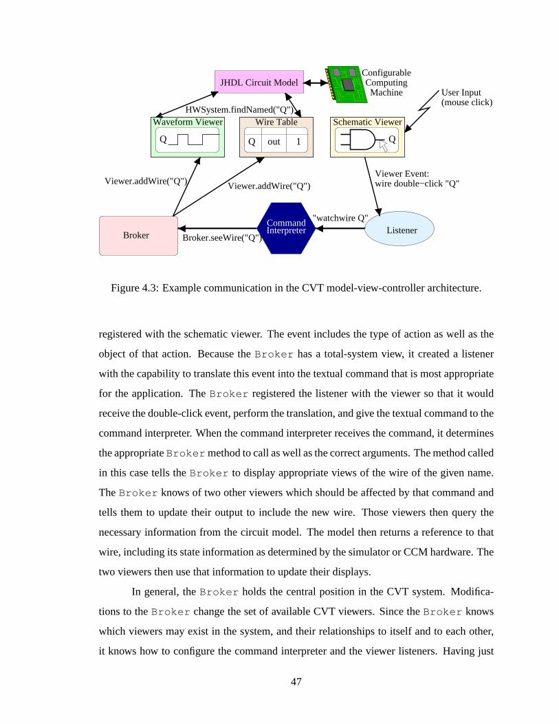
JHDL Circuit Model
Waveform Viewer
Q
wire double−click "Q"Viewer Event:
Wire Table Schematic Viewer
Broker.seeWire("Q")
Viewer.addWire("Q")
HWSystem.findNamed("Q")
"watchwire Q"
Viewer.addWire("Q")
User Input(mouse click)
ConfigurableComputing
Machine
InterpreterCommand
Broker
Q out 1
Listener
Q
Figure 4.3: Example communication in the CVT model-view-controller architecture.
registered with the schematic viewer. The event includes the type of action as well as the
object of that action. Because theBroker has a total-system view, it created a listener
with the capability to translate this event into the textual command that is most appropriate
for the application. TheBroker registered the listener with the viewer so that it would
receive the double-click event, perform the translation, and give the textual command to the
command interpreter. When the command interpreter receives the command, it determines
the appropriateBroker method to call as well as the correct arguments. The method called
in this case tells theBroker to display appropriate views of the wire of the given name.
TheBroker knows of two other viewers which should be affected by that command and
tells them to update their output to include the new wire. Those viewers then query the
necessary information from the circuit model. The model then returns a reference to that
wire, including its state information as determined by the simulator or CCM hardware. The
two viewers then use that information to update their displays.
In general, theBroker holds the central position in the CVT system. Modifica-
tions to theBroker change the set of available CVT viewers. Since theBroker knows
which viewers may exist in the system, and their relationships to itself and to each other,
it knows how to configure the command interpreter and the viewer listeners. Having just
47

this one class with information that makes up a system-wide view makes CVT easier to
maintain and update. The single system controller makes removing and adding viewers to
the system and managing system communication simple.
4.2 Generic Circuit Verification Tool
CVT’s original purpose was to replace the JAB tool as a default circuit verifica-
tion tool. A circuit can be loaded into CVT and then simulated or executed much like in
JAB. As with JAB, CVT has a hierarchical tree view, a port and wire table, and a com-
mand interpreter console. These features are contained in the main CVT viewer shown in
Figure 4.4.
Figure 4.4: CVT’s main circuit view.
CVT is not a feature-for-feature duplication of JAB. CVT’s improved architecture
led to an improved interaction with the viewers. Many features in JAB were only accessible
through menu items. CVT’s viewer listener model, however, allows many actions to be
48

more intuitive. For example, the user may wish to use the mouse to double-click on an
item in the circuit hierarchy. This causes an event to be dispatched which is caught by a
listener object. That listener then translates the event into a textual command to send to the
command interpreter part of the controller. If the item clicked is a normal cell element of
the design, the listener generates a command to create a schematic view of that cell; if the
item is a memory, a command to create a memory viewer is generated instead. Similarly,
the user may add wires to a waveform viewer, open new viewers by clicking on items
in schematic viewers, and perform simulation operations by clicking on step and cycle
buttons. The details of how this works are described in the example in Section 4.1.4. This
system was set up to enable the user to “feel” around the circuit visualization tools to find
the desired information without having a great deal of prior information. This helps to
eliminate what Olsen calls the “gulf of execution[12].” A gulf of execution occurs when
a user interface is such that a user has difficulty determining how to perform a particular
action to obtain a desired result from the system. In CVT, the user simply performs actions
within the viewers that appear to make sense to someone with minimal prior knowledge.
The listeners andBroker then perform a task that makes the most sense for each action.
The CVT system also allows for multiple means to accomplish the same task. For example,
many actions may be performed with mouse clicks, menu commands, keyboard shortcuts,
or commands typed directly in a console associated with the command interpreter.
4.3 Custom Circuit Interaction Components
Since CVT is written in a general-purpose programming language, there are many
ways to extend its capabilities. All that is required is a reference to the circuit design
from which all circuit structure and state information may be extracted. Indeed, the CVT
architecture is so simple and small, it would not take too much to recreate entirely the func-
tionality of the default viewers and controller. Should an application developer desire to do
that, the CVT system can still provide various resources to help build up an application.
CVT provides a toolbox of resources useful for building up custom circuit inter-
action environments for circuit design, debug, and execution. These resources include the
command interpreter, generic viewer frames, wire stimulators, and specific viewer frames
49
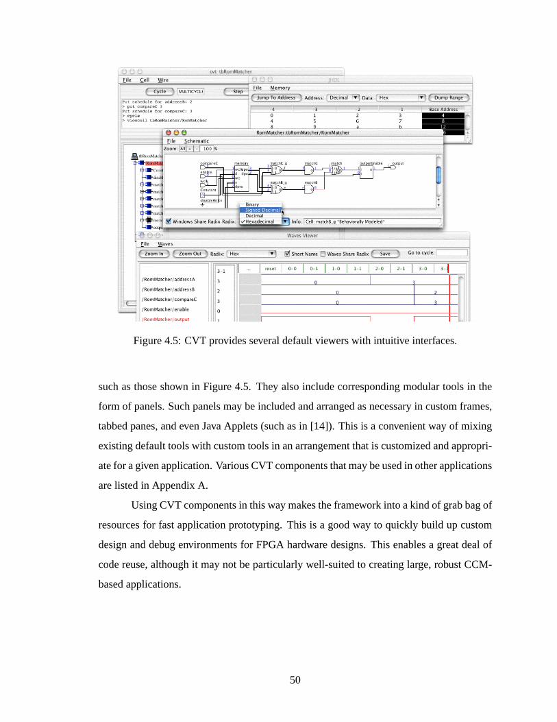
Figure 4.5: CVT provides several default viewers with intuitive interfaces.
such as those shown in Figure 4.5. They also include corresponding modular tools in the
form of panels. Such panels may be included and arranged as necessary in custom frames,
tabbed panes, and even Java Applets (such as in [14]). This is a convenient way of mixing
existing default tools with custom tools in an arrangement that is customized and appropri-
ate for a given application. Various CVT components that may be used in other applications
are listed in Appendix A.
Using CVT components in this way makes the framework into a kind of grab bag of
resources for fast application prototyping. This is a good way to quickly build up custom
design and debug environments for FPGA hardware designs. This enables a great deal of
code reuse, although it may not be particularly well-suited to creating large, robust CCM-
based applications.
50
4.4 Creating Full Custom CCM Applications by Extending CVT
Creating significant and solid CCM-based applications with CVT is best done by
extending the default model-view-controller architecture established by theBroker class
and related CVT components. This architecture is specifically designed to be scalable[12].
With the CVT framework as a basis for a CCM application architecture, developers may
more easily create a system that is more maintainable and modular.
4.4.1 Custom CCM Application Model Component
The model for a CVT-based custom CCM application might be nothing more than
a typical JHDL circuit design. However, many applications may wish to include extra fea-
tures in the circuit model to accommodate application requirements or platform-specific
features or needs. As instances of Java classes, JHDL designs may include extra fields and
methods to serve whatever purpose necessary in the CCM application. For example, meth-
ods may exist to assist viewers in locating key circuit components or interpreting encoded
values. As an example of this, see the edit distance application in Section 5.2. JHDL cir-
cuit models may also include design features that reflect the architecture of a specific CCM
platform. Several projects related to JHDL have done this by creating “board models” for
various CCM architectures that include such features as FIFO and memory interfaces. With
these interface elements in place, an application-specific design may be “dropped in” the
board model. This allows the same board model to be reused for various applications, thus
giving application designers a head start in making a particular design work on the given
target platform.
4.4.2 Custom CCM Application View Components
Application viewers may be of any form necessary to implement the application
specifications. However, viewers that follow the pattern established by the CVT architec-
ture help build up the application in a modular, scalable manner. This pattern contains three
communication points for each viewer:
• model queries
51

• outward inter-component communication
• inward inter-component communication
These communication points are shown in Figure 4.6. Viewer model queries are direct com-
munications between the viewer and the application model (circuit design). Viewers may
maintain references to the circuit model as necessary to query circuit structure and state
to garner information to be displayed in the viewer. However, this direct communication
should not perform model manipulations, such as clock stepping or wire value manipula-
tions. Viewer controls that are intended to perform such model manipulations or to com-
municate with other viewers should do so through the outward communication point. This
communication point directs events and messages to viewer listeners, which then translate
the messages into textual commands for the command interpreter in the CVT controller.
The viewer receives messages from other CVT component through theBroker . Because
theBroker is the only class that has a reference to the viewer, it is easier to exchange the
viewer for another or to update its communication API, since only theBroker class needs
to be updated to accommodate the change.
ViewerModel
(Broker)Controller
Listener
Figure 4.6: Communications to and from CVT viewers.
52

4.4.3 Custom CCM Application Controller Component
The custom application controller may be implemented by extending theBroker
class. Extending theBroker class involves overriding the two methods shown in Ta-
ble 4.1. The constructor method is a convenient place to create viewers known to the
Broker and to perform other initialization. TheregisterCLICommands method
gives the customBroker an opportunity to create custom textual commands for the com-
mand interpreter (CLInterpreter ). The defaultBroker also contains several other
methods which perform the various tasks found in the default CVT system. (See Sec-
tion A.1 in Appendix A for a listing of these methods.) The needs of the new textual
commands and the set of application viewers may be accommodated by overriding these
methods or by creating new methods.
Table 4.1:Broker methods for extending the CVT system
Method Name Argumentsnew Broker (constructor) HWSystemsystem,CLInterpreter interpregisterCLICommands HWSystemsystem,CLInterpreter interp
4.5 Application Deployment
As described in Section 1.2.3, deploying a CCM-based application involves prepar-
ing the application for use by the end user. This includes establishing the relationships
between the various components of the application system as they will be at runtime for
the final user as opposed to the application developer. For CVT this means executing the
CVT and other application code to build up the hardware model, the controller component,
and the application viewers, and creating the communications system among them. Appli-
cation deployment also means establishing the relationship between the hardware model
and the CCM board support software. This implies the existence of a minimum runtime
environment sufficient to support the needs of the application. CVT design considerations
related to establishing the runtime environment are discussed in Section 4.6. The remainder
53
of this section discusses the means of creating the model, view, and controller components
and integrating them at execution time.
Any Java class may be used to create and combine the various components of the
CCM application and act as a point of application execution. Typically, theTestBench
portion of the circuit design acts as this deployment class; however, the application execu-
tion is performed in static methods, so it does not really matter in which class it happens,
as long as the class has access to the appropriate methods. Application integration and ex-
ecution consists of creating the circuit design (by instancing a JHDLHWSystemand the
designTestBench ) and creating an instance of theBroker . This is the point at which
user-provided data may be used to configure the circuit design to include data folding and
other optimizations, as described in Section 1.4. Some applications may wish to also create
one or more viewers in the deployment methods, but this may also be performed in the con-
structor of theBroker as described in Section 4.4.3. Once the viewers have been created,
the flow of execution passes to them and the application initialization is complete.
The final application only needs to include the features of the CVT RCAF that are
necessary. For example, JHDL contains libraries that target a variety of FPGA technologies
(e.g. XC4000 series, Virtex, CSRC, etc.), but if a CCM application is only intended for
use on a particular platform, the extraneous libraries may be excluded. Likewise, default
viewers not used in the application may be left out. The current implementation of the
CVT RCAF scales down to only two to four megabytes compressed. This includes all
of the necessary JHDL classes to build up the circuit design model, the JHDL hardware
system and simulation environment, netlisting tools, all of the controller classes, and all of
the viewers necessary for the system. Appendix B shows the sizes of the various groups of
components that may be included in a configuration of CVT. When compared to the tens
or hundreds of megabytes for traditional, monolithic CAD tools, this is a small application
foundation that may reasonably be deployed to users.
4.6 Tradeoffs and Considerations in Application Deployment
A number of considerations related to the deployment of CVT-based applications
must be made. The requirements for the runtime environment needed to support CCM
54

applications based on CVT required tradeoffs to offer the best support for runtime flexi-
bility and application development simplicity. The important issues related to this include
ensuring that the framework and application code can execute on the host. They also in-
clude ensuring that the CVT framework can adequately control the CCM hardware. Finally,
deployment considerations include establishing a means of modifying the hardware config-
uration at execution time should the application require such a feature in order to optimize
the application performance.
4.6.1 Framework and Application Code Execution
The first deployment consideration is the runtime execution environment for the
CVT framework code and for the application code built on top of it. CVT is written in
Java for ease of development and for maximum compatibility with JHDL. A significant
disadvantage of using Java is that code execution is slower (because Java is an interpreted
language rather than native code). Java applications also require the Java Runtime Envi-
ronment, or JRE. In addition to the JRE, if a given application also requires the end user
to compile Java source code (a rare condition) then the Java Software Development Kit, or
Java SDK, is also required. However, Java applications have the advantage of being very
portable. As long as a standard JRE exists on a given platform, the CVT framework can
run on it. Also, many modern workstations include a JRE, or users may obtain one for free
from a number of different sources, particularly directly from Sun Microsystems.
4.6.2 CCM Board Support
CVT uses the JHDL Simulator API to operate the CCM hardware. This gives fea-
tures to CVT which are much like board support packages that are available for many CCM
platforms. However, the Simulator API does not perform its actions directly with the CCM
hardware. It still relies on an underlying board support package. JHDL includes interfaces
that may be used to create classes which integrate with these drivers and packages, even
if they are not written in Java. These interfaces include means of configuring the FPGA
hardware and manipulating the hardware state through cycling the system clock. They also
55

include methods for obtaining runtime hardware state to back annotate the circuit design
model.
4.6.3 Execution-time Hardware Design Modifications
The RCAF specification requires that the CCM application be able to modify the
hardware configuration based on user-supplied data at execution time. In implementing this
feature, CVT represents a compromise between two extremes. On one end is a low level,
yet complex means of manipulating existing hardware configurations. On the other end is
the use of massive EDA tools to synthesize and regenerate the hardware configuration from
design inputs in standardized and widely-used formats.
The low-level, complex solution may be implemented with such systems as Xin-
linx’s JBits software development kit[15]. The JBits tool provides APIs which allow a Java
program to perform very low-level manipulations to an existing configuration bitstream for
the Virtex family of Xilinx FPGAs. Thus, optimizations based on user data, such as the
type demonstrated in Section 1.4.3, could be performed on a bitstream that was produced
just once. This bitstream is created by Xilinx-specific tools based on a hardware design
netlist from the CAD tool. This bitstream could be generated during the deploy stage of
the application development process and then included with the final application. The prin-
ciple advantage of the JBits-style approach to execution-time modification of the hardware
design is that it can be performed very quickly compared to other means of modification.
JBits is also a relatively small tool with the ability to perform virtually any type of modifi-
cation necessary.
The JBits approache has significant disadvantages. The JBits approach will only
work with Xilinx Virtex FPGAs, thus limiting the set of CCMs for which it could be used.
The JBits API also demands a very low-level understanding of the FPGA hardware be-
ing targeted. The modifications would therefore either be very complex to carry out or
be constrained to not require very extensive modifications (e.g. limiting modifications to
LUT configuration changes and excluding more complex modifications that would require
routing changes).
56
A large, traditional EDA tool could also be used to modify an existing hardware
design. With a full EDA tool, the hardware design entry may be in a variety of widely-used
and familiar formats, such as VHDL, Verilog, and more. The execution-time design param-
eters may be included with these design entry components. The EDA tool then processes
the design entry to create a circuit netlist. This netlist is then processed by technology-
specific tools to perform placement and routing of the circuit components to generate low-
level configurations for the FPGA devices in the CCM. This approach is flexible to meet
the needs and preferences of the hardware designer. It also allows the designer to create a
high-level, behavioral design of the hardware if desired.
The full EDA tool approach also has disadvantages. The very size of the tool would
prevent it from being easily deployed along with a CCM application. Such tools often
require hundreds of megabytes of storage space for the program code. Licenses for such
tools are also typically very costly. Another problem is the requirement of the technology-
specific tools to perform placement and routing of the design. These tools also require a
significant amount of resources on the host system.
CVT offers a compromise between these two extremes by taking advantage of the
features of JHDL. JHDL may be used to regenerate circuit netlists of re-parameterized de-
signs. As with traditional EDA tools, this netlist must then be processed by placement and
routing tools specific to the FPGAs being targeted. However, JHDL itself is a very small
component. A sufficient subset of JHDL may only be as small as two to three megabytes
in size.1 This approach still requires that the runtime environment include the placement
and routing tools. However, this requirement is not entirely impractical. The size of these
tools is not altogether too high. And they are sometimes available for free (such as Xil-
inx’s ISE WebPACK tool[16]) or they might come bundled with a given CCM. Although
such tools might not be deployed along with CVT-based application, it is still reasonable
to expect the end user to have them available should a particular application require them.
Although design entry formats for JHDL are not as varied as with many full-featured EDA
tools, it still offers tremendous flexibility and breadth of usability due to its programmatic
1See Appendix B for a listing of various sizes. Minimum JHDL sizes include the size of the model listedin Table B.1, as well as at least one technology library listed in Table B.2.
57
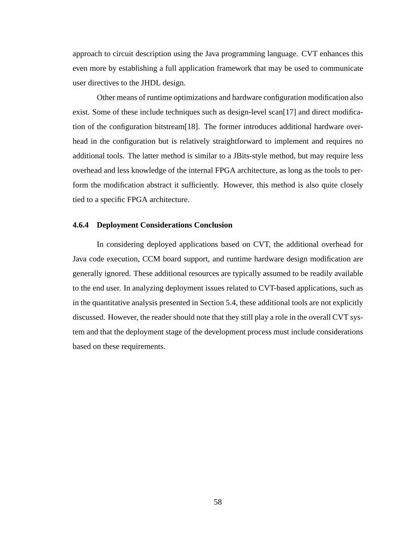
approach to circuit description using the Java programming language. CVT enhances this
even more by establishing a full application framework that may be used to communicate
user directives to the JHDL design.
Other means of runtime optimizations and hardware configuration modification also
exist. Some of these include techniques such as design-level scan[17] and direct modifica-
tion of the configuration bitstream[18]. The former introduces additional hardware over-
head in the configuration but is relatively straightforward to implement and requires no
additional tools. The latter method is similar to a JBits-style method, but may require less
overhead and less knowledge of the internal FPGA architecture, as long as the tools to per-
form the modification abstract it sufficiently. However, this method is also quite closely
tied to a specific FPGA architecture.
4.6.4 Deployment Considerations Conclusion
In considering deployed applications based on CVT, the additional overhead for
Java code execution, CCM board support, and runtime hardware design modification are
generally ignored. These additional resources are typically assumed to be readily available
to the end user. In analyzing deployment issues related to CVT-based applications, such as
in the quantitative analysis presented in Section 5.4, these additional tools are not explicitly
discussed. However, the reader should note that they still play a role in the overall CVT sys-
tem and that the deployment stage of the development process must include considerations
based on these requirements.
58
Chapter 5
Example Applications
Several applications demonstrate the use of CVT as a reconfigurable computing
application framework. A sample set of applications is presented in this chapter. These
example applications demonstrate the wide variety of applications possible as well as the
simplicity of building up CCM-based applications based on CVT. The first application, an
audio processing application, demonstrates the usefulness of internal hardware visibility
made possible by the JHDL application model. The next application, a string comparison
application, demonstrates the advantages of an application that is dynamically reconfig-
urable to obtain optimal application performance. The next application, a simple game,
demonstrates the use of the complete application communication architecture in CVT. An
analysis of the size of these three example applications gives insight into the amount of
development effort required to produce applications built on top of CVT. Finally, another
two applications, a hybrid CPU/FPGA system debugger, and a hardware-synthesized code
debugger, add more examples of the utility of the CVT system as an RCAF.
5.1 Audio Processing Application
The first example application performs custom processing on a two-channel audio
stream. This application demonstrates a method that may be used to include a custom
circuit debugging and/or application state view with the default CVT system. The approach
used by this application does not extend any of the CVT classes themselves. Instead, it
creates a custom circuit viewer which works independently of the default CVT viewers.
For this particular application, such a setup works well because the continuous streams of
input and output data do not require interactive control beyond the default controls offered
59
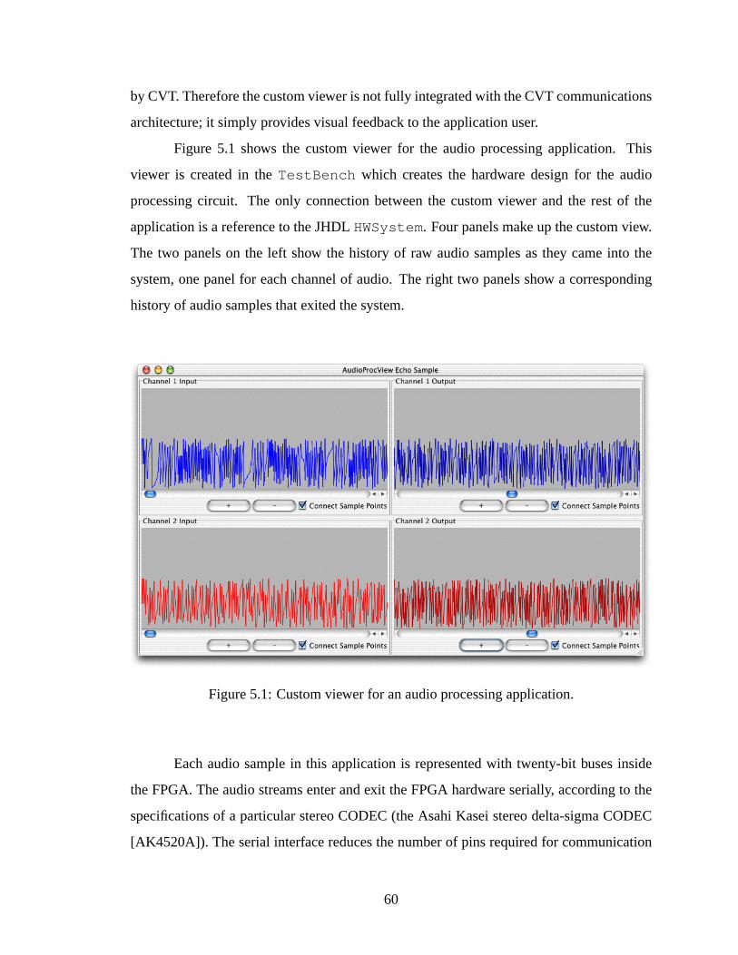
by CVT. Therefore the custom viewer is not fully integrated with the CVT communications
architecture; it simply provides visual feedback to the application user.
Figure 5.1 shows the custom viewer for the audio processing application. This
viewer is created in theTestBench which creates the hardware design for the audio
processing circuit. The only connection between the custom viewer and the rest of the
application is a reference to the JHDLHWSystem. Four panels make up the custom view.
The two panels on the left show the history of raw audio samples as they came into the
system, one panel for each channel of audio. The right two panels show a corresponding
history of audio samples that exited the system.
Figure 5.1: Custom viewer for an audio processing application.
Each audio sample in this application is represented with twenty-bit buses inside
the FPGA. The audio streams enter and exit the FPGA hardware serially, according to the
specifications of a particular stereo CODEC (the Asahi Kasei stereo delta-sigma CODEC
[AK4520A]). The serial interface reduces the number of pins required for communication
60
between the FPGA and the CODEC. This savings in I/O bandwidth would normally mean
that data visibility could only be obtained with the added complexity needed to de-serialize
and de-multiplex the data. JHDL simplifies this data visibility problem by providing full
internal visibility to the custom viewer. The data samples displayed in the custom viewer
come from values read from the wires which are internal to the hardware design. The
viewer obtains a reference to these wires using thefindNamed method in Table 3.1.
The get method in Table 3.8 returns the wire values to the viewer. The viewer buffers
these values to form the data sets from which the audio sample history panels derive the
information displayed. Within an execution environment that supports hardware readback,
this same sampling method works when the application is executed in hardware as well as
in simulation.
5.2 Edit Distance Application
The next example application computes the edit distance between two strings. Edit
distance is the number of character changes (insertions, deletions, and substitutions) re-
quired to transform one string (the source) into another string (the target). Edit distance
calculations are useful in a number of different applications. One of the most common
uses is the comparison of DNA (deoxyribonucleic acid), RNA (ribonucleic acid) or protein
strings. The bases of the DNA, RNA, or protein strings are represented by characters. These
characters are run through the edit distance calculator to determine how similar or dissim-
ilar two strings are. Such applications help biological and pharmaceutical researchers de-
termine such things as the effectiveness of new drugs. Because databases of information
related to such work is growing at a rate faster than performance improvements in general-
purpose computing, application-specific, CCM-base systems give these researchers a cost
effective way to keep pace with the data[3].
The following four subsections describe this application according to the model-
view-controller architecture described in Section 4.1. This shows how the various applica-
tion components correspond with the architectural components of the RCAF. It also shows
how the development of the application may be subdivided into easy-to-manage portions.
61
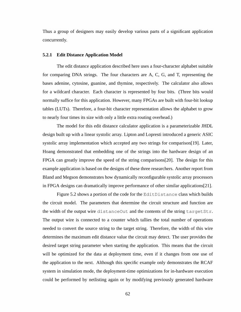
Thus a group of designers may easily develop various parts of a significant application
concurrently.
5.2.1 Edit Distance Application Model
The edit distance application described here uses a four-character alphabet suitable
for comparing DNA strings. The four characters are A, C, G, and T, representing the
bases adenine, cytosine, guanine, and thymine, respectively. The calculator also allows
for a wildcard character. Each character is represented by four bits. (Three bits would
normally suffice for this application. However, many FPGAs are built with four-bit lookup
tables (LUTs). Therefore, a four-bit character representation allows the alphabet to grow
to nearly four times its size with only a little extra routing overhead.)
The model for this edit distance calculator application is a parameterizable JHDL
design built up with a linear systolic array. Lipton and Lopresti introduced a generic ASIC
systolic array implementation which accepted any two strings for comparison[19]. Later,
Hoang demonstrated that embedding one of the strings into the hardware design of an
FPGA can greatly improve the speed of the string comparisons[20]. The design for this
example application is based on the designs of these three researchers. Another report from
Bland and Megson demonstrates how dynamically reconfigurable systolic array processors
in FPGA designs can dramatically improve performance of other similar applications[21].
Figure 5.2 shows a portion of the code for theEditDistance class which builds
the circuit model. The parameters that determine the circuit structure and function are
the width of the output wiredistanceOut and the contents of the stringtargetStr .
The output wire is connected to a counter which tallies the total number of operations
needed to convert the source string to the target string. Therefore, the width of this wire
determines the maximum edit distance value the circuit may detect. The user provides the
desired target string parameter when starting the application. This means that the circuit
will be optimized for the data at deployment time, even if it changes from one use of
the application to the next. Although this specific example only demonstrates the RCAF
system in simulation mode, the deployment-time optimizations for in-hardware execution
could be performed by netlisting again or by modifying previously generated hardware
62

configuration images. If the target string length and the counter width remain constant, then
the hardware configuration image can simply be modified, saving the added time that would
be required to perform placement and routing again. The method of updating optimizations
between execution runs could be determined by extensions to CVT, making the whole
process transparent to the user.
public class EditDistance extends Logic {
public static CellInterface[]cell_interface = {
5in("charIn",4),out("distanceOut",PARAM_WIDTH),param("outputWidth",INTEGER),param("targetString",STRING),
};10
public EditDistance( Node parent, Wire charIn,Wire distanceOut, String targetStr ) {
// constructor code ...}
15
} // end class EditDistance
Figure 5.2: TheEditDistance class creates the circuit model for the edit distance ap-plication.
The JHDL model for this application also has additional convenience methods to
support both the creation of the circuit structure and the interpretation of the circuit state.
These methods are found in theEDAlphabet class as well as theEditCellInput ,
EditCellInner , and EditCellOutput classes which make up the processors of
the systolic array. TheEDAlphabet class contains methods to convert between ASCII
characters and binary representations of characters. The processor classes provide methods
that indicate their state; the custom viewer described in Section 5.2.2 uses these methods
to conveniently obtain information to output.
63
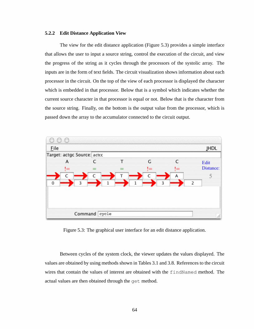
5.2.2 Edit Distance Application View
The view for the edit distance application (Figure 5.3) provides a simple interface
that allows the user to input a source string, control the execution of the circuit, and view
the progress of the string as it cycles through the processors of the systolic array. The
inputs are in the form of text fields. The circuit visualization shows information about each
processor in the circuit. On the top of the view of each processor is displayed the character
which is embedded in that processor. Below that is a symbol which indicates whether the
current source character in that processor is equal or not. Below that is the character from
the source string. Finally, on the bottom is the output value from the processor, which is
passed down the array to the accumulator connected to the circuit output.
Figure 5.3: The graphical user interface for an edit distance application.
Between cycles of the system clock, the viewer updates the values displayed. The
values are obtained by using methods shown in Tables 3.1 and 3.8. References to the circuit
wires that contain the values of interest are obtained with thefindNamed method. The
actual values are then obtained through theget method.
64
Each of the processor views in the edit distance application is a separate, parame-
terizable GUI panel. This GUI subpanel was developed along with the hardware design for
an individual processor. This custom view of a single processor was used to help debug
the hardware design. When the processor design was verified, both the processor and GUI
subpanel were duplicated in parameterizable arrays in the hardware design and complete
custom viewer respectively. Thus the development of the custom viewer not only built
up the final application interface, it also aided in the hardware design and debug from the
beginning of application development.
5.2.3 Edit Distance Application Controller
The controller for the edit distance application is built by extending the features of
the default CVTBroker class. Additional, custom commands are also added to the CVT
command interpreter. The code for the customBroker class is shown in Figure 5.4. A
new custom edit distance viewer is created in theEDBroker constructor on line 5. Line 11
creates and registers an instance of theEDCLICommandclass. This class implements a
command for the CVT command interpreter (theCLInterpreter class). This command
is tied to the text input field in the custom viewer in Figure 5.3. Entering a new source string
in the text field causes the custom command to be generated and sent to the command
interpreter, and hence theBroker . This results in an updated data schedule for the source
string input values that are streamed into the system. This example of custom interactive
circuit input and control shows how the deployed application can be built in such a way
that is most intuitive to the final user, not just the hardware designer.
5.2.4 Completing the Edit Distance Application
The edit distance application is executed by a JHDL testbench class. This class
is the principle execution point of the application; in this class, the system components
(the circuit model, the viewers, and the controller) are built and finally integrated into the
complete CCM application. The code for this class is shown in Figure 5.5. It contains a
main method which receives user data on lines 13 and 14. That information is then used
to create the testbench, and hence the circuit design itself, on line 16. This is the point
65
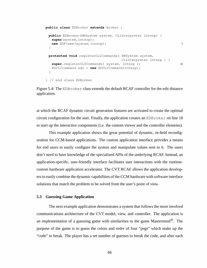
public class EDBroker extends Broker {
public EDBroker(HWSystem system, CLInterpreter interp) {super (system,interp);
5new EDFrame(system,interp);}
protected void registerCLICommands( HWSystem system,CLInterpreter interp ) {
10super .registerCLICommands( system, interp );EDCLICommand edc = new EDCLICommand(interp);
}
} // end class EDBroker
Figure 5.4: TheEDBroker class extends the default RCAF controller for the edit distanceapplication.
at which the RCAF dynamic circuit generation features are activated to create the optimal
circuit configuration for the user. Finally, the application creates anEDBroker on line 18
to start up the interactive components (i.e. the custom viewer and the controller elements).
This example application shows the great potential of dynamic, in-field reconfig-
uration for CCM-based applications. The custom application interface provides a means
for end users to easily configure the system and manipulate values sent to it. The users
don’t need to have knowledge of the specialized APIs of the underlying RCAF. Instead, an
application-specific, user-friendly interface facilitates user interactions with the runtime-
custom hardware application accelerator. The CVT RCAF allows the application develop-
ers to easily combine the dynamic capabilities of the CCM hardware with software interface
solutions that match the problem to be solved from the user’s point of view.
5.3 Guessing Game Application
The next example application demonstrates a system that follows the more involved
communications architecture of the CVT model, view, and controller. The application is
an implementation of a guessing game with similarities to the game MastermindR©. The
purpose of the game is to guess the colors and order of four “pegs” which make up the
“code” to break. The player has a set number of guesses to break the code, and after each
66

public class tbEditDistance extends Logic implements TestBench {
public tbEditDistance( Node parent, int width, String target ) {super (parent);
5Wire charIn = wire(4,"charIn");Wire distance = wire(width,"distance");new EditDistance( this , charIn, distance, target);Stimulator stim = new Stimulator( this );stim.addWire(charIn);
10}
public static void main( String[] args ) {int width = Integer.parseInt(args[0]);String target = args[1];
15HWSystem system = new HWSystem();new tbEditDistance( system, width, target);CLInterpreter interp = new CLInterpreter();new EDBroker(system,interp);
}20
} // end class tbEditDistance
Figure 5.5: ThetbEditDistance class creates and integrates the various applicationcomponents.
guess receives feedback that helps to plan the next guess. As with the previous example,
the application components associated with the model, view, and controller are discussed
separately in the following sections.
5.3.1 Guessing Game Application Model
The guessing game application model is a JHDL design made up of an array of cells
which represent each guess from the player. For simplicity, the hardware design is static,
although it could easily be parameterizable to create a dynamic design. (e.g. the number of
elements in the code, the maximum number of guesses, and the set of possible colors could
all be parameterized.)
The JHDL circuit has four input buses plus a control input which the application
uses to register each guess from the player. Another set of signals allow the application
to query the game state. Thus all of the circuit input and output is performed on the ex-
ternal port level, allowing sufficient circuit visibility even if the readback capability is not
available.
67
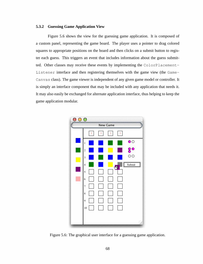
5.3.2 Guessing Game Application View
Figure 5.6 shows the view for the guessing game application. It is composed of
a custom panel, representing the game board. The player uses a pointer to drag colored
squares to appropriate positions on the board and then clicks on a submit button to regis-
ter each guess. This triggers an event that includes information about the guess submit-
ted. Other classes may receive these events by implementing theColorPlacement-
Listener interface and then registering themselves with the game view (theGame-
Canvas class). The game viewer is independent of any given game model or controller. It
is simply an interface component that may be included with any application that needs it.
It may also easily be exchanged for alternate application interface, thus helping to keep the
game application modular.
Figure 5.6: The graphical user interface for a guessing game application.
68

Table 5.1: ColorPlacementListener method for obtaining guess events from theguessing game viewer
Method Name ArgumentscolorsSubmitted GameCanvase source,int row, int[] guess
5.3.3 Guessing Game Application Controller
The controller for the guessing game application is also built by extending the fea-
tures of the default CVTBroker class. However, thisBroker extension involves more of
the features of the CVT communications architecture as described in Section 4.1. That is,
the controller includes not only theBroker extension, but also a viewer listener (an im-
plementation of theColorPlacementListener interface) and three custom textual
commands for the CVT command interpreter.
The three textual commands are used to tell the controller to start a new game, to
register a guess from the player, or to query the circuit state and update the game view with
appropriate feedback for the player. Each of these custom commands simply maps to a
corresponding method of the customBroker class. Those methods perform the tasks of
manipulating circuit inputs and game view parameters appropriately. Using these textual
commands to manage the flow of major system tasks helps to create a manageable history
of commands for later execution.
The textual commands also create a convenient point in which to place a bridge
between graphical user interface input and the application controller. An implementation
of the ColorPlacementListener interface performs this bridging role. This class
receives information from the application viewer about the player’s guess. It translates
this information into one or more of the text commands described above. The command
interpreter then logs those commands in its history and performs the appropriate method
calls in theBroker class.
Figure 5.7 shows the portion of the customBroker class which creates the various
components described above and establishes the relationships between them. Lines 14, 15,
and 16 create the three custom textual command objects and register them with the CVT
69

command interpreter. Line 20 creates the application view. Then line 21 creates a listener to
receive events from the application view. This is the listener which performs the translation
of GUI events to text commands. Thus, in just a few lines of a single method, the main
communications system of the application is established. This demonstrates the ease with
which a developer may integrate various components to build up significant applications
using the CVT RCAF.
public class PGBroker extends Broker {
public PGBroker( tbPG parent, HWSystem system ) {super (system, new CLInterpreter());
5this .parent = parent;openGame(); // causes the game view to display
}
protected void registerCLICommands( HWSystem system,10CLInterpreter interp ) {
super .registerCLICommands(system,interp);// registers put and get comands:Stimulator.registerCLICommands(interp);new CommandNewGame(this , interp);
15new CommandGuess(this , interp);new CommandFeedback( this , interp);// remember the interpreterthis .interp = interp;// create game view in this method for convenience only
20canvas = new GameCanvas();canvas.addListener( new ViewListener(interp));
}
/* ... remaining PGBroker methods and fields ... */25
} // end class PGBroker
Figure 5.7: TheEDBroker class extends the default RCAF controller for the edit distanceapplication.
5.4 Quantitative Analysis
This section discusses metrics for determining the value of an RCAF. The bulk
of the functionality of an RCAF-based application is intended to be in the RCAF itself.
70

Therefore, it is natural that the application-specific code layered on top of the RCAF should
be relatively small. Hence one useful metric to evaluate the usefulness of the RCAF is
the code size of the non-RCAF code. The smaller the size of the non-RCAF application
code, the better. That is because the small code size indicates that the RCAF establishes
an API and application framework that is not overly complex to use. The less code the
RCAF requires the application developer to write, the less likely the application will have
errors and the more likely it is to be easily-maintained. The size of the RCAF itself is also
important, because it will be deployed along with the application.
This section lists the various sizes of the three sample applications described above.
Sizes are given in both line counts and compiled code size. These measurements don’t
give any real indication about the size ofanyRCAF-based application. However, they may
offer information to help develop a “feel” for the amount of effort that may be necessary to
develop a full CCM application based on the CVT RCAF. Therefore, true analysis of this
data is a combination of both objective and subjective observations. The raw numbers must
be weighed against the capabilities and limitations of the corresponding applications.
EDIF (electronic design interchange format) netlist sizes are also given to help gain
an understanding for how much work the JHDL component of CVT does to support the ap-
plication. The EDIF netlist size correlates directly with the number of data structures that
JHDL must maintain during the simulation or in-hardware execution of the hardware de-
sign. Naturally, this also corresponds to the amount of physical FPGA hardware resources
required to host the design. Even very simple designs can generate very large netlists. For
example, the edit distance application may be scaled to very large sizes by embedding more
target characters, and hence more processors, in the hardware design. CVT manages the
scaling of such designs for the application, thus removing a great deal of the burden for
application support from the developer’s application design while still maintaining the full
capabilities of the acceleration hardware provided by the CCM.
The sizes for the three applications are given in Table 5.2. The size of the CVT
is from two to four megabytes in size, depending on the features included.1 Note that this
leaves out the sizes of other runtime components which may be required for the application,
1See Appendix B for a listing of CVT component sizes.
71

such as a Java virtual machine and CCM-specific hardware drivers. Such components are
assumed to be available on a system which includes a given target CCM, and are therefore
not part of the CCM application distribution.) The size of the application code layered on
top of CVT is relatively small—as much as two orders of magnitude smaller than CVT
itself. Given the features that could be included with the application—dynamic circuit
model generation, netlisting, platform control, etc.—the result is a small (relative to most
other full-featured CAD tools) simple, deployable application. The small sizes listed in
Table 5.2 also imply that the development effort for a given application is relatively small.
This adds to other, less quantitative benefits of CVT, such as rapid, in-hardware debugging,
reusable code, and a solid application architecture framework.
Table 5.2: Sizes of sample CVT-based applications.
Application Audio Processing Edit Distance Guessing GameNumber of Lines 2,157 1,315 2,523Model 1,570 696 1,588View 587 503 614Controller n/a 116 321
Compiled Size 48,161 bytes 37,960 bytes 65,192 bytesModel 32,350 bytes 18,627 bytes 38,825 bytesView 15,811 bytes 15,695 bytes 16,278 bytesController n/a 3,638 bytes 10,089 bytes
Compiled Size(ZIP Compressed)
27,139 bytes(43.6% deflated)
21,852 bytes(42.4% deflated)
35,102 bytes(46.2% deflated)
EDIF Size 5,773,711 bytes 130,437 bytes(4-character target)1,560,497 bytes(100-character target)
1,220,833 bytes
5.5 Additional Examples
Two other example applications demonstrate the utility of the CVT RCAF architec-
ture. Some of the user interface elements of the first application are shown in Figure 5.8.
72
Eric Roesler of the Configurable Computing Laboratory at Brigham Young University cre-
ated this application using CVT[22]. The application is used for debugging hybrid FPGA
systems that include a CPU (central processing unit) core in the FPGA configuration. This
is useful not only for debugging new CPU design cores for FPGAs, but also for verifying
the functionality of the CPU core and the software executing it as they work along side
other custom logic included in the same FPGA configuration. This application is unique
because of its multiple simultaneous views of the same circuit model. Each view offers
completely different types of insights into the execution state of the hardware. Figure 5.8
depicts a view of the major components of the CPU (arithmetic logic unit, instruction reg-
ister, the register file, etc.) and a view that shows a view of the original source code of the
software being executed in the CPU core. Another custom viewer not shown here is a view
of the assembly code version of the software. These views may be used simultaneously
with traditional schematic and waveform views to help designer verify the operation of the
hardware and software in the FPGA. The model-view-controller architecture used by CVT
helps to keep the various views separated from the model to enable each of them to display
independent and unique versions of the hardware state.
Figure 5.9 shows the interface to another example application. This application is
used to debug high-level software code that is synthesized to structural hardware compo-
nents[23]. As in the previous example, this example gives multiple independent views of
the hardware system. This example also uses a more complex controller system to manage
not only the JHDL model, but also the synthesis and debug system from which the JHDL
model is derived. This system divides the controller responsibilities between two classes.
The first class is the sameBroker class in the CVT system; this class basically provides
the same functionality of the default CVT system. The other class manages the hardware
synthesis and source code views for the debugging application. This separated controller
keeps the CVT system, including the JHDL circuit model, independent of the synthesis and
debug environment. This allows either system to be used just as well with any other system
of equal or comparable functionality. The result is a highly modular and easily-maintained
application.
73
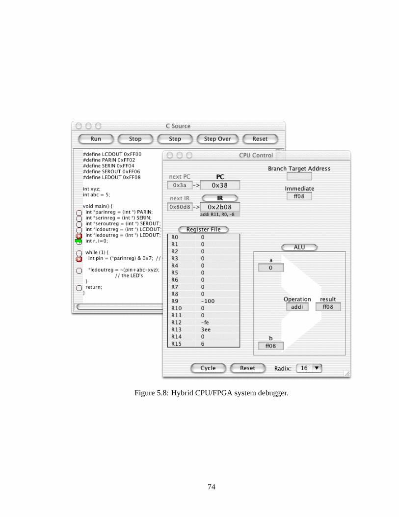
Figure 5.8: Hybrid CPU/FPGA system debugger.
74
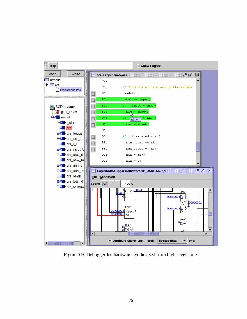
Figure 5.9: Debugger for hardware synthesized from high-level code.
75

76
Chapter 6
Conclusions and Future Work
Existing computer-aided design (CAD) and electronic design automation (EDA)
tools for hardware designs targeting FPGAs are inadequate to support the development
needs for configurable computing machine-based applications. While well-suited for ASIC
design and some static FPGA design, these tools lack the support for dynamic reconfigu-
ration and in-hardware debugging that are among the greatest advantages offered by con-
figurable computing machines (CCMs). Also, because they focus only on the hardware
design, these tools compel applications designers to divide the development process into
separate hardware and software development processes. These two processes typically
only meet in the deployment stage of the application development. Combining these de-
velopment processes into unified design, debug, and deploy stages would allow for greater
design exploration, better integration between hardware and software, improved custom
debugging capabilities and possibly better, more intuitive application user interfaces.
The conclusion of this research is that developers may use a reconfigurable comput-
ing application framework (RCAF) for creating CCM-based applications to overcome the
limitations of traditional, monolithic CAD/EDA tools. An RCAF offers a unique interface
layer between the CCM application hardware and software components. This layer does
not merely control the configuration and execution of the CCM hardware. It also main-
tains a hardware model that gives the application extraordinary visibility into the hardware
state based on the original design entry model. The RCAF also establishes an architecture
model on which significant applications may be built. This allows for excellent hardware
and software integration which gives the user unprecedented access to and control over
77
the hardware. CCM applications may also use RCAF features to provide dynamically-
configurable hardware designs which may improve in-field performance by optimizing the
hardware design based on user input.
6.1 Contributions of this Research
The main contributions of this research are the specification and implementation of
a reconfigurable computing application framework. The design and implementation of this
RCAF (called CVT) are built on top of existing technology and prior research. This prior
research provided the following principles for CCM application development:
• Hardware designs for FPGAs can be built up in simply and programmatically using
general purpose, object-oriented programming languages[9, 10].
• The software simulation and hardware execution of a hardware design can and should
be performed from within the same design environment for debugging[6, 11, 5].
• Circuit design and debug visualization can be done using custom viewers and circuit
control mechanisms that best reflect the usage and requirements of each individual
application.
• FPGA hardware designs may easily be modified to include optimizations based on
data provided at execution time[7, 8].
This solid foundation helped me create a system with the following features:
• CVT creates a design and debug approach for CCM application development that
integrates the development of the hardware and software components of CCM-based
applications. This gives the designer more freedom to explore whole-application
design alternatives. This integrated development also shortens the application devel-
opment time by preparing for final application deployment throughout the design and
debug stages of development.
• The CVT application model (as in the model-view-controller architecture) is con-
sistent with the original design-entry format. The model state is consistent with the
78
corresponding state of the actual CCM hardware. This gives the applications com-
plete visibility into the hardware design structure and state.
• CVT allows for custom hardware interaction and control. This control may be based
on the specifications of a given application rather than of the RCAF or the target
CCM. The application interface is built on top of the RCAF architecture, which takes
care of the low-level details of interacting with the CCM-specific interfaces. The
same application-specific interfaces may be used for both simulation and in-hardware
execution of the hardware design component of the application.
• Final CCM applications built on CVT may include dynamically-configured hardware
designs. This allows the applications to incorporate user-provided data to improve
the design performance.
• CCM applications based on CVT are simple to develop, relative to the complexity of
building up an entire application that may take advantage of the features of CCMs.
Resulting applications have a small, deployable form.
Individually, the above features do not necessarily represent significant new con-
tributions. However, the RCAF specification and the CVT implementation integrate these
features in such a way that does present a new and significant contribution to the CAD/EDA
community. This integration is built on top of sound architectural principles that help to
create a system that is modular, scalable, anddeployable. This system has already been
used to develop significant applications. The CVT framework allows these applications to
take advantage of CCM features that would otherwise only be available with a significant
increase in overall application development cost, particularly in time.
The pre-existing technology on which CVT is based consists of the JHDL system.
JHDL performs the role of the application model within the CVT system. This subsystem
performs a number of critical functions related to the RCAF specification given in Chap-
ter 2. These include interacting with and maintaining an image of the state of the circuit
within actual CCM hardware. These functions also include the ability to programmati-
cally and dynamically build up a hardware configuration. CVT works with JHDL through
79
the circuit structure, circuit state, and simulator APIs which JHDL makes available. CVT
creates a controller and viewer system to work with these JHDL APIs. It also establishes
the communications system to be used by these systems. This is in accordance with the
commonly used model-view-controller architecture for user interface design in software
systems.
The CVT system based on JHDL is not only an improvement over the previous sys-
tem to use JHDL (i.e. the JAB system described in Section 3.3). It also enables an approach
to CCM application development that allows the design and debug stages of development to
integrate the development of both the hardware and software of the CCM application. This
approach also permits better application design and debug by giving developers the ability
to easily generate custom development environments that match the needs of each applica-
tion. The new and unique feature of this development process which CVT provides is that
the features which enhance the design and debug stages of development may persist in the
application in the deploy stage and beyond. The final, deployed application will continue
to be flexible and portable because it inherits the same characteristics of the CVT RCAF
itself, including the characteristics listed in the bulleted items above. The CVT system is
an improvement over traditional CAD/EDA tools for CCM application development in that
it allows applications to retain their dynamic characteristics, which, in a normal application
development process, are typically discarded after the debug stage.
6.2 Future Work
Future work on the CVT RCAF system may include additional features, improve-
ments to existing capabilities,and continued architecture exploration. This section lists an
example for each of these categories.
The circuit model for CVT applications based on JHDL designs is a structural cir-
cuit model. While the circuit description may contain behaviorally modeled cells, such
components are typically only for simulation purposes. However, behavioral descriptions
of circuits can help shorten development time by eliminating the need to translate algo-
rithms from their original programmatic descriptions to structural circuit models. CVT
could be improved by including features that support such higher-level circuit descriptions.
80
Work being carried out by Tripp[24] and Hemmert[23] related to synthesis of high-level
behavioral code to structural designs and corresponding debugging support may be used to
create a system that better integrates behavioral synthesis. Hemmert’s system does already
include CVT as a foundation for its application architecture, however, it carries out all inter-
actions with Tripp’s synthesis tools independently of CVT. Integrated support could include
a specialized API within CVT to facilitate the inclusion of synthesized circuit components
within the CVT application model.
Current hardware support in CVT is dependent on individual CCM board models.
These board models are typically built on foundation APIs provided by JHDL. However,
board model creators have a lot of design freedom. Therefore, each board model may differ
significantly from the next. This means that application views and controls typically must
conform to the APIs of a specific board model. CVT hardware support may be improved
by providing platform-independent APIs to support all board models adhering to the APIs.
These APIs may be created by extending the current board model framework in JHDL.
Existing board models may be modified to fit this API. With a unified API for hardware
control, application developers need only to concentrate on the one set of APIs provided by
CVT, and such applications will work for any specific CCM board which has a JHDL/CVT
model.
The architecture specified and implemented for the CVT system is merely one way
to create an RCAF. Further architecture experimentation and exploration may continue
to produce systems with different characteristics and features. Although the current imple-
mentation is built on solid and well-known principles, alternate implementations may prove
to have qualities which are better-suited to particular classes of applications. For example,
CVT may be augmented to include a suite of varying controllers to fulfill the needs of
different types of applications: one may be well-suited for traditional digital logic design,
another may be useful for image-processing applications, another for pattern matching ap-
plications, etc. Developers may select the framework components which are the best fit to
the problem they are solving. Such architectural experimentation will likely be driven by
application development needs as they arise.
81

82

Appendix
83

84
Appendix A
CVT Component APIs
This appendix contains a listing of many application programming interfaces (APIs)
of various CVT components. Many of these components may be used within other appli-
cations as noted in Section 4.3. This is not a complete list of APIs, as can be found in the
documentation on the JHDL web site[25]. In particular, the vast number of APIs associated
with the JHDL tool are excluded from this listing. Many JHDL APIs were already listed in
Section 3.1.2. This appendix focuses on the APIs for the controller and viewer components
of the default CVT system. The purpose of this appendix is to give the reader a view of
the capabilities of CVT as well as the requirements for extending CVT to create custom
applications.
A.1 CVT Controller APIs
The following classes are components of the CVT controller. As described in Sec-
tion 4.1, the controller is the application component that receives user input and performs
corresponding manipulations to the model.
• Broker
• CLICommand
• CLInterpreter
• SimulatorThread
• Stimulator
85

The Broker Class
The Broker class is the main component of the CVT controller. This class receives
messages through the CLInterpreter to determine actions to perform on the CVT model (the
JHDL circuit design). The most important methods below are the constructor and the reg-
isterCLICommands methods. All other methods can also be overridden and supplemented
with methods to suit the needs of a given CCM application.
byucc.jhdl.apps.Broker.Broker
Return Type Method Name Arguments
Broker Broker (constructor) HWSystem, CLInter-
preter
CLInterpreter getInterp
void registerCustomViewer Window
void cycleSimulator int
void stepSimulator int
void resetSimulator
void newSchematicView Cell
void print Cell
void newMemoryViewerFrame Cell
boolean addWavesWatch Wire
void removeWavesWatch Wire
void closeViews
The CLInterpreter Class
The CLInterpreter class receives text commands from the user or from a class that acts
listens to events from interactive components and translates them to text commands. These com-
mands are interpreted and corresponding methods of the Broker class are invoked. Any custom
CLICommand may be registered with the CLInterpreter.
86
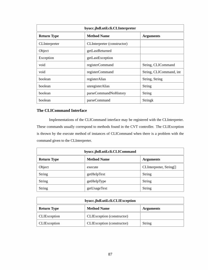
byucc.jhdl.util.cli.CLInterpreter
Return Type Method Name Arguments
CLInterpreter CLInterpreter (constructor)
Object getLastReturned
Exception getLastException
void registerCommand String, CLICommand
void registerCommand String, CLICommand, int
boolean registerAlias String, String
boolean unregisterAlias String
boolean parseCommandNoHistory String
boolean parseCommand Stringk
The CLICommand Interface
Implementations of the CLICommand interface may be registered with the CLInterpreter.
These commands usually correspond to methods found in the CVT controller. The CLIException
is thrown by the execute method of instances of CLICommand when there is a problem with the
command given to the CLInterpreter.
byucc.jhdl.util.cli.CLICommand
Return Type Method Name Arguments
Object execute CLInterpreter, String[]
String getHelpText String
String getHelpType String
String getUsageText String
byucc.jhdl.util.cli.CLIException
Return Type Method Name Arguments
CLIException CLIException (constructor)
CLIException CLIException (constructor) String
87
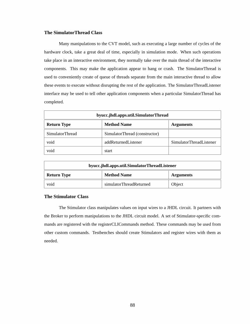
The SimulatorThread Class
Many manipulations to the CVT model, such as executing a large number of cycles of the
hardware clock, take a great deal of time, especially in simulation mode. When such operations
take place in an interactive environment, they normally take over the main thread of the interactive
components. This may make the application appear to hang or crash. The SimulatorThread is
used to conveniently create of queue of threads separate from the main interactive thread to allow
these events to execute without disrupting the rest of the application. The SimulatorThreadListener
interface may be used to tell other application components when a particular SimulatorThread has
completed.
byucc.jhdl.apps.util.SimulatorThread
Return Type Method Name Arguments
SimulatorThread SimulatorThread (constructor)
void addReturnedListener SimulatorThreadListener
void start
byucc.jhdl.apps.util.SimulatorThreadListener
Return Type Method Name Arguments
void simulatorThreadReturned Object
The Stimulator Class
The Stimulator class manipulates values on input wires to a JHDL circuit. It partners with
the Broker to perform manipulations to the JHDL circuit model. A set of Stimulator-specific com-
mands are registered with the registerCLICommands method. These commands may be used from
other custom commands. Testbenches should create Stimulators and register wires with them as
needed.
88
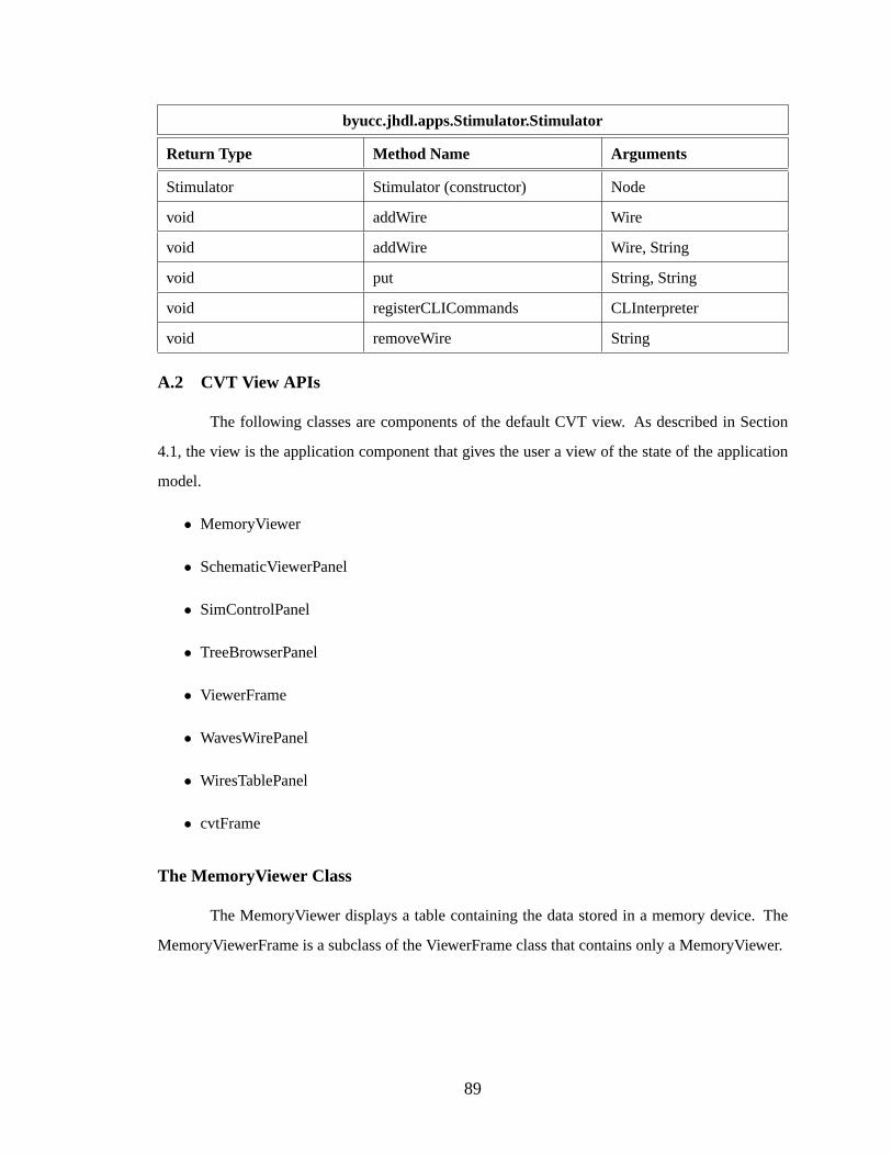
byucc.jhdl.apps.Stimulator.Stimulator
Return Type Method Name Arguments
Stimulator Stimulator (constructor) Node
void addWire Wire
void addWire Wire, String
void put String, String
void registerCLICommands CLInterpreter
void removeWire String
A.2 CVT View APIs
The following classes are components of the default CVT view. As described in Section
4.1, the view is the application component that gives the user a view of the state of the application
model.
• MemoryViewer
• SchematicViewerPanel
• SimControlPanel
• TreeBrowserPanel
• ViewerFrame
• WavesWirePanel
• WiresTablePanel
• cvtFrame
The MemoryViewer Class
The MemoryViewer displays a table containing the data stored in a memory device. The
MemoryViewerFrame is a subclass of the ViewerFrame class that contains only a MemoryViewer.
89
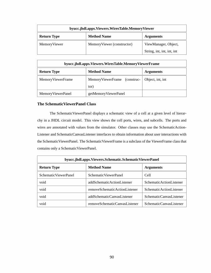
byucc.jhdl.apps.Viewers.WiresTable.MemoryViewer
Return Type Method Name Arguments
MemoryViewer MemoryViewer (constructor) ViewManager, Object,
String, int, int, int, int
byucc.jhdl.apps.Viewers.WiresTable.MemoryViewerFrame
Return Type Method Name Arguments
MemoryViewerFrame MemoryViewerFrame (construc-
tor)
Object, int, int
MemoryViewerPanel getMemoryViewerPanel
The SchematicViewerPanel Class
The SchematicViewerPanel displays a schematic view of a cell at a given level of hierar-
chy in a JHDL circuit model. This view shows the cell ports, wires, and subcells. The ports and
wires are annotated with values from the simulator. Other classes may use the SchematicAction-
Listener and SchematicCanvasListener interfaces to obtain information about user interactions with
the SchematicViewerPanel. The SchematicViewerFrame is a subclass of the ViewerFrame class that
contains only a SchematicViewerPanel.
byucc.jhdl.apps.Viewers.Schematic.SchematicViewerPanel
Return Type Method Name Arguments
SchematicViewerPanel SchematicViewerPanel Cell
void addSchematicActionListener SchematicActionListener
void removeSchematicActionListener SchematicActionListener
void addSchematicCanvasListener SchematicCanvasListener
void removeSchematicCanvasListenerSchematicCanvasListener
90

byucc.jhdl.apps.Viewers.Schematic.SchematicActionEvent
Return Type Method Name Arguments
SchematicActionEvent SchematicActionEvent (construc-
tor)
Object, int, String, Wire
SchematicActionEvent SchematicActionEvent (construc-
tor)
Object, int, String, Cell
SchematicActionEvent SchematicActionEvent Object, int, String
Wire getWire
Cell getCell
byucc.jhdl.apps.Viewers.Schematic.SchematicActionListener
Return Type Method Name Arguments
void schematicActionPerformed SchematicActionEvent
byucc.jhdl.apps.Viewers.Schematic.SchematicCanvasEvent
Return Type Method Name Arguments
SchematicCanvasEvent SchematicCanvasEvent Object, int, String
SchematicCanvasEvent SchematicCanvasEvent Object, int, String, String
SchematicCanvasEvent SchematicCanvasEvent Object, int, String, double
SchematicCanvasEvent SchematicCanvasEvent Object, int, String, int
String getStringValue
double getDoubleValue
int getIntegerValue
byucc.jhdl.apps.Viewers.Schematic.SchematicCanvasListener
Return Type Method Name Arguments
void schematicCanvasEventPerformedSchematicCanvasEvent
91

byucc.jhdl.apps.Viewers.Schematic.SchematicViewerFrame
Return Type Method Name Arguments
SchematicViewerFrame SchematicViewerFrame Cell
void addSchematicActionListener SchematicActionListener
void removeSchematicActionListener SchematicActionListener
The SimControlPanel Class
The SimControlPanel provides in interactive interface directly tied to the CLInterpreter
class. This panel includes buttons and textfields that correspond directly to specific text commands
for the CLInterpreter. It also has a general-purpose text field for entering in arbitrary text commands.
Other classes may use the SimControlActionListener interface to obtain information about user
interactions with the SimControlPanel.
byucc.jhdl.apps.Viewers.SimControl.SimControlPanel
Return Type Method Name Arguments
SimControlPanel SimControlPanel (constructor) boolean
SimControlPanel SimControlPanel (constructor) boolean, CLInterpreter
void addSimControlActionListener SimControlActionListener
void removeSimControlActionListener SimControlActionListener
byucc.jhdl.apps.Viewers.SimControl.SimControlPanel
Return Type Method Name Arguments
SimControlActionEvent SimControlActionEvent Object, int, String, int
int getNum
byucc.jhdl.apps.Viewers.SimControl.SimControlActionListener
Return Type Method Name Arguments
void simControlActionPerformed SimControlActionEvent
92

The TreeBrowserPanel Class
The TreeBrowserPanel displays a hierarchical view of a circuit design. The view format is a
tree similar to tree views used in many file system viewers. Other classes may use the TreeBrowser-
ActionListener interface to obtain information about user interactions with the TreeBrowserPanel.
The TreeBrowserFrame is a subclass of the ViewerFrame class that contains only a TreeBrowser-
Panel.
byucc.jhdl.apps.Viewers.TreeBrowser.TreeBrowserPanel
Return Type Method Name Arguments
TreeBrowserPanel TreeBrowserPanel (constructor) Cell
void addTreeBrowserActionListener TreeBrowserAction-
Listener
void removeTreeBrowser-
ActionListener
TreeBrowserAction-
Listener
Cell getSelectedCell
void loadClass Cell
byucc.jhdl.apps.Viewers.TreeBrowser.TreeBrowserActionEvent
Return Type Method Name Arguments
TreeBrowserActionEvent TreeBrowserActionEvent Object, int, String, Cell
TreeBrowserActionEvent TreeBrowserActionEvent Object, int, String
Cell getCell
byucc.jhdl.apps.Viewers.TreeBrowser.TreeBrowserActionListener
Return Type Method Name Arguments
void treeBrowserActionPerformed TreeBrowserActionEvent
93
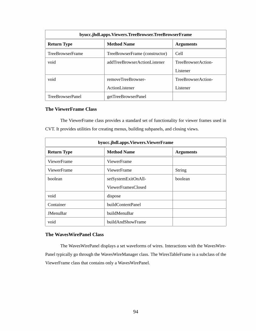
byucc.jhdl.apps.Viewers.TreeBrowser.TreeBrowserFrame
Return Type Method Name Arguments
TreeBrowserFrame TreeBrowserFrame (constructor) Cell
void addTreeBrowserActionListener TreeBrowserAction-
Listener
void removeTreeBrowser-
ActionListener
TreeBrowserAction-
Listener
TreeBrowserPanel getTreeBrowserPanel
The ViewerFrame Class
The ViewerFrame class provides a standard set of functionality for viewer frames used in
CVT. It provides utilities for creating menus, building subpanels, and closing views.
byucc.jhdl.apps.Viewers.ViewerFrame
Return Type Method Name Arguments
ViewerFrame ViewerFrame
ViewerFrame ViewerFrame String
boolean setSystemExitOnAll-
ViewerFramesClosed
boolean
void dispose
Container buildContentPanel
JMenuBar buildMenuBar
void buildAndShowFrame
The WavesWirePanel Class
The WavesWirePanel displays a set waveforms of wires. Interactions with the WavesWire-
Panel typically go through the WavesWireManager class. The WiresTableFrame is a subclass of the
ViewerFrame class that contains only a WavesWirePanel.
94

byucc.jhdl.apps.Viewers.Waves.WavesWirePanel
Return Type Method Name Arguments
WavesWirePanel WavesWirePanel
WavesWireManager getWireManager
byucc.jhdl.apps.Viewers.Waves.WavesWireManager
Return Type Method Name Arguments
WavesWireManager WavesWireManager
boolean addWatch Wire
boolean addWatch Wire, String
boolean isWatched String
void removeWatch String
void closeView
byucc.jhdl.apps.Viewers.Waves.WavesWireFrame
Return Type Method Name Arguments
WavesWireFrame WavesWireFrame
WavesWireManager getWireManager
The WiresTablePanel Class
The WiresTablePanel simply displays the set of wires owned by a particual cell in a circuit
model of the CVT system. This view shows the name, type, and state of each wire. Other classes
may use the WiresTableActionListener interface to obtain information about user interactions with
the WiresTablePanel. The WiresTableFrame is a subclass of the ViewerFrame class that contains
only a WiresTablePanel.
95

byucc.jhdl.apps.Viewers.WiresTable.WiresTablePanel
Return Type Method Name Arguments
WiresTablePanel WiresTablePanel (constructor) Cell
void closeView
void addWiresTableActionListener WiresTableActionListener
void removeWiresTableActionListener WiresTableActionListener
void rebuildTable Cell
Collection getSelectedWires
byucc.jhdl.apps.Viewers.WiresTable.WiresTableActionEvent
Return Type Method Name Arguments
WiresTableActionEvent WiresTableActionEvent (construc-
tor)
Object, int, String, Collec-
tion
WiresTableActionEvent WiresTableActionEvent Object, int, String
Collection getWires
byucc.jhdl.apps.Viewers.WiresTable.WiresTableActionListener
Return Type Method Name Arguments
void wiresTableActionPerformed WiresTableActionEvent
byucc.jhdl.apps.Viewers.WiresTable.WiresTableFrame
Return Type Method Name Arguments
WiresTableFrame WiresTableFrame Cell
void addWiresTableActionListener WiresTableActionListener
void removeWiresTableActionListener WiresTableActionListener
WiresTablePanel getWiresTablePanel
The cvtFrame Class
The cvtFrame class is the principal viewer for the CVT system. This viewer contains a
hierarchical view of the circuit model an a table of wires from the currently selected circuit cell.
This view also contains a panel that is used for user input directly to the CLInterpreter.
96
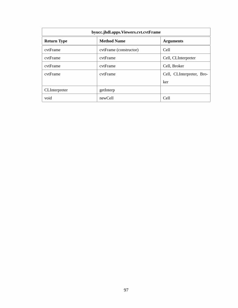
byucc.jhdl.apps.Viewers.cvt.cvtFrame
Return Type Method Name Arguments
cvtFrame cvtFrame (constructor) Cell
cvtFrame cvtFrame Cell, CLInterpreter
cvtFrame cvtFrame Cell, Broker
cvtFrame cvtFrame Cell, CLInterpreter, Bro-
ker
CLInterpreter getInterp
void newCell Cell
97

98
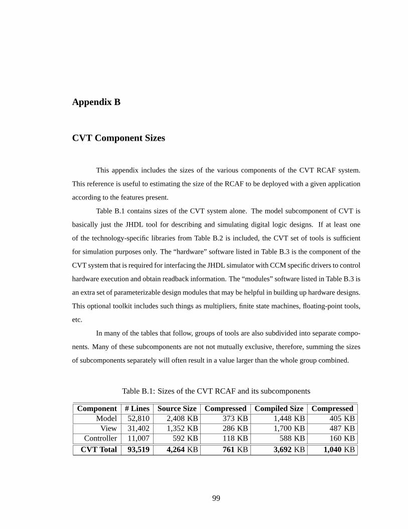
Appendix B
CVT Component Sizes
This appendix includes the sizes of the various components of the CVT RCAF system.
This reference is useful to estimating the size of the RCAF to be deployed with a given application
according to the features present.
Table B.1 contains sizes of the CVT system alone. The model subcomponent of CVT is
basically just the JHDL tool for describing and simulating digital logic designs. If at least one
of the technology-specific libraries from Table B.2 is included, the CVT set of tools is sufficient
for simulation purposes only. The “hardware” software listed in Table B.3 is the component of the
CVT system that is required for interfacing the JHDL simulator with CCM specific drivers to control
hardware execution and obtain readback information. The “modules” software listed in Table B.3 is
an extra set of parameterizable design modules that may be helpful in building up hardware designs.
This optional toolkit includes such things as multipliers, finite state machines, floating-point tools,
etc.
In many of the tables that follow, groups of tools are also subdivided into separate compo-
nents. Many of these subcomponents are not not mutually exclusive, therefore, summing the sizes
of subcomponents separately will often result in a value larger than the whole group combined.
Table B.1: Sizes of the CVT RCAF and its subcomponents
Component # Lines Source Size Compressed Compiled Size CompressedModel 52,810 2,408 KB 373 KB 1,448 KB 405 KBView 31,402 1,352 KB 286 KB 1,700 KB 487 KB
Controller 11,007 592 KB 118 KB 588 KB 160 KB
CVT Total 93,519 4,264KB 761KB 3,692KB 1,040KB
99

Table B.2: Sizes of various technology-specific libraries
Library # Lines Source Size Compressed Compiled Size CompressedVirtex 136,183 6,860 KB 1,238 KB 5,100 KB 1,809 KB
Virtex2 149,664 7,608 KB 1,316 KB 5,472 KB 1,940 KBXC4000 92,923 4,764 KB 863 KB 3,656 KB 1,261 KBXC9000 84,497 4,972 KB 1,062 KB 3,872 KB 1,527 KB
Total Xilinx 451,588 23,496KB 4,349KB 17,440KB 6,357KB
CSRC 31,128 1,736 KB 296 KB 1,340 KB 474 KBTeramac 31,719 2,164 KB 549 KB 780 KB 777 KB
Grand Total 514,435 27,396KB 5,192KB 20,532KB 7,605KB
Table B.3: Sizes of additional CVT components
Component # Lines Source Size Compressed Compiled Size CompressedHardware 50,277 2,496 KB 298 KB 1,296 KB 413 KBModules 40,641 1,544 KB 326 KB 1,036 KB 331 KB
Table B.4: Total size of all components listed in previous tables
Component # Lines Source Size Compressed Compiled Size CompressedTotal Size 698,812 35,700 KB 6,574 KB 26,550 KB 9,386 KB
100
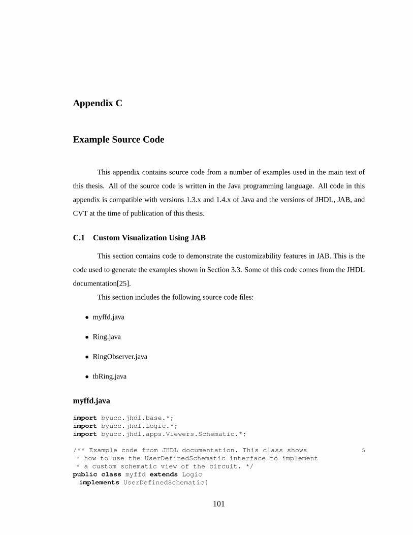
Appendix C
Example Source Code
This appendix contains source code from a number of examples used in the main text of
this thesis. All of the source code is written in the Java programming language. All code in this
appendix is compatible with versions 1.3.x and 1.4.x of Java and the versions of JHDL, JAB, and
CVT at the time of publication of this thesis.
C.1 Custom Visualization Using JAB
This section contains code to demonstrate the customizability features in JAB. This is the
code used to generate the examples shown in Section 3.3. Some of this code comes from the JHDL
documentation[25].
This section includes the following source code files:
• myffd.java
• Ring.java
• RingObserver.java
• tbRing.java
myffd.java
import byucc.jhdl.base.*;import byucc.jhdl.Logic.*;import byucc.jhdl.apps.Viewers.Schematic.*;
5/** Example code from JHDL documentation. This class shows* how to use the UserDefinedSchematic interface to implement* a custom schematic view of the circuit. */
public class myffd extends Logicimplements UserDefinedSchematic{
101
10public static CellInterface[] cell_interface = {in("d",1),out("q",1),
};
15private Wire q_out;
/** Constructor */public myffd(Node parent, Wire d, Wire q) {
super (parent);20connect("d",d);
q_out = connect("q",q);reg_o(d,q); //Make a d flip-flop with an implicit clock.
//Don’t forget there is an implicit clock.}
25
public static final int X_SIZE=25, Y_SIZE=40;
/** this is to set up the schematic size and the ports */public void initUserDefinedNode(UserDefinedNode udn){
30udn.setSize(X_SIZE, Y_SIZE);udn.addInPort(0,10,"d");// This is the implicit clock port.udn.addInPort(0,20,"c");udn.addOutPort(X_SIZE - 5+5, Y_SIZE-7,"q");
35}
/** Draw everyting else--be creative with the* circuit’s state. */
public void paint(UserDefinedNode udn){40udn.drawRect(0,0,X_SIZE,Y_SIZE);
//Check to see if the output is oneif (q_out.get( this ) != 0 ) {
//Draw grid lines on Cell if output one.for ( int i=0; i < X_SIZE; i+=8)
45udn.drawLine(i,0,i,Y_SIZE);for ( int i=0; i < Y_SIZE; i+=8)
udn.drawLine(0,i,X_SIZE,i);}
}50
} // end class myffd
Ring.java
import byucc.jhdl.base.CellInterface;import byucc.jhdl.base.Node;import byucc.jhdl.base.Wire;import byucc.jhdl.Logic.Logic;
5
/** A simple demo showing how custom schematics are useful.*/public class Ring extends Logic{
public static final int RING_LENGTH = 8;public static CellInterface[] cell_interface = {
102
10out("o",1)};/** Constructor */public Ring(Node parent, Wire o){
super (parent);15connect("o",o);
Wire inv_in = o;Wire inv_out = not(inv_in);
20Wire ff_in = inv_out;Wire ff_out = wire(1,"ffOut0");
for ( int i=0; i<RING_LENGTH; i++){new myffd( this ,ff_in,ff_out);
25// connect this output to the next input.ff_in = ff_out;
// if the next one is the last one--if (i == (RING_LENGTH - 2) )
30// connect it’s output to the inverter.ff_out = inv_in;
else// otherwise make a new wire to connect to// the new output.
35ff_out = wire(1,"ffOut"+(i+1));}
}} // end class Ring
RingObserver.java
import byucc.jhdl.base.Browser;import byucc.jhdl.base.Wire;import byucc.jhdl.base.WireValueException;import byucc.jhdl.base.SimulatorCallback;
5import java.awt.GridLayout;import javax.swing.AbstractButton;import javax.swing.BorderFactory;import javax.swing.JFrame;import javax.swing.JPanel;
10import javax.swing.JRadioButton;
/** This class implements SimulatorCallback and Browser to* observe the state of the outputs of the flip-flops in the* ring design. The result is a row of buttons that shows
15* whether each flop is on or off (1 or 0).* @author Anthony L. Slade */
public class RingObserver extends JFrameimplements Browser, SimulatorCallback {/** Constructor
20* @param flopOutputs array of the wires of interest */public RingObserver(Wire[] flopOutputs) {
this .flopOutputs = flopOutputs;
103

buildGUI();}
25/***** SimulatorCallback methods: *****/public void simulatorReset() {
setStates();}public void simulatorRefresh( int cycle, int step) {
30setStates();}public void simulatorUpdate( int cycle, int step) {
// ignore this method, it’s too fine-grained for GUIs}
35/** This method sets the states of the output visuals. */private void setStates() {
for ( int bi = 0; bi < 8; ++bi )try {
buttons[bi].setSelected( flopOutputs[bi]40.get( this ) == 1 );
} catch ( WireValueException wve ) {// something funny happened.buttons[bi].setSelected( false );
}45}
/** This method just initializes the contents of this* graphical viewer. */
private void buildGUI() {buttons = new AbstractButton[8];
50JPanel panel = new JPanel( new GridLayout(1,8));panel.setBorder(BorderFactory
.createTitledBorder("Custom View"));for ( int bi = 0; bi < 8; ++bi ) {
AbstractButton button = new JRadioButton();55button.setEnabled( false );
panel.add(button);buttons[bi] = button;
}getContentPane().add( panel );
60// show the new frame!setTitle("Custom View"); pack(); show();
}/** Array of the output buttons */private AbstractButton[] buttons;
65/** Maintain references to the wires of interest */private Wire[] flopOutputs;
} // end class RingObserver
tbRing.java
import byucc.jhdl.base.Browser;import byucc.jhdl.base.HWSystem;import byucc.jhdl.base.Node;import byucc.jhdl.base.TestBench;
5import byucc.jhdl.base.Wire;import byucc.jhdl.base.WireValueException;
104
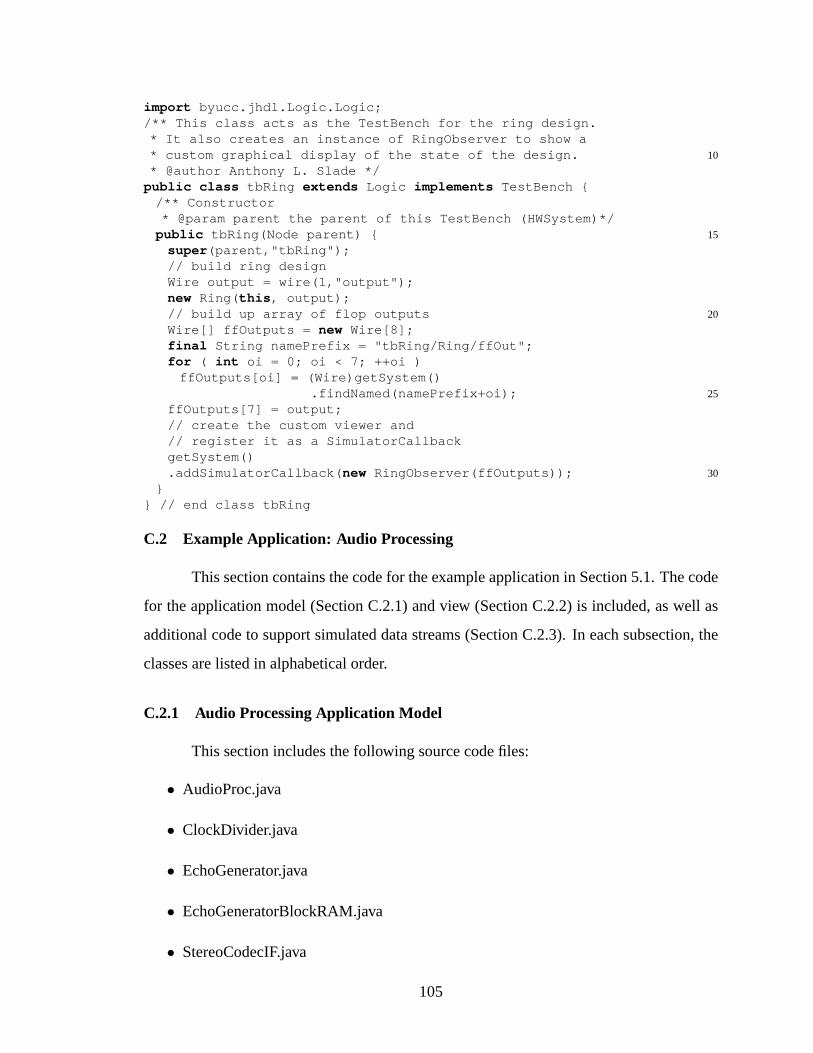
import byucc.jhdl.Logic.Logic;/** This class acts as the TestBench for the ring design.* It also creates an instance of RingObserver to show a
10* custom graphical display of the state of the design.* @author Anthony L. Slade */
public class tbRing extends Logic implements TestBench {/** Constructor* @param parent the parent of this TestBench (HWSystem)*/
15public tbRing(Node parent) {super (parent,"tbRing");// build ring designWire output = wire(1,"output");new Ring( this , output);
20// build up array of flop outputsWire[] ffOutputs = new Wire[8];final String namePrefix = "tbRing/Ring/ffOut";for ( int oi = 0; oi < 7; ++oi )
ffOutputs[oi] = (Wire)getSystem()25.findNamed(namePrefix+oi);
ffOutputs[7] = output;// create the custom viewer and// register it as a SimulatorCallbackgetSystem()
30.addSimulatorCallback( new RingObserver(ffOutputs));}
} // end class tbRing
C.2 Example Application: Audio Processing
This section contains the code for the example application in Section 5.1. The code
for the application model (Section C.2.1) and view (Section C.2.2) is included, as well as
additional code to support simulated data streams (Section C.2.3). In each subsection, the
classes are listed in alphabetical order.
C.2.1 Audio Processing Application Model
This section includes the following source code files:
• AudioProc.java
• ClockDivider.java
• EchoGenerator.java
• EchoGeneratorBlockRAM.java
• StereoCodecIF.java
105

• tbAudioProc.java
AudioProc.java
package model;
import byucc.jhdl.base.CellInterface;5import byucc.jhdl.base.Node;
import byucc.jhdl.base.Wire;import byucc.jhdl.Logic.Logic;import byucc.jhdl.Xilinx.Virtex.bufg;import byucc.jhdl.Xilinx.Virtex.ibufg;
10import byucc.jhdl.Xilinx.Virtex.obuf;
/*** This circuit implements a very basic echo function for the* stereo CODEC on the XSV board. This is also meant to be a
15* very simple demonstration application to show some of the* nice features of the CVT system.** Note that this demonstration circuit assumes a clock* frequency of 50 MHz. Set the XSV board frequency to 50 MHz
20* for propery operation of this demo.** The file AudioProc.ucf is appropriate for using this* design with the XSV board.*
25* @author Mike Wirthlin, Anthony Slade***/
public class AudioProc extends Logic {
30public static final int ECHO_DELAY = 5000;public static final int ECHO_ATTENUATION = 4;
public static CellInterface cell_interface[] = {in("clk",1),
35in("sdout",1),out("mclk",1),out("lrclk",1),out("sclk",1),out("sdin",1),
40//out("testport",5),param("echoDelay", INTEGER ), // # cycles for echo delay//param("echoAttenuation", INTEGER ),
};
45public AudioProc(Node parent, Wire clk, Wire sdout,Wire mclk, Wire lrclk, Wire sclk,Wire sdin/*,Wire testport*/) {
this (parent,clk,sdout,mclk,lrclk,sclk,sdin,/*testport,*/
106
50ECHO_DELAY);}
public AudioProc(Node parent, Wire clk, Wire sdout,Wire mclk, Wire lrclk, Wire sclk,
55Wire sdin,/*Wire testport,*/int echoDelay) {
// call constructor in Logic60super (parent,"AudioProcDemo");
// Connect calls.connect("clk",clk);connect("sdout",sdout);
65connect("mclk",mclk);connect("lrclk",lrclk);connect("sclk",sclk);connect("sdin",sdin);//connect("testport",testport);
70bind("echoDelay",echoDelay);//bind("echoAttenuation",echoAttenuation);
// Create Clock Wire.Wire internal_clk = wire(1,"internal_clk");
75Wire internal_ibufg_clk = wire(1,"internal_clk");new ibufg( this ,clk,internal_ibufg_clk);new bufg( this ,internal_ibufg_clk,internal_clk);setDefaultClock(internal_clk);
80//////////////////////////////////////////////////// Wires//////////////////////////////////////////////////Wire sampleData = wire(1,"sampleData");Wire rdatain = wire(20,"rdatain");
85Wire ldatain = wire(20,"ldatain");Wire rdataout = wire(20,"rdataout");Wire ldataout = wire(20,"ldataout");Wire internal_testport = wire(5,"internal_testport");
90//////////////////////////////////////////////////// Create the internal module that actually performs the// echo generation.//////////////////////////////////////////////////new EchoGenerator( this , internal_clk,
95rdatain,ldatain,sampleData,rdataout,ldataout);
// Interface to StereoCodec100new StereoCodecIF( this ,
internal_clk,// fast clockldataout, // output sample (left)rdataout, // output sample (right)
107

sdout, // Serial in pin105ldatain, // Left Data in
rdatain, // Right data inmclk, // mclk pinlrclk, // lrclk pinsclk, // sclk pin
110sdin, // sdin pin (serial out)sampleData, // increment signal4//, // divide 50 MHz by 4 (for mclk)/*internal_testport*/);
115// add testport pins//for (int i=0;i<internal_testport.getWidth();i++)// new obuf(this,internal_testport.gw(i),// testport.gw(i));
120}
}
ClockDivider.java
package model;
import byucc.jhdl.base.*;5import byucc.jhdl.Logic.*;
import byucc.jhdl.Xilinx.Virtex.*;import byucc.jhdl.Xilinx.Virtex.Modules.upcnt;
/**10* This class creates a programmable clock divider. The
* output is a regular signal (not a clock buffer). A clock* can be created by attaching a clock buffer to the output* of this circuit. Several of the XSV I/O components* require custom clocks. This circuit is used to facilitate
15* the creation of clock dividers for these resources.* <br><br>** This clock divider can divide the current clock by any* power of 2.
20** @author Anthony L. Slade**/
public class ClockDivider extends Logic {
25public static CellInterface cell_interface[] = {in("clk",1),out("cout",1),
};
30/***
108

**/public ClockDivider(Node parent, Wire clk, Wire cout,
int divide) {35super (parent);
this .clk = connect("clk",clk);this .cout = connect("cout",cout);setDefaultClock( this .clk);
40if ( divide == 1 ) {buf_o(clk,cout);return ;
}
45Wire fout = cout;Wire fin = null ;for ( int shift = 0; (1&(divide>>shift)) == 0;
++shift ) {fin = wire(1);
50reg_o(fin,fout);fout = fin;
}not_o(cout,fin);
}55
Wire clk;Wire cout;
}
EchoGenerator.java
package model;
import byucc.jhdl.base.BuildException;5import byucc.jhdl.base.CellInterface;
import byucc.jhdl.base.Node;import byucc.jhdl.base.Wire;import byucc.jhdl.Logic.Logic;
10import byucc.jhdl.Xilinx.Virtex.Modules.delay;import byucc.jhdl.Xilinx.Virtex.Modules.upcnt;
/** The internal echo generation circuit for the AudioProc* design
15* @author Anthony L. Slade */public class EchoGenerator extends Logic {
public static final int NUM_DELAY_SRL = 1536;
20public static CellInterface[] cell_interface = {in("clk",1), // The clock for this circuitin("rightDataIn",20),// Input data for right channelin("leftDataIn",20), // Input data for left channelin("sampleData",1), // Signals to sample the data
109

25out("rightDataOut",20), // Output data for right channelout("leftDataOut",20), // Output data for left channel//param("echoDelay", INTEGER ), // # delay cycles//param("attenuation", INTEGER )// shift amount
};30
/*** @param parent The parent Cell that creates this circuit** @param clk the clock for this circuit
35* @param rDataIn Right channel input* @param lDataIn Left channel input* @param sampleData Sample enable signal* @param rDataOut Right channel output* @param lDataOut Left channel output
40* <!--@param echoDelay Number of cycles to delay for echo* @param attenuation Number of bits to shift delayed* signal to attenuate the echo signal -->***/
45public EchoGenerator(Node parent,Wire clk,Wire rDataIn,Wire lDataIn,Wire sampleData,
50Wire rDataOut,Wire lDataOut//int echoDelay,//int attenuation) {
55// Call supersuper (parent,"EchoGenerator");
// connect callsWire clk_i = connect("clk",clk);
60Wire rDIn_i = connect("rightDataIn",rDataIn);Wire lDIn_i = connect("leftDataIn",lDataIn);Wire sample_i = connect("sampleData",sampleData);Wire rDOut_i = connect("rightDataOut",rDataOut);Wire lDOut_i = connect("leftDataOut",lDataOut);
65//bind("echoDelay",echoDelay);//bind("attenuation",attenuation);
setDefaultClock(clk_i);
70Wire inputAddress = wire(12,"inputAddress");Wire outputAddress = wire(12,"outputAddress");new upcnt( this ,clk_i,//clock wire
sample_i,//clock enableand(inputAddress.gw(11),//counter load
75inputAddress.gw(10),inputAddress.gw(8)),
gnd(12),//counter load datainputAddress,//counter output
110
0L,//counter reset state80"inputAddressCounter");
new upcnt( this ,clk_i,//clock wiresample_i,//clock enableand(outputAddress.gw(11),//counter load
outputAddress.gw(10),85outputAddress.gw(8)),
gnd(12),//counter load dataoutputAddress,//counter output1L,//counter reset state"outputAddressCounter");
90
Wire toDelayDataR = rDataIn.range(19,4,"toDelayDataR");Wire toDelayDataL = lDataIn.range(19,4,"toDelayDataL");Wire delayedDataRAMR = wire(16,"delayedDataRAMR");Wire delayedDataRAML = wire(16,"delayedDataRAML");
95
new EchoGeneratorBlockRAM( this ,clk_i,toDelayDataR,sample_i,
100inputAddress,outputAddress,delayedDataRAMR,"RightChannelDelayRAM");
new EchoGeneratorBlockRAM( this ,105clk_i,
toDelayDataL,sample_i,inputAddress,outputAddress,
110delayedDataRAML,"LeftChannelDelayRAM");
Wire delayedDataL = wire(16,"delayedDataR");Wire delayedDataR = wire(16,"delayedDataL");
115new delay( this ,NUM_DELAY_SRL,clk_i,delayedDataRAMR,sample_i,
120delayedDataR,"srlDelayR");
new delay( this ,NUM_DELAY_SRL,clk_i,
125delayedDataRAML,sample_i,delayedDataL,"srlDelayL");
add_o(rDIn_i,concat(gnd(4),delayedDataR),rDOut_i);130add_o(lDIn_i,concat(gnd(4),delayedDataL),lDOut_i);
}
111
}
EchoGeneratorBlockRAM.java
package model;
import byucc.jhdl.base.CellInterface;5import byucc.jhdl.base.Node;
import byucc.jhdl.base.Wire;import byucc.jhdl.Logic.Logic;import byucc.jhdl.Logic.Modules.DECODERS;
10import byucc.jhdl.Xilinx.Virtex.RAMB4Dual;import byucc.jhdl.Xilinx.Virtex.Modules.mux41;import byucc.jhdl.Xilinx.Virtex.Modules.mux81;
/** The internal echo generation circuit delay using Block15* RAMs for the AudioProc design.
* @author Anthony L. Slade */public class EchoGeneratorBlockRAM extends Logic {
public static CellInterface[] cell_interface = {in("clk",1),
20in("dataIn",16),in("sample",1),in("addressIn",12),in("addressOut",12),out("dataOut",16),
25};public EchoGeneratorBlockRAM(Node parent, Wire clk,
Wire dataIn, Wire sample,Wire addressIn,Wire addressOut, Wire dataOut,
30String name) {super (parent,name);
Wire clk_i = connect("clk",clk);setDefaultClock(clk_i);
35Wire dataIn_i = reg(connect("dataIn",dataIn),"dataIn");Wire sample_i
= reg(connect("sample",sample),"sampleData");Wire inputAddress
= reg(connect("addressIn",addressIn),"inputAddress");40Wire outputAddress
= reg(connect("addressOut",addressOut),"outputAddress");Wire delayedData = connect("dataOut",dataOut);
int [] zeroContents = new int [128];45for ( int zi = 0; zi < zeroContents.length; ++zi ) {
zeroContents[zi] = 0;//zeroContents[zi] = zi;
}
50Wire[] inputRAMEnable = new Wire[16];
112

Wire[] delayedDataArray = new Wire[14];for ( int wi = 0; wi < 14; ++wi ) {
inputRAMEnable[wi] = wire(1,"inputRAMEnable"+wi);delayedDataArray[wi] = wire(16,"delayedData"+wi);
55}for ( int wi = 14; wi < 16; ++wi ) {
inputRAMEnable[wi] = wire(1,"inputRAMEnable"+wi);}Wire inputRAMSelect
60= inputAddress.range(11,8,"inputRAMSelect");Wire outputRAMSelect
= outputAddress.range(11,8,"outputRAMSelect");DECODERS.decoder( this , inputRAMSelect,
inputRAMEnable, "inputRAMEnable");65
Wire inputAddressLow= inputAddress.range(7,0,"inputAddressLow");
Wire outputAddressLow= outputAddress.range(7,0,"outputAddressLow");
70for ( int br = 0; br < 14; ++br ) {new RAMB4Dual( this ,//parent
clk_i,clk_i,//clocksgnd("rstA"),//rstAvcc("enA"),//enA
75dataIn_i,//diAand(sample_i,inputRAMEnable[br]),//weAinputAddressLow,//addrAwire(16,"doA"),//doAgnd("rstB"),//rstB
80vcc("enB"),//enBgnd(16,"diB"),//diBgnd("weB"),//weBoutputAddressLow,//addrBdelayedDataArray[br],//doB
85zeroContents,//contents[]"delayRam");//name
}
Wire[] delayedDataArrayReg = new Wire[14];90for ( int wi = 0; wi < 14; ++wi ) {
delayedDataArrayReg[wi] = reg(delayedDataArray[wi],"delayedDataArrayReg"+wi);
}
95
Wire mux81Out0 = wire(16,"mux81Out0");Wire mux81Out1 = wire(16,"mux81Out1");Wire outputRAMSelectHi
= outputRAMSelect.range(3,3,"outputRAMSelectHi");100Wire outputRAMSelectLow
= outputRAMSelect.range(2,0,"outputRAMSelectLow");new mux81( this ,
delayedDataArrayReg[0],delayedDataArrayReg[1],
113
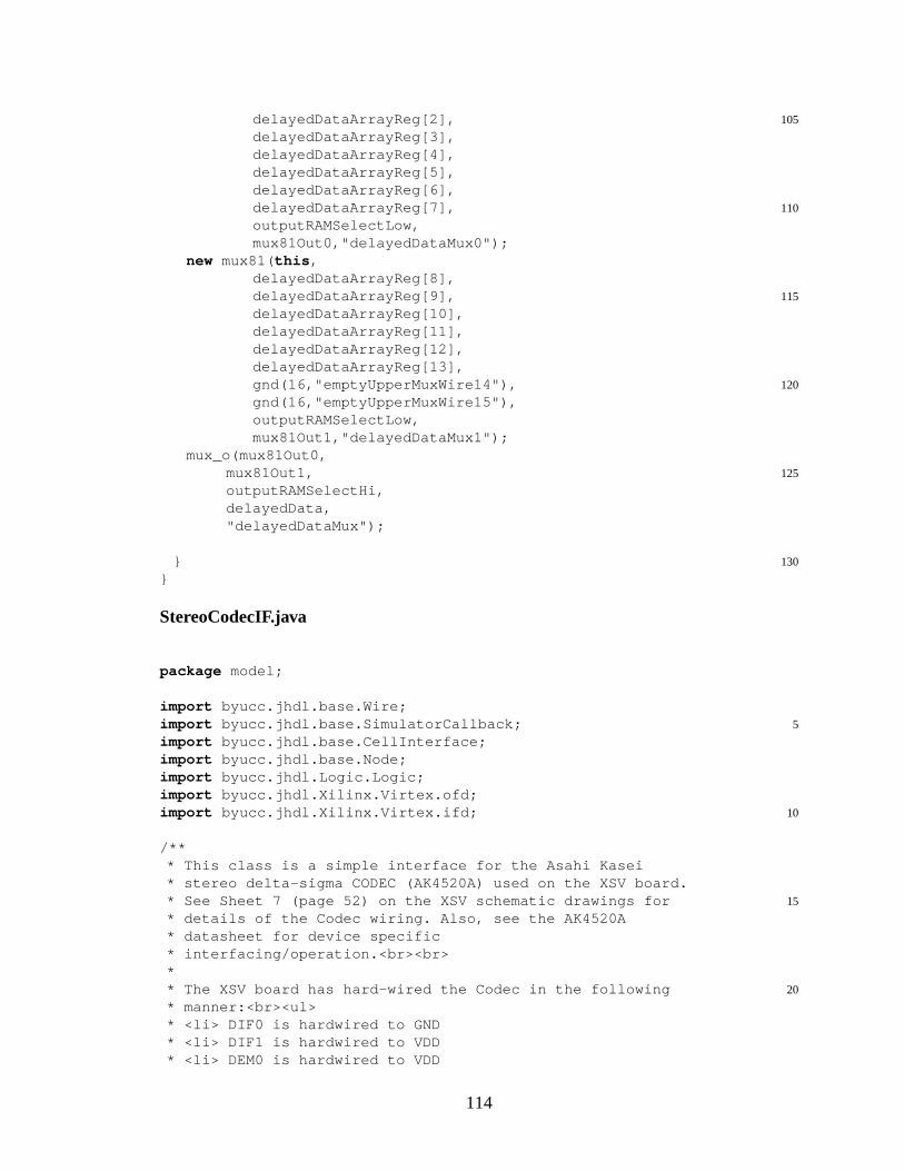
105delayedDataArrayReg[2],delayedDataArrayReg[3],delayedDataArrayReg[4],delayedDataArrayReg[5],delayedDataArrayReg[6],
110delayedDataArrayReg[7],outputRAMSelectLow,mux81Out0,"delayedDataMux0");
new mux81( this ,delayedDataArrayReg[8],
115delayedDataArrayReg[9],delayedDataArrayReg[10],delayedDataArrayReg[11],delayedDataArrayReg[12],delayedDataArrayReg[13],
120gnd(16,"emptyUpperMuxWire14"),gnd(16,"emptyUpperMuxWire15"),outputRAMSelectLow,mux81Out1,"delayedDataMux1");
mux_o(mux81Out0,125mux81Out1,
outputRAMSelectHi,delayedData,"delayedDataMux");
130}}
StereoCodecIF.java
package model;
import byucc.jhdl.base.Wire;5import byucc.jhdl.base.SimulatorCallback;
import byucc.jhdl.base.CellInterface;import byucc.jhdl.base.Node;import byucc.jhdl.Logic.Logic;import byucc.jhdl.Xilinx.Virtex.ofd;
10import byucc.jhdl.Xilinx.Virtex.ifd;
/*** This class is a simple interface for the Asahi Kasei* stereo delta-sigma CODEC (AK4520A) used on the XSV board.
15* See Sheet 7 (page 52) on the XSV schematic drawings for* details of the Codec wiring. Also, see the AK4520A* datasheet for device specific* interfacing/operation.<br><br>*
20* The XSV board has hard-wired the Codec in the following* manner:<br><ul>* <li> DIF0 is hardwired to GND* <li> DIF1 is hardwired to VDD* <li> DEM0 is hardwired to VDD
114
25* <li> DEM1 is hardwired to GND* <li> CMODE is hardwired to GND* </ul>* These constraints force the chip into the following* modes:<ul>
30* <li> MCLK must be set to 256 * fs (sampling frequency)* (See Table 1 in the AK4520A datasheet)* <li> The serial data mode is hard wired to Mode 2* (10). This requires the SDTO data to be MSB justified* and the SDTI data to be MSB justified. L/R = H/L and
35* SCLK >= 40 * fs.* (See Table 2 in the AK4520A datasheet)* <li> The de-emphasis filter is disabled.* </ul>*
40* This codec can sample data anywhere from 16kHz to 54* kHz. The actual sample rate is determined by the user of* this module. The sample rate is specified in this module* by setting the <tt>clkdivide</tt> parameter in the port* interface. This parameter is used to create a new internal
45* clock (mclk) that specifies the sample rate. See the* javadoc comment on the <tt>clkdivide</tt> parameter for* more information about setting this parameter.<br><Br>** For this module, the sampling clock rate is the frequency
50* of MCLK divided by 256 (mclk/256). This forces the input* clock to have a frequency between 4.096 MHz and 13.824* MHz.<br>** This module consumes about 58 slices.
55** Five external I/O pins are needed to support this* module. The pin locations for these nets can be forced by* using the following UCF File snippet:<pre>*
60*NET "sdout_pin" LOC = "P7";*NET "mclk_pin" LOC = "P3";*NET "sclk_pin" LOC = "P5";*NET "lrclk_pin" LOC = "P4";*NET "sdin_pin" LOC = "P6";
65*</pre>** @author Mike Wirthlin***/
70public class StereoCodecIF extends Logicimplements SimulatorCallback {
public static CellInterface cell_interface[] = {in("clk",1), // Module Clock
75in("ldatain",20), // Left Data Inin("rdatain",20), // Right Data Inin("sdout_pin",1), // Codec Serial Data (from Codec)out("ldataout",20), // Left Data Out
115
out("rdataout",20), // Right Data Out80out("mclk_pin",1), // Codec Master Clock Input
out("lrclk_pin",1), // Codec In/Out Channel Clock Pinout("sclk_pin",1), // Codec Audio serial data clock pinout("sdin_pin",1), // Codec Serial Data (to Codec)out("newsample",1), // New sample (pre-sampling cycle)
85param("clkdivide", INTEGER ), // clock divide};
/*** @param parent The parent Cell that creates this circuit
90** @param clk The input clock to the module. This should be* the system clock operating throughout the rest of the* design. This clock will be divided internally to* generate the appropriate internal clock signals. This
95* module has been successfully tested with a 50 MHz* clock.** @param ldatain The 20-bit left channel data digitized by* the codec. This data is sampled on the clock cycle
100* following the cycle when "newsample" is asserted.** @param rdatain The 20-bit right channel data digitized* by the codec. This data is sampled on the clock cycle* following the cycle when "newsample" is asserted.
105** @param sdout_pin The 1 bit serial input signal from the* CODEC (it is an output on the CODEC). The user of this* circuit does not need drive this signal - a pin with the* proper location properties is created for this signal
110* within this module.** @param ldataout The 20-bit left sample quantized by the* CODEC (data digitized from the Audio In port on the* board). This data should be sampled on the clock cycle
115* following the "newsample" signal.** @param rdataout The 20-bit right sample quantized by the* CODEC (data digitized from the Audio In port on the* board). This data should be sampled on the clock cycle
120* following the "newsample" signal.** @param mclk_pin This is the master clock used by the* Codec. This clock must be 256 * fs. If the sampling* frequency is 48 kHz, this clock should be 12.288
125* MHz. This clock is generated by dividing the input clock* by the integer value specified by the clkdivide* parameter. This module will create the logic to* generate the correct MCLK signal and will create the* output buffer for the signal. The user of this module
130* should not use this signal.** @param lrclk_pin This is the left/right clock
116

* signal. This proper timing for this signalis generated* by this module. This signal is connected to the
135* appropriate IOB within this module and should not be* used by the user circuit.** @param sclk_pin The serial data clock going to the* Codec. This clock will operate at 64 * fs. The IOB for
140* this signal is created within this module.** @param sdin_pin This is the signal that will drive the* serial input to the CODEC. The logic and IOB for this* signal is created within this module.
145** @param newsample When this signal is asserted, the user* design should sample the rdataout,ldataout signals and* should provide a new sample for the analog out. This* signal is asserted for one clock cycle every 1024 system
150* clocks.** @param clkdivide The number of clock cycles to divide* the incoming clock signal into the MCLK signal. Since* the MCLK must be 256 * fs (sampling frequency), the
155* clkdivide value can be calculate as follows: clkdivide =* sysclk / (fs * 256), where sysclk is the frequency of* the incoming clock signal. For example, if the incoming* clock has a frequency of 50 MHz and a sampling frequency* of 48 kHz is desired, the clkdivide value should be set
160* to: 50 MHz / (48k * 256) = 4.069 or 4. This value does* not need to be a power of two.***/
public StereoCodecIF( Node parent, Wire clk, Wire ldatain,165Wire rdatain, Wire sdout_pin,
Wire ldataout, Wire rdataout,Wire mclk_pin, Wire lrclk_pin,Wire sclk_pin, Wire sdin_pin,Wire newsample, int clkdivide) {
170
// Call supersuper (parent,"StereoCodecIF");
// connect calls175clk_i = connect("clk",clk);
ldatain_i = connect("ldatain",ldatain);rdatain_i = connect("rdatain",rdatain);sdout_i = connect("sdout_pin",sdout_pin);ldataout_i = connect("ldataout",ldataout);
180rdataout_i = connect("rdataout",rdataout);mclk_i = connect("mclk_pin",mclk_pin);lrclk_i = connect("lrclk_pin",lrclk_pin);sclk_i = connect("sclk_pin",sclk_pin);sdin_i = connect("sdin_pin",sdin_pin);
185newsample_i = connect("newsample",newsample);bind("clkdivide",clkdivide);
117
/*** Although all the logic in this circuit is clocked by
190* the system clock (whatever is default at this point),* this circuit changes its values at the internal "MCLK"* frequency. An internal "MCLK" signal (not clock) is* generated by dividing the input clock by the integer* parameter "clkdivide".
195** The signal "new_mclk" is used in the design to signal* the logic that the MCLK will be going high on the next* clock signal. Internal variables will use this signal* to make sure that things only change when MCLK is
200* going high.**/
Wire pre_internal_mclk = wire(1,"pre_internal_mclk");new ClockDivider( this ,clk,pre_internal_mclk,clkdivide);internal_mclk = reg(clk,pre_internal_mclk,
205"internal_mclk");Wire new_mclk;if (clkdivide == 1)
// If clkdivide == 1, there is a new MCLK every cyclenew_mclk = vcc("new_mclk");
210else// If clkdivide != 1, there is a new MCLK only when// pre_internal_mclk ==1 and internal_mclk == 0new_mclk = and(pre_internal_mclk,not(internal_mclk),
"new_mclk");215
/*** Create the output buffer and flip-flop for this* signal. Note that all output and input IOBs that* communicate with the StereoCodec use IOB flip-flops
220* that are clocked by the higher-frequency system* clock.**/
// Create the output buffer fornew ofd( this ,"mclk_pin",clk,internal_mclk,mclk_i);
225// mclk_i.addProperty(this,"LOC","P3");
/*** Create a 256-bit counter that is incremented each time* new_mclk is asserted. This 256-bit MCLK Counter
230* defines the complete sequence of reading and writing a* left and write sample from/to the CODEC. This is* essentially a 256-sequence statemachine.** All output logic will use this 256-bit counter to
235* determine their values. (i.e. the output forming logic* uses the counter).***/
Wire mclk_counter = wire(8,"mclk_counter");240Wire mclk_counter_plus_1 = add(mclk_counter,
118

constant(8,1));regce_o(clk,mclk_counter_plus_1,new_mclk,mclk_counter);
// create SCLK: bit 1 (divide mclk by four). This signal245// must be 180 deg out of phase with LRCLK.
internal_sclk = buf(mclk_counter.gw(1),"internal_sclk");new ofd( this ,"sclk_pin",clk,internal_sclk,sclk_i);// sclk_i.addProperty(this,"LOC","P5");
250// create LRCLK: bit 7internal_lrclk = buf(mclk_counter.gw(7),
"internal_lrclk");new ofd( this ,"lrclk_pin",clk,internal_lrclk,lrclk_i);// lrclk_i.addProperty(this,"LOC","P4");
255
/* The input data from the CODEC must be sampled on the* falling edge of SCLK. This occurs when the 8-bit* mclk_counter is XXXXXX11 and the new_mclk signal* is asserted.
260** MCLK counter* 00000011 - Sample Right bit 19* 00000111 - Sample Right bit 18* ...
265* 01001111 - Sample Right bit 0* 01010011 - No bit* 01010111 - No bit* ...* 10000011 - Sample Left bit 19
270* 10000111 - Sample Left bit 18* ...* 11001111 - Sample Left bit 0* 11010011 - No bit* 11010111 - No bit
275* ...* 11111111 - No bit** Sample/shift a bit* = CNT0*CNT1’*(CNT6’+CNT6*CNT4’*CNT5’)*NEW_MCLK
280*/
// sample_bit: asserted when counter is in a SCLK cycle// that represents a valid bit (i.e. the first twenty// bits associated with bits 19 through 0 of the
285// sample). The following 12 SCLK cycles contain invalid// data. i.e. (CNT6’+CNT6*CNT4’*CNT5’)*NEW_MCLKWire sample_bit = and(new_mclk,
or(not(mclk_counter.gw(6)),and(mclk_counter.gw(6),
290not(mclk_counter.gw(4)),not(mclk_counter.gw(5)))),
"sample_bit");// Sample the left input signal. This occurs when// in a valid SCLK cycle AND on falling edge of
119
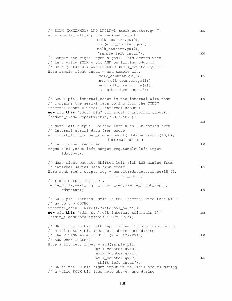
295// SCLK (XXXXXX01) AND LRCLK=1 (mclk_counter.gw(7))Wire sample_left_input = and(sample_bit,
mclk_counter.gw(0),not(mclk_counter.gw(1)),mclk_counter.gw(7),
300"sample_left_input");// Sample the right input signal. This occurs when// in a valid SCLK cycle AND on falling edge of// SCLK (XXXXXX01) AND LRCLK=0 (mclk_counter.gw(7))Wire sample_right_input = and(sample_bit,
305mclk_counter.gw(0),not(mclk_counter.gw(1)),not(mclk_counter.gw(7)),"sample_right_input");
310// SDOUT pin: internal_sdout is the internal wire that// contains the serial data coming from the CODEC.internal_sdout = wire(1,"internal_sdout");new ifd( this ,"sdout_pin",clk,sdout_i,internal_sdout);//sdout_i.addProperty(this,"LOC","P7");
315
// Next left output. Shifted left with LSB coming from// internal serial data from codec.Wire next_left_output_reg = concat(ldataout.range(18,0),
internal_sdout);320// left output register.
regce_o(clk,next_left_output_reg,sample_left_input,ldataout);
// Next right output. Shifted left with LSB coming from325// internal serial data from codec.
Wire next_right_output_reg = concat(rdataout.range(18,0),internal_sdout);
// right output register.regce_o(clk,next_right_output_reg,sample_right_input,
330rdataout);
// SDIN pin: internal_sdin is the internal wire that will// go to the CODEC.internal_sdin = wire(1,"internal_sdin");
335new ofd( this ,"sdin_pin",clk,internal_sdin,sdin_i);//sdin_i.addProperty(this,"LOC","P6");
// Shift the 20-bit left input value. This occurs during// a valid SCLK bit (see note above) and during
340// the RISING edge of SCLK (i.e. XXXXXX11)// AND when LRCLK=1Wire shift_left_input = and(sample_bit,
mclk_counter.gw(0),mclk_counter.gw(1),
345mclk_counter.gw(7),"shift_left_input");
// Shift the 20-bit right input value. This occurs during// a valid SCLK bit (see note above) and during
120
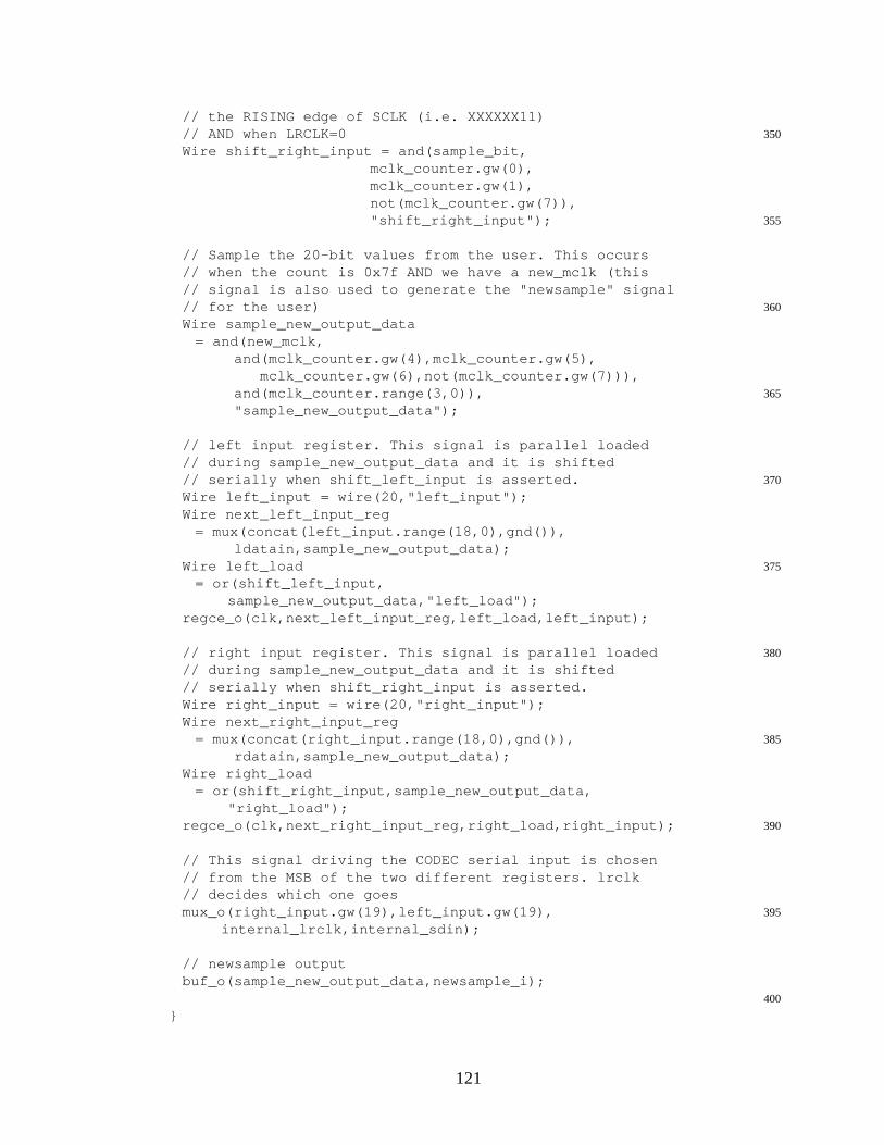
// the RISING edge of SCLK (i.e. XXXXXX11)350// AND when LRCLK=0
Wire shift_right_input = and(sample_bit,mclk_counter.gw(0),mclk_counter.gw(1),not(mclk_counter.gw(7)),
355"shift_right_input");
// Sample the 20-bit values from the user. This occurs// when the count is 0x7f AND we have a new_mclk (this// signal is also used to generate the "newsample" signal
360// for the user)Wire sample_new_output_data
= and(new_mclk,and(mclk_counter.gw(4),mclk_counter.gw(5),
mclk_counter.gw(6),not(mclk_counter.gw(7))),365and(mclk_counter.range(3,0)),
"sample_new_output_data");
// left input register. This signal is parallel loaded// during sample_new_output_data and it is shifted
370// serially when shift_left_input is asserted.Wire left_input = wire(20,"left_input");Wire next_left_input_reg
= mux(concat(left_input.range(18,0),gnd()),ldatain,sample_new_output_data);
375Wire left_load= or(shift_left_input,
sample_new_output_data,"left_load");regce_o(clk,next_left_input_reg,left_load,left_input);
380// right input register. This signal is parallel loaded// during sample_new_output_data and it is shifted// serially when shift_right_input is asserted.Wire right_input = wire(20,"right_input");Wire next_right_input_reg
385= mux(concat(right_input.range(18,0),gnd()),rdatain,sample_new_output_data);
Wire right_load= or(shift_right_input,sample_new_output_data,
"right_load");390regce_o(clk,next_right_input_reg,right_load,right_input);
// This signal driving the CODEC serial input is chosen// from the MSB of the two different registers. lrclk// decides which one goes
395mux_o(right_input.gw(19),left_input.gw(19),internal_lrclk,internal_sdin);
// newsample outputbuf_o(sample_new_output_data,newsample_i);
400
}
121
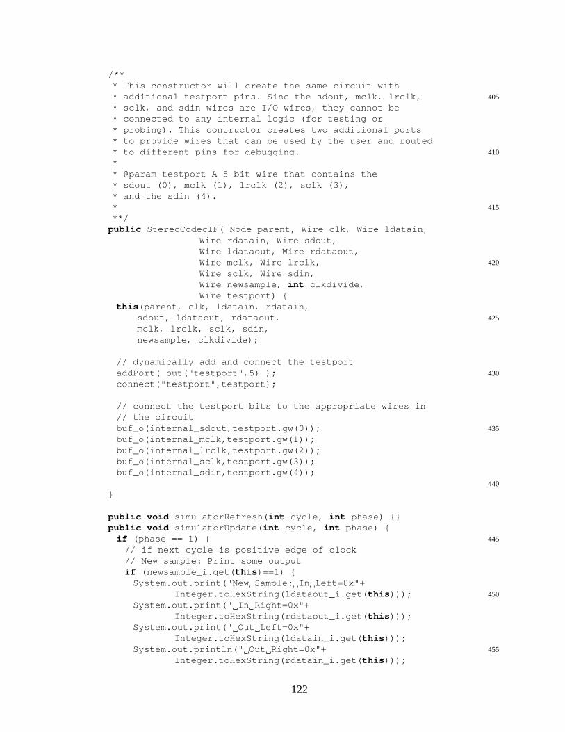
/*** This constructor will create the same circuit with
405* additional testport pins. Sinc the sdout, mclk, lrclk,* sclk, and sdin wires are I/O wires, they cannot be* connected to any internal logic (for testing or* probing). This contructor creates two additional ports* to provide wires that can be used by the user and routed
410* to different pins for debugging.** @param testport A 5-bit wire that contains the* sdout (0), mclk (1), lrclk (2), sclk (3),* and the sdin (4).
415***/
public StereoCodecIF( Node parent, Wire clk, Wire ldatain,Wire rdatain, Wire sdout,Wire ldataout, Wire rdataout,
420Wire mclk, Wire lrclk,Wire sclk, Wire sdin,Wire newsample, int clkdivide,Wire testport) {
this (parent, clk, ldatain, rdatain,425sdout, ldataout, rdataout,
mclk, lrclk, sclk, sdin,newsample, clkdivide);
// dynamically add and connect the testport430addPort( out("testport",5) );
connect("testport",testport);
// connect the testport bits to the appropriate wires in// the circuit
435buf_o(internal_sdout,testport.gw(0));buf_o(internal_mclk,testport.gw(1));buf_o(internal_lrclk,testport.gw(2));buf_o(internal_sclk,testport.gw(3));buf_o(internal_sdin,testport.gw(4));
440
}
public void simulatorRefresh( int cycle, int phase) {}public void simulatorUpdate( int cycle, int phase) {
445if (phase == 1) {// if next cycle is positive edge of clock// New sample: Print some outputif (newsample_i.get( this )==1) {
System.out.print("New Sample: In Left=0x"+450Integer.toHexString(ldataout_i.get( this )));
System.out.print(" In Right=0x"+Integer.toHexString(rdataout_i.get( this )));
System.out.print(" Out Left=0x"+Integer.toHexString(ldatain_i.get( this )));
455System.out.println(" Out Right=0x"+Integer.toHexString(rdatain_i.get( this )));
122

}}
}460public void simulatorReset() {}
// Assuming the maximum input frequency is 100 MHz,// Max divide = 100MHz / (256 * 16000) = 24.41 or 25.public static final int MAX_DIVIDE = 25;
465
public Wire clk_i;public Wire ldatain_i;public Wire rdatain_i;public Wire sdout_i;
470public Wire rdataout_i;public Wire ldataout_i;public Wire mclk_i;public Wire lrclk_i;public Wire sclk_i;
475public Wire sdin_i;public Wire newsample_i;
public Wire internal_mclk;public Wire internal_sclk;
480public Wire internal_lrclk;public Wire internal_sdout;public Wire internal_sdin;
}
tbAudioProc.java
package model;
import javax.swing.JFrame;5
import byucc.jhdl.apps.Viewers.cvt.cvtFrame;import byucc.jhdl.base.HWSystem;import byucc.jhdl.base.ProgrammaticTestBench;import byucc.jhdl.base.Wire;
10import byucc.jhdl.Logic.Logic;import byucc.jhdl.Logic.TechMapper;import byucc.jhdl.Xilinx.Virtex.VirtexTechMapper;
import view.AudioProcView;15
/** Program to execute and visualize the AudioProc design* @author Anthony L. Slade */
public class tbAudioProc extends Logicimplements ProgrammaticTestBench {
20
public static void printUsage() {System.err.println("USAGE: java tbAudioProc "
+"[-netlist|num_cycles] "
123
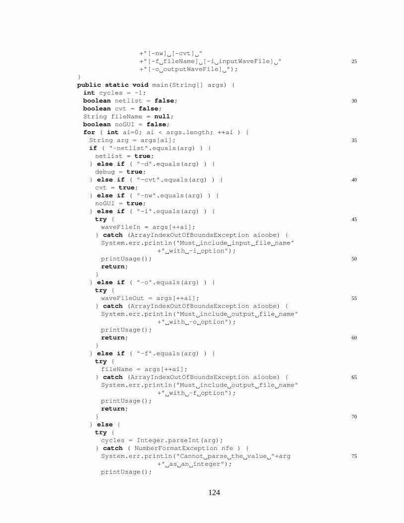
+"[-nw] [-cvt] "25+"[-f fileName] [-i inputWaveFile] "
+"[-o outputWaveFile] ");}public static void main(String[] args) {
int cycles = -1;30boolean netlist = false ;
boolean cvt = false ;String fileName = null ;boolean noGUI = false ;for ( int ai=0; ai < args.length; ++ai ) {
35String arg = args[ai];if ( "-netlist".equals(arg) ) {
netlist = true ;} else if ( "-d".equals(arg) ) {
debug = true ;40} else if ( "-cvt".equals(arg) ) {
cvt = true ;} else if ( "-nw".equals(arg) ) {
noGUI = true ;} else if ( "-i".equals(arg) ) {
45try {waveFileIn = args[++ai];
} catch (ArrayIndexOutOfBoundsException aioobe) {System.err.println("Must include input file name"
+" with -i option");50printUsage();
return ;}
} else if ( "-o".equals(arg) ) {try {
55waveFileOut = args[++ai];} catch (ArrayIndexOutOfBoundsException aioobe) {
System.err.println("Must include output file name"+" with -o option");
printUsage();60return ;
}} else if ( "-f".equals(arg) ) {
try {fileName = args[++ai];
65} catch (ArrayIndexOutOfBoundsException aioobe) {System.err.println("Must include output file name"
+" with -f option");printUsage();return ;
70}} else {
try {cycles = Integer.parseInt(arg);
} catch ( NumberFormatException nfe ) {75System.err.println("Cannot parse the value "+arg
+" as an integer");printUsage();
124
return ;}
80}}tbAudioProc tb = new tbAudioProc();if ( netlist ) {
TechMapper tm = getDefaultTechMapper();85((byucc.jhdl.Xilinx.TechMapper)tm).setInsertPads( false );
tm.netlist(tb.design, "audio.edn");return ;
}cvtFrame myCVT = null ;
90if ( cvt ) {myCVT = new cvtFrame(tb);
}AudioProcView view = new AudioProcView(tb.getSystem());
95if ( cycles > 0 ) {numCycles = cycles;if ( cvt ) {
myCVT.getInterp().parseCommand("cycle "+cycles);} else {
100tb.execute();}
}System.out.println("Ran circuit for "+cycles+" cycles");if ( null != fileName ) {
105view.writeToFile(fileName);System.out.println("Wrote data to the file "+fileName);
}
if ( !noGUI ) {110JFrame frame = new JFrame("Audio Processing Circuit"
+" Input & Output");frame.setContentPane(view);frame.pack();frame.setVisible( true );
}115if ( !cvt ) {
System.out.println("Done executing. Now exiting...");System.exit(0);
}}
120
private AudioProc design;private CodecWave codec;
public tbAudioProc() {125super ( new HWSystem());
setDefaultTechMapper( new VirtexTechMapper( true ) );clock = wire(1,"tbClock");clockDriver(clock,"01","tbClock");setDefaultClock(clock);
130Wire sdout = wire(1,"sdout");Wire mclk = wire(1,"mclk");
125
Wire lrck = wire(1,"lrck");Wire sclk = wire(1,"sclk");Wire sdin = wire(1,"sdin");
135//Wire testport = wire(5,"testport");design = new AudioProc( this ,clock,sdout,mclk,lrck,
sclk,sdin);//,testport);codec = new CodecWave( this ,mclk,lrck,sclk,sdin,sdout,
waveFileIn,waveFileOut);140clockVal = true ;
}
private static int numCycles = 1024;public void execute() {
145HWSystem system = getSystem();long count = 0;if ( debug ) {
System.err.println(count);}
150while ( !codec.isDone() ) {long time0 = System.currentTimeMillis();system.cycle(numCycles);long time1 = System.currentTimeMillis();count += numCycles;
155long time = time1-time0;if ( debug ) {
System.err.println(count+"; time(ms)="+time+"; cycles-per-second="
160+(((( double )numCycles)/(( double )time))*1000.0)
+"; ms-per-cycle="+(((( double )time)/
(( double )numCycles))/1000.0));165}
}}
public void reset() {170//clock.putB(this,clockVal = true);
}
public void clock() {//clock.putB(this,clockVal = !clockVal);
175}
private Wire clock;private boolean clockVal;
180private static String waveFileIn =CodecWave.WAVE_IN_DEFAULT;
private static String waveFileOut =CodecWave.WAVE_OUT_DEFAULT;
185private static boolean debug = false ;
126
}
C.2.2 Audio Processing Application View
This section includes the following source code files:
• AudioProcView.java
• WaveViewComponent.java
• WaveViewComponentData.java
• WaveViewPanel.java
AudioProcView.java
package view;
import java.awt.Color;5import java.io.File;
import java.io.FileInputStream;import java.io.FileOutputStream;import java.io.IOException;import java.io.ObjectInputStream;
10import java.io.ObjectOutputStream;import java.util.Random;import javax.swing.BoxLayout;import javax.swing.JFrame;import javax.swing.JPanel;
15
import byucc.jhdl.base.Browser;import byucc.jhdl.base.HWSystem;import byucc.jhdl.base.SimulatorCallback;import byucc.jhdl.base.Wire;
20import byucc.jhdl.base.WireValueException;
/** Custom view of the input and output of the AudioProc* design* @author Anthony L. Slade */
25public class AudioProcView extends JPanelimplements Browser, SimulatorCallback {
public static final int DEFAULT_NUM_SAMPLES = 10000;public static final int MAX_VALUE = 1+(1<<9);
30//public static final int MAX_VALUE = 1+(1<<8);//public static final int MIN_VALUE = -MAX_VALUE;public static final int MIN_VALUE = -5;
public static final String NAME_RIGHT_IN
127

35= "tbAudioProc/AudioProcDemo/rdatain";public static final String NAME_LEFT_IN
= "tbAudioProc/AudioProcDemo/ldatain";public static final String NAME_RIGHT_OUT
= "tbAudioProc/AudioProcDemo/rdataout";40public static final String NAME_LEFT_OUT
= "tbAudioProc/AudioProcDemo/ldataout";public static final String NAME_SAMPLE_DATA
= "tbAudioProc/AudioProcDemo/sampleData";
45public static void main(String[] args) {boolean test = false ;String fileName = null ;for ( int ai = 0; ai < args.length; ++ai) {
String arg = args[ai];50if ( "-test".equals(arg) ) {
test = true ;} else {
fileName = arg;}
55}if ( test ) {
JFrame frame = new JFrame("");AudioProcView view = new AudioProcView( new HWSystem());
60//Random rand = new Random();//int[] samples = new int[4];for ( int ii = 0; ii < DEFAULT_NUM_SAMPLES; ++ii ) {
int lIn =( int )(MAX_VALUE*Math.abs(Math.cos(.005*Math.PI*ii)));
65int lOut = (lIn * 5) / 7;int rIn =
( int )((MAX_VALUE>>1)*Math.cos(.01*Math.PI*ii+2));int rOut = (rIn * 5) / 7;rIn += (MAX_VALUE>>1);
70rOut += (MAX_VALUE>>1);view.addSamples(rIn,lIn,rOut,lOut, false );/*for ( int ib = 0; ib < 4; ++ib ) {
int next = Math.abs(rand.nextInt(MAX_VALUE-20));75if ( rand.nextBoolean() )
next = -next;samples[ib] = next;
}view.addSamples(samples[0],samples[1],
80samples[2],samples[3],false);*/
}
frame.setContentPane(view);85frame.pack();frame.setVisible( true );
return ;} else if ( null != fileName ) {
AudioProcView view
128

= readFromFile( new HWSystem(),fileName);90JFrame frame = new JFrame("AudioProcView "+fileName);
frame.setContentPane(view);frame.pack();frame.setVisible( true );return ;
} else {95System.err.println("Give a file name to view the data."
+" Use -test to show random data");return ;
}}
100
public AudioProcView(HWSystem system) {this (system,DEFAULT_NUM_SAMPLES);
}public AudioProcView(HWSystem system, int numSamples) {
105this (system,numSamples,NAME_RIGHT_IN,NAME_LEFT_IN,NAME_RIGHT_OUT,NAME_LEFT_OUT,NAME_SAMPLE_DATA);
}110public AudioProcView(HWSystem system, int numSamples,
String nameRightIn, String nameLeftIn,String nameRightOut,String nameLeftOut,String nameSampleData) {
115rdatain = (Wire)system.findNamed(nameRightIn);ldatain = (Wire)system.findNamed(nameLeftIn);rdataout = (Wire)system.findNamed(nameRightOut);ldataout = (Wire)system.findNamed(nameLeftOut);sampleData = (Wire)system.findNamed(nameSampleData);
120system.addSimulatorCallback( this );
System.err.println("MIN_VALUE = 0x"+Integer.toHexString(MIN_VALUE)+"; MAX_VALUE= 0x"
125+Integer.toHexString(MAX_VALUE));inR = new WaveViewPanel(MIN_VALUE, MAX_VALUE,
numSamples, "Channel 2 Input");inL = new WaveViewPanel(MIN_VALUE, MAX_VALUE,
numSamples, "Channel 1 Input");130outR = new WaveViewPanel(MIN_VALUE, MAX_VALUE,
numSamples, "Channel 2 Output");outL = new WaveViewPanel(MIN_VALUE, MAX_VALUE,
numSamples, "Channel 1 Output");inR.setWaveColor(Color.red);
135outR.setWaveColor(Color.red.darker());inL.setWaveColor(WaveViewComponent.FOREGROUND_DEFAULT);outL.setWaveColor(WaveViewComponent
.FOREGROUND_DEFAULT.darker());setLayout( new BoxLayout( this ,BoxLayout.X_AXIS));
140JPanel inputPanel = new JPanel();JPanel outputPanel = new JPanel();inputPanel.setLayout( new BoxLayout(inputPanel,
129

BoxLayout.Y_AXIS));outputPanel.setLayout( new BoxLayout(outputPanel,
145BoxLayout.Y_AXIS));inputPanel.add(inL);inputPanel.add(inR);outputPanel.add(outL);outputPanel.add(outR);add(inputPanel);add(outputPanel);
}150
public void addSamples( int inRSample, int inLSample,int outRSample, int outLSample,boolean repaint) {
155int offset = 0;inR.addSample(inRSample+offset, repaint);inL.addSample(inLSample+offset, repaint);outR.addSample(outRSample+offset, repaint);outL.addSample(outLSample+offset, repaint);
160}
public void resetSample() {inR.resetSamples();inL.resetSamples();
165outR.resetSamples();outL.resetSamples();
}
public void simulatorReset() {170resetSample();
}public void simulatorUpdate( int cycle, int step) {
if ( lastSampleDataAsserted ) {//System.err.println("putting samples");
175try {addSamples(rdatain.get( this ),
ldatain.get( this ),rdataout.get( this ),ldataout.get( this ),
180false );} catch (WireValueException wve) {
addSamples(0,0,0,0, false );}lastSampleDataAsserted = false ;
185} else {try {
lastSampleDataAsserted = sampleData.get( this )==1;} catch ( WireValueException wve ) {
lastSampleDataAsserted = false ;190}
}}public void simulatorRefresh( int cycle, int step) {
inR.repaint();195inL.repaint();
outR.repaint();
130

outL.repaint();}
200public void writeToFile(String fileName) {WaveViewComponentData dataInR, dataInL,
dataOutR, dataOutL;dataInR = inR.getData();dataInL = inL.getData();
205dataOutR = outR.getData();dataOutL = outL.getData();try {
File file = new File(fileName);FileOutputStream fos = new FileOutputStream(file);
210ObjectOutputStream oos = new ObjectOutputStream(fos);oos.writeObject(dataInR);oos.writeObject(dataInL);oos.writeObject(dataOutR);oos.writeObject(dataOutL);
215oos.close();} catch ( IOException ioe ) {
ioe.printStackTrace();}
}220public static AudioProcView readFromFile(HWSystem system,
String fileName) {AudioProcView view = new AudioProcView(system);WaveViewComponentData dataInR = null ,
dataInL = null , dataOutR = null , dataOutL = null ;225try {
File file = new File(fileName);FileInputStream fis = new FileInputStream(file);ObjectInputStream ois = new ObjectInputStream(fis);dataInR = (WaveViewComponentData)ois.readObject();
230dataInL = (WaveViewComponentData)ois.readObject();dataOutR = (WaveViewComponentData)ois.readObject();dataOutL = (WaveViewComponentData)ois.readObject();
} catch (IOException ioe) {ioe.printStackTrace();
235return null ;} catch ( ClassNotFoundException cnfe ) {
cnfe.printStackTrace();return null ;
}240view.inR.setData(dataInR);
view.inL.setData(dataInL);view.outR.setData(dataOutR);view.outL.setData(dataOutL);return view;
245}
/** The panels to display the audio samples */private WaveViewPanel inR, inL, outR, outL;
250/** The wires of interest */
131
private Wire rdatain, ldatain, rdataout,ldataout, sampleData;
/** Used to tell when to sample the data */255private boolean lastSampleDataAsserted;
}
WaveViewComponent.java
package view;
import java.awt.Color;5import java.awt.Graphics;
import java.awt.event.AdjustmentEvent;import java.awt.event.AdjustmentListener;import javax.swing.JComponent;import javax.swing.JScrollBar;
10
public class WaveViewComponent extends JComponentimplements AdjustmentListener {
public static final Color BACKGROUND15= Color.gray.brighter();
public static final Color BACKGROUND_DARKER= BACKGROUND.darker();
public static final Color BACKGROUND_BRIGHTER= BACKGROUND.brighter();
20public static final Color FOREGROUND_DEFAULT= Color.blue;
public WaveViewComponent( int minValue, int maxValue,int numSamples, boolean connected,
25JScrollBar scrollBar) {this (minValue,maxValue, new int [numSamples],
connected, scrollBar);}public WaveViewComponent( int minValue, int maxValue,
30int [] samplesArray,boolean connected,JScrollBar scrollBar) {
this ( new WaveViewComponentData(minValue,maxValue,samplesArray),
35connected, scrollBar);}public WaveViewComponent(WaveViewComponentData data,
boolean connected,JScrollBar scrollBar) {
40this .data = data;totalValue = ( double )(data.maxValue-data.minValue);maxRatio = (( double )data.maxValue)/totalValue;this .connected = connected;this .scrollBar = scrollBar;
45scrollBar.addAdjustmentListener( this );
132

setForeground(FOREGROUND_DEFAULT);}
public void addSample( int sample, boolean repaint) {50try {
data.samples[data.sIndex++] = sample;} catch ( ArrayIndexOutOfBoundsException aioobe ) {
data.samples[0] = sample;data.sIndex = 1;
55}if ( data.sIndex == data.sStart ) {
++data.sStart;if ( data.sStart == data.samples.length )
data.sStart = 0;60}
if ( repaint )repaint();
}
65public WaveViewComponentData getData() {return data;
}public void setData(WaveViewComponentData newData) {
if ( null != newData )70data = newData;
}
public void resetSamples() {data.sIndex = 0;
75data.sStart = 0;for ( int ind = 0; ind < data.samples.length; ++ind ) {
data.samples[ind] = 0;}repaint();
80}
public void setConnected( boolean connected) {this .connected = connected;repaint();
85}
public void zoomIn() {int visAmount = scrollBar.getVisibleAmount();if ( 1 >= visAmount )
90return ;int decAmount = visAmount/10;if ( 0 == decAmount )
decAmount = 1;visAmount -= decAmount;
95scrollBar.setVisibleAmount(visAmount);scrollBar.setBlockIncrement(visAmount);
}
public void zoomOut() {
133

100int visAmount = scrollBar.getVisibleAmount();int incAmount = visAmount/10;if ( 0 == incAmount )
incAmount = 1;visAmount += incAmount;
105if ( visAmount > data.samples.length )visAmount = data.samples.length;
if ( ( scrollBar.getValue() + visAmount )> data.samples.length ) {
scrollBar.setValue(data.samples.length-visAmount);110}
scrollBar.setVisibleAmount(visAmount);scrollBar.setBlockIncrement(visAmount);
}
115public void paint(Graphics gr) {int index = data.sStart+scrollBar.getValue();int nSamples = scrollBar.getVisibleAmount();int width = getWidth();int height = getHeight();
120int center = ( int )(maxRatio*( double )height);double xIncr = (( double )width) / (( double )nSamples-1.0);
gr.setColor(BACKGROUND);gr.fillRect(0,0,width,height);
125gr.setColor(BACKGROUND_DARKER);gr.drawLine(0,center,width,center);gr.setColor(BACKGROUND_BRIGHTER);gr.drawLine(0,center+1,width,center+1);gr.setColor(getForeground());
130
int lastX = 0;int lastY = center -
( int )(height*(( double )data.samples[index]/totalValue));for ( int cnt = 0; cnt < nSamples; ++cnt ) {
135int smpl;try {
smpl = data.samples[index+cnt];} catch (ArrayIndexOutOfBoundsException aioobe) {
index -= data.samples.length;140smpl = data.samples[0];
}int x = ( int )((( double )cnt)*xIncr);int y = center;if ( smpl != 0 )
145y -= height*(( double )smpl/totalValue);if ( connected ) {
gr.drawLine(lastX,lastY,x,y);lastX = x; lastY = y;
} else {150gr.fillRect(x,y,2,2);
}}
}
134
155public void adjustmentValueChanged(AdjustmentEvent event) {repaint();
}
/** The core data of this component. Includes minValue,160* maxValue, and the samples array. */
WaveViewComponentData data;/** The total of minValue and maxValue */private double totalValue;/** The ration of the total of minValue and maxValue that
165* is made up of maxValue */private double maxRatio;/** If true a line will connected consecutive samples,* otherwise, they will be represented by dots */
private boolean connected;170/** Used to determine location of sample space to display
* if the view is zoomed in. */private JScrollBar scrollBar;
}
WaveViewComponentData.java
package view;
import java.io.Serializable;5
/** Class to contain the core data for the WaveViewComponent* class. This class also makes it easier to serialize the* data for the WaveViewComponent class.* @author Anthony L. Slade */
10public class WaveViewComponentData implements Serializable {public WaveViewComponentData( int minValue,
int maxValue,int [] samples) {
this .minValue = minValue;15this .maxValue = maxValue;
this .samples = samples;sIndex = sStart = 0;
}/** The set of samples collected */
20int [] samples;/** The minimum value */int minValue;/** The maximum value */int maxValue;
25/** The current index into the samples. This is where new* samples are added */
int sIndex;/** This is the start index of the samples. When we start* to wrap around, this index will shift up */
30int sStart;}
135
WaveViewPanel.java
package view;
import java.awt.BorderLayout;5import java.awt.Color;
import java.awt.Dimension;import java.awt.event.ActionEvent;import java.awt.event.ActionListener;import javax.swing.BorderFactory;
10import javax.swing.Box;import javax.swing.BoxLayout;import javax.swing.JButton;import javax.swing.JCheckBox;import javax.swing.JComponent;
15import javax.swing.JFrame;import javax.swing.JPanel;import javax.swing.JScrollBar;
public class WaveViewPanel extends JPanel {20
public static final boolean DEFAULT_CONNECTED =true ;public static final Dimension DEFAULT_MIN_WAVE_VIEW_SIZE
= new Dimension(100,80);
25public static void main( String[] args ) {JFrame frame = new JFrame("Audio Wave Viewer");WaveViewPanel panel1
= new WaveViewPanel(-10,10,20,"Test Viewer 1");WaveViewPanel panel2
30= new WaveViewPanel(-20,10,15,"Test Viewer 2");WaveViewPanel panel3
= new WaveViewPanel(-10,10,1500,"Test Viewer 3");BoxLayout bl = new BoxLayout(frame.getContentPane(),
BoxLayout.Y_AXIS);35frame.getContentPane().setLayout(bl);
panel2.setWaveColor(Color.orange.brighter().brighter());panel3.setWaveColor(Color.pink.darker());
40frame.getContentPane().add(panel1);frame.getContentPane().add(panel2);frame.getContentPane().add(panel3);frame.pack();frame.setVisible( true );
45int [] values = {0,-5,-5,-9,-4,-1,3,7,9, 10,5,0,-7,-15,-16,-9,
};for ( int ii = 0; ii < values.length; ++ii ) {
panel1.addSample(values[ii], true );50panel2.addSample(values[ii], true );
for ( int iii = 0; iii < values.length; ++iii ) {panel3.addSample(values[iii], true );
136
}}
55}
public WaveViewPanel( int minValue, int maxValue,int numSamples,String name) {
60if ( null != name ) {setBorder(BorderFactory.createTitledBorder(name));
}setLayout( new BorderLayout());
65scrollBar = new JScrollBar(JScrollBar.HORIZONTAL,0,numSamples,0,numSamples);
waveView = new WaveViewComponent(minValue,maxValue,numSamples,
70DEFAULT_CONNECTED,scrollBar);
waveView.setMinimumSize(DEFAULT_MIN_WAVE_VIEW_SIZE);waveView.setPreferredSize(DEFAULT_MIN_WAVE_VIEW_SIZE);JPanel main = new JPanel( new BorderLayout());
75main.add(waveView, BorderLayout.CENTER);main.add(scrollBar, BorderLayout.SOUTH);add(main, BorderLayout.CENTER);add(createButtonBar(), BorderLayout.SOUTH);
}80
public void addSample( int sample, boolean repaint) {waveView.addSample(sample,repaint);
}
85public WaveViewComponentData getData() {return waveView.getData();
}public void setData(WaveViewComponentData data) {
waveView.setData(data);90}
public void repaint() {super .repaint(); if ( null != waveView)
waveView.repaint();95}
public void resetSamples() {waveView.resetSamples();
}100
public void setWaveColor(Color foreground) {waveView.setForeground(foreground);
}
105private JPanel createButtonBar() {JPanel retPanel = new JPanel();
137

retPanel.setLayout( new BoxLayout(retPanel,BoxLayout.X_AXIS));
retPanel.add(Box.createHorizontalGlue());110
JButton zoomIn = new JButton("+");JButton zoomOut = new JButton("-");zoomIn.addActionListener( new ActionListener() {
public void actionPerformed(ActionEvent event) {115waveView.zoomIn();
}});
zoomOut.addActionListener( new ActionListener() {public void actionPerformed(ActionEvent event) {
120waveView.zoomOut();}
});retPanel.add(zoomIn);retPanel.add(zoomOut);
125
JCheckBox connectedBox= new JCheckBox("Connect Sample Points",
DEFAULT_CONNECTED);connectedBox.addActionListener( new ActionListener() {
130public void actionPerformed(ActionEvent event) {JCheckBox src = (JCheckBox)event.getSource();waveView.setConnected(src.isSelected());
}});
135retPanel.add(connectedBox);
return retPanel;}private WaveViewComponent waveView;
140private JScrollBar scrollBar;}
C.2.3 Audio Processing Application Data Stream Simulation
This section includes the following source code files:
• CodecWave.java
• SerialWave.java
• SerialWaveOut.java
CodecWave.java
package model;
138
import byucc.jhdl.base.CellInterface;5import byucc.jhdl.base.Node;
import byucc.jhdl.base.Wire;import byucc.jhdl.Logic.Logic;
import data.SerialWave;10import data.SerialWaveOut;
public class CodecWave extends Logic {
public static CellInterface[] cell_interface = {15in("mclk",1), // master clock (˜ 4X sclk)
in("lrck",1), // left/right clockin("sclk",1), // sample clockin("sdin",1), // serial data in (from FPGA)out("sdout",1),// serial data out (to FPGA)
20param("wavFileNameIn",STRING),param("wavFileNameOut",STRING),
};
public static final String WAVE_IN_DEFAULT25= "stereo_8.wav";
public static final String WAVE_OUT_DEFAULT= "stereo_8_out.wav";
public CodecWave(Node parent, Wire mclk, Wire lrck,30Wire sclk, Wire sdin, Wire sdout) {
this (parent,mclk,lrck,sclk,sdin,sdout,WAVE_IN_DEFAULT,WAVE_OUT_DEFAULT);
}
35public CodecWave(Node parent, Wire mclk, Wire lrck,Wire sclk, Wire sdin, Wire sdout,String wavFileNameIn,String wavFileNameOut) {
super (parent,"CodecWave");40connect("mclk",mclk);
this .lrck = connect("lrck",lrck);this .sclk = connect("sclk",sclk);this .sdin = connect("sdin",sdin);this .sdout = connect("sdout",sdout);
45bind("wavFileNameIn",wavFileNameIn);bind("wavFileNameOut",wavFileNameOut);
waveFileIn = new SerialWave(wavFileNameIn);waveFileOut
50= new SerialWaveOut(wavFileNameIn,wavFileNameOut);}
public boolean isDone() {return waveFileOut.isDone();
55}
139
public void reset() {lastSclk = true ;lastLrck = false ;
60sdoutValue = false ;left = true ;bitInd = 19;// would be good to reset .WAV file here too!
65sdout.putB( this ,sdoutValue);}
public void clock() {if ( sclk.getB( this ) ) {
70lastSclk = true ;} else {
if ( lastSclk ) {updateSamples();
}75lastSclk = false ;
}sdout.putB( this ,sdoutValue);
}
80private void updateSamples() {{
boolean lrckVal = lrck.getB( this );if ( lrckVal ) {
if ( !lastLrck ) {85// switch to left channel
left = true ;bitInd = 19;//System.err.println("setting next real frame");waveFileIn.setNextRealFrame();
90waveFileOut.setNextRealFrame();}
} else if ( lastLrck) {// switch to right channelleft = false ;
95bitInd = 19;}lastLrck = lrckVal;
}int sdinValue = sdin.get( this );
100waveFileOut.setBit(left,bitInd,sdinValue);sdoutValue = waveFileIn.getBit(left,bitInd--)==1;
}
private Wire lrck;105private Wire sclk;
private Wire sdin;private Wire sdout;/** If true the current output and input are for the left* channel, otherwise they’re for the right channel */
110private boolean left;
140
/** The value to put to sdout */private boolean sdoutValue;/** The index of the bit to put next to the sdout */private int bitInd;
115/** Tracking sclk transitions tells us when to update* samples */
private boolean lastSclk;/** Tracking lrck transitions tells us when to switch* channels */
120private boolean lastLrck;/** This class streams in a .WAV file for us */private SerialWave waveFileIn;/** This class streams out a .WAV file for us */private SerialWaveOut waveFileOut;
125}
SerialWave.java
package data;
/**5* This file reads in a frame(1 sample from both left and
* right channels) from a wav file, and then is able to* return bits from those channels** @author M. Ryan Byrd & Anthony L. Slade
10* @version 1.0*/
import javax.sound.sampled.AudioFormat;import javax.sound.sampled.AudioInputStream;
15import javax.sound.sampled.AudioSystem;import javax.sound.sampled.UnsupportedAudioFileException;import java.io.File;import java.io.IOException;
20public class SerialWave {
private AudioInputStream myStream;/**because WAV files use a "differential" PCM encoding,*a running, modded total is used to get the "real" value*/
25private int currRealLeft = 0;/**because WAV files use a "differential" PCM encoding,*a running, modded total is used to get the "real" value*/
private int currRealRight = 0;//supports 8 or 16 bit wav files
30public static final int SAMPLE16 = 0x10000;public static final int SAMPLE8 = 0x100;private int sampleSize;private byte [] bArray;private int [] iArray;
35
public SerialWave(String fileName) {
141
File myFile = new File(fileName);try
40{myStream = AudioSystem.getAudioInputStream(myFile);
}catch (IOException myException)
{ return ;}45catch (UnsupportedAudioFileException myOtherException)
{ return ;}
AudioFormat myFormat = myStream.getFormat();if (myFormat.getSampleSizeInBits() == 16)
50sampleSize=SAMPLE16;else
sampleSize=SAMPLE8;bArray = new byte [myFormat.getFrameSize()];iArray = new int [myFormat.getFrameSize()];
55}
public void setNextRealFrame(){
int numBytes;60try {
numBytes = myStream.read(bArray);} catch ( IOException ioe ) {
ioe.printStackTrace();return ;// currRealRight and currRealLeft stay the same
65}for ( int ii = 0; ii < numBytes; ++ii ) {
iArray[ii] = (( int )bArray[ii])&0xFF;}
70switch (numBytes) {case (1): //MONO 8 Bits
currRealLeft = (currRealLeft+iArray[0]) % sampleSize;currRealRight = currRealLeft;break ;
75
case (2): //MONO 16 bits or STEREO 8 Bitsif (sampleSize==SAMPLE16) { //MONO 16 Bit
int diff = iArray[0] | (iArray[1]<<8);currRealLeft = (currRealLeft+diff) % sampleSize;
80currRealRight = currRealLeft;
} else { //STEREO 8 BitcurrRealLeft = (currRealLeft+iArray[0]) % sampleSize;currRealRight = (currRealRight+iArray[1]) % sampleSize;
85}break ;
case (4): //STEREO 16 Bitint diff = iArray[0] | (iArray[1]<<8);
90int diff2 = iArray[2] | (iArray[3]<<8);
142

currRealLeft = (currRealLeft+diff) % sampleSize;currRealRight = (currRealRight+diff2) % sampleSize;break ;
95default :// currRealRight and currRealLeft stay the same;
}}
100public int getRealValueLeft() { return currRealLeft; }public int getRealValueRight() { return currRealRight; }
public int getBit( boolean left, int bit){if (left)
105return ((currRealLeft>>bit)&1);else
return ((currRealRight>>bit)&1);}
110public long getFrameLength() {return myStream.getFrameLength();
}public float getSampleRate() {
return myStream.getFormat().getSampleRate();115}
}
SerialWaveOut.java
package data;
/*** This file writes out a frame(1 sample from both left and
5* right channels) from to a wav file as processed from input* it gets.** @author M. Ryan Byrd & Anthony L. Slade* @version 1.0
10*/
import javax.sound.sampled.AudioInputStream;import javax.sound.sampled.AudioSystem;import java.io.File;
15//import java.io.InputStream;import java.io.IOException;//import java.io.OutputStream;import java.io.PipedInputStream;import java.io.PipedOutputStream;
20import javax.sound.sampled.UnsupportedAudioFileException;import javax.sound.sampled.AudioFileFormat;import javax.sound.sampled.AudioFileFormat.Type;import javax.sound.sampled.AudioFormat;
25public class SerialWaveOut {
143

public static final String DEFAULT_FILE = "stereo_8";//public static final int NUM_ECHO_SAMPLES = 5120;public static final int NUM_ECHO_SAMPLES = 0;
30public static void main(String[] args) {SerialWave swIn = new SerialWave(DEFAULT_FILE+".wav");SerialWaveOut swOut
= new SerialWaveOut(DEFAULT_FILE+".wav",DEFAULT_FILE+"_out.wav");
35for ( int frame = 0; frame < swOut.getFrameLength();++frame ) {
if ( 0 == frame%100 )System.err.print(frame+",");
swIn.setNextRealFrame();40for ( int chan = 0; chan < 2; ++chan ) {
boolean left = (chan == 0);for ( int bit = 0; bit < 20; ++bit ) {
swOut.setBit(left,bit,swIn.getBit(left,bit));}
45}swOut.setNextRealFrame();
}}
50public SerialWaveOut(String fileNameIn,String fileNameOut) {
file = new File(fileNameOut);
55File myFileIn = new File(fileNameIn);AudioInputStream myStreamIn = null ;try {
myStreamIn = AudioSystem.getAudioInputStream(myFileIn);fileType
60= AudioSystem.getAudioFileFormat(myFileIn).getType();} catch (IOException myException) {
return ;} catch (UnsupportedAudioFileException myOtherException) {
return ;65}
AudioFormat myFormatIn = myStreamIn.getFormat();AudioFormat myFormatOut
= new AudioFormat(myFormatIn.getSampleRate(),708,//8-bit samples
2,//2 channelsfalse ,//unsignedmyFormatIn.isBigEndian());
75streamOut = new PipedInputStream();streamIn = new PipedOutputStream();try {
streamOut.connect(streamIn);} catch (IOException ioe) {
144

80ioe.printStackTrace();}frameLength = myStreamIn.getFrameLength()
+NUM_ECHO_SAMPLES;myStreamOut = new AudioInputStream(streamOut,myFormatOut,
85frameLength);
bArray = new byte [myFormatOut.getFrameSize()];iArray = new int [myFormatOut.getFrameSize()];
90startWriteThread();}
public SerialWaveOut(String fileNameOut,float sampleRate,
95long frameLength) {
file = new File(fileNameOut);
fileType = AudioFileFormat.Type.WAVE;100
AudioFormat myFormatOut= new AudioFormat(sampleRate,
8,//8-bit samples2,//2 channels
105false ,//unsignedfalse );//isBigEndian
streamOut = new PipedInputStream();streamIn = new PipedOutputStream();
110try {streamOut.connect(streamIn);
} catch (IOException ioe) {ioe.printStackTrace();
}115this .frameLength = frameLength;
myStreamOut = new AudioInputStream(streamOut,myFormatOut,frameLength);
bArray = new byte [myFormatOut.getFrameSize()];iArray = new int [myFormatOut.getFrameSize()];
120
startWriteThread();}
private void startWriteThread() {125//This is done in a separate thread so that deadlock does
// not result;see API documentation for the Piped*Stream// classes.( new Thread() {
public void run() {130try {
AudioSystem.write(myStreamOut,fileType,file);close();
} catch (IOException ioe) {
145
ioe.printStackTrace();135}
}}).start();
}
140
public long getFrameLength() {return frameLength;
}
145public boolean isDone() {return done;
}
private void close() {150try {
streamIn.flush();myStreamOut.close();streamIn.close();streamOut.close();
155} catch (IOException ioe) {ioe.printStackTrace();
}done = true ;
}160
/* debug stuff * /private long cumRealRight = 0;private long cumRealLeft = 0;private int maxRealRight = 0;
165private int maxRealLeft = 0;private long numSamples = 0;/* */
public void setNextRealFrame(){170/* debug stuff * /
++numSamples;cumRealRight += currRealRight;cumRealLeft += currRealLeft;if ( currRealRight > maxRealRight )
175maxRealRight = currRealRight;if ( currRealLeft > maxRealLeft )
maxRealLeft = currRealLeft;if ((numSamples%1000)==1) {
System.err.println("Num Samples = "+numSamples);180System.err.print("Average data value right = "
+(cumRealRight/numSamples));System.err.println("; Average data value left = "
+(cumRealLeft/numSamples));System.err.println("Max right = "+maxRealRight
185+"; Max left = "+maxRealLeft);}/* end debug stuff */
146
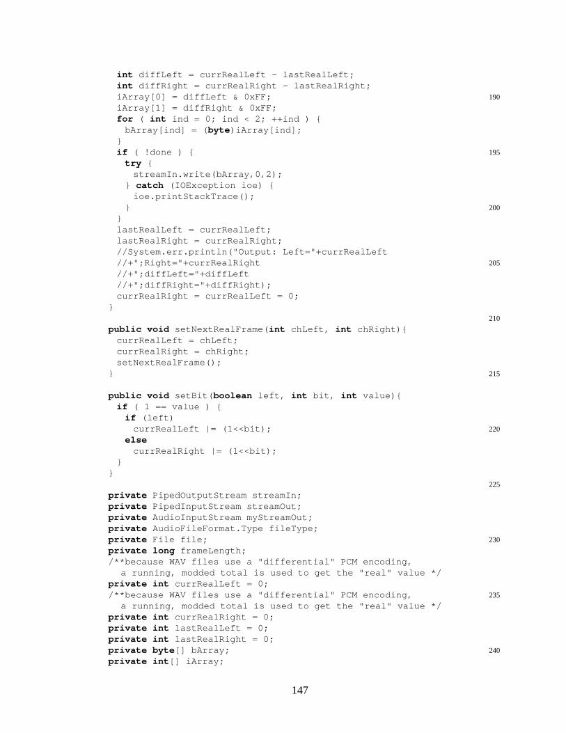
int diffLeft = currRealLeft - lastRealLeft;int diffRight = currRealRight - lastRealRight;
190iArray[0] = diffLeft & 0xFF;iArray[1] = diffRight & 0xFF;for ( int ind = 0; ind < 2; ++ind ) {
bArray[ind] = ( byte )iArray[ind];}
195if ( !done ) {try {
streamIn.write(bArray,0,2);} catch (IOException ioe) {
ioe.printStackTrace();200}
}lastRealLeft = currRealLeft;lastRealRight = currRealRight;//System.err.println("Output: Left="+currRealLeft
205//+";Right="+currRealRight//+";diffLeft="+diffLeft//+";diffRight="+diffRight);currRealRight = currRealLeft = 0;
}210
public void setNextRealFrame( int chLeft, int chRight){currRealLeft = chLeft;currRealRight = chRight;setNextRealFrame();
215}
public void setBit( boolean left, int bit, int value){if ( 1 == value ) {
if (left)220currRealLeft |= (1<<bit);
elsecurrRealRight |= (1<<bit);
}}
225
private PipedOutputStream streamIn;private PipedInputStream streamOut;private AudioInputStream myStreamOut;private AudioFileFormat.Type fileType;
230private File file;private long frameLength;/**because WAV files use a "differential" PCM encoding,
a running, modded total is used to get the "real" value */private int currRealLeft = 0;
235/**because WAV files use a "differential" PCM encoding,a running, modded total is used to get the "real" value */
private int currRealRight = 0;private int lastRealLeft = 0;private int lastRealRight = 0;
240private byte [] bArray;private int [] iArray;
147

private boolean done;
}
C.3 Example Application: Edit Distance
This section contains the code for the example application in Section 5.2. The
code for the application model (Section C.2.1) view (Section C.2.2) and controller (Sec-
tion C.2.1) is included. In each subsection, the classes are listed in alphabetical order.
C.3.1 Edit Distance Application Model
This section includes the following source code files:
• EDAlphabet.java
• EditCellInner.java
• EditCellInput.java
• EditCellOutput.java
• EditDistance.java
• NextDForNotNullIn.java
• NextDForNullIn.java
EDAlphabet.java
package model;
import byucc.jhdl.base.Cell;5import byucc.jhdl.base.Wire;
import byucc.jhdl.Logic.Logic;
/** Class that helps support the edit distance circuits.* @author Anthony L. Slade */
10public class EDAlphabet {/** constant for the Thymine base */public static final int BASE_T = 0x8; // 0b1000/** constant for the Guanine base */public static final int BASE_G = 0x4; // 0b0100
148
15/** constant for the Cytosine base */public static final int BASE_C = 0x2; // 0b0010/** constant for the Adenine base */public static final int BASE_A = 0x1; // 0b0001/** constant for a wildcard base */
20public static final int BASE_WILDCARD = 0x0;
/** @return the character for the given base value */public static char getBaseChar( int base) {
switch (base) {25case BASE_T:
return ’T’;case BASE_G:
return ’G’;case BASE_C:
30return ’C’;case BASE_A:
return ’A’;case BASE_WILDCARD:default :
35return ’W’;}
}
/** @return the integer value representation (BASE_T,40* BASE_G, BASE_C, BASE_A, or BASE_WILDCARD) of the given
* character */public static int getBaseValue( char base) {
switch (base) {case ’t’:
45case ’T’:return BASE_T;
case ’g’:case ’G’:
return BASE_G;50case ’c’:
case ’C’:return BASE_C;
case ’a’:case ’A’:
55return BASE_A;default :
return BASE_WILDCARD;}
}60
/** @return the integer value representation (BASE_T,* BASE_G, BASE_C, BASE_A, or BASE_WILDCARD) of the first* character of the given string */
public static int getBaseValue(String base) {65return getBaseValue(base.charAt(0));
}
/** @return the integer value representation (BASE_T,
149

* BASE_G, BASE_C, BASE_A, or BASE_WILDCARD) of the given70* character of the given string */
public static int getBaseValue(String base, int index) {return getBaseValue(base.charAt(index));
}
75public static Wire charEqualsConstant(Cell parent,Wire input,int base) {
return charEqualsConstant(parent, input,Logic.wire(parent,1,
80"charInEqConstChar"),base);
}
public static Wire charEqualsConstant(Cell parent,85Wire input,
Wire output,int base) {
new byucc.jhdl.Xilinx.Virtex.lut4(parent,"compare"
90+getBaseChar(base),input,output,getBaseCompareString(base));
return output;95}
public static String getBaseCompareString( int base) {switch (base) {case BASE_T:
100return "0100"; // "0b0000000100000000";case BASE_G:
return "0010"; // "0b0000000000010000";case BASE_C:
return "0004"; // "0b0000000000000100";105case BASE_A:
return "0002"; // "0b0000000000000010";case BASE_WILDCARD:default :
return "FFFF"; // "0b1111111111111111";110}
}}
EditCellInner.java
package model;
import byucc.jhdl.base.CellInterface;5import byucc.jhdl.base.Node;
import byucc.jhdl.base.Wire;import byucc.jhdl.Logic.Logic;
150
/** Inner PE of the edit distance circuit. This circuit is10* partially based on Justin Tripp’s VHDL version of the edit
* distance circuit for FPGAs.* @author Anthony. L. Slade */
public class EditCellInner extends Logic {
15public static final String PORT_CHAR_IN = "charIn";public static final String PORT_A_IN = "aIn";public static final String PORT_NULL_IN = "nullIn";public static final String PORT_A_OUT = "aOut";public static final String PORT_CHAR_OUT = "charOut";
20public static final String PORT_NULL_OUT = "nullOut";public static final String PARAM_INIT_A = "initA";public static final String PARAM_INIT_C = "initC";public static final String PARAM_CONST_CHAR = "constChar";
25public static CellInterface[] cell_interface = {in(PORT_CHAR_IN,4),in(PORT_A_IN,2),in(PORT_NULL_IN,1),out(PORT_A_OUT,2),
30out(PORT_CHAR_OUT,4),out(PORT_NULL_OUT,1),param(PARAM_INIT_A,INTEGER),param(PARAM_INIT_C,INTEGER),param(PARAM_CONST_CHAR,INTEGER),
35};
public EditCellInner(Node parent,Wire charIn,Wire aIn,
40Wire nullIn,Wire aOut,Wire charOut,Wire nullOut,int initA,
45int initC,int constChar) {
this (parent,charIn,aIn,nullIn,aOut,charOut,nullOut,initA,initC,constChar,"EditDistancePE");
}50
public EditCellInner(Node parent,Wire charIn,Wire aIn,Wire nullIn,
55Wire aOut,Wire charOut,Wire nullOut,int initA,int initC,
60int constChar,String name) {
151
super (parent,name);bind(PARAM_INIT_A,initA);bind(PARAM_INIT_C,initC);
65bind(PARAM_CONST_CHAR,constChar);System.err.println(name+":"
+EDAlphabet.getBaseChar(constChar));connect(PORT_CHAR_IN,charIn);connect(PORT_A_IN,aIn);
70connect(PORT_NULL_IN,nullIn);connect(PORT_A_OUT,aOut);connect(PORT_CHAR_OUT,charOut);connect(PORT_NULL_OUT,nullOut);
75if ( false ) {System.err.println("New EditCellInner:");System.err.println("\tinitA="+initA);System.err.println("\tinitC="+initC);System.err.println("\tconstChar="+constChar);
80}
reg_o(nor(charIn,"nullChar"),nullOut,"nullCharOut");
reg_o(charIn,charOut,"charReg");85
charInEqConstChar= EDAlphabet.charEqualsConstant( this , charOut,
constChar);Wire a = reg(aIn,"a");
90Wire d = aOut;Wire nextD = wire(2,"nextD");
/*if ( nullIn ) { // 3 bits
95if ( charactersEqual ) {d = initA;
} else {if ( initC==aIn )
d = initA+2;100else
d = initA;}
} else { // 7 bitsif ( charactersEqual ) {
105d = a;} else {
if ( (a+1)==aIn && (a+1)==d )d = a+2;
else110d = a;
}}*/Wire wireForNotNullIn = wire(2,"wireForNotNullIn");
115new NextDForNotNullIn( this ,charInEqConstChar,a,aIn,d,
152
wireForNotNullIn);Wire initWireForNullIn = wire(2,"initWireForNullIn");new NextDForNullIn( this ,charInEqConstChar,aIn,
initWireForNullIn,initA,initC);120mux_o(wireForNotNullIn,
initWireForNullIn,nullIn,nextD,"selectNextD");
125reg_o(nextD,d,"regD");}
public Wire getCharactersEqualWire() {return charInEqConstChar;
130}protected Wire charInEqConstChar;
}
EditCellInput.java
package model;
import byucc.jhdl.base.CellInterface;5import byucc.jhdl.base.Node;
import byucc.jhdl.base.Wire;import byucc.jhdl.Logic.Logic;
/** Front end to the edit distance circuit. This design is10* based on Justin Tripp’s implementation of the edit
* distance algorithm in VHDL.* @author Anthony L. Slade */
public class EditCellInput extends Logic {
15public static final String PORT_CHAR_IN = "charIn";public static final String PORT_NULL_IN = "nullIn";public static final String PORT_A_OUT = "aOut";public static final String PORT_CHAR_OUT = "charOut";public static final String PARAM_CONST_CHAR = "constChar";
20
public static CellInterface[] cell_interface = {in(PORT_CHAR_IN,4),in(PORT_NULL_IN,1),out(PORT_A_OUT,2),
25out(PORT_CHAR_OUT,4),param(PARAM_CONST_CHAR,INTEGER),
};
public EditCellInput(Node parent,30Wire charIn,
Wire nullIn,Wire aOut,Wire charOut,int constChar) {
153
35this (parent,charIn,nullIn,aOut,charOut,constChar,"EditDistanceInput");
}public EditCellInput(Node parent,
Wire charIn,40Wire nullIn,
Wire aOut,Wire charOut,int constChar,String name) {
45super (parent,name);bind(PARAM_CONST_CHAR,constChar);System.err.println(name+":"+
EDAlphabet.getBaseChar(constChar));connect(PORT_CHAR_IN,charIn);
50connect(PORT_NULL_IN,nullIn);connect(PORT_A_OUT,aOut);connect(PORT_CHAR_OUT,charOut);
Wire d = aOut;55prevCountWire = wire(2,"a");
Wire a = prevCountWire;Wire b = wire(2,"b");
reg_o(charIn,charOut,"charPass");60
regr_o(b.gw(1),nullIn,a.gw(1),"regA1");regs_o(b.gw(0),nullIn,a.gw(0),"regA0");Wire bPlusOne = add(b,constant(2,1),"bPlusOne");regs_o(bPlusOne.gw(1),nullIn,b.gw(1),"regB1");
65regr_o(bPlusOne.gw(0),nullIn,b.gw(0),"regB0");//regr_o( Wire d, Wire r,Wire q,String name)//regs_o( Wire d, Wire s,Wire q,String name)//regse_o(Wire d,Wire ce,Wire s,Wire q,String name)//regpe_o(Wire d,Wire ce, Wire q,String name)
70
Wire bEqD = wire(1,"bEqD");new byucc.jhdl.Xilinx.Virtex.lut4( this ,
"bEqD",concat(b,d,"concatBD"),
75bEqD,/* 0b 1000 0100 0010 0001 */ "8421");
Wire nextD = concat(wire(1,"nextD1"),a.gw(0),"nextD");charInEqConstChar
80= EDAlphabet.charEqualsConstant( this , charOut,constChar);
xor_o(a.gw(1),and(bEqD,not(charInEqConstChar,"notCharInEqConstChar"),
"addTwo"),85nextD.gw(1),"nextD1");
new byucc.jhdl.Xilinx.Virtex.fdrs( this ,"regD1",nextD.gw(1),
154
and(charInEqConstChar,90nullIn,"setD1"),
nullIn,d.gw(1));
regr_o(nextD.gw(0),nullIn,d.gw(0),"regD0");//public fdrs(Node parent,Wire d,Wire r,Wire s,Wire q)
95}public Wire getCharactersEqualWire() {
return charInEqConstChar;}public Wire getPreviousCountWire() {
100return prevCountWire;}protected Wire charInEqConstChar;protected Wire prevCountWire;
}
EditCellOutput.java
package model;
import byucc.jhdl.base.CellInterface;5import byucc.jhdl.base.Node;
import byucc.jhdl.base.Wire;import byucc.jhdl.Logic.Logic;import byucc.jhdl.Xilinx.Virtex.lut4;
10/** Back end to the edit distance circuit. This design is* based on Justin Tripp’s implementation of the edit* distance algorithm in VHDL.* @author Anthony L. Slade */
public class EditCellOutput extends Logic {15
public static final String PORT_CHAR_IN = "charIn";public static final String PORT_A_IN = "aIn";public static final String PORT_NULL_OUT = "nullOut";public static final String PORT_DISTANCE = "distance";
20public static final String PARAM_COUNTSIZE = "COUNTSIZE";public static final String PARAM_LENGTH = "length";
public static CellInterface[] cell_interface = {in(PORT_CHAR_IN,4),
25in(PORT_A_IN,2),out(PORT_NULL_OUT,1),out(PORT_DISTANCE,PARAM_COUNTSIZE),param(PARAM_COUNTSIZE,INTEGER),param(PARAM_LENGTH,INTEGER),// length of target string
30};
public EditCellOutput(Node parent,Wire charIn,Wire aIn,
35Wire nullOut,
155

Wire distance,int length) {
this (parent,charIn,aIn,nullOut,distance,length,"EditDistanceOutput");
40}public EditCellOutput(Node parent,
Wire charIn,Wire aIn,Wire nullOut,
45Wire distance,int length,String name) {
super (parent,name);int distWidth = distance.getWidth();
50bind(PARAM_COUNTSIZE,distWidth);bind(PARAM_LENGTH,length);connect(PORT_CHAR_IN,charIn);connect(PORT_A_IN,aIn);connect(PORT_NULL_OUT,nullOut);
55connect(PORT_DISTANCE,distance);
Wire nullChar = wire(1,"nullChar");reg_o(nor_o(charIn,nullChar,"nullChar"),
nullOut,"nullChar");60
Wire nextCount = wire(distWidth,"nextCount");
// Here’s the scheme for nextCount:// ----------------------------------------
65// | aIn | currDistance[1:0] | nextCount |// ----------------------------------------// | 0 | 0 | distance+0 |// | 0 | 1 | distance-1 |// | 0 | 2 | distance-2 |
70// | 0 | 3 | distance+1 |*// ----------------------------------------// | 1 | 0 | distance+1 |// | 1 | 1 | distance+0 |// | 1 | 2 | distance-1 |
75// | 1 | 3 | distance-2 |// ----------------------------------------// | 2 | 0 | distance+2 |// | 2 | 1 | distance+1 |// | 2 | 2 | distance+0 |
80// | 2 | 3 | distance-1 |// ----------------------------------------// | 3 | 0 | distance-1 |*// | 3 | 1 | distance+2 |// | 3 | 2 | distance+1 |
85// | 3 | 3 | distance+0 |// ----------------------------------------
// Set up the adder/subtractor// This adder/subtractor should be optimized to be able
156

90// to add or subtract either 1 or 2. This table shows// how it works:// ---------------------------------// | subtract | cin | one | result |// ---------------------------------
95// | 0 | 0 | 0 | +0 |// | 0 | 0 | 1 | +1 |// | 0 | 1 | 0 | +1 |// | 0 | 1 | 1 | +2 |// | 1 | 0 | 0 | -2 |
100// | 1 | 0 | 1 | -1 |// | 1 | 1 | 0 | -1 |// | 1 | 1 | 1 | -0 |// ---------------------------------Wire subtract = wire(1,"subtract");
105Wire cin = wire(1,"cin");Wire negate = subtract;Wire oneNeg = negate;for ( int negi = 2; negi < distWidth; ++negi ) {
oneNeg = concat(negate,oneNeg);110}
Wire one = wire(1,"one");// negative or positive one (can also be used for// negative 2)Wire oneNegPos = concat(oneNeg,one,"oneNegPos");
115add_o(distance,oneNegPos,cin,nextCount,"addSub");
// derive the control signals for the adder/subtractor// from aIn and the current count state.Wire catAInLowCount = concat(aIn,distance.range(1,0),
120"catAInLowCount");new lut4( this ,
"subtract",catAInLowCount,subtract,
125"9CE7"); // 0b 1001 1100 1110 0111new lut4( this ,
"cin",catAInLowCount,cin,
130"A521"); // 0b 1010 0101 0010 0001new lut4( this ,
"one",catAInLowCount,one,
135"FF7B"); // 0b 1111 1111 0111 1011
Wire resetOrNextCount = wire(distWidth,"muxOutCount");Wire constantInitLength = constant(distWidth,length,
"initLength");140mux_o(nextCount,constantInitLength,nullOut,
resetOrNextCount,"selCount");reg_o(resetOrNextCount,distance,"countReg");
}
157
}
EditDistance.java
package model;
import byucc.jhdl.base.CellInterface;5import byucc.jhdl.base.Node;
import byucc.jhdl.base.Wire;
import byucc.jhdl.Logic.Logic;
10public class EditDistance extends Logic {public static final String PORT_CHAR_IN = "charIn";public static final String PORT_DISTANCE = "distance";public static final String PARAM_TARGET = "target";public static final String PARAM_WIDTH = "WIDTH";
15public static CellInterface[] cell_interface = {in(PORT_CHAR_IN,4),out(PORT_DISTANCE,PARAM_WIDTH),param(PARAM_WIDTH,INTEGER),param(PARAM_TARGET,STRING),
20};public EditDistance( Node parent,
Wire charIn,Wire distance,String targetStr ) {
25super (parent);int width = distance.getWidth();bind(PARAM_TARGET,targetStr);bind(PARAM_WIDTH,width);connect(PORT_CHAR_IN,charIn);
30connect(PORT_DISTANCE,distance);int numCells = targetStr.length();
Wire nullIn = wire(numCells,"nullIn");Wire[] aOut = new Wire[numCells];
35Wire[] charOut = new Wire[numCells];int [] initA = new int [numCells];int [] initC = new int [numCells];int [] constChar = new int [numCells];initConstantArrays(initA,initC,constChar,
40targetStr,numCells);aOut[0] = wire(2,"aOut0");charOut[0] = wire(4,"charOut0");
new EditCellInput( this ,45charIn,
nullIn.gw(0),aOut[0],charOut[0],EDAlphabet.getBaseValue(targetStr,0));
50
158
for ( int inner = 1; inner < numCells; ++inner ) {aOut[inner] = wire(2,"aOut"+inner);charOut[inner] = wire(4,"charOut"+inner);new EditCellInner( this ,
55charOut[inner-1],aOut[inner-1],nullIn.gw(inner),aOut[inner],charOut[inner],
60nullIn.gw(inner-1),initA[inner%numCells],initC[inner%numCells],constChar[inner],"EditCellInner"+(inner-1));
65}new EditCellOutput( this ,
charOut[charOut.length-1],aOut[aOut.length-1],nullIn.gw(nullIn.getWidth()-1),
70distance,numCells);//length
}
private void initConstantArrays( int [] initA, int [] initC,75int [] constChar,
String target,int numCells) {
for ( int ind = 0; ind < numCells; ++ind ) {initA[ind] = ind&0x3;
80initC[ind] = ((ind+1)%4)&0x3;constChar[ind] = EDAlphabet.getBaseValue(target,ind);
}}
}
NextDForNotNullIn.java
package model;
import byucc.jhdl.base.CellInterface;5import byucc.jhdl.base.Node;
import byucc.jhdl.base.Wire;import byucc.jhdl.Logic.Logic;
/** Design to build hierarchy for the EditCellInner design10* @author Anthony L. Slade */
public class NextDForNotNullIn extends Logic {public static CellInterface[] cell_interface = {
in("charInEqConstChar",1),in("a",2),
15in("aIn",2),in("d",2),out("nextDForNotNullInWire",2),
159

};public NextDForNotNullIn(Node parent,
20Wire charInEqConstChar,Wire a,Wire aIn,Wire d,Wire output) {
25super (parent,"NextDForNotNullIn");/*if (!nullIn) {
if ( charactersEqual ) {d = a;
30} else {if ( (a+1)==aIn && (a+1)==d )
d = a+2;else
d = a;35}
}*/connect("charInEqConstChar",charInEqConstChar);connect("a",a);
40connect("aIn",aIn);connect("d",d);connect("nextDForNotNullInWire",output);
// a.gw(0) will just pass through no matter what45buf_o(a.gw(0),output.gw(0));
xor_o(a.gw(1),and(not(charInEqConstChar,"charsNotEqual"),
twoBitsPlusEqual(a,aIn,"aPlusEqAIn"),twoBitsPlusEqual(a,d,"aPlusEqD"),
50"decideAdd"),output.gw(1));
}
/** @return output of a lut that compares the two given55* wires. If the wires are equal (after adding 1 to the
* first wire), the output is asserted (high). */private Wire twoBitsPlusEqual(Wire wireA,
Wire wireB,String name) {
60Wire output = wire(1,name);String lutInit = "1842"; // 0b 0001 1000 0100 0010new byucc.jhdl.Xilinx.Virtex.lut4( this ,
name,concat(wireA,wireB,
65"concat"+name),output,lutInit);
return output;}
70}
160
NextDForNullIn.java
package model;
import byucc.jhdl.base.CellInterface;5import byucc.jhdl.base.Node;
import byucc.jhdl.base.Wire;import byucc.jhdl.Logic.Logic;
/** Design to build hierarchy for the EditCellInner design10* @author Anthony L. Slade */
public class NextDForNullIn extends Logic {public static CellInterface[] cell_interface = {
in("charInEqConstChar",1),in("aIn",2),
15out("nextDForNullInWire",2),};public NextDForNullIn(Node parent,
Wire charInEqConstChar,Wire aIn,
20Wire output,int initA,int initC) {
super (parent,"NextDForNullIn");/*
25if ( nullIn ) {if ( charactersEqual ) {
d = initA;} else {
if ( initC==aIn )30d = initA+2;
elsed = initA;
}}
35*/connect("charInEqConstChar",charInEqConstChar);connect("aIn",aIn);connect("nextDForNullInWire",output);
40int init0=0, init1=0;int initA0 = initA & 0x1;int initA1 = (initA >> 1) & 0x1;for ( int initInd = 0; initInd < 8; ++initInd ) {
init0 |= (initA0 << initInd);45init1 |= (initA1 << initInd);
}// The output will always just be initA unless// aIn==initC; in that case, the output will be initA+2,// so we just add 1 to bit[1] of the output for that
50// initC value; that will just be this xor:init1 ˆ= (1 << (initC&0x3));
161
String initStr0 = Integer.toHexString(init0);String initStr1 = Integer.toHexString(init1);
55
Wire lutInput = concat(charInEqConstChar,aIn,"chEqAInA");
new byucc.jhdl.Xilinx.Virtex.lut3( this ,"initWireForNullIn0",
60lutInput,output.gw(0),initStr0);
new byucc.jhdl.Xilinx.Virtex.lut3( this ,"initWireForNullIn1",
65lutInput,output.gw(1),initStr1);
}}
C.3.2 Edit Distance Application View
This section includes the following source code files:
• ComponentArrow.java
• ComponentInnerPE.java
• ComponentInputPE.java
• ComponentOutput.java
• ComponentPE.java
• EDFrame.java
• EDPanel.java
ComponentArrow.java
package view;
import java.awt.Color;5import java.awt.Dimension;
import java.awt.Graphics;import javax.swing.JComponent;
public class ComponentArrow extends JComponent {10public static final Color DEFAULT_COLOR = Color.red;
162
public static final int PREFERRED_HEIGHT = 20;public static final int PREFERRED_WIDTH = 40;public ComponentArrow() {
this (DEFAULT_COLOR);15}
public ComponentArrow(Color color) {arrowColor = color;setPreferredSize( new Dimension(PREFERRED_WIDTH,
PREFERRED_HEIGHT));20}
public void paint(Graphics gr) {int height = getHeight();int midHeight = height/2;
25int iWidth = getWidth();double dWidth = ( double )iWidth;double dSeventy = .7*dWidth;int iSeventy = ( int )dSeventy;gr.setColor(arrowColor);
30int [] xpoints = new int [9];int [] ypoints = new int [9];xpoints[0] = 0; ypoints[0] = midHeight-2;xpoints[1] = iSeventy; ypoints[1] = midHeight-2;xpoints[2] = iSeventy-4; ypoints[2] = 0;
35xpoints[3] = iSeventy; ypoints[3] = 0;xpoints[4] = iWidth; ypoints[4] = midHeight;xpoints[5] = iSeventy; ypoints[5] = height;xpoints[6] = iSeventy-4; ypoints[6] = height;xpoints[7] = iSeventy; ypoints[7] = midHeight+2;
40xpoints[8] = 0; ypoints[8] = midHeight+2;gr.fillPolygon(xpoints,ypoints,9);
}private Color arrowColor;
}
ComponentInnerPE.java
package view;
import javax.swing.JPanel;5
import byucc.jhdl.base.Browser;import byucc.jhdl.base.Cell;import byucc.jhdl.base.SimulatorCallback;import byucc.jhdl.base.Wire;
10
import model.EditCellInner;
/** Graphical representation of the state of an EditCellInner* @author Anthony L. Slade */
15public class ComponentInnerPE extends ComponentPE {
public ComponentInnerPE(EditCellInner cell) {
163
Wire compCharWire;Wire compEqualWire;
20Wire prevCountWire;Wire countWire;
compCharWire = cell.getAttachedWire(cell.PORT_CHAR_OUT);compEqualWire = cell.getCharactersEqualWire();
25prevCountWire = cell.getAttachedWire(cell.PORT_A_IN);countWire = cell.getAttachedWire(cell.PORT_A_OUT);
buildPanel(cell,Integer.parseInt(cell.getArgument(
30cell.PARAM_CONST_CHAR).toString()),compCharWire, compEqualWire,prevCountWire, countWire);
}}
ComponentInputPE.java
package view;
import javax.swing.JPanel;5
import byucc.jhdl.base.Browser;import byucc.jhdl.base.Cell;import byucc.jhdl.base.SimulatorCallback;import byucc.jhdl.base.Wire;
10
import model.EditCellInput;
/** Graphical representation of the state of an EditCellInner* @author Anthony L. Slade */
15public class ComponentInputPE extends ComponentPE {
public ComponentInputPE(EditCellInput cell) {Wire compCharWire;Wire compEqualWire;
20Wire prevCountWire;Wire countWire;
compCharWire = cell.getAttachedWire(cell.PORT_CHAR_OUT);compEqualWire = cell.getCharactersEqualWire();
25prevCountWire = cell.getPreviousCountWire();countWire = cell.getAttachedWire(cell.PORT_A_OUT);
buildPanel(cell,Integer.parseInt(
30cell.getArgument(cell.PARAM_CONST_CHAR).toString()),
compCharWire, compEqualWire,prevCountWire, countWire);
}
164
35}
ComponentOutput.java
package view;
import java.awt.Container;5import java.awt.GridLayout;
import javax.swing.JLabel;import javax.swing.JPanel;import javax.swing.JTextField;
10import byucc.jhdl.base.Browser;import byucc.jhdl.base.SimulatorCallback;import byucc.jhdl.base.Wire;import byucc.jhdl.base.WireValueException;
15import model.EditCellOutput;
/** Graphical representation of the state of an EditCellPE* @author Anthony L. Slade */
public class ComponentOutput extends JPanel20implements Browser, SimulatorCallback {
public static final String LABEL_PREFIX_GRAY= "<html><font color=\"gray\"><font size=\"+1\">";
public static final String LABEL_PREFIX_BLUE25= "<html><font color=\"blue\"><font size=\"+1\">";
public static final String LABEL_SUFFIX= "</font></font></html>";
public ComponentOutput(EditCellOutput cell) {30setLayout( new GridLayout(4,2));// 4 rows, 2 columns
// row 0add( new Container());JLabel editTextLabel
= new JLabel("<html><font color=\"blue\"><font size="35+"\"+0\">Edit</font></font></html>");
editTextLabel.setVerticalAlignment(JLabel.BOTTOM);add(editTextLabel);// row 1add( new Container());
40JLabel distanceTextLabel= new JLabel("<html><font color=\"blue\"><font size=\""
+"+0\">Distance:</font></font></html>");distanceTextLabel.setVerticalAlignment(JLabel.TOP);add(distanceTextLabel);
45// row 2add( new Container());distanceLabel = new JLabel(LABEL_PREFIX_GRAY+"0"
+LABEL_SUFFIX,JLabel.CENTER);add(distanceLabel);
50// row 3
165
prevCountTextField = new JTextField("0",1);add(prevCountTextField);prevCountTextField.setEditable( false );prevCountTextField.setHorizontalAlignment(JTextField.CENTER);
55add( new Container());
cell.getSystem().addSimulatorCallback( this );distanceWire = cell.getAttachedWire(cell.PORT_DISTANCE);prevCountWire = cell.getAttachedWire(cell.PORT_A_IN);
60nullOutWire = cell.getAttachedWire(cell.PORT_NULL_OUT);lastNullOut = 1;
}
public void simulatorUpdate( int cycle, int step) {65return ; // do nothing!
}public void simulatorRefresh( int cycle, int step) {
int distanceInt = 0;int prevCountInt = 0;
70int nullOutInt = 0;String labelPrefix = LABEL_PREFIX_GRAY;try {
distanceInt = distanceWire.get( this );prevCountInt = prevCountWire.get( this );
75nullOutInt = nullOutWire.get( this );if ( lastNullOut == 0
&& nullOutInt == 1 )labelPrefix = LABEL_PREFIX_BLUE;
lastNullOut = nullOutInt;80} catch (WireValueException wve) {}
distanceLabel.setText(labelPrefix+distanceInt+LABEL_SUFFIX);
prevCountTextField.setText(""+prevCountInt);}
85public void simulatorReset() {simulatorRefresh(0,0);
}
private Wire distanceWire;90private Wire prevCountWire;
private Wire nullOutWire;
private int lastNullOut;
95private JLabel distanceLabel;private JTextField prevCountTextField;
}
ComponentPE.java
package view;
import java.awt.Container;
166
5import java.awt.GridLayout;import javax.swing.Box;import javax.swing.JLabel;import javax.swing.JPanel;import javax.swing.JTextField;
10
import byucc.jhdl.base.Browser;import byucc.jhdl.base.Cell;import byucc.jhdl.base.SimulatorCallback;import byucc.jhdl.base.Wire;
15import byucc.jhdl.base.WireValueException;
import model.EDAlphabet;
/** Graphical representation of the state of an EditCellPE20* @author Anthony L. Slade */
public abstract class ComponentPE extends JPanelimplements Browser, SimulatorCallback {
public static final String LABEL_EQUAL25= "<html><center><font color=\"green\"><font size=\"+1\""
+">=</font></font></center></html>";public static final String LABEL_NOT_EQUAL
= "<html><center><font color=\"red\"><font size=\"+1\">"+"!=</font></font></center><html>";
30
protected void buildPanel(Cell peCell, int thisChar,Wire compCharWire,Wire compEqualWire,Wire prevCountWire,
35Wire countWire) {peCell.getSystem().addSimulatorCallback( this );this .compCharWire = compCharWire;this .compEqualWire = compEqualWire;this .prevCountWire = prevCountWire;
40this .countWire = countWire;buildPanel(thisChar);
}
public void simulatorUpdate( int cycle, int step) {45return ; // do nothing!
}public void simulatorRefresh( int cycle, int step) {
int compCharInt=0;int compEqualInt=0;
50int prevCountInt=0;int countInt=0;try {
compCharInt = compCharWire.get( this );compEqualInt = compEqualWire.get( this );
55prevCountInt = prevCountWire.get( this );countInt = countWire.get( this );
} catch (WireValueException wve) {}compCharTextField.setText(""
167

+EDAlphabet.getBaseChar(compCharInt));60equalityLabel.setText(compEqualInt==1?
LABEL_EQUAL:LABEL_NOT_EQUAL);prevCountTextField.setText(""+prevCountInt);
}public void simulatorReset() {
65simulatorRefresh(0,0);}
private void buildPanel( int thisChar) {setLayout( new GridLayout(4,2));// 4 rows, 2 columns
70// row 0JLabel charLabel
= new JLabel(""+EDAlphabet.getBaseChar(thisChar),JLabel.CENTER);
add( new Container());75add(charLabel);
// row 1add( new Container());equalityLabel
= new JLabel(LABEL_NOT_EQUAL,JLabel.CENTER);80add(equalityLabel);
// row 2add( new ComponentArrow());compCharTextField = new JTextField("_",1);compCharTextField.setEditable( false );
85compCharTextField.setHorizontalAlignment(JTextField.CENTER);add(compCharTextField);// row 3prevCountTextField = new JTextField("0",1);add(prevCountTextField);
90add( new ComponentArrow());prevCountTextField.setEditable( false );prevCountTextField.setHorizontalAlignment(JTextField.CENTER);
}
95private Wire compCharWire;private Wire compEqualWire;private Wire prevCountWire;private Wire countWire;
100private JLabel equalityLabel;private JTextField compCharTextField;private JTextField prevCountTextField;
}
EDFrame.java
package view;
import java.awt.BorderLayout;5import java.awt.Container;
import java.awt.event.ActionEvent;
168

import java.awt.event.KeyEvent;import javax.swing.Box;import javax.swing.JMenu;
10import javax.swing.JMenuBar;import javax.swing.JOptionPane;import javax.swing.JPanel;import javax.swing.KeyStroke;
15import byucc.jhdl.apps.Broker.Broker;import byucc.jhdl.apps.Broker.GUIListener;import byucc.jhdl.apps.Viewers.ViewerFrame;import byucc.jhdl.apps.Viewers.SimControl.SimControlPanel;import byucc.jhdl.apps.util.MenuFactory;
20import byucc.jhdl.base.HWSystem;import byucc.jhdl.util.cli.CLInterpreter;
/** Frame that contains an EDPanel, a SimControlPanel and a* basic menu to give a custom visualization of the edit
25* distance circuit.* @author Anthony L. Slade*/
public class EDFrame extends ViewerFrame {
public static final String ACTION_ABOUT_JHDL30= "About JHDL";
public EDFrame(HWSystem system, CLInterpreter interp) {this .interp = interp;contentPane = new JPanel( new BorderLayout());
35// edpanel = new EDPanel(design,sourceString,interp);edpanel = new EDPanel(system,interp);contentPane.add(edpanel,BorderLayout.NORTH);SimControlPanel scPanel =
new SimControlPanel( true ,interp);40scPanel.addSimControlActionListener(
new GUIListener(interp));contentPane.add(scPanel,BorderLayout.SOUTH);
buildAndShowFrame();45}
protected Container buildContentPanel() {return contentPane;
}50
protected JMenuBar buildMenuBar() {JMenuBar menuBar = new JMenuBar();
// Build the menus55fileMenu = buildFileMenu();
jhdlMenu = buildJHDLMenu();menuBar.add(fileMenu);menuBar.add(Box.createHorizontalGlue());menuBar.add(jhdlMenu);
60
169

return menuBar;}
public JMenu buildFileMenu() {65JMenu menu = new JMenu("File");
menu.setMnemonic(KeyEvent.VK_F);
menu.add(MenuFactory.newMenuItem(ACTION_CLOSE,KeyEvent.VK_C,
70KeyStroke.getKeyStroke(KeyEvent.VK_W,KeyEvent.CTRL_MASK),
this ) );menu.addSeparator();menu.add(MenuFactory.newMenuItem(ACTION_EXIT,
75KeyEvent.VK_X,KeyStroke.getKeyStroke(KeyEvent.VK_X,KeyEvent.CTRL_MASK), this ) );
return menu;}
80
public JMenu buildJHDLMenu() {JMenu menu = new JMenu("JHDL");menu.setMnemonic(KeyEvent.VK_J);
85menu.add(MenuFactory.newMenuItem(ACTION_ABOUT_JHDL,KeyEvent.VK_A,KeyStroke.getKeyStroke(KeyEvent.VK_A,
KeyEvent.CTRL_MASK),this ) );
90return menu;}
public void actionPerformed(ActionEvent e) {String s = e.getActionCommand();
95if (s.equals(ACTION_EXIT)) {if (!showConfirmDialogOnExit ||
JOptionPane.showConfirmDialog(this ,"Do you really want to quit?",
100"Exit Confirmation",JOptionPane.YES_NO_OPTION)
== JOptionPane.YES_OPTION)System.exit(0);
}105else if (s.equals(ACTION_CLOSE)) {
if (!showConfirmDialogOnClose ||JOptionPane.showConfirmDialog(
this ,"Do you really want to close this window?",
110"Close Confirmation",JOptionPane.YES_NO_OPTION)
== JOptionPane.YES_OPTION)dispose();
}
170
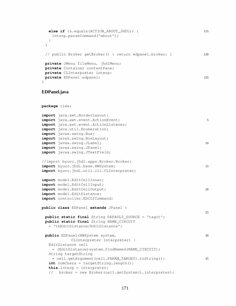
115else if (s.equals(ACTION_ABOUT_JHDL)) {interp.parseCommand("about");
}}
120// public Broker getBroker() { return edpanel.broker; }
private JMenu fileMenu, jhdlMenu;private Container contentPane;private CLInterpreter interp;
125private EDPanel edpanel;}
EDPanel.java
package view;
import java.awt.BorderLayout;5import java.awt.event.ActionEvent;
import java.awt.event.ActionListener;import java.util.Enumeration;import javax.swing.Box;import javax.swing.BoxLayout;
10import javax.swing.JLabel;import javax.swing.JPanel;import javax.swing.JTextField;
//import byucc.jhdl.apps.Broker.Broker;15import byucc.jhdl.base.HWSystem;
import byucc.jhdl.util.cli.CLInterpreter;
import model.EditCellInner;import model.EditCellInput;
20import model.EditCellOutput;import model.EditDistance;import controller.EDCLICommand;
public class EDPanel extends JPanel {25
public static final String DEFAULT_SOURCE = "tagct";public static final String NAME_CIRCUIT
= "tbEditDistance/EditDistance";
30public EDPanel(HWSystem system,CLInterpreter interpreter) {
EditDistance cell= (EditDistance)system.findNamed(NAME_CIRCUIT);
String targetString35= cell.getArgument(cell.PARAM_TARGET).toString();
int numChars = targetString.length();this .interp = interpreter;// broker = new Broker(cell.getSystem(),interpreter);
171
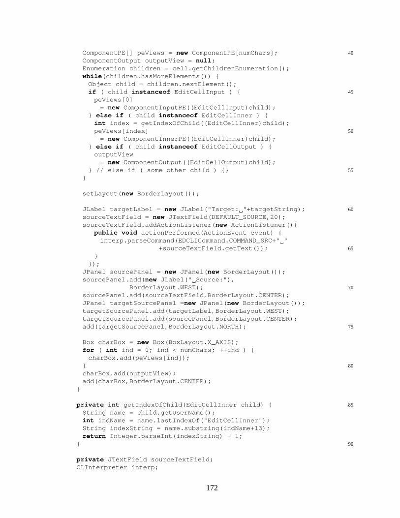
40ComponentPE[] peViews = new ComponentPE[numChars];ComponentOutput outputView = null ;Enumeration children = cell.getChildrenEnumeration();while (children.hasMoreElements()) {
Object child = children.nextElement();45if ( child instanceof EditCellInput ) {
peViews[0]= new ComponentInputPE((EditCellInput)child);
} else if ( child instanceof EditCellInner ) {int index = getIndexOfChild((EditCellInner)child);
50peViews[index]= new ComponentInnerPE((EditCellInner)child);
} else if ( child instanceof EditCellOutput ) {outputView
= new ComponentOutput((EditCellOutput)child);55} // else if ( some other child ) {}
}
setLayout( new BorderLayout());
60JLabel targetLabel = new JLabel("Target: "+targetString);sourceTextField = new JTextField(DEFAULT_SOURCE,20);sourceTextField.addActionListener( new ActionListener(){
public void actionPerformed(ActionEvent event) {interp.parseCommand(EDCLICommand.COMMAND_SRC+" "
65+sourceTextField.getText());}
});JPanel sourcePanel = new JPanel( new BorderLayout());sourcePanel.add( new JLabel(" Source:"),
70BorderLayout.WEST);sourcePanel.add(sourceTextField,BorderLayout.CENTER);JPanel targetSourcePanel = new JPanel( new BorderLayout());targetSourcePanel.add(targetLabel,BorderLayout.WEST);targetSourcePanel.add(sourcePanel,BorderLayout.CENTER);
75add(targetSourcePanel,BorderLayout.NORTH);
Box charBox = new Box(BoxLayout.X_AXIS);for ( int ind = 0; ind < numChars; ++ind ) {
charBox.add(peViews[ind]);80}
charBox.add(outputView);add(charBox,BorderLayout.CENTER);
}
85private int getIndexOfChild(EditCellInner child) {String name = child.getUserName();int indName = name.lastIndexOf("EditCellInner");String indexString = name.substring(indName+13);return Integer.parseInt(indexString) + 1;
90}
private JTextField sourceTextField;CLInterpreter interp;
172
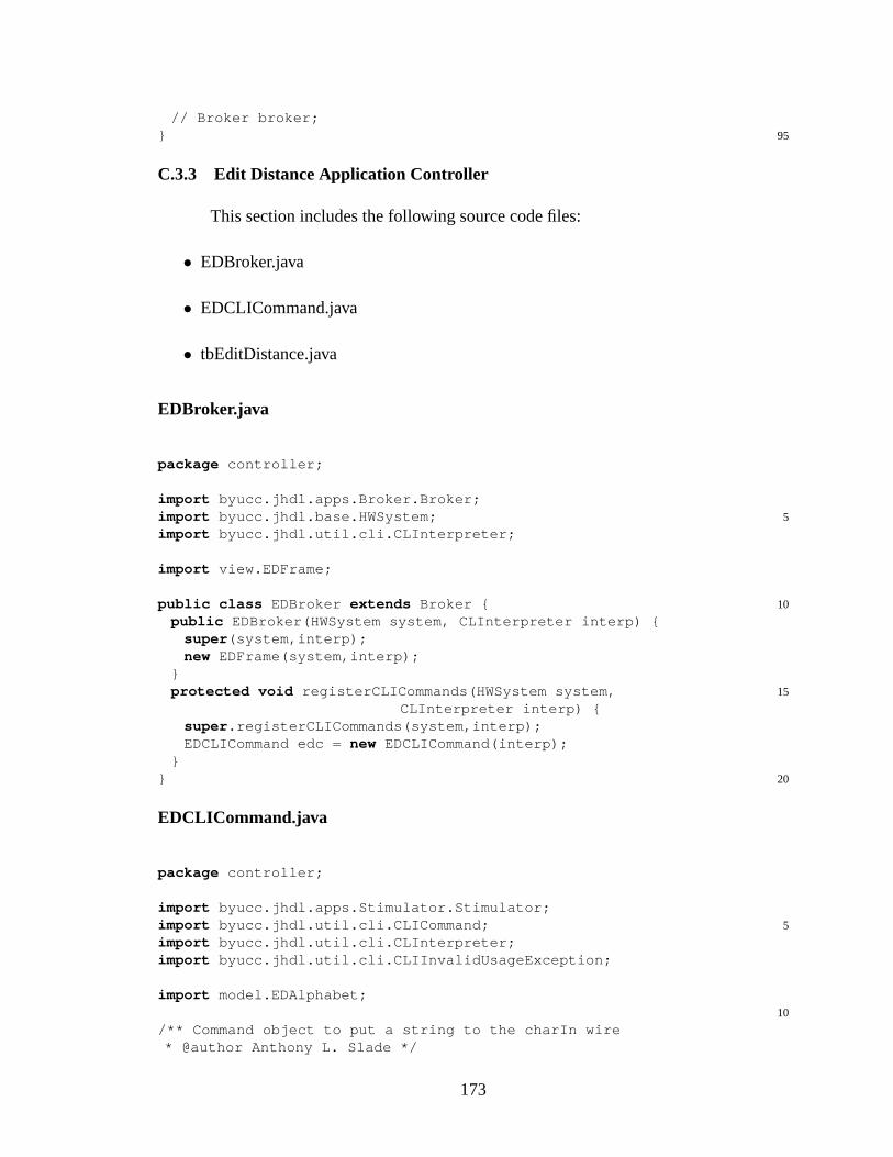
// Broker broker;95}
C.3.3 Edit Distance Application Controller
This section includes the following source code files:
• EDBroker.java
• EDCLICommand.java
• tbEditDistance.java
EDBroker.java
package controller;
import byucc.jhdl.apps.Broker.Broker;5import byucc.jhdl.base.HWSystem;
import byucc.jhdl.util.cli.CLInterpreter;
import view.EDFrame;
10public class EDBroker extends Broker {public EDBroker(HWSystem system, CLInterpreter interp) {
super (system,interp);new EDFrame(system,interp);
}15protected void registerCLICommands(HWSystem system,
CLInterpreter interp) {super .registerCLICommands(system,interp);EDCLICommand edc = new EDCLICommand(interp);
}20}
EDCLICommand.java
package controller;
import byucc.jhdl.apps.Stimulator.Stimulator;5import byucc.jhdl.util.cli.CLICommand;
import byucc.jhdl.util.cli.CLInterpreter;import byucc.jhdl.util.cli.CLIInvalidUsageException;
import model.EDAlphabet;10
/** Command object to put a string to the charIn wire* @author Anthony L. Slade */
173
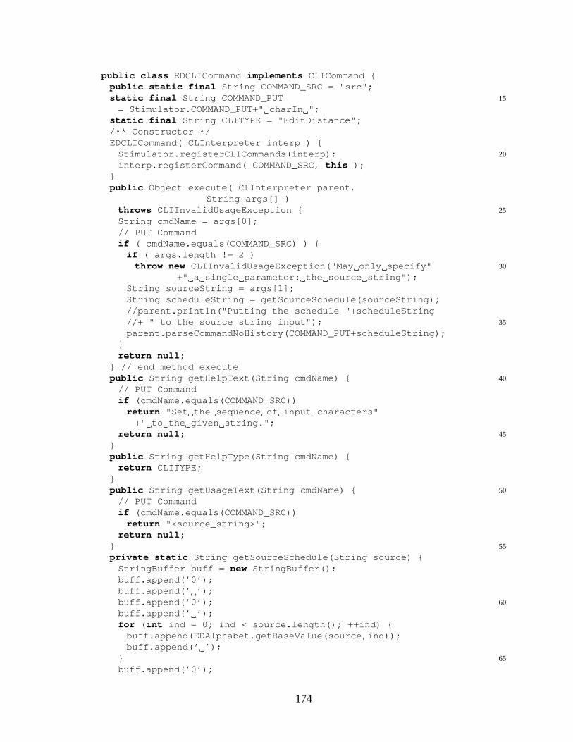
public class EDCLICommand implements CLICommand {public static final String COMMAND_SRC = "src";
15static final String COMMAND_PUT= Stimulator.COMMAND_PUT+" charIn ";
static final String CLITYPE = "EditDistance";/** Constructor */EDCLICommand( CLInterpreter interp ) {
20Stimulator.registerCLICommands(interp);interp.registerCommand( COMMAND_SRC, this );
}public Object execute( CLInterpreter parent,
String args[] )25throws CLIInvalidUsageException {
String cmdName = args[0];// PUT Commandif ( cmdName.equals(COMMAND_SRC) ) {
if ( args.length != 2 )30throw new CLIInvalidUsageException("May only specify"
+" a single parameter: the source string");String sourceString = args[1];String scheduleString = getSourceSchedule(sourceString);//parent.println("Putting the schedule "+scheduleString
35//+ " to the source string input");parent.parseCommandNoHistory(COMMAND_PUT+scheduleString);
}return null ;
} // end method execute40public String getHelpText(String cmdName) {
// PUT Commandif (cmdName.equals(COMMAND_SRC))
return "Set the sequence of input characters"+" to the given string.";
45return null ;}public String getHelpType(String cmdName) {
return CLITYPE;}
50public String getUsageText(String cmdName) {// PUT Commandif (cmdName.equals(COMMAND_SRC))
return "<source_string>";return null ;
55}private static String getSourceSchedule(String source) {
StringBuffer buff = new StringBuffer();buff.append(’0’);buff.append(’ ’);
60buff.append(’0’);buff.append(’ ’);for ( int ind = 0; ind < source.length(); ++ind) {
buff.append(EDAlphabet.getBaseValue(source,ind));buff.append(’ ’);
65}buff.append(’0’);
174
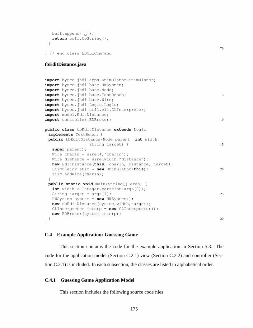
buff.append(’ ’);return buff.toString();
}70
} // end class EDCLICommand
tbEditDistance.java
import byucc.jhdl.apps.Stimulator.Stimulator;import byucc.jhdl.base.HWSystem;import byucc.jhdl.base.Node;
5import byucc.jhdl.base.TestBench;import byucc.jhdl.base.Wire;import byucc.jhdl.Logic.Logic;import byucc.jhdl.util.cli.CLInterpreter;import model.EditDistance;
10import controller.EDBroker;
public class tbEditDistance extends Logicimplements TestBench {public tbEditDistance(Node parent, int width,
15String target) {super (parent);Wire charIn = wire(4,"charIn");Wire distance = wire(width,"distance");new EditDistance( this , charIn, distance, target);
20Stimulator stim = new Stimulator( this );stim.addWire(charIn);
}public static void main(String[] args) {
int width = Integer.parseInt(args[0]);25String target = args[1];
HWSystem system = new HWSystem();new tbEditDistance(system,width,target);CLInterpreter interp = new CLInterpreter();new EDBroker(system,interp);
30}}
C.4 Example Application: Guessing Game
This section contains the code for the example application in Section 5.3. The
code for the application model (Section C.2.1) view (Section C.2.2) and controller (Sec-
tion C.2.1) is included. In each subsection, the classes are listed in alphabetical order.
C.4.1 Guessing Game Application Model
This section includes the following source code files:
175

• AttemptBlock.java
• AttemptBlockRight.java
• AttemptBlockRightColors.java
• AttemptBlockRightPlaces.java
• Multiplex.java
• PG.java
• PGCommon.java
• RandomPuzzle.java
• RandomPuzzleElement.java
• Redirect.java
• RedirectSelect.java
• SingleAssertState.java
• SolutionBlock.java
• Sum4Bits.java
• tbPG.java
AttemptBlock.java
package model;
import byucc.jhdl.apps.Viewers.Schematic.UserDefinedSchematic;5import byucc.jhdl.apps.Viewers.Schematic.UserDefinedNode;
import byucc.jhdl.base.Browser;import byucc.jhdl.base.CellInterface;import byucc.jhdl.base.Node;import byucc.jhdl.base.Wire;
10import byucc.jhdl.Logic.Logic;
public class AttemptBlock extends Logic
176

implements PGCommon/*, UserDefinedSchematic*/, Browser {public static CellInterface[] cell_interface =
15{in ("valueIn0",3),in ("valueIn1",3),in ("valueIn2",3),in ("valueIn3",3),
20in ("setValue",1),in ("guessIn0",3),in ("guessIn1",3),in ("guessIn2",3),in ("guessIn3",3),
25in ("setGuess",1),
out("valueOut0",3),out("valueOut1",3),out("valueOut2",3),
30out("valueOut3",3),
out("guessOut0",3),out("guessOut1",3),out("guessOut2",3),
35out("guessOut3",3),
out("numRightColors",3),out("numRightColorsRightPlaces",3),out("winIndicator",1),
40};public AttemptBlock( Node parent,
Wire valueIn0,Wire valueIn1,Wire valueIn2,
45Wire valueIn3,Wire setValue,Wire guessIn0,Wire guessIn1,Wire guessIn2,
50Wire guessIn3,Wire setGuess,
Wire valueOut0,Wire valueOut1,
55Wire valueOut2,Wire valueOut3,
Wire guessOut0,Wire guessOut1,
60Wire guessOut2,Wire guessOut3,
Wire numRightColors,Wire numRightColorsRightPlaces,
65Wire winIndicator) {
177
super (parent);connect("valueIn0",valueIn0);connect("valueIn1",valueIn1);
70connect("valueIn2",valueIn2);connect("valueIn3",valueIn3);connect("setValue",setValue);connect("guessIn0",guessIn0);connect("guessIn1",guessIn1);
75connect("guessIn2",guessIn2);connect("guessIn3",guessIn3);connect("setGuess",setGuess);
connect("valueOut0",valueOut0);80connect("valueOut1",valueOut1);
connect("valueOut2",valueOut2);connect("valueOut3",valueOut3);
connect("guessOut0",guessOut0);85connect("guessOut1",guessOut1);
connect("guessOut2",guessOut2);connect("guessOut3",guessOut3);
connect("numRightColors",numRightColors);90connect("numRightColorsRightPlaces",
numRightColorsRightPlaces);connect("winIndicator",winIndicator);
Wire setValueInternalCtl = wire(1,"setValueInternalCtl");95Wire setGuessInternalCtl = wire(1,"setGuessInternalCtl");
Wire setValueInternal = or(setValue,setValueInternalCtl,"setValueInternal");
Wire setGuessInternal = or(setGuess,setGuessInternalCtl,"setGuessInternal");
100new SingleAssertState( this ,setValue,setValueInternalCtl,"setValueStateMachine");
new SingleAssertState( this ,setGuess,setGuessInternalCtl,"setGuessStateMachine");
105regce_o(valueIn0,setValueInternal,valueOut0,"valueReg0");regce_o(valueIn1,setValueInternal,valueOut1,"valueReg1");regce_o(valueIn2,setValueInternal,valueOut2,"valueReg2");regce_o(valueIn3,setValueInternal,valueOut3,"valueReg3");
110Wire guessReg0 = regce_o(guessIn0,setGuessInternal,guessOut0,"guessReg0");
Wire guessReg1 = regce_o(guessIn1,setGuessInternal,guessOut1,"guessReg1");
Wire guessReg2 = regce_o(guessIn2,setGuessInternal,115guessOut2,"guessReg2");
Wire guessReg3 = regce_o(guessIn3,setGuessInternal,guessOut3,"guessReg3");
// If a new value is set, then there is not a new guess120// set too:
178
Wire guessIsSet = regr(setGuessInternal,setGuess,setValueInternal,"guessIsSet");
Wire numRightColorsInternal125= wire( 3, "numRightColorsInternal" );
Wire numRightColorsRightPlacesInternal= wire( 3, "numRightColorsRightPlacesInternal" );
Wire winIndicatorInternal= wire( 1, "winIndicatorInternal" );
130new AttemptBlockRight( this , valueOut0, valueOut1,valueOut2, valueOut3,guessReg0, guessReg1,guessReg2, guessReg3,numRightColorsInternal,
135numRightColorsRightPlacesInternal,winIndicatorInternal);
and_o(winIndicatorInternal,guessIsSet,winIndicator);
140// Generate Number of Colors in the Right PlaceWire zero = constant(3,0,"zero3bit");mux_o(zero,numRightColorsRightPlacesInternal,guessIsSet,
numRightColorsRightPlaces);
145// Generate Number of Colors Correctmux_o(zero,numRightColorsInternal,
guessIsSet,numRightColors);}
150
public void initUserDefinedNode(UserDefinedNode udn) {udn.setPortSeperation(0);udn.setSize(100,70);//udn.addInPort(0,20,"c"); //add an implicit clock port.
155//udn.addOutPort(40,30,"value");}
public void paint(UserDefinedNode udn) {/*
160int color = 0;try {
color = value.get((Browser)this);} catch ( byucc.jhdl.base.WireValueException wve ) {}udn.drawRect(0,0,40,40);
165udn.setColor(COLOR_SET[color]);//udn.fillRect(1,1,28,38);udn.drawString("COLOR",1,10);//Add creative stuff--*/
170}}
AttemptBlockRight.java
179

package model;
import byucc.jhdl.apps.Viewers.Schematic.UserDefinedSchematic;5import byucc.jhdl.apps.Viewers.Schematic.UserDefinedNode;
import byucc.jhdl.base.Browser;import byucc.jhdl.base.CellInterface;import byucc.jhdl.base.Node;import byucc.jhdl.base.Wire;
10import byucc.jhdl.Logic.Logic;
public class AttemptBlockRight extends Logicimplements PGCommon/*, UserDefinedSchematic*/, Browser {public static CellInterface[] cell_interface =
15{in ("value0",3),in ("value1",3),in ("value2",3),in ("value3",3),
20in ("guess0",3),in ("guess1",3),in ("guess2",3),in ("guess3",3),
25out("numRightColors",3),out("numRightColorsRightPlaces",3),out("winIndicator",1),
};public AttemptBlockRight( Node parent,
30Wire value0,Wire value1,Wire value2,Wire value3,Wire guess0,
35Wire guess1,Wire guess2,Wire guess3,
Wire numRightColors,40Wire numRightColorsRightPlaces,
Wire winIndicator) {
super (parent);connect("value0",value0);
45connect("value1",value1);connect("value2",value2);connect("value3",value3);connect("guess0",guess0);connect("guess1",guess1);
50connect("guess2",guess2);connect("guess3",guess3);
connect("numRightColors",numRightColors);connect("numRightColorsRightPlaces",
180
55numRightColorsRightPlaces);connect("winIndicator",winIndicator);
Wire g0v0Match = nor(xor(value0,guess0),"g0v0Match");Wire g0v1Match = nor(xor(value1,guess0),"g0v1Match");
60Wire g0v2Match = nor(xor(value2,guess0),"g0v2Match");Wire g0v3Match = nor(xor(value3,guess0),"g0v3Match");
Wire g1v0Match = nor(xor(value0,guess1),"g1v0Match");Wire g1v1Match = nor(xor(value1,guess1),"g1v1Match");
65Wire g1v2Match = nor(xor(value2,guess1),"g1v2Match");Wire g1v3Match = nor(xor(value3,guess1),"g1v3Match");
Wire g2v0Match = nor(xor(value0,guess2),"g2v0Match");Wire g2v1Match = nor(xor(value1,guess2),"g2v1Match");
70Wire g2v2Match = nor(xor(value2,guess2),"g2v2Match");Wire g2v3Match = nor(xor(value3,guess2),"g2v3Match");
Wire g3v0Match = nor(xor(value0,guess3),"g3v0Match");Wire g3v1Match = nor(xor(value1,guess3),"g3v1Match");
75Wire g3v2Match = nor(xor(value2,guess3),"g3v2Match");Wire g3v3Match = nor(xor(value3,guess3),"g3v3Match");
and_o(g0v0Match,g1v1Match,
80g2v2Match,g3v3Match,winIndicator);
// Generate Number of Colors in the Right Place85new AttemptBlockRightPlaces( this ,
g0v0Match,g0v1Match,g0v2Match,g0v3Match,
90
g1v0Match,g1v1Match,g1v2Match,g1v3Match,
95
g2v0Match,g2v1Match,g2v2Match,g2v3Match,
100
g3v0Match,g3v1Match,g3v2Match,g3v3Match,
105numRightColorsRightPlaces);
// Generate Number of Colors Correctnew AttemptBlockRightColors( this ,
181
g0v0Match,110g0v1Match,
g0v2Match,g0v3Match,
g1v0Match,115g1v1Match,
g1v2Match,g1v3Match,
g2v0Match,120g2v1Match,
g2v2Match,g2v3Match,
g3v0Match,125g3v1Match,
g3v2Match,g3v3Match,numRightColors);
}130
public void initUserDefinedNode(UserDefinedNode udn) {udn.setPortSeperation(0);udn.setSize(100,70);
135//udn.addInPort(0,20,"c"); //add an implicit clock port.//udn.addOutPort(40,30,"value");
}
public void paint(UserDefinedNode udn) {140/*
int color = 0;try {
color = value.get((Browser)this);} catch ( byucc.jhdl.base.WireValueException wve ) {}
145udn.drawRect(0,0,40,40);udn.setColor(COLOR_SET[color]);//udn.fillRect(1,1,28,38);udn.drawString("COLOR",1,10);//Add creative stuff--
150*/}
}
AttemptBlockRightColors.java
package model;
import byucc.jhdl.apps.Viewers.Schematic.UserDefinedSchematic;5import byucc.jhdl.apps.Viewers.Schematic.UserDefinedNode;
import byucc.jhdl.base.Browser;import byucc.jhdl.base.CellInterface;
182
import byucc.jhdl.base.Node;import byucc.jhdl.base.Wire;
10import byucc.jhdl.Logic.Logic;
public class AttemptBlockRightColors extends Logicimplements PGCommon/*, UserDefinedSchematic*/, Browser {public static CellInterface[] cell_interface =
15{in ("g0v0Match", 1),in ("g0v1Match", 1),in ("g0v2Match", 1),in ("g0v3Match", 1),
20
in ("g1v0Match", 1),in ("g1v1Match", 1),in ("g1v2Match", 1),in ("g1v3Match", 1),
25
in ("g2v0Match", 1),in ("g2v1Match", 1),in ("g2v2Match", 1),in ("g2v3Match", 1),
30
in ("g3v0Match", 1),in ("g3v1Match", 1),in ("g3v2Match", 1),in ("g3v3Match", 1),
35
out("numRightColors",3),};public AttemptBlockRightColors( Node parent,
Wire g0v0Match,40Wire g0v1Match,
Wire g0v2Match,Wire g0v3Match,
Wire g1v0Match,45Wire g1v1Match,
Wire g1v2Match,Wire g1v3Match,
Wire g2v0Match,50Wire g2v1Match,
Wire g2v2Match,Wire g2v3Match,
Wire g3v0Match,55Wire g3v1Match,
Wire g3v2Match,Wire g3v3Match,
Wire numRightColors60) {
super (parent);
183

connect( "g0v0Match", g0v0Match );connect( "g0v1Match", g0v1Match );connect( "g0v2Match", g0v2Match );
65connect( "g0v3Match", g0v3Match );
connect( "g1v0Match", g1v0Match );connect( "g1v1Match", g1v1Match );connect( "g1v2Match", g1v2Match );
70connect( "g1v3Match", g1v3Match );
connect( "g2v0Match", g2v0Match );connect( "g2v1Match", g2v1Match );connect( "g2v2Match", g2v2Match );
75connect( "g2v3Match", g2v3Match );
connect( "g3v0Match", g3v0Match );connect( "g3v1Match", g3v1Match );connect( "g3v2Match", g3v2Match );
80connect( "g3v3Match", g3v3Match );
connect("numRightColors",numRightColors);
// Build up some inverted signals:85Wire g0v0NotMatch = not(g0v0Match,"g0v0NotMatch");
Wire g1v1NotMatch = not(g1v1Match,"g1v1NotMatch");Wire g2v2NotMatch = not(g2v2Match,"g2v2NotMatch");Wire g3v3NotMatch = not(g3v3Match,"g3v3NotMatch");
90// Generate Number of Colors CorrectWire g0v0ColorMatch = g0v0Match;Wire g0v0NotColorMatch = not(g0v0ColorMatch,
"g0v0NotColorMatch");Wire g0v1ColorMatch = and(g0v1Match,
95g1v1NotMatch,g0v0NotColorMatch,"g0v1ColorMatch");
Wire g0v1NotColorMatch = not(g0v1ColorMatch,"g0v1NotColorMatch");
100Wire g0v2ColorMatch = and(g0v2Match,g2v2NotMatch,g0v0NotColorMatch,g0v1NotColorMatch,"g0v2ColorMatch");
105Wire g0v2NotColorMatch = not(g0v2ColorMatch,"g0v2NotColorMatch");
Wire g0v3ColorMatch = and(and(g0v3Match,g3v3NotMatch),g0v0NotColorMatch,g0v1NotColorMatch,
110g0v2NotColorMatch,"g0v3ColorMatch");
Wire g0v3NotColorMatch = not(g0v3ColorMatch,"g0v3NotColorMatch");
Wire g0ColorMatch = or(g0v0ColorMatch,g0v1ColorMatch,115g0v2ColorMatch,g0v3ColorMatch,
184
"g0ColorMatch");
Wire g1v1ColorMatch = g1v1Match;Wire g1v1NotColorMatch = not(g1v1ColorMatch,
120"g1v1NotColorMatch");Wire g1v2ColorMatch = and(g1v2Match,
g2v2NotMatch,g0v2NotColorMatch,g1v1NotColorMatch,
125"g1v2ColorMatch");Wire g1v2NotColorMatch = not(g1v2ColorMatch,
"g1v2NotColorMatch");Wire g1v3ColorMatch = and(and(g1v3Match,
g3v3NotMatch),130g0v3NotColorMatch,
g1v1NotColorMatch,g1v2NotColorMatch,"g1v3ColorMatch");
Wire g1v3NotColorMatch = not(g1v3ColorMatch,135"g1v3NotColorMatch");
Wire g1v0ColorMatch = and(and(g1v0Match,g0v0NotMatch),
g1v1NotColorMatch,g1v2NotColorMatch,
140g1v3NotColorMatch,"g1v0ColorMatch");
Wire g1v0NotColorMatch = not(g1v0ColorMatch,"g1v0NotColorMatch");
Wire g1ColorMatch = or(g1v0ColorMatch,g1v1ColorMatch,145g1v2ColorMatch,g1v3ColorMatch,
"g1ColorMatch");
Wire g2v2ColorMatch = g2v2Match;Wire g2v2NotColorMatch = not(g2v2ColorMatch,
150"g2v2NotColorMatch");Wire g2v3ColorMatch = and(and(g2v3Match,g3v3NotMatch),
g0v3NotColorMatch,g1v3NotColorMatch,g2v2NotColorMatch,
155"g2v3ColorMatch");Wire g2v3NotColorMatch = not(g2v3ColorMatch,
"g2v3NotColorMatch");Wire g2v0ColorMatch = and(and(g2v0Match,
g0v0NotMatch),160g1v0NotColorMatch,
g2v2NotColorMatch,g2v3NotColorMatch,"g2v0ColorMatch");
Wire g2v0NotColorMatch = not(g2v0ColorMatch,165"g2v0NotColorMatch");
Wire g2v1ColorMatch = and(g2v1Match,g1v1NotMatch,and(g0v1NotColorMatch,
g2v2NotColorMatch,
185
170g2v3NotColorMatch,g2v0NotColorMatch),
"g2v1ColorMatch");Wire g2v1NotColorMatch = not(g2v1ColorMatch,
"g2v1NotColorMatch");175Wire g2ColorMatch = or(g2v0ColorMatch,g2v1ColorMatch,
g2v2ColorMatch,g2v3ColorMatch,"g2ColorMatch");
Wire g3v3ColorMatch = g3v3Match;180Wire g3v3NotColorMatch = not(g3v3ColorMatch,
"g3v3NotColorMatch");Wire g3v0ColorMatch = and(and(g3v0Match,g0v0NotMatch),
g1v0NotColorMatch,g2v0NotColorMatch,
185g3v3NotColorMatch,"g3v0ColorMatch");
Wire g3v0NotColorMatch = not(g3v0ColorMatch,"g3v0NotColorMatch");
Wire g3v1ColorMatch = and(g3v1Match,190g1v1NotMatch,
and(g0v1NotColorMatch,g2v1NotColorMatch,g3v3NotColorMatch,g3v0NotColorMatch),
195"g3v1ColorMatch");Wire g3v1NotColorMatch = not(g3v1ColorMatch,
"g3v1NotColorMatch");Wire g3v2ColorMatch = and(g3v2Match,
g2v2NotMatch,200g0v2NotColorMatch,
and(g1v2NotColorMatch,g3v3NotColorMatch,g3v0NotColorMatch,g3v1NotColorMatch),
205"g3v2ColorMatch");Wire g3ColorMatch = or(g3v0ColorMatch,g3v1ColorMatch,
g3v2ColorMatch,g3v3ColorMatch,"g3ColorMatch");
210new Sum4Bits( this ,g0ColorMatch,g1ColorMatch,g2ColorMatch,g3ColorMatch,
215numRightColors);}
public void initUserDefinedNode(UserDefinedNode udn) {220udn.setPortSeperation(0);
udn.setSize(100,70);//udn.addInPort(0,20,"c"); //add an implicit clock port.//udn.addOutPort(40,30,"value");
186

}225
public void paint(UserDefinedNode udn) {/*int color = 0;try {
230color = value.get((Browser)this);} catch ( byucc.jhdl.base.WireValueException wve ) {}udn.drawRect(0,0,40,40);udn.setColor(COLOR_SET[color]);//udn.fillRect(1,1,28,38);
235udn.drawString("COLOR",1,10);//Add creative stuff--*/
}}
AttemptBlockRightPlaces.java
package model;
import byucc.jhdl.apps.Viewers.Schematic.UserDefinedSchematic;5import byucc.jhdl.apps.Viewers.Schematic.UserDefinedNode;
import byucc.jhdl.base.Browser;import byucc.jhdl.base.CellInterface;import byucc.jhdl.base.Node;import byucc.jhdl.base.Wire;
10import byucc.jhdl.Logic.Logic;
public class AttemptBlockRightPlaces extends Logicimplements PGCommon/*, UserDefinedSchematic*/, Browser {public static CellInterface[] cell_interface =
15{in ("g0v0Match",1),in ("g0v1Match",1),in ("g0v2Match",1),in ("g0v3Match",1),
20
in ("g1v0Match",1),in ("g1v1Match",1),in ("g1v2Match",1),in ("g1v3Match",1),
25
in ("g2v0Match",1),in ("g2v1Match",1),in ("g2v2Match",1),in ("g2v3Match",1),
30
in ("g3v0Match",1),in ("g3v1Match",1),in ("g3v2Match",1),in ("g3v3Match",1),
35
187

out("numRightColorsRightPlaces",3),};public AttemptBlockRightPlaces(Node parent,
Wire g0v0Match,40Wire g0v1Match,
Wire g0v2Match,Wire g0v3Match,
Wire g1v0Match,45Wire g1v1Match,
Wire g1v2Match,Wire g1v3Match,
Wire g2v0Match,50Wire g2v1Match,
Wire g2v2Match,Wire g2v3Match,
Wire g3v0Match,55Wire g3v1Match,
Wire g3v2Match,Wire g3v3Match,
Wire numRightColorsRightPlaces60) {
super (parent);connect( "g0v0Match", g0v0Match );connect( "g0v1Match", g0v1Match );connect( "g0v2Match", g0v2Match );
65connect( "g0v3Match", g0v3Match );
connect( "g1v0Match", g1v0Match );connect( "g1v1Match", g1v1Match );connect( "g1v2Match", g1v2Match );
70connect( "g1v3Match", g1v3Match );
connect( "g2v0Match", g2v0Match );connect( "g2v1Match", g2v1Match );connect( "g2v2Match", g2v2Match );
75connect( "g2v3Match", g2v3Match );
connect( "g3v0Match", g3v0Match );connect( "g3v1Match", g3v1Match );connect( "g3v2Match", g3v2Match );
80connect( "g3v3Match", g3v3Match );
connect( "numRightColorsRightPlaces",numRightColorsRightPlaces );
85// Generate Number of Colors in the Right Placenew Sum4Bits( this ,
g0v0Match,g1v1Match,g2v2Match,
188

90g3v3Match,numRightColorsRightPlaces);
}
95public void initUserDefinedNode(UserDefinedNode udn) {udn.setPortSeperation(0);udn.setSize(100,70);//udn.addInPort(0,20,"c"); //add an implicit clock port.//udn.addOutPort(40,30,"value");
100}
public void paint(UserDefinedNode udn) {/*int color = 0;
105try {color = value.get((Browser)this);
} catch ( byucc.jhdl.base.WireValueException wve ) {}udn.drawRect(0,0,40,40);udn.setColor(COLOR_SET[color]);
110//udn.fillRect(1,1,28,38);udn.drawString("COLOR",1,10);//Add creative stuff--*/
}115}
Multiplex.java
package model;
import byucc.jhdl.base.CellInterface;5import byucc.jhdl.base.Node;
import byucc.jhdl.base.Wire;import byucc.jhdl.Logic.Logic;
public class Multiplex extends Logic {10public static CellInterface[] cell_interface =
{in ("address",4),
in ("value0","WIDTH"),15in ("value1","WIDTH"),
in ("value2","WIDTH"),in ("value3","WIDTH"),in ("value4","WIDTH"),in ("value5","WIDTH"),
20in ("value6","WIDTH"),in ("value7","WIDTH"),in ("value8","WIDTH"),in ("value9","WIDTH"),in ("value10","WIDTH"),
25
189
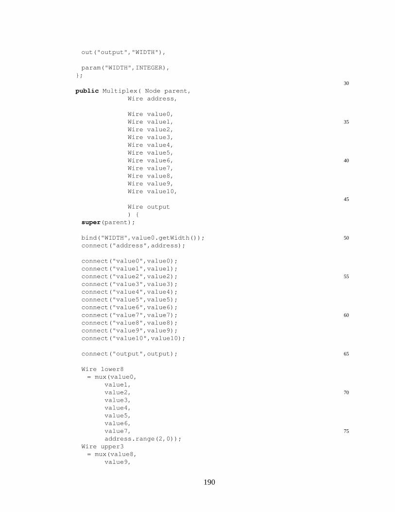
out("output","WIDTH"),
param("WIDTH",INTEGER),};
30
public Multiplex( Node parent,Wire address,
Wire value0,35Wire value1,
Wire value2,Wire value3,Wire value4,Wire value5,
40Wire value6,Wire value7,Wire value8,Wire value9,Wire value10,
45
Wire output) {
super (parent);
50bind("WIDTH",value0.getWidth());connect("address",address);
connect("value0",value0);connect("value1",value1);
55connect("value2",value2);connect("value3",value3);connect("value4",value4);connect("value5",value5);connect("value6",value6);
60connect("value7",value7);connect("value8",value8);connect("value9",value9);connect("value10",value10);
65connect("output",output);
Wire lower8= mux(value0,
value1,70value2,
value3,value4,value5,value6,
75value7,address.range(2,0));
Wire upper3= mux(value8,
value9,
190

80value10,constant(value0.getWidth(),0),address.range(1,0));
mux_o(lower8,upper3,
85address.gw(3),output);
}}
PG.java
package model;
import byucc.jhdl.base.CellInterface;5import byucc.jhdl.base.Node;
import byucc.jhdl.base.Wire;import byucc.jhdl.Logic.Logic;
public class PG extends Logic10implements PGCommon {
public static CellInterface[] cell_interface ={
in ("newGame",1),
15in ("pegInput0",3),in ("pegInput1",3),in ("pegInput2",3),in ("pegInput3",3),in ("registerGuess",1),
20
in ("statusAddress",4),
out("guess0",3),out("guess1",3),
25out("guess2",3),out("guess3",3),out("numRightColors",3),out("numRightColorsRightPlaces",3),
30out("gameOver",1),out("youWin",1),
};
public PG( Node parent,35Wire newGame,
Wire pegInput0,Wire pegInput1,Wire pegInput2,
40Wire pegInput3,Wire registerGuess,
191
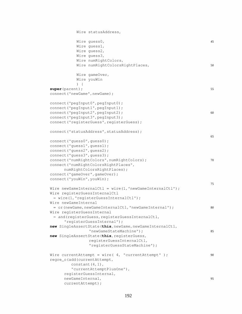
Wire statusAddress,
45Wire guess0,Wire guess1,Wire guess2,Wire guess3,Wire numRightColors,
50Wire numRightColorsRightPlaces,
Wire gameOver,Wire youWin) {
55super (parent);connect("newGame",newGame);
connect("pegInput0",pegInput0);connect("pegInput1",pegInput1);
60connect("pegInput2",pegInput2);connect("pegInput3",pegInput3);connect("registerGuess",registerGuess);
connect("statusAddress",statusAddress);65
connect("guess0",guess0);connect("guess1",guess1);connect("guess2",guess2);connect("guess3",guess3);
70connect("numRightColors",numRightColors);connect("numRightColorsRightPlaces",
numRightColorsRightPlaces);connect("gameOver",gameOver);connect("youWin",youWin);
75
Wire newGameInternalCtl = wire(1,"newGameInternalCtl");Wire registerGuessInternalCtl
= wire(1,"registerGuessInternalCtl");Wire newGameInternal
80= or(newGame,newGameInternalCtl,"newGameInternal");Wire registerGuessInternal
= and(registerGuess,registerGuessInternalCtl,"registerGuessInternal");
new SingleAssertState( this ,newGame,newGameInternalCtl,85"newGameStateMachine");
new SingleAssertState( this ,registerGuess,registerGuessInternalCtl,"registerGuessStateMachine");
90Wire currentAttempt = wire( 4, "currentAttempt" );regre_o(add(currentAttempt,
constant(4,1),"currentAttemptPlusOne"),
registerGuessInternal,95newGameInternal,
currentAttempt);
192

and_o(currentAttempt.gw(3),or(currentAttempt.gw(2),
currentAttempt.gw(1),"orCurrAtt"),100gameOver);
Wire randValue0 = wire( 3, "randValue0" );Wire randValue1 = wire( 3, "randValue1" );Wire randValue2 = wire( 3, "randValue2" );
105Wire randValue3 = wire( 3, "randValue3" );new RandomPuzzle( this ,randValue0,randValue1,
randValue2,randValue3);
Wire[] setGuessArray = new Wire[10];110
Wire[] guessOut0 = new Wire[11];Wire[] guessOut1 = new Wire[11];Wire[] guessOut2 = new Wire[11];Wire[] guessOut3 = new Wire[11];
115Wire[] numRightColorsArray = new Wire[11];Wire[] numRightColorsRightPlacesArray = new Wire[11];
Wire winIndicators = wire( 10, "winIndicators" );
120for ( int attempt = 0; attempt < 10; ++attempt ) {setGuessArray[attempt] = wire(1,"setGuess"+attempt);guessOut0[attempt]=wire(3,"guessOut0Attempt"+attempt);guessOut1[attempt]=wire(3,"guessOut1Attempt"+attempt);guessOut2[attempt]=wire(3,"guessOut2Attempt"+attempt);
125guessOut3[attempt]=wire(3,"guessOut3Attempt"+attempt);numRightColorsArray[attempt] = wire(3,"numRightColors"
+attempt);numRightColorsRightPlacesArray[attempt]
= wire(3,"numRightColorsRightPlaces"+attempt);130new AttemptBlock( this ,
randValue0,randValue1,randValue2,randValue3,newGameInternal,/*setValue*/pegInput0,pegInput1,
135pegInput2,pegInput3,setGuessArray[attempt],wire(3,"valueOut0_"+attempt),wire(3,"valueOut1_"+attempt),wire(3,"valueOut2_"+attempt),
140wire(3,"valueOut3_"+attempt),guessOut0[attempt],guessOut1[attempt],guessOut2[attempt],guessOut3[attempt],
145numRightColorsArray[attempt],numRightColorsRightPlacesArray[attempt],winIndicators.gw(attempt));
}150// This Block will only output the true solution:
193
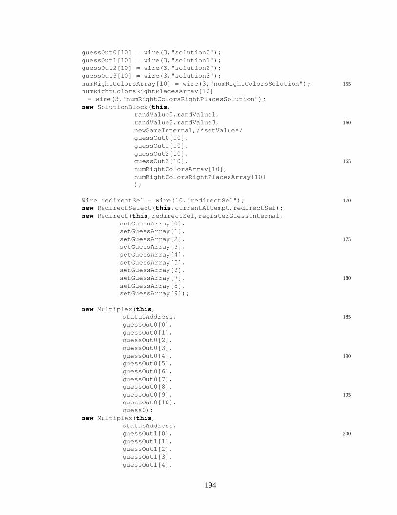
guessOut0[10] = wire(3,"solution0");guessOut1[10] = wire(3,"solution1");guessOut2[10] = wire(3,"solution2");guessOut3[10] = wire(3,"solution3");
155numRightColorsArray[10] = wire(3,"numRightColorsSolution");numRightColorsRightPlacesArray[10]
= wire(3,"numRightColorsRightPlacesSolution");new SolutionBlock( this ,
randValue0,randValue1,160randValue2,randValue3,
newGameInternal,/*setValue*/guessOut0[10],guessOut1[10],guessOut2[10],
165guessOut3[10],numRightColorsArray[10],numRightColorsRightPlacesArray[10]);
170Wire redirectSel = wire(10,"redirectSel");new RedirectSelect( this ,currentAttempt,redirectSel);new Redirect( this ,redirectSel,registerGuessInternal,
setGuessArray[0],setGuessArray[1],
175setGuessArray[2],setGuessArray[3],setGuessArray[4],setGuessArray[5],setGuessArray[6],
180setGuessArray[7],setGuessArray[8],setGuessArray[9]);
new Multiplex( this ,185statusAddress,
guessOut0[0],guessOut0[1],guessOut0[2],guessOut0[3],
190guessOut0[4],guessOut0[5],guessOut0[6],guessOut0[7],guessOut0[8],
195guessOut0[9],guessOut0[10],guess0);
new Multiplex( this ,statusAddress,
200guessOut1[0],guessOut1[1],guessOut1[2],guessOut1[3],guessOut1[4],
194
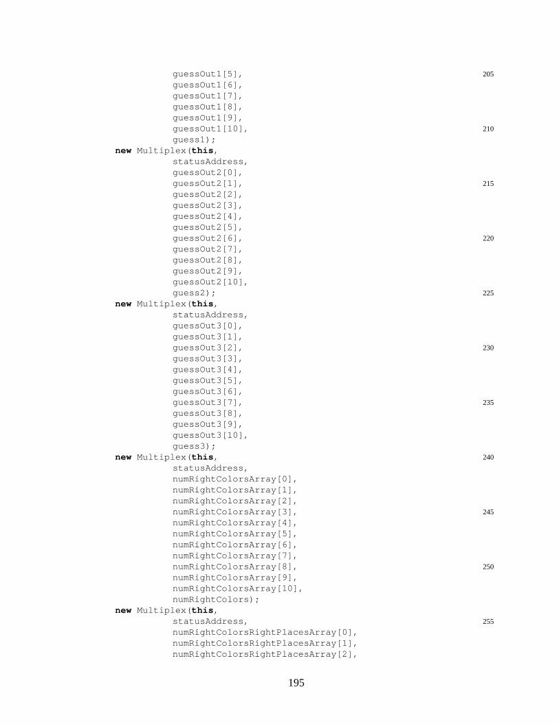
205guessOut1[5],guessOut1[6],guessOut1[7],guessOut1[8],guessOut1[9],
210guessOut1[10],guess1);
new Multiplex( this ,statusAddress,guessOut2[0],
215guessOut2[1],guessOut2[2],guessOut2[3],guessOut2[4],guessOut2[5],
220guessOut2[6],guessOut2[7],guessOut2[8],guessOut2[9],guessOut2[10],
225guess2);new Multiplex( this ,
statusAddress,guessOut3[0],guessOut3[1],
230guessOut3[2],guessOut3[3],guessOut3[4],guessOut3[5],guessOut3[6],
235guessOut3[7],guessOut3[8],guessOut3[9],guessOut3[10],guess3);
240new Multiplex( this ,statusAddress,numRightColorsArray[0],numRightColorsArray[1],numRightColorsArray[2],
245numRightColorsArray[3],numRightColorsArray[4],numRightColorsArray[5],numRightColorsArray[6],numRightColorsArray[7],
250numRightColorsArray[8],numRightColorsArray[9],numRightColorsArray[10],numRightColors);
new Multiplex( this ,255statusAddress,
numRightColorsRightPlacesArray[0],numRightColorsRightPlacesArray[1],numRightColorsRightPlacesArray[2],
195
numRightColorsRightPlacesArray[3],260numRightColorsRightPlacesArray[4],
numRightColorsRightPlacesArray[5],numRightColorsRightPlacesArray[6],numRightColorsRightPlacesArray[7],numRightColorsRightPlacesArray[8],
265numRightColorsRightPlacesArray[9],numRightColorsRightPlacesArray[10],numRightColorsRightPlaces);
or_o(winIndicators,youWin);}
270}
PGCommon.java
package model;
import java.awt.Color;5
public interface PGCommon {public static final Color[] COLOR_SET = {
Color.blue,Color.green.darker().darker(),
10Color.yellow,Color.magenta.darker().darker(),Color.pink,
};
15static final int DEFAULT_DATA_SET_SIZE = 5;static final int DEFAULT_NUM_PEGS = 4;static final int DEFAULT_NUM_TRIES = 10;
static int dataSetSize = DEFAULT_DATA_SET_SIZE;20static int numPegs = DEFAULT_NUM_PEGS;
static int numTries = DEFAULT_NUM_TRIES;}
RandomPuzzle.java
package model;
import byucc.jhdl.base.CellInterface;5import byucc.jhdl.base.Node;
import byucc.jhdl.base.Wire;import byucc.jhdl.Logic.Logic;
public class RandomPuzzle extends Logic {10public static CellInterface[] cell_interface =
{out("value0",3),out("value1",3),
196
out("value2",3),15out("value3",3),
};
public RandomPuzzle( Node parent,Wire value0,
20Wire value1,Wire value2,Wire value3) {
super (parent);25connect("value0",value0);
connect("value1",value1);connect("value2",value2);connect("value3",value3);
30new RandomPuzzleElement( this ,value0,0xE);
new RandomPuzzleElement( this ,value1,
350x8);new RandomPuzzleElement( this ,
value2,0xD);
new RandomPuzzleElement( this ,40value3,
0xB);}
}
RandomPuzzleElement.java
package model;
import byucc.jhdl.apps.Viewers.Schematic.UserDefinedSchematic;5import byucc.jhdl.apps.Viewers.Schematic.UserDefinedNode;
import byucc.jhdl.base.Browser;import byucc.jhdl.base.CellInterface;import byucc.jhdl.base.Node;import byucc.jhdl.base.Wire;
10import byucc.jhdl.Logic.Logic;
public class RandomPuzzleElement extends Logicimplements PGCommon, UserDefinedSchematic, Browser {public static CellInterface[] cell_interface =
15{out("value",3),
};private static final int width = 10;private Wire value;
20public RandomPuzzleElement( Node parent,Wire value,
197

int configInt) {
super (parent);25this .value = connect("value",value);
Wire flopOuts = wire( width, "flopOut" );Wire feedback = flopOuts.gw(width-1);Wire flopIn = feedback;for ( int wi = 0; wi < (width-1); ++wi ) {
30Wire flopOut, xorOut, andOut;flopOut = flopOuts.gw(wi);reg_o( flopIn, flopOut, "reg"+wi );
if ( ((configInt>>wi)&1) == 1 ) {35flopIn = wire( 1, "xor"+wi );
xor_o( flopOut, feedback, flopIn );} else {
flopIn = flopOut;}
40}regp_o( flopIn, feedback, "reg"+(width-1) );
Wire subOut= sub( flopOuts, constant( width, 1, "const1" ) );
45Wire addInA = concat( gnd(),subOut.gw(1),subOut.gw(0) );add_o( addInA,concat( gnd(),gnd(),subOut.gw(2) ),value );
}
50public void initUserDefinedNode(UserDefinedNode udn) {udn.setPortSeperation(0);udn.setSize(40,40);udn.addInPort(0,20,"c"); //add an implicit clock port.udn.addOutPort(40,30,"value");
55}
public void paint(UserDefinedNode udn) {int color = 0;try {
60color = value.get((Browser) this );} catch ( byucc.jhdl.base.WireValueException wve ) {}udn.drawRect(0,0,40,40);udn.setColor(COLOR_SET[color]);//udn.fillRect(1,1,28,38);
65udn.drawString("COLOR",1,10);//Add creative stuff--
}}
Redirect.java
package model;
import byucc.jhdl.base.CellInterface;
198
5import byucc.jhdl.base.Node;import byucc.jhdl.base.Wire;import byucc.jhdl.Logic.Logic;
public class Redirect extends Logic {10public static CellInterface[] cell_interface =
{in ("select",10),in ("value","WIDTH"),
15out("output0","WIDTH"),out("output1","WIDTH"),out("output2","WIDTH"),out("output3","WIDTH"),out("output4","WIDTH"),
20out("output5","WIDTH"),out("output6","WIDTH"),out("output7","WIDTH"),out("output8","WIDTH"),out("output9","WIDTH"),
25
param("WIDTH",INTEGER),};
public Redirect( Node parent,30Wire select,
Wire value,
Wire output0,35Wire output1,
Wire output2,Wire output3,Wire output4,Wire output5,
40Wire output6,Wire output7,Wire output8,Wire output9) {
45super (parent);
int width = value.getWidth();bind("WIDTH",width);connect("select",select);
50
connect("value",value);
connect("output0",output0);connect("output1",output1);
55connect("output2",output2);connect("output3",output3);connect("output4",output4);connect("output5",output5);
199

connect("output6",output6);60connect("output7",output7);
connect("output8",output8);connect("output9",output9);
Wire zero = constant(width,0,"zero");65
mux_o(zero,value,select.gw(0),output0);mux_o(zero,value,select.gw(1),output1);mux_o(zero,value,select.gw(2),output2);mux_o(zero,value,select.gw(3),output3);
70mux_o(zero,value,select.gw(4),output4);mux_o(zero,value,select.gw(5),output5);mux_o(zero,value,select.gw(6),output6);mux_o(zero,value,select.gw(7),output7);mux_o(zero,value,select.gw(8),output8);
75mux_o(zero,value,select.gw(9),output9);}
}
RedirectSelect.java
package model;
import byucc.jhdl.base.CellInterface;5import byucc.jhdl.base.Node;
import byucc.jhdl.base.Wire;import byucc.jhdl.Logic.Logic;
public class RedirectSelect extends Logic {10public static CellInterface[] cell_interface =
{in ("address",4),
out("select",10),15};
public RedirectSelect( Node parent,Wire address,
20Wire select) {
super (parent);connect("address",address);
25connect("select",select);
nor_o(address,select.gw(0));
and_o(nor(address.range(3,1)),30address.gw(0),
select.gw(1));and_o(nor(address.gw(3),
200
address.gw(2),address.gw(0)),
35address.gw(1),select.gw(2));
and_o(nor(address.gw(3),address.gw(2)),
address.gw(1),40address.gw(0),
select.gw(3));and_o(nor(address.gw(3),
address.gw(1),address.gw(0)),
45address.gw(2),select.gw(4));
and_o(nor(address.gw(3),address.gw(1)),
50address.gw(2),address.gw(0),select.gw(5));
and_o(nor(address.gw(3),address.gw(0)),
55address.gw(2),address.gw(1),select.gw(6));
and_o(nor(address.gw(3)),address.gw(2),
60address.gw(1),address.gw(0),select.gw(7));
and_o(nor(address.gw(2),address.gw(1),
65address.gw(0)),address.gw(3),select.gw(8));
and_o(nor(address.gw(2),address.gw(1)),
70address.gw(3),address.gw(0),select.gw(9));
}}
SingleAssertState.java
package model;
import byucc.jhdl.base.CellInterface;5import byucc.jhdl.base.Node;
import byucc.jhdl.base.Wire;import byucc.jhdl.Logic.Logic;
public class SingleAssertState extends Logic {
201
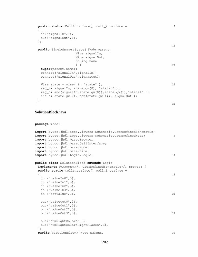
10public static CellInterface[] cell_interface ={
in("signalIn",1),out("signalOut",1),
};15
public SingleAssertState( Node parent,Wire signalIn,Wire signalOut,String name
20) {super (parent,name);connect("signalIn",signalIn);connect("signalOut",signalOut);
25Wire state = wire( 2, "state" );reg_o( signalIn, state.gw(0), "state0" );reg_o( and(signalIn,state.gw(0)),state.gw(1),"state1" );and_o( state.gw(0), not(state.gw(1)), signalOut );
}30}
SolutionBlock.java
package model;
import byucc.jhdl.apps.Viewers.Schematic.UserDefinedSchematic;5import byucc.jhdl.apps.Viewers.Schematic.UserDefinedNode;
import byucc.jhdl.base.Browser;import byucc.jhdl.base.CellInterface;import byucc.jhdl.base.Node;import byucc.jhdl.base.Wire;
10import byucc.jhdl.Logic.Logic;
public class SolutionBlock extends Logicimplements PGCommon/*, UserDefinedSchematic*/, Browser {public static CellInterface[] cell_interface =
15{in ("valueIn0",3),in ("valueIn1",3),in ("valueIn2",3),in ("valueIn3",3),
20in ("setValue",1),
out("valueOut0",3),out("valueOut1",3),out("valueOut2",3),
25out("valueOut3",3),
out("numRightColors",3),out("numRightColorsRightPlaces",3),
};30public SolutionBlock( Node parent,
202

Wire valueIn0,Wire valueIn1,Wire valueIn2,Wire valueIn3,
35Wire setValue,
Wire valueOut0,Wire valueOut1,Wire valueOut2,
40Wire valueOut3,
Wire numRightColors,Wire numRightColorsRightPlaces) {
45super (parent);connect("valueIn0",valueIn0);connect("valueIn1",valueIn1);connect("valueIn2",valueIn2);connect("valueIn3",valueIn3);
50connect("setValue",setValue);
connect("valueOut0",valueOut0);connect("valueOut1",valueOut1);connect("valueOut2",valueOut2);
55connect("valueOut3",valueOut3);
connect("numRightColors",numRightColors);connect("numRightColorsRightPlaces",
numRightColorsRightPlaces);60
Wire setValueInternalCtl = wire(1,"setValueInternalCtl");Wire setValueInternal = or(setValue,setValueInternalCtl,
"setValueInternal");new SingleAssertState( this ,setValue,setValueInternalCtl,
65"setValueStateMachine");
regce_o(valueIn0,setValueInternal,valueOut0,"valueReg0");regce_o(valueIn1,setValueInternal,valueOut1,"valueReg1");regce_o(valueIn2,setValueInternal,valueOut2,"valueReg2");
70regce_o(valueIn3,setValueInternal,valueOut3,"valueReg3");
constant_o(numRightColors,4);constant_o(numRightColorsRightPlaces,4);
}75
public void initUserDefinedNode(UserDefinedNode udn) {udn.setPortSeperation(0);udn.setSize(100,70);
80//udn.addInPort(0,20,"c"); //add an implicit clock port.//udn.addOutPort(40,30,"value");
}
public void paint(UserDefinedNode udn) {
203
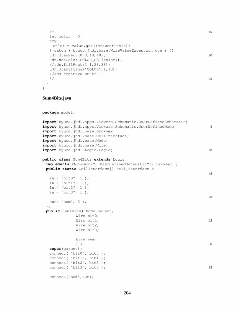
85/*int color = 0;try {
color = value.get((Browser)this);} catch ( byucc.jhdl.base.WireValueException wve ) {}
90udn.drawRect(0,0,40,40);udn.setColor(COLOR_SET[color]);//udn.fillRect(1,1,28,38);udn.drawString("COLOR",1,10);//Add creative stuff--
95*/}
}
Sum4Bits.java
package model;
import byucc.jhdl.apps.Viewers.Schematic.UserDefinedSchematic;5import byucc.jhdl.apps.Viewers.Schematic.UserDefinedNode;
import byucc.jhdl.base.Browser;import byucc.jhdl.base.CellInterface;import byucc.jhdl.base.Node;import byucc.jhdl.base.Wire;
10import byucc.jhdl.Logic.Logic;
public class Sum4Bits extends Logicimplements PGCommon/*, UserDefinedSchematic*/, Browser {public static CellInterface[] cell_interface =
15{in ( "bit0", 1 ),in ( "bit1", 1 ),in ( "bit2", 1 ),in ( "bit3", 1 ),
20
out( "sum", 3 ),};public Sum4Bits( Node parent,
Wire bit0,25Wire bit1,
Wire bit2,Wire bit3,
Wire sum30) {
super (parent);connect( "bit0", bit0 );connect( "bit1", bit1 );connect( "bit2", bit2 );
35connect( "bit3", bit3 );
connect("sum",sum);
204

and_o(bit0,bit1,bit2,bit3,sum.gw(2));40or_o(and(or(and(bit0,
bit1),and(bit2,
bit3)),not(sum.gw(2))),
45and(or(bit2,bit3),
xor(bit0,bit1)),
sum.gw(1));50xor_o(bit0,
bit1,bit2,bit3,sum.gw(0));
55}}
tbPG.java
package model;
import byucc.jhdl.apps.Stimulator.Stimulator;5import byucc.jhdl.base.Cell;
import byucc.jhdl.base.HWSystem;import byucc.jhdl.base.Node;import byucc.jhdl.base.ProgrammaticTestBench;import byucc.jhdl.base.Wire;
10import byucc.jhdl.Logic.Logic;import byucc.jhdl.Logic.TechMapper;import byucc.jhdl.Xilinx.Virtex.VirtexTechMapper;import byucc.jhdl.Xilinx.Virtex2.Virtex2TechMapper;
15import model.PG;import controller.PGBroker;
public class tbPG extends Logicimplements ProgrammaticTestBench {
20
public Cell design;
private Wire newGame;private Wire pegInput0;
25private Wire pegInput1;private Wire pegInput2;private Wire pegInput3;private Wire registerGuess;private Wire statusAddress;
30
private Wire guess0;private Wire guess1;private Wire guess2;
205
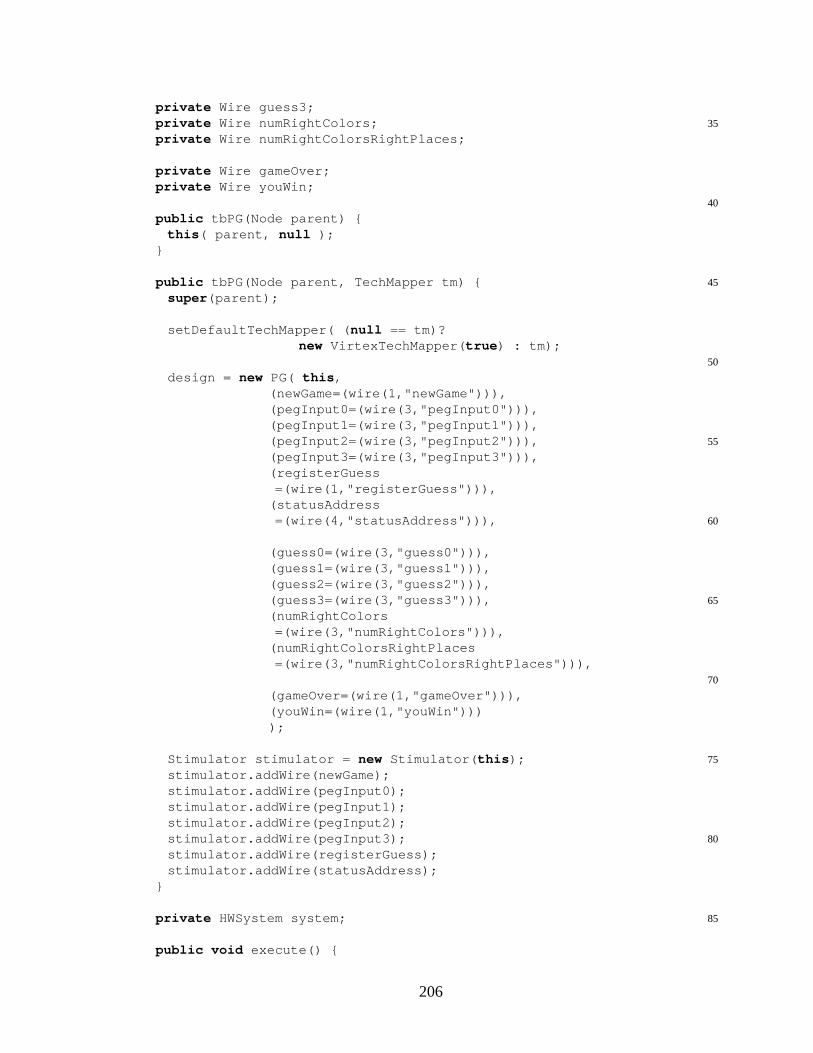
private Wire guess3;35private Wire numRightColors;
private Wire numRightColorsRightPlaces;
private Wire gameOver;private Wire youWin;
40
public tbPG(Node parent) {this ( parent, null );
}
45public tbPG(Node parent, TechMapper tm) {super (parent);
setDefaultTechMapper( ( null == tm)?new VirtexTechMapper( true ) : tm);
50
design = new PG( this ,(newGame=(wire(1,"newGame"))),(pegInput0=(wire(3,"pegInput0"))),(pegInput1=(wire(3,"pegInput1"))),
55(pegInput2=(wire(3,"pegInput2"))),(pegInput3=(wire(3,"pegInput3"))),(registerGuess=(wire(1,"registerGuess"))),
(statusAddress60=(wire(4,"statusAddress"))),
(guess0=(wire(3,"guess0"))),(guess1=(wire(3,"guess1"))),(guess2=(wire(3,"guess2"))),
65(guess3=(wire(3,"guess3"))),(numRightColors=(wire(3,"numRightColors"))),
(numRightColorsRightPlaces=(wire(3,"numRightColorsRightPlaces"))),
70
(gameOver=(wire(1,"gameOver"))),(youWin=(wire(1,"youWin"))));
75Stimulator stimulator = new Stimulator( this );stimulator.addWire(newGame);stimulator.addWire(pegInput0);stimulator.addWire(pegInput1);stimulator.addWire(pegInput2);
80stimulator.addWire(pegInput3);stimulator.addWire(registerGuess);stimulator.addWire(statusAddress);
}
85private HWSystem system;
public void execute() {
206
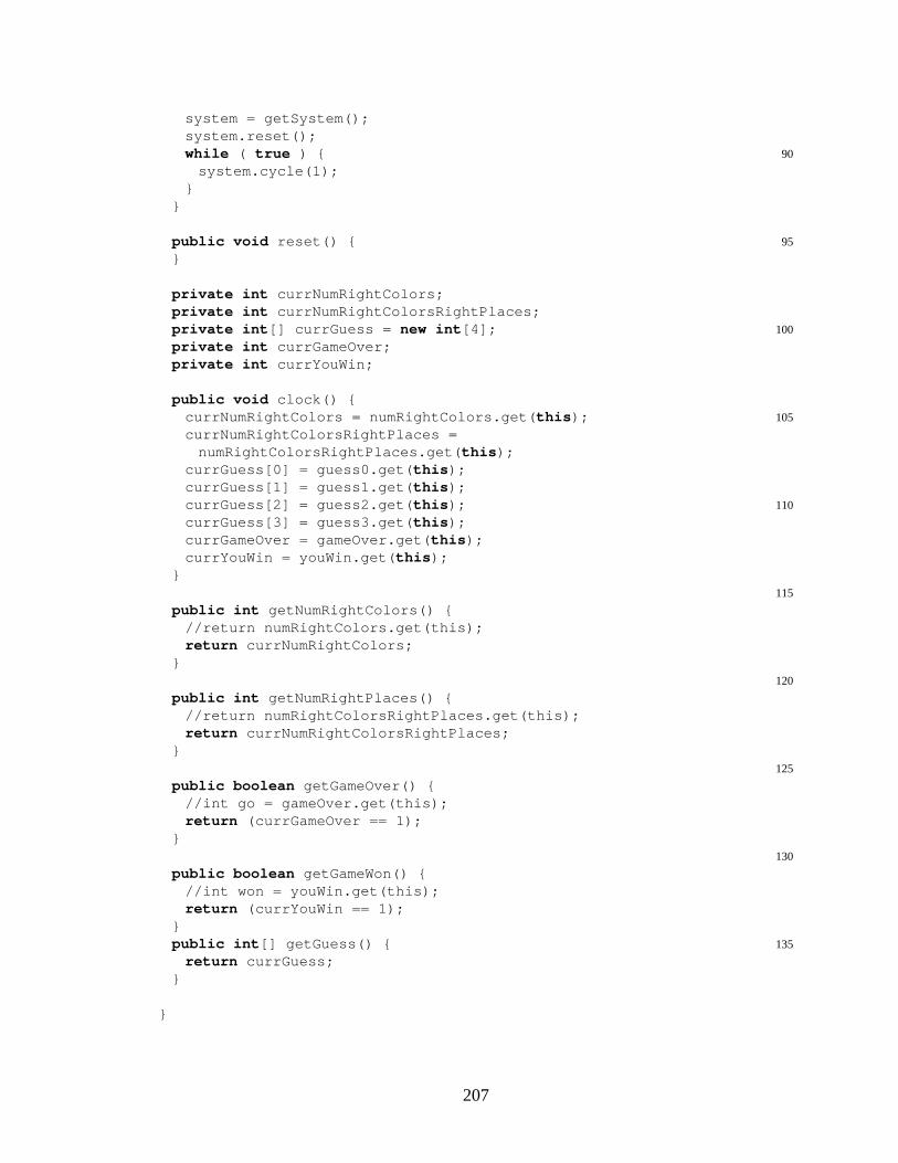
system = getSystem();system.reset();
90while ( true ) {system.cycle(1);
}}
95public void reset() {}
private int currNumRightColors;private int currNumRightColorsRightPlaces;
100private int [] currGuess = new int [4];private int currGameOver;private int currYouWin;
public void clock() {105currNumRightColors = numRightColors.get( this );
currNumRightColorsRightPlaces =numRightColorsRightPlaces.get( this );
currGuess[0] = guess0.get( this );currGuess[1] = guess1.get( this );
110currGuess[2] = guess2.get( this );currGuess[3] = guess3.get( this );currGameOver = gameOver.get( this );currYouWin = youWin.get( this );
}115
public int getNumRightColors() {//return numRightColors.get(this);return currNumRightColors;
}120
public int getNumRightPlaces() {//return numRightColorsRightPlaces.get(this);return currNumRightColorsRightPlaces;
}125
public boolean getGameOver() {//int go = gameOver.get(this);return (currGameOver == 1);
}130
public boolean getGameWon() {//int won = youWin.get(this);return (currYouWin == 1);
}135public int [] getGuess() {
return currGuess;}
}
207

C.4.2 Guessing Game Application View
This section includes the following source code files:
• ColorPlacementListener.java
• GameCanvas.java
• GameViewerFrame.java
• PGUtil.java
ColorPlacementListener.java
package view;
import java.awt.Color;5
/** Other classes use this to listen to where the user has* placed a color* @author Anthony Slade */
public interface ColorPlacementListener {10public void colorsSubmitted(GameCanvas source,
int row, int [] guess);}
GameCanvas.java
package view;
import java.awt.Color;5import java.awt.Dimension;
import java.awt.Font;import java.awt.Graphics;import java.awt.Point;import java.awt.Rectangle;
10import java.awt.event.MouseAdapter;import java.awt.event.MouseEvent;import java.awt.event.MouseMotionAdapter;import java.util.Collections;import java.util.HashSet;
15import java.util.Iterator;import java.util.Set;import javax.swing.JComponent;
import model.PGCommon;20
208
/** Visual representation of the PG game.* @author Anthony L. Slade */
public class GameCanvas extends JComponentimplements PGCommon {
25
public static void main(String[] args) {GameCanvas gc = new GameCanvas();gc.setFeedback(1,3,2);javax.swing.JFrame frame = new javax.swing.JFrame();
30frame.getContentPane().add(gc);frame.pack();frame.show();
}
35private static final int CANVAS_WIDTH = 300;private static final int CANVAS_HEIGHT = 400;private static final int RECT_WIDTH = 20;private static final int RECT_HEIGHT = 20;
40private static final int BASE_Y = 50;private static final int SPACE_Y = 10;private static final int BASE_X = 75;private static final int SPACE_X = 20;
45private static final int SUBMIT_X = 220;private static final int SUBMIT_WIDTH = 70;private static final int SUBMIT_HEIGHT = 20;
private static final int FEEDBACK_BASE_X = SUBMIT_X + 20;50private static final int FEEDBACK_WIDTH = 10;
private static final int FEEDBACK_HEIGHT = 10;private static final int FEEDBACK_SPACE_X = 5;private static final int FEEDBACK_SPACE_Y = 1;
55public GameCanvas() {Dimension size = new Dimension(CANVAS_WIDTH,
CANVAS_HEIGHT);setMinimumSize(size);setPreferredSize(size);
60setBackground(Color.white);setOpaque( true );draggableRects = new ColoredRectangle[dataSetSize];setRectangles
= Collections.synchronizedSet( new HashSet());65for ( int pal = 0; pal < dataSetSize; ++pal ) {
int x = RECT_WIDTH,y = (2*pal+2)*RECT_HEIGHT;
Color color = COLOR_SET[pal];ColoredRectangle cr = new ColoredRectangle(x,y,
70RECT_WIDTH,RECT_HEIGHT,color);
setRectangles.add(cr);draggableRects[pal] = new ColoredRectangle(x,y,
209
75RECT_WIDTH,RECT_HEIGHT,color);
}spaces = new ColoredRectangle[numTries][numPegs];
80for ( int row = 0; row < numTries; ++row ) {int y = BASE_Y + row*(RECT_HEIGHT+SPACE_Y);for ( int col = 0; col < numPegs; ++col ) {
int x = BASE_X + col*(RECT_WIDTH+SPACE_X);spaces[row][col]
85= new ColoredRectangle(x,y,RECT_WIDTH,RECT_HEIGHT,null );
}}currRow = 0;
90setMouseListening();draggedRect = intersectedRect = null ;listeners = Collections.synchronizedSet( new HashSet());submitButton = null ;feedback = new int [numTries][2];
95canvasFont = new Font("Times",Font.PLAIN,12);solution = new ColoredRectangle[numPegs];for ( int rect = 0; rect < numPegs; ++rect ) {
int x = BASE_X + rect*(RECT_WIDTH+SPACE_X);solution[rect] =
100new ColoredRectangle(x,BASE_Y - 40,RECT_WIDTH,RECT_HEIGHT, null );
}gameEnded = null ;
105waitingForFeedback = false ;}
public void addListener(ColorPlacementListener cpl) {listeners.add(cpl);
110}
public void removeListener(ColorPlacementListener cpl) {listeners.remove(cpl);
}115
/** Used to tell the view what the feedback is */public void setFeedback( int row, int numColorsRight,
int numPlacesRight) {try {
120feedback[row][0] = numColorsRight;feedback[row][1] = numPlacesRight;
} catch (ArrayIndexOutOfBoundsException aioobe) {}waitingForFeedback = false ;
125}
/** Tells the viewer that the game has ended and gives the* solution */
210
public void gameEnded( int [] actualSolution, boolean won) {130if ( won )
gameEnded = "Game Won!";else
gameEnded = "Game Over";for ( int sol = 0; sol < solution.length; ++sol ) {
135solution[sol].color = COLOR_SET[actualSolution[sol]];}submitButton = null ;currRow = -1;revalidate(); repaint();
140}
/** Outside class determines which row the user can* manipulate at the present time.* @param row the new row. */
145public void setCurrentRow( int row) {currRow = row;
}
/* Resets everything for a new game */150public void newGame() {
currRow = 0;for ( int row = 0; row < numTries; ++row ) {
for ( int col = 0; col < numPegs; ++col ) {ColoredRectangle cr = spaces[row][col];
155cr.color = null ;cr.drawColor = null ;setRectangles.remove(cr);
}feedback[row][0] = 0;
160feedback[row][1] = 0;}for ( int si = 0; si < solution.length; ++si )
solution[si].color = null ;gameEnded = null ;
165revalidate();repaint();}
/** Draws the component on the screen */public void paint(Graphics gr) {
170gr.setFont(canvasFont);gr.setColor(Color.white);gr.fillRect(0,0,CANVAS_WIDTH,CANVAS_HEIGHT);gr.setColor(Color.black);paintSolution(gr);
175paintGrid(gr);paintSetRectangles(gr);paintSubmitButton(gr);paintFeedback(gr);paintDraggedRectangle(gr);
180}
/** Draws the background grid. */
211
private void paintGrid(Graphics gr) {gr.setColor(Color.black);
185int startX = 2*RECT_WIDTH+10;for ( int row = 0; row < numTries; ++row ) {
gr.drawString(""+(row+1),startX+5,BASE_Y + 15 + row*(RECT_HEIGHT+SPACE_Y));
for ( int col = 0; col < numPegs; ++col ) {190ColoredRectangle cr = spaces[row][col];
if ( null != cr.color ) {continue ;
}gr.drawRect(( int )cr.getX(),
195( int )cr.getY(),( int )cr.getWidth(),( int )cr.getHeight());
}}
200gr.drawRect(startX,0,1,CANVAS_HEIGHT);gr.drawRect(startX,BASE_Y-10,CANVAS_WIDTH-startX,1);
}
/** Draws the solution if it has been set */205private void paintSolution(Graphics gr) {
for ( int col = 0; col < numPegs; ++col ) {ColoredRectangle cr = solution[col];if ( null == cr.color ) {
gr.setColor(Color.black);210gr.drawRect(( int )cr.getX(),
( int )cr.getY(),( int )cr.getWidth(),( int )cr.getHeight());
gr.setColor(Color.red);215gr.drawString("?",( int )cr.getX()+8,
( int )cr.getY()+15);} else {
gr.setColor(cr.color);gr.fillRect(( int )cr.getX(),
220( int )cr.getY(),( int )cr.getWidth(),( int )cr.getHeight());
}}
225gr.setColor(Color.black);if ( null != gameEnded ) {
ColoredRectangle cr = solution[numPegs-1];int x = ( int )cr.getX()+RECT_WIDTH+SPACE_X-10;int y = ( int )cr.getY()+15;
230gr.drawString(gameEnded,x,y);}
}
/** Draws the rectangles that have their color set. */235private void paintSetRectangles(Graphics gr) {
for ( Iterator itr = setRectangles.iterator();
212
itr.hasNext(); ) {ColoredRectangle cr = (ColoredRectangle)itr.next();gr.setColor(cr.drawColor);
240gr.fillRect(( int )cr.getX(),( int )cr.getY(),( int )cr.getWidth(),( int )cr.getHeight());
}245}
/** Draws the dragged rectangle, if any. */private void paintDraggedRectangle(Graphics gr) {
if ( null == draggedRect )250return ;
ColoredRectangle cr;if ( null != (cr=intersectedRect) ) {
gr.setColor(cr.drawColor);gr.fillRect(( int )cr.getX(),
255( int )cr.getY(),( int )cr.getWidth(),( int )cr.getHeight());
}cr = draggedRect;
260gr.setColor(cr.drawColor);gr.fillRect(( int )cr.getX(),
( int )cr.getY(),( int )cr.getWidth(),( int )cr.getHeight());
265}
/** Draws the submit button if there is one */private void paintSubmitButton(Graphics gr) {
if ( null == submitButton )270return ;
gr.setColor(Color.black);int x = ( int )submitButton.getX();int y = ( int )submitButton.getY();int w = ( int )submitButton.getWidth();
275int h = ( int )submitButton.getHeight();gr.drawRect(x,y,w,h);if ( submitPressed )
gr.setColor(Color.green.darker().darker());gr.drawRect(x+2,y+2,w-4,h-4);
280gr.drawString("Submit",x+15,y+15);}
/** Draws the feedback if there is any. NOTE! This method* is currently hard-coded for four pegs. It needs to be
285* parameterized. */private void paintFeedback(Graphics gr) {
for ( int row = 0; row < numTries; ++row) {int y = BASE_Y + row*(RECT_HEIGHT+SPACE_Y);int rightColors = feedback[row][0];
290int rightPlaces = feedback[row][1];
213
if ( row == currRow && waitingForFeedback ) {// this means we are waiting for feedback to come ingr.setColor(Color.gray);gr.drawString("?",4+FEEDBACK_BASE_X,
295y+FEEDBACK_HEIGHT);gr.drawString("?",4+FEEDBACK_BASE_X
+FEEDBACK_WIDTH+FEEDBACK_SPACE_X,y+FEEDBACK_HEIGHT);
gr.drawString("?",4+FEEDBACK_BASE_X,300y+2*FEEDBACK_HEIGHT+FEEDBACK_SPACE_Y);
gr.drawString("?",4+FEEDBACK_BASE_X+FEEDBACK_WIDTH+FEEDBACK_SPACE_X,y+2*FEEDBACK_HEIGHT+FEEDBACK_SPACE_Y);
} else if ( rightColors > 0 ) {305if ( rightPlaces > 0 ) {
gr.setColor(Color.magenta);gr.fillOval(FEEDBACK_BASE_X,y,
FEEDBACK_WIDTH, FEEDBACK_HEIGHT);if ( rightPlaces > 1 ) {
310gr.fillOval(FEEDBACK_BASE_X+FEEDBACK_WIDTH+FEEDBACK_SPACE_X,y,FEEDBACK_WIDTH, FEEDBACK_HEIGHT);
if ( rightPlaces > 2 ) {gr.fillOval(FEEDBACK_BASE_X,
315y+FEEDBACK_HEIGHT+FEEDBACK_SPACE_Y,FEEDBACK_WIDTH, FEEDBACK_HEIGHT);
if ( rightPlaces > 3 ) {gr.fillOval(FEEDBACK_BASE_X+FEEDBACK_WIDTH
+FEEDBACK_SPACE_X,320y+FEEDBACK_HEIGHT
+FEEDBACK_SPACE_Y,FEEDBACK_WIDTH, FEEDBACK_HEIGHT);
}}
325}}gr.setColor(Color.black);gr.drawOval(FEEDBACK_BASE_X,y,
FEEDBACK_WIDTH, FEEDBACK_HEIGHT);330if ( rightColors > 1 ) {
gr.drawOval(FEEDBACK_BASE_X+FEEDBACK_WIDTH+FEEDBACK_SPACE_X,y,FEEDBACK_WIDTH, FEEDBACK_HEIGHT);
if ( rightColors > 2 ) {335gr.drawOval(FEEDBACK_BASE_X,
y+FEEDBACK_HEIGHT+FEEDBACK_SPACE_Y,FEEDBACK_WIDTH, FEEDBACK_HEIGHT);
if ( rightColors > 3 ) {gr.drawOval(FEEDBACK_BASE_X+FEEDBACK_WIDTH
340+FEEDBACK_SPACE_X,y+FEEDBACK_HEIGHT+FEEDBACK_SPACE_Y,FEEDBACK_WIDTH, FEEDBACK_HEIGHT);
}}
214
345}}
}}
350/** Updates the given rectangle with the given color. If* all of the rectangles on the currRow are set, then the* submitButton is created. */
private void dropColor( ColoredRectangle droppee,Color color ) {
355droppee.color = color;droppee.drawColor = color;setRectangles.add(droppee);updateListeners(droppee);boolean allSet = true ;
360for ( int col = 0; col < numPegs; ++col ) {ColoredRectangle cr = spaces[currRow][col];if ( null == cr.color ) {
allSet = false ;break ;
365}}if ( allSet ) {
int y = BASE_Y + currRow*(RECT_HEIGHT+SPACE_Y);submitButton = new Rectangle(SUBMIT_X,y,
370SUBMIT_WIDTH,SUBMIT_HEIGHT);
}}
375/** Sets up the dragging of squares around the board and* clicking the submit button. */
private void setMouseListening() {addMouseListener( new MouseAdapter() {
public void mousePressed(MouseEvent evt) {380if ( currRow < 0 || currRow >= numTries
|| waitingForFeedback )return ;
Point pt = evt.getPoint();if ( null != submitButton
385&& submitButton.contains(pt) ) {submitPressed = true ;lastMousePoint = pt;revalidate();repaint();
}390for ( Iterator itr = setRectangles.iterator();
itr.hasNext(); ) {ColoredRectangle cr
= (ColoredRectangle)itr.next();if ( cr.contains(pt) ) {
395draggedRect = getDraggableForColor(cr.color);draggedRect.setLocation(cr.getLocation());lastMousePoint = pt;return ;
215
}400}
}public void mouseReleased(MouseEvent evt) {
if ( intersectedRect != null ) {dropColor(intersectedRect,draggedRect.color);
405intersectedRect = null ;}if ( null != draggedRect ) {
draggedRect = null ;revalidate();
410repaint();}if ( submitPressed
&& submitButton.contains(evt.getPoint()) ) {updateListeners();
415submitPressed = false ;waitingForFeedback = true ;revalidate();repaint();
}lastMousePoint = null ;
420}});
addMouseMotionListener( new MouseMotionAdapter() {public void mouseDragged(MouseEvent evt) {
if ( currRow < 0 || currRow >= numTries )425return ;
if ( null == draggedRect ) {if ( null == lastMousePoint )
return ;// In the middle of clicking the submit button
430if ( submitButton.contains(evt.getPoint()) ) {if ( !submitPressed ) {
submitPressed = true ;revalidate();repaint();
}435} else {
if ( submitPressed ) {submitPressed = false ;revalidate();repaint();
}440}
return ;}Point newPoint = evt.getPoint();int moveX
445= ( int )(newPoint.getX()-lastMousePoint.getX());int moveY
= ( int )(newPoint.getY()-lastMousePoint.getY());draggedRect.translate(moveX,moveY);lastMousePoint = newPoint;
450ColoredRectangle currIntersected = intersectedRect;intersectedRect = null ;for ( int col = 0; col < numPegs; ++col ) {
216
ColoredRectangle cr = spaces[currRow][col];if ( cr.intersects(draggedRect) ) {
455intersectedRect = cr;cr.drawColor = Color.gray;
}}if ( null != currIntersected
460&& currIntersected != intersectedRect ) {currIntersected.drawColor
= currIntersected.color;}revalidate();
465repaint();}
});}
470/** Finds an appropriate draggable rectangle for the given* color. This system allows us to avoid building a new* ColoredRectangle for every new drag event. */
private ColoredRectangle getDraggableForColor(Color color) {int ind = PGUtil.getIndexForColor(color);
475try {return draggableRects[ind];
} catch ( ArrayIndexOutOfBoundsException aioobe ) {return null ;
}480}
/** Tell registered listeners about a submission */private void updateListeners() {
int [] guessInts = new int [numPegs];485for ( int peg = 0; peg < numPegs; ++peg ) {
guessInts[peg]= PGUtil.getIndexForColor(spaces[currRow][peg].color);
}for ( Iterator itr = listeners.iterator();
490itr.hasNext(); ) {ColorPlacementListener cpl =
(ColorPlacementListener)itr.next();cpl.colorsSubmitted( this ,currRow,guessInts);
}495submitButton = null ;
}
/** Tell registered listeners about a change in color for a* space */
500private void updateListeners(ColoredRectangle rect) {// for ( int col = 0; col < numPegs; ++col ) {// if ( spaces[currRow][col] == rect ) {// Color color = rect.color;// for ( Iterator itr = listeners.iterator();
505// itr.hasNext(); ) {// ColorPlacementListener cpl =
217
// (ColorPlacementListener)itr.next();// cpl.colorUpdated(this,currRow,col,color);// }
510// return;// }// }
}
515/** Contains the set of rectangles on the canvas that have* had their colors set. This includes the pallette. When* a drag start event happens, this set of rectangles is* checked to see if one of them is being dragged. */
private Set setRectangles;520/** Registered listeners*/
private Set listeners;/** The set of spaces that the player can place a color* in. These may also be contained in setRectangles. */
private ColoredRectangle[][] spaces;525/** Indicates current row that can be manipulated */
private int currRow;/** Rectangle currently being dragged */private ColoredRectangle draggedRect;/** Set of ColoredRectangles already built and ready for
530* dragging */private ColoredRectangle[] draggableRects;/** If a draggedRect is intersecting a valid play space, it* will be remembered with this */
private ColoredRectangle intersectedRect;535/** Used to calculate where to move dragged rectangles */
private Point lastMousePoint;/** Used to outline the submit button */private Rectangle submitButton;/** Use to tell if the submitButton is currently being
540* pressed */private boolean submitPressed;/** Used to represent the progress feedback to the user */private int [][] feedback;/** Font used for painting this component */
545private Font canvasFont;/** Used to display the solution */private ColoredRectangle[] solution;/** Message for when the game is over */private String gameEnded;
550/** indicates if the values have been submitted and we’re* waiting for feedback before we can do anything else */
private boolean waitingForFeedback;}
555/** Class to contain information about color, size and* location of rectangles on the board. */
class ColoredRectangle extends Rectangle {ColoredRectangle( int x, int y, int width,
int height, Color color) {560super (x,y,width,height);
218
this .color = color;this .drawColor = color;
}Color color;
565Color drawColor;}
GameViewerFrame.java
package view;
import byucc.jhdl.apps.Viewers.ViewerFrame;5import byucc.jhdl.util.cli.CLInterpreter;
import java.awt.BorderLayout;import java.awt.Container;import java.awt.event.ActionEvent;
10import java.awt.event.ActionListener;
import javax.swing.JButton;import javax.swing.JMenuBar;import javax.swing.JPanel;
15
/** This is the main viewer for a Peggie (Mastermind) game.* @author Anthony L. Slade */
public class GameViewerFrame extends ViewerFrame {private CLInterpreter interp;
20private GameCanvas canvas;public GameViewerFrame(CLInterpreter interp,
GameCanvas canvas) {super ("");//Peggie");this .interp = interp;
25this .canvas = canvas;buildAndShowFrame();
}protected Container buildContentPanel() {
JPanel panel = new JPanel( new BorderLayout());30JButton button = new JButton("New Game");
button.addActionListener( new ActionListener() {public void actionPerformed(ActionEvent evt) {
interp.parseCommand("newgame");}
35});panel.add(button,BorderLayout.NORTH);panel.add(canvas,BorderLayout.CENTER);return panel;
}40protected JMenuBar buildMenuBar() {
return null ;}public void actionPerformed(ActionEvent evt) {}
}
219

PGUtil.java
package view;
import java.awt.Color;5
import model.PGCommon;
public class PGUtil implements PGCommon {static int getIndexForColor(Color color) {
10for ( int col = 0; col < COLOR_SET.length; ++col ) {if ( COLOR_SET[col].equals(color) ) {
return col;}
}15return -1;
}}
C.4.3 Guessing Game Application Controller
This section includes the following source code files:
• CommandFeedback.java
• CommandGuess.java
• CommandNewGame.java
• Peggie.java
• PGBroker.java
• ViewListener.java
CommandFeedback.java
package controller;
import byucc.jhdl.util.cli.CLICommand;5import byucc.jhdl.util.cli.CLIException;
import byucc.jhdl.util.cli.CLIInvalidUsageException;import byucc.jhdl.util.cli.CLInterpreter;
10/** This command tells the PGBroker that it is time to give
220
* feedback to the game viewer.* @author Anthony L. Slade */
public class CommandFeedback implements CLICommand {
15public static final String CMD_FEEDBACK = "feedback";
public CommandFeedback( PGBroker broker,CLInterpreter interp ) {
this .broker = broker;20interp.registerCommand( CMD_FEEDBACK, this );
}
public Object execute( CLInterpreter parent,String[] args )
25throws CLIException {if ( args.length < 3 )
throw new CLIInvalidUsageException();int row = -1;int [] guess = new int [args.length-2];
30try {row = Integer.parseInt(args[1]);for ( int ai = 2; ai < args.length; ++ ai ) {
guess[ai-2] = Integer.parseInt(args[ai]);}
35} catch ( NumberFormatException nfe ) {throw new CLIException("Unparsable integer value.");
}broker.setViewFeedback(row, guess);return null ;
40}
public String getHelpText( String cmdName ) {return "Updates game viewer with feedback for a guess.";
}45
public String getHelpType( String cmdName ) {return "PGBroker";
}
50public String getUsageText( String cmdName ) {return "row guess0 guess1 ...";
}
private PGBroker broker;55}
CommandGuess.java
package controller;
import byucc.jhdl.base.HWSystem;5import byucc.jhdl.apps.Broker.Broker;
import byucc.jhdl.apps.util.SimulatorThread;
221
import byucc.jhdl.apps.Viewers.ViewerFrame;import byucc.jhdl.util.cli.CLICommand;import byucc.jhdl.util.cli.CLIException;
10import byucc.jhdl.util.cli.CLIInvalidUsageException;import byucc.jhdl.util.cli.CLInterpreter;
import model.tbPG;import view.ColorPlacementListener;
15import view.GameCanvas;import view.GameViewerFrame;
/** This command tells the PGBroker to set the hardware* circuit and the game viewer to register a new guess.
20* @author Anthony L. Slade */public class CommandGuess implements CLICommand {
public static final String CMD_GUESS = "guess";ViewerFrame viewerFrame = null ;GameCanvas canvas;
25CLInterpreter interp;tbPG parent;public CommandGuess( PGBroker broker,
CLInterpreter interp ) {this .broker = broker;
30interp.registerCommand( CMD_GUESS, this );}public Object execute( CLInterpreter parent,
String[] args )throws CLIException {
35if ( args.length < 3 )throw new CLIInvalidUsageException();
int row = -1;int [] guess = new int [args.length-2];try {
40row = Integer.parseInt(args[1]);for ( int ai = 2; ai < args.length; ++ ai ) {
guess[ai-2] = Integer.parseInt(args[ai]);}
} catch ( NumberFormatException nfe ) {45throw new CLIException("Unparsable integer value.");
}broker.setGuess(row, guess);return null ;
}50public String getHelpText( String cmdName ) {
return "Registers a new guess in the game.";}public String getHelpType( String cmdName ) {
return "PGBroker";55}
public String getUsageText( String cmdName ) {return "row guess0 guess1 ...";
}private PGBroker broker;
60}
222

CommandNewGame.java
package controller;
import byucc.jhdl.base.HWSystem;5import byucc.jhdl.apps.Broker.Broker;
import byucc.jhdl.apps.util.SimulatorThread;import byucc.jhdl.apps.Viewers.ViewerFrame;import byucc.jhdl.util.cli.CLICommand;import byucc.jhdl.util.cli.CLIException;
10import byucc.jhdl.util.cli.CLInterpreter;
import model.tbPG;import view.ColorPlacementListener;import view.GameCanvas;
15import view.GameViewerFrame;
/** This command tells the PGBroker to set the hardware* circuit and the game viewer to start a new game.* @author Anthony L. Slade */
20public class CommandNewGameimplements CLICommand {public static final String CMD_NEW_GAME = "newgame";ViewerFrame viewerFrame = null ;GameCanvas canvas;CLInterpreter interp;
25tbPG parent;public CommandNewGame( PGBroker broker,
CLInterpreter interp ) {this .broker = broker;interp.registerCommand( CMD_NEW_GAME, this );
30}public Object execute( CLInterpreter parent,
String[] args )throws CLIException {broker.newGame();
35return null ;}public String getHelpText( String cmdName ) {
return "Starts a new game";}
40public String getHelpType( String cmdName ) {return "PGBroker";
}public String getUsageText( String cmdName ) {
return "";45}
private PGBroker broker;}
Peggie.java
import byucc.jhdl.base.HWSystem;
223

import model.tbPG;import controller.PGBroker;
5
public class Peggie {public static void main(String argv[]) {
HWSystem hws = new HWSystem();tbPG tb = new tbPG( hws );
10new PGBroker(tb,hws);}
}
PGBroker.java
package controller;
import byucc.jhdl.base.HWSystem;5import byucc.jhdl.apps.Broker.Broker;
import byucc.jhdl.apps.Stimulator.Stimulator;import byucc.jhdl.apps.util.SimulatorThread;import byucc.jhdl.apps.Viewers.ViewerFrame;import byucc.jhdl.util.cli.CLInterpreter;
10
import model.tbPG;import view.ColorPlacementListener;import view.GameCanvas;import view.GameViewerFrame;
15
/** The controller portion of the Peggie (Mastermind) game.* @author Anthony L. Slade */
public class PGBroker extends Broker {
20public PGBroker( tbPG parent, HWSystem system ) {super (system, new CLInterpreter());this .parent = parent;openGame();
}25
protected void registerCLICommands(HWSystem system,CLInterpreter interp) {
super .registerCLICommands(system,interp);new CommandNewGame(this , interp);
30new CommandGuess(this , interp);new CommandFeedback( this , interp);// registers put and get comands:Stimulator.registerCLICommands(interp);// remember the interpreter
35this .interp = interp;// create game view in this method for convenience onlycanvas = new GameCanvas();// make sure game view listener has command interpretercanvas.addListener( new ViewListener(interp));
40}
224
void newGame() {canvas.newGame();interp.parseCommandNoHistory("put newGame 1");
45interp.parseCommandNoHistory("cycle 2");interp.parseCommandNoHistory("put newGame 0");interp.parseCommandNoHistory("cycle 1");
}
50private void openGame() {if ( null != viewerFrame ) {
viewerFrame.setState(viewerFrame.NORMAL);viewerFrame.show();viewerFrame.toFront();
55} else {viewerFrame = new GameViewerFrame(interp,canvas);
}}
60/** This class is used to defer updating the GameCanvas* until after all simulation/execution has occured. */
private class CanvasUpdateThread extends SimulatorThread {CanvasUpdateThread(GameCanvas source,
int row, int [] guess) {65this .source = source;
this .row = row;this .guess = guess;
}public Object construct() { return null ; }
70/** This method is called back on the Swing event thread* after the main thread is finished executing. */
public void finished() {System.err.println("tbPG: updating GameCanvas now.");source.setFeedback(row,
75parent.getNumRightColors(),parent.getNumRightPlaces());
if ( parent.getGameOver() ) {source.gameEnded(guess, false );
} else if ( parent.getGameWon() ) {80source.gameEnded(getSolution(), true );
} else {source.setCurrentRow(row+1);source.revalidate();source.repaint();
}85// make sure that the super class’ finished method is
// called toosuper .finished();
}private GameCanvas source;
90private int row;private int [] guess;
}
void setGuess( int row, int [] guess) {95for ( int gi = 0; gi < guess.length; ++gi ) {
225
interp.parseCommandNoHistory("put pegInput"+gi+" "+guess[gi]);
}interp.parseCommandNoHistory("cycle 1");
100interp.parseCommandNoHistory("put registerGuess 1");interp.parseCommandNoHistory("cycle 2");interp.parseCommandNoHistory("put registerGuess 0");interp.parseCommandNoHistory("cycle 3");
}105
void setViewFeedback( int row, int [] guess) {interp.parseCommandNoHistory("put statusAddress "+row);interp.parseCommandNoHistory("cycle 2");// This thread will update the canvas, but only after any
110// previous Simulator threads (puts and cycles) have// completed.( new CanvasUpdateThread(canvas,row,guess)).start();
}
115private int [] getSolution() {interp.parseCommandNoHistory("put statusAddress 10");interp.parseCommandNoHistory("cycle 2");// this get is here so that we stall for the simulator// thread queue
120interp.parseCommandNoHistory("get statusAddress");return parent.getGuess();
}
private ViewerFrame viewerFrame = null ;125private GameCanvas canvas;
private CLInterpreter interp;private tbPG parent;
}
ViewListener.java
package controller;
import byucc.jhdl.util.cli.CLInterpreter;5
import view.ColorPlacementListener;import view.GameCanvas;
/** This listener receives events from the game view and10* translates them into CLICommands to execute.
* @author Anthony L. Slade */public class ViewListener implements ColorPlacementListener {
public ViewListener( CLInterpreter interp ) {15this .interp = interp;
}
public void colorsSubmitted( GameCanvas source,
226

int row, int [] guess ) {20
StringBuffer cmdParams = new StringBuffer(" ");cmdParams.append(row);for ( int gi = 0; gi < guess.length; ++gi ) {
cmdParams.append(" ");cmdParams.append(guess[gi]);25}
interp.parseCommand(CommandGuess.CMD_GUESS+cmdParams.toString());
interp.parseCommand(CommandFeedback.CMD_FEEDBACK+cmdParams.toString());
30}
private CLInterpreter interp;}
227

228

Bibliography
[1] W. Miller, “Real world applications for field programmable gate array devices-an
overview”, in WESCON/94. Idea/Microelectronics. Conference Record, Anaheim ,
CA, USA, September 1994, pp. 548–551.
[2] J. Villasenor and B. L. Hutchings, “The flexibility of configurable computing”,IEEE
Signal Processing Magazine, vol. 15, pp. 67–84, September 1998.
[3] S. Salamone, “Is acceleration hardware the wave of the future?”,Bio-IT World, July
2002.
[4] F. J. Kurdahi, N. Bagherzadeh, P. Athanas, and J. L. Munoz, “Guest editors’ intro-
duction: Configurable computing”,IEEE Design & Test of Computers, vol. 17, no. 1,
pp. 17–19, January–March 2000.
[5] B. L. Hutchings and B. E. Nelson, “Unifying simulation and execution in a design
environment for FPGA systems”,IEEE Transactions on Very Large Scale Integration
(VLSI) Systems, vol. 9, pp. 201–205, February 2001.
[6] P. S. Graham,Logical Hardware Debuggers for FPGA-based Systems, PhD thesis,
Brigham Young University, Provo, UT, USA, December 2001.
[7] P. W. Foulk, “Data-folding in SRAM configurable FPGAs”, inProceedings of IEEE
Workshop on FPGAs for Custom Computing Machines, D. A. Buell and K. L. Pocek,
Eds., Napa, CA, Apr. 1993, pp. 163–171.
[8] M. J. Wirthlin and B. L. Hutchings, “Improving functional density through run-
time constant propagation”, inACM/SIGDA International Symposium on Field Pro-
grammable Gate Arrays, Monterey, CA, Feb. 1997, pp. 86–92.
229
[9] P. Bellows and B. L. Hutchings, “JHDL - an HDL for reconfigurable systems”, in
Proceedings of the IEEE Symposium on Field-Programmable Custom Computing Ma-
chines, J. M. Arnold and K. L. Pocek, Eds., Napa, CA, April 1998, IEEE Computer
Society, pp. 175–184, IEEE Computer Society Press.
[10] B. L. Hutchings, P. Bellows, J. Hawkins, S. Hemmert, B. Nelson, and M. Rytting,
“A CAD suite for high-performance FPGA design”, inProceedings of the IEEE
Symposium on Field-Programmable Custom Computing Machines, J. M. Arnold and
K. L. Pocek, Eds., Napa, CA, April 1999, IEEE Computer Society, pp. 12–24, IEEE
Computer Society Press.
[11] B. L. Hutchings, B. Nelson, and M. Wirthlin, “Designing and debugging custom
computing applications”,IEEE Design & Test of Computers, vol. 17, no. 1, pp. 20–
28, January–March 2000.
[12] D. R. Olsen, Jr.,Developing User Interfaces, Morgan Kaufmann, 1998.
[13] C. S. Horstmann and G. Cornell,Core Java 2, Volume I: Fundamentals, Sun Mi-
crosystems Press, 6th edition, 2002.
[14] M. J. Wirthlin and B. McMurtrey, “IP delivery for FPGAs using applets and JHDL”,
in Design Automation Conference, B. Ackland, Ed., 2002, pp. 2–7.
[15] Xilinx, Incorporated, “Xilinx products: JBits SDK”, Mar. 2003,
http://www.xilinx.com/products/jbits/.
[16] Xilinx Incorporated, “Xilinx home: Products and solutions:
ISE logic design tools : Free ISE WebPACK”, Mar. 2003,
http://www.xilinx.com/xlnx/xil prodcatlandingpage.jsp?title=ISE+WebPack.
[17] T. B. Wheeler, “Improving design observability and controllability for functional
verification of FPGA-based circuits using design-level scan techniques”, Master’s
thesis, Brigham Young University, Provo, UT, USA, April 2001.
230
[18] W. J. Landaker, “Using hardware context-switching to enable a multitasking recon-
figurable computer system”, Master’s thesis, Brigham Young University, Provo, UT,
USA, August 2002.
[19] R. J. Lipton and D. Lopresti, “A systolic array for rapid string comparison”, in1985
Chapel Hill Conference on VLSI, H. Fuchs, Ed. 1985, pp. 363–376, Computer Science
Press.
[20] D. T. Hoang, “Searching genetic databases on Splash 2”, inProceedings of IEEE
Workshop on FPGAs for Custom Computing Machines, D. A. Buell and K. L. Pocek,
Eds., Napa, CA, Apr. 1993, pp. 185–191.
[21] I. M. Bland and G. Megson, “The systolic array genetic algorithm, an example of
systolic arrays as a reconfigurable design methodology”, inIEEE Symposium on
FPGAs for Custom Computing Machines, K. Pocek and J. Arnold, Eds., Napa Valley,
CA, USA, 1998, pp. 260–261.
[22] E. Roesler and B. Nelson, “Debug methods for hybrid CPU/FPGA systems”, Sub-
mitted to CFPT, 2002.
[23] K. S. Hemmert, J. L. Tripp, and B. L. Hutchings, “Simulation and synthesis of
csp-based interprocess communication”, Submitted to IEEE Symposium on Field-
Programmable Custom Computing Machines, 2003.
[24] J. L. Tripp, P. A. Jackson, and B. L. Hutchings, “Sea Cucumber: a synthesizing
compiler for FPGAs”, inField-Programmable Logic and Applications, M. Glesner,
P. Zipf, and M. Renovell, Eds., Montpellier, France, September 2002, vol. 2438 of
Lecture Notes in Computer Science, pp. 875–885, Springer-Verlag.
[25] BYU Configurable Computing Laboratory, “JHDL documentation tree”, Dec. 2002,
http://www.jhdl.org/docs/docs/jhdlDocs.html.
[26] P. I. Bliznakov, M. T. Rogers, N. Khan, A. Ali, and J. J. Shah, “User interface design
for feature modelers and feature based applications”, inProceedings of the 1995
Database Symposium, Boston, MA,USA, September 1995, ASME, pp. 535–543.
231
[27] E. Cerro-Prada, S. M. Charlwood, and P. B. James-Roxby, “Designing image pro-
cessing applications using reconfigurable computing”, inSeventh International Con-
ference on Image Processing And Its Applications, Manchester, UK, July 1999, vol. 1,
pp. 450–454.
[28] C. Mullen, “Rise and fall of monolithic software”,European Semiconductor Design
Production Assembly, vol. 23, no. 10, pp. 33–36, September 2001.
[29] C. R. Standridge and M. A. Centeno, “Concepts for modular simulation environ-
ments”, inSimulation Conference Proceedings, J. D. Tew, S. Manivannan, D. A.
Sadowski, and A. F. Seila, Eds., Winter 1994, pp. 657–663.
[30] C. R. Standridge, J. F. Kelly, T. Kelley, and J. Walther, “Progress in modular sim-
ulation environments”, inSimulation Conference Proceedings, J. M. Charnes, D. J.
Morrice, D. T. Brunner, and J. J. Swain, Eds., Winter 1996, pp. 714–720.
232