designer's guide - gardavous.com
TRANSCRIPT

Designer’s Guide
BusinessObjects 6.5
Windows

2 Designer’s Guide
Copyright Copyright © 2004 Business Objects. All rights reserved.If you find any problems with this documentation, please report them to Business Objects in writing at [email protected].
Trademarks Business Objects, the Business Objects logo, Crystal Reports, and Crystal Enterprise are trademarks or registered trademarks of Business Objects SA or its affiliated companies in the United States and other countries. All other names mentioned herein may be trademarks of their respective owners.Contains IBM Runtime Environment for AIX(R), Java(TM) 2 Technology Edition Runtime Modules (c) Copyright IBM Corporation 1999, 2000. All Rights Reserved.This product includes code licensed from RSA Security, Inc. Some portions licensed from IBM are available at http://oss.software.ibm.com/icu4j.
Use restrictions This software and documentation is commercial computer software under Federal Acquisition regulations, and is provided only under the Restricted Rights of the Federal Acquisition Regulations applicable to commercial computer software provided at private expense. The use, duplication, or disclosure by the U.S. Government is subject to restrictions set forth in subdivision (c)(1)(ii) of the Rights in Technical Data and Computer Software clause at 252.227-7013.
Patents Business Objects owns the following U.S. patents, which may cover products that are offered and sold by Business Objects: 5,555,403, 6,247,008 B1, 6,578,027 B2, 6,490,593 and 6,289,352.
Part Number 307-10-610-01

Designer’s Guide 3
Contents
Contents 3Preface Maximizing your information resources 7Information resources . . . . . . . . . . . . . . . . . . . . . . . . . . . . . . . . . . . . . . . . . . 9Services . . . . . . . . . . . . . . . . . . . . . . . . . . . . . . . . . . . . . . . . . . . . . . . . . . . . 11Useful addresses at a glance . . . . . . . . . . . . . . . . . . . . . . . . . . . . . . . . . . . . 12About this guide . . . . . . . . . . . . . . . . . . . . . . . . . . . . . . . . . . . . . . . . . . . . . . 14
Chapter 1 Introducing Designer 15Designer and universe fundamentals . . . . . . . . . . . . . . . . . . . . . . . . . . . . . . 17How do you use Designer to create universes? . . . . . . . . . . . . . . . . . . . . . . 22Who is the universe designer? . . . . . . . . . . . . . . . . . . . . . . . . . . . . . . . . . . . 26Introducing the universe development process . . . . . . . . . . . . . . . . . . . . . . 28Designer example materials . . . . . . . . . . . . . . . . . . . . . . . . . . . . . . . . . . . . . 32
Chapter 2 Basic operations and user interface 35Using Designer in your work environment . . . . . . . . . . . . . . . . . . . . . . . . . . 37Opening, saving, and closing a universe . . . . . . . . . . . . . . . . . . . . . . . . . . . 47Creating a universe . . . . . . . . . . . . . . . . . . . . . . . . . . . . . . . . . . . . . . . . . . . 50Setting universe parameters . . . . . . . . . . . . . . . . . . . . . . . . . . . . . . . . . . . . 53Using the Designer user interface . . . . . . . . . . . . . . . . . . . . . . . . . . . . . . . . 97Find and Replace . . . . . . . . . . . . . . . . . . . . . . . . . . . . . . . . . . . . . . . . . . . . 102Organizing the table display . . . . . . . . . . . . . . . . . . . . . . . . . . . . . . . . . . . . 106Selecting schema display options . . . . . . . . . . . . . . . . . . . . . . . . . . . . . . . 111Printing a universe . . . . . . . . . . . . . . . . . . . . . . . . . . . . . . . . . . . . . . . . . . . 121
Contents

4 Designer’s Guide
Con
Chapter 3 Inserting tables and joins 125What is a schema? . . . . . . . . . . . . . . . . . . . . . . . . . . . . . . . . . . . . . . . . . . 127Inserting tables . . . . . . . . . . . . . . . . . . . . . . . . . . . . . . . . . . . . . . . . . . . . . 129Using derived tables . . . . . . . . . . . . . . . . . . . . . . . . . . . . . . . . . . . . . . . . . 134Defining joins . . . . . . . . . . . . . . . . . . . . . . . . . . . . . . . . . . . . . . . . . . . . . . . 138Defining specific types of joins . . . . . . . . . . . . . . . . . . . . . . . . . . . . . . . . . 159Using cardinalities . . . . . . . . . . . . . . . . . . . . . . . . . . . . . . . . . . . . . . . . . . . 177Checking the universe . . . . . . . . . . . . . . . . . . . . . . . . . . . . . . . . . . . . . . . . 188
Chapter 4 Resolving join problems 195What is a join path problem? . . . . . . . . . . . . . . . . . . . . . . . . . . . . . . . . . . . 197Defining aliases . . . . . . . . . . . . . . . . . . . . . . . . . . . . . . . . . . . . . . . . . . . . . 200Defining contexts . . . . . . . . . . . . . . . . . . . . . . . . . . . . . . . . . . . . . . . . . . . . 205Resolving loops . . . . . . . . . . . . . . . . . . . . . . . . . . . . . . . . . . . . . . . . . . . . . 217Resolving Chasm Traps . . . . . . . . . . . . . . . . . . . . . . . . . . . . . . . . . . . . . . 247Resolving Fan Traps . . . . . . . . . . . . . . . . . . . . . . . . . . . . . . . . . . . . . . . . . 255Detecting join problems graphically . . . . . . . . . . . . . . . . . . . . . . . . . . . . . . 262Checking the universe . . . . . . . . . . . . . . . . . . . . . . . . . . . . . . . . . . . . . . . . 265
Chapter 5 Defining classes and objects 271Introduction to universe building . . . . . . . . . . . . . . . . . . . . . . . . . . . . . . . . 273Using the Universe pane . . . . . . . . . . . . . . . . . . . . . . . . . . . . . . . . . . . . . . 276Basic operations on classes, objects, and conditions . . . . . . . . . . . . . . . . 278Defining classes . . . . . . . . . . . . . . . . . . . . . . . . . . . . . . . . . . . . . . . . . . . . 280Defining objects . . . . . . . . . . . . . . . . . . . . . . . . . . . . . . . . . . . . . . . . . . . . . 284Using @Functions . . . . . . . . . . . . . . . . . . . . . . . . . . . . . . . . . . . . . . . . . . . 325Using a list of values . . . . . . . . . . . . . . . . . . . . . . . . . . . . . . . . . . . . . . . . . 341Using concatenated objects . . . . . . . . . . . . . . . . . . . . . . . . . . . . . . . . . . . 361Inserting a user object from BusinessObjects . . . . . . . . . . . . . . . . . . . . . . 363Using hierarchies . . . . . . . . . . . . . . . . . . . . . . . . . . . . . . . . . . . . . . . . . . . . 365Testing the universe . . . . . . . . . . . . . . . . . . . . . . . . . . . . . . . . . . . . . . . . . 370Using external strategies . . . . . . . . . . . . . . . . . . . . . . . . . . . . . . . . . . . . . . 371
tents

Designer’s Guide 5
Chapter 6 Using aggregate awareness 387What is aggregate awareness? . . . . . . . . . . . . . . . . . . . . . . . . . . . . . . . . . 389Setting up aggregate awareness . . . . . . . . . . . . . . . . . . . . . . . . . . . . . . . . 391Resolving loops involving aggregate tables . . . . . . . . . . . . . . . . . . . . . . . . 402Testing aggregate awareness . . . . . . . . . . . . . . . . . . . . . . . . . . . . . . . . . . 404
Chapter 7 Defining objects to enhance reports 405Linking returned values to images . . . . . . . . . . . . . . . . . . . . . . . . . . . . . . . 407Linking reports and documents outside the repository . . . . . . . . . . . . . . . . 416Linking reports in the repository for use in WebIntelligence and InfoView . 425Using analytic functions . . . . . . . . . . . . . . . . . . . . . . . . . . . . . . . . . . . . . . . 435
Chapter 8 Using Quick Design to build a universe 451Creating a basic universe automatically . . . . . . . . . . . . . . . . . . . . . . . . . . . 453
Chapter 9 Managing universes 463Distributing universes . . . . . . . . . . . . . . . . . . . . . . . . . . . . . . . . . . . . . . . . . 465Exporting a universe . . . . . . . . . . . . . . . . . . . . . . . . . . . . . . . . . . . . . . . . . 468Importing a universe . . . . . . . . . . . . . . . . . . . . . . . . . . . . . . . . . . . . . . . . . . 472Deploying universes . . . . . . . . . . . . . . . . . . . . . . . . . . . . . . . . . . . . . . . . . . 474Linking universes . . . . . . . . . . . . . . . . . . . . . . . . . . . . . . . . . . . . . . . . . . . . 483Including one universe within another . . . . . . . . . . . . . . . . . . . . . . . . . . . . 495Managing users and logins . . . . . . . . . . . . . . . . . . . . . . . . . . . . . . . . . . . . 496Optimizing universes . . . . . . . . . . . . . . . . . . . . . . . . . . . . . . . . . . . . . . . . . 498
Appendix A The Club database 501The Club database . . . . . . . . . . . . . . . . . . . . . . . . . . . . . . . . . . . . . . . . . . . 503
Index 509
Contents

6 Designer’s Guide
Con
tents
Maximizing your information resources
preface

8 Designer’s Guide
Max
OverviewInformation, services, and solutions
The Business Objects business intelligence solution is supported by thousands of pages of documentation, available from the products, on the Internet, on CD, and by extensive online help systems and multimedia. Packed with in-depth technical information, business examples, and advice on troubleshooting and best practices, this comprehensive documentation set provides concrete solutions to your business problems. Business Objects also offers a complete range of support and services to help maximize the return on your business intelligence investment. See in the following sections how Business Objects can help you plan for and successfully meet your specific technical support, education, and consulting requirements.
imizing your information resources
Designer’s Guide 9
Information resourcesWhatever your Business Objects profile, we can help you quickly access the documentation and other information you need.
Where do I start? Below are a few suggested starting points; there is a summary of useful web addresses on page 12.
Documentation RoadmapThe Documentation Roadmap references all Business Objects guides and multimedia, and lets you see at a glance what information is available, from where, and in what format. View or download the Business Objects Documentation Roadmap at www.businessobjects.com/services/documentation.htm
Documentation from the productsYou can access electronic documentation at any time from the product you are using. Online help, multimedia, and guides in Adobe PDF format are available from the product Help menus.
Documentation on the webThe full electronic documentation set is available to customers with a valid maintenance agreement on the Online Customer Support (OCS) website at www.businessobjects.com/services/support.htm
Buy printed documentationYou can order printed documentation through your local sales office, or from the online Business Objects Documentation Supply Store at www.businessobjects.com/services/documentation.htm
Search the Documentation CDSearch across the entire documentation set on the Business Objects Documentation CD shipped with our products. This CD brings together the full set of documentation, plus tips, tricks, multimedia tutorials, and demo materials.Order the Documentation CD online, from the Business Objects Documentation Supply Store, or from your local sales office.
Information resources

10 Designer’s Guide
Max
MultimediaAre you new to Business Objects? Are you upgrading from a previous release or expanding, for example, from our desktop to our web solution? Would you like to see a demonstration that shows how to use some of our more complicated or advanced features? Access our multimedia Quick Tours or Getting Started tutorials from the product, the Online Customer Support (OCS) website, or the Documentation CD.
How can I get the most recent documentation?You can get our most up-to-date documentation via the web. Regularly check the sites listed below for the latest documentation, samples, and tips.
Tips & TricksOpen to everyone, this is a regularly updated source of creative solutions to any number of business questions. You can even contribute by sending us your own tips.www.businessobjects.com/forms/tipsandtricks_login.asp
Product documentationWe regularly update and expand our documentation and multimedia offerings. With a valid maintenance agreement, you can get the latest documentation – in seven languages – on the Online Customer Support (OCS) website.
Developer Suite OnlineDeveloper Suite Online provides documentation, samples, and tips to those customers with a valid maintenance agreement and a Developer Suite license via the Online Customer Support (OCS) website.
Send us your feedbackDo you have a suggestion on how we can improve our documentation? Is there something you particularly like or have found useful? Drop us a line, and we will do our best to ensure that your suggestion is included in the next release of our documentation: [email protected]
NOTE
If your issue concerns a Business Objects product and not the documentation, please contact our Customer Support experts. For information about Customer Support visit: www.businessobjects.com/services/support.htm
imizing your information resources

Designer’s Guide 11
ServicesA global network of Business Objects technology experts provides customer support, education, and consulting to ensure maximum business intelligence benefit to your business.
How we can support you?Business Objects offers customer support plans to best suit the size and requirements of your deployment. We operate three global customer support centers:• Americas: San Jose, California and Atlanta, Georgia• Europe: Maidenhead, United Kingdom• Asia: Tokyo, Japan and Sydney, Australia
Online Customer SupportOur Customer Support website is open to all direct customers with a current maintenance agreement, and provides the most up-to-date Business Objects product and technical information. You can log, update, and track cases from this site using the Business Objects Knowledge Base.
Having an issue with the product?Have you exhausted the troubleshooting resources at your disposal and still not found a solution to a specific issue? For support in deploying Business Objects products, contact Worldwide Customer Support at: www.businessobjects.com/services/support.htm
Looking for the best deployment solution for your company?Business Objects consultants can accompany you from the initial analysis stage to the delivery of your deployment project. Expertise is available in relational and multidimensional databases, in connectivities, database design tools, customized embedding technology, and more.For more information, contact your local sales office, or contact us at: www. businessobjects.com/services/consulting.htm
Looking for training options? From traditional classroom learning to targeted e-learning seminars, we can offer a training package to suit your learning needs and preferred learning style. Find more information on the Business Objects Education website: www.businessobjects.com/services/education.htm
Services

12 Designer’s Guide
Max
Useful addresses at a glance
Address ContentBusiness Objects Documentation
www.businessobjects.com/services/documentation.htm
Overview of Business Objects documentation. Links to Online Customer Support, Documentation Supply Store, Documentation Roadmap, Tips & Tricks, Documentation mailbox.
Business Objects Documentation mailbox
Feedback or questions about documentation.
Product documentation
www.businessobjects.com/services/support.htm
The latest Business Objects product documentation, to download or view online.
Business Objects product information
www.businessobjects.com
Information about the full range of Business Objects products.
Developer Suite Online
www.techsupport.businessobjects.com
Available to customers with a valid maintenance agreement and a Developer Suite license via the Online Customer Support (OCS) website. Provides all the documentation, latest samples, kits and tips.
Knowledge Base (KB)
www.techsupport.businessobjects.com
Technical articles, documents, case resolutions.Also, use the Knowledge Exchange to learn what challenges other users – both customers and employees – face and what strategies they find to address complex issues. From the Knowledge Base, click the Knowledge Exchange link.
Tips & Tricks
www.businessobjects.com/forms/tipsandtricks_login.asp
Practical business-focused examples.
imizing your information resources

Designer’s Guide 13
Online Customer Support
www.techsupport.businessobjects.com
www.businessobjects.com/services
Starting point for answering questions, resolving issues.
Information about registering with Worldwide Customer Support.
Business Objects Education Services
www.businessobjects.com/services/education.htm
The range of Business Objects training options and products.
Business Objects Consulting Services
www.businessobjects.com/services/consulting.htm
Information on how Business Objects can help maximize your business intelligence investment.
Address Content
Useful addresses at a glance

14 Designer’s Guide
Max
About this guideThis guide describes Designer, a Business Objects software application. It describes how to create BusinessObjects universes, the semantic layer that represents database structure in everyday business terms. It also contains information on optimizing, managing and distributing universes.
AudienceThis guide is intended for the universe designer, the user of Designer.A universe designer should have a good working knowledge of SQL and relational database management systems. The designer should be familiar with the type of data and the logical structure of the databases used in the organization.
Conventions used in this guideThe conventions used in this guide are described in the table below.
Convention Indicates
Small capitals The names of all products such as BusinessObjects, WebIntelligence, Supervisor, and Designer.
This font Code, SQL syntax, computer programs. For example: @Select(Country\Country Id). This font is also used for all paths, directories, scripts, commands and files for UNIX.
Some code more code
Placed at the end of a line of code, the symbol ( ) indicates that the next line should be entered continuously with no carriage return.
$DIRECTORYPATHNAME The path to a directory in the Business Objects installation/configuration directory structure. For example:• $INSTALLDIR refers to the Business Objects
installation directory.• $LOCDATADIR refers to a subdirectory of the
BusinessObjects installation directory called locData.
imizing your information resources
Introducing Designer
chapter
16 Designer’s Guide
Intro
OverviewThis chapter gives you a general introduction to Designer, the tool you use to build BusinessObjects universes. It describes universes, what they contain, how they are created, and the role that universes have in your business environment.The typical universe development cycle is described, with best design practices recommended. The demonstration databases and universes shipped with Business Objects products are also described.
ducing Designer

Designer’s Guide 17
Designer and universe fundamentalsBusiness Objects Designer is a software tool that allows you to create BusinessObjects universes for BusinessObjects and WebIntelligence users.
What is a universe?A universe is a file that contains the following:• Connection parameters for one or more database middleware.• SQL structures called objects that map to actual SQL structures in the
database such as columns, tables, and database functions. Objects are grouped into classes. Objects and classes are both visible to BusinessObjects and WebIntelligence users.
• A schema of the tables and joins used in the database. Objects are built from the database structures that you include in your schema. The schema is only available to Designer users. It is not visible to BusinessObjects and WebIntelligence users.
BusinessObjects and WebIntelligence users connect to a universe, and run queries against a database. They can do data analysis and create reports using the objects in a universe, without seeing, or having to know anything about, the underlying data structures in the database.
What is the role of a universe?The role of a universe is to provide an easy to use and understand interface for non technical BusinessObjects and WebIntelligence users to run queries against a database to create reports and perform data analysis.As the universe designer, you use Designer to create objects that represent database structures, for example columns and database functions, that users need to access and query, to get the information necessary to meet their business requirements.The objects that you create in the universe must be relevant to the end user business environment and vocabulary. Their role is to present a business focussed front end to the SQL structures in the database.
Designer and universe fundamentals

18 Designer’s Guide
Intro
The following diagram shows the role of objects as the mapping layer between a database schema and the Query panel in BusinessObjects or the Query work area in WebIntelligence, that users use to create queries to run against database tables.
What does a universe contain?A universe contains the following structures:• Classes• Objects
ClassesA class is a logical grouping of objects within a universe. It represents a category of objects. The name of a class should indicate the category of the objects that it contains. A class can be divided hierarchically into subclasses.
ObjectsAn object is a named component that maps to data or a derivation of data in the database. The name of an object should be drawn from the business vocabulary of the targeted user group. For example, objects used in a universe used by a product manager could be Product, Life Cycle, or Release Date. A universe used by a financial analyst could contain objects such as Profit Margin, and Return on Investment.
database
database schemaobjects
Query panel in BusinessObjectsResult Objects pane in WebIntelligence
ducing Designer

Designer’s Guide 19
Types of objectsIn Designer, objects are qualified as one of three types: dimension, detail, or measure.
Objects infer SQL structures displayed in a schemaThe objects that BusinessObjects and WebIntelligence users see in a universe infer SQL structures that you have inserted into a database schema. You, as the universe designer, create this schema based on the tables and joins that are required to return the data, needed by users for their analysis and report creation.
Object type Description
Dimension Parameters for analysis. Dimensions typically relate to a hierarchy such as geography, product, or time. For example Last Name and City_Id
Detail Provide a description of a dimension, but are not the focus for analysis. For example Phone Number
Measure Convey numeric information which is used to quantify a dimension object. For example Sales Revenue
Designer and universe fundamentals

20 Designer’s Guide
Intro
The schema is a part of the universe file, but is only visible and accessible in Designer. You create the schema in the Structure pane of the Universe window. A schema is shown below for the sample universe Beach.unv.
How are objects presented in a universe?Objects are displayed as nodes in an tree explorer view in the Universe pane. You use the object explorer to create, delete, copy, view, and move classes and objects. Each object type is shown below.
Tables
Columns
Joins
detail object
dimension object
measure object
ducing Designer

Designer’s Guide 21
Viewing the universe windowThe Universe window in Designer is shown below. It contains both the Universe pane (visible to users) and the Structure pane (visible only in Designer).
Universe pane Structure pane
Designer and universe fundamentals
22 Designer’s Guide
Intro
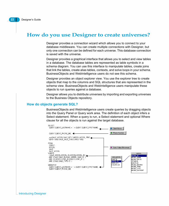
How do you use Designer to create universes?Designer provides a connection wizard which allows you to connect to your database middleware. You can create multiple connections with Designer, but only one connection can be defined for each universe. This database connection is saved with the universe.Designer provides a graphical interface that allows you to select and view tables in a database. The database tables are represented as table symbols in a schema diagram. You can use this interface to manipulate tables, create joins that link the tables, create alias tables, contexts, and solve loops in your schema. BusinessObjects and WebIntelligence users do not see this schema.Designer provides an object explorer view. You use the explorer tree to create objects that map to the columns and SQL structures that are represented in the schema view. BusinessObjects and WebIntelligence users manipulate these objects to run queries against a database.Designer allows you to distribute universes by importing and exporting universes to the Business Objects repository.
How do objects generate SQL?BusinessObjects and WebIntelligence users create queries by dragging objects into the Query Panel or Query work area. The definition of each object infers a Select statement. When a query is run, a Select statement and optional Where clause for all the objects is run against the target database.
ducing Designer

Designer’s Guide 23
When a user chooses to include dimension and/or detail objects with a measure object in the Query Panel or Query work area, a Group By clause containing the content of those dimension and detail objects is automatically added to the Select statement.The tables that are included in the From clause and the Joins in the Where clause, are inferred from the table schema that you build in the Structure pane.
What types of database schema are supported?Designer can support most types of database schema, including all those shown below. You do not need to redefine or optimize your database before using Designer.
How are universes used?Universes are used by BusinessObjects and WebIntelligence users. The universes are stored in the Universe domain of a Business Objects repository. An end user connects to a universe from either a BusinessObjects client application, or a web browser.The connection to the database is defined in the universe, so by connecting to the universe, the end user automatically has access to the data. The access to data is in turn restricted by the objects that are available in the universe. These objects have been created by you, the universe designer, based on the user needs profile for a defined user group.
Representing a targeted data needA universe can represent the data needs of any specific application, system, or group of users. For example, a universe can contain objects that represent the data needs of the Marketing or Accounting departments in a company.
How do you use Designer to create universes?

24 Designer’s Guide
Intro
A universe can also represent the data needs of a section within a department or any set of organized procedures such as a payroll or inventory system.An example of the types of classes that could be used in a human resources universe is shown below:
Examples of classes in the universe depicted above are Employee Information, Attendance Information, and Department Information.
Attendance InformationVacation Days Accrued
Sick Days TakenTotal Absences
Employee
Information
DepartmentInformation
HUMAN RESOURCES UNIVERSE
ducing Designer
Designer’s Guide 25
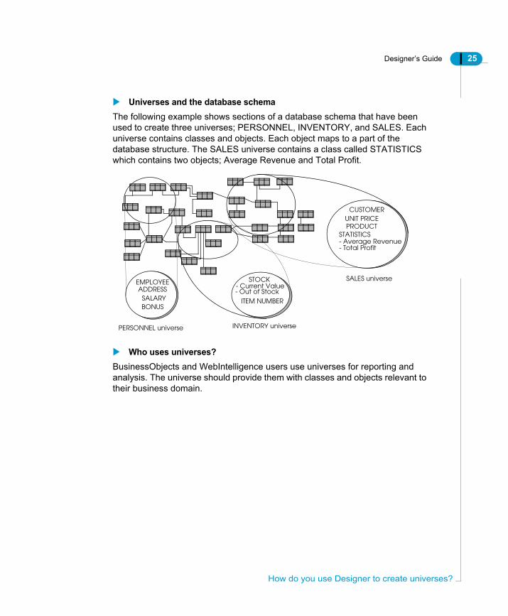
Universes and the database schemaThe following example shows sections of a database schema that have been used to create three universes; PERSONNEL, INVENTORY, and SALES. Each universe contains classes and objects. Each object maps to a part of the database structure. The SALES universe contains a class called STATISTICS which contains two objects; Average Revenue and Total Profit.
Who uses universes?BusinessObjects and WebIntelligence users use universes for reporting and analysis. The universe should provide them with classes and objects relevant to their business domain.
EMPLOYEE
SALARYBONUS
ADDRESS
CUSTOMERUNIT PRICEPRODUCT
STATISTICS
STOCK
- Out of StockITEM NUMBER
INVENTORY universe
SALES universe
- Average Revenue - Total Profit
- Current Value
PERSONNEL universe
How do you use Designer to create universes?

26 Designer’s Guide
Intro
Who is the universe designer?Universes are created by a universe designer using Designer. There is no standard profile for a universe designer. Within a company, the person designated as the universe designer may be the database administrator, an applications manager or developer, a project manager, or a Business Objects user who has acquired enough technical skills to create universes for other users.
Universe design teamsThere can be more than one universe designer in a company. The number of universe designers depends on the company’s data requirements. For example, one universe designer could be appointed for each application, project, department or functional area.
Required skills and knowledgeA universe designer should have the following skills and level of technical knowledge:
Skill/Knowledge Description
Ability to analyze user needs
Universes are created to meet a user need for data. The universe designer must have the skills to conduct user needs analyses to create classes and objects that are relevant to the user vocabulary, and to develop universes that meet the needs of the user community. These needs include report creation and query results that are suitable for analysis
Database knowledge Universe designer needs to have a good working knowledge of the company’s database management system (DBMS), how the databases are deployed, the logical database structure, and the type of data stored in company databases
Stuctured Query Language (SQL)
A working knowledge of SQL is necessary
ducing Designer

Designer’s Guide 27
What are the tasks of the universe designer?The universe designer is normally responsible for the following tasks:• Conducting user needs analysis• Designing and creating the universe• Distributing the universe• Maintaining the universe
Who is the universe designer?

28 Designer’s Guide
Intro
Introducing the universe development processThe following sections give an overview of how you manually create a universe, and describe how universe creation fits into a typical universe development cycle.
Universe design methodologyThe universe design methodology described in this manual consists of one planning stage, and three implementation phases:• Analysis of business problem and planning the universe solution• Designing a schema• Building the universe• Distributing the universe to usersEach implementation phase is based on an assumption that you have completed an initial planning phase. The planning phase can be done without using Designer, and is the decisive phase for the success or failure of your universe. A poorly planned universe that is not based on a study of user reporting needs will be difficult to design, implement, maintain, and will not be useful to your target users.Each of these phases is described as follows:
Plan the universe before you start using DesignerBefore starting the first phase, you should spend up to eighty percent of the time allotted for the universe creation project, planning the universe. You should note the following points:• You must analyze the data analysis and reporting needs of the target
audience for the universe. The structures that you use to create the schema should be based on a clearly defined user need to access the data contained in those tables and columns.
• You should have a clear idea of the objects that you need to create before you start using Designer. Do not create objects by looking at the columns available in the database, but identify columns that match an object that you have already identified from your user needs analysis.
Designing a schemaYou create a schema for the underlying database structure of your universe. This schema includes the tables and columns of the target database and the joins by which they are linked. You may need to resolve join problems such as loops,
ducing Designer

Designer’s Guide 29
chasm traps, and fan traps, which may occur in the structure by using aliases or contexts. You test the integrity of the overall structure. In this guide, the designing a schema phase is described in the chapter "Designing a Schema".
Building the universeYou create the objects that infer Select statements based on the components of your schema. You organize these objects into classes. These are objects that you have identified from an analysis of user reporting needs. You can create many types of objects to enhance user reporting capabilities, multidimensional analysis, and optimize query performance.You test the integrity of your universe structure. You should also perform tests in BusinessObjects or WebIntelligence on the universes.The building phase is described in the chapter "Building Universes".
Distributing the universeYou can distribute your universes to users for testing, and eventually for production, by exporting them to the repository or moving them using your file system. This phase is described in the chapter "Managing Universes".
Universe development cycleUniverse development is a cyclic process which includes planning, designing, building, distribution, and maintenance phases. You use Designer to design and build a universe, however, the usability of any universe is directly related to how successfully the other phases in the development cycle interact with each other.This section presents an overview of a universe design methodology that you can use to plan and implement a universe development project.
Introducing the universe development process
30 Designer’s Guide
Intro
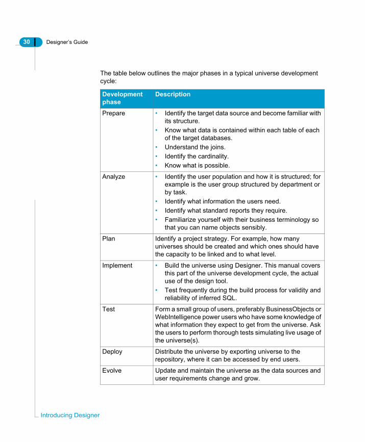
The table below outlines the major phases in a typical universe development cycle:
Development phase
Description
Prepare • Identify the target data source and become familiar with its structure.
• Know what data is contained within each table of each of the target databases.
• Understand the joins.• Identify the cardinality.• Know what is possible.
Analyze • Identify the user population and how it is structured; for example is the user group structured by department or by task.
• Identify what information the users need.• Identify what standard reports they require.• Familiarize yourself with their business terminology so
that you can name objects sensibly.
Plan Identify a project strategy. For example, how many universes should be created and which ones should have the capacity to be linked and to what level.
Implement • Build the universe using Designer. This manual covers this part of the universe development cycle, the actual use of the design tool.
• Test frequently during the build process for validity and reliability of inferred SQL.
Test Form a small group of users, preferably BusinessObjects or WebIntelligence power users who have some knowledge of what information they expect to get from the universe. Ask the users to perform thorough tests simulating live usage of the universe(s).
Deploy Distribute the universe by exporting universe to the repository, where it can be accessed by end users.
Evolve Update and maintain the universe as the data sources and user requirements change and grow.
ducing Designer

Designer’s Guide 31
NOTE
Universe design should always be driven primarily by user requirements and NOT the data source structure.
Optimizing universe planning and implementation timeThe analysis of user requirements and design are the most important stages in the process. Users must be heavily involved in the development process if the universe is going to fulfil their needs both with the business language used to name objects and the data that can be accessed.Implementation will be very quick and easy if the first three stages are carried out properly.You can spend up to 80% of the time allocated to the development of a universe on the first three stages:• Preparing• Analyzing• PlanningIf you have spent the time in the laying the foundation for your universe, the other 20% of the time spent actually using Designer to build your universe will be much more productive than if you have not spent the necessary time in planning and analysis.
Introducing the universe development process

32 Designer’s Guide
Intro
Designer example materialsThe following samples are shipped with Designer:
Demonstration databasesMost of the examples in this guide are based on the Club database built with Microsoft Access 2000. This database is used by the sales manager of the fictitious business, Island Resorts, to perform sales and marketing analysis. You can find the database file, Club.mdb, in the \demo\databases subfolder of the Business Objects installation folder.For more information on the structure of this database, refer to the appendix at the back of this guide.The efashion database is also shipped with Business Objects products. This MS Access 2000 database tracks 211 products (663 product color variations), sold over 13 stores (12 US, 1 in Canada), over 3 years. The database contains:• A central fact table with 89,000 rows of sales information on a weekly basis.• A second fact table containing promotions.• Two aggregate tables, which were set up with aggregate navigation.
SQL scripts for the demo databasesSQL creation scripts are shipped for both Windows and UNIX deployments. You can run these scripts in your database environment to create and populate the club and efashion databases. These SQL scripts are contained in the \demo\databases subfolder of the Business Objects installation folder. You have the following files:
Windows• efashion.zip• club.zip
UNIX• efashion.tar• club.tar
ducing Designer
Designer’s Guide 33
Demonstration universesA complete demo universe called beach.unv is delivered in the \demo\universes subfolder of the Business Objects installation folder. It was built with the Club database described above.You can use this universe to learn how to build specific objects and classes with Designer. Designer also comes with the efashion universe built using the efashion database.
Designer example materials

34 Designer’s Guide
Intro
ducing Designer
Basic operations and user interface
chapter

36 Designer’s Guide
Bas
OverviewThis chapter presents Designer. It describes the different types of work environments that you can use with Designer, the basic operations you can use when working with universes, and presents the Designer user interface.It shows you how to create a universe from scratch, define connections to your database middleware, and set database and connection parameters.This chapter also decribes how you can organize the schema display, and set display options for your table schema.
ic operations and user interface

Designer’s Guide 37
Using Designer in your work environmentYou create, modify, and update universes with Business Objects Designer. Designer can be used in two types of Business Objects environments:
Starting DesignerYou can start Designer from the task bar or by double clicking the Designer icon on the desktop. If Designer has been installed to work in an enterprise environment (with a repository) then you must log in to the repository before you can access Designer. If you are working in a workgroup environment (with no repository), then you access Designer directly.As Designer is most often used in an enterprise environment, the following sections describe logging in and starting Designer when you also have a repository connection.When you start Designer in a workgroup environment, the procedure is exactly the same, but you do not provide login information before starting Designer.
Environment Description
Enterprise Designer is used with a Business Objects repository. Universes are saved in the Universe domain of the repository. Universe access, version control, and security are controlled by Business Objects Supervisor. A universe is imported from and exported to the repository by the universe designer. This is the most common environment in which Designer is used.
Workgroup Designer is used alone with no repository connection. Access to universes, version control, and security are controlled by the universe designer.
Using Designer in your work environment

38 Designer’s Guide
Bas
Providing login informationWhen you use Designer with a repository, you must firstly provide the following login information in an identification box before you can start using Designer:
Starting a Designer session from the TaskbarYou can start Designer from the taskbar, by clicking the Designer icon on the desktop, or by using the Run command. Refer to the section Starting Designer with the Run command on page 40 for more information on using the run command.To start a Designer session from the task bar:1. Click the Start button on the taskbar.2. Point to the Programs menu.3. Click the Designer program from the BusinessObjects command.
The User Identification box appears.If you are using more than one repository, you can choose the appropriate repository from the User Identification box, however, if you are working with a single repository, then you do not have the choice. The User Identification box
Login information Description
User Name Your Business Objects user name. This is provided by your Business Objects supervisor.
Password Your Business Objects password. This is provided by your Business Objects supervisor.
Repository (if you are using multiple repositories)
The repository that you want to use for the current Designer session. If you are only using a single repository, then you do not have the option to choose a repository.
Use in Offline Mode Allows you to work on a universe locally without connecting to the target database. This option is only available after you have connected to the repository once. See the section Using Designer in online and offline modes on page 42 for more information.
Designer
ic operations and user interface

Designer’s Guide 39
below is for a single repository user.
The User Identification box below is for multiple repository user.
4. Type your user name and password. These are assigned to you by your supervisor.
5. If you are a multi repository user, then choose a repository. This does not apply if you are single repository user.
6. Select or clear the Use in Offline Mode check box.7. Click the OK button.
The welcome screen of the Quick Design wizard appears.8. Clear the Run this Wizard at Startup check box.9. Click Cancel.
An empty Designer session opens. The user name and repository name
Using Designer in your work environment

40 Designer’s Guide
Bas
appear in the title bar.
NOTE
For more information on disabling other wizard options, see the section Disactivating the Quick Design wizard on page 42. If you want to use the Quick Design wizard, then you can refer to the secion"Using the Quick Design Wizard" in the Building a Universe chapter.
Starting Designer with the Run commandYou can also launch a Designer session using the Run command as follows:1. Click the Start button from the Windows taskbar, and then click the Run
command.The Run dialog box appears.
2. In the Open text box, use the Browse button to locate the file Designer.exe in the BusinessObjects folder.
3. Click the OK button.The User Identification dialog box is displayed.
User and repository name
ic operations and user interface

Designer’s Guide 41
Run command optionsYou can use the options listed in the table below when you launch a session with the Run command:
You must enter all option names in lowercase characters preceded by a minus sign (-). After each option name that requires a value, you must enter an appropriate value. The options -nologo or -online do not have values.Parameters containing spaces need to be enclosed in double quotes.
EXAMPLELaunching Designer with the Run commandYou want to launch a session by entering your user name (jim) and your password (kiwi). You want to work with a specific repository (waitemata), and you do not want to display the startup logo.You use the following syntax:"C:\Program Files\Business Objects\BusinessObjects Enterprise 6\bin\Designer.exe" -user james -pass kiwi -keyfile waitemata -nologo
When you execute the Run command from now on, the main Designer window appears immediately. The User Identification dialog box is not displayed.
Option Description
-user The user name assigned to you by your supervisor.
-pass The password assigned to you by your supervisor (this option is mandatory if you enter the user option.)
-online or-offline
The connection mode: online or offline (optional). Online is the default.
-universe The name or path of the universe you wish to open (optional).
-nologo To run Designer without showing the logo screen.
-keyfile The name of the key file of the repository you wish to work with, if you are working with more than one repository. This is the <repository name>.key file stored in the locData folder in the Business Objects path:$INSTALLDIR\locData
Using Designer in your work environment
42 Designer’s Guide
Bas
Using the Quick Design Wizard appropriatelyWhen you start a Designer session for the first time, a Quick Design wizard appears by default. You can use the wizard to quickly create a universe, or to familiarize yourself with Designer ; however, it is not an appropriate tool for creating a complete universe that responds to end user reporting requirements.It is recommended that you disable the Quick Design wizard, and use it only as a means to familiarize yourself with Designer, and not use it to design universes. All the universe design, building, and maintenance information and procedures in this manual assume that you have disabled the Quick Design wizard, except for the section "Using the Quick Design Wizard" which deals specifically with using the wizard. For information on disabling other Quick Design wizard options, see the section Disactivating the Quick Design wizard on page 42.
Disactivating the Quick Design wizardWhen you first start a Designer session, a Quick Design wizard appears by default. You can prevent the wizard appearing automatically when you create a new universe as follows:To disactivate the Quick Design wizard:1. Select Tools > Options.
The Options dialog box opens to the General page.2. Clear the Show Welcome Wizard check box. This check box is already
cleared if you have cleared the Run this Wizard at Startup check box from the Startup Wizard Welcome page.
3. Clear the File/New Starts Quick Design Wizard check box.4. Click OK.
NOTE
You can activate the Quick Design Wizard at any time by selecting the above check boxes from the General page of the Options dialog box. Using the Quick Design wizard is covered in the chapter "Building Universes."
Using Designer in online and offline modesWhen you are using Designer in an enterprise environment (with a repository connection) you can start Designer in online mode (connected to the repository) or offline mode (not connected to the repository). The availability of a universe when you are working in offline mode depends on whether certain parameters
ic operations and user interface

Designer’s Guide 43
have been defined for the universe while in online mode. These parameters are described in the section Ensuring that a universe is available in offline mode on page 43.Online and Offline modes are described as follows:.
Ensuring that a universe is available in offline modeIf you want a universe to be accessible in offline mode, you must firstly ensure that the universe has been opened at least once in online mode, and that it has been saved with the Save for All Users check box selected in the Save Universe As box.
To make Offline mode available:1. Start a Designer session.2. Type your user name and password in the User Identification box.3. Ensure that the Use in Offline Mode check box is cleared. If it is not, clear the
check box.4. Click OK.5. Open the universe that you want to be accessible in offline mode.6. Select File > Save As.
The Save universe as box appears.7. Browse to the directory where you want to save the universe.8. Select the Save for All Users check box at the bottom right corner of the Save
Mode Description
Online Default mode of operation for Designer when you are working in an environment with a repository.
Offline Mode of operation for Designer when you are not connected to a repository.• Only available if you have previously connected in online
mode.• In offline mode you can open universes that are stored on your
local computer only if those universes have been opened previously in online mode.
• You can access databases where the connection and security information are stored on your local machine (personel and shared connections.)
• You can use offline mode when you do not have access to the repository, for example when working with a laptop off site, or when the network is not available.
Using Designer in your work environment

44 Designer’s Guide
Bas
As box.9. Click Save and close the universe.
The universe can now be opened in offline mode.
openning a universe in offline modeOnce a universe has been prepared correctly, you can open a universe in offline mode.
To open a universe in Offline mode:1. Start a Designer session.2. Type your user name and password in the User Identification box.3. Select the Use in Offline Mode check box.4. Click OK.
ic operations and user interface

Designer’s Guide 45
Accessing a universe in enterprise or workgroup modeBy default, a universe is saved in the mode in which you are already working. For example, if you launched a session in enterprise mode, any universe you save is automatically stored in that mode.The table below summarizes the effect of either mode on universe access. It indicates when saved universes can be accessed by other designers.
Key:✓ can access the universes
The information shown above is also valid for either an online or offline session.
Giving all users access to a universeYou can make a universe accessible to all Designer users in both workgroup and enterprise mode, by saving a universe in workgroup mode. The connection for the universe cannot be a secured connection. If you want to make a universe available to all users, you must save the universe with an unsecured connection.To make a universe accessible to all Designer users:1. Verify that the universe that you want to make available to all users does not
have a secured connection.2. Secured connections are required to export universe to the repository. If a
universe has a secured connection, select or create a new shared connection. See the section Defining and editing connections on page 54 for
Universes saved in workgroup mode
Unexported universes saved in enterprise mode
Exported universes saved in enterprise mode
Designer working in workgroup mode
✓
Designer working in enterprise mode
✓ ✓ ✓(if access to the universe is authorized by the supervisor)
General Supervisor
✓ ✓ ✓
Using Designer in your work environment

46 Designer’s Guide
Bas
more information.3. Select File > Save As.
A File Save box appears.4. Select the Save For All Users check box.
5. Click OK.
Select Save for all users
ic operations and user interface

Designer’s Guide 47
Opening, saving, and closing a universeThe basic operations of opening, saving, and closing a universe are described as follows:
Opening a universeYou open a universe using the menu commands or by clicking the Open button.To open a universe:1. Select File > Open.
A File Open box opens to the directory designated as the default universe file store. You can set this directory in the Save page of the Options dialog box (Tools > Options > Save).
2. If necessary, browse to the directory that contains the universe file (.UNV).3. Select a universe file and click Open
OrDouble click the universe file.The Universe opens in the current Designer window.
Saving universesYou should regularly save your universes throughout a work session. When you save a universe, Designer stores it as a file with a .UNV extension. In BusinessObjects or WebIntelligence, a user identifies the universe by the universe name (long name).
NOTE
You can also save the universe definition as an Adobe PDF file. See the section for complete information.
You can use the following maximum characters in the universe name (the long name) and .unv file name:
Name type Maximum number of characters
Universe name 35
.unv name 8
Opening, saving, and closing a universe

48 Designer’s Guide
Bas
Universe file names as identifiersYou should not change the universe filename (.unv with max 8 characters) after reports have been created based on that universe. BusinessObjects uses the filename as the unique identifier of the universe when the universe is opened outside the repository. If you change the filename, any report built on the universe with the old name, will not point to the universe once its name has been changed.
Saving a universeThe universe name can be different from the .unv name. You can use the following methods to save a universe:To save a universe:• Select File > Save from the menu bar• Click the Save icon• Press CTRL+S from the keyboard
NOTE
Do not save two different universes with the same file name but in different cases; for example, one universe named “Sales” and the other named “sales.” This can lead to conflicts when you attempt to export such universes to the repository.
Saving a universe definition as PDFYou save the universe information as an Adobe PDF file. You can save the same information that you can print out for a universe. This information includes:• General information: parameters, linked universes, and the graphical table
schema.• Component lists: lists of components in the universe including objects,
conditions, hierarchies, tables, joins, and contexts.• Component descriptions: descriptions for the objects, conditions, hierarchies,
tables, joins, and contexts in the universe.You can select what components that you want to appear in the PDF from the Print Options dialog box (Tools > Options > Print). These options are described in the section Setting print options on page 121.To save universe information as a PDF file:1. Select File > Save As2. Select portable Document Format (PDF) from the Save as type drop down list
ic operations and user interface

Designer’s Guide 49
box.
3. Click Save.
Setting default save optionsBy default, Designer stores the files that you save in the Universe subfolder in the Business Objects path. You can specify another default save folder as follows: 1. Select Tools > Options.
The Options dialog box appears.2. Click the Save tab.
The Save page appears.3. Type a file path in the Default Universe Folder text box.
Or4. Browse to a folder that contains .unv files.5. If you want to specify an automatic save time, select the Save Automatically
check box and select or type a time period number from the Minutes value select box.
6. Click OK.
Closing a universeYou can use the following methods to close a universe.To close a universe:• Select File Close from the menu bar• Click the close window button at the top right corner of the universe window• Press CTRL+W from the keyboard.
Opening, saving, and closing a universe

50 Designer’s Guide
Bas
Creating a universeBefore you can build a universe, you must firstly create a new universe file.When you create a new universe file, you must define a connection parameter to allow the universe to access your database middleware. You can also define other parameters that determine how Designer creates objects, links from the current universe to other universes, and query restrictions.You save the new universe as a .unv file. The new universe contains no classes and objects. You create these during the universe development process by designing a table schema and then creating objects that map to database structures.
What are universe parameters?Universe parameters are definitions and restrictions that you define for a universe that identify a universe and its database connections, specify the type of queries that can be run using the universe, and set the controls on the use of system resources.You define universe parameters from the Universe Parameters dialog box (File > Parameters) when you create a universe. The database connection is the only parameter that you must manually select or create when you create a new universe.You can modify these parameters at any time.You can define the following universe parameters:
Parameter Description
Definition Universe name, description, and connection parameters and information. These are the parameters that identify the universe. Refer to the section Identifying the universe on page 53 for information on defining and modifying this parameter.
Summary information
Version and revision information, designer comments, and universe statistics. Refer to the section Viewing and entering summary information on page 67 for information on defining and modifying this parameter.
Strategies Indicates the strategies used by the universe. A strategy is a script used to extract structural information from a database. Refer to the section Selecting strategies on page 69 for information on defining and modifying this parameter.
ic operations and user interface

Designer’s Guide 51
Creating a new universeThe following procedure describes how you can create a new universe from scratch by defining universe parameters then saving the universe. The procedure provides an overview of all the pages available from the Parameters dialog box.For more detailed information on each step you should refer to the respective section for the parameter in this chapter.Defining all the parameters at universe creation may not be necessary. You must select a connection, but you can accept the default values for other parameters, and then modify them as appropriate when necessary.
Creating a new universe from scratchTo create a new universe from scratch:1. Select File > New.
The Universe parameters dialog box opens to the Definition page. See the section Identifying the universe on page 53 for information on this page.- Type a name and description for the universe.- Select a connection from the Connection drop-down list box.Or- Click the New button if you want to define a new connection that is not listed in the drop-down list. See the section Defining and editing connections on page 54 for information on defining a new connection.
2. Click the Summary tab.The Summary page appears. See the section Viewing and entering summary
Controls Indicates the limitations set for the use of system resources. Refer to the section Indicating resource controls on page 76 for information on defining and modifying this parameter.
SQL Indicates the types of queries that the end user is allowed to run from the Query panel in Business Objects. Refer to the section Indicating SQL restrictions on page 78 for information on defining and modifying this parameter.
Links Indicates the settings defined for linked universes. Refer to the section Indicating options for linked universes on page 80 for information on defining and modifying this parameter.
Parameter Description
Creating a universe

52 Designer’s Guide
Bas
information on page 67 for information on this page.- Type universe information in the Comments box.
3. Click the Strategies tab.The Strategies page appears. It displays the strategies available for your connected data source. See the section Selecting strategies on page 69 for information on this page.- Select a strategy from each of the Objects, Joins, and Tables drop-down list boxes.Depending on the RDBMS for the connection, there can be more than one strategy available from each drop-down list box.
4. Click the Controls tab.The Controls page appears. See the section Indicating resource controls on page 76 for information on this page.- Select or clear check boxes in the Query Limits group box.- Enter values for the check boxes that you select.
5. Click the SQL tab.The SQL page appears. See the Indicating SQL restrictions on page 78 for information on this page.- Select or clear check boxes as appropriate.
6. Click the Links tab, if you want to link the new universe with an existing universe.The Links page appears. See the section Indicating options for linked universes on page 80 for information on this page.- Click the Add Link button to select a universe to link with the new universe.
7. Click the Parameters tab.The Parameters page appears. It lists SQL parameters that can be set to optimize SQL generation. See the section Setting SQL generation parameters on page 81 for information on this page.
8. Click OK.The universe and structure panes open up in Designer
9. Select File > Save.- Type a name for the universe file.- Click Save.
ic operations and user interface

Designer’s Guide 53
Setting universe parametersYou can set universe parameters for the following purposes:• Identifying the universe• Defining and editing connections• Viewing and entering summary information• Selecting strategies• Indicating resource controls• Indicating SQL restrictions• Indicating options for linked universes• Setting SQL generation parametersEach type of parameter is contained on a page in the Parameters dialog box (File > Parameters).Each group of parameters is described in its respective section below.
Identifying the universe Each universe is identified by the following parameters:
The name and description parameters are defined at universe creation from the Definition page of the Universe Parameters dialog box. You can modify the universe identification parameters at any time.You also define the database connection from this page.For information on defining a new connection, you can refer to the section Defining and editing connections on page 54.
Identifier Used by
File name(8 characters)
File system, BusinessObjects and WebIntelligence to reference the universe.
Long name(35 characters)
BusinessObjects and WebIntelligence users. WebIntelligence
Description BusinessObjects and WebIntelligence users.
Unique numeric ID Repository to identify universe. This number is assigned to the universe when it is first exported to the repository.
Setting universe parameters

54 Designer’s Guide
Bas
You can define the following identification parameters for a universe:
Modifying universe identification parametersTo modify universe identification parameters:1. Select File > Parameters.
OrClick the Universe Parameters button in the toolbar.The Universe Parameters dialog box opens to the Definition page.
2. Type a name and a description.3. Select a connection from the Connection drop-down list box.4. Click the Test button to verify that the connection is valid.
If you receive a message informing you that the server is not responding, the connection is not valid. You can correct connection parameters by clicking the Edit button and editing connection properties. If the error persists, refer to the section of the RDBMS documentation relating to error messages.
5. Click OK.
Defining and editing connectionsA connection is a named set of parameters that defines how a Business Objects application accesses data in a database file. A connection links BusinessObjects and WebIntelligence to your middleware. You must have a connection to access data.
Identification parameter
Description
Name Universe name. Identifies the universe to BusinessObjects and WebIntelligence users. The name characters supported by the registry are defined by the General Supervisor. Character support is RDBMS dependent.
Description Description of universe purpose and contents. Optional field. This description is viewable by BusinessObjects and WebIntelligence users, so information in this field can provide useful information about the role of the universe.
Connection Named set of parameters that defines how BusinessObjects or WebIntelligence accesses data in a database file. All available connections appear in the Connections drop-down list box. You can also create new connections.
ic operations and user interface

Designer’s Guide 55
You must select or create a connection when you create a universe. You can modify, delete, or replace the connection at any time.
NOTE
See the Data Access Guide for complete information on creating, modifying, and optimizing connections
You can create a new connection from the Definition page of the Universe Paameters dialog box (File > Parameters > Definition). You create a new connection when there is not an existing connection appropriate to the current universe. You can also edit the properties for a connection from the Definition page.You can view all connections available to a universe from the Connections list (Tools > Connections). You can delete, edit, and create new connections from this page.A connection contains three elements:• Data Access driver• Connection and login parameters• Connection typeEach element is described in the following sections:
Data Access driverA Data Access driver is the software layer that connects a universe to your middleware.Data Access drivers are shipped with Business Objects products. There is a Data Access driver for each supported middleware. When you install Designer, your Data Access key determines which Data Access drivers are installed.When you create a new connection, you select the appropriate Data Access driver for the RDBMS middleware that you use to connect to the target RDBMS.
Setting universe parameters
56 Designer’s Guide
Bas
Connection and login parametersYou configure the Data Access driver by specifying the following connection and login parameters.
Connection typeThe type of connection determines who can use the connection to access data. Designer automatically stores all the connections that you create during a work session. The next time you launch a session, these connections will be available to you. You can create three types of connections with Designer:
Each connection type is described as follows:
Personal connectionsRestricts access to data to the universe creator and the computer on which it was created. Connection parameters are stored in the PDAC.LSI file located in the LSI folder in the Business Objects folder under your user profile in Documents and Settings. An example of this path is shown below.
Parameter Description
Connection name Identifying name for the connection.
User name Your database user name. This is normally assigned to you by the database administrator.
Password Your database password. This is normally assigned to you by the database administrator.
Data source Data source or database name. If you are using an ODBC driver the data source name identifies the the target database. If you are using a native driver, the database name identifies the target database.
Connection Can be modified from...
Personal DesignerBusinessObjects
Shared DesignerBusinessObjects
Secured SupervisorDesigner (only available if you have it deployed with Supervisor)
ic operations and user interface

Designer’s Guide 57
C:\Documents and Settings\<user>\Application Data\Business Objects\Business Objects 6.0\lsi\pdac.lsiThese parameters are static and cannot be updated. Personal connections are unsecured in terms of Business Objects products security.You do not use personal connections to distribute universes. You could use personal connections in the following situations:• To access personal data on a local machine• To access specific database accounts to test an SQL sample through the
Free-hand SQL option in BusinessObjects.
Shared connectionsAllows access to data for all BusinessObjects and WebIntelligence users. These connections are unsecured in terms of Business Objects products security. Connection parameters are stored in the SDAC.LSI file located in the LSI folder in the Business Objects folder under your user profile in Documents and Settings. An example of this path is shown below.C:\Documents and Settings\<user>\Application Data\Business Objects\Business Objects 6.0\lsi\sdac.lsiIf the SDAC.SSI file is stored locally, only users having access to the local machine (through a mapped drive), can use the shared connections.Shared connections can be useful in a universe testing environment.
Secured connections• Centralizes and controls access to data. It is the safest type of connection,
and should used be to protect access to sensitive data.• You can create secured connections with Designer or Supervisor.• Connections are stored in the security domain of the repository. These can be
shared with designers and supervisors with the appropriate privileges.• You must use secured connections if you want to distribute universes through
the Business Objects repository.• Secured connections can be used and updated at any time. To define a
secured connection you must be using Business Objects products in Enterprise mode. You must be connected to a repository and using the Business Objects repository key file. The default name for this file is BOMain, but it can be modified at any time in Supervisor.
Setting universe parameters

58 Designer’s Guide
Bas
Setting passwords with personal and shared connectionsYou can set a password on any universe that has a personal or shared connection type. Using passwords, you can protect the universe from unauthorized users in an environment without a repository.
NOTE
If you forget a password, you can not recover the universe file. You should keep a backup file of universe passwords.
There are two different options available for the password you can set:• Protection Password causes a dialog box to appear; it simply prompts the
user to enter the password. If the password is correct, the universe is opened. • Write Reservation Password causes the following dialog box to appear:
The user can then open the universe in read only mode, or in read-write mode by entering the correct password.
ic operations and user interface

Designer’s Guide 59
To set a password when using personal or shared connections:1. Select Tools > Options
The Options dialog box appears.2. Click the Save tab.
The Save page appears.
3. Type a pass word in the Protection Password or the Write Reservation Password text boxes. You can enter up to 40 alphanumeric characters.
4. Click OK.
Defining a new connectionYou can define a new connection using the New Connection wizard. You access the wizard from:• Definition page of the Universe Parameters dialog box (File > Parameters>
Definition). You normally define a new connection when there is not an existing connection available for the data that the universe needs to access.
• Connections list (Tools > Connections). See the section Editing a connection on page 66 for more information on using the Connections dialog box.
You can use the connection wizard to set advanced and custom parameters for a connection. Refer to the Data Access Guide (Help > Data Access Guide) for complete information on creating, editing, and optimizing connections.
Setting universe parameters

60 Designer’s Guide
Bas
To define a new connection:1. Select File > Parameters.
OrClick the Universe Parameters button in the toolbar.The Universe Parameters dialog box opens to the Definition page.
2. Click the New button.
NOTE
You can also create a new connection from the Connections dialog box. Select Tools > Connections and click the Add button from the Connections list.
The Welcome page of the Connection Wizard appears.3. Click Next.
The Database Middleware page appears. It lists the database and middleware that correspond to your Data Access driver key.
4. Expand the node for the target database for the connection.The supported middleware for that database appear under the node.
5. Expand the node for the target middleware for the connection.The Data Access driver for the middleware appears.
6. Click a driver name and click Next.The Login Parameters page appears. The login parameters are described in
Parameters
Oracle Client is theData Access driverfor the Oracle middleware
ic operations and user interface

Designer’s Guide 61
the section Connection and login parameters.Do the following on the Login Parameters page:- Select the connection type from the Type list box: Secured, Shared, or Personal.- Type a name for the connection. You can enter up to 35 characters.- Type your user name and password. These are normally assigned by your database administrator.A Login Parameters page shown below:
7. Click Next.The Test Connection page appears. It summarizes the information for your
Setting universe parameters

62 Designer’s Guide
Bas
connection and allows you to verify that the connection is valid.
8. Click the Test Data Source button.If the connection is valid a message box appears indicating that the connection is correct. If you receive an error message, check to see that you entered all the parameters correctly. If the error persists, refer to the section of your RDBMS documentation relating to error messages.
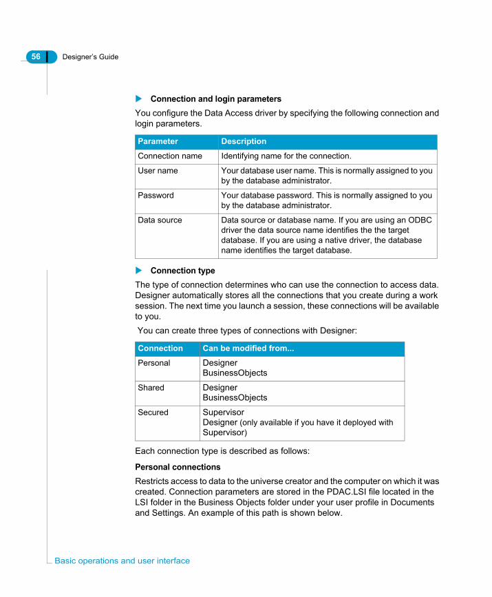
9. Click Next.10.The Advanced Parameter page appears. You can set connection time, array
fetch, and set locked resource options from this page. Refer to the Data Access Guide for a full description of advanced options. You can access the
ic operations and user interface
Designer’s Guide 63
Data access Guide by selecting Help > Data Access from Designer.
11.You can accept the default advanced settings, or type and select advanced options.Click Next.The Custom page appears. You can customize the settings for listed parameters. Refer to the Data Access Guide for a full description of Custom
Setting universe parameters

64 Designer’s Guide
Bas
settings.
12.Accept the default, or modify the listed settings.13.Click Finish.
If you created the connection from the Universe Parameters dialog box, the Universe Parameters dialog box appears with the new connection listed in the Connection box.If you created the connection from the Connections dialog box, the Connections appears. the new connection is now in the list. Click Finish to close the list.
NOTE
Avoid creating two different secured connections with the same name but in different cases; for example, one connection named “Status” and the other named “status.” This can lead to a conflict in the repository.
ic operations and user interface
Designer’s Guide 65
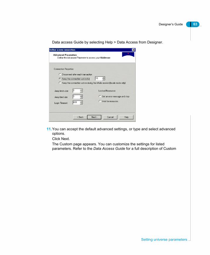
Viewing available connectionsYou can view all available stored connections in the Connections list. You can edit existing connections, and create new connections.To view available connections:1. Select Tools > Connections.
The Connections list appears. It displays all the connections available to the current universe.
2. Click Cancel to close the dialog box.You can edit connections from the Connections dialog box.You can edit a secured connection only if you are working in online mode. Personal and Shared connections can be modified in any mode.You cannot modify the name of an existing connection.
Setting universe parameters

66 Designer’s Guide
Bas
Editing a connectionTo edit a connection:1. Select Tools > Connections.
The Connections list appears.2. Click a connection name in the list of available connections.3. Click the Edit button.
The Login page for the connection appears.
4. Type a new datasource or database name in the Data Source box if required.5. Type modifications to login parameters as required.6. Click Next.
The Perform a Test page appears.7. Click the Test Data Source button to verify the modified connection.8. Click Next to move to the Advanced and Custom pages. You can modify
parameters as required. You can also accept the default or existing values.9. Click Finish from the Custom page to apply the changes to the connection.
ic operations and user interface

Designer’s Guide 67
Deleting a connectionYou can delete connections from the Connections list. You can delete a secured connection only if you are working in online mode. Personal and Shared connections can be deleted in any mode.To delete a connection:1. Select Tools > Connections.
The Connections list appears.2. Select a connection name in the list.3. Click the Remove button.
A confirmation box appears.4. Click Yes.
The connection is removed from the list.
Adding a new connectionYou can add a new connection from the Connections page by selecting Select Tools > Connections, clicking the Add button, and following the Define a new connection wizard. Full Instructions for following the connection wizard are in the section Adding a new connection.
Viewing and entering summary informationThe Summary page displays universe administration information. You can use this information to help you keep track of the development of the active universe.The Summary page displays the following information:
Information Description
Created Universe creation date and the name of the creator.
Modified Date of last modification and the name of the modifier.
Setting universe parameters

68 Designer’s Guide
Bas
Revision Revision number which indicates the number of times the universe has been exported to the repository.
Comments Information about universe for yourself or another designer. This information is only available in Designer. You should include information about the universe for users in the Description field on the Identification page.
Statistics List of the number of classes, objects, tables, aliases, joins, contexts, and hierarchies contained in the universe.
Information Description
ic operations and user interface

Designer’s Guide 69
Viewing and modifying summary informationTo view and modify summary information:1. Select File > Parameters.
OrClick the Parameters tool.The Universe parameters dialog box appears.
2. Click the Summary tab.The Summary page appears.
3. Type a comment in the Comment textbox.4. Click OK.
Selecting strategiesA strategy is a script that automatically extracts structural information from a database or flat file. Strategies have two principle roles:• Automatic join and cardinality detection (Join strategies)• Automatic class, object, and join creation (Objects and Joins strategies)Strategies can be useful if you want to automate the detection and creation of structures in your universe based on the SQL structures in the database.
Setting universe parameters

70 Designer’s Guide
Bas
NOTE
Strategies that automate the creation of universe structures are not necessarily an essential part of universe design and creation. They can be useful if you are creating a universe quickly, allowing you to use meta data information that already exists in a database or database design tool. However, if you are building a universe by creating objects and joins that are based on relationships that come directly from a user needs analysis, then you will probably not use the automatic creation possibilities that strategies offer.
In Designer you can specify two types of strategies:
Strategy Description
Built in strategy
Default strategy shipped with Designer. Built in strategies can not be customized.
External strategy
User defined script that contains the same type of information as a Built in strategy, but customized to optimize information retrieval from a database.
ic operations and user interface
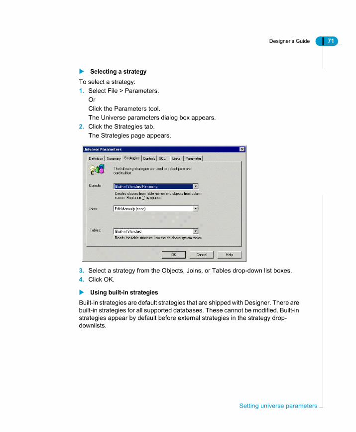
Designer’s Guide 71
Selecting a strategyTo select a strategy:1. Select File > Parameters.
OrClick the Parameters tool.The Universe parameters dialog box appears.
2. Click the Strategies tab.The Strategies page appears.
3. Select a strategy from the Objects, Joins, or Tables drop-down list boxes.4. Click OK.
Using built-in strategiesBuilt-in strategies are default strategies that are shipped with Designer. There are built-in strategies for all supported databases. These cannot be modified. Built-in strategies appear by default before external strategies in the strategy drop-downlists.
Setting universe parameters

72 Designer’s Guide
Bas
You can use built-in strategies for the following purposes:
* These automatic creation uses for strategies must be activated from the Database page of the Options dialog box.
Using the Objects strategyThe Objects strategies are used only for creating classes and objects automatically when you add a table to the table schema. To use this strategy you must activate it from the Database page of the Options dialog box. For more details see the section Using the automatic creation functions of a strategy on page 73.
Using the Joins strategyThe selected Joins strategy determines how Designer automatically detects cardinalities and joins in your table schema.Depending on your database, there can be one or more Join strategies in the list. For example, when using Oracle databases, you can specify a Join strategy to automatically detect joins based either on matching column names, or matching column number names.If you do not select a strategy, Designer uses the default Joins strategy which matches columns names to detect joins. The use of the selected join strategy to detect joins does not have to be activated. The strategy is always used when you choose to detect the joins or cardinalities in your table schema.
Strategy Used for ...
Objects Automatic creation of default clases and objects when tables are created in the table schema.*
Joins • Automatic extraction of default joins when tables are created in the table schema.*
• Automatic insertion of cardinality at join creation.*• Automatic detection of joins in table schema. When you
select Tools > Detect Joins, Designer uses the strategy to automatically detect candidate joins. You can choose to implement the joins or not.
• Automatic detection and insertion of cardinalities for existing joins in the table schema. When you select Tools > Detect Cardinalities, Designer uses the strategy to detect cardinalities for joins selected in the table schema.
Tables Filtering information available for tables in the table browser.
ic operations and user interface
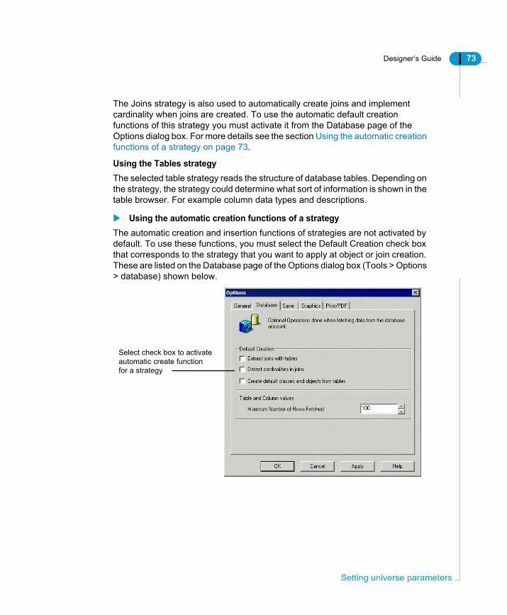
Designer’s Guide 73
The Joins strategy is also used to automatically create joins and implement cardinality when joins are created. To use the automatic default creation functions of this strategy you must activate it from the Database page of the Options dialog box. For more details see the section Using the automatic creation functions of a strategy on page 73.
Using the Tables strategyThe selected table strategy reads the structure of database tables. Depending on the strategy, the strategy could determine what sort of information is shown in the table browser. For example column data types and descriptions.
Using the automatic creation functions of a strategyThe automatic creation and insertion functions of strategies are not activated by default. To use these functions, you must select the Default Creation check box that corresponds to the strategy that you want to apply at object or join creation. These are listed on the Database page of the Options dialog box (Tools > Options > database) shown below.
Select check box to activateautomatic create functionfor a strategy
Setting universe parameters

74 Designer’s Guide
Bas
Each default creation option on the Database page is described as follows:
To select default creation options for strategies:1. Select Tools > Options
The Options dialog bax appears.2. Click the Database Tab.
The Database page appears.3. Select the check box that corresponds to the default creation function for
which you want to use the strategy.4. Click OK.
Option When cleared When selected
Extract joins with tables
Joins must be created manually. If you select Tools > Detect Joins, then Designer uses the strategy to detect joins and proposes candidate joins. You can choose to implement the candidate joins or not.
Retrieves tables with the joins that link them according to the selected Join strategy.
Detect cardinalities in joins
Cardinalities must be manually defined. If you select Tools > Detect Cardinalities, then Designer uses the strategy to detect and implement cardinalities for selected joins.
Detects and implements the cardinalities inherent in the joins at join creation.
Create default classes and objects from tables
Classes and objects must be created manually, either by creating directly in the Universe pane, or by dragging a table or column from the Structure pane to the Universe pane.
Default classes and objects are created in the Universe pane automatically when a table is added to the Structure pane. A class corresponds to the table name, and objects correspond to column names. It replaces all underscore characters (_) with spaces
ic operations and user interface

Designer’s Guide 75
Setting the number of rows to be retrievedFrom the Database Options dialog box, you can also indicate the maximum number of rows to be retrieved from each table of the database. This only applies to the rows returned in Designer, and not for queries run in BusinessObjects or WebIntelligence.To set the number of rows retrieved:• Enter a value in the text box of the Maximum Number of Rows Fetched option.
You can also click one or more times on the up or down arrow to increase or decrease the default value (100).
Using external strategiesAn external strategy is a user defined SQL script that follows a defined output structure to perform customized automatic universe creation tasks. External strategies are stored in an external XML strategy file (<RDBMS>.STG). SQL scripts in this file appear in the drop down list on the Strategies page with the other strategies.External strategies contain the same type of information as the built-in stratgies, but are often customized to allow Designer to retrieve a specific type of database information, or to optimize how information is retrieved from the database.For complete information on defining external strategies, see the section Using external strategies on page 371.
Setting universe parameters

76 Designer’s Guide
Bas
Indicating resource controlsDesigner offers a number of options that let you control the use of system resources. You can specify the following limitations on system resources:
Query Limits Description
Limit size of result set to a specified value
The number of rows that are returned in a query are limited to the number that you specify. This limits the number of rows returned to BusinessObjects, but does not restrict the RDBMS from processing all rows in the query. It only limits the number once the RDBMS has started to send rows.
Limit execution time to a specified value
Query execution time is limited to the number of minutes that you specify. See the section Limiting execution time for queries generating more than one SQL statement on page 77 for more details on this option.This limits the time that data is sent to BusinessObjects, but does not stop the process on the database.
Warn if cost estimate exceeds a specified value
You can implement the display of a warning message if the cost estimate exceeds the number of specified minutes. This feature is only available if your RDBMS supports the cost estimate capability. You can access the database guide for your RDBMS from the Designer online help for specific information on this feature.
Limit size of long text objects to a specified value
You specify the maximum number of characters for long text objects.Note: When this check box is not selected, the parameter is not activated. It is automatically set to the default maximum value (1000). To ensure that you allow results larger than the default, the check box must be selected, and a value entered.
ic operations and user interface

Designer’s Guide 77
Entering resource control informationTo enter resource control information:1. Select File > Parameters.
orClick the Parameters tool.The Universe parameters dialog box appears.
2. Click the Controls tab.The Controls page appears.
3. Select a check box in the Query Limits group box.4. Type a value in the text box that corresponds to the selected Query Limit
option. You can click the up and down arrows at the end of the textboxes to increase or decrease the value entered.
5. Click OK.
Limiting execution time for queries generating more than one SQL statementThe time limit that you specify for query execution is the total execution time for a query. If the query contains multiple SQL statements, then each statement is given an execution time equal to the total query execution time divided by the number of statements, so each statement in the query has the same execution time.If one statement requires a lot more time than others to run, it may not complete, as its execution time will not correspond to its alloted execution time within the query.
Setting universe parameters

78 Designer’s Guide
Bas
When you specify an execution time limit for multiple SQL statements, you need to take into account the normal execution time of the single statement that takes the longest time to run, and multiply this value by the number of statements in the query.
Indicating SQL restrictionsYou can set controls on the types of queries that end users can formulate from the Query Panel in BusinessObjects, or the Query work area in WebIntelligence.You can indicate controls for the following areas of query generation:• Use of subqueries, operators, and complex operands in individual queries.• Generation of multiple SQL statements.• Prevent or warn about the occurrence of a cartesian product.Each of these sets of controls is described in the following sections:
Query controlsYou can set the following controls for individual queries:
Option Description
Allow use of subqueries
Enables end users to formulate subqueries from the Query Panel.
Allow use of union, intersect and minus operators
Enables end users to combine queries using data set operators (union, intersect, and minus) to obtain one set of results.
Allow complex operands in Query Panel
Enables end users to use complex operands in their queries.
ic operations and user interface
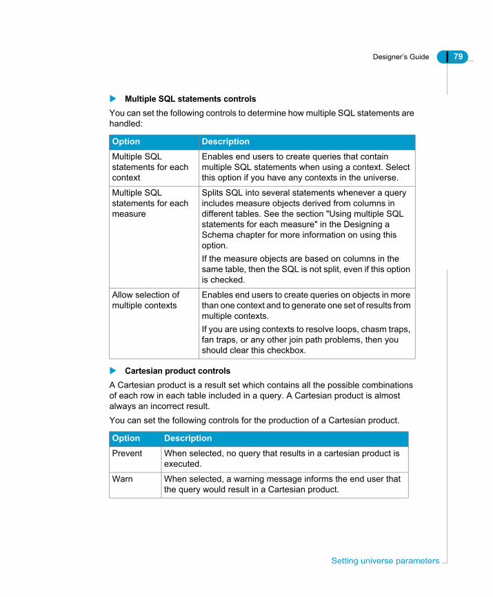
Designer’s Guide 79
Multiple SQL statements controlsYou can set the following controls to determine how multiple SQL statements are handled:
Cartesian product controlsA Cartesian product is a result set which contains all the possible combinations of each row in each table included in a query. A Cartesian product is almost always an incorrect result.You can set the following controls for the production of a Cartesian product.
Option Description
Multiple SQL statements for each context
Enables end users to create queries that contain multiple SQL statements when using a context. Select this option if you have any contexts in the universe.
Multiple SQL statements for each measure
Splits SQL into several statements whenever a query includes measure objects derived from columns in different tables. See the section "Using multiple SQL statements for each measure" in the Designing a Schema chapter for more information on using this option.If the measure objects are based on columns in the same table, then the SQL is not split, even if this option is checked.
Allow selection of multiple contexts
Enables end users to create queries on objects in more than one context and to generate one set of results from multiple contexts.If you are using contexts to resolve loops, chasm traps, fan traps, or any other join path problems, then you should clear this checkbox.
Option Description
Prevent When selected, no query that results in a cartesian product is executed.
Warn When selected, a warning message informs the end user that the query would result in a Cartesian product.
Setting universe parameters

80 Designer’s Guide
Bas
Entering SQL restriction optionsTo enter SQL restriction options:1. Select File>Parameters.
OrClick the Parameters tool.The Universe parameters dialog box appears.
2. Click the SQL tab.The SQL page appears.
3. Select or clear options in the Query and Multiple Paths group boxes.4. Select a radio button in the Cartesian Product group box.5. Click OK.
Indicating options for linked universesThe Links tab is used with dynamically linked universes, a subject covered in the Managing Universes chapter.
ic operations and user interface

Designer’s Guide 81
Setting SQL generation parametersIn Designer, you can dynamically configure certain SQL parameters that are common to most RDBMS to optimize the SQL generated in BusinessObjects and WebIntelligence products using the universe.
Using parameter (PRM) files in previous versions of DesignerIn previous versions of Designer, the SQL generation parameters used by a universe were maintained and edited in a separate file called a parameters (PRM) file. The values set in the PRM file applied to all universes using the associated data access driver defined for a connection.Many of the SQL parameters that are used to optimize query generation are now controlled within an individual universe file. The PRM file is now no longer used for the query generation parameters that you can set in Designer. PRM files are still used for parameters that are database specific.
NOTE
See the Data Access Guide for more information on the PRM file for your data access driver. You can access this guide by selecting Help > Data Access Guide.
Setting the SQL parameters dynamically in DesignerMany of the parameters common to most supported RDBMS middleware are available for editing in the Parameters tab in the universe parameters dialog box (File > Parameters > Parameter).These parameters apply only to the active universe, and are saved in the UNV file. When you modify an SQL parameter for a universe in Designer, the value defined in Designer is used, and not the value defined in the PRM file associated with the data access driver for the connection.
Editing SQL generation parametersYou can modify the values for SQL parameters that determine SQL generation in products using the universe.
Setting universe parameters

82 Designer’s Guide
Bas
To edit SQL generation parameters:1. Select File > Parameters.
The Parameters dialog box appears.2. Click the Parameter tab.
The Parameter page appears.
ic operations and user interface

Designer’s Guide 83
3. Edit, add, or remove parameters as follows:
3. Click OK.
NOTE
The SQL generation parameter values that you set in a universe, are only available to products using that universe.
To... then do the following:
Add a new parameter 1. Click any parameter in the list.2. Type a name in the Name box3. Type a value in the Value box.4. Click Add.
The new value appears at the bottom of the list
Change name or value 1. Click a parameter in the list.2. Type a new name in the Name box3. Type a new value in the Value box.4. Click Replace.
The value is replaced by the new definition.
Delete a parameter 1. Click the parameter that you want to remove from the list.
2. Click Delete.
Setting universe parameters

84 Designer’s Guide
Bas
Universe SQL parameters referenceThis section provides an alphabetical reference for the SQL generation parameters listed in the Parameter page of the Universe Parameters dialog box in Designer. These are SQL parameters that are common to most data access drivers. Each parameter is valid for the universe in which it is set. Other RDBMS specific and connection parameters are listed in the data access parameter (PRM) file for the target data access driver. Refer to the Data Access guide for a reference to the parameters in the PRM file.
ANSI92ANSI92 = Yes|No
AUTO_UPDATE_QUERYAUTO_UPDATE_QUERY = Yes|No
Values Yes|No
Default No
Description Specifies whether the SQL generated complies to the ANSI92 standard.Yes: Enables the SQL generation compliant to ANSI92 standard.No: SQL generation behaves according to the PRM parameter OUTER_JOIN_GENERATION.
Values Yes|No
Default Yes
Description Determines what happens when an object in a query is not available to a user profile.Yes: Query is updated and the object is removed from the query.No: Object is kept in the query.
ic operations and user interface

Designer’s Guide 85
BLOB_COMPARISONBLOB_COMPARISON = Yes|No
Values Yes|No
Default No
Can be edited? No
Description Species if a query can be generated with a DISTINCT statement when a BLOB file is used in the SELECT statement. It is related to the setting "No Duplicate Row" in the query properties.Yes: The DISTINCT statement can be used within the query. No: The DISTINCT statement cannot be used within the query even if the query setting "No Duplicate Row" is on.
Setting universe parameters

86 Designer’s Guide
Bas
BOUNDARY_WEIGHT_TABLE BOUNDARY_WEIGHT_TABLE = Integer 32bits [0-9]
COLUMNS_SORTCOLUMNS_SORT = Yes|No
Values Integer 32bits [0-9]
Default -1
Description Allows you to optimize the FROM clause when tables have many rows.If the table size is greater than the entered value, the table is declared as a subquery:FROM (SELECT col1, col2,...., coln FROM Table_Name WHERE simple condition).
A simple condition is defined as not having a subquery, and not having EXCEPT or BOTH operators.
Limitations Optimization is not implemented when:• the operator OR is in the query condition• only one table is involved in the SQL• the query contains an outer join• no condition is defined on the table that is being
optimized• the table being optimized is a derived table.
Values YES Columns are displayed in alphabetical orderNO Columns are displayed in the order they were retrieved from the database
Default No
Description Determines the order that columns are displayed in tables in the Structure pane.
ic operations and user interface

Designer’s Guide 87
COMBINE_WITHOUT_PARENTHESISCOMBINE_WITHOUT_PARENTHESIS=No
Values YES Removes the parentheses.NO Leaves the parentheses.
Default No
Description Specifies whether or not to encapsulate a query with parentheses when it contains UNION, INTERSECT or MINUS operators. Used with RedBrick.
Setting universe parameters
88 Designer’s Guide
Bas
COMBINED_WITH_SYNCHROCOMBINED_WITH_SYNCHRO = Y|N
CORE_ORDER_PRIORITYCORE_ORDER_PRIORITY = Yes|No
Values Yes|No
Default No
Description Specifies whether to allow a query to execute that contains UNION, INTERSECTION, or EXCEPT operators, and whose objects in each subquery are incompatible.Yes: Specifies that you do allow a query to execute that contains UNION, INTERSECTION and EXCEPT operators, and whose objects in each subquery are incompatible. This type of query generates synchronization (two blocks in the report).No: Specifies that you do not allow a query to execute that contains UNION, INTERSECTION and EXCEPT operators, and whose objects in each subquery are incompatible. When the query is executed the following error message is displayed: “This query is too complex. One of the subqueries contains incompatible objects.” This is the default value.
Values Yes|No
Default Yes
Description Specifies in which order you want classes and objects to be organized once two or more universes are linked in Designer.Yes: Specifies that classes and objects follow the order defined in the kernel universe.No: Specifies that classes and objects follow the order defined in the derived universe. This is the default value.
ic operations and user interface

Designer’s Guide 89
CORRECT_AGGREGATED_CONDITIONS_IF_DRILLCORRECT_AGGREGATED_CONDITIONS_IF_DRILL = Yes|No
CUMULATIVE_OBJECT_WHERECUMULATIVE_OBJECT_WHERE = Y|N
Values Yes|No
Default No
Description Specifies whether BusinessObjects can aggregate measures in queries and conditions.Yes: BusinessObjects can aggregate measures separately in the main query and the condition, if the query is drill enabled. No: BusinessObjects cannot aggregate measures separately in the main query and the condition, if the query is drill enabled.
Values Yes|No
Default No
Description Specifies the order of WHERE clauses that have the AND connective.Yes: Specifies that WHERE clauses that have the AND connective are set at the end of the condition.No: Specifies that WHERE clauses follow standard SQL syntax.Example:If the condition is find all French clients different from John or American cities different from New York, the SQL is then:WHERE (customer.first_name <> ‘John’)OR (city.city <> ‘New York’)AND customer_country.country = ‘France’AND city_country.country = ‘USA’
Setting universe parameters

90 Designer’s Guide
Bas
DECIMAL_COMMADECIMAL_COMMA = Yes|No
DISTINCT_VALUESDISTINCT_VALUES = GROUPBY|DISTINCT
Values Yes|No
Default Yes
Description Specifies that Business Objects products insert a comma as a decimal separator when necessary.Yes: Business Objects products insert a comma as a decimal separator when necessary.No: Business Objects products do not insert a comma as a decimal separator. This is the default value.
Values GROUPBY|DISTINCT
Default DISTINCT
Description Specifies whether SQL is generated with a DISTINCT or GROUPBY clause in a list of values and query panel when the option “Do not retrieve duplicate rows” is active.DISTINCT: The SQL is generated with a DISTINCT clause, for example;SELECT DISTINCTcust_nameFROMCustomersGROUPBY: The SQL is generated with a GROUP BY clause, for example;SELECTcust_nameFROMCustomersGROUPBY cust_name
ic operations and user interface

Designer’s Guide 91
END_SQL END_SQL = String
EVAL_WITHOUT_PARENTHESISEVAL_WITHOUT_PARENTHESIS = Yes|No
Values String
Default <empty string>
Description The statement specified in this parameter is added at the end of each SQL statement.
Example For IBM DB2 databases, you can use the following:END_SQL=FOR SELECT ONLYThe server will read blocks of data much faster.
Values Yes|No
Default No
Description By default, the function @Select(Class\object) is replaced by the Select statement for the object <Class\object> enclosed within brackets.For example, when combining two @Select statements, @select( objet1) *@select(objet2).If the SQL(objet1) = A-B and SQL(objet2) =C,then the operation is ( A-B ) * ( C ).You avoid the default adding of brackets by setting EVAL_WITHOUT_PARENTHESIS = Yes. The operation is then A - B * C.Yes: Brackets are removed from the Select statement for a function @Select(Class\object)No: Brackets are added around the Select statement for the function @Select(Class\object).
Setting universe parameters

92 Designer’s Guide
Bas
FILTER_IN_FROMFILTER_IN_FROM = Yes|No
FIRST_LOCAL_CLASS_PRIORITYFIRST_LOCAL_CLASS_PRIORITY = Yes|No
FORCE_SORTED_LOV FORCE_SORTED_LOV = Yes|No
Values Yes|No
Default No
Description Determines if query conditions are included in the FROM Clause. This setting is only applicable if the other universe parameter setting ANSI92 is set to Yes.Yes: When editing an outer join, the default behavior property selected in the drop down list box of the Advanced Join properties dialog box in Designer, is set to "All objects in FROM".No: When editing an outer join, the default behavior property selected in the drop down list box of the Advanced Join properties dialog box in Designer is set to "No object in FROM".
Values Yes|No
Default No
Description Only taken into account when CORE_ORDER_PRIORITY=Yes.Yes: Classes in derived universe are placed first.No: Objects and sub classes from derived universe appear after those of the core universe.
Values Yes|No
Default No
Description Retrieves a list of values that is sorted.Yes: Specifies that the list of values is sorted.No: Specifies that the list of values is not sorted.
ic operations and user interface

Designer’s Guide 93
MAX_INLIST_VALUESMAX_INLIST_VALUES = 99]
PATH_FINDER_OFFParameter is not listed by default. You must add the parameter manually to the lust and set a value. See Editing SQL generation parameters on page 81.PATH_FINDER_OFF= Y|N
Values Integer: min 0, max 256
Default 99
Description Allows you to increase to 256 the number of values you may enter in a condition when you use the IN LIST operator.99: Specifies that you may enter up to 99 values when you create a condition using the IN LIST operator. This is the default value.256: Specifies that you may enter up to 256 values when you create a condition using the IN LIST operator. 256 is the maximum authorized value you may enter.
Values Y|N
Default No default. You must manually enter the parameter.
Description Used for HPIW because the join generation is done by the database.Y: Joins are NOT generated in the query.N: Joins are generated in the query. This is the default behaviour.
Setting universe parameters
94 Designer’s Guide
Bas
REPLACE_COMMA_BY_CONCATREPLACE_COMMA_BY_SEPARATOR= Yes|No
Values Yes|No
Default Yes
Description In previous versions of Designer, a comma could be used to separate multiple fields in an object Select statement. The comma was treated as a concatenation operator. For universes that already use the comma in this way you can set REPLACE_COMMA_BY_SEPARATOR to No to keep this behavior. In the current version of Designer, this parameter is set to Yes by default, so that a expressions using a comma in this way are automatically changed to use concatenation syntax.Yes: Comma is replaced by the concatenation expression when multi field object is found.No: Keep the comma as it is.
ic operations and user interface
Designer’s Guide 95
SHORTCUT_BEHAVIOR SHORTCUT_BEHAVIOUR = Global|Successive
Values Global|Successive
Default Successive
Description Specifies how shortcut joins are applied. This parameter was formerly listed as GLOBAL_SHORTCUTS in the PRM files. The values have been changed to Global for Yes, and Successive for No.Global: Specifies that a shortcut joins are considered one by one. A shortcut join is applied only if it really bypasses one or more tables, and if it does not remove a table from the join path used by a following shortcut join. This is the default value.Successive: Specifies that all shortcut joins are applied. Note: If it generates a Cartesian product, no shortcut joins are applied.
Setting universe parameters
96 Designer’s Guide
Bas
THOROUGH_PARSETHOROUGH_PARSE = Yes|No
UNICODE_STRINGSUNICODE_STRINGS = Yes|No
Values Yes|No
Default No
Description Specifies the methodology used for default Parsing in the Query panel and individual object parsing.Yes: PREPARE, DESCRIBE, and EXECUTE statements are used to parse SQL for objects.Prepare+DescribeCol+ExecuteNo: PREPARE and DESCRIBE statements are used to parse SQL for objects.
Values Yes|No
Default No
Description Specifies whether the current universe can manipulate Unicode strings or not. Only applies to Microsoft SQL Server and Oracle 9. If the database character set in the SBO file is set as Unicode, then it is necessary to modify the SQL generation to handle specific Unicode column types like NCHAR and NVARCHAR. Yes: Conditions based on strings are formatted in the SQL according to the value for a parameter UNICODE_PATTERN in the PRM file, for example for MS SQL Server (sqlsrv.prm): UNICODE_PATTERN=N$The condition Customer_name='Arai ' becomesCustomer_name=N'Arai'.No: All conditions based on strings are formatted in the standard SQL. For example the condition Customer_name='Arai ' remains Customer_name='Arai'
ic operations and user interface
Designer’s Guide 97
Using the Designer user interfaceThe Designer interface user interface complies with Microsoft Windows standards. It features windows, menus, toolbars, shortcut keys, and online help.
The main components of the user interfaceEach universe is contained within a single universe window, which is contained within the Designer main window.You also use an independant window called a Table browser which shows all the tables available in the connected database.
Universe windowThe universe window is divided into two panes:
Table browserThe Table browser is a window that displays the tables available in the connected database. You can insert tables into the Structure pane by selecting the table and dragging it into the Structure pane, or by double-clicking the appropriate table in the Table browser.You can display the Table browser by any of the following methods:• Double-click the Structure pane background.• Right-click the Structure pane background and select Insert Table from the
contextual menu.• Select Insert > Tables.
NOTE
Using the table browser is described fully in the Designing a Schema chapter.
Pane Displays
Structure Graphical representation of the underlying target database of the universe. It includes the tables and joins to which you map objects that end users use to run their queries.
Universe Classes and objects defined in the universe. These are the components of the universe that the BusinessObjects and WebIntelligence users see and use to create their queries.
Using the Designer user interface

98 Designer’s Guide
Bas
the Designer user interfaceThe main components of the interface are labeled below:
Manipulating windows You can use the windows in the Designer user interface in the following ways:• In a work session, you can work on more than one universe at a time.
Designer displays each universe in one Structure pane and in one Universe pane.
• Recently opened universes are listed at the bottom of the File menu. You can modify the number of universes listed by selecting Tools > Options > General, and indicating the number of universes in the Recent File List.
• You can move, resize, or minimize any window within the Designer window.• You can position these windows in the way you find most convenient by
Selecting Window > Arrange, and selecting Cascade, Tile Horizontally, or Tile Vertically.
• You can line up all windows that were minimized in the Designer window by selecting Window > Arrange Icons.
Structurepane
Table Browser
Menu
Standard
Status bar Minimized window
Editing toolbar
Universe
Formula bar
pane
toolbar
ic operations and user interface
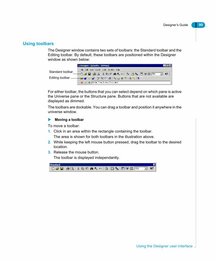
Designer’s Guide 99
Using toolbarsThe Designer window contains two sets of toolbars: the Standard toolbar and the Editing toolbar. By default, these toolbars are positioned within the Designer window as shown below:
For either toolbar, the buttons that you can select depend on which pane is active the Universe pane or the Structure pane. Buttons that are not available are displayed as dimmed.The toolbars are dockable. You can drag a toolbar and position it anywhere in the universe window.
Moving a toolbarTo move a toolbar:1. Click in an area within the rectangle containing the toolbar.
The area is shown for both toolbars in the illustration above.2. While keeping the left mouse button pressed, drag the toolbar to the desired
location.3. Release the mouse button.
The toolbar is displayed independantly.
Standard toolbar
Editing toolbar
Using the Designer user interface

100 Designer’s Guide
Bas
Hiding and showing toolbarsTo display or hide either toolbar alternately:1. Select View > Toolbars.
The Toolbars dialog box appears.
2. Select or clear checkboxes corresponding to toolbars.3. Select or clear options for the display of the toolbar buttons, tooltips, and
shortcut keys listed at the bottom of the dialog box.4. Click OK.
Performing an action or operation in DesignerIn Designer, you perform an action or operation in the following ways:• Select a command from a menu• Press the Alt key and enter a shortcut key from the keyboard• Click a button on the toolbar.
Using the mouse in DesignerIn Designer, you can use single and double mouse clicks as follows:
Single clickYou use a single click for the following actions:• performing a standard action (selecting a command or clicking a button)• selecting an element from the Universe pane, the Structure pane, or the Table
Browser.• If you select one or more components within the Designer window, a single-
click with the right mouse button causes a pop-up menu to be displayed. It
ic operations and user interface
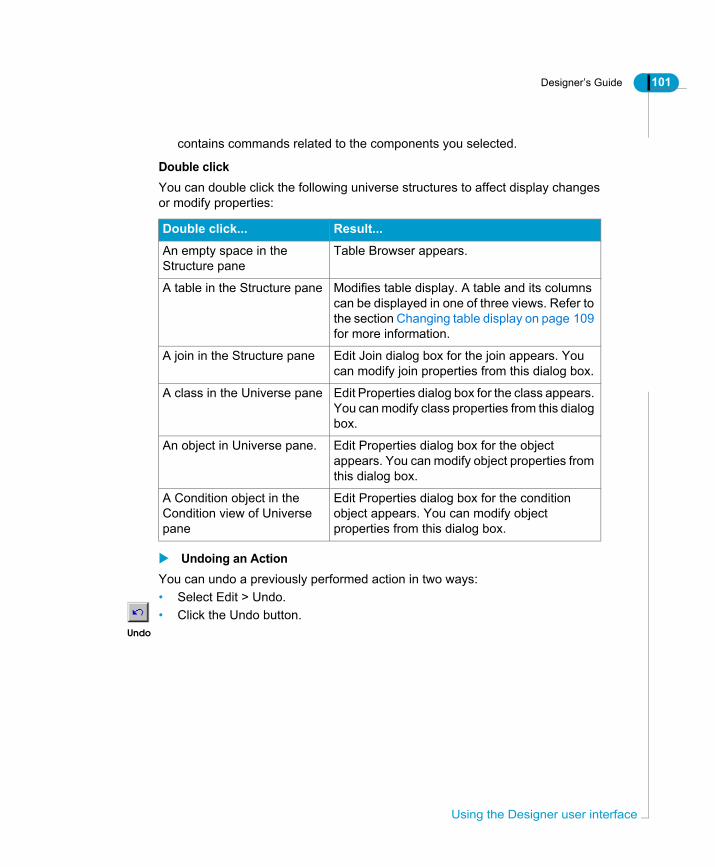
Designer’s Guide 101
contains commands related to the components you selected.
Double clickYou can double click the following universe structures to affect display changes or modify properties:
Undoing an Action You can undo a previously performed action in two ways:• Select Edit > Undo.• Click the Undo button.
Double click... Result...
An empty space in the Structure pane
Table Browser appears.
A table in the Structure pane Modifies table display. A table and its columns can be displayed in one of three views. Refer to the section Changing table display on page 109 for more information.
A join in the Structure pane Edit Join dialog box for the join appears. You can modify join properties from this dialog box.
A class in the Universe pane Edit Properties dialog box for the class appears. You can modify class properties from this dialog box.
An object in Universe pane. Edit Properties dialog box for the object appears. You can modify object properties from this dialog box.
A Condition object in the Condition view of Universe pane
Edit Properties dialog box for the condition object appears. You can modify object properties from this dialog box.
Undo
Using the Designer user interface

102 Designer’s Guide
Bas
Find and ReplaceYou can use Find to locate characters or a text string in both the universe and structure panes. You can use Find and Replace to locate and replace characters or text in the names and descriptions for any structure in the universe.
Using FindYou can search for text contained in universe structures in the universe and structure panes.
Setting Find optionsThe Find options available are dependant on whether the Universe pane or the Structure pane is active.You can set the following search options to locate a string:
Option Option is available... Description
Find What When Universe or Structure pane is active
Text string to search.
Match Case When Universe or Structure pane is active
Include upper and lower case character match in search.
Match whole word only
When Universe or Structure pane is active
Match on entire string.
Look also in names
When Universe pane is active
When selected, searches class and object names or predefined condition names only.When cleared, class, object or predefined condition names are not included in search.
Look also in descriptions
When Universe pane is active
When selected, includes all descriptions of universe structures in search.
Look also in SQL
When Universe pane is active
When selected, includes SQL definitions of objects, joins, and other universe structures in search.
ic operations and user interface
Designer’s Guide 103
Searching in a universeTo search in a universe:1. Click in the Universe or Structure pane.
You want to find a string in this pane.2. Select Edit > Find.
The Find and Replace box appears. The box for an active Universe pane is below.
The box for an active Structure pane appears below.
3. Type a character or a string in the Find What text box.4. Select or clear search option text boxes.5. Click Find Next.
When a character or string is found in the universe pane, the object is highlighted. When an instance is found in an object description, or SQL definition, the object properties box is opened automatically, and the character or string highlighted.
6. Click Find Next to search for another instance of the search string.7. Click Cancel to close the Find box.
Find and Replace

104 Designer’s Guide
Bas
Searching and replacing in a universeTo search and replace a character or string in a universe:1. Select Edit > Replace Next.
The Find and Replace box appears.2. Type a character or a string in the Find What text box.
3. Type a character or a string in the Replace box. This is the text item that you want to replace an instance of the contents of the Find What box.
4. Select or clear search option text boxes.5. Click Replace if you want to replace a text item each time an instance is
found.OrClick Replace All to automatically replace all instances in the universe.If you replace found items individually, the object properties box automatically opens and becomes the active box when an item appears in an object description. You need to click the Find and Replace box to continue the search.
ic operations and user interface

Designer’s Guide 105
Using Quick FindYou can search the active pane by typing the first letter of the search string in a search box at the bottom of the Universe pane.
If the Universe pane is active, the search is performed on class and object names.If the Structure pane is active, the search is performed on table names.
Quick Find text box
Find and Replace

106 Designer’s Guide
Bas
Organizing the table displayThis section describes the graphic features that you can use to organize and manipulate tables in the structure pane. The design methodolgy that you use to design the schema, and what you need to know to create a successful schema in the Structure pane, is described in the following chapter "Designing a Schema."
How are tables represented?In the Structure pane, tables are represented graphically as rectangular symbols. The name of the table appears within a strip in the upper part of the rectangle. The list of items within the rectangle represents the columns of the table. The lines connecting the tables are the joins.
Manipulating tablesYou can perform the following actions to manipulate tables in the Structure pane:
Selecting tablesYou can select tables as follows:
To undo a selection, place the pointer away from the tables and click again.
To select... Do the following...
One table Click the table.
Several tables • Hold left mouse button down while drawing a selection border around the tables.
• Click multiple tables while holding down the SHIFT key.
All tables at once Select Edit > Select All.
ic operations and user interface

Designer’s Guide 107
Deleting tablesTo delete a table:1. Select a table.2. Do one of the following actions:• Click the Cut button on the Standard toolbar.• Select Edit > Cut.• Press the Delete key.
Using List modeYou can use List Mode to list the tables, joins, and contexts used in the active universe. In List Mode Designer adds three panes above the display of the Structure pane. These panes are labeled Tables, Joins, and Contexts as shown below:
Cut
Table pane Joins pane Contexts pane
Organizing the table display
108 Designer’s Guide
Bas
You can use List Mode in the following ways:
Using the triangles between panes to filter listed componentsThe small triangles that appear between the panes act as filters on the display of the components. For example:• You click a table name in the Tables pane, and then click the triangle pointing
to the Joins pane. The Joins pane now shows only the joins of the selected table.
• You click a join name in the Joins pane, and then click the triangle pointing to the Tables pane. The Tables pane now only shows the tables linked by the join.
Returning to normal view from List ModeYou can remove List view and return to normal view in two ways:• When in List Mode, select View > List Mode.• When in List Mode, click the List Mode button.
Action Result
Click a listed component in any of the List mode panes.
Component is highlighted in Structure pane.
Select a table, join, or context in the Structure pane.
Corresponding listed companent in List pane is highlighted.
Double click a table name in the Table pane.
Rename Table box appears. You can rename the table and depending on the database, edit table owner and qualifier.
Double click a join name in the Joins pane.
Edit Join box for the join appears. You can edit join properties.
Double click a context name in the Contexts pane.
Edit Context box appears. You can add joins to the selected context by pressing CTRL and clicking joins in the list.
Click a component then click a triangle between two List panes.
Components in neighbouring list pane related to original component are displayed. All non-related components are filtered out.
Click on separator line between List pane and Structure pane, then drag line up or down.
List pane enlarges or decreases size depending on drag direction.
List Mode
ic operations and user interface
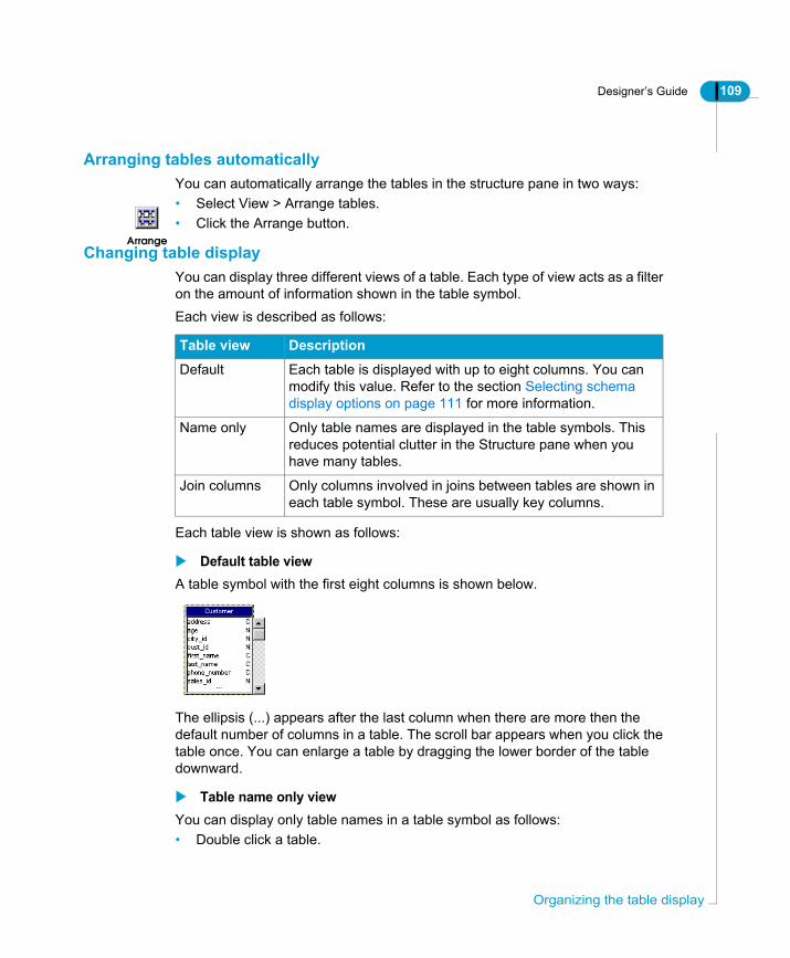
Designer’s Guide 109
Arranging tables automaticallyYou can automatically arrange the tables in the structure pane in two ways:• Select View > Arrange tables.• Click the Arrange button.
Changing table displayYou can display three different views of a table. Each type of view acts as a filter on the amount of information shown in the table symbol.Each view is described as follows:
Each table view is shown as follows:
Default table viewA table symbol with the first eight columns is shown below.
The ellipsis (...) appears after the last column when there are more then the default number of columns in a table. The scroll bar appears when you click the table once. You can enlarge a table by dragging the lower border of the table downward.
Table name only viewYou can display only table names in a table symbol as follows:• Double click a table.
Arrange
Table view Description
Default Each table is displayed with up to eight columns. You can modify this value. Refer to the section Selecting schema display options on page 111 for more information.
Name only Only table names are displayed in the table symbols. This reduces potential clutter in the Structure pane when you have many tables.
Join columns Only columns involved in joins between tables are shown in each table symbol. These are usually key columns.
Organizing the table display
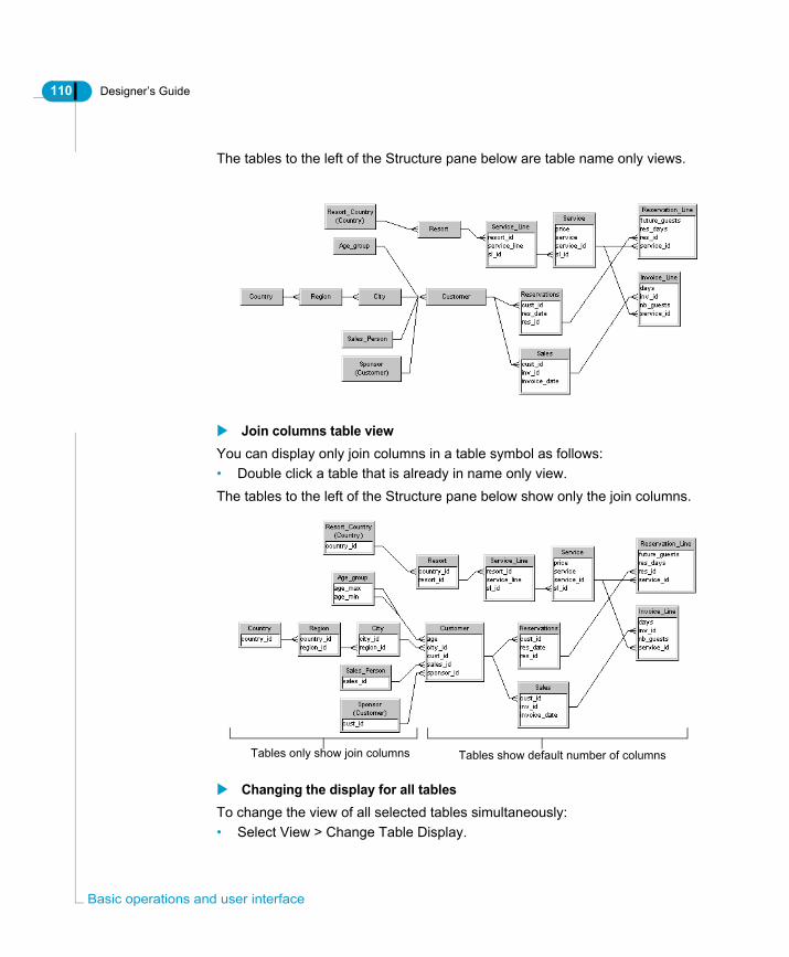
110 Designer’s Guide
Bas
The tables to the left of the Structure pane below are table name only views.
Join columns table viewYou can display only join columns in a table symbol as follows:• Double click a table that is already in name only view.The tables to the left of the Structure pane below show only the join columns.
Changing the display for all tablesTo change the view of all selected tables simultaneously:• Select View > Change Table Display.
Tables only show join columns Tables show default number of columns
ic operations and user interface

Designer’s Guide 111
Selecting schema display optionsYou can customize the shape or appearance of the tables, columns, joins, and cardinalities in the Structure pane.You have the following graphical options for the display of components in the structure pane:
Option Description
Join shape Joins can be represented as different types of simple lines, or as lines that include cardinality indicators such as crows feet ends, or cardinality ratios.
Best Side When selected the join linking two tables is automatically evaluated as being better displayed on the left or right side of one table, ending on the left or right side of another table, and having the shortest length.
Tables Tables can have 3D effect, show an aliased name, or show the number of rows. To display the number of rows in each table, you also need to refresh the row count by selecting View > Number of Rows in Table. This is described in the section Viewing the number of rows in database tables on page 116.
Columns A column data type can be displayed next to the column. Key columns can be underlined, and columns can also be shown left justified in the table symbol, or centered.
Default number of columns
You can type the default number of columns that are shown in a table symbol. If a table has more than the default number, the table symbol appears with an ellipsis (...) at the end of the column list. When you click the table once, a scroll bar appears at the side of the table.
Center on selection
The view of the Structure pane based on a calculated center point.
Selecting schema display options

112 Designer’s Guide
Bas
Setting graphic options for the Structure pane displayYou can set graphic options for the components of the Structure pane as follows:1. Select Tools > Options.
The Options dialog box appears.2. Click the Graphics tab.
The Graphics page appears. It lists graphic options for components in the structure pane.
3. Select or type graphic display options.4. Click OK.
Examples of graphical optionsThe following are some examples of the possible graphical representations of components in the structure pane using the graphical options available in the Options dialog box (Tools > Options > Graphics).
Aliased nameWhen selected an aliased table in the Structure pane is displayed both with its name and the name of the table from which it is derived, in parentheses, as shown below.
Show Row Count and Show FormatWhen Show Row Count is selected the number of rows in each table appears at the bottom of each table symbol. You need to select View > Number of rows in Table to refresh row numbers for all tables before the row count is displayed.
ic operations and user interface
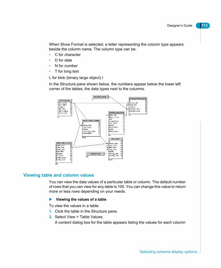
Designer’s Guide 113
When Show Format is selected, a letter representing the column type appears beside the column name. The column type can be:• C for character• D for date• N for number• T for long textL for blob (binary large object).IIn the Structure pane shown below, the numbers appear below the lower left corner of the tables, the data types next to the columns.
Viewing table and column valuesYou can view the data values of a particular table or column. The default number of rows that you can view for any table is 100. You can change this value to return more or less rows depending on your needs.
Viewing the values of a tableTo view the values in a table:1. Click the table in the Structure pane.2. Select View > Table Values.
A content dialog box for the table appears listing the values for each column
Selecting schema display options

114 Designer’s Guide
Bas
in the table.
3. Select the Distinct Values check box if you want to show only distinct values.4. Click Close.
Viewing the values of a columnWhen viewing column values you can enlarge the view of the columns by selecting View > Zoom In. This makes it easier to select a column.You can view the values for an individuel column as follows:1. Place the pointer over a table column in the Structure pane.
The pointer is transformed into a hand symbol.2. Right click the column and select View Column Values from the contextual
ic operations and user interface

Designer’s Guide 115
menu.A content dialog box for the column appears listing the column values.
3. Select the Distinct Values check box if you want to show only distinct values.4. Click Close.
Modifying the default value for number of returned rowsYou can modify the default value for the number of rows returned when you view table or column values. This can be useful if you only want to view a small sample of the values in a table, so you can restrict the returned values to a smaller number.To modify the number of rows fetched for a table:1. Select Tools > Options.
The Options dialog box appears.2. Click the Database tab.
The Database page appears.3. Type or select a number using the up and down arrows from the Table and
Column Values list box.The Database page below has 20 rows specified to be returned when values
Selecting schema display options

116 Designer’s Guide
Bas
are viewed for a table or column.
4. Click OK.
Viewing the number of rows in database tablesYou can display the number of rows in each table. You do this in two stages:• Activate the graphic option Show Row Count (Tools > Options > Graphics),• Refresh the row count for all tables by selecting View > Number of Rows in
Table.You can display the number of rows in each table in the database, or you can set a fixed number of rows for a selected table to optimize query performance. This allows you to control the order of tables in a From clause, which is based on table weight. This is described in the section Modifying the row count of a table on page 119.
NOTE
Displaying the number of rows in a table is not the same as setting the number of rows that are returned to view table or column values.
ic operations and user interface
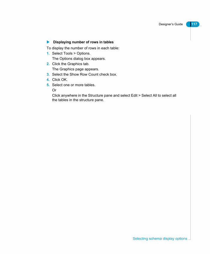
Designer’s Guide 117
Displaying number of rows in tablesTo display the number of rows in each table:1. Select Tools > Options.
The Options dialog box appears.2. Click the Graphics tab.
The Graphics page appears.3. Select the Show Row Count check box.4. Click OK.5. Select one or more tables.
OrClick anywhere in the Structure pane and select Edit > Select All to select all the tables in the structure pane.
Selecting schema display options

118 Designer’s Guide
Bas
NOTE
When you click in the Structure pane, you activate the menu items that relate to the components in the Structure pane. If you do not click in the Structure pane before selecting a menu item, only the menu items that apply to the Universe pane are available.
6. Select View > Number of rows in Table.The Table Row count box appears.
The options in this dialog box are described below:
7. Select the Refresh Row Count for All Tables radio button.8. Click OK.
The row count for each selected table appears under the bottom left corner of each table symbol in the Structure pane.
Option Description
Refresh row count for all tables
Refreshes the display of the row count for selected tables, or all the tables in the Structure pane.
Refresh undefined table row count only
Displays the row count of tables that were previously unselected. As a result, all the tables in the Structure pane appear with their row count.
Modify manually tables row count
Lets you modify the row count for either selected tables or all the tables in the Structure pane. Enter the new value in the text box beside the option. This option is used for optimizing queries, a topic covered in the next section.
ic operations and user interface
Designer’s Guide 119
Modifying the row count of a tableYou can modify the row count of tables. Two reasons for doing this are as follows:
To modify row count of one or more tables:1. Select Tools > Options.
The Options dialog box appears.2. Click the Graphics tab.
The Graphics page appears.3. Select the Show Row Count check box.4. Click OK.5. Select one or more tables.
OrClick anywhere in the Structure pane and select Edit > Select All to select all
Modify row count to...
Description
Optimize queries Query optimization is based on the order of the tables in the FROM clause of the generated SQL. Tables with many rows appear before tables with fewer rows. This order can be important especially for RDBMS that lack an optimizer feature.By modifying the row count of tables, you can change their order in the FROM clause.
Adapt row count to a subsequent change in data capacity
You can modify the row count of a table when the row count does not reflect the number of rows a table is to hold. For example, you can work with a test table having a row count of 100 even though the table will contain 50,000 rows.
Selecting schema display options

120 Designer’s Guide
Bas
the tables in the structure pane.6. Select View > Number of rows in Table.
The Table Row count box appears. 7. Select the Modify Manually Tables Row Count radio button.8. Type the number of rows that you want to display for the table.
9. Click OK.The row count for each selected table appears under the bottom left corner of each table symbol in the Structure pane.
ic operations and user interface

Designer’s Guide 121
Printing a universeDesigner provides all standard Windows print facilities. You can print out the schema, as well as lists of the tables, columns, and joins in the Structure pane. You can also control the way the components and information appear on a printed page.
NOTE
You can print out a PDF version of the universe definition and schema by saving the universe as a PDF> file, then printing the PDF file. See the section Saving a universe definition as PDF on page 48 for more information.
Setting print optionsYou can select print options from the Print page of the Options dialog box (Tools > Options > Print). The Print options that you set, also apply to the options that are saved to a PDF file when you save the universe definition as PDF. You can select the following print and PDF options:
Print option Prints out...
General information
Information on the following:• Universe parameters• Linked universesThe graphical structure of the schema in the Structural pane. You can select the scale for this graphic.
Component lists
Lists of components in the universe grouped by one or more of the following types: objects, conditions, hierarchies, tables, joins, and contexts.
Component descriptions
Descriptions for the following components: objects, conditions, hierarchies, tables, joins, and contexts.The description includes detailed information on the properties of the component. For an object, this information can include the SQL definition, qualification and security access level.
Printing a universe

122 Designer’s Guide
Bas
To set print options for a universe:1. Select Tools > Options.
The Options dialog box appears.2. Click the Print/PDF tab.
The Print page appears.
3. Select print option check boxes as required.4. Click OK.
Specifying Page SetupTo specify page setup options:1. Select File > Page Setup.
The Page Setup sheet appears. 2. Select or type page setup options.3. Click OK.
Using Print PreviewYou can preview your universe before printing in two ways:• Select File > print Preview.• Click the Print Preview button.
Print Preview
ic operations and user interface
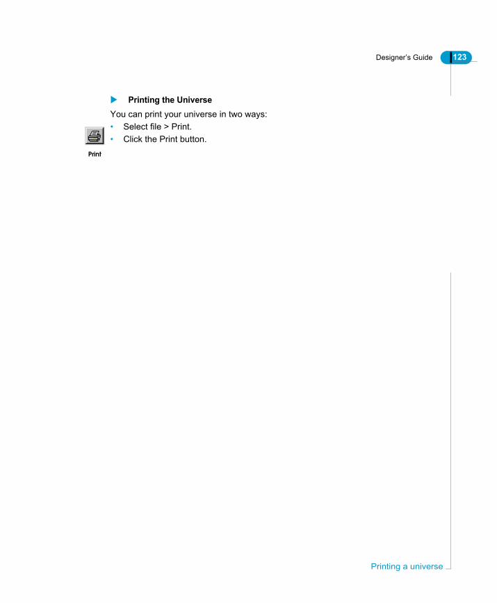
Designer’s Guide 123
Printing the UniverseYou can print your universe in two ways:• Select file > Print.• Click the Print button.
Printing a universe

124 Designer’s Guide
Bas
ic operations and user interface
Inserting tables and joins
chapter

126 Designer’s Guide
Inse
OverviewThis chapter describes how you can create a schema that contains all the SQL structures necessary to build the objects that BusinessObjects and WebIntelligence users use to build reports. These SQL structures include tables, columns, joins, and database functions. Building a correct schema is the basis for building a universe that meets all its end user reporting requirements.
rting tables and joins

Designer’s Guide 127
What is a schema?A schema is a graphical representation of database structures. In Designer you create a schema for the part of the database that your universe represents. The schema contains tables and joins. The tables contain columns that you eventually map to objects that end users use to create reports. The joins link the tables so that the correct data is returned for queries that are run on more than one table.You design the schema in the Structure pane by selecting tables from the target database using the Table Browser. You create joins to link the tables. When you have designed the schema for your universe, you can verify the schema using an automatic integrity check.A schema for the example Beach universe appears as follows:
Schema design is the basis for a successful universeGood schema design is essential to good universe design. You populate the schema with tables based on the columns that correspond to the objects that end users need to create reports. These objects should be defined from a user needs analysis. You should be looking at the database for tables that allow you to create these necessary objects.
Table
JoinCardinality indicator
Column
What is a schema?

128 Designer’s Guide
Inse
Schema design and the universe creation processCreating a schema is the first phase of the implementation stage of the universe development cycle. The user analysis and planning phases can all be done without using Designer; however, creating your schema is the first step using Designer to build your universe.The following diagram indicates where the schema design phase appears in a typical universe development cycle:
What are the stages of schema design?This chapter covers the following stages of schema design:• Inserting and organizing tables.• Creating joins and setting cardinalities• Resolving join problems such as loops, chasm traps, and fan traps.• Testing the integrity of your schema.
rting tables and joins

Designer’s Guide 129
Inserting tablesYou start designing a schema by selecting tables from the target database and inserting symbols that represent the tables in the Structure pane. In Designer, the table symbols are referred to simply as tables.You use the Table Browser to select insert tables into your schema. The Table Browser is an independent window that shows a tree view of the tables available in the target database.
NOTE
Before selecting tables, you can indicate strategies that you wish to use to help create your universe. For more information on this topic, see the section "Selecting Strategies" in the Designer Basics chapter.
Using the Table BrowserThe Table Browser is an independent window that shows a tree view of the tables and columns in your target database. You use the Table Browser to view and select tables in your database that you want to insert into your schema. The Table Browser is shown below. You expand the node next to a table name to display the columns for the table.
tables
Click to add table(s)Refreshes the display of tables
Inserting tables

130 Designer’s Guide
Inse
Activating the Table BrowserThe Table Browser is not visible by default. You must activate the Table Browser when you want to add tables to the Structure pane. You can activate the Table Browser using any of the methods listed below.To activate the Table Browser:• Select Insert > Tables.
Or• Double click an empty space in the Structure pane.
Or• Click the Table Browser button.
The Table Browser window appears in the Structure pane.
Inserting Tables From the Table BrowserYou can use any one of the following methods to insert one or multiple tables using the Table Browser:
Inserting a single tableTo insert a single table:• Click a table and click the Insert button.
Or• Right click a table and select Insert from the contextual menu.
Or• Double click a table.
Or• Click a table and drag it into the Structure pane.
The table appears in the Structure pane.
Inserting multiple tablesTo inser multiple tables:1. Hold down CTRL while you click individual tables.
Or2. Hold down SHIFT while you click the first table and last table in a continuous
Table Browser
rting tables and joins

Designer’s Guide 131
block of tables.Multiple tables are selected.
3. Click the Insert button.OrDrag the tables into the Structure pane.OrRight click the selected tables and select Insert form the contextual menu.Each table including all of its columns appears in the Structure pane. In the Table Browser any table that you insert in the universe is displayed with a check mark beside its name.
Viewing data from the Table BrowserYou can use the Table Browser to view the data contained in a table, or in an individual column.To view data from the Table Browser:1. Right click a table in the Table Browser
OrExpand a table node in the Table Browser and right click a column for the table.
2. Select View Table Values from the contextual menu.OrSelect View Column Values from the contextual menu.A box appears listing the data contained in the table or column.
Inserting tables

132 Designer’s Guide
Inse
TIPIf columns are to narrow to see complete row values, you can widen columns by pressing the key combination CTRL-SHIFT and the ’+’ key on the numeric keypad.
Optimizing Table Browser PerformanceThe time taken for a table to be inserted in the Structure pane from the Table Browser can vary depending on the following factors:
Table insertion slow because...
Optimize table insertion by...
There are a large number of tables in your database. Designer queries the system catalog, so when the catalog is very large, retrieving tables can be slow.
Building a data warehouse using the tables that you want to insert in a separate database account. Create a connection to the new warehouse.
You are automatically inserting joins and checking cardinalities with the tables that you are inserting.
Inserting tables only. You do this as follows:1. Select Tools > Options.
The Options dialog box appears.2. Click the database tab.
The Database page appears.3. Clear the following check boxes:• Extract Joins With Tables• Detect Cardinalities in Joins4. Click OK.
rting tables and joins
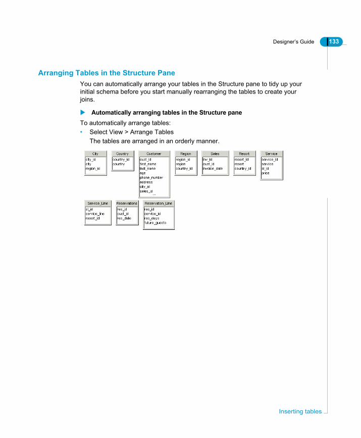
Designer’s Guide 133
Arranging Tables in the Structure PaneYou can automatically arrange your tables in the Structure pane to tidy up your initial schema before you start manually rearranging the tables to create your joins.
Automatically arranging tables in the Structure paneTo automatically arrange tables:• Select View > Arrange Tables
The tables are arranged in an orderly manner.
Inserting tables

134 Designer’s Guide
Inse
Using derived tablesDerived tables are tables that you define in the universe schema. You create objects on them as you do with any other table. A derived table is defined by an SQL query at the universe level that can be used as a logical table in Designer.Derived tables have the following advantages:• Reduced amout of data returned to the document for analysis.
You can include complex calculations and functions in a derived table. These operations are performed before the result set is returned to a document, which saves time and reduces the need for complex analysis of large amounts of data at the report level.
• Reduced maintenance of database summary tables.Derived tables can, in some cases, replace statistical tables that hold results for complex calculations that are incorporated into the universe using aggregate awareness. These aggregrate tables are costly to maintain and refresh frequently. Derived tables can return the same data and provide real time data analysis.
Derived tables are similar to database views, with the advantage that the SQL for a derived table can include BusinessObjects prompts.
Adding, editing, and deleting derived tablesDerived tables appear in your Designer schema in exactly the same way as normal database tables, but the workflow for creating them is different. Adding, editing, and deleting derived tables is described in the following sections.
rting tables and joins
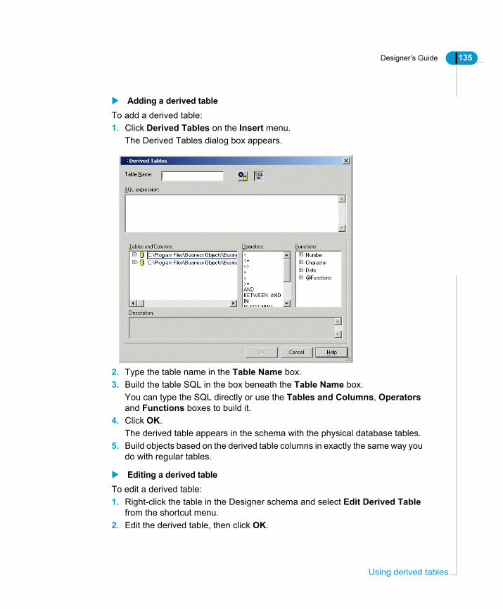
Designer’s Guide 135
Adding a derived tableTo add a derived table:1. Click Derived Tables on the Insert menu.
The Derived Tables dialog box appears.
2. Type the table name in the Table Name box.3. Build the table SQL in the box beneath the Table Name box.
You can type the SQL directly or use the Tables and Columns, Operators and Functions boxes to build it.
4. Click OK.The derived table appears in the schema with the physical database tables.
5. Build objects based on the derived table columns in exactly the same way you do with regular tables.
Editing a derived tableTo edit a derived table:1. Right-click the table in the Designer schema and select Edit Derived Table
from the shortcut menu.2. Edit the derived table, then click OK.
Using derived tables
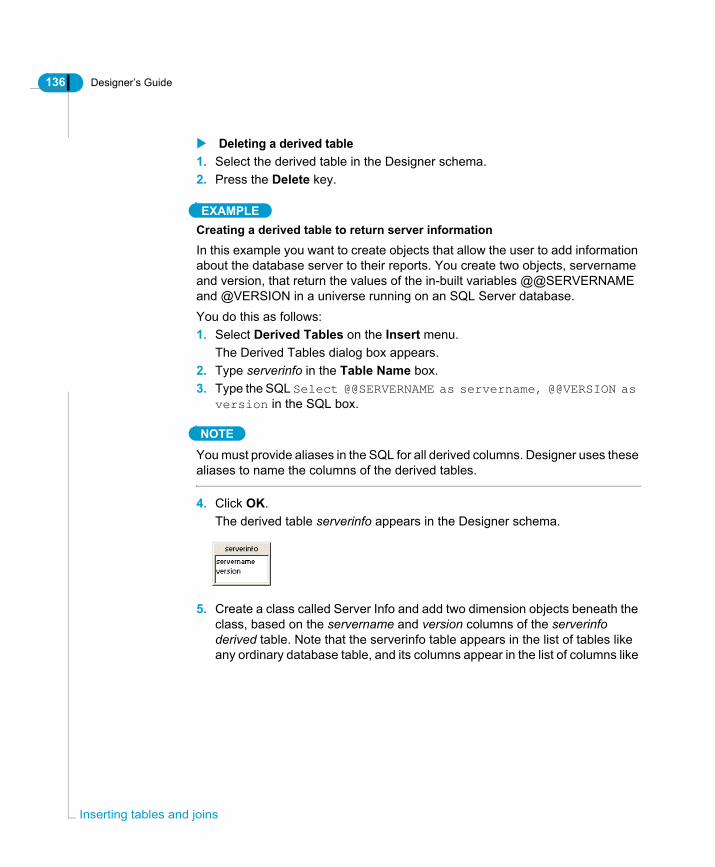
136 Designer’s Guide
Inse
Deleting a derived table1. Select the derived table in the Designer schema.2. Press the Delete key.
EXAMPLECreating a derived table to return server informationIn this example you want to create objects that allow the user to add information about the database server to their reports. You create two objects, servername and version, that return the values of the in-built variables @@SERVERNAME and @VERSION in a universe running on an SQL Server database.You do this as follows:1. Select Derived Tables on the Insert menu.
The Derived Tables dialog box appears.2. Type serverinfo in the Table Name box.3. Type the SQL Select @@SERVERNAME as servername, @@VERSION as
version in the SQL box.
NOTE
You must provide aliases in the SQL for all derived columns. Designer uses these aliases to name the columns of the derived tables.
4. Click OK.The derived table serverinfo appears in the Designer schema.
5. Create a class called Server Info and add two dimension objects beneath the class, based on the servername and version columns of the serverinfo derived table. Note that the serverinfo table appears in the list of tables like any ordinary database table, and its columns appear in the list of columns like
rting tables and joins

Designer’s Guide 137
ordinary table columns.
The user can now place the servername and version objects on a report.
EXAMPLEShowing the number of regions in each countryIn this example you create a table that shows the number of regions in each country. The SQL is as follows:select country,
count (r.region_id) as number_of_regions
from country c,
region r
where r.country_id = c.country_id
group by country
It is important in this case to alias the column that contains the calculation. Designer uses these aliases as the column names in the derived table. In this case the table has two columns: country and number_of_regions.
Using derived tables

138 Designer’s Guide
Inse
Defining joinsOnce you have inserted more than one table in the schema, you need to create joins between related tables. Joins are as important as the tables in a schema, as they allow you to combine data from multiple tables in a meaningful way.
What is a join?A join is a condition that links the data in seperate but related tables. The tables usually have a parent-child relationship. If a query does not contain a join, the database returns a result set that contains all possible combinations of the rows in the query tables. Such a result set is known as a Cartesian product and is rarely useful.For example, the Cartesian product of a query referencing two tables with 100 and 50 rows respectively has 5000 rows. In large databases or queries involving many tables, Cartesian products quickly become unmanageable. In Designer, joins are represented as lines linking tables in a schema.
Why use joins in a schema?You use joins to ensure that queries returning data from multiple tables do not return incorrect results. A join between two tables defines how data is returned when both tables are included in a query.Each table in a schema contains data in one or more columns that correspond to user requirements. In a production universe, BusinessObjects and WebIntelligence users may want to run queries that combine a number of different objects (each inferring a column) returning data from any combination of tables.Linking all tables in the schema with joins ensures that you restrict the number of ways that data from columns in different tables can be combined in a query. Joins limit column combinations between tables to matching or common columns. This prevents result data being returned that contains information from columns that have no sense being matched.
rting tables and joins

Designer’s Guide 139
NOTE
You should always create joins in the Structure pane. Joins that are not created from the Structure pane, for example a join manually defined in the Where clause for an object, are created at run time, so are not considered by Designer for integrity checks and context detection. The information for these processes is required at design time. Contexts and universe integrity are covered later in this chapter.
What SQL does a join Infer?By default Designer specifies a join implicitly in a WHERE clause through a reference to the matching or common columns of the tables.Normally there is one WHERE clause for each pair of tables being joined. So, if four tables are being combined, three WHERE conditions are necessary.The result of a query run including two tables linked by a join is a single table with columns from all the combined tables. Each row in this table contains data from the rows in the different input tables with matching values for the common columns.
ANSI 92 supportIf the target RDBMS supports ANSI 92, then you can set a universe parameter (File > Parameters > Parameter) ANSI92 to Yes to activate ANSI 92 support for joins created in your schema. When a universe supports the ANSI 92 standard for joins, newly created joins are specified in the FROM clause. You can also select the objects that are inferred by columns to be included in the FROM clause. ANSI 92 support is described in the section ANSI 92 support for joins in a universe on page 154.
Defining joins

140 Designer’s Guide
Inse
An example of a join operation on two tables is shown below:
What tables do not have to be joined?You should join all tables in the schema that are inferred in the SQL generated by objects in BusinessObjects and WebIntelligence queries run against the universe. The only exceptions to these are the following types of tables:• Base tables from the schema that have been aliased for each use. These are
the original tables for which you have created aliases either for renaming, or join problem resolution reasons. These base tables are typically not used in any object definition.
• Tables that are the target of table mapping for Supervisor.• Tables that are the target of aggregate awareness syntax (although this has
to be taken on a case-by-case basis). For example the two aggregate tables in the sample eFashion universe shown below are not joined to any table in
PATIENT_NO. DATE_DISCHARGED
123
456
789
05/20/01
06/05/01
07/18/01
PATIENT_NO. BILL_CHARGED
123
123
456
50.00
500.00
30.00
456 750.00
789 825.00
PATIENT_NO. DATE_DISCHARGED
123
123
456
05/20/01
05/20/01
06/05/01
456 06/05/01
789 07/18/01
BILL_CHARGED
50.00
500.00
30.00
750.00
825.00
PATIENT
BILLED
RESULT OF JOIN
PATIENT.DATE_DISCHARGED,BILLED.BILL_CHARGEDPATIENT,BILLEDPATIENT.PATIENT_NO=BILLED.PATIENT.NO
SELECTFROMWHERE
rting tables and joins

Designer’s Guide 141
the schema:
Joining primary and foreign keysYou normally create a join between the primary key in one table and the foreign key of another table. You can also create a join between two primary keys. It is very unusual for at least one side of a join to not include the primary key of the table.You need to understand how each key is constructed in your database. Multi column keys can affect how you set cardinalities for joins, and this can affect how you set up contexts in your schema.Detecting and Using contexts is described in the section “Defining Contexts” in the Solving Join Problems chapter.
Displaying keysYou can display primary and foreign keys in all tables in the Structure pane. The key columns appear underlined in each table that contains keys. When you select the option to display keys, you must refresh the structure before keys appear underlined.The ability to display key columns as underlined depends on primary keys being defined in the target database.
aggregate tables
Defining joins

142 Designer’s Guide
Inse
NOTE
When you display underlined key columns, the information is stored in the .UNV file. This information is lost when you export a universe to the repository. You have to re-display keys for a universe, each time it is imported.
To display keys:1. Select Tools > Options.
The Options dialog box opens to the General page.2. Click the Graphics tab.
The Graphics page appears.3. Select the Underline Keys check box in the Columns group box.
4. Click OK.You need to refresh the structure before key columns appear underlined.
5. Select View > Refresh Structure.The database structure is refreshed. The key columns in your schema are underlined as shown below:
Underline Keys
rting tables and joins

Designer’s Guide 143
Understanding the cardinaltity of a joinCardinalities further describe a join between 2 tables by stating how many rows in one table will match rows in another. This is very important for detecting join problems and creating contexts to correct the limitations of a target RDBMS structure.You should set cardinalities for each join in the schema. Designer can automatically detect and set cardinalities, but you should always manually check the cardinalities, taking into account the nature of the keys that are joined.Setting and using cardinalities is described in the section Using cardinalities on page 177.
Creating joinsYou have several approaches to creating joins in Designer:• Tracing joins manually in the schema.• Defining join properties directly.• Selecting automatically detected joins.• Automatically creating joins on table insertion.Each of these approaches is described in detail below.
Tracing joins manually in the schemaYou can graphically create individual joins between tables by using the mouse to trace a line from a column in one table to a matching column in another table.To create a join by tracing manually:1. Position the pointer over a column that you want to be one end of a join.
The pointer appears as a hand symbol.2. Click and hold down the left mouse button.
The column is highlighted.3. Drag the mouse to the column in another table that you want to be the other
Defining joins

144 Designer’s Guide
Inse
end of the join.As you drag, the pointer is transformed into a pencil symbol.
4. Position the pencil symbol over the target column.The target column is highlighted.
5. Release the mouse button.The join between the two tables is created.
6. Double click the new join.The Edit Join dialog box appears. It lists join properties. The properties that you can set for a join, including cardinality and join type, are described in the section Join properties on page 149.
7. Enter and select properties for the join.8. Click OK.
Defining join properties directlyYou create a join by directly defining join properties in the Edit Join dialog box.
rting tables and joins

Designer’s Guide 145
To create a join directly:1. Select Insert > Join.
OrClick the Insert Join button.The Edit Join dialog box appears.
2. Select a table from the Table1 drop-down list.The columns for the selected table appear in the list box under the table name.
3. Click the name of the column that you want to be at one end of the new join.4. Select a table from the Table2 drop-down list box.
The columns for the selected table appear in the list box under the table name.
5. Click the name of the column that you want to be at the other end of the new join.The properties that you can set for a join, including the join operator, cardinality, and join type are described in the section Join properties on
Insert Join
Defining joins

146 Designer’s Guide
Inse
page 1496. Enter and select properties for the join.7. Click OK.
The new join appears in the schema linking the two tables defined in the Edit Join dialog box.
Selecting automatically detected joinsYou can use the Designer feature Detect Joins to automatically detect selected joins in the schema. Designer identifies column names across tables in the target database and proposes candidate joins for the tables in your schema. You can then select which, or accept all, proposed joins you want to be created.
How are joins automatically detected?The joins are detected based on the Joins strategy that appears in the Strategies page of the Parameters dialog box (File > Parameters > Strategies tab).A strategy is a script file that automatically extracts structural information from the database. There are a number of inbuilt strategies that are shipped with Designer. These are listed in drop-down list boxes on the Strategies page of the Parameters dialog box.The default automatic join detection strategy detects joins based on matching column names, excluding key information. You can select which join strategy you want to apply when you use automatic join detection.
NOTE
Refer to the " Specifying Strategies" section in the chapter "Designer Basics" for more information on using strategies.
Using automatic join detection appropriatelyDetecting joins automatically is useful to help you quickly create joins in your schema. However, you need to be aware of the limitations of automatic join detection when designing your schema.Join strategies used to detect candidate joins match column names from the database. There may be instances in the target database when primary, foreign keys, and other join columns do not have the same name across different tables. Designer will not pick up these columns. You should always verify manually each join that you accept to be created that has been automatically detected. You should be aware that there may be other joins necessary that have not been detected.
rting tables and joins

Designer’s Guide 147
To create a join usin.g automatic detection:1. Verify that the join strategy that you want to use to detect joins is selected in
the Joins drop down list box on the Parameters dialog box. You can verify this as follows:
• Select File > Parameters and click the Strategies tab.• Select the strategy that you want to use to detect joins from the Joins drop-
down list box and click OK.2. Select multiple tables in the Structure pane.
You can select multiple tables by pressing SHIFT while clicking each table, or you can select all tables in a zone by clicking in an empty space, and dragging the cursor to define a rectangular zone that includes any number of tables.
3. Select Tools > Detect Joins.OrClick the Detect Joins button.The Candidate Joins dialog box appears. It lists candidate or proposed joins for the selected tables. The candidate joins also appear as blue lines between selected tables in the Structure pane.
4. Click Insert to create all candidate joins.5. Or
Select one or more joins and click Insert.You can select one or more joins by holding down CTRL and clicking individual tables, or holding down SHIFT and clicking the first and last join in a continuous block.The joins are inserted in you schema.
6. Click Close.
Detect Joins
Defining joins

148 Designer’s Guide
Inse
Inserting joins automatically with associated tablesYou can choose to insert joins automatically in the schema at the same time as the tables that use the joins are inserted into the structure pane. Automatic join creation is determined by two processes:• The active join strategy determines the column information used to detect the
join.• The default creation option Extract Joins With Tables must be selected to
allow the automatic creation of joins with their associated tables. This option is on the Database page of the Options dialog box.
Limitations when inserting joins automaticallyInserting joins automatically into your schema with associated tables is a quick way to get joins into your schema, but it can lead to serious design faults with your schema. The joins are inserted based on the database structure, so columns common to more than one table that have been renamed in the database will not be picked up.You should not use this technique to create joins in a production universe. Instead, use it for demonstration purposes, or as a quick way to build a universe, in which you will then carefully validate each join after insertion.To create a join automatically with an associated table:1. Verify that the join strategy that you want to use to detect joins is selected on
the Strategies page of the Parameters dialog box.2. Select Tools > Options.
The Options dialog box appears.3. Click the Database tab.
The Database page appears.4. Select the Extract Joins With Tables check box.5. Click OK.
Now when you insert a table that has columns referencing other columns in tables that have already been inserted into the Structure pane, the references between tables are automatically inserted as joins between appropriate tables.
rting tables and joins
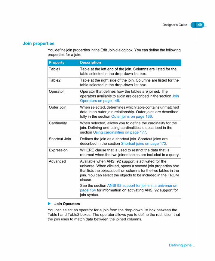
Designer’s Guide 149
Join propertiesYou define join properties in the Edit Join dialog box. You can define the following properties for a join:
Join OperatorsYou can select an operator for a join from the drop-down list box between the Table1 and Table2 boxes. The operator allows you to define the restriction that the join uses to match data between the joined columns.
Property Description
Table1 Table at the left end of the join. Columns are listed for the table selected in the drop-down list box.
Table2 Table at the right side of the join. Columns are listed for the table selected in the drop-down list box.
Operator Operator that defines how the tables are joined. The operators available to a join are described in the section Join Operators on page 149.
Outer Join When selected, determines which table contains unmatched data in an outer join relationship. Outer joins are described fully in the section Outer joins on page 166.
Cardinality When selected, allows you to define the cardinality for the join. Defining and using cardinalities is described in the section Using cardinalities on page 177.
Shortcut Join Defines the join as a shortcut join. Shortcut joins are described in the section Shortcut joins on page 172.
Expression WHERE clause that is used to restrict the data that is returned when the two joined tables are included in a query.
Advanced Available when ANSI 92 support is activated for the universe. When clicked, opens a second join properties box that lists the objects built on columns for the two tables in the join. You can select the objects to be included in the FROM clause.See the section ANSI 92 support for joins in a universe on page 154 for information on activating ANSI 92 support for join syntax.
Defining joins
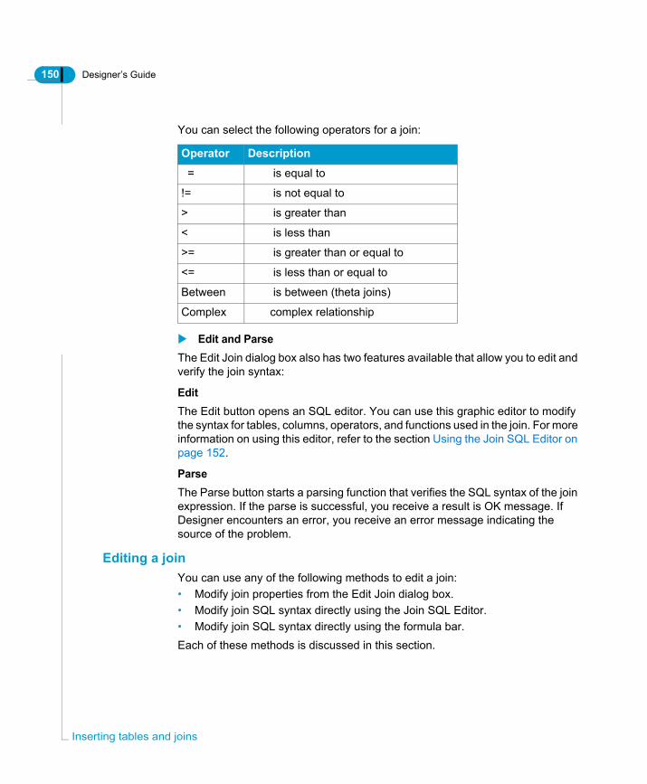
150 Designer’s Guide
Inse
You can select the following operators for a join:
Edit and ParseThe Edit Join dialog box also has two features available that allow you to edit and verify the join syntax:
EditThe Edit button opens an SQL editor. You can use this graphic editor to modify the syntax for tables, columns, operators, and functions used in the join. For more information on using this editor, refer to the section Using the Join SQL Editor on page 152.
ParseThe Parse button starts a parsing function that verifies the SQL syntax of the join expression. If the parse is successful, you receive a result is OK message. If Designer encounters an error, you receive an error message indicating the source of the problem.
Editing a joinYou can use any of the following methods to edit a join:• Modify join properties from the Edit Join dialog box.• Modify join SQL syntax directly using the Join SQL Editor.• Modify join SQL syntax directly using the formula bar.Each of these methods is discussed in this section.
Operator Description
= is equal to
!= is not equal to
> is greater than
< is less than
>= is greater than or equal to
<= is less than or equal to
Between is between (theta joins)
Complex complex relationship
rting tables and joins

Designer’s Guide 151
Using the Edit Join dialog boxYou can use the Edit Join dialog box to define and edit join properties. You can also access the Join SQL Editor to edit join syntax directly from this dialog box. Join properties are described in the section Join properties on page 149.To edit a join using the Edit Join dialog box:1. Double click a join in the Structure pane.
OrClick a join and select Edit > Join.The Edit Join dialog box appears.
2. Select an operator from the drop-down list box between the tables.3. Select other properties as required.4. If you are defining a join with ANSI 92 syntax, then click the Advanced button.5. Click OK.
Defining joins

152 Designer’s Guide
Inse
TIP
You can edit the SQL directly for the join by clicking the Edit button and using the Join SQL editor. See Using the Join SQL Editor on page 152 for more information.
Using the Join SQL EditorYou can use a graphical editor to directly modify the SQL expression for a join. You access this editor from the Edit Joins dialog box.To modify a join using the Join SQL Editor:1. Double click a join in the Structure pane.
OrClick a join and select Edit > Join.The Edit Join dialog box appears.
2. Click the Edit button.The Join SQL Definition box appears. The SQL expression for the join appears in the text box.
3. Click the join expression in the edit box at the place where you want to add or
rting tables and joins

Designer’s Guide 153
modify the SQL syntax.You can use the editing features to modify or add SQL syntax as follows:
The column, operator, or function appears in the join definition.4. Click OK.
Using the Formula barThe Formula bar is a text box above the Universe window that shows the formula or expression of any selected join in the Structure pane, or selected object in the Universe pane. You can use three editing buttons placed to the left of the Formula bar:
To display the Formula bar:• Select View > Formula Bar
The Formula Bar appears above the Universe window.
You want to... Then do the following...
Change a column at either join end
• Expand a table node in the Tables and Columns box.
• Double click a column name.
Change an operator used by the join
Double click an operator in the Operators box.
Use a function in the join
• Expand a function family node.• Double click a function.
Edit button Description
Cancel last modification that has not been validated. If you make several changes to a join expression without validating the changes, clicking the Cancel button returns the expression to its original state. If you want to undo any individual modifications, you should use the Edit > Undo, or click the Undo button.
Validate expression. This applies any changes to the join expression. You can undo changes after validation by using Edit > Undo, or clicking the Undo button.
Open Edit Join dialog box for selected join.
Defining joins

154 Designer’s Guide
Inse
To modify a join using the Formula Bar:1. Click a join that you want to edit.
The formula for the join appears in the Formula Bar.
2. Click the join expression in the Formula Bar at the place you want to modify the syntax.
3. Modify the expression as required.4. Click the Validate button to apply the changes.5. Press the Return key to quit the formula bar.
OrClick anywhere outside of the Formula bar.
ANSI 92 support for joins in a universeDesigner supports ANSI 92 syntax for joins. ANSI 92 is not supported by default. You must activate support by setting the SQl universe parameter ANSI92 to YES. This parameter is listed on the Parameter page of the universe parameters dialog box (File > Parameters > Parameter). Once activated, you can choose to use ANSI 92 syntax for joins in the universe.Ensure that you verify that the target RDBMS supports ANSI 92 before using the syntax in joins.Activating ANSI 92 support in the universe and defining a join using ANSI 92 syntax are described below.
Formula Bar
Editing
Selected join
Join expression
buttons
rting tables and joins

Designer’s Guide 155
EXAMPLEComparing default join syntax and ANSI 92 syntaxJoin syntax for two joins is shown below. The first shows the default behaviour where the join is defined in the WHERE clause, the second shows the same join in the FROM clause using the ANSI 92 standard.
Default join syntaxSELECT
Resort.resort,
'FY'+Format(Sales.invoice_date,'YYYY'),
sum(Invoice_Line.days * Invoice_Line.nb_guests * Service.price)
FROM
Resort,
Sales,
Invoice_Line,
Service,
Service_Line
WHERE
( Sales.inv_id=Invoice_Line.inv_id )
AND ( Invoice_Line.service_id=Service.service_id )
AND ( Resort.resort_id=Service_Line.resort_id )
AND ( Service.sl_id=Service_Line.sl_id )
GROUP BY
Resort.resort,
'FY'+Format(Sales.invoice_date,'YYYY')
Same join using the ANSI 92 standardSELECT
Resort.resort,
'FY'+Format(Sales.invoice_date,'YYYY'),
sum(Invoice_Line.days * Invoice_Line.nb_guests * Service.price)
FROM
Resort INNER JOIN Service_Line ON (Resort.resort_id=Service_Line.resort_id)
INNER JOIN Service ON (Service.sl_id=Service_Line.sl_id)
INNER JOIN Invoice_Line ON (Invoice_Line.service_id=Service.service_id)
INNER JOIN Sales ON (Sales.inv_id=Invoice_Line.inv_id)
Defining joins
156 Designer’s Guide
Inse
GROUP BY
Resort.resort,
'FY'+Format(Sales.invoice_date,'YYYY')
Activating ANSI 92 support in a universeTo activate ANSI 92 support for joins:1. Select File > Parameters.
The Universe Parameters dialog box appears.2. Click the Parameter tab.
The Parameters page appears. It lists certain SQL generation parameters that you can set at the universe level to opitimize SQL generation for the current universe. These are parameters that were included in the PRM file for the target RDBMS in previous versions of Business Objects products. Certain RDBMS specific parameters are still contained in the PRM files, but many standard SQL parameters are now listed in the Parameter page. See the chapter Setting SQL generation parameters on page 81 for a complete list of the available parameters.
3. Click the ANSI92 parameter in the list.4. Type YES in the value box.5. Click Replace.6. Click OK.
The ANSI 92 standard can now be applied to join definitions for the current universe. When you click the Advanced button on the Edit Join dialog box, the Advanced Join box appears. You can define a filter to determine which dimensions you want to include in the FROM clause for a join.
Defining a join with ANSI 92 syntaxYou can use ANSI 92 syntax to define a join from the Edit Join properties dialog box. You can do this by using an advanced editing box that allows you to select objects to be included in a join definition.To define a join using ANSI 92 syntax:1. Activate ANSI 92 support fo the universe. See the section Activating ANSI 92
rting tables and joins
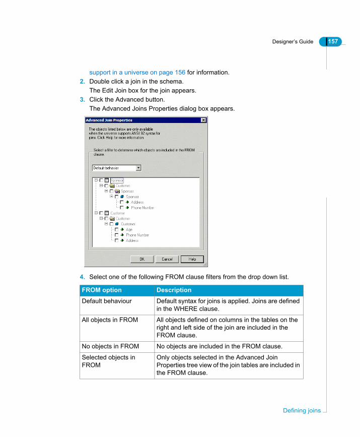
Designer’s Guide 157
support in a universe on page 156 for information.2. Double click a join in the schema.
The Edit Join box for the join appears.3. Click the Advanced button.
The Advanced Joins Properties dialog box appears.
4. Select one of the following FROM clause filters from the drop down list.
FROM option Description
Default behaviour Default syntax for joins is applied. Joins are defined in the WHERE clause.
All objects in FROM All objects defined on columns in the tables on the right and left side of the join are included in the FROM clause.
No objects in FROM No objects are included in the FROM clause.
Selected objects in FROM
Only objects selected in the Advanced Join Properties tree view of the join tables are included in the FROM clause.
Defining joins

158 Designer’s Guide
Inse
5. Select objects to be included in the FROM clause if you selected the Selected objects in FROM filter.
6. Click OK.7. Enter any other join parameters in the Edit Join box.8. Click OK.
Deleting joinsTo delete a join:1. Click a join.
The join is selected2. Do any of the following:• Press the backspace key on your keyboard• Press the Delete button on your keyboard• Right click the join and select Clear from the contextual menu.
A confirmation box appears asking to you to confirm the join deletion.3. Click Yes.
The join is deleted.
NOTE
Ensure that you are aware of all the consequences in both the schema and universe when you delete a join. Verify that deleting the join does not affect a context. If you try to delete a join, Designer warns you if the join is used in one or more contexts. You need to manually verify which context, and access the effect on the universe if the context is affected by the join deletion.
rting tables and joins

Designer’s Guide 159
Defining specific types of joins You can define the following types of joins in Designer:
Each join type is described fully in its respective section in this chapter. You use the same method to create each type of join; however, you must define different properties for each join in the Edit Join box at join creation.
Creating Equi-joinsAn equi-join links two tables on common values in a column in table 1 with a column in table 2. The restriction conforms to the following syntax:Table1.column_a = Table2.column_aIn a normalized database the columns used in an equi-join are usually the primary key from one table and the foreign key in the other. For information on keys, see the section Joining primary and foreign keys on page 141. When you create a new join, it is an equi-join by default. Most joins in your schema should be equi-joins.
Join type Description
Equi-Joins(includes complex equi-joins)
Link tables based on the equality between the values in the column of one table and the values in the column of another. Because the same column is present in both tables, the join synchronizes the two tables.You can also create complex equi-joins, where one join links multiple columns between two tables.
Theta Joins (conditional joins)
Link tables based on a relationship other than equality between two columns.
Outer Joins Link two tables, one of which has rows that do not match those in the common column of the other table.
Shortcut Joins Join providing an alternative path between two tables, bypassing intermediate tables, leading to the same result, regardless of direction. Optimizes query time by cutting long join paths as short as possible.
Self restricting joins
Single table join used to set a restriction on the table.
Defining specific types of joins

160 Designer’s Guide
Inse
EXAMPLEEqui-join restricts dataWhen a Select statement is run in the example below, the Select and From clauses create a Cartesian product. However, before any data is returned, the Where clause applies a restriction so that only rows where there is a match between the Country ID column in both the tables are returned.
Creating a new equi-joinTo create a new equi-join:• Create a join between two tables.
The default new join is an equi-join.
TIP
The different methods you can use to create joins are described in the section Creating joins on page 143.
rting tables and joins

Designer’s Guide 161
Creating an equi-join from an existing joinTo create an equi-join from an existing join:1. Double click an existing join.
The Edit Join box appears.2. Select a column in the Table1 list box.3. Select the matching column in the Table2 list box4. Select = from the Operator drop-down list box.
The Edit Join box below shows an equi-join between the tables Customer and Reservations.
NOTE
Common columns do not always have the same name. You need to verify primary and foreign key column names in the database. Different tables may use the same key columns, but have them renamed for each table depending on the table role in the database.
5. Click the Parse button to check the join syntax.If you receive an error message, check to see that the column is common to
Defining specific types of joins

162 Designer’s Guide
Inse
both tables.6. Click OK.
Creating complex equi-joinsYou can also create a complex equi-join. This is a single join that links multiple columns between two tables. You can create complex equi-joins by using the Complex operator for a join in the Edit Properties sheet for a join.The sample eFashion universe contains a complex join shown below.
Using a complex equi-join instead of multiple single equi-joins between joined columns has the following advantages:• Only one cardinality to detect. This can save time when detecting
cardinalities, and also keeps the schema uncluttered and easier to read.• You can view the SQL for all the joins between two tables in the Expression
text box in the Edit Properties box for the join. When you use multiple single equi-joins between two tables, you have a one expression for each join.
To create a complex equi-join:1. Double click an existing join.
The Edit Join box appears.2. Select multiple columns in the Table1 list box.3. Select the matching columns in the Table2 list box4. Select "Complex" from the Operator drop-down list box.
The Edit Join box below shows a complex equi-join between the tables
rting tables and joins

Designer’s Guide 163
Article_Color_Lookup and Shop_facts.
5. Click the Parse button to check the join syntax.If you receive an error message, check to see that the column is common to both tables.
6. Click OK.
Theta joinsA theta join is a join that links tables based on a relationship other than equality between two columns. A theta join could use any operator other than the "equal" operator.The following example and procedure show you how to create a theta join that uses the "Between" operator.
Defining specific types of joins

164 Designer’s Guide
Inse
EXAMPLETheta joinThe Age_Group table below contains age range information that can be used to analyze data on the age of customers.
You need to include this table in the universe, but there is no common column between the Customer table and the Age_Group table, so you cannot use an equi-join. You create a theta join using the operator "Between" for maximum age range and minimum age ranges. By using a theta join, you infer that a join exists where the value in a row of the Age column in the Customer table is between the values in a row for the Age_Min and Age_Max columns of the Age_Group table. The join is defined by the following expression:Customer.age between Age_group.age_min and Age_group.age_maxThe diagram below shows the joins between Age max, Age min, and Age, and the result set that is returned when the theta join is used in a query run on both Age_Group and Customer tables.
rting tables and joins

Designer’s Guide 165
Creating a theta joinTo create a theta join using range columns:1. Create a join between two tables.
An equi-join is created by default.2. Double click the join.
The Edit Join dialog box appears.3. Click a column in the Table1 column list box.4. Press and hold down the CTRL key and click two columns from the Table2
column list box.The example below shows the two columns age_min and age_max selected. The Between operator automatically appears in the operator drop-down list.
5. Click the Parse button to test for the validity of the join.If you receive an error message, check to see that you have correctly selected
Defining specific types of joins

166 Designer’s Guide
Inse
the columns.6. Click OK.
The join is created in the Structure pane.
Outer joinsAn outer join is a join that links two tables, one of which has rows that do not match those in the common column of the other table.You define an outer join by specifying which table is the outer table in the original equi-join. The outer table contains the column for which you want to return all values, even if they are unmatched. You specify the outer table from the Edit Join dialog box for the selected join.
Full outer joinsBy default you can create either a left outer, or a right outer join depending on which side of the join the outer table is designated. You can also create a full outer join by activating ANSI 92 support for joins in the universe. This is achieved by setting a universe SQL parameter ANSI 92 to YES (File>Parameters>Parameter). This allows the universe to support ANSI 92 syntax for joins, and you can select the tables on either side of a join to be outer tables. Refer to the section Defining a full outer join on page 169 for information on creating full outer joins.
EXAMPLEOuter joinThe tables Resort_Country and Resort below are linked by an equi-join.
rting tables and joins

Designer’s Guide 167
Each resort belongs to a country, but each country may not have a resort. If you use an equi-join, the result set of a query would only show information on the countries that have a resort; Australia, France, and the US.
However, you may wish to show all countries irrespective of an equivalent value in the foreign key of the Resort table. To achieve this you define an outer join so that all counties are returned, despite having no match in the Resort column, as shown below:
The syntax (Microsoft Access) for the outer join is as follows:SELECT
Resort_Country.country,
Resort.resort
FROM
Country Resort_Country,
Resort,
{ oj Resort_Country LEFT OUTER JOIN Resort ON Resort_Country.country_id=Resort.country_id }
NOTE
The example above uses Microsoft Access, so any one-to-many joins following the table Resort, would also have to have to use outer joins. If not, then a NULL returned by the original outer join, will not be taken into account if there is no matching NULL returned by following joins. The treatment of outer joins is
Defining specific types of joins

168 Designer’s Guide
Inse
RDBMS specific, so refer to your RDBMS documentation for information. See also the section Restrictions for the use of outer joins on page 171 for more information on restrictions using outer joins.
Creating an outer joinTo create an outer join:1. Double click an existing equi-join.
The Edit Join dialog box appears.2. Select the Outer Join check box for the table that returns all values in a query.
In the example below, you want to return all values for Resort_Country.
3. Click the Parse button to validate the join syntax.If you receive an error message, check to see that you selected the columns correctly.
4. Click OK.Designer displays the join in the Structure pane. The outer join is indicated by a small circle on the opposite side of the join to the table that returns
rting tables and joins

Designer’s Guide 169
unmatched values.
Defining a full outer joinYou can define an outer join using the ANSI 92 standard for defining outer joins. This allows you to specify a full outer join. To use the ANSI 92 standard for outer joins, you must set the ANSI 92 parameter to YES. This parameter is available on the Parameter page (File > Parameters > Parameter).
NOTE
For information on setting this parameter and other SQL generation parameters for the universe, refer to the section Setting SQL generation parameters on page 81.
When the ANSI 92 parameter has been set to YES, you can select the tables on both sides of the join to be outer tables. Before setting this parameter, you must ensure that your target RDBMS supports the ANSI 92 syntax for outer joins.You define a full outer join in two phases:• Activate ANSI 92 support for outer joins for the universe. See the section
Activating ANSI 92 support in a universe on page 156 for information.• Use the Edit join dialog box to define the full outer join.To define a full outer join:1. Activate ANSI 92 support for the universe.2. Double click a join in the schema.
The Edit Join dialog box appears.3. Select the Outer Join check box for both tables included in the join as shown
Defining specific types of joins
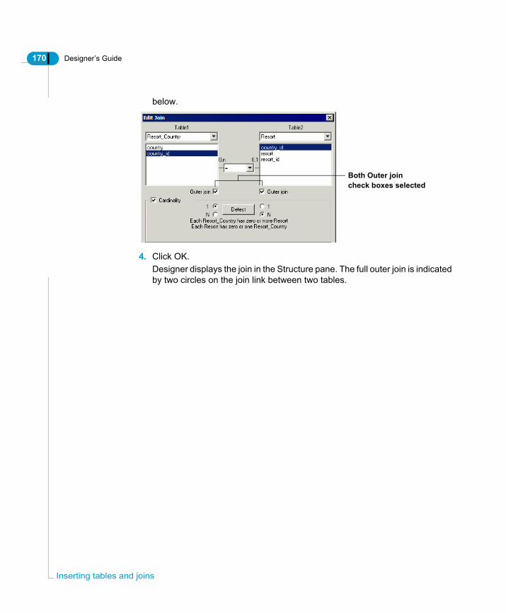
170 Designer’s Guide
Inse
below.
4. Click OK.Designer displays the join in the Structure pane. The full outer join is indicated by two circles on the join link between two tables.
Both Outer joincheck boxes selected
rting tables and joins

Designer’s Guide 171
Restrictions for the use of outer joinsUsing outer joins can be very useful, but you should be aware of the following performance and implementation issues:
Issue Description
Performance can be slower
More rows are returned and some databases will not use indexes when outer joins are involved, so large amounts of data could slow query performance.
Incomplete query hierarchy path for tables after the outer join (RDBMS dependent)
You should verify how your target RDBMS processes outer joins to avoid incomplete query paths after the original outer join. For example, in the Microsoft Access sample Club.mdb database, all one-to-many joins following the outer join in the join path must also be defined as outer joins. If not, the original outer join will be ignored by the resulting query.
In the example above, the join between Resort and Service_Line ignores the NULL values returned by the outer join between Resort_Country and Resort. When you run a query with the three tables, a database error is returned advising the user to create a separate query that performs the first join, and then include that query in the SQL statement. This type of error could be confusing to many users, so it is preferable in such cases to either not use outer joins, or to complete the path with outer joins.
Database limitations on the use of outer joins.
Not all databases allow control over outer joins in the WHERE clause. This is necessary when using a self restricting join. For example, a self restricting join ‘TYPE_CODE=10’, could return all rows where TYPE=10 or Type is NULL, as TYPE=10 will never be true when the type code is NULL, whereas NULL values are generated by the outer join.
Defining specific types of joins

172 Designer’s Guide
Inse
Shortcut joinsA shortcut join is a join that provides an alternative path between two tables. shortcut joins improve the performance of a query by not taking into account intermediate tables, and so shortening a normally longer join path.A common use of shortcut joins is to link a shared lookup table to another table further along a join path. The join path comprises several different tables in the same context.In such a case, the shortcut join is only effective when the value being looked up has been denormalized to lower levels in a hierarchy of tables, so the same value exists at all the levels being joined.
EXAMPLEShortcut joinIn the following example the column Article_code appears in both the tables Product_Promotion_Facts and Shop_Facts. The value of Article_code is the same for both tables. The normal path for a query using Article_code from Product_Promotion_Facts and Shop_Facts, is to pass through the intermediary table Article_Lookup.
The shortcut join directly linking Product_Promotion_Facts and Shop_Facts allows the query to ignore the intermediary table Article_Lookup, optimizing the query.
NOTE
Designer does not consider shortcut joins during automatic loop and context detection. However, if you set the cardinality for a shortcut join you avoid receiving the message 'Not all cardinalities are set' when detecting contexts.
Shortcut join
rting tables and joins
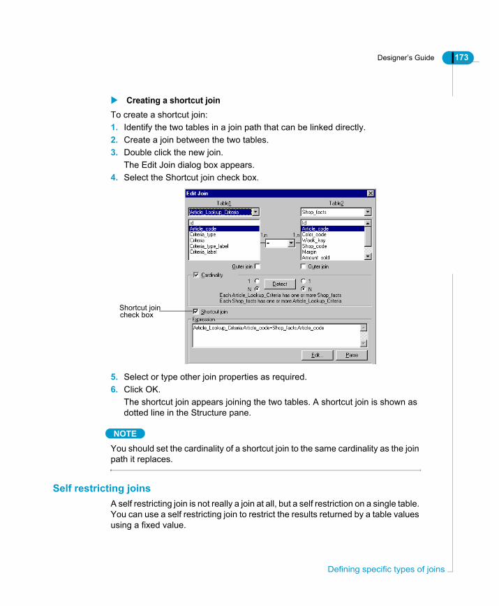
Designer’s Guide 173
Creating a shortcut joinTo create a shortcut join:1. Identify the two tables in a join path that can be linked directly.2. Create a join between the two tables.3. Double click the new join.
The Edit Join dialog box appears.4. Select the Shortcut join check box.
5. Select or type other join properties as required.6. Click OK.
The shortcut join appears joining the two tables. A shortcut join is shown as dotted line in the Structure pane.
NOTE
You should set the cardinality of a shortcut join to the same cardinality as the join path it replaces.
Self restricting joinsA self restricting join is not really a join at all, but a self restriction on a single table. You can use a self restricting join to restrict the results returned by a table values using a fixed value.
Shortcut joincheck box
Defining specific types of joins

174 Designer’s Guide
Inse
EXAMPLESelf restricting joinThe Sales table shown below contains rows of data for cars both sold and rented. The Sale_Type column is used as a flag to indicate the type of transaction (S = car sale, R = car rental). The self restricting join restricts the data returned from Sales to Sale_Type = S. This ensures that any object based on the Sales table, or joins passing through that table, would produce query results covering only car sales.
Without the self restricting join, the results set of the query would produce rows where the Sale_Type column is equal to either 'S' or 'R'.
TIPSetting the cardinality for a self restricting join helps to prevent receiving the message 'Not all cardinalities are set' when detecting contexts. You should set cardinality as one-to-one consistently, although the actual setting is not important, as long as it is set.
Creating a self restricting joinTo create a self restricting join:1. Select Insert > Join.
The Edit Join dialog box appears.2. Select the table that you want to set the self restricting join against from the
rting tables and joins

Designer’s Guide 175
Table1 drop- down list box.The columns for the selected table appear in the table column list.
3. Click the column that you want to use to define the restriction from the column drop-down list box.
4. Select the same table that you selected from the Table1 drop-down list box.5. Click the same column that you selected in the Table1 column list box.
The expression for the join appears in the Expression text box.
6. Replace the operand value in the join expression with the restriction value that you want to set on the join column.For example, if you want to restrict the returned values from the SALE_TYPE column to ’S’ for Sales, you replace SALE.SALE_TYPE after the = sign with
Defining specific types of joins

176 Designer’s Guide
Inse
’S’ as shown below:
7. Click the Parse button to verify the syntax.8. Click OK.
The self restricting join appears as a short line displayed against the column on which the self restricting join is defined.
rting tables and joins
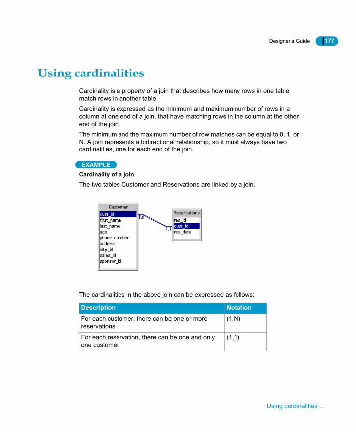
Designer’s Guide 177
Using cardinalitiesCardinality is a property of a join that describes how many rows in one table match rows in another table.Cardinality is expressed as the minimum and maximum number of rows in a column at one end of a join, that have matching rows in the column at the other end of the join.The minimum and the maximum number of row matches can be equal to 0, 1, or N. A join represents a bidirectional relationship, so it must always have two cardinalities, one for each end of the join.
EXAMPLECardinality of a joinThe two tables Customer and Reservations are linked by a join.
The cardinalities in the above join can be expressed as follows:
Description Notation
For each customer, there can be one or more reservations
(1,N)
For each reservation, there can be one and only one customer
(1,1)
Using cardinalities

178 Designer’s Guide
Inse
How are cardinalities used In Designer?The cardinality of a join does not have a role in the SQL generated when you run a query. However, Designer uses cardinalities to determine contexts and valid query paths.A context is a collection of joins which provide a valid query path. You use contexts to resolve join problems that can return too many or too few rows because of the way that tables are linked in the target database. Contexts are described in the section “Defining Contexts” in the Solving Join Problems chapter.Contexts affect the SQL generated for a query as they either direct the end user to take a particular join path, or solve a join path problem.:
Setting cardinalities can also help you understand how tables are related in the database, and to graphically identify potential join path problems in your schema.
You need to verify that cardinalities are correctly set for all joins in your schema to ensure that you have the correct contexts, and that you have valid join paths.
rting tables and joins

Designer’s Guide 179
Displaying cardinalitiesYou can display cardinalities in the Structure pane using the following symbols:
To display cardinalities:1. Select Tools > Options.
The Options dialog box opens to the General page.2. Click the Graphics tab.
The Graphics page appears.3. Click the Arrow, Arity, or 1,n radio button.4. Click OK.
Cardinality symbol
Example Description
Arrow Arrow indicates the "one" direction of the join. If cardinality is 1,1 then an arrow head is shown at each join end.
Parity Crow’s foot indicates the "many" end of the join. If cardinality is 1,1, then a straight line is shown.
1,N Cardinality is shown as a ratio at each end of the join.
Using cardinalities

180 Designer’s Guide
Inse
What cardinalities can be set for a join?You can set the following cardinalities for a join:
You can set cardinalities manually, or use the automatic cardinality detection tool in Designer. Both methods are described in the following sections.
Setting cardinalities manuallyYou can manually set cardinalities for joins by defining cardinality for a join in the Edit Join box for a join.
Why set cardinalities manually?When you set cardinalities manually, you must consider each individual join. This helps you to become aware of potential join path problems in your schema. You may not find these problems if you only select automatically detected cardinalites; for example, isolated one-to-one joins at the end of a join path, or excessive primary keys where not all columns are required to ensure uniqueness.
Cardinality Description
one-to-one (1,1) For every row in table 1, expect one and only one row in table 2
one-to-many (1,N) For every row in table 1, expect one or many rows in table 2
many-to-one (N,1) Same as for one-to-many (1,N), but the direction for the row match is opposite.
many-to-many (N,N) For each one or multiple rows in table 1, expect one or multiple rows in table 2.Many-to-many cardinalities are rare in relational databases and will return duplicate rows, causing slower performance and potentially inaccurate results. If you have (N,N) cardinalities, you should re-check the concerned joins, and ensure that you understand the relationship between the tables.
rting tables and joins

Designer’s Guide 181
Understanding keysYou determine cardinalities for most join cases by evaluating the primary and foreign keys in each table. Primary and foreign keys are described as follows:
Key Description
Primary Single or combination of columns in a table whose values identify each row in the table. The primary key guarantees row uniqueness in a table. Each table has only one primary key.
Foreign Column or combination of columns whose values are required to match a primary or another unique key in another table.Foreign keys implement constraints such as 'you cannot create a sale for a customer if that customer hasn't yet been created'. Each table can have multiple foreign keys.
Using cardinalities
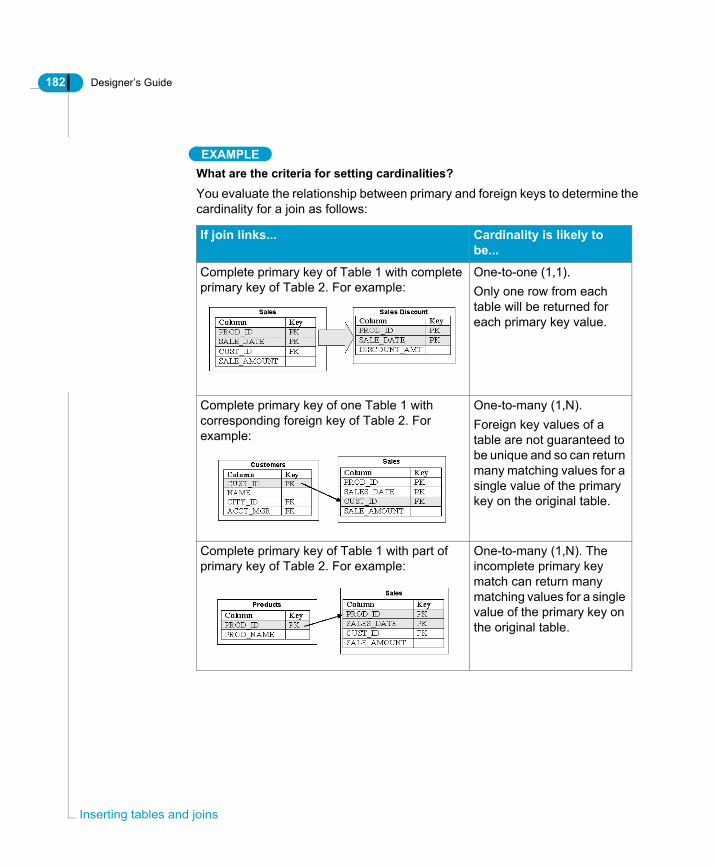
182 Designer’s Guide
Inse
EXAMPLEWhat are the criteria for setting cardinalities?You evaluate the relationship between primary and foreign keys to determine the cardinality for a join as follows:
If join links... Cardinality is likely to be...
Complete primary key of Table 1 with complete primary key of Table 2. For example:
One-to-one (1,1).Only one row from each table will be returned for each primary key value.
Complete primary key of one Table 1 with corresponding foreign key of Table 2. For example:
One-to-many (1,N).Foreign key values of a table are not guaranteed to be unique and so can return many matching values for a single value of the primary key on the original table.
Complete primary key of Table 1 with part of primary key of Table 2. For example:
One-to-many (1,N). The incomplete primary key match can return many matching values for a single value of the primary key on the original table.
rting tables and joins

Designer’s Guide 183
To set cardinalities manually:1. Double click a join.
OrClick a join and select Edit > Properties.The Edit Join dialog box appears.
2. Select the Cardinality check box.3. Select the 1 or N radio button for Table1.4. Select the 1 or N radio button for Table2.
5. Click OK.
Detecting cardinalities automaticallyYou can use the Designer feature Detect Cardinalities to automatically detect cardinalities for the following situations:• Selected joins• All joins• At join creation• From the Edit Join boxWhen using automatic cardinality detection, cardinalities are implemented automatically on detection.
Using cardinalities

184 Designer’s Guide
Inse
NOTE
You should use automatic cardinality detection appropriately. It can be very useful to quickly get all the cardinalities detected in the schema, however, there are a number of structural problems inherent in many relational databases which can lead to incorrect cardinality detection. These include incomplete primary joins, and over engineered primary keys. These are discussed in the section Using cardinalities to resolve database limitations on page 187.
Detecting cardinalities automatically for selected joinsTo automatically detect cardinalities for a selected join:• Click a join and select Tools > Detect Cardinalities.• Right click a join and select Detect Cardinalities from the contextual menu.The cardinality is displayed with the crow’s foot at the many end.
If you select Tools > Detect Cardinalities directly without selecting a join, you receive a message indicating that no join is selected, and asking if you want to detect cardinalities for all joins.Detecting cardinalities automatically for all joinsTo automatically detect cardinalities for all joins:1. Select Tools > Detect Cardinalities.
OrClick the Detect Cardinalities button.A message box appears asking if you want to detect cardinalities for all joins.
2. Click Yes.All joins in the Structure pane are shown with cardinalities.
DetectCardinalities
rting tables and joins

Designer’s Guide 185
Automatically detecting cardinalities on join creationTo automatically detect cardinalities on join creation:1. Select Tools > Options.
The Options dialog box opens to the General page.2. Click the Database tab.
The Database page appears.3. Select the Detect Cardinalities in Joins check box.
4. Click OK.5. When you create a new join, the cardinality is automatically detected and
displayed on the join.
Automatically detecting cardinality from the Edit Join boxTo automatically detect cardinality from the Edit Join box:1. Double click a join.
The Edit Join dialog box appears.2. Select the Cardinality check box.3. Click the Detect button.
The cardinality radio buttons are automatically selected for the detected cardinality. The two cardinalities are also expressed in sentence form.
4. Click OK.
Optimizing automatic cardinality detectionYou can improve the response time of cardinality detection by modifying a parameter in the PRM file of the target RDBMS. This directs the detection algorithm to read two instead of three SQL statements, improving the performance of the algorithm.
Using cardinalities

186 Designer’s Guide
Inse
The PRM file is a text file that lists parameters used to configure universe creation and SQL query generation in BusinessObjects and WebIntelligence products. There is a PRM file for each supported RDBMS.PRM files are located in the database folders under \Business Objects\Data Access 5.0\.
Verifying which PRM file is used by a connectionTo verify which PRM file is used by a universe connection:1. Select File > Parameters.
The Parameters dialog box appears.2. Click the Test button.
The Test Connection message box appears.3. Click the Details button.
The details of your connection appear in a drop down message box.4. Scroll down the message box to the line that starts with PRM.
This line indicates the file path and name of the PRM file currently used by the active universe.
5. Click OK.You return to the Parameters dialog box.
6. Click Cancel.
Optimizing cardinality detection using the PRM fileTo optimize cardinality detection using the PRM file:1. Open the PRM file for your target database in a text editor.
The PRM files are stored in the Data Access folder in the Business Objects
rting tables and joins

Designer’s Guide 187
path.2. Set the LIGHT_DETECT_CARDINALITY parameter to YES.3. Save and close the PRM file.
The next time you open the universe, automatic cardinality detection is optimized.
Using cardinalities to resolve database limitationsYou can use the following criteria for determining cardinalities in special join situations, which if untreated, could lead to errors in your schema design:
Problem Solution
Primary key of a lookup table has two columns. Each column is joined to a different fact table. Joins with each fact table are many-to-many as the primary key in both joins is incomplete.
Change a "many" end to a "one" for join at lookup table end. Do this as follows:Add a self restricting join (one-to-one) on the lookup table of the type; lookup.pk_column = pk_column value. This ensures the uniqueness of values in the primary key of the lookup table. The cardinality of the join at the lookup table is now one.
Primary key is excessive, so not all columns in a primary key are needed to guarantee uniqueness.
If you are the DBA for the target database, you can change the multi column primary key to a single column alpha numeric identifier. This would allow the table to take a "one" side of a join, which is much more difficult with a multi column primary key. If you are not the DBA, you could raise this point with your administrator.
Using cardinalities

188 Designer’s Guide
Inse
Checking the universeAs you design your universe, you should test its integrity periodically. You can verify universe integrity as follows:
Checking universe integrity automaticallyYou can set the following integrity check options in Designer to parse SQL structures at creation, universe export, and universe opening:
Setting automatic universe check optionsTo set automatic universe check options:1. Select Tools > Options.
The Options dialog box opens to the General page.2. Select or clear check boxes for appropriate universe automatic check options
Check universe Description
Automatically You can set Designer options to check the SQL syntax of universe structures at creation, universe export, or when a universe is opened.
Manually You run Check Integrity to check selected universe structures.
Automatic check option
Description
Automatic parse upon definition
Designer automatically checks the SQL definition of all objects, conditions, and joins at creation. It is applied when you click OK to validate structure creation.
Send check integrity Designer displays a warning each time you attempt to export an unchecked universe.
Check universe integrity at opening
All universes are checked automatically when opened.
rting tables and joins

Designer’s Guide 189
in the Integrity group box.
3. Click OK.
Checking universe integrity manuallyYou can use Check Integrity to test to verify if the design of your active universe is accurate and up-to-date.Check Integrity detects the following:• Errors in the objects, joins, conditions, and cardinalities of your universe.• Loops in join paths. • Any necessary contexts.• Changes to the target database.Before examining the elements of the universe against those of the database, the function checks whether the connection to the database is valid. If the connection is not valid, the function stops and returns an error message.
Types of errors detected by Check IntegrityCheck Integrity can detect:• Invalid syntax in the SQL definition of an object, condition, or join. • Loops• Isolated tables• Isolated joins• Loops within contexts• Missing or incorrect cardinalities
How does Check Integrity determine changes in a connected database?The Check Integrity function sends a request to the database for a list of tables. It then compares this list with the tables in the universe. It carries out the same action for columns.In the Structure pane, Check Integrity marks any tables or columns not matching those in the list as not available. These are tables or columns that may have been deleted or renamed in the database. See the section Refreshing the Universe Structure on page 192.
Checking the universe

190 Designer’s Guide
Inse
NOTE
The option Check Cardinalities can be slow to run with large amounts of data. If there is ambiguous or missing data, results can also be inaccurate. If your database is large, and may have incomplete data entries, then you should not select the option Check Cardinalities. If you do use this option, then you can optimize the cardinality detection by modifying the PRM file. For more information, refer to the section Optimizing automatic cardinality detection on page 185.
Verifying universe integrity with Check IntegrityTo verify universe integrity:1. Select Tools > Check Integrity.
OrClick the Check Integrity button.
2. The Integrity Check dialog box appears.
3. Select check boxes for components to be verified.
CheckIntegrity
rting tables and joins

Designer’s Guide 191
NOTE
You can select Check Cardinalities independantly of the Check All option. This allows you to verify the universe structure without checking cardinalities which may take a long time depending on the database.
4. Clear check boxes for components not to be verified.5. Select the Quick Parsing check box to verify only the syntax of components.
OrSelect Thorough Parsing check box to verify both the syntax and semantics of components.
6. Click OK.A message box displays the universe check progress.
If Check Integrity encounters no errors, it displays “OK” beside each error type.
7. Click the plus sign (+) beside the error type to view the list of components in
Checking the universe

192 Designer’s Guide
Inse
which the error occurred.
You can double click an item in the list to highlight the corresponding components in the Structure pane.
8. Click the Print button to print the window contents.9. Click OK.
REMINDERBefore selecting the Check for Loops check box, ensure that the cardinalities of joins have already been detected. Otherwise, the function erroneously identifies loops in the joins.
Refreshing the Universe StructureIf Check Integrity indicates that the database of your universe connection has been modified, you can use Refresh Structure to update the contents of the Structure pane.
rting tables and joins

Designer’s Guide 193
Refresh Structure can modify the universe structure to comply with changes in the database as follows:
To refresh the universe structure:• Select View > Refresh Structure.• A message box appears informing you of a change in the database, or that
no update is needed if no changes have been made.
If Then Designer does the following
Columns were added to tables
Adds the columns to the corresponding tables in the universe.
Columns were removed from tables
Displays a warning message indicating the columns and associated joins you should delete.
Tables were removed from the database
Displays a warning message indicating the tables and associated joins you should delete.
Tables were renamed in the database
Displays a message that says it no longer recognizes the corresponding tables in the universe. You should rename these tables to match those in the database. If the names still do not match, Designer returns a message stating that the renamed tables do not exist in the database.
No changes were made to the database
Displays a message informing you that no update is needed.
Checking the universe

194 Designer’s Guide
Inse
rting tables and joins
Resolving join problems
chapter

196 Designer’s Guide
Res
OverviewThis chapter describes the types of problems that can arise as you create joins between the tables in your schema. It explains how you can detect and resolve these join problems to ensure that the join paths taken by queries run on the universe return correct results.
olving join problems

Designer’s Guide 197
What is a join path problem?A join path is a series of joins that a query can use to access data in the tables linked by the joins. Join path problems can arise from the limited way that lookup and fact tables are related in a relational database. The three major join path problems that you encounter when designing a schema are the following:• loops• chasm traps• fan trapsYou can solve all these problems by creating aliases (a copy of a base table), contexts (a defined join path), and using features available in Designer to separate queries on measures or contexts.This section briefly defines lookup and fact tables, and describes the types of join path problems that you can encounter using these tables. It explains how you can use aliases, contexts, and other Designer features to resolve join path problems in your universe schema.In Designer, you typically create joins between lookup tables and fact tables.
What is a Lookup TableA lookup (or dimension) table contains information associated with a particular entity or subject. For example, a lookup table can hold geographical information on customers such as their names, telephone numbers as well as the cities and countries in which they reside.In Designer, dimension and detail objects are typically derived from lookup tables. A lookup table has the following join cardinality structure:
What is a Fact TableA fact table contains statistical information about transactions. For example, it may contain figures such as Sales Revenue or Profit.
DIMENSION
What is a join path problem?

198 Designer’s Guide
Res
In a BusinessObjects universe, most but not all, measures are defined from fact tables. A fact table is characterized by the following join cardinality structure:
What Types of Join Paths Return Incorrect Results?Queries can return incorrect results due to the limitations in the way that joins are performed in relational databases. Depending on how the lookup and fact tables in your table schema are related, join paths can produce instances where a query returns too few, or too many rows.The following types of join paths can produce incorrect results:
FACT
Type of Join Path Returns Description
Loop Too few rows Joins form multiple paths between lookup tables.
Converging many to one joins
Too many rows Many to one joins from two fact tables converge on a single lookup table. This type of join convergence can lead to a join path problem called a chasm trap.
Serial many to one joins
Too many rows A one to many join links a table which is in turn linked by a one to many join. This type of fanning out of one to many joins can lead to a join path problem called a fan trap.
olving join problems

Designer’s Guide 199
Detecting and Solving Join ProblemsDesigner provides a number of methods for detecting and solving join problems. Each of these methods is fully described in its corresponding section.You can use the following methods to detect and solve join path problems:
Most join path problems can be solved by creating an alias or implementing a context. You can use the automatic loop detection tools in Designer to identify loops in the schema, and automatic context detection to identify where Chasm traps occur. However, to resolve fan traps, you have to be able to visually analyze the schema and create aliases and if necessary contexts manually.
Join Problem Detected by Solved by
Loop • Detect Aliases• Detect Contexts• Detect Loops• Check Integrity• Visual analysis of
schema
Creating aliases and contexts to break loops.
Chasm trap (converging many to one joins)
Visual analysis of table schema.
• Creating a context.• Using the feature Multiple
SQL statements for each measure.
• Creating multiple universes (WebIntelligence only).
Fan trap (serial many to one joins)
Visual analysis of table schema.
• Creating an alias, creating a context using the alias, then building affected measure objects on the alias.
• Using Multiple SQL Statements for Each Measure.
What is a join path problem?
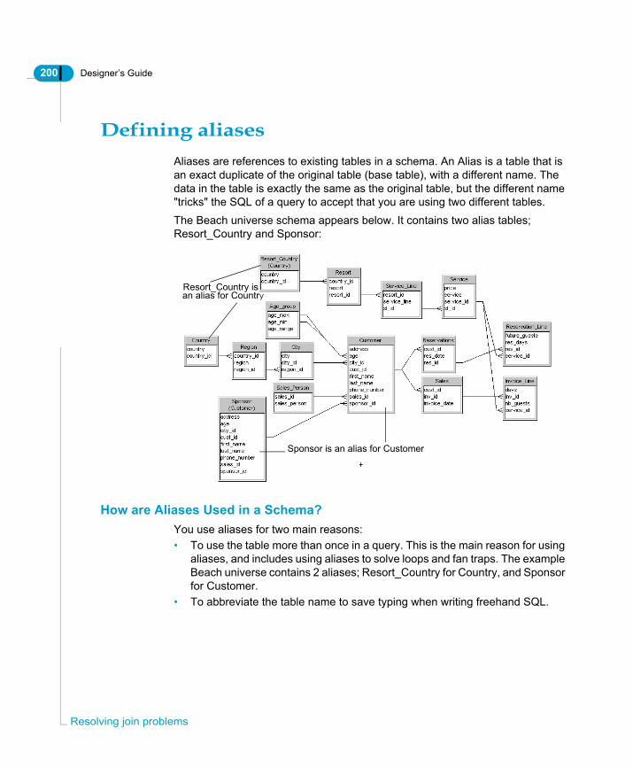
200 Designer’s Guide
Res
Defining aliasesAliases are references to existing tables in a schema. An Alias is a table that is an exact duplicate of the original table (base table), with a different name. The data in the table is exactly the same as the original table, but the different name "tricks" the SQL of a query to accept that you are using two different tables.The Beach universe schema appears below. It contains two alias tables; Resort_Country and Sponsor:
How are Aliases Used in a Schema?You use aliases for two main reasons:• To use the table more than once in a query. This is the main reason for using
aliases, and includes using aliases to solve loops and fan traps. The example Beach universe contains 2 aliases; Resort_Country for Country, and Sponsor for Customer.
• To abbreviate the table name to save typing when writing freehand SQL.
Sponsor is an alias for Customer
Resort_Country isan alias for Country
olving join problems

Designer’s Guide 201
TIPAnother possible use of aliases is to create an alias for each table as it is inserted into the schema. You then build the schema using the alias tables, not the original base tables. You place the base tables together away from the main universe structure. This allows you to give meaningful names to tables, and prevents the need to rebuild major sections of a universe structure should a base table need to be aliased at a later stage.
Using aliases to solve loopsThe most common use of aliases in universe development is to solve potential loops in the use of common tables. A loop is a set of joins that defines a closed path through a set of tables in a schema. Loops occur when joins form multiple paths between lookup tablesYou use an alias to break a loop by providing alternative table for an original lookup table that is being used for multiple query paths. This use of aliases is discussed in the section Resolving loops on page 217.
Using aliases to solve fan trapsAliases are also used to solve potential fan traps. These can occur in a serial one-to-many join path that can return inflated results when aggregates are summed at the "many" end of the joins. This use of aliases is discussed in the section Resolving Chasm Traps on page 247.
Creating AliasesYou can create aliases manually, or let Designer automatically detect potential aliases that will solve a join path loop.You need to create an alias manually to solve a fan trap. You also create aliases manually if you are creating a schema using only aliases and not the base tables.The automatic detection and creation of aliases to solve loops is described in the section Detecting and creating an alias on page 228.
Defining aliases

202 Designer’s Guide
Res
Creating an alias manuallyTo create an alias manually:1. Click the table that you want to use to create an alias.2. Select Insert > Alias
OrClick the Insert Alias button.The Creating an Alias box appears. It prompts you to enter a name for the new alias.
3. Enter a new name for the aliased table, or keep the one proposed.
NOTE
The name that you give to an alias should be relevant to the role of the alias to distinguish it from the base table. For example, Resort country is an alias for Counry. Resort Country is used for queries returning data for resort countries, the base table Country is used in queries returning data for customer countries.
4. Click OK.The aliased table appears in the Structure pane.
5. Create any joins necessary between the alias and other tables in the schema.
Insert Alias
Alias
Base table
olving join problems

Designer’s Guide 203
TIPTo avoid confusing base tables with aliases, you can display the alias with the name of the base table it represents in the table title as follows: Select Tools > Options > Graphics, and then select the Aliased Name check box.
Renaming an aliasYou can rename an alias at any time. Alias and table naming conventions are RDBMS dependent. You can rename an alias directly by renaming the table, or from a list of aliases in the universe.
Renaming an alias directlyTo rename an alias directly:1. Click a table and select Edit > Rename Table.
OrRight click a table and select Rename table from the contextual menu.The Rename Table dialog box appears.
2. Type a new name in the Table Name box.The availability of the Owner and Qualification fields is database specific. If they are active, then you can modify these as necessary.
3. Select the Upper case check box if you want the alias name to be shown as all uppercase.OrSelect the Lower case check box if you want the alias name to be shown as
Defining aliases

204 Designer’s Guide
Res
all lowercase.4. Click OK.
Renaming an alias from a listTo rename an alias from a list:1. Select Tools > List of Aliases.2. The List of Aliases appears. It lists all the aliases in the active universe.3. Click an alias name in the list.4. Type a new name for the selected alias in the New Name text box.5. Click Apply.6. Click OK.
Deleting an aliasYou delete an alias in the same way that you delete a table. If you have defined objects using the alias, you must modify these objects before you delete the alias, so that they use another table, or delete the objects if they are no longer necessary.If you do not modify or remove the objects using a deleted alias, queries using those objects will generate errors in BusinessObjects or WebIntelligence.To delete an alias:1. Click an alias and select Edit > Clear.
OrRight click an alias and select Clear from the contextual menu.OrClick an alias and press the DELETE key.If any objects use the alias, the following message appears:
If no objects use the alias, you do not receive a confirmation box. The alias is deleted immediately.
2. Click Yes.The alias is deleted from the Structure pane.
olving join problems

Designer’s Guide 205
Defining contextsContexts are a collection of joins which provide a valid query path for BusinessObjects and WebIntelligence to generate SQL.
How are Contexts Used in a Schema?You can use contexts in a universe schema for the following purposes:• Solving loops.• Solving chasm traps.• Assisting in some solutions for fan traps.• Assisting in detecting incompatibility for objects using aggregate awareness.
Using contexts to solve loopsThe most common use of contexts is to separate two query paths, so that one query returns data for one fact table, and the other query returns data for another fact table. You use contexts to direct join paths in a schema which contains multiple fact tables. Aliases are not appropriate in such schemas. This use of contexts is covered in the section Resolving loops on page 217.
Using contexts to solve chasm and fan trapsContexts are also used to solve potential chasm traps. These can occur when two many-to-one join paths converge on a single table. Multiple rows can be returned for a single dimension causing inflated results. Contexts can split out the query so that the correct number of rows are returned for the dimension. Contexts can also be used with aliases to solve fan traps. These uses of contexts are discussed in the section Resolving Chasm Traps on page 247.
Using contexts to determine AggregateAwareness incompatibilityYou can use contexts to exclude objects that are not compatible with an object using the @AggregateAware function in its definition, from being used in a query with the aggregate aware object. This use of contexts is discussed in the section "Using Aggregate Awareness" in the chapter "Building Universes".
Creating a ContextYou can let Designer automatically detect contexts, or you can create contexts manually.If you are using a context to resolve a loop or a chasm trap, you should always let Designer detect the contexts. However, for solving a fan trap (another join path problem), you may have to manually build a context.
Defining contexts
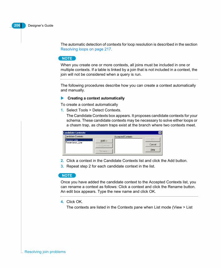
206 Designer’s Guide
Res
The automatic detection of contexts for loop resolution is described in the section Resolving loops on page 217.
NOTE
When you create one or more contexts, all joins must be included in one or multiple contexts. If a table is linked by a join that is not included in a context, the join will not be considered when a query is run.
The following procedures describe how you can create a context automatically and manually.
Creating a context automaticallyTo create a context automatically1. Select Tools > Detect Contexts.
The Candidate Contexts box appears. It proposes candidate contexts for your schema. These candidate contexts may be necessary to solve either loops or a chasm trap, as chasm traps exist at the branch where two contexts meet.
2. Click a context in the Candidate Contexts list and click the Add button.3. Repeat step 2 for each candidate context in the list.
NOTE
Once you have added the candidate context to the Accepted Contexts list, you can rename a context as follows: Click a context and click the Rename button. An edit box appears. Type the new name and click OK.
4. Click OK.The contexts are listed in the Contexts pane when List mode (View > List
olving join problems

Designer’s Guide 207
Mode) is active. The context for invoice Line is shown below.
5. The context for Invoice_Line is shown below.
Contexts appear here in List Mode
Context join path for Reservation_Line
Context join path for Reservation_Line
Defining contexts

208 Designer’s Guide
Res
Creating a context manuallyTo create a context manually:1. Select Insert > Context.
OrClick the Insert Context button.The New Context box appears.
2. Type a name for the context in the Context Name text box.3. Select all the joins defining the context in the Current Context Joins list.
You have the following options when creating the context:4. Click the Detect button to show the joins making up a suggested context with
context name.5. Select the Show Selected Only check box to see only selected joins.6. Click the Check button.
Designer checks the selected joins for any loops.7. Type a description of the data the context returns. This is the help text that a
BusinessObjects or WebIntelligence user sees when they run a query that takes the context path. This text should be useful to the end user.
8. Click OK.The context is created.
Insert Context
olving join problems

Designer’s Guide 209
Editing a contextYou can use a context editor to modify the following properties of a context:• Name• Joins included in the context• Description You can also check the context for any unresolved loops.
Editing context propertiesTo edit context properties:1. Select View > List Mode.
The List pane appears above the Structure pane. It contains list boxes for all the tables, joins, and contexts in the Structure pane.
2. Double click a context name in the Contexts list pane.The Edit Context box appears.
3. Type a new name in the Context Name box if you want to change the context
Defining contexts

210 Designer’s Guide
Res
name.4. Click a highlighted join to remove it from the context.
OrClick a join that is not highlighted to add it to the context.
5. Type a description for the context.6. Click OK.
The modifications appear in the context.
Deleting a contextYou can delete a context at any time from the Context list in the List pane. If you are adding or deleting a table or join within a context, you should delete the context before making the modification to the table or join.Once the modification is complete, you can either manually recreate the context if it is being used to solve a chasm trap, or use Detect Contexts to automatically detect a new context if it is being used to resolve a loop. Refer to the sectionDetecting and creating a context on page 230 for information on detecting contexts.
Deleting a context from the Context listTo delete a context from the context list:1. Ensure that List mode is active (Select View > List Mode).2. Right click a context name in the Contexts list box and select Clear from the
contextual menu.OrClick a context name in the Context list box and select Edit > Clear.The context is removed from the list.
Updating contextsContexts are not updated automatically when the universe structure is changed. If you add or remove any tables to the structure, or if you add or remove any joins, you must update all the contexts.If you have made only a simple change to the structure, you can update the joins that are included in each context manually using either the Edit Context box or the List pane. However, if you have made significant changes to the universe structure, you should delete the current contexts and re-create them.
olving join problems

Designer’s Guide 211
Join Paths that Prevent Context DetectionA one-to one-cardinality positioned at the end of a join path can prevent Context Detection in Designer from detecting a context. You resolve this problem by changing the cardinality of the table at the end of the join path to one-to-many.
EXAMPLEOne-to-one cardinality preventing context detectionThe schema below shows a table Sales_Extra_Info that contains particular information about each sale. It is joined by a one-to-one join to the Sales table.
When you visually examine the join paths, there are clearly two contexts in this schema; a reservations context, and a sales context. However, when you automatically detect contexts on this type of join path (Tools > Detect Contexts), you receive the following message:
Designer has not considered the one-to-one join at the end of the join path in the context detection, so does not consider that there are two contexts.
Defining contexts

212 Designer’s Guide
Res
Changing cardinality to allow the context detectionYou solve this problem by setting the cardinality of the join linking Sale_Extra_Info to Sales to one-to-many. It can also be many-to-one, the important factor is not to have the one-to-one join at the end of the join path. The schema below now has a one-to-many join at the end of the join path.
When you run Detect Contexts, the two contexts are detected as shown below:
How do Contexts Affect Queries?Depending on how you allow BusinessObjects and WebIntelligence users to use the objects defined on schema structures, contexts can lead to three types of queries being run:• Ambiguous queries• Inferred queries• Incompatible queriesYou can run these types of queries in BusinessObjects or WebIntelligence to test the SQL generated by the contexts. If any of these query types produces an error, or returns incorrect data, you need to analyze the concerned join paths.
Ambiguous queriesAn end user is prompted to choose between one query path or another. This occurs when a query includes objects that when used together do not give enough information to determine one context or the other.
olving join problems

Designer’s Guide 213
When a query is ambiguous, BusinessObjects or WebIntelligence displays a dialog box that prompts the user to select one of two contexts. When the user selects a context, the corresponding tables and joins are inserted into the SQL query.
EXAMPLERunning an ambiguous queryA BusinessObjects user runs the following query:Give me the services used by each age group of visitors for each resort:
When the query is run, the following dialog box appears:
The user must choose if they want information for services reserved by age group, or services paid by age group. If they select the Reservations context, the following SQL is generated:SELECTService.service,Age_group.age_range,Resort.resortFROMService,Age_group,Resort,
Defining contexts
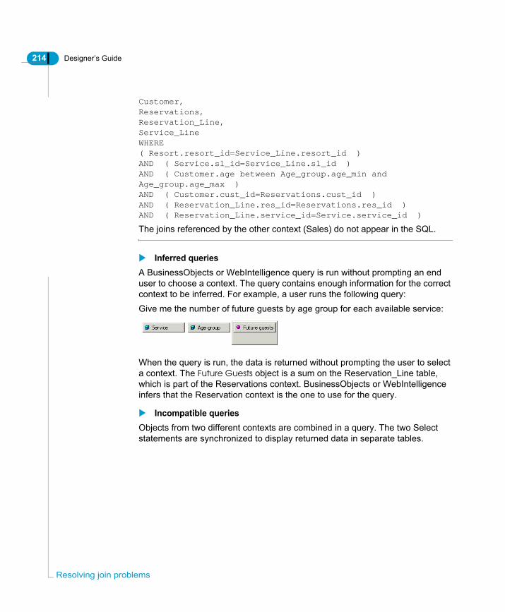
214 Designer’s Guide
Res
Customer,Reservations,Reservation_Line,Service_LineWHERE( Resort.resort_id=Service_Line.resort_id )AND ( Service.sl_id=Service_Line.sl_id )AND ( Customer.age between Age_group.age_min and Age_group.age_max )AND ( Customer.cust_id=Reservations.cust_id )AND ( Reservation_Line.res_id=Reservations.res_id )AND ( Reservation_Line.service_id=Service.service_id )
The joins referenced by the other context (Sales) do not appear in the SQL.
Inferred queriesA BusinessObjects or WebIntelligence query is run without prompting an end user to choose a context. The query contains enough information for the correct context to be inferred. For example, a user runs the following query:Give me the number of future guests by age group for each available service:
When the query is run, the data is returned without prompting the user to select a context. The Future Guests object is a sum on the Reservation_Line table, which is part of the Reservations context. BusinessObjects or WebIntelligence infers that the Reservation context is the one to use for the query.
Incompatible queriesObjects from two different contexts are combined in a query. The two Select statements are synchronized to display returned data in separate tables.
olving join problems

Designer’s Guide 215
EXAMPLEsRunning an incompatible queryA BusinessObjects user runs the following query:Give me the total number of guests company wide by age group and the months that reservations were made.
When the query is run, no prompt appears as BusinessObjects infers the use of both the Sales and Reservations contexts. The Select statements for both contexts are synchronized as follows:
The query is split into two parts: • Age Group and Number of Guests• Reservation Month
Defining contexts

216 Designer’s Guide
Res
When retrieving the results of the two queries, BusinessObjects combines the results (using Age Group). It then displays the results in two tables in the same report. The following example is section from such a report.
To allow incompatible queries to be run in BusinessObjects, you must select the Multiple SQL statements for each context option. This is described in the following section.
Selecting Multiple SQL statements for each contextTo select Multiple SQL statements for each context:1. Select File > Parameters.
The Universe Parameters dialog box appears.2. Click the SQL tab.
The SQL page appears.3. Select the Multiple SQL statements for each context check box.
4. Click OK.
olving join problems

Designer’s Guide 217
Resolving loopsIn a relational database schema, a common type of join path that returns too few rows is called a loop.
What is a Loop?A loop is a set of joins that defines a closed path through a set of tables in a schema. Loops occur when joins form multiple paths between lookup tables. An example of a loop is shown below.
The schema contains two linked sets of information:
These two sets of information are linked in a common join path forming a loop. The lookup table Country can be the country where a resort is situated, or the country in which a customer lives.
For each... the following information is linked
Resort Available service lines, services for each service line, invoice information for each service, and the country where the resort is situated.
Customer The city, region, and country where the customer lives, the sales for the customer, and the invoice information for each sale.
Resolving loops

218 Designer’s Guide
Res
Why loops in a universe schema and not in the database?In a database, multiple paths between tables may be valid and implemented to meet specific user requirements. When each path is included individually in a query it returns a distinct set of results.However, the schema that you design in Designer often needs to allow queries that include more than one path, which a relational database may not be designed to handle, so the information returned can be incorrect.The rows that are returned are an intersection of the results for each path, so fewer rows are returned than expected. It is also often difficult to determine the problem when you examine the results.
How Does a Loop Affect Queries?If you created a universe based on the above structure, any query run against the tables in the loop would return only results where the country values for resorts and the country values for customer origin are equivalent. This double restriction on the shared lookup Country table returns fewer rows than expected.
EXAMPLELoop returns incorrect resultsYou create the following objects using the schema that contains the above loop:
You run the following query in BusinessObjects: For each resort country, give me the number of guests from each country that stay at each resort.
olving join problems

Designer’s Guide 219
You would expect the following type of result:
For the resorts in France and the US, you have the number of German, Japanese, and US visitors staying in resorts in those countries.However, when you run the query using the universe containing the loop, you receive the following results:
This suggests that only visitors from the US stayed in resorts in the US. No other visitors came from any other country.
What is the loop doing to the query?The joins in the Structure are used to create the Where clause in the inferred SQL of a query. The purpose of the joins is to restrict the data that is returned by the query. In a loop, the joins apply more restrictions than you anticipate, and the data returned is incorrect.The Where clause created by the loop is shown below: WHERE ( Country.country_id=Resort.country_id )AND ( Resort.resort_id=Service_Line.resort_id )AND ( Service_Line.sl_id=Service.sl_id )AND ( Service.service_id=Invoice_Line.service_id )AND ( Sales.inv_id=Invoice_Line.inv_id )AND ( Customer.cust_id=Sales.cust_id )AND ( City.city_id=Customer.city_id )AND ( Region.region_id=City.region_id )
Resolving loops

220 Designer’s Guide
Res
AND ( Country.country_id=Region.country_id )AND ( Service_Line.service_line = 'Accommodation' )
The following two joins are both applying a restriction to the Country table:• Country.country_id=Resort.country_id• Country.country_id=Region.country_idCountry is serving two purposes:• Lookup for the resort country.• Lookup for the customer country of origin.This creates a restriction so that data is returned only when the resort country is the same as the customer country. The resulting report shows only the number of visitors from the US who visited resorts in the US.Depending on the nature of the loop, you can resolve the loop in Designer using either an alias to break the join path, or a context to separate the two join paths so that a query can only take one path or the other.
How does an alias break a loop?An alias breaks a loop by using the same table twice in the same query for a different purpose. The alias is identical to the base table with a different name. The data in the alias is exactly the same as the original table, but the different name “tricks” SQL into accepting that you are using two different tables.
NOTE
You can resolve the loop satisfactorily by creating only one alias table in the example we have been using. The Region join uses the original Country table, while the Showroom join uses the alias table. However, you could create a separate alias table for each join in the original table. In some relational database systems, this is necessary.
olving join problems
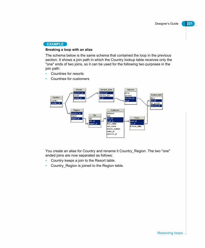
Designer’s Guide 221
EXAMPLEBreaking a loop with an aliasThe schema below is the same schema that contained the loop in the previous section. It shows a join path in which the Country lookup table receives only the "one" ends of two joins, so it can be used for the following two purposes in the join path:• Countries for resorts• Countries for customers
You create an alias for Country and rename it Country_Region. The two "one" ended joins are now separated as follows:• Country keeps a join to the Resort table.• Country_Region is joined to the Region table.
Resolving loops

222 Designer’s Guide
Res
The schema now appears as shown below:
When you run the same query that produced too few rows in the previous example:For each resort country, give me the number of guests from each country that stay at each resort.
The Where clause for this query is now:WHERE( City.city_id=Customer.city_id )AND ( City.region_id=Region.region_id )AND ( Country.country_id=Region.country_id )AND ( Resort_Country.country_id=Resort.country_id )AND ( Customer.cust_id=Sales.cust_id )AND ( Invoice_Line.inv_id=Sales.inv_id )AND ( Invoice_Line.service_id=Service.service_id )AND ( Resort.resort_id=Service_Line.resort_id )AND ( Service.sl_id=Service_Line.sl_id )AND ( Service_Line.service_line = 'Accommodation' )
There is now one join applying a restriction on the Country table and another join applying a restriction on the Resort_Country table. The loop has been broken.
olving join problems

Designer’s Guide 223
When the query is run, the following table is returned:
How does a context resolve a loop?A context resolves a loop by defining a set of joins that specify one specific path through tables in a loop. It ensures that joins are not included from different paths within the same SQL query.You often use contexts in schemas that contain multiple fact tables (“multiple stars”) that share lookup tables.
EXAMPLEResolving a loop with a contextThe schema below contains statistical information about sales and reservations. The statistics relating to each type of transaction are stored in the fact tables Sales and Reservations. The schema contains a loop as a join path can follow the sales path or the reservations path to get service information.
Resolving loops

224 Designer’s Guide
Res
If you created an alias for the Customer so that you had a Customer to Reservation join and a Customer_Sales to Sales join, you break the loop, but if you want to add a City table to the schema, you end up with a loop again as shown below:
You must continue creating aliases for each new table you add to the schema. This is difficult to maintain, and also ends up proliferating the number of similar objects using each table in the universe.The only way to resolve this loop is to leave the loop in place, and create a context that specifies one or the other path around the schema. This ensures that queries answer questions for one transaction or the other, such as: Is the customer information needed from the perspective of sales or reservations?In the example, you can follow two different paths from the Customer table to the Service table:
For this path... Designer detects these contexts...
Reservations and Reservation_Line
Reservation_Line
Sales and Invoice_Line
Sales_Line
olving join problems

Designer’s Guide 225
The Reservation_Line context appears below:
The Sales_Line context appears below:
These two tables are the of the two contexts
Both are arranged at the
th t j i th
the one to many
source
end ofjoin paths.
Resolving loops

226 Designer’s Guide
Res
You then create different sets of objects from the tables in the different contexts. Users can then run either Reservation queries or Sales queries, depending on the objects they select.
Visually Identifying LoopsYou can use the following guidelines to help you analyze your schema to determine whether an alias or context is appropriate for resolving loops. These can be useful to understand your schema, but you should use Detect Aliases and Detect Contexts to formally identify and resolve loops. See the section Detecting and creating an alias on page 228 and Detecting and creating a context on page 230 for more information.
Automatically Identifying and Resolving LoopsYou can use Designer to automatically detect loops and propose candidate aliases and contexts that you can insert in your schema to resolve the loops.
Cardinalities must be set before detecting loopsBefore using the automatic loop detection and resolution features, all cardinalities must be set for all joins in the schema.It is good design practise to either define cardinalities manually, or manually validate each cardinality that Designer proposes when using the automatic routine.You can set cardinalities in two ways:• Manually. Refer to the section “Using Cardinalities” in the Defining Joins
chapter for more information.• Use Detect Cardinalities. Refer to the section “Using Cardinalities” in the
Defining Joins chapter for more information.
If loop contains... then loop can be resolved by...
Only one lookup table Alias
A look up table that receives only "one" ends of joins
Alias
Two or more fact tables Context
olving join problems
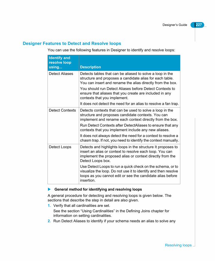
Designer’s Guide 227
Designer Features to Detect and Resolve loopsYou can use the following features in Designer to identify and resolve loops:
General method for identifying and resolving loopsA general procedure for detecting and resolving loops is given below. The sections that describe the step in detail are also given.1. Verify that all cardinalities are set.
See the section “Using Cardinalities” in the Defining Joins chapter for information on setting cardinalities.
2. Run Detect Aliases to identify if your schema needs an alias to solve any
Identify and resolve loop using... Description
Detect Aliases Detects tables that can be aliased to solve a loop in the structure and proposes a candidate alias for each table. You can insert and rename the alias directly from the box.You should run Detect Aliases before Detect Contexts to ensure that aliases that you create are included in any contexts that you implement.It does not detect the need for an alias to resolve a fan trap.
Detect Contexts Detects contexts that can be used to solve a loop in the structure and proposes candidate contexts. You can implement and rename each context directly from the box.Run Detect Contexts after DetectAliases to ensure that any contexts that you implement include any new aliases.It does not always detect the need for a context to resolve a chasm trap. If not, you need to identify the context manually.
Detect Loops Detects and highlights loops in the structure It proposes to insert an alias or context to resolve each loop. You can implement the proposed alias or context directly from the Detect Loops box.Use Detect Loops to run a quick check on the schema, or to visualize the loop. Do not use it to identify and then resolve loops as you cannot edit or see the candidate alias before insertion.
Resolving loops

228 Designer’s Guide
Res
loops.See the section Detecting and creating an alias on page 228 for more information.
3. Insert the candidate aliases proposed by Detect Aliases.4. Run Detect Contexts to identify if your schema needs a context to solve a loop
that could not be solved with an alias only.See the section Detecting and creating a context on page 230 for more information.
5. Implement the candidate contexts proposed by Detect Contexts.6. Test the resolved loop by creating objects and running queries.
See the chapter "Building Universes" for information on creating objects and testing the universe structures.
NOTE
If you are resolving loops for a schema that already has objects defined on the tables, then you must redefine any objects that now use an alias and not the base table.
Detecting and creating an aliasYou can use Detect Aliases, to automatically detect and indicate the tables causing loops in the active universe. Detect Aliases proposes candidate tables that you can edit, and insert in the schema.
REMINDERBefore using Detect Aliases, verify that all the tables in schema are linked by joins, and that all cardinalities are set.
To detect and create an alias:1. Select Tools > Detect Aliases.
OrClick the Detect Aliases button.The Detect Aliases dialog box appears. The left pane lists the table or tables that need an alias. The right pane lists proposed aliases that can be inserted
Detect Aliases
olving join problems

Designer’s Guide 229
to break the loop.
2. Select a table in the left pane.A suggested name for the candidate alias is listed in the right pane.
3. If you want to rename the proposed alias, click the Rename button and enter a new name in the Rename box.
4. Click the Create button.A message box prompts you to confirm the creation of the alias.
5. Click the OK button.The alias appear in the Structure pane/
6. Repeat steps 2 to 4 for any remaining tables.7. Click Close.
Resolving loops

230 Designer’s Guide
Res
Detecting and creating multiple aliasesSometimes when you create an alias, you need to create additional aliases to accommodate new join paths. When using Detect Alias, if Designer detects the need for further aliases, the following dialog box appears when you click the Create button.
In such a situation, two options are available to you:• You can accept that only the first table proposed will be aliased.• You can alias all the tables listed.
Detecting and creating a contextYou can use Detect Contexts to automatically detect the need for a context. Detect Contexts also proposes a candidate context. You can edit the candidate context before it is implemented.To detect and create a context:1. Select Tools > Detect Contexts.
OrClick the Detect Contexts button.The Candidate Contexts dialog box appears. The proposed contexts appear Detect Contexts
olving join problems
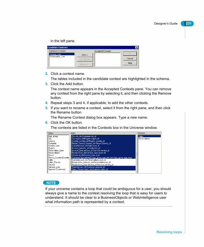
Designer’s Guide 231
in the left pane.
2. Click a context name.The tables included in the candidate context are highlighted in the schema.
3. Click the Add button.The context name appears in the Accepted Contexts pane. You can remove any context from the right pane by selecting it, and then clicking the Remove button.
4. Repeat steps 3 and 4, if applicable, to add the other contexts.5. If you want to rename a context, select it from the right pane, and then click
the Rename button.The Rename Context dialog box appears. Type a new name.
6. Click the OK button.The contexts are listed in the Contexts box in the Universe window.
NOTE
If your universe contains a loop that could be ambiguous for a user, you should always give a name to the context resolving the loop that is easy for users to understand. It should be clear to a BusinessObjects or WebIntelligence user what information path is represented by a context.
Resolving loops

232 Designer’s Guide
Res
Automatically detecting loopsYou can detect loops in your universe using Detect Loops. This is a feature that automatically checks for loops in the schema, and proposes either an alias or context to solve the loop.Detect Loops is useful to run quick checks for loops in the schema. It also proposes aliases and contexts to resolve detected loops; however, you have less control over the order that the alias and contexts are created than if you used Detect Aliases and Detect Contexts to resolve a loop.The recommended process for resolving loops is described in the section General method for identifying and resolving loops on page 227.
NOTE
You can also use Check Integrity to automatically check for errors in universe structures, including joins, cardinalities, and loops. Check Integrity proposes solutions to any errors it discovers. See the section Checking Universe Integrity Manually on page 266 for more information.
To detect loops in a schema:1. Verify that you have set cardinalities for all joins in the schema.2. Select Tools > Detect Loops.
OrClick the Detect Loops button.The Loop Detection box appears. It indicates how many loops have been detected and proposes a possible solution.
The detected join path that forms a loop is simultaneously highlighted in the
Detect Loop
olving join problems

Designer’s Guide 233
Structure pane as follows:
3. Click the forward button to display the next loop and proposed solution. For each loop that Designer detects, the join path is highlighted in the structure pane.
4. Click Close.
Creating aliases and contexts automaticallyDesigner proposes a candidate alias or a context to resolve a loop when you run Detect Loop. You can choose to insert the candidate alias or implement the candidate context directly from the Detect Loops box.To create an alias using Detect Loop:1. Select Tools > Detect Loops.
The Detect Loops box appears. It indicates one or more loops detected in the schema, and proposes a candidate alias or context for each loop.
2. Click the forward arrow button until the following message appears for a
Resolving loops

234 Designer’s Guide
Res
detected loop:This loop can be resolved with an alias.
3. Click the Insert Alias button.An alias is automatically inserted in the Structure pane. It is joined to the table that table that is causing the loop in the schema.
Creating a context using Detect LoopTo create a context using Detect Loops:1. Select Tools > Detect Loops.
The Detect Loops box appears. It indicates one or more loops detected in the schema, and proposes a candidate alias or context for each loop.
2. Click the forward arrow button until the following message appears for a
olving join problems
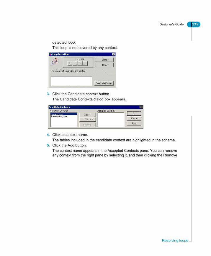
Designer’s Guide 235
detected loop:This loop is not covered by any context.
3. Click the Candidate context button.The Candidate Contexts dialog box appears.
4. Click a context name.The tables included in the candidate context are highlighted in the schema.
5. Click the Add button.The context name appears in the Accepted Contexts pane. You can remove any context from the right pane by selecting it, and then clicking the Remove
Resolving loops

236 Designer’s Guide
Res
button.6. Repeat steps 3 and 4, if applicable, to add the other contexts.7. Click OK.
A context confirmation box appears.
8. Click Close.The contexts are listed in the Contexts box in the Universe window.
Examples of Resolving LoopsThe following are worked examples showing you how to do the following:• Create an alias to break a loop caused by shared lookup tables• Create an alias to break a loop caused by shared lookup tables• Determining when an alias is not appropriate to break a loop• Creating a context to resolve a loop• Using an alias and context together to resolve a loopThe schemas are not based on the Beach universe. They use a schema based on a Shipping company and show another perspective of certain loop resolution examples already shown in this chapter with the Beach universe.
EXAMPLECreate an alias to break a loop caused by shared lookup tables.A sales database holds information about products sold to customers on a worldwide basis. These customers can:• Reside anywhere in the world• Order products from the company• Request that these products be shipped to a destination in any countryFor example, a customer residing in the UK can order a vehicle and then ask for it to be shipped to Brazil.
olving join problems

Designer’s Guide 237
The schema for this type of database is as follows:
You can interpret this schema as follows: • Each customer comes from one country.• Each customer can place one or more orders for a product.• The company ships each product ordered to a destination country, which may
not necessarily be the same as the customer’s country of residence. The tables and their columns are shown below:
You run a query to obtain the following information: • Names of customers• Customer’s country of residence• Dates of each order• Destination country of the shipmentThe SQL to extract this data is as follows:SELECT
Resolving loops
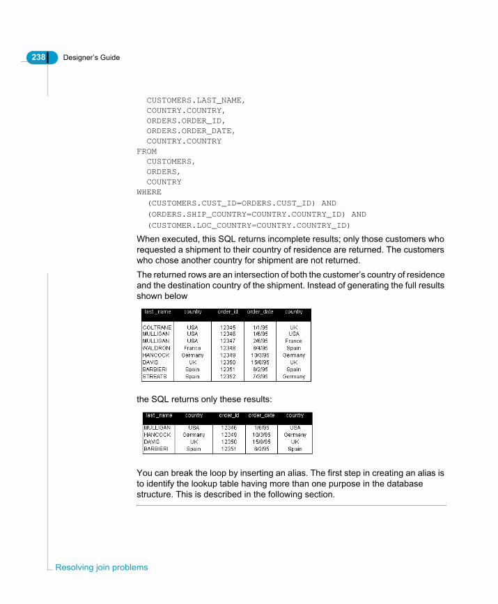
238 Designer’s Guide
Res
CUSTOMERS.LAST_NAME, COUNTRY.COUNTRY, ORDERS.ORDER_ID, ORDERS.ORDER_DATE, COUNTRY.COUNTRYFROM CUSTOMERS, ORDERS, COUNTRYWHERE
(CUSTOMERS.CUST_ID=ORDERS.CUST_ID) AND
(ORDERS.SHIP_COUNTRY=COUNTRY.COUNTRY_ID) AND
(CUSTOMER.LOC_COUNTRY=COUNTRY.COUNTRY_ID)
When executed, this SQL returns incomplete results; only those customers who requested a shipment to their country of residence are returned. The customers who chose another country for shipment are not returned. The returned rows are an intersection of both the customer’s country of residence and the destination country of the shipment. Instead of generating the full results shown below
the SQL returns only these results:
You can break the loop by inserting an alias. The first step in creating an alias is to identify the lookup table having more than one purpose in the database structure. This is described in the following section.
olving join problems
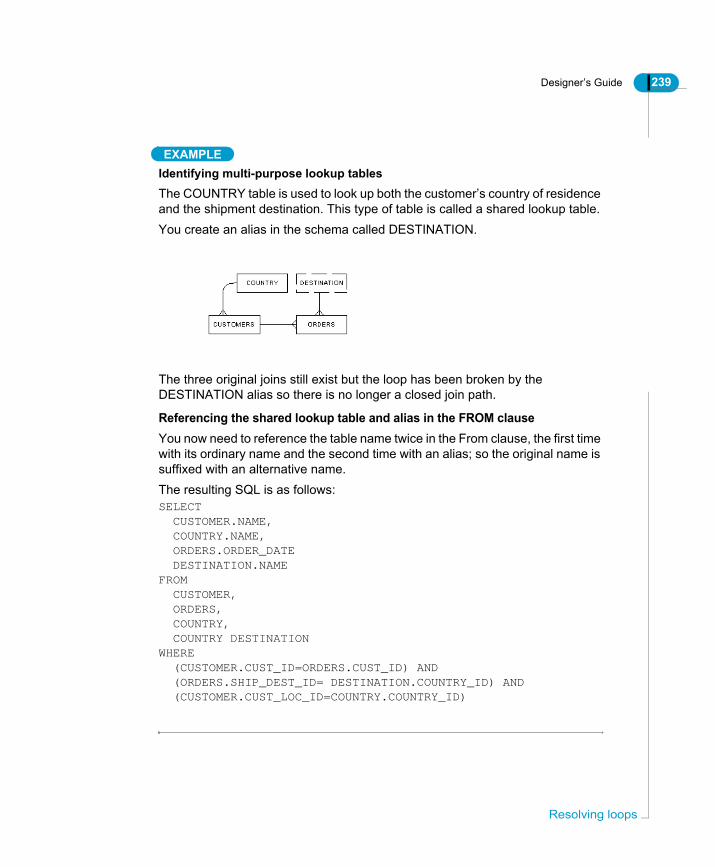
Designer’s Guide 239
EXAMPLEIdentifying multi-purpose lookup tablesThe COUNTRY table is used to look up both the customer’s country of residence and the shipment destination. This type of table is called a shared lookup table.You create an alias in the schema called DESTINATION.
The three original joins still exist but the loop has been broken by the DESTINATION alias so there is no longer a closed join path.
Referencing the shared lookup table and alias in the FROM clauseYou now need to reference the table name twice in the From clause, the first time with its ordinary name and the second time with an alias; so the original name is suffixed with an alternative name.The resulting SQL is as follows:SELECT CUSTOMER.NAME, COUNTRY.NAME, ORDERS.ORDER_DATE DESTINATION.NAMEFROM CUSTOMER, ORDERS, COUNTRY, COUNTRY DESTINATIONWHERE (CUSTOMER.CUST_ID=ORDERS.CUST_ID) AND (ORDERS.SHIP_DEST_ID= DESTINATION.COUNTRY_ID) AND (CUSTOMER.CUST_LOC_ID=COUNTRY.COUNTRY_ID)
Resolving loops

240 Designer’s Guide
Res
EXAMPLECreate an alias to break a loop caused by shared lookup tablesA sales database holds information about customers living in different countries. These customers can place orders for goods that can be delivered by a number of couriers or shipping companies. In this database, the names of the countries and shippers have been normalized into lookup tables. Normalization is a process that refines the relationships of tables by removing redundancies. For structural reasons, rather than two lookup tables, only one lookup table (SYSLOOKUPS) was created with a code, description and type field. The type field indicates the particular type of information the record holds; for example, country or shipper.Referred to as a “flexible lookup,” this type of table often appears in schemas automatically generated by CASE tools.
olving join problems
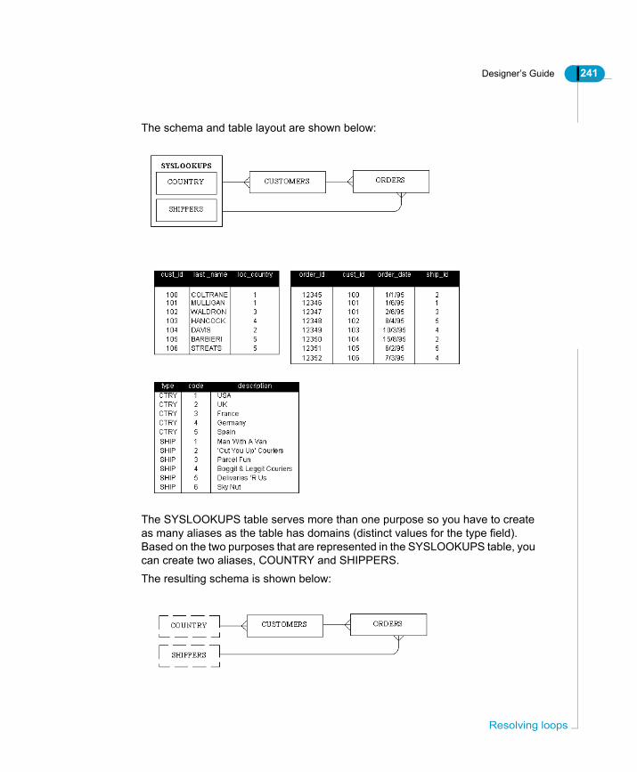
Designer’s Guide 241
The schema and table layout are shown below:
The SYSLOOKUPS table serves more than one purpose so you have to create as many aliases as the table has domains (distinct values for the type field). Based on the two purposes that are represented in the SYSLOOKUPS table, you can create two aliases, COUNTRY and SHIPPERS.The resulting schema is shown below:
Resolving loops
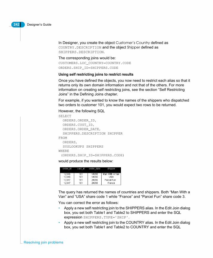
242 Designer’s Guide
Res
In Designer, you create the object Customer’s Country defined as COUNTRY.DESCRIPTION and the object Shipper defined as SHIPPERS.DESCRIPTION. The corresponding joins would be:CUSTOMERS.LOC_COUNTRY=COUNTRY.CODE
ORDERS.SHIP_ID=SHIPPERS.CODE
Using self restricting joins to restrict resultsOnce you have defined the objects, you now need to restrict each alias so that it returns only its own domain information and not that of the others. For more information on creating self restricting joins, see the section “Self Restricting Joins” in the Defining Joins chapter.For example, if you wanted to know the names of the shippers who dispatched two orders to customer 101, you would expect two rows to be returned.However, the following SQLSELECT ORDERS.ORDER_ID, ORDERS.CUST_ID, ORDERS.ORDER_DATE, SHIPPERS.DESCRIPTION SHIPPERFROM ORDERS, SYSLOOKUPS SHIPPERSWHERE (ORDERS.SHIP_ID=SHIPPERS.CODE)
would produce the results below:
The query has returned the names of countries and shippers. Both “Man With a Van” and “USA” share code 1 while “France” and “Parcel Fun” share code 3.You can correct the error as follows:• Apply a new self restricting join to the SHIPPERS alias. In the Edit Join dialog
box, you set both Table1 and Table2 to SHIPPERS and enter the SQL expression SHIPPERS.TYPE=’SHIP’.
• Apply a new self restricting join to the COUNTRY alias. In the Edit Join dialog box, you set both Table1 and Table2 to COUNTRY and enter the SQL
olving join problems

Designer’s Guide 243
expression COUNTRY.TYPE=’CTRY’.
Problems using restrictionsWhen you add the restriction to either the object’s Where clause or to the existing join between the alias and the CUSTOMERS/ORDERS table, this can produce the following problems:• When you add the restriction to the Where clause of an object, you must also
add the same restriction to every object built from the alias. If you are creating a number of objects on an alias that has many columns, you could have problems maintaining the universe.
• The restriction to the join between the alias and another table only takes effect when the join is invoked. If you run a simple query containing only the Shipper object, every row in the SHIPPERS alias (including the unwanted Country rows) is returned as there is no reason to include the ORDERS table. As the join is not seen as necessary, the restriction is not applied.
SummaryIn this example, we considered a schema with a shared lookup table. The actions carried out can be summarized as follows:1. Create a COUNTRY and SHIPPERS alias for the shared lookup table.2. Create self restricting joins for the aliases as restrictions.The aliases in this example resolve a loop by using one combined lookup table as two different lookup tables. These aliases also required the setting of restrictions (self-joins), so in some structures aliases may lead to the need for additional adjustments or restrictions.
EXAMPLEDetermining when an alias is not appropriate to break a loopCreating an alias to resolve the loop described above is not the optimal solution. In this case, the use of contexts is a better solution. The following example describes why aliases are not appropriate, and why contexts are a better solution in this case.If you try to identify the lookup table used for more than one purpose, it is not clear if it is the PRODUCTS table, or the CUSTOMERS table.
Resolving loops

244 Designer’s Guide
Res
If you decide to create two aliases for the PRODUCTS table as shown below:
The two aliases are ORDERED_PRODUCTS and LOANED_PRODUCTS. This could be confusing for users as they are more likely to understand products, and not ordered products or loaned products.If you also decide to add a COUNTRY table to indicate that the products are manufactured in several different countries you would have to join it directly to the PRODUCTS table.The resulting schema would be as follows:
In the schema above, it was necessary to create two new aliases, ORDERED_PRODUCTS_COUNTRY and LOANED_PRODUCTS_COUNTRY. The use of aliases is obviously an unsatisfactory and complicated solution for this particular schema.In this case, you should create contexts.
olving join problems

Designer’s Guide 245
EXAMPLECreating a context to resolve a loopA database contains information about customers who can either buy or rent products. In this database, there are two different ways to present the relationship between the customers and the products:• By products that have been ordered by (or sold to) customers.• By products that have been rented to customers. This database has the following type of schema:
If we wanted to run a query that returns only a list of customer names and a list of products, we could use the ORDER and ORDER_LINES table. The result would be a list of products ordered by each customer. By using the LOANS and LOAN_LINES tables, we would obtain a list of products rented by each customer.This schema contains a loop that causes any query involving all six joins simultaneously to result in a list made up of both products sold and rented to customers. If a product has been sold, but never rented to a customer or vice-versa, it would not appear in the list of results.
EXAMPLEUsing an alias and context together to resolve a loopYou can use contexts and aliases to resolve loops in a universe. The following example shows how to use both aliases and contexts together in a loop resolution.
Resolving loops
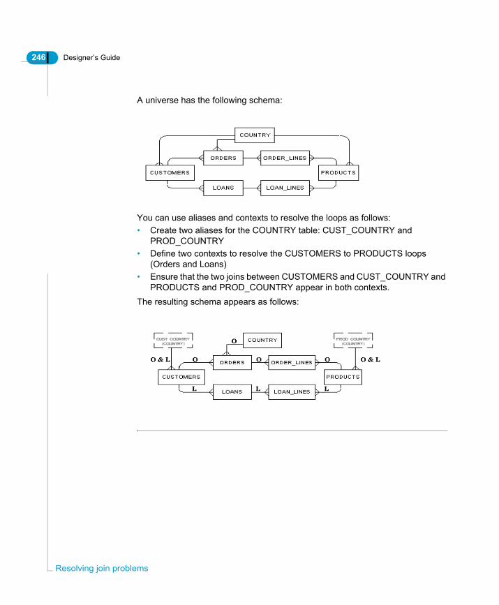
246 Designer’s Guide
Res
A universe has the following schema:
You can use aliases and contexts to resolve the loops as follows:• Create two aliases for the COUNTRY table: CUST_COUNTRY and
PROD_COUNTRY• Define two contexts to resolve the CUSTOMERS to PRODUCTS loops
(Orders and Loans)• Ensure that the two joins between CUSTOMERS and CUST_COUNTRY and
PRODUCTS and PROD_COUNTRY appear in both contexts. The resulting schema appears as follows:
olving join problems

Designer’s Guide 247
Resolving Chasm TrapsA chasm trap is a common problem in relational database schemas in which a join path returns more data than expected.
What is a Chasm Trap?A chasm trap is a type of join path between three tables when two "many-to-one" joins converge on a single table, and there is no context in place that separates the converging join paths.The example below shows a part of the Beach universe schema. The three tables have been separated from the rest of the schema to illustrate the chasm trap. It uses the same Club connection for data. The Service table receives the one ends of two one-to-many joins.
Resolving Chasm Traps

248 Designer’s Guide
Res
You will get incorrect results only when all the following conditions exist:
The following is an example that shows how queries that are run when all the above conditions exist return a Cartesian product.
Condition Example
A “many to one to many relationship” exists among three tables in the universe structure.
The query includes objects based on two tables both at the “many” end of their respective joins.
There are multiple rows returned for a single dimension.
many-to-one
one-to-many
olving join problems
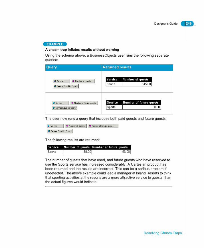
Designer’s Guide 249
EXAMPLEA chasm trap inflates results without warningUsing the schema above, a BusinessObjects user runs the following separate queries:
The user now runs a query that includes both paid guests and future guests:
The following results are returned:
The number of guests that have used, and future guests who have reserved to use the Sports service has increased considerably. A Cartesian product has been returned and the results are incorrect. This can be a serious problem if undetected. The above example could lead a manager at Island Resorts to think that sporting activities at the resorts are a more attractive service to guests, than the actual figures would indicate.
Query Returned results
Resolving Chasm Traps

250 Designer’s Guide
Res
How does a chasm trap inflate results?The chasm trap causes a query to return every possible combination of rows for one measure with every possible combination of rows for the other measure. In the example above, the following has occurred:• Number of guests transactions *Number of future guest transactions• Number of future guest transactions*Number of guests transactionsThe following example examines in detail how a chasm trap returns a Cartesian product:
EXAMPLEExamining the Cartesian product of a chasm trapWe need to examine the rows that are returned by the queries to make the aggregated figures. In our example, we can do this by adding the dimensions Days Billed and Days Reserved to the queries to return individual transaction details.The Number of Guests report appears as follows:
The Number of Future Guests report appears as follows:
The two reports show the following number of transactions:• Number of Guests = 3 transactions• Number of Future Guests = 2 transactions
olving join problems

Designer’s Guide 251
When the two dimensions are both added to the query, the following results are returned:
The query returns every possible combination of Number of Guests rows with every possible combination of Number of Future Guests rows: the Number of Guests transactions each appears twice, and the Number of Future Guests transactions each appears three times.When a sum is made on the returned data, the summed results are incorrect.Unlike loops, chasm traps are not detected automatically by Designer, however, you can use Detect Contexts (Tools>Detect Contexts) to automatically detect and propose candidate contexts in your schema.Detect Contexts examines the many to one joins in the schema. It picks up the table that receives converging many to one joins and proposes contexts to seperate the queries run on the table. This is the most effective way to ensure that your schema does not have have a chasm trap.You can also detect chasm traps graphically by analyzing the one-to-many join paths in your schema.If you do not run Detect Contexts, nor spot the chasm trap in the schema, the only way to see the problem is to look at the detail rows. Otherwise there is nothing to alert you to the situation.
Detecting a Chasm TrapYou can find chasm traps by using Detect Contexts to detect and propose candidate contexts, and then examining the table where any two contexts diverge. This point where two contexts intersect is the source of a chasm trap.If you have two fact tables with many to one joins converging to a single lookup table, then you have a potential chasm trap.
Resolving Chasm Traps
252 Designer’s Guide
Res
TIPFor information on organizing the table schema to detect join problems, refer to “Detecting join problems graphically” on page 262.
Resolving a Chasm TrapTo resolve a chasm trap you need to make two separate queries and then combine the results. Depending on the type of objects defined for the fact tables, and the type of end user environment, you can use the following methods to resolve a chasm trap:• Create a context for each fact table. This solution works in all cases.• Modify the SQL parameters for the universe so you can generate separate
SQL queries for each measure. This solution only works for measure objects. It does not generate separate queries for dimension or detail objects.
Each of these methods is described in the following sections.
Using contexts to resolve chasm trapsYou can define a context for each table at the "many" end of the joins. In our example you could define a context from SERVICE to RESERVATION_LINE and from SERVICE to INVOICE_LINE.When you run a query which includes objects from both contexts, this creates two Select statements that are synchronized to produce two separate tables in BusinessObjects, avoiding the creation of a Cartesian product.
When do you use contexts?Creating contexts will always solve a chasm trap in BusinessObjects universes. When you have dimension objects in one or both fact tables, you should always use a context.
Using contexts to solve a chasm trapTo use contexts to resolve a chasm trap:1. Identify the potential chasm trap by analyzing the "one-to-many-to-one" join
olving join problems

Designer’s Guide 253
path relations in the schema.2. Select Tools > Detect Contexts.
The Candidate Contexts box appears.
3. Select a proposed context in the Candidate Contexts list box and click the Add button to add it to the Accept Contexts list box.
4. Repeat for other listed contexts.The new contexts are listed in the Contexts pane of the List View bar.
5. Select File > Parameters.The Universe Parameters dialog box appears.
6. Click the SQL tab.The SQL page appears.
7. Select the Multiple SQL for each Context check box.
8. Click OK.When you run queries on the tables in the chasm trap, the query is separated for measures and dimensions defined on the affected tables.
Using Multiple SQL Statements for Each MeasureIf you have only measure objects defined for both fact tables, then you can use the Universe Parameters option Multiple SQL statements for each measure. This forces the generation of separate SQL queries for each measure that appears in the Query panel.This solution does not work for dimension and detail objects.
Resolving Chasm Traps

254 Designer’s Guide
Res
The following table describes when you can use Multiple SQL Statements for Each Measure and when you should avoid its use:
To activate Multiple SQL Statements for Each Measure:1. Select File > Parameters from the menu bar.
The Universe Parameters dialog box appears.2. Click the SQL tab.3. Select the Multiple SQL Statements for Each Measure check box in the
Multiple Paths group box. 4. Click OK.
You... In these situations...
Use Multiple SQL Statements for Each Measure
For both BusinessObjects and WebIntelligence universes that contain only measure objects defined for both fact tables. The advantage of using multiple SQL statements is that you can avoid using contexts that you need to maintain later.
Do not use Multiple SQL Statements for Each Measure
When you have dimension or detail objects defined for one or both of the fact tables. If a dimension or detail object is included in a query based on a universe using this solution, a Cartesian product will be returned.As this solution can slow query response time and produce incorrect results, than you should consider creating contexts to resolve the chasm trap.
olving join problems

Designer’s Guide 255
Resolving Fan TrapsA fan trap is a less common problem than chasm traps in a relational database schema. It has the same effect of returning more data than expected.
What is a Fan Trap?A fan trap is a type of join path between three tables when a “one-to-many” join links a table which is in turn linked by another “one-to-many” join. The fanning out effect of “one-to-many” joins can cause incorrect results to be returned when a query includes objects based on both tables.A simple example of a fan trap is shown below:
When you run a query that asks for the total number of car models sold by each model line, for a particular customer, an incorrect result is returned as you are performing an aggregate function on the table at the “one” end of the join, while still joining to the “many” end.
EXAMPLEA fan trap inflates results without warningUsing the schema above, a BusinessObjects user runs the following query:
The following results are returned:
Resolving Fan Traps
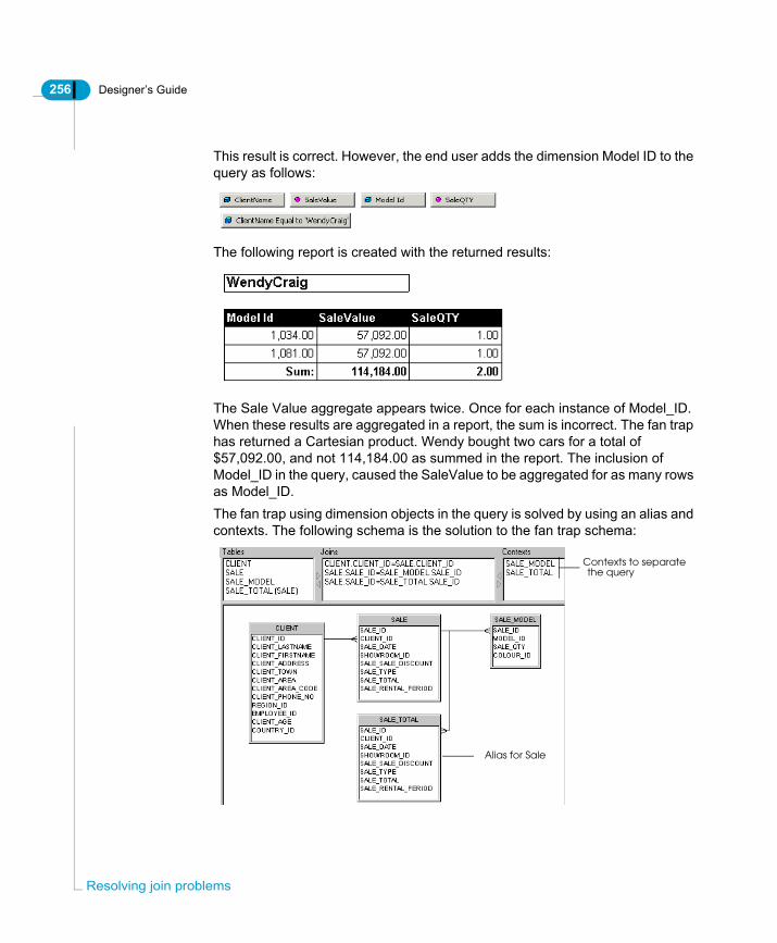
256 Designer’s Guide
Res
This result is correct. However, the end user adds the dimension Model ID to the query as follows:
The following report is created with the returned results:
The Sale Value aggregate appears twice. Once for each instance of Model_ID. When these results are aggregated in a report, the sum is incorrect. The fan trap has returned a Cartesian product. Wendy bought two cars for a total of $57,092.00, and not 114,184.00 as summed in the report. The inclusion of Model_ID in the query, caused the SaleValue to be aggregated for as many rows as Model_ID.The fan trap using dimension objects in the query is solved by using an alias and contexts. The following schema is the solution to the fan trap schema:
Alias for Sale
Contexts to separatethe query
olving join problems

Designer’s Guide 257
The original query which returned the Cartesian product for Wendy Craig, now returns the following table when run with the above solution:
How Do You Detect a Fan Trap?You cannot automatically detect fan traps. You need to visually examine the direction of the cardinalities displayed in the table schema.If you have two tables that are referenced by measure objects and are joined in a series of many to one joins, then you may have a potential fan trap.For a description to organize the table schema to detect join problems, see the section Detecting join problems graphically on page 262.
How Do You Resolve a Fan Trap?There are two ways to solve a fan trap problem.• Create an alias for the table containing the initial aggregation, then use Detect
Contexts (Tools > Detect Contexts) to detect and propose a context for the alias table and a context for the original table. This is the most effective way to solve the fan trap problem.
• Altering the SQL parameters for the universe. This only works for measure objects.
Both of these methods are described below.
Using aliases and contexts to resolve fan trapsYou create an alias table for the table producing the aggregation and then detect and implement contexts to separate the query. You can do this as follows:To use aliases and contexts to resolve a fan trap:1. Identify the potential fan trap by analyzing the "one-to-many-to-one-to-many"
join path relations in the schema.2. Create an alias for the table that is producing the multiplied aggregation.
For example, SaleValue in the previous example is an aggregate of the Sale_Total column in the Sales table. You create an alias called Sale_Total
Resolving Fan Traps

258 Designer’s Guide
Res
for Sale.
3. Create a join between the original table and the alias table.If you create a one-to-one join, Designer does not detect the context, and you must build the context manually. In most cases you can use a one-to-many which allows automatic detection and implementation of contexts.For example you create a one-to-many join between Sale and Sale_Total.
4. Build the object that is causing the aggregation on the alias tables.For example the original SaleValue object was defined as follows:sum(SALE.SALE_TOTAL). The new definition for SaleValue is:sum(Sale_Total.SALE_TOTAL).
5. Select Tools > Detect Contexts.The Candidate Contexts box appears. It proposes the candidate contexts for the join path for the base table and the new join path for the alias table.
Sale_Total is an alias for Sale
one-to-many join
olving join problems
Designer’s Guide 259
NOTE
If you have used a one-to-one join between the alias and the base table, then you need to create the context manually.
6. Click a candidate context and click Add.7. Repeat for the other candidate context.8. Click OK.
The contexts are created in the schema. You can view them in the Contexts pane when List Mode is active (View > List Mode). The context for the join
Resolving Fan Traps

260 Designer’s Guide
Res
path CLIENT>SALE>SALE_MODEL appears as follows:
And a second context for the CLIENT>SALE>SALE_TOTAL join path:
9. Select File > Parameters.The Parameters dialog appears.
10.Click the SQL tab.SQL page.The SQL page appears.
olving join problems
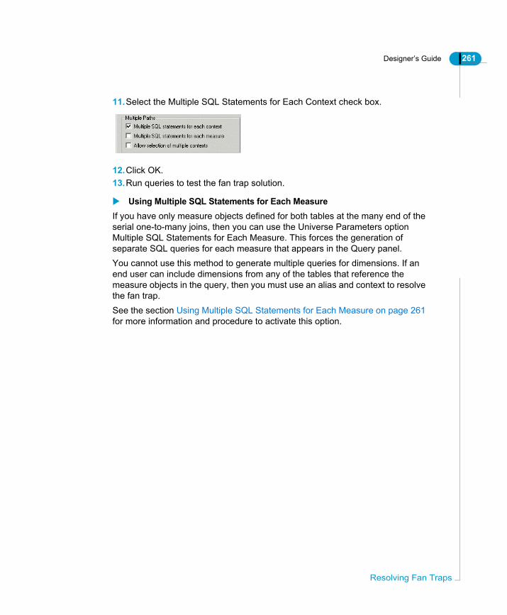
Designer’s Guide 261
11.Select the Multiple SQL Statements for Each Context check box.
12.Click OK.13.Run queries to test the fan trap solution.
Using Multiple SQL Statements for Each MeasureIf you have only measure objects defined for both tables at the many end of the serial one-to-many joins, then you can use the Universe Parameters option Multiple SQL Statements for Each Measure. This forces the generation of separate SQL queries for each measure that appears in the Query panel.You cannot use this method to generate multiple queries for dimensions. If an end user can include dimensions from any of the tables that reference the measure objects in the query, then you must use an alias and context to resolve the fan trap.See the section Using Multiple SQL Statements for Each Measure on page 261 for more information and procedure to activate this option.
Resolving Fan Traps

262 Designer’s Guide
Res
Detecting join problems graphicallyYou can visually detect potential chasm and fan traps in your table schema by arranging the tables in the Structure pane so that the "many" ends of the joins are to one side of the pane, and the "one" ends to the other. The example below shows the Beach universe schema arranged with a one to many flow from left to right.
olving join problems

Designer’s Guide 263
Potential chasm trapThe potential chasm traps are shown below:
Both of these join paths have been separated using the contexts Sales and Reservations.
Potential fan trapA universe schema for a car sales database is shown below:
Detecting join problems graphically
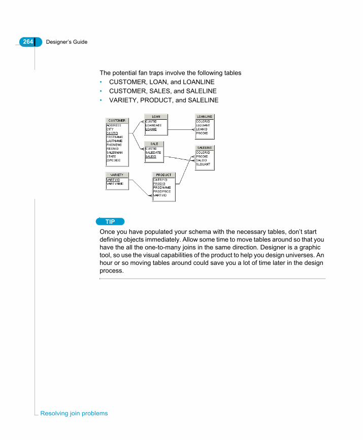
264 Designer’s Guide
Res
The potential fan traps involve the following tables• CUSTOMER, LOAN, and LOANLINE• CUSTOMER, SALES, and SALELINE• VARIETY, PRODUCT, and SALELINE
TIPOnce you have populated your schema with the necessary tables, don’t start defining objects immediately. Allow some time to move tables around so that you have the all the one-to-many joins in the same direction. Designer is a graphic tool, so use the visual capabilities of the product to help you design universes. An hour or so moving tables around could save you a lot of time later in the design process.
olving join problems

Designer’s Guide 265
Checking the universeAs you design your universe, you should test its integrity periodically. You can verify universe integrity as follows:
Checking Universe Integrity AutomaticallyYou can set the following integrity check options in Designer to parse SQL structures at creation, universe export, and universe opening:
Setting automatic universe check optionsTo set automatic universe check options:1. Select Tools > Options.
The Options dialog box opens to the General page.2. Select or clear check boxes for appropriate universe automatic check options
Check universe Description
Automatically You can set Designer options to check the SQL syntax of universe structures at creation, universe export, or when a universe is opened.
Manually You run Check Integrity to check selected universe structures.
Automatic check option Description
Automatic parse upon definition
Designer automatically checks the SQL definition of all objects, conditions, and joins at creation. It is applied when you click OK to validate structure creation.
Send check integrity Designer displays a warning each time you attempt to export an unchecked universe.
Check universe integrity at opening
All universes are checked automatically when opened.
Checking the universe
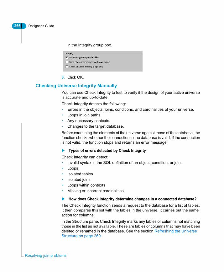
266 Designer’s Guide
Res
in the Integrity group box.
3. Click OK.
Checking Universe Integrity ManuallyYou can use Check Integrity to test to verify if the design of your active universe is accurate and up-to-date.Check Integrity detects the following:• Errors in the objects, joins, conditions, and cardinalities of your universe.• Loops in join paths. • Any necessary contexts.• Changes to the target database.Before examining the elements of the universe against those of the database, the function checks whether the connection to the database is valid. If the connection is not valid, the function stops and returns an error message.
Types of errors detected by Check IntegrityCheck Integrity can detect:• Invalid syntax in the SQL definition of an object, condition, or join. • Loops• Isolated tables• Isolated joins• Loops within contexts• Missing or incorrect cardinalities
How does Check Integrity determine changes in a connected database?The Check Integrity function sends a request to the database for a list of tables. It then compares this list with the tables in the universe. It carries out the same action for columns.In the Structure pane, Check Integrity marks any tables or columns not matching those in the list as not available. These are tables or columns that may have been deleted or renamed in the database. See the section Refreshing the Universe Structure on page 269.
olving join problems
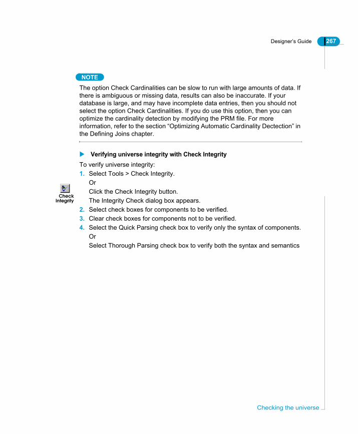
Designer’s Guide 267
NOTE
The option Check Cardinalities can be slow to run with large amounts of data. If there is ambiguous or missing data, results can also be inaccurate. If your database is large, and may have incomplete data entries, then you should not select the option Check Cardinalities. If you do use this option, then you can optimize the cardinality detection by modifying the PRM file. For more information, refer to the section “Optimizing Automatic Cardinality Dectection” in the Defining Joins chapter.
Verifying universe integrity with Check IntegrityTo verify universe integrity:1. Select Tools > Check Integrity.
OrClick the Check Integrity button.The Integrity Check dialog box appears.
2. Select check boxes for components to be verified.3. Clear check boxes for components not to be verified.4. Select the Quick Parsing check box to verify only the syntax of components.
OrSelect Thorough Parsing check box to verify both the syntax and semantics
CheckIntegrity
Checking the universe

268 Designer’s Guide
Res
of components.5. Click OK.
A message box displays the universe check progress.
If Check Integrity encounters no errors, it displays “OK” beside each error type.
6. Click the plus sign (+) beside the error type to view the list of components in
olving join problems

Designer’s Guide 269
which the error occurred.
You can double click an item in the list to highlight the corresponding components in the Structure pane.
7. Click the Print button to print the window contents.8. Click OK.
REMINDERBefore selecting the Check for Loops check box, ensure that the cardinalities of joins have already been detected. Otherwise, the function erroneously identifies loops in the joins.
Refreshing the Universe StructureIf Check Integrity indicates that the database of your universe connection has been modified, you can use Refresh Structure to update the contents of the Structure pane.
Checking the universe

270 Designer’s Guide
Res
Refresh Structure can modify the universe structure to comply with changes in the database as follows:
Refreshing a universeTo refresh the universe structure:• Select View > Refresh Structure.
A message box appears informing you of a change in the database, or that no update is needed if no changes have been made.
If Then Designer does the following
Columns were added to tables
Adds the columns to the corresponding tables in the universe.
Columns were removed from tables
Displays a warning message indicating the columns and associated joins you should delete.
Tables were removed from the database
Displays a warning message indicating the tables and associated joins you should delete.
Tables were renamed in the database
Displays a message that says it no longer recognizes the corresponding tables in the universe. You should rename these tables to match those in the database. If the names still do not match, Designer returns a message stating that the renamed tables do not exist in the database.
No changes were made to the database
Displays a message informing you that no update is needed.
olving join problems

Defining classes and objects
chapter

272 Designer’s Guide
Defi
OverviewThis chapter describes how you can create the classes and objects that are used by BusinessObjects and WebIntelligence users to run queries and create reports. it also covers optimizing object definitions to enhance end user reporting, and universe optimization.The previous chapters have described how you plan a universe, create a table schema which contains the database structure of a universe: the tables, columns, and joins, and also how to resolve loops in join paths.The schema that you have created is not visible by BusinessObjects and WebIntelligence users. Once this database structure is complete, you can now build the classes and objects that users see in the Universe pane, and will use to run queries on the databases structure to generate documents and reports.
ning classes and objects
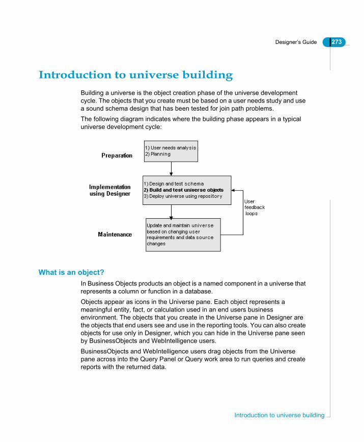
Designer’s Guide 273
Introduction to universe buildingBuilding a universe is the object creation phase of the universe development cycle. The objects that you create must be based on a user needs study and use a sound schema design that has been tested for join path problems.The following diagram indicates where the building phase appears in a typical universe development cycle:
What is an object?In Business Objects products an object is a named component in a universe that represents a column or function in a database. Objects appear as icons in the Universe pane. Each object represents a meaningful entity, fact, or calculation used in an end users business environment. The objects that you create in the Universe pane in Designer are the objects that end users see and use in the reporting tools. You can also create objects for use only in Designer, which you can hide in the Universe pane seen by BusinessObjects and WebIntelligence users.BusinessObjects and WebIntelligence users drag objects from the Universe pane across into the Query Panel or Query work area to run queries and create reports with the returned data.
Introduction to universe building

274 Designer’s Guide
Defi
Each object maps to a column or function in a target database, and when used in the Query Panel or Query work area, infers a Select statement. When multiple objects are combined, a Select statement is run on the database including the SQL inferred by each object and applying a default Where clause.The diagram below shows objects in the BusinessObjects universe pane and the same objects in the Designer universe pane. Each object in the Designer universe pane maps to a column in the universe schema, and infers a Select statement when used in a query.
As the universe designer, you use Designer to create the objects that BusinessObjects and WebIntelligence users include in the Query Panel or Query work area to run their queries.
BusinessObjects universe pane
Designer universe pane
SELECT run
database
Universe Schema
against
tables
ning classes and objects

Designer’s Guide 275
What types of objects are used in a universe?In Designer, you can qualify an object as being one of three types:
When you create an object, you assign it a qualification based on the role that you want that object to have in a query. This role determines the Select statement that the object infers when used in the query panel.
What is a class?A class is a container of objects. A class is the equivalent of a folder in the Windows environment. You create classes to house objects that have a common purpose in the universe.
Using classes and objectsYou organize classes and objects together in the universe pane to correspond to the way that the BusinessObjects and WebIntelligence users are accustomed to work with the information represented by the objects.
Object qualification
Examples Description
Dimension Focus of analysis in a query. A dimension maps to one or more columns or functions in the database that are key to a query.
Detail Provides descriptive data about a dimension. A detail is always attached to a dimension. It maps to one or more columns or functions in the database that provide detailed information related to a dimension.
Measure Contains aggregate functions that map to statistics in the database.
Details
Introduction to universe building

276 Designer’s Guide
Defi
Using the Universe paneYou create the classes and objects in a universe using the Universe pane.The Universe pane presents a hierarchical view of the classes and objects in the active universe. You use the Universe pane to view, create, edit, and organize classes and objectsThe universe pane is shown below. Class names appear beside a folder icon, and object names beside their qualification symbols.
Displaying classes and objects or conditionsYou can use the two radio buttons at the bottom of the window to display classes and objects, or condition objects in the Universe Pane. Condition objects are predefined Where clauses that can be used within one or more Select statements. For more information on creating and using condition objects, see the sectionDefining restrictions for objects on page 309.
Dimension
Measure
Detail
Object Qualification:
Open (All objects of the class are displayed.)
Closed (Only the class name is visible.)
Classes:
KEY
Classes/Objects filter
Classes/Conditions filter
ning classes and objects

Designer’s Guide 277
You can display two views of the universe pane:
The two views of the universe pane are shown below:
For more information on creating and using condition objects, see the section Defining restrictions for objects on page 309.
View To display the view... What it shows
Classes/Objects
Select left radio button All classes and objects
Classes/Conditions
Select right radio button All classes and conditions applied on objects contained within each class
Classes and Objects view Condition objects view
Classes and Objects radio button Classes and Conditions radio button
Using the Universe pane

278 Designer’s Guide
Defi
Basic operations on classes, objects, and conditions
You can perform the following operations in the Universe Pane that are common to classes, objects and conditions:
Cut, copy, pasteYou can cut, copy, and paste a selected component with the usual standard commands used in a Windows environment.
Moving classes, objects, or conditionsYou can move a component to another position in the window by dragging and dropping it at the desired location.
Showing or hiding classes, objects and conditionsYou can hide one or more components in the Universe Pane. These are hidden from BusinessObjects and WebIntelligence users, but remain visible in Designer.Hiding objects from end users can be useful for any of the following reasons:• Components are from linked universes and are not needed in the active
universe (see the section Linking Universes in Chapter 5 for information on linked universes).
• Objects are used only to optimize SQL syntax and should be hidden from end users.
• You are in the process of developing a component that you do not want end users to view from the Query Panel.
• You want to disable components temporarily without deleting them.
Hiding a class, object, or conditionTo hide a class, object, or condition:1. Click the component in the Universe pane.2. Select Edit > Hide Item(s).
OrClick the Show/Hide button on the Editing toolbar.The component name is displayed in italics in the Universe pane.
Showing a hidden class, object, or conditionThe name of hidden components appears in italics.
Show/Hide
ning classes and objects

Designer’s Guide 279
To show a hidden class, object, or condition:1. Click the hidden component in the Universe pane.2. Select Edit > Show Item(s).
The name of the component is no longer in italics. It is now visible to end users.
Basic operations on classes, objects, and conditions

280 Designer’s Guide
Defi
Defining classesA class is a container of one or more objects. Each object in a universe must be contained within a class. You use classes to group related objects. Classes make it easier for end users to find particular objects. You can create new classes and edit the properties of existing classes. Classes are represented as folders on a tree hierarchy in the Universe pane.
TIPA useful way to use classes is to group related dimension and detail objects into a class, and place measure objects in a separate class. The grouping of related objects can be further organized by using subclasses to break objects down into subsets. Subclasses are described in the section Using subclasses on page 283
Creating a classThere are two ways to create a class in the Universe pane:• Manually defining a class.• Automatically by dragging a table from the table schema into the Universe
pane.Both methods are described as follows:
Creating a class manuallyYou can create classes manually within the Universe pane. If you have analyzed user needs and have listed and grouped the potential objects into classes, then creating classes manually from your list is the best way to ensure that your universe structure corresponds to the needs of end users.To create a class in an empty Universe pane:1. Select Insert > Class.
OrClick the Insert Class button.A class properties box appears.
2. Type a name in the Class Name text box.3. Type a description for the class in the Description text box.4. Click OK.
The new named class folder appears in the Universe pane.
Insert class
ning classes and objects
Designer’s Guide 281
TIPIf you click Apply instead of OK, the name and description for a class are applied, but the properties box stays open. If you create another class, you can type properties for the new class in the same box. This allows you to create a series of classes using a single properties box. As you avoid a new properties box appearing with the creation of each class, you can save time and unnecessary clicking.
Creating a class in the universe pane with existing classesTo create a class with existing classes:1. Click the class that you want to precede the new class in the tree view and
select Insert > Class.OrClick the class that you want to precede the new class in the tree view and click the Insert Class button.A class properties box appears.
2. Type a name and description for the new class.3. Click OK.
The new named class folder appears in the Universe pane.
Creating a class automatically from the table schemaYou can create classes automatically by selecting a table in the table schema and dragging it into the Universe pane. The table name is the class name by default. New objects are also automatically created under the class. Each new object corresponds to a column in the table.You should edit the new class and object properties to ensure that they are appropriately named, and are relevant to end user needs. Editing object properties is described in the section Defining objects on page 284.The Objects strategy selected on the Strategies page in the Universe Parameters dialog box determines how the classes and objects are created automatically (File>Parameters>Strategies tab). This strategy can be modified. You can also create strategies to customize the class and object creation process. See the section Using external strategies on page 371, and the section "Selecting Strategies" in the Designer Basics chapter for more information on strategies.
Insert class
Defining classes

282 Designer’s Guide
Defi
NOTE
When you create class and objects automatically, you are creating the universe components directly from the database structure. You should be aware that the class and objects that you create should be the result of a user needs analysis, and not be directed by the columns and tables available in the database. Designing the universe from user needs is described in the section "Introducing the Universe Development Process" in chapter 1 "Introducing Designer and Universe Development."
To create a class automatically from the table schema:1. Select a table in the table schema.2. Drag the table across to the Universe pane and drop the table at the desired
position in the class hierarchy.A new class appears in the hierarchy. It contains an object for each column in the table dragged into the Universe pane. By default, the class name is the same as the table name, and each object name is the same as its corresponding column name.
Class propertiesYou can define the following properties for a class:
Property Description
Name Can contain up to 35 characters including special characters. Must be unique in universe. A class name is case sensitive. You can rename a class at any time.
Description Comment that describes a class. This description can be viewed by users in the query panel. Information in this field should be expressed in the business language of the user, and be relevant to their query needs. You create a line break by pressing CTRL + Return.
ning classes and objects
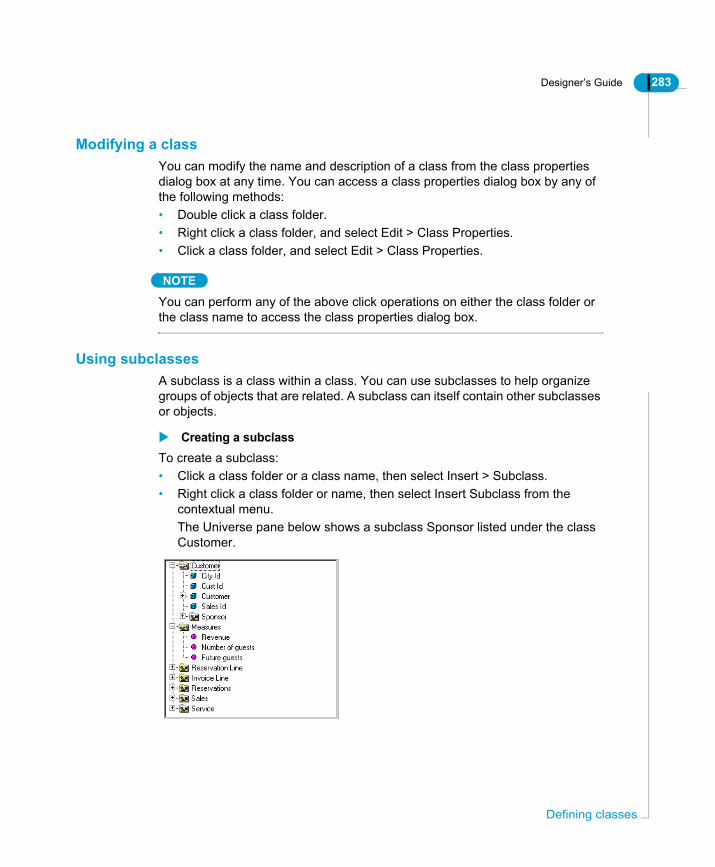
Designer’s Guide 283
Modifying a classYou can modify the name and description of a class from the class properties dialog box at any time. You can access a class properties dialog box by any of the following methods:• Double click a class folder.• Right click a class folder, and select Edit > Class Properties.• Click a class folder, and select Edit > Class Properties.
NOTE
You can perform any of the above click operations on either the class folder or the class name to access the class properties dialog box.
Using subclassesA subclass is a class within a class. You can use subclasses to help organize groups of objects that are related. A subclass can itself contain other subclasses or objects.
Creating a subclassTo create a subclass:• Click a class folder or a class name, then select Insert > Subclass.• Right click a class folder or name, then select Insert Subclass from the
contextual menu.The Universe pane below shows a subclass Sponsor listed under the class Customer.
Defining classes

284 Designer’s Guide
Defi
Defining objectsAn object is a universe component that maps to one or more columns in one or more tables in the universe database schema. An object can also map to a function defined on one or more columns.Each object infers a Select statement for the column or function to which it maps. When a BusinessObjects or WebIntelligence user builds a query using one or more objects in the Query Panel or Query work area, the content of the Select clause line in the Select statement is inferred using the column(s) or function represented by each object.
Creating an objectYou create objects in the Universe pane. BusinessObjects and WebIntelligence users identify an object by its name and qualification. You can create objects manually in the Universe pane, or automatically by dragging the appropriate database structure from the Structure pane to the Universe pane.
Creating an Object ManuallyYou create an object manually by inserting an object in the Universe pane, and then defining the properties for the object. An object must belong to a class.To create an object manually1. Right click a class in the Universe pane and select Insert Object from the
contextual menu.OrClick a class and click the Insert Object tool.An object is inserted under the selected class and the Edit Properties box for the object appears.
2. Type a name in the Name box.Ensure that object names are always expressed in the end user business vocabulary. This name may be different from the actual column names that the object is associated with in the database schema.
3. Click the Properties tab and select object properties.4. Type a Select statement in the Select box, or click the Select button to use the
SQL editor.
Insert Object
ning classes and objects

Designer’s Guide 285
NOTE
For information on object properties see the section Object properties on page 286. For information on using the SQL editor to define Select statements and Where clauses, see the section Using the SQL editor to define an object on page 299.
5. Click OK.
Creating an object automaticallyYou can create an object automatically by selecting a column in a table in the Structure pane and dragging it to the Universe pane. An object is created under the nearest class to the point where you drop the column. The default name for the object is the column name. All underscores are replaced with spaces. The default object datatype is derived from the column datatype. You can change this value by selecting a new datatype from the drop down list box in the Edit Properties sheet for the object.You should edit the new object properties to ensure that it is appropriately named, and is relevant to end user needs. Editing object properties is described in the section Defining objects on page 284.The Objects strategy selected on the Strategies page in the Universe Parameters dialog box determines how the classes and objects are created automatically (File>Parameters>Strategies tab). This strategy can be modified. You can also create strategies to customize the class and object creation process.Refer to Using external strategies on page 371, and the section "Selecting Strategies" in the chapter Designer Basics for more information on using strategies.
NOTE
When you create class and objects automatically, you are creating the universe components directly from the database structure. The classes and objects that you create should be the result of a user needs analysis, and not be directed by the columns and tables available in the database. Designing the universe from user needs is described in the section "Introducing the Universe Development Process" in chapter 1 "Introducing Designer and Universe Development."
To create an object automatically:1. Click a table column in the Structure pane.2. Drag the column across to the Universe pane and drop the table at the
Defining objects

286 Designer’s Guide
Defi
desired position in the class hierarchy. The column must be dropped under an existing class. A new object appears in the hierarchy. By default, the object name is the same as the column name.
NOTE
You should ensure that object names are always expressed in the end user business vocabulary. This name may be different from the actual column names that the object is associated with in the database schema.
Object propertiesYou define the following object properties from the Edit Properties dialog box for a selected object:
Edit Properties page Properties
DefinitionSee Definition on page 288 for full information on available object definition properties.
• Name• Datatype• Description• Select statement• Where clauseYou can access the SQL editor from this page to define SELECT and WHERE syntax.
ning classes and objects
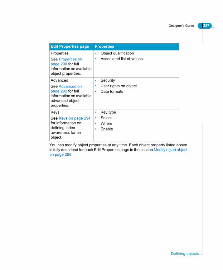
Designer’s Guide 287
You can modify object properties at any time. Each object property listed above is fully described for each Edit Properties page in the section Modifying an object on page 288.
PropertiesSee Properties on page 290 for full information on available object properties.
• Object qualification• Associated list of values
AdvancedSee Advanced on page 292 for full information on available advanced object properties.
• Security• User rights on object• Date formats
KeysSee Keys on page 294 for information on defining index awareness for an object.
• Key type• Select• Where• Enable
Edit Properties page Properties
Defining objects

288 Designer’s Guide
Defi
Modifying an objectYou can define object properties at object creation, or modify them at any time. You define object properties from the Edit Properties dialog box for the object (right-click object > Object Properties). The properties you can define on each page of the Edit Properties dialog box are described as follows.
DefinitionThe Definition page is shown below:
ning classes and objects

Designer’s Guide 289
You can define the following properties from the Definition page of the Edit Properties dialog box.
Property Description Required/Optional
Name Object name. It can consist of up to 35 alphanumeric characters including special characters and spaces. Name is case-sensitive. Object names must be unique within a class. Objects in different classes can have the same name.
Required
Type Object datatype. It can be one of four types: • Character• Date• Long text• NumberBlobs are not supported in the current version of Designer.
Required
Description Comments for object. This field can be viewed from the Query panel, so you can include information about the object that may be useful to an end user. Press Ctrl+Return to move the pointer to the next line.
Optional
Select Select statement inferred by the object. You can use the SQL Editor to create the Select statement. See the section Properties on page 290.
Required
Where Where clause of the Select statement inferred by the object. The Where clause restricts the number of rows returned in a query. You can use the SQL Editor to create the Where clause. See the section Properties on page 290
Optional
Defining objects
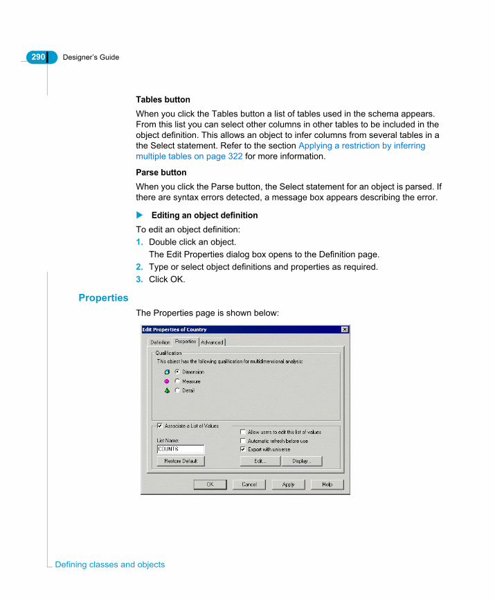
290 Designer’s Guide
Defi
Tables buttonWhen you click the Tables button a list of tables used in the schema appears. From this list you can select other columns in other tables to be included in the object definition. This allows an object to infer columns from several tables in a the Select statement. Refer to the section Applying a restriction by inferring multiple tables on page 322 for more information.
Parse buttonWhen you click the Parse button, the Select statement for an object is parsed. If there are syntax errors detected, a message box appears describing the error.
Editing an object definitionTo edit an object definition:1. Double click an object.
The Edit Properties dialog box opens to the Definition page.2. Type or select object definitions and properties as required.3. Click OK.
PropertiesThe Properties page is shown below:
ning classes and objects

Designer’s Guide 291
You can specify the following object qualifications and properties for a list of values from the Properties page of the Edit Properties dialog box:
Property Description
Qualification Defined role that object takes when used in the Query panel. You can qualify an object as being one of three types:• Dimension• Detail • MeasureRefer to the section What types of objects are used in a universe? on page 275 for a more detailed description of object qualifications.
Associate a List of Values
When selected, associates a file containing data values with an object. Activated by default.Refer to the section Using a list of values on page 341 for more information.
List Name Name of list of values file (LOV) associated with object. Can be up to 8 alphanumeric characters.
Allow users to edit this list of values
When selected, enables end users to edit the list of values.
Automatic refresh before use(BusinessObjects only)
When selected, refreshes the data contained in the list of values file before it is displayed in the Query Panel.Note: This only applies to BusinessObjects reports. In WebIntelligence, only the query definition of a list of values is exported to the repository. The values are not cached, so this option does not apply to WebIntelligence reports when selected.
Export with universe
When selected, the list of values is exported with the universe. The universe domain and document domain must exist on the same data account. A list of values is stored in the document domain.
Defining objects

292 Designer’s Guide
Defi
Specifying object qualification and list of values propertiesTo specify qualification and list of values properties for an object:1. Double click an object.
The Edit Properties box for the object appears.2. Click the Properties tab.
The Properties page appears.3. Click a qualification radio button to determine whether the object is a
dimension, detail, or measure.If you want to associate a list of returned values with the object, select the Associate a List of Values check box.For information on creating and using lists of values, see the section Using a list of values on page 341.
4. Click OK.
AdvancedThe Advanced page is shown below.
ning classes and objects

Designer’s Guide 293
You can define the following properties from the Advanced page of the Edit Properties dialog box:
Property Description
Security Access Level
Defines the security access level of the object.You can select a security level which restricts use of the object to end users with the appropriate security level. Security access levels are assigned to end user profiles in Business Objects Supervisor by an administrator.You can assign the following security access levels:• Public• Controlled• Restricted• Confidential• PrivateIf you assign Public then all users can see and use the object. If you assign Restricted, then only users with the user profile of Restricted or higher can see and use the object.
Can be used in Result
When selected, the object can be used in a query in the Query panel for BusinessObjects or the Web panel in WebIntelligence.
Can be used in Condition
When selected, the object can be used to set in a condition in BusinessObjects or WebIntelligence.
Can be used in Sort
When selected, returned values can be sorted in BusinessObjects or WebIntelligence.
Database Format Option only available for date objects. By default, the date format for the object is defined in the Regional Settings Properties dialog box of the MS-Windows Control Panel. You can modify this to use the target database format for storing dates. For example, the date format could be US format, or European format. For information on modifying this value, see the section Defining an object format on page 302.
Defining objects
294 Designer’s Guide
Defi
Defining object security and user rightsTo define security and user rights for an object:1. Double click an object.
The Edit Properties box for the object appears.2. Click the Advanced tab.
The Advanced page appears.3. Select a security access level from the Security Access Level drop down list
box.4. Select one or more check boxes in the Can Be Used In group box.5. Type a date format in the database Format text box, if you want to modify the
default date format.6. Click OK.
KeysThe Keys tab allows you to define index awareness for an object. Index awareness is the ability to take advantage of the indexes on key columns to speed data retrieval.The objects that you create in Designer are based on database columns that are meaningful to an end user. For example, a Customer object retrieves the field that contains the customer name. In this situation the customer table typically has a primary key (for example an integer) that is not meaningful to the end user, but which is very important for database performance. When you set up index awareness in Designer you tell Designer which database columns are primary and foreign keys. This can have a dramatic effect on query performance in the following ways:• Designer can take advantage of the indexes on key columns to speed data
retrieval. • Designer can generate SQL that filters in the most efficient way. This is
particularly important in a star schema database. If you build a query that involves filtering on a value in a dimension table, Designer can apply the filter directly on the fact table by using the dimension table foreign key. This eliminates unnecessary and costly joins to dimension tables.
Designer does not ignore duplicates with index awareness. If two customers have the same name, Designer will retrieve one only unless it is aware that each customer has a separate primary key.
ning classes and objects

Designer’s Guide 295
EXAMPLEFinding customers in a list of citiesIn this example you build a report on the Island Resorts Marketing Universe that returns revenue by customer for customers in Houston, Dallas, San Francisco, San Diego or Los Angeles. To do this you drag the Customer and Sales Revenue objects into the Result Objects pane in the Query panel, then drag the City object to the Conditions pane and restrict the city to the list above. Without index awareness, Designer generates the following SQL:SELECT
Customer.last_name,
sum(Invoice_Line.days * Invoice_Line.nb_guests * Service.price)
FROM
Customer,
Invoice_Line,
Service,
City,
Sales
WHERE
( City.city_id=Customer.city_id )
AND ( Customer.cust_id=Sales.cust_id )
AND ( Sales.inv_id=Invoice_Line.inv_id )
AND ( Invoice_Line.service_id=Service.service_id )
AND (
City.city IN ('Houston', 'Dallas', 'San Francisco', 'Los Angeles', 'San Diego')
)
GROUP BY
Customer.last_name
In this case Designer has created a join to the City table in order to restrict the cities retrieved.
Defining objects

296 Designer’s Guide
Defi
With index awareness, you tell Designer that city_id is the primary key of the City table and that it also appears in the Customer table as a foreign key. Using this information, Designer can restrict the cities without joining to the City table. The SQL is as follows:SELECT
Customer.last_name,
sum(Invoice_Line.days * Invoice_Line.nb_guests * Service.price)
FROM
Customer,
Invoice_Line,
Service,
Sales
WHERE
( Customer.cust_id=Sales.cust_id )
AND ( Sales.inv_id=Invoice_Line.inv_id )
AND ( Invoice_Line.service_id=Service.service_id )
AND (
Customer.city_id IN (10, 11, 12, 13, 14)
)
GROUP BY
Customer.last_name
In this case Designer is able to generate SQL that restricts the cities simply by filtering the values of the city_id foreign key.
Setting up primary key index awarenessTo set up primary key index awareness:1. Right-click the object on which you want to set up index awareness and select
ning classes and objects

Designer’s Guide 297
Object Properties from the menu.The Edit Properties Of dialog box appears.
2. Click the Keys tab.3. Click Insert.
A Primary Key line is inserted as shown below in the Keys page.
4. Do the following actions in to create key awareness for the primary key:- Select Primary in the Key Type list.- Click the ... button in the Select field to open the SQL editing dialog box.
The SQL Editor appears.- Use the SQL Editor to build the primary key SQL SELECT clause or type it directly. For example, for the City object above, the primary key SQL is City.city_id
For more information on the SQL Editor, see Using the SQL Editor on
Defining objects

298 Designer’s Guide
Defi
page 301.- Select the primary key data type from the drop-down list of key types.
5. Repeat steps 3 and 4 for all columns that make up the primary key.6. If you want to add a WHERE clause, do the following:
- Click within the line, under the Where column as shown below:
- Click the ... button in the Where field to open the SQL editing dialog box.The SQL Editor appears.- Use the SQL Editor to build the primary key SQL WHERE clause or type it directly. There is no Where clause in the example above.- Select Number from the drop-down list of key types.
7. Select Enabled.8. Click OK.
Setting up foreign key awarenessTo set up foreign key awareness:1. Right-click the object on which you want to set up index awareness
Select Object Properties from the menu.The Edit Properties Of dialog box appears.
2. Click the Keys tab.3. Click Insert.
A key line is inserted in the Keys page.4. Do the following to create key awareness for the foreign key:
- Select Foreign Key in the Key Type list.- Click the ... button in the Select field to open the SQL editing dialog box.The SQL Editor appears.- Use the SQL Editor to build the foreign key SQL SELECT clause or type it
ning classes and objects
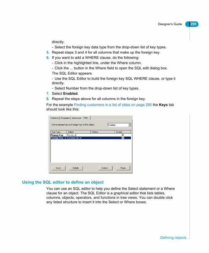
Designer’s Guide 299
directly.- Select the foreign key data type from the drop-down list of key types.
5. Repeat steps 3 and 4 for all columns that make up the foreign key.6. If you want to add a WHERE clause, do the following:
- Click in the highlighted line, under the Where column.- Click the ... button in the Where field to open the SQL edit dialog box.The SQL Editor appears.- Use the SQL Editor to build the foreign key SQL WHERE clause, or type it directly.- Select Number from the drop-down list of key types.
7. Select Enabled.8. Repeat the steps above for all columns in the foreign key.For the example Finding customers in a list of cities on page 295 the Keys tab should look like this:
Using the SQL editor to define an objectYou can use an SQL editor to help you define the Select statement or a Where clause for an object. The SQL Editor is a graphical editor that lists tables, columns, objects, operators, and functions in tree views. You can double click any listed structure to insert it into the Select or Where boxes.
Defining objects

300 Designer’s Guide
Defi
You have the following editing options available in the SQL Editor:
Edit options Description
Tables and columns
All tables and their respective columns that appear in the Structure pane.
Classes and objects
All classes and their respective objects that appear in the Universe pane.
Operators Operators available to combine SQL structures in a Select statement, or to set conditions in a Where clause.
Functions • Database functions, for example number, character, and date functions.
• @Functions specific to Business Objects products.Available functions are listed under the Functions entry in the parameters (.PRM) file for the target database. There is a .PRM file for each supported database. They are stored in the Data Access folder in the BusinessObjects path. You can add or modify the available functions by editing the .PRM file.Editing .PRM files is described in the Business Objects RDBMS guide for your database.
Show object SQL When selected, the SQL syntax is displayed for the objects that appear in the Select, or Where boxes.
Parse When clicked, parses the syntax. If the syntax is not valid, a message box appears describing the problem.
Description Displays a description of a selected object or function.
ning classes and objects
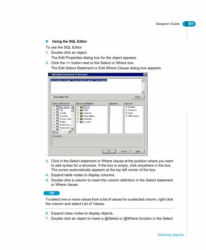
Designer’s Guide 301
Using the SQL EditorTo use the SQL Editor:1. Double click an object.
The Edit Properties dialog box for the object appears.2. Click the >> button next to the Select or Where box.
The Edit Select Statement or Edit Where Clause dialog box appears.
3. Click in the Select statement or Where clause at the position where you want to add syntax for a structure. If the box is empty, click anywhere in the box. The cursor automatically appears at the top left corner of the box.
4. Expand table nodes to display columns.5. Double click a column to insert the column definition in the Select statement
or Where clause.
TIP
To select one or more values from a list of values for a selected column, right click the column and select List of Values.
6. Expand class nodes to display objects.7. Double click an object to insert a @Select or @Where function in the Select
Defining objects

302 Designer’s Guide
Defi
statement or Where clause. These functions direct the current object to use the Select statement or Where clause of a selected object. For more information on using @Functions, see the section Using @Functions on page 325.
8. Double click an operator to insert the operator in the edit box.9. Expand function nodes to display available functions.10.Double click a function to insert the function in the edit box.11.Click the Parse button to validate the syntax.12.Click OK.
Defining an object formatYou can define a format for the data values of a selected object. The format applies to the related data values displayed in the cells of BusinessObjects and WebIntelligence reports.The tabs of the Object Format dialog box include settings for numbers, alignment, font, border, and shading.For example, you can display an integer in a format such as $1,000 rather than the default 1,000.00. Or you can apply a color, such as red, to critical data values.Number, Currency, Scientific and Percentage categories apply only to objects and variables with a numeric type, and the Date/Time category applies only to those with a date type.Information about formats is exported and imported with the universe.You can use the Remove Object Format command to remove any format you defined.
Modifying an object formatTo modify an object format:1. Right click an object 2. Select Object Format from the contextual menu.
The Object Format sheet appears.3. Click a format tab and select or type a format for the object.4. Click OK.
Removing an object formatYou can remove a format for an object at any time.
ning classes and objects
Designer’s Guide 303
To remove an object format:• Select an object and then select File > Remove Format.
Or• Right click an object and select Remove Format from the contextual menu.
Viewing the table used in an object definitionYou can view the table in the Structure pane that is used in an object definition from the Universe pane. This can be useful to quickly identify a table used by an object when object names do not easily indicate a specific table.
Viewing the table used by an objectTo view the table used by an object:1. Right click an object in the Universe pane.
A contextual menu appears.2. Select View Associated table from the contextual menu.
The associated table is highlighted in the Structure pane.
Defining a dimensionA dimension is an object that is a focus of analysis in a query. A dimension maps to one or more columns or functions in the database that are key to a query. For example Country, Sales Person, Products, or Sales Line.Dimension is the default qualification at object creation. You can change the qualification to dimension at any time.To define a dimension object:1. Double click an object.
The Edit Properties dialog box for the object appears.2. Click the Properties tab.
The Properties page appears.3. Select the Dimension radio button in the Qualification group box.4. Click OK.
Defining a detailA detail provides descriptive data about a dimension. A detail is always attached to a dimension. It maps to one or more columns or functions in the database that provide detailed information related to a dimension.You define a detail object by selecting Detail as the qualification for an object, and specifying the dimension attached to the detail.
Defining objects
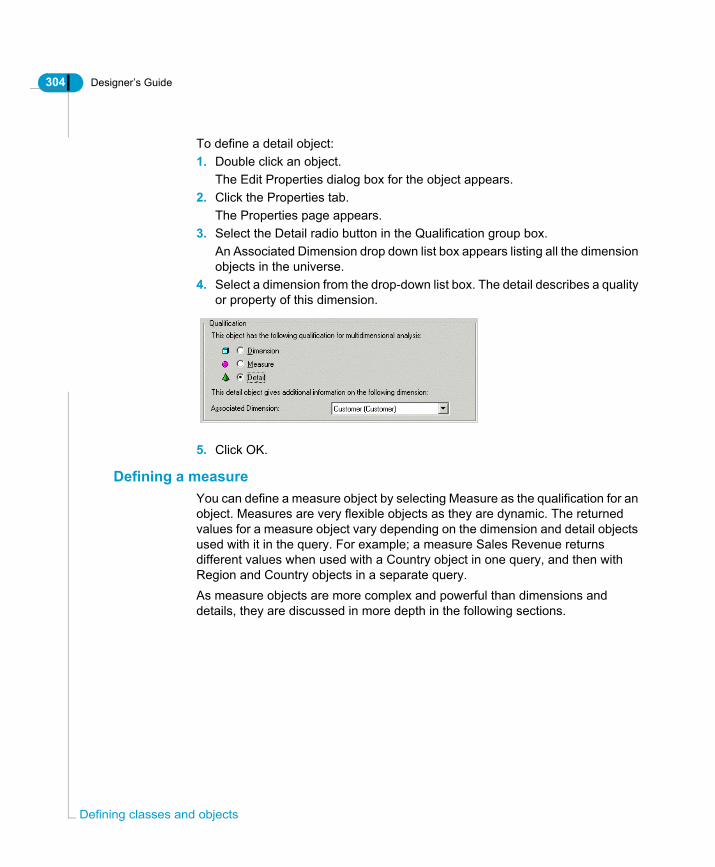
304 Designer’s Guide
Defi
To define a detail object:1. Double click an object.
The Edit Properties dialog box for the object appears.2. Click the Properties tab.
The Properties page appears.3. Select the Detail radio button in the Qualification group box.
An Associated Dimension drop down list box appears listing all the dimension objects in the universe.
4. Select a dimension from the drop-down list box. The detail describes a quality or property of this dimension.
5. Click OK.
Defining a measureYou can define a measure object by selecting Measure as the qualification for an object. Measures are very flexible objects as they are dynamic. The returned values for a measure object vary depending on the dimension and detail objects used with it in the query. For example; a measure Sales Revenue returns different values when used with a Country object in one query, and then with Region and Country objects in a separate query.As measure objects are more complex and powerful than dimensions and details, they are discussed in more depth in the following sections.
ning classes and objects
Designer’s Guide 305
What type of information does a measure return?A measure object returns numeric information. You create a measure by using aggregate functions. The five most common aggregate functions are the following:• Sum• Count• Average• Minimum• Maximum
How are measures different from dimensions and details?Measures differ from dimensions and details in the following ways:• Measures are dynamic• Measures can project aggregatesBoth these properties are described as follows:
How do measures behave dynamically?Returned values for a measure object vary depending on the dimension and detail objects used with the measure object in a query.
Defining objects

306 Designer’s Guide
Defi
The following example shows the same Revenue measure object used in two separate queries with different dimensions, resulting in the measure returning different values.
Measures infer a Group By clauseWhen you run a query that includes a measure object with other types of objects, a Group By clause is automatically inferred in the Select statement.The inference of the Group By clause depends on the following SQL rule:
Based on this rule, any dimension or detail used in the same query as a measure object will always be included in an automatically inferred Group By clause. To ensure that the query returns correct results, dimension and detail objects must NOT contain aggregates.
If the Select clause line contains an aggregate, everything outside of that aggregate in the clause must also appear in the Group By clause.
Same measure returns different results
ning classes and objects

Designer’s Guide 307
The following example shows that the Resort, Service Line, and Year dimension objects are all inferred in the Select clause and in the Group By clause.
NOTE
If a query contains only measure objects, no Group By clause is inferred.
Setting aggregate projection for a measureWhen you create a measure you must specify the way the aggregate function will be projected onto a report. Returned values for a measure object are aggregated at two levels of the query process:• Query level. Data is aggregated using the inferred Select statement.• Microcube to block level. When data is projected from the microcube to the
block in a report. This projection function of measures allows local aggregation in the microcube.
Dimensions inferredin GROUP BY
Results aggregated to lowest level Resort,then by Service Line and Year
Defining objects

308 Designer’s Guide
Defi
NOTE
A microcube is a conceptual way to present the data returned by a query before it is projected onto a report. It represents the returned values held in memory by a Business Objects reporting product. The block level is the 2 dimensional report that a user creates with the returned data. A user can choose to use all, or only some of the data held in the microcube to create a report. A user can also do aggregate functions on the returned values in the microcube (local aggregation) to create new values on a report.
The two levels of aggregation fit into the query process as follows:
The diagram shows the following processes in a query:• User creates a query in BusinessObjects or WebIntelligence.• BusinessObjects or WebIntelligence infers the SQL from the query and sends
a Select statement to the target database.• The data is returned to the microcube. This is the first aggregation level.• The microcube projects the aggregated data onto the report. Data is split out
in the Query panel requiring aggregation to lower levels. This is the second aggregation level.
When you initially make a query the result set of the Select statement is stored in the microcube, and all data then held in the microcube is projected into a block. As data is projected from the lowest level held in the microcube no projection aggregation is taking place.However, when you use the Query panel, or the Slice and Dice panel, to project only partial data from the microcube, aggregation is required to show measure values at a higher level.
ning classes and objects
Designer’s Guide 309
For example, in the previous example, if you do not project the year data into the block, the three rows related to Year need to be reduced to one row to show the overall Sales Revenue for that resort, so a sum aggregation is used.You set projection aggregation on the Properties page of the Edit Properties sheet for a measure (right-click object > Object Properties > Properties).Projection aggregation is different from Select aggregation.
Choosing how a measure is projected when aggregatedYou define what aggregate function is used to aggregate the returned results for the second level of aggregation (locally in the microcube) for a measure in the properties for the measure. You can so this at object creation or modify this parameter at any time.
Creating a measureTo create a measure:1. Double click an object.
The Edit Properties dialog box for the object appears.2. Click the Properties tab.
The Properties page appears.3. Select the Measure radio button in the Qualification group box.
A Function drop down list box appears listing aggregate functions.4. Select a function.5. Click OK.
Defining restrictions for objectsA restriction is a condition in SQL that sets criteria to limit the data returned by a query.You define restrictions on objects to limit the data available to users. Your reasons for limiting user access to data should be based on the data requirements of the target user. A user may not need to have access to all the values returned by an object. You might also want to restrict user access to certain values for security reasons.
Defining objects

310 Designer’s Guide
Defi
You can define two types of restrictions in a universe:
NOTE
In BusinessObjects and WebIntelligence, users can apply conditions in the Query Panel or Query work area. As the universe designer, you should avoid creating optional restrictions that are simple to apply at the user level. Users can create these conditions themselves when necessary.
Defining a Where clause for an objectYou apply a further restriction on an object by adding a condition in the Where box from the Definition page of the Edit Properties dialog box for an object.You can define the condition at object creation, or add it to the object definition at any time.In a universe, the Where clause in an SQL statement can be used in two ways to restrict the number of rows that are returned by a query. • A Where clause is automatically inferred in the Select statement for an object
by joins linking tables in the schema. Joins are usually based on equality between tables. They prevent Cartesian products being created by restricting the data returned from joined tables.
• You add a condition in the Where clause for an object. This is an additional condition to the existing Where clause inferred by joins. You define a Where clause to further restrict the data that is returned in a query, for example when you want to limit users to queries on a sub-set of the data.
Restriction type Description
Forced Restriction defined in the Where clause for an object. It cannot be accessed by users and so cannot be overridden in BusinessObjects or WebIntelligence.
Optional Restriction defined in special condition objects that users can choose to use or not use in a query. A condition object is a predefined Where clause that can be inserted into the Select statement inferred by objects in the Query Panel or Query work area.
ning classes and objects

Designer’s Guide 311
EXAMPLEModifying the default (join only) Where clause for an objectThe report below is an unrestricted block containing data for sales people from all countries:
The SQL for this query appears below. The Where clause contains only restrictions inferred by the joins between the tables Customer, City, Region, and Sales_Person.SELECTSales_Person.sales_person,Country.countryFROMSales_Person,Country,Region,City,CustomerWHERE( City.city_id=Customer.city_id )AND ( City.region_id=Region.region_id )AND ( Country.country_id=Region.country_id )AND ( Sales_Person.sales_id=Customer.sales_id )
If you want to restrict users to see only returned values specific to France, you can add a condition to the Where clause of the Country object. The following report shows sales people for France only:
The SQL for the query is as follows:
Defining objects

312 Designer’s Guide
Defi
SELECT Sales_Person.sales_person, Country.countryFROM Sales_Person, Country, Region, City, CustomerWHERE ( City.city_id=Customer.city_id ) AND ( City.region_id=Region.region_id ) AND ( Country.country_id=Region.country_id ) AND ( Sales_Person.sales_id=Customer.sales_id ) AND ( Country.country = 'France' )
The Where clause has an additional line. This is the restriction that you have added to the Where clause of the Country object.
NOTE
Apart from self restricting joins, you should not create a join in a Where clause. A join in a Where clause is not considered by Detect Contexts (automatic context detection) or aggregate aware incompatibility detection. You should ensure that all joins are visible in the Structure pane. This ensures that all joins are available to the Designer automatic detection tools.
Defining a Where clauseTo define a Where clause:1. Double click an object.
The Edit Properties dialog box opens to the Definition page.2. Type the syntax directly into the Where clause text box.
OrClick the >> Button next to the Where box to open the Where clause editor.
3. Double click columns, objects, operators, or functions that appear in the SQL structures and features lists.
ning classes and objects
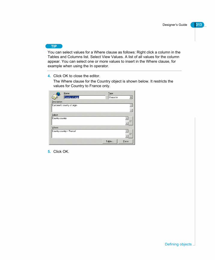
Designer’s Guide 313
TIPYou can select values for a Where clause as follows: Right click a column in the Tables and Columns list. Select View Values. A list of all values for the column appear. You can select one or more values to insert in the Where clause, for example when using the In operator.
4. Click OK to close the editor.The Where clause for the Country object is shown below. It restricts the values for Country to France only.
5. Click OK.
Defining objects
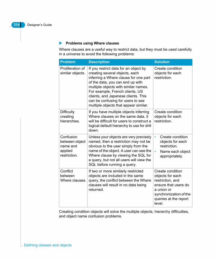
314 Designer’s Guide
Defi
Problems using Where clausesWhere clauses are a useful way to restrict data, but they must be used carefully in a universe to avoid the following problems:
Creating condition objects will solve the multiple objects, hierarchy difficulties, and object name confusion problems.
Problem Description Solution
Proliferation of similar objects.
If you restrict data for an object by creating several objects, each inferring a Where clause for one part of the data, you can end up with multiple objects with similar names. For example, French clients, US clients, and Japanese clients. This can be confusing for users to see multiple objects that appear similar.
Create condition objects for each restriction.
Difficulty creating hierarchies.
If you have multiple objects inferring Where clauses on the same data, it will be difficult for users to construct a logical default hierarchy to use for drill down.
Create condition objects for each restriction.
Confusion between object name and applied restriction.
Unless your objects are very precisely named, then a restriction may not be obvious to the user simply from the name of the object. A user can see the Where clause by viewing the SQL for a query, but not all users will view the SQL before running a query.
• Create condition objects for each restriction.
• Name each object appropriately.
Conflict between Where clauses.
If two or more similarly restricted objects are included in the same query, the conflict between the Where clauses will result in no data being returned.
Create condition objects for each restriction, and ensure that users do a union or synchronization of the queries at the report level.
ning classes and objects

Designer’s Guide 315
The conflict between Where clauses can be solved by creating condition objects and ensuring that users know that they must join the queries using a UNION or SYNCHRONIZE operator at the report level.Given the potential problems with Where clauses defined in an object definition, you should avoid using them, and where possible create condition objects which, when used correctly can avoid the problems with hard coded Where clauses.
NOTE
Apart from self restricting joins, you should not create a join in a condition object. A join in a condition object is the equivalent to creating a join in a reusable Where clause, and so is not considered by Detect Contexts (automatic context detection) or aggregate aware incompatibility detection. You should ensure that all joins are visible in the Structure pane. This ensures that all joins are available to the Designer automatic detection tools.
Defining condition objectsA condition object is a predefined Where clause that can be inserted into the Select statement inferred by objects in the Query Panel or Query work area.Condition objects are stored in the Conditions view of the Universe pane. You access the conditions view by clicking the Conditions radio button at the right bottom of the universe pane.
Defining objects

316 Designer’s Guide
Defi
The condition objects for the Beach universe and the Where clause that the Young American condition infers are shown below.
Advantages and restrictions for using condition objectsUsing condition objects has the following advantages:• Useful for complex or frequently used conditions.• Gives users the choice of applying the condition.• No need for multiple objects.• Condition objects do not change the view of the classes and objects in the
Universe pane.
NOTE
You may need to direct users to use the condition objects view of the Universe pane.
The only disadvantages for using condition objects is that you may want to force a condition on users to restrict their access to part of the data set. In this case you need to define a Where clause in the object definition.
Condition objects do not solve conflicting Where clausesUsing condition objects does not solve the problem of conflicting Where clauses returning an empty data set. If a user runs a query that includes two condition objects that access the same data, the two conditions are combined with the AND
Where clausefor Young American
Conditions radio button
condition objects
ning classes and objects
Designer’s Guide 317
operator, so the two conditions are not met, and no data is returned. This problem can be solved at the report level by users creating two queries, one for each condition object and then combining the queries.
Creating a condition objectTo create a condition object:1. Click the Conditions radio button at the bottom right of the Universe pane.
The Conditions view of the Universe pane appears. It contains a tree view of all the classes in the universe.
2. Right click a class and select Insert Condition from the contextual menu.OrClick a class and click the Insert Condition button.An Edit Properties dialog box appears. A default name appears in the Name box. The Where box is empty.
3. Type a name for the condition.4. Type the Where clause syntax directly into the Where clause box.
OrClick the >> Button next to the Where clause box to open the Where clause editor.
5. Double click columns, objects, operators, or functions that appear in the SQL structures and features lists.
6. Click OK to close the editor.The definition for a condition called Young American is shown below. It restricts the returned values to American customers less than or equal to thirty
Insert condition
Defining objects

318 Designer’s Guide
Defi
years old.
7. Click the Parse button to verify the syntax.8. Click OK.
The new condition object appears in the condition view of the Universe pane.
Using condition objects in the same queryIf you have two condition objects defined for the same object, and both are used in the same query, no data is returned, as the two Where clauses create a false condition. Where possible you should avoid hardcoding Where clauses in the definition of an object, but also when you use condition objects, users need to be aware of the potential problems.Users can solve the problem of returning an empty data set by joining two queries, one query for each condition object.
NOTE
To avoid BusinessObjects and WebIntelligence users combining two condition objects in the same query, you can include in the description for a condition object ’X’ that it should not be used with object ’Y’.
ning classes and objects

Designer’s Guide 319
Why do multiple Where clauses return an empty data set?When you add a Where clause to the definition of an object, the restriction is added to the restrictions set by the joins using the AND operator. If you combine two objects in a query, both applying a restriction on the same data set, then the two Where clauses are combined in successive AND clauses. The result of such a query is that no data will satisfy both conditions, and no data is returned.For example, a user wants to know the services that are available at the Bahamas and Hawaiian Club hotel resorts. The following query is run using the condition objects for Bahamas resort and Hawaiian Resort:
The SQL for this query is as follows:SELECTService.service,Resort.resortFROMService,Resort,Service_LineWHERE( Resort.resort_id=Service_Line.resort_id )AND ( Service.sl_id=Service_Line.sl_id ) AND (( Resort.resort = 'Bahamas Beach' )AND ( Resort.resort = 'Hawaiian Club' ))
The two Where clause restrictions are combined in AND clauses at the end of the Where clause.
Defining objects

320 Designer’s Guide
Defi
When the query is run, the following message box appears:
The two restrictions on country cannot be met in the same query, so no data is returned.
Creating two queries to combine restrictionsUsers can solve the problem of using two condition objects in the same query by running two queries, one for each Where clause, and using the UNION operator to combine the results.
EXAMPLECombining condition objects in BusinessObjects or WebIntelligenceIn BusinessObjects or WebIntelligence the two condition objects can be used in a query as follows:The first query is with the Bahamas Beach condition object:
CombineQuery Panel inBusinessObjects button
Queries
ning classes and objects

Designer’s Guide 321
Create a second query by clicking the Combine Queries button. You create the second query using the Hawaiian Beach condition object:
When the query is run, the following results are returned:
Using self restricting joins to apply restrictionsYou can use self restricting joins to restrict data to one or another column in a table, based on a flag which is used to switch between the two columns. A flag is a third column whose values determine which one of the two alternate columns is used in a query.See the section Self Restricting Joins in the chapter Designing a Schema for more information on creating and using self restricting joins.
Second query
Defining objects
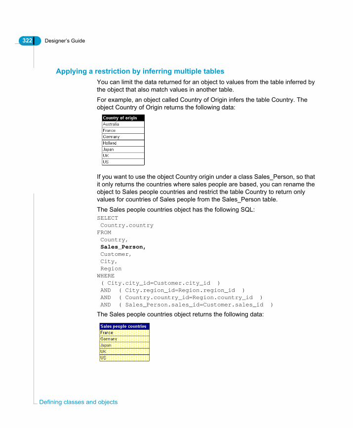
322 Designer’s Guide
Defi
Applying a restriction by inferring multiple tablesYou can limit the data returned for an object to values from the table inferred by the object that also match values in another table.For example, an object called Country of Origin infers the table Country. The object Country of Origin returns the following data:
If you want to use the object Country origin under a class Sales_Person, so that it only returns the countries where sales people are based, you can rename the object to Sales people countries and restrict the table Country to return only values for countries of Sales people from the Sales_Person table.The Sales people countries object has the following SQL:SELECT Country.countryFROM Country, Sales_Person, Customer, City, RegionWHERE ( City.city_id=Customer.city_id ) AND ( City.region_id=Region.region_id ) AND ( Country.country_id=Region.country_id ) AND ( Sales_Person.sales_id=Customer.sales_id )
The Sales people countries object returns the following data:
ning classes and objects

Designer’s Guide 323
You apply the restriction by specifying that when the Country object is used in a query, the Sales_Person table must also be inferred in the From clause of the Select statement.Country under the Sales_Person class then only returns countries in which sales people are based. You apply the restriction by using the Tables button in the object definition sheet.The Country table must be joined to the Sales_Person table by intermediary joins using only equi-joins.
NOTE
If you make any changes to the SQL for an object that has a table restriction defined in its Select statement, then Designer automatically redetermines which tables are needed by the object’s Select statement and Where clause. You are not notified if the table restriction is over ridden in the tables inferred by the object.
Inferring multiple tables to apply a conditionTo infer multiple tables that apply a condition for an object:1. Double click an object.
The Edit Properties dialog box for the object appears.2. Click the Tables button.
A list of tables in the universe appears.3. Select one or more tables that you want the object to infer in addition to the
current table. You can select multiple tables by holding down CTRL and clicking table names in the list. The tables Country and Sales_Person are
Tables button
Defining objects

324 Designer’s Guide
Defi
selected below:
4. Click OK in each dialog box.5. Run queries in BusinessObjects or WebIntelligence to test the table
restriction.
When do you use each method to apply a restriction?You can use the following guidelines to set restrictions in a universe:• Avoid using Where clauses in object definitions. If you need to use a Where
clause, you should be aware of the potential problems using multiple objects, and conflicting Where clauses.
• Use Condition Objects when you want to assist users by providing optional pre-defined Conditions, avoiding multiple objects and changes to the classes and objects view of the Universe pane.
• Use Self-Restricting Joins to apply restrictions to tables when you want the restriction to apply irrespective of where the table is used in the SQL. This method is ideal when a table uses a flag to switch between two or more domains.
• Use Additional Joins when a lookup table serves more than one purpose in the universe.
ning classes and objects

Designer’s Guide 325
Using @Functions@Functions are special functions that provide more flexible methods for specifying the SQL for an object. @Functions are available in the Functions pane of the Edit Select box for an object. @Functions are very flexible. Depending on what you want to achieve, you can use any @function in either a Select statement, or a Where clause.
EXAMPLEUsing the @Prompt function to restrict returned values to entered prompt valueThe @Prompt function is one of the @functions available in Designer. You can use the @Prompt function to display a message box when an object is used in a BusinessObjects or WebIntelligence query.The message box prompts a user to enter a value for the object. The query returns values for the entered prompt value as shown below:
@Prompt function for Resort object
Resort definition in Designer Query using Resort (@Prompt) in BusinessObjects
User types in value
Using @Functions

326 Designer’s Guide
Defi
You can incorporate one or more @functions in the Select statement or the Where clause of an object. The following @functions are available:
You can insert @functions in the Select statement or Where clause for an object as follows:
Inserting an @function in an objectTo insert an @function in the SQL definition for an object:1. Double click an object.
The edit properties dialog box for the object appears.2. Click the >> button next to the Select box.
OrClick the >> button next to the Where box.The Edit Select statement or Edit Where clause dialog box appears. The Edit Where clause dialog box for Resort is shown below.
3. Click in the Select statement or Where clause at the position where you want to add the @function. If the box is empty as above, click anywhere in the box.
@Function Description Usually used in object
@Aggregate_Aware Incorporates columns containing aggregated and dimension data into objects.
Select statement
@Prompt Prompts user to enter a value for a restriction each time the object using the @Prompt function is included in a query.
• Select statement
• Where clause
@Script Runs a script each time the object using the @Script function is included in a query.
Where clause
@Select Allows you to use the Select statement of another object.
Select statement
@Variable Calls the value of a variable stored in memory, for example in a referenced text file.
Where clause
@Where Allows you to use the Where clause of another object.
Where clause
ning classes and objects

Designer’s Guide 327
The cursor automatically appears at the top left corner of the box.
4. Click the @functions node in the Functions pane.The list of available @functions appears.
5. Double click a @function.The syntax for the @function is added to the Select statement or Where clause. A description of the syntax appears in the Description box at the bottom of the dialog box. You can use this to help you type the parameters for
Click and enterfunction here
Using @Functions
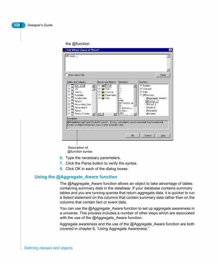
328 Designer’s Guide
Defi
the @function.
6. Type the necessary parameters.7. Click the Parse button to verify the syntax.8. Click OK in each of the dialog boxes.
Using the @Aggregate_Aware functionThe @Aggregate_Aware function allows an object to take advantage of tables containing summary data in the database. If your database contains summary tables and you are running queries that return aggregate data, it is quicker to run a Select statement on the columns that contain summary data rather than on the columns that contain fact or event data.You can use the @Aggregate_Aware function to set up aggregate awareness in a universe. This process includes a number of other steps which are associated with the use of the @Aggregate_Aware function.Aggregate awareness and the use of the @Aggregate_Aware function are both covered in chapter 6, “Using Aggregate Awareness.”
Description of@function syntax
ning classes and objects

Designer’s Guide 329
Using the @Prompt functionYou can use the @Prompt function to create an interactive object. You use a @Prompt function in the Where clause for an object. It forces a user to enter a value for a restriction when that object is used in a query. When the user runs the query, a prompt box appears asking for a value to be entered.@Prompts are useful when you want to force a restriction in the inferred SQL but do not want to preset the value of the condition.
SyntaxThe syntax of the function is as follows:
The syntax is described in the following table:
@Prompt(‘message’,‘type’,[lov],[MONO|MULTI],[FREE|CONSTRAINED])
Syntax Description
’message’ Text of the prompt message. The text must be enclosed between single quotes, for example, ‘Choose a Region’, ‘Pick a time period’, or ’Choose a showroom’. The text appears in the prompt box when the query is run.
’type’ Data type returned by the function. It can be one of the following:• ’A’ for alphanumeric• ‘N’ for number• D’ for dateThe specified data type must be enclosed in single quotes.
lov List of values (optional). You can specify two types of list of values:• Hard coded list. Each value is separately enclosed in single
quotes and separated by a comma. The whole list is enclosed in curly brackets. For example, {'Australia', 'France', 'Japan', 'United Kingdom', 'USA'}.
• Pointer to a List of Values from an existing object. You invoke the target lov by double clicking on the object containing the lov that you want to use in the Classes and Objects panel. This gives the Class name and the Object name, separated by a backslash. It must be enclosed in single quotes. For example: 'Client\Country'.
Using @Functions

330 Designer’s Guide
Defi
NOTE
For each of the optional parameters, if you omit an argument, you must still enter the commas as separators.
EXAMPLEUsing @Prompt to restrict countriesThe object Country returns values for the countries of resorts. If you want to restrict the returned values to resorts for only one country, you would need a separate object for each resort country in the universe. However, using the @Prompt, you need only one object as follows:
The user is prompted to enter the name of the country, and the returned values are the resorts from that particular country, as shown below:
MONO User can only select only one value from the list of values (optional).
MULTI User can select multiple values from the list of values (optional).
FREE User can enter a value of their choice, or select one from the list of values.
CONSTRAINED
User must select a value from the list of values.
Syntax Description
ning classes and objects

Designer’s Guide 331
When a query is run in BusinessObjects or WebIntelligence, the following prompt box appears:
Using the @Script functionThe @Script function returns the result of a Visual Basic for Applications macro (VBA macro). You use the @Script function to run a specified VBA macro each time a query that includes the object is refreshed or run.
NOTE
VBA macros can only run in a Windows environment.
You would typically use a @Script function in a Where clause to run a more complex process than a simple prompt box (@Prompt function).VBA macros are stored in BusinessObjects report files (.REP). The default directory for these reports is the UserDocs folder in the BusinessObjects path, however, you can define any folder to store .REP files.
Do not use @Script function in a universe used for WebIntelligenceWebIntelligence 2.6 upwards can refresh BusinessObjects full client documents and, if the server is running Windows NT, it supports VBA macros within documents. However, it cannot support VBA macros which have user interaction as the VBA macro is run on the server, not on the client. An error message is displayed when the BusObj running on the server tries to display the VBA form to the user, it can't access the user's screen, as it is on another machine.If a universe is being accessed by BusinessObjects and WebIntelligence users, then you should not use the @Script function, but stay with a simpler design using the @Prompt function for interactive objects.
SyntaxThe syntax for the @Script function is as follows:
@Script(‘var_name’, ‘vartype’, ‘script_name’)
Using @Functions
332 Designer’s Guide
Defi
The syntax is described in the following table
NOTE
The second argument is optional; however, if it is omitted, you must still include commas as separators.
Using the @Select functionYou can use the @Select function to re-use the Select statement of another object. When the @Select function is used in the Select statement of an object, it specifies the path of another object in the universe as a parameter of the @Select function, in the form Class_Name\Object_Name. This then acts as a pointer to the Select statement of the referenced object.Using the @Select function allows you to use existing code, which has the following advantages:• You have to maintain only one instance of the SQL code.• Ensures consistency of the code.
NOTE
When you use @Select and @Where functions, one object now depends on another in the universe. You have created a new object dependency. When one object is deleted, the other object using the @Select or @Where function needs to be manually updated.
Syntax Description
’var_name’ Variable name declared in the macro. This name enables the results of the executed macro to be recovered in the SQL definition of an object. This name must be identical in both the VBA macro and in the SQL definition of the object.
’var_type’ Data type returned by the function. It can be one of the following:• ’A’ for alphanumeric• ‘N’ for number• ’D’ for date.The specified data type must be enclosed in single quotes.
’script_name’ Name of the VBA macro to be executed.
ning classes and objects

Designer’s Guide 333
SyntaxThe @Select function has the following syntax:
• Classname is the name of the class that contains the referenced object.• Objectname is the name of the referenced object.
EXAMPLEUsing @Select to re-use the Service_line Select statementYou create an object called Promotional Service Line which is used to return service lines used in promotional campaigns for different resorts in the Club database. This object is in a new class called Promotions. You can use @Select to reference the existing Select statement for the Service_lines object.The Select statement for Promotional Service Line appears below:
@Select(Classname\Objectname)
Using @Functions
334 Designer’s Guide
Defi
Using the @Variable functionThe @Variable function is used to call the value assigned to one of two types of variables:
NOTE
The @Variable function retrieves a single value set by a prompt. If you use the @Variable in a case where the prompt requires multiple values, BusinessObjects returns an error. This error is not picked up by the SQL parser when you run a SQL check, as the syntax is verified with an empty value for the @Variable function. If you want to define a prompt with multiple values, you should use the @Prompt function.
Using the @function to call each type of variable is described in the following sections:
Using the @Variable with BusinessObjects system variablesYou can use the @Variable function with BusinessObjects system variables to restrict data according to the identity of the currently logged in BusinessObjects user.
NOTE
To use the @Variable function with BusinessObjects system variables the BusinessObjects login parameters must be the same as the database login parameters.
Variable Description
BusinessObjects system variable
Values for the BusinessObjects system variables BOUSER (BusinessObjects user name) and BOPASS (BusinessObjects password). The returned data is then restricted based on that BusinessObjects user’s login profile.
Personal text file variable
Value stored in a personal text file. This file is read when an instance of BusinessObjects is started, and the value is stored in memory. It is called when a query is run with an object that uses the @Variable function.
ning classes and objects

Designer’s Guide 335
The User Name and Password assigned to each BusinessObjects user are held as the following BusinessObjects system variables:• BOUSER defines the User Name• BOPASS defines the PasswordThese two variables appear in the User Identification box which users must complete to log in to a Business Objects product as shown, below:
You use the @Variable function in the Where clause for an object to restrict data access for a user to their database profile when that object is used in a query.
SyntaxThe @Variable syntax with Business Objects system variables is as follows:
You insert the @Variable on the operand side of the condition in the Where clause for an object from the Definition page of its Edit properties sheet.
EXAMPLEUsing @Variable to restrict employee access to employee dataIn the universe for a human resources database, you have an object called Employee name. You want to restrict the returned data for Employee name to the values authorized in the database for each user. This would allow you to control what employee information each user is allowed to see. This information is defined by their database profile.You insert the @Variable function in the Where clause as followsEmployees.Employee_Name = @Variable(’BOUSER’)
@Variable(‘BOUSER’)
BOUSER
BOPASS
Using @Functions

336 Designer’s Guide
Defi
The object definition is shown below:
When the object Employee name is used in a query, the data is returned only for the value in the tables that matches the BOUSER value.In the example above, an employee Jim Kiwi wants to see his latest evaluation by management based on his quarterly assessment. He runs the following query:
The evaluation data for Jim is returned.
Using the @Variable function with text file variablesYou use @Variable function in the Where clause of an object to reference a variable in an associated text file. This allows you to define user specific conditions on an object.To use this variable, BusinessObjects needs to be launched by a command line that includes the -VARs parameter. You will need to change the command line in Windows shortcuts on all PCs that use this feature.
ning classes and objects

Designer’s Guide 337
NOTE
Ensuring that BusinessObjects is launched by a command line makes using the @Variable function difficult to maintain for universe deployments of more than a few users. If you have more than a few users, or a geographically diverse user base, you should not use @functions with associated text files to implement restrictions.
SyntaxYou use the following syntax for the @Variable function:
To use a @Variable function with an associated text file:1. Create a text file that contains a list of variables with the corresponding
values. Use the following format:Variable name = value
2. Add the following to a command line used to start BusinessObjects:Busobj.exe -vars text_file_name.txtFor example, if you have a text file called Bovars.txt, you would type the following:
C:\BusinessObjects\Busobj.exe -vars Bovars.txt
The -vars syntax is a switch that tells the operating system to load the text file into memory for use by BusinessObjects.
NOTE
The Busobj.exe -vars text_file_name.txt syntax only applies if you store the text file in the BusinessObjects path. If you store the text file anywhere else on your computer, or on a server, you must specify the full file path.
3. Open the Edit Properties sheet for the object that you want to reference the text variable.
4. Insert the @Variable on the operand side of the condition in the Where clause.For example;
COUNTRY.COUNTRY_NAME = @Variable('Country')
’Country’ is the name of the variable in the text file.5. Click OK and save the universe.
@Variable(’variable name’)
Using @Functions

338 Designer’s Guide
Defi
Advantages using the @Variable function with text file variables?The principle advantage for using the @Variable function with text file variables is that you can update the values for the variables in the text file without making any changes to the universe.
Disadvantages using the @Variable function with text file variablesYou have a number of important disadvantages using this function:• The command string must be changed on every client post to include the -
vars <textfile.txt> argument.• Security can be a problem, as a text file on a PC can be modified locally.Given the number of potential problems using the @Variable function with text variables, if you are using Business Objects products in an enterprise environment, then you should use the security options available in Supervisor to control access to data.
Using the @Where functionYou can use the @Where function to re-use the Where clause of another object. When the @Where function is used in the Where clause of an object, it specifies the path of another object in the universe as a parameter of the @Where function, in the form Class_Name\Object_Name. This then acts as a pointer to the Where clause of the referenced object.Using the Where clause creates a dynamic link between two objects. When the Where clause of the original object is modified, the Where clause of the referencing object is automatically updated.Using the @Where function allows you to use existing code. This has the following advantages:• You have to maintain only one instance of the SQL code.• Ensures consistency of the code.When you use @Select and @Where functions, one object now depends on another in the universe. You have created a new object dependency. When one object is deleted, the other object using the @Select or @Where function needs to be manually updated.
ning classes and objects

Designer’s Guide 339
NOTE
When you use @Select and @Where functions, one object now depends on another in the universe. You have created a new object dependency. When one object is deleted, the other object using the @Select or @Where function needs to be manually updated.
SyntaxThe syntax of this function is the following:
• Classname is the name of a class.• Objectname is the name of the referenced object.
EXAMPLEUsing @Where to re-use the Resort Where clauseYou create an object called Resort Service Lines which is used to return service lines available at each resort. You want to reuse the @Prompt function defined in the Resort object, so that users are prompted to enter a resort name when they query the services available at that particular resort.The SQL for the Resort object (the object that you want to reference) appears as follows:
@Where(Classname\Objectname)
Using @Functions
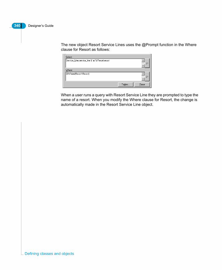
340 Designer’s Guide
Defi
The new object Resort Service Lines uses the @Prompt function in the Where clause for Resort as follows:
When a user runs a query with Resort Service Line they are prompted to type the name of a resort. When you modify the Where clause for Resort, the change is automatically made in the Resort Service Line object.
ning classes and objects

Designer’s Guide 341
Using a list of valuesA list of values is a list that contains the data values associated with an object. A list of values can contain data from two types of data source:
How is a list of values used in the reporting products?In BusinessObjects or WebIntelligence, a user can create a query in the Query Panel or Web Panel using the operand “Show list of values” to apply to an object when applying a condition.
NOTE
A.LOV file is also created whenever any condition is applied to an object in the query panel that requires a restriction on the column values inferred by the object.
A.LOV file is also created whenever any condition is applied to an object in the query panel that requires a restriction on the column values inferred by the object.The List of Values for an object appears showing values available for the object, allowing the user to choose the terms for the condition. The first time a list of values is used, it is saved as a.LOV file in the User Data folder in the Business Objects path. This allows the SELECT DISTINCT query to be run only once for an object.
List of values data source
Description
Database file When you create an object, Designer automatically associates a list of values with the object. The list of values is not created until a user, or you the designer, choose to display a list of values for the object in the Query panel. A SELECT DISTINCT query is then run against the column or columns inferred by the object.The returned data is stored in a file with a.LOV extension in the User Docs folder in the BusinessObjects path. The.LOV file is then used as the source for values for the list.
External file Personal data, for example a text file, or an Excel file can be associated with a list of values.A list of values that is based on an external file is fixed. You cannot have a dynamic link with an external file. You must refresh the.LOV file if your external file has changed.
Using a list of values
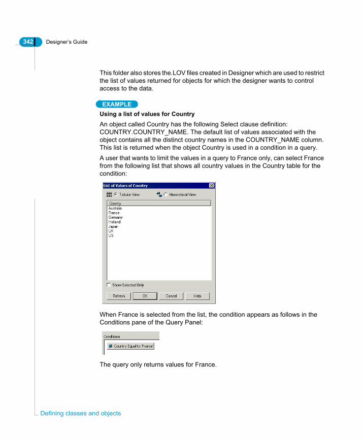
342 Designer’s Guide
Defi
This folder also stores the.LOV files created in Designer which are used to restrict the list of values returned for objects for which the designer wants to control access to the data.
EXAMPLEUsing a list of values for CountryAn object called Country has the following Select clause definition: COUNTRY.COUNTRY_NAME. The default list of values associated with the object contains all the distinct country names in the COUNTRY_NAME column. This list is returned when the object Country is used in a condition in a query.A user that wants to limit the values in a query to France only, can select France from the following list that shows all country values in the Country table for the condition:
When France is selected from the list, the condition appears as follows in the Conditions pane of the Query Panel:
The query only returns values for France.
ning classes and objects

Designer’s Guide 343
Defining how a list of values is used with an objectWhen you create a dimension or detail object in Designer, it is automatically assigned an associated list of values. This list does not physically exist when you create an object, but by default, the object has the ability to query the database to return a list of its values when used in the Query Panel.
NOTE
No default list of values is assigned to measure objects.
When a condition is first placed on an object in the Query panel that requires a list of values to be displayed in either Designer or BusinessObjects, a SELECT DISTINCT statement is run against the appropriate columns inferred by the object, and the list of values is returned.A.LOV file is automatically created in the User Docs folder to hold the list values. The next time that the list of values is required for the object in either Designer or BusinessObjects, the values are returned from the.LOV file and not from the database.
The designer’s role in controlling lists of valuesAs the universe designer, you can define how the data is presented in the list, and define restrictions on the amount and type of data returned to the list.You can set the properties for an object to determine the following actions for a list of values:• If a list of values is associated with an object.• When the list is refreshed.• Define a query that sets conditions on the SELECT DISTINCT query that an
object uses to return a list of values. You save this query in the properties of an object.
• Display list values either as a simple list, or as an object hierarchy.• If the list is based on column values, or values from an external file, for
example an Excel spreadsheet.You can also create a permanent list for values for an object and export this list to the repository. This.LOV file is then always used as the list of values for that object. It is not updated.
Using a list of values

344 Designer’s Guide
Defi
List of values properties and optionsYou can define the following object properties which allow you to control how a list of values for an object is used in BusinessObjects or WebIntelligence.
Property Description
Associate a List of Values
• When selected, allows a list of values to be associated with the object. It is selected by default.
• When cleared, no list of values is associated with the object.
• Selected by default for dimensions and details. Not selected for measures.
List name Name of the.LOV file that stores the returned list data. Limited to 8 characters.
ning classes and objects

Designer’s Guide 345
Allow users to edit this List of Values
• When selected, users can edit the list of values file in BusinessObjects and WebIntelligence.
• When cleared, the user cannot edit the list.Note: This does not apply to personal data files such as Excel spreadsheets. These are not exported to the repository. They remain on a local machine. A BusinessObjects user can edit a local file, or change the target list of values for another local data file.
The purpose of a list of values is usually to limit the set of available values to a user. If they can edit a list, you no longer have control over the values they choose. Normally, if you are not using a personal data file as a list of values source, you clear this option to ensure that users do not edit lists of values.
Automatic refresh before use (BusinessObjects only)
• When selected, the list data is refreshed each time the list of values for an object is displayed in the Query panel. This can have an effect on performance each time the .LOV is refreshed. This option does not apply to WebIntelligence reports.
• When cleared, the list is refreshed only once at the start of a user logon session.
If the list contains values that regularly change, then you can select this option, but you should take into account the effect on performance.If list values are affected by row restrictions in Supervisor, then you should always select this option so users do not see values restricted by the supervisor.If the list contents are stable, then you should clear this option.
Property Description
Using a list of values
346 Designer’s Guide
Defi
You can edit, display, or assign the default name to a list of values by clicking the following buttons:
Defining properties and options for a lost of valuesTo define properties and options for a list of values (.LOV) file:1. Double click an object.
The Edit Properties dialog box opens to the Definition page.2. Click the Properties tab.
The Properties page appears.3. Select or clear check boxes in the list of values group box at the bottom of the
Export with universe
• When selected, the.LOV file associated with the object is exported with the universe to the repository. The universe domain and document domain must exist on the same data account. A list of values is stored in the document domain. The document domain does not have to be visible to the a user’s profile in Supervisor.
• You must create the list of values that is associated with the object for it to be exported. This list is saved as a.LOV file.
• When cleared, a.LOV file for the object is not exported to the repository.
Select this option if you customize this list regularly. This allows your modifications to be exported and imported with the universe.
Option Description
Restore Default Restores default name assigned to the.LOV file at object creation.
Edit Allows you to edit the values displayed in the list. You can use the editor to restrict the values displayed in the list when used in the Query Panel or Query work area.
Display Displays the list of values for the object. When you want to create a permanent list to be exported with the universe to the repository, you must click Display to create the.LOV file. You can then edit the file.
Property Description
ning classes and objects

Designer’s Guide 347
page.4. Type a name for the associated.LOV file in the List Name box.5. Click the Edit button if you want to define restrictions on the list values6. Use the Query panel to create a query on the list data.7. Click the Display button to see the list of values.
When you click this button, a SELECT DISTINCT query is run against the columns inferred by the object in the database. This is the same method used in the reporting products to create the.LOV file for the object.
8. Click OK.
Viewing a list of values associated with an objectIn Designer, you can view the list of values associated with an object. When you view a list of values, a default.LOV file is automatically created in the User Docs directory to hold the returned data. By default, when you view a list of values you automatically create a.LOV file.You can view a list of values in a list format, or as an object hierarchy.To view a list of values:1. Double click an object.
The Edit Properties dialog box opens to the Definition page.2. Click the Properties tab.
The Properties page appears.3. Click the Display button.
The List of Values dialog box displays all the possible data values associated
Using a list of values

348 Designer’s Guide
Defi
with the object.
4. Click Cancel.
Creating a list of valuesYou create a list of values as follows:1. View the list of values for an object.2. Click OK.
Designer stores list of values (.LOV) files in a subfolder of the UserDocs folder in the BusinessObjects path. The name of the subfolder is the same as the universe that contains the object used to create the.LOV.
Once you have created the.LOV file, you can edit the list to restrict the data that is returned to the.LOV file, or modify how the data is presented in the list.
Editing a list of valuesYou can modify the contents of a list of values in two ways:• Apply a condition to the SELECT DISTINCT query that generates the list. For
example, you restrict the resorts in the list of values for the Resort object to those resorts that have more than a minimum number of reserved guests.
• Create a hierarchy to simplify for users the process of choosing a value from the list. This can be very useful if a list contains a lot of values.
displays a
of the values
refreshes the view of the values
displays a tabularview of the values
Creates the list of values file
The list of values
filters the display to selected items only
hierarchical view
ning classes and objects

Designer’s Guide 349
Applying a condition to a list of valuesTo apply a condition to a list of values:1. Double click an object.
The object Edit Properties sheet appears.2. Click the Properties tab.
The Properties page appears.3. Select the Associate a List of Values check box.4. If you want to rename the list, then type a name for the.LOV file in the List
Name box.
5. Click the Edit button.The Query panel appears. The active object is listed in the Result Objects pane.
6. Drag an object that you want to serve as a condition on the list of values for
Using a list of values

350 Designer’s Guide
Defi
the active object over to the Conditions pane.7. Double click an operator in the Operators pane.8. Double click an operand in the Operand pane.9. Select or type values as required.
For example the following query returns customers only from France.
10.Click OK.11.Click Display to view the restricted list of values.
A blank list appears.12.Click Refresh.
ning classes and objects

Designer’s Guide 351
13.The values appear in the list.
14.Click OK in each of the dialog boxes.
Creating a hierarchy for a list of valuesTo create a hierarchy for a list of values:1. Double click an object.
The object Edit Properties sheet appears.2. Click the Properties tab.
The Properties page appears.3. Select the Associate a List of Values check box.4. If you want to rename the list, then type a name for the.LOV file in the List
Name box.5. Click the Edit button.
The Query panel appears. The active object is listed in the Result Objects pane.
6. Drag the objects that you want to place in the hierarchy into the Result
Using a list of values

352 Designer’s Guide
Defi
Objects box to the right of the existing object, as shown below:
7. Click OK.8. Click Display to view the restricted list of values.
A blank list appears.9. Click Refresh.
The values appear in the list.
10.Click OK in each of the dialog boxes.
ning classes and objects
Designer’s Guide 353
Exporting a list of valuesYou can export a list of values with the universe to the repository. The associated.LOV file is copied to a sub directory of the UserData folder in the BusinessObjects path on the repository server.In the repository, .LOV files are stored in a document domain that must have a matching universe domain in the same database account.
How is an exported .LOV used in BusinessObjects or WebIntelligence?When a user runs a query in BusinessObjects or WebIntelligence using an object that is associated with a .LOV file exported from Designer, the list of values that is returned for the object is determined by one of the following:• The data contained in the .LOV file.• The SQL for the SELECT DISTINCT query defined in the .LOV file.If you have created a condition in Designer to restrict the data values returned for an object, the restricted list appears, and not the default list of all the data values. The list retains all conditions and formatting implemented in Designer.If you had not exported the .LOV file with the universe, then the object would simply return the default list with no conditions and formatting. A default .LOV file would then be created to hold the data.
Exporting a list with or without dataYou can export a list of values to the repository in two ways:
Export .LOV... Description
With query definition only (no data)
The .LOV file is exported with the definition of the SELECT DISTINCT query to return values to the list. All conditions that you set for the .LOV in the Designer Query panel are retained. The .LOV file contains no data, and is populated the first time the object is used to return values in the Query Panel or Query work area. You should use this method for data that is updated regularly, or if the list of values can be very large.
With data The .LOV file is exported or imported with all the data that is returned when you display or edit a list of values in Designer. This can be useful if the data in the .LOV does not change. However, if the data is regularly updated, or if the list contains a lot of values, then you should not export the data with the .LOV as it can slow the export process.
Using a list of values

354 Designer’s Guide
Defi
Exporting a list of values definitionTo export a list of values definition (no data):1. Create a list of values for an object.2. Select the Export with Universe check box on the Properties page for the
object.Below, a list of values Cust_FR is associated with the Customer to return only values for customers in France.
3. Select Tools > Lists of Values.The Lists of Values dialog box appears. It lists the classes and objects in the current universe and contains options to manage the list of values for each object.
4. Expand a class and select the object with an associated .LOV file that you want to export to the repository.
5. Click the Purge button.The data is deleted from the .LOV file for the object. The .LOV file now only
ning classes and objects

Designer’s Guide 355
contains the query definition for the list of values.6. Click OK.7. Select File > Export.
The Export Universe box appears.8. Select the universe filename from the list of universes.9. Click OK.
A message box appears telling you that the universe was successfully exported.
NOTE
When you export a .LOV file to the repository, it is copied to a sub-directory of the UserDocs folder on the repository server. The path for the sub directory is the same as the path for the exported universe on the repository server. For example if the universe is stored in the following directory: \Universe\<key file name>\<universe domain name>\<universe name>an exported .LOV file for the universe is stored in the following path: \UserDocs\<key file name>\<universe domain name>\<universe name>\<lov filename.LOV>
Exporting a list of values with dataTo export a list of values with data:1. Create a list of values for an object.2. Select the Export with Universe check box on the Properties page for the
object.3. Click the Display button.
The list of values appears.4. If the list is empty, click the Refresh button to populate the list.5. Click OK in each of the dialog boxes.6. Select File > Export.
The Export Universe box appears.7. Select the universe filename from the list of universes.8. Click OK.
A message box appears telling you that the universe was successfully exported.
Using a list of values

356 Designer’s Guide
Defi
Refreshing values in a list of valuesYou can refresh the data in a list of values in Designer using two methods:• Display the list of values for an object, and click the Refresh button.• Select Tools > Lists of Values to display the Lists of Values management box,
select an object and click the Refresh button.
Using data from a personal data fileYou can assign a list of values to an object that contains personal rather than corporate data retrieved from a database server. Personal data is data stored in a flat file such as a text file or data from one of the following applications: Microsoft Excel, Lotus 1-2-3, or dBASE.Using a personal data file as a list of values has the following advantages:• Retrieving data from a personal data file can be quicker than accessing your
corporate database.• Users need these values which do not exist in the database.• You control the values that users see when they work with lists of values.The disadvantage using a personal data file, is that the data is fixed. You must update the data manually if the values need to be changed.
Creating a list of values from a personal data fileTo create a list of values from personal data file:1. Select Tools > Lists of Values.
The List of Values dialog box appears.2. Expand a class and click an object.3. Click the Personal Data radio button in the Properties group box.
A message box tells you that you are about to change the list of values type from corporate to personal.
4. Click OK.The Access Personal Data dialog box appears. The available options depend
ning classes and objects

Designer’s Guide 357
on the file type you select.
5. Click the Browse button and select the file that you want to use as the list of values.OrType the file name in the Name text box.
6. Select the file format from the Format list box.7. You can select one of the following file formats:• Text Files (*.asc; *.prn; *.txt; *.csv)• Microsoft Excel Files• dBASE• Microsoft Excel 97.
NOTE
If your file was created in Excel 97, you must use the Microsoft Excel 97 option, not the Microsoft Excel Files option.
8. Specify the remaining options, as necessary.In a text file, one line is equivalent to one row. For a text file, indicate the type of column delimiter: a tabulation, space, or character. If you select character as the type, enter the character in the text box.
9. Click OK.
Using a list of values
358 Designer’s Guide
Defi
Administering lists of values in the universeYou can manage all the lists of values in the active universe from the Lists of Values dialog box (Tools > Lists of Values). All the classes and objects are presented in a tree view. You can select any object, and access its list of values. You can perform the following actions from the Lists of Values dialog box:
Option Description
Edit Displays the Query Panel used to define a query for the selected object. You can define and edit existing queries for a list of values.
Display Displays the current list of values for the selected object.
Purge Clears the contents of the list of values currently assigned to the selected object.
Refresh Refreshes the display of the list of values.
ning classes and objects

Designer’s Guide 359
Accessing the Lists of Values administration toolTo access the Lists of Values administration tool:1. Select Tools > Lists of Values
The Lists of Values dialog box appears.
2. Expand a class and select an object.3. Click a button or select an option to perform an administrative task.4. Click OK.
Using a list of values

360 Designer’s Guide
Defi
Optimizing and customizing LOV filesSome common methods used to optimize and customize LOVs are as follows:
Method Description
Point LOV to a smaller table
By default LOV point to the same object as the object they are attached to. But if this object points to a large table (number of rows) then refreshing the LOV may be slow. If there is an alternative smaller or faster table that returns the same values, then the LOV should be edited to point to that alternative table.
Combining code and description
A typical customization of a .LOV is to combine a 'code' and 'description'. An object returns a 'sales type code' which may not have a meaningful value to some users. Editing the LOV to display the 'sales type description' will help them when viewing the LOV. The opposite can be done for the 'sales type description' object to display the code along with the description.
ning classes and objects

Designer’s Guide 361
Using concatenated objectsA concatenated object is a combination of two existing objects. For example, you create an object Full Name, which is a concatenation of the objects Last Name and First Name in the Customer class.
Creating a concactenated objectTo create a concatenated object:1. Create an object.
For example, you create a new object Full Name in the Customer class. You should also type a description for the object such as “This object is a concatenation of the customer’s first and last name.”
2. Double click the object.The Edit Properties dialog box appears.
3. Type the syntax for the concatenated object in the Select box.For example you type the following syntax for the Full Name object (MS Access syntax):rtrim (Customer.first_name + ‘ ‘ + Customer.last_name)Where rtrim is a function that removes the blank space at the end of a character string, and the two quotes are used to insert a space between the
Using concatenated objects

362 Designer’s Guide
Defi
first and last name.
NOTE
You can also click the Edit button to open the SQL Editor. You can use the graphic tools in the editor to help you specify the SQL syntax for the object. For more information on this editor, refer to the Designing a Schema chapter.
4. Click OK in each of the dialog boxes.When you run a query on the Full Name object in BusinessObjects, the following results are returned:
ning classes and objects

Designer’s Guide 363
Inserting a user object from BusinessObjectsUsers can create user defined objects in BusinessObjects from existing objects in a universe. A user object is created to serve a specific end reporting need. However, they can be used only in the report in which they were created.User objects have a name, qualification, and definition. User objects are stored as files with the .udo extension in the Universe subfolder.If a user object can be useful to other users of a universe, you as the universe designer, can insert the user object into the universe. It then becomes available to other users. For example, a user creates an object Sales Tax in a sales universe. This measure object is defined with the following Select syntax:Sum ({Service\Price * 0.07})
where 0.07 is the current sales tax rate.
TIPFor full information on creating user objects, refer to the BusinessObjects User’s Guide.
You decide that the Sales Tax object is useful and that it should be available to all the users who work with the universe. You insert the user object into the universe as follows.
Inserting a user object into a universeTo insert a user object into a universe:1. Select Insert > User Objects.
The Insert User Objects dialog box appears. 2. Select a file with the .udo extension.3. Click the Open button.
A new class called Created from User Objects appears in the Universe pane of Designer.By default, user object files are stored within the Universe subfolder; they
Inserting a user object from BusinessObjects

364 Designer’s Guide
Defi
have a .udo extension.4. Expand the class to view the user object.
ning classes and objects
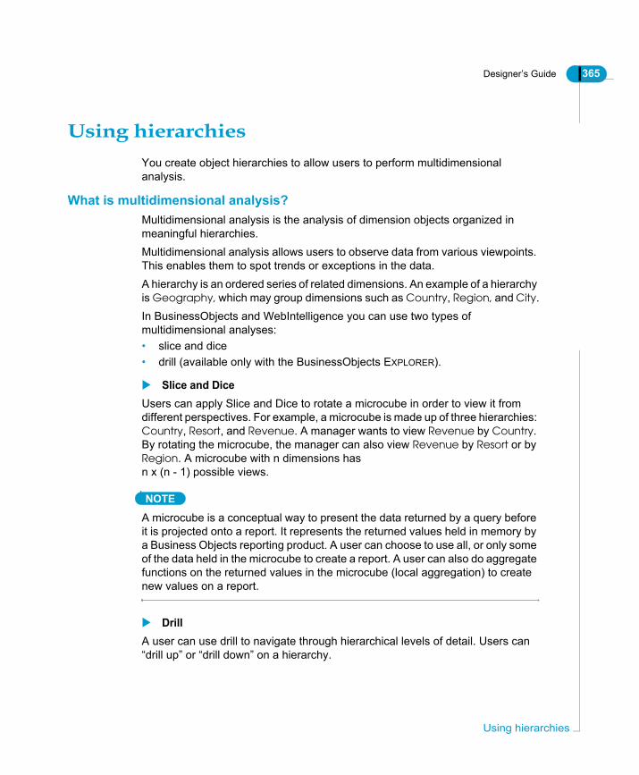
Designer’s Guide 365
Using hierarchiesYou create object hierarchies to allow users to perform multidimensional analysis.
What is multidimensional analysis?Multidimensional analysis is the analysis of dimension objects organized in meaningful hierarchies.Multidimensional analysis allows users to observe data from various viewpoints. This enables them to spot trends or exceptions in the data.A hierarchy is an ordered series of related dimensions. An example of a hierarchy is Geography, which may group dimensions such as Country, Region, and City.In BusinessObjects and WebIntelligence you can use two types of multidimensional analyses:• slice and dice• drill (available only with the BusinessObjects EXPLORER).
Slice and DiceUsers can apply Slice and Dice to rotate a microcube in order to view it from different perspectives. For example, a microcube is made up of three hierarchies: Country, Resort, and Revenue. A manager wants to view Revenue by Country. By rotating the microcube, the manager can also view Revenue by Resort or by Region. A microcube with n dimensions has n x (n - 1) possible views.
NOTE
A microcube is a conceptual way to present the data returned by a query before it is projected onto a report. It represents the returned values held in memory by a Business Objects reporting product. A user can choose to use all, or only some of the data held in the microcube to create a report. A user can also do aggregate functions on the returned values in the microcube (local aggregation) to create new values on a report.
DrillA user can use drill to navigate through hierarchical levels of detail. Users can “drill up” or “drill down” on a hierarchy.
Using hierarchies

366 Designer’s Guide
Defi
For example, a manager wants to track reservation data over time. As the universe designer, you could set up a Reservation Time hierarchy to include the dimensions Reservation Year, Reservation Quarter, Reservation Month, and Reservation Date. From a higher level of aggregation for example Reservation Quarter, the manager can drill down to a more detailed level such as Reservation Month or Reservation Date. He or she could also drill up from Reservation Quarter to Reservation Year to see a more summarized view of the data.
How to identify a hierarchyHierarchies can take different forms. Examples of classic hierarchies include: • Geography: Continent ➨ Country ➨ Region ➨ City• Products: Category ➨ Brand ➨ Product• Time: Year ➨ Quarter ➨ Month ➨ Week ➨ DayIt is also possible for a hierarchy to be “mixed” such as the following:Geography/Products: Continent ➨ Country ➨ Category ➨ Brand ➨ ProductThe hierarchies implicit in the data are dependant on the nature of the data and the way it has been stored in the database. You may need to analyze the data very carefully in order to find the hierarchies in your specific system that are best suited to the analysis requirements of your user group.While there are no precise rules for determining where the hierarchies in the data lie, the one-to-many (1-N) relationships inherent in the database structure can indicate the existence of hierarchies.In the schema below, the one-to-many relationships between the tables imply a geographical hierarchy.
More detailed Less detailed
ning classes and objects

Designer’s Guide 367
Setting up hierarchiesBy default, Designer provides a set of default hierarchies for multidimensional analysis. These are the classes and the objects arranged in the order that they appear in the Universe pane. When you create objects, you should organize them hierarchically, to ensure that default hierarchies have a sense to users.You often need to create customized hierarchies that include objects from different classes. In these cases you need to create a new hierarchy.You can view default, and create new hierarchies from the Hierarchies editor. This is a graphic editor that allows you to manage the hierarchies in the universe.
Viewing hierarchiesTo view hierarchies in the universe:1. Select Tools > Hierarchies.
OrClick the Hierarchies button.The Hierarchies editor appears. Designer represents hierarchies with a folder symbol, and dimensions with a cube symbol.The left pane lists all the classes that contain dimension objects in the active universe. The right pane shows all the customized hierarchies that you create.
2. Click a hierarchy node (the + sign) to see the dimensions organized
HierarchiesEditor
Using hierarchies

368 Designer’s Guide
Defi
hierarchically.3. Click Cancel.
Setting up the hierarchiesYou create a new hierarchy by creating a new folder in the Custom Hierarchies pane, then adding the appropriate dimensions in a hierarchical order.You can delete a hierarchy or a dimension in a hierarchy by selecting the hierarchy or dimension and clicking the Remove button.To create a new hierarchy: 1. From the Hierarchies editor, click the New button.
OrFrom the Hierarchies editor, select a class in the left pane and drag it over to the right pane.A folder representing the hierarchy appears in the right pane.
2. Type a name for the hierarchy.3. Press RETURN to apply the name.4. Select the new hierarchy.
The hierarchy is highlighted.5. Expand a default hierarchy node in the left pane.
This is the hierarchy that contains dimensions that you want to add to the new custom hierarchy.
6. Click a dimension. To select a series of dimensions, hold down CTRL and click each dimension.One or more dimensions are highlighted.
7. Click the Add button.One or more dimensions appear in the right pane, under the selected hierarchy.
NOTE
The Unused objects only check box is a useful way to view only the dimension objects that you have not yet selected for inclusion in a hierarchy.
Rearranging the order of dimensions and hierarchiesYou can rearrange the order in which the dimension objects appear within a hierarchy. To move an object, click it, and then click the Move Up or Move Down button. You can also re-arrange the order of hierarchies in the same way.
ning classes and objects
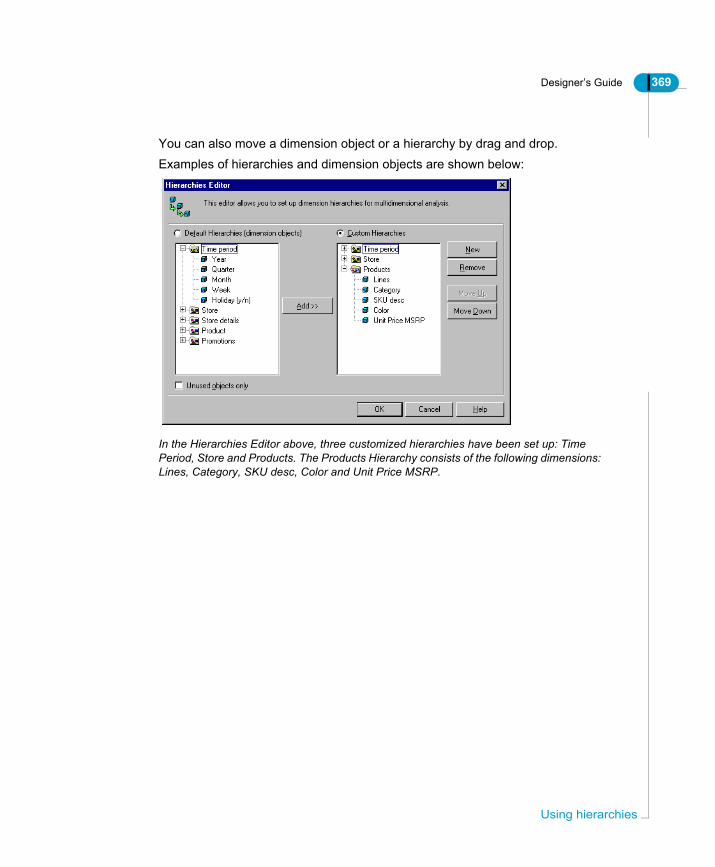
Designer’s Guide 369
You can also move a dimension object or a hierarchy by drag and drop.Examples of hierarchies and dimension objects are shown below:
In the Hierarchies Editor above, three customized hierarchies have been set up: Time Period, Store and Products. The Products Hierarchy consists of the following dimensions: Lines, Category, SKU desc, Color and Unit Price MSRP.
Using hierarchies

370 Designer’s Guide
Defi
Testing the universeYou can test the integrity of the objects and classes in your universe by running regular checks with Check Integrity (Tools > Check Integrity), and by testing objects in BusinessObjects and WebIntelligence.
Testing the integrity of the universe As you create and modify classes and objects, you should use Check Integrity regularly to test the integrity of your universe regularly using Check Integrity. You can refer to the section "Checking the Universe" in the Designing a Schema chapter for information on using Check Integrity.
Testing the universe with BusinessObjects or WebIntelligenceYou can test objects by running test queries in BusinessObjects or WebIntelligence. When you test object you can ask the following type of questions:• Do the objects exist? If not, did you save the universe after the last created?• Is the SQL correct?• Are the results of the query correct?You must also test the joins, by evaluating if returned results are correct, and by checking the schema components with Check Integrity.
ning classes and objects

Designer’s Guide 371
Using external strategiesDesigner uses built-in automated routines to automatically create universe components based on the database structure. These routines are called strategies and are available from the Strategies page of the Parameters dialog box (Files > Parameters > Strategies). These strategies are built-in to Designer. You cannot access or modify them. The use and activation of strategies is described in the section Selecting strategies on page 69.You can also create SQL scripts that follow a defined output structure to perform customized automatic universe creation tasks. You can select these from the Strategies page with the other strategies. These user defined and customized scripts are called External strategies.This section describes external strategies and their use.
Migrating external strategies to Designer 6.5External strategies in previous versions of Designer were defined in an external text file called the st<xxxx>.txt file.This file is no longer supported in Designer 6.5. To ensure that your customized and user defined external strategies used in previous versions are available from Designer 6.5, you must do the following:• Edit the new external strategy file (<RDBMS>.STG) as follows:
- Open the external strategy file for your target RDBMS in a XML editor.- Create a new entry for each strategy.- For each strategy, copy the SQL script directly into the STG file using the SQL tag.Or- Enter a file path to reference the data in an external text file using the FILE tag.Both methods are described fully in the section Creating an external strategy on page 382.
• Copy the Help text to a second XML file (<RDBMS><language>.STG). This is described in the section Creating Help text for external strategies on page 373.
• Verify that the external strategy file is declared in the general parameters file (SBO), not the parameters file (PRM), as was the case for previous versions of Designer. This is described in the section Verifying that the external strategy file is declared on page 375.
Using external strategies

372 Designer’s Guide
Defi
External strategies in Designer 6.5 overviewThe way in which external strategies are created and managed is new in Designer 6.5. The table below provides an overview of the files used and their role in the creation and management of external strategies in Designer 6.5.
Roles and files in external strategies management process
Description
External strategies stored and created in External strategy file (<RDBMS>.STG).
XML file contains external strategy name, type, SQL script, or file reference to external text file containing data. File is stored here:$INSTALLDIR/dataAccess/RDBMS/connectionServer/<RDBMS>/<RDBMS>.stg.One file for each RDBMS. Uses the strategy.dtd file here:$INSTALLDIR/dataAccess/RDBMS/connectionServer/strategy.dtdRelated sections:• How is the strategy file (STG) structured? on
page 376• Creating an external strategy on page 382
Help text for external strategies stored and created in External strategy language file(<RDBMS><language>.STG)
XML file contains Help text for each external strategy in the external strategy file. This is the text that appears under an external strategy when it is selected on the Strategies page. File is stored here:$INSTALLDIR/dataAccess/RDBMS/connectionServer/<RDBMS>/<RDBMS><language>.stg.Uses the strategy_localization.dtd file located here:$INSTALLDIR/dataAccess/RDBMS/connectionServer/strategy_localization.dtd.Related section:Creating Help text for external strategies on page 373.
External strategy file is declared in the general data access file (SBO) for the target RDBMS.
XML file contains the general data access parameters for a target RDBMS. The name of the external strategy file is set as the value for the parameter External Strategies by default.Related section:Verifying that the external strategy file is declared on page 375
ning classes and objects
Designer’s Guide 373
What is an external strategy?An external strategy is an SQL script stored externally to the .UNV file, and structured so that it can be used by Designer to automate object or join creation, and table detection tasks in a universe. External strategies are stored in an external strategy file with the extension STG. External strategy files are in XML format. There is one for each supported RDBMS.External strategy files are stored in the following directory:
NOTE
You should use an XML editor to edit the external strategy file.
Accessing external strategies in DesignerExternal strategies appear in the drop down list boxes that also list the built-in strategies on the Strategies page. Each drop down list box corresponds to a strategy type category in the XML file. An external strategy appears in the list with External Strategy prefixing the strategy name as follows:
For example, an external strategy for join creation called Constraints in the Strategy file, appears as External Strategy:Constaints in the Joins drop down list on the Strategies page.
Creating Help text for external strategiesOn the Strategies page, a commentary note appears under each selected strategy. This is the Help text for the strategy. For built-in strategies the Help text cannot be accessed or edited. However, you can access and edit the Help text for external strategies.
NOTE
In previous versions of Designer the Help text was included in the strategy text file in the section [HELP]. The text in this section is now stored in a separate file, the external strategy language file described below.
$INSTALLDIR/dataAccess/RDBMS/connectionServer/<RDBMS>/<rdbms>.stg
External Strategy:<strategy name>
Using external strategies

374 Designer’s Guide
Defi
External strategy Help text is stored in a separate fileThe Help text for external strategies is stored in a separate external strategy language file called <RDBMS><language>.stg. For example, oaracleen.stg is the Help text file for the strategies in the oracle.stg file.You can edit and customize Help text entries. The Help text should describe briefly what the strategy does to help designers who may not be familiar with the strategy.For each external strategy that appears in the external strategy file, you should ensure that a corresponding entry with Help text appears in the external strategy language file.There is a strategy language file for each language version of Designer that you have installed. The external strategy language file is in the same directory as the external strategy file. For example, if you have a French version of Designer, the external strategy language file for Oracle is oraclefr.stg. The English version is oracleen.stg.When you create a new external strategy in the external strategy file, you also create an entry for the Help text in the external strategy language file. This provides information about the external strategy to other designers using the universe.
EXAMPLEHelp text entry for the strategy shipped with Oracle data access driverThe Help text for the strategy Classes and Objects listed in the oracleen.stg file is shown below. This is the Help text for the Classes and Strategies external strategy defined in the file oracle.stg.<Strategy Name="Classes_and_Objects">
<Message id="Help">This strategy reads the database structure. It associates tables with classes, and columns with objects.</Message>
<Message id="Name">External Strategy: Classes and Objects</Message>
Creating a Help entry for an external strategyTo create a Help entry for an external strategy:1. Open the external strategy language file for the target RDBMS in an XML
ning classes and objects

Designer’s Guide 375
editor. The external strategy language file for a target RDBMS is located here:$INSTALLDIR/dataAccess/RDBMS/connectionServer/<RDBMS>/<RDBMS><language>.stg.For example:$INSTALLDIR/dataAccess/RDBMS/connectionServer/oracle/oracleen.stg.
2. Create a new Name element.3. Enter the name of the strategy. This is the strategy for which you are creating
Help text.4. Create a Message ID called Help. This tag contains the Help text.5. Enter the Help text.6. Create a Message ID called Name. This tag contains the name that you want
to appear in the strategy drop down list when the external strategy is selected.7. Enter a strategy name.
Validate, save, and close the file.When you next start up Designer, the Help text appears under the selected external strategy.
TIPAn easy way to create and set parameters for a new Name element is to copy an existing Name element and fill in the new values for the new strategy.
Verifying that the external strategy file is declaredAn external strategy file is declared in the Parameter section of the general parameter (SBO) file for the target RDBMS. For example, the external strategy file for Oracle is oracle.stg. It has the value oracle in the oracle.sbo file as shown below:
oracle is the name of theexternal strategy file for Oracle.This is declared in theoracle.sbo file.
Using external strategies
376 Designer’s Guide
Defi
Verifying that the strategy file is declared in the SBO fileTo verify that an external strategy file is declared correctly:1. Open the SBO file for the target RDBMS.2. Ensure that the parameter Strategies Name is set to the name of the external
strategies file. This is the default setting.3. If the name is not set correctly, enter the correct name of the external
strategies file.4. If you have made modifications, save and close the file.
Or5. If you have not made any modifications, close the file without saving.
NOTE
External strategies in previous version of Designer were declared in the PRM file. This is no longer the case for Designer 6.5. The Strategies File parameter in the SBO file is set to the name of the external strategies file for the target RDBMS by default. Refer to the section What is an external strategy? on page 373 for full information on migrating external strategies to Designer 6.5.
Using example external strategiesAll external strategy files contain a number of existing strategies delivered with Business Objects products. For example, a file may contain one object strategy, one join strategy, and one table browser strategy, or multiple strategies of each type.You can customize an example file, or use it as the basis to create a new external strategy. You can customize an existing strategy or create your own.Save a copy of each file before modifying it.
How is the strategy file (STG) structured?There is an external strategy file (STG) file in XML format for each supported RDBMS. You migrate existing or create new external strategies to this file. All external strategy files use the strategy dtd (<RDBMS>.dtd) file in the following directory:
$INSTALLDIR/dataAccess/RDBMS/connectionServer
ning classes and objects

Designer’s Guide 377
The elements in the external strategy XML file are defined in the external strategy DTD file. If you are using certain XML editors, for example XML SPY, the available parameters are listed in a drop down list when you create a new strategy element. The external strategy file contains one main section called Strategies. All the external strategies are defined in this section. The Strategies section has the following elements and parameters:
File element Description
Strategy Main element. All external strategies are created within this element.
Name Name of the external strategy. This name appears in the drop down list on the Strategies page. Default element.
Type The list that the external strategy appears in on the Strategy page. There are 3 values:• JOIN: Join strategy appears in the Joins list.• OBJECT: Classes and objects strategy appears in
the Classes and Objects list.• STRUCT: Table detection strategy appears in the
Tables list.
SQL The SQL code for the script. This is the SQL script that Designer runs when the strategy is selected. The SQL script must follow a specific output format for object and join creation, and table detection routines to run correctly. See the section The output format of object strategies (OBJECT) on page 380 for information on structuring the SQL for an external strategy.
Connection Specify a database connection. The connection type must be personal.
SkipMeasures When set to Y, it skips the screen in the Quick Design wizard that deals with the creation of measures:
File File path of an external text file that contains data organized in a specific output format that creates a universe automatically. See the section Creating a text file for data on page 384 for more information.
Using external strategies

378 Designer’s Guide
Defi
EXAMPLEClasses and Objects external strategy in oracle.stgThe external strategy file for Oracle is oracle.stg. It is stored in the directory $INSTALLDIR/dataAccess/RDBMS/connectionServer/oracle/oracle.stg. This file contains a number of example external strategies shipped with Designer. You can customize these strategies, or use them as templates for new ones.An external strategy from the oracle.stg file that automatically associates tables with classes, and columns with objects is shown below:<Strategy Name="Classes_and_Objects">
<Type>OBJECT</Type>
<SQL>SELECT
U1.table_name,'|',
U1.column_name,'|',
translate(initcap(U1.table_name),'_',' '),'|',
translate(initcap(U1.column_name),'_',' '),'|',
U1.table_name||'.'||U1.column_name,'|',
' ','|',
decode(SUBSTR(U1.DATA_TYPE,1,1),'N','N','F','N','D','D','C'),'|',
SUBSTR(U2.comments,1,474),'|',
'O','|'
FROM USER_TAB_COLUMNS U1,USER_COL_COMMENTS U2
WHERE
U1.table_name=U2.table_name
and U1.column_name=U2.column_name
UNION
SELECT
S.SYNONYM_NAME,'|',
U1.column_name,'|',
translate(initcap(S.SYNONYM_NAME),'_',' '),'|',
translate(initcap(U1.column_name),'_',' '),'|',
S.SYNONYM_NAME||'.'||U1.column_name,'|',
' ','|',
decode(SUBSTR(U1.DATA_TYPE,1,1),'N','N','F','N','D','D','C'),'|',
SUBSTR(U2.comments,1,474),'|',
'O','|'
FROM ALL_TAB_COLUMNS U1, ALL_COL_COMMENTS U2, ALL_OBJECTS O,
ning classes and objects

Designer’s Guide 379
USER_SYNONYMS S
WHERE
S.table_owner=O.owner
AND S.table_name=O.object_name
AND (O.OBJECT_TYPE='TABLE' OR O.OBJECT_TYPE='VIEW')
AND O.owner=U1.owner
AND O.object_name=U1.table_name
AND U1.owner=U2.owner
AND U1.table_name=U2.table_name
AND U1.column_name=U2.column_name</SQL>
</Strategy>
The output formats of strategiesYou write or copy the SQL script within the <SQL> tag in the external strategies file. The order and type of information returned by the SQL script depends on whether you are creating an object, join, or table strategy. Designer has different information needs for each of the different types of strategies. When you create the SQL script for a strategy, you must ensure that the generated output for the script matches the output formats described below. The script output is formatted as a series of columns. Each column corresponds to a unit of generated information used to create the object, join, or table components.This section presents the output formats for:• Object strategies• Join strategies• Table browser strategies.
Using external strategies

380 Designer’s Guide
Defi
The output format of object strategies (OBJECT)The output format of an object strategy contains nine columns. You must ensure that your output includes all these columns even if they contain null values.
EXAMPLEExternal object strategy that copies column comments to object descriptionsThe example below does not contain a Where clause. The output column for the Where clause is empty.<Strategies><Strategy Name="Read Column descriptions"><Type>OBJECT</Type>
Column number
Column contains...
Description
1 Table Table name format is [Qualifier.][Owner.]Table where each name can have up to 35 characters. If you leave this column empty, then the tables are obtained from the Select (fifth column) and Where (sixth column).
2 Column Name Name of the column.
3 Class Name Name of a class. Subclasses are written as follows: Class\Subclass format.
4 Object Name Name of the object or condition. If the object name is empty, then a class and its description are created.
5 Select Select statement.
6 Where: If you leave the Select column empty, but include a Where clause, then a predefined condition and its description are created.
7 Type C (Character), N (Numeric), D (Date), T (Long Text). If the column is left empty, the default is N.
8 Description Description of the object.
9 Qualification D (Dimension), M (Measure), or I (Detail). If the column is left empty, the default is D.
ning classes and objects

Designer’s Guide 381
<SQL>Select
</SQL>
The output format of join strategies (JOIN) The output format of a join strategy contains the following columns:
Col Description
Table_name, ‘|’, 1 Table name
Column_name, ‘|’, 2 Column name
Replace (Table_name,’_’,’ ‘), ‘|’, 3 Replace underscores in table name with blanks in Class name
Replace (Column_name, ‘_’, ‘ ‘),’|’, 4 Replace underscore in column name with blanks in Object name.
Table_name||’.’||Column_name, ‘|’, 5 Concatenate table name to column name separated by a period. This is the Select statement.
,’|’, 6 No Where clause
Column_Desc,’|’, 7 Get column description from system tables
Column_type,’|’, 8 Get column type from system tables
‘ ‘,’|’ 9 Object type null will default to a Dimension.
Column number
Column contains... Description
1 Table1 Name of first table in join
2 Table2 Name of second table in join.
3 Join Definition The actual definition of the join in a table1.column1=table2.column2 form
4 Outertype Outer join type. L=outer left, R=outer right. If the column is left empty, there is no outer join.
5 Cardinality (optional) valid values are 11, 1N, N1.
Using external strategies

382 Designer’s Guide
Defi
The output format of table browser strategies (STRUCT)The output format of a table browser strategy contains the following columns:
Creating an external strategyYou can create an external strategy in two ways:
Both methods are described in the following procedure.
Creating an external strategyTo create an external strategy directly:1. Open the external strategy file for the target RDBMS in an XML editor. The
strategy file for a target RDBMS is located here:$INSTALLDIR/dataAccess/RDBMS/connectionServer/<RDBMS>/
Column number
Column contains...
Description
1 Qualifier RDBMS dependant. The Table Qualifier is the database name or some other identification.
2 Owner RDBMS dependant
3 Table Name of the table, view, or synonym.
4 Column Column name.
5 Data Type C (Character), N (Numeric), D (Date), T (Long Text). If the column is left empty, the default is C.
6 Nullable Idicates whether there can be null values in columns
7 Y (Yes) or N (No) Default is unknown.
Create external strategy by...
Tag in XML file
Description
Inserting SQL script directly.
SQL You insert the SQL script for the strategy directly in the external strategy file using the SQL tag.
Referencing data in an external file
FILE You enter the file path and name for an external text file that contains the data for the strategy.
ning classes and objects

Designer’s Guide 383
<RDBMS>.stg.2. Create a new strategy element.
This is the new strategy. If you are using an XML editor for example XML Spy, the Name, Type, and SQL elements for the strategy are created automatically.
3. Enter a strategy name.The name of the strategy is visible in the Strategies tab of the Universe Parameters dialog box and in the Quick Design wizard.
4. Enter a TYPE parameter: OBJECT, JOIN, or STRUCT.For example, TYPE=OBJECT.
5. Enter the SQL statement of the strategy. The SQL format is described in the section The output formats of strategies on page 379.OrIf you want to reference a text file containing data, replace the SQL element with the File element. Enter the file path for the data file, for example C:\Path\Filename.txt
6. Add optional elements and set values if necessary.7. Check the validity of the XML file, then save and close the file.8. Verify that the external strategy file is declared in the general data access file
for the target RDBMS (<RDBMS>.SBO). Do this as follows:- Open the general data access file (SBO) in the directory:$INSTALLDIR/dataAccess/RDBMS/connectionServer/<RDBMS>/- Ensure that the Strategies File element is set to the name of the external strategies file. This is the default value.- If you have modified the SBO file, save and close the file.The external strategy appears in the Join, Objects, or Tables drop down lists on the Strategies page of the Parameters dialog box. You must close and restart Designer for a newly created external strategy to be visible.
NOTE
If you want to add Help text that appears under the external strategy when it is selected on the Strategies page, you add this text to a separate file, the external <RDBMS><language>.STG file, located in the same directory as the external strategy file. Adding Help text for an external strategy is described in the section Creating Help text for external strategies on page 373.
Using external strategies

384 Designer’s Guide
Defi
Creating a text file for dataYou can create a text file that contains the data for an external strategy. When you create an external strategy, you can enter the file path and name for the text file instead of directly inserting the SQL. You insert the FILE element in the external strategy file, and set the value to the file path and name.The output of the SQL script must adhere to the correct format for the type of strategy, object, join, or table. The output formats are described in the section The output formats of strategies on page 379.All formats consist of columns of information separated by tabulations.
Applying external strategies in DesignerYou apply external strategies as follows:1. Ensure that the external strategy that you want to use is selected in the
Strategies page of the Parameters dialog box.For example,
• To insert objects extracted with an object strategy, you select the Candidate Objects command from the Insert menu.
• To insert joins derived from a join strategy, select the Detect Joins command from the Tools menu.
• To insert tables extracted with a table browser strategy, you select the Tables command from the Insert menu.
NOTE
When you select a join strategy, Designer will use the strategy to detect candidate joins and cardinalities. You can choose to apply the suggested joins or cardinalities. If you want the candidate join and cardinalities to be automatically applied based on the selected strategy, you must select the corresponding creation options on the database page of the Options dialog box (Tools > Options > database). See the section Using the automatic creation functions of a strategy on page 73 for more iniformation.
ning classes and objects
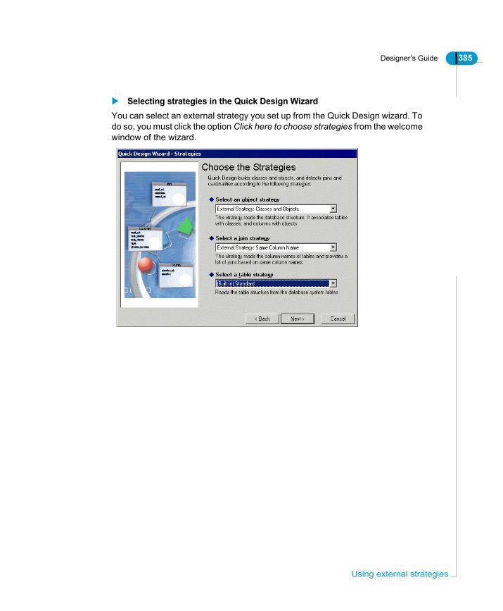
Designer’s Guide 385
Selecting strategies in the Quick Design WizardYou can select an external strategy you set up from the Quick Design wizard. To do so, you must click the option Click here to choose strategies from the welcome window of the wizard.
Using external strategies

386 Designer’s Guide
Defi
ning classes and objects
Using aggregate awareness
chapter

388 Designer’s Guide
Usin
OverviewYou can use features in Designer to allow you to define the Select statement for an object to run a query against aggregate tables in the database instead of the base tables. You can set conditions so that a query will be run against aggregate tables when it optimizes the query, and if not, then the query will be run against the base tables. This ability of an object to use aggregate tables to optimize a query is called aggregate awareness.This chapter describes how you can set up aggregate awareness in your universe.
g aggregate awareness

Designer’s Guide 389
What is aggregate awareness?Aggregate awareness is a term that describes the ability of a universe to make use of aggregate tables in a database. These are tables that contain pre-calculated data. You can use a function called @Aggregate_Aware in the Select statement for an object that directs a query to be run against aggregate tables rather than a table containing non aggregated data.Using aggregate tables speeds up the execution of queries, improving the performance of SQL transactions.The reliability and usefulness of aggregate awareness in a universe depends on the accuracy of the aggregate tables. They must be refreshed at the same time as all fact tables.A universe that has one or more objects with alternative definitions based on aggregate tables is said to be "aggregate aware". These definitions correspond to levels of aggregation. For example, an object called Profit can be aggregated by month, by quarter, or by year. These objects are called aggregate objects.Queries built from a universe using aggregate objects return information aggregated to the appropriate level at optimal speed.
Applying aggregate awareness to data warehousesAggregate awareness is particularly useful when working with data warehouses. For example, consider a data warehouse organized into three dimensions: time, geography, and product.
At its lowest level, this data warehouse can store daily information about customers and products. There is one row for each customer’s daily product purchases; this can be expressed as follows:365 days x 100 cities x 10 products = 365,000 rows.If you ask for information about yearly sales, the database engine must add up a large number of rows. However, the yearly sales of companies may actually involve fewer rows, as follows:
Time Dimension
Year Quarter
Month Day
Geography Dimension
Country Region
State City
Product Dimension
Company Division
Group Product
Levels
What is aggregate awareness?

390 Designer’s Guide
Usin
3 years x 3 countries x 3 companies = 27 rowsSo, in this example, 27 rows from a table are sufficient to answer the question. Based on this information, it would be far more efficient to pre-summarize these rows into aggregate tables.
g aggregate awareness

Designer’s Guide 391
Setting up aggregate awarenessSetting up aggregate awareness in a universe is a four-part process. The main steps of the methodology are summarized in the diagram below.
Build the Objects
1. Identify all the possible definitions (table/column
Define any necessary contexts
Define one context per level of aggregation.
Specify the incompatible objects
1. Build an objects/aggregate tables matrix.
2. For the first aggregate table, decide whether each object is either:
combinations) of the objects.
2. Arrange the objects by level of aggregation.
3. Build the objects using the @Aggregate_Awareness function.
- at the same level of aggregation or higher (compatible) - at a lower level of aggregation (incompatible)3. Check only the boxes of objects that are incompatible for that table.4. Repeat the steps for the remaining aggregate tables.
Test the results
1. Run several queries.2. Compare the results.
Setting up aggregate awareness

392 Designer’s Guide
Usin
Each stage of the above process is described in detail in the following sections. The example schema shown below is used to illustrate each stage:
The schema contains three predefined aggregate tables: AAMONTH, AAQTR, and AAYEAR.
NOTE
The example schema is not representative of a typical schema. Use it as a way to follow the steps to set up aggregate awareness. In a production schema, an aggregate table would generally combine several dimensions rather than a single dimension based on time. The time dimension (Year, Quarter, and Month) would also normally be defined from within a master table, not an aggregate table.
Building the objectsThe first step in setting up aggregate awareness in a universe is to determine which objects are to be aggregate aware. You can use either measure objects or dimension objects.An object Sales Revenue has the following definition based on the above schema:PRODUCTS.PRICE*ORDER_LINES.QUANTYou want to redefine Sales_Revenue to use the aggregate tables where possible instead of performing a aggregation using the non aggregate tables.
g aggregate awareness

Designer’s Guide 393
Each of the stages that you complete to redefine Sales Revenue as aggregate aware, you also need complete for any other objects that you want to use aggregate tables in their definitions.
Identifying all combinations of the aggregate objectsYou need to identify all possible combinations of the objects in the various tables. The Sales Revenue object can be defined in the following ways:• AAMONTH.REVENUE• AAYEAR.REVENUE• AAQTR.REVENUE• PRODUCTS.PRICE*ORDER_LINES.QUANT
Arranging objects in aggregate level orderOnce you have identified all combinations of the objects, you arrange them according to their level of aggregation as follows:• AAYEAR.REVENUE is the highest level of aggregation.• AAQTR.REVENUE is the next level.• AAMONTH.REVENUE is the next level.• PRODUCTS.PRICE*ODER_LINES.QUANT is the lowest level of
aggregation.
Defining aggregate objects with the @Aggregate_Aware functionYou then re-define the Select statement using the @Aggregate_Aware function for all aggregate aware objects. The @Aggregate_Aware function directs an object to query first of all the aggregate tables listed as its parameters. If the aggregate tables are not appropriate, then the query is run with the original aggregate based on the non-aggregated table. For more information about @Functions see the section “Using @Functions” in the Defining Classes and Objects chapter.
Setting up aggregate awareness

394 Designer’s Guide
Usin
The Select statement for Sales Revenue using the @Aggregate_Aware function appears below.
The syntax of the @Aggregate_Aware function is as follows:
where agg_table_1 is the aggregate with the highest level of aggregation, and agg_table_n the aggregate with the lowest level.You must enter the names of all aggregate tables as arguments. You place the names of tables from left to right in descending order of aggregation.
To define an object using @Aggregate_AwareTo re-define an object using @Aggregate_Aware:1. Double click an object.
The Edit Properties dialog box for the object appears.2. Click the >> button next to the Select box.
The Edit Select Statement dialog box appears.3. Click at the beginning of the Select statement.
OrClick anywhere in the select box if the object does not yet have a Select
@Aggregate_Aware(sum(agg_table_1), ... sum(agg_table_n))
g aggregate awareness

Designer’s Guide 395
statement.The cursor appears at the top left corner of the box.
4. Click the @Functions node in the Functions pane.The list of available @functions appears.
5. Double click @Aggregate_Aware.The syntax for @Aggregate_Aware is inserted in the Select statement. A description of the syntax appears in the Description box at the bottom of the dialog box. You can use this to help you type the parameters for the @function.
6. Insert the aggregates within the brackets of the @AggregateAware function in order (highest to lowest level of aggregation data).
7. Separate each aggregate with a comma. For the example, the syntax for the
Setting up aggregate awareness
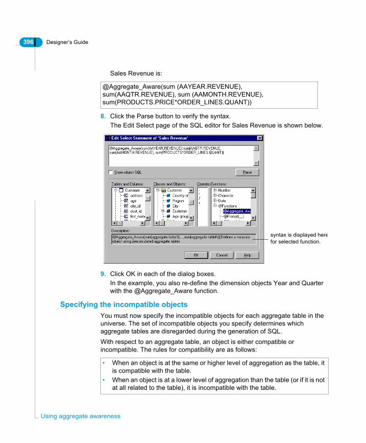
396 Designer’s Guide
Usin
Sales Revenue is:
8. Click the Parse button to verify the syntax.The Edit Select page of the SQL editor for Sales Revenue is shown below.
9. Click OK in each of the dialog boxes.In the example, you also re-define the dimension objects Year and Quarter with the @Aggregate_Aware function.
Specifying the incompatible objectsYou must now specify the incompatible objects for each aggregate table in the universe. The set of incompatible objects you specify determines which aggregate tables are disregarded during the generation of SQL.With respect to an aggregate table, an object is either compatible or incompatible. The rules for compatibility are as follows:
@Aggregate_Aware(sum (AAYEAR.REVENUE), sum(AAQTR.REVENUE), sum (AAMONTH.REVENUE), sum(PRODUCTS.PRICE*ORDER_LINES.QUANT))
syntax is displayed herefor selected function.
• When an object is at the same or higher level of aggregation as the table, it is compatible with the table.
• When an object is at a lower level of aggregation than the table (or if it is not at all related to the table), it is incompatible with the table.
g aggregate awareness

Designer’s Guide 397
Using a matrix to analyse the objectsYou may find it useful to build a matrix in order to analyze the compatibility of objects and aggregate tables. In the first two columns of this matrix, you can list the names of classes and objects. Then you can create a column heading for each aggregate table in your universe. A blank matrix based on the schema of the example would look like this:
For each table, enter a checkmark (✓ ) if the object is incompatible.
Class Object AAYEAR AAQTR AAMONTH
Customers Customer Code(CUSTOMER.CUST_ID)
Customer Name(CUSTOMER.LAST_NAME)
Customer City(CUSTOMER.CITY)
Customer Nationality(COUNTRIES.COUNT_NAME)
Products Product Code(PRODUCT.PROD_ID)
Product Name(PRODUCT.PROD_NAME)
Orders Order Year(AAYEAR.PROD_NAME)
Order Quarter(AAQTR.QTR)
Order Month(AAMONTH.MONTH)
Order Date(ORDERS.ORDER_DATE)
SalesMeasure
Sales Revenue(@Aggregate_Aware(...))
Setting up aggregate awareness
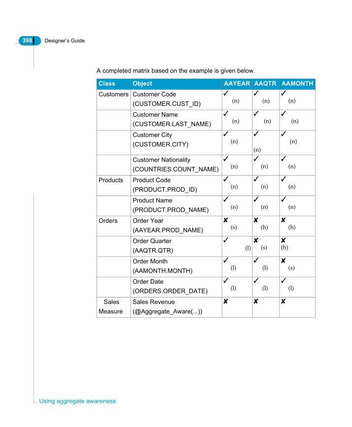
398 Designer’s Guide
Usin
A completed matrix based on the example is given below.
Class Object AAYEAR AAQTR AAMONTH
Customers Customer Code(CUSTOMER.CUST_ID)
✓ (n)
✓ (n)
✓ (n)
Customer Name(CUSTOMER.LAST_NAME)
✓ (n)
✓ (n)
✓ (n)
Customer City(CUSTOMER.CITY)
✓ (n)
✓
(n)
✓ (n)
Customer Nationality(COUNTRIES.COUNT_NAME)
✓ (n)
✓ (n)
✓ (n)
Products Product Code(PRODUCT.PROD_ID)
✓ (n)
✓ (n)
✓ (n)
Product Name(PRODUCT.PROD_NAME)
✓ (n)
✓ (n)
✓ (n)
Orders Order Year(AAYEAR.PROD_NAME)
✘ (s)
✘ (h)
✘ (h)
Order Quarter(AAQTR.QTR)
✓
(l)✘ (s)
✘(h)
Order Month(AAMONTH.MONTH)
✓ (l)
✓ (l)
✘ (s)
Order Date(ORDERS.ORDER_DATE)
✓ (l)
✓ (l)
✓ (l)
SalesMeasure
Sales Revenue(@Aggregate_Aware(...))
✘ ✘ ✘
g aggregate awareness
Designer’s Guide 399
Specifying incompatible objectsYou now specify the incompatible objects. You use the Aggregate Navigation dialog box (Tools > Aggregate Navigation) to specify the incompatible objects. You specify incompatible objects using the Aggregate Navigation as follows:1. Select Tools > Aggregate Navigation.
The Aggregate Navigation box appears. It consists of two panes:• Universe Tables, which lists all the tables of the universe.• Associated Incompatible Objects, which lists all the objects of the universe.2. Click an aggregate table in the left pane.3. In the right pane, select the check box for each incompatible object.
For example, based on the matrix, for the AAYEAR table all the objects in the Customers class are incompatible. You select the check box beside the class
✓ (n) This object has nothing to do with the aggregate table. It is therefore incompatible.
✓ (l) This object is at a lower level of aggregation than this aggregate table; it cannot be used to derive information. It is therefore incompatible.
✘ (s) This object is at the same level of aggregation than this aggregate table; it can be used to derive information. It is therefore compatible.
✘ (h) This object is at a higher level of aggregation than this aggregate table; it can be used to derive information. It is therefore compatible.
Setting up aggregate awareness

400 Designer’s Guide
Usin
name as follows:
4. Repeat the above steps for each aggregate table in your universe.For example, the incompatible objects for the AAQTR table are shown below.
g aggregate awareness
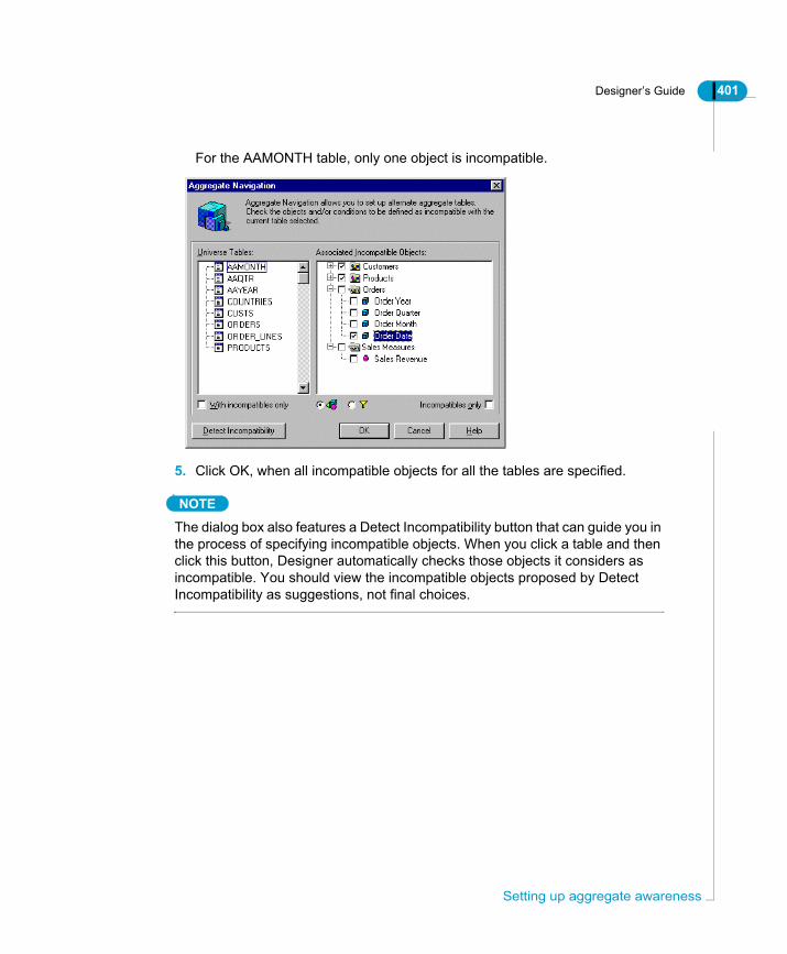
Designer’s Guide 401
For the AAMONTH table, only one object is incompatible.
5. Click OK, when all incompatible objects for all the tables are specified.
NOTE
The dialog box also features a Detect Incompatibility button that can guide you in the process of specifying incompatible objects. When you click a table and then click this button, Designer automatically checks those objects it considers as incompatible. You should view the incompatible objects proposed by Detect Incompatibility as suggestions, not final choices.
Setting up aggregate awareness

402 Designer’s Guide
Usin
Resolving loops involving aggregate tablesWhen a database contains one or more aggregate tables, you should resolve any loops using contexts.
EXAMPLEResolving a loop involving an aggregate tableA simple schema containing agregate tables is shown below:
Note the following points in the schema:• FACT_AGG1 is an aggregate table that is nearly identical to the FACT table.
It contains the (Customer) City Key, the Product Key, and the Month key in addition to a number of measures aggregated to Customer City, Product and Month.
• FACT_AGG2 is also an aggregate table similar to the FACT table. Its measures are aggregated to Customer State, Product and Year.
• The measures (the key performance indicators) are stored in all the fact tables. Sales Revenue is stored in FACT_AGG1, FACT_AGG2 and FACT, but is aggregated to the respective levels of each table.
For a query with sales Revenue and Customer State, you want to use the join between CUST_STATE and FACT_AGG2 rather than the join between CUST_STATE and CUST_CITY.However, before you can run this query, you need to define three contexts, for example FACT, FACT_AGG1 and FACT_AGG2. You do not need to rename the context with more meaningful labels as they are transparent to the users.The joins included in the three contexts are illustrated on the next page. In each schema, the darker set of joins represents the given context.
g aggregate awareness
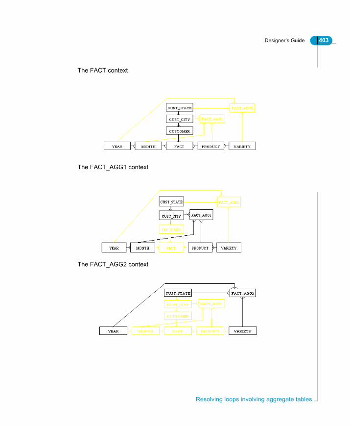
Designer’s Guide 403
The FACT context
The FACT_AGG1 context
The FACT_AGG2 context
Resolving loops involving aggregate tables

404 Designer’s Guide
Usin
Testing aggregate awarenessThe final step in setting up aggregate awareness is to test the results in BusinessObjects or WebIntelligence.Based on the first example, we can run the following queries and then compare the different results.
BusinessObjects
g aggregate awareness
Defining objects to enhance reports
chapter
406 Designer’s Guide
Defi
OverviewYou can define more complex Select statements for objects to enable BusinessObjects and WebIntelligence users to create reports that have useful features such as returning images for objects, hyperlinks to related reports and documents, and more powerful functions and calculations where the processing is done at the database end, and not at the Business Objects client end.This chapter describes how you can do the following:• Link returned values to images for BusinessObjects and WebIntelligence.• Link returned values to target documents and reports in BusinessObjects and
WebIntelligence.• Link reports in the repository for WebIntelligence.• Use analytic functions for more powerful calculations for supported RDBMS.
ning objects to enhance reports
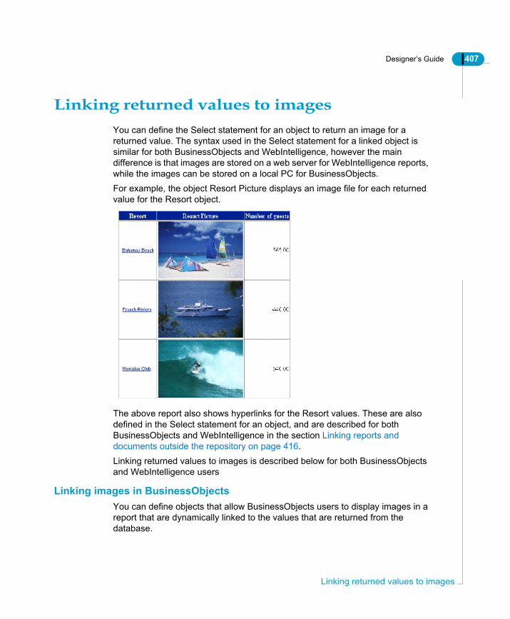
Designer’s Guide 407
Linking returned values to imagesYou can define the Select statement for an object to return an image for a returned value. The syntax used in the Select statement for a linked object is similar for both BusinessObjects and WebIntelligence, however the main difference is that images are stored on a web server for WebIntelligence reports, while the images can be stored on a local PC for BusinessObjects.For example, the object Resort Picture displays an image file for each returned value for the Resort object.
The above report also shows hyperlinks for the Resort values. These are also defined in the Select statement for an object, and are described for both BusinessObjects and WebIntelligence in the section Linking reports and documents outside the repository on page 416. Linking returned values to images is described below for both BusinessObjects and WebIntelligence users
Linking images in BusinessObjectsYou can define objects that allow BusinessObjects users to display images in a report that are dynamically linked to the values that are returned from the database.
Linking returned values to images

408 Designer’s Guide
Defi
The object that displays images must have the image format specified in the image format properties. The format can be either Bitmap (.BMP) or .TIF.You display images linked to the result of a query by specifying the path of an image file in the Select statement of an object. BusinessObjects displays the image stored on the local PC that matches a returned value for the object.
Image file names must be the same as object returned valuesThe image files names must be identical to the values returned by the object. If not, there will be no match between a returned value and a corresponding image, so no image will be returned. For example, if a returned value for Resorts is Bahamas Beach, then the Bitmap image that corresponds to that value is the Bahamas Beach.BMP.You do not have to match the full string for returned values with the image files. You can match the files on a shortened string, however, when matching on a specified number of characters, the image files must all have the minimum number of characters. Refer to Specifying the matching string length for image and .HTM files on page 424 for an example using a specified number of characters.
Defining an object to display images in BusinessObjectsTo define an object to display images for returned values in BusinessObjects:1. Create and name a new object.
This is the object that a user includes in a query to display the images that match the values returned by another object in the query. For example, you create an object called Resort Picture to display a picture of each resort.
2. Right-click the new object and select Object Format from the contextual
ning objects to enhance reports
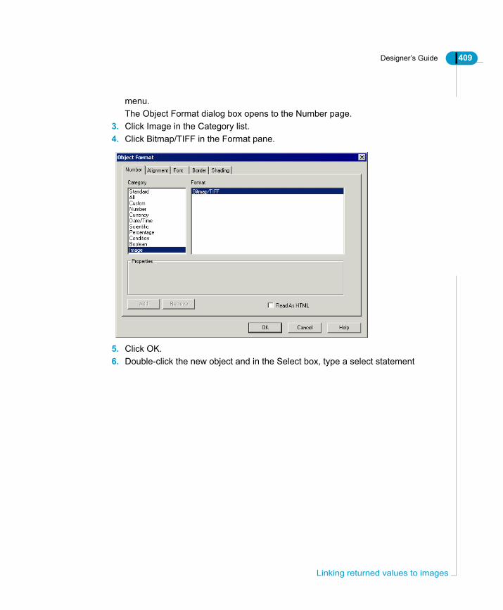
Designer’s Guide 409
menu.The Object Format dialog box opens to the Number page.
3. Click Image in the Category list.4. Click Bitmap/TIFF in the Format pane.
5. Click OK.6. Double-click the new object and in the Select box, type a select statement
Linking returned values to images

410 Designer’s Guide
Defi
with the following syntax:
The Select statement for the Resort Picture object in the previous example is:
The syntax is described below:
The Definition page for the object Resort Picture is shown below:
7. Click the Parse button to verify the Select statement then click OK.8. Run a report in BusinessObjects to test the universe.
'image file path'+SQL link+'.image file format'
'D:\BOStore\Images\'+Resort.resort+'.bmp'
Syntax Description
image file path Location on the local PC for the image files, for example D:\BOStore\Images\
+ Concatenation operator. The value returned by the Select statement is concatenated with the file path and file format using the (+) operator. This is RDBMS dependent. Microsoft Access uses +, but for Oracle you use ||.
SQL-link The part of the data that you need to specify the data for which the picture is returned. This is the Select statement for the object that you want to match with the image files, for example Resort.resort.
Image file format Either .bmp, or .tif
ning objects to enhance reports

Designer’s Guide 411
Linking images in WebIntelligenceYou can define objects that allow WebIntelligence users to display images in a report that are dynamically linked to the values that are returned from the database. This can be very useful in extranets where a report can include images of products, or hyperlinks to other reports that are stored on the web server, based on the values returned in a query.You display images linked to the result of a query by defining the properties of an object so that WebIntelligence displays an image file stored on an HTTP server that matches the result of the Select statement for the object.
Verifying your resourcesBefore you can display image files correctly in a WebIntelligence report, you need to verify the following:• Ensure that the image files are stored on an HTTP server.• Ensure there is an image that matches each value returned by the Select
statement for the linked object. For example, if you have 150 products in your PRODUCT table, then you need to ensure that you have 150 images, each with a name that corresponds to a product value.
• If you are matching each image with the full name of a returned value, then you must verify that each image has the same name as each associated value.
• If you are matching on a specified number of characters, then you must verify that the image files all have the minimum number of characters. Refer to Specifying the matching string length for image and .HTM files on page 424 for an example using a specified number of characters.
• Ensure that the image files are stored in a format supported by the browsers used by the end users.
Example universe and image filesThe following procedure uses an example universe BeachWeb which is available for download in the Universe Design section on the Tips and Tricks website available to all Business Objects clients http://www.businessobjects.com/services/infocenter.The BeachWeb universe is a modified version of the Beach universe which is shipped with BusinessObjects. You can find it in the BeachWeb.ZIP file, which also contains image files, .HTM files, and the Club.MDB to which you need to create a connection for the BeachWeb universe. The Club.mdb is also shipped
Linking returned values to images

412 Designer’s Guide
Defi
with BusinessObjects, so you may already have a copy of this database. For information on setting up the BeachWeb universe, refer to the Readme file in the BeachWeb.ZIP.
Defining an object to display images in WebIntelligenceTo define an object to display images for returned values in WebIntelligence:1. Open the universe in Designer.2. Create and name a new object.
This is the object that users will use in their query to display the images that match the values returned by another object in the report. For example, the BeachWeb example universe contains a new object called Resort Picture. This is the object that WebIntelligence users will use to display a picture of each resort.
3. Right-click the new object and select Object Format from the contextual menu.The Object Format dialog box opens to the Number page.
4. Select the Read as HTML check box. If the check box is grayed, you must click the check box to clear it, and then click it again to select it.
5. Click OK.6. Double-click the new object and in the Select box, type a select statement
ning objects to enhance reports

Designer’s Guide 413
with the following syntax:
7. The Select statement for the Resort Picture object in the BeachWeb example
'<IMG SRC="webfolder'+SQL link+'.image file format" border=0>'
Linking returned values to images

414 Designer’s Guide
Defi
is as follows:
8. The syntax is described below:
The Definition page for the object Resort Picture is shown below:
9. Click the Parse button to verify the Select statement then click OK.
'<IMG SRC="//casa/Scripts/JamesC/'+Resort.resort+'.jpg" border=0>'
Syntax Description
IMG SRC= Image source location tag
Webfolder Location on the web server for the image files, for example //casa/Scripts/JamesC/. You must use the forward slash (/) to specify a URL address on the HTTP server.
+ Concatenation operator. The value returned by the Select statement is concatenated with the file path and file format using the (+) operator. This is RDBMS dependent. Microsoft Access uses +, but for Oracle you use ||.
SQL-link The part of the data that you need to specify the picture in the web folder. This is the Select statement for the object that you want to match with the image files, for example Resort.resort.
Image file format Any format supported by the web browser, for example .JPG, .GIF, .BMP.
border=0 Specifies that the image has no border, so is bordered only by the table cell.
ning objects to enhance reports

Designer’s Guide 415
10.Save the universe and export it to your repository.11.Run a report in WebIntelligence to test the universe.
Linking returned values to images

416 Designer’s Guide
Defi
Linking reports and documents outside the repository
You can display a hyperlink for values that are returned to a BusinessObjects report saved in HTML, or WebIntelligence report. An end user can click on the hyperlink to open a related report stored locally for BusinessObjects, or on a web server for WebIntelligence reports.For example, if you have an object called Resort that returns the names of hotel resorts, you can define the Select statement for Resort so that a hyperlink is displayed for each value that is returned in the Resort column as shown below:
Each Resort hyperlink directs the browser to a corresponding .htm page. For example, when a user clicks on the Bahamas Beach hyperlink, the following page is displayed giving a description of the Bahamas Beach hotel:
ning objects to enhance reports
Designer’s Guide 417
You display hyperlinks linked to the result of a query by defining the properties of an object so that BusinessObjects or WebIntelligence displays the returned value as a hyperlink. When a user clicks on the hyperlink, a web page or report is displayed that matches the returned value.The procedure to define a Select statement for an object to display a returned value as a hyperlink is the same as the procedure that you use to display a linked image. The syntax for the Select statement however is different.Defining objects to return values as hyperlinks described for both BusinessObjects and WebIntelligence.
Linking HTML reports and documents in BusinessObjectsYou can display returned values as hyperlinks in a BusinessObjects report saved in HTML format. Users can click on a hyperlink to open up a related HTML report or document.Reports in HTML can be sent to any users with the associated images and documents saved with the report, so that all related information is available and accessible by following hyperlinks.
Linking objects to HTML documents in BusinessObjectsTo define an obect to return values linked to HTML documents in BusinessObjects:1. Open the universe in Designer.2. Right-click the object that you want to return values linked to other
documents.3. Select Object Format from the contextual menu.
The Object Format dialog box opens to the Number page.4. Select the Read as HTML check box. If the check box is grayed, you must
Linking reports and documents outside the repository

418 Designer’s Guide
Defi
click the check box to clear it, and then click it again to select it.
5. Click OK.6. Double-click the object and in the Select box, modify the select statement to
use the following syntax:
The Select statement for the Resort object in the example is as follows:
7. The syntax is described below:
'<a href=document filepath'+SQL link+'.htm>’+SQL link+’</a>'
'<a href=D:\BOStore\Reports\'+left(Resort.resort,5)+'.htm>'+Resort.resort+'</a>'
Syntax Description
<href= Hypertext reference tag
document filepath Location on the local PC for the html document files, for example D:\BOStore\Reports\
ning objects to enhance reports
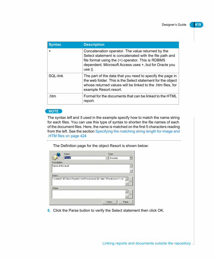
Designer’s Guide 419
NOTE
The syntax left and 5 used in the example specify how to match the name string for each files. You can use this type of syntax to shorten the file names of each of the document files. Here, the name is matched on the first 5 characters reading from the left. See the section Specifying the matching string length for image and .HTM files on page 424
The Definition page for the object Resort is shown below:
8. Click the Parse button to verify the Select statement then click OK.
+ Concatenation operator. The value returned by the Select statement is concatenated with the file path and file format using the (+) operator. This is RDBMS dependent. Microsoft Access uses +, but for Oracle you use ||.
SQL-link The part of the data that you need to specify the page in the web folder. This is the Select statement for the object whose returned values will be linked to the .htm files, for example Resort.resort.
.htm Format for the documents that can be linked to the HTML report.
Syntax Description
Linking reports and documents outside the repository
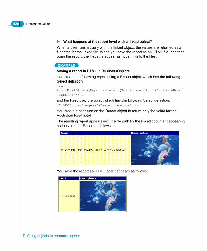
420 Designer’s Guide
Defi
What happens at the report level with a linked object?When a user runs a query with the linked object, the values are returned as a filepaths for the linked file. When you save the report as an HTML file, and then open the report, the filepaths appear as hyperlinks to the files.
EXAMPLESaving a report in HTML in BusinessObjectsYou create the following report using a Resort object which has the following Select definition:'<a href=D:\BOStore\Reports\'+left(Resort.resort,5)+'.htm>'+Resort.resort+'</a>'
and the Resort picture object which has the following Select definition:'D:\BOStore\Images\'+Resort.resort+'.bmp'
You create a condition on the Resort object to return only the value for the Australian Reef hotel.The resulting report appears with the file path for the linked document appearing as the value for Resort as follows:
You save the report as HTML, and it appears as follows:
ning objects to enhance reports

Designer’s Guide 421
When you click on the hyperlink, the linked document opens:
NOTE
When a user saves a report as HTML which contains hyperlinks, they can also save all the linked documents and images with the report by selecting the option All Reports in Document in the HTML options page that indicates save options for the HTML page.
Linking reports and documents in WebIntelligenceYou can display a hyperlink for values that are returned to a WebIntelligence report. When a user clicks on the hyperlink, it opens a related report on a web server.For example, if you have an object called Resort that returns the names of hotel resorts, you can define the Select statement for Resort so that a hyperlink is displayed for each value that is returned in the Resort column.Each Resort hyperlink directs the browser to a corresponding .htm page on the HTTP server. For example, when a user clicks on the Bahamas Beach hyperlink, a page is displayed giving a description of the Bahamas Beach hotel.You display hyperlinks linked to the result of a query by defining the properties of an object so that WebIntelligence displays the returned value as a hyperlink. When a user clicks on t he hyperlink, a web page or report is displayed that matches the returned value. The web pages must be stored on an HTTP server.
Linking reports and documents outside the repository

422 Designer’s Guide
Defi
Defining objects to return values as hyperlinks to documentsThe procedure to define a Select statement for an object to display a returned value as a hyperlink is the same as the procedure that you use to display a linked image. The syntax for the Select statement however is different. The following procedure uses the same BeachWeb universe example which is available for download at the Universe Design section on the Tips and Tricks website available to all Business Objects clients http://www.businessobjects.com/services/infocenter.To define objects to return values as hyperlinks to documents:1. Open the universe in Designer.2. Right-click the object that you want to return a value as a hyperlink.3. Select Object Format from the contextual menu.
The Object Format dialog box opens to the Number page.4. Select the Read as HTML check box. If the check box is grayed, you must
click the check box to clear it, and then click it again to select it.5. Click OK.6. Double-click the object and in the Select box, modify the select statement to
use the following syntax:
The Select statement for the Resort object in the BeachWeb example is as follows:
The syntax that differs from the syntax used to display images is described
'<a href=webfolder'+SQL link+'.htm>’+SQL link+’</a>'
'<a href=http://casa/Scripts/JamesC/'+left(Resort.resort,5)+'.htm>'+Resort.resort+'</a>'
ning objects to enhance reports

Designer’s Guide 423
below:
The Definition page for the object Resort is shown below:
7. Click the Parse button to verify the Select statement then click OK.8. Save the universe and export it to your repository.9. Run a report in WebIntelligence to test the universe.
Syntax Description
<href= Hypertext reference tag
Webfolder Location on the web server for the .htm files, for example http://casa/Scripts/JamesC/. You must use the forward slash (/) to specify a URL address on the HTTP server.
SQL-link The part of the data that you need to specify the page in the web folder. This is the Select statement for the object whose returned values will be linked to the .htm files in the web folder, for example Resort.resort.
Linking reports and documents outside the repository

424 Designer’s Guide
Defi
Specifying the matching string length for image and .HTM filesYou do not have to match the full string for returned values with the image and .HTM pages. The following examples show how you can match a specified number of characters in the image or .HTM file name with a returned value, instead of matching on the full file name:• Image files:
• .HTM files:
Other syntax used in this example includes:• Left indicates the position in the string from which the number of characters is
counted.• 6 indicates the number of characters counted. So in the example above, the
image files and the result of the SQL-link statement are matched on the first 6 characters starting from the left.
Using this type of syntax allows you to keep your image file naming to within a restricted number of characters or naming format.
'<IMG SRC="//casa/Scripts/JamesC/'+left(Products.Service,6)+'.jpg" border=0>'
'<a href=http://casa/Scripts/JamesC'+'/'+left(Products.Service,6)+'.htm>'+ Products.Service+ '</a>'
ning objects to enhance reports

Designer’s Guide 425
Linking reports in the repository for use in WebIntelligence and InfoView
You can define objects in a universe that allow WebIntelligence and BusinessObjects users to create reports using objects that enable linking of returned values to other reports and documents.When these reports are exported to the repository, users can click on returned values displayed as hyperlinks to open another related report stored in the document domain of the repository.
Linking at the universe levelYou link reports in the repository at the universe level by using a function called the OpenDocument function in the definition of an object.The OpenDocument function can also be inserted into a WebIntelligence report at the report level, however, the Designer’s Guide only describes the use of the OpenDocument function in a universe.
NOTE
You should only use the OpenDocument function in universes that are designed for WebIntelligence and InfoView users. BusinessObjects users can create reports using objects that are defined with the OpenDocument function, but once these reports are exported, the linking feature is only available to WebIntelligence and InfoView.
How do you link reports based on returned values?You enable report linking in a universe by creating an object (the link object) whose returned values are the same as the values used as input to a prompt in an existing report (the target report).The OpenDocument function allows the returned values for the link object to be returned as hyperlinks. When hyperlink is clicked the value is used as the prompt input for the target report.WebIntelligence and BusinessObjects users can create reports using the link object as they would with any other object. When InfoView or WebIntelligence users refresh these reports, they can use the hyperlinks to access more detailed documents for the link object.
Linking reports in the repository for use in WebIntelligence and InfoView

426 Designer’s Guide
Defi
EXAMPLELinking Resort values to more detailed reportsA WebIntelligence user creates a document using an object called Resort_link. The Select statement for this object contains the OpenDocument function that allows its returned values (resort names) to be displayed as hyperlinks.When the user clicks on a resort name, the value is automatically sent as input for a prompt, opening another report giving number of guests in age groups and country of origin by year for that resort.An overview of the process appears below:
In Designer
In WebIntelligence or InfoView
ning objects to enhance reports
Designer’s Guide 427
What is the OpenDocument function?OpenDocument is a function that enables you to open a WebIntelligence or BusinessObjects document using a URL. You can use it to create a hyperlink to a document from a report or an HTML page.In Designer, you use the OpenDocument function to return values as hyperlinks that serve as input to a prompt defined in another report.
NOTE
This section gives all the parameters possible for the OpenDocument function. The example that is given in this section uses OpenDocument to link to a report with a single value prompt. This allows dynamic linking between an object used in one report, and information in another report. However, you can also link returned values to a non-prompt document, and use the syntax for multi-value prompts. To use the syntax for these possibilities, you need to hardcode the values within the OpenDocument URL.
JSP and ASP implementationsIn InfoView there are two implementations of the OpenDocument function:• JSP script: openDocument.jsp• ASP script: openDocument.aspEither one is installed when you deploy InfoView. The script that is installed depends on whether you install InfoView using JSP or ASP. The scripts are installed in the following paths:• http://ServerName:PortNumber/VirtualDirectory/scripts/
openDocument.jsp• http://ServerName:PortNumber/VirtualDirectory/scripts/
openDocument.aspVirtualDirectory is the virtual directory specified in the Configuration tool when InfoView is deployed. By default this is wijsp for InfoView using JSP and wiasp for InfoView using ASP.
Linking reports in the repository for use in WebIntelligence and InfoView

428 Designer’s Guide
Defi
OpenDocument parametersThe following table lists the OpenDocument parameters that you use to create a link object and describes the value you can set for each parameter. The section Setting up report linking based on returned values on page 431 describes how to use the syntax in a Select statement to set up report linking from the universe, and gives a working example.All of the OpenDocument parameters are case sensitive. You must use the correct case when you include them in a URL.The column “Value is mandatory” indicates whether or not the parameter must take a value. Certain parameters can be left without value. For some of these values, a default value may be used
Syntax Description Value is mandatory
Example
http://<server name>:<server port>
First part of the URL to WebIntelligence.
Yes http://www.myserver.com:8085/
virtual directory/scripts/openDocument.web application?
Second part of the URL. Web application dependant.
Yes wijsp/scripts/openDocument.jsp?Orwiasp/scripts/openDocument.asp?
sDocName Name of the target document.
Yes sDocName=opend1
sType Document type. The possible values are:• wid = WebIntelligence
6.x document• wqy = WebIntelligence
2.x document• rep = BusinessObjects
document• bqy = BusinessQuery
document• agn = Non
BusinessObjects document.
Yes sType=wid
ning objects to enhance reports

Designer’s Guide 429
iDocID Document ID. This is the number that identifies the document in the repository. The Document ID is listed with the properties of a report in InfoView.
Yes iDocID=63
sRepoType Repository type. Values can be:• Corporate• Personal• InboxDefault value is corporate.
No. Default is Corporate.
sRepoType=corporate
Syntax Description Value is mandatory
Example
Linking reports in the repository for use in WebIntelligence and InfoView

430 Designer’s Guide
Defi
Using OpenDocument with the SELECT for an objectYou define the Select statement for the link object in two parts:• Set the OpenDocument URL as equal to the ‘returned value’. This displays
the returned value as a hyperlink.• Add the SELECT for the link object after the first part of the syntax. This is the
original Select statement for the object.The Select statement for a link object follows the following order:
The concatenation operator (+) shown is for Microsoft Access. Use the operator appropriate for your target RDBMS.
lsSprompt message Prompt message that you have defined for a single value prompt in a target document.
Yes: if you are linking to a target document with a prompt.No: if you are linking returned values to a non prompt document.
lsSResort?
lsMprompt message Prompt message for multi- value prompt.You define the multi-prompt within the URL with values. You then define the Select to open a document that corresponds to the values of the multiple prompts.
Yes: if you are using mult-value promptsNo: if you are not using multi-value prompts.
lsMCountry=France&lsMCountry=USA
sRefresh Refresh the document or not. Possible values are:Y = refresh documentno value = do not refresh document.
No. Default is no value.
sRefresh=Y
Syntax Description Value is mandatory
Example
‘<a href=”OpenDocument URL=’+object SELECT+’”>’+object SELECT+’</a>’
ning objects to enhance reports
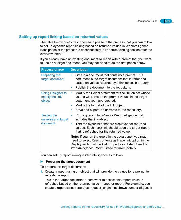
Designer’s Guide 431
Setting up report linking based on returned valuesThe table below briefly describes each phase in the process that you can follow to set up dynamic report linking based on returned values in WebIntelligence. Each phase of the process is described fully in its corresponding section after the overview table.If you already have an existing document or report with a prompt that you want to use as a target document, you may not need to do the first phase below.
You can set up report linking in WebIntelligence as follows:
Preparing the target documentTo prepare the target document:1. Create a report using an object that will provide the values for a prompt to
refresh the report.This is the target document. Users want to access this report which is refreshed based on the returned value in another report. For example, you create a report called resort_year_guest_origin that shows number of guests
Process phase Description
Preparing the target document
• Create a document that contains a prompt. This document is the target document that is refreshed based on values returned by a link object in a query.
• Publish the document to the repository.
Using Designer to modify the link object
• Modify the Select statement for the link object whose values will serve as the prompt values in the target document you have created.
• Modify the format of the link object.• Save and export the universe to the repository.
Testing the universe and target document
• Run a query in InfoView or WebIntelligence that includes the link object.
• Test the hyperlinks that are displayed for returned values. Each hyperlink should open the target report that is refreshed for the returned value.
Note: If you run the query in the Java panel, you may need to select Read contents as Hyperlink option in the Display section of the Cell Properties sub-tab. See the WebIntelligence User’s Guide for more details.
Linking reports in the repository for use in WebIntelligence and InfoView
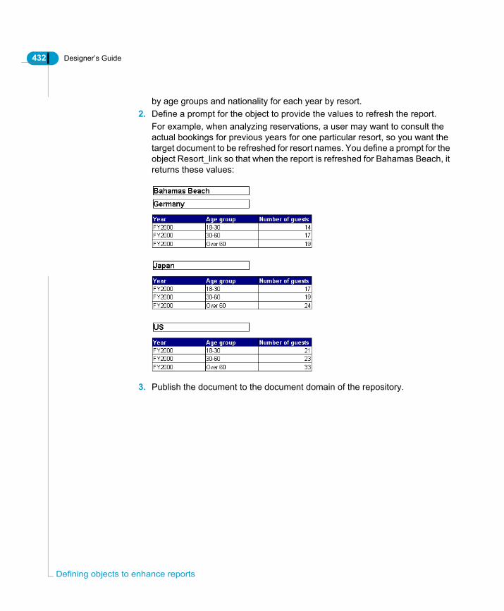
432 Designer’s Guide
Defi
by age groups and nationality for each year by resort. 2. Define a prompt for the object to provide the values to refresh the report.
For example, when analyzing reservations, a user may want to consult the actual bookings for previous years for one particular resort, so you want the target document to be refreshed for resort names. You define a prompt for the object Resort_link so that when the report is refreshed for Bahamas Beach, it returns these values:
3. Publish the document to the document domain of the repository.
ning objects to enhance reports

Designer’s Guide 433
Using Designer to modify the link objectYou modify the Select statement of the link object, and then modify the format of the object to allow returned values to be displayed as hyperlinks.To modify the Select statement of the link object:1. Start Designer and open a universe.2. Double click the link object. This is the object whose values are to be used as
input for the prompt in the target document. Create a new object if you do not have an existing object to provide values for the target document prompt.
3. In the Select box for the link object, type the following syntax:
Each part of the syntax is described in the section OpenDocument parameters on page 428, and Using OpenDocument with the SELECT for an object on page 430.Verify that you are using a JSP or ASP InfoView deployment.For example, below is a modified Select statement for an object called Resort_link that returns resort values:
• waitemata is the name of the WebIntelligence server.• 8085 is the port number of the server.• wijsp is the virtual directory.• jsp is the web application type.• resort_year_guest_origin is the name of the target document.• wid is the WebIntelligence document type• 456 is the document identifier• Resort? is the prompt message4. Click the Parse button to verify the syntax, and click OK.5. In the Universe pane, right-click the link object and select Object Format from
the contextual menu.The Object Format dialog box opens to the Number page.
6. Select the Read as HTML check box. If the check box is grayed, you must
'<a href="http://<WebI server name>:<server port>/<virtual directory>/scripts/openDocument.<web application>?sDocName=<document name>&sType=<document type>&iDocID=<document id>&lsS<prompt message>='+object SELECT+'">'+object SELECT+'</a>'
'<a href="http://waitemata:8085/wijsp/scripts/openDocument.jsp?sDocName=resort_year_guest_origin&sType=wid&iDocID=456&lsSResort?='+Resort.resort+'">'+Resort.resort+'</a>'
Linking reports in the repository for use in WebIntelligence and InfoView

434 Designer’s Guide
Defi
click the check box to clear it, and then click it again to select it.7. Click OK.8. Save and export the universe to the repository.
Testing the universe and target documentYou need to test the target document and link object in InfoView. Do this as follows:1. Start InfoView and create a document using the link object.2. Run the query.3. Test the hyperlinks that are displayed for returned values.
Each hyperlink should open the target report for the clicked value.
NOTE
If you are using the Java panel to create reports, the hyperlinks may not be activated. If this is the case, you select the Read contents as Hyperlink option in the Display section of the Cell Properties sub-tab. See the WebIntelligence User’s Guide for more details.
ning objects to enhance reports
Designer’s Guide 435
Using analytic functionsDesigner supports the use of analytic functions for specific RDBMS. Analytic functions are called RISQL functions in RedBrick, and OLAP functions in Teradata. You can use Designer to define analytic functions for objects in a universe.BusinessObjects users can use these objects in reports without having to use the extended syntax required to do advanced reporting. WebIntelligence users can also use analytic functions to perform data analysis that is not normally possible within the limited reporting capabilities of InfoView.This section describes how you can define Analytic, RISQL, and OLAP functions for objects in a universe for the following RDBMS:• IBM DB2 UDB and Oracle• RedBrick (RISQL functions)• Teradata (OLAP functions)
What are analytic functions?An analytic function is a function that performs an analytical task on a result set that can be divided into ordered groups of rows or partitions.In Designer you can define objects with analytic functions to calculate rankings, cumulative aggregates, and ratios within one or more partitions. Depending on your RDBMS, you can also define the range of rows on which you want to apply the analysis within the partition.For a full description of analytic functions refer to your RDBMS documentation.
What are the advantages of using analytic functions?Defining objects using analytic functions in Designer has the following benefits for BusinessObjects and WebIntelligence users:• Reusable objects. All objects using analytic functions can be used in both
BusinessObjects and WebIntelligence reports.• Reduced work for BusinessObjectsusers. An object defined with an analytic
function can perform data analysis that would normally require the use of extended syntax at the report level.
• Added functionality for WebIntelligence users. A number of data analysis tasks such as calculating rolling averages and applying advanced aggregate processing are not normally available in InfoView. Objects that use analytic functions now allow WebIntelligence users to conduct advanced data
Using analytic functions

436 Designer’s Guide
Defi
analysis that was not previously possible.• Improved query performance. The calculations are done on the server.
Which analytic function families are supported?You can define analytic functions for the following function families:• Ranking• Accumulative aggregation• Ratio, Ratio to Report, or Reporting Aggregate
How are analytic functions used in Designer?You use analytic functions by defining the analytic function in the SELECT statement for an object.The RDBMS section in each Parameters (PRM) file lists the analytic functions that can be used in a SELECT statement. This list may not contain all the functions available for each family in each of the RDBMS supported for analytic functions.
What is a PRM file?The PRM file is a parameter file used to configure universe creation and SQL query generation in BusinessObjects and WebIntelligence products. There is a PRM file for each supported RDBMS. PRM files are located in the following folder:<INSTALLDIR>\dataAccess\RDBMS\connectionServer\<rdbms>\See the Data Access Guide for full information on modifying parameter files.Before using an analytic function, you should verify that it is listed in the PRM file. If it is not listed, you can add the name of the function to the list. Designer will then support its use in the Select statement for an object. See the section Verifying and Adding Analytic Function Support to the PRM File on page 440 for more information.
Using analytic functions for each RDBMSUsing analytic functions will be described for each of the following RDBMS: • Syntax that you can use for analytic, RISQL, and OLAP functions in the Select
statement.• How you can verify and modify PRM files to ensure the support of unlisted
analytic functions.• RDBMS specific rules and restrictions for the use of analytic functions.• Inserting analytic function syntax automatically when editing Select
ning objects to enhance reports

Designer’s Guide 437
statements.
Using analytic functions

438 Designer’s Guide
Defi
IBM DB2 UDB and OracleYou can use the same syntax for analytic functions for both RDBMS.
Defining The Select StatementYou define an analytic function in the Select statement for an object. You need to type the syntax in one of the edit boxes for the Select statement.
NOTE
You can automate syntax entry by adding analytic functions to the Functions list in the Edit Select Statement dialog box. To make a function available in the Functions list, you need to add the analytic function to the [FUNCTIONS] section of the PRM file. See the section Inserting syntax automatically in Select statements on page 448 for more information.
Analytic functions are identified by the keyword OVER; for example:
The clause that follows the OVER keyword defines the partition, and how the rows are ordered in the result table.
RANK() OVER (PARTITION BY calender.cal_year ORDER BY SUM(telco_facts.total_billed_rev)DESC)
ning objects to enhance reports

Designer’s Guide 439
The syntax for each family of analytic functions is described as follows:
Using a Window clauseFor the Windows Aggregate family, you can also define a <window clause> which defines the range for the window size after arg3. For example;
For the BETWEEN clause syntax and other window size definitions, refer to your RDBMS documentation.
Function family Syntax Description
Ranking
RANK() OVER(PARTITION BY arg1 ORDER BY arg2 ASC/DESC)
• arg1 is optional. If no argument is included, then the partition is by default the whole result set.
• arg2 is required. The rank is based on this argument value.
• ASC/DESC determines whether values are sorted in ascending or descending order. ASC is the default value.
WindowsAggregate
SUM(arg1) OVER(PARTITION BY arg2 ORDER BY arg3)
• arg1 is the argument on which the cumulative aggregation is based.
• arg2 is the reset clause. It is optional.• arg3 is the group clause. It is optional.
ReportingAggregate
RATIO_TO_REPORT(arg1) OVER(PARTITION BY arg2)
• arg1 is the argument on which the ratio is based.
• arg2 is the reset clause. It is optional.
<window frame units> ::=ROW|RANGE<window frame start>::=UNBOUNDED PRECEDING|<window frame preceding>|CURRENT ROW<window frame between>
Using analytic functions

440 Designer’s Guide
Defi
Verifying and Adding Analytic Function Support to the PRM FileThe PRM files for IBM DB2 UDB and Oracle have been updated to support the use of analytic functions.However, the PRM file may not contain all the analytic functions available in the target RDBMS.Before using an analytic function, you should verify that it is listed in the RDBMS section of the PRM file, and if necessary, add it to the list.You can do this as follows:To add support for an analytic function to the Oracle or IBM DB2 PRM file:1. Browse to the Data Access directory in the Business Objects path.2. Open the PRM file for your RDBMS in a text editor.3. Scroll to the RDBMS section of the PRM file.4. Verify that the following parameters and values are present:
5. If you want to use an analytic function that is not listed, type the name of the function at the end of the list. For example, to use RATIO_TO_REPORT you need to add it to the list as follows:
6. Save any modifications and close the file.You need to restart Designer for any changes to the PRM file to take effect.
Parameter and value in PRM Description
OVER_CLAUSE = Y Generates the appropriate SQL (OVER_CLAUSE).
RISQL_FUNCTIONS = <list of functions used> Analytic functions available.
ning objects to enhance reports
Designer’s Guide 441
Rules For Using Analytic FunctionsThe following rules apply when using analytic functions for DB2 UDB and Oracle:
Restrictions for using analytic functions in Oracle and DB2You have the following restrictions when using analytic functions with IBM DB2 UDB v7.1 and Oracle 8.1.6:• You can not use the functions @prompt and @variable in the definition of an
object that also uses analytic functions.• Analytic functions are not supported as user objects in BusinessObjects
(Reporter). If you add an analytic function to the Functions section in the PRM file (to populate the list of functions in the Edit SQL dialog box), you must ensure that IN MACRO is set to N.
• Objects that use analytic functions cannot be used as a condition or in a sort. If end users try to use these objects to define a condition, they will receive a
Rule Description
Analytic functions cannot appear in a GROUP BY clause.
Aggregate functions such as SUM defined in the analytic function are used in the GROUP BY clause, but an analytic function such as RANK will not be used.To ensure that analytic functions are not used in GROUP BY clause, they are listed after the RISQL FUNCTIONS parameter in the PRM file. The OVER_CLAUSE preceding it must be set to Y. This is the default setting.
Analytic functions must not generate a GROUP BY clause.
If you add an analytic function to the Functions section in the PRM file (to populate the list of functions in the Edit SQL dialog box), you must ensure that the GROUP CLAUSE is set to N. This will prevent it from generating a GROUP BY clause. See the section Inserting syntax automatically in Select statements on page 448 for more information.
If an analytic function uses an aggregate function, all the dimensions used by the analytic function will appear in the GROUP BY clause.
For example; RANK() OVER (PARTITION BY year ORDER BY SUM(sales). The GROUP BY clause will contain the dimension year even if the rank function is used alone in a query.
Using analytic functions

442 Designer’s Guide
Defi
SQL error message. You can prevent the end user from using an object in either a condition or a sort by editing the object properties as follows:
Preventing use of an analytic object in a condition or sortTo prevent the use of an analytic function in a condition or sort:1. Right-click the object in Designer.2. Select Object Properties from the contextual menu.
The Edit Properties dialog box appears.3. Clear the Condition and Sort check boxes in the Can Be Used In group box.
4. Click OK.
ning objects to enhance reports

Designer’s Guide 443
RedBrick (RISQL functions)The following sections describe how you can use RISQL functions in Designer.
Defining The Select StatementYou define an analytic function in the Select statement for an object. You need to type the syntax in one of the edit boxes for the Select statement.
NOTE
You can automate syntax entry by adding RISQL functions to the Functions list in the Edit Select Statement dialog box. To make a function available in the Functions list, you need to add the RISQL function to the [FUNCTIONS] section of the PRM file. See the section Inserting syntax automatically in Select statements on page 448 for more information.
The syntax for each family of RISQL functions is described as follows
Verifying and Adding RISQL Function Support To The PRM FileThe PRM file may not contain all the RISQL functions available. Before using an RISQL function, you should verify that it is listed in the RDBMS section of the PRM file, and if necessary, add it to the list. You can do this as follows:
Function family Syntax Description
Ranking (RANK) RANK(arg1)For example:RANK(SUM(telco_facts.total_billed_rev))
arg1 is required. The rank is based on this argument.
Aggregate Families (CUME, MOVINGAVG, MOVINGSUM)
MOVINGSUM(arg1,Number)For example:MOVINGSUM (COUNT(complants.id),2)
• arg1 is required. The cumulative aggregation is based on this argument.
• Number is optional. This is the number of preceding lines used for the sum.
Ratio (RATIOTOREPORT)
RATIOTOREPORT(arg1)For example:RATIOTOREPORT (SUM(telco_facts.total_billed_rev))
arg1 is required. The ratio is based on this argument.
Using analytic functions

444 Designer’s Guide
Defi
To add support for an analytic function to the Redbrick PRM file:1. Browse to the Data Access directory in the Business Objects path.2. Open the PRM file for your RDBMS in a text editor.3. Scroll to the RDBMS section of the PRM file.4. Verify that the following parameters and values are present:
An example appears below:
5. If you want to use an RISQL function that is not listed, type the name of the function at the end of the list.
6. Save any modifications and close the file.You need to restart Designer for any changes to the PRM file to take effect.
Parameter and value in PRM Description
OLAP_CLAUSE = WHEN Applies the condition.
RISQL_FUNCTIONS = <list of functions used> Analytic functions available.
ning objects to enhance reports

Designer’s Guide 445
Rules for using RISQL functionsThe following rules apply when using RISQL functions:
Restrictions for using analytic functions in RedBrickYou have the following restrictions when using RISQL functions:• RESET BY clause is not supported.• SORT BY clause not supported. See the section for the procedure describing
how you can prevent the end user from using an object in a sort by editing the object properties Preventing use of an analytic object in a condition or sort on page 442.
Rule Description
RISQL functions cannot appear in a GROUP BY clause.
Aggregate functions such as SUM defined in the RISQL function are used in the GROUP BY clause, but an analytic function such as RANK will not be used.To ensure that RISQL functions are not used in the GROUP BY clause, they are listed after the RISQL FUNCTIONS parameter in the PRM file. The OVER_CLAUSE preceding it must be set to WHEN. This is the default setting.
RISQL functions must not generate a GROUP BY clause.
If you add an RISQL function to the Functions section in the PRM file (to populate the list of functions in the Edit SQL dialog box), you must ensure that the GROUP CLAUSE is set to N. This will prevent it from generating a GROUP BY clause. See the section Inserting syntax automatically in Select statements on page 448 for more information.
You can use an RISQL function in a condition
A WHEN clause is generated
Using analytic functions

446 Designer’s Guide
Defi
Teradata (OLAP functions)The following sections describe how you can use OLAP functions in Designer.
Defining the Select statementRatio functions are not available in Teradata V2R3. You define an OLAP function in the Select statement for an object. You need to type the syntax in one of the edit boxes for the Select statement.For information on how to make a function available in Functions list to automate syntax entry, see the section Inserting syntax automatically in Select statements on page 448.The syntax for each family of OLAP functions is described as follows:
Verifying and adding OLAP function support In the PRM fileThe PRM file for Teradata has been updated to support the use of OLAP functions. However, the PRM file may not contain all the OLAP functions available. Before using an OLAP function, you should verify that it is listed in the RDBMS section of the PRM file, and if necessary, add it to the list. You can do this as follows:
Function family Syntax Description
Ranking (RANK) RANK(arg1 DESC/ASC)For example:RANK(invoice_line.nb_guests)
• arg1 is required. The rank is based on this argument. The argument can be an object or a list of objects.
NOTE: You cannot use an object that uses an aggregate object (sum, avg, min, count) as arg1.• DESC/ASC specifies the
ranking order. ASC is the order by default.
Aggregate Families (CSUM, MAVG, MDIFF, MLINREG, MSUM
CSUM(arg1 DESC/ASC)For example:CSUM(invoice_line.nb_guests)
• arg1 is required. The cumulative aggregation is based on this argument. The argument can be an object or a list of objects.
• DESC/ASC specifies the order of result rows. ASC is the order by default.
ning objects to enhance reports

Designer’s Guide 447
To add support for an analytic function to the Teradata PRM file1. Browse to the Data Access directory in the Business Objects path.2. Open the PRM file for your RDBMS in a text editor.3. Scroll to the RDBMS section of the PRM file.4. Verify that the following parameters and values are present:
An example appears below:
5. If you want to use an RISQL function that is not listed, type the name of the function at the end of the list.
6. Save any modifications and close the file.You need to restart Designer for any changes to the PRM file to take effect.
Rules for using OLAP functionsThe following rules apply when using OLAP functions:• OLAP functions cannot appear in a GROUP BY clause. To ensure that OLAP
functions are not used in GROUP BY clause, they are listed after the RISQL FUNCTIONS parameter in the PRM file. The OVER_CLAUSE preceding it must be set to QUALIFY. This is the default setting.
• You cannot combine an object using an OLAP function with an object using an aggregate function in the same query.
• You can use OLAP functions in a condition. A QUALIFY clause is generated.• You can use OLAP functions in a SORT BY clause.
Restrictions for using analytic functions in TeradataYou have the following restrictions when using OLAP functions:• RESET BY clause is not supported.• OLAP functions cannot be used in a sub-query.• An OLAP function cannot be used in the same Select statement as another
Parameter and value in PRM Description
OLAP_CLAUSE = QUALIFY Applies the condition.
RISQL_FUNCTIONS = <list of functions used> Analytic functions available.
Using analytic functions
448 Designer’s Guide
Defi
function.• An OLAP function cannot be based on another function.• OLAP functions are not supported as user objects in BusinessObjects
(Reporter).
Inserting syntax automatically in Select statementsYou can automate the insertion of analytic function syntax by adding the analytic function to the Functions list box in the Edit Select Statement dialog box.You populate the Functions list box by adding the analytic function to the list of functions under the [FUNCTION] section in the appropriate PRM file for the target RDBMS.Once added to the PRM file, the function becomes available in the Functions list box in the Edit Select Statement dialog box. When you double click the function syntax, the defined syntax is inserted in the edit box.When you add the analytic function to the PRM file, you must set the following values:
You can add an analytic function to the [FUNCTION] section in the PRM file as follows:To add an analytic function to the PRM file:1. Browse to the Data Access directory in the Business Objects path.2. Open the PRM file for your RDBMS in a text editor.3. Scroll to the [FUNCTION] section of the PRM file.4. Copy an existing function and paste it at the end of the list.5. Type a unique number for the newly pasted function, and modify the values
Parameter Description
GROUP = N Analytic, RISQL, and OLAP functions cannot generate a GROUP BY clause. By setting the value N, you prevent the analytic function from being used in a GROUP BY clause.
For IBM DB2 UDB v.7.1 and ORACLE 8.1.6 only:IN_MACRO = N
This prevents the analytic function for DB2 UDB and Oracle from being used in user objects in BusinessObjects (Reporter). For RedBrick and Teradata, this value can be set at Y.
ning objects to enhance reports

Designer’s Guide 449
as appropriate for the analytic function that you want to add to the list.6. Set the GROUP value to N.
If you are using IBM DB2 UDB, or ORACLE, set the IN_MACRO value to N.For example:
7. Save and close the PRM file.You need to restart Designer for the changes to be applied.
NOTE
When you restart Designer, the syntax for the added analytic function appears under the appropriate Type node (Number, Character, or Date).
Using analytic functions

450 Designer’s Guide
Defi
ning objects to enhance reports
Using Quick Design to build a universe
chapter

452 Designer’s Guide
Usin
OverviewYou can use a universe design wizard to quickly build a universe.You should not use the quick design wizard to build a production universe. It can be a useful tool to create limited demonstration universes, or as an introduction to Designer.
g Quick Design to build a universe
Designer’s Guide 453
Creating a basic universe automaticallyFor a demonstration or quick test universe based on a simple relational schema, Designer provides Quick Design, a wizard for creating a basic yet complete universe. You can use the resulting universe immediately, or you can modify the objects and create complex new ones. In this way, you can gradually refine the quality and structure of your universe.If you are designing a production universe, you should create the universe manually. All chapters of the Designer’s Guide are based on showing you how to manually create a universe. This is the only section that deals with automatic universe creation.
Why use the Quick Design wizard?The Quick Design wizard assists you throughout the creation of a universe. It guides you in establishing a connection to the database and then lets you create simple classes and objects. The wizard also provides built-in strategies for the automatic creation of objects, joins, and tables.Using Quick Design has the following benefits: • If you are new to Designer, it can help you get familiar with the user interface
and basic universe design.• If you are creating a demonstration universe, it saves you time by automating
much of the design process. With the wizard, you can quickly set up a working model of your universe, and then you can customize the universe to suit the needs of your target audience.
Using the Quick Design WizardQuick Design is the name of the wizard that you use to automatically create a universe. Each step in the wizard is described in each of the following scetions.
Creating a basic universe automatically

454 Designer’s Guide
Usin
Starting the Quick Design wizardTo start the Quick Design wizard:1. Start Designer.
The User Identification dialog box is displayed.
2. In the User Identification dialog box, enter your user name and password.The user name and password are assigned to you by your supervisor.If you intend to work in offline mode, click the check box. For more information on online and offline modes, refer to the section "Using Designer in Online and Offline Modes" in the Designer Basics chapter.
3. If applicable, choose a repository. If you are a user of more than one repository, the User Identification dialog box lets you choose the repository you want to work with. If you are not given a choice, you belong to only one repository.
4. Click the OK button.The welcome screen of the Quick Design wizard appears.
NOTE
If you do not want the wizard to appear the next time you launch a Designer session, clear the check box Run this Wizard at Startup. In addition, you can find two options relating to the display of the wizard in the General tab of the Options dialog box: Show Welcome Wizard and File/New Starts Quick Design wizard (Tools menu, Options command).
The welcome screenThe welcome screen displays an overview of the four steps necessary to create a basic universe. It also provides a check box: Click here to choose strategies. If you click this check box, you will be able to select the strategies for creating the universe; otherwise, Designer applies the default built-in strategies.
g Quick Design to build a universe

Designer’s Guide 455
In each dialog box that follows, Quick Design prompts you for the information needed to carry out the action.To move from one dialog box to the next, click the Next button. You can return to the previous dialog box by clicking the Back button. You may end the process and quit Quick Design at any time by clicking the Cancel button.
When you select the Click here to choose strategies check box, a strategies dialog box appears listing the strategies you can choose to determine how Designer creates your objects, joins, and objects. This dialog box is described in the section Choosing the strategies on page 456. You can select a strategy, or accept the default strategies.Click the Begin button to start the creation process.
Defining the universe parametersIn this step, you define the universe parameters: the universe name and a database connection.
Creating a basic universe automatically

456 Designer’s Guide
Usin
You can enter a long name of up to 35 alphanumeric characters for the universe.
You can either create the connection, or select an existing one. To create a connection, click the New button, and specify the necessary parameters in the dialog boxes that follow. For more instructions on these dialog boxes, refer to the section "Defining and Editing Connections" in the Designer Basics chapter.To check whether your connection is valid, click the Test button. The Edit button lets you modify the parameters of the connection. Click the Next button to proceed to the next step.
Choosing the strategiesIf you clicked the check box for strategies in the welcome screen, Quick Design prompts you to specify strategies for the creation of objects, joins, and tables.
g Quick Design to build a universe

Designer’s Guide 457
A strategy is a script that reads structural information from a database or flat file. Designer uses these scripts to create objects, joins, and tables automatically.
From a list box, you can select another strategy, or none at all. Brief descriptions of the current strategies appear just below the list boxes. In addition to the built-in internal strategies provided by Designer, you can also create your own external strategies. Refer to the section “Using Strategies” in the Defining Classes and Objects chapter.Click the Next button to proceed to the next step.
Creating a basic universe automatically
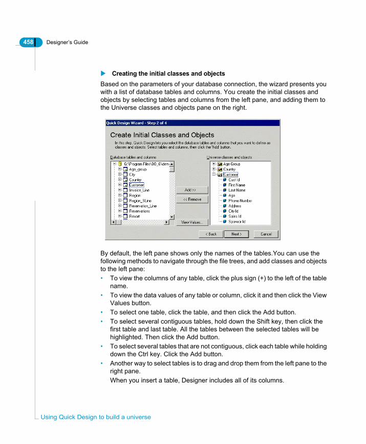
458 Designer’s Guide
Usin
Creating the initial classes and objectsBased on the parameters of your database connection, the wizard presents you with a list of database tables and columns. You create the initial classes and objects by selecting tables and columns from the left pane, and adding them to the Universe classes and objects pane on the right.
By default, the left pane shows only the names of the tables.You can use the following methods to navigate through the file trees, and add classes and objects to the left pane:• To view the columns of any table, click the plus sign (+) to the left of the table
name.• To view the data values of any table or column, click it and then click the View
Values button.• To select one table, click the table, and then click the Add button.• To select several contiguous tables, hold down the Shift key, then click the
first table and last table. All the tables between the selected tables will be highlighted. Then click the Add button.
• To select several tables that are not contiguous, click each table while holding down the Ctrl key. Click the Add button.
• Another way to select tables is to drag and drop them from the left pane to the right pane. When you insert a table, Designer includes all of its columns.
g Quick Design to build a universe

Designer’s Guide 459
In the right pane, the names of classes are displayed beside a folder icon. Click the plus sign (+) beside the class name to view the objects. You can rename a class or object by double-clicking it and entering a new name in the dialog box.By default, an object is qualified as a dimension object, which is indicated by the cube symbol that precedes the object’s name.To remove a class or object, click it and then click the Remove button.Click the Next button to move to the next step.
Creating measure objectsA measure object is derived from an aggregate function: Count, Sum, Minimum, or Maximum. This type of object provides numeric information. Examples of measure objects are shown in the right pane of the dialog box below:
If you wish to view the data values associated with an object, click it and then click the View Values button.To create a measure object, click the appropriate object in the left pane, and then click the aggregate button. You can rename any measure object you create.Grouping measure objects in one or more measures classes improves the organization of the universe. It also facilitates the end user’s ease of navigation. For more information on measure objects, refer to the section “Defining a Measure” in the Defining Classes and Objects chapter.When you click the Next button, Quick Design begins creating your universe.
Creating a basic universe automatically

460 Designer’s Guide
Usin
Generating the universeQuick Design automatically generates your new universe based on the parameters you specified. It indicates the number of classes, objects, and joins created in your universe.
In the dialog box above, a message states that loops exist within the joins of the universe. Designer enables you to resolve loops with aliases and contexts. Refer to the Designing a Schema chapter for more information.
g Quick Design to build a universe

Designer’s Guide 461
When you click the Finish button, the Universe pane and the Structure pane of your new universe appear.
The universe created with the Quick Design wizard. This universe is identified by a long name “Sales Analysis”, which is displayed in the title bar of the window.
Ending a Work SessionSelect File > Save As to save the universe, then File > Close to close the universe.When you save the universe, Designer prompts you to enter a file name. A universe file name can contain up to eight characters; it has a .unv extension. By default, Designer stores these files in the Universe subfolder of the BusinessObjects folder. In Windows 2000, this folder appears under the Local Data folder for your user profile.
Universe Structure
Main Designer window
pane pane
Creating a basic universe automatically
462 Designer’s Guide
Usin
NOTE
You should avoid saving two different universes with the same file name but in different cases; for example, one universe named “Sales” and the other named “sales.” This may lead to a conflict when you attempt to export such universes to the repository.
To quit Designer, select File > Exit.
Following up on a universe created with the Quick Design wizardOnce you have created a basic universe with Quick Designer, you may find it necessary to edit joins, and to resolve all loops using aliases or contexts. In addition, you can choose to enhance your universe with more complex components using the various Designer functionalities. For the appropriate information, you should refer to the relevant section in this manual.
g Quick Design to build a universe

Managing universes
chapter

464 Designer’s Guide
Man
OverviewThis chapter is about universe management. It describes how to do the following: • Distribute universes to users through a Business Objects repository, or
through a file system.• Deploy universes in the repository by exporting and importing universes
between universe domains, and over different repositories.• Link universes dynamically allowing reuse of core components across multple
universes.• Manage logins to control access to universes.• Optimize universes to improve query performance over a network.
aging universes
Designer’s Guide 465
Distributing universesWhen a universe has completed the design, build, and test phases, you distribute it to BusinessObjects and WebIntelligence users, or other designers. When you distribute a universe, you must be aware of the following issues:• universe identification• distribution methods• workgroup design
These topics are covered in the next sections.
How is a universe identified?A universe is identified by the following parameters:
Distribution methodsThere are two ways to distribute a universe:• Using the Business Objects repository• Through the file system.
Distributing universes through the Business Objects repositoryThe Business Objects repository is a centralized set of relational data structures stored on a database. The repository allows BusinessObjects and WebIntelligence users to share resources in a controlled and secured environment. The repository is made up of three domains:• Security domain• Universe domain• Document domain.
Identifier Description
File name 8 characters and a .unv extension.
Long name Consists of up to 35 characters. This is the name by which end users identify the universe in BusinessObjects or WebIntelligence, so it should be a name that describes the purpose of the universe.
Unique system identifier
Identifier assigned by the repository when you export the universe. This identifier is null if you have never exported the universe.
Distributing universes

466 Designer’s Guide
Man
Universes are stored, distributed, and administered from the universe domain. There can be one or several universe domains.You export a universe to the universe domain of the repository, and import a universe from the repository to you local machine.The following rules apply to the universe identifiers stored in universe domains:• A universe identifier is unique across all universe domains.• The combination of file name and long name must be unique within a universe
domain.
Distributing universes through the file systemIf you do not use the repository, you can distribute universes to users or designers through the file system. You can also set a password on a universe to be shared from the Save tab of the Options dialog box. For more information on this dialog box, see the section "Saving a Universe" in the Designer Basics chapter.
NOTE
Distributing universes through the file system does not permit the same level of security and control as the repository.
Working with multiple designersYou can use Designer in a multiple user environment in which several designers can work on the same universes without causing conflicts between versions.You can lock a universe so that only one designer at a time can make modifications on the universe, and a universe can also be assigned a version number to keep track of changes.
Locking a universeWhen stored in a universe domain, a universe can be shared by several designers provided that they have been granted the necessary privileges by the supervisor. Only one designer can work on a given universe at a time. A designer who wants to work on a universe, can do so only if the universe has not been locked by another designer.
aging universes

Designer’s Guide 467
NOTE
You lock a universe from the Import or Export dialog box. When a universe is locked, a padlock symbol is displayed next to the universe name. When another designer locks the universe, the padlock symbol appears dimmed.
Revision numberEach time you export a universe to a universe domain, Designer increments the revision number of the universe. This allows you to determine which is the latest version of the universe.
Distributing universes

468 Designer’s Guide
Man
Exporting a universeYou export a universe to the universe domain of the repository. From this domain, the universe is available to BusinessObjects and WebIntelligence users and other designers.When you export a universe, Designer copies the universe from a local directory to a subfolder of the main universe folder that stores the universes exported to the repository.The subfolder is named after the universe domain to which you exported the universe. Each universe in this subfolder is assigned a system identifier. Refer to the section How is a universe identified? on page 465 for more information in identifiers.You can not export a universe if it has been locked in the universe domain by another designer.You can export only a universe defined with a secured connection.
NOTE
If you modify and then export a universe while a BusinessObjects user is concurrently using a local copy of the universe, any changes that you have made to the universe will not be available to the BusinessObjects user until they have logged out and back in to the repository.
aging universes
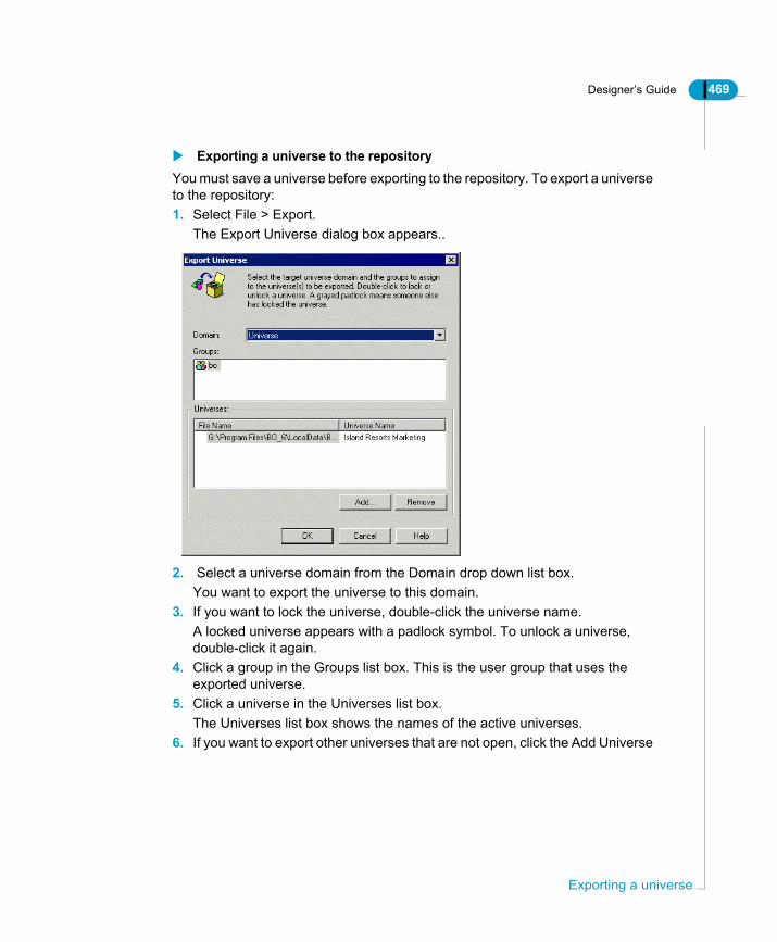
Designer’s Guide 469
Exporting a universe to the repositoryYou must save a universe before exporting to the repository. To export a universe to the repository:1. Select File > Export.
The Export Universe dialog box appears..
2. Select a universe domain from the Domain drop down list box.You want to export the universe to this domain.
3. If you want to lock the universe, double-click the universe name.A locked universe appears with a padlock symbol. To unlock a universe, double-click it again.
4. Click a group in the Groups list box. This is the user group that uses the exported universe.
5. Click a universe in the Universes list box.The Universes list box shows the names of the active universes.
6. If you want to export other universes that are not open, click the Add Universe
Exporting a universe
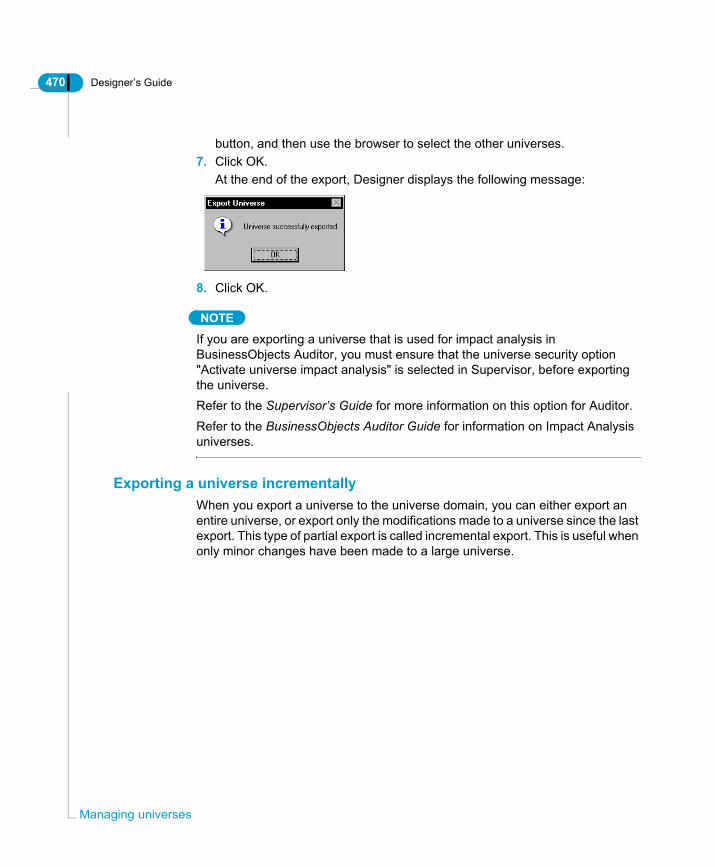
470 Designer’s Guide
Man
button, and then use the browser to select the other universes.7. Click OK.
At the end of the export, Designer displays the following message:
8. Click OK.
NOTE
If you are exporting a universe that is used for impact analysis in BusinessObjects Auditor, you must ensure that the universe security option "Activate universe impact analysis" is selected in Supervisor, before exporting the universe.Refer to the Supervisor’s Guide for more information on this option for Auditor.Refer to the BusinessObjects Auditor Guide for information on Impact Analysis universes.
Exporting a universe incrementallyWhen you export a universe to the universe domain, you can either export an entire universe, or export only the modifications made to a universe since the last export. This type of partial export is called incremental export. This is useful when only minor changes have been made to a large universe.
aging universes

Designer’s Guide 471
Activating incremental exportTo activate incremental export:1. Select Tools > Options.
The Options dialog box opens to the General page.2. Select the Allow incremental export check box.
3. Click OK.When you export a universe, only the modifications are exported.
Select Allowincremental export
Exporting a universe

472 Designer’s Guide
Man
Importing a universeYou can import one or more universes stored in a universe domain of the repository. When you import a universe, it is copied to your local machine. You can select the directory where you want the universe to be copied.
Importing a universe from the repositoryTo import a universe from the repository:1. Select the Import command from the File menu.
The Import Universe dialog box appears.
2. Select a universe domain from the Domain drop down list box.You want to import a universe from this domain.
3. If you want to lock the universe, double-click the universe name.A locked universe appears with a padlock symbol. To unlock a universe, double-click it again.
4. Click a universe name.This is the universe that you want to import.
aging universes

Designer’s Guide 473
TIPTo select several universes, click each universe while holding down the Ctrl key.
5. Verify the file path for the import folder in the Import Folder box.The universe is exported to this folder. The default subfolder is Universe. You can specify another folder by clicking the Browse button, and selecting a file path to the correct folder.
6. Click OK.When the import process is finished, the following message box appears:
7. Click OK.
Importing a universe
474 Designer’s Guide
Man
Deploying universesYou can deploy universes over different domains in the repository. Typically, you store universes in a development domain while they are being developed, and then migrate them to a production domain, first for testing, then as production universes.
NOTE
You can only deploy universes between domains within the same repository. If you want to deploy a universe in a different respository, you must apply a non secured connection and save it for all users. You can then apply a new secured connection and export the universe to a different repository. Refer to the section Exporting universes to a different repository on page 480 for more information.
Migrating a universe from one domain to anotherYou migrate a universe from a development domain to a production domain by exporting the universe to the production domain.When you export updated versions of a universe between domains, you need to be aware of the following issues:• Conflicting file names and universe identifiers• Changing the source universe for BusinessObjects reports that have been
built on a universe in one particular domain• Migrating derived universes between domains• Exchanging universes between repositoriesEach of these issues is described in its corresponding section in this chapter.
Conflicting file names and identifiersWhen you export a universe to the repository for the first time, a unique identifier is allocated to the universe. This information is used to set security rights on the universe in the repository.The identifier is updated on the local version of the universe when you export the universe to a different domain. If you export the same universe to another domain, the local identifier is changed to identify the universe in its new domain. This can lead to conflicting universe name and identifier if you try to export the same universe back to the original domain.
aging universes

Designer’s Guide 475
EXAMPLEExporting a universe to different domainsYou export a universe to a development domain, and then export the universe to a production domain. The universe identifier is updated on the local version of the universe. The universe now has an identifier for the production domain, not the development domain. When you then try to export the universe back to the development domain, the export is refused as the universe now has different identifier. A universe with the same name and the original identifier already exists in the development domain.
How do you recognize a universe identifier conflictYou have an identifier conflict when you try to export the universe to a domain, and you receive an error message informing you that you that a universe with the same name already exists. This usually occurs if you have also exported the universe to another domain. The identifier has been modified for the universe locally for the last domain to which it was exported.
How do you solve a universe identifier conflict?You solve an identifier conflict between domains by disabling the Prevent from Overwriting Universe parameter for universes in Business Objects Supervisor. You must have supervisor rights to set this parameter. If you do not, then you must see a Business Objects product administrator in your company who has supervisor rights with Supervisor.Once this parameter is set, a universe in a domain can be overwritten by a universe with the same name being exported to the domain with a different identifier. The identifier is synchronized with the identifier of the local universe that you are exporting to the domain.
Deploying universes

476 Designer’s Guide
Man
Solving universe identifier conflicts using Business Objects SupervisorTo solve a universe identifier conflict using Supervisor:1. Ensure that you have supervisor rights.2. Start Business Objects Supervisor.3. Select a user in the User pane.
This is the user who needs more access rights.4. Click the Configuration tab at the bottom of the Resource pane.5. Click the Designer icon.6. Select Resource > Properties.
The Command Restriction dialog box appears.7. Expand the Universe folder.8. Click the Prevent from Overwriting Universe item.9. Click the Prevent from Overwriting Universe item in the properties pane to the
right of the folder view.10.Select Disable or Hidden from the Status drop down list box.11.Click OK.
When you next export a universe to the repository, you receive a message asking if you want to overwrite the existing universe in the domain. You click Yes, and the universe identifier is synchronized between your local version and the universe domain version.
Updating the source universe for reporting productsIf users have been creating documents with a universe while in one domain, they need to change the source universe for their documents when you move the universe to another domain, and the original universe is no longer available.
Changing the source universe of documentsTo change the source universe of documents:1. Verify that the target universe is available in the universe folder for the new
domain.2. Start BusinessObjects and open a document.3. Select Data > View Data.
The Data Provider dialog box appears.4. Click the Definition tab.
The Definition page appears.5. Click the ellipsis button next to the name of the current target universe in the
aging universes

Designer’s Guide 477
Universe box.6. The Change Universe box appears. It lists the universes in the available
domains.7. Select the new universe for the document.8. Click OK in each of the dialog boxes.
When the document is refreshed, it uses the new universe data source.
Migrating derived universes between domainsA derived universe is a universe that is dynamically linked to another universe that contains common structures. The linked universe is called a core universe.The derived universe contains the link to a core universe. The link is defined in its universe parameters.The core universe does not have the link to a derived universes defined in its parameters.Refer to the section Linking universes on page 483 for information on linked universes.When you export a derived universe to a different domain, you must migrate both the derived and the core universes to the same domain.You can use the following procedure to ensure that you do not have identifier conflicts when exporting a derived and core universe to another domain.
Migrating a derived universe to another domainYou have a derived universe linked to a core universe. Both are in the test domain of a respository. You want to migrate the derived universe to the production domain of the same repository.To migrate a derived universe to another domain:1. Export the core universe to the production domain.
If there are several core universes linked to the derived universe, you export each core universe.
2. Change the source universe for the derived universe to point to the new
Deploying universes

478 Designer’s Guide
Man
domain directory for each core universe. You do this as follows:- Select Edit > Links.
The Links page of the Universe Parameters dialog box appears.
- Select the core universe in the list of linked universes.In the example above, the Island Resorts Universe is the core universe.
- Click the Change Source button.The Universe to Link dialog box appears.
- Browse to and select the core universe that is in the production domain folder.
In the following example, you browse to the uni_production folder that
aging universes

Designer’s Guide 479
contains the core universe..
- Click Open.- Click OK.
The derived universe now references the core universe in the production domain. In the example above, this is \Universes\bo_repo\uni_production\beach.unv.
3. If the derived universe links to several core universes, you must repeat step 2 for each core universe.
4. Export the derived universe to the production domain.Both derived and core universes have been exported to the production domain.
If you want to continue using documents in the production domain that were created with the derived universe in the test domain, you must change the source universe of these documents to the new derived universe in the Production folder.If you want to continue using the derived universe in the test domain to create test reports, you must now re-import the derived universe from the test domain. This updates your local copy of the universe with the correct path to the test domain which has been modified when you performed the Change Source operation.
Deploying universes

480 Designer’s Guide
Man
Exporting universes to a different repositoryYou can export a universe to a different repository. There are two ways to export a universe to another repository:• If you are defined as a supervisor in Supervisor, then you can export the
universe directly to another repository. You must have supervisor rights defined for the second repository.
• If you are not a supervisor, then you must remove the Business Objects security on the universe by applying a non secure connection, saving the universe for all users, and then reapplying a secure connection for the second repository, before exporting to the second repository.
Exporting a universe to a different repository if you have Supervisor rightsYou want to export a universe from one repository to a second repository.To export a universe to a different repository if you have Supervisor rights:1. Start Supervisor and log into the second repository.2. If a connection pointing to the database that you want use for the universe to
be exported does not exist, create one.3. Select Tools > Export Universes.4. Click Add and browse to a universe.5. Select the universe and click Open.6. Select the universe in the Universes list and click the Parameters button.7. Select the connection from the Connection drop down list.8. Click OK.
The universe is exported to the second repository.
Exporting a universe to a different repository if you do not have Supervisor rightsIf you do not have supervisor rights, then you can not export a universe to another repository directly, you must firstly save the universe with a personal or shared connection. This is called saving a universe in workgroup mode.Refer to the section “Giving all users access to a universe” in the Designer Basics chapter for information on saving a universe in Workgroup mode.Once the universe is saved in workgroup more, you can reapply a secured connection to the universe, connect to the second respository, and import the new universe.
aging universes

Designer’s Guide 481
To export a universe to a different repository without using Supervisor:1. Open a universe.2. Create a new personal or shared connection for the universe.
This is a temporary connection . It is only to allow you to save the universe in workgroup mode.
3. Select File > Save As.4. Select the Save For All Users check box.5. Browse to a directory where you want to save the universe.6. Save and close the universe.7. Select Tools > Login As.
The User Identification box appears.8. Log in to the second repository.9. Select File > Open10.Browse to and select the universe that you saved in step 6. This is the
universe that you want to export to the second repository.If you get a universe connection not accessible message, click OK.
11.Create a new secured connection for the universe.Point the connection to the data source that you want to use for the universe when it is exported to the second repository.
12.Select File > Export.The universe is exported to the second respository. If this not the first time that you have exported the universe to the repository, you may have problems with conflicting universe identifiers. For information on solving identifier problems refer to the section Conflicting file names and identifiers on page 474.
NOTE
You cannot save linked universes in workgroup mode. Before you migrate a linked universe to a different repository, you must first remove the link and then include the contents of the core universe within the derived universe. This is described in the section Including one universe within another on page 495.
Deploying universes

482 Designer’s Guide
Man
Running BusinessObjects from DesignerOnce you have created, saved, and exported a universe, you should test to see how the universe works in BusinessObjects.From Designer, you can launch a BusinessObjects session by selecting Tools > Run > BusinessObjects.If you are a supervisor-designer at your site, then you can launch Supervisor by selecting Tools > Run > Supervisor.
aging universes

Designer’s Guide 483
Linking universesYou can dynamically link one or more universes.
What are linked universes?Linked universes are universes that share common components such as parameters, classes, objects, or joins. When you link two universes, one universe has the role of a core universe, the other a derived universe. When changes are made in the core universe, they are automatically propagated to the derived universes.
NOTE
For information on deploying linked universes, see the section Migrating derived universes between domains on page 477
What is a core universe?The core universe is a universe to which other universes are linked. It contains components that are common to the other universes linking to it. These universes are called derived universes.The core universe represents a re-usable library of components.A core universe can be a kernel or master universe depending on the way the core universe components are used in the derived universes. Kernal and master universes are described in the section .Creating a link between two universes on page 489.
What is a derived universe?A derived universe is a universe that contains a link to a core universe. The link allows the derived universe to share common components of the core universe:• If the linked core universe is a kernal universe, then components can be
added to the derived universe.• If the linked core universe is a master universe, then the derived universe
contains all the core universe components. Classes and objects are not added to the derived universe. They can be hidden in the derived universe depending on the user needs of the target audience.
Linking universes

484 Designer’s Guide
Man
EXAMPLELinked core and derived universesThe example shows two linked universes; one the core universe containing the common components, the other the derived universe that uses the core structures, but has also new classes and objects specific to itself.Beach.unv is the core universe. It is used by the sales manager of Island Resorts to perform marketing analysis. This universe is one of the demo universes delivered with BusinessObjects and WebIntelligence. The contents of the universe are shown below:
aging universes
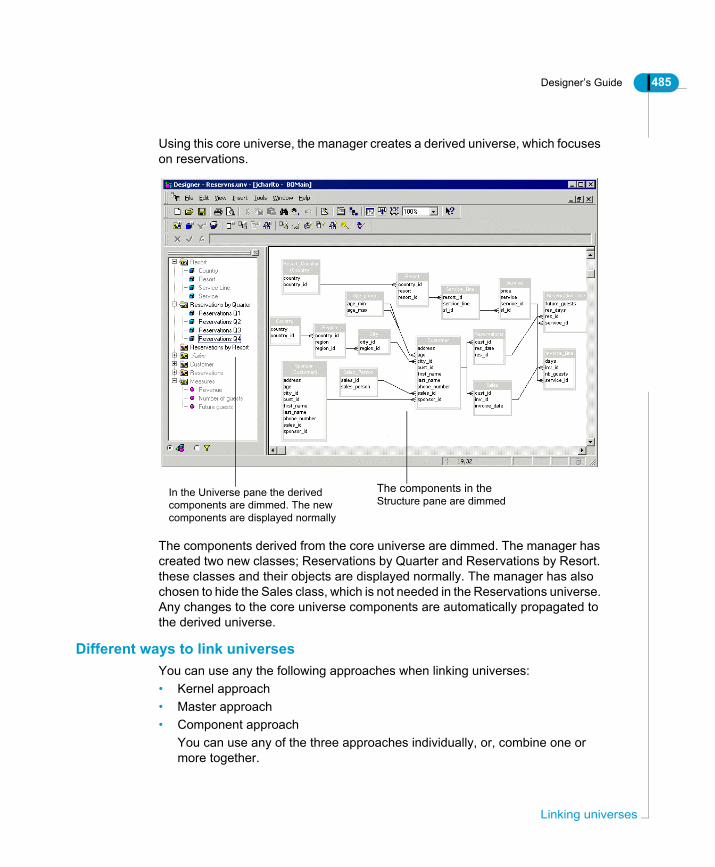
Designer’s Guide 485
Using this core universe, the manager creates a derived universe, which focuses on reservations.
The components derived from the core universe are dimmed. The manager has created two new classes; Reservations by Quarter and Reservations by Resort. these classes and their objects are displayed normally. The manager has also chosen to hide the Sales class, which is not needed in the Reservations universe. Any changes to the core universe components are automatically propagated to the derived universe.
Different ways to link universesYou can use any the following approaches when linking universes:• Kernel approach• Master approach• Component approach
You can use any of the three approaches individually, or, combine one or more together.
In the Universe pane the derivedcomponents are dimmed. The newcomponents are displayed normally
The components in theStructure pane are dimmed
Linking universes

486 Designer’s Guide
Man
Kernel approachWith the kernel approach, one universe contains the core components. These are the components common in all universes. The derived universes that you create from this kernel universe contain these core components as well as their own specific components. The approach is shown below.
The universes Human Resources and Sales are derived from a kernel universe. They contain core components of the kernel universe as well as their own specific components.
Any changes you make to the kernel universe are automatically reflected in the core components of all the derived universes.
Master approachThe master approach is another way of organizing the common components of linked universes.The master universe holds all possible components. In the universes derived from the master, certain components are hidden depending on their relevance to the target users of the derived universe.
Sales universe
Kernel
+Kernel
Human Resources
+Kernel
Derived
added components
universeUniverses
aging universes

Designer’s Guide 487
The components visible in the derived universes are always a subset of the master universe. There are no new components added specific to the derived universe.The approach is shown in the diagram below.
The universes Human Resources and Sales are derived from a master universe. They contain components from the master universe, some of which may be hidden.
Any changes you make to the master universe are automatically reflected in the core components of all the derived universes.
Component approachThe component approach involves merging two or more universes into one universe.
The Sales universe was created by merging two universes: Part 1 and Part 2.
Advantages of linking universesYou have the following advantages when linking universes:• Reduce development and maintenance time. When you modify a component
in the core universe, Designer propagates the change to the same
Sales
Master
Master
Human Resources
Master
DERIVED UNIVERSES
_
_
Hidden components
Hidden components
Sales
Part 1 Part 2
Part 1 Part 2
Linking universes

488 Designer’s Guide
Man
component in all the derived universes.• You can centralize often used components in a core universe, and then
include them in all new universes. You do not have to re-create common components each time you create a new universe.
• Facilitate specialization. Development can be split between database administrators who set up a basic core universe, and the more specialized designers who create more functional universes based on their specific field.
Requirements for linking universesYou can link the active universe to a core universe, only if the following requirements are met:• The core universe and derived universe use the same data account, or
database, and the same RDBMS. Using the same connection for both the core and the derived universe makes managing the universes easier, but this can be changed at any time.
• The core universe was exported and re-imported at least once. The derived universe does not need to have been exported before creating a link.
• Exported derived universes are located in the same universe domain as the core universe.
• You are authorized to link the given universe.
Restrictions when linking universesYou need to be aware of the following restrictions when linking universes:• You can use only one level of linking. You cannot create derived universes
from a universe which is itself derived.• All classes and objects are unique in both the core universe and the derived
universes. If not conflicts will occur.• The two universe structures must allow joins to be created between a table in
one universe to a table in the other universe. If not, then Cartesian products can result when a query is run with objects from both structures.
• Only the table schema, classes and objects of the core universe are available in the derived universe. Contexts must be re-detected in the derived universe.
• Lists of values associated with a core universe are not saved when you export a derived universe with the core universe structures.
aging universes

Designer’s Guide 489
Creating a link between two universesYou can link an active universe to another universe. When you do so, the active universe becomes the derived universe, and the linked universe becomes the core universe. Components from the core universe are inherited by the derived universe.
NOTE
To link a universe to a core universe, the core universe must have been exported to the repository at least once. Otherwise, Designer does not allow the link.
Creating a link between a derived universe and a core universeTo create a link between a derived universe and a core universe:1. Ensure that the active universe is the one that you want to link to the core
universe.For example, the universe below is a version of the Beach universe that contains only sales information for countries, but no resort data. You want to link this sales universe with a resort universe that contains resort data. The sales Beach universe below is the derived universe, and the Resort universe
Linking universes

490 Designer’s Guide
Man
is the core universe.
2. Select Edit > Links.The Universe Parameters dialog box opens to the Links page.:
3. Click the Add Link button.
No Resort class Missing Resort data tables
aging universes
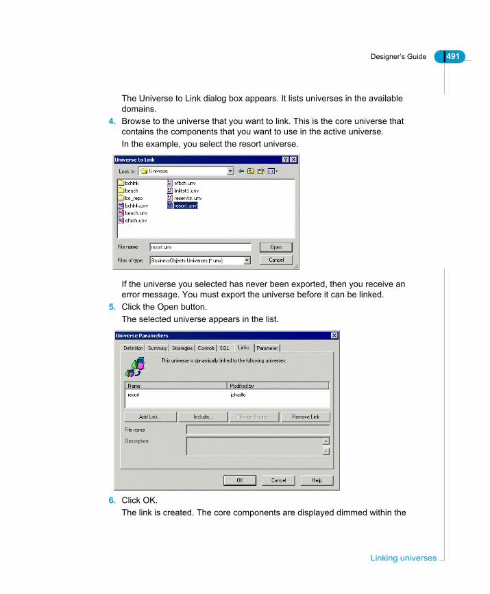
Designer’s Guide 491
The Universe to Link dialog box appears. It lists universes in the available domains.
4. Browse to the universe that you want to link. This is the core universe that contains the components that you want to use in the active universe.In the example, you select the resort universe.
If the universe you selected has never been exported, then you receive an error message. You must export the universe before it can be linked.
5. Click the Open button.The selected universe appears in the list.
6. Click OK.The link is created. The core components are displayed dimmed within the
Linking universes

492 Designer’s Guide
Man
active universe.
Editing a derived universeYou complete the linking process by creating joins between the core tables and the derived universe tables. You must delete all current contexts and re-detect the contexts for the new structure.
NOTE
You can not edit any structure, class, or object from the linked universe (core universe), within the derived universe.
Editing the derived universeTo edit the derived universe:1. Create joins between the core and derived universe structures.
Creating joins ensures that Cartesian products are not returned for objects
Resort class fromcore universe
Resort data tables from core universe
aging universes

Designer’s Guide 493
included in a query from both structures.2. Remove existing contexts.3. Detect aliases.4. Detect contexts.5. Hide or Create new objects as required.
NOTE
For information on hiding a component, refer to the section "Showing or hiding classes, objects, and conditions" in the Building Universes chapter.
Removing a linkYou can remove a link to a core universe only if the derived universe does not contain objects based on core components, or joins to core components.
Removing a link in the derived universeTo remove a link in the derived universe:1. Open the derived universe.2. Select Edit > Links.
The Links page of the Universe Parameters dialog box appears.1. Click the name of the core universe in the list.2. Click the Remove Link button.3. Click the OK.
The components from the core universe are removed from the active universe.
Relocating the core universeIf the location of your core universe has changed, then you need to indicate the new location in order to maintain the link.
Linking universes

494 Designer’s Guide
Man
Updating a link to a relocated core universeTo update the link to a relocated core universe:1. Open the derived universe.2. Select Edit > Links.3. Click the linked core universe in the list.4. Click the Change Source button.
The Universe to Link dialog box appears.5. Browse to the new location of the core universe.6. Click the Open button.
The new core universe appears in the Links list.
Derived universes and lists of valuesLists of values associated with core objects are not saved with the derived universe, when it is exported to the repository.One method you can use to save lists of values associated with the core objects is as follows:1. Create new objects using the same definition as the objects containing lists of
values that you want to export to the repository with the derived universe.2. Assign the new objects the same lists of values as the core objects.3. Hide these new objects.
The hidden objects serve the function of holding the lists of values so that they can be exported and imported with the derived universe.
Presenting objects in the order of the core universeBy default, the order in which you arrange the objects of the derived universe is that which will be seen by users of the universe, even if the order later changes in the core universe. If you want your derived universe to present objects always in the order they are presented in the core universe, you must set a parameter accordingly in the *.PRM file of the database you are using.The parameter setting is CORE_ORDER_PRIORITY = Y.See your database documentation for details on how to set the parameters in the relevant *.PRM file.
aging universes

Designer’s Guide 495
Including one universe within anotherYou can copy the components of a core universe to a derived universe. The resulting components in the derived universe are independent of those in the core universe. These components are not linked to the core universe. Any changes made to the core universe are not inherited by the derived universe.
Copying a core universe into a derived universeWhen you copy a core universe into a derived universe, the resulting components in the derived universe are independent of those in the core universe. These components are not linked to the core universe. Any changes made to the core universe are not inherited by the derived universe.You copy a core universe into a derived universe for any of the following reasons:• To copy the contents of a given universe into an active universe.• To no longer keep the dynamic link between two universes.
NOTE
If your two universes were linked before the operation, the procedure removes the dynamic link components in the active universe are no longer dynamically linked to the external universe.
Copying a core universe into derived universeTo copy a core universe into a derived universe:1. Open a universe.2. Select Edit > Links.
The Links page of the Universe Parameters dialog box appears.3. Click the Add Link button.
The Universe to Link dialog box appears. It lists universes in the available domains.
4. Browse to and select the universe that you want to copy. This is the core universe that contains the components that you want to use in the active universe.
5. Click the Include button.6. Click OK.
The components from the core universe are displayed within the active universe.
Including one universe within another

496 Designer’s Guide
Man
Managing users and loginsYou can log into Designer as a different user and also change your login.
Managing loginsYou can log into Designer as a different user without quitting your work session. User identification is defined in Supervisor. You can log in as another user only if you know the corresponding user name and password.
Logging on as a different user To log in as a different user:1. Select Tools > Login As.
If there are open universes, Designer closes them automatically.The User Identification dialog box appears.
2. Select or type a user name in the User Name box.3. Type a password in the Password box.4. If applicable, choose a repository in the Security Domain box.
This box does not appear if you are a user of only one repository. The user shown below has access to multiple repositories.
5. Click OK.For more information on the User Identification dialog box, refer to the section "Starting a Designer Session" in the Designer Basics chapter.
When you log in as another user in Designer, you are automatically entitled to all the rights of that user; however, you may also be prohibited from certain operations as a result of restrictions set on the profile by the supervisor.
aging universes

Designer’s Guide 497
Managing passwordsDuring a Designer session, you can change the password with which you logged provided that your supervisor has enabled you to do so. You cannot, however, change your user name.
Changing passwordsTo change your password:1. Select Tools > Change Password.
The Change Password dialog box appears..
2. Type your existing password in the Enter Old Password box.3. Type your new password in the Enter New Password box.4. Confirm your new password by typing it again in the Confirm New Password
box.5. Click OK.
The password is changed.
Managing users and logins
498 Designer’s Guide
Man
Optimizing universesQuery time can often be shortened by optimizing a universe. There are several ways you can optimize a universe:• Optimizing the Array Fetch parameter in the Universe Parameters.• Allocating a weight to each table.• Using shortcut joins.• Creating and using aggregate tables in your database.Each of these methods is described as follows:
Optimizing the array fetch parameterThe Array Fetch parameter in the CS.CFG file allows you to set the maximum number of rows that are permitted in a FETCH procedure. The CFG file is a XML file that specifies default values for certain parameters used by Business Objects products when queries are run against a database.The Array Fetch parameter determines the packet size on the network. For example, if you set the Array Fetch at 20, and you plan to retrieve 100 rows, then five fetches will be executed to retrieve the data. Some data sources do not allow modifying the FETCH size. In this case all rows will be returned in a single FETCH. If you want to retrieve binary long-objects (BLOB), you should set the Array Fetch size as 1.If you have a network that allows you to send a large array fetch, then you can set a new larger value (values can be set from 1 to 999). This will speed up the FETCH procedure, and reduce your query processing time.
Modifying the array fetch parameterTo modify the Array Fetch parameter:1. Open the CS.CFG file in a XML editor.
The CFG file is stored in the following directory:<INSTALDIR>\dataAccess\RDBMS\connectionServer.
2. Search for the parameter Array Fetch.3. Set the parameter value. Save and close the CFG file.4. Restart Designer.
aging universes

Designer’s Guide 499
Allocating table weightsTable weight is a measure of how many rows there are in a table. Lighter tables have less rows than heavier tables. By default BusinessObjects sorts tables from the lighter to the heavier tables (those with the least amount of rows to those with the most). This determines the table order in the FROM clause of the SQL statement.The order in which tables are sorted at the database level depends on your database. For example, Sybase uses the same order as BusinessObjects, but Oracle uses the opposite order. The SQL will be optimized for most databases, but not for Oracle where the smallest table is put first in the sort order.So, if you are using BusinessObjects, and are using an Oracle database, you can optimize the SQL by reversing the order that BusinessObjects sorts the tables. To do this you must change a parameter in the relevant PRM file of the database.
Modifying the PRM file to allocate table weightsTo modify the PRM file to allocate table weights:1. Open the PRM file for your database in a XML editor.
The PRM file is stored in the following directory:<INSTALLDIR>\dataAccess\RDBMS\connectionServer\<rdbms>\For example, the file for Oracle is oracle.prm in here:<INSTALLDIR>\dataAccess\RDBMS\connectionServer\oracle\oracle.prm
2. Find the REVERSE_TABLE_WEIGHT parameter in the Configuration section of the file.
3. Change the Y to an N.For example the parameter appears as REVERSE_TABLE_WEIGHT=N. If the line is not in the file, the default is Y.
4. This forces BusinessObjects to sort the tables from those with the most rows to those with the least rows.
5. Save and close the .PRM files.6. Restart Designer to apply the changes to the .PRM file.
Modifying the number of returned rows for a table You can also manually change the number of rows for any table in Designer. To view the number of rows in any table, select View > Number of rows in tables. The number of rows appears at the bottom left of each table symbol. You can modify this number as follows:
Optimizing universes

500 Designer’s Guide
Man
Modifying the number of returned rowsTo modify the number of returned rows for a table:1. Open a universe in Designer.2. Right-click the relevant table3. Select Number of Rows in Table from the contextual menu.
The Table Row Count dialog box appears.4. Select the Modify manually tables row count radio button.
A text box appears at the left of the dialog box.5. Type a number in the text box. This is the number of rows that you want to
use for the table.6. Click OK, then save the universe.
Using shortcut joinsA shortcut join links two tables that are already joined in a common path. You can use a shortcut join to reduce the number of tables that are used in a query. Refer to the section on shortcut joins in the chapter Designing a Schema for more information.
NOTE
Shortcut joins will not create loops.
aging universes

The Club database
appendix

502 Designer’s Guide
OverviewThis appendix provides detailed information on the structure of the Club database built with Microsoft Access. This is the database from which most of the examples and illustrations in this guide are derived.You can find the database file, Club.mdb, in the \demo\databases subfolder in the Business Objects path. Also in this folder, you will find the efashion demo database.

Designer’s Guide 503
The Club databaseThe Club database is used in most of the examples given in this guide.
The structure of the tablesThe Club database is used by the sales manager of Island Resorts, a fictitious business specializing in packaged holidays. Based on the information in this database, the sales manager can perform sales and marketing analysis. The database is made up of the following tables:• Age_group• City• Country• Customer• Invoice_Line• Region• Region_Sline• Reservation_Line• Reservations• Resort• Sales• Sales_Person• Service• Service_LineThe next sections describe each of the above tables and their columns.
The Age_group tableThe Age_group table stores information on the age ranges of customers.
Column Name Description
age_min the lower limit of the age range
age_max the upper limit of the age range
age_range the age range of customers
The Club database

504 Designer’s Guide
Here are the results of a query on the data in the Age_group table:
The City tableThe City table stores information on the city in which the customers reside.
The Country tableThe Country table relates to the country in which the customer resides.
The Customer tableThe Customer table contains information relating to customer identification such as name and address.
Column Name Description
city_id system-generated city number
city the city in which the customer resides (Albertville, Amsterdam, Augsburg...Versailles, Washington D.C., Yokohama)
region_id system-generated region number
Column Name Description
country_id system-generated country number
country The name of the country in which the customer resides (Australia, France, Germany, Holland, Japan, UK, US.)
Column Name Description
cust_id system-generated customer number
first_name first name of the customer
last_name last name of the customer
age age of the customer
phone_number phone number of the customer
address first line of the customer’s address
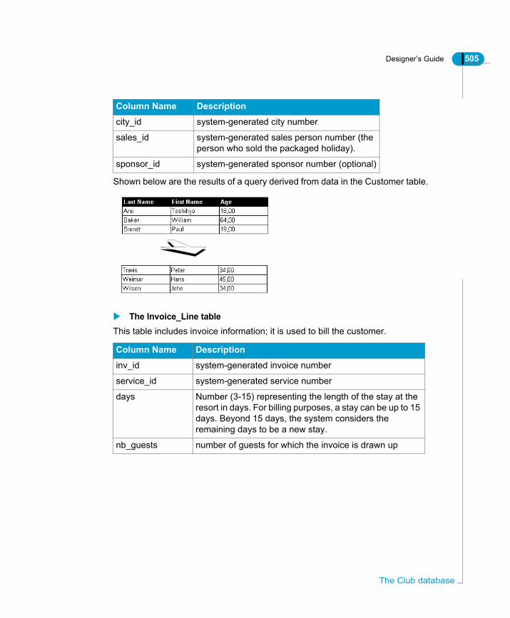
Designer’s Guide 505
Shown below are the results of a query derived from data in the Customer table.
The Invoice_Line tableThis table includes invoice information; it is used to bill the customer.
city_id system-generated city number
sales_id system-generated sales person number (the person who sold the packaged holiday).
sponsor_id system-generated sponsor number (optional)
Column Name Description
inv_id system-generated invoice number
service_id system-generated service number
days Number (3-15) representing the length of the stay at the resort in days. For billing purposes, a stay can be up to 15 days. Beyond 15 days, the system considers the remaining days to be a new stay.
nb_guests number of guests for which the invoice is drawn up
Column Name Description
The Club database

506 Designer’s Guide
The Region tableThe Region table stores information on the geographical region in which the customer resides.
The Region_Sline tableThis table enables calculation of a sales revenue aggregate in the universe. Aggregate awareness is covered in Chapter 5 of this guide.
The Reservation_Line tableInformation relating to customer reservations is stored in the Reservation_Line table.
Column Name Description
region_id system-generated region number
region geographical region in which the customer resides (Bavaria, East Coast, East Germany...Wales, West, West Japan)
country_id system-generated country number
Column Name Description
sl_id system-generated service line number (service line information is given in the Service_Line table)
region_id system-generated region number
sales_revenue the total sales revenue by region.
Column Name Description
res_id system-generated reservation number
service_id system-generated service number
res_days days of the week reserved (1 - 7)
future_guests number of future guests (1 - 5)

Designer’s Guide 507
The Reservations tableThe Reservation table contains information on the date of the customer reservation.
The Resort tableThe Resort table contains information on each resort.
The Sales tableThe Sales table contains sales information.
The Sales_Person tableThe Sales_Person table stores information on the sales persons of the Island Resorts business.
Column Name Description
res_id system-generated reservation number
cust_id system-generated customer number
res_date the date on which the customer reserved
Column Name Description
resort_id system-generated resort number
resort the name of the resort: Australian Reef, Bahamas Beach, French Riviera, Hawaiian Club, Royal Caribbean
country_id system-generated country number
Column Name Description
inv_id system-generated invoice number
cust_id system-generated customer number
invoice_date date of the invoice
Column Name Description
sales_id system-generated sales person number
sales_person name of the sales person (Andersen, Barrot, Bauman... Moore, Nagata, Schmidt)
The Club database

508 Designer’s Guide
The Service tableThe Service table includes information on the price and types of services available in a given resort.
The following is the result of a query performed on the service column of this table:
The Service_Line tableThe Service_Line table stores information on the service line of resorts. Service line means simply the category in which the service falls.
Column Name Description
service_id system-generated service number
service services available in a resort (see the query results below)
sl_id system-generated service line number (service line information is given in the next table)
price the price of the service
Column Name Description
sl_id system-generated service line number
service_line Service line includes: accommodation, food and drinks, recreation
resort_id system-generated resort number (values 1 to 5)

Designer’s Guide 509
Index
@Aggregate_Aware 328, 393syntax 394@function 325@Prompt 329@Script 331@Select 332@Variable 334@Where 338
Aaccess
external strategy 373to universe for all users 45
actionundo 101
activatelist mode 107table browser 130
addconnection 67table 130
administerlist of values 358
advancedobject options 292
aggregateset projection for measure 307tables 389
aggregate aware 389data warehouse 389define objects 393identify objects 392navigate incompatible objects 399navigate tables 399set up 391specify incompatible objects 396test universe 404
aliascreate 201, 227, 228, 233define 200delete 204detect 227, 228inappropriate use of 243multiple 230name 201, 203resolve fan trap 257resolve loop 220role in schema 200
allocatetable weights 499
allowcomplex operators 78subquery 78
analytic function 435advantages 435available in Fuctions list 448IBM DB2 438Oracle 438RedBrick 443supported types 436Teradata 446
ANSI 92create full outer join 169define join 156support for joins 139, 154
ANSI92universe parameter 84
applyexternal strategy 384
arrangetables automatically 133
arrange tables 109array fetch
optimize 498assign
password 58
Index

510 Designer’s Guide
Inde
Auditoruse of impact analysis universes 470
AUTO_UPDATE_QUERYuniverse parameter 84
automaticcardinality detection 183class creation 281create alias creation 233create context 233join insert 148loop detection 232object creation 285table arrange 109universe check 188, 265
BBeach universe 32BLOB_COMPARISON
universe parameter 85BOUNDARY_WEIGHT_TABLE
universe parameter 86browser
table 97build
hierarchy 367Business Objects
consulting services 11, 13documentation 10Documentation Supply Store 9support services 11training services 11, 13
BusinessObjectschange target universe 476link HTML reports 417link objects 407start from Designer 482
Ccardinality 211
define 177detect 74, 183display 179keys 181optimize 185optimize detection 185resolve database limitation 187set for join 180set manually 180use in Designer 178
cartesian productprevent 79warn 79
case sensitiveconnection name 64
changepasswords 497schema display 111table display 109
characterfind or replace 102
chasm trap 247detect 251identify 251resolve 247, 252use contexts 252use multiple SQL 253visually detect 262
checkuniverse 188, 189, 265, 266
check integrity 370automatic parse 188, 265change in database 192, 269error types 189, 266print results 192, 269send option 188, 265when start Designer 188, 265
x

Designer’s Guide 511
class 18, 275create 280, 281create default 74define 280edit 283hide 278modify 283move 278properties 282subclass 283
clearlist of values 358
clipboardoperations 278
closeuniverse 49
Club database 32, 502Age_group table 503City table 504Country table 504Customer table 504Invoice table 505Region table 506Region_Sline table 506Reservation_Line table 506Resort table 507Sales table 507Sales_Person table 507Service table 508Service_Line table 508structure of tables 503
columnview values 113
COLUMNS_SORTuniverse parameter 86
COMBINE_WITHOUT_PARENTHESISuniverse parameter 87
combined queriesallow 78
COMBINED_WITH_SYNCHROuniverse parameter 88
commandRun 41
commentobject 289
commentsuniverse 67
complex conditionallow 78enable 78
complex joincreate 162
component approachto linked universes 487
concatenated object 361create 361syntax 361
conditionapply to list of values 349enable complex 78infer multiple tables 322object see condition objectview 276
condition objectconflicting Where clauses 316createdefine 315hide 278move 278use in query 318
conflictuniverse identifier 474, 476universe identifier solve 475
connectionadd 67create new 59database engine 56define 54delete 67modify 54name 56name case sensitive 64new 59password 56, 58personal 56secured 56shared 56universe parameter 53view available 65
Index

512 Designer’s Guide
Inde
consultantsBusiness Objects 11
contextambiguous queries 212create 205, 230, 233define 205delete 210detect 227, 230detection problems 211edit 209incompatible queries 212modify 209multiple SQL statements 79resolve chasm trap 252resolve fan trap 257resolve loop 223role in schema 205update 210
context inferred queries 212copy 278CORE_ORDER_PRIORITY
universe parameter 88CORRECT_AGGREGATED_CONDITIONS_IF_D
RILLuniverse parameter 89
createalias 201, 227, 228class 280, 281complex join 162condition objectconnection 54, 59context 205, 230default classes and objects 74detail 303dimension 303dynamic SQl parameters 81equi-join 159external strategy 382hierarchy 365, 367hierarchy for list of values 351join 143, 144, 147link 489list of values 348list of values from file 356measure 304object 284, 285self join 173subclass 283theta join 163universe 50, 51
cription 289CUMULATIVE_OBJECT_WHERE
universe parameter 89customer support 11customize
list of values 360cut 278
Ddata
drill 365list of values file 356return empty set 319view 131
data typedisplay 112, 113
databasesupported schema 23view tables 129
x
Designer’s Guide 513
database engineconnection 56
datedatabase format 293
DECIMAL_COMMAuniverse parameter 90
declareexternal strategy 375
defaultclasses and objects 74modify save options 49save options 49
define 247.PRM file 436@function 325aggregate aware objects 393cardinality 177chasm trap 247class 280complex equi-join 162condition objectconnection 59context 205detail 303dimension 303dynamic SQL parameters 81external strategy 373fan trap 255list of values 343loop 217measure 304object 284self join 173shortcut join 172theta join 163universe parameters 50Where clause 310
deletealias 204connection 67context 210join 158SQL parameters 81table 106
demodatabase 32materials 9universe 32
deployuniverse 474
derived tableusing 134
derived universecreate link 489export to different domain 477migrate 477object order 494
descriptionmodify 54universe 53
designschema 128
design wizarddisactivate 42
Designerexample materials 32interface components 98perform action 100Run command 40start 37, 38structure pane 97universe pane 97universe window 97user interface 97
detailcreate 303define 303
Index
514 Designer’s Guide
Inde
detectaliases 227, 228cardinalities 183cardinalities in joins 74chasm trap 251contexts 227, 230fan trap 257integrity errors 189, 266join path problems 262joins 146loops 227, 232optimize cardinality 185universe errors 189, 266
Developer Suite 10, 12dimension
create 303define 303
disactivatedesign wizard 42
displaycardinalities 179change table 109data type 112, 113formula bar 153key 141number of table rows 116object 20organize tables 106row count 112schema 112schema options 111
DISTINCT_VALUESuniverse parameter 90
distributeuniverse 465
documentexchange between repositories 480link 421link to returned values 416linking 425update universe source 476
document domain 465
documentationCD 9feedback on 10on the web 9printed, ordering 9roadmap 9search 9
Documentation Supply Store 9drill 365dynamic
SQL parameters 81
Eedit
class 283connection 54context 209dynamic SQL parameters 81hierarchies 367join 150, 152list of values 348object 288SQL editor 299use formula bar 153
editorSQL 152
education see trainingeFashion
database 502universe 32
END_SQLuniverse parameter 91
enterprise modeaccess universe in 45
equi-joincomplex 162create 159define 159
errorCheck Integrity 189, 266
EVAL_WITHOUT_PARENTHESISuniverse parameter 91
exampleuniverse and database 32
x
Designer’s Guide 515
exportderived universe to different domain 477impact analysis universe 470linked universe 477list of values 353lock universe 466universe 468universe conflict 474, 476universe incrementally 470universe to different repository 480
external strategy 371accessing in Designer 373apply in Designer 384create 382create SQL text file 384creating Help text 373declare external strategy file 375define 373files and process overview 372insert SQL directly 382join strategy output format 381migrate to 6.5 371migrating Help text 373object strategy output format 380output format 379reference text file 382select 69set number rows retrieved 75STG file parameters 376table browser strategy output format 382using 371using examples 376
extractjoins with tables 74
Ffact table
define 197
fan trapdefine 255detect 257identify 257inflated results 255resolve 255, 257use alias and context 257use multiple SQL 261visually detect 262
feedbackon documentation 10
filecreate list of values 356
filterclass and conditions 276
FILTER_IN_FROMuniverse parameter 92, 96
findloops in schema 226quick search in universe 105search in universe 102
FIRST_LOCAL_CLASS_PRIORITYuniverse parameter 92
fixchasm trap 252fan trap 255loops 217
flexible lookup table 240FORCE_SORTED_LOV
universe parameter 92foreign key 141
index aware 294set up awareness 298
formatobject 302remove 302show data type 113
formula bardisplay 153edit join 153
full outer joincreate 169
functionadd to PRM file 448available in Functions list 448
Index

516 Designer’s Guide
Inde
Ggenerate
dynamic SQL parameters 81graphic
create join 143detect join path problems 262identify loops 226tables 106
Group clausemeasure infers 306
HHelp
create for external strategy 373hide
class 278condition object 278object 278
hierarchychange order of objects 368create 365, 367, 368drill 365editor 367identify 366list of values 351set up 367, 368slice and dice 365
IIBM DB2
analytic function 438identifier
conflict in universe domain 474, 476identify conflict 475solve conflict 475, 476use Supervisor to solve 476
identifyaggregation levels 392chasm trap 251fan trap 257hierarchy 366identifier conflict 475loop 226universe 53, 465
imagelink to returned value 407
importlock universe 466universe 472
incompatible object 396incorrect result
chasm trap 249fan trap 255loops 218
incremental export 470index
awareness 294index aware
set up foreign key index 298set up primary key index 296using 294
inflated resultchasm trap 249fan trap 255
InfoViewsetting up report linking 431
insert@function 325optimize 132tables 129, 130user object 363
integritycheck automatically 188, 265check manually 189, 266check universe 188, 265
interfacecomponents 98
intersectallow 78enable 78
x

Designer’s Guide 517
Jjoin
ANSI 92 support 139, 154create 143, 144define 138define with ANSI 92 syntax 156delete 158detect 146, 147detect cardinality 74edit 150, 152edit with formula bar 153equi-join 159foreign key 141insert with tables 148modify 150operators 149outer join 159, 166parse 150primary key 141properties 149retrieve linked tables 74self join 159, 173set cardinality 180shortcut join 159, 172strategy 72supported types 159theta join 159, 163
join pathalias define 200chasm trap 199, 247detect problems 199, 262fact tables role 197fan trap 199incorrect results 198lookup table 197loops 199problems overview 197solve problems 199
Kkernel approach
to linked universes 486
kernel universechange 493remove link 493
keyaware 294cardinality 181display 141primary key 141
key awarenessset up foreign key awareness 298set up primary key awareness 296
key foreign 141key tab
key awareness options 294Knowledge Base 12
Llaunch
BusinessObjects from Designer 482Designer 37, 38Designer with Run command 40
limitquery execution time 76, 77
linkcreate 489dynamic 489HTML reports 417reports 416, 421reports in repository 431reports on returned values 425reports with OpenDocument function 428returned value to image 407returned values to reports 416set up report to report 431test OpenDocument function 434to reports from universe 425universes 80
Index

518 Designer’s Guide
Inde
linked universe 483advantages 487component approach 487CORE_ORDER_PRIORITY 494dynamic link 489include one within another 495kernel approach 486linking methods 485master approach 486object order 494remove link 493requirements 488restrictions 488set up 489
list modeactivate 107
list of values 341administer 358apply condition 349associate object 290clear 358create 348create hierarchy 351customize 360define 343display 358edit 348, 358export 353manage 358modify 348optimize 360options 344personal data file 356properties 344purge 358refresh 356, 358specify properties 292use in reporting 341view 347
lockuniverse 466
log inas another user 496
loginoffline mode 38password 38repository 38user name 38
lookup tabledefine 197
lookup tablesflexible 240shared 239
loopdefine 217detect 227, 232effect on queries 218examples 236identify 226resolve 217, 226resolve with alias 220resolve with contexts 223
LOV see list of values
Mmanage
lists of values 358manual
object creation 284set cardinality 180universe check 189, 266
master approachto linked universes 486
MAX_INLIST_VALUESuniverse parameter 93
measureaggregate functions 305aggregate projection 307create 304define 304dynamic nature 305Group clause 306multiple statements 79
methodologyuniverse design 28
migrateexternal strategy Help text 373external strategy to 6.5 371
x

Designer’s Guide 519
minusallow 78
modifyarray fetch 498class 283connection 54context 209default save options 49description 54join 150, 152link object 433list of values 348number of returned rows 499object 288object format 302returned rows number 115row count 116, 119schema display 111table display 109universe definition parameters 54universe name 54Where clause 310
mouseactions 100
moveclass 278object 278toolbar 99
multidimensional analysis 365create hierarchies 368types of 365
multimediaquick tours 10
multiple aliases 230multiple SQL
chasm trap 253fan trap 261use to resolve chasm trap 253
Nname
alias 201, 203connection 56, 64object 289universe 53
normalization 240number
universe revision 467
Index
520 Designer’s Guide
Inde
Oobject 18, 273, 289
advanced options 292associate list of values 290change hierarchy order 368comment 289concatenated 361create 284, 285create default 74date format 293define 284define aggregate aware 393define restriction 309detail see detaildimension see dimensiondisplay 20edit 288format 302generate SQL overview 22hide 278hierarchy 365in condition 293in result 293incompatible 396key awareness options 294link to image 407measure see measuremodify 288modify link 433move 278name 289overview of SQL inferred 19Parse button 290properties 286qualification 19, 290remove format 302role overview 273security 294security access 293Select statement 289specify qualification 292strategy 72Tables button 290type 275, 289types 275
user access 294user object 363view 276Where clause 289
offline modelogin 38work in 42
olap function 435Treadata 446
Online Customer Support 11online mode
work in 42open
universe 47OpenDocument
implementations of function 427linking in universe 425parameters 428use in Select 430
operatorjoin 149
optimizelist of values 360table browser 132universe 498
optionsAllow users to edit this List of Values 345Associate a List of Values 344Automatic refresh before use 345Export with universe 346
Oracleanalytic functions 438
organizetable display 106, 133
outer joinANSI 92 169create 166define 159full 169restrictions 171
outputformat for external strategy 379
x
Designer’s Guide 521
Ppage
specify setup 122parameter file
define 436parse
join 150Parse button 290password
change 497connection 56, 58login 38
paste 278PATH_FINDER_OFF
universe parameter 93PDF
save as 48personal
connection 56plan
universe design stages 28prevent
cartesian product 79preview
universe 122primary key 141
index aware 294set up awareness 296
printCheck Integrity results 192, 269page setup 122preview 122set options 121universe 121
PRM file 436add function 448
problem detecting contexts 211properties
universe 50purge
list of values 358
Qqualification
object 290, 292query
allow subquery 78ambiguous 212combine condition objects 320complex conditions 78condition objects use of 318incompatible 212inferred 212intersect 78limit execution time 76, 77loops 218set controls 77, 78union 78
query limitset 76
Quick Designdesactivate wizard 42display options 454
quick designwizard 453
RRedBrick
risql function 443refresh
list of values 356, 358structure 192, 269
removeobject format 302
replacestring or character 102
REPLACE_COMMA_BY_CONCATuniverse parameter 94
reportlink 416, 421link to another report 425linking 425setting up linking 431
Index

522 Designer’s Guide
Inde
repositorydomains 465export universe 468, 480export using Supervisor 480incremental universe export 470login 38migrate derived universe 477migrate universe between domains 474
resolvechasm trap 247, 252fan trap 255, 257join path problems 199loop with alias 220loop with context 223loops 217, 226
restrictiondefine 309guidelines for use 324multiple tables 322self join use of 321Where clause 310Where clause problems 314
revision number 467risql function 435
RedBrick 443row
display number of 116modify returned number 115modify row count 116, 119set maximum retrieved 75
row countadapting to data volume 119display 112query optimization 119show 112
Run commandoptions 41start Designer 40syntax 41
Ssave
as PDF 48defaults 49modify defaults 49universe 47
schemaalias use of 200context use of 205define 127design stages 128detect join path problems 262display 111display row count 112populate with tables 129refresh 192, 269show data type 112use of cardinalities 178
searchdocumentation 9in universe 102
securedconnection 56
securityconnection name 64object 294object access 293
security domain 465SELECT
use of OpenDocument function 430select
schema display options 111strategies 69table 106
Select statement 289self join
create 173define 159restrict data 321
x

Designer’s Guide 523
setcardinality 180dynamic SQl parameters 81maximum rows retrieved 75query controls 77resource controls 76row count 116save defaults 49save options 49schema display options 112
set uphierarchies 368linked universes 489
sharedconnection 56
shortcut joincreate 172define 159
SHORTCUT_BEHAVIORuniverse parameter 95
showlist mode 107row count 112
slice and dice 365solve
chasm trap 252fan trap 255loops 217
sourcechange universe 476
SQLcreate text file for external strategy 384editor 299multiple statements 79set query controls 78
SQL editoredit join 152
SQL parametersdynamic 81
startBusinessObjects from Designer 482Designer 37, 38Run command 40
statisticsuniverse 67
STGfile parameters 376
strategyexternal see external strategy 371joins 72objects 72output formats 379select 69select in Quick Design Wizard 385tables 73
stringfind and replace 102
structureSTG file 376
Structure panerefresh 192, 269
structure pane 97display options 112
subclasscreate 283
subqueryallow 78
summaryuniverse information 67
Supervisorexport universe 480set overwrite universe right 476
supportcustomer 11
syntax@Aggregate_Aware 394automatic insert in SELECT 448concatenated objects 361Run command 41
Index

524 Designer’s Guide
Inde
Ttable
add 130aggregate 389arrange 133arrange automatically 109browser see table browserchange display 109create default class and objects 74delete 106derived 134display number of rows 116extract joins 74fact define 197graphic display 106infer multiple tables 322insert 129, 130insert with joins 148lookup 197loops with aggregate table 402manipulate 106modify number of returned rows 499optimize insert 132organize 106organize display 133populate schema 129select 106strategy 73view values 113
table browser 97activate 130optimize 132using 129view data 131
table weightallocate 499
Tables button 290Teradata
olap function 446test
report linking 434universe 370
theta joincreate 163define 159
THOROUGH_PARSEuniverse parameter 96
Tips & Tricks 10toolbar
move 99using 99
trainingon Business Objects products 11
troubleshootCheck Integrity 191, 268
typeobject 289
Uudo file
user object 363undo
action 101UNICODE_STRINGS
universe parameter 96union
allow 78enable 78
x

Designer’s Guide 525
universe.unv file extension 47access to all users 45change target in BusinessObjects 476check integrity 188, 265close 49comments 67connection 53create 50, 51create connection 54create default classes and objects 74creation overview 22define connection 54define parameters 50definition parameters 53deploy 474description 53design methodology 28designer profile 26development cycle 29distribute 465distribute using file system 466dynamic link 489edit connection 54exchange between repositories 480export 468file name 465identifier 465identify 53, 465import 472include within another 495link universes 80lock 466long name 47, 465migrate between domains 474modify name 54name 53, 465object order in derived universe 494open 47optimize 498overview 17print 121Quick Design wizard 453resource controls 76revision number 467
roles 17save 47save options 49statistics 67summary information 67test 370update for documents 476utilisation overview 23window overview 21workgroup design 466
universe check integrity 370universe design
development cycle 29planning stages 28
universe development cycleoverview 28
Universe pane 276view conditions 276
universe pane 97universe parameter
reference list 84update
context 210source universe 476
used 293user
access to object 294access to universe 45login 38, 496
user object 363
Vvalidate
universe 188, 265values
column view 113table view 113
verifyuniverse 188, 265
Index
526 Designer’s Guide
Inde
viewcondition in Universe pane 276connections 65data from table browser 131database tables 129list of values 347number of rows 116objects 276
view conditions 276
Wwarn
cartesian product 79web
customer support 11getting documentation via 9useful addresses 12
WebIntelligencelink images 411link reports 421setting up report linking 431
Where clauseconflict 319conflicting 316define 310modify 310object 289problems with 314return no data 319
windowsmanipulating 98
wizardquick design 453
workgroupuniverse design 466
workgroup modeaccess universe in 45
x