design of a multi purpose fixture for 4-axis cnc machine
TRANSCRIPT
AIJREAS VOLUME 1, ISSUE 3 (2016, March) (ISSN-2455-6300) Online
AAAnnnvvveeessshhhaaannnaaa ’’’sss IIInnnttteeerrrnnnaaatttiiiooonnnaaalll JJJooouuurrrnnnaaalll ooofff RRReeessseeeaaarrrccchhh iiinnn EEEnnngggiiinnneeeeeerrriiinnnggg aaannnddd AAApppppplll iiieeeddd SSSccciiieeennnccceeesss
AAAnnnvvveeessshhhaaannnaaa ’’’sss IIInnnttteeerrrnnnaaatttiiiooonnnaaalll JJJooouuurrrnnnaaalll ooofff RRReeessseeeaaarrrccchhh iiinnn EEEnnngggiiinnneeeeeerrriiinnnggg aaannnddd AAApppppplll iiieeeddd SSSccciiieeennnccceeesss
EEE---mmmaaaiii lll ::: [email protected] , WWWeeebbbsssiiittteee ::: www.anveshanaindia.com 1
Design Of A Multi Purpose Fixture For 4-Axis CNC Machine
Baloji Badavath
Assistant Professor, Mechanical HOD,
MIST College
Email Id:[email protected]
Abstract
Many of the parts require sophisticated fixture
in order to be machined. A variety of CNC machine
brands all of which have differently designed tables.
They needed a way of sharing the clamping systems with
all of the machines. After reviewing the fixtures and
machines, we designed, and tested a clamping system
which would eliminate the need for different fixtures for
each machine. This means that each time an operation is
complete the part, with its current fixture, must be taken
out of the CNC machine and re-fixture for the next
operation. Information on the CNC machines will be
gathered and the similarities and differences of the tables
and fixtures will be analyzed. Based on this data a new
process and design will be created. Finally, we will look
at the effectiveness of the proposed designs and
improvements to verify that it will improve the
manufacturing process.
In the present design BFW BMV40 CNC machine take in
to consideration for developing new fixture design. As a
designer the drive table specifications are considered as
per the machine developer and rest of the part is
considered as per the customer requirement of individual
parts. Different stages of rotor blades take in to
consideration to prepare a multiple usage fixture for all
clamping requirements.
Key words; fixtures, 4-axis rotary CNC machines,
clamping, time monitoring design optimization
CHAPTER-1
INTRODUCTION
1.1 Introduction to fixtures
1.1.1 Definition Of Fixture And Jig
Fixtures, being used in machine shop, are
strong and rigid mechanical devices which
Dr. S. Chakradhara Goud
Professor and Principal, Dept. of
Mechanical Engineering, Sri Sarada
Institute of Science and Technology
Email Id:[email protected]
enable easy, quick and consistently
accurate locating, supporting and
clamping, blanks against cutting tool(s)
and result faster and accurate machining
with consistent quality, functional ability
and interchangeability.
Jig is a fixture with an additional feature
of tool guidance.
1.1.2 Purpose Of Using Fixtures And
Jigs The fixture is a special tool for holding a
work piece in proper position during
manufacturing operation. For supporting
and clamping the work piece, device is
provided. Frequent checking, positioning,
individual marking and non-uniform
quality in manufacturing process is
eliminated by fixture. This increase
productivity and reduce operation time.
Fixture is widely used in the
industry practical production because of
feature and advantages.
To locate and immobilize work pieces for
machining, inspection, assembly and other
operations fixtures are used. A fixture
consists of a set of locators and clamps.
Locators are used to determine the position
and orientation of a, whereas clamps exert
clamping forces so that the work piece is
pressed firmly against locators. Clamping
has to be appropriately planned at the stage
of machining fixture design. The design of
a fixture is a highly complex and intuitive
process, which require knowledge. Fixture
design plays an important role at the setup

AIJREAS VOLUME 1, ISSUE 3 (2016, March) (ISSN-2455-6300) Online
AAAnnnvvveeessshhhaaannnaaa ’’’sss IIInnnttteeerrrnnnaaatttiiiooonnnaaalll JJJooouuurrrnnnaaalll ooofff RRReeessseeeaaarrrccchhh iiinnn EEEnnngggiiinnneeeeeerrriiinnnggg aaannnddd AAApppppplll iiieeeddd SSSccciiieeennnccceeesss
AAAnnnvvveeessshhhaaannnaaa ’’’sss IIInnnttteeerrrnnnaaatttiiiooonnnaaalll JJJooouuurrrnnnaaalll ooofff RRReeessseeeaaarrrccchhh iiinnn EEEnnngggiiinnneeeeeerrriiinnnggg aaannnddd AAApppppplll iiieeeddd SSSccciiieeennnccceeesss
EEE---mmmaaaiii lll ::: [email protected] , WWWeeebbbsssiiittteee ::: www.anveshanaindia.com 2
planning phase. Proper fixture design is
crucial for developing product quality in
different terms of accuracy, surface finish
and precision of the machined parts In
existing design the fixture set up is done
manually, so the aim of this project is to
replace with hydraulic fixture to save time
for loading and unloading of component.
Hydraulic fixture provides the
manufacturer for flexibility in holding
forces and to optimize design for machine
operation as well as process function
ability.
1.2 Problem statement for present
project:
To initiate the fixture-design process,
clearly state the problem to be solved or
needs to be met. State these requirements
as broadly as possible, but specifically
enough to define the scope of the design
project. The designer should ask some
basic questions: Is the new tooling
required for first-time production or to
improve existing production?
This phase of the fixture-design
process requires the most creativity. A
typical work piece can be located and
clamped several different ways. The
natural tendency is to think of one
solution, then develop and refine it while
blocking out other, perhaps better
solutions. A designer should brainstorm
for several good tooling alternatives, not
just choose one path right away. During
this phase, the designer's goal should be
adding options, not discarding them. In the
interest of economy, alternative designs
should be developed only far enough to
make sure they are feasible and to do a
cost estimate. The designer usually starts
with at least three options: permanent,
modular, and general-purpose work
holding. Each of these options has many
clamping and locating options of its own.
The more standard locating and clamping
devices that a designer is familiar with, the
more creative he can be. Areas for locating
a part include flat exterior surfaces
(machined and un machined), cylindrical
and curved exterior surfaces. The exact
procedure used to construct the
preliminary design sketches is not as
important as the items sketched. Generally,
the preliminary sketch should start should
start with the part to be fixture. The
required locating and supporting elements,
including a base, should be the next items
added. Then sketch the clamping devices.
Finally, add the machine tool and cutting
tools. Sketching these items together helps
identify any problem areas in the design of
the complete fixture.
1.3 Introduction to Implement the
Design:
The final phase of the fixture-design
process consists of turning the chosen
design approach into reality. Final details
are decided, final drawings are made, and
the tooling is built and tested. The
following guidelines should be considered
during the final-design process to make the
fixture less costly while improving its
efficiency. These rules are a mix of
practical considerations, sound design
practices, and common sense.
1.3.1.Important considerations while
designing fixtures:
Designing of jigs and fixtures depends
upon so many factors. These factors are
analyzed to get design inputs for jigs and
fixtures. The list of such factors is
mentioned below:
a. Study of work piece and finished
component size and geometry.
b. Type and capacity of the machine, its
extent of automation.
c. Provision of locating devices in the
machine.
AIJREAS VOLUME 1, ISSUE 3 (2016, March) (ISSN-2455-6300) Online
AAAnnnvvveeessshhhaaannnaaa ’’’sss IIInnnttteeerrrnnnaaatttiiiooonnnaaalll JJJooouuurrrnnnaaalll ooofff RRReeessseeeaaarrrccchhh iiinnn EEEnnngggiiinnneeeeeerrriiinnnggg aaannnddd AAApppppplll iiieeeddd SSSccciiieeennnccceeesss
AAAnnnvvveeessshhhaaannnaaa ’’’sss IIInnnttteeerrrnnnaaatttiiiooonnnaaalll JJJooouuurrrnnnaaalll ooofff RRReeessseeeaaarrrccchhh iiinnn EEEnnngggiiinnneeeeeerrriiinnnggg aaannnddd AAApppppplll iiieeeddd SSSccciiieeennnccceeesss
EEE---mmmaaaiii lll ::: [email protected] , WWWeeebbbsssiiittteee ::: www.anveshanaindia.com 3
d. Available clamping arrangements in the
machine.
e. Available indexing devices, their
accuracy.
f. Evaluation of variability in the
performance results of the machine.
g. Rigidity and of the machine tool under
consideration.
h. Study of ejecting devices, safety
devices, etc.
i. Required level of the accuracy in the
work and quality to be produced.
Introduction to 4-axis Milling
Adding a 4th axis rotary table to a milling
machine in any sort of work setting
provides several advantages to machine
work. Having another axis to work with
gives milling machine users more
precision and accuracy, without having to
change positions of the part being
machined. Also, an additional axis would
prove to make any milling machine more
diverse in the work it is capable of doing;
lathe machines introduce the aspect of a
rotating part, so a rotary table would add
the same benefits provided. A 4th axis
rotary table, in general, can provide more
precision and ease to a complex design,
reducing time and costs for the production
of a certain piece.
The Importance of a 4th Axis Rotary
Table
Just like with the other three axes of
motion, the 4th axis can be adjusted for
specific amounts of distances to accurately
tell what position you are at in relation to
the dimensions of the piece. Furthermore,
the scales used to measure its motion can
save time and resources by reducing the
amount of mistakes that could result in
major delays, such as re-working the piece
from the beginning. Since users will easily
be able to calculate and set the positions
needed for the work done, machining
multiple pieces is simpler to accomplish.
Objectives:
(1) CNC with 4-axis attachments.
(2) Clamping system for Fourth axis
Rotary.
(3) Fourth axis with flat bed clamping
fixing system.
(4) Fourth axis with chuck clamping
system.
(5) Special purpose fixture for
different applications.
(6) Study of market requirements for
the present application.
(7) Comparative study on both
clamping system with motion
analysis.
2. Literature survey
2.1. Design of machining fixture by
C.RadhaMadhavi1, B.Ramu2,
K.Srinivasulu stated that
Fixture Design consists of High product
rate, low manufacturing operation cost.
The fixture should be designed in such-a-
way that part/product change overtime is
very less. The report consists of study of
input data from customers like Part
drawing and Assembly drawing. The
AIJREAS VOLUME 1, ISSUE 3 (2016, March) (ISSN-2455-6300) Online
AAAnnnvvveeessshhhaaannnaaa ’’’sss IIInnnttteeerrrnnnaaatttiiiooonnnaaalll JJJooouuurrrnnnaaalll ooofff RRReeessseeeaaarrrccchhh iiinnn EEEnnngggiiinnneeeeeerrriiinnnggg aaannnddd AAApppppplll iiieeeddd SSSccciiieeennnccceeesss
AAAnnnvvveeessshhhaaannnaaa ’’’sss IIInnnttteeerrrnnnaaatttiiiooonnnaaalll JJJooouuurrrnnnaaalll ooofff RRReeessseeeaaarrrccchhh iiinnn EEEnnngggiiinnneeeeeerrriiinnnggg aaannnddd AAApppppplll iiieeeddd SSSccciiieeennnccceeesss
EEE---mmmaaaiii lll ::: [email protected] , WWWeeebbbsssiiittteee ::: www.anveshanaindia.com 4
fixture design begins with part modeling,
Machining and Analysis of various parts in
the fixture assembly using AutoCAD and
Solid works, for a analysis COSMOS
Software package is used. The actual
design begins with study details of project
proposal summary from customer.
The main purpose of fixture is to locate the
work quickly and accurately, support it
properly and hold it securely, thereby
ensuring the all parts produced in same
fixture will come within specified limits.
Another important aspect in designing the
fixture is to reduce non production time
i.e. setup time. Operator conformability
has prime consideration in fixture design.
In this fixture design ergonomic aspects
have studied carefully reducing operator
fatigue to minimum.
Rigid clamping and proper loading
sequence has achieved the total assembly
accuracy within prescribed limit. The self
alignment of components has achieved by
designed loading sequence.
2.2 A Review on Design of Fixtures by
Shailesh S.Pachbhai1, Laukik P.Raut2
1Research Scholar, Department of
Mechanical Engineering, G.H.Raisoni
college of Engineering, Nagpur 440016,
2Assistant Professor, Department of
Mechanical Engineering, G.H.Raisoni
college of Engineering, Nagpur 440016.
The efficiency and reliability of the fixture
design has enhanced by the system and the
result of the fixture design has made more
reasonable. To reduce cycle time required
for loading and unloading of part, this
approach is useful. If modern CAE, CAD
are used in designing the systems then
significant improvement can be assured.
To fulfill the multifunctional
and high performance fixturing
requirements optimum design approach
can be used to provide comprehensive
analyses and determine an overall optimal
design. Fixture layout and dynamic
clamping forces optimization method
based on optimal fixture layout could
minimize the deformation and uniform the
deformation most effectively .The
proposed fixture will fulfilled researcher
production target and enhanced the
efficiency, Hydraulic fixture reduces
operation time and increases productivity,
high quality of operation, reduce accidents. 3.1 DESIGN CONSIDERATIONS
Specifications for present project:
(1) The indexing chuck to chuck distance
=450mm
(2) Bed length in CNC VMC bmv45
=600 -850mm
(3) Indexing chuck Diameter (ID -150mm)
(4) In case of flat Fixture the Side plates
dimensions =80x80
(5) No of Tap holes 16 no’s of M12 Tap
–on both plates
(6) These side plates size is less than the
job so that it can clamp rigidly.
(7) side plates Thickness = 30mm
(8) Overall chuck dia in O.D=350mm.
3.2 Auto Cad design Layouts
Introduction to cad
Computer-aided design (CAD) is the use
of computer systems to assist in the
creation, modification, analysis, or
optimization of a design. CAD software is
used to increase the productivity of the
designer, improve the quality of design,
improve communications through
documentation, and to create a database
for manufacturing. CAD output is often in
the form of electronic files for print,
machining, or other manufacturing
operations.
AIJREAS VOLUME 1, ISSUE 3 (2016, March) (ISSN-2455-6300) Online
AAAnnnvvveeessshhhaaannnaaa ’’’sss IIInnnttteeerrrnnnaaatttiiiooonnnaaalll JJJooouuurrrnnnaaalll ooofff RRReeessseeeaaarrrccchhh iiinnn EEEnnngggiiinnneeeeeerrriiinnnggg aaannnddd AAApppppplll iiieeeddd SSSccciiieeennnccceeesss
AAAnnnvvveeessshhhaaannnaaa ’’’sss IIInnnttteeerrrnnnaaatttiiiooonnnaaalll JJJooouuurrrnnnaaalll ooofff RRReeessseeeaaarrrccchhh iiinnn EEEnnngggiiinnneeeeeerrriiinnnggg aaannnddd AAApppppplll iiieeeddd SSSccciiieeennnccceeesss
EEE---mmmaaaiii lll ::: [email protected] , WWWeeebbbsssiiittteee ::: www.anveshanaindia.com 5
Computer-aided design is used in
many fields. Its use in designing electronic
systems is known as Electronic Design
Automation, or EDA. In mechanical
design it is known as Mechanical Design
Automation (MDA) or computer-aided
drafting (CAD), which includes the
process of creating a technical
drawing with the use of computer
software.
CAD software for mechanical
design uses either vector-based graphics to
depict the objects of traditional drafting, or
may also produce raster graphics showing
the overall appearance of designed objects.
However, it involves more than just
shapes. As in the
manual drafting of technical and engineeri
ng drawings, the output of CAD must
convey information, such as materials,
processes, dimensions, and tolerances,
according to application-specific
conventions.
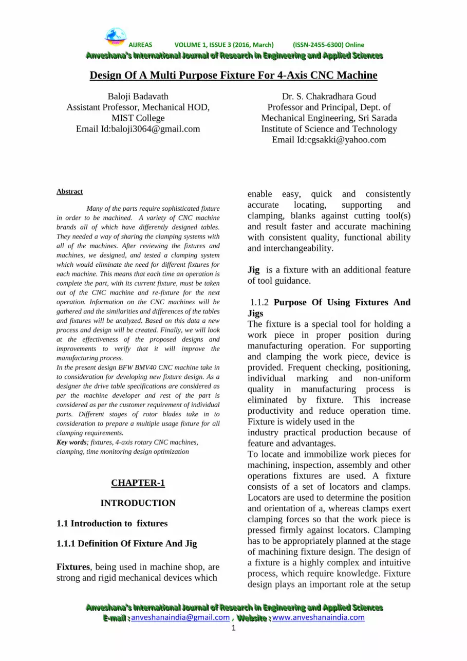
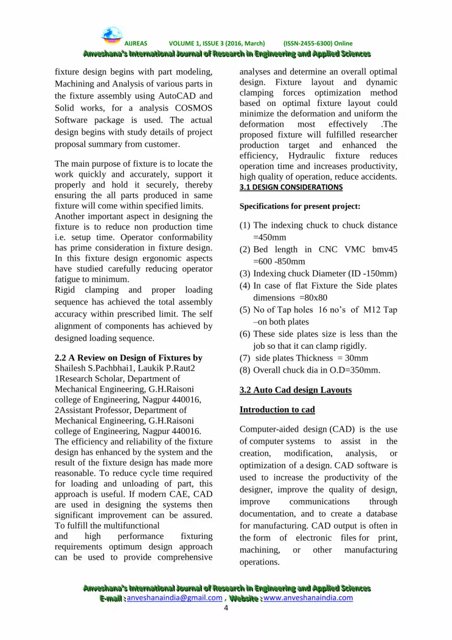
Insert preparation in AutoCAD for 2nd side
modified fixture
Fixing insert f second side modified
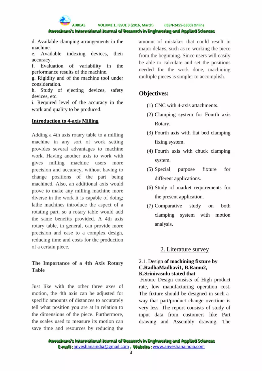
Fixture base on second side modified
DESIGN CONSIDERATIONS OF
BEARING HOUSING PATTREN:
Housing fixing bore-100mm,
Bearing size-60mm dia (I.D),
Supported wall thickness-12mm,
bottom wall thickness-10mm,
INTRODUCTION TO UNI-
GRAPHICS:
Unigraphics software is one of the
world’s most advanced and tightly
integrated CAD/CAM/CAE software
package developed by Siemens PLM
Software, offers several pre-packaged
Mach Series solutions for NC machining.
Available in a range of capability levels,
AIJREAS VOLUME 1, ISSUE 3 (2016, March) (ISSN-2455-6300) Online
AAAnnnvvveeessshhhaaannnaaa ’’’sss IIInnnttteeerrrnnnaaatttiiiooonnnaaalll JJJooouuurrrnnnaaalll ooofff RRReeessseeeaaarrrccchhh iiinnn EEEnnngggiiinnneeeeeerrriiinnnggg aaannnddd AAApppppplll iiieeeddd SSSccciiieeennnccceeesss
AAAnnnvvveeessshhhaaannnaaa ’’’sss IIInnnttteeerrrnnnaaatttiiiooonnnaaalll JJJooouuurrrnnnaaalll ooofff RRReeessseeeaaarrrccchhh iiinnn EEEnnngggiiinnneeeeeerrriiinnnggg aaannnddd AAApppppplll iiieeeddd SSSccciiieeennnccceeesss
EEE---mmmaaaiii lll ::: [email protected] , WWWeeebbbsssiiittteee ::: www.anveshanaindia.com 6
these solutions accelerate programming
and improve productivity for a variety of
typical manufacturing challenges, from
basic machining to complex, multiple-axis
and multi-function machining, as well as
mould and die manufacturing it also
merges solid and surface modelling
techniques into one powerful tool set. The
packages include complete capabilities for
geometry import, CAD modeling and
drafting, full associatively to part designs,
NC tool path creation, verification and
post processing, along with productivity
tools that streamline the overall machining
process.
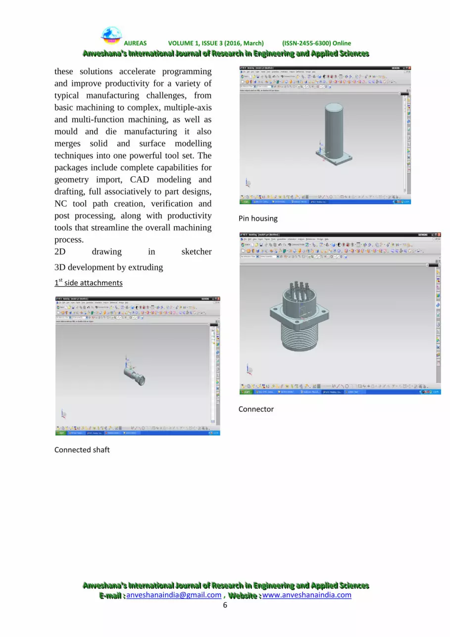
2D drawing in sketcher
3D development by extruding
1st side attachments
Connected shaft
Pin housing
Connector
AIJREAS VOLUME 1, ISSUE 3 (2016, March) (ISSN-2455-6300) Online
AAAnnnvvveeessshhhaaannnaaa ’’’sss IIInnnttteeerrrnnnaaatttiiiooonnnaaalll JJJooouuurrrnnnaaalll ooofff RRReeessseeeaaarrrccchhh iiinnn EEEnnngggiiinnneeeeeerrriiinnnggg aaannnddd AAApppppplll iiieeeddd SSSccciiieeennnccceeesss
AAAnnnvvveeessshhhaaannnaaa ’’’sss IIInnnttteeerrrnnnaaatttiiiooonnnaaalll JJJooouuurrrnnnaaalll ooofff RRReeessseeeaaarrrccchhh iiinnn EEEnnngggiiinnneeeeeerrriiinnnggg aaannnddd AAApppppplll iiieeeddd SSSccciiieeennnccceeesss
EEE---mmmaaaiii lll ::: [email protected] , WWWeeebbbsssiiittteee ::: www.anveshanaindia.com 7
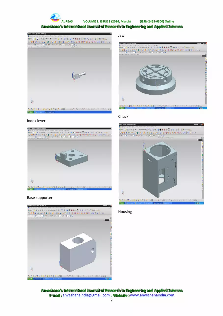
Index lever
Base supporter
Jaw
Chuck
Housing
AIJREAS VOLUME 1, ISSUE 3 (2016, March) (ISSN-2455-6300) Online
AAAnnnvvveeessshhhaaannnaaa ’’’sss IIInnnttteeerrrnnnaaatttiiiooonnnaaalll JJJooouuurrrnnnaaalll ooofff RRReeessseeeaaarrrccchhh iiinnn EEEnnngggiiinnneeeeeerrriiinnnggg aaannnddd AAApppppplll iiieeeddd SSSccciiieeennnccceeesss
AAAnnnvvveeessshhhaaannnaaa ’’’sss IIInnnttteeerrrnnnaaatttiiiooonnnaaalll JJJooouuurrrnnnaaalll ooofff RRReeessseeeaaarrrccchhh iiinnn EEEnnngggiiinnneeeeeerrriiinnnggg aaannnddd AAApppppplll iiieeeddd SSSccciiieeennnccceeesss
EEE---mmmaaaiii lll ::: [email protected] , WWWeeebbbsssiiittteee ::: www.anveshanaindia.com 8
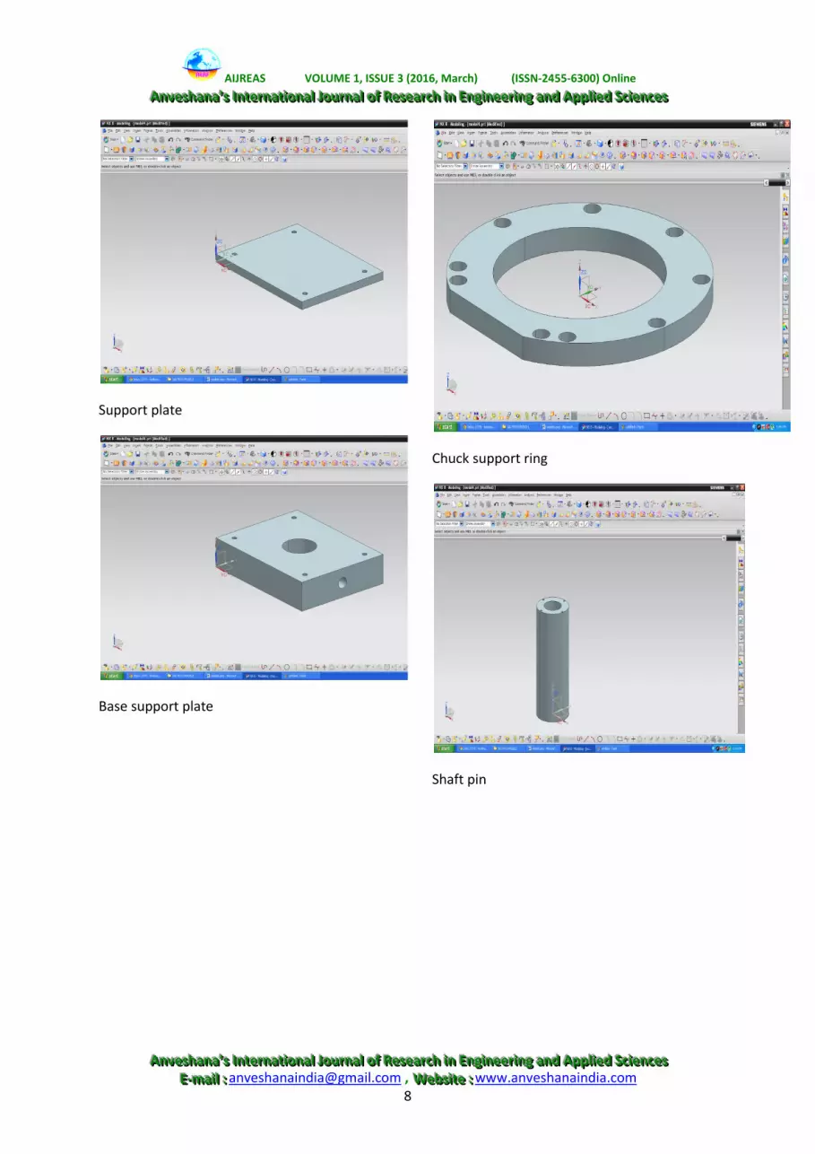
Support plate
Base support plate
Chuck support ring
Shaft pin
AIJREAS VOLUME 1, ISSUE 3 (2016, March) (ISSN-2455-6300) Online
AAAnnnvvveeessshhhaaannnaaa ’’’sss IIInnnttteeerrrnnnaaatttiiiooonnnaaalll JJJooouuurrrnnnaaalll ooofff RRReeessseeeaaarrrccchhh iiinnn EEEnnngggiiinnneeeeeerrriiinnnggg aaannnddd AAApppppplll iiieeeddd SSSccciiieeennnccceeesss
AAAnnnvvveeessshhhaaannnaaa ’’’sss IIInnnttteeerrrnnnaaatttiiiooonnnaaalll JJJooouuurrrnnnaaalll ooofff RRReeessseeeaaarrrccchhh iiinnn EEEnnngggiiinnneeeeeerrriiinnnggg aaannnddd AAApppppplll iiieeeddd SSSccciiieeennnccceeesss
EEE---mmmaaaiii lll ::: [email protected] , WWWeeebbbsssiiittteee ::: www.anveshanaindia.com 9
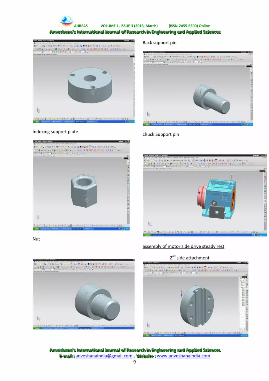
Indexing support plate
Nut
Back support pin
chuck Support pin
assembly of motor side drive steady rest
2nd side attachment

AIJREAS VOLUME 1, ISSUE 3 (2016, March) (ISSN-2455-6300) Online
AAAnnnvvveeessshhhaaannnaaa ’’’sss IIInnnttteeerrrnnnaaatttiiiooonnnaaalll JJJooouuurrrnnnaaalll ooofff RRReeessseeeaaarrrccchhh iiinnn EEEnnngggiiinnneeeeeerrriiinnnggg aaannnddd AAApppppplll iiieeeddd SSSccciiieeennnccceeesss
AAAnnnvvveeessshhhaaannnaaa ’’’sss IIInnnttteeerrrnnnaaatttiiiooonnnaaalll JJJooouuurrrnnnaaalll ooofff RRReeessseeeaaarrrccchhh iiinnn EEEnnngggiiinnneeeeeerrriiinnnggg aaannnddd AAApppppplll iiieeeddd SSSccciiieeennnccceeesss
EEE---mmmaaaiii lll ::: [email protected] , WWWeeebbbsssiiittteee ::: www.anveshanaindia.com 10
fixture plate on second side for vertical
motion attachment
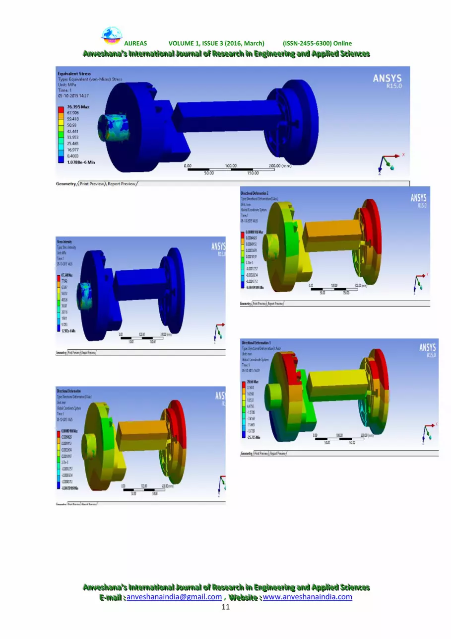
MESHING OF PRESENT PROJECT
Results & Discussions
AIJREAS VOLUME 1, ISSUE 3 (2016, March) (ISSN-2455-6300) Online
AAAnnnvvveeessshhhaaannnaaa ’’’sss IIInnnttteeerrrnnnaaatttiiiooonnnaaalll JJJooouuurrrnnnaaalll ooofff RRReeessseeeaaarrrccchhh iiinnn EEEnnngggiiinnneeeeeerrriiinnnggg aaannnddd AAApppppplll iiieeeddd SSSccciiieeennnccceeesss
AAAnnnvvveeessshhhaaannnaaa ’’’sss IIInnnttteeerrrnnnaaatttiiiooonnnaaalll JJJooouuurrrnnnaaalll ooofff RRReeessseeeaaarrrccchhh iiinnn EEEnnngggiiinnneeeeeerrriiinnnggg aaannnddd AAApppppplll iiieeeddd SSSccciiieeennnccceeesss
EEE---mmmaaaiii lll ::: [email protected] , WWWeeebbbsssiiittteee ::: www.anveshanaindia.com 11

AIJREAS VOLUME 1, ISSUE 3 (2016, March) (ISSN-2455-6300) Online
AAAnnnvvveeessshhhaaannnaaa ’’’sss IIInnnttteeerrrnnnaaatttiiiooonnnaaalll JJJooouuurrrnnnaaalll ooofff RRReeessseeeaaarrrccchhh iiinnn EEEnnngggiiinnneeeeeerrriiinnnggg aaannnddd AAApppppplll iiieeeddd SSSccciiieeennnccceeesss
AAAnnnvvveeessshhhaaannnaaa ’’’sss IIInnnttteeerrrnnnaaatttiiiooonnnaaalll JJJooouuurrrnnnaaalll ooofff RRReeessseeeaaarrrccchhh iiinnn EEEnnngggiiinnneeeeeerrriiinnnggg aaannnddd AAApppppplll iiieeeddd SSSccciiieeennnccceeesss
EEE---mmmaaaiii lll ::: [email protected] , WWWeeebbbsssiiittteee ::: www.anveshanaindia.com 12
FIGURE 1 Model (A4) > Static Structural (A5) >
Moment
FIGURE 2 Model (A4) > Static Structural (A5) > Force
FIGURE 3 Model (A4) > Static Structural (A5) >
Moment 2

AIJREAS VOLUME 1, ISSUE 3 (2016, March) (ISSN-2455-6300) Online
AAAnnnvvveeessshhhaaannnaaa ’’’sss IIInnnttteeerrrnnnaaatttiiiooonnnaaalll JJJooouuurrrnnnaaalll ooofff RRReeessseeeaaarrrccchhh iiinnn EEEnnngggiiinnneeeeeerrriiinnnggg aaannnddd AAApppppplll iiieeeddd SSSccciiieeennnccceeesss
AAAnnnvvveeessshhhaaannnaaa ’’’sss IIInnnttteeerrrnnnaaatttiiiooonnnaaalll JJJooouuurrrnnnaaalll ooofff RRReeessseeeaaarrrccchhh iiinnn EEEnnngggiiinnneeeeeerrriiinnnggg aaannnddd AAApppppplll iiieeeddd SSSccciiieeennnccceeesss
EEE---mmmaaaiii lll ::: [email protected] , WWWeeebbbsssiiittteee ::: www.anveshanaindia.com 13
CONCLUSIONS
From the study of simulations on fixture
there is not so much deflection occurring
on the fixture when compared to single
stated inserted fixture. The multipurpose
use of the present fixture not showing any
rotational deflection but with load and
forces taken into account it shows a slight
deflection comparably negligible as
considered for practical approach. This
project shows an edge of multipurpose job
work can be done with out changing
number of inserts for each job.
Limitations &Future scope
1. Theoretical simulations only observed
in the present project with material and
work piece and loads are taken from
practical values of work place.
2. Rotational forces can be studied by
applying practical rpm of components can
be studied.
3.Practical study may given a direct
solution to the extension of this work.
4. Limitation of present study can be
extended to a materialized practical work
and comparison in industry.