design and simulation of muon ionization cooling channels for the fermilab neutrino factory...
TRANSCRIPT

PHYSICAL REVIEW SPECIAL TOPICS - ACCELERATORS AND BEAMS, VOLUME 4, 041301 (2001)
Design and simulation of muon ionization cooling channelsfor the Fermilab Neutrino Factory feasibility study
J. Monroe, P. Spentzouris, V. Balbekov, and P. LebrunFermi National Accelerator Laboratory, Batavia, Illinois 60510
G. Penn, C. Kim,* and E. S. KimLawrence Berkeley National Laboratory, Berkeley, California 94707
D. M. KaplanIllinois Institute of Technology, Chicago, Illinois 60621(Received 2 January 2001; published 17 April 2001)
In the past few years, the concept of a high intensity muon storage ring has been pursued as an optionfor the next generation neutrino source. To produce the high intensity muon beam needed for the success-ful operation of a neutrino source, on the order of 1020 muon decays per year, the phase space occupiedby the muon beam must be significantly reduced before the beam is accelerated. The initial transverseemittance of the muon beam before acceleration is assumed to be 9p mm rad. Because of the timelimitation imposed by the muon lifetime, the technique employed to accomplish the desired emittancereduction is ionization cooling. In this paper we present two ionization cooling lattice designs, which usesolenoidal focusing elements and liquid hydrogen absorbers to reduce the muon beam phase space. Wediscuss the design concepts and engineering constraints for these lattices and present simulation resultsobtained using a detailed tracing code with a complete model of muon-matter interactions. The reductionin transverse emittance is approximately a factor of 5. This result is within a factor of 2 of the total cool-ing requirements for a successful neutrino factory design and within a factor of 1.4 of the requirementsfor the main cooling section specified in the conceptual design of this machine.
DOI: 10.1103/PhysRevSTAB.4.041301 PACS numbers: 41.75.Lx
I. INTRODUCTION
The successful design of a high intensity neutrino sourcerequires that the transverse phase space occupied by themuon beam after production, capture, and bunching be re-duced by approximately a factor of 10 in each plane be-fore the beam is accelerated. The technique which couldaccomplish the required cooling within the time limit im-posed by the muon lifetime is ionization cooling [1–3].In ionization cooling, the beam loses both transverse andlongitudinal momentum by ionization energy loss, whilepassing through material. The longitudinal momentum isthen restored to the beam in accelerating rf cavities. Thissequence, repeated many times, results in a reduction ofthe angular spread of the beam particles, and thereby re-duces the normalized transverse emittance.
Ionization cooling is limited by heating of the beam dueto multiple Coulomb scattering in the energy-absorbingmaterial. To minimize this heating effect, the absorbersare placed in a strong focusing field. An approximate dif-ferential equation for the rate of change of the normalizedtransverse emittance en inside the absorber is [2,3]
den
dz� 2
1b2
dEm
dzen
Em
1 bgb�
2ddz
�u2� , (1.1)
*Deceased.
1098-4402�01�4(4)�041301(12)$15.00
where z is the path length, Em is the beam energy, b �y�c, �u2� is the mean-square planar scattering angle, andb� is the betatron function of the beam, with the beam sizegiven by sx � sy �
penb��bg. To first order, �u2� �
� 0.0136 GeVpbc �2 z
LR, where LR is the radiation length of the
energy absorbing medium. Using this expression we canrewrite Eq. (1.1) as
den
dz� 2
1b2
dEm
dzen
Em
11
b3
b��0.0136 GeV�2
2EmmmLRc2 .
(1.2)
Since the heating term is proportional to b� and inverselyproportional to LR , we place the absorbers in low b�
regions and use material with high LR (liquid hydrogen)in order to maximize cooling.
A. Cooling channel design considerations
To obtain the strong beam focusing at the absorberneeded for optimal cooling, several lattice configurationshave been considered. Focusing by solenoids has beenselected based on the results of design studies and on theconstraints imposed for a realistic, technically feasiblecooling channel design. Solenoidal focusing has the advan-tage of naturally focusing in both transverse planes, simpli-fying the design of the transverse beam optics. Solenoidscan be used to focus a large transverse emittance beamto small b� at absorbers located outside the magnet or
© 2001 The American Physical Society 041301-1

PRST-AB 4 J. MONROE et al. 041301 (2001)
to provide continuous focusing, allowing the use of longabsorbers inside the solenoid. A complication with the useof solenoids stems from the fact that a beam entering themagnet acquires angular momentum by its interaction withthe radial component of the fringe field. In the absence ofabsorbers, this effect is reversible, since at the exit of thesolenoid the beam loses the angular momentum acquiredat the entrance. However, with an absorber inside the sole-noid, the beam loses angular momentum as the transversemomentum decreases, so at the exit the cancellation is notexact and the beam retains a net angular momentum. Ifthis net angular momentum is not compensated, it resultsin transverse emittance dilution outside of the focusingfield.
The technique we use to compensate for the accumula-tion of angular momentum is to alternate the sign of thesolenoidal field. In an ideal case, where this “field flip” is astep function, the solution would be to alternate the sign tocancel the residual angular momentum after each absorber.However, the field flip cannot be instantaneous, and its fi-nite length induces a perturbation of the transverse motionand hence the longitudinal velocity of the beam particles.This perturbation can significantly dilute the beam phasespace and introduces a coupling of the longitudinal andtransverse motions.
Even without a field flip, there are several other effectspeculiar to particle motion in ionization cooling chan-nels with solenoids which cause transverse-longitudinalcoupling. First is the dependence of path length ontransverse momentum within a solenoidal field: particlesat large transverse amplitude At traverse a greater dis-tance, therefore the time of flight of these particles islarger than that of particles with small At , with At �q
�r2�b2�� 1 �px�pz�2 1 �py�pz�2. (Here r is the
distance from the beam axis, and a Cartesian right-handedcoordinate system is used, with the z axis coincidingwith the axis of the solenoid.1) An off-axis particle has alonger time of flight than an on-axis particle with the sameenergy, and so will arrive in an rf cavity later and see adifferent accelerating gradient. Second, the presence of anabsorber within the solenoidal field correlates energy losswith At , since particles at large At traverse more material,thus losing more energy. The result of these two effects isa growth of the momentum spread of the beam which iscorrelated with At . In addition, energy loss in the absorberis momentum dependent, and the slope of the energy loss,dE�dz, as a function of energy is unfavorable at a beammomentum of 200 MeV�c, the mean beam momentumwe have considered in our studies. This low momentum,200 MeV�c with a 10% spread, also causes some bunchdistortion due to the nonrelativistic motion of the beam
1Unless explicitly stated otherwise, this coordinate system isused in all of the discussions in this paper.
041301-2
particles. On the other hand, low momentum is favored foroptimal cooling performance [see Eq. (1.1)], so the valueof 200 MeV�c is selected in order to maintain coolingwithout maximizing the undesirable effects presentedabove.
Neglecting any longitudinal-transverse coupling, for afixed minimum betatron function b�,min, the transverseemittance settles to an equilibrium value, beyond whichany additional cooling is canceled by reheating caused bymultiple Coulomb scattering [see Eq. (1.1)]. For the lat-tices presented here, after this equilibrium is achieved thetransverse emittance increases with channel length with arate which depends on the specifics of the lattice design.For example, the growth of the energy spread due to theenergy-loss fluctuations in the interactions of the beamwith the absorber (energy straggling) could cause crossingof energy resonances for some fraction of the beam in de-signs using periodic lattices. This effect could contributesignificantly to emittance heating even prior to the pointof equilibrium emittance.
The growth of the transverse amplitude–path-lengthcoupling can be suppressed by frequently changing thesign of the magnetic field. In order to disrupt coherentLarmor motion, the length scale for the change in themagnetic field sign has to be shorter than the Larmorwavelength (see Sec. I C 1). As a result, the frequencywith which we alternate the sign of the field is a subjectof optimization for all cooling channel designs.
B. Cooling channel lattices
Several different lattices based on the use of short al-ternating solenoids have been considered for muon-beamcooling [4,5]. For a neutrino factory, the LBL group pro-posed a one-harmonic sinusoidal focusing field configura-tion (FOFO) [6], while Derbenev and Balbekov proposeda lattice featuring a long, constant solenoidal field of onepolarity followed by another of opposite polarity, with onlyone field flip (single flip) [7].
Of these, the FOFO is conceptually the most straight-forward and has been simulated in great detail with twodistinct tracking codes, ICOOL [8] and DPGEANT [9], bothof which include a complete description of the beam inter-actions with the absorbers. In this lattice, the field varies si-nusoidally with a 2.2 m period, constraining the placementof absorbers and rf cavities. For example, the absorbersare placed at the points of b�,min to minimize emittancegrowth due to multiple Coulomb scattering. The strictperiodicity of the lattice, with 50–75 cells in the cool-ing channel, produces several betatron motion resonanceswhich could be a significant source of particle loss.
The single flip cooling channel is the more technicallystraightforward of the two lattices; however, the longitu-dinal behavior of the muon beam in the field flip regionis quite complex. There is no field periodicity in this lat-tice; the field on axis is constant and changes polarity only
041301-2

PRST-AB 4 DESIGN AND SIMULATION OF MUON IONIZATION … 041301 (2001)
once in 150 m. For this reason, there are no constraints onthe placement of rf cavities or absorbers. The lack of pe-riodicity eliminates the problem of betatron resonances aswell; however, at the field flip the longitudinal-transversecorrelations significantly dilute the beam phase space, ac-counting for the majority of particle loss in this design.
C. Particle motion in solenoidal magnetic fields withabsorbers
Here we present a first-order treatment of particle mo-tion in a lattice containing solenoids and absorbers. Weconsider two solutions to the problems of angular momen-tum growth and longitudinal-transverse-coupling-inducedemittance dilution. In the alternating solenoid solution(FOFO), the field changes sign every few meters. In thelong solenoid approach (single flip), the field changes signonly once.
Detailed discussions of particle motion in axial fieldscan be found in many references in the literature (see, forexample, [10]). Here we present only the concepts rele-vant to the cooling channel design. In a uniform magneticfield Bz , without absorbers, there are three constants of mo-tion: the magnitude of the transverse momentum and thetwo transverse components of the position of the Larmorcenter:
pt �q
p2x 1 p2
y , xL � x 1cpy
eB,
yL � y 2cpx
eB.
(1.3)
Any distribution F�xL, yL, pt� is stationary, i.e.,�dF�dz� � 0, but here we will consider only axi-ally symmetric beams, such as
d2NptdptrLdrL
�1
4p2s2rL
s2pt
exp
µ2
r2L
2s2rL
2p2
t
2s2pt
∂,
(1.4)
where rL �q
x2L 1 y2
L is the Larmor radius. In this case,the emittance of the beam for any transverse direction canbe defined to be e � srLspt .
With the addition of energy loss and rf acceleration,the quasistationary distribution has the same form asEq. (1.4). We can express the beam moments in terms ofthe initial beam properties, s0
rLand s0
pT, and the scaled
longitudinal coordinate z �zp j
dpdz j [11], as
s2rL
� �s0rL
�2 1s�2
x z
2
s2pt
� �s0pt
�2e22z 1 s�2px
�1 2 e22z � .
(1.5)
The terms above marked by a star are the ultimateequilibrium sizes of the beam in a perfect alternatingsolenoid channel [12]. Using Eq. (1.1) for a beam inequilibrium ( den
dz � 0), with an instantaneous field flip
041301-3
and jBzj � const, we can express the equilibrium beammoments as
s�2x �
b2�
2pb2 d�u2�
dz
Çdzdp
Ç,
s�2px
�p3
2d�u2�
dz
Çdzdp
Ç,
(1.6)
where p is the total momentum, jdp�dzj is the rate of mo-mentum loss in the absorber, and u is the planar scatteringangle due to multiple Coulomb scattering.2
The longitudinal motion presents a very serious problemduring cooling. As mentioned in Sec. I A, both the depen-dence of energy loss on momentum in an absorber andenergy straggling increase the energy spread of the beam.Another serious effect is the dependence of longitudinalvelocity on transverse momentum. In the FOFO we intro-duce an energy-amplitude correlation in the input beam tocorrect for this effect. In the single flip this effect is muchsmaller than the perturbation due to the field flip; therefore,we do not introduce such a correction. Any field flip in-troduces a longitudinal momentum spread, which resultsin an excitation of synchrotron oscillations with ampli-tude Em 2 Eref. This is a direct consequence of the largechange of the transverse momentum of the beam particlesat the field flip. At a reference energy Eref, the longitu-
dinal velocity yz �c2pz
Eref�
cEref
qE2
ref 2 m2c4 2 p2t c2 of
a particle which has no transverse momentum (pt � 0)differs from that of a particle with nonzero transverse mo-mentum. Since longitudinal focusing depends on yz , thecentral energy of the beam in the rf bucket, Ec, dependson transverse momentum as
Ec � Eref
s1 1
p2t
m2c2 , (1.7)
where the reference (ideal) particle has energy Eref and notransverse momentum. Since at a field flip the transversemomentum changes, this dependence results in an effectiveshift of the central energy of the beam which was capturedin the rf bucket before the flip. This is a serious problemin the single flip lattice, resulting in the excitation of syn-chrotron oscillations. However, in the case of the FOFO,where the field flips with a period much shorter than thesynchrotron period, the resulting disturbance of the syn-chrotron motion is a high-frequency, periodic function oftime, where harmonics of the synchrotron frequency arestrongly suppressed.
1. Alternating solenoid solution: FOFO lattice
The FOFO lattice is, in its ideal form, a channel wherethe solenoidal magnetic field on axis has the form Bz �B0 sin�2pz�L�, where L is the periodicity and B0 is the
2It is assumed that energy loss in an absorber is exactly com-pensated by rf acceleration.
041301-3

PRST-AB 4 J. MONROE et al. 041301 (2001)
peak magnetic field on axis. For the typical mode of op-eration, small deviations in the magnetic field profile areunimportant, but in the geometry described below the mag-netic field is very close to being a pure sinusoid due to thefact that the aperture of the coils producing the field iscomparable to the period L.
The single-particle motion in a FOFO channel withoutany absorbers or rf cavities can be written in the Larmorframe of the beam as
x00R 1 k2
0 sin2�2pz�L�xR � 0 , (1.8)
where k0 � eB0�2pz and xR is the transverse spatial co-ordinate. Here, since the longitudinal magnetic field ischanging sign, the Larmor frame is oscillating betweenthe extreme values 6k0L�2p rad, rather than rotating ina circle as it does in a uniform solenoid. This form of Hill’sequation reduces to a special case of Mathieu’s equation,and thus the regions of stable motion are determined by theproperties of the first order Mathieu function. In particu-lar, particle motion is stable for all k0L , 7.21, with theboundary between stable and unstable motion correspond-ing to p phase advance per half-period.
Within this operating regime, the beta function oscillatesfrom a minimum in the zero magnetic field regions to amaximum at the peak magnetic field. The extremes of thebeta function are approximately given as
b minmax
�1.4Lk0L
∑1 2
µk0L7.21
∂2∏61�2
. (1.9)
Thus, for a given required momentum acceptance, theminimum beta function can be significantly reduced onlyby shortening the period L. Because this moves coils withopposite polarity closer to each other, there is more can-cellation of the field produced by each coil, requiring ei-ther more current per coil for a given magnetic field ora reduction in beam momentum to make the beam easierto focus. The trend toward higher current densities andstronger magnetic forces on the coils makes it extremelychallenging to build channels whose minimum beta func-tion is well below the radius of the aperture of the magnets.
The channel considered here operates with the parame-ters B0 � 3.4 T, pref
z � 200 MeV�c (the longitudinal mo-mentum of the reference particle), and L � 2.2 m yieldingk0L � 5.6. The input beam momentum is higher than themomentum of the p resonance, which for the above chan-nel parameters occurs for Pz � 155 MeV�c, as shown inFig. 1. Also shown in Fig. 1 is the location of the stopbands as a function of Pz for this channel configuration; itis clear that the maximum relative momentum spread al-lowed is on the order of 622%. The choice of the beamcentral momentum value is a compromise between, on onehand, minimizing the required rf for cooling and mak-ing beam focusing easier (lower momentum is preferable),and, on the other hand, avoiding longitudinal emittancegrowth and reducing the relative momentum spread of thebeam (higher momentum is preferable). The cell length is
041301-4
0
10
20
30
40
50
60
70
80
90
100
0 50 100 150 200 250 300 350 400
Pz (MeV/c)
βMIN
(cm
)
centralmomentum
stopbands
FIG. 1. (Color) Minimum b function for the FOFO channel asa function of Pz .
limited by the magnetic aperture of 1.36 m diameter re-quired to fit 200 MHz rf cavities inside, which results inlarge cancellations of the field on axis due to fringe fieldsfrom neighboring coils; already at this period, the mag-netic field increases from 3.4 T on axis to over 7 T at thecoils.
The field period is less than the Larmor wavelength;therefore, there is no coherent Larmor motion in thisalternating-solenoid– type cooling channel. As the rever-sal of field polarity changes the transverse momentumof the beam particles, the Larmor centers move, and thebeam particles pick out new helical trajectories. Thisincoherence is illustrated in the projection of the motiononto the x z and px z planes in Figs. 2 and 3, respec-tively. With this field configuration, particles at largeamplitudes do not necessarily remain at large amplitudesover more than one field period, which suppresses thetransverse amplitude–path-length correlation.
In the full cooling channel, the matched beam has aminimum beta of 40 cm and a maximum of 80 cm. Thesevalues are closer together than predicted from Eq. (1.9)for a monoenergetic beam, due to the large longitudinal
FIG. 2. (Color) x (cm) vs z (m) in three cells of the FOFOcooling channel. The dashed line is a projection of the referenceparticle’s motion (note the incoherence of the Larmor rotationwith respect to the magnetic field period).
041301-4

PRST-AB 4 DESIGN AND SIMULATION OF MUON IONIZATION … 041301 (2001)
0 1 2 3 4 5 6
-5
0
5
Px (MeV) Bz (T)
FIG. 3. (Color) px (MeV�c) vs z (m) in three cells of the FOFOcooling channel. The transverse momentum changes at the lo-cation of each field reversal, which gives rise to the incoherenceof the Larmor motion, shown in the preceding figure.
and transverse emittances of the input beam. In addition,a correlation between the energy and the transverse am-plitude of the initial particle distribution is necessary tomatch the beam properly into the rf system. This is theonly non-Gaussian modification to the model beam distri-bution. The form of the correlation can be described interms of the typical energy E�A� for a particle with a giventransverse amplitude A, E�A� � Eref�1 1 A�AC�. Here,Eref is the nominal beam energy (corresponding to the ref-erence particle for this design) and AC represents the inten-sity of the correlation, with small values indicating a largecorrelation. The (normalized) transverse amplitude A canbe written as
A �Pz
mcb�
�x2 1 y2� 1b�Pz
mc�x0�2 1 �y0�2 . (1.10)
In this expression b0�, Bz , and the net canonical angular
momentum were set to zero for simplicity. The value ofAC chosen in this simulation for optimum performance is340 000p mm mrad. This correlation is sufficiently strongto push up the average energy of the initial beam by 10%,increasing the energy spread as well. Without the correla-tion, beam transmission is reduced from 70% to 55%, andthe fraction of particles occupying the target phase spacenever goes above 35%.
2. Constant field solution: single flip lattice
In the single field flip cooling channel, there is ideallyno field periodicity, hence there is no betatron motion.Instead, the critical issue in the design of a single flipcooling channel is the control of the longitudinal motion.
To describe the beam dynamics in the single flip chan-nel, let us first isolate the transverse motion by consideringparticle trajectories in a long solenoid passing through ab-sorbers, without multiple Coulomb scattering. When theincoming beam is matched to the acceptance of the long so-lenoid, the beam particles follow helical trajectories aboutthe field lines of the solenoid, with no change in the po-sitions of the helix centers. As particles pass through anabsorber their transverse momentum decreases, resultingin a smaller helix radius, given by cpT �eB.
041301-5
Even in the ideal case with no multiple Coulomb scat-tering effects, a long solenoidal channel with absorbers isby itself not sufficient for cooling, because such a configu-ration does nothing to reduce the transverse size of thebeam. The beam at the start of the channel is ratherlarge, sx � 4.5 cm, which is unrealistic for the geomet-ric acceptance of any downstream acceleration system. Toreduce the transverse size of the beam, we introduce asecond long solenoid with the opposite polarity.
The field between the two sections is reversed by a setof matching solenoids. This field reversal causes the Lar-mor centers to move closer to the axis of the second sole-noid, where beam particles follow new helical trajectorieswith radii approximately proportional to the position ofthe Larmor center before the field flip. In the second sole-noid, where the Larmor motion for all particles is centeredapproximately at the beam axis, cooling reduces both thetransverse size and transverse momentum of the beam.
Multiple Coulomb scattering effects change this picturein the following way: the Larmor radius of the helical tra-jectories about the field lines cannot decay past the radiuscorresponding to the transverse momentum introduced bythe scattering process and there is a diffusion in the radialdistribution of the Larmor centers. Figure 4 illustrates anexample of particle motion in such a channel. The randomshifts in the position of a particle’s Larmor center due tomultiple Coulomb scattering lead to the somewhat wobblytrajectory in Fig. 4.
The value of the minimum achievable emittance differsfor the first and second solenoids in the single flip cool-ing channel design, designated by e
�out�1 and e
�out�2 in the
following. Using the notation from Sec. I C, in the first so-
X
Y
Z
FIG. 4. (Color) X, Y vs z particle motion in the single flip chan-nel. The dashed lines indicate magnetic field lines and the loca-tion of the change in field polarity. In the first half of the coolingchannel the transverse momentum and therefore the radius of theLarmor motion decreases, but the distance of the Larmor centerfrom the beam axis changes only due to multiple Coulomb scat-tering. In the second half, the Larmor center coincides with thebeam axis, and the radius of the Larmor motion decreases withthe transverse momentum.
041301-5

PRST-AB 4 J. MONROE et al. 041301 (2001)
lenoid the input beam is much larger than the equilibriumemittance,
s0rL1
¿ s�x , s0
pt1 ¿ s�px
. (1.11)
For the following calculations we will assume that thebeam is matched to the acceptance of the solenoid andthat the mean canonical angular momentum of the beamis zero. In this case, s0
rL1�s
0pt1 � c�eB; this condition is
slightly violated when the muons are born in a magneticfield.
From Eq. (1.6), for matched beams, transverse emit-tance in a uniform solenoidal field tends to the same limitas in an alternating solenoidal field, but twice as fast. How-ever, the behavior of the beam envelope in a uniform fieldis quite different from that in a periodic field. The beamradius decays with the transverse momentum in an alter-nating solenoidal field, but grows slowly in the uniformsolenoid due to the diffusion of Larmor centers causedby multiple Coulomb scattering. As a result, the beamemittance,
e2 � s2rL
s2pt
�
∑�s0
rL�2 1
s�2x z
2
∏�s0
pt�2e22z 1 s�2
px�1 2 e22z � ,
(1.12)
decreases at the beginning and grows later having a mini-mum at some value of the scaled length z [12]. The cool-ing channel should end when this minimum is achieved.In the first solenoid, using the conditions from (1.11), wefind that the minimum occurs at
x1 � ln2s0
rL1s
0pt1
s�xs�
px
� ln2e
01
e�, (1.13)
expressed in terms of the initial and equilibrium values ofthe transverse emittance. At the emittance minimum, thetransverse momentum has decayed almost to equilibrium,while the increase in beam radius is relatively small, thusone can write for the first solenoid
s�out�rL1
� s0rL1
, s�out�pt1 � s�
px,
e�out�1 � s�out�
rL1s
�out�pt1 �
se
01e�
2.
(1.14)
Following the first long solenoid is a matching sectionin which the axial magnetic field flips from B to 2B. Theradial magnetic field in this region changes the transversemomentum of all particles. If the change in axial fieldpolarity occurs quickly enough, the particle’s transversespatial coordinates do not change, resulting in
p0x2 � p
�out�x1 2
eByc
, p0y2 � p
�out�y1 1
eBxc
.
(1.15)
The actual transverse drift in the matching section can beestimated as
041301-6
Drr
�eBL2pc
, (1.16)
where L � R is the effective length of the field flip andR is the radius of the matching solenoid. Using Eq. (1.3),the following transformation occurs at the field flip:
rL ()ptceB
. (1.17)
After the field flip, the muon beam distribution can bedescribed by relation (1.4) with the following initial con-ditions [12,13]:
s0rL2
�cs
�out�pt1
eB�
cs�px
eB�
s�x
2(1.18)
and
s0pt2 �
eBs�out�rL1
c�
eBs0rL1
c� s0
pt1 . (1.19)
Thus the field flip causes a strong decrease in the radiusof Larmor centers, almost instantaneously. With initialconditions (1.18) and (1.19), the minimum emittance inthe second solenoid is
e�out�2 �
e�
2
µp2x2 1
1p
2x2
∂, (1.20)
where x2 � 12 ln� 2e
01
e� ln 2e01
e� � is the value of z where theminimum emittance is achieved. Strictly speaking, in thecalculation of the emittance minimum in the second sole-noid, it is necessary to take into account the kick from theradial field at the exit of the solenoid, which increases thetransverse momentum spread. However, this effect is notstrong because the beam size here is relatively small.
The dominant cause of particle loss in a single field flipcooling channel is the sharp increase in momentum spreadat the field flip. Following Eq. (1.7), with the exchange ofLarmor radius for transverse momentum at the field flip,Eq. (1.17), the change of the central energy of the bucketafter the field flip is described by
Ec � Eref
s1 1
2eBe01
m2c2 . (1.21)
Since the excitation of synchrotron oscillations at this pointis proportional B, the limiting factor in the performance ofthe single flip cooling channel is ultimately the field of 5 T.The value of the field cannot be further reduced withoutlosing significantly in transverse cooling performance.
D. Design Goals
An initial design study of all the components of a neu-trino factory [14] concluded that the cooling needed isapproximately 1 order of magnitude in each transverseplane, without unmanageable longitudinal dilution of thebunch. Given that the “minicooling” upstream of the cool-ing channel reduces transverse emittance by a factor of
041301-6
PRST-AB 4 DESIGN AND SIMULATION OF MUON IONIZATION … 041301 (2001)
�p
2 [14,15], the initial transverse emittance of the beaminto the cooling channel was assumed to be 9p mm rad,and we targeted an output emittance of 1.5p mm rad. Theinput rms bunch length was 8.5 cm, and the momentumspread of the beam was 10%.
While rms emittance provides a useful gauge of coolingperformance, for a neutrino factory the number of muonsdecaying in the downward straight section of a storagering is the ultimate figure of merit. Thus, the most usefulmeasure of cooling channel performance is the number ofmuons exiting the cooling channel within the acceptance ofthe acceleration system. This acceptance was specified asa four-dimensional hypersphere in transverse phase spacewith a radius equal to 2.5s, where s2 � 1.5p mm rad,and an ellipse in longitudinal phase space with an area of150p mm [15]. Within these limits, 99% of the muonsare expected to be accelerated and delivered to the storagering, while a negligible fraction of muons lying outsidethese limits will be accelerated. In Secs. II B and III B wepresent the yield into this acceptance for the FOFO andsingle flip cooling channel designs, respectively.
E. Design Constraints
Engineering feasibility for superconducting solenoids isa complicated function that depends on such parameters asfield, current density, and stress on the conductor. While adetailed engineering study has yet to be performed, a con-servative rule of thumb for solenoids built from Nb3Sn,based on keeping the hoop stress within manageable lim-its, is that BJR , 350 MPa [16], where B is the magneticfield at the coil, R is the radius, and J is the current density,all evaluated where their product is a maximum. Coils sat-isfying this inequality should have forces on the windingsthat are within acceptable limits.
The thickness of the absorber vessel windows is a criti-cal parameter, from the standpoint of both technical fea-sibility and cooling performance. The windows must bethick enough to sustain the LH2 pressure, yet as thin aspossible to minimize emittance heating due to multiplescattering. The window thicknesses for these cooling chan-nel lattices and beams have been chosen based on theASME standard for pressure vessels [17], which, for ab-sorber radius of *10 cm and LH2 pressure of �1 atm,dictates a minimum window thickness of approximately200 mm. Assuming aluminum-alloy windows, a 200 mmwindow thickness is 0.2% of a radiation length. For com-parison, 10–30 cm of liquid hydrogen is 1.2%–3.5% of aradiation length.
A 200 MeV�c muon beam loses on average 3.6 MeV ofenergy in a 12 cm long absorber. At the beginning of thecooling channel, where bunches of up to 1013 muons maybe incident at a 15 Hz repetition rate, including power dis-sipated by decay electrons and x rays from the rf cavities,power of the order of 100 W will be dissipated in such anabsorber. This power dissipation is within the range that
041301-7
has been handled successfully at the SLAC [18] and Bates[19] laboratories, utilizing a flow-through cooling loopdesign with an external heat exchanger.
The choice of parameters for the rf cavities is also an im-portant factor in the cooling performance. The parametersused in our study follow technical feasibility guidelines forachievable gradients and frequencies defined in Ref. [15].To maximize the accelerating gradient per unit rf power,the cavities are closed at the ends by thin beryllium win-dows [20]. The resulting trade-off in cooling performancebetween gradient and window-induced multiple scatteringbecomes a part of the design optimization.
The optimization —currently in progress —of these twotypes of cooling channels depends strongly on the applica-tion of realistic hardware design constraints. At this stage,both configurations have had preliminary engineering de-sign reviews, and thus far meet the standards of technicalfeasibility.
II. THE FOFO CHANNEL
A. Cooling channel description
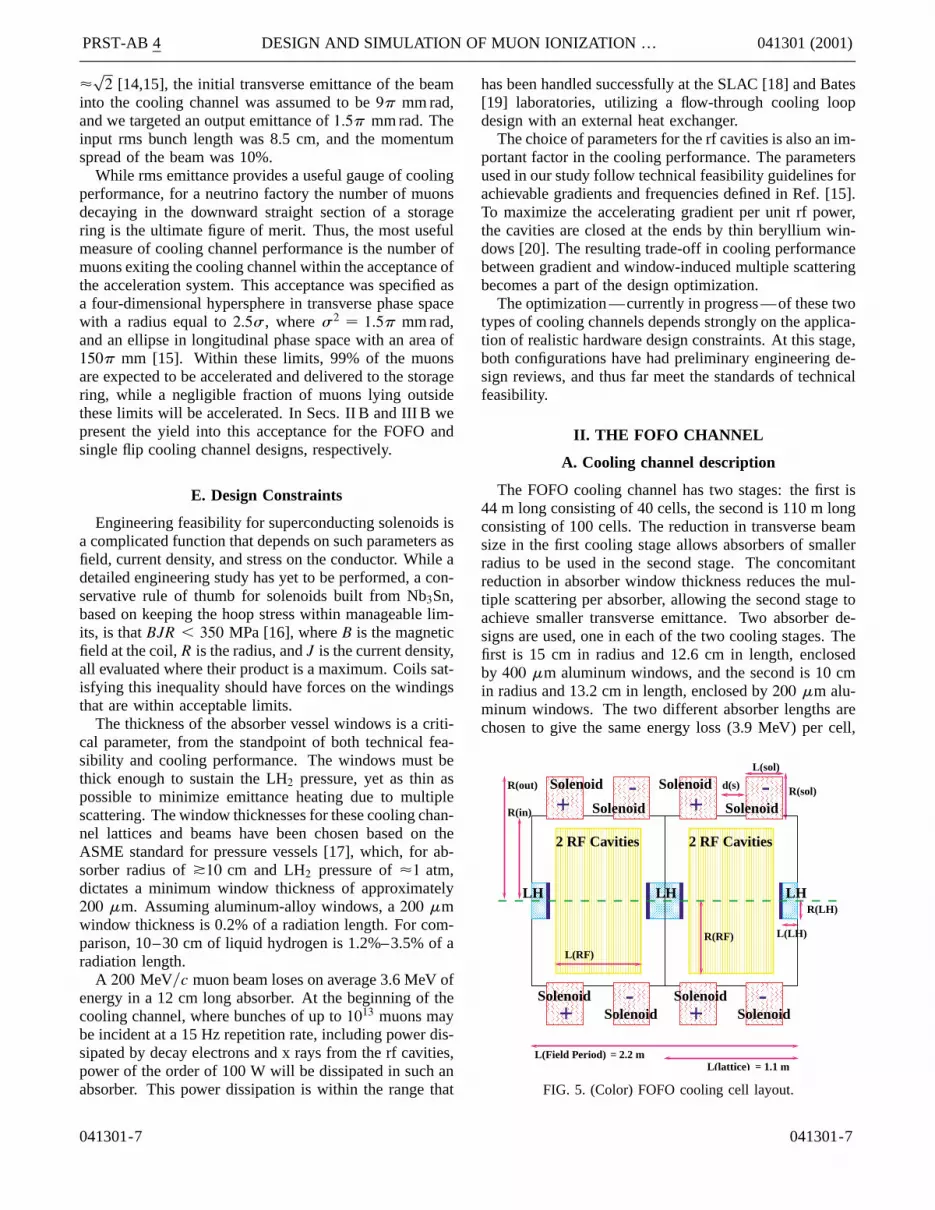
The FOFO cooling channel has two stages: the first is44 m long consisting of 40 cells, the second is 110 m longconsisting of 100 cells. The reduction in transverse beamsize in the first cooling stage allows absorbers of smallerradius to be used in the second stage. The concomitantreduction in absorber window thickness reduces the mul-tiple scattering per absorber, allowing the second stage toachieve smaller transverse emittance. Two absorber de-signs are used, one in each of the two cooling stages. Thefirst is 15 cm in radius and 12.6 cm in length, enclosedby 400 mm aluminum windows, and the second is 10 cmin radius and 13.2 cm in length, enclosed by 200 mm alu-minum windows. The two different absorber lengths arechosen to give the same energy loss (3.9 MeV) per cell,
LHLH
L(RF)
Solenoid
+ Solenoid -
+Solenoid
Solenoid -
R(in) +2 RF Cavities2 RF Cavities
R(RF) L(LH)
L(sol)
Solenoid
Solenoid
Solenoid
+ Solenoid -- R(sol)d(s)
L(Field Period) = 2.2 m = 1.1 mL(lattice)
R(out)
R(LH)LH
FIG. 5. (Color) FOFO cooling cell layout.
041301-7

PRST-AB 4 J. MONROE et al. 041301 (2001)
TABLE I. List of parameters for the 3.4 T FOFO.
Parameters Values
Length of section, DL 1.1 mMaximum magnetic field 3.4 TNumber of sections per stage 40/100Length of hydrogen (LH2) absorber 0.126/0.132 mDensity of LH2 0.0708 g�cm3
Thickness of hydrogen windows (Al) 400 mm/200 mmEnergy loss per section, nominal �3.9 MeVRadial aperture, in LH2 15.0/10.0 cmLength of linac (per section) 0.6586 mNumber of rf cells 2Frequency (MHz) 201.25 MHzPeak field, on axis 15 MV�mOptimum sync. phase fs 29.7±
Acceleration at optimum fs �4.3 MVBeryllium window thickness 125 mmRadial aperture, linac r � 17 cmNominal momentum P0 210 MeV�cNormalized transverse emittance eTn 9000p mm mradb� 40.0 cmsx , lab frame 4.5 cmsPt , lab frame 20.0 MeV�cLongitudinal bunch spread sz 10.0 cmLongitudinal emittance eLn 15 mm6D invariant emittance 1215 mm3
such that the rf system does not require retuning to main-tain an approximately constant beam energy.
The FOFO magnetic field is sinusoidal at the beam axis,with 1.1 m half-period and 3.4 T maximum field on axis.The magnetic field is generated by 30 cm long Helmholtzcoils with an inner diameter of 1.36 m and outer diameterof 2.06 m. Each half-period of the magnetic field has twocoils of the same polarity separated by a 20 cm gap (forpower coupling to the rf), and magnets in adjacent cellshave opposite polarity. All coils have a current density of49 A�mm2. The large aperture is necessary to accommo-date the 201.25 MHz rf cavities. While the peak field onaxis is 3.4 T, the peak field at the coils is close to 7 T.
The layout of the FOFO cooling cell is shown in Fig. 5,and the channel parameters are tabulated in Table I. Eachcooling cell consists of a half-period of the FOFO lat-tice, with two p�2 mode pillbox rf cavities and a liquidhydrogen absorber. The rf cavities have a peak field of15 MV�m, use beryllium windows, and are each 32.93 cmlong, giving an rf phase advance per cavity equal to p�2.Each pair of rf cavities accelerates the beam by 4.3 MeV�cat a synchronous phase of 29.7±. This energy is then re-moved by the hydrogen absorber. In this example, thechannel is tuned so that there is no net acceleration ofthe beam.
B. Simulation results
Figure 6 shows results from a simulation of the FOFOchannel. Within 6D phase space cuts of 150 mm longi-
041301-8
Total Particle Transmission
0.0
0.1
0.2
0.3
0.4
0.5
0.6
0.7
0.8
0.9
1.0
0 5 0 100 150Z (m)
Tran
smis
sion
Particles in Phase Space Cuts (6D)longitudinal < 150 mm
0.0
0.1
0.2
0.3
0.4
0.5
0.6
0.7
0.8
0.9
1.0
0 5 0 100 150Z (m)
Tran
smis
sion
transverse < 15 mm
transverse < 9.375 mm
Longitudinal Emittance
0
5
1 0
1 5
2 0
2 5
3 0
0 5 0 100 150Z (m)
εL (
mm
)
Transverse Emittance
0
1
2
3
4
5
6
7
8
9
0 5 0 100 150Z (m)
εN
(m
m)
FIG. 6. (Color) FOFO channel performance as a function of thelongitudinal coordinate z. Top right: fractional transmission; topleft: transmission into the acceleration acceptance cuts, uppercurve (blue line) with a 9.375 mm rad transverse cut, lowercurve (green line) with a 15 mm rad transverse cut; bottom left:transverse emittance; bottom right: longitudinal emittance.
tudinal and 9375p mm mrad transverse emittances, thefraction of initial muons increases from 10% to 45%. Anadditional 25% of the initial beam is transmitted to the endof the cooling channel but lies outside of the target regionof phase space. The remaining 30% of the original beamis lost due to particle decays, scraping against apertures,or stopping in the absorbers. Of the lost muons, approxi-mately 10% are lost due to muon decays, and about 6%because of muons with sufficiently high transverse ampli-tude to scrape against the rf windows (at 17 cm radius).In addition, 44 m into the channel, the liquid hydrogenabsorber radius is reduced to 10 cm, causing another4% of the input beam to be scraped. The remaining lossesare from a combination of discrete events with large-angle scattering or large energy loss, or particles falling outof the rf bucket and eventually crossing the p resonancefor the FOFO channel (at a momentum of 155 MeV�cfor this lattice), which causes them to fall outside thetransverse acceptance of the channel.
In the FOFO channel, the beam is cooled in a self-similar manner, so that the transverse rms propertiesmaintain their proportion. In the longitudinal direction,there is heating in phase space due to the unfavorableslope of the energy loss dE�dz as a function of energyand the energy straggling. This leads approximately toa doubling of occupied longitudinal phase space, whichresults in reduced transmission rather than increasedemittance, as particles fall out of the rf bucket.
The beta function of 40 cm at the liquid hydrogen ab-sorbers corresponds roughly to an equilibrium emittanceof 2200p mm mrad. The final emittance of the beam isvery close to this value. These results are summarized inTable II. For comparison, a total energy of �600 MeV wasremoved by the absorbers and returned via rf acceleration,
041301-8

PRST-AB 4 DESIGN AND SIMULATION OF MUON IONIZATION … 041301 (2001)
TABLE II. Evolution of beam parameters in the FOFO coolingchannel. The number of muons per proton incident on target isshown in parentheses in the last three rows.
Parameter z � 0 m z � 100 m z � 150 m
eT (mm rad) 9.0 3.0 2.2eL (mm) 15 22 27
N9 mm (%) 10 37 43 (0.095)N15 mm (%) 19 55 60 (0.132)Npart (%) 100 (0.22) 80 (0.176) 73 (0.16)
which in the absence of multiple scatter would have cooledthe beam from 9000p mm mrad to �450p mm mrad.
III. THE SINGLE FLIP COOLING CHANNEL
A. Cooling channel description
The single flip cooling channel has two stages. Betweenthe two cooling stages there is a 2.47 m long matchingsection in which the axial field changes polarity. The first
0 5.0 1.0 1.5 2.0
-5.08
-5.04
-5.0
-2 -1 0 1 2 3 4Z
+/- 0.5 kG
5 T
= 1 %
Z (m)
One Section, L = 2.47 m
Z (m)
Bz (Tesla)
+/- 4T
Length of Flip = 0.8 m
Bz (Tesla)
-5.0
5.0
0.0
FIG. 7. (Color) Top: variation of the axial field Bz (kGauss) atr � 0 cm in the single flip cooling channel, for the constantfield stages. Bottom: variation of the axial field at r � 0 in thematching (field flip) section.
041301-9
stage consists of twenty-one 2.47 m long cooling cells, ata nearly constant magnetic field of 25 T on axis. Thesecond stage consists of forty-two 2.47 m long cells at15 T on axis. Within each cooling stage the magneticfields vary by only 61%; for this reason there is verylittle modulation of the beam envelope. The axial fieldversus z for both cooling stages and the matching sectionis shown in Fig. 7. The beam envelope modulation has awavelength of �1.5 m, with an amplitude of 62 cm. TheLarmor radius of the nominal particle is 0.6 cm, and theLarmor wavelength is �3 m m.
The most sensitive parameter of this cooling channeldesign is the derivative with respect to z of the z componentof the magnetic field at the location of the field flip. Ideally,when the field flip is very fast, there is no drift of theLarmor centers [Eq. (1.6) for L ! 0]. In this case theminimum transverse-longitudinal correlation is induced inthe beam, since there is no drift of the Larmor centersand the pt change depends on the Larmor radius, andhence matching into the rf bucket acceptance producesmaximal transmission. In a more realistic case, pT andthus the difference of the central energy of the beam in therf bucket, Ec, to Eref increase significantly [see Eq. (1.21)]due to the radial field in the flip region, which excitesa large synchrotron oscillation. As a result, the largestparticle losses occur within 8 to 12 m after the field flip,although the synchrotron period in this channel is �28 m.
TABLE III. List of parameters for the 5 T single flip coolingchannel.
Parameters Values
Length of section, DL 2.47 mMaximum magnetic field 5.0 TNumber of cells per stage 21/42Length of hydrogen (LH2) absorber 0.32–0.35 mDensity of LH2 0.0708 g�cm3
Thickness of hydrogen windows (Al) 300 mmEnergy loss per cell, nominal �10 MeVRadial aperture, in LH2 r � 20.0 cmLength of linac (per section) 1.974 mNumber of rf cells 6Frequency (MHz) 201.25 MHzPeak field, on axis 15 MV�mOptimum sync. phase fs 28.65±
Acceleration at optimum fs �12.5 MVBeryllium window thickness 125 mmRadial aperture, linac r � 19 cmNominal momentum P0 200 ! 280 MeV�c
(at the field flip)Normalized transverse emittance eTn 12 250p mm mradb� 21.0 cmsx , lab frame 4.5 cmsPt , lab frame 30.0 MeV�cLongitudinal bunch spread sz 31.6 cmLongitudinal emittance eLn 849 mm6D invariant emittance 1200 mm3
041301-9

PRST-AB 4 J. MONROE et al. 041301 (2001)
1 1
LHLH
R(LH)
L(RF)
7 Be WindowsR(in)
R(out)6 RF Cavities
R(RF)
L(LH) 1 Al window
1 Al window
d L(sol)
R(sol)
Solenoid Solenoid Solenoid
SolenoidSolenoidSolenoid
FIG. 8. (Color) Single flip cooling cell layout.
-5T
+5T
Solenoid
SolenoidSolenoid
Solenoid
Solenoid
Solenoid Solenoid
Solenoid
R(L-in)
R(L-out)
d(s)
d(L)
L(small sol.)
R(s-in)R(s-out)
L(sol.)
Matching Section Length = 247 cm
FIG. 9. (Color) Single flip matching section.
Each 2.47 m cooling cell contains one liquid hydrogenabsorber of length between 31 and 34 cm, with radius20 cm, and one 1.97 m long linac. The accelerating struc-ture consists of six p�2 mode pillbox cavities, with a peakgradient of 15 MV�m, operating at about 30± synchronousphase. The cells of the linac are separated by 125 mmthick beryllium windows, with radius 19 cm. By design,the nominal particle gains 12.5 MV per linac and loses10 MeV per absorber, thus the nominal channel momen-tum increases linearly by 2.5 MeV per 2.47 m long cell.This acceleration is chosen to increase the acceptance ofthe rf bucket as the rms energy spread increases throughthe channel, and thereby avoid particle loss due to this lon-gitudinal phase space dilution. To maintain a constant en-ergy loss per cell of 10 MeV, the lengths of the absorbersincrease from 31.8 to 35 cm. The list of parameters forthe 5 T single flip channel is shown in Table III, and thelayouts for the cooling cells and the field flip section areshown in Figs. 8 and 9, respectively.
B. Simulation results
The single flip cooling channel increases the numberof particles within the 6D acceleration acceptance phasespace by a factor of 5 in 150 m. The transmission through
041301-10
the cooling channel is 80%, and approximately half ofthese particles are within the transverse acceleration ac-ceptance cuts. Nearly all particles transmitted through thecooling channel are within the longitudinal accelerationacceptance.
The minimum achievable emittance is limited by mul-tiple scattering. In this channel, the multiple scatteringlimit (for an absorber of length 32 cm) is 0.0162 rad. Theinitial rms angular spread of the beam sx0 � 0.1604 rad.After 21 sections, sx0 � 0.0489 rad, a reduction by ap-proximately a factor of 3. The transverse size of the beam,sx , is unchanged. The length of the first channel could,in principle, be extended to cool to the multiple scatter-ing limit; however, the 21 3 2.47 m length is chosen toboth minimize the total length of the cooling channel andcompensate for the expansion of the beam envelope in thematching section. In a conservative matching section de-sign, the change in axial field polarity occurs in approxi-mately 0.8 m. The reduction in solenoidal focusing and thelarge radial fields cause the rms angular spread to increaseby about a factor of 3. The second cooling channel reducessx0 by the same factor, and sx by approximately a factorof 2. The length of the second cooling channel is addi-tionally constrained by the requirement that the beam exitsthe solenoid with the appropriate transverse correlations,such that the beam outside the solenoid has no angularmomentum.
The majority of the particle loss occurs at the field flip,where the momentum spread increases dramatically, dueto the radial fields. The longitudinal phase space dilu-tion is particularly evident, as can be seen in Fig. 10. Themomentum perturbation at the location of the change infield polarity excites a large synchrotron oscillation, which
0 40 80 120 160 200
0.8
0.9
1
0 40 80 120 160 200
4.
.6.
8.
10.
0 40 80 120 160 200
20.
30.
40.
50.
60.
70.
0 40 80 120 160 200
0.1
0.2
0.3
0.4
0.5Transmission into 15mm acceptance
Transmission into 9mm acceptance
Transmission (%)
Transverse Emittance (mm. rad.)
Particles in 6D cuts: Long.= 150 mm
Longitudinal Emittance(mm.)
Z(m) Z(m)
Z(m) Z(m)
FIG. 10. (Color) Performance of the single flip channel. Topleft: fractional transmission; top right: fractional transmis-sion into acceleration acceptance, lower curve (blue) with a9.375 mm rad transverse cut, upper curve (green) with a 15 mmtransverse cut; bottom left: transverse emittance; bottom right:longitudinal emittance.
041301-10

PRST-AB 4 DESIGN AND SIMULATION OF MUON IONIZATION … 041301 (2001)
TABLE IV. Evolution of beam parameters in the single flipcooling channel. The number of muons per proton incident ontarget is shown in parentheses in the last three rows.
Parameter z � 0 m z � 100 m z � 150 m
eT (mm rad) 11.5 3.7 2.9eL (mm) 20 40 47
N9 mm (%) 7 28 35 (0.077)N15 mm (%) 13 46 50 (0.11)Npart (%) 100 (0.22) 84 (0.185) 80 (0.176)
causes particles at high transverse amplitudes to effectivelyfall out of the rf bucket. By the end of the cooling channel,such large-amplitude particles have been scraped longitu-dinally, resulting in a net growth of the longitudinal emit-tance of only a factor of 2.2, due primarily to straggling.The channel performance is summarized in Table IV, andthe transmission and emittance as a function of z are shownin Fig. 10.
IV. CONCLUSION
We have presented two distinct designs of ionizationcooling lattices based on solenoidal focusing elements andliquid hydrogen absorbers. These designs have been op-timized for initial beam parameters relevant to an intenseneutrino source [15], and engineering feasibility has beenused as a guideline to constrain the parameters chosen forthe solenoids, the hydrogen absorbers, and the rf systems.The two lattices differ in the type of solenoidal focusingused to minimize b� at the absorber: the FOFO uses shortsolenoids (with respect to the Larmor wavelength) withalternating field polarity, while the single flip uses longsolenoids, with only one field polarity change. The twolattices have different design limitations: the periodic na-ture of the FOFO introduces betatron resonances, whilethe strong perturbation of the beam’s transverse motionin the field-flip section of the single flip introduces lon-gitudinal phase dilution (and thus losses) due to the largetransverse-longitudinal phase space coupling.
We have shown that with careful optimization of the de-sign parameters these inherent problems are manageable,while respecting the standards of cooling lattice engineer-ing feasibility. Both designs produce a cooling factor of4.5 for cooling-channel length of 150 m, where coolingfactor is defined as the increase in muon intensity withinthe acceptance of the subsequent acceleration system. Thisis within 40% of the cooling goal that has been set for asuccessful neutrino factory [15]. The two lattices also havesimilar total muon transmission rates of 70%–80%. Theperformance of ionization cooling lattices of the types dis-cussed in this paper can be further improved by implement-ing different variations of the solenoid field configuration.For example, in the short alternating solenoid case con-sidered here (FOFO), the magnetic field contains only oneharmonic (simple sinusoidal function of position). Other
041301-11
designs, currently under consideration, which use more so-phisticated coil configurations may deliver improved cool-ing performance by introducing more harmonics to thefield [21,22].
ACKNOWLEDGMENTS
This work was supported in part by grants from theIllinois Board of Higher Education, the Illinois Depart-ment of Commerce and Community Affairs, the NationalScience Foundation, and the U.S. Department of Energy.
[1] C. M. Ankenbrandt et al., Phys. Rev. ST Accel. Beams 2,081001 (1999).
[2] G. I. Budker and A. N. Skrinsky, Sov. Phys. Usp. 21, 277(1978).
[3] D. Neuffer, Part. Accel. 14, 75 (1983).[4] G. Penn and J. S. Wurtele, Phys. Rev. Lett. 85, 764-767
(2000).[5] D. M. Kaplan, Nucl. Instrum. Methods Phys., Res. Sect. A
453, 37 (2000).[6] E. Kim, C. Kim, G. Penn, A. M. Sessler, and J. S. Wurtele,
Fermi National Laboratory Mucool Note No. 36, 1999(http://www-mucool.fnal.gov/mcnotes/muc0036.ps).
[7] Ya. Derbenev, Fermi National Laboratory Mucool NoteNo. 108, 2000 (http://www-mucool.fnal.gov/mcnotes/muc0108.ps); V. Balbekov, in Proceedings of the NeutrinoFactory Workshop, 2000 (unpublished).
[8] R. Fernow, in Proceedings of the 1999 Particle Accel-erator Conference, New York, edited by A. Luccio andW. MacKay (IEEE, Piscataway, NJ, 1999), p. 3020.
[9] P. Lebrun, see www-pat/simulations/muc; also GEANT3User Manual (http://wwwinfo.cern.ch/asd/geant/index.html).
[10] Martin Reiser, Theory and Design of Charged ParticleBeams (Wiley-Interscience, New York, 1994), Sec. 3.4.4.
[11] Ignoring the MCS term, Eq. (1.1) results in e�z� �e�0�e2z��b2Edz�dE� � e�0�e2z��pdz�dp�, which motivatesthe definition of z �
zp j
dpdz j as the scaled longitudinal
coordinate.[12] These expressions result from the evolution of the initial
beam distribution (1.4), using Eq. (1.1). See also V. Bal-bekov, Fermi National Laboratory Mucool Note No. 118,2000 (http://www-mucool.fnal.gov/mcnotes/muc0118.ps);C. Wang and K. Kim, Fermi National Laboratory Mu-cool Note No. 92, 2000 (http://www-mucool.fnal.gov/mcnotes/muc0092.ps).
[13] C. Wang and K. Kim, Fermi National Laboratory Mu-cool Note No. 142, 2000 (http://www-mucool.fnal.gov/mcnotes/muc0142.ps).
[14] R. Palmer, Fermi National Laboratory Mucool NoteNo. 46, 1999.
[15] N. Holtkamp and D. Finley (Fermilab ReportNo. Fermilab-PUB-00–108–E).
[16] J. Miller (private communication).[17] ASME Boiler and Pressure Vessel Code, ANSI�ASME
BPV-VIII-I (American Society of Mechanical Engineers,New York, 1980), part UG-32.
041301-11

PRST-AB 4 J. MONROE et al. 041301 (2001)
[18] J. W. Mark, SLAC Report No. SLAC-PUB-3169, 1984.[19] E. J. Beise et al., Nucl. Instrum. Methods Phys. Res.,
Sect. A 378, 383 (1996).[20] A. Moretti, N. Holtkamp, T. Jurgens, Z. Qian, and V.
Wu, in Proceedings of the 20th International Linac Con-ference (Linac 2000), Monterey, California, 2000, eConfC000821:THc18, 2000.
041301-12
[21] V. Balbekov, Fermi National Laboratory Mucool NoteNo. 130, 2000 (http://www-mucool.fnal.gov/mcnotes/muc0130.ps).
[22] B. Palmer, Fermi National Laboratory Mucool NoteNo. 114, 2000 (http://www-mucool.fnal.gov/mcnotes/muc0114.ps).
041301-12