design and performance of speculative flow control for high-radix datacenter interconnect switches
TRANSCRIPT
J. Parallel Distrib. Comput. 69 (2009) 680–695
Contents lists available at ScienceDirect
J. Parallel Distrib. Comput.
journal homepage: www.elsevier.com/locate/jpdc
Design and performance of speculative flow control for high-radix datacenterinterconnect switchesI
Cyriel Minkenberg ∗, Mitchell GusatIBM Research GmbH, Zurich Research Laboratory, Säumerstrasse 4, 8803 Rüschlikon, Switzerland
a r t i c l e i n f o
Article history:Received 18 March 2008Accepted 29 July 2008Available online 14 August 2008
Keywords:Interconnection networksFlow controlSpeculation
a b s t r a c t
High-radix switches are desirable building blocks for large computer interconnection networks, becausethey are more suitable to convert chip I/O bandwidth into low latency and low cost than low-radixswitches [J. Kim, W.J. Dally, B. Towles, A.K. Gupta, Microarchitecture of a high-radix router, in: Proc. ISCA2005, Madison, WI, 2005]. Unfortunately, most existing switch architectures do not scale well to a largenumber of ports, for example, the complexity of the buffered crossbar architecture scales quadraticallywith the number of ports. Compoundedwith support for long round-trip times andmany virtual channels,the overall buffer requirements limit the feasibility of such switches tomodest port counts. Compromisingon the buffer sizing leads to a drastic increase in latency and reduction in throughput, as long as traditionalcredit flow control is employed at the link level. We propose a novel link-level flow control protocolthat enables high-performance scalable switches that are based on the increasingly popular bufferedcrossbar architecture, to scale to higher port counts without sacrificing performance. By combiningcredited and speculative transmission, this scheme achieves reliable delivery, low latency, and highthroughput, even with crosspoint buffers that are significantly smaller than the round-trip time. Theproposed scheme substantially reduces message latency and improves throughput of partially bufferedcrossbar switches loaded with synthetic uniform and non-uniform bursty traffic. Moreover, simulationsreplaying traces of several typical MPI applications demonstrate communication speedup factors of 2 to10 times.
© 2008 Elsevier Inc. All rights reserved.
1. Introduction
The role of the interconnection network in scientific, as wellas commercial computer systems is of growing importance. Theunderlying trend is that the growing demand for computingcapacity will be met through parallelism at the instruction, thread,core, and machine level.As a consequence, the scale, speed, and efficiency of the
interconnects must grow significantly, for these reasons:• Increasing parallelism: More cores per processor, clustering,massively parallel processing.• Computer busses are being replaced by switched networks toachieve bandwidth scalability.• The communication infrastructure (SAN, LAN, IO, IPC) isbeing consolidated to reduce cost and power and improvemanageability.
I Expanded version of a paper published in the proceedings of the 21st IEEEInternational Parallel and Distributed Processing Symposium (IPDPS 2007), LongBeach, CA, March 2007.∗ Corresponding author.E-mail addresses: [email protected] (C. Minkenberg), [email protected]
(M. Gusat).
0743-7315/$ – see front matter© 2008 Elsevier Inc. All rights reserved.doi:10.1016/j.jpdc.2008.07.014
• Virtualization of computing infrastructure introduces morevariability (unpredictability) in the network load, potentiallyharming application performance, scalability, and overallefficiency. While performance remains our main concern,efficiency is becoming a particularly vexing issue in thelight of escalating power consumption and cooling issues indatacenters.
As neither busses nor legacy LAN/WANs canmeet all datacenterand high-performance computing requirements – notably lowlatency, high bandwidth, high reliability, and low cost – anumber of networking technologies designed specifically forthe datacenter environment have emerged. Examples are FibreChannel, commonly employed in storage area networks (StAN),Myrinet and QsNet (Quadrics), used for low-latency, high-bandwidth inter-process communication in high-performancecomputing or clustering environments, and InfiniBand [10],designed as a comprehensive datacenter interconnect. Moreover,there is a significant thrust to enhance next-generation Ethernetwith the capabilities required by datacenters, for example level-2congestion management [9].Our focus is the design of the switching nodes used in such
networks, in particularwith regard to their radix, i.e., the number ofports. Kim et al. show in [13] that the network latency isminimized

C. Minkenberg, M. Gusat / J. Parallel Distrib. Comput. 69 (2009) 680–695 681
by selecting the optimal switch radix, given the aggregate switchbandwidth feasible in current technology. This is a given valueindependent of the radix, i.e., the product of port count and portspeed is fixed. Given a target network port count, the end-to-endlatency increases if the radix is smaller than the optimum, becausethe hop count increases. On the other hand, if the radix is largerthan the optimum, the serialization latency increases because ofthe reduced port speed. The result indicates that as the aggregatebandwidth increases, the optimal radix also increases. The authorsestimate the optimal radices for 2003 and 2010 technologies at 40and 127, respectively. The overall network cost also decreases asthe radix increases, because for a given, fixed network bisectionbandwidth, a higher radix reduces the hop count, thus requiringfewer switches and internal cables.Modern switches are commonly based on crossbars of the
buffered or unbuffered variety. A detailed discussion on therelativemerits and drawbacks of buffered vs. unbuffered crossbarswould exceed the scope of this paper. However, both scalepoorly as their radix increases. With unbuffered crossbars thescaling bottleneck is the central scheduler: obtaining a high-quality matching for a large number of ports in a short time slotis extremely challenging (see for instance [16]). With bufferedcrossbars the scaling bottleneck lies in the aggregate bufferrequirements, which scale quadratically with the number ofports [8].Although VLSI density is very high nowadays, the issue of buffer
scaling remains relevant for a number of reasons:
• Increasing scale and distribution, higher levels of parallelism,and serialization/deserialization required for high-speed seriallinks have led to higher latencies. In combination withincreasing line rates, this has resulted in significantly largerbandwidth-delay products (BDP) and hence proportionallylarger buffers.• As argued above, large-radix switches have become attractivefrom the point of view of optimizing end-to-end latency, thuscompounding the buffer requirements.• Buffer sharing becomes unattractive, or even infeasible froman implementation perspective as aggregate switch throughput(line rate times radix) increases, because of the required wiringcomplexity and extremely short access times. By partitioningbuffers on a per-port basis, leading to the buffered crossbararchitecture, both the wiring complexity and memory speedcan be reduced drastically. However, this entails quadraticscaling of the number of crosspoints, thus further compoundingthe buffer scaling issue.• Roughly speaking,manufacturing yield decreases exponentiallywith increasing die size. This problem has been exacerbated byshrinking CMOS feature sizes. Smaller buffers mean a smallerdie and, hence, lower cost.• Last, but certainly not least, with the advent of chip multipro-cessors with many tens of cores, a single die comprises CPUs,multiple cache levels, aswell as an on-chip interconnection net-work. Hence, a CMP architect faces the dilemma of trading offsilicon area between processors and caches on one side andswitches on the other.
This scaling issue of buffered crossbars has recently receivedconsiderable attention, with the majority of solutions proposed sofar focusing on architectural changes to the switch core. Instead,we can derive more substantial benefits by focusing on a switch’slink-level flow control (LL-FC) protocol, which governs buffer al-location and link traversal. The main contribution of this paper isa new LL-FC scheme that addresses the key requirements of com-puter interconnects: (1) it enables full bandwidth utilization withdownstream buffers that are significantly smaller than the round-trip-time × bandwidth product (bandwidth-delay product, BDP),
(2) it reduces latency by eliminating the flow-control latency ofconventional LL-FC protocols, and (3) it provides reliable delivery.The key novel aspect is that it combines speculative and credited
modes of transmission. The speculative mode predominates whenutilization is low to reduce latency, whereas the credited modepredominates when utilization is high to achieve high maximumthroughput. Applied to the buffered crossbar architecture, theproposed scheme can substantially reduce the overall bufferrequirements.The remainder of the paper is organized as follows: Section 2
reviews the role of LL-FC in interconnection networks (ICTNs)and some existing LL-FC protocols. Section 3 explains the detailsof our speculative flow control (SFC) scheme. In Section 4 weapply SFC to the buffered crossbar architecture and show howthis reduces the overall buffer requirements. In Section 5 weexamine the performance of the proposed scheme by means ofsimulation, using synthetic traffic patterns, whereas in Section 6we present results obtained by replaying traces of a number ofbenchmark MPI applications on a model of a parallel computerwith an SFC-enabled interconnection network. Section 7 discussesimplementation aspects. Finally, we conclude in Section 8.
2. Link-level flow control
Despite a large body of research results [3,6,12,14,19] accruingover the last few decades, the role of LL-FC in the design of ICTNs isoften confoundedwith related, yet separate, topics such as routing,congestion control, and deadlock management. Nevertheless,technologies such as Fibre Channel, InfiniBand, Myrinet, or QsNetall feature some form of LL-FC. Ethernet features grant-like PAUSEframes (defined in IEEE 802.3x) that can be used to temporarilythrottle the sender on a full-duplex link.We proceedwith a reviewof the merits of LL-FC and some basic protocols.
2.1. Lossless vs. lossy networks
Interconnection networks can be categorized as follows:• Lossless networks, which take every possible measure inhardware not to lose any packet, such as InfiniBand, FibreChannel, RapidIO, PCIe, Myrinet, QsNet and others. They rely onLL-FC to prevent data loss due to buffer overflow. Transmissionerrors are typically recovered by a link-level retransmissionmechanism implemented in hardware.• Best-effort or lossynetworks,whichmayoccasionally drop somepackets and must rely on end-to-end retries at higher layers torecover. Best known are TCP/IP and ATM networks.
The crucial difference between a best-effort and a losslessICTN is that, by design, the former allows – and even relieson – packet loss, whereas the latter are not allowed to drop apacket. Best-effort networks typically employ end-to-end flowand congestion control in software (e.g. TCP). This reduces thecomplexity and cost of the network nodes, at the expense ofexporting the problem from the network to the end nodes. Thisapproach is well suited to the WAN/LAN environment, but theincurred drawbacks of reduced performance and reliability maybe unacceptable for the datacenter environment. Recovery frompacket drops incurs a significant latency. The network resourcesalready used by any packet that is dropped are wasted, includingthe power consumed by links and switches along the forwardingroute thus far. Moreover, drops can lead to long iSCSI timeouts inSAN networks or, even worse, to system crashes in IPC networks.To prevent a source from being overly greedy, and thus exac-
erbating this problem, TCP employs slow start with an additive-increase multiplicative-decrease (AIMD) window-adjustmentalgorithm. In a datacenter environment, however, a slow start isundesirable as it introduces significant latency until the full linkbandwidth can be used.
682 C. Minkenberg, M. Gusat / J. Parallel Distrib. Comput. 69 (2009) 680–695
Lossless networks, on the other hand, prevent buffer overflows,offer faster response time in the case of corrupted packets, do notsuffer from loss-induced throughput limitations, and allow burstyflows to start sending immediately at full bandwidth. Furthermore,their goodput does not collapse when loaded beyond saturation.On the downside, LL-FC can cause congestion to propagate inmultistage networks, thus inducing saturation trees.
2.2. Role of LL-FC
An LL-FC protocol provides a closed feedback loop to control theflow of data from a sender to a receiver. We distinguish variousLL-FC protocols by the semantics of the control information usedto inform the upstream sender about the downstream receiver’sbuffer status. The design of an LL-FC protocol involves trading offbuffer space, bandwidth overhead, robustness, performance, andcomplexity.The main objective of most LL-FC protocols is to regulate
the flow of data from sender to receiver in such a way thatthe receiver’s buffer is not forced to either drop packets forlack of space (overflow) or idle unnecessarily (underflow). Moregenerally, LL-FC protocols fulfill one or more of the followingpurposes:
• Buffer overflow avoidance: Eliminating avoidable losses im-proves efficiency and reliability.• Buffer underflow avoidance: Preventing buffer underrunsachieves work conservation at the link level.• Quality of Service (QoS): Per-service-class LL-FC informationsupports service differentiation (priorities, classes, lanes, virtualchannels).• Resource separation: By separately flow-controlling individualbuffer partitions, guarantees toward deadlock avoidance orforward progress can be made. While this can be useful inconjunction with QoS support, it should be treated as anorthogonal issue.
Although LL-FC can prevent buffer overflows, packet dropsdue to transmission errors can never be completely avoided.Therefore, lossless networks often also employ a link-level reliabledelivery (LL-RD) mechanism to ensure quick retransmission ofcorrupted packets. The purpose of LL-RD is to ensure error-free,in-order, single-copy delivery, typically implemented using errordetection (e.g. parity or cyclic redundancy check) and, optionally,error correction (e.g., forward error-correcting code), along witha retransmission scheme (often referred to as automatic repeatrequest–ARQ) to retry failed packets and recover the correct packetorder. Success and failure are communicated using positive (ACK)and/or negative acknowledgments (NAK), respectively. Preferably,LL-RD is implemented in hardware for optimum performance.The most common FC protocols are credit-, grant-, and rate-
based FC. In grant-based FC, also referred to as on-off FC, thesemantics of an FC message are either ‘‘stop sending’’ or ‘‘startsending’’. In credit-based FC, the semantics are ‘‘permission to sendup to x data units’’ in the case of absolute credits, or ‘‘permissionto send up to x additional data units’’ in the case of relative(incremental) credits. Finally, the semantics of rate-based FC areeither ‘‘send slower (by a factor x)’’ or ‘‘send faster (by a factor x)’’.The round-trip time (RTT) is the sum of the latencies δd and δc of
the forward data path and the reverse control path, respectively:RTT = δd + δc . The RTT is often normalized with respect to thepacket duration. The normalized round trip equals τ =
⌈BdWdRTTLd
⌉,
where Bd is the speed of the data channel,Wd the width of the datachannel, and Ld the length of a data packet. The RTT plays a crucialrole in properly dimensioning the receiver buffer sizeQR to achievelosslessness and work conservation.
2.3. Credit FC
Credit-based FC [14,19,12] typically uses relative (incremental)credit updates for efficiency, and requires one round trip worthof buffer space (QR = τ ) to achieve losslessness and workconservation, whereas grant-based FC requires two round tripsworth of buffer space (QR = 2τ ) to do the same. However, relativecredit FC is a stateful protocol, meaning that the current state asobserved by the sender depends on the history of FC information.On/off grant FC, on the other hand, is stateless, meaning that thecurrent state depends only on the most recent FC information.Hence, credits are more efficient, whereas grants are morerobust.We briefly review relative credit FC, considering a simple
point-to-point scenario with one sender S and one receiver Rcommunicating over a bidirectional link. Both S and R havebuffers to store packets; we assume fixed-size packets (cells),although this is not a strict requirement. Initially, R advertises thenumber of credits to S—we assume a granularity of one cell percredit, although this may vary per implementation. S maintainsa credit count that tracks the difference between the aggregatenumber of credits received and the number of credits consumed.S decrements the credit count for every cell sent; when the countreaches zero, no more cells can be sent until new credits arrive.R issues a new credit every time a cell departs from its buffer.The ratio between the normalized RTT and the receiver’s buffersize QR (in cells) determines the maximum link utilization ρmax asfollows:
ρmax = min(QRτ, 1). (1)
Consider the minimum turn-around time of a specific credit;if the credit is issued at t0, it arrives at the sender at t0 + δc .Assuming the sender has traffic queued up at that time, andimmediately sends a cell consuming the credit, the correspondingstorage location will be reused at t0 + δc + δd at the earliest, so itfollows that the turn-around time equals RTT. Moreover, as thereare QR credits, a maximum of QR cells can be injected during oneRTT, hence the maximum injection rate equals min
(QRτ, 1). This
implies that QR ≥ τ must hold to achieve full link utilization.Consider the situation where, at the start of time slot t1, the
receiver buffer is completely full, so that no free credits are incirculation. During t1, the receiver removes one cell from its bufferand issues a credit. The restart time is the latency from t1 until thesender can resume transmission. It follows that the restart time ofcredit FC equals δc . It can be shown that theworst-case restart timeof grant FC equals τ + δc .A major difference between credit and grant FC is that credit FC
operates losslessly with any buffer size greater than zero, whereasgrant FC requires at least one RTT worth of overflow buffer space.However, performance suffers if the downstream buffer size is lessthan τ cells. As Fig. 1 illustrates, in this case the RTT becomes amultiplicative factor in the burst latency. Here, a burst of six cellsis transmitted through a crosspoint that has room for only twocells (i.e., two credits). Between every pair of two cells, a latencyof one full RTT is incurred. Hence, the end-to-end latency of theburst equals three times the RTT.
2.4. ACK/NAK FC
A fourth, rarely used FC protocol is known as ACK/NAK FC [4,Section 13.3.3]. With this protocol, the sender does not maintainany state information about the receiver buffer. The sender isfree to send whenever it has data. When a cell arrives at thereceiver, it gets stored if there is room or dropped if there is

C. Minkenberg, M. Gusat / J. Parallel Distrib. Comput. 69 (2009) 680–695 683
Fig. 1. Burst latency. QR = 2 cells, burst size= 6 cells, RTT= 4 cell slots.
none. In the former case, the cell is acknowledged positively (ACK),otherwise it is acknowledged negatively (NAK). The sender storesunacknowledged cells in a retransmission buffer, and the receivermust ensure that cells are reordered properly, because cell dropslead to out-of-order arrivals.This type of FC is rather unpopular because it is wasteful of
bandwidth, while having similar overall buffer requirements ascredit FC. However, it does have two significant benefits. First,the maximum link utilization does not depend on the ratio QR/τ .ACK/NAK FC can operate at full link bandwidth with QR =1 regardless of τ , as long as the receiver buffer is not full.Second, the restart time is equal to zero, because the conditionto start transmitting does not depend on the state of the receiverbuffer. Because reception is not guaranteed, the sender has aretransmission buffer of size QRTX to store cells that are waitingto be acknowledged. The sender can only transmit when theretransmission buffer is not full. It follows that to obtain full linkutilization QRTX ≥ τ must hold. Therefore, the overall minimumbuffer requirement equals QR + QRTX = 1+ τ .
2.5. Controlling multiple downstream buffers
So far, we have only considered the case with a singledownstream buffer. However, in many applications, the receivermay have multiple separate buffers, each being flow-controlledindependently. A commonexample is a link that supportsmultiple,say L, virtual channels. To ensure that each lane canmake progressindependently of the other channels, each lane has a privatebuffer space that is managed with its own credits. Another highlyrelevant example is the N × N buffered crossbar architecture (seealso Section 4), which performs switching among N inputs andN outputs. This architecture features N separate buffers at thereceiving end of each input link.In the general case with M downstream buffers, the overall
buffer sizes under the requirement that each buffer must be ableto sustain full link bandwidth scale asMτ for credit FC (M receiverbuffers) and τ + M for ACK/NAK FC (one retransmission bufferandM downstream buffers). Clearly, the latter scales much betterthan the former. This advantage derives from the fact that a singleretransmission buffer is sufficient because there are only τ cells inflight (one link) regardless of the number of downstream buffers.
3. Speculative flow control
Wepropose a novel LL-FC protocol that combines the propertiesof credits and ACK/NAK FC in such a way that it shares theadvantages of both. Because of its speculative aspect, we refer toit as speculative flow control (SFC). SFC is a point-to-point protocolin which a sender and a receiver communicate over a bidirectionalchannel. For the purpose of the discussion, the downstreamchannel (sender to receiver) carries data messages, i.e., cells, andthe upstream channel carries FC messages. The receiver may havemultiple (M), independently managed buffers in which cells canbe stored. These buffers may correspond to, e.g., virtual channelsor to different output ports. We assume that the sender maintainsone queue corresponding to every downstream buffer to preventhead-of-line blocking. The receiver issues separate credits for everybuffer, i.e., every credit is uniquely associated with one buffer.Correspondingly, the sendermaintains an available credit count forevery buffer.
3.1. Rules of operation
SFC combines credited and speculative modes of operation,with the credited mode taking precedence over the speculativeone. In the speculative mode, the sender is allowed to transmitcells evenwithout sufficient credits. The following rules govern theoperation of the SFC protocol:
R1 A cell is eligible for credited transmission if the sender hassufficient credits for the cell’s destination downstreambuffer, i.e., the available credits represent at least asmuch buffer space as is needed to store the entire cell.The sender may perform a speculative transmission ina given time slot if and only if no cell is eligible forcredited transmission. A transmitted cell is referred to asspeculative if there were insufficient credits, otherwise itis referred to as credited.
R2 The receiver drops an incoming cell if its buffer is fullor the cell is corrupted, out of order, or a duplicate. Forevery dropped cell a NAK identifying the dropped cellis returned. To this end, every cell carries a sequencenumber.
684 C. Minkenberg, M. Gusat / J. Parallel Distrib. Comput. 69 (2009) 680–695
R3 The receiver issues an ACK for a cell at the instant the cellis removed from its buffer, i.e., when the correspondingbuffer space is freed up. Each ACK identifies theacknowledged cell by means of its sequence number.
R4 Each cell remains stored at the sender until it is positivelyacknowledged.
R5 Each cell may be speculatively transmitted at mostonce. All retransmissions must be performed as creditedtransmissions.
R6 The sender consumes credit for every cell sent, i.e., forspeculative as well as credited transmissions.
R7 The cellswaiting at the sender can be partitioned into un-sent cells and cells waiting for positive acknowledgment.A cell waiting for positive acknowledgment is only eli-gible for retransmission after it has been negatively ac-knowledged or expired. Cells are expired after a certaintime to deal with corrupted cells and ACKs. When creditsare available, negatively acknowledged and expired cellstake precedence over unsent cells.
In the remainder of this section, we will explain the rationalebehind these rules.
R1 implies that credited transmissions take strict precedenceover speculative ones. This ensures that the desirable properties,specifically high utilization, of credits are preserved.The receiver drops a cell if either the buffer is full (speculative
cells only), the cell arrives out of order (OOO), or an uncorrectabletransmission error corrupted the cell. In all of these cases, R2requires that the receiver returns a NAK for the dropped cell. ThisNAK comprises a sequence number uniquely identifying the cell. Inan alternative implementation, the receiver could accept OOO cellsand perform resequencing on a per-flow basis to ensure in-orderdelivery. This reduces the number of retransmissions at the cost ofresequencing buffers and logic.Instead of being communicated explicitly, credits are conveyed
implicitly by the acknowledgments. According toR3 the receiverreturns a positive acknowledgment (ACK) when a cell leaves, notwhen it enters, its buffer. Hence, an ACK is equivalent to anincremental credit, whereas a NAK is equivalent to an incrementalcredit for a dropped cell. From the perspective of LL-RD, the ACKcan be returned upon entrance, but by delaying it until exit, theoverhead of LL-FC and LL-RD can be condensed into a single FCmessage. Moreover, this approach enables cell replacements, asdiscussed in Section 3.2. The main drawback is that cells remainstored longer at the sender, so it impacts the retransmission bufferdimensioning. NAKs, on the other hand, are returned right after cellarrival.According to R4, all cells remain stored in the sender’s buffer
until positively acknowledged. This holds for speculative as wellas credited cells, even though credited cells will not be dropped asa result of overflow. However, the RDmechanism also covers othersources of cell loss, such as unrecoverable transmission errors.Hence, SFC fully integrates LL-RD, dealing with protocol-specificas well as protocol-independent causes of loss.As excessive speculation may cause bandwidth wastage, R5
limits the number of speculations to atmost one per cell. Also, cellswaiting for acknowledgement and negatively acknowledged cellsare not eligible for speculation.
R6 specifies a conservative credit policy. This means that acredit is consumed even though there may be no space in thereceiving buffer. Correspondingly, the receiver returns a credit forevery incoming cell, even the ones that have been dropped. R6implies that the credit count may be negative. The classificationinto speculative and credited cells (R1) can be reformulatedas follows: a cell selected for transmission is credited if thecorresponding credit count is greater than or equal to zero afterdecrementing, and otherwise it is a speculative cell. Any queue
for which the credit count is less than or equal to zero (beforedecrementing) can only perform speculative transmissions. Thebenefits of adopting R6 are that all credited cells are guaranteedto not be dropped because of buffer overflow, and that cells neednot be explicitly marked as credited or speculative.The purpose of R7 is to minimize the number of retransmis-
sions bywaiting for explicit positive or negative acknowledgments.Upon positive acknowledgment, the sender removes the corre-sponding cell from its buffer. Upon negative acknowledgment, itmarks the corresponding cell as eligible for retransmission. As thereceiver only accepts cells in the correct sequence, all other cellsin flight (to the same downstream buffer) will also be droppedand negatively acknowledged. Upon reception of a NAK, the senderstops transmitting new (previously unsent) cells to that down-stream buffer until the corresponding cell has been retransmitted.To ensure that unacknowledged cells do not wait forever when
a severe transmission error damages the cell so badly that thereceiver does not even detect its presence, or when the ACK/NAKis lost, cells should be aged. Cells having an age over a certain(conservative) threshold are expired and treated the same asnegatively acknowledged cells.The specific policies used to arbitrate among eligible cells
for either speculative or credited transmission can be chosenaccording to preference. The only restriction is that cells belongingto the same flow should be served in the order of their arrival.
3.2. SFC with replacement
The SFC rules of operation specify that (i) a cell should be storedat the sender until acknowledged and (ii) a cell is acknowledgedwhen departing from the receiver’s buffer. This opens up thepossibility of replacing cells already stored at the receiver bynewly arriving ones. Such replacements are useful in severalcontexts, for example to support multiple levels of priority. Usingconventional credits, dedicated receiver buffer space must beallocated to every priority to ensure progress and prevent priorityinversion [15]. When multiple priorities share a buffer, priorityinversion occurs when low-priority cells hog the receiving buffer,thus preventing higher-priority ones from entering the buffer.With SFC, it is possible to replace a low-priority cell when a high-priority one arrives at a full buffer. To signal the replacement, thereceiver issues a NAK for the replaced (dropped) cell. Preferably,to minimize the number of retransmissions, the receiver shouldreplace the most recently arrived cell from the lowest prioritypresent. To ensure in-order delivery, the sender also revertsthe corresponding expected next sequence number back to thesequence number of the cell replaced.However, this mechanism only works properly when the
sender’s retransmission buffer is larger than the downstreambuffer. Otherwise, injections of new cells would be prevented bya full retransmission buffer. Hence, the ‘‘oversize’’ of the retrans-mission buffer directly determines howmany replacements can bemade.
3.3. Applications
A few potential fields of application for SFC are:
• Datacenter interconnection networks: SFC enables a mix oflossless and lossy traffic to coexist in the same network.Furthermore, it simultaneously offers high reliability for storageand system area networks, low latency for parallel computingapplications, and high utilization.• Buffered crossbar switches: The buffer requirements of this typeof switch scale quadratically with the port count. ApplyingSFC may reduce this requirement. We study this application indetail in Section 5.

C. Minkenberg, M. Gusat / J. Parallel Distrib. Comput. 69 (2009) 680–695 685
• Quality-of-service: Providing QoS using conventional creditsrequires pre-allocating buffer space to every traffic class. WithSFC, the buffer space can be shared dynamically amongmultiplepriorities, without leading to priority inversion (Section 3.2),which occurs when low-priority traffic is stalled in a sharedbuffer, thus preventing higher-priority traffic from entering.• Congestion control: The problem of downstream buffer hoggingis also responsible for tree saturation [21] in lossless intercon-nects: Cells destined for a ‘‘hot’’ (i.e., overloaded) node use up adisproportionate share of network buffers. In severe cases, thiscan lead to a collapse of aggregate network throughput. The roleof SFC complements that of congestion control: LL-FC dealswithtransient congestion at the link level to prevent buffer over-flows, whereas congestion control acts on an end-to-end basisto dealwith long-term congestion to counteract tree saturation.As SFC enables replacement of cells in downstream buffers, itmay be useful for fighting tree saturation. This application is leftfor future study.
4. An SFC-enabled buffered crossbar switch
Having studied the role of LL-FC in interconnection networksand defined the SFC protocol, we now proceed with a specific SFCcase study, namely, the combined-input-crosspoint-queued (CICQ)switch architecture (shown in Fig. 2), which features upstreambuffers (input queues) organized as virtual output queues (VOQs)and an N × N buffered crossbar switching core; the flow controlprotocol is usually based on incremental credits.Shared-memory switch architectures have been unable to
keep pace with the rising port counts and line rates, becauseimplementing a shared memory with the required aggregatethroughput is extremely difficult, the main limitation beingwiring rather than logic gates. The buffered crossbar has emergedas a viable alternative to the shared-memory architecture. Bydedicating a buffer to every input–output combination, allmemories operate at one instead of N times the line rate.
4.1. Related work
Packet switches based on buffered crossbars have attractedincreasing attention [1,11,13,17,23,26] in recent years. The advan-tages of the CICQ architecture are that it has a balanced distribu-tion of scheduling complexity, memories that operate no fasterthan the line rate, and excellent performance characteristics un-der a wide range of traffic patterns without requiring speedup. Itsmain drawback is that its memory requirements grow quadrati-cally with N . When taking into account the (normalized) roundtrip τ between the line cards and the buffered crossbar as wellas support for P priorities (or virtual channels), the overall buffersize scales as O(N2Pτ). This linear dependency on the RTT is a di-rect consequence of credit FC, as explained in Section 2.3. As theswitch radix N increases, this memory requirement quickly be-comes prohibitively large. Despite ever-increasing CMOS densities,the amount of buffering available per crosspoint remains small.The key issue is that there are N2 individual memories, each withtheir own (significant) control overhead. Several recent studieshave aimed at reducing the buffer requirements:In [13], a hierarchical crossbar architecture is proposed that
partitions the ports into groups of n, such that there are (N/n)2subswitches, each having buffers only at its in- and outputs, but nointernal buffers. This reduces the overall buffer area by a factor nto O(N2Pτ/n), with 1 < n < N .The architecture described in [2] collapses all crosspoint buffers
belonging to the same output into one small output queue, whichis managed with credits that are allocated on demand to specificinputs using a request-grant protocol. Using this approach, the
Fig. 2. Combined- input- and crosspoint-queued switch, N = 4.
overall buffer area scales as O(NP). This approach has three majordrawbacks: (1) the minimum latency increases by one additionalRTT, (2) the write bandwidth of the output buffers is higher thanthe line rate (it is basically an output-queued switch), and (3) theoutput ports are assumed to never be flow-controlled.In [22], the authors propose an architecture that features a load-
balancing stage in front of the buffered crossbar. Cells for a givenoutput can be stored in any of the crosspoints associated with thedestination output, which enables sharing of the available bufferspace and, consequently, reduces the overall buffer area by a factorN to O(NPτ). However, because multiple inputs may try to accessthe same crosspoint buffer simultaneously, this approach alsorequires a request-grant protocol and a bipartite graph-matchingalgorithm to resolve contention. This adds significant latency andcomplexity.In [25], the τ factor is addressed by implementing FIFO buffers
close to the buffered crossbar to cope with the RTT. The overallbuffer area scales as O(NP(N + τ)). Unfortunately, this induceshead-of-line blocking.In [24] a rate-controlled CICQ switch is proposed. Instead
of employing an LL-FC protocol, it exchanges VOQ occupancyinformation among all input queues to determine suitable VOQservice rates. Using this approach, each crosspoint scales by Nrather than τ , so the overall buffer area scales as O(N3P). Hence,this approach only makes sense if τ > N . Moreover, it incurssignificant worst-case latency because of the global VOQ stateexchange process. As in [2], this approach assumes that the outputports are never flow-controlled. Both schemes may lead to bufferoverflows when the outputs cannot always be served.Four of these schemes achieve their buffer area reduction by
modifying the switch architecture, while keeping the basic creditFC in place, whereas the last one [24] omits LL-FC altogether.

686 C. Minkenberg, M. Gusat / J. Parallel Distrib. Comput. 69 (2009) 680–695
Fig. 3. Latency–throughput characteristics with uniform Bernoulli traffic. τ =8, 16, 32, 64 time slots. N = 16, crosspoint memory size QR = bτ/Nc+ 2, windowsize QRTX = QRN .
4.2. Reducing buffer area by SFC
We propose to tackle the buffer area issue by modifying the LL-FC protocol rather than the architecture. The SFC protocol is verywell suited to buffered crossbars, because there are N downstreambuffers per input link, as described in Section 2.5. Hence, we canexpect to gain a significant advantage from SFC. In general, theretransmission buffer size QRTX should be dimensioned as follows:QRTX = max(τ ,QRN). This ensures that the retransmission buffercan store at least a full round trip worth of cells or all cells in thecrossbar row, whichever is larger. In general, the crosspoint buffersizeQR should be sized such that the total buffer space available perrow is at least τ cells. This ensures that the link can be fully utilizedunder high load. Under this condition,QRTX evaluates toQRN . In theideal case, this implies QR = τ/N , so the total buffer space neededfor a CICQ switchwith SFC equals NQR + QRTX = 2QRN = 2τ cellsper row, or 2Nτ in total. As the total buffer space for a CICQ switchwith conventional credit FC equals N2τ cells, the aggregate bufferrequirement is reduced by a factor of N/2. In addition, half of thememory required for SFC resides on the line cards,where resourcesare generally less scarce and less expensive than in the core.
5. Simulation results
Webuilt a softwaremodel of the proposed architecturewith theOMNeT++ simulation environment [18] to obtain its performancecharacteristics by simulation. Specifically, we measured the meanaggregate throughput and the mean latency. The latency wasmeasured per burst, i.e., from the time the first cell of a burstentered the system until the last cell exited. The results wereobtainedusing theAkaroa2MRIP (Multiple Replications In Parallel)tool [20],with a statistical confidence of at least 95% and aprecisionof 0.4% on the throughput and 5% on the delay.In our experiments, we studied the effect of SFC on the
performance of a CICQ switch with N = 16 and N =
64 ports. The arbitration policies at the VOQs and the outputqueues were both longest queue first (LQF). We varied the RTTand set the crosspoint buffer size to bτ/Nc + 2 cells.1 Weused Bernoulli and bursty arrivals with an average burst sizeof 10 and 20 cells/burst. We measured the latency–throughputcharacteristics with a uniform destination distribution and thethroughput–nonuniformity characteristics with a nonuniformdestination distribution.Fig. 3 shows the results for uniform Bernoulli traffic, which is
similar to a GUPS (giga-updates per second) benchmark. In this
1 Because of model implementation details, at least two cells per crosspoint arerequired.
case, enabling SFC made no observable difference, regardless ofRTT. The likelihood that there is no opportunity for a creditedtransmission is very low, because in this scenario (a) there isenough buffer space to cover one RTT, (b) the traffic is uniform,and (c) every burst comprises just a single cell. Hence, the effect ofspeculation is negligible.Fig. 4(a) and (b) show the latency–throughput results for bursty
traffic, whereas Fig. 4(c) and (d) show the latency improvementratios obtained by using SFC, i.e., the latency with SFC divided bythe latency without SFC. We observed a notable latency reduction,especially at low loads. Moreover, this difference increased withthe RTT.When the crosspoint size is smaller than the average burstsize, the tail of a burst must often wait in the line card until thehead of the burst has exited the crossbar. This has the undesirableeffect of making the mean latency dependent on the RTT, whichis clearly visible in Fig. 4(a) and (b). The ratio between the meanburst size B and crosspoint size QR directly determines the latencyat very low loads (10%). The ratio
⌈BQR
⌉evaluates to 5 (QR = 2), 4
(QR = 3), 3 (QR = 4), and 2 (QR = 6), respectively. These valuescorrespond quite closely to the ratio (RTT-multiple) between themean latencies at 10% of the ‘‘SFC off’’ curves in Fig. 4(a) and theRTT. The cause of this high latency was illustrated earlier in Fig. 1.This effect becomes more pronounced as the burst size
increases, as evidenced by Fig. 4(b), which shows results for burstytraffic with an average burst size of 20 cells/burst. The RTT-multiples at low load are around 10, 7, 5, and 4, respectively, whichagain correspond to the ratio
⌈BQR
⌉. These results demonstrate that
when τ is much larger than the crosspoint size, using SFC canreduce the average burst latency by a factor up to
⌈BQR
⌉.
The behavior of SFC and non-SFC converges as the loadapproaches 100%. This confirms that the interaction of speculativeand credited operation automatically adjusts to the load level,with speculations predominating at low loads, and creditedtransmissions prevailing at high loads.Fig. 4(e) and (f) show themaximum throughput as a function of
the nonuniformity factorw. The drastic difference between opera-tion with and without SFC is due to the ratio between τ and cross-point size QR: the maximum throughput without SFC is limited tomin(QR/τ , 1) when w = 1, whereas SFC enables full throughputunder unbalanced traffic, owing to its speculative mode of oper-ation. This illustrates that SFC can also be effective at high loads;in general, SFC is effective when the achievable throughput for agiven crosspoint exceeds the rate supported by the available cred-its. For example, this is the case with bursty uniform traffic at lowto medium loads, or with strongly non-uniform traffic.The results also demonstrate that the difference in performance
increases with N . For a given τ , as N increases the required cross-point buffer size QR decreases because there are more crosspointbuffers per row. As a result, the latency ratio
⌈BQR
⌉increases. In
other words, the negative effect on latency of small crosspointbuffers is exacerbated as the switch radix increases, reinforcing theapplicability of SFC to high-radix computer interconnect switches.This behavior is evident when comparing Fig. 4(g) and (h), whichshow the results for N = 64, burst sizes 10 and 20, and τ = 8, 16,32, and 64 time slots, with Fig. 4(a) and (b). The latency reductionowing to SFC is even more pronounced in this case.We also studied the behavior with two traffic classes. As an
example, we considered strict priority scheduling, in which thehigher priority always takes precedence. Fig. 5 shows the resultsfor bursty traffic (mean burst size 10 and 20 cells), with τ = 8and 32 time slots. Each subfigure shows the delay vs. aggregatethroughput characteristics of priority 0 (P0, high), priority one (P1,low), and aggregate (ALL), comparing the same system (i) withoutSFC, (ii) with SFC but without replacement, and (iii) with SFC and

C. Minkenberg, M. Gusat / J. Parallel Distrib. Comput. 69 (2009) 680–695 687
Fig. 4. Latency–throughput characteristicswith uniform and nonuniform traffic of varying burstiness. τ = 8, 16, 32, 64 time slots. Crosspointmemory sizeQR = bτ/Nc+2,window size QRTX = QRN .
replacement. The replacement policy is activatedwhen an arrivingcell finds the buffer full. If there are any cells of lower priority, theincoming cell replaces themost recent arrival of the lowest prioritypresent in the buffer. In principle, replacement can be applied toany QoS mechanism, although the implementation complexity ofthe replacement policy may be prohibitive.First, speculation drastically reduced the latency of low- as
well as of high-priority traffic. With replacement, the high-prioritylatency was further reduced. This gain did not incur an increase ofthe mean latency of low-priority traffic.
6. Application-level simulations
6.1. System description
To determine the impact of SFC at the application level, weimplemented SFC in the MARS (MPI Application Replay networkSimulator) simulation environment, which is capable of replayingMPI application traces. This environment is described in detail in[5]. The system simulated comprised N computing nodes each

688 C. Minkenberg, M. Gusat / J. Parallel Distrib. Comput. 69 (2009) 680–695
Fig. 5. Latency–throughput characteristics with two priorities. Uniform traffic of varying burstiness. τ = 8, 16, 32, 64 time slots. N = 16, crosspoint memory sizeQR = bτ/Nc + 2, window size QRTX = QRN .
connected via an adapter to the interconnection network. Eachcomputing node comprised a number of processors (task replayengines) and a system bus. In all of the traces simulated, eachnode replayed a single task. As we are primarily interested indetermining the impact of the interconnection network, the CPUwas simulated as being infinitely fast, i.e., all CPU operations wereperformed in zero time.Each node was connected to the network through an adapter
separated into an ingress (node-to-network) and egress (network-to-node) interface. Before delivering large MPI messages to theingress interface, the computing node divided them into segmentsof up to 1024bytes. Each ingress interface comprised virtual outputqueues (VOQs), i.e., cells were sorted into different queues basedon their next-hop destination. Messages received from the nodewere segmented into 20-byte cells and transmitted at a line rate of5 GB/s (cell duration = 4 ns). The VOQs were served in a round-robin fashion. Each egress interface comprised a 1 MB outputbuffer, flow-controlled using credits, which reassembled cells intomessages and passed these on to the node as soon as they werecomplete.The interconnection network topology is either single-stage
or multi-stage. The single-stage network consists of a singleswitch that directly connects to all nodes, whereas the multi-stage network employs a regular bidirectional fat-tree topologywith a configurable number of levels. Using N-port switches, anL-level fat tree can support up to N ∗ (N/2)L−1 nodes using (2S −1)(N/2)S−1 switches. We employed static, deterministic, shortest-path up/down routing in the fat tree topology.Each switch was a buffered crossbar (as described in Section 4)
with four cellsworth of buffer per crosspoint. In all simulations, theoutput service discipline to select which input to serve was oldestcell first (OCF), rather than LQF to avoid the potential starvationissues associated with LQF. The age of a cell is determined bythe injection time of the message it belongs to. In multi-stagenetworks, the crosspoint queues were organized in a VOQ fashion
to allow cells destined to non-blocked next-hop destinations toovertake blocked cells.Each network link (adapter to switch and switch to switch) had
a latency of 100 ns; as a result, the per-hop RTT was equivalentto 52 cells, including a one-cell processing delay at each end.To determine performance with a fully buffered switch, we ranselected traces with a per-crosspoint buffer size of 64 cells.The adapters and switches were configured to run in either
interleaved or non-interleaved wormhole switching (WHS) mode.In interleaved mode, cells belonging to different messages maybe interleaved on the links, whereas in wormhole mode allcells belonging to the same message are sent contiguously;nevertheless, gaps may still appear because of a lack of credits.In wormhole mode, overtaking of blocked cells is not allowed,otherwise deadlocks can occur; as a result, virtual output queuingis to a large extent ineffective in this mode.By design, SFC may lead to reordering of cells because of
failed speculations. Hence, to be able to combine SFC withwormhole switching, we do not apply the contiguity requirementto retransmissions. In all cases, the retransmission window size isset to the number of crosspoint buffers per row times the numberof cells per crosspoint.The key performancemetrics are the completion time, measured
from the injection of the first message until the completion of thelast, and themean message delay. A message’s delay was measuredfrom the time of the source node had injected it into the adapteruntil the destination node had received it completely. We alsorecorded the time-weighted average input buffer occupancy ofeach adapter, the injection rate of each input adapter, and thethroughput rate of each switch output port. Each of these metricswas measured over 100 µs intervals.
6.2. All-to-all
We first simulated an all-to-all personalized exchange on a N-node system. In this scenario, the computing nodes were replaced
C. Minkenberg, M. Gusat / J. Parallel Distrib. Comput. 69 (2009) 680–695 689
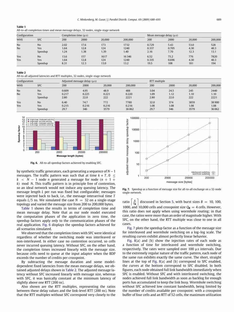
Table 1All-to-all completion times and mean message delays, 32 nodes, single-stage network
Configuration Completion time (µs) Mean message delay (µs)WHS SFC 200 2000 20,000 200,000 200 2000 20,000 200,000
No No 2.02 17.6 173 1732 0.729 5.43 53.0 528No Yes 1.64 12.8 124 1240 0.337 0.705 4.30 40.3
Speedup 1.24 1.38 1.39 1.40 2.16 7.70 12.3 13.1
Yes No 13.6 157 1617 16346 6.52 75.2 776 7820Yes Yes 1.64 12.8 124 1240 0.335 0.696 4.30 40.3
Speedup 8.31 12.3 13.0 13.2 19.5 108 181 194
Table 2All-to-all adjusted latencies and RTT multiples, 32 nodes, single-stage network
Configuration Adjusted message delay (µs) RTT multipleWHS SFC 200 2000 20,000 200,000 200 2000 20,000 200,000
No No 0.609 4.95 48.9 488 3.04 24.5 245 2440No Yes 0.217 0.225 0.221 0.220 1.09 1.12 1.10 1.10
Speedup 2.80 22.0 222 2221 2.80 22.0 222 2221
Yes No 6.40 74.7 772 7780 32.0 374 3859 38900Yes Yes 0.215 0.216 0.216 0.216 1.08 1.08 1.08 1.08
Speedup 29.7 346 3579 36062 29.7 346 3579 36062
Fig. 6. All-to-all speedup factors achieved by enabling SFC.
by synthetic traffic generators, each generating a sequence ofN−1messages. The traffic pattern was such that at time k ∗ T , 0 ≤k < N − 1 node n generated a message for node (n + 1 +k) mod N . This traffic pattern is in principle free of contention,so an ideal network would not induce any queuing latency. Themessage length L per run was fixed but configurable; messageswere injected back to back, i.e., the message interarrival time Tequals L/5 ns. We simulated the case N = 32 on a single-stagetopology and varied the message size from 200 to 200,000 bytes.Table 1 shows the results in terms of completion time and
mean message delay. Note that as our node model executedthe computation phases of the application in zero time, thespeedup factors apply only to the communication phases of thereal application. Fig. 6 displays the speedup factors achieved forall scenarios simulated.We observed that the completion timeswith SFCwere identical
regardless of whether the switching mode was interleaved ornon-interleaved. In either case no contention occurred, so cellsnever incurred queuing latency. Without SFC, on the other hand,the completion times increased linearly with the message size,because cells need to queue at the input adapter when the BDPexceeds the number of credits per crosspoint.By subtracting the message duration and some model-
dependent fixed latencies from the mean message delays, we ob-tained adjusted delays shown in Table 2. The adjusted message la-tency without SFC increased linearly with message size, whereaswith SFC, it was basically constant at the minimum latency ofslightly above one RTT (200 ns).Also shown are the RTT multiples, representing the ratios
between these delay values and the link-level RTT (200 ns). Notethat the RTT multiples without SFC correspond very closely to the
Fig. 7. Speedup as a function of message size for all-to-all exchange on a 32-nodesingle-network.
ratio⌈BQR
⌉discussed in Section 5, with burst sizes B = 10, 100,
1000, and 10,000 cells and crosspoint size QR = 4 cells. However,this ratio does not apply when using wormhole routing; in thatcase, the ratiosweremore than an order ofmagnitude higher.WithSFC, on the other hand, the RTT multiple was close to one in allcases.Fig. 7 plots the speedup factor as a function of the message size
for interleaved and wormhole switching on a log–log scale. Theresulting curves exhibit almost perfectly linear behavior.Fig. 8(a) and (b) show the injection rates of each node as
a function of time for interleaved and wormhole switching,respectively. The rates were sampled over 100 µs intervals. Dueto the extremely regular nature of the traffic pattern, each node ofthe same run exhibits exactly the same curve. The short, straightlines at the top of Fig. 8(a) and (b) correspond to SFC enabled,the curves at the bottom correspond to SFC disabled. In bothfigures, each node obtained full link bandwidth immediately whenSFC is enabled. Without SFC and with interleaved switching, thenodes achieved full link bandwidth as soon as backlog for enoughports has accumulated to keep the link busy. Wormhole switchingwithout SFC achieved low constant bandwidth, being limited bythe number of credits available per crosspoint: with a crosspointbuffer of four cells and an RTT of 52 cells, the maximum utilization
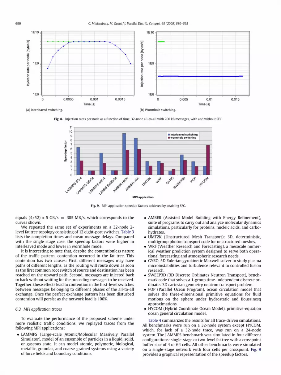
690 C. Minkenberg, M. Gusat / J. Parallel Distrib. Comput. 69 (2009) 680–695
(a) Interleaved switching. (b) Wormhole switching.
Fig. 8. Injection rates per node as a function of time, 32-node all-to-all with 200 kB messages, with and without SFC.
Fig. 9. MPI application speedup factors achieved by enabling SFC.
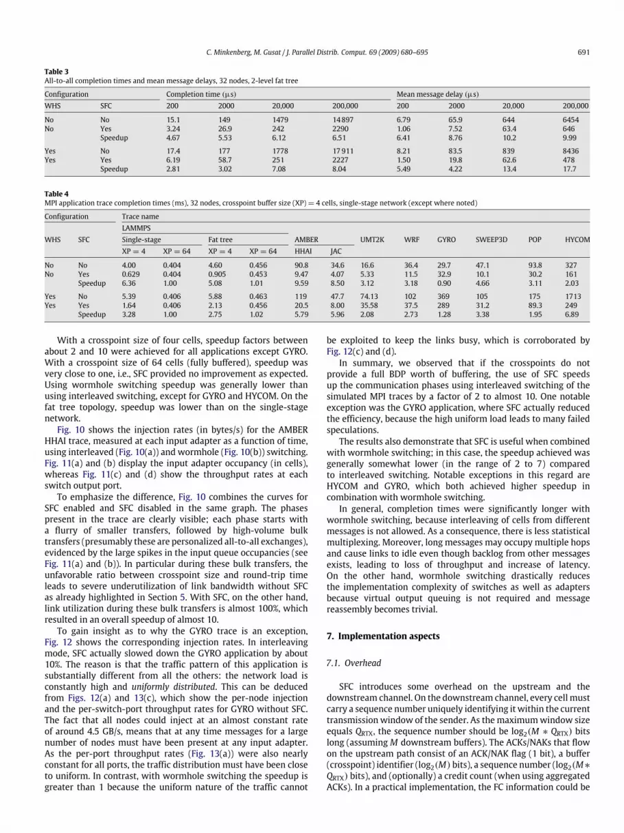
equals (4/52) ∗ 5 GB/s = 385 MB/s, which corresponds to thecurves shown.We repeated the same set of experiments on a 32-node 2-
level fat tree topology consisting of 12 eight-port switches. Table 3lists the completion times and mean message delays. Comparedwith the single-stage case, the speedup factors were higher ininterleaved mode and lower in wormhole mode.It is interesting to note that, despite the contentionless nature
of the traffic pattern, contention occurred in the fat tree. Thiscontention has two causes: First, different messages may havepaths of different lengths, as the routing will route down as soonas the first common root switch of source and destination has beenreached on the upward path. Second, messages are injected backto backwithout waiting for the precedingmessages to be received.Together, these effects lead to contention in the first-level switchesbetween messages belonging to different phases of the all-to-allexchange. Once the perfect exchange pattern has been disturbedcontention will persist as the network load is 100%.
6.3. MPI application traces
To evaluate the performance of the proposed scheme undermore realistic traffic conditions, we replayed traces from thefollowing MPI applications:• LAMMPS (Large-scale Atomic/Molecular Massively ParallelSimulator), model of an ensemble of particles in a liquid, solid,or gaseous state. It can model atomic, polymeric, biological,metallic, granular, and coarse-grained systems using a varietyof force fields and boundary conditions.
• AMBER (Assisted Model Building with Energy Refinement),suite of programs to carry out and analyze molecular dynamicssimulations, particularly for proteins, nucleic acids, and carbo-hydrates.• UMT2K (Unstructured Mesh Transport): 3D, deterministic,multigroup photon transport code for unstructured meshes.• WRF (Weather Research and Forecasting), a mesocale numer-ical weather prediction system designed to serve both opera-tional forecasting and atmospheric research needs.• GYRO, 5D Eulerian gyrokinetic Maxwell solver to study plasmamicroinstabilities and turbulence relevant to controlled fusionresearch.• SWEEP3D (3D Discrete Ordinates Neutron Transport), bench-mark code that solves a 1-group time-independent discrete or-dinates 3D cartesian geometry neutron transport problem.• POP (Parallel Ocean Program), ocean circulation model thatsolves the three-dimensional primitive equations for fluidmotions on the sphere under hydrostatic and Boussinesqapproximations.• HYCOM (Hybrid Coordinate Ocean Model), primitive-equationocean general circulation model.
Table 4 summarizes the results for all trace-driven simulations.All benchmarks were run on a 32-node system except HYCOM,which, for lack of a 32-node trace, was run on a 24-nodesystem. The LAMMPS benchmark was simulated in four differentconfigurations: single-stage or two-level fat tree with a crosspointbuffer size of 4 or 64 cells. All other benchmarks were simulatedon a single-stage network with four cells per crosspoint. Fig. 9provides a graphical representation of the speedup factors.
C. Minkenberg, M. Gusat / J. Parallel Distrib. Comput. 69 (2009) 680–695 691
Table 3All-to-all completion times and mean message delays, 32 nodes, 2-level fat tree
Configuration Completion time (µs) Mean message delay (µs)WHS SFC 200 2000 20,000 200,000 200 2000 20,000 200,000
No No 15.1 149 1479 14897 6.79 65.9 644 6454No Yes 3.24 26.9 242 2290 1.06 7.52 63.4 646
Speedup 4.67 5.53 6.12 6.51 6.41 8.76 10.2 9.99
Yes No 17.4 177 1778 17911 8.21 83.5 839 8436Yes Yes 6.19 58.7 251 2227 1.50 19.8 62.6 478
Speedup 2.81 3.02 7.08 8.04 5.49 4.22 13.4 17.7
Table 4MPI application trace completion times (ms), 32 nodes, crosspoint buffer size (XP)= 4 cells, single-stage network (except where noted)
Configuration Trace nameLAMMPS
WHS SFC Single-stage Fat tree AMBER UMT2K WRF GYRO SWEEP3D POP HYCOMXP = 4 XP = 64 XP = 4 XP = 64 HHAI JAC
No No 4.00 0.404 4.60 0.456 90.8 34.6 16.6 36.4 29.7 47.1 93.8 327No Yes 0.629 0.404 0.905 0.453 9.47 4.07 5.33 11.5 32.9 10.1 30.2 161
Speedup 6.36 1.00 5.08 1.01 9.59 8.50 3.12 3.18 0.90 4.66 3.11 2.03
Yes No 5.39 0.406 5.88 0.463 119 47.7 74.13 102 369 105 175 1713Yes Yes 1.64 0.406 2.13 0.456 20.5 8.00 35.58 37.5 289 31.2 89.3 249
Speedup 3.28 1.00 2.75 1.02 5.79 5.96 2.08 2.73 1.28 3.38 1.95 6.89
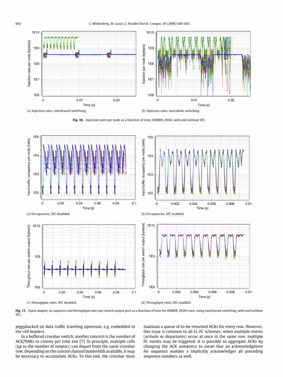
With a crosspoint size of four cells, speedup factors betweenabout 2 and 10 were achieved for all applications except GYRO.With a crosspoint size of 64 cells (fully buffered), speedup wasvery close to one, i.e., SFC provided no improvement as expected.Using wormhole switching speedup was generally lower thanusing interleaved switching, except for GYRO and HYCOM. On thefat tree topology, speedup was lower than on the single-stagenetwork.Fig. 10 shows the injection rates (in bytes/s) for the AMBER
HHAI trace, measured at each input adapter as a function of time,using interleaved (Fig. 10(a)) and wormhole (Fig. 10(b)) switching.Fig. 11(a) and (b) display the input adapter occupancy (in cells),whereas Fig. 11(c) and (d) show the throughput rates at eachswitch output port.To emphasize the difference, Fig. 10 combines the curves for
SFC enabled and SFC disabled in the same graph. The phasespresent in the trace are clearly visible; each phase starts witha flurry of smaller transfers, followed by high-volume bulktransfers (presumably these are personalized all-to-all exchanges),evidenced by the large spikes in the input queue occupancies (seeFig. 11(a) and (b)). In particular during these bulk transfers, theunfavorable ratio between crosspoint size and round-trip timeleads to severe underutilization of link bandwidth without SFCas already highlighted in Section 5. With SFC, on the other hand,link utilization during these bulk transfers is almost 100%, whichresulted in an overall speedup of almost 10.To gain insight as to why the GYRO trace is an exception,
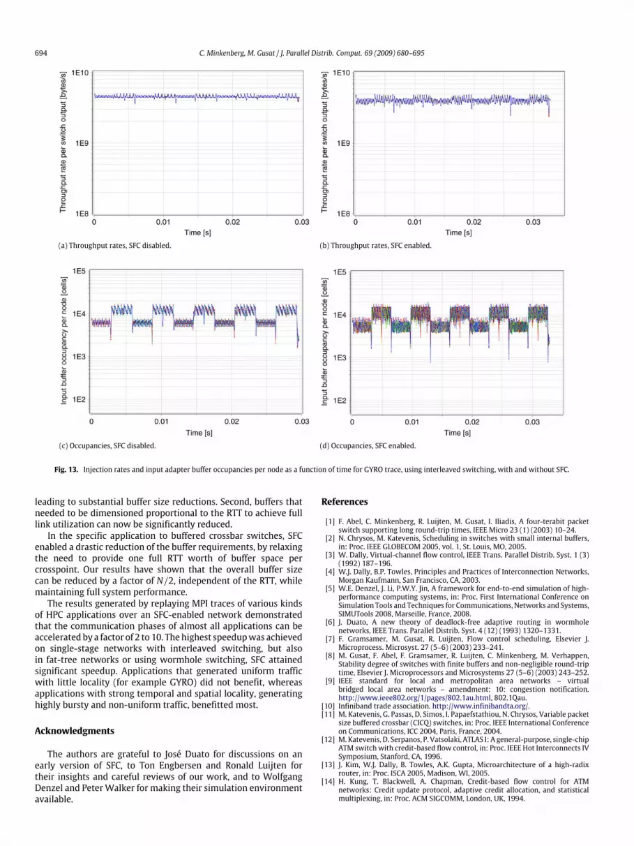
Fig. 12 shows the corresponding injection rates. In interleavingmode, SFC actually slowed down the GYRO application by about10%. The reason is that the traffic pattern of this application issubstantially different from all the others: the network load isconstantly high and uniformly distributed. This can be deducedfrom Figs. 12(a) and 13(c), which show the per-node injectionand the per-switch-port throughput rates for GYRO without SFC.The fact that all nodes could inject at an almost constant rateof around 4.5 GB/s, means that at any time messages for a largenumber of nodes must have been present at any input adapter.As the per-port throughput rates (Fig. 13(a)) were also nearlyconstant for all ports, the traffic distribution must have been closeto uniform. In contrast, with wormhole switching the speedup isgreater than 1 because the uniform nature of the traffic cannot
be exploited to keep the links busy, which is corroborated byFig. 12(c) and (d).In summary, we observed that if the crosspoints do not
provide a full BDP worth of buffering, the use of SFC speedsup the communication phases using interleaved switching of thesimulated MPI traces by a factor of 2 to almost 10. One notableexception was the GYRO application, where SFC actually reducedthe efficiency, because the high uniform load leads to many failedspeculations.The results also demonstrate that SFC is useful when combined
with wormhole switching; in this case, the speedup achieved wasgenerally somewhat lower (in the range of 2 to 7) comparedto interleaved switching. Notable exceptions in this regard areHYCOM and GYRO, which both achieved higher speedup incombination with wormhole switching.In general, completion times were significantly longer with
wormhole switching, because interleaving of cells from differentmessages is not allowed. As a consequence, there is less statisticalmultiplexing. Moreover, long messages may occupy multiple hopsand cause links to idle even though backlog from other messagesexists, leading to loss of throughput and increase of latency.On the other hand, wormhole switching drastically reducesthe implementation complexity of switches as well as adaptersbecause virtual output queuing is not required and messagereassembly becomes trivial.
7. Implementation aspects
7.1. Overhead
SFC introduces some overhead on the upstream and thedownstream channel. On the downstream channel, every cell mustcarry a sequence number uniquely identifying it within the currenttransmissionwindow of the sender. As themaximumwindow sizeequals QRTX, the sequence number should be log2(M ∗ QRTX) bitslong (assumingM downstream buffers). The ACKs/NAKs that flowon the upstream path consist of an ACK/NAK flag (1 bit), a buffer(crosspoint) identifier (log2(M) bits), a sequence number (log2(M∗QRTX) bits), and (optionally) a credit count (when using aggregatedACKs). In a practical implementation, the FC information could be
692 C. Minkenberg, M. Gusat / J. Parallel Distrib. Comput. 69 (2009) 680–695
(a) Injection rates, interleaved switching. (b) Injection rates, wormhole switching.
Fig. 10. Injection rates per node as a function of time, AMBER_HHAI, with and without SFC.
(a) Occupancies, SFC disabled. (b) Occupancies, SFC enabled.
(c) Throughput rates, SFC disabled. (d) Throughput rates, SFC enabled.
Fig. 11. Input adapter occupancies and throughput rates per switch output port as a function of time for AMBER_HHAI trace, using interleaved switching, with and withoutSFC.
piggybacked on data traffic traveling upstream, e.g. embedded inthe cell headers.In a buffered crossbar switch, another concern is the number of
ACK/NAKs to convey per time slot [7]. In principle, multiple cells(up to the number of outputs) can depart from the same crossbarrow.Depending on the control channel bandwidth available, itmaybe necessary to accumulate ACKs. To this end, the crossbar must
maintain a queue of to-be-returned ACKs for every row. However,this issue is common to all LL-FC schemes; when multiple events(arrivals or departures) occur at once in the same row, multipleFC events may be triggered. It is possible to aggregate ACKs bychanging the ACK semantics to mean that an acknowledgmentfor sequence number x implicitly acknowledges all precedingsequence numbers as well.

C. Minkenberg, M. Gusat / J. Parallel Distrib. Comput. 69 (2009) 680–695 693
(a) SFC disabled, interleaved switching. (b) SFC enabled, interleaved switching.
(c) SFC disabled, wormhole switching. (d) SFC enabled, wormhole switching.
Fig. 12. Injection rates per node as a function of time for the GYRO trace, with and without SFC.
As there can be at most one arrival per row per time slot, onlya single NAK can be generated. Our model imposes no restrictionon the control channel bandwidth, so all new ACKs/NAKs can bereturned at once and no aggregation is needed.
7.2. Hardware
The main hardware complexity burden of SFC rests onthe sender. First, a retransmission buffer is required withan accompanying queuing structure. New entries are alwaysenqueued at the tail of the queue, but reads and dequeueoperations may occur at any point in the queue. Processingan ACK/NAK involves finding the entry with the correspondingsequence number (and buffer ID) in the retransmission queue.Upon ACK, the corresponding queue entry (and any precedingones) is removed. UponNAK, the entry ismarked so that it becomeseligible for retransmission.For every incoming cell, the receiver must determine whether
there is room in the destination buffer, and whether the cellcontains any errors, is in the correct order, or is a duplicate. Ifthere is an error, the cell is out of order, the buffer is full, orthe cell is a duplicate, the cell is dropped and a NAK returned.Otherwise, the cell is stored and the expected next sequencenumber is incremented. The receiver issues an ACK for a cell whenit is removed from the buffer.In the case of multiple downstream buffers, the number of
ACK/NAKs per time slot (as described above) also determines therate of operations on the retransmission queue.
To minimize the number of retransmissions caused by out-of-order arrivals, the sender keeps track of the sequence numberof the last negatively acknowledged cell for every downstreambuffer. Further transmissions of new cells, speculative as well ascredited, to this buffer are not allowed until that cell is positivelyacknowledged. This reduces bandwidth wastage due to long trainsof OOO cells following an unsuccessful speculation. Once thesender knows a cell was lost, further speculative transmissions areuseless as these are sure to be dropped. To reduce the time duringwhich no speculative transmissions are allowed, this sequencenumber can be reset as soon as the corresponding cell is sentcredited, instead of waiting until the ACK is received, because thelikelihood of a credited cell being dropped is very low.
8. Conclusions
Motivated by the need for high-radix switches for computerinterconnection networks, we proposed a novel link-level flow-control method: speculative flow control (SFC). It specificallyaddresses the ICTN requirements of losslessness, low error rates,and low latency. SFC combines credited and speculative modesof transmission, in which the credited mode corresponds toconventional credit flow control, whereas the speculative modeallows ‘‘violations’’ of the credit semantics. This allows significantreductions in latency for bursty traffic. Furthermore, SFC impactsbuffer sizing in twoways. First, buffers that traditionally needed tobe allocated (partitioned) on a per-flow basis can now be shared,
694 C. Minkenberg, M. Gusat / J. Parallel Distrib. Comput. 69 (2009) 680–695
(a) Throughput rates, SFC disabled. (b) Throughput rates, SFC enabled.
(c) Occupancies, SFC disabled. (d) Occupancies, SFC enabled.
Fig. 13. Injection rates and input adapter buffer occupancies per node as a function of time for GYRO trace, using interleaved switching, with and without SFC.
leading to substantial buffer size reductions. Second, buffers thatneeded to be dimensioned proportional to the RTT to achieve fulllink utilization can now be significantly reduced.In the specific application to buffered crossbar switches, SFC
enabled a drastic reduction of the buffer requirements, by relaxingthe need to provide one full RTT worth of buffer space percrosspoint. Our results have shown that the overall buffer sizecan be reduced by a factor of N/2, independent of the RTT, whilemaintaining full system performance.The results generated by replaying MPI traces of various kinds
of HPC applications over an SFC-enabled network demonstratedthat the communication phases of almost all applications can beacceleratedby a factor of 2 to 10. Thehighest speedupwas achievedon single-stage networks with interleaved switching, but alsoin fat-tree networks or using wormhole switching, SFC attainedsignificant speedup. Applications that generated uniform trafficwith little locality (for example GYRO) did not benefit, whereasapplications with strong temporal and spatial locality, generatinghighly bursty and non-uniform traffic, benefitted most.
Acknowledgments
The authors are grateful to José Duato for discussions on anearly version of SFC, to Ton Engbersen and Ronald Luijten fortheir insights and careful reviews of our work, and to WolfgangDenzel and PeterWalker for making their simulation environmentavailable.
References
[1] F. Abel, C. Minkenberg, R. Luijten, M. Gusat, I. Iliadis, A four-terabit packetswitch supporting long round-trip times, IEEE Micro 23 (1) (2003) 10–24.
[2] N. Chrysos, M. Katevenis, Scheduling in switches with small internal buffers,in: Proc. IEEE GLOBECOM 2005, vol. 1, St. Louis, MO, 2005.
[3] W. Dally, Virtual-channel flow control, IEEE Trans. Parallel Distrib. Syst. 1 (3)(1992) 187–196.
[4] W.J. Dally, B.P. Towles, Principles and Practices of Interconnection Networks,Morgan Kaufmann, San Francisco, CA, 2003.
[5] W.E. Denzel, J. Li, P.W.Y. Jin, A framework for end-to-end simulation of high-performance computing systems, in: Proc. First International Conference onSimulation Tools and Techniques for Communications, Networks and Systems,SIMUTools 2008, Marseille, France, 2008.
[6] J. Duato, A new theory of deadlock-free adaptive routing in wormholenetworks, IEEE Trans. Parallel Distrib. Syst. 4 (12) (1993) 1320–1331.
[7] F. Gramsamer, M. Gusat, R. Luijten, Flow control scheduling, Elsevier J.Microprocess. Microsyst. 27 (5–6) (2003) 233–241.
[8] M. Gusat, F. Abel, F. Gramsamer, R. Luijten, C. Minkenberg, M. Verhappen,Stability degree of switches with finite buffers and non-negligible round-triptime, Elsevier J. Microprocessors and Microsystems 27 (5–6) (2003) 243–252.
[9] IEEE standard for local and metropolitan area networks – virtualbridged local area networks – amendment: 10: congestion notification.http://www.ieee802.org/1/pages/802.1au.html, 802.1Qau.
[10] Infiniband trade association. http://www.infinibandta.org/.[11] M. Katevenis, G. Passas, D. Simos, I. Papaefstathiou, N. Chrysos, Variable packet
size buffered crossbar (CICQ) switches, in: Proc. IEEE International Conferenceon Communications, ICC 2004, Paris, France, 2004.
[12] M. Katevenis, D. Serpanos, P. Vatsolaki, ATLAS I: A general-purpose, single-chipATM switchwith credit-based flow control, in: Proc. IEEE Hot Interconnects IVSymposium, Stanford, CA, 1996.
[13] J. Kim, W.J. Dally, B. Towles, A.K. Gupta, Microarchitecture of a high-radixrouter, in: Proc. ISCA 2005, Madison, WI, 2005.
[14] H. Kung, T. Blackwell, A. Chapman, Credit-based flow control for ATMnetworks: Credit update protocol, adaptive credit allocation, and statisticalmultiplexing, in: Proc. ACM SIGCOMM, London, UK, 1994.

C. Minkenberg, M. Gusat / J. Parallel Distrib. Comput. 69 (2009) 680–695 695
[15] R. Luijten, C. Minkenberg, M. Gusat, Reducing memory size in bufferedcrossbars with large internal flow control latency, in: Proc. IEEE GLOBECOM2003, vol. 7, San Fransisco, CA, 2003.
[16] C. Minkenberg, F. Abel, P. Müller, R. Krishnamurthy, M. Gusat, Controlpath implementation of a low-latency optical HPC switch, in: Proc. HotInterconnects 13, Stanford, CA, 2005.
[17] M. Nabeshima, Input-queued switches using two schedulers in parallel, IEICETrans. Commun. E85-B (2) (2002) 523–531.
[18] Omnet++ discrete event simulation system. http://www.omnetpp.org/.[19] C. Özveren, R. Simcoe, G. Varghese, Reliable and efficient hop-by-hop flow
control, IEEE J. Sel. Areas Commun. 13 (4) (1993) 642–650.[20] K. Pawlikowski, H.-D. Jeong, J.-S. Lee, On credibility of simulation studies of
telecommunication networks, IEEE Commun. Mag. 40 (1) (2002) 132–139.[21] G. Pfister, V. Norton, Hot spot contention and combining in multistage
interconnection networks, IEEE Trans. Comput. C-34 (10) (1985) 933–938.[22] R. Rojas-Cessa, Z. Dong, Z. Guo, Load-balanced combined input-crosspoint
buffered packet switch and long round-trip times, IEEE Commun. Lett. 4 (7)(2005) 661–663.
[23] R. Rojas-Cessa, E. Oki, Z. Jing, H. Chao, CIXB-1: Combined input-one-cell-crosspoint buffered switch, in: Proc. 2001 IEEE Workshop on High-Performance Switching and Routing HPSR 2001, Dallas, TX, 2001.
[24] K. Yoshigoe, Rate-based flow-control for the CICQ switch, in: Proc. 30th IEEEConference on Local Computer Networks, LCN 2005, Sydney, Australia, 2005.
[25] K. Yoshigoe, The CICQ switch with virtual crosspoint queues for large RTT, in:Proc. IEEE International Conference on Communications, ICC 2006, Istanbul,Turkey, 2006.
[26] K. Yoshigoe, K. Christensen, A. Jacob, The RR/RR CICQ switch: Hardwaredesign for 10-Gbps link speed, in: Proc. IEEE Int. Performance, Computing, andCommunications Conf. IPCCC 2003, Phoenix, AZ, 2003.
Cyriel Minkenberg received an M.Sc. degree in electricalengineering from Eindhoven University of Technology,the Netherlands, in 1996. In 1997, he joined the High-Speed Switching group at the IBM Zurich ResearchLaboratory (ZRL) to work towards a Ph.D. degree, whichhe obtained in 2001, also from Eindhoven Universityof Technology. He is currently a research staff memberat ZRL, where he is responsible for the architectureand performance evaluation of the OSMOSIS crossbarscheduler. He is also participating in the IEEE 801.1auWorking Group to standardize congestion management
in 10G Ethernet networks. His research interests include switch architectures,networking protocols, performance modeling, and simulation. Minkenberg hasco-authored over 20 publications in international journals and conferencesproceedings. He received the 2001 IEEE Fred W. Ellersick Award for the bestpaper published in an IEEE Communications Society magazine in 2000, the HotInterconnects 2005 Best Paper Award, and the IPDPS 2007 Architectures Track BestPaper Award.
Mitchell Gusat is a researcher at the IBM Zurich ResearchLaboratory. His research interests include distributed sys-tems, HPC architectures, coherency protocols, switchingand scheduling algorithms. His current focus is on flowand congestion control for datacenters; in this area hehas contributed to RapidIO, InfiniBand and Ethernet con-gestion management. He has Masters in Electrical Engi-neering from the University of Timisoara and in ComputerEngineering from the University of Toronto. He is memberof ACM and IEEE.