design and analysis of neodymium free spoke-type motor with segmented wing shape permanent-magnet...
TRANSCRIPT
Design and Analysis of Neodymium Free SPOKE-type Motor with Segmented Wing Shape Permanent-Magnet
for concentrating flux density
Mohammad Mizanoor Rahman1, Kyung-Tae Kim1 and Jin Hur1, Senior Member IEEE 1School of Electrical Engineering, University of Ulsan
102 Street Dae-hak, Nam-gu Ulsan, Korea
Abstract— This paper proposes a new design of wing shaped SPOKE-type permanent magnet brush-less direct current (BLDC) motor using ferrite permanent magnet (Fe-PM) instead of neodymium permanent magnet (Nd-PM). Here, a method to maximize the torque density is developed. The proposed model has an improved output characteristic as it uses the properties of the magnetic flux effect of the SPOKE-type motor with an additional pushing assistant Fe-PM and sub assistant Fe-PM in the shape of SPOKE. This is optimized by using proposed analytical calculation method for improving torque density. This paper validates results of the analytical model by finite element analysis (FEA) for proposed wing shaped SPOKE-type BLDC motors.
I. INTRODUCTION Permanent magnet (PM) brushless DC (BLDC) motors are
widely used in many industry applications such as home appliances and electric vehicles as they have high efficiency and easy controllability over a wide range of operating speeds. BLDC motors have emerged in recent years as a very strong contender to replace induction motors used in electronically controlled variable speed applications. They offer superior performance in terms of increased efficiency and reduced noise, highly efficient, high power density, low size compared to conventional machines. Rare-earth resources are frequently used in electrical machinery. In particular, they are necessary substances for low carbon green growth projects. However, there is a high demand and short supply of rare-earth resources, which has caused a hike in the price of neodymium permanent magnets (Nd-PM). In order to solve such problems, ferrite permanent magnets (Fe-PM) are used as an alternate to Nd-PMs of the BLDC motors, because the price ratio per weight (PRW) of Fe-PM to Nd-PM is around 1:20 [1].
A variety of motors without rare-earth materials such as an induction motor, a switched reluctance motor, and a SPOKE-type motor using Fe-PM have been developed, and their characteristics as a driving motor of electric vehicles reviewed in many research works [2]-[9]. This paper proposes a design method using Fe-PM as the production
cost is comparatively cheap than that of Nd-PM. But, the residual flux density of the Fe-PM is lower than the Nd-PM [1]. This makes the Fe-PM unable to generate high torque. To solve this problem, the design has been performed from the concept of Halbach magnetization in the form of the combination of SPOKE-type and additional push type in order to get high output characteristics. The Halbach magnetized permanent magnet arrays offer many attractive features which can be effectively used for the design of rotary electrical machines [10]. One important characteristic of Halbach array is that it can eliminate the flux in one side of the array and enlarge the flux on the other side of it [11]. The attention is being focused on the SPOKE-type BLDC motor because the rotor structure of SPOKE-type BLDC motor has higher saliency ratios and the magnetic flux generated by PMs, resulting in increase of higher torque density per volume.
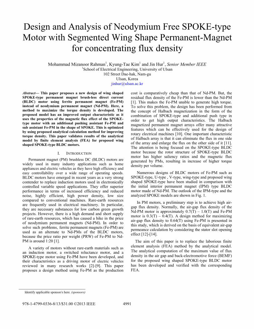
Numerous designs of BLDC motors of Fe-PM such as SPOKE-type, U-type , V-type, wing-type and proposed wing shaped SPOKE-type have been studied in comparison with the initial interior permanent magnet (IPM) type BLDC motor made of Nd-PM. The outlook of the IPM-type and the analyzed SPOKE models are shown in Fig. 1.
In PM motors, a preliminary step is to achieve high air-gap flux density. Normally, the air-gap flux density of the Nd-PM motor is approximately 0.7(T) – 1.0(T) and Fe-PM motor is 0.3(T) – 0.4(T). A design method for maximizing air-gap flux density to 0.64(T) using Fe-PM is presented in this study, which is derived on the basis of equivalent air-gap permeance calculation by considering the stator slot opening effect [12]-[14].
The aim of this paper is to replace the laborious finite element analysis (FEA) method by the analytical model. The analytical computation of the maximum value of flux density in the air gap and back-electromotive force (BEMF) for the proposed wing shaped SPOKE-type BLDC motor has been developed and verified with the corresponding FEA.
Identify applicable sponsor/s here. (sponsors)
4991978-1-4799-0336-8/13/$31.00 ©2013 IEEE
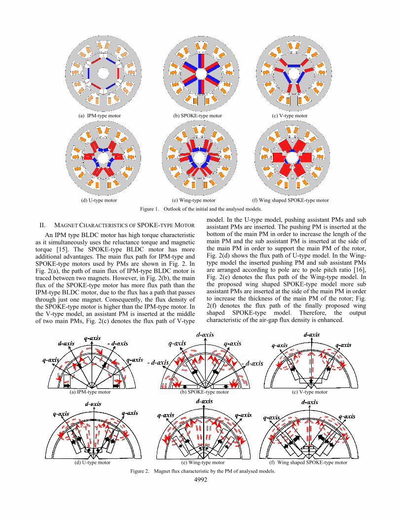
II. MAGNET CHARACTERISTICS OF SPOKE-TYPE MOTOR An IPM type BLDC motor has high torque characteristic
as it simultaneously uses the reluctance torque and magnetic torque [15]. The SPOKE-type BLDC motor has more additional advantages. The main flux path for IPM-type and SPOKE-type motors used by PMs are shown in Fig. 2. In Fig. 2(a), the path of main flux of IPM-type BLDC motor is traced between two magnets. However, in Fig. 2(b), the main flux of the SPOKE-type motor has more flux path than the IPM-type BLDC motor, due to the flux has a path that passes through just one magnet. Consequently, the flux density of the SPOKE-type motor is higher than the IPM-type motor. In the V-type model, an assistant PM is inserted at the middle of two main PMs, Fig. 2(c) denotes the flux path of V-type
model. In the U-type model, pushing assistant PMs and sub assistant PMs are inserted. The pushing PM is inserted at the bottom of the main PM in order to increase the length of the main PM and the sub assistant PM is inserted at the side of the main PM in order to support the main PM of the rotor, Fig. 2(d) shows the flux path of U-type model. In the Wing-type model the inserted pushing PM and sub assistant PMs are arranged according to pole arc to pole pitch ratio [16], Fig. 2(e) denotes the flux path of the Wing-type model. In the proposed wing shaped SPOKE-type model more sub assistant PMs are inserted at the side of the main PM in order to increase the thickness of the main PM of the rotor; Fig. 2(f) denotes the flux path of the finally proposed wing shaped SPOKE-type model. Therefore, the output characteristic of the air-gap flux density is enhanced.
(a) IPM-type motor (b) SPOKE-type motor (c) V-type motor
(d) U-type motor (e) Wing-type motor (f) Wing shaped SPOKE-type motor
Figure 1. Outlook of the initial and the analysed models.
(a) IPM-type motor (b) SPOKE-type motor (c) V-type motor
(d) U-type motor (e) Wing-type motor (f) Wing shaped SPOKE-type motor
Figure 2. Magnet flux characteristic by the PM of analysed models.
4992
III. DESIGN OF PROPOSED WING SHAPED SPOKE-TYPE BLDC MOTOR
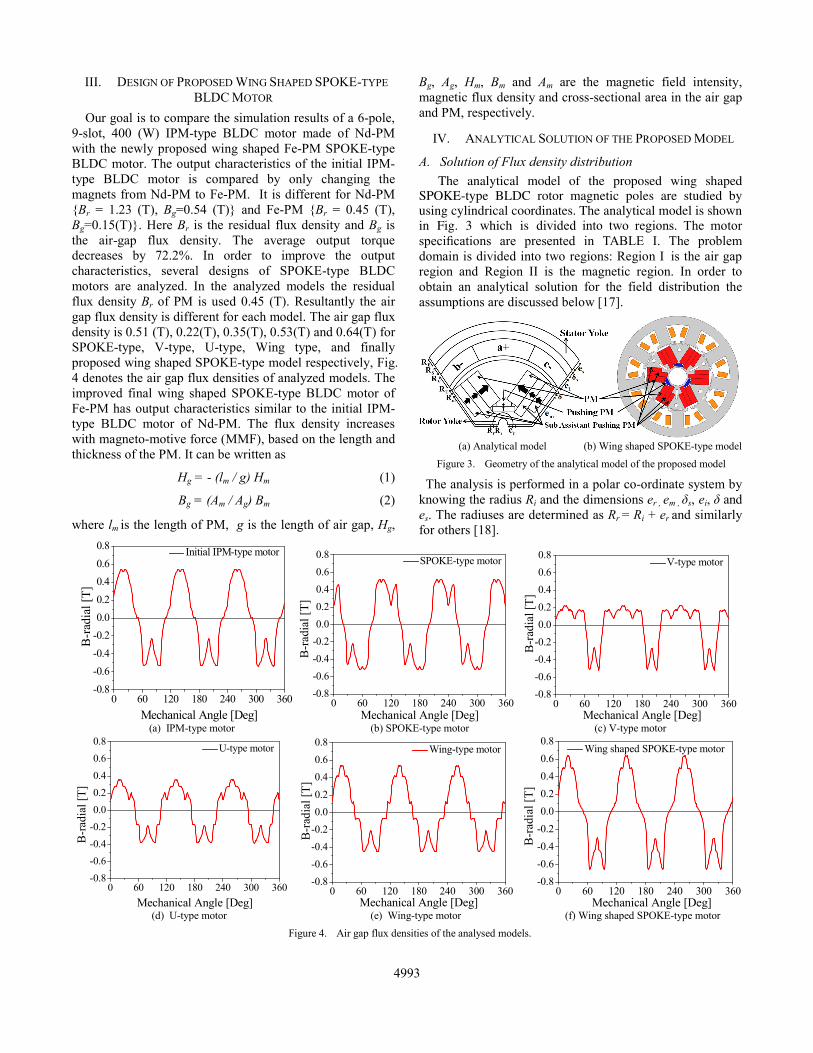
Our goal is to compare the simulation results of a 6-pole, 9-slot, 400 (W) IPM-type BLDC motor made of Nd-PM with the newly proposed wing shaped Fe-PM SPOKE-type BLDC motor. The output characteristics of the initial IPM-type BLDC motor is compared by only changing the magnets from Nd-PM to Fe-PM. It is different for Nd-PM {Br = 1.23 (T), Bg=0.54 (T)} and Fe-PM {Br = 0.45 (T), Bg=0.15(T)}. Here Br is the residual flux density and Bg is the air-gap flux density. The average output torque decreases by 72.2%. In order to improve the output characteristics, several designs of SPOKE-type BLDC motors are analyzed. In the analyzed models the residual flux density Br of PM is used 0.45 (T). Resultantly the air gap flux density is different for each model. The air gap flux density is 0.51 (T), 0.22(T), 0.35(T), 0.53(T) and 0.64(T) for SPOKE-type, V-type, U-type, Wing type, and finally proposed wing shaped SPOKE-type model respectively, Fig. 4 denotes the air gap flux densities of analyzed models. The improved final wing shaped SPOKE-type BLDC motor of Fe-PM has output characteristics similar to the initial IPM-type BLDC motor of Nd-PM. The flux density increases with magneto-motive force (MMF), based on the length and thickness of the PM. It can be written as
Hg = - (lm / g) Hm (1)
Bg = (Am / Ag) Bm (2)
where lm is the length of PM, g is the length of air gap, Hg,
Bg, Ag, Hm, Bm and Am are the magnetic field intensity, magnetic flux density and cross-sectional area in the air gap and PM, respectively.
IV. ANALYTICAL SOLUTION OF THE PROPOSED MODEL
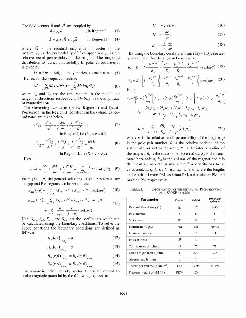
A. Solution of Flux density distribution The analytical model of the proposed wing shaped
SPOKE-type BLDC rotor magnetic poles are studied by using cylindrical coordinates. The analytical model is shown in Fig. 3 which is divided into two regions. The motor specifications are presented in TABLE I. The problem domain is divided into two regions: Region I is the air gap region and Region II is the magnetic region. In order to obtain an analytical solution for the field distribution the assumptions are discussed below [17].
The analysis is performed in a polar co-ordinate system by knowing the radius Ri and the dimensions er , em , δs, ei, δ and es. The radiuses are determined as Rr = Ri + er and similarly for others [18].
(a) Analytical model (b) Wing shaped SPOKE-type model
Figure 3. Geometry of the analytical model of the proposed model
0 60 120 180 240 300 360-0.8-0.6-0.4-0.20.00.20.40.60.8
B-r
adia
l [T]
Mechanical Angle [Deg]
Initial IPM-type motor
0 60 120 180 240 300 360-0.8-0.6-0.4-0.20.00.20.40.60.8
B-r
adia
l [T]
Mechanical Angle [Deg]
SPOKE-type motor
0 60 120 180 240 300 360
-0.8-0.6-0.4-0.20.00.20.40.60.8
B-r
adia
l [T]
Mechanical Angle [Deg]
V-type motor
(a) IPM-type motor (b) SPOKE-type motor (c) V-type motor
0 60 120 180 240 300 360-0.8-0.6-0.4-0.20.00.20.40.60.8
B-ra
dial
[T]
Mechanical Angle [Deg]
U-type motor
0 60 120 180 240 300 360
-0.8-0.6-0.4-0.20.00.20.40.60.8
B-r
adia
l [T]
Mechanical Angle [Deg]
Wing-type motor
0 60 120 180 240 300 360
-0.8-0.6-0.4-0.20.00.20.40.60.8
B-r
adia
l [T]
Mechanical Angle [Deg]
Wing shaped SPOKE-type motor
(d) U-type motor (e) Wing-type motor (f) Wing shaped SPOKE-type motor
Figure 4. Air gap flux densities of the analysed models.
4993
The field vectors B and H are coupled by
HμB o= , in Region I (3)
MμHrμμB oo += , in Region II (4)
where M is the residual magnetization vector of the magnet, μo is the permeability of free space and μr is the relative recoil permeability of the magnet. The magnetic distribution M varies sinusoidally. In polar co-ordinates it is given by
θR MθMrM += , in cylindrical co-ordinates (5) Hence, for the proposed machine
∑−∑=∞
=
∞
= 1,3,5...nθ
1,3,5...nr Msin(pθMcos(pθM ))
(6) where rR and θθ
are the unit vectors in the radial and tangential directions respectively, M=Br/μo
is the amplitude of magnetization.
The Governing Laplacian (in the Region I) and Quasi-Poissonion (in the Region II) equations in the cylindrical co-ordinates are given below.
02dθ1φ
2d2r
1dr
1dφr1
2dr1φ
2d1φ
2 =++=∇ (7)
In Region I, i.e (Rm < r < Rs)
rμ
divM2dθ2φ
2d2r
1
dr2dφ
r
12dr2φ
2d2φ
2 =++=∇ (8)
In Region II, i.e (Rr < r < Rm) Here,
∑=++=∞
= .1,3,5,..nnpθMncos
r1
dθdMθ
r1
drdMr
rMr
divM )(
(9)
From (5) – (9) the general solutions of scalar potential for air-gap and PM regions can be written as:
( ) ( ) ( )∑ ⋅⋅+⋅=∞
=
−
1,3,5...n
npg2n
npg1n npθcosrSrSθr,airφ
(10)
( ) ( ) ( )
( ) ( )∑ ⋅+
⋅+
∑ ⋅⋅+⋅=
∞
=
∞
=
−
1,3,5...n r0
r
1,3,5...n
npm2n
npm1n
npθcosnp1
r
μμ
B
npθcosrSrSθr,magφ (11)
Here Sg1n, Sg2n, Sm1n and Sm2n
are the coefficients which can be calculated using the boundary conditions. To solve the above equations the boundary conditions are defined as follows:
( ) 0θr,HsRrθ1 =
= (12)
( ) 0θr,HrRrθ2 =
= (13)
mm RrrRrrl θrBθrB == = ),(),( 2 (14)
mm RrθRrlθ θrBθrB == = ),(),( 2 (15)
The magnetic field intensity vector H can be related to scalar magnetic potential by the following expressions
gradφH −= , (16)
drdφ
Hr −= , (17)
dθdφ
r1
Hθ ⋅−= (18)
By using the boundary conditions from (12) – (15), the air-gap magnetic flux density can be solved as
( )npθcosr
R
R
R
R
r
R
R1KB
1npm
s
1npm
s
1np
m
1npr
R ×+⋅⋅−×= ⎥⎦
⎤⎢⎣
⎡⎥⎦
⎤⎢⎣
⎡ ++−+
(19)
( )npθsinr
R
R
R
R
r
R
R1KB
1npm
s
1npm
s
1np
m
1npr
θ ×−⋅⋅−×= ⎥⎦
⎤⎢⎣
⎡⎥⎦
⎤⎢⎣
⎡ ++−+
(20)
Here,
( ) ( ) ( ) ( ) ( ) ( )⎪⎭
⎪⎬⎫
⎪⎩
⎪⎨⎧
⎥⎥⎦
⎤
⎢⎢⎣
⎡
⎥⎥⎦
⎤
⎢⎢⎣
⎡−+++−++−=
sR
2npmR
rμ1rμ1rμ1sR
2npmR
rμ1rμ1mR
2nprR
rμ-12Do
43
222
2211
2211
rrrrspm
rrrrssppmmm wlwlwww
wlwlwlwlwlR
++++
++++=
.
( )∑ ++
⋅−=∞
=1,3,5...nr
o
r μ1p1
npD4B
K
(21)
where μr is the relative recoil permeability of the magnet, p is the pole pair number, θ is the relative position of the stator with respect to the rotor, Rr is the internal radius of the magnet, Ri is the stator inner bore radius, Rs is the stator outer bore radius, Rm is the volume of the magnet and r is the mean air gap radius where the flux density has to be calculated. lm, lp, ls, lr1, lr2, wm, ws, wr1 and wr2 are the lengths and widths of main PM, assistant PM, sub assistant PM and pushing PM respectively.
TABLE I. SPECIFICATIONS OF THE INITIAL AND PROPOSED WING SHAPED SPOKE-TYPE MOTOR
Parameter Symbol Initial Proposed SPOKE
Residual flux density (T) Br 1.23 0.45
Pole number p 6 6
Slot number Qs 9 9
Permanent magnet PM Nd Ferrite
Input current (A) I 11 11
Phase number φ 3 3
Turn number per phase N 72 72
Mean air-gap radius (mm) r 27.5 27.5
Air-gap length (mm) g 1 1
Torque per volume (KNm/m3) TRV 13.600 14.691
Price per weight of PM (%) PRW 20 1
4994
B. Calculation of Back-Electromotive Force With the knowledge of armature winding distribution
BEMF of the analytical model of PM BLDC motor can be calculated from the no-load flux density distribution. According to Faraday’s law, the voltage induced in a single coil is equal to the negative derivative of the flux linked by the coil, i.e.
( )dt
dφNtE c
c −= (22)
The flux linkage φc is equal to
( ) ( )∫−
=2
cζ
2cζ
dθtθ,R,Bsrsc Rltφ (23)
where ls, N and ζc are the stack length, number of coil turns and coil pitch respectively. It is sufficient to know only radial component of the flux density Bsr for calculation of the flux linkage which is given by
( ) ( ) ( ) ( ) ( )θr,λtθ,r,Bθr,λtθ,r,Btθ,r,B bθaRsr +=
+⎭⎬⎫
⎩⎨⎧ ∑ −+×∑ −=
∞
=
∞
= 1,3,5...ns0sam0
1,3,5nRn θθmQcosλλωtθnpcosB ])([])([
(24)
∑ −×∑ −∞
=
∞
= 1,3,5,...ns0sbm
1,3,5,...nθn θθmQsinλωtθ npsinB )]([)]([
where BRn, Bθn are the Fourier coefficients of the air-gap flux density from (19) and (20), λ0, λam, λbm are the coefficients of the complex relative air gap permeance, Qs is the number of slots, ω is the rotor speed R is the radius close to the stator surface and θso=0 and Am=1 as the coil pitch is an odd integer of the slot pitch. So the flux linkage becomes
( ) ∑ +=∞
= ⎩⎨⎧
⎟⎠⎞
⎜⎝⎛
1,3,5...n
crn0s 2
npsinnp
2BλRltcφ
ζ
( )( )
+∑+
+
−=
⎥⎦⎤
⎢⎣⎡
mλN
1m s
cs
bmθnamRn AmQnp
2mQnpsin
λBλB
ζ
(25)
( )( )
( )nptωcosmAmQnp
2mQnpsin
λBλBλN
1m s
cs
bmθnamRn ×∑−
−
+
⎪⎪⎭
⎪⎪⎬
⎫⎥⎦⎤
⎢⎣⎡
=
ζ
According to (22) the voltage induced in a single coil can
be calculated. The voltages induced in adjacent slots are phase shifted, so they should be summed as vectors which is taken into account via distribution factor. The distribution factor for the nth harmonic is given by
( )( )2αnqsin
2αnqsinkdn = (26)
where q is the number of slots per pole per phase and α is the phase shift between the voltages induced in two adjacent slots. The final expression for the BEMF waveform of phase A is expressed below,
( ) ∑ +=∞
= ⎩⎨⎧
⎟⎠⎞
⎜⎝⎛
1,3,5...n
crn0dnsA 2
np2sinBλkRNltEζ
ω
( )( )
∑ ++
+
−=
⎥⎦⎤
⎢⎣⎡
λN
1mm
s
cs
bmθnamrn AmQnp
np2
mQnpsin
λBλB
ζ
(27)
( )( )
( )[ ]0λN
1mm
s
cs
bmθnamrn αptnsinAmQnp
np2
mQnpsinλBλB −×∑
−
−+
⎪⎪⎭
⎪⎪⎬
⎫⎥⎦⎤
⎢⎣⎡
=ω
ζ
where αo is equal to zero for phase-A, 2π/3 for phase-B and 4π/3 for phase-C.
V. RESULTS AND DISCUSSION
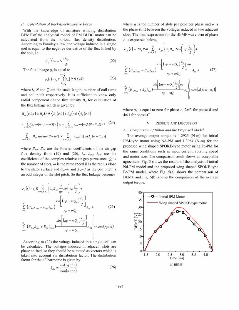
A. Comparison of Initial and the Proposed Model The average output torque is 1.2925 (N-m) for initial
IPM-type motor using Nd-PM and 1.3964 (N-m) for the proposed wing shaped SPOKE-type motor using Fe-PM for the same conditions such as input current, rotating speed and motor size. The comparison result shows an acceptable agreement. Fig. 5 shows the results of the analysis of initial Nd-PM model and the proposed wing shaped SPOKE-type Fe-PM model, where Fig. 5(a) shows the comparison of BEMF and Fig. 5(b) shows the comparison of the average output torque.
1.5 2.0 2.5 3.0 3.5 4.00
5
10
15
20
25
30
35
40
BEM
F [V
]
Time [ms]
Initial IPM Motor Wing shaped SPOKE-type motor
(a) BEMF
4995
1 2 3 4 50.0
0.3
0.6
0.9
1.2
1.5
1.8A
vera
ge T
orqu
e [N
m]
Time [ms]
Initial IPM Motor Wing shaped SPOKE-type Motor
(b) Average output torque
Figure 5. Comparison of initial model and wing shaped SPOKE-model
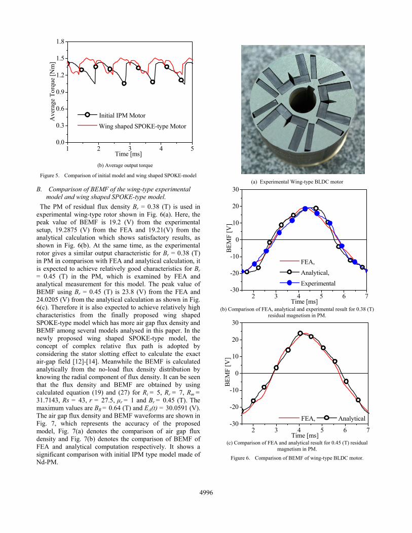
B. Comparison of BEMF of the wing-type experimental model and wing shaped SPOKE-type model.
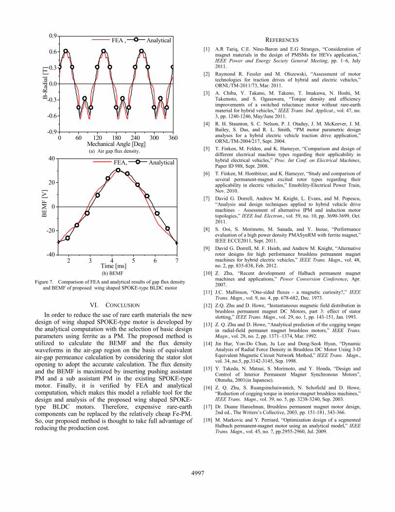
The PM of residual flux density Br = 0.38 (T) is used in experimental wing-type rotor shown in Fig. 6(a). Here, the peak value of BEMF is 19.2 (V) from the experimental setup, 19.2875 (V) from the FEA and 19.21(V) from the analytical calculation which shows satisfactory results, as shown in Fig. 6(b). At the same time, as the experimental rotor gives a similar output characteristic for Br = 0.38 (T) in PM in comparison with FEA and analytical calculation, it is expected to achieve relatively good characteristics for Br = 0.45 (T) in the PM, which is examined by FEA and analytical measurement for this model. The peak value of BEMF using Br = 0.45 (T) is 23.8 (V) from the FEA and 24.0205 (V) from the analytical calculation as shown in Fig. 6(c). Therefore it is also expected to achieve relatively high characteristics from the finally proposed wing shaped SPOKE-type model which has more air gap flux density and BEMF among several models analysed in this paper. In the newly proposed wing shaped SPOKE-type model, the concept of complex relative flux path is adopted by considering the stator slotting effect to calculate the exact air-gap field [12]-[14]. Meanwhile the BEMF is calculated analytically from the no-load flux density distribution by knowing the radial component of flux density. It can be seen that the flux density and BEMF are obtained by using calculated equation (19) and (27) for Ri = 5, Rr = 7, Rm = 31.7143, Rs = 43, r = 27.5, μr = 1 and Br = 0.45 (T). The maximum values are BR = 0.64 (T) and EA(t) = 30.0591 (V). The air gap flux density and BEMF waveforms are shown in Fig. 7, which represents the accuracy of the proposed model, Fig. 7(a) denotes the comparison of air gap flux density and Fig. 7(b) denotes the comparison of BEMF of FEA and analytical computation respectively. It shows a significant comparison with initial IPM type model made of Nd-PM.
(a) Experimental Wing-type BLDC motor
2 3 4 5 6 7-30
-20
-10
0
10
20
30
BEM
F [V
]
Time [ms]
FEA, Analytical, Experimental
(b) Comparison of FEA, analytical and experimental result for 0.38 (T)
residual magnetism in PM.
2 3 4 5 6 7-30
-20
-10
0
10
20
30
BEM
F [V
]
Time [ms]
FEA, Analytical
(c) Comparison of FEA and analytical result for 0.45 (T) residual
magnetism in PM.
Figure 6. Comparison of BEMF of wing-type BLDC motor.
4996
VI. CONCLUSION In order to reduce the use of rare earth materials the new
design of wing shaped SPOKE-type motor is developed by the analytical computation with the selection of basic design parameters using ferrite as a PM. The proposed method is utilized to calculate the BEMF and the flux density waveforms in the air-gap region on the basis of equivalent air-gap permeance calculation by considering the stator slot opening to adopt the accurate calculation. The flux density and the BEMF is maximized by inserting pushing assistant PM and a sub assistant PM in the existing SPOKE-type motor. Finally, it is verified by FEA and analytical computation, which makes this model a reliable tool for the design and analysis of the proposed wing shaped SPOKE-type BLDC motors. Therefore, expensive rare-earth components can be replaced by the relatively cheap Fe-PM. So, our proposed method is thought to take full advantage of reducing the production cost.
REFERENCES [1] A.R Tariq, C.E. Nino-Baron and E.G Stranges, “Consideration of
magnet materials in the design of PMSMs for HEVs application,” IEEE Power and Energy Society General Meeting, pp. 1–6, July 2011.
[2] Raymond R. Fessler and M. Olszewski, “Assessment of motor technologies for traction drives of hybrid and electric vehicles,” ORNL/TM-2011/73, Mar. 2011.
[3] A. Chiba, Y. Takano, M. Takeno, T. Imakawa, N. Hoshi, M. Takemoto, and S. Ogasawara, “Torque density and efficiency improvements of a switched reluctance motor without rare-earth material for hybrid vehicles,” IEEE Trans. Ind. Applicat., vol. 47, no. 3, pp. 1240-1246, May/June 2011.
[4] R. H. Staunton, S. C. Nelson, P. J. Otaduy, J. M. McKeever, J. M. Bailey, S. Das, and R. L. Smith, “PM motor parametric design analyses for a hybrid electric vehicle traction drive application,” ORNL/TM-2004/217, Sept. 2004.
[5] T. Finken, M. Felden, and K. Hameyer, “Comparison and design of different electrical machine types regarding their applicability in hybrid electrical vehicles,” Proc. Int Conf. on Electrical Machines, Paper ID 988, Sept. 2008.
[6] T. Finken, M. Hombitzer, and K. Hameyer, “Study and comparison of several permanent-magnet excited rotor types regarding their applicability in electric vehicles,” Emobility-Electrical Power Train, Nov. 2010.
[7] David G. Dorrell, Andrew M. Knight, L. Evans, and M. Popescu, “Analysis and design techniques applied to hybrid vehicle drive machines – Assessment of alternative IPM and induction motor topologies,” IEEE Ind. Electron., vol. 59, no. 10, pp. 3690-3699, Oct. 2011.
[8] S. Ooi, S. Morimoto, M. Sanada, and Y. Inoue, “Performance evaluation of a high power density PMASynRM with ferrite magnet,” IEEE ECCE2011, Sept. 2011.
[9] David G. Dorrell, M. F. Hsieh, and Andrew M. Knight, “Alternative rotor designs for high performance brushless permanent magnet machines for hybrid electric vehicles,” IEEE Trans. Magn., vol. 48, no. 2, pp. 835-838, Feb. 2012.
[10] Z. Zhu, “Recent development of Halbach permanent magnet machines and applications,” Power Conversion Conference, Apr. 2007.
[11] J.C. Mallinson, “One-sided fluxes - a magnetic curiosity?,” IEEE Trans. Magn., vol. 9, no. 4, pp. 678-682, Dec. 1973.
[12] Z.Q. Zhu and D. Howe, “Instantaneous magnetic field distribution in brushless permanent magnet DC Motors, part 3: effect of stator slotting,” IEEE Trans. Magn., vol. 29, no. 1, pp. 143-151, Jan. 1993.
[13] Z. Q. Zhu and D. Howe, “Analytical prediction of the cogging torque in radial-field permanet magnet brushless motors,” IEEE Trans. Magn., vol. 28, no. 2, pp. 1371–1374, Mar. 1992.
[14] Jin Hur, Yon-Do Chun, Ju Lee and Dong-Seok Hyun, “Dynamic Analysis of Radial Force Density in Brushless DC Motor Using 3-D Equivalent Magnetic Circuit Network Method,” IEEE Trans. Magn., vol. 34, no.5, pp.3142-3145, Sep. 1998.
[15] Y. Takeda, N. Matsui, S. Morimoto, and Y. Honda, “Design and Control of Interior Permanent Magnet Synchronous Motors”, Ohmsha, 2001(in Japanese).
[16] Z. Q. Zhu, S. Ruangsinchaiwanich, N. Schofield and D. Howe, “Reduction of cogging torque in interior-magnet brushless machines,” IEEE Trans. Magn., vol. 39, no. 5, pp. 3238-3240, Sep. 2003.
[17] Dr. Duane Hanselman, Brushless permanent magnet motor design, 2nd ed., The Writers’s Collective, 2003, pp. 151-181, 343-366.
[18] M. Markovic and Y. Perriard, “Optimization design of a segmented Halbach permanent-magnet motor using an analytical model,” IEEE Trans. Magn., vol. 45, no. 7, pp.2955-2960, Jul. 2009.
0 60 120 180 240 300 360-0.9
-0.6
-0.3
0.0
0.3
0.6
0.9B
-Rad
ial [
T]
Mechanical Angle [Deg]
FEA , Analytical
(a) Air gap flux density.
2 3 4 5 6 7-40
-20
0
20
40
BEM
F [V
]
Time [ms]
FEA, Analytical
(b) BEMF
Figure 7. Comparison of FEA and analytical results of gap flux density and BEMF of proposed wing shaped SPOKE-type BLDC motor
4997