description of an interference test facility (itf) to assess gnss receivers performance in presence...
TRANSCRIPT
Description of an Interference Test Facility (ITF) to assess GNSS receivers performance in presence of
interference Dr. Jérôme Soubielle* / Willy Vigneau* / Jaron Samson** / David Jimenez Banos** / Luciano
Musumeci***
* Technology Dpt / Radionavigation Domain
M3systems Lavernose, France
[email protected] / [email protected]
** Radio Navigation Systems and Techniques (TEC-ETN)
European Space Agency ESA/ESTEC Noordwijk, The Netherlands
[email protected] / [email protected]
*** Politecnico di Torino Turin, Italy
Abstract—The E5 and E6 bands, which will be used by Galileo, will have to be shared with many ground-based applications in the aeronautical, communications and military domains. It becomes crucial to evaluate the effects of interference from terrestrial sources on the performance of GNSS Receivers. In order to solve this issue, the data recording in different locations (e.g. urban, rural and airport) in addition to the ability to replay and generate GNSS signals with identified interference may help the investigation of advanced interference mitigation techniques and the testing of their implementation in the receivers. The objective of this paper is to present the Interference Test Facility (ITF), a test-bed to assess GNSS receiver performance in presence of interference. This project aimed at developing an interference test facility to be used to generate (simulate or replay) interference and to assess the performance of the GNSS receivers when they have to face an intentional or non intentional interference. The paper introduces the hardware description of the ITF platform and its main functionalities. The paper addresses also a panorama of the potential interference signals in the GPS and Galileo bands and a test campaign that was performed to collect data representative of the interferences that may impact the GNSS receivers in various environments (urban, airport, etc.). This data collection was used further in the ITF project during the validation phase in order to demonstrate the capacity of the ITF platform to replay real interference signals. This validation consisted in demonstrating the equivalence of the impact of simulated and real interference.
Keywords : Interference Test Facility, Galileo bands, field-tests campaign, real/simulated raw data replay, GNSS signal simulator
I. INTRODUCTION
Galileo will start using E5 and especially E6 bands (+ new modernized L5-GPS signal + potential new GNSS signals) which will have to be shared with many aeronautical, military and ground-based users.
It becomes crucial to evaluate the interferences effects on these Radionavigation systems caused by interference and also on the GNSS receivers. In order to solve this issue, the data recording in different locations (e.g. urban, rural and airport) in addition to the ability to replay and generate GNSS signals with identified interference may help the investigation of advanced interference mitigation techniques and the testing of their implementation in the receivers.
The Interference Test Facility is the platform to cope with these functions.
II. ORUS HW/SW ENVIRONMENT This paper deals with some simulation data obtained with a
simulation tool developed by M3Systems and which is called ORUS. This chapter describes briefly this tool which is not only a simulation device.
ORUS (Open Receiver for Upgraded Services) is a complete hardware/software environment for modeling and processing Satellite RadioNavigation signal processing chains and characterizing and processing GNSS broadcast signals (SIS). ORUS allows the user to model the different functions of RadioNavigation receivers (present and modernized GPS, future Galileo signals). This is done by means of a modular and hierarchical architecture (open receiver) and associated HW/SW modules library dedicated to Radionavigation signals processing.
The modeling and processing environment offers a user friendly interface describing the system architecture. A multi-window graphical environment allows the user to visualize the model « vertical » hierarchy and offers a functional decomposition of the tool (modeling window, simulation window, monitoring window, and library). The software environment provides a component library and specific modules for RadioNavigation signal processing chains (GPS, EGNOS, Galileo) from the higher level (test-bed, complete
978-1-4244-8739-4/10/$26.00 ©2010 IEEE

receivers) to the lower level (shift registers, Look-up tables, etc.) including intermediate modules (signal generators, interference generators, signal processing modules, etc.).
ORUS intends to support the Satellite RadioNavigation community (Research labs, Institutions, Universities, Service providers) to model and simulate the Radionavigation processing chain at different levels depending on their objectives. The envisaged applications are therefore: Training models applied to existing RadioNavigation systems, Performance assessment for new signals or systems, innovative receiver architecture, R&D: Innovative algorithms design & Calibration, Radionavigation application development: Quality Of Service validation.
HW/SW models are available to process GPS and Galileo signals at different C/N0 levels including the processing of the PRS signals.
The ORUS environment has already been used by ESA and CNES (French Space Agency) to acquire and store GIOVE-A signals at 2Gbits/s. ESA has processed the recorded GIOVE-A signals with ORUS in the E1, E5 and E6 bands. In addition, the DGA (French Ministry of Defense) has used the simulation features of ORUS to assess the Galileo PRS signal characteristics (robustness to interferences).
For the ITF project, ORUS was used to generate a library of interference data composed of DME, JTIDS/MIDS, Primary Radar, Narrow Band, Wide Band and CW interference signals.
III. PROJECT STUDY LOGIC The study logic followed during the project to define,
develop and validate the ITF platform included the following steps:
A. Feasibility study of the ITF platform using existing hardware The goal of the first part of the project was to identify
existing hardware which may be used as part of the ITF platform. This study will not be addressed into this paper.
B. Definition of the interference that may appear in the Galileo bands This part of the project aimed at defining all the possible
interferences to the Galileo system. In addition, field-tests campaigns and ORUS simulations have been performed to get raw data and simulated data. This data shall be considered as input for the ITF platform.
C. Definition of the ITF platform and of the corresponding test-plan This section was the core of the ITF project as it detailed
the ITF architecture, the Human Machine Interface (HMI) and the test plan of the platform.
D. Coding and validation of the ITF platform This part of the project corresponded to the ITF
development i.e. the software coding of the functions to configure and command the different equipments, and the user
graphical interface to use the ITF. It also included the validation testing of the ITF.
E. Demonstration of the ITF platform The goal of this last part of the project was to demonstrate
that the ITF platform was able to generate interferences and GNSS signals according to the specified requirements.
IV. DEFINITION OF THE INTERFERENCE IN THE GALILEO BANDS
The Galileo Satellite Radionavigation system is designed to broadcast signals on 3 different RNSS (Radio Navigation Satellite Service) frequency bands: E5, E6 and E1 bands.
All the three bands were considered for the present study with a particular attention to E5 and E6 bands which are the more exposed to interferences, the E1 band being the one more protected from other systems.
One important source of interference is composed of the many radiofrequency emitters that radiate near or in the RNSS bands described above (it has to be noted that those RNSS bands intersect with ARNS – protected bands reserved for aeronautics - in E5 and E2/E1).
The Near-band interference category refers to signals theoretically out of the RNSS bands but which radiate into these bands because of spurious emissions.
In-band, near-band and out-of-band emissions thus provoke interference with GNSS signals, whether directly if they are in-band, through spurious emissions if they are near-band, or through harmonics if they are out-of-band.
Basically, the E1 band is essentially threatened by spurious emissions or harmonics from fairly remote and powerful sources.
TABLE I. POTENTIAL INTERFERENCE IN THE GALILEO GNSS BANDS
Freq. Bands
Potential impact of the interference Interference type Galileo signal bands
In the Galileo signal bands
DME/TACAN E5a, E5b
JTIDS/MIDS E5a, E5b
Radio Amateur E6
Wind Profiler E6
Near the Galileo signal band
Civil Primary radar -
Military Primary radar E5b, E6
Secondary radar E5a, E5b, E6
Out of the Galileo signal bands
VOR E5a, E5b, E6, E1
ILS E5a, E5b, E6, E1
VHF/COM E5a, E5b, E6, E1
Radio Amateur E5a, E6, E1

TV emitters, VHF/UHF emitters, mobile satellite services, and UWB emissions are among the most widespread factors. Previous experiences proved that in some circumstances these sources could be very disruptive, potentially leading to complete outage or navigation errors, for quite a long time. Experience also revealed that GPS C/A receivers were vulnerable to CW interfering shapes (static or swept CW: [1]&[2]), and that the induced error was not always timely detected, as it took days for the “RFI-hunters” to locate the faulty source.
E5 (E5a/L5 and E5b) is known to be sensitive to pulsed interference sources as generally emitted from other aeronautical navigation services, but still remains vulnerable to the other types. DME and JTIDS/MIDS operating in-band, with fairly high emitting power, constitute the major contributors. However, there are many other systems operating in the vicinity of the E5 band, or radiating so much power that out-of-band products are still likely to threaten an E5 receiver.
Finally, many applications either military (radars), radios (radio-amateur), other radars (aeronautical systems or wind profilers) or scientific (active satellite sensors for earth exploration or research) may caused interference into the E6 band. In particular, some primary or secondary surveillance radars or ultra-high-powered tactical radars (like the AN/TPS 59 device) may have a great impact on GNSS receivers in E6 band.
V. MEASUREMENT CAMPAIGNS The measurement campaigns were performed in order to
collect data representative of the interferences that may impact the Galileo receivers. The data was collected with a Galileo antenna (ROKE MANOR) connected to a Tektronix RSA3408A Spectrum analyzer (see Fig. 1) which allows recording raw IQ or spectrum data.
This data was saved in order to initiate an interference database for the ITF platform.
The main interferences which were measured at the surroundings of Toulouse are:
• DME - Channel 124X at 1211MHz in E5b-band
• VOR - 117,7MHz - Harmonic 10 at 1294,7 MHz in E5b band
• TACAN - 1194MHz in E6-band
• Secondary radar 1030MHz & 1090MHz (Out of GNSS bands)
Unfortunately, the other potential interference signals identified during the bibliography phase were not measured because of different reasons:
• Primary radar: new frequency allocation (2.7GHz) of the Toulouse airport STAR2000 radar.
• Wind Profiler radar : no such equipment near Toulouse
• JTIDS/MIDS : no such equipment near Toulouse + military domain (no information when signal is present or not)
• ILS : signal pointed toward the sky (3° elevation beam)
• VHF communications : no detection
• Radio amateur : signal detected out of band without any harmonics into the GNSS bands
These measurement campaigns highlighted the main difficulties to catch the interference signals of the GNSS bands:
• Location of the potential interference at different sites (time and cost of the measurements).
• Military sources & Radio amateur: no exact information about where and when the signals are active.
• Detection and recording of non repetitive (continuous or pulsed) interference.
• Detection of signals theoretically out of the GNSS bands but finally with components into the GNSS bands because of faulty RF equipments.

Figure 1. DME – Channel 124X at 1211MHz in E5-band
VI. ELEMENTS OF THE ITF PLATFORM The diagram at the end of the (see Fig. 9) illustrates the
global architecture of the ITF platform with the main elements. The ITF is composed of 4 main parts as described below:
A. ITF controller This element is responsible for driving the generation of
the GNSS and interference signals according to the scenario and the parameters settings fixed by the ITF user. In addition, this element provides a log file with the generated interference per frequency and epoch and the display of the expected spectrum.
The control of the GNSS and interference signals by the ITF controller allows to “synchronizing” the different equipments. All the start and stop commands are dated and logged in the GPS time reference, this allows correlating in post processing the interference characteristics with the measured performances of a GNSS receiver connected to the output of the ITF platform.
B. GNSS constellation generation This element is in charge of generating GNSS-signals of
one or multiple constellations (Galileo, GPS, and Glonass), according to the configuration of the ITF controller.
At this time, the ITF platform is able to manage the following GNSS signal generator: Spirent GSS 7700 and GSS 7800.
C. Interferences generation This element is in charge of providing a set of
interferences (with up to 4 signal generators and external TTL sources) according to the configuration of the ITF controller. External TTL sources are used only to generate double pulse interferences.
The capability to control up to 4 signals generators at the same time allows the ITF platform to simulate a multi interference environment.
At this time, the ITF platform is able to manage the following signal generators: Agilent 8267D, 8257D, 8267C and 4438C. The list of interference which may be generated by each equipment can differ according to the considered equipment but also according to the installed hardware and software configuration options. As the result, two signal generators with the same reference but with different options will be able to generate different interference signals.
D. RF output generation This part of ITF combines all the signals and provides
them at the ITF RF output.
Each waveform signal generator and GNSS signal simulator is accessible and remotely controlled through its Ethernet link by the ITF controller.
VII. FUNCTIONALITIES OF THE ITF PLATFORM The ITF includes the following functionalities.
A. Single & Multiple interference generation Up to 4 interference signals may be generated with the
capacity to select the start and stop time of each interference (see Fig. 2) and the following parameters: frequency, bandwidth, power, pulse repetition frequency, pulse width, duty-cycle.
B. Parametric interference generation (dynamic interference parameters) For one interference signal only, the target is to set
dynamically the interference parameters. The start and stop times may be selected according to the user needs but also the following parameters may be variable during the simulation: Frequency, bandwidth, power, Pulse repetition frequency, pulse width and duty-cycle. N simulations may be automatically and successively performed with different parameters settings as described on the top of the figure below (see Fig. 3). The interference may be also switched off during some parts of the simulation. This last configuration may be used to let the GNSS receiver connected to the ITF RF output recover a nominal state.
An example of test-results obtained using the “Parametric interference generation” is shown in Fig. 4. In this example a Septentrio PolarX3G-receiver was connected to the ITF. Pulsed interference was generated, with a fixed pulse width of 50 μs, while the power was increased step-wise from -100 to -60 dBm, and the duty cycle was increased step-wise from 10% to 100 %. The plot shows the impact of the power and duty cycle of pulsed interference on the PolarX3G’s effective C/N0, when tracking the Galileo E5a signal.
Figure 2. Example of a start&stop setting
Figure 3. Example of a parametric configuration sequence

Figure 4. Effective C/No of the PolarX3G receiver, in the presence of pulsed interference generated by the ITF
C. Real raw IQ data replay (from the Spectrum Analyser) The ITF platform can replay real IQ data recorded with the
Tektronix RSA3408A spectrum analyzer.
This sequence with a limited duration is continuously repeated until one stop command.
D. Simulation ORUS data replay The ITF platform can replay simulated IQ data generated
with the ORUS signal simulator developed by M3Systems (see section II of this paper). The ORUS library interference is composed of the DME, JTIDS/MIDS, Primary Radar, Narrow Band, Wide Band and CW interference signals.
This sequence with a limited duration is continuously repeated until one stop command.
E. Real spectrum data replay (from the Spectrum Analyser) The ITF platform can replay spectrum data recorded with
the Tektronix RSA RSA3408A spectrum analyzer or with the ROHDE AND SCHWARZ FSQ-B72 spectrum analyzer.
To perform this function, the ITF platform computes first a signal sequence whose spectrum is the one recorded by the spectrum analyzer. Then, this sequence with a limited duration is continuously repeated until one stop command.
One important difference compared to the real/simulation data replay is that the computed signal is representative of the frequential and amplitude characteristics of the real signal. The phase information is lost during the recording of the spectrum and cannot be recovered. As the conclusion, the generated output signal is only partially representative of the real signal.
F. GNSS signal generation The ITF platform can remotely control the SimGen
software on the Spirent computer to play an existing GNSS scenario.
To perform these functionalities, a friendly HMI (Human Machine Interface) was developed in order to allow the user to easily set up the simulations.
VIII. ITF DEMONSTRATION The demonstration procedure consists in an analysis and
comparison of the raw data at the output of the GNSS receiver using real GNSS data (ESTEC antenna) or simulated data (Spirent).
The selected test receiver for the demonstration was the Septentrio Polarx3G. This receiver is connected through a serial link to a laptop with the ‘Rx control’ software in order to log the receiver raw data (Rinex Files).
The observables selected to perform the ITF demonstration were the signal to noise ratio in order to analyze the effects of the interference on the GNSS signals (see Fig. 4).
According to this procedure, the capacity of the ITF
platform to set the Spirent scenario in order to have the same behavior of the GNSS receiver using the real signal was demonstrated. This was verified on three different simulations using three different interference signals with different settings (one example is given on Fig. 6). This comparison was performed with and without interference.
Figure 5. Analysis of the interference on the GNSS Septentrio PolarxG3
(signal to noise ratio for each in-sight satellite)
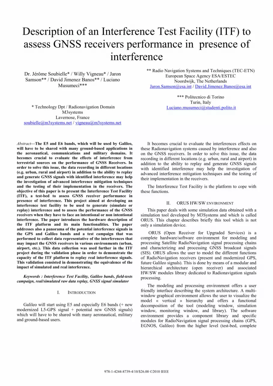
Figure 6. Equivalence of the interference impact on the real and simulated GNSS signals
Figure 7. Equivalence of the interference impact on the real and simulated GNSS signals
One limitation shall be noticed: this equivalence was demonstrated taking into account the offset between the noise floors at the RF antenna output (used to record a real GNSS signal) and at the Spirent RF output (used to generate a simulated GNSS signal).
When there is no interference, this offset has no impact on the GNSS receiver observables as the receiver sees only the signal to noise ratio (see top of the figure below).
When one interference is generated by the ITF platform, the user specifies the interference power J which results into a J/S interference to signal power ratio.
Because the noise power levels differ, at a given power level J, the resulting J/S power ratio differs (see Fig. 6).
As the result, the interference impact on the equivalent C/No is more important and so the receiver behaviour is not exactly the same. For our demonstration, the interference power level was manually calibrated to take into account the noise floor offset.
IX. CONCLUSION The ITF platform enables a user to test the performance of
GNSS receivers against interference signals for different configurations and types of inputs:
• Interferences generated by the Arbitrary Waveform Generators, depending on the supported modulations and options.
• Interferences collected during field-tests, either single interference or environment-representative interference (urban, rural, airport).
• Interferences generated by the ORUS platform from a specific ‘interference library’.
The ITF platform has been extensively validated using the ESTEC Lab equipments and verifying the generated
interference spectrum, time domain characteristics and parameters. A demonstration also allows validating the effects on GNSS receivers.
Some improvements and potential follow-up ideas have been already identified:
• ITF post-processing tool: to develop an automatic tool to analyze the impact of the interference on the GNSS receiver;
• ITF Hardware/packaging: to integrate all the equipments into a single hardware rack in order to facilitate the use of the ITF platform
Moreover, it could be interesting to use the real Galileo signals which will be available within the next few months or years in order to fully demonstrate the ITF platform with real signals.
ACKNOWLEDGMENT This project has been realized in the frame of an ESA
contract and the test campaigns and demonstration tests were performed thanks to the facilities provided by the TEC-ETN laboratory.
REFERENCES
[1] A Comparison of CW and Swept CW effects on a C/A code GPS receiver. K. D. Johnston. Air Force Institute of Technology School of Engineering. ION GPS 1999.
[2] CW Jamming effects on a COTS C/A code receiver. K. D. Johnston. Air Force Institute of Technology School of Engineering. ION GPS 1999.
[3] Methodology for determining compatibility of GPS L5 with existing systems and preliminary results. C. Hegarty. ION GPS-99.
[4] Validation of the feasibility of Coexistence of the new civil GPS L5 signal with existing systems. M. Tran, T. Kim, C. J. Hegarty. Mitre 2001.
[5] GPS and GLONASS radio interference in Germany; F. Butsch. Institute of navigation. University of Stuttgart. ION GPS-97.
[6] Location of GPS Interferers - John E. Wohlfiel; Bereket Tanju. ION 1999
[7] Interference Direction Finding for Aviation Applications of GPS. Konstantin Gromov, Dennis Akos, Sam Pullen, Per Enge, and Bradford Parkinson, Boris Pervan - ION 1999
[8] Testing and Research on Interference to GPS from UWB Transmitters - Ming Luo, Dennis Akos, Michael Koenig, Guttorm Opshaug, Sam Pullen, and Per Enge, Bob Erlandson, Sally Frodge - ION 2001
[9] GPS Receiver Susceptibility to Ultra-Wideband RFI: Test Results and RFI Link Analyses. Robert J. Erlandson, A. J. Van Dierendonck - ION 2001
[10] A Technique of Interference Monitoring in GNSS Applications, Based on ACF and Prony Methods. L. Lo Presti, B. Motella. ION GNSS 2006.

Figure 8. ITF architecture