deadlock-free multicast wormhole routing in 2-d mesh multicomputers
TRANSCRIPT
Adaptive Multicast Wormhole Routingin 2D Mesh MulticomputersXiaola Lin, Philip K. McKinley, and Abdol-Hossein EsfahanianTechnical ReportMSU-CPS-93-14May 1993A short version of this report appeared in Proc. PARLE'93,Munich, Germany, June 1993.
Adaptive Multicast Wormhole Routingin 2D Mesh Multicomputers �Xiaola Lin, Philip K. McKinley, and Abdol-Hossein EsfahanianDepartment of Computer ScienceMichigan State UniversityEast Lansing, Michigan 48824flinx, mckinley, esfahani [email protected] 1993AbstractThe issues of adaptive multicast wormhole routing in 2D mesh multicomputersare studied. Three adaptive multicast wormhole routing strategies are proposed andevaluated. The methods include minimal partially-adaptive, minimal fully-adaptive,and nonminimal adaptive routing. All the algorithms, which are the �rst deadlock-free adaptive multicast wormhole routing algorithms ever proposed, are shown to bedeadlock-free. A study has been conducted that compares the performance of thesemulticast algorithms. The results show that the minimal fully-adaptive routing methodcreates the least tra�c, however, double vertical channels are required in order to avoiddeadlock. The nonminimal routing algorithm exhibits the best adaptivity, although itcreates more network tra�c than the other methods.�This work was supported in part by the NSF grants MIP-9204066, CDA-9121641, and CDA-9222901, by DOEgrant DE-FG02-93ER25167, and by an Ameritech Faculty Fellowship.ii

1 IntroductionMassively parallel computers (MPCs) are seen as a viable platform on which to solve the so-calledgrand-challenge problems. Most such systems are characterized by the distribution of memoryamong an ensemble of processor nodes, which communicate by sending messages through a network.These systems are often said to be scalable because, as the number of nodes in the system increases,the total communication bandwidth, memory bandwidth, and processing capability of the systemalso increase.E�cient communication among nodes is critical to the performance of MPCs. Communicationoperations include not only point-to-point operations, in which two processes communicate withone another, but also collective operations, which involve more than two processes. Multicast isa collective communication service in which the same message is delivered from a source node toan arbitrary number of destination nodes. Both unicast, which involves a single destination, andbroadcast, which involves all nodes in the network, are special cases of multicast. Multicast commu-nication has several uses in large-scale multiprocessors [21], including direct use in various parallelalgorithms [6, 14], implementation of data parallel programming operations, such as replicationand barrier synchronization [25], and support of shared-data invalidation and updating in systemsusing a distributed shared-memory paradigm [17].E�cient implementation of multicast communication services depends on the particular systemarchitecture, which includes the network topology and the underlying switching technique usedto transfer messages across the network. The two-dimensional (2D) mesh topology has becomepopular in the construction of large-scale distributed-memory multiprocessors. Networks withmesh topologies o�er massive parallelism and are more scalable than many other approaches tomultiprocessor interconnection [23]. Formally, an m � n 2D mesh consists of N = m � n nodes;each node has an associated integer coordinate pair (x; y), 0 � x < n and 0 � y < m. Twonodes with coordinates (xi; yi) and (xj ; yj) are connected by a communication channel if and onlyif jxi � xj j + jyi � yj j = 1. Figure 1 illustrates a 4 � 5 2D mesh; notice that adjacent nodes areconnected by two unidirectional channels in opposite directions. As shown in Figure 1, directions areused to describe the relative positions of nodes. For example, node (1; 2) is said to be northwest of1

node 3; 0. The 2D mesh topology is used in the Symult 2010 [24], the Intel Touchstone DELTA [10],and the commercial successor to the latter, the Intel Paragon [9].4,0
4,1
4,2
4,3
2,0 3,0
2,1 3,1
2,2 3,2
1,0
1,1
1,2
1,3 2,3 3,3
0,0
0,1
0,2
0,3
node (including router)
unidirectionalcommunication channel
N
S
EW Figure 1. Example 4� 5 2D meshThe predominant switching technique used in new generation parallel machines is wormholerouting [4]. In this approach, a message is divided into a number of its for transmission. Theheader it(s) of a message governs the route, and the remaining its follow in a pipeline fashion.The two salient features of wormhole routing are that (1) only minimal bu�ers are required and (2)the network latency is distance-insensitive when there is no channel contention [23]. In wormhole-routed systems, each node contains a separate router to handle such communication-related tasks.As shown in Figure 2, several pairs of external channels connect the router to neighboring routers;the pattern in which the external channels are connected de�nes the network topology. Usually,the router can relay multiple messages simultaneously, provided that each incoming message re-quires a unique outgoing channel. A router is connected to the local processor/memory by oneor more pairs of internal channels. One channel of each pair is for input, the other for output.If each node possesses exactly one pair of internal channels, a so-called one-port communicationarchitecture [12] results, and the local processor must transmit (receive) messages sequentially. Amulti-port architecture reduces this bottleneck. In the case of an all-port system, every externalchannel has a corresponding internal channel, allowing the node to send to and receive from all itsports simultaneously. For a survey of wormhole routing in direct networks, please refer to [23].Because messages may hold some channels while waiting for others, wormhole routing is par-ticularly susceptible to deadlock. Typically, deadlock is avoided in the routing algorithm, whichdetermines the path followed by a message in order to reach its destination(s). Routing can be2

Local
Processor/Memory
externalinputchannels
externaloutputchannels
Router
internalinputchannels
internaloutputchannels
Figure 2. Generic MPC node architectureclassi�ed as deterministic or adaptive. In deterministic routing, the path followed by a message iscompletely determined by the source and destination addresses. A routing technique is adaptiveif, for a given source and destination, the path taken by a particular message depends on dynamicnetwork conditions, such as the presence of faulty or congested channels. By accounting for currentconditions, adaptive routing can be used to improve system performance [3, 20]. An adaptiverouting algorithm is said to be minimal if the path selected is one of the shortest paths between thesource and destination pair. Using a minimal routing algorithm, every channel visited will bringthe message closer to the destination. A nonminimal routing algorithm allows messages to followa longer path, usually in response to current network conditions.Several related routing problems have been studied previously. For example, adaptive routingalgorithms for unicast communication [20, 11, 8] and deterministic routing algorithms for multicastcommunication [18] have been proposed for wormhole-routed networks. In addition, adaptive multi-cast routing algorithms have been proposed for networks using store-and-forward switching [15, 16].As will be explained in detail in next section, none of these methods alone can be extended to providedeadlock-free adaptive multicast wormhole routing.In this paper, three deadlock-free adaptive multicast routing algorithms for wormhole-routed2D mesh networks are presented. Section 2 discusses the issues involved in designing such algo-rithms so that they are both adaptive and deadlock-free. A partially-adaptive minimal multicast3
routing algorithm is presented in Section 3; each message is routed deterministically to at most onedestination. In Section 4, a fully-adaptive minimal multicast routing method is given that routesthe message adaptively to all destination at the expense of additional channels in the network. InSection 5, a nonminimal adaptive multicast algorithm is proposed that is based on a node-labelingassignment used in earlier deterministic multicast algorithms [18]. Section 6 describes variations ofthe algorithms presented in Sections 4 and 5 in which up to four independent worms may be usedto instantiate a multicast operation. Comparisons of all the proposed adaptive routing algorithmsin terms of several metrics are presented in Section 7. Section 8 contains concluding remarks.2 Deadlock Problems in Adaptive Multicast Wormhole RoutingOne of the most important issues in designing an adaptive routing algorithm is how to guaranteefreedom from deadlock. A deadlock occurs when two or more messages are delayed forever due to acyclic dependency among their requested resources. In wormhole-routed networks, the critical re-sources are channels. Since blocked messages are not bu�ered at intermediate nodes and, therefore,not removed from the network, one way to avoid deadlock is to guarantee that cyclic dependenciesin channel usage cannot arise. This strategy has been used in the design of numerous deadlock-freerouting algorithms for wormhole-routed networks.For example, deadlock-free deterministic unicast communication can be implemented by simplyassigning to each channel a unique number and allocating channels to messages in strictly ascending(alternatively, descending) order [5]. A channel numbering scheme often used in n-dimensionalmeshes is based on the dimension of channels. In such dimension-ordered routing, each messageis routed in one dimension at a time, arriving at the proper coordinate in each dimension beforeproceeding to the next dimension. By enforcing a strictly monotonic order on the dimensionstraversed, deadlock-free routing is guaranteed. Examples of dimension-ordered routing include XYrouting for the 2D mesh and E-cube routing for the hypercube [23].Avoiding cyclic dependencies has also been used to develop deadlock-free adaptive unicastrouting algorithms. One such approach uses virtual channels multiplexed on each physical channel.Each virtual channel has its own it bu�er, control, and data path [2]. In the virtual networkmodel [11], there are two virtual channels for each physical channel in a 2D mesh. The network is4
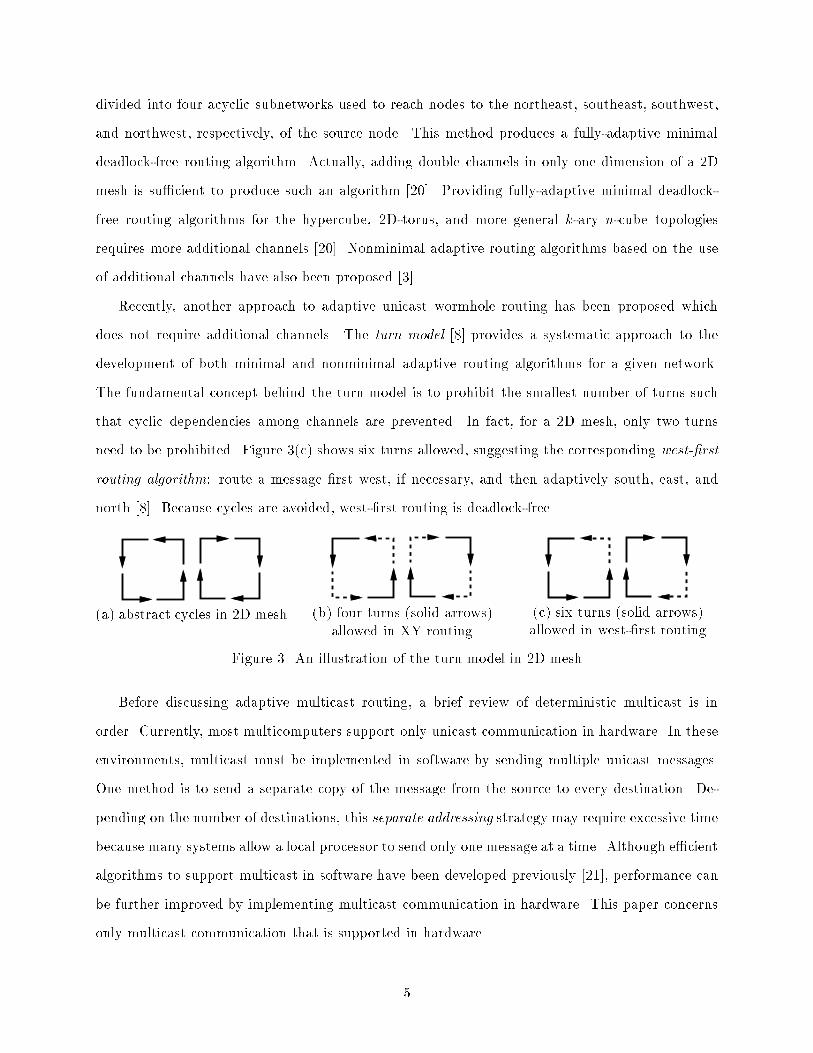
divided into four acyclic subnetworks used to reach nodes to the northeast, southeast, southwest,and northwest, respectively, of the source node. This method produces a fully-adaptive minimaldeadlock-free routing algorithm. Actually, adding double channels in only one dimension of a 2Dmesh is su�cient to produce such an algorithm [20]. Providing fully-adaptive minimal deadlock-free routing algorithms for the hypercube, 2D-torus, and more general k-ary n-cube topologiesrequires more additional channels [20]. Nonminimal adaptive routing algorithms based on the useof additional channels have also been proposed [3].Recently, another approach to adaptive unicast wormhole routing has been proposed whichdoes not require additional channels. The turn model [8] provides a systematic approach to thedevelopment of both minimal and nonminimal adaptive routing algorithms for a given network.The fundamental concept behind the turn model is to prohibit the smallest number of turns suchthat cyclic dependencies among channels are prevented. In fact, for a 2D mesh, only two turnsneed to be prohibited. Figure 3(c) shows six turns allowed, suggesting the corresponding west-�rstrouting algorithm: route a message �rst west, if necessary, and then adaptively south, east, andnorth [8]. Because cycles are avoided, west-�rst routing is deadlock-free.(a) abstract cycles in 2D mesh (b) four turns (solid arrows)allowed in XY routing (c) six turns (solid arrows)allowed in west-�rst routingFigure 3. An illustration of the turn model in 2D meshBefore discussing adaptive multicast routing, a brief review of deterministic multicast is inorder. Currently, most multicomputers support only unicast communication in hardware. In theseenvironments, multicast must be implemented in software by sending multiple unicast messages.One method is to send a separate copy of the message from the source to every destination. De-pending on the number of destinations, this separate addressing strategy may require excessive timebecause many systems allow a local processor to send only one message at a time. Although e�cientalgorithms to support multicast in software have been developed previously [21], performance canbe further improved by implementing multicast communication in hardware. This paper concernsonly multicast communication that is supported in hardware.5
0,0 1,0 2,0 3,0 4,0 5,0
0,1 1,1 2,1 3,1 4,1 5,1
0,2 1,2 2,2 3,2 4,2 5,2
1,3 2,3 3,3 4,3 5,3
0,4 1,4 2,4 3,4 4,4 5,4
0,5 1,5 2,5 3,5 4,5 5,5
0,3
source node
destination node
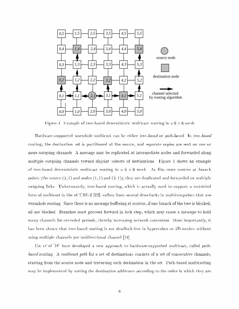
channel selected by routing algorithmFigure 4. Example of tree-based deterministic multicast routing in a 6� 6 meshHardware-supported wormhole multicast can be either tree-based or path-based. In tree-basedrouting, the destination set is partitioned at the source, and separate copies are sent on one ormore outgoing channels. A message may be replicated at intermediate nodes and forwarded alongmultiple outgoing channels toward disjoint subsets of destinations. Figure 4 shows an exampleof tree-based deterministic multicast routing in a 6 � 6 mesh. As its enter routers at branchpoints (the source (2; 1) and nodes (1; 1) and (3; 1)), they are duplicated and forwarded on multipleoutgoing links. Unfortunately, tree-based routing, which is actually used to support a restrictedform of multicast in the nCUBE-2 [22], su�ers from several drawbacks in multicomputers that usewormhole routing. Since there is no message bu�ering at routers, if one branch of the tree is blocked,all are blocked. Branches must proceed forward in lock step, which may cause a message to holdmany channels for extended periods, thereby increasing network contention. More importantly, ithas been shown that tree-based routing is not deadlock-free in hypercubes or 2D-meshes withoutusing multiple channels per unidirectional channel [18].Lin et al [18] have developed a new approach to hardware-supported multicast, called path-based routing. A multicast path for a set of destinations consists of a set of consecutive channels,starting from the source node and traversing each destination in the set. Path-based multicastingmay be implemented by sorting the destination addresses according to the order in which they are6
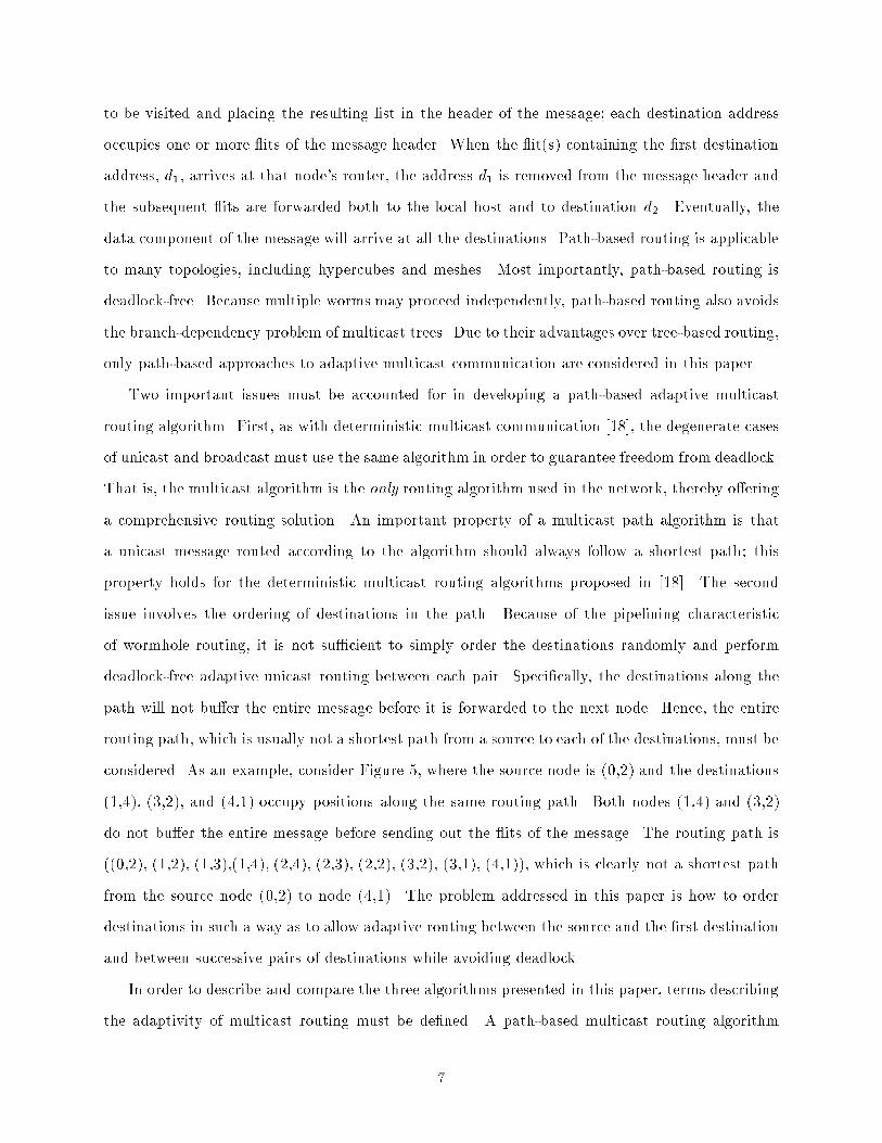
to be visited and placing the resulting list in the header of the message; each destination addressoccupies one or more its of the message header. When the it(s) containing the �rst destinationaddress, d1, arrives at that node's router, the address d1 is removed from the message header andthe subsequent its are forwarded both to the local host and to destination d2. Eventually, thedata component of the message will arrive at all the destinations. Path-based routing is applicableto many topologies, including hypercubes and meshes. Most importantly, path-based routing isdeadlock-free. Because multiple worms may proceed independently, path-based routing also avoidsthe branch-dependency problem of multicast trees. Due to their advantages over tree-based routing,only path-based approaches to adaptive multicast communication are considered in this paper.Two important issues must be accounted for in developing a path-based adaptive multicastrouting algorithm. First, as with deterministic multicast communication [18], the degenerate casesof unicast and broadcast must use the same algorithm in order to guarantee freedom from deadlock.That is, the multicast algorithm is the only routing algorithm used in the network, thereby o�eringa comprehensive routing solution. An important property of a multicast path algorithm is thata unicast message routed according to the algorithm should always follow a shortest path; thisproperty holds for the deterministic multicast routing algorithms proposed in [18]. The secondissue involves the ordering of destinations in the path. Because of the pipelining characteristicof wormhole routing, it is not su�cient to simply order the destinations randomly and performdeadlock-free adaptive unicast routing between each pair. Speci�cally, the destinations along thepath will not bu�er the entire message before it is forwarded to the next node. Hence, the entirerouting path, which is usually not a shortest path from a source to each of the destinations, must beconsidered. As an example, consider Figure 5, where the source node is (0,2) and the destinations(1,4), (3,2), and (4,1) occupy positions along the same routing path. Both nodes (1,4) and (3,2)do not bu�er the entire message before sending out the its of the message. The routing path is((0,2), (1,2), (1,3),(1,4), (2,4), (2,3), (2,2), (3,2), (3,1), (4,1)), which is clearly not a shortest pathfrom the source node (0,2) to node (4,1). The problem addressed in this paper is how to orderdestinations in such a way as to allow adaptive routing between the source and the �rst destinationand between successive pairs of destinations while avoiding deadlock.In order to describe and compare the three algorithms presented in this paper, terms describingthe adaptivity of multicast routing must be de�ned. A path-based multicast routing algorithm7

0,0 1,0 2,0 3,0 4,0 5,0
0,1 1,1 2,1 3,1 4,1 5,1
0,2 4,2 5,2
0,3 3,3 4,3 5,3
0,4 3,4 4,4 5,4
0,5 1,5 2,5 3,5 4,5 5,5
source node
destination node
routing algorithm
busy channel
channel selected by
1,3
1,2 2,2
2,3
2,41,4
3,2Figure 5. An example of adaptive routing in a 6� 6 meshis minimal if it always follows a shortest path between each pair of nodes in the multicast path;otherwise, it is nonminimal. A multicast routing algorithm is de�ned to be fully-adaptive if themessage can take any path between each pair of nodes in the multicast path, that is, from s to d1and from dj to dj+1, for 1 � j � k � 1. A multicast algorithm is partially adaptive if it can routemessages adaptively between only some pairs of nodes in the multicast path.Finally, a distinction should be drawn between the adaptive multicast routing problem inwormhole-routed networks and the same problem in store-and-forward networks. In the latter,deadlock is usually avoided by providing adequate bu�er space at routers or, in their absence, atlocal processors, which are necessarily required to forward messages. With the deadlock problemsolved outside of the routing algorithm, adaptive or fault-tolerant multicast routing algorithmsfor store-and-forward networks [15, 16] are invariably based on multicast trees, and would riskdeadlock in wormhole-routed networks. Further, in evaluating the performance of such algorithms,latency is assumed to be linear in the path length; therefore, such algorithms do not exploit thedistance-insensitivity of wormhole routing. 8
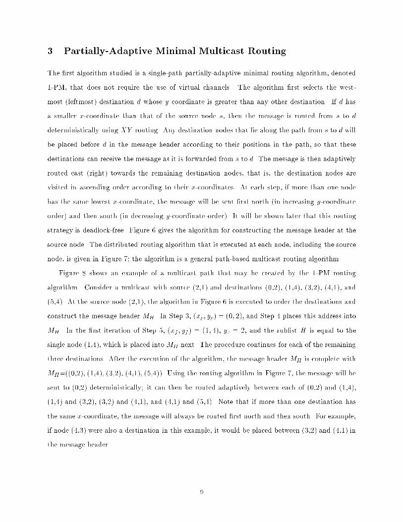
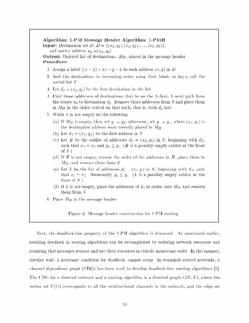
3 Partially-Adaptive Minimal Multicast RoutingThe �rst algorithm studied is a single-path partially-adaptive minimal routing algorithm, denoted1-PM, that does not require the use of virtual channels. The algorithm �rst selects the west-most (leftmost) destination d whose y coordinate is greater than any other destination. If d hasa smaller x-coordinate than that of the source node s, then the message is routed from s to ddeterministically using XY routing. Any destination nodes that lie along the path from s to d willbe placed before d in the message header according to their positions in the path, so that thesedestinations can receive the message as it is forwarded from s to d. The message is then adaptivelyrouted east (right) towards the remaining destination nodes, that is, the destination nodes arevisited in ascending order according to their x-coordinates. At each step, if more than one nodehas the same lowest x-coordinate, the message will be sent �rst north (in increasing y-coordinateorder) and then south (in decreasing y-coordinate order). It will be shown later that this routingstrategy is deadlock-free. Figure 6 gives the algorithm for constructing the message header at thesource node. The distributed routing algorithm that is executed at each node, including the sourcenode, is given in Figure 7; the algorithm is a general path-based multicast routing algorithm.Figure 8 shows an example of a multicast path that may be created by the 1-PM routingalgorithm. Consider a multicast with source (2,1) and destinations (0,2), (1,4), (3,2), (4,1), and(5,4). At the source node (2,1), the algorithm in Figure 6 is executed to order the destinations andconstruct the message header MH . In Step 3, (xp; yp) = (0; 2), and Step 4 places this address intoMH . In the �rst iteration of Step 5, (xf ; yf) = (1; 4), yc = 2, and the sublist H is equal to thesingle node (1,4), which is placed intoMH next. The procedure continues for each of the remainingthree destinations. After the execution of the algorithm, the message header MH is complete withMH=((0,2), (1,4), (3,2), (4,1), (5,4)). Using the routing algorithm in Figure 7, the message will besent to (0,2) deterministically; it can then be routed adaptively between each of (0,2) and (1,4),(1,4) and (3,2), (3,2) and (4,1), and (4,1) and (5,4). Note that if more than one destination hasthe same x-coordinate, the message will always be routed �rst north and then south. For example,if node (4,3) were also a destination in this example, it would be placed between (3,2) and (4,1) inthe message header. 9
Algorithm: 1-PM Message Header Algorithm: 1-PMHInput: Destination set D, D = f(x1; y1); (x2; y2); : : : ; (xk; yk)g,and source address u0 =(x0; y0).Output: Ordered list of destinations, MH , placed in the message header.Procedure:1. Assign a label ((x+ 1)� n)� y � 1 to each address (x; y) in D.2. Sort the destinations in increasing order using their labels as keys; call thesorted list S.3. Let dp = (xp; yp) be the �rst destination in the list.4. Find those addresses of destinations that lie on the X-�rst, Y-next path fromthe source u0 to destination dp. Remove those addresses from S and place themin MH in the order visited on that path, that is, with dp last.5. While S is not empty do the following:(a) If MH is empty, then set yc = y0; otherwise, set yc = yr , where (xr; yr) isthe destination address most recently placed in MH .(b) Let df = (xf ; yf) be the �rst address in S.(c) Let H be the sublist of addresses dh = (xh; yh) in S, beginning with df ,such that xh = xf and yh � yc. (H is a possibly empty sublist at the frontof S.)(d) If H is not empty, reverse the order of the addresses in H , place them inMH , and remove them from S.(e) Let L be the list of addresses dl = (xl; yl) in S, beginning with df , suchthat xl = xf . Necessarily, yl � yc. (L is a possibly empty sublist at thefront of S.)(f) If L is not empty, place the addresses of L, in order, into MH and removethem from S.6. Place MH in the message header.Figure 6. Message header construction for 1-PM routing.Next, the deadlock-free property of the 1-PM algorithm is discussed. As mentioned earlier,avoiding deadlock in routing algorithms can be accomplished by ordering network resources andrequiring that messages request and use these resources in strictly monotonic order. In this manner,circular wait, a necessary condition for deadlock, cannot occur. In wormhole-routed networks, achannel dependence graph (CDG) has been used to develop deadlock-free routing algorithms [5].The CDG for a directed network and a routing algorithm is a directed graph G(V;E), where thevertex set V (G) corresponds to all the unidirectional channels in the network, and the edge set10
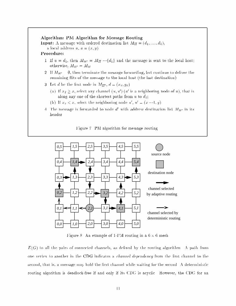
Algorithm: PM Algorithm for Message RoutingInput: A message with ordered destination list MH = (d1; : : : ; dk),a local address u, u = (x; y).Procedure:1. If u = d1, then MH 0 = MH � fd1g and the message is sent to the local host;otherwise, MH 0 =MH .2. IfMH 0 = ;, then terminate the message forwarding, but continue to deliver theremaining its of the message to the local host (the last destination).3. Let d be the �rst node in MH 0 , d = (xd; yd).(a) If xd � x, select any channel (u; u0) (u0 is a neighboring node of u), that isalong any one of the shortest paths from u to d1;(b) If xd < x, select the neighboring node u0, u0 = (x� 1; y).4. The message is forwarded to node d0 with address destination list MH 0 in itsheader. Figure 7. PM algorithm for message routing.0,0 1,0 2,0 3,0 4,0 5,0
0,1 1,1 2,1 3,1 4,1 5,1
0,2 1,2 2,2 3,2 4,2 5,2
0,3 1,3 2,3 3,3 4,3 5,3
0,4 1,4 2,4 3,4 4,4 5,4
0,5 1,5 2,5 3,5 4,5 5,5
source node
destination node
channel selected
by adaptive routing
deterministic routingchannel selected byFigure 8. An example of 1-PM routing in a 6� 6 mesh.E(G) to all the pairs of connected channels, as de�ned by the routing algorithm. A path fromone vertex to another in the CDG indicates a channel dependency from the �rst channel to thesecond, that is, a message may hold the �rst channel while waiting for the second. A deterministicrouting algorithm is deadlock-free if and only if its CDG is acyclic. However, the CDG for an11

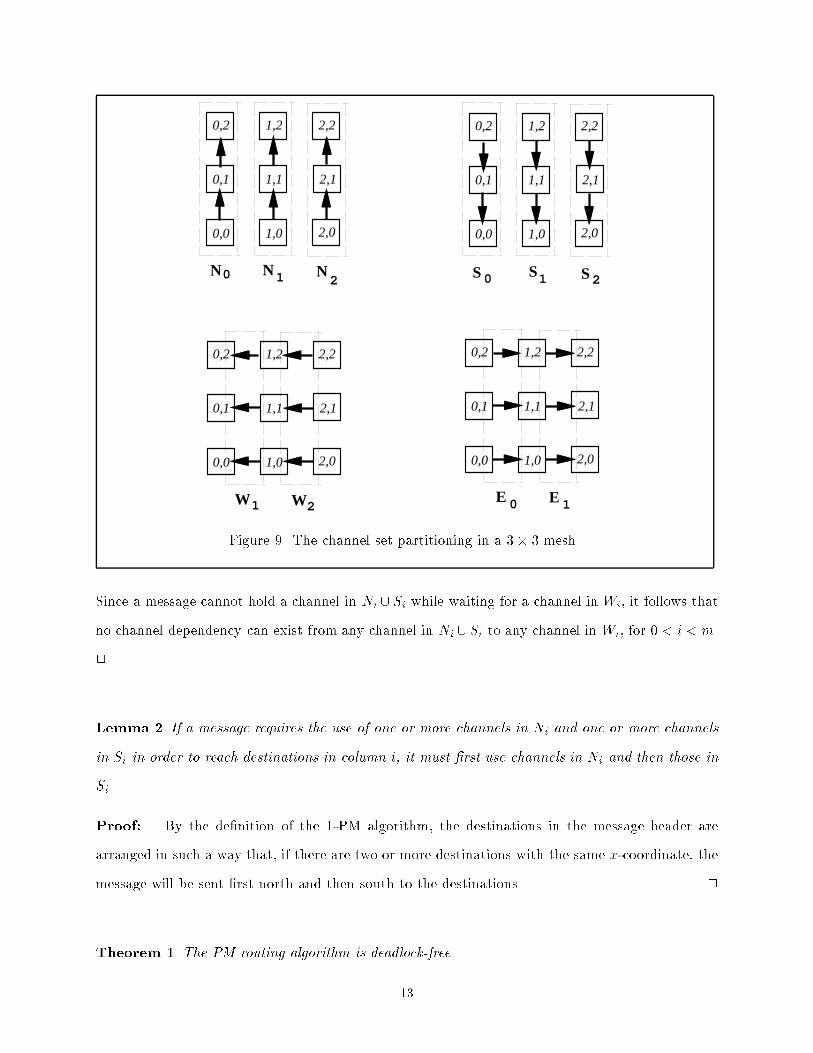
adaptive routing algorithm may contain cycles, even though the routing algorithm is deadlock-free.Therefore, the CDG alone is of limited use in the development of deadlock-free adaptive routingalgorithms. Alternative methods have been developed to prove that certain adaptive unicast routingalgorithms are deadlock-free even though their CDGs contain cycles [7, 1].A new method, the message ow model [19], is used to prove that the deadlock-free propertyholds for 1-PM routing and the algorithms described in later sections. It is assumed that everydestination node can consume any incoming message. For a given routing algorithm, a channel(u; v) is deadlock-immune if and only if, for any message arriving at v from channel (u; v), thelast it of the message can eventually be sent out towards its destination(s), thus releasing thechannel (u; v). A routing algorithm is deadlock-free if and only if every channel in the network isdeadlock-immune when using the algorithm.In order to show that all channels are deadlock-immune when using the 1-PM algorithm, thechannels in an m�n mesh are �rst partitioned into 4m�2 disjoint sets according to their directionsas follows:Ni = f((i; j); (i; j+ 1))j0 � j < n � 1g, for 0 � i < m,Si = f((i; j); (i; j� 1))j0 < j < ng, for 0 � i < m,Wi = f((i; j); (i� 1; j))j0� j < ng for 0 < i < m,Ei = f((i; j); (i+ 1; j))j0� j < ng for 0 � i < m� 1.Figure 9 shows these subsets for a 3� 3 mesh.The following lemmas are required to show the deadlock-free property of the 1-PM routingalgorithm.Lemma 1 Let Ni [ Sj denote the union of the two channel sets Ni and Sj. Under 1-PM routing,there does not exist a channel dependency from any channel in Ni [ Si to any channel in Wi, for0 < i < m.Proof: The 1-PM algorithm routes the message �rst to a west-most destination node (a nodewith smallest x-coordinate), and then sends the message from west to east, that is, in increasingorder of the x-coordinates. According to the 1-PM algorithm, the channels must be used in thefollowing order: Wm�1;Wm�2; : : : ;W1, N0 [ S0; E0; N1 [ S1; E1; : : : ; Em�2; Nm�1 [ Sm�1, that is,zero or one channel from setWm�1, followed by zero or one channel from set Wm�2; : : :, followed byzero or one channel from set W1, followed by zero or more channels from set N0[S0; : : :, and so on.12
0,0 1,0 2,0
0,1 1,1 2,1
0,2 1,2 2,2
0,0 1,0 2,0
0,1 1,1 2,1
0,2 1,2 2,2
0,0 1,0 2,0
0,1 1,1 2,1
0,2 1,2 2,2
0,0 1,0 2,0
0,1 1,1 2,1
0,2 1,2 2,2
N
W W E
N N0 1
1 2 1
S S S
E
0 1 2
0
2
Figure 9. The channel set partitioning in a 3� 3 mesh.Since a message cannot hold a channel in Ni [ Si while waiting for a channel in Wi, it follows thatno channel dependency can exist from any channel in Ni [ Si to any channel in Wi, for 0 < i < m.2Lemma 2 If a message requires the use of one or more channels in Ni and one or more channelsin Si in order to reach destinations in column i, it must �rst use channels in Ni and then those inSi.Proof: By the de�nition of the 1-PM algorithm, the destinations in the message header arearranged in such a way that, if there are two or more destinations with the same x-coordinate, themessage will be sent �rst north and then south to the destinations. 2Theorem 1 The PM routing algorithm is deadlock-free.13
Proof: It is �rst proved by induction that every channel in Ni [ Si, m > i � 0, as well as everychannel in Ei, m � 1 > i � 0, is deadlock-immune. It is then shown that every channel in Wi,m > i > 0, is also deadlock-immune.The induction variable is i. When i = 1,Nm�i[Sm�i contains the channels connecting the nodesin column m� 1. By Lemma 1, there is no channel dependency from any channel in Nm�1 [ Sm�1to any channel in Wm�1, so after a message arrives at a node in column m� 1 from a channel inEm�1, all of the remaining destinations in the message header for a multicast must also be locatedin column m� 1. By Lemma 2, there is no channel dependency from any channel in Sm�1 to anychannel in Nm�1, thus the message can eventually be sent to the remaining destinations after ithas arrived at any node in column m � 1. Hence, all the channels in Nm�1 [ Sm�1 [ Em�2 aredeadlock-immune.Suppose that the assumption is true for i = p; p � 1, and consider i = p + 1. By Lemma1, there is no channel dependency from any channel in Nm�(p+1) [ Sm�(p+1) to any channel inWm�(p+1), and by induction, the channels in Em�(p+1) are deadlock-immune. If there were achannel in Nm�(p+1)[Sm�(p+1) involving a deadlock, then only among those channels in Nm�(p+1)[Sm�(p+1) could a cyclic channel dependency be formed that could not be broken. By Lemma 2, if amessage �rst uses one or more channels in Sm�(p+1), then requests a channel in Nm�(p+1), the �rstdestination in the message header must be a node in some column `, ` � m� p. Because adaptiverouting is used, such a dependency can always be removed by selecting an alternative channelin Em�(p+1), which is deadlock-immune by the induction assumption. Therefore, no unbreakablecyclic dependency can be formed among the channels in Nm�(p+1)[Sm�(p+1), and all the channelsin Nm�(p+1) [ Sm�(p+1) [Em�(p+2) are deadlock-immune.Finally, by Lemma 1, if a message requires channels in Wi, for 0 < i < m, such channels canbe used only before using any channels in Np [ Sp, for 0 � p < m, and before any channels in Ep,for 0 < p < m. It is easy to see that the channels in W1 are deadlock-immune, as is also true forthe channels in W2, W3, and so on.Because every channel in the mesh network is deadlock-immune under the 1-PM routing, therouting algorithm is deadlock-free. 214

Given a multicast with k destination nodes, Step 1 of the 1-PMH algorithm in Figure 6 takesat most O(k) time. Step 2 can be executed in O(k log k) time, since it involves simply sorting thedestinations based on their labels. Step 3 takes at most O(k) time, as does the while loop in Step4, since it processes each destination a constant number of times. Thus, the time complexity ofthe 1-PMH algorithm is O(k log k). Such an algorithm may need to be executed only once for agiven set of destinations; in fact, it may be possible to order the destinations at compile time. Therouting algorithm in Figure 7 requires O(1) time, since each node in a 2D mesh has at most fouroutgoing channels to choose from.The 1-PM algorithm sends a message using a single multicast path. Although the route fromthe source to the last destination node may be relatively long, this strategy is particularly well-suited for one-port architectures, such as the Intel Paragon [9]. If more than one worm wereused to implement a multicast operation in a one-port system, then the worms would have tobe transmitted sequentially from the source node, reducing the bene�ts of pipelining provided bywormhole routing.However, if the architecture o�ers multiple internal channels, then the use of more than oneworm is e�ective in reducing the lengths of the constituent multicast paths and the total number ofchannels required to implement a particular multicast operation. In this approach, the destinationset is partitioned into subsets. A separate worm is transmitted for each subset, following a multicastpath that visits each destination node in the subset.Figure 10 gives the message header construction algorithm for the 2-PM algorithm, a partially-adaptive multicast routing algorithm that uses up to two worms; the worms can proceed in parallelas long as the source node has at least two internal channels. In this algorithm, the set of destinationnodes is divided into two subsets, and copies of the message are routed independently along twomulticast paths. The 2-PM message routing algorithm itself, which is executed at each intermediatenode, is identical to that of the PM algorithm given in Figure 7.Figure 11 shows an example of two multicast paths that may be created by the above algorithm.At the source node (2,1), the set of destinations f(0; 2); (1; 4); (3; 2); (4; 1); (5; 4)g is divided intotwo subsets: f(0; 2); (1; 4)g; and f(3; 2); (4; 1); (5; 4)g. In the �rst path, the message is routeddeterministically from the source node (2,1) to node (0,2) and then adaptively from (0,2) to (1,4).15
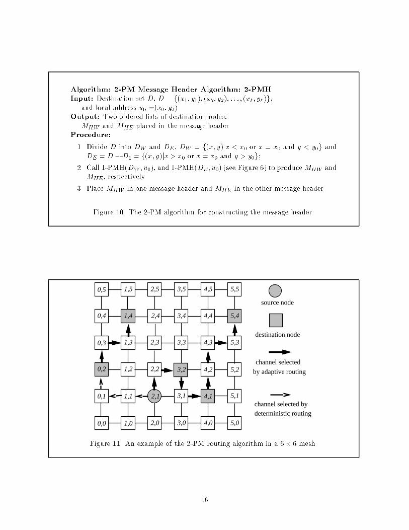
Algorithm: 2-PM Message Header Algorithm: 2-PMHInput: Destination set D, D = f(x1; y1); (x2; y2); : : : ; (xk; yk)g,and local address u0 =(x0; y0).Output: Two ordered lists of destination nodes:MHW and MHE placed in the message header.Procedure:1. Divide D into DW and DE , DW = f(x; y)jx < x0 or x = x0 and y < y0g andDE = D �D1 = f(x; y)jx > x0 or x = x0 and y > y0g;2. Call 1-PMH(DW ; u0), and 1-PMH(DE; u0) (see Figure 6) to produceMHW andMHE, respectively.3. Place MHW in one message header and MHE in the other message header.Figure 10. The 2-PM algorithm for constructing the message header.
0,0 1,0 2,0 3,0 4,0 5,0
0,1 1,1 2,1 3,1 4,1 5,1
0,2 1,2 2,2 3,2 4,2 5,2
0,3 1,3 2,3 3,3 4,3 5,3
0,4 1,4 2,4 3,4 4,4 5,4
0,5 1,5 2,5 3,5 4,5 5,5
source node
destination node
channel selected
by adaptive routing
deterministic routingchannel selected byFigure 11. An example of the 2-PM routing algorithm in a 6� 6 mesh.16

In the second path, the message is forwarded from (2,1) to (3,2), from (3,2) to (4,1), and from (4,1)to (5,4), all adaptively. The following corollary follows directly from Theorem 1.Corollary 1 The 2-PM algorithm is deadlock-free.4 Fully-Adaptive Minimal Multicast RoutingIn the 1-PM algorithm, a message is routed deterministically to one west-most destination node;destinations along that path are also reached deterministically. For unicast communication, inwhich the number of the destinations is one, this property implies that the message has to bedelivered deterministically to any destination node that lies west of the source node. Hence, onlyabout half of the unicast messages can be routed adaptively. It can be easily shown that, withoutintroducing virtual channels, it is impossible to implement fully-adaptive deadlock-free routingeven for unicast communication [23]. In order to support fully-adaptive multicast routing, thetechnique used here is to double the vertical channels. Suppose that one set of the vertical channelsis identi�ed as CV 1 and the other as CV 2. The channels of the network are further partitioned intotwo disjoint sets CW and CE as follows,CW = fcjc is horizontal channel from east to west or c 2 CV 1gCE = fcjc is horizontal channel from west to east or c 2 CV 2g.Like the 2-PM algorithm, the proposed fully-adaptive minimal routing algorithm, 2-FM, is adual-path multicast algorithm. The destination set is divided into two subsets, MHW and MHE.The setMHW contains the destination nodes that are to the west of the source, andMHE the nodesto the east of the source. The message will be delivered to MHW using the channels in CW andto MHE using the channels in CE . The multicast routing for MHE is the same as that of the PMrouting algorithm described in the previous section; since there is no destination node to the westof the source node in MHE , the message can be forwarded fully-adaptively. The routing in CW issimilar to the routing in CE but in the opposite direction. Figure 12 gives the 2-FM algorithm forconstructing the message header. The algorithm �rst divides the set of destination addresses intotwo subsets, DW and DE. The addresses in DE are ordered in exactly the same way as the 1-PMHalgorithm in Figure 6. The nodes in DW are ordered from east to west, that is, in descending orderof their x-coordinates. Two independent multicast paths result, each of which uses a di�erent set17

of channels to deliver the message to one of the subsets of the destinations. Figure 13 describes theFM routing algorithm for a 2D mesh with double vertical channels. The FM routing algorithm issimilar to the one in Figure 7 except that deterministic routing is not required.Algorithm: 2-FM Message Header Algorithm: 2-FMHInput: Destination set D, D = f(x1; y1); (x2; y2); : : : ; (xk; yk)g,and source address u0 =(x0; y0).Output: Two ordered lists of destination nodes:MHE and MHW placed in the message header.Procedure:1. Divide D into DW and DE such thatDW = f(x; y)jx > x0 or x = x0 and y > y0g, and DE = D �DW .2. Call 1-PMH(DE; u0) (see Figure 6), which returns MHE .3. Assign a label (x� n) + y to each address (x; y) in DW .4. Sort the destinations in DW in decreasing order using their labels as keys; callthe sorted list SW .5. While SW is not empty do the following:(a) If MHW is empty, then set yc = y0; Otherwise, set yc = yr, where (xr; yr)is the destination address most recently placed in MHW .(b) Let df = (xf ; yf) be the �rst address in SW .(c) Let H be the sublist of addresses dh = (xh; yh) in SW , beginning with df ,such that xh = xf and yh � yc. (H is a possibly empty sublist at the frontof SW .)(d) If H is not empty, reverse the order of the addresses in H , place them inMHW , and remove them from SW .(e) Let L be the list of addresses dl = (xl; yl) in SW , beginning with df , suchthat xl = xf ; necessarily, yl � yc. (L is a possibly empty sublist at thefront of SW .)(f) If L is not empty, place the addresses of L into MHW and remove themfrom SW .6. Construct two messages, one with message header MHE and the other withmessage header MHW .Figure 12. 2-FM algorithm for constructing the message headerFigure 14 shows an example of the multicast paths that may be created by the 2-FM routingalgorithm. At the source node (2,1), the 2-FMH algorithm �rst divides the set of the destinationsinto two subsets: (0,2), (1,4); and (3,2), (4,1), (5,4). One copy of the message is forwarded to (0,2)18

Algorithm: FM Algorithm for Message RoutingInput: A message with ordered destination list MH = (d1; : : : ; dk),MH is MHW or MHE, a local address u, u = (x; y).Procedure:1. If u = d1, then set MH 0 =MH � fd1g and the message is delivered to the localnode; otherwise, set MH 0 =MH .2. IfMH 0 = ;, then terminate the message forwarding, but continue to deliver theremaining its of the message to the local host.3. Let d be the �rst node in MH 0 , d = (xh; yh). Select any channel (u; u0) in CLif the header is MHW (or CR if the header is MHE) that is in any one of theshortest paths from u to d1.4. The message is sent to node u0 with destination address list MH 0 in its header.Figure 13. FM algorithm for message routing.
0,0 1,0 2,0 3,0 4,0 5,0
0,1 1,1 2,1 3,1 4,1 5,1
0,2 1,2 2,2 3,2 4,2 5,2
0,3 1,3 2,3 3,3 4,3 5,3
0,4 1,4 2,4 3,4 4,4 5,4
0,5 1,5 2,5 3,5 4,5 5,5
source node
destination node
channel selectedadaptively by
routing algorithmFigure 14. An example of 2-FM routing algorithm in a 6� 6 mesh.19

and (1,4) adaptively using channels in CW ; another copy of the same message is sent adaptively to(3,2), (4,1) and (5,4), using channels in CE.Theorem 2 The FM routing algorithm is deadlock-free.Proof: The message routing in the subnetwork with channels in CE is the same as the messagerouting in the PM algorithm. Hence, the message routing is from west to east, is fully-adaptive,and is deadlock-free according to Theorem 1. For the message routed in other subnetwork withchannels in CW , the proof is similar to the proof of Theorem 1. however, the induction would startfrom the west-most column. 2As with the 1-PMH algorithm, the 2-FMH algorithm in Figure 12 requires O(k log k) time fora multicast with k destination nodes, but again may be executed once at compile time. Step 1requires O(k) time, and Step 2 calls the 1-PMH algorithm with O(jDEj log jDEj) time, jDEj � k.Step 3 requires O(k) time and Step 4, a sort, requires O(jDW j log jDW j) time, jDW j � k. The whileloop in Step 5 requires O(DW ) time, since each destination is processed a constant number of times.Step 6 requires O(k) time. Thus, the time complexity of the 2-FMH algorithm is O(k log k). Therouting algorithm in Figure 13 obviously requires O(1) time.5 Nonminimal Adaptive Multicast RoutingIn nonminimal adaptive routing, a message can be derouted, that is, routed along a non-shortestpath, in the presence of a blocked channel. As shown in [13], nonminimal adaptive routing has thepotential to provide lower latency and higher throughput than minimal adaptive routing, especiallyunder non-uniform tra�c. In addition to handling the deadlock problem, a nonminimal multicastalgorithm must also avoid livelock, in which a message fails to be delivered to its destinations dueto its repeated derouting.The solution presented here is to modify a deterministic dual-path method [18] so as to supportnonminimal adaptive routing. The method is based on a node-labeling scheme. First, a Hamiltonianpath in the 2D mesh is selected and integer numbers are assigned to the nodes according to theirpositions in the path. The 2D mesh is next divided into two subnetworks, one called the high-channel network, containing all of the channels from lower labeled nodes to higher labeled nodes;20

the other called the low-channel network containing all of the channels from higher labeled nodesto lower labeled nodes. Figure 17 shows a label assignment for the nodes in a 6 � 6 mesh. Thelabel assignment function ` for an m� n mesh can be expressed as`(x; y) = 8><>: x � n+ y + 1 if x is evenx � n+ n� y if x is oddThe destination node set is divided into two subsets, one containing destination nodes with labelshigher than that of the source node, the other containing destinations with labels lower than thatof the source node. The message is delivered to these two sets of the destinations using the high-channel and low-channel subnetworks, respectively.Figure 15 and Figure 16, respectively, give the message header construction algorithm and therouting algorithm for the label-based, dual-path approach, collectively called the 2-LD routingalgorithm. The algorithm in Figure 15 divides the destinations into two subsets of the destinationsas described above, and sorts the two subsets in ascending and descending order, respectively, usingtheir labels as keys. The routing algorithm in Figure 16 is a general, path-like routing algorithm [18],which uses di�erent sets of the channels for di�erent subsets of destinations.Algorithm: LD Message Header AlgorithmInput: Destination set D, local address u0 and node label assignment function `.Output: Two sorted lists of addresses, DH and DL, placed in the message header.Procedure:1. Divide D into two sets DH and DL such that DH contains all the destinationnodes with higher ` value than `(u0), and DL contains the nodes with lower `value than `(u0).2. Sort the destination nodes in each of DH and DL, using the ` value as the key.3. Construct two messages, one containing DH as part of the header and the othercontaining DL as part of the header.Figure 15. 2-LD algorithm for constructing the message header.Figure 17 shows an example of the two multicast paths that may be created by the 2-LDalgorithm. The source node (2,1) has label `(2; 1)=14; the destination nodes (0,2), (1,4), (3,2),(4,1), (5,4) have the labels 3, 8, 22, 26, and 32, respectively. At the source node, the destination21
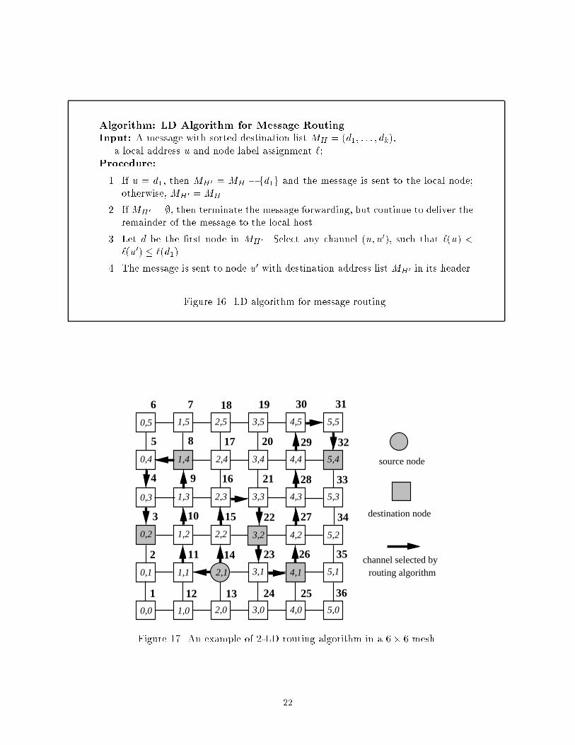
Algorithm: LD Algorithm for Message RoutingInput: A message with sorted destination list MH = (d1; : : : ; dk),a local address u and node label assignment `;Procedure:1. If u = d1, then MH 0 = MH � fd1g and the message is sent to the local node;otherwise, MH 0 =MH .2. IfMH 0 = ;, then terminate the message forwarding, but continue to deliver theremainder of the message to the local host.3. Let d be the �rst node in MH 0 . Select any channel (u; u0), such that `(u) <`(u0) � `(d1).4. The message is sent to node u0 with destination address list MH 0 in its header.Figure 16. LD algorithm for message routing.
0,0 1,0 2,0 3,0 4,0 5,0
0,1 1,1 2,1 3,1 4,1 5,1
0,2 1,2 2,2 3,2 4,2 5,2
0,3 1,3 2,3 3,3 4,3 5,3
0,4 1,4 2,4 3,4 4,4 5,4
0,5 1,5 2,5 3,5 4,5 5,5
1
2
3
4
5
6 7 18 19 30 31
12 13 24 25 36
8
9
10
11 14
15
16
17 20
21
22
23 26
27
28
29 32
33
34
35
source node
destination node
channel selected byrouting algorithmFigure 17. An example of 2-LD routing algorithm in a 6� 6 mesh.22

node set is divided into two subsets: f(0; 2); (1; 4)g, whose labels are lower than that of the sourcenode, and f(3; 2); (4; 1); (5; 4)g, whose labels are higher than that of the source node. The messagewill be delivered to the two sets of destinations using the low-channel network and high-channelnetwork, respectively. For example, in the high-channel network, the message can be forwardedfrom the source node (2,1) with label 14 to destination (3,2) with label 22 by di�erent paths, suchas (14, 15, 22) or (14, 15, 16, 21, 22), or (14, 15, 16, 17, 20, 21, 22), etc. The message can be sentfrom node (3,2) with label 22 to destination (4,1) with label 26 by di�erent paths, such as (22, 23,26) or (22, 23, 24, 25, 26).Theorem 3 The LD routing algorithm is deadlock-free.Proof: Since the two multicast paths are independent, and the message is always forwarded bya multicast path in either of the two disjoint acyclic subnetworks, it is straightforward to see thatno cyclic dependency can arise in the routing. Hence, the algorithm is deadlock free. 2Because the message is routed in an increasing (or decreasing) order, no destination will bevisited more than once in a multicast.Theorem 4 The LD routing algorithm is livelock-free.Proof: Suppose that a message has arrived at node u and that d is the next destination in themessage header. Without loss of generality, assume that l(u) < l(d). The message can only berouted in high-channel network, that is, in the increasing order of the labels. After traveling atmost l(d)� l(u) channels, the message will arrive at node d. Therefore, the routing algorithm islivelock-free. 2The time complexity of the algorithm in Figure 15 is O(k log k) for a multicast with k destinationnodes since it is, in fact, a sorting algorithm. Also, the routing algorithm in Figure 16 only requiresO(1) time. 23

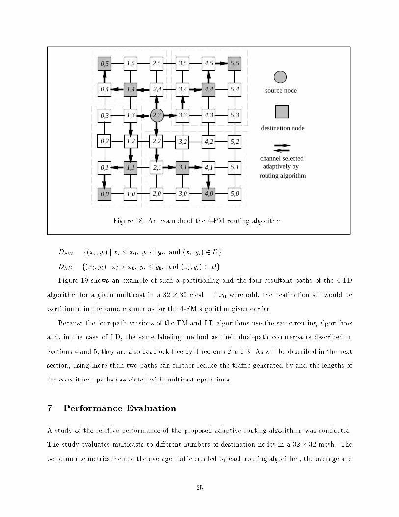
6 Four-path Adaptive Multicast RoutingDepending on the port model of the system, it may be possible to use more than two paths toimplement a multicast operation. In a 2D mesh, most nodes have outgoing degree four, so up tofour paths can be used to deliver a message. However, the worms can be transmitted in parallelonly if each node is equipped with as many internal channels as external channels. In this section,we describe deadlock-free extensions of the FM and LD algorithms in which up to four paths areused to implement each multicast. The PM algorithm cannot be extended to four paths withoutrisking deadlock.Extending the FM and LD algorithms can be accomplished by simply modifying their respectivemessage header construction components; the actual routing algorithms (Figures 13 and 16) remainunchanged. Suppose that the source node of a multicast message is d0 = (x0; y0). In the case ofthe four-path FM algorithm, denoted 4-FM, the destination set D is partitioned into at most foursubsets DNE; DNW ; DSW , and DSE as follows:DNE = f(xi; yi) j xi > x0; yi � y0; and (xi; yi) 2 DgDNW = f(xi; yi) j xi � x0; yi > y0; and (xi; yi) 2 DgDSW = f(xi; yi) j xi < x0; yi � y0; and (xi; yi) 2 DgDSE = f(xi; yi) j xi � x0; yi < y0; and (xi; yi) 2 Dg .Figure 18 shows an example of the four-path FM algorithm, 4-FM. In this example, D = f(0,0), (0, 5), (1, 1), (1,4), (3, 1), (4, 0), (4, 4), (5, 5)g. The set D is partitioned into four subsets asfollows: DNE = f(4, 4), (5, 5) g; DNW = f(0, 5), (1, 4)g; DSW = f(0, 0), (1, 1)g; and DSE = f(3,1), (4, 0)g. The source message will be sent to the destinations by four multicast paths, each withthe subset as the destination set, respectively.Similarly, the LD algorithm can also be modi�ed to use up to four paths for a given multicast.However, in this case, the manner in which the destination set is partitioned depends on the locationof the source node in the network and the particular labeling method used. For example, given thelabeling shown in Figure 19 and a source node d0 = (x0; y0), if x0 is even then the destination setis partitioned as follows:DNE = f(xi; yi) j xi � x0; yi > y0; and (xi; yi) 2 DgDNW = f(xi; yi) j xi < x0; yi � y0; and (xi; yi) 2 Dg24
0,0 1,0 2,0 3,0 4,0 5,0
0,1 1,1 2,1 3,1 4,1 5,1
0,2 1,2 2,2 3,2 4,2 5,2
0,3 1,3 2,3 3,3 4,3 5,3
0,4 1,4 2,4 3,4 4,4 5,4
0,5 1,5 2,5 3,5 4,5 5,5
source node
destination node
channel selectedadaptively by
routing algorithmFigure 18. An example of the 4-FM routing algorithm.DSW = f(xi; yi) j xi � x0; yi < y0; and (xi; yi) 2 DgDSE = f(xi; yi) j xi > x0; yi � y0; and (xi; yi) 2 DgFigure 19 shows an example of such a partitioning and the four resultant paths of the 4-LDalgorithm for a given multicast in a 32 � 32 mesh. If x0 were odd, the destination set would bepartitioned in the same manner as for the 4-FM algorithm given earlier.Because the four-path versions of the FM and LD algorithms use the same routing algorithmsand, in the case of LD, the same labeling method as their dual-path counterparts described inSections 4 and 5, they are also deadlock-free by Theorems 2 and 3. As will be described in the nextsection, using more than two paths can further reduce the tra�c generated by and the lengths ofthe constituent paths associated with multicast operations.7 Performance EvaluationA study of the relative performance of the proposed adaptive routing algorithms was conducted.The study evaluates multicasts to di�erent numbers of destination nodes in a 32� 32 mesh. Theperformance metrics include the average tra�c created by each routing algorithm, the average and25

0,0 1,0 2,0 3,0 4,0 5,0
0,1 1,1 2,1 3,1 4,1 5,1
0,2 1,2 2,2 3,2 4,2 5,2
0,3 1,3 2,3 3,3 4,3 5,3
0,4 1,4 2,4 3,4 4,4 5,4
0,5 1,5 2,5 3,5 4,5 5,5
1
2
3
4
5
6 7 18 19 30 31
12 13 24 25 36
8
9
10
11 14
15
16
17 20
21
22
23 26
27
28
29 32
33
34
35
source node
destination node
channel selected byrouting algorithmFigure 19. An example of the multi-path 4-LD routing algorithm.maximum distances from the source to the destinations along the path(s), and the number of thealternative paths available to each routing algorithm. Randomly generated multicast sets (at least1000 sets per plotted point) with di�erent numbers of destinations were generated and tested. Thenumber of destination nodes, k, was selected from 1 to 100.In comparing the tra�c created by the algorithms, each unit of tra�c represents the transmis-sion of a message over a channel. The tra�c is de�ned as the total number of channels used fora given multicast communication. A multicast with k destinations requires at least k units of thetra�c. The additional tra�c is de�ned as the total amount of tra�c minus k. Figure 20 plots theamount of additional tra�c generated by the six routing algorithms in a 32 � 32 mesh. Amongthe six routing algorithms, the 4-FM algorithm creates the least tra�c. Interestingly, the 2-PMand 2-FM algorithms produce almost the same amount of tra�c as 1-PM, even though the latteruses only one path. Although 2-FM does not show a very signi�cant improvement over the 1-PMalgorithm, since it uses a double-vertical channel network, it would be expected to achieve a lowernetwork latency than that of 1-PM algorithm. 26

01002003004005006007000 20 40 60 80 100Number of Destination Nodes
AverageAdditionalTra�c 1-PM .........................................................................................................................
...............................................................................................................................2-FM2-PM2-LD4-LD . .. . ........................................................
.......... . . ............ . . .. . . .. . . .. . . .. . . .. . . .4-FM . . ......... . . .. . .. . .. . .. . .. . .. . .. . .. . .. . .. . ..
. .. . .. . .. . .. . .. . .. . .. . .Figure 20. Generated multicast tra�c in 32� 32 mesh.Figure 21 compares the algorithms in terms of the average length of the path between thesource and a destination. As expected, the average path length depends heavily on the numberof paths used. The average path path lengths of the four-path algorithms (4-FM and 4-LD) areapproximately half those of the three dual-path algorithms (2-LD, 2-PM, and 2-FM), which are inturn approximately half that of 1-PM. Among algorithms using the same number of paths, a slightadvantage goes to the minimal algorithms.Figure 22 compares the algorithms in terms of the maximum length of the path between thesource and a destination. The maximum path length is important for cases in which the performanceof the algorithm depends on when the last destination receives the message; an example is the useof multicast in distributed barrier synchronization [25]. Again, the 2-LD, 2-PM and 2-FM methodshave similar maximum path length, although the 2-LD algorithm produces slightly longer maximumpath lengths because it is nonminimal. The three methods also produce paths whose maximumlengths are approximately 3/4 that of paths produced by the 1-PM algorithm. The maximum27
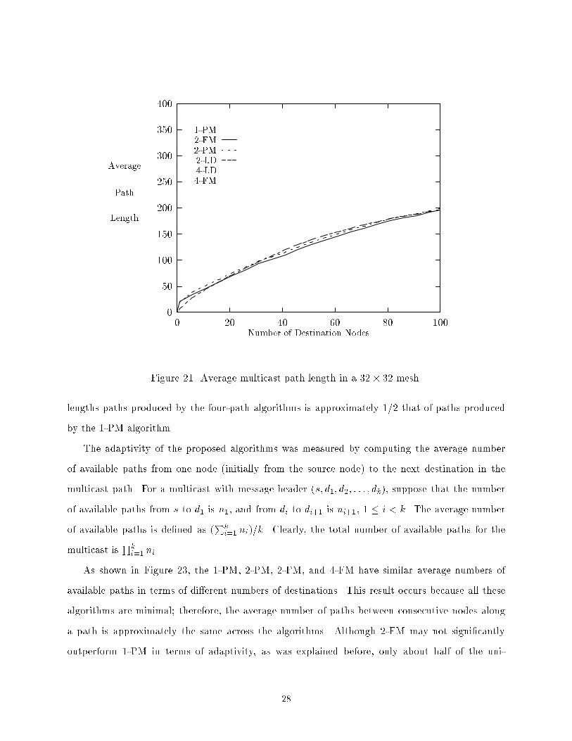
0501001502002503003504000 20 40 60 80 100Number of Destination Nodes
AveragePathLength 1-PM ...........................................................................................
..................................................................................................2-FM2-PM2-LD4-LD . .. . .......... . . .. . . .. . . .. . . .. . . .. . . .. . . .. . . .. . . .. . . .. . . .. . . .. . . .. . . .. . . .. . . .. . . .. . . .. . . .
4-FM . . .... . . .. . .. . .. . .. . .. . .. . .. . .. . .. . .. . .. . .. . .. . .. . .. . .. . .. . .. . .. . .Figure 21. Average multicast path length in a 32� 32 mesh.lengths paths produced by the four-path algorithms is approximately 1/2 that of paths producedby the 1-PM algorithm.The adaptivity of the proposed algorithms was measured by computing the average numberof available paths from one node (initially from the source node) to the next destination in themulticast path. For a multicast with message header (s; d1; d2; : : : ; dk), suppose that the numberof available paths from s to d1 is n1, and from di to di+1 is ni+1, 1 � i < k. The average numberof available paths is de�ned as (Pki=1 ni)=k. Clearly, the total number of available paths for themulticast is Qki=1 ni.As shown in Figure 23, the 1-PM, 2-PM, 2-FM, and 4-FM have similar average numbers ofavailable paths in terms of di�erent numbers of destinations. This result occurs because all thesealgorithms are minimal; therefore, the average number of paths between consecutive nodes alonga path is approximately the same across the algorithms. Although 2-FM may not signi�cantlyoutperform 1-PM in terms of adaptivity, as was explained before, only about half of the uni-28

01002003004005006007008000 20 40 60 80 100Number of Destination Nodes
MaximumPathLength 1-PM ...........................................................................................................................
..........................................................................................................................2-FM2-PM2-LD4-LD . .. . ................................... . . .. . . ....... . . .. . . .. . . .. . . .. . . .. . . .. . . .. . . .. . . .. . . .. . . .
4-FM . . .... . . .. . .. . .. . .. . .. . .. . .. . .. . .. . .. . .. . .. . .. . .. . .. . .. . .. . .. . .. . .Figure 22. Maximum multicast path length in a 32� 32 mesh.cast communications can be performed adaptively in 1-PM, while all of the unicast messages areadaptively routed in 2-FM. Hence, 2-FM would be expected to exhibit better performance if thepercentage of the unicast communication were relatively high.The 2-LD algorithm exhibits better adaptivity than any of the minimal algorithms. Since 2-LDcan select nonminimal routes between consecutive nodes along the path, the average number ofalternative paths is higher. However, when the number of destinations becomes large, the twoalgorithms have very close performance in terms of adaptivity because 2-LD is decreasingly likelyto choose routes that are nonminimal.Finally, the 4-LD algorithm exhibits the best adaptivity because the nonminimal routes fordestinations in one quadrant may range far into other quadrants. In fact, the number of pathsbetween certain pairs of destinations can be extremely large. However, this result is somewhatmisleading, since the worms for destinations in di�erent quadrants may contend for channels. InFigure 19, for example, if node (5; 1) were also a destination, then the worm for the southeast29

1101001000100001000001e+ 061e+ 0710 20 30 40 50 60 70 80 90 100Number of Destination Nodes
AveragePathNumber 1-PM ............................................................................................................................................................................................2-FM2-PM2-LD4-LD . .. . ............................ . . . . . . .4-FM . . ........... . ................... . .. . .. . . .. . . .. . .. . . .. . .. . .. . .. . .. . .. . .. . .. . .Figure 23. Available number of paths in a 32� 32 meshquadrant could potentially deroute from node (4; 0) all the way to the channel from (4; 5) to (5; 5),which is used by the worm in the northeast quadrant. If the message were long, one of the wormswould be delayed.8 Concluding RemarksThree adaptive multicast wormhole routing algorithms for 2D mesh multicomputers have been pro-posed. The algorithms include partially-adaptive minimal routing, fully-adaptive minimal routing,and nonminimal adaptive routing methods. The proposed adaptive routing algorithms are simpleand deadlock-free. The minimal routing methods are livelock-free in nature, and the nonminimalrouting method has been shown to be livelock-free. Two versions of each, using di�erent numbersof paths, were studied; the number of paths should match the port model of the architecture. Theserouting strategies are the �rst adaptive multicast wormhole routing algorithms ever proposed.30
A study has been conducted to compare the performance of the proposed adaptive routingalgorithms. The results indicate that the four-path approaches create the least tra�c and theshortest paths. The nonminimal routing algorithms o�er the best adaptivity, but require morechannels for message transmission. The adaptivity of the minimal algorithms are close in value,however, the PM algorithms have a simpler control structure and do not require virtual channels,as do the FM algorithms. When the number of the destinations is relatively large, the 2-LD routingalgorithm does not o�er more adaptivity than the minimal algorithms. Since the PM algorithmsuse deterministic routing for about half the cases of unicast communication, they may be preferredonly if the percentage of unicast communication is relatively low; for unicast-intensive tra�c, theFM routing algorithms are likely to be better choices because they o�er full adaptivity for allunicast messages. Finally, it should be noted that all these routing methods for 2D mesh can beextended to mesh topologies with any dimension.AcknowledgementsThe authors would like to express their sincere appreciation to Professor Lionel M. Ni for hiscontributions to this work. This work was supported in part by the NSF grants CDA-9121641, CDA-9222901, and MIP-9204066, by DOE grant DE-FG02-93ER25167, and by an Ameritech FacultyFellowship.References[1] Berman, P., Gravano, L., Sanz, J., and Pifarre, G. Adaptive deadlock- and livelock-free routingwith all minimal paths in torus networks. In Proc. 4th ACM Symposium on Parallel Algorithmsand Architectures (June 1992), pp. 3{12.[2] Dally, W. J. Virtual channel ow control. IEEE Transactions on Computers 3, 2 (Mar. 1992),194{205.[3] Dally, W. J., and Aoki, H. Adaptive routing using virtual channels. Tech. rep., MassachusettsInstitute of Technology, Laboratory for Computer Science, Sept. 1990.[4] Dally, W. J., and Seitz, C. L. The torus routing chip. Journal of Distributed Computing 1, 3(1986), 187{196.[5] Dally, W. J., and Seitz, C. L. Deadlock-free message routing in multiprocessor interconnectionnetworks. IEEE Transactions on Computers C-36, 5 (May 1987), 547{553.31

[6] DeMara, R. F., and Moldovan, D. I. Performance indices for parallel marker-propagation. InProceedings of the 1991 International Conference on Parallel Processing (1991), pp. 658{659.St. Charles, Illinois, Aug. 12-17.[7] Duato, J. On the design of deadlock-free adaptive routing algorithms for multicomputers:design methodologies. In Proceedings of 1991 Parallel Architectures and Languages EuropeConference (PARLE'91) (1991).[8] Glass, C. J., and Ni, L. M. The turn model for adaptive routing. In Proc. of the 19th AnnualInternational Symposium on Computer Architecture (May 1992), pp. 278{287.[9] Intel Corporation. Paragon XP/S Product Overview, 1991.[10] Intel Corporation. A Touchstone DELTA System Description, 1991.[11] Jesshope, C. R., Miller, P. R., and Yantchev, J. T. High Performance Communications in Pro-cessor Networks. In Proceedings of IEEE 16th Annual International Symposium on ComputerArchitecture (1989), pp. 150{157.[12] Johnsson, S. L., and Ho, C.-T. Optimum broadcasting and personalized communication inhypercubes. IEEE Transactions on Computers C-38, 9 (Sept. 1989), 1249{1268.[13] Konstantinidou, S., and Snyder, L. Chaos Router: Architecture and Performance. In Proceed-ings of the 18th Annual Symposium on Computer Architecture (1991), pp. 222{231.[14] Kumar, V., and Singh, V. Scalability of parallel algorithms for the all-pairs shortest pathproblem. Tech. Rep. ACT-OODS-058-90, Rev. 1, MCC, Jan. 1991.[15] Lan, Y. Fault-tolerant multi-destination routing in hypercube multicomputers. In Proceedingsof the 12th International Conference on Distributed Computing Systems (June 1992), pp. 632{639.[16] Lan, Y. Multicast in faulty hypercubes. In Proc. of the 1992 International Conference onParallel Processing (Aug. 1992), vol. I, pp. 58{61.[17] Li, K., and Schaefer, R. A hypercube shared virtual memory. In Proc. of the 1989 InternationalConference on Parallel Processing (Aug. 1989), vol. I, pp. 125 { 132.[18] Lin, X., McKinley, P. K., and Ni, L. M. Deadlock-free multicast wormhole routing in 2Dmesh multicomputers. accepted to appear in IEEE Transactions on Parallel and DistributedSystems.[19] Lin, X., McKinley, P. K., and Ni, L. M. The message ow model for routing in wormhole-routed networks. In Proc. of the 1993 International Conference on Parallel Processing (1993),vol. I, pp. 294{297.[20] Linder, D. H., and Harden, J. C. An adaptive and fault tolerant wormhole routing strategyfor kary n-cubes. IEEE Transactions on Computers 40, 1 (Jan. 1991), 2{12.[21] McKinley, P. K., Xu, H., Esfahanian, A.-H., and Ni, L. M. Unicast-based multicast communi-cation in wormhole-routed networks. In Proc. of the 1992 International Conference on ParallelProcessing (Aug. 1992), vol. II, pp. 10{19.[22] NCUBE Company. NCUBE 6400 Processor Manual, 1990.32

[23] Ni, L. M., and McKinley, P. K. A survey of wormhole routing techniques in direct networks.IEEE Computer 26, 2 (Feb. 1993), 62{76.[24] Seitz, C. L., Athas, W. C., Flaig, C. M., Martin, A. J., Seizovic, J., Steele, C. S., and Su,W.-K. The architecture and programming of the Ametek Series 2010 multicomputer. InProceedings of the Third Conference on Hypercube Concurrent Computers and Applications,Volume I (Pasadena, CA, Jan. 1988), ACM, pp. 33{36.[25] Xu, H., McKinley, P. K., and Ni, L. M. E�cient implementation of barrier synchronization inwormhole-routed hypercube multicomputers. Journal of Parallel and Distributed Computing16 (1992), 172{184.
33