ddc suite 2.0 / version 2.1 pg5 2.0 - product index
TRANSCRIPT

DDC Suite 2.0 / Version 2.1 PG5 2.0

Table of ContentDDC Suite 2.0 ManualTable of ContentIntroductionDDC Suite - Fupla
Creating a new projectCreating a new CPU in the projectBasic settings in Fupla
Create air condition First Fupla page
Structuring dataSecond Fupla page
Structuring dataThird Fupla page
Structuring dataCreate a template
Fourth Fupla pageOnline featuresHDLog Offline Trending
HDLog with DDC Suite BasicsHDLog with DDC Suite In useHDLog with DDC Suite Accessing data within SWeb
Sweb AlarmingAlarming with DDC Suite BasicsAlarming with DDC Suite In useUsing alarm text in Sweb applicationAlarming with DDC Suite AddOn toolSweb Alarming advanced
1
618212528373856708390
106116118123132135142150167170175189200207
BACnetBACnet with DDC Suite In useBACnet with DDC Suite AddOn toolBACnet advanced
Using templatesCreating a new CPU in the projectImporting templatesMultiple Import of templatesToDo’s after an importPredefined templates
DocumentationFBox Functions and ParametersAddon toolSystem descriptionI/O Allocation
Visi.PlusInstallation of Visi.PlusStart upCreating a new projectBasic settingsPreparationsImporting data from FuplaAddressing the resourcesGo onlineAlarm managementHistorical dataUser Front-EndDrawing picuresEngineering with templates
DDC Suite Advanced Detailed InformationsOverview
215217235248257259262272284294301302308314318322325331334341345348356370375379383395411425426
Family : InitialisationFamily : GeneralFamily : Analogue valuesFamily : AlarmingFamily : Set pointsFamily : System and clocksFamily : ControlsFamily : Controller
Hints & TricksInitialisation
431435437444456463474481493494

2Title of this presentation
PG5 Building Advanced / DDC Suite 2.0Overview developing DDC Suite
2000 Starting developing first FBoxes
… … in lot of projects tested and always improved …
2004/April FBoxes attained the core style and functionality
2004/November DDC Suite became SBC product - version 1.0 Germany/Netherland
2005/March Fupla editor adoption to improve mechanism – version 1.3
2006 Annual update with improved functionality – version 1.3.x
2007 Annual update with improved functionality – version 1.3.y
2008/June Annual update with dramatic development – version 2.0
- HDLog implemented
- Alarming implemented
- BACnet implemented
PG5 license management

3Title of this presentation
PG5 Building Advanced / DDC Suite 2.0Overview developing DDC Suite
General basics
Overview
4Title of this presentation
PG5 Building Advanced / DDC Suite 2.0General
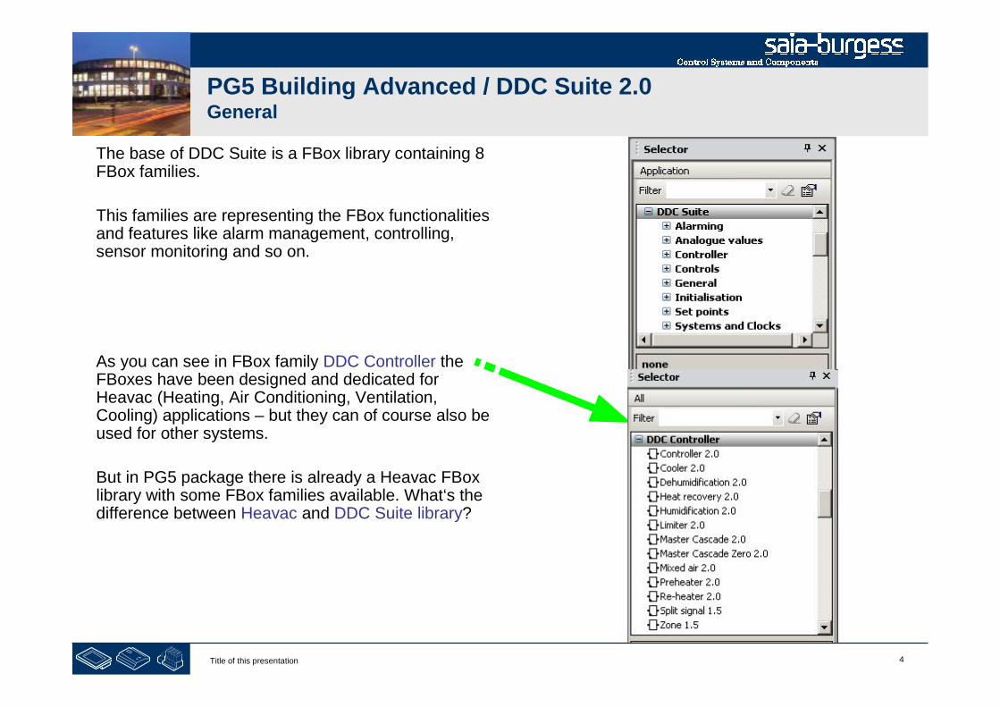
The base of DDC Suite is a FBox library containing 8FBox families.
This families are representing the FBox functionalitiesand features like alarm management, controlling,sensor monitoring and so on.
As you can see in FBox family DDC Controller theFBoxes have been designed and dedicated forHeavac (Heating, Air Conditioning, Ventilation,Cooling) applications – but they can of course also beused for other systems.
But in PG5 package there is already a Heavac FBoxlibrary with some FBox families available. What‘s thedifference between Heavac and DDC Suite library?
5Title of this presentation
PG5 Building Advanced / DDC Suite 2.0PG5 Building Standard (Heavac)
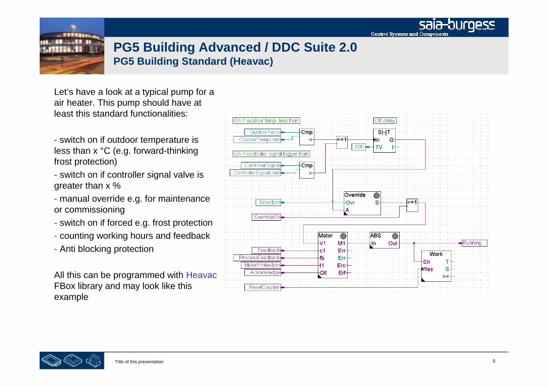
Let‘s have a look at a typical pump for aair heater. This pump should have atleast this standard functionalities:
- switch on if outdoor temperature isless than x °C (e.g. forward-thinkingfrost protection)
- switch on if controller signal valve isgreater than x %
- manual override e.g. for maintenanceor commissioning
- switch on if forced e.g. frost protection
- counting working hours and feedback
- Anti blocking protection
All this can be programmed with HeavacFBox library and may look like thisexample
6Title of this presentation
PG5 Building Advanced / DDC Suite 2.0PG5 Building Advanced (DDC Suite)
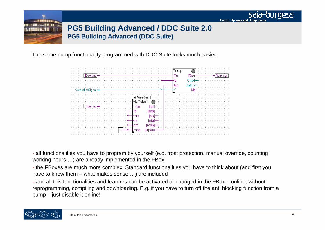
The same pump functionality programmed with DDC Suite looks much easier:
- all functionalities you have to program by yourself (e.g. frost protection, manual override, countingworking hours …) are already implemented in the FBox
- the FBoxes are much more complex. Standard functionalities you have to think about (and first youhave to know them – what makes sense …) are included
- and all this functionalities and features can be activated or changed in the FBox – online, withoutreprogramming, compiling and downloading. E.g. if you have to turn off the anti blocking function from apump – just disable it online!

7Title of this presentation
PG5 Building Advanced / DDC Suite 2.0Summary 1
If we compare both fupla pages (Heavac and DDC Suite) we can find additional advantages:
This is not the single difference – but this is the first impression.
Let‘s have a look at the data of this pump control.
Higher integrated FBoxes. Know how and experiences from systems engineering has been moved into thelibrary, families and FBoxes
The first difference:
- reading and understanding the Fupla is easier – less FBoxes on 1 page, less connections
- clear and well arranged – easier to handle for e.g. a new member in programming or service team
- easy to maintain
8Title of this presentation
PG5 Building Advanced / DDC Suite 2.0PG5 Building Standard (Heavac)
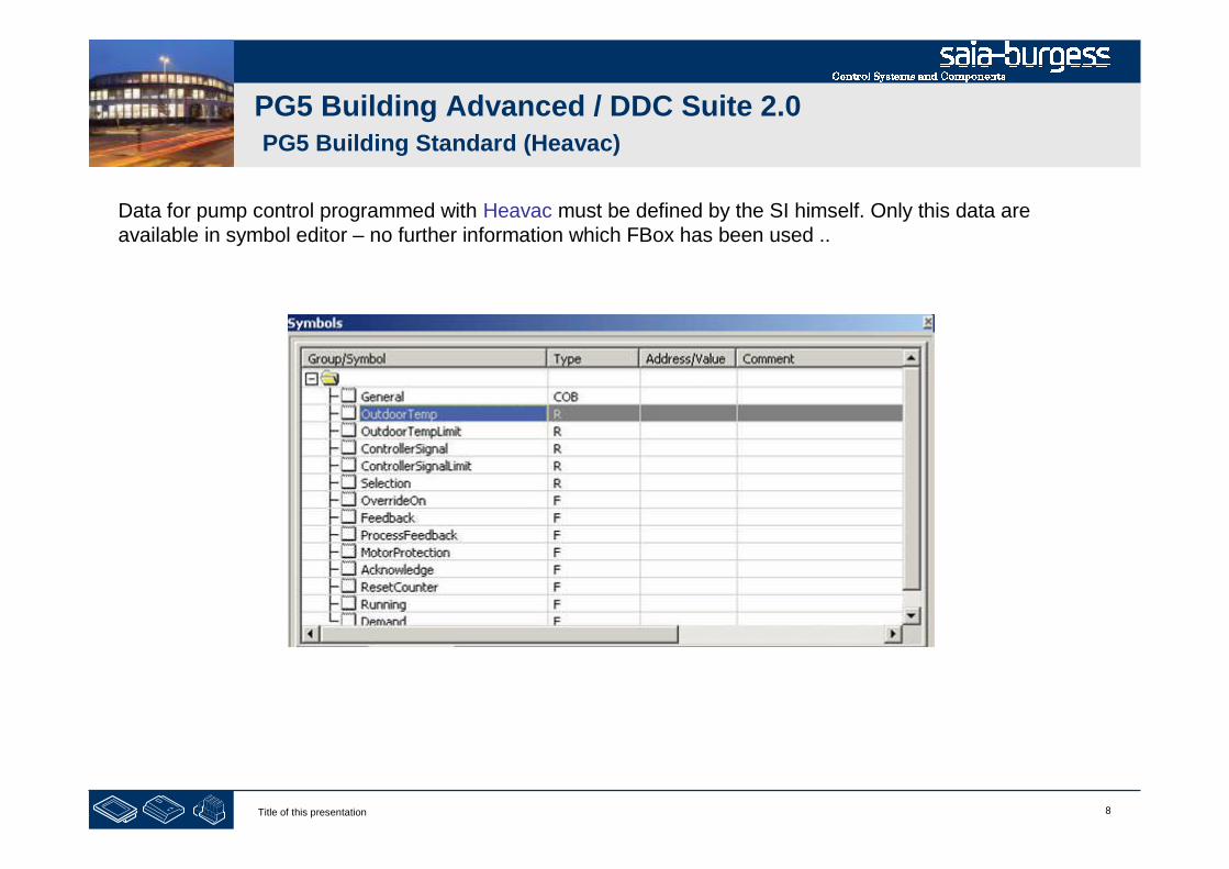
Data for pump control programmed with Heavac must be defined by the SI himself. Only this data areavailable in symbol editor – no further information which FBox has been used ..

9Title of this presentation
PG5 Building Advanced / DDC Suite 2.0PG5 Building Standard (Heavac)
Each FBox contains more or less data and they can get a symbolic definition in detailed adjust window toaccess them in symbol editor. Sometimes a FBox needs more than 1 symbolic definition (e.g. 1 for registerand 1 for flag).
Per FBox at least 1 symbol must be defined – and this symbolic data contains more information, arranged inan array.
You can find some information in detail windows or in help file – but in this moment you can‘t use thesymbols with sense.
If you have to give the data points to a SCADA system engineer (also Web or HMI) – he‘s not able to doanything with it. Too less information.

10Title of this presentation
PG5 Building Advanced / DDC Suite 2.0PG5 Building Standard (Heavac)
There is an additional possibility to get detailed symbols and alittle bit more information – half automatically. Therefore eachFBox must get a text in FBox property Name.
In symbol editor nothing happens – the program must be „build“.After build in symbol editor a new tab System is available andtherein the default group structure „A.HVC.“ is visible. Each FBoxwill create a subfolder using the text from FBox property name.But this will only work if the build has been successfully.
11Title of this presentation
PG5 Building Advanced / DDC Suite 2.0PG5 Building Standard (Heavac)
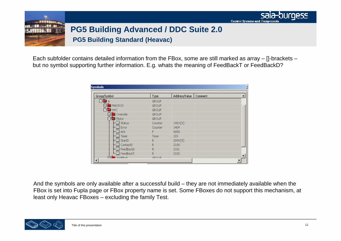
Each subfolder contains detailed information from the FBox, some are still marked as array – []-brackets –but no symbol supporting further information. E.g. whats the meaning of FeedBackT or FeedBackD?
And the symbols are only available after a successful build – they are not immediately available when theFBox is set into Fupla page or FBox property name is set. Some FBoxes do not support this mechanism, atleast only Heavac FBoxes – excluding the family Test.
12Title of this presentation
PG5 Building Advanced / DDC Suite 2.0PG5 Building Advanced (DDC Suite)
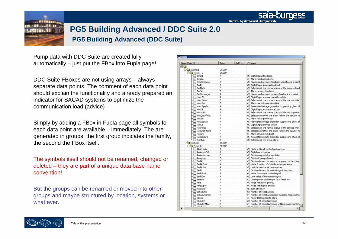
Pump data with DDC Suite are created fullyautomatically – just put the FBox into Fupla page!
DDC Suite FBoxes are not using arrays – alwaysseparate data points. The comment of each data pointshould explain the functionality and already prepared anindicator for SACAD systems to optimize thecommunication load (advice)
Simply by adding a FBox in Fupla page all symbols foreach data point are available – immediately! The aregenerated in groups, the first group indicates the family,the second the FBox itself.
The symbols itself should not be renamed, changed ordeleted – they are part of a unique data base nameconvention!
But the groups can be renamed or moved into othergroups and maybe structured by location, systems orwhat ever.

13Title of this presentation
PG5 Building Advanced / DDC Suite 2.0Summary 2
In contrast to half automatically created symbols from Heavac FBoxes (half automatically because you haveto edit FBox property name and start a build) to DDC Suite FBoxes the created symbols
Fully automatically generated symbols when FBox is put on Fupla page
The second difference:
- are immediately available
- movable, restructured during engineering can
- are single data points with own symbols and comment
- format of each data point listed in help file
- suitable to build up a object oriented, component and/or system data structure
This 2 operative differences (more compact/complex FBoxes – fully automatically createdsymbolic data points) are representing the core of DDC Suite – easier, faster and better
engineering.

14Title of this presentation
DDC Suite 2.0 / PG5 Building AdvancedGeneral overview
DDC Suite is an extension of PG5 containing
1. FBox library – the DDC Suite base. This FBoxes are higher implemented, using single data points andcreating groups and symbols fully automatically
2. Fupla templates – predefined systems e.g. heating circuit, hot water, air condition – to start up in an easyway
3. Template objects for SWeb application – for each FBox graphical objects and adjust objects areavailable. Also for the predefined systems we have predefined Sweb system templates
4. Template objects in ViSi.Plus. During import data from Fupla into ViSi.Plus the FBoxes are detected andhandled in ViSi.Plus data base again like FBoxes. At least not only the data points are imported –additional predefined alarm settings and historical trend information are generated automatically duringimport.
DDC Suite is not a totally different thing in PG5 - some FBoxes, Fupla and Web templates – and of course theFBoxes itself can be used without Sweb or ViSi.Plus. And they are compatible with Heavac FBoxes.
The target of DDC Suite is
Reducing engineering time – safe money - easier programming
Improve software quality – having higher “minimum standard level” then competitors
1Title of this presentation
PG5 Building Advanced / DDC Suite 2.0Working with Fupla
DDC Suite - Fupla
2Title of this presentation
DDC Suite 2.0 / PG5 Building AdvancedSyntax and remarks of actions during workshop
Please follow the teachers advice. Please
- use the same symbol names
- use the same group names
- place the FBoxes approx. at the same position
- do not work faster or different even if you are a “frequent PG5 user”
This workshop will show you some basic mechanism, structured workflow and well structured symbolorganisation. Don’t be afraid. You don’t
- have to learn all FBoxes during this workshop
- have to be familiar with application programming
- must be a super programmer
If you just learn the mechanism and philosophy you’ll understand the advantage SI can have with DDC Suite
3Title of this presentation
DDC Suite 2.0 / PG5 Building AdvancedSyntax and remarks of actions during workshop
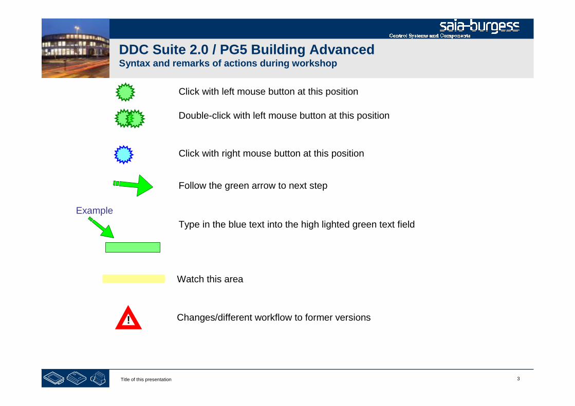
Click with left mouse button at this position
Click with right mouse button at this position
Follow the green arrow to next step
Example
Type in the blue text into the high lighted green text field
Double-click with left mouse button at this position
Watch this area
Changes/different workflow to former versions!

4Title of this presentation
PG5 Building Advanced / DDC Suite 2.0Working with Fupla
Creating a new project
5Title of this presentation
DDC Suite 2.0 / PG5 Building AdvancedWorking with Fupla
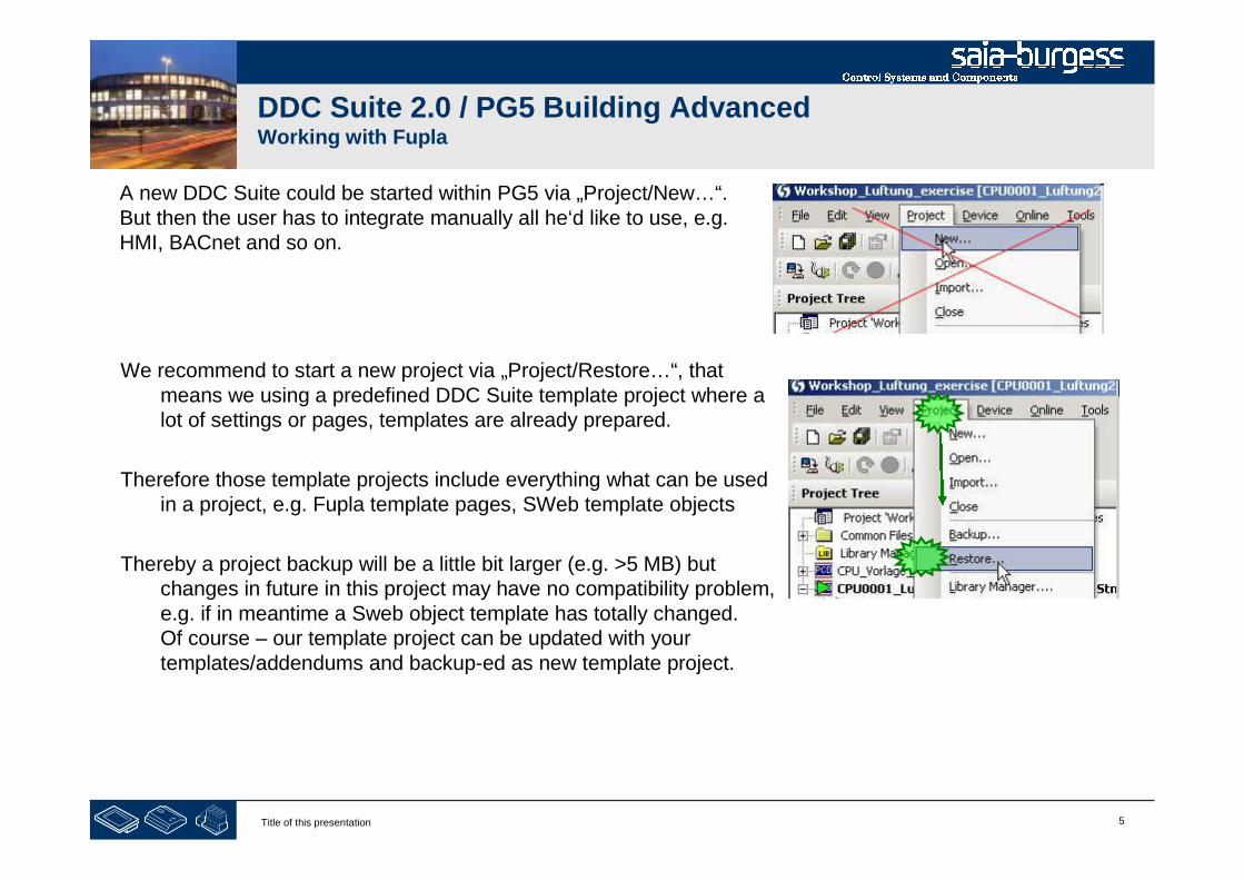
A new DDC Suite could be started within PG5 via „Project/New…“.But then the user has to integrate manually all he‘d like to use, e.g.HMI, BACnet and so on.
We recommend to start a new project via „Project/Restore…“, thatmeans we using a predefined DDC Suite template project where alot of settings or pages, templates are already prepared.
Therefore those template projects include everything what can be usedin a project, e.g. Fupla template pages, SWeb template objects
Thereby a project backup will be a little bit larger (e.g. >5 MB) butchanges in future in this project may have no compatibility problem,e.g. if in meantime a Sweb object template has totally changed.Of course – our template project can be updated with yourtemplates/addendums and backup-ed as new template project.
6Title of this presentation
DDC Suite 2.0 / PG5 Building AdvancedWorking with Fupla
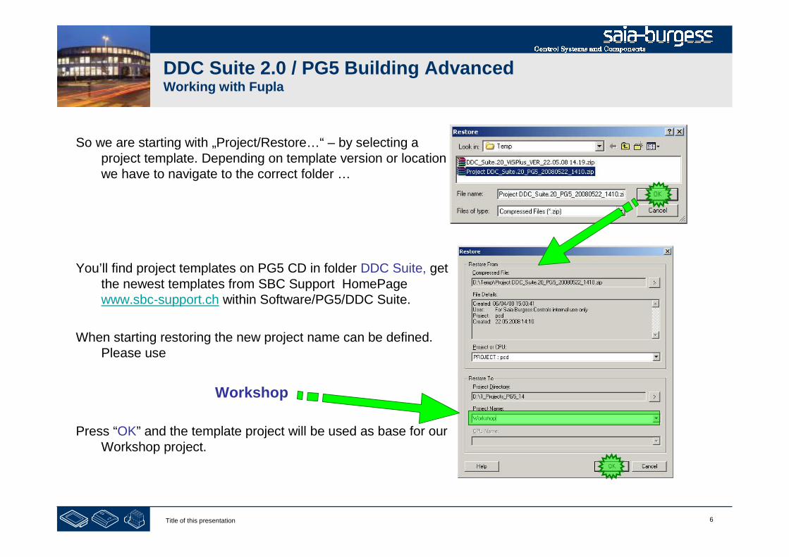
So we are starting with „Project/Restore…“ – by selecting aproject template. Depending on template version or locationwe have to navigate to the correct folder …
You’ll find project templates on PG5 CD in folder DDC Suite, getthe newest templates from SBC Support HomePagewww.sbc-support.ch within Software/PG5/DDC Suite.
When starting restoring the new project name can be defined.Please use
Workshop
Press “OK” and the template project will be used as base for ourWorkshop project.

7Title of this presentation
DDC Suite 2.0 / PG5 Building AdvancedWorking with Fupla
If we have a look into our workshop project (use Windows File Explorer) we’llsee that already some folders are included:
- CPU-Template : a CPU template which should be used for each new CPEwe have to add in this project
- FbdToDms : Containing some information if a ViSi.Plus SCADA systemshould be used
- And a PG5_Template containing :
- FBox_AddOns : Containing some files for some language depending definitionsand also some additional features
- Fupla_Templates : here you’ll find some predefined Fupla pages or systems, tobe imported into Fupla
- Sweb_Objects : Graphical objects and adjust objects (pages) for SWebapplications designed with SWebEditor.

8Title of this presentation
PG5 Building Advanced / DDC Suite 2.0Working with Fupla
Creating a new CPU in the project
9Title of this presentation
DDC Suite 2.0 / PG5 Building AdvancedWorking with Fupla
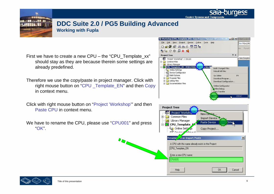
First we have to create a new CPU – the “CPU_Template_xx”should stay as they are because therein some settings arealready predefined.
Therefore we use the copy/paste in project manager. Click withright mouse button on “CPU _Template_EN” and then Copyin context menu.
Click with right mouse button on “Project ’Workshop’” and thenPaste CPU in context menu.
We have to rename the CPU, please use “CPU001” and press“OK”.
10Title of this presentation
DDC Suite 2.0 / PG5 Building AdvancedWorking with Fupla
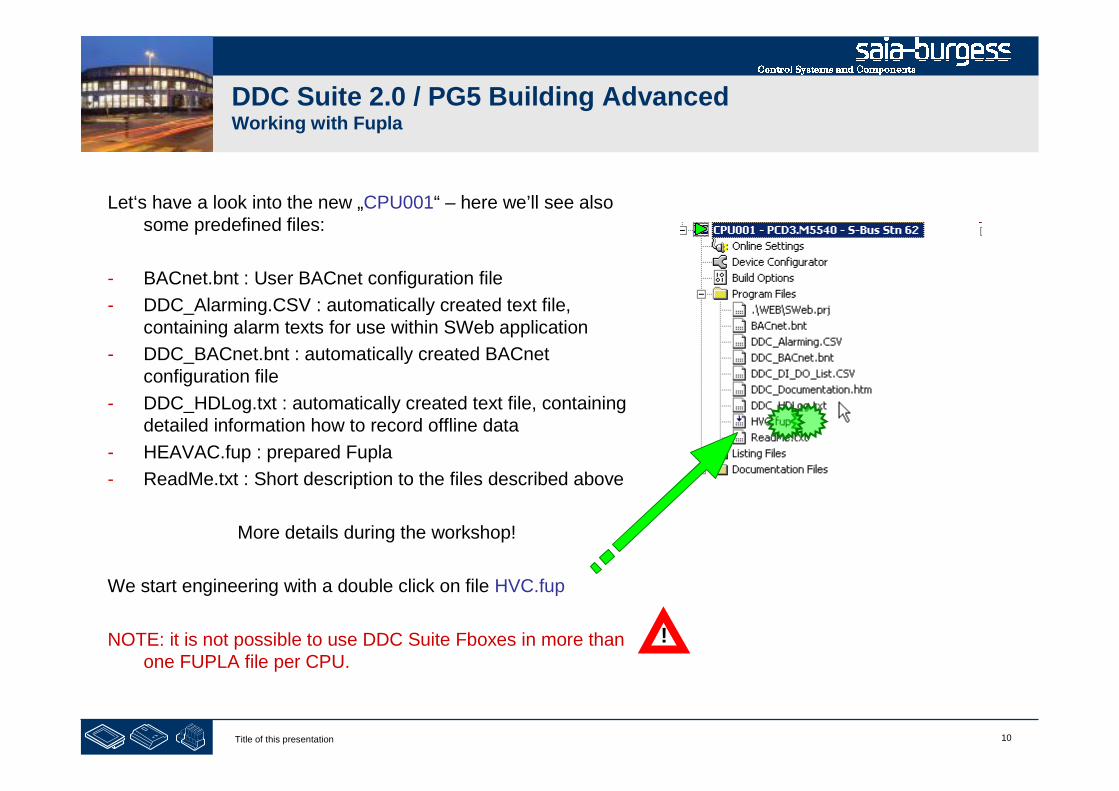
Let‘s have a look into the new „CPU001“ – here we’ll see alsosome predefined files:
- BACnet.bnt : User BACnet configuration file
- DDC_Alarming.CSV : automatically created text file,containing alarm texts for use within SWeb application
- DDC_BACnet.bnt : automatically created BACnetconfiguration file
- DDC_HDLog.txt : automatically created text file, containingdetailed information how to record offline data
- HEAVAC.fup : prepared Fupla
- ReadMe.txt : Short description to the files described above
More details during the workshop!
We start engineering with a double click on file HVC.fup
NOTE: it is not possible to use DDC Suite Fboxes in more thanone FUPLA file per CPU.
!

11Title of this presentation
PG5 Building Advanced / DDC Suite 2.0Working with Fupla
Basic settings in Fupla
12Title of this presentation
DDC Suite 2.0 / PG5 Building AdvancedWorking with Fupla
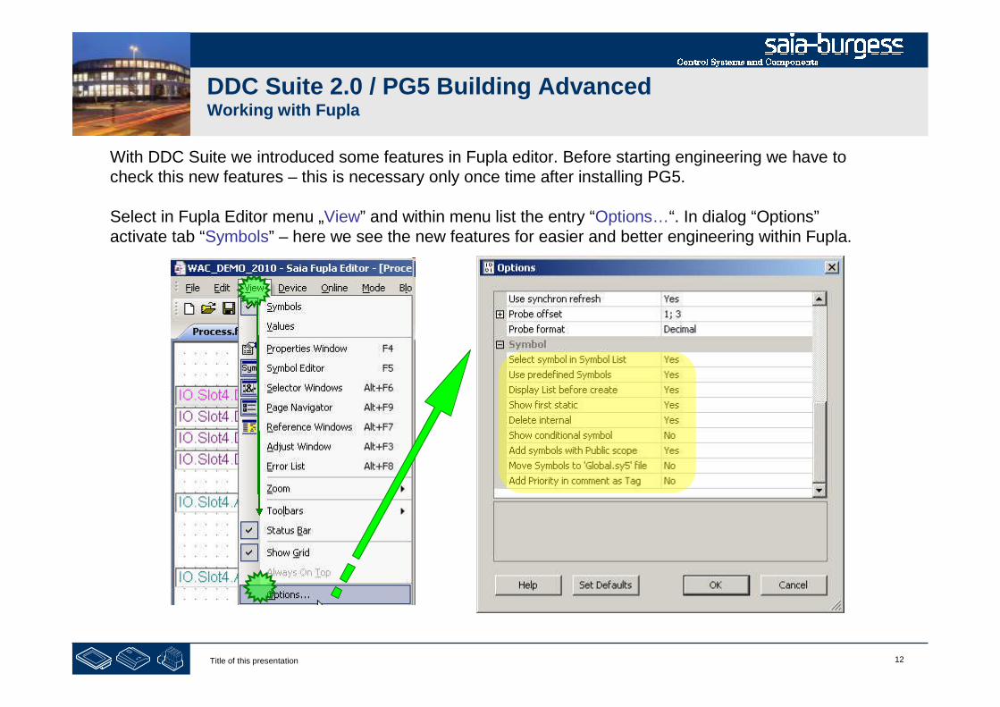
With DDC Suite we introduced some features in Fupla editor. Before starting engineering we have tocheck this new features – this is necessary only once time after installing PG5.
Select in Fupla Editor menu „View” and within menu list the entry “Options…“. In dialog “Options”activate tab “Symbols” – here we see the new features for easier and better engineering within Fupla.
13Title of this presentation
DDC Suite 2.0 / PG5 Building AdvancedWorking with Fupla
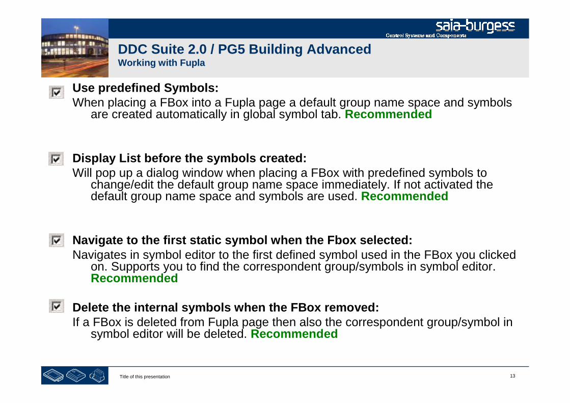
Use predefined Symbols:When placing a FBox into a Fupla page a default group name space and symbols
are created automatically in global symbol tab. Recommended
Display List before the symbols created:Will pop up a dialog window when placing a FBox with predefined symbols to
change/edit the default group name space immediately. If not activated thedefault group name space and symbols are used. Recommended
Navigate to the first static symbol when the Fbox selected:Navigates in symbol editor to the first defined symbol used in the FBox you clicked
on. Supports you to find the correspondent group/symbols in symbol editor.Recommended
Delete the internal symbols when the FBox removed:If a FBox is deleted from Fupla page then also the correspondent group/symbol in
symbol editor will be deleted. Recommended
14Title of this presentation
DDC Suite 2.0 / PG5 Building AdvancedWorking with Fupla
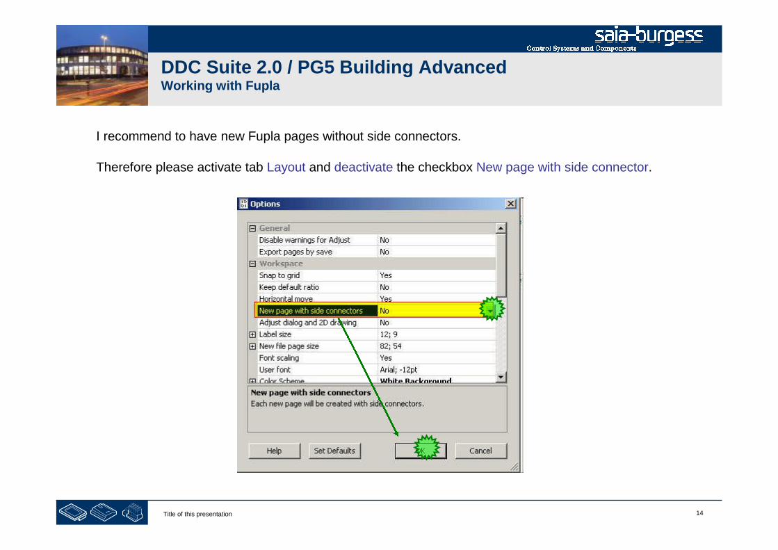
I recommend to have new Fupla pages without side connectors.
Therefore please activate tab Layout and deactivate the checkbox New page with side connector.
15Title of this presentation
DDC Suite 2.0 / PG5 Building AdvancedWorking with Fupla
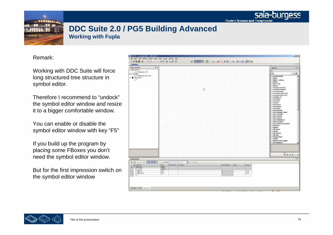
Remark:
Working with DDC Suite will forcelong structured tree structure insymbol editor.
Therefore I recommend to “undock”the symbol editor window and resizeit to a bigger comfortable window.
You can enable or disable thesymbol editor window with key “F5”
If you build up the program byplacing some FBoxes you don’tneed the symbol editor window.
But for the first impression switch onthe symbol editor window

16Title of this presentation
DDC Suite 2.0 / PG5 Building AdvancedWorking with Fupla
At least we have to check a setting to be sure that the symbols are created in the right way.Click with right mouse button into symbol editor, the select in context menu “Advanced” and in next contextmenu “Options …”
Please set ALL settings in dialog “Symbol Editor Options” to have the same behaviour!
17Title of this presentation
DDC Suite 2.0 / PG5 Building AdvancedWorking with Fupla
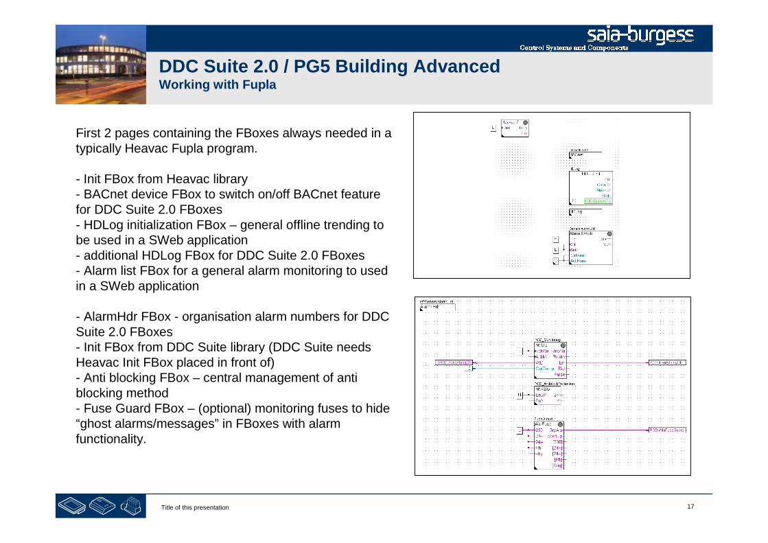
First 2 pages containing the FBoxes always needed in atypically Heavac Fupla program.
- Init FBox from Heavac library- BACnet device FBox to switch on/off BACnet featurefor DDC Suite 2.0 FBoxes- HDLog initialization FBox – general offline trending tobe used in a SWeb application- additional HDLog FBox for DDC Suite 2.0 FBoxes- Alarm list FBox for a general alarm monitoring to usedin a SWeb application
- AlarmHdr FBox - organisation alarm numbers for DDCSuite 2.0 FBoxes- Init FBox from DDC Suite library (DDC Suite needsHeavac Init FBox placed in front of)- Anti blocking FBox – central management of antiblocking method- Fuse Guard FBox – (optional) monitoring fuses to hide“ghost alarms/messages” in FBoxes with alarmfunctionality.
18Title of this presentation
DDC Suite 2.0 / PG5 Building AdvancedWorking with Fupla
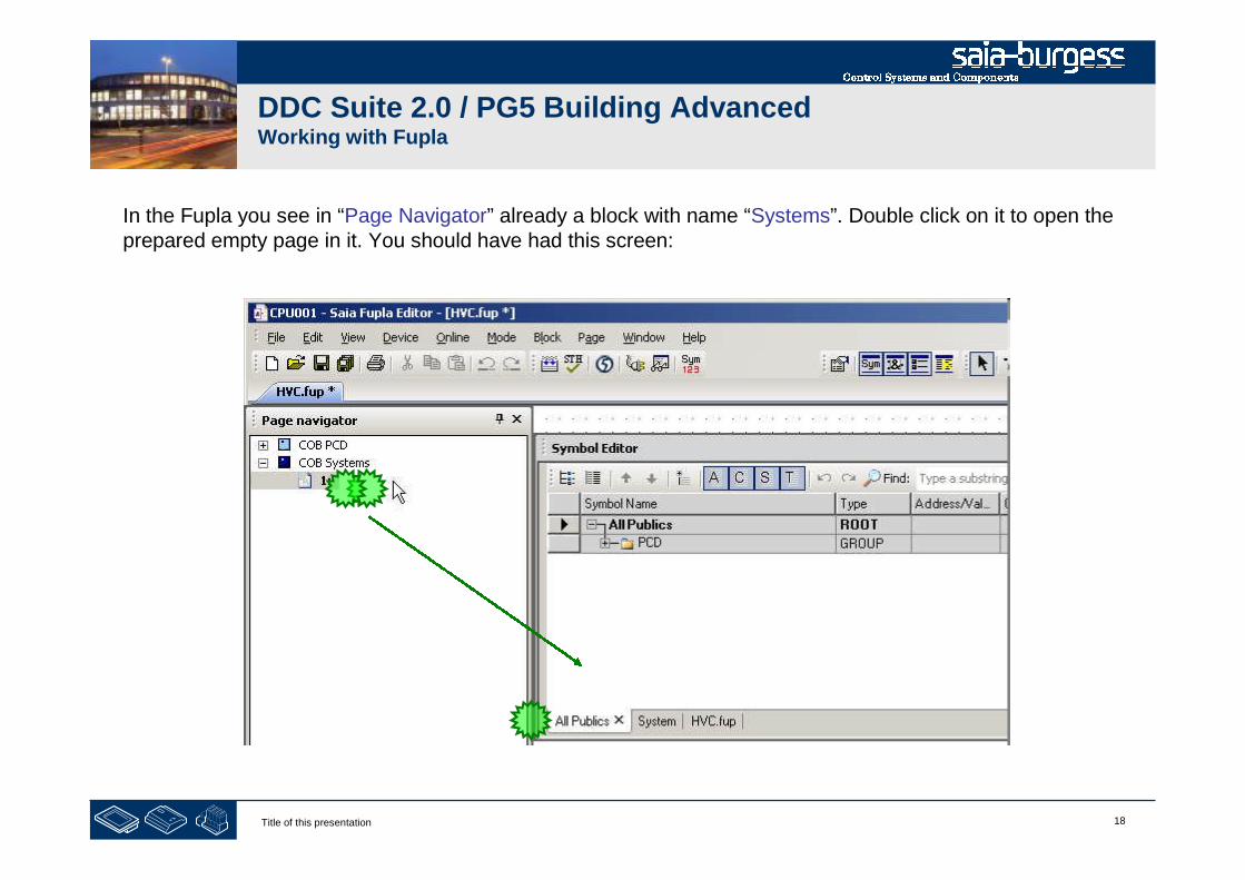
In the Fupla you see in “Page Navigator” already a block with name “Systems”. Double click on it to open theprepared empty page in it. You should have had this screen:
19Title of this presentation
DDC Suite 2.0 / PG5 Building AdvancedWorking with Fupla
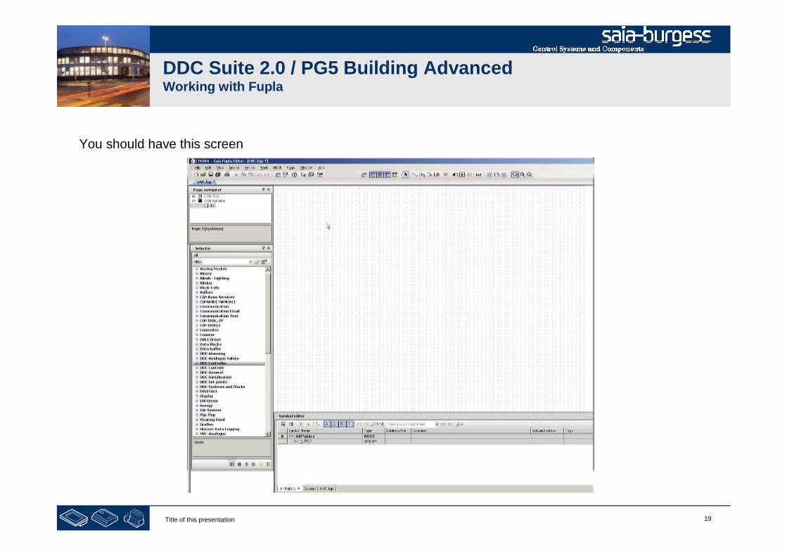
You should have this screen
20Title of this presentation
DDC Suite 2.0 / PG5 Building AdvancedWorking with Fupla
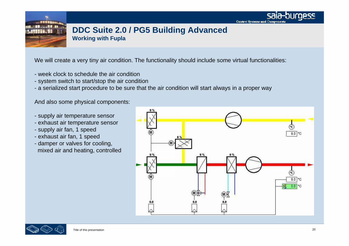
We will create a very tiny air condition. The functionality should include some virtual functionalities:
- week clock to schedule the air condition- system switch to start/stop the air condition- a serialized start procedure to be sure that the air condition will start always in a proper way
And also some physical components:
- supply air temperature sensor- exhaust air temperature sensor- supply air fan, 1 speed- exhaust air fan, 1 speed- damper or valves for cooling,mixed air and heating, controlled

21Title of this presentation
DDC Suite 2.0 / PG5 Building AdvancedWorking with Fupla
First Fupla page will contain
- the virtual functionalities week clock, system switch, serialized start procedure- physical components supply air temperature sensor, exhaust air temperature sensor
22Title of this presentation
DDC Suite 2.0 / PG5 Building AdvancedWorking with Fupla
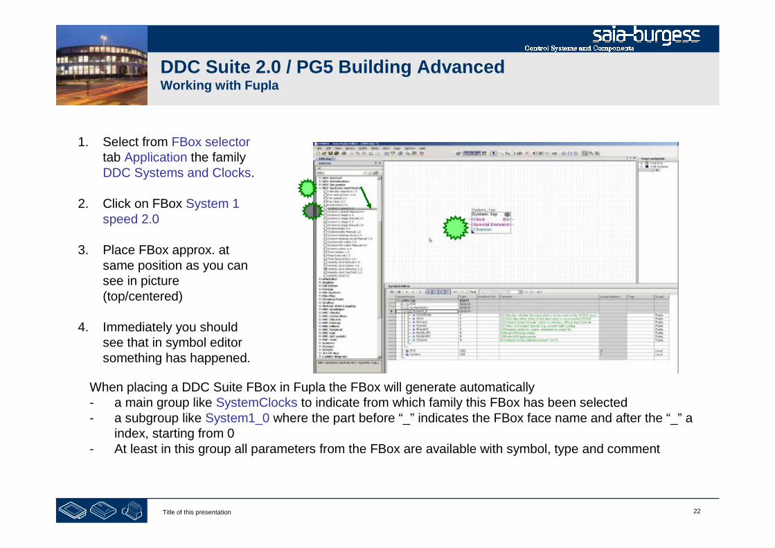
1. Select from FBox selectortab Application the familyDDC Systems and Clocks.
2. Click on FBox System 1speed 2.0
3. Place FBox approx. atsame position as you cansee in picture(top/centered)
4. Immediately you shouldsee that in symbol editorsomething has happened.
When placing a DDC Suite FBox in Fupla the FBox will generate automatically- a main group like SystemClocks to indicate from which family this FBox has been selected- a subgroup like System1_0 where the part before “_” indicates the FBox face name and after the “_” a
index, starting from 0- At least in this group all parameters from the FBox are available with symbol, type and comment
23Title of this presentation
DDC Suite 2.0 / PG5 Building AdvancedWorking with Fupla
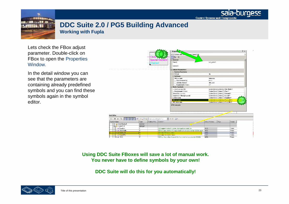
Lets check the FBox adjustparameter. Double-click onFBox to open the PropertiesWindow.
In the detail window you cansee that the parameters arecontaining already predefinedsymbols and you can find thesesymbols again in the symboleditor.
Using DDC Suite FBoxes will save a lot of manual work.You never have to define symbols by your own!
DDC Suite will do this for you automatically!

24Title of this presentation
DDC Suite 2.0 / PG5 Building AdvancedWorking with Fupla
The FBox System 1 speed 2.0 gives us thepossibility to start/stop e.g. the air condition
- Manually by selecting parameter HMI Lowerpriority
- optional by clock via FBox Input or SCADA
- optional by a calendar feature
DDC Suite FBoxes using always online parameters. Therefore it’s possible to use e.g. during commissioninga clock FBox to start/stop the air condition as long the SCADA system is not present.
If the SCADA is online it’s easy to use the SCADA clock manager to start/stop the air condition. Just switchthe parameter … Clock accessed by from Input to SCADA. Now the SCADA can write the start/stop clockcommand into the parameter … Requirement of clock.
Maybe you can also switch back automatically to the clock FBox if you detect that the SCADA is offline ...
25Title of this presentation
DDC Suite 2.0 / PG5 Building AdvancedWorking with Fupla
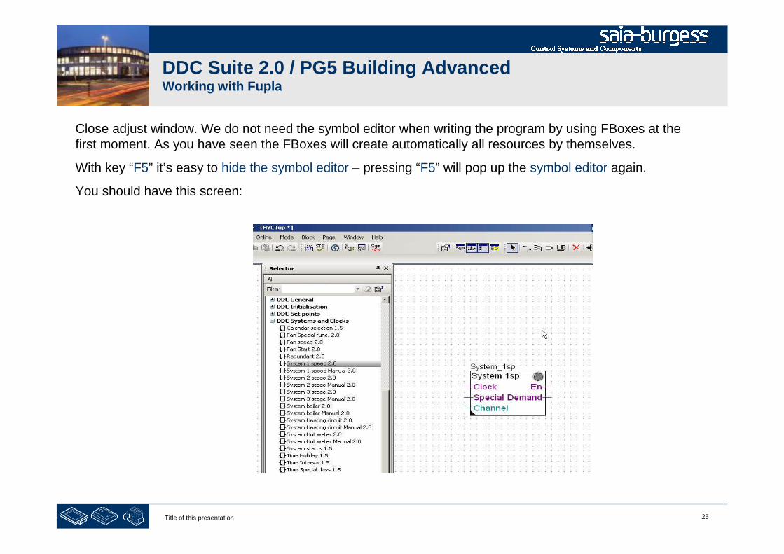
Close adjust window. We do not need the symbol editor when writing the program by using FBoxes at thefirst moment. As you have seen the FBoxes will create automatically all resources by themselves.
With key “F5” it’s easy to hide the symbol editor – pressing “F5” will pop up the symbol editor again.
You should have this screen:
26Title of this presentation
DDC Suite 2.0 / PG5 Building AdvancedWorking with Fupla
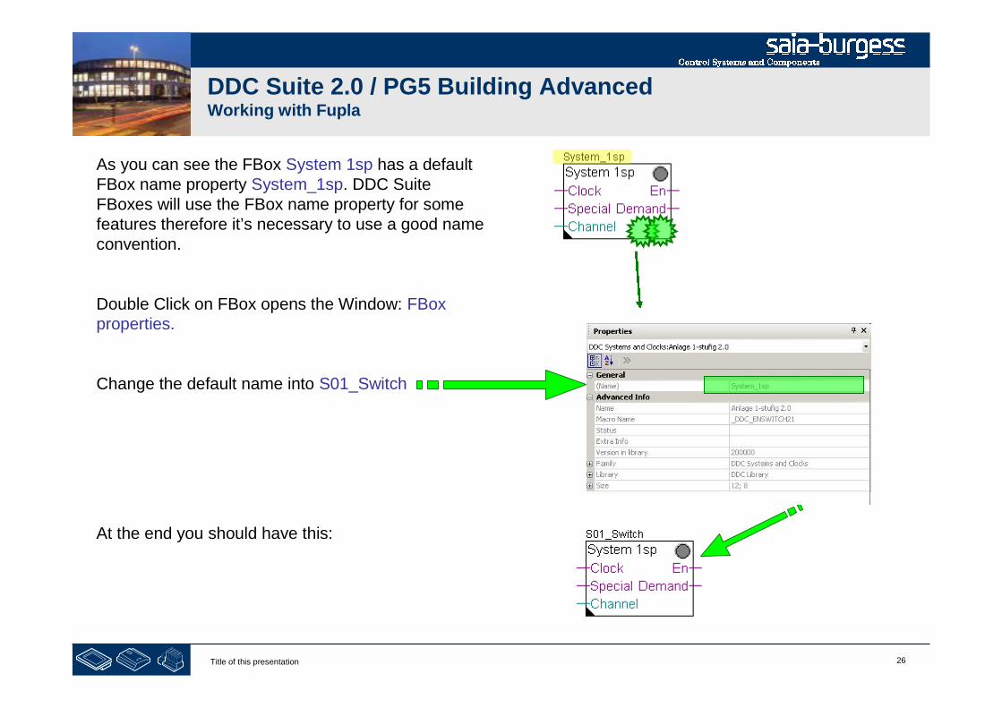
As you can see the FBox System 1sp has a defaultFBox name property System_1sp. DDC SuiteFBoxes will use the FBox name property for somefeatures therefore it’s necessary to use a good nameconvention.
Double Click on FBox opens the Window: FBoxproperties.
Change the default name into S01_Switch
At the end you should have this:
27Title of this presentation
DDC Suite 2.0 / PG5 Building AdvancedWorking with Fupla
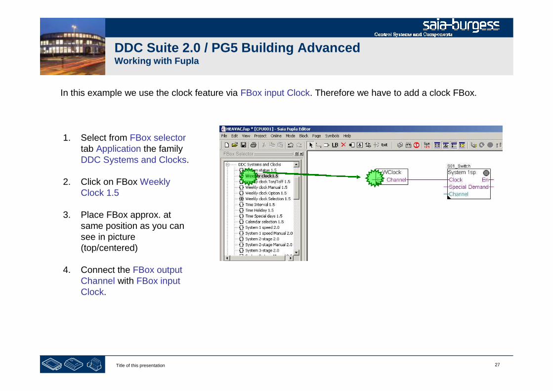
1. Select from FBox selectortab Application the familyDDC Systems and Clocks.
2. Click on FBox WeeklyClock 1.5
3. Place FBox approx. atsame position as you cansee in picture(top/centered)
4. Connect the FBox outputChannel with FBox inputClock.
In this example we use the clock feature via FBox input Clock. Therefore we have to add a clock FBox.

28Title of this presentation
DDC Suite 2.0 / PG5 Building AdvancedWorking with Fupla
1. Select from FBox selectortab Standard the familybinary.
2. Use FBox High and connectat En from FBox WClock
3. Use FBox Low and connectat Special from FBoxSystem 1sp
Now we have to close some FBox inputs. E.g. the input En from FBox WClock should be always high, theinput Special from FBox System 1sp is not used, therefore always low.

29Title of this presentation
DDC Suite 2.0 / PG5 Building AdvancedWorking with Fupla
1. Select from FBox selectortab Application the familyDDC General.
2. Use FBox Register connect1.5 and connectat Channel from FBoxSystem 1sp
This FBox is also useful to set aconstant value instead of aconnector.
The input Channel from FBox System 1sp is also not used (optional for use with a calendar feature). Buththis is an integer connector, therefore we need a special FBox to “close” this connector.
30Title of this presentation
DDC Suite 2.0 / PG5 Building AdvancedWorking with Fupla
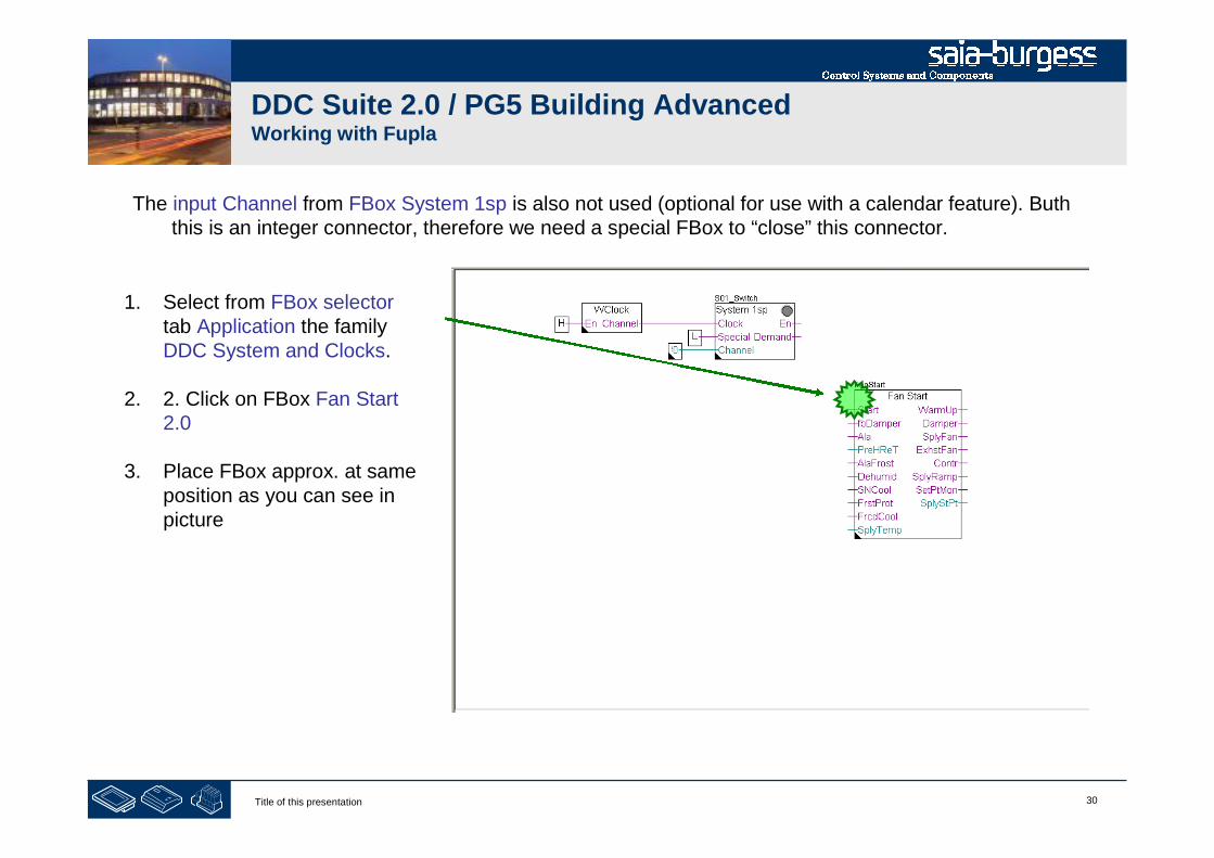
1. Select from FBox selectortab Application the familyDDC System and Clocks.
2. 2. Click on FBox Fan Start2.0
3. Place FBox approx. at sameposition as you can see inpicture
The input Channel from FBox System 1sp is also not used (optional for use with a calendar feature). Buththis is an integer connector, therefore we need a special FBox to “close” this connector.
31Title of this presentation
DDC Suite 2.0 / PG5 Building AdvancedWorking with Fupla
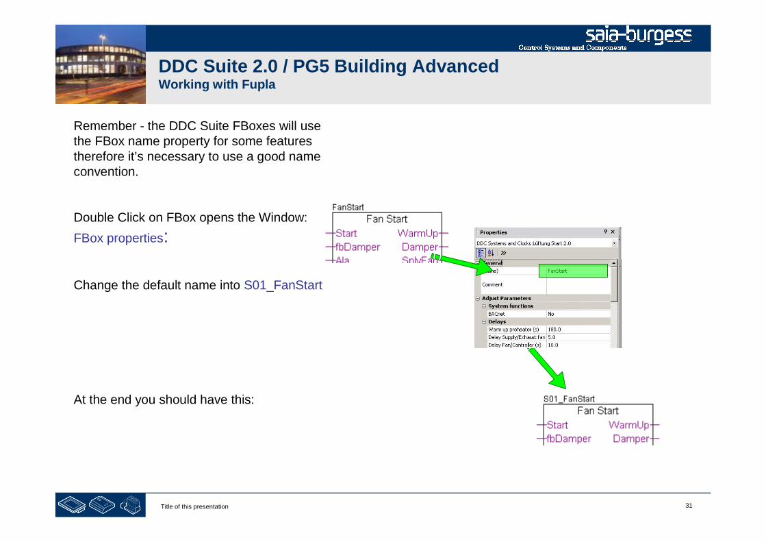
Remember - the DDC Suite FBoxes will usethe FBox name property for some featurestherefore it’s necessary to use a good nameconvention.
Double Click on FBox opens the Window:
FBox properties:
Change the default name into S01_FanStart
At the end you should have this:
32Title of this presentation
DDC Suite 2.0 / PG5 Building AdvancedWorking with Fupla
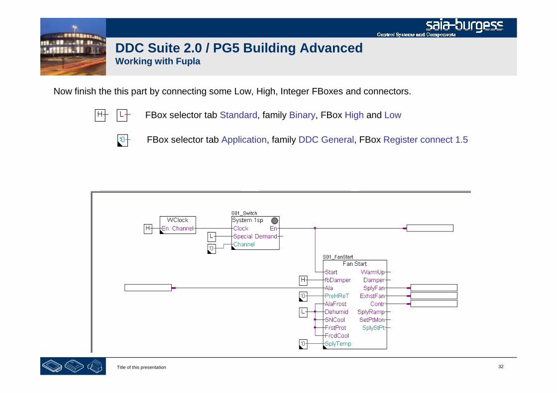
Now finish the this part by connecting some Low, High, Integer FBoxes and connectors.
FBox selector tab Standard, family Binary, FBox High and Low
FBox selector tab Application, family DDC General, FBox Register connect 1.5
33Title of this presentation
DDC Suite 2.0 / PG5 Building AdvancedWorking with Fupla
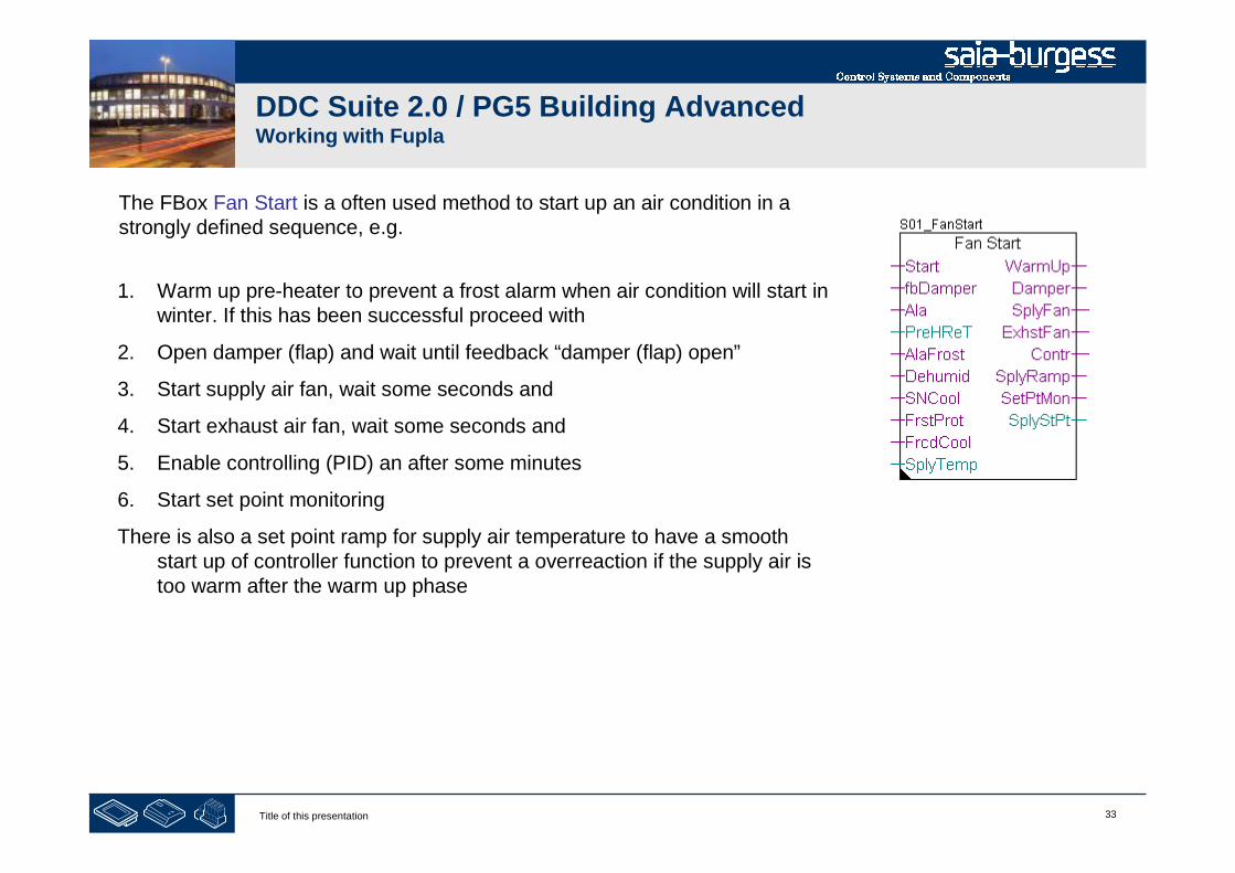
The FBox Fan Start is a often used method to start up an air condition in astrongly defined sequence, e.g.
1. Warm up pre-heater to prevent a frost alarm when air condition will start inwinter. If this has been successful proceed with
2. Open damper (flap) and wait until feedback “damper (flap) open”
3. Start supply air fan, wait some seconds and
4. Start exhaust air fan, wait some seconds and
5. Enable controlling (PID) an after some minutes
6. Start set point monitoring
There is also a set point ramp for supply air temperature to have a smoothstart up of controller function to prevent a overreaction if the supply air istoo warm after the warm up phase
34Title of this presentation
DDC Suite 2.0 / PG5 Building AdvancedWorking with Fupla
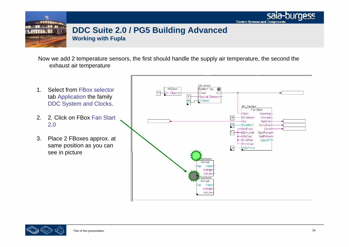
1. Select from FBox selectortab Application the familyDDC System and Clocks.
2. 2. Click on FBox Fan Start2.0
3. Place 2 FBoxes approx. atsame position as you cansee in picture
Now we add 2 temperature sensors, the first should handle the supply air temperature, the second theexhaust air temperature
35Title of this presentation
DDC Suite 2.0 / PG5 Building AdvancedWorking with Fupla
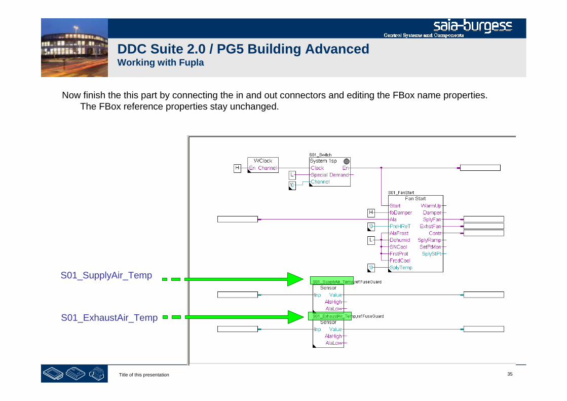
S01_SupplyAir_Temp
Now finish the this part by connecting the in and out connectors and editing the FBox name properties.The FBox reference properties stay unchanged.
S01_ExhaustAir_Temp
36Title of this presentation
DDC Suite 2.0 / PG5 Building AdvancedWorking with Fupla
!
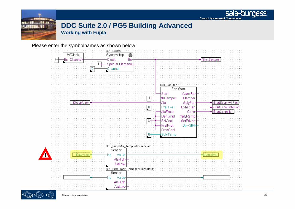
Please enter the symbolnames as shown below
37Title of this presentation
DDC Suite 2.0 / PG5 Building AdvancedWorking with Fupla
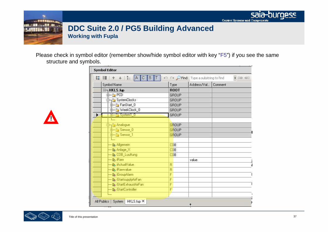
Please check in symbol editor (remember show/hide symbol editor with key “F5”) if you see the samestructure and symbols.
!
38Title of this presentation
DDC Suite 2.0 / PG5 Building AdvancedWorking with Fupla
The Sensor FBox with name “S01_SupplyAirFan_Temp” is connected to symbols “iRawValue” and“iActualValue” because the input is the raw value from analogue input FBox and the output is theconverted, filtered and calibrated actual value.
The Sensor FBox with name “S01_ExhaustAirFan_Temp” should be connected the same symbols butthan we’ll have e.g. the symbol “iRawValue” used for two different functionalities.
Now this is the point where we should start to structure the symbols we got from the FBoxes and declaredby us.
Structuring data is good for- Finding data in a big list much easier- Gives more information about the data itself- Reduces type writing error by reusing same symbol declarations- Is the base for writing reusable software
!

39Title of this presentation
DDC Suite 2.0 / PG5 Building AdvancedWorking with Fupla
- structuring data

40Title of this presentation
DDC Suite 2.0 / PG5 Building AdvancedWorking with Fupla
Let’s edit the page property “name”.Right mouse click in the page inPage Navigator select Propertiesand type in text field “Name”
S01 Start/Stop air condition

41Title of this presentation
DDC Suite 2.0 / PG5 Building AdvancedWorking with Fupla
Now we will start to organise the data in symbol editor -all from the FBoxes and the few symbols we definedare used in the air condition. Therefore they should begrouped in a “main” group named e.g. “S01” (=System01).
S01
On this Fupla page we have 3 virtual functionalities,week clock, system switch and fan start. We can nottouch them (not physically existing), therefore Irecommend to define a sub group “System” withingroup “S01”
System

42Title of this presentation
DDC Suite 2.0 / PG5 Building AdvancedWorking with Fupla
Let’s move the data from FBox WClock into the groupS01.System. To find the data just click on FBox. Symboleditor will jump automatically into the group containing thefirst defined data from this FBox.
You see they are located in SystemClocks.WeekClock_0
Now drag&drop the group WeekClock_0 into the groupS01.System

43Title of this presentation
DDC Suite 2.0 / PG5 Building AdvancedWorking with Fupla
Rename the group WeekClock_0 into
Weekclock
You can move and rename groups. This is useful to buildup a clear structure and to define clear names. This willhelp you to find very easy data points in symbol editor –and the group names are used from Sweb and ViSi.Plusfor mapping data from a FBox into a view object!
Creating a clear data structure is a must! The structurewithin this workshop is only a example how to do it.
But never move or rename the symbols within a group ifthey are created from a FBox automatically. They are akind of data base name space convention. If you renamethem the Sweb and ViSi.Plus view object won’t work anymore!
44Title of this presentation
DDC Suite 2.0 / PG5 Building AdvancedWorking with Fupla
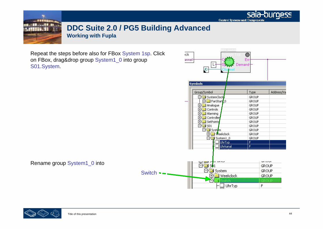
Repeat the steps before also for FBox System 1sp. Clickon FBox, drag&drop group System1_0 into groupS01.System.
Rename group System1_0 into
Switch

45Title of this presentation
DDC Suite 2.0 / PG5 Building AdvancedWorking with Fupla
Repeat the steps before also for FBox Fan Start. Click onFBox, drag&drop group FanStart_0 into groupS01.System.
Rename group FanStart_0 into
FanStart

46Title of this presentation
DDC Suite 2.0 / PG5 Building AdvancedWorking with Fupla
Now the symbols in connectors connected to the FBoxinputs or outputs at this 3 FBoxes should also be movedinto the group S01.System.
Mark the symbols:
- iStartSystem
- iStartSupplyAirFan
- iStartExhaustAirFan
- iStartController
- iGroupAlarm
And drag&drop them into group S01.System
47Title of this presentation
DDC Suite 2.0 / PG5 Building AdvancedWorking with Fupla
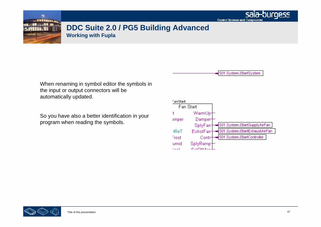
When renaming in symbol editor the symbols inthe input or output connectors will beautomatically updated.
So you have also a better identification in yourprogram when reading the symbols.
48Title of this presentation
DDC Suite 2.0 / PG5 Building AdvancedWorking with Fupla
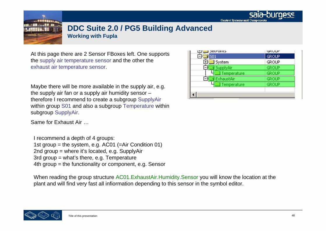
At this page there are 2 Sensor FBoxes left. One supportsthe supply air temperature sensor and the other theexhaust air temperature sensor.
Maybe there will be more available in the supply air, e.g.the supply air fan or a supply air humidity sensor –therefore I recommend to create a subgroup SupplyAirwithin group S01 and also a subgroup Temperature withinsubgroup SupplyAir.
Same for Exhaust Air …
I recommend a depth of 4 groups:1st group = the system, e.g. AC01 (=Air Condition 01)2nd group = where it’s located, e.g. SupplyAir3rd group = what’s there, e.g. Temperature4th group = the functionality or component, e.g. Sensor
When reading the group structure AC01.ExhaustAir.Humidity.Sensor you will know the location at theplant and will find very fast all infiormation depending to this sensor in the symbol editor.
49Title of this presentation
DDC Suite 2.0 / PG5 Building AdvancedWorking with Fupla
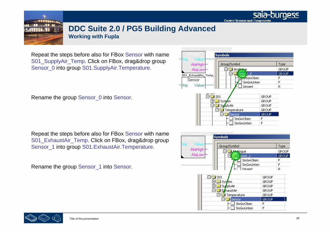
Repeat the steps before also for FBox Sensor with nameS01_SupplyAir_Temp. Click on FBox, drag&drop groupSensor_0 into group S01.SupplyAir.Temperature.
Rename the group Sensor_0 into Sensor.
Repeat the steps before also for FBox Sensor with nameS01_ExhaustAir_Temp. Click on FBox, drag&drop groupSensor_1 into group S01.ExhaustAir.Temperature.
Rename the group Sensor_1 into Sensor.
50Title of this presentation
DDC Suite 2.0 / PG5 Building AdvancedWorking with Fupla
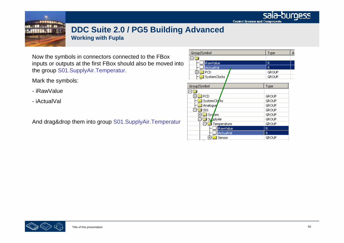
Now the symbols in connectors connected to the FBoxinputs or outputs at the first FBox should also be moved intothe group S01.SupplyAir.Temperatur.
Mark the symbols:
- iRawValue
- iActualVal
And drag&drop them into group S01.SupplyAir.Temperatur
51Title of this presentation
DDC Suite 2.0 / PG5 Building AdvancedWorking with Fupla
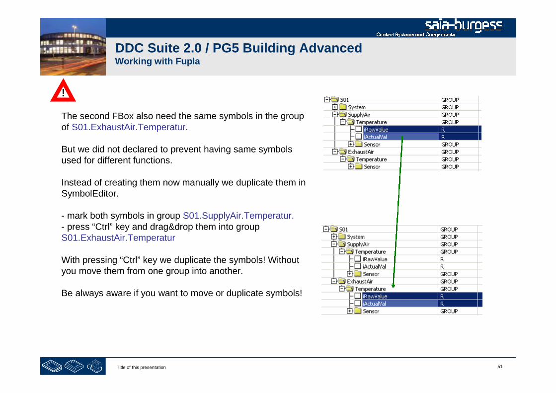
The second FBox also need the same symbols in the groupof S01.ExhaustAir.Temperatur.
But we did not declared to prevent having same symbolsused for different functions.
Instead of creating them now manually we duplicate them inSymbolEditor.
- mark both symbols in group S01.SupplyAir.Temperatur.- press “Ctrl” key and drag&drop them into groupS01.ExhaustAir.Temperatur
With pressing “Ctrl” key we duplicate the symbols! Withoutyou move them from one group into another.
Be always aware if you want to move or duplicate symbols!
!
52Title of this presentation
DDC Suite 2.0 / PG5 Building AdvancedWorking with Fupla
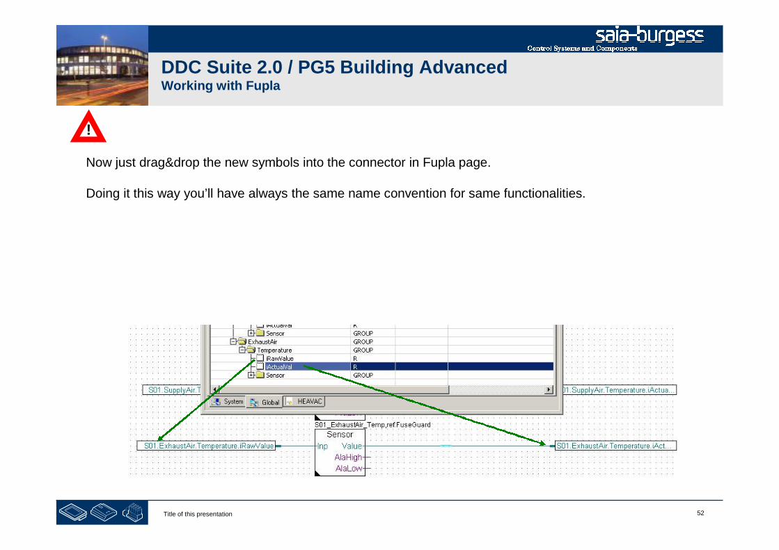
Now just drag&drop the new symbols into the connector in Fupla page.
Doing it this way you’ll have always the same name convention for same functionalities.
!

53Title of this presentation
DDC Suite 2.0 / PG5 Building AdvancedWorking with Fupla
Second Fupla page will contain
- physical components supply air fan, exhaust air fan
54Title of this presentation
DDC Suite 2.0 / PG5 Building AdvancedWorking with Fupla
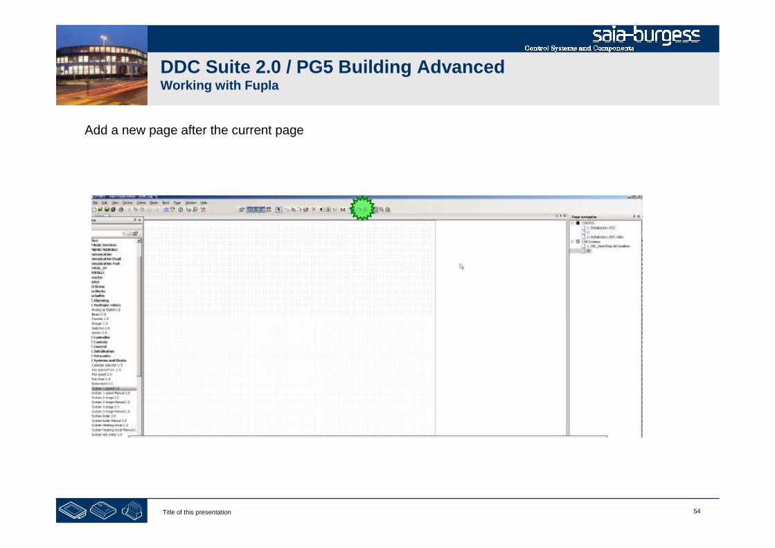
Add a new page after the current page
55Title of this presentation
DDC Suite 2.0 / PG5 Building AdvancedWorking with Fupla
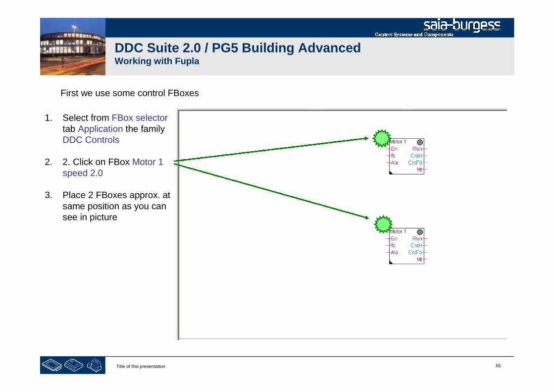
First we use some control FBoxes
1. Select from FBox selectortab Application the familyDDC Controls
2. 2. Click on FBox Motor 1speed 2.0
3. Place 2 FBoxes approx. atsame position as you cansee in picture

56Title of this presentation
DDC Suite 2.0 / PG5 Building AdvancedWorking with Fupla
The FBox Motor 1 speed controls any drive viaone digital output. The features are
- Virtual switch e.g. to start/stop for testingor maintenance
- Start delay- Counting working hours- Counting switch-on via feedback input- Monitoring this counter to indicate e.g.
after 2000 working hours “maintenancenecessary”
- Collecting all information for a clearpresentation why the motor is running ornot
57Title of this presentation
DDC Suite 2.0 / PG5 Building AdvancedWorking with Fupla
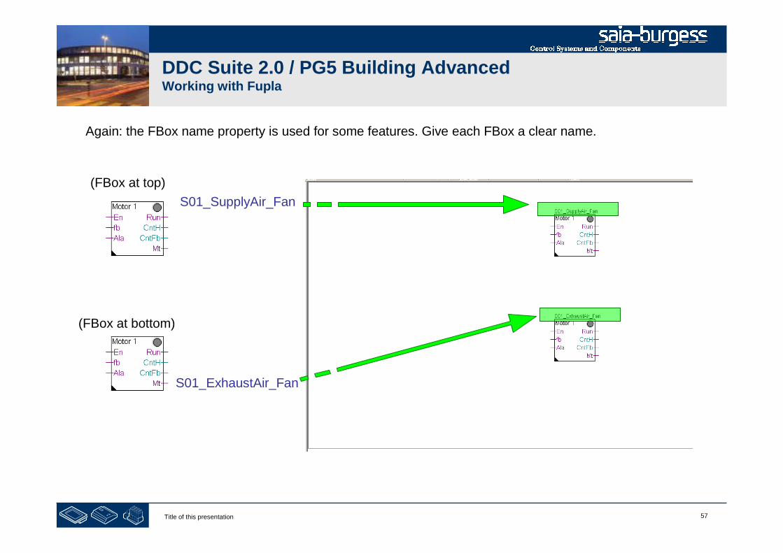
Again: the FBox name property is used for some features. Give each FBox a clear name.
S01_SupplyAir_Fan
S01_ExhaustAir_Fan
(FBox at top)
(FBox at bottom)
58Title of this presentation
DDC Suite 2.0 / PG5 Building AdvancedWorking with Fupla
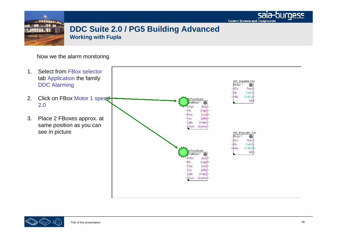
Now we the alarm monitoring
1. Select from FBox selectortab Application the familyDDC Alarming
2. Click on FBox Motor 1 speed2.0
3. Place 2 FBoxes approx. atsame position as you cansee in picture

59Title of this presentation
DDC Suite 2.0 / PG5 Building AdvancedWorking with Fupla
Give each FBox a clear name.
S01_SupplyAir_FanAla
S01_ExhaustAir_FanAla
(FBox at top)
(FBox at bottom)
60Title of this presentation
DDC Suite 2.0 / PG5 Building AdvancedWorking with Fupla
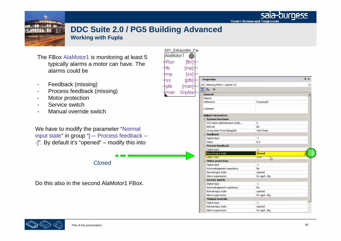
The FBox AlaMotor1 is monitoring at least 5typically alarms a motor can have. Thealarms could be
- Feedback (missing)- Process feedback (missing)- Motor protection- Service switch- Manual override switch
We have to modify the parameter “Normalinput state” in group “[--- Process feedback ---]”. By default it’s “opened” – modify this into
Closed
Do this also in the second AlaMotor1 FBox.
61Title of this presentation
DDC Suite 2.0 / PG5 Building AdvancedWorking with Fupla
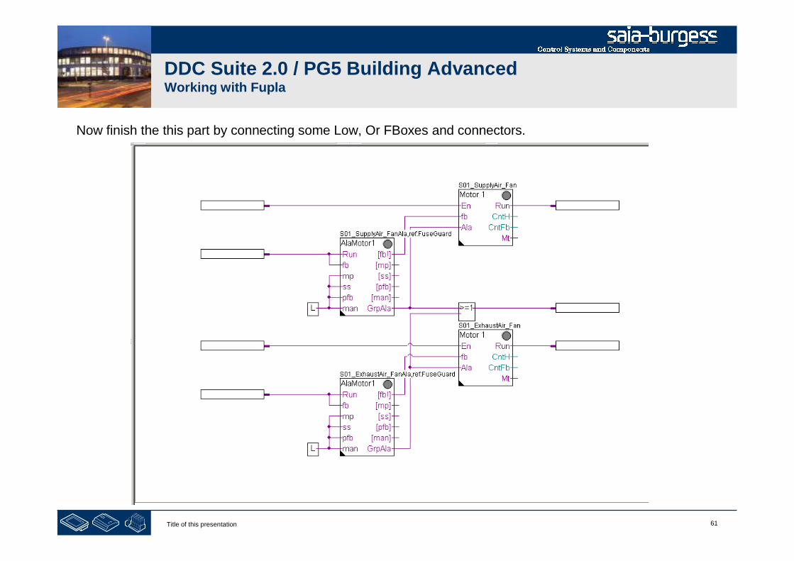
Now finish the this part by connecting some Low, Or FBoxes and connectors.

62Title of this presentation
DDC Suite 2.0 / PG5 Building AdvancedWorking with Fupla
Finally we add the FBox selector tab Application, family DDC Alarming FBox Acknowledge 1.5.
Via this FBox we can acknowledge stored alarms from this position till end of program. It’s easier thanswitching to initialization page to access the adjust window from InitLib FBox.
63Title of this presentation
DDC Suite 2.0 / PG5 Building AdvancedWorking with Fupla
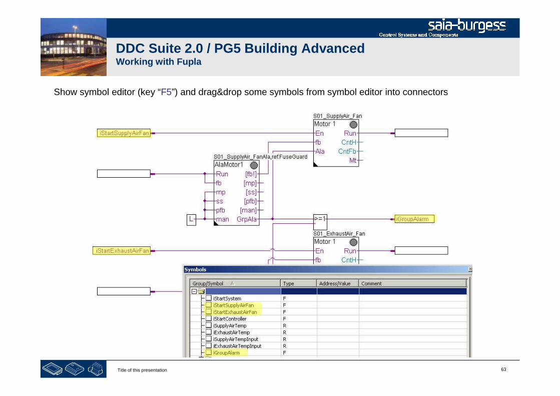
Show symbol editor (key “F5”) and drag&drop some symbols from symbol editor into connectors
64Title of this presentation
DDC Suite 2.0 / PG5 Building AdvancedWorking with Fupla

65Title of this presentation
DDC Suite 2.0 / PG5 Building AdvancedWorking with Fupla
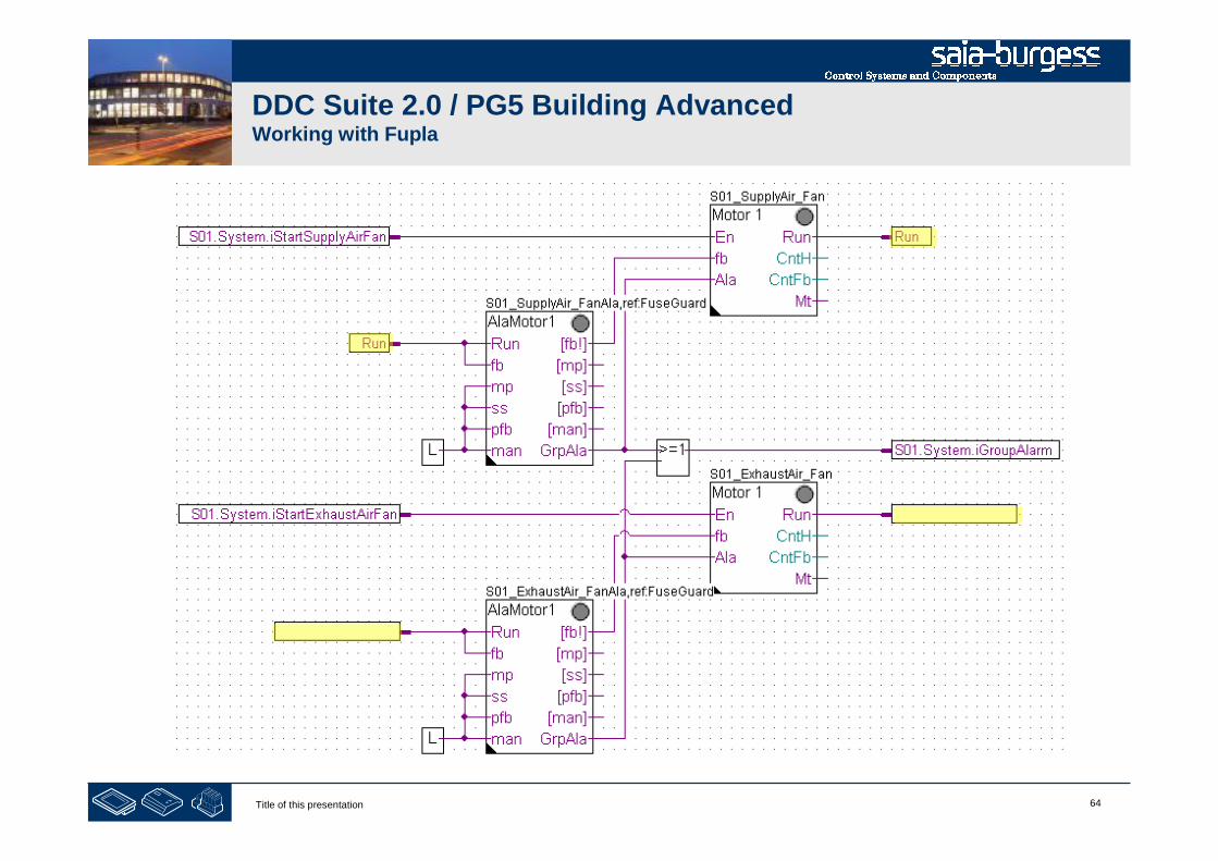
Please check in symbol editor (remember show/hide symbol editor with key “F5”) if you see the samestructure and symbols.

66Title of this presentation
DDC Suite 2.0 / PG5 Building AdvancedWorking with Fupla
- structuring data

67Title of this presentation
DDC Suite 2.0 / PG5 Building AdvancedWorking with Fupla
Double click in Fupla page and type in
text field “Name”
S01 Supply/Exhaust air fan
68Title of this presentation
DDC Suite 2.0 / PG5 Building AdvancedWorking with Fupla
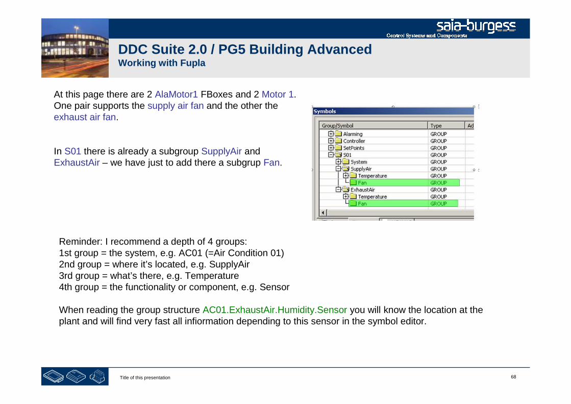
At this page there are 2 AlaMotor1 FBoxes and 2 Motor 1.One pair supports the supply air fan and the other theexhaust air fan.
In S01 there is already a subgroup SupplyAir andExhaustAir – we have just to add there a subgrup Fan.
Reminder: I recommend a depth of 4 groups:1st group = the system, e.g. AC01 (=Air Condition 01)2nd group = where it’s located, e.g. SupplyAir3rd group = what’s there, e.g. Temperature4th group = the functionality or component, e.g. Sensor
When reading the group structure AC01.ExhaustAir.Humidity.Sensor you will know the location at theplant and will find very fast all infiormation depending to this sensor in the symbol editor.

69Title of this presentation
DDC Suite 2.0 / PG5 Building AdvancedWorking with Fupla
Repeat the steps before also for FBox Motor 1 with nameS01_SupplyAir_Fan. Click on FBox, drag&drop groupMotor1speed_0 into group S01.SupplyAir.Fan.
Rename the group Motor1speed_0 into Control. (becausethe fan will have a second FBox and this FBox will controlthe fan)
Repeat the steps before also for FBox AlaMotor1 withname S01_SupplyAir_FanAla. Click on FBox, drag&dropgroup Motor1_0 into group S01.SupplyAir.Fan.
Rename the group Motor1_0 into Alarming. (because thefan has already another FBox and this FBox will handlethe alarming of the fan)
70Title of this presentation
DDC Suite 2.0 / PG5 Building AdvancedWorking with Fupla
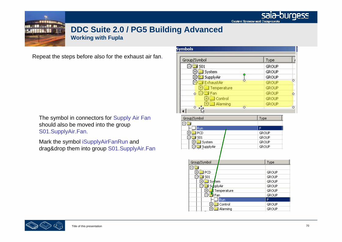
Repeat the steps before also for the exhaust air fan.
The symbol in connectors for Supply Air Fanshould also be moved into the groupS01.SupplyAir.Fan.
Mark the symbol iSupplyAirFanRun anddrag&drop them into group S01.SupplyAir.Fan
71Title of this presentation
DDC Suite 2.0 / PG5 Building AdvancedWorking with Fupla
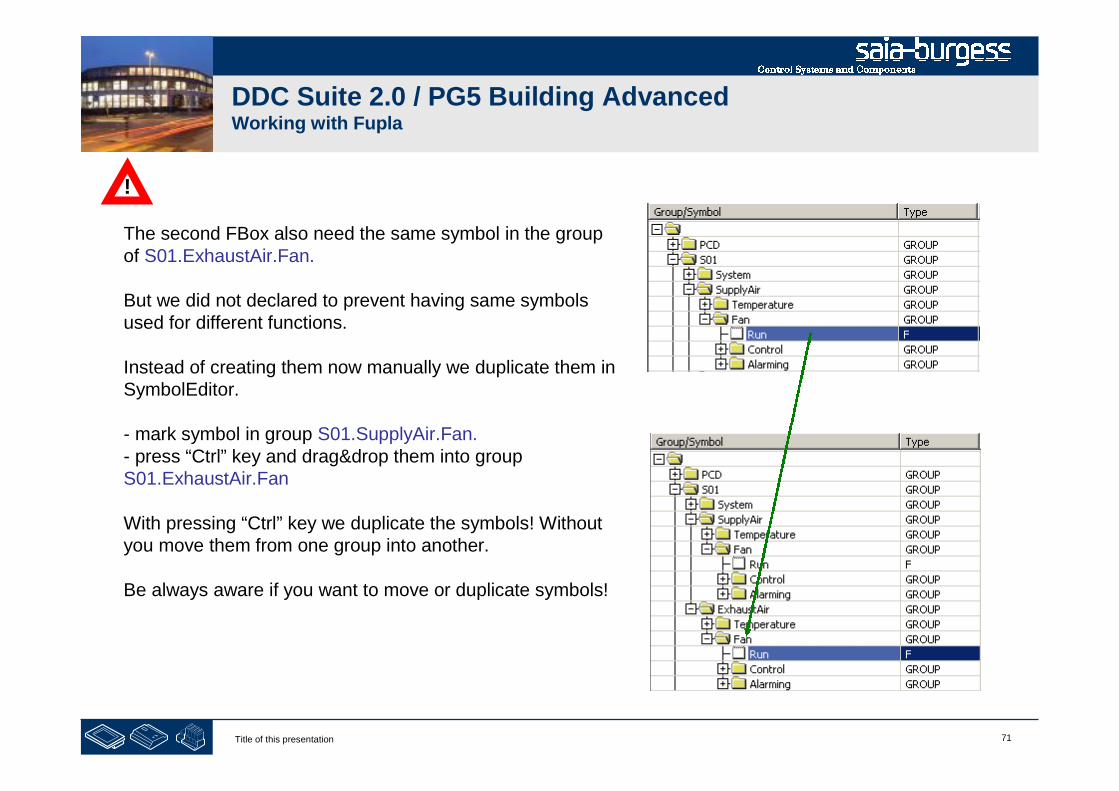
The second FBox also need the same symbol in the groupof S01.ExhaustAir.Fan.
But we did not declared to prevent having same symbolsused for different functions.
Instead of creating them now manually we duplicate them inSymbolEditor.
- mark symbol in group S01.SupplyAir.Fan.- press “Ctrl” key and drag&drop them into groupS01.ExhaustAir.Fan
With pressing “Ctrl” key we duplicate the symbols! Withoutyou move them from one group into another.
Be always aware if you want to move or duplicate symbols!
!

72Title of this presentation
DDC Suite 2.0 / PG5 Building AdvancedWorking with Fupla
Now just drag&drop the new symbol into the connector in Fupla page.
Doing it this way you’ll have always the same name convention for same functionalities.
!
73Title of this presentation
DDC Suite 2.0 / PG5 Building AdvancedWorking with Fupla
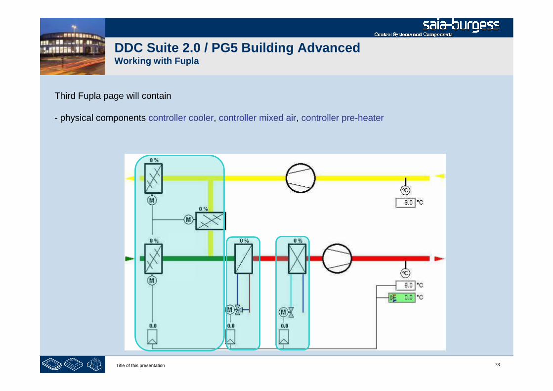
Third Fupla page will contain
- physical components controller cooler, controller mixed air, controller pre-heater

74Title of this presentation
DDC Suite 2.0 / PG5 Building AdvancedWorking with Fupla
Add a new page after the current page
75Title of this presentation
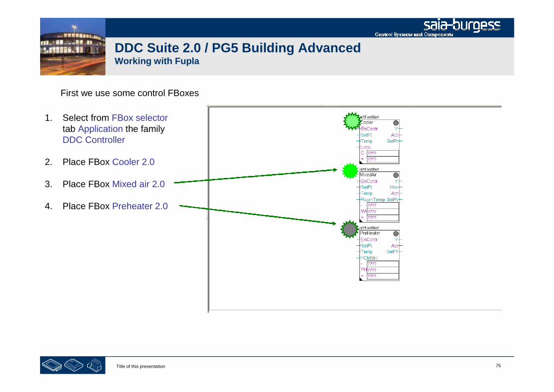
DDC Suite 2.0 / PG5 Building AdvancedWorking with Fupla
First we use some control FBoxes
1. Select from FBox selectortab Application the familyDDC Controller
2. Place FBox Cooler 2.0
3. Place FBox Mixed air 2.0
4. Place FBox Preheater 2.0

76Title of this presentation
DDC Suite 2.0 / PG5 Building AdvancedWorking with Fupla
Give each FBox a clear name. FBox reference properties get a prefix S01_.
Name: S01_CoolerReference: S01_FanStart
Name: S01_MixedAirReference: S01_FanStart
Name: S01_PreheaterReference: S01_FanStart

77Title of this presentation
DDC Suite 2.0 / PG5 Building AdvancedWorking with Fupla
Now finish the this part by connecting some Low, Register connectors and Value FBoxes.
1. Select from FBox selector tabApplication the family DDC Setpoints
2. Place FBox Integer 2.0
3. Type in FBox name propertyS01_SupplyAirTempSetPoint
FBox selector tab Standard, family Binary, FBox Low
FBox selector tab Application, family DDC General,FBox Register connect 1.5

78Title of this presentation
DDC Suite 2.0 / PG5 Building AdvancedWorking with Fupla
We have to set a value in FBox Register connect connected to Input YCldStrt:
1. Open adjust window withdouble click on FBox
2. Type in value 456
This represents 45.6 and will beused as valve signal duringstart up phase. More info lateron during test ….

79Title of this presentation
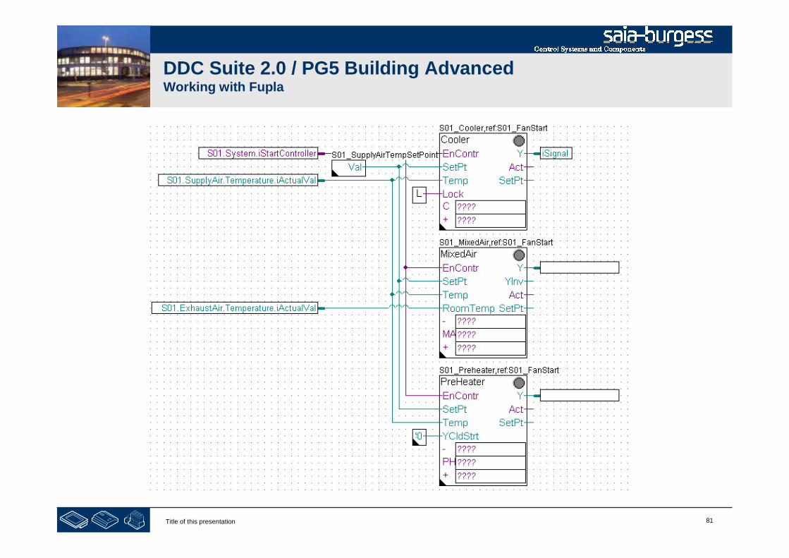
DDC Suite 2.0 / PG5 Building AdvancedWorking with Fupla
Now finish the this part by connecting input and output connectors.
80Title of this presentation
DDC Suite 2.0 / PG5 Building AdvancedWorking with Fupla
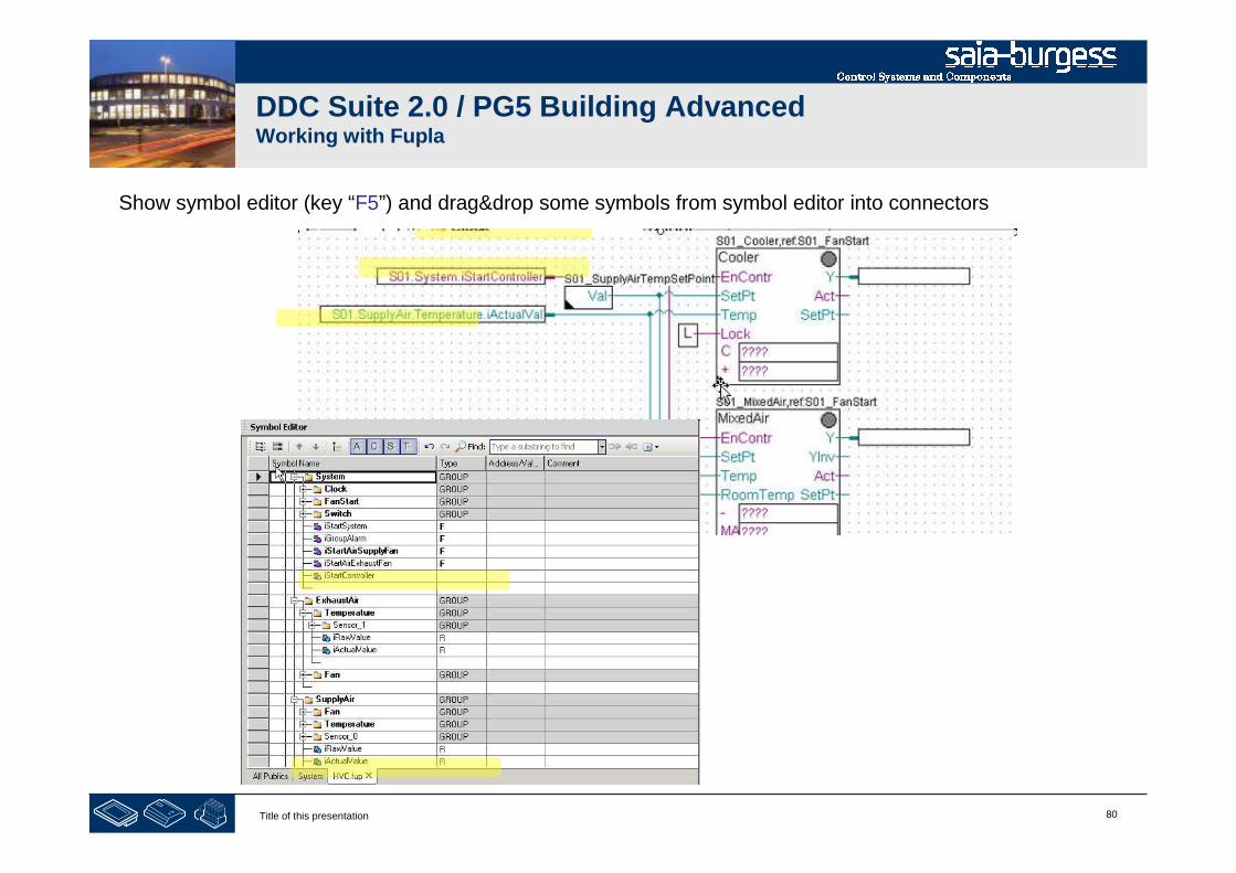
Show symbol editor (key “F5”) and drag&drop some symbols from symbol editor into connectors
81Title of this presentation
DDC Suite 2.0 / PG5 Building AdvancedWorking with Fupla

82Title of this presentation
DDC Suite 2.0 / PG5 Building AdvancedWorking with Fupla
Please check in symbol editor (remember show/hide symbol editor with key “F5”) if you see the samestructure and symbols.
83Title of this presentation
DDC Suite 2.0 / PG5 Building AdvancedWorking with Fupla
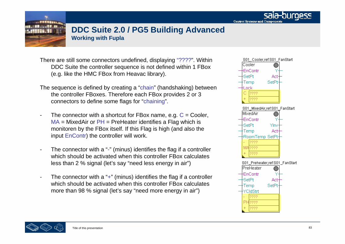
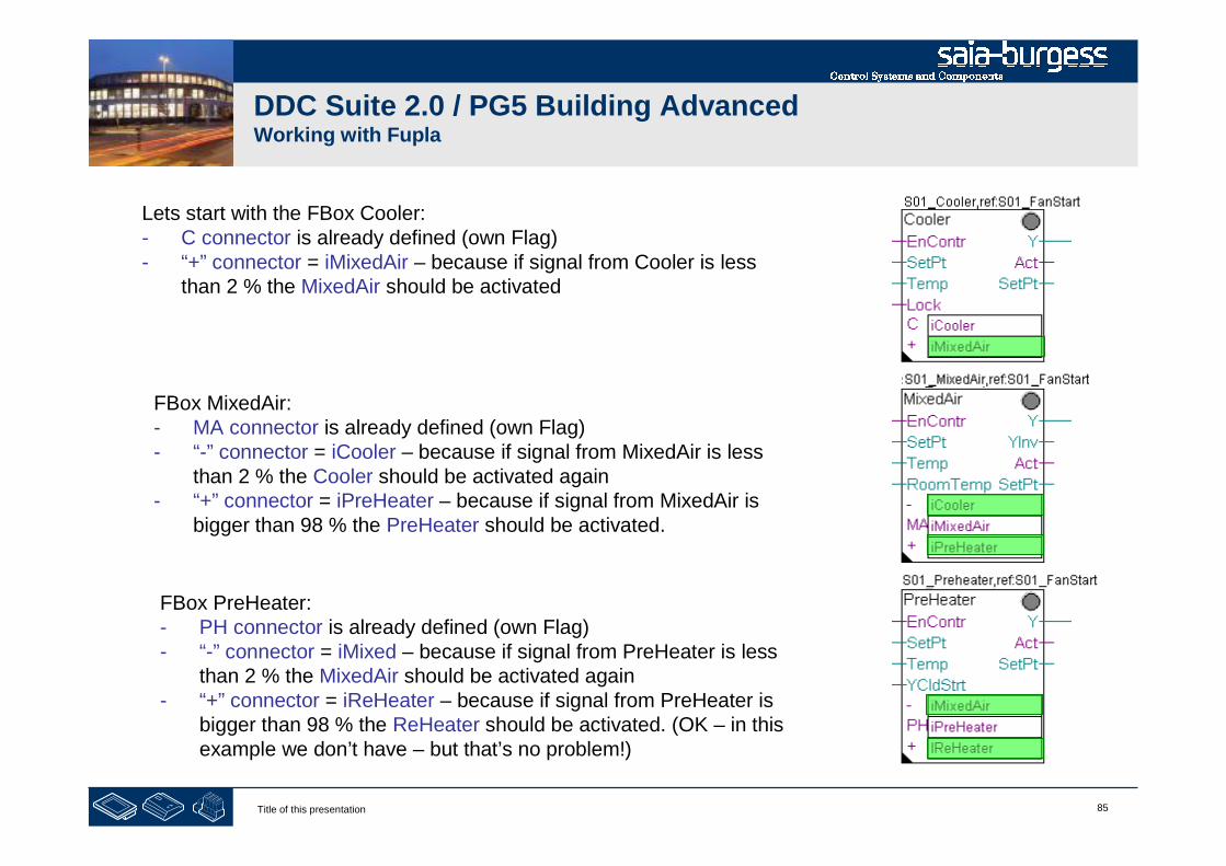
There are still some connectors undefined, displaying “????”. WithinDDC Suite the controller sequence is not defined within 1 FBox(e.g. like the HMC FBox from Heavac library).
The sequence is defined by creating a “chain” (handshaking) betweenthe controller FBoxes. Therefore each FBox provides 2 or 3connectors to define some flags for “chaining”.
- The connector with a shortcut for FBox name, e.g. C = Cooler,MA = MixedAir or PH = PreHeater identifies a Flag which ismonitoren by the FBox itself. If this Flag is high (and also theinput EnContr) the controller will work.
- The connector with a “-” (minus) identifies the flag if a controllerwhich should be activated when this controller FBox calculatesless than 2 % signal (let’s say “need less energy in air”)
- The connector with a “+” (minus) identifies the flag if a controllerwhich should be activated when this controller FBox calculatesmore than 98 % signal (let’s say “need more energy in air”)

84Title of this presentation
DDC Suite 2.0 / PG5 Building AdvancedWorking with Fupla
Lets start with the FBox Cooler:- C connector = iCooler. This flag is monitored by FBox
FBox MixedAir:- MA connector = iMixedAir. This flag is monitored by FBox.
FBox PreHeater:- PH connector = iPreHeater. This flag is monitored by FBox.
85Title of this presentation
DDC Suite 2.0 / PG5 Building AdvancedWorking with Fupla
Lets start with the FBox Cooler:- C connector is already defined (own Flag)- “+” connector = iMixedAir – because if signal from Cooler is less
than 2 % the MixedAir should be activated
FBox MixedAir:- MA connector is already defined (own Flag)- “-” connector = iCooler – because if signal from MixedAir is less
than 2 % the Cooler should be activated again- “+” connector = iPreHeater – because if signal from MixedAir is
bigger than 98 % the PreHeater should be activated.
FBox PreHeater:- PH connector is already defined (own Flag)- “-” connector = iMixed – because if signal from PreHeater is less
than 2 % the MixedAir should be activated again- “+” connector = iReHeater – because if signal from PreHeater is
bigger than 98 % the ReHeater should be activated. (OK – in thisexample we don’t have – but that’s no problem!)

86Title of this presentation
DDC Suite 2.0 / PG5 Building AdvancedWorking with Fupla
87Title of this presentation
DDC Suite 2.0 / PG5 Building AdvancedWorking with Fupla
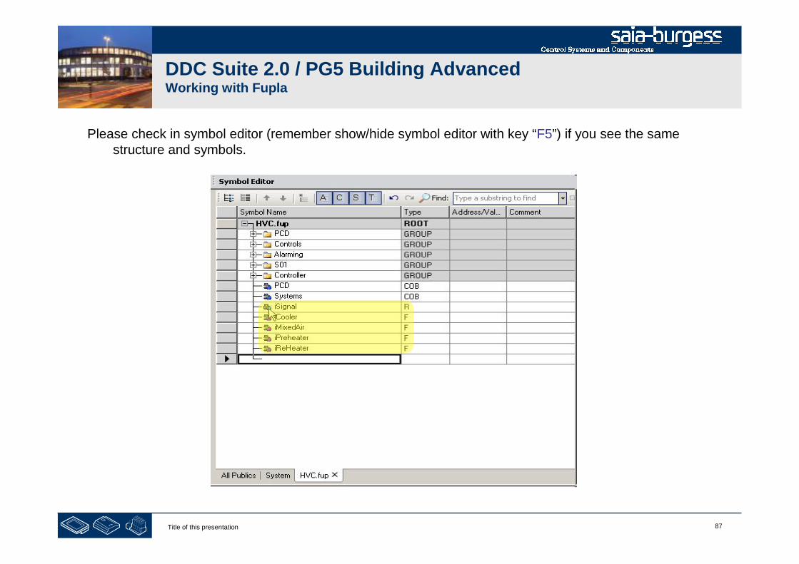
Please check in symbol editor (remember show/hide symbol editor with key “F5”) if you see the samestructure and symbols.
88Title of this presentation
DDC Suite 2.0 / PG5 Building AdvancedWorking with Fupla
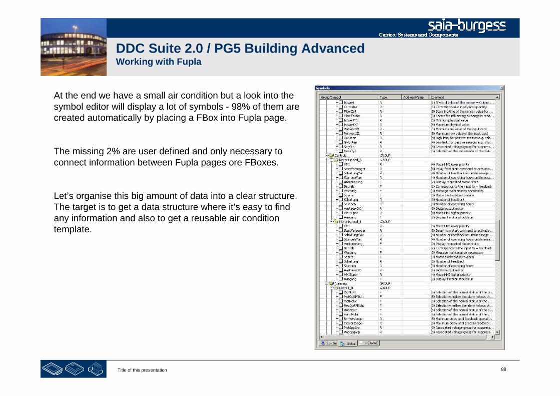
At the end we have a small air condition but a look into thesymbol editor will display a lot of symbols - 98% of them arecreated automatically by placing a FBox into Fupla page.
The missing 2% are user defined and only necessary toconnect information between Fupla pages ore FBoxes.
Let’s organise this big amount of data into a clear structure.The target is to get a data structure where it’s easy to findany information and also to get a reusable air conditiontemplate.
89Title of this presentation
DDC Suite 2.0 / PG5 Building AdvancedWorking with Fupla
- structuring data

90Title of this presentation
DDC Suite 2.0 / PG5 Building AdvancedWorking with Fupla
Double click in Fupla page and type in
text field “Name”
S01 Controller

91Title of this presentation
DDC Suite 2.0 / PG5 Building AdvancedWorking with Fupla
At this page there are 3 controller FBoxes representing anunit and 1 FBox for a set point. Maybe the unit will havemore than one FBox it’s always a good thing to create aseparate group
So let’s create a group
Cooler to store all data for the cooler/valve unit
MixedAir to store all data for the mixed air/damper unit
Preheater to store all data for the preheater/valve unit

92Title of this presentation
DDC Suite 2.0 / PG5 Building AdvancedWorking with Fupla
Repeat the steps before also for FBox Cooler withname S01_Cooler. Click on FBox, drag&drop groupCooler_0 into group S01.Cooler. Rename the groupCooler_0 into Controller.
Repeat the steps before also for FBox MixedAir withname S01_MixedAir. Click on FBox, drag&drop groupMixedAir_0 into group S01.MixedAir. Rename thegroup MixedAir_0 into Controller.
Repeat the steps before also for FBox PreHeater withname S01_Preheater. Click on FBox, drag&drop groupPreheater_0 into group S01.Preheater. Rename thegroup Preheater_0 into Controller.

93Title of this presentation
1. Mark the symbol iCooler drag&drop it intogroup S01.Cooler
2. Mark the symbol iMixedAir drag&drop it intogroup S01.MixedAir
3. Mark the symbol iPreHeater and iReHeaterdrag&drop them into group S01.Preheater
DDC Suite 2.0 / PG5 Building AdvancedWorking with Fupla
94Title of this presentation
DDC Suite 2.0 / PG5 Building AdvancedWorking with Fupla
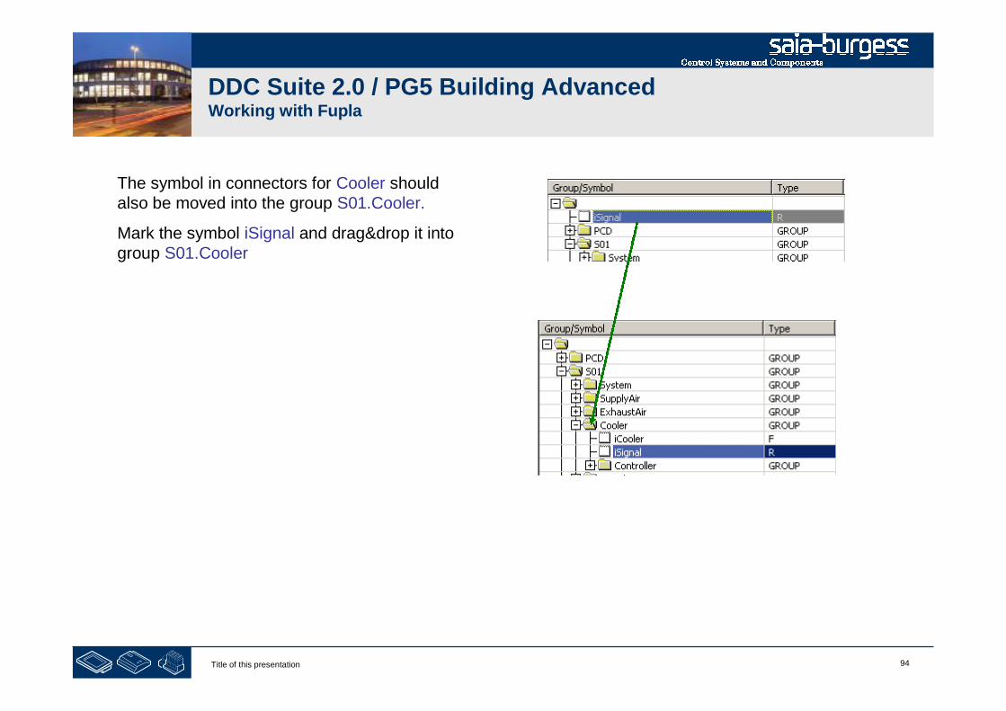
The symbol in connectors for Cooler shouldalso be moved into the group S01.Cooler.
Mark the symbol iSignal and drag&drop it intogroup S01.Cooler

95Title of this presentation
DDC Suite 2.0 / PG5 Building AdvancedWorking with Fupla
The other controller FBoxes also need the same symbol inthe group of S01.MixedAir and S01.PreHeater.
But we did not declared to prevent having same symbolsused for different functions.
Instead of creating them now manually we duplicate them inSymbolEditor.
- mark symbol in group S01.Cooler.- press “Ctrl” key and drag&drop them into groupS01.MixedAir
Repeat this also for PreHeater.
With pressing “Ctrl” key we duplicate the symbols! Withoutyou move them from one group into another.
Be always aware if you want to move or duplicate symbols!
!
96Title of this presentation
DDC Suite 2.0 / PG5 Building AdvancedWorking with Fupla
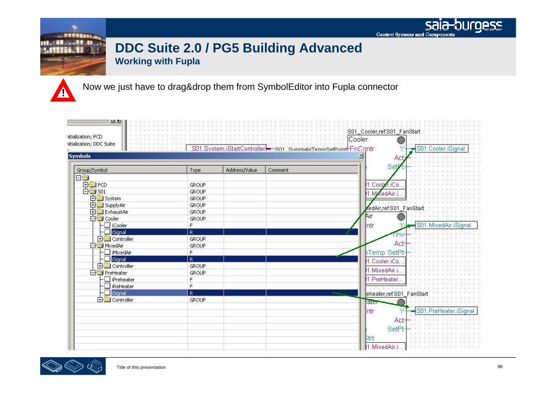
Now we just have to drag&drop them from SymbolEditor into Fupla connector!
97Title of this presentation
DDC Suite 2.0 / PG5 Building AdvancedWorking with Fupla
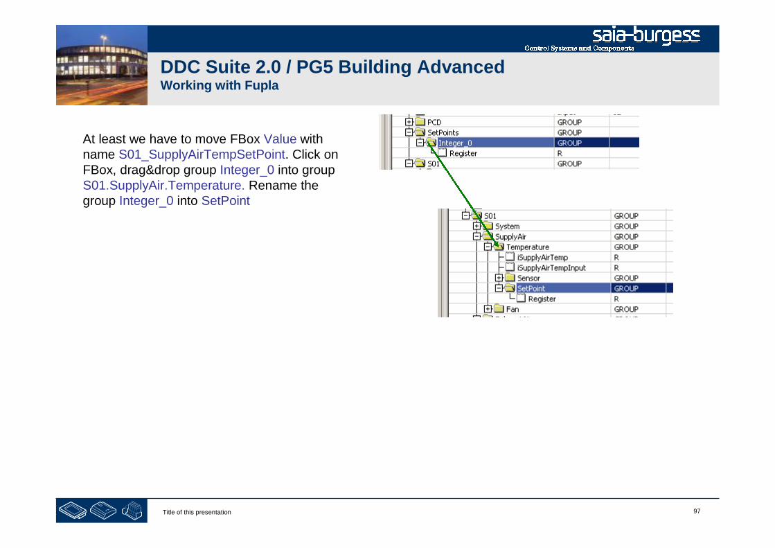
At least we have to move FBox Value withname S01_SupplyAirTempSetPoint. Click onFBox, drag&drop group Integer_0 into groupS01.SupplyAir.Temperature. Rename thegroup Integer_0 into SetPoint

98Title of this presentation
DDC Suite 2.0 / PG5 Building AdvancedWorking with Fupla
At least all data should be moved intogroup S01(or subgroups) and nosymbol any more in root
The groups Analogue, Controls,Alarming and Controller should alsobe empty (no “+” sign in front of thefolder)
Now we have moved all data in aclear and unique structure.
Now press key “F2” to build the program.
Any error messages?
Yes: rewind to first slide and repeat all lessons …

99Title of this presentation
DDC Suite 2.0 / PG5 Building AdvancedWorking with Fupla
At this point we have created a small and nice air condition application. In real life it would be bigger withmuch more FBoxes or symbols – but we can reuse this in future if we store it as template.
Therefore we export this application as tempalte.Click on Page in menu and in context menu entryExport…
Type in file name, use AirCondition and pressbutton Export
100Title of this presentation
DDC Suite 2.0 / PG5 Building AdvancedWorking with Fupla
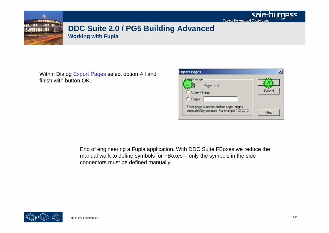
Within Dialog Export Pages select option All andfinish with button OK.
End of engineering a Fupla application. With DDC Suite FBoxes we reduce themanual work to define symbols for FBoxes – only the symbols in the sideconnectors must be defined manually.
101Title of this presentation
DDC Suite 2.0 / PG5 Building AdvancedWorking with Fupla
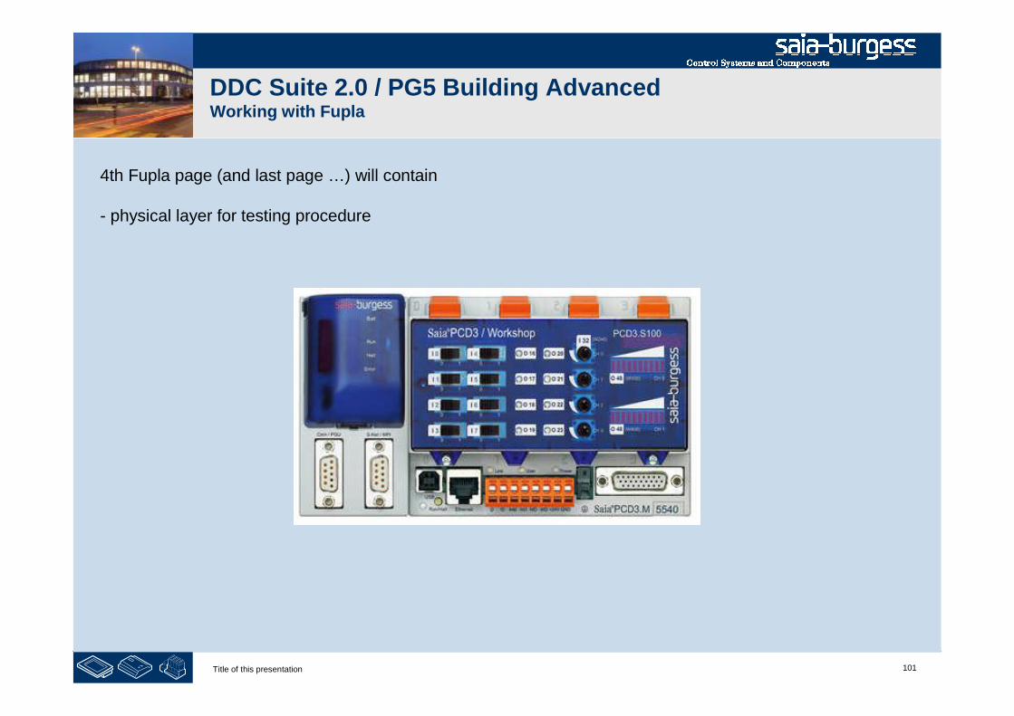
4th Fupla page (and last page …) will contain
- physical layer for testing procedure
102Title of this presentation
DDC Suite 2.0 / PG5 Building AdvancedWorking with Fupla
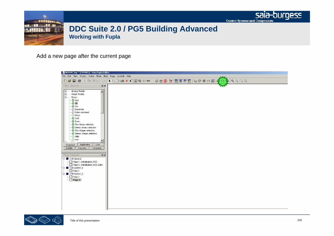
Add a new page after the current page

103Title of this presentation
DDC Suite 2.0 / PG5 Building AdvancedWorking with Fupla
Connect also to FBox inputs and outputs all connectors
1. Select from FBox selectortab Application the familyHVC Analogue
2. Place FBox PCD2.W4stretch up to 2 inputs
3. Place FBox PCD2.W2stretch up to 2 outputs
104Title of this presentation
DDC Suite 2.0 / PG5 Building AdvancedWorking with Fupla
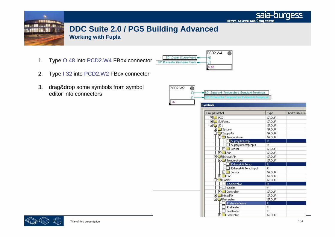
1. Type O 48 into PCD2.W4 FBox connector
2. Type I 32 into PCD2.W2 FBox connector
3. drag&drop some symbols from symboleditor into connectors

105Title of this presentation
DDC Suite 2.0 / PG5 Building AdvancedWorking with Fupla
Now press key “F2” to build the program.
Any error messages?
Yes: rewind to first slide and repeat all lessons …
Everything OK: download program

1Title of this presentation
PG5 Building Advanced / DDC Suite 2.0Online features
DDC Suite - Online features
2Title of this presentation
DDC Suite 2.0 / PG5 Building AdvancedOnline features
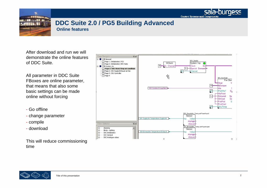
After download and run we willdemonstrate the online featuresof DDC Suite.
All parameter in DDC SuiteFBoxes are online parameter,that means that also somebasic settings can be madeonline without forcing
- Go offline
- change parameter
- compile
- download
This will reduce commissioningtime

3Title of this presentation
DDC Suite 2.0 / PG5 Building AdvancedOnline features
If PCD clock is on time the FBox System 1spwill enable the air condition by clock demand.
Until all settings have been made we’ll blockthe air condition, just open adjust window andset parameter “HMI Lower priority” to Off andwrite this into PCD.
You will see that the LED of the FBox turns toRED – indication that this “system” is undermanual operation.
Close adjust window.

4Title of this presentation
DDC Suite 2.0 / PG5 Building AdvancedOnline features
Lets have a look into FBox Sensor – openadjust window from FBox with nameS01_SupplyAir_Temp.
By default this FBox expects already aphysical value at input In. But the PCDworkshop model supports only a active linearsignal – so we have to convert the value.Therefore
- Select Conversion at parameter CardType
- set Physical. Value min to 15.0
- set Physical. Value min to 26.0
- set raw input value min to 0
- set raw input value max to 1000
And write this settings into PCD.
5Title of this presentation
DDC Suite 2.0 / PG5 Building AdvancedOnline features
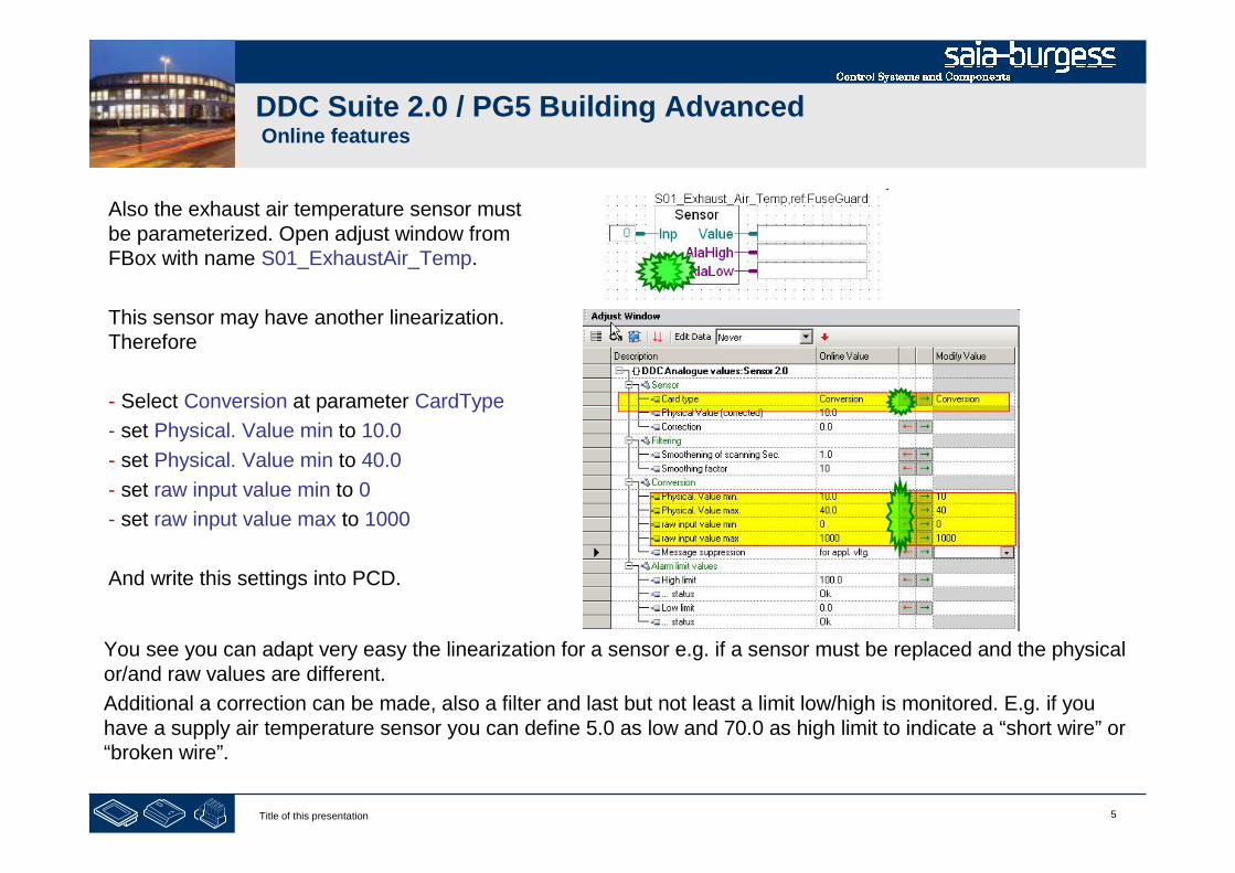
Also the exhaust air temperature sensor mustbe parameterized. Open adjust window fromFBox with name S01_ExhaustAir_Temp.
This sensor may have another linearization.Therefore
- Select Conversion at parameter CardType
- set Physical. Value min to 10.0
- set Physical. Value min to 40.0
- set raw input value min to 0
- set raw input value max to 1000
And write this settings into PCD.
You see you can adapt very easy the linearization for a sensor e.g. if a sensor must be replaced and the physicalor/and raw values are different.
Additional a correction can be made, also a filter and last but not least a limit low/high is monitored. E.g. if youhave a supply air temperature sensor you can define 5.0 as low and 70.0 as high limit to indicate a “short wire” or“broken wire”.
6Title of this presentation
DDC Suite 2.0 / PG5 Building AdvancedOnline features
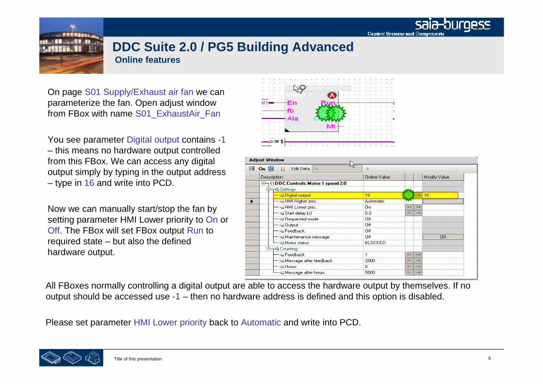
On page S01 Supply/Exhaust air fan we canparameterize the fan. Open adjust windowfrom FBox with name S01_ExhaustAir_Fan
You see parameter Digital output contains -1– this means no hardware output controlledfrom this FBox. We can access any digitaloutput simply by typing in the output address– type in 16 and write into PCD.
Now we can manually start/stop the fan bysetting parameter HMI Lower priority to On orOff. The FBox will set FBox output Run torequired state – but also the definedhardware output.
All FBoxes normally controlling a digital output are able to access the hardware output by themselves. If nooutput should be accessed use -1 – then no hardware address is defined and this option is disabled.
Please set parameter HMI Lower priority back to Automatic and write into PCD.
7Title of this presentation
DDC Suite 2.0 / PG5 Building AdvancedOnline features
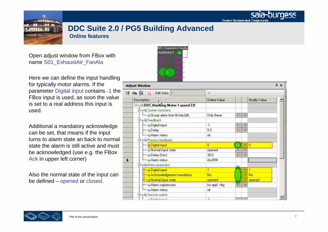
Open adjust window from FBox withname S01_ExhaustAir_FanAla
Here we can define the input handlingfor typically motor alarms. If theparameter Digital input contains -1 theFBox input is used, as soon the valueis set to a real address this input isused.
Additional a mandatory acknowledgecan be set, that means if the inputturns to alarm state an back to normalstate the alarm is still active and mustbe acknowledged (use e.g. the FBoxAck in upper left corner)
Also the normal state of the input canbe defined – opened or closed.
8Title of this presentation
DDC Suite 2.0 / PG5 Building AdvancedOnline features
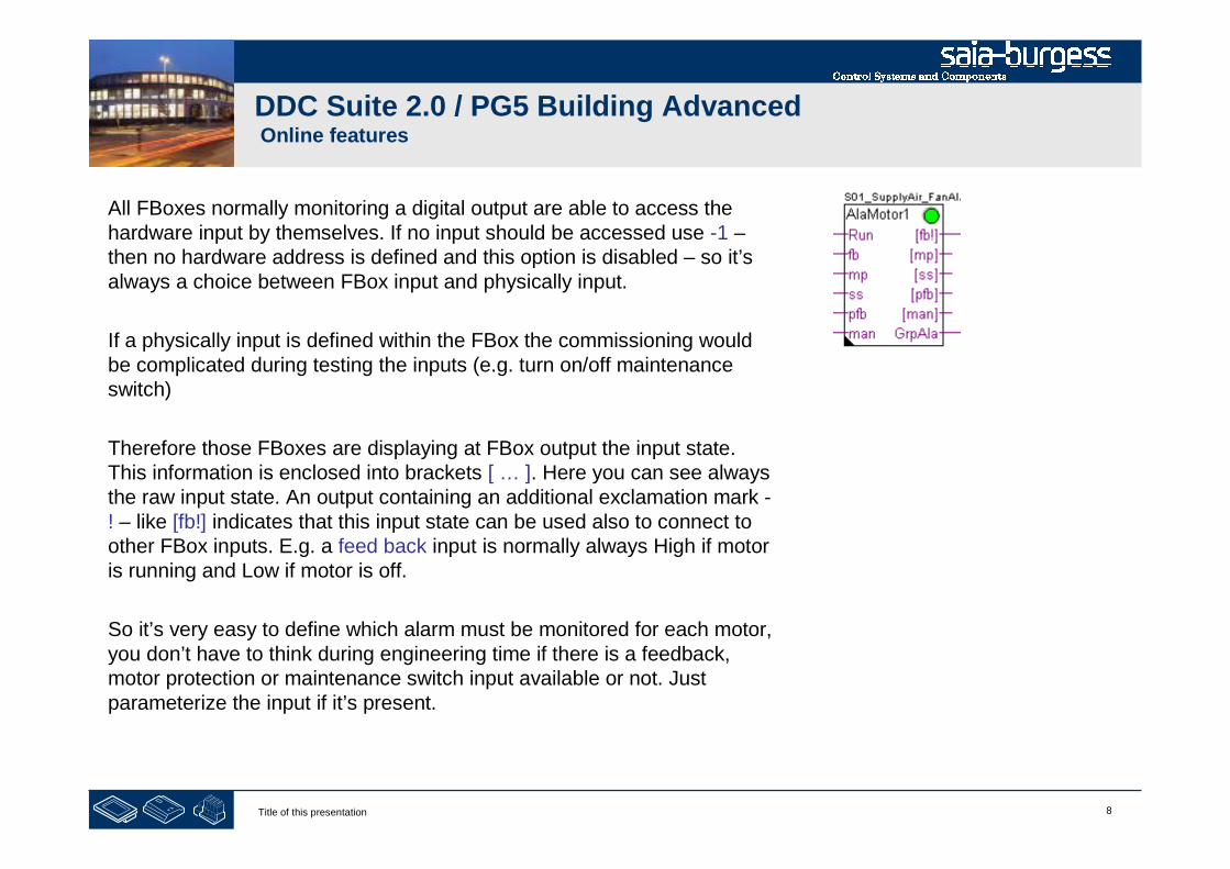
All FBoxes normally monitoring a digital output are able to access thehardware input by themselves. If no input should be accessed use -1 –then no hardware address is defined and this option is disabled – so it’salways a choice between FBox input and physically input.
If a physically input is defined within the FBox the commissioning wouldbe complicated during testing the inputs (e.g. turn on/off maintenanceswitch)
Therefore those FBoxes are displaying at FBox output the input state.This information is enclosed into brackets [ … ]. Here you can see alwaysthe raw input state. An output containing an additional exclamation mark -! – like [fb!] indicates that this input state can be used also to connect toother FBox inputs. E.g. a feed back input is normally always High if motoris running and Low if motor is off.
So it’s very easy to define which alarm must be monitored for each motor,you don’t have to think during engineering time if there is a feedback,motor protection or maintenance switch input available or not. Justparameterize the input if it’s present.

9Title of this presentation
DDC Suite 2.0 / PG5 Building AdvancedSyntax and remarks of actions during workshop
Back to page S01 Start/Stop air condition.
Turn potentiometer to left position until you have theminimum value of 15.0 and 10.0.
This will be the start point to have a defined controllerbehaviour during the controller functionalityexplanation.
1Title of this presentation
PG5 Building Advanced / DDC Suite 2.0HDLog – offline trending
HDLog
Offline trending

2Title of this presentation
DDC Suite 2.0 / PG5 Building AdvancedHDLog – offline trending
To use offline trend functionality in a PCD wehave to use the FBox family Historic DataLogging – available since 2 years.
An HDLog Init FBox implements the corefunctionality, allocating memory and providesan interface to Sweb or ViSi.Plus (or any otherSCADA) system.
3Title of this presentation
DDC Suite 2.0 / PG5 Building AdvancedHDLog – offline trending
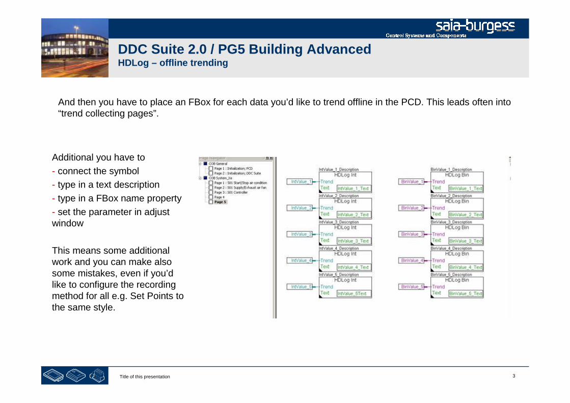
And then you have to place an FBox for each data you’d like to trend offline in the PCD. This leads often into“trend collecting pages”.
Additional you have to
- connect the symbol
- type in a text description
- type in a FBox name property
- set the parameter in adjustwindow
This means some additionalwork and you can make alsosome mistakes, even if you’dlike to configure the recordingmethod for all e.g. Set Points tothe same style.

4Title of this presentation
PG5 Building Advanced / DDC Suite 2.0HDLog – offline trending
HDLog with DDC Suite
Basics
5Title of this presentation
DDC Suite 2.0 / PG5 Building AdvancedHDLog – offline trending
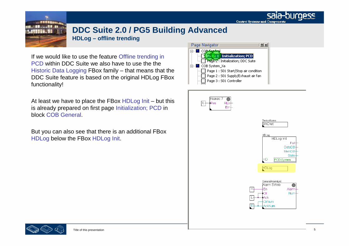
If we would like to use the feature Offline trending inPCD within DDC Suite we also have to use the theHistoric Data Logging FBox family – that means that theDDC Suite feature is based on the original HDLog FBoxfunctionality!
At least we have to place the FBox HDLog Init – but thisis already prepared on first page Initialization; PCD inblock COB General.
But you can also see that there is an additional FBoxHDLog below the FBox HDLog Init.
6Title of this presentation
DDC Suite 2.0 / PG5 Building AdvancedHDLog – offline trending
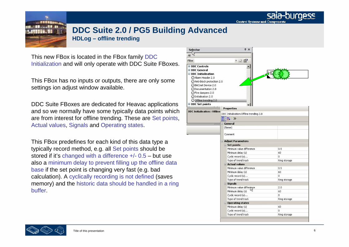
This new FBox is located in the FBox family DDCInitialization and will only operate with DDC Suite FBoxes.
This FBox has no inputs or outputs, there are only somesettings ion adjust window available.
DDC Suite FBoxes are dedicated for Heavac applicationsand so we normally have some typically data points whichare from interest for offline trending. These are Set points,Actual values, Signals and Operating states.
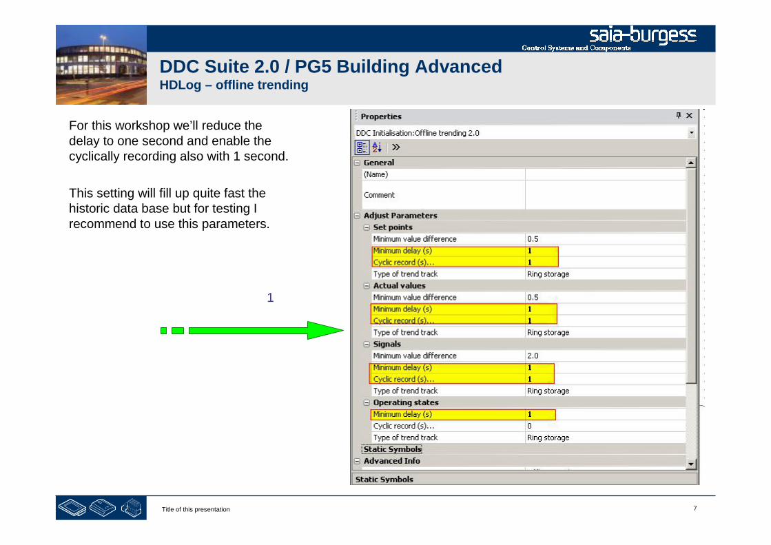
This FBox predefines for each kind of this data type atypically record method, e.g. all Set points should bestored if it’s changed with a difference +/- 0.5 – but usealso a minimum delay to prevent filling up the offline database if the set point is changing very fast (e.g. badcalculation). A cyclically recording is not defined (savesmemory) and the historic data should be handled in a ringbuffer.
7Title of this presentation
DDC Suite 2.0 / PG5 Building AdvancedHDLog – offline trending
For this workshop we’ll reduce thedelay to one second and enable thecyclically recording also with 1 second.
This setting will fill up quite fast thehistoric data base but for testing Irecommend to use this parameters.
1
8Title of this presentation
DDC Suite 2.0 / PG5 Building AdvancedHDLog – offline trending
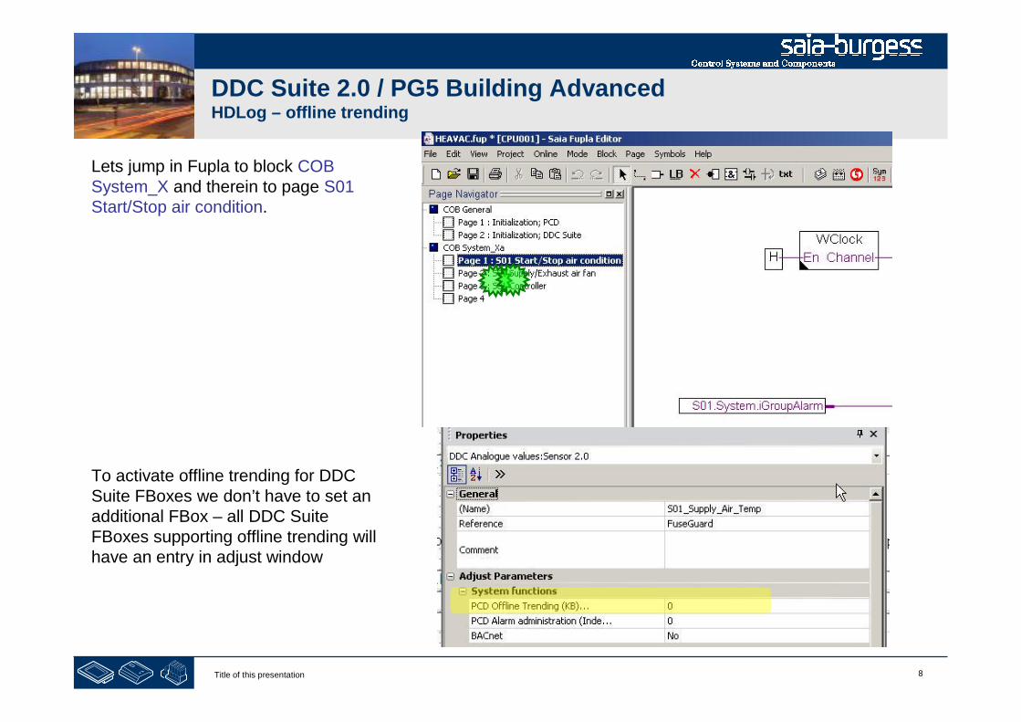
Lets jump in Fupla to block COBSystem_X and therein to page S01Start/Stop air condition.
To activate offline trending for DDCSuite FBoxes we don’t have to set anadditional FBox – all DDC SuiteFBoxes supporting offline trending willhave an entry in adjust window
9Title of this presentation
DDC Suite 2.0 / PG5 Building AdvancedHDLog – offline trending
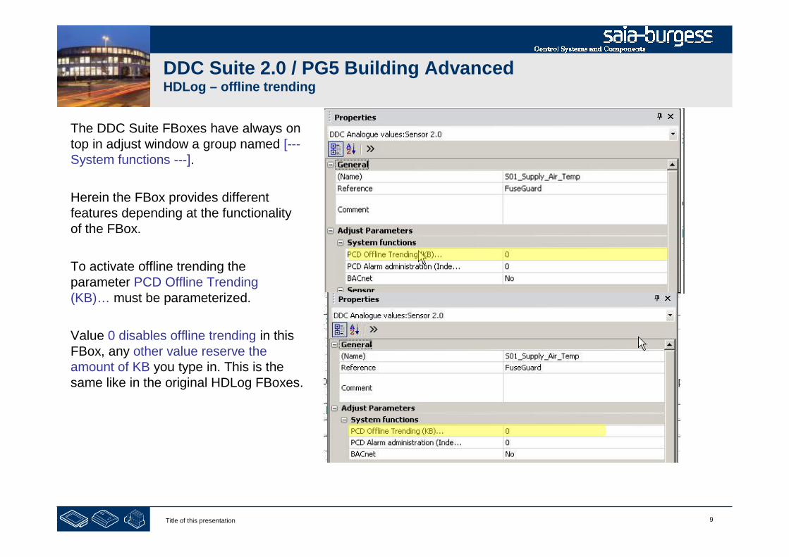
The DDC Suite FBoxes have always ontop in adjust window a group named [---System functions ---].
Herein the FBox provides differentfeatures depending at the functionalityof the FBox.
To activate offline trending theparameter PCD Offline Trending(KB)… must be parameterized.
Value 0 disables offline trending in thisFBox, any other value reserve theamount of KB you type in. This is thesame like in the original HDLog FBoxes.
10Title of this presentation
DDC Suite 2.0 / PG5 Building AdvancedHDLog – offline trending
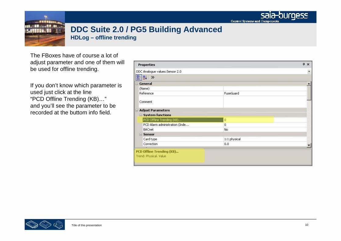
The FBoxes have of course a lot ofadjust parameter and one of them willbe used for offline trending.
If you don’t know which parameter isused just click at the line“PCD Offline Trending (KB)…”and you’ll see the parameter to berecorded at the buttom info field.

11Title of this presentation
PG5 Building Advanced / DDC Suite 2.0HDLog – offline trending
HDLog with DDC Suite
In use
12Title of this presentation
DDC Suite 2.0 / PG5 Building AdvancedHDLog – offline trending
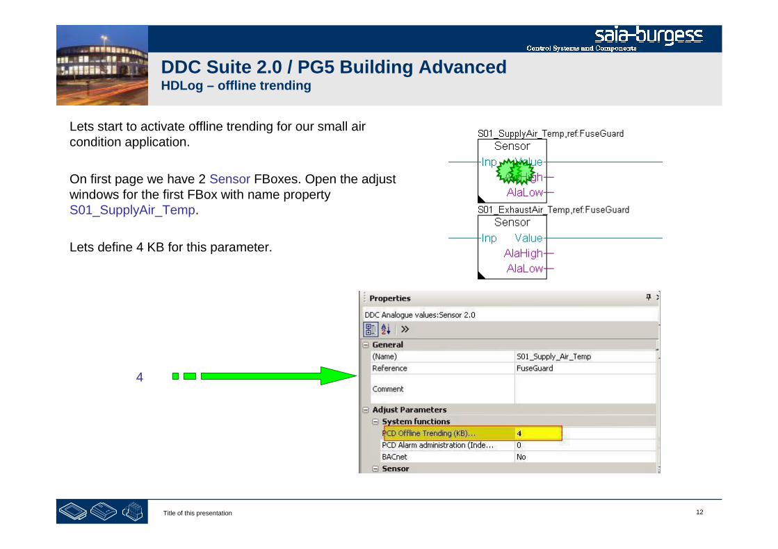
Lets start to activate offline trending for our small aircondition application.
On first page we have 2 Sensor FBoxes. Open the adjustwindows for the first FBox with name propertyS01_SupplyAir_Temp.
Lets define 4 KB for this parameter.
4

13Title of this presentation
DDC Suite 2.0 / PG5 Building AdvancedHDLog – offline trending
Repeat this is with second Sensor FBox. Open adjustwindows for first FBox with name propertyS01_ExhaustAir_Temp.
4
14Title of this presentation
DDC Suite 2.0 / PG5 Building AdvancedHDLog – offline trending
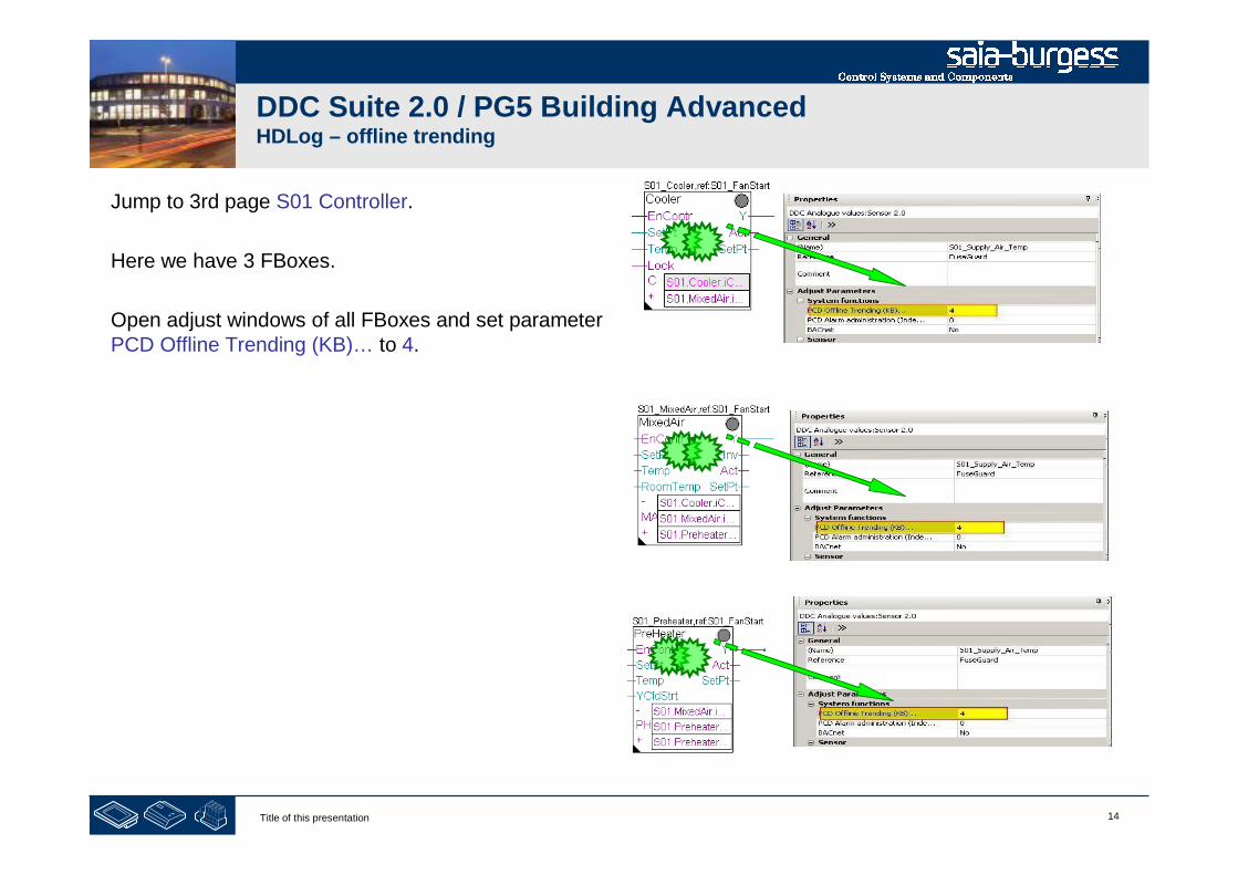
Jump to 3rd page S01 Controller.
Here we have 3 FBoxes.
Open adjust windows of all FBoxes and set parameterPCD Offline Trending (KB)… to 4.
15Title of this presentation
DDC Suite 2.0 / PG5 Building AdvancedHDLog – offline trending
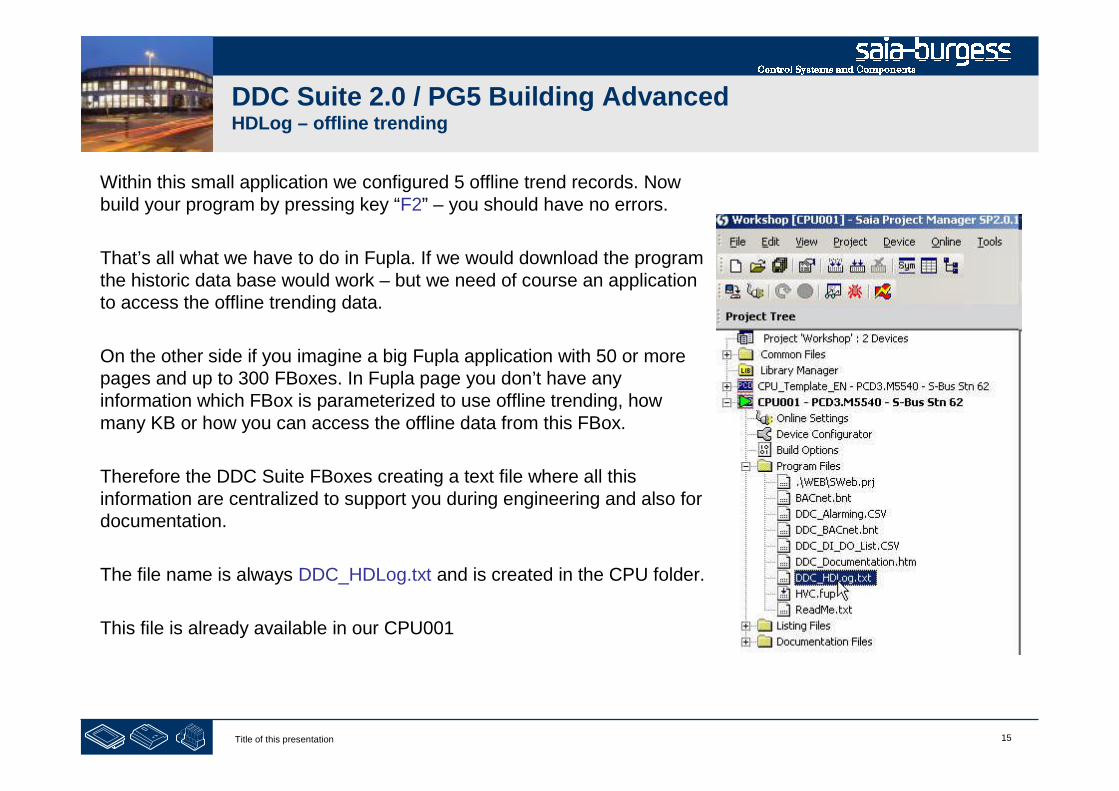
Within this small application we configured 5 offline trend records. Nowbuild your program by pressing key “F2” – you should have no errors.
That’s all what we have to do in Fupla. If we would download the programthe historic data base would work – but we need of course an applicationto access the offline trending data.
On the other side if you imagine a big Fupla application with 50 or morepages and up to 300 FBoxes. In Fupla page you don’t have anyinformation which FBox is parameterized to use offline trending, howmany KB or how you can access the offline data from this FBox.
Therefore the DDC Suite FBoxes creating a text file where all thisinformation are centralized to support you during engineering and also fordocumentation.
The file name is always DDC_HDLog.txt and is created in the CPU folder.
This file is already available in our CPU001
16Title of this presentation
DDC Suite 2.0 / PG5 Building AdvancedHDLog – offline trending
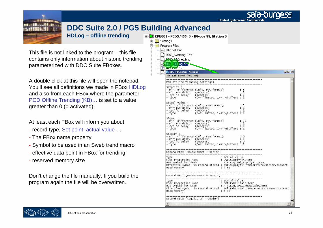
This file is not linked to the program – this filecontains only information about historic trendingparameterized with DDC Suite FBoxes.
A double click at this file will open the notepad.You’ll see all definitions we made in FBox HDLogand also from each FBox where the parameterPCD Offline Trending (KB)… is set to a valuegreater than 0 (= activated).
At least each FBox will inform you about
- record type, Set point, actual value …
- The FBox name property
- Symbol to be used in an Sweb trend macro
- effective data point in FBox for trending
- reserved memory size
Don’t change the file manually. If you build theprogram again the file will be overwritten.

17Title of this presentation
DDC Suite 2.0 / PG5 Building AdvancedHDLog – offline trending
At this point we have created a small and nice air condition application. In real life it would be bigger withmuch more FBoxes or symbols – but we can reuse this in future if we store it as template.
Therefore we export this application as tempalte.Click on Page in menu and in context menu entryExport…
Type in file name, use AirCondition_HDLog andpress button Export

18Title of this presentation
DDC Suite 2.0 / PG5 Building AdvancedHDLog – offline trending
Within Dialog Export Pages select option All andfinish with button OK.
End of engineering a Fupla application. With DDC Suite FBoxes we reduce themanual work to define symbols for FBoxes – only the symbols in the sideconnectors must be defined manually.

19Title of this presentation
PG5 Building Advanced / DDC Suite 2.0HDLog – offline trending
HDLog with DDC Suite
Accessing data within SWeb

20Title of this presentation
DDC Suite 2.0 / PG5 Building AdvancedHDLog – offline trending
We will create a fast Sweb application.
First open your Web Editor Project (Sweb.prj)
21Title of this presentation
DDC Suite 2.0 / PG5 Building AdvancedHDLog – offline trending
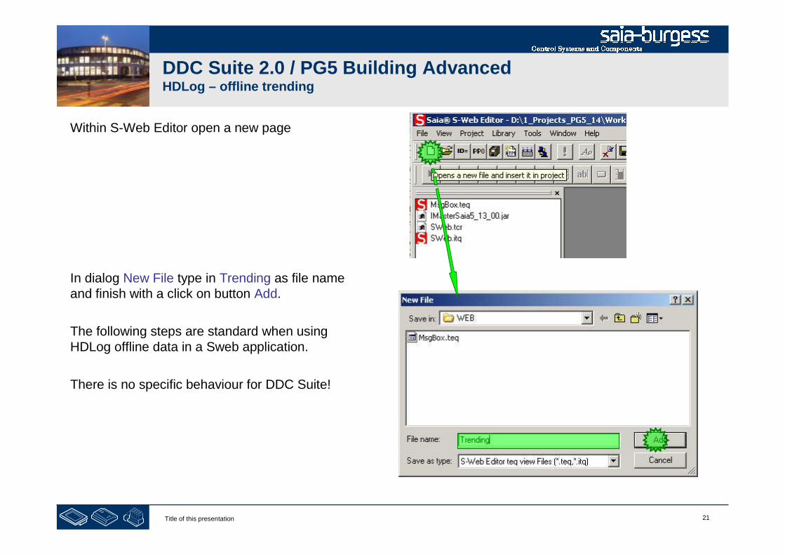
Within S-Web Editor open a new page
In dialog New File type in Trending as file nameand finish with a click on button Add.
The following steps are standard when usingHDLog offline data in a Sweb application.
There is no specific behaviour for DDC Suite!

22Title of this presentation
DDC Suite 2.0 / PG5 Building AdvancedHDLog – offline trending
The new page Trending.teqappears and we have to add atrend macro.
Insert a Macro …

23Title of this presentation
DDC Suite 2.0 / PG5 Building AdvancedHDLog – offline trending
Within Select_Insert macro From librarydialog
- Select folder SaiaTrendMacro
- then OfflineTrendComplete_5_13_01.esm
And in dialog Configure Macro Infos onmacro instance just click on button OK.
24Title of this presentation
DDC Suite 2.0 / PG5 Building AdvancedHDLog – offline trending
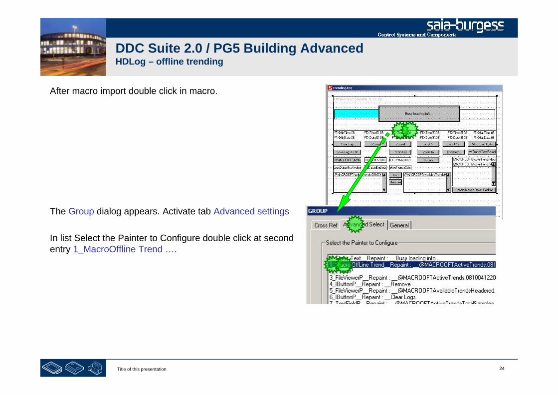
After macro import double click in macro.
The Group dialog appears. Activate tab Advanced settings
In list Select the Painter to Configure double click at secondentry 1_MacroOffline Trend ….
25Title of this presentation
DDC Suite 2.0 / PG5 Building AdvancedHDLog – offline trending
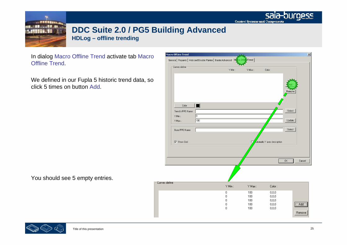
In dialog Macro Offline Trend activate tab MacroOffline Trend.
We defined in our Fupla 5 historic trend data, soclick 5 times on button Add.
You should see 5 empty entries.
26Title of this presentation
DDC Suite 2.0 / PG5 Building AdvancedHDLog – offline trending
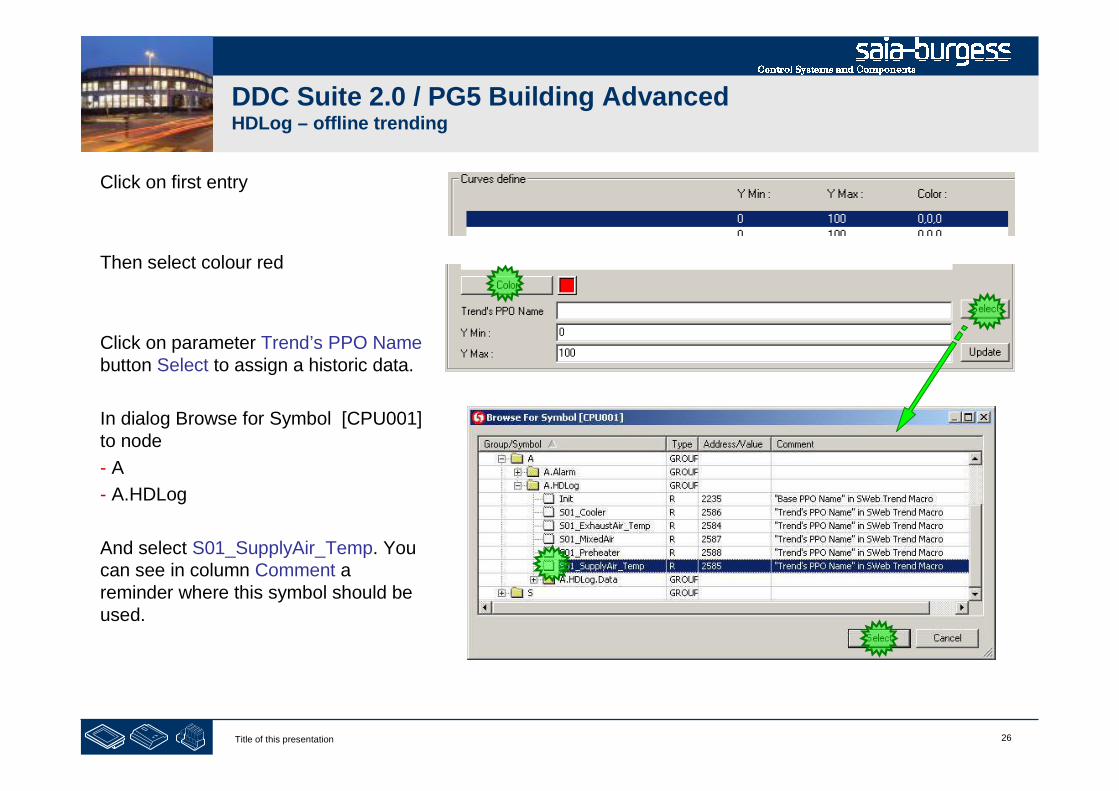
Click on first entry
Then select colour red
Click on parameter Trend’s PPO Namebutton Select to assign a historic data.
In dialog Browse for Symbol [CPU001]to node
- A
- A.HDLog
And select S01_SupplyAir_Temp. Youcan see in column Comment areminder where this symbol should beused.

27Title of this presentation
DDC Suite 2.0 / PG5 Building AdvancedHDLog – offline trending
You see the DDC Suite FBox uses the FBox name property to generate automatically a symbol in symbol editorwithin system tab, group A.HDLog.
Therefore it’s necessary to define always the FBox name property – it’s also in use for other features …

28Title of this presentation
DDC Suite 2.0 / PG5 Building AdvancedHDLog – offline trending
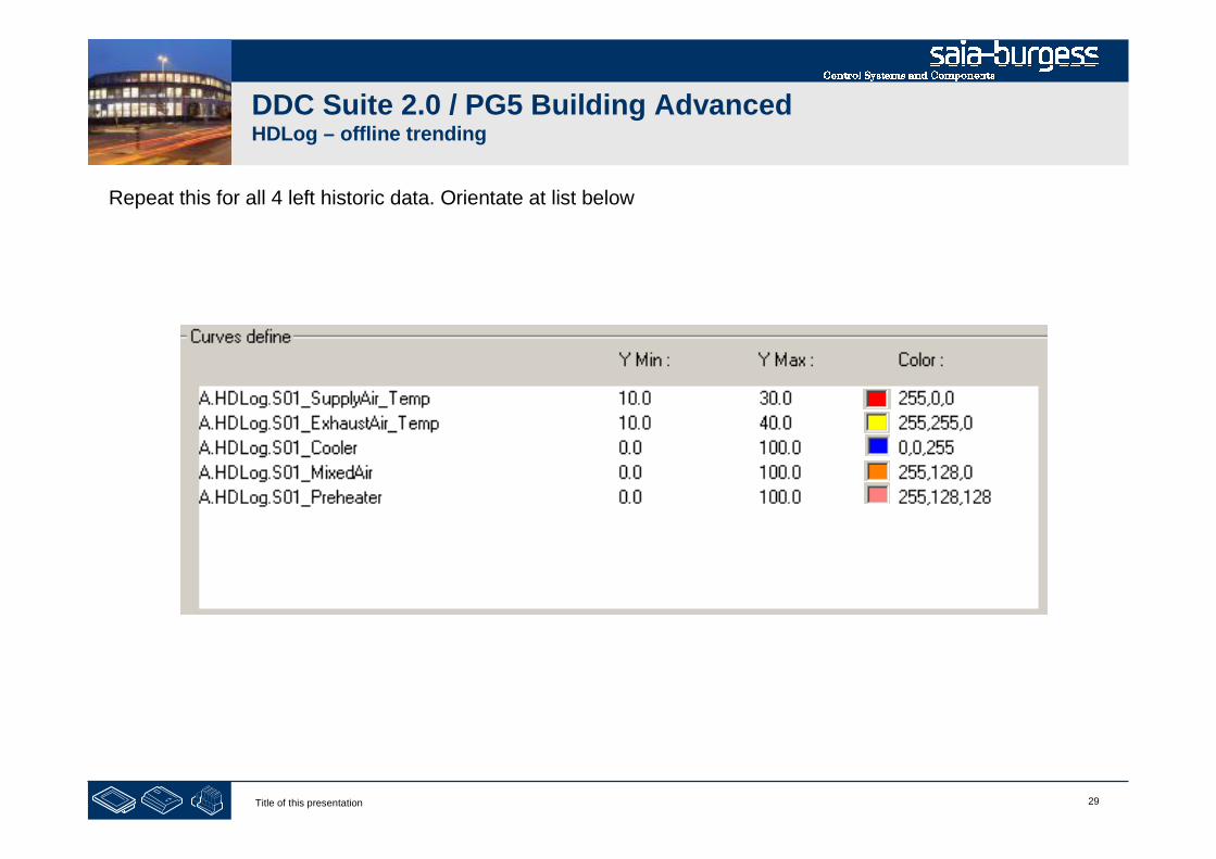
Set parameter
Y-Min: to 10.0
Y-Max: to 30.0
And click on button Update.
29Title of this presentation
DDC Suite 2.0 / PG5 Building AdvancedHDLog – offline trending
Repeat this for all 4 left historic data. Orientate at list below
30Title of this presentation
DDC Suite 2.0 / PG5 Building AdvancedHDLog – offline trending
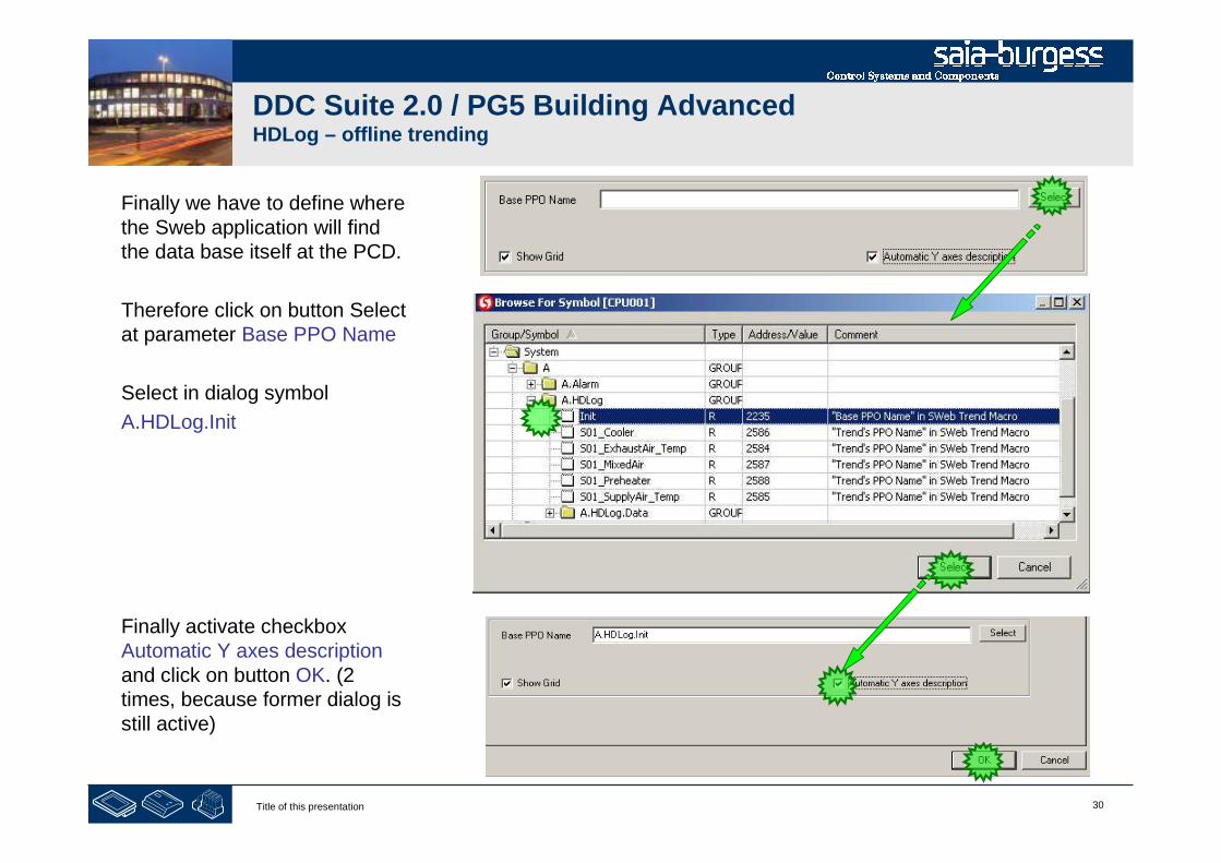
Finally we have to define wherethe Sweb application will findthe data base itself at the PCD.
Therefore click on button Selectat parameter Base PPO Name
Select in dialog symbol
A.HDLog.Init
Finally activate checkboxAutomatic Y axes descriptionand click on button OK. (2times, because former dialog isstill active)
31Title of this presentation
DDC Suite 2.0 / PG5 Building AdvancedHDLog – offline trending
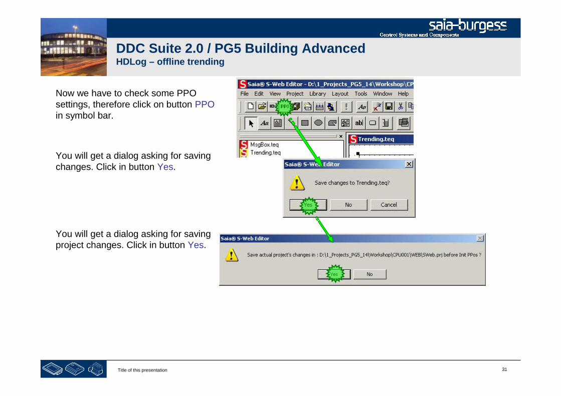
Now we have to check some PPOsettings, therefore click on button PPOin symbol bar.
You will get a dialog asking for savingchanges. Click in button Yes.
You will get a dialog asking for savingproject changes. Click in button Yes.

32Title of this presentation
DDC Suite 2.0 / PG5 Building AdvancedHDLog – offline trending
You will see the PPOs Initialisationlist.
We have to define the format for allsymbols containing to S01 aircondition.
Set Format to DEC.1
The format for A.HDLog.Init staysunchanged (DEC).
End by clicking on button OK.
33Title of this presentation
DDC Suite 2.0 / PG5 Building AdvancedHDLog – offline trending
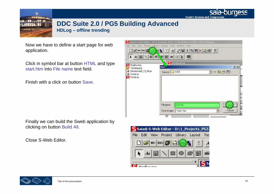
Now we have to define a start page for webapplication.
Click in symbol bar at button HTML and typestart.htm into File name text field.
Finish with a click on button Save.
Finally we can build the Sweb application byclicking on button Build All.
Close S-Web Editor.
34Title of this presentation
DDC Suite 2.0 / PG5 Building AdvancedHDLog – offline trending
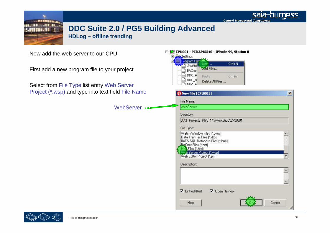
Now add the web server to our CPU.
First add a new program file to your project.
Select from File Type list entry Web ServerProject (*.wsp) and type into text field File Name
WebServer

35Title of this presentation
DDC Suite 2.0 / PG5 Building AdvancedHDLog – offline trending
Select within SAIA – Web-Builder-C all files and add then to list WEB Server Content.
Press button Generate, close Web Builder and build in PG5 the CPU, download .
1Title of this presentation
PG5 Building Advanced / DDC Suite 2.0SWeb alarming
SWeb alarming

2Title of this presentation
DDC Suite 2.0 / PG5 Building AdvancedSWeb alarming
To use SWeb alarming functionality in a PCDwe have to use the FBox family Alarming –available since 2 years.
An Alarm SWeb FBox implements the corefunctionality, allocating memory and providesan interface to Sweb or via CGI calls.
3Title of this presentation
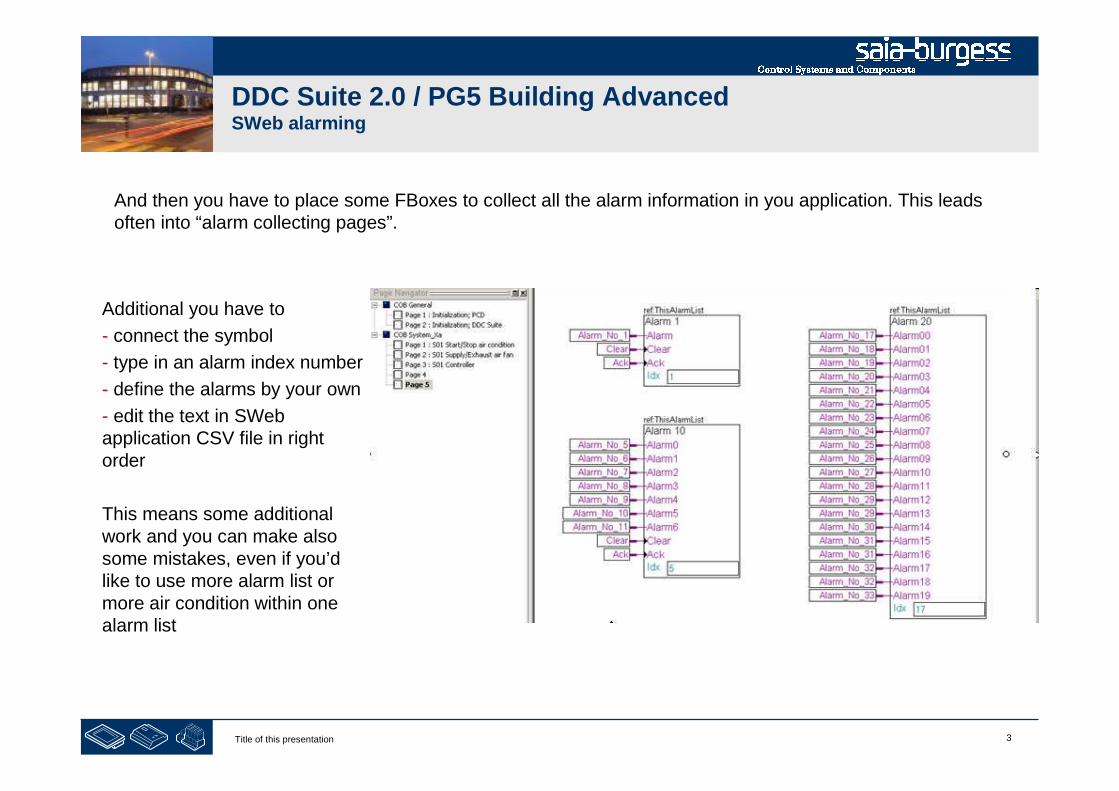
DDC Suite 2.0 / PG5 Building AdvancedSWeb alarming
And then you have to place some FBoxes to collect all the alarm information in you application. This leadsoften into “alarm collecting pages”.
Additional you have to
- connect the symbol
- type in an alarm index number
- define the alarms by your own
- edit the text in SWebapplication CSV file in rightorder
This means some additionalwork and you can make alsosome mistakes, even if you’dlike to use more alarm list ormore air condition within onealarm list

4Title of this presentation
PG5 Building Advanced / DDC Suite 2.0SWeb alarming
Alarming with DDC Suite
Basics
5Title of this presentation
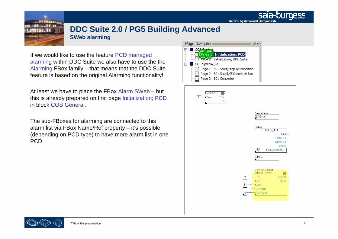
DDC Suite 2.0 / PG5 Building AdvancedSWeb alarming
If we would like to use the feature PCD managedalarming within DDC Suite we also have to use the theAlarming FBox family – that means that the DDC Suitefeature is based on the original Alarming functionality!
At least we have to place the FBox Alarm SWeb – butthis is already prepared on first page Initialization; PCDin block COB General.
The sub-FBoxes for alarming are connected to thisalarm list via FBox Name/Ref property – it’s possible(depending on PCD type) to have more alarm list in onePCD.

6Title of this presentation
DDC Suite 2.0 / PG5 Building AdvancedSWeb alarming
Lets start to define the alarms for SWeb forthe air condition.
Activate page S01 Start/Stop air condition inblock COB System_X.
To activate alarm management in DDC SuiteFBoxes we don’t have to set additionalFBoxes – all DDC Suite FBoxes supportingalarm management will have an entry inadjust window

7Title of this presentation
DDC Suite 2.0 / PG5 Building AdvancedSWeb alarming
The DDC Suite FBoxes have always ontop in adjust window a group named [---System functions ---].
Herein the FBox provides differentfeatures depending at the functionalityof the FBox.
To activate alarm management theparameter PCD Alarm administration(Index)… must be parameterized.
Value 0 disables alarm managemt inthis FBox, any other value defines thebase alarm index for the first alarm inthis FBox. This is the same like in theoriginal Alarm FBoxes.
8Title of this presentation
DDC Suite 2.0 / PG5 Building AdvancedSWeb alarming
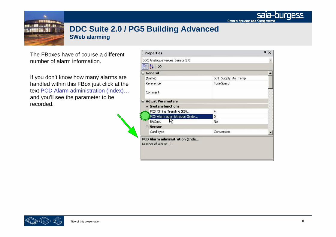
The FBoxes have of course a differentnumber of alarm information.
If you don’t know how many alarms arehandled within this FBox just click at thetext PCD Alarm administration (Index)…and you’ll see the parameter to berecorded.

9Title of this presentation
PG5 Building Advanced / DDC Suite 2.0SWeb alarming
Alarming with DDC Suite
In use
10Title of this presentation
DDC Suite 2.0 / PG5 Building AdvancedSWeb alarming
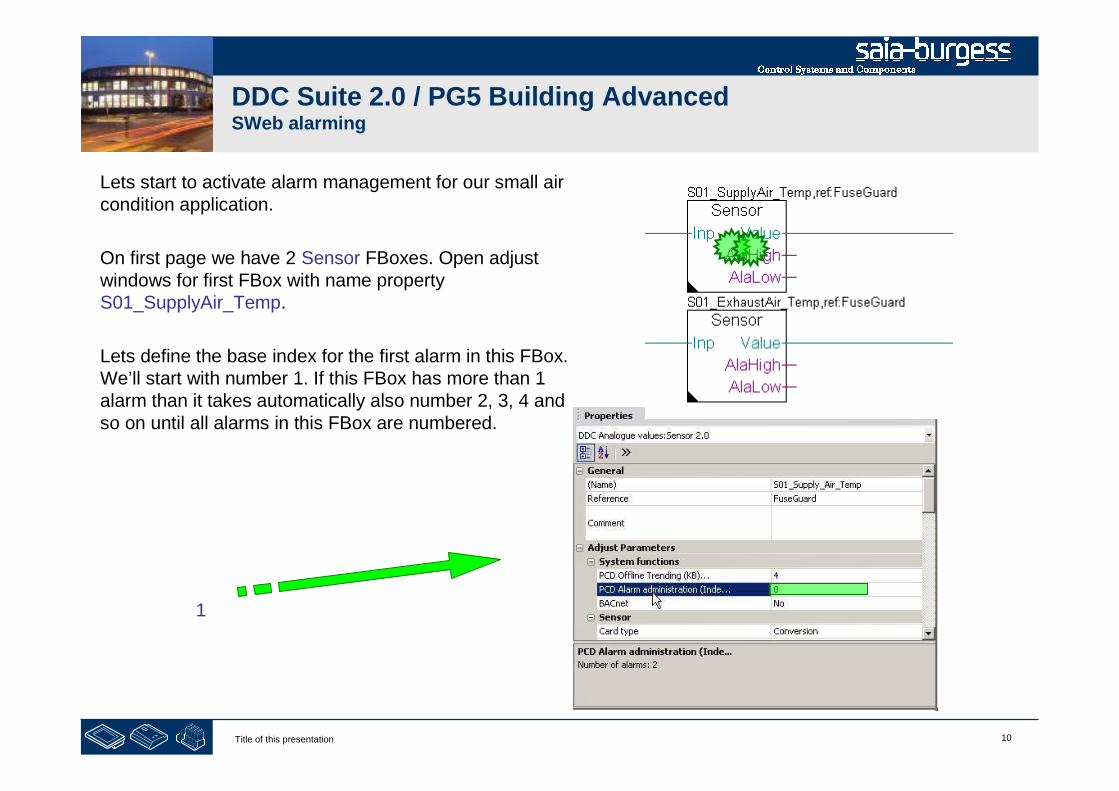
Lets start to activate alarm management for our small aircondition application.
On first page we have 2 Sensor FBoxes. Open adjustwindows for first FBox with name propertyS01_SupplyAir_Temp.
Lets define the base index for the first alarm in this FBox.We’ll start with number 1. If this FBox has more than 1alarm than it takes automatically also number 2, 3, 4 andso on until all alarms in this FBox are numbered.
1
11Title of this presentation
DDC Suite 2.0 / PG5 Building AdvancedSWeb alarming
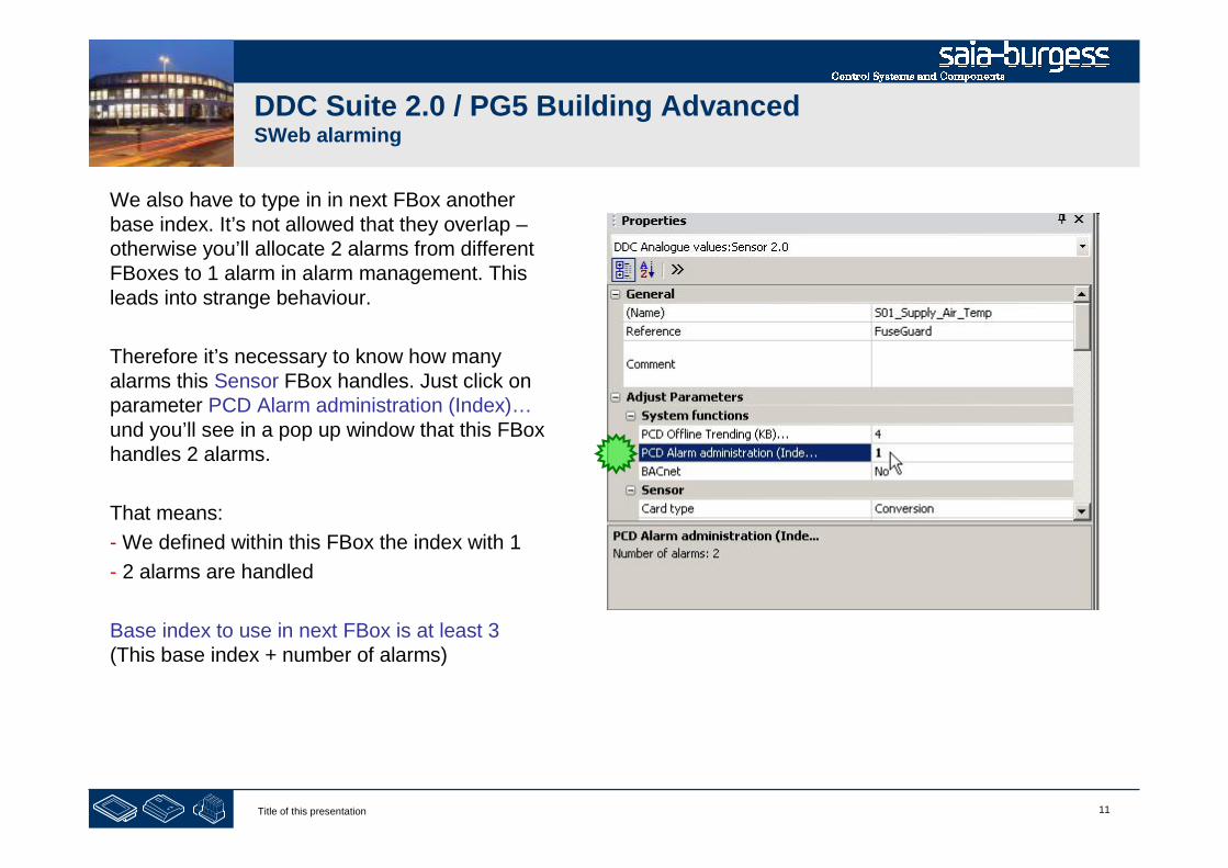
We also have to type in in next FBox anotherbase index. It’s not allowed that they overlap –otherwise you’ll allocate 2 alarms from differentFBoxes to 1 alarm in alarm management. Thisleads into strange behaviour.
Therefore it’s necessary to know how manyalarms this Sensor FBox handles. Just click onparameter PCD Alarm administration (Index)…und you’ll see in a pop up window that this FBoxhandles 2 alarms.
That means:
- We defined within this FBox the index with 1
- 2 alarms are handled
Base index to use in next FBox is at least 3(This base index + number of alarms)

12Title of this presentation
DDC Suite 2.0 / PG5 Building AdvancedSWeb alarming
Open adjust windows for first FBox with nameproperty S01_ExhaustAir_Temp.
The base index we calculated for next FBox is3, type in in parameter PCD Alarmadministration (Index)…
Now we can check again how many alarms thisFBox handles. Again 2 – so base index for nextFBox is calculated 3+2 = 5
3
13Title of this presentation
DDC Suite 2.0 / PG5 Building AdvancedSWeb alarming
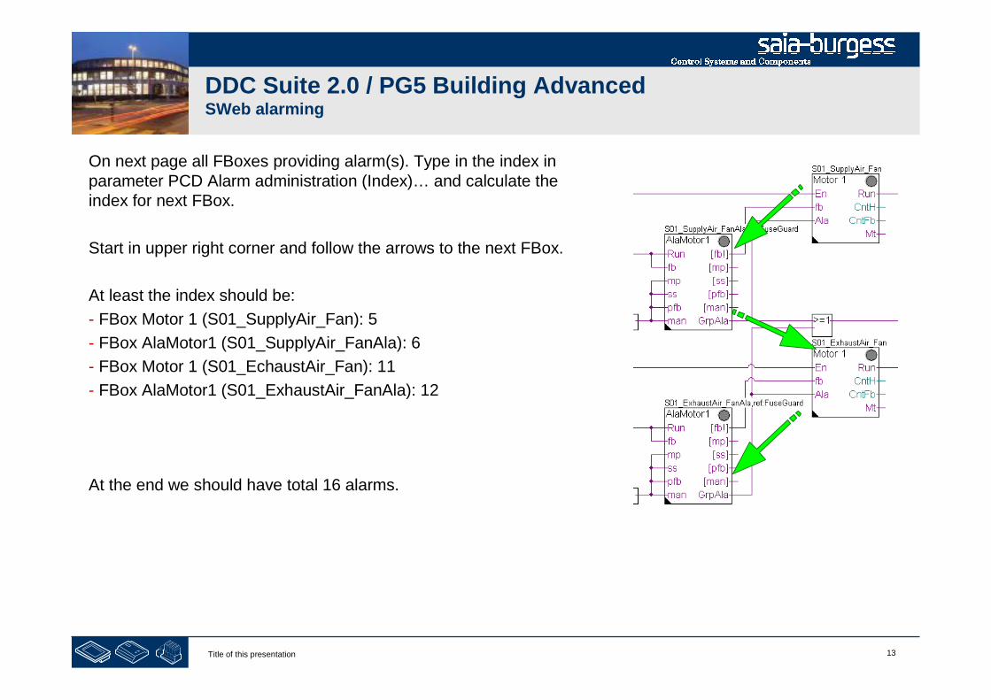
On next page all FBoxes providing alarm(s). Type in the index inparameter PCD Alarm administration (Index)… and calculate theindex for next FBox.
Start in upper right corner and follow the arrows to the next FBox.
At least the index should be:
- FBox Motor 1 (S01_SupplyAir_Fan): 5
- FBox AlaMotor1 (S01_SupplyAir_FanAla): 6
- FBox Motor 1 (S01_EchaustAir_Fan): 11
- FBox AlaMotor1 (S01_ExhaustAir_FanAla): 12
At the end we should have total 16 alarms.

14Title of this presentation
DDC Suite 2.0 / PG5 Building AdvancedSWeb alarming
So far – so good. But if we have more than 1 alarm list – how dothe DDC Suite FBoxes know to which alarm list the alarm have tobe assigned?
The FBoxes from FBox family Alarming are using the Name/Refmechanism to assign an FBox to an alarm list – but the DDC SuiteFBoxes are using already the FBox property Ref. So we must haveanother possibility.
Therefore we in DDC Suite FBox family DDC Initialisation theFBox Alarm Header 2.0.
Place this FBox on first page in the
Upper left corner.
15Title of this presentation
DDC Suite 2.0 / PG5 Building AdvancedSWeb alarming
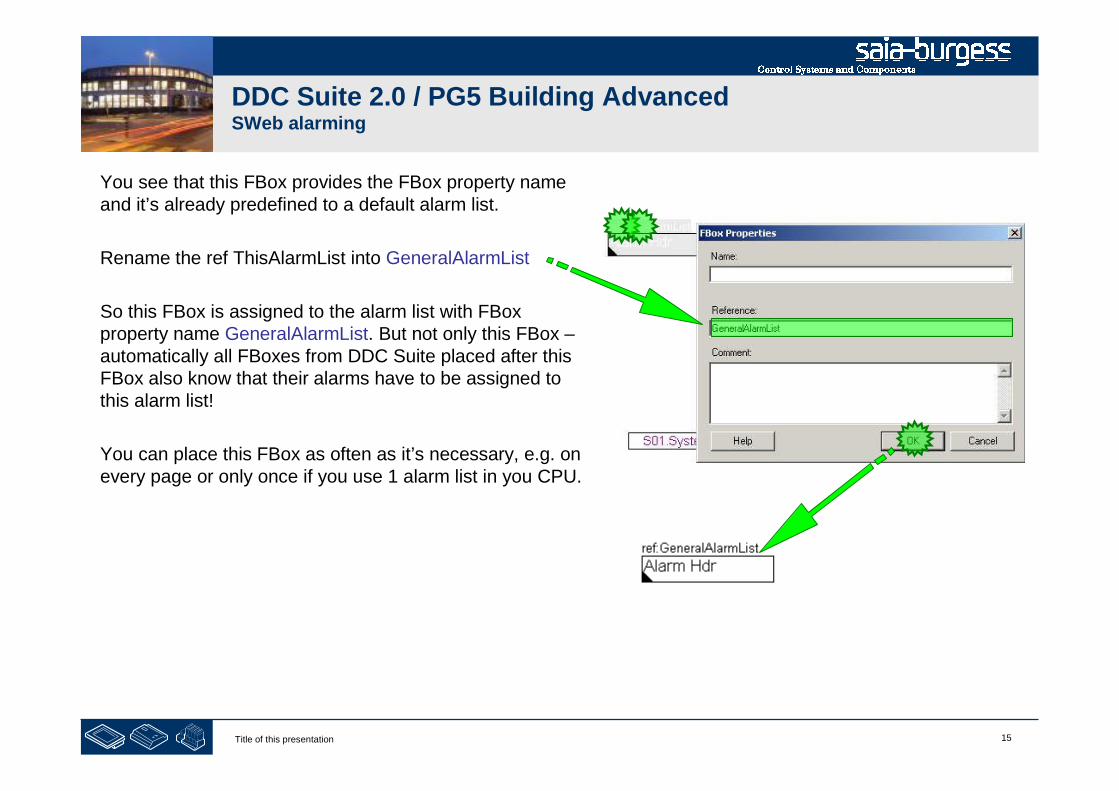
You see that this FBox provides the FBox property nameand it’s already predefined to a default alarm list.
Rename the ref ThisAlarmList into GeneralAlarmList
So this FBox is assigned to the alarm list with FBoxproperty name GeneralAlarmList. But not only this FBox –automatically all FBoxes from DDC Suite placed after thisFBox also know that their alarms have to be assigned tothis alarm list!
You can place this FBox as often as it’s necessary, e.g. onevery page or only once if you use 1 alarm list in you CPU.
16Title of this presentation
DDC Suite 2.0 / PG5 Building AdvancedSWeb alarming
So we defined all alarm numbers and also the alarm list.Build the program. Now we could start to implement theAlarm macro in Sweb application – but I don’t know whichalarm in a FBox is assigned as second or third alarm andalso I cannot see any Information in Fupla itself or insymbol editor.
So this means the alarms are “hidden” – not really useful.
But the DDC Suite FBoxes are creating during buildprocess automatically a file with name DDC_Alarming.csv.
This file is already listed in CPU Program Files folder.
Double click on it, Excel should open this file.

17Title of this presentation
DDC Suite 2.0 / PG5 Building AdvancedSWeb alarming
The CSV file contains 4 columns
A: to which alarm list the alarm isassigned
B: alarm number in alarmadministration
C: same as B but with prefix “Alarm_”
D: alarm text
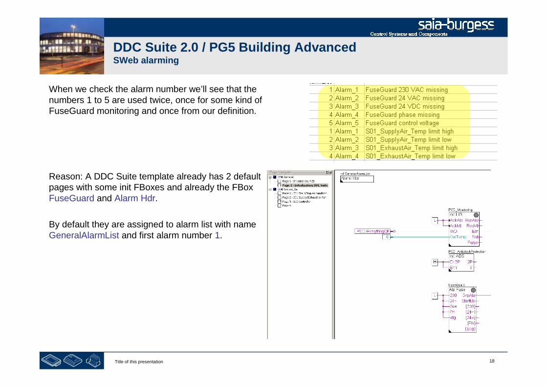
18Title of this presentation
DDC Suite 2.0 / PG5 Building AdvancedSWeb alarming
When we check the alarm number we’ll see that thenumbers 1 to 5 are used twice, once for some kind ofFuseGuard monitoring and once from our definition.
Reason: A DDC Suite template already has 2 defaultpages with some init FBoxes and already the FBoxFuseGuard and Alarm Hdr.
By default they are assigned to alarm list with nameGeneralAlarmList and first alarm number 1.

19Title of this presentation
DDC Suite 2.0 / PG5 Building AdvancedSWeb alarming
So we have to re-address the alarms – but this is donevery fast and quite smart. In CSV file we see that 1 to 5 isused twice – but maybe it would be better to reserve 6 to10 and start with alarm number 11 in our air conditionapplication.
1. Close Excel2. Jump to first page S01 Start/Stop air condition3. open adjust window from FBox Alarm Hdr4. modify parameter Base alarm index from 1 to 11
5. Close adjust parameter6. Build program (use key “F2”)7. open file DDC_Alarming.csv in PG5 project manager

20Title of this presentation
DDC Suite 2.0 / PG5 Building AdvancedSWeb alarming
This looks much better – and it’s very easy to “move”alarms numbers for a complete application (e.g. the aircondition) instead of renumbering within each FBox.
Lets have a look at column C. The alarm text is createdautomatically. The FBox using this method:
Use FBox property name and add a detailed information –because one FBox may have more than one alarm.
So the first part can be defined by yourself.
(To modify detailed information see chapter Swebalarming - advanced)

21Title of this presentation
DDC Suite 2.0 / PG5 Building AdvancedSWeb alarming
At this point we have created a small and nice air condition application. In real life it would be bigger withmuch more FBoxes or symbols – but we can reuse this in future if we store it as template.
Therefore we export this application as tempalte.Click on Page in menu and in context menu entryExport…
Type in file name, useAirCondition_HDLog_Alarm and press buttonExport

22Title of this presentation
DDC Suite 2.0 / PG5 Building AdvancedSWeb alarming
Within Dialog Export Pages select option All andfinish with button OK.
End of engineering a Fupla application. With DDC Suite FBoxes we reduce themanual work to define symbols for FBoxes – only the symbols in the sideconnectors must be defined manually.

23Title of this presentation
PG5 Building Advanced / DDC Suite 2.0SWeb alarming
Using alarm text in Sweb application

24Title of this presentation
DDC Suite 2.0 / PG5 Building AdvancedSWeb alarming
OK – back to SWeb engineering. Now we have aCSV file with all necessary information.
Open S-Web Editor
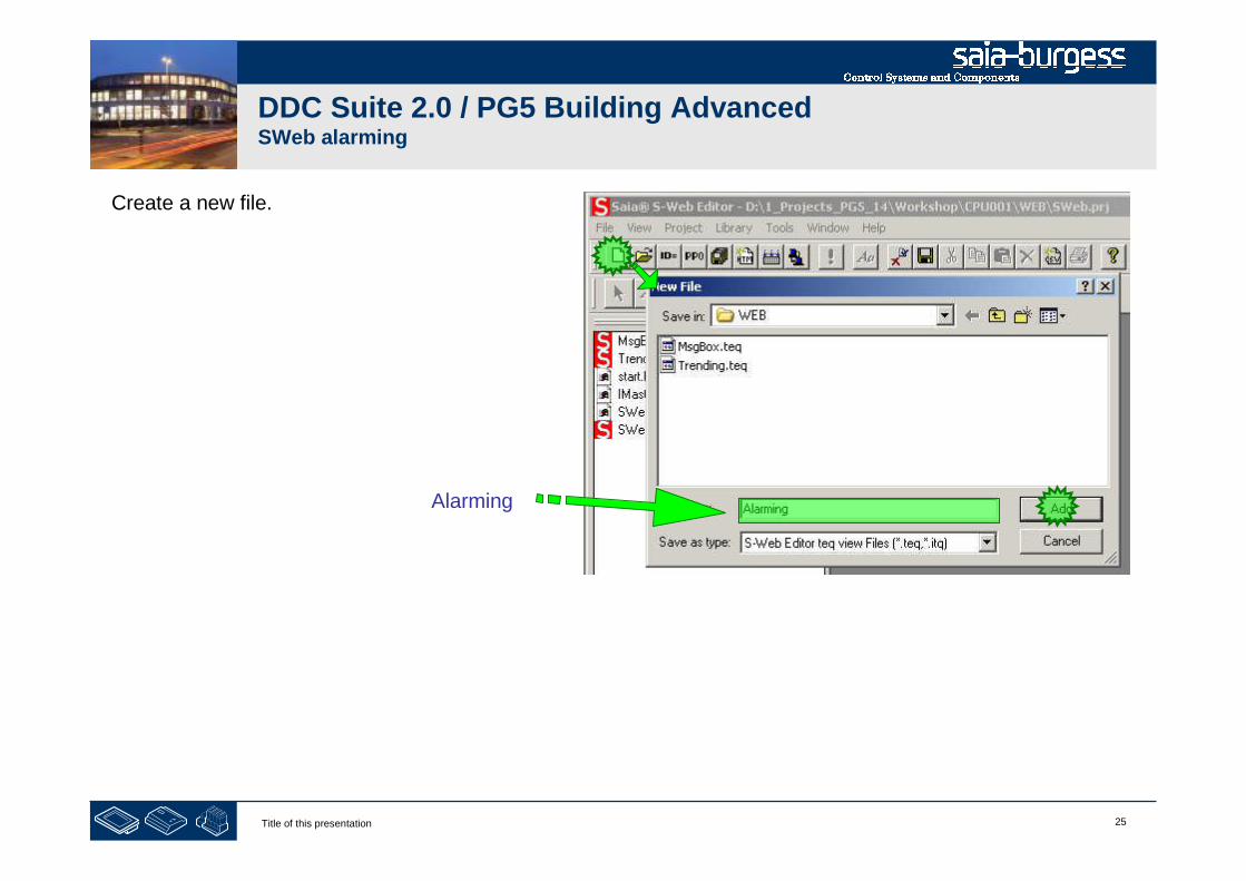
25Title of this presentation
DDC Suite 2.0 / PG5 Building AdvancedSWeb alarming
Create a new file.
Alarming
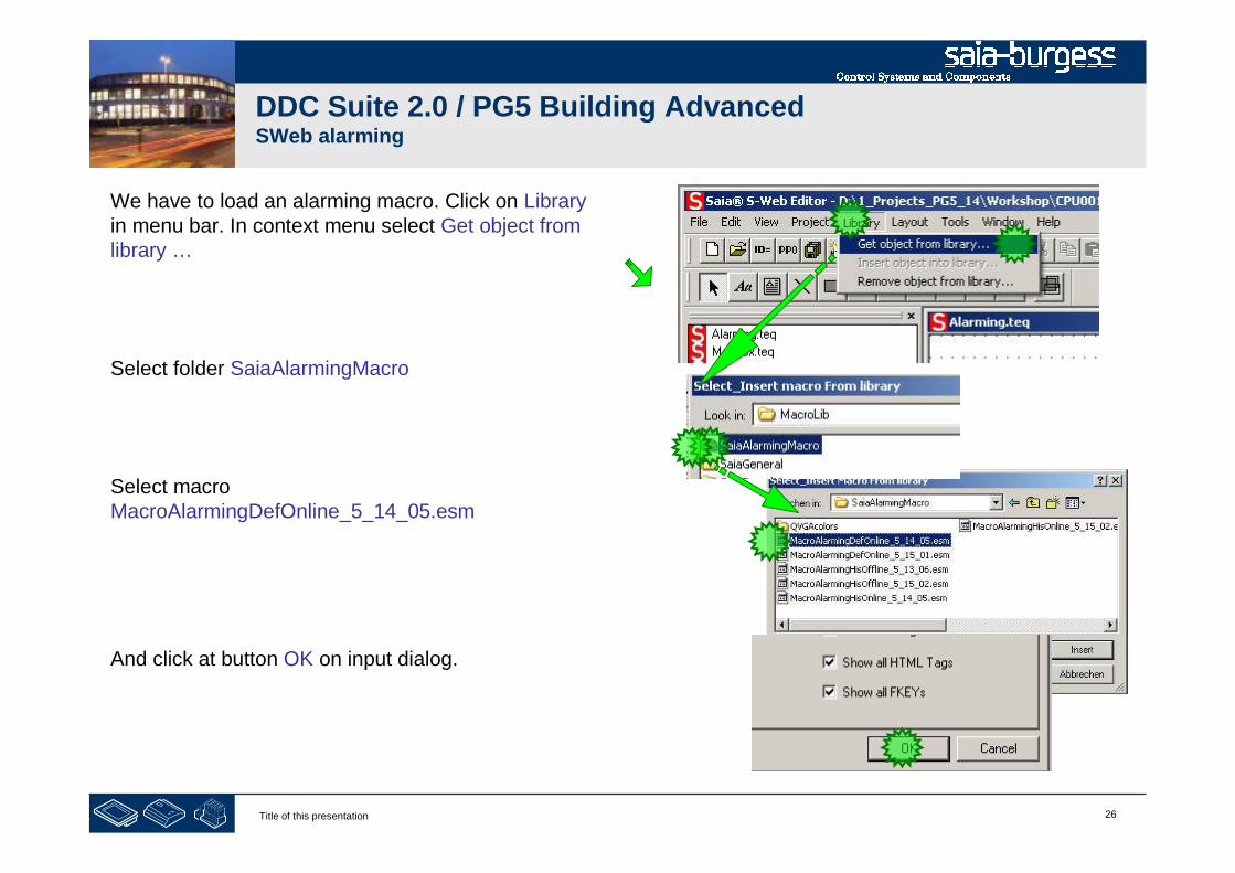
26Title of this presentation
DDC Suite 2.0 / PG5 Building AdvancedSWeb alarming
We have to load an alarming macro. Click on Libraryin menu bar. In context menu select Get object fromlibrary …
Select folder SaiaAlarmingMacro
Select macroMacroAlarmingDefOnline_5_14_05.esm
And click at button OK on input dialog.

27Title of this presentation
DDC Suite 2.0 / PG5 Building AdvancedSWeb alarming
After macro import double click in macro.
The Group dialog appears. Activate tab Advanced settings
In list Select the Painter to Configure double click at firstentry 0_Macro DefOnlineAlarm ….

28Title of this presentation
DDC Suite 2.0 / PG5 Building AdvancedSWeb alarming
In dialog Macro DefOnlineAlarm activate tab MacroAlarming.
First we have to define which alarm list we’d like toshow in this view. Therefore click on buttonSelect at parameter Alarm List PPO Name.
Select from group
- System
- System.A
- System.A.Alarm
- System.A.Alarm.GeneralAlarmList
Entry MyHandle end click on button Select.
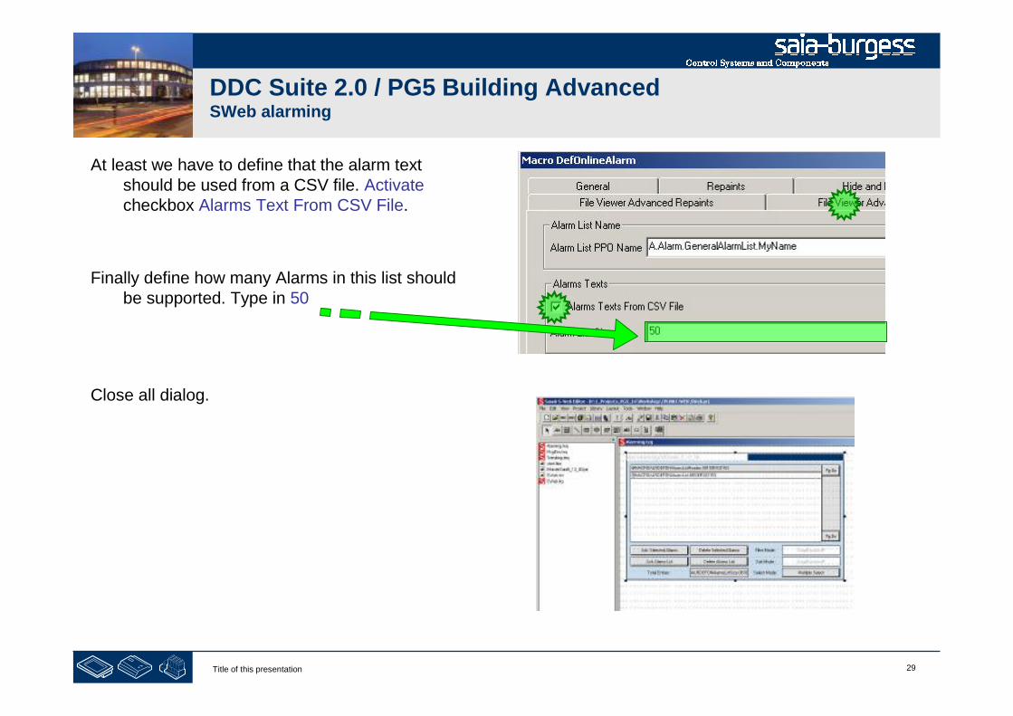
29Title of this presentation
DDC Suite 2.0 / PG5 Building AdvancedSWeb alarming
At least we have to define that the alarm textshould be used from a CSV file. Activatecheckbox Alarms Text From CSV File.
Finally define how many Alarms in this list shouldbe supported. Type in 50
Close all dialog.
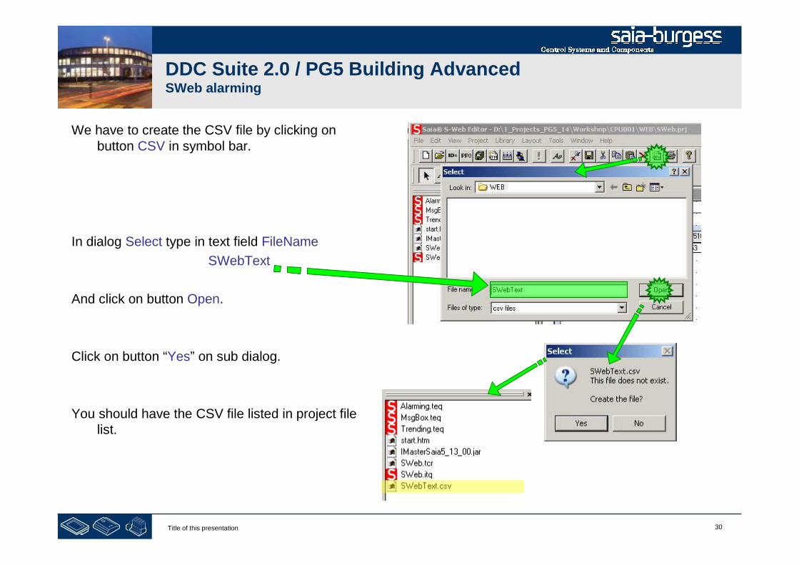
30Title of this presentation
DDC Suite 2.0 / PG5 Building AdvancedSWeb alarming
We have to create the CSV file by clicking onbutton CSV in symbol bar.
In dialog Select type in text field FileName
SWebText
And click on button Open.
Click on button “Yes” on sub dialog.
You should have the CSV file listed in project filelist.
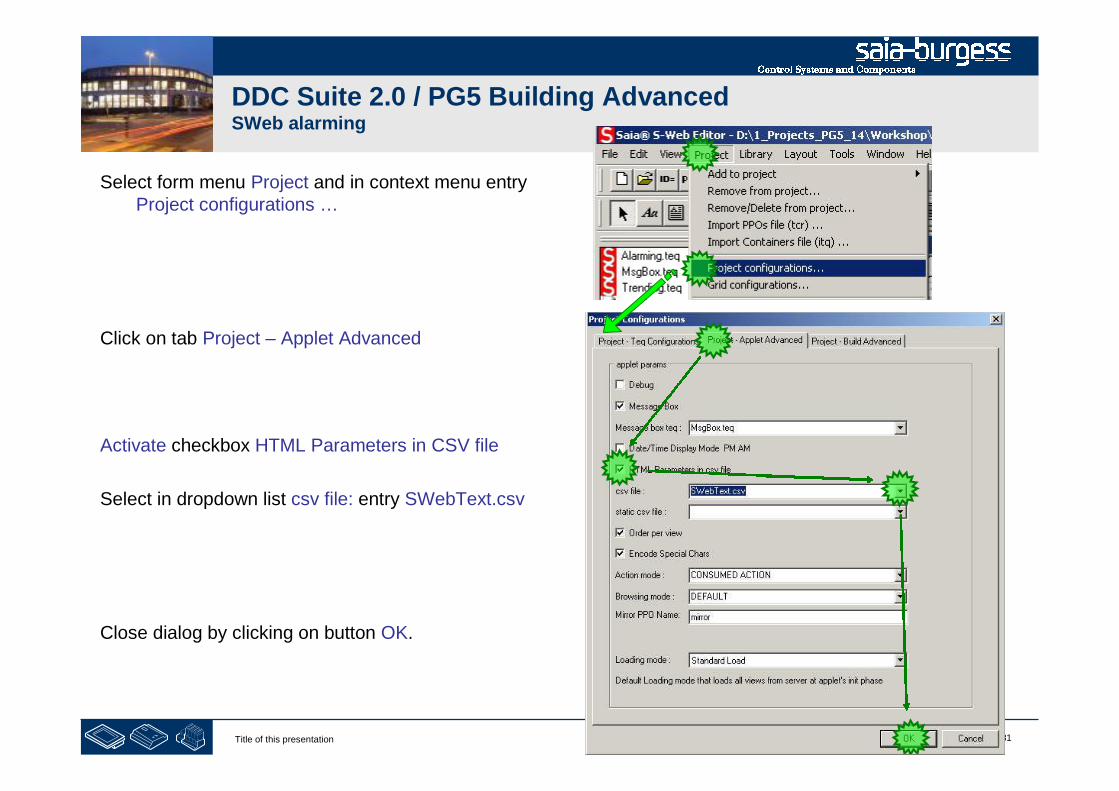
31Title of this presentation
DDC Suite 2.0 / PG5 Building AdvancedSWeb alarming
Select form menu Project and in context menu entryProject configurations …
Click on tab Project – Applet Advanced
Activate checkbox HTML Parameters in CSV file
Select in dropdown list csv file: entry SWebText.csv
Close dialog by clicking on button OK.
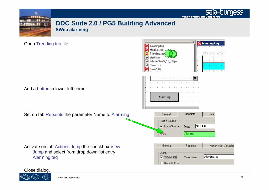
32Title of this presentation
DDC Suite 2.0 / PG5 Building AdvancedSWeb alarming
Open Trending.teq file
Add a button in lower left corner
Set on tab Repaints the parameter Name to Alarming
Activate on tab Actions Jump the checkbox ViewJump and select from drop down list entryAlarming.teq
Close dialog.

33Title of this presentation
DDC Suite 2.0 / PG5 Building AdvancedSWeb Alarming
To create the default Alarm text’swe have to press the button orchoose the command“Generate HTMLTAGS CSV File”from the project menu.
34Title of this presentation
PG5 Building Advanced / DDC Suite 2.0SWeb alarming
Alarming with DDC Suite
AddOn tool

35Title of this presentation
DDC Suite 2.0 / PG5 Building AdvancedSWeb alarming
The new DDC Suite Addon Tool is automatically installed with PG5 2.0.200
The DDC Suite Addon Tool merges the Alarm text’s from the DDC_Alarming.csv into theSWebText.csv file, that is used by the Web Alarming Macro.

36Title of this presentation
DDC Suite 2.0 / PG5 Building AdvancedSWeb alarming
In the project, right click on "Program Files"Select the "File Type" DDC Suite (*.ddc):
Take care that the Option “Linked/Built” has tobe deactivated.
Choose a nice name i.e. DDC_Addon.ddc

37Title of this presentation
DDC Suite 2.0 / PG5 Building AdvancedSWeb alarming
The Addon tool recognizes thepath to the CPU folder andwrites per default into theSWebText.csv file.
You can also choose a differentoutput file by clicking the“Browse” button (if you did notuse a DDC Suite template).

38Title of this presentation
DDC Suite 2.0 / PG5 Building AdvancedSWeb alarming
Click on button Generate.
.
If the update has been successful a Success text appears in the status bar

39Title of this presentation
DDC Suite 2.0 / PG5 Building AdvancedSWeb alarming
When you check theSWebText.scv file you’ll seethat the alarm text has beenupdated completely.
Undefined alarms inDDC_Alarming.csv are removedand replaced with a “-”.
The AddOn tool will walkthrough all alarms defined in theSWebText.csv file and replaceunused alarm with a “-”! If youtype in manually a text in anunused alarm you’ll loos thisinformation!

40Title of this presentation
DDC Suite 2.0 / PG5 Building AdvancedSWeb alarming
Back in S-Web Editor.
- save the project by clicking on disk symbol button
- Build the S-Web project by clicking on build button
Close S-Web Editor.
Open WebServer project from PG5 project manager
Select from left list
- Alarming.teq
- SWebText.csv
Click on button Add, press Generate
End WebServer.
Build program in PG5 project manager
Download program into PCD

1Title of this presentation
PG5 Building Advanced / DDC Suite 2.0SWeb alarming
SWeb alarming - advanced

2Title of this presentation
DDC Suite 2.0 / PG5 Building AdvancedSWeb alarming
Remember – the alarm text is created by
FBox property Name
detailed information – because one FBox may havemore than one alarm
So the first part can be defined by yourself – but thesecond part is “hard coded in FBox”, e.g. the FBox“Sensor” from family “Analogue values” supports 2 alarm,“limit low” and “limit high”.
How can this default texts customized?
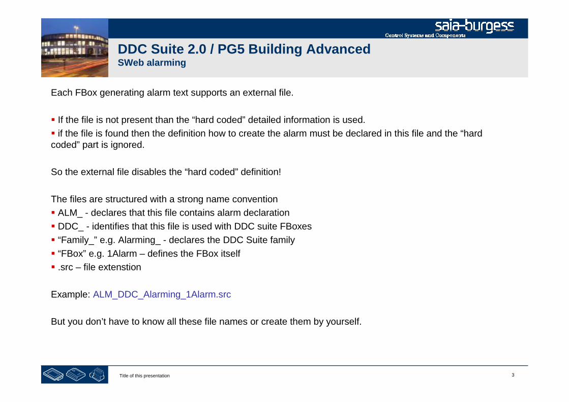
3Title of this presentation
DDC Suite 2.0 / PG5 Building AdvancedSWeb alarming
Each FBox generating alarm text supports an external file.
If the file is not present than the “hard coded” detailed information is used.
if the file is found then the definition how to create the alarm must be declared in this file and the “hardcoded” part is ignored.
So the external file disables the “hard coded” definition!
The files are structured with a strong name convention
ALM_ - declares that this file contains alarm declaration
DDC_ - identifies that this file is used with DDC suite FBoxes
“Family_” e.g. Alarming_ - declares the DDC Suite family
“FBox” e.g. 1Alarm – defines the FBox itself
.src – file extenstion
Example: ALM_DDC_Alarming_1Alarm.src
But you don’t have to know all these file names or create them by yourself.
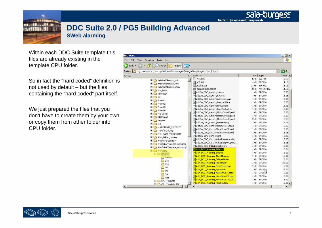
4Title of this presentation
DDC Suite 2.0 / PG5 Building AdvancedSWeb alarming
Within each DDC Suite template thisfiles are already existing in thetemplate CPU folder.
So in fact the “hard coded” definition isnot used by default – but the filescontaining the “hard coded” part itself.
We just prepared the files that youdon’t have to create them by your ownor copy them from other folder intoCPU folder.
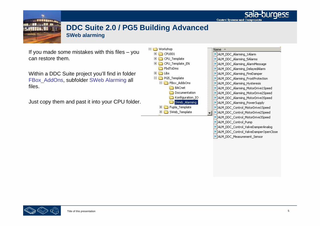
5Title of this presentation
DDC Suite 2.0 / PG5 Building AdvancedSWeb alarming
If you made some mistakes with this files – youcan restore them.
Within a DDC Suite project you’ll find in folderFBox_AddOns, subfolder SWeb Alarming allfiles.
Just copy them and past it into your CPU folder.

6Title of this presentation
DDC Suite 2.0 / PG5 Building AdvancedSWeb alarming
Now lets customize the detailed alarm information for FBox Sensor.
The FBox Sensor is from FBox family Analogue Values. Lets check if there is a file named
ALM_DDC_AnalogueValue_Sensor.src
Unfortunately not – but when we check the files you’ll find a file named
ALM_DDC_Measurement_Sensor.src
During translating DDC Suite into English we hade some different texts within FBoxes, files and description –there may be some small differences – but at the end you can identify them normally.
At least – there is a chapter DDC Suite - advanced – detailed information wherein you’ll find for each FBox ifit supports an external files for alarming and the file name. Please refer this chapter if you are not able to findthe file you’re looking for.

7Title of this presentation
DDC Suite 2.0 / PG5 Building AdvancedSWeb alarming
Please open file ALM_DDC_Measurement_Sensor.src with Notepad.
You’ll see for each alarm an entry like $WRFILE “DDC_Alarming.CSV” …. Always terminated with aconstruct of @&Name@. This indicates “use here the FBox property Name”.
The text after this construct is the detailed information and can be changed without problems.
Please modify “limit high” into “broken wire” and “limit low” into “short circuit”. Save file and close Notepad.

8Title of this presentation
DDC Suite 2.0 / PG5 Building AdvancedSWeb alarming
Close Excel and build program.
A “Rebuild All Files” is required – we didn’tchange any file listed in program files folderwithin PG5 project manager – so we have toforce to rebuild the while program to be sure thatthe changes in such external files are executed.
Open file DDC_Alarming.csv in PG5 projectmanager.
You see it’s very easy to customize the defaultalarm texts e.g. if it’s a demand from end user.
The FBoxes will search for external files
1st in CPU folder, if there not present
2nd in PG5 libs folder, if there not found
3rd “hard coded” definition is used
1Title of this presentation
PG5 Building Advanced / DDC Suite 2.0BACnet
BACnet
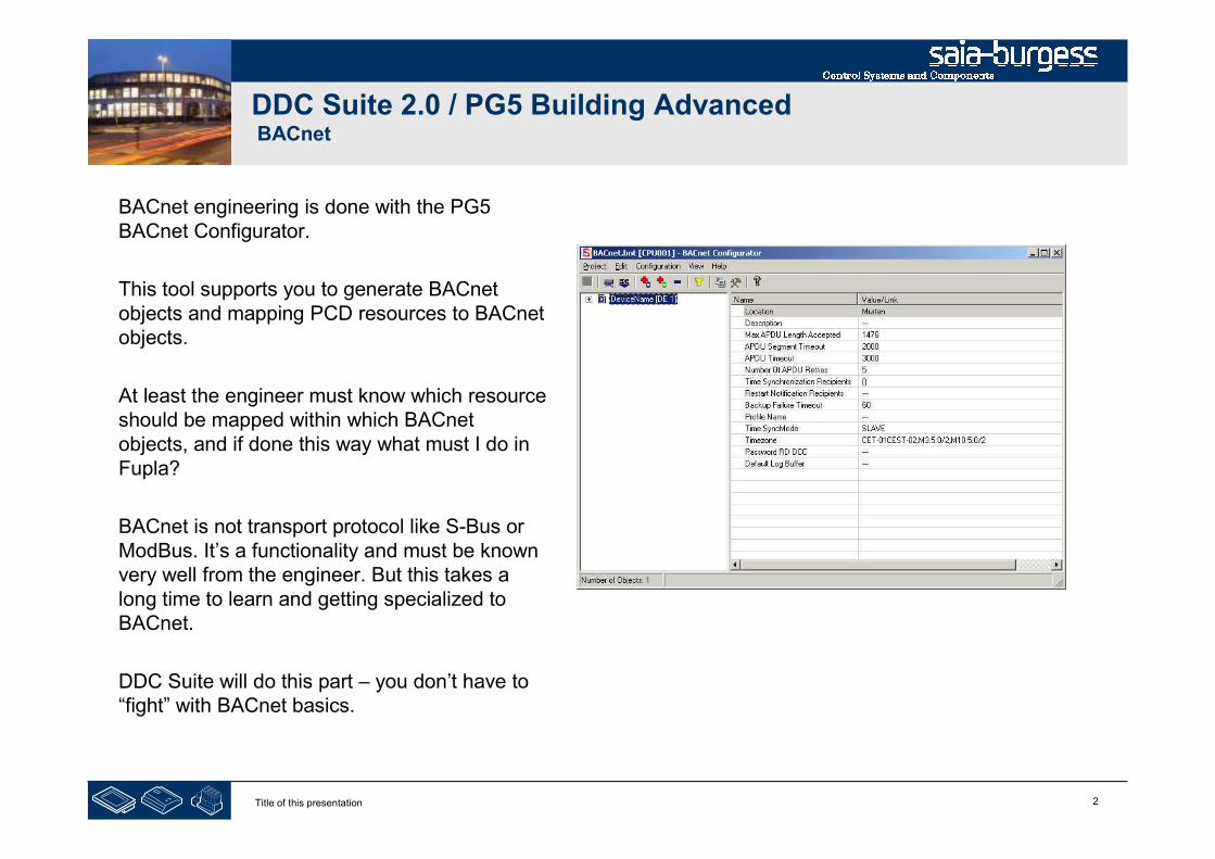
2Title of this presentation
DDC Suite 2.0 / PG5 Building AdvancedBACnet
BACnet engineering is done with the PG5BACnet Configurator.
This tool supports you to generate BACnetobjects and mapping PCD resources to BACnetobjects.
At least the engineer must know which resourceshould be mapped within which BACnetobjects, and if done this way what must I do inFupla?
BACnet is not transport protocol like S-Bus orModBus. It’s a functionality and must be knownvery well from the engineer. But this takes along time to learn and getting specialized toBACnet.
DDC Suite will do this part – you don’t have to“fight” with BACnet basics.
3Title of this presentation
PG5 Building Advanced / DDC Suite 2.0BACnet
BACnet with DDC Suite
In use
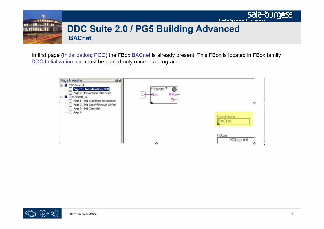
4Title of this presentation
DDC Suite 2.0 / PG5 Building AdvancedBACnet
In first page (Initialization; PCD) the FBox BACnet is already present. This FBox is located in FBox familyDDC Initialization and must be placed only once in a program.
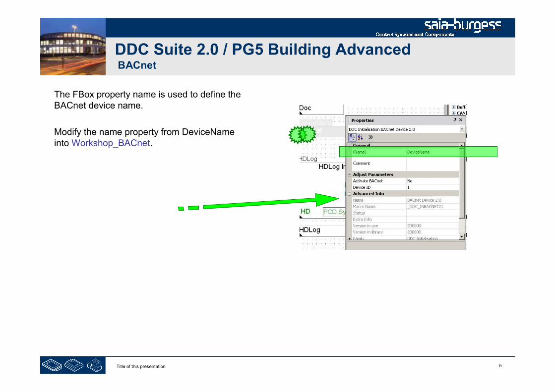
5Title of this presentation
DDC Suite 2.0 / PG5 Building AdvancedBACnet
The FBox property name is used to define theBACnet device name.
Modify the name property from DeviceNameinto Workshop_BACnet.
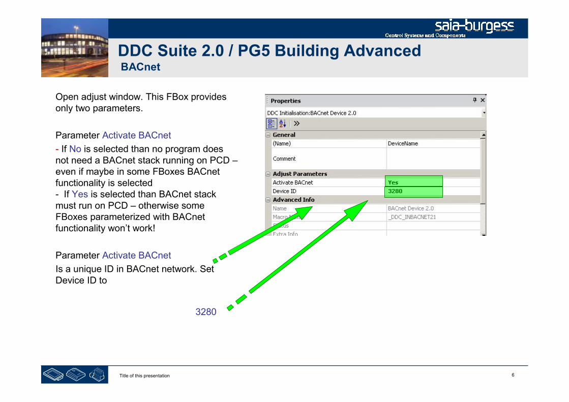
6Title of this presentation
DDC Suite 2.0 / PG5 Building AdvancedBACnet
Open adjust window. This FBox providesonly two parameters.
Parameter Activate BACnet
- If No is selected than no program doesnot need a BACnet stack running on PCD –even if maybe in some FBoxes BACnetfunctionality is selected- If Yes is selected than BACnet stackmust run on PCD – otherwise someFBoxes parameterized with BACnetfunctionality won’t work!
Parameter Activate BACnet
Is a unique ID in BACnet network. SetDevice ID to
3280
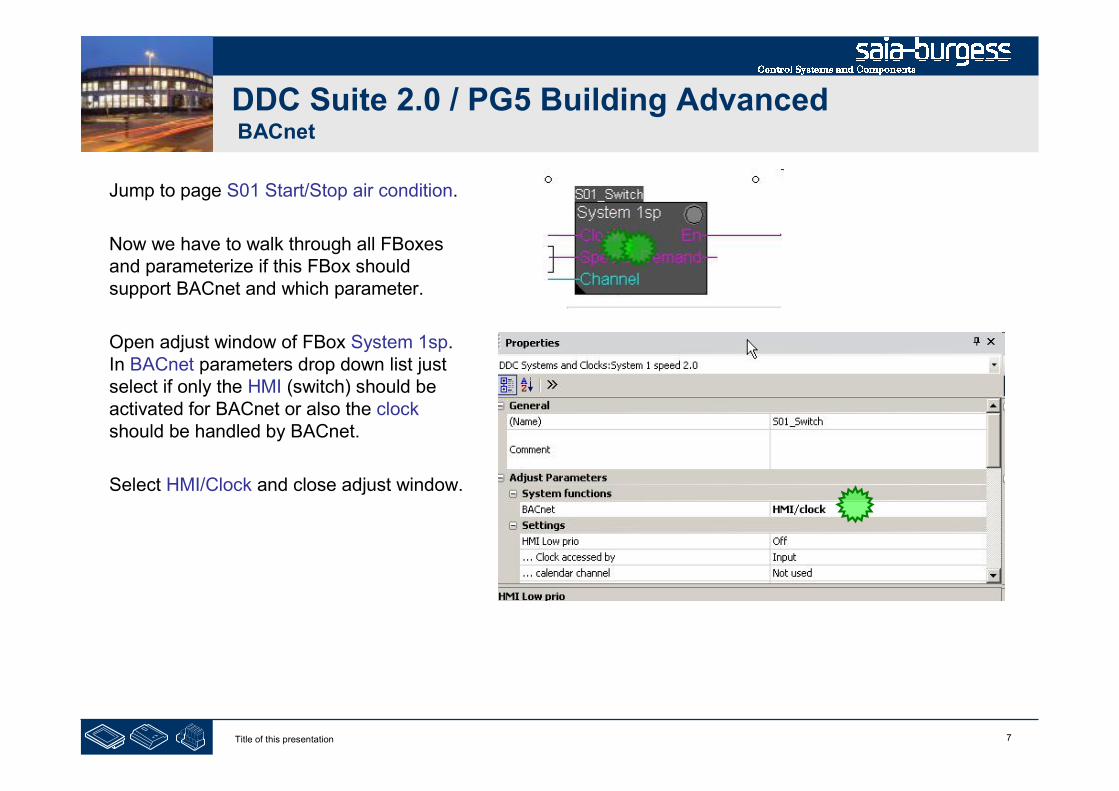
7Title of this presentation
DDC Suite 2.0 / PG5 Building AdvancedBACnet
Jump to page S01 Start/Stop air condition.
Now we have to walk through all FBoxesand parameterize if this FBox shouldsupport BACnet and which parameter.
Open adjust window of FBox System 1sp.In BACnet parameters drop down list justselect if only the HMI (switch) should beactivated for BACnet or also the clockshould be handled by BACnet.
Select HMI/Clock and close adjust window.
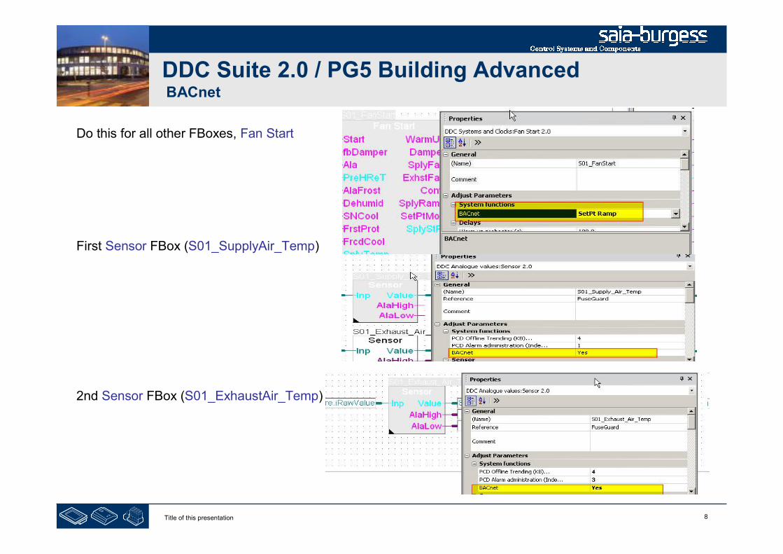
8Title of this presentation
DDC Suite 2.0 / PG5 Building AdvancedBACnet
Do this for all other FBoxes, Fan Start
First Sensor FBox (S01_SupplyAir_Temp)
2nd Sensor FBox (S01_ExhaustAir_Temp)

9Title of this presentation
DDC Suite 2.0 / PG5 Building AdvancedBACnet
Next page, first Motor 1 FBox(S01_SupplyAir_Fan)
first AlaMotor1 FBox(S01_SupplyAir_FanAla)
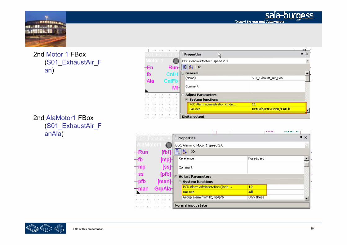
10Title of this presentation
2nd Motor 1 FBox(S01_ExhaustAir_Fan)
2nd AlaMotor1 FBox(S01_ExhaustAir_FanAla)
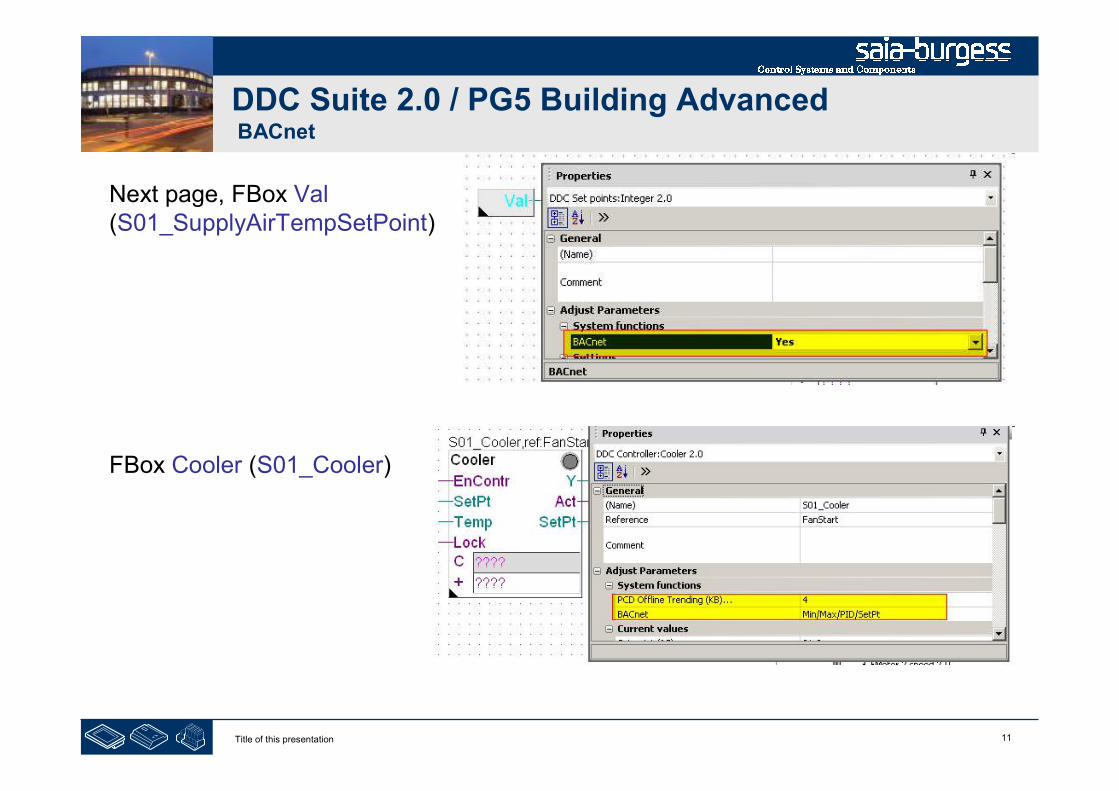
11Title of this presentation
DDC Suite 2.0 / PG5 Building AdvancedBACnet
Next page, FBox Val(S01_SupplyAirTempSetPoint)
FBox Cooler (S01_Cooler)
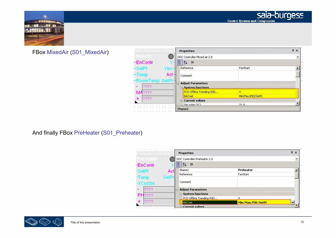
12Title of this presentation
FBox MixedAir (S01_MixedAir)
And finally FBox PreHeater (S01_Preheater)
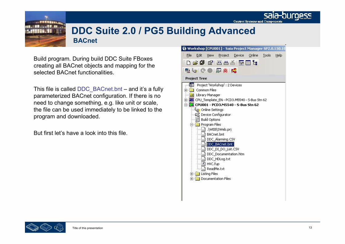
13Title of this presentation
DDC Suite 2.0 / PG5 Building AdvancedBACnet
Build program. During build DDC Suite FBoxescreating all BACnet objects and mapping for theselected BACnet functionalities.
This file is called DDC_BACnet.bnt – and it’s a fullyparameterized BACnet configuration. If there is noneed to change something, e.g. like unit or scale,the file can be used immediately to be linked to theprogram and downloaded.
But first let’s have a look into this file.
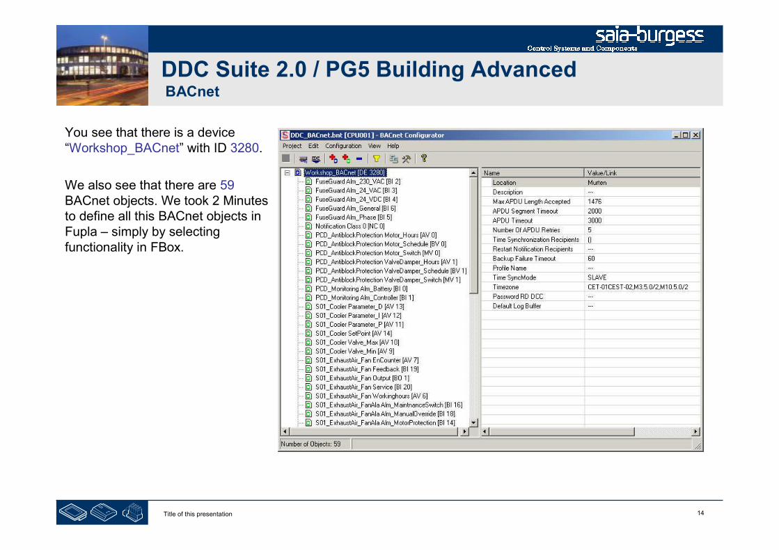
14Title of this presentation
DDC Suite 2.0 / PG5 Building AdvancedBACnet
You see that there is a device“Workshop_BACnet” with ID 3280.
We also see that there are 59BACnet objects. We took 2 Minutesto define all this BACnet objects inFupla – simply by selectingfunctionality in FBox.
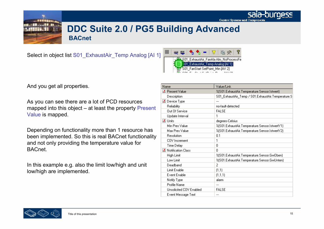
15Title of this presentation
DDC Suite 2.0 / PG5 Building AdvancedBACnet
Select in object list S01_ExhaustAir_Temp Analog [AI 1]
And you get all properties.
As you can see there are a lot of PCD resourcesmapped into this object – at least the property PresentValue is mapped.
Depending on functionality more than 1 resource hasbeen implemented. So this is real BACnet functionalityand not only providing the temperature value forBACnet.
In this example e.g. also the limit low/high and unitlow/high are implemented.

16Title of this presentation
DDC Suite 2.0 / PG5 Building AdvancedBACnet
Example FBox Sensor

17Title of this presentation
DDC Suite 2.0 / PG5 Building AdvancedBACnet
Example FBox Motor 1 (Commandable object)
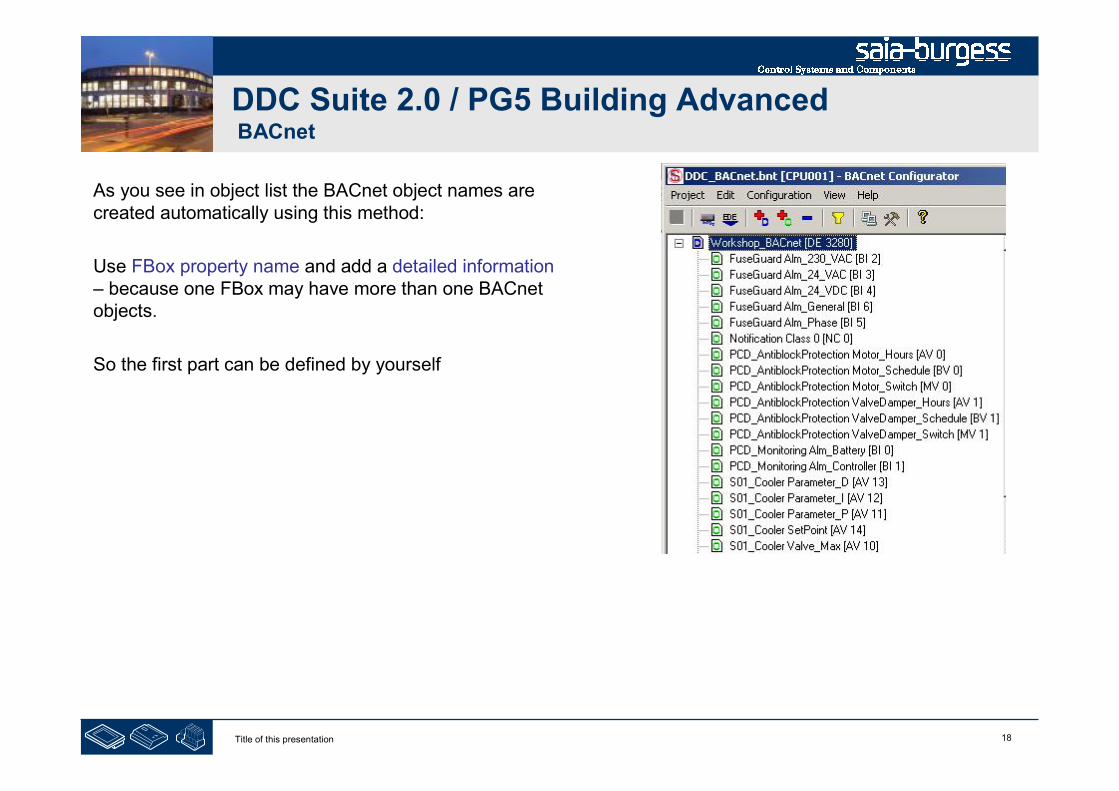
18Title of this presentation
DDC Suite 2.0 / PG5 Building AdvancedBACnet
As you see in object list the BACnet object names arecreated automatically using this method:
Use FBox property name and add a detailed information– because one FBox may have more than one BACnetobjects.
So the first part can be defined by yourself

19Title of this presentation
DDC Suite 2.0 / PG5 Building AdvancedBACnet
At this point we have created a small and nice air condition application. In real life it would be bigger withmuch more FBoxes or symbols – but we can reuse this in future if we store it as template.
Therefore we export this application as tempalte.Click on Page in menu and in context menu entryExport…
Type in file name, useAirCondition_HDLog_Alarm_BACnet and pressbutton Export
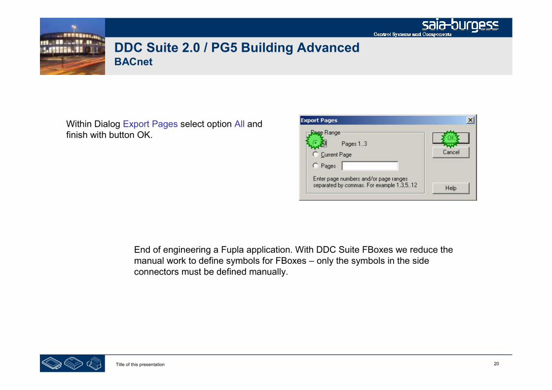
20Title of this presentation
DDC Suite 2.0 / PG5 Building AdvancedBACnet
Within Dialog Export Pages select option All andfinish with button OK.
End of engineering a Fupla application. With DDC Suite FBoxes we reduce themanual work to define symbols for FBoxes – only the symbols in the sideconnectors must be defined manually.

21Title of this presentation
PG5 Building Advanced / DDC Suite 2.0BACnet
BACnet with DDC Suite
AddOn tool
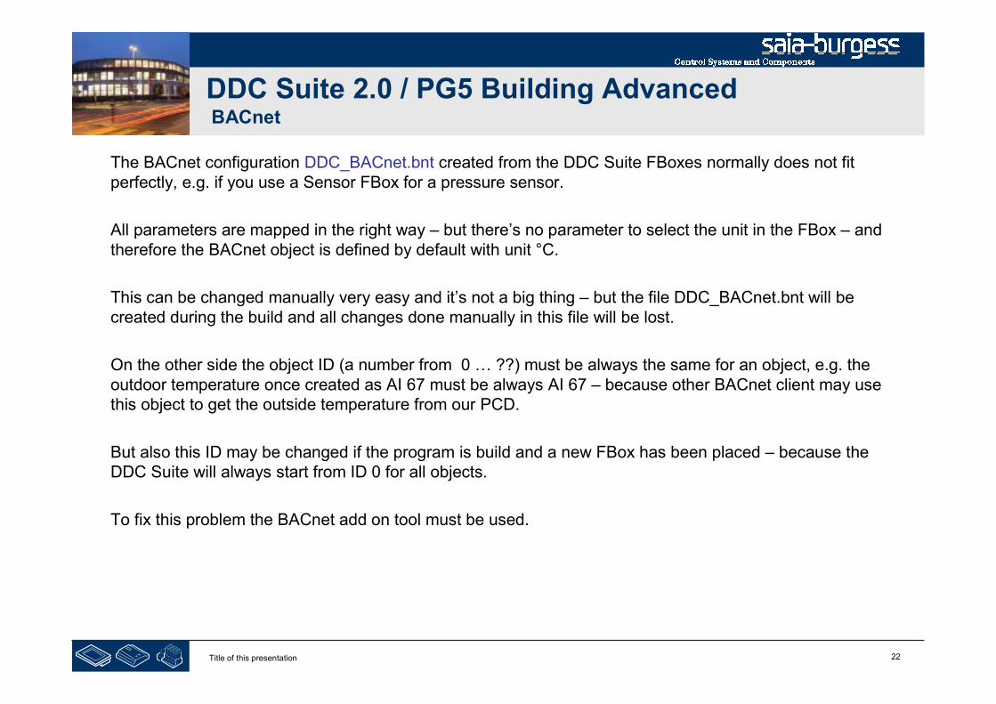
22Title of this presentation
DDC Suite 2.0 / PG5 Building AdvancedBACnet
The BACnet configuration DDC_BACnet.bnt created from the DDC Suite FBoxes normally does not fitperfectly, e.g. if you use a Sensor FBox for a pressure sensor.
All parameters are mapped in the right way – but there’s no parameter to select the unit in the FBox – andtherefore the BACnet object is defined by default with unit °C.
This can be changed manually very easy and it’s not a big thing – but the file DDC_BACnet.bnt will becreated during the build and all changes done manually in this file will be lost.
On the other side the object ID (a number from 0 … ??) must be always the same for an object, e.g. theoutdoor temperature once created as AI 67 must be always AI 67 – because other BACnet client may usethis object to get the outside temperature from our PCD.
But also this ID may be changed if the program is build and a new FBox has been placed – because theDDC Suite will always start from ID 0 for all objects.
To fix this problem the BACnet add on tool must be used.
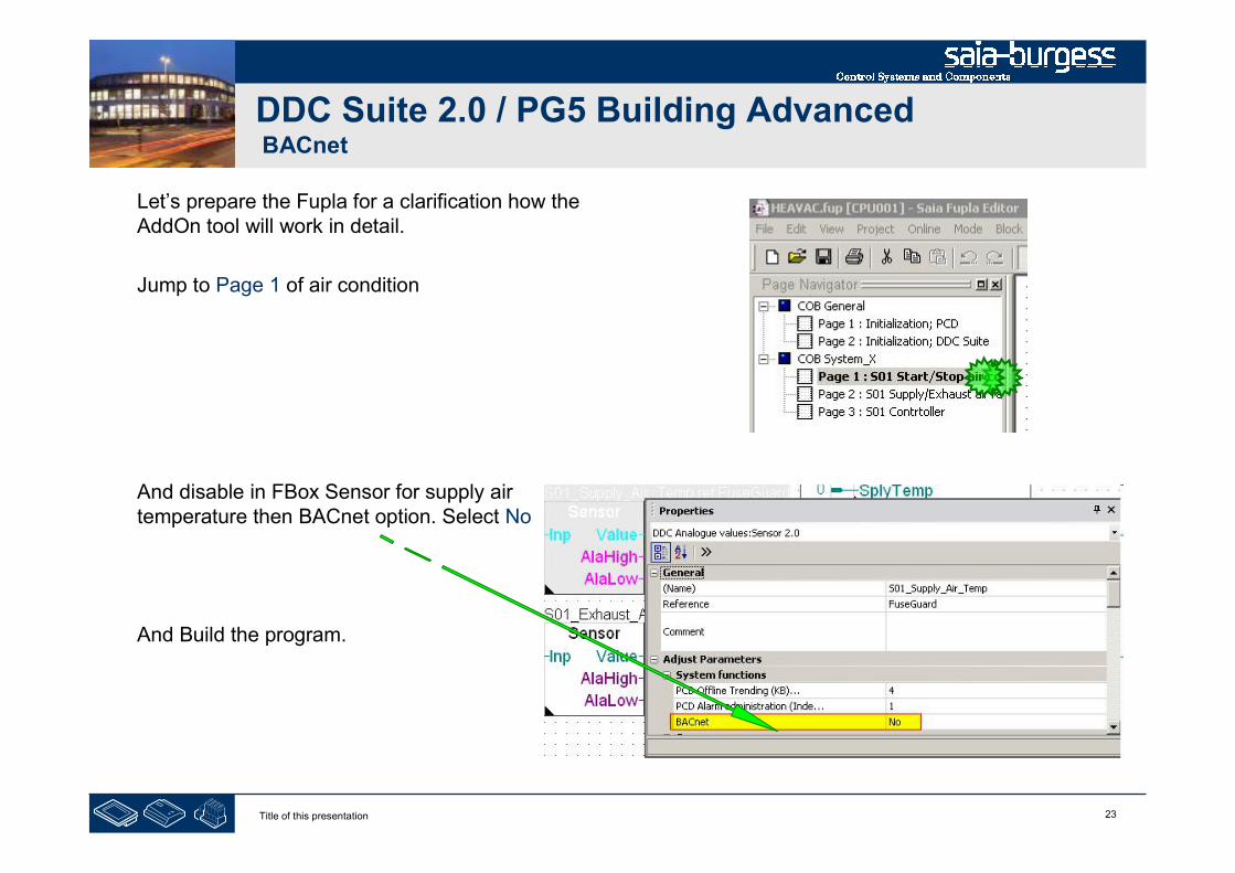
23Title of this presentation
DDC Suite 2.0 / PG5 Building AdvancedBACnet
Let’s prepare the Fupla for a clarification how theAddOn tool will work in detail.
Jump to Page 1 of air condition
And disable in FBox Sensor for supply airtemperature then BACnet option. Select No
And Build the program.
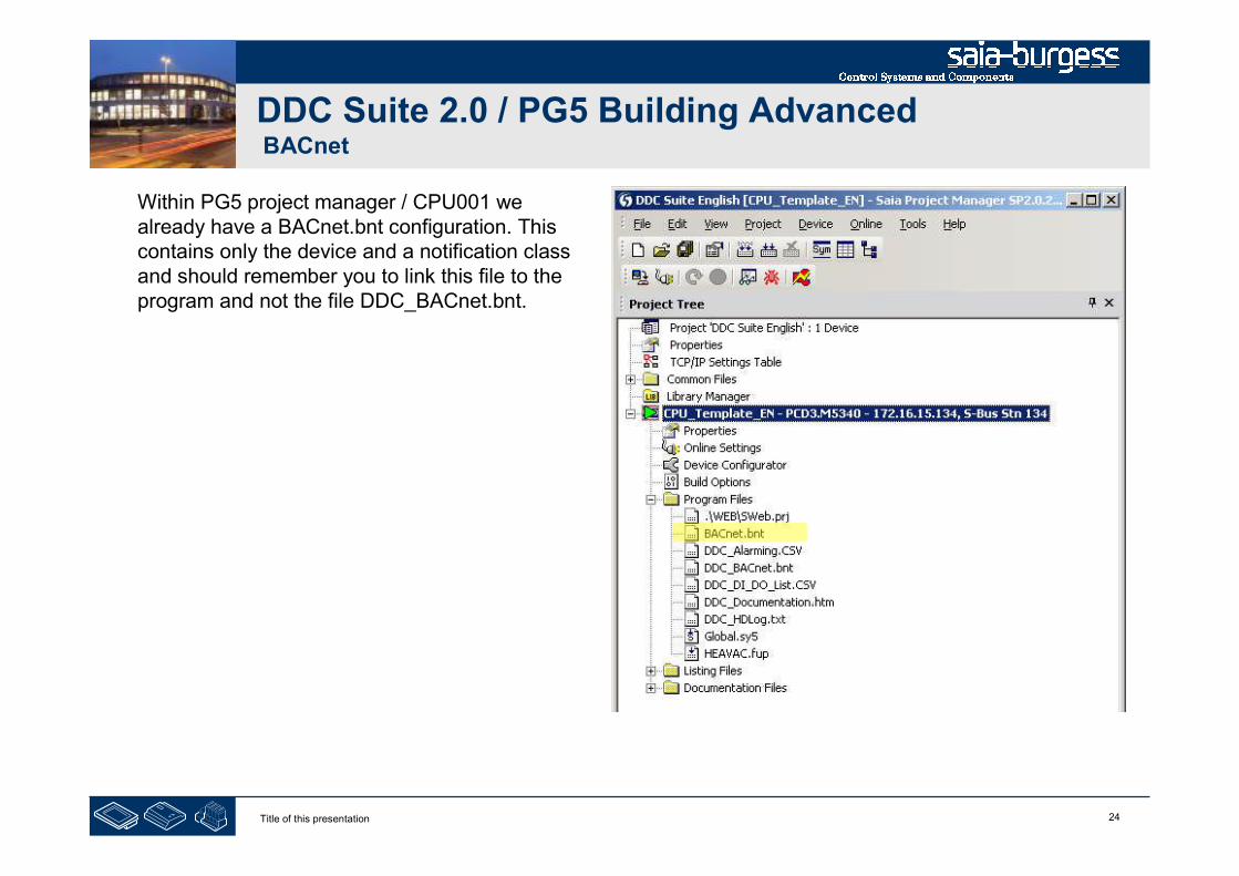
24Title of this presentation
DDC Suite 2.0 / PG5 Building AdvancedBACnet
Within PG5 project manager / CPU001 wealready have a BACnet.bnt configuration. Thiscontains only the device and a notification classand should remember you to link this file to theprogram and not the file DDC_BACnet.bnt.
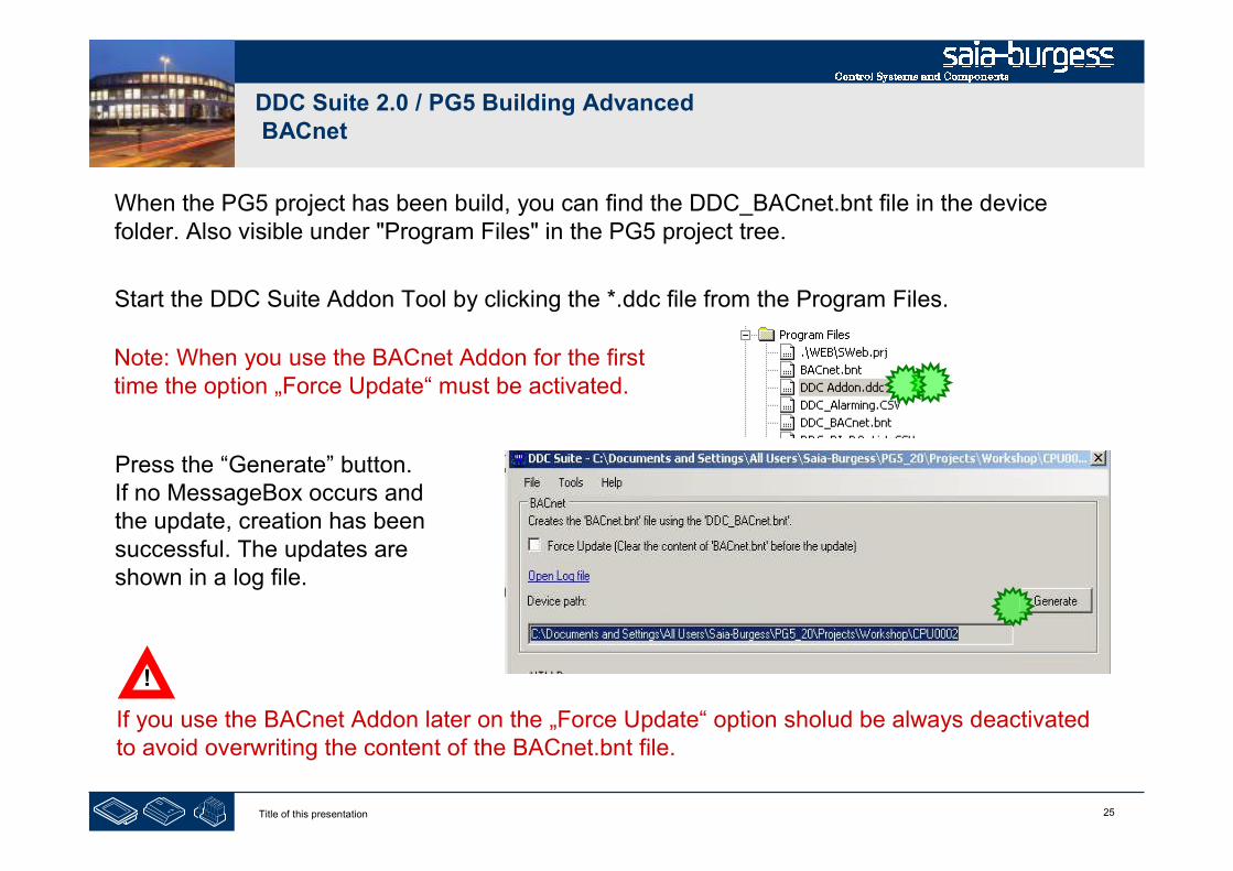
25Title of this presentation
DDC Suite 2.0 / PG5 Building AdvancedBACnet
When the PG5 project has been build, you can find the DDC_BACnet.bnt file in the devicefolder. Also visible under "Program Files" in the PG5 project tree.
Start the DDC Suite Addon Tool by clicking the *.ddc file from the Program Files.
Press the “Generate” button.If no MessageBox occurs andthe update, creation has beensuccessful. The updates areshown in a log file.
Note: When you use the BACnet Addon for the firsttime the option „Force Update“ must be activated.
If you use the BACnet Addon later on the „Force Update“ option sholud be always deactivatedto avoid overwriting the content of the BACnet.bnt file.
!

26Title of this presentation
DDC Suite 2.0 / PG5 Building AdvancedBACnet
Open BACnet configurator to check the settings.
For better understanding we have to sort theobjects by type.
Click in context menu on entry “View” and then“Sort by Type”

27Title of this presentation
DDC Suite 2.0 / PG5 Building AdvancedBACnet
You’ll see that object AI 0 (analogue input ID 0) isdefined from Sensor FBox with name property
S01_ExhaustAir_Temp
because this was the first FBox generating ananalogue input object.
Maybe now a client will be parameterized to readAI 0 from device 3280 to get the exhaust airtemperature.
If we change the ID of an object than also allclients must be updated! Therefore it’s absolutelynecessary to keep them unchanged!

28Title of this presentation
DDC Suite 2.0 / PG5 Building AdvancedBACnet
Close BACnet configurator and turn on in SensorFBox of supply air temperature the BACnetoption to Yes
And build the program.
Open file DDC_BACnet.bnt – and you’ll see thatwithin this configuration the exhaust air temp.object now is ID 1 – because the Sensor FBoxfor supply air temp. is in front of the exhaust airtemp.
So after a build the object ID in DDC_BACnet.bntfile can be always different – depending on thesettings or if you removed/added an FBox!

29Title of this presentation
DDC Suite 2.0 / PG5 Building AdvancedBACnet
OK – but we use the BACnet.bnt file and this file is not changed from DDC Suite. So exhaustair temp. object is still 0 – but we have to add the new supply air temp. object.
But this object also is defined with ID 0 – and two objects of same type cannot have thesame ID.
How to solve this problem? The AddOn will do this for you.
Start the DDC AddOn and press the generate button.
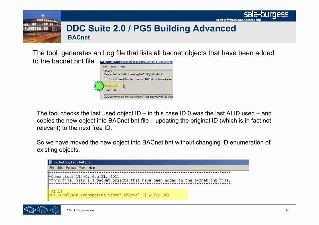
30Title of this presentation
DDC Suite 2.0 / PG5 Building AdvancedBACnet
The tool generates an Log file that lists all bacnet objects that have been addedto the bacnet.bnt file
The tool checks the last used object ID – in this case ID 0 was the last AI ID used – andcopies the new object into BACnet.bnt file – updating the original ID (which is in fact notrelevant) to the next free ID.
So we have moved the new object into BACnet.bnt without changing ID enumeration ofexisting objects.

31Title of this presentation
DDC Suite 2.0 / PG5 Building AdvancedBACnet
When now checking the BACnet.bnt file you’ll see that the exhaust air temp. object is still AI 0 and supply airtemp. object has become AI 1.
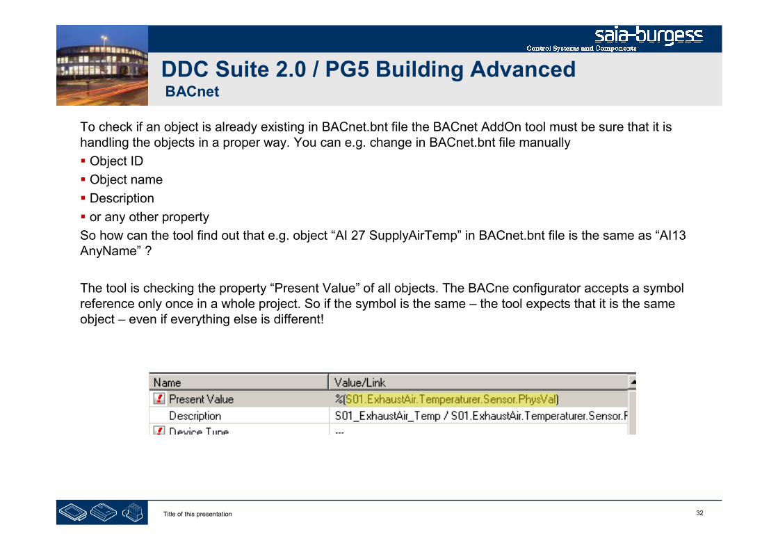
32Title of this presentation
DDC Suite 2.0 / PG5 Building AdvancedBACnet
To check if an object is already existing in BACnet.bnt file the BACnet AddOn tool must be sure that it ishandling the objects in a proper way. You can e.g. change in BACnet.bnt file manually
Object ID
Object name
Description
or any other property
So how can the tool find out that e.g. object “AI 27 SupplyAirTemp” in BACnet.bnt file is the same as “AI13AnyName” ?
The tool is checking the property “Present Value” of all objects. The BACne configurator accepts a symbolreference only once in a whole project. So if the symbol is the same – the tool expects that it is the sameobject – even if everything else is different!
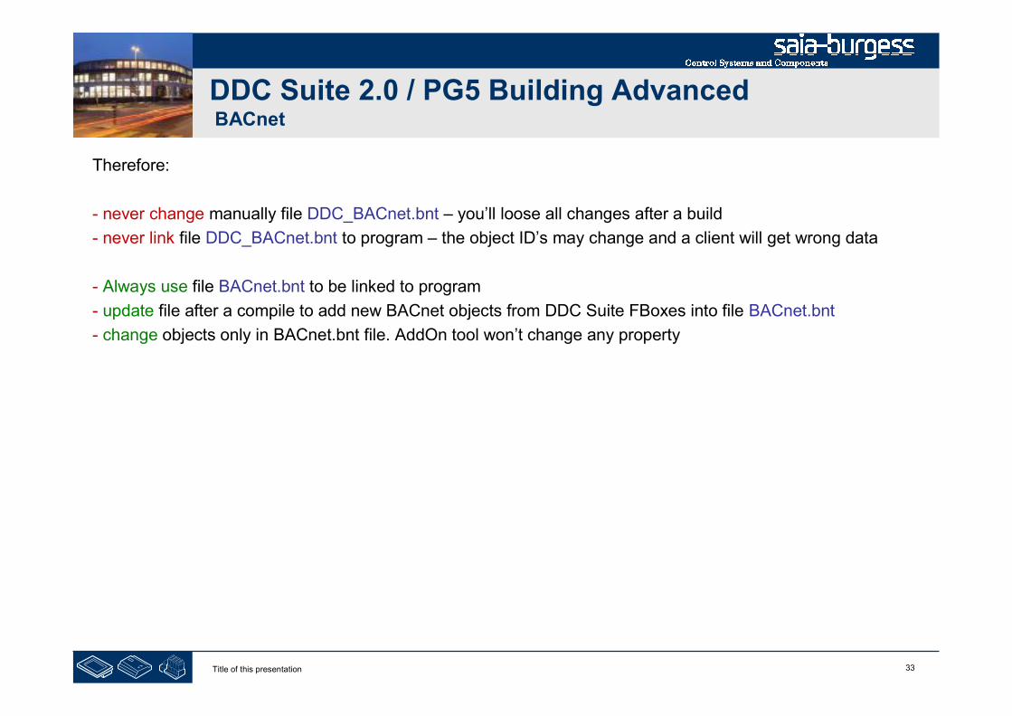
33Title of this presentation
DDC Suite 2.0 / PG5 Building AdvancedBACnet
Therefore:
- never change manually file DDC_BACnet.bnt – you’ll loose all changes after a build
- never link file DDC_BACnet.bnt to program – the object ID’s may change and a client will get wrong data
- Always use file BACnet.bnt to be linked to program
- update file after a compile to add new BACnet objects from DDC Suite FBoxes into file BACnet.bnt
- change objects only in BACnet.bnt file. AddOn tool won’t change any property

1Title of this presentation
PG5 Building Advanced / DDC Suite 2.0BACnet
BACnet – advanced
Only use this if you have to modify thecreation of BACnet objects by the DDC
Suite Fboxes. Advanced knowledgerequired
!
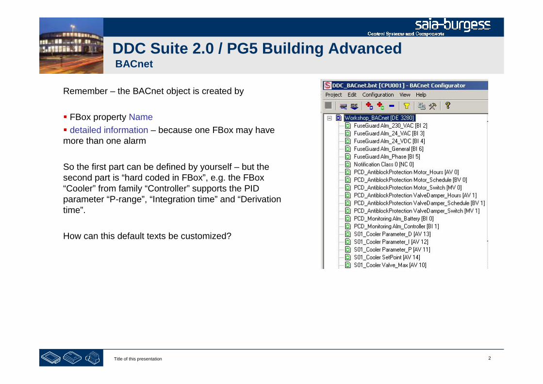
2Title of this presentation
DDC Suite 2.0 / PG5 Building AdvancedBACnet
Remember – the BACnet object is created by
FBox property Name
detailed information – because one FBox may havemore than one alarm
So the first part can be defined by yourself – but thesecond part is “hard coded in FBox”, e.g. the FBox“Cooler” from family “Controller” supports the PIDparameter “P-range”, “Integration time” and “Derivationtime”.
How can this default texts be customized?

3Title of this presentation
DDC Suite 2.0 / PG5 Building AdvancedBACnet
Each FBox generating BACnet objects supports an external file.
If the file is not present than the “hard coded” detailed information is used.
if the file is found then the definition how to create the alarm must be declared in this file and the “hardcoded” part is ignored.
So the external file disables the “hard coded” definition!
The files are structured with a strong name convention
BAC_ - declares that this file contains BACnet declaration
DDC_ - identifies that this file is used with DDC suite FBoxes
“Family_” e.g. Alarming_ - declares the DDC Suite family
“FBox” e.g. 1Alarm – defines the FBox itself
.src – file extenstion
Example: BAC_DDC_Alarming_1Alarm.src
But you don’t have to know all these file names or create them by yourself.
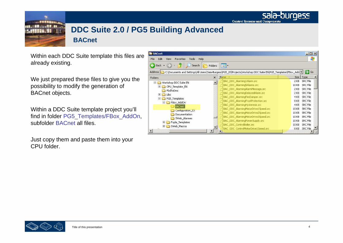
4Title of this presentation
DDC Suite 2.0 / PG5 Building AdvancedBACnet
Within each DDC Suite template this files arealready existing.
We just prepared these files to give you thepossibility to modify the generation ofBACnet objects.
Within a DDC Suite template project you’llfind in folder PG5_Templates/FBox_AddOn,subfolder BACnet all files.
Just copy them and paste them into yourCPU folder.

5Title of this presentation
DDC Suite 2.0 / PG5 Building AdvancedBACnet
Now lets customize the detailed BACnet object information for FBox Cooler.
The FBox Cooler is from FBox family Controller. Lets check if there is a file named
BAC_DDC_Controller_Cooler.src
Unfortunately not – but when we check the files you’ll find a file named
BAC_DDC_RegulationCooler.src
During translating DDC Suite into English we hade some different texts within FBoxes, files and description –there may be some small differences – but at the end you can identify them normally.
At least – there is a chapter DDC Suite - advanced – detailed information wherein you’ll find for each FBox ifit supports an external files for alarming and the file name. Please refer this chapter if you are not able to findthe file you’re looking for.
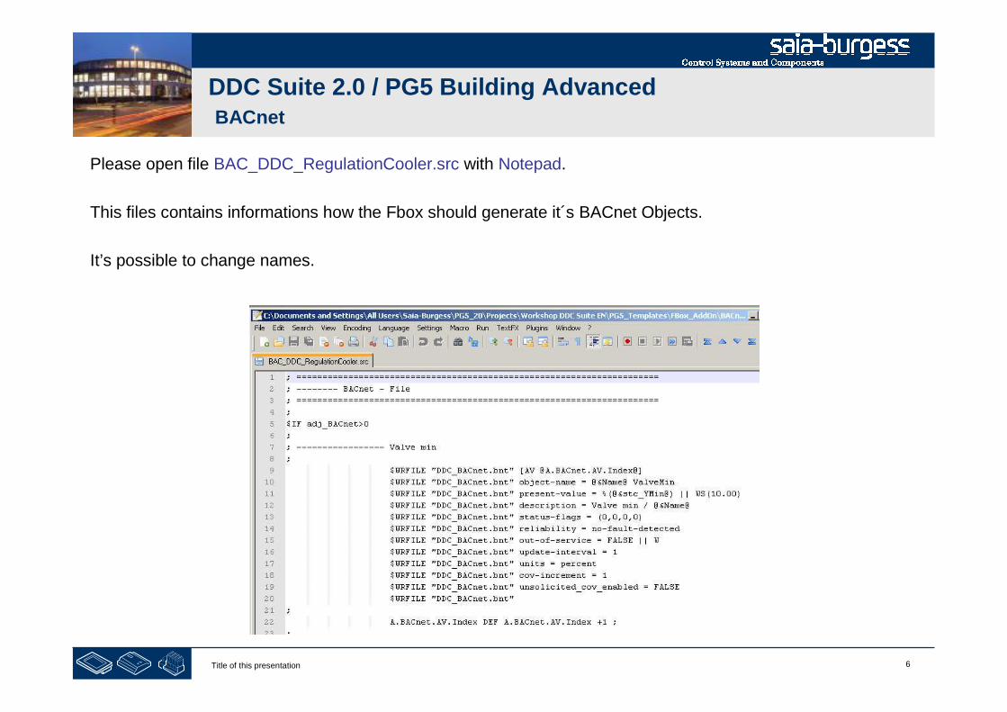
6Title of this presentation
DDC Suite 2.0 / PG5 Building AdvancedBACnet
Please open file BAC_DDC_RegulationCooler.src with Notepad.
This files contains informations how the Fbox should generate it´s BACnet Objects.
It’s possible to change names.

7Title of this presentation
DDC Suite 2.0 / PG5 Building AdvancedBACnet
Now lets modify the names of the PID parameters.
You have to search for the following lines of code in the .bnt file
The Object Name is created with the Fbox Name (@&Name@) plus an extension i.e. Proportional Range
This extension can be modifieed according to your needs
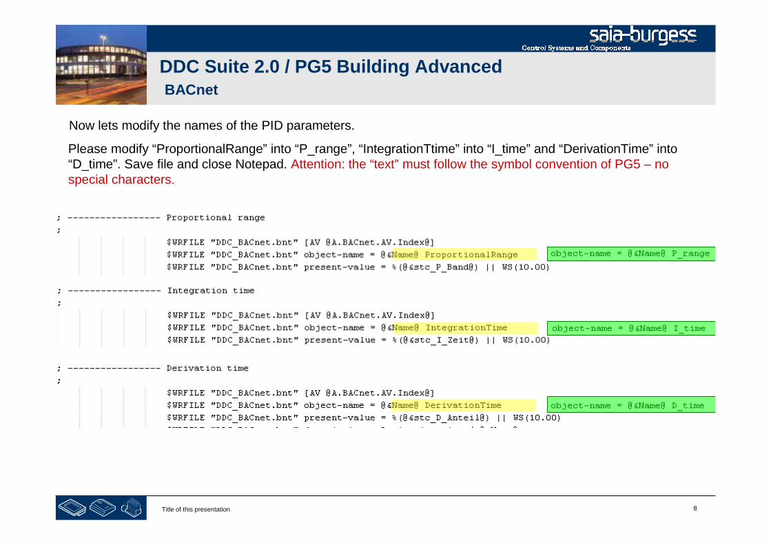
8Title of this presentation
DDC Suite 2.0 / PG5 Building AdvancedBACnet
Now lets modify the names of the PID parameters.
Please modify “ProportionalRange” into “P_range”, “IntegrationTtime” into “I_time” and “DerivationTime” into“D_time”. Save file and close Notepad. Attention: the “text” must follow the symbol convention of PG5 – nospecial characters.
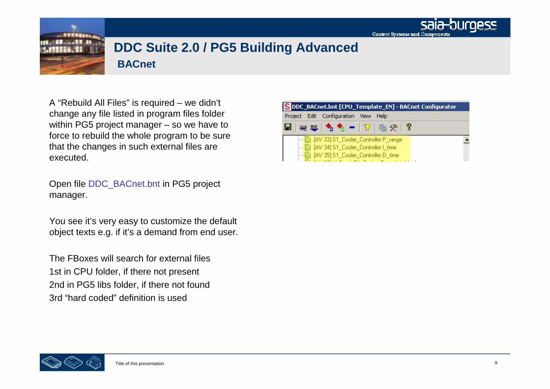
9Title of this presentation
DDC Suite 2.0 / PG5 Building AdvancedBACnet
A “Rebuild All Files” is required – we didn’tchange any file listed in program files folderwithin PG5 project manager – so we have toforce to rebuild the whole program to be surethat the changes in such external files areexecuted.
Open file DDC_BACnet.bnt in PG5 projectmanager.
You see it’s very easy to customize the defaultobject texts e.g. if it’s a demand from end user.
The FBoxes will search for external files
1st in CPU folder, if there not present
2nd in PG5 libs folder, if there not found
3rd “hard coded” definition is used
1Title of this presentation
PG5 Building Advanced / DDC Suite 2.0Working with Fupla
Using templates
2Title of this presentation
DDC Suite 2.0 / PG5 Building AdvancedUsing templates
During the last workshops we programmed a nice small air condition with
- 3 Fupla pages, basic functionality
- Offline trending in PCD
- Alarm management in PCD
- BACnet configuration
In real life we expect to use this air condition within another CPU in this project or in another project. Thereforeit would be nice if we create a template.
Lets see how easy we can do this.
3Title of this presentation
PG5 Building Advanced / DDC Suite 2.0Working with Fupla
Creating a new CPU in the project

4Title of this presentation
DDC Suite 2.0 / PG5 Building AdvancedUsing templates
We’ll start with a new CPU.
Therefore we use the copy/p0aste in project manager. Click withright mouse button on “CPU _Template_EN” and then Copyin context menu.
Click with right mouse button on “Project ’Workshop’” and thenPaste CPU in context menu.
We have to rename the CPU, please use “CPU002” and press“OK”.
Open HEAVAC.fup from CPU002
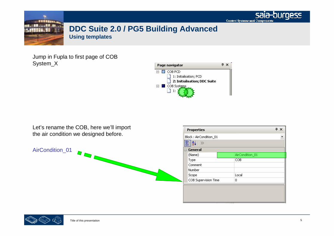
5Title of this presentation
DDC Suite 2.0 / PG5 Building AdvancedUsing templates
Jump in Fupla to first page of COBSystem_X
Let’s rename the COB, here we’ll importthe air condition we designed before.
AirCondition_01
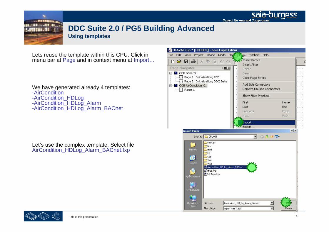
6Title of this presentation
DDC Suite 2.0 / PG5 Building AdvancedUsing templates
Lets reuse the template within this CPU. Click inmenu bar at Page and in context menu at Import…
We have generated already 4 templates:-AirCondition-AirCondition_HDLog-AirCondition_HDLog_Alarm-AirCondition_HDLog_Alarm_BACnet
Let’s use the complex template. Select fileAirCondition_HDLog_Alarm_BACnet.fxp

7Title of this presentation
DDC Suite 2.0 / PG5 Building AdvancedUsing templates
1. Uncheck Set Internal Variables to systemdefined
This is really necessary – otherwise you’llimport the template and all FBoxes won’thave internal symbols. But werestructured and renamed the groups toreuse them easily!
2. Select option After current page

8Title of this presentation
DDC Suite 2.0 / PG5 Building AdvancedUsing templates
Change in column Page Name the PrefixS01 into AC01_Shop with Find &Replace
DO NOT OK Button! OTHERWISEYOU WILL START IMPORT!
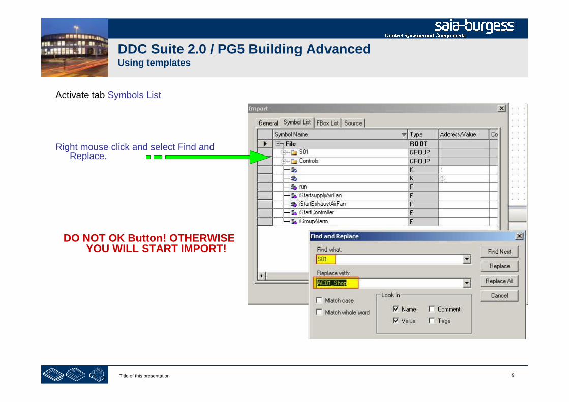
9Title of this presentation
Activate tab Symbols List
Right mouse click and select Find andReplace.
DO NOT OK Button! OTHERWISEYOU WILL START IMPORT!
DDC Suite 2.0 / PG5 Building AdvancedUsing templates
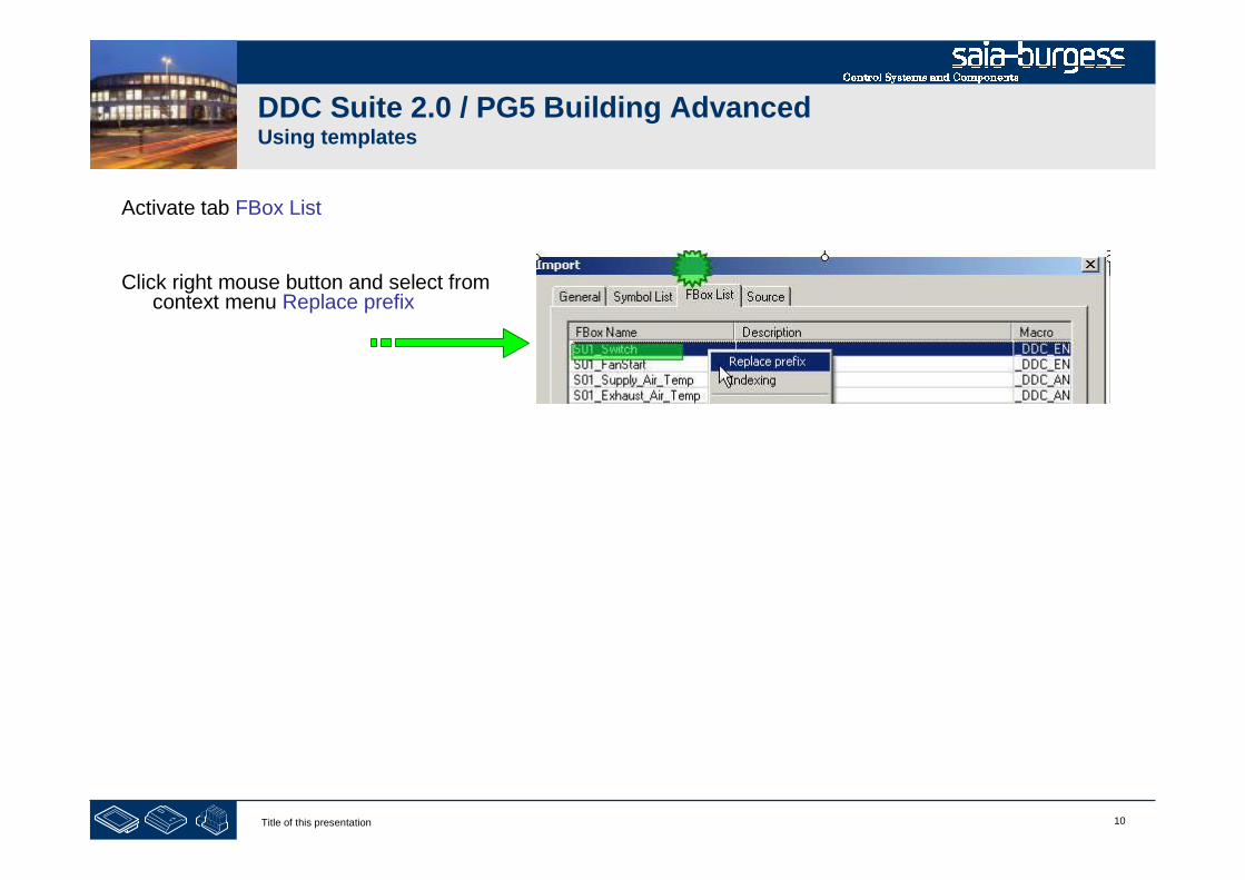
10Title of this presentation
DDC Suite 2.0 / PG5 Building AdvancedUsing templates
Activate tab FBox List
Click right mouse button and select fromcontext menu Replace prefix
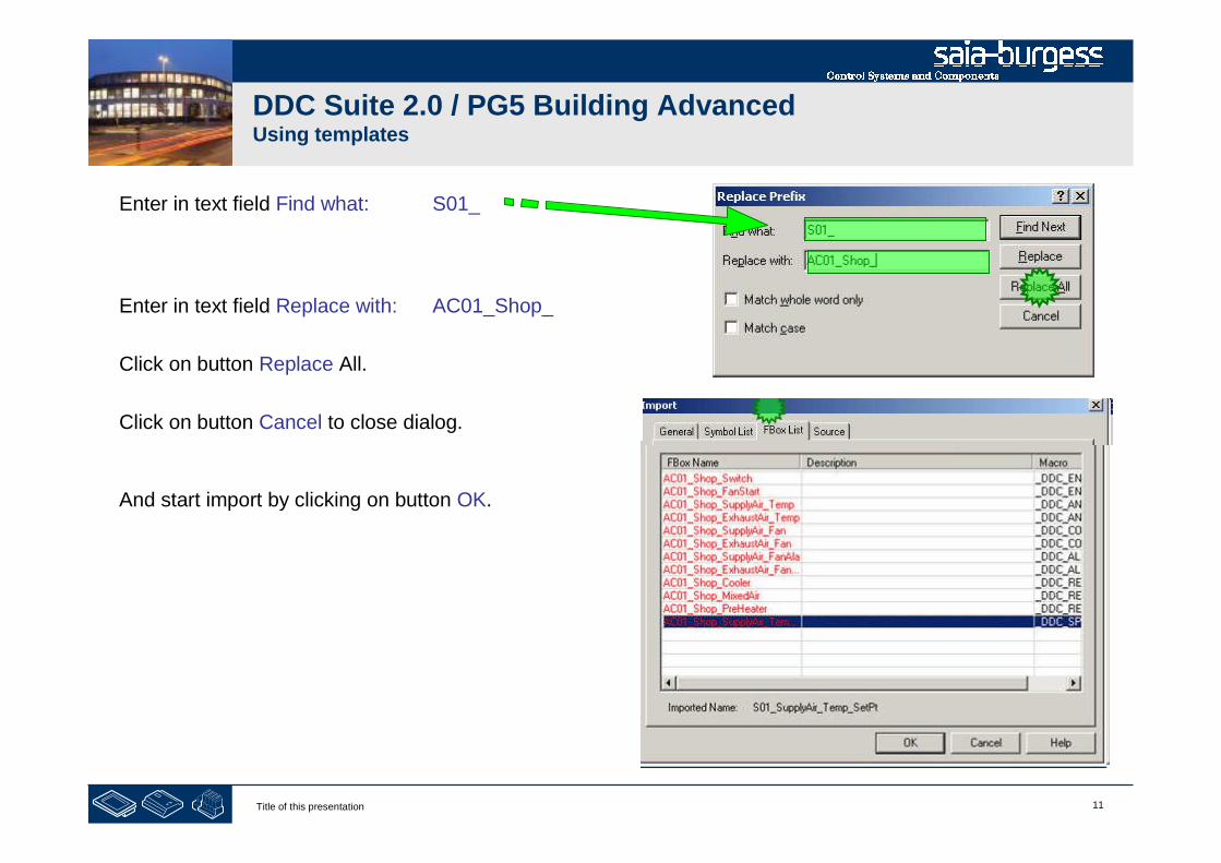
11Title of this presentation
DDC Suite 2.0 / PG5 Building AdvancedUsing templates
Enter in text field Find what: S01_
Enter in text field Replace with: AC01_Shop_
Click on button Replace All.
Click on button Cancel to close dialog.
And start import by clicking on button OK.
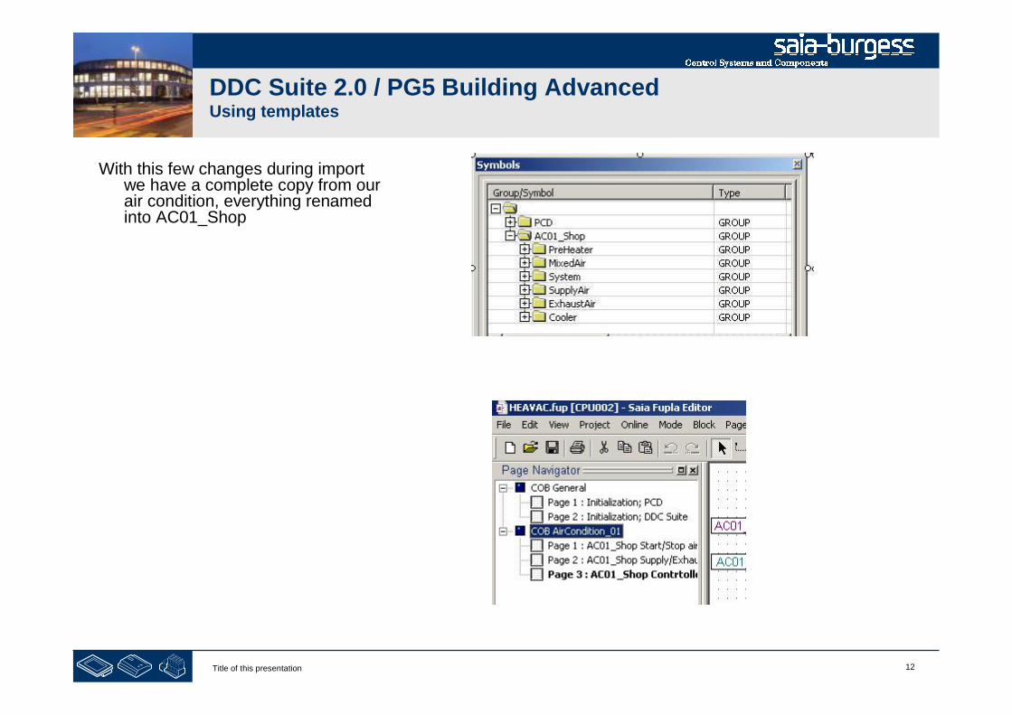
12Title of this presentation
DDC Suite 2.0 / PG5 Building AdvancedUsing templates
With this few changes during importwe have a complete copy from ourair condition, everything renamedinto AC01_Shop
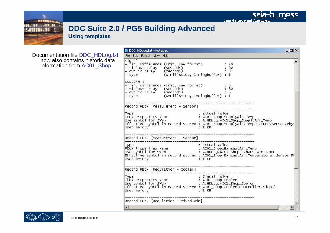
13Title of this presentation
DDC Suite 2.0 / PG5 Building AdvancedUsing templates
Documentation file DDC_HDLog.txtnow also contains historic datainformation from AC01_Shop
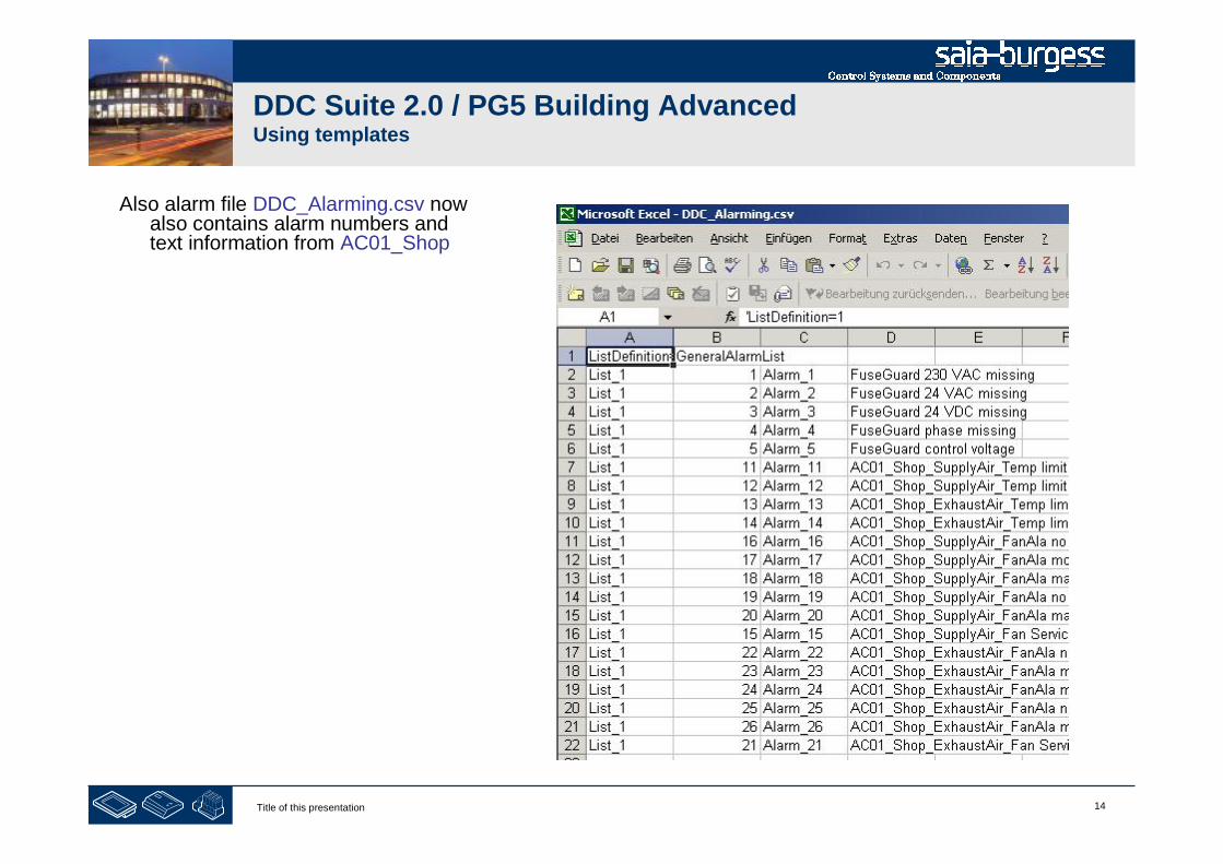
14Title of this presentation
DDC Suite 2.0 / PG5 Building AdvancedUsing templates
Also alarm file DDC_Alarming.csv nowalso contains alarm numbers andtext information from AC01_Shop
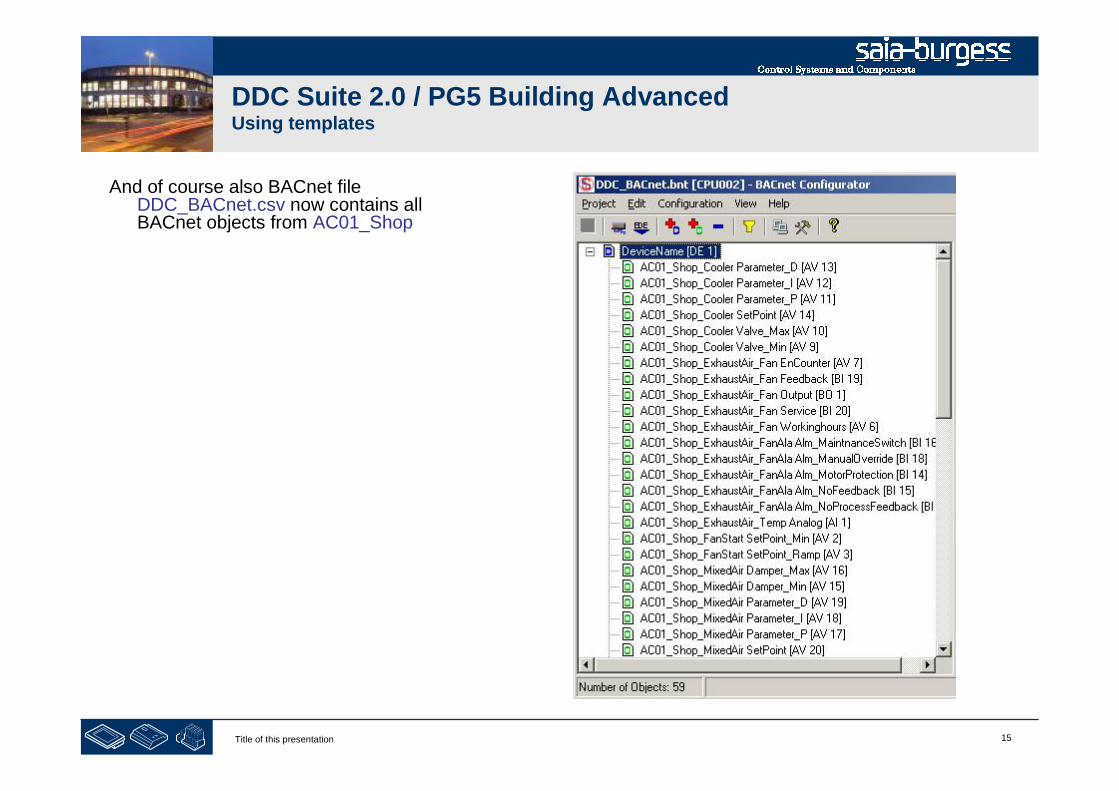
15Title of this presentation
DDC Suite 2.0 / PG5 Building AdvancedUsing templates
And of course also BACnet fileDDC_BACnet.csv now contains allBACnet objects from AC01_Shop
16Title of this presentation
PG5 Building Advanced / DDC Suite 2.0Working with Fupla
Multiple Import
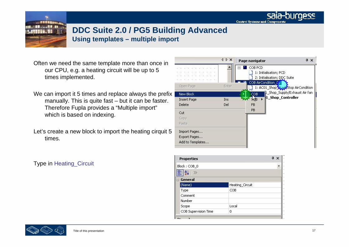
17Title of this presentation
DDC Suite 2.0 / PG5 Building AdvancedUsing templates – multiple import
Often we need the same template more than once inour CPU, e.g. a heating circuit will be up to 5times implemented.
We can import it 5 times and replace always the prefixmanually. This is quite fast – but it can be faster.Therefore Fupla provides a “Multiple import”which is based on indexing.
Let’s create a new block to import the heating cirquit 5times.
Type in Heating_Circuit

18Title of this presentation
DDC Suite 2.0 / PG5 Building AdvancedUsing templates – multiple import
Lets reuse the template within this CPU. Click inmenu bar at Page and in context menu at Import…
The DDC Suite already contains some basictemplates. We have to go to the PG5_Templatesfolder and there select the Fupla_Templates folder.
Then you’ll see that the project also contains afolder “Fupla Templates”

19Title of this presentation
DDC Suite 2.0 / PG5 Building AdvancedUsing templates – multiple import
Open the folder “Fupla_Templates” with a doubleclick.
We have some templates for systems - heatingcircuit, air condition - and functionalities – likecalendar.
Open folder “Systems” with a double click.
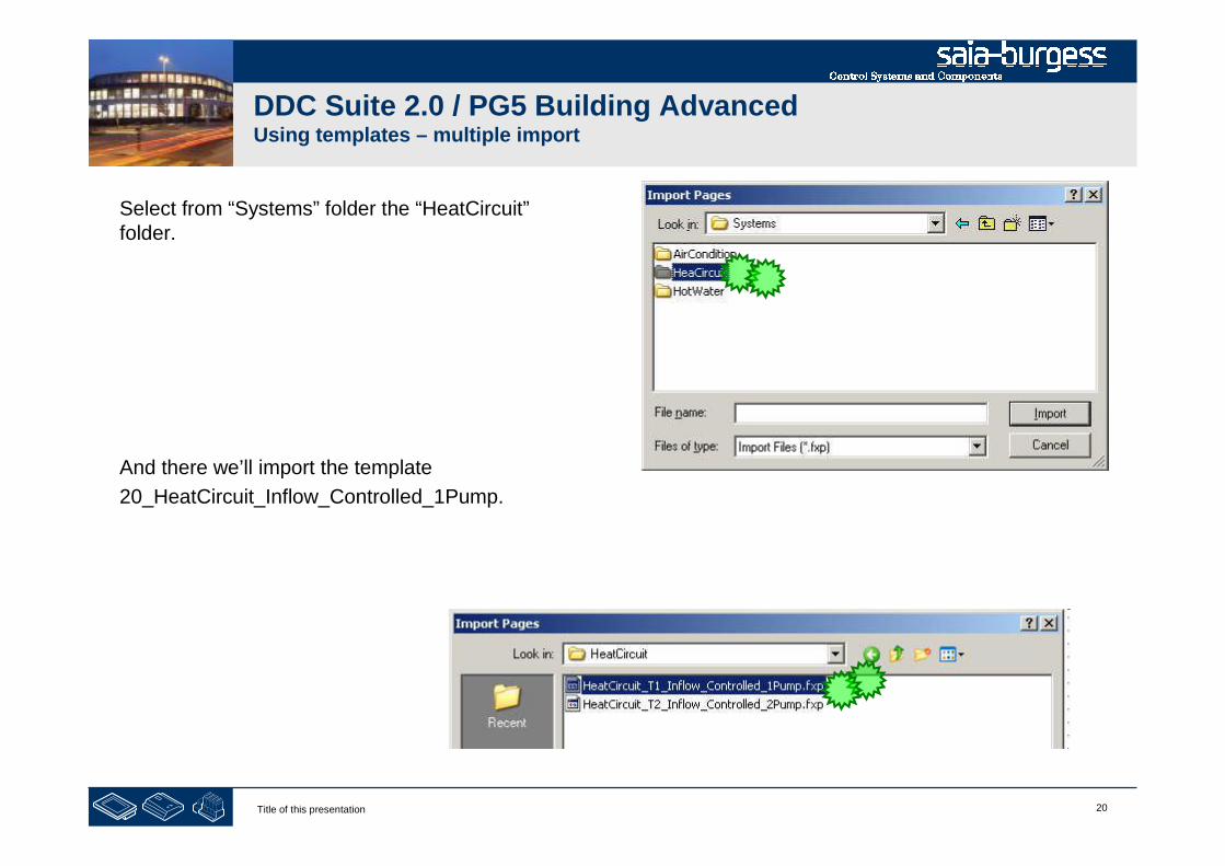
20Title of this presentation
DDC Suite 2.0 / PG5 Building AdvancedUsing templates – multiple import
Select from “Systems” folder the “HeatCircuit”folder.
And there we’ll import the template
20_HeatCircuit_Inflow_Controlled_1Pump.
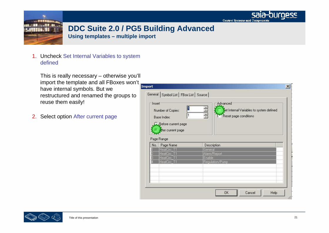
21Title of this presentation
DDC Suite 2.0 / PG5 Building AdvancedUsing templates – multiple import
1. Uncheck Set Internal Variables to systemdefined
This is really necessary – otherwise you’llimport the template and all FBoxes won’thave internal symbols. But werestructured and renamed the groups toreuse them easily!
2. Select option After current page
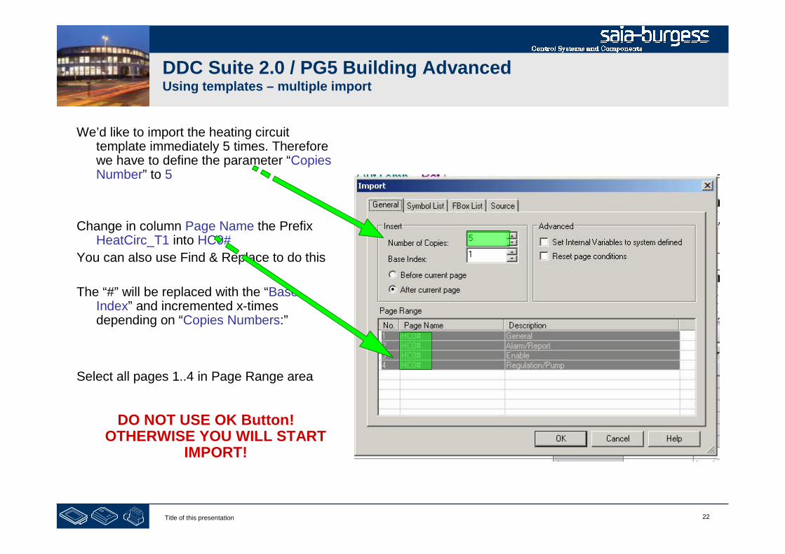
22Title of this presentation
DDC Suite 2.0 / PG5 Building AdvancedUsing templates – multiple import
We’d like to import the heating circuittemplate immediately 5 times. Thereforewe have to define the parameter “CopiesNumber” to 5
Change in column Page Name the PrefixHeatCirc_T1 into HC0#
You can also use Find & Replace to do this
The “#” will be replaced with the “BaseIndex” and incremented x-timesdepending on “Copies Numbers:”
Select all pages 1..4 in Page Range area
DO NOT USE OK Button!OTHERWISE YOU WILL START
IMPORT!
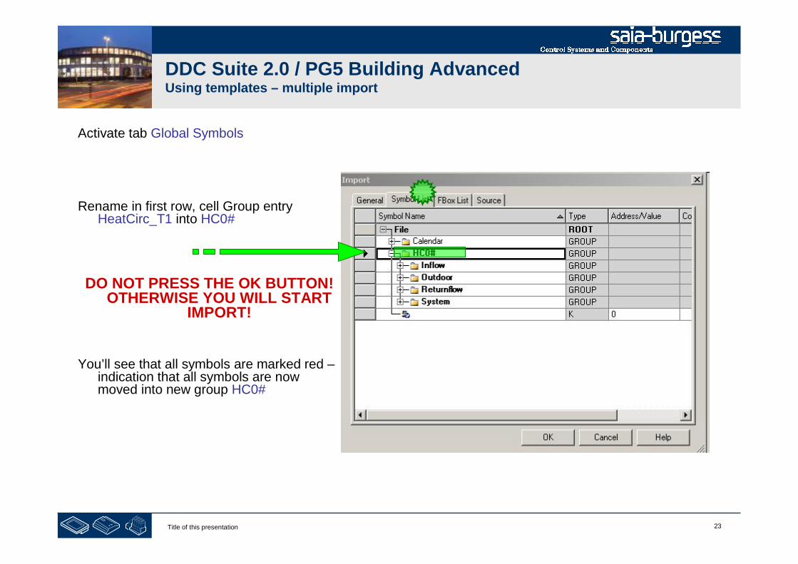
23Title of this presentation
DDC Suite 2.0 / PG5 Building AdvancedUsing templates – multiple import
Activate tab Global Symbols
Rename in first row, cell Group entryHeatCirc_T1 into HC0#
DO NOT PRESS THE OK BUTTON!OTHERWISE YOU WILL START
IMPORT!
You’ll see that all symbols are marked red –indication that all symbols are nowmoved into new group HC0#

24Title of this presentation
DDC Suite 2.0 / PG5 Building AdvancedUsing templates – multiple import
Activate tab FBox List
Mark all entries, click with right mousebutton and select from context menuReplace prefix
DO NOT PRESS THE OK BUTTON!OTHERWISE YOU WILL START
IMPORT!

25Title of this presentation
DDC Suite 2.0 / PG5 Building AdvancedUsing templates – multiple import
Enter in text field Find what: HeatCirc_T1_
Enter in text field Replace with: HC0#_
Click on button Replace All.
Click on button Cancel to close dialog.
And start import by clicking on button OK.
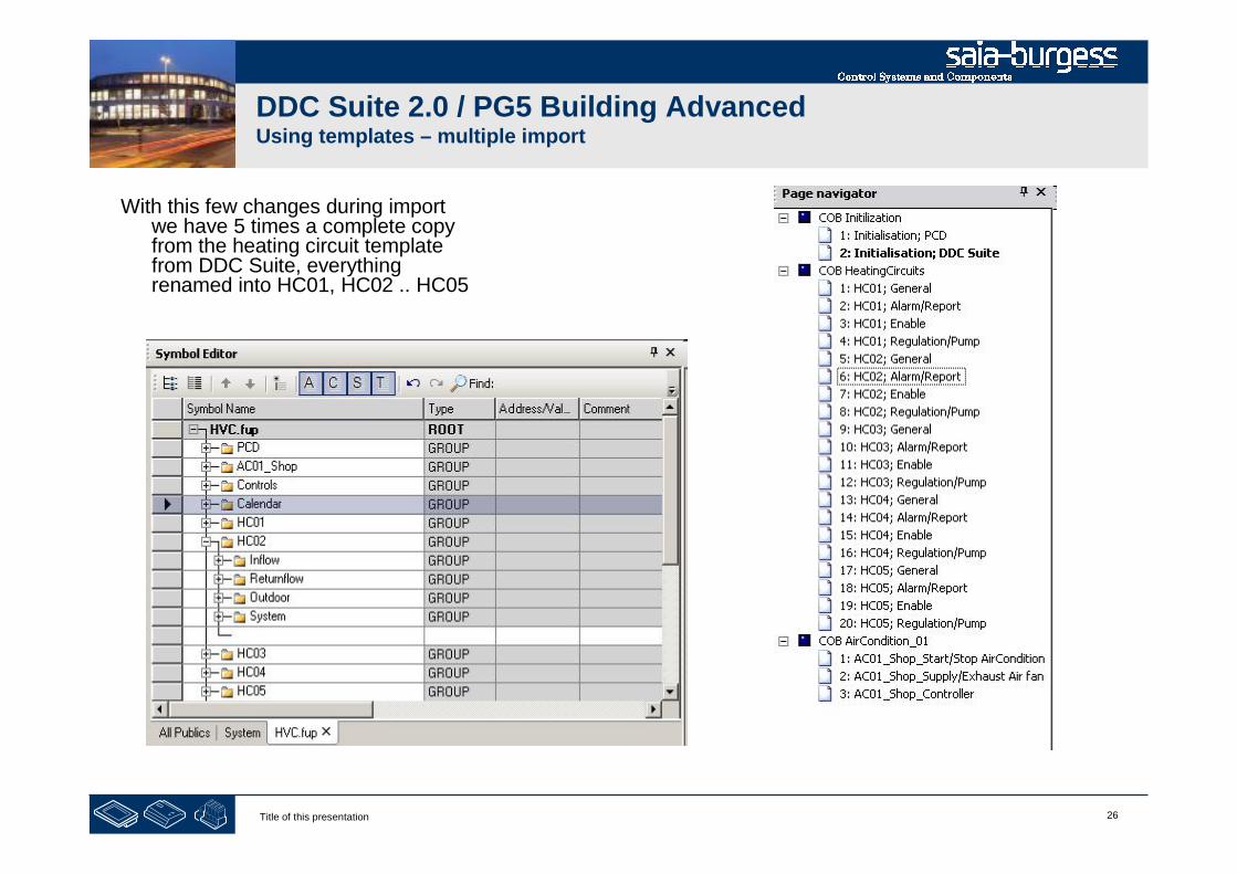
26Title of this presentation
DDC Suite 2.0 / PG5 Building AdvancedUsing templates – multiple import
With this few changes during importwe have 5 times a complete copyfrom the heating circuit templatefrom DDC Suite, everythingrenamed into HC01, HC02 .. HC05

27Title of this presentation
DDC Suite 2.0 / PG5 Building AdvancedUsing templates – multiple import
http://www.youtube.com/watch?v=E0LJsXTtN1Y
On YouTube you can find a video, that explains how to do a multiple import :

28Title of this presentation
PG5 Building Advanced / DDC Suite 2.0Working with Fupla
ToDo’s after an import
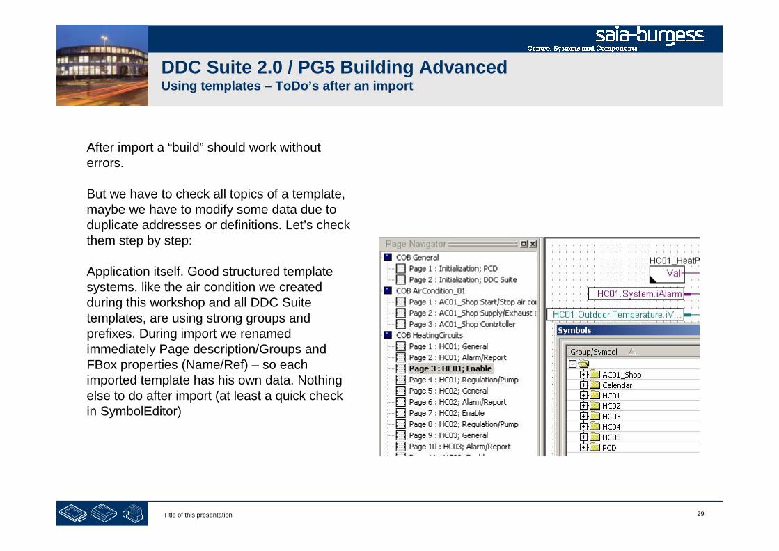
29Title of this presentation
DDC Suite 2.0 / PG5 Building AdvancedUsing templates – ToDo’s after an import
After import a “build” should work withouterrors.
But we have to check all topics of a template,maybe we have to modify some data due toduplicate addresses or definitions. Let’s checkthem step by step:
Application itself. Good structured templatesystems, like the air condition we createdduring this workshop and all DDC Suitetemplates, are using strong groups andprefixes. During import we renamedimmediately Page description/Groups andFBox properties (Name/Ref) – so eachimported template has his own data. Nothingelse to do after import (at least a quick checkin SymbolEditor)
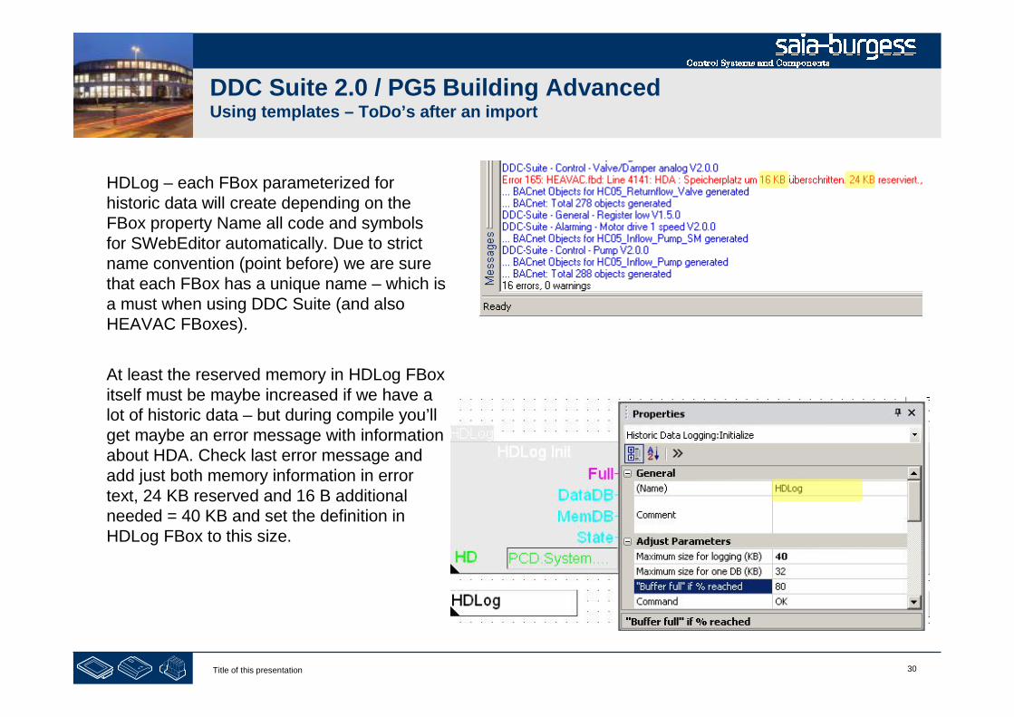
30Title of this presentation
DDC Suite 2.0 / PG5 Building AdvancedUsing templates – ToDo’s after an import
HDLog – each FBox parameterized forhistoric data will create depending on theFBox property Name all code and symbolsfor SWebEditor automatically. Due to strictname convention (point before) we are surethat each FBox has a unique name – which isa must when using DDC Suite (and alsoHEAVAC FBoxes).
At least the reserved memory in HDLog FBoxitself must be maybe increased if we have alot of historic data – but during compile you’llget maybe an error message with informationabout HDA. Check last error message andadd just both memory information in errortext, 24 KB reserved and 16 B additionalneeded = 40 KB and set the definition inHDLog FBox to this size.

31Title of this presentation
DDC Suite 2.0 / PG5 Building AdvancedUsing templates – ToDo’s after an import
Let’s check the alarm numbers, especially if allsystems are connected to the same alarm list.
When we check the file “DDC_Alarming.csv” andsort by column A and B then we’ll see that a lot ofalarm numbers are multi defined.
By default the templates are defined in FBox“AlarmHdr” to use alarm no. 11 as first alarm.
Now we have to reorganize the alarm numbers.Lets check the file and find out how many alarmsthe air condition and a heating circuit defines. (sortby column “C”)
Air condition: 16Heating circuit: 17
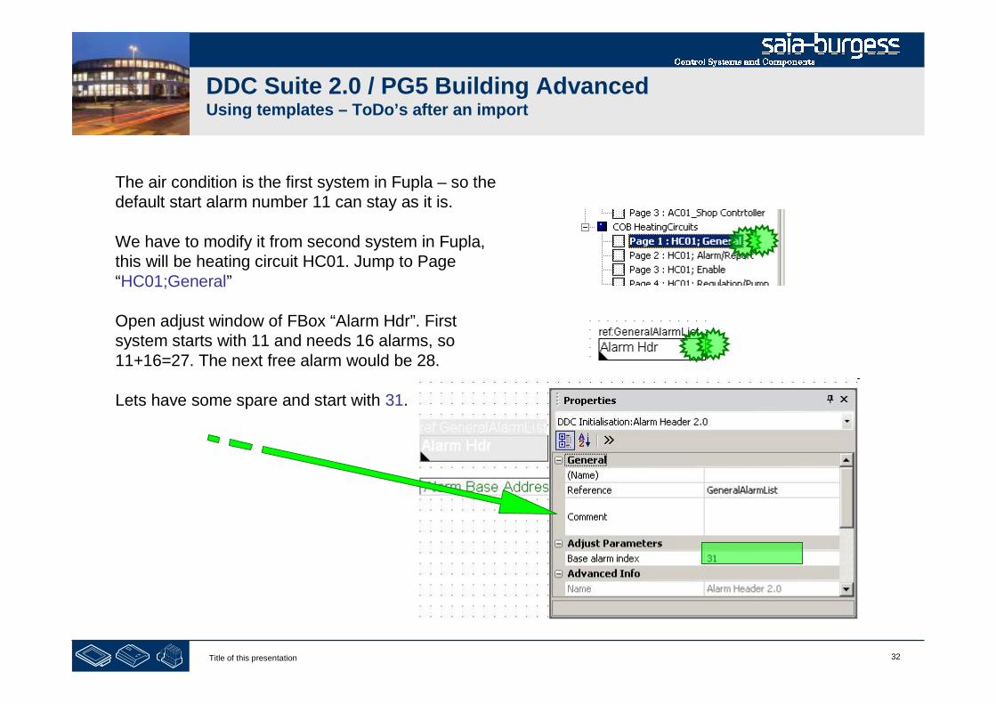
32Title of this presentation
DDC Suite 2.0 / PG5 Building AdvancedUsing templates – ToDo’s after an import
The air condition is the first system in Fupla – so thedefault start alarm number 11 can stay as it is.
We have to modify it from second system in Fupla,this will be heating circuit HC01. Jump to Page“HC01;General”
Open adjust window of FBox “Alarm Hdr”. Firstsystem starts with 11 and needs 16 alarms, so11+16=27. The next free alarm would be 28.
Lets have some spare and start with 31.

33Title of this presentation
DDC Suite 2.0 / PG5 Building AdvancedUsing templates – ToDo’s after an import
Repeat this with all other systems. Let’s take thefollowing base alarm numbers:
HC01: 31
HC02: 51
HC03: 71
HC04: 91
HC05: 111
After compile we should have an alarm list withoutdouble defined alarm numbers.
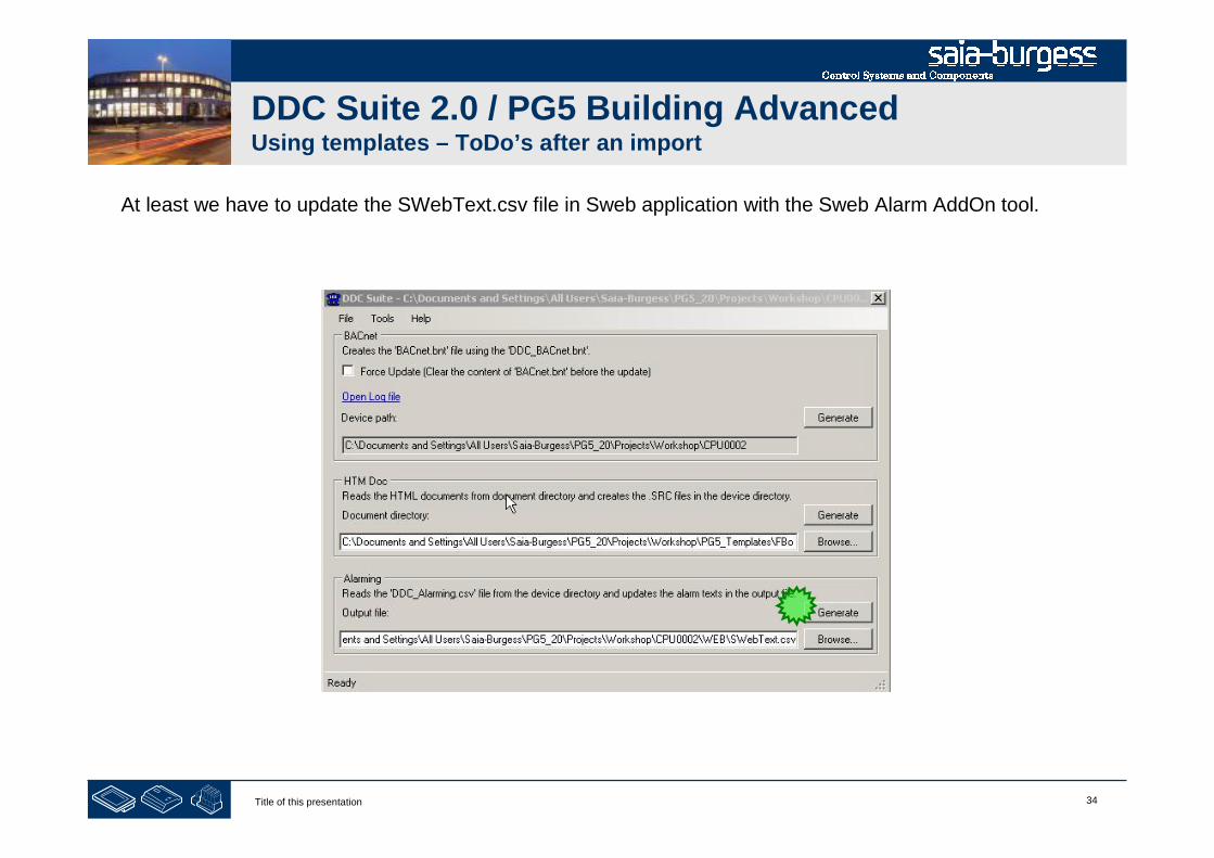
34Title of this presentation
DDC Suite 2.0 / PG5 Building AdvancedUsing templates – ToDo’s after an import
At least we have to update the SWebText.csv file in Sweb application with the Sweb Alarm AddOn tool.

35Title of this presentation
DDC Suite 2.0 / PG5 Building AdvancedUsing templates – ToDo’s after an import
BACnet – each FBox parameterized for BACnetwill create depending on the FBox property Nameall code and symbols and objects automatically.
Due to strict name convention (point before) weare sure that each FBox has a unique name –which is a must when using DDC Suite (and alsoHEAVAC FBoxes).
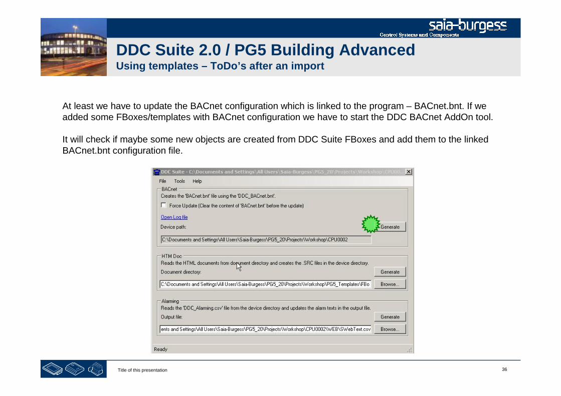
36Title of this presentation
DDC Suite 2.0 / PG5 Building AdvancedUsing templates – ToDo’s after an import
At least we have to update the BACnet configuration which is linked to the program – BACnet.bnt. If weadded some FBoxes/templates with BACnet configuration we have to start the DDC BACnet AddOn tool.
It will check if maybe some new objects are created from DDC Suite FBoxes and add them to the linkedBACnet.bnt configuration file.
37Title of this presentation
DDC Suite 2.0 / PG5 Building AdvancedUsing templates – ToDo’s after an import
After checking the settings for HDLog, alarming and BACnet we have to rebuild the program to be surethat all files are updated before downloading the program.

38Title of this presentation
PG5 Building Advanced / DDC Suite 2.0Working with Fupla
Predefined templates

39Title of this presentation
DDC Suite 2.0 / PG5 Building AdvancedUsing templates – Predefined templates
HeatCircuit_T1_Inflow_Controlled_1Pump
Outdoor temp. sensor Inflow temp. sensor Returnflow temp. sensor Pump Valve
Set point calculated via outdoor temp. Inflow temp. controlled Returnflow temp. max. controlled
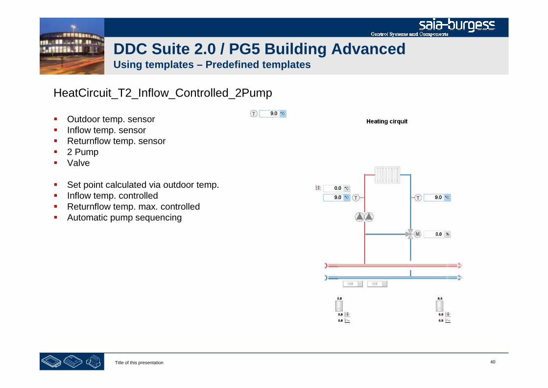
40Title of this presentation
DDC Suite 2.0 / PG5 Building AdvancedUsing templates – Predefined templates
HeatCircuit_T2_Inflow_Controlled_2Pump
Outdoor temp. sensor Inflow temp. sensor Returnflow temp. sensor 2 Pump Valve
Set point calculated via outdoor temp. Inflow temp. controlled Returnflow temp. max. controlled Automatic pump sequencing

41Title of this presentation
DDC Suite 2.0 / PG5 Building AdvancedUsing templates – Predefined templates
HotWater_T1_Primary_Uncontrolled_Circulation
Tank temp. (top) sensor Tank temp. (bottom) sensor Inflow temp. sensor Max. temp. limiter Pump Valve
Inflow temp. controlled Disinfection
Circulation: Pump
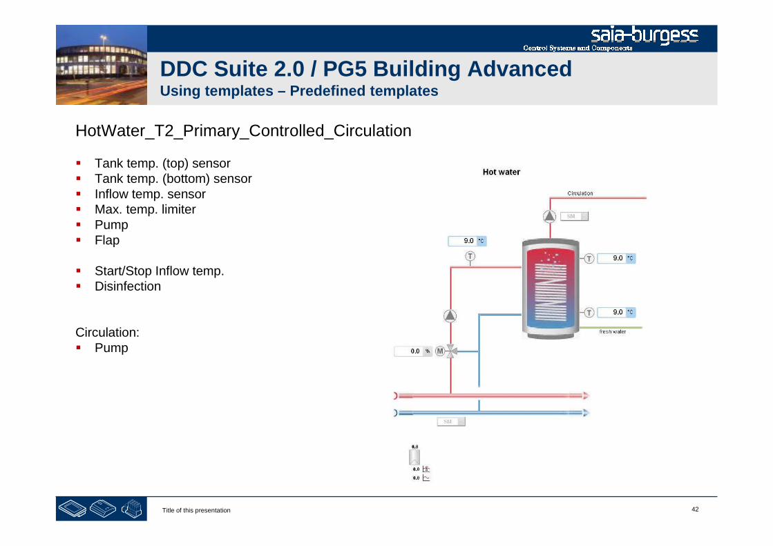
42Title of this presentation
DDC Suite 2.0 / PG5 Building AdvancedUsing templates – Predefined templates
HotWater_T2_Primary_Controlled_Circulation
Tank temp. (top) sensor Tank temp. (bottom) sensor Inflow temp. sensor Max. temp. limiter Pump Flap
Start/Stop Inflow temp. Disinfection
Circulation: Pump

43Title of this presentation
DDC Suite 2.0 / PG5 Building AdvancedUsing templates – Predefined templates
AirCondition_T1_PressContr_Master_CoolMixAirHeat
Outdoor temp. sensor Supply air temp. sensor Exhaust air temp. sensor 2 room temp. sensor Room set point correction Cooler/Mixed Air/Heater Supply/Exhaust fan
Air condition sequence start Master-Sequence cascade Heater frost protection Summer night cooling Room frost protection

44Title of this presentation
DDC Suite 2.0 / PG5 Building AdvancedUsing templates – Predefined templates
AirCondition_T2_1speed_Master_CoolMixAirHeat
Outdoor temp. sensor
Supply air temp. sensor
Exhaust air temp. sensor
2 room temp. sensor
Room set point correction
Cooler/Mixed Air/Heater
Supply/Exhaust fan
Air condition sequence start
Master-Sequence cascade
Heater frost protection
Summer night cooling
Room frost protection

1Title of this presentation
PG5 Building Advanced / DDC Suite 2.0Documentation
DDC Suite - Documentation

2Title of this presentation
DDC Suite 2.0 / PG5 Building AdvancedDocumentation
DDC Suite FBoxes are object oriented in functionality. Therefore each FBox contains a function, like “Sensormeasurement”, and all necessary data point.
So it’s possible have a clear description with all parameter for a FBox like:
Recording of the measurement reading with calibration, filtering and limit valuemonitoring. The connected analogue value can be upgraded according to thetype.
PCD2.W220 NI1000 DIN : The raw score is supplied by the card(standard/analogue module/PCD2.W220) and the physical value calculated herePCD2.W340 NI1000 DIN : The raw score is supplied by the card(standard/analogue module/PCD2.W340) and the physical value calculated hereThe physical value is already attached at the input contact.Conversion: An arbitrary value (mostly from an active sensor) is converted bymeans of a linear equation.
The recorded measurement reading can be calibrated by specifying anadjustment. Subsequently, the measurement reading is filtered. The frequencyof the measurement reading can be set, the smoothing factor states theallotment, which is included in the new measurement reading in case of ameasured value alteration.
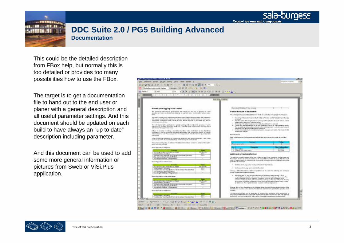
3Title of this presentation
DDC Suite 2.0 / PG5 Building AdvancedDocumentation
This could be the detailed descriptionfrom FBox help, but normally this istoo detailed or provides too manypossibilities how to use the FBox.
The target is to get a documentationfile to hand out to the end user orplaner with a general description andall useful parameter settings. And thisdocument should be updated on eachbuild to have always an “up to date”description including parameter.
And this document can be used to addsome more general information orpictures from Sweb or ViSi.Plusapplication.

4Title of this presentation
DDC Suite 2.0 / PG5 Building AdvancedDocumentation
DDC Suite FBoxes are able to do this. Each FBox supports an external file.
If the file is not present then no documentation is created from this FBox
if the file is found then the definition for documentation is parsed in this file
So the external file enables the documentation!
There are 2 kind of files
files which are parsed from the FBox during build – they are not editable
Source files, editable e.g. with MS Word and saved in HTML format
The first type of files are structured with a strong name convention
DOC_ - declares that this file contains documentation information
DDC_ - identifies that this file is used with DDC suite FBoxes
“Family_” e.g. Alarming - declares the DDC Suite family
“FBox” e.g. 1Alarm – defines the FBox itself
.src – file extenstion
Example: DOC_DDC_Alarming_1Alarm.src
But you don’t have to know all these file names or create them by yourself.

5Title of this presentation
DDC Suite 2.0 / PG5 Building AdvancedDocumentation
The source files are structured with a strong name convention
DOC_ - declares that this file contains documentation information
DDC_ - identifies that this file is used with DDC suite FBoxes
“Family_” e.g. Alarming - declares the DDC Suite family
“FBox” e.g. 1Alarm_ – defines the FBox itself
addendum “Main” - general part, must exist
addendum “HDLog” this part contains the description about historic data (optional)
addendum “Alarm” this part contains the description about alarm data points (optional)
addendum “BACnet” this part contains the description BACnet data points (optional)
.src – file extenstion
So one FBox can have up to 4 source files (DOC_DDC_FamilyFBox_Main.html,DOC_DDC_FamilyFBox_HDLog.html, DOC_DDC_FamilyFBox_Alarm.html,DOC_DDC_FamilyFBox_BACnet.html)
But you don’t have to know all these file names or create them by yourself.
And these source files must be converted into the file the FBox is able to parse during build. Thiswill do the AddOn tool.
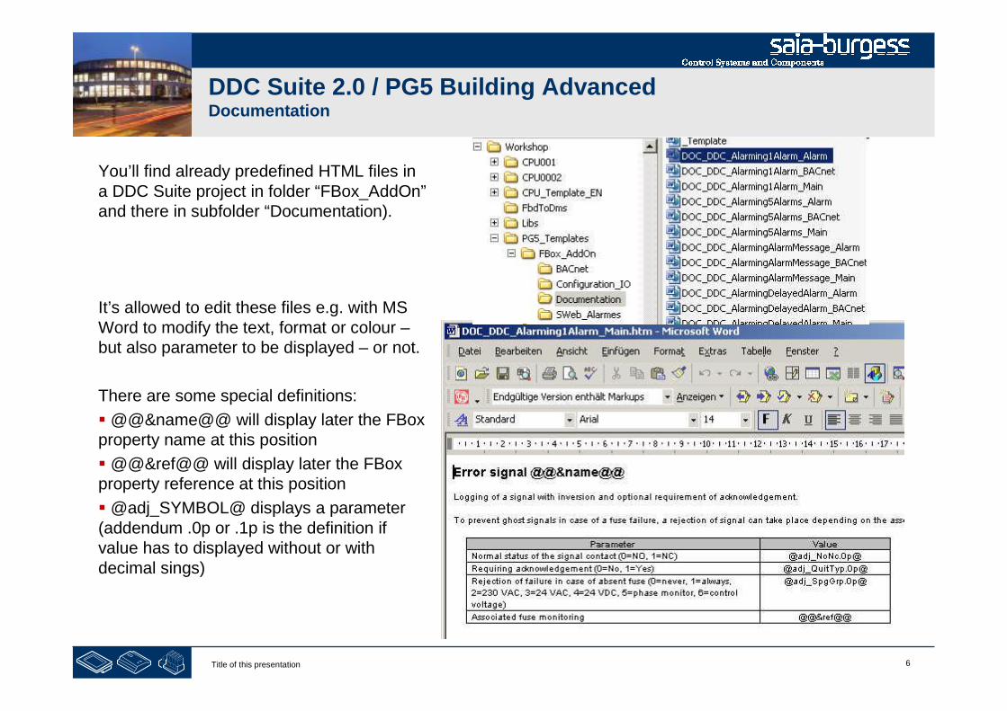
6Title of this presentation
DDC Suite 2.0 / PG5 Building AdvancedDocumentation
You’ll find already predefined HTML files ina DDC Suite project in folder “FBox_AddOn”and there in subfolder “Documentation).
It’s allowed to edit these files e.g. with MSWord to modify the text, format or colour –but also parameter to be displayed – or not.
There are some special definitions:
@@&name@@ will display later the FBoxproperty name at this position
@@&ref@@ will display later the FBoxproperty reference at this position
@adj_SYMBOL@ displays a parameter(addendum .0p or .1p is the definition ifvalue has to displayed without or withdecimal sings)

7Title of this presentation
DDC Suite 2.0 / PG5 Building AdvancedDocumentation
After changing the file you must save it– but in a special format.
Select from menu “File&Save as” andselect file type “Website, filtered(*.htm).
This will produce a slim HTML file – ifyou save it as default HTML file type –it won’t work!

8Title of this presentation
DDC Suite 2.0 / PG5 Building AdvancedDocumentation
After modifying the source files to your belongings we have to combine the (up to) 4 source files into the*.SRC file which is used from the FBox.
These source files must be converted into the file the FBox is able to parse during build. This will do theDDC AddOn tool.
Start the *.ddc Addon tool by double clicking on it.
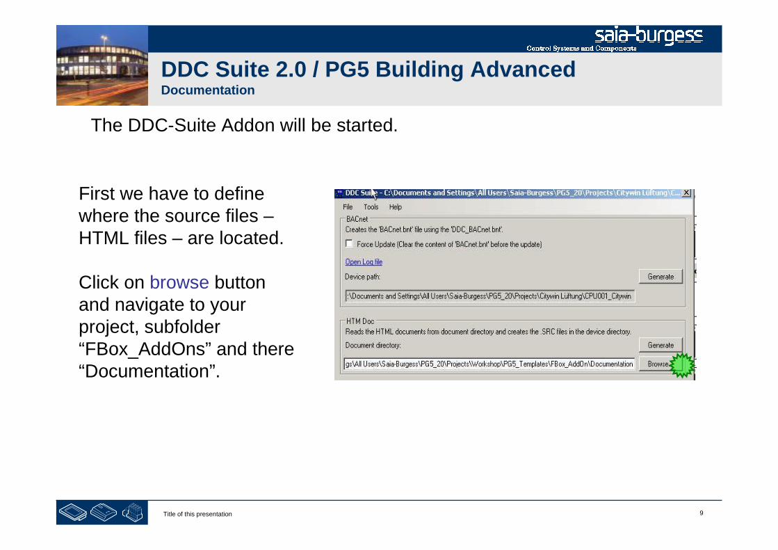
9Title of this presentation
DDC Suite 2.0 / PG5 Building AdvancedDocumentation
The DDC-Suite Addon will be started.
First we have to definewhere the source files –HTML files – are located.
Click on browse buttonand navigate to yourproject, subfolder“FBox_AddOns” and there“Documentation”.
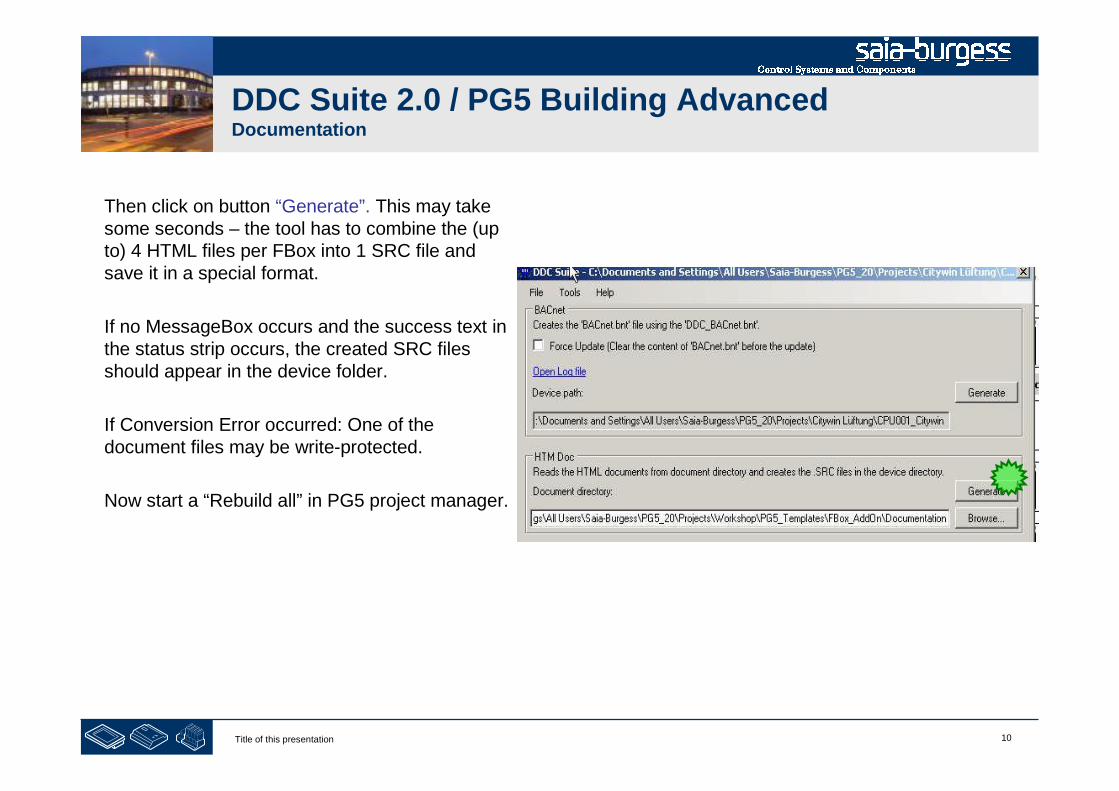
10Title of this presentation
DDC Suite 2.0 / PG5 Building AdvancedDocumentation
Then click on button “Generate”. This may takesome seconds – the tool has to combine the (upto) 4 HTML files per FBox into 1 SRC file andsave it in a special format.
If no MessageBox occurs and the success text inthe status strip occurs, the created SRC filesshould appear in the device folder.
If Conversion Error occurred: One of thedocument files may be write-protected.
Now start a “Rebuild all” in PG5 project manager.

11Title of this presentation
DDC Suite 2.0 / PG5 Building AdvancedDocumentation
Open the document with a doubleclick – by default it will be displayedwith your default browser.
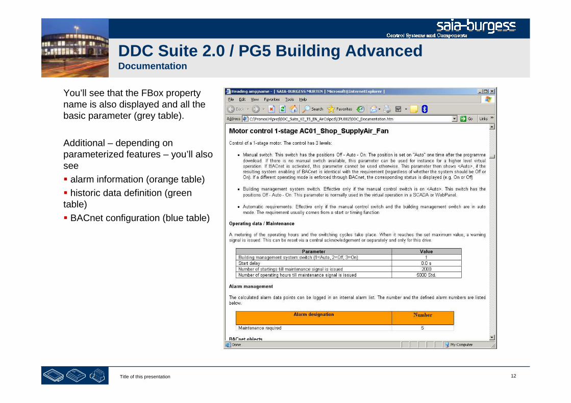
12Title of this presentation
DDC Suite 2.0 / PG5 Building AdvancedDocumentation
You’ll see that the FBox propertyname is also displayed and all thebasic parameter (grey table).
Additional – depending onparameterized features – you’ll alsosee
alarm information (orange table)
historic data definition (greentable)
BACnet configuration (blue table)
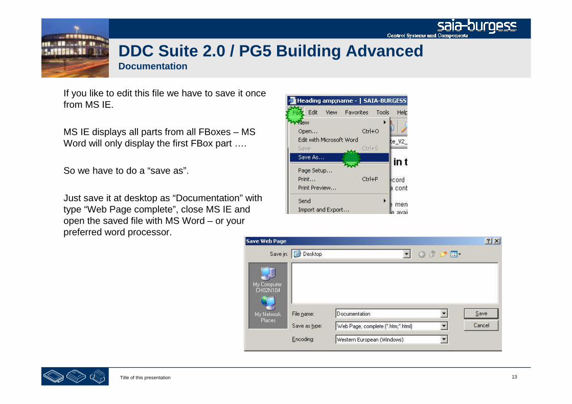
13Title of this presentation
DDC Suite 2.0 / PG5 Building AdvancedDocumentation
If you like to edit this file we have to save it oncefrom MS IE.
MS IE displays all parts from all FBoxes – MSWord will only display the first FBox part ….
So we have to do a “save as”.
Just save it at desktop as “Documentation” withtype “Web Page complete”, close MS IE andopen the saved file with MS Word – or yourpreferred word processor.
14Title of this presentation
PG5 Building Advanced / DDC Suite 2.0Documentation
System description
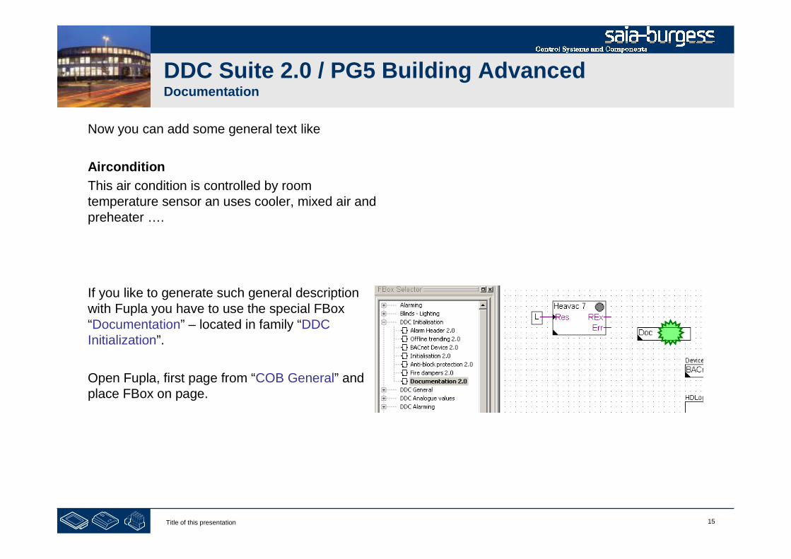
15Title of this presentation
DDC Suite 2.0 / PG5 Building AdvancedDocumentation
Now you can add some general text like
Aircondition
This air condition is controlled by roomtemperature sensor an uses cooler, mixed air andpreheater ….
If you like to generate such general descriptionwith Fupla you have to use the special FBox“Documentation” – located in family “DDCInitialization”.
Open Fupla, first page from “COB General” andplace FBox on page.
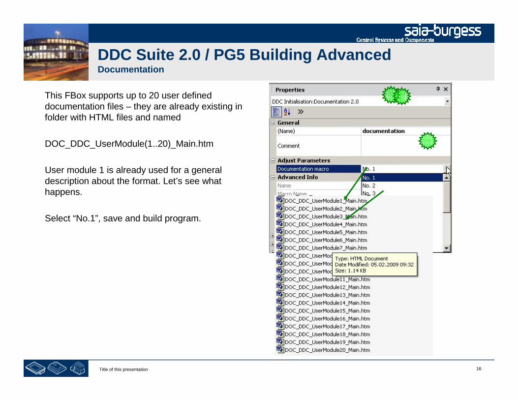
16Title of this presentation
DDC Suite 2.0 / PG5 Building AdvancedDocumentation
This FBox supports up to 20 user defined documentation files – they are already existing in folder with HTML files and named
DOC_DDC_UserModule(1..20)_Main.htm
User module 1 is already used for a general description about the format. Let’s see what happens.
Select “No.1”, save and build program.
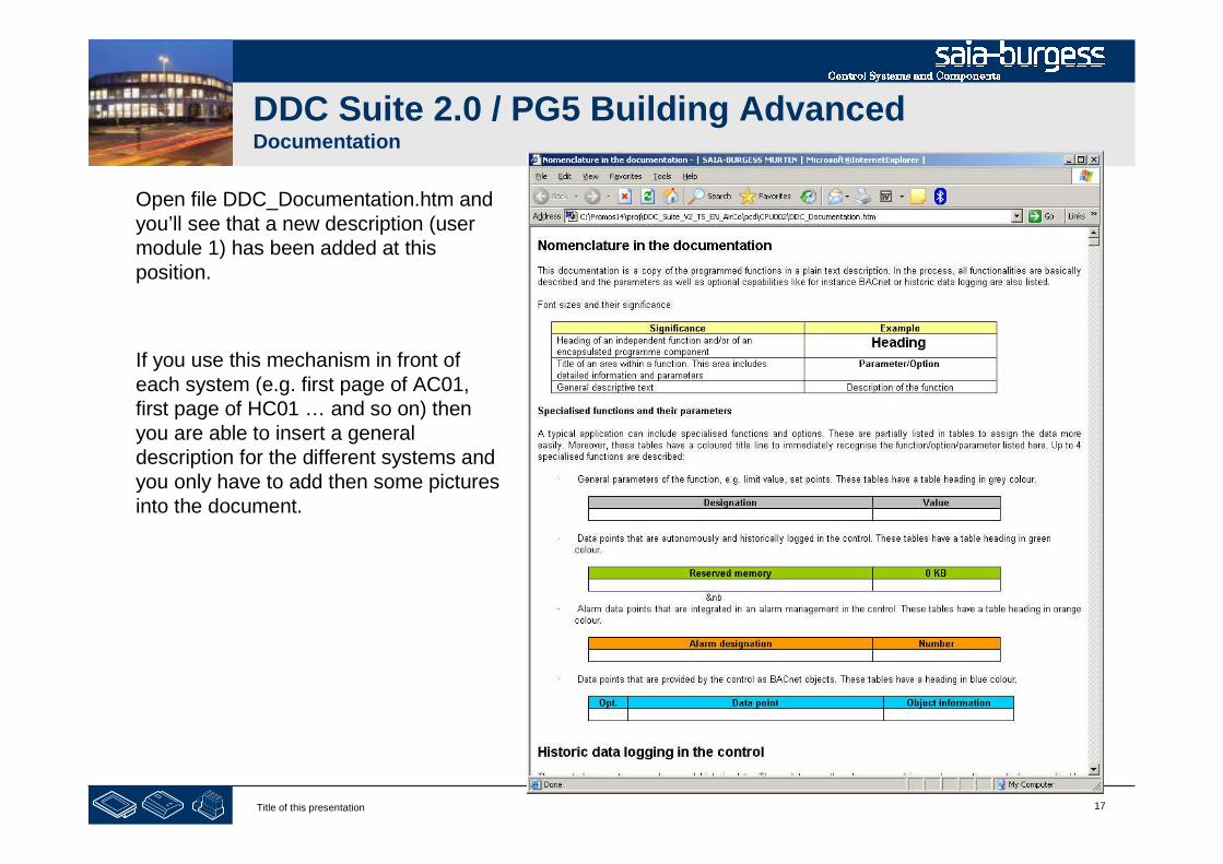
17Title of this presentation
DDC Suite 2.0 / PG5 Building AdvancedDocumentation
Open file DDC_Documentation.htm andyou’ll see that a new description (usermodule 1) has been added at thisposition.
If you use this mechanism in front ofeach system (e.g. first page of AC01,first page of HC01 … and so on) thenyou are able to insert a generaldescription for the different systems andyou only have to add then some picturesinto the document.

18Title of this presentation 18Dokumentation
PG5 Building Advanced / DDC Suite 2.0Dokumentation
I/O Allocation
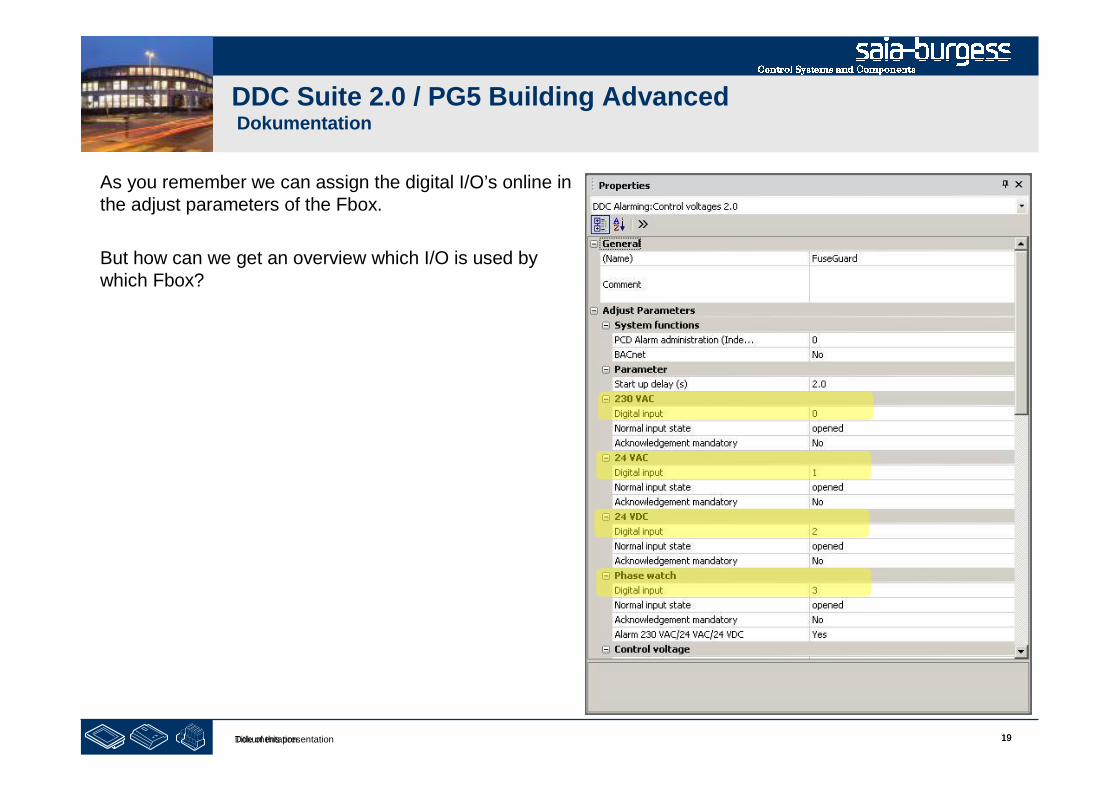
19Title of this presentation 19Dokumentation
DDC Suite 2.0 / PG5 Building AdvancedDokumentation
As you remember we can assign the digital I/O’s online inthe adjust parameters of the Fbox.
But how can we get an overview which I/O is used bywhich Fbox?

20Title of this presentation 20Dokumentation
DDC Suite 2.0 / PG5 Building AdvancedDokumentation
After a build you can see the I/Oallocation in the following file.
DDC_DI_DI_List.csv
You can double click it to view it withMS Excel

21Title of this presentation 21Dokumentation
DDC Suite 2.0 / PG5 Building AdvancedDokumentation
In this file you see the following informations:
•Name of Datapoint
• Type digital I/O
• Adress digital I/O
• Fbox Property Name
• Name of Fbox
• Family of FBox

1Title of this presentation
PG5 Building Advanced / DDC Suite 2.0DDC Suite and ViSi.Plus
ViSi.Plus
2Title of this presentation
DDC Suite 2.0 / PG5 Building AdvancedSyntax and remarks of actions during workshop
Please follow the teachers advice.
Please:
- use the same symbol names
- use the same group names
- place the FBoxes approx. at the same position
- do not work faster or different even if you are a “frequent ViSi.Plus user”
This workshop will show you some basic mechanism, structured workflow and well structured symbolorganisation. Don’t be afraid.
You don’t
- have to learn all FBoxes during this workshop
- have to be familiar with application programming
- must be a super programmer
If you just learn the mechanism and philosophy you’ll understand the advantage SI can have with DDC Suite
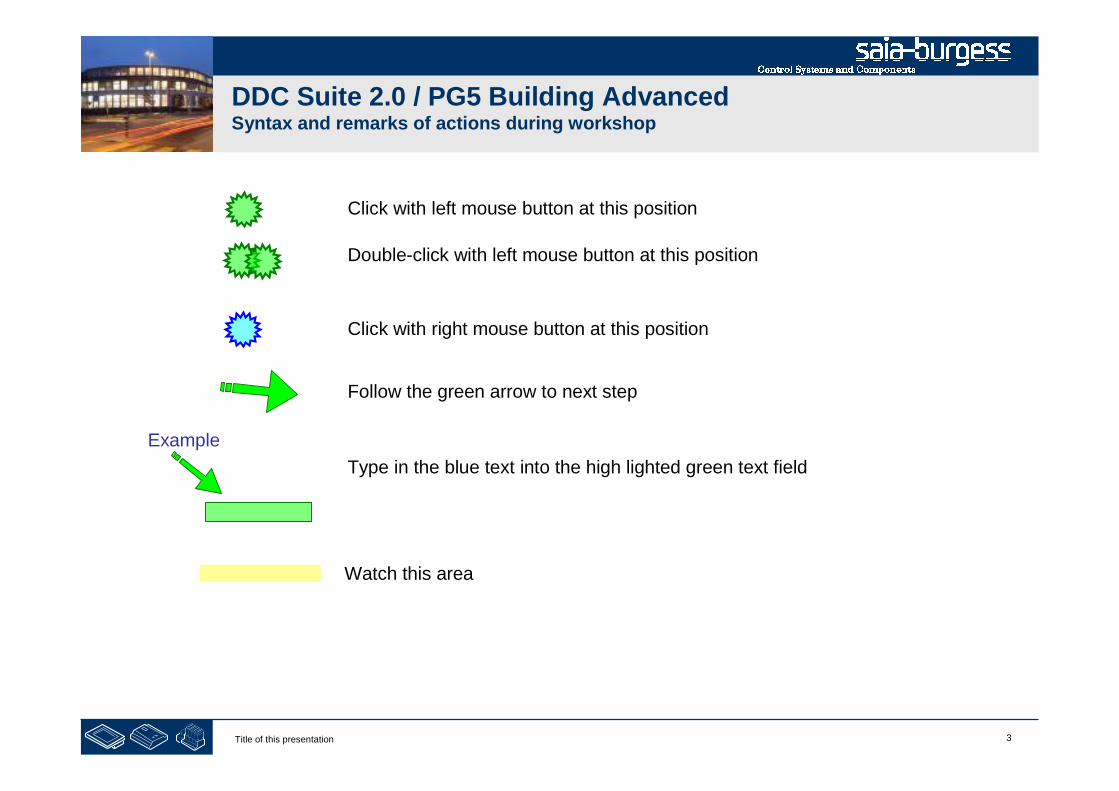
3Title of this presentation
DDC Suite 2.0 / PG5 Building AdvancedSyntax and remarks of actions during workshop
Click with left mouse button at this position
Click with right mouse button at this position
Follow the green arrow to next step
Example
Type in the blue text into the high lighted green text field
Double-click with left mouse button at this position
Watch this area

4Title of this presentation
PG5 Building Advanced / DDC Suite 2.0DDC Suite and ViSi.Plus
Installation of Visi.Plus
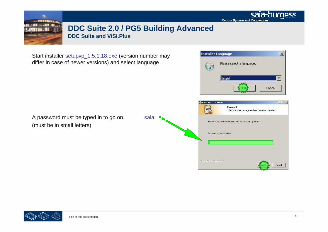
5Title of this presentation
DDC Suite 2.0 / PG5 Building AdvancedDDC Suite and ViSi.Plus
Start installer setupvp_1.5.1.18.exe (version number maydiffer in case of newer versions) and select language.
A password must be typed in to go on. saia
(must be in small letters)

6Title of this presentation
DDC Suite 2.0 / PG5 Building AdvancedDDC Suite and ViSi.Plus
Click on “Welcome …” dialog at button Next to continue
Select option I accept the terms in the License Agreementand click on button Next.
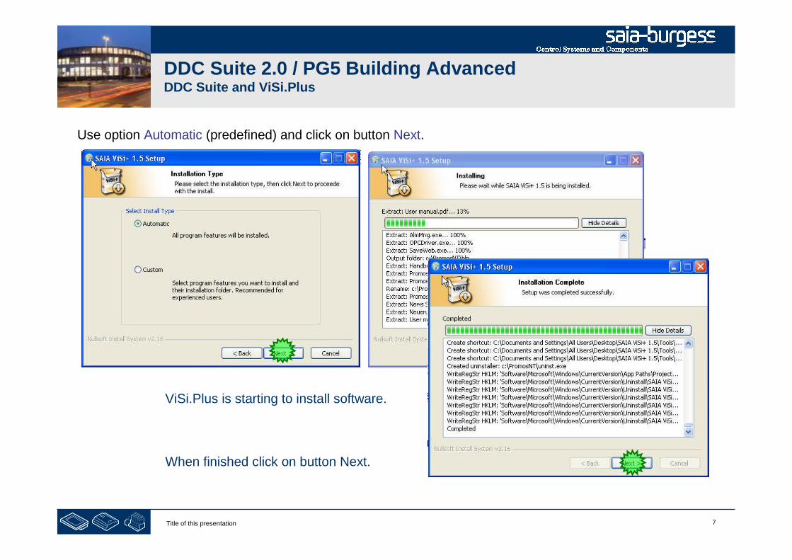
7Title of this presentation
DDC Suite 2.0 / PG5 Building AdvancedDDC Suite and ViSi.Plus
Use option Automatic (predefined) and click on button Next.
ViSi.Plus is starting to install software.
When finished click on button Next.
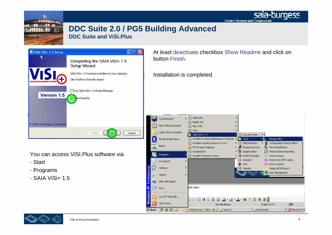
8Title of this presentation
DDC Suite 2.0 / PG5 Building AdvancedDDC Suite and ViSi.Plus
You can access ViSI.Plus software via
- Start
- Programs
- SAIA ViSi+ 1.5
At least deactivate checkbox Show Readme and click onbutton Finish.
Installation is completed.
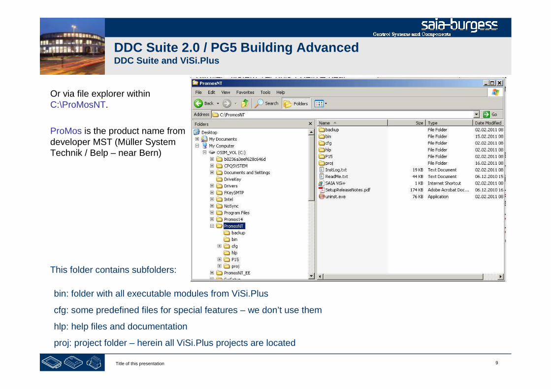
9Title of this presentation
DDC Suite 2.0 / PG5 Building AdvancedDDC Suite and ViSi.Plus
Or via file explorer withinC:\ProMosNT.
ProMos is the product name fromdeveloper MST (Müller SystemTechnik / Belp – near Bern)
bin: folder with all executable modules from ViSi.Plus
cfg: some predefined files for special features – we don’t use them
hlp: help files and documentation
proj: project folder – herein all ViSi.Plus projects are located
This folder contains subfolders:

10Title of this presentation
PG5 Building Advanced / DDC Suite 2.0DDC Suite and ViSi.Plus
Start up

11Title of this presentation
DDC Suite 2.0 / PG5 Building AdvancedDDC Suite and ViSi.Plus
I recommend to access ViSi.Plus modules viafile explorer or if you work often with ViSi.Pluscreate some desktop shortcuts.
Why? ViSi.Plus is a modular software andduring engineering it’s not necessary to startalways all modules – this will cost time duringstart up.
Therefore we will start only the modules whichare necessary to work with.
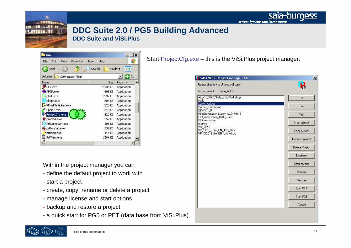
12Title of this presentation
DDC Suite 2.0 / PG5 Building AdvancedDDC Suite and ViSi.Plus
Within the project manager you can
- define the default project to work with
- start a project
- create, copy, rename or delete a project
- manage license and start options
- backup and restore a project
- a quick start for PG5 or PET (data base from ViSi.Plus)
Start ProjectCfg.exe – this is the ViSi.Plus project manager.

13Title of this presentation
PG5 Building Advanced / DDC Suite 2.0DDC Suite and ViSi.Plus
Creating a new project

14Title of this presentation
DDC Suite 2.0 / PG5 Building AdvancedDDC Suite and ViSi.Plus
A new ViSi.Plus DDC Suite project could be started within projectmanager via „New project “. But then the user has to integratemanually all he‘d like to use, e.g. HMI, BACnet, graphics, screens,pictures and so on.
We recommend to start a new project via„Restore“, that means we are using a predefinedDDC Suite template projects where a lot ofsettings or pages, templates are already prepared.
Therefore those template projects includeeverything what can be used in a project, e.g.FBox libraries, Fupla template pages, SWebtemplate objects
Thereby a project backup will be a little bit larger(e.g. >20 MB) but changes in future in this projectmay have no compatibility problem, e.g. if inmeantime a FBox library has totally changed.
Of course – our template project can be updatedwith 3rd party libraries and backup-ed as newtemplate project.

15Title of this presentation
DDC Suite 2.0 / PG5 Building AdvancedDDC Suite and ViSi.Plus
So we are starting with „Restore “ – by selecting a projecttemplate. Depending on template version or location we haveto navigate to the correct folder …
First we have to select the folder wherein the templates areavailable and click on button OK.
From Visi.Plus version 1.5.1.18 the VP_DDC_Suite_XX_YYtemplates are available the backup folder of PromosNT(C:\PromosNT\backup)
(Get the newest templates from SBC Support HomePagewww.sbc-support.ch within Software/PG5/DDC Suite)
Now you’ll see in list Available backups all project templates.Select a project and press “OK” and the template project willbe used as base for our Workshop project.
(DDC_Suite_V2_T2_ViSiPlus_International_VER_08.10.08 16.27.zip)

16Title of this presentation
DDC Suite 2.0 / PG5 Building AdvancedDDC Suite and ViSi.Plus
After restoring the template project just select it in projectlist and click on button OK.
The project manager will terminate and nothing elsehappens. By clicking on button OK we just define theselected project as default project ViSi.Plus will work withwhen we start manually some modules.
Of course this is not the way the end user has to startViSi.Plus! Therefore we have a project starter moduleswhich will start all necessary modules in a defined way.
I recommend to use the method I show for engineering –because is more comfortable.

17Title of this presentation
DDC Suite 2.0 / PG5 Building AdvancedDDC Suite and ViSi.Plus
If we have a look into our workshop project (useWindows File Explorer) we’ll see that already somefolders are included:
- bmp: all BMP or GIF files must be located here
- cfg: data base files, language depending files
- dat: historic data files
- drv: driver settings
- lic: license file
- log: log files
- mac: macros to be used/created in graphic editor
- pcd: PG5 project
- src: screen file, all pages and pop up windows
- www: web server files
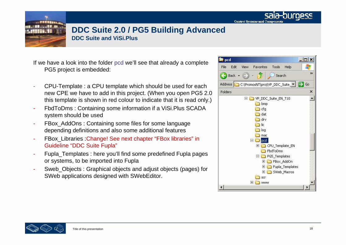
18Title of this presentation
DDC Suite 2.0 / PG5 Building AdvancedDDC Suite and ViSi.Plus
If we have a look into the folder pcd we’ll see that already a completePG5 project is embedded:
- CPU-Template : a CPU template which should be used for eachnew CPE we have to add in this project. (When you open PG5 2.0this template is shown in red colour to indicate that it is read only.)
- FbdToDms : Containing some information if a ViSi.Plus SCADAsystem should be used
- FBox_AddOns : Containing some files for some languagedepending definitions and also some additional features
- FBox_Libraries :Change! See next chapter “FBox libraries” inGuideline “DDC Suite Fupla”
- Fupla_Templates : here you’ll find some predefined Fupla pagesor systems, to be imported into Fupla
- Sweb_Objects : Graphical objects and adjust objects (pages) forSWeb applications designed with SWebEditor.
19Title of this presentation
DDC Suite 2.0 / PG5 Building AdvancedDDC Suite and ViSi.Plus
Why?
A ViSi.Plus project does not only contain some pictures and graphics – it should also contain the PG5project itself because ViSi.Plus can get a lot of information out of a PG5 project!
And ViSi.Plus project manager will backup all sub folders within the ViSi.Plus project – so if you backupyour project you’ll have always a complete backup – and not only the part PG5 or ViSi.Plus. This makesyour project consistent.
The PG5 project within a ViSi.Plus project must always be defined as pcd. ViSi.Plus is looking always toa PG5 project pcd within pcd folder. If you rename the PG5 project ViSi.Plus cannot find the PG5 projectanymore – this is a hard restriction.

20Title of this presentation
PG5 Building Advanced / DDC Suite 2.0DDC Suite and ViSi.Plus
Basic settings
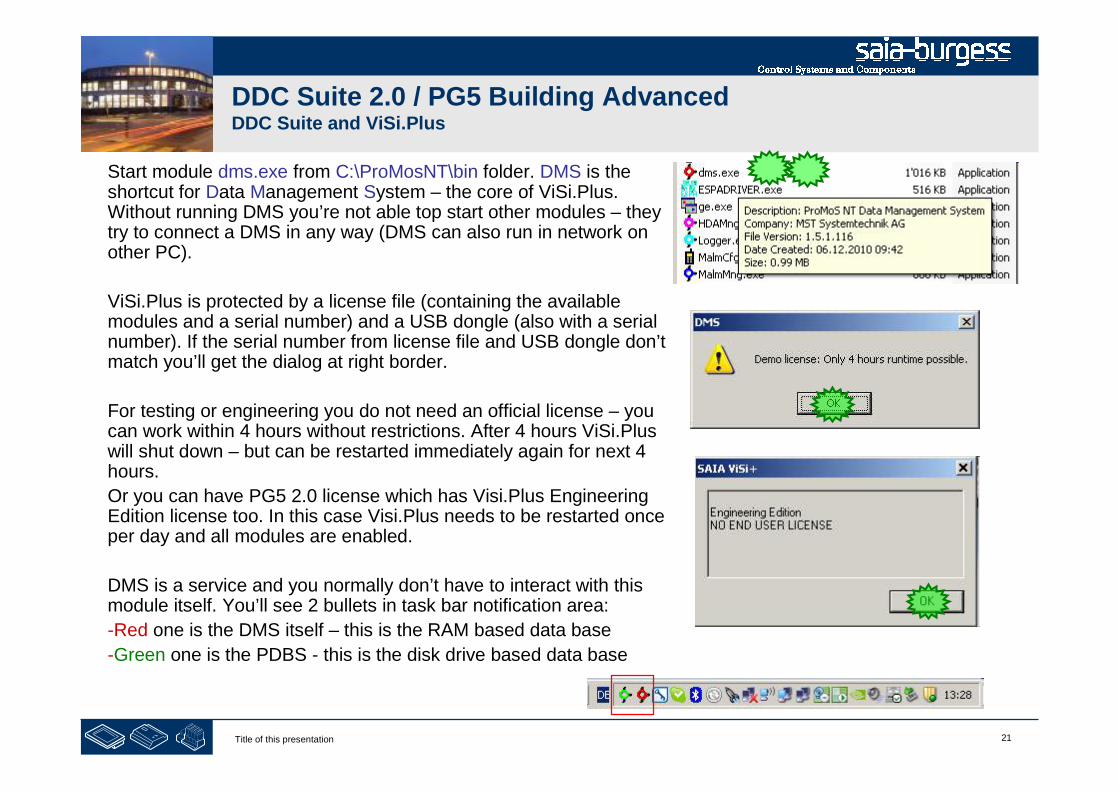
21Title of this presentation
DDC Suite 2.0 / PG5 Building AdvancedDDC Suite and ViSi.Plus
Start module dms.exe from C:\ProMosNT\bin folder. DMS is theshortcut for Data Management System – the core of ViSi.Plus.Without running DMS you’re not able top start other modules – theytry to connect a DMS in any way (DMS can also run in network onother PC).
ViSi.Plus is protected by a license file (containing the availablemodules and a serial number) and a USB dongle (also with a serialnumber). If the serial number from license file and USB dongle don’tmatch you’ll get the dialog at right border.
For testing or engineering you do not need an official license – youcan work within 4 hours without restrictions. After 4 hours ViSi.Pluswill shut down – but can be restarted immediately again for next 4hours.
Or you can have PG5 2.0 license which has Visi.Plus EngineeringEdition license too. In this case Visi.Plus needs to be restarted onceper day and all modules are enabled.
DMS is a service and you normally don’t have to interact with thismodule itself. You’ll see 2 bullets in task bar notification area:
-Red one is the DMS itself – this is the RAM based data base
-Green one is the PDBS - this is the disk drive based data base

22Title of this presentation
DDC Suite 2.0 / PG5 Building AdvancedDDC Suite and ViSi.Plus
Now we can start pet.exe. PET is a shortcut forProcess Engineering Tool.
When starting PET first time after installation it will askfor a PLC-driver. Select the entry SDRIVER.PET.
Finally you see PET application.

23Title of this presentation
DDC Suite 2.0 / PG5 Building AdvancedDDC Suite and ViSi.Plus
ViSi.Plus can manage PG5 projects sotherefore we have to define first time afterinstallation which PG5 version we’d liketo use.
Therefore select from menu SAIA-PG5, incontext menu Options PG5 and therePG5 Version.
Select from drop down list PromosCommunication Driver entry PG5 Version2.0 and finish by clicking on button OK.

24Title of this presentation
PG5 Building Advanced / DDC Suite 2.0DDC Suite and ViSi.Plus
Preparation

25Title of this presentation
DDC Suite 2.0 / PG5 Building AdvancedDDC Suite and ViSi.Plus
OK – basic preparations finished.
What we can see in PET:
- symbol bar with icons with PG5 connectivity
- tab Process objects where all objects from data baseare listed
As we see there are no process objects – we have tocreate some. But this we’ll do in a normal way – meansengineering a Fupla and getting the data from theFupla into ViSi.Plus data base.
Therefore just click on symbol PG5
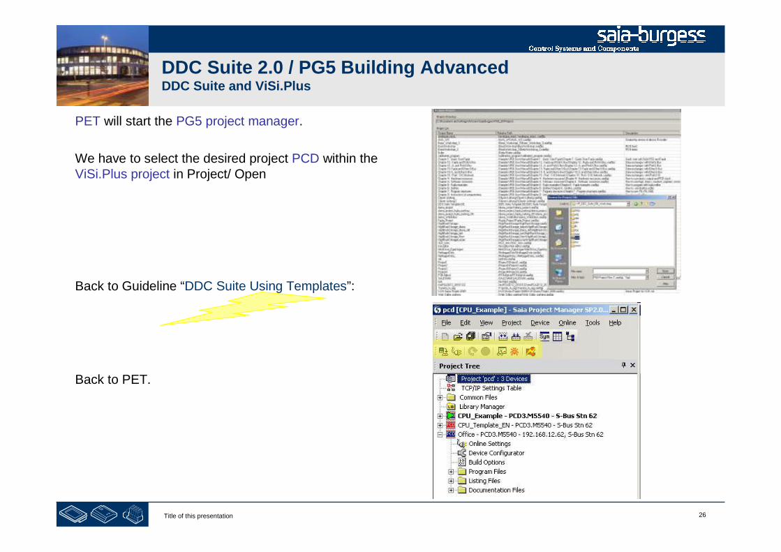
26Title of this presentation
DDC Suite 2.0 / PG5 Building AdvancedDDC Suite and ViSi.Plus
PET will start the PG5 project manager.
We have to select the desired project PCD within theViSi.Plus project in Project/ Open
Back to Guideline “DDC Suite Using Templates”:
Back to PET.

27Title of this presentation
PG5 Building Advanced / DDC Suite 2.0DDC Suite and ViSi.Plus
Importing data from Fupla
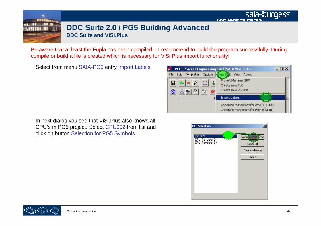
28Title of this presentation
DDC Suite 2.0 / PG5 Building AdvancedDDC Suite and ViSi.Plus
Be aware that at least the Fupla has been compiled – I recommend to build the program successfully. Duringcompile or build a file is created which is necessary for ViSi.Plus import functionality!
Select from menu SAIA-PG5 entry Import Labels.
In next dialog you see that ViSi.Plus also knows allCPU’s in PG5 project. Select CPU002 from list andclick on button Selection for PG5 Symbols.

29Title of this presentation
DDC Suite 2.0 / PG5 Building AdvancedDDC Suite and ViSi.Plus
A progress dialog is shown and ViSi.Plus is parsing afile in PG5 project in CPU002 to find all DDC SuiteFBoxes and the depending group structure.
Maybe after import you don’t see any process objects– in this case we have to set a filter. Select Optionsfrom menu and then Filter.
Select in dialog from drop down list PLC-Name entryCPU002 and click on button OK.

30Title of this presentation
DDC Suite 2.0 / PG5 Building AdvancedDDC Suite and ViSi.Plus
Now we see that PET imported 81process objects.
If you’d like – count the DDC SuiteFBoxes (with internal data) in Fupla –and you’ll count 81 FBoxes.
In fact – PET handles DDC SuiteFBoxes as object – not as single datapoints.
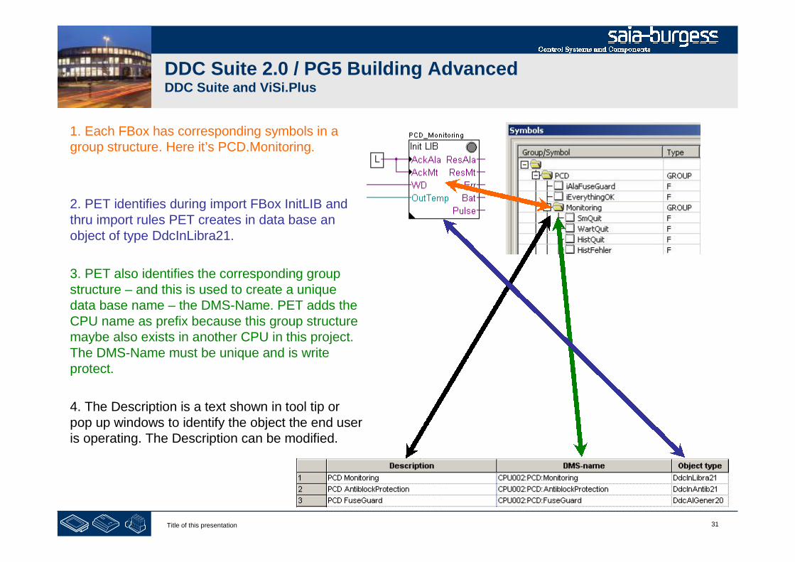
31Title of this presentation
DDC Suite 2.0 / PG5 Building AdvancedDDC Suite and ViSi.Plus
1. Each FBox has corresponding symbols in agroup structure. Here it’s PCD.Monitoring.
2. PET identifies during import FBox InitLIB andthru import rules PET creates in data base anobject of type DdcInLibra21.
3. PET also identifies the corresponding groupstructure – and this is used to create a uniquedata base name – the DMS-Name. PET adds theCPU name as prefix because this group structuremaybe also exists in another CPU in this project.The DMS-Name must be unique and is writeprotect.
4. The Description is a text shown in tool tip orpop up windows to identify the object the end useris operating. The Description can be modified.
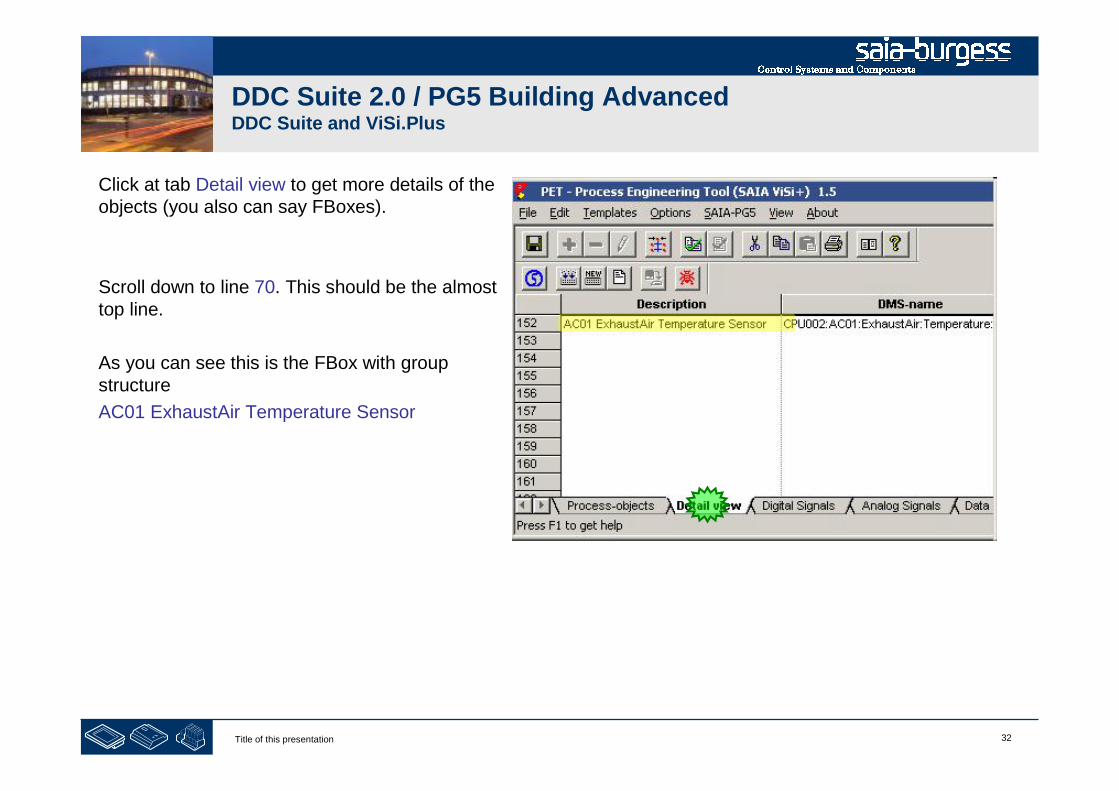
32Title of this presentation
DDC Suite 2.0 / PG5 Building AdvancedDDC Suite and ViSi.Plus
Click at tab Detail view to get more details of theobjects (you also can say FBoxes).
Scroll down to line 70. This should be the almosttop line.
As you can see this is the FBox with groupstructure
AC01 ExhaustAir Temperature Sensor
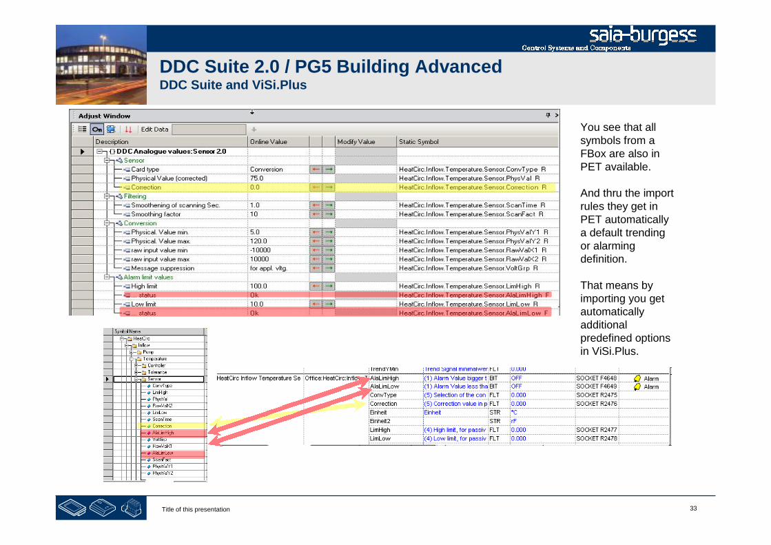
33Title of this presentation
DDC Suite 2.0 / PG5 Building AdvancedDDC Suite and ViSi.Plus
You see that allsymbols from aFBox are also inPET available.
And thru the importrules they get inPET automaticallya default trendingor alarmingdefinition.
That means byimporting you getautomaticallyadditionalpredefined optionsin ViSi.Plus.

34Title of this presentation
DDC Suite 2.0 / PG5 Building AdvancedDDC Suite and ViSi.Plus
To make it clear:
- within up to 98% of all cases you don’t have to parameterize manually datapoints for trending or alarming in ViSi.Plus with DDC Suite FBoxes
- if you use always dedicated FBoxes for alarming or trending – even ig theyproduce a data overhead in Fupla – you never have to parameterize thosefunctionalities
- Of course you have to modify the default alarm texts or priorities – but this canbe done “on the fly” during runtime of ViSi.Plus
So this import feature within ViSi.Plus saves you a lot of work!

35Title of this presentation
PG5 Building Advanced / DDC Suite 2.0DDC Suite and ViSi.Plus
Addressing the resources

36Title of this presentation
DDC Suite 2.0 / PG5 Building AdvancedDDC Suite and ViSi.Plus
ViSi.Plus is getting data from a PCD via S-Bus communication.Therefore each data point must have a unique address like R123 or F 234.
By default the symbols in Symbol Editor have no address sowe have to define the address.
Let’s do this in PET – because here it takes 2 minutes to sortand address all data points. No matter if you address 100 or10.000 data points.
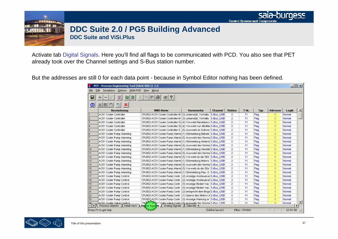
37Title of this presentation
DDC Suite 2.0 / PG5 Building AdvancedDDC Suite and ViSi.Plus
Activate tab Digital Signals. Here you’ll find all flags to be communicated with PCD. You also see that PETalready took over the Channel settings and S-Bus station number.
But the addresses are still 0 for each data point - because in Symbol Editor nothing has been defined.

38Title of this presentation
DDC Suite 2.0 / PG5 Building AdvancedDDC Suite and ViSi.Plus
Within this workshop we do not have a lot of data points and USB communication is quite fast – that meansthat we can get all information within 1 second into ViSi.Plus if we are online.
But if this will be a big application with 10 PCD and each PCD with up to 5 air conditions than you can imaginethat it may tale probably some second if an alarm is detected by ViSi.Plus. Therefore we should organise thedata points into groups (telegrams) to optimize the communication load.
This is already prepared, just double click on column header “Comment”.
You see that the comment contains a number from 1 to 5 in brackets. This number indicates thecommunication philosophy, e.g.
(1) communicate as fast and often as possible(alarm/view values) to have “real time” behaviour
(2) once per 5 second, e.g. feedback informationhaving by default some delay
(3) once per minute (or less), e.g. working hours orclock status
(4) only at start up and then never, e.g. SetPoints(update them if HMI or SWeb in use)
(5) only at start up and then never, alwayscommissioning data points (open/closed and so on)
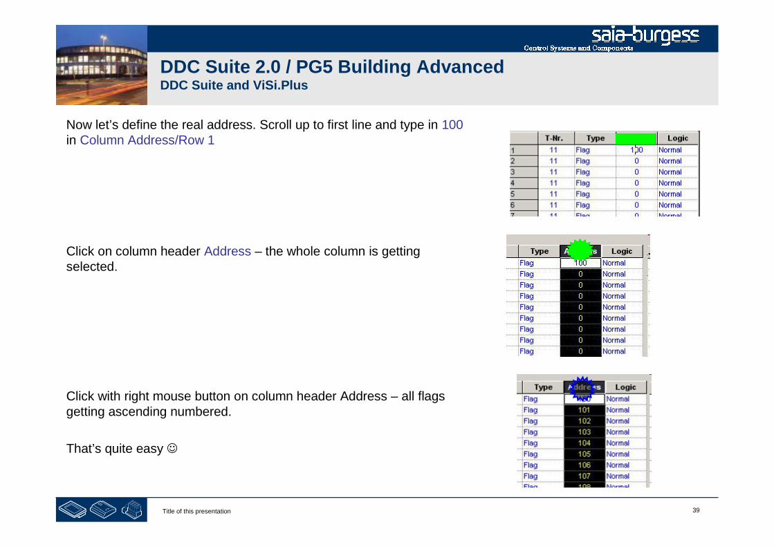
39Title of this presentation
DDC Suite 2.0 / PG5 Building AdvancedDDC Suite and ViSi.Plus
Now let’s define the real address. Scroll up to first line and type in 100in Column Address/Row 1
Click on column header Address – the whole column is gettingselected.
Click with right mouse button on column header Address – all flagsgetting ascending numbered.
That’s quite easy

40Title of this presentation
DDC Suite 2.0 / PG5 Building AdvancedDDC Suite and ViSi.Plus
We have to repeat the same procedure at tab Analog Signals. Hereinall registers are listed. Activate tab.
Double click at column header Comment to sort by communicationpriority
Now let’s define the real address. Scroll up to first line and type in 200in Column Address/Row 1
Click on column header Address – the whole column is gettingselected.
Click with right mouse button on column header Address – all registersgetting ascending numbered.

41Title of this presentation
DDC Suite 2.0 / PG5 Building AdvancedDDC Suite and ViSi.Plus
Finally save your work by clicking at disk symbol.
Now we must get the address information back into PG5 SymbolEditor. Select from menu SAIA-PG5 entry Export Options.
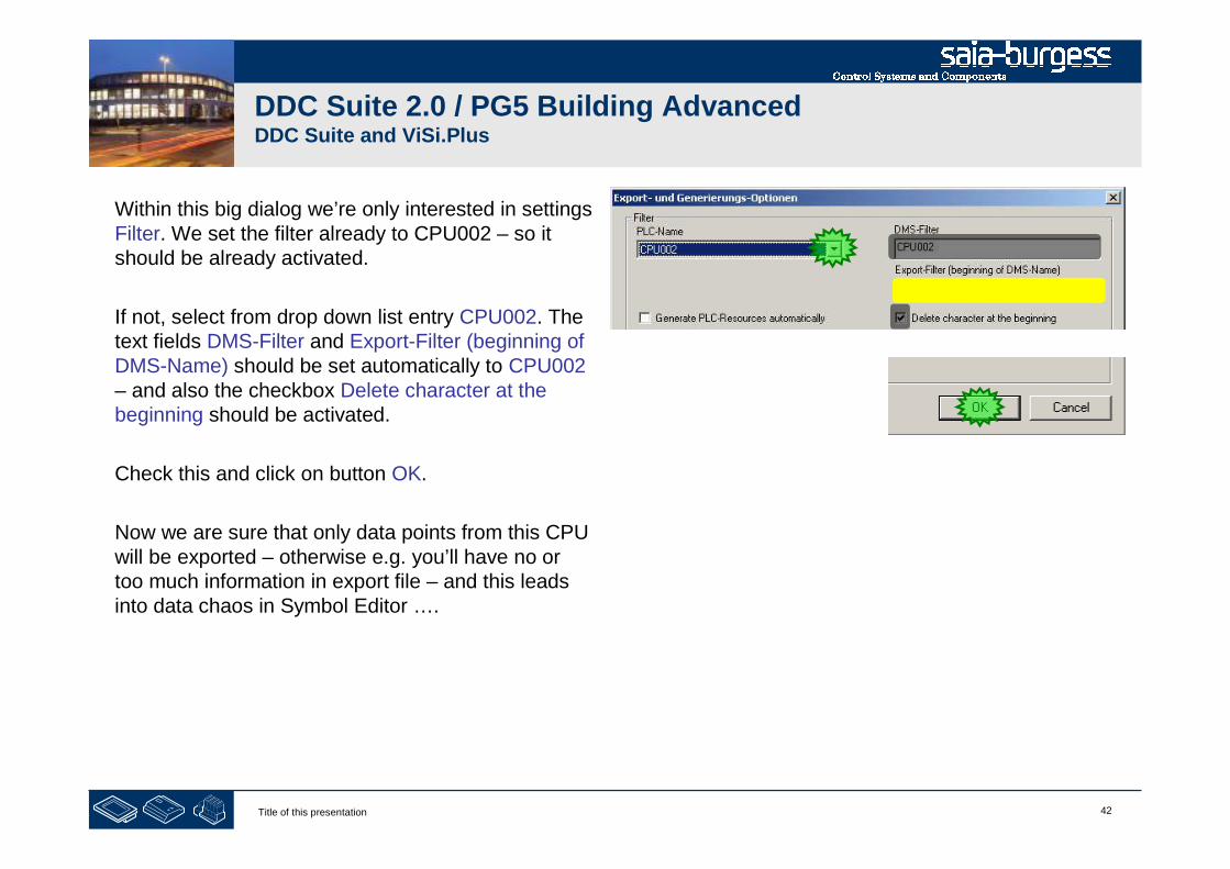
42Title of this presentation
DDC Suite 2.0 / PG5 Building AdvancedDDC Suite and ViSi.Plus
Within this big dialog we’re only interested in settingsFilter. We set the filter already to CPU002 – so itshould be already activated.
If not, select from drop down list entry CPU002. Thetext fields DMS-Filter and Export-Filter (beginning ofDMS-Name) should be set automatically to CPU002– and also the checkbox Delete character at thebeginning should be activated.
Check this and click on button OK.
Now we are sure that only data points from this CPUwill be exported – otherwise e.g. you’ll have no ortoo much information in export file – and this leadsinto data chaos in Symbol Editor ….
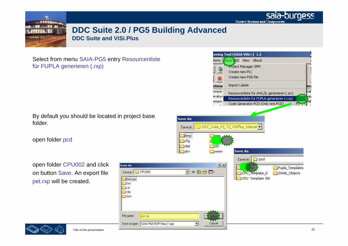
43Title of this presentation
DDC Suite 2.0 / PG5 Building AdvancedDDC Suite and ViSi.Plus
Select from menu SAIA-PG5 entry Resourcenlistefür FUPLA generieren (.rxp)
By default you should be located in project basefolder.
open folder pcd
open folder CPU002 and click
on button Save. An export file
pet.rxp will be created.
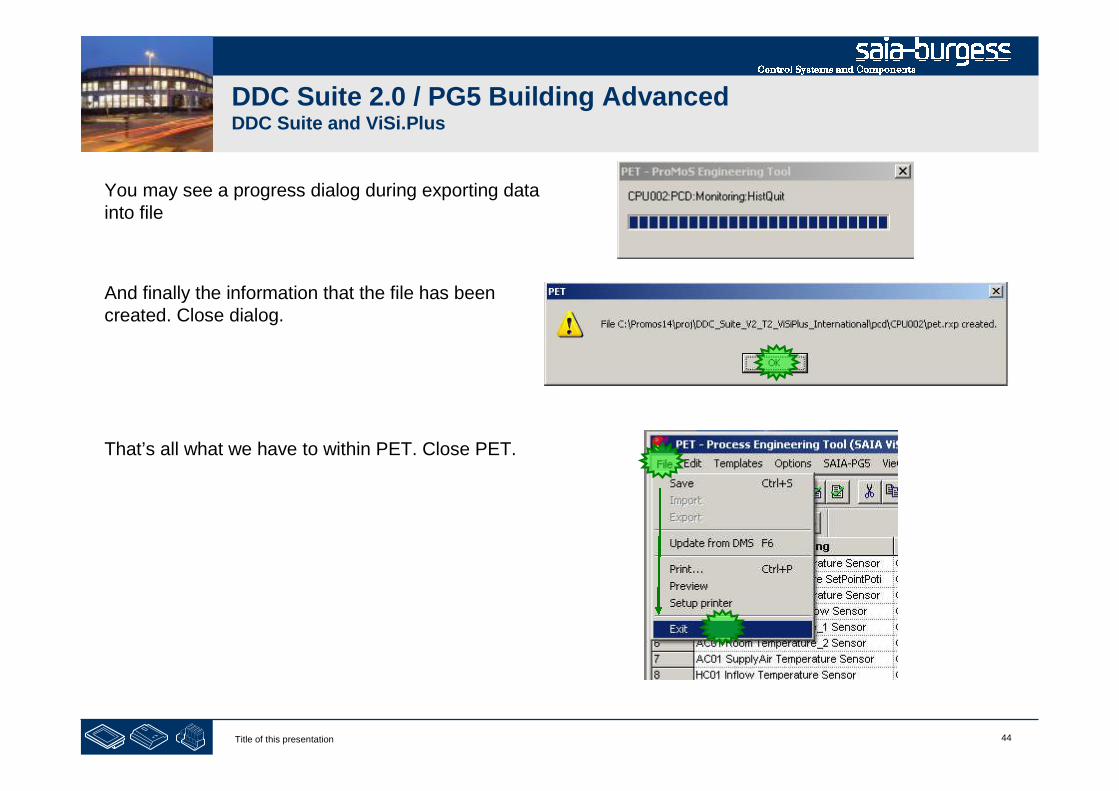
44Title of this presentation
DDC Suite 2.0 / PG5 Building AdvancedDDC Suite and ViSi.Plus
You may see a progress dialog during exporting datainto file
And finally the information that the file has beencreated. Close dialog.
That’s all what we have to within PET. Close PET.
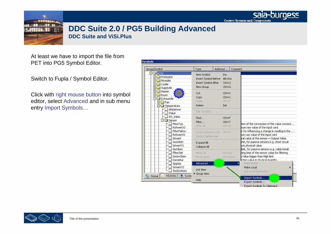
45Title of this presentation
DDC Suite 2.0 / PG5 Building AdvancedDDC Suite and ViSi.Plus
At least we have to import the file fromPET into PG5 Symbol Editor.
Switch to Fupla / Symbol Editor.
Click with right mouse button into symboleditor, select Advanced and in sub menuentry Import Symbols…

46Title of this presentation
DDC Suite 2.0 / PG5 Building AdvancedDDC Suite and ViSi.Plus
Within dialog Import Symbols select fromdrop down list Files of type entry ViSiPlusSymbol Files (*.rxp)
Select file pet.rxp and start import byclicking on button Import.
You’ll see a dialog to inform you that thereis NO UNDO possible.
I do Not see this pop up in PG5 2.0 why !!!!
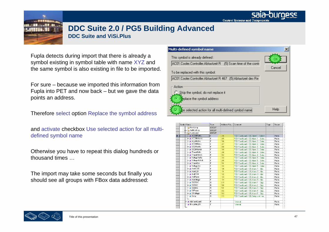
47Title of this presentation
DDC Suite 2.0 / PG5 Building AdvancedDDC Suite and ViSi.Plus
Fupla detects during import that there is already asymbol existing in symbol table with name XYZ andthe same symbol is also existing in file to be imported.
For sure – because we imported this information fromFupla into PET and now back – but we gave the datapoints an address.
Therefore select option Replace the symbol address
and activate checkbox Use selected action for all multi-defined symbol name
Otherwise you have to repeat this dialog hundreds orthousand times …
The import may take some seconds but finally youshould see all groups with FBox data addressed:

48Title of this presentation
DDC Suite 2.0 / PG5 Building AdvancedDDC Suite and ViSi.Plus
The import may take some seconds butfinally you should see all groups with FBoxdata addressed:
You’ll see also some groups with symbolswithout address – they are only internalsymbols used in connectors.
At least all symbols in almost all groupsshould be addressed.
Save, build program and download into PCDand go online with Fupla.
49Title of this presentation
PG5 Building Advanced / DDC Suite 2.0DDC Suite and ViSi.Plus
Go online

50Title of this presentation
DDC Suite 2.0 / PG5 Building AdvancedDDC Suite and ViSi.Plus
Till now we only imported FBoxes into ViSi.Plus (viaPET) – addressing data points and exporting back intoFupla.
1st – lets start the ViSi.Plus communications driver.Start SDriver.exe from folder C:\ProMosNT\bin
SDriver is a service and also available in task barnotification area.
Now we have to define the physical communicationlayer. Therefore we have to access the SDriverwindow. Click with right mouse button on SDriversymbol in task bar and select Show.

51Title of this presentation
DDC Suite 2.0 / PG5 Building AdvancedDDC Suite and ViSi.Plus
SDriver list on left side all Channels defined within PET. Ofcourse – we got this information during import from PG5but SDriver handles this only as name. The real physicallayer must be defined now.
Good to know:
Communication disabled
trying to initiate communication
communication established
communication failed
Click with right mouse button on channel, dialog
For detailed communication settings will prompted
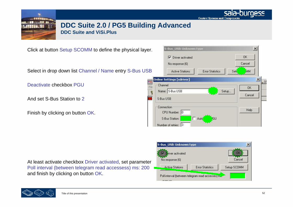
52Title of this presentation
DDC Suite 2.0 / PG5 Building AdvancedDDC Suite and ViSi.Plus
Click at button Setup SCOMM to define the physical layer.
Select in drop down list Channel / Name entry S-Bus USB
Deactivate checkbox PGU
And set S-Bus Station to 2
Finish by clicking on button OK.
At least activate checkbox Driver activated, set parameterPoll interval (between telegram read accessess) ms: 200and finish by clicking on button OK.
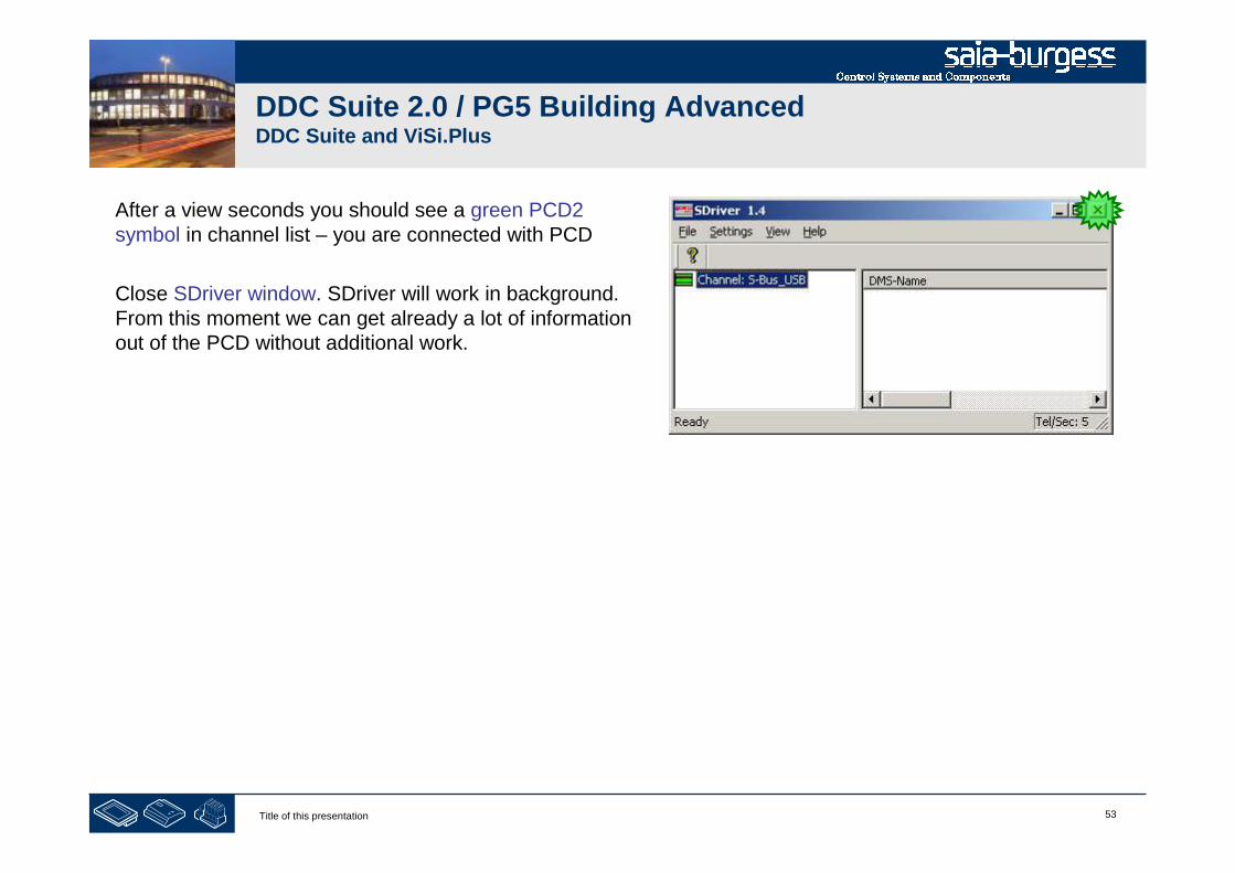
53Title of this presentation
DDC Suite 2.0 / PG5 Building AdvancedDDC Suite and ViSi.Plus
After a view seconds you should see a green PCD2symbol in channel list – you are connected with PCD
Close SDriver window. SDriver will work in background.From this moment we can get already a lot of informationout of the PCD without additional work.

54Title of this presentation
PG5 Building Advanced / DDC Suite 2.0DDC Suite and ViSi.Plus
Alarm management

55Title of this presentation
DDC Suite 2.0 / PG5 Building AdvancedDDC Suite and ViSi.Plus
Let’s check if we have some active alarms.
1st – lets start the ViSi.Plus Alarm Manager. StartAlmMng.exe from folder C:\ProMosNT\bin. AlmMng is aservice and also available in task bar notification area.
2nd - to view the alarms we have to start the Alarm viewer.Start AlmView.exe from folder C:\ProMosNT\bin
The alarm viewer is the front end forEnd user to view/acknowledge alarmsand/or search in alarm history

56Title of this presentation
DDC Suite 2.0 / PG5 Building AdvancedDDC Suite and ViSi.Plus
First click on column header and than onbutton Q to acknowledge all alarms.
All alarms should be acknowledged.
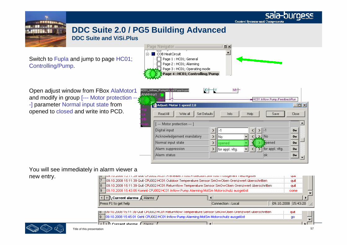
57Title of this presentation
DDC Suite 2.0 / PG5 Building AdvancedDDC Suite and ViSi.Plus
Switch to Fupla and jump to page HC01;Controlling/Pump.
Open adjust window from FBox AlaMotor1and modify in group [--- Motor protection ---] parameter Normal input state fromopened to closed and write into PCD.
You will see immediately in alarm viewer anew entry.

58Title of this presentation
PG5 Building Advanced / DDC Suite 2.0DDC Suite and ViSi.Plus
Historical data
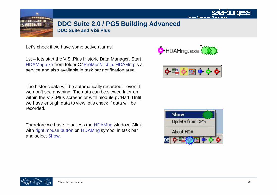
59Title of this presentation
DDC Suite 2.0 / PG5 Building AdvancedDDC Suite and ViSi.Plus
Let’s check if we have some active alarms.
1st – lets start the ViSi.Plus Historic Data Manager. StartHDAMng.exe from folder C:\ProMosNT\bin. HDAMng is aservice and also available in task bar notification area.
The historic data will be automatically recorded – even ifwe don’t see anything. The data can be viewed later onwithin the ViSi.Plus screens or with module pCHart. Untilwe have enough data to view let’s check if data will berecorded.
Therefore we have to access the HDAMng window. Clickwith right mouse button on HDAMng symbol in task barand select Show.
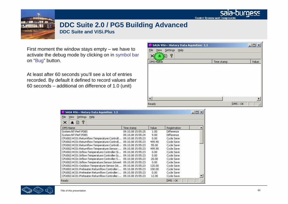
60Title of this presentation
DDC Suite 2.0 / PG5 Building AdvancedDDC Suite and ViSi.Plus
First moment the window stays empty – we have toactivate the debug mode by clicking on in symbol baron “Bug” button.
At least after 60 seconds you’ll see a lot of entriesrecorded. By default it defined to record values after60 seconds – additional on difference of 1.0 (unit)

61Title of this presentation
DDC Suite 2.0 / PG5 Building AdvancedDDC Suite and ViSi.Plus
Deactivate debug mode by clicking again in symbolbar on “Bug” button.
Close HDAMng window. HDAMng will work inbackground.
62Title of this presentation
PG5 Building Advanced / DDC Suite 2.0DDC Suite and ViSi.Plus
User Front-End
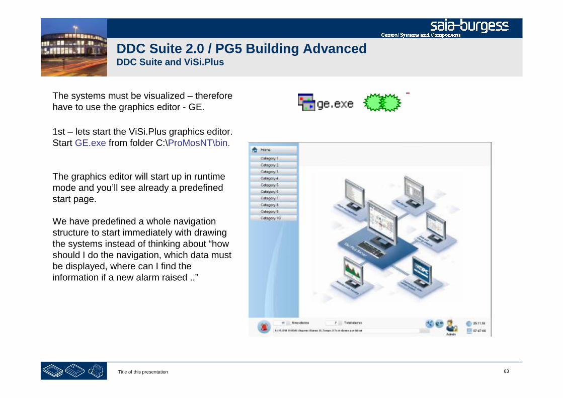
63Title of this presentation
DDC Suite 2.0 / PG5 Building AdvancedDDC Suite and ViSi.Plus
The systems must be visualized – thereforehave to use the graphics editor - GE.
1st – lets start the ViSi.Plus graphics editor.Start GE.exe from folder C:\ProMosNT\bin.
The graphics editor will start up in runtimemode and you’ll see already a predefinedstart page.
We have predefined a whole navigationstructure to start immediately with drawingthe systems instead of thinking about “howshould I do the navigation, which data mustbe displayed, where can I find theinformation if a new alarm raised ..”
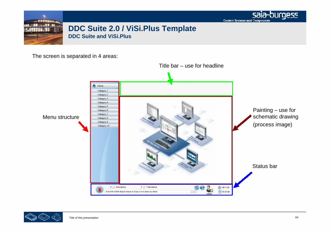
64Title of this presentation
DDC Suite 2.0 / ViSi.Plus TemplateDDC Suite and ViSi.Plus
The screen is separated in 4 areas:
Title bar – use for headline
Painting – use forschematic drawing
(process image)
Status bar
Menu structure

65Title of this presentation
DDC Suite 2.0 / ViSi.Plus TemplateDDC Suite and ViSi.Plus
Status bar displays basic information:
Alarm bell icon, grey if there is noalarm, red if min. 1 alarm active (clickfor alarm list view)
number of new (not yetacknowledged) alarms and total activealarms
last alarm text
Date and time
User name logged on
“User” Icon > click for login dialog
Or press CTRL+L to get the login window
Username: Admin
Password: admin
Icon “settings” > click to setupmenu structure
Icon “talk” > click to setup user
(both icons only visible if user rightlevel 16 active)
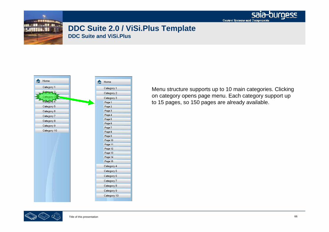
66Title of this presentation
DDC Suite 2.0 / ViSi.Plus TemplateDDC Suite and ViSi.Plus
Menu structure supports up to 10 main categories. Clickingon category opens page menu. Each category support upto 15 pages, so 150 pages are already available.

67Title of this presentation
DDC Suite 2.0 / ViSi.Plus TemplateDDC Suite and ViSi.Plus
Adapting menu structure can be done in runtime mode by clicking on “settings” icon in status bar
Select number of visible main categories. Changes willupdate view immediately.
Category name and pages of category can be modifiedby clicking on a category

68Title of this presentation
DDC Suite 2.0 / ViSi.Plus TemplateDDC Suite and ViSi.Plus
Select number of visible pages of category. Text of category and pages can be modified by clicking ontexts.
An icon indicating the basic meaning (air condition,chillers, electrics … ) of category can be defined byclicking on icon in icon bar.
View is updated immediately
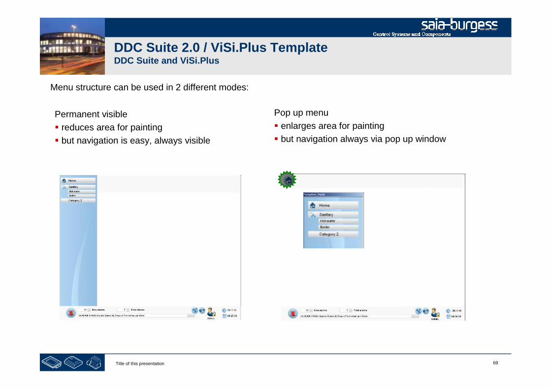
69Title of this presentation
DDC Suite 2.0 / ViSi.Plus TemplateDDC Suite and ViSi.Plus
Menu structure can be used in 2 different modes:
Permanent visible
reduces area for painting
but navigation is easy, always visible
Pop up menu
enlarges area for painting
but navigation always via pop up window

70Title of this presentation
DDC Suite 2.0 / ViSi.Plus TemplateDDC Suite and ViSi.Plus
Style can be modified in edit mode. Each page is using a “Master” (= background page). 2 predefinedbackground pages are available:
Go to “Edit mode” with pressing “E” and click on the window and press the property button to open theWindow-properties popup. Select in property “Master” the style for the pages (page by page) if you like tohave not always a unique menu structure style.

71Title of this presentation
DDC Suite 2.0 / ViSi.Plus TemplateDDC Suite and ViSi.Plus
If you like to change all pages from “permanent” to “pop up” menu structure style open file“Background_with_PopUp_NavBar.psc”
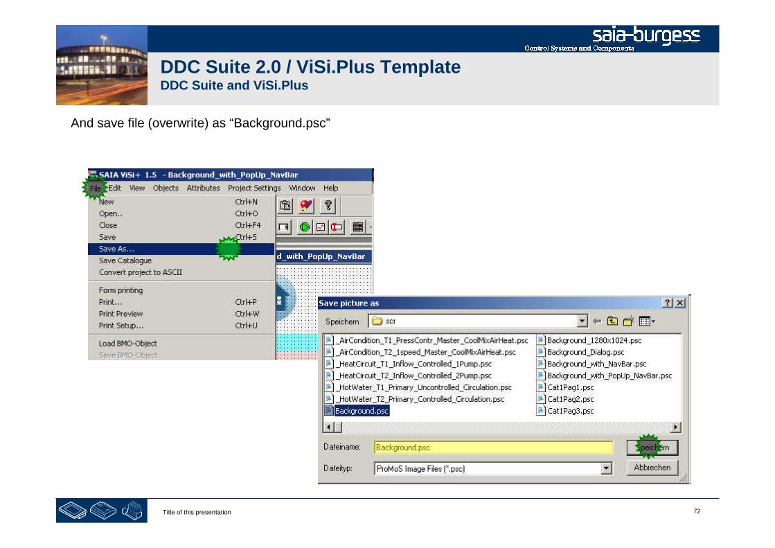
72Title of this presentation
DDC Suite 2.0 / ViSi.Plus TemplateDDC Suite and ViSi.Plus
And save file (overwrite) as “Background.psc”
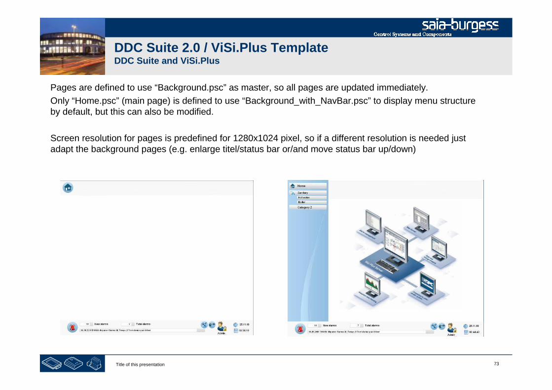
73Title of this presentation
DDC Suite 2.0 / ViSi.Plus TemplateDDC Suite and ViSi.Plus
Pages are defined to use “Background.psc” as master, so all pages are updated immediately.
Only “Home.psc” (main page) is defined to use “Background_with_NavBar.psc” to display menu structureby default, but this can also be modified.
Screen resolution for pages is predefined for 1280x1024 pixel, so if a different resolution is needed justadapt the background pages (e.g. enlarge titel/status bar or/and move status bar up/down)

74Title of this presentation
PG5 Building Advanced / DDC Suite 2.0DDC Suite and ViSi.Plus
Drawing picures
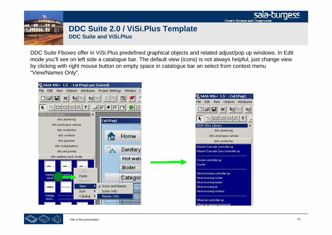
75Title of this presentation
DDC Suite 2.0 / ViSi.Plus TemplateDDC Suite and ViSi.Plus
DDC Suite Fboxes offer in ViSi.Plus predefined graphical objects and related adjust/pop up windows. In Editmode you’ll see on left side a catalogue bar. The default view (icons) is not always helpful, just change viewby clicking with right mouse button on empty space in catalogue bar an select from context menu“View/Names Only”.
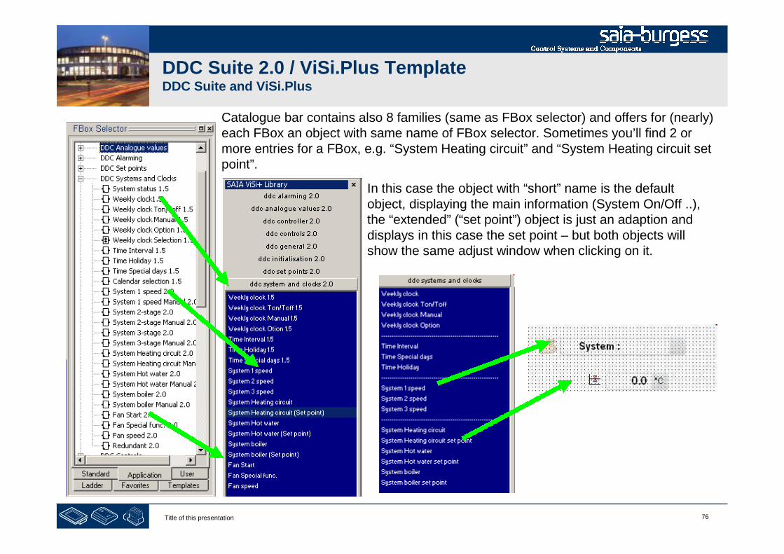
76Title of this presentation
DDC Suite 2.0 / ViSi.Plus TemplateDDC Suite and ViSi.Plus
In this case the object with “short” name is the defaultobject, displaying the main information (System On/Off ..),the “extended” (“set point”) object is just an adaption anddisplays in this case the set point – but both objects willshow the same adjust window when clicking on it.
Catalogue bar contains also 8 families (same as FBox selector) and offers for (nearly)each FBox an object with same name of FBox selector. Sometimes you’ll find 2 ormore entries for a FBox, e.g. “System Heating circuit” and “System Heating circuit setpoint”.

77Title of this presentation
DDC Suite 2.0 / ViSi.Plus TemplateDDC Suite and ViSi.Plus
You just have to select the corresponding object for an FBox and initialize it with the related object fromViSi.Plus data base. All adjust windows are predefined, clicking on graphic object will open a pop up.

78Title of this presentation
DDC Suite 2.0 / PG5 Building AdvancedDDC Suite and ViSi.Plus
Let’s check the first Fupla page (General)of our air condition. There are 3 FBoxes tobe displayed in ViSi.Plus:
Alarm header – no Visi.Plus template
Manual operation
Sensor - Outdoor air temperature
Lets find out how the FBox is named inFBox selector. Click on FBox “ManualOP”and in FBox selector we see that “ManualOperation 2.0” is selected from family“DDC General”

79Title of this presentation
Let us select the AirCondition AC01 page inonline and press “E” to goto edit mode.
Drag and drop the objectinto the page. When youdrop the object a dialoguewill be shown. Remember– during import data fromFupla ViSi.Plus treatedeach FBox as object. Andnow ViSi.Plus detects thatyou would like to display(some) data from FBox“Manual operation” …
DDC Suite 2.0 / PG5 Building AdvancedDDC Suite and ViSi.Plus
Lets find a related ViSi.Plus object in GE. Select catalogue “DDC General” and check if there is an object“Manual operation” available.

80Title of this presentation
DDC Suite 2.0 / PG5 Building AdvancedDDC Suite and ViSi.Plus
ViSi.Plus is checking its data base (which is infact the whole Fupla data) if there is a “FBox”Manual Operation 2.0 available. A leastViSi.Plus found one for Air Condition 01 (AC01)and three for Heat Circuits – listed in field “to”
Now we just have to assign theAC01:System:Manual FBox to this object. Clickon the entry and then OK.
Move the object into the upper left area. If youclick away from the object it disappears (Itsvisibility property is off). To show at least theoutline of the object please go to the “Viewmenu” and check the “Show Invisible Objects”.
Save (short key “CTRL-S”) and switch toruntime mode by pressing key “E”.
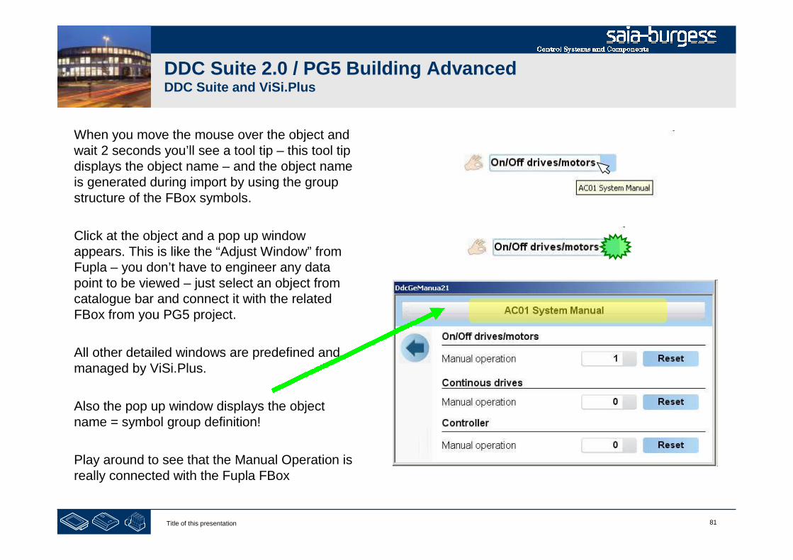
81Title of this presentation
DDC Suite 2.0 / PG5 Building AdvancedDDC Suite and ViSi.Plus
When you move the mouse over the object andwait 2 seconds you’ll see a tool tip – this tool tipdisplays the object name – and the object nameis generated during import by using the groupstructure of the FBox symbols.
Click at the object and a pop up windowappears. This is like the “Adjust Window” fromFupla – you don’t have to engineer any datapoint to be viewed – just select an object fromcatalogue bar and connect it with the relatedFBox from you PG5 project.
All other detailed windows are predefined andmanaged by ViSi.Plus.
Also the pop up window displays the objectname = symbol group definition!
Play around to see that the Manual Operation isreally connected with the Fupla FBox
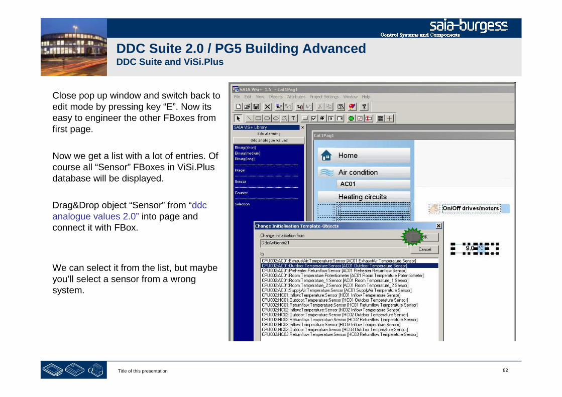
82Title of this presentation
DDC Suite 2.0 / PG5 Building AdvancedDDC Suite and ViSi.Plus
Close pop up window and switch back toedit mode by pressing key “E”. Now itseasy to engineer the other FBoxes fromfirst page.
Now we get a list with a lot of entries. Ofcourse all “Sensor” FBoxes in ViSi.Plusdatabase will be displayed.
Drag&Drop object “Sensor” from “ddcanalogue values 2.0” into page andconnect it with FBox.
We can select it from the list, but maybeyou’ll select a sensor from a wrongsystem.
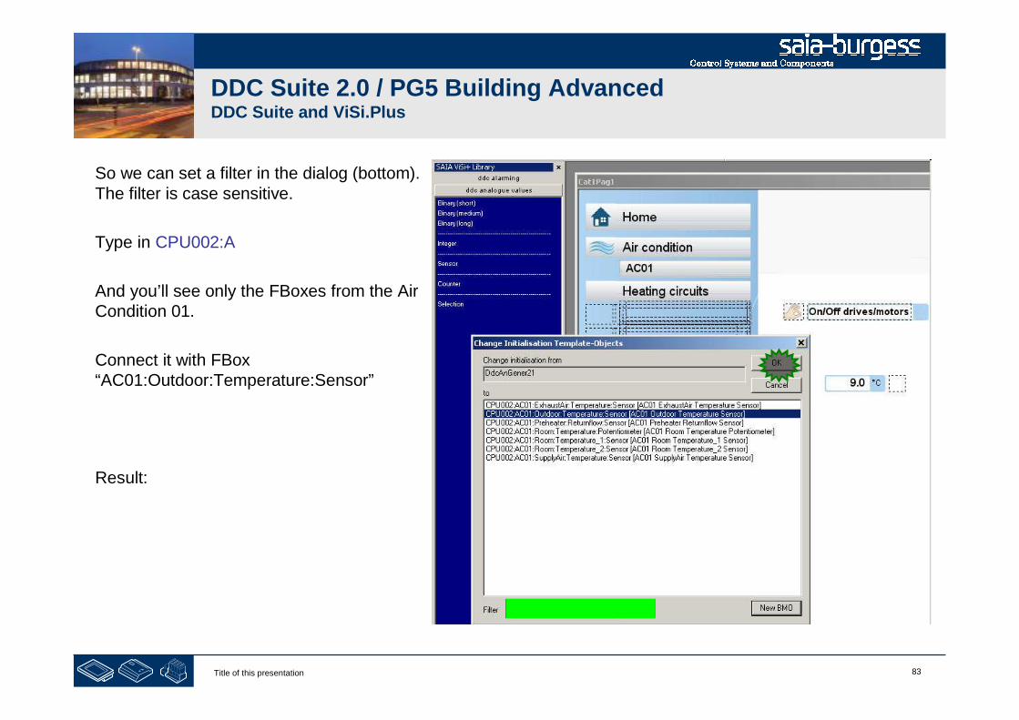
83Title of this presentation
DDC Suite 2.0 / PG5 Building AdvancedDDC Suite and ViSi.Plus
So we can set a filter in the dialog (bottom).The filter is case sensitive.
Type in CPU002:A
And you’ll see only the FBoxes from the AirCondition 01.
Connect it with FBox“AC01:Outdoor:Temperature:Sensor”
Result:
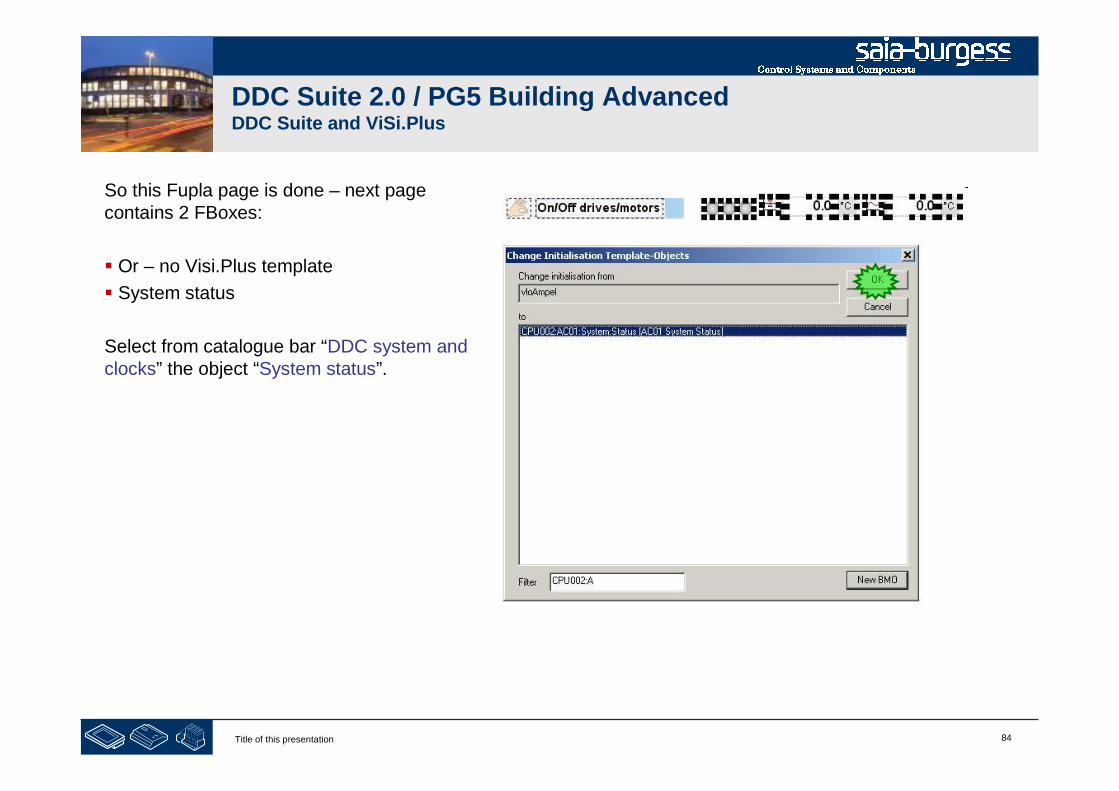
84Title of this presentation
DDC Suite 2.0 / PG5 Building AdvancedDDC Suite and ViSi.Plus
So this Fupla page is done – next pagecontains 2 FBoxes:
Or – no Visi.Plus template
System status
Select from catalogue bar “DDC system andclocks” the object “System status”.

85Title of this presentation
DDC Suite 2.0 / PG5 Building AdvancedDDC Suite and ViSi.Plus
So this Fupla page is done – next page does not contain FBoxwhich has template. So let us go to the page “Filter”. There are 3 FBoxes there:
� 3 times AlaDelay – Delayed Alarm
Drag and drop from catalogue bar “DDC alarming” the object “Delayed Alarm filter right” 2 times and “Delayed Alarm filter left” once.
The “right” ones should be connected to the Outdoor filter and the Supply air filter while the “left” one should be connected to the Exhaust air filter.

86Title of this presentation
DDC Suite 2.0 / PG5 Building AdvancedDDC Suite and ViSi.Plus
So this Fupla page is done – nextpage contains 4 Fboxes shouldbe placed and connected as wehave done before:
System 1sp
Fan Start
Fan special
Selection
Drag and drop from cataloguebar “DDC system and clocks” theobjects “System 1 speed”, “Fanstart” and “Fan Special func.”.
Drag and drop from cataloguebar “DDC analogue values” theobject “Selection”.
And connect them to the FBoxes.
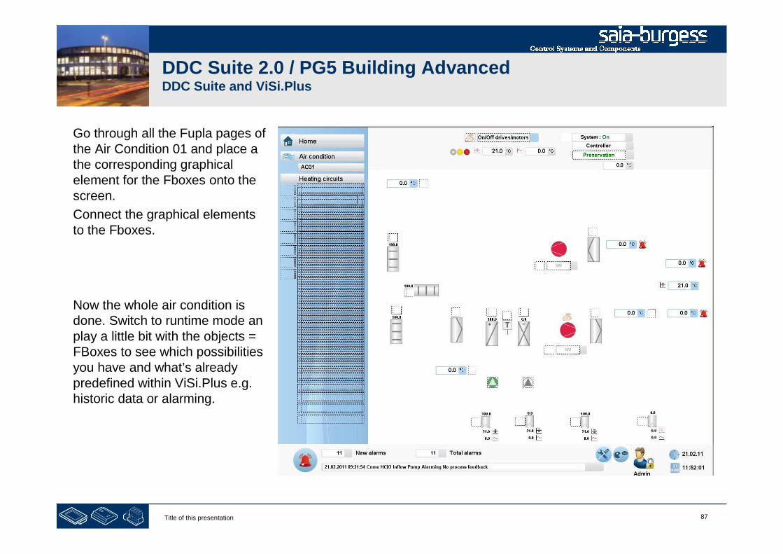
87Title of this presentation
DDC Suite 2.0 / PG5 Building AdvancedDDC Suite and ViSi.Plus
Go through all the Fupla pages ofthe Air Condition 01 and place athe corresponding graphicalelement for the Fboxes onto thescreen.
Connect the graphical elementsto the Fboxes.
Now the whole air condition isdone. Switch to runtime mode anplay a little bit with the objects =FBoxes to see which possibilitiesyou have and what’s alreadypredefined within ViSi.Plus e.g.historic data or alarming.
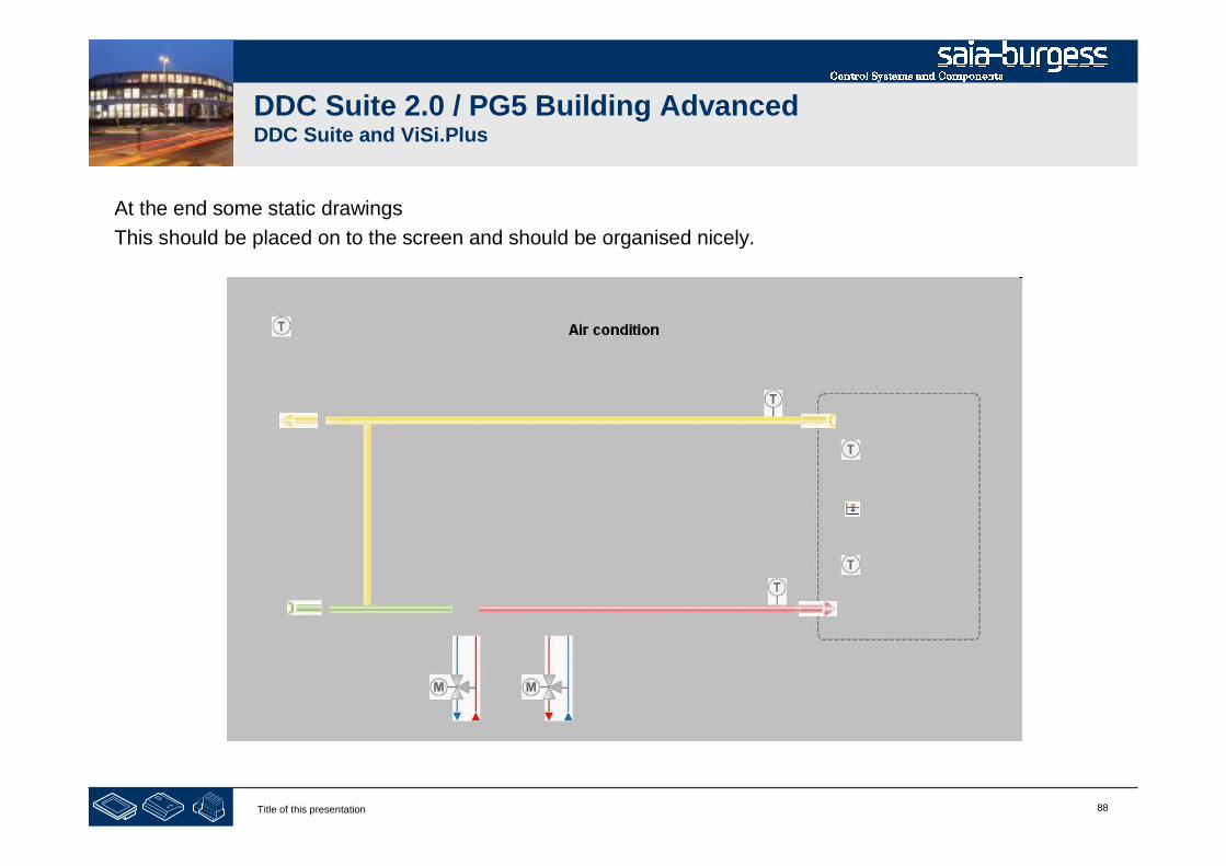
88Title of this presentation
DDC Suite 2.0 / PG5 Building AdvancedDDC Suite and ViSi.Plus
At the end some static drawings
This should be placed on to the screen and should be organised nicely.
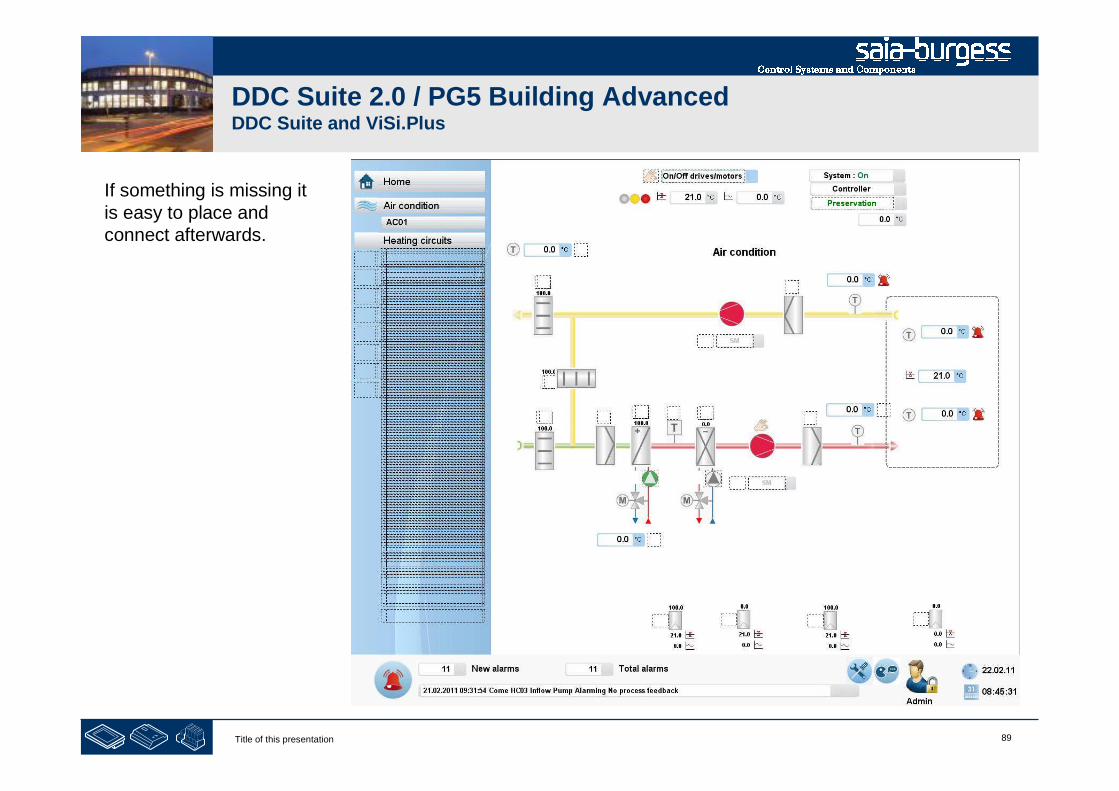
89Title of this presentation
DDC Suite 2.0 / PG5 Building AdvancedDDC Suite and ViSi.Plus
If something is missing itis easy to place andconnect afterwards.

90Title of this presentation
PG5 Building Advanced / DDC Suite 2.0DDC Suite and ViSi.Plus
Engineering with templates
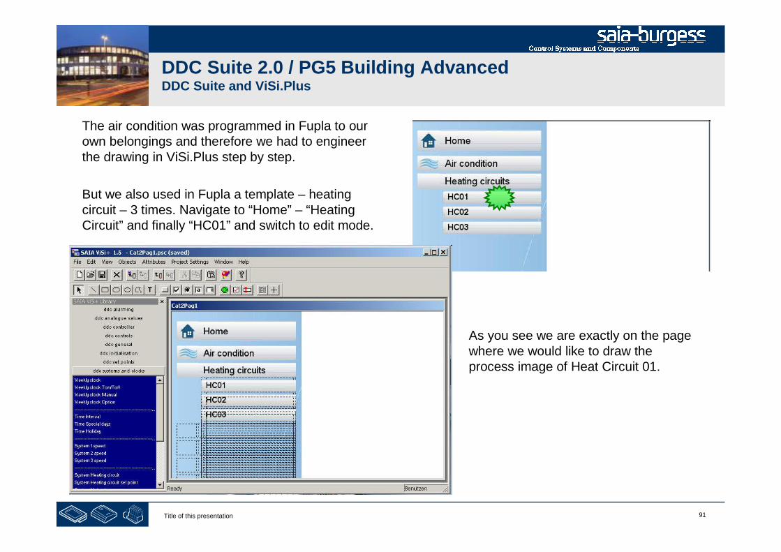
91Title of this presentation
DDC Suite 2.0 / PG5 Building AdvancedDDC Suite and ViSi.Plus
As you see we are exactly on the pagewhere we would like to draw theprocess image of Heat Circuit 01.
The air condition was programmed in Fupla to ourown belongings and therefore we had to engineerthe drawing in ViSi.Plus step by step.
But we also used in Fupla a template – heatingcircuit – 3 times. Navigate to “Home” – “HeatingCircuit” and finally “HC01” and switch to edit mode.

92Title of this presentation
DDC Suite 2.0 / PG5 Building AdvancedDDC Suite and ViSi.Plus
In Fupla we used a template – and this template waspredefined by DDC Suite. You’ll also find a relatedtemplate in ViSi.Plus to such Fupla templates.
Click on icon “Load picture” (or menu “File/Open”).The Fupla template was named“HeatCircuit_Inflow_Controlled_1Pump”.
Select the file with the same name and click on theOpen button.

93Title of this presentation
DDC Suite 2.0 / PG5 Building AdvancedDDC Suite and ViSi.Plus
When the file is opened you can see the predefinedheating circuit template. It’s created in the same way aswe did before – only the connection to FBoxes is notdone.
Press short key “CTRL+A” to mark all objects
Press short key “CTRL+C” to copy them to clip board
Press short key “CTRL+F4” to close the picture
Press short key “CTRL+V” to paste it into our structure– and move the whole template that it fits into the page

94Title of this presentation
DDC Suite 2.0 / PG5 Building AdvancedDDC Suite and ViSi.Plus
The object on the left side arenot necessary if we usepermanent navigation bar .
Please select the unnecessaryobjects and delete them.

95Title of this presentation
DDC Suite 2.0 / PG5 Building AdvancedDDC Suite and ViSi.Plus
Now we have to assign to each objectan FBox from out heating circuit HC01.
Unselect by clicking into an empty placeon page and click on first object“Requirement” to mark it.
Press “Space bar” (key “space”) andthe dialogue to assign a FBox will bedisplayed.
The filter “CPU002:A” is still active – wehave to modify it. Change filter into“CPU002:HC01” to be sure that weselect always objects from HC01.
Assign the FBox to object and click OK
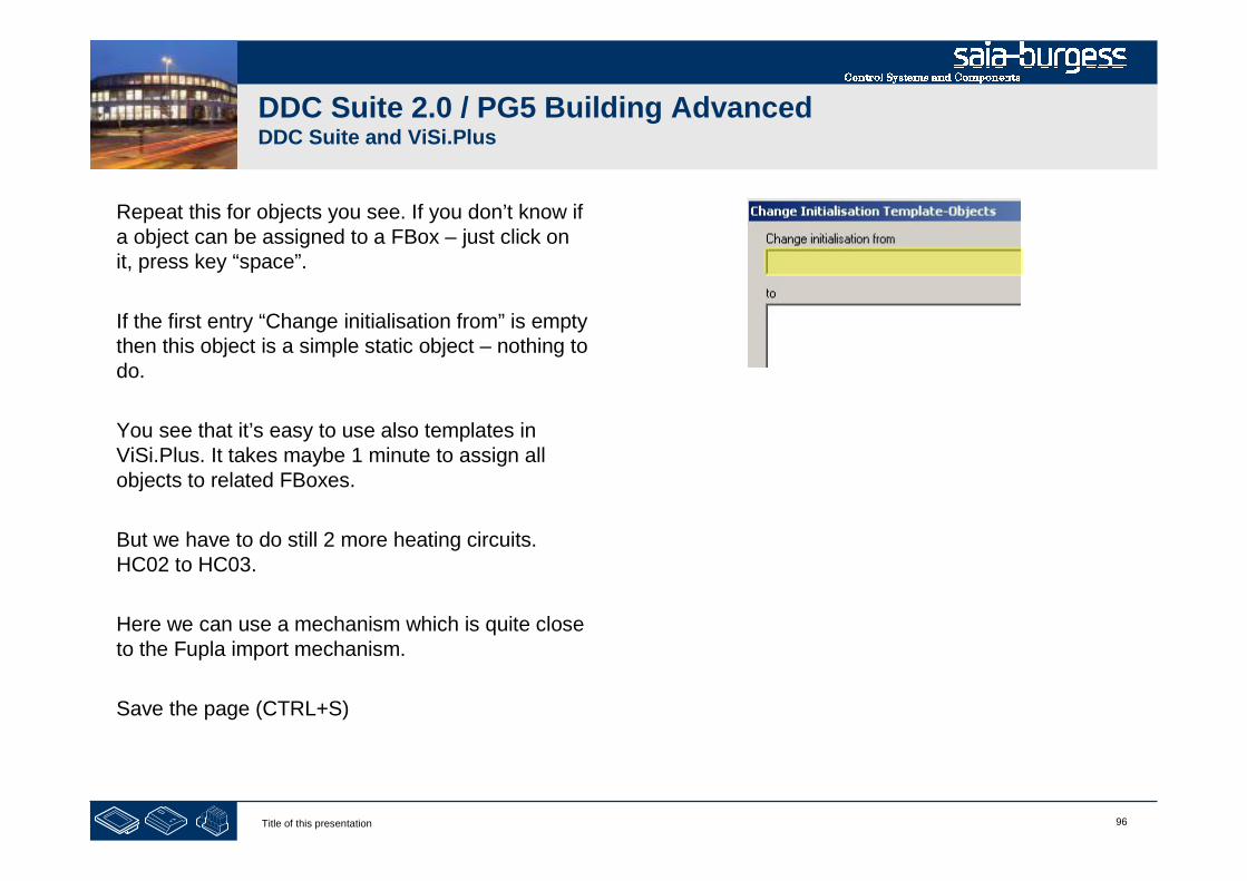
96Title of this presentation
DDC Suite 2.0 / PG5 Building AdvancedDDC Suite and ViSi.Plus
Repeat this for objects you see. If you don’t know ifa object can be assigned to a FBox – just click onit, press key “space”.
If the first entry “Change initialisation from” is emptythen this object is a simple static object – nothing todo.
You see that it’s easy to use also templates inViSi.Plus. It takes maybe 1 minute to assign allobjects to related FBoxes.
But we have to do still 2 more heating circuits.HC02 to HC03.
Here we can use a mechanism which is quite closeto the Fupla import mechanism.
Save the page (CTRL+S)
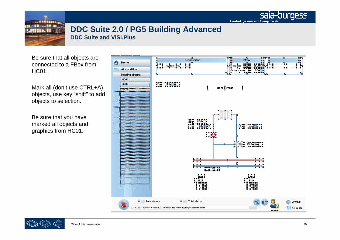
97Title of this presentation
DDC Suite 2.0 / PG5 Building AdvancedDDC Suite and ViSi.Plus
Be sure that all objects areconnected to a FBox fromHC01.
Mark all (don’t use CTRL+A)objects, use key “shift” to addobjects to selection.
Be sure that you havemarked all objects andgraphics from HC01.
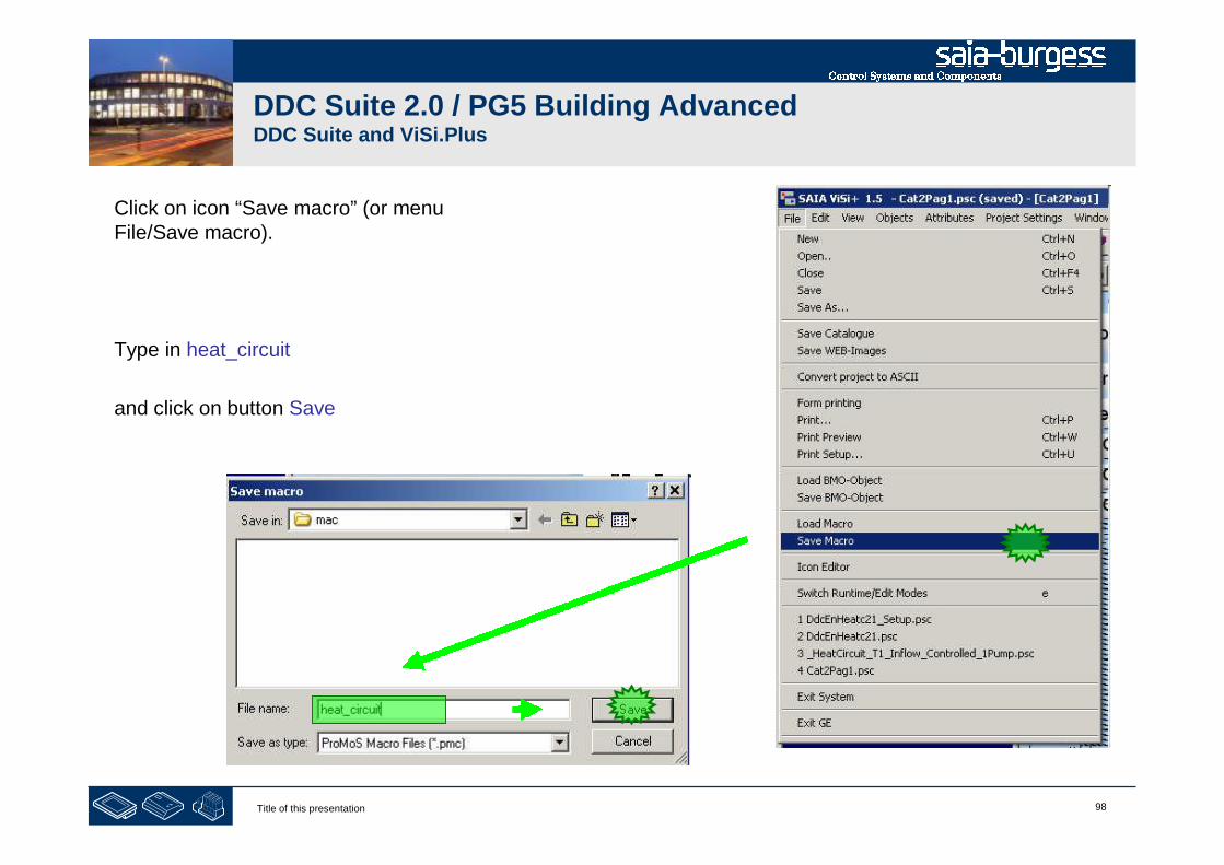
98Title of this presentation
DDC Suite 2.0 / PG5 Building AdvancedDDC Suite and ViSi.Plus
Click on icon “Save macro” (or menuFile/Save macro).
Type in heat_circuit
and click on button Save

99Title of this presentation
DDC Suite 2.0 / PG5 Building AdvancedDDC Suite and ViSi.Plus
Switch to runtime mode, navigate to HC02 andswitch back to edit mode.
Click on icon “Load macro” (or menu File/Loadmacro)
Select the macro we saved before:heat_circuit.pmc and press “Open”
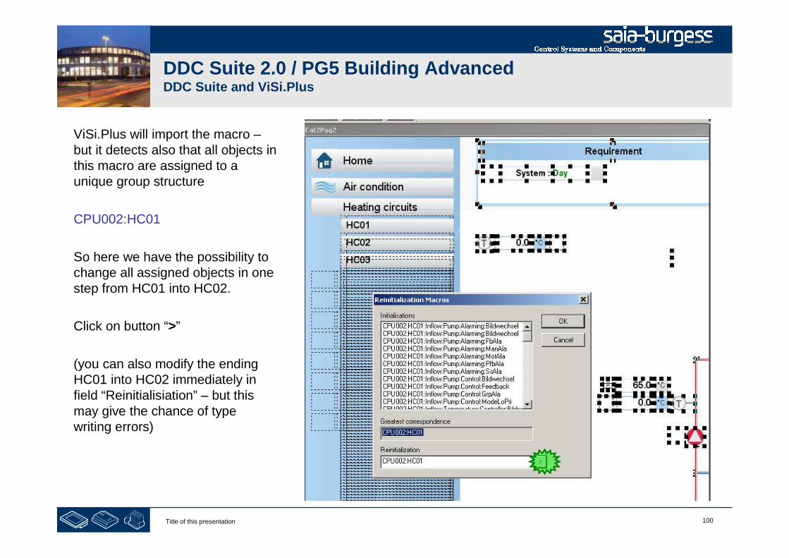
100Title of this presentation
DDC Suite 2.0 / PG5 Building AdvancedDDC Suite and ViSi.Plus
ViSi.Plus will import the macro –but it detects also that all objects inthis macro are assigned to aunique group structure
CPU002:HC01
So here we have the possibility tochange all assigned objects in onestep from HC01 into HC02.
Click on button “>”
(you can also modify the endingHC01 into HC02 immediately infield “Reinitialisiation” – but thismay give the chance of typewriting errors)
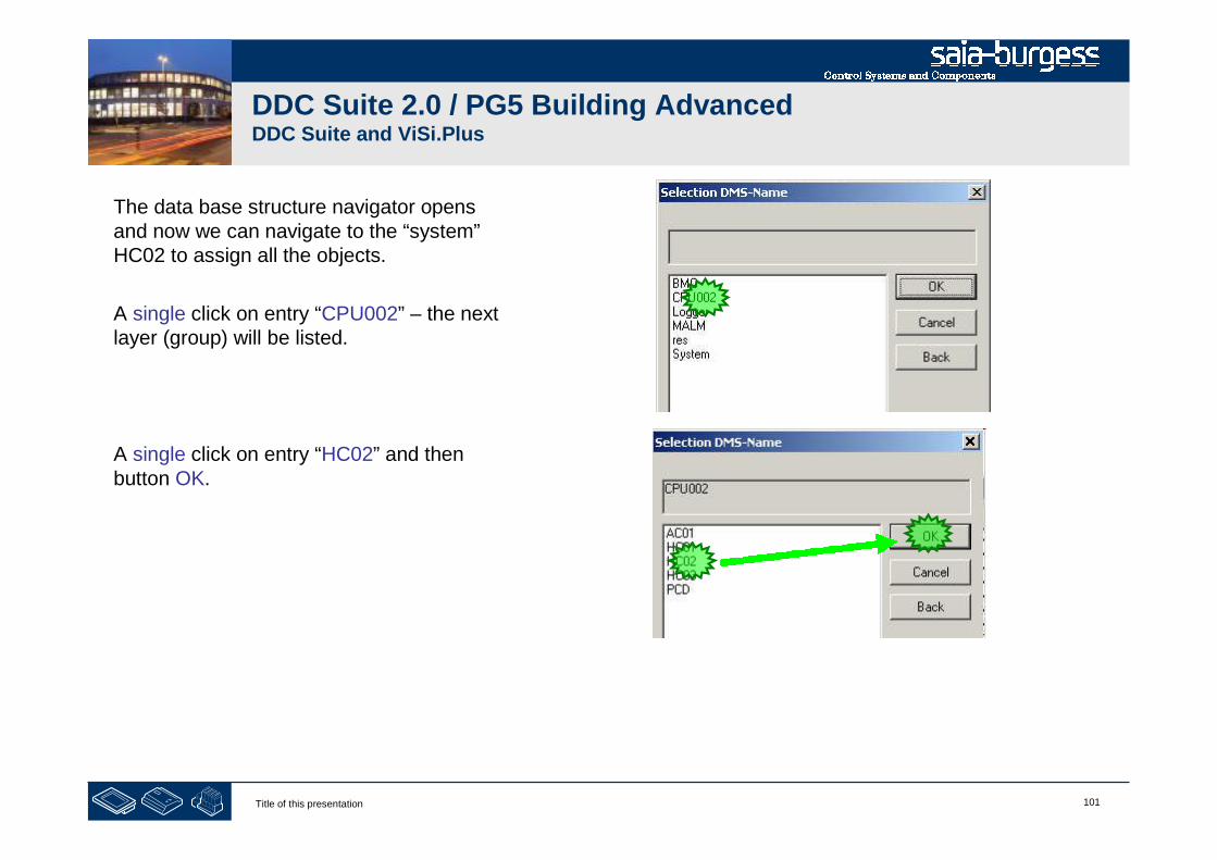
101Title of this presentation
DDC Suite 2.0 / PG5 Building AdvancedDDC Suite and ViSi.Plus
The data base structure navigator opensand now we can navigate to the “system”HC02 to assign all the objects.
A single click on entry “CPU002” – the nextlayer (group) will be listed.
A single click on entry “HC02” and thenbutton OK.

102Title of this presentation
DDC Suite 2.0 / PG5 Building AdvancedDDC Suite and ViSi.Plus
Check if field “Reinitialization” is changed into
CPU002:HC02
And press OK.
That’s all. Check if the objects are assigned to HC02 –do this in runtime mode.
Now you can imagine how many time you save whenyou have to draw big air condition with up to 50, 60 or100 objects.
103Title of this presentation
DDC Suite 2.0 / PG5 Building AdvancedDDC Suite and ViSi.Plus
Any problems?
Yes: rewind to first slide and repeat all lessons …
Everything OK: Congratulation

DDC Suite - advanced – detailed information
Stephan Hintze / 05.12.2008
2Title of this presentation
DDC Suite Advanced
Overview

3Title of this presentation
DDC Suite Advanced – Overview
DDC Suite FBoxes are able to implement additional external source files. Those files are available for SWebAlarming,BACnet, Documentation and ExtraAddOn.
Depending of FBox functionalities it can be any combination of those files. In the following description you’ll have on top theFBox name and then a definition which files are supported and their file names:
BACnet: BAC_DDC_InitLibrary.srcDoc-File: DOC_DDC_InitialisationLibrary.srcAddOn: AddOn_DDC_InitialisationLibrary.src
These files are normally predefined and used to change some texts (alarming) or optimize BACnet object – but they can alsobe used to implement additional functionality into the FBox or to improve functions. This can be handled like an object inheritmechanism
In fact if you improve e.g. for FBox “1 Alarm” the functionality in an external file – all FBoxes in the program will inherit thisnew improvement. This is a very powerful possibility.
NOTE: There are only AddOn files for the FBoxes that have online I/O addressing.
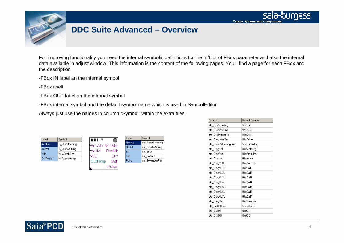
4Title of this presentation
DDC Suite Advanced – Overview
For improving functionality you need the internal symbolic definitions for the In/Out of FBox parameter and also the internaldata available in adjust window. This information is the content of the following pages. You’ll find a page for each FBox andthe description
-FBox IN label an the internal symbol
-FBox itself
-FBox OUT label an the internal symbol
-FBox internal symbol and the default symbol name which is used in SymbolEditor
Always just use the names in column “Symbol” within the extra files!

5Title of this presentation
DDC Suite Advanced – Overview
Example: The FBox “ManualOp” has 3 outputs to indicate if there is a FBox in manual mode. If you’d like to have onesymbol if any output is high than you can use of course an “OR” gate – but you can improve the FBox itself.
In file “AddOn_DDC_GeneralManualInfo.src” we could type in:
A.DDC_Suite.Name.Manual equ f ; New symbol indicating any FBox under manual operation
publ A.DDC_Suite.Name.Manual ; make it available in symbol editor system tab
sth out_Motoren ;orh out_Antriebe ;orh out_Regler ;out A.DDC_Suite.Name.Manual ;
After a rebuild you’ll see the new symbol in system tab an can use it in your program. This example is like “adding an FBoxoutput”
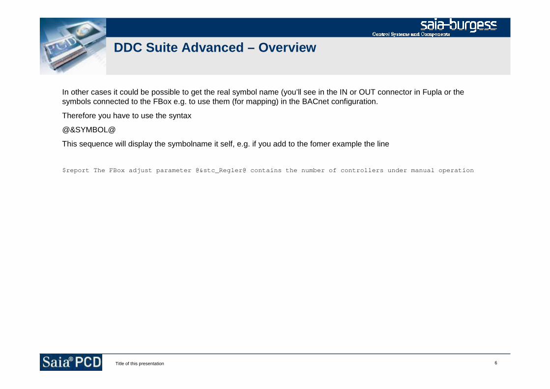
6Title of this presentation
DDC Suite Advanced – Overview
In other cases it could be possible to get the real symbol name (you’ll see in the IN or OUT connector in Fupla or thesymbols connected to the FBox e.g. to use them (for mapping) in the BACnet configuration.
Therefore you have to use the syntax
@&SYMBOL@
This sequence will display the symbolname it self, e.g. if you add to the fomer example the line
$report The FBox adjust parameter @&stc_Regler@ contains the number of controllers under manual operation

7Title of this presentation
DDC Suite Advanced
Family : Initialisation
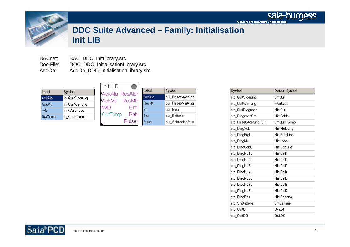
8Title of this presentation
DDC Suite Advanced – Family: InitialisationInit LIB
BACnet: BAC_DDC_InitLibrary.srcDoc-File: DOC_DDC_InitialisationLibrary.srcAddOn: AddOn_DDC_InitialisationLibrary.src

9Title of this presentation
DDC Suite Advanced – Family: InitialisationInit ABS
BACnet: BAC_DDC_InitAntiBlocking.srcDoc-File: DOC_DDC_InitialisationAntiBlocking.srcAddOn: AddOn_DDC_InitialisationAntiBlocking.src
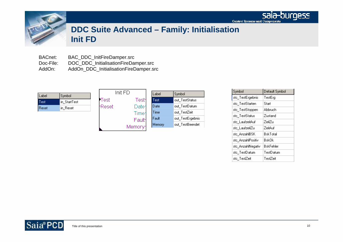
10Title of this presentation
DDC Suite Advanced – Family: InitialisationInit FD
BACnet: BAC_DDC_InitFireDamper.srcDoc-File: DOC_DDC_InitialisationFireDamper.srcAddOn: AddOn_DDC_InitialisationFireDamper.src
11Title of this presentation
DDC Suite Advanced
Family : General
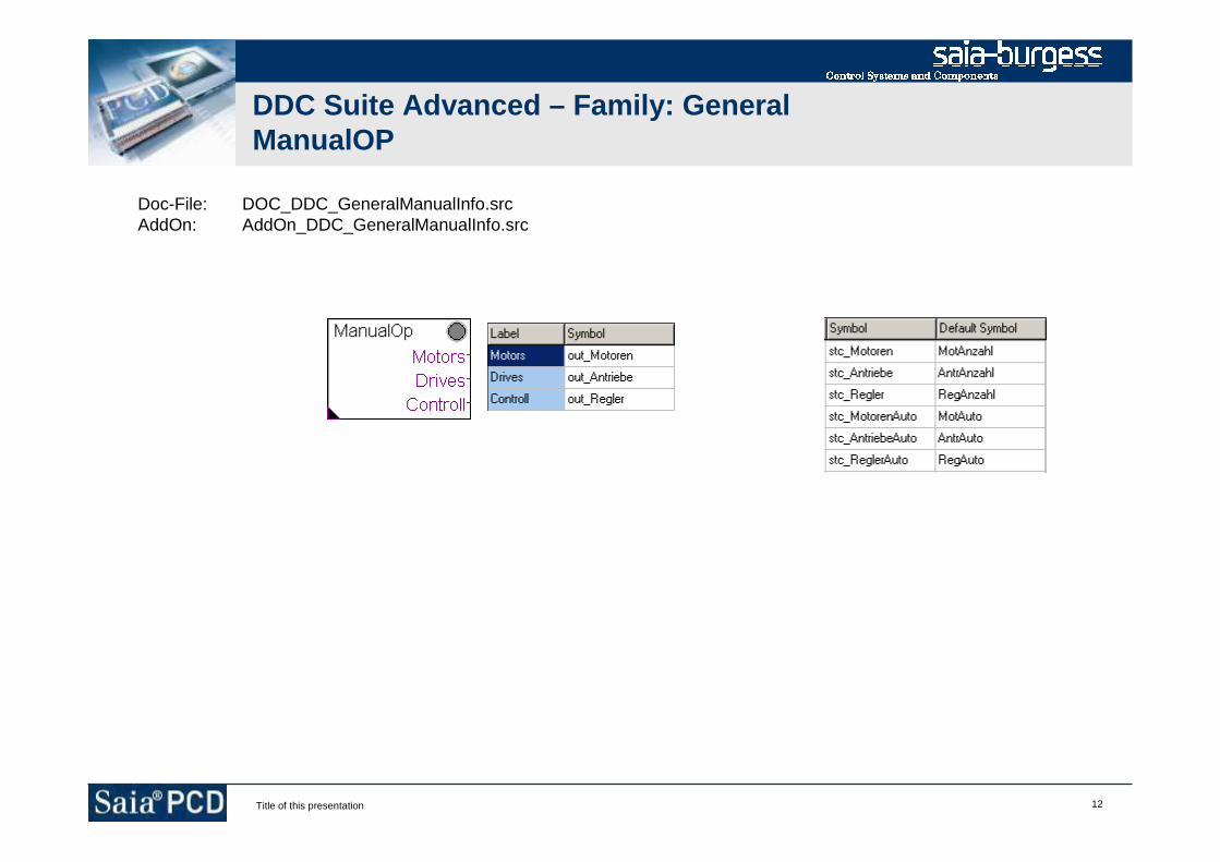
12Title of this presentation
DDC Suite Advanced – Family: GeneralManualOP
Doc-File: DOC_DDC_GeneralManualInfo.srcAddOn: AddOn_DDC_GeneralManualInfo.src
13Title of this presentation
DDC Suite Advanced
Family : Analogue values
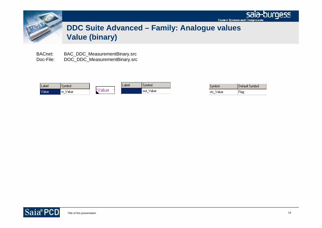
14Title of this presentation
DDC Suite Advanced – Family: Analogue valuesValue (binary)
BACnet: BAC_DDC_MeasurementBinary.srcDoc-File: DOC_DDC_MeasurementBinary.src
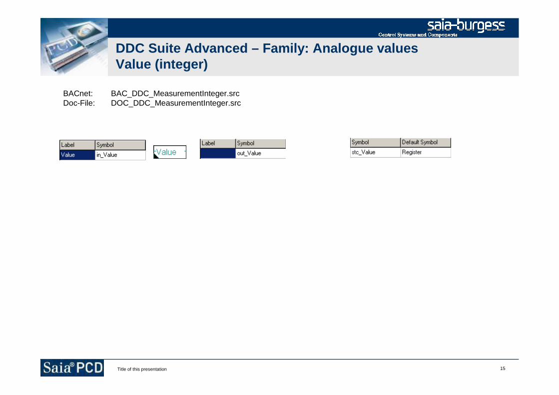
15Title of this presentation
DDC Suite Advanced – Family: Analogue valuesValue (integer)
BACnet: BAC_DDC_MeasurementInteger.srcDoc-File: DOC_DDC_MeasurementInteger.src
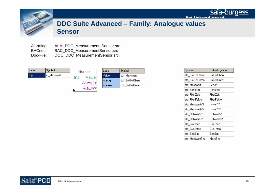
16Title of this presentation
DDC Suite Advanced – Family: Analogue valuesSensor
Alarming: ALM_DDC_Measurement_Sensor.srcBACnet: BAC_DDC_MeasurementSensor.srcDoc-File: DOC_DDC_MeasurementSensor.src
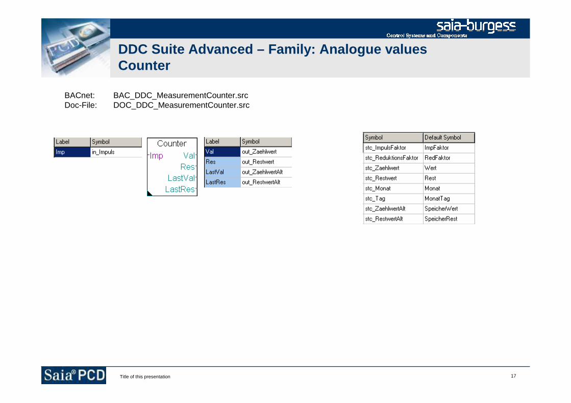
17Title of this presentation
DDC Suite Advanced – Family: Analogue valuesCounter
BACnet: BAC_DDC_MeasurementCounter.srcDoc-File: DOC_DDC_MeasurementCounter.src
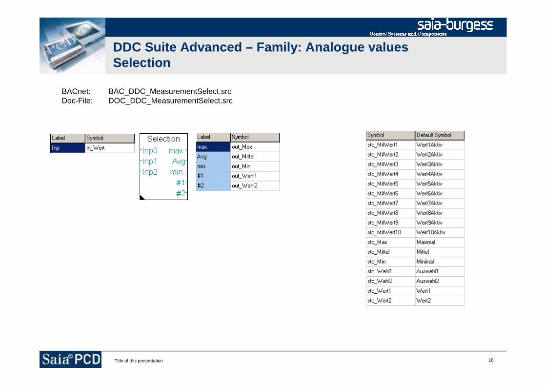
18Title of this presentation
DDC Suite Advanced – Family: Analogue valuesSelection
BACnet: BAC_DDC_MeasurementSelect.srcDoc-File: DOC_DDC_MeasurementSelect.src
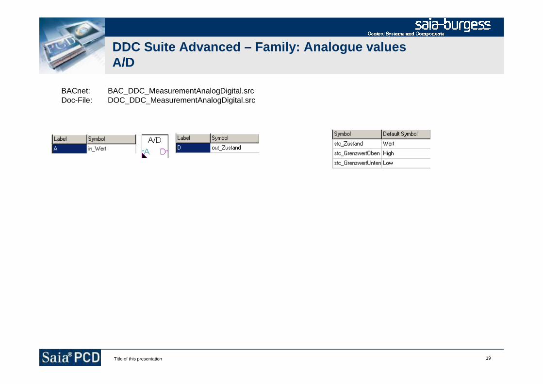
19Title of this presentation
DDC Suite Advanced – Family: Analogue valuesA/D
BACnet: BAC_DDC_MeasurementAnalogDigital.srcDoc-File: DOC_DDC_MeasurementAnalogDigital.src
20Title of this presentation
DDC Suite Advanced
Family : Alarming
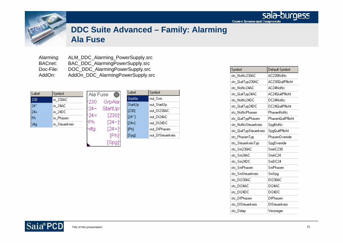
21Title of this presentation
DDC Suite Advanced – Family: AlarmingAla Fuse
Alarming: ALM_DDC_Alarming_PowerSupply.srcBACnet: BAC_DDC_AlarmingPowerSupply.srcDoc-File: DOC_DDC_AlarmingPowerSupply.srcAddOn: AddOn_DDC_AlarmingPowerSupply.src

22Title of this presentation
DDC Suite Advanced – Family: Alarming1 Ala/Msg
Alarming: ALM_DDC_Alarming_AlarmMessage.srcBACnet: BAC_DDC_AlarmingAlarmMessage.srcDoc-File: DOC_DDC_AlarmingAlarmMessage.srcAddOn: AddOn_DDC_AlarmingAlarmMessage.src

23Title of this presentation
DDC Suite Advanced – Family: Alarming1 Alarm
Alarming: ALM_DDC_Alarming_1Alarm.srcBACnet: BAC_DDC_Alarming1Alarm.srcDoc-File: DOC_DDC_Alarming1Alarm.srcAddOn: AddOn_DDC_Alarming1Alarm.src
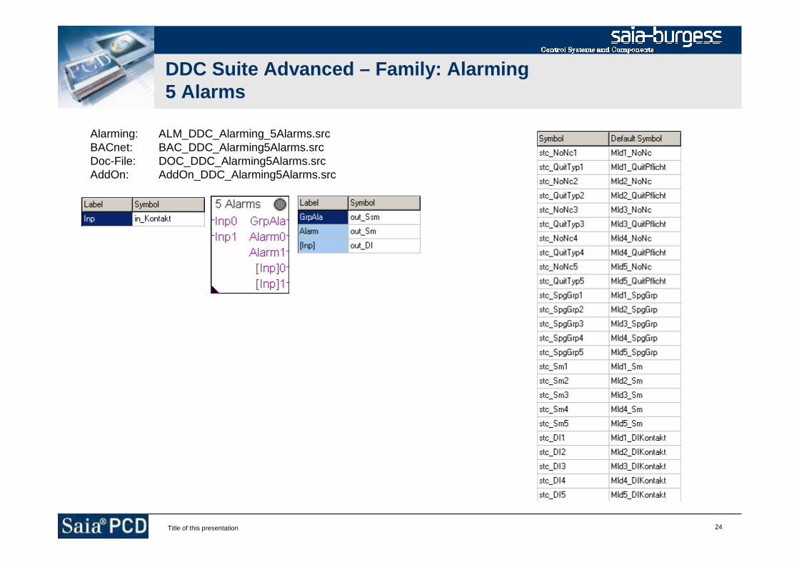
24Title of this presentation
DDC Suite Advanced – Family: Alarming5 Alarms
Alarming: ALM_DDC_Alarming_5Alarms.srcBACnet: BAC_DDC_Alarming5Alarms.srcDoc-File: DOC_DDC_Alarming5Alarms.srcAddOn: AddOn_DDC_Alarming5Alarms.src

25Title of this presentation
DDC Suite Advanced – Family: AlarmingAlaDelay
Alarming: ALM_DDC_Alarming_DelayedAlarm.srcBACnet: BAC_DDC_AlarmingDelayedAlarm.srcDoc-File: DOC_DDC_AlarmingDelayedAlarm.srcAddOn: AddOn_DDC_AlarmingDelayedAlarm.src
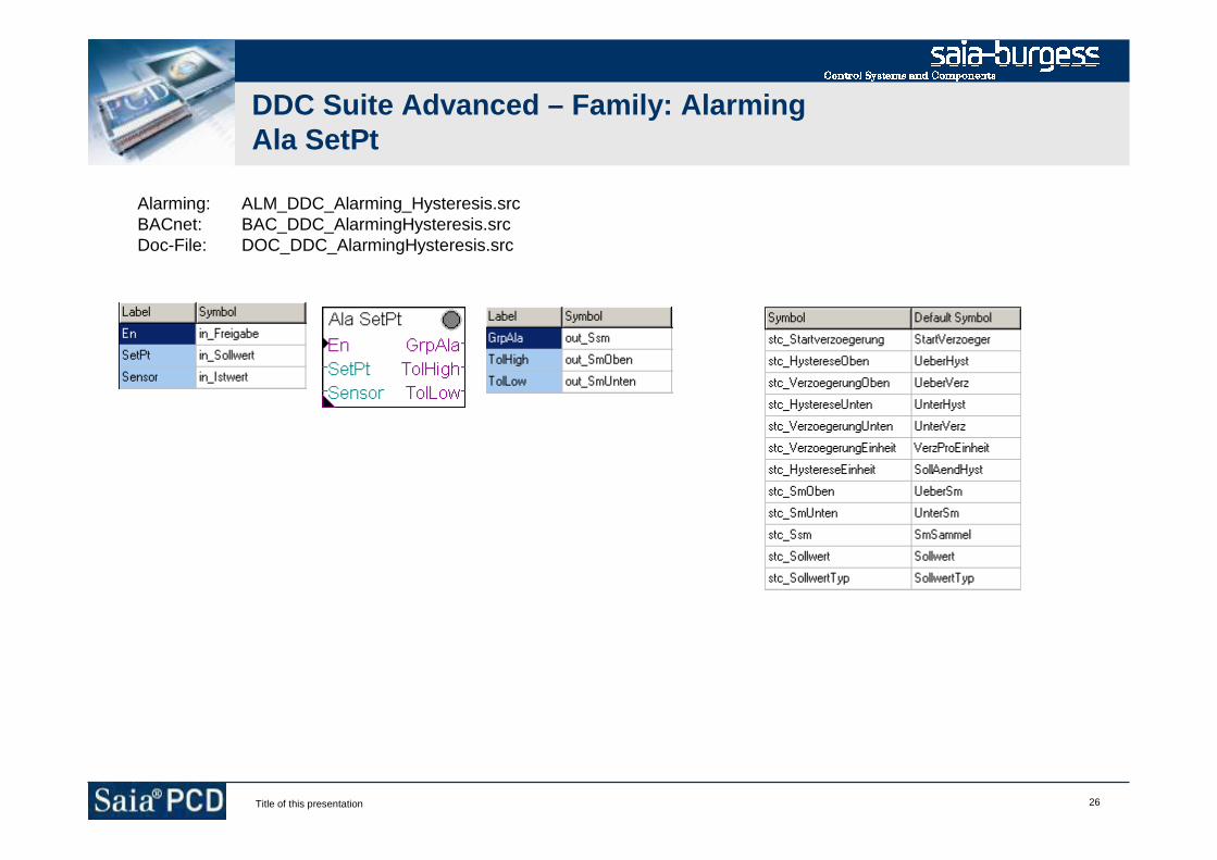
26Title of this presentation
DDC Suite Advanced – Family: AlarmingAla SetPt
Alarming: ALM_DDC_Alarming_Hysteresis.srcBACnet: BAC_DDC_AlarmingHysteresis.srcDoc-File: DOC_DDC_AlarmingHysteresis.src

27Title of this presentation
DDC Suite Advanced – Family: AlarmingAlaMotor1
Alarming: ALM_DDC_Alarming_MotorDrive1Speed.srcBACnet: BAC_DDC_AlarmingMotorDrive1Speed.srcDoc-File: DOC_DDC_AlarmingMotorDrive1Speed.srcAddOn: AddOn_DDC_AlarmingMotorDrive1Speed.src
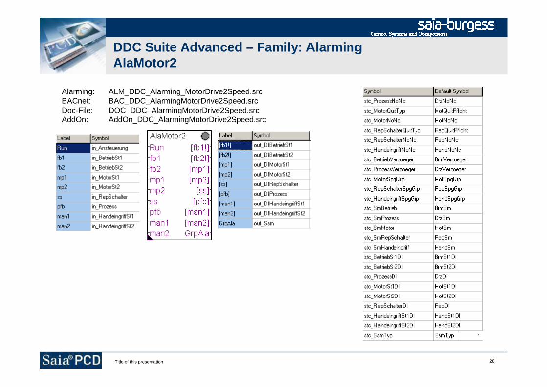
28Title of this presentation
DDC Suite Advanced – Family: AlarmingAlaMotor2
Alarming: ALM_DDC_Alarming_MotorDrive2Speed.srcBACnet: BAC_DDC_AlarmingMotorDrive2Speed.srcDoc-File: DOC_DDC_AlarmingMotorDrive2Speed.srcAddOn: AddOn_DDC_AlarmingMotorDrive2Speed.src

29Title of this presentation
DDC Suite Advanced – Family: AlarmingAlaMotor3
Alarming: ALM_DDC_Alarming_MotorDrive3Speed.srcBACnet: BAC_DDC_AlarmingMotorDrive3Speed.srcDoc-File: DOC_DDC_AlarmingMotorDrive3Speed.srcAddOn: AddOn_DDC_AlarmingMotorDrive3Speed.src
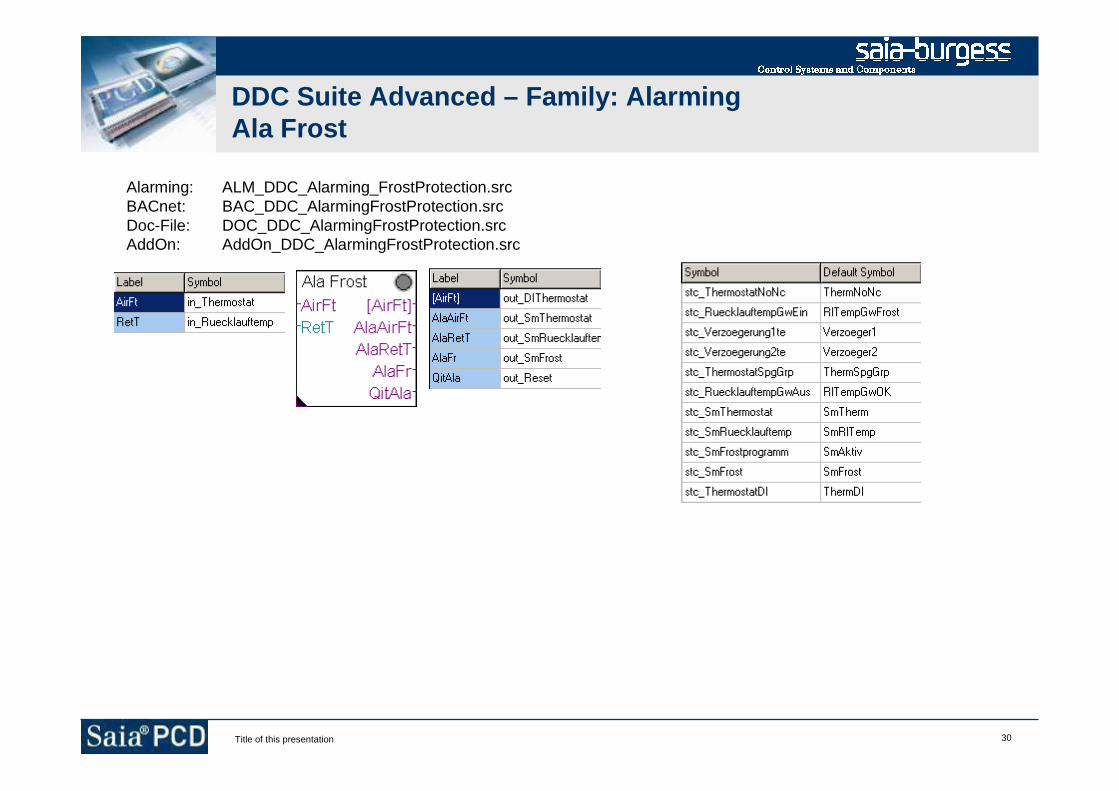
30Title of this presentation
DDC Suite Advanced – Family: AlarmingAla Frost
Alarming: ALM_DDC_Alarming_FrostProtection.srcBACnet: BAC_DDC_AlarmingFrostProtection.srcDoc-File: DOC_DDC_AlarmingFrostProtection.srcAddOn: AddOn_DDC_AlarmingFrostProtection.src
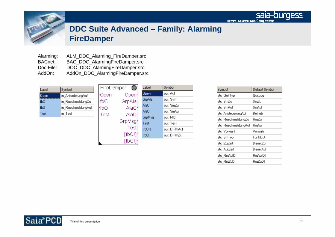
31Title of this presentation
DDC Suite Advanced – Family: AlarmingFireDamper
Alarming: ALM_DDC_Alarming_FireDamper.srcBACnet: BAC_DDC_AlarmingFireDamper.srcDoc-File: DOC_DDC_AlarmingFireDamper.srcAddOn: AddOn_DDC_AlarmingFireDamper.src
32Title of this presentation
DDC Suite Advanced
Family : Set points
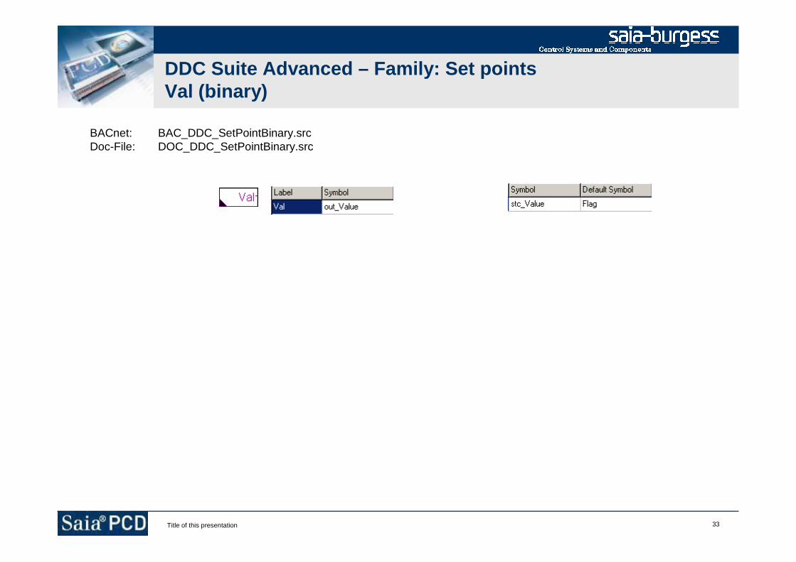
33Title of this presentation
DDC Suite Advanced – Family: Set pointsVal (binary)
BACnet: BAC_DDC_SetPointBinary.srcDoc-File: DOC_DDC_SetPointBinary.src

34Title of this presentation
DDC Suite Advanced – Family: Set pointsVal (integer)
BACnet: BAC_DDC_SetPointInteger.srcDoc-File: DOC_DDC_SetPointInteger.src

35Title of this presentation
DDC Suite Advanced – Family: Set pointsHysteresis
BACnet: BAC_DDC_SetPointWithHysteresis.srcDoc-File: DOC_DDC_SetPointWithHysteresis.src
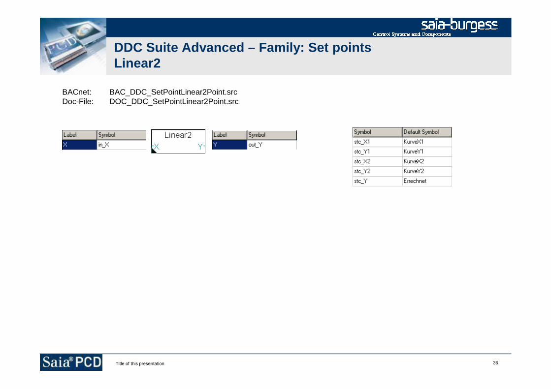
36Title of this presentation
DDC Suite Advanced – Family: Set pointsLinear2
BACnet: BAC_DDC_SetPointLinear2Point.srcDoc-File: DOC_DDC_SetPointLinear2Point.src

37Title of this presentation
DDC Suite Advanced – Family: Set pointsLinear4
BACnet: BAC_DDC_SetPointLinear4Point.srcDoc-File: DOC_DDC_SetPointLinear4Point.src

38Title of this presentation
DDC Suite Advanced – Family: Set pointsRoom
BACnet: BAC_DDC_SetPointRoom.srcDoc-File: DOC_DDC_SetPointRoom.src
39Title of this presentation
DDC Suite Advanced
Family : System and clocks
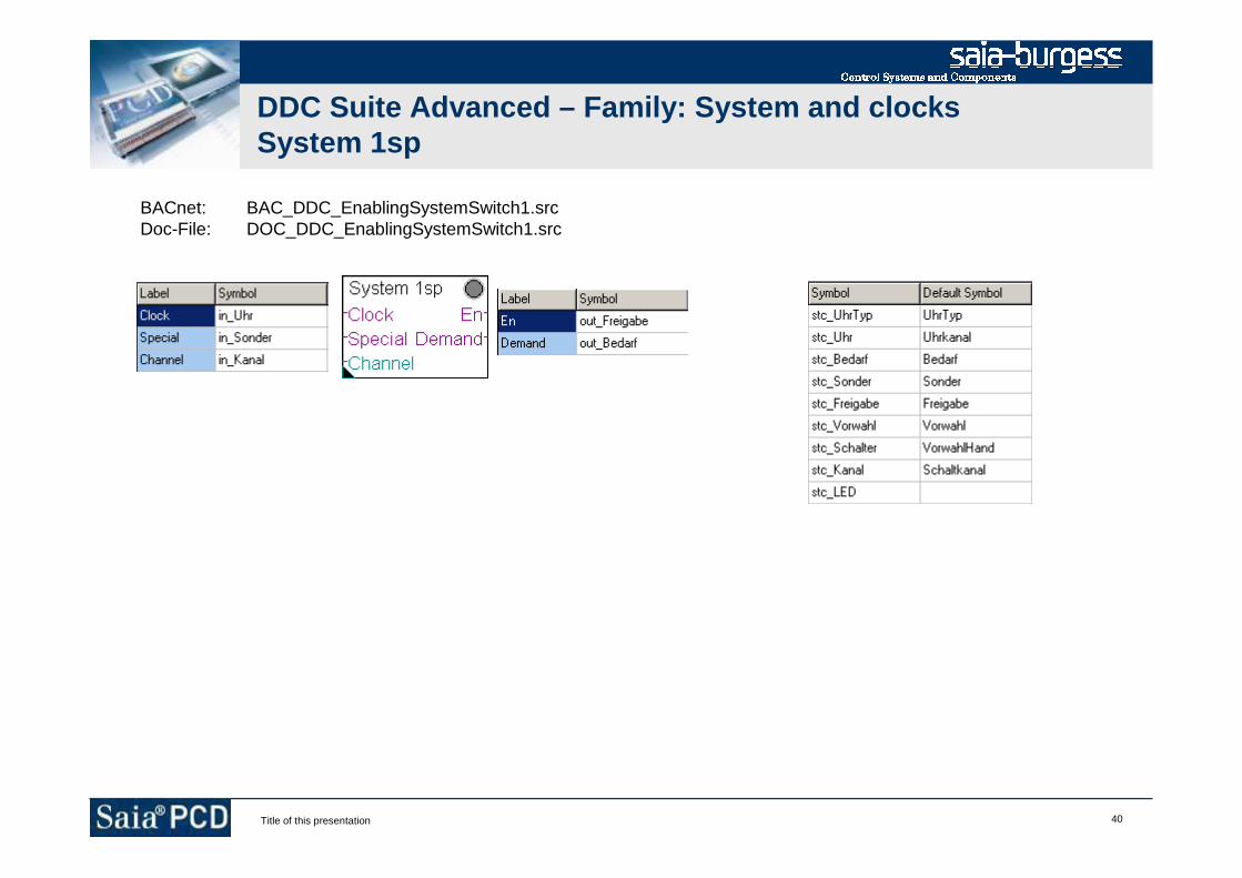
40Title of this presentation
DDC Suite Advanced – Family: System and clocksSystem 1sp
BACnet: BAC_DDC_EnablingSystemSwitch1.srcDoc-File: DOC_DDC_EnablingSystemSwitch1.src

41Title of this presentation
DDC Suite Advanced – Family: System and clocksSystem 2sp
BACnet: BAC_DDC_EnablingSystemSwitch2.srcDoc-File: DOC_DDC_EnablingSystemSwitch2.src

42Title of this presentation
DDC Suite Advanced – Family: System and clocksSystem 3sp
BACnet: BAC_DDC_EnablingSystemSwitch3.srcDoc-File: DOC_DDC_EnablingSystemSwitch3.src
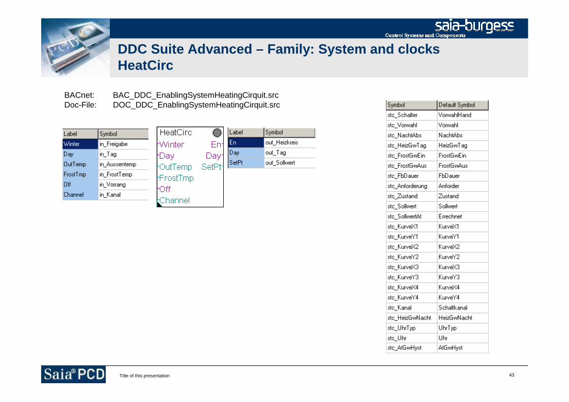
43Title of this presentation
DDC Suite Advanced – Family: System and clocksHeatCirc
BACnet: BAC_DDC_EnablingSystemHeatingCirquit.srcDoc-File: DOC_DDC_EnablingSystemHeatingCirquit.src
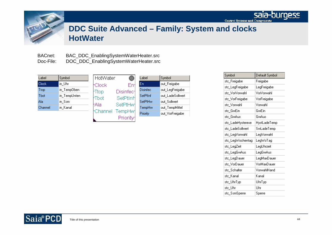
44Title of this presentation
DDC Suite Advanced – Family: System and clocksHotWater
BACnet: BAC_DDC_EnablingSystemWaterHeater.srcDoc-File: DOC_DDC_EnablingSystemWaterHeater.src

45Title of this presentation
DDC Suite Advanced – Family: System and clocksBoiler
BACnet: BAC_DDC_EnablingSystemBoiler.srcDoc-File: DOC_DDC_EnablingSystemBoiler.src

46Title of this presentation
DDC Suite Advanced – Family: System and clocksFanStart
BACnet: BAC_DDC_EnablingStartAirCondition.srcDoc-File: DOC_DDC_EnablingStartAirCondition.src
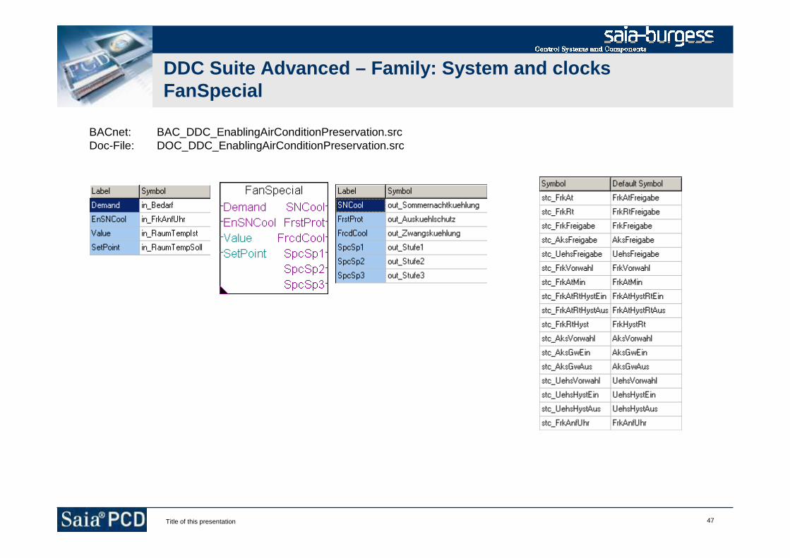
47Title of this presentation
DDC Suite Advanced – Family: System and clocksFanSpecial
BACnet: BAC_DDC_EnablingAirConditionPreservation.srcDoc-File: DOC_DDC_EnablingAirConditionPreservation.src

48Title of this presentation
DDC Suite Advanced – Family: System and clocksFanSpeed
BACnet: BAC_DDC_EnablingAirConditionDemand2ndSpeed.srcDoc-File: DOC_DDC_EnablingAirConditionDemand2ndSpeed.src
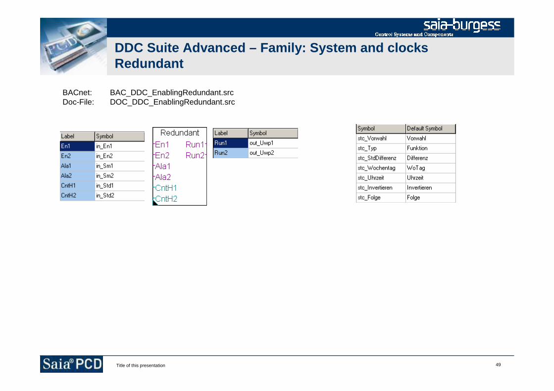
49Title of this presentation
DDC Suite Advanced – Family: System and clocksRedundant
BACnet: BAC_DDC_EnablingRedundant.srcDoc-File: DOC_DDC_EnablingRedundant.src
50Title of this presentation
DDC Suite Advanced
Family : Controls

51Title of this presentation
DDC Suite Advanced – Family: ControlsMotor 1
Alarming: ALM_DDC_Control_MotorDrive1Speed.srcBACnet: BAC_DDC_ControlMotorDrive1Speed.srcDoc-File: DOC_DDC_ControlMotorDrive1Speed.srcAddOn: AddOn_DDC_ControlMotorDrive1Speed.src
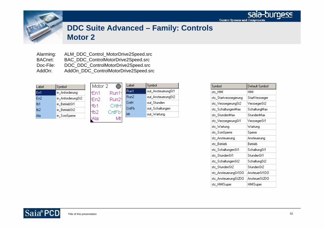
52Title of this presentation
DDC Suite Advanced – Family: ControlsMotor 2
Alarming: ALM_DDC_Control_MotorDrive2Speed.srcBACnet: BAC_DDC_ControlMotorDrive2Speed.srcDoc-File: DOC_DDC_ControlMotorDrive2Speed.srcAddOn: AddOn_DDC_ControlMotorDrive2Speed.src

53Title of this presentation
DDC Suite Advanced – Family: ControlsMotor 3
Alarming: ALM_DDC_Control_MotorDrive3Speed.srcBACnet: BAC_DDC_ControlMotorDrive23peed.srcDoc-File: DOC_DDC_ControlMotorDrive23peed.srcAddOn: AddOn_DDC_ControlMotorDrive3Speed.src

54Title of this presentation
DDC Suite Advanced – Family: ControlsPump
Alarming: ALM_DDC_Control_Pump.srcBACnet: BAC_DDC_ControlPump.srcDoc-File: DOC_DDC_ControlPump.srcAddOn: AddOn_DDC_ControlPump.src
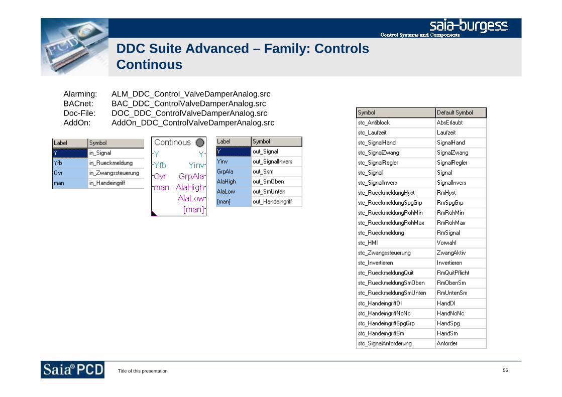
55Title of this presentation
DDC Suite Advanced – Family: ControlsContinous
Alarming: ALM_DDC_Control_ValveDamperAnalog.srcBACnet: BAC_DDC_ControlValveDamperAnalog.srcDoc-File: DOC_DDC_ControlValveDamperAnalog.srcAddOn: AddOn_DDC_ControlValveDamperAnalog.src

56Title of this presentation
DDC Suite Advanced – Family: ControlsO/C
Alarming: ALM_DDC_Control_ValveDamperOpenClose.srcBACnet: BAC_DDC_ControlValveDamperOpenClose.srcDoc-File: DOC_DDC_ControlValveDamperOpenClose.srcAddOn: AddOn_DDC_ControlValveDamperOpenClose.src

57Title of this presentation
DDC Suite Advanced
Family : Controller
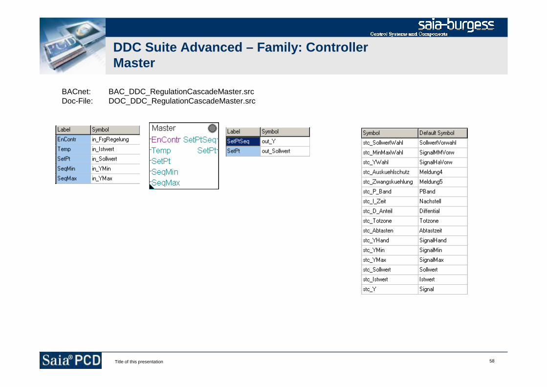
58Title of this presentation
DDC Suite Advanced – Family: ControllerMaster
BACnet: BAC_DDC_RegulationCascadeMaster.srcDoc-File: DOC_DDC_RegulationCascadeMaster.src
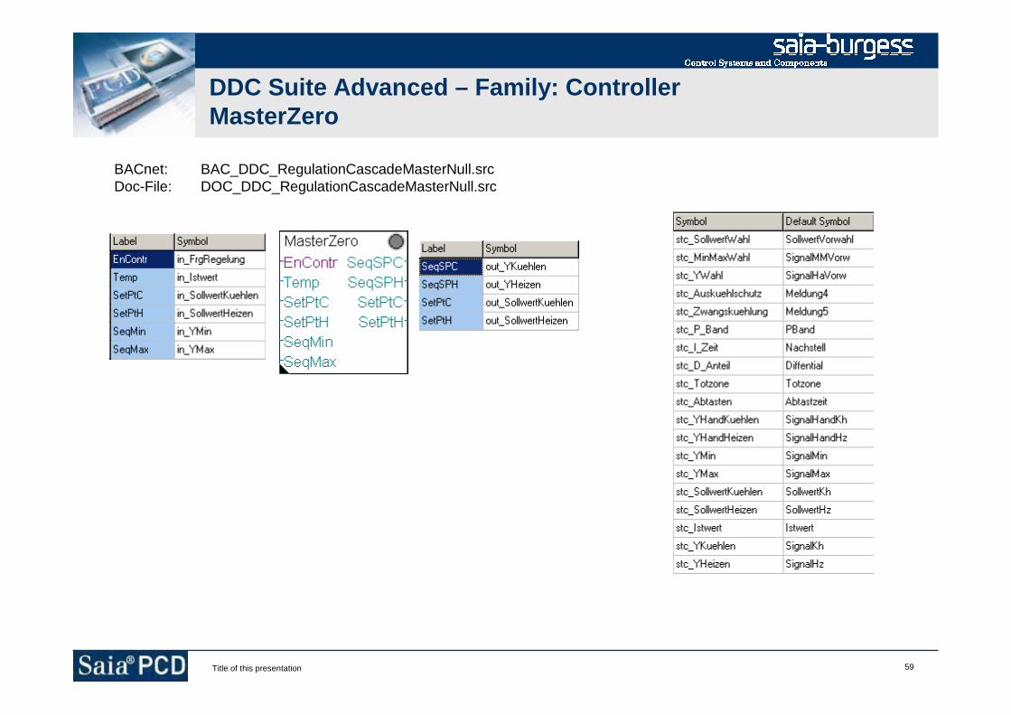
59Title of this presentation
DDC Suite Advanced – Family: ControllerMasterZero
BACnet: BAC_DDC_RegulationCascadeMasterNull.srcDoc-File: DOC_DDC_RegulationCascadeMasterNull.src
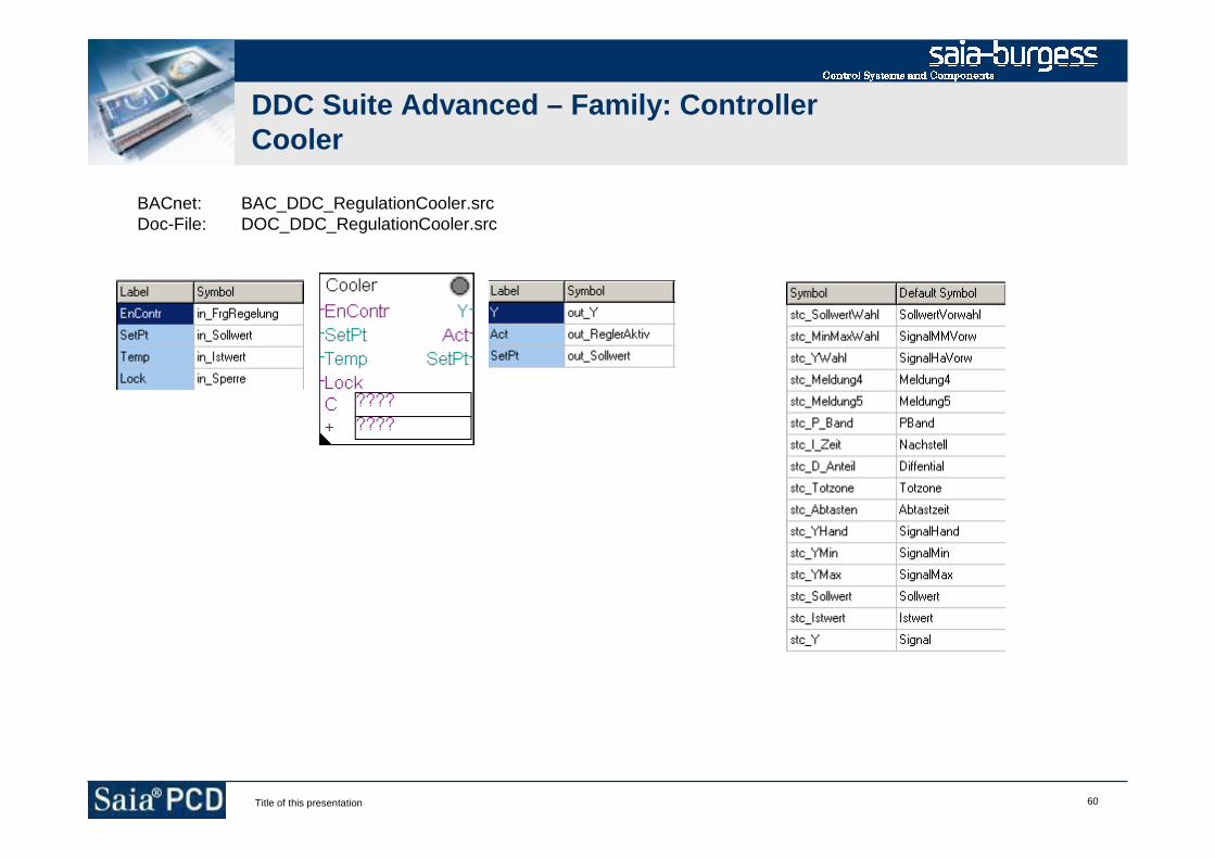
60Title of this presentation
DDC Suite Advanced – Family: ControllerCooler
BACnet: BAC_DDC_RegulationCooler.srcDoc-File: DOC_DDC_RegulationCooler.src

61Title of this presentation
DDC Suite Advanced – Family: ControllerHeatRec
BACnet: BAC_DDC_RegulationHeatRecovery.srcDoc-File: DOC_DDC_RegulationHeatRecovery.src

62Title of this presentation
DDC Suite Advanced – Family: ControllerMixedAir
BACnet: BAC_DDC_RegulationMixedAir.srcDoc-File: DOC_DDC_RegulationMixedAir.src

63Title of this presentation
DDC Suite Advanced – Family: ControllerPreheater
BACnet: BAC_DDC_RegulationPreheater.srcDoc-File: DOC_DDC_RegulationPreheater.src
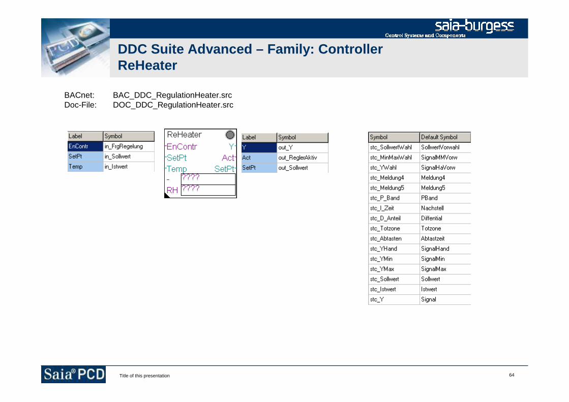
64Title of this presentation
DDC Suite Advanced – Family: ControllerReHeater
BACnet: BAC_DDC_RegulationHeater.srcDoc-File: DOC_DDC_RegulationHeater.src

65Title of this presentation
DDC Suite Advanced – Family: ControllerHumid
BACnet: BAC_DDC_RegulationHumidifying.srcDoc-File: DOC_DDC_RegulationHumidifying.src

66Title of this presentation
DDC Suite Advanced – Family: ControllerDeHumid
BACnet: BAC_DDC_RegulationDehumidifying.srcDoc-File: DOC_DDC_RegulationDehumidifying.src
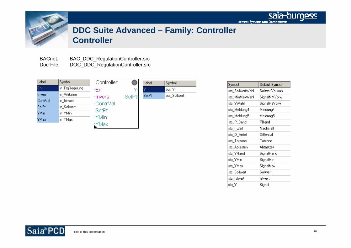
67Title of this presentation
DDC Suite Advanced – Family: ControllerController
BACnet: BAC_DDC_RegulationController.srcDoc-File: DOC_DDC_RegulationController.src
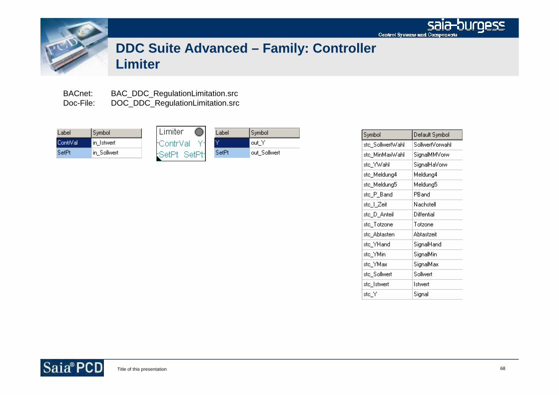
68Title of this presentation
DDC Suite Advanced – Family: ControllerLimiter
BACnet: BAC_DDC_RegulationLimitation.srcDoc-File: DOC_DDC_RegulationLimitation.src
DDC Suite – hints & tricks
Stephan Hintze / 05.12.2008

2Title of this presentation
DDC Suite Advanced
Initialisation

3Title of this presentation
DDC Suite Advanced – Overview
The FBox “InitLIB” supports the outdoor temperature at input “OutTemp” toFBoxes for calculation or comparison.
This means that all such FBoxes in program will use a single uniqueoutdoor temperature. But what if each system has it’s own outdoortemperature sensor?
After a first build the FBox “InitLIB” creates a symbol in system tab whichcan be used to assign in program another outdoor temperature. So it’seasy to map for each system it’s own temperature.

4Title of this presentation
DDC Suite Advanced – Overview
Acknowledging alarms also is done from the FBox “InitLIB” for wholeprogram. You can also split this into system parts. Just transfer the“acknowledge” command from system on first page of system into theprovided symbol and reset it on last system page.

5Title of this presentation
DDC Suite Advanced – Overview
Resetting maintenance messages and reinitializing internal counter is alsodone from the FBox “InitLIB” for whole program. You can also split this intosystem parts. Just transfer the “clear maintenance” command from systemon first page of system into the provided symbol and reset it on last systempage.