date by check
TRANSCRIPT
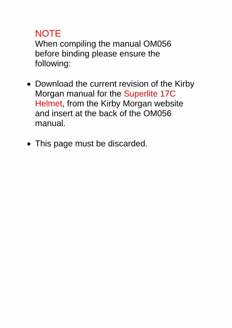
NOTE When compiling the manual OM056 before binding please ensure the following:
• Download the current revision of the Kirby Morgan manual for the Superlite 17C Helmet, from the Kirby Morgan website and insert at the back of the OM056 manual.
• This page must be discarded.
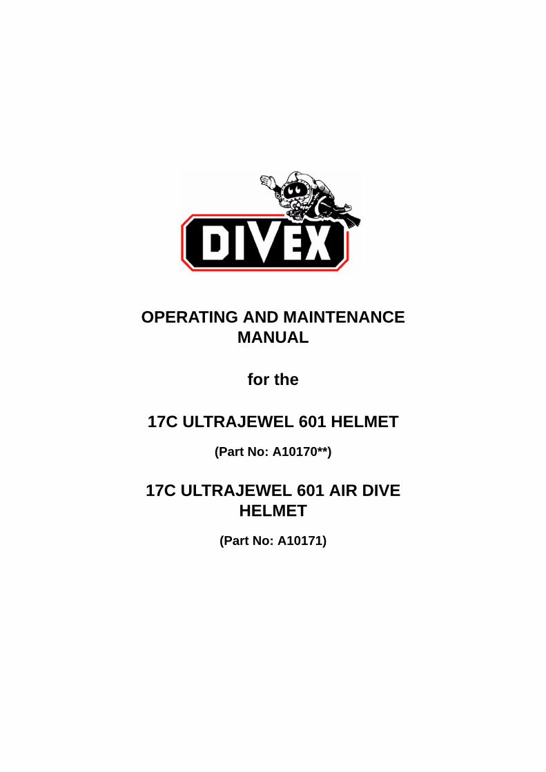
OPERATING AND MAINTENANCE MANUAL
for the
17C ULTRAJEWEL 601 HELMET
(Part No: A10170**)
17C ULTRAJEWEL 601 AIR DIVE HELMET
(Part No: A10171)

(Intentionally Blank)
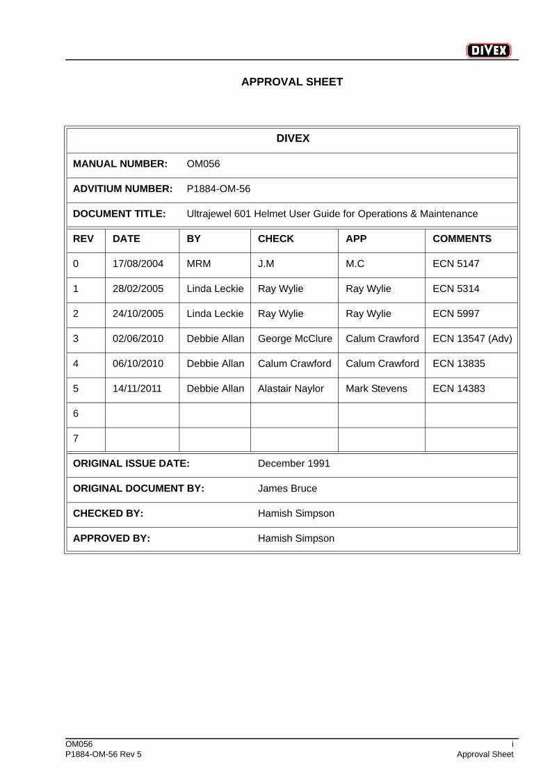
OM056 iP1884-OM-56 Rev 5 Approval Sheet
APPROVAL SHEET
DIVEX
MANUAL NUMBER: OM056
ADVITIUM NUMBER: P1884-OM-56
DOCUMENT TITLE: Ultrajewel 601 Helmet User Guide for Operations & Maintenance
REV DATE BY CHECK APP COMMENTS
0 17/08/2004 MRM J.M M.C ECN 5147
1 28/02/2005 Linda Leckie Ray Wylie Ray Wylie ECN 5314
2 24/10/2005 Linda Leckie Ray Wylie Ray Wylie ECN 5997
3 02/06/2010 Debbie Allan George McClure Calum Crawford ECN 13547 (Adv)
4 06/10/2010 Debbie Allan Calum Crawford Calum Crawford ECN 13835
5 14/11/2011 Debbie Allan Alastair Naylor Mark Stevens ECN 14383
6
7
ORIGINAL ISSUE DATE: December 1991
ORIGINAL DOCUMENT BY: James Bruce
CHECKED BY: Hamish Simpson
APPROVED BY: Hamish Simpson
ii OM056Approval Sheet P1884-OM-56 Rev 5
(Intentionally Blank)
OM056 iiiP1884-OM-56 Rev 5 Table of Contents
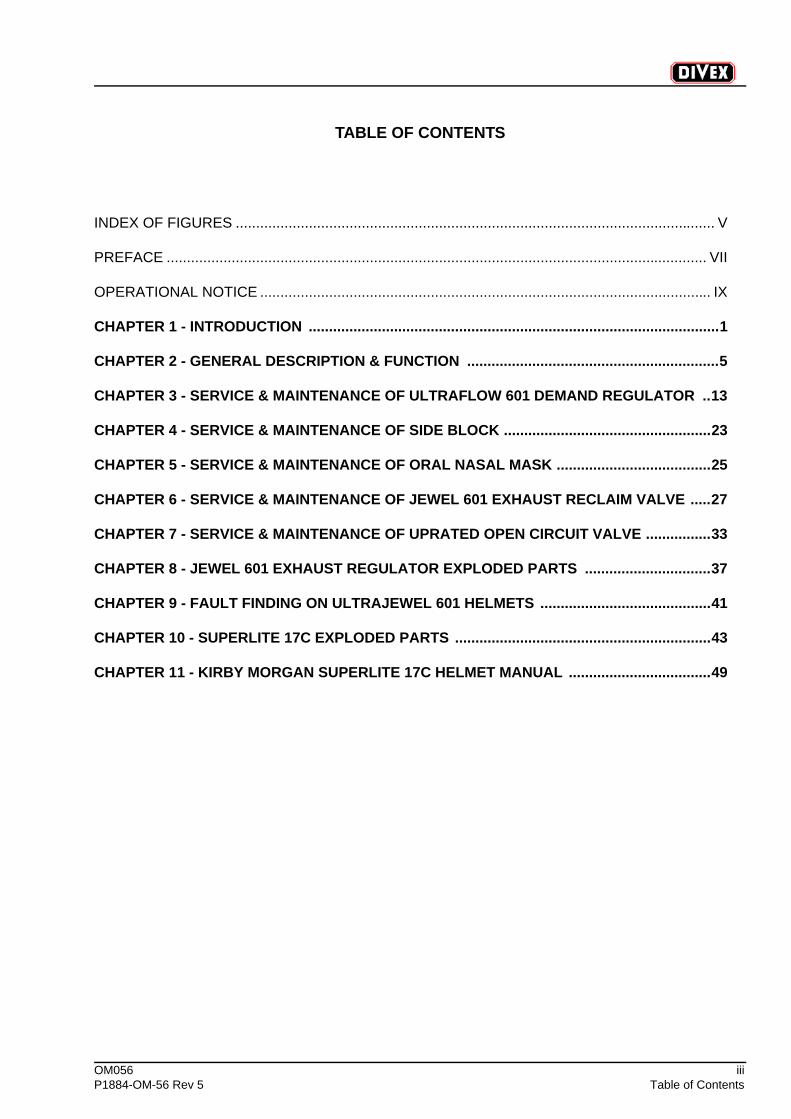
INDEX OF FIGURES ...................................................................................................................... V
PREFACE ..................................................................................................................................... VII
OPERATIONAL NOTICE ............................................................................................................... IX
CHAPTER 1 - INTRODUCTION .....................................................................................................1
CHAPTER 2 - GENERAL DESCRIPTION & FUNCTION ..............................................................5
CHAPTER 3 - SERVICE & MAINTENANCE OF ULTRAFLOW 601 DEMAND REGULATOR ..13
CHAPTER 4 - SERVICE & MAINTENANCE OF SIDE BLOCK ...................................................23
CHAPTER 5 - SERVICE & MAINTENANCE OF ORAL NASAL MASK ......................................25
CHAPTER 6 - SERVICE & MAINTENANCE OF JEWEL 601 EXHAUST RECLAIM VALVE .....27
CHAPTER 7 - SERVICE & MAINTENANCE OF UPRATED OPEN CIRCUIT VALVE ................33
CHAPTER 8 - JEWEL 601 EXHAUST REGULATOR EXPLODED PARTS ...............................37
CHAPTER 9 - FAULT FINDING ON ULTRAJEWEL 601 HELMETS ..........................................41
CHAPTER 10 - SUPERLITE 17C EXPLODED PARTS ...............................................................43
CHAPTER 11 - KIRBY MORGAN SUPERLITE 17C HELMET MANUAL ...................................49
TABLE OF CONTENTS
iv OM056Table of Contents P1884-OM-56 Rev 5
(Intentionally Blank)
OM056 vP1884-OM-56 Rev 5 Index of Figures
INDEX OF FIGURES
Page
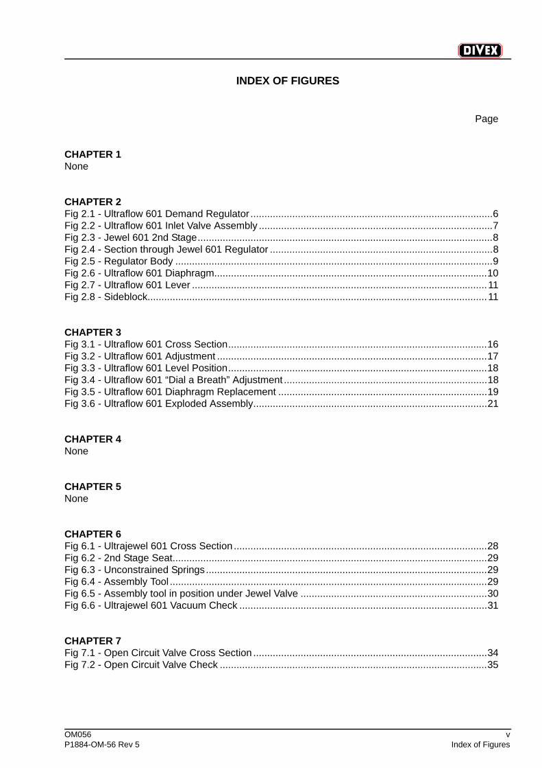
CHAPTER 1 None
CHAPTER 2 Fig 2.1 - Ultraflow 601 Demand Regulator .......................................................................................6Fig 2.2 - Ultraflow 601 Inlet Valve Assembly ....................................................................................7Fig 2.3 - Jewel 601 2nd Stage..........................................................................................................8Fig 2.4 - Section through Jewel 601 Regulator ................................................................................8Fig 2.5 - Regulator Body ..................................................................................................................9Fig 2.6 - Ultraflow 601 Diaphragm..................................................................................................10Fig 2.7 - Ultraflow 601 Lever ..........................................................................................................11Fig 2.8 - Sideblock..........................................................................................................................11
CHAPTER 3 Fig 3.1 - Ultraflow 601 Cross Section.............................................................................................16Fig 3.2 - Ultraflow 601 Adjustment .................................................................................................17Fig 3.3 - Ultraflow 601 Level Position.............................................................................................18Fig 3.4 - Ultraflow 601 “Dial a Breath” Adjustment .........................................................................18Fig 3.5 - Ultraflow 601 Diaphragm Replacement ...........................................................................19Fig 3.6 - Ultraflow 601 Exploded Assembly....................................................................................21
CHAPTER 4 None
CHAPTER 5 None
CHAPTER 6 Fig 6.1 - Ultrajewel 601 Cross Section ...........................................................................................28Fig 6.2 - 2nd Stage Seat.................................................................................................................29Fig 6.3 - Unconstrained Springs.....................................................................................................29Fig 6.4 - Assembly Tool ..................................................................................................................29Fig 6.5 - Assembly tool in position under Jewel Valve ...................................................................30Fig 6.6 - Ultrajewel 601 Vacuum Check .........................................................................................31
CHAPTER 7 Fig 7.1 - Open Circuit Valve Cross Section ....................................................................................34Fig 7.2 - Open Circuit Valve Check ................................................................................................35
vi OM056Index of Figures P1884-OM-56 Rev 5
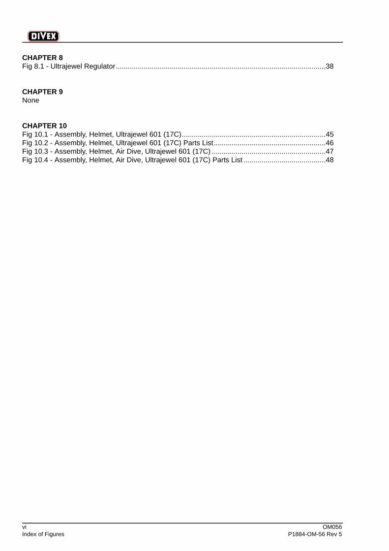
CHAPTER 8 Fig 8.1 - Ultrajewel Regulator.........................................................................................................38
CHAPTER 9 None
CHAPTER 10 Fig 10.1 - Assembly, Helmet, Ultrajewel 601 (17C)........................................................................45Fig 10.2 - Assembly, Helmet, Ultrajewel 601 (17C) Parts List........................................................46Fig 10.3 - Assembly, Helmet, Air Dive, Ultrajewel 601 (17C) .........................................................47Fig 10.4 - Assembly, Helmet, Air Dive, Ultrajewel 601 (17C) Parts List .........................................48
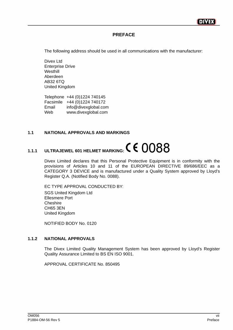
OM056 viiP1884-OM-56 Rev 5 Preface
PREFACE
The following address should be used in all communications with the manufacturer:
Divex LtdEnterprise DriveWesthillAberdeenAB32 6TQUnited Kingdom
Telephone +44 (0)1224 740145Facsimile +44 (0)1224 740172Email [email protected] www.divexglobal.com
1.1 NATIONAL APPROVALS AND MARKINGS
1.1.1 ULTRAJEWEL 601 HELMET MARKING:
Divex Limited declares that this Personal Protective Equipment is in conformity with theprovisions of Articles 10 and 11 of the EUROPEAN DIRECTIVE 89/686/EEC as aCATEGORY 3 DEVICE and is manufactured under a Quality System approved by Lloyd’sRegister Q.A. (Notified Body No. 0088).
EC TYPE APPROVAL CONDUCTED BY:SGS United Kingdom LtdEllesmere PortCheshireCH65 3ENUnited Kingdom
NOTIFIED BODY No. 0120
1.1.2 NATIONAL APPROVALS
The Divex Limited Quality Management System has been approved by Lloyd’s RegisterQuality Assurance Limited to BS EN ISO 9001.
APPROVAL CERTIFICATE No. 850495

viii OM056Preface P1884-OM-56 Rev 5
(Intentionally Blank)
OM056 ixP1884-OM-56 Rev 5 Operational Notice
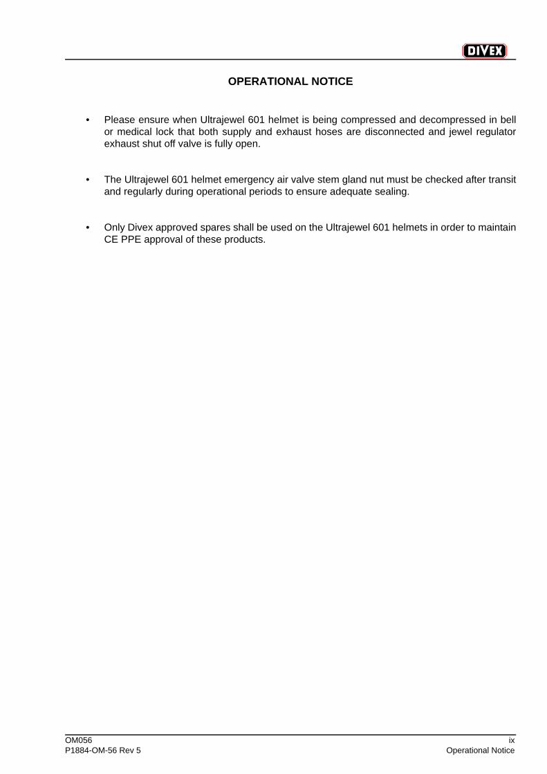
OPERATIONAL NOTICE
• Please ensure when Ultrajewel 601 helmet is being compressed and decompressed in bellor medical lock that both supply and exhaust hoses are disconnected and jewel regulatorexhaust shut off valve is fully open.
• The Ultrajewel 601 helmet emergency air valve stem gland nut must be checked after transitand regularly during operational periods to ensure adequate sealing.
• Only Divex approved spares shall be used on the Ultrajewel 601 helmets in order to maintainCE PPE approval of these products.
x OM056Operational Notice P1884-OM-56 Rev 5
(Intentionally Blank)
OM056 1P1884-OM-56 Rev 5 Chapter 1
CHAPTER 1 INTRODUCTION
CONTENTS
Page
1.1 Introduction..................................................................................................................2
1.1.1 System Requirements ...................................................................................................2
1.1.2 Operation .......................................................................................................................2
2 OM056Chapter 1 P1884-OM-56 Rev 5
1.1 INTRODUCTION
The A10170 / A10171 Ultrajewel 601 diver’s helmet consists principally of Kirby MorganSuperlite 17C helmet which has been modified by fitting an Ultraflow 601 demand regulatorand Jewel 601 exhaust reclaim regulator.
The Ultrajewel 601 is suitable for diving to depths of 500 msw.
The Ultrajewel 601 helmet is capable of being interfaced with a Trelleborg or similar drysuitfitted with an appropriate neck yoke compatible with the helmet.
NOTEOnly one neckseal must be present in the system i.e. if the suit is fitted with aneckseal do not fit one to the helmet neck ring.
1.1.1 SYSTEM REQUIREMENTS
1.1.2 OPERATION
It is the User’s responsibility to inspect the helmet before every use in accordance with theirown diving and safety procedures. This inspection should include but is not limited to:
NOTEHelmet chin support must not be removed.
Required Supply Pressure at Diver: 8-20 bar over bottom pressureoptimum: 10-12 bar
Helmet Gas Supply Hose Connection: No. 6/8 JIC Male
Helmet Exhaust / Reclaim Connection: No. 8 JIC Male
It is intended that this helmet is used in conjunction with the short hose assembly, partno. C1506B. This connects between the No. 8 JIC fitting on the helmet and therequired No. 8/10 JIC fitting on the exhaust umbilical. This hose incorporates a swivelfitting which allows for easier movement of the diver’s head.
Bailout Connection: 9-16UNF female (O-ring seal) i.e. USDivers Type regular connection
Demand regulator cover: Free from dents
Neckdam: Not torn or punctured
OM056 3P1884-OM-56 Rev 5 Chapter 1
The helmet should also be pressure tested as follows:
1. Seal the helmet with an appropriate test plug in the neckdam.
2. Set to closed circuit operation, close the exhaust shut-off valve and introduce somegas into the helmet using the defogger valve.
3. Immerse the helmet in water and check for escaping gas. Any bubbles will indicate apoint of potential water ingress/ gas loss in normal use.
Neck ring o-ring: In place / undamaged & lubricated withChristolube or similar
Bent tube assembly: No dents or kinks
Face port: Must be in good condition
Oral / nasal assembly: Fitted correctly
Oral / nasal mushroom valve assembly: Fitted correctly
Helmet locking pull pins: Engage / disengage properly
Head cushion: Properly fastened inside helmet
Exhaust shut-off ball valve: Function test
Free flow / defogger valve: Function test
Bailout valve: Function test
Communications system: Function test
Open circuit valve: Function test
4 OM056Chapter 1 P1884-OM-56 Rev 5
(Intentionally Blank)
OM056 5P1884-OM-56 Rev 5 Chapter 2
CHAPTER 2 GENERAL DESCRIPTION & FUNCTION
CONTENTS
Page
2.1 Helmet...........................................................................................................................6
2.2 Ultraflow 601 Demand Regulator ...............................................................................6
2.3 Jewel 601 Exhaust Reclaim Regulator ......................................................................7
2.4 Modifications from the Standard DSI Superflow Regulator...................................10
6 OM056Chapter 2 P1884-OM-56 Rev 5
2.1 HELMET
The function, operation and maintenance of the helmet are described in the appropriate DSIManual. However, it is important to note that when used in a gas recovery / closed circuitmode, sealing of the neck dam is particularly important. Any leakage from the neck dam willadversely affect helium recovery rates and the work of breathing.
Leakage may also permit ingress of water to the helmet itself.
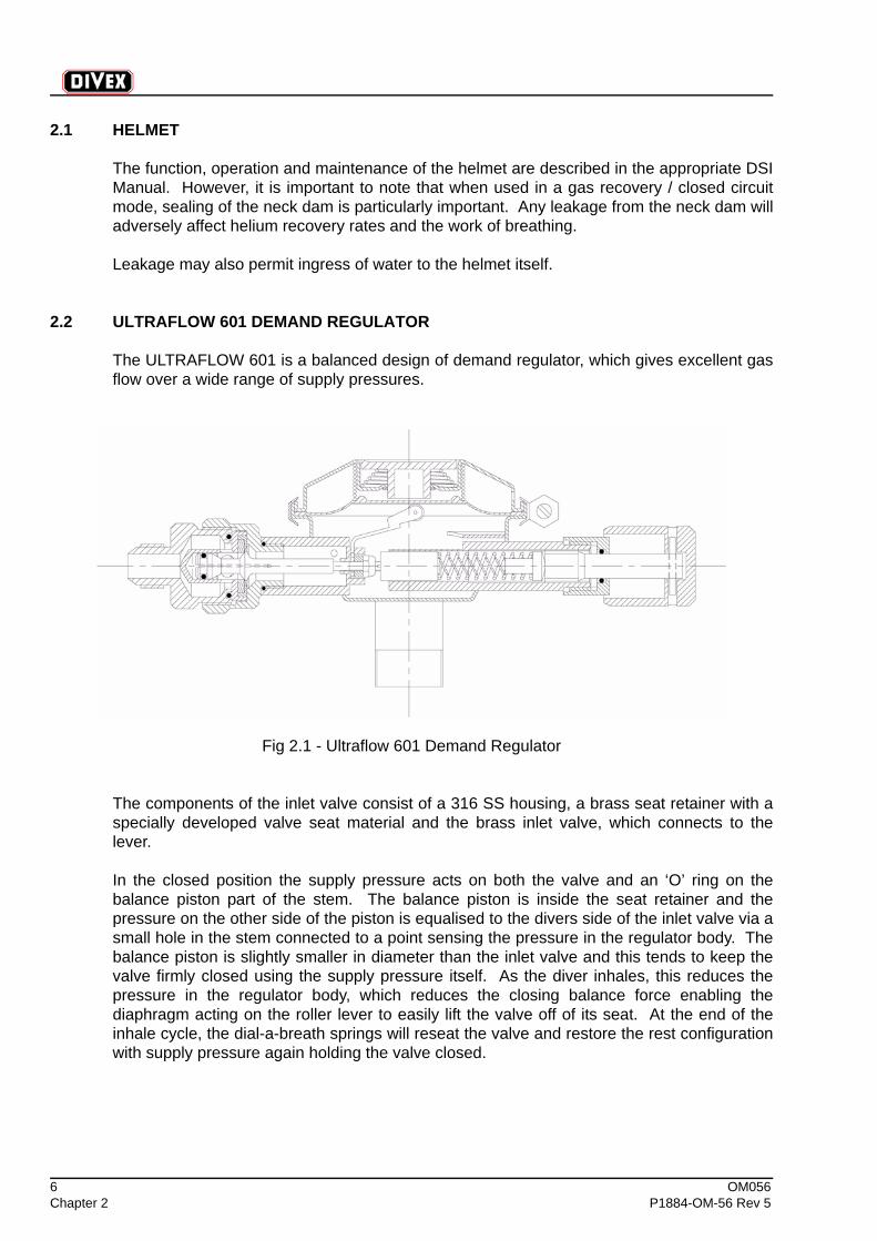
2.2 ULTRAFLOW 601 DEMAND REGULATOR
The ULTRAFLOW 601 is a balanced design of demand regulator, which gives excellent gasflow over a wide range of supply pressures.
Fig 2.1 - Ultraflow 601 Demand Regulator
The components of the inlet valve consist of a 316 SS housing, a brass seat retainer with aspecially developed valve seat material and the brass inlet valve, which connects to thelever.
In the closed position the supply pressure acts on both the valve and an ‘O’ ring on thebalance piston part of the stem. The balance piston is inside the seat retainer and thepressure on the other side of the piston is equalised to the divers side of the inlet valve via asmall hole in the stem connected to a point sensing the pressure in the regulator body. Thebalance piston is slightly smaller in diameter than the inlet valve and this tends to keep thevalve firmly closed using the supply pressure itself. As the diver inhales, this reduces thepressure in the regulator body, which reduces the closing balance force enabling thediaphragm acting on the roller lever to easily lift the valve off of its seat. At the end of theinhale cycle, the dial-a-breath springs will reseat the valve and restore the rest configurationwith supply pressure again holding the valve closed.
OM056 7P1884-OM-56 Rev 5 Chapter 2
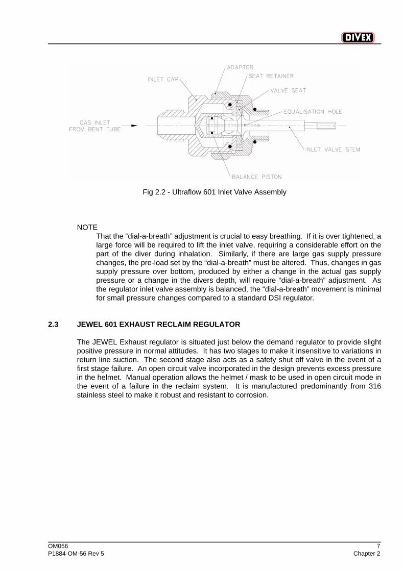
Fig 2.2 - Ultraflow 601 Inlet Valve Assembly
NOTEThat the “dial-a-breath” adjustment is crucial to easy breathing. If it is over tightened, alarge force will be required to lift the inlet valve, requiring a considerable effort on thepart of the diver during inhalation. Similarly, if there are large gas supply pressurechanges, the pre-load set by the “dial-a-breath” must be altered. Thus, changes in gassupply pressure over bottom, produced by either a change in the actual gas supplypressure or a change in the divers depth, will require “dial-a-breath” adjustment. Asthe regulator inlet valve assembly is balanced, the “dial-a-breath” movement is minimalfor small pressure changes compared to a standard DSI regulator.
2.3 JEWEL 601 EXHAUST RECLAIM REGULATOR
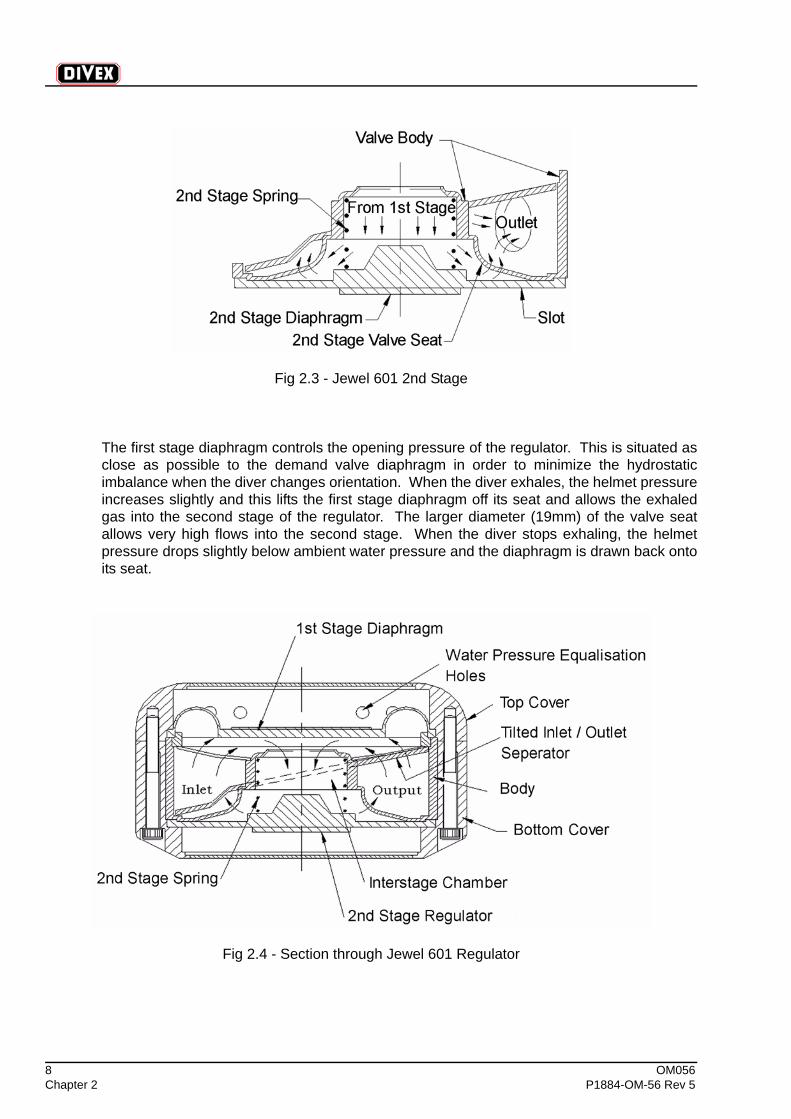
The JEWEL Exhaust regulator is situated just below the demand regulator to provide slightpositive pressure in normal attitudes. It has two stages to make it insensitive to variations inreturn line suction. The second stage also acts as a safety shut off valve in the event of afirst stage failure. An open circuit valve incorporated in the design prevents excess pressurein the helmet. Manual operation allows the helmet / mask to be used in open circuit mode inthe event of a failure in the reclaim system. It is manufactured predominantly from 316stainless steel to make it robust and resistant to corrosion.
8 OM056Chapter 2 P1884-OM-56 Rev 5
Fig 2.3 - Jewel 601 2nd Stage
The first stage diaphragm controls the opening pressure of the regulator. This is situated asclose as possible to the demand valve diaphragm in order to minimize the hydrostaticimbalance when the diver changes orientation. When the diver exhales, the helmet pressureincreases slightly and this lifts the first stage diaphragm off its seat and allows the exhaledgas into the second stage of the regulator. The larger diameter (19mm) of the valve seatallows very high flows into the second stage. When the diver stops exhaling, the helmetpressure drops slightly below ambient water pressure and the diaphragm is drawn back ontoits seat.
Fig 2.4 - Section through Jewel 601 Regulator
OM056 9P1884-OM-56 Rev 5 Chapter 2
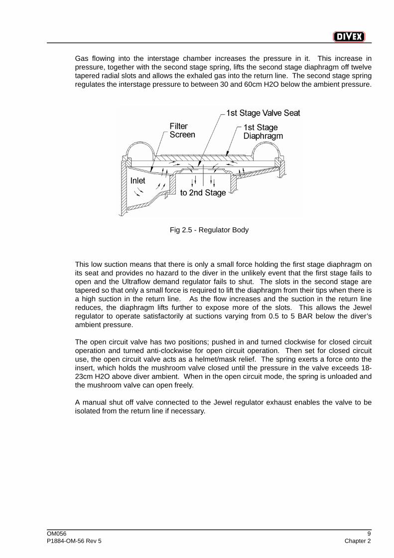
Gas flowing into the interstage chamber increases the pressure in it. This increase inpressure, together with the second stage spring, lifts the second stage diaphragm off twelvetapered radial slots and allows the exhaled gas into the return line. The second stage springregulates the interstage pressure to between 30 and 60cm H2O below the ambient pressure.
Fig 2.5 - Regulator Body
This low suction means that there is only a small force holding the first stage diaphragm onits seat and provides no hazard to the diver in the unlikely event that the first stage fails toopen and the Ultraflow demand regulator fails to shut. The slots in the second stage aretapered so that only a small force is required to lift the diaphragm from their tips when there isa high suction in the return line. As the flow increases and the suction in the return linereduces, the diaphragm lifts further to expose more of the slots. This allows the Jewelregulator to operate satisfactorily at suctions varying from 0.5 to 5 BAR below the diver’sambient pressure.
The open circuit valve has two positions; pushed in and turned clockwise for closed circuitoperation and turned anti-clockwise for open circuit operation. Then set for closed circuituse, the open circuit valve acts as a helmet/mask relief. The spring exerts a force onto theinsert, which holds the mushroom valve closed until the pressure in the valve exceeds 18-23cm H2O above diver ambient. When in the open circuit mode, the spring is unloaded andthe mushroom valve can open freely.
A manual shut off valve connected to the Jewel regulator exhaust enables the valve to beisolated from the return line if necessary.
10 OM056Chapter 2 P1884-OM-56 Rev 5
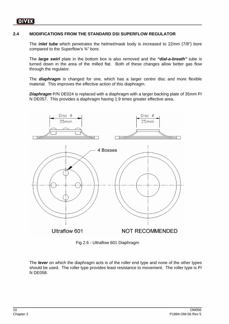
2.4 MODIFICATIONS FROM THE STANDARD DSI SUPERFLOW REGULATOR
The inlet tube which penetrates the helmet/mask body is increased to 22mm (7/8”) borecompared to the Superflow’s ¾” bore.
The large swirl plate in the bottom box is also removed and the “dial-a-breath” tube isturned down in the area of the milled flat. Both of these changes allow better gas flowthrough the regulator.
The diaphragm is changed for one, which has a larger centre disc and more flexiblematerial. This improves the effective action of this diaphragm.
Diaphragm P/N DE024 is replaced with a diaphragm with a larger backing plate of 35mm P/N DE057. This provides a diaphragm having 1.9 times greater effective area.
Fig 2.6 - Ultraflow 601 Diaphragm
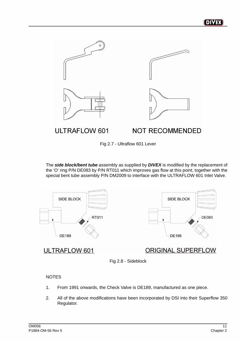
The lever on which the diaphragm acts is of the roller end type and none of the other typesshould be used. The roller type provides least resistance to movement. The roller type is P/N DE058.
OM056 11P1884-OM-56 Rev 5 Chapter 2
Fig 2.7 - Ultraflow 601 Lever
The side block/bent tube assembly as supplied by DIVEX is modified by the replacement ofthe ‘O’ ring P/N DE083 by P/N RT011 which improves gas flow at this point, together with thespecial bent tube assembly P/N DM2009 to interface with the ULTRAFLOW 601 Inlet Valve.
Fig 2.8 - Sideblock
NOTES
1. From 1991 onwards, the Check Valve is DE189, manufactured as one piece.
2. All of the above modifications have been incorporated by DSI into their Superflow 350Regulator.

12 OM056Chapter 2 P1884-OM-56 Rev 5
(Intentionally Blank)
OM056 13P1884-OM-56 Rev 5 Chapter 3
CHAPTER 3 SERVICE & MAINTENANCE OF ULTRAFLOW 601 DEMAND REGULATOR
CONTENTS
Page
3.1 Ultraflow Disassembly ..............................................................................................14
3.2 Ultraflow 601 Assembly ............................................................................................14
3.3 Adjustment .................................................................................................................16
3.4 Replacement of Diaphragm ......................................................................................19
3.5 Ultraflow 601 Regulator.............................................................................................21
14 OM056Chapter 3 P1884-OM-56 Rev 5
Technicians who possess valid service technician training certification for this equipmentshould carry out all service work.
3.1 ULTRAFLOW DISASSEMBLY
To be read in conjunction with drawing on Fig 3.6 -.
1. Remove the cover Clamp Screw (Item 29) and Cover Clamp (Item 15), lift the Cover(Item 13) off with spring (Item 14) and pull out the Diaphragm (Item 11).
2. The “dial-a-breath” control is removed by backing the Knob (Item 27) out until the Nut(Item 25) is exposed enough to use a wrench. The Knob (Item 27), Nut (Item 25) ‘O’Ring (Item 28), Washer (Item 24) and Shaft (Item 23) all come out as one. The Knob(Item 27) may be removed from the shaft (Item 23) by punching out the Lock Pin (Item26). A 3/32” diameter punch should be used. The ‘O’ ring (Item 28) and Washer (Item24) remain on the Shaft (Item 23) and may now be removed. Tilt the helmet so that theSpacer (Item 22), Spring Set (Item 21) and Piston (Item 20) fall out of the adjustmentShaft Tube of the Regulator Body (Item 8).
3. Remove the Bent Tube Assembly from the Inlet Valve Assembly.
4. Remove the complete Inlet Valve Assembly from the Demand Regulator Body (Item 8),using a wrench on the ULTRAFLOW Adaptor Flats (Item 3).
5. The Inlet Valve Assembly can now be carefully pulled away from the DemandRegulator Body leaving the Valve Stem (Item 1) in place in the Regulator.
6. The Valve Stem can be removed from the Regulator by removing the Nut (Item 19).Use a straight slot screwdriver to rotate the valve Stem (Item 1) while the Retaining Nut(Item 19) is held with the correct spanner from the DSI Service Tool Kit.
7. Undo the Nut (Item 9), which secures the inlet tube to the helmet/bandmask. Removethe Regulator Body (Item 8), Nut (Item 9) and ‘O’ Ring (Item 10). All parts should bethoroughly cleaned and parts replaced as indicated with ‘O’ rings being lubricated onlywith Christo-lube fluorinated grease before installation.
3.2 ULTRAFLOW 601 ASSEMBLY
To be read in conjunction with the Drawing on Fig 3.6 -.
During re-assembly of the Demand Regulator, replace all questionable and damaged partswith new. Lubricate all ‘O’ rings and threaded metal parts lightly only with Christo-lubefluorinated grease.
1. Install the Inlet Valve Stem (Item 1) in the Regulator Body. Fit the Washer (Item 16),Lever (Item 17) and Spacer (Item 18) on to the Shaft of the Inlet Valve Stem. Screw theNut (Item 19) on to the threaded end of the Inlet Valve Stem until the Inlet Valvethreads protrude slightly (about 2 threads past the Nut). Use a straight slot screwdriverand special DSI spanner for this operation.
OM056 15P1884-OM-56 Rev 5 Chapter 3
CAUTIONThe Lock Nut (Item 19) is a Nyloc Nut and should always be replaced with new ifremoved from the Inlet Valve.
2. Assemble the ULTRAFLOW Adaptor (Item 3), Seat Retainer (Item 4) and Inlet Cap(Item 2).
3. Install the Piston (Item 20), Spring Set (Item 21) and Spacer (Item 22) into theAdjustment Tube of the Regulator Body (Item 8). Generously apply Christo-lubeFluorinated Grease to this assembly.
4. Thread the main adjustment Shaft (Item 23) into the Tube. Slide the Washer (Item 24)and ‘O’ Ring (Item 28) onto the adjustment Shaft (Item 23). Slide the Packing Nut(Item 25) onto the Shaft and tighten it onto the threaded tube of the Regulator (Item 8).
5. Fit the Knob (Item 27) onto the adjustment Shaft (Item 23) and align the holes for theRetaining Pin (Item 26).
CAUTIONSupport the adjustment Knob (Item 27) while tapping Retaining Pin (Item 6) to preventdamage to the shaft (Item 23) and the Body (Item 8).
6. Tighten the Inlet Valve Nut (Item 19) until the Lever (Item 7) is snug with no play. Overtightening this Nut will cause the Regulator to free flow.
7. Assemble the Bent Tube Assembly to the Inlet Valve Assembly.
NOTEThe sealing washer should be DIVEX P/N RT011, which improves flow characteristics.
8. Adjust the Regulator as described in section 3.3 .
16 OM056Chapter 3 P1884-OM-56 Rev 5
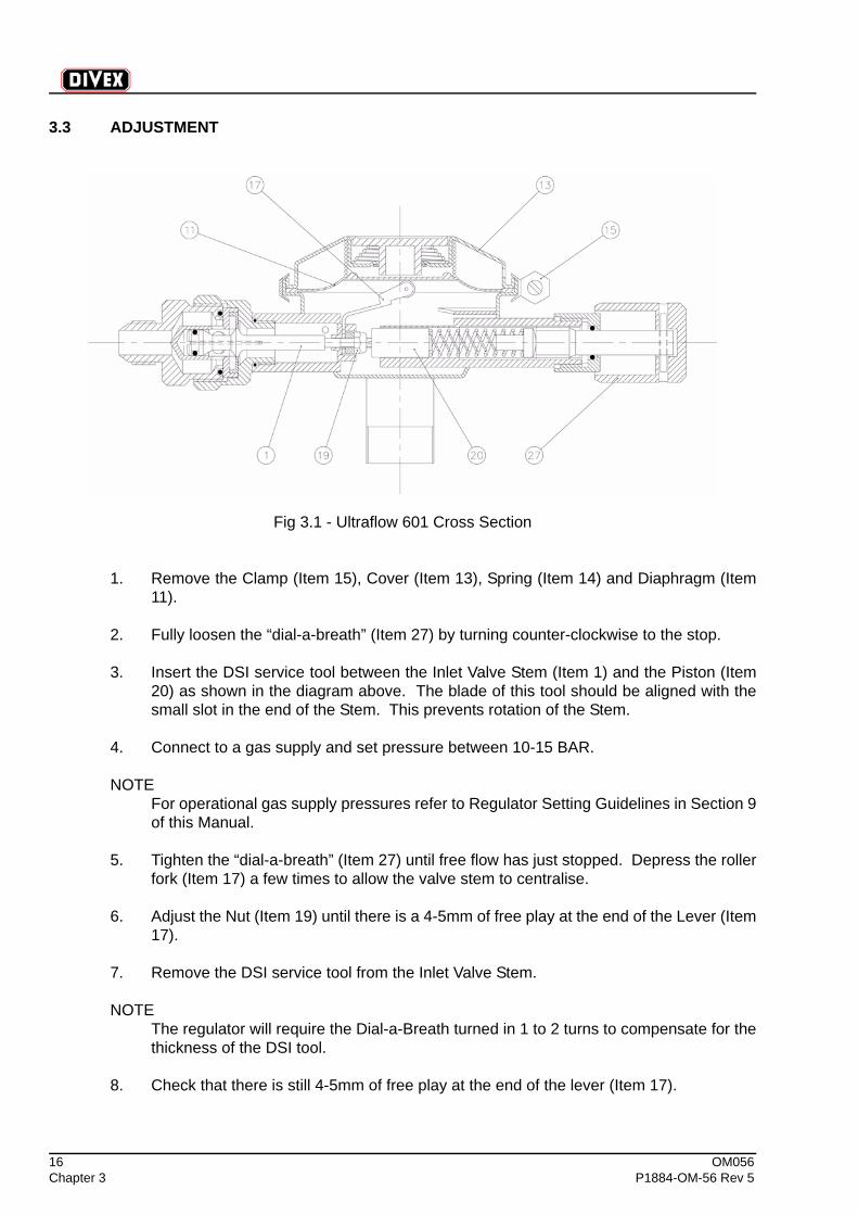
3.3 ADJUSTMENT
Fig 3.1 - Ultraflow 601 Cross Section
1. Remove the Clamp (Item 15), Cover (Item 13), Spring (Item 14) and Diaphragm (Item11).
2. Fully loosen the “dial-a-breath” (Item 27) by turning counter-clockwise to the stop.
3. Insert the DSI service tool between the Inlet Valve Stem (Item 1) and the Piston (Item20) as shown in the diagram above. The blade of this tool should be aligned with thesmall slot in the end of the Stem. This prevents rotation of the Stem.
4. Connect to a gas supply and set pressure between 10-15 BAR.
NOTEFor operational gas supply pressures refer to Regulator Setting Guidelines in Section 9of this Manual.
5. Tighten the “dial-a-breath” (Item 27) until free flow has just stopped. Depress the rollerfork (Item 17) a few times to allow the valve stem to centralise.
6. Adjust the Nut (Item 19) until there is a 4-5mm of free play at the end of the Lever (Item17).
7. Remove the DSI service tool from the Inlet Valve Stem.
NOTEThe regulator will require the Dial-a-Breath turned in 1 to 2 turns to compensate for thethickness of the DSI tool.
8. Check that there is still 4-5mm of free play at the end of the lever (Item 17).
OM056 17P1884-OM-56 Rev 5 Chapter 3
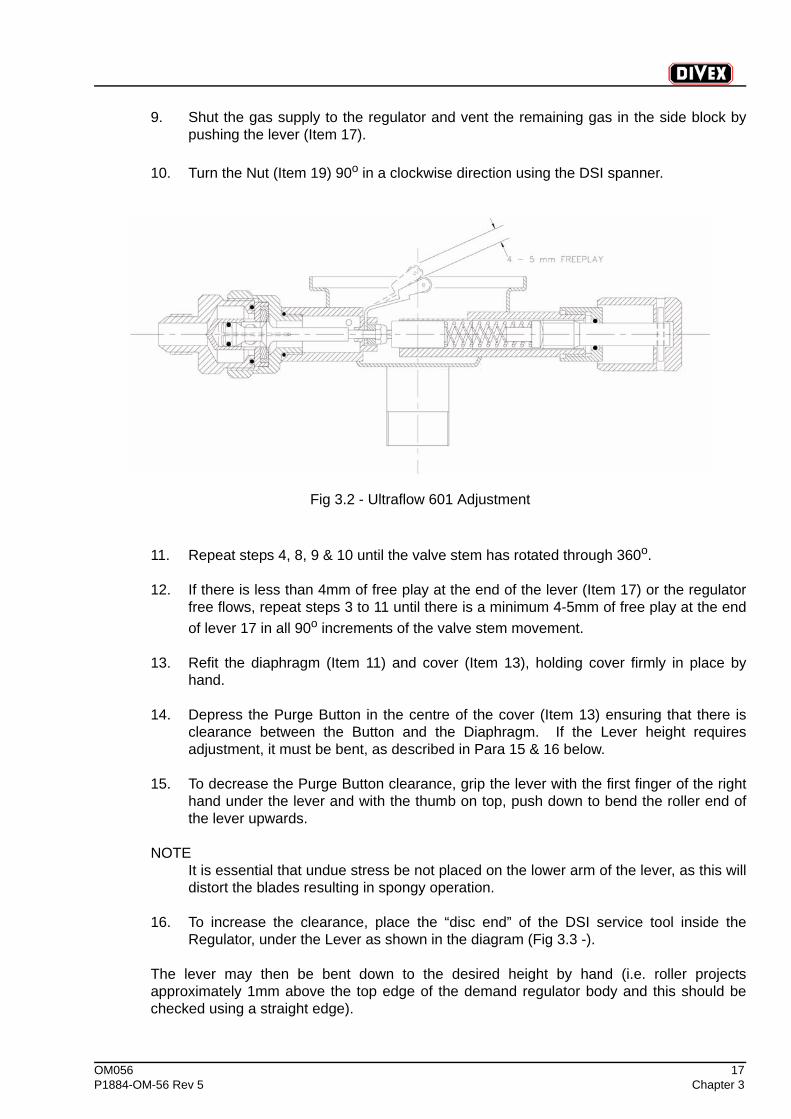
9. Shut the gas supply to the regulator and vent the remaining gas in the side block bypushing the lever (Item 17).
10. Turn the Nut (Item 19) 90o in a clockwise direction using the DSI spanner.
Fig 3.2 - Ultraflow 601 Adjustment
11. Repeat steps 4, 8, 9 & 10 until the valve stem has rotated through 360o.
12. If there is less than 4mm of free play at the end of the lever (Item 17) or the regulatorfree flows, repeat steps 3 to 11 until there is a minimum 4-5mm of free play at the endof lever 17 in all 90o increments of the valve stem movement.
13. Refit the diaphragm (Item 11) and cover (Item 13), holding cover firmly in place byhand.
14. Depress the Purge Button in the centre of the cover (Item 13) ensuring that there isclearance between the Button and the Diaphragm. If the Lever height requiresadjustment, it must be bent, as described in Para 15 & 16 below.
15. To decrease the Purge Button clearance, grip the lever with the first finger of the righthand under the lever and with the thumb on top, push down to bend the roller end ofthe lever upwards.
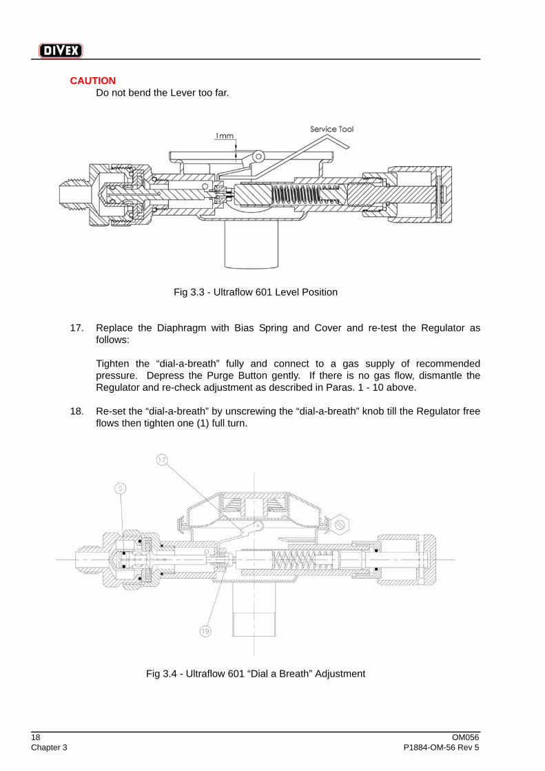
NOTEIt is essential that undue stress be not placed on the lower arm of the lever, as this willdistort the blades resulting in spongy operation.
16. To increase the clearance, place the “disc end” of the DSI service tool inside theRegulator, under the Lever as shown in the diagram (Fig 3.3 -).
The lever may then be bent down to the desired height by hand (i.e. roller projectsapproximately 1mm above the top edge of the demand regulator body and this should bechecked using a straight edge).
18 OM056Chapter 3 P1884-OM-56 Rev 5
CAUTIONDo not bend the Lever too far.
Fig 3.3 - Ultraflow 601 Level Position
17. Replace the Diaphragm with Bias Spring and Cover and re-test the Regulator asfollows:
Tighten the “dial-a-breath” fully and connect to a gas supply of recommendedpressure. Depress the Purge Button gently. If there is no gas flow, dismantle theRegulator and re-check adjustment as described in Paras. 1 - 10 above.
18. Re-set the “dial-a-breath” by unscrewing the “dial-a-breath” knob till the Regulator freeflows then tighten one (1) full turn.
Fig 3.4 - Ultraflow 601 “Dial a Breath” Adjustment
OM056 19P1884-OM-56 Rev 5 Chapter 3
NOTES
(1) It is not permissible to loosen the Nut (Item 19) more than one eighth of a turn toadjust the Lever height. If the Nut is loosened beyond this amount, the Regulator willnot flow to its maximum rate.
(2) It is essential that all Regulator parts should be free from dirt and rubber componentsshould be inspected for any sign of deterioration.
(3) All internal parts should be lightly lubricated with Christo-lube Fluorinated Grease,especially ‘O’ Ring (Item 5).
(4) The Two opposing blades on the bottom of the Lever (Item 17) must be accuratelyaligned with each other and be free from tool marks or burrs.
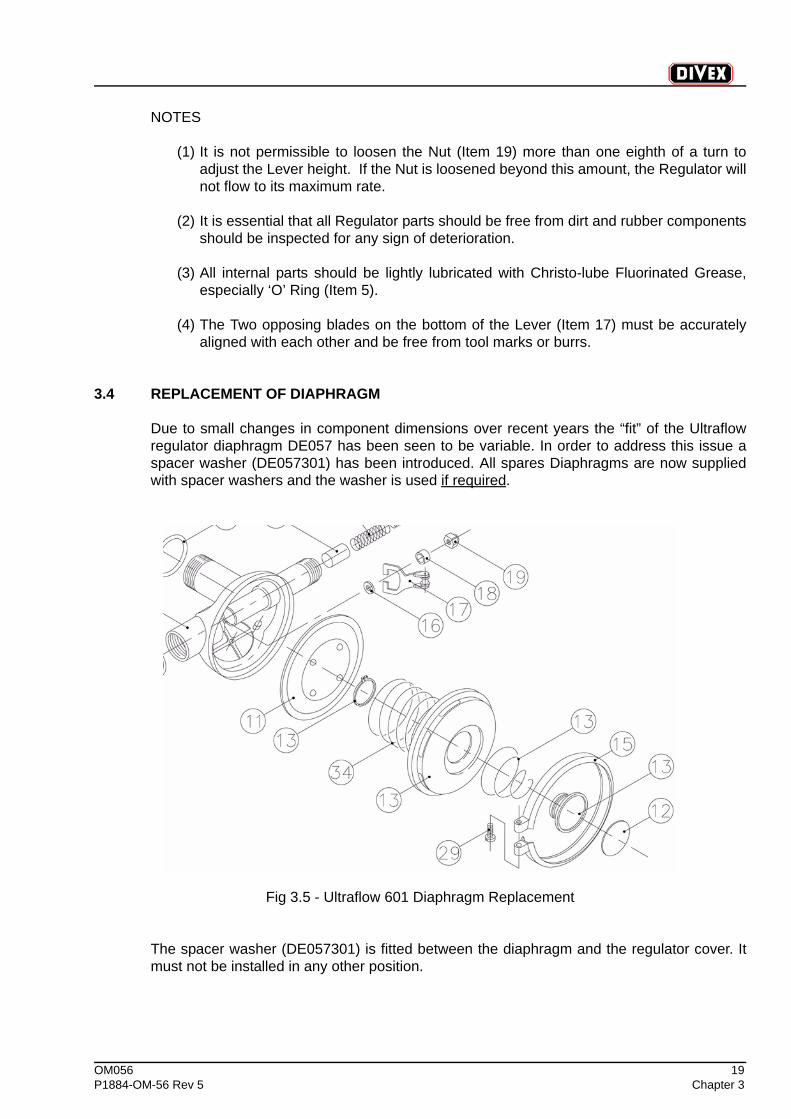
3.4 REPLACEMENT OF DIAPHRAGM
Due to small changes in component dimensions over recent years the “fit” of the Ultraflowregulator diaphragm DE057 has been seen to be variable. In order to address this issue aspacer washer (DE057301) has been introduced. All spares Diaphragms are now suppliedwith spacer washers and the washer is used if required.
Fig 3.5 - Ultraflow 601 Diaphragm Replacement
The spacer washer (DE057301) is fitted between the diaphragm and the regulator cover. Itmust not be installed in any other position.
20 OM056Chapter 3 P1884-OM-56 Rev 5
Small changes in component tolerances for parts used on the Ultraflow regulator assemblyhas resulted in some cases with the assembled regulator not having as secure a grip of thediaphragm between regulator body and the cover as is ideal.
Investigation of various options has determined that a spacer washer is the simplest & bestsolution to this issue.
Trained & competent service technicians can easily judge whether this spacer washer needsto be fitted.
The test is simple: when the regulator body/diaphragm / biasing spring/cover & clamp havebeen assembled and the clamp screw (#29 on diagram) tightened to the recommendedtorque setting of 8 inch/pounds.
If when holding the assembled regulator in one hand and holding around the clamp with theother and twisting, the clamp band can be turned without much effort by the technician thenthe washer should be fitted. If the clamp is secure without the washer being installed then it isnot required. No tools should be used to grip either part.
Supplies of the diaphragm now include a washer and an instruction guidance sheet.
Should you have any queries on this matter you should contact [email protected].
OM056 21P1884-OM-56 Rev 5 Chapter 3
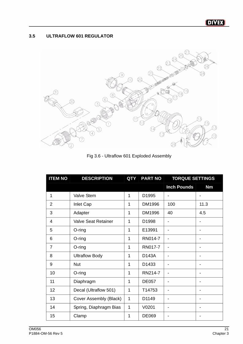
3.5 ULTRAFLOW 601 REGULATOR
Fig 3.6 - Ultraflow 601 Exploded Assembly
ITEM NO DESCRIPTION QTY PART NO TORQUE SETTINGS
Inch Pounds Nm
1 Valve Stem 1 D1995 - -
2 Inlet Cap 1 DM1996 100 11.3
3 Adapter 1 DM1996 40 4.5
4 Valve Seat Retainer 1 D1998 - -
5 O-ring 1 E13991 - -
6 O-ring 1 RN014-7 - -
7 O-ring 1 RN017-7 - -
8 Ultraflow Body 1 D143A - -
9 Nut 1 D1433 - -
10 O-ring 1 RN214-7 - -
11 Diaphragm 1 DE057 - -
12 Decal (Ultraflow 501) 1 T14753 - -
13 Cover Assembly (Black) 1 D1149 - -
14 Spring, Diaphragm Bias 1 V0201 - -
15 Clamp 1 DE069 - -
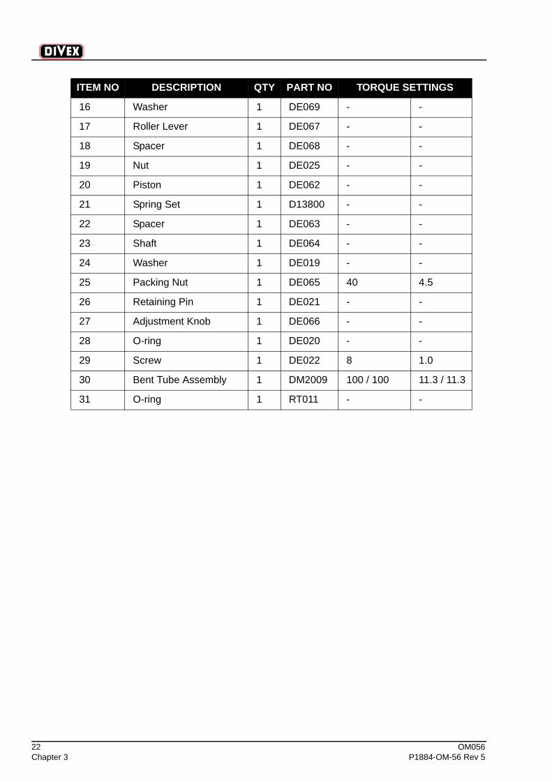
22 OM056Chapter 3 P1884-OM-56 Rev 5
16 Washer 1 DE069 - -
17 Roller Lever 1 DE067 - -
18 Spacer 1 DE068 - -
19 Nut 1 DE025 - -
20 Piston 1 DE062 - -
21 Spring Set 1 D13800 - -
22 Spacer 1 DE063 - -
23 Shaft 1 DE064 - -
24 Washer 1 DE019 - -
25 Packing Nut 1 DE065 40 4.5
26 Retaining Pin 1 DE021 - -
27 Adjustment Knob 1 DE066 - -
28 O-ring 1 DE020 - -
29 Screw 1 DE022 8 1.0
30 Bent Tube Assembly 1 DM2009 100 / 100 11.3 / 11.3
31 O-ring 1 RT011 - -
ITEM NO DESCRIPTION QTY PART NO TORQUE SETTINGS
OM056 23P1884-OM-56 Rev 5 Chapter 4
CHAPTER 4 SERVICE & MAINTENANCE OF SIDE BLOCK
CONTENTS
Page
4.1 Service & Maintenance of Side Block......................................................................24
24 OM056Chapter 4 P1884-OM-56 Rev 5
4.1 SERVICE & MAINTENANCE OF SIDE BLOCK
Maintenance of the Side Block with regard to DIVEX equipment consists of checking thecondition of the ‘O’ Ring at the top of the bent tube assembly. If there is any doubt about thecondition, replace. For maintenance on the remainder of the side block, refer to the DSIManual.

OM056 25P1884-OM-56 Rev 5 Chapter 5
CHAPTER 5 SERVICE & MAINTENANCE OF ORAL NASAL MASK
CONTENTS
Page
5.1 Service & Maintenance of Oral Nasal Mask ............................................................26
26 OM056Chapter 5 P1884-OM-56 Rev 5
5.1 SERVICE & MAINTENANCE OF ORAL NASAL MASK
Remove the Oral Nasal Mask first removing the nose block device by unscrewing the knoband removing the packing nut and ‘O’ rings. Pull the nose block device out of the oral nasal.Unscrew the outer nuts on the communications posts and remove the microphone wire lugs.
Grasp the oral nasal and slowly pull off the regulator mount nut and the connector. The oralnasal is now out of the headgear and can be inspected. Replace if necessary noting that alight coat of silicone lubricant will preserve the rubber.
Reassembly is the reverse of the above sequence.
OM056 27P1884-OM-56 Rev 5 Chapter 6
CHAPTER 6 SERVICE & MAINTENANCE OF JEWEL 601 EXHAUST RECLAIM VALVE
CONTENTS
Page
6.1 Jewel 601 Disassembly .............................................................................................28
6.2 Jewel 601 Regulator Inspections .............................................................................28
6.3 Jewel 601 Regulator Assembly ................................................................................29
6.4 Jewel 601 Regulator Check ......................................................................................30

28 OM056Chapter 6 P1884-OM-56 Rev 5
Technicians who possess valid service technician training certification for this equipmentshould carry out all service work.
6.1 JEWEL 601 DISASSEMBLY
It is unnecessary to remove the JEWEL 601 from the helmet or mask for maintenance and itis generally undesirable to do so.
Fig 6.1 - Ultrajewel 601 Cross Section
Unscrewing the four socket head screws (7) allows the covers (2) and (3) the 1st stagediaphragm (4), the 2nd stage diaphragm (5) and the 2nd stage spring (6) to be removed.(note: be ready to catch the 2nd stage spring)
Diaphragm item 4 is available in either natural rubber part # D5069R or neoprene D5069N.
For the A10170 helmet the standard diaphragm fitted is the D5069R and for the A10171 thestandard diaphragm fitted is the D5069N.
6.2 JEWEL 601 REGULATOR INSPECTIONS
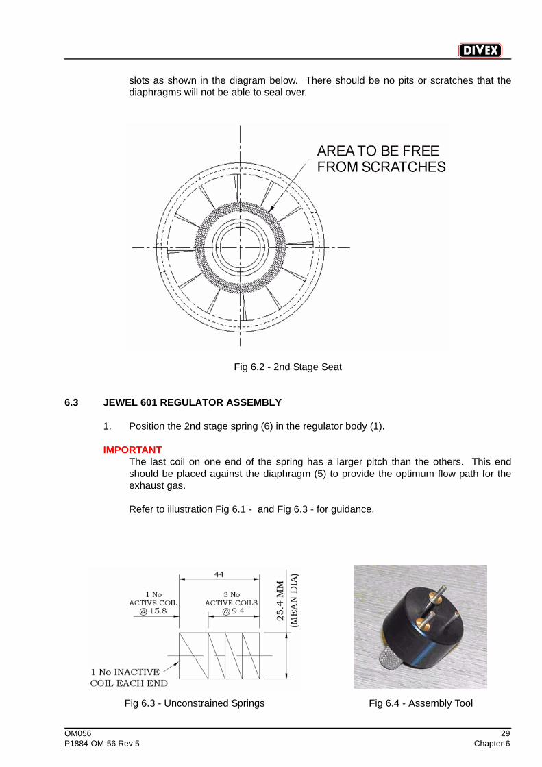
1. 1st stage diaphragm (4) and 2nd stage diaphragm (5): Check if the rubber hasseparated from metal parts. Inspect for cracks, pinholes, cuts, pinching, wear orabrasion.
2. Valve seats: Check the regulator body (1) around the seat of the 1st stage valve andthe sealing face of the 2nd stage around an imaginary circle that joins the points of the
OM056 29P1884-OM-56 Rev 5 Chapter 6
slots as shown in the diagram below. There should be no pits or scratches that thediaphragms will not be able to seal over.
Fig 6.2 - 2nd Stage Seat
6.3 JEWEL 601 REGULATOR ASSEMBLY
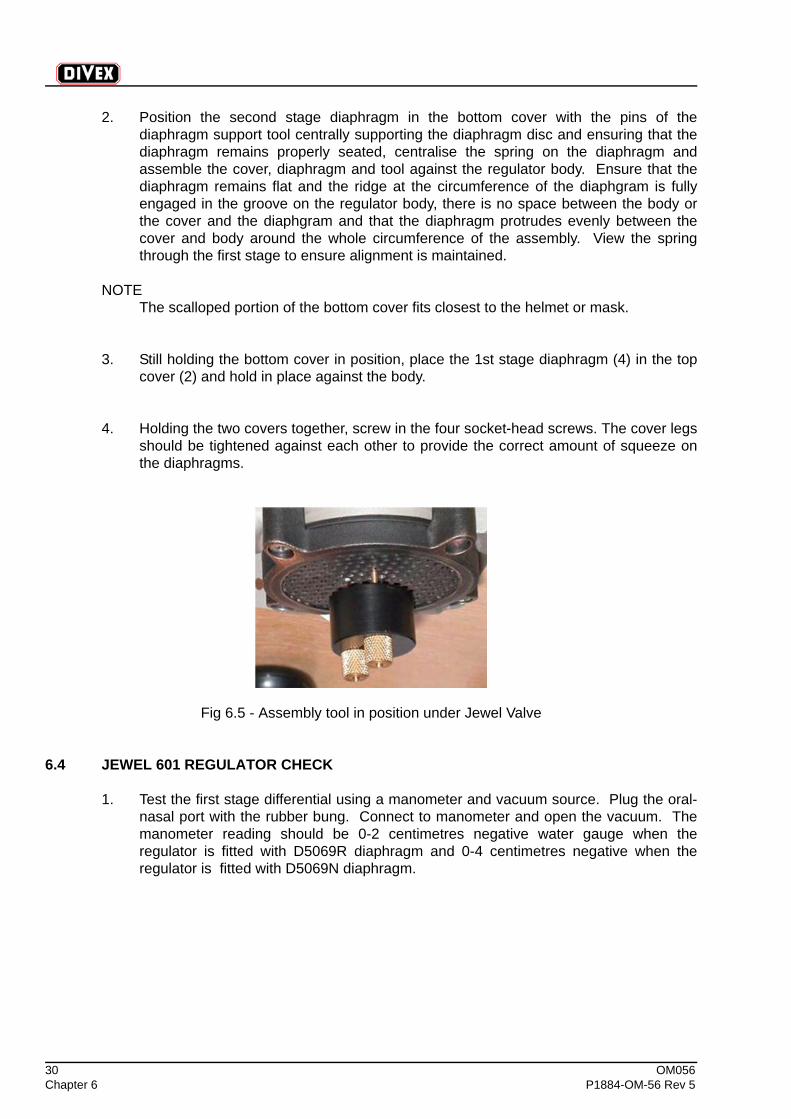
1. Position the 2nd stage spring (6) in the regulator body (1).
IMPORTANTThe last coil on one end of the spring has a larger pitch than the others. This endshould be placed against the diaphragm (5) to provide the optimum flow path for theexhaust gas.
Refer to illustration Fig 6.1 - and Fig 6.3 - for guidance.
Fig 6.3 - Unconstrained Springs Fig 6.4 - Assembly Tool
30 OM056Chapter 6 P1884-OM-56 Rev 5
2. Position the second stage diaphragm in the bottom cover with the pins of thediaphragm support tool centrally supporting the diaphragm disc and ensuring that thediaphragm remains properly seated, centralise the spring on the diaphragm andassemble the cover, diaphragm and tool against the regulator body. Ensure that thediaphragm remains flat and the ridge at the circumference of the diaphgram is fullyengaged in the groove on the regulator body, there is no space between the body orthe cover and the diaphgram and that the diaphragm protrudes evenly between thecover and body around the whole circumference of the assembly. View the springthrough the first stage to ensure alignment is maintained.
NOTEThe scalloped portion of the bottom cover fits closest to the helmet or mask.
3. Still holding the bottom cover in position, place the 1st stage diaphragm (4) in the topcover (2) and hold in place against the body.
4. Holding the two covers together, screw in the four socket-head screws. The cover legsshould be tightened against each other to provide the correct amount of squeeze onthe diaphragms.
Fig 6.5 - Assembly tool in position under Jewel Valve
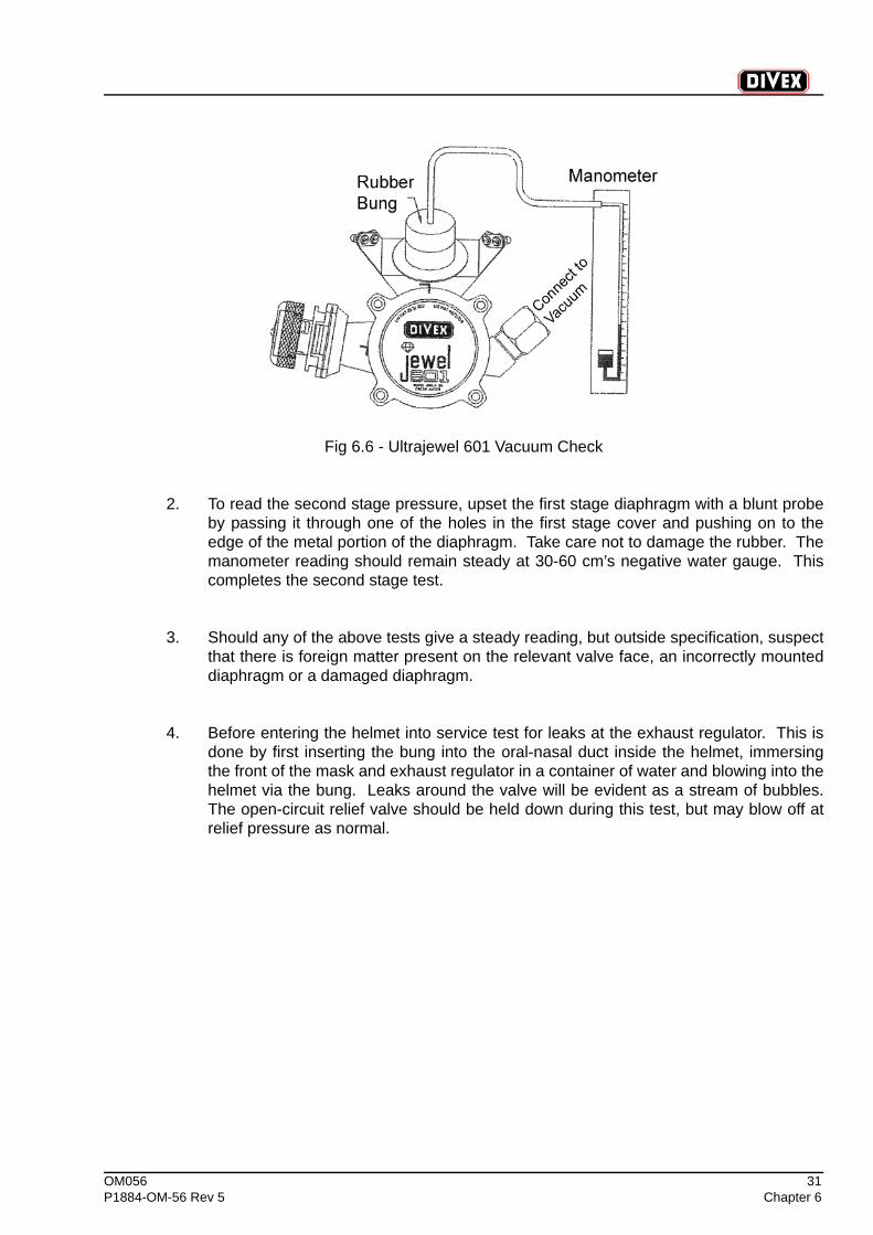
6.4 JEWEL 601 REGULATOR CHECK
1. Test the first stage differential using a manometer and vacuum source. Plug the oral-nasal port with the rubber bung. Connect to manometer and open the vacuum. Themanometer reading should be 0-2 centimetres negative water gauge when theregulator is fitted with D5069R diaphragm and 0-4 centimetres negative when theregulator is fitted with D5069N diaphragm.
OM056 31P1884-OM-56 Rev 5 Chapter 6
Fig 6.6 - Ultrajewel 601 Vacuum Check
2. To read the second stage pressure, upset the first stage diaphragm with a blunt probeby passing it through one of the holes in the first stage cover and pushing on to theedge of the metal portion of the diaphragm. Take care not to damage the rubber. Themanometer reading should remain steady at 30-60 cm’s negative water gauge. Thiscompletes the second stage test.
3. Should any of the above tests give a steady reading, but outside specification, suspectthat there is foreign matter present on the relevant valve face, an incorrectly mounteddiaphragm or a damaged diaphragm.
4. Before entering the helmet into service test for leaks at the exhaust regulator. This isdone by first inserting the bung into the oral-nasal duct inside the helmet, immersingthe front of the mask and exhaust regulator in a container of water and blowing into thehelmet via the bung. Leaks around the valve will be evident as a stream of bubbles.The open-circuit relief valve should be held down during this test, but may blow off atrelief pressure as normal.

32 OM056Chapter 6 P1884-OM-56 Rev 5
(Intentionally Blank)
OM056 33P1884-OM-56 Rev 5 Chapter 7
CHAPTER 7 SERVICE & MAINTENANCE OF UPRATED OPEN CIRCUIT VALVE
CONTENTS
Page
7.1 Disassembly of the Open Circuit Valve ...................................................................34
7.2 Open Circuit Valve Inspection ..................................................................................34
7.3 Open Circuit Valve Assembly ...................................................................................35
7.4 Open Circuit Valve Check .........................................................................................35
7.5 Routine Maintenance.................................................................................................36
7.5.1 Maintenance Schedule ................................................................................................36
34 OM056Chapter 7 P1884-OM-56 Rev 5
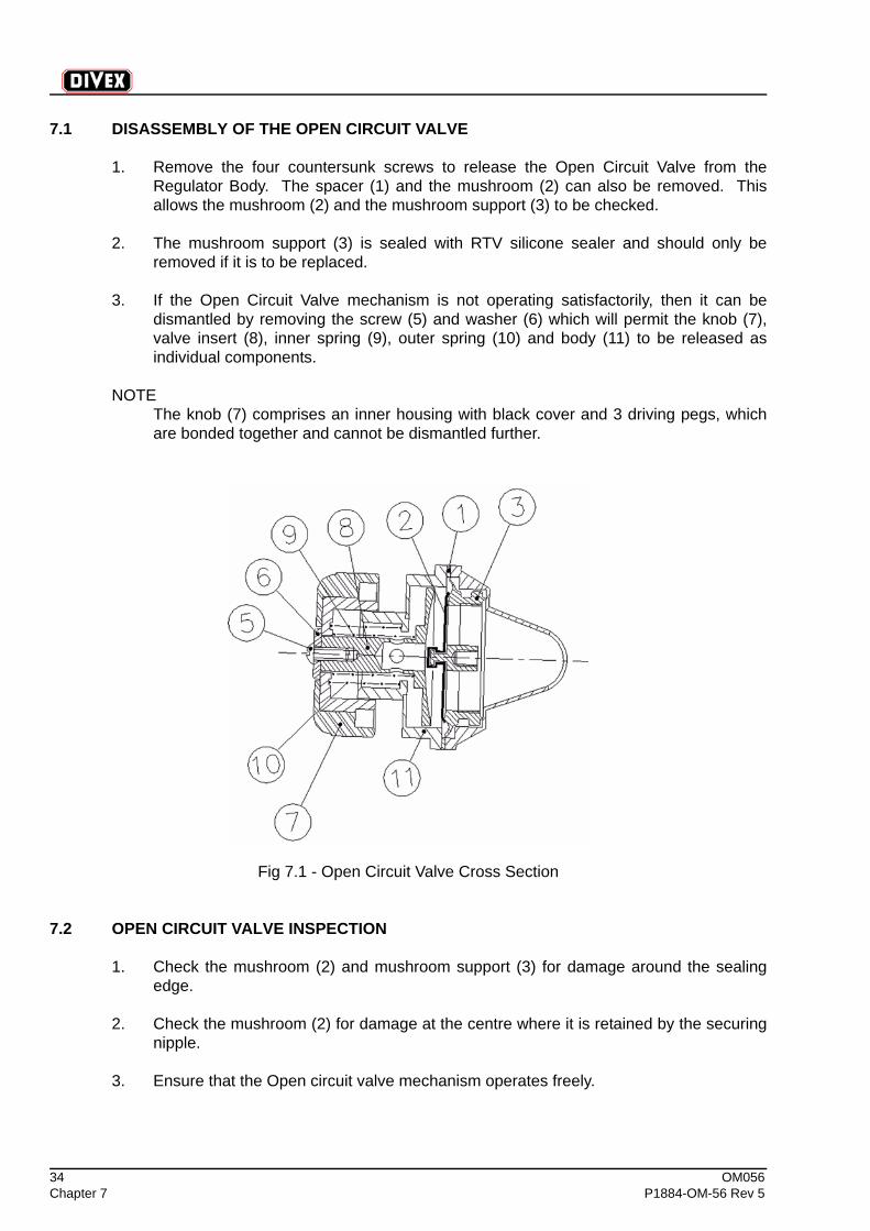
7.1 DISASSEMBLY OF THE OPEN CIRCUIT VALVE
1. Remove the four countersunk screws to release the Open Circuit Valve from theRegulator Body. The spacer (1) and the mushroom (2) can also be removed. Thisallows the mushroom (2) and the mushroom support (3) to be checked.
2. The mushroom support (3) is sealed with RTV silicone sealer and should only beremoved if it is to be replaced.
3. If the Open Circuit Valve mechanism is not operating satisfactorily, then it can bedismantled by removing the screw (5) and washer (6) which will permit the knob (7),valve insert (8), inner spring (9), outer spring (10) and body (11) to be released asindividual components.
NOTEThe knob (7) comprises an inner housing with black cover and 3 driving pegs, whichare bonded together and cannot be dismantled further.
Fig 7.1 - Open Circuit Valve Cross Section
7.2 OPEN CIRCUIT VALVE INSPECTION
1. Check the mushroom (2) and mushroom support (3) for damage around the sealingedge.
2. Check the mushroom (2) for damage at the centre where it is retained by the securingnipple.
3. Ensure that the Open circuit valve mechanism operates freely.
OM056 35P1884-OM-56 Rev 5 Chapter 7
7.3 OPEN CIRCUIT VALVE ASSEMBLY
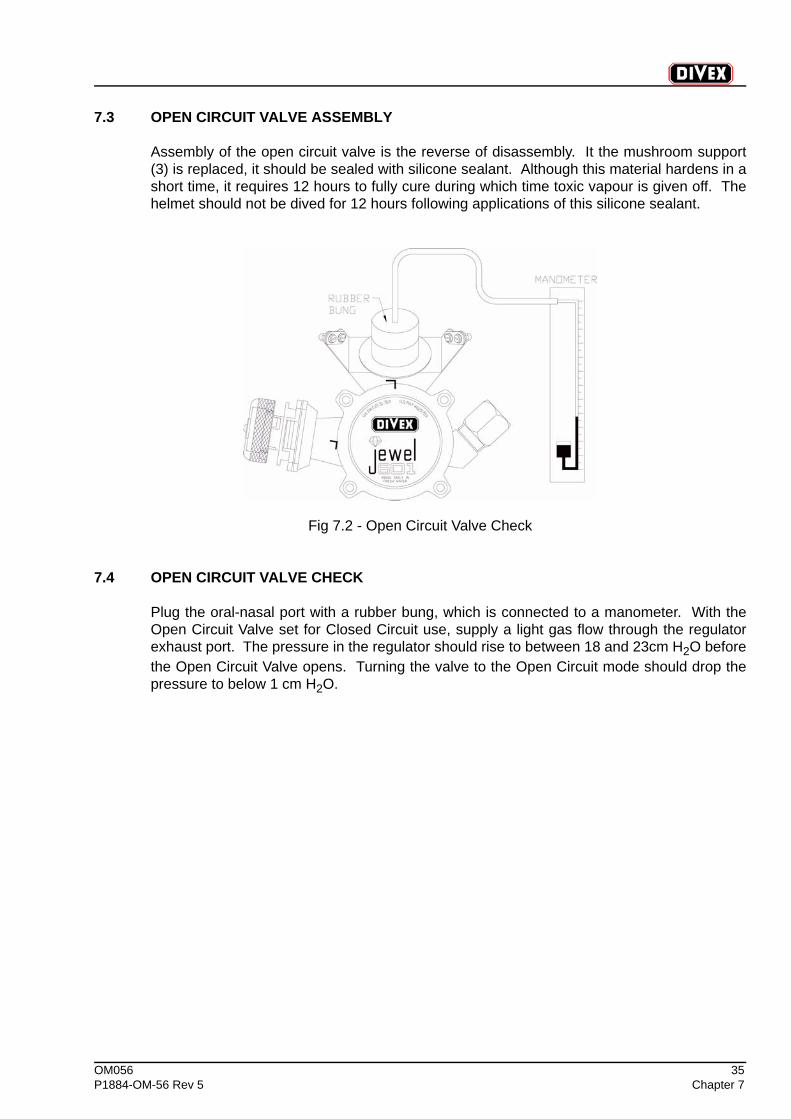
Assembly of the open circuit valve is the reverse of disassembly. It the mushroom support(3) is replaced, it should be sealed with silicone sealant. Although this material hardens in ashort time, it requires 12 hours to fully cure during which time toxic vapour is given off. Thehelmet should not be dived for 12 hours following applications of this silicone sealant.
Fig 7.2 - Open Circuit Valve Check
7.4 OPEN CIRCUIT VALVE CHECK
Plug the oral-nasal port with a rubber bung, which is connected to a manometer. With theOpen Circuit Valve set for Closed Circuit use, supply a light gas flow through the regulatorexhaust port. The pressure in the regulator should rise to between 18 and 23cm H2O beforethe Open Circuit Valve opens. Turning the valve to the Open Circuit mode should drop thepressure to below 1 cm H2O.
36 OM056Chapter 7 P1884-OM-56 Rev 5
7.5 ROUTINE MAINTENANCE
7.5.1 MAINTENANCE SCHEDULE
Clean and inspect mask or helmet inside and out.
Check operation of all moving parts.
Flush fresh water through the Jewel regulator in reverse direction to the gas flow so that itcomes out of the open-circuit valve and into the helmet.
NOTETake care not to soak the communications.
Check adjustment of neck rings.
Check the neck ring o-ring is in useable condition.
Inspect neck dams for tears or deterioration, which could lead to failure.
Refer to appropriate DSI Manual for detailed procedures.
Dismantle, clean and inspect JEWEL valve (see Chapter 6).
This check should be made daily if grouting or grit blasting, grinding or jetting.
Inspect oral nasal for signs of deterioration.
Inspect and adjust demand regulator (see Chapter 3).
Lubricate packing on nose clearing device as described in DSI Manual.
Test Check valve on main supply connection as described in DSI Manual.
24 hours next due at hrs.
Weekly next due
Monthly next due
OM056 37P1884-OM-56 Rev 5 Chapter 8
CHAPTER 8 JEWEL 601 EXHAUST REGULATOR EXPLODED PARTS
CONTENTS
Page
8.1 Jewel 601 Exhaust Regulator Explored Parts.........................................................38
38 OM056Chapter 8 P1884-OM-56 Rev 5
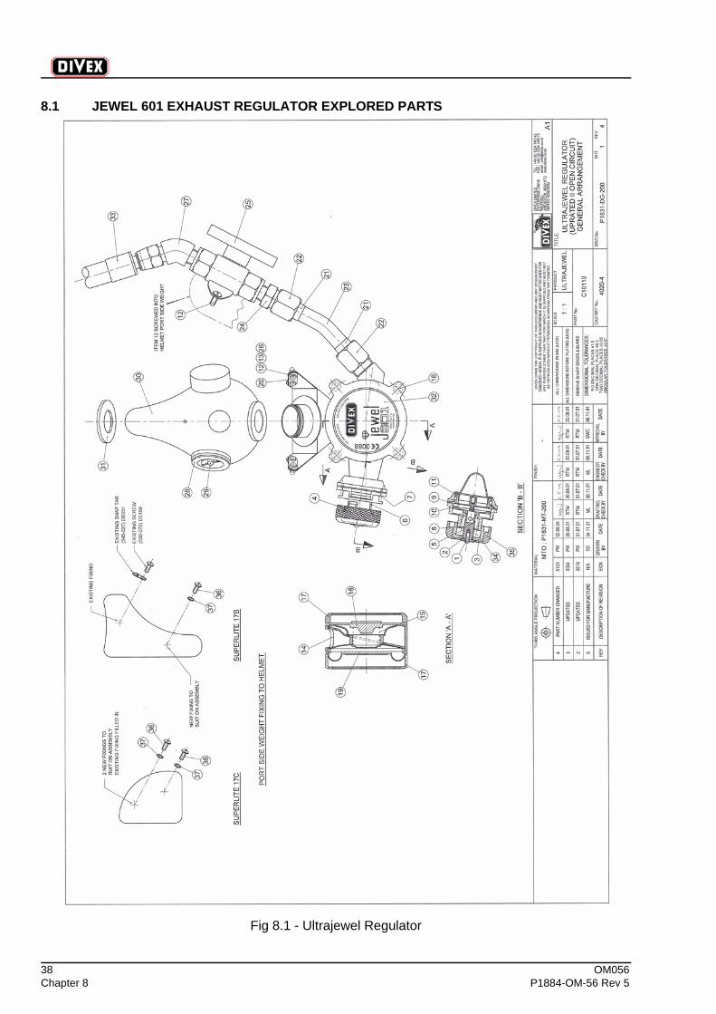
8.1 JEWEL 601 EXHAUST REGULATOR EXPLORED PARTS
Fig 8.1 - Ultrajewel Regulator
OM056 39P1884-OM-56 Rev 5 Chapter 8
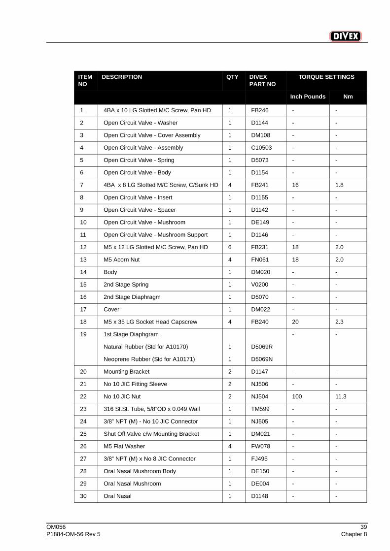
ITEM NO
DESCRIPTION QTY DIVEX PART NO
TORQUE SETTINGS
Inch Pounds Nm
1 4BA x 10 LG Slotted M/C Screw, Pan HD 1 FB246 - -
2 Open Circuit Valve - Washer 1 D1144 - -
3 Open Circuit Valve - Cover Assembly 1 DM108 - -
4 Open Circuit Valve - Assembly 1 C10503 - -
5 Open Circuit Valve - Spring 1 D5073 - -
6 Open Circuit Valve - Body 1 D1154 - -
7 4BA x 8 LG Slotted M/C Screw, C/Sunk HD 4 FB241 16 1.8
8 Open Circuit Valve - Insert 1 D1155 - -
9 Open Circuit Valve - Spacer 1 D1142 - -
10 Open Circuit Valve - Mushroom 1 DE149 - -
11 Open Circuit Valve - Mushroom Support 1 D1146 - -
12 M5 x 12 LG Slotted M/C Screw, Pan HD 6 FB231 18 2.0
13 M5 Acorn Nut 4 FN061 18 2.0
14 Body 1 DM020 - -
15 2nd Stage Spring 1 V0200 - -
16 2nd Stage Diaphragm 1 D5070 - -
17 Cover 1 DM022 - -
18 M5 x 35 LG Socket Head Capscrew 4 FB240 20 2.3
19 1st Stage Diaphgram - -
Natural Rubber (Std for A10170) 1 D5069R
Neoprene Rubber (Std for A10171) 1 D5069N
20 Mounting Bracket 2 D1147 - -
21 No 10 JIC Fitting Sleeve 2 NJ506 - -
22 No 10 JIC Nut 2 NJ504 100 11.3
23 316 St.St. Tube, 5/8”OD x 0.049 Wall 1 TM599 - -
24 3/8” NPT (M) - No 10 JIC Connector 1 NJ505 - -
25 Shut Off Valve c/w Mounting Bracket 1 DM021 - -
26 M5 Flat Washer 4 FW078 - -
27 3/8” NPT (M) x No 8 JIC Connector 1 FJ495 - -
28 Oral Nasal Mushroom Body 1 DE150 - -
29 Oral Nasal Mushroom 1 DE004 - -
30 Oral Nasal 1 D1148 - -
40 OM056Chapter 8 P1884-OM-56 Rev 5
Inch Pounds Nm
31 Oral Nasal Retaining Washer 1 D5045 - -
32 Sticker 1 T9210 - -
33 Whip Assembly 1 C1506B - -
34 Open Circuit Valve - 2nd Spring 1 D1135 - -
35 Open Circuit Valve - Cover Assembly 1 DM108 - -
36 10 UNC Pan HD 2 DE2713 18 2.3
37 10 UNC Washer 2 DE094 - -
ITEM NO
DESCRIPTION QTY DIVEX PART NO
TORQUE SETTINGS
OM056 41P1884-OM-56 Rev 5 Chapter 9
CHAPTER 9 FAULT FINDING ON ULTRAJEWEL 601 HELMETS
CONTENTS
Page
9.1 Demand Valve Faults.................................................................................................42
9.2 Exhaust Faults ...........................................................................................................42

42 OM056Chapter 9 P1884-OM-56 Rev 5
9.1 DEMAND VALVE FAULTS
Problem: Diver complains of a continuous free flow.
a. The Diver should check and adjust the “dial a breath” knob.
b. The Demand Regulator is in need of servicing and adjustment.
Problem: Diver complains of difficult to breathe.
a. The Diver should check and adjust the “dial a breath” knob.
b. The supply pressure should be checked to ensure it is within the recommended rangeand is not restricted in any way.
c. The Demand Regulator is in need of servicing and adjustment.
9.2 EXHAUST FAULTS
Problem: Leaking of gas is evident from the jewel valve.
a. Check all mushroom valves and diaphragms for condition and cleanliness and clean asnecessary or if faulty replace.
b. Check for any sign of leakage from the umbilical end connections.

OM056 43P1884-OM-56 Rev 5 Chapter 10
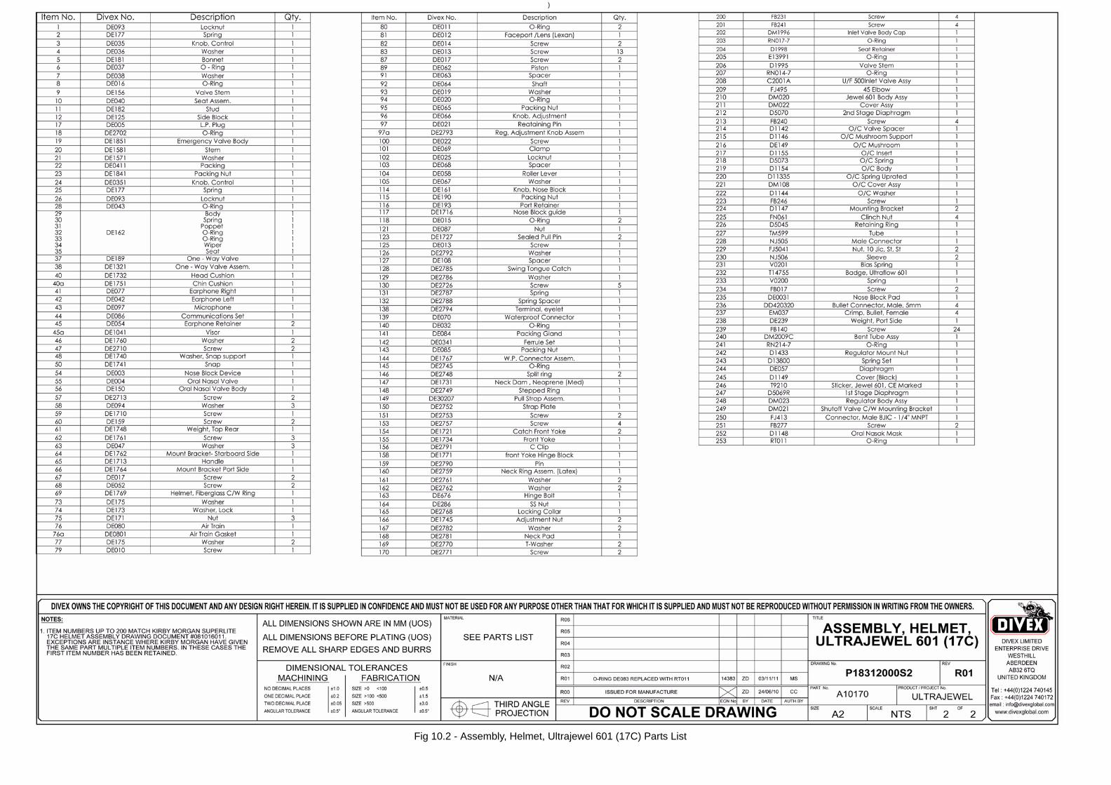
CHAPTER 10 SUPERLITE 17C EXPLODED PARTS
CONTENTS
10.1 Assembly, Helmet, Ultrajewel 601 (17C)
10.2 Assembly, Helmet, Ultrajewel 601 (17C) Parts List
10.3 Assembly, Helmet, Air Dive, Ultrajewel 601 (17C)
10.4 Assembly, Helmet, Air Dive, Ultrajewel 601 (17C) Parts List
44 OM056Chapter 10 P1884-OM-56 Rev 5
(Intentionally Blank)
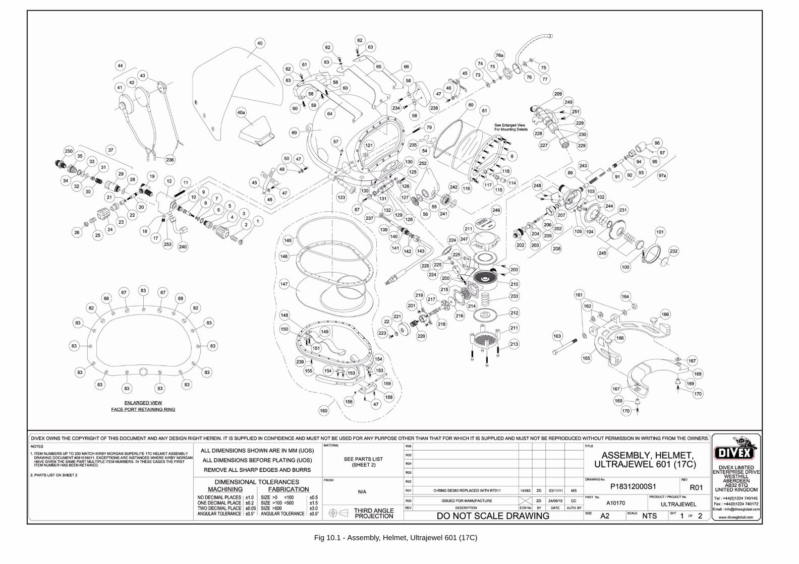
Fig 10.1 - Assembly, Helmet, Ultrajewel 601 (17C)
)
Fig 10.2 - Assembly, Helmet, Ultrajewel 601 (17C) Parts List
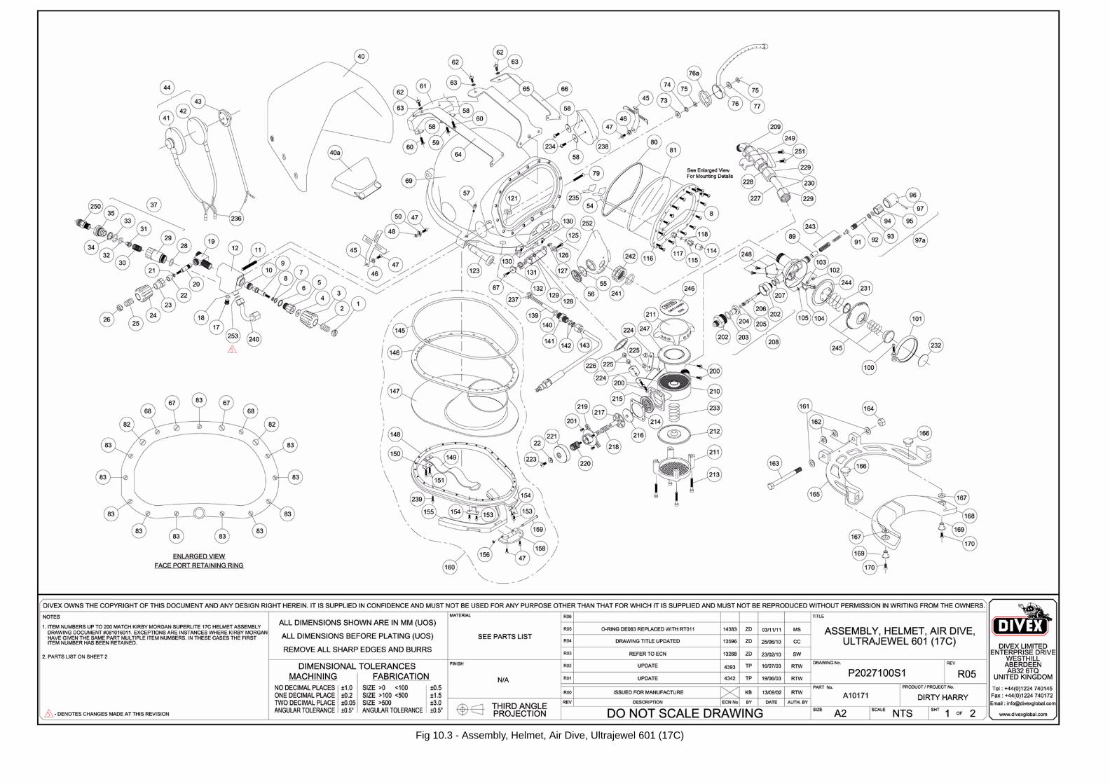
Fig 10.3 - Assembly, Helmet, Air Dive, Ultrajewel 601 (17C)
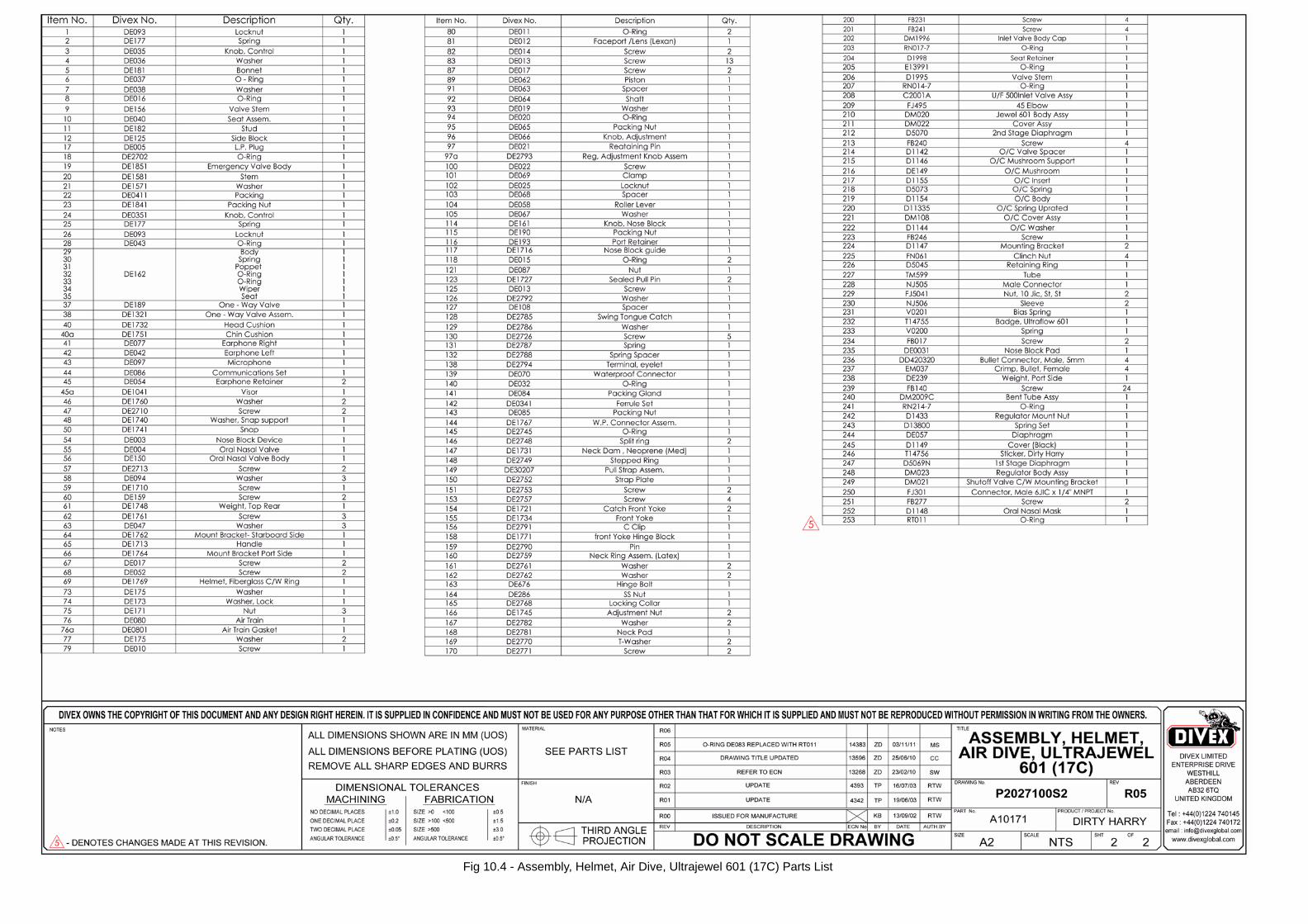
Fig 10.4 - Assembly, Helmet, Air Dive, Ultrajewel 601 (17C) Parts List
OM056 49P1884-OM-56 Rev 5 Chapter 11
CHAPTER 11 KIRBY MORGAN SUPERLITE 17C HELMET MANUAL
50 OM056Chapter 11 P1884-OM-56 Rev 5
(Intentionally Blank)