integrity check and vibration study for agitator vessel by fea
TRANSCRIPT
International Journal of Innovative and Emerging Research in Engineering
Volume 2, Special Issue 1 MEPCON 2015
47
Available online at www.ijiere.com
International Journal of Innovative and Emerging
Research in Engineering e-ISSN: 2394 - 3343 p-ISSN: 2394 - 5494
Integrity Check and Vibration Study for
Agitator Vessel by FEA
Harshad Narvekara, Vijay Bhosalea a K. J. Somaiya College of Engg., Vidyavihar, Mumbai, India
ABSTRACT:
Industrial agitators are machines used in industries that process products in the chemical, food,
pharmaceutical and cosmetic industries, in a view of mixing liquids together, promote the reactions of
chemical substance, keeping homogeneous liquid bulk during storage or increase heat transfer (heating or
cooling). The alarming drawback of the agitator vessel under consideration is its vigorous and unwanted
vibration. It is required to check the integrity of the vessel for various operating conditions and also to check
the level of vibrations so as to impart modifications if necessary to keep the vibrations of the vessel within
the limits from the point of view of proper functioning of the vessel and safety issues. This report consists of
structural analysis of equipment using ANSYS software to check the integrity of the vessel and to check the
vibration level of agitator shaft.
Keywords: agitator vessel, integrity, structural analysis, vibration
I. INTRODUCTION
The agitation in mechanical agitator vessels (pressure vessel) is achieved by the rotation of an impeller which can
help in blending, enhancement of heat transfer or enhancement of mass transfer of fluids. The stirred tank reactor with
rotating mixers remains the backbone of the chemical process industries (CPI). It is important for the process
developers and plant design engineers to understand the mechanical design aspects of agitator reactors. For a successful
agitator equipment design, it is necessary to find the ideal balance between the process requirements and an
economical, mechanical solution of the vessel-agitator system. [1]
The objective of this project is to find out the root cause of vibration and the feasible solution to minimize it in
conjunction with integrity of the vessel using FEA.
The aim of the project is to prepare a CAD model of the equipment as per the specifications using SolidWorks
2012. Static Structural Analysis is performed on the model using ANSYS APDL 14.0 platform to find the von-mises
stress and displacement vector sum to check whether the results are within the limits as per ASME Boiler and Pressure
Vessel codes VIII Division 1 and 2, Addenda 2011a. Modal Analysis is performed on shaft-impeller assembly to check
the vibration levels.
II. CAD MODELLING
A. Specifications of the agitator vessel
Table 1: Specifications of the agitator vessel
Sr. No Description Qty. Material Size (mm)
1. Main Shell 1 PLATE-SA240-316L SS316L
10712 X 3000 X 10
2. Upperdish end 1 SS316L Ellipsoidal 2:1
3. Bottomdish end 1 SS316L Ellipsoidal 2:1
4. Nozzle pad 1 FL-SA182M-F316L OD: 594.9 ID: 406.
5. Jacket Shell 1 PLATE SA516GR70 11052 X 2912 X 6
6. Jacket Bottomdish end 1 SA516GR70 Ellipsoidal 2:1
7. Pad Plates 4 PLATE SA516GR70 500 X 10
8. Leg Support 4 PIPE-SA106M-GRB-200DN
OD: 219.08 ID: 174.64
9. Base plate for leg support 4 PLATE SA516GR70 420 X 420 X 55
10. Covering for Jacket shell 1 PLATE SA240-316L OD: 1762
ID: 1710
International Journal of Innovative and Emerging Research in Engineering
Volume 2, Special Issue 1 MEPCON 2015
48
B. CAD Model
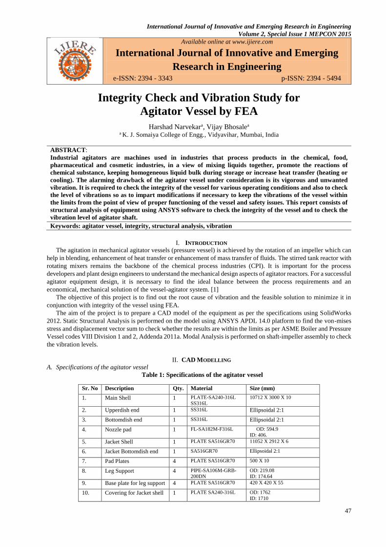
Using the detail drawing and assembly drawing of the various significant parts of the equipment necessary for the
analysis are modelled in SolidWorks 2012. The parasolid files of the parts are imported in ANSYS APDL 14.0
platform for further analysis.
Fig. 1 CAD Model of the equipment
III. STRUCTURAL ANALYSIS IN ANSYS APDL
A. Pre-Processing
The assembly of the model is applied with the necessary pre-processor attributes. [2]
1. Type of analysis: Structural & Thermal Analysis
2. Type of element: SOLID186, MASS21, TARGE170, CONTA175
3. The properties imparted to the material model are
a. Modulus of Elasticity = 2.1e11 N/m2 at 298 (K)
Modulus of Elasticity = 1.98e11 N/m2 at 373(K)
b. Poisson’s ratio = 0.3
c. Density = 7750 (kg/m3)
d. Co-eff. of Thermal Expansion= 1.65E-05 (/K)
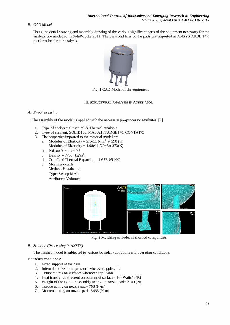
e. Meshing details
Method: Hexahedral
Type: Sweep Mesh
Attributes: Volumes
Fig. 2 Matching of nodes in meshed components
B. Solution (Processing in ANSYS)
The meshed model is subjected to various boundary condtions and operating conditions.
Boundary conditions:
1. Fixed support at the base
2. Internal and External pressure wherever applicable
3. Temperatures on surfaces wherever applicable
4. Heat transfer coeffecient on outermost surface= 10 (Watts/m2K)
5. Weight of the agitator assembly acting on nozzle pad= 3100 (N)
6. Torque acting on nozzle pad= 768 (N-m)
7. Moment acting on nozzle pad= 5665 (N-m)
International Journal of Innovative and Emerging Research in Engineering
Volume 2, Special Issue 1 MEPCON 2015
49
Operating Conditions:
1. Process fluid: Water
2. Design Pressure Shell Side= 0.15 (barg)
3. Design Pressure Jacket Side= 0.15(barg)
4. Design Temperature Shell Side= 373 (K)
5. Design Temperature Jacket Side= 316 (K)
6. Surrounding Temperature= 298 (K)
The model is solved using APDL Solver to obtain the Solution.
C. Post-Processing
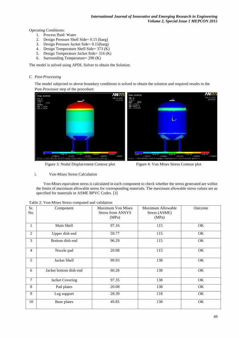
The model subjected to above boundary conditions is solved to obtain the solution and required results in the
Post-Processor step of the procedure:
Figure 3: Nodal Displacement Contour plot Figure 4: Von Mises Stress Contour plot
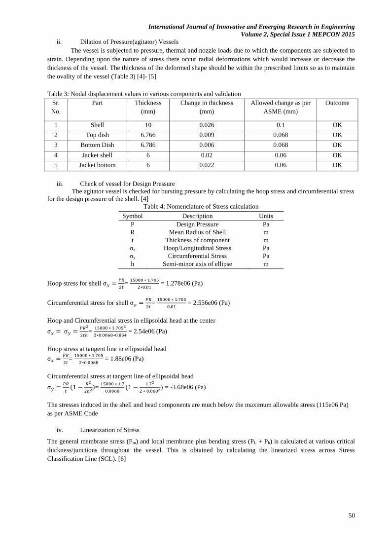
i. Von-Mises Stress Calculation
Von-Mises equivalent stress is calculated in each component to check whether the stress generated are within
the limits of maximum allowable stress for corresponding materials. The maximum allowable stress values are as
specified for materials in ASME BPVC Codes. [3]
Table 2: Von-Mises Stress computed and validation
Sr.
No.
Component Maximum Von Mises
Stress from ANSYS
(MPa)
Maximum Allowable
Stress (ASME)
(MPa)
Outcome
1 Main Shell 97.16 115 OK
2 Upper dish end 59.77 115 OK
3 Bottom dish end 96.29 115 OK
4 Nozzle pad 20.08 115 OK
5 Jacket Shell 99.93 138 OK
6 Jacket bottom dish end 60.28 138 OK
7 Jacket Covering 97.35 138 OK
8 Pad plates 20.08 138 OK
9 Leg support 28.39 118 OK
10 Base plates 49.85 138 OK
International Journal of Innovative and Emerging Research in Engineering
Volume 2, Special Issue 1 MEPCON 2015
50
ii. Dilation of Pressure(agitator) Vessels
The vessel is subjected to pressure, thermal and nozzle loads due to which the components are subjected to
strain. Depending upon the nature of stress there occur radial deformations which would increase or decrease the
thickness of the vessel. The thickness of the deformed shape should be within the prescribed limits so as to maintain
the ovality of the vessel (Table 3) [4]- [5]
Table 3: Nodal displacement values in various components and validation
Sr.
No.
Part Thickness
(mm)
Change in thickness
(mm)
Allowed change as per
ASME (mm)
Outcome
1 Shell 10 0.026 0.1 OK
2 Top dish 6.766 0.009 0.068 OK
3 Bottom Dish 6.786 0.006 0.068 OK
4 Jacket shell 6 0.02 0.06 OK
5 Jacket bottom 6 0.022 0.06 OK
iii. Check of vessel for Design Pressure
The agitator vessel is checked for bursting pressure by calculating the hoop stress and circumferential stress
for the design pressure of the shell. [4]
Table 4: Nomenclature of Stress calculation
Symbol Description Units
P Design Pressure Pa
R Mean Radius of Shell m
t Thickness of component m
σx Hoop/Longitudinal Stress Pa
σy Circumferential Stress Pa
h Semi-minor axis of ellipse m
Hoop stress for shell σ𝑥 =𝑃𝑅
2𝑡=
15000 ∗ 1.705
2∗0.01 = 1.278e06 (Pa)
Circumferential stress for shell σ𝑦 =𝑃𝑅
2𝑡=
15000 ∗ 1.705
0.01 = 2.556e06 (Pa)
Hoop and Circumferential stress in ellipsoidal head at the center
σ𝑥 = σ𝑦 =𝑃𝑅2
2𝑡ℎ=
15000 ∗ 1.7052
2∗0.0068∗0.854 = 2.54e06 (Pa)
Hoop stress at tangent line in ellipsoidal head
σ𝑥 =𝑃𝑅
2𝑡=
15000 ∗ 1.705
2∗0.0068 = 1.88e06 (Pa)
Circumferential stress at tangent line of ellipsoidal head
σ𝑦 =𝑃𝑅
𝑡(1 −
𝑅2
2ℎ2)= 15000 ∗ 1.7
0.0068(1 −
1.72
2 ∗ 0.0682) = -3.68e06 (Pa)
The stresses induced in the shell and head components are much below the maximum allowable stress (115e06 Pa)
as per ASME Code
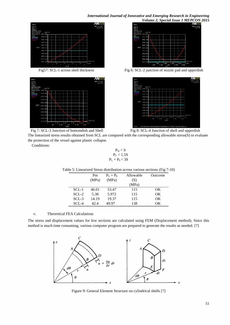
iv. Linearization of Stress
The general membrane stress (Pm) and local membrane plus bending stress (PL + Pb) is calculated at various critical
thickness/junctions throughout the vessel. This is obtained by calculating the linearized stress across Stress
Classification Line (SCL). [6]
International Journal of Innovative and Emerging Research in Engineering
Volume 2, Special Issue 1 MEPCON 2015
51
Fig57: SCL-1 across shell thickness Fig 6: SCL-2 junction of nozzle pad and upperdish
Fig 7: SCL-3 Junction of bottomdish and Shell Fig 8: SCL-4 Junction of shell and upperdish
The linearized stress results obtained from SCL are compared with the corresponding allowable stress(S) to evaluate
the protection of the vessel against plastic collapse.
Conditions:
Pm < S
PL < 1.5S
PL + Pb < 3S
Table 5: Linearized Stress distribution across various sections (Fig 7-10)
Pm
(MPa)
PL + Pb
(MPa)
Allowable
(S)
(MPa)
Outcome
SCL-1 46.01 53.47 115 OK
SCL-2 5.38 5.972 115 OK
SCL-3 14.19 19.37 115 OK
SCL-4 42.4 49.97 138 OK
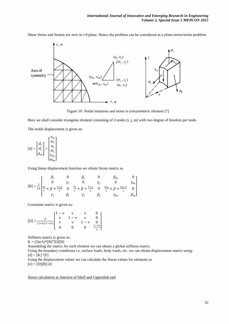
v. Theoretical FEA Calculations
The stress and displacement values for few sections are calculated using FEM (Displacement method). Since this
method is much time consuming, various computer program are prepared to generate the results as needed. [7]
Figure 9: General Element Structure on cylindrical shells [7]
International Journal of Innovative and Emerging Research in Engineering
Volume 2, Special Issue 1 MEPCON 2015
52
Shear Stress and Strains are zero in r-θ plane. Hence the problem can be considered as a plane-stress/strain problem.
Figure 10: Nodal notations and stress in axisymmetric element [7]
Here we shall consider triangular element consisting of 3 nodes (i, j, m) with two degree of freedom per node.
The nodal displacement is given as:
[d] = [
𝑑𝑖
𝑑𝑗
𝑑𝑚
] =
[ 𝑢𝑜
𝑤𝑖
𝑢𝑗
𝑤𝑗
𝑢𝑚
𝑤𝑚]
Using linear displacement function we obtain Strain matrix as
[B] = 1
2𝐴
[
𝛽𝑖 0 𝛽𝑗 0 𝛽𝑚 0
0 𝛾𝑖 0 𝛾𝑗 0 𝛾𝑚
𝛼𝑖
𝑟+ 𝛽 +
𝛾𝑖∗𝑍
𝑟0
𝛼𝑗
𝑟+ 𝛽 +
𝛾𝑗∗𝑧
𝑟0
𝛼𝑚
𝑟+ 𝛽 +
𝛾𝑚∗𝑧
𝑟0
𝛾𝑖 𝛽𝑖 𝛾𝑗 𝛽𝑗 𝛾𝑚 𝛽𝑚]
Constitute matrix is given as:
[D] = 𝐸
(1+𝜈)(1−2𝜈)
[ 1 − 𝜈 𝜈 𝜈 0
𝜈 1 − 𝜈 𝜈 0𝜈 𝜈 1 − 𝜈 0
0 0 01−2𝜈
2 ]
Stiffness matrix is given as:
K = (2πrA)*[B]T[D][B]
Assembling the matrix for each element we can obtain a global stiffness matrix.
Using the boundary conditions i.e. surface loads, body loads, etc. we can obtain displacement matrix using:
[d] = [K]-1[F]
Using the displacement values we can calculate the Stress values for elements as
[σ] = [D][B]{d}
Stress calculation at Junction of Shell and Upperdish end
International Journal of Innovative and Emerging Research in Engineering
Volume 2, Special Issue 1 MEPCON 2015
53
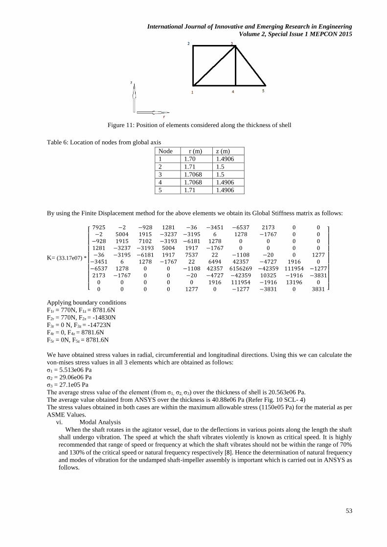
Figure 11: Position of elements considered along the thickness of shell
Table 6: Location of nodes from global axis
Node r (m) z (m)
1 1.70 1.4906
2 1.71 1.5
3 1.7068 1.5
4 1.7068 1.4906
5 1.71 1.4906
By using the Finite Displacement method for the above elements we obtain its Global Stiffness matrix as follows:
K= (33.17e07) *
[
7925 −2 −928 1281 −36 −3451 −6537 2173 0 0−2 5004 1915 −3237 −3195 6 1278 −1767 0 0
−928 1915 7102 −3193 −6181 1278 0 0 0 01281 −3237 −3193 5004 1917 −1767 0 0 0 0−36 −3195 −6181 1917 7537 22 −1108 −20 0 1277
−3451 6 1278 −1767 22 6494 42357 −4727 1916 0−6537 1278 0 0 −1108 42357 6156269 −42359 111954 −12772173 −1767 0 0 −20 −4727 −42359 10325 −1916 −3831
0 0 0 0 0 1916 111954 −1916 13196 00 0 0 0 1277 0 −1277 −3831 0 3831 ]
Applying boundary conditions
F1r = 770N, F1z = 8781.6N
F2r = 770N, F2z = -14830N
F3r = 0 N, F3z = -14723N
F4r = 0, F4z = 8781.6N
F5r = 0N, F5z = 8781.6N
We have obtained stress values in radial, circumferential and longitudinal directions. Using this we can calculate the
von-mises stress values in all 3 elements which are obtained as follows:
σ1 = 5.513e06 Pa
σ2 = 29.06e06 Pa
σ3 = 27.1e05 Pa
The average stress value of the element (from σ1, σ2, σ3) over the thickness of shell is 20.563e06 Pa.
The average value obtained from ANSYS over the thickness is 40.88e06 Pa (Refer Fig. 10 SCL- 4)
The stress values obtained in both cases are within the maximum allowable stress (1150e05 Pa) for the material as per
ASME Values.
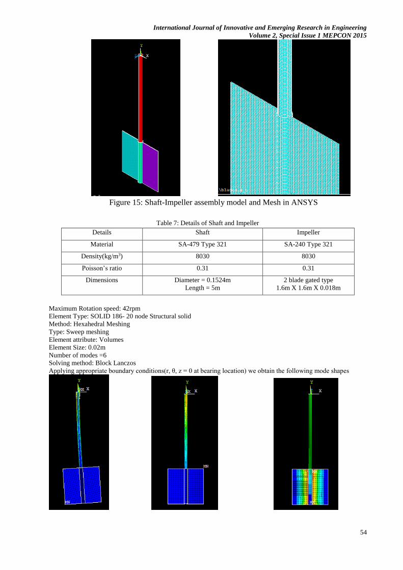
vi. Modal Analysis
When the shaft rotates in the agitator vessel, due to the deflections in various points along the length the shaft
shall undergo vibration. The speed at which the shaft vibrates violently is known as critical speed. It is highly
recommended that range of speed or frequency at which the shaft vibrates should not be within the range of 70%
and 130% of the critical speed or natural frequency respectively [8]. Hence the determination of natural frequency
and modes of vibration for the undamped shaft-impeller assembly is important which is carried out in ANSYS as
follows.
International Journal of Innovative and Emerging Research in Engineering
Volume 2, Special Issue 1 MEPCON 2015
54
Figure 15: Shaft-Impeller assembly model and Mesh in ANSYS
Table 7: Details of Shaft and Impeller
Details Shaft Impeller
Material SA-479 Type 321 SA-240 Type 321
Density(kg/m3) 8030 8030
Poisson’s ratio 0.31 0.31
Dimensions Diameter = 0.1524m
Length = 5m
2 blade gated type
1.6m X 1.6m X 0.018m
Maximum Rotation speed: 42rpm
Element Type: SOLID 186- 20 node Structural solid
Method: Hexahedral Meshing
Type: Sweep meshing
Element attribute: Volumes
Element Size: 0.02m
Number of modes =6
Solving method: Block Lanczos
Applying appropriate boundary conditions(r, θ, z = 0 at bearing location) we obtain the following mode shapes
International Journal of Innovative and Emerging Research in Engineering
Volume 2, Special Issue 1 MEPCON 2015
55
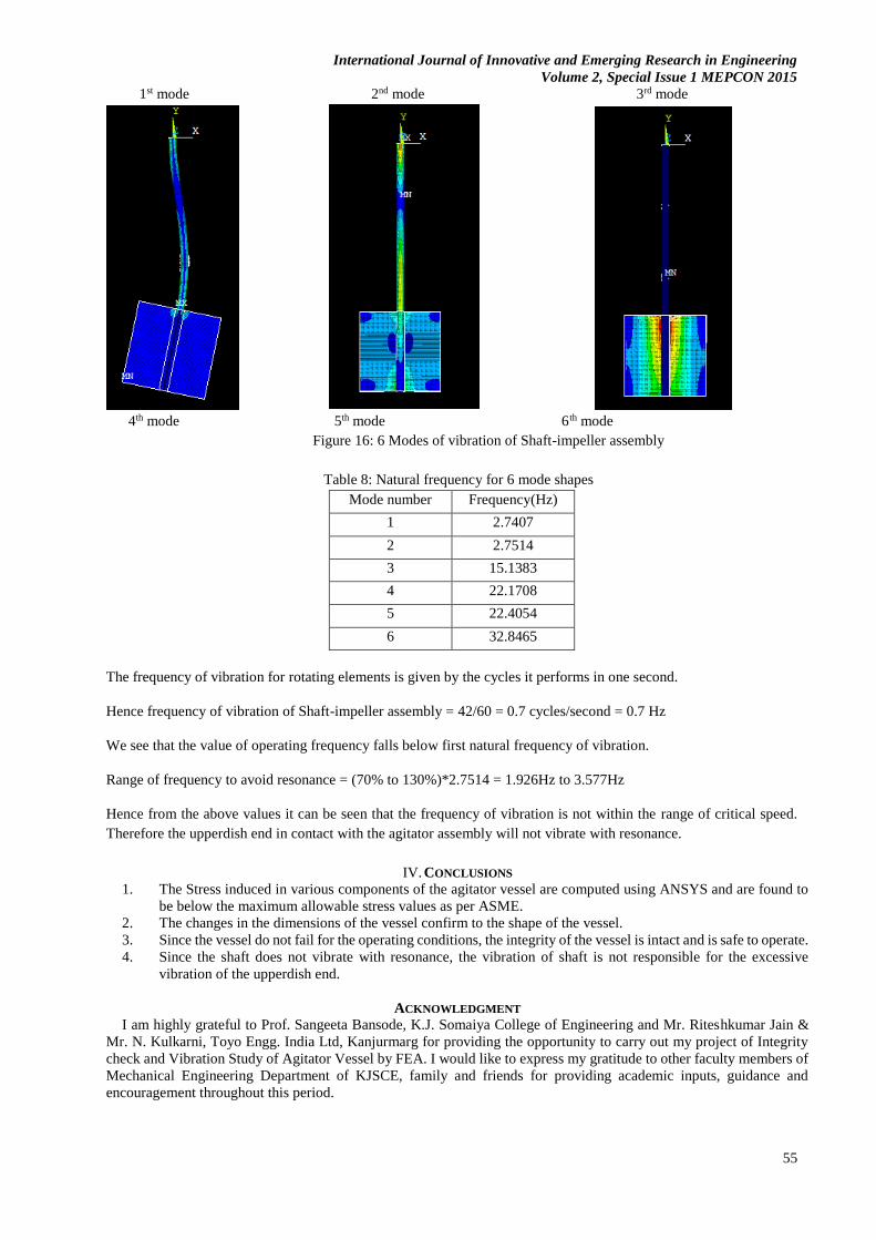
1st mode 2nd mode 3rd mode
4th mode 5th mode 6th mode
Figure 16: 6 Modes of vibration of Shaft-impeller assembly
Table 8: Natural frequency for 6 mode shapes
Mode number Frequency(Hz)
1 2.7407
2 2.7514
3 15.1383
4 22.1708
5 22.4054
6 32.8465
The frequency of vibration for rotating elements is given by the cycles it performs in one second.
Hence frequency of vibration of Shaft-impeller assembly = 42/60 = 0.7 cycles/second = 0.7 Hz
We see that the value of operating frequency falls below first natural frequency of vibration.
Range of frequency to avoid resonance = (70% to 130%)*2.7514 = 1.926Hz to 3.577Hz
Hence from the above values it can be seen that the frequency of vibration is not within the range of critical speed.
Therefore the upperdish end in contact with the agitator assembly will not vibrate with resonance.
IV. CONCLUSIONS
1. The Stress induced in various components of the agitator vessel are computed using ANSYS and are found to
be below the maximum allowable stress values as per ASME.
2. The changes in the dimensions of the vessel confirm to the shape of the vessel.
3. Since the vessel do not fail for the operating conditions, the integrity of the vessel is intact and is safe to operate.
4. Since the shaft does not vibrate with resonance, the vibration of shaft is not responsible for the excessive
vibration of the upperdish end.
ACKNOWLEDGMENT
I am highly grateful to Prof. Sangeeta Bansode, K.J. Somaiya College of Engineering and Mr. Riteshkumar Jain &
Mr. N. Kulkarni, Toyo Engg. India Ltd, Kanjurmarg for providing the opportunity to carry out my project of Integrity
check and Vibration Study of Agitator Vessel by FEA. I would like to express my gratitude to other faculty members of
Mechanical Engineering Department of KJSCE, family and friends for providing academic inputs, guidance and
encouragement throughout this period.

International Journal of Innovative and Emerging Research in Engineering
Volume 2, Special Issue 1 MEPCON 2015
56
REFERENCES
[1] M. Stadtaus, H. Weiss, W. Himmelshbach and J. Smith , “Tapping into the mechanics of mixing,” Chemical
Engineering, vol. 117, no. April 2010, April 2010.
[2] ANSYS INC, “ANSYS Help Topics,” 2011. [Online]. Available: www.ansys.com.
[3] ASME Boiler and Pressure Vessel Committee on Materials, “Properties(Metric) Materials,” 2011.
[4] D. Moss and M. Basic, Pressure Vessel Design Manual 4th Edition, Waltham: Elsevier INC, 2013, pp. 38-73.
[5] ASME Boiler and Pressure Vessels Committee on Pressure Vessels, “2010 ASME Boiler and Pressure Vessel
Code Division 1,” 2011.
[6] ASME Boiler and Pressure Vessel Committee on Pressure vessels, “2010 ASME Boiler and Pressure Vessel
Code Division 2,” 2011.
[7] D. L. Logan, A First Course in the Finite Element Method, 4th ed., Chris Carson, 2007, p. 836.
[8] M. Joshi, Process Equipment design, The MacMillan Company of India, 1976.