datasheet and user manual for wm-e1s® metering modem
TRANSCRIPT
Datasheet and User manual for WM-E1S® metering modem
______________________________________________ ____
Rev: 2.73
2022-03-08
Document specifications
This documentation was made for presenting the installation and configuration steps of the WM-E 1S® energy metering modem.
Document Version: REV 2.73
Hardware Type/Version: WM-E1S® modem for the Elster® / Honeywell® Alpha A1500, A1700, A1800, A1140/A1160 electricity meters
Hardware Version: V 4.70
Firmware Version:
Standard version: V2.4.27
Input extender board version: V2.4.25.8B
TLS version: V2.5.52 TLS
WM-E Term® config. software version:
V 1.3.58
Pages: 38
Status: Final
Created: 26-09-2019
Last Modified: 08-03-2022
Chapter 1. Introduction
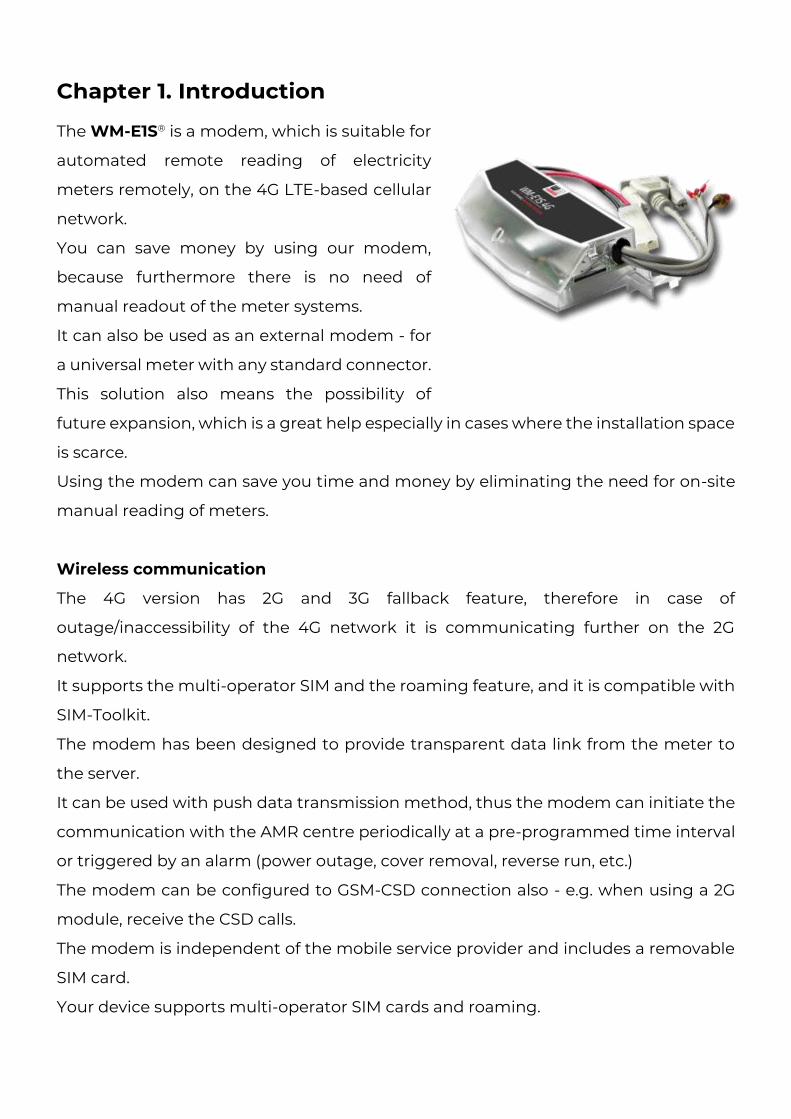
The WM-E1S® is a modem, which is suitable for
automated remote reading of electricity
meters remotely, on the 4G LTE-based cellular
network.
You can save money by using our modem,
because furthermore there is no need of
manual readout of the meter systems.
It can also be used as an external modem - for
a universal meter with any standard connector.
This solution also means the possibility of
future expansion, which is a great help especially in cases where the installation space
is scarce.
Using the modem can save you time and money by eliminating the need for on-site
manual reading of meters.
Wireless communication
The 4G version has 2G and 3G fallback feature, therefore in case of
outage/inaccessibility of the 4G network it is communicating further on the 2G
network.
It supports the multi-operator SIM and the roaming feature, and it is compatible with
SIM-Toolkit.
The modem has been designed to provide transparent data link from the meter to
the server.
It can be used with push data transmission method, thus the modem can initiate the
communication with the AMR centre periodically at a pre-programmed time interval
or triggered by an alarm (power outage, cover removal, reverse run, etc.)
The modem can be configured to GSM-CSD connection also - e.g. when using a 2G
module, receive the CSD calls.
The modem is independent of the mobile service provider and includes a removable
SIM card.
Your device supports multi-operator SIM cards and roaming.
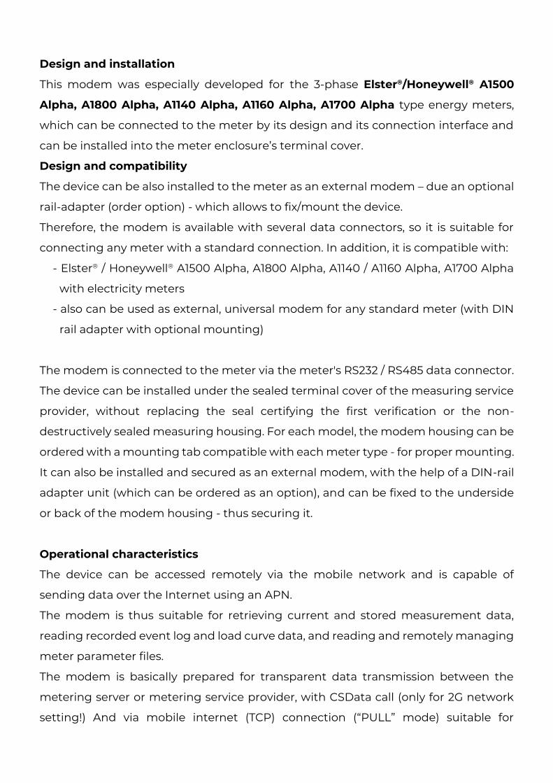
Design and installation
This modem was especially developed for the 3-phase Elster®/Honeywell® A1500
Alpha, A1800 Alpha, A1140 Alpha, A1160 Alpha, A1700 Alpha type energy meters,
which can be connected to the meter by its design and its connection interface and
can be installed into the meter enclosure’s terminal cover.
Design and compatibility
The device can be also installed to the meter as an external modem – due an optional
rail-adapter (order option) - which allows to fix/mount the device.
Therefore, the modem is available with several data connectors, so it is suitable for
connecting any meter with a standard connection. In addition, it is compatible with:
- Elster® / Honeywell® A1500 Alpha, A1800 Alpha, A1140 / A1160 Alpha, A1700 Alpha
with electricity meters
- also can be used as external, universal modem for any standard meter (with DIN
rail adapter with optional mounting)
The modem is connected to the meter via the meter's RS232 / RS485 data connector.
The device can be installed under the sealed terminal cover of the measuring service
provider, without replacing the seal certifying the first verification or the non-
destructively sealed measuring housing. For each model, the modem housing can be
ordered with a mounting tab compatible with each meter type - for proper mounting.
It can also be installed and secured as an external modem, with the help of a DIN-rail
adapter unit (which can be ordered as an option), and can be fixed to the underside
or back of the modem housing - thus securing it.
Operational characteristics
The device can be accessed remotely via the mobile network and is capable of
sending data over the Internet using an APN.
The modem is thus suitable for retrieving current and stored measurement data,
reading recorded event log and load curve data, and reading and remotely managing
meter parameter files.
The modem is basically prepared for transparent data transmission between the
metering server or metering service provider, with CSData call (only for 2G network
setting!) And via mobile internet (TCP) connection (“PULL” mode) suitable for
electricity meter registers. and remote reading of load curves, use of standard reading
commands, remote reading and modification of the meter / parameters, updating of
the meter application firmware.
Over the RS232/RS485 compatible data connection, some models have the 2-Inputs
option (for sabotage or relay/tariff switch status). In case of input line presence, the
device is able to detect the input signal changes and generating and transmitting
SMS alert notification.
Data connection
The modem can be ordered with various data connectivity options, depending on the
version:
- RS232 port (DSUB connector)
- RS485 port (2- or 4-pin ferrule connector)
- RS232 (DSUB9) and RS485 ports (2- or 4-wire socket connector)
- connector)
- RS232 and RS485 ports (RJ12 connector)
Power source and power outage
The device can be powered from the meter’s mains connection (by general 100V-240V
AC voltage).
The modem can be connected through the following modes:
a.) the meter is connected to the 57.7/100V AC power network: the modem must
be connected to line voltage (100V, L1..L2 or L2..L3 or L1..L3)
b.) the meter is connected to the 230/400V AC power network: the modem must
be connected to the phase voltage (230V, L1..N or L2..N or L3..N)
In case of the need of using external DC power, the modem can be orderd in DC-
voltage version.
Supercapacitor
The modem is also available with a power outage protection by an optional
supercapacitor component, which allows to continue the modem operation in case
of minor power outage(s).
In case of a power outage, the supercapacitors will discharge by time, and the modem
will shut down. When the power supply returns, the modem restarts and sends data
over the cellular network, and the capacitor components will be charged).
Configuration and firmware refresh
The modem can be configured locally via RS232 port, remotely with a CSData call (only
if you use a setting that also uses a 2G network!) Or via a mobile internet (TCP)
connection, and its firmware can be updated. The modem is configurable via TCP port
remotely (or via local serial connection) and operating on the wireless network by
configuring the APN, username and password (APN information is provided by your
local mobile operator).
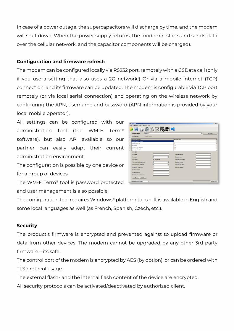
All settings can be configured with our
administration tool (the WM-E Term®
software), but also API available so our
partner can easily adapt their current
administration environment.
The configuration is possible by one device or
for a group of devices.
The WM-E Term® tool is password protected
and user management is also possible.
The configuration tool requires Windows® platform to run. It is available in English and
some local languages as well (as French, Spanish, Czech, etc.).
Security
The product’s firmware is encrypted and prevented against to upload firmware or
data from other devices. The modem cannot be upgraded by any other 3rd party
firmware – its safe.
The control port of the modem is encrypted by AES (by option), or can be ordered with
TLS protocol usage.
The external flash- and the internal flash content of the device are encrypted.
All security protocols can be activated/deactivated by authorized client.
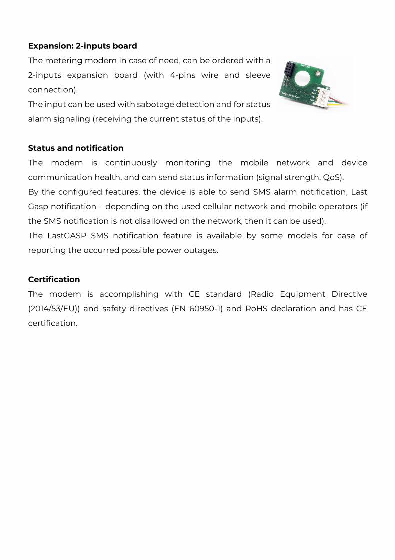
Expansion: 2-inputs board
The metering modem in case of need, can be ordered with a
2-inputs expansion board (with 4-pins wire and sleeve
connection).
The input can be used with sabotage detection and for status
alarm signaling (receiving the current status of the inputs).
Status and notification
The modem is continuously monitoring the mobile network and device
communication health, and can send status information (signal strength, QoS).
By the configured features, the device is able to send SMS alarm notification, Last
Gasp notification – depending on the used cellular network and mobile operators (if
the SMS notification is not disallowed on the network, then it can be used).
The LastGASP SMS notification feature is available by some models for case of
reporting the occurred possible power outages.
Certification
The modem is accomplishing with CE standard (Radio Equipment Directive
(2014/53/EU)) and safety directives (EN 60950-1) and RoHS declaration and has CE
certification.
Chapter 2. Connectors, interfaces
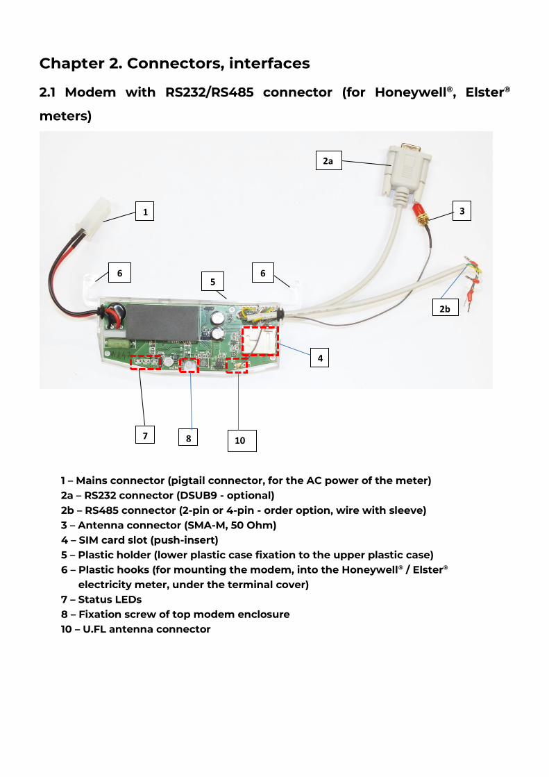
2.1 Modem with RS232/RS485 connector (for Honeywell®, Elster®
meters)
1
2a
3
2b
4
7 8
6 6
10
1 – Mains connector (pigtail connector, for the AC power of the meter) 2a – RS232 connector (DSUB9 - optional) 2b – RS485 connector (2-pin or 4-pin - order option, wire with sleeve) 3 – Antenna connector (SMA-M, 50 Ohm) 4 – SIM card slot (push-insert) 5 – Plastic holder (lower plastic case fixation to the upper plastic case) 6 – Plastic hooks (for mounting the modem, into the Honeywell® / Elster® electricity meter, under the terminal cover) 7 – Status LEDs 8 – Fixation screw of top modem enclosure 10 – U.FL antenna connector
5
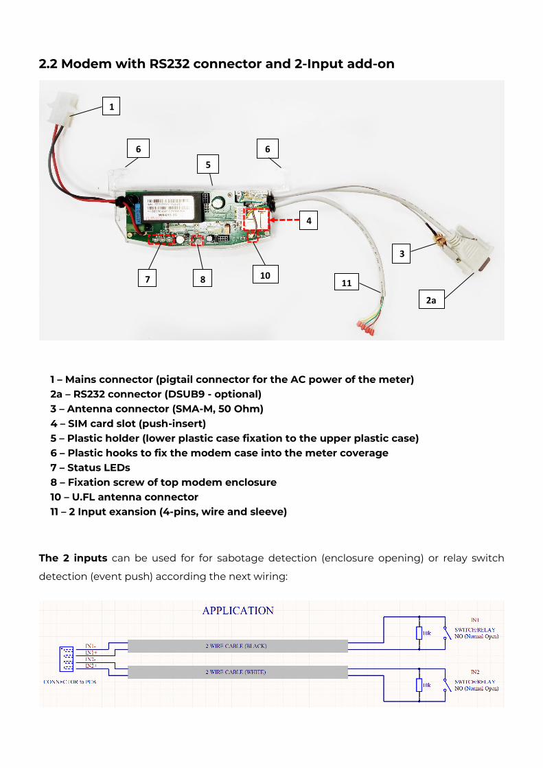
2.2 Modem with RS232 connector and 2-Input add-on
The 2 inputs can be used for for sabotage detection (enclosure opening) or relay switch
detection (event push) according the next wiring:
1
2a
3
4
7 8
6 6
10
1 – Mains connector (pigtail connector for the AC power of the meter) 2a – RS232 connector (DSUB9 - optional) 3 – Antenna connector (SMA-M, 50 Ohm) 4 – SIM card slot (push-insert) 5 – Plastic holder (lower plastic case fixation to the upper plastic case) 6 – Plastic hooks to fix the modem case into the meter coverage 7 – Status LEDs 8 – Fixation screw of top modem enclosure 10 – U.FL antenna connector 11 – 2 Input exansion (4-pins, wire and sleeve)
11
5
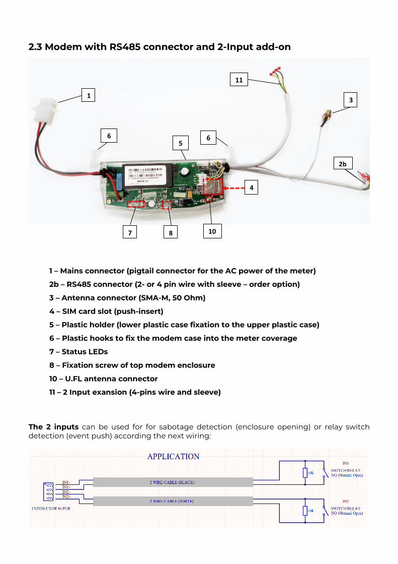
2.3 Modem with RS485 connector and 2-Input add-on
The 2 inputs can be used for for sabotage detection (enclosure opening) or relay switch detection (event push) according the next wiring:
1 3
2b
4
7 8
6 6
10
1 – Mains connector (pigtail connector for the AC power of the meter)
2b – RS485 connector (2- or 4 pin wire with sleeve – order option)
3 – Antenna connector (SMA-M, 50 Ohm)
4 – SIM card slot (push-insert)
5 – Plastic holder (lower plastic case fixation to the upper plastic case)
6 – Plastic hooks to fix the modem case into the meter coverage
7 – Status LEDs
8 – Fixation screw of top modem enclosure
10 – U.FL antenna connector
11 – 2 Input exansion (4-pins wire and sleeve)
11
5
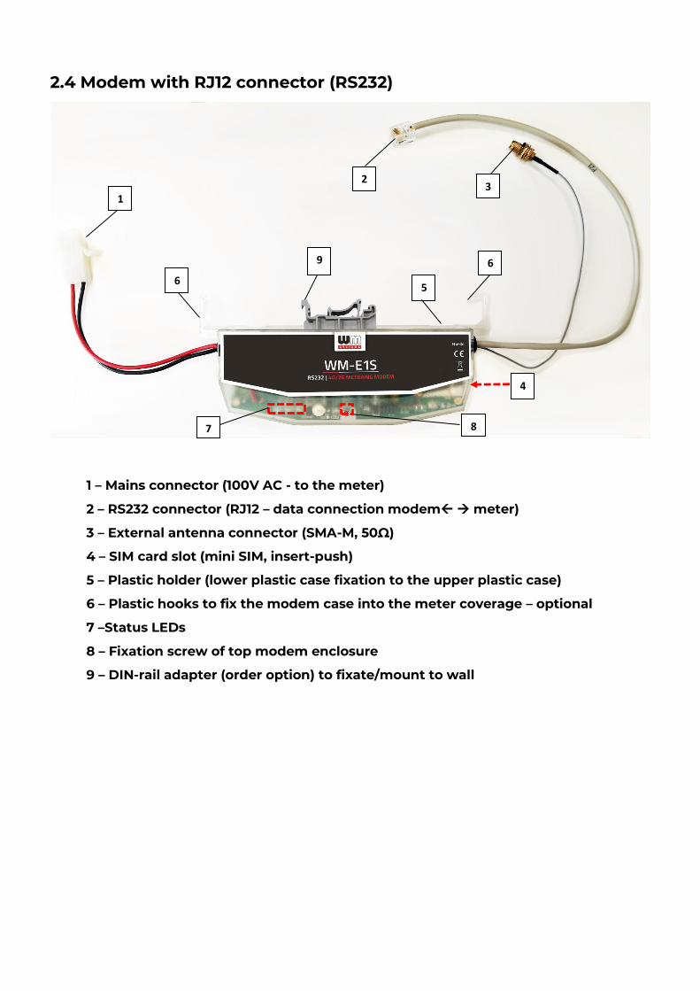
2.4 Modem with RJ12 connector (RS232)
1
2
4
1 – Mains connector (100V AC - to the meter)
2 – RS232 connector (RJ12 – data connection modem → meter)
3 – External antenna connector (SMA-M, 50Ω)
4 – SIM card slot (mini SIM, insert-push)
5 – Plastic holder (lower plastic case fixation to the upper plastic case)
6 – Plastic hooks to fix the modem case into the meter coverage – optional
7 –Status LEDs
8 – Fixation screw of top modem enclosure
9 – DIN-rail adapter (order option) to fixate/mount to wall
6
7
5 6
9
8
3
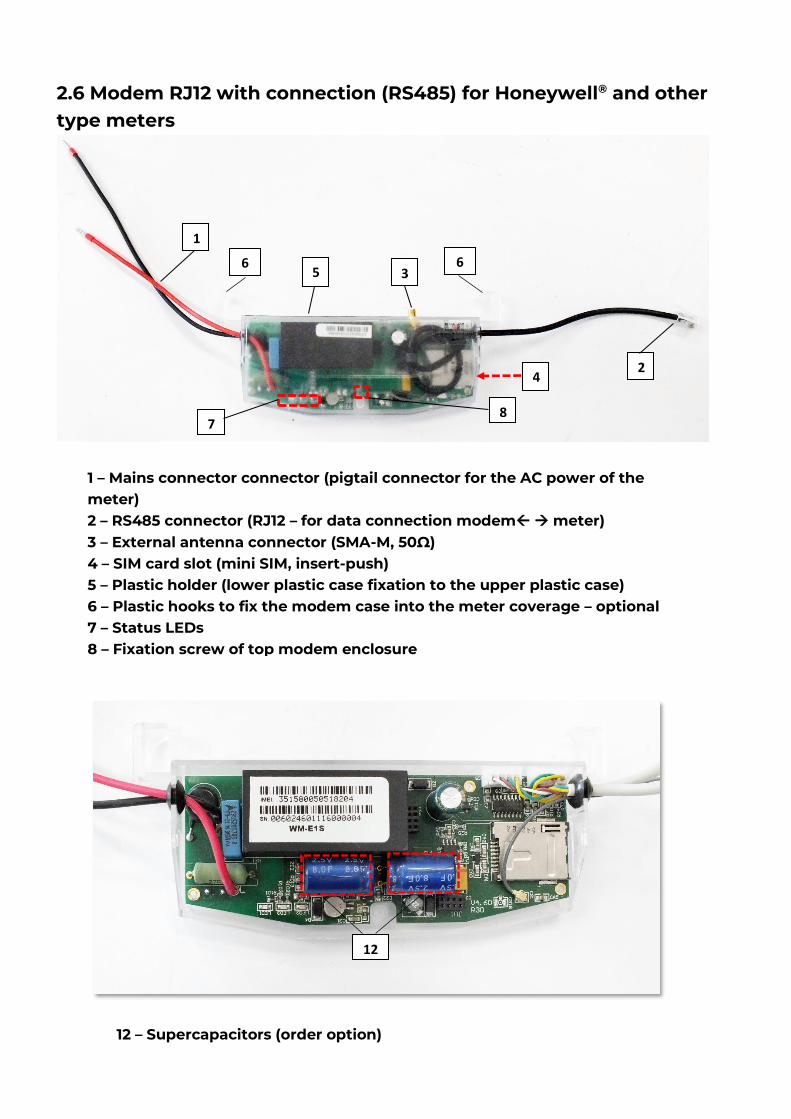
2.6 Modem RJ12 with connection (RS485) for Honeywell® and other type meters
1
2 4
7
5
8
3 6 6
1 – Mains connector connector (pigtail connector for the AC power of the meter) 2 – RS485 connector (RJ12 – for data connection modem → meter) 3 – External antenna connector (SMA-M, 50Ω) 4 – SIM card slot (mini SIM, insert-push) 5 – Plastic holder (lower plastic case fixation to the upper plastic case) 6 – Plastic hooks to fix the modem case into the meter coverage – optional 7 – Status LEDs 8 – Fixation screw of top modem enclosure
12
12 – Supercapacitors (order option)
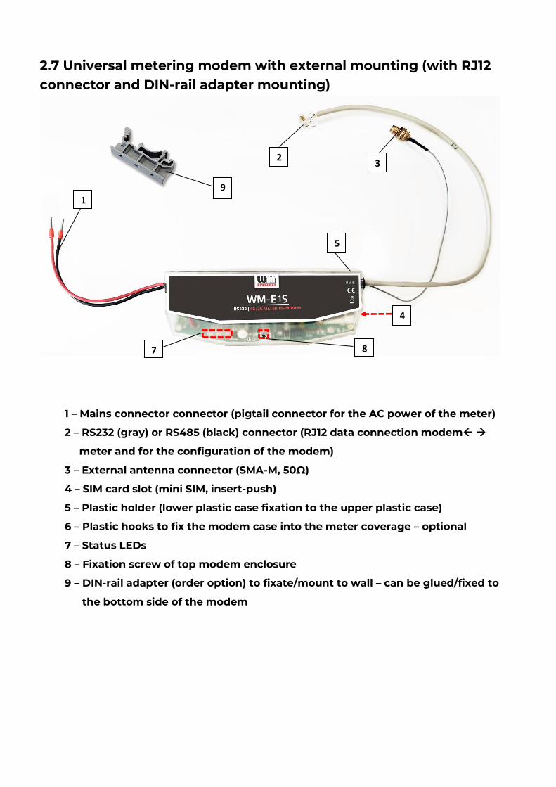
2.7 Universal metering modem with external mounting (with RJ12 connector and DIN-rail adapter mounting)
1
2
4
7
5
9
8
3
1 – Mains connector connector (pigtail connector for the AC power of the meter)
2 – RS232 (gray) or RS485 (black) connector (RJ12 data connection modem →
meter and for the configuration of the modem)
3 – External antenna connector (SMA-M, 50Ω)
4 – SIM card slot (mini SIM, insert-push)
5 – Plastic holder (lower plastic case fixation to the upper plastic case)
6 – Plastic hooks to fix the modem case into the meter coverage – optional
7 – Status LEDs
8 – Fixation screw of top modem enclosure
9 – DIN-rail adapter (order option) to fixate/mount to wall – can be glued/fixed to
the bottom side of the modem
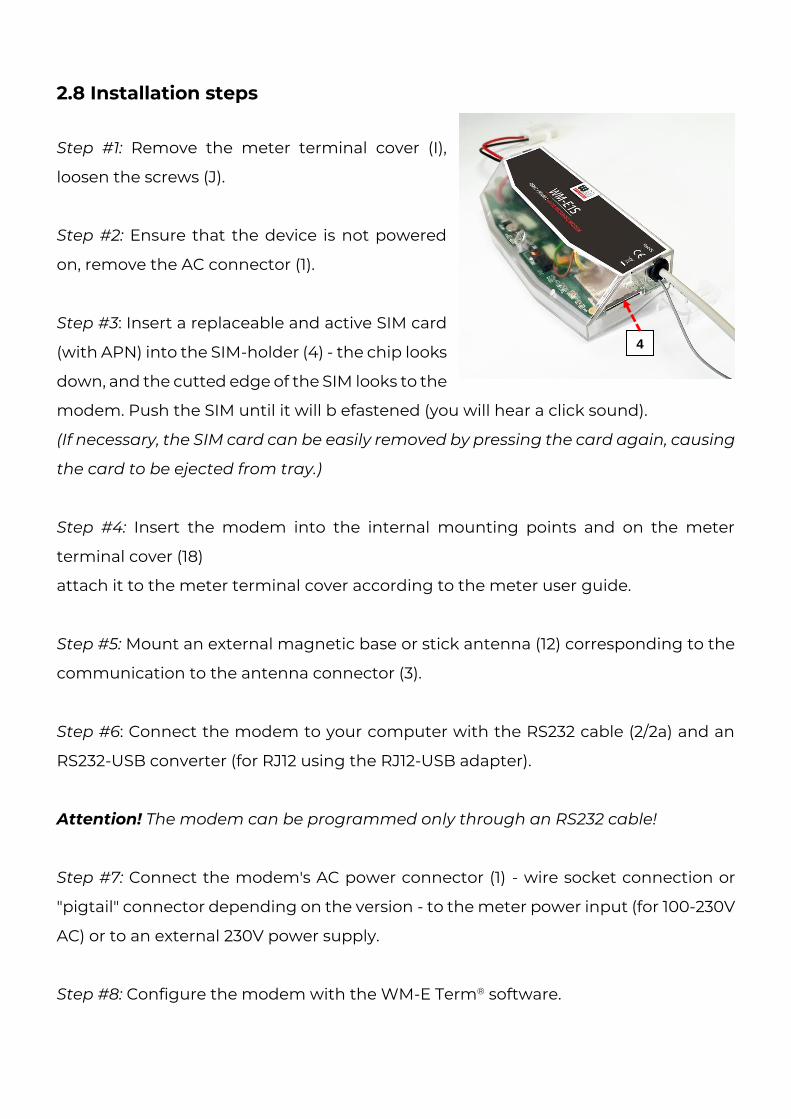
2.8 Installation steps
Step #1: Remove the meter terminal cover (I),
loosen the screws (J).
Step #2: Ensure that the device is not powered
on, remove the AC connector (1).
Step #3: Insert a replaceable and active SIM card
(with APN) into the SIM-holder (4) - the chip looks
down, and the cutted edge of the SIM looks to the
modem. Push the SIM until it will b efastened (you will hear a click sound).
(If necessary, the SIM card can be easily removed by pressing the card again, causing
the card to be ejected from tray.)
Step #4: Insert the modem into the internal mounting points and on the meter
terminal cover (18)
attach it to the meter terminal cover according to the meter user guide.
Step #5: Mount an external magnetic base or stick antenna (12) corresponding to the
communication to the antenna connector (3).
Step #6: Connect the modem to your computer with the RS232 cable (2/2a) and an
RS232-USB converter (for RJ12 using the RJ12-USB adapter).
Attention! The modem can be programmed only through an RS232 cable!
Step #7: Connect the modem's AC power connector (1) - wire socket connection or
"pigtail" connector depending on the version - to the meter power input (for 100-230V
AC) or to an external 230V power supply.
Step #8: Configure the modem with the WM-E Term® software.
4
Step #9: After completing the configuration, remove the R232 cable (or RJ12 cable) -
labeled 2/2a - from the USB adapter.
Step #10: Disconnect the modem AC power connector (1) from the meter (or power
source). The modem will be shutting down.
Step #11: Make a data connection between the modem and the meter on the interface
you want to use (port nr. 2 / 2a - RS232 data connection, data connection 2b to the
meter RS232 data connector (G), or via RS485 port, or via the RJ12 connector (2) to the
modem's RS485 connector (D)) - according to the meter type and according to the
factory instructions.
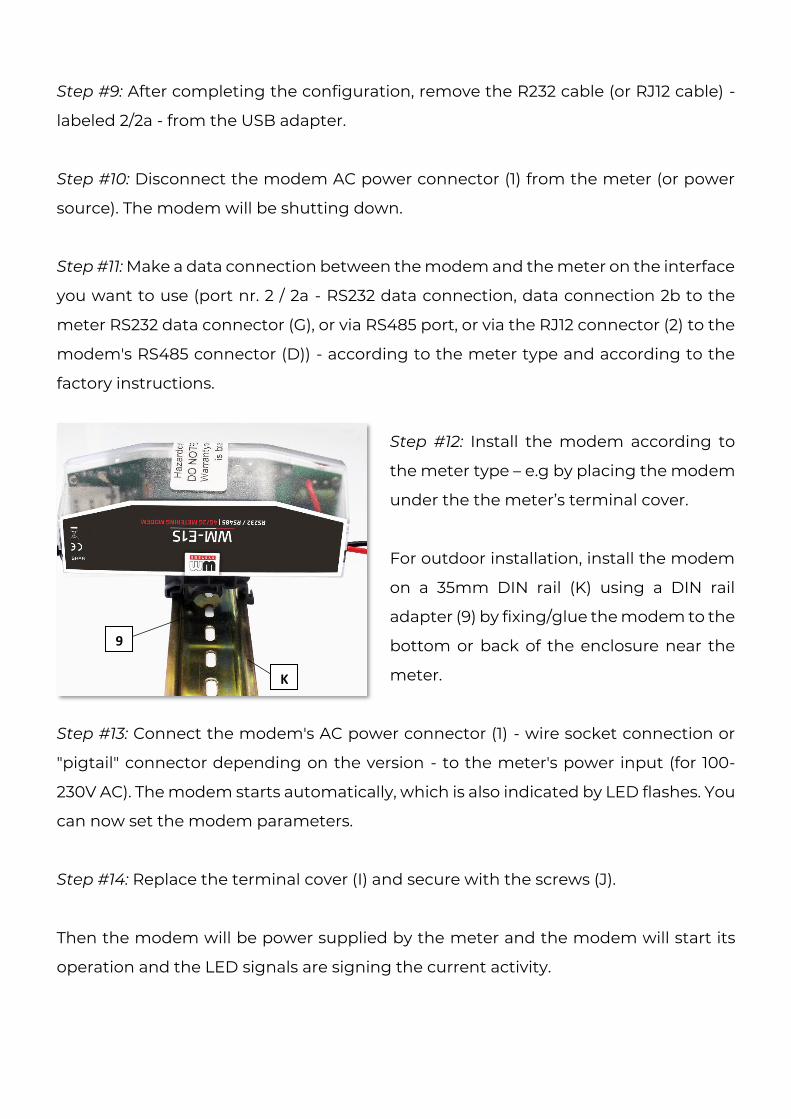
Step #12: Install the modem according to
the meter type – e.g by placing the modem
under the the meter’s terminal cover.
For outdoor installation, install the modem
on a 35mm DIN rail (K) using a DIN rail
adapter (9) by fixing/glue the modem to the
bottom or back of the enclosure near the
meter.
Step #13: Connect the modem's AC power connector (1) - wire socket connection or
"pigtail" connector depending on the version - to the meter's power input (for 100-
230V AC). The modem starts automatically, which is also indicated by LED flashes. You
can now set the modem parameters.
Step #14: Replace the terminal cover (I) and secure with the screws (J).
Then the modem will be power supplied by the meter and the modem will start its
operation and the LED signals are signing the current activity.
9
K
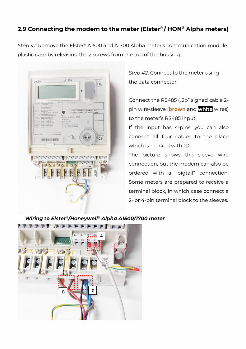
2.9 Connecting the modem to the meter (Elster® / HON® Alpha meters) Step #1: Remove the Elster® A1500 and A1700 Alpha meter’s communication module
plastic case by releasing the 2 screws from the top of the housing.
Step #2: Connect to the meter using
the data connector.
Connect the RS485 („2b” signed cable 2-
pin wire/sleeve (brown and white wires)
to the meter’s RS485 input.
If the input has 4-pins, you can also
connect all four cables to the place
which is marked with “D”.
The picture shows the sleeve wire
connection, but the modem can also be
ordered with a “pigtail” connection.
Some meters are prepared to receive a
terminal block, in which case connect a
2- or 4-pin terminal block to the sleeves.
Wiring to Elster®/Honeywell® Alpha A1500/1700 meter
A
B C
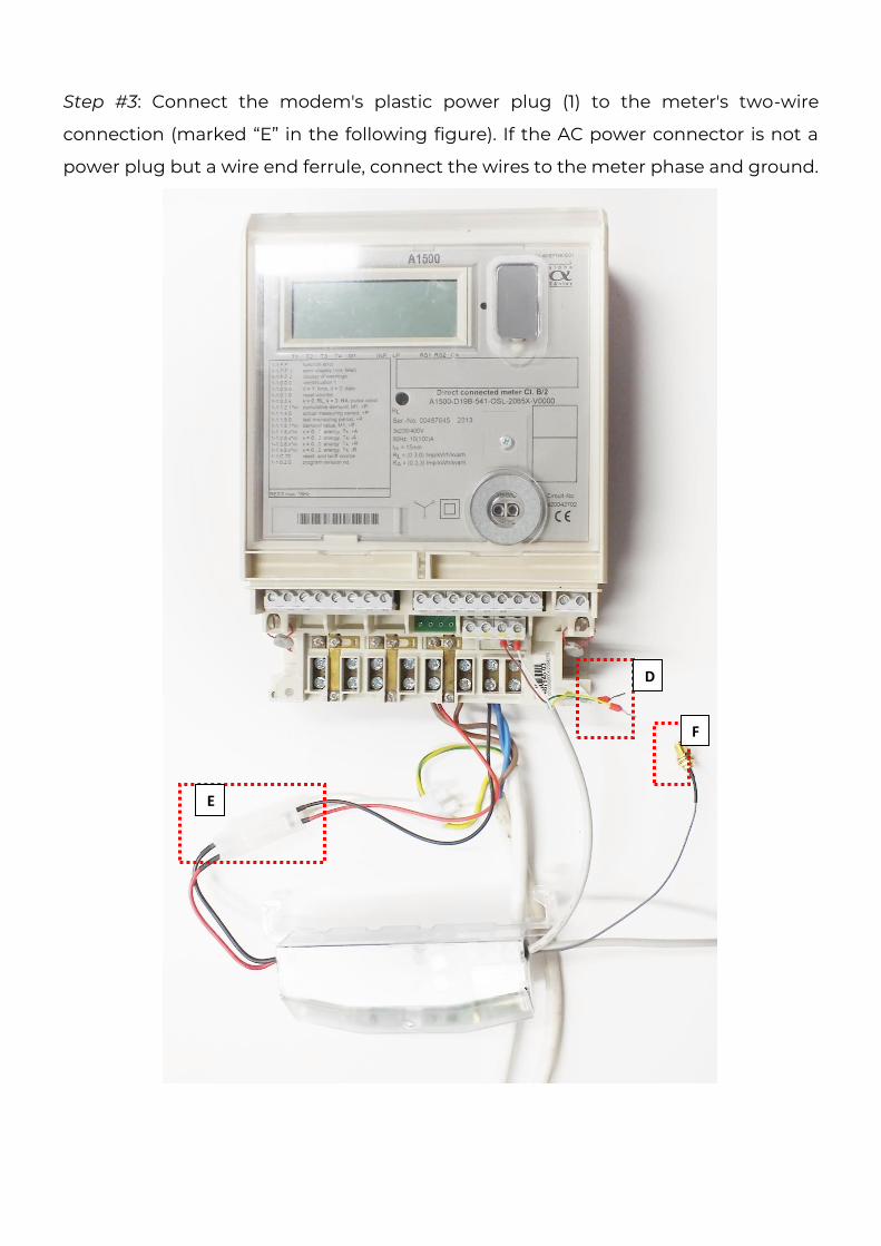
Step #3: Connect the modem's plastic power plug (1) to the meter's two-wire
connection (marked “E” in the following figure). If the AC power connector is not a
power plug but a wire end ferrule, connect the wires to the meter phase and ground.
E
D
F
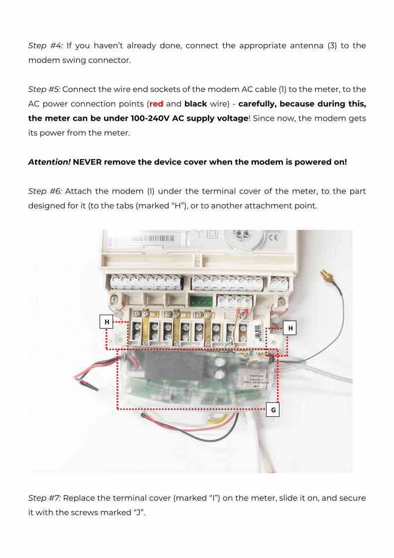
Step #4: If you haven’t already done, connect the appropriate antenna (3) to the
modem swing connector.
Step #5: Connect the wire end sockets of the modem AC cable (1) to the meter, to the
AC power connection points (red and black wire) - carefully, because during this,
the meter can be under 100-240V AC supply voltage! Since now, the modem gets
its power from the meter.
Attention! NEVER remove the device cover when the modem is powered on!
Step #6: Attach the modem (I) under the terminal cover of the meter, to the part
designed for it (to the tabs (marked “H”), or to another attachment point.
Step #7: Replace the terminal cover (marked “I”) on the meter, slide it on, and secure
it with the screws marked “J”.
H H
G
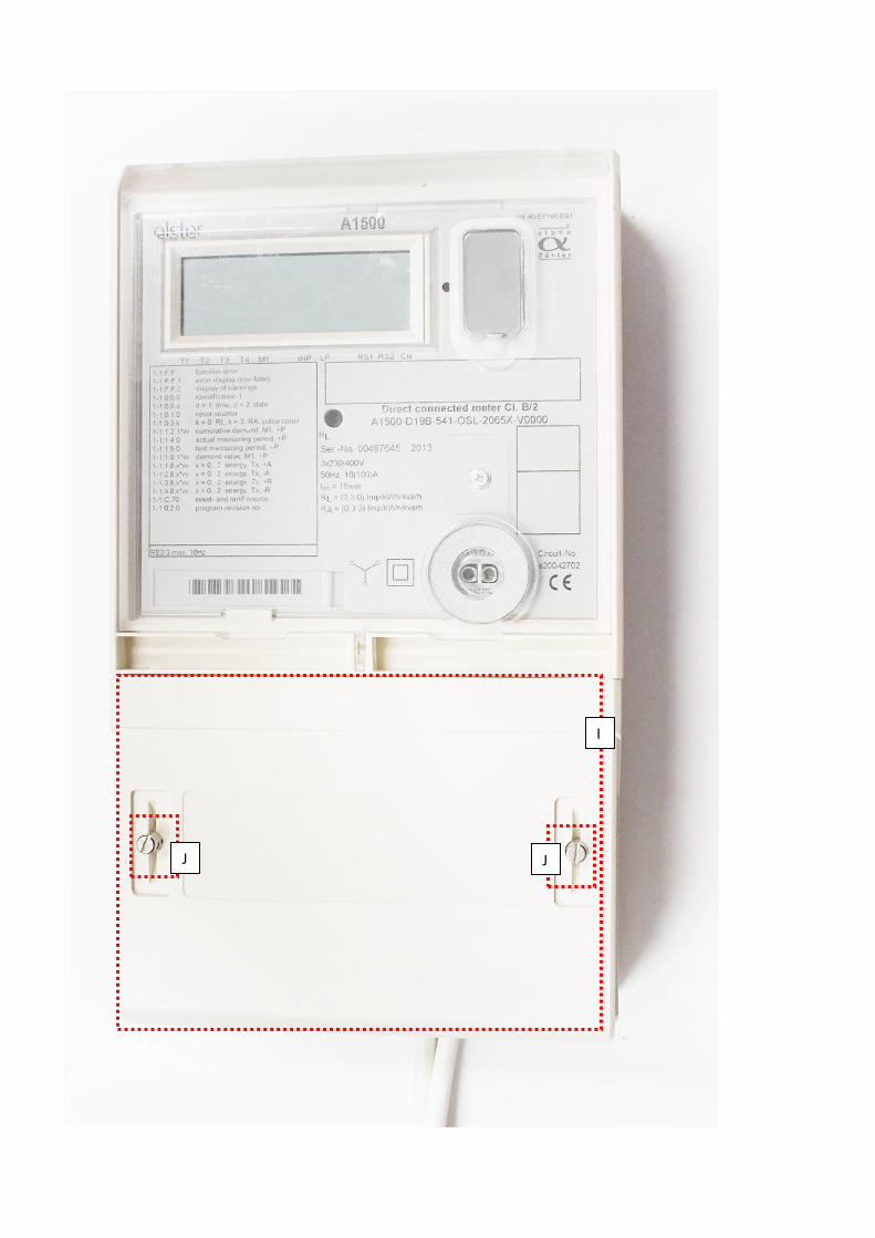
J J
I
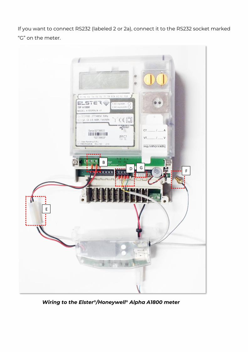
If you want to connect RS232 (labeled 2 or 2a), connect it to the RS232 socket marked
“G” on the meter.
Wiring to the Elster®/Honeywell® Alpha A1800 meter
B
D
E
F G
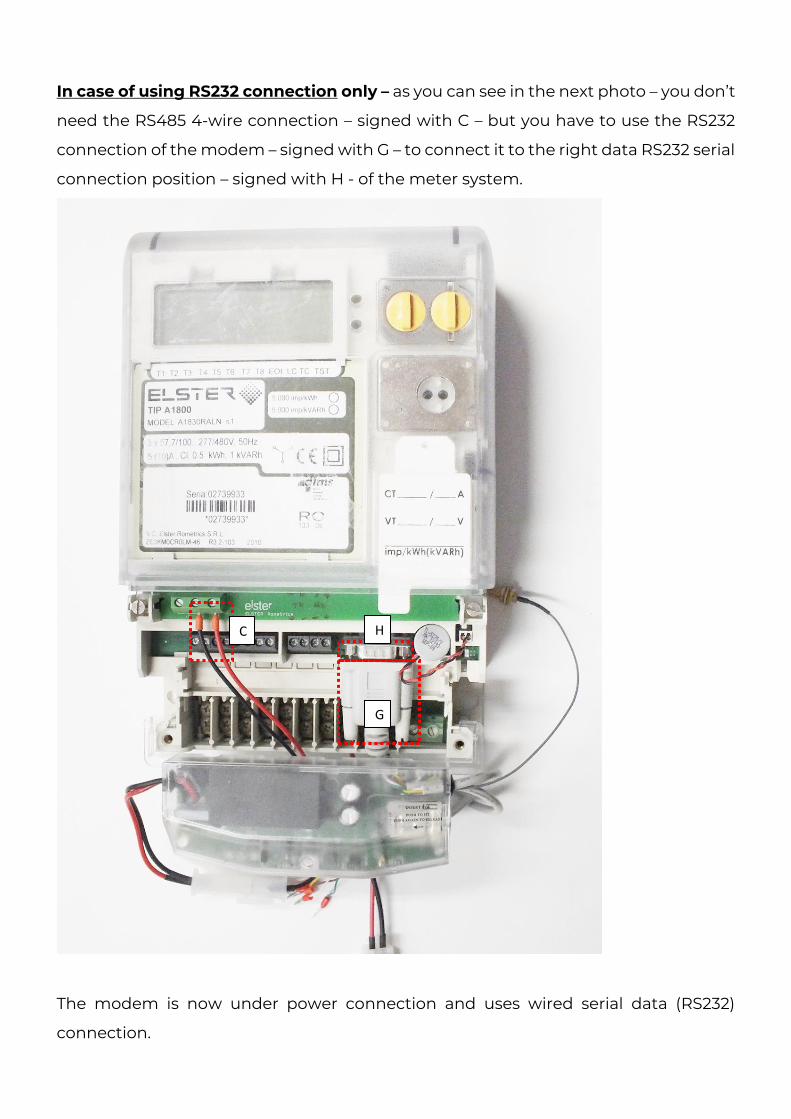
In case of using RS232 connection only – as you can see in the next photo – you don’t
need the RS485 4-wire connection – signed with C – but you have to use the RS232
connection of the modem – signed with G – to connect it to the right data RS232 serial
connection position – signed with H - of the meter system.
The modem is now under power connection and uses wired serial data (RS232)
connection.
G
H C
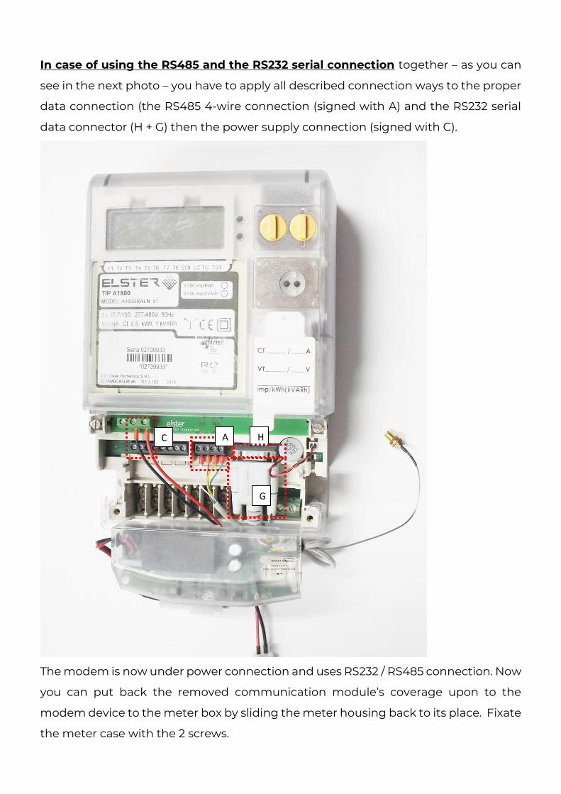
In case of using the RS485 and the RS232 serial connection together – as you can
see in the next photo – you have to apply all described connection ways to the proper
data connection (the RS485 4-wire connection (signed with A) and the RS232 serial
data connector (H + G) then the power supply connection (signed with C).
The modem is now under power connection and uses RS232 / RS485 connection. Now
you can put back the removed communication module’s coverage upon to the
modem device to the meter box by sliding the meter housing back to its place. Fixate
the meter case with the 2 screws.
H C
G
A
2.10 Antenna connection
The modem requires enough signal strength of the cellular network and LTE or similar
antenna for the proper operation and good communication.
Where the signal strength of the cellular network is sufficienty, there an internal
antenna may be enough to use.
However, in places where the signal strength is low or poor, you should use an external
antenna (50 Ohm, SMA connector), which can be mounted to the modem – you can
place it even inside of the top cover of the meter.
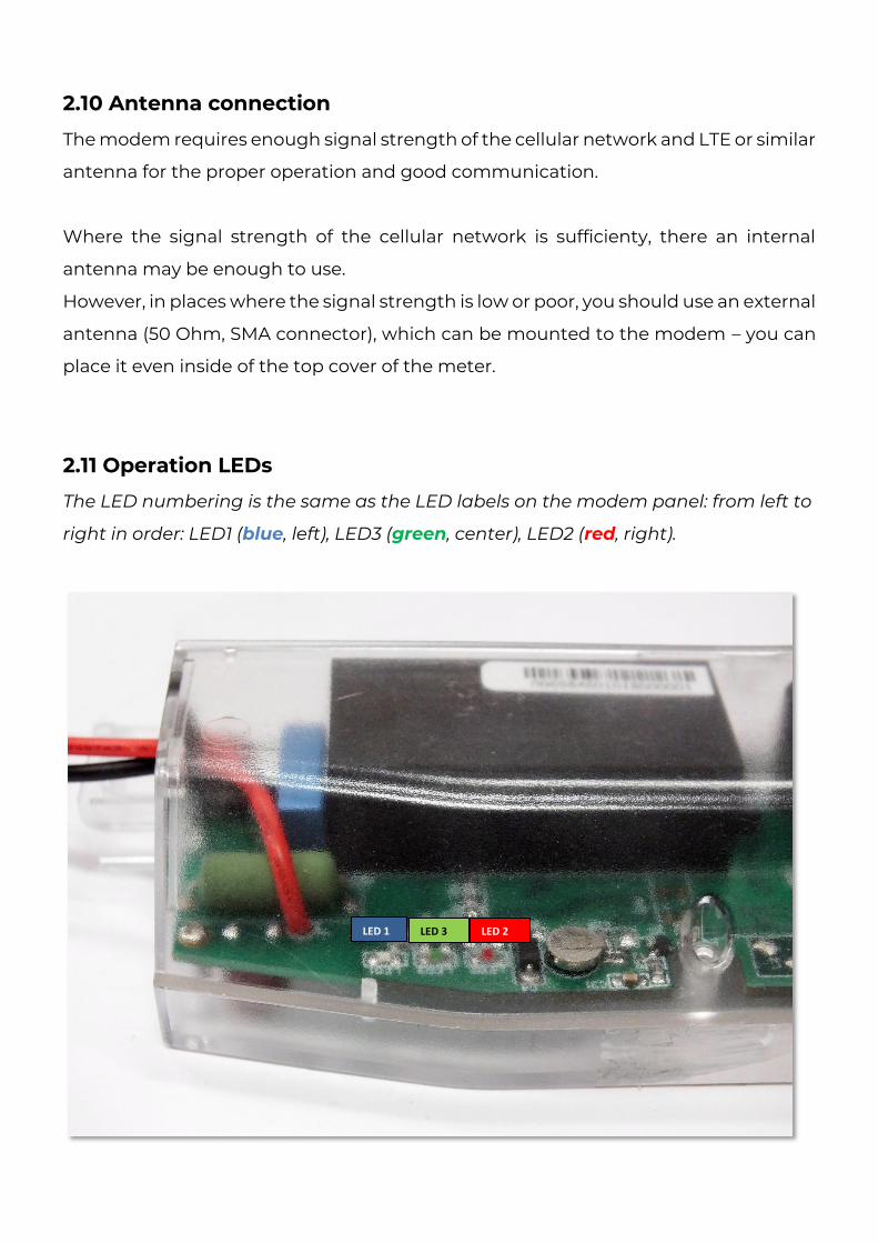
2.11 Operation LEDs
The LED numbering is the same as the LED labels on the modem panel: from left to
right in order: LED1 (blue, left), LED3 (green, center), LED2 (red, right).
LED 3 LED 1 LED 2
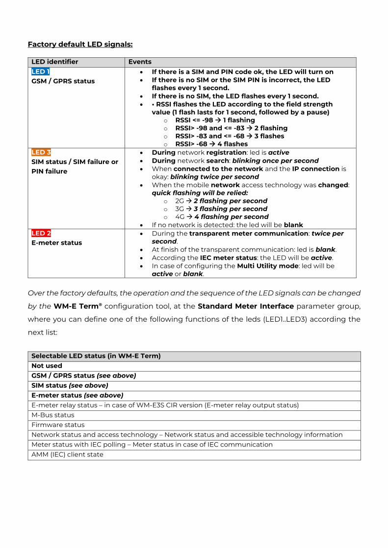
Factory default LED signals:
LED identifier Events LED 1 GSM / GPRS status
• If there is a SIM and PIN code ok, the LED will turn on • If there is no SIM or the SIM PIN is incorrect, the LED
flashes every 1 second. • If there is no SIM, the LED flashes every 1 second. • • RSSI flashes the LED according to the field strength
value (1 flash lasts for 1 second, followed by a pause) o RSSI <= -98 → 1 flashing o RSSI> -98 and <= -83 → 2 flashing o RSSI> -83 and <= -68 → 3 flashes o RSSI> -68 → 4 flashes
LED 3 SIM status / SIM failure or PIN failure
• During network registration: led is active • During network search: blinking once per second • When connected to the network and the IP connection is
okay: blinking twice per second • When the mobile network access technology was changed:
quick flashing will be relied: o 2G → 2 flashing per second o 3G → 3 flashing per second o 4G → 4 flashing per second
• If no network is detected: the led will be blank LED 2 E-meter status
• During the transparent meter communication: twice per second.
• At finish of the transparent communication: led is blank. • According the IEC meter status: the LED will be active. • In case of configuring the Multi Utility mode: led will be
active or blank. Over the factory defaults, the operation and the sequence of the LED signals can be changed
by the WM-E Term® configuration tool, at the Standard Meter Interface parameter group,
where you can define one of the following functions of the leds (LED1..LED3) according the
next list:
Selectable LED status (in WM-E Term) Not used GSM / GPRS status (see above) SIM status (see above) E-meter status (see above) E-meter relay status – in case of WM-E3S CIR version (E-meter relay output status) M-Bus status Firmware status Network status and access technology – Network status and accessible technology information Meter status with IEC polling – Meter status in case of IEC communication
AMM (IEC) client state
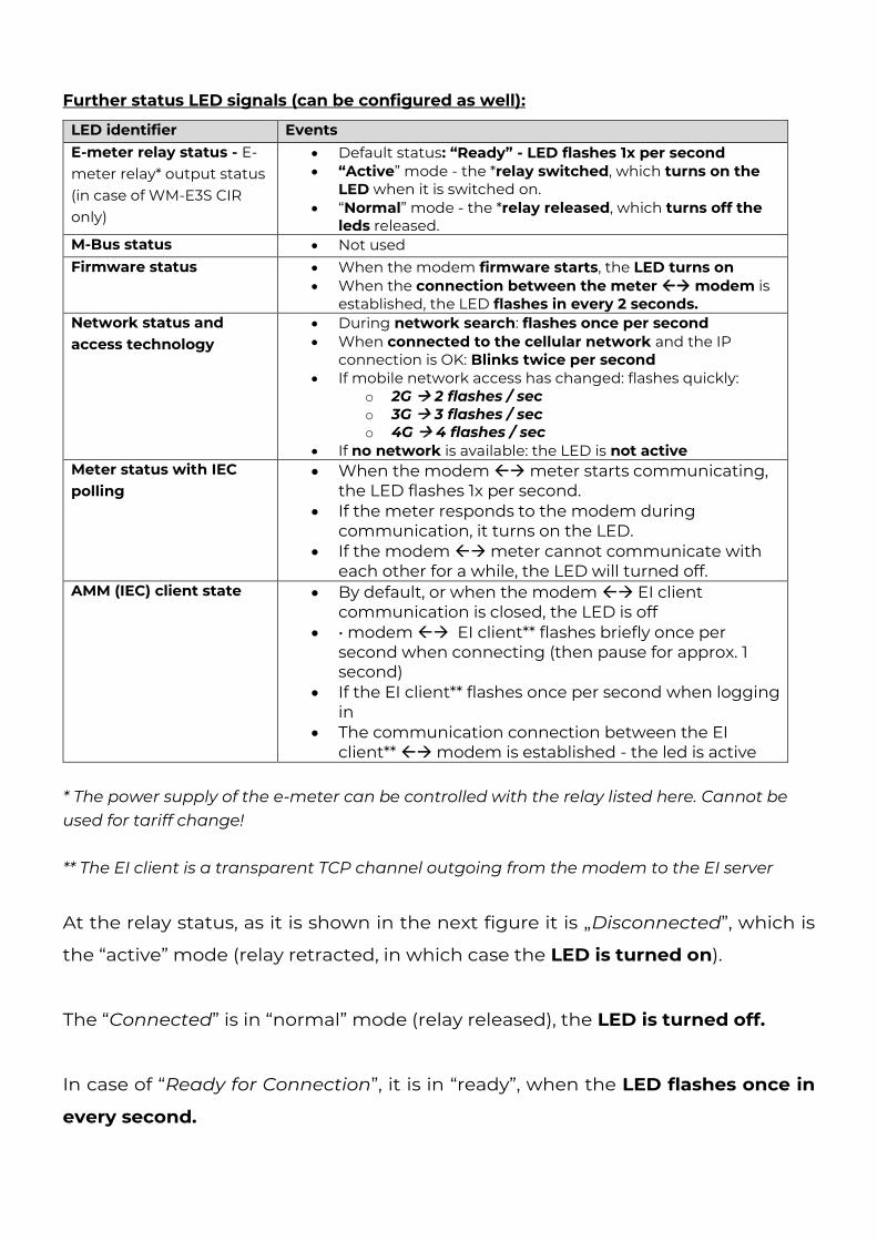
Further status LED signals (can be configured as well):
LED identifier Events E-meter relay status - E-meter relay* output status (in case of WM-E3S CIR only)
• Default status: “Ready” - LED flashes 1x per second • “Active” mode - the *relay switched, which turns on the
LED when it is switched on. • “Normal” mode - the *relay released, which turns off the
leds released. M-Bus status • Not used Firmware status
• When the modem firmware starts, the LED turns on • When the connection between the meter → modem is
established, the LED flashes in every 2 seconds. Network status and access technology
• During network search: flashes once per second • When connected to the cellular network and the IP
connection is OK: Blinks twice per second • If mobile network access has changed: flashes quickly:
o 2G → 2 flashes / sec o 3G → 3 flashes / sec o 4G → 4 flashes / sec
• If no network is available: the LED is not active Meter status with IEC polling
• When the modem → meter starts communicating, the LED flashes 1x per second.
• If the meter responds to the modem during communication, it turns on the LED.
• If the modem → meter cannot communicate with each other for a while, the LED will turned off.
AMM (IEC) client state • By default, or when the modem → EI client communication is closed, the LED is off
• • modem → EI client** flashes briefly once per second when connecting (then pause for approx. 1 second)
• If the EI client** flashes once per second when logging in
• The communication connection between the EI client** → modem is established - the led is active
* The power supply of the e-meter can be controlled with the relay listed here. Cannot be used for tariff change! ** The EI client is a transparent TCP channel outgoing from the modem to the EI server
At the relay status, as it is shown in the next figure it is „Disconnected”, which is
the “active” mode (relay retracted, in which case the LED is turned on).
The “Connected” is in “normal” mode (relay released), the LED is turned off.
In case of “Ready for Connection”, it is in “ready”, when the LED flashes once in
every second.
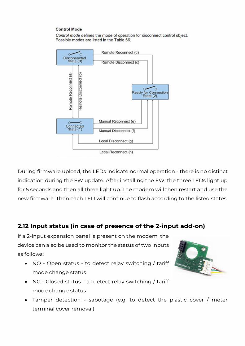
During firmware upload, the LEDs indicate normal operation - there is no distinct
indication during the FW update. After installing the FW, the three LEDs light up
for 5 seconds and then all three light up. The modem will then restart and use the
new firmware. Then each LED will continue to flash according to the listed states.
2.12 Input status (in case of presence of the 2-input add-on)
If a 2-input expansion panel is present on the modem, the
device can also be used to monitor the status of two inputs
as follows:
• NO - Open status - to detect relay switching / tariff
mode change status
• NC - Closed status - to detect relay switching / tariff
mode change status
• Tamper detection - sabotage (e.g. to detect the plastic cover / meter
terminal cover removal)
There is opportunity to monitoring – as a safety option – sabotage events or detect the
relay/tariff change or relay switching changes. Therefore the device is able to detect
the input signal changes and generating and transmitting SMS alert notification –
according the settings.
The SMS message setting and input delay interval can be configured by the WM-E
Term® application – in the AMM (IEC) parameter group part.
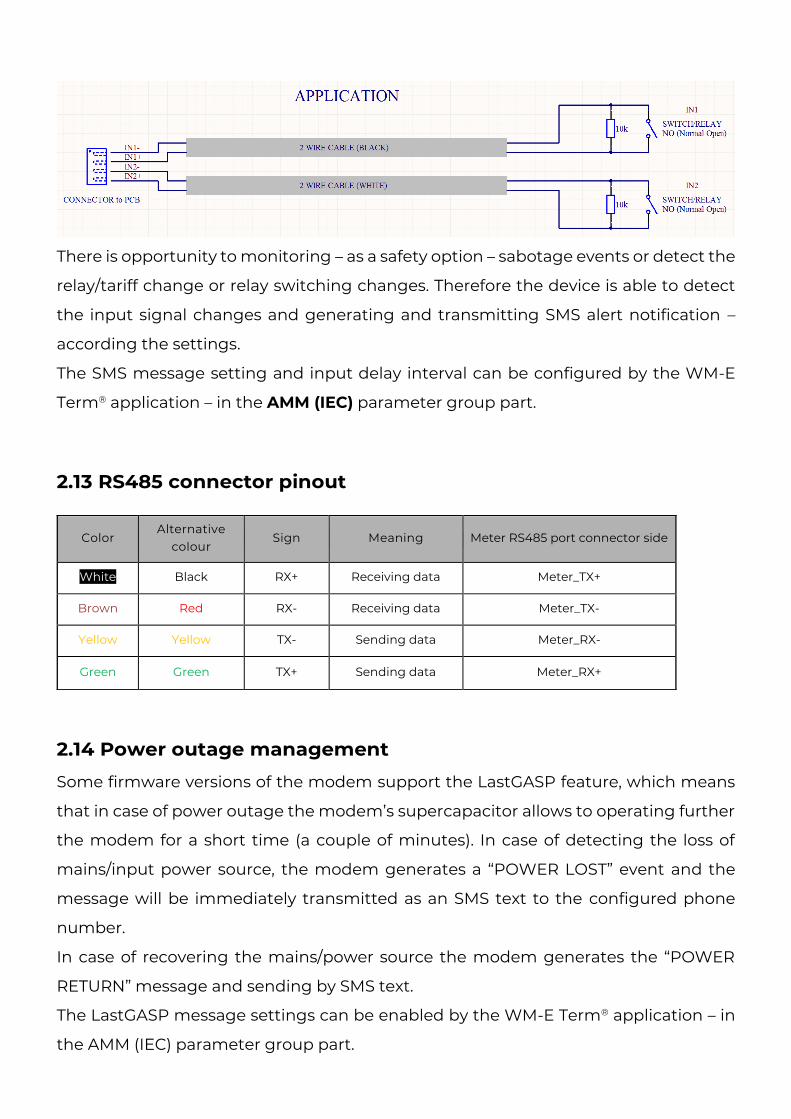
2.13 RS485 connector pinout
2.14 Power outage management
Some firmware versions of the modem support the LastGASP feature, which means
that in case of power outage the modem’s supercapacitor allows to operating further
the modem for a short time (a couple of minutes). In case of detecting the loss of
mains/input power source, the modem generates a “POWER LOST” event and the
message will be immediately transmitted as an SMS text to the configured phone
number.
In case of recovering the mains/power source the modem generates the “POWER
RETURN” message and sending by SMS text.
The LastGASP message settings can be enabled by the WM-E Term® application – in
the AMM (IEC) parameter group part.
Color Alternative
colour Sign Meaning Meter RS485 port connector side
White Black RX+ Receiving data Meter_TX+
Brown Red RX- Receiving data Meter_TX-
Yellow Yellow TX- Sending data Meter_RX-
Green Green TX+ Sending data Meter_RX+
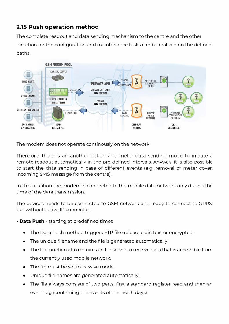
2.15 Push operation method
The complete readout and data sending mechanism to the centre and the other
direction for the configuration and maintenance tasks can be realized on the defined
paths.
The modem does not operate continously on the network.
Therefore, there is an another option and meter data sending mode to initiate a remote readout automatically in the pre-defined intervals. Anyway, it is also possible to start the data sending in case of different events (e.g. removal of meter cover, incoming SMS message from the centre).
In this situation the modem is connected to the mobile data network only during the time of the data transmission.
The devices needs to be connected to GSM network and ready to connect to GPRS, but without active IP connection.
- Data Push - starting at predefined times
• The Data Push method triggers FTP file upload, plain text or encrypted.
• The unique filename and the file is generated automatically.
• The ftp function also requires an ftp server to receive data that is accessible from
the currently used mobile network.
• The ftp must be set to passive mode.
• Unique file names are generated automatically.
• The file always consists of two parts, first a standard register read and then an
event log (containing the events of the last 31 days).
• The readings shown as standard IEC format, including some ASCII control
characters
like STX ETX, etc. also.
- Alarm Push (sending alarms) - starting when new event can be read from meter
• Alarm Push method triggers TCP sending of a DLMS WPDU contains the IP
address,
• listening port number for transparent service, and the meter ID.
- Triggering with SMS
• GPRS connection can be activated remotely with a defined SMS from any call
number.
• The SMS text must be left empty.
• After the SMS received, the modem will connect to IP network, and will be
accessible as a IP server for a time period defined in the config file.
• Example config file will be provided with a 30 minute setting.
2.16 LED operation during the CSD call
The CSD call consists of two parts:
a.) We want to read / configure a meter in transparent mode
b.) We want to perform a modem configuration / firmware update
To read / configure a meter in transparent mode:
- The LED configured for GSM / GPRS status will be lit continuously during the CSD call.
- The LED that is configured for e-meter status will flash according to the CSD call status:
• It will flash every half second from the beginning of the connection to the end of the
connection / If the measuring interface is not configured for a baud rate of 9600, the
LED will be lit continuously from the beginning to the end of the connection
• After closing the connection, the LED will turn off
If you want a modem configuration / firmware update:
- The LED configured for GSM / GPRS status will be lit continuously during the CSD call.
- In this case, the other LEDs do not change due to the CSD mode.
2.17 Configuring from CSD connection
If the modem restarts due to an incorrect configuration, it is possible to access it
with a CSD call. Its operation can be fine-tuned in the WM-E Term software with a
value that can be specified in the PDP connection delay field in the APN parameter
group.
For more information, see Chapter 3.1 of the WM-E Term User Manual.
2.18 Data control direction (DCD) feature
In case of using the WM-E1S® modem with Itrón® SL7000 or other meters or the WM-
E1SL® meter through RS232 connection, there you can use the DCD feature - due to
the RS232 data connection – there you can declare the direction of the data control
according the following parameter settings as options.
For configuring the DCD feature, choose the RS485 interface settings parameter
group.
Note that it is valid for the RS232 port!
DCD Parameter values:
• Fix 0 (provides logical 0 value as result for the connected meter)
• Fix 1 (provides logical 1 value as result for the connected meter)
• Standard
• Inverted (opposite direction)
Important! This feature needs of using the 2.49B or later firmware version for the
modem.
2.19 Automatic network reconnection
If the mobile network provider drops the modem from the cellular network due to the
device’s network inactivity, there are available parameters if these are set, then
automatic and periodical connection connection rebuild can be caused. If the network
provider sends a message to the modem that the data connection has been lost, the
connection will be restored automatically. If you do not send a message, you can
choose from these two workarounds to follow:
a.) Active mode - Use periodical ping, set the ping:
1. For setting this, set the Watchdog parameter group’s ping parameters as
Ping IP-address, Number of ping retries, Ping wait-time (for reply) and
Wait-time (for next).
2. If there is no ping response, it reconnects to the network after the time
interval specified in the Seconds, gprs connection closed and restored after
this time parameter.
Attention! In case of frequent ping using, the data traffic will be higher, but the
chances are higher that the device will remain on the cellular network.
b.) Passive mode - If you don’t use the ping - set the connection retry:
1. For setting this, use the Watchdog parameter group’s Seconds, gprs
connection closed and restored after this time parameter.
2. Here you can define that after the network drops out the modem, how long
does the modem wait before trying to reconnect to the mobile network
again. Ask your mobile provider about the offered settings.
Attention! If there is less data traffic and there is no ping configured, the
device may not stay on the network for a long time.

If you set this parameter to a low value that can cause frequent network
reconnections.
Therefore under no circumstances should you set this value lower than what
your mobile service provider recommends. (e.g. there are mobile network
providers that limit the number of times a modem can log on to the network
in a given time).
Chapter 3. Modem Configuration
3.1 Configuration
The modem must be configured by the WM-E Term® software by configuring its
parameters which must be performed before the normal operation and usage.
Over the parameter settings of meter, modem and communication, etc., you can also
test the modem communication by the configuration program.
Important! The modem can be configured throu RS232 connection only!
During the configuration, you have to remove the meter-modem data connection
(2/2a) and you have to connect the modem to your computer by the following hints.
Important!
Note that until the configuration the modem is not connected to the meter, therefore
it cannot readout the parameter values through the RJ12 interface.
The modem can be connected with the RS232 cable (2a) - or in case of version C by
the RJ12 cable (2) and by using the RJ12-USB converter by directly to your computer.
Important! During the configuration, the power supply of the modem must be
assured by its AC plug from an externa power source (from 100-230V AC or by the
meter 57-100V AC).
Use the WM-E Term program for the configuration – use the WM-E Term User
manual.
For the proper communication of the modem, you have to configure the APN
settings of the SIM – as PIN code, APN, username and password. These all can
configured by using the WM-E Term® software through the serial link connection.
For the successful operation of the communication module it is necessary to have
appropriate signal strength.
In places where the signal strength is strong it is possible to use internal antenna, for
areas with poor reception mount an external antenna (50 Ohm SMA connection) to
the antenna connector (3) of the device, which you can place inside even inside the
meter enclosure (under the plastic housing).
If you want to readout the meter parameter values during the PC-modem connection,
after the RJ12-configuration you made, then you should select a different
configuration port to the meter as TCP/IP or Optical, etc.
3.2 Configuring the modem by WM-E Term®
The Microsoft .NET framework runtime environment is required on your computer.
Download WM-E Term® to your computer from the following location using a
browser:
https://www.m2mserver.com/m2m-downloads/WM-ETerm_V1_3_58.zip
Then unzip the .zip file to a directory and execute the WM-ETerm.exe file.
The configuration software supports user account management and password
change. You can log in to the program with a password! Follow the WM-E Term®
configuration software’s User's Guide!
The firmware v2.4.27 can be downloaded from here:
https://www.m2mserver.com/m2m-downloads/SMP_WME1S_V2_4_27.dwl
The firmware for Input expansion board version v2.4.25.8B can be downloaded here:
https://www.m2mserver.com/m2m-downloads/SMP_WME1S_V2_4_25_8B.dwl
After the firmware update, the modem will restart and work according to the new
settings.
The LEDs on the device always inform you about the current status of the modem.
Factory configuration file sample (for WM-E Term):
https://www.m2mserver.com/m2m-downloads/WM-E1S_STD_default.zip
For the operation of the modem cellular network communication and SIM card
settings (such as APN, password, and account) are required.
In addition, be sure to review and save the transparent mode data speed functions in
the WM-E Term program for the RS232, RS485 settings. In addition, you must send
the configured configuration to the modem using the program - according to the
configuration software’s User Manual document.
WM-E Term User Manual:
https://www.m2mserver.com/m2m-downloads/WM-E-TERM_User_Manual_V1_92.pdf
3.3 Sending an SMS about the meter
Depending on the meter configuration, by using the modem, the meter can send SMS
message corresponding to standard AT commands to the phone number which was
configured at the meter side.
It is worth configuring this primarily for alarms and special events, according to the
capabilities of the meter.
No other settings are required in WM-E Term®.
Chapter 4. Support If you have a technical question regarding the usage You can find us on the following contact possibilities: Email: [email protected] Phone: +36 20 333-1111 4.1 Support The product has a identification void which has important product related information for the support line. Warning! Damaging or removing the void sticker means the loss of product guarantee. Online product support available here: https://www.m2mserver.com/en/support/
4.2 Product Support The documents and information related on the product are available here. https://www.m2mserver.com/en/product/wm-e1s/
Chapter 5. Legal notice ©2022. WM Systems LLC.
The text of and illustrations presented in this document are under copyright.
Copying, usage, replication or publication of the original document or its’ parts are
possible with the agreement and permission of the WM Systems LLC. only.
The figures in this document are illustrations, those can be different from the real
appearance.
The WM Systems LLC doesn’t take any responsibility for text inaccuracy in this
document.
The presented information can be changed without any notice.
The printed information in this document are informative only. For further details
contact us.
Warning
Any fault or upcoming error during the software upload/refresh can lead to the
device breakdown. When this situation happens call our specialists.