cycle infrastructure design - gov.uk
TRANSCRIPT
Cycle Infrastructure Design
Local Transport Note 1/20July 2020
Local Transport Note 1/20July 2020
Cycle Infrastructure Design
This Local Transport Note was commissioned by the Department for Transport. It was led by WSP and Phil Jones Associates in collaboration with a DfT-led expert steering group.
Published by TSO (The Stationery Office), part of Williams Lea, and available from:
Online www.tsoshop.co.uk
Mail, Telephone, Fax & E-mail TSO PO Box 29, Norwich, NR3 1GN Telephone orders/General enquiries: 0333 202 5070 Fax orders: 0333 202 5080 E-mail: [email protected] Textphone 0333 202 5077
TSO@Blackwell and other Accredited Agents
Published with the permission of the Department for Transport on behalf of the Controller of Her Majesty’s Stationery Office.
© Crown copyright 2020
All rights reserved
Copyright in the typographical arrangement rests with the Crown.
You may re-use this document/publication (not including logos) free of charge in any format or medium, under the terms of the Open Government Licence v3.0. To view this licence, visit http://www.nationalarchives.gov.uk/doc/open-government-licence/version/3 or write to the Information Policy Team, The National Archives, Kew, Richmond, Surrey TW9 4DU; or email: [email protected].
First published 2020
ISBN 978 0 11 553713 4
Printed in the United Kingdom for TSO (The Stationery Office) J003658610 c2.5 07/20
Contents
Foreword ....................................................................................... 3
1 Introduction ....................................................................... 5
2 Cycling in context ........................................................... 15
3 Planning for cycling ........................................................ 21
4 Design principles and processes ................................. 29
5 Geometric requirements ................................................ 39
6 Space for cycling within highways ............................... 49
7 Quiet mixed traffic streets and lanes ........................... 73
8 Motor traffic free routes ................................................ 83
9 Transitions between carriageways, cycle lanes and cycle tracks .............................................................. 89
10 Junctions and crossings ................................................ 95
11 Cycle parking and other equipment ........................... 131
12 Planning and designing for commercial cycling ........141
13 Traffic signs, road markings and wayfinding ............ 145
1
Cycle Infrastructure Design
14 Integrating cycling with highway improvements and new developments ................................................ 153
15 Construction and maintenance .................................. 163
Appendices ............................................................................... 171
Appendix A: Cycling Level of Service Tool ............................ 172
Appendix B: Junction Assessment Tool ................................ 178
Appendix C: Legal issues ........................................................ 185
Appendix D: Image list and credits ........................................ 193
2
Cycle Infrastructure Design
Foreword
As the Prime Minister said when he launched the Government’s ambitious plan for cycling in July 2020, cycling will play a far bigger part in our transport system from now on. We need to see significant increases in cycling in our cities and towns, and everywhere else too.
To achieve that, the quality of cycling infrastructure must sharply improve. Properly-protected bike lanes, cycle-safe junctions and interventions for low-traffic streets encourage people to cycle.
Too much cycling infrastructure is substandard, providing little protection from motorised traffic and giving up at the very places it is most needed. Some is actually worse than nothing, because it entices novice cyclists with the promise of protection, then abandons them at the most important places. Poor cycling infrastructure discourages cycling and wastes public money.
In some places, even without much special provision, cycling is already mass transit. Last year in Greater Manchester, for example, as many journeys were made by bike as on the conurbation’s entire Metrolink tram system. In central London, bikes made up almost a third of rush-hour traffic. And that was before the COVID19 pandemic, which resulted in large increases as people rediscovered cycling and walking during lockdown.
This updated national guidance for highway authorities and designers aims to help cycling become a form of mass transit in many more places. Cycling must no longer be treated as marginal, or an afterthought. It must not be seen as mainly part of the leisure industry, but as a means of everyday transport. It must be placed at the heart of the transport network, with the capital spending, road space and traffic planners’ attention befitting that role.
The guidance delivers on our commitment to boost design standards and improve safety. It sets out the much higher standards now expected, and describes some of the failings common in the past, which will be strongly discouraged in future.
The Government intends that all proposed schemes will be checked by a new inspectorate against the summary principles before funding is agreed, and that finished schemes will be inspected as appropriate to ensure that they have been delivered in compliance with them.
It will be a condition of any future Government funding for new cycle infrastructure that it is designed in a way that is consistent with this national guidance.
The Department for Transport will also reserve the right to ask for appropriate funding to be returned for any schemes built in a way which is not consistent with the guidance. In short, schemes which do not follow this guidance will not be funded.
This guidance has been developed closely with stakeholders so that it reflects the latest developments in cycle infrastructure design, including proven design elements pioneered by Transport for London and by the Cycle Ambition Cities and in Wales under the Welsh Active Travel Design Guidance. I am grateful to our stakeholders for their valuable input into the review process.
It reflects current best practice, standards and legal requirements. Inclusive cycling is an underlying theme throughout so that people cycling of all ages and abilities are considered. The design options include segregation from traffic, measures for cycling at junctions and roundabouts, and updated guidance on crossings, signal design and the associated traffic signs and road markings.
Furthermore, to receive Government funding for local highways investment where the main element is not cycling or walking, there will be a presumption that schemes must deliver or improve cycling infrastructure to the standards in this Local Transport Note, unless it can be shown that there is little or no need for cycling in the particular highway scheme.
The Department will work with the highways and transportation professions to ensure that the guidance is understood by local authorities and their supply chain so that it is embedded in local highways design standards, which will enable people of all ages and abilities to cycle.
The guidance will be reviewed regularly to ensure it continues to reflect the latest developments in cycle infrastructure design practice.
Chris Heaton-Harris MP Minister of State with responsibility for cycling and walking
3
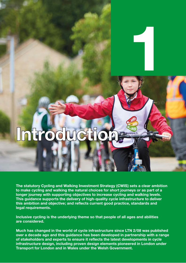
IntroductionIntroduction
The statutory Cycling and Walking Investment Strategy (CWIS) sets a clear ambition to make cycling and walking the natural choices for short journeys or as part of a longer journey with supporting objectives to increase cycling and walking levels. This guidance supports the delivery of high-quality cycle infrastructure to deliver this ambition and objective; and reflects current good practice, standards and legal requirements.
Inclusive cycling is the underlying theme so that people of all ages and abilities are considered.
Much has changed in the world of cycle infrastructure since LTN 2/08 was published over a decade ago and this guidance has been developed in partnership with a range of stakeholders and experts to ensure it reflects the latest developments in cycle infrastructure design, including proven design elements pioneered in London under Transport for London and in Wales under the Welsh Government.
1
1.1 Summary of requirements1.1.1 Local authorities are responsible for setting design standards for their roads. This national guidance provides a recommended basis for those standards based on five overarching design principles and 22 summary principles. There will be an expectation that local authorities will demonstrate that they have given due consideration to this guidance when designing new cycling schemes and, in particular, when applying for Government funding that includes cycle infrastructure.
1.1.2 The guidance contains tools which give local authorities flexibility on infrastructure design and sets a measurable quality threshold to achieve when designing cycling schemes. The Cycling Level of Service (CLoS) at Appendix A and the Junction Assessment tools (JAT) at Appendix B are new mechanisms introduced to set minimum quality criteria. Only schemes with a minimum score of 70% under the CLoS, no critical fails and under the JAT no red-scored turning movements will generally be considered for funding. Where schemes are proposed for funding that do not meet these minimum criteria, authorities will be required to justify their design choices. It still gives local authorities flexibility on design of infrastructure, but sets an objective and measurable quality threshold. Use of these tools is explained in more detail in Chapter 4, Section 4.5.
1.1.3 To effectively apply this guidance those designing cycling and walking schemes should have an appropriate level of of experience and training. An example would be the Institute of Highway Engineers’ Professional Certificate & Diploma in Active Travel that allows applicants to demonstrate their experience and produce work to the required standard. For more information please see: www.theihe.org/courses/active-travel
1.2 Purpose1.2.1 This Local Transport Note provides guidance and good practice for the design of cycle infrastructure, in support of the Cycling and Walking Investment Strategy. The scope of the document is limited to design matters. Further reading on related matters, helpful tools and advice on procedural issues are included in the Appendices. Local Transport Note (LTN) 1/20 replaces previous guidance on cycle infrastructure design provided by LTN 2/08, and accordingly LTN 2/08 is withdrawn.
1.2.2 LTN 1/20 also replaces LTN 1/12: Shared Use Routes for Pedestrians and Cyclists, and accordingly, LTN 1/12 is now withdrawn. See also Chapter 6, Section 6.5.
1.3 Application1.3.1 The guidance covers England and Northern Ireland. A number of other documents can also be used in Northern Ireland and designers should take advice from the roads authority before initiating any design. Where the text refers to highway authorities for England, the equivalent term in Northern Ireland is road authority. In Northern Ireland the Department for Infrastructure is the sole road authority. The guidance should be applied to all changes associated with highway improvements, new highway construction and new or improved cycle facilities, including those on other rights of way such as bridleways and routes within public open space. Separate guidance is available for Scotland and Wales. In Scotland, the relevant guidance is Cycling by Design published by Transport Scotland and in Wales, the relevant guidance is the Active Travel Design Guidance, published by the Welsh Government.
1.3.2 The CWIS recommends that local authorities prepare Local Cycling and Walking Infrastructure Plans (LCWIPs). This guidance (see Chapter 3) should be applied when identifying the infrastructure required to create good quality cycle networks when preparing the LCWIP or other local network plan for cycling.
6
Cycle Infrastructure Design
1.4 Definitions1.4.1 The built environment should be accessible to all, including young people, older people, and disabled people. The concept of ‘inclusive design’ underpins the document, although it is acknowledged that what individual people consider to be acceptable will vary. Design should begin with the principle that all potential cyclists and their machines should be catered for in all cycle infrastructure design.
1.4.2 For the purpose of this document, the term cycle refers to the full range of vehicles shown in Figure 5.2 in Chapter 5 and described in the accompanying text, including hand-cranked cycles and cycles that conform to the Electrically Assisted Pedal Cycle Regulations 1983 (as amended). It does not include mopeds, stand-on scooters or other powered two-wheeled vehicles. The terms cyclist and cycling refer to anybody using a human powered vehicle as described above.
1.4.3 The terms pedestrian and walking include people using mobility aids such as wheelchairs and mobility scooters designed for use on the footway, and people with physical, sensory or cognitive impairments who are travelling on foot.
1.4.4 The term cycle lane has the meaning given in Schedule 1 of the Traffic Signs Regulations and General Directions 2016 (as amended).
1.4.5 For ease of reading the term cycle track is used in its widest sense (rather than the legal definition) to describe routes for cycling within the highway boundary that are physically separated from motor vehicles and pedestrians, such as by a kerb, verge, level difference or material delineation. Paths away from the highway that have been designated for cycling are variously described as cycle tracks, cycle paths, greenways and towpaths. Off-carriageway cycling provision may either be physically segregated from pedestrian facilities or a common surface may be shared.
1.4.6 Cyclists and pedestrians are considered to be ‘traffic’, within the meaning of the Road Traffic Regulation Act 1984 and the Traffic Management Act 2004, and therefore duties to manage the road network to secure ‘expeditious and safe movement for all traffic’ apply to them as well as motorised modes.
1.5 Core design principles1.5.1 There are five core design principles which represent the essential requirements to achieve more people travelling by cycle or on foot, based on best practice both internationally and across the UK.
1.5.2 Networks and routes should be Coherent; Direct; Safe; Comfortable and Attractive.
1.5.3 Inclusive design and accessibility should run through all five of these core design principles. Designers should always aim to provide infrastructure that meets these principles and therefore caters for the broadest range of people.
1.5.4 Infrastructure must be accessible to all and the needs of vulnerable pedestrians and local people must be considered early in the process to ensure schemes are supported locally in the long term. The Equality Act 2010 requires public sector authorities to comply with the Public Sector Equality Duty in carrying out their functions. This includes making reasonable adjustments to the existing built environment to ensure the design of infrastructure is accessible to all.
7
Cycle Infrastructure Design
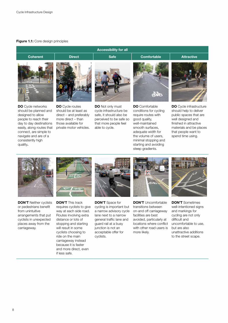
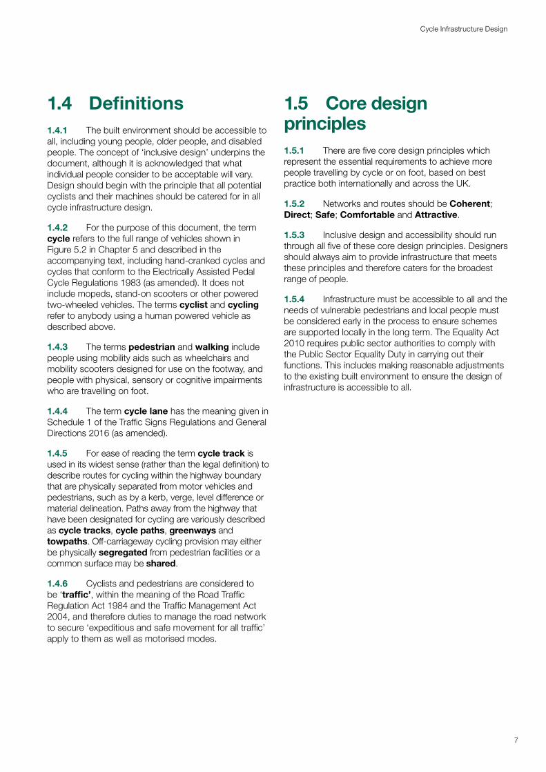
Figure 1.1: Core design principles
Accessibility for all
Coherent Direct Safe Comfortable Attractive
DO Cycle networks should be planned and designed to allow people to reach their day to day destinations easily, along routes that connect, are simple to navigate and are of a consistently high quality.
DO Cycle routes should be at least as direct – and preferably more direct – than those available for private motor vehicles.
DO Not only must cycle infrastructure be safe, it should also be perceived to be safe so that more people feel able to cycle.
DO Comfortable conditions for cycling require routes with good quality, well maintained -smooth surfaces, adequate width for the volume of users, minimal stopping and starting and avoiding steep gradients.
DO Cycle infrastructure should help to deliver public spaces that are well designed and finished in attractive materials and be places that people want to spend time using.
DON’T Neither cyclists or pedestrians benefit from unintuitive arrangements that put cyclists in unexpected places away from the carriageway.
DON’T This track requires cyclists to give way at each side road. Routes involving extra distance or lots of stopping and starting will result in some cyclists choosing to ride on the main carriageway instead because it is faster and more direct, even if less safe.
DON’T Space for cycling is important but a narrow advisory cycle lane next to a narrow general traffic lane and guard rail at a busy junction is not an acceptable offer for cyclists.
DON’T Uncomfortable transitions between on-and off carriageway facilities are best avoided, particularly at locations where conflict with other road users is more likely.
DON’T Sometimes well-intentioned signs and markings for cycling are not only difficult and uncomfortable to use, but are also unattractive additions to the street scape.
8
Cycle Infrastructure Design
1.6 Summary Principles
The following summary principles form an integral part of this guidance.
1.6.1 Creating a national default position where high quality cycle infrastructure is provided as a matter of course in local highway schemes requires a long term commitment to deliver the solutions outlined in this document. The 22 summary principles below will help practitioners deliver high quality infrastructure based on the lessons learned from cycle infrastructure delivered to date – both where this has been done well but also where delivery did not meet the outcomes desired.
1) Cycle infrastructure should be accessible to everyone from 8 to 80 and beyond: it should be planned and designed for everyone. The opportunity to cycle in our towns and cities should be universal.
The ability to deliver a right to cycle requires infrastructure and routes which are accessible to all regardless of age, gender, ethnicity or disability and does not create hazards for vulnerable pedestrians. Improvements to highways should always seek to enhance accessibility for all.
Figure 1.2: Accessible cycle infrastructure
2) Cycles must be treated as vehicles and not as pedestrians. On urban streets, cyclists must be physically separated from pedestrians and should not share space with pedestrians. Where cycle routes cross pavements, a physically segregated track should always be provided. At crossings and junctions, cyclists should not share the space used by pedestrians but should be provided with a separate parallel route.
Shared use routes in streets with high pedestrian or cyclist flows should not be used. Instead, in these sorts of spaces distinct tracks for cyclists should be made, using sloping, pedestrian-friendly kerbs and/or different surfacing. Shared use routes away from streets may be appropriate in locations such as canal towpaths, paths through housing estates, parks and other green spaces, including in cities. Where cycle routes use such paths in built-up areas, you should try to separate them from pedestrians, perhaps with levels or a kerb.
Figure 1.3: Dedicated cycle facility in area with high pedestrian flows
9
Cycle Infrastructure Design
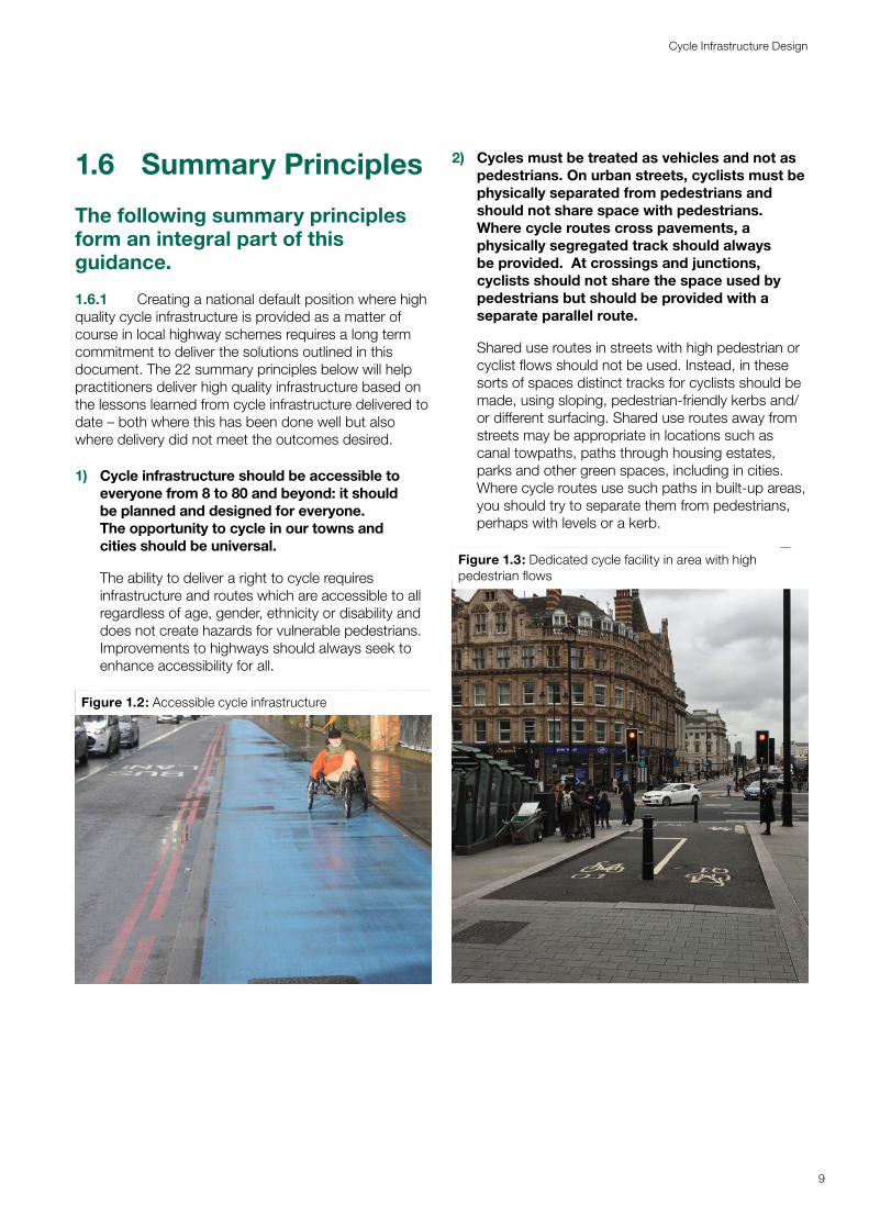
3) Cyclists must be physically separated and protected from high volume motor traffic, both at junctions and on the stretches of road between them.
Protection can be achieved either by creating physically separated cycle facilities, or by the closure of roads to through motor traffic using bollards, planters or other physical barriers (with access, Blue Badge holders, buses and so on still allowed). Segregated facilities can be implemented with full kerb segregation or light segregation (for example with wands, stepped kerbs, planters etc.) On roads with high volumes of motor traffic or high speeds, cycle routes indicated only with road markings or cycle symbols should not be used as people will perceive them to be unacceptable for safe cycling.
Figure 1.4: Cycle lane incorporating light segregation with flexible wands
4) Side street routes, if closed to through traffic to avoid rat-running, can be an alternative to segregated facilities or closures on main roads – but only if they are truly direct.
For directness it will often be necessary to mix the two, with stretches of routes on back streets joined to segregated routes on main roads and across junctions where there is no sufficiently direct side street. Routes that are not direct or that see significant volumes of rat-running traffic will not be used and should not be provided.
5) Cycle infrastructure should be designed for significant numbers of cyclists, and for non-standard cycles. Our aim is that thousands of cyclists a day will use many of these schemes.
We also want to see increasing numbers of cargo bikes to replace some van journeys. Cycle routes must be accessible to recumbents, trikes, handcycles, and other cycles used by disabled cyclists. Many current tracks and lanes are too narrow or constrained to meet these objectives. To allow faster cyclists to overtake, and make room for non-standard bikes, cycle tracks should ideally be 2 metres wide in each direction, or 3 to 4m (depending on cycle flows) for bidirectional tracks though there may have to be exceptions.
6) Consideration of the opportunities to improve provision for cycling will be an expectation of any future local highway schemes funded by Government.
To receive Government funding for local highways investment where the main element is not cycling or walking, there will be a presumption that schemes must deliver or improve cycling infrastructure to the standards in this Local Transport Note, unless it can be shown that there is little or no need for cycling in the particular highway scheme. Any new cycling infrastructure must be in line with this national guidance. The approach of continuous improvement is recognised in both the National Planning Policy Framework and Local Cycling and Walking Infrastructure Plan Guidance. Cycle infrastructure requirements should be embedded in local authority planning, design and highways adoption policies and processes.
7) Largely cosmetic interventions which bring few or no benefits for cycling or walking will not be funded from any cycling or walking budget.
Too many schemes badged as being for cycling or walking do little more than prettify the status quo, such as installing nicer-looking pavements and road surfaces but doing little or nothing to restrict through traffic or provide safe space for cycling. Schemes whose main purpose and/or effect is aesthetic improvement of the public realm must be funded from other budgets.
10
Cycle Infrastructure Design
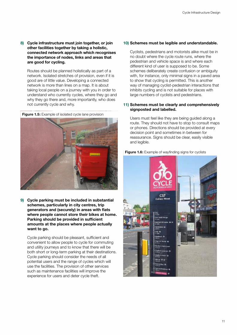
8) Cycle infrastructure must join together, or join other facilities together by taking a holistic, connected network approach which recognises the importance of nodes, links and areas that are good for cycling.
Routes should be planned holistically as part of a network. Isolated stretches of provision, even if it is good are of little value. Developing a connected network is more than lines on a map. It is about taking local people on a journey with you in order to understand who currently cycles, where they go and why they go there and, more importantly, who does not currently cycle and why.
Figure 1.5: Example of isolated cycle lane provision
9) Cycle parking must be included in substantial schemes, particularly in city centres, trip generators and (securely) in areas with flats where people cannot store their bikes at home. Parking should be provided in sufficient amounts at the places where people actually want to go.
Cycle parking should be pleasant, sufficient and convenient to allow people to cycle for commuting and utility journeys and to know that there will be both short or long-term parking at their destinations. Cycle parking should consider the needs of all potential users and the range of cycles which will use the facilities. The provision of other services such as maintenance facilities will improve the experience for users and deter cycle theft.
10) Schemes must be legible and understandable.
Cyclists, pedestrians and motorists alike must be in no doubt where the cycle route runs, where the pedestrian and vehicle space is and where each different kind of user is supposed to be. Some schemes deliberately create confusion or ambiguity with, for instance, only minimal signs in a paved area to show that cycling is permitted. This is another way of managing cyclist-pedestrian interactions that inhibits cycling and is not suitable for places with large numbers of cyclists and pedestrians.
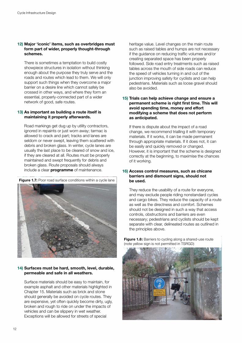
11) Schemes must be clearly and comprehensively signposted and labelled.
Users must feel like they are being guided along a route. They should not have to stop to consult maps or phones. Directions should be provided at every decision point and sometimes in between for reassurance. Signs should be clear, easily visible and legible.
Figure 1.6: Example of wayfinding signs for cyclists
11
Cycle Infrastructure Design
12) Major ‘iconic’ items, such as overbridges must form part of wider, properly thought-through schemes.
There is sometimes a temptation to build costly showpiece structures in isolation without thinking enough about the purpose they truly serve and the roads and routes which lead to them. We will only support such things when they overcome a major barrier on a desire line which cannot safely be crossed in other ways, and where they form an essential, properly-connected part of a wider network of good, safe routes.
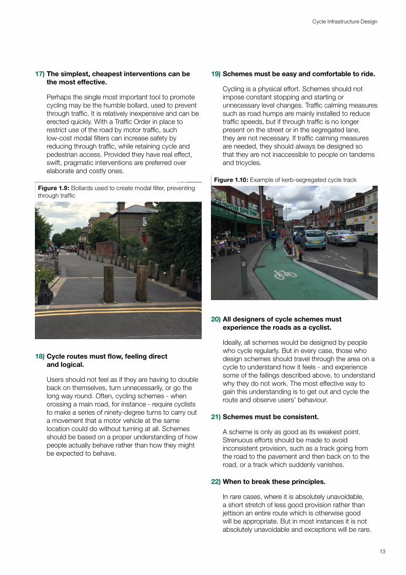
13) As important as building a route itself is maintaining it properly afterwards.
Road markings get dug up by utility contractors, ignored in repaints or just worn away; tarmac is allowed to crack and part; tracks and lanes are seldom or never swept, leaving them scattered with debris and broken glass. In winter, cycle lanes are usually the last place to be cleared of snow and ice, if they are cleared at all. Routes must be properly maintained and swept frequently for debris and broken glass. Route proposals should always include a clear programme of maintenance.
Figure 1.7: Poor road surface conditions within a cycle lane
14) Surfaces must be hard, smooth, level, durable, permeable and safe in all weathers.
Surface materials should be easy to maintain, for example asphalt and other materials highlighted in Chapter 15. Materials such as brick and stone should generally be avoided on cycle routes. They are expensive, yet often quickly become dirty, ugly, broken and rough to ride on under the impacts of vehicles and can be slippery in wet weather. Exceptions will be allowed for streets of special
heritage value. Level changes on the main route such as raised tables and humps are not necessary if the guidance on reducing traffic volumes and/or creating separated space has been properly followed. Side road entry treatments such as raised tables across the mouth of side roads can reduce the speed of vehicles turning in and out of the junction improving safety for cyclists and can help pedestrians. Materials such as loose gravel should also be avoided.
15) Trials can help achieve change and ensure a permanent scheme is right first time. This will avoid spending time, money and effort modifying a scheme that does not perform as anticipated.
If there is dispute about the impact of a road change, we recommend trialling it with temporary materials. If it works, it can be made permanent through appropriate materials. If it does not, it can be easily and quickly removed or changed. However, it is important that the scheme is designed correctly at the beginning, to maximise the chances of it working.
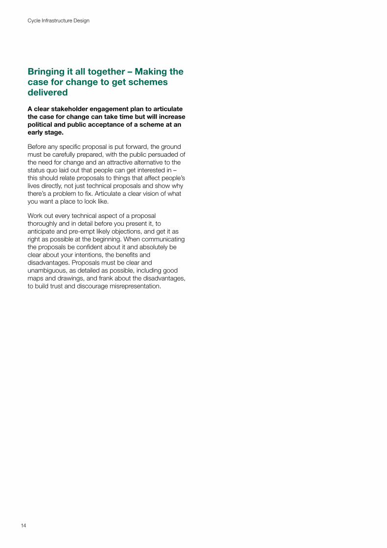
16) Access control measures, such as chicane barriers and dismount signs, should not be used.
They reduce the usability of a route for everyone, and may exclude people riding nonstandard cycles and cargo bikes. They reduce the capacity of a route as well as the directness and comfort. Schemes should not be designed in such a way that access controls, obstructions and barriers are even necessary; pedestrians and cyclists should be kept separate with clear, delineated routes as outlined in the principles above.
Figure 1.8: Barriers to cycling along a shared-use route (note yellow sign is not permitted in TSRGD)
12
Cycle Infrastructure Design
17) The simplest, cheapest interventions can be the most effective.
Perhaps the single most important tool to promote cycling may be the humble bollard, used to prevent through traffic. It is relatively inexpensive and can be erected quickly. With a Traffic Order in place to restrict use of the road by motor traffic, such low-cost modal filters can increase safety by reducing through traffic, while retaining cycle and pedestrian access. Provided they have real effect, swift, pragmatic interventions are preferred over elaborate and costly ones.
Figure 1.9: Bollards used to create modal filter, preventing through traffic
18) Cycle routes must flow, feeling direct and logical.
Users should not feel as if they are having to double back on themselves, turn unnecessarily, or go the long way round. Often, cycling schemes - when crossing a main road, for instance - require cyclists to make a series of ninety-degree turns to carry out a movement that a motor vehicle at the same location could do without turning at all. Schemes should be based on a proper understanding of how people actually behave rather than how they might be expected to behave.
19) Schemes must be easy and comfortable to ride.
Cycling is a physical effort. Schemes should not impose constant stopping and starting or unnecessary level changes. Traffic calming measures such as road humps are mainly installed to reduce traffic speeds, but if through traffic is no longer present on the street or in the segregated lane, they are not necessary. If traffic calming measures are needed, they should always be designed so that they are not inaccessible to people on tandems and tricycles.
Figure 1.10: Example of kerb-segregated cycle track
20) All designers of cycle schemes must experience the roads as a cyclist.
Ideally, all schemes would be designed by people who cycle regularly. But in every case, those who design schemes should travel through the area on a cycle to understand how it feels - and experience some of the failings described above, to understand why they do not work. The most effective way to gain this understanding is to get out and cycle the route and observe users’ behaviour.
21) Schemes must be consistent.
A scheme is only as good as its weakest point. Strenuous efforts should be made to avoid inconsistent provision, such as a track going from the road to the pavement and then back on to the road, or a track which suddenly vanishes.
22) When to break these principles.
In rare cases, where it is absolutely unavoidable, a short stretch of less good provision rather than jettison an entire route which is otherwise good will be appropriate. But in most instances it is not absolutely unavoidable and exceptions will be rare.
13
Cycle Infrastructure Design
Bringing it all together – Making the case for change to get schemes delivered
A clear stakeholder engagement plan to articulate the case for change can take time but will increase political and public acceptance of a scheme at an early stage.
Before any specific proposal is put forward, the ground must be carefully prepared, with the public persuaded of the need for change and an attractive alternative to the status quo laid out that people can get interested in – this should relate proposals to things that affect people’s lives directly, not just technical proposals and show why there’s a problem to fix. Articulate a clear vision of what you want a place to look like.
Work out every technical aspect of a proposal thoroughly and in detail before you present it, to anticipate and pre-empt likely objections, and get it as right as possible at the beginning. When communicating the proposals be confident about it and absolutely be clear about your intentions, the benefits and disadvantages. Proposals must be clear and unambiguous, as detailed as possible, including good maps and drawings, and frank about the disadvantages, to build trust and discourage misrepresentation.
14
Cycle Infrastructure Design
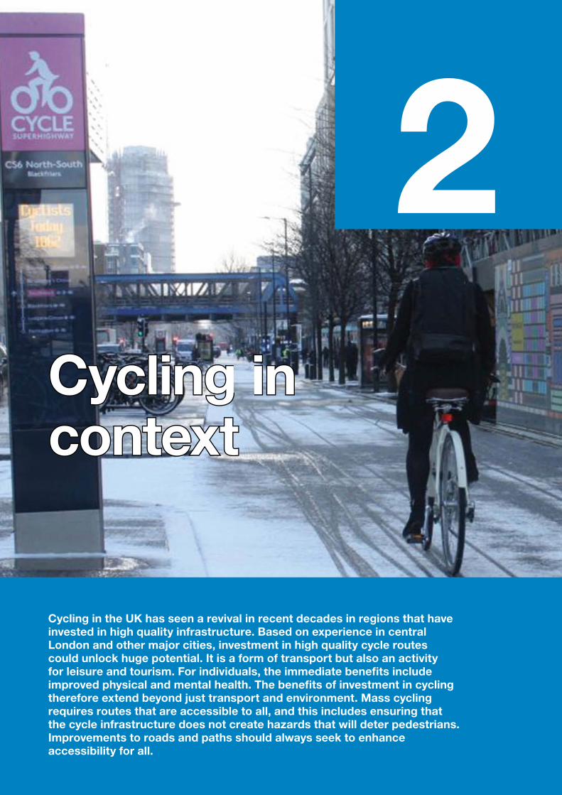
2Cycling in Cycling in contextcontext
Cycling in the UK has seen a revival in recent decades in regions that have invested in high quality infrastructure. Based on experience in central London and other major cities, investment in high quality cycle routes could unlock huge potential. It is a form of transport but also an activity for leisure and tourism. For individuals, the immediate benefits include improved physical and mental health. The benefits of investment in cycling therefore extend beyond just transport and environment. Mass cycling requires routes that are accessible to all, and this includes ensuring that the cycle infrastructure does not create hazards that will deter pedestrians. Improvements to roads and paths should always seek to enhance accessibility for all.
2.1 Introduction2.1.1 This document is about infrastructure design, but it is important to understand the context in which design is taking place. This chapter describes the role of cycling as a means of transport, physical activity, leisure and tourism activity. It looks at some of the benefits that accrue from more people cycling more safely and more often. Careful design, construction and maintenance is required to ensure that cycling is accessible to all potential cyclists.
2.1.2 Increasing levels of traffic congestion, air pollution and poor health associated with inactivity require new approaches to transport planning. Towns and cities around the world are embracing cycling as a vital component of their sustainable transport policies.
1 Aldred R, Goodman A, Gulliver J and Woodcock J, Cycling injury risk in London: A case-control study exploring the impact of cycle volumes, motor vehicle volumes, and road characteristics including speed limits. Accident Analysis and Prevention, Vol 117, August 2018
2 Transport Statistics Great Britain, DfT, 2016
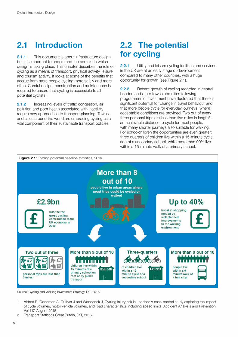
2.2 The potential for cycling2.2.1 Utility and leisure cycling facilities and services in the UK are at an early stage of development compared to many other countries, with a huge opportunity for growth (see Figure 2.1).
2.2.2 Recent growth of cycling recorded in central London and other towns and cities following programmes of investment have illustrated that there is significant potential for change in travel behaviour and that more people cycle for everyday journeys1 where acceptable conditions are provided. Two out of every three personal trips are less than five miles in length2 – an achievable distance to cycle for most people, with many shorter journeys also suitable for walking. For schoolchildren the opportunities are even greater: three quarters of children live within a 15-minute cycle ride of a secondary school, while more than 90% live within a 15-minute walk of a primary school.
Figure 2.1: Cycling potential baseline statistics, 2016
Source: Cycling and Walking Investment Strategy, DfT, 2016
16
Cycle Infrastructure Design
2.2.3 Cycling for leisure and tourism has also experienced rapid growth. Sustainable tourism can be an important factor in supporting rural economies, and cycling and walking are both very accessible activities to improve public health.
2.3 The benefits of cycling2.3.1 Enabling more people to cycle will help local authorities to achieve a broad range of positive transport outcomes and wider environment and public health goals. Local land use and transport strategies provide the opportunity for local authorities to plan how to increase cycling to help deliver these goals.
3 PJA/University of Birmingham The Value of Cycling: rapid evidence review of the economic benefits of cycling, DfT, 20164 Brooke Lyndhurst Investing in Cycling and Walking, Rapid Evidence Assessment, DfT, 20165 Brooke Lyndhurst Investing in Cycling and Walking, Rapid Evidence Assessment, DfT, 20166 PJA/University of Birmingham The Value of Cycling: rapid evidence review of the economic benefits of cycling, DfT, 2016
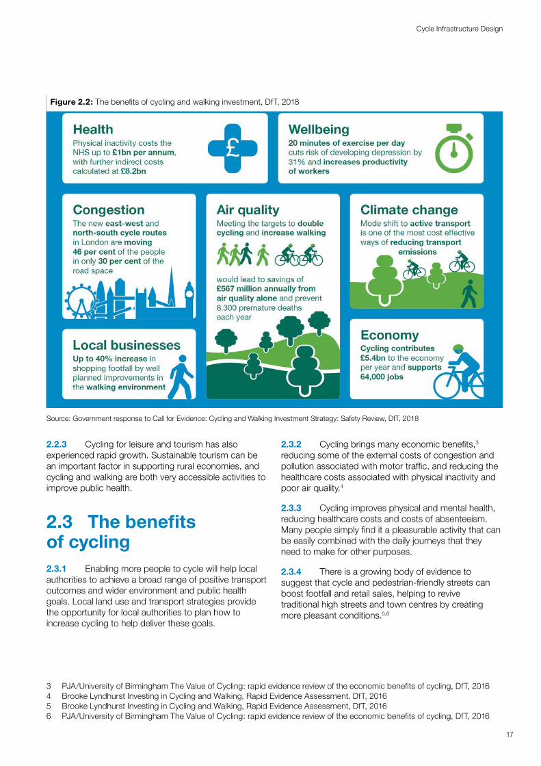
2.3.2 Cycling brings many economic benefits,3 reducing some of the external costs of congestion and pollution associated with motor traffic, and reducing the healthcare costs associated with physical inactivity and poor air quality.4
2.3.3 Cycling improves physical and mental health, reducing healthcare costs and costs of absenteeism. Many people simply find it a pleasurable activity that can be easily combined with the daily journeys that they need to make for other purposes.
2.3.4 There is a growing body of evidence to suggest that cycle and pedestrian-friendly streets can boost footfall and retail sales, helping to revive traditional high streets and town centres by creating more pleasant conditions.5,6
Figure 2.2: The benefits of cycling and walking investment, DfT, 2018
Source: Government response to Call for Evidence: Cycling and Walking Investment Strategy: Safety Review, DfT, 2018
17
Cycle Infrastructure Design
2.3.5 As an affordable mode of transport, cycling can be an important way for people to access local services, education and employment. This is particularly the case for those who need to travel when public transport is unavailable.
7 Value for Money assessment of cycling grants, DfT, 20148 Wheels for Wellbeing, Guide to Inclusive Cycling, 2017
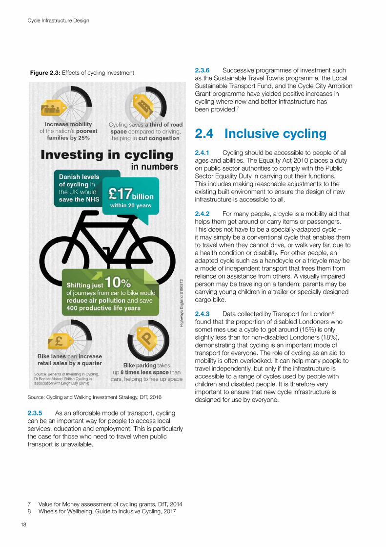
2.3.6 Successive programmes of investment such as the Sustainable Travel Towns programme, the Local Sustainable Transport Fund, and the Cycle City Ambition Grant programme have yielded positive increases in cycling where new and better infrastructure has been provided.7
2.4 Inclusive cycling2.4.1 Cycling should be accessible to people of all ages and abilities. The Equality Act 2010 places a duty on public sector authorities to comply with the Public Sector Equality Duty in carrying out their functions. This includes making reasonable adjustments to the existing built environment to ensure the design of new infrastructure is accessible to all.
2.4.2 For many people, a cycle is a mobility aid that helps them get around or carry items or passengers. This does not have to be a specially-adapted cycle – it may simply be a conventional cycle that enables them to travel when they cannot drive, or walk very far, due to a health condition or disability. For other people, an adapted cycle such as a handcycle or a tricycle may be a mode of independent transport that frees them from reliance on assistance from others. A visually impaired person may be traveling on a tandem; parents may be carrying young children in a trailer or specially designed cargo bike.
2.4.3 Data collected by Transport for London8 found that the proportion of disabled Londoners who sometimes use a cycle to get around (15%) is only slightly less than for non-disabled Londoners (18%), demonstrating that cycling is an important mode of transport for everyone. The role of cycling as an aid to mobility is often overlooked. It can help many people to travel independently, but only if the infrastructure is accessible to a range of cycles used by people with children and disabled people. It is therefore very important to ensure that new cycle infrastructure is designed for use by everyone.
Figure 2.3: Effects of cycling investment
Source: Cycling and Walking Investment Strategy, DfT, 2016
18
Cycle Infrastructure Design
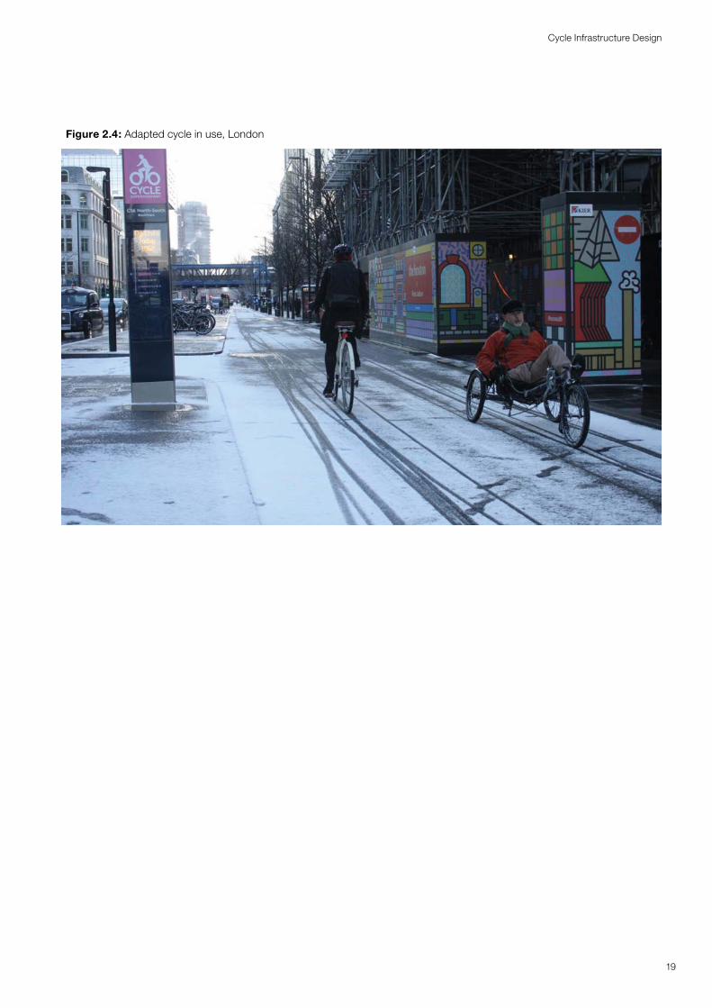
Figure 2.4: Adapted cycle in use, London
19
Cycle Infrastructure Design
3Planning Planning for cyclingfor cycling
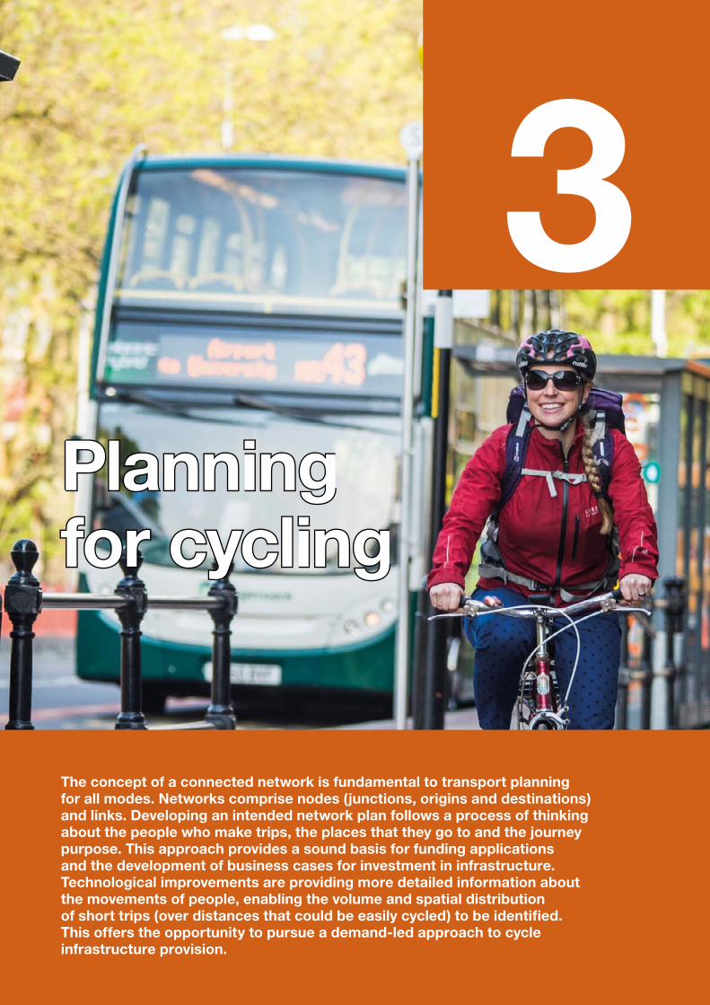
The concept of a connected network is fundamental to transport planning for all modes. Networks comprise nodes (junctions, origins and destinations) and links. Developing an intended network plan follows a process of thinking about the people who make trips, the places that they go to and the journey purpose. This approach provides a sound basis for funding applications and the development of business cases for investment in infrastructure. Technological improvements are providing more detailed information about the movements of people, enabling the volume and spatial distribution of short trips (over distances that could be easily cycled) to be identified. This offers the opportunity to pursue a demand-led approach to cycle infrastructure provision.
3.1 Introduction3.1.1 This chapter looks at the process of planning local networks for cycling and explains various techniques for applying data to network planning and delivery. It summarises the information in the Department’s Local Cycling and Walking Infrastructure Plans9 suite of guidance.
3.1.2 A network plan is a vital component of infrastructure development, setting out the connections between origins and destinations, providing a basis for prioritisation in investment programmes, and informing design teams about the routes likely to carry higher volumes of cycle traffic.
3.1.3 Planning for cycling should be based around providing a network of on- and/or off-carriageway routes that are suitable for all abilities. Subject to topographical constraints, the aim is to create a densely spaced network (typically with 250m to 1km spacing between routes depending on the density of land use) so that all people can easily travel by cycle for trips within and between neighbourhoods. In addition to this there will be longer distance routes within the local network that may serve leisure, tourism and utility cycling.
3.1.4 The guidance on Local Cycling and Walking Infrastructure Plans (LCWIPs) gives details on the process for developing a local cycle network and prioritising the interventions for implementation. This chapter draws on that guidance to put the various design elements described in subsequent chapters of this document into context.
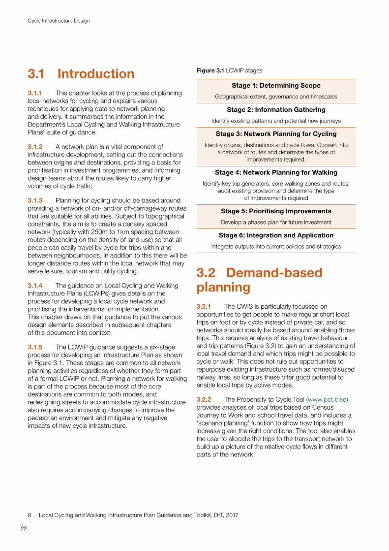
3.1.5 The LCWIP guidance suggests a six-stage process for developing an Infrastructure Plan as shown in Figure 3.1. These stages are common to all network planning activities regardless of whether they form part of a formal LCWIP or not. Planning a network for walking is part of the process because most of the core destinations are common to both modes, and redesigning streets to accommodate cycle infrastructure also requires accompanying changes to improve the pedestrian environment and mitigate any negative impacts of new cycle infrastructure.
9 Local Cycling and Walking Infrastructure Plan Guidance and Toolkit, DfT, 2017
Figure 3.1 LCWIP stages
Stage 1: Determining Scope
Geographical extent, governance and timescales
Stage 2: Information Gathering
Identify existing patterns and potential new journeys
Stage 3: Network Planning for Cycling
Identify origins, destinations and cycle flows. Convert into a network of routes and determine the types of
improvements required.
Stage 4: Network Planning for Walking
Identify key trip generators, core walking zones and routes, audit existing provision and determine the type
of improvements required
Stage 5: Prioritising Improvements
Develop a phased plan for future investment
Stage 6: Integration and Application
Integrate outputs into current policies and strategies
3.2 Demand-based planning3.2.1 The CWIS is particularly focussed on opportunities to get people to make regular short local trips on foot or by cycle instead of private car, and so networks should ideally be based around enabling those trips. This requires analysis of existing travel behaviour and trip patterns (Figure 3.2) to gain an understanding of local travel demand and which trips might be possible to cycle or walk. This does not rule out opportunities to repurpose existing infrastructure such as former/disused railway lines, so long as these offer good potential to enable local trips by active modes.
3.2.2 The Propensity to Cycle Tool (www.pct.bike) provides analyses of local trips based on Census Journey to Work and school travel data, and includes a ‘scenario planning’ function to show how trips might increase given the right conditions. The tool also enables the user to allocate the trips to the transport network to build up a picture of the relative cycle flows in different parts of the network.
22
Cycle Infrastructure Design
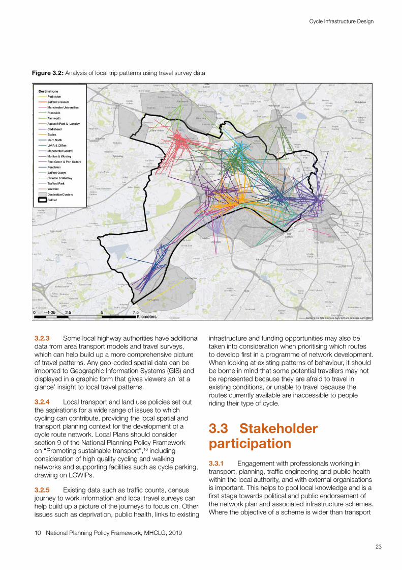
Figure 3.2: Analysis of local trip patterns using travel survey data
3.2.3 Some local highway authorities have additional data from area transport models and travel surveys, which can help build up a more comprehensive picture of travel patterns. Any geo-coded spatial data can be imported to Geographic Information Systems (GIS) and displayed in a graphic form that gives viewers an ‘at a glance’ insight to local travel patterns.
3.2.4 Local transport and land use policies set out the aspirations for a wide range of issues to which cycling can contribute, providing the local spatial and transport planning context for the development of a cycle route network. Local Plans should consider section 9 of the National Planning Policy Framework on “Promoting sustainable transport”,10 including consideration of high quality cycling and walking networks and supporting facilities such as cycle parking, drawing on LCWIPs.
3.2.5 Existing data such as traffic counts, census journey to work information and local travel surveys can help build up a picture of the journeys to focus on. Other issues such as deprivation, public health, links to existing
10 National Planning Policy Framework, MHCLG, 2019
infrastructure and funding opportunities may also be taken into consideration when prioritising which routes to develop first in a programme of network development. When looking at existing patterns of behaviour, it should be borne in mind that some potential travellers may not be represented because they are afraid to travel in existing conditions, or unable to travel because the routes currently available are inaccessible to people riding their type of cycle.
3.3 Stakeholder participation3.3.1 Engagement with professionals working in transport, planning, traffic engineering and public health within the local authority, and with external organisations is important. This helps to pool local knowledge and is a first stage towards political and public endorsement of the network plan and associated infrastructure schemes. Where the objective of a scheme is wider than transport
23
Cycle Infrastructure Design
provision, for example to enable improved public health or access to employment and education opportunities, it is essential that relevant officers and representatives from those sectors are involved from the beginning alongside transportation professionals and advocates to ensure acceptance of the scheme.
3.3.2 Network planning across a whole city or region can be difficult for stakeholders as individuals generally know their patch or regular route, but not other areas. A series of community-based workshops supported by online opportunities can be an effective way to gather local knowledge.
3.3.3 New cycle infrastructure is often delivered within a local policy context of creating better places and healthy lifestyles, and can involve major changes to the look and feel of a street. Communicating the vision behind a scheme is important, particularly as many people who participate in engagement have rarely used a cycle themselves. While it is inevitable that not everybody will welcome changes, those in opposition are often the most vociferous participants and the engagement process should try to build consensus. It should also enable a record of design decisions and the rationale behind them to be developed to help build consensus.
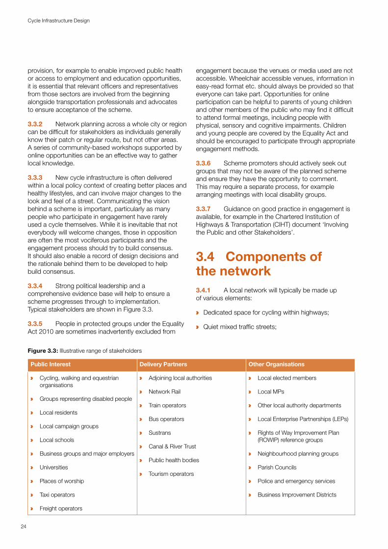
3.3.4 Strong political leadership and a comprehensive evidence base will help to ensure a scheme progresses through to implementation. Typical stakeholders are shown in Figure 3.3.
3.3.5 People in protected groups under the Equality Act 2010 are sometimes inadvertently excluded from
engagement because the venues or media used are not accessible. Wheelchair accessible venues, information in easy-read format etc. should always be provided so that everyone can take part. Opportunities for online participation can be helpful to parents of young children and other members of the public who may find it difficult to attend formal meetings, including people with physical, sensory and cognitive impairments. Children and young people are covered by the Equality Act and should be encouraged to participate through appropriate engagement methods.
3.3.6 Scheme promoters should actively seek out groups that may not be aware of the planned scheme and ensure they have the opportunity to comment. This may require a separate process, for example arranging meetings with local disability groups.
3.3.7 Guidance on good practice in engagement is available, for example in the Chartered Institution of Highways & Transportation (CIHT) document ‘Involving the Public and other Stakeholders’.
3.4 Components of the network3.4.1 A local network will typically be made up of various elements:
a Dedicated space for cycling within highways;
a Quiet mixed traffic streets;
Figure 3.3: Illustrative range of stakeholders
Public Interest Delivery Partners Other Organisations
a Cycling, walking and equestrian organisations
a Groups representing disabled people
a Local residents
a Local campaign groups
a Local schools
a Business groups and major employers
a Universities
a Places of worship
a Taxi operators
a Freight operators
a Adjoining local authorities
a Network Rail
a Train operators
a Bus operators
a Sustrans
a Canal & River Trust
a Public health bodies
a Tourism operators
a Local elected members
a Local MPs
a Other local authority departments
a Local Enterprise Partnerships (LEPs)
a Rights of Way Improvement Plan (ROWIP) reference groups
a Neighbourhood planning groups
a Parish Councils
a Police and emergency services
a Business Improvement Districts
24
Cycle Infrastructure Design
a Motor traffic free routes;
a Junction treatments and crossings; and
a Cycle parking at origins, destinations and interchanges with other modes
3.4.2 Cycle routes may also fulfil various functions as part of the network:
a Primary routes – between major trip generators;
a Secondary routes – connections into local centres;
a Local access to streets and attractors; and
a Long distance and leisure routes
3.4.3 All elements listed above can form an integrated network. The appropriate design depends on traffic speeds and flows, whether the network is rural, urban or residential, and scheme-specific factors such as the available budget and political support. Further guidance on selecting the appropriate type of cycle provision is given in Chapter 4.
3.4.4 As well as cycle-specific infrastructure, general highway improvements, other capital transport schemes, local traffic management and speed management measures can play an important role in creating conditions conducive to more cycling (see Chapter 14).
3.4.5 There may be more than one way to connect two places in a network. The Route Selection Tool (RST) in the LCWIP guidance offers a way to compare the qualities of each potential alignment.
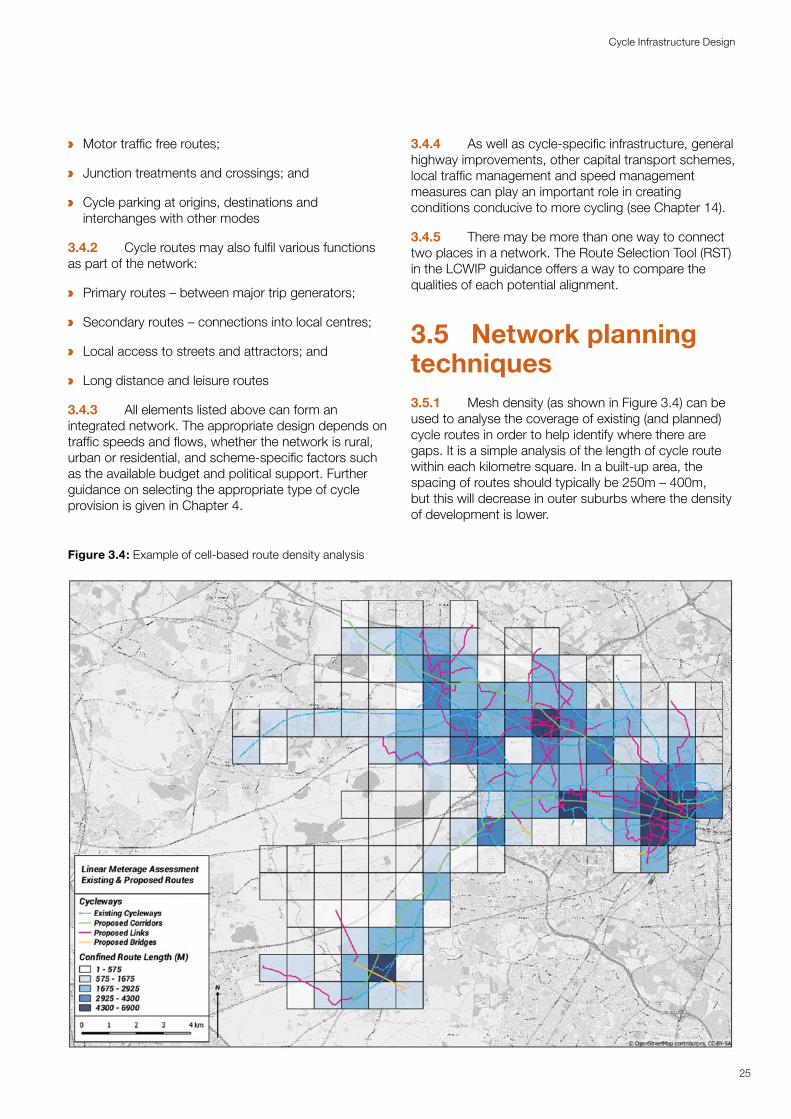
3.5 Network planning techniques3.5.1 Mesh density (as shown in Figure 3.4) can be used to analyse the coverage of existing (and planned) cycle routes in order to help identify where there are gaps. It is a simple analysis of the length of cycle route within each kilometre square. In a built-up area, the spacing of routes should typically be 250m – 400m, but this will decrease in outer suburbs where the density of development is lower.
Figure 3.4: Example of cell-based route density analysis
25
Cycle Infrastructure Design
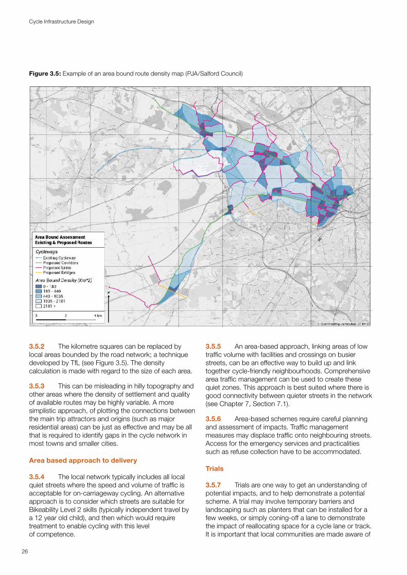
Figure 3.5: Example of an area bound route density map (PJA/Salford Council)
3.5.2 The kilometre squares can be replaced by local areas bounded by the road network; a technique developed by TfL (see Figure 3.5). The density calculation is made with regard to the size of each area.
3.5.3 This can be misleading in hilly topography and other areas where the density of settlement and quality of available routes may be highly variable. A more simplistic approach, of plotting the connections between the main trip attractors and origins (such as major residential areas) can be just as effective and may be all that is required to identify gaps in the cycle network in most towns and smaller cities.
Area based approach to delivery
3.5.4 The local network typically includes all local quiet streets where the speed and volume of traffic is acceptable for on-carriageway cycling. An alternative approach is to consider which streets are suitable for Bikeability Level 2 skills (typically independent travel by a 12 year old child), and then which would require treatment to enable cycling with this level of competence.
3.5.5 An area-based approach, linking areas of low traffic volume with facilities and crossings on busier streets, can be an effective way to build up and link together cycle-friendly neighbourhoods. Comprehensive area traffic management can be used to create these quiet zones. This approach is best suited where there is good connectivity between quieter streets in the network (see Chapter 7, Section 7.1).
3.5.6 Area-based schemes require careful planning and assessment of impacts. Traffic management measures may displace traffic onto neighbouring streets. Access for the emergency services and practicalities such as refuse collection have to be accommodated.
Trials
3.5.7 Trials are one way to get an understanding of potential impacts, and to help demonstrate a potential scheme. A trial may involve temporary barriers and landscaping such as planters that can be installed for a few weeks, or simply coning-off a lane to demonstrate the impact of reallocating space for a cycle lane or track. It is important that local communities are made aware of
26
Cycle Infrastructure Design
trials well in advance, and that they take place for long enough to allow a scheme to settle down as people get used to the new arrangements. It is particularly important to make local disability groups aware of changes, which may impact on their ability to navigate, or to gain access to facilities such as disabled parking spaces. Engagement sessions with local disabled people may help identify and communicate alternative accessible routes. The provision of travel buddies to help visually impaired people learn to adjust to changes along previously familiar routes at the start of trial schemes may be particularly helpful and is recommended.
3.5.8 Trials will require the appropriate temporary or experimental traffic orders where existing legal arrangements on the highway (such as parking, turning, access) are being altered. Trials will also need to comply with relevant legal requirements, including the Traffic Signs Regulations and General Directions (TSRGD).11
11 Traffic Signs Regulations and General Directions, DFT, 2016
3.5.9 It is important to monitor behaviour before and during the trial period, and after final scheme implementation. Trials can form an important part of the engagement process, helping to generate local support and explain how the issues encountered might be addressed in the final scheme. Sharing data and experience is important to help build up knowledge of the processes of planning, engagement and participation that result in successful scheme delivery, and which are just as vital as the physical design aspects.
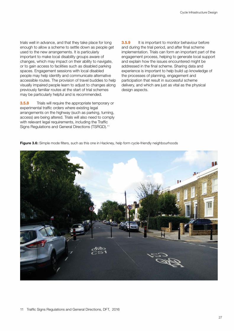
Figure 3.6: Simple mode filters, such as this one in Hackney, help form cycle-friendly neighbourhoods
27
Cycle Infrastructure Design
4Design principles Design principles and processesand processes
Cycle traffic has its own characteristics that are distinct from motor traffic and pedestrian traffic. These should be recognised and incorporated from the outset of the planning and design process. There are five fundamental design principles for all cycle infrastructure that will ensure it is accessible to all. The relative importance of each attribute, and how each is delivered, will depend on the situation in which design is being applied. For example, safety for cyclists is largely determined by achieving separation from busy and fast motor traffic, but this can be achieved in several ways, by provision of separate infrastructure, through removal of traffic from an existing street, or a reduction in traffic speed or volume. There are audit and review procedures that offer a framework to help understand the issues behind the five criteria and how to prioritise addressing them when designing schemes. When designing new highways and improvement schemes, planning for cycling from the outset can ensure that sufficient land is acquired to accommodate the optimum design.
4.1 Introduction4.1.1 This chapter looks at some of the basic ideas that underpin the design process for cycle route networks. Dimensions to meet the needs of all people able to use a cycle are set out in Chapter 5 and subsequent chapters covering design elements. This chapter includes:
a The basis of designing for cyclists’ needs;
a Minimising the effort required to cycle;
a Providing protection from motor traffic in different circumstances; and
a Quality assessment techniques
4.2 Core design principles4.2.1 There are five principles which represent the core requirements for people wishing to travel by cycle or on foot. Accessibility for all is a requirement that should always be considered in relation to each of the principles. Designers should always aim to provide infrastructure that meets these principles and therefore caters for the broadest range of people. While cyclists and pedestrians share the same underlying design principles, the geometric design requirements for pedestrians and cyclists are not the same, owing to the differential in speed and mass. Geometric requirements are explored in Chapter 5.
4.2.2 When people are travelling by cycle, they need networks and routes that are:
a Coherent;
a Direct;
a Safe;
a Comfortable; and
a Attractive
4.2.3 These design principles are further described below.
Coherent
4.2.4 Cycle networks should be planned and designed to allow people to reach their day to day destinations easily, along routes that connect, are simple to navigate and are of a consistently high quality. Abrupt reductions in the quality of provision for cyclists – such as a busy high-speed roundabout without facilities – will mean that an otherwise serviceable route becomes unusable by most potential users. Sections that do not meet accessibility standards, such as steps on a cycle route, will render a whole journey inaccessible for some people.
4.2.5 Main roads are often the only direct, coherent route available to move between places, but these are usually the roads where people most fear the danger from motor vehicles. Consequently, the provision of adequately safe, attractive and comfortable facilities along these roads is crucial to creating a coherent cycling network.
4.2.6 A cycle route may vary in nature along its length, for example a signed route along a quiet street may continue as a motor traffic free route through a green space, but the connection between successive sections should be obvious. Similarly, a route through a complex junction should be clear to all road users. Direction signs, road markings and coloured surfacing in combination with physical design features can all help to provide coherence.
Direct
4.2.7 Directness is measured in both distance and time, and so routes should provide the shortest and fastest way of travelling from place to place. This includes providing facilities at junctions that minimise delay and the need to stop. Minimising the effort required to cycle, by enabling cyclists to maintain momentum, is an important aspect of directness. An indirect designated route involving extra distance or more stopping and starting will result in some cyclists choosing the most direct, faster option, even if it is less safe.
4.2.8 To make cycling an attractive alternative to driving short distances, cycle routes should be at least as direct – and preferably more direct – than those available for private motor vehicles. Permitting cyclists to make movements prohibited to motor traffic, allowing contraflow cycling, and creating links between cul-de-sacs to enable cyclists to take the shortest route, should be the default approach in traffic management
30
Cycle Infrastructure Design
schemes and new road networks. Area-wide schemes and new developments can enable filtered permeability, allowing cyclists and pedestrians to take more direct routes than motorised traffic.
Safe
4.2.9 Not only must cycle infrastructure be safe, it should also be perceived to be safe so that more people feel able to cycle.
4.2.10 Safety and environmental improvements for all road users can be achieved by reducing motor traffic volumes and speeds, for example by introducing filtered permeability or traffic calming. Reducing motor traffic may also release space to enable the construction of separate facilities for cyclists on links and at junctions.
4.2.11 On busy strategic roads where a significant reduction in traffic speeds and volumes is not appropriate, safety will need to be achieved by providing dedicated and protected space for cycling, which may involve reallocating existing space within the highway (or providing a parallel route). Reallocation will typically involve moving kerb lines and street furniture, and providing well-designed crossings and facilities at junctions where most casualties occur. The potential for conflict between pedestrians and cyclists should be minimised by keeping them separate except in low speed, low traffic environments (see Figure 4.2). Where pedestrians and cyclists share surfaces, sufficient width should be provided to enable users to feel safe by allowing them to see other users and to avoid each other when passing.
4.2.12 Cycle routes remote from roads may have other risks relating to crime and personal security. The risk of crime can be reduced through the removal of hiding places along a route, by providing frequent access points, by providing lighting, and by passive surveillance from overlooking buildings and other users.
4.2.13 Maintenance to address surface defects, overgrown vegetation, fallen leaves, snow and ice will all help to reduce the likelihood of falls and crashes for all people and preserve available width and sight lines for cyclists. Cycle parking should be sited where people using the facilities can feel safe from traffic and crime, and away from pedestrian paths.
Comfortable
4.2.14 Comfortable conditions for cycling require routes with good quality, well-maintained smooth surfaces, adequate width for the volume of users, minimal stopping and starting, avoiding steep gradients, excessive or uneven crossfall and adverse camber. The need to interact with high speed or high-volume motor traffic also decreases user comfort by increasing the level of stress and the mental effort required to cycle.
4.2.15 Adequate width is important for comfort. Cycling is a sociable activity and many people will want to cycle side by side, and to overtake another cyclist safely. It is important that cyclists can choose their own speed so that they can make comfortable progress commensurate with the amount of effort they wish to put in.
4.2.16 Designers should consider comfort for all users including children, families, older and disabled people using three or four-wheeled cycles. Families are more likely to use off-carriageway facilities. Young children may need additional space to wobble or for an accompanying parent to ride alongside.
Attractive
4.2.17 Cycling and walking provide a more sensory experience than driving. People are more directly exposed to the environment they are moving through and value attractive routes through parks, waterfront locations, and well-designed streets and squares. Cycling is a pleasurable activity, in part because it involves such close contact with the surroundings, but this also intensifies concerns about personal security and traffic danger. The attractiveness of the route will therefore affect whether users choose cycling as a means of transport.
4.2.18 The environment should be attractive, stimulating and free from litter or broken glass. The ability for people to window shop, walk or cycle two abreast, converse or stop to rest or look at a view, makes for a more pleasant experience.
4.2.19 Cycle infrastructure should help to deliver public spaces that are well designed and finished in attractive materials and be places that people want to spend time using. The surfaces, landscaping and street furniture should be well maintained and in keeping with the surrounding area. Planting in parks and rural areas should consider the aesthetic and sensory qualities that create attractive vistas and fragrances as well as practical considerations about maintenance.
31
Cycle Infrastructure Design
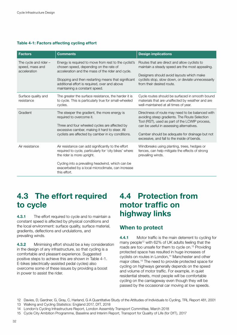
Table 4-1: Factors affecting cycling effort
Factors Comments Design implications
The cycle and rider – speed, mass and acceleration
Energy is required to move from rest to the cyclist’s chosen speed, depending on the rate of acceleration and the mass of the rider and cycle.
Stopping and then restarting means that significant additional effort is required, over and above maintaining a constant speed.
Routes that are direct and allow cyclists to maintain a steady speed are the most appealing.
Designers should avoid layouts which make cyclists stop, slow down, or deviate unnecessarily from their desired route.
Surface quality and resistance
The greater the surface resistance, the harder it is to cycle. This is particularly true for small-wheeled cycles.
Cycle routes should be surfaced in smooth bound materials that are unaffected by weather and are well-maintained at all times of year.
Gradient The steeper the gradient, the more energy is required to overcome it.
Three and four wheeled cycles are affected by excessive camber, making it hard to steer. All cyclists are affected by camber in icy conditions.
Directness of route may need to be balanced with avoiding steep gradients. The Route Selection Tool (RST), used as part of the LCWIP process, can be useful in assessing alternatives.
Camber should be adequate for drainage but not excessive, and fall to the inside of bends.
Air resistance Air resistance can add significantly to the effort required to cycle, particularly for ‘city bikes’ where the rider is more upright.
Cycling into a prevailing headwind, which can be exacerbated by a local microclimate, can increase this effort.
Windbreaks using planting, trees, hedges or fences, can help mitigate the effects of strong prevailing winds.
4.3 The effort required to cycle4.3.1 The effort required to cycle and to maintain a constant speed is affected by physical conditions and the local environment: surface quality, surface material, gradients, deflections and undulations, and prevailing winds.
4.3.2 Minimising effort should be a key consideration in the design of any infrastructure, so that cycling is a comfortable and pleasant experience. Suggested positive steps to achieve this are shown in Table 4-1. E-bikes (electrically-assisted pedal cycles) alsoovercome some of these issues by providing a boostin power to assist the rider.
12 Davies, D, Gardner, G, Gray, C, Harland, G A Quantitative Study of the Attitudes of Individuals to Cycling, TRL Report 481, 200113 Walking and Cycling Statistics: England 2017, DfT, 201814 London’s Cycling Infrastructure Report, London Assembly Transport Committee, March 201815 Cycle City Ambition Programme, Baseline and Interim Report, Transport for Quality of Life (for DfT), 2017
4.4 Protection from motor traffic on highway links
When to protect
4.4.1 Motor traffic is the main deterrent to cycling for many people12 with 62% of UK adults feeling that the roads are too unsafe for them to cycle on.13 Providing protected space has resulted in huge increases of cyclists on routes in London,14 Manchester and other major cities.15 The need to provide protected space for cycling on highways generally depends on the speed and volume of motor traffic. For example, in quiet residential streets, most people will be comfortable cycling on the carriageway even though they will be passed by the occasional car moving at low speeds.
32
Cycle Infrastructure Design
On busier and faster highways, most people will not be prepared to cycle on the carriageway, so they will not cycle at all, or some may unlawfully use the footway.
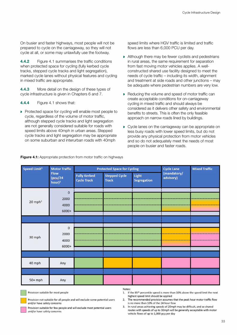
4.4.2 Figure 4.1 summarises the traffic conditions when protected space for cycling (fully kerbed cycle tracks, stepped cycle tracks and light segregation), marked cycle lanes without physical features and cycling in mixed traffic are appropriate.
4.4.3 More detail on the design of these types of cycle infrastructure is given in Chapters 6 and 7.
4.4.4 Figure 4.1 shows that:
a Protected space for cycling will enable most people to cycle, regardless of the volume of motor traffic, although stepped cycle tracks and light segregation are not generally considered suitable for roads with speed limits above 40mph in urban areas. Stepped cycle tracks and light segregation may be appropriate on some suburban and interurban roads with 40mph
speed limits where HGV traffic is limited and traffic flows are less than 6,000 PCU per day.
a Although there may be fewer cyclists and pedestrians in rural areas, the same requirement for separation from fast moving motor vehicles applies. A well-constructed shared use facility designed to meet the needs of cycle traffic – including its width, alignment and treatment at side roads and other junctions – may be adequate where pedestrian numbers are very low.
a Reducing the volume and speed of motor traffic can create acceptable conditions for on-carriageway cycling in mixed traffic and should always be considered as it delivers other safety and environmental benefits to streets. This is often the only feasible approach on narrow roads lined by buildings.
a Cycle lanes on the carriageway can be appropriate on less busy roads with lower speed limits, but do not provide any physical protection from motor vehicles and so do not adequately meet the needs of most people on busier and faster roads.
Figure 4.1: Appropriate protection from motor traffic on highways
33
Cycle Infrastructure Design
4.4.5 The values in Figure 4.1 are derived from the following guidance: Tables 5.2 and 5.3 in the Design Manual for Bicycle Traffic, CROW Record 28, 2016; London Cycling Design Standards, Chapter 2, TfL 2016 and the Urban Bikeway Design Guide, NACTO, 2012. The numbers are based on the frequency of interactions between opposing vehicles at different speed/flow permutations and user satisfaction surveys (in the research for CROW and TfL design guides) which helped to define the points at which people feel uncomfortable sharing the carriageway.
4.4.6 When cycle tracks or light segregation are used to provide protected space for cyclists this potentially introduces issues for kerbside access for parking and delivery, and additional complications around pedestrian crossing points and bus stops that will need to be addressed during design. Suitable protection will also need to be provided through junctions as well as on links to create a complete, coherent and safe route that is useable by most people. Guidance on the design of junctions is given in Chapter 10.
16 Manual for Streets, Department for Transport, 2007
Protection on highway links in different contexts
4.4.7 Where highway conditions require cycling in a protected space, the design affects the appearance of the street. The additional separation from motor traffic that a cycle track provides can make streets more attractive with better ambience for pedestrians. However, additional street clutter such as signs, coloured surfaces or upstand kerbs also has potentially negative impacts that need to be minimised.
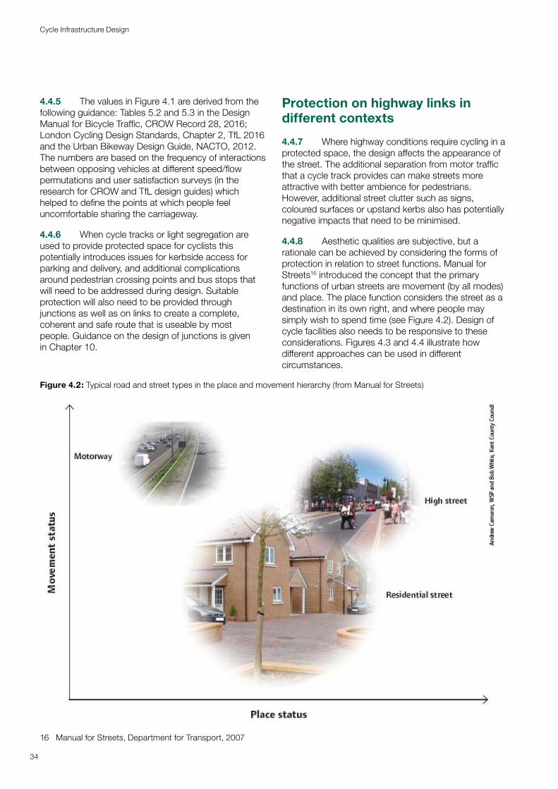
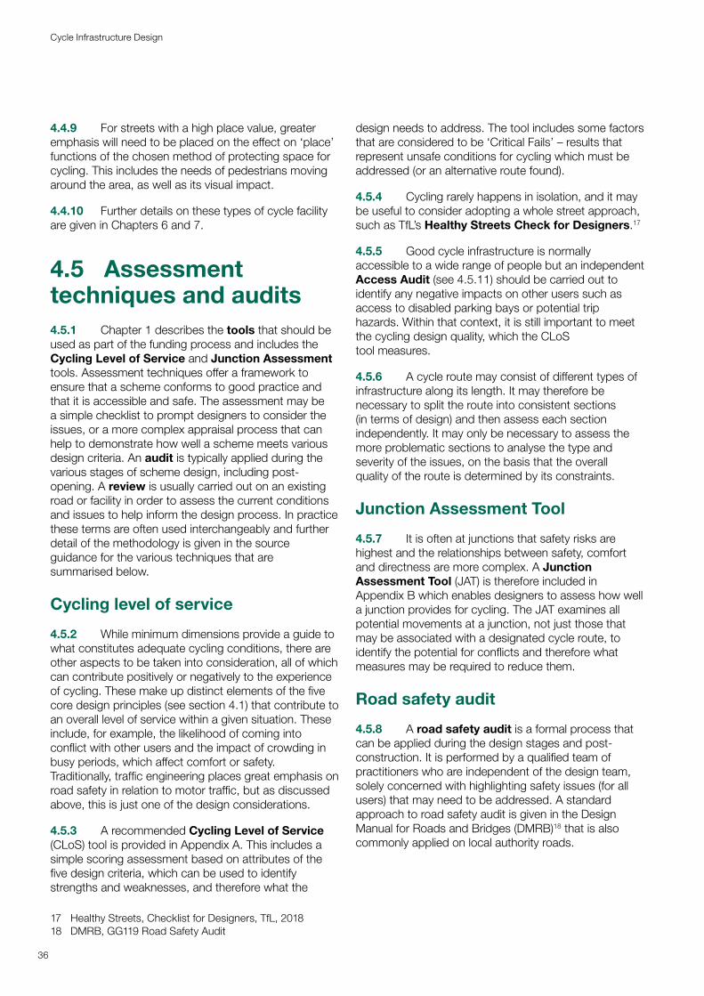
4.4.8 Aesthetic qualities are subjective, but a rationale can be achieved by considering the forms of protection in relation to street functions. Manual for Streets16 introduced the concept that the primary functions of urban streets are movement (by all modes) and place. The place function considers the street as a destination in its own right, and where people may simply wish to spend time (see Figure 4.2). Design of cycle facilities also needs to be responsive to these considerations. Figures 4.3 and 4.4 illustrate how different approaches can be used in different circumstances.
Figure 4.2: Typical road and street types in the place and movement hierarchy (from Manual for Streets)
34
Cycle Infrastructure Design
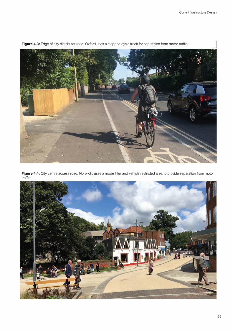
Figure 4.3: Edge of city distributor road, Oxford uses a stepped cycle track for separation from motor traffic
Figure 4.4: City centre access road, Norwich, uses a mode filter and vehicle restricted area to provide separation from motor traffic
35
Cycle Infrastructure Design
4.4.9 For streets with a high place value, greater emphasis will need to be placed on the effect on ‘place’ functions of the chosen method of protecting space for cycling. This includes the needs of pedestrians moving around the area, as well as its visual impact.
4.4.10 Further details on these types of cycle facility are given in Chapters 6 and 7.
4.5 Assessment techniques and audits 4.5.1 Chapter 1 describes the tools that should be used as part of the funding process and includes the Cycling Level of Service and Junction Assessment tools. Assessment techniques offer a framework to ensure that a scheme conforms to good practice and that it is accessible and safe. The assessment may be a simple checklist to prompt designers to consider the issues, or a more complex appraisal process that can help to demonstrate how well a scheme meets various design criteria. An audit is typically applied during the various stages of scheme design, including post-opening. A review is usually carried out on an existing road or facility in order to assess the current conditions and issues to help inform the design process. In practice these terms are often used interchangeably and further detail of the methodology is given in the source guidance for the various techniques that are summarised below.
Cycling level of service
4.5.2 While minimum dimensions provide a guide to what constitutes adequate cycling conditions, there are other aspects to be taken into consideration, all of which can contribute positively or negatively to the experience of cycling. These make up distinct elements of the five core design principles (see section 4.1) that contribute to an overall level of service within a given situation. These include, for example, the likelihood of coming into conflict with other users and the impact of crowding in busy periods, which affect comfort or safety. Traditionally, traffic engineering places great emphasis on road safety in relation to motor traffic, but as discussed above, this is just one of the design considerations.
4.5.3 A recommended Cycling Level of Service (CLoS) tool is provided in Appendix A. This includes a simple scoring assessment based on attributes of the five design criteria, which can be used to identify strengths and weaknesses, and therefore what the
17 Healthy Streets, Checklist for Designers, TfL, 201818 DMRB, GG119 Road Safety Audit
design needs to address. The tool includes some factors that are considered to be ‘Critical Fails’ – results that represent unsafe conditions for cycling which must be addressed (or an alternative route found).
4.5.4 Cycling rarely happens in isolation, and it may be useful to consider adopting a whole street approach, such as TfL’s Healthy Streets Check for Designers.17
4.5.5 Good cycle infrastructure is normally accessible to a wide range of people but an independent Access Audit (see 4.5.11) should be carried out to identify any negative impacts on other users such as access to disabled parking bays or potential trip hazards. Within that context, it is still important to meet the cycling design quality, which the CLoS tool measures.
4.5.6 A cycle route may consist of different types of infrastructure along its length. It may therefore be necessary to split the route into consistent sections (in terms of design) and then assess each section independently. It may only be necessary to assess the more problematic sections to analyse the type and severity of the issues, on the basis that the overall quality of the route is determined by its constraints.
Junction Assessment Tool
4.5.7 It is often at junctions that safety risks are highest and the relationships between safety, comfort and directness are more complex. A Junction Assessment Tool (JAT) is therefore included in Appendix B which enables designers to assess how well a junction provides for cycling. The JAT examines all potential movements at a junction, not just those that may be associated with a designated cycle route, to identify the potential for conflicts and therefore what measures may be required to reduce them.
Road safety audit
4.5.8 A road safety audit is a formal process that can be applied during the design stages and post-construction. It is performed by a qualified team of practitioners who are independent of the design team, solely concerned with highlighting safety issues (for all users) that may need to be addressed. A standard approach to road safety audit is given in the Design Manual for Roads and Bridges (DMRB)18 that is also commonly applied on local authority roads.
36
Cycle Infrastructure Design
4.5.9 A road safety audit will only consider one of the five core design principles (i.e. safety). If a problem is highlighted, the design modification recommended may adversely affect how well the scheme meets the other four principles. For example, if a road safety audit recommends that cyclists should lose priority at a junction as a mitigation measure for an identified risk, this would have an adverse effect on comfort and directness. It is for the designer to decide whether and to what extent to accept the recommendations of the safety audit, taking into account the overall impact on the level of service for cycling. Any decisions should be documented as part of the audit process.
Walking, Cycling and Horse Riding Assessment and Review
4.5.10 DMRB also contains guidance on undertaking a Walking, Cycling & Horse-Riding Assessment and Review (WCHAR).19 Although this is applicable to trunk roads, it provides a good basis for assessing the needs of all users along and across interurban roads.
Equality and access assessments
4.5.11 Local authorities are bound by the Equality Act 2010 in discharging their functions, which includes managing their road networks. Designers should provide infrastructure that is accessible to all, and the dimensions and other features set out in this guidance should help ensure that their designs comply with the Public Sector Equality Duty. An Access Audit should be undertaken of all proposals to ensure that a scheme meets the needs of those with protected characteristics under the Equality Act 2010, particularly people with a disability. The Access Audit (also formerly known as a DDA audit, Disability Discrimination Act Audit or Disabled Access Audit) is an assessment of a building, a street environment or a service against best-practice standards to benchmark its accessibility for disabled people. It may form part of an overall Equality Impact Assessment.
19 DMRB, Volume 5, Section 2, HD42 Cycling, Walking and Horse-Riding Assessment and Review
37
Cycle Infrastructure Design
5Geometric requirementsGeometric requirements
Meeting the core design criteria requires attention to the space, sightlines, gradients and surface conditions available for cycling. The geometric conditions that provide a good level of service for cycling are universal and should apply to all types of cycle infrastructure. This document takes the dimensional requirements of the concept ‘design cycle vehicle’ described below as the determinant of the minimal dimensions for widths, lengths and corner radii to ensure that routes are accessible to all.
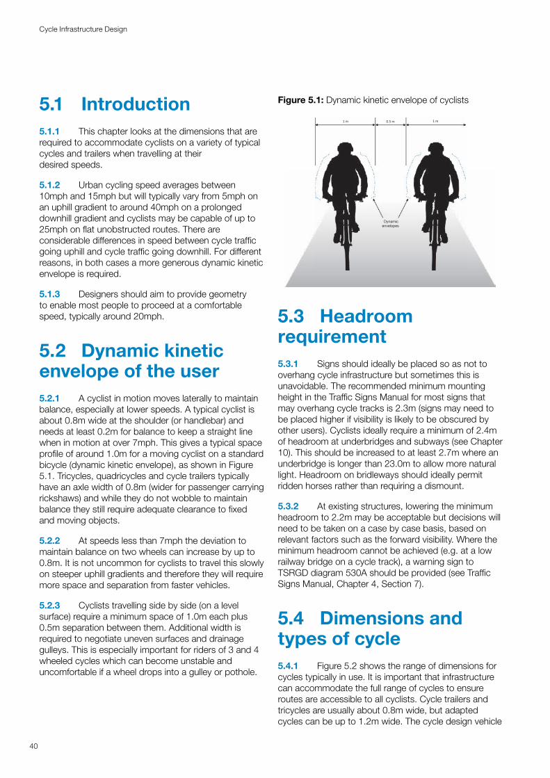
5.1 Introduction5.1.1 This chapter looks at the dimensions that are required to accommodate cyclists on a variety of typical cycles and trailers when travelling at their desired speeds.
5.1.2 Urban cycling speed averages between 10mph and 15mph but will typically vary from 5mph on an uphill gradient to around 40mph on a prolonged downhill gradient and cyclists may be capable of up to 25mph on flat unobstructed routes. There are considerable differences in speed between cycle traffic going uphill and cycle traffic going downhill. For different reasons, in both cases a more generous dynamic kinetic envelope is required.
5.1.3 Designers should aim to provide geometry to enable most people to proceed at a comfortable speed, typically around 20mph.
5.2 Dynamic kinetic envelope of the user5.2.1 A cyclist in motion moves laterally to maintain balance, especially at lower speeds. A typical cyclist is about 0.8m wide at the shoulder (or handlebar) and needs at least 0.2m for balance to keep a straight line when in motion at over 7mph. This gives a typical space profile of around 1.0m for a moving cyclist on a standard bicycle (dynamic kinetic envelope), as shown in Figure 5.1. Tricycles, quadricycles and cycle trailers typically have an axle width of 0.8m (wider for passenger carrying rickshaws) and while they do not wobble to maintain balance they still require adequate clearance to fixed and moving objects.
5.2.2 At speeds less than 7mph the deviation to maintain balance on two wheels can increase by up to 0.8m. It is not uncommon for cyclists to travel this slowly on steeper uphill gradients and therefore they will require more space and separation from faster vehicles.
5.2.3 Cyclists travelling side by side (on a level surface) require a minimum space of 1.0m each plus 0.5m separation between them. Additional width is required to negotiate uneven surfaces and drainage gulleys. This is especially important for riders of 3 and 4 wheeled cycles which can become unstable and uncomfortable if a wheel drops into a gulley or pothole.
Figure 5.1: Dynamic kinetic envelope of cyclists
5.3 Headroom requirement 5.3.1 Signs should ideally be placed so as not to overhang cycle infrastructure but sometimes this is unavoidable. The recommended minimum mounting height in the Traffic Signs Manual for most signs that may overhang cycle tracks is 2.3m (signs may need to be placed higher if visibility is likely to be obscured by other users). Cyclists ideally require a minimum of 2.4m of headroom at underbridges and subways (see Chapter 10). This should be increased to at least 2.7m where an underbridge is longer than 23.0m to allow more natural light. Headroom on bridleways should ideally permit ridden horses rather than requiring a dismount.
5.3.2 At existing structures, lowering the minimum headroom to 2.2m may be acceptable but decisions will need to be taken on a case by case basis, based on relevant factors such as the forward visibility. Where the minimum headroom cannot be achieved (e.g. at a low railway bridge on a cycle track), a warning sign to TSRGD diagram 530A should be provided (see Traffic Signs Manual, Chapter 4, Section 7).
5.4 Dimensions and types of cycle5.4.1 Figure 5.2 shows the range of dimensions for cycles typically in use. It is important that infrastructure can accommodate the full range of cycles to ensure routes are accessible to all cyclists. Cycle trailers and tricycles are usually about 0.8m wide, but adapted cycles can be up to 1.2m wide. The cycle design vehicle
1 m 0.5 m 1 m
Dynamic envelopes
40
Cycle Infrastructure Design
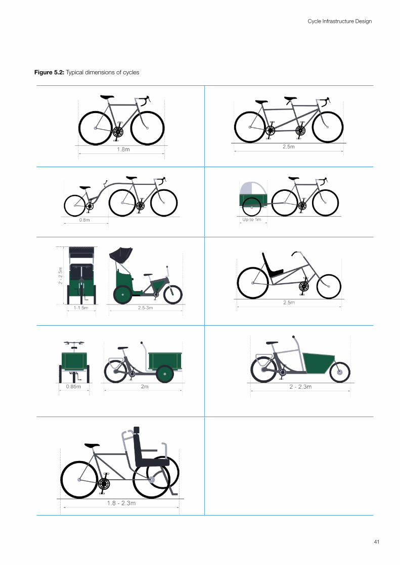
Figure 5.2: Typical dimensions of cyclesFigure 5.2: Typical dimensions of cycles
Cycle Infrastructure Design
41
Cycle Infrastructure Design
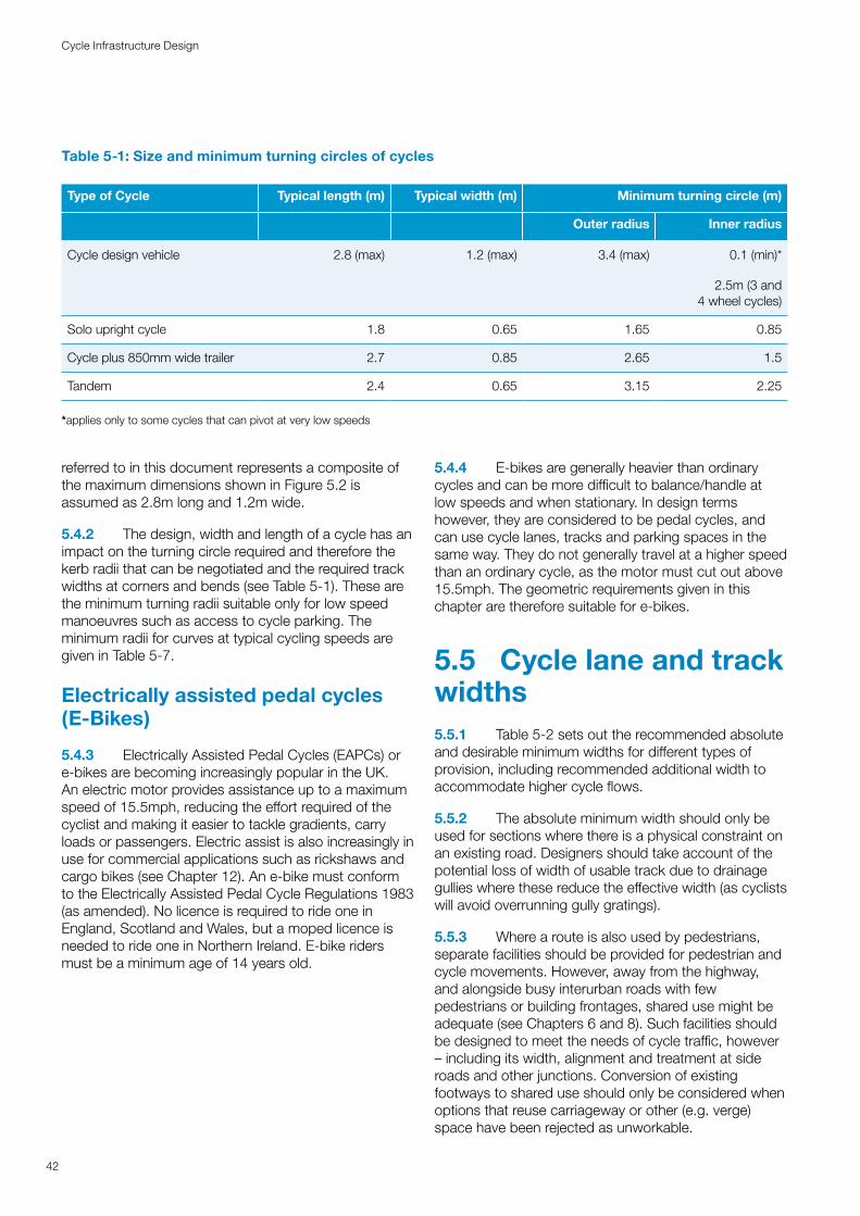
Table 5-1: Size and minimum turning circles of cycles
Type of Cycle Typical length (m) Typical width (m) Minimum turning circle (m)
Outer radius Inner radius
Cycle design vehicle 2.8 (max) 1.2 (max) 3.4 (max) 0.1 (min)*
2.5m (3 and 4 wheel cycles)
Solo upright cycle 1.8 0.65 1.65 0.85
Cycle plus 850mm wide trailer 2.7 0.85 2.65 1.5
Tandem 2.4 0.65 3.15 2.25
*applies only to some cycles that can pivot at very low speeds
referred to in this document represents a composite of the maximum dimensions shown in Figure 5.2 is assumed as 2.8m long and 1.2m wide.
5.4.2 The design, width and length of a cycle has an impact on the turning circle required and therefore the kerb radii that can be negotiated and the required track widths at corners and bends (see Table 5-1). These are the minimum turning radii suitable only for low speed manoeuvres such as access to cycle parking. The minimum radii for curves at typical cycling speeds are given in Table 5-7.
Electrically assisted pedal cycles (E-Bikes)
5.4.3 Electrically Assisted Pedal Cycles (EAPCs) or e-bikes are becoming increasingly popular in the UK.An electric motor provides assistance up to a maximumspeed of 15.5mph, reducing the effort required of thecyclist and making it easier to tackle gradients, carryloads or passengers. Electric assist is also increasingly inuse for commercial applications such as rickshaws andcargo bikes (see Chapter 12). An e-bike must conformto the Electrically Assisted Pedal Cycle Regulations 1983(as amended). No licence is required to ride one inEngland, Scotland and Wales, but a moped licence isneeded to ride one in Northern Ireland. E-bike ridersmust be a minimum age of 14 years old.
5.4.4 E-bikes are generally heavier than ordinary cycles and can be more difficult to balance/handle at low speeds and when stationary. In design terms however, they are considered to be pedal cycles, and can use cycle lanes, tracks and parking spaces in the same way. They do not generally travel at a higher speed than an ordinary cycle, as the motor must cut out above 15.5mph. The geometric requirements given in this chapter are therefore suitable for e-bikes.
5.5 Cycle lane and track widths
42
Cycle Infrastructure Design
5.5.1 Table 5-2 sets out the recommended absolute and desirable minimum widths for different types of provision, including recommended additional width to accommodate higher cycle flows.
5.5.2 The absolute minimum width should only be used for sections where there is a physical constraint on an existing road. Designers should take account of the potential loss of width of usable track due to drainage gullies where these reduce the effective width (as cyclists will avoid overrunning gully gratings).
5.5.3 Where a route is also used by pedestrians, separate facilities should be provided for pedestrian and cycle movements. However, away from the highway, and alongside busy interurban roads with few pedestrians or building frontages, shared use might be adequate (see Chapters 6 and 8). Such facilities should be designed to meet the needs of cycle traffic, however – including its width, alignment and treatment at sideroads and other junctions. Conversion of existingfootways to shared use should only be considered whenoptions that reuse carriageway or other (e.g. verge)space have been rejected as unworkable.
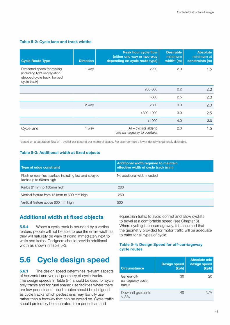
Table 5-2: Cycle lane and track widths
Cycle Route Type Direction
Peak hour cycle flow (either one way or two-way
depending on cycle route type)
Desirable minimum
width* (m)
Absolute minimum at
constraints (m)
Protected space for cycling (including light segregation, stepped cycle track, kerbed cycle track)
1 way <200 2.0 1.5
200-800 2.2 2.0
>800 2.5 2.0
2 way <300 3.0 2.0
>300-1000 3.0 2.5
>1000 4.0 3.0
Cycle lane 1 way All – cyclists able to use carriageway to overtake
2.0 1.5
*based on a saturation flow of 1 cyclist per second per metre of space. For user comfort a lower density is generally desirable.
Table 5-3: Additional width at fixed objects
Type of edge constraintAdditional width required to maintain effective width of cycle track (mm)
Flush or near-flush surface including low and splayed kerbs up to 60mm high
No additional width needed
Kerbs 61mm to 150mm high 200
Vertical feature from 151mm to 600 mm high 250
Vertical feature above 600 mm high 500
43
Cycle Infrastructure Design
Additional width at fixed objects
5.5.4 Where a cycle track is bounded by a vertical feature, people will not be able to use the entire width as they will naturally be wary of riding immediately next to walls and kerbs. Designers should provide additional width as shown in Table 5-3.
5.6 Cycle design speed5.6.1 The design speed determines relevant aspects of horizontal and vertical geometry of cycle tracks. The design speeds in Table 5-4 should be used for cycle only tracks and for rural shared use facilities where there are few pedestrians – such routes should be designed as cycle tracks which pedestrians may lawfully use rather than a footway that can be cycled on. Cycle traffic should preferably be separated from pedestrian and
equestrian traffic to avoid conflict and allow cyclists to travel at a comfortable speed (see Chapter 6). Where cycling is on-carriageway, it is assumed that the geometry provided for motor traffic will be adequate to cater for all types of cycle.
Table 5-4: Design Speed for off-carriageway cycle routes
CircumstanceDesign speed
(kph)
Absolute min design speed
(kph)
General off-carriageway cycle tracks
30 20
Downhill gradients > 3%
40 N/A
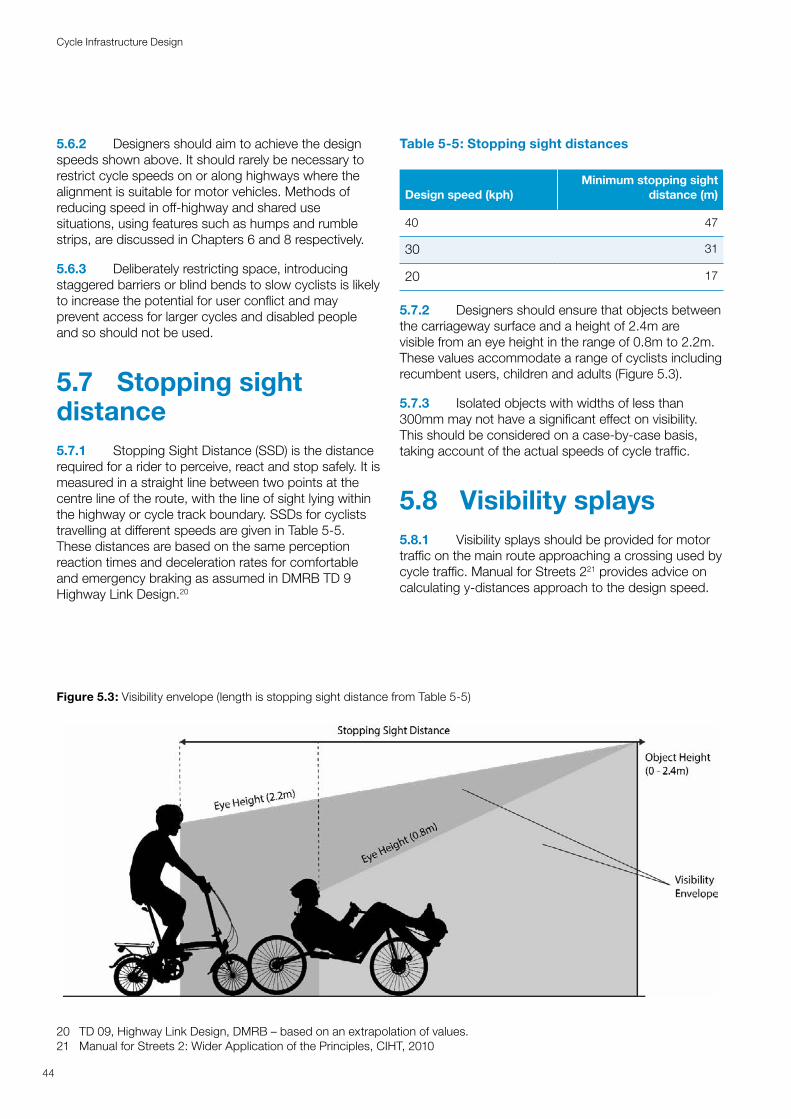
5.6.2 Designers should aim to achieve the design speeds shown above. It should rarely be necessary to restrict cycle speeds on or along highways where the alignment is suitable for motor vehicles. Methods of reducing speed in off-highway and shared use situations, using features such as humps and rumble strips, are discussed in Chapters 6 and 8 respectively.
5.6.3 Deliberately restricting space, introducing staggered barriers or blind bends to slow cyclists is likely to increase the potential for user conflict and may prevent access for larger cycles and disabled people and so should not be used.
5.7 Stopping sight distance5.7.1 Stopping Sight Distance (SSD) is the distance required for a rider to perceive, react and stop safely. It is measured in a straight line between two points at the centre line of the route, with the line of sight lying within the highway or cycle track boundary. SSDs for cyclists travelling at different speeds are given in Table 5-5. These distances are based on the same perception reaction times and deceleration rates for comfortable and emergency braking as assumed in DMRB TD 9 Highway Link Design.20
20 TD 09, Highway Link Design, DMRB – based on an extrapolation of values.21 Manual for Streets 2: Wider Application of the Principles, CIHT, 2010
Table 5-5: Stopping sight distances
Design speed (kph)Minimum stopping sight
distance (m)
40 47
30 31
20 17
5.7.2 Designers should ensure that objects between the carriageway surface and a height of 2.4m are visible from an eye height in the range of 0.8m to 2.2m. These values accommodate a range of cyclists including recumbent users, children and adults (Figure 5.3).
5.7.3 Isolated objects with widths of less than 300mm may not have a significant effect on visibility. This should be considered on a case-by-case basis, taking account of the actual speeds of cycle traffic.
5.8 Visibility splays5.8.1 Visibility splays should be provided for motor traffic on the main route approaching a crossing used by cycle traffic. Manual for Streets 221 provides advice on calculating y-distances approach to the design speed.
Figure 5.3: Visibility envelope (length is stopping sight distance from Table 5-5)
44
Cycle Infrastructure Design
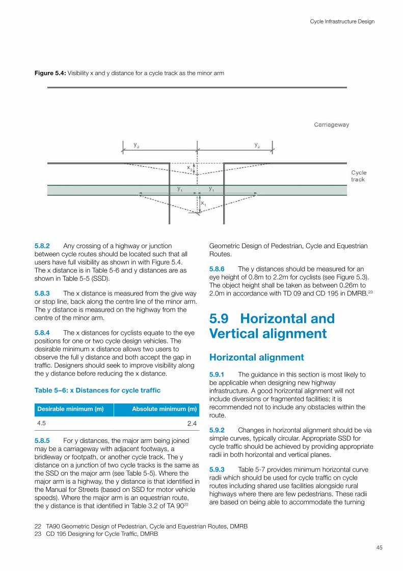
Figure 5.4: Visibility x and y distance for a cycle track as the minor arm
45
Cycle Infrastructure Design
5.8.2 Any crossing of a highway or junction between cycle routes should be located such that all users have full visibility as shown in with Figure 5.4. The x distance is in Table 5-6 and y distances are as shown in Table 5-5 (SSD).
5.8.3 The x distance is measured from the give way or stop line, back along the centre line of the minor arm. The y distance is measured on the highway from the centre of the minor arm.
5.8.4 The x distances for cyclists equate to the eye positions for one or two cycle design vehicles. The desirable minimum x distance allows two users to observe the full y distance and both accept the gap in traffic. Designers should seek to improve visibility along the y distance before reducing the x distance.
Table 5–6: x Distances for cycle traffic
Desirable minimum (m) Absolute minimum (m)
4.5 2.4
5.8.5 For y distances, the major arm being joined may be a carriageway with adjacent footways, a bridleway or footpath, or another cycle track. The y distance on a junction of two cycle tracks is the same as the SSD on the major arm (see Table 5-5). Where the major arm is a highway, the y distance is that identified in the Manual for Streets (based on SSD for motor vehicle speeds). Where the major arm is an equestrian route, the y distance is that identified in Table 3.2 of TA 9022
22 TA90 Geometric Design of Pedestrian, Cycle and Equestrian Routes, DMRB23 CD 195 Designing for Cycle Traffic, DMRB
Geometric Design of Pedestrian, Cycle and Equestrian Routes.
5.8.6 The y distances should be measured for an eye height of 0.8m to 2.2m for cyclists (see Figure 5.3). The object height shall be taken as between 0.26m to 2.0m in accordance with TD 09 and CD 195 in DMRB.23
5.9 Horizontal and Vertical alignment
Horizontal alignment
5.9.1 The guidance in this section is most likely to be applicable when designing new highway infrastructure. A good horizontal alignment will not include diversions or fragmented facilities; it is recommended not to include any obstacles within the route.
5.9.2 Changes in horizontal alignment should be via simple curves, typically circular. Appropriate SSD for cycle traffic should be achieved by providing appropriate radii in both horizontal and vertical planes.
5.9.3 Table 5-7 provides minimum horizontal curve radii which should be used for cycle traffic on cycle routes including shared use facilities alongside rural highways where there are few pedestrians. These radii are based on being able to accommodate the turning
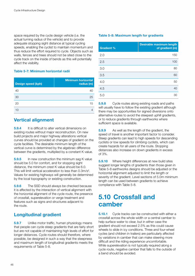
space required by the cycle design vehicle (i.e. the actual turning radius of the vehicle) and to provide adequate stopping sight distance at typical cycling speeds, enabling the cyclist to maintain momentum and thus reduce the effort required to cycle. Objects such as walls, fences and trees should not be sited close to the cycle track on the inside of bends as this will potentially affect the visibility.
Table 5-7: Minimum horizontal radii
Design speed (kph)Minimum horizontal
radius (m)
40 40
30 25
20 15
10 4
Vertical alignment
5.9.4 It is difficult to alter vertical dimensions on existing routes without major reconstruction. On new build projects and major highway alterations vertical curves should be provided at changes of gradient on the cycle facilities. The desirable minimum length of the vertical curve is determined by the algebraic difference between the gradients, multiplied by a constant K value.
5.9.5 In new construction the minimum sag K value should be 5.0 for comfort, and for stopping sight distance, the minimum crest K value should be 6.0. This will limit vertical acceleration to less than 0.3m/s². Values for existing highways will generally be determined by the local topography or existing construction.
5.9.6 The SSD should always be checked because it is affected by the interaction of vertical alignment with the horizontal alignment of the cycle route, the presence of crossfall, superelevation or verge treatment and features such as signs and structures adjacent to the route.
Longitudinal gradient
5.9.7 Unlike motor traffic, human physiology means that people can cycle steep gradients that are fairly short but are not capable of maintaining high levels of effort for longer distances. Cycle routes should therefore, where possible, be designed in such a way that the steepness and maximum length of longitudinal gradients meets the requirements of Table 5-8.
Table 5-8: Maximum length for gradients
Gradient %Desirable maximum length
of gradient (m)
2.0 150
2.5 100
3.0 80
3.5 60
4.0 50
4.5 40
5.0 30
5.9.8 Cycle routes along existing roads and paths will usually have to follow the existing gradient although there may be opportunities for signed diversions onto alternative routes to avoid the steepest uphill gradients, or to reduce gradients through earthworks where sufficient space is available.
5.9.9 As well as the length of the gradient, the speed of travel is another important factor to consider. Steep gradients can lead to high speeds for descending cyclists or low speeds for climbing cyclists, which can create hazards for all users of the route. Stopping distances also increase on down gradients in excess of 3%.
5.9.10 Where height differences at new build sites suggest longer lengths of gradients than those given in Table 5-8 earthworks designs should be adjusted or the horizontal alignment adjusted to limit the length or severity of the gradient. Level sections of 5.0m minimum length can be used between gradients to achieve compliance with Table 5-8.
5.10 Crossfall and camber5.10.1 Cycle tracks can be constructed with either a crossfall across the whole width or a central camber to help surface water to clear, but in either case the gradient should not exceed 2.5% as this could cause wheels to slide in icy conditions. Three and four-wheel cycles (and children in trailers) are particularly affected by variations in camber that can make steering more difficult and the riding experience uncomfortable. While superelevation is not typically required along a cycle route, negative camber that falls to the outside of a bend should be avoided.
46
Cycle Infrastructure Design
5.11 Edge protection 5.11.1 Gradients present a potential hazard where cyclists could lose control. Designers should carefully consider the combination of horizontal and vertical geometry where gradients are greater than 3%. Unguarded hazards (e.g. fixed objects, steep drops or water hazards) should not be permitted within 4.5m of the route where they would lie in the path of an out-of-control cycle. An example location where a hazard should be guarded is adjacent to the vertical drop to the water at the bottom of an access ramp that approaches a river bank or canal towpath.
5.11.2 Edge protection may be necessary including alongside ramps to overbridges and underbridges (see Grade Separation in Chapter 10).
5.11.3 A crash barrier or safety fence may be necessary alongside roads with speed limits of 50mph or above where there is a physical constraint such as a bridge parapet or steep embankment that places the cycle track immediately alongside the carriageway without a verge or separating margin.
47
Cycle Infrastructure Design
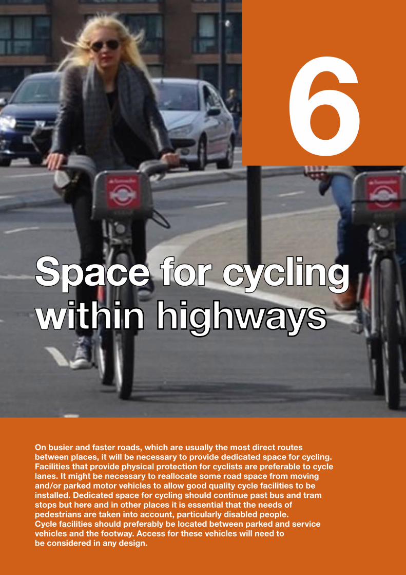
SSppaaccee f foorr c cyyclcliningg wwithin highwaysithin highways
On busier and faster roads, which are usually the most direct routes between places, it will be necessary to provide dedicated space for cycling. Facilities that provide physical protection for cyclists are preferable to cycle lanes. It might be necessary to reallocate some road space from moving and/or parked motor vehicles to allow good quality cycle facilities to be installed. Dedicated space for cycling should continue past bus and tram stops but here and in other places it is essential that the needs of pedestrians are taken into account, particularly disabled people. Cycle facilities should preferably be located between parked and service vehicles and the footway. Access for these vehicles will need to be considered in any design.
6
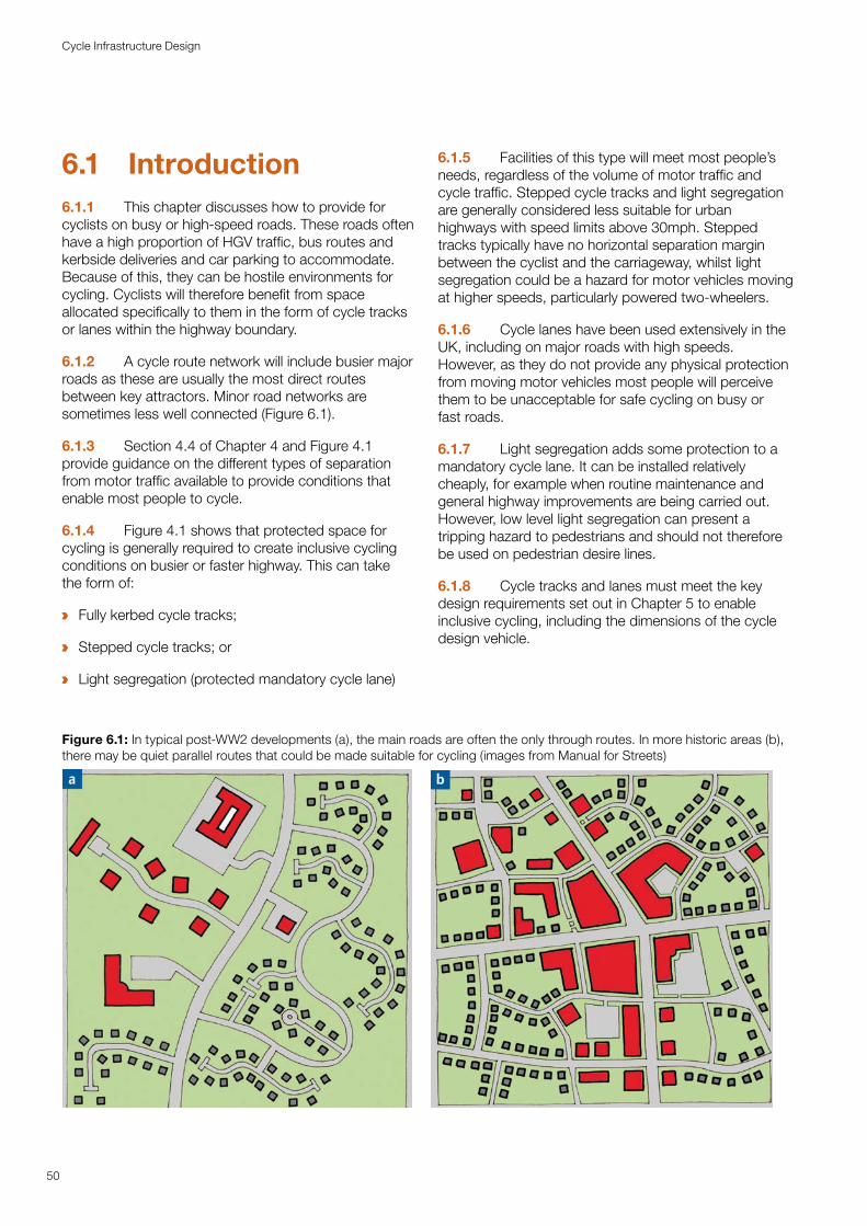
6.1 Introduction6.1.1 This chapter discusses how to provide for cyclists on busy or high-speed roads. These roads often have a high proportion of HGV traffic, bus routes and kerbside deliveries and car parking to accommodate. Because of this, they can be hostile environments for cycling. Cyclists will therefore benefit from space allocated specifically to them in the form of cycle tracks or lanes within the highway boundary.
6.1.2 A cycle route network will include busier major roads as these are usually the most direct routes between key attractors. Minor road networks are sometimes less well connected (Figure 6.1).
6.1.3 Section 4.4 of Chapter 4 and Figure 4.1 provide guidance on the different types of separation from motor traffic available to provide conditions that enable most people to cycle.
6.1.4 Figure 4.1 shows that protected space for cycling is generally required to create inclusive cycling conditions on busier or faster highway. This can take the form of:
a Fully kerbed cycle tracks;
a Stepped cycle tracks; or
a Light segregation (protected mandatory cycle lane)
6.1.5 Facilities of this type will meet most people’s needs, regardless of the volume of motor traffic and cycle traffic. Stepped cycle tracks and light segregation are generally considered less suitable for urban highways with speed limits above 30mph. Stepped tracks typically have no horizontal separation margin between the cyclist and the carriageway, whilst light segregation could be a hazard for motor vehicles moving at higher speeds, particularly powered two-wheelers.
6.1.6 Cycle lanes have been used extensively in the UK, including on major roads with high speeds. However, as they do not provide any physical protection from moving motor vehicles most people will perceive them to be unacceptable for safe cycling on busy or fast roads.
6.1.7 Light segregation adds some protection to a mandatory cycle lane. It can be installed relatively cheaply, for example when routine maintenance and general highway improvements are being carried out. However, low level light segregation can present a tripping hazard to pedestrians and should not therefore be used on pedestrian desire lines.
6.1.8 Cycle tracks and lanes must meet the key design requirements set out in Chapter 5 to enable inclusive cycling, including the dimensions of the cycle design vehicle.
Figure 6.1: In typical post-WW2 developments (a), the main roads are often the only through routes. In more historic areas (b), there may be quiet parallel routes that could be made suitable for cycling (images from Manual for Streets)
50
Cycle Infrastructure Design
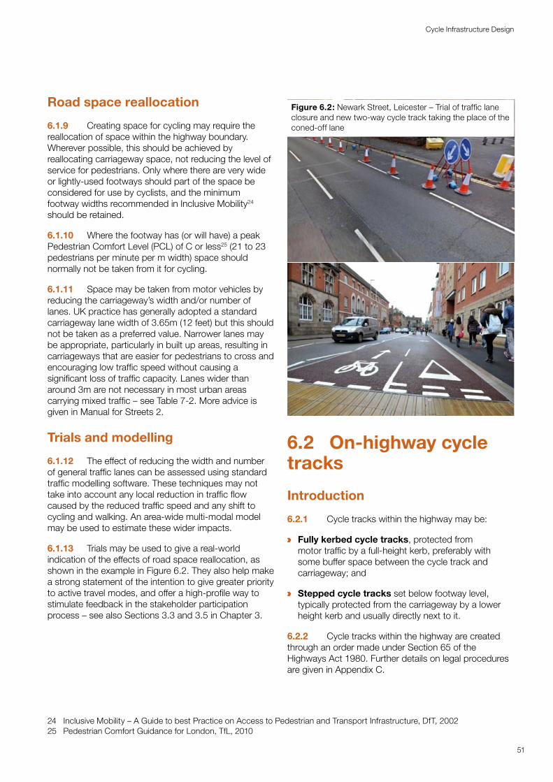
Road space reallocation
6.1.9 Creating space for cycling may require the reallocation of space within the highway boundary. Wherever possible, this should be achieved by reallocating carriageway space, not reducing the level of service for pedestrians. Only where there are very wide or lightly-used footways should part of the space be considered for use by cyclists, and the minimum footway widths recommended in Inclusive Mobility24 should be retained.
6.1.10 Where the footway has (or will have) a peak Pedestrian Comfort Level (PCL) of C or less25 (21 to 23 pedestrians per minute per m width) space should normally not be taken from it for cycling.
6.1.11 Space may be taken from motor vehicles by reducing the carriageway’s width and/or number of lanes. UK practice has generally adopted a standard carriageway lane width of 3.65m (12 feet) but this should not be taken as a preferred value. Narrower lanes may be appropriate, particularly in built up areas, resulting in carriageways that are easier for pedestrians to cross and encouraging low traffic speed without causing a significant loss of traffic capacity. Lanes wider than around 3m are not necessary in most urban areas carrying mixed traffic – see Table 7-2. More advice is given in Manual for Streets 2.
Trials and modelling
6.1.12 The effect of reducing the width and number of general traffic lanes can be assessed using standard traffic modelling software. These techniques may not take into account any local reduction in traffic flow caused by the reduced traffic speed and any shift to cycling and walking. An area-wide multi-modal model may be used to estimate these wider impacts.
6.1.13 Trials may be used to give a real-world indication of the effects of road space reallocation, as shown in the example in Figure 6.2. They also help make a strong statement of the intention to give greater priority to active travel modes, and offer a high-profile way to stimulate feedback in the stakeholder participation process – see also Sections 3.3 and 3.5 in Chapter 3.
24 Inclusive Mobility – A Guide to best Practice on Access to Pedestrian and Transport Infrastructure, DfT, 200225 Pedestrian Comfort Guidance for London, TfL, 2010
Figure 6.2: Newark Street, Leicester – Trial of traffic lane closure and new two-way cycle track taking the place of the coned-off lane
6.2 On-highway cycle tracks
Introduction
6.2.1 Cycle tracks within the highway may be:
a Fully kerbed cycle tracks, protected from motor traffic by a full-height kerb, preferably with some buffer space between the cycle track and carriageway; and
a Stepped cycle tracks set below footway level, typically protected from the carriageway by a lower height kerb and usually directly next to it.
6.2.2 Cycle tracks within the highway are created through an order made under Section 65 of the Highways Act 1980. Further details on legal procedures are given in Appendix C.
51
Cycle Infrastructure Design
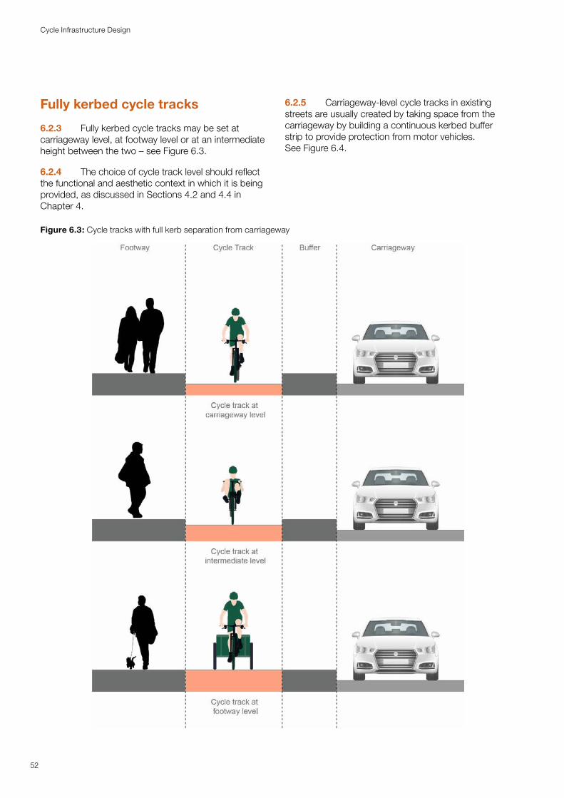
Fully kerbed cycle tracks
6.2.3 Fully kerbed cycle tracks may be set at carriageway level, at footway level or at an intermediate height between the two – see Figure 6.3.
6.2.4 The choice of cycle track level should reflect the functional and aesthetic context in which it is being provided, as discussed in Sections 4.2 and 4.4 in Chapter 4.
6.2.5 Carriageway-level cycle tracks in existing streets are usually created by taking space from the carriageway by building a continuous kerbed buffer strip to provide protection from motor vehicles. See Figure 6.4.
Figure 6.3: Cycle tracks with full kerb separation from carriageway
52
Cycle Infrastructure Design
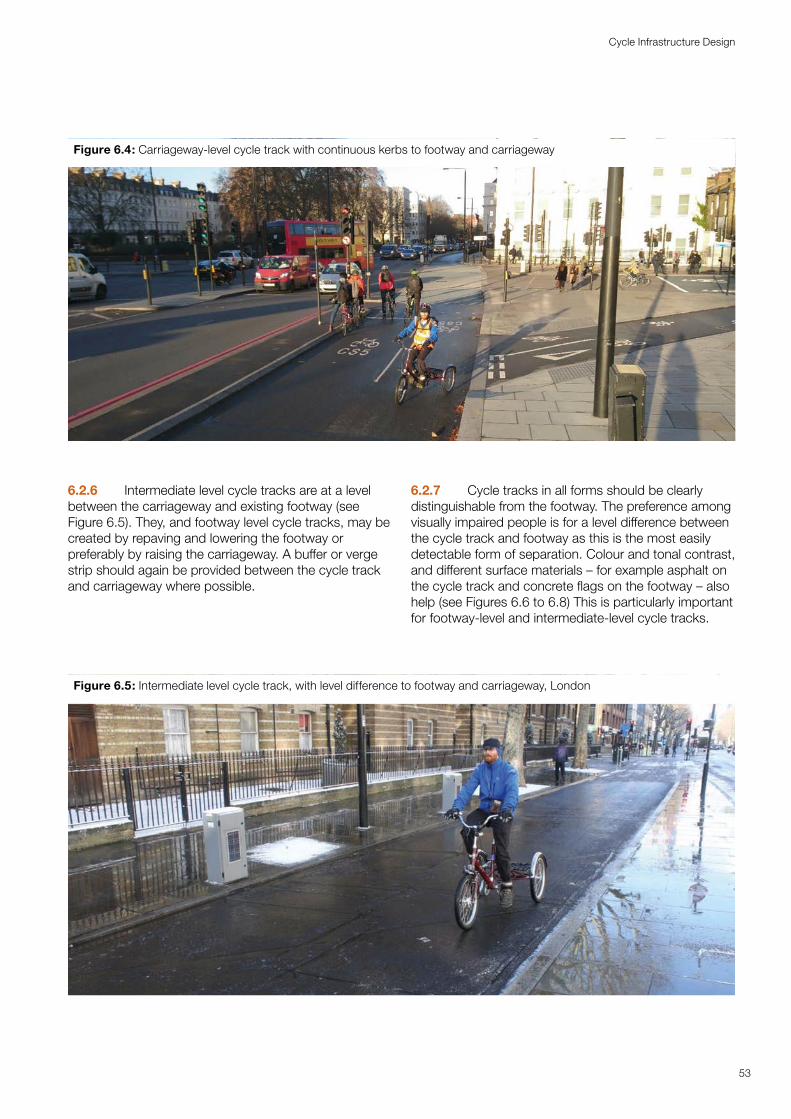
Figure 6.4: Carriageway-level cycle track with continuous kerbs to footway and carriageway
6.2.6 Intermediate level cycle tracks are at a level between the carriageway and existing footway (see Figure 6.5). They, and footway level cycle tracks, may be created by repaving and lowering the footway or preferably by raising the carriageway. A buffer or verge strip should again be provided between the cycle track and carriageway where possible.
6.2.7 Cycle tracks in all forms should be clearly distinguishable from the footway. The preference among visually impaired people is for a level difference between the cycle track and footway as this is the most easily detectable form of separation. Colour and tonal contrast, and different surface materials – for example asphalt on the cycle track and concrete flags on the footway – also help (see Figures 6.6 to 6.8) This is particularly important for footway-level and intermediate-level cycle tracks.
Figure 6.5: Intermediate level cycle track, with level difference to footway and carriageway, London
53
Cycle Infrastructure Design
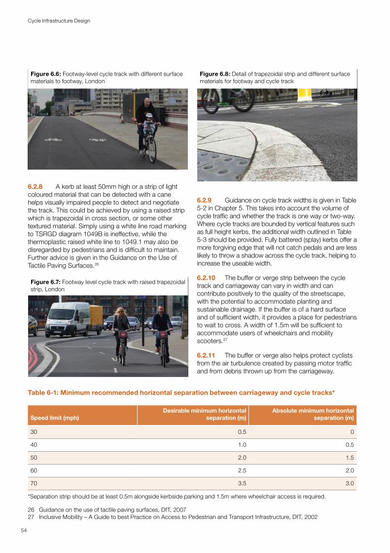
Figure 6.6: Footway-level cycle track with different surface materials to footway, London
6.2.8 A kerb at least 50mm high or a strip of light coloured material that can be detected with a cane helps visually impaired people to detect and negotiate the track. This could be achieved by using a raised strip which is trapezoidal in cross section, or some other textured material. Simply using a white line road marking to TSRGD diagram 1049B is ineffective, while the thermoplastic raised white line to 1049.1 may also be disregarded by pedestrians and is difficult to maintain. Further advice is given in the Guidance on the Use of Tactile Paving Surfaces.26
Figure 6.7: Footway level cycle track with raised trapezoidal strip, London
26 Guidance on the use of tactile paving surfaces, DfT, 200727 Inclusive Mobility – A Guide to best Practice on Access to Pedestrian and Transport Infrastructure, DfT, 2002
Figure 6.8: Detail of trapezoidal strip and different surface materials for footway and cycle track
6.2.9 Guidance on cycle track widths is given in Table 5-2 in Chapter 5. This takes into account the volume of cycle traffic and whether the track is one way or two-way. Where cycle tracks are bounded by vertical features such as full height kerbs, the additional width outlined in Table 5-3 should be provided. Fully battered (splay) kerbs offer a more forgiving edge that will not catch pedals and are less likely to throw a shadow across the cycle track, helping to increase the useable width.
6.2.10 The buffer or verge strip between the cycle track and carriageway can vary in width and can contribute positively to the quality of the streetscape, with the potential to accommodate planting and sustainable drainage. If the buffer is of a hard surface and of sufficient width, it provides a place for pedestrians to wait to cross. A width of 1.5m will be sufficient to accommodate users of wheelchairs and mobility scooters.27
6.2.11 The buffer or verge also helps protect cyclists from the air turbulence created by passing motor traffic and from debris thrown up from the carriageway.
Table 6-1: Minimum recommended horizontal separation between carriageway and cycle tracks*
Speed limit (mph) Desirable minimum horizontal
separation (m)Absolute minimum horizontal
separation (m)
30 0.5 0
40 1.0 0.5
50 2.0 1.5
60 2.5 2.0
70 3.5 3.0
*Separation strip should be at least 0.5m alongside kerbside parking and 1.5m where wheelchair access is required.
54
Cycle Infrastructure Design
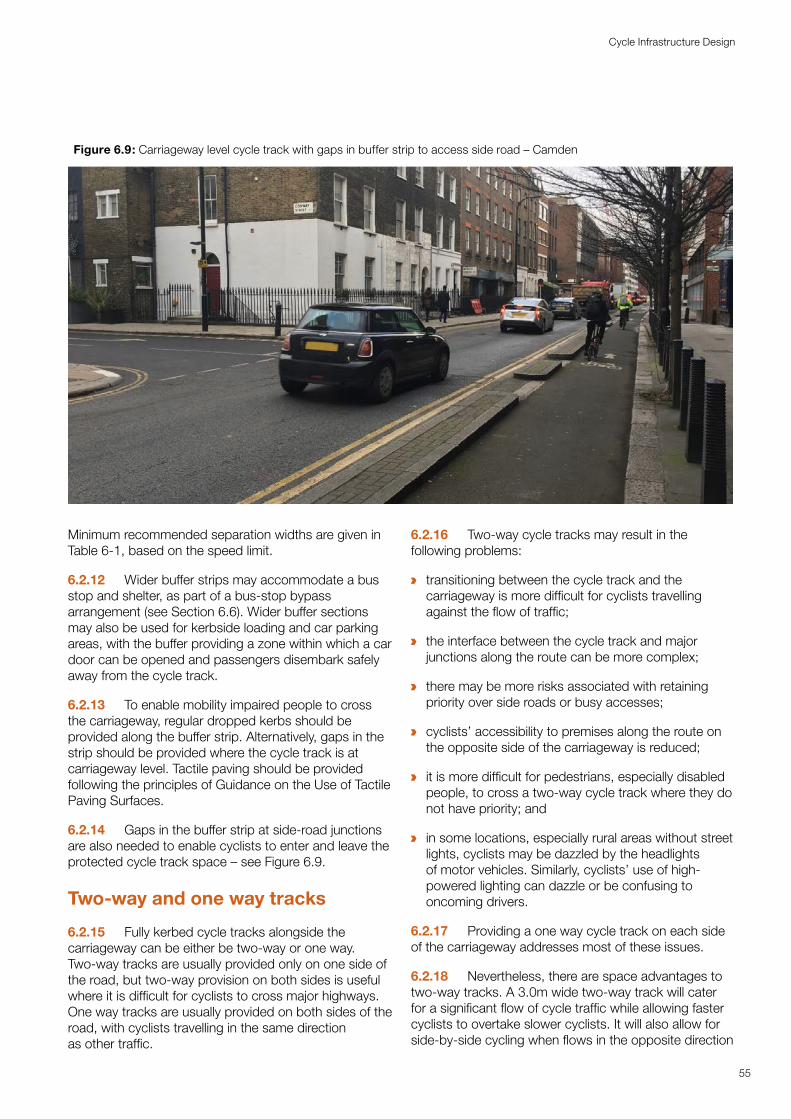
a
a
a
a
a
a
55
Cycle Infrastructure Design
Figure 6.9: Carriageway level cycle track with gaps in buffer strip to access side road – Camden
Minimum recommended separation widths are given in Table 6-1, based on the speed limit.
6.2.12 Wider buffer strips may accommodate a bus stop and shelter, as part of a bus-stop bypass arrangement (see Section 6.6). Wider buffer sections may also be used for kerbside loading and car parking areas, with the buffer providing a zone within which a car door can be opened and passengers disembark safely away from the cycle track.
6.2.13 To enable mobility impaired people to cross the carriageway, regular dropped kerbs should be provided along the buffer strip. Alternatively, gaps in the strip should be provided where the cycle track is at carriageway level. Tactile paving should be provided following the principles of Guidance on the Use of Tactile Paving Surfaces.
6.2.14 Gaps in the buffer strip at side-road junctions are also needed to enable cyclists to enter and leave the protected cycle track space – see Figure 6.9.
Two-way and one way tracks
6.2.15 Fully kerbed cycle tracks alongside the carriageway can be either be two-way or one way. Two-way tracks are usually provided only on one side of the road, but two-way provision on both sides is useful where it is difficult for cyclists to cross major highways. One way tracks are usually provided on both sides of the road, with cyclists travelling in the same direction as other traffic.
6.2.16 Two-way cycle tracks may result in the following problems:
transitioning between the cycle track and the carriageway is more difficult for cyclists travelling against the flow of traffic;
the interface between the cycle track and major junctions along the route can be more complex;
there may be more risks associated with retaining priority over side roads or busy accesses;
cyclists’ accessibility to premises along the route on the opposite side of the carriageway is reduced;
it is more difficult for pedestrians, especially disabled people, to cross a two-way cycle track where they do not have priority; and
in some locations, especially rural areas without street lights, cyclists may be dazzled by the headlights of motor vehicles. Similarly, cyclists’ use of high-powered lighting can dazzle or be confusing to oncoming drivers.
6.2.17 Providing a one way cycle track on each side of the carriageway addresses most of these issues.
6.2.18 Nevertheless, there are space advantages to two-way tracks. A 3.0m wide two-way track will cater for a significant flow of cycle traffic while allowing faster cyclists to overtake slower cyclists. It will also allow for side-by-side cycling when flows in the opposite direction
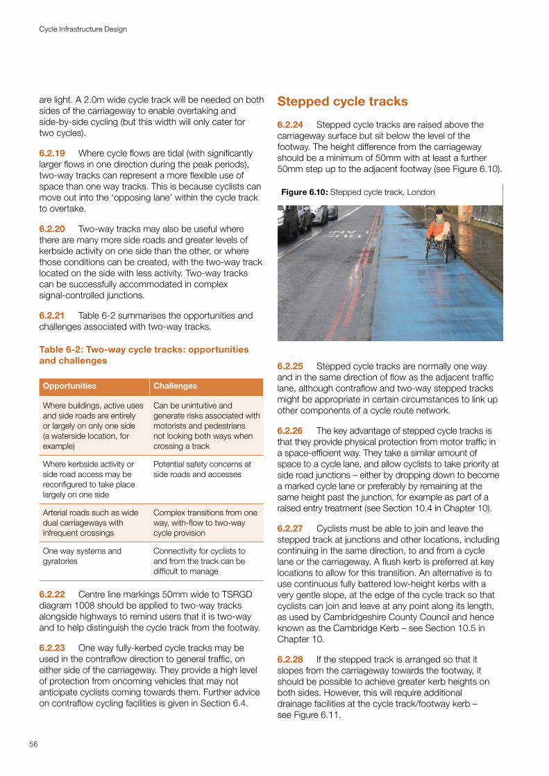
are light. A 2.0m wide cycle track will be needed on both sides of the carriageway to enable overtaking and side-by-side cycling (but this width will only cater for two cycles).
6.2.19 Where cycle flows are tidal (with significantly larger flows in one direction during the peak periods), two-way tracks can represent a more flexible use of space than one way tracks. This is because cyclists can move out into the ‘opposing lane’ within the cycle track to overtake.
6.2.20 Two-way tracks may also be useful where there are many more side roads and greater levels of kerbside activity on one side than the other, or where those conditions can be created, with the two-way track located on the side with less activity. Two-way tracks can be successfully accommodated in complex signal-controlled junctions.
6.2.21 Table 6-2 summarises the opportunities and challenges associated with two-way tracks.
Table 6-2: Two-way cycle tracks: opportunities and challenges
Opportunities Challenges
Where buildings, active uses and side roads are entirely or largely on only one side (a waterside location, for example)
Can be unintuitive and generate risks associated with motorists and pedestrians not looking both ways when crossing a track
Where kerbside activity or side road access may be reconfigured to take place largely on one side
Potential safety concerns at side roads and accesses
Arterial roads such as wide dual carriageways with infrequent crossings
Complex transitions from one way, with-flow to two-way cycle provision
One way systems and gyratories
Connectivity for cyclists to and from the track can be difficult to manage
6.2.22 Centre line markings 50mm wide to TSRGD diagram 1008 should be applied to two-way tracks alongside highways to remind users that it is two-way and to help distinguish the cycle track from the footway.
6.2.23 One way fully-kerbed cycle tracks may be used in the contraflow direction to general traffic, on either side of the carriageway. They provide a high level of protection from oncoming vehicles that may not anticipate cyclists coming towards them. Further advice on contraflow cycling facilities is given in Section 6.4.
Stepped cycle tracks
6.2.24 Stepped cycle tracks are raised above the carriageway surface but sit below the level of the footway. The height difference from the carriageway should be a minimum of 50mm with at least a further 50mm step up to the adjacent footway (see Figure 6.10).
Figure 6.10: Stepped cycle track, London
6.2.25 Stepped cycle tracks are normally one way and in the same direction of flow as the adjacent traffic lane, although contraflow and two-way stepped tracks might be appropriate in certain circumstances to link up other components of a cycle route network.
6.2.26 The key advantage of stepped cycle tracks is that they provide physical protection from motor traffic in a space-efficient way. They take a similar amount of space to a cycle lane, and allow cyclists to take priority at side road junctions – either by dropping down to become a marked cycle lane or preferably by remaining at the same height past the junction, for example as part of a raised entry treatment (see Section 10.4 in Chapter 10).
6.2.27 Cyclists must be able to join and leave the stepped track at junctions and other locations, including continuing in the same direction, to and from a cycle lane or the carriageway. A flush kerb is preferred at key locations to allow for this transition. An alternative is to use continuous fully battered low-height kerbs with a very gentle slope, at the edge of the cycle track so that cyclists can join and leave at any point along its length, as used by Cambridgeshire County Council and hence known as the Cambridge Kerb – see Section 10.5 in Chapter 10.
6.2.28 If the stepped track is arranged so that it slopes from the carriageway towards the footway, it should be possible to achieve greater kerb heights on both sides. However, this will require additional drainage facilities at the cycle track/footway kerb – see Figure 6.11.
56
Cycle Infrastructure Design
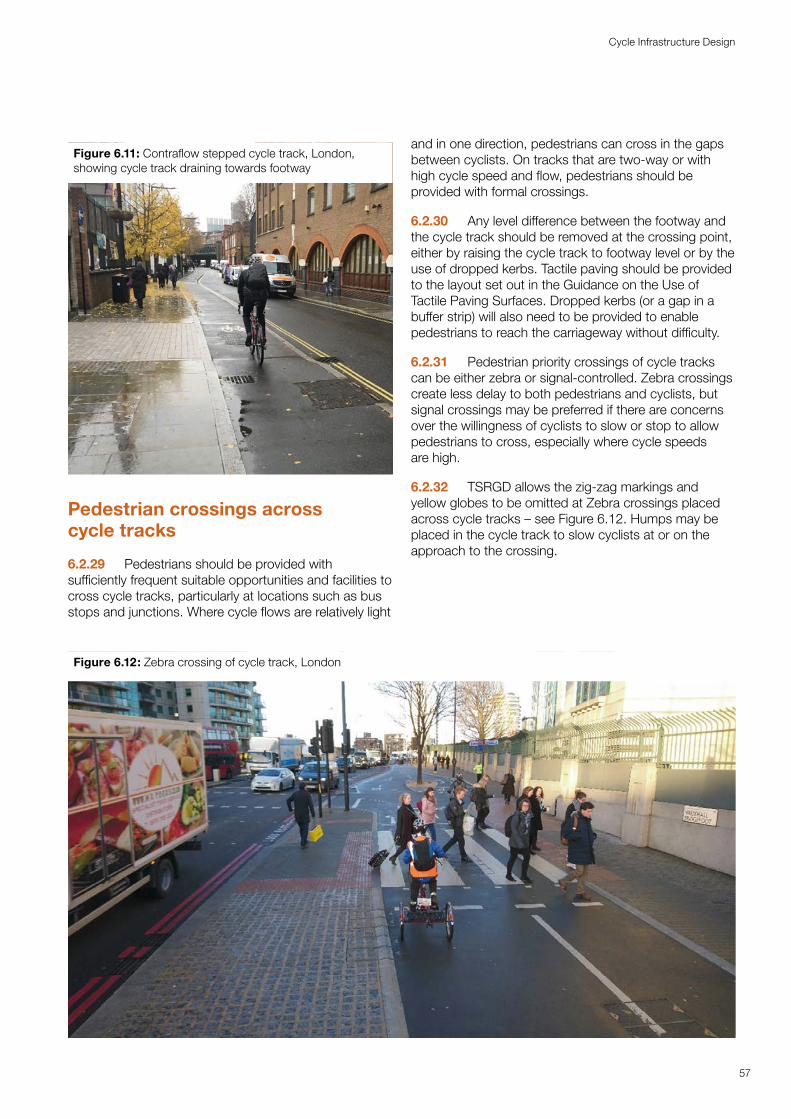
Figure 6.11: Contraflow stepped cycle track, London, showing cycle track draining towards footway
Pedestrian crossings across cycle tracks
6.2.29 Pedestrians should be provided with sufficiently frequent suitable opportunities and facilities to cross cycle tracks, particularly at locations such as bus stops and junctions. Where cycle flows are relatively light
and in one direction, pedestrians can cross in the gaps between cyclists. On tracks that are two-way or with high cycle speed and flow, pedestrians should be provided with formal crossings.
6.2.30 Any level difference between the footway and the cycle track should be removed at the crossing point, either by raising the cycle track to footway level or by the use of dropped kerbs. Tactile paving should be provided to the layout set out in the Guidance on the Use of Tactile Paving Surfaces. Dropped kerbs (or a gap in a buffer strip) will also need to be provided to enable pedestrians to reach the carriageway without difficulty.
6.2.31 Pedestrian priority crossings of cycle tracks can be either zebra or signal-controlled. Zebra crossings create less delay to both pedestrians and cyclists, but signal crossings may be preferred if there are concerns over the willingness of cyclists to slow or stop to allow pedestrians to cross, especially where cycle speeds are high.
6.2.32 TSRGD allows the zig-zag markings and yellow globes to be omitted at Zebra crossings placed across cycle tracks – see Figure 6.12. Humps may be placed in the cycle track to slow cyclists at or on the approach to the crossing.
Figure 6.12: Zebra crossing of cycle track, London
57
Cycle Infrastructure Design
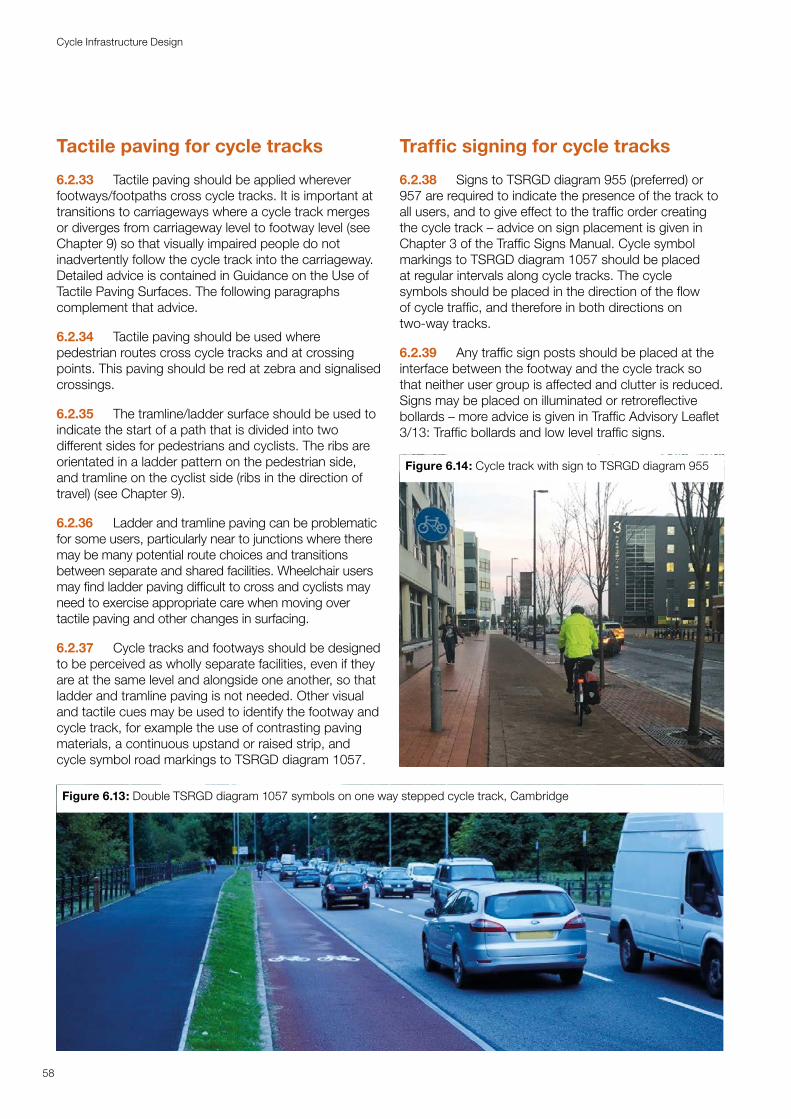
Tactile paving for cycle tracks
6.2.33 Tactile paving should be applied wherever footways/footpaths cross cycle tracks. It is important at transitions to carriageways where a cycle track merges or diverges from carriageway level to footway level (see Chapter 9) so that visually impaired people do not inadvertently follow the cycle track into the carriageway. Detailed advice is contained in Guidance on the Use of Tactile Paving Surfaces. The following paragraphs complement that advice.
6.2.34 Tactile paving should be used where pedestrian routes cross cycle tracks and at crossing points. This paving should be red at zebra and signalised crossings.
6.2.35 The tramline/ladder surface should be used to indicate the start of a path that is divided into two different sides for pedestrians and cyclists. The ribs are orientated in a ladder pattern on the pedestrian side, and tramline on the cyclist side (ribs in the direction of travel) (see Chapter 9).
6.2.36 Ladder and tramline paving can be problematic for some users, particularly near to junctions where there may be many potential route choices and transitions between separate and shared facilities. Wheelchair users may find ladder paving difficult to cross and cyclists may need to exercise appropriate care when moving over tactile paving and other changes in surfacing.
6.2.37 Cycle tracks and footways should be designed to be perceived as wholly separate facilities, even if they are at the same level and alongside one another, so that ladder and tramline paving is not needed. Other visual and tactile cues may be used to identify the footway and cycle track, for example the use of contrasting paving materials, a continuous upstand or raised strip, and cycle symbol road markings to TSRGD diagram 1057.
Figure 6.13: Double TSRGD diagram 1057 symbols on one way stepped cycle track, Cambridge
58
Cycle Infrastructure Design
Traffic signing for cycle tracks
6.2.38 Signs to TSRGD diagram 955 (preferred) or 957 are required to indicate the presence of the track to all users, and to give effect to the traffic order creating the cycle track – advice on sign placement is given in Chapter 3 of the Traffic Signs Manual. Cycle symbol markings to TSRGD diagram 1057 should be placed at regular intervals along cycle tracks. The cycle symbols should be placed in the direction of the flow of cycle traffic, and therefore in both directions on two-way tracks.
6.2.39 Any traffic sign posts should be placed at the interface between the footway and the cycle track so that neither user group is affected and clutter is reduced. Signs may be placed on illuminated or retroreflective bollards – more advice is given in Traffic Advisory Leaflet 3/13: Traffic bollards and low level traffic signs.
Figure 6.14: Cycle track with sign to TSRGD diagram 955
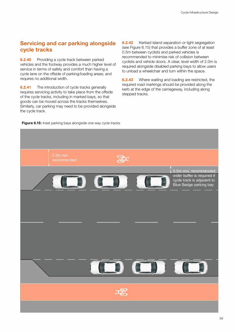
Servicing and car parking alongside cycle tracks
6.2.40 Providing a cycle track between parked vehicles and the footway provides a much higher level of service in terms of safety and comfort than having a cycle lane on the offside of parking/loading areas; and requires no additional width.
6.2.41 The introduction of cycle tracks generally requires servicing activity to take place from the offside of the cycle tracks, including in marked bays, so that goods can be moved across the tracks themselves. Similarly, car parking may need to be provided alongside the cycle track.
6.2.42 Kerbed island separation or light segregation (see Figure 6.15) that provides a buffer zone of at least 0.5m between cyclists and parked vehicles is recommended to minimise risk of collision between cyclists and vehicle doors. A clear, level width of 2.0m is required alongside disabled parking bays to allow users to unload a wheelchair and turn within the space.
6.2.43 Where waiting and loading are restricted, the required road markings should be provided along the kerb at the edge of the carriageway, including along stepped tracks.
Figure 6.15: Inset parking bays alongside one way cycle tracks
59
Cycle Infrastructure Design
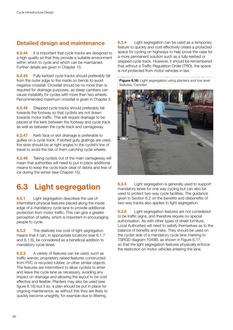
Detailed design and maintenance
6.2.44 It is important that cycle tracks are designed to a high quality so that they provide a suitable environment within which to cycle and which can be maintained. Further details are given in Chapter 15.
6.2.45 Fully kerbed cycle tracks should preferably fall from the outer edge to the inside on bends to avoid negative crossfall. Crossfall should be no more than is required for drainage purposes, as steep cambers can cause instability for cycles with more than two wheels. Recommended maximum crossfall is given in Chapter 5.
6.2.46 Stepped cycle tracks should preferably fall towards the footway so that cyclists are not drawn towards motor traffic. This will require drainage to be placed at the kerb between the footway and cycle track as well as between the cycle track and carriageway.
6.2.47 Kerb face or slot drainage is preferable to gullies on a cycle track. If slotted gully gratings are used, the slots should be at right angles to the cyclist’s line of travel to avoid the risk of them catching cycle wheels.
6.2.48 Taking cyclists out of the main carriageway will mean that authorities will need to put in place additional means to keep the cycle track clear of debris and free of ice during the winter (see Chapter 15).
6.3 Light segregation6.3.1 Light segregation describes the use of intermittent physical features placed along the inside edge of a mandatory cycle lane to provide additional protection from motor traffic. This can give a greater perception of safety, which is important in encouraging people to cycle.
6.3.2 The relatively low cost of light segregation means that it can, in appropriate locations (see 6.1.7 and 6.1.8), be considered as a beneficial addition to mandatory cycle lanes.
6.3.3 A variety of features can be used, such as traffic wands, proprietary raised features constructed from PVC or recycled rubber, or other similar objects. The features are intermittent to allow cyclists to enter and leave the cycle lane as necessary, avoiding any impact on drainage and allowing the layout to be cost effective and flexible. Planters may also be used (see figure 6.16) but if so, a plan should be put in place for ongoing maintenance, as without this they are likely to quickly become unsightly, for example due to littering.
6.3.4 Light segregation can be used as a temporary feature to quickly and cost effectively create a protected space for cycling on highways to help prove the case for a more permanent solution such as a fully-kerbed or stepped cycle track. However, it should be remembered that without a Traffic Regulation Order (TRO), the space is not protected from motor vehicles in law.
Figure 6.16: Light segregation using planters and low level features, Camden
6.3.5 Light segregation is generally used to support mandatory lanes for one way cycling but can also be used to protect two-way cycle facilities. The guidance given in Section 6.2 on the benefits and disbenefits of two-way tracks also applies to light segregation.
6.3.6 Light segregation features are not considered to be traffic signs, and therefore require no special authorisation. As with other types of street furniture, Local Authorities will need to satisfy themselves as to the balance of benefits and risks. They should be used on the cyclist side of a mandatory cycle lane marking to TSRGD diagram 1049B, as shown in Figure 6.17, so that the light segregation features physically enforce the restriction on motor vehicles entering the lane.
60
Cycle Infrastructure Design
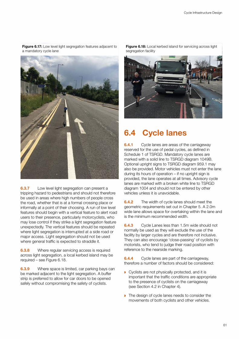
Figure 6.17: Low level light segregation features adjacent to a mandatory cycle lane
6.3.7 Low level light segregation can present a tripping hazard to pedestrians and should not therefore be used in areas where high numbers of people cross the road, whether that is at a formal crossing place or informally at a point of their choosing. A run of low level features should begin with a vertical feature to alert road users to their presence, particularly motorcyclists, who may lose control if they strike a light segregation feature unexpectedly. The vertical features should be repeated where light segregation is interrupted at a side road or major access. Light segregation should not be used where general traffic is expected to straddle it.
6.3.8 Where regular servicing access is required across light segregation, a local kerbed island may be required – see Figure 6.18.
6.3.9 Where space is limited, car parking bays can be marked adjacent to the light segregation. A buffer strip is preferred to allow for car doors to be opened safely without compromising the safety of cyclists.
Figure 6.18: Local kerbed island for servicing across light segregation facility
6.4 Cycle lanes6.4.1 Cycle lanes are areas of the carriageway reserved for the use of pedal cycles, as defined in Schedule 1 of TSRGD. Mandatory cycle lanes are marked with a solid line to TSRGD diagram 1049B. Optional upright signs to TSRGD diagram 959.1 may also be provided. Motor vehicles must not enter the lane during its hours of operation – if no upright sign is provided, the lane operates at all times. Advisory cycle lanes are marked with a broken white line to TSRGD diagram 1004 and should not be entered by other vehicles unless it is unavoidable.
6.4.2 The width of cycle lanes should meet the geometric requirements set out in Chapter 5. A 2.0m wide lane allows space for overtaking within the lane andis the minimum recommended width.
6.4.3 Cycle Lanes less than 1.5m wide should not normally be used as they will exclude the use of the facility by larger cycles and are therefore not inclusive. They can also encourage ‘close-passing’ of cyclists by motorists, who tend to judge their road position with reference to the nearside marking.
6.4.4 Cycle lanes are part of the carriageway, therefore a number of factors should be considered:
a Cyclists are not physically protected, and it is important that the traffic conditions are appropriate to the presence of cyclists on the carriageway (see Section 4.2 in Chapter 4).
a The design of cycle lanes needs to consider the movements of both cyclists and other vehicles.
61
Cycle Infrastructure Design
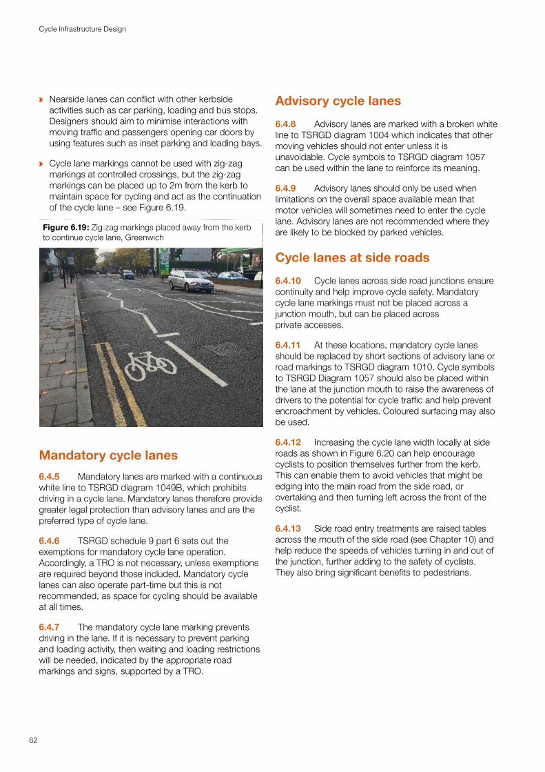
a Nearside lanes can conflict with other kerbside activities such as car parking, loading and bus stops. Designers should aim to minimise interactions with moving traffic and passengers opening car doors by using features such as inset parking and loading bays.
a Cycle lane markings cannot be used with zig-zag markings at controlled crossings, but the zig-zag markings can be placed up to 2m from the kerb to maintain space for cycling and act as the continuation of the cycle lane – see Figure 6.19.
Figure 6.19: Zig-zag markings placed away from the kerb to continue cycle lane, Greenwich
Mandatory cycle lanes
6.4.5 Mandatory lanes are marked with a continuous white line to TSRGD diagram 1049B, which prohibits driving in a cycle lane. Mandatory lanes therefore provide greater legal protection than advisory lanes and are the preferred type of cycle lane.
6.4.6 TSRGD schedule 9 part 6 sets out the exemptions for mandatory cycle lane operation. Accordingly, a TRO is not necessary, unless exemptions are required beyond those included. Mandatory cycle lanes can also operate part-time but this is not recommended, as space for cycling should be available at all times.
6.4.7 The mandatory cycle lane marking prevents driving in the lane. If it is necessary to prevent parking and loading activity, then waiting and loading restrictions will be needed, indicated by the appropriate road markings and signs, supported by a TRO.
Advisory cycle lanes
6.4.8 Advisory lanes are marked with a broken white line to TSRGD diagram 1004 which indicates that other moving vehicles should not enter unless it is unavoidable. Cycle symbols to TSRGD diagram 1057 can be used within the lane to reinforce its meaning.
6.4.9 Advisory lanes should only be used when limitations on the overall space available mean that motor vehicles will sometimes need to enter the cycle lane. Advisory lanes are not recommended where they are likely to be blocked by parked vehicles.
Cycle lanes at side roads
6.4.10 Cycle lanes across side road junctions ensure continuity and help improve cycle safety. Mandatory cycle lane markings must not be placed across a junction mouth, but can be placed across private accesses.
6.4.11 At these locations, mandatory cycle lanes should be replaced by short sections of advisory lane or road markings to TSRGD diagram 1010. Cycle symbols to TSRGD Diagram 1057 should also be placed within the lane at the junction mouth to raise the awareness of drivers to the potential for cycle traffic and help prevent encroachment by vehicles. Coloured surfacing may also be used.
6.4.12 Increasing the cycle lane width locally at side roads as shown in Figure 6.20 can help encourage cyclists to position themselves further from the kerb. This can enable them to avoid vehicles that might be edging into the main road from the side road, or overtaking and then turning left across the front of the cyclist.
6.4.13 Side road entry treatments are raised tables across the mouth of the side road (see Chapter 10) and help reduce the speeds of vehicles turning in and out of the junction, further adding to the safety of cyclists. They also bring significant benefits to pedestrians.
62
Cycle Infrastructure Design
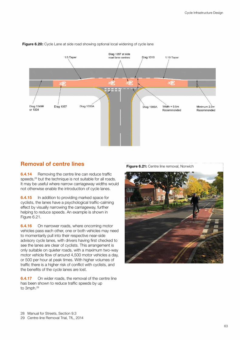
Figure 6.20: Cycle Lane at side road showing optional local widening of cycle lane
63
Cycle Infrastructure Design
Removal of centre lines
6.4.14 Removing the centre line can reduce traffic speeds,28 but the technique is not suitable for all roads. It may be useful where narrow carriageway widths would not otherwise enable the introduction of cycle lanes.
6.4.15 In addition to providing marked space for cyclists, the lanes have a psychological traffic-calming effect by visually narrowing the carriageway, further helping to reduce speeds. An example is shown in Figure 6.21.
6.4.16 On narrower roads, where oncoming motor vehicles pass each other, one or both vehicles may need to momentarily pull into their respective near-side advisory cycle lanes, with drivers having first checked to see the lanes are clear of cyclists. This arrangement is only suitable on quieter roads, with a maximum two-way motor vehicle flow of around 4,500 motor vehicles a day, or 500 per hour at peak times. With higher volumes of traffic there is a higher risk of conflict with cyclists, and the benefits of the cycle lanes are lost.
6.4.17 On wider roads, the removal of the centre line has been shown to reduce traffic speeds by up to 3mph.29
28 Manual for Streets, Section 9.3 29 Centre-line Removal Trial, TfL, 2014
Figure 6.21: Centre line removal, Norwich
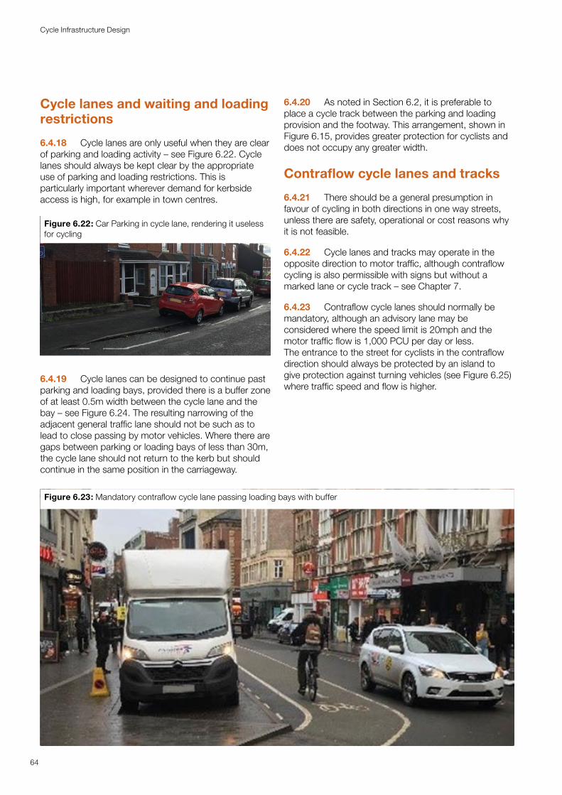
Cycle lanes and waiting and loading restrictions
6.4.18 Cycle lanes are only useful when they are clear of parking and loading activity – see Figure 6.22. Cycle lanes should always be kept clear by the appropriate use of parking and loading restrictions. This is particularly important wherever demand for kerbside access is high, for example in town centres.
Figure 6.22: Car Parking in cycle lane, rendering it useless for cycling
6.4.19 Cycle lanes can be designed to continue past parking and loading bays, provided there is a buffer zone of at least 0.5m width between the cycle lane and the bay – see Figure 6.24. The resulting narrowing of the adjacent general traffic lane should not be such as to lead to close passing by motor vehicles. Where there are gaps between parking or loading bays of less than 30m, the cycle lane should not return to the kerb but should continue in the same position in the carriageway.
6.4.20 As noted in Section 6.2, it is preferable to place a cycle track between the parking and loading provision and the footway. This arrangement, shown in Figure 6.15, provides greater protection for cyclists and does not occupy any greater width.
Contraflow cycle lanes and tracks
6.4.21 There should be a general presumption in favour of cycling in both directions in one way streets, unless there are safety, operational or cost reasons why it is not feasible.
6.4.22 Cycle lanes and tracks may operate in the opposite direction to motor traffic, although contraflow cycling is also permissible with signs but without a marked lane or cycle track – see Chapter 7.
6.4.23 Contraflow cycle lanes should normally be mandatory, although an advisory lane may be considered where the speed limit is 20mph and the motor traffic flow is 1,000 PCU per day or less. The entrance to the street for cyclists in the contraflow direction should always be protected by an island to give protection against turning vehicles (see Figure 6.25) where traffic speed and flow is higher.
Figure 6.23: Mandatory contraflow cycle lane passing loading bays with buffer
64
Cycle Infrastructure Design
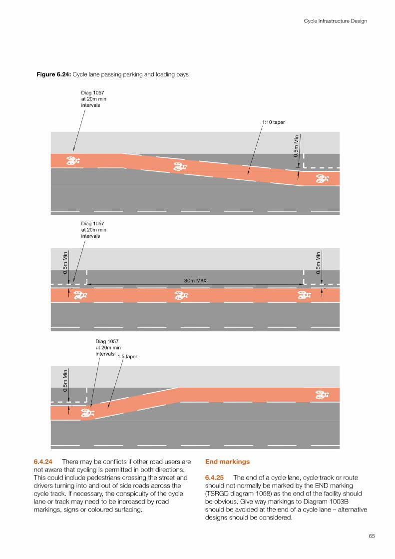
6.4.24 There may be conflicts if other road users are not aware that cycling is permitted in both directions. This could include pedestrians crossing the street and drivers turning into and out of side roads across the cycle track. If necessary, the conspicuity of the cycle lane or track may need to be increased by road markings, signs or coloured surfacing.
End markings
6.4.25 The end of a cycle lane, cycle track or route should not normally be marked by the END marking (TSRGD diagram 1058) as the end of the facility should be obvious. Give way markings to Diagram 1003B should be avoided at the end of a cycle lane – alternative designs should be considered.
Figure 6.24: Cycle lane passing parking and loading bays
1:10 taper
Diag 1057at 20m minintervals
0.5m
Min
Diag 1057at 20m minintervals 1:5 taper
30m MAX
Diag 1057at 20m minintervals
0.5m
Min
0.5m
Min
0.5m
Min 30m MAX
Diag 1057at 20m minintervals
0.5m
Min
0.5m
Min
Diag 1057at 20m minintervals 1:5 taper
0.5m
Min
1:10 taper
Diag 1057at 20m minintervals 1:5 taper
Diag 1057at 20m minintervals
0.5m
Min
0.5m
Min
1:10 taper
30m MAX
Diag 1057at 20m minintervals
Diag 1057at 20m minintervals
0.5m
Min
0.5m
Min
0.5m
Min
65
Cycle Infrastructure Design
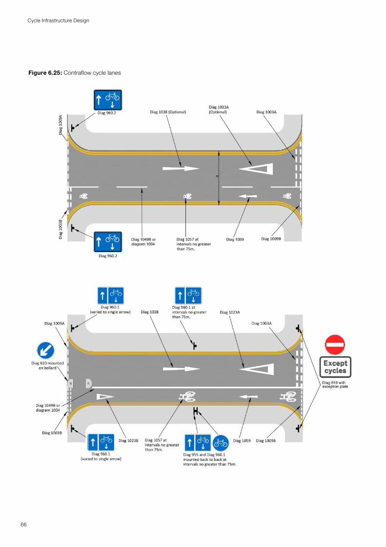
Figure 6.25: Contraflow cycle lanes
66
Cycle Infrastructure Design
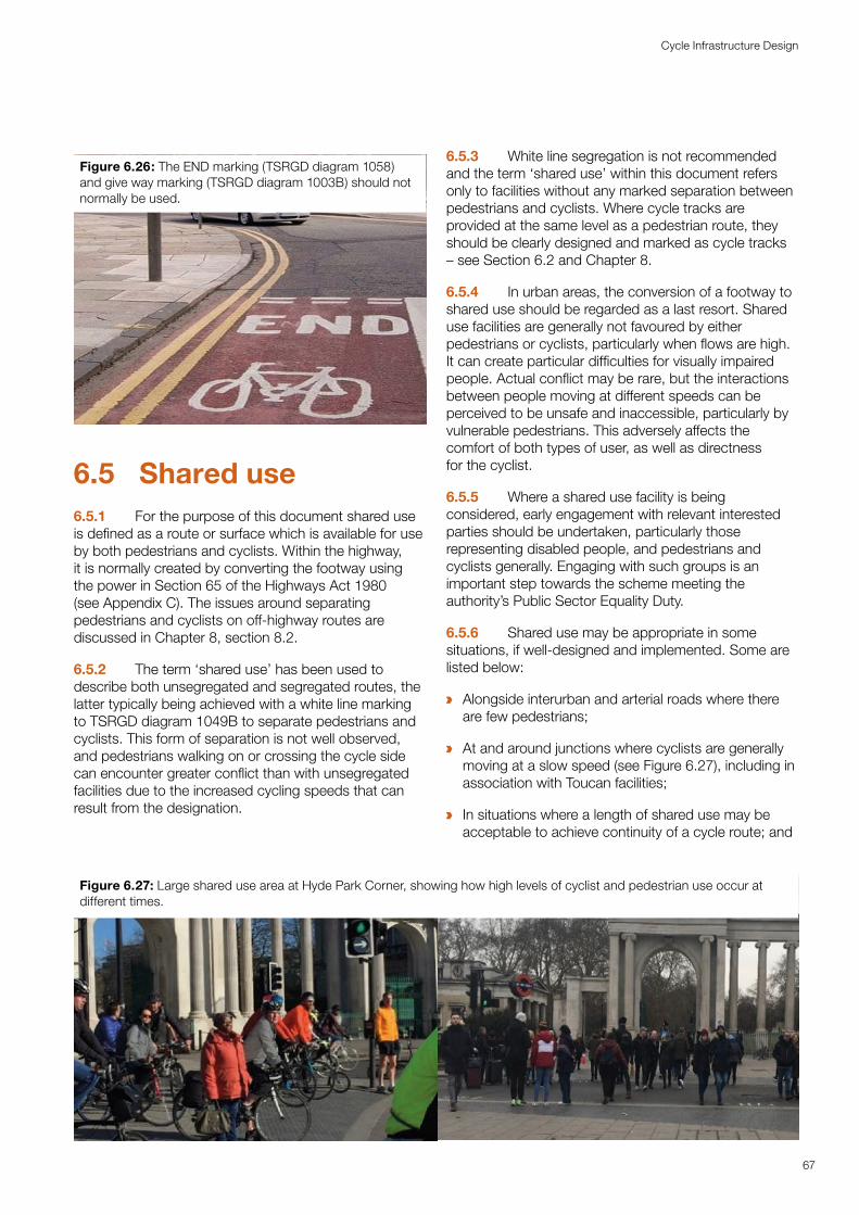
Figure 6.26: The END marking (TSRGD diagram 1058) and give way marking (TSRGD diagram 1003B) should not normally be used.
6.5 Shared use 6.5.1 For the purpose of this document shared use is defined as a route or surface which is available for use by both pedestrians and cyclists. Within the highway, it is normally created by converting the footway using the power in Section 65 of the Highways Act 1980 (see Appendix C). The issues around separating pedestrians and cyclists on off-highway routes are discussed in Chapter 8, section 8.2.
6.5.2 The term ‘shared use’ has been used to describe both unsegregated and segregated routes, the latter typically being achieved with a white line marking to TSRGD diagram 1049B to separate pedestrians and cyclists. This form of separation is not well observed, and pedestrians walking on or crossing the cycle side can encounter greater conflict than with unsegregated facilities due to the increased cycling speeds that can result from the designation.
6.5.3 White line segregation is not recommended and the term ‘shared use’ within this document refers only to facilities without any marked separation between pedestrians and cyclists. Where cycle tracks are provided at the same level as a pedestrian route, they should be clearly designed and marked as cycle tracks – see Section 6.2 and Chapter 8.
6.5.4 In urban areas, the conversion of a footway to shared use should be regarded as a last resort. Shared use facilities are generally not favoured by either pedestrians or cyclists, particularly when flows are high. It can create particular difficulties for visually impaired people. Actual conflict may be rare, but the interactions between people moving at different speeds can be perceived to be unsafe and inaccessible, particularly by vulnerable pedestrians. This adversely affects the comfort of both types of user, as well as directness for the cyclist.
6.5.5 Where a shared use facility is being considered, early engagement with relevant interested parties should be undertaken, particularly those representing disabled people, and pedestrians and cyclists generally. Engaging with such groups is an important step towards the scheme meeting the authority’s Public Sector Equality Duty.
6.5.6 Shared use may be appropriate in some situations, if well-designed and implemented. Some are listed below:
a Alongside interurban and arterial roads where there are few pedestrians;
a At and around junctions where cyclists are generally moving at a slow speed (see Figure 6.27), including in association with Toucan facilities;
a In situations where a length of shared use may be acceptable to achieve continuity of a cycle route; and
Figure 6.27: Large shared use area at Hyde Park Corner, showing how high levels of cyclist and pedestrian use occur at different times.
67
Cycle Infrastructure Design
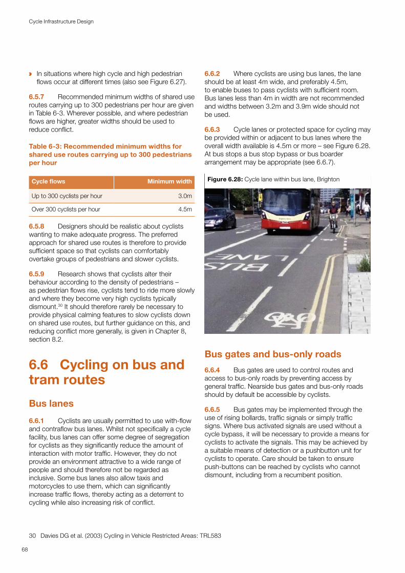
a In situations where high cycle and high pedestrian flows occur at different times (also see Figure 6.27).
6.5.7 Recommended minimum widths of shared use routes carrying up to 300 pedestrians per hour are given in Table 6-3. Wherever possible, and where pedestrian flows are higher, greater widths should be used to reduce conflict.
Table 6-3: Recommended minimum widths for shared use routes carrying up to 300 pedestrians per hour
Cycle flows Minimum width
Up to 300 cyclists per hour 3.0m
Over 300 cyclists per hour 4.5m
6.5.8 Designers should be realistic about cyclists wanting to make adequate progress. The preferred approach for shared use routes is therefore to provide sufficient space so that cyclists can comfortably overtake groups of pedestrians and slower cyclists.
6.5.9 Research shows that cyclists alter their behaviour according to the density of pedestrians – as pedestrian flows rise, cyclists tend to ride more slowly and where they become very high cyclists typically dismount.30 It should therefore rarely be necessary to provide physical calming features to slow cyclists down on shared use routes, but further guidance on this, and reducing conflict more generally, is given in Chapter 8, section 8.2.
6.6 Cycling on bus and tram routes
Bus lanes
6.6.1 Cyclists are usually permitted to use with-flow and contraflow bus lanes. Whilst not specifically a cycle facility, bus lanes can offer some degree of segregation for cyclists as they significantly reduce the amount of interaction with motor traffic. However, they do not provide an environment attractive to a wide range of people and should therefore not be regarded as inclusive. Some bus lanes also allow taxis and motorcycles to use them, which can significantly increase traffic flows, thereby acting as a deterrent to cycling while also increasing risk of conflict.
30 Davies DG et al. (2003) Cycling in Vehicle Restricted Areas: TRL583
6.6.2 Where cyclists are using bus lanes, the lane should be at least 4m wide, and preferably 4.5m, to enable buses to pass cyclists with sufficient room. Bus lanes less than 4m in width are not recommended and widths between 3.2m and 3.9m wide should not be used.
6.6.3 Cycle lanes or protected space for cycling may be provided within or adjacent to bus lanes where the overall width available is 4.5m or more – see Figure 6.28. At bus stops a bus stop bypass or bus boarder arrangement may be appropriate (see 6.6.7).
Figure 6.28: Cycle lane within bus lane, Brighton
Bus gates and bus-only roads
6.6.4 Bus gates are used to control routes and access to bus-only roads by preventing access by general traffic. Nearside bus gates and bus-only roads should by default be accessible by cyclists.
6.6.5 Bus gates may be implemented through the use of rising bollards, traffic signals or simply traffic signs. Where bus activated signals are used without a cycle bypass, it will be necessary to provide a means for cyclists to activate the signals. This may be achieved by a suitable means of detection or a push button unit for cyclists to operate. Care should be taken to ensure push-buttons can be reached by cyclists who cannot dismount, including from a recumbent position.
68
Cycle Infrastructure Design
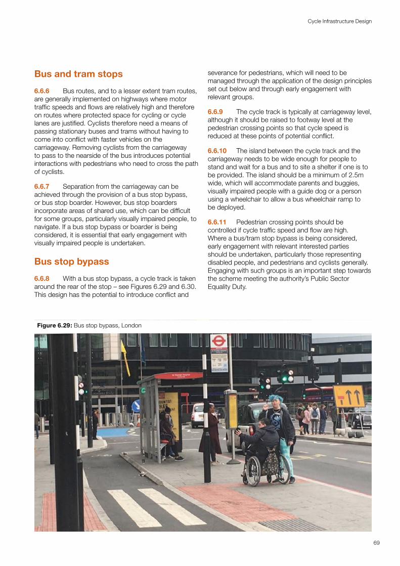
Bus and tram stops
6.6.6 Bus routes, and to a lesser extent tram routes, are generally implemented on highways where motor traffic speeds and flows are relatively high and therefore on routes where protected space for cycling or cycle lanes are justified. Cyclists therefore need a means of passing stationary buses and trams without having to come into conflict with faster vehicles on the carriageway. Removing cyclists from the carriageway to pass to the nearside of the bus introduces potential interactions with pedestrians who need to cross the path of cyclists.
6.6.7 Separation from the carriageway can be achieved through the provision of a bus stop bypass, or bus stop boarder. However, bus stop boarders incorporate areas of shared use, which can be difficult for some groups, particularly visually impaired people, to navigate. If a bus stop bypass or boarder is being considered, it is essential that early engagement with visually impaired people is undertaken.
Bus stop bypass
6.6.8 With a bus stop bypass, a cycle track is taken around the rear of the stop – see Figures 6.29 and 6.30. This design has the potential to introduce conflict and
severance for pedestrians, which will need to be managed through the application of the design principles set out below and through early engagement with relevant groups.
6.6.9 The cycle track is typically at carriageway level, although it should be raised to footway level at the pedestrian crossing points so that cycle speed is reduced at these points of potential conflict.
6.6.10 The island between the cycle track and the carriageway needs to be wide enough for people to stand and wait for a bus and to site a shelter if one is to be provided. The island should be a minimum of 2.5m wide, which will accommodate parents and buggies, visually impaired people with a guide dog or a person using a wheelchair to allow a bus wheelchair ramp to be deployed.
6.6.11 Pedestrian crossing points should be controlled if cycle traffic speed and flow are high. Where a bus/tram stop bypass is being considered, early engagement with relevant interested parties should be undertaken, particularly those representing disabled people, and pedestrians and cyclists generally. Engaging with such groups is an important step towards the scheme meeting the authority’s Public Sector Equality Duty.
Figure 6.29: Bus stop bypass, London
69
Cycle Infrastructure Design
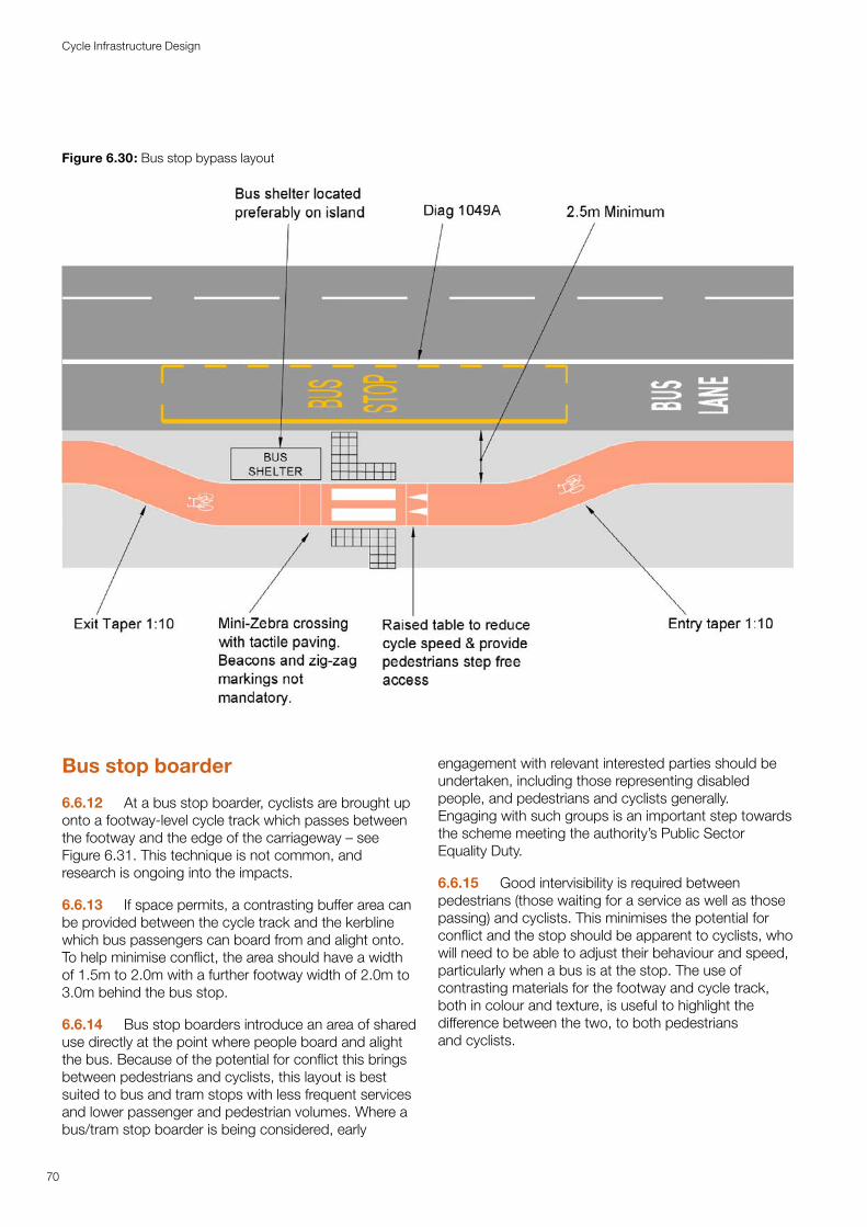
Bus stop boarder
6.6.12 At a bus stop boarder, cyclists are brought up onto a footway-level cycle track which passes between the footway and the edge of the carriageway – see Figure 6.31. This technique is not common, and research is ongoing into the impacts.
6.6.13 If space permits, a contrasting buffer area can be provided between the cycle track and the kerbline which bus passengers can board from and alight onto. To help minimise conflict, the area should have a width of 1.5m to 2.0m with a further footway width of 2.0m to 3.0m behind the bus stop.
6.6.14 Bus stop boarders introduce an area of shared use directly at the point where people board and alight the bus. Because of the potential for conflict this brings between pedestrians and cyclists, this layout is best suited to bus and tram stops with less frequent services and lower passenger and pedestrian volumes. Where a bus/tram stop boarder is being considered, early
engagement with relevant interested parties should be undertaken, including those representing disabled people, and pedestrians and cyclists generally. Engaging with such groups is an important step towards the scheme meeting the authority’s Public Sector Equality Duty.
6.6.15 Good intervisibility is required between pedestrians (those waiting for a service as well as those passing) and cyclists. This minimises the potential for conflict and the stop should be apparent to cyclists, who will need to be able to adjust their behaviour and speed, particularly when a bus is at the stop. The use of contrasting materials for the footway and cycle track, both in colour and texture, is useful to highlight the difference between the two, to both pedestrians and cyclists.
Figure 6.30: Bus stop bypass layout
70
Cycle Infrastructure Design
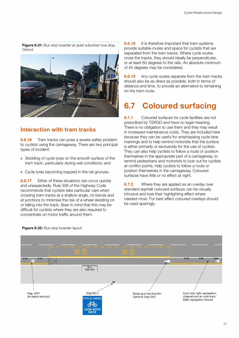
Figure 6.31: Bus stop boarder at quiet suburban bus stop, Oxford
Interaction with tram tracks
6.6.16 Tram tracks can pose a severe safety problem to cyclists using the carriageway. There are two principal types of incident:
a Skidding of cycle tyres on the smooth surface of the tram track, particularly during wet conditions; and
a Cycle tyres becoming trapped in the rail grooves.
6.6.17 Either of these situations can occur quickly and unexpectedly. Rule 306 of the Highway Code recommends that cyclists take particular care when crossing tram tracks at a shallow angle, on bends and at junctions to minimise the risk of a wheel skidding on or falling into the track. Bear in mind that this may be difficult for cyclists where they are also required to concentrate on motor traffic around them.
6.6.18 It is therefore important that tram systems provide suitable routes and space for cyclists that are separated from the tram tracks. Where cycle routes cross the tracks, they should ideally be perpendicular, or at least 60 degrees to the rails. An absolute minimum of 45 degrees may be considered.
6.6.19 Any cycle routes separate from the tram tracks should also be as direct as possible, both in terms of distance and time, to provide an alternative to remaining on the tram route.
6.7 Coloured surfacing6.7.1 Coloured surfaces for cycle facilities are not prescribed by TSRGD and have no legal meaning. There is no obligation to use them and they may result in increased maintenance costs. They are included here because they can be useful for emphasising cycle lane markings and to help remind motorists that the surface is either primarily or exclusively for the use of cyclists. They can also help cyclists to follow a route or position themselves in the appropriate part of a carriageway, to remind pedestrians and motorists to look out for cyclists at conflict points, help cyclists to follow a route or position themselves in the carriageway. Coloured surfaces have little or no effect at night.
6.7.2 Where they are applied as an overlay over standard asphalt coloured surfaces can be visually intrusive and lose their highlighting effect where needed most. For best effect coloured overlays should be used sparingly.
Figure 6.32: Bus stop boarder layout
71
Cycle Infrastructure Design
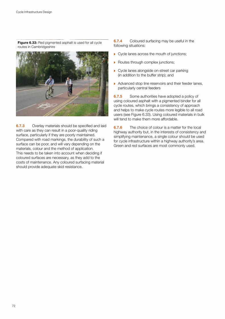
Figure 6.33: Red pigmented asphalt is used for all cycle routes in Cambridgeshire
6.7.3 Overlay materials should be specified and laid with care as they can result in a poor-quality riding surface, particularly if they are poorly maintained. Compared with road markings, the durability of such a surface can be poor, and will vary depending on the materials, colour and the method of application. This needs to be taken into account when deciding if coloured surfaces are necessary, as they add to the costs of maintenance. Any coloured surfacing material should provide adequate skid resistance.
6.7.4 Coloured surfacing may be useful in the following situations:
a Cycle lanes across the mouth of junctions;
a Routes through complex junctions;
a Cycle lanes alongside on-street car parking (in addition to the buffer strip); and
a Advanced stop line reservoirs and their feeder lanes, particularly central feeders
6.7.5 Some authorities have adopted a policy of using coloured asphalt with a pigmented binder for all cycle routes, which brings a consistency of approach and helps to make cycle routes more legible to all road users (see Figure 6.33). Using coloured materials in bulk will tend to make them more affordable.
6.7.6 The choice of colour is a matter for the local highway authority but, in the interests of consistency and simplifying maintenance, a single colour should be used for cycle infrastructure within a highway authority’s area. Green and red surfaces are most commonly used.
72
Cycle Infrastructure Design
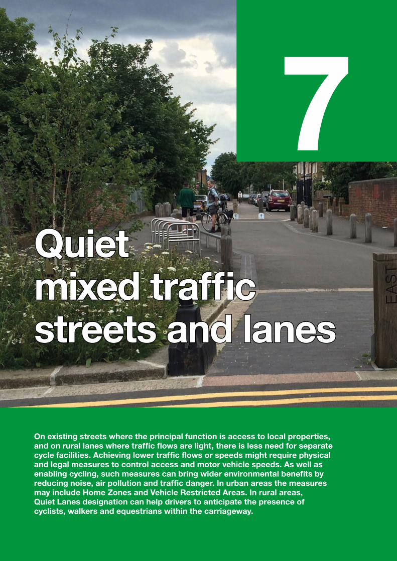
7Quiet Quiet mixed traffic mixed traffic streets and lanesstreets and lanes
On existing streets where the principal function is access to local properties, and on rural lanes where traffic flows are light, there is less need for separate cycle facilities. Achieving lower traffic flows or speeds might require physical and legal measures to control access and motor vehicle speeds. As well as enabling cycling, such measures can bring wider environmental benefits by reducing noise, air pollution and traffic danger. In urban areas the measures may include Home Zones and Vehicle Restricted Areas. In rural areas, Quiet Lanes designation can help drivers to anticipate the presence of cyclists, walkers and equestrians within the carriageway.
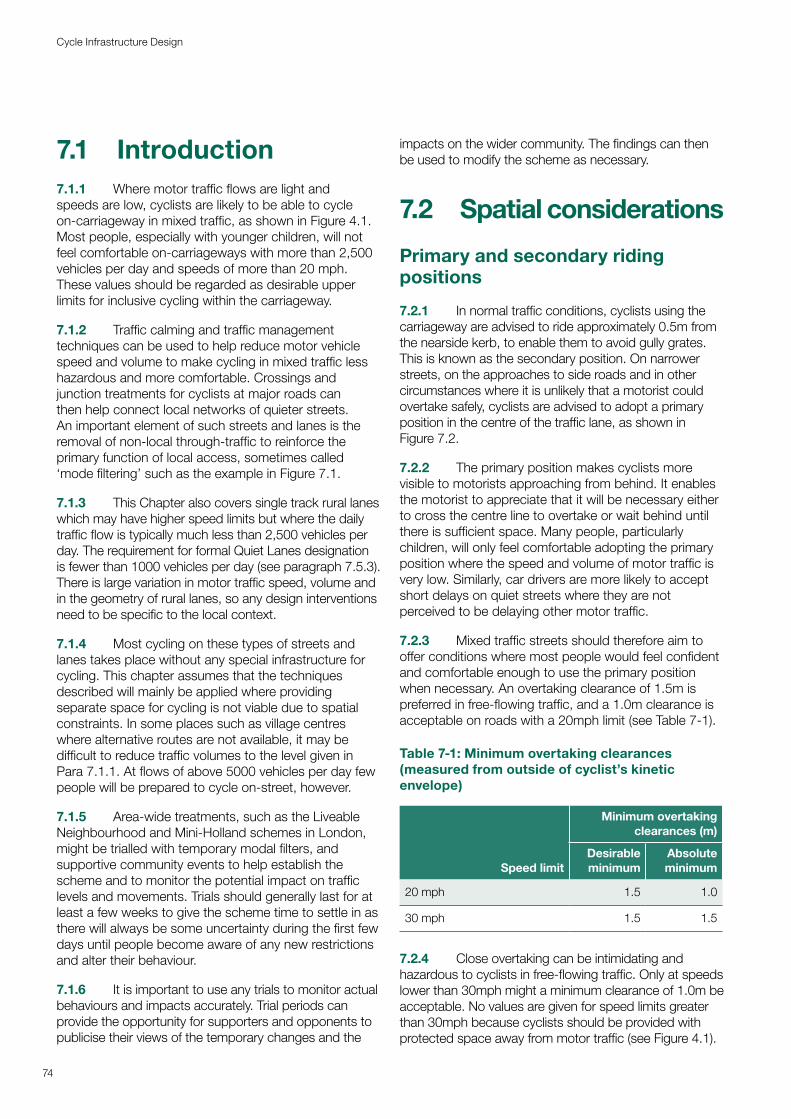
7.1 Introduction7.1.1 Where motor traffic flows are light and speeds are low, cyclists are likely to be able to cycle on-carriageway in mixed traffic, as shown in Figure 4.1. Most people, especially with younger children, will not feel comfortable on-carriageways with more than 2,500 vehicles per day and speeds of more than 20 mph. These values should be regarded as desirable upper limits for inclusive cycling within the carriageway.
7.1.2 Traffic calming and traffic management techniques can be used to help reduce motor vehicle speed and volume to make cycling in mixed traffic less hazardous and more comfortable. Crossings and junction treatments for cyclists at major roads can then help connect local networks of quieter streets. An important element of such streets and lanes is the removal of non-local through-traffic to reinforce the primary function of local access, sometimes called ‘mode filtering’ such as the example in Figure 7.1.
7.1.3 This Chapter also covers single track rural lanes which may have higher speed limits but where the daily traffic flow is typically much less than 2,500 vehicles per day. The requirement for formal Quiet Lanes designation is fewer than 1000 vehicles per day (see paragraph 7.5.3). There is large variation in motor traffic speed, volume and in the geometry of rural lanes, so any design interventions need to be specific to the local context.
7.1.4 Most cycling on these types of streets and lanes takes place without any special infrastructure for cycling. This chapter assumes that the techniques described will mainly be applied where providing separate space for cycling is not viable due to spatial constraints. In some places such as village centres where alternative routes are not available, it may be difficult to reduce traffic volumes to the level given in Para 7.1.1. At flows of above 5000 vehicles per day few people will be prepared to cycle on-street, however.
7.1.5 Area-wide treatments, such as the Liveable Neighbourhood and Mini-Holland schemes in London, might be trialled with temporary modal filters, and supportive community events to help establish the scheme and to monitor the potential impact on traffic levels and movements. Trials should generally last for at least a few weeks to give the scheme time to settle in as there will always be some uncertainty during the first few days until people become aware of any new restrictions and alter their behaviour.
7.1.6 It is important to use any trials to monitor actual behaviours and impacts accurately. Trial periods can provide the opportunity for supporters and opponents to publicise their views of the temporary changes and the
impacts on the wider community. The findings can then be used to modify the scheme as necessary.
7.2 Spatial considerations
Primary and secondary riding positions
7.2.1 In normal traffic conditions, cyclists using the carriageway are advised to ride approximately 0.5m from the nearside kerb, to enable them to avoid gully grates. This is known as the secondary position. On narrower streets, on the approaches to side roads and in other circumstances where it is unlikely that a motorist could overtake safely, cyclists are advised to adopt a primary position in the centre of the traffic lane, as shown in Figure 7.2.
7.2.2 The primary position makes cyclists more visible to motorists approaching from behind. It enables the motorist to appreciate that it will be necessary either to cross the centre line to overtake or wait behind until there is sufficient space. Many people, particularly children, will only feel comfortable adopting the primary position where the speed and volume of motor traffic is very low. Similarly, car drivers are more likely to accept short delays on quiet streets where they are not perceived to be delaying other motor traffic.
7.2.3 Mixed traffic streets should therefore aim to offer conditions where most people would feel confident and comfortable enough to use the primary position when necessary. An overtaking clearance of 1.5m is preferred in free-flowing traffic, and a 1.0m clearance is acceptable on roads with a 20mph limit (see Table 7-1).
Table 7-1: Minimum overtaking clearances (measured from outside of cyclist’s kinetic envelope)
Speed limit
Minimum overtaking clearances (m)
Desirable minimum
Absolute minimum
20 mph 1.5 1.0
30 mph 1.5 1.5
7.2.4 Close overtaking can be intimidating and hazardous to cyclists in free-flowing traffic. Only at speeds lower than 30mph might a minimum clearance of 1.0m be acceptable. No values are given for speed limits greater than 30mph because cyclists should be provided with protected space away from motor traffic (see Figure 4.1).
74
Cycle Infrastructure Design
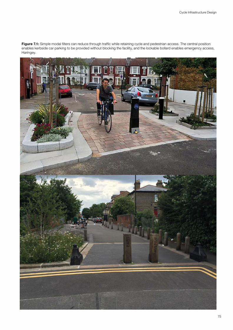
Figure 7.1: Simple modal filters can reduce through traffic while retaining cycle and pedestrian access. The central position enables kerbside car parking to be provided without blocking the facility, and the lockable bollard enables emergency access, Haringey.
75
Cycle Infrastructure Design
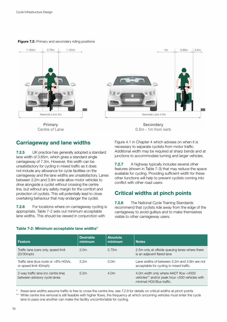
Figure 7.2: Primary and secondary riding positions
Table 7-2: Minimum acceptable lane widths*
Carriageway and lane widths
7.2.5 UK practice has generally adopted a standard lane width of 3.65m, which gives a standard single carriageway of 7.3m. However, this width can be unsatisfactory for cycling in mixed traffic as it does not include any allowance for cycle facilities on the carriageway and the lane widths are unsatisfactory. Lanes between 3.2m and 3.9m wide allow motor vehicles to drive alongside a cyclist without crossing the centre line, but without any safety margin for the comfort and protection of cyclists. This will potentially lead to close overtaking behaviour that may endanger the cyclist.
7.2.6 For locations where on-carriageway cycling is appropriate, Table 7-2 sets out minimum acceptable lane widths. This should be viewed in conjunction with
Figure 4.1 in Chapter 4 which advises on when it is necessary to separate cyclists from motor traffic. Additional width may be required at sharp bends and at junctions to accommodate turning and larger vehicles.
7.2.7 A highway typically includes several other features (shown in Table 7-3) that may reduce the space available for cycling. Providing sufficient width for these other functions will help to prevent cyclists coming into conflict with other road users.
Critical widths at pinch points
7.2.8 The National Cycle Training Standards recommend that cyclists ride away from the edge of the carriageway to avoid gulleys and to make themselves visible to other carriageway users.
FeatureDesirable minimum
Absolute minimum Notes
Traffic lane (cars only, speed limit 20/30mph)
3.0m 2.75m 2.5m only at offside queuing lanes where there is an adjacent flared lane
Traffic lane (bus route or >8% HGVs, or speed limit 40mph)
3.2m 3.0m Lane widths of between 3.2m and 3.9m are not acceptable for cycling in mixed traffic.
2-way traffic lane (no centre line) between advisory cycle lanes
5.5m 4.0m 4.0m width only where AADT flow <4000 vehicles** and/or peak hour <500 vehicles with minimal HGV/Bus traffic.
* these lane widths assume traffic is free to cross the centre line, see 7.2.9 for details on critical widths at pinch points** While centre line removal is still feasible with higher flows, the frequency at which oncoming vehicles must enter the cycle
lane to pass one another can make the facility uncomfortable for cycling.
76
Cycle Infrastructure Design
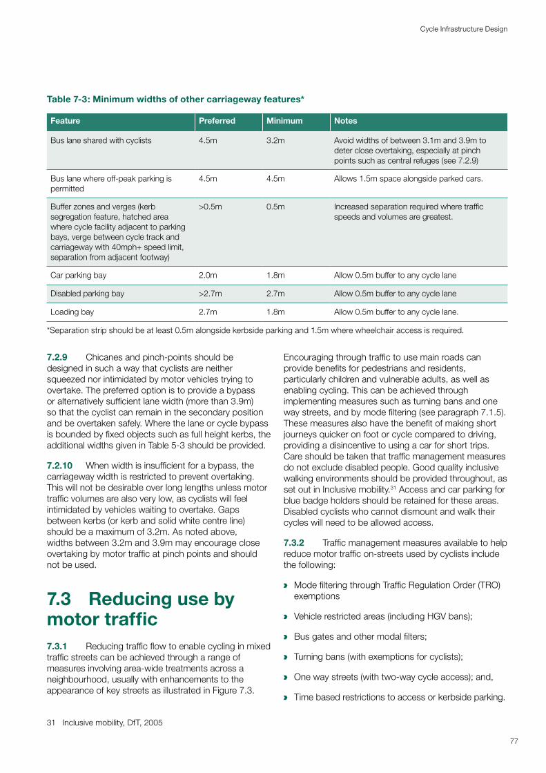
a
a
a
a
a
a
Table 7-3: Minimum widths of other carriageway features*
Feature Preferred Minimum Notes
Bus lane shared with cyclists 4.5m 3.2m Avoid widths of between 3.1m and 3.9m to deter close overtaking, especially at pinch points such as central refuges (see 7.2.9)
Bus lane where off-peak parking is permitted
4.5m 4.5m Allows 1.5m space alongside parked cars.
Buffer zones and verges (kerb segregation feature, hatched area where cycle facility adjacent to parking bays, verge between cycle track and carriageway with 40mph+ speed limit, separation from adjacent footway)
>0.5m 0.5m Increased separation required where traffic speeds and volumes are greatest.
Car parking bay 2.0m 1.8m Allow 0.5m buffer to any cycle lane
Disabled parking bay >2.7m 2.7m Allow 0.5m buffer to any cycle lane
Loading bay 2.7m 1.8m Allow 0.5m buffer to any cycle lane.
*Separation strip should be at least 0.5m alongside kerbside parking and 1.5m where wheelchair access is required.
77
Cycle Infrastructure Design
7.2.9 Chicanes and pinch-points should be designed in such a way that cyclists are neither squeezed nor intimidated by motor vehicles trying to overtake. The preferred option is to provide a bypass or alternatively sufficient lane width (more than 3.9m) so that the cyclist can remain in the secondary position and be overtaken safely. Where the lane or cycle bypass is bounded by fixed objects such as full height kerbs, the additional widths given in Table 5-3 should be provided.
7.2.10 When width is insufficient for a bypass, the carriageway width is restricted to prevent overtaking. This will not be desirable over long lengths unless motor traffic volumes are also very low, as cyclists will feel intimidated by vehicles waiting to overtake. Gaps between kerbs (or kerb and solid white centre line) should be a maximum of 3.2m. As noted above, widths between 3.2m and 3.9m may encourage close overtaking by motor traffic at pinch points and should not be used.
7.3 Reducing use by motor traffic 7.3.1 Reducing traffic flow to enable cycling in mixed traffic streets can be achieved through a range of measures involving area-wide treatments across a neighbourhood, usually with enhancements to the appearance of key streets as illustrated in Figure 7.3.
31 Inclusive mobility, DfT, 2005
Encouraging through traffic to use main roads can provide benefits for pedestrians and residents, particularly children and vulnerable adults, as well as enabling cycling. This can be achieved through implementing measures such as turning bans and one way streets, and by mode filtering (see paragraph 7.1.5). These measures also have the benefit of making short journeys quicker on foot or cycle compared to driving, providing a disincentive to using a car for short trips. Care should be taken that traffic management measures do not exclude disabled people. Good quality inclusive walking environments should be provided throughout, as set out in Inclusive mobility.31 Access and car parking for blue badge holders should be retained for these areas. Disabled cyclists who cannot dismount and walk their cycles will need to be allowed access.
7.3.2 Traffic management measures available to help reduce motor traffic on-streets used by cyclists include the following:
Mode filtering through Traffic Regulation Order (TRO) exemptions
Vehicle restricted areas (including HGV bans);
Bus gates and other modal filters;
Turning bans (with exemptions for cyclists);
One way streets (with two-way cycle access); and,
Time based restrictions to access or kerbside parking.
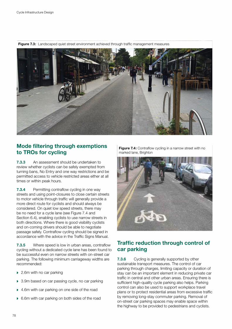
a
a
a
a
Figure 7.3: Landscaped quiet street environment achieved through traffic management measures
78
Cycle Infrastructure Design
Mode filtering through exemptions to TROs for cycling
7.3.3 An assessment should be undertaken to review whether cyclists can be safely exempted from turning bans, No Entry and one way restrictions and be permitted access to vehicle restricted areas either at all times or within peak hours.
7.3.4 Permitting contraflow cycling in one way streets and using point-closures to close certain streets to motor vehicle through traffic will generally provide a more direct route for cyclists and should always be considered. On quiet low speed streets, there may be no need for a cycle lane (see Figure 7.4 and Section 6.4), enabling cyclists to use narrow streets in both directions. Where there is good visibility cyclists and on-coming drivers should be able to negotiate passage safely. Contraflow cycling should be signed in accordance with the advice in the Traffic Signs Manual.
7.3.5 Where speed is low in urban areas, contraflow cycling without a dedicated cycle lane has been found to be successful even on narrow streets with on-street car parking. The following minimum carriageway widths are recommended:
2.6m with no car parking
3.9m based on car passing cycle, no car parking
4.6m with car parking on one side of the road
6.6m with car parking on both sides of the road
Figure 7.4: Contraflow cycling in a narrow street with no marked lane, Brighton
Traffic reduction through control of car parking
7.3.6 Cycling is generally supported by other sustainable transport measures. The control of car parking through charges, limiting capacity or duration of stay can be an important element in reducing private car traffic in central and other urban areas. Ensuring there is sufficient high-quality cycle parking also helps. Parking control can also be used to support workplace travel plans or to protect residential areas from excessive traffic by removing long-stay commuter parking. Removal of on-street car parking spaces may enable space within the highway to be provided to pedestrians and cyclists.
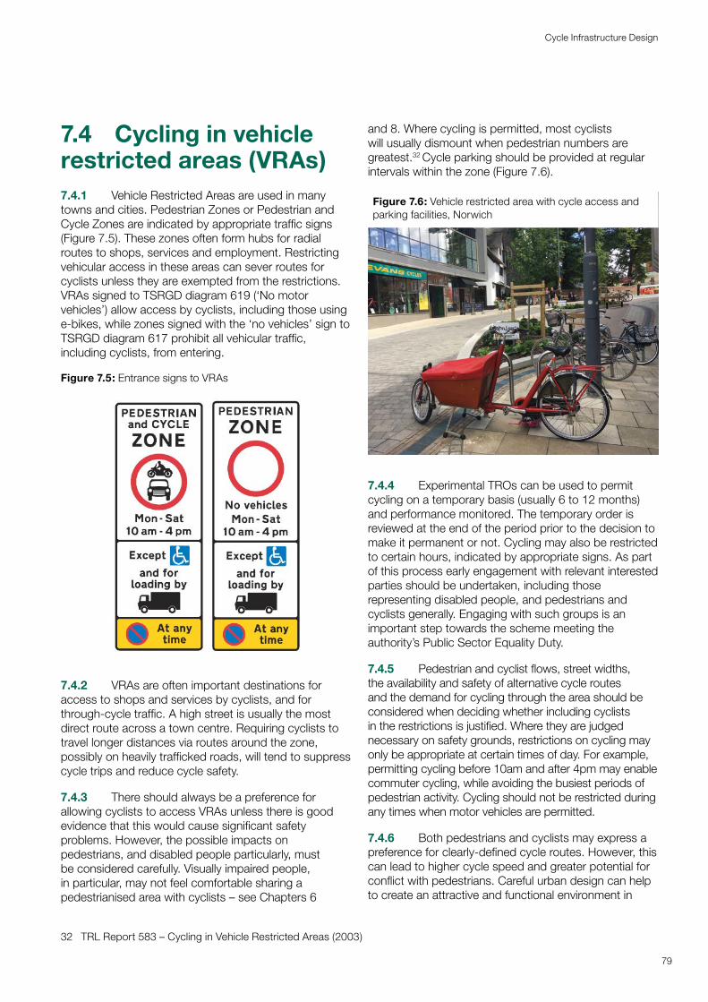
7.4 Cycling in vehicle restricted areas (VRAs)7.4.1 Vehicle Restricted Areas are used in many towns and cities. Pedestrian Zones or Pedestrian and Cycle Zones are indicated by appropriate traffic signs (Figure 7.5). These zones often form hubs for radial routes to shops, services and employment. Restricting vehicular access in these areas can sever routes for cyclists unless they are exempted from the restrictions. VRAs signed to TSRGD diagram 619 (‘No motor vehicles’) allow access by cyclists, including those using e-bikes, while zones signed with the ‘no vehicles’ sign to TSRGD diagram 617 prohibit all vehicular traffic, including cyclists, from entering.
Figure 7.5: Entrance signs to VRAs
7.4.2 VRAs are often important destinations for access to shops and services by cyclists, and for through-cycle traffic. A high street is usually the most direct route across a town centre. Requiring cyclists to travel longer distances via routes around the zone, possibly on heavily trafficked roads, will tend to suppress cycle trips and reduce cycle safety.
7.4.3 There should always be a preference for allowing cyclists to access VRAs unless there is good evidence that this would cause significant safety problems. However, the possible impacts on pedestrians, and disabled people particularly, must be considered carefully. Visually impaired people, in particular, may not feel comfortable sharing a pedestrianised area with cyclists – see Chapters 6
32 TRL Report 583 – Cycling in Vehicle Restricted Areas (2003)
and 8. Where cycling is permitted, most cyclists will usually dismount when pedestrian numbers are greatest.32 Cycle parking should be provided at regular intervals within the zone (Figure 7.6).
Figure 7.6: Vehicle restricted area with cycle access and parking facilities, Norwich
7.4.4 Experimental TROs can be used to permit cycling on a temporary basis (usually 6 to 12 months) and performance monitored. The temporary order is reviewed at the end of the period prior to the decision to make it permanent or not. Cycling may also be restricted to certain hours, indicated by appropriate signs. As part of this process early engagement with relevant interested parties should be undertaken, including those representing disabled people, and pedestrians and cyclists generally. Engaging with such groups is an important step towards the scheme meeting the authority’s Public Sector Equality Duty.
7.4.5 Pedestrian and cyclist flows, street widths, the availability and safety of alternative cycle routes and the demand for cycling through the area should be considered when deciding whether including cyclists in the restrictions is justified. Where they are judged necessary on safety grounds, restrictions on cycling may only be appropriate at certain times of day. For example, permitting cycling before 10am and after 4pm may enable commuter cycling, while avoiding the busiest periods of pedestrian activity. Cycling should not be restricted during any times when motor vehicles are permitted.
7.4.6 Both pedestrians and cyclists may express a preference for clearly-defined cycle routes. However, this can lead to higher cycle speed and greater potential for conflict with pedestrians. Careful urban design can help to create an attractive and functional environment in
79
Cycle Infrastructure Design
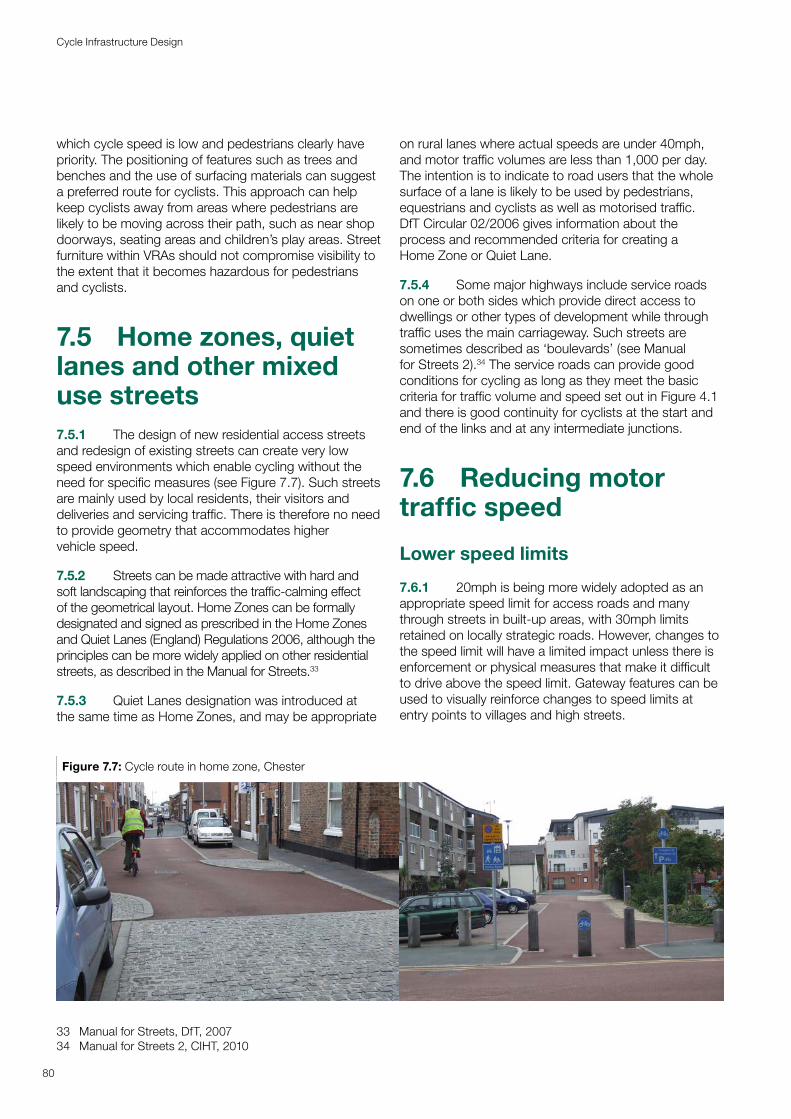
which cycle speed is low and pedestrians clearly have priority. The positioning of features such as trees and benches and the use of surfacing materials can suggest a preferred route for cyclists. This approach can help keep cyclists away from areas where pedestrians are likely to be moving across their path, such as near shop doorways, seating areas and children’s play areas. Street furniture within VRAs should not compromise visibility to the extent that it becomes hazardous for pedestrians and cyclists.
7.5 Home zones, quiet lanes and other mixed use streets7.5.1 The design of new residential access streets and redesign of existing streets can create very low speed environments which enable cycling without the need for specific measures (see Figure 7.7). Such streets are mainly used by local residents, their visitors and deliveries and servicing traffic. There is therefore no need to provide geometry that accommodates higher vehicle speed.
7.5.2 Streets can be made attractive with hard and soft landscaping that reinforces the traffic-calming effect of the geometrical layout. Home Zones can be formally designated and signed as prescribed in the Home Zones and Quiet Lanes (England) Regulations 2006, although the principles can be more widely applied on other residential streets, as described in the Manual for Streets.33
7.5.3 Quiet Lanes designation was introduced at the same time as Home Zones, and may be appropriate
33 Manual for Streets, DfT, 200734 Manual for Streets 2, CIHT, 2010
on rural lanes where actual speeds are under 40mph, and motor traffic volumes are less than 1,000 per day. The intention is to indicate to road users that the whole surface of a lane is likely to be used by pedestrians, equestrians and cyclists as well as motorised traffic. DfT Circular 02/2006 gives information about the process and recommended criteria for creating a Home Zone or Quiet Lane.
7.5.4 Some major highways include service roads on one or both sides which provide direct access to dwellings or other types of development while through traffic uses the main carriageway. Such streets are sometimes described as ‘boulevards’ (see Manual for Streets 2).34 The service roads can provide good conditions for cycling as long as they meet the basic criteria for traffic volume and speed set out in Figure 4.1 and there is good continuity for cyclists at the start and end of the links and at any intermediate junctions.
7.6 Reducing motor traffic speed
Lower speed limits
7.6.1 20mph is being more widely adopted as an appropriate speed limit for access roads and many through streets in built-up areas, with 30mph limits retained on locally strategic roads. However, changes to the speed limit will have a limited impact unless there is enforcement or physical measures that make it difficult to drive above the speed limit. Gateway features can be used to visually reinforce changes to speed limits at entry points to villages and high streets.
Figure 7.7: Cycle route in home zone, Chester
80
Cycle Infrastructure Design
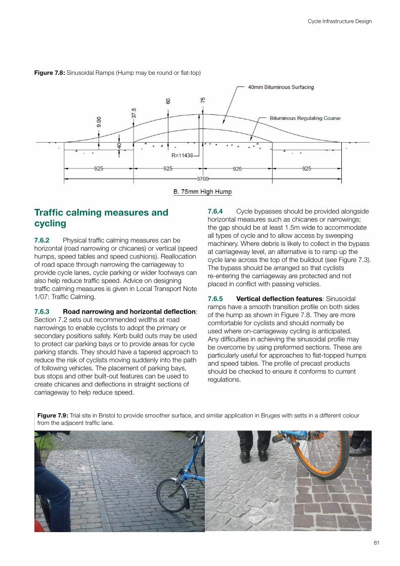
Traffic calming measures and cycling
7.6.2 Physical traffic calming measures can be horizontal (road narrowing or chicanes) or vertical (speed humps, speed tables and speed cushions). Reallocation of road space through narrowing the carriageway to provide cycle lanes, cycle parking or wider footways can also help reduce traffic speed. Advice on designing traffic calming measures is given in Local Transport Note 1/07: Traffic Calming.
7.6.3 Road narrowing and horizontal deflection: Section 7.2 sets out recommended widths at road narrowings to enable cyclists to adopt the primary or secondary positions safely. Kerb build outs may be used to protect car parking bays or to provide areas for cycle parking stands. They should have a tapered approach to reduce the risk of cyclists moving suddenly into the path of following vehicles. The placement of parking bays, bus stops and other built-out features can be used to create chicanes and deflections in straight sections of carriageway to help reduce speed.
7.6.4 Cycle bypasses should be provided alongside horizontal measures such as chicanes or narrowings; the gap should be at least 1.5m wide to accommodate all types of cycle and to allow access by sweeping machinery. Where debris is likely to collect in the bypass at carriageway level, an alternative is to ramp up the cycle lane across the top of the buildout (see Figure 7.3). The bypass should be arranged so that cyclists re-entering the carriageway are protected and not placed in conflict with passing vehicles.
7.6.5 Vertical deflection features: Sinusoidal ramps have a smooth transition profile on both sides of the hump as shown in Figure 7.8. They are more comfortable for cyclists and should normally be used where on-carriageway cycling is anticipated. Any difficulties in achieving the sinusoidal profile may be overcome by using preformed sections. These ar e particularly useful for approaches to flat-topped humps and speed tables. The profile of precast pr oducts should be checked to ensure it conforms to current regulations.
Figure 7.8: Sinusoidal Ramps (Hump may be round or flat-top)
Figure 7.9: Trial site in Bristol to provide smoother surface, and similar application in Bruges with setts in a different colour from the adjacent traffic lane.
81
Cycle Infrastructure Design
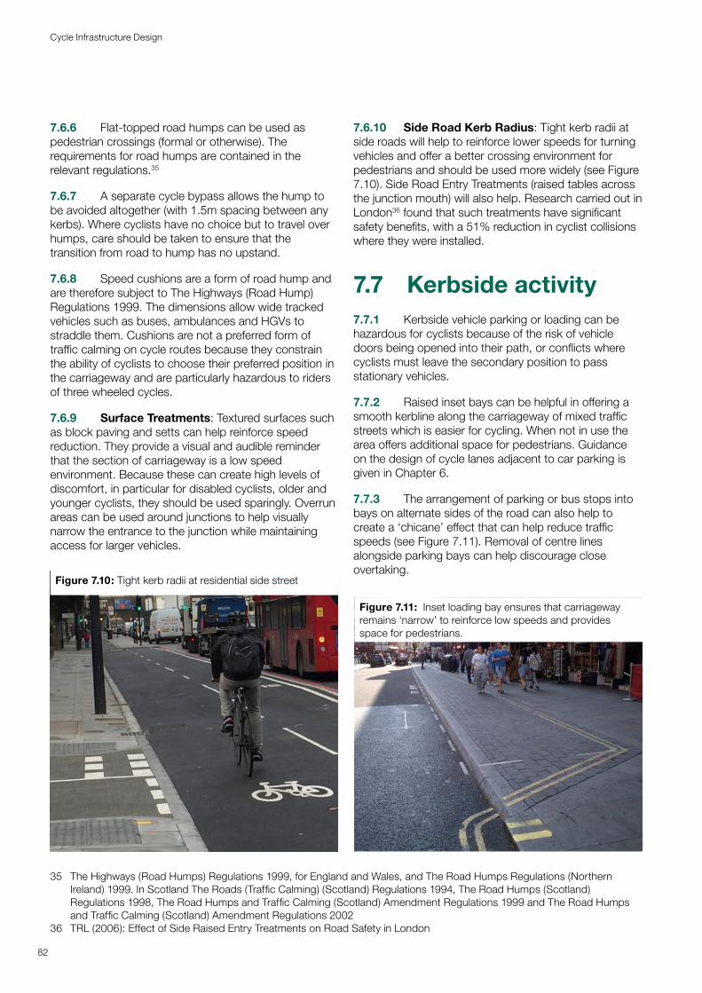
7.6.6 Flat-topped road humps can be used as pedestrian crossings (formal or otherwise). The requirements for road humps are contained in the relevant regulations.35
7.6.7 A separate cycle bypass allows the hump to be avoided altogether (with 1.5m spacing between any kerbs). Where cyclists have no choice but to travel over humps, care should be taken to ensure that the transition from road to hump has no upstand.
7.6.8 Speed cushions are a form of road hump and are therefore subject to The Highways (Road Hump) Regulations 1999. The dimensions allow wide tracked vehicles such as buses, ambulances and HGVs to straddle them. Cushions are not a preferred form of traffic calming on cycle routes because they constrain the ability of cyclists to choose their preferred position in the carriageway and are particularly hazardous to riders of three wheeled cycles.
7.6.9 Surface Treatments: Textured surfaces such as block paving and setts can help reinforce speed reduction. They provide a visual and audible reminder that the section of carriageway is a low speed environment. Because these can create high levels of discomfort, in particular for disabled cyclists, older and younger cyclists, they should be used sparingly. Overrun areas can be used around junctions to help visually narrow the entrance to the junction while maintaining access for larger vehicles.
35 The Highways (Road Humps) Regulations 1999, for England and Wales, and The Road Humps Regulations (Northern Ireland) 1999. In Scotland The Roads (Traffic Calming) (Scotland) Regulations 1994, The Road Humps (Scotland) Regulations 1998, The Road Humps and Traffic Calming (Scotland) Amendment Regulations 1999 and The Road Humps and Traffic Calming (Scotland) Amendment Regulations 2002
36 TRL (2006): Effect of Side Raised Entry Treatments on Road Safety in London
7.6.10 Side Road Kerb Radius: Tight kerb radii at side roads will help to reinforce lower speeds for turning vehicles and offer a better crossing environment for pedestrians and should be used more widely (see Figure 7.10). Side Road Entry Treatments (raised tables across the junction mouth) will also help. Research carried out in London36 found that such treatments have significant safety benefits, with a 51% reduction in cyclist collisions where they were installed.
7.7 Kerbside activity7.7.1 Kerbside vehicle parking or loading can be hazardous for cyclists because of the risk of vehicle doors being opened into their path, or conflicts where cyclists must leave the secondary position to pass stationary vehicles.
7.7.2 Raised inset bays can be helpful in offering a smooth kerbline along the carriageway of mixed traffic streets which is easier for cycling. When not in use the area offers additional space for pedestrians. Guidance on the design of cycle lanes adjacent to car parking is given in Chapter 6.
7.7.3 The arrangement of parking or bus stops into bays on alternate sides of the road can also help to create a ‘chicane’ effect that can help reduce traffic speeds (see Figure 7.11). Removal of centre lines alongside parking bays can help discourage close overtaking.
Figure 7.10: Tight kerb radii at residential side street
Figure 7.11: Inset loading bay ensures that carriageway remains ‘narrow’ to reinforce low speeds and provides space for pedestrians.
82
Cycle Infrastructure Design
8Motor Motor traffic free traffic free routesroutes
Motor traffic free routes away from the highway can form important links for everyday trips. They are attractive to those who prefer to avoid motor traffic. To achieve their full potential, off-highway routes need to be designed and maintained to a high level of quality, particularly in terms of surfacing, accessibility and lighting. They also need to be well maintained and kept free of leaf debris, ice and snow in winter. It may be appropriate to design them as shared use paths, with an expectation that all users will take care, but in some situations such as busier commuter routes it will be preferable to provide separation between pedestrians and cyclists.
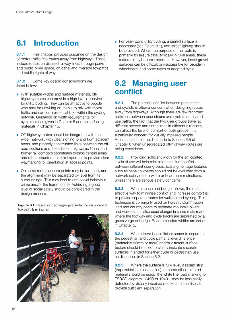
8.1 Introduction8.1.1 This chapter provides guidance on the design of motor traffic free routes away from highways. These include routes on disused railway lines, through parks and public open space, on canal and riverside towpaths, and public rights of way.
8.1.2 Some key design considerations are listed below:
a With suitable widths and surface materials, off-highway routes can provide a high level of service for utility cycling. They can be attractive to people who may be unwilling or unable to mix with motor traffic and can form essential links within the cycling network. Guidance on width requirements for cycle routes is given in Chapter 5 and on surfacing materials in Chapter 15.
a Off-highway routes should be integrated with the wider network, with clear signing to and from adjacent areas, and properly constructed links between the off-road sections and the adjacent highways. Canal and former rail corridors sometimes bypass central areas and other attractors, so it is important to provide clear waymarking for orientation at access points.
a On some routes access points may be far apart, and the alignment may be separated by level from its surroundings. This may lead to anti-social behaviour, crime and/or the fear of crime. Achieving a good level of social safety should be considered in the design process.
a For year-round utility cycling, a sealed surface is necessary (see Figure 8.1), and street lighting should be provided. Where the purpose of the route is primarily for leisure trips, typically in rural areas, these features may be less important. However, loose gravel surfaces can be difficult or inaccessible for people in wheelchairs and some types of adapted cycle.
8.2 Managing user conflict8.2.1 The potential conflict between pedestrians and cyclists is often a concern when designing routes away from highways. Although there are few recorded collisions between pedestrians and cyclists on shared use paths, the fact that the two user groups travel at different speeds and sometimes in different directions, can affect the level of comfort of both groups. It is a particular concern for visually impaired people. Reference should also be made to Section 6.5 of Chapter 6 when unsegregated off-highway routes are being considered.
8.2.2 Providing sufficient width for the anticipated levels of use will help minimise the risk of conflict between different user groups. Existing heritage features such as canal towpaths should not be excluded from a network solely due to width or headroom restrictions, unless there are serious safety concerns.
8.2.3 Where space and budget allows, the most effective way to minimise conflict and increase comfort is to provide separate routes for walking and cycling. This technique is commonly used on Forestry Commission land and country parks to separate mountain bikers and walkers. It is also used alongside some main roads where the footway and cycle tracks are separated by a grass verge or hedge. Recommended widths are set out in Chapter 5.
8.2.4 Where there is insufficient space to separate the pedestrian and cycle paths, a level difference (preferably 60mm or more) and/or different surface texture should be used to clearly indicate separate surfaces intended for either cycle or pedestrian use, as discussed in Section 6.2.
8.2.5 Where the surface is fully level, a raised strip (trapezoidal in cross section), or some other textured material should be used. The white line road marking to TSRGD diagram 1049B or 1049.1 may be less easily detected by visually impaired people and is unlikely to provide sufficient separation.
Figure 8.1: Resin bonded aggregate surfacing on widened towpath, Birmingham
84
Cycle Infrastructure Design
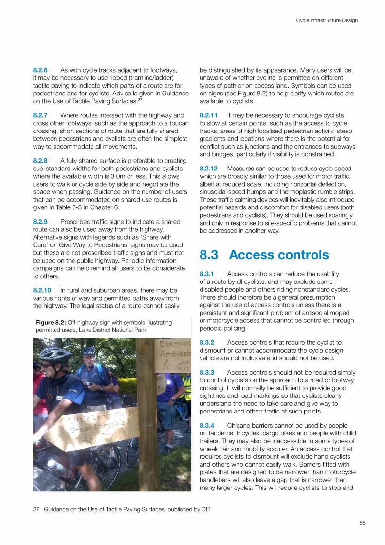
8.2.6 As with cycle tracks adjacent to footways, it may be necessary to use ribbed (tramline/ladder) tactile paving to indicate which parts of a route are for pedestrians and for cyclists. Advice is given in Guidance on the Use of Tactile Paving Surfaces.37
8.2.7 Where routes intersect with the highway and cross other footways, such as the approach to a toucan crossing, short sections of route that are fully shared between pedestrians and cyclists are often the simplest way to accommodate all movements.
8.2.8 A fully shared surface is preferable to creating sub-standard widths for both pedestrians and cyclists where the available width is 3.0m or less. This allows users to walk or cycle side by side and negotiate the space when passing. Guidance on the number of users that can be accommodated on shared use routes is given in Table 6-3 in Chapter 6.
8.2.9 Prescribed traffic signs to indicate a shared route can also be used away from the highway. Alternative signs with legends such as ‘Share with Care’ or ‘Give Way to Pedestrians’ signs may be used but these are not prescribed traffic signs and must not be used on the public highway. Periodic information campaigns can help remind all users to be considerate to others.
37 Guidance on the Use of Tactile Paving Surfaces, published by DfT
8.2.10 In rural and suburban areas, there may be various rights of way and permitted paths away from the highway. The legal status of a route cannot easily
be distinguished by its appearance. Many users will be unaware of whether cycling is permitted on different types of path or on access land. Symbols can be used on signs (see Figure 8.2) to help clarify which routes are available to cyclists.
8.2.11 It may be necessary to encourage cyclists to slow at certain points, such as the access to cycle tracks, areas of high localised pedestrian activity, steep gradients and locations where there is the potential for conflict such as junctions and the entrances to subways and bridges, particularly if visibility is constrained.
8.2.12 Measures can be used to reduce cycle speed which are broadly similar to those used for motor traffic, albeit at reduced scale, including horizontal deflection, sinusoidal speed humps and thermoplastic rumble strips. These traffic calming devices will inevitably also introduce potential hazards and discomfort for disabled users (both pedestrians and cyclists). They should be used sparingly and only in response to site-specific problems that cannot be addressed in another way.
8.3 Access controls8.3.1 Access controls can reduce the usability of a route by all cyclists, and may exclude some disabled people and others riding nonstandard cycles. There should therefore be a general presumption against the use of access controls unless there is a persistent and significant problem of antisocial moped or motorcycle access that cannot be controlled through periodic policing.
8.3.2 Access controls that require the cyclist to dismount or cannot accommodate the cycle design vehicle are not inclusive and should not be used.
8.3.3 Access controls should not be required simply to control cyclists on the approach to a road or footway crossing. It will normally be sufficient to provide good sightlines and road markings so that cyclists clearly understand the need to take care and give way to pedestrians and otherr traffic at such points.
8.3.4 Chicane barriers cannot be used by people on tandems, tricycles, cargo bikes and people with child trailers. They may also be inaccessible to some types of wheelchair and mobility scooter. An access control that requires cyclists to dismount will exclude hand cyclists and others who cannot easily walk. Barriers fitted with plates that are designed to be narrower than motorcycle handlebars will also leave a gap that is narrower than many larger cycles. This will require cyclists to stop and
Figure 8.2: Off-highway sign with symbols illustrating permitted users, Lake District National Park
85
Cycle Infrastructure Design
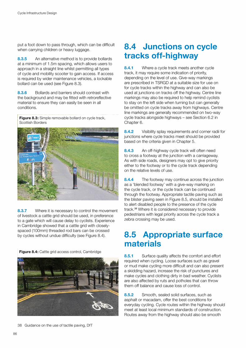
put a foot down to pass through, which can be difficult when carrying children or heavy luggage.
8.3.5 An alternative method is to provide bollards at a minimum of 1.5m spacing, which allows users to approach in a straight line whilst permitting all types of cycle and mobility scooter to gain access. If access is required by wider maintenance vehicles, a lockable bollard can be used (see Figure 8.3).
8.3.6 Bollards and barriers should contrast with the background and may be fitted with retroreflective material to ensure they can easily be seen in all conditions.
Figure 8.3: Simple removable bollard on cycle track, Scottish Borders
8.3.7 Where it is necessary to control the movement of livestock a cattle grid should be used, in preference to a gate which will cause delay to cyclists. Experience in Cambridge showed that a cattle grid with closely-spaced (100mm) threaded rod bars can be crossed by cycles without undue difficulty (see Figure 8.4).
38 Guidance on the use of tactile paving, DfT
8.4 Junctions on cycle tracks off-highway8.4.1 Where a cycle track meets another cycle track, it may require some indication of priority, depending on the level of use. Give-way markings are prescribed in TSRGD at a suitable size for use on for cycle tracks within the highway and can also be used at junctions on tracks off the highway. Centre line markings may also be required to help remind cyclists to stay on the left side when turning but can generally be omitted on cycle tracks away from highways. Centre line markings are generally recommended on two-way cycle tracks alongside highways – see Section 6.2 in Chapter 6.
8.4.2 Visibility splay requirements and corner radii for junctions where cycle tracks meet should be provided based on the criteria given in Chapter 5.
8.4.3 An off-highway cycle track will often need to cross a footway at the junction with a carriageway. As with side roads, designers may opt to give priority either to the footway or to the cycle track depending on the relative levels of use.
8.4.4 The footway may continue across the junction as a ‘blended footway’ with a give-way marking on the cycle track, or the cycle track can be continued through the footway. Appropriate tactile paving such as the blister paving seen in Figure 8.5, should be installed to alert disabled people to the presence of the cycle track.38 Where it is considered necessary to provide pedestrians with legal priority across the cycle track a zebra crossing may be used.
8.5 Appropriate surface materials8.5.1 Surface quality affects the comfort and effort required when cycling. Loose surfaces such as gravel or mud make cycling more difficult and can also present a skidding hazard, increase the risk of punctures and make cycles and clothing dirty in bad weather. Cyclists are also affected by ruts and potholes that can throw them off balance and cause loss of control.
8.5.2 Smooth, sealed solid surfaces, such as asphalt or macadam, offer the best conditions for everyday cycling. Cycle routes within the highway should meet at least local minimum standards of construction. Routes away from the highway should also be smooth
Figure 8.4: Cattle grid access control, Cambridge
86
Cycle Infrastructure Design
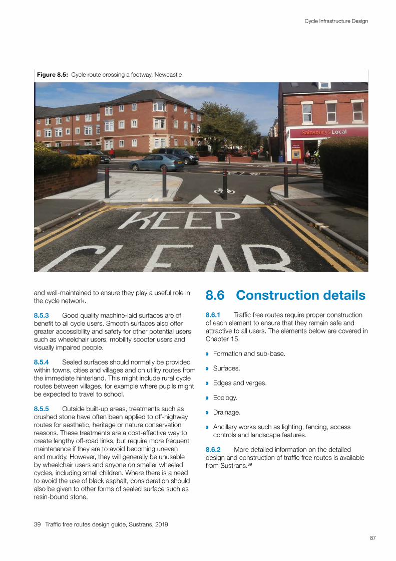
and well-maintained to ensure they play a useful role in the cycle network.
8.5.3 Good quality machine-laid surfaces are of benefit to all cycle users. Smooth surfaces also offer greater accessibility and safety for other potential users such as wheelchair users, mobility scooter users and visually impaired people.
8.5.4 Sealed surfaces should normally be provided within towns, cities and villages and on utility routes from the immediate hinterland. This might include rural cycle routes between villages, for example where pupils might be expected to travel to school.
8.5.5 Outside built-up areas, treatments such as crushed stone have often been applied to off-highway routes for aesthetic, heritage or nature conservation reasons. These treatments are a cost-effective way to create lengthy off-road links, but require more frequent maintenance if they are to avoid becoming uneven and muddy. However, they will generally be unusable by wheelchair users and anyone on smaller wheeled cycles, including small children. Where there is a need to avoid the use of black asphalt, consideration should also be given to other forms of sealed surface such as resin-bound stone.
39 Traffic free routes design guide, Sustrans, 2019
8.6 Construction details8.6.1 Traffic free routes require proper construction of each element to ensure that they remain safe and attractive to all users. The elements below are covered in Chapter 15.
a Formation and sub-base.
a Surfaces.
a Edges and verges.
a Ecology.
a Drainage.
a Ancillary works such as lighting, fencing, access controls and landscape features.
8.6.2 More detailed information on the detailed design and construction of traffic free routes is available from Sustrans.39
Figure 8.5: Cycle route crossing a footway, Newcastle
87
Cycle Infrastructure Design

8.7 Lighting8.7.1 In urban areas, highway standard street lighting may be appropriate for off-carriageway routes and will assist in offering a good degree of personal security. Energy consumption and impact on wildlife can be reduced if the lighting is switched off between midnight and 5am when there is unlikely to be much use. Lighting can also be operated by detectors which are triggered by the presence of cyclists and pedestrians.
8.7.2 Low level lighting on bollards or solar LED studs can also be used and will offer some improvement in social safety. Solar lights should not be placed in areas where the tree canopy or adjacent buildings will significantly obscure daylight, although most will work where there is partial shading. The manufacturer’s instructions will provide advice on exact requirements for each product.
8.7.3 Further guidance on the design of lighting for off-highway cycle routes is available from Sustrans.
8.8 Maintenance8.8.1 Traffic free routes quickly become unattractive or unusable when littered with broken glass or dumped refuse and should be included in routine cleansing operations.
8.8.2 Autumn leaf-fall and subsequent leaf mould can be slippery and hazardous if not cleared. Unlike highways, there is no natural sweeping effect from the passage of cyclists and pedestrians. Where a traffic free route forms part of the local cycle network for utility trips it should be prioritised for snow and ice clearance (see Chapter 15).
88
Cycle Infrastructure Design
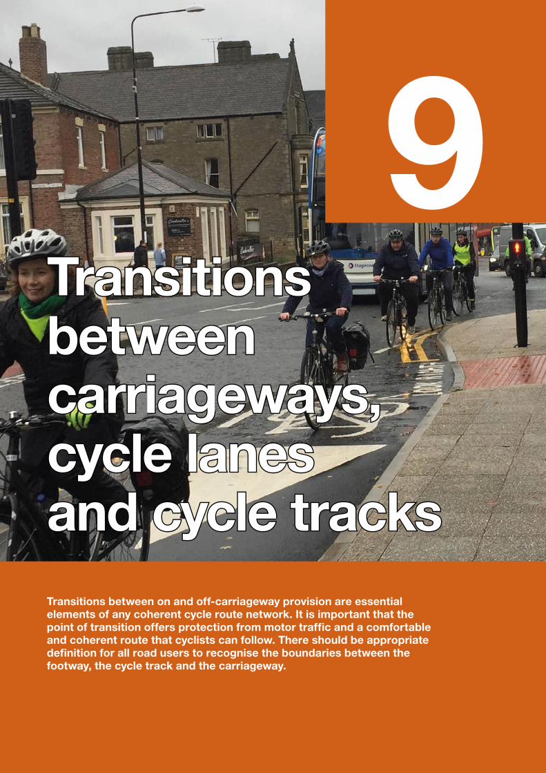
9Transitions Transitions between between carriageways, carriageways, cycle lanes cycle lanes and cycle tracksand cycle tracksTransitions between on and off-carriageway provision are essential elements of any coherent cycle route network. It is important that the point of transition offers protection from motor traffic and a comfortable and coherent route that cyclists can follow. There should be appropriate definition for all road users to recognise the boundaries between the footway, the cycle track and the carriageway.
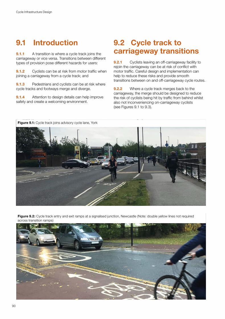
9.1 Introduction9.1.1 A transition is where a cycle track joins the carriageway or vice versa. Transitions between different types of provision pose different hazards for users:
9.1.2 Cyclists can be at risk from motor traffic when joining a carriageway from a cycle track; and
9.1.3 Pedestrians and cyclists can be at risk where cycle tracks and footways merge and diverge.
9.1.4 Attention to design details can help improve safety and create a welcoming environment.
9.2 Cycle track to carriageway transitions 9.2.1 Cyclists leaving an off-carriageway facility to rejoin the carriageway can be at risk of conflict with motor traffic. Careful design and implementation can help to reduce these risks and provide smooth transitions between on and off-carriageway cycle routes.
9.2.2 Where a cycle track merges back to the carriageway, the merge should be designed to reduce the risk of cyclists being hit by traffic from behind whilst also not inconveniencing on-carriageway cyclists (see Figures 9.1 to 9.3).
Figure 9.1: Cycle track joins advisory cycle lane, York
Figure 9.2: Cycle track entry and exit ramps at a signalised junction, Newcastle (Note: double yellow lines not required across transition ramps)
90
Cycle Infrastructure Design
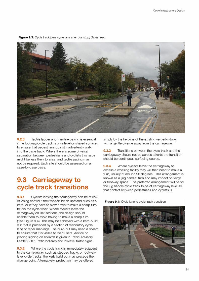
9.2.3 Tactile ladder and tramline paving is essential if the footway/cycle track is on a level or shared surface, to ensure that pedestrians do not inadvertently walk into the cycle track. Where there is some physical separation between pedestrians and cyclists this issue might be less likely to arise, and tactile paving may not be required. Each site should be assessed on a case-by-case basis.
9.3 Carriageway to cycle track transitions 9.3.1 Cyclists leaving the carriageway can be at risk of losing control if their wheels hit an upstand such as a kerb, or if they have to slow down to make a sharp turn to join the cycle track. Where cyclists leave the carriageway on link sections, the design should enable them to avoid having to make a sharp turn (See Figure 9.4). This may be achieved with a kerb-build out that is preceded by a section of mandatory cycle lane or taper markings. The build-out may need a bollard to ensure that it is visible to road users. Advice on placing signing on bollards is given in Traffic Advisory Leaflet 3/13: Traffic bollards and lowlevel traffic signs.
9.3.2 Where the cycle track is immediately adjacent to the carriageway, such as stepped tracks or footway-level cycle tracks, the kerb build out may precede the diverge point. Alternatively, protection may be offered
simply by the kerbline of the existing verge/footway, with a gentle diverge away from the carriageway.
9.3.3 Transitions between the cycle track and the carriageway should not be across a kerb; the transition should be continuous surfacing course.
9.3.4 Where cyclists leave the carriageway to access a crossing facility they will then need to make a turn, usually of around 90 degrees. This arrangement is known as a `jug handle’ turn and may impact on verge or footway space. The preferred arrangement will be for the jug handle cycle track to be at carriageway level so that conflict between pedestrians and cyclists is
Figure 9.3: Cycle track joins cycle lane after bus stop, Gateshead
Figure 9.4: Cycle lane to cycle track transition
91
Cycle Infrastructure Design
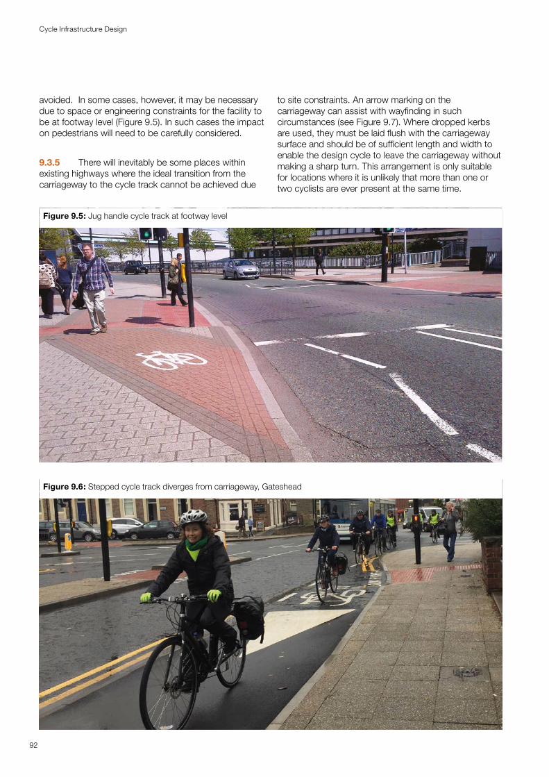
avoided. In some cases, however, it may be necessary due to space or engineering constraints for the facility to be at footway level (Figure 9.5). In such cases the impact on pedestrians will need to be carefully considered.
9.3.5 There will inevitably be some places within existing highways where the ideal transition from the carriageway to the cycle track cannot be achieved due
to site constraints. An arrow marking on the carriageway can assist with wayfinding in such circumstances (see Figure 9.7). Where dropped kerbs are used, they must be laid flush with the carriageway surface and should be of sufficient length and width to enable the design cycle to leave the carriageway without making a sharp turn. This arrangement is only suitable for locations where it is unlikely that more than one or two cyclists are ever present at the same time.
Figure 9.5: Jug handle cycle track at footway level
92
Cycle Infrastructure Design
Figure 9.6: Stepped cycle track diverges from carriageway, Gateshead
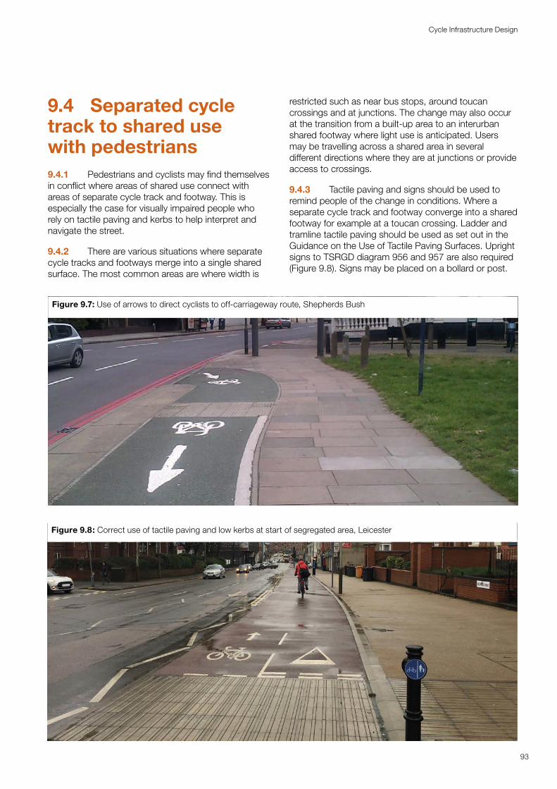
9.4 Separated cycle track to shared use with pedestrians9.4.1 Pedestrians and cyclists may find themselves in conflict where areas of shared use connect with areas of separate cycle track and footway. This is especially the case for visually impaired people who rely on tactile paving and kerbs to help interpret and navigate the street.
9.4.2 There are various situations where separate cycle tracks and footways merge into a single shared surface. The most common areas are where width is
restricted such as near bus stops, around toucan crossings and at junctions. The change may also occur at the transition from a built-up area to an interurban shared footway where light use is anticipated. Users may be travelling across a shared area in several different directions where they are at junctions or provide access to crossings.
9.4.3 Tactile paving and signs should be used to remind people of the change in conditions. Where a separate cycle track and footway converge into a shared footway for example at a toucan crossing. Ladder and tramline tactile paving should be used as set out in the Guidance on the Use of Tactile Paving Surfaces. Upright signs to TSRGD diagram 956 and 957 are also required (Figure 9.8). Signs may be placed on a bollard or post.
Figure 9.7: Use of arrows to direct cyclists to off-carriageway route, Shepherds Bush
93
Cycle Infrastructure Design
Figure 9.8: Correct use of tactile paving and low kerbs at start of segregated area, Leicester
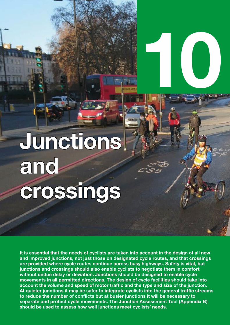
10Junctions Junctions and and crossingscrossings
It is essential that the needs of cyclists are taken into account in the design of all new and improved junctions, not just those on designated cycle routes, and that crossings are provided where cycle routes continue across busy highways. Safety is vital, but junctions and crossings should also enable cyclists to negotiate them in comfort without undue delay or deviation. Junctions should be designed to enable cycle movements in all permitted directions. The design of cycle facilities should take into account the volume and speed of motor traffic and the type and size of the junction. At quieter junctions it may be safer to integrate cyclists into the general traffic streams to reduce the number of conflicts but at busier junctions it will be necessary to separate and protect cycle movements. The Junction Assessment Tool (Appendix B) should be used to assess how well junctions meet cyclists’ needs.
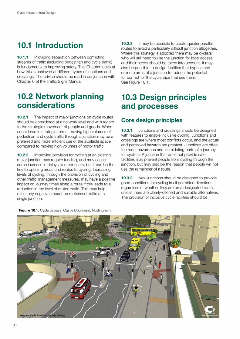
10.1 Introduction10.1.1 Providing separation between conflicting streams of traffic (including pedestrian and cycle traffic) is fundamental to improving safety. This Chapter looks at how this is achieved at different types of junctions and crossings. The advice should be read in conjunction with Chapter 6 of the Traffic Signs Manual.
10.2 Network planning considerations10.2.1 The impact of major junctions on cycle routes should be considered at a network level and with regard to the strategic movement of people and goods. When considered in strategic terms, moving high volumes of pedestrian and cycle traffic through a junction may be a preferred and more efficient use of the available space compared to moving high volumes of motor traffic.
10.2.2 Improving provision for cycling at an existing major junction may require funding, and may cause some increase in delays to other users, but it can be the key to opening areas and routes to cycling. Increasing levels of cycling, through the provision of cycling and other traffic management measures, may have a positive impact on journey times along a route if this leads to a reduction in the level of motor traffic. This may help offset any negative impact on motorised traffic at a single junction.
10.2.3 It may be possible to create quieter parallel routes to avoid a particularly difficult junction altogether. Where this strategy is adopted there may be cyclists who will still need to use the junction for local access and their needs should be taken into account. It may also be possible to design facilities that bypass one or more arms of a junction to reduce the potential for conflict for the cycle trips that use them. See Figure 10.1.
10.3 Design principles and processes
Core design principles
10.3.1 Junctions and crossings should be designed with features to enable inclusive cycling. Junctions and crossings are where most conflicts occur, and the actual and perceived hazards are greatest. Junctions are often the most hazardous and intimidating parts of a journey for cyclists. A junction that does not provide safe facilities may prevent people from cycling through the junction, but may also be the reason that people will not use the remainder of a route.
10.3.2 New junctions should be designed to provide good conditions for cycling in all permitted directions, regardless of whether they are on a designated route, unless there are clearly-defined and suitable alternatives. The provision of inclusive cycle facilities should be
Figure 10.1: Cycle bypass, Castle Boulevard, Nottingham
96
Cycle Infrastructure Design
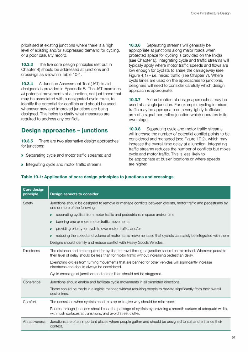
prioritised at existing junctions where there is a high level of existing and/or suppressed demand for cycling, or a poor casualty record.
10.3.3 The five core design principles (set out in Chapter 4) should be addressed at junctions and crossings as shown in Table 10-1.
10.3.4 A Junction Assessment Tool (JAT) to aid designers is provided in Appendix B. The JAT examines all potential movements at a junction, not just those that may be associated with a designated cycle route, to identify the potential for conflicts and should be used whenever new and improved junctions are being designed. This helps to clarify what measures are required to address any conflicts.
Design approaches – junctions
10.3.5 There are two alternative design approaches for junctions:
a Separating cycle and motor traffic streams; and
a Integrating cycle and motor traffic streams
10.3.6 Separating streams will generally be appropriate at junctions along major roads when protected space for cycling is provided on the link(s) (see Chapter 6). Integrating cycle and traffic streams will typically apply where motor traffic speeds and flows are low enough for cyclists to share the carriageway (see Figure 4.1) – i.e. mixed traffic (see Chapter 7). Where cycle lanes are used on the approaches to junctions, designers will need to consider carefully which design approach is appropriate.
10.3.7 A combination of design approaches may be used at a single junction. For example, cycling in mixed traffic may be appropriate on a very lightly-trafficked arm of a signal-controlled junction which operates in its own stage.
10.3.8 Separating cycle and motor traffic streams will increase the number of potential conflict points to be considered and managed (see Figure 10.2), which may increase the overall time delay at a junction. Integrating traffic streams reduces the number of conflicts but mixes cycle and motor traffic. This is less likely to be appropriate at busier locations or where speeds are higher.
Table 10-1: Application of core design principles to junctions and crossings
Core design principle Design aspects to consider
Safety Junctions should be designed to remove or manage conflicts between cyclists, motor traffic and pedestrians by one or more of the following:
a separating cyclists from motor traffic and pedestrians in space and/or time;
a banning one or more motor traffic movements;
a providing priority for cyclists over motor traffic; and/or
a reducing the speed and volume of motor traffic movements so that cyclists can safely be integrated with them
Designs should identify and reduce conflict with Heavy Goods Vehicles.
Directness The distance and time required for cyclists to travel through a junction should be minimised. Wherever possible their level of delay should be less than for motor traffic without increasing pedestrian delay.
Exempting cycles from turning movements that are banned for other vehicles will significantly increase directness and should always be considered.
Cycle crossings at junctions and across links should not be staggered.
Coherence Junctions should enable and facilitate cycle movements in all permitted directions.
These should be made in a legible manner, without requiring people to deviate significantly from their overall desire lines.
Comfort The occasions when cyclists need to stop or to give way should be minimised.
Routes through junctions should ease the passage of cyclists by providing a smooth surface of adequate width, with flush surfaces at transitions, and avoid street clutter.
Attractiveness Junctions are often important places where people gather and should be designed to suit and enhance their context.
97
Cycle Infrastructure Design
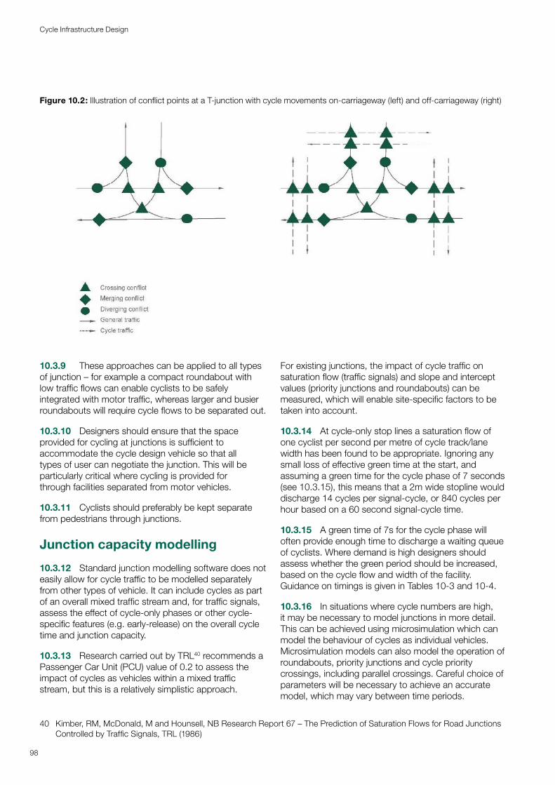
10.3.9 These approaches can be applied to all types of junction – for example a compact roundabout with low traffic flows can enable cyclists to be safely integrated with motor traffic, whereas larger and busier roundabouts will require cycle flows to be separated out.
10.3.10 Designers should ensure that the space provided for cycling at junctions is sufficient to accommodate the cycle design vehicle so that all types of user can negotiate the junction. This will be particularly critical where cycling is provided for through facilities separated from motor vehicles.
10.3.11 Cyclists should preferably be kept separate from pedestrians through junctions.
Junction capacity modelling
10.3.12 Standard junction modelling software does not easily allow for cycle traffic to be modelled separately from other types of vehicle. It can include cycles as part of an overall mixed traffic stream and, for traffic signals, assess the effect of cycle-only phases or other cycle-specific features (e.g. early-release) on the overall cycle time and junction capacity.
10.3.13 Research carried out by TRL40 recommends a Passenger Car Unit (PCU) value of 0.2 to assess the impact of cycles as vehicles within a mixed traffic stream, but this is a relatively simplistic approach.
40 Kimber, RM, McDonald, M and Hounsell, NB Research Report 67 – The Prediction of Saturation Flows for Road Junctions Controlled by Traffic Signals, TRL (1986)
For existing junctions, the impact of cycle traffic on saturation flow (traffic signals) and slope and intercept values (priority junctions and roundabouts) can be measured, which will enable site-specific factors to be taken into account.
10.3.14 At cycle-only stop lines a saturation flow of one cyclist per second per metre of cycle track/lane width has been found to be appropriate. Ignoring any small loss of effective green time at the start, and assuming a green time for the cycle phase of 7 seconds (see 10.3.15), this means that a 2m wide stopline would discharge 14 cycles per signal-cycle, or 840 cycles per hour based on a 60 second signal-cycle time.
10.3.15 A green time of 7s for the cycle phase will often provide enough time to discharge a waiting queue of cyclists. Where demand is high designers should assess whether the green period should be increased, based on the cycle flow and width of the facility. Guidance on timings is given in Tables 10-3 and 10-4.
10.3.16 In situations where cycle numbers are high, it may be necessary to model junctions in more detail. This can be achieved using microsimulation which can model the behaviour of cycles as individual vehicles. Microsimulation models can also model the operation of roundabouts, priority junctions and cycle priority crossings, including parallel crossings. Careful choice of parameters will be necessary to achieve an accurate model, which may vary between time periods.
Figure 10.2: Illustration of conflict points at a T-junction with cycle movements on-carriageway (left) and off-carriageway (right)
98
Cycle Infrastructure Design
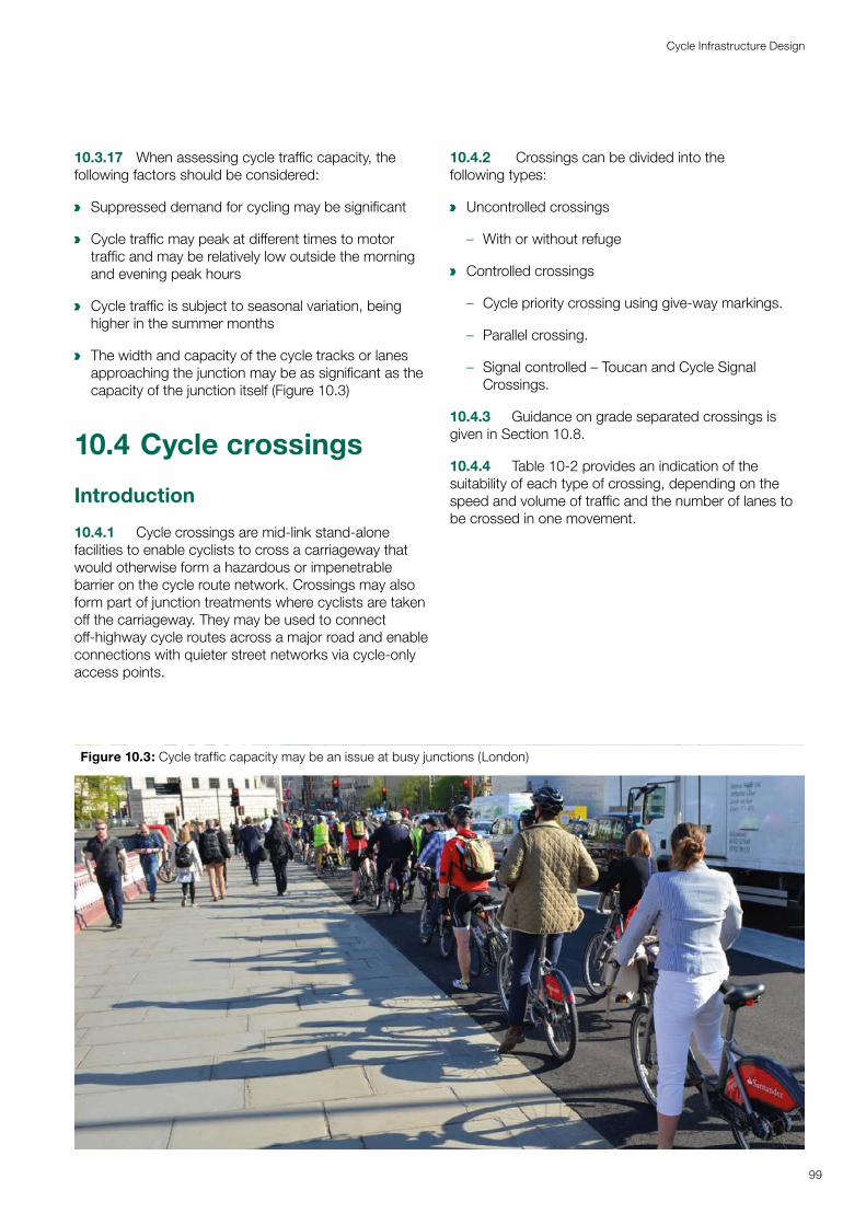
10.3.17 When assessing cycle traffic capacity, the following factors should be considered:
a Suppressed demand for cycling may be significant
a Cycle traffic may peak at different times to motor traffic and may be relatively low outside the morning and evening peak hours
a Cycle traffic is subject to seasonal variation, being higher in the summer months
a The width and capacity of the cycle tracks or lanes approaching the junction may be as significant as the capacity of the junction itself (Figure 10.3)
10.4 Cycle crossings
Introduction
10.4.1 Cycle crossings are mid-link stand-alone facilities to enable cyclists to cross a carriageway that would otherwise form a hazardous or impenetrable barrier on the cycle route network. Crossings may also form part of junction treatments where cyclists are taken off the carriageway. They may be used to connect off-highway cycle routes across a major road and enable connections with quieter street networks via cycle-only access points.
10.4.2 Crossings can be divided into the following types:
a Uncontrolled crossings
– With or without refuge
a Controlled crossings
– Cycle priority crossing using give-way markings.
– Parallel crossing.
– Signal controlled – Toucan and Cycle Signal Crossings.
10.4.3 Guidance on grade separated crossings is given in Section 10.8.
10.4.4 Table 10-2 provides an indication of the suitability of each type of crossing, depending on the speed and volume of traffic and the number of lanes to be crossed in one movement.
Figure 10.3: Cycle traffic capacity may be an issue at busy junctions (London)
99
Cycle Infrastructure Design
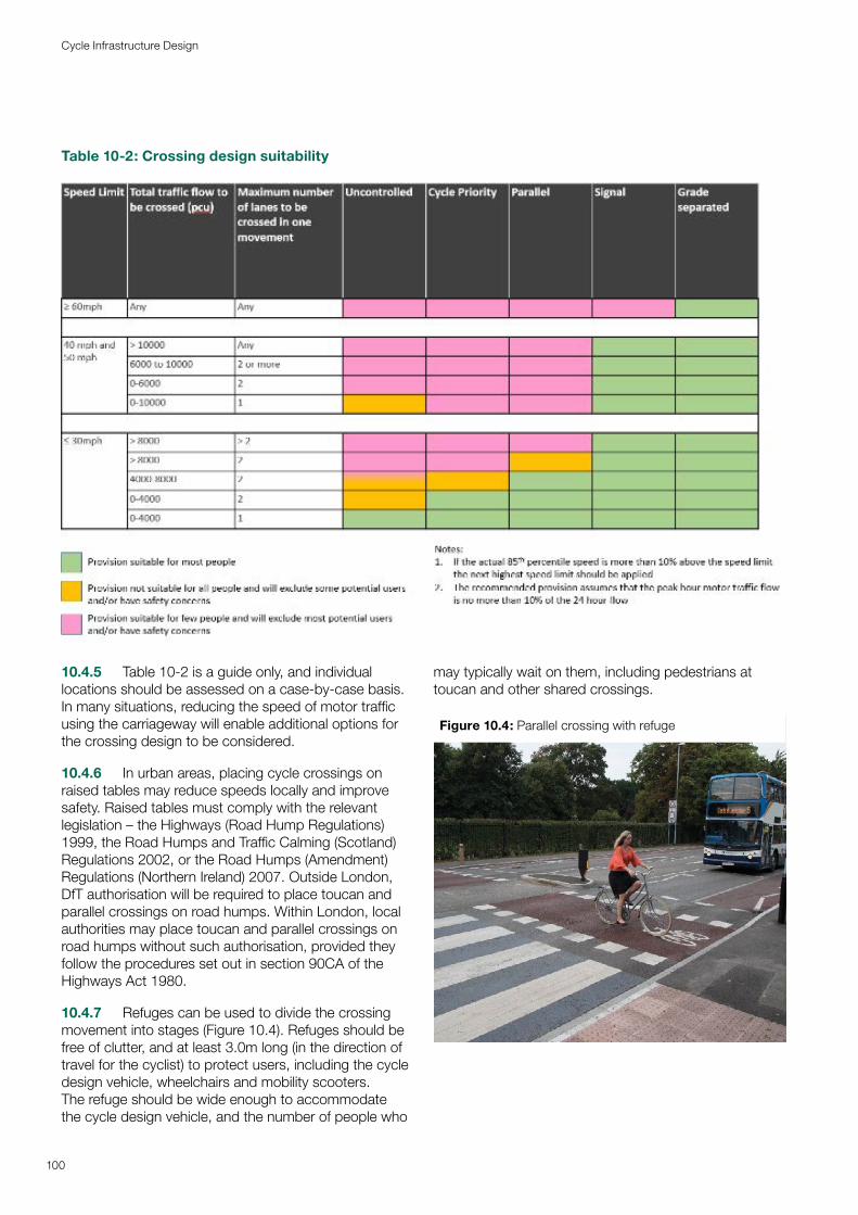
10.4.5 Table 10-2 is a guide only, and individual locations should be assessed on a case-by-case basis. In many situations, reducing the speed of motor traffic using the carriageway will enable additional options for the crossing design to be considered.
10.4.6 In urban areas, placing cycle crossings on raised tables may reduce speeds locally and improve safety. Raised tables must comply with the relevant legislation – the Highways (Road Hump Regulations) 1999, the Road Humps and Traffic Calming (Scotland) Regulations 2002, or the Road Humps (Amendment) Regulations (Northern Ireland) 2007. Outside London, DfT authorisation will be required to place toucan and parallel crossings on road humps. Within London, local authorities may place toucan and parallel crossings on road humps without such authorisation, provided they follow the procedures set out in section 90CA of the Highways Act 1980.
10.4.7 Refuges can be used to divide the crossing movement into stages (Figure 10.4). Refuges should be free of clutter, and at least 3.0m long (in the direction of travel for the cyclist) to protect users, including the cycle design vehicle, wheelchairs and mobility scooters. The refuge should be wide enough to accommodate the cycle design vehicle, and the number of people who
may typically wait on them, including pedestrians at toucan and other shared crossings.
Figure 10.4: Parallel crossing with refuge
Table 10-2: Crossing design suitability
100
Cycle Infrastructure Design
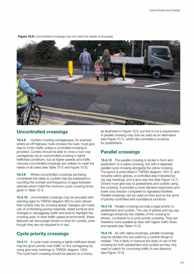
Uncontrolled crossings
10.4.8 Cyclists crossing carriageways, for example where an off-highway route crosses the road, must give way to motor traffic unless a controlled crossing is provided. Cyclists should be able to cross a two-way carriageway via an uncontrolled crossing in lightly trafficked conditions, but at higher speeds and traffic volumes uncontrolled crossings are unlikely to meet the needs of all users (see Table 10-2 and Figure 10.5).
10.4.9 Where uncontrolled crossings are being considered the delay to cyclists may be assessed by counting the number and frequency of gaps between vehicles which meet the minimum cycle crossing times given in Table 10-3.
10.4.10 Uncontrolled crossings may be provided with warning signs to TSRGD diagram 950 to warn drivers that cyclists may be crossing ahead. Designs can make use of contrasting paving materials, street furniture and changes in carriageway width and level to highlight the crossing area. In slow traffic speed environments, these features can encourage drivers to stop for cyclists, even though they are not required to in law.
Cycle priority crossings
10.4.11 A cycle route crossing a lightly trafficked street may be given priority over traffic on the carriageway by using give-way markings to TSRGD diagram 1003. The cycle track crossing should be placed on a hump,
as illustrated in Figure 10.6, but this is not a requirement. A parallel crossing may now be used as an alternative (see Figure 10.7), which also provides a crossing for pedestrians.
Parallel crossings
10.4.12 The parallel crossing is similar in form and application to a zebra crossing, but with a separate parallel cycle crossing alongside the zebra crossing. The layout is prescribed in TSRGD diagram 1001.5, and includes yellow globes, a controlled area indicated by zig-zag markings, and a give-way line (See Figure 10.7). Drivers must give way to pedestrians and cyclists using the crossing. It provides a more demand responsive and lower cost solution compared to signalised facilities. Parallel crossings can be used on links and on the arms of priority-controlled and roundabout junctions.
10.4.13 Parallel crossings provide a legal priority to pedestrians and cyclists. The use of globes and zig-zag markings enhances the visibility of the crossing to drivers, compared to a cycle priority crossing. They are therefore more suitable at sites with higher traffic flows and speeds (see Table 10-2).
10.4.14 As with zebra crossings, parallel crossings may be divided into two parts by a central refuge or median. This is likely to improve the ease of use of the crossing for both pedestrians and cyclists as they only need to watch for oncoming traffic in one direction (see Figure 10.4).
Figure 10.5: Uncontrolled crossings may not meet the needs of all people
101
Cycle Infrastructure Design

Figure 10.6: Cycle priority crossing
102
Cycle Infrastructure Design
Figure 10.7: Parallel crossing, Hackney
Toucan crossings
10.4.15 Toucan crossings are signal-controlled crossings shared between pedestrians and cyclists, with no separation between the two types of user. They may be installed at junctions or as stand-alone crossings. Zig-zag markings must not be placed at toucan facilities at junctions.
10.4.16 Toucan crossings can use nearside or farside pedestrian/cyclist signals, but not a combination of both. Farside pedestrian and cycle signal heads are prescribed in TSRGD diagrams 4003.5 and 4003.6, nearside toucan signal heads are prescribed in TSRGD diagram 4003.7. High level repeater signals to TSRGD diagram 4003.7A may also be used with nearside signal heads. Farside signals may be fitted with countdown timers.
10.4.17 Toucan crossings should be used where it is necessary to provide a shared facility, for example when there are space restrictions or where there is a shared use path or area leading to the crossing. As they incorporate shared use facilities, where such a crossing is being considered, early engagement with relevant interested parties should be undertaken, including those representing disabled people, and pedestrians and cyclists generally. Engaging with such groups is an important step towards meeting the local authority’s Public Sector Equality Duty.
10.4.18 Minimum crossing times at toucans are defined by walking speeds. Advice on timings is given in Chapter 6 of the Traffic Signs Manual.
10.4.19 On wider roads and at busier junctions, a staggered toucan crossing is often used to combine pedestrian and cycle movements and minimise delay to motor traffic. However, negotiating a staggered refuge
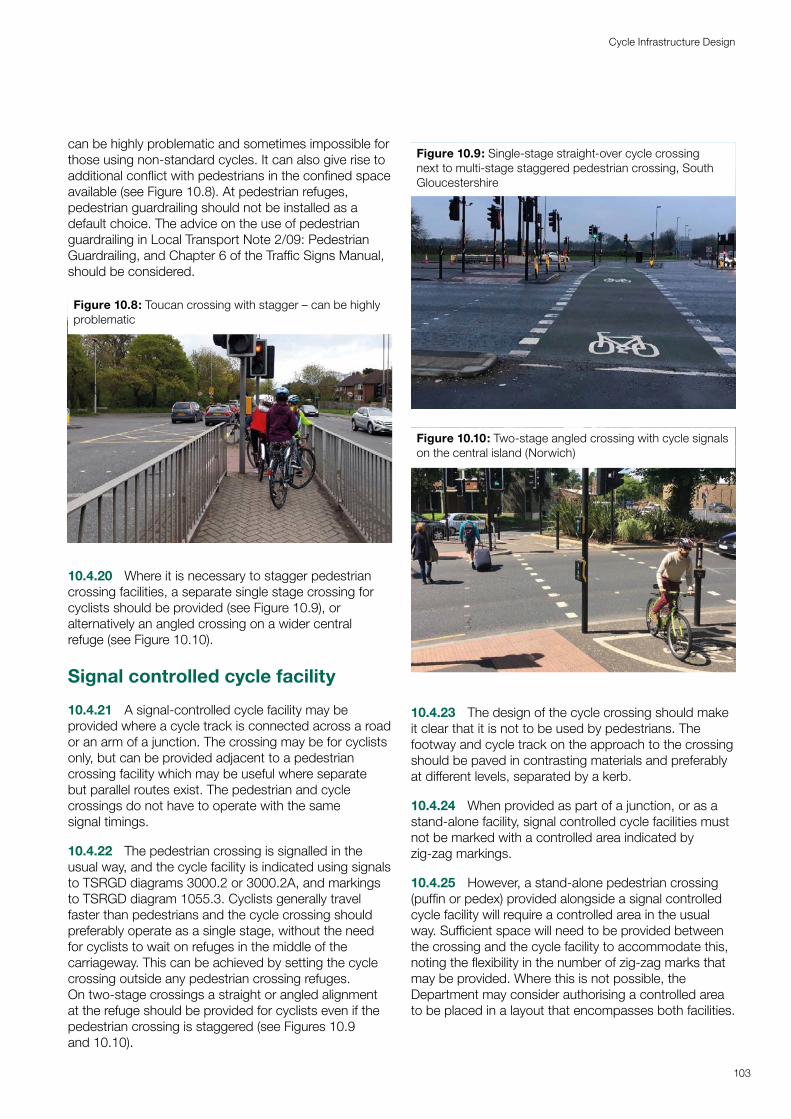
can be highly problematic and sometimes impossible for those using non-standard cycles. It can also give rise to additional conflict with pedestrians in the confined space available (see Figure 10.8). At pedestrian refuges, pedestrian guardrailing should not be installed as a default choice. The advice on the use of pedestrian guardrailing in Local Transport Note 2/09: Pedestrian Guardrailing, and Chapter 6 of the Traffic Signs Manual, should be considered.
Figure 10.8: Toucan crossing with stagger – can be highly problematic
10.4.20 Where it is necessary to stagger pedestrian crossing facilities, a separate single stage crossing for cyclists should be provided (see Figure 10.9), or alternatively an angled crossing on a wider central refuge (see Figure 10.10).
Signal controlled cycle facility
10.4.21 A signal-controlled cycle facility may be provided where a cycle track is connected across a road or an arm of a junction. The crossing may be for cyclists only, but can be provided adjacent to a pedestrian crossing facility which may be useful where separate but parallel routes exist. The pedestrian and cycle crossings do not have to operate with the same signal timings.
10.4.22 The pedestrian crossing is signalled in the usual way, and the cycle facility is indicated using signals to TSRGD diagrams 3000.2 or 3000.2A, and markings to TSRGD diagram 1055.3. Cyclists generally travel faster than pedestrians and the cycle crossing should preferably operate as a single stage, without the need for cyclists to wait on refuges in the middle of the carriageway. This can be achieved by setting the cycle crossing outside any pedestrian crossing refuges. On two-stage crossings a straight or angled alignment at the refuge should be provided for cyclists even if the pedestrian crossing is staggered (see Figures 10.9 and 10.10).
Figure 10.9: Single-stage straight-over cycle crossing next to multi-stage staggered pedestrian crossing, South Gloucestershire
Figure 10.10: Two-stage angled crossing with cycle signals on the central island (Norwich)
10.4.23 The design of the cycle crossing should make it clear that it is not to be used by pedestrians. The footway and cycle track on the approach to the crossing should be paved in contrasting materials and preferably at different levels, separated by a kerb.
10.4.24 When provided as part of a junction, or as a stand-alone facility, signal controlled cycle facilities must not be marked with a controlled area indicated by zig-zag markings.
10.4.25 However, a stand-alone pedestrian crossing (puffin or pedex) provided alongside a signal controlled cycle facility will require a controlled area in the usual way. Sufficient space will need to be provided between the crossing and the cycle facility to accommodate this, noting the flexibility in the number of zig-zag marks that may be provided. Where this is not possible, the Department may consider authorising a controlled area to be placed in a layout that encompasses both facilities.
103
Cycle Infrastructure Design
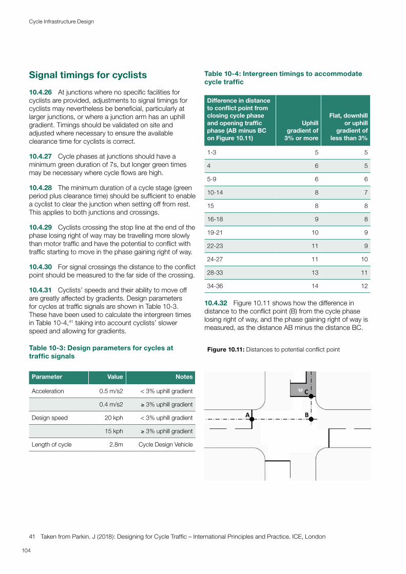
Signal timings for cyclists
10.4.26 At junctions where no specific facilities for cyclists are provided, adjustments to signal timings for cyclists may nevertheless be beneficial, particularly at larger junctions, or where a junction arm has an uphill gradient. Timings should be validated on site and adjusted where necessary to ensure the available clearance time for cyclists is correct.
10.4.27 Cycle phases at junctions should have a minimum green duration of 7s, but longer green times may be necessary where cycle flows are high.
10.4.28 The minimum duration of a cycle stage (green period plus clearance time) should be sufficient to enable a cyclist to clear the junction when setting off from rest. This applies to both junctions and crossings.
10.4.29 Cyclists crossing the stop line at the end of the phase losing right of way may be travelling more slowly than motor traffic and have the potential to conflict with traffic starting to move in the phase gaining right of way.
10.4.30 For signal crossings the distance to the conflict point should be measured to the far side of the crossing.
10.4.31 Cyclists’ speeds and their ability to move off are greatly affected by gradients. Design parameters for cycles at traffic signals are shown in Table 10-3. These have been used to calculate the intergreen times in Table 10-4,41 taking into account cyclists’ slower speed and allowing for gradients.
Table 10-3: Design parameters for cycles at traffic signals
Parameter Value Notes
Acceleration 0.5 m/s2 < 3% uphill gradient
0.4 m/s2 ≥ 3% uphill gradient
Design speed 20 kph < 3% uphill gradient
15 kph ≥ 3% uphill gradient
Length of cycle 2.8m Cycle Design Vehicle
41 Taken from Parkin. J (2018): Designing for Cycle Traffic – International Principles and Practice. ICE, London
Table 10-4: Intergreen timings to accommodate cycle traffic
Difference in distance to conflict point from closing cycle phase and opening traffic phase (AB minus BC on Figure 10.11)
Uphill gradient of
3% or more
Flat, downhill or uphill
gradient of less than 3%
1-3 5 5
4 6 5
5-9 6 6
10-14 8 7
15 8 8
16-18 9 8
19-21 10 9
22-23 11 9
24-27 11 10
28-33 13 11
34-36 14 12
10.4.32 Figure 10.11 shows how the difference in distance to the conflict point (B) from the cycle phase losing right of way, and the phase gaining right of way is measured, as the distance AB minus the distance BC.
Figure 10.11: Distances to potential conflict point
104
Cycle Infrastructure Design
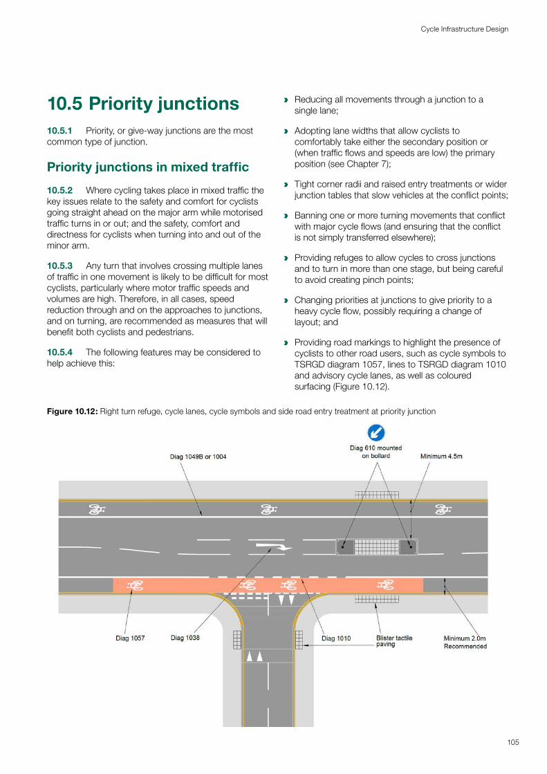
10.5 Priority junctions 10.5.1 Priority, or give-way junctions are the most common type of junction.
Priority junctions in mixed traffic
10.5.2 Where cycling takes place in mixed traffic the key issues relate to the safety and comfort for cyclists going straight ahead on the major arm while motorised traffic turns in or out; and the safety, comfort and directness for cyclists when turning into and out of the minor arm.
10.5.3 Any turn that involves crossing multiple lanes of traffic in one movement is likely to be difficult for most cyclists, particularly where motor traffic speeds and volumes are high. Therefore, in all cases, speed reduction through and on the approaches to junctions, and on turning, are recommended as measures that will benefit both cyclists and pedestrians.
10.5.4 The following features may be considered to help achieve this:
a Reducing all movements through a junction to a single lane;
a Adopting lane widths that allow cyclists to comfortably take either the secondary position or (when traffic flows and speeds are low) the primary position (see Chapter 7);
a Tight corner radii and raised entry treatments or wider junction tables that slow vehicles at the conflict points;
a Banning one or more turning movements that conflict with major cycle flows (and ensuring that the conflict is not simply transferred elsewhere);
a Providing refuges to allow cycles to cross junctions and to turn in more than one stage, but being careful to avoid creating pinch points;
a Changing priorities at junctions to give priority to a heavy cycle flow, possibly requiring a change of layout; and
a Providing road markings to highlight the presence of cyclists to other road users, such as cycle symbols to TSRGD diagram 1057, lines to TSRGD diagram 1010 and advisory cycle lanes, as well as coloured surfacing (Figure 10.12).
Figure 10.12: Right turn refuge, cycle lanes, cycle symbols and side road entry treatment at priority junction
105
Cycle Infrastructure Design
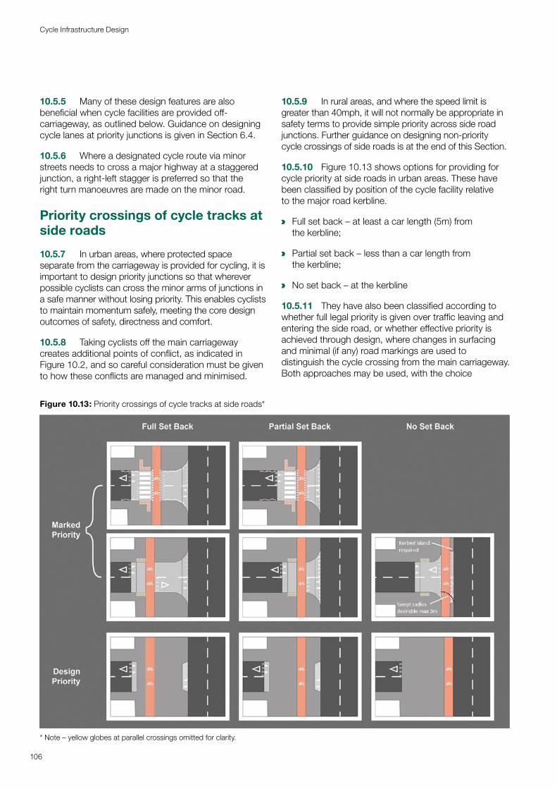
10.5.5 Many of these design features are also beneficial when cycle facilities are provided off-carriageway, as outlined below. Guidance on designing cycle lanes at priority junctions is given in Section 6.4.
10.5.6 Where a designated cycle route via minor streets needs to cross a major highway at a staggered junction, a right-left stagger is preferred so that the right turn manoeuvres are made on the minor road.
Priority crossings of cycle tracks at side roads
10.5.7 In urban areas, where protected space separate from the carriageway is provided for cycling, it is important to design priority junctions so that wherever possible cyclists can cross the minor arms of junctions in a safe manner without losing priority. This enables cyclists to maintain momentum safely, meeting the core design outcomes of safety, directness and comfort.
10.5.8 Taking cyclists off the main carriageway creates additional points of conflict, as indicated in Figure 10.2, and so careful consideration must be given to how these conflicts are managed and minimised.
10.5.9 In rural areas, and where the speed limit is greater than 40mph, it will not normally be appropriate in safety terms to provide simple priority across side road junctions. Further guidance on designing non-priority cycle crossings of side roads is at the end of this Section.
10.5.10 Figure 10.13 shows options for providing for cycle priority at side roads in urban areas. These have been classified by position of the cycle facility relative to the major road kerbline.
a Full set back – at least a car length (5m) from the kerbline;
a Partial set back – less than a car length from the kerbline;
a No set back – at the kerbline
10.5.11 They have also been classified according to whether full legal priority is given over traffic leaving and entering the side road, or whether effective priority is achieved through design, where changes in surfacing and minimal (if any) road markings are used to distinguish the cycle crossing from the main carriageway. Both approaches may be used, with the choice
Figure 10.13: Priority crossings of cycle tracks at side roads*
* Note – yellow globes at parallel crossings omitted for clarity.
106
Cycle Infrastructure Design
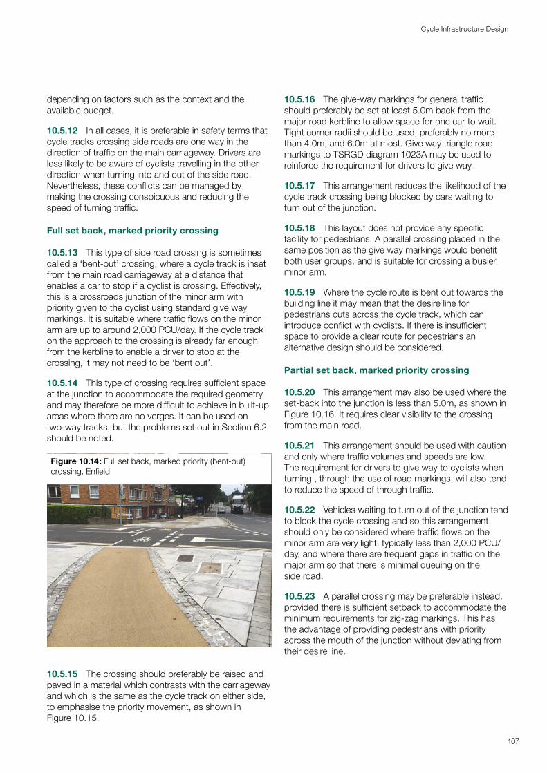
depending on factors such as the context and the available budget.
10.5.12 In all cases, it is preferable in safety terms that cycle tracks crossing side roads are one way in the direction of traffic on the main carriageway. Drivers are less likely to be aware of cyclists travelling in the other direction when turning into and out of the side road. Nevertheless, these conflicts can be managed by making the crossing conspicuous and reducing the speed of turning traffic.
Full set back, marked priority crossing
10.5.13 This type of side road crossing is sometimes called a ‘bent-out’ crossing, where a cycle track is inset from the main road carriageway at a distance that enables a car to stop if a cyclist is crossing. Effectively, this is a crossroads junction of the minor arm with priority given to the cyclist using standard give way markings. It is suitable where traffic flows on the minor arm are up to around 2,000 PCU/day. If the cycle track on the approach to the crossing is already far enough from the kerbline to enable a driver to stop at the crossing, it may not need to be ‘bent out’.
10.5.14 This type of crossing requires sufficient space at the junction to accommodate the required geometry and may therefore be more difficult to achieve in built-up areas where there are no verges. It can be used on two-way tracks, but the problems set out in Section 6.2 should be noted.
Figure 10.14: Full set back, marked priority (bent-out) crossing, Enfield
10.5.15 The crossing should preferably be raised and paved in a material which contrasts with the carriageway and which is the same as the cycle track on either side, to emphasise the priority movement, as shown in Figure 10.15.
10.5.16 The give-way markings for general traffic should preferably be set at least 5.0m back from the major road kerbline to allow space for one car to wait. Tight corner radii should be used, preferably no more than 4.0m, and 6.0m at most. Give way triangle road markings to TSRGD diagram 1023A may be used to reinforce the requirement for drivers to give way.
10.5.17 This arrangement reduces the likelihood of the cycle track crossing being blocked by cars waiting to turn out of the junction.
10.5.18 This layout does not provide any specific facility for pedestrians. A parallel crossing placed in the same position as the give way markings would benefit both user groups, and is suitable for crossing a busier minor arm.
10.5.19 Where the cycle route is bent out towards the building line it may mean that the desire line for pedestrians cuts across the cycle track, which can introduce conflict with cyclists. If there is insufficient space to provide a clear route for pedestrians an alternative design should be considered.
Partial set back, marked priority crossing
10.5.20 This arrangement may also be used where the set-back into the junction is less than 5.0m, as shown in Figure 10.16. It requires clear visibility to the crossing from the main road.
10.5.21 This arrangement should be used with caution and only where traffic volumes and speeds are low. The requirement for drivers to give way to cyclists when turning , through the use of road markings, will also tend to reduce the speed of through traffic.
10.5.22 Vehicles waiting to turn out of the junction tend to block the cycle crossing and so this arrangement should only be considered where traffic flows on the minor arm are very light, typically less than 2,000 PCU/day, and where there are frequent gaps in traffic on the major arm so that there is minimal queuing on the side road.
10.5.23 A parallel crossing may be preferable instead, provided there is sufficient setback to accommodate the minimum requirements for zig-zag markings. This has the advantage of providing pedestrians with priority across the mouth of the junction without deviating from their desire line.
107
Cycle Infrastructure Design
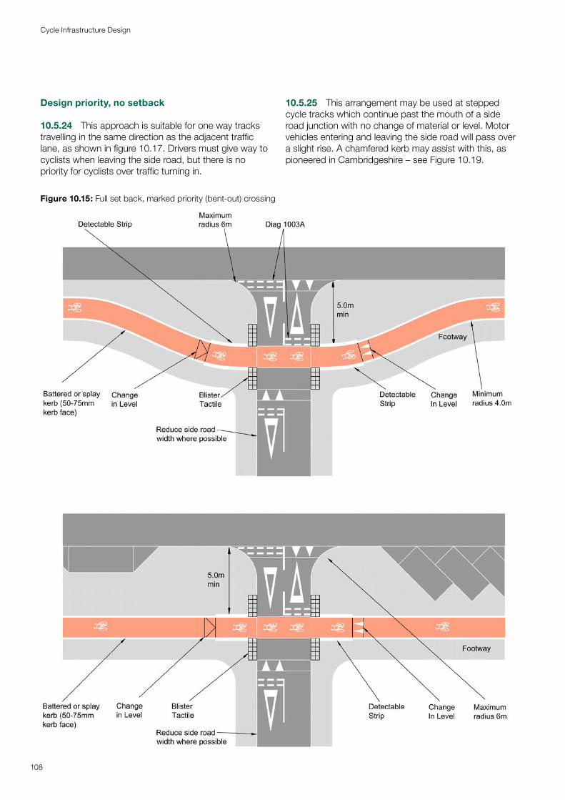
Design priority, no setback
10.5.24 This approach is suitable for one way tracks travelling in the same direction as the adjacent traffic lane, as shown in figure 10.17. Drivers must give way to cyclists when leaving the side road, but there is no priority for cyclists over traffic turning in.
10.5.25 This arrangement may be used at stepped cycle tracks which continue past the mouth of a side road junction with no change of material or level. Motor vehicles entering and leaving the side road will pass over a slight rise. A chamfered kerb may assist with this, as pioneered in Cambridgeshire – see Figure 10.19.
Figure 10.15: Full set back, marked priority (bent-out) crossing
108
Cycle Infrastructure Design
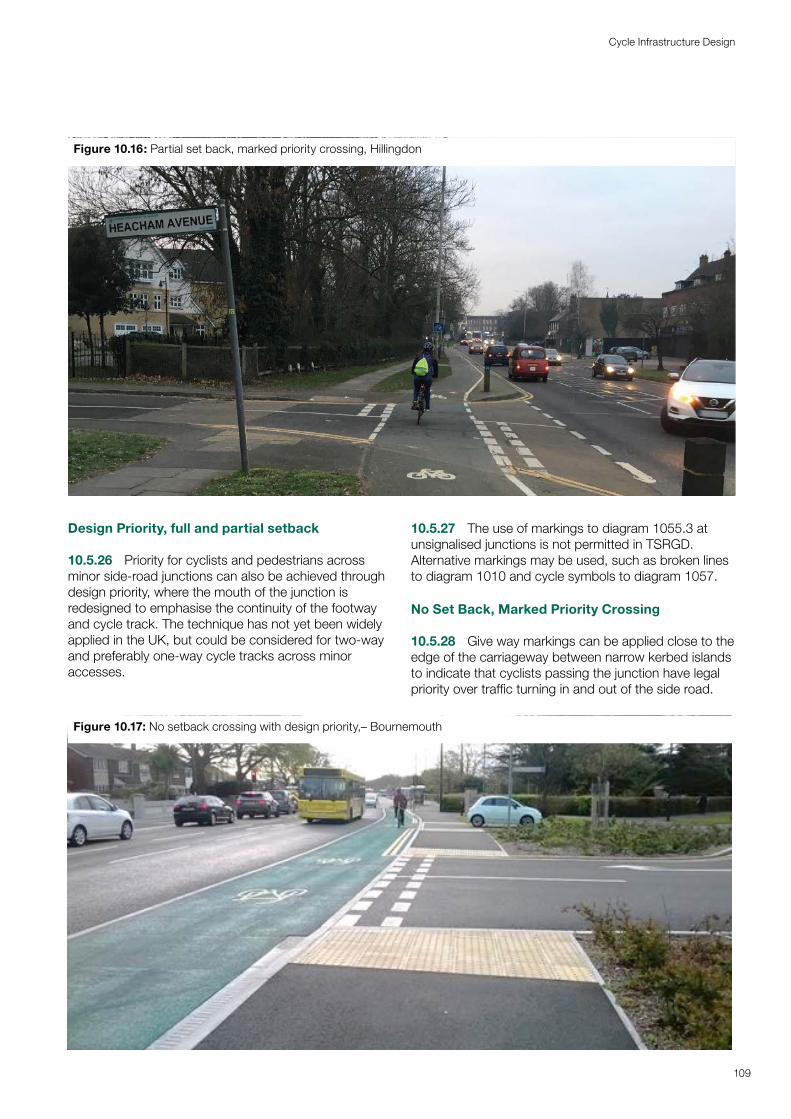
Design Priority, full and partial setback
10.5.26 Priority for cyclists and pedestrians across minor side-road junctions can also be achieved through design priority, where the mouth of the junction is redesigned to emphasise the continuity of the footway and cycle track. The technique has not yet been widely applied in the UK, but could be considered for two-way and preferably one-way cycle tracks across minor accesses.
10.5.27 The use of markings to diagram 1055.3 at unsignalised junctions is not permitted in TSRGD. Alternative markings may be used, such as broken lines to diagram 1010 and cycle symbols to diagram 1057.
No Set Back, Marked Priority Crossing
10.5.28 Give way markings can be applied close to the edge of the carriageway between narrow kerbed islands to indicate that cyclists passing the junction have legal priority over traffic turning in and out of the side road.
Figure 10.16: Partial set back, marked priority crossing, Hillingdon
Figure 10.17: No setback crossing with design priority,– Bournemouth
109
Cycle Infrastructure Design
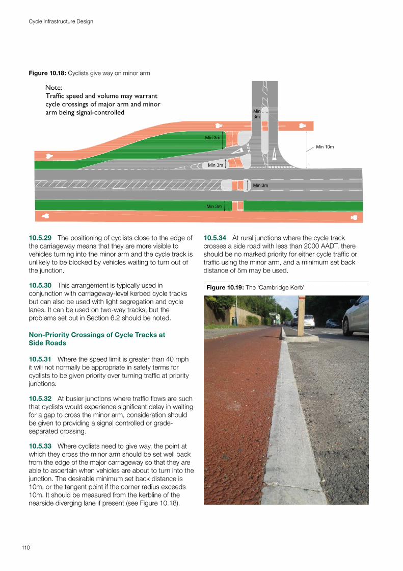
Figure 10.18: Cyclists give way on minor arm
Note:Traffic speed and volume may warrantcycle crossings of major arm and minorarm being signal-controlled
Min 10m
Min 3m
Min 3m
Min 3m
Min 3m
Min3m
110
Cycle Infrastructure Design
10.5.29 The positioning of cyclists close to the edge of the carriageway means that they are more visible to vehicles turning into the minor arm and the cycle track is unlikely to be blocked by vehicles waiting to turn out of the junction.
10.5.30 This arrangement is typically used in conjunction with carriageway-level kerbed cycle tracks but can also be used with light segregation and cycle lanes. It can be used on two-way tracks, but the problems set out in Section 6.2 should be noted.
Non-Priority Crossings of Cycle Tracks at Side Roads
10.5.31 Where the speed limit is greater than 40 mph it will not normally be appropriate in safety terms for cyclists to be given priority over turning traffic at priority junctions.
10.5.32 At busier junctions where traffic flows are such that cyclists would experience significant delay in waiting for a gap to cross the minor arm, consideration should be given to providing a signal controlled or grade-separated crossing.
10.5.33 Where cyclists need to give way, the point at which they cross the minor arm should be set well back from the edge of the major carriageway so that they are able to ascertain when vehicles are about to turn into the junction. The desirable minimum set back distance is 10m, or the tangent point if the corner radius exceeds 10m. It should be measured from the kerbline of the nearside diverging lane if present (see Figure 10.18).
10.5.34 At rural junctions where the cycle track crosses a side road with less than 2000 AADT, there should be no marked priority for either cycle traffic or traffic using the minor arm, and a minimum set back distance of 5m may be used.
Figure 10.19: The ‘Cambridge Kerb’
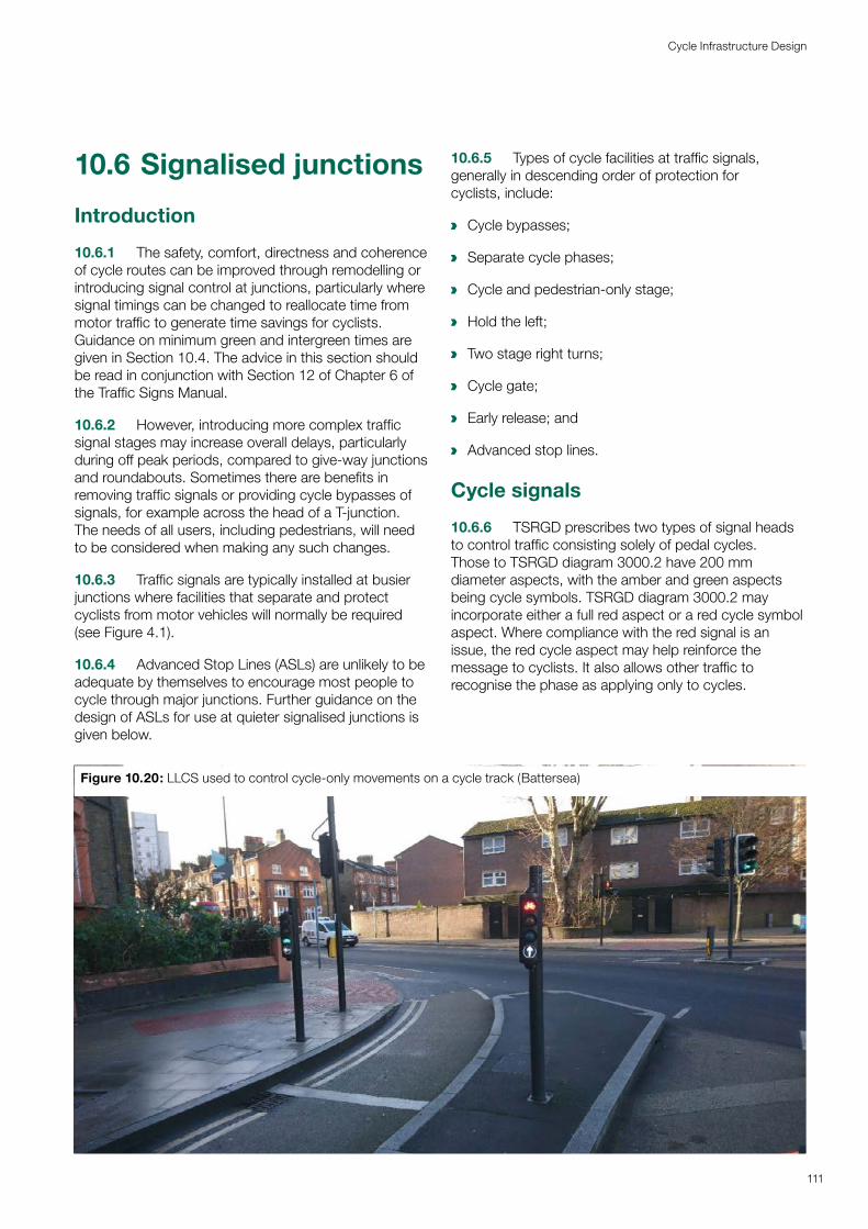
10.6 Signalised junctions
Introduction
10.6.1 The safety, comfort, directness and coherence of cycle routes can be improved through remodelling or introducing signal control at junctions, particularly where signal timings can be changed to reallocate time from motor traffic to generate time savings for cyclists. Guidance on minimum green and intergreen times are given in Section 10.4. The advice in this section should be read in conjunction with Section 12 of Chapter 6 of the Traffic Signs Manual.
10.6.2 However, introducing more complex traffic signal stages may increase overall delays, particularly during off peak periods, compared to give-way junctions and roundabouts. Sometimes there are benefits in removing traffic signals or providing cycle bypasses of signals, for example across the head of a T-junction. The needs of all users, including pedestrians, will need to be considered when making any such changes.
10.6.3 Traffic signals are typically installed at busier junctions where facilities that separate and protect cyclists from motor vehicles will normally be required (see Figure 4.1).
10.6.4 Advanced Stop Lines (ASLs) are unlikely to be adequate by themselves to encourage most people to cycle through major junctions. Further guidance on the design of ASLs for use at quieter signalised junctions is given below.
10.6.5 Types of cycle facilities at traffic signals, generally in descending order of protection for cyclists, include:
a Cycle bypasses;
a Separate cycle phases;
a Cycle and pedestrian-only stage;
a Hold the left;
a Two stage right turns;
a Cycle gate;
a Early release; and
a Advanced stop lines.
Cycle signals
10.6.6 TSRGD prescribes two types of signal heads to control traffic consisting solely of pedal cycles. Those to TSRGD diagram 3000.2 have 200 mm diameter aspects, with the amber and green aspects being cycle symbols. TSRGD diagram 3000.2 may incorporate either a full red aspect or a red cycle symbol aspect. Where compliance with the red signal is an issue, the red cycle aspect may help reinforce the message to cyclists. It also allows other traffic to recognise the phase as applying only to cycles.
Figure 10.20: LLCS used to control cycle-only movements on a cycle track (Battersea)
111
Cycle Infrastructure Design
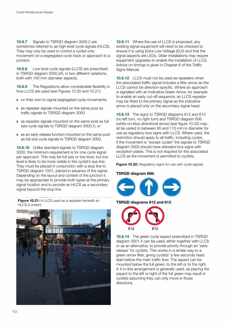
10.6.7 Signals to TSRGD diagram 3000.2 are sometimes referred to as high level cycle signals (HLCS). They may only be used to control a cyclist-only movement on a segregated cycle track or approach to a junction.
10.6.8 Low level cycle signals (LLCS) are prescribed in TSRGD diagram 3000.2A, in two different variations, both with 100 mm diameter aspects.
10.6.9 The Regulations allow considerable flexibility in how LLCS are used (see Figures 10.20 and 10.21):
a on their own to signal segregated cycle movements,
a as repeater signals mounted on the same post as traffic signals to TSRGD diagram 3000
a as repeater signals mounted on the same post as full size cycle signals to TSRGD diagram 3000.2; or
a as an early release function mounted on the same post as full-size cycle signals to TSRGD diagram 3000.
10.6.10 Unlike standard signals to TSRGD diagram 3000, the minimum requirement is for one cycle signal per approach. This may be full size or low level, but low level is likely to be more visible in the cyclist’s eye-line. They must be placed in conjunction with a stop line to TSRGD diagram 1001, placed in advance of the signal. Depending on the layout and context of the junction it may be appropriate to provide both types at the primary signal location and to provide an HLCS as a secondary signal beyond the stop line.
Figure 10.21: A LLCS used as a repeater beneath an HLCS (London)
112
Cycle Infrastructure Design
10.6.11 Where the use of LLCS is proposed, any existing signal equipment will need to be checked to ensure it is using Extra Low Voltage (ELV) and that the signal aspects are LEDs. Older installations may require equipment upgrades to enable the installation of LLCS. Advice on timings is given in Chapter 6 of the Traffic Signs Manual.
10.6.12 LLCS must not be used as repeaters when the associated traffic signal includes a filter arrow as the LLCS cannot be direction-specific. Where an approach is signalled with an Indicative Green Arrow, for example to enable an early cut-off sequence, an LLCS repeater may be fitted to the primary signal as the indicative arrow is placed only on the secondary signal head.
10.6.13 The signs to TSRGD diagrams 612 and 613 (no left turn, no right turn) and TSRGD diagram 606 (white-on-blue directional arrow) (see figure 10.22) may all be varied to between 95 and 110 mm in diameter for use as regulatory box signs with LLCS. Where used, the restriction should apply to all traffic, including cycles. If the movement is “except cycles” the signals to TSRGD diagram 3000 should have standard box signs with exception plates. This is not required for the associated LLCS as the movement is permitted to cyclists.
Figure 10.22: Regulatory signs for use with cycle signals
TSRGD diagram 606:
TSRGD diagrams 612 and 613
10.6.14 The green cycle aspect prescribed in TSRGD diagram 3001.4 can be used, either together with LLCS or as an alternative, to provide priority through an ‘early release’ for cyclists. This works in a similar way to a green arrow filter, giving cyclists’ a few seconds head start before the main traffic flow. The aspect can be mounted below the full green, to the left or to the right. A 4-in-line arrangement is generally used, as placing the aspect to the left or right of the full green may result in cyclists assuming they can only move in those directions.
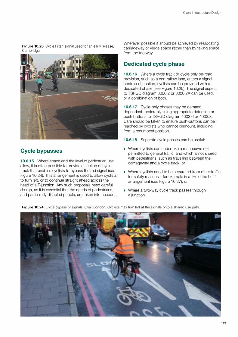
Figure 10.23 ‘Cycle Filter’ signal used for an early release, Cambridge
Cycle bypasses
10.6.15 Where space and the level of pedestrian use allow, it is often possible to provide a section of cycle track that enables cyclists to bypass the red signal (see Figure 10.24). This arrangement is used to allow cyclists to turn left, or to continue straight ahead across the head of a T-junction. Any such proposals need careful design, as it is essential that the needs of pedestrians, and particularly disabled people, are taken into account.
Wherever possible it should be achieved by reallocating carriageway or verge space rather than by taking space from the footway.
Dedicated cycle phase
10.6.16 Where a cycle track or cycle-only on-road provision, such as a contraflow lane, enters a signal-controlled junction, cyclists can be provided with a dedicated phase (see Figure 10.25). The signal aspect to TSRGD diagram 3000.2 or 3000.2A can be used, or a combination of both.
10.6.17 Cycle-only phases may be demand dependent, preferably using appropriate detection or push buttons to TSRGD diagram 4003.6 or 4003.8. Care should be taken to ensure push-buttons can be reached by cyclists who cannot dismount, including from a recumbent position.
10.6.18 Separate cycle phases can be useful:
a Where cyclists can undertake a manoeuvre not permitted to general traffic, and which is not shared with pedestrians, such as travelling between the carriageway and a cycle track; or
a Where cyclists need to be separated from other traffic for safety reasons – for example in a ‘Hold the Left’ arrangement (see Figure 10.27); or
a Where a two-way cycle track passes through a junction.
Figure 10.24: Cycle bypass of signals, Oval, London. Cyclists may turn left at the signals onto a shared use path.
113
Cycle Infrastructure Design
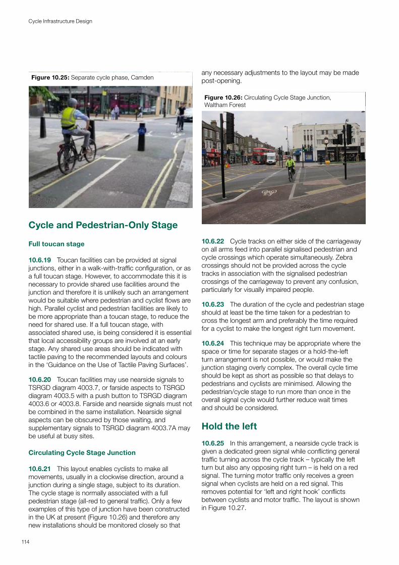
Figure 10.25: Separate cycle phase, Camden
Cycle and Pedestrian-Only Stage
Full toucan stage
10.6.19 Toucan facilities can be provided at signal junctions, either in a walk-with-traffic configuration, or as a full toucan stage. However, to accommodate this it is necessary to provide shared use facilities around the junction and therefore it is unlikely such an arrangement would be suitable where pedestrian and cyclist flows are high. Parallel cyclist and pedestrian facilities are likely to be more appropriate than a toucan stage, to reduce the need for shared use. If a full toucan stage, with associated shared use, is being considered it is essential that local accessibility groups are involved at an early stage. Any shared use areas should be indicated with tactile paving to the recommended layouts and colours in the ‘Guidance on the Use of Tactile Paving Surfaces’.
10.6.20 Toucan facilities may use nearside signals to TSRGD diagram 4003.7, or farside aspects to TSRGD diagram 4003.5 with a push button to TSRGD diagram 4003.6 or 4003.8. Farside and nearside signals must not be combined in the same installation. Nearside signal aspects can be obscured by those waiting, and supplementary signals to TSRGD diagram 4003.7A may be useful at busy sites.
Circulating Cycle Stage Junction
10.6.21 This layout enables cyclists to make all movements, usually in a clockwise direction, around a junction during a single stage, subject to its duration. The cycle stage is normally associated with a full pedestrian stage (all-red to general traffic). Only a few examples of this type of junction have been constructed in the UK at present (Figure 10.26) and therefore any new installations should be monitored closely so that
any necessary adjustments to the layout may be made post-opening.
Figure 10.26: Circulating Cycle Stage Junction, Waltham Forest
10.6.22 Cycle tracks on either side of the carriageway on all arms feed into parallel signalised pedestrian and cycle crossings which operate simultaneously. Zebra crossings should not be provided across the cycle tracks in association with the signalised pedestrian crossings of the carriageway to prevent any confusion, particularly for visually impaired people.
10.6.23 The duration of the cycle and pedestrian stage should at least be the time taken for a pedestrian to cross the longest arm and preferably the time required for a cyclist to make the longest right turn movement.
10.6.24 This technique may be appropriate where the space or time for separate stages or a hold-the-left turn arrangement is not possible, or would make the junction staging overly complex. The overall cycle time should be kept as short as possible so that delays to pedestrians and cyclists are minimised. Allowing the pedestrian/cycle stage to run more than once in the overall signal cycle would further reduce wait times and should be considered.
Hold the left
10.6.25 In this arrangement, a nearside cycle track is given a dedicated green signal while conflicting general traffic turning across the cycle track – typically the left turn but also any opposing right turn – is held on a red signal. The turning motor traffic only receives a green signal when cyclists are held on a red signal. This removes potential for ‘left and right hook’ conflicts between cyclists and motor traffic. The layout is shown in Figure 10.27.
114
Cycle Infrastructure Design
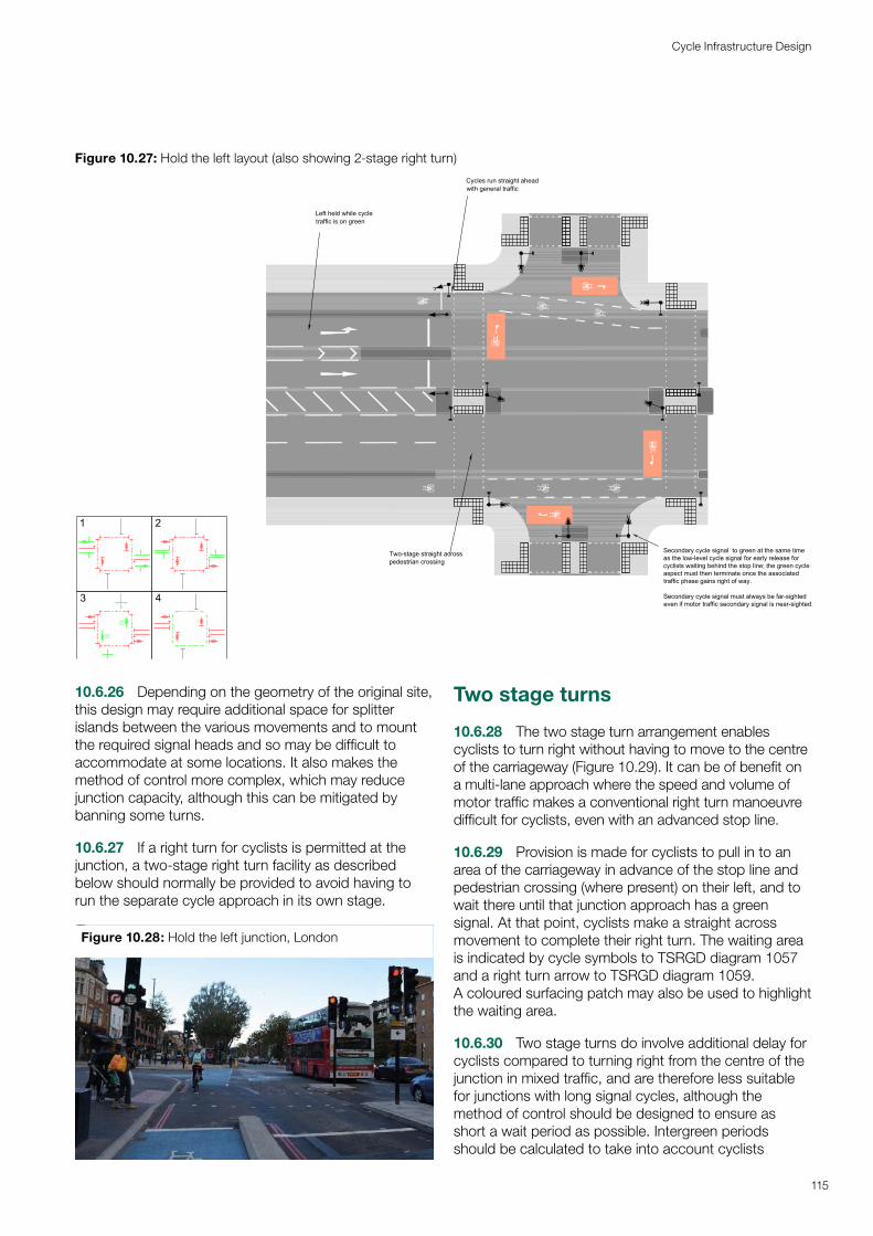
Figure 10.27: Hold the left layout (also showing 2-stage right turn)
c
Left held while cycletraffic is on green
Cycles run straight aheadwith general traffic
Two-stage straight acrosspedestrian crossing
c
c
c
c
Secondary cycle signal to green at the same timeas the low-level cycle signal for early release forcyclists waiting behind the stop line; the green cycleaspect must then terminate once the associatedtraffic phase gains right of way.
Secondary cycle signal must always be far-sightedeven if motor traffic secondary signal is near-sighted.
EarlyStart
EarlyStart
1
3
2
4
115
Cycle Infrastructure Design
10.6.26 Depending on the geometry of the original site,this design may require additional space for splitter islands between the various movements and to mount the required signal heads and so may be difficult to accommodate at some locations. It also makes the method of control more complex, which may reduce junction capacity, although this can be mitigated by banning some turns.
10.6.27 If a right turn for cyclists is permitted at the junction, a two-stage right turn facility as described below should normally be provided to avoid having to run the separate cycle approach in its own stage.
Figure 10.28: Hold the left junction, London
Two stage turns
10.6.28 The two stage turn arrangement enables cyclists to turn right without having to move to the centre of the carriageway (Figure 10.29). It can be of benefit on a multi-lane approach where the speed and volume of motor traffic makes a conventional right turn manoeuvre difficult for cyclists, even with an advanced stop line.
10.6.29 Provision is made for cyclists to pull in to an area of the carriageway in advance of the stop line and pedestrian crossing (where present) on their left, and to wait there until that junction approach has a green signal. At that point, cyclists make a straight across movement to complete their right turn. The waiting area is indicated by cycle symbols to TSRGD diagram 1057 and a right turn arrow to TSRGD diagram 1059. A coloured surfacing patch may also be used to highlight the waiting area.
10.6.30 Two stage turns do involve additional delay for cyclists compared to turning right from the centre of the junction in mixed traffic, and are therefore less suitable for junctions with long signal cycles, although the method of control should be designed to ensure as short a wait period as possible. Intergreen periods should be calculated to take into account cyclists
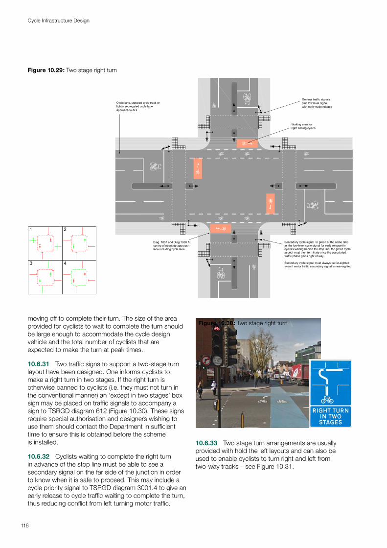
Figure 10.29: Two stage right turn
Secondary cycle signal to green at the same timeas the low-level cycle signal for early release forcyclists waiting behind the stop line; the green cycleaspect must then terminate once the associatedtraffic phase gains right of way.
Secondary cycle signal must always be far-sightedeven if motor traffic secondary signal is near-sighted.
Diag. 1057 and Diag 1059 Atcentre of nearside approachlane including cycle lane
Cycle lane, stepped cycle track orlightly segregated cycle laneapproach to ASL
Waiting area forright turning cycles
General traffic signalsplus low level signalwith early cycle release
c
c
c
c
c
c
c
c
1
4
2
3
116
Cycle Infrastructure Design
moving off to complete their turn. The size of the area provided for cyclists to wait to complete the turn should be large enough to accommodate the cycle design vehicle and the total number of cyclists that are expected to make the turn at peak times.
10.6.31 Two traffic signs to support a two-stage turn layout have been designed. One informs cyclists to make a right turn in two stages. If the right turn is otherwise banned to cyclists (i.e. they must not turn in the conventional manner) an ‘except in two stages’ box sign may be placed on traffic signals to accompany a sign to TSRGD diagram 612 (Figure 10.30). These signs require special authorisation and designers wishing to use them should contact the Department in sufficient time to ensure this is obtained before the scheme is installed.
10.6.32 Cyclists waiting to complete the right turn in advance of the stop line must be able to see a secondary signal on the far side of the junction in order to know when it is safe to proceed. This may include a cycle priority signal to TSRGD diagram 3001.4 to give an early release to cycle traffic waiting to complete the turn, thus reducing conflict from left turning motor traffic.
Figure 10.30: Two stage right turn
10.6.33 Two stage turn arrangements are usually provided with hold the left layouts and can also be used to enable cyclists to turn right and left from two-way tracks – see Figure 10.31.
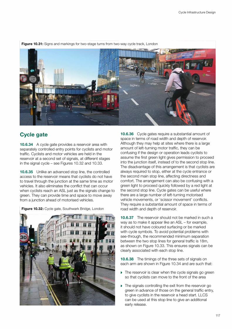
a
a
Figure 10.31: Signs and markings for two-stage turns from two-way cycle track, London
117
Cycle Infrastructure Design
Cycle gate
10.6.34 A cycle gate provides a reservoir area with separately controlled entry points for cyclists and motor traffic. Cyclists and motor vehicles are held in the reservoir at a second set of signals, at different stages in the signal cycle – see Figures 10.32 and 10.33.
10.6.35 Unlike an advanced stop line, the controlled access to the reservoir means that cyclists do not have to travel through the junction at the same time as motor vehicles. It also eliminates the conflict that can occur when cyclists reach an ASL just as the signals change to green. They can provide time and space to move away from a junction ahead of motorised vehicles.
Figure 10.32: Cycle gate, Southwark Bridge, London
10.6.36 Cycle gates require a substantial amount of space in terms of road width and depth of reservoir. Although they may help at sites where there is a large amount of left-turning motor traffic, they can be confusing if the design or operation leads cyclists to assume the first green light gives permission to proceed into the junction itself, instead of to the second stop line. The disadvantage of this arrangement is that cyclists are always required to stop, either at the cycle entrance or the second main stop line, affecting directness and comfort. The arrangement can also be confusing with a green light to proceed quickly followed by a red light at the second stop line. Cycle gates can be useful where there are a large number of left-turning motorised vehicle movements, or ‘scissor movement’ conflicts. They require a substantial amount of space in terms of road width and depth of reservoir.
10.6.37 The reservoir should not be marked in such a way as to make it appear like an ASL – for example, it should not have coloured surfacing or be marked with cycle symbols. To avoid potential problems with see-through, the recommended minimum separation between the two stop lines for general traffic is 18m, as shown on Figure 10.33. This ensures signals can be clearly associated with each stop line.
10.6.38 The timings of the three sets of signals on each arm are shown in Figure 10.34 and are such that:
The reservoir is clear when the cycle signals go green so that cyclists can move to the front of the area
The signals controlling the exit from the reservoir go green in advance of those on the general traffic entry, to give cyclists in the reservoir a head start. LLCS can be used at this stop line to give an additional early release.
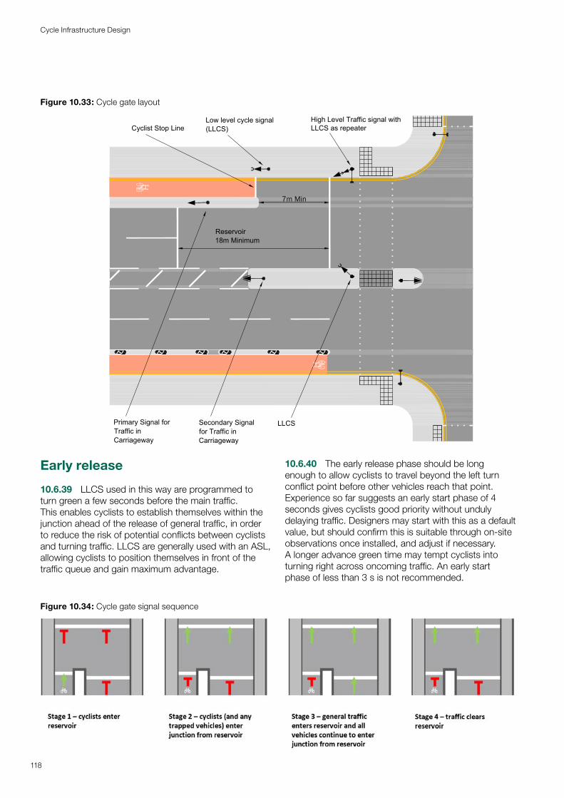
Early release
10.6.39 LLCS used in this way are programmed to turn green a few seconds before the main traffic. This enables cyclists to establish themselves within the junction ahead of the release of general traffic, in order to reduce the risk of potential conflicts between cyclists and turning traffic. LLCS are generally used with an ASL, allowing cyclists to position themselves in front of the traffic queue and gain maximum advantage.
10.6.40 The early release phase should be long enough to allow cyclists to travel beyond the left turn conflict point before other vehicles reach that point. Experience so far suggests an early start phase of 4 seconds gives cyclists good priority without unduly delaying traffic. Designers may start with this as a default value, but should confirm this is suitable through on-site observations once installed, and adjust if necessary. A longer advance green time may tempt cyclists into turning right across oncoming traffic. An early start phase of less than 3 s is not recommended.
Figure 10.33: Cycle gate layout
7m Min
Low level cycle signal(LLCS)
High Level Traffic signal withLLCS as repeater
LLCS
c
c
Reservoir18m Minimum
Cyclist Stop Line
Secondary Signalfor Traffic inCarriageway
Primary Signal forTraffic inCarriageway
c
Figure 10.34: Cycle gate signal sequence
118
Cycle Infrastructure Design
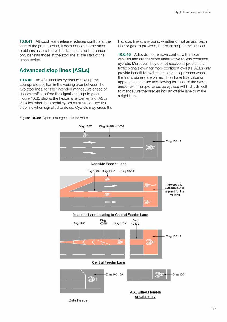
10.6.41 Although early release reduces conflicts at the start of the green period, it does not overcome other problems associated with advanced stop lines since it only benefits those at the stop line at the start of the green period.
Advanced stop lines (ASLs)
10.6.42 An ASL enables cyclists to take up the appropriate position in the waiting area between the two stop lines, for their intended manoeuvre ahead of general traffic, before the signals change to green. Figure 10.35 shows the typical arrangements of ASLs. Vehicles other than pedal cycles must stop at the first stop line when signalled to do so. Cyclists may cross the
first stop line at any point, whether or not an approach lane or gate is provided, but must stop at the second.
10.6.43 ASLs do not remove conflict with motor vehicles and are therefore unattractive to less confident cyclists. Moreover, they do not resolve all problems at traffic signals even for more confident cyclists. ASLs only provide benefit to cyclists on a signal approach when the traffic signals are on red. They have little value on approaches that are free-flowing for most of the cycle, and/or with multiple lanes, as cyclists will find it difficult to manoeuvre themselves into an offside lane to make a right turn.
Figure 10.35: Typical arrangements for ASLs
119
Cycle Infrastructure Design
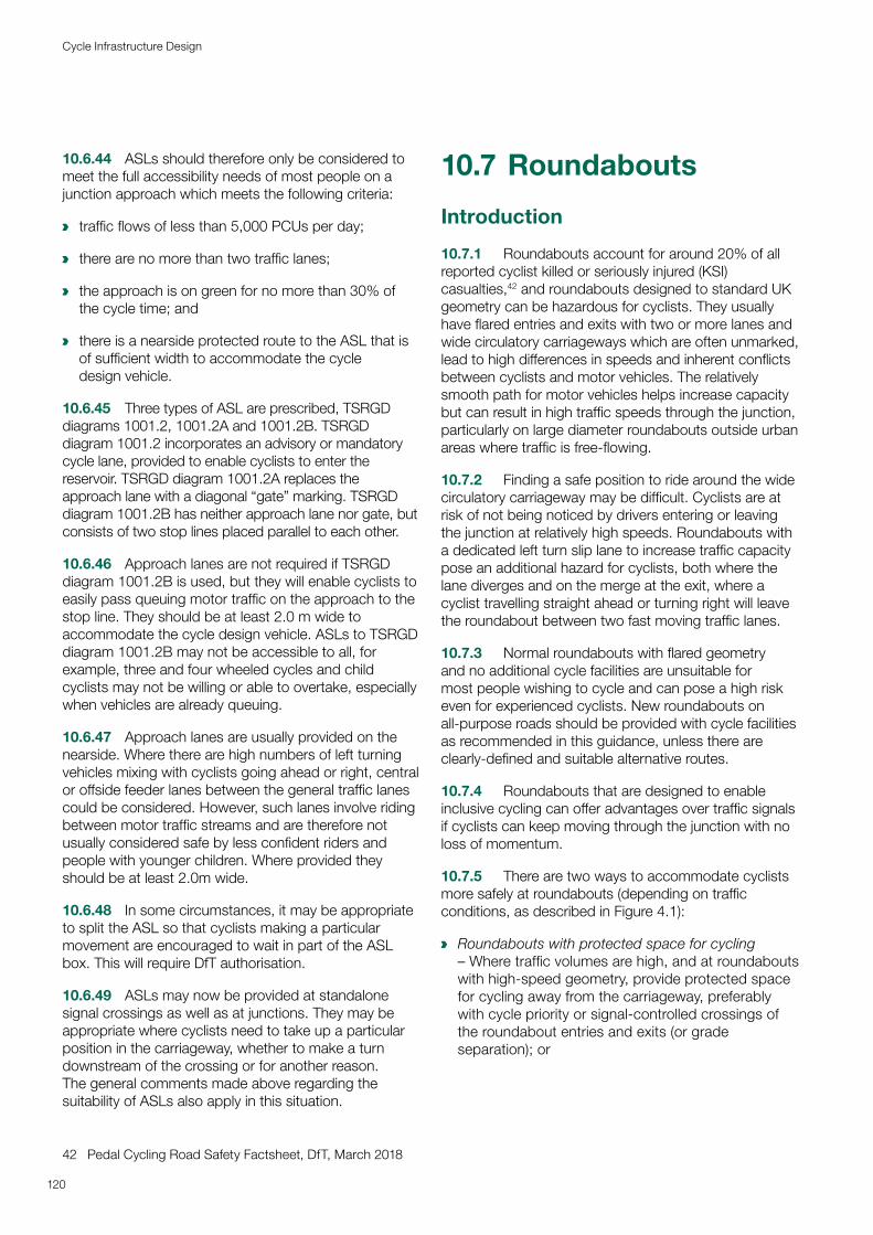
10.6.44 ASLs should therefore only be considered to meet the full accessibility needs of most people on a junction approach which meets the following criteria:
a traffic flows of less than 5,000 PCUs per day;
a there are no more than two traffic lanes;
a the approach is on green for no more than 30% of the cycle time; and
a there is a nearside protected route to the ASL that is of sufficient width to accommodate the cycle design vehicle.
10.6.45 Three types of ASL are prescribed, TSRGD diagrams 1001.2, 1001.2A and 1001.2B. TSRGD diagram 1001.2 incorporates an advisory or mandatory cycle lane, provided to enable cyclists to enter the reservoir. TSRGD diagram 1001.2A replaces the approach lane with a diagonal “gate” marking. TSRGD diagram 1001.2B has neither approach lane nor gate, but consists of two stop lines placed parallel to each other.
10.6.46 Approach lanes are not required if TSRGD diagram 1001.2B is used, but they will enable cyclists to easily pass queuing motor traffic on the approach to the stop line. They should be at least 2.0 m wide to accommodate the cycle design vehicle. ASLs to TSRGD diagram 1001.2B may not be accessible to all, for example, three and four wheeled cycles and child cyclists may not be willing or able to overtake, especially when vehicles are already queuing.
10.6.47 Approach lanes are usually provided on the nearside. Where there are high numbers of left turning vehicles mixing with cyclists going ahead or right, central or offside feeder lanes between the general traffic lanes could be considered. However, such lanes involve riding between motor traffic streams and are therefore not usually considered safe by less confident riders and people with younger children. Where provided they should be at least 2.0m wide.
10.6.48 In some circumstances, it may be appropriate to split the ASL so that cyclists making a particular movement are encouraged to wait in part of the ASL box. This will require DfT authorisation.
10.6.49 ASLs may now be provided at standalone signal crossings as well as at junctions. They may be appropriate where cyclists need to take up a particular position in the carriageway, whether to make a turn downstream of the crossing or for another reason. The general comments made above regarding the suitability of ASLs also apply in this situation.
42 Pedal Cycling Road Safety Factsheet, DfT, March 2018
10.7 Roundabouts
Introduction
10.7.1 Roundabouts account for around 20% of all reported cyclist killed or seriously injured (KSI) casualties,42 and roundabouts designed to standard UK geometry can be hazardous for cyclists. They usually have flared entries and exits with two or more lanes and wide circulatory carriageways which are often unmarked, lead to high differences in speeds and inherent conflicts between cyclists and motor vehicles. The relatively smooth path for motor vehicles helps increase capacity but can result in high traffic speeds through the junction, particularly on large diameter roundabouts outside urban areas where traffic is free-flowing.
10.7.2 Finding a safe position to ride around the wide circulatory carriageway may be difficult. Cyclists are at risk of not being noticed by drivers entering or leaving the junction at relatively high speeds. Roundabouts with a dedicated left turn slip lane to increase traffic capacity pose an additional hazard for cyclists, both where the lane diverges and on the merge at the exit, where a cyclist travelling straight ahead or turning right will leave the roundabout between two fast moving traffic lanes.
10.7.3 Normal roundabouts with flared geometry and no additional cycle facilities are unsuitable for most people wishing to cycle and can pose a high risk even for experienced cyclists. New roundabouts on all-purpose roads should be provided with cycle facilities as recommended in this guidance, unless there are clearly-defined and suitable alternative routes.
10.7.4 Roundabouts that are designed to enable inclusive cycling can offer advantages over traffic signals if cyclists can keep moving through the junction with no loss of momentum.
10.7.5 There are two ways to accommodate cyclists more safely at roundabouts (depending on traffic conditions, as described in Figure 4.1):
a Roundabouts with protected space for cycling – Where traffic volumes are high, and at roundabouts with high-speed geometry, provide protected space for cycling away from the carriageway, preferably with cycle priority or signal-controlled crossings of the roundabout entries and exits (or grade separation); or
120
Cycle Infrastructure Design
a Roundabouts for cycling in mixed traffic conditions – Compact or Mini-roundabouts, where traffic volumes and speeds are (or can be made) low, and the lane widths are narrow so that with other traffic cyclists can safely share the single lane entries, exits and the circulatory carriageway in the primary position.
10.7.6 At existing normal roundabouts the options for improving conditions for cycling are:
a Remodel the junction as a Compact Roundabout, with or without protected space depending on motor traffic volumes and speeds;
a Provide protected space for cycling around the junction, with suitable crossings of each arm;
a Provide grade separated cycle tracks around and/or across the junction;
a Introduce signal control to the roundabout, with protected space or other suitable facilities for cycling; or
a Replace the roundabout with a signal controlled or other form of junction, with appropriate cycle facilities.
10.7.7 Cycle lanes on the outside of the circulatory carriageway should not be used, even on compact and mini-roundabouts, since cycle lanes offer no physical protection and cyclists using them are very vulnerable to ‘left hook’ collisions when motor vehicles are exiting the junction.
Roundabouts with protected space for cycling
10.7.8 Roundabouts with higher traffic flows and speeds should have protected space for cycling, both around the junction and on all approaches and exits, so that cyclists do not need to cycle in mixed traffic.
10.7.9 The design of the protected space should reflect the local context, as described in Chapter 4, Section 4.4. Fully-kerbed cycle tracks will often be appropriate. As with all cycle tracks they will need to be able to accommodate the anticipated volume of cycle traffic and the cycle design vehicle.
Figure 10.36: Footway-level cycle track around large roundabout, Harrow
10.7.10 Two-way cycle tracks reduce the distance cyclists need to travel when making right turns. However, where cyclists have priority over the roundabout entries and exits, one way circulatory cycle tracks have the advantage that they would only approach from the right, i.e. in the same direction as motor traffic on the roundabout, meaning that drivers are more likely to be aware of them.
10.7.11 Median islands should be provided on the roundabout arms to achieve deflection and provide refuges for cycle and pedestrian crossings.
10.7.12 The preferred type of cycle crossing of the roundabout entries and exits should follow the guidance given in Section 10.3. In urban areas, parallel crossings may be appropriate, and have the advantage that they give immediate priority to cyclists and pedestrians, and reduce delays to motor traffic unless the numbers crossing are high. They can also be placed close to the circulatory carriageway and so provide a reasonably direct route for both types of user. A suggested layout for a roundabout with one way off-carriageway cycle tracks and parallel crossings is shown in Figure 10.37.
121
Cycle Infrastructure Design
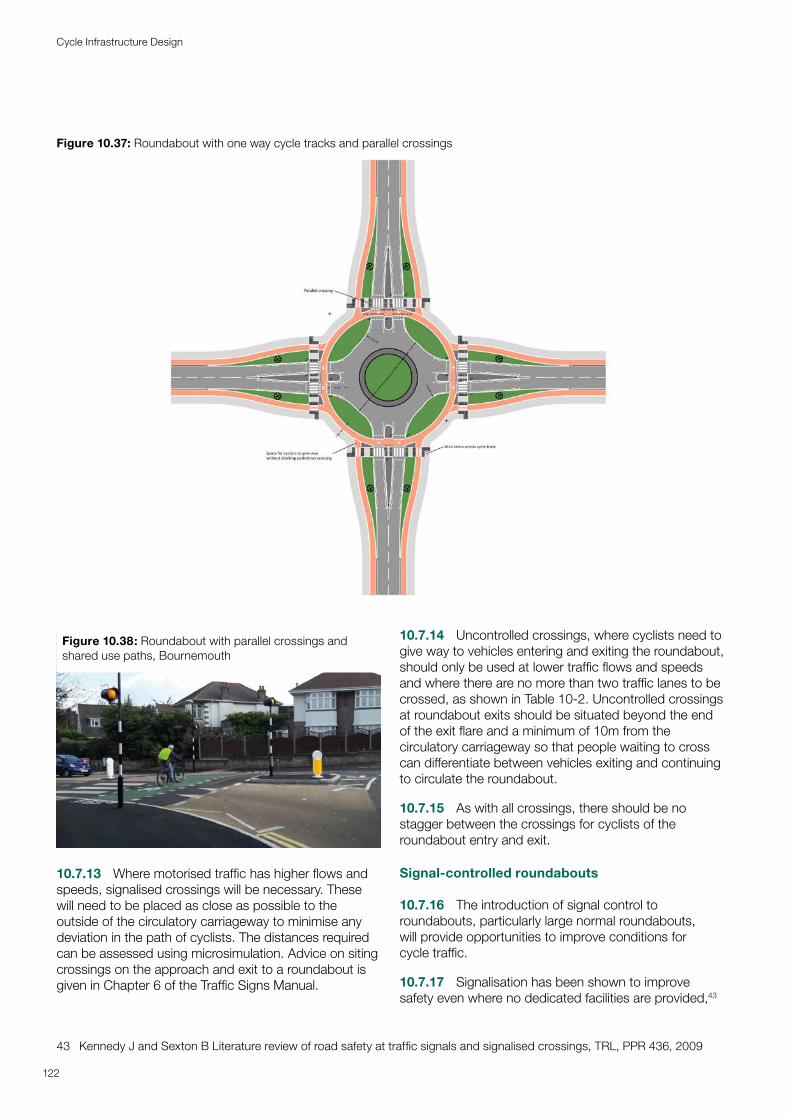
Figure 10.37: Roundabout with one way cycle tracks and parallel crossings
122
Cycle Infrastructure Design
Figure 10.38: Roundabout with parallel crossings and shared use paths, Bournemouth
10.7.13 Where motorised traffic has higher flows and speeds, signalised crossings will be necessary. These will need to be placed as close as possible to the outside of the circulatory carriageway to minimise any deviation in the path of cyclists. The distances required can be assessed using microsimulation. Advice on siting crossings on the approach and exit to a roundabout is given in Chapter 6 of the Traffic Signs Manual.
43 Kennedy J and Sexton B Literature review of road safety at traffic signals and signalised crossings, TRL, PPR 436, 2009
10.7.14 Uncontrolled crossings, where cyclists need to give way to vehicles entering and exiting the roundabout, should only be used at lower traffic flows and speeds and where there are no more than two traffic lanes to be crossed, as shown in Table 10-2. Uncontrolled crossings at roundabout exits should be situated beyond the end of the exit flare and a minimum of 10m from the circulatory carriageway so that people waiting to cross can differentiate between vehicles exiting and continuing to circulate the roundabout.
10.7.15 As with all crossings, there should be no stagger between the crossings for cyclists of the roundabout entry and exit.
Signal-controlled roundabouts
10.7.16 The introduction of signal control to roundabouts, particularly large normal roundabouts, will provide opportunities to improve conditions for cycle traffic.
10.7.17 Signalisation has been shown to improve safety even where no dedicated facilities are provided,43
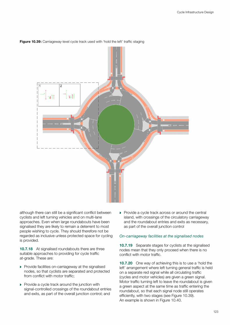
a
a
a
Figure 10.39: Carriageway-level cycle track used with ‘hold the left’ traffic staging
123
Cycle Infrastructure Design
although there can still be a significant conflict between cyclists and left turning vehicles and on multi-lane approaches. Even when large roundabouts have been signalised they are likely to remain a deterrent to most people wishing to cycle. They should therefore not be regarded as inclusive unless protected space for cycling is provided.
10.7.18 At signalised roundabouts there are three suitable approaches to providing for cycle traffic at-grade. These are:
Provide facilities on-carriageway at the signalised nodes, so that cyclists are separated and protected from conflict with motor traffic;
Provide a cycle track around the junction with signal-controlled crossings of the roundabout entries and exits, as part of the overall junction control; and
Provide a cycle track across or around the central island, with crossings of the circulatory carriageway and the roundabout entries and exits as necessary, as part of the overall junction control
On-carriageway facilities at the signalised nodes
10.7.19 Separate stages for cyclists at the signalised nodes mean that they only proceed when there is no conflict with motor traffic.
10.7.20 One way of achieving this is to use a ‘hold the left’ arrangement where left turning general traffic is held on a separate red signal while all circulating traffic (cycles and motor vehicles) are given a green signal. Motor traffic turning left to leave the roundabout is given a green aspect at the same time as traffic entering the roundabout, so that each signal node still operates efficiently, with two stages (see Figure 10.39). An example is shown in Figure 10.40.
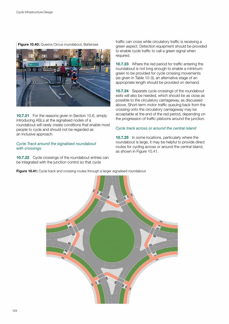
Figure 10.40: Queens Circus roundabout, Battersea
10.7.21 For the reasons given in Section 10.6, simply introducing ASLs at the signalised nodes of a roundabout will rarely create conditions that enable most people to cycle and should not be regarded as an inclusive approach.
Cycle Track around the signalised roundabout with crossings
10.7.22 Cycle crossings of the roundabout entries can be integrated with the junction control so that cycle
traffic can cross while circulatory traffic is receiving a green aspect. Detection equipment should be provided to enable cycle traffic to call a green signal when required.
10.7.23 Where the red period for traffic entering the roundabout is not long enough to enable a minimum green to be provided for cycle crossing movements (as given in Table 10-3), an alternative stage of an appropriate length should be provided on demand.
10.7.24 Separate cycle crossings of the roundabout exits will also be needed, which should be as close as possible to the circulatory carriageway, as discussed above. Short-term motor traffic queuing back from the crossing onto the circulatory carriageway may be acceptable at the end of the red period, depending on the progression of traffic platoons around the junction.
Cycle track across or around the central island
10.7.25 In some locations, particularly where the roundabout is large, it may be helpful to provide direct routes for cycling across or around the central island, as shown in Figure 10.41.
Figure 10.41: Cycle track and crossing routes through a larger signalised roundabout
124
Cycle Infrastructure Design
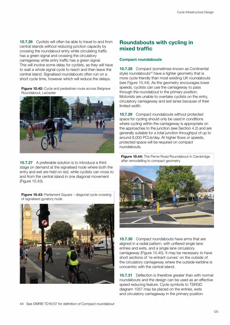
10.7.26 Cyclists will often be able to travel to and from central islands without reducing junction capacity by crossing the roundabout entry while circulating traffic has a green signal and crossing the circulatory carriageway while entry traffic has a green signal. This will involve some delay for cyclists, as they will have to wait a whole signal cycle to reach and then leave the central island. Signalised roundabouts often run on a short cycle time, however which will reduce the delays.
Figure 10.42: Cycle and pedestrian route across Belgrave Roundabout, Leicester
10.7.27 A preferable solution is to introduce a third stage on demand at the signalised node where both the entry and exit are held on red, while cyclists can cross to and from the central island in one diagonal movement (Figure 10.43).
Figure 10.43: Parliament Square – diagonal cycle crossing of signalised gyratory node
44 See DMRB TD16/07 for definition of Compact roundabout
Roundabouts with cycling in mixed traffic
Compact roundabouts
10.7.28 Compact (sometimes known as Continental style) roundabouts44 have a tighter geometry that is more cycle friendly than most existing UK roundabouts (see Figure 10.44). As the geometry encourages lower speeds, cyclists can use the carriageway to pass through the roundabout in the primary position. Motorists are unable to overtake cyclists on the entry, circulatory carriageway and exit lanes because of their limited width.
10.7.29 Compact roundabouts without protected space for cycling should only be used in conditions where cycling within the carriageway is appropriate on the approaches to the junction (see Section 4.2) and are generally suitable for a total junction throughput of up to around 8,000 PCUs/day. At higher flows or speeds, protected space will be required on compact roundabouts.
Figure 10.44: The Perne Road Roundabout in Cambridge after remodelling to compact geometry
10.7.30 Compact roundabouts have arms that are aligned in a radial pattern, with unflared single lane entries and exits, and a single lane circulatory carriageway (Figure 10.45). It may be necessary to have short sections of ‘re-entrant curves’ on the outside of the circulatory carriageway where the outside kerbline is concentric with the central island.
10.7.31 Deflection is therefore greater than with normal roundabouts and the design can be used as an effective speed reducing feature. Cycle symbols to TSRGD diagram 1057 may be placed on the entries, exits and circulatory carriageway in the primary position.
125
Cycle Infrastructure Design
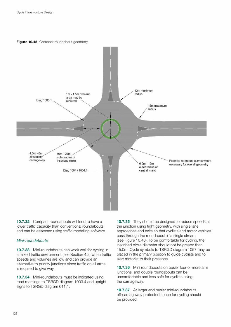
Figure 10.45: Compact roundabout geometry
126
Cycle Infrastructure Design
10.7.32 Compact roundabouts will tend to have a lower traffic capacity than conventional roundabouts, and can be assessed using traffic modelling software.
Mini-roundabouts
10.7.33 Mini-roundabouts can work well for cycling in a mixed traffic environment (see Section 4.2) when traffic speeds and volumes are low and can provide an alternative to priority junctions since traffic on all arms is required to give way.
10.7.34 Mini-roundabouts must be indicated using road markings to TSRGD diagram 1003.4 and upright signs to TSRGD diagram 611.1.
10.7.35 They should be designed to reduce speeds at the junction using tight geometry, with single lane approaches and exits so that cyclists and motor vehicles pass through the roundabout in a single stream (see Figure 10.46). To be comfortable for cycling, the inscribed circle diameter should not be greater than 15.0m. Cycle symbols to TSRGD diagram 1057 may be placed in the primary position to guide cyclists and to alert motorist to their presence.
10.7.36 Mini roundabouts on busier four or more arm junctions, and double roundabouts can be uncomfortable and less safe for cyclists using the carriageway.
10.7.37 At larger and busier mini-roundabouts, off-carriageway protected space for cycling should be provided.
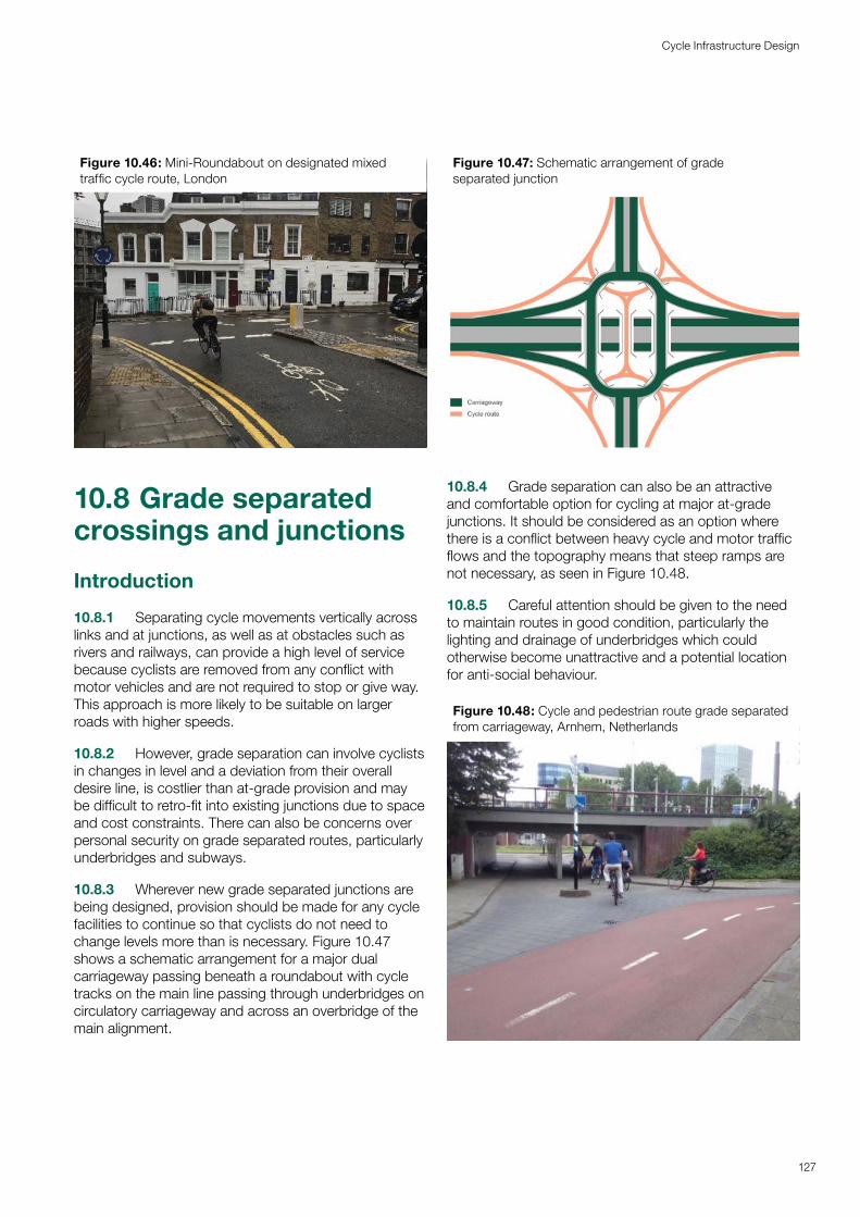
Figure 10.46: Mini-Roundabout on designated mixed traffic cycle route, London
10.8 Grade separated crossings and junctions
Introduction
10.8.1 Separating cycle movements vertically across links and at junctions, as well as at obstacles such as rivers and railways, can provide a high level of service because cyclists are removed from any conflict with motor vehicles and are not required to stop or give way. This approach is more likely to be suitable on larger roads with higher speeds.
10.8.2 However, grade separation can involve cyclists in changes in level and a deviation from their overall desire line, is costlier than at-grade provision and may be difficult to retro-fit into existing junctions due to space and cost constraints. There can also be concerns over personal security on grade separated routes, particularly underbridges and subways.
10.8.3 Wherever new grade separated junctions are being designed, provision should be made for any cycle facilities to continue so that cyclists do not need to change levels more than is necessary. Figure 10.47 shows a schematic arrangement for a major dual carriageway passing beneath a roundabout with cycle tracks on the main line passing through underbridges on circulatory carriageway and across an overbridge of the main alignment.
Figure 10.47: Schematic arrangement of grade separated junction
10.8.4 Grade separation can also be an attractive and comfortable option for cycling at major at-grade junctions. It should be considered as an option where there is a conflict between heavy cycle and motor traffic flows and the topography means that steep ramps are not necessary, as seen in Figure 10.48.
10.8.5 Careful attention should be given to the need to maintain routes in good condition, particularly the lighting and drainage of underbridges which could otherwise become unattractive and a potential location for anti-social behaviour.
Figure 10.48: Cycle and pedestrian route grade separated from carriageway, Arnhem, Netherlands
127
Cycle Infrastructure Design
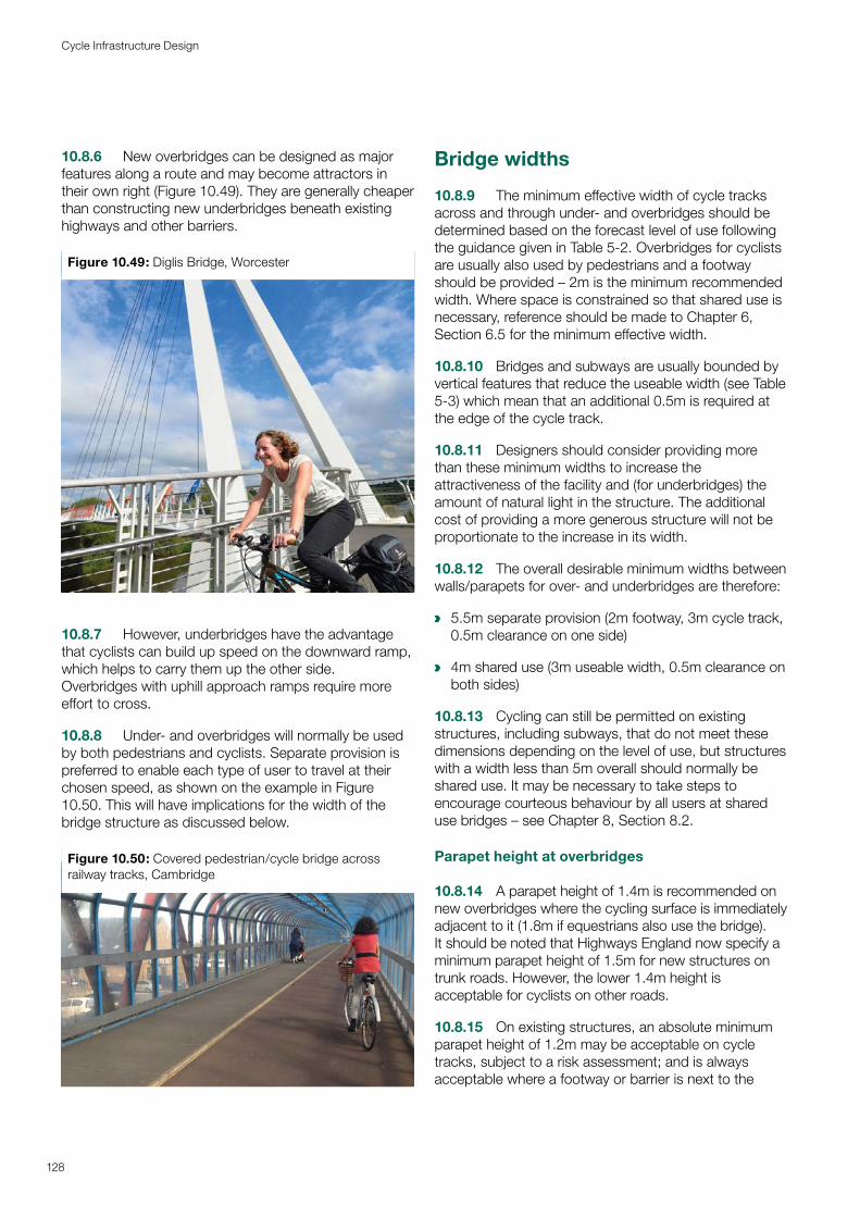
10.8.6 New overbridges can be designed as major features along a route and may become attractors in their own right (Figure 10.49). They are generally cheaper than constructing new underbridges beneath existing highways and other barriers.
Figure 10.49: Diglis Bridge, Worcester
10.8.7 However, underbridges have the advantage that cyclists can build up speed on the downward ramp, which helps to carry them up the other side. Overbridges with uphill approach ramps require more effort to cross.
10.8.8 Under- and overbridges will normally be used by both pedestrians and cyclists. Separate provision is preferred to enable each type of user to travel at their chosen speed, as shown on the example in Figure 10.50. This will have implications for the width of the bridge structure as discussed below.
Figure 10.50: Covered pedestrian/cycle bridge across railway tracks, Cambridge
Bridge widths
10.8.9 The minimum effective width of cycle tracks across and through under- and overbridges should be determined based on the forecast level of use following the guidance given in Table 5-2. Overbridges for cyclists are usually also used by pedestrians and a footway should be provided – 2m is the minimum recommended width. Where space is constrained so that shared use is necessary, reference should be made to Chapter 6, Section 6.5 for the minimum effective width.
10.8.10 Bridges and subways are usually bounded by vertical features that reduce the useable width (see Table 5-3) which mean that an additional 0.5m is required at the edge of the cycle track.
10.8.11 Designers should consider providing more than these minimum widths to increase the attractiveness of the facility and (for underbridges) the amount of natural light in the structure. The additional cost of providing a more generous structure will not be proportionate to the increase in its width.
10.8.12 The overall desirable minimum widths between walls/parapets for over- and underbridges are therefore:
a 5.5m separate provision (2m footway, 3m cycle track, 0.5m clearance on one side)
a 4m shared use (3m useable width, 0.5m clearance on both sides)
10.8.13 Cycling can still be permitted on existing structures, including subways, that do not meet these dimensions depending on the level of use, but structures with a width less than 5m overall should normally be shared use. It may be necessary to take steps to encourage courteous behaviour by all users at shared use bridges – see Chapter 8, Section 8.2.
Parapet height at overbridges
10.8.14 A parapet height of 1.4m is recommended on new overbridges where the cycling surface is immediately adjacent to it (1.8m if equestrians also use the bridge). It should be noted that Highways England now specify a minimum parapet height of 1.5m for new structures on trunk roads. However, the lower 1.4m height is acceptable for cyclists on other roads.
10.8.15 On existing structures, an absolute minimum parapet height of 1.2m may be acceptable on cycle tracks, subject to a risk assessment; and is always acceptable where a footway or barrier is next to the
128
Cycle Infrastructure Design
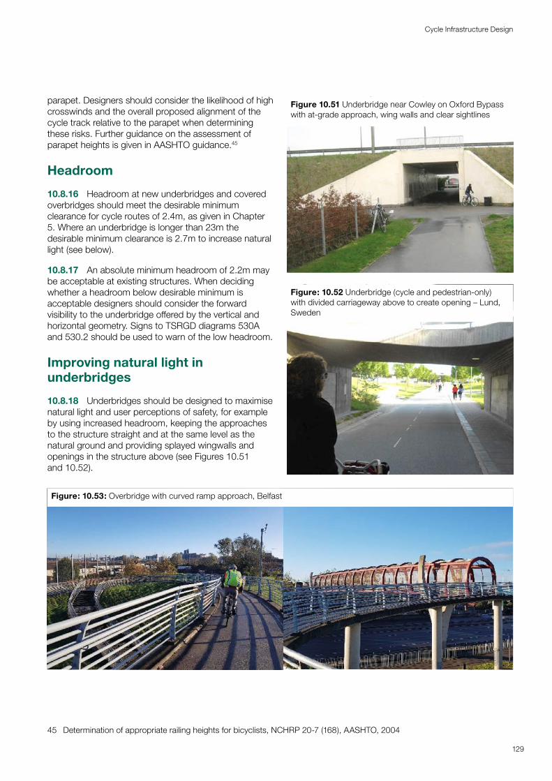
parapet. Designers should consider the likelihood of high crosswinds and the overall proposed alignment of the cycle track relative to the parapet when determining these risks. Further guidance on the assessment of parapet heights is given in AASHTO guidance.45
Headroom
10.8.16 Headroom at new underbridges and covered overbridges should meet the desirable minimum clearance for cycle routes of 2.4m, as given in Chapter 5. Where an underbridge is longer than 23m the desirable minimum clearance is 2.7m to increase natural light (see below).
10.8.17 An absolute minimum headroom of 2.2m may be acceptable at existing structures. When deciding whether a headroom below desirable minimum is acceptable designers should consider the forward visibility to the underbridge offered by the vertical and horizontal geometry. Signs to TSRGD diagrams 530A and 530.2 should be used to warn of the low headroom.
Improving natural light in underbridges
10.8.18 Underbridges should be designed to maximise natural light and user perceptions of safety, for example by using increased headroom, keeping the approaches to the structure straight and at the same level as the natural ground and providing splayed wingwalls and openings in the structure above (see Figures 10.51 and 10.52).
45 Determination of appropriate railing heights for bicyclists, NCHRP 20-7 (168), AASHTO, 2004
Figure 10.51 Underbridge near Cowley on Oxford Bypass with at-grade approach, wing walls and clear sightlines
Figure: 10.52 Underbridge (cycle and pedestrian-only) with divided carriageway above to create opening – Lund, Sweden
Figure: 10.53: Overbridge with curved ramp approach, Belfast
129
Cycle Infrastructure Design

Alignment of cycle tracks and ramps
10.8.19 The horizontal and vertical alignment of cycle tracks through grade-separated structures and any ramps on their approaches should follow the recommendations given in Chapter 5.
10.8.20 Where ramps are in a zig-zag arrangement, horizontal curves should be provided at the ends of the ramp sections with a minimum radius of 5m, so that cyclists can maintain momentum. An example of a more generous curved approach ramp is shown in Figure 10.53.
10.8.21 Ramps will normally be used by both cyclists and pedestrians and gradients should be suitable for wheelchair users and other disabled people. It is preferable that ramps consist of a separate footway and cycle track. As noted in Table 5-8, a gradient of 5% should be regarded as the desirable maximum for slopes of up to 30m in length and will often be optimum for limiting the diversion distance while ensuring the ramp is easy to climb. An absolute maximum of 8% should be used for ramps.
10.8.22 Shallower gradients should be used where possible and the approach to the structure is on the desire line, such as where a cycle track alongside a road is gently raised to bridge level.
10.8.23 Ramps of 5% gradient and above should be divided into sections that do not exceed 10m in length, and with intermediate resting places at least 2m long.
10.8.24 Stepped ramps should not be provided because they are inaccessible for cyclists and mobility impaired people.
Wheeling ramps
10.8.25 Wheeling ramps can be provided to enable cycles to be rolled up or down a flight of steps that interrupt a cycle route, such as Figure 10.54. While they are better than simply requiring people to carry their cycle up and down stairs, they are not inclusive; they do not cater for non-standard cycles and are inaccessible to many people.
10.8.26 They will therefore only form part of an inclusive system if an alternative facility is provided which will cater for all users – see Figure 10.55.
Figure: 10.54: Wheeling Ramp, Cambridge Station
Figure 10.55: Cycle lift and wheeling ramps, Utrecht Station – most people use the ramps on the stairs because they are quicker but the lift meets the needs of people who cannot use them. (Note that the road markings do not comply with UK regulations.)
130
Cycle Infrastructure Design
11Cycle parking and Cycle parking and other equipmentother equipment
Cycle parking is an essential component of cycle infrastructure. Sufficient and convenient residential cycle parking enables people to choose cycling. At the trip end, proximity to destinations is important for short stay parking, while for longer-stay parking security concerns can be a factor. As with other infrastructure, designers should consider access for all cycles and their passengers. Additional equipment and services enhance the quality of experience and convenience of cycling, making it accessible and attractive to more people.
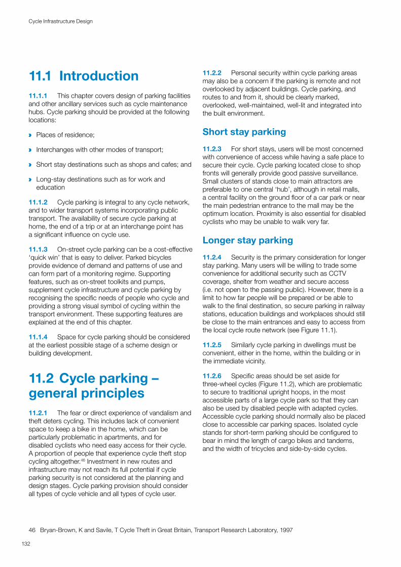
11.1 Introduction11.1.1 This chapter covers design of parking facilities and other ancillary services such as cycle maintenance hubs. Cycle parking should be provided at the following locations:
a Places of residence;
a Interchanges with other modes of transport;
a Short stay destinations such as shops and cafes; and
a Long-stay destinations such as for work and education
11.1.2 Cycle parking is integral to any cycle network, and to wider transport systems incorporating public transport. The availability of secure cycle parking at home, the end of a trip or at an interchange point has a significant influence on cycle use.
11.1.3 On-street cycle parking can be a cost-effective ‘quick win’ that is easy to deliver. Parked bicycles provide evidence of demand and patterns of use and can form part of a monitoring regime. Supporting features, such as on-street toolkits and pumps, supplement cycle infrastructure and cycle parking by recognising the specific needs of people who cycle and providing a strong visual symbol of cycling within the transport environment. These supporting features are explained at the end of this chapter.
11.1.4 Space for cycle parking should be considered at the earliest possible stage of a scheme design or building development.
11.2 Cycle parking – general principles11.2.1 The fear or direct experience of vandalism and theft deters cycling. This includes lack of convenient space to keep a bike in the home, which can be particularly problematic in apartments, and for disabled cyclists who need easy access for their cycle. A proportion of people that experience cycle theft stop cycling altogether.46 Investment in new routes and infrastructure may not reach its full potential if cycle parking security is not considered at the planning and design stages. Cycle parking provision should consider all types of cycle vehicle and all types of cycle user.
46 Bryan-Brown, K and Savile, T Cycle Theft in Great Britain, Transport Research Laboratory, 1997
11.2.2 Personal security within cycle parking areas may also be a concern if the parking is remote and not overlooked by adjacent buildings. Cycle parking, and routes to and from it, should be clearly marked, overlooked, well-maintained, well-lit and integrated into the built environment.
Short stay parking
11.2.3 For short stays, users will be most concerned with convenience of access while having a safe place to secure their cycle. Cycle parking located close to shop fronts will generally provide good passive surveillance. Small clusters of stands close to main attractors are preferable to one central ‘hub’, although in retail malls, a central facility on the ground floor of a car park or near the main pedestrian entrance to the mall may be the optimum location. Proximity is also essential for disabled cyclists who may be unable to walk very far.
Longer stay parking
11.2.4 Security is the primary consideration for longer stay parking. Many users will be willing to trade some convenience for additional security such as CCTV coverage, shelter from weather and secure access (i.e. not open to the passing public). However, there is a limit to how far people will be prepared or be able to walk to the final destination, so secure parking in railway stations, education buildings and workplaces should still be close to the main entrances and easy to access from the local cycle route network (see Figure 11.1).
11.2.5 Similarly cycle parking in dwellings must be convenient, either in the home, within the building or in the immediate vicinity.
11.2.6 Specific areas should be set aside for three-wheel cycles (Figure 11.2), which are problematic to secure to traditional upright hoops, in the most accessible parts of a large cycle park so that they can also be used by disabled people with adapted cycles. Accessible cycle parking should normally also be placed close to accessible car parking spaces. Isolated cycle stands for short-term parking should be configured to bear in mind the length of cargo bikes and tandems, and the width of tricycles and side-by-side cycles.
132
Cycle Infrastructure Design
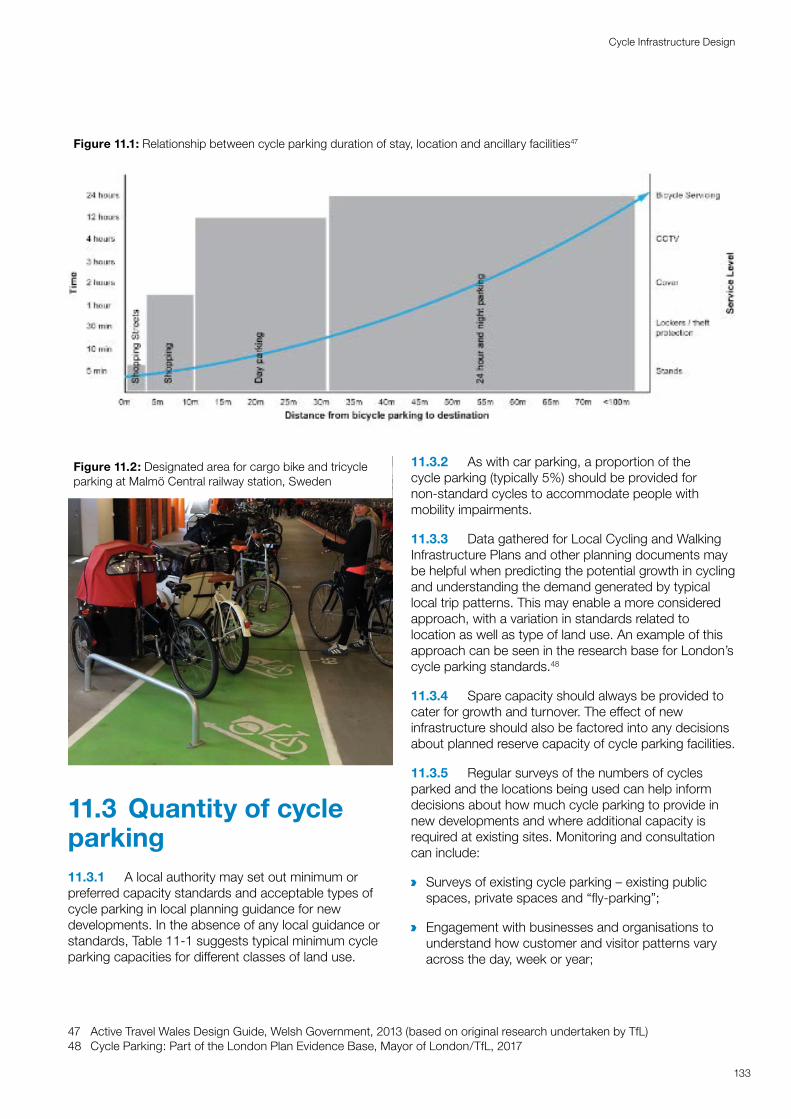
a
a
Figure 11.1: Relationship between cycle parking duration of stay, location and ancillary facilities47
133
Cycle Infrastructure Design
Figure 11.2: Designated area for cargo bike and tricycle parking at Malmö Central railway station, Sweden
11.3 Quantity of cycle parking11.3.1 A local authority may set out minimum or preferred capacity standards and acceptable types of cycle parking in local planning guidance for new developments. In the absence of any local guidance or standards, Table 11-1 suggests typical minimum cycle parking capacities for different classes of land use.47
47 Active Travel Wales Design Guide, Welsh Government, 2013 (based on original research undertaken by TfL)48 Cycle Parking: Part of the London Plan Evidence Base, Mayor of London/TfL, 2017
11.3.2 As with car parking, a proportion of the cycle parking (typically 5%) should be provided for non-standard cycles to accommodate people with mobility impairments.
11.3.3 Data gathered for Local Cycling and Walking Infrastructure Plans and other planning documents may be helpful when predicting the potential growth in cycling and understanding the demand generated by typical local trip patterns. This may enable a more considered approach, with a variation in standards related to location as well as type of land use. An example of this approach can be seen in the research base for London’s cycle parking standards.48
11.3.4 Spare capacity should always be provided to cater for growth and turnover. The effect of new infrastructure should also be factored into any decisions about planned reserve capacity of cycle parking facilities.
11.3.5 Regular surveys of the numbers of cycles parked and the locations being used can help inform decisions about how much cycle parking to provide in new developments and where additional capacity is required at existing sites. Monitoring and consultation can include:
Surveys of existing cycle parking – existing public spaces, private spaces and “fly-parking”;
Engagement with businesses and organisations to understand how customer and visitor patterns vary across the day, week or year;
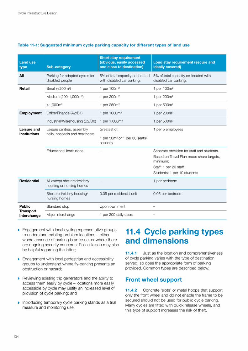
a Engagement with local cycling representative groups to understand existing problem locations – either where absence of parking is an issue, or where there are ongoing security concerns. Police liaison may also be helpful regarding the latter;
a Engagement with local pedestrian and accessibility groups to understand where fly-parking presents an obstruction or hazard;
a Reviewing existing trip generators and the ability to access them easily by cycle – locations more easily accessible by cycle may justify an increased level of provision of cycle parking; and
a Introducing temporary cycle parking stands as a trial measure and monitoring use.
11.4 Cycle parking types and dimensions11.4.1 Just as the location and comprehensiveness of cycle parking varies with the type of destination served, so does the appropriate form of parking provided. Common types are described below.
Front wheel support
11.4.2 Concrete ‘slots’ or metal hoops that support only the front wheel and do not enable the frame to be secured should not be used for public cycle parking. Many cycles are fitted with quick release wheels, and this type of support increases the risk of theft.
Table 11-1: Suggested minimum cycle parking capacity for different types of land use
Land use type Sub-category
Short stay requirement (obvious, easily accessed and close to destination)
Long stay requirement (secure and ideally covered)
All Parking for adapted cycles for disabled people
5% of total capacity co-located with disabled car parking.
5% of total capacity co-located with disabled car parking.
Retail Small (<200m²) 1 per 100m² 1 per 100m²
Medium (200-1,000m²) 1 per 200m² 1 per 200m²
>1,000m² 1 per 250m² 1 per 500m²
Employment Office/Finance (A2/B1) 1 per 1000m² 1 per 200m²
Industrial/Warehousing (B2/B8) 1 per 1,000m² 1 per 500m²
Leisure and Institutions
Leisure centres, assembly halls, hospitals and healthcare
Greatest of:
1 per 50m² or 1 per 30 seats/capacity
1 per 5 employees
Educational Institutions – Separate provision for staff and students.
Based on Travel Plan mode share targets, minimum:
Staff: 1 per 20 staff
Students; 1 per 10 students
Residential All except sheltered/elderly housing or nursing homes
– 1 per bedroom
Sheltered/elderly housing/ nursing homes
0.05 per residential unit 0.05 per bedroom
Public Transport Interchange
Standard stop Upon own merit –
Major interchange 1 per 200 daily users –
134
Cycle Infrastructure Design
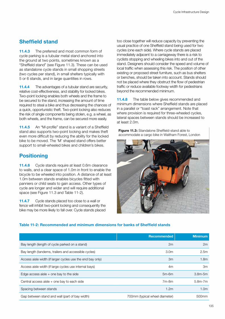
Sheffield stand
11.4.3 The preferred and most common form of cycle parking is a tubular metal stand anchored into the ground at two points, sometimes known as a “Sheffield stand” (see Figure 11.3). These can be used as standalone cycle stands in small shopping streets (two cycles per stand), in small shelters typically with 5 or 6 stands, and in large quantities in rows.
11.4.4 The advantages of a tubular stand are security, relative cost-effectiveness, and stability for locked bikes. Two-point locking enables both wheels and the frame to be secured to the stand, increasing the amount of time required to steal a bike and thus decreasing the chances of a quick, opportunistic theft. Two-point locking also reduces the risk of single components being stolen, e.g. a wheel, as both wheels, and the frame, can be secured more easily.
11.4.5 An “M-profile” stand is a variant of a Sheffield stand also supports two-point locking and makes theft even more difficult by reducing the ability for the locked bike to be moved. The ‘M’ shaped stand offers better support to small-wheeled bikes and children’s bikes.
Positioning
11.4.6 Cycle stands require at least 0.6m clearance to walls, and a clear space of 1.0m in front to enable the bicycle to be wheeled into position. A distance of at least 1.0m between stands enables bicycles fitted with panniers or child seats to gain access. Other types of cycle are longer and wider and will require additional space (see Figure 11.3 and Table 11-2).
11.4.7 Cycle stands placed too close to a wall or fence will inhibit two-point locking and consequently the bike may be more likely to fall over. Cycle stands placed
too close together will reduce capacity by preventing the usual practice of one Sheffield stand being used for two cycles (one each side). Where cycle stands are placed immediately adjacent to a carriageway there is a risk to cyclists stopping and wheeling bikes into and out of the stand. Designers should consider the speed and volume of local traffic when assessing this risk. The position of other existing or proposed street furniture, such as bus shelters or benches, should be taken into account. Stands should not be placed where they obstruct the flow of pedestrian traffic or reduce available footway width for pedestrians beyond the recommended minimum.
11.4.8 The table below gives recommended and minimum dimensions where Sheffield stands are placed in a parallel or “toast rack” arrangement. Note that where provision is required for three-wheeled cycles, lateral spaces between stands should be increased to at least 2.0m.
Figure 11.3: Standalone Sheffield-stand able to accommodate a cargo bike in Waltham Forest, London
Table 11-2: Recommended and minimum dimensions for banks of Sheffield stands
Recommended Minimum
Bay length (length of cycle parked on a stand) 2m 2m
Bay length (tandems, trailers and accessible cycles) 3.0m 2.5m
Access aisle width (if larger cycles use the end bay only) 3m 1.8m
Access aisle width (if large cycles use internal bays) 4m 3m
Edge access aisle + one bay to the side 5m-6m 3.8m-5m
Central access aisle + one bay to each side 7m-8m 5.8m-7m
Spacing between stands 1.2m 1.0m
Gap between stand and wall (part of bay width) 700mm (typical wheel diameter) 500mm
135
Cycle Infrastructure Design
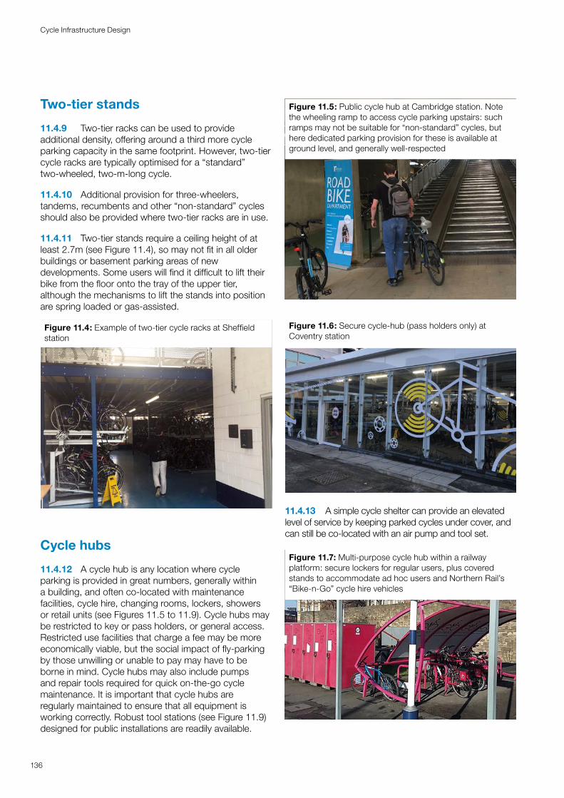
Two-tier stands
11.4.9 Two-tier racks can be used to provide additional density, offering around a third more cycle parking capacity in the same footprint. However, two-tier cycle racks are typically optimised for a “standard” two-wheeled, two-m-long cycle.
11.4.10 Additional provision for three-wheelers, tandems, recumbents and other “non-standard” cycles should also be provided where two-tier racks are in use.
11.4.11 Two-tier stands require a ceiling height of at least 2.7m (see Figure 11.4), so may not fit in all older buildings or basement parking areas of new developments. Some users will find it difficult to lift their bike from the floor onto the tray of the upper tier, although the mechanisms to lift the stands into position are spring loaded or gas-assisted.
Figure 11.4: Example of two-tier cycle racks at Sheffield station
Cycle hubs
11.4.12 A cycle hub is any location where cycle parking is provided in great numbers, generally within a building, and often co-located with maintenance facilities, cycle hire, changing rooms, lockers, showers or retail units (see Figures 11.5 to 11.9). Cycle hubs may be restricted to key or pass holders, or general access. Restricted use facilities that charge a fee may be more economically viable, but the social impact of fly-parking by those unwilling or unable to pay may have to be borne in mind. Cycle hubs may also include pumps and repair tools required for quick on-the-go cycle maintenance. It is important that cycle hubs are regularly maintained to ensure that all equipment is working correctly. Robust tool stations (see Figure 11.9) designed for public installations are readily available.
Figure 11.5: Public cycle hub at Cambridge station. Note the wheeling ramp to access cycle parking upstairs: such ramps may not be suitable for “non-standard” cycles, but here dedicated parking provision for these is available at ground level, and generally well-respected
Figure 11.6: Secure cycle-hub (pass holders only) at Coventry station
11.4.13 A simple cycle shelter can provide an elevated level of service by keeping parked cycles under cover, and can still be co-located with an air pump and tool set.
Figure 11.7: Multi-purpose cycle hub within a railway platform: secure lockers for regular users, plus covered stands to accommodate ad hoc users and Northern Rail’s “Bike-n-Go” cycle hire vehicles
136
Cycle Infrastructure Design
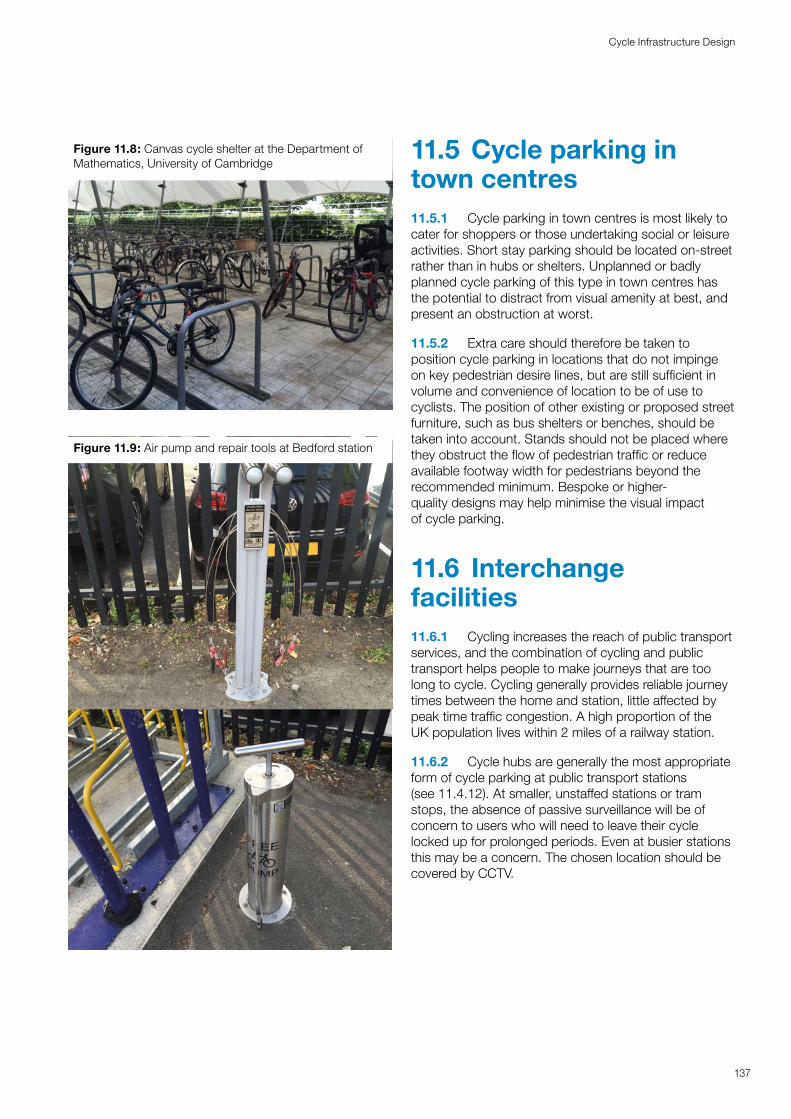
Figure 11.8: Canvas cycle shelter at the Department of Mathematics, University of Cambridge
Figure 11.9: Air pump and repair tools at Bedford station
11.5 Cycle parking in town centres 11.5.1 Cycle parking in town centres is most likely to cater for shoppers or those undertaking social or leisure activities. Short stay parking should be located on-street rather than in hubs or shelters. Unplanned or badly planned cycle parking of this type in town centres has the potential to distract from visual amenity at best, and present an obstruction at worst.
11.5.2 Extra care should therefore be taken to position cycle parking in locations that do not impinge on key pedestrian desire lines, but are still sufficient in volume and convenience of location to be of use to cyclists. The position of other existing or proposed street furniture, such as bus shelters or benches, should be taken into account. Stands should not be placed where they obstruct the flow of pedestrian traffic or reduce available footway width for pedestrians beyond the recommended minimum. Bespoke or higher-quality designs may help minimise the visual impact of cycle parking.
11.6 Interchange facilities11.6.1 Cycling increases the reach of public transport services, and the combination of cycling and public transport helps people to make journeys that are too long to cycle. Cycling generally provides reliable journey times between the home and station, little affected by peak time traffic congestion. A high proportion of the UK population lives within 2 miles of a railway station.
11.6.2 Cycle hubs are generally the most appropriate form of cycle parking at public transport stations (see 11.4.12). At smaller, unstaffed stations or tram stops, the absence of passive surveillance will be of concern to users who will need to leave their cycle locked up for prolonged periods. Even at busier stations this may be a concern. The chosen location should be covered by CCTV.
137
Cycle Infrastructure Design
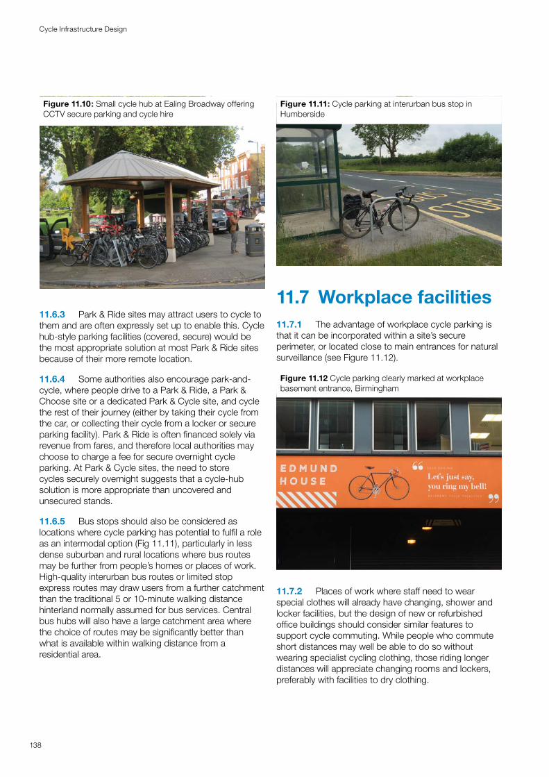
Figure 11.10: Small cycle hub at Ealing Broadway offering CCTV secure parking and cycle hire
11.6.3 Park & Ride sites may attract users to cycle to them and are often expressly set up to enable this. Cycle hub-style parking facilities (covered, secure) would be the most appropriate solution at most Park & Ride sites because of their more remote location.
11.6.4 Some authorities also encourage park-and-cycle, where people drive to a Park & Ride, a Park & Choose site or a dedicated Park & Cycle site, and cycle the rest of their journey (either by taking their cycle from the car, or collecting their cycle from a locker or secure parking facility). Park & Ride is often financed solely via revenue from fares, and therefore local authorities may choose to charge a fee for secure overnight cycle parking. At Park & Cycle sites, the need to store cycles securely overnight suggests that a cycle-hub solution is more appropriate than uncovered and unsecured stands.
11.6.5 Bus stops should also be considered as locations where cycle parking has potential to fulfil a role as an intermodal option (Fig 11.11), particularly in less dense suburban and rural locations where bus routes may be further from people’s homes or places of work. High-quality interurban bus routes or limited stop express routes may draw users from a further catchment than the traditional 5 or 10-minute walking distance hinterland normally assumed for bus services. Central bus hubs will also have a large catchment area where the choice of routes may be significantly better than what is available within walking distance from a residential area.
Figure 11.11: Cycle parking at interurban bus stop in Humberside
11.7 Workplace facilities11.7.1 The advantage of workplace cycle parking is that it can be incorporated within a site’s secure perimeter, or located close to main entrances for natural surveillance (see Figure 11.12).
Figure 11.12 Cycle parking clearly marked at workplace basement entrance, Birmingham
11.7.2 Places of work where staff need to wear special clothes will already have changing, shower and locker facilities, but the design of new or refurbished office buildings should consider similar features to support cycle commuting. While people who commute short distances may well be able to do so without wearing specialist cycling clothing, those riding longer distances will appreciate changing rooms and lockers, preferably with facilities to dry clothing.
138
Cycle Infrastructure Design
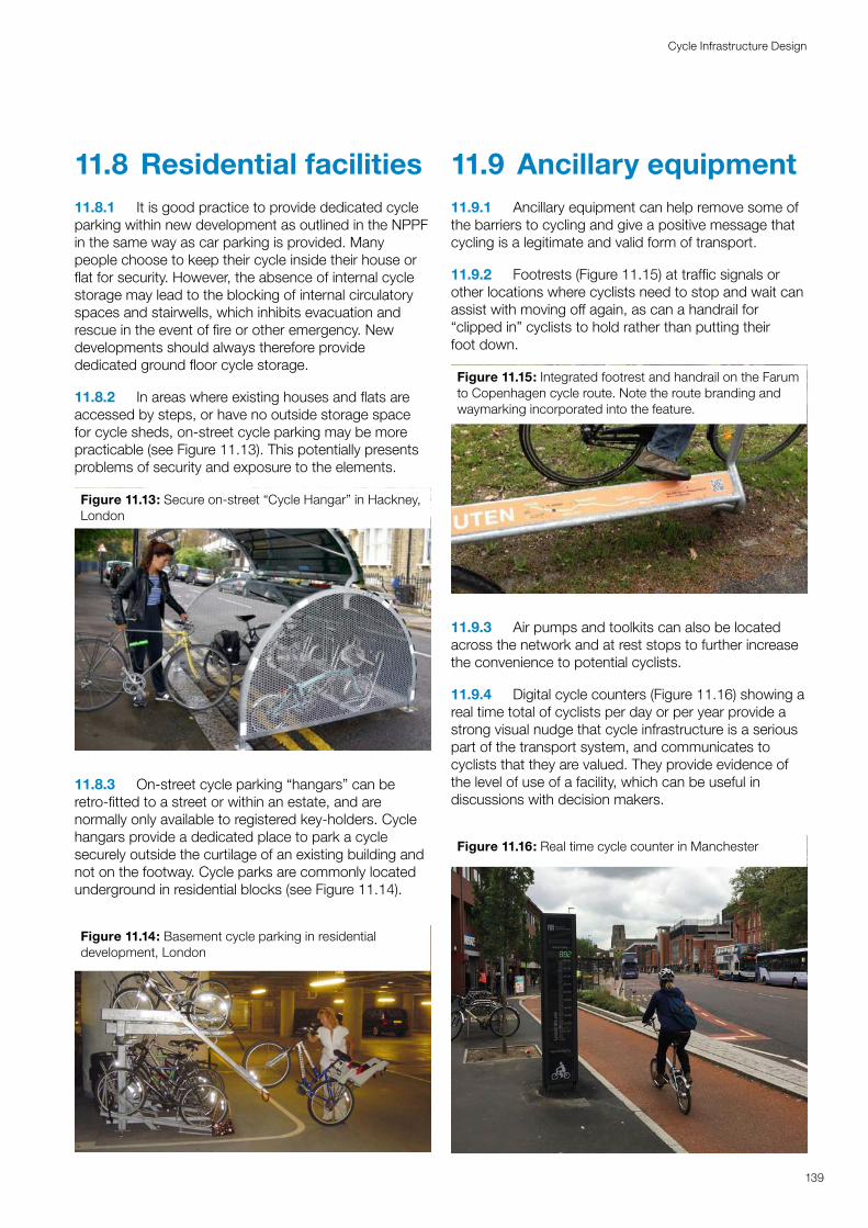
11.8 Residential facilities11.8.1 It is good practice to provide dedicated cycle parking within new development as outlined in the NPPF in the same way as car parking is provided. Many people choose to keep their cycle inside their house or flat for security. However, the absence of internal cycle storage may lead to the blocking of internal circulatory spaces and stairwells, which inhibits evacuation and rescue in the event of fire or other emergency. New developments should always therefore provide dedicated ground floor cycle storage.
11.8.2 In areas where existing houses and flats are accessed by steps, or have no outside storage space for cycle sheds, on-street cycle parking may be more practicable (see Figure 11.13). This potentially presents problems of security and exposure to the elements.
Figure 11.13: Secure on-street “Cycle Hangar” in Hackney, London
11.8.3 On-street cycle parking “hangars” can be retro-fitted to a street or within an estate, and are normally only available to registered key-holders. Cycle hangars provide a dedicated place to park a cycle securely outside the curtilage of an existing building and not on the footway. Cycle parks are commonly located underground in residential blocks (see Figure 11.14).
Figure 11.14: Basement cycle parking in residential development, London
11.9 Ancillary equipment11.9.1 Ancillary equipment can help remove some of the barriers to cycling and give a positive message that cycling is a legitimate and valid form of transport.
11.9.2 Footrests (Figure 11.15) at traffic signals or other locations where cyclists need to stop and wait can assist with moving off again, as can a handrail for “clipped in” cyclists to hold rather than putting their foot down.
Figure 11.15: Integrated footrest and handrail on the Farum to Copenhagen cycle route. Note the route branding and waymarking incorporated into the feature.
11.9.3 Air pumps and toolkits can also be located across the network and at rest stops to further increase the convenience to potential cyclists.
11.9.4 Digital cycle counters (Figure 11.16) showing a real time total of cyclists per day or per year provide a strong visual nudge that cycle infrastructure is a serious part of the transport system, and communicates to cyclists that they are valued. They provide evidence of the level of use of a facility, which can be useful in discussions with decision makers.
Figure 11.16: Real time cycle counter in Manchester
139
Cycle Infrastructure Design
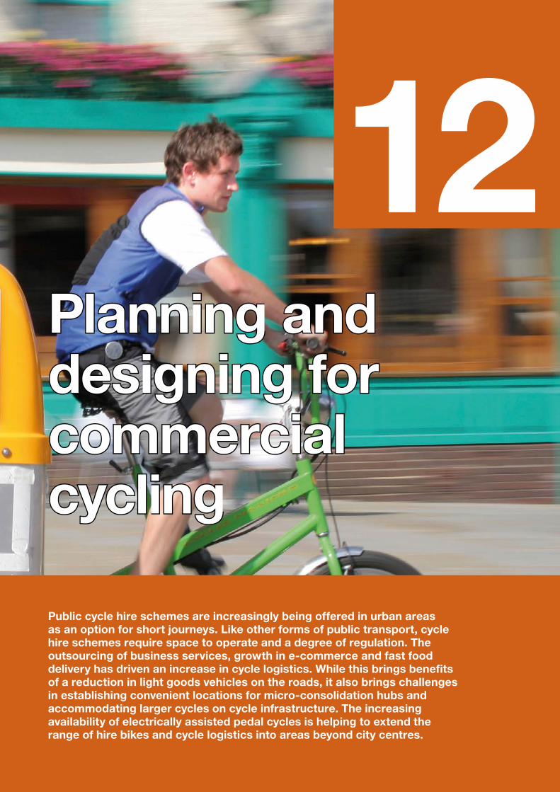
12Planning and Planning and designing for designing for commercial commercial cyclingcycling
Public cycle hire schemes are increasingly being offered in urban areas as an option for short journeys. Like other forms of public transport, cycle hire schemes require space to operate and a degree of regulation. The outsourcing of business services, growth in e-commerce and fast food delivery has driven an increase in cycle logistics. While this brings benefits of a reduction in light goods vehicles on the roads, it also brings challenges in establishing convenient locations for micro-consolidation hubs and accommodating larger cycles on cycle infrastructure. The increasing availability of electrically assisted pedal cycles is helping to extend the range of hire bikes and cycle logistics into areas beyond city centres.
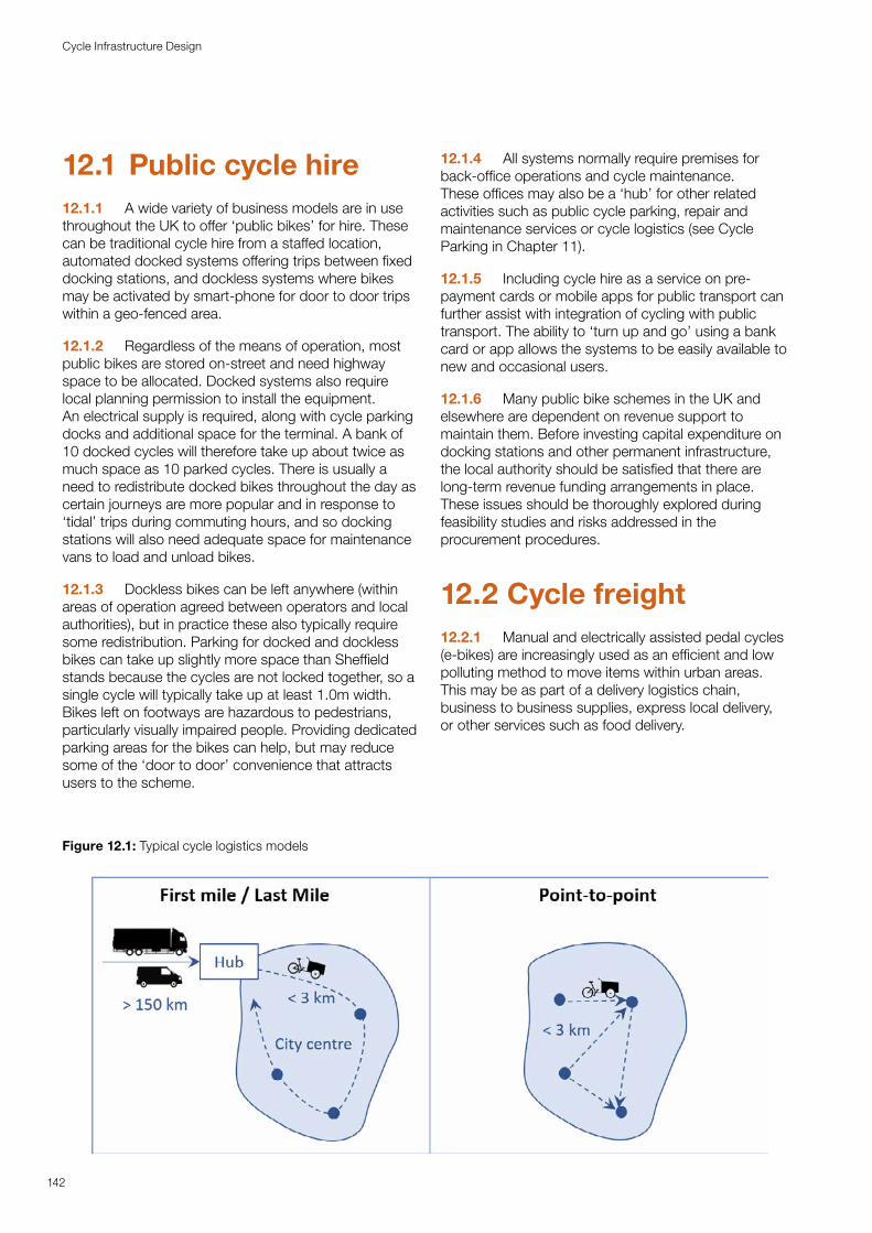
12.1 Public cycle hire12.1.1 A wide variety of business models are in use throughout the UK to offer ‘public bikes’ for hire. These can be traditional cycle hire from a staffed location, automated docked systems offering trips between fixed docking stations, and dockless systems where bikes may be activated by smart-phone for door to door trips within a geo-fenced area.
12.1.2 Regardless of the means of operation, most public bikes are stored on-street and need highway space to be allocated. Docked systems also require local planning permission to install the equipment. An electrical supply is required, along with cycle parking docks and additional space for the terminal. A bank of 10 docked cycles will therefore take up about twice as much space as 10 parked cycles. There is usually a need to redistribute docked bikes throughout the day as certain journeys are more popular and in response to ‘tidal’ trips during commuting hours, and so docking stations will also need adequate space for maintenance vans to load and unload bikes.
12.1.3 Dockless bikes can be left anywhere (within areas of operation agreed between operators and local authorities), but in practice these also typically require some redistribution. Parking for docked and dockless bikes can take up slightly more space than Sheffield stands because the cycles are not locked together, so a single cycle will typically take up at least 1.0m width. Bikes left on footways are hazardous to pedestrians, particularly visually impaired people. Providing dedicated parking areas for the bikes can help, but may reduce some of the ‘door to door’ convenience that attracts users to the scheme.
12.1.4 All systems normally require premises for back-office operations and cycle maintenance. These offices may also be a ‘hub’ for other related activities such as public cycle parking, repair and maintenance services or cycle logistics (see Cycle Parking in Chapter 11).
12.1.5 Including cycle hire as a service on pre-payment cards or mobile apps for public transport can further assist with integration of cycling with public transport. The ability to ‘turn up and go’ using a bank card or app allows the systems to be easily available to new and occasional users.
12.1.6 Many public bike schemes in the UK and elsewhere are dependent on revenue support to maintain them. Before investing capital expenditure on docking stations and other permanent infrastructure, the local authority should be satisfied that there are long-term revenue funding arrangements in place. These issues should be thoroughly explored during feasibility studies and risks addressed in the procurement procedures.
12.2 Cycle freight12.2.1 Manual and electrically assisted pedal cycles (e-bikes) are increasingly used as an efficient and low polluting method to move items within urban areas. This may be as part of a delivery logistics chain, business to business supplies, express local delivery, or other services such as food delivery.
Figure 12.1: Typical cycle logistics models
142
Cycle Infrastructure Design
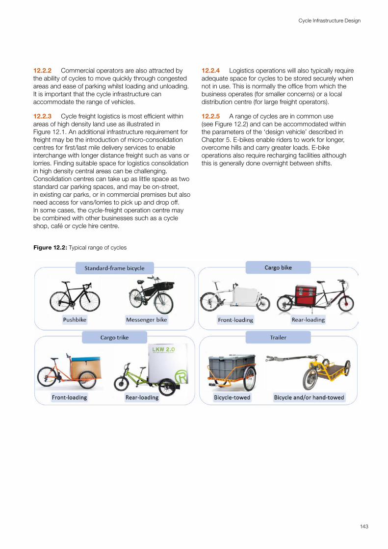
12.2.2 Commercial operators are also attracted by the ability of cycles to move quickly through congested areas and ease of parking whilst loading and unloading. It is important that the cycle infrastructure can accommodate the range of vehicles.
12.2.3 Cycle freight logistics is most efficient within areas of high density land use as illustrated in Figure 12.1. An additional infrastructure requirement for freight may be the introduction of micro-consolidation centres for first/last mile delivery services to enable interchange with longer distance freight such as vans or lorries. Finding suitable space for logistics consolidation in high density central areas can be challenging. Consolidation centres can take up as little space as two standard car parking spaces, and may be on-street, in existing car parks, or in commercial premises but also need access for vans/lorries to pick up and drop off. In some cases, the cycle-freight operation centre may be combined with other businesses such as a cycle shop, café or cycle hire centre.
12.2.4 Logistics operations will also typically require adequate space for cycles to be stored securely when not in use. This is normally the office from which the business operates (for smaller concerns) or a local distribution centre (for large freight operators).
12.2.5 A range of cycles are in common use (see Figure 12.2) and can be accommodated within the parameters of the ‘design vehicle’ described in Chapter 5. E-bikes enable riders to work for longer, overcome hills and carry greater loads. E-bike operations also require recharging facilities although this is generally done overnight between shifts.
Figure 12.2: Typical range of cycles
143
Cycle Infrastructure Design
13Traffic signs, road Traffic signs, road markings and markings and wayfindingwayfinding
Traffic signs and road markings must comply with the Traffic Signs Regulations and General Directions, or be authorised by the Secretary of State, when used within the highway, but the legislation allows for considerable flexibility in their use. There is a balance to be struck between providing enough signs for people to be able to understand and follow cycle infrastructure and ensuring that the signs themselves do not create confusion or street clutter. Routes on other rights of way not on the highway can use customised waymarking.
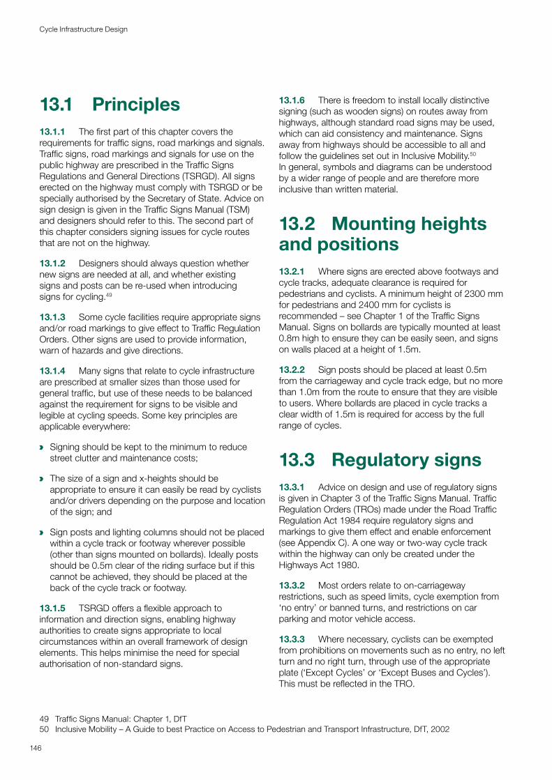
13.1 Principles13.1.1 The first part of this chapter covers the requirements for traffic signs, road markings and signals. Traffic signs, road markings and signals for use on the public highway are prescribed in the Traffic Signs Regulations and General Directions (TSRGD). All signs erected on the highway must comply with TSRGD or be specially authorised by the Secretary of State. Advice on sign design is given in the Traffic Signs Manual (TSM) and designers should refer to this. The second part of this chapter considers signing issues for cycle routes that are not on the highway.
13.1.2 Designers should always question whether new signs are needed at all, and whether existing signs and posts can be re-used when introducing signs for cycling.49
13.1.3 Some cycle facilities require appropriate signs and/or road markings to give effect to Traffic Regulation Orders. Other signs are used to provide information, warn of hazards and give directions.
13.1.4 Many signs that relate to cycle infrastructure are prescribed at smaller sizes than those used for general traffic, but use of these needs to be balanced against the requirement for signs to be visible and legible at cycling speeds. Some key principles are applicable everywhere:
a Signing should be kept to the minimum to reduce street clutter and maintenance costs;
a The size of a sign and x-heights should be appropriate to ensure it can easily be read by cyclists and/or drivers depending on the purpose and location of the sign; and
a Sign posts and lighting columns should not be placed within a cycle track or footway wherever possible (other than signs mounted on bollards). Ideally posts should be 0.5m clear of the riding surface but if this cannot be achieved, they should be placed at the back of the cycle track or footway.
13.1.5 TSRGD offers a flexible approach to information and direction signs, enabling highway authorities to create signs appropriate to local circumstances within an overall framework of design elements. This helps minimise the need for special authorisation of non-standard signs.
49 Traffic Signs Manual: Chapter 1, DfT50 Inclusive Mobility – A Guide to best Practice on Access to Pedestrian and Transport Infrastructure, DfT, 2002
13.1.6 There is freedom to install locally distinctive signing (such as wooden signs) on routes away from highways, although standard road signs may be used, which can aid consistency and maintenance. Signs away from highways should be accessible to all and follow the guidelines set out in Inclusive Mobility.50 In general, symbols and diagrams can be understood by a wider range of people and are therefore more inclusive than written material.
13.2 Mounting heights and positions13.2.1 Where signs are erected above footways and cycle tracks, adequate clearance is required for pedestrians and cyclists. A minimum height of 2300 mm for pedestrians and 2400 mm for cyclists is recommended – see Chapter 1 of the Traffic Signs Manual. Signs on bollards are typically mounted at least 0.8m high to ensure they can be easily seen, and signs on walls placed at a height of 1.5m.
13.2.2 Sign posts should be placed at least 0.5m from the carriageway and cycle track edge, but no more than 1.0m from the route to ensure that they are visible to users. Where bollards are placed in cycle tracks a clear width of 1.5m is required for access by the full range of cycles.
13.3 Regulatory signs13.3.1 Advice on design and use of regulatory signs is given in Chapter 3 of the Traffic Signs Manual. Traffic Regulation Orders (TROs) made under the Road Traffic Regulation Act 1984 require regulatory signs and markings to give them effect and enable enforcement (see Appendix C). A one way or two-way cycle track within the highway can only be created under the Highways Act 1980.
13.3.2 Most orders relate to on-carriageway restrictions, such as speed limits, cycle exemption from ‘no entry’ or banned turns, and restrictions on car parking and motor vehicle access.
13.3.3 Where necessary, cyclists can be exempted from prohibitions on movements such as no entry, no left turn and no right turn, through use of the appropriate plate (‘Except Cycles’ or ‘Except Buses and Cycles’). This must be reflected in the TRO.
146
Cycle Infrastructure Design
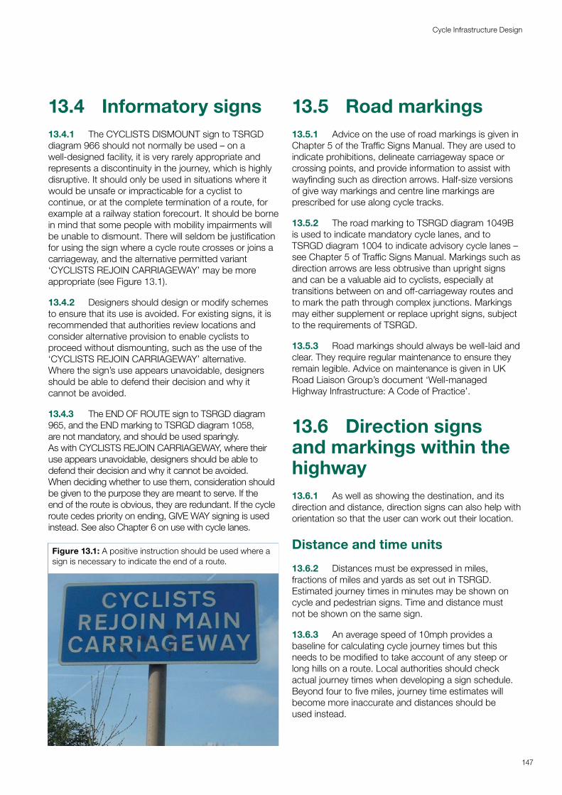
13.4 Informatory signs13.4.1 The CYCLISTS DISMOUNT sign to TSRGD diagram 966 should not normally be used – on a well-designed facility, it is very rarely appropriate and represents a discontinuity in the journey, which is highly disruptive. It should only be used in situations where it would be unsafe or impracticable for a cyclist to continue, or at the complete termination of a route, for example at a railway station forecourt. It should be borne in mind that some people with mobility impairments will be unable to dismount. There will seldom be justification for using the sign where a cycle route crosses or joins a carriageway, and the alternative permitted variant ‘CYCLISTS REJOIN CARRIAGEWAY’ may be more appropriate (see Figure 13.1).
13.4.2 Designers should design or modify schemes to ensure that its use is avoided. For existing signs, it is recommended that authorities review locations and consider alternative provision to enable cyclists to proceed without dismounting, such as the use of the ‘CYCLISTS REJOIN CARRIAGEWAY’ alternative. Where the sign’s use appears unavoidable, designers should be able to defend their decision and why it cannot be avoided.
13.4.3 The END OF ROUTE sign to TSRGD diagram 965, and the END marking to TSRGD diagram 1058, are not mandatory, and should be used sparingly. As with CYCLISTS REJOIN CARRIAGEWAY, where their use appears unavoidable, designers should be able to defend their decision and why it cannot be avoided. When deciding whether to use them, consideration should be given to the purpose they are meant to serve. If the end of the route is obvious, they are redundant. If the cycle route cedes priority on ending, GIVE WAY signing is used instead. See also Chapter 6 on use with cycle lanes.
Figure 13.1: A positive instruction should be used where a sign is necessary to indicate the end of a route.
13.5 Road markings 13.5.1 Advice on the use of road markings is given in Chapter 5 of the Traffic Signs Manual. They are used to indicate prohibitions, delineate carriageway space or crossing points, and provide information to assist with wayfinding such as direction arrows. Half-size versions of give way markings and centre line markings are prescribed for use along cycle tracks.
13.5.2 The road marking to TSRGD diagram 1049B is used to indicate mandatory cycle lanes, and to TSRGD diagram 1004 to indicate advisory cycle lanes – see Chapter 5 of Traffic Signs Manual. Markings such as direction arrows are less obtrusive than upright signs and can be a valuable aid to cyclists, especially at transitions between on and off-carriageway routes and to mark the path through complex junctions. Markings may either supplement or replace upright signs, subject to the requirements of TSRGD.
13.5.3 Road markings should always be well-laid and clear. They require regular maintenance to ensure they remain legible. Advice on maintenance is given in UK Road Liaison Group’s document ‘Well-managed Highway Infrastructure: A Code of Practice’.
13.6 Direction signs and markings within the highway13.6.1 As well as showing the destination, and its direction and distance, direction signs can also help with orientation so that the user can work out their location.
Distance and time units
13.6.2 Distances must be expressed in miles, fractions of miles and yards as set out in TSRGD. Estimated journey times in minutes may be shown on cycle and pedestrian signs. Time and distance must not be shown on the same sign.
13.6.3 An average speed of 10mph provides a baseline for calculating cycle journey times but this needs to be modified to take account of any steep or long hills on a route. Local authorities should check actual journey times when developing a sign schedule. Beyond four to five miles, journey time estimates will become more inaccurate and distances should be used instead.
147
Cycle Infrastructure Design
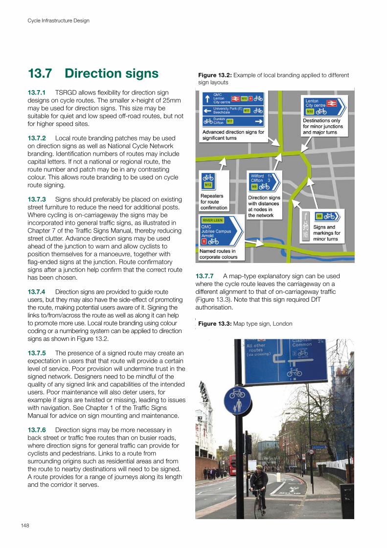
13.7 Direction signs13.7.1 TSRGD allows flexibility for direction sign designs on cycle routes. The smaller x-height of 25mm may be used for direction signs. This size may be suitable for quiet and low speed off-road routes, but not for higher speed sites.
13.7.2 Local route branding patches may be used on direction signs as well as National Cycle Network branding. Identification numbers of routes may include capital letters. If not a national or regional route, the route number and patch may be in any contrasting colour. This allows route branding to be used on cycle route signing.
13.7.3 Signs should preferably be placed on existing street furniture to reduce the need for additional posts. Where cycling is on-carriageway the signs may be incorporated into general traffic signs, as illustrated in Chapter 7 of the Traffic Signs Manual, thereby reducing street clutter. Advance direction signs may be used ahead of the junction to warn and allow cyclists to position themselves for a manoeuvre, together with flag-ended signs at the junction. Route confirmatory signs after a junction help confirm that the correct route has been chosen.
13.7.4 Direction signs are provided to guide route users, but they may also have the side-effect of promoting the route, making potential users aware of it. Signing the links to/from/across the route as well as along it can help to promote more use. Local route branding using colour coding or a numbering system can be applied to direction signs as shown in Figure 13.2.
13.7.5 The presence of a signed route may create an expectation in users that that route will provide a certain level of service. Poor provision will undermine trust in the signed network. Designers need to be mindful of the quality of any signed link and capabilities of the intended users. Poor maintenance will also deter users, for example if signs are twisted or missing, leading to issues with navigation. See Chapter 1 of the Traffic Signs Manual for advice on sign mounting and maintenance.
13.7.6 Direction signs may be more necessary in back street or traffic free routes than on busier roads, where direction signs for general traffic can provide for cyclists and pedestrians. Links to a route from surrounding origins such as residential areas and from the route to nearby destinations will need to be signed. A route provides for a range of journeys along its length and the corridor it serves.
Figure 13.2: Example of local branding applied to different sign layouts
13.7.7 A map-type explanatory sign can be used where the cycle route leaves the carriageway on a different alignment to that of on-carriageway traffic (Figure 13.3). Note that this sign required DfT authorisation.
Figure 13.3: Map type sign, London
148
Cycle Infrastructure Design
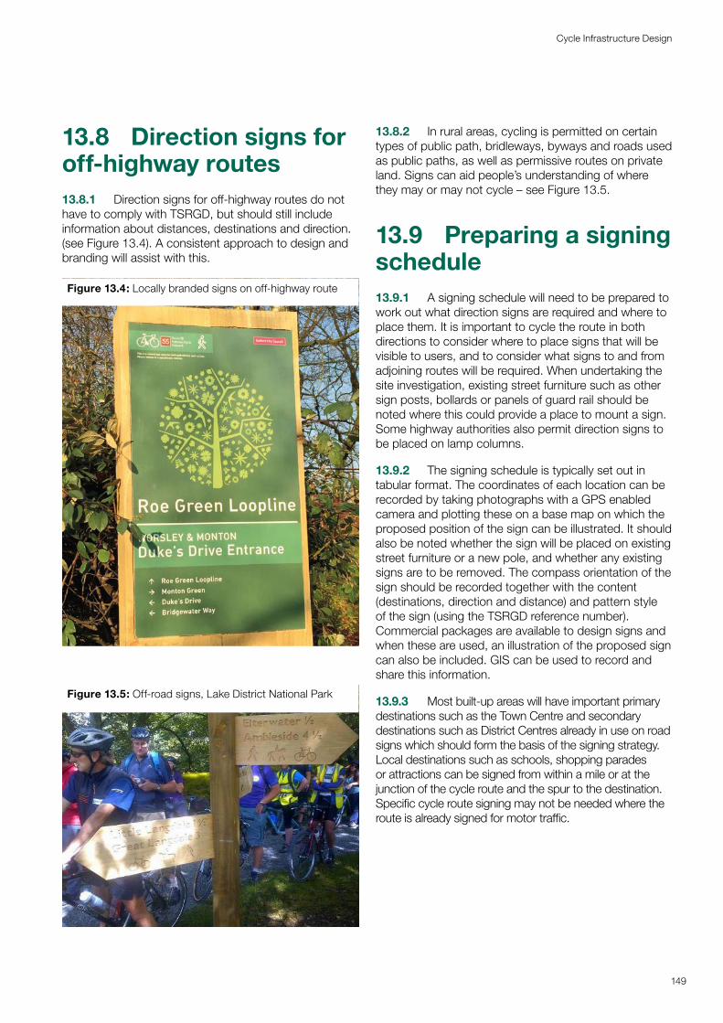
13.8 Direction signs for off-highway routes13.8.1 Direction signs for off-highway routes do not have to comply with TSRGD, but should still include information about distances, destinations and direction. (see Figure 13.4). A consistent approach to design and branding will assist with this.
Figure 13.4: Locally branded signs on off-highway route
Figure 13.5: Off-road signs, Lake District National Park
13.8.2 In rural areas, cycling is permitted on certain types of public path, bridleways, byways and roads used as public paths, as well as permissive routes on private land. Signs can aid people’s understanding of where they may or may not cycle – see Figure 13.5.
13.9 Preparing a signing schedule13.9.1 A signing schedule will need to be prepared to work out what direction signs are required and where to place them. It is important to cycle the route in both directions to consider where to place signs that will be visible to users, and to consider what signs to and from adjoining routes will be required. When undertaking the site investigation, existing street furniture such as other sign posts, bollards or panels of guard rail should be noted where this could provide a place to mount a sign. Some highway authorities also permit direction signs to be placed on lamp columns.
13.9.2 The signing schedule is typically set out in tabular format. The coordinates of each location can be recorded by taking photographs with a GPS enabled camera and plotting these on a base map on which the proposed position of the sign can be illustrated. It should also be noted whether the sign will be placed on existing street furniture or a new pole, and whether any existing signs are to be removed. The compass orientation of the sign should be recorded together with the content (destinations, direction and distance) and pattern style of the sign (using the TSRGD reference number). Commercial packages are available to design signs and when these are used, an illustration of the proposed sign can also be included. GIS can be used to record and share this information.
13.9.3 Most built-up areas will have important primary destinations such as the Town Centre and secondary destinations such as District Centres already in use on road signs which should form the basis of the signing strategy. Local destinations such as schools, shopping parades or attractions can be signed from within a mile or at the junction of the cycle route and the spur to the destination. Specific cycle route signing may not be needed where the route is already signed for motor traffic.
149
Cycle Infrastructure Design
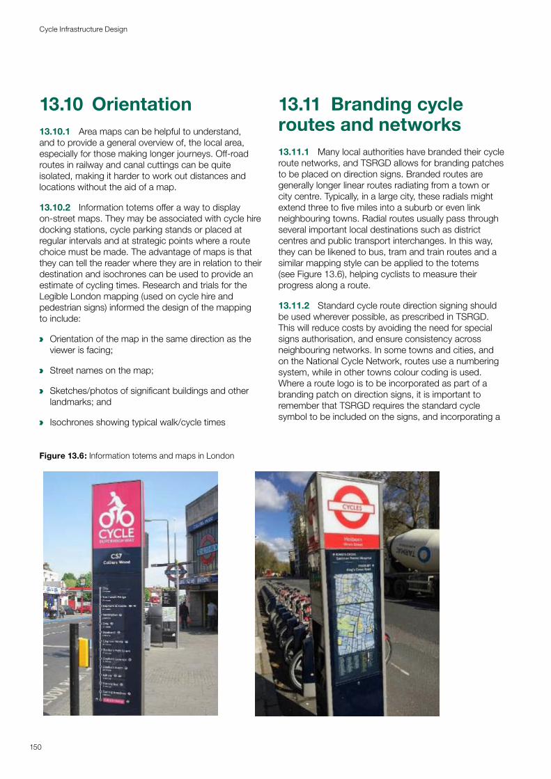
13.10 Orientation13.10.1 Area maps can be helpful to understand, and to provide a general overview of, the local area, especially for those making longer journeys. Off-road routes in railway and canal cuttings can be quite isolated, making it harder to work out distances and locations without the aid of a map.
13.10.2 Information totems offer a way to display on-street maps. They may be associated with cycle hire docking stations, cycle parking stands or placed at regular intervals and at strategic points where a route choice must be made. The advantage of maps is that they can tell the reader where they are in relation to their destination and isochrones can be used to provide an estimate of cycling times. Research and trials for the Legible London mapping (used on cycle hire and pedestrian signs) informed the design of the mapping to include:
a Orientation of the map in the same direction as the viewer is facing;
a Street names on the map;
a Sketches/photos of significant buildings and other landmarks; and
a Isochrones showing typical walk/cycle times
13.11 Branding cycle routes and networks13.11.1 Many local authorities have branded their cycle route networks, and TSRGD allows for branding patches to be placed on direction signs. Branded routes are generally longer linear routes radiating from a town or city centre. Typically, in a large city, these radials might extend three to five miles into a suburb or even link neighbouring towns. Radial routes usually pass through several important local destinations such as district centres and public transport interchanges. In this way, they can be likened to bus, tram and train routes and a similar mapping style can be applied to the totems (see Figure 13.6), helping cyclists to measure their progress along a route.
13.11.2 Standard cycle route direction signing should be used wherever possible, as prescribed in TSRGD. This will reduce costs by avoiding the need for special signs authorisation, and ensure consistency across neighbouring networks. In some towns and cities, and on the National Cycle Network, routes use a numbering system, while in other towns colour coding is used. Where a route logo is to be incorporated as part of a branding patch on direction signs, it is important to remember that TSRGD requires the standard cycle symbol to be included on the signs, and incorporating a
Figure 13.6: Information totems and maps in London
150
Cycle Infrastructure Design
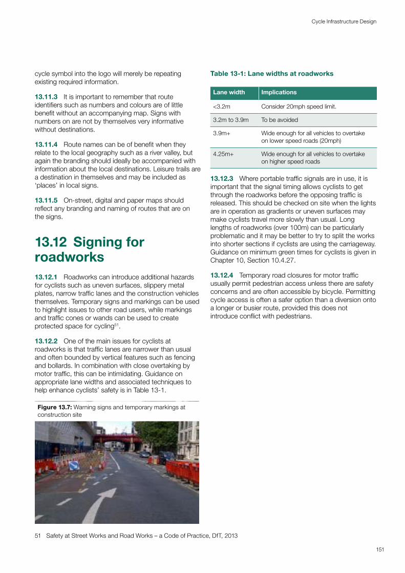
cycle symbol into the logo will merely be repeating existing required information.
13.11.3 It is important to remember that route identifiers such as numbers and colours are of little benefit without an accompanying map. Signs with numbers on are not by themselves very informative without destinations.
13.11.4 Route names can be of benefit when they relate to the local geography such as a river valley, but again the branding should ideally be accompanied with information about the local destinations. Leisure trails are a destination in themselves and may be included as ‘places’ in local signs.
13.11.5 On-street, digital and paper maps should reflect any branding and naming of routes that are on the signs.
13.12 Signing for roadworks13.12.1 Roadworks can introduce additional hazards for cyclists such as uneven surfaces, slippery metal plates, narrow traffic lanes and the construction vehicles themselves. Temporary signs and markings can be used to highlight issues to other road users, while markings and traffic cones or wands can be used to create protected space for cycling51.
13.12.2 One of the main issues for cyclists at roadworks is that traffic lanes are narrower than usual and often bounded by vertical features such as fencing and bollards. In combination with close overtaking by motor traffic, this can be intimidating. Guidance on appropriate lane widths and associated techniques to help enhance cyclists’ safety is in Table 13-1.
Figure 13.7: Warning signs and temporary markings at construction site
51 Safety at Street Works and Road Works – a Code of Practice, DfT, 2013
Table 13-1: Lane widths at roadworks
Lane width Implications
<3.2m Consider 20mph speed limit.
3.2m to 3.9m To be avoided
3.9m+ Wide enough for all vehicles to overtake on lower speed roads (20mph)
4.25m+ Wide enough for all vehicles to overtake on higher speed roads
13.12.3 Where portable traffic signals are in use, it is important that the signal timing allows cyclists to get through the roadworks before the opposing traffic is released. This should be checked on site when the lights are in operation as gradients or uneven surfaces may make cyclists travel more slowly than usual. Long lengths of roadworks (over 100m) can be particularly problematic and it may be better to try to split the works into shorter sections if cyclists are using the carriageway. Guidance on minimum green times for cyclists is given in Chapter 10, Section 10.4.27.
13.12.4 Temporary road closures for motor traffic usually permit pedestrian access unless there are safety concerns and are often accessible by bicycle. Permitting cycle access is often a safer option than a diversion onto a longer or busier route, provided this does not introduce conflict with pedestrians.
151
Cycle Infrastructure Design
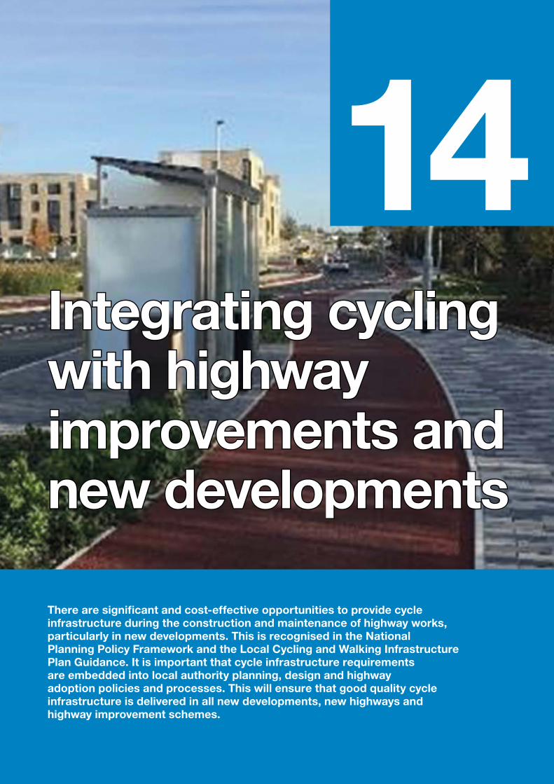
14Integrating cycling Integrating cycling with highway with highway improvements and improvements and new developmentsnew developments
There are significant and cost-effective opportunities to provide cycle infrastructure during the construction and maintenance of highway works, particularly in new developments. This is recognised in the National Planning Policy Framework and the Local Cycling and Walking Infrastructure Plan Guidance. It is important that cycle infrastructure requirements are embedded into local authority planning, design and highway adoption policies and processes. This will ensure that good quality cycle infrastructure is delivered in all new developments, new highways and highway improvement schemes.
14.1 Introduction14.1.1 This chapter covers the delivery of new and improved cycle infrastructure as an integral part of general highway improvement and maintenance work and in new developments.
14.1.2 Appropriate cycle facilities should be provided within all new and improved highways in accordance with the guidance contained in this document, regardless of whether the scheme is on a designated cycle route, unless there are clearly-defined and suitable alternatives.
14.1.3 With appropriate policies and processes in place, most schemes for cycle traffic will be delivered alongside other highway works and as part of new developments. There are opportunities to specify and enforce the requirement for a good standard of cycle provision to developers and contractors through planning briefs, supplementary planning guidance and contract procurement documentation, as appropriate.
14.1.4 The requirements should include the provision of new cycle routes connecting to and through developments and enhancing the provision for cycling when making alterations to links and junctions on existing highways. It will not usually be acceptable to maintain an existing poor level of service when undertaking highway improvement schemes. More modest but still effective improvements can be achieved as part of highway maintenance – for example when road markings are being renewed.
14.2 Policy background14.2.1 The National Planning Policy Framework (NPPF)51 sets out the national policy context for land use planning and states that planning policies should:
a ‘provide for high quality walking and cycling networks and supporting facilities such as cycle parking (drawing on Local Cycling and Walking Infrastructure Plans)’ (Para 104d).
14.2.2 The NPPF also states that applications for development should:
a ‘give priority first to pedestrian and cycle movements, both within the scheme and with neighbouring areas’ (Para 110a).
14.2.3 The NPPF in Para 91 sets the overall requirement that planning policies should ‘aim to achieve healthy, inclusive and safe places’ and that this can be achieved by promoting social interaction and healthy lifestyles through layouts and easy connections that encourage walking and cycling.
14.2.4 Local Cycling and Walking Infrastructure Plans (LCWIPs) are described in more detail in Chapter 3, and supported by the NPPF. They offer a well-founded process for local authorities to identify how cycling and walking networks should be provided and improved across a wide area.
14.2.5 The LCWIP guidance states that they should be incorporated into local authority policies so that appropriate consideration is given to cycling and walking in all local planning and transport decisions.
14.2.6 LCWIPs should expressly consider planned new developments, both in terms of the additional demands they will create for cycling and walking and more significantly how new and improved highway infrastructure created and funded by development can contribute to these networks. This can be achieved through the Community Infrastructure Levy, Section 106 contributions and Section 278 highway agreements.
14.2.7 Where local authorities have developed a future cycling network through an LCWIP it will enable them to seek meaningful and worthwhile contributions from new developments rather than ad-hoc and isolated measures which do not enable active travel journeys beyond the site.
14.2.8 The LCWIP guidance also notes that opportunities should be taken to embed the requirements of cyclists and pedestrians in other transport schemes, such as junction improvements or maintenance works. When maintaining, improving or creating new highways, authorities should therefore treat walking and cycling with the same importance and consideration as motorised transport.
14.2.9 It should also be noted that the Network Management Duty placed on traffic authorities by the Traffic Management Act 2004 to manage their road networks with a view to securing ‘expeditious movement for all traffic’ includes pedestrian and cycle traffic.
154
Cycle Infrastructure Design
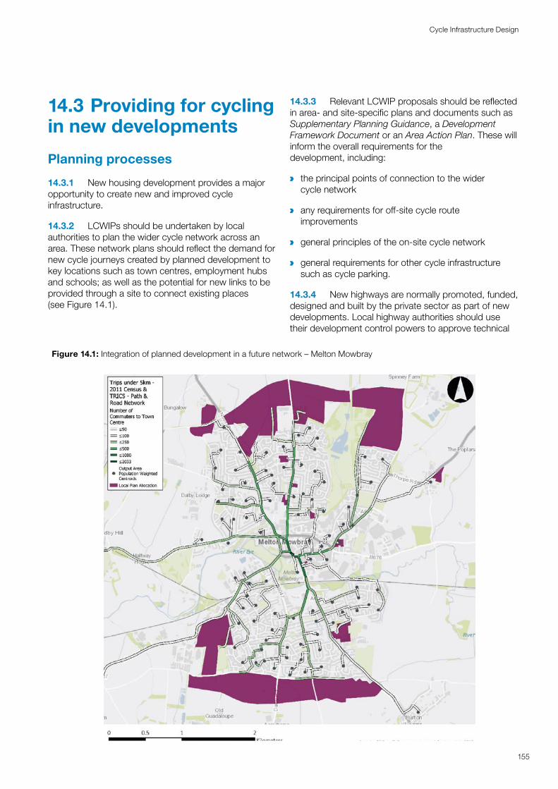
14.3 Providing for cycling in new developments
Planning processes
14.3.1 New housing development provides a major opportunity to create new and improved cycle infrastructure.
14.3.2 LCWIPs should be undertaken by local authorities to plan the wider cycle network across an area. These network plans should reflect the demand for new cycle journeys created by planned development to key locations such as town centres, employment hubs and schools; as well as the potential for new links to be provided through a site to connect existing places (see Figure 14.1).
14.3.3 Relevant LCWIP proposals should be reflected in area- and site-specific plans and documents such as Supplementary Planning Guidance, a Development Framework Document or an Area Action Plan. These will inform the overall requirements for the development, including:
a
a
a
the principal points of connection to the wider cycle network
any requirements for off-site cycle route improvements
general principles of the on-site cycle network
a general requirements for other cycle infrastructure such as cycle parking.
14.3.4 New highways are normally promoted, funded, designed and built by the private sector as part of new developments. Local highway authorities should use their development control powers to approve technical
Figure 14.1: Integration of planned development in a future network – Melton Mowbray
155
Cycle Infrastructure Design
designs to enable people to use cycles for everyday journeys. New highways (including cycle tracks) created within a development will normally be offered for adoption to the highway authority under Section 38 of the Highways Act 1980 (see Appendix C).
14.3.5 The planning and design of the site accesses, the internal network and any off-site highway improvements will usually be informed by the Transport Assessment (TA) for the new development. This is used to forecast the all-mode travel demands of the site and assess their impact on the surrounding network. It should be noted that smaller developments which fall below the normal thresholds to provide Transport Assessments should still be required to provide and/or contribute towards new and improved cycle infrastructure.
14.3.6 It is important that the TA does not overestimate motor traffic travel demands, which could make it difficult to provide well-designed cycle infrastructure, particularly at the site access points. Travel demand forecasts should take into account the potential for the increased levels of cycling that will be enabled by high-quality cycle facilities, both on- and off-site.
14.3.7 New developments that have important destinations within them, such as schools and retail centres, should be provided with cycle and pedestrian links to adjacent residential areas and local cycle routes so that residents can cycle to the new facilities. Similarly, large new residential developments should offer external links to adjacent employment, education, administrative, transport interchange and retail destinations.
14.3.8 Planning conditions can require that specific cycle parking and cycle routes are provided, and specify the standard that should be met within the new site for planning permission to be formally granted. Reference may be made to a design code which is usually prepared by the development team and agreed with the local highway authority. The local authority must provide a reason for the conditions – such as fulfilling the policies set out within a local cycling strategy, meeting the cycle parking standards in local planning guidance, or contributing to the schemes in the LCWIP.
14.3.9 Planning obligations or agreements (Section 106 agreements) can also be used. Planning obligations apply to the land rather than the developer, including future users, and are often used to secure funding to mitigate the negative impacts of the development. This might for example be by providing improved crossings or cycle routes in the locality, or providing infrastructure elsewhere to compensate for a loss of green space.
14.3.10 Since 2010, planning authorities have also been able to use the Community Infrastructure Levy (CIL) to ‘pool’ charges made on various new developments. This is as an alternative to Section 106. The advantages of CIL are that it can be charged on any residential development and all developments over 100m sq. (with some exemptions) and that the money levied can be spent to improve infrastructure across the whole local area, not just that related to the development site. The amount of the levy is set by the local authority each year and is directly related to the size of development. This gives planners and developers more certainty about the amounts involved for a given development.
Planning the network
14.3.11 Manual for Streets provides guidance on the planning of transport networks for new developments and generally recommends that they are well connected to their surroundings with a choice of routes. In some cases, however, it may be appropriate to provide fewer accesses and routes for private cars to give priority to sustainable modes of transport (filtered permeability) – see Chapter 7.
14.3.12 Cycling facilities should be regarded as an essential component of the site access and any off-site highway improvements that may be necessary. Developments that do not adequately make provision for cycling in their transport proposals should not be approved. This may include some off-site improvements along existing highways that serve the development.
14.3.13 Within larger sites it will be necessary to plan a network of cycle routes that connect all parts of the development. This network should follow the principles set out in Chapter 3. The opportunity of designing a wholly new highway network means there should be a presumption of providing a densely-spaced network with around 250m between designated cycle routes.
14.3.14 Cycle networks within new developments should generally be made up of the elements listed in Chapter 3, Section 3.4, i.e.:
a Dedicated space for cycling within highways (Chapter 6)
a Quiet mixed traffic streets (Chapter 7)
a Motor traffic free routes (Chapter 8)
a Junction treatments and crossings (Chapter 10)
a Cycle parking at origins, destinations and interchanges with other modes (Chapter 11).
156
Cycle Infrastructure Design
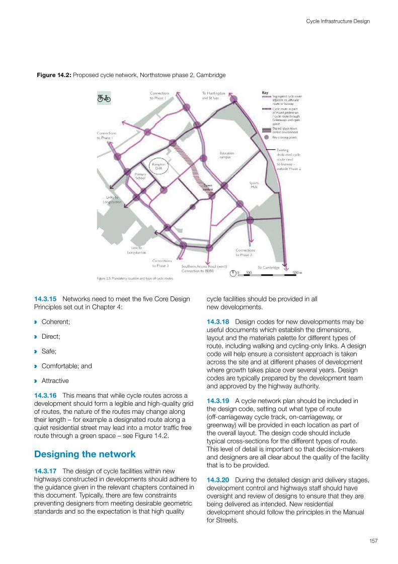
14.3.15 Networks need to meet the five Core Design Principles set out in Chapter 4:
a Coherent;
a Direct;
a Safe;
a Comfortable; and
a Attractive
14.3.16 This means that while cycle routes across a development should form a legible and high-quality grid of routes, the nature of the routes may change along their length – for example a designated route along a quiet residential street may lead into a motor traffic free route through a green space – see Figure 14.2.
Designing the network
14.3.17 The design of cycle facilities within new highways constructed in developments should adhere to the guidance given in the relevant chapters contained in this document. Typically, there are few constraints preventing designers from meeting desirable geometric standards and so the expectation is that high quality
cycle facilities should be provided in all new developments.
14.3.18 Design codes for new developments may be useful documents which establish the dimensions, layout and the materials palette for different types of route, including walking and cycling-only links. A design code will help ensure a consistent approach is taken across the site and at different phases of development where growth takes place over several years. Design codes are typically prepared by the development team and approved by the highway authority.
14.3.19 A cycle network plan should be included in the design code, setting out what type of route (off-carriageway cycle track, on-carriageway, or greenway) will be provided in each location as part of the overall layout. The design code should include typical cross-sections for the different types of route. This level of detail is important so that decision-makers and designers are all clear about the quality of the facility that is to be provided.
14.3.20 During the detailed design and delivery stages, development control and highways staff should have oversight and review of designs to ensure that they are being delivered as intended. New residential development should follow the principles in the Manual for Streets.
Figure 14.2: Proposed cycle network, Northstowe phase 2, Cambridge
157
Cycle Infrastructure Design
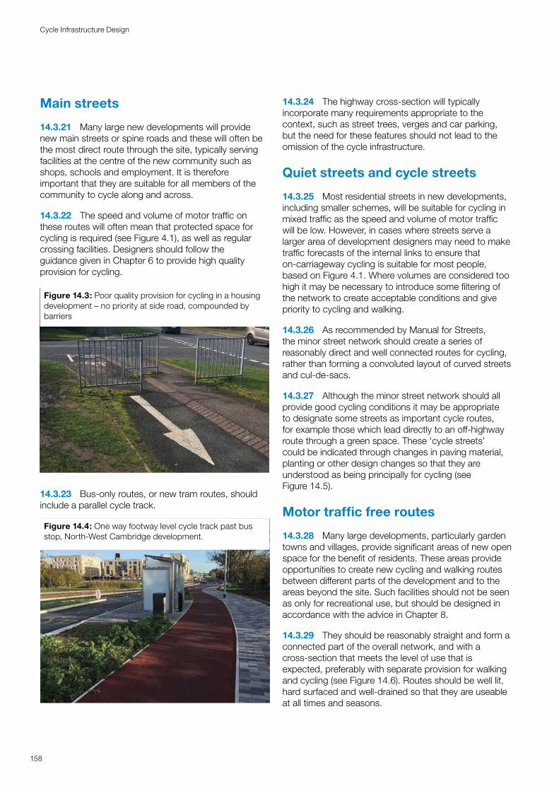
Main streets
14.3.21 Many large new developments will provide new main streets or spine roads and these will often be the most direct route through the site, typically serving facilities at the centre of the new community such as shops, schools and employment. It is therefore important that they are suitable for all members of the community to cycle along and across.
14.3.22 The speed and volume of motor traffic on these routes will often mean that protected space for cycling is required (see Figure 4.1), as well as regular crossing facilities. Designers should follow the guidance given in Chapter 6 to provide high quality provision for cycling.
Figure 14.3: Poor quality provision for cycling in a housing development – no priority at side road, compounded by barriers
14.3.23 Bus-only routes, or new tram routes, should include a parallel cycle track.
Figure 14.4: One way footway level cycle track past bus stop, North-West Cambridge development.
14.3.24 The highway cross-section will typically incorporate many requirements appropriate to the context, such as street trees, verges and car parking, but the need for these features should not lead to the omission of the cycle infrastructure.
Quiet streets and cycle streets
14.3.25 Most residential streets in new developments, including smaller schemes, will be suitable for cycling in mixed traffic as the speed and volume of motor traffic will be low. However, in cases where streets serve a larger area of development designers may need to make traffic forecasts of the internal links to ensure that on-carriageway cycling is suitable for most people, based on Figure 4.1. Where volumes are considered too high it may be necessary to introduce some filtering of the network to create acceptable conditions and give priority to cycling and walking.
14.3.26 As recommended by Manual for Streets, the minor street network should create a series of reasonably direct and well connected routes for cycling, rather than forming a convoluted layout of curved streets and cul-de-sacs.
14.3.27 Although the minor street network should all provide good cycling conditions it may be appropriate to designate some streets as important cycle routes, for example those which lead directly to an off-highway route through a green space. These ‘cycle streets’ could be indicated through changes in paving material, planting or other design changes so that they are understood as being principally for cycling (see Figure 14.5).
Motor traffic free routes
14.3.28 Many large developments, particularly garden towns and villages, provide significant areas of new open space for the benefit of residents. These areas provide opportunities to create new cycling and walking routes between different parts of the development and to the areas beyond the site. Such facilities should not be seen as only for recreational use, but should be designed in accordance with the advice in Chapter 8.
14.3.29 They should be reasonably straight and form a connected part of the overall network, and with a cross-section that meets the level of use that is expected, preferably with separate provision for walking and cycling (see Figure 14.6). Routes should be well lit, hard surfaced and well-drained so that they are useable at all times and seasons.
158
Cycle Infrastructure Design
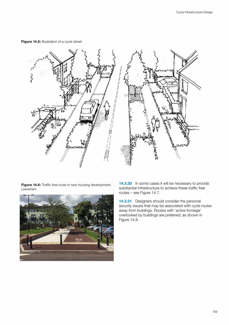
Figure 14.5: Illustration of a cycle street
159
Cycle Infrastructure Design
Figure 14.6: Traffic free route in new housing development, Lewisham
14.3.30 In some cases it will be necessary to provide substantial infrastructure to achieve these traffic free routes – see Figure 14.7.
14.3.31 Designers should consider the personal security issues that may be associated with cycle routes away from buildings. Routes with ‘active frontage’ overlooked by buildings are preferred, as shown in Figure 14.8.
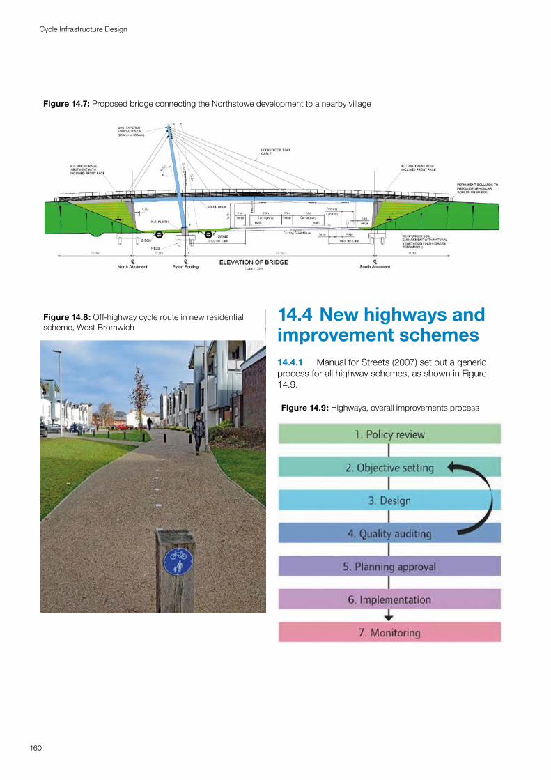
Figure 14.7: Proposed bridge connecting the Northstowe development to a nearby village
160
Cycle Infrastructure Design
Figure 14.8: Off-highway cycle route in new residential scheme, West Bromwich
14.4 New highways and improvement schemes14.4.1 Manual for Streets (2007) set out a generic process for all highway schemes, as shown in Figure 14.9.
Figure 14.9: Highways, overall improvements process
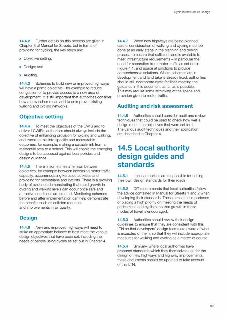
14.4.2 Further details on this process are given in Chapter 3 of Manual for Streets, but in terms of providing for cycling, the key steps are:
a Objective setting;
a Design; and
a Auditing.
14.4.3 Schemes to build new or improved highways will have a prime objective – for example to reduce congestion or to provide access to a new area of development. It is still important that authorities consider how a new scheme can add to or improve existing walking and cycling networks.
Objective setting
14.4.4 To meet the objectives of the CWIS and to deliver LCWIPs, authorities should always include the objective of enhancing provision for cycling and walking, and translate this into specific and measurable outcomes; for example, making a suitable link from a residential area to a school. This will enable the emerging designs to be assessed against local policies and design guidance.
14.4.5 There is sometimes a tension between objectives, for example between increasing motor traffic capacity, accommodating kerbside activities and providing for pedestrians and cyclists. There is a growing body of evidence demonstrating that rapid growth in cycling and walking levels can occur once safe and attractive conditions are created. Monitoring schemes before and after implementation can help demonstrate the benefits such as collision reduction and improvements in air quality.
Design
14.4.6 New and improved highways will need to strike an appropriate balance to best meet the various design objectives that have been set, including the needs of people using cycles as set out in Chapter 4.
14.4.7 When new highways are being planned, careful consideration of walking and cycling must be done at an early stage in the planning and design process to ensure that sufficient land is available to meet infrastructure requirements – in particular the need for separation from motor traffic as set out in Figure 4.1, and space at junctions to provide comprehensive solutions. Where schemes are in development and land take is already fixed, authorities should still incorporate cycle facilities meeting the guidance in this document as far as is possible. This may require some rethinking of the space and provision given to motor traffic.
Auditing and risk assessment
14.4.8 Authorities should consider audit and review techniques that could be used to check how well a design meets the objectives that were set for it. The various audit techniques and their application are described in Chapter 4.
14.5 Local authority design guides and standards14.5.1 Local authorities are responsible for setting their own design standards for their roads.
14.5.2 DfT recommends that local authorities follow the advice contained in Manual for Streets 1 and 2 when developing their standards. These stress the importance of placing a high priority on meeting the needs of pedestrians and cyclists, so that growth in these modes of travel is encouraged.
14.5.3 Authorities should review their design guidelines to ensure that they are consistent with this LTN so that developers’ design teams are aware of what is expected of them, so that they will include appropriate measures for walking and cycling as a matter of course.
14.5.4 Similarly, where local authorities have prepared standards which they themselves use for the design of new highways and highway improvements, these documents should be updated to take account of this LTN.
161
Cycle Infrastructure Design
15Construction Construction and and maintenancemaintenance
Routine and seasonal maintenance plays a major role in cycle safety. Cyclists are particularly vulnerable to defects and debris on the surface which can destabilise the rider. Maintenance costs can be minimised through careful design and selection of construction materials. Regular inspections enable maintenance work to be cost effectively programmed and prioritised. Cycle track construction can be more lightweight than the carriageway but needs to be of robust materials that offer a long-lasting safe and comfortable riding surface. Winter maintenance of cycle tracks differs from the carriageway due to the lightweight construction of the track and the mechanics of the de-icing process.
15.1 Introduction15.1.1 This chapter considers maintenance of cycle facilities from the perspective of design and construction. While it includes some commentary on routine maintenance, more detailed sources of advice on this aspect are in the further reading and references.
15.1.2 Careful design and selection of construction methods and materials will reduce the long-term costs of maintenance. Cycle-only routes and shared facilities do not require the same construction strength as carriageways, but do need to be able to withstand maintenance vehicles where these are used. There is no natural ‘sweeping effect’ from passing cyclists as there is on the carriageway, and limited crushing action from bicycle tyres. Cyclists are more directly affected by hazardous surfaces so routine and winter maintenance of cycle tracks requires a different approach to that used on-carriageways.
15.2 Construction materials15.2.1 Surface quality affects the comfort and effort required when cycling. Loose surfaces such as gravel or mud can also present a skidding hazard, increase the risk of punctures and make cycles and clothing dirty in bad weather. Cyclists are also affected by ruts and potholes that can throw them off balance. Smooth, sealed solid surfaces offer the best conditions for everyday cycling.
15.2.2 Good quality machine laid surfaces will appeal to a wide range of users from people on lightweight racing cycles through to child cyclists. Smooth surfaces also offer greater accessibility and safety for other potential users such as wheelchair users, mobility scooters and blind and partially sighted people.
15.2.3 Sealed surfaces should normally be provided within towns, cities and villages and on commuter routes from the immediate hinterland. This might include rural cycle routes between villages, for example where pupils might be expected to travel to school.
15.2.4 Cobbles and setts are uncomfortable for cycling, although in heritage areas a 2.0m wide virtual cycle lane can be created using setts or cobbles that have been sliced or planed to create a smoother surface. Most local highway authorities specify that cycle routes within the highway must adhere to local minimum
52 Sustrans Design Manual, Chapter 6. Detail design of traffic free routes, Sustrans, 2014 (draft)
standards of construction. There is much greater variation in quality on routes away from the highway.
15.2.5 Outside built-up areas, treatments such as crushed stone may be applied to off-highway routes for aesthetic, heritage or nature conservation. These treatments are a cost-effective way to create lengthy off-road links but will be less accessible.
15.2.6 Cycle tracks require proper construction of each element:52
a Formation and sub-base;
a Surfaces (including transitions, see Chapter 9);
a Edges and verges;
a Ecology;
a Drainage; and
a Ancillary works such as lighting, fencing, access controls and landscape features.
Formation
15.2.7 The sub-grade must provide stable conditions on which the track can be formed (usually present already within highways). Away from the existing highway this can be simply done by compacting the natural ground, but where the ground is contaminated or unstable, a capping material may be required. Geotextiles (felt, polypropylenes or plastic grid systems) can be used to add stability.
15.2.8 Cyclists and pedestrians do not create a high loading requirement, but where vehicles and machinery are to be used for construction and maintenance, the formation must be able to support these. All vegetation must be removed with the top soil. Decomposing matter can lead to voids and subsidence. ‘No-dig’ construction may be required in places of ecological or archaeological significance.
Sub-base
15.2.9 The sub-base provides the main load-bearing layer, helping to distribute loads evenly across the path. Existing stable surfaces such as disused railway lines or roads will generally not require thick sub-base, while less stable environments such as clay will require a thicker base.
164
Cycle Infrastructure Design
15.2.10 Typical cycle tracks will have a 150mm sub-base layer which can also cope with occasional use by maintenance vehicles. Type 1 aggregate (stone and dust mix) is normally used and can be supplemented with plastic grid for additional strength.
15.2.11 The type of stone used should reflect local acidity conditions to avoid changes to pH of adjacent soils when water percolates through the sub-base. Maximum stone size must be no greater than half of the thickness of the sub-base layer. To ensure a smooth surface the sub-base should be compacted and levelled with a roller to a tolerance of 10mm.
Surfacing
15.2.12 Sealed surfaces are more expensive to install; however, this additional cost is more than offset by reduced maintenance requirements over the whole life of a scheme. While there may be initial concerns about disturbance to the natural environment or the appearance, these can be addressed through choice of materials and the overall reduced impact on wildlife due to reduced maintenance following construction. These issues may need careful explanation during discussions with local stakeholders.
15.2.13 The base (binder) course is recommended to be a 60mm layer of asphalt concrete with a coarse stone size overlain by a 20mm smooth asphalt riding surface. An 80mm single-layer (AC14) construction with 14mm stones is also commonly used. A paving machine should be used to create a smooth riding surface.
15.2.14 Spray and chip surfacing offers a sealed surface with a more natural appearance than black bituminous surfacing, and provides more grip in icy and wet conditions. A 6mm rounded profile stone should be used, to avoid creating a puncture hazard. The loose gravel surface takes several weeks to bed in on cycle routes and may need some sweeping. The surfacing can only be applied in dry and warmer conditions (usually May to October). An increasing range of products based on recycled rubber or plastic is also available to provide a similar effect to tar spray and chip.
15.2.15 Concrete can be used as a base and wearing course that provides additional strength. This may be required to accommodate farm vehicles or HGV access for example. The joints should be smooth. A brushed surface provides skid resistance without the uncomfortable corrugation of a tamped surface.
15.2.16 Block paving can offer a reasonable surface and different coloured blocks can help delineate the cycle path although it will require greater effort to cycle on than bituminous surfacing. Paving slabs are less
suitable due to lower skid resistance and the likelihood of rocking and cracking. Tactile paving blocks (as opposed to tactile paving slabs) can be used to avoid cracking and lifting where vehicles need to overrun for maintenance.
15.2.17 Non-standard surfacing material (such as tiles) are sometimes introduced in public realm schemes. Designers should ensure that the skid resistance value is adequate for cycling in both dry and wet conditions.
15.2.18 Unbound surfaces are generally unsuitable for utility cycling and in practice have proven to require regular maintenance and repair, being prone to erosion on gradients and easily damaged by horses. Further advice on construction is available from Sustrans and other organisations.
Edges and verges
15.2.19 Concrete kerbs or timber/concrete edgings often form a part of highway construction standards. Edgings are less frequently required on tracks away from the highway due to the simpler characteristics of the path. Edging may be required in more formal settings such as parks and public realm schemes, or to reinforce construction such as preventing the movement of block paving, or wash out of the base in areas prone to flooding.
15.2.20 The verges adjacent to off-road paths act as natural drainage, absorbing the run-off from the sealed surface. French (stone) drains may provide additional absorption if required. Vertical features such as hedges and walls reduce the useable width, so ideally a mown grass verge or low, slow growing plants should be provided for 1.0m immediately next to the path.
Hedgerows and fences
15.2.21 Hedgerows should be set back at least 1.0m from the path and maintained in such a way that they do not overhang, encroach across, or drop thorns on the path (new plants adjacent to cycle tracks should be non-thorn varieties). A fence height of 1.5m will be sufficient for stock control and enable most adult cyclists to see over the top. Barbed wire fencing should be attached on the stock side of any posts. Network Rail requires at least 4.0m clearance between the operational railway line and fences. Weldmesh fencing offers lower security than palisade fencing but is less visually intrusive.
15.2.22 Fencing may also be required to protect path users from steep drops, water or high-speed traffic immediately alongside the cycle path.
165
Cycle Infrastructure Design
Drainage
15.2.23 Paths should be constructed with crossfall or camber, as set out in Chapter 5, with drainage falling to the inside on bends. If drainage gulleys are used, grates should use patterns that will not catch bicycle wheels. The path itself should not be lower than the adjacent natural ground because water will then have no escape route.
15.2.24 Paths in wetland, adjacent to rivers or in cuttings prone to flooding, can be built on a causeway to make the path more resilient. However, an understanding of the potential impact on drainage and ecology is required. In some cases, a boardwalk may offer the better ecological solution.
15.2.25 Simple ditches or swales alongside the path will help avoid surface water run-off from flooding into adjacent areas. UPVC filter drains set in a stone bed can help water to percolate more slowly however, will require maintenance as they can become blocked by roots from vegetation. Regular inspection pits can help to isolate the location of blockages to ease maintenance. Pipe gradients should be between 1:15 and 1:50. Soakaways can be used to divert collected water back into the natural water table.
15.2.26 Culverts can offer a more cost effective and less visually intrusive option to bridges where a cycle track crosses a small stream or drainage feature.
15.3 Lighting15.3.1 Within urban areas standard street lighting is usually designed to cover footways and cycle tracks as well as the carriageway. People using tracks alongside unlit carriageways may be blinded or dazzled by the lights of oncoming vehicles, particularly on tracks alongside high speed rural roads. Drivers may also be confused when seeing cycle lights approaching on their nearside. These hazards can be reduced by, for example, locating the track further away from the carriageway edge, or by providing with flow cycle tracks alongside both sides of the carriageway.
15.3.2 Cycle routes across large quiet parks or along canal towpaths may not be well used outside peak commuting times after dark, even if lighting is provided. In these cases, a suitable street lit on road alternative that matches the desire line as closely as possible should be considered. Subways should be lit at all times, using
53 Asset Management Guidance for Footways and Cycleways: Pavement Design and Maintenance, UKRLG, 201854 Asset Management Guidance for Footways and Cycleways: An Approach to Risk Based Maintenance Management,
UKRLG, 2018
vandal resistant lighting where necessary. It is not expected that routes outside built up ar eas used primarily for recreation would normally need to be lit except where there were road safety concerns, such as at crossings or where the track is directly alongside the carriageway.
15.3.3 Where an off-carriageway track requires lighting, the designer needs to consider the proximity of an electricity supply, energy usage, and light pollution.
15.3.4 The Highways Act 1980, section 65(1) contains powers to light cycle tracks. Technical design guidance may be found in TR23, Lighting of Cycle Tracks (ILE, 1998).
15.4 Importance of maintenance15.4.1 Poorly maintained cycle and pedestrian surfaces are hazardous and unattractive to users. Potholes, debris, fallen leaves, poor drainage or snow and ice can all increase the likelihood of a collision or fall. Routes that form part of the highway are generally included within the local authority highway maintenance regimes for cleansing and repair, but routes in parks and on other public rights of way may have much more variable arrangements.
15.4.2 The most important routes within a local network may be away from the highway and will potentially require more frequent inspection and maintenance than other off-road environments due to their status within the cycle route network. Accumulations of mud, fallen leaves, overgrown vegetation and low overhanging branches can be hazardous. Where surfaces are allowed to significantly deteriorate, cyclists will use nearby carriageways that offer better conditions or will stop cycling altogether.
15.4.3 In May 2018 the UK Roads Liaison Group (UKRLG) updated its guidance on the construction, maintenance and management of footways and cycle routes to reflect current good practice. The guidance supports the ‘Well Managed Highway Infrastructure’ code of practice of the UKRLG. The documents recognise the various ways in which maintenance is considered:
a Selection of design and construction materials;53
a Reviewing risk (including seasonal risks) and risk-based maintenance regimes;54 and
166
Cycle Infrastructure Design
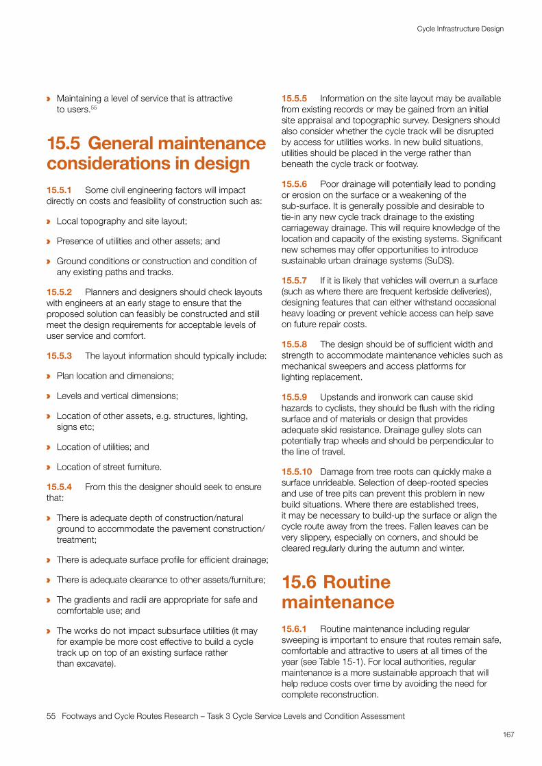
a Maintaining a level of service that is attractive to users.55
15.5 General maintenance considerations in design15.5.1 Some civil engineering factors will impact directly on costs and feasibility of construction such as:
a Local topography and site layout;
a Presence of utilities and other assets; and
a Ground conditions or construction and condition of any existing paths and tracks.
15.5.2 Planners and designers should check layouts with engineers at an early stage to ensure that the proposed solution can feasibly be constructed and still meet the design requirements for acceptable levels of user service and comfort.
15.5.3 The layout information should typically include:
a Plan location and dimensions;
a Levels and vertical dimensions;
a Location of other assets, e.g. structures, lighting, signs etc;
a Location of utilities; and
a Location of street furniture.
15.5.4 From this the designer should seek to ensure that:
a There is adequate depth of construction/natural ground to accommodate the pavement construction/treatment;
a There is adequate surface profile for efficient drainage;
a There is adequate clearance to other assets/furniture;
a The gradients and radii are appropriate for safe and comfortable use; and
a The works do not impact subsurface utilities (it may for example be more cost effective to build a cycle track up on top of an existing surface rather than excavate).
55 Footways and Cycle Routes Research – Task 3 Cycle Service Levels and Condition Assessment
15.5.5 Information on the site layout may be available from existing records or may be gained from an initial site appraisal and topographic survey. Designers should also consider whether the cycle track will be disrupted by access for utilities works. In new build situations, utilities should be placed in the verge rather than beneath the cycle track or footway.
15.5.6 Poor drainage will potentially lead to ponding or erosion on the surface or a weakening of the sub-surface. It is generally possible and desirable to tie-in any new cycle track drainage to the existing carriageway drainage. This will require knowledge of the location and capacity of the existing systems. Significant new schemes may offer opportunities to introduce sustainable urban drainage systems (SuDS).
15.5.7 If it is likely that vehicles will overrun a surface (such as where there are frequent kerbside deliveries), designing features that can either withstand occasional heavy loading or prevent vehicle access can help save on future repair costs.
15.5.8 The design should be of sufficient width and strength to accommodate maintenance vehicles such as mechanical sweepers and access platforms for lighting replacement.
15.5.9 Upstands and ironwork can cause skid hazards to cyclists, they should be flush with the riding surface and of materials or design that provides adequate skid resistance. Drainage gulley slots can potentially trap wheels and should be perpendicular to the line of travel.
15.5.10 Damage from tree roots can quickly make a surface unrideable. Selection of deep-rooted species and use of tree pits can prevent this problem in new build situations. Where there are established trees, it may be necessary to build-up the surface or align the cycle route away from the trees. Fallen leaves can be very slippery, especially on corners, and should be cleared regularly during the autumn and winter.
15.6 Routine maintenance15.6.1 Routine maintenance including regular sweeping is important to ensure that routes remain safe, comfortable and attractive to users at all times of the year (see Table 15-1). For local authorities, regular maintenance is a more sustainable approach that will help reduce costs over time by avoiding the need for complete reconstruction.
167
Cycle Infrastructure Design
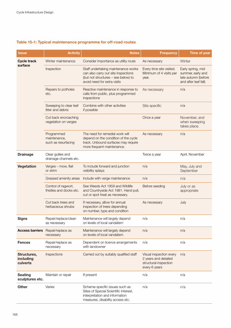
Table 15-1: Typical maintenance programme for off-road routes
Issue Activity Notes Frequency Time of year
Cycle track surface
Winter maintenance Consider importance as utility route As necessary Winter
Inspection Staff undertaking maintenance works can also carry out site inspections (but not structures – see below) to avoid need for extra visits
Every time site visited. Minimum of 4 visits per year.
Early spring, mid summer, early and late autumn (before and after leaf fall)
Repairs to potholes etc.
Reactive maintenance in response to calls from public, plus programmed inspections
As necessary n/a
Sweeping to clear leaf litter and debris
Combine with other activities if possible
Site specific n/a
Cut back encroaching vegetation on verges
Once a year November, and when sweeping takes place.
Programmed maintenance, such as resurfacing
The need for remedial work will depend on the condition of the cycle track. Unbound surfaces may require more frequent maintenance.
As necessary n/a
Drainage Clear gullies and drainage channels etc.
Twice a year April, November
Vegetation Verges – mow, flail or strim
To include forward and junction visibility splays
n/a May, July and September
Grassed amenity areas Include with verge maintenance n/a n/a
Control of ragwort, thistles and docks etc.
See Weeds Act 1959 and Wildlife and Countryside Act 1981. Hand pull, cut or spot treat as necessary.
Before seeding July or as appropriate
Cut back trees and herbaceous shrubs
If necessary, allow for annual inspection of trees depending on number, type and condition
As necessary July
Signs Repair/replace/clean as necessary
Maintenance will largely depend on levels of local vandalism
n/a n/a
Access barriers Repair/replace as necessary
Maintenance will largely depend on levels of local vandalism
n/a n/a
Fences Repair/replace as necessary
Dependent on licence arrangements with landowner
n/a n/a
Structures, including culverts
Inspections Carried out by suitably qualified staff Visual inspection every 2 years and detailed structural inspection every 6 years
n/a
Seating sculptures etc.
Maintain or repair If present n/a n/a
Other Varies Scheme-specific issues such as Sites of Special Scientific Interest, interpretation and information measures, disability access etc.
n/a n/a
168
Cycle Infrastructure Design
15.6.2 The most heavily used parts of the cycle route network should be prioritised for maintenance. This may be determined through monitoring of use or by a definition of strategic, secondary and local access routes within a formal cycle network plan. Local stakeholders may also be a valuable source of information about specific problems. When authorities adopt an area-wide risk-based approach they will also need to consider the age and present condition of the facility when prioritising routine maintenance so that deteriorated surfaces can be repaired.
15.6.3 Seasonal maintenance may include clearing sand and beach debris in coastal areas, clearing leaf fall, clearing flooding debris alongside rivers and keeping routes free of snow and ice.
15.6.4 Further detail on assessing maintenance priorities is included in the UKRLG guidance.
169
Cycle Infrastructure Design

Appendices
171
Cycle Infrastructure Design
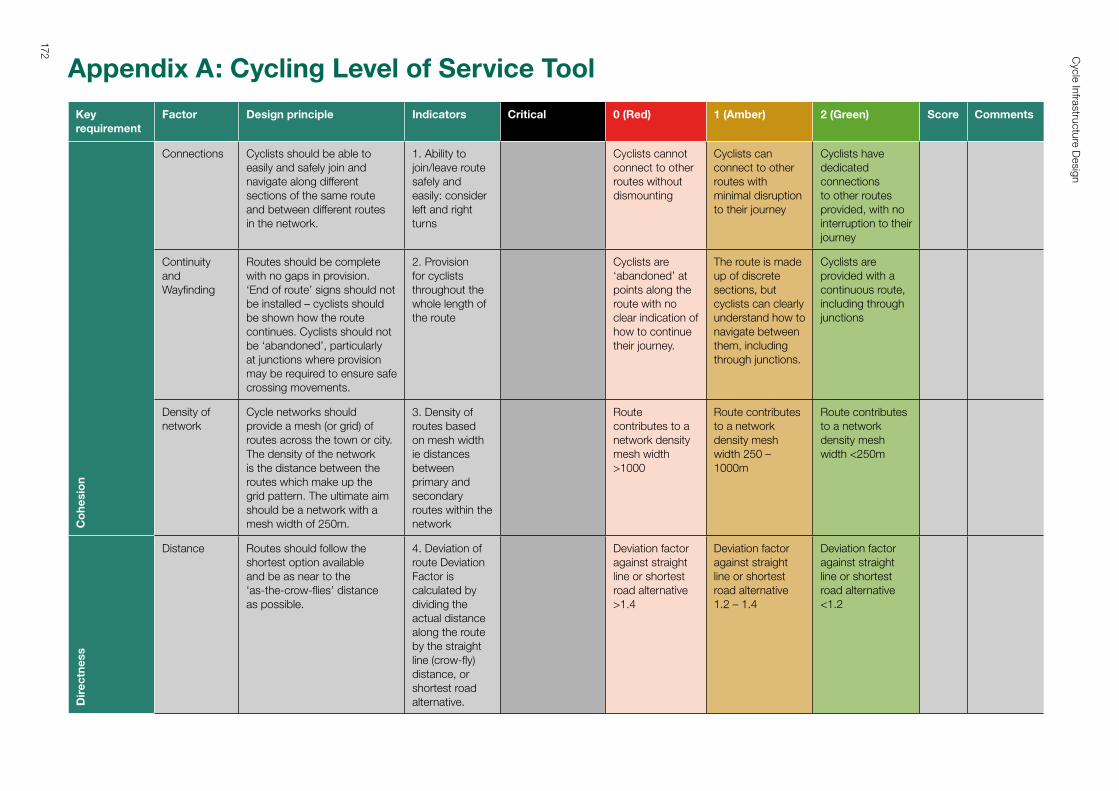
Appendix A: Cycling Level of Service Tool
Key requirement
Factor Design principle Indicators Critical 0 (Red) 1 (Amber) 2 (Green) Score Comments
Co
hesi
on
Connections Cyclists should be able to easily and safely join and navigate along different sections of the same route and between different routes in the network.
1. Ability to join/leave route safely and easily: consider left and right turns
Cyclists cannot connect to other routes without dismounting
Cyclists can connect to other routes with minimal disruption to their journey
Cyclists have dedicated connections to other routes provided, with no interruption to their journey
Continuity and Wayfinding
Routes should be complete with no gaps in provision. ‘End of route’ signs should not be installed – cyclists should be shown how the route continues. Cyclists should not be ‘abandoned’, particularly at junctions where provision may be required to ensure safe crossing movements.
2. Provision for cyclists throughout the whole length of the route
Cyclists are ‘abandoned’ at points along the route with no clear indication of how to continue their journey.
The route is made up of discrete sections, but cyclists can clearly understand how to navigate between them, including through junctions.
Cyclists are provided with a continuous route, including through junctions
Density of network
Cycle networks should provide a mesh (or grid) of routes across the town or city. The density of the network is the distance between the routes which make up the grid pattern. The ultimate aim should be a network with a mesh width of 250m.
3. Density of routes based on mesh width ie distances between primary and secondary routes within the network
Route contributes to a network density mesh width >1000
Route contributes to a network density mesh width 250 – 1000m
Route contributes to a network density mesh width <250m
Dir
ectn
ess
Distance Routes should follow the shortest option available and be as near to the ‘as‑the‑crow‑flies’ distance as possible.
4. Deviation of route Deviation Factor is calculated by dividing the actual distance along the route by the straight line (crow‑fly) distance, or shortest road alternative.
Deviation factor against straight line or shortest road alternative >1.4
Deviation factor against straight line or shortest road alternative 1.2 – 1.4
Deviation factor against straight line or shortest road alternative <1.2
172 Cycle Infrastructure D
esign
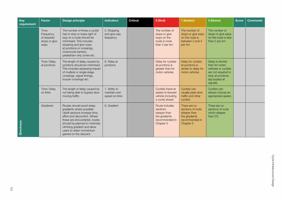
Key requirement
Factor Design principle Indicators Critical 0 (Red) 1 (Amber) 2 (Green) Score CommentsD
irec
tnes
s
Time: Frequency of required stops or give ways
The number of times a cyclist has to stop or loses right of way on a route should be minimised. This includes stopping and give ways at junctions or crossings, motorcycle barriers, pedestrian‑only zones etc.
5. Stopping and give way frequency
The number of stops or give ways on the route is more than 4 per km
The number of stops or give ways on the route is between 2 and 4 per km
The number of stops or give ways on the route is less than 2 per km
Time: Delay at junctions
The length of delay caused by junctions should be minimised. This includes assessing impact of multiple or single stage crossings, signal timings, toucan crossings etc.
6. Delay at junctions
Delay for cyclists at junctions is greater than for motor vehicles
Delay for cyclists at junctions is similar to delay for motor vehicles
Delay is shorter than for motor vehicles or cyclists are not required to stop at junctions (eg bypass at signals)
Time: Delay on links
The length of delay caused by not being able to bypass slow moving traffic.
7. Ability to maintain own speed on links
Cyclists travel at speed of slowest vehicle (including a cycle) ahead
Cyclists can usually pass slow traffic and other cyclists
Cyclists can always choose an appropriate speed.
Gradients Routes should avoid steep gradients where possible. Uphill sections increase time, effort and discomfort. Where these are encountered, routes should be planned to minimise climbing gradient and allow users to retain momentum gained on the descent.
8. Gradient Route includes sections steeper than the gradients recommended in Chapter 5
There are no sections of route steeper than the gradients recommended in Chapter 5
There are no sections of route which steeper than 2%
Appendix A: Cycling Level of Service Tool
Key requirement
Factor Design principle Indicators Critical 0 (Red) 1 (Amber) 2 (Green) Score Comments
Co
hesi
on
Connections Cyclists should be able to easily and safely join and navigate along different sections of the same route and between different routes in the network.
1. Ability to join/leave route safely and easily: consider left and right turns
Cyclists cannot connect to other routes without dismounting
Cyclists can connect to other routes with minimal disruption to their journey
Cyclists have dedicated connections to other routes provided, with no interruption to their journey
Continuity and Wayfinding
Routes should be complete with no gaps in provision. ‘End of route’ signs should not be installed – cyclists should be shown how the route continues. Cyclists should not be ‘abandoned’, particularly at junctions where provision may be required to ensure safe crossing movements.
2. Provision for cyclists throughout the whole length of the route
Cyclists are ‘abandoned’ at points along the route with no clear indication of how to continue their journey.
The route is made up of discrete sections, but cyclists can clearly understand how to navigate between them, including through junctions.
Cyclists are provided with a continuous route, including through junctions
Density of network
Cycle networks should provide a mesh (or grid) of routes across the town or city. The density of the network is the distance between the routes which make up the grid pattern. The ultimate aim should be a network with a mesh width of 250m.
3. Density of routes based on mesh width ie distances between primary and secondary routes within the network
Route contributes to a network density mesh width >1000
Route contributes to a network density mesh width 250 – 1000m
Route contributes to a network density mesh width <250m
Dir
ectn
ess
Distance Routes should follow the shortest option available and be as near to the ‘as‑the‑crow‑flies’ distance as possible.
4. Deviation of route Deviation Factor is calculated by dividing the actual distance along the route by the straight line (crow‑fly) distance, or shortest road alternative.
Deviation factor against straight line or shortest road alternative >1.4
Deviation factor against straight line or shortest road alternative 1.2 – 1.4
Deviation factor against straight line or shortest road alternative <1.2
173
Cycle Infrastructure D
esign
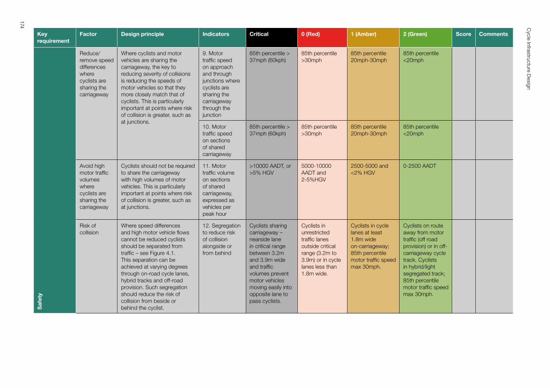
Key requirement
Factor Design principle Indicators Critical 0 (Red) 1 (Amber) 2 (Green) Score CommentsS
afet
y
Reduce/ remove speed differences where cyclists are sharing the carriageway
Where cyclists and motor vehicles are sharing the carriageway, the key to reducing severity of collisions is reducing the speeds of motor vehicles so that they more closely match that of cyclists. This is particularly important at points where risk of collision is greater, such as at junctions.
9. Motor traffic speed on approach and through junctions where cyclists are sharing the carriageway through the junction
85th percentile > 37mph (60kph)
85th percentile >30mph
85th percentile 20mph‑30mph
85th percentile <20mph
10. Motor traffic speed on sections of shared carriageway
85th percentile > 37mph (60kph)
85th percentile >30mph
85th percentile 20mph‑30mph
85th percentile <20mph
Avoid high motor traffic volumes where cyclists are sharing the carriageway
Cyclists should not be required to share the carriageway with high volumes of motor vehicles. This is particularly important at points where risk of collision is greater, such as at junctions.
11. Motor traffic volume on sections of shared carriageway, expressed as vehicles per peak hour
>10000 AADT, or >5% HGV
5000‑10000 AADT and 2‑5%HGV
2500‑5000 and <2% HGV
0‑2500 AADT
Risk of collision
Where speed differences and high motor vehicle flows cannot be reduced cyclists should be separated from traffic – see Figure 4.1. This separation can be achieved at varying degrees through on‑road cycle lanes, hybrid tracks and off‑road provision. Such segregation should reduce the risk of collision from beside or behind the cyclist.
12. Segregation to reduce risk of collision alongside or from behind
Cyclists sharing carriageway – nearside lane in critical range between 3.2m and 3.9m wide and traffic volumes prevent motor vehicles moving easily into opposite lane to pass cyclists.
Cyclists in unrestricted traffic lanes outside critical range (3.2m to 3.9m) or in cycle lanes less than 1.8m wide.
Cyclists in cycle lanes at least 1.8m wide on‑carriageway; 85th percentile motor traffic speed max 30mph.
Cyclists on route away from motor traffic (off road provision) or in off‑carriageway cycle track. Cyclists in hybrid/light segregated track; 85th percentile motor traffic speed max 30mph.
174 Cycle Infrastructure D
esign
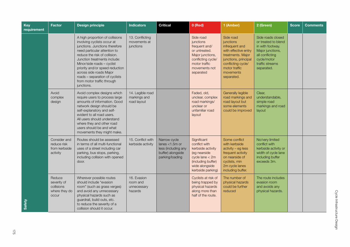
Key requirement
Factor Design principle Indicators Critical 0 (Red) 1 (Amber) 2 (Green) Score CommentsS
afet
y
A high proportion of collisions involving cyclists occur at junctions. Junctions therefore need particular attention to reduce the risk of collision. Junction treatments include: Minor/side roads – cyclist priority and/or speed reduction across side roads Major roads – separation of cyclists from motor traffic through junctions.
13. Conflicting movements at junctions
Side road junctions frequent and/ or untreated. Major junctions, conflicting cycle/ motor traffic movements not separated
Side road junctions infrequent and with effective entry treatments. Major junctions, principal conflicting cycle/ motor traffic movements separated.
Side roads closed or treated to blend in with footway. Major junctions, all conflicting cycle/motor traffic streams separated.
Avoid complex design
Avoid complex designs which require users to process large amounts of information. Good network design should be self‑explanatory and self‑evident to all road users. All users should understand where they and other road users should be and what movements they might make.
14. Legible road markings and road layout
Faded, old, unclear, complex road markings/ unclear or unfamiliar road layout
Generally legible road markings and road layout but some elements could be improved
Clear, understandable, simple road markings and road layout
Consider and reduce risk from kerbside activity
Routes should be assessed in terms of all multi‑functional uses of a street including car parking, bus stops, parking, including collision with opened door.
15. Conflict with kerbside activity
Narrow cycle lanes <1.5m or less (including any buffer) alongside parking/loading
Significant conflict with kerbside activity (eg nearside cycle lane < 2m (including buffer) wide alongside kerbside parking)
Some conflict with kerbside activity – eg less frequent activity on nearside of cyclists, min 2m cycle lanes including buffer.
No/very limited conflict with kerbside activity or width of cycle lane including buffer exceeds 3m.
Reduce severity of collisions where they do occur
Wherever possible routes should include “evasion room” (such as grass verges) and avoid any unnecessary physical hazards such as guardrail, build outs, etc. to reduce the severity of a collision should it occur.
16. Evasion room and unnecessary hazards
Cyclists at risk of being trapped by physical hazards along more than half of the route.
The number of physical hazards could be further reduced
The route includes evasion room and avoids any physical hazards.
175
Cycle Infrastructure D
esign
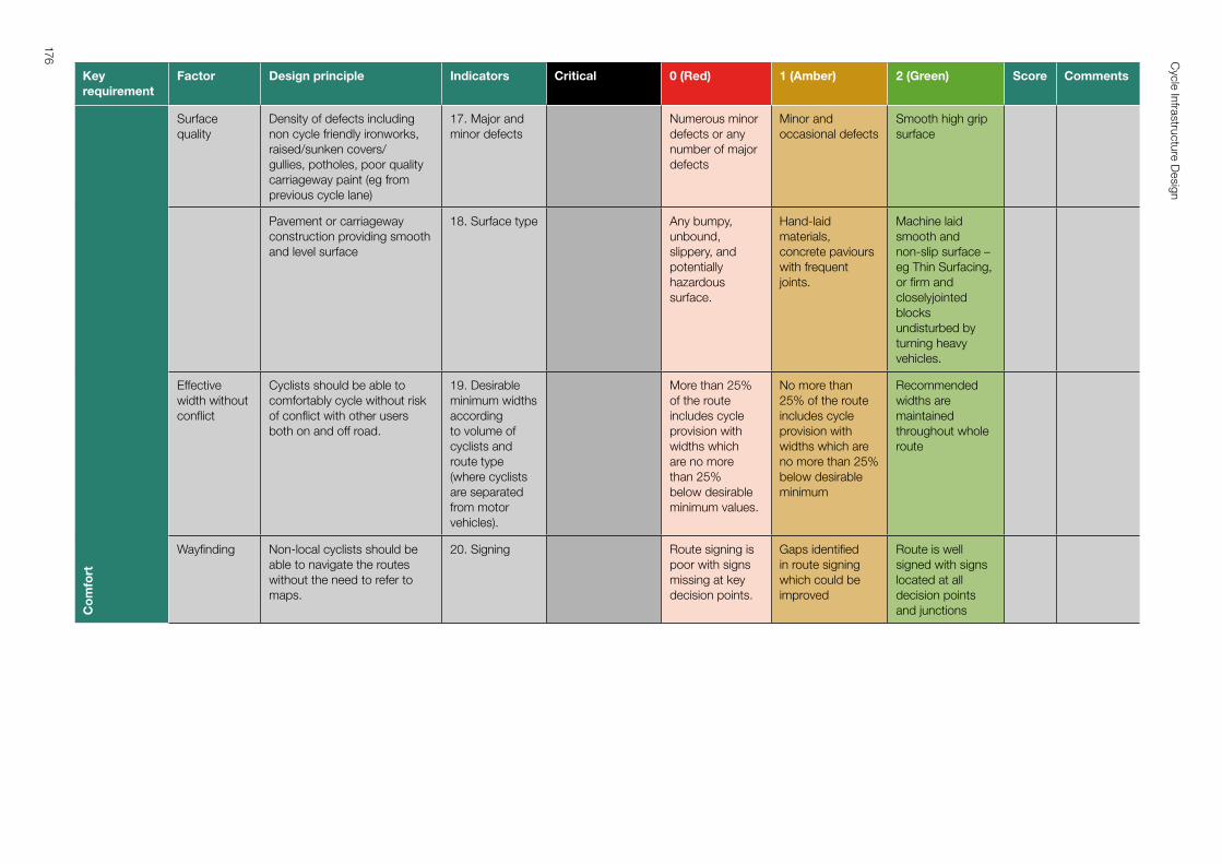
Key requirement
Factor Design principle Indicators Critical 0 (Red) 1 (Amber) 2 (Green) Score CommentsC
om
fort
Surface quality
Density of defects including non cycle friendly ironworks, raised/sunken covers/gullies, potholes, poor quality carriageway paint (eg from previous cycle lane)
17. Major and minor defects
Numerous minor defects or any number of major defects
Minor and occasional defects
Smooth high grip surface
Pavement or carriageway construction providing smooth and level surface
18. Surface type Any bumpy, unbound, slippery, and potentially hazardous surface.
Hand‑laid materials, concrete paviours with frequent joints.
Machine laid smooth and non‑slip surface – eg Thin Surfacing, or firm and closelyjointed blocks undisturbed by turning heavy vehicles.
Effective width without conflict
Cyclists should be able to comfortably cycle without risk of conflict with other users both on and off road.
19. Desirable minimum widths according to volume of cyclists and route type (where cyclists are separated from motor vehicles).
More than 25% of the route includes cycle provision with widths which are no more than 25% below desirable minimum values.
No more than 25% of the route includes cycle provision with widths which are no more than 25% below desirable minimum
Recommended widths are maintained throughout whole route
Wayfinding Non‑local cyclists should be able to navigate the routes without the need to refer to maps.
20. Signing Route signing is poor with signs missing at key decision points.
Gaps identified in route signing which could be improved
Route is well signed with signs located at all decision points and junctions
176 Cycle Infrastructure D
esign
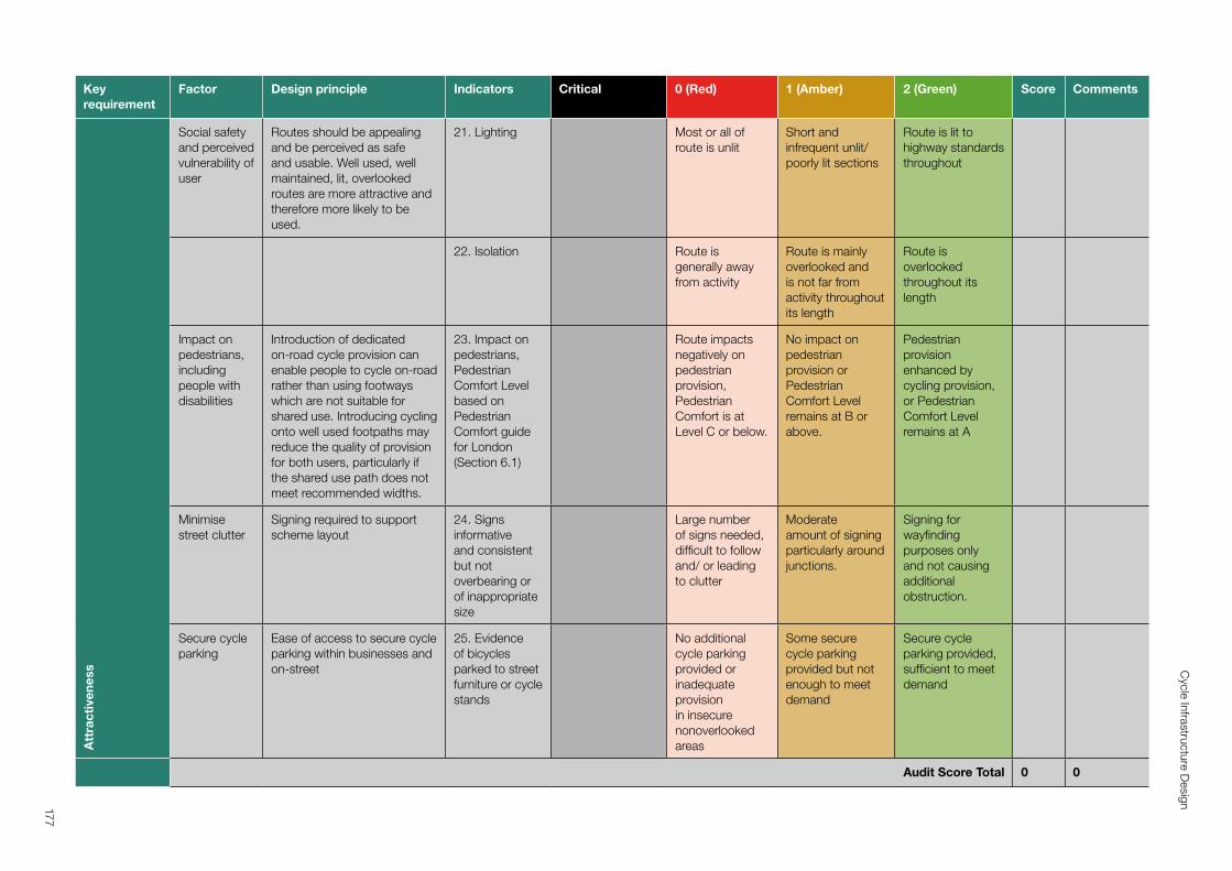
Key requirement
Factor Design principle Indicators Critical 0 (Red) 1 (Amber) 2 (Green) Score CommentsA
ttra
ctiv
enes
s
Social safety and perceived vulnerability of user
Routes should be appealing and be perceived as safe and usable. Well used, well maintained, lit, overlooked routes are more attractive and therefore more likely to be used.
21. Lighting Most or all of route is unlit
Short and infrequent unlit/poorly lit sections
Route is lit to highway standards throughout
22. Isolation Route is generally away from activity
Route is mainly overlooked and is not far from activity throughout its length
Route is overlooked throughout its length
Impact on pedestrians, including people with disabilities
Introduction of dedicated on‑road cycle provision can enable people to cycle on‑road rather than using footways which are not suitable for shared use. Introducing cycling onto well used footpaths may reduce the quality of provision for both users, particularly if the shared use path does not meet recommended widths.
23. Impact on pedestrians, Pedestrian Comfort Level based on Pedestrian Comfort guide for London (Section 6.1)
Route impacts negatively on pedestrian provision, Pedestrian Comfort is at Level C or below.
No impact on pedestrian provision or Pedestrian Comfort Level remains at B or above.
Pedestrian provision enhanced by cycling provision, or Pedestrian Comfort Level remains at A
Minimise street clutter
Signing required to support scheme layout
24. Signs informative and consistent but not overbearing or of inappropriate size
Large number of signs needed, difficult to follow and/ or leading to clutter
Moderate amount of signing particularly around junctions.
Signing for wayfinding purposes only and not causing additional obstruction.
Secure cycle parking
Ease of access to secure cycle parking within businesses and on‑street
25. Evidence of bicycles parked to street furniture or cycle stands
No additional cycle parking provided or inadequate provision in insecure nonoverlooked areas
Some secure cycle parking provided but not enough to meet demand
Secure cycle parking provided, sufficient to meet demand
Audit Score Total 0 0
177
Cycle Infrastructure D
esign
a
a
a
Appendix B: Junction Assessment Tool
178
Cycle Infrastructure Design
1. IntroductionAs junctions pose the greatest risk of collisions to all road users, they require close attention to create conditions which will attract a wide range of new users. Fear of motor traffic in the current highway environment is a major factor preventing the uptake of cycling by a broader range of people.56
The Junction Assessment Tool (JAT) is an adaptation of a similar tool in the 2014 London Cycling Design Standards (LCDS), and is intended to be used at the design stage as well as for the assessment of existing junctions. It follows the same themes as the critical junctions assessment in the Route Selection Tool, but looks more closely at how a cyclist would move through a junction.
The tool has been expanded to be more explicit for a range of junction types and to aid its use by practitioners who may lack experience in objectively considering cycle safety and perception of cycle route quality. The outputs and methodology are similar to the LCDS tool.
A junction assessment should consider ALL potential cycle movements through a junction. It is not sufficient to plan a cycle route as a linear corridor from A to B if joining or leaving it midway is problematic, dangerous or impossible. However, there may be some situations where not all movements at a junction need to be considered if some are not permitted for cyclists (e.g. at the ends of a motorway slip road) or if some turning movements are banned (although an exemption for cycles should always be considered).
2. Scoring cycle movements and the overall junctionThe junction assessment should be represented graphically by colour-coding each movement red, amber or green.
Movements designated as red are the most uncomfortable or unsafe for cyclists, and so on:
Red: where conditions exist that are most likely to give rise to the most common collision types, then the movement should be represented on the plan as a red arrow
Amber: where the risk of those collision types has been reduced by design layout or traffic management interventions, then the movement should be coloured amber
Green: where the potential for collisions has been removed entirely, then the movement should be coloured green
56 Pooley, C, Tight, M, Jones, T, Horton, D, Scheldeman, G, Jopson, A, Mullen, C, Chisholm, A, Strano, E & Constantine, S 2011, Understanding walking and cycling: summary of key findings and recommendations. Lancaster University, Lancaster
‘Green’ should be taken to mean suitable for all potential cyclists; ‘red’ means suitable only for a minority of cyclists (and, even for them, it may be uncomfortable to make). Green movements will exceed the standards that have typically been achieved in the UK to date.
To aid option appraisal and a comparison with existing provision, proposed schemes should be assessed numerically by giving a score of 0, 1 and 2 to the red, amber and green movements respectively.
In addition, any banned movements for cycling (shown on the diagram in black with a cross at the end) will also score zero.
An overall percentage score for the junction should be derived by dividing the total score for all of the possible movements with the maximum possible score, if all were coded green.
The worked example below, taken from Section 2.2.7 of the London Cycling Design Standards shows how this is done.
3. Applying the toolCriteria for the types of collision, conflicts and conditions which would be scored 0,1 or 2 are listed in the red-amber-green tables below.
The first section of the table gives criteria for all junctions, and should be applied in conjunction with the section specific to the type of junction (e.g. priority junction) under consideration.
Where a movement would meet criteria falling into more than one scoring band (e.g. red and amber) the worst score should be taken – i.e. meeting any red criterion means the movement is scored as red.
4. Worked exampleThis example shows a busy high street crossed by a cycle route on offset side streets that are closed to motor vehicles. Traffic signals hold general traffic on the high street in both directions to allow a separate stage for cycle movements only.
Cycle movements out of the side streets are all shown with green arrows as they can take place unopposed during that stage. Cyclists on the high street turning right into either side street have to cross two lanes of general traffic and then look for a gap in a further two lanes of oncoming traffic. The presence of the right turn-pocket is helpful but without separation in time and space this movement is still difficult and should be marked as red.
Cyclists moving along the high street can do so within a bus lane and so this movement is shown as amber as they do not have to mix with the main traffic flow. The other side street to the south has banned movements for all vehicles including cyclists and so this is shown as black with a cross at the end.
The overall junction score is 24/40, or 60%.
179
Cycle Infrastructure Design
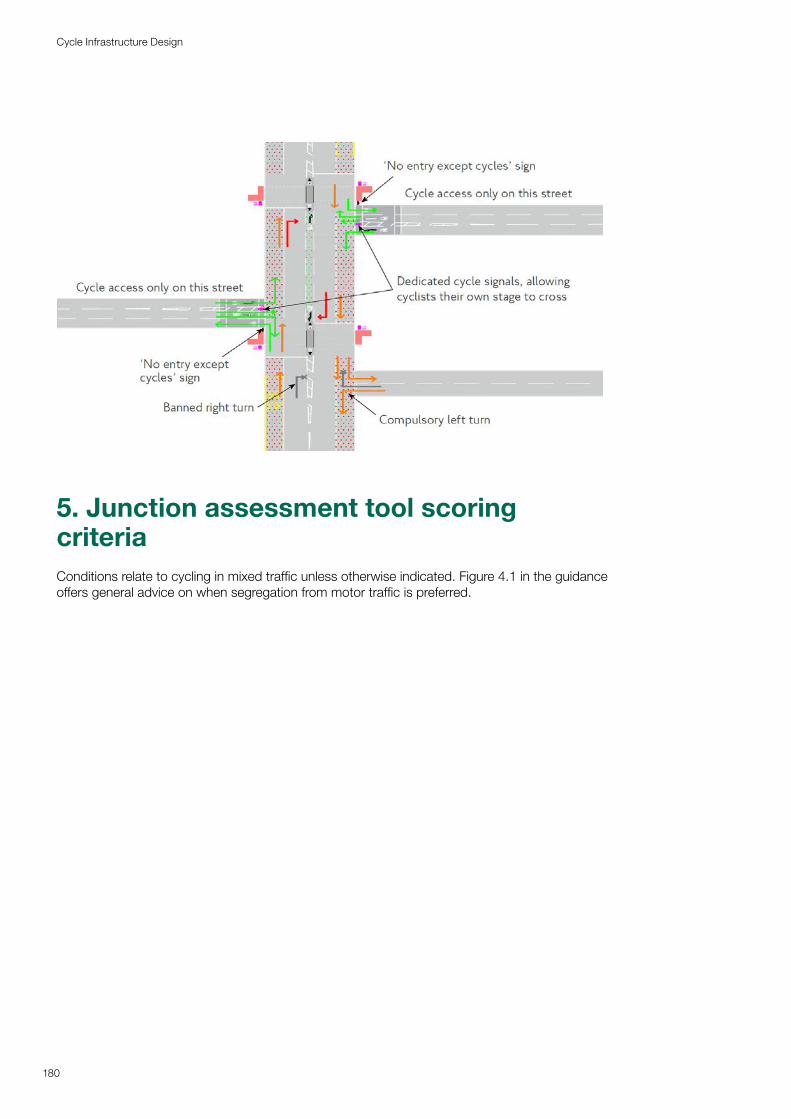
5. Junction assessment tool scoring criteriaConditions relate to cycling in mixed traffic unless otherwise indicated. Figure 4.1 in the guidance offers general advice on when segregation from motor traffic is preferred.
180
Cycle Infrastructure Design
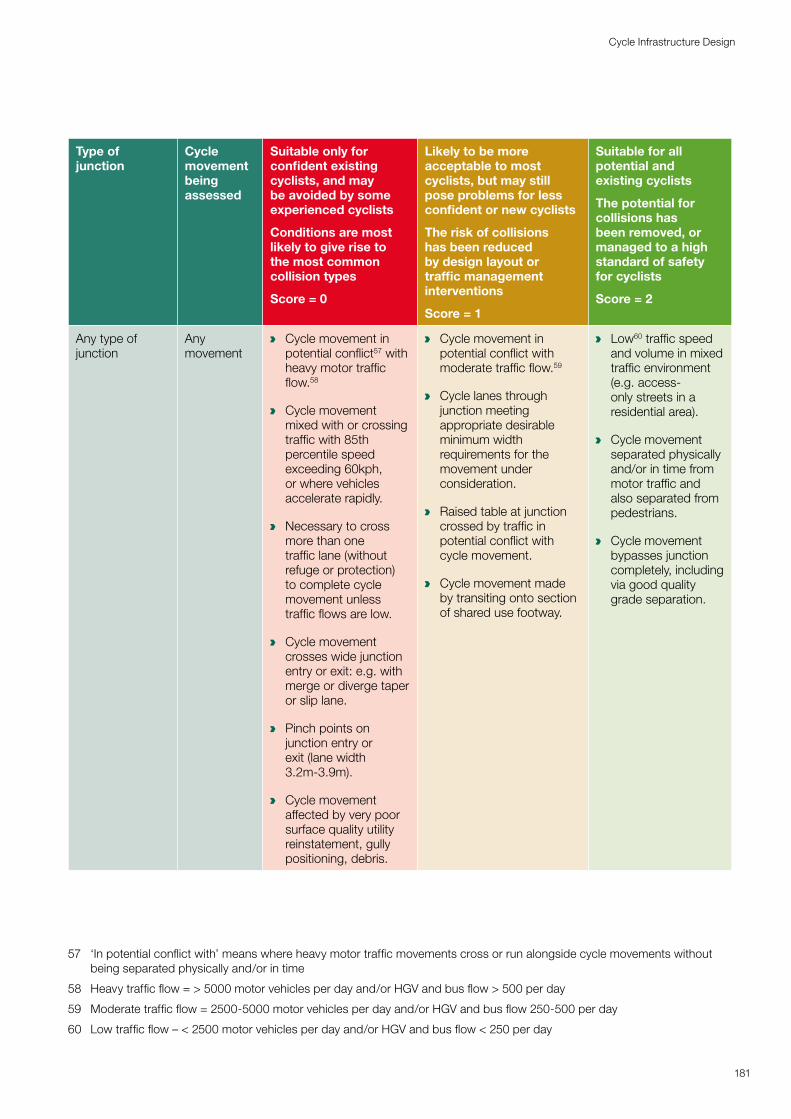
Type of junction
Cycle movement being assessed
Suitable only for confident existing cyclists, and may be avoided by some experienced cyclists
Conditions are most likely to give rise to the most common collision types
Score = 0
Likely to be more acceptable to most cyclists, but may still pose problems for less confident or new cyclists
The risk of collisions has been reduced by design layout or traffic management interventions
Score = 1
Suitable for all potential and existing cyclists
The potential for collisions has been removed, or managed to a high standard of safety for cyclists
Score = 2
Any type of junction
Any movement
a Cycle movement in potential conflict57 with heavy motor traffic flow.58
a Cycle movement mixed with or crossing traffic with 85th percentile speed exceeding 60kph, or where vehicles accelerate rapidly.
a Necessary to cross more than one traffic lane (without refuge or protection) to complete cycle movement unless traffic flows are low.
a Cycle movement crosses wide junction entry or exit: e.g. with merge or diverge taper or slip lane.
a Pinch points on junction entry or exit (lane width 3.2m-3.9m).
a Cycle movement affected by very poor surface quality utility reinstatement, gully positioning, debris.
a Cycle movement in potential conflict with moderate traffic flow.59
a Cycle lanes through junction meeting appropriate desirable minimum width requirements for the movement under consideration.
a Raised table at junction crossed by traffic in potential conflict with cycle movement.
a Cycle movement made by transiting onto section of shared use footway.
a Low60 traffic speed and volume in mixed traffic environment (e.g. access-only streets in a residential area).
a Cycle movement separated physically and/or in time from motor traffic and also separated from pedestrians.
a Cycle movement bypasses junction completely, including via good quality grade separation.
57 ‘In potential conflict with’ means where heavy motor traffic movements cross or run alongside cycle movements without being separated physically and/or in time
58 Heavy traffic flow = > 5000 motor vehicles per day and/or HGV and bus flow > 500 per day
59 Moderate traffic flow = 2500-5000 motor vehicles per day and/or HGV and bus flow 250-500 per day
60 Low traffic flow – < 2500 motor vehicles per day and/or HGV and bus flow < 250 per day
181
Cycle Infrastructure Design
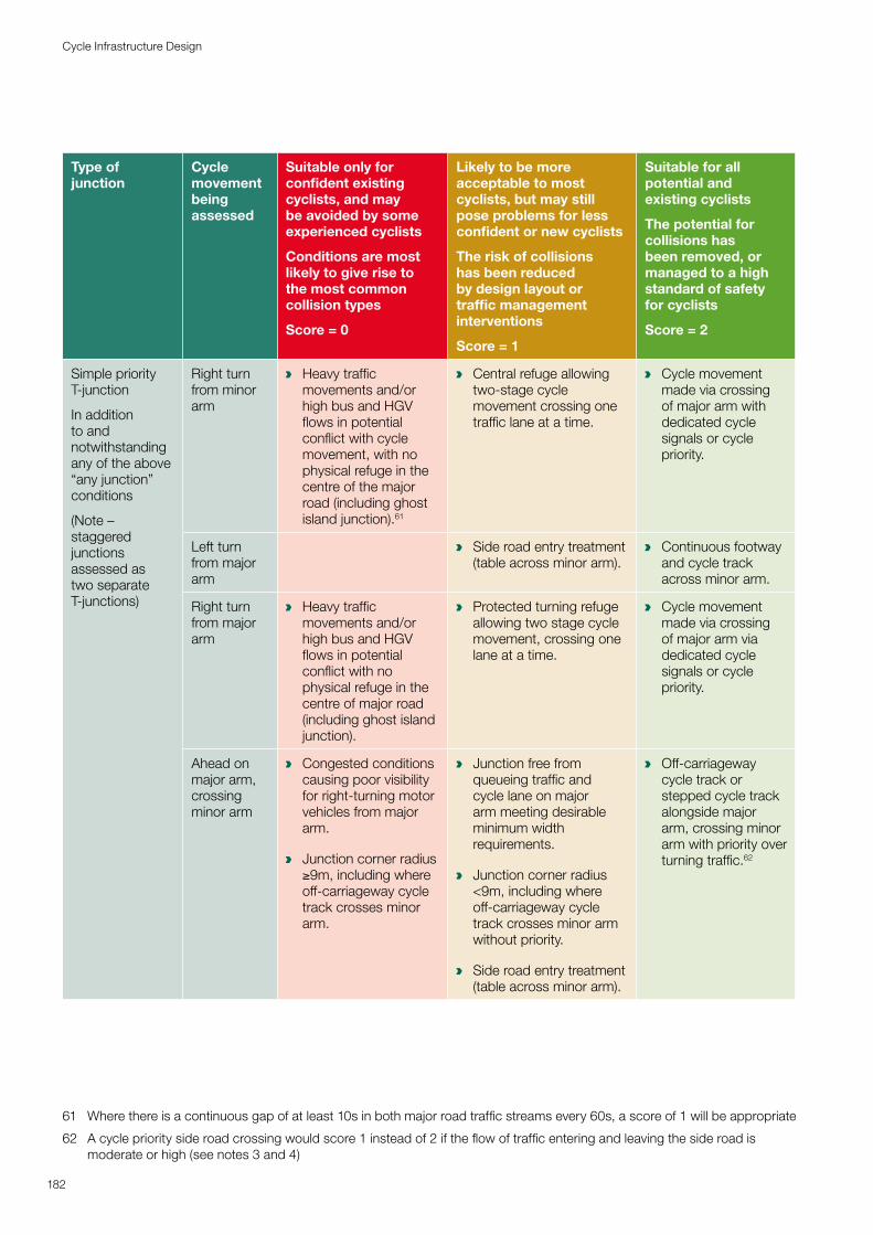
Type of junction
Cycle movement being assessed
Suitable only for confident existing cyclists, and may be avoided by some experienced cyclists
Conditions are most likely to give rise to the most common collision types
Score = 0
Likely to be more acceptable to most cyclists, but may still pose problems for less confident or new cyclists
The risk of collisions has been reduced by design layout or traffic management interventions
Score = 1
Suitable for all potential and existing cyclists
The potential for collisions has been removed, or managed to a high standard of safety for cyclists
Score = 2
Simple priority T-junction
In addition to and notwithstanding any of the above “any junction” conditions
(Note – staggered junctions assessed as two separate T-junctions)
Right turn from minor arm
a Heavy traffic movements and/or high bus and HGV flows in potential conflict with cycle movement, with no physical refuge in the centre of the major road (including ghost island junction).61
a Central refuge allowing two-stage cycle movement crossing one traffic lane at a time.
a Cycle movement made via crossing of major arm with dedicated cycle signals or cycle priority.
Left turn from major arm
a Side road entry treatment (table across minor arm).
a Continuous footway and cycle track across minor arm.
Right turn from major arm
a Heavy traffic movements and/or high bus and HGV flows in potential conflict with no physical refuge in the centre of major road (including ghost island junction).
a Protected turning refuge allowing two stage cycle movement, crossing one lane at a time.
a Cycle movement made via crossing of major arm via dedicated cycle signals or cycle priority.
Ahead on major arm, crossing minor arm
a Congested conditions causing poor visibility for right-turning motor vehicles from major arm.
a Junction corner radius ≥9m, including where off-carriageway cycle track crosses minor arm.
a Junction free from queueing traffic and cycle lane on major arm meeting desirable minimum width requirements.
a Junction corner radius <9m, including where off-carriageway cycle track crosses minor arm without priority.
a Side road entry treatment (table across minor arm).
a Off-carriageway cycle track or stepped cycle track alongside major arm, crossing minor arm with priority over turning traffic.62
61 Where there is a continuous gap of at least 10s in both major road traffic streams every 60s, a score of 1 will be appropriate
62 A cycle priority side road crossing would score 1 instead of 2 if the flow of traffic entering and leaving the side road is moderate or high (see notes 3 and 4)
182
Cycle Infrastructure Design
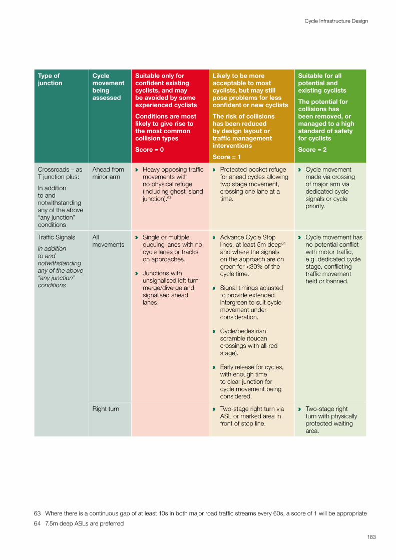
Type of junction
Cycle movement being assessed
Suitable only for confident existing cyclists, and may be avoided by some experienced cyclists
Conditions are most likely to give rise to the most common collision types
Score = 0
Likely to be more acceptable to most cyclists, but may still pose problems for less confident or new cyclists
The risk of collisions has been reduced by design layout or traffic management interventions
Score = 1
Suitable for all potential and existing cyclists
The potential for collisions has been removed, or managed to a high standard of safety for cyclists
Score = 2
Crossroads – as T junction plus:
In addition to and notwithstanding any of the above “any junction” conditions
Ahead from minor arm
a Heavy opposing traffic movements with no physical refuge (including ghost island junction).63
a Protected pocket refuge for ahead cycles allowing two stage movement, crossing one lane at a time.
a Cycle movement made via crossing of major arm via dedicated cycle signals or cycle priority.
Traffic Signals
In addition to and notwithstanding any of the above “any junction” conditions
All movements
a Single or multiple queuing lanes with no cycle lanes or tracks on approaches.
a Junctions with unsignalised left turn merge/diverge and signalised ahead lanes.
a Advance Cycle Stop lines, at least 5m deep64 and where the signals on the approach are on green for <30% of the cycle time.
a Signal timings adjusted to provide extended intergreen to suit cycle movement under consideration.
a Cycle/pedestrian scramble (toucan crossings with all-red stage).
a Early release for cycles, with enough time to clear junction for cycle movement being considered.
a Cycle movement has no potential conflict with motor traffic, e.g. dedicated cycle stage, conflicting traffic movement held or banned.
Right turn a Two-stage right turn via ASL or marked area in front of stop line.
a Two-stage right turn with physically protected waiting area.
63 Where there is a continuous gap of at least 10s in both major road traffic streams every 60s, a score of 1 will be appropriate
64 7.5m deep ASLs are preferred
183
Cycle Infrastructure Design
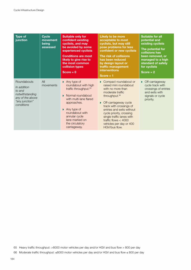
Type of junction
Cycle movement being assessed
Suitable only for confident existing cyclists, and may be avoided by some experienced cyclists
Conditions are most likely to give rise to the most common collision types
Score = 0
Likely to be more acceptable to most cyclists, but may still pose problems for less confident or new cyclists
The risk of collisions has been reduced by design layout or traffic management interventions
Score = 1
Suitable for all potential and existing cyclists
The potential for collisions has been removed, or managed to a high standard of safety for cyclists
Score = 2
Roundabouts
In addition to and notwithstanding any of the above “any junction” conditions
All movements
a Any type of roundabout with high traffic throughput.65
a Normal roundabout with multi-lane flared approaches.
a Any type of roundabout with annular cycle lane marked on the circulatory carriageway.
a Compact roundabout or raised mini roundabout with no more than moderate traffic throughput.66
a Off-carriageway cycle track with crossings of entries and exits without cycle priority, crossing single traffic lanes with traffic flows < 4000 vehicles per day or 400 HGV/bus flow.
a Off-carriageway cycle track with crossings of entries and exits with signals or cycle priority.
65 Heavy traffic throughput: >8000 motor vehicles per day and/or HGV and bus flow > 800 per day
66 Moderate traffic throughput: ≤8000 motor vehicles per day and/or HGV and bus flow ≤ 800 per day
184
Cycle Infrastructure Design
a
a
a
a
a
a
a
Appendix C: Legal issuesThese notes are for guidance only. Practitioners will need to obtain their own legal advice before acting on information provided in this appendix.
185
Cycle Infrastructure Design
Descriptions and definitionsCycling may be legally permitted in several different places:
On the Highway
On a Cycle Track
On a Bridleway
On a Restricted Byway (formerly Road Used as a Public Path)
On a Byway Open to All Traffic (BOAT)
On paths within some public parks, open spaces or across private land
On canal and river towing paths
Different laws apply to the creation of the different types of cycling provision. Most cycle routes form part of the highway or public rights of way networks. Definitions of the most common types of provision are given below:
Highway: This is defined as “a way over which the public has the right to pass and repass, and may be any way, court, alley, footpath, bridleway.” While most ‘highway’ forms part of the road network, other types of route can still form part of what is legally termed maintainable highway.
Carriageway: A way constituting or comprised in a highway (other than a cycle track), over which the public have a right of way for passage of vehicles. [Highways Act 1980 (S329)]. Cycle lanes are part of the carriageway.
Cycle Track: A way constituting or comprised in a highway, over which the public have the following, but no other, rights of way; a right of way on pedal cycles (other than pedal cycles which are motor vehicles within the meaning of the Road Traffic Act 1988) with or without a right of way on foot. [Section 329(1) Highways Act 1980; the words in brackets were inserted by section 1 of the Cycle Tracks Act 1984 and updated by the Road Traffic (Consequential Provisions) Act 1988]. Cycle tracks may be newly constructed or created through conversion of a footway or footpath.
Footway: A way comprised in a highway, which also comprises a carriageway, over which the public has a right of way on foot only [Section 329(1) Highway Act 1980]. Footways are the pedestrian paths alongside a carriageway, referred to colloquially as the pavement. Driving a vehicle (including cycling) or riding a horse on a footway is an offence under the Highways Act 1835.
Public Rights of Way: These comprise Footpaths, Bridleways, Restricted Byways and Byways Open to All Traffic. All public rights of way are highways and are shown on the Definitive Map held by local highway authorities, which is required to be constantly reviewed and updated.
Footpath: A highway over which the public have a right of way on foot only, not being a footway [Section 329(1) Highways Act 1980].
Bridleway: A right of way on horseback (or leading a horse), foot and bicycle. The Countryside Act 1968 gave cyclists a right to use bridleways; however, they must give way to pedestrians and equestrians. There is no penalty for failing to comply. Since the bridleway forms part of the highway it remains for case law to establish whether the offending cyclist could be said to be ‘furiously driving a carriage on a highway so as to endanger life and limb’, see Highways Act 1835. There may occasionally be a local byelaw to prohibit cycling on a particular bridleway.
Restricted Byways: Are generally open only to pedestrians, cyclists, horse-riders and horsedrawn vehicles and replace the former category of Roads Used as Public Paths (RUPPs). Created by the Countryside and Rights of Way Act 2000 (S48).
Byways Open to All Traffic (BOATs): Are open to motorised traffic, but are used by the public mainly for the purposes for which footpaths and bridleways are used. They rarely have a sealed surface and are generally used in a similar way to restricted byways and bridleways. The definition was created under the Wildlife and Countryside Act 1981 (S66).
Towing Path: The towpath alongside a canal or river. There is no general statutory right to cycle on a towpath in England and Wales (although some sections may also be public rights of way). Cycling may be permitted (or prohibited) through a byelaw.
Cycleway and Cycle Path: Neither of these terms has any legal definition but they often describe continuous cycle routes (usually away from the carriageway) that may be formed by any permutation of the above.
Transport device definitionsCycle: A pedal cycle is defined as ‘a bicycle, a tricycle, or a cycle having four or more wheels, not being in any case a motor vehicle’ (Section 192(1) of the Road Traffic Act 1988 (c.52)). In law, a cycle is considered a ‘vehicle’ as a consequence of the Ellis v Nott-Bower judgment in 1896. A cycle is also considered a carriage by section 85 of the Local Government Act 1888.
Electrically Assisted Pedal Cycles (EAPCs): Electrically assisted pedal cycles, often known as e-bikes, are defined in the Electrically Assisted Pedal Cycle Regulations 1983 (as amended). They can legally be ridden where pedal cycles are allowed, but only by someone aged 14 years or more. They are not classed as motor vehicles for the purposes of road traffic legislation.
Manual powered wheelchairs and mobility scooters: These are defined as ‘invalid carriages’ in law, and there are three classes:
Class 1 – Manual, self-propelled or attendant propelled wheelchairs.
Class 2 – Powered wheelchairs and mobility scooters with a maximum speed of 4 mph.
Class 3 – Powered wheelchairs and mobility scooters with a maximum speed of 8 mph
Invalid carriages can be used on footways, footpaths, bridleways or pedestrianised areas, provided that they are used in accordance with prescribed requirements. Users of invalid carriages have no specific right to use a cycle track, but they commit no offence in doing so unless an order or local by-law exists creating one.
Class 2 wheelchairs and mobility scooters are intended to be used predominantly on footways. Class 3 wheelchairs and mobility scooters are intended for use on footways and along roads. They can travel at up to 8 mph on roads, but must be fitted with a switch that reduces their top speed to 4 mph for use on footways.
186
Cycle Infrastructure Design
Powered invalid carriages are not classed as motor vehicles for the purposes of road traffic legislation (Road Traffic Act 1988, section 185(1)). However, the Vehicle Excise and Registration Act 1994 requires that Class 3 wheelchairs and mobility scooters are registered with the Driver and Vehicle Licensing Agency for road use. They are exempt from vehicle excise duty, but are still required to display a valid (nil duty) tax disc.
Motor vehicle: For use on public roads, motor vehicles must be registered and fitted with a registration plate or plates. They must also be insured and taxed for road use, and they can only be operated by someone in possession of a driver’s licence. Motor vehicles cannot normally be used on footways, footpaths or cycle tracks.
Creating cycle tracksCreating a cycle track within the highway boundary. Procedure – Highways Act 1980
There are two ways in which this can be achieved. Either all or part of the existing footway is converted to a cycle track, or a new cycle track can be constructed alongside the footway.
Section 21 of the Road Traffic Act 1988 makes it an offence to drive or park a motor vehicle wholly or partly on a cycle track, and the making of a Traffic Regulation Order (TRO) is therefore no longer required to control such use. A TRO may be required if the intention is for the cycle track to be one way only, as the default is for two-way cycling. This situation could apply on stepped cycle tracks, for example. However, if vehicular rights for private access existed prior to the conversion of a footway to a cycle track, these are not necessarily extinguished on creation of the cycle track.
Public consultation is not a mandatory requirement, however, engagement with those likely to be affected is strongly recommended, particularly groups representing disabled people.
Converting a footway to cycle track: To create a cycle track using part or all of an existing footway (or extending the kerbs into the carriageway) the Highway Authority must first ‘remove’ the existing footway under Section 66(4) and then ‘create’ the cycle track under Section 65(1). The process need not involve physical construction work other than the erection of signs.
Creating a new cycle track: A local authority may create a new cycle track “in or by the side of a highway” under section 65(1) of the Highways Act 1980. This would apply where the sole purpose of widening the footway is to create a cycle track, i.e. the footway is not altered.
The creation or conversion of a cycle track is normally completed by a resolution of a Highway Authority committee, regardless of whether any actual construction is required or if it is simply a change of status of an existing footway. There needs to be clear evidence that the local highway authority has exercised its powers, which can be provided by a resolution of the appropriate committee or portfolio holder etc. to ensure that a clear audit trail has been established.
Highway authorities also have a general power of improvement under the Highways Act 1980, which allows them to create, alter or remove footways without the need to seek planning consent.
Creating a cycle track outside the highway boundary. Procedure – Town and Country Planning Act 1990 and Highways Act 1980
If there is no suitable public space within the highway boundary, then the adjacent land (i.e. not existing highway land) could be used. The land must be acquired from the owner (by Compulsory Purchase Order or dedication) to enable use by pedestrians and cyclists.
187
Cycle Infrastructure Design
General powers to acquire land are provided by the Highways Act 1980 s239. Local authorities may resolve to exercise compulsory purchase powers, either to improve the highway or to promote countryside access. The former is more commonly known, but the latter does provide opportunities to create facilities for leisure that have a low utility component. More information is available in the latest edition of ‘The Compulsory Purchase Procedure Manual66.
Creating cycle tracks in new development – dedication of land to the highway. Procedure – Highways Act 1980 and Town and Country Planning Act 1990
Sections 37 and 38 of the Highways Act provide the means for land to be dedicated as public highway. The Act does not refer to the nature of the use, simply referring to dedicating a “way as a highway” and may therefore be for any function acceptable to the Highway Authority e.g. footway, cycle track, carriageway etc.
Agreements under Highways Act 1980 S38 between developers and highway authorities will include confirmation that the developers are the owners of the land, and through the S38 agreement, are dedicating the land, shown on development plan drawings, to the highway maintainable at public expense. Such plans/drawings invariably indicate the nature of the works to be undertaken and, therefore, the future use of the land e.g. bridge, carriageway, cycle track etc. that establishes the status of each element as additions to the highway network.
The dedication as highway is often confirmed by the signing of the S38 agreement before the physical completion of the carriageway, footway, cycle track etc. This enables the Highway Authority to exercise its various powers to do works within the highway and complete any outstanding construction works in the event of the failure of the developer to complete their obligations under the agreement. This also indicates that the dedication to the highway is not dependent on works being carried out by the landowner prior to that dedication.
Where a cycle track is to be created by the Highway Authority, consent under the Town and Country Planning Act 1990 will often be required for the change of use and engineering works to create the cycle track.
Converting an existing footpath to a cycle track: Procedure – Cycle Tracks Act (CTA) 1984 (as amended) to convert all or part to shared use
An existing urban footpath or alleyway may be suitable for shared use by cyclists and pedestrians. This is typically a maintainable highway not adjacent to the carriageway and not on the definitive map, with or without a cycle prohibition order (which may be in the form of a byelaw). The new Order could allow cyclists to use part or the entire width of the footpath. Rural footpaths are more likely to be recorded as rights of way on the definitive map, but broadly the same procedures apply.
Under the CTA, a Highway Authority may designate “any footpath for which they are highway authority”, or part of it, as a cycle track. There is no differentiation in it being a definitive footpath (appearing on the definitive footpath map), or an urban footpath (surfaced highway as found in urban areas and created after the drawing up of the definitive map). Any footpath which forms part of the highway, whether or not surfaced or maintained by the Highway Authority, is a footpath for the purposes of the CTA and should be converted by its application.
To convert all or part of an urban footpath maintainable as highway or a public footpath recorded in the rights of way map to a cycle track, a Cycle Tracks Order must be made under Section 3 of the CTA and the Cycle Tracks Regulations 1984 (SI1984/1431). Detailed advice on the conversion of footpaths is contained in Circular Roads 1/86 (Background to the Cycle Tracks Act 1984 and the Cycle Tracks Regulations 1984).
188
Cycle Infrastructure Design
If the land is not owned by the Highway Authority, it must ensure that the landowner has consented in writing [CTA s3]. Any land lying outside the width of the existing footpath which needs to be acquired for the purposes of constructing the cycle track must be dedicated to/ purchased by the Highway Authority to enable widening to take place.
Public consultation is a mandatory requirement for conversions carried out under the 1984 Act. The Regulations specify that, before making the order, a local highway authority has to consult:
a. one or more organisations representing persons who use the footpath involved or who are likely to be affected by any provision of the proposed order;
b. any other local authority , parish council or community council within whose area the footpath is situated;
c. those statutory undertakers whose operational land is crossed by the footpath; and
d. the chief officer of police for the police area.
Where the footpath crosses agricultural land, the authority will need to obtain consent from the land owner(s). If there are no objections or objections are withdrawn, the order can be confirmed by the local highway authority. If there are un-withdrawn objections, the order can be confirmed by the Secretary of State, who may decide that a local public inquiry is first required.
In practice, the Cycle Tracks Act is often not used, even though it was intended to help local authorities to rationalise existing rights of way to permit cycling more widely. Walking advocates, such as The Ramblers, oppose many applications due to the loss of the footpath from the definitive map (and subsequently from published O.S. maps).
Dealing with objections to the Orders can be costly to the local authority, and any unresolved objections result in a Public Inquiry. The option to create a new cycle track alongside an existing footpath is therefore often preferred by local authorities as a pragmatic method.
The CTA 84 s3(10) (as amended) states that the local authority has the power to carry out any physical works necessary. Any change of use, that would have constituted development within the meaning of the Town and Country Planning Act 1971, is deemed to be granted under Part III of that Act. Any existing byelaw prohibiting cycling would need to be reversed.
Creating a cycle route using permissive rights:
A landowner may give permission for cyclists to use land occupied by a definitive footpath to avoid the use of the Cycle Tracks Act or because they wish to retain control of the land. The path then becomes a ‘permissive path’ for cycling.
Permissive rights are useful where a landowner is willing to allow public use but does not want a permanent right of way to be created. Where the landowner is willing to allow a permanent right of way, he or she can dedicate the land as public highway, and this is a useful alternative in some cases.
A commonly used permissive agreement is where the local authority (or another party) purchases an interest in the land, constructs a path and then allows the public to use it. The land interest can be:
a freehold, which gives a permanent interest; or
a leasehold, which gives an interest for the period of the lease, e.g. 125 years; or
a licence, which comprises permission to construct and permission for the public to use.
189
Cycle Infrastructure Design
The Department does not encourage the use of permissive rights by licence, because licences can be withdrawn at short notice and at any time. Where a local authority owns a footpath, or where the footpath is maintained at public expense, the preferred option would be to introduce higher-level rights for users by upgrading it to a Cycle Track, Restricted Byway or Bridleway. Otherwise, permissive rights based on a leasehold or freehold interest might be appropriate.
Sustrans has created numerous permissive rights routes that have worked satisfactorily. The interests are largely freehold or leasehold – licences are generally avoided, because of their poor security of tenure. Sustrans can advise on the implementation of permissive agreements.
Creating a new cycle track parallel to an existing footpath
Local authorities can create new cycle tracks under s65(1) Highways Act 1980. New footpaths, bridleways or restricted byways can be created under sections 25 or 26 of the Highways Act 1980, either through agreement or by using compulsory powers. A route might also be dedicated for use as a cycle track if there is a precedent of sustained use by cyclists. Creating a cycle track on a new alignment might require planning approval if it is outside the highway boundary.
In this case, the footpath is not converted but the surface is widened, such that a cycle track is created alongside and separate from the existing footpath. The use of the Cycle Tracks Act does not therefore apply.
In these circumstances, segregation by some form of physical delineation (kerb, surfacing) is appropriate because cyclists have no legal right to cycle on the original section of footpath. This practice is sometime used to avoid objections that the cycle track will result in the removal of a footpath from the definitive map (see note on CTA above).
Any byelaw or order prohibiting cycling on the adjacent footpath should be removed prior to (or in parallel with other procedures) for the creation of a cycle track. This may not be strictly necessary as the cycle track is alongside the footpath, but the presence of any form of prohibition, supported by signs to give it effect, will appear illogical and lead to confusion over user rights.
If the Highway Authority does not own the land, they will need to purchase it (compulsorily if required) or achieve a dedication as highway from the owner. The wording of any dedication is usually along the lines of (the landowner) ‘hereby freely dedicates the land shown coloured pink on the attached plan to the highway maintainable at public expense’. It is up to the local Highway Authority to determine what modes are permitted. The plans used for the transaction/dedication agreement could be extracts from the scheme plans. No further action is required to formally create the footway/additional carriageway to give the police the power to enforce relevant offences under the Road Traffic Regulation Act 1984.
Cycle track which terminates at the rear of a footway and conversion of the footway crossing (to enable cyclists to reach the carriageway) Procedure – Highways Act 1980
If the cycle track order ends at the back of the footway, it is necessary to create a short section of cycle track in the highway to join the carriageway. The footway should be converted by using the powers available under the Highways Act 1980. There are no requirements in legislation for a cycle track to be of a minimum length or travel in any direction relative to the carriageway. This may be interpreted as permitting the conversion of the short length of footway necessary to achieve a crossing of the carriageway. This may be either straight across, or may link two routes in a staggered arrangement or to reach a point where there is good visibility to ensure a safer crossing.
190
Cycle Infrastructure Design
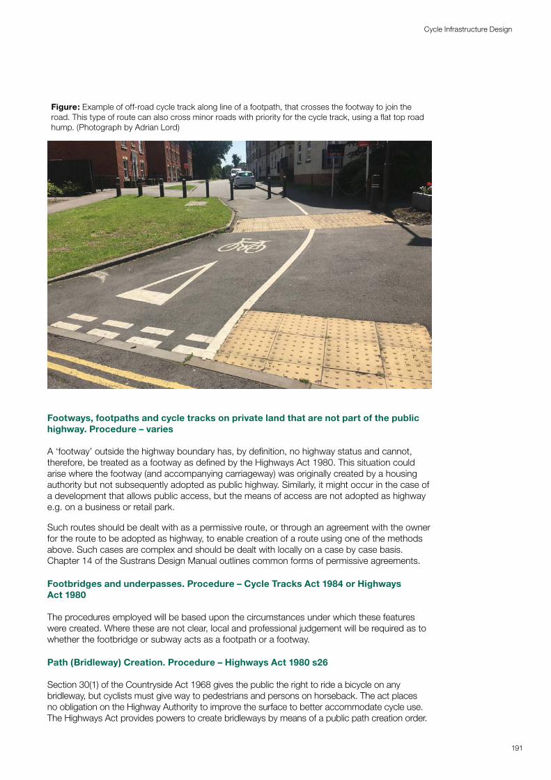
Figure: Example of off-road cycle track along line of a footpath, that crosses the footway to join the road. This type of route can also cross minor roads with priority for the cycle track, using a flat top road hump. (Photograph by Adrian Lord)
Footways, footpaths and cycle tracks on private land that are not part of the public highway. Procedure – varies
A ‘footway’ outside the highway boundary has, by definition, no highway status and cannot, therefore, be treated as a footway as defined by the Highways Act 1980. This situation could arise where the footway (and accompanying carriageway) was originally created by a housing authority but not subsequently adopted as public highway. Similarly, it might occur in the case of a development that allows public access, but the means of access are not adopted as highway e.g. on a business or retail park.
Such routes should be dealt with as a permissive route, or through an agreement with the owner for the route to be adopted as highway, to enable creation of a route using one of the methods above. Such cases are complex and should be dealt with locally on a case by case basis. Chapter 14 of the Sustrans Design Manual outlines common forms of permissive agreements.
Footbridges and underpasses. Procedure – Cycle Tracks Act 1984 or Highways Act 1980
The procedures employed will be based upon the circumstances under which these features were created. Where these are not clear, local and professional judgement will be required as to whether the footbridge or subway acts as a footpath or a footway.
Path (Bridleway) Creation. Procedure – Highways Act 1980 s26
Section 30(1) of the Countryside Act 1968 gives the public the right to ride a bicycle on any bridleway, but cyclists must give way to pedestrians and persons on horseback. The act places no obligation on the Highway Authority to improve the surface to better accommodate cycle use. The Highways Act provides powers to create bridleways by means of a public path creation order.
191
Cycle Infrastructure Design
Creating a new cycle track adjacent to a bridleway. Procedure – TCPA and GPDO
This process is similar to widening a footpath as described above, but the highway is adjacent to a bridleway and not a footpath.
Conversion of a footpath alongside a watercourse/river/canal. Procedure – varies
Cycle tracks created alongside a watercourse by the conversion of a public footpath will inevitably require engineering works, if only in the form of signs. In addition to the use of the Cycle Tracks Act or planning approval (if access is based on permissive rights), it may be necessary to obtain consent under the Water Resources Act 1991 – contact the Environment Agency for more information. In some regions and in most circumstances, the agreement of the Internal Drainage Board will be required where any work impacts upon its operations.
Cycling is permitted on most towpaths owned and maintained by the Canal & River Trust, and they frequently work closely with local authorities to improve routes for cyclists and pedestrians. In the case of footpaths alongside canals, the Canal & River Trust’s powers to introduce a byelaw prohibiting cycling take precedence over any highway rights. It is therefore recommended that contact be made with their local office to agree the best means of achieving and maintaining cycle access.
192
Cycle Infrastructure Design
Appendix D: Image list and credits
193
Cycle Infrastructure Design
Figure number Credit/source
Chapter 1 Cover Bikeability Trust
Fig 1.1 TfL
Fig 1.2 Wheels for Wellbeing
Fig 1.3 PJA
Fig 1.4 PJA
Fig 1.5 PJA
Fig 1.6 PJA
Fig 1.7 PJA
Fig 1.8 PJA
Fig 1.9 PJA
Fig 1.10 PJA
Chapter 2 Cover Wheels for Wellbeing
Fig 2.1 DfT
Fig 2.2 DfT
Fig 2.3 DfT
Fig 2.4 Wheels for Wellbeing
Chapter 3 Cover TfGM
Fig 3.1 DfT
Fig 3.2 PJA
Fig 3.3 DfT
Fig 3.4 PJA
Fig 3.5 PJA
Fig 3.6 PJA
Chapter 4 Cover PJA
Fig 4.1 PJA
Fig 4.2 DfT
Fig 4.3 PJA
Fig 4.4 PJA
Chapter 5 Cover DfT
Fig 5.1 DfT
Fig 5.2 PJA
Fig 5.3 PJA
Fig 5.4 PJA
Chapter 6 Title PJA
Fig 6.1 DfT – Manual for Streets
Fig 6.2 PJA
Fig 6.3 PJA
Fig 6.4 WSP (Wheels for Wellbeing)
Figure number Credit/source
Fig 6.5 WSP (Wheels for Wellbeing)
Fig 6.6 PJA
Fig 6.7 PJA
Fig 6.8 PJA
Fig 6.9 PJA
Fig 6.10 Wheels for Wellbeing
Fig 6.11 PJA
Fig 6.12 WSP (Wheels for Wellbeing)
Fig 6.13 PJA
Fig 6.14 PJA
Fig 6.15 PJA
Fig 6.16 PJA
Fig 6.17 PJA
Fig 6.18 PJA
Fig 6.19 PJA
Fig 6.20 PJA
Fig 6.21 PJA
Fig 6.22 PJA
Fig 6.23 PJA
Fig 6.24 PJA
Fig 6.25 PJA
Fig 6.26 PJA
Fig 6.27 PJA
Fig 6.28 Mark Strong
Fig 6.29 PJA
Fig 6.30 PJA
Fig 6.31 PJA
Fig 6.32 PJA
Fig 6.33 PJA
Chapter 7 Title PJA
Fig 7.1 PJA
Fig 7.2 PJA
Fig 7.3 PJA
Fig 7.4 PJA
Fig 7.5 DfT
Fig 7.6 PJA
Fig 7.7 PJA
Figure number Credit/source
Fig 7.8 Welsh Government
Fig 7.9 PJA
Fig 7.10 PJA
Fig 7.11 PJA
Chapter 8 Title Page Bikeability Trust
Fig 8.1 PJA
Fig 8.2 PJA
Fig 8.3 PJA
Fig 8.4 PJA
Fig 8.5 PJA
Chapter 9 Title Page PJA
Fig 9.1 PJA
Fig 9.2 PJA
Fig 9.3 PJA
Fig 9.4 PJA
Fig 9.5 PJA
Fig 9.6 PJA
Fig 9.7 PJA
Fig 9.8 PJA
Chapter 10 Title WSP
Fig 10.1 Nottingham CC
Fig 10.2 PJA
Fig 10.3 PJA
Fig 10.4 Cambridge Cycle Campaign
Fig 10.5 Lucy Marstrand
Fig 10.6 PJA
Fig 10.7 PJA
Fig 10.8 Lucy Marstrand
Fig 10.9 PJA
Fig 10.10 PJA
Fig 10.11 PJA
Fig 10.12 PJA
Fig 10.13 PJA
Fig 10.14 PJA
Fig 10.15 PJA
Fig 10.16 PJA
Fig 10.17 Lucy Marstrand
Fig 10.18 PJA
Fig 10.19 PJA
Fig 10.20 PJA
Fig 10.21 WSP
Fig 10.22 DfT TSRGD
Fig 10.23 PJA
Fig 10.24 WSP
Figure number Credit/source
Fig 10.25 PJA
Fig 10.26 WSP
Fig 10.27 PJA
Fig 10.28 PJA
Fig 10.29 PJA
Fig 10.30 PJA
Fig 10.31 WSP
Fig 10.32 WSP
Fig 10.33 PJA
Fig 10.34 PJA
Fig 10.35 PJA
Fig 10.36 PJA
Fig 10.37 Cambridgeshire CC
Fig 10.38 Lucy Marstrand
Fig 10.39 PJA
Fig 10.40 WSP
Fig 10.41 PJA
Fig 10.42 PJA
Fig 10.43 PJA
Fig 10.44 Cambridgeshire CC
Fig 10.45 PJA
Fig 10.46 PJA
Fig 10.47 PJA
Fig 10.48 PJA
Fig 10.49 Sustrans
Fig 10.50 PJA
Fig 10.51 PJA
Fig 10.52 PJA
Fig 10.53 Paul Hogarth Company
Fig 10.54 PJA
Fig 10.55 Wheels for Wellbeing
Chapter 11 Title DfT
Fig 11.1 PJA
Fig 11.2 PJA
Fig 11.3 PJA
Fig 11.4 PJA
Fig 11.5 PJA
Fig 11.6 PJA
Fig 11.7 PJA
Fig 11.8 PJA
Fig 11.9 PJA
Fig 11.10 PJA
Fig 11.11 PJA
Fig 11.12 PJA
Fig 11.13 PJA
194
Cycle Infrastructure Design
Figure number Credit/source
Fig 11.14 PJA
Fig 11.15 PJA
Fig 11.16 PJA
Chapter 12 Title DfT
Fig 12.1 WSP/Element Energy
Fig 12.2 WSP/Element Energy
Chapter 13 Title PJA
Fig 13.1 PJA
Fig 13.2 Transport Initiatives/ Nottingham City Council
Fig 13.3 PJA
Fig 13.4 PJA
Fig 13.5 PJA
Fig 13.6 PJA
Fig 13.7 PJA
Chapter 14 Title Cambridgeshire CC
Fig 14.1 PJA/Leicestershire CC
Fig 14.2 Cambridgeshire CC
Fig 14.3 PJA
Fig 14.4 Cambridgeshire CC
Fig 14.5 PlaceOnEarth
Fig 14.6 PJA
Fig 14.7 Cambridgeshire CC
Fig 14.8 Sandwell BC
Fig 14.9 DfT – Manual for Streets
Ch 15 Title Andy Pickett
195
Cycle Infrastructure Design