critical analysis of international precast concrete pipe ... - mdpi
TRANSCRIPT

infrastructures
Review
Critical Analysis of International Precast ConcretePipe Standards
Lui S. Wong 1 ID and Moncef L. Nehdi 2,* ID
1 VP Engineering & Quality, Con Cast Pipe, 299 Brock Road South, Puslinch, ON N0B 2J0, Canada;[email protected]
2 Department of Civil & Environmental Engineering, Western University, London, ON N6A 5B9, Canada* Correspondence: [email protected]; Tel.: +1-(519)-661-2111 (ext. 88308)
Received: 18 May 2018; Accepted: 13 June 2018; Published: 22 June 2018�����������������
Abstract: Reinforced concrete pipe (RCP) standard guidelines and industry practice have ratherbeen disconnected from the end-users’ expectations. No genuine effort has so far been made tocreate synergy between the expertise gained and advances made around the world. With the adventof strong competition from flexible pipe products and changing end-user expectations, a criticallook at the current state-of-the-art is needed. In the present paper, RCP standards from a studyarea representing a quarter of the world’s population (Canada, United States, United Kingdom,China, Australia and New Zealand) were critically analyzed. Comparisons were made in terms ofproduct and material requirements, structural load testing, hydrostatic performance, and durabilityrequirements. It is shown that the RCP sector lags modern developments in concrete technology,standard code advances and materials innovations. The analysis also revealed various knowledgegaps in terms of the mechanical, hydrostatic and durability performance of RCP. Recommendationsemanating from this critical analysis aim at tailoring performance-based guidelines that can bettercapture current market needs and user expectations.
Keywords: concrete pipe; design; standard; comparison; load test; hydrostatic test; durability;hydrogen sulfide attack; corrosion
1. Introduction
1.1. Reinforced Concrete Pipe Development
Archeological evidence shows that sewer type construction has existed for thousands ofyears [1]. The documented history of gravity sewer pipe using rigid materials such as concrete,clay and bricks in North America can be traced back to the late 19th century [2]. Through scientificresearch, engineers have continuously evolved the pipe’s strength, durability, and joint performance.For instance, Marston et al. [3] were the first to develop a rational design approach for a rigid pipe.They discovered that the installation conditions influenced the load acting on the pipe. Orlander [4] andSpanglar [5] further enhanced Marston’s theory by better describing the stress distribution around the pipe.
In the mid-1960s, Frank Heger studied the structural behavior of reinforced concrete pipe (RCP)under the three-edge bearing test [6]. This test is still being used today as a primary structural testingmethod for rigid concrete pipes. The use of welded deformed wire fabric as pipe reinforcement wasalso reported by Frank Heger. It enhanced crack control and offered better bonding between theconcrete and reinforcing steel, resulting in a substantial reduction of the needed reinforcing steel [7].With advancements in computational technology, finite element modeling (FEM) was used to simulatethe pipe-soil interaction, which provided a better approximation of the earth pressure envelopearound the pipe. In the 1970s and 1980s, Heger developed earth pressure distribution based on four
Infrastructures 2018, 3, 18; doi:10.3390/infrastructures3030018 www.mdpi.com/journal/infrastructures
Infrastructures 2018, 3, 18 2 of 25
standard installation methods. This was later published by the American Society of Civil Engineering(ASCE) [8], AASHTO LRFD [9] and the Canadian Highway Bridge Design Code [10]. Going intothe new millennium, fiber-reinforced concrete pipe was investigated by the industry. Steel fiber forpipe reinforcement was adopted in European Standard BS EN 1916 [11] in 2002. The use of steelfiber as primary pipe reinforcement was first published in the US [12] in 2013, followed by usingsynthetic fiber-reinforced concrete pipe (FRCP) [13] in 2015. Several studies of fiber-reinforced concretein Canada were published between 2012 and 2016 [14–17].
1.2. Competition from Flexible Pipe Industry
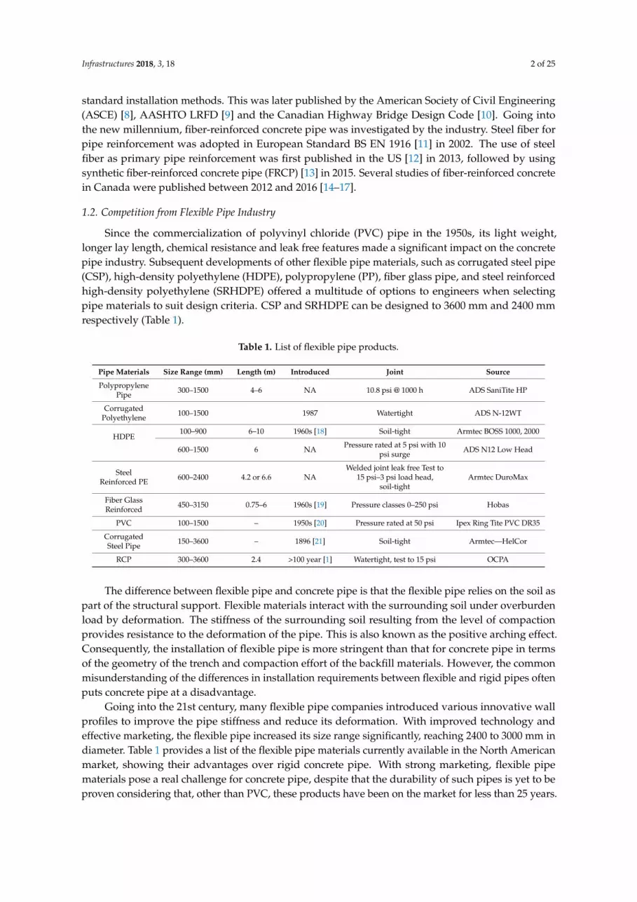
Since the commercialization of polyvinyl chloride (PVC) pipe in the 1950s, its light weight,longer lay length, chemical resistance and leak free features made a significant impact on the concretepipe industry. Subsequent developments of other flexible pipe materials, such as corrugated steel pipe(CSP), high-density polyethylene (HDPE), polypropylene (PP), fiber glass pipe, and steel reinforcedhigh-density polyethylene (SRHDPE) offered a multitude of options to engineers when selectingpipe materials to suit design criteria. CSP and SRHDPE can be designed to 3600 mm and 2400 mmrespectively (Table 1).
Table 1. List of flexible pipe products.
Pipe Materials Size Range (mm) Length (m) Introduced Joint Source
PolypropylenePipe 300–1500 4–6 NA 10.8 psi @ 1000 h ADS SaniTite HP
CorrugatedPolyethylene 100–1500 1987 Watertight ADS N-12WT
HDPE100–900 6–10 1960s [18] Soil-tight Armtec BOSS 1000, 2000
600–1500 6 NA Pressure rated at 5 psi with 10psi surge ADS N12 Low Head
SteelReinforced PE 600–2400 4.2 or 6.6 NA
Welded joint leak free Test to15 psi–3 psi load head,
soil-tightArmtec DuroMax
Fiber GlassReinforced 450–3150 0.75–6 1960s [19] Pressure classes 0–250 psi Hobas
PVC 100–1500 – 1950s [20] Pressure rated at 50 psi Ipex Ring Tite PVC DR35
CorrugatedSteel Pipe 150–3600 – 1896 [21] Soil-tight Armtec—HelCor
RCP 300–3600 2.4 >100 year [1] Watertight, test to 15 psi OCPA
The difference between flexible pipe and concrete pipe is that the flexible pipe relies on the soil aspart of the structural support. Flexible materials interact with the surrounding soil under overburdenload by deformation. The stiffness of the surrounding soil resulting from the level of compactionprovides resistance to the deformation of the pipe. This is also known as the positive arching effect.Consequently, the installation of flexible pipe is more stringent than that for concrete pipe in termsof the geometry of the trench and compaction effort of the backfill materials. However, the commonmisunderstanding of the differences in installation requirements between flexible and rigid pipes oftenputs concrete pipe at a disadvantage.
Going into the 21st century, many flexible pipe companies introduced various innovative wallprofiles to improve the pipe stiffness and reduce its deformation. With improved technology andeffective marketing, the flexible pipe increased its size range significantly, reaching 2400 to 3000 mm indiameter. Table 1 provides a list of the flexible pipe materials currently available in the North Americanmarket, showing their advantages over rigid concrete pipe. With strong marketing, flexible pipematerials pose a real challenge for concrete pipe, despite that the durability of such pipes is yet to beproven considering that, other than PVC, these products have been on the market for less than 25 years.

Infrastructures 2018, 3, 18 3 of 25
1.3. Hydrostatic Performance Challenges
There is a need to preserve the advantages of reinforced concrete pipe through understandingthe expectations of the end user and the advent of technological advancements and innovations thatcan propel its performance and bridge the gap between the market needs and current standards.A pipeline is expected to resist infiltration of groundwater or soil and resist the exfiltration of theflow [22]. The pipe joint is expected to withstand movements of the pipe such as deflections withoutcausing leakage. Profiled gaskets, O-ring gaskets or welded joints are needed where the groundwaterlevel is above invert and infiltration cannot be tolerated, especially in sanitary applications. The term“watertightness” is commonly used by specifiers to describe this condition, but this is usuallymisinterpreted by the pipe manufacturers. Pipe manufacturers usually perform limited routinehydrostatic tests internally and assume that the joint performs equally to the corresponding externalpressure. The watertightness of a joint is interpreted based on laboratory results from the gasketsupplier. Hydrostatic pressure was quantified for instance by the Ministry of Transportation Ontario(MTO) Gravity Pipe Design Guideline [22] at 10.5-m head for RCP and 7.5-m for HDPE and PVCwithout leak. This quantifies the hydrostatic performance expectations and conditions of any gravitysewer, including RCP. Joint performance of RCP was mentioned in several reports and publications [22,23].Joint failures were reported due to ground movement (e.g., soil settlement), infiltration and exfiltrationcaused by installation and joint sealant materials, and inadequate design and application.
1.4. Bio-Corrosion Challenges
Challenges of microbiologically induced precast concrete pipe corrosion (MICC) posesa significant threat to RCP used to carry sewage. Concrete corrosion due to the exposure to hydrogensulfide in the sewerage environment was first reported by Parker [24] in 1945. Hydrogen sulfide gasinduced by bacteria growth on the interface between the sewage and the pipe forms sulfuric acid.The acidic environment rich in sulfate corrodes the upper part of the concrete pipe causing peelingand reduction in wall thickness and subsequent reinforcing steel corrosion. Figure 1 exhibits a 40-yearold pipe removed from its service, showing the level of the sewerage. The deterioration results inmechanical strength reduction and hence, service life reduction. Wu et al. [25] recently reporteda reduction in service life from 75 and 100 years to less than 20 years for a concrete tunnel segment inEdmonton constructed in 2001. 50% reduction in the service life of concrete truck sewers were reportedin their findings indicating various deterioration due to the biogenic corrosion of concrete. In recentyears, various researchers have explored developing prediction models for the concrete pipe wallreduction rate and service life span [26–28] by considering factors that influence MICC. New findingshowever still require implementation in concrete pipe standards so that innovative improvements canbe introduced in full scale RCP production.
Infrastructures 2018, 3, x FOR PEER REVIEW 3 of 25
1.3. Hydrostatic Performance Challenges
There is a need to preserve the advantages of reinforced concrete pipe through understanding the expectations of the end user and the advent of technological advancements and innovations that can propel its performance and bridge the gap between the market needs and current standards. A pipeline is expected to resist infiltration of groundwater or soil and resist the exfiltration of the flow [22]. The pipe joint is expected to withstand movements of the pipe such as deflections without causing leakage. Profiled gaskets, O-ring gaskets or welded joints are needed where the groundwater level is above invert and infiltration cannot be tolerated, especially in sanitary applications. The term “watertightness” is commonly used by specifiers to describe this condition, but this is usually misinterpreted by the pipe manufacturers. Pipe manufacturers usually perform limited routine hydrostatic tests internally and assume that the joint performs equally to the corresponding external pressure. The watertightness of a joint is interpreted based on laboratory results from the gasket supplier. Hydrostatic pressure was quantified for instance by the Ministry of Transportation Ontario (MTO) Gravity Pipe Design Guideline [22] at 10.5-m head for RCP and 7.5-m for HDPE and PVC without leak. This quantifies the hydrostatic performance expectations and conditions of any gravity sewer, including RCP. Joint performance of RCP was mentioned in several reports and publications [22,23]. Joint failures were reported due to ground movement (e.g., soil settlement), infiltration and exfiltration caused by installation and joint sealant materials, and inadequate design and application.
1.4. Bio-Corrosion Challenges
Challenges of microbiologically induced precast concrete pipe corrosion (MICC) poses a significant threat to RCP used to carry sewage. Concrete corrosion due to the exposure to hydrogen sulfide in the sewerage environment was first reported by Parker [24] in 1945. Hydrogen sulfide gas induced by bacteria growth on the interface between the sewage and the pipe forms sulfuric acid. The acidic environment rich in sulfate corrodes the upper part of the concrete pipe causing peeling and reduction in wall thickness and subsequent reinforcing steel corrosion. Figure 1 exhibits a 40-year old pipe removed from its service, showing the level of the sewerage. The deterioration results in mechanical strength reduction and hence, service life reduction. Wu et al. [25] recently reported a reduction in service life from 75 and 100 years to less than 20 years for a concrete tunnel segment in Edmonton constructed in 2001. 50% reduction in the service life of concrete truck sewers were reported in their findings indicating various deterioration due to the biogenic corrosion of concrete. In recent years, various researchers have explored developing prediction models for the concrete pipe wall reduction rate and service life span [26–28] by considering factors that influence MICC. New findings however still require implementation in concrete pipe standards so that innovative improvements can be introduced in full scale RCP production.
Figure 1. 40 year-old concrete pipe showing the level of sewage.
Figure 1. 40 year-old concrete pipe showing the level of sewage.

Infrastructures 2018, 3, 18 4 of 25
1.5. Scope of Study
This paper compares the manufacturing standards of RCP used in five concrete pipe consumptioncountries representing a quarter of the world’s population: Canada, the United States of America (US),the United Kingdom (UK), Australia and New Zealand, and the People’s Republic of China (China).These countries are hereafter called the study area. The governing RCP standards in the study area arelisted in Table 2. In addition to the geometry and tolerance requirements, the RCP acceptance criteriain the study area consist of structural strength, hydrostatic performance, and concrete quality. Table 3exhibits the similarities and differences of the various acceptance criteria. This study endeavors toreveal the shortcomings of current standards and the discrepancy between them and the pipe marketexpectations, aiming at supporting the need for change and the potential development of standardsthat capture recent technological RCP advancements. The study will particularly focus on comparingstructural strength examination, hydrostatic pressure performance evaluation and concrete durabilitymeasurement provisions in current RCP standards. RCP structural design methodology, hydraulicdesign as well as the pressure pipe application are not within the scope of the study.
Table 2. List of RCP standards.
Study Area Design Standardand Reference
Materials andManufacturing
Specification
StructuralStrength Testing
Standard
HydrostaticPerformance
Testing Standard
CanadaCSA S6
OCPA Concrete PipeDesign Manual
CSA A257.2 (RCP) CSA A257.0 CSA A257.0
USAASCE15
ACPA Concrete PipeDesign Manual
ASTM C76 (RCP)ASTM C1765 (SFRCP)
ASTM C1818 (SynFRCP)ASTM C497 ASTM C443
ASTM C1628
UnitedKingdom BS EN 1295 BS EN 1916 (RCP, SFRCP) BS EN 1916 BS EN 1916
Australia &New Zealand AS/NZS 3725 AS/NZS 4058 (RCP)
AS4139 (FRCP) AS/NZS 4058 AS/NZS 4058
China CECS 143 GB/T11836 (RCP) GB/T16752 GB/T16752
Table 3. Acceptance criteria for RCP.
Study Area Materials DurabilityTest
VisualInspection
ConcreteStrength
ReinforcementPlacement and Amount
LoadTest
HydrostaticTest
Canada Absorption Yes Yes Yes Note 1USA 1 Yes Absorption Yes Yes Note 2USA 2 Yes Absorption Yes Yes Cover and amount Note 2
UK Yes Yes Cover only Yes YesAustralia &
New Zealand Absorption Yes Cover only Yes Yes
China Yes Yes Cover only Yes Yes
Note 1—owner required; Note 2—joint conform to ASTM C443, C990, C1628 or other specifications.
1.6. Selection of Study Area
The study area was selected to cover countries having well-established concrete pipe associationsand/or related industrial non-profit regulatory bodies. The US and Canada are selected asa representation of North American standards. The American Standards of Testing and Materials(ASTM) are widely adopted and referenced around the world. British Standards were selected asa representation for European countries and many Commonwealth Nations. Countries such asMalaysia also adopt British Standards for reinforced concrete pipe. Hong Kong, a former Britishoversea colony, also adopts British Standards for drainage design guides. Australia and New Zealandare part of the front end of pipe technology advancement and were also selected. China, who withabout 19% of the world’s population is one of the fastest growing economies in the world, was also
Infrastructures 2018, 3, 18 5 of 25
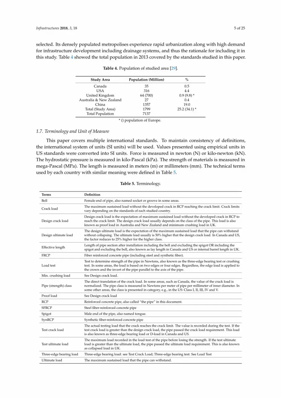
selected. Its densely populated metropolises experience rapid urbanization along with high demandfor infrastructure development including drainage systems, and thus the rationale for including it inthis study. Table 4 showed the total population in 2013 covered by the standards studied in this paper.
Table 4. Population of studied area [29].
Study Area Population (Million) %
Canada 35 0.5USA 316 4.4
United Kingdom 64 (700) 0.9 (9.8) *Australia & New Zealand 27 0.4
China 1357 19.0Total (Study Area) 1799 25.2 (34.1) *Total Population 7137
* () population of Europe.
1.7. Terminology and Unit of Measure
This paper covers multiple international standards. To maintain consistency of definitions,the international system of units (SI units) will be used. Values presented using empirical units inUS standards were converted into SI units. Force is measured in newton (N) or kilo-newton (kN).The hydrostatic pressure is measured in kilo-Pascal (kPa). The strength of materials is measured inmega-Pascal (MPa). The length is measured in meters (m) or millimeters (mm). The technical termsused by each country with similar meaning were defined in Table 5.
Table 5. Terminology.
Terms Definition
Bell Female end of pipe, also named socket or groove in some areas.
Crack load The maximum sustained load without the developed crack in RCP reaching the crack limit. Crack limitsvary depending on the standards of each studied country.
Design crack loadDesign crack load is the expectation of maximum sustained load without the developed crack in RCP toreach the crack limit. The design crack load usually depends on the class of the pipe. This load is alsoknown as proof load in Australia and New Zealand and minimum crushing load in UK.
Design ultimate loadThe design ultimate load is the expectation of the maximum sustained load that the pipe can withstandwithout collapsing. The ultimate load usually is 50% higher that the design crack load. In Canada and US,the factor reduces to 25% higher for the higher class.
Effective length Length of pipe section after installation including the bell and excluding the spigot OR including thespigot and excluding the bell, also known as lay length in Canada and US or internal barrel length in UK.
FRCP Fiber reinforced concrete pipe (including steel and synthetic fiber).
Load testTest to determine strength of the pipe in Newtons, also known as the three-edge bearing test or crushingtest. In some areas, the load is based on two edges or four edges. Regardless, the edge load is applied tothe crown and the invert of the pipe parallel to the axis of the pipe.
Min. crushing load See Design crack load.
Pipe (strength) classThe direct translation of the crack load. In some areas, such as Canada, the value of the crack load isnormalized. The pipe class is measured in Newtons per meter of pipe per millimeter of inner diameter. Insome other areas, the class is presented in category, e.g., in the US: Class I, II, III, IV and V.
Proof load See Design crack load
RCP Reinforced concrete pipe, also called “the pipe” in this document.
SFRCP Steel fiber-reinforced concrete pipe
Spigot Male end of the pipe, also named tongue.
SynRCP Synthetic fiber-reinforced concrete pipe
Test crack loadThe actual testing load that the crack reaches the crack limit. The value is recorded during the test. If thetest crack load is greater than the design crack load, the pipe passed the crack load requirement. This loadis also known as three-edge bearing load or D-load in Canada and US.
Test ultimate loadThe maximum load recorded in the load test of the pipe before losing the strength. If the test ultimateload is greater than the ultimate load, the pipe passed the ultimate load requirement. This is also knownas collapsed load in UK.
Three-edge bearing load Three-edge bearing load: see Test Crack Load; Three-edge bearing test: See Load Test
Ultimate load The maximum sustained load that the pipe can withstand.

Infrastructures 2018, 3, 18 6 of 25
2. Products and Materials Requirements
2.1. Geometrical Requirements
The pipe’s geometrical requirements including size, wall thickness, shape, and joint profile providenot only hydraulic capacity, but also structural strength to withstand overburden earth and live loads.Joint design provides necessary hydraulic continuity and hydrostatic performance. Australia and NewZealand offer the widest pipe size range from 100 mm to 4200 mm in inner diameter, while Canada andthe US offer sizes between 300 mm to 3600 mm. The RCP size is limited by its mass and dimensionsnot to exceed logistic limits of local transportation authorities. Each study area offers multiple wallthickness specifications for various pipe classes. Increasing the pipe’s wall thickness allows for morespace to accommodate the reinforcing steel, thus increasing flexural and shear strength. In Canada andthe US, there are three types of wall thickness classes named A, B and C; each type is mathematicallyrelated to the size of the pipe inner diameter as illustrated in Equation (1).
WT =ID300
+ x (Wall A) ; WT =ID300
+ 25.4 (Wall B) ; WT =ID300
+ 38.1 (Wall C) (1)
where: x varies from 0 to 19.1 mm for 900 mm–300 mm pipe diameter; x = 0 for pipe diameter of975 mm or larger. ID = pipe nominal size in mm; WT = pipe wall thickness in mm
It is necessary to control tolerances on pipe geometrical characteristics to ensure that theabove-mentioned properties meet the requirements.
Table 6 compares the tolerances of the pipe inner diameter and wall thickness among all studyareas. The US and Canada have tighter inner diameter tolerances of ±5 mm for smaller size pipes(e.g., 300-mm) and ±9 mm for larger size pipes (e.g., 3000 mm), respectively. China has a tighterwall thickness tolerance of −2 mm for the 300 mm to 675 mm pipe diameter range, and −5 mm for3000 mm pipe diameter. Canada does not have an upper limit for wall thickness if walls thicker thanspecified will not reduce the strength of the pipe. In the UK, the tolerance for pipe size is not found inthe specifications. However, the requirement for the joint tolerance is specified in BS EN 1916:2002Section 4.3.4 in relation to durability evaluation.
Table 6. Tolerance requirements for pipe size and wall thickness (mm).
SizeInner Diameter Tolerance Wall Thickness Tolerance
Canada US AS/NZ China Canada US AS/NZ China
300 ±5 ±6 ±7 +4/−8 −3/+ ±3 −3/+5 −2/+8450 ±7 ±8 ±7 +4/−8 −3/+ ±3 −4/+5 −2/+8600 ±9 ±9 ±7 +4/−8 −4/+ ±4 ±5 −2/+8675 ±7 ±7 ±8 +4/−8 −4/+ ±4 ±6 −2/+8900 ±9 ±9 ±8 +6/−10 −5/+ ±5 ±7 −3/+10
1200 ±10 ±9 ±8 +6/−10 −5/+ ±5 ±8 −3/+101500 ±10 ±9 ±10 +6/−10 −5/+ ±5 ±9 −3/+101800 ±10 ±9 ±13 +8/−12 −5/+ ±5 ±10 −4/+122400 ±10 ±9 ±13 +8/−12 −5/+ ±5 ±10 −4/+123000 ±10 ±9 ±13 +10/−14 −5/+ ±5 ±10 −5/+14
In terms of effective length, standards in Canada and the US require that the pipe be not less than10 mm per meter length, or 13 mm whichever is less. Australia and New Zealand have an effectivelength tolerance of 15 mm; and China allows tolerances of 18 mm over and 12 mm under. The effectivelength has a relatively greater tolerance since the impact on the overall length of the pipeline isless significant and field adjustment is usually made. The square-ness of the end face of the pipe isdetermined by comparing the effective length measurement on opposite sides of the pipe. Out ofsquare-ness on the end face will result in misalignment of the pipeline. Excessive or uneven gapwill also pose a threat to joint performance. Australia and New Zealand have the most stringent

Infrastructures 2018, 3, 18 7 of 25
tolerances of 2 to 10 mm between 300 mm to 3000 mm of inner pipe diameter. Canada and the USallow up to 20 mm for 3000 mm diameter pipe. Table 7 provides a full comparison of pipe end facesquare-ness in standards. Standards in Canada and the US do not specify geometric measurementmethods. However, the quality program describes the use of go-and-no-go gauge in evaluating thesize and joint tolerance; and the inspection of the steel header and pallet, which forms the pipe joint.Australia and New Zealand specify that such measurements should be taken at right angles and ata specific location along the pipe. A mean value shall be taken from the results of internal diametermeasurements. The length of the pipe shall be taken at three one-third points around the circumference.In China, the geometric measurement seems to be the most stringent among all pipe performancemeasures. Specific measurement methods for inner diameter, measurement points, joint geometry,effective length, thickness, straightness and square-ness are defined.
Table 7. Maximum variation in length between opposite sides (mm).
Size CAN/US AS/NZ China
300 6 2 10450 6 2 10600 6 3 10675 7 3 10900 9 5 10
1200 12 6 121500 15 8 151800 16 9 152400 20 10 153000 20 10 15
2.2. Concrete for Precast Pipe
The mechanical strength of concrete provides the rigidity of the pipe to withstand varioustypes of loads, including earth load, live load, fluid load and induced load due to bedding andinstallation. Typical compressive strength specifications for concrete used in pipes are listed in Table 8.Strength evaluation relies mostly on quality control cylinders cast from the concrete mixture during thepipe’s manufacturing process. Core samples from the actual pipe are usually an acceptable alternativethough undesirable due to the often-tight spacing of the reinforcing steel. The compressive strengthstandard requirements for Canada and the US vary from 28 MPa to 42 MPa, depending on the pipe sizeand class. Higher class and/or larger pipe size require higher compressive strength. Some standardsspecify 40 MPa regardless of the pipe class and size. In China, additional factors are applied to thecylinder compressive strength to account for different manufacturing processes. These factors are1.25, 1.0, 1.0, and 1.5 for pipes made by the centrifuging process, packer head, vertical vibration,and vibrational pressing, respectively.
Table 8. 28-day Compressive strength requirements.
Study Areas Class 1 Class 2 Class 3 Class 4 Class 5
Canada –50D:30 MPa ≤ 2400 mm35MPa > 2400 mm
65D:30 MPa ≤ 2100 mm35 MPa > 2100 mm
100D:30 MPa ≤ 1350 mm35 MPa > 1350 mm
140D:40 MPa all size
USCL1:28 MPa ≤ 2400 mm34 MPa > 2400 mm
CL2:28 MPa ≤ 2400 mm34 MPa > 2400 mm
CL3:28 MPa ≤ 2100 mm34 MPa > 2100 mm
CL4:28 MPa ≤ 1350 mm(B-wall) or35 MPa larger dia.1650 mm (C-wall)
CL5:42 MPa all size
UK 40 MPa all sizes and classes
Australia &New Zealand Not specified in the materials standard
China 40 MPa all size and class
Infrastructures 2018, 3, 18 8 of 25
2.3. Conventional Reinforcement and Concrete Cover
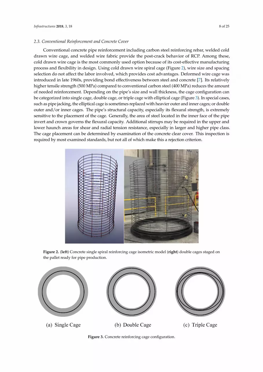
Conventional concrete pipe reinforcement including carbon steel reinforcing rebar, welded colddrawn wire cage, and welded wire fabric provide the post-crack behavior of RCP. Among these,cold drawn wire cage is the most commonly used option because of its cost-effective manufacturingprocess and flexibility in design. Using cold drawn wire spiral cage (Figure 2), wire size and spacingselection do not affect the labor involved, which provides cost advantages. Deformed wire cage wasintroduced in late 1960s, providing bond effectiveness between steel and concrete [7]. Its relativelyhigher tensile strength (500 MPa) compared to conventional carbon steel (400 MPa) reduces the amountof needed reinforcement. Depending on the pipe’s size and wall thickness, the cage configuration canbe categorized into single cage, double cage, or triple cage with elliptical cage (Figure 3). In special cases,such as pipe jacking, the elliptical cage is sometimes replaced with heavier outer and inner cages; or doubleouter and/or inner cages. The pipe’s structural capacity, especially its flexural strength, is extremelysensitive to the placement of the cage. Generally, the area of steel located in the inner face of the pipeinvert and crown governs the flexural capacity. Additional stirrups may be required in the upper andlower haunch areas for shear and radial tension resistance, especially in larger and higher pipe class.The cage placement can be determined by examination of the concrete clear cover. This inspection isrequired by most examined standards, but not all of which make this a rejection criterion.
Infrastructures 2018, 3, x FOR PEER REVIEW 8 of 25
2.3. Conventional Reinforcement and Concrete Cover
Conventional concrete pipe reinforcement including carbon steel reinforcing rebar, welded cold drawn wire cage, and welded wire fabric provide the post-crack behavior of RCP. Among these, cold drawn wire cage is the most commonly used option because of its cost-effective manufacturing process and flexibility in design. Using cold drawn wire spiral cage (Figure 2), wire size and spacing selection do not affect the labor involved, which provides cost advantages. Deformed wire cage was introduced in late 1960s, providing bond effectiveness between steel and concrete [7]. Its relatively higher tensile strength (500 MPa) compared to conventional carbon steel (400 MPa) reduces the amount of needed reinforcement. Depending on the pipe’s size and wall thickness, the cage configuration can be categorized into single cage, double cage, or triple cage with elliptical cage (Figure 3). In special cases, such as pipe jacking, the elliptical cage is sometimes replaced with heavier outer and inner cages; or double outer and/or inner cages. The pipe’s structural capacity, especially its flexural strength, is extremely sensitive to the placement of the cage. Generally, the area of steel located in the inner face of the pipe invert and crown governs the flexural capacity. Additional stirrups may be required in the upper and lower haunch areas for shear and radial tension resistance, especially in larger and higher pipe class. The cage placement can be determined by examination of the concrete clear cover. This inspection is required by most examined standards, but not all of which make this a rejection criterion.
In Canada, the requirement to inspect the placement of reinforcement is optional depending on the requirement of the owner. The quality of the placement is usually reflected in the load test. If the permissible variation exceeds the minimum cover, the pipe is still acceptable if its capacity meets or exceeds the target crack load and ultimate load. In the US, the pipe may be accepted based on either of the following options: conducting the load test, which does not require the inspection of the cage placement; or to fully inspect the steel amount, cage placement and concrete cover, which exempts the destructive load test. The UK, Australia, New Zealand, and China require the inspection of the concrete cover regardless of the load test result. In addition, the concrete cover offers a protective barrier against the ingress of harmful species such as sulfate and chloride ions. Given the same concrete quality in an aggressive environment, the larger the cover the longer is the allowed time for chloride ions to penetrate and reach the reinforcing steel and initiate corrosion.
Figure 2. (left) Concrete single spiral reinforcing cage isometric model (right) double cages staged on the pallet ready for pipe production. Figure 2. (left) Concrete single spiral reinforcing cage isometric model (right) double cages staged onthe pallet ready for pipe production.Infrastructures 2018, 3, x FOR PEER REVIEW 9 of 25
Figure 3. Concrete reinforcing cage configuration.
Table 9 lists the minimum concrete cover requirements in relationship to fabrication for each study area. In terms of concrete cover thickness, a minimum of 13-mm is specified in Canada and the US, without specifying the exact measurement method or how measurements are recorded. In contrast, China requires full concrete cover measurements to be carried out at three specific locations along the pipe axis with each location having three points spaced at 120 degrees apart around the circumference. These measurements are taken by exposing the reinforcing steel.
Table 9. Concrete cover requirements.
Study Area Condition Permissible Limit Mating Surface
Canada/US Single cage Place at 35–50% from inner wall, min 13 mm
Spigot 6.5 mm to the circumf. Wire
Bell 13 mm to the circumf. wire Double/multiple cages:
Wall < 63 mm Wall ≥ 63 mm
19 mm, min 13 mm 25 mm, min 13 mm
No restriction to the longitudinal wire
UK General condition 15 mm or max aggregate size whichever is larger *
Not specified
Australia/New Zealand
Dry Cast Wall ≤ 25 mm 25 mm < wall ≤ 35 mm Wall > 35 mm Wet Cast (50 MPa)
Barrel ** 6/- mm 8/- mm 10/20 mm 25/35 mm
Mating surface ** 4/- mm 5/- mm 6/10 mm 25/35 mm
China Wall ≤ 40 mm 40 mm < Wall ≤ 100 mm Wall > 100 mm
Min 10 mm cover Min 15 mm cover Min 20 mm cover
Not specified
* BS 5911-1:2002 Section 6.1.1; ** Minimum cover for normal exposure/marine exposure.
3. Product Strength Evaluation
3.1. Pipe Strength Classification
Pipe strength is a common way to classify concrete pipes. The class either reflects the normalized load values or is presented by a sequential category number or alphabetically. In Canada, the RCP class represents the design crack load in Newtons per meter length per millimeter inner diameter that the pipe can withstand. For example, 65-D represents a pipe that can withstand 65 N per meter length per millimeter inner diameter, known as the design load, without a single crack reaching the crack limit. This is a normalized value, which can be translated into the minimum design crack load required in the load test by multiplying the inner diameter and the actual length of the pipe specimen (Equation (2)). The pipe is also required to be tested to its ultimate capacity. A minimum safety factor of 1.5 must be exceeded for 100-D pipes or lower, and 1.25 for 140-D pipes or higher.
LIDCDL ××= and UL = SF × DL (2)
Figure 3. Concrete reinforcing cage configuration.

Infrastructures 2018, 3, 18 9 of 25
In Canada, the requirement to inspect the placement of reinforcement is optional depending onthe requirement of the owner. The quality of the placement is usually reflected in the load test. If thepermissible variation exceeds the minimum cover, the pipe is still acceptable if its capacity meets orexceeds the target crack load and ultimate load. In the US, the pipe may be accepted based on eitherof the following options: conducting the load test, which does not require the inspection of the cageplacement; or to fully inspect the steel amount, cage placement and concrete cover, which exemptsthe destructive load test. The UK, Australia, New Zealand, and China require the inspection of theconcrete cover regardless of the load test result. In addition, the concrete cover offers a protectivebarrier against the ingress of harmful species such as sulfate and chloride ions. Given the same concretequality in an aggressive environment, the larger the cover the longer is the allowed time for chlorideions to penetrate and reach the reinforcing steel and initiate corrosion.
Table 9 lists the minimum concrete cover requirements in relationship to fabrication for each studyarea. In terms of concrete cover thickness, a minimum of 13-mm is specified in Canada and the US,without specifying the exact measurement method or how measurements are recorded. In contrast,China requires full concrete cover measurements to be carried out at three specific locations along thepipe axis with each location having three points spaced at 120 degrees apart around the circumference.These measurements are taken by exposing the reinforcing steel.
Table 9. Concrete cover requirements.
Study Area Condition Permissible Limit Mating Surface
Canada/US Single cage Place at 35–50% frominner wall, min 13 mm Spigot 6.5 mm to the circumf. Wire
Bell 13 mm to the circumf. wire
Double/multiple cages:Wall < 63 mmWall ≥ 63 mm
19 mm, min 13 mm25 mm, min 13 mm No restriction to the longitudinal wire
UK General condition 15 mm or max aggregatesize whichever is larger * Not specified
Australia/NewZealand
Dry CastWall ≤ 25 mm25 mm < wall ≤ 35 mmWall > 35 mmWet Cast (50 MPa)
Barrel **6/- mm8/- mm10/20 mm25/35 mm
Mating surface **4/- mm5/- mm6/10 mm25/35 mm
ChinaWall ≤ 40 mm40 mm < Wall ≤ 100 mmWall > 100 mm
Min 10 mm coverMin 15 mm coverMin 20 mm cover
Not specified
* BS 5911-1:2002 Section 6.1.1; ** Minimum cover for normal exposure/marine exposure.
3. Product Strength Evaluation
3.1. Pipe Strength Classification
Pipe strength is a common way to classify concrete pipes. The class either reflects the normalizedload values or is presented by a sequential category number or alphabetically. In Canada, the RCPclass represents the design crack load in Newtons per meter length per millimeter inner diameterthat the pipe can withstand. For example, 65-D represents a pipe that can withstand 65 N per meterlength per millimeter inner diameter, known as the design load, without a single crack reaching thecrack limit. This is a normalized value, which can be translated into the minimum design crack loadrequired in the load test by multiplying the inner diameter and the actual length of the pipe specimen(Equation (2)). The pipe is also required to be tested to its ultimate capacity. A minimum safety factorof 1.5 must be exceeded for 100-D pipes or lower, and 1.25 for 140-D pipes or higher.
DL = C × ID × L and UL = SF × DL (2)

Infrastructures 2018, 3, 18 10 of 25
where: DL = design crack load in N; C = class of pipe in N/m/mm; ID = inner diameter in mm;L = effective length in m; UL = ultimate load; SF = safety factor.
In the UK, the pipe class represents the design ultimate load in kilo-newton per meter length andper meter diameter of the pipe. For example, Class 120 indicates that the pipe can withstand 120 kN,known as collapse load or crush load, per meter length per meter inner diameter without collapsing.The design crack load is specified as 67% of the design ultimate; hence 80.4 kN/m/m for Class 120 pipe.This is equivalent to a safety factor of 1.5 between the design crack load and ultimate load.
The load requirements of each class in the US are equivalent to those in Canada, except thatthe class is represented by sequential numbers instead of the load. Class 2, 3, 4, and 5 in the US areequivalent to 50-D, 65-D, 100-D and 140-D in Canada. China, Australia and New Zealand also usesequential numbers to represent pipe strength category. Class 1 and Class 2 in China are equivalent toClass 1 and Class 3 in the US, respectively. The design crack load requirements of each class specified inAustralia and New Zealand do not have a linear relationship to the pipe size. The required design crackload, known as proof load, for each class is listed in Table 4.2 in AS/NZ 4058:2007 [30]. For example,Class 6 is closer to 140-D in Canada when the pipe diameter is smaller than 450-mm, but 100-D whenthe diameter is larger than 2100 mm. Figures 4 and 5 display the load class comparison among thestudy areas. The linearity and non-linearity are also portrayed in Figure 6 with the pipe strength atcrack load is normalized to Newton per meter length pipe per mm inner diameter.
Infrastructures 2018, 3, x FOR PEER REVIEW 10 of 25
where: DL = design crack load in N; C = class of pipe in N/m/mm; ID = inner diameter in mm; L = effective length in m; UL = ultimate load; SF = safety factor.
In the UK, the pipe class represents the design ultimate load in kilo-newton per meter length and per meter diameter of the pipe. For example, Class 120 indicates that the pipe can withstand 120 kN, known as collapse load or crush load, per meter length per meter inner diameter without collapsing. The design crack load is specified as 67% of the design ultimate; hence 80.4 kN/m/m for Class 120 pipe. This is equivalent to a safety factor of 1.5 between the design crack load and ultimate load.
The load requirements of each class in the US are equivalent to those in Canada, except that the class is represented by sequential numbers instead of the load. Class 2, 3, 4, and 5 in the US are equivalent to 50-D, 65-D, 100-D and 140-D in Canada. China, Australia and New Zealand also use sequential numbers to represent pipe strength category. Class 1 and Class 2 in China are equivalent to Class 1 and Class 3 in the US, respectively. The design crack load requirements of each class specified in Australia and New Zealand do not have a linear relationship to the pipe size. The required design crack load, known as proof load, for each class is listed in Table 4.2 in AS/NZ 4058:2007 [30]. For example, Class 6 is closer to 140-D in Canada when the pipe diameter is smaller than 450-mm, but 100-D when the diameter is larger than 2100 mm. Figures 4 and 5 display the load class comparison among the study areas. The linearity and non-linearity are also portrayed in Figure 6 with the pipe strength at crack load is normalized to Newton per meter length pipe per mm inner diameter.
Figure 4. Comparison of crack load in various standards (1200 mm diameter pipe or under).
0
50
100
150
200
250
0 300 600 900 1200
Load
(kN
)
Size (mm)
China CL1
China CL2
China CL3
UK CL120
Aus NZ CL2
Aus NZ CL4
Aus NZ CL6
Aus NZ CL 10
Canada 50D
Canada 65D
Canada 100D
Canada 140D
US CL1
US CL2
Figure 4. Comparison of crack load in various standards (1200 mm diameter pipe or under).

Infrastructures 2018, 3, 18 11 of 25
Infrastructures 2018, 3, x FOR PEER REVIEW 11 of 25
Figure 5. Comparison of crack load in various standards (1200 mm dimeter pipe or larger).
Figure 6. Comparison of normalized design crack load in various standards.
3.2. Structural Load Test
The structural load test, also known as the three-edge bearing test, is a destructive test that has been commonly adopted to evaluate the crack load and ultimate load of RCP. The test has over 100 years of history indicating its success in RCP assessment [31]. This is a primary acceptance test among all study areas, though the examination process and interpretation of the test results are slightly different. In common, the testing procedure is to apply load evenly on a vertical plane along the
0
50
100
150
200
250
300
350
400
450
500
1200 1700 2200 2700 3200 3700 4200
Load
(kN
)
Size (mm)
China CL1
China CL2
China CL3
UK CL120
Aus NZ CL2
Aus NZ CL4
Aus NZ CL6
Aus NZ CL 10
Canada 50D
Canada 65D
Canada 100D
Canada 140D
US CL1
US CL2
0
50
100
150
200
250
0 500 1000 1500 2000 2500 3000
N /
m /
mm
dia
met
er
Pipe size
China CL2
China CL3
US CL3
US CL4
US CL5
UK CL120
UK CL150
Aus/NZ CL4
Aus/NZ CL6
Aus/NZ CL8
Canada 65D
Canada 100D
Canada 140D
Figure 5. Comparison of crack load in various standards (1200 mm dimeter pipe or larger).
Infrastructures 2018, 3, x FOR PEER REVIEW 11 of 25
Figure 5. Comparison of crack load in various standards (1200 mm dimeter pipe or larger).
Figure 6. Comparison of normalized design crack load in various standards.
3.2. Structural Load Test
The structural load test, also known as the three-edge bearing test, is a destructive test that has been commonly adopted to evaluate the crack load and ultimate load of RCP. The test has over 100 years of history indicating its success in RCP assessment [31]. This is a primary acceptance test among all study areas, though the examination process and interpretation of the test results are slightly different. In common, the testing procedure is to apply load evenly on a vertical plane along the
0
50
100
150
200
250
300
350
400
450
500
1200 1700 2200 2700 3200 3700 4200
Load
(kN
)
Size (mm)
China CL1
China CL2
China CL3
UK CL120
Aus NZ CL2
Aus NZ CL4
Aus NZ CL6
Aus NZ CL 10
Canada 50D
Canada 65D
Canada 100D
Canada 140D
US CL1
US CL2
0
50
100
150
200
250
0 500 1000 1500 2000 2500 3000
N /
m /
mm
dia
met
er
Pipe size
China CL2
China CL3
US CL3
US CL4
US CL5
UK CL120
UK CL150
Aus/NZ CL4
Aus/NZ CL6
Aus/NZ CL8
Canada 65D
Canada 100D
Canada 140D
Figure 6. Comparison of normalized design crack load in various standards.
3.2. Structural Load Test
The structural load test, also known as the three-edge bearing test, is a destructive test thathas been commonly adopted to evaluate the crack load and ultimate load of RCP. The test has over100 years of history indicating its success in RCP assessment [31]. This is a primary acceptance testamong all study areas, though the examination process and interpretation of the test results are slightlydifferent. In common, the testing procedure is to apply load evenly on a vertical plane along the crown

Infrastructures 2018, 3, 18 12 of 25
of the pipe and the pipe axis. The load definition and terminology vary among study areas and aretranslated for consistency in Table 5.
Figure 7 illustrates load progression during the three-edge bearing test and the critical loaddefinitions. The load in most procedures is applied to the pipe either in continuous or discrete manner.The inspector examines the crack development by measuring the crack width and length using a crackgauge. Subsequently, the load is carried to the design crack load and in some study areas, the pipeis loaded to failure. Figure 8 illustrates based on specification requirement the progression of theload test for each study area. The load is normalized and the load rate is assumed to be an averagefrom the specification for comparison purpose. The definition of the crack limit for each study area isdifferent. The crack load is defined when the judgmental crack width and length occur. The ultimateload is defined as the maximum applied load on the pipe, which is identical among all study areas.The definition of crack limit determination, testing procedure, crack load and ultimate load aresummarized in Table 10.
Table 10. Load test summary.
Procedure andSetup Canada US UK Australia/New
Zealand China
Load orientation(Figure 9) Three edges Three edges Three edges
Four edgesTwo edges
Three edges Three edges
Load rate(kN/min/m) 7–37 Max 109.4/43.8
Max 43.8 20–25 Min 10 30
Loadincrementation to
crack load
Continuous todesign andactual crack
load
Continuous todesign andactual crack
load
Load to designcrack load andhold for crack
inspection
Load to design crackload and hold for crackinspection remove theload and re-inspect the
crack.
Load to 80% DLStep load untilcrack load isdetermined
Hold load at eachinterval
Loadincrementation to
ultimate load
Continuousfrom crack load
to ultimate(collapse) load
if needed
Continuousfrom crack load
to ultimate(collapse) load
if needed
Continuous toultimate (collapse)
load
Continuous to designultimate load
Load 80% ULIncrease at aninterval until
collapsed.Hold load for
inspection
Crack limit undercrack load
0.3 mm wide ×300 mm long
0.3 mm wide ×300 mm long
0.3 mm wide × 300mm long
0.15–0.25 mm ** × 300mm long
0.2 mm × 300mm long
Allowable crackwidth (w/o load) Not specified Not specified 0.15 mm × 300 mm
long0.1–0.2 mm *** × 300
mm long 0.05 mm
Measuring tool Crack gauge Crack gauge Not specified Crack gauge Crack gauge
Crack loaddetermination
Actual crackload
Actual crackload
Design crack load(Pass/Fail)
Design crack load(Pass/Fail) Actual crack load
Ultimate loaddetermination
Actual ultimateload
Actual ultimateload
Actual ultimateload
Design ultimate load(Pass/Fail)
Actual ultimateload
* Up to 75% Max 109.4 kN/min/m, 75–100% DL Max 43.8 kN/min/m; ** Crack width depends on concrete coverunder applied load. *** Crack width depends on concrete cover after load removed.

Infrastructures 2018, 3, 18 13 of 25Infrastructures 2018, 3, x FOR PEER REVIEW 13 of 25
Figure 7. Load test progression. Figure 7. Load test progression.

Infrastructures 2018, 3, 18 14 of 25Infrastructures 2018, 3, x FOR PEER REVIEW 14 of 25
Figure 8. Comparison of load test progression in various standards.
3.2.1. Canada and US
The load test in Canada and the US are governed by CSA 257.0-14 [32] Section 4 and ASTM C497-15 [33] Section 4, respectively. Both testing procedures and crack measurement criteria are very similar, except for the unit conversion between imperial and metric and the loading rate. The crack limit is defined as 0.3 mm (0.01 inch) wide and 300 mm (12 inches) long. The applied loading rate is between 7 and 37 kN/min/m in Canada until the formation of crack that meets the crack limit. In the US, a faster loading rate up to 109.4 kN/min before reaching 75% of the design crack load is followed by a slower rate of 43.8 kN/min/m until the actual crack limit is reached. There is no limitation of the loading rate after the crack load is determined up until failure. In the entire process, the load increment is continuous without a pulse for crack inspection. The inspector will need to focus on spotting the crack, measure, and determine that the crack limit is reached. The load value is then recorded. This could be a difficult task depending on the number of inspectors, their experience and their judgement. After the crack load is determined, the pipe is then loaded to failure. The maximum load that the pipe can withstand is recorded. The class of the pipe is calculated based on the crack load and the ultimate load divided by the safety factor, whichever is smallest. In the US, the design strength and ultimate strength of the pipe are expressed in pound per linear foot.
3.2.2. United Kingdom
The load test in the UK also includes fiber-reinforced concrete pipe (FRCP) and is outlined in BS EN 1916-2002 [11] Annex C. The standard details the bearing strip dimensions and three typical load arrangements. The space between the bearing strips is determined by the 30-degree angle in between them and is larger than that in all other study areas Figure 9c. For example, for a 1200 mm pipe with 125 mm wall thickness, the space between bearing strips is calculated to be about 380 mm in comparison to 100 mm in Canada and the US. For larger diameter pipe (>1200 mm), the load test with four contact points (two top, two bottom) is also an option (Figure 9d). An adjustment factor of 0.64 is applied to the test result calculation to account for the additional load angle. In terms of loading procedure, the loading rate is in between 20 and 25 kN/min/m. The load selection is to be held at the design crack load to allow for crack inspection. The standard also requires crack stability to be monitored. If the crack limit is not reached and the cracks are stable, the pipe is considered to be in
Figure 8. Comparison of load test progression in various standards.
3.2.1. Canada and US
The load test in Canada and the US are governed by CSA 257.0-14 [32] Section 4 and ASTMC497-15 [33] Section 4, respectively. Both testing procedures and crack measurement criteria are verysimilar, except for the unit conversion between imperial and metric and the loading rate. The cracklimit is defined as 0.3 mm (0.01 inch) wide and 300 mm (12 inches) long. The applied loading rate isbetween 7 and 37 kN/min/m in Canada until the formation of crack that meets the crack limit. In theUS, a faster loading rate up to 109.4 kN/min before reaching 75% of the design crack load is followedby a slower rate of 43.8 kN/min/m until the actual crack limit is reached. There is no limitation ofthe loading rate after the crack load is determined up until failure. In the entire process, the loadincrement is continuous without a pulse for crack inspection. The inspector will need to focus onspotting the crack, measure, and determine that the crack limit is reached. The load value is thenrecorded. This could be a difficult task depending on the number of inspectors, their experience andtheir judgement. After the crack load is determined, the pipe is then loaded to failure. The maximumload that the pipe can withstand is recorded. The class of the pipe is calculated based on the crack loadand the ultimate load divided by the safety factor, whichever is smallest. In the US, the design strengthand ultimate strength of the pipe are expressed in pound per linear foot.
3.2.2. United Kingdom
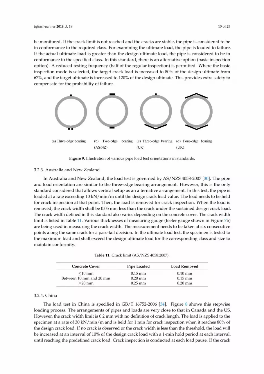
The load test in the UK also includes fiber-reinforced concrete pipe (FRCP) and is outlined inBS EN 1916-2002 [11] Annex C. The standard details the bearing strip dimensions and three typicalload arrangements. The space between the bearing strips is determined by the 30-degree angle inbetween them and is larger than that in all other study areas Figure 9c. For example, for a 1200 mmpipe with 125 mm wall thickness, the space between bearing strips is calculated to be about 380 mmin comparison to 100 mm in Canada and the US. For larger diameter pipe (>1200 mm), the load testwith four contact points (two top, two bottom) is also an option (Figure 9d). An adjustment factorof 0.64 is applied to the test result calculation to account for the additional load angle. In terms ofloading procedure, the loading rate is in between 20 and 25 kN/min/m. The load selection is to beheld at the design crack load to allow for crack inspection. The standard also requires crack stability to
Infrastructures 2018, 3, 18 15 of 25
be monitored. If the crack limit is not reached and the cracks are stable, the pipe is considered to bein conformance to the required class. For examining the ultimate load, the pipe is loaded to failure.If the actual ultimate load is greater than the design ultimate load, the pipe is considered to be inconformance to the specified class. In this standard, there is an alternative option (basic inspectionoption). A reduced testing frequency (half of the regular inspection) is permitted. Where the basicinspection mode is selected, the target crack load is increased to 80% of the design ultimate from67%, and the target ultimate is increased to 120% of the design ultimate. This provides extra safety tocompensate for the probability of failure.
Infrastructures 2018, 3, x FOR PEER REVIEW 15 of 25
conformance to the required class. For examining the ultimate load, the pipe is loaded to failure. If the actual ultimate load is greater than the design ultimate load, the pipe is considered to be in conformance to the specified class. In this standard, there is an alternative option (basic inspection option). A reduced testing frequency (half of the regular inspection) is permitted. Where the basic inspection mode is selected, the target crack load is increased to 80% of the design ultimate from 67%, and the target ultimate is increased to 120% of the design ultimate. This provides extra safety to compensate for the probability of failure.
Figure 9. Illustration of various pipe load test orientations in standards.
3.2.3. Australia and New Zealand
In Australia and New Zealand, the load test is governed by AS/NZS 4058-2007 [30]. The pipe and load orientation are similar to the three-edge bearing arrangement. However, this is the only standard considered that allows vertical setup as an alternative arrangement. In this test, the pipe is loaded at a rate exceeding 10 kN/min/m until the design crack load value. The load needs to be held for crack inspection at that point. Then, the load is removed for crack inspection. When the load is removed, the crack width shall be 0.05 mm less than the crack under the sustained design crack load. The crack width defined in this standard also varies depending on the concrete cover. The crack width limit is listed in Table 11. Various thicknesses of measuring gauge (feeler gauge shown in Figure 7b) are being used in measuring the crack width. The measurement needs to be taken at six consecutive points along the same crack for a pass-fail decision. In the ultimate load test, the specimen is tested to the maximum load and shall exceed the design ultimate load for the corresponding class and size to maintain conformity.
Table 11. Crack limit (AS/NZS 4058:2007).
Concrete Cover Pipe Loaded Load Removed ≤10 mm 0.15 mm 0.10 mm
Between 10 mm and 20 mm 0.20 mm 0.15 mm ≥20 mm 0.25 mm 0.20 mm
3.2.4. China
The load test in China is specified in GB/T 16752-2006 [34]. Figure 8 shows this stepwise loading process. The arrangements of pipes and loads are very close to that in Canada and the US. However, the crack width limit is 0.2 mm with no definition of crack length. The load is applied to the specimen at a rate of 30 kN/min/m and is held for 1 min for crack inspection when it reaches 80% of the design crack load. If no crack is observed or the crack width is less than the threshold, the load will be increased at an interval of 10% of the design crack load with a 1-min hold period at each interval, until reaching the predefined crack load. Crack inspection is conducted at each load pause. If the crack width is still less than the limit of 0.2 mm, the load is continued at 5% of the design crack load interval with 3-min hold period for examination until the 0.2 mm crack width is observed and the crack load is then recorded. To continue the load test towards ultimate, the load is applied to and
Figure 9. Illustration of various pipe load test orientations in standards.
3.2.3. Australia and New Zealand
In Australia and New Zealand, the load test is governed by AS/NZS 4058-2007 [30]. The pipeand load orientation are similar to the three-edge bearing arrangement. However, this is the onlystandard considered that allows vertical setup as an alternative arrangement. In this test, the pipe isloaded at a rate exceeding 10 kN/min/m until the design crack load value. The load needs to be heldfor crack inspection at that point. Then, the load is removed for crack inspection. When the load isremoved, the crack width shall be 0.05 mm less than the crack under the sustained design crack load.The crack width defined in this standard also varies depending on the concrete cover. The crack widthlimit is listed in Table 11. Various thicknesses of measuring gauge (feeler gauge shown in Figure 7b)are being used in measuring the crack width. The measurement needs to be taken at six consecutivepoints along the same crack for a pass-fail decision. In the ultimate load test, the specimen is tested tothe maximum load and shall exceed the design ultimate load for the corresponding class and size tomaintain conformity.
Table 11. Crack limit (AS/NZS 4058:2007).
Concrete Cover Pipe Loaded Load Removed
≤10 mm 0.15 mm 0.10 mmBetween 10 mm and 20 mm 0.20 mm 0.15 mm
≥20 mm 0.25 mm 0.20 mm
3.2.4. China
The load test in China is specified in GB/T 16752-2006 [34]. Figure 8 shows this stepwiseloading process. The arrangements of pipes and loads are very close to that in Canada and the US.However, the crack width limit is 0.2 mm with no definition of crack length. The load is applied to thespecimen at a rate of 30 kN/min/m and is held for 1 min for crack inspection when it reaches 80% ofthe design crack load. If no crack is observed or the crack width is less than the threshold, the load willbe increased at an interval of 10% of the design crack load with a 1-min hold period at each interval,until reaching the predefined crack load. Crack inspection is conducted at each load pause. If the crack
Infrastructures 2018, 3, 18 16 of 25
width is still less than the limit of 0.2 mm, the load is continued at 5% of the design crack load intervalwith 3-min hold period for examination until the 0.2 mm crack width is observed and the crack load isthen recorded. To continue the load test towards ultimate, the load is applied to and held at 80% of thedesign ultimate load for 1 min. The load is then continued at 10% of the design ultimate load intervalwith a 1-min hold period at each interval until the predefined ultimate load is reached. A 3-min holdperiod is required for crack and damage inspection. If the pipe has not reached the ultimate load limit,loading is continued at intervals of 5% of the design ultimate load followed by a 3-min hold period toallow stabilization of the crack and crack inspection. The last step is repeated until the pipe reaches themaximum load. In this loading exercise, if the load causing the crack limit and ultimate limit occursduring the load increment process, the previous load interval value becomes the official crack load orultimate load for reporting, respectively.
4. Hydrostatic Performance and Joint Design
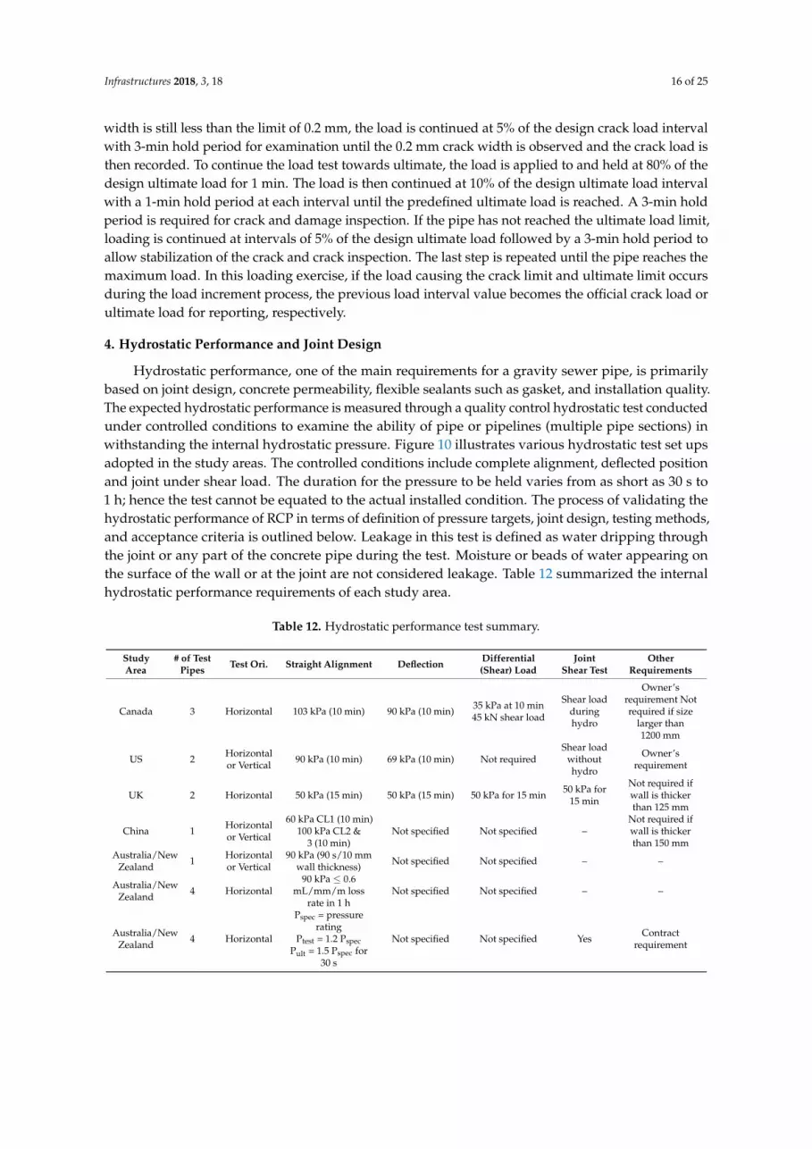
Hydrostatic performance, one of the main requirements for a gravity sewer pipe, is primarilybased on joint design, concrete permeability, flexible sealants such as gasket, and installation quality.The expected hydrostatic performance is measured through a quality control hydrostatic test conductedunder controlled conditions to examine the ability of pipe or pipelines (multiple pipe sections) inwithstanding the internal hydrostatic pressure. Figure 10 illustrates various hydrostatic test set upsadopted in the study areas. The controlled conditions include complete alignment, deflected positionand joint under shear load. The duration for the pressure to be held varies from as short as 30 s to1 h; hence the test cannot be equated to the actual installed condition. The process of validating thehydrostatic performance of RCP in terms of definition of pressure targets, joint design, testing methods,and acceptance criteria is outlined below. Leakage in this test is defined as water dripping throughthe joint or any part of the concrete pipe during the test. Moisture or beads of water appearing onthe surface of the wall or at the joint are not considered leakage. Table 12 summarized the internalhydrostatic performance requirements of each study area.
Table 12. Hydrostatic performance test summary.
StudyArea
# of TestPipes Test Ori. Straight Alignment Deflection Differential
(Shear) LoadJoint
Shear TestOther
Requirements
Canada 3 Horizontal 103 kPa (10 min) 90 kPa (10 min) 35 kPa at 10 min45 kN shear load
Shear loadduringhydro
Owner’srequirement Notrequired if size
larger than1200 mm
US 2 Horizontalor Vertical 90 kPa (10 min) 69 kPa (10 min) Not required
Shear loadwithouthydro
Owner’srequirement
UK 2 Horizontal 50 kPa (15 min) 50 kPa (15 min) 50 kPa for 15 min 50 kPa for15 min
Not required ifwall is thickerthan 125 mm
China 1 Horizontalor Vertical
60 kPa CL1 (10 min)100 kPa CL2 &
3 (10 min)Not specified Not specified –
Not required ifwall is thickerthan 150 mm
Australia/NewZealand 1 Horizontal
or Vertical90 kPa (90 s/10 mm
wall thickness) Not specified Not specified – –
Australia/NewZealand 4 Horizontal
90 kPa ≤ 0.6mL/mm/m loss
rate in 1 hNot specified Not specified – –
Australia/NewZealand 4 Horizontal
Pspec = pressurerating
Ptest = 1.2 PspecPult = 1.5 Pspec for
30 s
Not specified Not specified Yes Contractrequirement

Infrastructures 2018, 3, 18 17 of 25
Infrastructures 2018, 3, x FOR PEER REVIEW 17 of 25
Figure 10. Illustration of various hydrostatic test setup standard configurations.
4.1. Pipe Hydrostatic Performance in Canada
CSA A257.3 [32] specifies the RCP joint requirements, which include the internal hydrostatic test, physical test of the joint materials, and inspection requirement of joint design. This standard also stipulates that the infiltration requirement shall be quantified by the owners and the testing in the installed position shall be conducted due to those factors beyond the manufacturing of the pipe. The hydrostatic test detailed in CSA A257.0 [32] Section 7 consists of three testing positions: Straight alignment, maximum deflected position and joints under differential load, as illustrated in Figure 10b,g,i, respectively. The testing requires three pipe sections installed horizontally in between bulkheads. Two joints are being tested simultaneously. In the straight alignment, the setup is internally and hydrostatically pressurized to 103 kPa for 10 min to assess leakage. In the deflected position, the middle section is deflected by creating a joint gap to the maximum of 13 mm on one side. This position is intended to create the worst possible misalignment in the field. The setup is required to be pressurized to 90 kPa for 10 min followed by leakage observation. In the final position, the middle section is suspended. The additional weight includes the pipe and water mass to create a maximum differential load of 25 kN, 35 kN and 45 kN for 300 mm, 375 mm and 450 mm, and 525 mm pipes or larger, respectively. The purpose of applying the differential load at each side of the joint is to create a joint offset for maximum permissible annular gap leading to the least effective pressure
Figure 10. Illustration of various hydrostatic test setup standard configurations.
4.1. Pipe Hydrostatic Performance in Canada
CSA A257.3 [32] specifies the RCP joint requirements, which include the internal hydrostatictest, physical test of the joint materials, and inspection requirement of joint design. This standardalso stipulates that the infiltration requirement shall be quantified by the owners and the testingin the installed position shall be conducted due to those factors beyond the manufacturing of thepipe. The hydrostatic test detailed in CSA A257.0 [32] Section 7 consists of three testing positions:Straight alignment, maximum deflected position and joints under differential load, as illustratedin Figure 10b,g,i, respectively. The testing requires three pipe sections installed horizontally inbetween bulkheads. Two joints are being tested simultaneously. In the straight alignment, the setup isinternally and hydrostatically pressurized to 103 kPa for 10 min to assess leakage. In the deflectedposition, the middle section is deflected by creating a joint gap to the maximum of 13 mm on oneside. This position is intended to create the worst possible misalignment in the field. The setup isrequired to be pressurized to 90 kPa for 10 min followed by leakage observation. In the final position,the middle section is suspended. The additional weight includes the pipe and water mass to createa maximum differential load of 25 kN, 35 kN and 45 kN for 300 mm, 375 mm and 450 mm, and 525 mmpipes or larger, respectively. The purpose of applying the differential load at each side of the joint isto create a joint offset for maximum permissible annular gap leading to the least effective pressureseal from the gasket. Under this setup, the target pressure, therefore, is reduced to 35 kPa for 10 min.The hydrostatic test is satisfied only if the tests in all positions passed.

Infrastructures 2018, 3, 18 18 of 25
4.2. Pipe Hydrostatic Performance in US
Hydrostatic performance is not a rejection criterion in ASTM C76 [35]. ASTM C76 refers totesting standards ASTM C443 [36], ASTM C990 [37], and ASTM C1628 [38] at the discretion of theowner. The test is conducted using two pipe sections connected based on the joint design assembly.The pipe sections are plugged with two bulkheads and pressurized to the design target. In ASTM C443,joint performance using rubber gasket is defined for a watertight joint of concrete pipe to be able towithstand 90 kPa of pressure without leakage. The test is performed via two pipe specimens with thetest joint in between. As illustrated in Figure 10a,c, straight alignment position and maximum deflectedposition are required. The internal pressure is held for 10 min at 90 kPa for straight alignment and69 kPa for maximum deflected position with the joint being opened to 13 mm on one side. ASTM C990details the physical requirement of the sealant materials, design of the joints, testing method forsealants and the performance of the joints. It requires the pipe specimens to be stacked vertically andto internally pressurize the test joint to 69 kPa for 10 min. This standard also states that the test isnot intended to simulate the installation or pressure at service level, but only used as quality control.ASTM C1628 addresses the design of the joint for circular and non-circular gaskets, testing methods forgaskets and hydrostatic performance with the same pressure target as ASTM C443, and allows alternativelyfor external testing if there is no objection from the owner. In addition, the manufacturer has an option tocombine the joint structural test and the hydrostatic test to prove the water tightness under load.
4.3. Pipe Hydrostatic Performance in Australia and New Zealand
When a watertight joint is specified in the non-pressure sewerage and drainage pipe, AS/NZS4058 requires a test pressure of 90 kPa to be reached. In New Zealand, there are specifically twooptions to achieve 90 kPa pressure: a single pipe test or a pipeline test consisting of four test sections,as illustrated in Figure 10a,d,e, respectively. In New Zealand, water loss is permitted in the pipelinetest (four test pipes in an aligned position) if the loss is less than 0.6 mL per hour per mm diameter permeter length. For example, four pieces of 600 mm diameter RCP with 2.5 m lay length will allow waterloss up to 3.6 L per hour. In Australia and New Zealand, a contract may specify greater than or equalto 50 kPa and ultimate pressure test. In this case, the test pressure needs to reach at least 20% morethan the specified allowable working pressure. The ultimate pressure shall also reach the lesser of50% more than the allowable working pressure or 20% more plus 75 kPa. In addition, the hydrostatictest in a deflected position and a position under differential load are not required. However, the jointassembly test for the pipes with flexible joints is detailed in Appendix H of the standard. The test isconducted using two pipe sections with maximum deflection between them. A visual assessment isrequired on the joint gap, positive overlapping between the bell and spigot and damage if applicable.However, no hydrostatic performance is being conducted in this position.
4.4. Pipe Hydrostatic Performance in UK
The UK is the only study area which assesses the joint durability due to tightening. The procedureof the test records the deformation and tightening force or pressure in comparison to the calculatedvalues in order to evaluate the durability. This is detailed in Annex A of the standard. Annex Ecomprises a hydrostatic performance test that is similar to that in the other study areas. A two-pipesetup illustrated in Figure 10c,f,h for an aligned position, a deflected position and a position underdifferential load, respectively requires the internal hydrostatic pressure to exceed 50 kPa for 15 min.In the deflected position, the amount of deflection is created based on 12,500 per diameter in millimetersor 50 mm, whichever is smaller. For 300-mm, 600-mm and 900-mm diameter pipes, the requireddeflection can be created by a joint gap of 42-mm, 20-mm, and 14-mm, respectively. For 1200-mmpipe, the deflection will be created from a 10-mm joint gap. In the position under shear load, the loadis applied to the spigot end of a pipe supported by the joint. A differential load in kilo-newton of0.03 times the diameter is applied. For example, for a 1200-mm pipe, the load is calculated to be 36 kN.
Infrastructures 2018, 3, 18 19 of 25
The manufacturer may combine the deflection and the differential load together with reduction of thedifferential load to 0.01 times the diameter instead of 0.03. All positions require a target pressure of50 kPa, which implies minimum requirement regardless of site conditions. Pipes with wall thicknesslarger than 12 mm are exempted from this test.
4.5. Pipe Hydrostatic Performance in China
Like all other study areas, the internal hydrostatic pressure test is one of the RCP performancecriteria. The target pressure is based on the class of the pipe. Class 1 requires the internal pressure tobe 60-kPa. Classes 2 and 3 require the internal pressure to be 100-kPa. Pipes with walls thicker than150-mm are exempted from this test. The test pipe is setup in horizontal or vertical orientation withbulkheads on both ends of the pipe. The target pressure is introduced within one minute and held for10 min. The operator is required to look for signs of leakage at the end of the test. However, since onlyone pipe section is required in the test, it does not assess the joint performance, nor does it evaluatedeflected or differential load conditions against hydrostatic pressure.
5. Concrete Pipe Durability
Gravity sewer pipe is expected to have up to 75 years of design life [22]. The concretepipe industry has been promoting up to 100-year design life. RCP may be subjected to thermalcontractions, shrinkage, creep, leaching, sulfate attack, freeze thaw cycling, alkali-aggregate reactions,biogenic corrosion and chloride-ions induced corrosion, bacterial effects, abrasion, and sustainedmechanical load [22]. Although typical pH in natural ground conditions is not usually detrimental, low pHconditions may prevail in ground water. Aerobic bacteria activities in sewerage create acidic environmentscausing damage by biogenic sulfuric acid attack. Porosity and cracks allow chloride ions to penetrateand further corrode the reinforcing steel. In reviewing RCP standards, measuring concrete porosity anddefining allowable crack widths are primary methods to ensure the required durability expectation.
5.1. Absorption Test
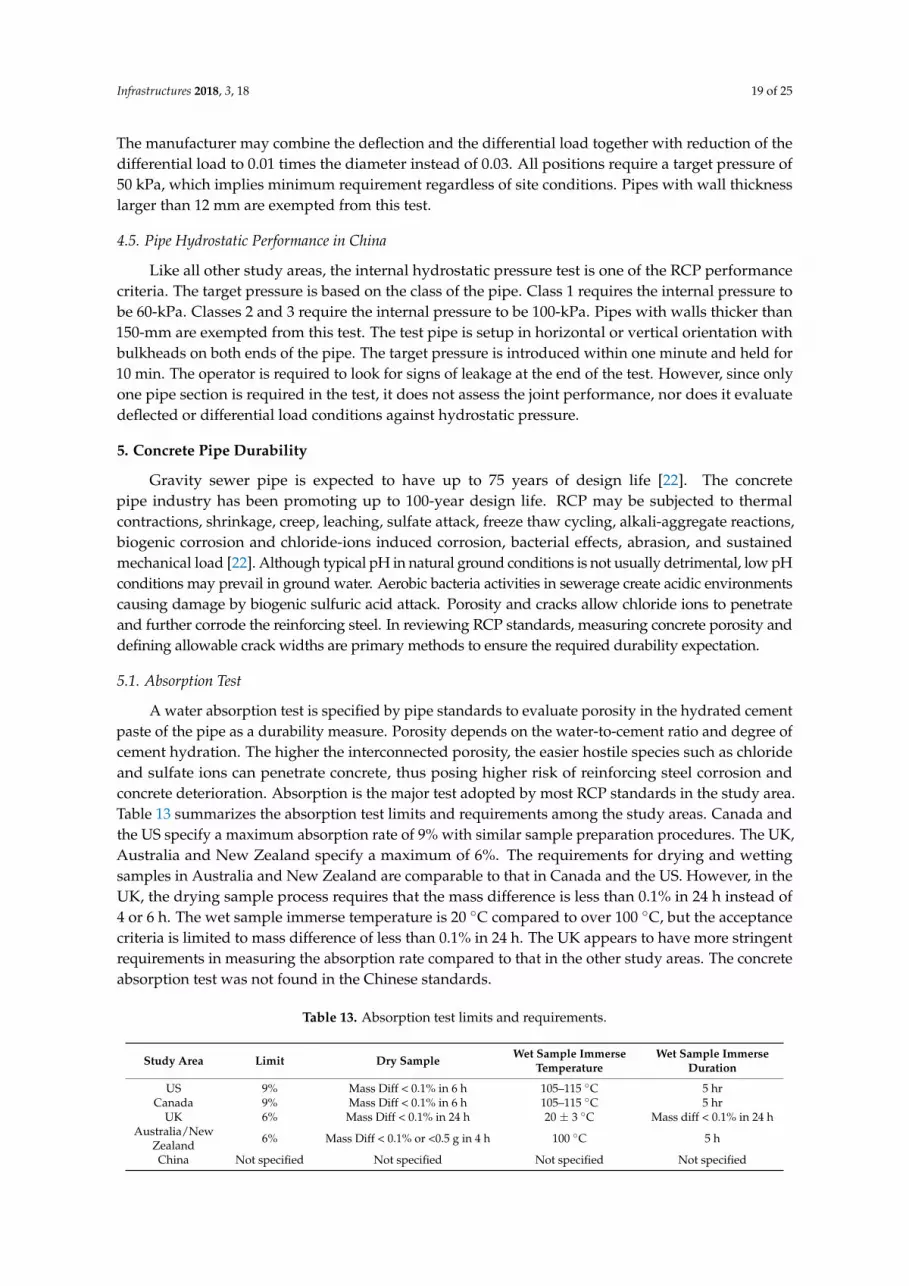
A water absorption test is specified by pipe standards to evaluate porosity in the hydrated cementpaste of the pipe as a durability measure. Porosity depends on the water-to-cement ratio and degree ofcement hydration. The higher the interconnected porosity, the easier hostile species such as chlorideand sulfate ions can penetrate concrete, thus posing higher risk of reinforcing steel corrosion andconcrete deterioration. Absorption is the major test adopted by most RCP standards in the study area.Table 13 summarizes the absorption test limits and requirements among the study areas. Canada andthe US specify a maximum absorption rate of 9% with similar sample preparation procedures. The UK,Australia and New Zealand specify a maximum of 6%. The requirements for drying and wettingsamples in Australia and New Zealand are comparable to that in Canada and the US. However, in theUK, the drying sample process requires that the mass difference is less than 0.1% in 24 h instead of4 or 6 h. The wet sample immerse temperature is 20 ◦C compared to over 100 ◦C, but the acceptancecriteria is limited to mass difference of less than 0.1% in 24 h. The UK appears to have more stringentrequirements in measuring the absorption rate compared to that in the other study areas. The concreteabsorption test was not found in the Chinese standards.
Table 13. Absorption test limits and requirements.
Study Area Limit Dry Sample Wet Sample ImmerseTemperature
Wet Sample ImmerseDuration
US 9% Mass Diff < 0.1% in 6 h 105–115 ◦C 5 hrCanada 9% Mass Diff < 0.1% in 6 h 105–115 ◦C 5 hr
UK 6% Mass Diff < 0.1% in 24 h 20 ± 3 ◦C Mass diff < 0.1% in 24 hAustralia/New
Zealand 6% Mass Diff < 0.1% or <0.5 g in 4 h 100 ◦C 5 h
China Not specified Not specified Not specified Not specified

Infrastructures 2018, 3, 18 20 of 25
5.2. Crack Width
Crack limits in pipe standards include definitions of crack width and length and are often specifiedin all study areas to assess structural performance. The limit is specified in the load test to determinethe design crack load and thus the classification of the pipe. Hairline cracks, however, occur muchearlier than the design crack width, but are not measured or recorded. Cracks provide a path formoisture and harmful ions to ingress. If a crack extends to the reinforcing steel, the pipe becomessusceptible to corrosion. Crack allowance under the load tests in Canada, US and UK are specified as0.3-mm. Australia and New Zealand allow for a crack of up to 0.25 mm for concrete cover exceeding20-mm, while China limits the crack to 0.2-mm. The crack limit without load from Australia and NewZealand is set at 0.1-mm, 0.15-mm and 0.2-mm for concrete cover less than 10-mm, in between 10 and20-mm, and larger than 20-mm, respectively, which is 0.05 mm narrower than that when the load isapplied. A 0.15-mm crack is permitted in the UK without loading. China specifies 0.05-mm crackwidth without loading, which is presumably a definition of a hairline crack. If the length of the crackis less than 300-mm, then it is generally defined as acceptable. In Canada and the US, there are nospecified crack limits without loading.
5.3. Concrete Cover
The concrete cover provides a barrier against carbonation and the penetration of chloride andsulfate ions. High early strength cement and high sulfate resistant cement are usually used in RCPproducts to increase productivity and enhance durability. Table 14 compares the minimum concretecover specification in relationship to durability among all study areas. For 1200-mm RCP with 125-mmwall thickness, Canada and the US require 13-mm minimum cover, Australia and New Zealand require10-mm and 25-mm minimum cover for normal or aggressive exposure environments, respectively,the UK requires 15-mm and China requires 20-mm minimum cover. Canada and the US require theleast protection from the concrete cover. As mentioned in Section 2.3, concrete cover inspections aremandatory except in Canada where it is an option based on the owner’s requirements.
Table 14. Comparison of minimum concrete cover requirements.
Minimum ConcreteCover (mm) Canada/US Australia/New Zealand China UK
6 – Wall ≤ 25 mm, normalexposure, dry cast – –
8 – 25 mm < Wall ≤ 35 mm,normal exposure, dry cast – –
10 – Wall > 35 mm, normalexposure, dry cast Wall ≤ 40 mm –
13 All wallthickness – – –
15 – – 40 mm < Wall≤ 100 mm
All wall thickness(not defined as minimum)
20 – – Wall > 100 mm –
25 – Wall > 35 mm, aggressiveexposure, dry cast – –
35 – Wall > 35 mm, aggressiveexposure, wet cast – –

Infrastructures 2018, 3, 18 21 of 25
6. Discussion and Recommendations
6.1. Concrete Cover and Crack Limit
The thickness of the concrete cover impacts the structural performance and durability of concretepipe. The placement of the reinforcing steel cage directly affects the flexural strength and crack load,and thus shall be measured and controlled and be part of the acceptance criteria.
Crack limits are defined in standards of all study areas. The load class is defined by the cracklimit but the limit is not related to the durability requirements. In the area where RCP is subjected tosaline storm-water, appearance of crack and the crack growth can be expedited [39]. When the cracklimit is reached, the crack would have extended to the reinforcing steel, which could create a channelfor corrosive substances. Hairline cracks occur at a much earlier loading stage. In all study areas,hairline crack is not clearly defined as part of testing, but it is implied that visible cracks smaller thanthe crack limit are permitted in the pipe. It is assumed that hairline cracks pose no structural concernand will heal after the pipe is put in service owing to the formation of calcium carbonate, which isknown as autogenous healing [40]. Yet, significant autogenous healing was not observed in crackwidths between 0.5 mm (0.02 inch) and 3 mm (0.1 inch). In a report by Busba et al. [41], crack widthguideline was provided based on the aggressiveness of the chloride ions environment because the RCPdesign life will be impacted by the crack width. The standards from the study areas mostly specifya 0.3-mm crack width limit. China, Australia and New Zealand specify as small as a 0.2-mm crackwidth limit. The pipe crack width limitation in the current standards only relate to structural andhydrostatic criteria, but do not exhibit any rational consideration of durability.
6.2. Load Test
The US is the only country surveyed whose standards prescribe steel design without having theload test as a mandatory validation criterion. Load testing is required for classes and sizes not listedin the standard. Standards from the other countries in terms of structural strength are performancebased. Canadian standards specify steel requirements, but the pipe is considered acceptable if themanufacturer can demonstrate its capacity through the load test. Both the US and Canada rely onthe inspector to observe cracks during the load test. The inspector must capture the moment whenthe crack limit is reached using a crack gauge. Most of the time, the loading process is continuous ata pre-determined rate, often with only one person assigned to observe the crack. The design crackmay occur at the invert or obvert of the pipe from either ends of the specimen, or at the outside of thepipe spring-line. In large diameter pipes, depending on the reinforcing steel configuration, the 0.3-mmcrack may be governed by radial tension or shear capacity. It will be very difficult for a single personto determine the location of the first crack that reaches the limit width and the corresponding loadvalue. In many cases, the process relies on inspector experience to observe the crack before physicallymeasuring it. The time required to call an actual design load may sometimes span over 10 kN ofload, which can make a difference between a pass or fail decision. In the UK, when the design crackload is reached, the load is held for 3 to 5 min for examination of the crack. This period allows theinspector to carefully detect the crack and decide. The test procedure in the Chinese standard requiresfurther incremental step loading. The test is required to reach 80% of the expected crack load followedby incremental loading and pausing. Each increment requires a one to three min hold period forcrack examination. A similar approach is taken to determine the ultimate load. At each hold period,the inspector is allowed the time to capture and measure the crack, and use judgement. If the decisionis made during the load increment, the final recorded strength is reported back to the previous loadincrement. This will eliminate bias, yet it is rather a time-consuming process. In Australia and NewZealand, the load test also requires measuring the crack after the load is removed. This is to ensure thatthe load applied is still in the elastic zone. This could avoid inexperienced inspector overestimatingthe design crack.

Infrastructures 2018, 3, 18 22 of 25
Considering the discussion above, it is recommended that the load test be conducted witha pause at the design load for crack inspection and load removal, before the ultimate load test isconducted. In addition, to eliminate human interpretation of the crack load, other instrumentationmay be introduced such as linear variable differential transducer (LVDT) to determine the crack loadby studying the load-deformation curve of the pipe.
6.3. Hydrostatic Performance Test
Internal hydrostatic pressure is measured for pipes up to a certain size as a quality controlrequirement in all study areas. External pressure test, such as ASTM C1103, is offered only as an optionto the owner and may not provide cost-effective measures. Gravity sewers in general create an openchannel flow inside the pipeline. Unless the pipe is being used as a siphon pipe or there is unplannedblockage of the pipe, the internal pressure does not exceed the depth of the fluid inside the pipe.In deep installations where the sustained ground water level is above the pipe obvert, the externalhydrostatic pressure poses a risk of infiltration. The current hydrostatic test does not simulate theactual external pressure. The test only lasts for 10 min and does not prove performance under sustainedpressure. Under current quality programs in the US and Canada, internal hydrostatic tests are notrequired for larger pipe size due to the difficulty in sealing the pipe. In addition, whether the gasketfunctions both ways for infiltration and exfiltration requires dedicated investigation. The test doesnot define the working pressure and ultimate pressure; hence, the pipe cannot be pressure rated.The owner of the pipeline will rely on the field test to evaluate water-tightness. In Australia and NewZealand, there is an option to specify the required pressure rating of the RCP. Consequently, when theexternal pressure is a concern, the designer may select the concrete pressure pipe. The actual issueoccurs when the hydrostatic test is misinterpreted by the specifier and the designer. RCP has beenspecified in situations where the ground water level is 10-m above the pipe, provided that the pipe istested to 105 kPa. It is thus recommended that concrete pipe standards emphasize an infiltration limitor provide a method to test the infiltration capacity. The hydrostatic performance under a defined jointgap shall also be evaluated. This can potentially quantify the installation quality.
6.4. Durability
The simple absorption test is the only test specified in all examined standards. The test isconsidered as a quality evaluation, yet it is not a reliable parameter for estimating of the concretepipe durability. The test provides a rough estimation of the pore volume, but gives no indicationof the real concrete permeability [42]. No effective measure has yet been put in place to deal withmicrobiologically induced concrete corrosion (MICC), which is one of the major issues in concrete pipedurability. In terms of concrete pipe durability, all examined standards in the various study areas lagcurrent concrete design codes, such as CSA A23.1 and CSA A23.4. The design guideline was publishedby the US Environmental Protection Agency as early as 1974 [43] and many municipal standards toprescribe the size, slope and turbulence control for the sole purpose of minimizing hydrogen sulfide andMICC. However, three is no provisions in existing concrete pipe standards to address the threat of MICC.
It is recommended that further development of the absorption test be undertaken. In addition,consideration of the concrete pipe exposure class is recommended. Additional tests for evaluatingchloride ions penetration, sulfate attack, MICC as well as minimum cover requirements shouldbe considered in a versatile concrete pipe performance-based standard. This would allowfurther developments of the RCP technology, including concrete mixtures with less permeability,alternative cementitious materials, and the use of plastic liners.
7. Conclusions
Standard provisions for precast concrete pipe around the world have generally been disconnected.For example, Canada has the most stringent hydrostatic performance. China has the tightest geometrictolerance in size and wall thickness and requires more effort in examination of cracks during the load

Infrastructures 2018, 3, 18 23 of 25
test, but does not require hydrostatic joint performance. None of the specifications give considerationto infiltration resistance and MICC exposure evaluation. Nevertheless, there has been little effort tocritically analyze the international experience gained in this field, to compare performance criteria andcome up with best international practice guidelines. In the present study, a sustained effort was madeto critically review current RCP standards from Canada, the US, the UK, Australia, New Zealand,and China so as to reveal strengths and weaknesses that need improvements upon the currentstate-of-the-art. This effort has exposed various knowledge gaps along with gaps between standardsand the end-user expectations in terms of hydrostatic performance against infiltration, durability tohydrogen sulfide attack of the RCP, etc. Recommendations emanating from this critical analysisinclude the necessity to review and update concrete pipe standards in order to capture moderndevelopments in concrete technology, advances in standard concrete codes and test methods, and totailor performance-based guidelines that can better capture the pipe structural, hydrostatic anddurability performance. These guidelines will set a new platform for technological advancement inRCP. Such an effort is particularly needed to enhance the RCP competitiveness considering the currentmarket reality and the advent of many contenders for concrete pipe replacement using various flexiblematerial formulations.
Author Contributions: The initial draft of this review article was developed by S.W. under the supervision ofM.L.N. The final version is the product of collaborative work including input from both authors.
Funding: This research received no funding. Funding for subsequent phases of this research is expected fromCon Cast Pipe, Puslinch, ON, Canada and the Natural Science and Engineering Research Council of Canada.
Acknowledgments: The authors acknowledge Con Cast Pipe, Puslinch, ON, Canada for providing informationrelated to their products and industry practice.
Conflicts of Interest: The authors have no conflict of interest to declare.
References
1. Ontario Concrete Pipe Association (OCPA). Concrete Pipe Design Manual; OCPA: Kitchener, ON, Canada.2. Schladweiler, J.C. The History of Sanitary Sewer. 2017. Available online: http://www.sewerhistory.org/
(accessed on 14 June 2018).3. Marston, A.; Anderson, A.O. The Theory of Loads on Pipes in Ditches and Test of Cement and Clay Drain Tile and
Sewer Pipe; Iowa State College of Agriculture and Mechanic Arts: Ames, IA, USA, 1931.4. Orlander, H.C. Stress Analysis of Concrete Pipe; Engineering Monograph No. 6; US Bureau of Reclamation:
Washington, DC, USA, 1950.5. Spangler, M. Soil Engineering; International Textbook Company: Scranton, PA, USA, 1960.6. Heger, F. Structural Behaviour of Circular Reinforced Concrete Pipe—Development of Theory. J. Proc.
1963, 60, 1567–1614.7. Heger, F.; Gillespie, J. Design of Circular Concrete Pipe Reinforced with Welded Deformed Wire Fabric;
Transportation Research Board: Washington, DC, USA, 1967.8. American Society of Civil Engineers (ASCE). Standard Practice for Direct Design of Buried Precast Concrete Pipe
Using Standard Installation; ASCE15; ASCE: Reston, VA, USA, 1993.9. American Association of State Highway and Transportation Officials (AASHTO). LRFD Bridge Design
Specification; AASHTO: Washington, DC, USA, 2014.10. CSA Group. Canadian Highway Bridge Design Code; CSA S6; CSA Group: Mississauga, ON, Canada, 2014.11. British Standards Institution (BSI). Concrete Pipes and Fittings, Unreinforced, Steel Fibre and Reinforced; BS EN
1916:2002; BSI: London, UK, 2002.12. ASTM International. Standard Specification for Steel Fiber Reinforced Concrete Culvert, Storm Drain, and Sewer
Pipe; ASTM C1765; ASTM International: West Conshohocken, PA, USA, 2013.13. ASTM International. Standard Specification for Synthetic Fiber Reinforced Concrete Culvert, Storm Drain, and Sewer
Pipe; ASTM C1818: ASTM International: West Conshohocken, PA, USA, 2015.14. Mohamed, N.; Soliman, A.M.; Nehdi, M.L. Utilization of steel fibres in precast concrete pipes. In Proceedings
of the TAC 2012. Tunnel and Underground Space: Sustainability and Innovations, Montreal, QC, Canada,17 October 2012; (TAC Paper 158). Transportation Association of Canada: Ottawa, ON, Canada, 2012.

Infrastructures 2018, 3, 18 24 of 25
15. Mohamed, N.; Soliman, A.M.; Nehdi, M.L. Full-scale pipes using dry-cast steel fibre-reinforced concrete.Constr. Build. Mater. 2012, 72, 411–422. [CrossRef]
16. Mohamed, N.; Soliman, A.M.; Nehdi, M.L. Mechanical performance of full-scale precast steel fibre-reinforcedconcrete pipes. Eng. Struct. 2012, 84, 287–299. [CrossRef]
17. Mohamed, N.; Nehdi, M.L. Rational finite element assisted design of precast steel fibre-reinforced concretepipes. Eng. Struct. 2012, 124, 196–206. [CrossRef]
18. Lester, H.G. Corrugated Polyethylene Pipe Design Manual & Installation Guide; Plastic Pipe Institute: Irving, TX, USA, 2017.19. Curran, S.D. Fiberglass Pipe Past, Present and Future; Fiber Glass Tank and Pipe Institute: Houston, TX, USA, 2013.20. Walker, R. The Early History of PVC Pipe.1990. Available online: https://theplumber.com/early-history-of-
pvc-pipe/ (accessed on 21 June 2018).21. Rinker Materials. Corrugated Steel Pipe. 1994. Available online: https://www.google.
com/url?sa=t&rct=j&q=&esrc=s&source=web&cd=2&cad=rja&uact=8&ved=0ahUKEwi7o6-3yubbAhXVA4gKHXtJCGIQFggqMAE&url=https%3A%2F%2Fwww.rinkerpipe.com%2FTechnicalInfo%2Ffiles%2FInfoBriefs%2FIS304CorrugatedSteelPipe.pdf&usg=AOvVaw2tKXPVnfeH7LlycUpm4-cM(accessed on 21 June 2018).
22. Ministry of Transportation Ontario. MTO Gravity Pipe Design Guideline; Ministry of Transportation Ontario:St. Catharines, ON, Canada, 2007.
23. Pratt, C.; Yang, H.; Hodkiewicz, M. Factors Influencing Pipe Failures in the West Australia Environment.2011. Available online: https://ceed.wa.edu.au/wp-content/uploads/2017/02/Christopher.Pratt_pdf(accessed on 21 June 2018).
24. Parker, C.D. The Corrosion of Concrete. The Sewage Branch of the Melbourne and Metropolitan Board ofWorks. Aust. J. Exp. Biol. Med. Sci. 1945, 23, 81–90. [CrossRef]
25. Wu, L.; Hu, C.; Liu, W. The sustainability of Concrete in Sewer Tunnel—A Narrative Review of AcidCorrosion in the City of Edmonton Canada. Sustainability 2018, 10, 517. [CrossRef]
26. Vollertsen, J.; Nielsen, A.H.; Jensen, H.S.; Rudelle, E.A.; Hvitved-Jacobsen, T. Modeling the Corrosion ofConcrete Sewer. In Proceedings of the 12th International Conference on Urban Drainage, Porto Alegre,Brazil, 11–16 September 2011.
27. Sulikowski, J.; Kozubal, J. The Durability of a Concrete Sewer Pipeline Under Deterioration by Sulphate andChloride Corrosion. Procedia Eng. 2016, 153, 698–705. [CrossRef]
28. Bielefeldt, A.; Gutierrez-Padilla, M.G.; Ovtchinnikov, S.; Silverstein, J.; Hernandez, M. Backterial Kinetics ofSulfur Oxidizing Bacteria and Their Biodeterioration Rates of Concrete Sewer Pipe Samples. J. Environ. Eng.2017, 136, 731–738. [CrossRef]
29. Population Reference Bureau. 2013 World Population Data Sheet; Population Reference Bureau: Washington, DC, USA, 2013.30. Australian Standard. Precast Concrete Pipes (Pressure and Non-Pressure); AS/NZS 4058; Environmental Health
Directorate: East Perth, Australia, 2007.31. Carleton, E.; Hiner, S.; Kurdziel, J. The History and Application of the Three-Edge Bearing Test for Concrete
Pipe. In Concrete Pipe and Box Culverts; Meyerand, J.J., Beakley, J., Eds.; ASTM STP1601; ASTM International:West Conshohocken, PA, USA, 2017; pp. 18–27.
32. CSA Group. Standards for Concrete Pipe and Manhole Sections; CSA A257; CSA Group: Mississauga, ON, Canada, 2014.33. ASTM International. Standard Test Methods for Concrete Pipe, Manhole Sections, or Tile; ASTM C497;
ASTM International: West Conshohocken, PA, USA, 2015.34. Test Methods of Concrete and Reinforced Concrete Drainage and Sewer Pipe; GB/T 16752; Standardization
Administration of the People’s Republic of China: Beijing, China, 2006.35. ASTM International. Standard Specification for Reinforced Concrete Culvert, Storm Drain, and Sewer Pipe;
ASTM C76; ASTM International: West Conshohocken, PA, USA, 2016.36. ASTM International. Standard Specification for Joints for Concrete Pipe and Manholes, Using Rubber Gasket;
ASTM C443; ASTM International: West Conshohocken, PA, USA, 2012.37. ASTM International. Standard Specification for Joints for Concrete Pipe, Manholes, and Precast Box Sections Using
Preformed Flexible Joint Sealants; ASTM C990; ASTM International: West Conshohocken, PA, USA, 2009.38. ASTM International. Standard Specification for Joints for Concrete Gravity Flow Sewer Pipe, Using Rubber Gaskets;
ASTM C1628; ASTM International: West Conshohocken, PA, USA, 2017.39. Marr, J. A Research Plan and Report on Factors Affecting Culvert Pipe Service Life in Minnesota;
Minnesota Department of Transportation: Saint Paul, MN, USA, 2012.

Infrastructures 2018, 3, 18 25 of 25
40. American Concrete Pipe Association. Cracks in Installed Reinforced Concrete Pipe; American Concrete PipeAssociation: Irving, TX, USA, 2007.
41. Busba, E.R.; Sagues, A.A.; Mullins, G. Reinforced Concrete Pipe Cracks—Acceptance Criteria; University of SouthFlorida: Tampa, FL, USA, 2009.
42. De Schutter, G.; Audenaert, K. Evaluation of water absorption of concrete as a measure for resistance againstcarbonation and chloride migration. Mater. Struct. 2004, 37, 591–596. [CrossRef]
43. Environmental Protection Agency (EPA). Process Design Manual for Sulfide Control in Sanitary Sewerage System;Environmental Protection Agency: Washington, DC, USA, 1974.
© 2018 by the authors. Licensee MDPI, Basel, Switzerland. This article is an open accessarticle distributed under the terms and conditions of the Creative Commons Attribution(CC BY) license (http://creativecommons.org/licenses/by/4.0/).