contributions to the design of precast concrete culverts with
TRANSCRIPT
Rev. IBRACON Estrut. Mater., vol. 14, no. 4, e14409, 2021
ORIGINAL ARTICLE
Corresponding author: Aline Bensi Domingues. E-mail: [email protected] Financial support: This study was partially financed by the Coordenação de Aperfeiçoamento de Pessoal de Nível Superior - Brasil (CAPES) - Finance Code 001. Conflict of interest: Nothing to declare.
This is an Open Access article distributed under the terms of the Creative Commons Attribution License, which permits unrestricted use, distribution, and reproduction in any medium, provided the original work is properly cited.
Rev. IBRACON Estrut. Mater., vol. 14, no. 4, e14409, 2021| https://doi.org/10.1590/S1983-41952021000400009 1/20
Received 05 September 2019 Accepted 01 September 2020
Contributions to the design of precast concrete culverts with unusual cross sections Contribuição ao projeto estrutural de galerias de concreto pré-moldado com seções transversais não usuais Aline Bensi Dominguesa Mounir Khalil El Debsa
aUniversidade de São Paulo – USP, Escola de Engenharia de São Carlos, Departamento de Engenharia de Estruturas, São Carlos, SP, Brasil
Abstract: Culverts are structures used in road and railway infrastructure works such as underpasses. Among the several forms of cross-sections, the rectangular one (box culvert) has been mostly employed. However, when installed at high embankments, this structure shows high values of bending moment and shear force, which tend to be amplified by the soil arching. This paper addresses a study of section culvert with an arc cover, called modified, and a section defined by three arches, with a flat base. Such cross-section forms reduce the bending moment due to their geometry, and efforts can be decreased with the use of reduced thicknesses by mechanisms of soil-structure interaction. Analyses were performed in the plane-strain deformation with finite elements towards considering soil-structure interaction, and the results proved the influence of the geometry shape on the soil-culvert interaction behavior. A comparative analysis of the material cost index (ICM) values for 25 geometries (12 modified culverts, 12 culverts defined by three arcs and 1 box culvert) was used for estimating the economic viability of each unusual section culvert. The results showed 27 and 54% economy in materials for modified culvert and culvert defined by three arcs, respectively, in comparison with the rectangular section.
Keywords: precast concrete, culvert, section arch, soil-structure interaction, soil arching effect.
Resumo: As galerias são estruturas utilizadas em obras de infraestrutura rodoviária e ferroviária como passagens inferiores ou para transposição de talvegues. Embora existam várias formas de seções transversais, a seção transversal retangular (box culvert) é a mais empregada. No entanto, à medida que esta estrutura é instalada em elevadas alturas de terra, a forma retangular apresenta altos valores de momento fletor e força cortante. Este efeito tende a ser ampliado com o arqueamento do solo em grandes alturas de aterro. Neste artigo apresenta-se um estudo de galeria de seção com cobertura em arco, chamada modificada, e de seção definida por três arcos, com uma base plana. Com estas formas de seções transversais têm-se a diminuição dos esforços de flexão, devido à geometria. Além disto, pode-se reduzir ainda mais esses esforços com o emprego de espessuras reduzidas considerando os mecanismos de interação solo-estrutura. Para considerar a interação solo-estrutura foram realizadas análises no estado plano de deformação com elementos finitos. Os resultados comprovaram a influência significativa do formato das geometrias no comportamento da interação solo-galeria. Além disso, a análise comparativa do índice de custo de material (ICM) foi utilizada para estimar a viabilidade econômica de cada galeria não-usual. Os valores índice de custos de material foram analisados para 25 geometrias (12 galerias modificadas, 12 galerias definidas por três arcos e 1 galeria retangular), para as situações representativas preestabelecidas, os resultados mostram que a maior economia com material é de 29 e 54% para modificada e definida por três arcos, respectivamente, em comparação com a seção retangular.
Palavras-chave: concreto pré-moldado, galeria enterrada, seção transversal não usual, interação solo-estrutura.
How to cite: A. B. Domingues and M. K. El Debs, “Contributions to the design of precast concrete culverts with unusual cross sections,” Rev. IBRACON Estrut. Mater., vol. 14, no. 4, e14409, 2021, https://doi.org/10.1590/S1983-41952021000400009
A. B. Domingues and M. K. El Debs
Rev. IBRACON Estrut. Mater., vol. 14, no. 4, e14409, 2021 2/20
1 INTRODUCTION Culverts are normally used for sewage, water or gas distribution, urban drainage and underpasses, and, in a smaller
proportion, but high potential, passage of electricity, telephony and data transmission cables. Precast concrete culverts are widely employed in streams and rainwater under highways or railways, or even as underpass for vehicles and pedestrians, with no effect on their superstructure. Their efficiency has been recognized both technically and economically.
In general, circular section tubes are the most common type of buried structures, and small cross-section tubes are constructed almost in this shape. However, the use of trapezoidal, arc, elliptical or ovoid sections is common when larger diameters or spans are required [1]. The rectangular section of precast concrete, known as box culvert, is used in cases of larger spans, often for vehicle or pedestrian traffic crossing waterways, while promoting an adequate water passage, with up to 4.0-meter span.
A survey on total highway budgets conducted with data provided by DNIT [2] revealed the cost of culvert represented 11.7% of the overall value of the highway construction. Another survey based on a feasibility study for the implementation of VALEC railway sections [3] reported three budget alternatives for the same stretch, evidencing the costs for the implementation of culverts represented 13.44%, 15.19% and 15.73% (for alternatives 1, 2 and 3, respectively) of the total budgets for the railway. Such exemplified values are in agreement with other data from the literature that indicate approximately 10 to 15% of the budget refer to the construction of culverts for roadways [4].
Despite the applicability of precast concrete box culverts, they may not be suitable in situations of, for instance, installation under high embankment. Like any buried structure, culverts cause an intense redistribution of stresses in the surrounding soil, which affects the stresses applied to the structure itself. Great depths of soil show even higher concentrations of stresses, thus increasing the internal forces in the structure, especially the shear force. Kim and Yoo [5], Pimentel et al. [6] and Abuhajar [7] observed the arching effect of the soil around the box culverts under high embankments is more significant and may lead to serious failures in the structures. Therefore, improvements in the structural performance of different processes can offer greater security and important savings, in comparison to the most used culverts, i.e., those of circular or rectangular shapes.
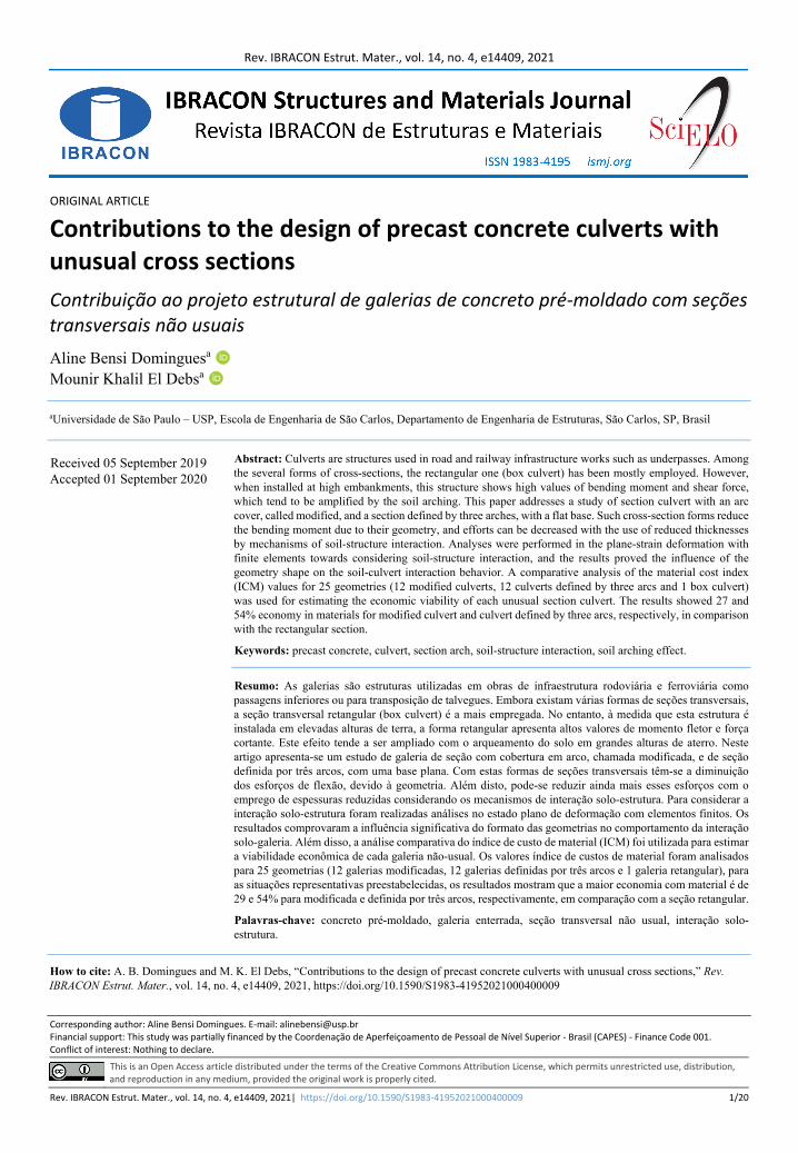
As an alternative to usual cross sections, this article reports on a study of a precast concrete culvert with modified cross-section (Figure 1a); its cover slab displays the shape of an arch, and the cross-section is defined by three arches (Figure 1b). The structural behavior of the construction is improved in the sections by the arc segments, thus reducing both bending moments and shear force.
Figure 1. Cross section of the proposed culvert.
A. B. Domingues and M. K. El Debs
Rev. IBRACON Estrut. Mater., vol. 14, no. 4, e14409, 2021 3/20
Modified culvert is the main option for box culvert for installation under high embankments. In this section format, the combination of the arc coverage favors the distribution of bending moments, similarly to the behavior of three-sided precast concrete arch sections [8], [9]. The percentage of arc slope (i = ha/b) of the roof slab affects the stress distribution. The advantage of the section with arch cover is its better construction details such as bedding and compaction. The flat geometry of the base favors the compaction of the foundation. The backfill quality around the proposed culverts is higher than that of circular section tubes, since the latter may provide poor compaction in the base, leading to complex stresses, uneven settlement over the culvert, and its possible structural distress.
On the other hand, the shape of the section defined by three arcs varies regarding the proportions between the radii of the circumference arcs. If the radius of the side arc is greater than that of the roof arc, an “ellipse” section is created; if the lateral and coverage radii are the same, the section configuration is called “horseshoe”. Finally, if the radius of the lateral arc is smaller than the radius of the roof arc, a “lenticular” section is formed.
The benefit of the culvert defined by the three arches tends to increase with the installation depth due to the interaction process established between the surrounding soil and the structure - great depths undergo tension changes from the contribution of soil confinement and mobilization of the arching effect. High embankment is estimated when the soil height is over 3 meters, or when the relationship between the installation depth (H) and the span (Bc) is greater than 1 (H/Bc> 1), i.e., the largest of two values. Under large backfill heights, the structure is not affected by the cyclic traffic loading, whose interference is rapidly reduced with an increase in the landfill height over the culvert.
Arc sections show an alteration in the distribution of internal forces, and the soil-culvert interaction is established with higher intensity in great depths, which, in some situations, increases the loads on the structure, and decreases them in others. This behavior can be affected by both type of installation of the culvert and relative stiffness of the system, i. e., relative stiffness between box culvert and surrounding soil (e.g., rigid, semi-rigid, flexible). In general, precast concrete culverts behave like rigid ducts, i.e., they support the loads imposed by themselves. Culverts defined by three arches can be dimensioned in such a way as to behave as semi-rigid ones, reducing the thickness of the walls and, therefore, affecting the soil-culvert interaction and mobilizing resistant soil mechanisms that support more loads according to the structure's flexibility - the thinner the culvert wall, the stronger the interaction of the structure with the soil. On the other hand, the soil will support loads imposed on the system. In this case, the stress capacity of the soil is more demanding, thus inducing reductions in the values of the internal forces in the culvert. Another important aspect is both thickness reduction and increased flexibility of the culvert contribute to the arching effect of the soil; consequently, evaluations of culverts with such characteristics must consider the mechanism of soil-structure interaction through numerical simulations.
The characteristics of the modified culvert and culvert defined by three arcs of circumference are better than those of preexisting culverts (box culvert or pipes tubes) in installation conditions under high embankments. For example, a reduction in weight due to a reduction in thicknesses not only saves material, but also facilitates transportation and assembly phase. Among the favorable characteristics is the ease of construction of the bedding, since the soil of foundation can be well compacted and the reactions at the bottom of the structure become uniform, thus reducing the concentrated stresses. On the other hand, both bending moments and thickness of the bottom can also increase. The installation of the section defined by three arches promotes an easier construction of the lateral embankment near the base; therefore, differently from circular sections, the well-consolidated compaction of the lateral soil prisms contributes to containment.
2 STRUCTURAL BEHAVIOR AND NUMERICAL MODELING The action of soil pressure distribution on buried structures is essential for their design. In general, culverts are
subject to vertical and horizontal pressures. The former is balanced by the reaction of the soil in the bottom slab. Stresses in buried structures are mainly due to actions such as own weight, soil load, fluid pressures inside the duct, loads produced by overloads on the surface, depending on the nature of the traffic (road, rail, air|), actions by construction overloads, lateral pressures produced by the soil, actions from compaction equipment during the construction of the backfill, and actions produced by driving and during the handling, transport, and assembly of a culvert [10].
In simplified cases, the stresses acting on a culvert are equivalent to geostatic pressures. In this hypothesis, the calculation of uniform vertical pressures (Pv) produced by the soil is a linear function of the height of the soil over the culvert (hsoil) and the specific weight of the soil (γsoil). The horizontal pressures (Ph) are calculated with a coefficient of passive earth pressure (Ph = kPv). However, in some cases, simplified models lead to uneconomical solutions, or unsafe solutions, with cracks emerging above desirable limit values [6], [11]. Although culverts are relatively simple structures, the stress applied to them during their construction and subsequent useful life is complex.
A. B. Domingues and M. K. El Debs
Rev. IBRACON Estrut. Mater., vol. 14, no. 4, e14409, 2021 4/20
A reduction or increase in the load applied to a duct due to the characteristics of the soil, geometry, rigidity of the structure, and consequent relative movement between the structure and the adjacent soil can be positive or negative arching. In active (positive) arching, the structure in a soil mass is more compressible than the surrounding soil. When pressure is applied to this system due to the soil's own weight or overload, the structure deforms more than the soil. Stresses in the structure are lower than geostatic stresses, whereas those of the adjacent soil are greater. This phenomenon, which normally occurs in flexible culverts, resembles a distribution of the soil pressures acting above the culvert to the sides.
For passive (negative) arching, the soil is more compressible than the structure, and, therefore, undergoes greater displacements, mobilizing shear stresses that increase the total pressure on the structure and decrease the pressure on the adjacent soil. Initially, since the structure deforms uniformly, the stresses are higher at the edges and lower at the center line.
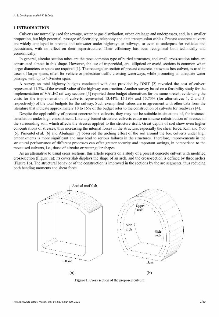
However, the material of real structures exhibits a nonlinear behavior and does not deform uniformly, causing stress distributions to be more complex. According to Evans [12], a structure of more flexible central portion of the spans can experience simultaneous active and passive arching on its faces, as shown in Figure 2. Therefore, the evaluation of the behavior and efficiency of each proposed culvert requires the incorporation of soil-structure interaction.
Figure 2. Stress distribution in a flexible rectangular structure.
The behavior of the culvert is affected by the conditions of the surrounding soil and the characteristics of the structure itself. The soil-culvert interaction influences the behavior of the pressure distribution, hence, the stresses acting on the structure. A more complete assessment of a buried structure, especially over great depths, considers the non-linearity of the geotechnical conditions, the structure itself and the interfaces. The finite element numerical modeling is a suitable process; therefore, it simulated the soil-culvert interaction system. The culvert model is characterized as a plane strain deformation; consequently, Finite Element Method (FEM) assessed the behavior and efficiency of each proposed culvert. FEM analysis with GeoStudio computational package [13] was used because it is suitable for geotechnical analyses.
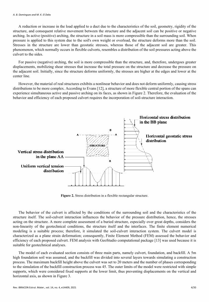
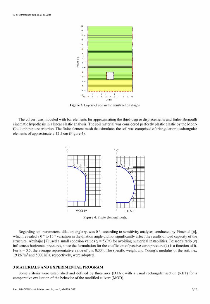
The model of each evaluated section consists of three main parts, namely culvert, foundation, and backfill. A 5m high foundation soil was assumed, and the backfill was divided into several layers towards simulating a construction process. The maximum backfill height above the culvert was set to 20 meters and the number of phases corresponding to the simulation of the backfill construction process was 45. The outer limits of the model were restricted with simple supports, which were considered fixed supports at the lower limit, thus preventing displacements on the vertical and horizontal axis, as shown in Figure 3.
A. B. Domingues and M. K. El Debs
Rev. IBRACON Estrut. Mater., vol. 14, no. 4, e14409, 2021 5/20
Figure 3. Layers of soil in the construction stages.
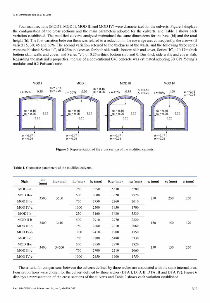
The culvert was modeled with bar elements for approximating the third-degree displacements and Euler-Bernoulli cinematic hypothesis in a linear elastic analysis. The soil material was considered perfectly plastic elastic by the Mohr-Coulomb rupture criterion. The finite element mesh that simulates the soil was comprised of triangular or quadrangular elements of approximately 12.5 cm (Figure 4).
Figure 4. Finite element mesh.
Regarding soil parameters, dilation angle ψs was 0 °, according to sensitivity analyses conducted by Pimentel [6], which revealed a 0 ° to 15 ° variation in the dilation angle did not significantly affect the results of load capacity of the structure. Abuhajar [7] used a small cohesion value (cs = 5kPa) for avoiding numerical instabilities. Poisson's ratio (ν) influences horizontal pressures, since the formulation for the coefficient of passive earth pressure (k) is a function of it. For k = 0.5, the average representative value of ν is 0.334. The specific weight and Young’s modulus of the soil, i.e., 19 kN/m3 and 5000 kPa, respectively, were adopted.
3 MATERIALS AND EXPERIMENTAL PROGRAM Some criteria were established and defined by three arcs (DTA), with a usual rectangular section (RET) for a
comparative evaluation of the behavior of the modified culvert (MOD).
A. B. Domingues and M. K. El Debs
Rev. IBRACON Estrut. Mater., vol. 14, no. 4, e14409, 2021 6/20
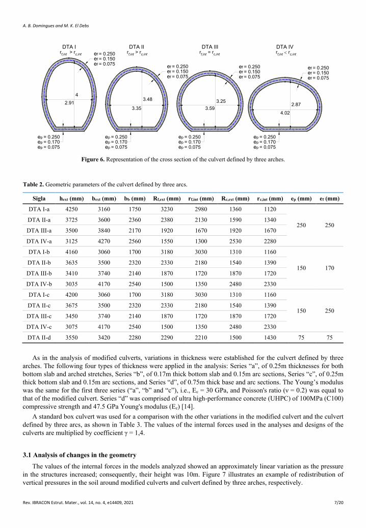
Four main sections (MOD I, MOD II, MOD III and MOD IV) were characterized for the culverts. Figure 5 displays the configuration of the cross sections and the main parameters adopted for the culverts, and Table 1 shows each variation established. The modified culverts analyzed maintained the same dimensions for the base (bl) and the total height (h). The first variation between them was related to a reduction in the coverage arc; consequently, the arrows (i) varied 15, 30, 45 and 60%. The second variation referred to the thickness of the walls, and the following three series were established: Series “a”, of 0.25m thicknesses for both side walls, bottom slab and cover, Series “b”, of 0.17m thick bottom slab, walls and cover, and Series “c”, of 0.25m thick bottom slab and 0.15m thick side walls and cover slab. Regarding the material´s properties, the use of a conventional C40 concrete was estimated adopting 30 GPa Young’s modulus and 0.2 Poisson's ratio.
3.25
3.25
0.25 0.50 0.75 1.00i = 15% i = 30% i = 45% i = 60%
3.25
3.25
3.25
3.25
3.25
3.25
ep = 0.15ep = 0.25
ef = 0.17ef = 0.25
ec = 0.15ec = 0.25
ep = 0.15ep = 0.25
ef = 0.17ef = 0.25
ep = 0.15ep = 0.25
ef = 0.17ef = 0.25
ep = 0.15ep = 0.25
ef = 0.17ef = 0.25
ec = 0.15ec = 0.25 ec = 0.15
ec = 0.25 ec = 0.15ec = 0.25
MOD I MOD II MOD III MOD IV
Figure 5. Representation of the cross section of the modified culverts.
Table 1. Geometric parameters of the modified culverts.
Sigla bext (mm) hext (mm) ha (mm) hr (mm) Rext (mm) rint (mm) ec (mm) ep (mm) ef (mm)
MOD I-a
3500 3500
250 3250 5530 5280
250 250 250 MOD II-a 500 3000 3020 2770
MOD III-a 750 2750 2260 2010
MOD IV-a 1000 2500 1950 1700
MOD I-b
3400 3410
250 3160 5480 5330
150 150 170 MOD II-b 500 2910 2970 2820
MOD III-b 750 2660 2210 2060
MOD IV-b 1000 2410 1900 1750
MOD I-c
3400 34500
250 3200 5480 5330
150 150 250 MOD II-c 500 2950 2970 2820
MOD III-c 750 2700 2210 2060
MOD IV-c 1000 2450 1900 1750
The criteria for comparisons between the culverts defined by three arches are associated with the same internal area. Four proportions were chosen for the culvert defined by three arches (DTA I, DTA II, DTA III and DTA IV). Figure 6 displays a representation of the cross sections of the culverts and Table 2 shows each variation established.
A. B. Domingues and M. K. El Debs
Rev. IBRACON Estrut. Mater., vol. 14, no. 4, e14409, 2021 7/20
43.48
2.913.35
3.253.59
2.87
4.02
DTA I DTA II DTA III DTA IV
ef = 0.150ef = 0.075
rf,int > rc,int rf,int > rc,int rf,int = rc,int rf,int < rc,intef = 0.250
ep = 0.170ep = 0.075
ep = 0.250ep = 0.170ep = 0.075
ep = 0.250ep = 0.170ep = 0.075
ep = 0.250ep = 0.170ep = 0.075
ep = 0.250
ef = 0.150ef = 0.075
ef = 0.250ef = 0.150ef = 0.075
ef = 0.250ef = 0.150ef = 0.075
ef = 0.250
Figure 6. Representation of the cross section of the culvert defined by three arches.
Table 2. Geometric parameters of the culvert defined by three arcs.
Sigla hext (mm) bext (mm) bb (mm) Rf,ext (mm) rf,int (mm) Rc,ext (mm) rc,int (mm) ep (mm) ef (mm)
DTA I-a 4250 3160 1750 3230 2980 1360 1120
250 250 DTA II-a 3725 3600 2360 2380 2130 1590 1340
DTA III-a 3500 3840 2170 1920 1670 1920 1670
DTA IV-a 3125 4270 2560 1550 1300 2530 2280
DTA I-b 4160 3060 1700 3180 3030 1310 1160
150 170 DTA II-b 3635 3500 2320 2330 2180 1540 1390
DTA III-b 3410 3740 2140 1870 1720 1870 1720
DTA IV-b 3035 4170 2540 1500 1350 2480 2330
DTA I-c 4200 3060 1700 3180 3030 1310 1160
150 250 DTA II-c 3675 3500 2320 2330 2180 1540 1390
DTA III-c 3450 3740 2140 1870 1720 1870 1720
DTA IV-c 3075 4170 2540 1500 1350 2480 2330
DTA II-d 3550 3420 2280 2290 2210 1500 1430 75 75
As in the analysis of modified culverts, variations in thickness were established for the culvert defined by three arches. The following four types of thickness were applied in the analysis: Series “a”, of 0.25m thicknesses for both bottom slab and arched stretches, Series “b”, of 0.17m thick bottom slab and 0.15m arc sections, Series “c”, of 0.25m thick bottom slab and 0.15m arc sections, and Series “d”, of 0.75m thick base and arc sections. The Young’s modulus was the same for the first three series (“a”, “b” and “c”), i.e., Ec = 30 GPa, and Poisson's ratio (ν = 0.2) was equal to that of the modified culvert. Series “d” was comprised of ultra high-performance concrete (UHPC) of 100MPa (C100) compressive strength and 47.5 GPa Young's modulus (Ec) [14].
A standard box culvert was used for a comparison with the other variations in the modified culvert and the culvert defined by three arcs, as shown in Table 3. The values of the internal forces used in the analyses and designs of the culverts are multiplied by coefficient γ = 1,4.
3.1 Analysis of changes in the geometry
The values of the internal forces in the models analyzed showed an approximately linear variation as the pressure in the structures increased; consequently, their height was 10m. Figure 7 illustrates an example of redistribution of vertical pressures in the soil around modified culverts and culvert defined by three arches, respectively.
A. B. Domingues and M. K. El Debs
Rev. IBRACON Estrut. Mater., vol. 14, no. 4, e14409, 2021 8/20
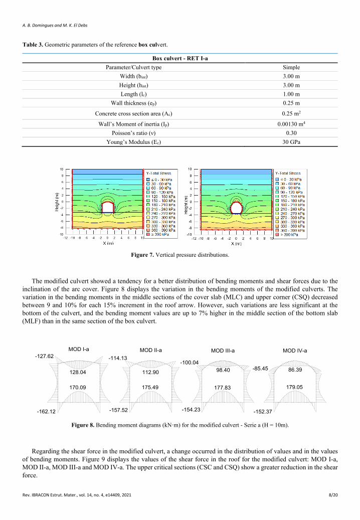
Table 3. Geometric parameters of the reference box culvert.
Box culvert - RET I-a Parameter/Culvert type Simple
Width (bint) 3.00 m Height (hint) 3.00 m Length (lc) 1.00 m
Wall thickness (ep) 0.25 m
Concrete cross section area (Ac) 0.25 m2
Wall’s Moment of inertia (Ip) 0.00130 m4 Poisson’s ratio (ν) 0.30
Young’s Modulus (Ec) 30 GPa
Figure 7. Vertical pressure distributions.
The modified culvert showed a tendency for a better distribution of bending moments and shear forces due to the inclination of the arc cover. Figure 8 displays the variation in the bending moments of the modified culverts. The variation in the bending moments in the middle sections of the cover slab (MLC) and upper corner (CSQ) decreased between 9 and 10% for each 15% increment in the roof arrow. However, such variations are less significant at the bottom of the culvert, and the bending moment values are up to 7% higher in the middle section of the bottom slab (MLF) than in the same section of the box culvert.
112.90
175.49
-162.12
170.09
128.04
-127.62
-157.52
-114.13MOD I-a MOD II-a
177.83
-154.23
-100.0498.40 86.39
179.05
-152.37
-85.45
MOD III-a MOD IV-a
Figure 8. Bending moment diagrams (kN·m) for the modified culvert - Serie a (H = 10m).
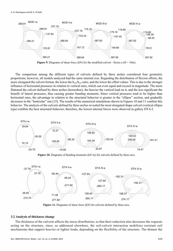
Regarding the shear force in the modified culvert, a change occurred in the distribution of values and in the values of bending moments. Figure 9 displays the values of the shear force in the roof for the modified culvert: MOD I-a, MOD II-a, MOD III-a and MOD IV-a. The upper critical sections (CSC and CSQ) show a greater reduction in the shear force.
A. B. Domingues and M. K. El Debs
Rev. IBRACON Estrut. Mater., vol. 14, no. 4, e14409, 2021 9/20
-390.21
299.91
-388.84
237.18
390.21
176.97
-137.94
-299.91
167.72
-123.24
-237.18
388.84
MOD I-a MOD II-a
-387.65
175.16
387.65
159.68
-107.45
-175.16
MOD III-a
119.68
387.82
-88.43-387.82
153.5
-119.68-106.39
MOD IV-a
Figure 9. Diagrams of shear force (kN) for the modified culvert - Series a (H = 10m).
The comparison among the different types of culverts defined by three arches considered four geometric proportions; however, all models analyzed had the same internal size. Regarding the distribution of flexion efforts, the more elongated the culvert format, the lower the hext/bext ratio, and the lower the effort values. This is due to the stronger influence of horizontal pressures in relation to vertical ones, which can even equal and exceed in magnitude. The more flattened the culvert defined by three arches (horseshoe), the heavier the vertical load on it, and the less significant the benefit of lateral pressures, thus causing greater bending moments. Since vertical pressures tend to be higher than horizontal ones, the advantage in relation to the structural behavior is greater in the “ellipse” section, and gradually decreases in the “lenticular” one [15]. The results of the numerical simulations shown in Figures 10 and 11 confirm this behavior. The analysis of the culverts defined by three arches revealed the most elongated shape culvert (vertical ellipse type) exhibits the best structural behavior; therefore, the lowest internal forces were observed in gallery DTA-I.
-24.75
74.15
29.6472.27
149.26
-19.58
DTA I-a DTA II-a
-20.05-85.25
149.52206.65
19.47
108.65
163.39 -120.34
DTA III-aDTA IV-a
-181.41
20.97
Figure 10. Diagrams of bending moments (kN·m) for culverts defined by three arcs.
271.60
71.48
85.44
-271.60
37.79
212.74
29.05
-85.44
-37.79DTA I-a DTA II-a
-192.31
274.17
198.37
260.17
128.40
-127.94
127.94
-260.17-192.31
DTA III-a DTA IV-a
Figure 11. Diagrams of shear force (kN) for culverts defined by three arcs.
3.2 Analysis of thickness change The thickness of the culverts affects the stress distribution, so that their reduction also decreases the requests
acting on the structure, since, as addressed elsewhere, the soil-culvert interaction mobilizes resistant soil mechanisms that support heavier or lighter loads, depending on the flexibility of the structure. The thinner the
A. B. Domingues and M. K. El Debs
Rev. IBRACON Estrut. Mater., vol. 14, no. 4, e14409, 2021 10/20
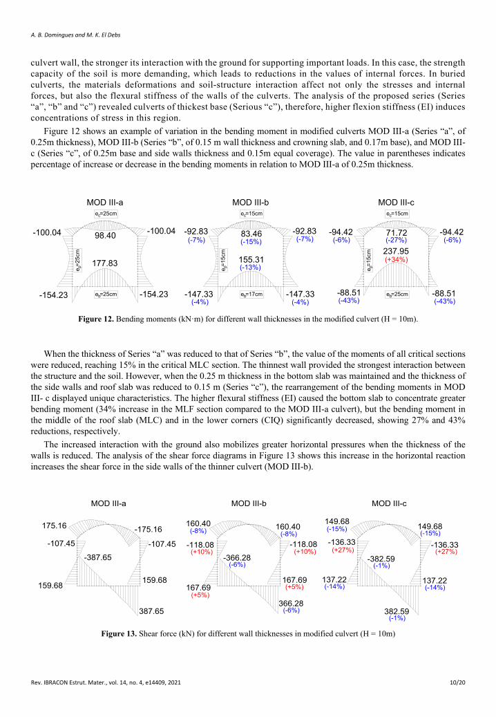
culvert wall, the stronger its interaction with the ground for supporting important loads. In this case, the strength capacity of the soil is more demanding, which leads to reductions in the values of internal forces. In buried culverts, the materials deformations and soil-structure interaction affect not only the stresses and internal forces, but also the flexural stiffness of the walls of the culverts. The analysis of the proposed series (Series “a”, “b” and “c”) revealed culverts of thickest base (Serious “c”), therefore, higher flexion stiffness (EI) induces concentrations of stress in this region.
Figure 12 shows an example of variation in the bending moment in modified culverts MOD III-a (Series “a”, of 0.25m thickness), MOD III-b (Series “b”, of 0.15 m wall thickness and crowning slab, and 0.17m base), and MOD III-c (Series “c”, of 0.25m base and side walls thickness and 0.15m equal coverage). The value in parentheses indicates percentage of increase or decrease in the bending moments in relation to MOD III-a of 0.25m thickness.
177.83
-154.23
-100.04 98.40 -100.04
-154.23
155.31
-147.33
-92.83 83.46
-147.33
-92.83
-88.51
237.95
-94.42 71.72
-88.51
-94.42
MOD III-a MOD III-b MOD III-c
(-7%)
(-4%)
(-13%)
(-15%) (-7%)
(-4%)e =25cmb
e =25cmc
e =2
5cm
p
e =17cmb
e =15cmc
e =1
5cm
p
e =25cmb
e =15cmc
e =1
5cm
p
(-6%) (-6%)
(-43%) (-43%)
(-27%)
(+34%)
Figure 12. Bending moments (kN·m) for different wall thicknesses in the modified culvert (H = 10m).
When the thickness of Series “a” was reduced to that of Series “b”, the value of the moments of all critical sections were reduced, reaching 15% in the critical MLC section. The thinnest wall provided the strongest interaction between the structure and the soil. However, when the 0.25 m thickness in the bottom slab was maintained and the thickness of the side walls and roof slab was reduced to 0.15 m (Series “c”), the rearrangement of the bending moments in MOD III- c displayed unique characteristics. The higher flexural stiffness (EI) caused the bottom slab to concentrate greater bending moment (34% increase in the MLF section compared to the MOD III-a culvert), but the bending moment in the middle of the roof slab (MLC) and in the lower corners (CIQ) significantly decreased, showing 27% and 43% reductions, respectively.
The increased interaction with the ground also mobilizes greater horizontal pressures when the thickness of the walls is reduced. The analysis of the shear force diagrams in Figure 13 shows this increase in the horizontal reaction increases the shear force in the side walls of the thinner culvert (MOD III-b).
-387.65
159.68
-107.45
175.16
-366.28
167.69
-118.08
160.40
387.65
159.68
-107.45
-175.16
366.28
160.40
-118.08
167.69
-382.59
137.22
-136.33
149.68 149.68
-136.33
382.59
137.22
MOD III-a MOD III-b MOD III-c
(-8%)
(+5%)
(+10%)
(-6%)
(-6%)
(+5%)
(+10%)
(-8%)(-15%) (-15%)
(+27%) (+27%)
(-14%) (-14%)
(-1%)
(-1%) Figure 13. Shear force (kN) for different wall thicknesses in modified culvert (H = 10m)
A. B. Domingues and M. K. El Debs
Rev. IBRACON Estrut. Mater., vol. 14, no. 4, e14409, 2021 11/20
In general, precast concrete culverts behave as rigid conduits; however, an alternative and relatively simple approach known as relative stiffness (RS) and designed by Gumbel et al. [16] shows some pipes may fall into either category (a flexible or a semi-rigid pipe). The “relative stiffness” criterion refers to the stiffness of the whole system (soil and buried conduit). Regarding the approximation of the sections defined by three arches in a circular section of the same area, only the thickest culverts (Series a) are considered rigid, with values of RS around 7.0. In series “b” and “c”, the systems behave with intermediate relative stiffness, with RS values between 30 and 33, and in the culvert defined by three arcs (Series “d”), the calculation of the relative stiffness provided values of the order of 155 for RR. According to the limits established by Gumbel et al. [16], Series “d” corresponds to a structure that supports 78% of the load imposed on the system. The result shows good measurements of the system for changes in the structure´s stiffness, although this verification is not ideal for other cross-sections, including circular ones.
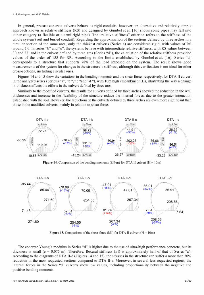
Figures 14 and 15 show the variations in the bending moments and the shear force, respectively, for DTA II culvert in the analyzed series (Serious “a”, “b “,” c “and” d “), with 10m high embankment (H), illustrating the way a change in thickness affects the efforts in the culvert defined by three arcs.
Similarly to the modified culverts, the results for culverts defined by three arches showed the reduction in the wall thicknesses and increase in the flexibility of the structure reduce the internal forces, due to the greater interaction established with the soil. However, the reductions in the culverts defined by three arches are even more significant than those in the modified culverts, mainly in relation to shear force.
72.27
149.26-85.25
-19.58
58.72
-50.94-70.43131.56
-15.24
44.91
36.27
-36.66
28.35
-33.29
86.51
DTA II-a DTA II-b DTA II-c DTA II-d
(-19%)
(-17%)(-12%)
(-38%)
(-40%)202.25(+36%)
(-61%)
(-57%)(-42%)
e =25cmb
e =25cmc
e =2
5cm
f
e =17cmb
e =15cmc
e =1
5cm
f
e =25cmb
e =15cmc
e =1
5cm
f
e =7.5cmb
e =7.5cmc
e =7
.5cm
f
Figure 14. Comparison of the bending moments (kN·m) for DTA II culvert (H = 10m)
271.60
71.48
85.44
254.55
52.31
-70.09
267.34
81.74
-47.0170.09
-254.55-271.60
208.56
7.64
-36.9136.91
-208.56
7.64
-85.44
DTA II-a
47.01
-267.34
DTA II-dDTA II-cDTA II-b
(-18%)
(-6%)
(-27%)
(-2%)
(+14%)
(-45%) (-57%)
(-89%)
(-57%)
Figure 15. Comparison of the shear force (kN) for DTA II culvert (H = 10m)
The concrete Young’s modulus in Series “d” is higher due to the use of ultra-high performance concrete, but its thickness is small (e = 0.075 m). Therefore, flexural stiffness (EI) is approximately half of that of Series “a”. According to the diagrams of DTA II-d (Figures 14 and 15), the stresses in the structure can suffer a more than 50% reduction in the most requested sections compared to DTA II-a. Moreover, in several less requested regions, the internal forces in the Series “d” culverts show low values, including proportionality between the negative and positive bending moments.
A. B. Domingues and M. K. El Debs
Rev. IBRACON Estrut. Mater., vol. 14, no. 4, e14409, 2021 12/20
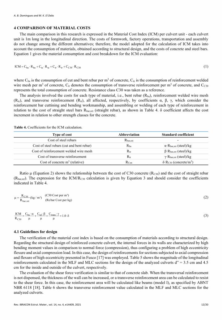
4 COMPARISON OF MATERIAL COSTS The main comparison in this research is expressed in the Material Cost Index (ICM) per culvert unit - each culvert
unit is 1m long in the longitudinal direction. The costs of formwork, factory operations, transportation and assembly do not change among the different alternatives; therefore, the model adopted for the calculation of ICM takes into account the consumption of materials, obtained according to structural design, and the costs of concrete and steel bars. Equation 1 gives the material consumption and cost breakdown for the ICM evaluation:
ba ba te te tr tr C30 C30ICM C R C R C R C R= ⋅ + ⋅ + ⋅ + ⋅ (1)
where Cba is the consumption of cut and bent rebar per m3 of concrete, Cte is the consumption of reinforcement welded wire mesh per m3 of concrete, Ctr denotes the consumption of transverse reinforcement per m3 of concrete, and CC30 represents the total consumption of concrete. Resistance class C30 was taken as a reference.
The analysis involved the costs for each type of material, i.e., bent rebar (Rba), reinforcement welded wire mesh (Rte), and transverse reinforcement (Rtr), all affected, respectively, by coefficients α, β, γ, which consider the reinforcement bar cuttining and bending workmanship, and assembling or welding of each type of reinforcement in relation to the cost of straight steel bars Rbar,ret (straight rebar), as shown in Table 4. δ coefficient affects the cost increment in relation to other strength classes for the concrete.
Table 4. Coefficients for the ICM calculation.
Type of cost Abbreviation Standard coefficient Cost of steel rebars Rbar,ret -
Cost of steel rebars (cut and bent rebar) Rba α·Rbar,ret (steel)/kg Cost of reinforcement welded wire mesh Rte β·Rbar,ret (steel)/kg
Cost of transverse reinforcement Rtr γ·Rbar,ret (steel)/kg Cost of concrete m3 (relative) RCon δ·RC30 (concrete/m3)
Ratio μ (Equation 2) shows the relationship between the cost of C30 concrete (RC30) and the cost of straight rebar (Rbar,ret). The expression for the ICM/RC30 calculation is given by Equation 3 and should consider the coefficients indicated in Table 4.
C30
bar,ret
(C30 Cost per m³)R (kg / m³)(Re bar Cost per kg)R
µ = (2)
ba tel trans
C30
C C CICM 1.0R
⋅α ⋅β ⋅ γ= + + + ⋅δ
µ µ µ (3)
4.1 Guidelines for design The verification of the material cost index is based on the consumption of materials according to structural design.
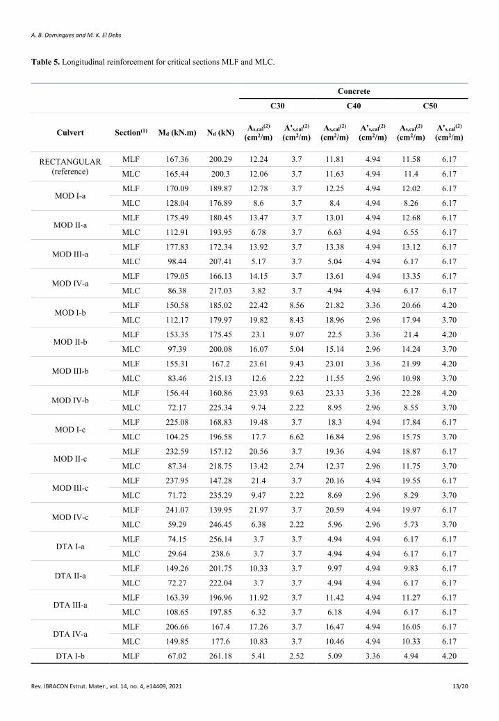
Regarding the structural design of reinforced concrete culvert, the internal forces in its walls are characterized by high bending moment values in comparison to normal force (compression), thus configuring a problem of high eccentricity flexure and axial compression load. In this case, the design of reinforcements for sections subjected to axial compression and flexure of high eccentricity presented in Fusco [17] was employed. Table 5 shows the magnitude of the longitudinal reinforcements calculated in the MLF and MLC sections for the design of the analyzed culverts d” = 3.5 cm and 4.5 cm for the inside and outside of the culvert, respectively.
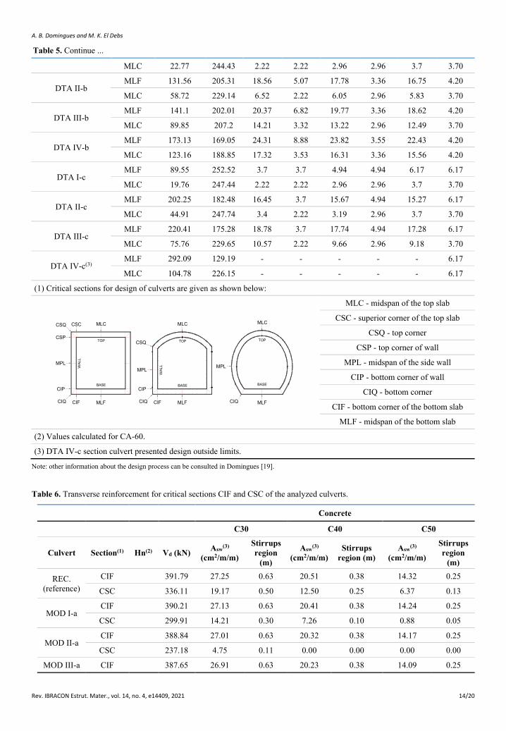
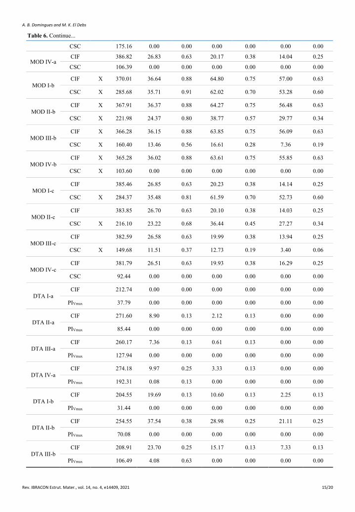
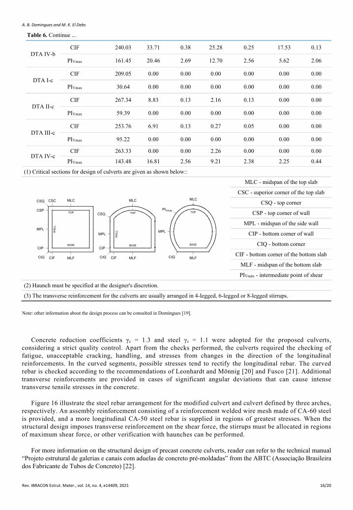
The evaluation of the shear force verification is similar to that of concrete slab. When the transversal reinforcement is not dispensed, the thickness of the wall can be increased, or a transverse reinforcement area can be calculated to resist to the shear force. In this case, the reinforcement area will be calculated like beams (model I), as specified by ABNT NBR 6118 [18]. Table 6 shows the transverse reinforcement value calculated in the MLF and MLC sections for the analyzed culverts.
A. B. Domingues and M. K. El Debs
Rev. IBRACON Estrut. Mater., vol. 14, no. 4, e14409, 2021 13/20
Table 5. Longitudinal reinforcement for critical sections MLF and MLC.
Concrete
C30 C40 C50
Culvert Section(1) Md (kN.m) Nd (kN) As,cal(2) (cm2/m)
A's,cal(2) (cm2/m)
As,cal(2) (cm2/m)
A's,cal(2) (cm2/m)
As,cal(2) (cm2/m)
A's,cal(2) (cm2/m)
RECTANGULAR (reference)
MLF 167.36 200.29 12.24 3.7 11.81 4.94 11.58 6.17
MLC 165.44 200.3 12.06 3.7 11.63 4.94 11.4 6.17
MOD I-a MLF 170.09 189.87 12.78 3.7 12.25 4.94 12.02 6.17
MLC 128.04 176.89 8.6 3.7 8.4 4.94 8.26 6.17
MOD II-a MLF 175.49 180.45 13.47 3.7 13.01 4.94 12.68 6.17
MLC 112.91 193.95 6.78 3.7 6.63 4.94 6.55 6.17
MOD III-a MLF 177.83 172.34 13.92 3.7 13.38 4.94 13.12 6.17
MLC 98.44 207.41 5.17 3.7 5.04 4.94 6.17 6.17
MOD IV-a MLF 179.05 166.13 14.15 3.7 13.61 4.94 13.35 6.17
MLC 86.38 217.03 3.82 3.7 4.94 4.94 6.17 6.17
MOD I-b MLF 150.58 185.02 22.42 8.56 21.82 3.36 20.66 4.20
MLC 112.17 179.97 19.82 8.43 18.96 2.96 17.94 3.70
MOD II-b MLF 153.35 175.45 23.1 9.07 22.5 3.36 21.4 4.20
MLC 97.39 200.08 16.07 5.04 15.14 2.96 14.24 3.70
MOD III-b MLF 155.31 167.2 23.61 9.43 23.01 3.36 21.99 4.20
MLC 83.46 215.13 12.6 2.22 11.55 2.96 10.98 3.70
MOD IV-b MLF 156.44 160.86 23.93 9.63 23.33 3.36 22.28 4.20
MLC 72.17 225.34 9.74 2.22 8.95 2.96 8.55 3.70
MOD I-c MLF 225.08 168.83 19.48 3.7 18.3 4.94 17.84 6.17
MLC 104.25 196.58 17.7 6.62 16.84 2.96 15.75 3.70
MOD II-c MLF 232.59 157.12 20.56 3.7 19.36 4.94 18.87 6.17
MLC 87.34 218.75 13.42 2.74 12.37 2.96 11.75 3.70
MOD III-c MLF 237.95 147.28 21.4 3.7 20.16 4.94 19.55 6.17
MLC 71.72 235.29 9.47 2.22 8.69 2.96 8.29 3.70
MOD IV-c MLF 241.07 139.95 21.97 3.7 20.59 4.94 19.97 6.17
MLC 59.29 246.45 6.38 2.22 5.96 2.96 5.73 3.70
DTA I-a MLF 74.15 256.14 3.7 3.7 4.94 4.94 6.17 6.17
MLC 29.64 238.6 3.7 3.7 4.94 4.94 6.17 6.17
DTA II-a MLF 149.26 201.75 10.33 3.7 9.97 4.94 9.83 6.17
MLC 72.27 222.04 3.7 3.7 4.94 4.94 6.17 6.17
DTA III-a MLF 163.39 196.96 11.92 3.7 11.42 4.94 11.27 6.17
MLC 108.65 197.85 6.32 3.7 6.18 4.94 6.17 6.17
DTA IV-a MLF 206.66 167.4 17.26 3.7 16.47 4.94 16.05 6.17
MLC 149.85 177.6 10.83 3.7 10.46 4.94 10.33 6.17
DTA I-b MLF 67.02 261.18 5.41 2.52 5.09 3.36 4.94 4.20
A. B. Domingues and M. K. El Debs
Rev. IBRACON Estrut. Mater., vol. 14, no. 4, e14409, 2021 14/20
MLC 22.77 244.43 2.22 2.22 2.96 2.96 3.7 3.70
DTA II-b MLF 131.56 205.31 18.56 5.07 17.78 3.36 16.75 4.20
MLC 58.72 229.14 6.52 2.22 6.05 2.96 5.83 3.70
DTA III-b MLF 141.1 202.01 20.37 6.82 19.77 3.36 18.62 4.20
MLC 89.85 207.2 14.21 3.32 13.22 2.96 12.49 3.70
DTA IV-b MLF 173.13 169.05 24.31 8.88 23.82 3.55 22.43 4.20
MLC 123.16 188.85 17.32 3.53 16.31 3.36 15.56 4.20
DTA I-c MLF 89.55 252.52 3.7 3.7 4.94 4.94 6.17 6.17
MLC 19.76 247.44 2.22 2.22 2.96 2.96 3.7 3.70
DTA II-c MLF 202.25 182.48 16.45 3.7 15.67 4.94 15.27 6.17
MLC 44.91 247.74 3.4 2.22 3.19 2.96 3.7 3.70
DTA III-c MLF 220.41 175.28 18.78 3.7 17.74 4.94 17.28 6.17
MLC 75.76 229.65 10.57 2.22 9.66 2.96 9.18 3.70
DTA IV-c(3) MLF 292.09 129.19 - - - - - 6.17
MLC 104.78 226.15 - - - - - 6.17
(1) Critical sections for design of culverts are given as shown below:
CSQ
MPL
CSP
CIP
CIQ CIF MLF
CSC MLC
CIP
CIQ CIF MLF
MLC
MPL
CSQ
MLC
BASE
MPL
CIQ MLF
TOP
WA
LL
BASE
TOP
WA
LL
BASE
TOP
MLC - midspan of the top slab
CSC - superior corner of the top slab
CSQ - top corner
CSP - top corner of wall
MPL - midspan of the side wall
CIP - bottom corner of wall
CIQ - bottom corner
CIF - bottom corner of the bottom slab
MLF - midspan of the bottom slab
(2) Values calculated for CA-60.
(3) DTA IV-c section culvert presented design outside limits.
Note: other information about the design process can be consulted in Domingues [19].
Table 6. Transverse reinforcement for critical sections CIF and CSC of the analyzed culverts.
Concrete
C30 C40 C50
Culvert Section(1) Hn(2) Vd (kN) Asw(3) (cm2/m/m)
Stirrups region
(m)
Asw(3) (cm2/m/m)
Stirrups region (m)
Asw(3) (cm2/m/m)
Stirrups region
(m)
REC. (reference)
CIF 391.79 27.25 0.63 20.51 0.38 14.32 0.25
CSC 336.11 19.17 0.50 12.50 0.25 6.37 0.13
MOD I-a CIF 390.21 27.13 0.63 20.41 0.38 14.24 0.25
CSC 299.91 14.21 0.30 7.26 0.10 0.88 0.05
MOD II-a CIF 388.84 27.01 0.63 20.32 0.38 14.17 0.25
CSC 237.18 4.75 0.11 0.00 0.00 0.00 0.00
MOD III-a CIF 387.65 26.91 0.63 20.23 0.38 14.09 0.25
Table 5. Continue ...
A. B. Domingues and M. K. El Debs
Rev. IBRACON Estrut. Mater., vol. 14, no. 4, e14409, 2021 15/20
CSC 175.16 0.00 0.00 0.00 0.00 0.00 0.00
MOD IV-a CIF 386.82 26.83 0.63 20.17 0.38 14.04 0.25
CSC 106.39 0.00 0.00 0.00 0.00 0.00 0.00
MOD I-b CIF X 370.01 36.64 0.88 64.80 0.75 57.00 0.63
CSC X 285.68 35.71 0.91 62.02 0.70 53.28 0.60
MOD II-b CIF X 367.91 36.37 0.88 64.27 0.75 56.48 0.63
CSC X 221.98 24.37 0.80 38.77 0.57 29.77 0.34
MOD III-b CIF X 366.28 36.15 0.88 63.85 0.75 56.09 0.63
CSC X 160.40 13.46 0.56 16.61 0.28 7.36 0.19
MOD IV-b CIF X 365.28 36.02 0.88 63.61 0.75 55.85 0.63
CSC X 103.60 0.00 0.00 0.00 0.00 0.00 0.00
MOD I-c CIF 385.46 26.85 0.63 20.23 0.38 14.14 0.25
CSC X 284.37 35.48 0.81 61.59 0.70 52.73 0.60
MOD II-c CIF 383.85 26.70 0.63 20.10 0.38 14.03 0.25
CSC X 216.10 23.22 0.68 36.44 0.45 27.27 0.34
MOD III-c CIF 382.59 26.58 0.63 19.99 0.38 13.94 0.25
CSC X 149.68 11.51 0.37 12.73 0.19 3.40 0.06
MOD IV-c CIF 381.79 26.51 0.63 19.93 0.38 16.29 0.25
CSC 92.44 0.00 0.00 0.00 0.00 0.00 0.00
DTA I-a CIF 212.74 0.00 0.00 0.00 0.00 0.00 0.00
PIVmax 37.79 0.00 0.00 0.00 0.00 0.00 0.00
DTA II-a CIF 271.60 8.90 0.13 2.12 0.13 0.00 0.00
PIVmax 85.44 0.00 0.00 0.00 0.00 0.00 0.00
DTA III-a CIF 260.17 7.36 0.13 0.61 0.13 0.00 0.00
PIVmax 127.94 0.00 0.00 0.00 0.00 0.00 0.00
DTA IV-a CIF 274.18 9.97 0.25 3.33 0.13 0.00 0.00
PIVmax 192.31 0.08 0.13 0.00 0.00 0.00 0.00
DTA I-b CIF 204.55 19.69 0.13 10.60 0.13 2.25 0.13
PIVmax 31.44 0.00 0.00 0.00 0.00 0.00 0.00
DTA II-b CIF 254.55 37.54 0.38 28.98 0.25 21.11 0.25
PIVmax 70.08 0.00 0.00 0.00 0.00 0.00 0.00
DTA III-b CIF 208.91 23.70 0.25 15.17 0.13 7.33 0.13
PIVmax 106.49 4.08 0.63 0.00 0.00 0.00 0.00
Table 6. Continue...
A. B. Domingues and M. K. El Debs
Rev. IBRACON Estrut. Mater., vol. 14, no. 4, e14409, 2021 16/20
DTA IV-b CIF 240.03 33.71 0.38 25.28 0.25 17.53 0.13
PIVmax 161.45 20.46 2.69 12.70 2.56 5.62 2.06
DTA I-c CIF 209.05 0.00 0.00 0.00 0.00 0.00 0.00
PIVmax 30.64 0.00 0.00 0.00 0.00 0.00 0.00
DTA II-c CIF 267.34 8.83 0.13 2.16 0.13 0.00 0.00
PIVmax 59.39 0.00 0.00 0.00 0.00 0.00 0.00
DTA III-c CIF 253.76 6.91 0.13 0.27 0.05 0.00 0.00
PIVmax 95.22 0.00 0.00 0.00 0.00 0.00 0.00
DTA IV-c CIF 263.33 0.00 0.00 2.26 0.00 0.00 0.00
PIVmax 143.48 16.81 2.56 9.21 2.38 2.25 0.44
(1) Critical sections for design of culverts are given as shown below::
CSQ
MPL
CSP
CIP
CIQ CIF MLF
CSC MLC
CIP
CIQ CIF MLF
MLC
MPL
CSQ
MLC
BASE
MPL
CIQ MLF
TOP
WAL
L
BASE
TOP
WAL
L
BASE
TOPPIVmáx
MLC - midspan of the top slab
CSC - superior corner of the top slab
CSQ - top corner
CSP - top corner of wall
MPL - midspan of the side wall
CIP - bottom corner of wall
CIQ - bottom corner
CIF - bottom corner of the bottom slab
MLF - midspan of the bottom slab
PIVmáx - intermediate point of shear
(2) Haunch must be specified at the designer's discretion.
(3) The transverse reinforcement for the culverts are usually arranged in 4-legged, 6-legged or 8-legged stirrups.
Note: other information about the design process can be consulted in Domingues [19].
Concrete reduction coefficients γc = 1.3 and steel γs = 1.1 were adopted for the proposed culverts, considering a strict quality control. Apart from the checks performed, the culverts required the checking of fatigue, unacceptable cracking, handling, and stresses from changes in the direction of the longitudinal reinforcements. In the curved segments, possible stresses tend to rectify the longitudinal rebar. The curved rebar is checked according to the recommendations of Leonhardt and Mönnig [20] and Fusco [21]. Additional transverse reinforcements are provided in cases of significant angular deviations that can cause intense transverse tensile stresses in the concrete.
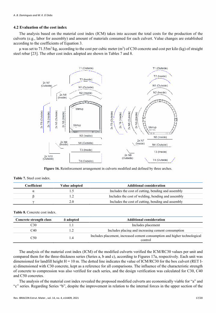
Figure 16 illustrate the steel rebar arrangement for the modified culvert and culvert defined by three arches, respectively. An assembly reinforcement consisting of a reinforcement welded wire mesh made of CA-60 steel is provided, and a more longitudinal CA-50 steel rebar is supplied in regions of greatest stresses. When the structural design imposes transverse reinforcement on the shear force, the stirrups must be allocated in regions of maximum shear force, or other verification with haunches can be performed.
For more information on the structural design of precast concrete culverts, reader can refer to the technical manual “Projeto estrutural de galerias e canais com aduelas de concreto pré-moldadas” from the ABTC (Associação Brasileira dos Fabricante de Tubos de Concreto) [22].
Table 6. Continue ...
A. B. Domingues and M. K. El Debs
Rev. IBRACON Estrut. Mater., vol. 14, no. 4, e14409, 2021 17/20
4.2 Evaluation of the cost index The analysis based on the material cost index (ICM) takes into account the total costs for the production of the
culverts (e.g., labor for assembly) and amount of materials consumed for each culvert. Value changes are established according to the coefficients of Equation 3.
μ was set to 71.55m3/kg, according to the cost per cubic meter (m3) of C30 concrete and cost per kilo (kg) of straight steel rebar [23]. The other cost index adopted are shown in Tables 7 and 8.
Figure 16. Reinforcement arrangement in culverts modified and defined by three arches.
Table 7. Steel cost index.
Coefficient Value adopted Additional consideration α 1.5 Includes the cost of cutting, bending and assembly β 1.2 Includes the cost of welding, bending and assembly γ 2.0 Includes the cost of cutting, bending and assembly
Table 8. Concrete cost index.
Concrete strength class δ adopted Additional consideration C30 1.1 Includes placement C40 1.2 Includes placing and increasing cement consumption
C50 1.4 Includes placement, increased cement consumption and higher technological control
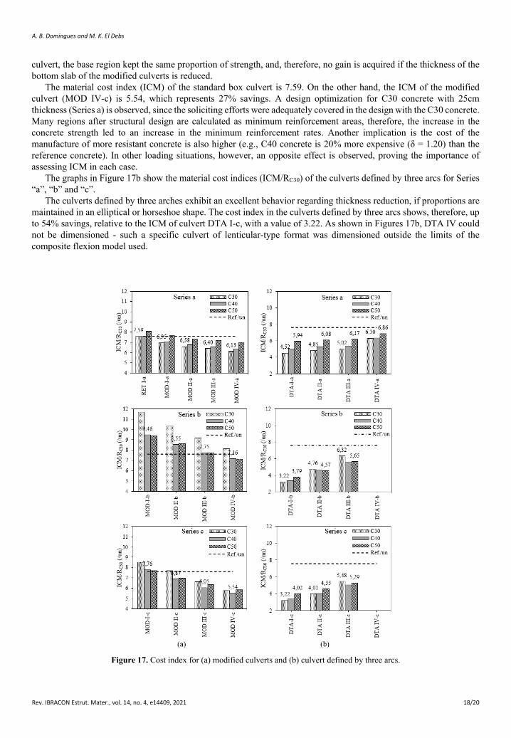
The analysis of the material cost index (ICM) of the modified culverts verified the ICM/RC30 values per unit and
compared them for the three-thickness series (Series a, b and c), according to Figures 17a, respectively. Each unit was dimensioned for landfill height H = 10 m. The dotted line indicates the value of ICM/RC30 for the box culvert (RET I-a) dimensioned with C30 concrete, kept as a reference for all comparisons. The influence of the characteristic strength of concrete to compression was also verified for each series, and the design verification was calculated for C30, C40 and C50 concretes.
The analysis of the material cost index revealed the proposed modified culverts are economically viable for “a” and “c” series. Regarding Series “b”, despite the improvement in relation to the internal forces in the upper section of the
A. B. Domingues and M. K. El Debs
Rev. IBRACON Estrut. Mater., vol. 14, no. 4, e14409, 2021 18/20
culvert, the base region kept the same proportion of strength, and, therefore, no gain is acquired if the thickness of the bottom slab of the modified culverts is reduced.
The material cost index (ICM) of the standard box culvert is 7.59. On the other hand, the ICM of the modified culvert (MOD IV-c) is 5.54, which represents 27% savings. A design optimization for C30 concrete with 25cm thickness (Series a) is observed, since the soliciting efforts were adequately covered in the design with the C30 concrete. Many regions after structural design are calculated as minimum reinforcement areas, therefore, the increase in the concrete strength led to an increase in the minimum reinforcement rates. Another implication is the cost of the manufacture of more resistant concrete is also higher (e.g., C40 concrete is 20% more expensive (δ = 1.20) than the reference concrete). In other loading situations, however, an opposite effect is observed, proving the importance of assessing ICM in each case.
The graphs in Figure 17b show the material cost indices (ICM/RC30) of the culverts defined by three arcs for Series “a”, “b” and “c”.
The culverts defined by three arches exhibit an excellent behavior regarding thickness reduction, if proportions are maintained in an elliptical or horseshoe shape. The cost index in the culverts defined by three arcs shows, therefore, up to 54% savings, relative to the ICM of culvert DTA I-c, with a value of 3.22. As shown in Figures 17b, DTA IV could not be dimensioned - such a specific culvert of lenticular-type format was dimensioned outside the limits of the composite flexion model used.
Figure 17. Cost index for (a) modified culverts and (b) culvert defined by three arcs.
A. B. Domingues and M. K. El Debs
Rev. IBRACON Estrut. Mater., vol. 14, no. 4, e14409, 2021 19/20
According to the ICM values and the results shown in Tables 5 and 6, an increase in the concrete fck, despite reducing the reinforcement calculated in certain regions, increases the minimum reinforcement areas, thus leading to a slightly higher ICM of higher strength concretes in comparison to reference C30 concrete.
The ICM indications do not consider expenses with molds and that the coefficients adopted in the expression for their calculation may vary according to the market or region.
5 CONCLUSIONS This article has reported a numerical investigation on the behavior of culverts at great depths (H> Bc), and, according
to the results for the box culvert and the proposed culverts with unusual cross sections, the following conclusions can be drawn: a) The analysis of the diagrams showed changes in the geometries of the cross sections significantly changed the
requesting strength. In modified culverts, larger arrows in the coverage arc decrease the stress in the upper part in both bending moments and shear force, with no changes in the lower part. Regarding culverts defined by three arches, cross sections of ellipse shape promote the best distribution of strength, and the greater the radius of the lateral arc (rf) in relation to the radius of the coverage arc (rc), the lesser the strength. Moreover, a decrease in the width of the bottom slab (b) also reduces the stress at the base.
b) The stress acting on the culverts is lower when the thicknesses of the walls are reduced, due to a stronger interaction established with the soil, thus mobilizing a higher strength capacity of the surrounding soil, and a change in the flexural rigidity (EI) of the bottom slab in relation to the EI adopted for the side walls and roof affects the stress distribution.
c) The dimensions demonstrated the viability of the proposed cross sections for installation under elevated embankments. The cost index enabled the quantification of the materials savings for the modified culverts, which represent 5% to 27% in the analyzed models in comparison to the box culverts, according to the thickness of the walls and the proportion in the abatements of the arch roof. Moreover, an analysis of the cost index for the culvert defined by three arches proved even more optimistic, with material savings ranging from 17 to 54% in comparison to the box culvert. The analysis of the dimensions for the culvert defined by three arches also revealed a reduction in the thickness of the walls is quite efficient for sections of “ellipse” and “horseshoe” types; however, the thickness of “lenticular” culverts should not be reduced if rf is much lower than rc. The replacement of the box culvert for the unusual cross-sectional culvert reduces the requesting stress. Regarding
the reduction in the thicknesses usually employed, the greater the interaction between the structure and the soil, the smaller the bending moments, due to the greater participation of the resistant mechanism of the soil. A reduction in thickness causes the structure to become less resistant to the stress produced by high localized pressures.
ACKNOWLEDGEMENTS The authors acknowledge the Coordenação de Aperfeiçoamento de Pessoal de Nível Superior - Brazil (CAPES) –
[Código de Financiamento 001] for the financial support, and the Brazilian Association of Concrete Pipe (ABTC - Associação Brasileira dos Fabricantes de Tubos de Concreto). The first author is indebted to the School of Engineering of São Carlos and CNPq, for the financial support for the continuation of the research through the granting of a doctoral scholarship.
REFERENCES [1] B. D. S. Bueno and Y. D. J. Costa, Dutos Enterrados: Aspectos Geotécnicos. São Carlos: EESC-USP, 2009.
[2] Departamento Nacional de Infraestrutura de Transportes, Planilha de Preços Unitários da Rodovia BR-242/TO: Trecho Divisa BA/TO a Divisa TO/MT. Brasília, 2012.
[3] VALEC Engenharia, Construções e Ferrovias S.A., Estudo de Viabilidade Técnica, Econômica e Ambiental (EF-151): Trecho Itumbiara/GO – Goiânia/GO – Brasília/DF. Brasília, 2012.
[4] M. K. El Debs, “Contribuição ao projeto de galerias enterradas: alternativas em argamassa armada,” Ph.D. dissertation, SET-EESC, São Carlos, 1984.
[5] K. Kim and C. H. Yoo, "Design loading on deeply buried box culverts," J. Geotech. Geoenviron. Eng., vol. 131, no. 1, pp. 20–27, 2005.
[6] M. Pimentel, P. Costa, C. Félix, and J. Figueiras, "Behavior of reinforced concrete box culverts under high embankments," J. Struct. Eng., vol. 135, pp. 366–375, Apr 2009.
A. B. Domingues and M. K. El Debs
Rev. IBRACON Estrut. Mater., vol. 14, no. 4, e14409, 2021 20/20
[7] O. S. A. Abuhajar, “Static and seismic soil culvert interaction,” Ph.D. dissertation, Prog. Civ. Environ. Eng., Univ. Western Ontario, Ontario, 2013.
[8] J. D. Marshall, J. B. Anderson, R. L. Meadows, and T. J. Jensen, "Full-scale testing of three-sided precast concrete arch sections," J. Bridge Eng., vol. 19, no. 12, 04014051, 2014.
[9] M. Zoghi and D. N. Farhey, "Performance assessment of a precast-concrete, buried, small arch bridge," J. Perform. Constr. Facil. Wash., vol. 20, pp. 244–252, Aug 2006.
[10] M. K. El Debs, Projeto Estrutural de Tubos de Seção Retangular de Concreto Armado, 1a. ed. Ribeirão Preto: Associação Brasileira dos Produtores de Tubos de Concreto, 2008.
[11] R. M. Bennett, S. M. Wood, E. C. Drumm, and N. R. Rainwater, "Vertical loads on concrete box culverts under high embankments," J. Bridge Eng., vol. 10, no. 6, pp. 643–649, 2005.
[12] C. H. Evans, “An examination on arching in granular soils,” M.S. thesis, Dept. Civ. Eng., Massachusetts Inst. Technol., Massachusetts, 1983.
[13] GEOSLOPE International Ltd., Stress-Deformation Modeling with SIGMA/W. Calgary, 2013.
[14] Comitté Euro-International Du Béton, CEB-FIP Model CODE 2010: First Complete Draft, vol. 1 (Bulletin 55). Alemanha, 2010.
[15] M. K. El Debs, Concreto Pré-Moldado: Fundamentos e Aplicações, 2a ed. São Paulo: Oficina de Textos, 2017.
[16] J. E. Gumbel, M. P. O’Reilly, L. M. Lake, and D. R. Carder, “The development of a new design method for buried flexible pipes,” in Europe ’82. Proc. Basel, 1982.
[17] P. B. Fusco, Estruturas de Concreto: Solicitações Normais. Rio de Janeiro: Guanabara Dois, 1981.
[18] Associação Brasileira de Normas Técnicas, Projeto de Estruturas de Concreto, NBR 6118, 2014.
[19] A. B. Domingues, “Contribuição ao projeto estrutural de galerias de concreto pré-moldado com seções transversais não usuais,” M.S. thesis, Esc. Eng. São Carlos, Univ. São Paulo, São Carlos, 2017.
[20] F. Leonhardt and E. Mönnig, Construções em Concreto: Princípios Básicos Sobre a Armação de Estruturas de Concreto Armado, vol. 3. Rio de Janeiro: Interciência, 1978.
[21] P. B. Fusco, Técnicas de Armar as Estruturas de Concreto, 7a ed. São Paulo: PINI, 1995.
[22] Associação Brasileira dos Fabricantes de Tubos de Concreto, Projeto Estrutural de Galerias e Canais com Aduelas de Concreto Pré-Moldadas, 2018.
[23] Sistema Nacional de Pesquisa de Custos e Índices da Construção Civil, Tabela de Preços e Custos de Referência: SINAPI Relatório de Insumos e Composições – Jan/17 – Com Desoneração. Rio de Janeiro, 2017.
Author contributions: ABD: conceptualization, methodology, numerical analysis, formal analysis, writing; MKD: conceptualization, methodology, supervision.
Editors: Vladimir Guilherme Haach, José Luiz Antunes de Oliveira e Sousa, Guilherme Aris Parsekian.