creating specific grammars with generic grammars: towards flexible urban design
TRANSCRIPT

1/21
Designing with Urban Induction Patterns - A methodological approach
José Beirão1, José Duarte2, Rudi Stouffs3, Henco Bekkering4 12Faculty of Architecture, TU Lisboa, Portugal, 134Faculty of Architecture, TU Delft, Netherlands [email protected] / [email protected], [email protected], [email protected], [email protected]
Keywords: design machines, shape grammars, urban design, discursive grammars, design methodology. Abstract
This paper develops a model for an urban design tool based on discursive grammars. The proposed design synthesis process is consistent with a reflective design process. The formalism, called urban grammars, is formally defined and a design methodology for urban design based on urban grammars is proposed and discussed. An urban design is obtained from a full formulation-generation-evaluation cycle of design patterns called urban induction patterns, each one of them being also a limited cycle of formulation-generation-evaluation encoded as a discursive grammar replicating a generic design move. The defined structure is compatible with the principles of design machines but keeping the reflective structure of the design process. 1. Research context
This paper describes research being developed as part of the City Induction research project. This research project aims at developing a design tool including design support features for urban design. The main idea of City Induction is to put together GIS and CAD tools and several tools for urban analysis to support urban programme formulation, urban design generation as a means of design exploration, and integrating evaluation and validation of urban designs (Duarte et al., forthcoming). Specifically, the design tool aims at analyzing data from a particular context on a GIS platform using the provided data to formulate the urban programme specifications for that context (formulation module – Montenegro, 2010), generate design solutions for those specifications using discursive grammars as the generative formalism (generation module) and evaluate the resulting designs against the specifications (evaluation module – Gil and Duarte, 2008). This paper unravels the main concepts involved in the definitions of the generation module focusing on the formal definitions of Urban Grammars and the methodology for designing with urban grammars. A subsequent paper will focus and develop the discursive structure of urban induction patterns.
The role of the generation module is to allow design exploration and defining a conscious set of design rules while keeping the necessary adaptability to adjust to contextual changes. The generation module uses discursive grammars (Duarte, 2001) as a means to achieve this purpose. A discursive grammar is composed of a programming grammar setting the specifications for some design task, a generation grammar to produce the designs, and a set of heuristics to guide the generation rules into fulfilling the specifications defined by the programming grammar. Both the generation grammar and the programming grammar are composed of a description grammar (Stiny, 1981) and a shape grammar (Stiny and Gips, 1972). The shape part in the programming grammar may be empty.

2/21
The City Induction tool is provided with a city ontology which is responsible for supporting the communication between the three modules. In computer science, according to the definition of Gruber (1993), an ontology is a formal representation of concepts from shared real or imagined domains and the specification of relationships between them. The city ontology defines and organizes the significant concepts and relations among the various types of objects and features found in urban space which are amenable to be used in the urban design process.
This design tool was developed to be applied with a specific urban design methodology. In this paper we explain how City Induction (the tool) is used by following a specific set of procedures which find support in the three modules of City Induction and how this structure (tool and methodology) supports a regular and interactive urban design workflow. However, our focus will be centred on the role of the generation module. The tool is foreseen to be used at district planning level for which the case studies stand as an example.
2. Design as a series of reflective design moves
Our understanding of a design system encompasses the combination of design machines (Stiny and March, 1981) and a design methodology in which the reflective process of design, both reflection-in-action and reflection-on-action (Schön, 1983) can be applied in consonance with current design practices. This concept implies that the system is capable of updating its awareness of the environment as well as updating the interpretation of such awareness. In other words, such a system should be capable of ‘double-loop’ learning (Argyris and Schön, 1978), i.e., learning and correcting errors in ways that involve modification of the understanding of the environment. We could translate this into a simpler statement by saying that a design system needs to deal with the evolution of the designer’s knowledge and his/her awareness of the requirements of a given design problem, as well as with the nature of the design problem itself. This is consistent with the widely accepted idea that design is an ill defined problem and that the problem definition evolves along the design process (Ormerod, 2005; Cross, 1982).
A design machine defines an algorithmic structure for design and it is composed of four parts: a receptor, an effector, a language of designs and a theory. The receptor establishes the relation between descriptions of the outside world (design context) and the system. It interprets the descriptions of the outside world and generates other descriptions formed as a finite sequence of symbols encoding design specifications (design programmes or briefs). The effector produces an object or design according to the set of design specifications. The language of designs provides a set of candidate designs which may be seen as corresponding to a particular design language. The theory establishes the relations through which we can compare our understanding of the context with the designs and thus providing the link to fit designs with specifications. It represents the system of values in design.
A design machine implies a clear understanding of the context, or, more precisely, that we know in detail which data the receptor should extract from the outside world and that we know how to interpret that information. This is not always valid. We can only have such understanding with respect to short isolated decisions (moves) upon which we can reflect and judge. Every move implies an appreciation of the states of the design,

3/21
before and after the move, and a quality judgement on them (Schön and Wiggins, 1992). Furthermore, design synthesis occurs from a progressive awareness of its rules which means that no language of designs may be known at the beginning of a design process, at least if we accept that some creative decision needs to be made. An approach to overcome this problem is proposed further ahead in this paper.
Therefore, we understand design as a reflective process resulting from a series of see-move-see actions during which a solution for a design problem is progressively formed (Schön and Wiggins, 1992). Urban design, being an intrinsically complex design task and involving many decision makers provides less space for creative exploration than architectural design. However, involving more participants is also the reason why most urban design strategies involve more agreements, even formal agreements, than architectural design strategies. Most urban design actions, moves in Schön’s terms, can be formally represented by small sets of rules, in order to keep meaning as an urban design move. Each of these design actions can be encoded into shape grammars, i.e., algorithms that are able to replicate such design moves. In order to do so, we should try to understand the design actions needed to design specific urban morphologies and what are the main parameters that allow us to produce significant changes in terms of morphological exploration in urban design. A language of designs for urban design can be defined by arranging in particular ways meaningful design actions codified in such a fashion.
Schön’s see-move-see cycles imply: firstly that a design is a sequence of reflective cycles, secondly that each move is the consequence of some local evaluation on a design state or context and thirdly that each move is followed by a reflective action on the instantiation of that move, i.e., again a local evaluation of the instantiated design. Seeing implies an appreciation of circumstances in a design for which the designer is able to recognize some mismatch with some design goal or contextual feature which enables him/her to react by applying some ‘move experiment’ to upgrade the quality of the evolving design. Therefore, an effective design system can only be built if the reflective structure is maintained. Such procedure follows exactly the algorithmic structure of Alexander’s pattern language (1977), where, although patterns are arranged from general and large scale to detail and small scale, still the order of their application is not based on such top-down structure but on the interpretation of context admitting that different scale patterns may be applied. Basically, an applied pattern sets the conditions for another pattern to occur.
In the development of City Induction’s generation module we have maintained design rules organized in meaningful sets corresponding to urban design moves. These small sets of meaningful rules were called urban induction patterns (UIP) because they correspond to recurrent urban design actions that urban designers apply during their design processes. We can organize them in a similar way as proposed by Alexander et al (1977) or following a similar concept in a more rigorous way as Gamma et al (1995) proposed later, but replacing the code sample by a shape grammar, or more accurately by a small discursive grammar (Duarte, 2001). Together, the UIPs form a very generic grammar with very relaxed parameters. A complete urban design is produced by an urban grammar which is a complete arrangement of UIPs where each UIP’s parameters have been constrained according to specific criteria previously defined by the formulation

4/21
module or directly by the designer. An urban grammar is a specific designing grammar for urban design.
The generation module follows the assumption that languages of designs are synthesized along the design process. In order to do so, we looked at synthesis in terms of arrangements of design moves rather than sequences of design rules. What makes a design meaningful is the contextual meaning of its design moves. UIPs being discursive grammars carry partially the information we need to produce meaningful design moves. The rest of the semantic manipulation is left for the user to define. Design exploration becomes a process of human machine interaction.
To further detail this subject we need to focus on the definitions of urban induction patterns and urban grammars. 3. Urban grammars and urban induction patterns
A city ontology supports the communication between the City Induction modules by
structuring the concepts and representations of cities and their urban elements, and the relationships among these concepts and representations. The city ontology is the communication protocol between the three modules.
The top level of the city ontology includes 5 object classes, namely networks, blocks, zones, landscapes and focal points (for further details see Beirão et al, 2009). Each object class is a set of object types each represented as geometry (shapes and parameterized shapes) and attributes (labels). The ontology defines a dependency structure on all the shape sets and label sets that compose an urban plan allowing grammars to take them as parameterized shapes and labels for the application of rules to generate urban designs. Each set of parameterized shapes that is part of the ontology is noted with Si where the index i defines the position of the set in the ontology from 1, 2,…, n and n is the total number of shape sets in the ontology.
As a broad definition, an urban induction pattern is a recurrent urban design move encoded into a small generic grammar that can be applied to replicate that design move in various contexts and an urban grammar Γ is a specific arrangement of UIPs, that is, a compound generic grammar of urban induction patterns.
The model proposed here is diagrammed in Figure 1 and it was framed within the design domain defined by the 4 case studies shown in Figure 2, from which we defined UIPs based on the designers’ own explanation of their design moves. This simplification provides a manageable working design domain but wide enough to develop our proof of concept. However, it can be extended by (1) enlarging the city ontology and (2) by increasing the set of available UIPs. Such design model provides an ever extendible design model, or a potentially infinite urban patterns grammar – denoted in Figure 1 as the ‘universal’ urban patterns grammar .
The generation module contains all the urban grammars that can be defined through all the possible arrangements of UIPs and all their parameter variations. Therefore, we will denote as urban patterns grammar a set Γ, a very generic grammar containing all specific urban grammars ' that can be defined by the Cartesian product of subsets of the UIPs available in the generation module (Figure 1). In summary, grammars denote

5/21
urban patterns grammars or urban grammars made of patterns and grammars denote urban induction patterns or design moves.
Figure 1 - Definitions
Formally, an urban grammar ' is the Cartesian product of user-selected grammars
1 2 3 ... n that take a set of parameterized shapes from the city ontology, respectively 1 2 3, , ,..., nS S S S , to design an urban plan. The urban grammar ' is a subset of the Cartesian product of all grammars . A complete layout of an urban plan is defined along 4 design phases which produce 4 sub-designs with different levels of detail. Each design phase uses some of the parallel grammars, 1 to n of the urban grammar ' to generate the several layers that define the sub-design produced at that design phase. Label

6/21
sets 1 2 3, , ,..., nL L L L , are the label sets in grammars 1 2 3, , ,..., n , respectively, and they correspond to the classes of attributes in the ontology. The structure is similar to the one presented by Li for the Yingzao fashi grammar (Li, 2001).
Any urban grammar ' is built up from a sequence of UIPs. It is a sequence of design decisions which in the end reflects the design language of the urban plan(ner) and other involved decision makers. The same urban grammar ' can be used to produce different instantiations by applying different parameter values to the parametric shape rules or by applying the rules in different ways. The urban pattern grammar Γ is, in fact, an algorithmic implementation of part of a Pattern Language as Alexander conceived it, but done in a way that allows a designer to define his own pattern language ' .
Following the previous definitions, a UIP is a sub-grammar of ' . A UIP uses some of the parallel grammars in ' which are a subset of ' , namely some components of
1 2 3{ , , ,..., }n . A UIP is a compound grammar composed of a set of parallel discursive grammars i of the form { , , , , , , , , , }i i i iD U G H S L W R F I where Si is the set of parameterized shapes corresponding to the ith shape object class in the ontology, Li is the set of labels corresponding to the ith attribute object class in the ontology and Ii is the initial shape. The initial shape Ii is always a shape in Si generated by a previous UIP or a shape in I0 in the case of initial UIPs where I0 is the set of initial labelled shapes. These initial labelled shapes are existent objects found in the representations of the existent context which are used by the initial UIPs to start the design. There are only two types of initial shapes, Is, denotes the intervention site limit and Ref objects are labelled shapes representing selected elements from the site context. The Ref objects are selected by the designer for being perceived as referential elements in the design context and therefore the best candidates to define the main guidelines of a plan. Each UIP addresses a goal G which is to be achieved through a set of description rules D starting from an initial description U. A set of heuristics H decides which of the rules in the set of rules R to apply at each stage of the design process. W is a set of weights and F a set of functions used to constrain the generation to comply with existing regulations and quality standards. Weights may also be used as a way of expressing the relative importance of elements in the design allowing rules to be applied according to that relative importance.
Summarizing: the universal urban grammar represents the tool’s scope of application. UIPs are available and customizable generic design moves expressed through the grammars . The available set of UIPs can be extended by the designer by adding a new, customizable grammar ' to complete his grammar Γ’, thereby implicitly extending the grammar Γ towards . Every generic design move or UIP can be further customized by the designer by constraining the range of parameters to be assigned to the rules defining specific design moves. Any arrangement of specific design moves defines a specific grammar ' corresponding to a designer’s language which through a specific assignment of parameters instantiates urban designs within the designer’s language. The urban pattern grammar is a very generic grammar containing all possible urban grammars ' composed of arrangements of generic design moves ( and ' ) and corresponds to the available scope of the design tool. The universal urban grammar can be always extendible by (1) adding new objects to the ontology and (2) by creating new design moves (UIPs) operating with objects from the new object classes.

7/21
The discursive grammar structure guarantees that each move follows Schön’s reflective structure which in our words will be formulation-generation-evaluation. Formulation stands for recognition of the context for which particular goals should apply.
A distinction between the City Induction model and the UIPs model should be made clear at this point. The City Induction model contains a formulation-generation-evaluation structure in which the formulation sets an urban programme (a set of generic goals to be achieved by the final design), whilst a UIP, being a discursive grammar, contains a formulation-generation-evaluation structure that is locally applied if a set of circumstances is recognized in the design context for which a local set of goals is established for the design move. See(1) in the see(1)-move-see(2) cycle stands for: recognize context and formulate local goals. Move stands for: generate design move towards specific goals. The generation follows the goals using specific heuristics. See(2) stands for: analyse generated move for validation.
4. Designing with urban induction patterns
To set out the main structure for an implementation of City Induction’s generation
module we defined a wide set of UIPs based on 4 urban plans used as case studies (Figure 2). Each UIP captured the rules underlying the designers’ moves while designing the respective plans. UIPs were codified very abstractly as part of a very generic shape grammar in such a way that they could produce different formalizations by setting different values to the available rule parameters or by applying the rules in different ways. In some cases the UIPs have options, i.e., alternative subsets of rules that follow a common initial set of rules. These subsets produce alternative solutions to the main problem posed by the pattern. If no restriction or constraint is previously defined by the formulation module the decision is up to the designer who is therefore allowed to follow his/her design convictions.
The verification of this concept could be tested by finding the application of UIPs on the case studies and other well known urban plans such as Cerdá’s Barcelona plan. The design diversity can be obtained just by combining different design moves, their optional rules and by manipulating the available parameter values. The main idea is that most designs are the result of different combinations of the same generic design moves, but we can only affirm this with respect to urban design.
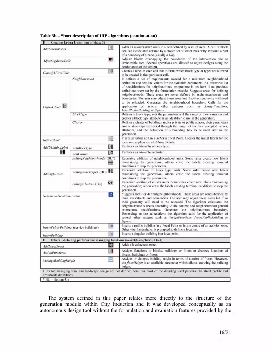
Table 3 shows a list of UIPs. The application sequence is not random but is also not predetermined. It is always based on properties of the previous design iteration which are recognized by the UIPs either based on shape recognition or attribute (label) recognition. Whatever the sequence may be, several design levels are identified in Table 3 and separated by grey rows where the main goals of these design levels are described. The table is incomplete and shows only the patterns that were developed or sketched until now and which are being implemented as an AutoCad extension (Beirão et al, 2010).
In very generic terms a design follows several cycles of formulation, generation and evaluation. Each of these parts is preceded by an analytical phase with stronger incidence on the initial stage of the design process (beginning of 1st cycle) and also before the evaluation procedures. In detail, the regular design cycle workflow is based on the following sequence of procedures:

8/21
1. context analysis – gathering and structuring data from the design context using a GIS support platform (formulation)
2. programme formulation – sets the goal specifications for the plan – we may consider these as soft goals as they may be fine-tuned later in the feedback loops (formulation)
3. preparation of drawing base (design generation base or initial design features) – the generation module needs to initiate the generation process with a correct definition of the intervention site, Is, represented as a polygon (a closed Lwpolyline in AutoCad which can be turned into a MapBulkFeature in AutoCadMap) inside which the generation of designs will take place (manual procedure – generation)
4. start – a kind of ‘Start Design’ button (generation) – this is basically a mouse click, but the immediate following action is checking the list of specifications defined by the formulation module through a table prompt that allows the user to further customize or check the available parameters
5. reference (Ref) selection – selection of pre-existent elements that the designer wants to use as referential items to support some of his/her design decisions (manual selection and automatic labelling of pre-existent elements – generation)
6. UIP selection and generation (generation) – selection of UIPs from a list of available ones and the automatic generation until they prompt some request for:
7. parameter assignments – in case these parameter assignments are not already defined by the formulation module
8. looping back to redefine previous decisions or jumping into the next step – loops back to start (point 4)
9. end of generation with a plan layout output 10. evaluation procedures – checks the design resulting from the generation process
and feeds back information on the quality of the results (evaluation) 11. and finally, looping back to programme formulation or any point of the generation
process in order to redefine the designs to meet the redefined goals. Each one of these steps still deserves some comments. 1./2. – These two points concern the development of the formulation module. As such
they will not be addressed in detail here. However, the designer is supposed to have a list of specifications on planning goals, say, an excel sheet with the necessary data. This is the list the designer is supposed to check (or add information to) after pressing the ‘Start Button’ mentioned in point 4. Considering the generation module alone without the formulation module completing this list, the designer/user is then supposed to do the job completing the needed information and of course he/she is supposed to be in possession of such information through any analytical means available.
3. – The drawing preparation can be a manual or a semi-automated procedure depending on the tools available upstream in the formulation process and also on the specific characteristics of the design context. For instance, the intervention site, Is, maybe constrained by higher level regulations or topography, and therefore not allow for construction on the entire intervention site surface. We will call the resulting area available for construction as urbanizable area, Ua. However, network connections (streets) may need to link the isolated Ua areas. So, some rules apply to Is while others are operational only within the urbanizable areas, for instance, main axes patterns which are

9/21
responsible for determining design guidelines for the main elements of the street network may apply to Is, while grid generation and block generation patterns may only apply to Uas. Is and Uas are defined in different design layers and the UIPs’ rules respond differently to them. Layers are identified through different object classes in the ontology.
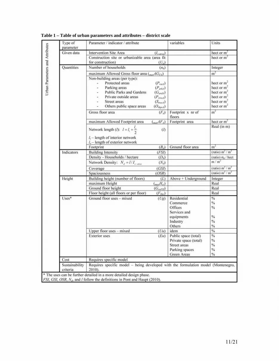
4. – The ‘Start Button’ prompts up a list of specifications to be fulfilled. The complete list may or may not be completed entirely. However, minimum requirements will be mandatory, otherwise the list returns back when checked. During the generation process the UIPs seek information on the specifications available in this list. If some specific information is not available the UIP prompts another request before continuing. There are mainly 2 types of specifications that may be needed by the generation; first, generic specifications (Table 1) concerning the overall urban parameters and second, design specifications concerning design components such as street components or block size input specifications (Table 2). The relations that naturally exist between some of the parameters are defined through their relational functions such that completing one field will automatically complete the related ones. This provides the designer with new data on related factors.
5. – References (Ref) are points, lines, polylines, boundaries or regions selected from among pre-existing ones to act as referential elements for the design. The initial rules on the available initial patterns take these Ref entities as their initial shapes for the generation of designs. Refs can be classified with different degrees of importance so that the rules can perform qualitative decisions distinguishing between very important references and less important references. The rating criteria can be used by some UIPs to determine how the rules are used (e.g.: the MIAxis option in MainAxis – Table 3). This is one of the situations where weights are used in the UIP definition.
6./7. – The UIPs search for parameter input in the list of specifications that was set by the formulation module (or by the designer, as explained above). If a needed specification is not found the UIP prompts a request to complete this information. The system was conceived to allow completing programme information at different stages of the design generation.
8. – This is a design loop, not exactly a feedback loop, but a reflective loop, as it allows the designer to rethink his/her decisions. This process should happen at the end of each design level in order to provide a high degree of reflectivity.
9. – At a certain point the designer will be satisfied with a preliminary design output resulting from the generation sequence and ready to evaluate the results in order to refine or even rethink them. This ready-for-evaluation output is not necessarily a complete final design. Outputs for evaluation may be taken at the end of each design phase in order to allow intermediate evaluation procedures. This is also important because usually the approving processes by local authorities are also phased in several steps. As a principle we follow the four phases defined by Beirão (2005) although the definition of boundaries between the phases is set in such a way that some flexibility is allowed. The main idea here is to use the relationships defined in the ontology to control this behaviour. Relationships between objects can be established on the basis of inheritance properties without which certain operations may not occur or may be needed for further steps. Also a minimum set of specifications might be required for each design phase. For instance, a design phase may only be finished when an n number of specifications is fulfilled by the

10/21
generation, but a new phase can only start when an n a number of specifications is fulfilled, n and a being natural numbers ( , , 0n a n a ).
10./11. – These two points concern the evaluation module and will not be detailed here. However, point 10 concerns the real feedback loop where the information produced by the evaluation returns back to the formulation and generation in order to fine tune goals and designs. This is the point where optimization algorithms might be introduced into the system.
The above description can be considered a rough sketch of the design methodology for using City Induction and an approximate outline of its embedded algorithm.
11/21
Table 1 – Table of urban parameters and attributes – district scale

12/21
Table 2 – User input parameters / control parameters – the image shows the window prompt already implemented in our prototype implementation; courtyard depth is not implemented in this window.
Figure 2 - (1) Plan for Praia, Cape Verde and (3) Plan for Moita, Portugal (both by Chuva Gomes) and (2) Ijburg, Netherlands (by van Dongen, Claus and Schaap on a master plan by Palmbout) and (4) Ypenburg, Netherlands (by Palmbout).
1 2
3 4

13/21
An urban design is completed buy generating solutions from a complete set of UIPs until the final required level of detail is achieved. Each UIP follows an algorithm which is a specific set of instructions to generate a specific design move. Table 3 gives a short description on the algorithms of the patterns. Due to space constraints we show only a few patterns/algorithms, enough to give an idea of how to reach a complete design. The information provided here, is just enough to understand the concept of the generation module. The solution space is limited, bounded by the design languages of the 4 case studies. However, the universe of design solutions provided by this set of UIPs is already way beyond the capacity of human prediction. The number of design options is humanly unreachable.
The reflective quality in design generation proposed here is achieved by letting the generative system stop at specific moments to let it perform the needed analytical routines necessary to such a reflective process. These routines can feedback new information which can be used to alter the specifications set initially in the table of specifications, either through the reuse of the formulation module or directly by the designer. The idea is to allow always the possibility of human interaction.
In order to allow an effective reflection on intermediate results, the design cycles need to be framed in meaningful stages. Montenegro (2009) in his approach to the formulation model already distinguishes two stages, a preparation stage called pre-design phase and the design phase where a distinction between two levels of scale is related with the phase distinction, namely, he relates the pre-design phase with the level of a master plan and design phase with detail plans. He points out that the available data needed for defining the programme is different in nature at those two design stages and that they involve different decision makers and different pre-existent data. Therefore, it is important to allow the design exploration process in the first design steps to come back and ‘rephrase’ some of the design requirements which will be directly or indirectly represented by a set of urban parameters or indicators used as target goals. Beirão (2005) also points out four design phases related with the development of design rules regarding territorial large scale decisions (1), the design of urban grids (2), the design of the urban units (3) and detailing a plan (4). Furthermore, these phases are many times scale related and may imply different locally defined decisions.
4.1. A short note on the nature of urban parameters and indicators Urban design goals or constraints are frequently expressed in terms of urban
indicators establishing development boundaries or setting specific goals. Density is probably the most commonly used indicator. Berghauser-Pont and Haupt (2010), trying to put some order into the chaotic concept of density developed a pretty neat set of urban parameters or urban indicators, the ‘spacematrix’, based on 3 basic indicators, network density (N), building intensity (FSI) and coverage (GSI) from which several indicators can be derived, in particular, spaciousness (OSR) which puts forward a quite accurate indicator for the amount of non-built space at the ground level compared with the gross floor area. The ingenious part in this work is that the authors found a way of providing 5 different levels of aggregation of urban components (building, lot, island (block), fabric and district) which always relate the built space with the open space defined in a

14/21
particular boundary at a particular level of aggregation thereby allowing the calculation of a tare space which is the difference in base land area between two levels of scale. To avoid controversy and use a universal indicator system we used these indicators plus some additional conventional parameters which are generally used, especially by stakeholders, such as number of households from which a standard density definition may be derived. The interest in using the ‘spacematrix’ concepts is that the authors were able to relate certain combinations of indicators with certain morphological patterns which can allow for a very neat perception during the first steps in a design of what certain premises mean in terms of target indicators. This is an important detail. We can use algorithms to establish relationships between indicators set as design goals and alternative characteristic morphologies that fit with the goals. This may provide some intelligence to the design system enabling it to deliver information on the kind of morphologies that best fit the goals.
Table 1 shows the indicators and attributes used in City Induction to provide target goals for the generation of designs. These are the maximum number of specifications that the generation module requires to start a design generation. To be able to generate results, the system will need at least information on building intensity goals, coverage goals and street hierarchies. The information in the table may be inserted in the beginning if known; however, if at any moment in the generation the application of a particular UIP needs information that is not yet available it will request it from the user of the tool. Furthermore, some information in the table is completed along the generation process (e.g.: network length) and other information is automatically completed just because the parameter values are derived from other parameters which are being updated. The process of completing target specifications is therefore progressive and interactive allowing a reflective attitude along the design process.
5. Discussion
Several issues are addressed in this paper aiming at defining a design system for
urban design. The main idea is expressed in the definitions of the City Induction project where the structure of a system for formulating, generating and evaluating urban designs is proposed (Duarte et al., forthcoming). The main argument in this paper is that this macro structure for a creative design process can only work as a complex sequence of similarly structured decisions. Complex, because it is a long sequence of decisions and because feedback (or double-loop learning) should and can be provided. Such structure was devised due to the impossibility of having a totally clear understanding of a context in the beginning of a design process and because a specific language of designs can not be synthesized without a reflective process.
As a practical design tool, City Induction was considered to allow an open interactivity with the designer while introducing some advantages comparing with regular design processes. First, the advantage of using GIS based assessment tools for context analysis allows a more accurate evaluation of the conditions of the context and to use them as input to the generation. Second, the UIPs allow a fast generation of alternative designs which are generated in accordance with the topological structure needed for integration in the GIS environment where one can benefit again from the use of the available evaluation tools as well as the ones in the evaluation model. Such a design

15/21
system is foreseen as design support tool as well as a design decision support tool where a designer may use the advantages of the integration of contextual data information assessment, extended exploration of combinatorial and parametric design generation, and evaluation of design outputs on different levels of detail. Together they define the basis for city information modelling (CIM).
Table 3a – Short description of UIP algorithms
16/21
Table 3b – Short description of UIP algorithms (continuation)
The system defined in this paper relates more directly to the structure of the
generation module within City Induction and it was developed conceptually as an autonomous design tool without the formulation and evaluation features provided by the

17/21
formulation and evaluation modules. The main premise here is that an experienced designer or design team can do much of the decision making themselves without the use of these two modules but would benefit considerably from the possibility of using the generative features together with the assessment tools already found in the GIS environment, whether they are used for supporting design decisions or for validating them. Furthermore, in such an environment an experienced designer has still the possibility of changing or refining options moving design exploration into new fields and therefore providing double-loop learning.
In this regard, the proposed concept of designs being generated from a progressive accumulation of design decisions expressed through the generative formalism of urban induction patterns seems coherent with Schön’s concept of reflection-in-action whilst allowing at each step a generative structure consistent with the design machine concept. Our concept allows the designer to start from an ill or vaguely defined problem. At the beginning of the design process there is no need to have a complete description of the outside world, nor of the system of values to appreciate it. The system of values and the descriptions of the outside world can be progressively built along the design process by updating descriptions through the receptor as needed, as the designer becomes progressively more aware of what the important information is and what the system of values should be. Likewise, the language of designs is not selected at the beginning but is progressively constrained while design actions are being taken through the selection of UIPs, selection of available options and constraining the available parameters.
We should also point out that we have not changed the algorithmic structure of design proposed by Stiny and March. We could in our context talk of two types of design machines corresponding to two different levels of detail in the design process, (1) a general one corresponding to the overall design and (2) a detailed level corresponding to the UIPs. Our addition to the concept is a structure that allows for progressive awareness of the context which is the natural way in which designers work. The important thing here is to understand that awareness of the context is not dependent just on the extraction and treatment of contextual information but also in seeing, and seeing not only what exists, but also seeing moves, i.e., attempts at possible worlds, which usually start from schematic strategies and progress to detailed strategies. Design is not just a generation process; it is also a learning process. In fact, Lawson (2006) proposes that design is a negotiation between problem and solution using the activities of analysis, synthesis and evaluation. This seems also coherent with our structure. Independently of the human interactivity that is planned for this tool, this model still allows for total automation just because the design machine structure is maintained. However, because decision making is known to be intrinsically emotional (Damásio, 1995) we also invested in a human interactive system.
In this paper, we show that such a design environment can be achieved not by a formulation-generation-evaluation linear sequence, but by a spiral sequence of such triptych sequences addressing increasing levels of detail, and permitting one to backtrack for changing the system of values or the design rules, i.e., updating or further contextualizing the theory and the language of designs.
If we could say that in urban design the scale to start addressing the problem is known and that correct reasoning implies moving from large scale to detail, which we cannot, even then designers’ creative processes would be so intrinsically different from one

18/21
another that some would develop early strong assumptions on a large scale whilst others would do it on small scale. As such making decisions on different levels of scale (de Jong, 2009) of a design problem is a dynamic process that requires a reflective approach and is dependent on the context and on designer’s preconceptions. Furthermore, the role of preconceptions in design, or default assumptions (Minsky, 1985) is highly determined by tacit knowledge, that is, depending on the degree of experience of the designer, we are likely to find different systems of values and more or less structured design languages. Still, a good designer is usually willing to change or evolve and, therefore, ready to make further transformations in his/her design language.
The spectrum of uncertainty and the technical limitations are too many for accommodating them all. However, City Induction’s generation module is structured as a freer design machine where the theory and the language of designs are customized along the design process. We can say that City Induction contains a universe of designs that can be customized into a language of designs.
Finally, let us consider the role of the ontology in City Induction. We already said that this ontology defines the communication protocol between the 3 modules in City Induction. But how does it work considering the definition of a design machine? What is its role in a design machine? The simple answer is that the ontology contains the main components of the theories and the languages of designs. The ontology in City Induction organizes the concepts involved in the description of cities by defining their relationships.
Because the interpretation of the world is subjective, we should consider that ontologies are knowledge structures that can and should be in continuous upgrading. In theory, City Induction could be a system in constant upgrading by extending the existent object model. Pinto et al (2004) proposes a methodology for evolving ontologies which could be applicable to our case.
Although we still need much extra work to put forward a more comprehensive ontology that allows for more in depth approach to urban design, the openness of the system’s concept, allowing the ontology extension and the customization of urban induction patterns, seems to constitute a very powerful structure for integrating analysis, design generation and evaluation in the same urban design workflow.
In a subsequent paper we demonstrate the discursive structure of UIPs showing the case of DefineUUnit. This pattern points a way towards an added feature of the design system – the possibility of customizing UIPs. In such patterns, some of the rules are customized by the designer before the pattern is applied and stored for future application allowing a designer to create a personal library of patterns. The customization is defined within the predefined structure of the pattern.
Future work will be needed to establish a correct interface to provide a user friendly working environment for the proposed tools and design methodology.
6. Conclusion We propose a formalism for developing grammars for urban design synthesis that
encompasses reflective action in the design process. We call them Urban Grammars. Urban grammars are arrangements of urban design moves encoded with a discursive grammar which is able to generate a typical urban design move in different contexts.

19/21
These urban design moves have the structure of a design pattern. They imply the identification of a particular design state during the urban design process to which a typical (generic) urban design move can be applied as a recurrent solution. These design patterns are called Urban Induction Patterns.
Figure 3 – The Praia plan model showing the closed blocks along the main promenade.
In order to address practicality, we sketched a design methodology for urban design based on urban grammars. The methodology foresees the use of an interactive urban design tool which enables fast response to sets of possible worlds in urban design and generates them in a format which enables a stronger communication with GIS platforms both at the level of input data and output data, therefore promoting the integration of analysis/formulation, generation and evaluation of urban designs.
This structure is proposed as a way of generating semantically elaborated designs that give response to contextual conditions. We show the compatibility of this structure with the principles of a design machine.

20/21
Acknowledgements
The City Induction project is funded by the Fundação para a Ciência e Tecnologia (FCT), Portugal (PTDC/AUR/64384/2006), hosted by ICIST at TU Lisbon, and coordinated by José P. Duarte. J.N. Beirão is also funded by the FCT by grant SFRH/BD/39034/2007. Beirão, J. Gil, and N. Montenegro are responsible for the generation, the evaluation, and the formulation modules, respectively. We would like to thank Sevil Sariyildiz for the readings, comments and support. References
Alexander, C. et alt.: 1977, A Pattern Language: Towns, Buildings, Construction, Oxford University Press, New York.
Argyris, C., and Schön, D.: 1978, Organizational learning: A theory of action perspective, Reading, Mass: Addison Wesley.
Beirão, J.N., 2005. Gramáticas Urbanas: por uma Metodologia de Desenho Urbano Flexível. (Urban Grammars: Towards a Flexible Urban Design Methodology) Master Thesis. Lisboa: ISCTE, Lisbon University. Available at: http://www.bquadrado.com/paginas_web/targets/grammars.html.
Beirão, J; Duarte, J; Stouffs, R: 2008, Structuring a Generative Model for Urban Design: Linking GIS to Shape Grammars, Architecture in Computro [26th eCAADe Conference Proceedings / ISBN 978-0-9541183-7-2] Antwerpen (Belgium) 17-20 September 2008, pp. 929-938.
Beirão, J.N., Montenegro, N., Gil, J., Duarte, J.P., Stouffs, R.: 2009, The city as a street system: A street description for a city ontology, SIGraDi 2009 - Proceedings of the 13th Congress of the Iberoamerican Society of Digital Graphics, Sao Paulo, Brazil, November 16-18, 2009.
Beirao, J., Mendes, G., Duarte, J., Stouffs, R.: 2010, Implementing a Generative Urban Design Model: Grammar-based design patterns for urban design, FUTURE CITIES [28th eCAADe Conference Proceedings / ISBN 978-0-9541183-9-6] ETH Zurich (Switzerland) 15-18 September 2010, pp.265-274 http://cumincad.scix.net/cgi-bin/works/Show?ecaade2010_084
Beirão, JN, Duarte, JP, Stouffs, R, 2011, Creating Specific Grammars with Generic Grammars: Towards Flexible Urban Design, Nexus Network Journal, Springer, Vol.13, (forthcoming, April, 2011), available at http://www.springerlink.com/content/g024086x4n113760/
Berghauser-Pont M. and Haupt P.: 2010, Spacematrix – Space, Density and Urban Form, NAI Publishers.
Cross, N.: 1982, Designerly Ways of Knowing, Design Studies, Vol. 3, No. 4, pp. 221-227.
Damásio, A.: 1995, Descartes’ error: Emotion, Reason, and the Human Brain, Harper Perennial, HarperCollins Publishers, New York.
Duarte, J.P.: 2001, Customizing Mass Housing: a discursive grammar for Siza´s Malagueira house, Ph.D. Dissertation, Massachusetts Institute of Technology, Cambridge.
Duarte, JP; Beirão, JN; Montenegro, N; Gil, J (forthcoming), City Induction: formulating, generating, and evaluating urban plans, in Halatsch et al. (eds.) Digital Urban Modelling and Simulation, CCIS Series Communications in Computer and Information Science Series, Springer-Verlag.
Gamma, E., Helm, R., Johnson, R. and Vlissides, J.: 1995, Design Patterns: Elements of Reusable Object-Oriented Software, Addison-Wesley, Reading, MA.
21/21
Gil, J and Duarte, JP, 2008, Towards an Urban Design Evaluation Framework, Architecture in Computro - 26th eCAADe Conference Proceedings, Antwerpen, pp. 257-264.
Gruber, T. B.: 1993, A translation approach to portable ontology specifications, Knowledge Acquisition, 5(2), pp. 257-267.
de Jong, T.: 2009, The evolution of a design, genes, combinations, mutations and a selective environment. Lecture in the Botanical Garden for technical plants TUDelft at 11th of September 2009.
Lawson, B., 2006. How designers think: the design process demystified, Architectural press.
Li, A.: 2001, A shape grammar for teaching the architectural style of the Yingzao fashi, PhD dissertation, MIT.
Minsky, M.: 1985, The Society of Mind, Simon & Schuster Paperbacks, New York.
Montenegro, N.C.: 2010, Building a Pre-Design Ontology – Towards a model for urban programs. Msc Dissertation. FAUTL (Faculty of Architecture, Technical University of Lisbon), Lisboa.
Montenegro, N.C., Duarte, J.P.: 2009, Computational Ontology of Urban Design: Towards a City Information Model, Computation: The New Realm of Architectural Design [27th eCAADe Conference Proceedings] Istanbul (Turkey) 16-19 September 2009, pp. 253-260.
Ormerod, T.C.: 2005, Planning and ill-defined problems, The cognitive psychology of planning, Vol.1, pp. 53-70.
Pinto H.S., Staab S., Tempich C.: 2004, DILIGENT: Towards a fine-grained methodology for Distributed, Loosely-controlled and evolving Engineering of oNTologies. ECAI 2004: 393-397
Schön, D.A., Wiggins G.: 1992, Kinds of seeing and their functions in designing. Design Studies, 13 2, pp.135-156.
Stiny, G. and Gips J.: 1972, Shape Grammars and the Generative Specification of Painting and Sculpture, Information Processing, 71, pp. 1460-1465.
Stiny and March, 1981, Design Machines, Environment and Planning B: Planning and Design, 8, pp. 245-255.
Stiny, G.: 1980a, Introduction to shape and shape grammars, Environment and Planning B: Planning and Design, 7, pp. 343-351.
Stiny, G.: 1981, A note on the description of designs, Environment and Planning B: Planning and Design, 8, pp. 257-267.