corrosion mitigation of reinforcement in concrete using
TRANSCRIPT
International Journal of Recent Technology and Engineering (IJRTE)
ISSN: 2277-3878, Volume-8 Issue-4, November 2019
1950
Published By:
Blue Eyes Intelligence Engineering & Sciences Publication
Retrieval Number: C6272098319/2019©BEIESP
DOI:10.35940/ijrte.C6272.118419
Corrosion Mitigation of Reinforcement in Concrete
using Magnesium Anodes
Yogesh Iyer Murthy, Sumit Gandhi, Abhishek Kumar
Abstract: In the present work, an attempt has been made for
the cathodic protection of structural steel reinforcement using
Magnesium anode. For the same, two slabs were casted using
steel reinforcement mat of 10 mm diameter. First slab was casted
with cement containing 3.5% NaCl by weight of cement was
added, while the other was casted without NaCl. Magnesium
anode with design life of three years was centrally placed in both
the cases. Half-cell potential readings were taken on regular
basis along with temperature and relative humidity. It could be
concluded that the negative potential in both cases increased
towards the center, i.e. towards the anode. Further, significant
drop in negative potential could be observed in the slabs with
increase in duration of cathodic protection. Relative humidity
and temperature were found to play major role in HCP readings.
Keywords: Cathodic protection, Half-cell Potential,
Magnesium Anode, Corrosion mitigation.
I. INTRODUCTION
Reinforced cement concrete (RCC) structures are known for
their high strength characteristics. The steel reinforcement in
concrete is expected to provide high tensile and flexural
strength to the structure as concretes are weak in tension.
The structural performance of steel depends largely on the
exposure conditions such as the presence of chlorides,
carbonates, sulfates and other ionic materials. The presence
of these elements leads to the detrimental effect such as
reduced structural performance due to advent of corrosion.
Various methods could be found in literature to prevent
corrosion. These include use of corrosion resistant steel re-
bars (Hurley, 2006), stainless steel and galvanized steel,
thermosetting polymers (Yeh, 2008), laminates and
reinforced plastics (Sun et.al., 2016), thermoplastics, non-
metals like elastomers, use of inhibitors (Gaidis, 2004),
paints (Mayne, 1970) (Das et.al., 2015), epoxy coatings
(Saravanan et.al., 2007), powder coating (Du et.al.,2016)
and cathodic protection, each having inherent advantages
and disadvantages. The selection of a suitable method would
largely depend on the degree of exposure of structure,
economics and the discretion of the designer.
Revised Manuscript Received on November 15, 2019.
Mr. Yogesh Iyer Murthy, Sr. Bridge Engineer, Department of Civil
Engineering, Shri Govindram Seksaria Institute of Technology and Science,
Indore.
Dr. Abhishek Kumar, Department of Industrial and Production
Engineering, Motilal Nehru National Institute of Technology, Allahabad,
India.
Dr. Sumit Gandhi, Associate Professor, Department of Civil
Engineering, Jaypee University Of Engineering And Technology, MP,
India.
Among the above mentioned methods of corrosion
prevention, cathodic protection technique is unique as most
of the other methods (except application of corrosion
resistant steel re-bars and stainless steel and galvanized
steel) involve coating of suitable material over the steel and
subsequent embedment of steel in concrete. The peeling off
such coatings while pouring of concrete is a common
phenomenon resulting in the ingress of corrosion. On the
other hand, cathodic protection involves the installation of
suitable electrochemically active electrode as anode as an
exterior member, designed for a suitable time period. The
application of such anodes as exterior member aids in visual
inspection and upon the completion of design period, or
otherwise, the anodes can be conveniently replaced. Thus,
precise monitoring of reinforcement is enabled. The
commonly used anodes for cathodic protection of steel in
concrete are Aluminum, Magnesium and Zinc anodes, in
either pure form or as alloys in varying proportion (Byrne
et.al, 2016)
The application of cathodic protection in reinforced concrete
structures is still in nascent stage of investigation (Kessler,
1997) (Parthiban et.al. 2008). Since chloride induced
corrosion is reported to be a major factor which affects the
durability (Angst et.al., 2009) (Angst et.al. 2011)
(Apostolopoulos, 2013) (C.L. Page, 1975) (V.Kumar, 1998)
of RCC, the primary objective of the current investigation is
to understand the behavior of pure Magnesium anode in
chloride atmosphere.
II. EXPERIMENTAL SET-UP
Concrete Slab:
Portland Pozzolana cement was used for casting slabs of
dimension 1 x 1 x 0.1 m3. The coarse aggregates used were
20 mm down, while the fine aggregates conformed grading
zone II of Indian Standards IS -383-1970. Nominal mix of
ratio 1:1.5:3 with a water/cement ratio of 0.45 was used to
prepare reinforced cement concrete slab. Tap water of
specifications mentioned in Table 1 was used for mixing and
curing purpose.
Table 1: Tap water characteristics confirming IS:
10500:2012
S.No. Parameter Value
1 Chloride 168mg/l
2 pH 7.6
3 Fluoride 0.4mg/l
4 Dissolved Oxygen 10.15mg/l
5 Chemical Oxygen Demand 0
Corrosion Mitigation of Reinforcement in Concrete using Magnesium Anodes
1951 Published By:
Blue Eyes Intelligence Engineering & Sciences Publication
Retrieval Number: C6272098319/2019©BEIESP
DOI:10.35940/ijrte.C6272.118419
6 Biological Oxygen
Demand
0
7 Free Residual Chlorine 0.1mg/l
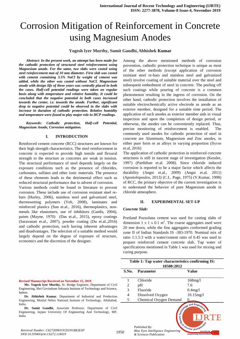
950 mm long reinforcing steel rods of 10 mm diameter were
treated with 0.1M HCl solution followed by washing and
drying to remove preliminary corrosion sites. Mat of
reinforcements was placed in the formwork ensuring a clear
cover of 25 mm from all sides and from the top. The surface
area of the steel reinforcements was found to be 1.884 m2.
Wire connections were extended at regular intervals outside
the slabs through which potentials could be measured as
shown in Fig. 1.
Fig.1. (a) Reinforcement mat, wire connections and anode placement details of the slabs; (b)
Casted concrete.
Cathodic Protection:
Pure Magnesium anode 22 mm diameter and 250 mm long
was placed centrally on the slab and fastened tightly with
the reinforcement at the center in order to complete the
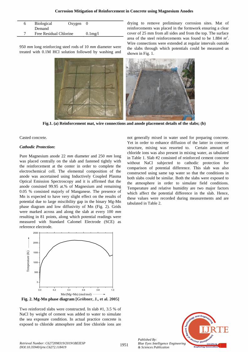
electrochemical cell. The elemental composition of the
anode was ascertained using Inductively Coupled Plasma
Optical Emission Spectroscopy and it is affirmed that the
anode consisted 99.95 at.% of Magnesium and remaining
0.05 % consisted majorly of Manganese. The presence of
Mn is expected to have very slight effect on the results of
potential due to large miscibility gap in the binary Mg-Mn
phase diagram and low diffusivity of Mn (Fig. 2). Grids
were marked across and along the slab at every 100 mm
resulting in 81 points, along which potential readings were
measured with Standard Calomel Electrode (SCE) as
reference electrode.
Fig. 2. Mg-Mn phase diagram [Gröbner, J., et al. 2005]
Two reinforced slabs were constructed. In slab #1, 3.5 % of
NaCl by weight of cement was added to water to simulate
the sea exposure condition. In actual practice concrete is
exposed to chloride atmosphere and free chloride ions are
not generally mixed in water used for preparing concrete.
Yet in order to enhance diffusion of the latter in concrete
structure, mixing was resorted to. Certain amount of
chloride ions was also present in mixing water, as tabulated
in Table 1. Slab #2 consisted of reinforced cement concrete
without NaCl subjected to cathodic protection for
comparison of potential difference. This slab was also
constructed using same tap water so that the conditions in
both slabs could be similar. Both the slabs were exposed to
the atmosphere in order to simulate field conditions.
Temperature and relative humidity are two major factors
which affect the potential difference in the slab. Hence,
these values were recorded during measurements and are
tabulated in Table 2.
0.0 0.2 0.4 0.6 0.8 1.0
0
500
1000
1500
2000
2500
Tem
pera
ture
(K
)
Mn/(Mg+Mn) (mol/mol)
International Journal of Recent Technology and Engineering (IJRTE)
ISSN: 2277-3878, Volume-8 Issue-4, November 2019
1952
Published By:
Blue Eyes Intelligence Engineering & Sciences Publication
Retrieval Number: C6272098319/2019©BEIESP
DOI:10.35940/ijrte.C6272.118419
Table 2. Temperature and relative humidity during the measurements on different days.
Days 8 12 26 46 54 59 66 70
Temperature (°C) 26 26 24 25 24 25 26 26
Relative Humidity (%) 58 48 59 56 56 55 50 54
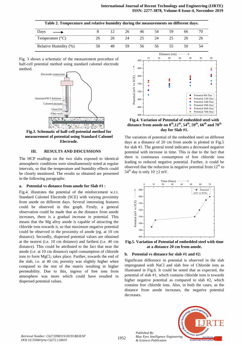
Fig. 3 shows a schematic of the measurement procedure of
half-cell potential method using standard calomel electrode
method.
Fig.3. Schematic of half-cell potential method for
measurement of potential using Standard Calomel
Electrode.
III. RESULTS AND DISCUSSIONS
The HCP readings on the two slabs exposed to identical
atmospheric conditions were simultaneously noted at regular
intervals, so that the temperature and humidity effects could
be closely monitored. The results so obtained are presented
in the following paragraphs:
a. Potential vs distance from anode for Slab #1 :
Fig.4. illustrates the potential of the reinforcement w.r.t.
Standard Calomel Electrode (SCE) with varying proximity
from anode on different days. Several interesting features
could be observed in this graph. Firstly, a general
observation could be made that as the distance from anode
increases, there is a gradual increase in potential. This
means that the Mg alloy anode is capable of attracting the
chloride ions towards it, so that maximum negative potential
could be observed in the proximity of anode (eg. at 10 cm
distance). Secondly, dispersed potential values are obtained
at the nearest (i.e. 10 cm distance) and farthest (i.e. 40 cm
distance). This could be attributed to the fact that near the
anode (i.e. at 10 cm distance) rapid consumption of chloride
ions to form MgCl2 takes place. Further, towards the end of
the slab, i.e. at 40 cm, porosity was slightly higher when
compared to the rest of the matrix resulting in higher
permeability. Due to this, ingress of free ions from
atmosphere was more which could have resulted in
dispersed potential values.
Fig.4. Variation of Potential of embedded steel with
distance from anode on 8th
,12th
, 54th
, 59th
, 66th
and 70th
day for Slab #1.
The variation of potential of the embedded steel on different
days at a distance of 20 cm from anode is plotted in Fig.5
for slab #1. The general trend indicates a decreased negative
potential with increase in time. This is due to the fact that
there is continuous consumption of free chloride ions
leading to reduced negative potential. Further, it could be
observed that the reduction in negative potential from 12th
to
54th
day is only 10 +2 mV.
Fig.5. Variation of Potential of embedded steel with time
at a distance 20 cm from anode.
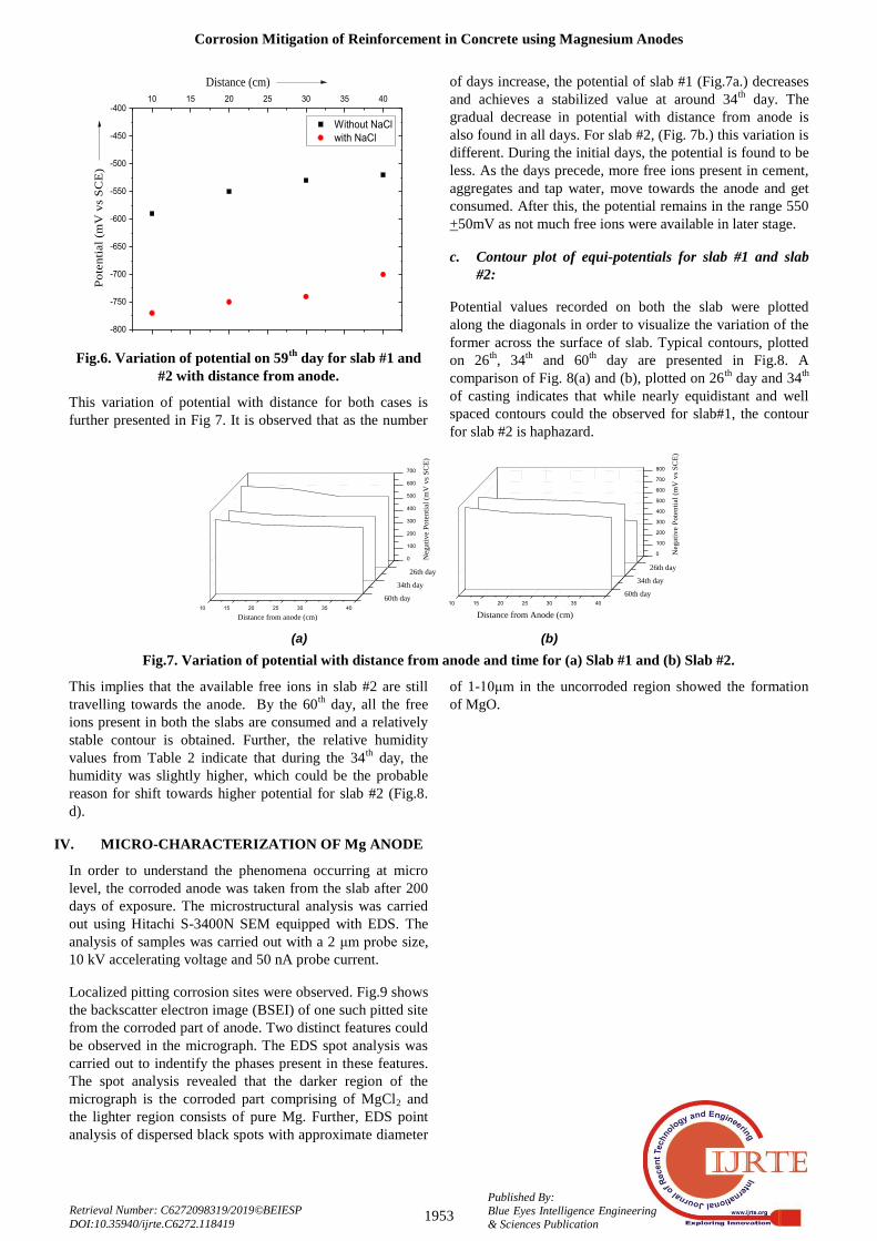
b. Potential vs distance for slab #1 and #2:
Significant difference in potential is observed in the slab
impregnated with NaCl and slab free of Chloride ions as
illustrated in Fig.6. It could be noted that as expected, the
potential of slab #1, which contains chloride ions is towards
higher negative potential as compared to slab #2, which
contains free chloride ions. Also, in both the cases, as the
distance from anode increases, the negative potential
decreases.
Electrode connection
Saturated KCl Solution
Calomel mixture
Glass Frit
Fiber wick -900
-850
-800
-750
-700
-650
-600
-55010 15 20 25 30 35 40
Distance (cm)
Potential 8th Day
Potential 12th Day
Potential 54th Day
Potential 59th Day
Potential 66th Day
Potential 70th Day
Po
ten
tial
(mV
vs
SC
E)
-800
-780
-760
-740
-720
-700
-680
-660
0 10 20 30 40 50 60 70
Time (Days)
Po
ten
tial
(m
V v
s S
CE
)
Potential
(mV vs SCE)
Corrosion Mitigation of Reinforcement in Concrete using Magnesium Anodes
1953 Published By:
Blue Eyes Intelligence Engineering & Sciences Publication
Retrieval Number: C6272098319/2019©BEIESP
DOI:10.35940/ijrte.C6272.118419
Fig.6. Variation of potential on 59th
day for slab #1 and
#2 with distance from anode.
This variation of potential with distance for both cases is
further presented in Fig 7. It is observed that as the number
of days increase, the potential of slab #1 (Fig.7a.) decreases
and achieves a stabilized value at around 34th
day. The
gradual decrease in potential with distance from anode is
also found in all days. For slab #2, (Fig. 7b.) this variation is
different. During the initial days, the potential is found to be
less. As the days precede, more free ions present in cement,
aggregates and tap water, move towards the anode and get
consumed. After this, the potential remains in the range 550
+50mV as not much free ions were available in later stage.
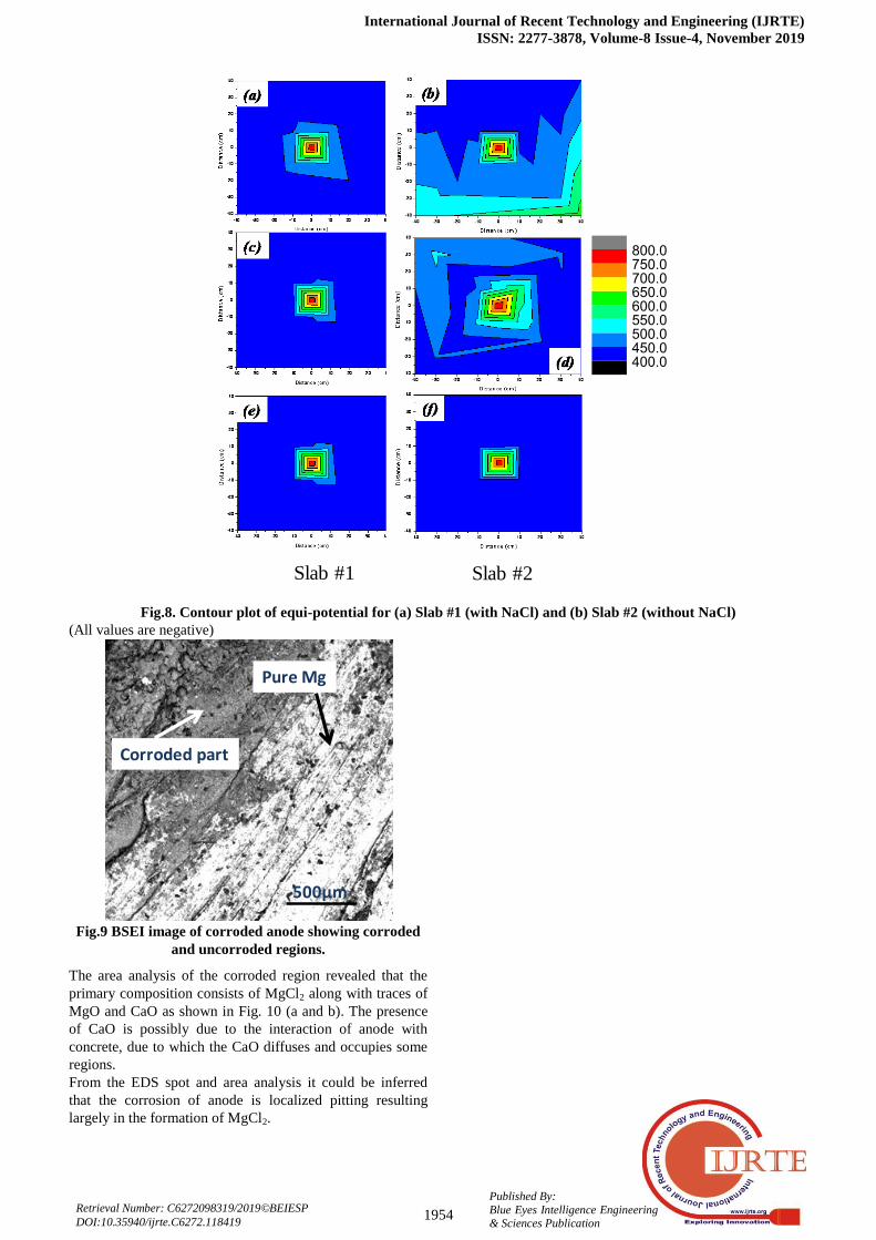
c. Contour plot of equi-potentials for slab #1 and slab
#2:
Potential values recorded on both the slab were plotted
along the diagonals in order to visualize the variation of the
former across the surface of slab. Typical contours, plotted
on 26th
, 34th
and 60th
day are presented in Fig.8. A
comparison of Fig. 8(a) and (b), plotted on 26th
day and 34th
of casting indicates that while nearly equidistant and well
spaced contours could the observed for slab#1, the contour
for slab #2 is haphazard.
Fig.7. Variation of potential with distance from anode and time for (a) Slab #1 and (b) Slab #2.
This implies that the available free ions in slab #2 are still
travelling towards the anode. By the 60th
day, all the free
ions present in both the slabs are consumed and a relatively
stable contour is obtained. Further, the relative humidity
values from Table 2 indicate that during the 34th
day, the
humidity was slightly higher, which could be the probable
reason for shift towards higher potential for slab #2 (Fig.8.
d).
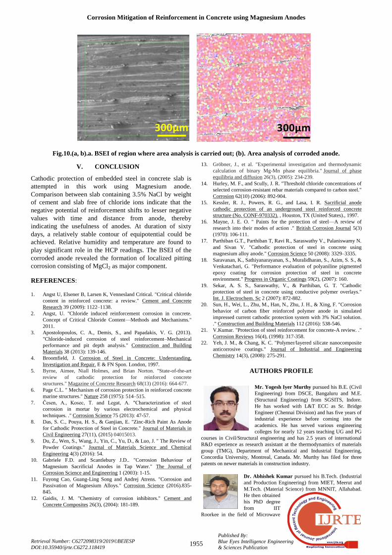
IV. MICRO-CHARACTERIZATION OF Mg ANODE
In order to understand the phenomena occurring at micro
level, the corroded anode was taken from the slab after 200
days of exposure. The microstructural analysis was carried
out using Hitachi S-3400N SEM equipped with EDS. The
analysis of samples was carried out with a 2 μm probe size,
10 kV accelerating voltage and 50 nA probe current.
Localized pitting corrosion sites were observed. Fig.9 shows
the backscatter electron image (BSEI) of one such pitted site
from the corroded part of anode. Two distinct features could
be observed in the micrograph. The EDS spot analysis was
carried out to indentify the phases present in these features.
The spot analysis revealed that the darker region of the
micrograph is the corroded part comprising of MgCl2 and
the lighter region consists of pure Mg. Further, EDS point
analysis of dispersed black spots with approximate diameter
of 1-10μm in the uncorroded region showed the formation
of MgO.
-800
-750
-700
-650
-600
-550
-500
-450
-40010 15 20 25 30 35 40
Distance (cm)
Without NaCl
with NaCl
Po
ten
tial
(mV
vs
SC
E)
10 15 20 25 30 35 40
0
100
200
300
400
500
600
700
26th day
34th day
60th day
Distance from anode (cm)
Neg
ati
ve P
ote
nti
al
(mV
vs
SC
E)
10 15 20 25 30 35 40
0
100
200
300
400
500
600
700
800
26th day
34th day
60th day
Distance from Anode (cm)
Neg
ati
ve P
ote
nti
al
(mV
vs
SC
E)
(a) (b)
International Journal of Recent Technology and Engineering (IJRTE)
ISSN: 2277-3878, Volume-8 Issue-4, November 2019
1954
Published By:
Blue Eyes Intelligence Engineering & Sciences Publication
Retrieval Number: C6272098319/2019©BEIESP
DOI:10.35940/ijrte.C6272.118419
Fig.8. Contour plot of equi-potential for (a) Slab #1 (with NaCl) and (b) Slab #2 (without NaCl)
(All values are negative)
Fig.9 BSEI image of corroded anode showing corroded
and uncorroded regions.
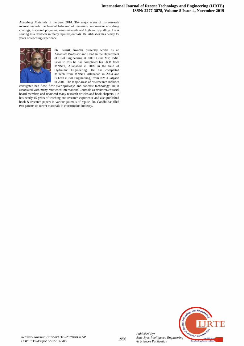
The area analysis of the corroded region revealed that the
primary composition consists of MgCl2 along with traces of
MgO and CaO as shown in Fig. 10 (a and b). The presence
of CaO is possibly due to the interaction of anode with
concrete, due to which the CaO diffuses and occupies some
regions.
From the EDS spot and area analysis it could be inferred
that the corrosion of anode is localized pitting resulting
largely in the formation of MgCl2.
Slab #1 Slab #2Slab #1 Slab #2
-40 -30 -20 -10 0 10 20 30 40
-40
-30
-20
-10
0
10
20
30
40D
ista
nce
(cm
)
Distance (cm)
400.0450.0500.0550.0600.0650.0700.0750.0800.0
500μm
Corroded part
Pure Mg
Corrosion Mitigation of Reinforcement in Concrete using Magnesium Anodes
1955 Published By:
Blue Eyes Intelligence Engineering & Sciences Publication
Retrieval Number: C6272098319/2019©BEIESP
DOI:10.35940/ijrte.C6272.118419
Fig.10.(a, b).a. BSEI of region where area analysis is carried out; (b). Area analysis of corroded anode.
V. CONCLUSION
Cathodic protection of embedded steel in concrete slab is
attempted in this work using Magnesium anode.
Comparison between slab containing 3.5% NaCl by weight
of cement and slab free of chloride ions indicate that the
negative potential of reinforcement shifts to lesser negative
values with time and distance from anode, thereby
indicating the usefulness of anodes. At duration of sixty
days, a relatively stable contour of equipotential could be
achieved. Relative humidity and temperature are found to
play significant role in the HCP readings. The BSEI of the
corroded anode revealed the formation of localized pitting
corrosion consisting of MgCl2 as major component.
REFERENCES:
1. Angst U, Elsener B, Larsen K, Vennesland Critical. "Critical chloride
content in reinforced concrete: a review." Cement and Concrete
Research 39 (2009): 1122–1138.
2. Angst, U. "Chloride induced reinforcement corrosion in concrete.
Concept of Critical Chloride Content—Methods and Mechanisms."
2011.
3. Apostolopoulos, C. A., Demis, S., and Papadakis, V. G. (2013).
"Chloride-induced corrosion of steel reinforcement–Mechanical
performance and pit depth analysis." Construction and Building
Materials 38 (2013): 139-146.
4. Broomfield, J. Corrosion of Steel in Concrete: Understanding,
Investigation and Repair. E & FN Spon. London, 1997.
5. Byrne, Aimee, Niall Holmes, and Brian Norton. "State-of-the-art
review of cathodic protection for reinforced concrete
structures." Magazine of Concrete Research 68(13) (2016): 664-677.
6. Page C.L. " Mechanism of corrosion protection in reinforced concrete
marine structures." Nature 258 (1975): 514–515.
7. Česen, A., Kosec, T. and Legat, A. "Characterization of steel
corrosion in mortar by various electrochemical and physical
techniques. ." Corrosion Science 75 (2013): 47-57.
8. Das, S. C., Pouya, H. S., & Ganjian, E. "Zinc-Rich Paint As Anode
for Cathodic Protection of Steel in Concrete." Journal of Materials in
Civil Engineering 27(11), (2015) 04015013.
9. Du, Z., Wen, S., Wang, J., Yin, C., Yu, D., & Luo, J. " The Review of
Powder Coatings." Journal of Materials Science and Chemical
Engineering 4(3) (2016): 54.
10. Gabriele F.D. and Scantlebury J.D.. "Corrosion Behaviour of
Magnesium Sacrificial Anodes in Tap Water." The Journal of
Corrosion Science and Engineering 1 (2003): 1-15.
11. Fuyong Cao, Guang-Ling Song and Andrej Atrens. "Corrosion and
Passivation of Magnesium Alloys." Corrosion Science (2016).835-
845.
12. Gaidis, J. M. "Chemistry of corrosion inhibitors." Cement and
Concrete Composites 26(3), (2004): 181-189.
13. Gröbner, J., et al. "Experimental investigation and thermodynamic
calculation of binary Mg-Mn phase equilibria." Journal of phase
equilibria and diffusion 26(3), (2005): 234-239.
14. Hurley, M. F., and Scully, J. R. "Threshold chloride concentrations of
selected corrosion-resistant rebar materials compared to carbon steel."
Corrosion 62(10) (2006): 892-904.
15. Kessler, R. J., Powers, R. G., and Lasa, I. R. Sacrificial anode
cathodic protection of an underground steel reinforced concrete
structure (No. CONF-970332). , Houston, TX (United States)., 1997.
16. Mayne, J. E. O. " Paints for the protection of steel—A review of
research into their modes of action ." British Corrosion Journal 5(3)
(1970): 106-111.
17. Parthiban G.T., Parthiban T, Ravi R., Saraswathy V., Palaniswamy N.
and Sivan V. "Cathodic protection of steel in concrete using
magnesium alloy anode." Corrosion Science 50 (2008): 3329–3335.
18. Saravanan, K., Sathiyanarayanan, S., Muralidharan, S., Azim, S. S., &
Venkatachari, G. "Performance evaluation of polyaniline pigmented
epoxy coating for corrosion protection of steel in concrete
environment." Progress in Organic Coatings 59(2), (2007): 160.
19. Sekar, A. S. S., Saraswathy, V., & Parthiban, G. T. "Cathodic
protection of steel in concrete using conductive polymer overlays."
Int. J. Electrochem. Sc 2 (2007): 872-882.
20. Sun, H., Wei, L., Zhu, M., Han, N., Zhu, J. H., & Xing, F. "Corrosion
behavior of carbon fiber reinforced polymer anode in simulated
impressed current cathodic protection system with 3% NaCl solution.
." Construction and Building Materials 112 (2016): 538-546.
21. V.Kumar. "Protection of steel reinforcement for concrete-A review. ."
Corrosion Reviews 16(4), (1998): 317-358.
22. Yeh, J. M., & Chang, K. C. "Polymer/layered silicate nanocomposite
anticorrosive coatings." Journal of Industrial and Engineering
Chemistry 14(3), (2008): 275-291.
AUTHORS PROFILE
Mr. Yogesh Iyer Murthy pursued his B.E. (Civil
Engineering) from DSCE, Bangaluru and M.E.
(Structural Engineering) from SGSITS, Indore.
He has worked with L&T ECC as Sr. Bridge
Engineer (Chennai Division) and has five years of
industrial experience before coming into the
academics. He has served various engineering
colleges for nearly 12 years teaching UG and PG
courses in Civil/Structural engineering and has 2.5 years of international
R&D experience as research assistant at the thermodynamics of materials
group (TMG), Department of Mechanical and Industrial Engineering,
Concordia University, Montreal, Canada. Mr. Murthy has filed for three
patents on newer materials in construction industry.
Dr. Abhishek Kumar pursued his B.Tech. (Industrial
and Production Engineering) from MIET, Meerut and
M.Tech. (Material Science) from MNNIT, Allahabad.
He then obtained
his PhD degree
from IIT
Roorkee in the field of Microwave
300μm 300μm
International Journal of Recent Technology and Engineering (IJRTE)
ISSN: 2277-3878, Volume-8 Issue-4, November 2019
1956
Published By:
Blue Eyes Intelligence Engineering & Sciences Publication
Retrieval Number: C6272098319/2019©BEIESP
DOI:10.35940/ijrte.C6272.118419
Absorbing Materials in the year 2014. The major areas of his research
interest include mechanical behavior of materials, microwave absorbing
coatings, dispersed polymers, nano materials and high entropy alloys. He is
serving as a reviewer in many reputed journals. Dr. Abhishek has nearly 15
years of teaching experience.
Dr. Sumit Gandhi presently works as an
Associate Professor and Head in the Department
of Civil Engineering at JUET Guna MP, India.
Prior to this he has completed his Ph.D from
MNNIT, Allahabad in 2009 in the field of
Hydraulic Engineering. He has completed
M.Tech from MNNIT Allahabad in 2004 and
B.Tech (Civil Engineering) from NMU Jalgaon
in 2001. The major areas of his research includes
corrugated bed flow, flow over spillways and concrete technology. He is
associated with many renowned International Journals as reviewer/editorial
board member; and reviewed many research articles and book chapters. He
has nearly 15 years of teaching and research experience and also published
book & research papers in various journals of repute. Dr. Gandhi has filed
two patents on newer materials in construction industry.