corrosion in gas-cooled reactors - nuclear regulatory
TRANSCRIPT
Letter Report TLR-RES/DE/CIB-CMB-2021-04
CORROSION IN GAS-COOLED REACTORS
March 2021 PREPARED FOR: U.S. Nuclear Regulatory Commission TASK ORDER NO. 3131002N0007 (Task 2a) PREPARED BY: Oak Ridge National Laboratory JoJo Lee Bruce A. Pint
PROGRAM MANAGERS: Office of Nuclear Regulatory Research U.S. Nuclear Regulatory Commission B. Harris R. Iyengar

DISCLAIMER This report was prepared as an account of work sponsored by an agency of the U.S. Government. Neither the U.S. Government nor any agency thereof, nor any employee, makes any warranty, expressed or implied, or assumes any legal liability or responsibility for any third party's use, or the results of such use, of any information, apparatus, product, or process disclosed in this publication, or represents that its use by such third party complies with applicable law.

This report does not contain or imply legally binding requirements. Nor does this report establish or modify any regulatory guidance or positions of the U.S. Nuclear Regulatory Commission and is not binding on the Commission.
DOCUMENT AVAILABILITY Reports produced after January 1, 1996, are generally available free via US Department of Energy (DOE) SciTech Connect. Website www.osti.gov Reports produced before January 1, 1996, may be purchased by members of the public from the following source: National Technical Information Service 5285 Port Royal Road Springfield, VA 22161 Telephone 703-605-6000 (1-800-553-6847) TDD 703-487-4639 Fax 703-605-6900 E-mail [email protected] Website http://classic.ntis.gov/ Reports are available to DOE employees, DOE contractors, Energy Technology Data Exchange representatives, and International Nuclear Information System representatives from the following source: Office of Scientific and Technical Information PO Box 62 Oak Ridge, TN 37831 Telephone 865-576-8401 Fax 865-576-5728 E-mail [email protected] Website http://www.osti.gov/contact.html
This report was prepared as an account of work sponsored by an agency of the United States Government. Neither the United States Government nor any agency thereof, nor any of their employees, makes any warranty, express or implied, or assumes any legal liability or responsibility for the accuracy, completeness, or usefulness of any information, apparatus, product, or process disclosed, or represents that its use would not infringe privately owned rights. Reference herein to any specific commercial product, process, or service by trade name, trademark, manufacturer, or otherwise, does not necessarily constitute or imply its endorsement, recommendation, or favoring by the United States Government or any agency thereof. The views and opinions of authors expressed herein do not necessarily state or reflect those of the United States Government or any agency thereof.
ORNL/SPR-2020/1579
Materials Science & Technology Division
TASK 2A: CORROSION IN GAS-COOLED REACTORS
JoJo Lee Bruce Pint
March 2021
Prepared by OAK RIDGE NATIONAL LABORATORY
Oak Ridge, TN 37831-6283 managed by
UT-BATTELLE, LLC for the
US DEPARTMENT OF ENERGY under contract DE-AC05-00OR22725

iii
CONTENTS
LIST OF FIGURES ...................................................................................................................................... v LIST OF TABLES ........................................................................................................................................ v LIST OF ABBREVIATIONS ..................................................................................................................... vii EXECUTIVE SUMMARY .......................................................................................................................... 1 1. OVERVIEW ......................................................................................................................................... 2
1.1 IMPURITIES IN CIRCULATING HELIUM COOLANT ........................................................ 4 1.2 CARBON DIOXIDE-COOLED REACTORS ........................................................................... 5
2. IHX CORROSION IN IMPURE HTGR HELIUM ENVIRONMENTS ............................................. 7 2.1 IHX ALLOY SELECTION ........................................................................................................ 7 2.2 CORROSION BEHAVIOR IN IMPURE HELIUM .................................................................. 9 2.3 EFFECT OF HELIUM ENVIRONMENT ON MECHANICAL PROPERTIES .................... 14 2.4 MITIGATION STRATEGIES FOR HELIUM ENVIRONMENTAL EFFECTS ................... 17 2.5 MODELING HTGR ENVIRONMENTAL EFFECTS ............................................................ 18
3. EMISSIVITY CHANGES OF RPV ALLOYS IN OXIDIZING ENVIRONMENTS OF HELIUM-COOLED HTGRS ............................................................................................................. 19 3.1 INTRODUCTION .................................................................................................................... 19 3.2 TOTAL EMISSIVITY EXPERIMENTS ................................................................................. 20
4. RADIATION EFFECTS ..................................................................................................................... 23 5. LITERATURE REVIEW SUMMARY AND CONCLUSIONS ....................................................... 24 6. KNOWLEDGE GAPS FOR HTGR ALLOY CORROSION ISSUES .............................................. 25 REFERENCES ........................................................................................................................................... 26

v
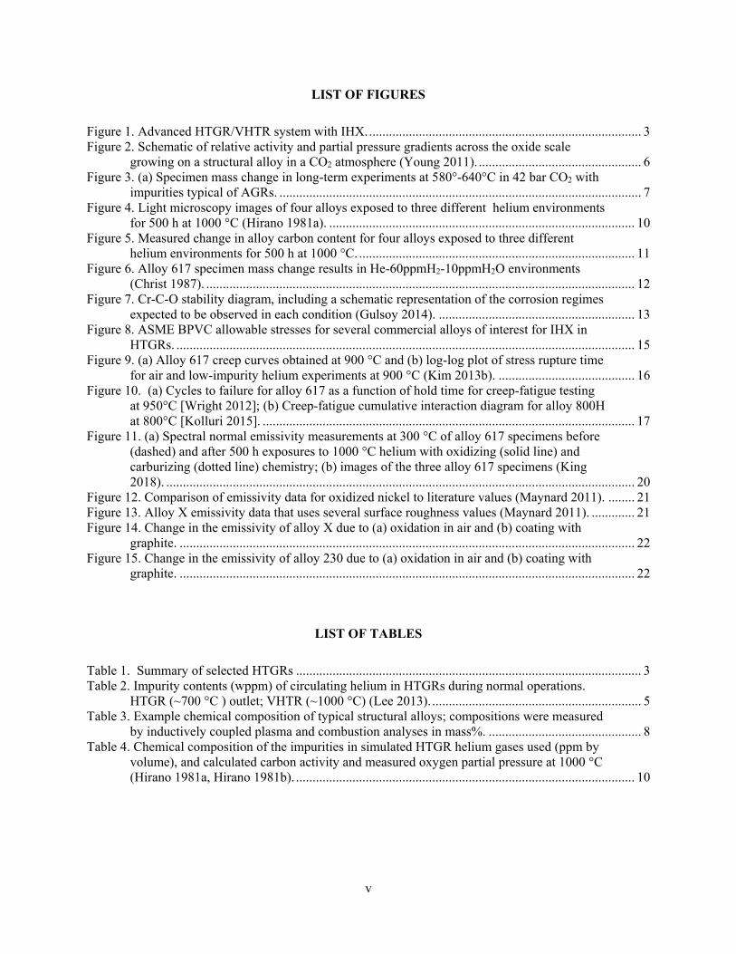
LIST OF FIGURES
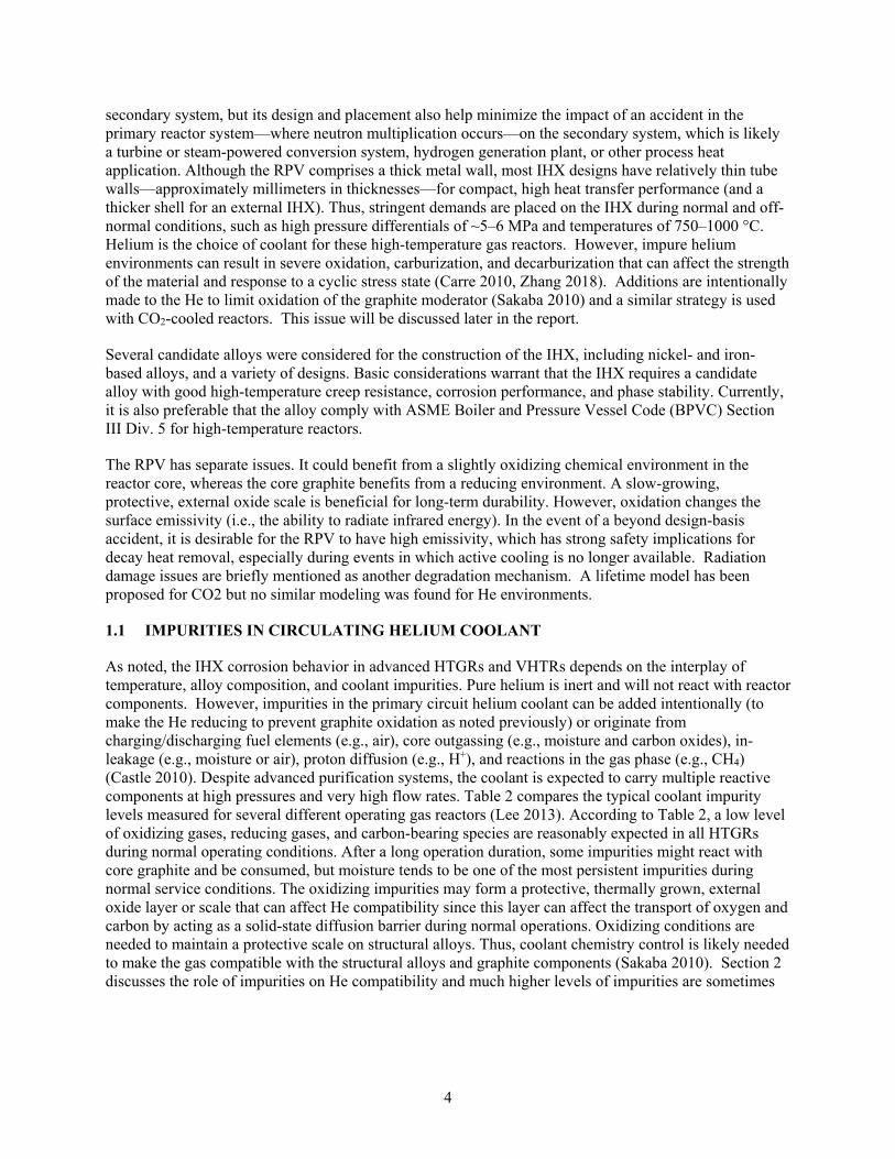
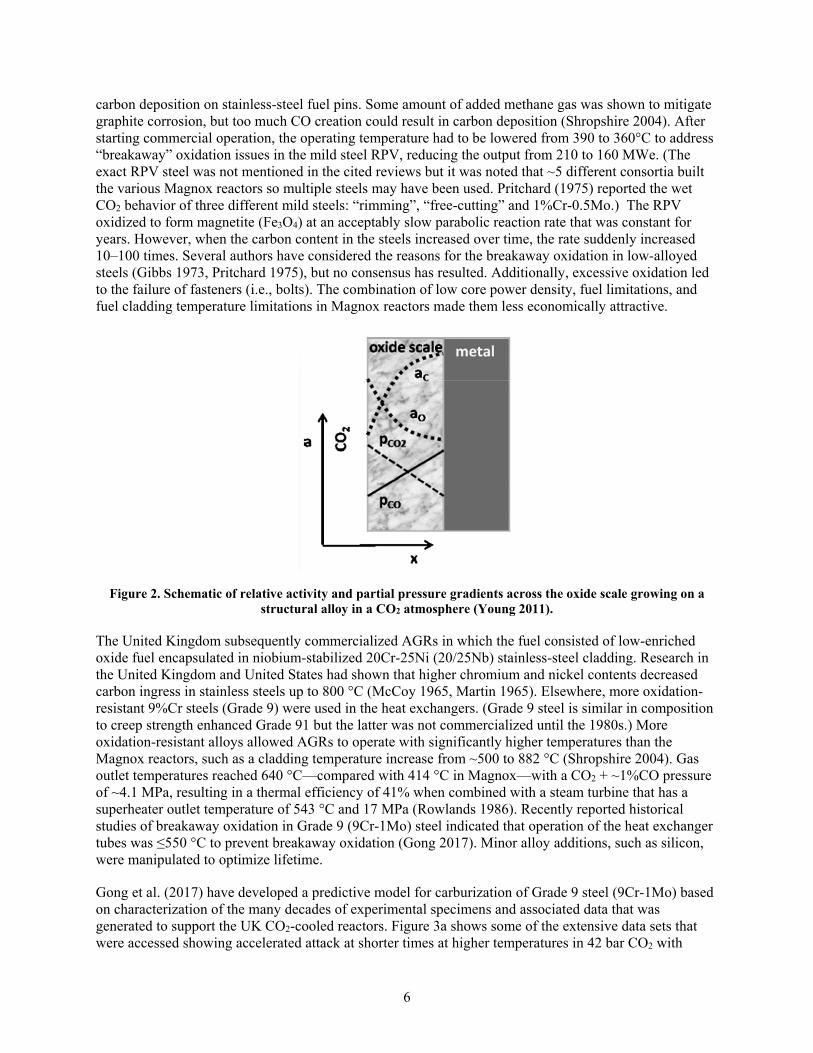
Figure 1. Advanced HTGR/VHTR system with IHX. .................................................................................. 3 Figure 2. Schematic of relative activity and partial pressure gradients across the oxide scale
growing on a structural alloy in a CO2 atmosphere (Young 2011). ................................................. 6 Figure 3. (a) Specimen mass change in long-term experiments at 580°-640°C in 42 bar CO2 with
impurities typical of AGRs. ............................................................................................................. 7 Figure 4. Light microscopy images of four alloys exposed to three different helium environments
for 500 h at 1000 °C (Hirano 1981a). ............................................................................................ 10 Figure 5. Measured change in alloy carbon content for four alloys exposed to three different
helium environments for 500 h at 1000 °C. ................................................................................... 11 Figure 6. Alloy 617 specimen mass change results in He-60ppmH2-10ppmH2O environments
(Christ 1987). ................................................................................................................................. 12 Figure 7. Cr-C-O stability diagram, including a schematic representation of the corrosion regimes
expected to be observed in each condition (Gulsoy 2014). ........................................................... 13 Figure 8. ASME BPVC allowable stresses for several commercial alloys of interest for IHX in
HTGRs. .......................................................................................................................................... 15 Figure 9. (a) Alloy 617 creep curves obtained at 900 °C and (b) log-log plot of stress rupture time
for air and low-impurity helium experiments at 900 °C (Kim 2013b). ......................................... 16 Figure 10. (a) Cycles to failure for alloy 617 as a function of hold time for creep-fatigue testing
at 950°C [Wright 2012]; (b) Creep-fatigue cumulative interaction diagram for alloy 800H at 800°C [Kolluri 2015]. ................................................................................................................ 17
Figure 11. (a) Spectral normal emissivity measurements at 300 °C of alloy 617 specimens before (dashed) and after 500 h exposures to 1000 °C helium with oxidizing (solid line) and carburizing (dotted line) chemistry; (b) images of the three alloy 617 specimens (King 2018). ............................................................................................................................................. 20
Figure 12. Comparison of emissivity data for oxidized nickel to literature values (Maynard 2011). ........ 21 Figure 13. Alloy X emissivity data that uses several surface roughness values (Maynard 2011). ............. 21 Figure 14. Change in the emissivity of alloy X due to (a) oxidation in air and (b) coating with
graphite. ......................................................................................................................................... 22 Figure 15. Change in the emissivity of alloy 230 due to (a) oxidation in air and (b) coating with
graphite. ......................................................................................................................................... 22
LIST OF TABLES
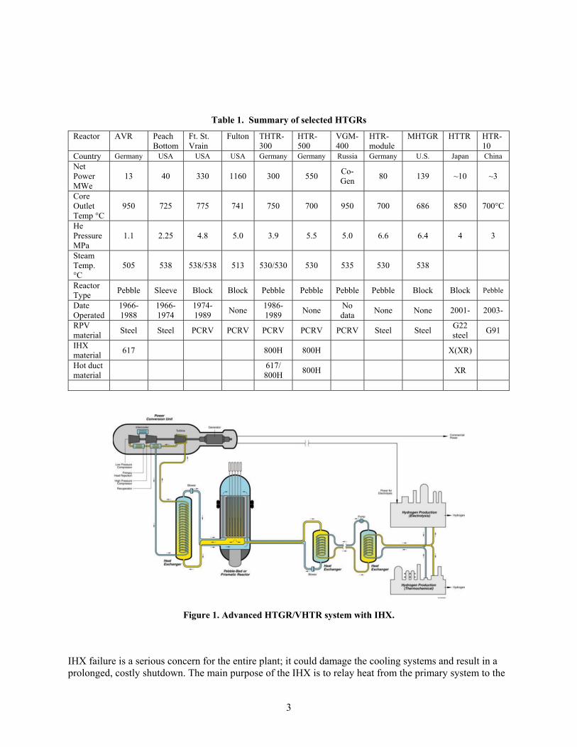
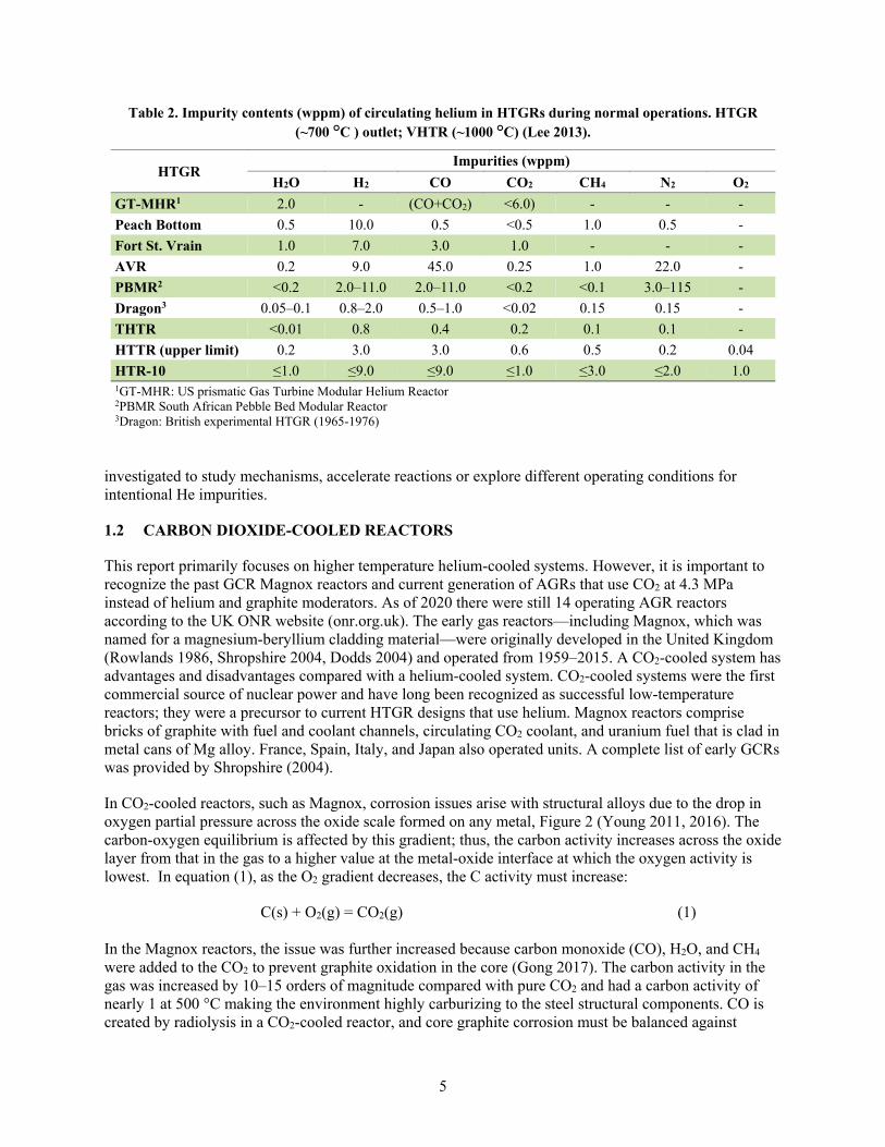
Table 1. Summary of selected HTGRs ........................................................................................................ 3 Table 2. Impurity contents (wppm) of circulating helium in HTGRs during normal operations.
HTGR (~700 °C ) outlet; VHTR (~1000 °C) (Lee 2013). ............................................................... 5 Table 3. Example chemical composition of typical structural alloys; compositions were measured
by inductively coupled plasma and combustion analyses in mass%. .............................................. 8 Table 4. Chemical composition of the impurities in simulated HTGR helium gases used (ppm by
volume), and calculated carbon activity and measured oxygen partial pressure at 1000 °C (Hirano 1981a, Hirano 1981b). ...................................................................................................... 10

vii
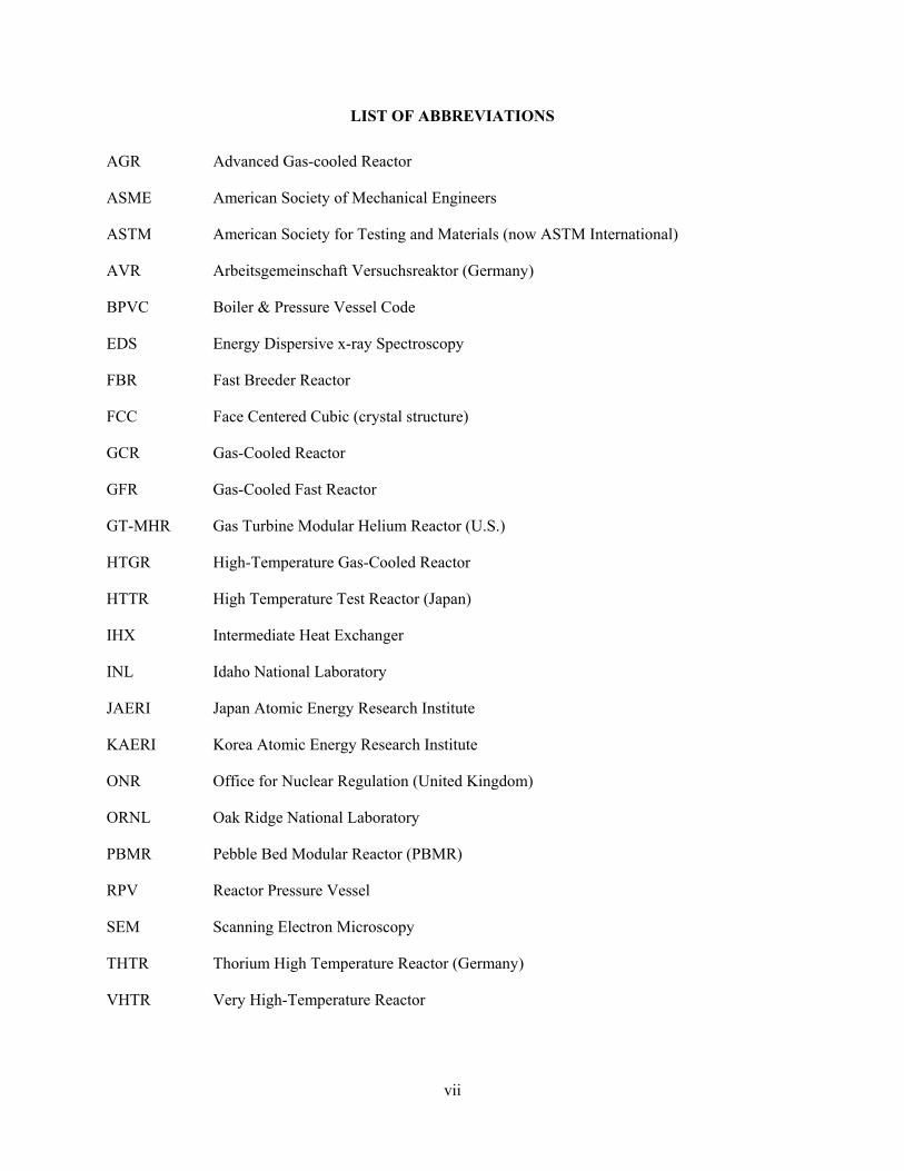
LIST OF ABBREVIATIONS
AGR Advanced Gas-cooled Reactor
ASME American Society of Mechanical Engineers
ASTM American Society for Testing and Materials (now ASTM International)
AVR Arbeitsgemeinschaft Versuchsreaktor (Germany)
BPVC Boiler & Pressure Vessel Code
EDS Energy Dispersive x-ray Spectroscopy
FBR Fast Breeder Reactor
FCC Face Centered Cubic (crystal structure)
GCR Gas-Cooled Reactor
GFR Gas-Cooled Fast Reactor
GT-MHR Gas Turbine Modular Helium Reactor (U.S.)
HTGR High-Temperature Gas-Cooled Reactor
HTTR High Temperature Test Reactor (Japan)
IHX Intermediate Heat Exchanger
INL Idaho National Laboratory
JAERI Japan Atomic Energy Research Institute
KAERI Korea Atomic Energy Research Institute
ONR Office for Nuclear Regulation (United Kingdom)
ORNL Oak Ridge National Laboratory
PBMR Pebble Bed Modular Reactor (PBMR)
RPV Reactor Pressure Vessel
SEM Scanning Electron Microscopy
THTR Thorium High Temperature Reactor (Germany)
VHTR Very High-Temperature Reactor

1
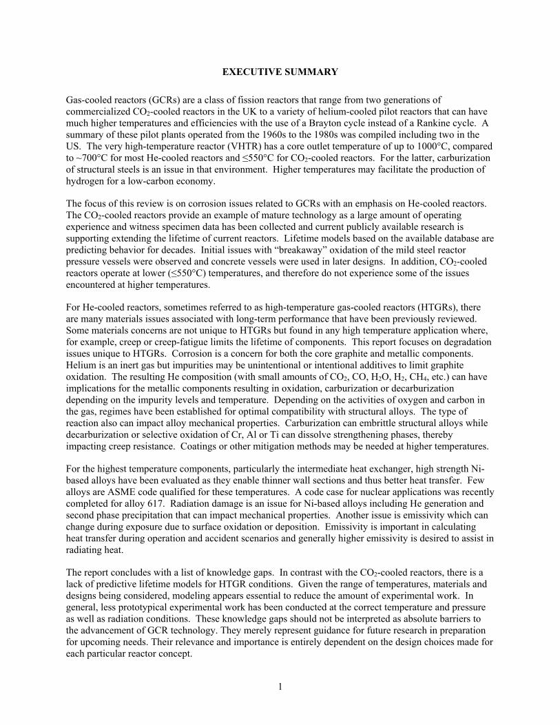
EXECUTIVE SUMMARY
Gas-cooled reactors (GCRs) are a class of fission reactors that range from two generations of commercialized CO2-cooled reactors in the UK to a variety of helium-cooled pilot reactors that can have much higher temperatures and efficiencies with the use of a Brayton cycle instead of a Rankine cycle. A summary of these pilot plants operated from the 1960s to the 1980s was compiled including two in the US. The very high-temperature reactor (VHTR) has a core outlet temperature of up to 1000°C, compared to ~700°C for most He-cooled reactors and ≤550°C for CO2-cooled reactors. For the latter, carburization of structural steels is an issue in that environment. Higher temperatures may facilitate the production of hydrogen for a low-carbon economy.
The focus of this review is on corrosion issues related to GCRs with an emphasis on He-cooled reactors. The CO2-cooled reactors provide an example of mature technology as a large amount of operating experience and witness specimen data has been collected and current publicly available research is supporting extending the lifetime of current reactors. Lifetime models based on the available database are predicting behavior for decades. Initial issues with “breakaway” oxidation of the mild steel reactor pressure vessels were observed and concrete vessels were used in later designs. In addition, CO2-cooled reactors operate at lower (≤550°C) temperatures, and therefore do not experience some of the issues encountered at higher temperatures.
For He-cooled reactors, sometimes referred to as high-temperature gas-cooled reactors (HTGRs), there are many materials issues associated with long-term performance that have been previously reviewed. Some materials concerns are not unique to HTGRs but found in any high temperature application where, for example, creep or creep-fatigue limits the lifetime of components. This report focuses on degradation issues unique to HTGRs. Corrosion is a concern for both the core graphite and metallic components. Helium is an inert gas but impurities may be unintentional or intentional additives to limit graphite oxidation. The resulting He composition (with small amounts of CO2, CO, H2O, H2, CH4, etc.) can have implications for the metallic components resulting in oxidation, carburization or decarburization depending on the impurity levels and temperature. Depending on the activities of oxygen and carbon in the gas, regimes have been established for optimal compatibility with structural alloys. The type of reaction also can impact alloy mechanical properties. Carburization can embrittle structural alloys while decarburization or selective oxidation of Cr, Al or Ti can dissolve strengthening phases, thereby impacting creep resistance. Coatings or other mitigation methods may be needed at higher temperatures.
For the highest temperature components, particularly the intermediate heat exchanger, high strength Ni-based alloys have been evaluated as they enable thinner wall sections and thus better heat transfer. Few alloys are ASME code qualified for these temperatures. A code case for nuclear applications was recently completed for alloy 617. Radiation damage is an issue for Ni-based alloys including He generation and second phase precipitation that can impact mechanical properties. Another issue is emissivity which can change during exposure due to surface oxidation or deposition. Emissivity is important in calculating heat transfer during operation and accident scenarios and generally higher emissivity is desired to assist in radiating heat.
The report concludes with a list of knowledge gaps. In contrast with the CO2-cooled reactors, there is a lack of predictive lifetime models for HTGR conditions. Given the range of temperatures, materials and designs being considered, modeling appears essential to reduce the amount of experimental work. In general, less prototypical experimental work has been conducted at the correct temperature and pressure as well as radiation conditions. These knowledge gaps should not be interpreted as absolute barriers to the advancement of GCR technology. They merely represent guidance for future research in preparation for upcoming needs. Their relevance and importance is entirely dependent on the design choices made for each particular reactor concept.
2
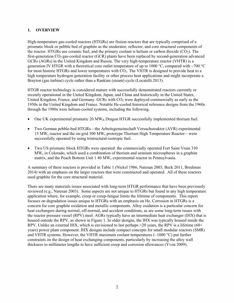
1. OVERVIEW
High-temperature gas-cooled reactors (HTGRs) are fission reactors that are typically comprised of a prismatic block or pebble bed of graphite as the moderator, reflector, and core structural components of the reactor. HTGRs use ceramic fuel, and the primary coolant is helium or carbon dioxide (CO2). The first-generation CO2 gas-cooled reactor (GCR) plants have been replaced by second-generation advanced GCRs (AGRs) in the United Kingdom and Russia. The very high-temperature reactor (VHTR) is a generation IV HTGR with a theoretical core outlet temperature of up to 1000 °C, compared with ~700 °C for most historic HTGRs and lower temperatures with CO2. The VHTR is designed to provide heat to a high temperature hydrogen generation facility or other process heat applications and might incorporate a Brayton (gas turbine) cycle rather than a Rankine (steam) cycle (Locatelli 2013).
HTGR reactor technology is considered mature with successfully demonstrated reactors currently or recently operational in the United Kingdom, Japan, and China and historically in the United States, United Kingdom, France, and Germany. GCRs with CO2 were deployed commercially as early as the 1950s in the United Kingdom and France. Notable He-cooled historical reference designs from the 1960s through the 1980s were helium-cooled systems, including the following.
• One UK experimental prismatic 20 MWth Dragon HTGR successfully implemented thorium fuel.
• Two German pebble-bed HTGRs—the Arbeitsgemeinschaft Versuchsreaktor (AVR) experimental 15 MWe reactor and the on-grid 300 MWe prototype Thorium High Temperature Reactor—were successfully operated by using tristructural-isotropic fuel.
• Two US prismatic block HTGRs were operated: the commercially operated Fort Saint Vrain 330 MWe in Colorado, which used a combination of thorium and uranium microspheres in a graphite matrix, and the Peach Bottom Unit 1 40 MWe experimental reactor in Pennsylvania.
A summary of these reactors is provided in Table 1 (Nickel 1986, Natesan 2003, Beck 2011, Bredimas 2014) with an emphasis on the larger reactors that were constructed and operated. All of these reactors used graphite for the core structural material.
There are many materials issues associated with long-term HTGR performance that have been previously reviewed (e.g., Natesan 2003). Some aspects are not unique to HTGRs but found in any high temperature application where, for example, creep or creep-fatigue limits the lifetime of components. This report focuses on degradation issues unique to HTGRs with an emphasis on He. Corrosion in HTGRs is a concern for core graphite oxidation and metallic components. Alloy oxidation is a particular concern for heat exchangers during normal, off-normal, and accident conditions, as are some long-term issues with the reactor pressure vessel (RPV) steel. AGRs typically have an intermediate heat exchanger (IHX) that is housed outside the RPV, as shown in Figure 1. In older designs, the IHX was typically housed inside the RPV. Unlike an external IHX, which is envisioned to last perhaps <20 years, the RPV is a lifetime (60+ years) power plant component. IHX designs include compact concepts for small modular reactors (SMR) and VHTR systems. However, the VHTR maximum coolant temperatures (~1000 °C) put further constraints on the design of heat exchanging components, particularly by increasing the alloy wall thickness to millimeter lengths to have sufficient creep and corrosion allowances (Yvon 2009).
3
Table 1. Summary of selected HTGRs Reactor AVR Peach
Bottom Ft. St. Vrain
Fulton THTR-300
HTR-500
VGM-400
HTR-module
MHTGR HTTR HTR-10
Country Germany USA USA USA Germany Germany Russia Germany U.S. Japan China Net Power MWe
13 40 330 1160 300 550 Co-Gen 80 139 ~10 ~3
Core Outlet Temp °C
950 725 775 741 750 700 950 700 686 850 700°C
He Pressure MPa
1.1 2.25 4.8 5.0 3.9 5.5 5.0 6.6 6.4 4 3
Steam Temp. °C
505 538 538/538 513 530/530 530 535 530 538
Reactor Type Pebble Sleeve Block Block Pebble Pebble Pebble Pebble Block Block Pebble
Date Operated
1966-1988
1966-1974
1974-1989 None 1986-
1989 None No data None None 2001- 2003-
RPV material Steel Steel PCRV PCRV PCRV PCRV PCRV Steel Steel G22
steel G91
IHX material 617 800H 800H X(XR)
Hot duct material 617/
800H 800H XR
Figure 1. Advanced HTGR/VHTR system with IHX.
IHX failure is a serious concern for the entire plant; it could damage the cooling systems and result in a prolonged, costly shutdown. The main purpose of the IHX is to relay heat from the primary system to the
4
secondary system, but its design and placement also help minimize the impact of an accident in the primary reactor system—where neutron multiplication occurs—on the secondary system, which is likely a turbine or steam-powered conversion system, hydrogen generation plant, or other process heat application. Although the RPV comprises a thick metal wall, most IHX designs have relatively thin tube walls—approximately millimeters in thicknesses—for compact, high heat transfer performance (and a thicker shell for an external IHX). Thus, stringent demands are placed on the IHX during normal and off-normal conditions, such as high pressure differentials of ~5–6 MPa and temperatures of 750–1000 °C. Helium is the choice of coolant for these high-temperature gas reactors. However, impure helium environments can result in severe oxidation, carburization, and decarburization that can affect the strength of the material and response to a cyclic stress state (Carre 2010, Zhang 2018). Additions are intentionally made to the He to limit oxidation of the graphite moderator (Sakaba 2010) and a similar strategy is used with CO2-cooled reactors. This issue will be discussed later in the report.
Several candidate alloys were considered for the construction of the IHX, including nickel- and iron-based alloys, and a variety of designs. Basic considerations warrant that the IHX requires a candidate alloy with good high-temperature creep resistance, corrosion performance, and phase stability. Currently, it is also preferable that the alloy comply with ASME Boiler and Pressure Vessel Code (BPVC) Section III Div. 5 for high-temperature reactors.
The RPV has separate issues. It could benefit from a slightly oxidizing chemical environment in the reactor core, whereas the core graphite benefits from a reducing environment. A slow-growing, protective, external oxide scale is beneficial for long-term durability. However, oxidation changes the surface emissivity (i.e., the ability to radiate infrared energy). In the event of a beyond design-basis accident, it is desirable for the RPV to have high emissivity, which has strong safety implications for decay heat removal, especially during events in which active cooling is no longer available. Radiation damage issues are briefly mentioned as another degradation mechanism. A lifetime model has been proposed for CO2 but no similar modeling was found for He environments.
1.1 IMPURITIES IN CIRCULATING HELIUM COOLANT
As noted, the IHX corrosion behavior in advanced HTGRs and VHTRs depends on the interplay of temperature, alloy composition, and coolant impurities. Pure helium is inert and will not react with reactor components. However, impurities in the primary circuit helium coolant can be added intentionally (to make the He reducing to prevent graphite oxidation as noted previously) or originate from charging/discharging fuel elements (e.g., air), core outgassing (e.g., moisture and carbon oxides), in-leakage (e.g., moisture or air), proton diffusion (e.g., H+), and reactions in the gas phase (e.g., CH4) (Castle 2010). Despite advanced purification systems, the coolant is expected to carry multiple reactive components at high pressures and very high flow rates. Table 2 compares the typical coolant impurity levels measured for several different operating gas reactors (Lee 2013). According to Table 2, a low level of oxidizing gases, reducing gases, and carbon-bearing species are reasonably expected in all HTGRs during normal operating conditions. After a long operation duration, some impurities might react with core graphite and be consumed, but moisture tends to be one of the most persistent impurities during normal service conditions. The oxidizing impurities may form a protective, thermally grown, external oxide layer or scale that can affect He compatibility since this layer can affect the transport of oxygen and carbon by acting as a solid-state diffusion barrier during normal operations. Oxidizing conditions are needed to maintain a protective scale on structural alloys. Thus, coolant chemistry control is likely needed to make the gas compatible with the structural alloys and graphite components (Sakaba 2010). Section 2 discusses the role of impurities on He compatibility and much higher levels of impurities are sometimes
5
Table 2. Impurity contents (wppm) of circulating helium in HTGRs during normal operations. HTGR (~700 °C ) outlet; VHTR (~1000 °C) (Lee 2013).
HTGR Impurities (wppm)
H2O H2 CO CO2 CH4 N2 O2 GT-MHR1 2.0 - (CO+CO2) <6.0) - - - Peach Bottom 0.5 10.0 0.5 <0.5 1.0 0.5 - Fort St. Vrain 1.0 7.0 3.0 1.0 - - - AVR 0.2 9.0 45.0 0.25 1.0 22.0 - PBMR2 <0.2 2.0–11.0 2.0–11.0 <0.2 <0.1 3.0–115 - Dragon3 0.05–0.1 0.8–2.0 0.5–1.0 <0.02 0.15 0.15 - THTR <0.01 0.8 0.4 0.2 0.1 0.1 - HTTR (upper limit) 0.2 3.0 3.0 0.6 0.5 0.2 0.04 HTR-10 ≤1.0 ≤9.0 ≤9.0 ≤1.0 ≤3.0 ≤2.0 1.0 1GT-MHR: US prismatic Gas Turbine Modular Helium Reactor 2PBMR South African Pebble Bed Modular Reactor 3Dragon: British experimental HTGR (1965-1976)
investigated to study mechanisms, accelerate reactions or explore different operating conditions for intentional He impurities.
1.2 CARBON DIOXIDE-COOLED REACTORS
This report primarily focuses on higher temperature helium-cooled systems. However, it is important to recognize the past GCR Magnox reactors and current generation of AGRs that use CO2 at 4.3 MPa instead of helium and graphite moderators. As of 2020 there were still 14 operating AGR reactors according to the UK ONR website (onr.org.uk). The early gas reactors—including Magnox, which was named for a magnesium-beryllium cladding material—were originally developed in the United Kingdom (Rowlands 1986, Shropshire 2004, Dodds 2004) and operated from 1959–2015. A CO2-cooled system has advantages and disadvantages compared with a helium-cooled system. CO2-cooled systems were the first commercial source of nuclear power and have long been recognized as successful low-temperature reactors; they were a precursor to current HTGR designs that use helium. Magnox reactors comprise bricks of graphite with fuel and coolant channels, circulating CO2 coolant, and uranium fuel that is clad in metal cans of Mg alloy. France, Spain, Italy, and Japan also operated units. A complete list of early GCRs was provided by Shropshire (2004).
In CO2-cooled reactors, such as Magnox, corrosion issues arise with structural alloys due to the drop in oxygen partial pressure across the oxide scale formed on any metal, Figure 2 (Young 2011, 2016). The carbon-oxygen equilibrium is affected by this gradient; thus, the carbon activity increases across the oxide layer from that in the gas to a higher value at the metal-oxide interface at which the oxygen activity is lowest. In equation (1), as the O2 gradient decreases, the C activity must increase:
C(s) + O2(g) = CO2(g) (1) In the Magnox reactors, the issue was further increased because carbon monoxide (CO), H2O, and CH4 were added to the CO2 to prevent graphite oxidation in the core (Gong 2017). The carbon activity in the gas was increased by 10–15 orders of magnitude compared with pure CO2 and had a carbon activity of nearly 1 at 500 °C making the environment highly carburizing to the steel structural components. CO is created by radiolysis in a CO2-cooled reactor, and core graphite corrosion must be balanced against
6
carbon deposition on stainless-steel fuel pins. Some amount of added methane gas was shown to mitigate graphite corrosion, but too much CO creation could result in carbon deposition (Shropshire 2004). After starting commercial operation, the operating temperature had to be lowered from 390 to 360°C to address “breakaway” oxidation issues in the mild steel RPV, reducing the output from 210 to 160 MWe. (The exact RPV steel was not mentioned in the cited reviews but it was noted that ~5 different consortia built the various Magnox reactors so multiple steels may have been used. Pritchard (1975) reported the wet CO2 behavior of three different mild steels: “rimming”, “free-cutting” and 1%Cr-0.5Mo.) The RPV oxidized to form magnetite (Fe3O4) at an acceptably slow parabolic reaction rate that was constant for years. However, when the carbon content in the steels increased over time, the rate suddenly increased 10–100 times. Several authors have considered the reasons for the breakaway oxidation in low-alloyed steels (Gibbs 1973, Pritchard 1975), but no consensus has resulted. Additionally, excessive oxidation led to the failure of fasteners (i.e., bolts). The combination of low core power density, fuel limitations, and fuel cladding temperature limitations in Magnox reactors made them less economically attractive.
Figure 2. Schematic of relative activity and partial pressure gradients across the oxide scale growing on a structural alloy in a CO2 atmosphere (Young 2011).
The United Kingdom subsequently commercialized AGRs in which the fuel consisted of low-enriched oxide fuel encapsulated in niobium-stabilized 20Cr-25Ni (20/25Nb) stainless-steel cladding. Research in the United Kingdom and United States had shown that higher chromium and nickel contents decreased carbon ingress in stainless steels up to 800 °C (McCoy 1965, Martin 1965). Elsewhere, more oxidation-resistant 9%Cr steels (Grade 9) were used in the heat exchangers. (Grade 9 steel is similar in composition to creep strength enhanced Grade 91 but the latter was not commercialized until the 1980s.) More oxidation-resistant alloys allowed AGRs to operate with significantly higher temperatures than the Magnox reactors, such as a cladding temperature increase from ~500 to 882 °C (Shropshire 2004). Gas outlet temperatures reached 640 °C—compared with 414 °C in Magnox—with a CO2 + ~1%CO pressure of ~4.1 MPa, resulting in a thermal efficiency of 41% when combined with a steam turbine that has a superheater outlet temperature of 543 °C and 17 MPa (Rowlands 1986). Recently reported historical studies of breakaway oxidation in Grade 9 (9Cr-1Mo) steel indicated that operation of the heat exchanger tubes was ≤550 °C to prevent breakaway oxidation (Gong 2017). Minor alloy additions, such as silicon, were manipulated to optimize lifetime.
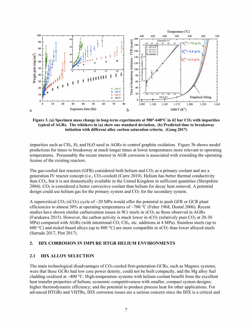
Gong et al. (2017) have developed a predictive model for carburization of Grade 9 steel (9Cr-1Mo) based on characterization of the many decades of experimental specimens and associated data that was generated to support the UK CO2-cooled reactors. Figure 3a shows some of the extensive data sets that were accessed showing accelerated attack at shorter times at higher temperatures in 42 bar CO2 with
7
a b
Figure 3. (a) Specimen mass change in long-term experiments at 580°-640°C in 42 bar CO2 with impurities typical of AGRs. The whiskers in (a) show one standard deviation, (b) Predicted time to breakaway
initiation with different alloy carbon saturation criteria. (Gong 2017)
impurities such as CH4, H2 and H2O used in AGRs to control graphite oxidation. Figure 3b shows model predictions for times to breakaway at much longer times at lower temperatures more relevant to operating temperatures. Presumably the recent interest in AGR corrosion is associated with extending the operating license of the existing reactors.
The gas-cooled fast reactors (GFR) considered both helium and CO2 as a primary coolant and are a generation IV reactor concept (i.e., CO2-cooled) (Carre 2010). Helium has better thermal conductivity than CO2, but it is not domestically available in the United Kingdom in sufficient quantities (Shropshire 2004). CO2 is considered a better convective coolant than helium for decay heat removal. A potential design could use helium gas for the primary system and CO2 for the secondary system.
A supercritical CO2 (sCO2) cycle of ~20 MPa would offer the potential to push GFR or GCR plant efficiencies to almost 50% at operating temperatures of ~700 °C (Feher 1968, Dostal 2006). Recent studies have shown similar carburization issues in 9Cr steels in sCO2 as those observed in AGRs (Furukawa 2015). However, the carbon activity is much lower in sCO2 (relatively pure CO2 at 20-30 MPa) compared with AGRs (with intentional CO, CH4, etc. additions at 4 MPa). Stainless steels (up to 600 °C) and nickel-based alloys (up to 800 °C) are more compatible in sCO2 than lower alloyed steels (Sarrade 2017, Pint 2017).
2. IHX CORROSION IN IMPURE HTGR HELIUM ENVIRONMENTS
2.1 IHX ALLOY SELECTION
The main technological disadvantages of CO2-cooled first-generation GCRs, such as Magnox systems, were that these GCRs had low core power density, could not be built compactly, and the Mg alloy fuel cladding oxidized at ~400 °C. High-temperature systems with helium coolant benefit from the excellent heat transfer properties of helium; economic competitiveness with smaller, compact system designs; higher thermodynamic efficiency; and the potential to produce process heat for other applications. For advanced HTGRs and VHTRs, IHX corrosion issues are a serious concern since the IHX is a critical and
8
expensive component. There are several design choices and geometries for the IHX component. Helical coil and shell-and-tube-type heat exchangers are mature industrial heat exchanger designs (Zhang 2018). A compact heat exchanger design is desirable for some advanced HTGRs/VHTRs and SMRs. The compact designs are a less mature technology. The fin-and-plate and microchannel printed circuit heat exchangers are compact IHX designs, and both designs involve thin metal plates stacked and joined together. For compact heat exchangers, the choice of heat exchanger alloy is crucial for higher operating temperatures (>750 °C) for which the possibility of a 20–30 year design lifetime is more challenging due to creep and oxidation concerns.
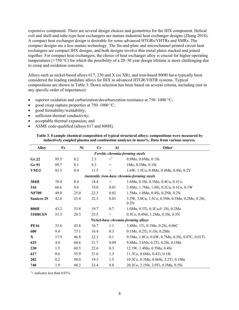
Alloys such as nickel-based alloys 617, 230 and X (or XR), and iron-based 800H have typically been considered the leading candidate alloys for IHX in advanced HTGR/VHTR systems. Typical compositions are shown in Table 3. Down selection has been based on several criteria, including (not in any specific order of importance):
• superior oxidation and carburization/decarburization resistance at 750–1000 °C; • good creep rupture properties at 750–1000 °C; • good formability/weldability; • sufficient thermal conductivity; • acceptable thermal expansion; and • ASME code-qualified (alloys 617 and 800H).
Table 3. Example chemical composition of typical structural alloys; compositions were measured by inductively coupled plasma and combustion analyses in mass%. Data from various sources.
Alloy Fe Ni Cr Al Other Ferritic chromia-forming steels
Gr.22 95.5 0.2 2.3 <* 0.9Mo, 0.6Mn, 0.1Si Gr.91 89.7 0.1 8.3 < 1Mo, 0.3Mn, 0.1Si VM12 83.3 0.4 11.5 < 1.6W, 1.5Co, 0.4Mo, 0.4Mn, 0.4Si, 0.2V
Austenitic iron-base chromia-forming steels 304H 70.4 8.4 18.4 < 1.6Mn, 0.3Si, 0.3Mo, 0.4Cu, 0.1Co 316 66.6 9.6 19.0 0.01 2.4Mo, 1.7Mn, 1.0Si, 0.2Cu, 0.1Co, 0.1W NF709 49.0 25.0 22.3 0.02 1.5Mo, 1.0Mn, 0.4Si, 0.2Nb, 0.2N Sanicro 25 42.6 25.4 22.3 0.03 3.5W, 3.0Cu, 1.5Co, 0.5Nb, 0.5Mn, 0.2Mo, 0.2Si,
0.2N 800H 43.2 33.8 19.7 0.7 1.0Mn, 0.5Ti, 0.3Cu,0 .3Si, 0.2Mo 310HCbN 51.3 20.3 25.5 < 0.3Co, 0.4Nb, 1.2Mn, 0.3Si, 0.3N
Nickel-base chromia-forming alloys PE16 33.6 43.8 16.7 1.1 3.4Mo, 1Ti, 0.1Mn, 0.2Si, 0.06C 600 9.4 73.1 16.4 0.3 0.1Mo, 0.2Ti, 0.1Si, 0.2Mn X 17.9 46.8 22.1 0.1 9.5Mo, 1.8Co, 0.6W, 0.7Mn, 0.3Si, 0.07C, 0.01Ti 625 4.0 60.6 21.7 0.09 9.4Mo, 3.6Nb, 0.2Ti, 0.2Si, 0.1Mn 230 1.5 60.5 22.6 0.3 12.3W, 1.4Mo, 0.5Mn, 0.4Si 617 0.6 55.9 21.6 1.3 11.3Co, 8.6Mo, 0.4Ti, 0.1Si 282 0.2 58.0 19.3 1.5 10.3Co, 8.3Mo, 0.06Si, 2.2Ti, 0.1Mn 740 1.9 48.2 23.4 0.8 20.2Co, 2.1Nb, 2.0Ti, 0.3Mn, 0.5Si *< indicates less than 0.01%
9
For example, several steels were evaluated in the UK program (Bates 1976), and alloy 800H—a modification of alloy 800—was used in German HTGRs steam generators and is code-qualified in ASME BPVC Section III, Division 5 for high-temperature reactors. However, it is qualified only up to 760 °C for oxidation resistance and creep rupture, and its resistance to corrosion and creep at higher temperatures (up to 950 °C) is inadequate (Gulsoy and Was 2015). At higher temperatures, nickel-based superalloys are needed. Alloy X has adequate oxidation resistance but can form brittle intermetallic phases above 750 °C in impure helium that are detrimental to its high-temperature mechanical properties. Alloys 617 and 230 tend to have similar oxidation, carburization, and decarburization behavior, but alloy 617 has superior creep properties due to γ´ phase strengthening. Thus, this section will primarily focus on the nickel-based alloys. The two leading candidate alloys that were investigated are alloys 617 and 230, with work published from Japan Atomic Energy Research Institute (JAERI) and Korea Atomic Energy Research Institute (KAERI) (Jang 2008, Kim 2013b, Kim 2014). Previously, JAERI evaluated alloy XR, which is an improved formulation of alloy X, during conceptualization of the HTTR (Hirano 1981, Kurata 1995).
2.2 CORROSION BEHAVIOR IN IMPURE HELIUM
All of the nickel-based alloys of interest form an external Cr2O3 scale in air and in most oxidizing environments. The chromia will form until the underlying alloy substrate is depleted in chromium to a critical level of 10–15wt% (Evans 1999, Huczkowski 2004, Duan 2017). The Cr2O3 external layer becomes a solid-state diffusion barrier, and growth is governed by transport through this layer along oxide grain boundaries. As the diffusion distance increases with time, parabolic kinetics are typically observed, such as in Young (2016). Diffusion through the scale can be accelerated by elements, such as titanium, and decreased by large rare-earth ions in the alloy, which is known as the reactive element (RE) effect (Whittle and Stringer 1980, Pint 1996). For example, alloy 230 has slower reaction rates than alloy 617 due to a small lanthanum addition (Duan 2017). Chromia growth is generally ascribed to be rate-limited by chromium outward diffusion, but RE additions can switch the mechanism to inward oxygen transport, such as in Quadakkers (1989). Because Cr2O3 can have n-type or p-type semiconductor properties, its behavior can be affected by oxygen partial pressure (PO2) with p-type behavior in high PO2 and n-type behavior in low PO2. The latter is more relevant to helium environments.
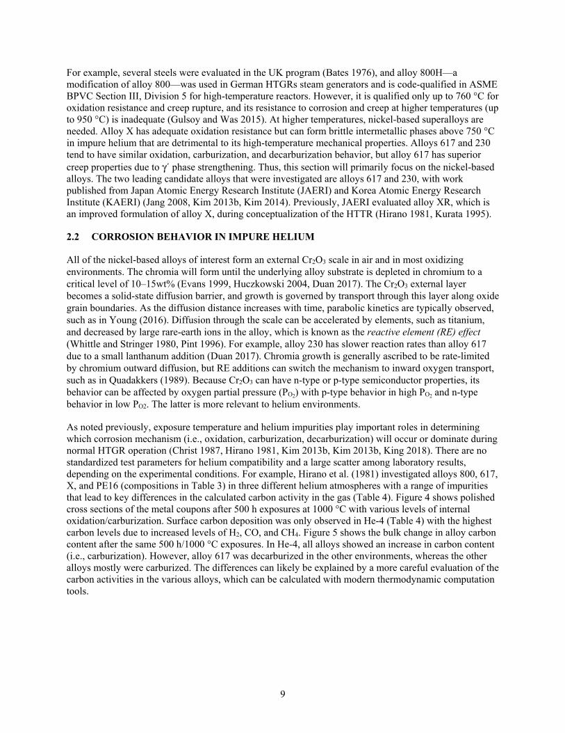
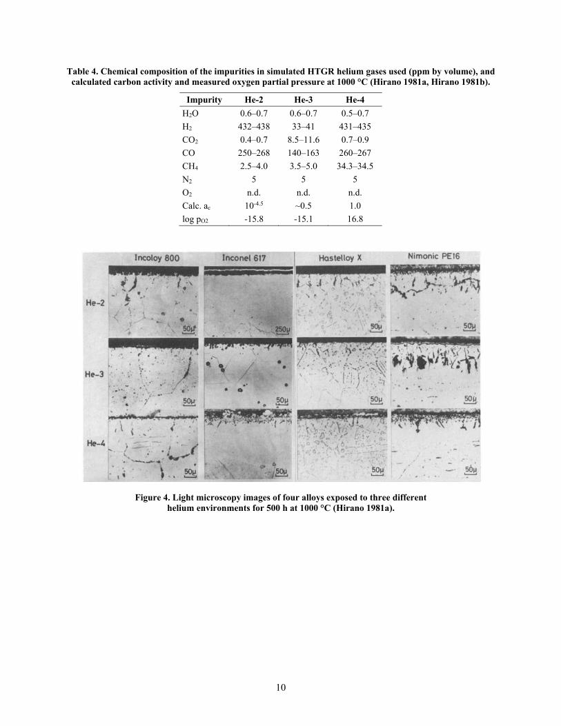
As noted previously, exposure temperature and helium impurities play important roles in determining which corrosion mechanism (i.e., oxidation, carburization, decarburization) will occur or dominate during normal HTGR operation (Christ 1987, Hirano 1981, Kim 2013b, Kim 2013b, King 2018). There are no standardized test parameters for helium compatibility and a large scatter among laboratory results, depending on the experimental conditions. For example, Hirano et al. (1981) investigated alloys 800, 617, X, and PE16 (compositions in Table 3) in three different helium atmospheres with a range of impurities that lead to key differences in the calculated carbon activity in the gas (Table 4). Figure 4 shows polished cross sections of the metal coupons after 500 h exposures at 1000 °C with various levels of internal oxidation/carburization. Surface carbon deposition was only observed in He-4 (Table 4) with the highest carbon levels due to increased levels of H2, CO, and CH4. Figure 5 shows the bulk change in alloy carbon content after the same 500 h/1000 °C exposures. In He-4, all alloys showed an increase in carbon content (i.e., carburization). However, alloy 617 was decarburized in the other environments, whereas the other alloys mostly were carburized. The differences can likely be explained by a more careful evaluation of the carbon activities in the various alloys, which can be calculated with modern thermodynamic computation tools.
10
Table 4. Chemical composition of the impurities in simulated HTGR helium gases used (ppm by volume), and calculated carbon activity and measured oxygen partial pressure at 1000 °C (Hirano 1981a, Hirano 1981b).
Impurity He-2 He-3 He-4 H2O 0.6–0.7 0.6–0.7 0.5–0.7 H2 432–438 33–41 431–435 CO2 0.4–0.7 8.5–11.6 0.7–0.9 CO 250–268 140–163 260–267 CH4 2.5–4.0 3.5–5.0 34.3–34.5 N2 5 5 5 O2 n.d. n.d. n.d. Calc. ac 10-4.5 ~0.5 1.0 log pO2 -15.8 -15.1 16.8
Figure 4. Light microscopy images of four alloys exposed to three different
helium environments for 500 h at 1000 °C (Hirano 1981a).
11
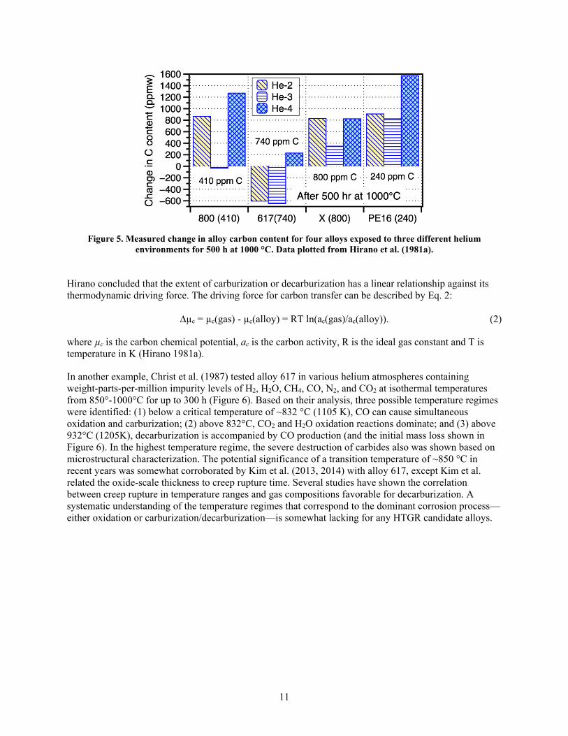
Figure 5. Measured change in alloy carbon content for four alloys exposed to three different helium
environments for 500 h at 1000 °C. Data plotted from Hirano et al. (1981a).
Hirano concluded that the extent of carburization or decarburization has a linear relationship against its thermodynamic driving force. The driving force for carbon transfer can be described by Eq. 2:
Δµc = µc(gas) - µc(alloy) = RT ln(ac(gas)/ac(alloy)). (2)
where µc is the carbon chemical potential, ac is the carbon activity, R is the ideal gas constant and T is temperature in K (Hirano 1981a).
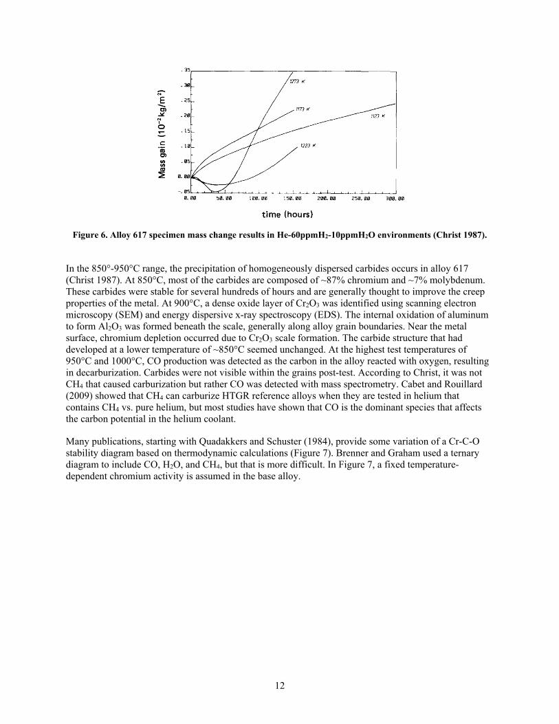
In another example, Christ et al. (1987) tested alloy 617 in various helium atmospheres containing weight-parts-per-million impurity levels of H2, H2O, CH4, CO, N2, and CO2 at isothermal temperatures from 850°-1000°C for up to 300 h (Figure 6). Based on their analysis, three possible temperature regimes were identified: (1) below a critical temperature of ~832 °C (1105 K), CO can cause simultaneous oxidation and carburization; (2) above 832°C, CO2 and H2O oxidation reactions dominate; and (3) above 932°C (1205K), decarburization is accompanied by CO production (and the initial mass loss shown in Figure 6). In the highest temperature regime, the severe destruction of carbides also was shown based on microstructural characterization. The potential significance of a transition temperature of ~850 °C in recent years was somewhat corroborated by Kim et al. (2013, 2014) with alloy 617, except Kim et al. related the oxide-scale thickness to creep rupture time. Several studies have shown the correlation between creep rupture in temperature ranges and gas compositions favorable for decarburization. A systematic understanding of the temperature regimes that correspond to the dominant corrosion process—either oxidation or carburization/decarburization—is somewhat lacking for any HTGR candidate alloys.
12
Figure 6. Alloy 617 specimen mass change results in He-60ppmH2-10ppmH2O environments (Christ 1987).
In the 850°-950°C range, the precipitation of homogeneously dispersed carbides occurs in alloy 617 (Christ 1987). At 850°C, most of the carbides are composed of ~87% chromium and ~7% molybdenum. These carbides were stable for several hundreds of hours and are generally thought to improve the creep properties of the metal. At 900°C, a dense oxide layer of Cr2O3 was identified using scanning electron microscopy (SEM) and energy dispersive x-ray spectroscopy (EDS). The internal oxidation of aluminum to form Al2O3 was formed beneath the scale, generally along alloy grain boundaries. Near the metal surface, chromium depletion occurred due to Cr2O3 scale formation. The carbide structure that had developed at a lower temperature of ~850°C seemed unchanged. At the highest test temperatures of 950°C and 1000°C, CO production was detected as the carbon in the alloy reacted with oxygen, resulting in decarburization. Carbides were not visible within the grains post-test. According to Christ, it was not CH4 that caused carburization but rather CO was detected with mass spectrometry. Cabet and Rouillard (2009) showed that CH4 can carburize HTGR reference alloys when they are tested in helium that contains CH4 vs. pure helium, but most studies have shown that CO is the dominant species that affects the carbon potential in the helium coolant.
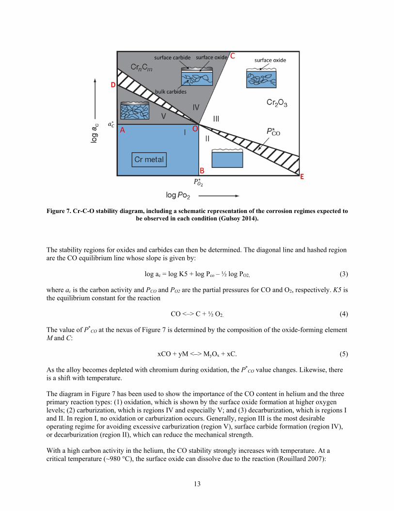
Many publications, starting with Quadakkers and Schuster (1984), provide some variation of a Cr-C-O stability diagram based on thermodynamic calculations (Figure 7). Brenner and Graham used a ternary diagram to include CO, H2O, and CH4, but that is more difficult. In Figure 7, a fixed temperature-dependent chromium activity is assumed in the base alloy.
13
Figure 7. Cr-C-O stability diagram, including a schematic representation of the corrosion regimes expected to
be observed in each condition (Gulsoy 2014).
The stability regions for oxides and carbides can then be determined. The diagonal line and hashed region are the CO equilibrium line whose slope is given by:
log ac = log K5 + log Pco – ½ log PO2, (3)
where ac is the carbon activity and PCO and PO2 are the partial pressures for CO and O2, respectively. K5 is the equilibrium constant for the reaction
CO <–> C + ½ O2. (4)
The value of P*CO at the nexus of Figure 7 is determined by the composition of the oxide-forming element
M and C:
xCO + yM <–> MyOx + xC. (5)
As the alloy becomes depleted with chromium during oxidation, the P*CO value changes. Likewise, there
is a shift with temperature.
The diagram in Figure 7 has been used to show the importance of the CO content in helium and the three primary reaction types: (1) oxidation, which is shown by the surface oxide formation at higher oxygen levels; (2) carburization, which is regions IV and especially V; and (3) decarburization, which is regions I and II. In region I, no oxidation or carburization occurs. Generally, region III is the most desirable operating regime for avoiding excessive carburization (region V), surface carbide formation (region IV), or decarburization (region II), which can reduce the mechanical strength.
With a high carbon activity in the helium, the CO stability strongly increases with temperature. At a critical temperature (~980 °C), the surface oxide can dissolve due to the reaction (Rouillard 2007):
14
Cr2O3 + 3Csolution <–> 2Crsolution + 3CO(g). (6)
Brenner and Graham (1984) suggest that H2O and/or H2 were needed to facilitate the surface oxide reduction. Dissolution was also studied by Adharapurapu (2011a, 2011b).
Several studies have examined the effect of H2O impurities on oxidation in helium. Guillou (2011) studied alloy 230 and found a complex but relatively minor effect of varying both PH2 and PH2O. Shindo et al. (1986) studied a wider range of alloys and gas compositions and also found complex results, depending on whether the environment was carburizing or decarburizing and whether the alloy contained high levels of aluminum and titanium.
As a final note, the hydrogen effect on defect structures of oxide layers has been studied by several authors (Kim 2013a, Kofstad and Lillerud 1980, Norby 1990). Kim et al. (2013a) studied hydrogen effects on the oxidation behavior of alloy 230 in high-temperature steam environments with and without 10 or 20 vol% H2 at 900 °C for up to 1,000 h. The Mott-Schottky analysis was used to characterize oxide layer semiconduction. The alloy-oxide scale exhibits an n-type semiconductor behavior in steam. In the Kim et al. test, the defect density was higher in the alloy when 20% vol H2 was added to the steam and subsequent diffusion of O2 in the oxide layer was enhanced, resulting in increased oxidation. With hydrogen in the steam, there was enhanced defect and void formation in the metal, including: (1) the penetration of hydrogen along grain boundaries and reduction of metal ions by hydrogen, (2) the formation of metal interstitials and oxygen vacancies by metal ions reduced by valence electrons, and (3) the enhanced diffusion of defects and void formation. Proton diffusion is a process that could impact IHX and process heat exchangers, but it is not well understood and could warrant further investigation via fundamental mechanistic studies.
Conclusions
- Most Ni-based alloys of interest form Cr2O3 surface oxides and undergo oxidation, carburization or decarburization depending on the impurities present in the He
- Cr-C-O stability diagrams are calculated to describe these performance regimes that vary with temperature and alloy composition and emphasize the importance of the CO content in the He (e.g. Table 2)
- Region III in Figure 7 is the most desirable operating condition to avoid the most aggressive degradation modes
- At ~1000°C, the surface oxide can be reduced in impure He environments depending on the relative C and O activities.
2.3 EFFECT OF HELIUM ENVIRONMENT ON MECHANICAL PROPERTIES
The initial design parameters of stress, operating temperature, and component lifetime determine the type of alloy and the necessary component thickness. However, many studies have found that the helium environment also affects mechanical properties (Yun 1984, Shankar and Natesan 2007, Natesan and Shankar 2009, Lee 2013a). In addition to metal loss or affected metal (Figure 4), helium exposure can affect creep-rupture lifetime. For example, Hosoi and Abe (1975) and Shankar and Natesan (2007) found that the creep life of alloy 617 was strongly affected by helium impurities. Generally, oxidation can decrease lifetime, and carburization can increase lifetime but decrease ductility at failure.
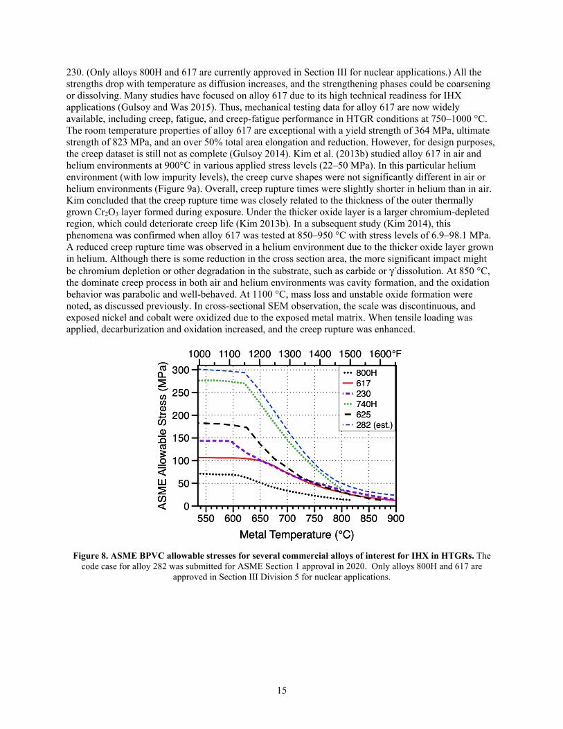
As noted previously, most of the mechanical property studies focus on a few commercial alloys, such as 800H (Natesan and Shankar 2009), and nickel-based alloys, such as 617 (Shankar and Natesan 2007). As a benchmark, Figure 8 shows the ASME BPVC (Section I) allowable stresses for alloys 800H, 617, and
15
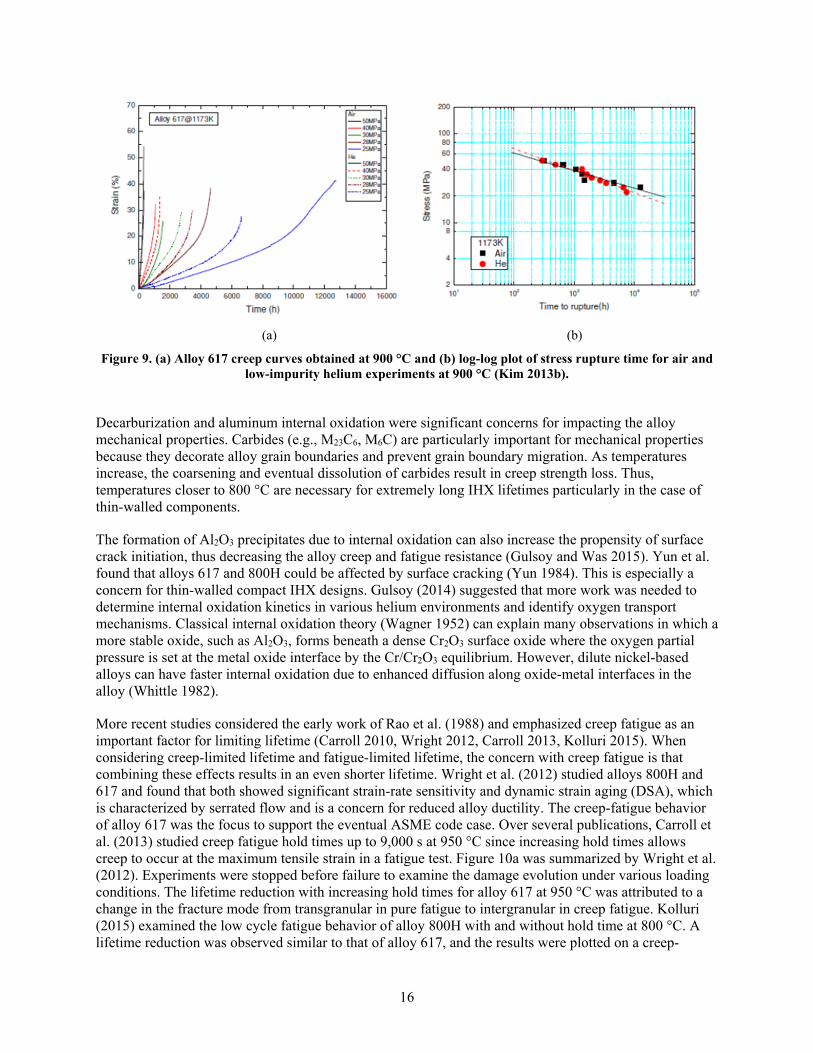
230. (Only alloys 800H and 617 are currently approved in Section III for nuclear applications.) All the strengths drop with temperature as diffusion increases, and the strengthening phases could be coarsening or dissolving. Many studies have focused on alloy 617 due to its high technical readiness for IHX applications (Gulsoy and Was 2015). Thus, mechanical testing data for alloy 617 are now widely available, including creep, fatigue, and creep-fatigue performance in HTGR conditions at 750–1000 °C. The room temperature properties of alloy 617 are exceptional with a yield strength of 364 MPa, ultimate strength of 823 MPa, and an over 50% total area elongation and reduction. However, for design purposes, the creep dataset is still not as complete (Gulsoy 2014). Kim et al. (2013b) studied alloy 617 in air and helium environments at 900°C in various applied stress levels (22–50 MPa). In this particular helium environment (with low impurity levels), the creep curve shapes were not significantly different in air or helium environments (Figure 9a). Overall, creep rupture times were slightly shorter in helium than in air. Kim concluded that the creep rupture time was closely related to the thickness of the outer thermally grown Cr2O3 layer formed during exposure. Under the thicker oxide layer is a larger chromium-depleted region, which could deteriorate creep life (Kim 2013b). In a subsequent study (Kim 2014), this phenomena was confirmed when alloy 617 was tested at 850–950 °C with stress levels of 6.9–98.1 MPa. A reduced creep rupture time was observed in a helium environment due to the thicker oxide layer grown in helium. Although there is some reduction in the cross section area, the more significant impact might be chromium depletion or other degradation in the substrate, such as carbide or γ´dissolution. At 850 °C, the dominate creep process in both air and helium environments was cavity formation, and the oxidation behavior was parabolic and well-behaved. At 1100 °C, mass loss and unstable oxide formation were noted, as discussed previously. In cross-sectional SEM observation, the scale was discontinuous, and exposed nickel and cobalt were oxidized due to the exposed metal matrix. When tensile loading was applied, decarburization and oxidation increased, and the creep rupture was enhanced.
Figure 8. ASME BPVC allowable stresses for several commercial alloys of interest for IHX in HTGRs. The
code case for alloy 282 was submitted for ASME Section 1 approval in 2020. Only alloys 800H and 617 are approved in Section III Division 5 for nuclear applications.
16
(a) (b)
Figure 9. (a) Alloy 617 creep curves obtained at 900 °C and (b) log-log plot of stress rupture time for air and low-impurity helium experiments at 900 °C (Kim 2013b).
Decarburization and aluminum internal oxidation were significant concerns for impacting the alloy mechanical properties. Carbides (e.g., M23C6, M6C) are particularly important for mechanical properties because they decorate alloy grain boundaries and prevent grain boundary migration. As temperatures increase, the coarsening and eventual dissolution of carbides result in creep strength loss. Thus, temperatures closer to 800 °C are necessary for extremely long IHX lifetimes particularly in the case of thin-walled components.
The formation of Al2O3 precipitates due to internal oxidation can also increase the propensity of surface crack initiation, thus decreasing the alloy creep and fatigue resistance (Gulsoy and Was 2015). Yun et al. found that alloys 617 and 800H could be affected by surface cracking (Yun 1984). This is especially a concern for thin-walled compact IHX designs. Gulsoy (2014) suggested that more work was needed to determine internal oxidation kinetics in various helium environments and identify oxygen transport mechanisms. Classical internal oxidation theory (Wagner 1952) can explain many observations in which a more stable oxide, such as Al2O3, forms beneath a dense Cr2O3 surface oxide where the oxygen partial pressure is set at the metal oxide interface by the Cr/Cr2O3 equilibrium. However, dilute nickel-based alloys can have faster internal oxidation due to enhanced diffusion along oxide-metal interfaces in the alloy (Whittle 1982).
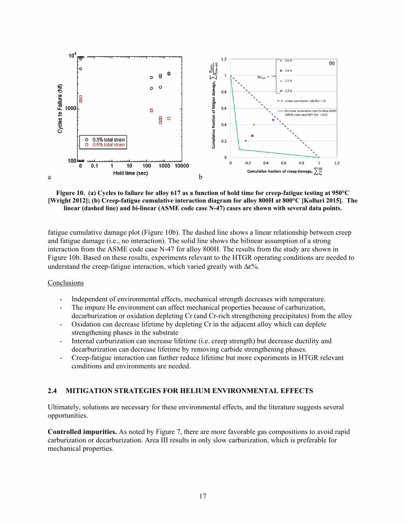
More recent studies considered the early work of Rao et al. (1988) and emphasized creep fatigue as an important factor for limiting lifetime (Carroll 2010, Wright 2012, Carroll 2013, Kolluri 2015). When considering creep-limited lifetime and fatigue-limited lifetime, the concern with creep fatigue is that combining these effects results in an even shorter lifetime. Wright et al. (2012) studied alloys 800H and 617 and found that both showed significant strain-rate sensitivity and dynamic strain aging (DSA), which is characterized by serrated flow and is a concern for reduced alloy ductility. The creep-fatigue behavior of alloy 617 was the focus to support the eventual ASME code case. Over several publications, Carroll et al. (2013) studied creep fatigue hold times up to 9,000 s at 950 °C since increasing hold times allows creep to occur at the maximum tensile strain in a fatigue test. Figure 10a was summarized by Wright et al. (2012). Experiments were stopped before failure to examine the damage evolution under various loading conditions. The lifetime reduction with increasing hold times for alloy 617 at 950 °C was attributed to a change in the fracture mode from transgranular in pure fatigue to intergranular in creep fatigue. Kolluri (2015) examined the low cycle fatigue behavior of alloy 800H with and without hold time at 800 °C. A lifetime reduction was observed similar to that of alloy 617, and the results were plotted on a creep-
17
a b
Figure 10. (a) Cycles to failure for alloy 617 as a function of hold time for creep-fatigue testing at 950°C [Wright 2012]; (b) Creep-fatigue cumulative interaction diagram for alloy 800H at 800°C [Kolluri 2015]. The
linear (dashed line) and bi-linear (ASME code case N-47) cases are shown with several data points.
fatigue cumulative damage plot (Figure 10b). The dashed line shows a linear relationship between creep and fatigue damage (i.e., no interaction). The solid line shows the bilinear assumption of a strong interaction from the ASME code case N-47 for alloy 800H. The results from the study are shown in Figure 10b. Based on these results, experiments relevant to the HTGR operating conditions are needed to understand the creep-fatigue interaction, which varied greatly with Δε%.
Conclusions
- Independent of environmental effects, mechanical strength decreases with temperature. - The impure He environment can affect mechanical properties because of carburization,
decarburization or oxidation depleting Cr (and Cr-rich strengthening precipitates) from the alloy - Oxidation can decrease lifetime by depleting Cr in the adjacent alloy which can deplete
strengthening phases in the substrate - Internal carburization can increase lifetime (i.e. creep strength) but decrease ductility and
decarburization can decrease lifetime by removing carbide strengthening phases. - Creep-fatigue interaction can further reduce lifetime but more experiments in HTGR relevant
conditions and environments are needed.
2.4 MITIGATION STRATEGIES FOR HELIUM ENVIRONMENTAL EFFECTS
Ultimately, solutions are necessary for these environmental effects, and the literature suggests several opportunities.
Controlled impurities. As noted by Figure 7, there are more favorable gas compositions to avoid rapid carburization or decarburization. Area III results in only slow carburization, which is preferable for mechanical properties.
18
Alloying. Alloy composition, such as the selection of stronger nickel-based alloys, is clearly an important factor. Several studies have looked at a range of alloy compositions, including Bates et al. (1976), which looked at various steel compositions, Dean and Ennis (1984), Huchtemann (1989), and Adharapurapu (2011a), which studied nickel-based alloys. The 2011 study used modern computational software to assist with the design. Ultimately, there is a balance between mechanical properties, environmental resistance, and alloy cost. To a large degree, studies focus on commercial alloys due to availability and qualification. However, it is important to understand how composition affects performance. For example, alloy 617 is an austenitic (i.e., face-centered cubic [FCC]) alloy that is a solid solution strengthened by cobalt, molybdenum, and tungsten additions, and further improvements in mechanical properties are realized by γ´ formation due to the aluminum and titanium additions; chromium-, molybdenum-, and tungsten-rich carbides; and titanium-based carbo-nitrides (Gulsoy 2014), as shown in Table 3. Although high chromium contents facilitate the formation of a protective chromium-rich surface oxide, if the composition results in the formation of chromium-rich phases such as sigma, then there could be a detrimental effect on mechanical properties, including ductility. Adding aluminum can be beneficial for oxidation resistance but reduce the alloy’s mechanical properties. Figure 8 shows significantly stronger alloys available in other sections of the ASME code that would require a new code case for nuclear applications.
Coatings. Several studies have suggested coatings to mitigate the environmental effects. In particular, aluminum-containing coatings can facilitate the formation of a more chemically stable, slower growing Al2O3 surface oxide (Cabet 2008, Clark 2013). The coating on a nickel-based alloy can be either a Ni-Al diffusion coating or a sprayed NiCrAlY or NiCoCrAlY composition, similar to the coatings used in gas-turbine engines (Goward 1986). Clark et al. (2013) investigated ferritic (i.e., body-centered cubic phase) FeCrAlY coatings. However, the coatings were initially evaluated by the aircraft engine industry and were found to have negative effects since iron diffused into the substrate and nickel diffused into the coating, forming FCC (i.e., austenitic) phases and degrading the oxidation resistance (Goward 1986). Even aluminum-containing coatings can have detrimental effects on mechanical properties since aluminum diffuses into the substrate. However, Al2O3 is thought to be a good C diffusion barrier (B. Jönsson 1997) and more studies are needed to explore the potential benefit and risk associated with coating flaws.
Conclusions
- Several mitigation strategies have been suggested to limit environmental effects and thereby extend component lifetimes:
o Control He impurity to minimize detrimental mechanisms o Consider stronger alloys o Oxidation-resistant coatings
- It is difficult to determine which is the most effective mitigation strategy because of the limited information available. Reducing the impurity effects may minimize detrimental effects but may not be practical for operation. Stronger alloys may be more expensive or difficult to fabricate and made not be code qualified for this application. Coatings can have attractive performance, particularly in laboratory studies, but may be difficult to fabricate and reliably deploy on a commercial scale.
2.5 MODELING HTGR ENVIRONMENTAL EFFECTS
No HTGR-specific alloy performance or lifetime environmental effects models were identified in the open literature. A mechanical property model was tested for a specific IHX design but the validation was relatively short times and corrosion was not mentioned (Kitagawa 1984). Models have been proposed for
19
graphite (Oku 2004, Mohanty 2011) and related to fuel performance (Wang 2004, IAEA 2010) and system performance (IAEA 2013). Accident modeling also has been conducted using MELCOR (Young 2010).
3. EMISSIVITY CHANGES OF RPV ALLOYS IN OXIDIZING ENVIRONMENTS OF HELIUM-COOLED HTGRS
3.1 INTRODUCTION
For HTGR and VHTR systems, a material with high surface emissivity is desirable for efficient decay heat removal, especially for accident conditions in which there is a loss of coolant. For example, if an object is at a higher temperature than its environment, then increasing its emissivity will lower its temperature. Notwithstanding air in-leakage in severe but low probability accident conditions, the oxidizing impurities still persist in the purified helium coolant, and oxidation can cause surface modifications of metallic components. Particulates inside the RPV can cause the abrasion of metallic surfaces, thus changing the emissivity properties of pressure vessel alloys. Especially in HTGRs and VHTRs, one significant issue under consideration is graphite dust generation, which can coat alloy surfaces and potentially change their emissivity. Preliminary calculations show that graphite dust could accumulate at a rate of 0.1 kg/MW at the reactor’s end of life, depending on the core geometry and format (Maynard 2011).
Large emissivity changes for HTGR alloy components in oxidizing environments have been reported by several authors (King 2018). Generally, a material’s emissivity will largely depend on the temperature and surface finish. High-temperature reactors benefit from high thermal efficiency, so the ability of a material to emit thermal radiation is important because it impacts heat transfer mechanisms. Emissivity can have a value from 0 (shiny mirror) to 1 (blackbody).
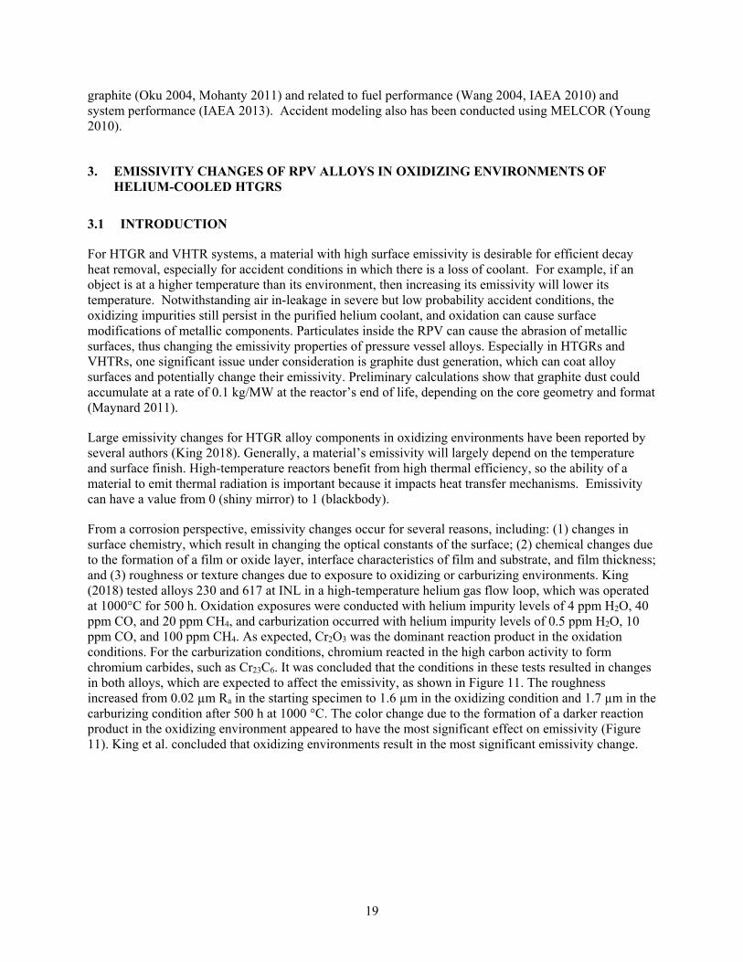
From a corrosion perspective, emissivity changes occur for several reasons, including: (1) changes in surface chemistry, which result in changing the optical constants of the surface; (2) chemical changes due to the formation of a film or oxide layer, interface characteristics of film and substrate, and film thickness; and (3) roughness or texture changes due to exposure to oxidizing or carburizing environments. King (2018) tested alloys 230 and 617 at INL in a high-temperature helium gas flow loop, which was operated at 1000°C for 500 h. Oxidation exposures were conducted with helium impurity levels of 4 ppm H2O, 40 ppm CO, and 20 ppm CH4, and carburization occurred with helium impurity levels of 0.5 ppm H2O, 10 ppm CO, and 100 ppm CH4. As expected, Cr2O3 was the dominant reaction product in the oxidation conditions. For the carburization conditions, chromium reacted in the high carbon activity to form chromium carbides, such as Cr23C6. It was concluded that the conditions in these tests resulted in changes in both alloys, which are expected to affect the emissivity, as shown in Figure 11. The roughness increased from 0.02 µm Ra in the starting specimen to 1.6 µm in the oxidizing condition and 1.7 µm in the carburizing condition after 500 h at 1000 °C. The color change due to the formation of a darker reaction product in the oxidizing environment appeared to have the most significant effect on emissivity (Figure 11). King et al. concluded that oxidizing environments result in the most significant emissivity change.
20
Figure 11. (a) Spectral normal emissivity measurements at 300 °C of alloy 617 specimens before (dashed) and
after 500 h exposures to 1000 °C helium with oxidizing (solid line) and carburizing (dotted line) chemistry; (b) images of the three alloy 617 specimens (King 2018).
3.2 TOTAL EMISSIVITY EXPERIMENTS
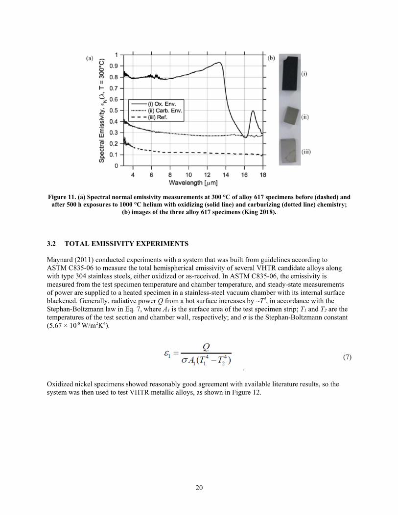
Maynard (2011) conducted experiments with a system that was built from guidelines according to ASTM C835-06 to measure the total hemispherical emissivity of several VHTR candidate alloys along with type 304 stainless steels, either oxidized or as-received. In ASTM C835-06, the emissivity is measured from the test specimen temperature and chamber temperature, and steady-state measurements of power are supplied to a heated specimen in a stainless-steel vacuum chamber with its internal surface blackened. Generally, radiative power Q from a hot surface increases by ~T4, in accordance with the Stephan-Boltzmann law in Eq. 7, where A1 is the surface area of the test specimen strip; T1 and T2 are the temperatures of the test section and chamber wall, respectively; and σ is the Stephan-Boltzmann constant (5.67 × 10⁻⁸ W/m2K4).
. (7)
Oxidized nickel specimens showed reasonably good agreement with available literature results, so the system was then used to test VHTR metallic alloys, as shown in Figure 12.
21
Figure 12. Comparison of emissivity data for oxidized nickel to literature values (Maynard 2011).
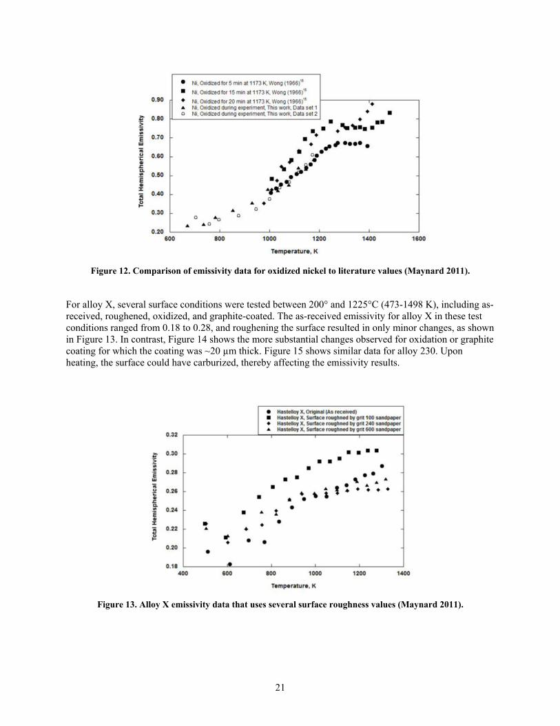
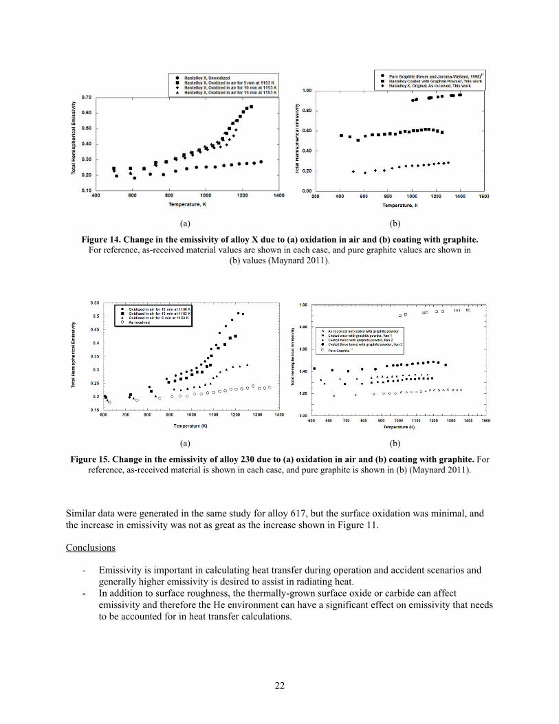
For alloy X, several surface conditions were tested between 200° and 1225°C (473-1498 K), including as-received, roughened, oxidized, and graphite-coated. The as-received emissivity for alloy X in these test conditions ranged from 0.18 to 0.28, and roughening the surface resulted in only minor changes, as shown in Figure 13. In contrast, Figure 14 shows the more substantial changes observed for oxidation or graphite coating for which the coating was ~20 µm thick. Figure 15 shows similar data for alloy 230. Upon heating, the surface could have carburized, thereby affecting the emissivity results.
Figure 13. Alloy X emissivity data that uses several surface roughness values (Maynard 2011).
22
(a) (b)
Figure 14. Change in the emissivity of alloy X due to (a) oxidation in air and (b) coating with graphite. For reference, as-received material values are shown in each case, and pure graphite values are shown in
(b) values (Maynard 2011).
(a) (b)
Figure 15. Change in the emissivity of alloy 230 due to (a) oxidation in air and (b) coating with graphite. For reference, as-received material is shown in each case, and pure graphite is shown in (b) (Maynard 2011).
Similar data were generated in the same study for alloy 617, but the surface oxidation was minimal, and the increase in emissivity was not as great as the increase shown in Figure 11.
Conclusions
- Emissivity is important in calculating heat transfer during operation and accident scenarios and generally higher emissivity is desired to assist in radiating heat.
- In addition to surface roughness, the thermally-grown surface oxide or carbide can affect emissivity and therefore the He environment can have a significant effect on emissivity that needs to be accounted for in heat transfer calculations.
23
4. RADIATION EFFECTS
In addition to traditional corrosion, radiation can also degrade the structural alloys. Angeliu et al. (2007) reviewed the effects of radiation on Ni-based alloys relevant to HTGR applications. Much of the data comes from the use of PE16 (Table 3) as the fuel cladding in the Dounreay Prototype Fast Reactor in the UK and alloy X. The conclusions of the review were:
- Ni-based alloys are embrittled by neutron exposures at elevated temperatures due to He generation (fast neutron n,α reactions) and second phase precipitation at alloy grain boundaries
- Nuclear grade alloys which minimize certain elements (e.g. B, Al, Ti, Nb, Si) may mitigate some of these embrittlement mechanisms
- Radiation induced swelling and creep would not be expected to exceed design allowables of 1% - Experimental studies are required to assess radiation-induced embrittlement under prototypical
conditions
More data are available on the radiation embrittlement of RPV steels. Reviews by Odette et al. (1998) and Nanstad (2016) are just a few examples of the many publications in this area. This type of embrittlement has been studied for many decades and the embrittlement mechanisms of alloys and welds are relatively well understood. Thus, current best practices should minimize many of the issues with radiation induced precipitation (due to radiation enhanced diffusion) and the associated hardening observed in RPV steels at ~300°C.
One other issue is the effect of fission product interactions on the mechanical properties of reference HTGR structural metals, which has been studied since the late 1970s. Although the candidate metals have changed over the decades, the significance of these studies has not changed. In terms of fission product inventory, depending on the fuel makeup, the most significant quantities of fission products generated are cesium, tellurium, and iodine. Gas-borne inventories in a 3,150 MW HTGR after 4 years range from 10-11 to 10-12 atm for PCs, PTe, and PI2 (Aronson 1978); these values are very small and in the range of an ultrahigh vacuum. The design limit is ~10-8 to 10-9 atm. When interacting with structural alloys, the fission products are in elemental form or they might combine to form compounds. CsI is a particularly stable and likely compound. The chemical reactivity of these gas-borne radionuclides is very low, leading to minimal alloy interaction. However, over long periods of time, these volatile species could impact the surface oxide on the metallic components and possibly the mechanical properties if they deposit on metal surfaces and concentrate there at high temperatures. The species could concentrate in localized areas, such as alloy grain boundaries or in regions of high stress.
Aronson et al. (1978) studied type 304 stainless steel, alloy 800, and Hastelloy X heated to 550–650 °C in the presence of CsI for 1,000 h. Qualitative results were obtained by adding tellurium powder to the surface of specimens for each alloy to simulate fission products. The specimens were placed in a sealed quartz tube and heated in a furnace. CsI tarnished the metals to form a grayish-brown reaction product. Using a water rinse, Cr6+ was detected in the water, but iron and nickel were not. Aronson et al. also investigated the long-term exposure of HTGR materials to more prototypic low concentrations of I2, Te2, CsI, and low PO2. Bend tests to study alloy embrittlement were conducted. Overall, no alloy corrosion was observed unless oxygen or air were included in the tests.
Conclusions
- Ni-based alloys are embrittled by radiation and this needs to be accounted for when considering mechanical property degradation.
- Fission product interactions also need to be considered but the values are very low so their impacts might only be realized after long exposures
24
5. LITERATURE REVIEW SUMMARY AND CONCLUSIONS
This review of the CO2 and He compatibility literature summarized representative studies that produce a general framework for understanding the effects of these environments on the corrosion of structural materials relevant to gas-cooled reactors. Such knowledge can be used to inform regulatory decisions of new reactor designs.
Based on this literature assessment, there is a general understand of the effect of CO2 and helium environments on structural alloys. The Magnox and AGR CO2 reactors have been operating in the UK for more than 60 years and extensive testing has resulted in predictive capabilities (Figure 3b) for the structural steels used in the UK AGR reactors that are preparing for license extensions. Carburization is an issue and it is mitigated either by using more highly alloyed stainless steels like for the AGR fuel cladding or by reducing the temperature, which impacts the reactor efficiency. (Section 1.2)
For the He environment, there is minimal commercial experience, no standardization of the impurities present in the He, a range of temperatures being considered and a number of structural alloys being investigated for this application. The result is a wider range of possible oxidation/carburization/ decarburization reactions and an incomplete database. Because of the larger number of variables, most of the research has been mechanistic or focused on a narrow set of conditions. The type of modeling shown in Figure 3b has not been identified for HTGR conditions (Section 2.5). Nevertheless, the major issues and degradation mechanisms have been identified.
- Fe-based alloy 800H is used at lower temperatures and is ASME code qualified to 760°C - Ni-based alloys are used at higher temperatures because of their superior creep strength
o Alloy 617 was ASME code qualified in 2020 and has been widely studied for this application
- Most alloys of interest form a Cr2O3 surface oxide and undergo oxidation, carburization or decarburization depending on the impurities present in the He
o He impurities are intentionally added to limit oxidation of the graphite components and low levels of impurities may have only limited effect on performance
o Cr-C-O stability diagrams have been widely used to describe performance covering a range of intentional and unintentional impurity levels
o Region III in Figure 7 is the most desirable operating condition o At the highest temperatures, the environment can reduce the surface oxide
- Temperature alone in the 750°-1000°C operating window constrains structural alloy performance due to creep (Figure 8), fatigue and oxidation
o The impure He environment can affect mechanical properties, therefore, a goal is to minimize negative effects (Section 2.3)
o Oxidation can decrease lifetime by depleting Cr from the alloy and affecting strengthening phases (e.g. dissolution of Cr-rich carbides)
o Carburization can increase creep strength but decrease ductility o Decarburization can decrease lifetime by removing carbide strengthening phases
- Solutions to improve material performance have been explored to a limit extent (Section 2.4) and may be especially needed for higher temperature performance
- The effect of the environment on emissivity have been quantified (Section 3.2) - General information about radiation embrittlement due to He generation and fission product
interactions have been studied in general but experimental studies under prototypical HTGR conditions are needed to generate more specific and relevant information
25
6. KNOWLEDGE GAPS FOR HTGR ALLOY CORROSION ISSUES
Because CO2-cooled reactors have been commercialized for more than 60 years, the gap analysis focuses on He-cooled reactors. The review determined that corrosion mechanisms have been studied for candidate commercial alloys under a range of He environments and temperatures. There is a clear need for better predictive capabilities for He compatibility and long-term performance, which would avoid extended experimental campaigns for each design change and new material, and will also assist in evaluating off-normal and accident scenarios. An example model for breakaway oxidation in AGR CO2 conditions was shown in Figure 3b based on a large body of relevant operation specific data (Gong 2017).) Experimentally-validated models would be very useful to designers, operators and regulators to show how design choices and materials selection impact reactor performance, safety and lifetime.
• One of the main needs is to integrate the current knowledge into a clearer framework of reaction rates to estimate component lifetimes as a function of temperature and other operating parameters. Such a framework also would assist in understanding the effect of environment on long-term mechanical properties and identify missing experimental data.
• No experimental studies were found on the effect of He pressure and velocity on corrosion rates which could also impact the environmental impact on mechanical properties. Most studies were conducted at ambient pressure but operation will likely occur at 4-7 MPa (Table 1), which could significantly affect reaction rates.
• Figure 7 shows a basic understanding of how impurities affect oxidation and carburization but does not include the effects of temperature, alloy composition and other impurities, such as H2O. A predictive model could incorporate these factors and model impurity ingress by various mechanisms, including off-normal and accident conditions. Such an effort would be useful to revisit information in the literature such as Equation 2.
• Once He impurity conditions are selected that minimize the impact on graphite oxidation as well as degradation and mechanical properties of the metallic components, parametric studies are needed to determine the permissible operating window of variations in He chemistry, temperature, etc. and the impact of off-normal operation.
• Models are needed to predict alloy corrosion rates as a function of various reactor condition (temperature, He impurities, alloy microstructure, etc.) for the RPV, IHX and other components. A modeling iteration would incorporate environmental effects on mechanical properties. Such a model would help identify missing properties, and model validation would yield additional insight into the role of component thickness and microstructure on design lifetime.
• Prototypic condition irradiation experiments are needed to assess the impact of radiation on long-term performance (Section 4)
• Experiments have focused on a few commercial alloys, particularly those that are ASME code-qualified for this application such as alloys 800H and 617. It may be useful to consider higher-performance commercial alloys (Figure 8). More studies of model alloys may add additional mechanistic insight into the relevant degradation mechanisms.
• To improve lifetimes and increase the operating window, other mitigation methods such as coatings need to be more fully explored to determine which strategies are most cost effective (Section 2.4).
26
REFERENCES
R. R. Adharapurapu, D. Kumar, J. Zhu, C. J. Torbet, G. S. Was, T. M. Pollock, (2011a) “Chromia-Assisted Decarburization of W-Rich Ni-Based Alloys in Impure Helium at 1273 K (1000°C),” Metallurgical and Materials Transactions A 42, 1229-1244.
R. R. Adharapurapu, D. Kumar, J. Zhu, T. M. Pollock, (2011b) “Carburization of W- and Re-rich Ni-based alloys in impure helium at 1000°C,” Corrosion Science 53, 388–398.
T. M.Angeliu, J. T. Ward, J. K.Witter, (2007) “Assessing the effects of radiation damage on Ni-base alloys for the prometheus space reactor system,” Journal of Nuclear Materials 366, 223-237.
S. Aronson, J. G. Y. Chow, P. Soo, M. Friedlander, (1978) “Effect of fission product interactions on the corrosion and mechanical properties of HTGR Alloys,” Report BNL-NUREG-25325, NRC.
H. G. A. Bates, W. Betteridge, R. H. Cook, L. W. Graham & D. F. Lupton (1976) The Behavior of Metals in High-Temperature Reactor Helium for Steam Generators, Nuclear Technology, 28:3, 424-440
J. M. Beck and L. F. Pincock, (2011) “High Temperature Gas-cooled Reactors Lessons Learned Applicable to the Next Generation Nuclear Plant,” INL Report INL/EXT-10-19329, INL, Idaho Falls, ID.
A. Bredimas, K. Kugeler, M. A. Futterer, (2014) “Strengths, weaknesses, opportunities and threats for HTRdeployment in Europe,” Nuclear Engineering and Design 271, 193–200.
J. Berka, M. Vilémová, P. Sajdl, (2015). Testing of degradation of alloy 800 H in impure helium at 760 °C. Journal of Nuclear Materials, 464, 221-229. doi:10.1016/j.jnucmat.2015.03.054
K. G. E. Brenner & L. W. Graham (1984) “The Development and Application of a Unified Corrosion Model for High-Temperature Gas-Cooled Reactor Systems,” Nuclear Technology, 66:2, 404-414, DOI: 10.13182/NT84-A33443
C. Cabet, G. Girardin, F. Rouillard, J. Chapovaloff, K. Wolski and M. Pijolat, (2008) “Comparison of the High Temperature Surface Reactivity in Impure Helium of Two Materials for Gas Cooled Reactors,” Mater. Sci. Forum, 595-598, 439-448.
C. Cabet, G. Girardin, F. Rouillard, J. Chapovaloff, K. Wolski and M. Pijolat, (2008) “Comparison of the High Temperature Surface Reactivity in Impure Helium of Two Materials for Gas Cooled Reactors,” Mater. Sci. Forum, 595-598, 439-448.
C. Cabet, F. Thieblemont and C. Guerre, (2008) “Protective coatings for very high temperature reactor applications,” Materials and Corrosion 59, 591-597. DOI: 10.1002/maco.200804142
C. Cabet and F. Rouillard, (2009) “Corrosion of high temperature metallic materials in VHTR,” Journal of Nuclear Materials 392, 235–242 doi.org/10.1016/j.jnucmat.2009.03.029
F. Carre, P. Yvon, P. Anzieu, N. Chauvin, J.-Y. Malo, (2010) Update of the French R&D strategy on gas-cooled reactors,” Nuclear Engineering and Design 240, 2401–2408.
L. J. Carroll, C. Cabet, M.C. Carroll, R.N. Wright, “The development of microstructural damage during high temperature creep–fatigue of a nickel alloy,” International Journal of Fatigue 47 (2013) 115–125.
B. Castle, (2010) “NGNP Reactor Coolant Chemistry Control Study,” INL report INL/EXT-10-19533, Idaho Falls.
J. Chapovaloff, F. Rouillard, P. Combrade, M. Pijolat, K. Wolski, (2013). Assessing the kinetics of high temperature oxidation of Inconel 617 in a dedicated HTR impure helium facility coupling
27
thermogravimetry and gas phase chromatography. Journal of Nuclear Materials, 441(1-3), 293-300. doi:10.1016/j.jnucmat.2013.06.012
X. Chen, M. A. Sokolov, S. Sham, D. L. Erdman III, J. T. Busby, K. Moa, J. F. Stubbins, (2013) “Experimental and modeling results of creep–fatigue life of Inconel 617 and Haynes 230 at 850°C,” Journal of Nuclear Materials 432, 94–101.
H. J. Christ, U. Kunecke, K. Meye, H. G. Sockel, (1987). High temperature corrosion of the nickel-based alloy Inconel 617 in helium containing small amounts of impurities. Materials Science and Engineering, 87, 161-168.
E. A. Clark, J. Y. Yang, D. Kumar, G. S. Was and C. G. Levi, (2013) “Engineered Coatings for Ni Alloys in High Temperature Reactors,” Met. Mater. Trans. A 44, 835-847.
A. V. Dean and P. J. Ennis, (1984) The Development of High-Strength Alloys Resistant to Corrosion in Impure Helium, Nuclear Technology, 66:1, 117-123, DOI: 10.13182/NT84- A33460
P. Dodds, (2004) “Developing New Reactors: Learning the Lessons of the Past,” Nuclear Energy 43(6), 331-336.
V. Dostal, P. Hejzlar and M. J. Driscoll, (2006) “High-Performance Supercritical Carbon Dioxide Cycle for Next-Generation Nuclear Reactors,” Nuclear Technology, 154 (3), 265-282.
R. Duan, A. Jalowicka, K. A. Unocic, B. A. Pint, P. Huczkowski, A. Chyrkin, D. Grüner, R. Pillai and W. J. Quadakkers, (2017) “Predicting Oxidation-Limited Lifetime of Thin Walled Components of NiCrW alloy 230,” Oxidation of Metals 87, 11–38.
A. Duval, F. Miserque, M. Tabarant, J.-P. Nogier, A. Gédéon, (2010) “Influence of the Oxygen Partial Pressure on the Oxidation of Inconel 617 Alloy at High Temperature,” Oxidation of Metals 74, 215–238. DOI 10.1007/s11085-010-9207-5
H. E. Evans, A. T. Donaldson and T. C. Gilmour, (1999) "Mechanisms of Breakaway Oxidation and Application to a Chromia-Forming Steel," Oxidation of Metals 52, 379-402.
E. G. Feher, (1968) “The Supercritical Thermodynamic Power Cycle,” Energy Conversion, 8, 85-90.
T. Furukawa and F. Rouillard, (2015) “Oxidation and carburizing of FBR structural materials in carbon dioxide,” Progress in Nuclear Energy 82, 136–141.
G. B. Gibbs, (1973) “A Model for Mild Steel Oxidation in CO2,” Oxidation of Metals 7, 173-184.
Y. Gong, D. J. Young, P. Kontis, Y. L. Chiu, H. Larsson, A. Shin, J. M. Pearson, M. P. Moody and R. C. Reed, (2017) “On the breakaway oxidation of Fe9Cr1Mo steel in high pressure CO2,” Acta Materialia, 130, 361-374.
G. W. Goward, (1986) “Protective Coatings - Purpose, Role and Design,” Materials Science & Technology 2, 194-200.
S. Guillou, C. Cabet, C. Desgranges, L. Marchetti, Y. Wouters, (2011) “Influence of Hydrogen and Water Vapour on the Kinetics of Chromium Oxide Growth at High Temperature,” Oxidation of Metals 76, 193–214. DOI 10.1007/s11085-011-9246-6
G. Gulsoy, (2014) “Mechanism of internal oxidation of alloy 617 in controlled impurity helium environments at high temperatures,” PhD Thesis, University of Michigan, Ann Arbor, MI.
G. Gulsoy, G. S. Was, (2015) “Surface oxidation of Alloy 617 in low oxygen partial pressure He–CO–CO2 environments at 750–850 °C,” Corrosion Science, 90, 529-534. doi:10.1016/j.corsci.2014.10.042
T. Hirano, H. Araki, H. Yoshida, (1981a) “Carburization and decarburization of superalloys in the simulated HTGR helium,” Journal of Nuclear Materials, 97, 272-280.
28
T. Hirano, T. Noda and H. Yoshida, (1981b) “Oxygen Potentials in the Simulated High-Temperature Gas-Cooled Reactor Helium Gases,” Journal of Nuclear Materials 102, 272-279.
T. Hirano, M. Okada, H. Araki, T. Noda, H. Yoshida and R. Watanabe, (1981c) “Corrosion of Inconel 617 in HTGR Grade Helium, Metallurgical Transactions A 12, 451-458.
Y. Hosoi and S. Abe, (1975) “The Effect of Helium Environment on the Creep Rupture Properties of Inconel 617 at 1000°C,” Metallurgical Transactions 6, 1141-1178.
B. Huchtemann, (1989) “The Effect of Alloy Chemistry on Creep Behaviour in a Helium Environment with Low Oxygen Partial Pressure,” Materials Science and Engineering A 121, 623-626.
P. Huczkowski, N. Christiansen, V. Shemet, J. Piron-Abellan, L. Singheiser and W. J. Quadakkers, (2004) “Oxidation Limited Life Times of Chromia Forming Ferritic Steels,” Materials and Corrosion 55, 825-830.
IAEA (2010) “High Temperature Gas Cooled Reactor Fuels and Materials,” IAEA-TECDOC-1645.
IAEA (2013) “Evaluation of High Temperature Gas Cooled Reactor Performance” IAEA-TECDOC-1694
C. Jang, D. Lee, D. Kim, (2008) “Oxidation behaviour of an Alloy 617 in very high-temperature air and helium environments,” International Journal of Pressure Vessels and Piping, 85(6), 368-377. doi:10.1016/j.ijpvp.2007.11.010
C. Jang, S. H. Kim, I. Sah and D. Kim, (2016) “Creep behavior of Alloy 617 in high temperature air and helium environments – effect of oxidation damage,” Journal of Mechanical Science and Technology 30 (2016) 4433–4438. DOI 10.1007/s12206-016-0907-x
A. Jalowicka, R. Duan, P. Huczkowski, A. Chyrkin, D. Grüner, B. A. Pint, K. A. Unocic and W. J. Quadakkers, (2015) “Effect of Specimen Thickness on Microstructural Changes During Oxidation of the NiCrW Alloy 230 at 950–1050°C,” JOM 67, 2573-2588.
B. Jönsson and C. Svedberg, "Limiting Factors for Fe-Cr-Al and NiCr in Controlled Industrial Atmospheres," Mater. Sci. Forum, 251-254 (1997) 551-558.
D. Kim, I. Sah, C. Jang, (2010) “Effects of high temperature aging in an impure helium environment on low temperature embrittlement of Alloy 617 and Haynes 230,” Journal of Nuclear Materials 405, 9–16.
D. Kim, I. Sah, H. J. Lee, C. Jang, (2013a) “Hydrogen effects on oxidation behaviors of Haynes 230 in high temperature steam environments,” Solid State Ionics, 243, 1-7. doi:10.1016/j.ssi.2013.04.010
W.-G. Kim, G.-G. Lee, J.-Y., Park, S.-D., Hong, Y.-W. Kim, (2013b) Creep and Oxidation Behaviors of Alloy 617 in Air and Helium Environments at 1173K. Procedia Engineering, 55, 819-822. doi:10.1016/j.proeng.2013.03.337
W.-G. Kim, J.-Y. Park, G.-G. Lee, S.-D. Hong, Y.-W. Kim, (2014) Temperature effect on the creep behavior of alloy 617 in air and helium environments. Nuclear Engineering and Design, 271, 291-300. doi:10.1016/j.nucengdes.2013.11.050.
J. L. King, A. Shahsafi, K. Blomstrand, K. Sridharan, M. A. Kats, (2018). Impact of corrosion on the emissivity of advanced reactor structural alloys. Journal of Nuclear Materials, 508, 465-471. doi:10.1016/j.jnucmat.2018.05.047
M. Kitagawa, H. Hattori, A. Ohtomo, T. Teramae, J. Hamanaka and H. Ukikusa (1984) “Lifetime Test of a Partial Model of a High-Temperature Gas-Cooled Reactor Helium-Helium Heat Exchanger,” Nuclear Technology, 66, 675-684.
29
P. Kofstad, K. P. Lillerud, (1980) “On High Temperature Oxidation of Chromium, II. Properties of Cr2O3 and the Oxidation Mechanism of Chromium,” Journal of the Electrochemical Society 127, 2410-2419.
M. Kolluri, P. ten Pierick, T. Bakker, (2015) “Characterization of high temperature tensile and creep–fatigue properties of Alloy 800H for intermediate heat exchanger components of (V)HTRs,” Nuclear Engineering and Design 284, 38–49
D. Kumar, R. R. Adharapurapu, T. M. Pollock, G. S. Was, (2011) “High-Temperature Oxidation of Alloy 617 in Helium Containing Part-Per-Million Levels of CO and CO2 as Impurities,” Metallurgical and Materials Transactions A 42, 1245-1265.
Y. Kurata, Y. Ogawa, T. Suzuki, M. Shindo, H. Nakajima, T. Kondo, (1995) “Long-Term Creep Properties of Hastelloy XR in Simulated High-Temperature Gas-Cooled Reactor Helium,” Journal of Nuclear Science and Technology, 32(11), 1108-1117. doi:10.1080/18811248.1995.9731825
G.-G. Lee, S. Jung, J.-Y. Park, W.-G. Kim, S.-D. Hong, Y.-W. Kim, (2013) “Microstructural Investigation of Alloy 617 Creep-ruptured at High Temperature in a Helium Environment,” Journal of Materials Science Technology 29 (2013) 1177-1183.
J. J. Lee, T. K. Ghosh, S. K. Loyalka, (2013) “Oxidation rate of nuclear-grade graphite NBG-18 in the kinetic regime for VHTR air ingress accident scenarios,” Journal of Nuclear Materials, 438, 77-87. doi:10.1016/j.jnucmat.2013.03.002
G. Locatelli M. Mancini, N. Todeschini, (2013) “Generation IV nuclear reactors: Current status and future prospects,” Energy Policy 61, 1503-1520.
W. R. Martin and J. R. Weir, (1965) “Influence of Chromium Content on Carburization of Chromium-Nickel-Iron Alloys in Carbon Dioxide,” Journal of Nuclear Materials 16, 19-24.
R. K. Maynard, (2011). “Total hemispherical emissivity of very high temperature reactor (VHTR) candidate materials,” Hastelloy X, Haynes 230 and Alloy 617. University of Missouri-Columbia.
H. E. McCoy, (1965) “Type 304 Stainless Steel vs Flowing CO2 at Atmospheric Pressure and 1100-1800°F” Corrosion 21, 84-94.
K. Mo, G. Lovicu, H. M. Tung, X. A. Chen, J. F. Stubbins, (2011) “High Temperature Aging and Corrosion Study on Alloy 617 and Alloy 230,” Journal of Engineering for Gas Turbines and Power 133, 052908. DOI: 10.1115/1.4002819
K. Mo, G. Lovicu, X. Chen, H.-M. Tung, J. B. Hansen and J. F. Stubbins, (2013) “Mechanism of plastic deformation of a Ni-based superalloy for VHTR applications,” Journal of Nuclear Materials 441, 695–703.
S. Mohanty and S. Majumdar, “HTGR Graphite Core Component Stress Analysis Research Program – Task 1,” Report ANL-11/04, Argonne National Laboratory, 2011.
R. K. Nanstad, M. A. Sokolov, S. R. Ortner, P. D. Styman, (2018) “Neutron and Thermal Embrittlement of RPV Steels: An Overview,” in International Review of Nuclear Reactor Pressure Vessel Surveillance Programs, W. L. Server and M. Brumovsky eds., ASTM Selected Technical Papers, vol.1603, pp.68-106. DOI: 10.1520/STP160320170063
K Natesan, A. Purohit, S. W. Tam, (2003) “Materials Behavior in HTGR Environments,” US NRC Report NUREG/CR-6824.
K. Natesan, P.S. Shankar, (2009) “Uniaxial creep response of Alloy 800H in impure helium and in low oxygen potential environments for nuclear reactor applications,” Journal of Nuclear Materials 394 (2009) 46–51.
30
K. Natesan, A. Moisseytsev, S. Majumdar, (2009) “Preliminary issues associated with the next generation nuclear plant intermediate heat exchanger design,” Journal of Nuclear Materials 392, 307–315.
H. Nickel, F. Schubert and H. Schuster, (1986) “Very High Temperature Design Criteria for Nuclear Heat Exchangers in Advanced High Temperature Reactors,” Nuclear Engineering and Design 94, 337-343.
T. Norby, (1990) “Proton conduction in oxides,” Solid State Ionics, 40-41, 857-862. doi:https://doi.org/10.1016/0167-2738(90)90138-H
G. R. Odette and G. E. Lucas, (1998) “Recent Progress in Understanding Reactor Pressure Vessel Steel Embrittlement,” Radiation Effects & Defects in Solids 144, 189-231.
T. Oku, M. Ishihara, “Lifetime evaluation of graphite components for HTGRs,” Nuclear Engineering and Design 227 (2004) 209-217.
B. A. Pint, (1996) “Experimental Observations in Support of the Dynamic Segregation Theory to Explain the Reactive Element Effect,” Oxidation of Metals 45, 1-37.
B. A. Pint and R. G. Brese, (2017) “High-Temperature Materials Chapter 4 in Fundamentals and Applications of Supercritical Carbon Dioxide Based Power Cycles, K. Brun and P. Friedman, eds., Elsevier, London, pp.67-104.
A. M. Pritchard, J. E. Antill, K. R. J. Cottell, K. A. Peakall and A. E. Truswell, (1975) “The Mechanisms of Breakaway Oxidation of Three Mild Steels in High-Pressure CO2 at 500°C,” Oxidation of Metals 9, 181-214.
W. J. Quadakkers, H. Holzbrecher, K. G. Briefs and H. Beske, (1989) "Differences in Growth Mechanisms of Oxide Scales Formed on ODS and Conventional Wrought Alloys," Oxidation of Metals 32, 67-88.
W. J. Quadakkers and H. Schuster, (1984) “Thermodynamic and Kinetic Aspects of the Corrosion of High-Temperature Alloys in High-Temperature Gas-Cooled Reactor Helium,” Nuclear Technology, 66, 383-391, DOI: 10.13182/NT84-A33441.
K. B. S. Rao, H. P. Meurer, H. Schuster, (1988) “Creep-Fatigue Interaction of lnconel 617 at 950°C in Simulated Nuclear Reactor Helium,” Materials Science and Engineering A 104, 37-51
F. Rouillard, C. Cabet, K. Wolski, M. Pijolat, (2007) “Oxide-Layer Formation and Stability on a Nickel-Base Alloy in Impure Helium at High Temperature,” Oxidation of Metals 68, 133–148. DOI 10.1007/s11085-007-9065-y
P. C. Rowlands, J. C. P. Garrett, L. A. Popple, A. Whittaker, A. Hoaskey,(1986) “The oxidation performance of Magnox and advanced gas-cooled reactor steels in high pressure CO2,” Nuclear Energy 25, 267-275.
N Sakaba, S. Hamamoto, Y. Takeda, (2010) “Helium Chemistry for Very High Temperature Reactors,” Journal of Nuclear Science and Technology, 47, 269-277.
S. Sarrade, D Férona, F. Rouillard, S. Perrin, R. Robin, J.-C. Ruiz, H.-A. Turc, (2017) “Overview on corrosion in supercritical fluids,” J. of Supercritical Fluids 120, 335–344.
P. S. Shankar, K. Natesan, (2007) “Effect of trace impurities in helium on the creep behavior of Alloy 617 for very high temperature reactor applications,” Journal of Nuclear Materials 366, 28–36.
M. Shindo, W. J. Quadakkers, H. Schuster, (1986) “Corrosion Behavior of High-Temperature Alloys in Impure He Environments,” J. Nucl. Mater. 140, 94-105.
Shropshire, D. E. (2004). Lessons learned from Gen I carbon dioxide cooled reactors, INEEL/CON-04-01526 and ASME Pape ICONE12-49380 Twelfth International Conference on Nuclear Engineering, presented April 2004, Arlington VA.
31
C. Wagner, (1952) “Theoretical Analysis of the Diffusion Processes Determining the Oxidation Rate of Alloys,” Journal of the Electrochemical Society, 99, 369-380.
J. Wang, (2004) “An integrated performance model for high temperature gas cooled reactor coated particle fuel,” MIT PhD Thesis, Cambridge, MA.
D. P. Whittle, Y. Shida, G. C. Wood, F. H. Stott, B. D. Bastow, (1982) “Enhanced Diffusion of Oxygen During Internal Oxidation of Nickel-Base Alloys,” Phil. Mag. A, 46, 931-949.
D. P. Whittle and J. Stringer, (1980) "Improvement in Properties: Additives in Oxidation Resistance," Philosophical Transactions of the Royal Society of London, Serial A 295, 309-29.
J.K. Wright, L.J. Carroll, C. Cabet, T.M. Lillo, J.K. Benz, J.A. Simpson, W.R. Lloyd, J.A. Chapman, R.N. Wright, (2012) “Characterization of elevated temperature properties of heat exchanger and steam generator alloys,” Nuclear Engineering and Design 251, 252– 260.
D. J. Young, J. Zhang, C. Geers M. Schütze, (2011) “Recent advances in understanding metal dusting: A review,” Materials and Corrosion 62, 7-28.
D. J. Young, (2016) “High Temperature Oxidation and Corrosion of Metals,” 2nd edition, Oxford: Elsevier.
H. M. Yun, P. J. Ennis, H. Nickel and H. Schuster, (1984) “The Effect of High Temperature Reactor Primary Circuit Helium on the Formation and Propagation of Surface Cracks in Alloy 800H and Inconel 617,” Journal of Nuclear Materials 125, 258-272
P. Yvon and F. Carré, (2009) “Structural materials challenges for advanced reactor systems,” Journal of Nuclear Materials 385, 217-222.
X. Zhang, H. Keramati, M. Arie, F. Singer, R. Tiwari, A. Shooshtari, M. Ohadi, (2018) “Recent Developments in High Temperature Heat Exchangers: A Review,” Frontiers in Heat and Mass Transfer 11, 18. DOI: 10.5098/hmt.11.18