cordex controller panel mount/rack mount 125/220vdc
TRANSCRIPT

Cordex Controller Panel Mount/Rack Mount 125/220Vdc
018-570-B2

Argus Technologies Ltd. Visit www.argus.ca
Burnaby, British Columbia. Telephone: 604 436 5900 Fax: 604 436 1233 Argus Technologies reserves the right to make changes to the products and information contained in this document without notice. Copyright 2008 Argus Technologies Ltd. Argus® is a registered trademark of Argus Technologies Ltd. All Rights Reserved. Printed in Canada.
This page intentionally left blank.

Argus Technologies Ltd. 018-570-B2 Rev C Printed in Canada. © 2005 Argus Technologies Ltd. ARGUS and CORDEX are trademarks of Argus Technologies Ltd. All Rights Reserved.
Cordex Controller
Panel Mount/Rack Mount
125/220Vdc 018-570-B2
The following documents and drawings are included in this manual to provide the necessary information required for routine installation of the unit:
• Specifications: 018-570-B1
• CSA/NRTL Equivalence: 048-554-10
• Important Safety Instructions and Installation: 018-570-C0
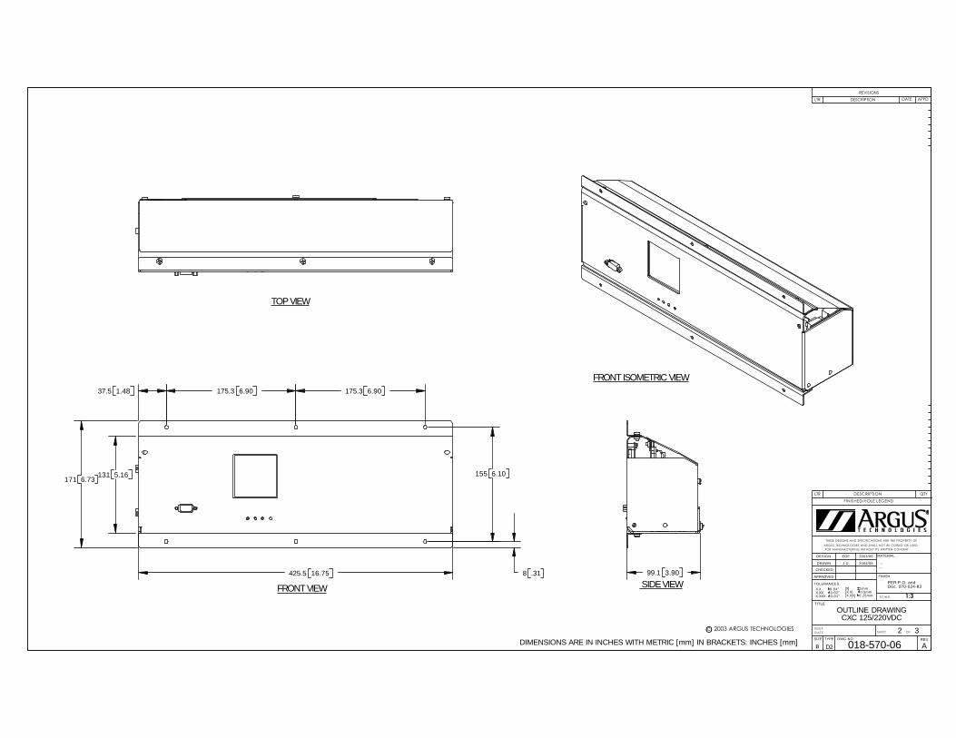
• Outline Drawings: 018-570-06
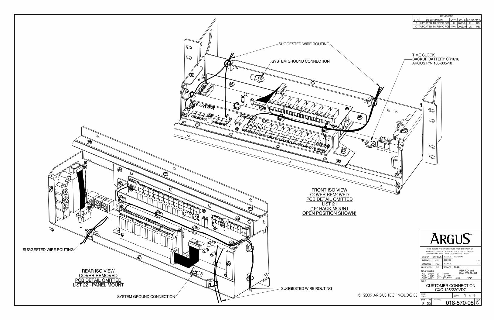
• Customer Connections: 018-570-08
• Warranty and Service Information: 048-700-10
• Service Centers: 048-693-10

This page intentionally left blank.

Specifications for Argus’ Cordex Controller Panel/Rack Mount 125/220Vdc
Argus Technologies Ltd. 018-570-B1 Rev B WC Printed in Canada. © 2005 Argus Technologies Ltd. ARGUS and CORDEX are trademarks of Argus Technologies Ltd. All Rights Reserved. Page 1 of 3
Basic Unit Input Voltage: 90 to 300Vdc within rated limits MTBF: 472,000 @ 25°C (77°F)
EMC: The unit meets requirements of:
ICES-003 Class A EN 55022 Class A (CISPR 22) EN 61000-4-2 ESD EN 61000-4-3 Radiated Immunity EN 61000-4-4 EFT /Burst EN 61000-4-6 Conducted Immunity FCC Part 15 Class A, FCC Part 68
Ground Fault Detection: 0 – 10mA In accordance with FCC requirements, we provide the following statement as specified in the FCC guidelines for conformance to Part 15, Class A:
NOTE: This equipment has been tested and found to comply with the limits for a Class A digital device, pursuant to part 15 of the FCC Rules. These limits are designed to provide reasonable protection against harmful interference when the equipment is operated in a commercial environment. This equipment generates, uses, and can radiate radio frequency energy and, if not installed and used in accordance with the instruction manual, may cause harmful interference to radio communications. Operation of this equipment in a residential area is likely to cause harmful interference in which case the user will be required to correct the interference at his own expense.
Any changes or modifications to this equipment not expressly described in this manual could void the FCC compliance.
Environmental Operating Temperature: 0 to 65°C standard @ 3000m derate to 55°C @ 4000m
(32 to 149°F derate to 131°F @ 13124ft) [Optional -40°C]
Storage Temperature: -20 to 70°C standard
(-4 to 158°F) -40 to 80°C optional
(-40 to 176°F) Humidity: 0 to 95% non-condensing Elevation: -500 to +4000m
(-1640 to 13124 ft)
Specifications for Argus’ Cordex Controller Panel/Rack Mount 125/220Vdc Continued
Argus Technologies Ltd. 018-570-B1 Rev B WC Printed in Canada. © 2005 Argus Technologies Ltd. ARGUS and CORDEX are trademarks of Argus Technologies Ltd. All Rights Reserved. Page 2 of 3
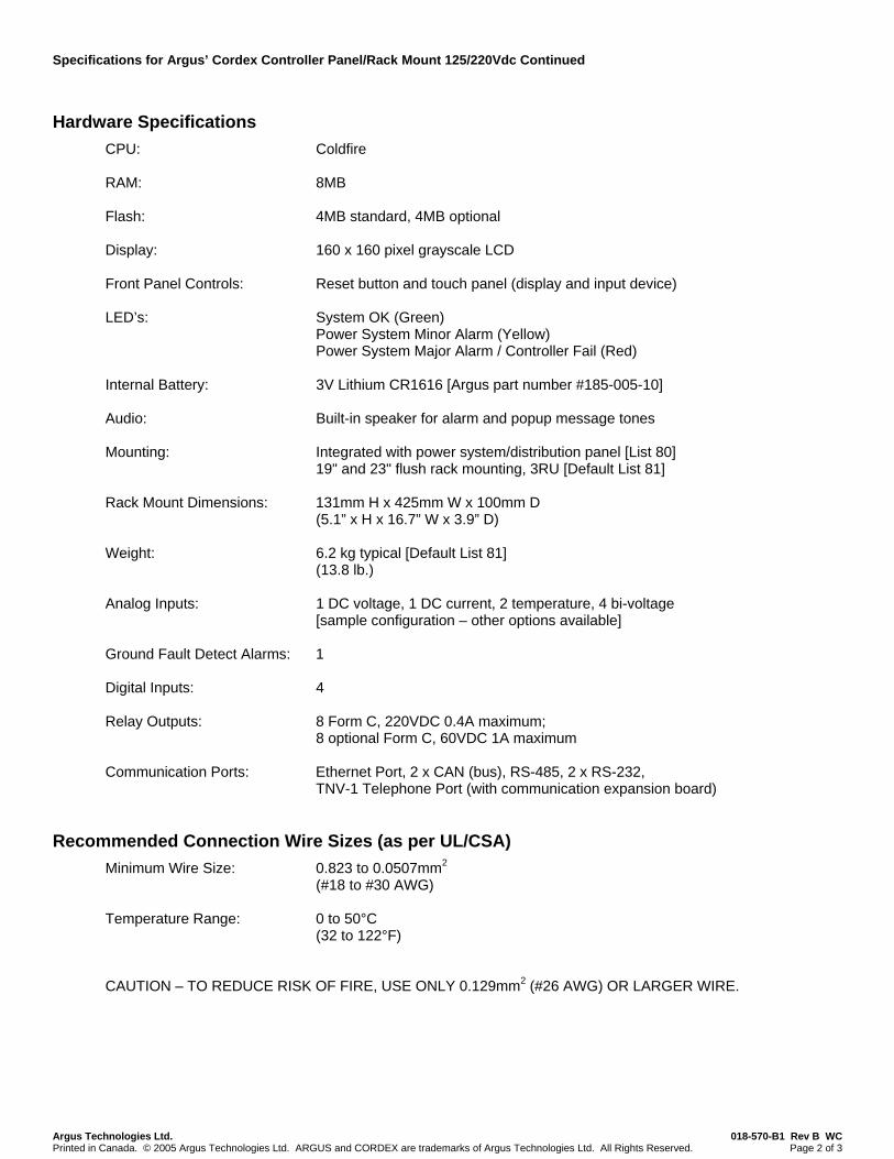
Hardware Specifications CPU: Coldfire RAM: 8MB Flash: 4MB standard, 4MB optional Display: 160 x 160 pixel grayscale LCD Front Panel Controls: Reset button and touch panel (display and input device) LED’s: System OK (Green)
Power System Minor Alarm (Yellow) Power System Major Alarm / Controller Fail (Red)
Internal Battery: 3V Lithium CR1616 [Argus part number #185-005-10] Audio: Built-in speaker for alarm and popup message tones Mounting: Integrated with power system/distribution panel [List 80]
19" and 23" flush rack mounting, 3RU [Default List 81] Rack Mount Dimensions: 131mm H x 425mm W x 100mm D
(5.1” x H x 16.7” W x 3.9” D) Weight: 6.2 kg typical [Default List 81]
(13.8 lb.) Analog Inputs: 1 DC voltage, 1 DC current, 2 temperature, 4 bi-voltage
[sample configuration – other options available] Ground Fault Detect Alarms: 1 Digital Inputs: 4 Relay Outputs: 8 Form C, 220VDC 0.4A maximum;
8 optional Form C, 60VDC 1A maximum Communication Ports: Ethernet Port, 2 x CAN (bus), RS-485, 2 x RS-232,
TNV-1 Telephone Port (with communication expansion board)
Recommended Connection Wire Sizes (as per UL/CSA) Minimum Wire Size: 0.823 to 0.0507mm2
(#18 to #30 AWG) Temperature Range: 0 to 50°C
(32 to 122°F) CAUTION – TO REDUCE RISK OF FIRE, USE ONLY 0.129mm2 (#26 AWG) OR LARGER WIRE.

Specifications for Argus’ Cordex Controller Panel/Rack Mount 125/220Vdc Continued
Argus Technologies Ltd. 018-570-B1 Rev B WC Printed in Canada. © 2005 Argus Technologies Ltd. ARGUS and CORDEX are trademarks of Argus Technologies Ltd. All Rights Reserved. Page 3 of 3
Part Numbers and List Options This product is available to order under the following part numbers and list options: Description Part Number/List Option Cordex Controller .......................................................................................................................................018-570-20 Basic unit............................................................................................................................................................ *List 0 125V system software configuration ....................................................................................................................List 3 220V system software configuration .................................................................................................................. *List 4 19” rack, flush mounting brackets .................................................................................................................... *List 21 Door mounting brackets .....................................................................................................................................List 22 23” rack, flush mounting brackets ......................................................................................................................List 25 Standard temperature (0 to 65°C)......................................................................................................................List 40 Extended temperature (-40 to 65°C)..................................................................................................................List 42 Gray finish with blue silkscreen..........................................................................................................................List 50 Charcoal finish with white (contrasting) silkscreen ............................................................................................List 56 Temp sensor assembly:
1/4” lug, 6’ cable....................................................................................................................................List 71 1/4” lug, 12’ cable..................................................................................................................................List 72 1/4” lug, 24’ cable..................................................................................................................................List 73 3/8” lug, 6’ cable....................................................................................................................................List 74 3/8” lug, 12’ cable..................................................................................................................................List 75 3/8” lug, 24’ cable..................................................................................................................................List 76 3/8” lug, 50’ cable..................................................................................................................................List 77 1/4” lug, 50’ cable..................................................................................................................................List 78
CAN bus port (required for Cordex rectifier communications interface) ............................................................List 90 Auxiliary CAN bus port .......................................................................................................................................List 91 RS-485 port (required for Pathfinder rectifier communications interface) .........................................................List 92 Ethernet port ......................................................................................................................................................List 93 Expansion board, communication (Lists 90-93 must be ordered separately)....................................................List 95 Expansion board, output relay, 8 x 1A Form C, internal ....................................................................................List 96 Internal modem, global (includes List 95) ....................................................................................................... List 101 Expanded Flash memory ................................................................................................................................ List 110 Analog input configuration: add one current shunt input ................................................................................ List 128 * Default options Cable, 9-pin null modem ............................................................................................................................877-482-20 Cable, RJ-12 to RJ-12; sorted by length:
1’....................................................................................................................................................877-176-26 1.5’.................................................................................................................................................877-176-21 19” .................................................................................................................................................877-176-27 2’....................................................................................................................................................877-176-22 6’....................................................................................................................................................877-176-23 12’..................................................................................................................................................877-176-24 25’..................................................................................................................................................877-176-25
The above information is valid at the time of publication. Consult factory for up-to-date ordering information. Specifications are subject to change without notice.

What are the CSA and NRTL?CSA (Canadian Standards Association also known as CSA International) was established in 1919 as an independent testing laboratory in Canada. CSA received its recognition as an NRTL (Nationally Recognized Testing Laboratory) in 1992 from OSHA (Occupational Safety and Health Administration) in the United States of America (Docket No. NRTL-2-92). This was expanded and renewed in 1997, 1999, and 2001. The specific notifications were posted on OSHA’s official website as follows:
Federal Register #: 59:40602 - 40609 [08/09/1994] Federal Register #: 64:60240 - 60241 [11/04/1999] Federal Register #: 66:35271 - 35278 [07/03/2001]
When these marks appear with the indicator “C and US” or “NRTL/C” it means that the product is certified for both the US and Canadian markets, to the applicable US and Canadian standards. (1)
Argus rectifier and power system products, bearing the aforementioned CSA marks, are certified to CSA C22.2 No. 950 and UL 1950, or CSA/UL 60950.
As part of the reciprocal, US/Canada agreement regarding testing laboratories, the Standards Council of Canada (Canada’s national accreditation body) granted Underwriters Laboratories (UL) authority to certify products for sale in Canada. (2)
Only Underwriters Laboratories may grant a licence for the use of this mark, which indicates compliance with both Canadian and US requirements. (3)
What are NRTLs and what do they do?NRTLs are third party organizations recognized by OSHA, US Department of Labor, under the NRTL program.
The testing and certifications are based on product safety standards developed by US based standards developing organizations and are often issued by the American National Standards Institute (ANSI). (4)
The NRTL determines that a product meets the requirements of an appropriate consensus-based product safety standard either by successfully testing the product itself, or by verifying that a contract laboratory has done so, and the NRTL certifies that the product meets the requirements of the product safety standard. (4)
When was the NRTL started and who governs it?In 1983, in a suit brought on by an independent testing laboratory, OSHA was court ordered to remove specific references to UL (Underwriters Laboratories) and FMRC (Factory Mutual Research Corporation) from its regulations.
In 1988, OSHA revised its regulations to remove those references and the NRTL program was established.
The NRTL Program is both national and international in scope with foreign labs permitted.
References:Information in this document has been developed from the official websites of the respective organizations.(1) www.csa-international.org(2) www.scc.ca(3) www.ulc.ca(4) www.osha.gov
CSA/NRTL — MARKS — BACKGROUND
argusdcpower.com
048-554-10-I1 Rev C (2004/02)
The product on which either of these marks appear has been certified by CSA as meeting applicable Canada/US standards.
The product on which this mark appears has been certified by UL as meeting applicable Canada/US standards.

IMPORTANT SAFETY INSTRUCTIONS
SAVE THESE INSTRUCTIONS
1. Please read this manual prior to use to become familiar with the product’s numerous features and operating procedures. To obtain a maximum degree of safety, follow the sequences as outlined.
2. This manual provides warnings and special notes for the user:
a. Points that are vital to the proper operation of the product or the safety of the operator are indicated by the heading: WARNING.
b. A notation that is in Bold Italic typeface covers points that are important to the performance or ease of use of the product.
3. Before using the product, read all instructions and cautionary markings on the product and any equipment connected to the product.
4. Do not expose the product to rain or snow; install only in a clean, dry environment.
5. CAUTION – Unless otherwise noted, use of an attachment not recommended or sold by the product manufacturer may result in a risk of fire, electric shock, or injury to persons.
6. CAUTION – Do not operate the product if it has received a sharp blow, it has been dropped, or otherwise damaged in any way – return it to a qualified service center for repair.
7. CAUTION – Do not disassemble the product – call our qualified service centers for servicing. Incorrect reassembling may result in a risk of electrical shock or fire.
8. CAUTION – Danger of explosion if battery is incorrectly replaced. Replace only with the same or equivalent type recommended by the manufacturer. Discard used batteries according to the manufacturer’s instructions.
9. WARNING – High voltage hazard. Extreme caution should be maintained when servicing or touching conductive components connected to the product.
10. WARNING – The telephone line cord is to be disconnected before accessing the inside of the equipment.
i

ii
TABLE OF CONTENTS 1 INTRODUCTION ............................................................................................................................................................. 1
1.1 Scope of the Manual ..................................................................................................................................... 1 1.2 Product Overview.......................................................................................................................................... 1 1.3 Part Numbers and List Options..................................................................................................................... 1
2 HARDWARE FEATURES................................................................................................................................................. 2 2.1 Operator Interface Devices ........................................................................................................................... 2 2.2 Serial Ports.................................................................................................................................................... 3 2.3 Real Time Clock............................................................................................................................................ 3 2.4 Lithium Battery Backup ................................................................................................................................. 3 2.5 Analog Input Channels.................................................................................................................................. 4 2.6 Digital Input Channels ................................................................................................................................... 4 2.7 Alarm and Control Output Relays ................................................................................................................. 4 2.8 CXC System Fail Alarm/Relay ...................................................................................................................... 4
3 INSPECTION.................................................................................................................................................................. 5 3.1 Packing Materials.......................................................................................................................................... 5 3.2 Check for Damage ........................................................................................................................................ 5
4 INSTALLATION .............................................................................................................................................................. 6 4.1 Safety Precautions ........................................................................................................................................ 6 4.2 Shelf Preparation/Mounting .......................................................................................................................... 6
5 WIRING AND CONNECTIONS .......................................................................................................................................... 7 5.1 Safety Precautions ........................................................................................................................................ 7 5.2 Front Access ................................................................................................................................................. 7 5.3 Tools Required.............................................................................................................................................. 7 5.4 Power System Chassis Ground and DC Ground Reference ........................................................................ 7 5.5 Power Inputs ................................................................................................................................................. 7 5.6 Analog Inputs ................................................................................................................................................ 8 5.7 Digital Inputs ................................................................................................................................................. 8 5.8 Relay Outputs ............................................................................................................................................. 10 5.9 Rectifier Connections.................................................................................................................................. 10 5.10 Network Connection and Remote Communications ................................................................................... 11
6 MAINTENANCE ........................................................................................................................................................... 13 6.1 Lithium Battery Replacement...................................................................................................................... 13
7 ARGUS CONVENTIONS................................................................................................................................................ 14 7.1 Numbering System...................................................................................................................................... 14 7.2 Acronyms and Definitions ........................................................................................................................... 14
Argus Technologies Ltd. 018-570-C0 Rev B WC Printed in Canada. © 2005 Argus Technologies Ltd. ARGUS and CORDEX are trademarks of Argus Technologies Ltd. All Rights Reserved. Page 1 of 14
1 Introduction
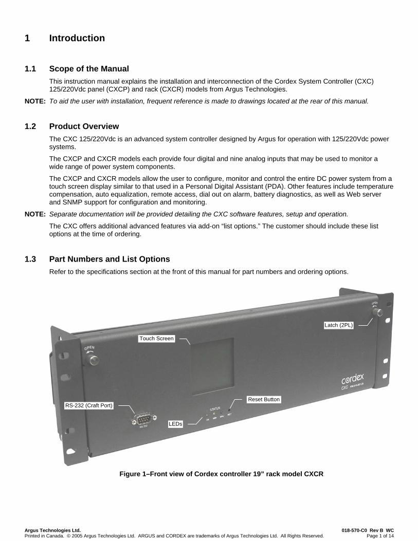
1.1 Scope of the Manual This instruction manual explains the installation and interconnection of the Cordex System Controller (CXC) 125/220Vdc panel (CXCP) and rack (CXCR) models from Argus Technologies.
NOTE: To aid the user with installation, frequent reference is made to drawings located at the rear of this manual.
1.2 Product Overview The CXC 125/220Vdc is an advanced system controller designed by Argus for operation with 125/220Vdc power systems.
The CXCP and CXCR models each provide four digital and nine analog inputs that may be used to monitor a wide range of power system components.
The CXCP and CXCR models allow the user to configure, monitor and control the entire DC power system from a touch screen display similar to that used in a Personal Digital Assistant (PDA). Other features include temperature compensation, auto equalization, remote access, dial out on alarm, battery diagnostics, as well as Web server and SNMP support for configuration and monitoring.
NOTE: Separate documentation will be provided detailing the CXC software features, setup and operation.
The CXC offers additional advanced features via add-on “list options.” The customer should include these list options at the time of ordering.
1.3 Part Numbers and List Options Refer to the specifications section at the front of this manual for part numbers and ordering options.
Figure 1–Front view of Cordex controller 19” rack model CXCR
Latch (2PL)
Touch Screen
Reset ButtonRS-232 (Craft Port)
LEDs

Argus Technologies Ltd. 018-570-C0 Rev B WC Printed in Canada. © 2005 Argus Technologies Ltd. ARGUS and CORDEX are trademarks of Argus Technologies Ltd. All Rights Reserved. Page 2 of 14
2 Hardware Features
Behind the CXC’s front panel lies the main controller motherboard, which contains a microprocessor, memory, removable lithium battery, as well as numerous other electronic components. The input/output (I/O) board houses a series of terminal connections. Space is also available to add optional output relays or an internal modem. Connections are oriented for front access.
2.1 Operator Interface Devices The user interfaces with the CXC by one or more of the following methods:
• Graphical input device, front panel LEDs and audio speaker. • RS-232 serial port (local “craft” port w/ null modem cable). • Optional Ethernet connection.
2.1.1 Basic Audio Speaker
A built-in audio speaker confirms activity with short tones; that is, for successful selection of an item or selecting outside the bounds of a window prompt. The speaker also sounds an intermittent tone during active alarms.
2.1.2 Front Panel Descriptions
The front panel contains a touch screen, a local RS-232 serial (Craft) port, a reset button and LEDs. A brief description of each is provided below:
2.1.3 Touch Screen
Located on the front panel is a 160 x 160-pixel graphical LCD with touch screen similar to those used in PDAs. This graphical user interface (GUI) allows the operator to interact with screen selectable items using a fingertip.
Figure 2–Sample screen of CXC graphical user interface
2.1.4 RS-232 Serial (Craft) Port
Local access to the CXC is possible through a front panel RS-232 serial port; using a null modem cable. The communication protocol supports a web interface (via Microsoft® Internet Explorer 6 or greater). The remote screen display is an enhanced version of the CXC’s front panel display.
2.1.5 Reset Button
A reset button is located on the front panel for restarting the CXC’s microprocessor. It takes approximately 15 seconds before the display reappears after pressing the reset button.
NOTE: Refer also to the software manual – always select the reset menu item, on the pop-up window of the touch screen, and follow the prompts before pressing the reset button.

Argus Technologies Ltd. 018-570-C0 Rev B WC Printed in Canada. © 2005 Argus Technologies Ltd. ARGUS and CORDEX are trademarks of Argus Technologies Ltd. All Rights Reserved. Page 3 of 14
Latch
Touch Screen
LEDs
RS-232 (Craft Port) Reset Button
Figure 3–Front view of Cordex controller panel model CXCP
2.1.6 Front Panel LEDs
The CXC has three LEDs located on the front panel. These are used to display the alarm status of the power system, CXC progress and status during startup, file transfers and lamp tests.
2.1.6.1 Alarm Conditions
The CXC illuminates the LED that corresponds to the system alarm status. The following show the corresponding alarm status for each LED color:
• Green – No alarms present • Yellow – Minor alarm is present (no major alarms) • Red – Major alarm is present.
Only one LED is illuminated at a time during alarm conditions.
2.1.6.2 Progress and Status Indication
The LEDs are also used in the following situations:
• Base unit validation – all three LEDs are on at the same time. • File transfer – when recovering from invalid firmware application – the red LED is illuminated. • Lamp Test – all three LEDs flash on and off at the same time for 2 seconds.
2.2 Serial Ports
2.2.1 CAN (Option)
Two CAN Serial ports, for communications with Argus’ Cordex rectifiers and other CAN-enabled equipment, are located next to the RS-485 port on the CXC.
2.2.2 Ethernet (Option)
One 10/100 Base T Ethernet port is provided for CXC communications with a local area network (LAN), e.g. the Internet.
2.3 Real Time Clock The CXC contains a real time clock (Y2K compliant), which allows time stamps to be placed on alarm, and statistical events contained in the historical data files.
2.4 Lithium Battery Backup A removable lithium battery (see Specifications) is included in the system to retain time and date settings upon power loss or reset.

Argus Technologies Ltd. 018-570-C0 Rev B WC Printed in Canada. © 2005 Argus Technologies Ltd. ARGUS and CORDEX are trademarks of Argus Technologies Ltd. All Rights Reserved. Page 4 of 14
2.5 Analog Input Channels The CXCP and CXCR each have up to nine analog channels, including up to five voltage inputs, two current inputs, and two temperature inputs.
2.5.1 Voltage Inputs Voltage-input channel V2 provides monitoring of the charge (battery) voltage. The CXC software is pre-configured to monitor V2 for battery voltage. V2 is used as the system reference for rectifier float voltage, low voltage disconnect (LVD), system high voltage alarm, and system low voltage alarm.
2.5.2 Ground Fault Detect (GFD) V2 is also used for GFD (internally connected circuit). Ground fault is detected when either terminal of V2 (system voltage that is normally connected to the battery string) shorts to earth ground either directly or through some conductive means. The GFD circuit will detect a fault current range of ±10mA. The resolution is 1mA.
The GFD will trip an alarm if the fault current exceeds the user configurable Trip Value under Configuration menu of Alarms/Configure Alarms/Miscellaneous Alarms/GFD. The default setting is ±5mA.
As with any analog input, the GFD can also be calibrated as required. See Analog Calibration menu in the CXC software manual.
2.5.3 Current Inputs Up to two current-input channels (I1 and I2) provide monitoring of current; e.g., discharge (load) and charge (battery). The CXC software is pre-configured to monitor I1 for load current using an external DC current transformer. The second optional current input is factory configured to monitor an external 50mV current shunt.
2.5.4 Temperature Inputs Two dedicated temperature probe inputs (T1 and T2) provide monitoring of battery temperature or room/ambient temperature. They may also be used for temperature compensation (temp comp). A voltage is supplied to these terminals to power the temperature sensors.
2.5.5 General-Purpose Inputs The general-purpose (GP) input channels monitor various analog signals depending on how the channels are configured. The configuration determines whether the signals allowed are to be bipolar (may vary in either polarity from zero, e.g. +/-150Vdc), unipolar (may vary positive from zero, e.g. 0 to +300Vdc), or temperature.
All four GP inputs are factory configured as unipolar voltage inputs.
2.6 Digital Input Channels The CXC can accommodate up to four digital input channels.
NOTE: Each channel may be set by closing (shorting) or opening the inputs with a voltage free contact to achieve the appropriate condition. This is differs from the digital inputs on other Cordex controllers which require a zero or system voltage potential at the input to activate or deactivate the appropriate condition.
These channels can monitor digital alarm/control signals from rectifiers, converters and many other types of equipment. Some of these channels are pre-assigned to monitor specific signals. See the Software manual for more information.
2.7 Alarm and Control Output Relays Each CXCP or CXCR contains eight standard and eight optional Form C alarm output relays to extend alarms and control external apparatus. Each internally generated alarm or control signal may be mapped to any one of the 16 relays, or, several signals may be mapped to just one relay or none at all.
2.8 CXC System Fail Alarm/Relay The CXC system fail alarm activates because of a major internal failure. During such a condition, the unit will attempt to reset, but if this fails, an alarm condition will be extended to a relay and the red LED on the front panel will illuminate. This is a fail-safe signal to the remote monitoring equipment; i.e. alarm will be extended even if power to the unit is interrupted.

Argus Technologies Ltd. 018-570-C0 Rev B WC Printed in Canada. © 2005 Argus Technologies Ltd. ARGUS and CORDEX are trademarks of Argus Technologies Ltd. All Rights Reserved. Page 5 of 14
3 Inspection
3.1 Packing Materials All Argus products are shipped in rugged, double walled boxes and suspended via solid inserts to minimize shock that may occur during transportation. Packaging assemblies and methods are tested to International Safe Transit Association standards.
Products are also packaged with Cortex. This plastic wrap contains a corrosive-inhibitor that protects the product from corrosion for up to two years.
3.1.1 Returns for Service
Save the original shipping container. If the product needs to be returned for service, it should be packaged in its original shipping container. If the original container is unavailable, make sure the product is packed with at least three inches of shock-absorbing material to prevent shipping damage.
NOTE: Argus Technologies is not responsible for damage caused by the improper packaging of returned products.
3.2 Check for Damage Prior to unpacking the product, note any damage to the shipping container. Unpack the product and inspect the exterior for damage. If any damage is observed contact the carrier immediately.
WARNING To prevent possible ESD damage, all models of CXC controllers require that when the unit is open the users not touch the circuitry without a wrist strap properly worn and connected.
Continue the inspection for any internal damage. In the unlikely event of internal damage, please inform the carrier and contact Argus Technologies for advice on the impact of any damage.
Verify that you have all the necessary parts per your order for proper assembly.
Argus Technologies Ltd. 018-570-C0 Rev B WC Printed in Canada. © 2005 Argus Technologies Ltd. ARGUS and CORDEX are trademarks of Argus Technologies Ltd. All Rights Reserved. Page 6 of 14
4 Installation
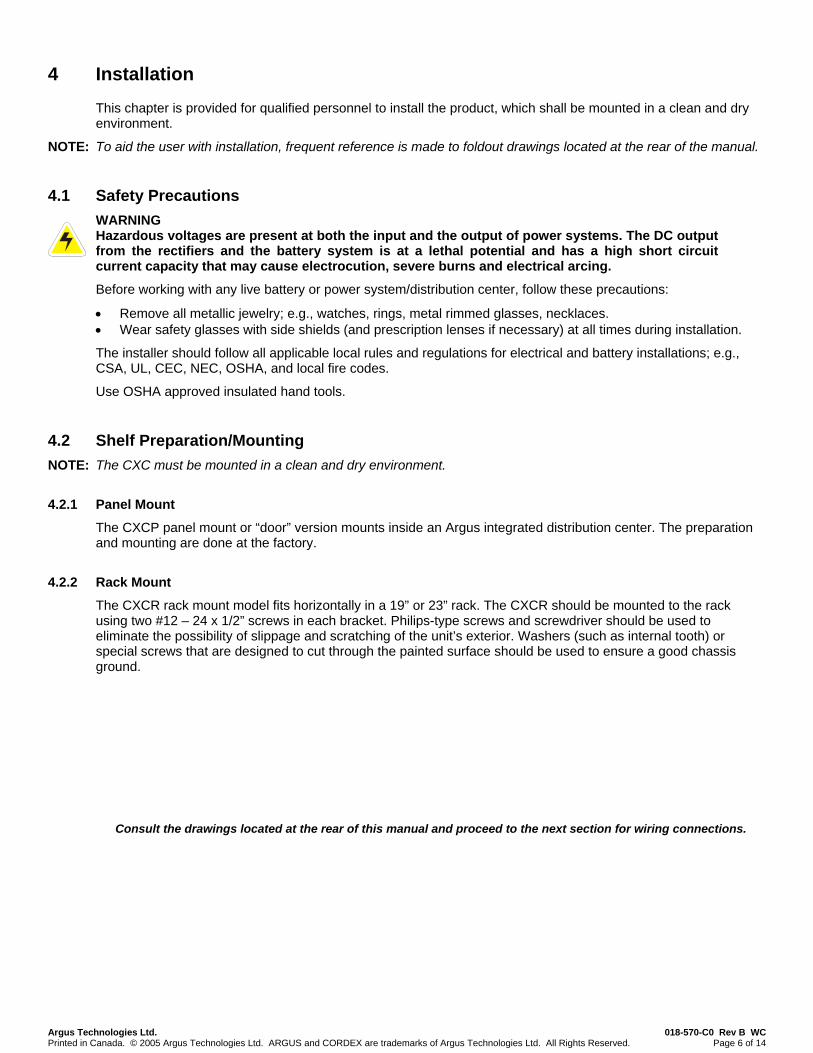
This chapter is provided for qualified personnel to install the product, which shall be mounted in a clean and dry environment.
NOTE: To aid the user with installation, frequent reference is made to foldout drawings located at the rear of the manual.
4.1 Safety Precautions WARNING Hazardous voltages are present at both the input and the output of power systems. The DC output from the rectifiers and the battery system is at a lethal potential and has a high short circuit current capacity that may cause electrocution, severe burns and electrical arcing.
Before working with any live battery or power system/distribution center, follow these precautions:
• Remove all metallic jewelry; e.g., watches, rings, metal rimmed glasses, necklaces. • Wear safety glasses with side shields (and prescription lenses if necessary) at all times during installation.
The installer should follow all applicable local rules and regulations for electrical and battery installations; e.g., CSA, UL, CEC, NEC, OSHA, and local fire codes.
Use OSHA approved insulated hand tools.
4.2 Shelf Preparation/Mounting NOTE: The CXC must be mounted in a clean and dry environment.
4.2.1 Panel Mount
The CXCP panel mount or “door” version mounts inside an Argus integrated distribution center. The preparation and mounting are done at the factory.
4.2.2 Rack Mount
The CXCR rack mount model fits horizontally in a 19” or 23” rack. The CXCR should be mounted to the rack using two #12 – 24 x 1/2” screws in each bracket. Philips-type screws and screwdriver should be used to eliminate the possibility of slippage and scratching of the unit’s exterior. Washers (such as internal tooth) or special screws that are designed to cut through the painted surface should be used to ensure a good chassis ground.
Consult the drawings located at the rear of this manual and proceed to the next section for wiring connections.
Argus Technologies Ltd. 018-570-C0 Rev B WC Printed in Canada. © 2005 Argus Technologies Ltd. ARGUS and CORDEX are trademarks of Argus Technologies Ltd. All Rights Reserved. Page 7 of 14
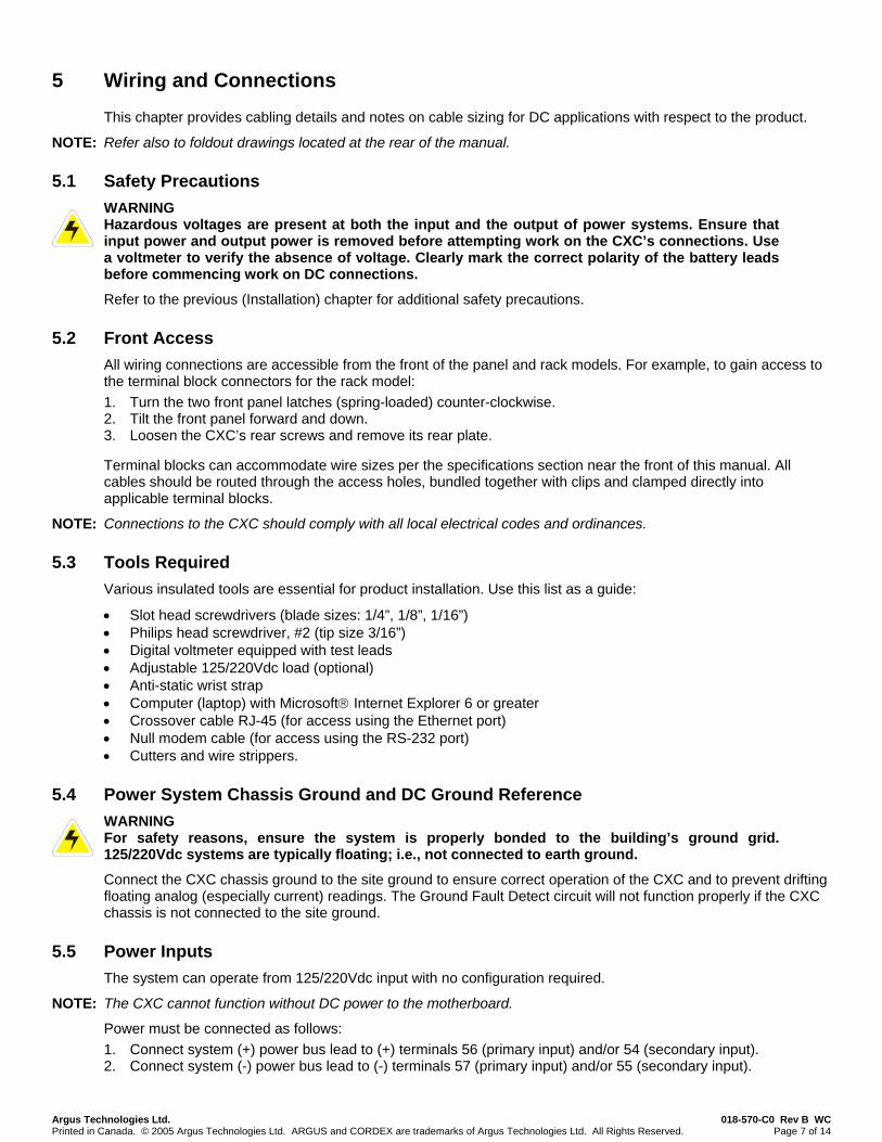
5 Wiring and Connections
This chapter provides cabling details and notes on cable sizing for DC applications with respect to the product.
NOTE: Refer also to foldout drawings located at the rear of the manual.
5.1 Safety Precautions WARNING Hazardous voltages are present at both the input and the output of power systems. Ensure that input power and output power is removed before attempting work on the CXC’s connections. Use a voltmeter to verify the absence of voltage. Clearly mark the correct polarity of the battery leads before commencing work on DC connections.
Refer to the previous (Installation) chapter for additional safety precautions.
5.2 Front Access All wiring connections are accessible from the front of the panel and rack models. For example, to gain access to the terminal block connectors for the rack model: 1. Turn the two front panel latches (spring-loaded) counter-clockwise. 2. Tilt the front panel forward and down. 3. Loosen the CXC’s rear screws and remove its rear plate.
Terminal blocks can accommodate wire sizes per the specifications section near the front of this manual. All cables should be routed through the access holes, bundled together with clips and clamped directly into applicable terminal blocks.
NOTE: Connections to the CXC should comply with all local electrical codes and ordinances.
5.3 Tools Required Various insulated tools are essential for product installation. Use this list as a guide:
• Slot head screwdrivers (blade sizes: 1/4”, 1/8”, 1/16”) • Philips head screwdriver, #2 (tip size 3/16”) • Digital voltmeter equipped with test leads • Adjustable 125/220Vdc load (optional) • Anti-static wrist strap • Computer (laptop) with Microsoft® Internet Explorer 6 or greater • Crossover cable RJ-45 (for access using the Ethernet port) • Null modem cable (for access using the RS-232 port) • Cutters and wire strippers.
5.4 Power System Chassis Ground and DC Ground Reference WARNING For safety reasons, ensure the system is properly bonded to the building’s ground grid. 125/220Vdc systems are typically floating; i.e., not connected to earth ground.
Connect the CXC chassis ground to the site ground to ensure correct operation of the CXC and to prevent drifting floating analog (especially current) readings. The Ground Fault Detect circuit will not function properly if the CXC chassis is not connected to the site ground.
5.5 Power Inputs The system can operate from 125/220Vdc input with no configuration required.
NOTE: The CXC cannot function without DC power to the motherboard.
Power must be connected as follows: 1. Connect system (+) power bus lead to (+) terminals 56 (primary input) and/or 54 (secondary input). 2. Connect system (-) power bus lead to (-) terminals 57 (primary input) and/or 55 (secondary input).
Argus Technologies Ltd. 018-570-C0 Rev B WC Printed in Canada. © 2005 Argus Technologies Ltd. ARGUS and CORDEX are trademarks of Argus Technologies Ltd. All Rights Reserved. Page 8 of 14
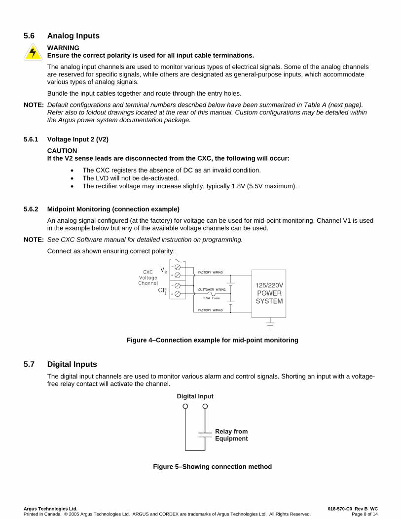
5.6 Analog Inputs WARNING Ensure the correct polarity is used for all input cable terminations.
The analog input channels are used to monitor various types of electrical signals. Some of the analog channels are reserved for specific signals, while others are designated as general-purpose inputs, which accommodate various types of analog signals.
Bundle the input cables together and route through the entry holes.
NOTE: Default configurations and terminal numbers described below have been summarized in Table A (next page). Refer also to foldout drawings located at the rear of this manual. Custom configurations may be detailed within the Argus power system documentation package.
5.6.1 Voltage Input 2 (V2)
CAUTION If the V2 sense leads are disconnected from the CXC, the following will occur:
• The CXC registers the absence of DC as an invalid condition. • The LVD will not be de-activated. • The rectifier voltage may increase slightly, typically 1.8V (5.5V maximum).
5.6.2 Midpoint Monitoring (connection example)
An analog signal configured (at the factory) for voltage can be used for mid-point monitoring. Channel V1 is used in the example below but any of the available voltage channels can be used.
NOTE: See CXC Software manual for detailed instruction on programming.
Connect as shown ensuring correct polarity:
Figure 4–Connection example for mid-point monitoring
5.7 Digital Inputs The digital input channels are used to monitor various alarm and control signals. Shorting an input with a voltage-free relay contact will activate the channel.
Figure 5–Showing connection method

Argus Technologies Ltd. 018-570-C0 Rev B WC Printed in Canada. © 2005 Argus Technologies Ltd. ARGUS and CORDEX are trademarks of Argus Technologies Ltd. All Rights Reserved. Page 9 of 14
CAUTION: to reduce risk of fire, use only 0.129mm2 (#26 AWG) or larger wire.
Terminal Description Default Name Signal Range 1 and 2; V2 Voltage Input 2 Charge Voltage Pos (+)/Neg (-) 0-300Vdc 3 and 4; GP1* General Input 1 GP1 Pos (+)/Neg (-) 0-300Vdc 5 and 6; GP2* General Input 2 GP2 Pos (+)/Neg (-) 0-300Vdc 7 and 8; GP3* General Input 3 GP3 Pos (+)/Neg (-) 0-300Vdc 9 and 10; GP4* General Input 4 GP4 Pos (+)/Neg (-) 0-300Vdc 11 and 12; T1 Temp Input 1 T1 Pos (+)/Neg (-) 0-20Vdc 13 and 14; T2 Temp Input 2 T2 Pos (+)/Neg (-) 0-20Vdc 15 and 16; I2 Current Input 2 I2 Pos (+)/Neg (-) ±50mV 19 and 20; D1** Digital Input 1 Distribution Fuse (Alarm) N/A Short or open 21 and 22; D2** Digital Input 2 Distribution CB (Alarm) N/A Short or open 23 and 24; D3** Digital Input 3 Battery CB (Alarm) N/A Short or open 25 and 26; D4** Digital Input 4 Battery CB (Alarm) N/A Short or open 27, 28 and 29; K1*** Alarm Output 1 LVD1 NC/COM/NO 220Vdc, 0.4A 30, 31 and 32; K2*** Alarm Output 2 LVD2 NC/COM/NO 220Vdc, 0.4A 33, 34 and 35; K3*** Alarm Output 3 LVD3 NC/COM/NO 220Vdc, 0.4A 36, 37 and 38; K4*** Alarm Output 4 System Minor NC/COM/NO 220Vdc, 0.4A 39, 40 and 41; K5*** Alarm Output 5 System Major NC/COM/NO 220Vdc, 0.4A 42, 43 and 44; K6*** Alarm Output 6 AC Mains Hi-Low NC/COM/NO 220Vdc, 0.4A 45, 46 and 47; K7*** Alarm Output 7 Not assigned NC/COM/NO 220Vdc, 0.4A 48, 49 and 50; K8*** Alarm Output 8 Not assigned NC/COM/NO 220Vdc, 0.4A 51, 52 and 53; K0**** Alarm Output 0 System Fail Output NC/COM/NO 220Vdc, 0.4A 54 and 55; B PWR Secondary Power Secondary Power Pos (+)/Neg (-) 90-300Vdc 56 and 57; A PWR Power Power Pos (+)/Neg (-) 90-300Vdc DCCT input; P3 Current Input 1 I1 Pos (+)/Neg (-);
Pwr (+)/Pwr (-) ±15Vdc, 100mA max.
Table A–Wiring connections * Bipolar (Voltage Input) is ±150Vdc, Unipolar Voltage (Input) is 0—300Vdc, Temp Probe is 0—20Vdc with power source. ** See Table B for definitions of impedance levels. *** Can be configured to de-energize on alarm (DOA) or energize on alarm (EOA). **** System Fail output relay is fail-safe and will de-energize during an alarm condition.
NOTE: DCCT power output is protected against short circuits and is able to power four DCCTs.
To aid the user with installation, frequent reference is made to drawings located at the rear of this manual. Custom configurations may be detailed within the Argus power system documentation package.
5.7.1 Programming the Digital Input
The digital input channels (terminals 19 through 26) can be programmed for “active high” or “active low.” Active high indicates “alarm on the presence of a short circuit” and active low indicates “alarm on the removal of the short circuit.”
NOTE: See CXC Software manual for detailed instruction on programming.
Impedance Level (Ohms)
Considered As “0” (Off) Impedance Level (Ohms) Considered As “1” (On)
> 1M < 1
Table B–Digital input impedance level definitions

Argus Technologies Ltd. 018-570-C0 Rev B WC Printed in Canada. © 2005 Argus Technologies Ltd. ARGUS and CORDEX are trademarks of Argus Technologies Ltd. All Rights Reserved. Page 10 of 14
5.8 Relay Outputs WARNING Relays are rated at 220Vdc 0.4A. Exceeding these limits may damage the relay and other circuitry in the CXC.
Terminals 27 to 50 provide 8 Form C contacts (NO, COM and NC) for extending various alarm or control signals. Each relay output can be wired for NO and/or NC operation during an alarm or control condition. See Figure 6.
Figure 6–Showing relay connections in the de-energized state
Relays can be programmed to energize or de-energize during an alarm condition (see Software manual). When the CXC reset button is pressed or power is lost, all relays de-energize.
Relay contacts 1-8 are high capacity and intended to be used for controlling LVD contactors.
5.8.1 System Fail Relay
Terminals 51 to 53 provide connections for a system (supervisory) fail relay. This fail-safe relay (i.e. it is de-energized during an alarm condition) can be wired for NO or NC operation.
5.8.2 LVD Control
The LVD control functions can be hardwired directly from the assigned relay output pins to the LVD contactor panel. See Controls Menu Defaults in the Software manual.
5.8.3 CEMF Cell Control
The CEMF control function can be hardwired directly from the assigned channel in to the CEMF cell controller panel. See Controls Menu Defaults in the Software manual.
5.8.4 Optional Relays and Outputs
Eight relays and outputs may be added to the CXC (panel and rack models) with the purchase of an optional expansion board (see List Options at the front of this manual).
5.9 Rectifier Connections
5.9.1 CAN Out Serial Port
A single CAN Out serial port, for communications with Argus’ Cordex rectifiers and other CAN-enabled equipment (nodes) on the same system, is located next to the rear Ethernet port.
Daisy-chain from node to node (CAN OUT of one node to CAN IN of another) as necessary and ensure that only the last node is terminated.
Argus Technologies Ltd. 018-570-C0 Rev B WC Printed in Canada. © 2005 Argus Technologies Ltd. ARGUS and CORDEX are trademarks of Argus Technologies Ltd. All Rights Reserved. Page 11 of 14
5.10 Network Connection and Remote Communications The Cordex system can be set up, monitored and tested via ETHERNET 10/100 Base-T or with a RS-232 serial data connection, or over a phone line using a modem.
NOTE: Pinouts are shown in the customer connections drawing.
The communication protocol supports a web interface. The remote screen display is an enhanced version of the CXC’s front panel display.
Some standard scenarios are described below:
5.10.1 Ethernet Port for Network Connection (Standard Network Cable)
The Ethernet port is designed for CXC connection to a user supplied network (TCP/IP secured by user) via a front panel RJ-45 jack. Connect to the Cordex controller using a standard network cable.
On the jack of the CXCP and CXCR only are two LEDs used to provide indication of status. The green LED illuminates when disconnected and flashes when there is activity on the line. The amber or yellow LED is off when disconnected and illuminates when a successful (data) connection is present.
5.10.2 Ethernet Port for Local Connection (Crossover Cable)
Local access (e.g. laptop computer) is also possible from the Ethernet port connection using a standard network crossover cable.
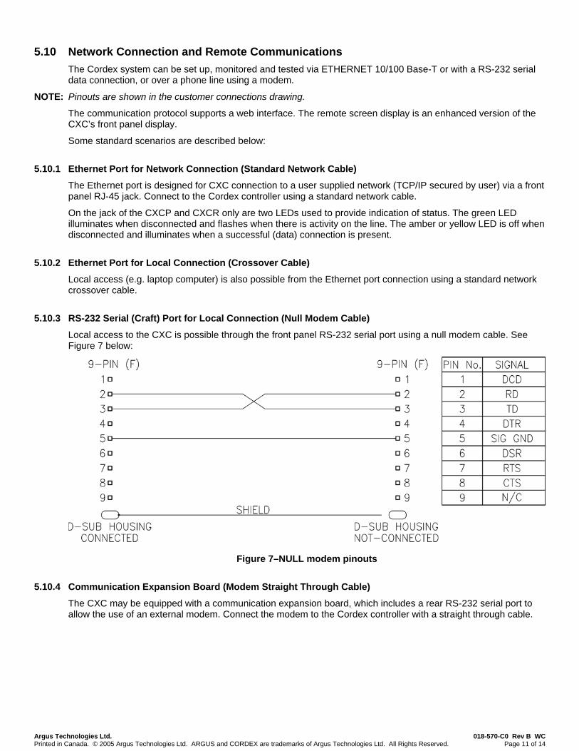
5.10.3 RS-232 Serial (Craft) Port for Local Connection (Null Modem Cable)
Local access to the CXC is possible through the front panel RS-232 serial port using a null modem cable. See Figure 7 below:
Figure 7–NULL modem pinouts
5.10.4 Communication Expansion Board (Modem Straight Through Cable)
The CXC may be equipped with a communication expansion board, which includes a rear RS-232 serial port to allow the use of an external modem. Connect the modem to the Cordex controller with a straight through cable.

Argus Technologies Ltd. 018-570-C0 Rev B WC Printed in Canada. © 2005 Argus Technologies Ltd. ARGUS and CORDEX are trademarks of Argus Technologies Ltd. All Rights Reserved. Page 12 of 14
See Figure 8 below for a rendering of CXC connections for power system communications:
SNMP Server Remote Monitor
Technician's PC
Modem
Modem
PSTN
Cordex Controller (CXC)
LCD
Ethernet RS-232 RS-485 CAN CAN Analog + Digital I/O
System I/O
I/O Expansion
Battery Cells
3 Phase Mains
System I/O
Rectifiers
Intranet Internet
RS-232
Expansion Bus
Rectifier Bus, RS-485 or CAN
Technician's PC
Mains Monitor
Battery Cell
Monitor
Technician's PC
or
Crossover Cable
Null Modem Cable
Standard Network Cable
Straight Through Cable
Figure 8–Communications connections
See also Remote Communications in the Software manual for more details on local and remote communications.
Argus Technologies Ltd. 018-570-C0 Rev B WC Printed in Canada. © 2005 Argus Technologies Ltd. ARGUS and CORDEX are trademarks of Argus Technologies Ltd. All Rights Reserved. Page 13 of 14
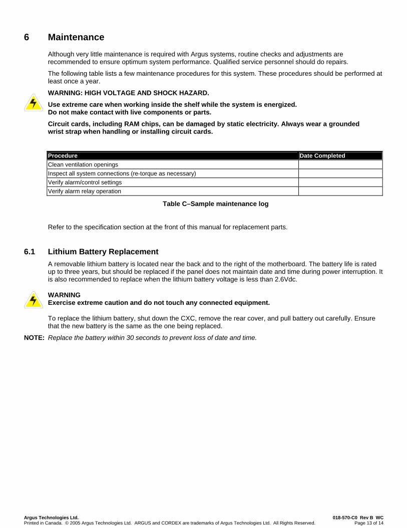
6 Maintenance
Although very little maintenance is required with Argus systems, routine checks and adjustments are recommended to ensure optimum system performance. Qualified service personnel should do repairs.
The following table lists a few maintenance procedures for this system. These procedures should be performed at least once a year.
WARNING: HIGH VOLTAGE AND SHOCK HAZARD.
Use extreme care when working inside the shelf while the system is energized. Do not make contact with live components or parts.
Circuit cards, including RAM chips, can be damaged by static electricity. Always wear a grounded wrist strap when handling or installing circuit cards.
Procedure Date Completed Clean ventilation openings Inspect all system connections (re-torque as necessary) Verify alarm/control settings Verify alarm relay operation
Table C–Sample maintenance log
Refer to the specification section at the front of this manual for replacement parts.
6.1 Lithium Battery Replacement A removable lithium battery is located near the back and to the right of the motherboard. The battery life is rated up to three years, but should be replaced if the panel does not maintain date and time during power interruption. It is also recommended to replace when the lithium battery voltage is less than 2.6Vdc.
WARNING Exercise extreme caution and do not touch any connected equipment.
To replace the lithium battery, shut down the CXC, remove the rear cover, and pull battery out carefully. Ensure that the new battery is the same as the one being replaced.
NOTE: Replace the battery within 30 seconds to prevent loss of date and time.
Argus Technologies Ltd. 018-570-C0 Rev B WC Printed in Canada. © 2005 Argus Technologies Ltd. ARGUS and CORDEX are trademarks of Argus Technologies Ltd. All Rights Reserved. Page 14 of 14
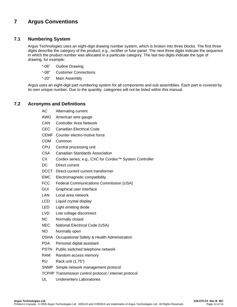
7 Argus Conventions
7.1 Numbering System Argus Technologies uses an eight-digit drawing number system, which is broken into three blocks. The first three digits describe the category of the product; e.g., rectifier or fuse panel. The next three digits indicate the sequence in which the product number was allocated in a particular category. The last two digits indicate the type of drawing, for example:
“-06” Outline Drawing “-08” Customer Connections “-20” Main Assembly
Argus uses an eight-digit part numbering system for all components and sub assemblies. Each part is covered by its own unique number. Due to the quantity, categories will not be listed within this manual.
7.2 Acronyms and Definitions AC Alternating current AWG American wire gauge CAN Controller Area Network CEC Canadian Electrical Code CEMF Counter electro-motive force COM Common CPU Central processing unit CSA Canadian Standards Association CX Cordex series; e.g., CXC for Cordex™ System Controller DC Direct current DCCT Direct-current current transformer EMC Electromagnetic compatibility FCC Federal Communications Commission (USA) GUI Graphical user interface LAN Local area network LCD Liquid crystal display LED Light emitting diode LVD Low voltage disconnect NC Normally closed NEC National Electrical Code (USA) NO Normally open OSHA Occupational Safety & Health Administration PDA Personal digital assistant PSTN Public switched telephone network RAM Random access memory RU Rack unit (1.75”) SNMP Simple network management protocol TCP/IP Transmission control protocol / internet protocol UL Underwriters Laboratories
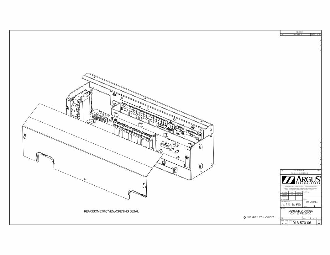
REAR ISOMETRIC VIEW-OPENING DETAIL
SIZE DWG NO.TYPE
B
SHEET
TITLE
I SSUE
D A T E OF
TOLERANCES
SCALE
APPROVED
CHECKED
DRAWN
DESIGN MATERIAL
FINISH
FOR MANUFACTURING WITHOUT ITS WRITTEN CONSENT.
ARGUS TECHNOLOGIES AND SHALL NOT BE COPIED OR USED
THESE DESIGNS AND SPECIFICATIONS ARE THE PROPERTY OF
LTR
FINISHED HOLE LEGEND
QTYDESCRIPTION
REVISIONS
LTR DESCRIPTION APPDDATE
REV
X.X 0.04"X.XX 0.02"X.XXX 0.01"
[X] 1mm[X.X] 0.5mm[X.XX] 0.25mm
018-570-06
OUTLINE DRAWINGCXC 125/220VDC
...
...
1:2
PER P.O. andDoc. 070-024-83
1 3
EOF
J.U.
2003/06
2004/08
D2
c 2003 ARGUS TECHNOLOGIESO
A
131 5.16
425.5 16.75
171 6.73155 6.10
175.3 6.90 175.3 6.9037.5 1.48
8 .31
FRONT VIEW
TOP VIEW
99.1 3.90
SIDE VIEW
FRONT ISOMETRIC VIEW
SIZE DWG NO.TYPE
B
SHEET
TITLE
I SSUE
D A T E OF
TOLERANCES
SCALE
APPROVED
CHECKED
DRAWN
DESIGN MATERIAL
FINISH
FOR MANUFACTURING WITHOUT ITS WRITTEN CONSENT.
ARGUS TECHNOLOGIES AND SHALL NOT BE COPIED OR USED
THESE DESIGNS AND SPECIFICATIONS ARE THE PROPERTY OF
LTR
FINISHED HOLE LEGEND
QTYDESCRIPTION
REVISIONS
LTR DESCRIPTION APPDDATE
REV
X.X 0.04"X.XX 0.02"X.XXX 0.01"
[X] 1mm[X.X] 0.5mm[X.XX] 0.25mm
018-570-06
OUTLINE DRAWINGCXC 125/220VDC
...
...
1:3
PER P.O. andDoc. 070-024-83
2 3
EOF
J.U.
2003/06
2004/08
D2
c 2003 ARGUS TECHNOLOGIESO
ADIMENSIONS ARE IN INCHES WITH METRIC [mm] IN BRACKETS: INCHES [mm]

584.3 23.00
425.5 16.75
22.2 .88
57.2 2.25
101.6 4.00
132.6 5.22
566.7 22.31
FRONT VIEW - 23" MOUNTING
482.7 19.00
425.5 16.75
132.5 5.22
101.6 4.00
57.2 2.25
22.2 .88
465.1 18.31
FRONT VIEW - 19" MOUNTING
SIZE DWG NO.TYPE
B
SHEET
TITLE
I SSUE
D A T E OF
TOLERANCES
SCALE
APPROVED
CHECKED
DRAWN
DESIGN MATERIAL
FINISH
FOR MANUFACTURING WITHOUT ITS WRITTEN CONSENT.
ARGUS TECHNOLOGIES AND SHALL NOT BE COPIED OR USED
THESE DESIGNS AND SPECIFICATIONS ARE THE PROPERTY OF
REVISIONS
LTR DESCRIPTION APPDDATE
REV
X.X 0.04"X.XX 0.02"X.XXX 0.01"
[X] 1mm[X.X] 0.5mm[X.XX] 0.25mm
018-570-06
OUTLINE DRAWINGCXC 125/220VDC
...
...
PER P.O. andDoc. 070-024-83
3 3
EOF
J.U.
2003/06
2004/08
D2
c 2004 ARGUS TECHNOLOGIESO
A
DIMENSIONS ARE IN INCHES WITH METRIC [mm] IN BRACKETS: INCHES [mm]
REV BY
© 2009 ARGUS TECHNOLOGIES
JK2009/10WH MEUPDATED TO REV C PCBCFL2005/01JU RDUPDATED TO REV B PCBB
REVISIONSDESCRIPTIONLTR APPDDATEDWN CHKD
SYSTEM GROUND CONNECTION
(19" RACK MOUNTOPEN POSITION SHOWN)
SUGGESTED WIRE ROUTING
FRONT ISO VIEWCOVER REMOVED
PCB DETAIL OMITTEDLIST 21
TIME CLOCKBACKUP BATTERY CR1616ARGUS P/N 185-005-10
LIST 22 - PANEL MOUNTPCB DETAIL OMITTED
SYSTEM GROUND CONNECTION
REAR ISO VIEWCOVER REMOVED
SUGGESTED WIRE ROUTING
SUGGESTED WIRE ROUTING
2004/08
D2 C
F.L
R.D 2004/08
SIZE DWG NO.TYPE
B
SHEET
TITLE
ISSUEDATE OF
TOLERANCES
SCALE
APPROVED
CHECKED
DRAWN
DESIGN MATERIAL
....J.U.
2003/06
018-570-08
EF/RD/JK
1 4CXC 125/220VDC
Doc. 070-024-83
X.XXX
2004/08
0.01"0.02"X.XX
FINISH
0.25mm
....
FOR MANUFACTURING WITHOUT ITS WRITTEN CONSENT.ARGUS TECHNOLOGIES AND SHALL NOT BE COPIED OR USED
0.04"
THESE DESIGNS AND SPECIFICATIONS ARE THE PROPERTY OF
REV
CUSTOMER CONNECTION
X.X [X] 1mm[X.X] 0.5mm[X.XX]
PER P.O. and
1:2

© 2009 ARGUS TECHNOLOGIES
1:2
SIZE DWG NO.TYPE
B
SHEET
TITLE
ISSUEDATE OF
TOLERANCES
SCALE
APPROVED
CHECKED
DRAWN
DESIGN MATERIAL
FINISH
FOR MANUFACTURING WITHOUT ITS WRITTEN CONSENT.ARGUS TECHNOLOGIES AND SHALL NOT BE COPIED OR USEDTHESE DESIGNS AND SPECIFICATIONS ARE THE PROPERTY OF
REVISIONS
LTR DESCRIPTION APPDDATE
REV
D2
2004/08 R.D
2004/08
2004/08 F.L
2003/06
C
0.01"
0.04"
X.XXX 0.02"
X.X X.XX
0.25mm
018-570-08
CXC 125/220VDCCUSTOMER CONNECTION
....
....
Doc. 070-024-83
2 4
EF/RD/JK
J.U.
[X] 1mm[X.X] 0.5mm[X.XX]
PER P.O. and
REV BY
RELAY#7
RELAY#8
DETAIL A
19 20D1
21 22D2
23 24D3
25 26D4
27 28 29NC C NO
30 31 32NC C NO
33 34 35NC C NO
36 37 38NC C NO
39 40 41NC C NO
42 43 44NC C NO
45 46 47NC C NO
48 49 50NC C NO
51 52 53NC C NO
54 55+B PWR -
56 57+A PWR -
RELAY#1
RELAY#3
RELAY#2
RELAY#4
RELAY#5
RELAY#6
RELAY#0
SYSTEM FAIL
DCCT
TEMP
3 DCCT SENSE +2 +15V DCCT POWER
DETAIL B
T2
4 -15V DCCT POWER
1 2V2+ V2-
3 4GP1+ GP1-
5 6GP2+ GP2-
7 8GP3+ GP4+
GP4-
11 12T1+ T1-
13 14T2+ T2-
GP3-
9 10 15 16I2+ I2-
V2
CHARGEVOLTAGE
GP1
VOLTAGE#3
GP2
VOLTAGE#4
GP3
VOLTAGE#5
GP4
VOLTAGE#6
#1
1
I1
DCCTINPUT
T1
TEMPPROBE
I1
P3
P3
3 4
2
#2PROBE
1 DCCT SENSE -
I2
CURRENT#2
SOME DETAILS OMMITED
A
TOP VIEW - I/O BOARD (707-360-20)
B

© 2009 ARGUS TECHNOLOGIES
1
4. NC
1 8
RJ45
3. CANL4. CANL5. CANH
1 6
6. NC
8. COM27. COM26. RX-5. COM14. COM13. RX+
1. TX+2. TX-
1. GND2. CANH
1. NC2. RING3. TIP
4
RS485
CAN2
CAN1
ETHERNET
J8
P1
J2
J3
J4
J5
J1
LIST 95 - EXPANSION BOARD, COMMUNICATION
MODEM
TOP VIEW - COMMUNICATION BOARD (707-329-20)
U1
TELCO
CAN1
BATTERY
J8
RS485
P6
P2
LIST 92 LIST 90 LIST 93
ETHERNET
SOME DETAILS OMMITED
CAN 2TELCO RS485 CAN 1
To I/O Board
TOP VIEW-MOTHER BOARD (707-314-20)
To Front PanelETHERNET
RJ12OFFSET
1:2
SIZE DWG NO.TYPE
B
SHEET
TITLE
ISSUEDATE OF
TOLERANCES
SCALE
APPROVED
CHECKED
DRAWN
DESIGN MATERIAL
FINISH
FOR MANUFACTURING WITHOUT ITS WRITTEN CONSENT.ARGUS TECHNOLOGIES AND SHALL NOT BE COPIED OR USEDTHESE DESIGNS AND SPECIFICATIONS ARE THE PROPERTY OF
REVISIONS
LTR DESCRIPTION APPDDATE
REV
D2
2004/08 R.D
2004/08
2004/08 F.L
2003/06
C
0.01"
0.04"
X.XXX 0.02"
X.X X.XX
0.25mm
018-570-08
CXC 125/220VDCCUSTOMER CONNECTION
....
....
Doc. 070-024-83
3 4
EF/RD/JK
J.U.
[X] 1mm[X.X] 0.5mm[X.XX]
PER P.O. and
REV BY
6
RJ11
1
1. GND2. RS485+3. RS485-4. RS485-5. RS485+6. SCI EN
RJ12OFFSET

© 2009 ARGUS TECHNOLOGIES
1:2
SIZE DWG NO.TYPE
B
SHEET
TITLE
ISSUEDATE OF
TOLERANCES
SCALE
APPROVED
CHECKED
DRAWN
DESIGN MATERIAL
FINISH
FOR MANUFACTURING WITHOUT ITS WRITTEN CONSENT.ARGUS TECHNOLOGIES AND SHALL NOT BE COPIED OR USEDTHESE DESIGNS AND SPECIFICATIONS ARE THE PROPERTY OF
REVISIONS
LTR DESCRIPTION APPDDATE
REV
D2
2004/08 R.D
2004/08
2004/08 F.L
2003/06
C
0.01"
0.04"
X.XXX 0.02"
X.X X.XX
0.25mm
018-570-08
CXC 125/220VDCCUSTOMER CONNECTION
....
....
Doc. 070-024-83
4 4
EF/RD/JK
J.U.
[X] 1mm[X.X] 0.5mm[X.XX]
PER P.O. and
REV BY
TOP VIEW-EXPANSION BOARD(707-179-20)LIST 96-EXPANSION BOARD, OUTPUT RELAY, 8 X 1A FORM C, INTERNAL
C
DETAIL WITH EXPANSION BOARD MOUNTED ON
1
1
REAR VIEW
SUGGESTED WIRE ROUTING
DETAIL RIBBON CABLE NOT SHOWN
161
NC C8 N0
#15
SCALE 2 : 1
138
139
140
TB6 TB7 TB8 TB9
160
DETAIL C
NC C1 N0
RELAY#10
NC C2 N0
142
143
141
144
145
146
#9RELAY
NC C3 N0
RELAY#12
NC C4 N0
149
148
147
150
151
152
#11RELAY
NC C5 N0
RELAY#14
NC C6 N0
155
154
153
156
157
158
#13RELAY
NC C7 N0
RELAY#16
RELAY
159

This page intentionally left blank.
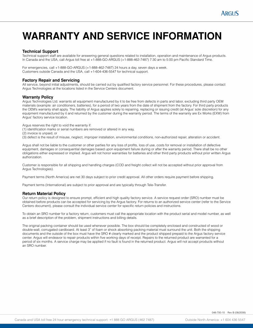
Technical SupportTechnical support staff are available for answering general questions related to installation, operation and maintenance of Argus products. In Canada and the USA, call Argus toll free at +1-888-GO-ARGUS (+1-888-462-7487) 7:30 am to 5:00 pm Pacific Standard Time.
For emergencies, call +1-888-GO-ARGUS (+1-888-462-7487) 24 hours a day, seven days a week.Customers outside Canada and the USA, call +1-604-436-5547 for technical support.
Factory Repair and ServicingAll service, beyond initial adjustments, should be carried out by qualified factory service personnel. For these procedures, please contact Argus Technologies at the locations listed in the Service Centers document.
Warranty PolicyArgus Technologies Ltd. warrants all equipment manufactured by it to be free from defects in parts and labor, excluding third party OEM materials (example: air conditioners, batteries), for a period of two years from the date of shipment from the factory. For third party products the OEM’s warranty shall apply. The liability of Argus applies solely to repairing, replacing or issuing credit (at Argus’ sole discretion) for any equipment manufactured by it and returned by the customer during the warranty period. The terms of the warranty are Ex Works (EXW) from Argus’ factory service location.
Argus reserves the right to void the warranty if: (1) identification marks or serial numbers are removed or altered in any way, (2) invoice is unpaid, or (3) defect is the result of misuse, neglect, improper installation, environmental conditions, non-authorized repair, alteration or accident.
Argus shall not be liable to the customer or other parties for any loss of profits, loss of use, costs for removal or installation of defective equipment, damages or consequential damages based upon equipment failure during or after the warranty period. There shall be no other obligations either expressed or implied. Argus will not honor warranties for batteries and other third party products without prior written Argus authorization.
Customer is responsible for all shipping and handling charges (COD and freight collect will not be accepted without prior approval from Argus Technologies).
Payment terms (North America) are net 30 days subject to prior credit approval. All other orders require payment before shipping.
Payment terms (International) are subject to prior approval and are typically through Tele-Transfer.
Return Material PolicyOur return policy is designed to ensure prompt, efficient and high quality factory service. A service request order (SRO) number must be obtained before products can be accepted for servicing by the Argus factory. For returns to an authorized service center (refer to the Service Centers document), please consult the individual service center for specific return policies and instructions.
To obtain an SRO number for a factory return, customers must call the appropriate location with the product serial and model number, as well as a brief description of the problem, shipment instructions and billing details.
The original packing container should be used whenever possible. The box should be completely enclosed and constructed of wood or double-wall, corrugated cardboard. At least 3” of foam or shock absorbing packing material must surround the unit. Both the shipping documents and the outside of the box must have the SRO # clearly marked and the product shipped prepaid to the Argus factory service center. Argus will endeavor to repair products within five working days of receipt. Repairs to the returned product are warranted for a period of six months. A service charge may be applied if no fault is found in the returned product. Argus will not accept products without an SRO number.
WARRANTY AND SERVICE INFORMATION
Canada and USA toll free 24 hour emergency technical support: +1 888 GO ARGUS (462 7487) Outside North America: +1 604 436 5547
048-700-10 Rev B (08/2008)
048-693-10 Rev C (04/2008)
Canada and USA toll free 24 hour emergency technical support: +1 888 GO ARGUS (462 7487) Outside North America: +1 604 436 5547
Service CentersFactory Service Centers
Canada and InternationalArgus Technologies Ltd.ATTN: RMA Returns7033 Antrim Avenue Burnaby, BC, V5J 4M5 Canada Tel: +1 604 436 5900Fax: +1 604 436 1233Email: [email protected]
USA Argus Technologies Inc.ATTN: RMA Returns3116 Mercer AvenueBellingham, WA, 98225 USA Tel: +1-360 756 4904Fax: +1-360 647 0498Email: [email protected]
Asia-PacificPCM Electronics (Dong Guan) Co., Ltd.Hongli Industrial Area, Miaobian, Liaobu Town, Dongguan City, Guangdong Province, 523400 China Tel: +86 755 8895 3310Fax: +86 755 8895 3307
Authorized Service Center
ArgentinaArgus Technologies de ArgentinaBelen 315, Capital Federal, Buenos Aires, 1407l ArgentinaTel: +54 (11) 4672 4821Fax: +54 (11) 4504 4698Cell: +54 9 (11) 4993 9996Email: [email protected]
AsiaArgus Technologies Asia Pte LtdBlk 6 Tagore Lane #160Singapore 787570Tel: +65 6458 8900Fax: +65 6458 2122
AustraliaCPS National8/376 Newbridge RdMoorebank, NSW, 2170 Australia Tel: +61 02 9822 8977Fax: +61 02 9822 8077
Australia/New ZealandAlpha Power Systems Pty Ltd.Unit 3, 30 Heathcote Road Moorebank, NSW, 2170 Australia Tel: +61 02 9602 8331Fax: +61 02 9602 9180
Century Yuasa37 - 65 Colbalt StreetCarole Park QLD 4300Australian Sales & ServiceTel: +61 07 3361 6587Fax: +61 07 3361 6705New Zealand Sales & Service Tel: +64 9 978 6689Fax: +64 9 978 6677
BrazilArgus Brasil Serviços e Comércio LtdaRua: Constituição,145/147 - Santos São Paulo – Brasil 11015-471Tel: +55 (13) 3234 2469Fax: +55 (13) 3234 2469Cell: +55 (13) 7806 1438Email: [email protected]
CanadaCompower Systems Inc.118 Tiffield Road Toronto, ON, M1V 5N2 Canada Tel: +1 416 293 3088Fax: +1 416 293 0671
EuropeAlpha Technologies Europe Ltd.Cartel Business EstateEdinburgh WayHarlow, Essex, CM20 2DU UK Tel: +44 1279 422110Fax: +44 1279 423355
Mexico & Central AmericaTechnologies Argus First De Mexico SA de CVAnatole France No. 17Col. PolancoMexico City, 11560 Mexico Tel: +52 55 5280 6990Fax: +52 55 5280 6585
RomaniaAlphapower SRLStr. Paul Constantinescu nr.5Timisoara, RomaniaTel: +40 21 569 1214Cell: +40 31 816 1491
South AmericaArgus Technologies ArgentinaSanto Tome 2573, Capital FederalBuenos Aires, 1416 ArgentinaTel: +54 11 4504 4698Cell: +54 9 11 4993 9996E-pager: [email protected]
TurkeyIPC Enerji Elk San ve TIC ASInonu cad. Kanarya sok. No:20Yenisahra - KadikoyIstanbul, TurkeyTel: +90 216 317 41 42Fax: +90 216 472 90 66