netdirector® rack-mount console kvm switch with ip access
TRANSCRIPT
1
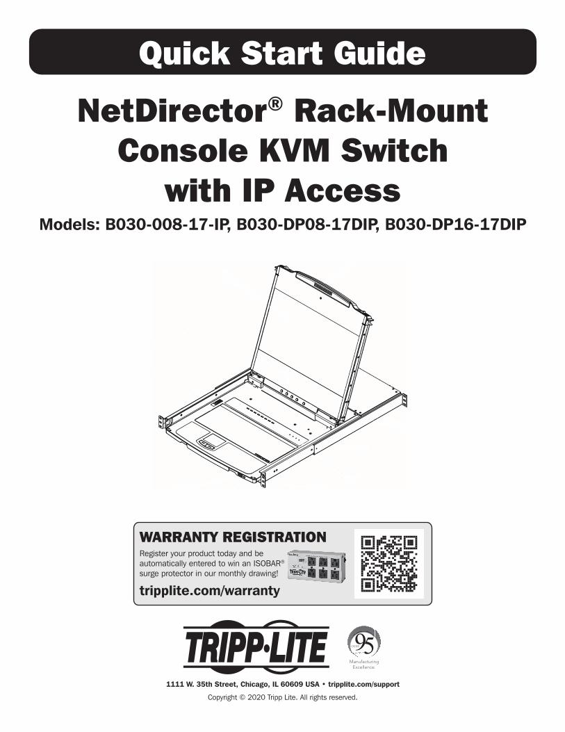
Quick Start Guide
NetDirector® Rack-MountConsole KVM Switch
with IP AccessModels: B030-008-17-IP, B030-DP08-17DIP, B030-DP16-17DIP
WARRANTY REGISTRATIONRegister your product today and be automatically entered to win an ISOBAR® surge protector in our monthly drawing!
tripplite.com/warranty
1111 W. 35th Street, Chicago, IL 60609 USA • tripplite.com/support
Copyright © 2020 Tripp Lite. All rights reserved.
2
Table of Contents
1. Package Contents .................................................... 3
2. System Requirements .............................................. 4 2.1 Built-in LCD Console ......................................... 4 2.2 Optional External Console ................................ 4 2.3 Computers ....................................................... 4 2.4 Operating Systems ........................................... 4
3. Features ................................................................... 5 3.1 Components ..................................................... 6
4. Important Safety Instructions .................................. 8 4.1 General Safety Instructions .............................. 8 4.2 Rack-Mounting Safety Instructions ................... 9
5. Installation ............................................................. 10 5.1 Standard Rack Mounting ................................ 10 5.2 2-Post Rack Mounting .................................... 10 5.3 Grounding ...................................................... 10 5.4 KVM Switch Installation .................................. 10 5.5 Opening/Closing the Console .......................... 11 5.5.1 Opening Separately .............................. 11 5.5.2 Opening Together ................................. 12 5.5.3 Opening Precautions ............................ 13 5.5.4 Closing the Console ............................. 14 5.6 Network Setup – IP Address Configuration ...... 16 5.6.1 Local Console ...................................... 16 5.6.2 IP Installer ........................................... 17 5.6.3 Browser .............................................. 17
6. Basic Operation ...................................................... 19 6.1 LCD OSD Configuration ................................... 19 6.1.1 LCD Buttons ........................................ 19 6.1.2 Adjustment Settings ............................. 19 6.1.3 Hot Plugging ....................................... 19 6.1.4 Powering Off and Restarting .................. 19 6.1.5 USB Peripheral Devices ........................ 19
7. KVM Operation ....................................................... 20 7.1 Local Console Login ....................................... 20 7.2 Logging into the KVM over IP ......................... 20 7.2.1 Web Browser ...................................... 20 7.2.2 AP Windows Client Login ...................... 20 7.2.3 AP Java Client Login ............................. 23
8. Warranty and Product Registration ........................ 24
FCC InformationThis device complies with part 15 of the FCC Rules. Operation is subject to the following two conditions: (1) This device may not cause harmful interference, and (2) this device must accept any interference received, including interference that may cause undesired operation.
Note: This equipment has been tested and found to comply with the limits for a Class A digital device, pursuant to part 15 of the FCC Rules. These limits are designed to provide reasonable protection against harmful interference when the equipment is operated in a commercial environment. This equipment generates, uses, and can radiate radio frequency energy and, if not installed and used in accordance with the instruction manual, may cause harmful interference to radio communications. Operation of this equipment in a residential area is likely to cause harmful interference in which case the user will be required to correct the interference at his own expense. The user must use shielded cables and connectors with this equipment. Any changes or modifications to this equipment not expressly approved by Tripp Lite could void the user’s authority to operate this equipment.
User NoticeAll information, documentation, and specifications contained in this manual are subject to change without prior notification by the manufacturer. The manufacturer makes no representations or warranties, either expressed or implied, with respect to the contents hereof and specifically disclaims any warranties as to merchantability or fitness for any particular purpose. Any of the manufacturer’s software described in this manual is sold or licensed “as is.” Should the programs prove defective following their purchase, the buyer (and not the manufacturer, its distributor, or its dealer), assumes the entire cost of all necessary servicing, repair and any incidental or consequential damages resulting from any defect in the software.
The manufacturer of this system is not responsible for any radio and/or TV interference caused by unauthorized modifications to this device. It is the responsibility of the user to correct such interference.
The manufacturer is not responsible for any damage incurred in the operation of this system if the correct operational voltage setting was not selected prior to operation. VERIFY THAT THE VOLTAGE SETTING IS CORRECT BEFORE USE.
3
1. Package Contents
• NetDirector B030-Series Rack-Mount Console KVM Switch with IP Access
• (x2) High-Speed HDMI Cables - 6 ft. or (x2) DisplayPort Cables - 6 ft. (depending on model purchased)
• (x2) USB 2.0 A/B Cables – 6 ft.
• IEC C13 to NEMA 5-15P Power Cord
• Grounding Wire
• Quick Start Guide
• CD with Owner’s Manual
Check to ensure all components are present and in good order. If anything is missing or was damaged in shipping, contact your dealer.
Read this manual thoroughly and follow the installation and operation procedures carefully to prevent any damage to the switch or to any other devices on the installation.
Optional Accessories• N201-Series Cat6 Gigabit Snagless Patch Cables
• P006-Series IEC C13 to NEMA 5-15P Power Cords
• P580-Series DisplayPort Cables with Latches (M/M)
• P569-Series High-Speed HDMI Cables, 4K (M/M)
• P782-XXX-DH* HDMI/DVI + USB KVM Cable Kits (for model B030-008-17-IP only)
*XXX refers to the length, with cables available in 6 ft. (006), 10 ft. (010) and 15 ft. (015) lengths
4
2. System Requirements
2.1 Built-In LCD ConsoleThe integrated LCD monitor’s maximum resolution is 1920 x 1080 @ 60 Hz. Ensure all resolution settings of the connected computers do not exceed the LCD monitor’s maximum resolution.
2.2 Optional External Console• Model B030-008-17-IP: A DVI (user-supplied adapter required) or HDMI monitor capable of displaying the highest resolutions provided by
any computer in the installation.
• Models B030-DPXX-17DIP: A DisplayPort monitor capable of displaying the highest resolutions provided by any computer in the installation.
• USB keyboard and mouse.
2.3 ComputersThe following equipment must be installed on each computer:
• A DVI, HDMI or DisplayPort video graphics card.
• USB mouse and keyboard ports.
2.4 Operating SystemsOS Supported Versions
Windows NT and higher
Mac OS 9.0 and higher
Linux RedHat 9.0 and higher
Linux SuSE 10 and higher
Linux Mandriva (Mandrake) 9.0 and higher
UNIX AIX 4.3 and higher
UNIX FreeBSD 5.5 and higher
UNIX Sun Solaris 8 and higher
Novell Netware 5.0 and higher
DOS 6.2 and higher
5
3. Features
• Rack-Mount Console KVM Switch with built-in IP Access in a dual-rail housing with top and bottom clearance for integrated operation in 1U of rack space.
• KVM console combines a 17.3” LCD monitor, keyboard and touchpad.
• Model B030-008-17-IP: connect an external DVI monitor or computer using HDMI to DVI adapter cables.
• Models B030-DP08-17DIP / B030-DP16-17DIP: connect an external DisplayPort monitor using DisplayPort cables.
• Multi-platform support; compatible with Windows®, Mac®, Linux® and Sun.
• Dual-Rail – LCD Monitor module can slide independently of the keyboard/touchpad module.
• A single console controls up to 8 or 16 computers.
• Remotely access computers via LAN, WAN, or the internet – control your installation when and where you want.
• 10/100/1000 Mbps network port.
• Grayscale option to improve transfer speed in low-bandwidth situations.
• User-selectable network transfer rate.
• Optional external console ports located on the rear of the device – manage computers in the LCD KVM switch from an external console (monitor, USB keyboard, USB mouse).
• Features a USB 1.1 hub port on the front of the console for the connection of a USB peripheral device, such as a flash drive or external mouse.
• Console lock – enables the console modules to remain securely locked away in position when not in use.
• Supports a browser-based user interface
• Browser access can be disabled – AP Windows and Java Clients are available for non-browser IP access to the KVM.
• Graphical OSD and graphical toolbars for convenient, user-friendly operation.
• Up to 64 user accounts – up to 32 concurrent remote logins.
• Message board feature allows logged-in users to communicate with one another and a remote user to take exclusive control of the KVM functions.
• Panel Array Mode – view all ports at the same time in a grid format.
• Broadcast Mode support – keyboard commands can be broadcast to all available computers in the installation.
• Three user account types: Super Administrator, Administrator and User.
• Supports SSL 128-bit data encryption and RSA 1024-bit certificates to secure user browser logins.
• Flexible encryption design allows users to choose any combination of 56-bit DES, 168-bit 3DES, 256-bit AES, 128-bit RC4, or Random for independent KB/Mouse, video and virtual media data encryption.
• Remote authentication support: RADIUS, LDAP, LDAPS and MS Active Directory.
• Flash firmware upgradable over a network connection.
• Ports can be set to Exclusive, Occupy and Share.
• Network Interfaces: TCP/IP, HTTP, HTTPS, UDP, RADIUS, DHCP, SSL, ARP, DNS, 10Base-T/100Base-TX, Auto Sense and Ping.
• Supports video resolutions up to 1920 x 1080 @ 60 Hz.
• DDC emulation – video settings of attached computers are automatically adjusted for optimal output to the monitor.
• HDCP support (local monitor and external console port only).
• Includes an advanced FPGA graphics processor for improved video quality.
• UltraSync for USB mice ensures local and remote mouse movement are the same, eliminating the need to constantly re-sync the two movements.
• Both IPv4 and IPv6 are supported.
• BIOS level access.
• Includes Automated Certificate Signing Request (CSR) creation utility and third-party CA certificate authentication.
• Multi-language support; remote onscreen diagnostics can be displayed in English, Spanish, French, German, Russian, Italian, Japanese, Korean, traditional Chinese and simplified Chinese.
• Remote access interface on-screen keyboard offers multi-language support.
• Supports exit Macros.
• Windows-based log server.
6
3. Features
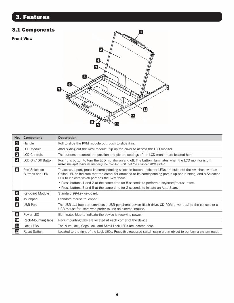
3.1 Components
Front View
No. Component Description
1 Handle Pull to slide the KVM module out; push to slide it in.
2 LCD Module After sliding out the KVM module, flip up the cover to access the LCD monitor.
3 LCD Controls The buttons to control the position and picture settings of the LCD monitor are located here.
4 LCD On / Off Button Push this button to turn the LCD monitor on and off. The button illuminates when the LCD monitor is off. Note: The light indicates that only the monitor is off, not the attached KVM switch.
5 Port Selection Buttons and LED
To access a port, press its corresponding selection button. Indicator LEDs are built into the switches, with an Online LED to indicate that the computer attached to its corresponding port is up and running, and a Selection LED to indicate which port has the KVM focus.• Press buttons 1 and 2 at the same time for 5 seconds to perform a keyboard/mouse reset.• Press buttons 7 and 8 at the same time for 2 seconds to initiate an Auto Scan.
6 Keyboard Module Standard 99-key keyboard.
7 Touchpad Standard mouse touchpad.
8 USB Port The USB 1.1 hub port connects a USB peripheral device (flash drive, CD-ROM drive, etc.) to the console or a USB mouse for users who prefer to use an external mouse.
9 Power LED Illuminates blue to indicate the device is receiving power.
10 Rack-Mounting Tabs Rack-mounting tabs are located at each corner of the device.
11 Lock LEDs The Num Lock, Caps Lock and Scroll Lock LEDs are located here.
12 Reset Switch Located to the right of the Lock LEDs. Press this recessed switch using a thin object to perform a system reset.
1
3
5
2
67
89 10
11
12
4
7
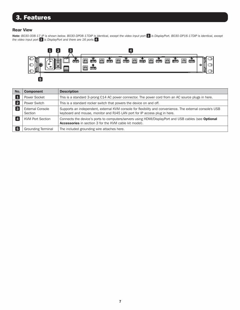
Rear ViewNote: B030-008-17-IP is shown below. B030-DP08-17DIP is identical, except the video input port 3 is DisplayPort. B030-DP16-17DIP is identical, except the video input port 3 is DisplayPort and there are 16 ports 4 .
1
5
2 3 4
No. Component Description
1 Power Socket This is a standard 3-prong C14 AC power connector. The power cord from an AC source plugs in here.
2 Power Switch This is a standard rocker switch that powers the device on and off.
3 External Console Section
Supports an independent, external KVM console for flexibility and convenience. The external console's USB keyboard and mouse, monitor and RJ45 LAN port for IP access plug in here.
4 KVM Port Section Connects the device’s ports to computers/servers using HDMI/DisplayPort and USB cables (see Optional Accessories in section 3 for the KVM cable kit model).
5 Grounding Terminal The included grounding wire attaches here.
3. Features

8
4. Important Safety Instructions
4.1 General Safety Instructions• Read all of these instructions and save them for future reference.
• Follow all warnings and instructions marked on the device.
• Do not place the device on any unstable surface. If the device falls, serious damage will result.
• Do not use the device near water.
• Do not place the device near or over, radiators or heat registers.
• The device cabinet is provided with slots and openings to allow for adequate ventilation. To ensure reliable operation and protect against overheating, these openings should never be blocked or covered.
• The device should never be placed on a soft surface, such as a bed, sofa or rug. Doing so will block the device’s ventilation openings. Moreover, the device should not be placed in a built-in enclosure unless adequate ventilation has been provided.
• Never spill liquid of any type on the device.
• Unplug the device from the wall outlet before cleaning. Use a damp cloth for cleaning. Do not use liquid or aerosol cleaners.
• The device should be operated from the power source indicated on the marking label. If uncertain of the power available, consult your dealer or local power company.
• The device is designed for IT power distribution systems up to 230V phase-to-phase voltage.
• As an added safety feature, the device is equipped with a 3-wire grounding-type plug. If unable to insert the plug into the outlet, contact an electrician to replace the obsolete outlet. Do not attempt to plug into a 2-prong ungrounded outlet. Always follow local/national wiring codes.
• Do not allow anything to rest on the power cord or cables. Route the power cord and cables to avoid them being stepped on or tripped over.
• If an extension cord is used with this device, ensure the total ampere ratings of all products used on the extension cord do not exceed its rated ampere rating. Also, ensure all products plugged into the wall do not exceed a total of 15 amperes.
• Consideration should be given to the connection of equipment and the supply circuit, as well as what effect overloading the supply circuit might have on overcurrent protection and supply wiring.
• To help protect the system from unexpected transient increases and decreases in electrical power, use a Tripp Lite Surge Protector, Line Conditioner, or Uninterruptible Power Supply (UPS).
• Position system cables and power cables carefully so nothing rests on any cables.
• When connecting or disconnecting power to hot-pluggable power supplies, observe the following guidelines:
– Install the power supply before connecting the power cable to the power supply.
– Unplug the power cable before removing the power supply.
– If the system has multiple sources of power, disconnect power from the system by unplugging all power cables from the power supplies.
• Never push objects of any kind into or through cabinet slots. They may touch dangerous voltage points or short out parts, resulting in a risk of fire or electrical shock.
• Do not attempt to service the device; refer all servicing to qualified service personnel.
• If the following conditions occur, unplug the device from the wall outlet and bring it to qualified service personnel for repair:
– The power cord or plug has become damaged or frayed.
– Liquid has been spilled into the device.
– The device has been exposed to rain or water.
– The device has been dropped, or the cabinet has been damaged.
– The device exhibits a distinct change in performance, indicating a need for service.
– The device does not operate normally when the operating instructions are followed.
• Only adjust controls covered in the operating instructions. Improper adjustment of other controls may result in damage that will require extensive work by a qualified technician to repair.
• Use of this equipment in life support applications where failure of this equipment can reasonably be expected to cause the failure of the life support equipment or to significantly affect its safety or effectiveness is not recommended. Do not use this equipment in the presence of a flammable anesthetic mixture with air, oxygen or nitrous oxide.
9
4. Important Safety Instructions
4.2 Rack-Mounting Safety Instructions• The ambient operating temperature in the rack may be an issue and is dependent upon the rack load and ventilation. When installing in a
closed or multi-device rack assembly, ensure the temperature will not exceed the maximum rated ambient temperature.
• Before installing the rack, ensure the stabilizers are secured to the rack, extended to the floor and the full weight of the rack rests on the floor. Install front and side stabilizers on a single rack or front stabilizers for joined multiple racks before working on the rack.
• Always load the rack from the bottom up with the heaviest item loaded into the rack first.
• When loading the rack, avoid creating a hazardous condition due to uneven loading.
• Ensure the rack is level and stable before extending a device from the rack.
• Use caution when pressing the rail release latches or sliding a device into or out of a rack; slide rails can pinch your fingers.
• After a device is inserted into the rack, carefully extend the rail into a locking position, then slide the device into the rack.
• Do not overload the AC supply branch circuit that provides power to the rack. The total rack load should not exceed 80 percent of the branch circuit rating.
• Ensure that proper airflow is provided to devices in the rack.
• Do not step on or stand on any device when servicing other devices in a rack.
• Do not connect the RJ11 connector marked “Upgrade” to a public telecommunication network.
• Caution! Slide/Rail (LCD KVM) mounted equipment is not to be used as a shelf or work space.
10
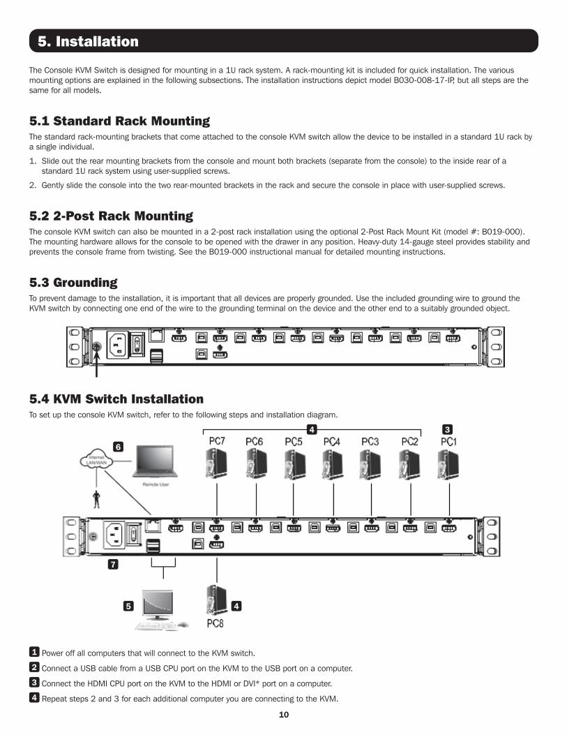
5. Installation
The Console KVM Switch is designed for mounting in a 1U rack system. A rack-mounting kit is included for quick installation. The various mounting options are explained in the following subsections. The installation instructions depict model B030-008-17-IP, but all steps are the same for all models.
5.1 Standard Rack MountingThe standard rack-mounting brackets that come attached to the console KVM switch allow the device to be installed in a standard 1U rack by a single individual.
1. Slide out the rear mounting brackets from the console and mount both brackets (separate from the console) to the inside rear of a standard 1U rack system using user-supplied screws.
2. Gently slide the console into the two rear-mounted brackets in the rack and secure the console in place with user-supplied screws.
5.2 2-Post Rack MountingThe console KVM switch can also be mounted in a 2-post rack installation using the optional 2-Post Rack Mount Kit (model #: B019-000). The mounting hardware allows for the console to be opened with the drawer in any position. Heavy-duty 14-gauge steel provides stability and prevents the console frame from twisting. See the B019-000 instructional manual for detailed mounting instructions.
5.3 GroundingTo prevent damage to the installation, it is important that all devices are properly grounded. Use the included grounding wire to ground the KVM switch by connecting one end of the wire to the grounding terminal on the device and the other end to a suitably grounded object.
5.4 KVM Switch InstallationTo set up the console KVM switch, refer to the following steps and installation diagram.
1 Power off all computers that will connect to the KVM switch.
2 Connect a USB cable from a USB CPU port on the KVM to the USB port on a computer.
3 Connect the HDMI CPU port on the KVM to the HDMI or DVI* port on a computer.
4 Repeat steps 2 and 3 for each additional computer you are connecting to the KVM.
34
6
7
5 4
11
5. Installation
5 (Optional) Add an external console to the KVM by connecting an HDMI or DVI* monitor and USB keyboard and mouse to the console ports on the back of the device.
6 Connect the LAN port on the back of the device to the network using Cat5e/6 cable.
7 Plug the included power cord into a Tripp Lite Surge Protector, Power Distribution Device (PDU), Uninterruptible Power Supply (UPS) or AC wall outlet.
8 Power the connected computers.
9 Power the KVM device.
*Using an HDMI to DVI adapter cable, such as Tripp Lite’s P566-Series cables.
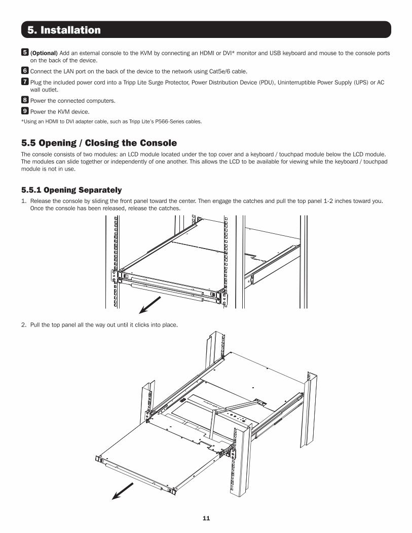
5.5 Opening / Closing the ConsoleThe console consists of two modules: an LCD module located under the top cover and a keyboard / touchpad module below the LCD module. The modules can slide together or independently of one another. This allows the LCD to be available for viewing while the keyboard / touchpad module is not in use.
5.5.1 Opening Separately1. Release the console by sliding the front panel toward the center. Then engage the catches and pull the top panel 1-2 inches toward you.
Once the console has been released, release the catches.
2. Pull the top panel all the way out until it clicks into place.
12
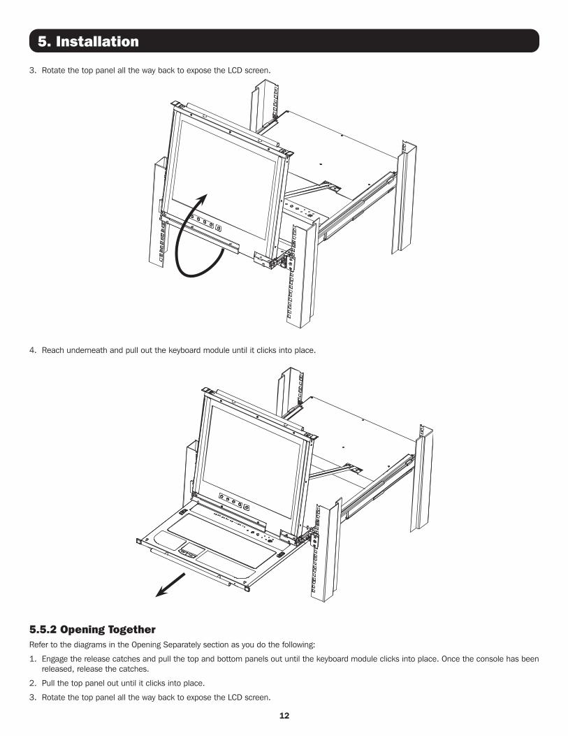
3. Rotate the top panel all the way back to expose the LCD screen.
4. Reach underneath and pull out the keyboard module until it clicks into place.
5.5.2 Opening TogetherRefer to the diagrams in the Opening Separately section as you do the following:
1. Engage the release catches and pull the top and bottom panels out until the keyboard module clicks into place. Once the console has been released, release the catches.
2. Pull the top panel out until it clicks into place.
3. Rotate the top panel all the way back to expose the LCD screen.
5. Installation
13
5. Installation
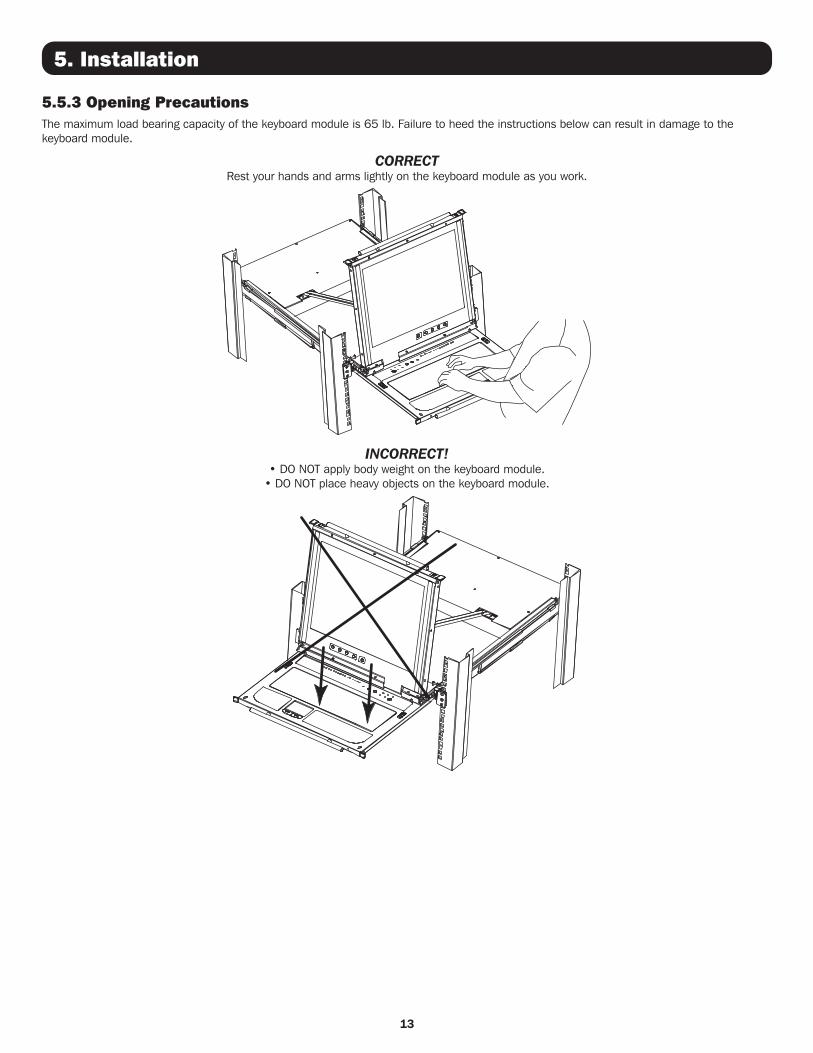
5.5.3 Opening PrecautionsThe maximum load bearing capacity of the keyboard module is 65 lb. Failure to heed the instructions below can result in damage to the keyboard module.
CORRECT Rest your hands and arms lightly on the keyboard module as you work.
INCORRECT! • DO NOT apply body weight on the keyboard module.
• DO NOT place heavy objects on the keyboard module.
14
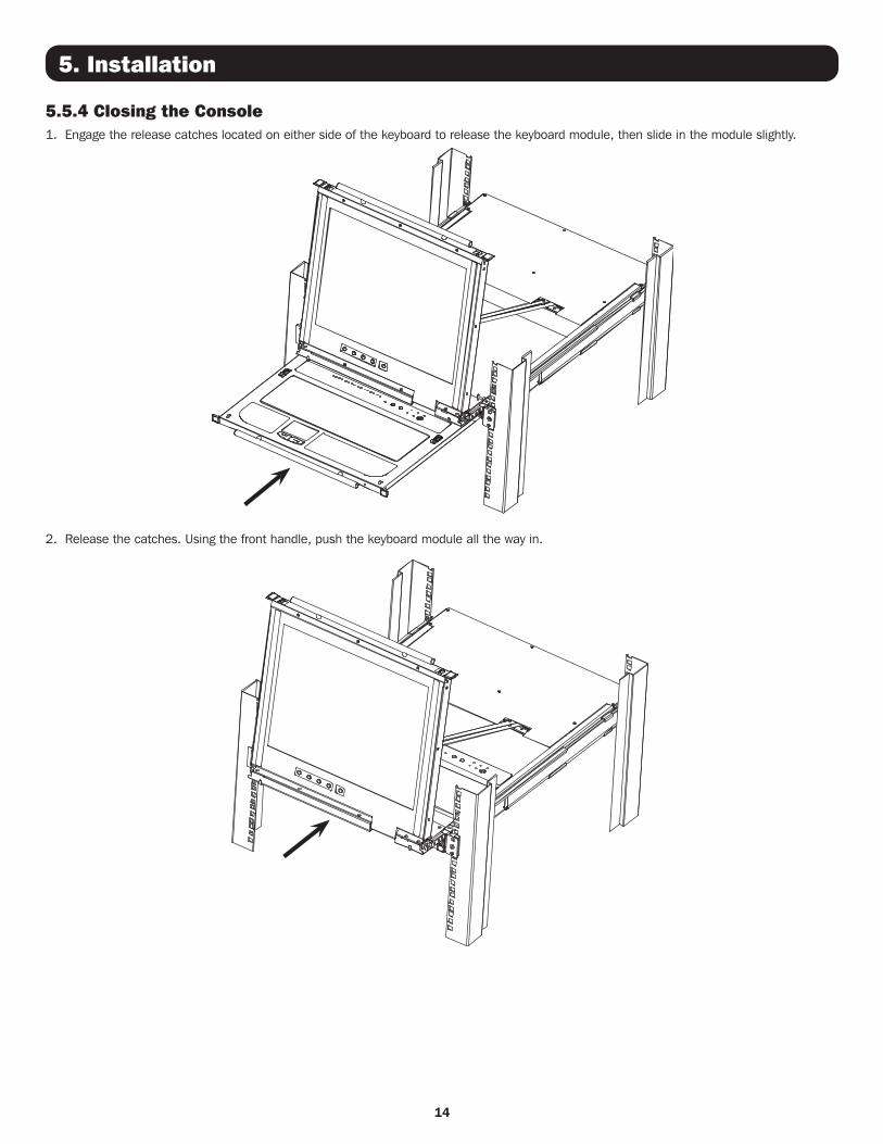
5.5.4 Closing the Console1. Engage the release catches located on either side of the keyboard to release the keyboard module, then slide in the module slightly.
2. Release the catches. Using the front handle, push the keyboard module all the way in.
5. Installation
15
5. Installation
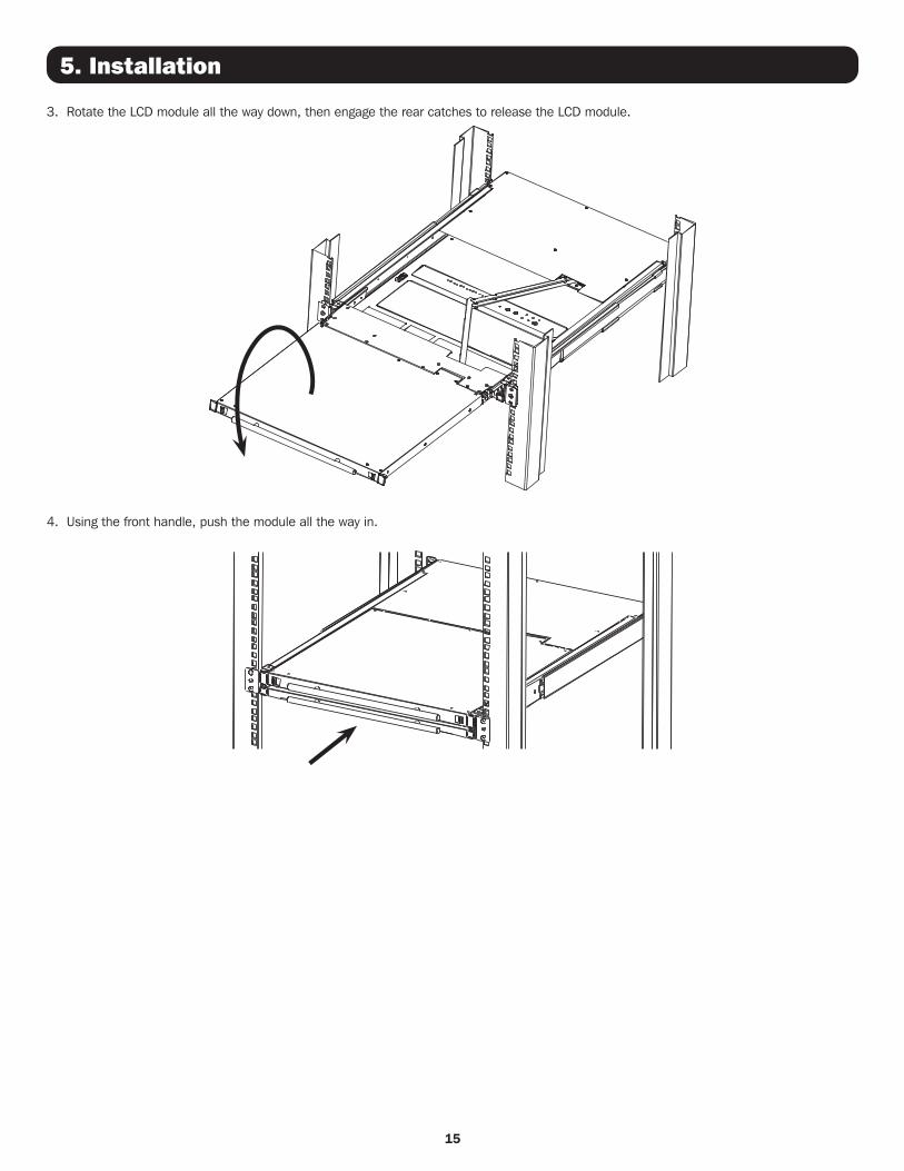
3. Rotate the LCD module all the way down, then engage the rear catches to release the LCD module.
4. Using the front handle, push the module all the way in.
16
5. Installation
5.6 Network Setup – IP Address ConfigurationBy default, the KVM will automatically have an IP address assigned via DHCP server. To configure a fixed IP address, you will need to access the KVM switch in one of three ways: Local Console, IP Installer or Browser.
5.6.1 Local ConsoleNote: The local console OSD only allows IPv4 network settings configuration. For IPv6, access the Web Management Interface.
1. When accessing the console KVM switch for the first time, a prompt will appear asking for a username and password. The default Username is administrator, and the default Password is password. For security purposes, changing the username and password is strongly recommended. Once the default username and password are entered, the OSD Main page will appear.
2. Press the [F4] key to open the OSD ADM page.
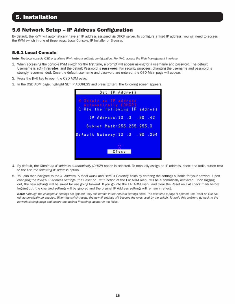
3. In the OSD ADM page, highlight SET IP ADDRESS and press [Enter]. The following screen appears.
4. By default, the Obtain an IP address automatically (DHCP) option is selected. To manually assign an IP address, check the radio button next to the Use the following IP address option.
5. You can then navigate to the IP Address, Subnet Mask and Default Gateway fields by entering the settings suitable for your network. Upon changing the KVM’s IP Address settings, the Reset on Exit function of the F4: ADM menu will be automatically activated. Upon logging out, the new settings will be saved for use going forward. If you go into the F4: ADM menu and clear the Reset on Exit check mark before logging out, the changed settings will be ignored and the original IP Address settings will remain in effect.
Note: Although the changed IP settings are ignored, they still remain in the network settings fields. The next time a page is opened, the Reset on Exit box will automatically be enabled. When the switch resets, the new IP settings will become the ones used by the switch. To avoid this problem, go back to the network settings page and ensure the desired IP settings appear in the fields.
17
5. Installation
5.6.2 IP InstallerComputers running Windows can use the IP Installer utility found in the included CD-ROM to assign an IP address to the KVM.
Notes:
• The IP Installer Settings section located in the KVM’s Web Management Interface network page must be enabled in order to use the IP Installer to assign an IP address. This setting is enabled by default.
• The local console OSD only configures IPv4 network settings. For IPv6, access the Web Management Interface.
1. Save the IP Installer.exe file from the CD to a desired location on a computer that is on the same network as the KVM switch.
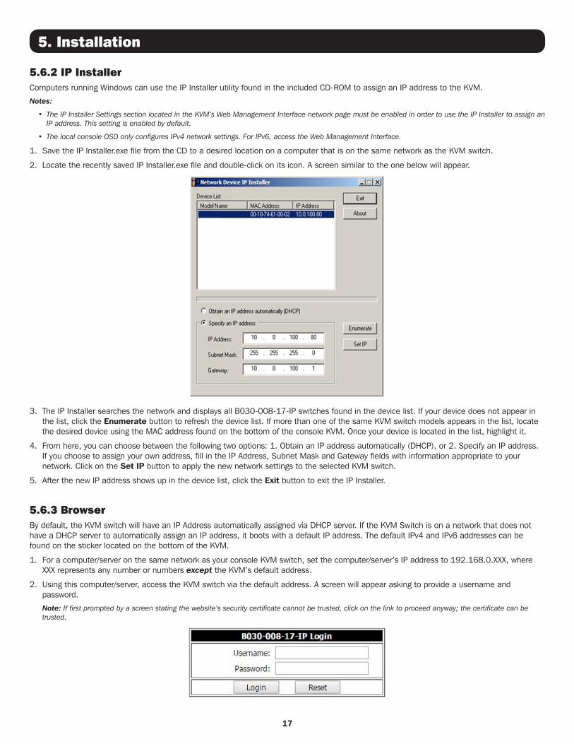
2. Locate the recently saved IP Installer.exe file and double-click on its icon. A screen similar to the one below will appear.
3. The IP Installer searches the network and displays all B030-008-17-IP switches found in the device list. If your device does not appear in the list, click the Enumerate button to refresh the device list. If more than one of the same KVM switch models appears in the list, locate the desired device using the MAC address found on the bottom of the console KVM. Once your device is located in the list, highlight it.
4. From here, you can choose between the following two options: 1. Obtain an IP address automatically (DHCP), or 2. Specify an IP address. If you choose to assign your own address, fill in the IP Address, Subnet Mask and Gateway fields with information appropriate to your network. Click on the Set IP button to apply the new network settings to the selected KVM switch.
5. After the new IP address shows up in the device list, click the Exit button to exit the IP Installer.
5.6.3 BrowserBy default, the KVM switch will have an IP Address automatically assigned via DHCP server. If the KVM Switch is on a network that does not have a DHCP server to automatically assign an IP address, it boots with a default IP address. The default IPv4 and IPv6 addresses can be found on the sticker located on the bottom of the KVM.
1. For a computer/server on the same network as your console KVM switch, set the computer/server’s IP address to 192.168.0.XXX, where XXX represents any number or numbers except the KVM’s default address.
2. Using this computer/server, access the KVM switch via the default address. A screen will appear asking to provide a username and password.
Note: If first prompted by a screen stating the website’s security certificate cannot be trusted, click on the link to proceed anyway; the certificate can be trusted.
18
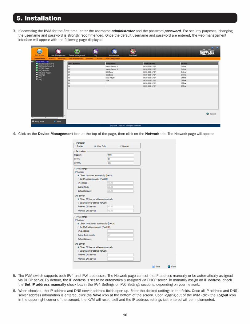
3. If accessing the KVM for the first time, enter the username administrator and the password password. For security purposes, changing the username and password is strongly recommended. Once the default username and password are entered, the web management interface will appear with the following page displayed:
4. Click on the Device Management icon at the top of the page, then click on the Network tab. The Network page will appear.
5. The KVM switch supports both IPv4 and IPv6 addresses. The Network page can set the IP address manually or be automatically assigned via DHCP server. By default, the IP address is set to be automatically assigned via DHCP server. To manually assign an IP address, check the Set IP address manually check box in the IPv4 Settings or IPv6 Settings sections, depending on your network.
6. When checked, the IP address and DNS server address fields open up. Enter the desired settings in the fields. Once all IP address and DNS server address information is entered, click the Save icon at the bottom of the screen. Upon logging out of the KVM (click the Logout icon in the upper-right corner of the screen), the KVM will reset itself and the IP address settings just entered will be implemented.
5. Installation
19
6. Basic Operation
6.1 LCD OSD Configuration
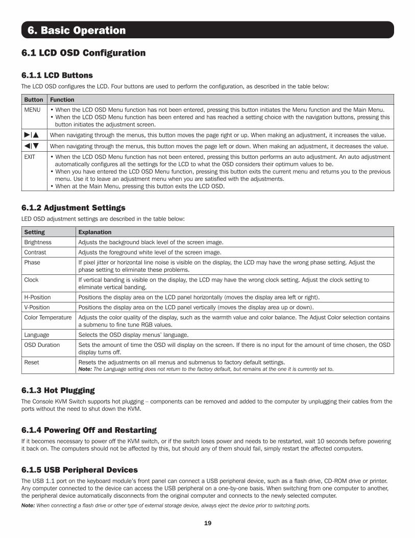
6.1.1 LCD ButtonsThe LCD OSD configures the LCD. Four buttons are used to perform the configuration, as described in the table below:
Button Function
MENU • When the LCD OSD Menu function has not been entered, pressing this button initiates the Menu function and the Main Menu.• When the LCD OSD Menu function has been entered and has reached a setting choice with the navigation buttons, pressing this
button initiates the adjustment screen.
When navigating through the menus, this button moves the page right or up. When making an adjustment, it increases the value.
When navigating through the menus, this button moves the page left or down. When making an adjustment, it decreases the value.
EXIT • When the LCD OSD Menu function has not been entered, pressing this button performs an auto adjustment. An auto adjustment automatically configures all the settings for the LCD to what the OSD considers their optimum values to be.
• When you have entered the LCD OSD Menu function, pressing this button exits the current menu and returns you to the previous menu. Use it to leave an adjustment menu when you are satisfied with the adjustments.
• When at the Main Menu, pressing this button exits the LCD OSD.
6.1.2 Adjustment SettingsLED OSD adjustment settings are described in the table below:
Setting Explanation
Brightness Adjusts the background black level of the screen image.
Contrast Adjusts the foreground white level of the screen image.
Phase If pixel jitter or horizontal line noise is visible on the display, the LCD may have the wrong phase setting. Adjust the phase setting to eliminate these problems.
Clock If vertical banding is visible on the display, the LCD may have the wrong clock setting. Adjust the clock setting to eliminate vertical banding.
H-Position Positions the display area on the LCD panel horizontally (moves the display area left or right).
V-Position Positions the display area on the LCD panel vertically (moves the display area up or down).
Color Temperature Adjusts the color quality of the display, such as the warmth value and color balance. The Adjust Color selection contains a submenu to fine tune RGB values.
Language Selects the OSD display menus’ language.
OSD Duration Sets the amount of time the OSD will display on the screen. If there is no input for the amount of time chosen, the OSD display turns off.
Reset Resets the adjustments on all menus and submenus to factory default settings.Note: The Language setting does not return to the factory default, but remains at the one it is currently set to.
6.1.3 Hot PluggingThe Console KVM Switch supports hot plugging – components can be removed and added to the computer by unplugging their cables from the ports without the need to shut down the KVM.
6.1.4 Powering Off and RestartingIf it becomes necessary to power off the KVM switch, or if the switch loses power and needs to be restarted, wait 10 seconds before powering it back on. The computers should not be affected by this, but should any of them should fail, simply restart the affected computers.
6.1.5 USB Peripheral DevicesThe USB 1.1 port on the keyboard module’s front panel can connect a USB peripheral device, such as a flash drive, CD-ROM drive or printer. Any computer connected to the device can access the USB peripheral on a one-by-one basis. When switching from one computer to another, the peripheral device automatically disconnects from the original computer and connects to the newly selected computer.
Note: When connecting a flash drive or other type of external storage device, always eject the device prior to switching ports.
20
7. KVM Operation
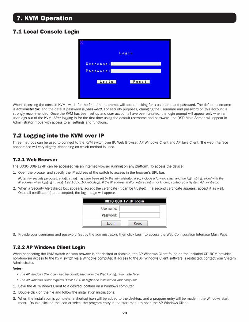
7.1 Local Console Login
When accessing the console KVM switch for the first time, a prompt will appear asking for a username and password. The default username is administrator, and the default password is password. For security purposes, changing the username and password on this account is strongly recommended. Once the KVM has been set up and user accounts have been created, the login prompt will appear only when a user logs out of the KVM. After logging in for the first time using the default username and password, the OSD Main Screen will appear in Administrator mode with access to all settings and functions.
7.2 Logging into the KVM over IPThree methods can be used to connect to the KVM switch over IP: Web Browser, AP Windows Client and AP Java Client. The web interface appearance will vary slightly, depending on which method is used.
7.2.1 Web Browser The B030-008-17-IP can be accessed via an internet browser running on any platform. To access the device:
1. Open the browser and specify the IP address of the switch to access in the browser’s URL bar.
Note: For security purposes, a login string may have been set by the administrator. If so, include a forward slash and the login string, along with the IP address when logging in. (e.g. 192.168.0.100/abcdefg). If the IP address and/or login string is not known, contact your System Administrator.
2. When a Security Alert dialog box appears, accept the certificate (it can be trusted). If a second certificate appears, accept it as well. Once all certificate(s) are accepted, the login page will appear.
3. Provide your username and password (set by the administrator), then click Login to access the Web Configuration Interface Main Page.
7.2.2 AP Windows Client LoginWhen connecting the KVM switch via web browser is not desired or feasible, the AP Windows Client found on the included CD-ROM provides non-browser access to the KVM switch via a Windows computer. If access to the AP Windows Client software is restricted, contact your System Administrator.
Notes:
• The AP Windows Client can also be downloaded from the Web Configuration Interface.
• The AP Windows Client requires Direct X 8.0 or higher be installed on your computer.
1. Save the AP Windows Client to a desired location on a Windows computer.
2. Double-click on the file and follow the installation instructions.
3. When the installation is complete, a shortcut icon will be added to the desktop, and a program entry will be made in the Windows start menu. Double-click on the icon or select the program entry in the start menu to open the AP Windows Client.
21
7. KVM Operation
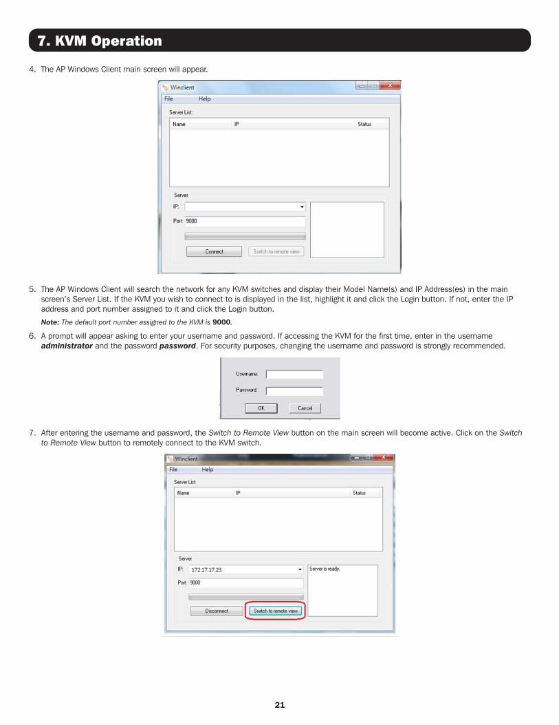
4. The AP Windows Client main screen will appear.
5. The AP Windows Client will search the network for any KVM switches and display their Model Name(s) and IP Address(es) in the main screen’s Server List. If the KVM you wish to connect to is displayed in the list, highlight it and click the Login button. If not, enter the IP address and port number assigned to it and click the Login button.
Note: The default port number assigned to the KVM is 9000.
6. A prompt will appear asking to enter your username and password. If accessing the KVM for the first time, enter in the username administrator and the password password. For security purposes, changing the username and password is strongly recommended.
7. After entering the username and password, the Switch to Remote View button on the main screen will become active. Click on the Switch to Remote View button to remotely connect to the KVM switch.
22
7. KVM Operation
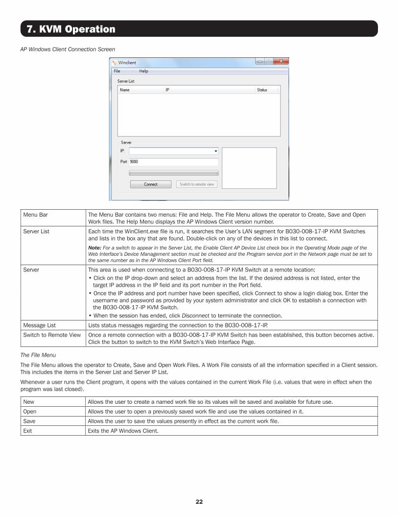
AP Windows Client Connection Screen
Menu Bar The Menu Bar contains two menus: File and Help. The File Menu allows the operator to Create, Save and Open Work files. The Help Menu displays the AP Windows Client version number.
Server List Each time the WinClient.exe file is run, it searches the User’s LAN segment for B030-008-17-IP KVM Switches and lists in the box any that are found. Double-click on any of the devices in this list to connect.
Note: For a switch to appear in the Server List, the Enable Client AP Device List check box in the Operating Mode page of the Web Interface’s Device Management section must be checked and the Program service port in the Network page must be set to the same number as in the AP Windows Client Port field.
Server This area is used when connecting to a B030-008-17-IP KVM Switch at a remote location:• Click on the IP drop-down and select an address from the list. If the desired address is not listed, enter the
target IP address in the IP field and its port number in the Port field.• Once the IP address and port number have been specified, click Connect to show a login dialog box. Enter the
username and password as provided by your system administrator and click OK to establish a connection with the B030-008-17-IP KVM Switch.
• When the session has ended, click Disconnect to terminate the connection.
Message List Lists status messages regarding the connection to the B030-008-17-IP.
Switch to Remote View Once a remote connection with a B030-008-17-IP KVM Switch has been established, this button becomes active. Click the button to switch to the KVM Switch’s Web Interface Page.
The File Menu
The File Menu allows the operator to Create, Save and Open Work Files. A Work File consists of all the information specified in a Client session. This includes the items in the Server List and Server IP List.
Whenever a user runs the Client program, it opens with the values contained in the current Work File (i.e. values that were in effect when the program was last closed).
New Allows the user to create a named work file so its values will be saved and available for future use.
Open Allows the user to open a previously saved work file and use the values contained in it.
Save Allows the user to save the values presently in effect as the current work file.
Exit Exits the AP Windows Client.
23
7. KVM Operation
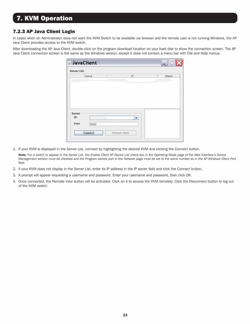
7.2.3 AP Java Client LoginIn cases when an Administrator does not want the KVM Switch to be available via browser and the remote user is not running Windows, the AP Java Client provides access to the KVM switch.
After downloading the AP Java Client, double-click on the program download location on your hard disk to show the connection screen. The AP Java Client connection screen is the same as the Windows version, except it does not contain a menu bar with File and Help menus.
1. If your KVM is displayed in the Server List, connect by highlighting the desired KVM and clicking the Connect button.
Note: For a switch to appear in the Server List, the Enable Client AP Device List check box in the Operating Mode page of the Web Interface’s Device Management section must be checked and the Program service port in the Network page must be set to the same number as in the AP Windows Client Port field.
2. If your KVM does not display in the Server List, enter its IP address in the IP server field and click the Connect button.
3. A prompt will appear requesting a username and password. Enter your username and password, then click OK.
4. Once connected, the Remote View button will be activated. Click on it to access the KVM remotely. Click the Disconnect button to log out of the KVM switch.
2420-07-302 93-3CD2_RevA
1111 W. 35th Street, Chicago, IL 60609 USA • tripplite.com/support
8. Warranty and Product Registration
3-Year Limited Warranty
TRIPP LITE warrants its products to be free from defects in materials and workmanship for a period of three (3) years from the date of initial purchase. TRIPP LITE’s obligation under this warranty is limited to repairing or replacing (at its sole option) any such defective products. To obtain service under this warranty, you must obtain a Returned Material Authorization (RMA) number from TRIPP LITE or an authorized TRIPP LITE service center. Products must be returned to TRIPP LITE or an authorized TRIPP LITE service center with transportation charges prepaid and must be accompanied by a brief description of the problem encountered and proof of date and place of purchase. This warranty does not apply to equipment which has been damaged by accident, negligence or misapplication or has been altered or modified in any way.
EXCEPT AS PROVIDED HEREIN, TRIPP LITE MAKES NO WARRANTIES, EXPRESS OR IMPLIED, INCLUDING WARRANTIES OF MERCHANTABILITY AND FITNESS FOR A PARTICULAR PURPOSE. Some states do not permit limitation or exclusion of implied warranties; therefore, the aforesaid limitation(s) or exclusion(s) may not apply to the purchaser.
EXCEPT AS PROVIDED ABOVE, IN NO EVENT WILL TRIPP LITE BE LIABLE FOR DIRECT, INDIRECT, SPECIAL, INCIDENTAL OR CONSEQUENTIAL DAMAGES ARISING OUT OF THE USE OF THIS PRODUCT, EVEN IF ADVISED OF THE POSSIBILITY OF SUCH DAMAGE. Specifically, TRIPP LITE is not liable for any costs, such as lost profits or revenue, loss of equipment, loss of use of equipment, loss of software, loss of data, costs of substitutes, claims by third parties, or otherwise.
PRODUCT REGISTRATION
Visit tripplite.com/warranty today to register your new Tripp Lite product. You’ll be automatically entered into a drawing for a chance to win a FREE Tripp Lite product!*
* No purchase necessary. Void where prohibited. Some restrictions apply. See website for details.
Regulatory Compliance Identification Numbers
For the purpose of regulatory compliance certifications and identification, your Tripp Lite product has been assigned a unique series number. The series number can be found on the product nameplate label, along with all required approval markings and information. When requesting compliance information for this product, always refer to the series number. The series number should not be confused with the marketing name or model number of the product.
WEEE Compliance Information for Tripp Lite Customers and Recyclers (European Union)
Under the Waste Electrical and Electronic Equipment (WEEE) Directive and implementing regulations, when customers buy new electrical and electronic equipment from Tripp Lite they are entitled to:
• Send old equipment for recycling on a one-for-one, like-for-like basis (this varies depending on the country)
• Send the new equipment back for recycling when this ultimately becomes waste
Tripp Lite has a policy of continuous improvement. Specifications are subject to change without notice.