convection heat transfer in concentric annuli
TRANSCRIPT

EHT 17(1) #12204
Experimental Heat Transfer, 17:19–29, 2004Copyright © Taylor & Francis Inc.ISSN: 0891-6152 print/1521-0480 onlineDOI: 10.1080/08916150490246528
CONVECTION HEAT TRANSFER INCONCENTRIC ANNULI
J. Dirker and H. Van der VyverDepartment of Mechanical Engineering, Rand Afrikaans University,Johannesburg, South Africa
J. P. MeyerDepartment of Mechanical and Aeronautical Engineering, University of Pretoria,Pretoria, South Africa
A comparative study is presented of literature involving convective heat transfer in annuli.It is shown that more research is needed in the area of convective heat transfer correlationsin concentric annuli, as little agreement is found among existing correlations. A correlationpredicting Nusselt numbers in annuli with ratios ranging from 1.7 to 3.2 was developedexperimentally for water as fluid. The correlation has an accuracy of 3% in terms ofexperimental values for a Reynolds number range, based on the hydraulic diameter, of4,000 to 30,000. The correlation was also compared to numerical predictions.
Many researchers have investigated heat transfer in annuli, particularly in orderto obtain correlations that can describe the Nusselt numbers for a wide range of flowconditions and annular diameter ratios. Having direct correlations meant that the time-consuming process of finding the annular convective heat transfer coefficient by meansof, for instance, a linear regression analysis such as the Wilson plot method [1], couldbe replaced. The Wilson plot analysis method requires a great amount of experimentaldata from which, by means of an iterative process, a Sieder and Tate type of heat transfercorrelation is developed.
A summary of some correlations available in the literature, intended for calculatingNusselt numbers in concentric annuli, is given in Table 1. Most of these equations arefunctions of the annular diameter ratio, the Reynolds number, and the Prandtl number,and correspond with the Dittus-Boelter type of form.
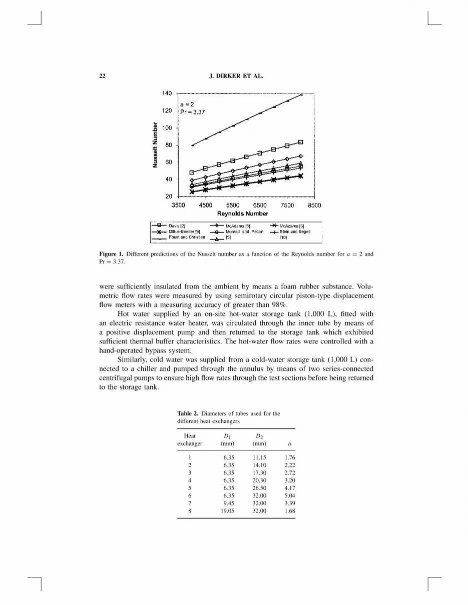
The correlations contained in Table 1 and which were developed for water as flowmedium were compared for an arbitrary case with an annular diameter ratio of 2 and aPrandtl number of 3.37 and is shown in Figure 1.
All correlations predict an almost linear increase in Nusselt number with an increasein the Reynolds number. Compared to the other predictions, the equation by Foust andChristian [2] overpredicts the Nusselt number by approximately a factor of 3. When thepredictions of Foust and Christian [2] are omitted, a difference in predicted values of
Received 18 December 2002; accepted 21 May 2003.Address correspondence to Prof. J. P. Meyer, Department of Mechanical and Aeronautical Engineering,
University of Pretoria, Pretoria, 0002, South Africa. E-mail: [email protected]
19

20 J. DIRKER ET AL.
NOMENCLATURE
a annular diameter ratio (= D2/D1)Ci inner tube convective heat transfer
correlation coefficient—Wilson plotCo annulus convective heat transfer
correlation coefficient—Wilson plotD1 diameter of outer wall of inner tube, mD2 diameter of inner wall of outer tube, mDh hydraulic diameter of annulus
(= D2 − D1), mDi inner diameter of inner tube, mh convective heat transfer coefficient,
W/m2 Kk thermal conductivity, W/m Kk turbulent kinetic energyNu Nusselt numbern exponent of Prandtl numberP exponent of Reynolds number in Wilson
plot function
Pr Prandtl numberRe Reynolds numberε dissipation rateζ correlation functionµ viscosity, N s/m2
Subscriptsave averageDh based on the hydraulic diameter of the
annulusf based on film temperature
Tf = 12 (Tave + Tw)
i inner tube sideo annulus sidew wall
±20% relative to the average predicted value is found to exist. The same trend was foundto be true for a wide range of annular diameter ratios and Prandtl numbers.
No indication was found in the literature of the existence of an accurate heat transfercorrelation for concentric annuli. The purpose of this investigation was thus to deduce acorrelation with which accurate predictions could be made of average Nusselt numbersat the inner annular wall under turbulent flow conditions using water.
EXPERIMENTAL FACILITY
Eight different concentric tube-in-tube heat exchangers, each with a different annu-lar diameter ratio and cross-sectional area, were used to perform experimental tests on.Refer to Table 2 for some dimensions. Water in the annulus was heated by circulating hotwater through the inner tube. The heat exchangers, each with an effective length of about6 m, were constructed from hard-drawn refrigeration copper tubing and were operatedin a horizontal counterflow arrangement. All heat exchangers were thermally insulatedform the ambient by using standardized pipe insulators.
Concentric annular cross-sectional areas were maintained over the entire lengthsof each heat exchanger, by supporting the inner tubes with sets of radial pins producingstarlike supporting structures. The size and position of the supporting pins were carefullycalculated to minimize possible sagging of the inner tube. Pins, with diameter of 0.6 mm,were placed symmetrically to minimize possible unbalanced flow patterns. In the caseof the smallest annulus, the supporting structures occupied at most 6.5% of the cross-sectional flow area.
Temperature measurements were facilitated by means of K-type thermocouplesfixed on the outside surfaces of entry and exit regions of the heat exchangers. At eachmeasuring location either two or three thermocouples were used to obtain a more cu-rate temperature value. Temperature errors were usually less than 0.1 K. Measuring points

Tabl
e1.
Equ
atio
nsav
aila
ble
from
the
liter
atur
ede
scri
bing
the
Nus
selt
num
ber
ina
smoo
thco
ncen
tric
annu
lus
duri
ngfo
rced
conv
ectio
n
Dia
met
erR
eyno
lds
Aut
hor(
s)C
orre
latio
nra
tiora
nge
num
ber
rang
eM
ediu
m
Dav
is[3
]∗ N
u Dh
=0.
038a
0.15
(a−
1)0.
2R
e0.8
Dh
Pr1/
3( µ µ
w
) 0.14
o
1.18
–6,8
00N
otsp
ecifi
edA
llm
edia
McA
dam
s[4
]N
u Dh
=0.
0310
5a0.
15(a
−1)
0.2R
e0.8
Dh
Pr1/
3( µ µ
w
) 0.14
1.18
–6,8
00N
otsp
ecifi
edA
llm
edia
Fous
tan
dC
hris
tian
[2]
∗ Nu D
h=
0.04
a
(a+
1)0.
2R
e0.8
Dh
Pr0.
41.
2–1.
843,
000–
60,0
00W
ater
McA
dam
s[4
]N
u Dh
=0.
023R
e0.8
Dh
Pr1 3
( µ µw
) 0.14
Not
spec
ified
Not
spec
ified
Not
spec
ified
Mon
rad
and
Pelto
n[5
]N
u Dh
=0.
023
[ 2ln
a−
a2
+1
a−
1/a
−2a
lna
] Re0.
8D
hPr
n1.
65,
2.45
,17
12,0
00–2
20,0
00W
ater
,ai
r
Wie
gand
etal
.[6
]N
u Dh
=0.
023a
0.45
Re0.
8D
hPr
n
( µ µw
) 0.14
1–10
Not
spec
ified
Flui
ds:µ
mat
eria
l≤
2µw
ater
Kay
san
dL
eung
[7]
Res
ults
liste
din
tabl
esfo
rva
riou
sco
nditi
ons
1–∞
104–1
06N
otsp
ecifi
ed
Petu
khov
and
Roi
zen
[8]
∗ Nu D
h=
0.06
759a
0.16
(a+
1)0.
2ζ
Re0.
8D
h1–
14.3
104–3
×10
5A
ir
with
ζ=
1+
7.5
[a
−5
(a+
1)R
e Dh
] 0.6fo
ra
≥5
ζ=
1fo
ra
≤5
Ditt
us-B
oelte
r[9
]N
u Dh
=0.
023R
e0.8
Dh
Prn
Not
spec
ified
Not
spec
ified
Not
spec
ified
Stei
nan
dB
egel
l[1
0]N
u Dh,f
=0.
0200
a0.
5R
e0.8
Dh,f
Pr1/
3f
1.23
2,1.
463,
1.69
430
,000
–390
,000
Wat
er
Cro
okst
onet
al.
[11]
Nu D
h,f
=0.
23a
1/4R
e3/4
Dh
Pr1/
310
,16
,31
17,0
00–1
00,0
00A
ir
∗ Ori
gina
leq
uatio
nsw
ere
rew
ritte
nas
toha
veth
eR
eyno
lds
and
Nus
selt
num
bers
base
don
the
annu
lar
hydr
aulic
diam
eter
:D
h=
D2
−D
1.
21
22 J. DIRKER ET AL.
Figure 1. Different predictions of the Nusselt number as a function of the Reynolds number for a = 2 andPr = 3.37.
were sufficiently insulated from the ambient by means a foam rubber substance. Volu-metric flow rates were measured by using semirotary circular piston-type displacementflow meters with a measuring accuracy of greater than 98%.
Hot water supplied by an on-site hot-water storage tank (1,000 L), fitted withan electric resistance water heater, was circulated through the inner tube by means ofa positive displacement pump and then returned to the storage tank which exhibitedsufficient thermal buffer characteristics. The hot-water flow rates were controlled with ahand-operated bypass system.
Similarly, cold water was supplied from a cold-water storage tank (1,000 L) con-nected to a chiller and pumped through the annulus by means of two series-connectedcentrifugal pumps to ensure high flow rates through the test sections before being returnedto the storage tank.
Table 2. Diameters of tubes used for thedifferent heat exchangers
Heat D1 D2exchanger (mm) (mm) a
1 6.35 11.15 1.762 6.35 14.10 2.223 6.35 17.30 2.724 6.35 20.30 3.205 6.35 26.50 4.176 6.35 32.00 5.047 9.45 32.00 3.398 19.05 32.00 1.68
CONVECTIVE HEAT TRANSFER IN CONCENTRIC ANNULI 23
EXPERIMENTAL PROCEDURE
Experimental tests [12] were performed at a wide range of inner tube and annularflow rate combinations. A wide annular flow rate range was covered in the turbulentflow regime in order to facilitate the development of an accurate annular heat transfercorrelation.
At first the inner tube flow rate was fixed at an arbitrary level while changing theannular flow rate. For each annular flow rate, adequate time was given for steady-stateconditions to be established before inlet and outlet temperatures were captured by meansof a data logger and flow rates were measured with both displacement flow meters andvariable-area flow meters. The process was repeated for an array of inner tube flow rates,which produced a wide range of inner tube and annular flow rates. Hot- and cold-waterinlet temperatures were maintained at in the vicinity of 50 and 10◦C, respectively.
A high level of accuracy in the experimental data was maintained. More than 90%of all data points represented conditions with energy balance errors of less than 1%between the inner tube and annular heat transfer rates. A Reynolds number range, basedon the hydraulic diameter, of 2,600 to 35,000 was covered in experiments performed onthe eight heat exchangers setups.
PROCESSING OF DATA
To facilitate the Wilson plot process the internal and annular Nusselt numbers canbe written by means of Eqs. (1) and (2), respectively:
Nui = hiDi
ki
= CiRe0.8i Pr1/3
i
(µ
µw
)0.14
i
(1)
Nuo = hoDh
ko
= CoRePo,Dh
Pr1/3o
(µ
µw
)0.14
o
(2)
P , Ci , and Co are added to account for geometry influences. For the inner tube theexponent of the Reynolds number was kept at 0.8 as proposed in the literature [1]. Withthe modified Wilson plot method (Briggs and Young [1]), the values of P , Ci , and Co
were obtained as functions of the annular diameter ratio. The value of Ci was found tobe constant, namely, in the region of 0.027, as can be expected. The values of P and Co
are given in Figures 2 and 3.By using these values, more than 95% of all data points were predicted within 3%
accuracy by the Wilson plot-obtained correlations for the different heat exchangers. AllWilson plot correlations exhibited a median error of less than or in close proximity to1%. Standard deviations for error values were less than 2%.
DERIVATION OF CORRELATION
P and Co showed a dependence on the annular diameter ratio. The value of P ex-hibited a downward trend when the annular diameter ratio was increased. (See Figure 2.)On the other hand, the value of Co had an upward trend for an increasing annular diameterratio. (See Figure 3.)

24 J. DIRKER ET AL.
Figure 2. P values obtained from Wilson plot analyses.
Results obtained for annular diameter ratios of 4.17 and 3.39, which are encircledin Figures 2 and 3, did not agree with the general trend of the rest of the heat exchangers.These annular cases were rebuilt and the experimental tests repeated. The values of P
and Co were reaffirmed. A great possibility exists that even though these cases wererebuilt, concentricity could not be maintained due to the great distance between the innertube and outer tube of these annuli.
From the available experimental results, the behavior of P and Co can be describedrelatively precisely for annular diameter ratios below 3.2. For ratios greater than 3.2, thisis unfortunately not the case, and more experimental data are needed. Unfortunately,commercial-sized tubes, which could produce more annular ratios ranging from 3 to 5,are not readily available, making the investigation process difficult.
Figure 3. Co values obtained from Wilson plot analyses.
CONVECTIVE HEAT TRANSFER IN CONCENTRIC ANNULI 25
Using results for annular ratios of below 3.2, it was possible to describe the trendmathematically by evaluating different curve-fits. Equations (3) and (4) exhibited thebest accuracies and are indicated in Figures 2 and 3 as dotted lines. Linear-type curveapproximations were also considered, but due to a loss in accuracy, Eqs. (3) and (4) weredecided upon.
P = 1.013e−0.067a (3)
Co = 0.003a1.86
0.063a3 − 0.674a2 + 2.225a − 1.157(4)
By substituting (3) and (4) into (2), a correlation for the prediction of the Nusselt numberis produced.
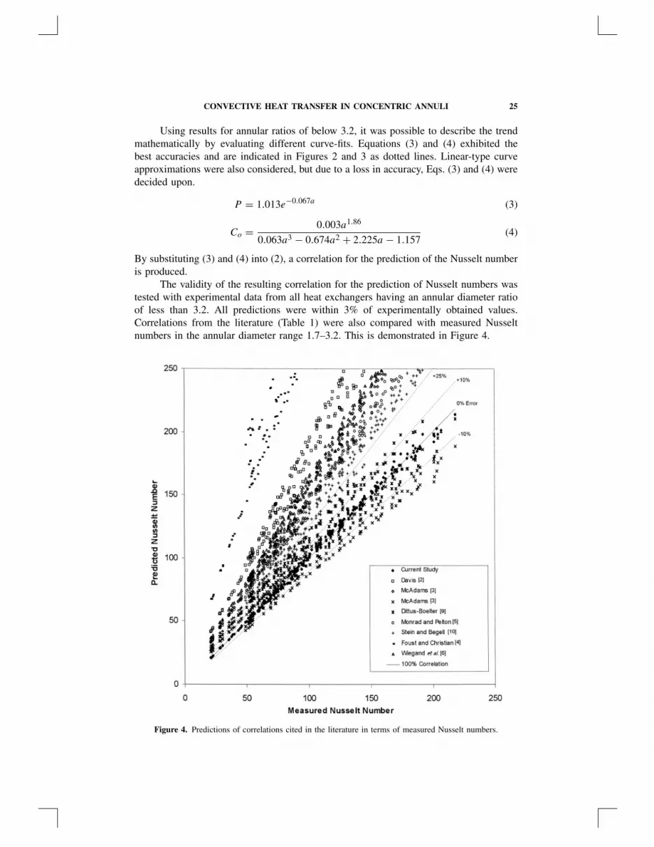
The validity of the resulting correlation for the prediction of Nusselt numbers wastested with experimental data from all heat exchangers having an annular diameter ratioof less than 3.2. All predictions were within 3% of experimentally obtained values.Correlations from the literature (Table 1) were also compared with measured Nusseltnumbers in the annular diameter range 1.7–3.2. This is demonstrated in Figure 4.
Figure 4. Predictions of correlations cited in the literature in terms of measured Nusselt numbers.
26 J. DIRKER ET AL.
Figure 5. Comparison between the deduced correlation and correlations from the literature for a wide rangeof annular diameter ratios.
Only a small number of the predictions were within 10% of the measured Nusseltnumbers, except the current correlation, which predicts all values within ±3%. A largeprediction scatter is also exhibited by most of the correlations. Two main predictionbands are present. The first band, being in proximity to the measured values, consistsof predictions by a correlation recommended by McAdams [4], and the Dittus-Boeltercorrelation [9]. The second band is located outside the 25% range from the measuredvalues and consists of predictions of various authors. Predictions of Foust and Christian[2] had the highest deviance from the measured Nusselt numbers.
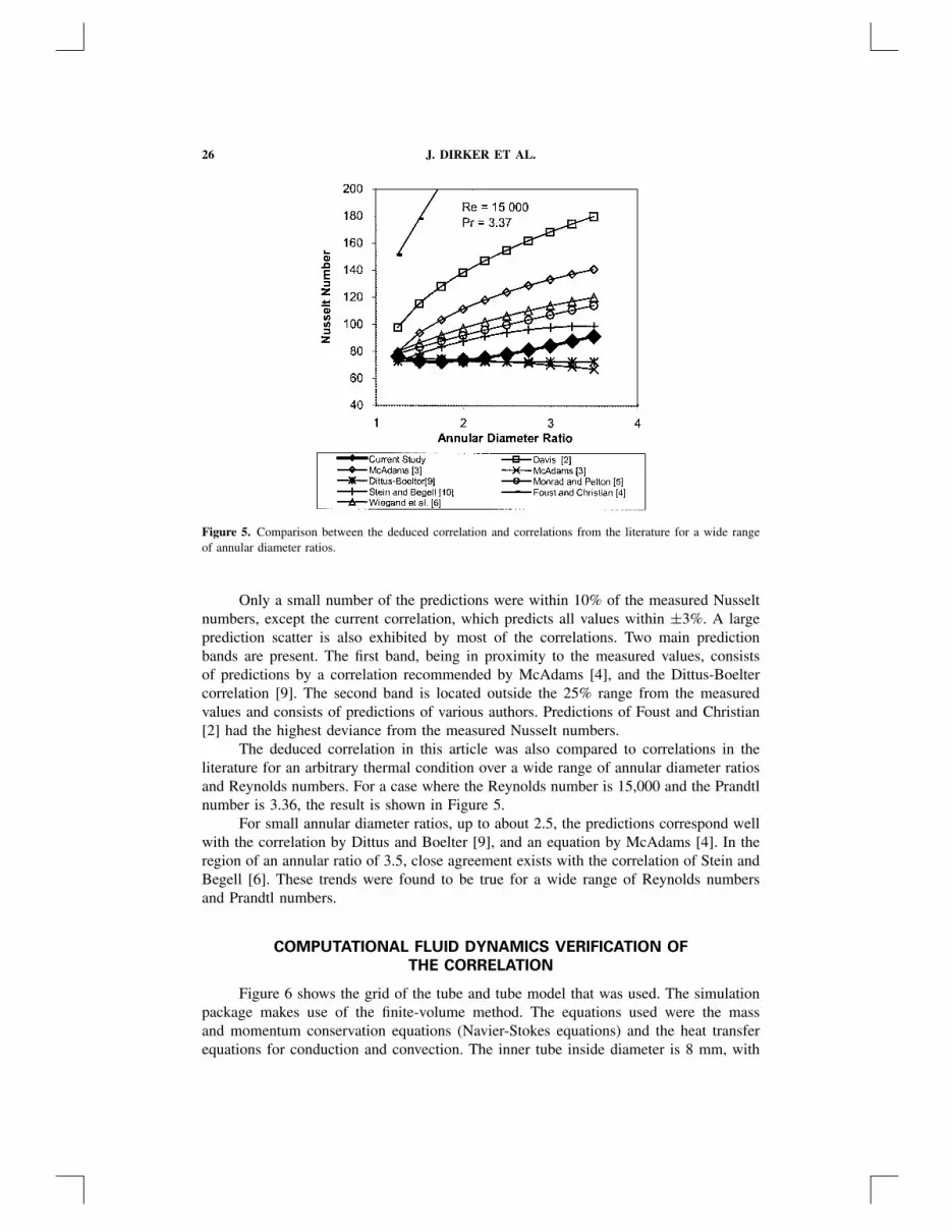
The deduced correlation in this article was also compared to correlations in theliterature for an arbitrary thermal condition over a wide range of annular diameter ratiosand Reynolds numbers. For a case where the Reynolds number is 15,000 and the Prandtlnumber is 3.36, the result is shown in Figure 5.
For small annular diameter ratios, up to about 2.5, the predictions correspond wellwith the correlation by Dittus and Boelter [9], and an equation by McAdams [4]. In theregion of an annular ratio of 3.5, close agreement exists with the correlation of Stein andBegell [6]. These trends were found to be true for a wide range of Reynolds numbersand Prandtl numbers.
COMPUTATIONAL FLUID DYNAMICS VERIFICATION OF
THE CORRELATION
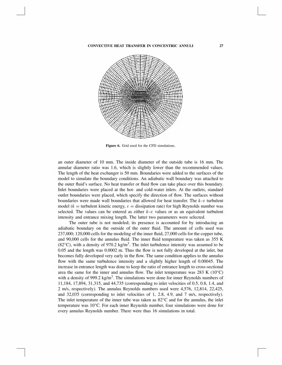
Figure 6 shows the grid of the tube and tube model that was used. The simulationpackage makes use of the finite-volume method. The equations used were the massand momentum conservation equations (Navier-Stokes equations) and the heat transferequations for conduction and convection. The inner tube inside diameter is 8 mm, with
CONVECTIVE HEAT TRANSFER IN CONCENTRIC ANNULI 27
Figure 6. Grid used for the CFD simulations.
an outer diameter of 10 mm. The inside diameter of the outside tube is 16 mm. Theannular diameter ratio was 1.6, which is slightly lower than the recommended values.The length of the heat exchanger is 50 mm. Boundaries were added to the surfaces of themodel to simulate the boundary conditions. An adiabatic wall boundary was attached tothe outer fluid’s surface. No heat transfer or fluid flow can take place over this boundary.Inlet boundaries were placed at the hot- and cold-water inlets. At the outlets, standardoutlet boundaries were placed, which specify the direction of flow. The surfaces withoutboundaries were made wall boundaries that allowed for heat transfer. The k–ε turbulentmodel (k = turbulent kinetic energy, ε = dissipation rate) for high Reynolds number wasselected. The values can be entered as either k–ε values or as an equivalent turbulentintensity and entrance mixing length. The latter two parameters were selected.
The outer tube is not modeled; its presence is accounted for by introducing anadiabatic boundary on the outside of the outer fluid. The amount of cells used was237,000; 120,000 cells for the modeling of the inner fluid, 27,000 cells for the copper tube,and 90,000 cells for the annulus fluid. The inner fluid temperature was taken as 355 K(82◦C), with a density of 970.2 kg/m3. The inlet turbulence intensity was assumed to be0.05 and the length was 0.0002 m. Thus the flow is not fully developed at the inlet, butbecomes fully developed very early in the flow. The same condition applies to the annulusflow with the same turbulence intensity and a slightly higher length of 0.00045. Theincrease in entrance length was done to keep the ratio of entrance length to cross-sectionalarea the same for the inner and annulus flow. The inlet temperature was 283 K (10◦C)with a density of 999.2 kg/m3. The simulations were done for inner Reynolds numbers of11,184, 17,894, 31,315, and 44,735 (corresponding to inlet velocities of 0.5, 0.8, 1.4, and2 m/s, respectively). The annulus Reynolds numbers used were 4,576, 12,814, 22,425,and 32,035 (corresponding to inlet velocities of 1, 2.8, 4.9, and 7 m/s, respectively).The inlet temperature of the inner tube was taken as 82◦C and for the annulus, the inlettemperature was 10◦C. For each inner Reynolds number, four simulations were done forevery annulus Reynolds number. There were thus 16 simulations in total.

28 J. DIRKER ET AL.
Figure 7. Comparison between the deduced correlation and CFD data for an annular ratio of 1.6.
A heat balance between the inner and annulus flow was done on the data, and theaverage error in heat balance was 5.1%. The Nusselt numbers of the computational fluiddynamics (CFD) results were compared with the results predicted by the Dittus-Boelter,Sieder, and Tate and Petukhov correlations [13], and the average error was 13.6% for theannulus with respect to the CFD results were found.
When compared with the correlation found in this study, the average error was only9%. These results are displayed in Figure 7.
CONCLUSION
As was expected, it was found that the convective heat transfer correlation for anannulus is dependent on the annular diameter ratios. A correlation was deduced from ex-perimental results that predicts Nusselt numbers accurately within 3% from the measuredvalues for diameter ratios between 1.7 and 3.2 and a Reynolds number range of 4,000to 30,000. For small annular diameter ratios of below 2.5, the correlation agreed closelywith those by Dittus and Boelter [9], and McAdams [3]. For higher annular diameterratios it approaches a correlation by Stein and Begell [6]. The correlation was furthervalidated with CFD results.
REFERENCES
1. D. E. Briggs and E. H. Young, Modified Wilson Plot Technique for Obtaining Heat TransferCorrelations for Shell and Tube Heat Exchangers, Chem. Eng. Prog. Symp., vol. 65, pp. 35–45,1969.
2. A. S. Foust and G. A. Christian, Non-boiling Heat Transfer Coefficients in Annuli, AIChE J.,vol. 36, pp. 541–554, 1940.

CONVECTIVE HEAT TRANSFER IN CONCENTRIC ANNULI 29
3. E. S. Davis, Heat Transfer and Pressure Drop in Annuli, Trans. ASME, pp. 755–760, October1943.
4. W. H. McAdams, Heat Transmission, McGraw-Hill, New York, 1954.5. C. C. Monrad and J. F. Pelton, Heat Transfer by Convection in Annular Spaces, AIChE J.,
vol. 38, pp. 593–611, 1942.6. J. H. Wiegand, E. L. McMillen, and R. E. Larson, Discussion on: Annular Heat Transfer
Coefficients for Turbulent Flow, AIChE J., vol. 41, pp. 147–153, 1945.7. W. M. Kays and E. Y. Leung, Heat Transfer in Annular Passages—Hydrodynamically Devel-
oped Turbulent Flow with Arbitrarily Prescribed Heat Flux, Int. J. Heat Mass Transfer, vol. 6,pp. 537–557, 1963.
8. B. S. Petukhov and L. I. Roizen, Generalized Relationships for Heat Transfer in TurbulentFlow of Gas in Tubes of Annular Section, High Temp., vol. 2, pp. 65–68, 1964.
9. F. W. Dittus and L. M. K. Boelter, University of California, Berkeley, Publications on Engi-neering, vol. 2, p. 443, 1930.
10. R. P. Stein and W. Begell, Heat Transfer to Water in Turbulent Flow in Internally HeatedAnnuli, AIChE J., vol. 4, pp. 127–131, 1958.
11. R. B. Crookston, R. R. Rothfus, and R. I. Kermode, Turbulent Heat Transfer with Annuli withSmall Cores, Int. J. Heat Mass Transfer, vol. 11, pp. 415–426, 1968.
12. J. Dirker, Heat Transfer Coefficient in Concentric Annuli, M.Ing. thesis, Rand Afrikaans Uni-versity, Johannesburg, South Africa, 2002.
13. J. P. Holman, Heat Transfer, McGraw-Hill, London, 1992.