controlled morphology of porous polyvinyl butyral nanofibers
TRANSCRIPT
Hindawi Publishing CorporationJournal of NanomaterialsVolume 2011, Article ID 292516, 6 pagesdoi:10.1155/2011/292516
Research Article
Controlled Morphology of Porous Polyvinyl Butyral Nanofibers
Daniela Lubasova and Lenka Martinova
Department of Nonwovens, Technical University of Liberec, 46117 Liberec, Czech Republic
Correspondence should be addressed to Daniela Lubasova, [email protected]
Received 12 August 2010; Revised 3 December 2010; Accepted 17 January 2011
Academic Editor: Theodore Tsotsis
Copyright © 2011 D. Lubasova and L. Martinova. This is an open access article distributed under the Creative CommonsAttribution License, which permits unrestricted use, distribution, and reproduction in any medium, provided the original work isproperly cited.
A simple and effective method for the fabrication of porous nanofibers based on the solvent evaporation methods in one-stepelectrospinning process from the commercial polyvinyl butyral (PVB) is presented. The obtained nanofibers are prevalentlyamorphous with diameters ranging from 150 to 4350 nm and specific surface area of approximately 2–20 m2/g. Pore size withirregular shape of the porous PVB fibers ranged approximately from 50 to 200 nm. The effects of polymer solution concentration,composition of the solvents mixture, and applied voltage on fiber diameter and morphology were investigated. The theoreticalapproach for the choice of poor and good solvents for PVB was explained by the application Hansen solubility parameter (HSP)and two-dimensional graph. Three basic conditions for the production of porous PVB nanofibers were defined: (i) applicationof good/poor solvent mixture for spinning solution, (ii) differences of the evaporation rate between good/poor solvent, and (iii)correct ratios of good/poor solvent (v/v). The diameter of prepared porous PVB fibers decreased as the polymer concentrationwas lowered and with higher applied voltage. These nanofiber sheets with porous PVB fibers could be a good candidate for high-efficiency filter materials in comparison to smooth fibers without pores.
1. Introduction
Many literature references discuss the production of porousnanofibers in the electrospinning process. There are a lot ofmethods, such as the extraction of a component from bi-component nanofibers, phase separation during electrospin-ning, and production of porous nanofibers under specificprocess conditions (temperature, humidity). These methodsare technically difficult and demand two step production orspecial additional device [1–3].
First idea for producing the porous nanofibers in one steparose after studying works published by Elford [4] and Ferry[5]. One of the earliest methods of making microporousmembranes was described there. In the method’s simpletsform, a polymer is dissolved in a two-component solventmixture consisting of volatile good solvent and an involatilepoor solvent for a polymer. This two-component polymersolution is cast on a glass plate. As the good, volatile solventevaporates the casting solution is enriched in the poor,non-volatile solvent. The polymer precipitates, forming theporous membrane structure.
An interesting finding is that the use of evaporation ofsolvents yields polymer fibers with a relatively regular porousstructure. The regular phase morphology is induced by rapidphase separation in an electrospinning jet when a highlyvolatile solvent is used. The solvent-rich regions in the jetresult in the pores after its intensive evaporation.
The development of porous fibers by electrospinning wasstudied by Lubasova and Martinova [6], where porous PCLnanofibers from a nonsolvent/solvent/polymer system wereprepared. The same principle is described in the reference ofQi et al. [7], where an alcohol was used as a non-solvent anddichloromethane as a solvent for PLA. It was confirmed that aporous structure of nanofibers could be obtained by varyingthe ratio of non-solvent/solvent in the ternary system withdifferent values of evaporation rate.
It was proved that porous nanofibers are more efficientfor cultivation of different cells and the growth could beinfluenced by the morphology of the nanofibers in previouswork. The cells attach easily to porous nanofibers and showbetter growth than the cells grown on nonporous nanofibers.Khil et al. [8] prepared a porous polycaprolactone (PCL)

2 Journal of Nanomaterials
5
4
3
21
High voltagesource
Figure 1: Schematic of a simple electrospinning experiment; (1)electrode grounding shield, (2) nanofiber sheet, (3) direction ofnanofiber formation, (4) a special flat electrode with polymersolution, and (5) a positive electrode.
filament by an electrospinning process and studied thegrowth characteristics of cells on these nonwoven fabrics.This work revived the important role of scaffold porosity forproliferation of living animal cells.
2. Materials and Method
PVB (Mowital B60H, dynamic viscosity of 10% solutionin ethanol 160–260 mPa·S) was purchased from Kuraray.Several spinning solutions were prepared by dissolvingPVB in the different types and quantities of solvents andtheir mixtures (methanol, ethanol, tetrahydrofuran (THF),dimethylsulfoxide (DMSO)). The total polymer concen-tration was fixed at 8 and 10 wt.%. PVB solutions insolvent mixtures were prepared by magnetic stirring at roomtemperature overnight.
A schematic representation of the equipment used in thelaboratory for electrospinning is depicted in Figure 1. Theelectrospinning process of PVB solutions was carried out at avoltage of 30 or 35 kV and the electrode-to-collector distancewas fixed at 10 cm.
3. Experimental Results and Discussion
3.1. Theoretical Approach for Choice of Optimal Solvents. HSPwas used for the prediction of the solubility of polymersin various solvents or their mixture. The application ofa solubility parameter is the practical way of predictingthe polymer solubility or quality of the solvent. Hansen[9] derived a practical extension of Hildebrand solubilityparameter into three parts: polar force component (δp),dispersion force component, (δd) and hydrogen bondingcomponent (δh):
δ2total = δ2
d + δ2p + δ2
h. (1)
HSP for polymers is commonly obtained by an indirectmethod which involves testing the relevant material incontact with many solvents under conditions relevant to agiven problem. When the bond energy of the material issimilar to that of a given solvent, it will dissolve, swell, oradsorb onto the material. An accurate prediction of solubilityparameter components from the chemical structure is dif-ficult because the interaction of different structural groups
0 5 10 15 20 25
PolymerSolventNon-solvent
Good
Poor
R
0
5
10
15
20
δ p(M
Pa1/
2)
δh (MPa1/2)
Figure 2: The solubility sphere for a polymer.
producing overall polar and hydrogen-bonding propertiesdoes not obey simple rules. Despite this, a useful predictionmethod based on molecular structure has been proposedby Van Krevelen [10]. According to Van Krevelen eachparameter can be estimated using (2), where Fd is thedispersion component, Fp the polar component, Eh thecontribution of hydrogen bond forces to the cohesive energy,i the contributing group, and Vm the molar volume of thepolymer:
δd =∑Fdi
Vm, δp =
√∑F2
pi
Vm, δh =
√∑Ehi
Vm. (2)
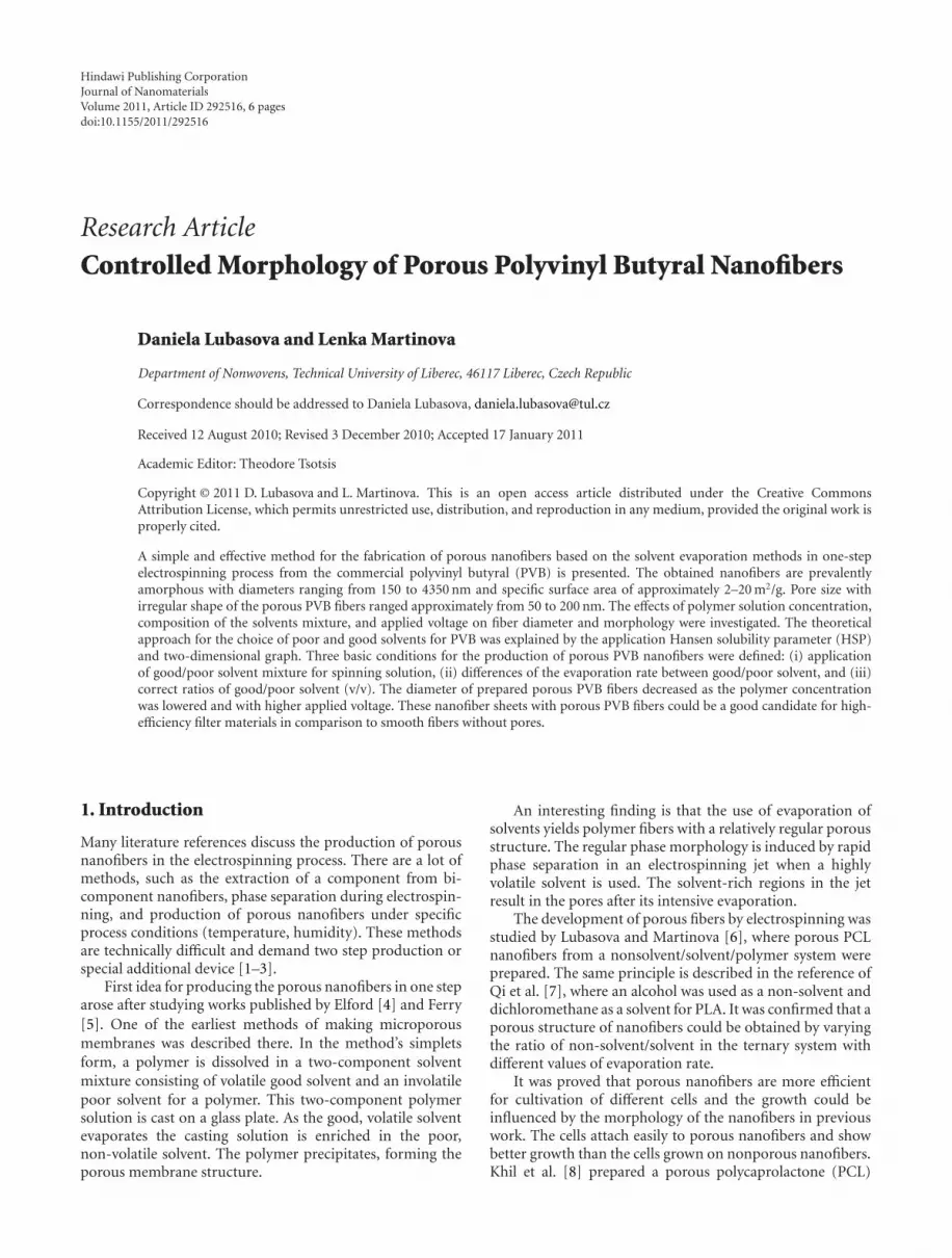
Hansen used a three-dimensional geometrical model to theinterpret solubility of a polymer by a graphical method.Hansen’s three-dimensional volume can be similarly illus-trated in a two-dimensional (2D) graph that uses only twoof the three parameters, most commonly δp and δh, seeFigure 2. This model introduces a “solubility sphere” of apolymer as a circle in a 2D system where the axes arerepresented by the two solubility components (δp and δh).The centre of the solubility sphere is located at the point( Pδp, Pδh) with HSP of the polymer. The radius of thesolubility sphere is the interaction radius R. Solvent pointsare represented by HSP of solvents ( Sδp, Sδh). If a solventpoint is located at the centre of the solubility sphere, then thepolymer can be dissolved by the solvent. On the other hand, ifthe solvent point is placed outside the solubility sphere, suchsolvent does not dissolve the polymer.
3.2. Preparation and Spinning of PVB Solutions. Determina-tion of the good and poor solvents for PVB and processingof porous nanofibers was the main goal. The solubilityparameter of the polymer PVB was predicted using (2) tocalculate δd, δp, and δh which are shown in Table 1. For amore detailed explanation refer to Van Krevelen [10].
The 2D graph was constructed in the first step. Thisgraph uses only two of the three HSP components, partic-ularly δp and δh; see Figure 3.
Journal of Nanomaterials 3
Table 1: HSP calculation for PVB using the Hoftyzer-Van Krevelen method.
Structural groups No. of groups N [–] N·Fdi [J1/2·cm3/2·mol−1] N·F2pi [J·cm3·mol−2] N·Ehi [J·mol−1]
–CH2– 5 1,350 0 0
=CH– 4 800 0 0
–O– 2 200 320,000 6,000
CH3– 1 420 0 0
OH– 1 210 250,000 20,000
Sum 2,980 570,000 26,000
δd [MPa1/2] δp [MPa1/2] δh [MPa1/2]
PVB 15.5 6.5 10.4
Table 2: Quality of solvents for dissolving PVB.
Polymer/solventsPVB Vapor pressure (25◦C) [kPa]
Δδ(S-P) [MPa1/2] Character of the solvent
THF 2.5 Good 26.27
DMSO 9.9 Poor 0.08
Ethanol 9.3 Poor 24.60
Methanol 13.2 Poor 32.7
0 5 10 15 20 250
5
10
15
20
PVBTHFDMSO
EthanolMethanol
δ p(M
Pa1/
2)
δh (MPa1/2)
Figure 3: Two-dimensional graph for prediction of good or poorsolvent for PVB: grey area implies poor solvent; white area impliesgood solvent.
Table 3: Solvent mixtures used as PVB solvents for electrospinning.
Solvent mixtures
Ethanol/methanol (9/1, 8/2 and 7/3 v/v)
Ethanol/DMSO (9/1, 8/2 and 7/3 v/v)
THF/DMSO (95/5, 9/1 and 8/2 v/v)
Secondly, a parameter Δδ(S-P)2D was evaluated, which isgiven by the distance between the HSP of solvent-point and
Table 4: Morphology of PVB fibers.
Solvent mixtures Morphology of nanofibers
Ethanol/methanol 9/1 (v/v) nonporous
Ethanol/DMSO 9/1 (v/v) partly porous
THF/DMSO 95/5 (v/v) porous
THF/DMSO 9/1 (v/v) porous
the centre of the solubility sphere in the 2D graph, see (3).This parameter can be simply used for prediction of the pooror good solvent. It is expected that the low values of thisparameter signify good solvent while higher values indicatepoor solvent (see Table 2):
Δδ(S-P)2D =[(
Sδp − Pδp
)2+(
Sδh − Pδh
)2]1/2
. (3)
Several spinning solutions were prepared by dissolving PVBin a mixture of different good and poor solvent combinations(ethanol/methanol, ethanol/DMSO and THF/DMSO). Thevolume ratios of good and poor solvents were varied; seeTable 3. The concentration of polymer solutions was aconstant 10 wt.%.
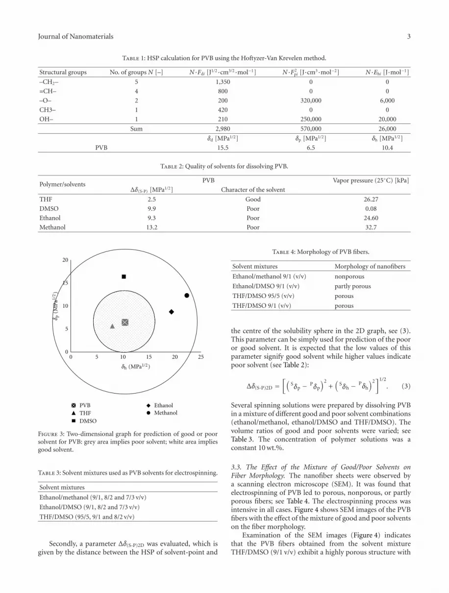
3.3. The Effect of the Mixture of Good/Poor Solvents onFiber Morphology. The nanofiber sheets were observed bya scanning electron microscope (SEM). It was found thatelectrospinning of PVB led to porous, nonporous, or partlyporous fibers; see Table 4. The electrospinning process wasintensive in all cases. Figure 4 shows SEM images of the PVBfibers with the effect of the mixture of good and poor solventson the fiber morphology.
Examination of the SEM images (Figure 4) indicatesthat the PVB fibers obtained from the solvent mixtureTHF/DMSO (9/1 v/v) exhibit a highly porous structure with

4 Journal of Nanomaterials
5 μm
(a)
5 μm
(b)
5 μm
(c)
Figure 4: SEM images of PVB nanofibers prepared from 10 wt.% polymer solution from the mixtures: (a) ethanol/methanol (9/1 v/v), (b)ethanol/DMSO (9/1 v/v), (c) THF/DMSO (9/1 v/v).
0
10
20
30
40
50
850 1550 2250 2950 3650 4350 5050 5750
Freq
uen
cy(−
)
Fiber diameter (nm)
Figure 5: Histogram of the fiber diameter for electrospun PVB10 wt.% solution from the electrode-to-collector distance of 10 cmand applied voltage of 30 kV.
a pore size of approximately 100 nm. The elliptically shapedpores covered the entire surface of the fibers. Electrospinningof PVB from ethanol/DMSO 9/1 (v/v) led to partially porousfibers with smaller fiber diameters. Non-porous nanofiberswere prepared from the mixture of the ethanol/methanol9/1 (v/v). The SEM images shown in Figure 4 imply thatthe emerging porous structure of fibers is observed onlyfor the mixtures of good and poor solvents with the higherdifference in the evaporation rate between good and poorsolvents. The results in Table 2 show the smallest value ofvapor pressure for DMSO in comparison with other solvents.
A difference in porous and partially porous nanofibersmay be attributed to the parameter Δδ(S-P)2D. In the caseof partially porous fibers, the values of Δδ(S-P)2D parameterfor ethanol and DMSO are 9.3 and 9.9 MPa1/2, respectively.In comparison with porous fibers, the values of parameterΔδ(S-P)2D for THF and DMSO are 2.5 and 9.9 MPa1/2,respectively. These differences play a significant role for theproduction of porous fibers.
The described method for the preparation of porousfibers was successful although it leads to higher fiberdiameters; see Figure 5. Histograms of fiber diameters wereobtained from the image analysis LUCIA G. The averagefiber diameter of these fibers was 2546 nm. For that reason,decreasing the fiber diameter by the effect of lower concen-tration or higher applied voltage during process was solved.
3.4. The Effect of PVB Concentration on Fiber Diameter. Theelectrospinning of 8 wt.% solutions PVB prepared from themixture of the THF/DMSO and the effect of the ratio ofgood and poor solvent were investigated. The pore sizeof electrospun nanofibers formed by the good and poorsolvent evaporation method is influenced by many factors. Ingeneral, increasing the ratio of the poor solvent or decreasingthe polymer concentration changes the porosity. The SEMimages confirm that the quantity of the pores on the fibersincreases when the ratio of good and poor solvent decreases(Figure 6).
The histogram of the fiber diameters shows the reductionof fiber diameter by decreasing PVB concentration from 10to 8 wt.%. The average fiber diameter of these fibers was605 nm (Figure 7).
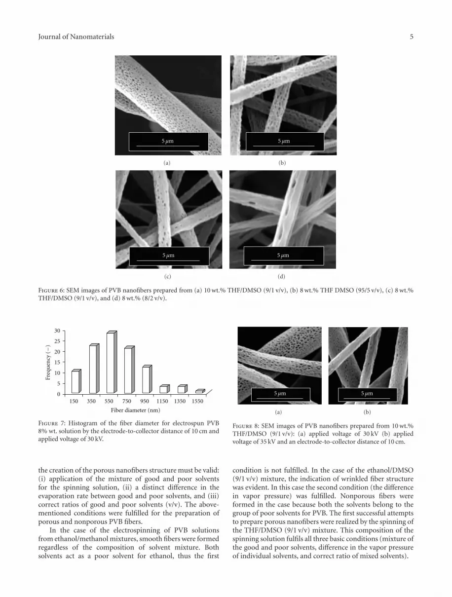
3.5. The Effect of Applied Voltage on Fiber Diameter. It wasfound that the small change of voltage from 30 to 35 kVinfluences both fiber diameter and porosity. Solutions ofPVB in the mixture of the THF/DMSO (9/1 v/v) with aconcentration of 10 wt.% was electrospun. SEM micrographs(Figure 8) show the result. The jet of the polymer fluid caneasily start the phase separation with a lower voltage of 30 kV,and the structure is more porous. Diffusivity of good andpoor solvents reduces the difference of the vapor pressureof the components when increasing the voltage. Thereforenanofibers with lower porosity and smaller fiber diameterare obtained. The average fiber diameter of these fibers was1411 nm; see Figure 9.
4. Conclusion
The results show that the vapor pressure of the solventsplays an important role in fiber diameter and porosity. Thedependence of nanofiber morphology on different solventmixtures (good and poor), volume ratios of good and poorsolvent and the concentration of polymer solution werestudied. HSP was found as a useful tool for the prediction ofsuitable solvents for preparation of the porous nanofibers viathe electrospinning process. All three defined conditions for
Journal of Nanomaterials 5
5 μm
(a)
5 μm
(b)
5 μm
(c)
5 μm
(d)
Figure 6: SEM images of PVB nanofibers prepared from (a) 10 wt.% THF/DMSO (9/1 v/v), (b) 8 wt.% THF DMSO (95/5 v/v), (c) 8 wt.%THF/DMSO (9/1 v/v), and (d) 8 wt.% (8/2 v/v).
0
5
10
15
20
25
30
150 350 550 750 950 1150 1350 1550
Freq
uen
cy(−
)
Fiber diameter (nm)
Figure 7: Histogram of the fiber diameter for electrospun PVB8% wt. solution by the electrode-to-collector distance of 10 cm andapplied voltage of 30 kV.
the creation of the porous nanofibers structure must be valid:(i) application of the mixture of good and poor solventsfor the spinning solution, (ii) a distinct difference in theevaporation rate between good and poor solvents, and (iii)correct ratios of good and poor solvents (v/v). The above-mentioned conditions were fulfilled for the preparation ofporous and nonporous PVB fibers.
In the case of the electrospinning of PVB solutionsfrom ethanol/methanol mixtures, smooth fibers were formedregardless of the composition of solvent mixture. Bothsolvents act as a poor solvent for ethanol, thus the first
5 μm
(a)
5 μm
(b)
Figure 8: SEM images of PVB nanofibers prepared from 10 wt.%THF/DMSO (9/1 v/v): (a) applied voltage of 30 kV (b) appliedvoltage of 35 kV and an electrode-to-collector distance of 10 cm.
condition is not fulfilled. In the case of the ethanol/DMSO(9/1 v/v) mixture, the indication of wrinkled fiber structurewas evident. In this case the second condition (the differencein vapor pressure) was fulfilled. Nonporous fibers wereformed in the case because both the solvents belong to thegroup of poor solvents for PVB. The first successful attemptsto prepare porous nanofibers were realized by the spinning ofthe THF/DMSO (9/1 v/v) mixture. This composition of thespinning solution fulfils all three basic conditions (mixture ofthe good and poor solvents, difference in the vapor pressureof individual solvents, and correct ratio of mixed solvents).

6 Journal of Nanomaterials
650 950 1250 1550 1850 2150 2450 27500
5
10
15
20
25
30
Freq
uen
cy(−
)
Fiber diameter (nm)
Figure 9: Histogram of the fiber diameter for electrospun PVB10 wt.% solution from the electrode-to-collector distance of 10 cmand applied voltage of 35 kV.
Three qualities of PVB nanofibers were obtained: (i)nonporous, (ii) partially porous, and (iii) porous. Themixture of good and poor solvents applied for preparationof the polymer solution leads to porous or partially porousnanofibers through electrospinning. A qualitative and quan-titative difference in porosity of the nanofibers is given bythe different value of the evaporation rate of good and poorsolvents. The correct ratios of the good and poor solventshave to be exactly defined. In the case of the ratio 9/1(v/v), the nanofibers were more porous than in the case ofthe ratio 8/2 (v/v). The smooth and finer nanofibers wereobtained from the PVB solution in an ethanol/methanolmixture. Both these solvents are defined as poor for PVB.Experimental results showed that the decrease of the polymerconcentration reduced the fiber diameter while the porousstructure remained unchanged. In contrast, an increase inthe applied voltage reduces the fiber diameter but porosityof the fibers is diminished.
It is expected that the porous fibers could find autilization in filtration applications, in which the effectivesurface area of porous fibers is the advantage.
Acknowledgments
This work was supported by Grant no. 1M0554 and GACRno. 304/07/1129.
References
[1] C. H. Kim, Y. H. Jung, H. Y. Kim, D. R. Lee, N. Dharmaraj,and K. E. Choi, “Effect of collector temperature on the porousstructure of electrospun fibers,” Macromolecular Research, vol.14, no. 1, pp. 59–65, 2006.
[2] Y. You, J. H. Youk, S. W. Lee, B. M. Min, S. J. Lee, and W. H.Park, “Preparation of porous ultrafine PGA fibers via selectivedissolution of electrospun PGA/PLA blend fibers,” MaterialsLetters, vol. 60, no. 6, pp. 757–760, 2006.
[3] S. O. Han, W. K. Son, D. Cho, J. H. Youk, and W. H.Park, “Preparation of porous ultra-fine fibres via selectivethermal degradation of electrospun polyetherimide/poly(3-hydroxybutyrate-co-3-hydroxyvalerate) fibres,” PolymerDegradation and Stability, vol. 86, no. 2, pp. 257–262, 2004.
[4] W. J. Elford, “Principles governing the preparation of mem-branes having graded porosities. The properties of “gradocol”
membranes as ultrafilters,” Transactions of the Faraday Society,vol. 33, pp. 1094–1104, 1937.
[5] J. D. Ferry, “Ultrafilter membranes and ultrafiltration,” Chem-ical Reviews, vol. 18, no. 3, pp. 373–455, 1936.
[6] D. Lubasova and L. Martinova, “Formation mechanism ofporous polycaprolactone nanofibers prepared by electrospin-ning,” in Proceedings of the 42nd IUPAC Congress, Glasgow,Scotland, August 2009.
[7] Z. Qi, H. Yu, Y. Chen, and M. Zhu, “Highly porousfibers prepared by electrospinning a ternary system ofnonsolvent/solvent/poly(l-lactic acid),” Materials Letters, vol.63, no. 3-4, pp. 415–418, 2009.
[8] M. S. Khil, S. R. Bhattarai, H. Y. Kim, S. Z. Kim, and K. H.Lee, “Novel fabricated matrix via electrospinning for tissueengineering,” Journal of Biomedical Materials Research Part B,vol. 72, no. 1, pp. 117–124, 2005.
[9] Ch. Hansen, Hansen Solubility Parameters: A User’s Handbook,CRC Press/Taylor and Francis, New York, NY, USA, 2007.
[10] D. W. Van Krevelen, Properties of Polymers: Their Corre-lation with Chemical Structure; Their Numerical Estimationand Prediction from Additive Group Contributions, Elsevier,Amsterdam, The Netherlands, 1990.