contactless power supply for moving sensors and actuators in high-precision mechatronic systems with...
TRANSCRIPT

Sensors and Actuators A 148 (2008) 319–328
Contents lists available at ScienceDirect
Sensors and Actuators A: Physical
journa l homepage: www.e lsev ier .com/ locate /sna
Contactless power supply for moving sensors and actuators in high-precisionmechatronic systems with long-stroke power transfer capability in x–y plane
J. de Boeij ∗, E. Lomonova, J.L. Duarte, A.J.A. VandenputEindhoven University of Technology, Department of Electrical Engineering, PO Box 513, 5600 MB Eindhoven, The Netherlands
a r t i c l e i n f o
Article history:Received 28 January 2008Received in revised form 31 July 2008Accepted 1 August 2008Available online 27 August 2008
Keywords:Contactless energy transferMechatronic systemsInductive couplingMoving load
a b s t r a c t
In this paper, a new topology for contactless energy transfer is proposed and tested that can transfer energyto a moving load using inductive coupling. This contactless energy transfer topology is designed to supplypower to the moving parts in high-precision mechatronic systems without cable slabs. The proposedtopology provides long-stroke contactless energy transfer capability in the x–y plane and a short-strokemovement of a few millimeters perpendicular to the plane. In addition, it is tolerant to rotations. Theelectrical steady-state, electrical transient, combined electrical and mechanical transient and forces ofthe contactless energy transfer system are modeled.
The experimental setup consists of a platform with one secondary coil, which is attached to a linearactuator. Underneath the platform is an array of primary coils, that are each connected to a half-bridgesquare wave power supply. The load on the secondary side is a rectifier with a 50 � resistor. The energytransfer to the load is measured while the secondary coil is moved over the array of primary coils bythe linear actuator. The secondary coil moves with a stroke of 18 cm at speeds over 1 m/s, while up to265 W of power is transferred continuously with 90% efficiency. The proposed system is very suitable for
transferring energy without cable slab to planar actuators and to conventional linear (short- and long-stroke) actuators in high-precision motion systems, such as lithography, die-bonding and component1
ptatTewisc
e(wml
IoaTisttan
so[t
0d
placement machines.
. Introduction
In high-tech mechatronic systems, a cable slab to the movingart of the machine is a source of disturbances. It introduces fric-ion, stiffness and damping and limits the stroke of the mover. Inddition, the cables break after a certain number of movements dueo the strains induced by the motion, resulting in machine failures.he cable slabs are necessary to provide power to the mover and toxchange information between the moving part and the controller,hich is located on the fixed world. This disadvantage is especially
mportant in systems with air bearings or with a magnetic suspen-ion, which can move without mechanical contact if the cable slabould be omitted [1,2].
To omit a cable slab, both the energy transfer and informationxchange should be made wireless. Contactless energy transfer
CET) is possible by means of an inductive coupling and severalireless techniques are available for sending information, e.g. radioodulation, infrared and laser. To test these techniques, a contact-ess planar actuator with manipulator is studied as shown in Fig. 1.
∗ Corresponding author. Tel.: +31 402473412; fax: +31 402434364.E-mail address: [email protected] (J. de Boeij).
oo
pcbsa
924-4247/$ – see front matter © 2008 Elsevier B.V. All rights reserved.oi:10.1016/j.sna.2008.08.012
© 2008 Elsevier B.V. All rights reserved.
t consists of a contactless planar actuator with moving magnetsver an array of suspension coils combining magnetic suspensionnd propulsion with a manipulator on top of the floating platform.he energy transfer to the moving platform is done by means of annductive coupling between the fixed primary coils and the movingecondary coil. The aim of this research project is to transfer energyo the moving platform continuously and at every position in ordero enhance the functionality of the platform, while maintaining thedvantages of operating without contact and cables slabs, which isecessary to reach submicron precision.
Previously presented methods for contactless energy transferuffer from limited stroke, cannot supply energy at every positionr cannot deal with moving loads. The systems discussed in Refs.3,4] require that the primary and secondary coil are aligned andhat they can tolerate only slight misalignments of the center axesf the coils, which makes them suitable for rotational movementnly.
Contactless energy transfer from a stationary part to translating
art is also feasible either by using elongated coils with cores as dis-ussed in Ref. [5], a grid of primary coils [6–8] or by using chargingays [9,10]. These systems either have the disadvantage of limitedtroke in the case of elongated coils or they cannot supply energyt every possible position.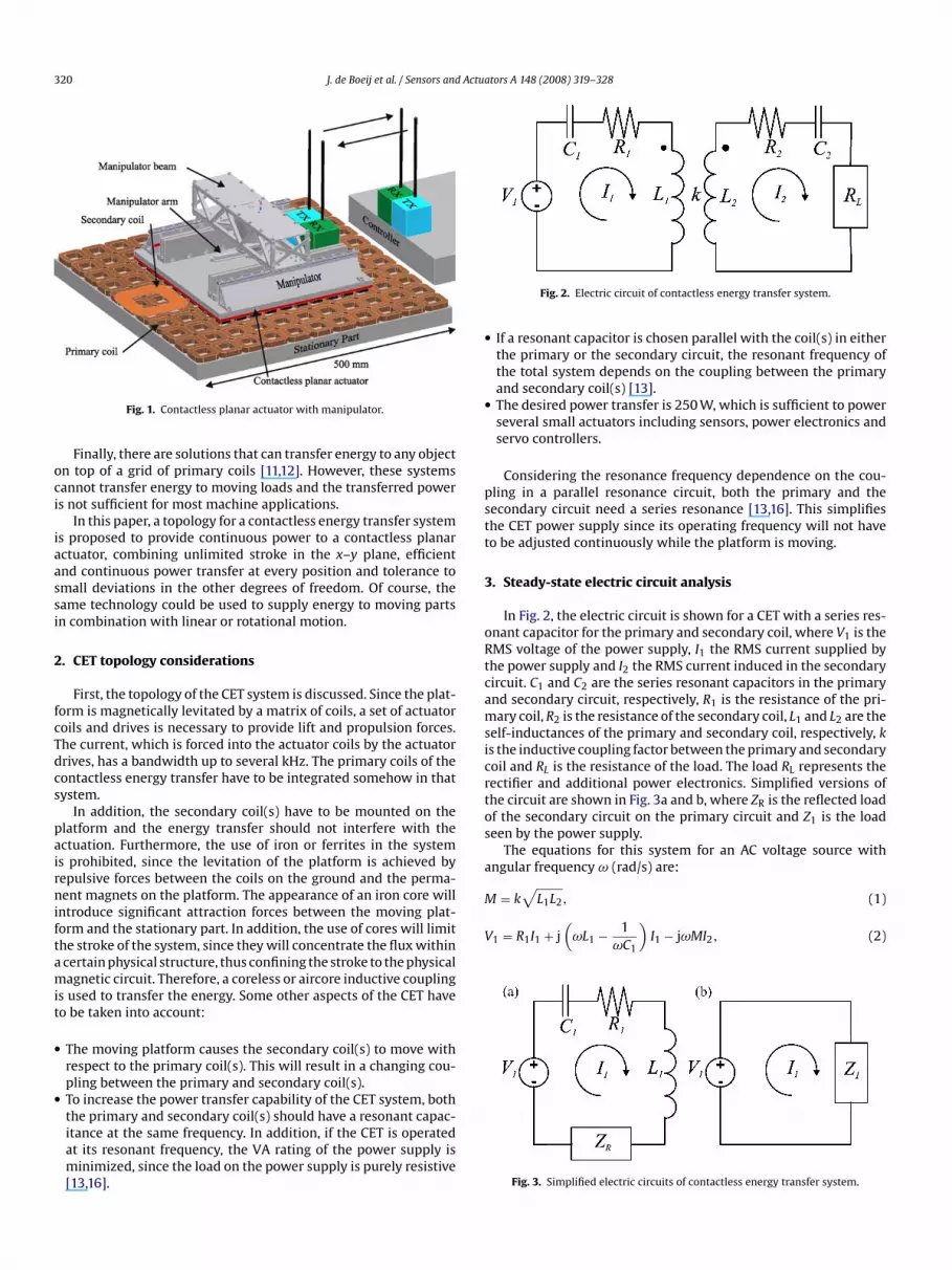
320 J. de Boeij et al. / Sensors and Actuators A 148 (2008) 319–328
oci
iaassi
2
fcTdcs
pairniftamit
•
•
•
•
pstt
3
oRtcamsicrtos
a
M = k L1L2, (1)
V1 = R1I1 + j(
ωL1 − 1ωC1
)I1 − jωMI2, (2)
Fig. 1. Contactless planar actuator with manipulator.
Finally, there are solutions that can transfer energy to any objectn top of a grid of primary coils [11,12]. However, these systemsannot transfer energy to moving loads and the transferred powers not sufficient for most machine applications.
In this paper, a topology for a contactless energy transfer systems proposed to provide continuous power to a contactless planarctuator, combining unlimited stroke in the x–y plane, efficientnd continuous power transfer at every position and tolerance tomall deviations in the other degrees of freedom. Of course, theame technology could be used to supply energy to moving partsn combination with linear or rotational motion.
. CET topology considerations
First, the topology of the CET system is discussed. Since the plat-orm is magnetically levitated by a matrix of coils, a set of actuatoroils and drives is necessary to provide lift and propulsion forces.he current, which is forced into the actuator coils by the actuatorrives, has a bandwidth up to several kHz. The primary coils of theontactless energy transfer have to be integrated somehow in thatystem.
In addition, the secondary coil(s) have to be mounted on thelatform and the energy transfer should not interfere with thectuation. Furthermore, the use of iron or ferrites in the systems prohibited, since the levitation of the platform is achieved byepulsive forces between the coils on the ground and the perma-ent magnets on the platform. The appearance of an iron core will
ntroduce significant attraction forces between the moving plat-orm and the stationary part. In addition, the use of cores will limithe stroke of the system, since they will concentrate the flux withincertain physical structure, thus confining the stroke to the physicalagnetic circuit. Therefore, a coreless or aircore inductive coupling
s used to transfer the energy. Some other aspects of the CET haveo be taken into account:
The moving platform causes the secondary coil(s) to move withrespect to the primary coil(s). This will result in a changing cou-pling between the primary and secondary coil(s).To increase the power transfer capability of the CET system, both
the primary and secondary coil(s) should have a resonant capac-itance at the same frequency. In addition, if the CET is operatedat its resonant frequency, the VA rating of the power supply isminimized, since the load on the power supply is purely resistive[13,16].Fig. 2. Electric circuit of contactless energy transfer system.
If a resonant capacitor is chosen parallel with the coil(s) in eitherthe primary or the secondary circuit, the resonant frequency ofthe total system depends on the coupling between the primaryand secondary coil(s) [13].The desired power transfer is 250 W, which is sufficient to powerseveral small actuators including sensors, power electronics andservo controllers.
Considering the resonance frequency dependence on the cou-ling in a parallel resonance circuit, both the primary and theecondary circuit need a series resonance [13,16]. This simplifieshe CET power supply since its operating frequency will not haveo be adjusted continuously while the platform is moving.
. Steady-state electric circuit analysis
In Fig. 2, the electric circuit is shown for a CET with a series res-nant capacitor for the primary and secondary coil, where V1 is theMS voltage of the power supply, I1 the RMS current supplied byhe power supply and I2 the RMS current induced in the secondaryircuit. C1 and C2 are the series resonant capacitors in the primarynd secondary circuit, respectively, R1 is the resistance of the pri-ary coil, R2 is the resistance of the secondary coil, L1 and L2 are the
elf-inductances of the primary and secondary coil, respectively, ks the inductive coupling factor between the primary and secondaryoil and RL is the resistance of the load. The load RL represents theectifier and additional power electronics. Simplified versions ofhe circuit are shown in Fig. 3a and b, where ZR is the reflected loadf the secondary circuit on the primary circuit and Z1 is the loadeen by the power supply.
The equations for this system for an AC voltage source withngular frequency ω (rad/s) are:√
Fig. 3. Simplified electric circuits of contactless energy transfer system.

Actuators A 148 (2008) 319–328 321
j
wct
C
C
its
Z
Z
Z
I
I
|
wttt
P
P
�
rt
V
trrtlepw
4
gatrtW
ieceof
taitdBptasa1
distmondary coil is situated in the bottom-left corner of the area ofinteraction with the middle primary coil.
In the optimization routine, the coupling at this particularposition is maximized using the nonlinear sequential quadratic
Table 1Dimensions of primary and secondary coil
Parameter Primary coil Secondary coil
Value Dimension Value Dimension
J. de Boeij et al. / Sensors and
ωMI1 = (R2 + RL)I2 + j(
ωL2 − 1ωC2
)I2, (3)
here M is the mutual inductance of the primary and secondaryoil. To obtain the desired resonance frequency f0 (Hz) = w0/2�,he resonance capacitors C1 and C2 must be suitably chosen:
1 = 1
ω20L1
, (4)
2 = 1
ω20L2
. (5)
This choice of the resonance capacitors ensures that thempedance of the secondary circuit Z2, the reflected impedance ofhe secondary circuit to the primary circuit ZR and the impedanceeen by the power supply Z1 are purely resistive at ω = ω0:
2 = R2 + RL + j(
ω0L2 − 1ω0C2
)= R2 + RL, (6)
R = ω20M2
Z2= ω2
0k2L1L2
R2 + RL, (7)
1 = R1 + j(
ω0L1 − 1ω0C1
)+ ZR = R1 + ω2
0k2L1L2
R2 + RL. (8)
By substituting Eq. (5) into Eq. (3) for ω = ω0 the relation between1 and I2 becomes:
2 = j|K |I1, (9)
K | = ω0M
R2 + RL, (10)
here |K| is a gain relating the current I2 to I1. Eqs. (9) and (10) showhat I2 leads I1 by 90◦. Now the power transferred to the load Pout,he power supplied by the power supply Pin and the efficiency ofhe total system � are calculated:
in = I21Z1, (11)
out = |K |2I21RL, (12)
= Pout
Pin= |K |2RL
Z1. (13)
By rewriting Eq. (12) and using the relation V1 = I1Z1, theequired voltage of the power supply can be calculated necessaryo transfer the desired power Pout:
1 =√
PoutZ21
|K |2RL. (14)
From Eqs. (5) and (4), it is clear that the resonant frequency ofhe circuit does not depend on the coupling, since the choice of theesonant capacitors only depends on the inductance of the coils. Ineality, the two series resonant capacitors will not cancel the induc-ances of the primary and secondary coil completely. Therefore, theoad seen by the power supply (Z1) will not be purely resistive. Nev-rtheless, Z1 does depend on the coupling, which implies that theower transfer capability of the system depends on the coupling asell.
. Coil geometry
The design of the primary and secondary coil is optimized toet a coupling that is as constant as possible for a sufficiently large
rea. This area should be large enough to allow the secondary coilo move from one primary coil to the next one without a largeeduction in coupling. If this can be achieved, the power can beransferred by one primary coil that is closest to the secondary coil.hen the secondary coil moves out of range, the first primary coil
cccrr
Fig. 4. Secondary coil above a matrix of nine primary coils.
s turned off and the next one will be energized. To ensure a smoothnergy transfer to the moving load, the position dependence of theoupling should be minimized, while keeping the coupling highnough to get a high-efficiency energy transfer. To allow the sec-ndary coil to move from one primary coil to the next, the toleranceor misalignments should be large.
In the proposed system, this is done by using a 3D geometry forhe primary coil, instead of the spiral structures described in otherpplications [3,4,12,11]. By applying not only a layer of windingsn the x–y plane (spiral), but also a significant number of layers onop of each other, the decay of the B-field in the direction perpen-icular to the plane is not as fast. This results in a fairly constant-field around the primary coil, which accommodates good cou-ling in a large area. Furthermore, since the system is supposed toransfer power to a load moving in a plane, it is convenient to useshape that is symmetrical in 2D for both the primary coil and the
econdary coil: a square for instance. The geometry of the primarynd the secondary coils are optimized with FEM using Maxwell 3D0 Optimetrics [17].
The resulting geometry of the coils is shown in Fig. 4 and theimensions are listed in Table 1. The dimensional parameters listed
n Table 1 are clarified in Fig. 5. The drawing in Fig. 4 shows oneecondary coil above nine primary coils. The black square showshe area in which the center of the secondary coil can move, while
aintaining good coupling with the middle primary coil. The sec-
w 60.0 mm 130.0 mmt 10.0 mm 30.0 mmh 10.0 mm 2.0 mm1 1.0 mm 1.0 mm2 11.0 mm 31.0 mm

322 J. de Boeij et al. / Sensors and Actua
pUwwcmiuatu
wmcωsocmctF
tbp
r
ar
5
t
v
M
wswtt
x
⎡⎢⎣
u
y
x
y
w
A
B = 0L2 0
M T, (25)
Fig. 5. Definition of coil dimensional parameters.
rogramming (SQP) method within Maxwell 3D 10 Optimetrics.nfortunately, it is not possible to optimize a range of positionithin this routine, but it is a good starting point. When the entireorkspace is analyzed, it is found that the geometry has a lower
oupling when the coils are centered. Therefore, the geometry isanually adjusted to realize a good coupling at all positions, by
ncreasing ct and c� of the secondary coil. If the primary coil issed in the magnetic suspension of a contactless planar actuator,s discussed in Section 1, the shape of the primary coil is fixed byhe design of the actuator and only the secondary coil is optimizedsing this procedure.
The coupling between the primary coil and the secondary coilithin that area is calculated with Maxwell 3D 10 Optimetrics andeasured. The measurements were done by applying a sinusoidal
urrent in the primary coil with RMS value I1 and angular frequency. Then, the induced voltage of the secondary coil VEMF is mea-
ured at a grid of positions in the workspace. The self-inductancesf both coils were measured using an impedance analyzer and byalculating k = VEMF/(ωI1
√L1L2), the coupling is found at each
easurement point. The results are shown in Fig. 6, where (0,0)orresponds with the center of the black square and the centers ofhe primary and secondary coil are aligned. Fig. 6 shows that theEM predictions are very close to the measured values.
The coupling k is fairly constant within most of the area, only onhe outer edges it drops fast. However, the coupling ripple definedy Eq. (15) is 25%, which is quite small considering the large dis-lacement of the secondary coil:
ipple (%) = max − minmax
× 100. (15)
Although this system is designed with square shaped coils, it islso possible to design a system with similar characteristics usingectangular coils.
C
Fig. 6. Coupling between prim
tors A 148 (2008) 319–328
. Simulation of the electrical transient of the CET system
Before simulating the electrical transient, the differential equa-ions of the system have to be defined:
1 = R1i1 + L1di1dt
+ 1C1
∫ t
0
i1 d� − Mdi2dt
, (16)
di1dt
= (R2 + RL)i2 + L2di2dt
+ 1C2
∫ t
0
i2 d�, (17)
here i1 is the current in the primary circuit, i2 the current in theecondary circuit and v1 the voltage supplied by the power supply,hich are all arbitrary functions of time. The differential equa-
ions are transformed to a state-space notation for simulation ofhe electrical transient.
First, the state is defined:
= [ x1 x2 x3 x4 ]T, (18)
x1x2x3x4
⎤⎥⎦ =
⎡⎢⎢⎢⎢⎢⎣
∫ t
0
i1 d�
i1∫ t
0
i2 d�
i2
⎤⎥⎥⎥⎥⎥⎦
, (19)
= [v1], (20)
= [ i1 i2 ]T. (21)
Next, the state-space model is calculated:
˙ = Ax + Bu, (22)
= Cx + Du, (23)
ith
=
⎡⎢⎢⎢⎢⎢⎣
0 1 0 0L2
C1˛
L2R1
˛
M
C2˛
M(R2 + RL)˛
0 0 0 1
M
C1˛
MR1
˛
L1
C2˛
L1(R2 + RL)˛
⎤⎥⎥⎥⎥⎥⎦
, (24)
[ ]
˛ ˛=[
0 1 0 00 0 0 1
], (26)
ary and secondary coil.

J. de Boeij et al. / Sensors and Actuators A 148 (2008) 319–328 323
D
˛
vbuows
icsasc1wo
Table 2Measured electric circuit parameters of the three primary circuits in the experimen-tal CET setup (shown in Fig. 13)
Primary 1 Primary 2 Primary 3
Inductance (�H) 980 944 878Resistance (�) 5.6 5.7 5.1Capacitance (nF) 0.73 0.76 0.82Resonance (kHz) 190 190 189
Trwl
6t
Fig. 7. Transfer function of CET system for v1 to i1.
= [ 0 0 ]T, (27)
= M2 − L1L2. (28)
The power supply is a voltage source that outputs a square waveoltage v1. A square wave is chosen, since it is easier to be generatedy switched-mode converters. In addition, a resonance circuit issed, so the current will be approximately sinusoidal, because allther frequencies will be filtered out by the resonance. This is clearhen the transfer functions of v1 to i1 and i2 are studied, which are
hown in Figs. 7 and 8.To transfer 250 W of power, the needed RMS sinusoidal voltage
s calculated from Eq. (14). Next, the 191 kHz square wave voltage isalculated by multiplying the RMS sine wave voltage by
√2(�/4). A
quare wave voltage v1 is supplied by the power supply for 0.35 msnd the corresponding input and output power are calculated byolving the state-space model. The parameters of the primary cir-
uit used for the simulation are shown in Table 2 (primary circuit), which are the measured values of the experimental setup thatill be discussed later. The secondary circuit has an inductancef 49 �H, a capacitance of 14.1 nF and a load resistance of 50 �.
Fig. 8. Transfer function of CET system for v1 to i2.
bmtctpsd
tsnwii
stprarare
a
Fig. 9. Supplied and transferred power.
he results are shown in Fig. 9. Within 70 �s, the power transfer iseaching steady-state and the transferred power is indeed 250 With an efficiency of approximately 95%, which does not include
osses in the power electronics.
. Simulation of the combined electrical and mechanicalransient
The platform with the secondary coil is moving and the couplingetween the primary and secondary coil will change during thisovement. Therefore, not all parameters of the differential equa-
ion in the previous section are constant. The coupling factor k willhange depending on the position according to Fig. 6, which showshe coupling for different positions. The impedance Z1 seen by theower supply will change as well, so the voltage v1 of the powerupply will have to be adjusted in order to keep transferring theesired power.
The best way to control the transferred power is by controllinghe current i2 in the secondary coil. However, if the current in theecondary coil is not known, the system is not observable and it isot possible to control current i2 explicitly by adjusting the squareave voltage v1 using the state-space model. Since the moving load
s not connected to the fixed world it is not likely that data about i2s available for the power supply.
From the steady-state equations it is possible to relate the sinu-oidal RMS voltage to the transferred power (Eq. (14)). In ordero use this equation, the system has to be in steady-state. In therevious section, it is shown that it takes 70 �s for the system toeach steady-state while operating at 191 kHz. The variations of kre related to mechanical movement, which will be in a frequencyange typically up to 50–100 Hz. It would, therefore, be obvious to
ssume that the energy transfer remains quasi-static due to theelatively slowly changing k. If this is valid, then the steady-statequation (14) can be used to adjust the voltage.To test this assumption, the state-space model is solved withsinusoidally time-varying k at different frequencies with the

324 J. de Boeij et al. / Sensors and Actuators A 148 (2008) 319–328
sieict
7
ugbt
F
agtiiw2b
btttotnm
8
cita
Fig. 10. Ripple of transferred real power.
ame parameters used in the previous section, while the voltages adjusted according to Eq. (14). The result is shown in Fig. 10. Thenergy transfer is not completely in steady-state, since the chang-ng k results in a ripple of the transferred power. From the plot itan be concluded that at low-frequency variations of k, the powerransfer can be assumed quasi-static.
. Forces between the primary and secondary coil
Since the contactless energy transfer system is supposed to besed in high-precision motion systems, it is important to investi-ate possible disturbance forces. The force between two coils cane calculated by the gradient of the mutual inductance betweenhe coils as [15]:
= −i1i2∇M. (29)
The maximum force between the coils is obtained, when thebsolute value of the product of i1 and i2 reaches its maximum. Theradient of the coupling is calculated using FEM simulations withinhe area of the black square of Fig. 4. According to the simulationsn Section 5, the maximum absolute value of the product of i1 and
2, when transferring 250 W, is 3.44. The gradient of the couplingithin the area of the black square is multiplied by 3.44 and the-norm of the result is taken to retrieve the maximum force actingetween the primary and secondary coil.
b
wt
Fig. 12. Half-bridge power supply of
Fig. 11. Maximum force between primary and secondary coil.
In Fig. 11, the maximum force is shown within the area of thelack square of Fig. 4. The force is never higher than 6 mN. Moreover,he product of i1 and i2 is a sine function with a frequency that iswice the frequency of the square wave power supply. In this case,his implies that the force oscillates between ±6 mN at a frequencyf 382 kHz. From the low force and especially the high frequency ofhe force oscillation, it can be concluded that the CET system willot cause any mechanical disturbance on the moving part of theachine.
. Experimental setup
An experimental setup was built to test the CET design, whichonsists of an array of three stationary primary coils that are fixedn a row on top of a ceramic structure. The ceramic structure is usedo allow heat from the coils to be conducted to the iron base framend, at the same time, to prevent eddy current losses in the iron
ase frame.The primary coils are made of litz wire. Each bundle of litzire consists of 60 strands of 71 �m and the strands are wrapped
ogether with a layer of cotton. The strand size has been chosen
the primary resonant circuit.

J. de Boeij et al. / Sensors and Actua
a[dc
tsacs
1odaTmp
iwop
nvpasst
Ttt
TMC
IRCR
ts
(sostcoof
9
ldT1fTmto
vsfmooWo
plcT
vcthe voltage of the DC bus supply according to Eq. (14). A step-downconverter with a bandwidth of 1 kHz is connected to the DC bussupply to regulate the DC bus voltage by changing the duty-cycle ofa 25 kHz PWM signal. The step-down converter could operate up to200 V, so the maximum power is only 50 W. In Fig. 14, the measured
Fig. 13. Picture of experimental CET setup.
fter examining the AC losses using the method described in Ref.14]. The turns of the coil are fixed by glue that has been applieduring the winding process. Approximately 120 turns fitted in theross-section, resulting in a 0.3 filling factor.
Each primary coil is connected in series with a resonant capaci-or. Each resonant circuit is driven by a separate half-bridge powerupply, which is shown in Fig. 12, that applies a square wave volt-ge of 191 kHz over the resonant circuit. An overview of the electricircuit parameters of the primary coils and of the correspondingeries capacitors is shown in Table 2.
The secondary coil is made of litz wire with 100 strands of00 �m and is fixed onto a ceramic plate that is bolted to the moverf a linear actuator. Again, ceramic material is used for heat con-uction and for the minimization of eddy current losses. The linearctuator can move the secondary coil over the three primary coils.he position of the secondary coil with respect to the array of pri-ary coils is measured by the encoder of the linear actuator. A
icture of the experimental setup is shown in Fig. 13.The secondary coil is connected in series with a resonant capac-
tor. The circuit is then connected to a full-bridge diode rectifierith a 100 �F capacitor to generate a DC output. The DC output
f the rectifier is connected to a 50 � resistor. The electric circuitarameters of the secondary circuit are listed in Table 3.
All subsystems are connected to a DS1103 dSpace system run-ing the control program at 8 kHz. This program controls the DC busoltage of the primary coil power supplies and it determines whichrimary coil power supply is enabled. The position of the linearctuator is controlled using a PID controller running on the dSpaceystem. Depending on the position of the linear actuator, the dSpaceystem enables the primary coil that is completely overlapped byhe secondary coil.
The primary coil activation is controlled by a multi-port switch.he multi-port switch has four active coil states, state 1 enableshe power supply of the first primary coil, states 2 and 3 enablehe power supply of the second and third primary coil, respec-
able 3easured electric circuit parameters of the secondary circuit in the experimental
ET setup
nductance (�H) 49esistance (�) 0.3apacitance (nF) 14.1esonance (kHz) 191
F
tors A 148 (2008) 319–328 325
ively. State 4 disables all power supplies and this state is used forwitching from one power supply to the next.
When the secondary coil moves out of range of primary coil 1active coil state 1), the active supply is switched off (active coiltate 4) and one sample time later the second supply is switchedn (active coil state 2). For one sample time, none of the powerupplies is active (active coil state 4), which is necessary to allowhe triac in the power supply that is switched off to block the cir-uit after the current in the resonant circuit is damped. There is nother control mechanism in the power electronics and the systemperates without any measurement on the secondary site, exceptor the position of the secondary coil.
. Results
The secondary coil is moving over all three primary coils fol-owing a sinusoidal position reference, which represents a totalisplacement of 18 cm (i.e. the amplitude of the sine wave is 9 cm).he frequency of the sinusoidal position reference is 2 Hz, so ins the secondary coil makes two cycles (one cycle implies moving
rom primary coil 1 over primary coil 2 to primary coil 3 and back).he coupling between the primary coils and the secondary coil iseasured along the trajectory. In Fig. 14, the coupling between the
hree primary coils and the secondary coil is shown along the 18 cmf the secondary coil trajectory.
The voltage and current from the DC bus supply as well as theoltage and current to the 50 � load resistor are measured andhown in Figs. 15 and 16, respectively. The cycle is clearly visiblerom the active coil plot, which represents the state of the active coil
ulti-port switch. The secondary coil reaches a maximum speedf 1.1 m/s over the second primary coil. Due to this speed the sec-ndary coil is in range of the second primary coil for only 60 ms.hen the active coil state reaches 4, all power supplies are switched
ff and no current is drawn from the DC bus supply.By calculating the RMS values of the voltages and currents the
ower from the DC bus supply Pin as well as the power to the 50 �oad resistor Pout and the efficiency � according to Eq. (13) can bealculated. This calculation includes losses in the power electronics.he values are listed in Table 5.
The variation in coupling is clearly visible in the current andoltage waveforms of the load. This suggests that the power transferan be further smoothed by measuring the coupling and changing
ig. 14. Measured coupling between the three primary coils and the secondary coil.

326 J. de Boeij et al. / Sensors and Actuators A 148 (2008) 319–328
Fig. 15. Measured voltage, current and active primary coil of the DC bus supply withconstant supply voltage.
Table 4Measured values of voltages, currents, power and efficiency of the CET to a 50 � loadresistor
Variable RMS value Dimension
VDC bus 452 VIDC bus 0.66 APin 301 WVIP�
catvc
TVD
V
VIPVIP�
Fw
av
FpFta
1
load 115 Vload 2.3 Aout 265 W
88 %
oupling of the secondary coil with the primary coils is shown forll positions in the workspace. Every sample time, the coupling athat particular position is retrieved from these measured couplingalues and the voltage required to transfer the desired power isalculated using Eq. (14). The required voltage is then converted to
able 5alues of voltages, currents, power and efficiency of the CET to a 50 � resistor withC bus voltage compensation
ariable RMS value Dimension
DC bus 187 VDC bus 0.27 Ain 50 Wload 49 V
load 0.95 Aout 47 W
93 %
pt2
V
poiRDt2v
ig. 16. Measured voltage, current and active primary coil of the 50 � load resistorith constant supply voltage.
duty-cycle for the step-down converter, which realizes the desiredalue (Fig. 17).
From comparing the voltage and current waveforms fromigs. 16 and 18, it is clear that the variation of coupling can be com-ensated by adjusting the DC bus voltage accordingly, as is shown inig. 17. The ripples of the voltage and current of the 50 � load resis-or have been greatly reduced. The RMS values of voltage, currentnd power, as well as the efficiency is listed in Table 5.
0. Durability of the CET system
The durability of the CET system is determined by the thermalroperties of the system and the quality of the isolation betweenhe windings. The voltage over the primary coil when transferring65 W can be calculated by:
coil = Ldi
dt. (30)
Since the primary circuit is powered by a half-bridge power sup-ly, the RMS voltage over the primary circuit is half the RMS valuef the DC bus voltage. The power drawn from the DC bus supplys almost equal to the power put into the primary circuit, so theMS current through the primary coil is twice the current from the
C bus supply. From the value of IDC bus in Table 4, it follows thathe peak value of the primary coil voltage equals (√
22�f0L2IDC bus).1 kV. Each coil has about 120 windings so each winding has a peakoltage drop of 18 V, which is rather high.

J. de Boeij et al. / Sensors and Actuators A 148 (2008) 319–328 327
Fig. 17. Measured voltage, current and active primary coil of the DC bus supply withsupply voltage compensation.
Fig. 18. Measured voltage, current and active primary coil of the 50 � load resistorwith supply voltage compensation.
5
P
wpcote
fMctaitdtcTt
pdftm
Fig. 19. Measured input and output power.
In addition, the resistance of the primary circuit (R1) is about.5 �. The ohmic losses in the primary circuit can be calculated by:
loss = (2IDC bus)2R1, (31)
hich equals about 10 W of heat that is dissipated in the activerimary coil. On the secondary side, the losses in the secondaryoil are negligible since the resistance of the secondary circuit isnly 0.3 �, resulting in a loss of 0.3 × 2.32 = 1.6 W. Moreover, due tohe planar geometry of the secondary coil, the generated heat canasily be removed by either convection or conduction.
To investigate the durability of the CET system, energy is trans-erred for 30 min, while supplying 250 W continuously to the load.
eanwhile, the temperatures of the primary coils, the resonantapacitors and the power electronics are monitored as is the powerhat is transferred to the 50 � load resistor. A fan is installed fordditional cooling and the temperature of the components is mon-tored using a thermal camera. The secondary coil is moved overhe three primary coils with the same sinusoidal trajectory as isiscussed in the previous section. The frequency of the sinusoidalrajectory is lowered from 2 Hz to 0.5 Hz in order to give the thermalamera time to adjust during the movement of the secondary coil.his implies that the outer coils will dissipate most of the heat, sincehe second primary coil is only active for 0.48 s of each 2 s cycle.
In Fig. 19, the input power from the DC bus supply and the out-ut power, which is transferred to the 50 � load resistor, is shown
uring the 30 min experiment. The efficiency of the energy trans-er varies between 88.8% and 89.8% and the total amount of energyhat is transferred is 450 kJ. The highest temperatures during theeasurement in the components of the setup, i.e. primary coils,
Fig. 20. Measured component temperatures.

3 Actua
rbmcTs
1
bmpt
b9tmarstov
ten1
plptms
A
aw
tw
R
[
[
[
[
[
field geometry, IEEE Transactions on Power Electronics 16 (January (1)) (2001)142–150.
28 J. de Boeij et al. / Sensors and
esonant capacitors and power electronics components of the half-ridge power supply, are shown in Fig. 20. The highest temperatureeasured is 37.6 ◦C at the surface of the outer primary coil. The
oils reach steady-state temperature after approximately 15 min.he power electronics components and resonant capacitors reachteady-state temperature earlier.
1. Conclusion
A new topology for CET to a moving load has been proposed,uilt and tested. The CET topology allows for a long-stroke move-ent in a plane and a short-stroke movement of a few millimeters
erpendicular to the plane. In addition, it is tolerant to small rota-ions.
Power transfer up to 265 W with a resistive load of 50 � haseen demonstrated. The power was transferred at approximately0% efficiency, while the secondary coil was moving with speeds upo 1.1 m/s over the primary coils. From simulations and measure-
ents, it can be concluded that the mechanical movement is notffected by the energy transfer and vice versa. The electrical systememains in steady-state, since the variations in coupling are muchlower than the resonant frequency of the CET system. Moreover,he CET system does not introduce noticeable disturbance forcesn the mover, due to the low amplitude of the force (6 mN) and theery high frequency of the force oscillation (382 kHz).
The CET system has been tested for up to 30 min, whileransferring 250 W of power continuously, which equals a totalnergy transfer of 450 kJ. The temperature of the compo-ents did not exceed 38 ◦C and steady-state was reached after5 min.
The primary and secondary coil are designed to minimize theosition dependence of the coupling. In addition, the effect on the
oad voltage and current of the relatively small variations in cou-ling can be further reduced by adjusting the DC bus voltage onhe primary side. This system is very useful for supplying power to
oving parts in high-precision mechatronic systems without cablelabs.
cknowledgments
This research is sponsored by SenterNovem. SenterNovem is angency of the Dutch Ministry of Economical Affairs. The authorsould like to thank Marijn Uyt de Willigen, Marcel Hendrix and
[[
[
tors A 148 (2008) 319–328
he companies Tecnotion, Philips and Gimex for their assistanceith the experimental setup.
eferences
[1] J.C. Compter, P.C.M. Frissen, Displacement Device, International Patent WO2006/075291 A2, July 2006.
[2] J. de Boeij, M. Steinbuch, H.M. Gutiérrez, Real-time control of the 3-DOF sleddynamics of a null-flux maglev system with a passive sled, IEEE Transactionson Magnetics 42 (May (5)) (2006).
[3] C. Fernandez, O. Garcia, R. Prieto, J.A. Cobos, S. Gabriels, G. Van der Borght,Design issues of a core-less transformer of a contact-less application, in: 17thAnnual IEEE Applied Power Electronics Conference and Exposition, APEC, Vol.1, 2002, pp. 339–345.
[4] R. Mecke, C. Rathge, High frequency resonant inverter for contactless energytransmission over large airgap, in: Proceedings of the 25th Annual IEEE PowerElectronics Specialist Conference, 2004, pp. 1737–1743.
[5] G.L.M. Jansen, 2-Dimensional Displacement Device, International Patent Appli-cation, WO 2005/013464 A1.
[6] S. Adachi, F. Sato, S. Kikuchi, Considerations of contactless power station withselective exitation to moving robot, IEEE Transactions on Magnetics 35 (Septem-ber (5)) (1999) 3583–3585.
[7] F. Sato, J. Murakami, H. Matsuki, S. Kikuchi, K. Harakawa, T. Satoh, Stable energytransmission to moving loads utilizing new CLPS, IEEE Transactions on Mag-netics 32 (September (5)) (1996) 5034–5036.
[8] F. Sato, H. Matsuki, S. Kikuchi, T. Seto, T. Satoh, H. Osada, K. Seki, A new meandertype contactless power transmission system-active excitation with a char-acteristics of coil shape, IEEE Transaction on Magnetics 34 (July (4)) (1998)2069–2071.
[9] G.A. Covic, G. Elliott, O.H. Stielau, R.M. Green, J.T. Boys, The design of a contact-less energy transfer system for a people mover system, in: Proceedings of theIEEE International Conference on Power System Technology, PowerCon 2000,Vol. 1, December 2000, pp. 79–84.
10] H. Ayano, K. Yamamoto, N. Hino, I. Yamato, Highly-efficient contactless electricalenergy transmission system, in: Proceedings of the 28th Annual Conference ofthe IEEE Industrial Electronics Society, IECON 2002, Vol. 2, November 2002, pp.1364–1369.
11] K. Hatanaka, F. Sato, H. Matsuki, S. Kikuchi, J. Murakami, M. Kawase, T. Satoh,Power transmission of a desk with a cord-free power supply, IEEE Transactionson Magnetics 38 (September (5)) (2002) 3329–3331.
12] S.Y.R. Hui, W.C. Ho, A new generation of universal contactless battery chargingplatform for portable consumer electronic equipment, in: Proceedings of the35th Annual IEEE Power Electronics Specialists Conference, 2004, pp. 638–644.
13] C. Wang, G.A. Covic, O.H. Stielau, Power transfer capability and bifurcation phe-nomena of loosely coupled inductive power transfer systems, IEEE Transactionson Industrial Electronics 51 (February (1)) (2004) 148–157.
14] C.R. Sullivan, Computationally efficient winding loss calculation with multi-ple windings, arbitrary waveforms and two-dimensional or three-dimensional
15] F.W. Grover, Inductance Calculations, Dover, New York, USA, 1964.16] J.O. Bird, Electrical Circuit Theory and Technology, Newnes, Reed Elsevier plc,
Oxford, UK, 2000.17] Ansoft, Maxwell 10 User’s Guide, Ansoft, Pittsburgh, PA, USA, 2003.