mechatronic developments for railway
TRANSCRIPT
MECHATRONIC DEVELOPMENTS FOR RAILWAY VEHICLES OF THE FUTURE
Kortüm, W.1, Jaschinski, A.2
DLR, Institute of Aeroelasticity, Vehicle System Dynamics, D-82234 Wessling, Germany
Abstract: Railway vehicles have principally been designed by mechanical engineers since railways began in the early 1800s, i.e. before electronics and feedback control were invented. Today however they contain substantial amounts of electronic and computer control, in particular the traction systems which have been converted entirely. However, electronic control can also be applied to the vehicle suspension and guidance functions which can provide large improvements in performance. At first (and still today) these feedback controlled components have been added-on to a readily designed or existing mechanical system resulting often in some worth-while improvement. More recently new approaches of incorporation of sensors, controllers and actuators into the design process from the start enable vehicle designers to take advantage of different mechanical configurations which are not possible with a purely mechanical approach – in other words the true spirit of mechatronics, i.e. configurating and optimising mechanics and electronics jointly. This paper provides a brief survey of the state-of-the-art of the mechatronic development for railway vehicles and presents new research results of a related EC-research project (“Mechatronic Train”). The software tools which have been used for analysis, design and evaluation as well as a new concept of a mechatronic single-axis running gear , a special DLR-development are presented. This running gear is based on individually suspended wheels which are controlled by a differential torque improving stability and guidance. Two principal implementations of this running gear are described. Kurzfassung: Schienenfahrzeuge wurden seit ihrer Einführung (ca. 1800) primär von Maschinenbau-Ingenieuren entworfen, bevor Elektronik und Regelungtechnik in der technischen Anwendung Fuß fassen konnten. Heute enthalten diese Fahrzeuge komplexe Systeme der Steuerung und Regelung insbesondere zur Traktionregelung. Elektronische Regelung kann aber auch nutzbringend für Aufhängungssysteme und zur Unterstützung der primären Führung eingesetzt werden, wodurch wesentliche Effizienzsteigerungen (Komfort, Sicherheit, Verschleiß) erzielbar sind. Zunächst wurden (und werden) diese geregelten Systemkomponenten als Ergänzung (add-on) zu bereits fertig entwickelten mechanischen Systemen hinzugefügt. Neuere Ansätze verfolgen nun Entwicklungen, bei denen von vornherein mechanische und elektronisch geregelte Komponenten bzw. komplette Fahrzeuge im Sinne der (reinen) Mechatronik neu konfiguriert und gemeinsam optimiert werden. Der folgende Beitrag gibt eine Übersicht über den Stand der mechatronischen Entwicklung bei Schienenfahrzeugen uns stellt insbesondere die Forschungsergebnisse eines diesbezüglichen EU-Projektes („Mechatronic Train“) vor. Dabei werden sowohl die Software-Werkzeuge, die beim Entwurf und der Bewertung eingesetzt worden sind, als auch ein mechatronischese Einchaslaufwerk, eine spezielle DLR-Entwicklung, vorgestellt. Dieses Laufwerk basiert auf einem Losradpaar, in das ein geregeltes Differenztorsionsmoment zur Laufstabilisierung und „Lenkung“ eingespeist wird. Zwei prinzipiell mögliche Ausführungen dieses Laufwerks werden kurz beschrieben. Keywords: Railways, dynamics, active vehicle suspension, control
1 [email protected], http://www.ae.op.dlr.de 2 [email protected], http://www.ae.op.dlr.de
1 Introduction
1.1 Background The steadily increasing pressure of competition is forcing the world's railways to reflect economic criteria in planning procedures to an ever greater extent. This begins with maintenance for the track infrastructure and ends with procurement costs for new vehicles. Today's railway systems are in many respects very cost-intensive and hence often uncompetitive in comparison with other modes of transport. The rail vehicles of tomorrow must therefore be more cost-effective and energy-efficient. This means that they need to be lighter and mechanically more straightforward. To this end it is necessary to make use of new lightweight designs and straightforward mechanical configurations. An important possibility for achieving this is by making widespread use of advanced electronic control apparatus which needs to be embedded within the vehicle system from the earliest stages of development. The main systems on a railway vehicle for which a mechatronic approach is appropriate are the suspension, traction and braking systems. Of these, the suspension system is of the greatest interest, partly because traditionally it has been wholly mechanical, but also because it is more fundamental to the complete vehicle design than either of the other two. The main emphasis will therefore be upon the use of active control in suspensions, although some comments have also been included about the mechatronic state-of-the-art in these other areas. The arrival of active suspensions has heralded the "Mechatronic Design Period", although it will be seen that there is still a long way to go in terms of fulfilling its promise. It is worth remarking that there have been a large number of theoretical studies, but the emphasis in this survey is upon practical implementations. Section 4 of the paper will deal with future possibilities and will include some ideas which so far have only been explored theoretically, but which might point the way to the future.
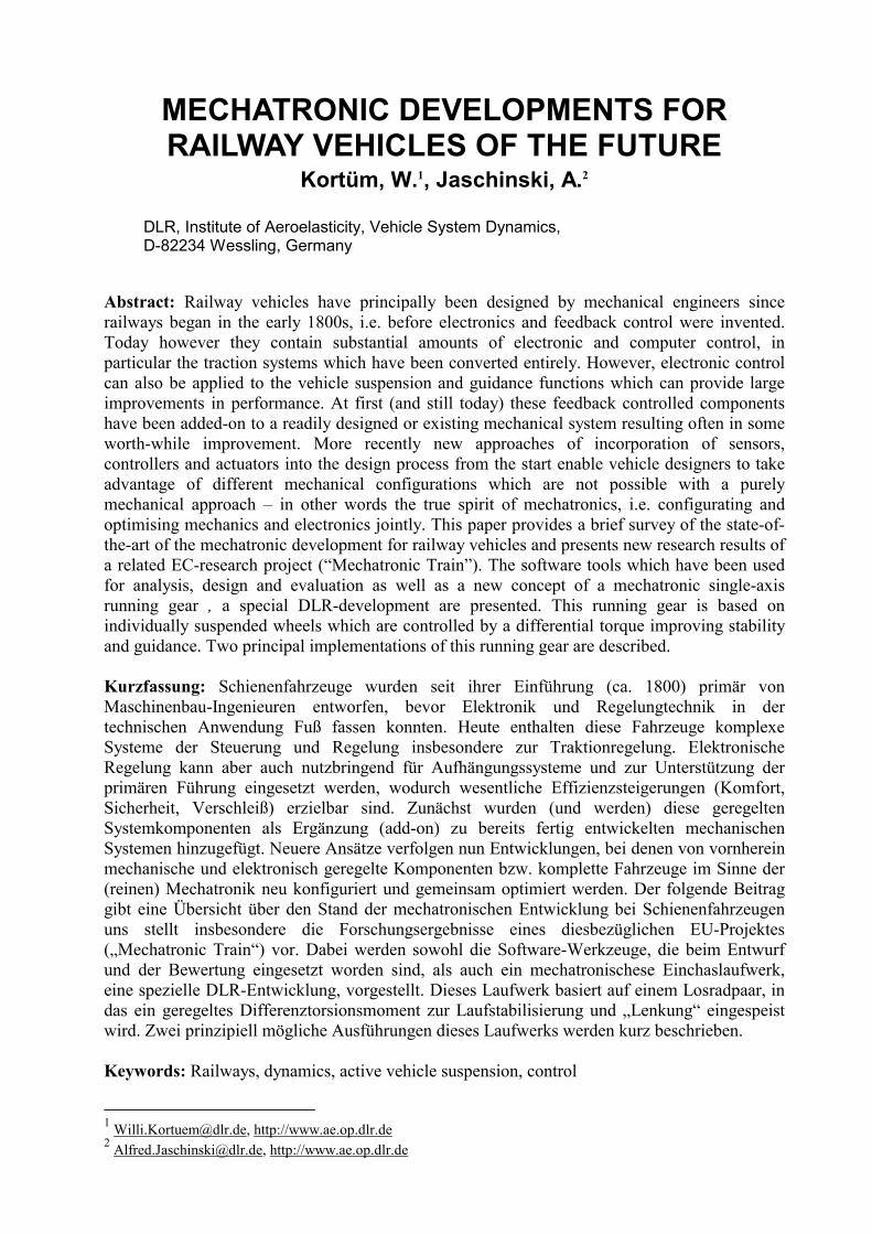
1.2 Application of mechatronics If it is assumed that there will be actuators, sensors and controllers at the heart of future railway vehicles, it is possible to discover ways of exploiting the synergy of the mechanics and the electronics to achieve a superior solution. This is of course what the discipline of Mechatronics is about, not just adding electronic control to an existing mechanical system, but re-designing the mechanical system to take full advantage of control. So, what are the possibilities for Mechatronics in rail vehicles?
150 years of suspensiondevelopment
Effect of Mechatronics?
Figure 1: Evolution in vehicle design
This can best be answered by considering the way in which rail vehicle design has evolved historically – see Fig. 1. In the early days of railways, the vehicles were mechanically very simple. They were, essentially, boxes on two sets of wheels. At the time passengers thought they were wonderful, but in fact their performance was poor. Demands for higher speed and better

ride quality necessitated evolutionary development over a period of 150 years or more, leading to the basic structure of high speed passenger vehicles which we have today – four-axled vehicles with two bogies which can run stably at high speeds and go round the curves in a reasonable manner, and having soft secondary suspensions to provide modern standards of ride quality. It is however clear that these are heavy and mechanically complicated, and one of the best ways of achieving lighter, simpler vehicles is to go back to the structure of those early vehicles. This is something which most people agree cannot be achieved effectively with passive suspension technology, but can be achieved through active control. The lower weight and mechanical complexity reduce both capital cost and running cost, and this can be spent on the provision of the active systems and their maintenance. The challenge is to design the active systems so that there is a net benefit [13]. This principle, of simplifying the mechanical system by the use of active steering and active suspensions, in other words exchanging mechanical complexity for electronic control complexity, is potentially an extremely important contribution to railway technology, but there are major technical challenges to be overcome [12]. The following sections of the paper will identify what has been achieved so far and what challenges remain.
1.3 Research objectives One fundamental problem with active vehicle systems is the interaction between structural dynamics, the forces between wheel and rail, and the control systems. Accordingly, a proper understanding of the engineering science is needed for an integrated application of electronic and mechanical components to achieve the optimum systems design of railway trains, and it is possible to identify the following specific objectives, [4] 1. To develop a fundamental understanding of the dynamic response of lightweight rail vehicles
with active controls. 2. To develop methods of analysis for advanced vehicles emphasizing configurations which
take full advantage of emerging control technology (leading to reduced weight, lower cost, lower car-body structural vibrations, etc.)
3. To research systems architectures (sensors, actuators, processing) which provide the level of safety, reliability, and maintainability needed for an operational railway.
2. Railway Vehicle Design
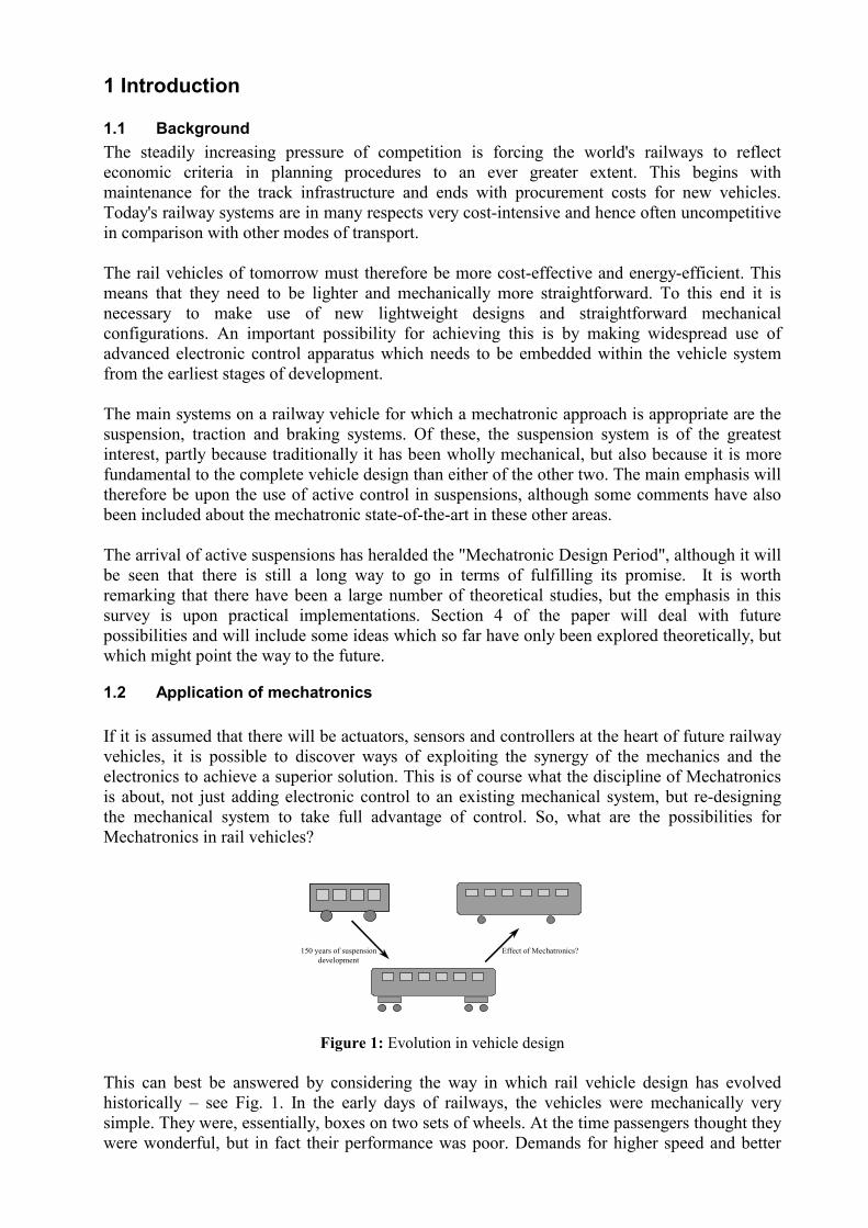
2.1 System dynamics It is useful to explain the essential mechanical arrangement of a modern high-speed rail vehicle shown in Fig. 2, which is an arrangement which has evolved over nearly two centuries of railway operation. There is the vehicle body for the passengers, and underneath are two bogies each having two pairs of wheels, connected by a solid axle to form what’s called a wheelset. The suspension arrangement which interconnects these seven masses – one body, two bogies, four wheelsets – is complicated. There is the primary suspension from the wheelsets to the bogie, mainly dealing with running stability. Also there is the secondary suspension from the bogies to the vehicle body, nowadays usually a very soft set of airsprings which ensure that the passengers experience a good ride quality. Both stages of suspension are carefully designed in the lateral and vertical directions, and some of the rotational modes such as yawing and rolling are important as well. Of course what is shown here is just a "passive” arrangement where the performance depends upon springs, dampers, and so on.
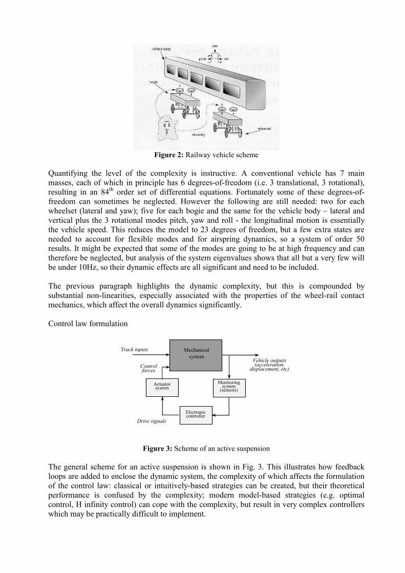
Figure 2: Railway vehicle scheme
Quantifying the level of the complexity is instructive. A conventional vehicle has 7 main masses, each of which in principle has 6 degrees-of-freedom (i.e. 3 translational, 3 rotational), resulting in an 84th order set of differential equations. Fortunately some of these degrees-of-freedom can sometimes be neglected. However the following are still needed: two for each wheelset (lateral and yaw); five for each bogie and the same for the vehicle body – lateral and vertical plus the 3 rotational modes pitch, yaw and roll - the longitudinal motion is essentially the vehicle speed. This reduces the model to 23 degrees of freedom, but a few extra states are needed to account for flexible modes and for airspring dynamics, so a system of order 50 results. It might be expected that some of the modes are going to be at high frequency and can therefore be neglected, but analysis of the system eigenvalues shows that all but a very few will be under 10Hz, so their dynamic effects are all significant and need to be included. The previous paragraph highlights the dynamic complexity, but this is compounded by substantial non-linearities, especially associated with the properties of the wheel-rail contact mechanics, which affect the overall dynamics significantly. Control law formulation
Mechanicalsystem
Track inputs
Vehicle outputs(acceleration,
displacement, etc)
Monitoringsystem
(sensors)
Electroniccontroller
Actuatorsystem
Controlforces
Drive signals
Figure 3: Scheme of an active suspension
The general scheme for an active suspension is shown in Fig. 3. This illustrates how feedback loops are added to enclose the dynamic system, the complexity of which affects the formulation of the control law: classical or intuitively-based strategies can be created, but their theoretical performance is confused by the complexity; modern model-based strategies (e.g. optimal control, H infinity control) can cope with the complexity, but result in very complex controllers which may be practically difficult to implement.

Normally of course restricted models will be used for design of specific active suspensions: an end-view model for tilting, a sideview model for the vertical suspension, a plan view model for the lateral suspension and for wheelset dynamics. These simplified models are important, but the complexity is still high and there are a number of other higher frequency modes and non-linear effects which need to be included, and so the design problem remains complicated.
2.3 Design requirements Another issue relates to what has to be achieved when designing an active suspension controller, and Fig. 4 summarises the design requirements. On the left are the inputs, and these are separated into three types: the deterministic track inputs describing the intended track features - curves, gradient, etc; the random track inputs describing the irregularities, ie the deviations from the intended track position; and thirdly there are the force inputs, principally the changes in load as people get on and off the vehicle. All these occur in the vertical, lateral and roll direction.
Act
uato
rs
Sens
ors
Controller
Track features(deterministic)
Track irregularities(stochastic)
Load changes
Body acceleration(minimise)
Suspension deflection(constrain)
Stability(constrain)
Curving performance(optimise)
Vehicle system
Figure 4: Design requirements
On the right are the outputs, and four items are shown. The acceleration levels on the vehicle body which represent the quality of ride, are to be minimised. The suspension movements must not become too large, and must therefore be constrained. It’s also necessary to ensure that there is a minimum margin of stability, another constraint. And finally there’s curving performance, mainly about minimising any wear of the wheels and the rails, so an optimisation is needed. There are therefore three input types to consider, two output measures to minimise and two design constraints to meet, and the diagram also indicates the influences from the inputs to the outputs, the end result of which is a non-trivial multi-objective design process, particularly when combined with the dynamic complexity mentioned earlier.
2.4 Methodologies and tools Railway vehicle design is still dominated by the mechanical engineering aspects, but taking advantage of mechatronic opportunities requires the engineers to take on board not only the new conceptual approach implicit in the discipline, but also the design tools which are required for an integrated approach to mechanical, electronic and software system design. Modelling and simulation of railway vehicles is specific, not only because the model for dynamic analysis should include model of suspension components, which can be modelled by many simulation tools, but particularly because of the necessity of a sophisticated model for wheel/rail contact. Because of its specificity, general modelling and simulation do not support railway vehicle modelling. Only some multibody system (MBS) modelling and simulation packages have implemented the wheel/rail module in particular SIMPACK, [19]
The design process of modern railway vehicles is affected by a number of different disciplines influencing each other, such as control, flexibility, aerodynamics, hydraulics, etc. In order to apply these facilities to the model, the packages enabling to simulate the wheel-rail contact must be extended with new design features. For example some MBS packages include simple and restricted control loops; alternatively the controller must be added as a user-defined element. The connection of MBS or railway-dedicated packages with control design packages is amore convenient way for the designers. The coupling of simulation codes is described e.g. in [28]. Using different specialised packages for mechanical and control design decreases demands on the designer. Despite using different packages, it is possible to simulate and optimise whole vehicle model from the earliest design stages
3. Mechatronic Opportunities This section provides an overview of the possibilities that exist for mechatronic railway vehicles. It provides a progressive overview, starting with the active control techniques which are currently employed and moving on through a sequence of opportunities which are increasingly further away from the current state-of-the-art in railway technology.
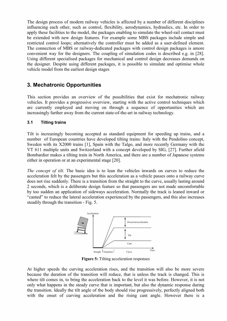
3.1 Tilting trains Tilt is increasingly becoming accepted as standard equipment for speeding up trains, and a number of European countries have developed tilting trains: Italy with the Pendolino concept, Sweden with its X2000 trains [1], Spain with the Talgo, and more recently Germany with the VT 611 multiple units and Switzerland with a concept developed by SIG, [27]. Further afield Bombardier makes a tilting train in North America, and there are a number of Japanese systems either in operation or at an experimental stage [20]. The concept of tilt. The basic idea is to lean the vehicles inwards on curves to reduce the acceleration felt by the passengers but this acceleration as a vehicle passes onto a railway curve does not rise suddenly. There is a transition from the straight to the curve, usually lasting around 2 seconds, which is a deliberate design feature so that passengers are not made uncomfortable by too sudden an application of sideways acceleration. Normally the track is leaned inward or “canted” to reduce the lateral acceleration experienced by the passengers, and this also increases steadily through the transition - Fig. 5.
Time
Acceleration
TransitionStraight Curve
Tilt
Perceived acceleration
Cant
Figure 5: Tilting acceleration responses
At higher speeds the curving acceleration rises, and the transition will also be more severe because the duration of the transition will reduce, that is unless the track is changed. This is where tilt comes in, to bring the acceleration back to the level it was before. However, it is not only what happens in the steady curve that is important, but also the dynamic response during the transition. Ideally the tilt angle of the body should rise progressively, perfectly aligned both with the onset of curving acceleration and the rising cant angle. However there is a
complication, because irregularities in the track (i.e. imperfections between how the track is meant to be and how it actually is laid) have the effect of adding a random higher frequency element to the acceleration perceived by the passengers. Tilting cannot affect this because it is principally a purely lateral effect, and the purpose of the lateral secondary suspension is to keep these accelerations low enough. In fact, the tilt system must avoid reacting to these irregularities, otherwise a number of problems arise. Tilting controller strategies. The most intuitive control approach is to put an accelerometer on the vehicle body to measure the lateral acceleration which the tilt action is required to reduce. The accelerometer signal is used to drive the actuator in a direction which will bring it towards zero, i.e. a classical application of negative feedback. There are two problems with this approach. Firstly, if the passengers are left without lateral acceleration, a significant proportion of them experience motion sickness. The other problem is interaction with the lateral suspension, and it can be shown that if the tilt loop bandwidth is low enough not to interfere with the lateral suspension, it is then too slow-acting on the curve transition. The dynamic interaction problem can be avoided by putting the accelerometer on a non-tilting part, in other words the bogie. This provides a “tilt angle command signal” for a feedback loop using a measurement of the tilt angle, typically scaled so that the system compensates for around 60 to 70% of the curving acceleration to avoid motion sickness effects. However the accelerometer on the bogie is not only measuring the curving acceleration, but also the pure lateral accelerations due to track irregularities. Consequently it is necessary to add an electronic filter to reduce the effects of the irregularities, otherwise on straight track this results in a poor ride quality, but this creates too much delay at the start of the curve. The solution is to use the signal from the vehicle in front to provide precedence, carefully designed so that the delay introduced by the filter compensates for the precedence time corresponding to a vehicle length. And this scheme, albeit with detailed variations, is what most manufacturers now use. This evolution of control strategies took place over nearly 30 years. Initially it seemed to be a straightforward control system, and lengthy development time arose a proper mechatronic systems approach which recognised the complete problem "domain" was not adopted - the complexity of the basic dynamic system, the form of the track excitations, the tilting mechanism, the sensing possibilities, etc. Nevertheless it can be seen that there are now clear signs of manufacturers starting to think mechatronically, resulting in more effective, better-integrated designs.
3.2 Active secondary suspension The introduction of tilting is potentially the tip of an iceberg: once an active system has been introduced and accepted for railway operation, the introduction of other active solutions is technically much easier. Tilting is a specific form of active secondary suspension between the bogie and the body, so the paper next looks at how the idea of active secondary suspensions can be generalised, principally with the objective of improving the vehicle response to track irregularities, i.e. to improve ride quality. Passive suspension characteristics. In a railway vehicle the primary suspension from the wheels to the bogies is fairly stiff, the bogies more or less follow the way in which the track moves vertically as the vehicle travels along. The secondary springs from the bogie to the body are there to transmit the low frequency intended movements so the vehicle follows the track, but at the same time to isolate the higher frequency irregularities to provide a good ride quality.
The amount of damping provided for the secondary suspension is a difficult design trade-off. If it is too low there will be a lot of activity in the resonant modes; if it is too high the dampers transmit high frequency track movements to the vehicle body, and modal dampings in the region of 20% are typically chosen. Use of active elements. Active control provides a solution, because by replacing the dampers with actuators, measuring the vertical velocity at each end of the vehicle and making the actuator force proportional to the body velocity, the actuators then apply damping to an absolute reference, and increased damping now controls the resonance of the suspension without making things worse at high frequencies. This is the concept known as "skyhook damping", identified many years ago [11] but still providing the basis for most active suspensions. Some care in the controller design is needed because skyhook damping can create large suspension deflections when gradients and curves are encountered [14] but overall the concept is extremely beneficial.
ActuatorSensor
Controller
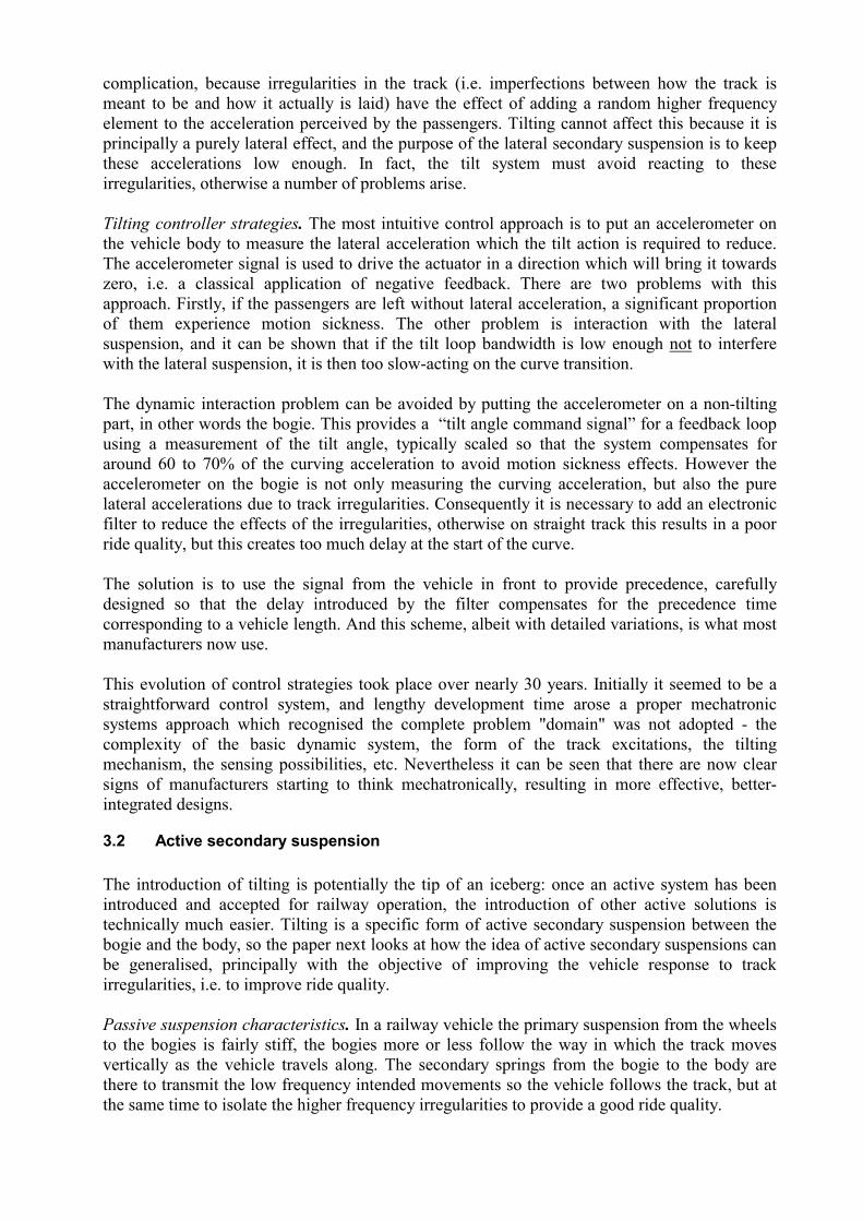
Figure 6: Active secondary suspension control scheme This implementation of skyhook damping gives an important improvement in ride quality, but in fact there are other things which can be done. For example, normally the suspension frequency in pitching is somewhat higher than in the vertical or bouncing direction, whereas it can readily be demonstrated that there is a definite advantage in having a lower frequency in pitch, but with an active suspension it is possible to bring together the signals from the two ends of the vehicle, separate them into bouncing and pitching and independently control the vehicle modes, in particular to make the pitching response significantly softer - see Fig. 6. The combination of this modal approach and skyhook damper gives substantial improvements in ride quality, and both theoretical and experimental investigations have shown up to 60% reduction in rms acceleration levels. Applications. The only active secondary suspension which has run regularly in service in Europe (apart from tilt) is a low grade active lateral suspension using pneumatic actuators on the Fiat Pendolino trains, and this same facility is provided on some of the newer Fiat tilting bogies. However there are also a number of successful examples of full scale experimental implementations [5] which help to understand the mechatronic opportunities. A very significant development has been conducted by Siemens SGP in Austria on an experimental vehicle. They have semi-active secondary vertical dampers, fully-active pneumatic actuators to keep the lateral suspension centred on curves, and electro-mechanical tilt actuators (mentioned before in connection with trends in tilting trains). What is particularly interesting about this development is the way the control systems have been integrated, including a full set of inertial sensors, and this almost certainly represents the most advanced mechatronic implementation which is currently available [25]. Most of the serious experimental work at present is concerned with the lateral direction, because generally speaking that is the harder design problem. It is probable that once these have been proved in operation the deficiencies of the vertical suspensions will be highlighted, and this may prompt a spate of work on active vertical suspension. For example a laboratory rig has been used to assess the use of actively-controlled damping for a secondary air suspension [26].

3.3 Controlling wheels and wheelsets Control of the primary suspension to give active steering/guidance is a much more substantial step in technology, and this sub-section reviews the principles and explains the kind of practical implementations which have been investigated.
Lateral movement
Solid axle
Rolling radius
Track
Wheel flange
Figure 7: Features of a railway wheelset
3.3.1 Wheelset dynamics. It is necessary to understand how the conventional railway wheelset works, which has been a vital element of railway vehicles since railways began, but the way it works is not always obvious to people. A wheelset consists of two coned or otherwise profiled wheels rigidly connected by an axle - Fig. 7. On straight track the wheelset runs in a centralised position, but when a curve is encountered the wheelset naturally moves outwards; this causes the outer wheel to run on a larger radius and the inner on a smaller radius. Being connected by the axle the wheels must still rotate at the same rotational speed, so the outer wheel moves faster along the track, and the effect is to make the wheelset go around the curve. A popular misconception is that it is the flange which makes the vehicle follow the curve, but in fact this is not the case - it's entirely a consequence of the profiling of the wheels and the designer's job is to avoid contact between the flange and the rail otherwise large amounts of wear results. Unfortunately, while this inherent curving action is obviously just what is needed, there is a problem, and this arises when you start to look at the dynamics of the wheelset. Its motion occurs both laterally and in the rotational yaw direction. The forces on the wheelset arise from so-called “creepages” between the wheel and rail, small relative velocities which arise because of elastic deformation of the steel at the point of contact and which apply in both the longitudinal and the lateral directions. The overall effect is an instability, principally a kinematic oscillation [29]. Adding mechanical dampers does not stabilise the wheelset, and it is necessary to add springs, and the normal solution is to have two wheelsets connected via longitudinal and lateral springs within a bogie as seen in Fig. 8. The lateral springs are necessary to transmit the curving forces, but the longitudinal springs are mainly there to stabilise the wheelsets, essentially by providing a yaw stiffness.
Figure 8: Mechanical scheme of a conventional bogie
However, on a curve these stabilising longitudinal springs produce forces which interfere with the natural curving action of the wheelset. The result is that on the tighter curves the wheel

flange will be in contact with the side of the rail, causing wear of the wheels, wear of the rails and often significant amounts of noise. There is therefore a difficult design trade-off: stiff springs give stable high-speed running, but poor curving; soft springs mean that the curving performance is better, but stable running is only possible at low speeds. Great ingenuity has been applied in finding mechanical solutions to this design trade-off [9]: “cross-braced bogies” with carefully-designed linkages between the wheelsets; “steering bogies” with linkages to the vehicle body which try and get the wheelsets into more or less the right position on steady curves, but none of these fundamentally overcomes the problem which has been outlined.
3.3.2 Active control of wheels and wheelsets. It is now possible to discuss where control fits in, because appropriate use of active control can provide new levels of performance not achievable with a conventional passive bogie. One possibility is where the longitudinal springs seen in Fig. 8 are replaced by actuators, and this enables characteristics to be obtained which either are not possible with a purely mechanical solution, or at least extremely difficult in practice. In the more general case a wheelset can be actively-connected in both directions, including directly to the vehicle body (i.e. without a bogie), which provides the basis for identifying a range of possible control approaches. These are outlined in the sections which follow, although it is important to emphasise that these are very much concept diagrams to describe the basic idea, and a lot of extra engineering detail would be needed in practice.
Actuator
Frame/vehicle body
Figure 9: Actively-steered wheelset
The first option in Fig. 9 shows the longitudinal springs in series with the actuators – the idea here is that the higher frequency oscillations of the wheelset are stabilised by the springs, with low bandwidth active control provided by the actuators, essentially to “relax” the force they produce when the vehicle goes round curves so as to allow the wheelset to take up its natural curving position. This approach has been studied applied to a conventional bogie, and it is been shown possible to get extremely good performance with really quite a simple control law which minimises the wheelset yaw torque applied at low frequencies [22]. Actuator power levels are extremely low, a few tens of Watts only, which means that practical implementation is not a problem. The same idea has also been applied to single-axle running gear in Germany, and forms the basic scheme in some Integral railcars, manufactured in Austria and now running in service, [24].

Rotaryactuator
Figure 10: Actively-stabilised wheelset
Fig. 10 shows another approach, which is the other way round to the previous paragraph - passively steered, actively stabilised. As mentioned earlier, conventional dampers do not stabilise the wheelset; however applying a yaw torque to the wheelset which is proportional to the lateral velocity of the wheelset produces a form of active damping which is stabilising, and a detailed analysis shows that it doesn’t interfere the natural curving either. In fact a number of control laws are possible for this scheme, not only the active damping principle but other ideas as well [15].
Bearings
Rotaryactuator
Figure 11: Wheelset with independently-rotating wheels
3.3.3 Wheelsets with independently rotating wheels. A modification of the basic wheelset which railway suspension designers have looked at many times over the years are wheelsets in which the wheels are free to rotate independently on the axles [3]. It is commonly stated that this removes the instability because the two wheels are no longer connected mechanically. In fact if analysed carefully this is not the case [6], but stabilisation is much more straightforward, and in this case dampers are effective. However the natural curving action disappears, again because the connection between the wheels has disappeared, and so active control in this case is there primarily to steer the wheelset through the curves, as Fig. 11 shows. Fig. 12 presents an important alternative idea which can be used with independently-rotating wheels – rather than use actuators, it is possible to control the torque being applied to the two wheels separately, the sum of the torques providing propulsion and braking as normal, with the difference being used to steer the wheelset
TL TR
Figure 12: Torque-controlled independently-rotating wheels
This mechatronic wheelset concept has been developed by DLR [8] which directly interacts with the wheelset’s friction forces and thus drastically changes the usual running dynamics. This is achieved by the controlled transmission of a differential torque from one wheel to another. This torque is produced using electromagnetic forces, avoiding internal slippage and wear, as a mechanical coupling would produce. It is also possible to switch between different characteristics of coupling or control strategies during the vehicle in operation. The main aim of such a mechatronic wheelset is to resolve the design conflict between stability, curving performance, comfort and wear. As the controlled wheelset runs stably by directly controlling the longitudinal slip forces there is more freedom to design its suspension to provide more comfort and not to restrict the ability to run through narrow curves. Both wheel forces and friction power can be considerably reduced leading to less wear and less noise. By the chance to simplify the suspension mechanically and to combine traction and steering functionality a generation of unconventional, powerful and light railway vehicles becomes possible.
.
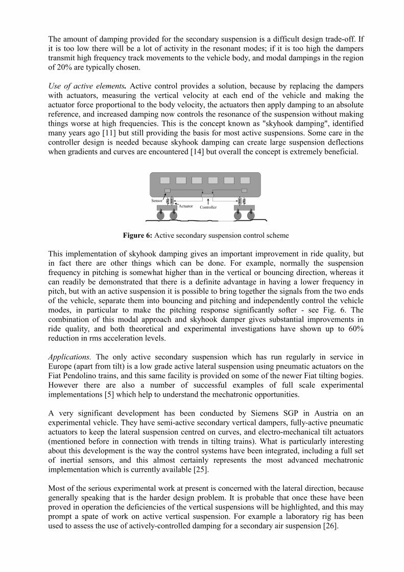
Figure 13: An experimental vehicle on the 1:5 scaled roller rig at Oberpfaffenhofen. Currently there are two generic 1:5-scaled experimental vehicles available. They are called generic because they can be freely adapted to a number of wheelset configurations, from the classic solid wheelset to independently rotating wheels and connection of the wheels by an arbitrary passive, semi-active or active torque coupling. On the first test vehicle this coupling is provided mechanically by a special gearbox, on the second vehicle electrodynamically by an independent and individually controlled drive motor of each wheel. As a first approach a gearbox was developed that couples the two wheels of an axle in such way that the differential torque can be introduced from an external servo motor directly between the two wheels [7]. This superimpositional gearbox represents only one possible solution for this principle. The mechanical coupling can be replaced by an electrodynamic one. In particular it is possible to use the same control schemes for axles with wheels driven independently by separate traction motors. The commanded differential torque is superimposed to the propulsion or braking torque, allowing the investigation of active stabilisation combined with driving or braking. Nevertheless, special control strategies are needed to keep full control of the vehicle near to the limit of adhesion. So this second vehicle represents a typical meachatronic approach of a mechanically simplier system offering more performance than the electromechanical one. The controller is implemented on a digital signal processor (DSP) card housed in a PC. Via a second DSP card the state measurements are collected and written to a database. Using the SIMPACK-MATLAB/Simulink interface the non-linear and three-dimensional model of the complete mechatronic system can be simulated and the control loop can be optimised. After the
automatic transfer of the controller code to the DSP the test vehicle is ready to validate the controller and to prove the feasibility and stability of the system in a real hardware environment [8].
3.3.4 First results for the torque controlled wheelset. Measurements of experiments performed on a 1:5 scaled roller rig [10], Fig.13, showed the stabilisation of the vehicle up to its maximum speed, the lateral positioning and the reduction of frictional power and thus wear for the different vehicle configurations (gearboxes or single motors), wheel profiles and control strategies [8]. With wheel motors a better and more precise response was shown compared to the mechanical superimposition used so far. This is due to the lack of additional mechanical nonlinearities, such as friction and clearances of the gearboxes. For the experiments, either the roller rig can be powered to execute experiments with a non-powered vehicle, or the roller rig can be braked when the vehicle wheels are driven to simulate traction processes.
� � � � � � � � �
� � � � � �
� � � � � � � � �
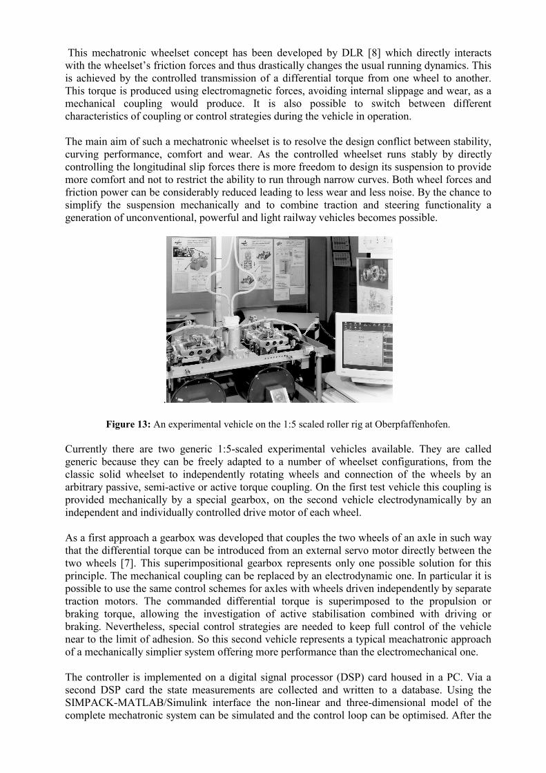
Figure 14: Lateral behaviour of powered vehicle (0.9 Nm)
Figure 14 shows commanded lateral displacement, actual lateral displacement and relative torque, measured from roller rig experiments. In addition, a drive torque of 0.9 Nm per wheel is applied, which uses half of the available friction coefficient. The differential torque acts on both wheels with same amount and opposite direction. A desired value of +/- 5mm is commanded to show the general steering and positioning ability. The vehicle reacts precisely despite the slow speed of scaled 30 km/h in this experiment. The small amount of steady differential torque is needed to keep the central position results from small but inevitable angular inaccuracies of the practical suspension. A vehicle with passive independently rotating wheels would react very sensitively on such inaccuracies. The active control whereas can fully compensate them.
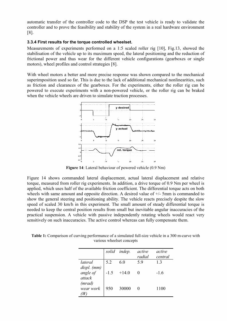
Table 1: Comparison of curving performance of a simulated full-size vehicle in a 300 m-curve with various wheelset concepts
solid indep. active
radial active central
lateral displ. (mm)
5.2 6.0 5.9 1.3
angle of attack (mrad)
-1.5 +14.0 0 -1.6
wear work (W)
950 30000 0 1100

Figure 15: Lateral behaviour of vehicle with solid wheelsets (top) versus torque control (bottom) during
curve transition with track excitation. Indicated is the lateral displacement (mm) versus time Table 1 shows SIMPACK simulation results comparing the curving performance (leading axle) of a generic 2-axle vehicle optionally equipped with solid wheelset, independently rotating wheels, or active torque control. In one case, the control strategy was chosen to keep the wheelset in radial position, in the second case to centre it and to keep it away from the flange (as described in the previous chapter). As example a curve with 300 m radius, 150 mm superelevation and a speed of 108 km/h was chosen. The vehicle is one of the reference models defined for the Mechatronic Train project and shows already a very good performance with solid wheelsets due to a suspension with very low yaw stiffness but high yaw damping.
• Due to that soft yaw suspension the solid wheelset performs very well, but gets near to the flange.
• The passive independently rotating wheels have no tendency of self centring or radial
positioning, leading to extremely high values of angle of attack and wear work, due to lateral creep.
• The active wheelset aligned radially has theoretically no wear work (as the spin was not
calculated), but the contact point is almost on the flange because the lateral forces have to be fully produced by gravitational stiffness.
• The actively centred wheelset has the lowest lateral displacement, but a slightly
increased wear work, because the lateral forces are partially produced by lateral friction for this extremely low lateral displacement.
� � � � � � � � � �
� � � � � � � � � �

It has to be mentioned that these simulations only show the steady-state curving on perfect track without excitations. The advantages of the actively centred wheelset are much higher if real track with exciations is taken into account, see Fig. 15. The wheelset can react on disturbances, damp lateral oscillations actively, and avoid hard flange contact. Therefore, a significant reduction of wear compared to other passive solutions can be expected on real track. In addition, the controlled wheelset does not have the tendency of limit cycle hunting above the critical speed.
Carrying Frame
Wheel Bearings
Stub-Axle
Actuator
Figure 16: Directly-steered wheels
3.3.5 Directly-steered wheels. So far the paper has looked at applying control to conventional wheelsets, but the next scheme, seen in Fig. 16, is totally different because there is no axle. The wheels are pivotted about a vertical axis, and there is a track rod connecting the wheels to keep them parallel. There are a number of ways in which steering can be achieved - here the steering angle is directly adjusted by an actuator, but differential torque control is another choice [17] i.e. the idea described in the previous paragraph but applied via a different mechanism. The wheels are of course now completely independent and must therefore be steered [30]. Here we can see significant mechatronic influences starting to appear, because the basic mechanical scheme has been fundamentally changed to accommodate the benefits provided by active control.
3.3.6 Range of options for active wheel/wheelset control. The preceding sub-sections have indicated a great variety of possibilities for achieving active steering. Firstly, there is the control approach – is the control being used to steer to stabilise or both? Secondly what method is providing the control – actuator control or torque control? Also to be decided is the wheel configuration – normal solid-axle, independently-rotating wheels on an axle, or steered wheels? Superimposed on these choices is also the type of control hardware – sensors, controllers actuators, etc – and so the decision as to which is the best solution for a particular application is complex and still open, and it is clear that significant research is still needed to help resolve some of these issues.
3.4 Traction and braking Electric traction systems have been common in railways for many years, and the addition of electronics and control has mainly been associated with exploitation of power electronic drives. Probably the main consequence of this has been the ability to replace d.c. motors with smaller and more efficient a.c. motors. In general this has resulted in an easing of the mechanical design, rather than the kind of fundamental change which follows from mechatronic integration, although there have been cases of vehicles for low speed systems in which "hub" motors have been directly connected to the wheels, thereby removing the need for a gearbox and/or mechanical drive and creating substantial simplifications in bogie design. The other significant impact is that the traction system has been able increasingly to provide braking effort through electrical regenerative action, although the net effect upon the main mechanical braking system has so far been relatively small.

Advanced control can provide a much more effective use of the adhesion which is available at the wheel-rail interface, and there are examples of theoretical and experimental studies which demonstrate the ability through the sophisticated power control to operate at the peak of the adhesion/slip characteristic, [2], [21].Wheelslide protection of railway braking systems has been fitted for many years, but the pneumatic brake actuators which are predominant in the industry are insufficiently fast to do other than provide fairly simple on-off control when wheelslide is detected. Recent examples of wheelslide protection are making much more extensive use of the sophistication which is possible through electronic control [12]. In addition, a number of braking system manufacturers are investigating more advanced braking actuators (e.g. electro-mechanical systems), at least in part because of the enhanced control capability which these will provide, and in many senses these developments reflect the changes away from traditional mechanical engineering solutions which have also been seen with the suspension systems and towards a mechatronic approach.
4. Future Mechatronic Vehicles As mechatronic trains develop more and more electronics will appear within railway vehicles, and more profound integration of the various systems is possible. The propulsion system already has a lot of electronics, and this can be linked in with active steering. As mentioned earlier, the possibility has already been recognised of avoiding the need for steering actuators if the traction motors driving the wheels are differentially controlled to achieve the steering action. Obviously this needs a high level of integration between the suspension and drive control systems, particularly to accommodate the requirements of safety criticality. An exciting new concept is the idea of a "wheel motor" in which there is mechanical integration of the wheel and the traction motor [23]- see Fig 17.
Figure 17: Wheel motor It must be remembered that the suspension, guidance, propulsion and braking forces of a railway vehicle all pass through the contact point between the wheels and the rail, a patch of compressed metal perhaps 2cm in size. There is a tendency to design these systems independently, but once they are all electronically-controlled, it will be possible to optimise the use of this contact patch through an integrated control system, and Fig. 18 shows an overall scheme. There will be a set of sensors measuring what’s happening, a controller which carries out drive, suspension and steering control, and the forces produced all act upon the vehicle dynamic system. The diagram also shows a track database system which could contain the intended alignment of the track, although important questions arise regarding the accuracy of the track information. Nevertheless, this kind of conceptual approach raises some extremely interesting possibilities.

Suspensionactuators
Suspensioncontroller
Motor/brakes
Steeringactuators
Drivecontroller
Steeringcontroller
Sensors Vehicledynamics
VehicleControl system
Track database Vehicle position Track information
Vehicle motions
Steering actions
Drive actionsSuspension actions
Figure 18: Integrated control scheme
So it is possible to look forward to a full implementation of mechatronic principles for the design of running gear, using single wheels in which electronics is applied to an integrated control system, controlling traction, braking and suspension forces in an optimal way. The concept, in particular the use of active steering, is potentially liberating from the operational viewpoint, because in principle it is possible to dictate the direction through switches from the vehicle rather than the track. Conventional track switches could disappear such that the track is continuous in both directions through the switch, with the sensors causing the vehicle to follow one route or the other, and if this is combined with electronically rather than mechanically-coupled vehicles all sorts of possibilities arise which could significantly enhance the operational flexibility of railway operation. Most of the developments which exist at present are what might be called "first generation" systems, having limited functionality with restricted control laws, usually applied locally to the actuators. It is however possible to envisage subsequent generations for which the mechatronic opportunities (and challenges) will be much greater:
• A second generation of systems with a higher degree of functionality (e.g. lateral and vertical), integrated measurement systems for higher reliability and fault-tolerance, and control laws which take a more complete view of the vehicle or train system.
• A third generation of systems offering a further increase in functionality, probably
highly integrated with other vehicle dynamic systems such as traction and braking, and using information from facilities such as track profile databases, satellite positioning system etc.
5. Conclusions Everywhere one looks at the technology of transport vehicles, the increasing importance of mechatronic solutions to vehicle design is apparent. Aircraft have essentially already made the transition, with full integration of controls and computation and the mechanical/aerodynamic structure through fly-by-wire. The automotive industry has also made substantial changes with electronic engine controls and anti-lock braking systems, and other changes are imminent: brake-by-wire, active stability control, and steer-by-wire. The railway industry is following, but given the significantly longer product life cycle it is probably inevitable that it is lagging behind the aircraft and automotive industries. Nevertheless active tilting is now well established, and a number of practical developments have been reported recently which involve a high degree of control applied to the running gear. It is interesting to see that, although the concepts of active secondary suspensions have been understood for many years, the actual take-up on real, operational vehicles is relatively low. They only really affect ride quality, for which the commercial return is relatively low, whereas

the burgeoning interest in various forms of active steering is motivated by substantial changes in vehicle configuration. The engineering challenges are greater, but the operational benefits are likely to be substantial if safe, reliable, cost-effective solutions can be developed. It seems inevitable that rail vehicles will become “increasingly mechatronic” in some form or another, and comparison with the other industries mentioned makes it clear that such an evolution (or revolution?) is strategically important for railways. An EC research project, has made an important contribution to the evolution of this new mechatronic technology for trains, the aim being to identify the opportunities, to provide the scientific basis upon which practical applications can be developed, and to disseminate the research results and potential benefits [4].
6. REFERENCES
[1] Anderson E, Bahr H V and Nilstam N G (1995) Allowing higher speeds on existing tracks - design considerations of the X2000 train for Swedish State Railways Proc IMechE Pt F, Vol 209, No 2, pp 93-104
[2] Beck, H.-P. and B. Engel (1996). Traction drive control with PI state controller and Kalman filter - first experimental results, Proc. 13th IFAC Congress, Vol P, pp 343 - 8, San Francisco.
[3] Dukkipati, R V, Narayanaswamy, S and Osman, M O M, (1993) Independently rotating wheel systems for railways - a state-of-the-art review Vehicle System Dynamics, Vol 21, , pp 297-330.
[4] Ellis B and Goodall R M (1999) The Mechatronic Train: Requirements and Concepts, Proceedings of World Congress on Railway Research, Tokyo, Japan, Oct 1999.
[5] Goodall R M (1997) Active railway suspensions: Implementation status and technological trends, Vehicle System Dynamics, Vol 28, pp 87-117
[6] Goodall R M and Li H (2000) Solid axle and independently-rotating railway wheelsets – a control engineering assessment of stability, Vehicle System Dynamics, Vol 33, pp 57-67.
[7] Gretzschel, M. (1995). Konzeption und Konstruktion einer aktiven Torsionsverbindung für einen generischen Eisenbahnradsatz. Diplomarbeit, TU München, Nr. 674.
[8] Gretzschel M and Bose L (1999) A Mechatronic approach for active influence on railway vehicle running behaviour, Proc 16th IAVSD SymposiumDynamics of Vehicles on Roads and Tracks, Pretoria
[9] Illingworth, R and Pollard, M G (1982) The use of steering suspension to reduce wheel and rail wear in curves, Proc Instn. Mech. Engrs, Vol 196, pp 379-385.
[10] Jaschinski, A.; Chollet, H., Iwnicki, S., Wickens, A., von Würzen, J. (1999) The Application of Roller Rigs to Railway Vehicle Dynamics.Vehicle System Dynamics, 31, Nos. 5,6, pp. 345-392
[11] Karnopp, D. (1978). Are Active Suspensions Really Necessary? ASME, 78-WA/DE/2. [12] Kortüm, W.; Goodall, R.M.(2000) Mechatronic Research and Development for Railway
Vehicles.AVEC 2000, Ann Arbor, USA, August 2000. Proceedings of AVEC 2000, 5th International Symposium on Advanced Vehicle Control, pp. 653 – 660.
[13] Kortüm, W.; Goodall, R.M.; Hedrick, J.K. (1997). Mechatronics in Ground Transportation - Current Trends and Future Possibilites. 15th Symposium on Transportation Systems, 1997, Greece.
[14] Li H and Goodall R M (1999) Linear and non-linear skyhook damping control laws for active railway suspensions, Control Engineering Practice, No 7, Vol 7, pp 843-850.
[15] Mei T X and Goodall R M (1999) Wheelset control strategies for a 2-axle railway vehicle, Proc 16th IAVSD Symposium, Pretoria, Aug 1999.
[16] Pollard, M.G. and N.J.A. Simons (1983). Passenger comfort - the role of active suspensions, Proc IMechE, Vol 198D, No 35, pp 1-15.
[17] Powell, A.J. and A.H. Wickens (1995). Active guidance of railway vehicles using traction motor torque control, Proc. 14th IAVSD Symposium, Ann Arbor, Mi, USA.
[18] Roth, P.-A. and M. Lizell (1995) Lateral semi-active damping system for trains, Proc. 14th IAVSD Symposium, Ann Arbor, MI, USA.
[19] Rulka, W. (2001). Effiziente Simulation der Dynamik mechatronischer Systeme für industrielle Anwendungen. DLR IB 532-01-06
[20] Sasaki, K., et al. (1996). Active tilting control of series E991 e.m.u. experimental train (development of third generation active tilting control, Proc. STech96, Paper C514/055/96, IMechE.
[21] Schwartz H J and Pfeiffer R (2000) Wheel creep control for light rail vehicles, Railway Technical Review, No 2, pp 4-12.
[22] Shen G and Goodall R M (1997) Active yaw relaxation for improved bogie performance, Vehicle System Dynamics, Vol 28, Nos 4-5, pp 273-289.
[23] Shelly T, (1999) Motors make the wheel go round, Eureka, Vol 19, No 5, pp 38-39. [24] Sommerer R (1999) Integral – ein Gliederzugsystem fur den Vollbahnbetrieb, ZEV + DET Glas.
Ann. 123 2, pp 73-84. [25] Stribersky A, Muller H and Rath B (1998) The development of an integrated suspension control
technology for passenger trains. Proc IMechE Pt F, Vol 212, pp 33-42. [26] Tang J S (1996) Passive and semi-active airspring suspensions for rail passenger vehicles -
theory and practice. Proc IMechE Vol 210, pp 103-117. [27] Various authors (1997). Proc. IMechE Seminar S479 on Tilting trains for the UK? [28] Veitl, A. et al. (1999), Methodologies for Coupling Models and Codes in Mechatronic System
Analysis and Design, In IAVSD 99, Pretoria. [29] Wickens, A H (1969) General aspects of the lateral dynamics of railway vehicles, Jnl of
Engineering for Industry and Transportation, ASME, Series B, 9(3) pp 869-878. [30] Wickens, A.H. and R.M. Goodall (1993). Wheels or Fields. The future of suspension and drive
systems, Proc. Int. Conf. on Railways, Institution of Civil Engineers, pp 362-378, Thomas Telford, May 1993.