contact us:
TRANSCRIPT
DMI DINESH METAL INDUSTRIESIMPORTERS, STOCKISTS & AUTHORIZED DEALERS OF: CARBON STEEL SEAMLESS PIPES & TUBES, FERROUS & NON FERROUS METALS
Contact us:Head O�ce: 79/81, West View Building A,Shop No. 1, Ground Floor,10th Khetwadi Lane,Mumbai 400 004, India +91-22-2380 2185 +91-22-2380 2421 [email protected]
Branch o�ce:34,Fruitwala Lane ,Near Jain Raksha Bandhan,Bapunagar, Ahmedabad 380 024, India +91-79-2274 3905 +91-79-2273 0820 [email protected]
www.dmitubes.com
DMI

OUR TARGETMaximum Customer Satisfaction
Ambition:Our aspiration is continual reliability and fairness in co operation with all market partners. All employees feel obliged to ful�ll this target. That's why commitment and responsibility play a signi�cant role at Dinesh Metal Industries.
Policy:To supply products of highest possible standards of Quality and Services in accordance to the agreed terms and conditions of customer orders, thus meeting customer satisfaction as well as continually improve our Quality Management System through e�ective team work of our employees.
Vision:Dinesh Metal Industries vision is to be the world's steel industry benchmark in �Value Creation� through the excellence of its people, its innovative approach and overall conduct. Underpinning this vision is a performance culture committed to aspiration targets, safety and social responsibility, continuous improvement, openness and transparency.
Mission:We are committed to provide the highest standards of products and services to our clients. Quality, Integrity and Value are the keystones of our business.
2
AMBITION
VISION
POLICY
MISSION
Dinesh Metal Industries is a reliable partner and specialist of seamless steel tubes and pipes since 1995. With 5,000 tons of continually available stock we are one of the most signi�cant steel tube suppliers in Indian Market.
We deliver complete packages either from our central Warehouse in kalamboli or from strategically selected warehouse from Taloja, Mumbai or Ahmedabad. This, combined with our comprehensive service, is sure to satisfy our customers requirements fully and individually every time.
Our long-term partnership with major customers is based on their recognition of our dedication, reliability and the consistent high quality of our products and service.
ABOUT US
1
We are Authorized Dealer for Indian Seamless Metal Tubes Limited and Jindal Saw Limited

OURPRODUCTSCarbon Steel:ASTM (A53,A106), SA(179,192,210,213), DIN(2391, 17175), BS(3059), NACE(MR0175 and MR103), EN speci�cation, HIC testing , H2 Service and SSC tested material for sour application etc.
Line Pipes:API 5L(B,X42,X52,X56,X60,X65-PSL-I & PSL2)
Alloy Steel:ASTM A335(P11,P22,T11,T22,P5,P9,P91,T91)
Low Temperature Pipes: ASTM A333 Gr. 3 & 6
Major Steel Grade:SAE (1019, 1518,1035,1010,1541,4130,4140,8620), DIN 17175(ST 35.8,ST 45.8, ST 52, 16Mo3, 13CrMo44,10CrMo44,10CrMo910) & other steel grade as per customer requirement.
Dimensions:Outer diameter : 21.3mm to 609.6mm (i.e. ½�NB to 24�NB)
Wall thickness: 2.77mm to 40 mm
3
Available for delivery in random lengths of 5 meters to 12 meters or in acut length according to customers requirements
4
OURSERVICESCut Lenghts: With our modern high performance saws we can ful�ll the customers requirements. Larger quantities can be cut to size within short notice.
Logistics:Dinesh Metal Industries quality de�nition encompasses the complete service spectrum of the company. We only deliver high quality products and guarantee deliveries in time.
24hr service: With our in-house crane, Dinesh Metal Industries guarantees a smooth delivery process. With our 24-hr service we prove our reliability and punctuality around the clock. This way we can deliver to our customers all across the world just in time.
Shipping via Truck / Rail / Ship: The delivery with di�erent means of transport allows a high level of �exibility possible and ensures that customers with di�erent delivery connections can be supplied

5
HOWWE WORKYour Enquiry: Our sales team are all experts in their �eld. On receiving your enquiry we will allocate the most suitable representative who will then discuss your requirements with you and prepare a quote. For standard tubes we aim to give you feedback within 24 hours of receiving your enquiry. If the speci�cations and quality requirements are more complex it may take slightly longer, but we will keep you posted on its progress.
Analyzing the order: After receiving your order our customer service team will process all relevant details, leasing with our technical, quality and planning departments.
Order Con�rmation: You will then receive your order con�rmation with a �nal delivery date.
Acknowledgement: The response times for order acknowledgement can vary depending on the complexity of your requirements on quality and inspection test plans.
After sales service: Our customer service team can also handle your Kanban requirements, stock management as well as long term contracts.
6
OUR EXPERTISE& CORE VALUESBoilers, Heat Exchangers & Condenser Applications
Mechanical Tubing & Structural Application
Petroleum and Petrochemicals
Re�neries
Fertilizers
Dairy and Sugar
Oil Drilling
Automobile Applications
General Engineering
Fluid Conveyance Applications
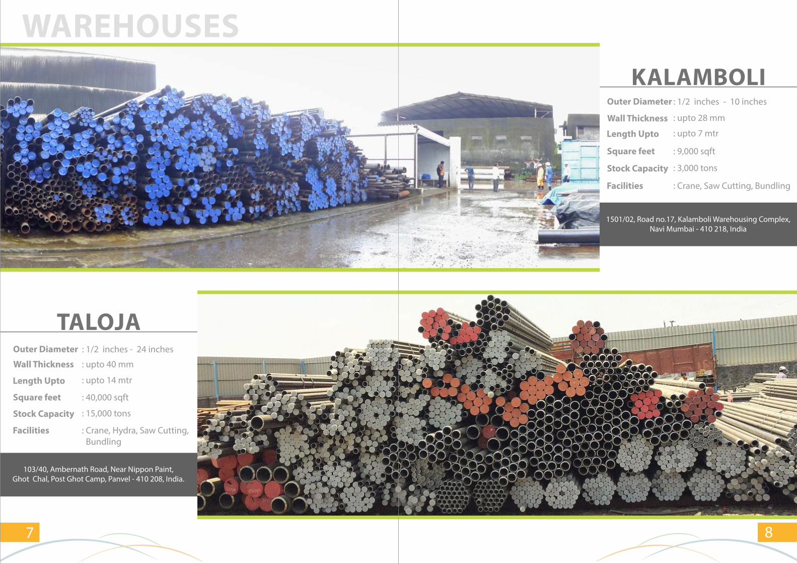
TALOJAOuter Diameter : 1/2 inches - 24 inches
: upto 40 mmWall Thickness
: upto 14 mtrLength Upto
: 40,000 sqftSquare feet
: Crane, Hydra, Saw Cutting, Bundling
Stock Capacity
103/40, Ambernath Road, Near Nippon Paint,Ghot Chal, Post Ghot Camp, Panvel - 410 208, India.
7
WAREHOUSES
Facilities
: 15,000 tons
KALAMBOLIOuter Diameter : 1/2 inches - 10 inches
: upto 28 mmWall Thickness
: upto 7 mtrLength Upto
: 9,000 sqftSquare feet
: Crane, Saw Cutting, BundlingFacilities
1501/02, Road no.17, Kalamboli Warehousing Complex,Navi Mumbai - 410 218, India
8
: 3,000 tonsStock Capacity
10
Sch.20
Sch.30
STD Sch.40
XS Sch.60
Sch.80
Sch.100
Sch.120
Sch.140
Sch.160
XXS
--
W.thick-weight-
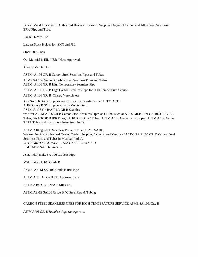
2.771.27
2.771.27
3.731.62
--
3.731.62
--
--
--
4.781.95
7.472.55
--
--
2.871.69
2.871.69
3.912.20
--
3.912.20
--
--
--
5.562.90
7.823.64
--
--
3.382.50
3.382.50
4.553.24
--
4.553.24
--
--
--
6.354.24
9.095.45
--
--
3.563.39
3.563.39
4.854.47
--
4.854.47
--
--
--
6.355.62
9.707.78
--
--
3.684.05
3.684.05
5.085.42
--
5.085.42
--
--
--
7.147.25
10.159.55
--
--
3.915.44
3.915.44
5.547.48
--
5.547.48
--
--
--
8.7411.12
0
11.0713.44
--
--
5.168.64
5.168.64
7.0111.41
--
7.0111.41
--
--
--
9.5314.92
14.0220.4
--
--
5.4911.30
5.4911.30
7.6215.28
--
7.6215.28
--
--
--
11.1321.35
15.2427.69
--
--
5.7413.57
5.7413.57
8.0818.64
--
8.0818.64
--
--
--
--
--
--
--
6.0216.08
6.0216.08
8.5622.33
--
8.5622.33
--
11.1328.33
--
13.4933.55
17.1241.04
--
--
6.5521.77
6.5521.77
9.5330.98
--
9.5330.98
--
12.7040.29
--
15.8849.13
19.0557.45
--
--
7.1128.27
7.1128.27
10.9742.58
--
10.9742.58
--
14.2754.22
--
18.2667.59
21.9579.25
6.3533.33
7.0436.83
8.1842.56
8.1842.56
12.7064.67
10.3153.11
12.7064.67
15.0975.95
18.2690.47
20.62100.97
23.01111.31
22.23107.97
6.3541.76
7.8051.01
9.2760.31
9.2760.31
12.7081.55
12.7081.55
15.0996.01
18.26114.75
21.44133.06
25.40155.15
28.58172.33
25.40115.15
6.3549.71
8.3865.19
9.5373.86
10.3179.73
12.7097.44
14.27108.93
17.48132.05
21.44159.87
25.40186.92
28.58208.08
33.32238.69
25.40186.92
7.9267.91
9.5381.33
9.5381.33
11.1394.55
12.70107.39
15.09126.72
19.05158.10
23.83194.98
27.79224.66
31.75253.58
35.71281.72
--
7.9277.83
9.5393.27
9.5393.27
12.70123.30
12.70123.30
16.66160.12
21.44203.53
26.19245.56
30.96286.65
36.53333.19
40.49365.35
--
7.9287.75
11.13122.43
9.53105.21
14.27155.80
12.70139.21
19.05205.83
23.83254.67
29.36309.76
34.93363.73
39.67408.45
45.24459.59
--
9.53117.15
12.70155.12
9.53117.15
15.09183.42
12.70155.12
20.62247.83
26.19311.17
32.54381.62
38.10441.49
44.45508.11
50.01564.81
--
9.53129.08
12.70171.03
9.53129.08
--
12.70171.03
22.23293.76
28.58373.83
34.99450.89
41.28527.02
47.63600.63
53.98672.26
--
9.53141.12
14.27209.64
9.53141.12
17.48255.24
12.70187.06
24.61355.26
30.96442.08
38.89547.71
46.02640.03
52.37720.15
59.54808.22
--
21.30
26.70
33.40
42.20
48.30
60.30
73.00
88.90
101.60
114.30
141.30
168.30
219.10
273.00
323.80
355.60
406.40
457.20
508.00
558.80
609.60
15
20
25
32
40
50
65
80
90
100
125
150
200
250
300
350
400
450
500
550
600
1/2”
3/4”
1”
1 1/4”
1 1/2”
2”
2 1/2”
3”
3 1/2”
4”
5”
6”
8”
10”
12”
14”
16”
18”
20”
22”
24”
OD(mm)
NominalPipe Size
(mm/inch)
Wall ThicknessKgs. / Meter
DIMENSIONS & WEIGHT
9
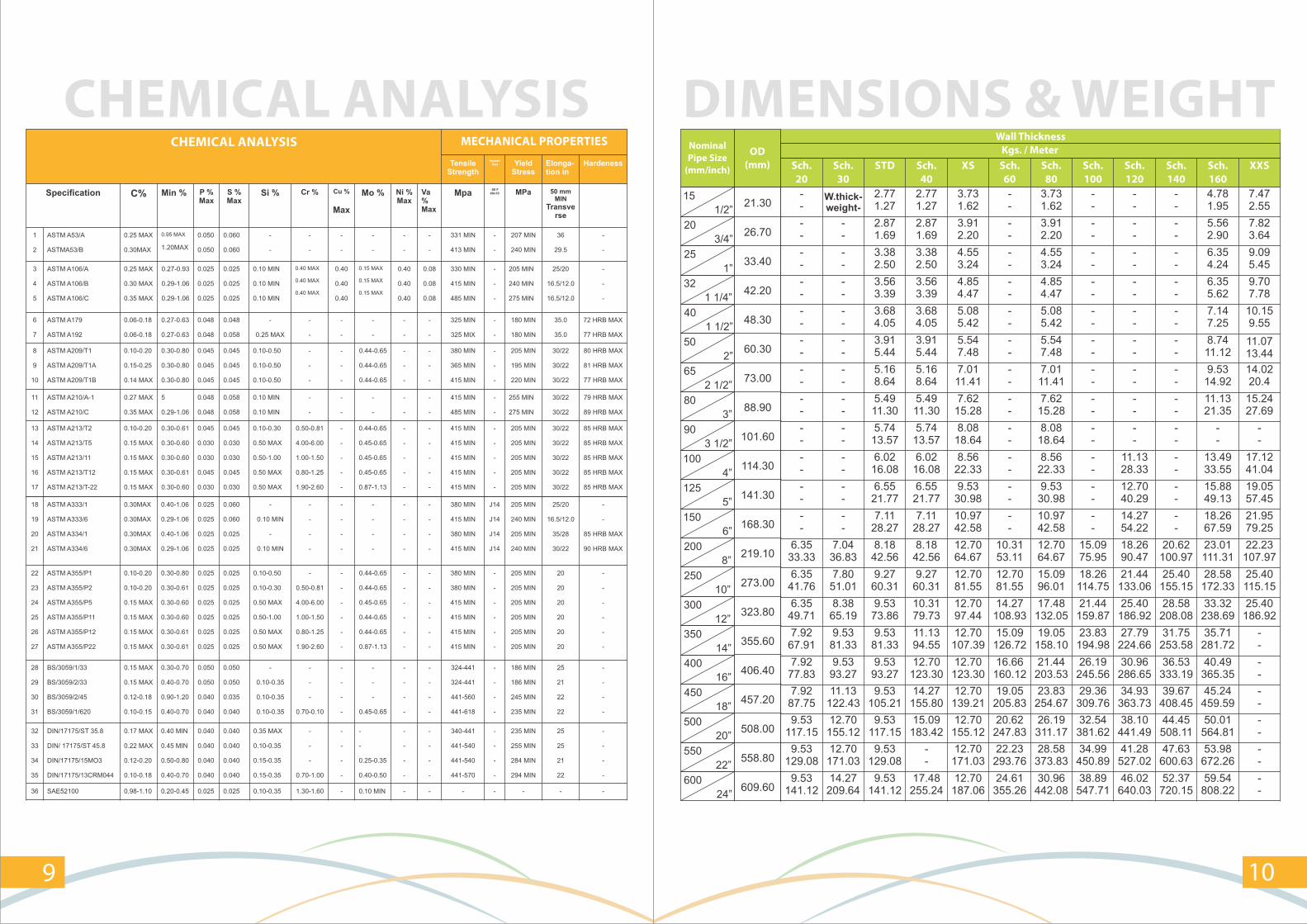
CHEMICAL ANALYSISCHEMICAL ANALYSIS MECHANICAL PROPERTIES
TensileStrength
ImpactTest Yield
StressElonga-tion in
Hardeness
Specification C% Min % P %Max
S %Max
Si % Cr % Cu %
Max
Mo % Ni %Max
Va %Max
Mpa-50 F40x10 MPa 50 mm
MIN
Transverse
1
2
ASTM A53/A
ASTMA53/B
0.25 MAX
0.30MAX
0.95 MAX
1.20MAX
0.050
0.050
0.060
0.060
-
-
-
-
-
-
-
-
-
-
-
-
331 MIN
413 MIN
-
-
207 MIN
240 MIN
36
29.5
-
-
3
4
5
ASTM A106/A
ASTM A106/B
ASTM A106/C
0.25 MAX
0.30 MAX
0.35 MAX
0.27-0.93
0.29-1.06
0.29-1.06
0.025
0.025
0.025
0.025
0.025
0.025
0.10 MIN
0.10 MIN
0.10 MIN
0.40 MAX
0.40 MAX
0.40 MAX
0.40
0.40
0.40
0.15 MAX
0.15 MAX
0.15 MAX
0.40
0.40
0.40
0.08
0.08
0.08
330 MIN
415 MIN
485 MIN
-
-
-
205 MIN
240 MIN
275 MIN
25/20
16.5/12.0
16.5/12.0
-
-
-
6
7
ASTM A179
ASTM A192
0.06-0.18
0.06-0.18
0.27-0.63
0.27-0.63
0.048
0.048
0.048
0.058
-
0.25 MAX
-
-
-
-
-
-
-
-
-
-
325 MIN
325 MIX
-
-
180 MIN
180 MIN
35.0
35.0
72 HRB MAX
77 HRB MAX
8
9
10
ASTM A209/T1
ASTM A209/T1A
ASTM A209/T1B
0.10-0.20
0.15-0.25
0.14 MAX
0.30-0.80
0.30-0.80
0.30-0.80
0.045
0.045
0.045
0.045
0.045
0.045
0.10-0.50
0.10-0.50
0.10-0.50
-
-
-
-
-
-
0.44-0.65
0.44-0.65
0.44-0.65
-
-
-
-
-
-
380 MIN
365 MIN
415 MIN
-
-
-
205 MIN
195 MIN
220 MIN
30/22
30/22
30/22
80 HRB MAX
81 HRB MAX
77 HRB MAX
11
12
ASTM A210/A-1
ASTM A210/C
0.27 MAX
0.35 MAX
5
0.29-1.06
0.048
0.048
0.058
0.058
0.10 MIN
0.10 MIN
-
-
-
-
-
-
-
-
-
-
415 MIN
485 MIN
-
-
255 MIN
275 MIN
30/22
30/22
79 HRB MAX
89 HRB MAX
13
14
15
16
17
ASTM A213/T2
ASTM A213/T5
ASTM A213/11
ASTM A213/T12
ASTM A213/T-22
0.10-0.20
0.15 MAX
0.15 MAX
0.15 MAX
0.15 MAX
0.30-0.61
0.30-0.60
0.30-0.60
0.30-0.61
0.30-0.60
0.045
0.030
0.030
0.045
0.030
0.045
0.030
0.030
0.045
0.030
0.10-0.30
0.50 MAX
0.50-1.00
0.50 MAX
0.50 MAX
0.50-0.81
4.00-6.00
1.00-1.50
0.80-1.25
1.90-2.60
-
-
-
-
-
0.44-0.65
0.45-0.65
0.45-0.65
0.45-0.65
0.87-1.13
-
-
-
-
-
-
-
-
-
-
415 MIN
415 MIN
415 MIN
415 MIN
415 MIN
-
-
-
-
-
205 MIN
205 MIN
205 MIN
205 MIN
205 MIN
30/22
30/22
30/22
30/22
30/22
85 HRB MAX
85 HRB MAX
85 HRB MAX
85 HRB MAX
85 HRB MAX
18
19
20
21
ASTM A333/1
ASTM A333/6
ASTM A334/1
ASTM A334/6
0.30MAX
0.30MAX
0.30MAX
0.30MAX
0.40-1.06
0.29-1.06
0.40-1.06
0.29-1.06
0.025
0.025
0.025
0.025
0.060
0.060
0.025
0.025
-
0.10 MIN
-
0.10 MIN
-
-
-
-
-
-
-
-
-
-
-
-
-
-
-
-
-
-
-
-
380 MIN
415 MIN
380 MIN
415 MIN
J14
J14
J14
J14
205 MIN
240 MIN
205 MIN
240 MIN
25/20
16.5/12.0
35/28
30/22
-
-
85 HRB MAX
90 HRB MAX
22
23
24
25
26
27
ASTM A355/P1
ASTM A355/P2
ASTM A355/P5
ASTM A355/P11
ASTM A355/P12
ASTM A355/P22
0.10-0.20
0.10-0.20
0.15 MAX
0.15 MAX
0.15 MAX
0.15 MAX
0.30-0.80
0.30-0.61
0.30-0.60
0.30-0.60
0.30-0.61
0.30-0.61
0.025
0.025
0.025
0.025
0.025
0.025
0.025
0.025
0.025
0.025
0.025
0.025
0.10-0.50
0.10-0.30
0.50 MAX
0.50-1.00
0.50 MAX
0.50 MAX
-
0.50-0.81
4.00-6.00
1.00-1.50
0.80-1.25
1.90-2.60
-
-
-
-
-
-
0.44-0.65
0.44-0.65
0.45-0.65
0.44-0.65
0.44-0.65
0.87-1.13
-
-
-
-
-
-
-
-
-
-
-
-
380 MIN
380 MIN
415 MIN
415 MIN
415 MIN
415 MIN
-
-
-
-
-
-
205 MIN
205 MIN
205 MIN
205 MIN
205 MIN
205 MIN
20
20
20
20
20
20
-
-
-
-
-
-
28
29
30
31
BS/3059/1/33
BS/3059/2/33
BS/3059/2/45
BS/3059/1/620
0.15 MAX
0.15 MAX
0.12-0.18
0.10-0.15
0.30-0.70
0.40-0.70
0.90-1.20
0.40-0.70
0.050
0.050
0.040
0.040
0.050
0.050
0.035
0.040
-
0.10-0.35
0.10-0.35
0.10-0.35
-
-
-
0.70-0.10
-
-
-
-
-
-
-
0.45-0.65
-
-
-
-
-
-
-
-
324-441
324-441
441-560
441-618
-
-
-
-
186 MIN
186 MIN
245 MIN
235 MIN
25
21
22
22
-
-
-
-
32
33
34
35
DIN/17175/ST 35.8
DIN/ 17175/ST 45.8
DIN/17175/15MO3
DIN/17175/13CRM044
0.17 MAX
0.22 MAX
0.12-0.20
0.10-0.18
0.40 MIN
0.45 MIN
0.50-0.80
0.40-0.70
0.040
0.040
0.040
0.040
0.040
0.040
0.040
0.040
0.35 MAX
0.10-0.35
0.15-0.35
0.15-0.35
-
-
-
0.70-1.00
-
-
-
-
-
-
0.25-0.35
0.40-0.50
-
-
-
-
-
-
-
-
340-441
441-540
441-540
441-570
-
-
-
-
235 MIN
255 MIN
284 MIN
294 MIN
25
25
21
22
-
-
-
-
36 SAE52100 0.98-1.10 0.20-0.45 0.025 0.025 0.10-0.35 1.30-1.60 - 0.10 MIN - - - - - - -
Dinesh Metal Industries is Authorized Dealer / Stockiest / Supplier / Agent of Carbon and Alloy Steel Seamless/ ERW Pipe and Tube.
Range -1/2” to 16”
Largest Stock Holder for ISMT and JSL.
Stock:5000Tons
Our Material is EIL / IBR / Nace Approved.
Charpy V-notch test
ASTM A 106 GR. B Carbon Steel Seamless Pipes and Tubes
ASME SA 106 Grade B Carbon Steel Seamless Pipes and Tubes ASTM A 106 GR. B High Temperature Seamless Pipe
ASTM A 106 GR. B High Carbon Seamless Pipe for High Temperature Service
ASTM A 106 GR. B Charpy V-notch test
Our SA 106 Grade B pipes are hydrostatically tested as per ASTM A530. A 106 Grade B SMSL pipe Charpy V-notch test ASTM A 106 Gr. B/API 5L GR-B Seamless we offer ASTM A 106 GR B Carbon Steel Seamless Pipes and Tubes such as A 106 GR.B Tubes, A 106 GR.B IBR Tubes, SA 106 GR.B IBR Pipes, SA 106 GR.B IBR Tubes, ASTM A 106 Grade .B IBR Pipes, ASTM A 106 Grade B IBR Tubes and many more items from India.
ASTM A106 grade B Seamless Pressure Pipe (ASME SA106) We are Stockist,Authorised Dealer, Trader, Supplier, Exporter and Vendor of ASTM SA A 106 GR. B Carbon Steel Seamless Pipes and Tubes in Mumbai (India). NACE MR0175/ISO15156-2, NACE MR0103 and PED ISMT Make SA 106 Grade B
JSL(Jindal) make SA 106 Grade B Pipe
MSL make SA 106 Grade B
ASME ASTM SA 106 Grade B IBR Pipe
ASTM A 106 Grade B EIL Approved Pipe
ASTM A106 GR B NACE MR 0175
ASTM/ASME SA106 Grade B / C Steel Pipe & Tubing
CARBON STEEL SEAMLESS PIPES FOR HIGH TEMPERATURE SERVICE ASME SA 106, Gr.: B
ASTM A106 GR. B Seamless Pipe we export to:
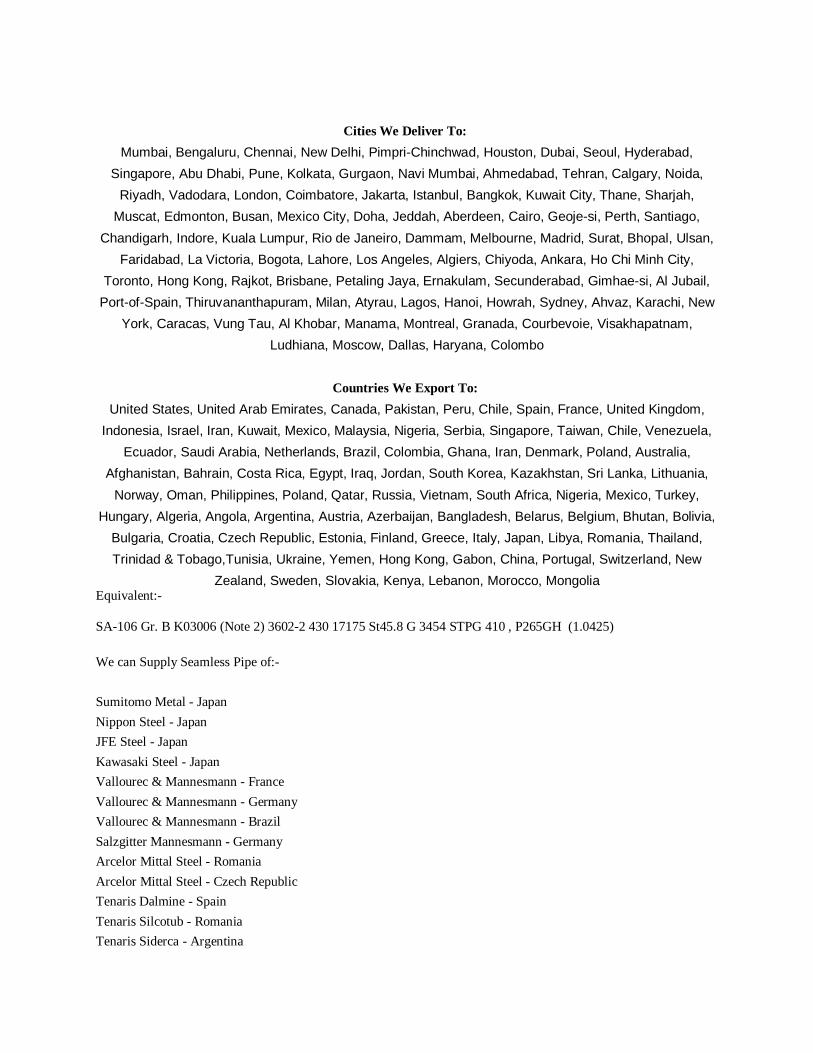
Cities We Deliver To:
Mumbai, Bengaluru, Chennai, New Delhi, Pimpri-Chinchwad, Houston, Dubai, Seoul, Hyderabad,
Singapore, Abu Dhabi, Pune, Kolkata, Gurgaon, Navi Mumbai, Ahmedabad, Tehran, Calgary, Noida,
Riyadh, Vadodara, London, Coimbatore, Jakarta, Istanbul, Bangkok, Kuwait City, Thane, Sharjah,
Muscat, Edmonton, Busan, Mexico City, Doha, Jeddah, Aberdeen, Cairo, Geoje-si, Perth, Santiago,
Chandigarh, Indore, Kuala Lumpur, Rio de Janeiro, Dammam, Melbourne, Madrid, Surat, Bhopal, Ulsan,
Faridabad, La Victoria, Bogota, Lahore, Los Angeles, Algiers, Chiyoda, Ankara, Ho Chi Minh City,
Toronto, Hong Kong, Rajkot, Brisbane, Petaling Jaya, Ernakulam, Secunderabad, Gimhae-si, Al Jubail,
Port-of-Spain, Thiruvananthapuram, Milan, Atyrau, Lagos, Hanoi, Howrah, Sydney, Ahvaz, Karachi, New
York, Caracas, Vung Tau, Al Khobar, Manama, Montreal, Granada, Courbevoie, Visakhapatnam,
Ludhiana, Moscow, Dallas, Haryana, Colombo
Countries We Export To:
United States, United Arab Emirates, Canada, Pakistan, Peru, Chile, Spain, France, United Kingdom,
Indonesia, Israel, Iran, Kuwait, Mexico, Malaysia, Nigeria, Serbia, Singapore, Taiwan, Chile, Venezuela,
Ecuador, Saudi Arabia, Netherlands, Brazil, Colombia, Ghana, Iran, Denmark, Poland, Australia,
Afghanistan, Bahrain, Costa Rica, Egypt, Iraq, Jordan, South Korea, Kazakhstan, Sri Lanka, Lithuania,
Norway, Oman, Philippines, Poland, Qatar, Russia, Vietnam, South Africa, Nigeria, Mexico, Turkey,
Hungary, Algeria, Angola, Argentina, Austria, Azerbaijan, Bangladesh, Belarus, Belgium, Bhutan, Bolivia,
Bulgaria, Croatia, Czech Republic, Estonia, Finland, Greece, Italy, Japan, Libya, Romania, Thailand,
Trinidad & Tobago,Tunisia, Ukraine, Yemen, Hong Kong, Gabon, China, Portugal, Switzerland, New
Zealand, Sweden, Slovakia, Kenya, Lebanon, Morocco, Mongolia Equivalent:-
SA-106 Gr. B K03006 (Note 2) 3602-2 430 17175 St45.8 G 3454 STPG 410 , P265GH (1.0425)
We can Supply Seamless Pipe of:-
Sumitomo Metal - Japan
Nippon Steel - Japan
JFE Steel - Japan
Kawasaki Steel - Japan
Vallourec & Mannesmann - France
Vallourec & Mannesmann - Germany
Vallourec & Mannesmann - Brazil
Salzgitter Mannesmann - Germany
Arcelor Mittal Steel - Romania
Arcelor Mittal Steel - Czech Republic
Tenaris Dalmine - Spain
Tenaris Silcotub - Romania
Tenaris Siderca - Argentina
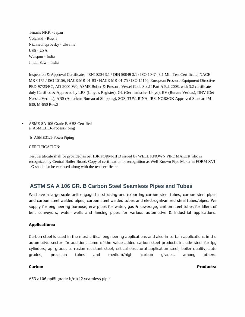
Tenaris NKK - Japan
Volzhski - Russia
Nizhnedneprovsky - Ukraine
USS - USA
Welspun - India
Jindal Saw – India
Inspection & Approval Certificates : EN10204 3.1 / DIN 50049 3.1 / ISO 10474 3.1 Mill Test Certificate, NACE
MR-0175 / ISO 15156, NACE MR-01-03 / NACE MR-01-75 / ISO 15156, European Pressure Equipment Directive
PED-97/23/EC, AD-2000-W0, ASME Boiler & Pressure Vessel Code Sec.II Part A Ed. 2008, with 3.2 certificate
duly Certified & Approved by LRS (Lloyd's Register), GL (Germanischer Lloyd), BV (Bureau Veritas), DNV (Det
Norske Veritas), ABS (American Bureau of Shipping), SGS, TUV, RINA, IRS, NORSOK Approved Standard M-
630, M-650 Rev.3
• ASME SA 106 Grade B ABS Certified a ASME31.3-ProcessPiping
b ASME31.1-PowerPiping
CERTIFICATION:
Test certificate shall be provided as per IBR FORM-III D issued by WELL KNOWN PIPE MAKER who is recognized by Central Boiler Board. Copy of certification of recognition as Well Known Pipe Maker in FORM XVI - G shall also be enclosed along with the test certificate.
ASTM SA A 106 GR. B Carbon Steel Seamless Pipes and Tubes
We have a large scale unit engaged in stocking and exporting carbon steel tubes, carbon steel pipes
and carbon steel welded pipes, carbon steel welded tubes and electrogalvanized steel tubes/pipes. We
supply for engineering purpose, erw pipes for water, gas & sewerage, carbon steel tubes for idlers of
belt conveyors, water wells and lancing pipes for various automotive & industrial applications.
Applications:
Carbon steel is used in the most critical engineering applications and also in certain applications in the
automotive sector. In addition, some of the value-added carbon steel products include steel for lpg
cylinders, api grade, corrosion resistant steel, critical structural application steel, boiler quality, auto
grades, precision tubes and medium/high carbon grades, among others.
Carbon Products:
A53 a106 api5l grade b/c x42 seamless pipe
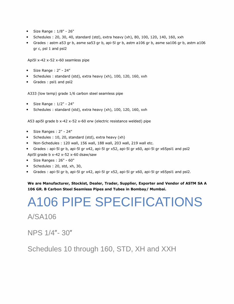
• Size Range : 1/8" - 26"
• Schedules : 20, 30, 40, standard (std), extra heavy (xh), 80, 100, 120, 140, 160, xxh
• Grades : astm a53 gr b, asme sa53 gr b, api-5l gr b, astm a106 gr b, asme sa106 gr b, astm a106
gr c, psl 1 and psl2
Api5l x-42 x-52 x-60 seamless pipe
• Size Range : 2" - 24"
• Schedules : standard (std), extra heavy (xh), 100, 120, 160, xxh
• Grades : psl1 and psl2
A333 (low temp) grade 1/6 carbon steel seamless pipe
• Size Range : 1/2" - 24"
• Schedules : standard (std), extra heavy (xh), 100, 120, 160, xxh
A53 api5l grade b x-42 x-52 x-60 erw (electric resistance welded) pipe
• Size Ranges : 2" - 24"
• Schedules : 10, 20, standard (std), extra heavy (xh)
• Non-Schedules : 120 wall, 156 wall, 188 wall, 203 wall, 219 wall etc.
• Grades : api-5l gr b, api-5l gr x42, api-5l gr x52, api-5l gr x60, api-5l gr x65psl1 and psl2
Api5l grade b x-42 x-52 x-60 dsaw/saw
• Size Ranges : 26" - 60"
• Schedules : 20, std, xh, 30,
• Grades : api-5l gr b, api-5l gr x42, api-5l gr x52, api-5l gr x60, api-5l gr x65psl1 and psl2.
We are Manufacturer, Stockist, Dealer, Trader, Supplier, Exporter and Vendor of ASTM SA A
106 GR. B Carbon Steel Seamless Pipes and Tubes in Bombay/ Mumbai.
A106 PIPE SPECIFICATIONS A/SA106
NPS 1/4″- 30″
Schedules 10 through 160, STD, XH and XXH
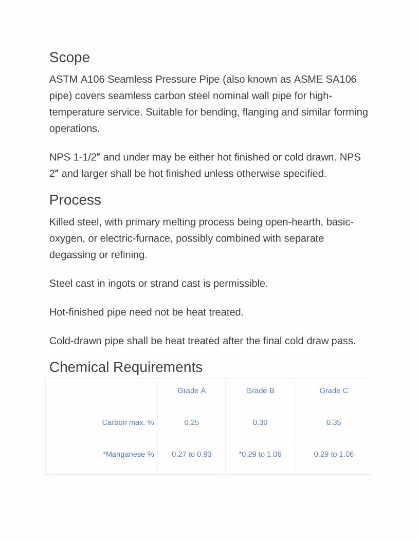
Scope ASTM A106 Seamless Pressure Pipe (also known as ASME SA106
pipe) covers seamless carbon steel nominal wall pipe for high-
temperature service. Suitable for bending, flanging and similar forming
operations.
NPS 1-1/2″ and under may be either hot finished or cold drawn. NPS
2″ and larger shall be hot finished unless otherwise specified.
Process Killed steel, with primary melting process being open-hearth, basic-
oxygen, or electric-furnace, possibly combined with separate
degassing or refining.
Steel cast in ingots or strand cast is permissible.
Hot-finished pipe need not be heat treated.
Cold-drawn pipe shall be heat treated after the final cold draw pass.
Chemical Requirements
Grade A Grade B Grade C
Carbon max. % 0.25 0.30 0.35
*Manganese % 0.27 to 0.93 *0.29 to 1.06 0.29 to 1.06
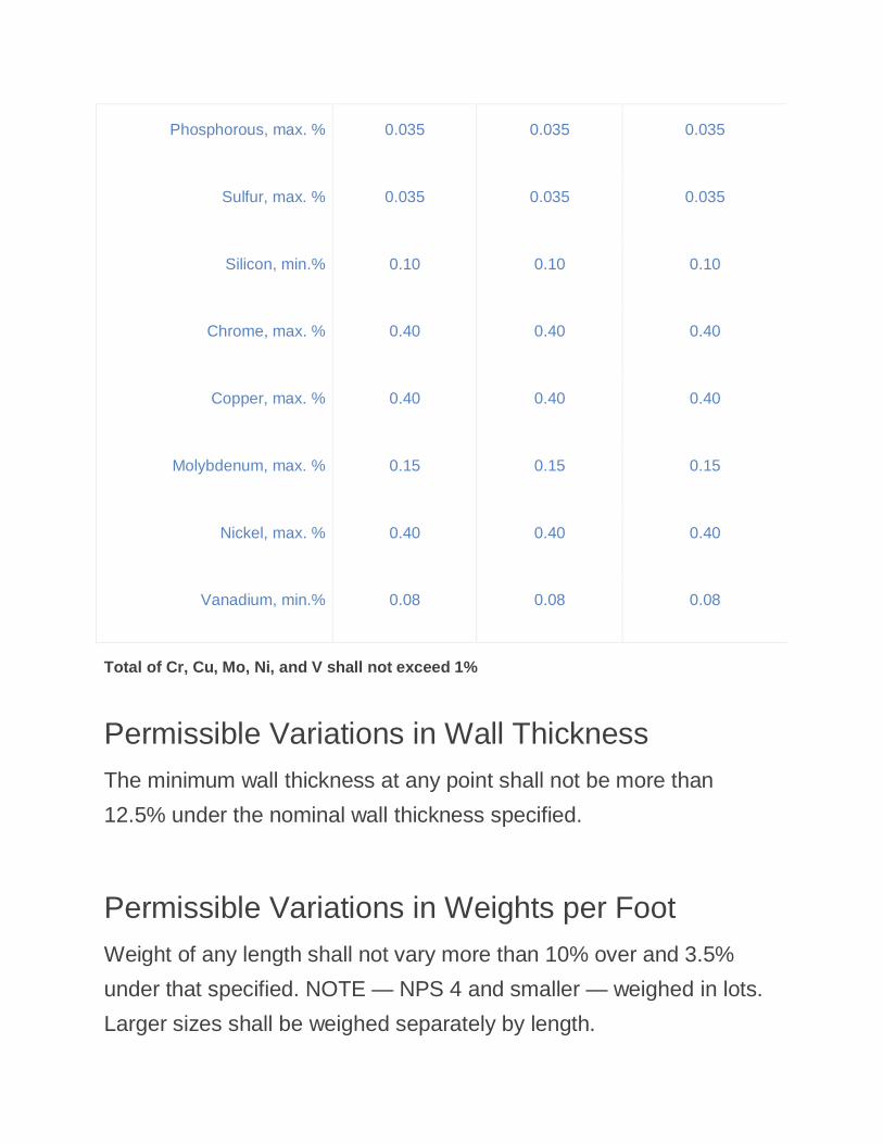
Phosphorous, max. % 0.035 0.035 0.035
Sulfur, max. % 0.035 0.035 0.035
Silicon, min.% 0.10 0.10 0.10
Chrome, max. % 0.40 0.40 0.40
Copper, max. % 0.40 0.40 0.40
Molybdenum, max. % 0.15 0.15 0.15
Nickel, max. % 0.40 0.40 0.40
Vanadium, min.% 0.08 0.08 0.08
Total of Cr, Cu, Mo, Ni, and V shall not exceed 1%
Permissible Variations in Wall Thickness The minimum wall thickness at any point shall not be more than
12.5% under the nominal wall thickness specified.
Permissible Variations in Weights per Foot Weight of any length shall not vary more than 10% over and 3.5%
under that specified. NOTE — NPS 4 and smaller — weighed in lots.
Larger sizes shall be weighed separately by length.
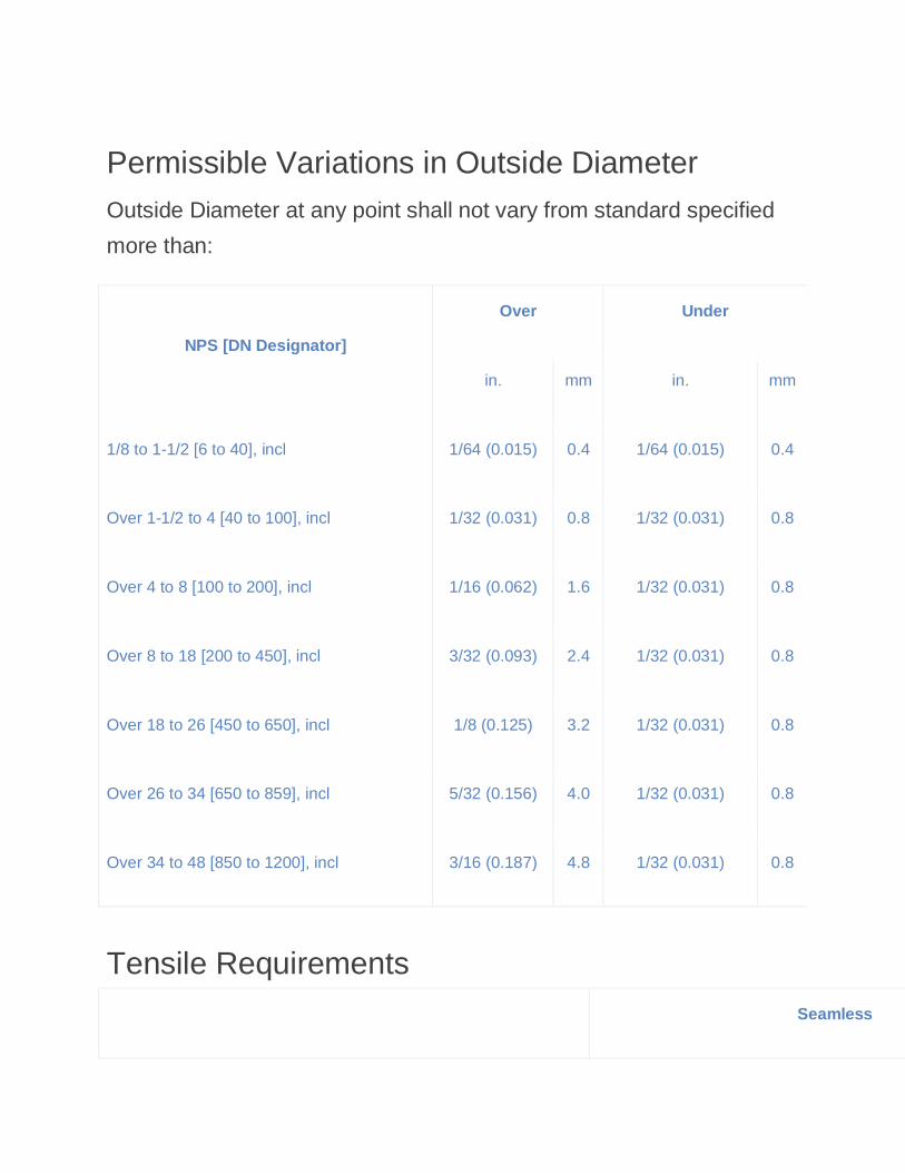
Permissible Variations in Outside Diameter Outside Diameter at any point shall not vary from standard specified
more than:
NPS [DN Designator]
Over Under
in. mm in. mm
1/8 to 1-1/2 [6 to 40], incl 1/64 (0.015) 0.4 1/64 (0.015) 0.4
Over 1-1/2 to 4 [40 to 100], incl 1/32 (0.031) 0.8 1/32 (0.031) 0.8
Over 4 to 8 [100 to 200], incl 1/16 (0.062) 1.6 1/32 (0.031) 0.8
Over 8 to 18 [200 to 450], incl 3/32 (0.093) 2.4 1/32 (0.031) 0.8
Over 18 to 26 [450 to 650], incl 1/8 (0.125) 3.2 1/32 (0.031) 0.8
Over 26 to 34 [650 to 859], incl 5/32 (0.156) 4.0 1/32 (0.031) 0.8
Over 34 to 48 [850 to 1200], incl 3/16 (0.187) 4.8 1/32 (0.031) 0.8
Tensile Requirements
Seamless
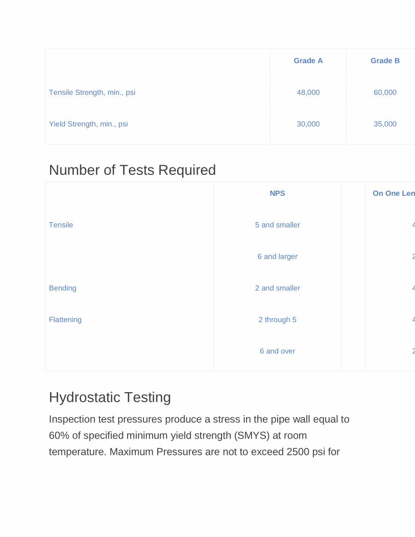
Grade A Grade B
Tensile Strength, min., psi 48,000 60,000
Yield Strength, min., psi 30,000 35,000
Number of Tests Required
NPS On One Length from Each Lot of
Tensile 5 and smaller
400 or less
6 and larger
200 or less
Bending 2 and smaller
400 or less
Flattening 2 through 5
400 or less
6 and over
200 or less
Hydrostatic Testing Inspection test pressures produce a stress in the pipe wall equal to
60% of specified minimum yield strength (SMYS) at room
temperature. Maximum Pressures are not to exceed 2500 psi for
NPS3 and must stay under 2800 psi for the larger sizes. Pressure is
maintained for not less than 5 seconds.
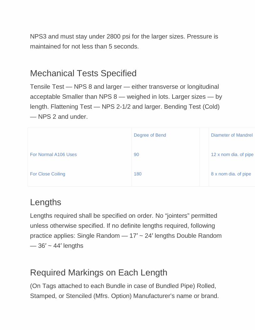
Mechanical Tests Specified Tensile Test — NPS 8 and larger — either transverse or longitudinal
acceptable Smaller than NPS 8 — weighed in lots. Larger sizes — by
length. Flattening Test — NPS 2-1/2 and larger. Bending Test (Cold)
— NPS 2 and under.
Degree of Bend
Diameter of Mandrel
For Normal A106 Uses 90
12 x nom dia. of pipe
For Close Coiling 180
8 x nom dia. of pipe
Lengths Lengths required shall be specified on order. No “jointers” permitted
unless otherwise specified. If no definite lengths required, following
practice applies: Single Random — 17′ ~ 24′ lengths Double Random
— 36′ ~ 44′ lengths
Required Markings on Each Length (On Tags attached to each Bundle in case of Bundled Pipe) Rolled,
Stamped, or Stenciled (Mfrs. Option) Manufacturer’s name or brand.
Length of pipe. A106 A, A 106 B, A 106 C. ANSI schedule number.
Hydrostatic test pressures and/or NDE; Weight per foot (NPS 4 and
larger) or NH if neither is specified. Additional “S” if tested
supplementary requirements.
Referenced Documents
� ASTM A 530/A 530M Specification for General Requirements for
Specialized Carbon and Alloy Steel Pipe
� ASTM E 213 Practice for Ultrasonic Examination of Metal Pipe and
Tubing
� ASTM E 309 Practice for Eddy-Current Examination of Steel
Tubular Products Using Magnetic Saturation
� ASTM E 381 Method of Macroetch testing Steel Bars, Billets,
Blooms, and Forgings
� ASTM E 570 Practice for Flux Leakage Examination of
Ferromagnetic Steel Tubular Products
� ASME B26.10M Welded and Seamless Wrought Steel Pipe
General Information Orders for material under this specification should include the
following, as required, to describe the desired material adequately:
*ASTM A 106 grade B Seamless Pressure Pipe
B) Unless otherwise specified by the purchaser, for each reduction of
0.01 % below the specified carbon maximum, an increase of 0.06 %
manganese above the specified maximum will be permitted up to a
maximum of 1.65 %.
*ASME SA 106 grade B Seamless Pressure Pipe
B) For each reduction of 0.01 % below the specified carbon maximum,
an increase of 0.06 % manganese above the specified maximum will
be permitted up to a maximum of 1.35 %.
NACE CARBON STEEL PIPES
IBR PIPES
Head Office
Adress: 79/81, West View Building A, 10th Khetwadi Lane, Mumbai-400004
Phone: +91 22 23802185
Tele Fax: +91 22 23802421
E-mail:[email protected]
NPS 1/8" to NPS 48” Wall thickness: Schedules 10 through 160, STD, XS, XXS.
*Commonly requested unscheduled walls up to 4” and certified minimum wall items
- See more at: http://www.fedsteel.com/products/carbon-pipe-and-tube/astm-a106-seamless-carbon-steel-pipe.html#sthash.Hukik5Ck.dpuf.
Complimenta
ry Copy
for C
ertific
ation Use
Specification for Drill Pipe
ANSI/API SPECIFICATION 5DPFIRST EDITION, AUGUST 2009
EFFECTIVE DATE: AUGUST 1, 2010
CONTAINS API MONOGRAM ANNEX AS PART OF U.S. NATIONAL ADOPTION
ISO 11961:2008 (Identical), Petroleum and natural gas industries—Steel drill pipe

Complimenta
ry Copy
for C
ertific
ation Use
Complimenta
ry Copy
for C
ertific
ation Use
Special Notes
API publications necessarily address problems of a general nature. With respect to particular circumstances, local,state, and federal laws and regulations should be reviewed.
Neither API nor any of API's employees, subcontractors, consultants, committees, or other assignees make anywarranty or representation, either express or implied, with respect to the accuracy, completeness, or usefulness of theinformation contained herein, or assume any liability or responsibility for any use, or the results of such use, of anyinformation or process disclosed in this publication. Neither API nor any of API's employees, subcontractors,consultants, or other assignees represent that use of this publication would not infringe upon privately owned rights.
Users of this recommended practice should not rely exclusively on the information contained in this document.Sound business, scientific, engineering, and safety judgment should be used in employing the information containedherein.
API publications may be used by anyone desiring to do so. Every effort has been made by the Institute to assure theaccuracy and reliability of the data contained in them; however, the Institute makes no representation, warranty, orguarantee in connection with this publication and hereby expressly disclaims any liability or responsibility for loss ordamage resulting from its use or for the violation of any authorities having jurisdiction with which this publication mayconflict.
API publications are published to facilitate the broad availability of proven, sound engineering and operatingpractices. These publications are not intended to obviate the need for applying sound engineering judgmentregarding when and where these publications should be utilized. The formulation and publication of API publicationsis not intended in any way to inhibit anyone from using any other practices.
Any manufacturer marking equipment or materials in conformance with the marking requirements of an API standardis solely responsible for complying with all the applicable requirements of that standard. API does not represent,warrant, or guarantee that such products do in fact conform to the applicable API standard.
All rights reserved. No part of this work may be reproduced, translated, stored in a retrieval system, or transmitted by any means, electronic, mechanical, photocopying, recording, or otherwise, without prior written permission from the publisher. Contact the
Publisher, API Publishing Services, 1220 L Street, N.W., Washington, D.C. 20005.
Copyright © 2009 American Petroleum Institute
Complimenta
ry Copy
for C
ertific
ation Use
API Foreword
Nothing contained in any API publication is to be construed as granting any right, by implication or otherwise, for themanufacture, sale, or use of any method, apparatus, or product covered by letters patent. Neither should anythingcontained in the publication be construed as insuring anyone against liability for infringement of letters patent.
Shall: As used in a standard, “shall” denotes a minimum requirement in order to conform to the specification.
Should: As used in a standard, “should” denotes a recommendation or that which is advised but not required in orderto conform to the specification.
This document was produced under API standardization procedures that ensure appropriate notification andparticipation in the developmental process and is designated as an API standard. Questions concerning theinterpretation of the content of this publication or comments and questions concerning the procedures under whichthis publication was developed should be directed in writing to the Director of Standards, American PetroleumInstitute, 1220 L Street, N.W., Washington, D.C. 20005. Requests for permission to reproduce or translate all or anypart of the material published herein should also be addressed to the director.
Generally, API standards are reviewed and revised, reaffirmed, or withdrawn at least every five years. A one-timeextension of up to two years may be added to this review cycle. Status of the publication can be ascertained from theAPI Standards Department, telephone (202) 682-8000. A catalog of API publications and materials is publishedannually by API, 1220 L Street, N.W., Washington, D.C. 20005.
Suggested revisions are invited and should be submitted to the Standards Department, API, 1220 L Street, NW,Washington, D.C. 20005, [email protected].
ii
Complimenta
ry Copy
for C
ertific
ation Use
iii
Contents Page
API Foreword ...................................................................................................................................................... ii
Foreword ............................................................................................................................................................. v
Introduction ........................................................................................................................................................ vi
1 Scope ...................................................................................................................................................... 1
2 Conformance .......................................................................................................................................... 1 2.1 Dual citing of normative references .................................................................................................... 1 2.2 Units of measurement ........................................................................................................................... 2
3 Normative references ............................................................................................................................ 2
4 Terms, definitions, symbols and abbreviated terms ......................................................................... 4 4.1 Terms and definitions ........................................................................................................................... 4 4.2 Symbols and abbreviated terms .......................................................................................................... 8
5 Information to be supplied when placing orders for drill-pipe ....................................................... 10
6 Requirements for drill-pipe ................................................................................................................. 11 6.1 General ................................................................................................................................................. 11 6.2 Dimensions, masses and connections ............................................................................................. 11 6.3 Material requirements ......................................................................................................................... 12 6.4 Process of manufacture for drill-pipe................................................................................................ 13 6.5 Traceability ........................................................................................................................................... 14 6.6 Inspection and testing — General ..................................................................................................... 15 6.7 Testing of welds................................................................................................................................... 16 6.8 Tensile test ........................................................................................................................................... 16 6.9 Hardness test ....................................................................................................................................... 17 6.10 Charpy V-notch impact test ................................................................................................................ 18 6.11 Transverse side-bend test .................................................................................................................. 18 6.12 Imperfections and defects in drill-pipe ............................................................................................. 19 6.13 Visual inspection of the drill-pipe weld zone .................................................................................... 19 6.14 Non-destructive examination of the weld zone ................................................................................ 20 6.15 Marking of drill-pipe ............................................................................................................................ 21 6.16 Minimum facility requirements for drill-pipe manufacturers .......................................................... 23 6.17 Documentation requirements of drill-pipe ........................................................................................ 23
7 Requirements for drill-pipe body ....................................................................................................... 24 7.1 Information to be supplied when placing orders for drill-pipe bodies .......................................... 24 7.2 Dimensional and mass requirements ................................................................................................ 24 7.3 Material requirements ......................................................................................................................... 26 7.4 Process of manufacture ...................................................................................................................... 27 7.5 Traceability ........................................................................................................................................... 28 7.6 Inspection and testing — General ..................................................................................................... 28 7.7 Testing of chemical composition ....................................................................................................... 28 7.8 Tensile tests ......................................................................................................................................... 29 7.9 Charpy V-notch impact tests .............................................................................................................. 30 7.10 Drill-pipe-body wall thickness ............................................................................................................ 31 7.11 Drill-pipe-body length ......................................................................................................................... 31 7.12 Internal upset ....................................................................................................................................... 31 7.13 Internal profile ...................................................................................................................................... 32 7.14 Straightness ......................................................................................................................................... 32 7.15 Upset alignment ................................................................................................................................... 32 7.16 Mass determination ............................................................................................................................. 32 7.17 Imperfections and defects of drill-pipe body .................................................................................... 32 7.18 Visual inspection of drill-pipe body ................................................................................................... 33
Complimenta
ry Copy
for C
ertific
ation Use
iv
7.19 Non-destructive examination ............................................................................................................ 34 7.20 Marking ................................................................................................................................................ 37 7.21 Minimum facility requirements for drill-pipe-body manufacturer .................................................. 38 7.22 Documentation requirements ............................................................................................................ 38
8 Requirements for tool joints .............................................................................................................. 39 8.1 Information to be supplied when placing orders for tool joints .................................................... 39 8.2 Dimensional requirements ................................................................................................................. 40 8.3 Material requirements......................................................................................................................... 40 8.4 Process of manufacture ..................................................................................................................... 41 8.5 Traceability .......................................................................................................................................... 42 8.6 Inspection and testing — General ..................................................................................................... 42 8.7 Testing of chemical composition ...................................................................................................... 42 8.8 Tensile tests ........................................................................................................................................ 43 8.9 Hardness tests .................................................................................................................................... 44 8.10 Charpy V-notch impact tests ............................................................................................................. 44 8.11 Imperfections and defects ................................................................................................................. 45 8.12 Non-destructive examination ............................................................................................................ 46 8.13 Marking ................................................................................................................................................ 47 8.14 Minimum facility requirements for tool-joint manufacturers ......................................................... 47 8.15 Documentation requirements for tool joints .................................................................................... 48
Annex A (normative) Tables in SI units ......................................................................................................... 49
Annex B (normative) Figures in SI (USC) units ............................................................................................. 67
Annex C (normative) Tables in USC units ..................................................................................................... 81
Annex D (normative) Purchaser inspection .................................................................................................. 99
Annex E (informative) Supplementary requirements ................................................................................. 100
Annex F (informative) Procedures used to convert from USC units to SI units for drill-pipe ................ 103
Annex G (normative) Product specification levels ..................................................................................... 107
Annex H (informative) API monogram .......................................................................................................... 109
Bibliography ................................................................................................................................................... 112
Complimenta
ry Copy
for C
ertific
ation Use
v
Foreword
ISO (the International Organization for Standardization) is a worldwide federation of national standards bodies (ISO member bodies). The work of preparing International Standards is normally carried out through ISO technical committees. Each member body interested in a subject for which a technical committee has been established has the right to be represented on that committee. International organizations, governmental and non-governmental, in liaison with ISO, also take part in the work. ISO collaborates closely with the International Electrotechnical Commission (IEC) on all matters of electrotechnical standardization.
International Standards are drafted in accordance with the rules given in the ISO/IEC Directives, Part 2.
The main task of technical committees is to prepare International Standards. Draft International Standards adopted by the technical committees are circulated to the member bodies for voting. Publication as an International Standard requires approval by at least 75 % of the member bodies casting a vote.
Attention is drawn to the possibility that some of the elements of this document may be the subject of patent rights. ISO shall not be held responsible for identifying any or all such patent rights.
ISO 11961 was prepared by Technical Committee ISO/TC 67, Materials, equipment and offshore structures for petroleum, petrochemical and natural gas industries, Subcommittee SC 5, Casing, tubing and drill pipe.
This second edition cancels and replaces the first edition (ISO 11961:1996), which has been extensively technically revised.
It is the intention of ISO/TC 67 that either this edition or the previous edition of ISO 11961 be applicable, at the option of the purchaser (as defined in 4.1.31), for a period of six months from the first day of the calendar quarter immediately following the date of publication of this edition, after which period the previous edition will no longer be applicable.
Complimenta
ry Copy
for C
ertific
ation Use
vi
Introduction
This International Standard is based on API Spec 5D and API Spec 7.
Users of this International Standard should be aware that further or differing requirements may be needed for individual applications. This International Standard is not intended to inhibit a vendor from offering, or the purchaser from accepting, alternative equipment or engineering solutions for the individual application. This may be particularly applicable where there is innovative or developing technology. Where an alternative is offered, the vendor should identify any variations from this International Standard and provide details.
This International Standard includes provisions of various natures. These are identified by the use of certain verbal forms:
a) SHALL is used to indicate that a provision is MANDATORY;
b) SHOULD is used to indicate that a provision is not mandatory, but RECOMMENDED as good practice;
c) MAY is used to indicate that a provision is OPTIONAL.
Complimenta
ry Copy
for C
ertific
ation Use
API Specification 5DP / ISO 11961
1
Petroleum and natural gas industries — Steel drill pipe
1 Scope
This International Standard specifies the technical delivery conditions for steel drill-pipes with upset pipe-body ends and weld-on tool joints for use in drilling and production operations in petroleum and natural gas industries for three product specification levels (PSL-1, PSL-2 and PSL-3). The requirements for PSL-1 form the basis of this International Standard. The requirements that define different levels of standard technical requirements for PSL-2 and PSL-3 are in Annex G.
This International Standard covers the following grades of drill-pipe:
grade E drill-pipe;
high-strength grades of drill-pipe, grades X, G and S.
A typical drill-pipe configuration is given, showing main elements and lengths (see Figure B.1). The main dimensions and masses of the grades of drill-pipe are given in both SI units (see Table A.1) and in USC units (see Table C.1).
This International Standard can also be used for drill-pipe with tool joints not specified by ISO or API standards.
By agreement between purchaser and manufacturer, this International Standard can also be applied to other drill-pipe body and/or tool-joint dimensions. This International Standard lists supplementary requirements that can optionally be agreed between purchaser and manufacturer, for testing, performance verification and non-destructive examination (see Annex E).
This International Standard does not consider performance properties.
NOTE 1 In this International Standard, drill-pipe is designated by label 1, label 2, grade of material (E, X, G and S), upset type and type of rotary shouldered connection. Designations are used for the purpose of identification in ordering.
NOTE 2 Reference can be made to ISO 10424-2 or API Spec 7-2 for the detailed requirements for the threading of drill-pipe tool joints.
NOTE 3 Reference can be made to API RP 7G for the performance properties of the drill-pipe.
2 Conformance
2.1 Dual citing of normative references
In the interests of world-wide application of this International Standard, Technical Committee ISO/TC 67 has decided, after detailed technical analysis, that certain of the normative documents listed in Clause 3 and prepared by ISO/TC 67 or another ISO Technical Committee are interchangeable in the context of the relevant requirement with the relevant document prepared by the American Petroleum Institute (API), the American Society for Testing and Materials (ASTM) and the American National Standards Institute (ANSI). These latter documents are cited in the running text following the ISO reference and preceded by ―or‖, for example ―ISO XXXX or API YYYY‖. Application of an alternative normative document cited in this manner will lead to technical results different from the use of the preceding ISO reference. However, both results are acceptable and these documents are thus considered interchangeable in practice.
Complimenta
ry Copy
for C
ertific
ation Use
2 Specification for Drill Pipe
2.2 Units of measurement
In this International Standard, data are expressed in both the International System (SI) of units and the United States Customary (USC) system of units. Separate tables for data expressed in SI units and USC units are in Annex A and Annex C, respectively. Figures are in Annex B and express data in both SI and USC units. For a specific order item, it is intended that only one system of units be used, without combining data expressed in the other system.
Products manufactured to specifications expressed in either of these unit systems shall be considered equivalent and totally interchangeable. Consequently, compliance with the requirements of this International Standard as expressed in one system provides compliance with requirements expressed in the other system.
For data expressed in the SI system, a comma is used as the decimal separator and a space as the thousands separator. For data expressed in the USC system, a dot (on the line) is used as the decimal separator and a space as the thousands separator.
In the text, data in SI units are followed by data in USC units in brackets.
NOTE The procedures used to convert from USC units to SI units are given in informative Annex F.
3 Normative references
The following referenced documents are indispensable for the application of this document. For dated references, only the edition cited applies. For undated references, the latest edition of the referenced document (including any amendment) applies.
ISO 6506-1, Metallic materials — Brinell Hardness test — Part 1: Test method
ISO 6507-1, Metallic materials — Vickers hardness test — Part 1: Test method
ISO 6508-1, Metallic materials — Rockwell hardness test — Part 1:Test method (scales A, B, C, D, E, F, G, H, K, N, T)
ISO 6892, Metallic materials — Tensile testing
ISO 7500-1, Metallic materials — Verification of static uni-axial testing machines — Part 1: Tension/compression testing machines — Verification and calibration of the force-measuring system
ISO 9303, Seamless and welded (except submerged arc-welded) steel tubes for pressure purposes — Full peripheral ultrasonic testing for the detection of longitudinal imperfections
ISO 9304, Seamless and welded (except submerged arc-welded) steel tubes for pressure purposes — Eddy current testing for the detection of imperfections
ISO 9305, Seamless steel tubes for pressure purposes — Full peripheral ultrasonic testing for the detection of transverse imperfections
ISO 9402, Seamless and welded (except submerged arc-welded) steel tubes for pressure purposes — Full peripheral magnetic transducer/flux leakage testing of ferromagnetic steel tubes for the detection of longitudinal imperfections
ISO 9513, Metallic materials — Calibration of extensometers used in uniaxial testing
ISO 9598, Seamless steel tubes for pressure purposes — Full peripheral magnetic transducer/flux leakage testing of ferromagnetic steel tubes for the detection of transverse imperfections
Complimenta
ry Copy
for C
ertific
ation Use
API Specification 5DP/ISO 11961 3
ISO/TR 9769, Steel and iron — Review of available methods of analysis
ISO/TR 10400, Petroleum and natural gas industries — Equations and calculations for the properties of casing, tubing, drill-pipe and line pipe used as casing or tubing
ISO 10424-2, Petroleum and natural gas industries — Rotary drilling equipment — Part 2: Threading and gauging of rotary shouldered thread connections
ISO 11484, Steel tubes for pressure purposes — Qualification and certification of non-destructive (NDT) personnel
ISO 13665, Seamless and welded steel tubes for pressure purposes — Magnetic particle inspection of the tube body for the detection of surface imperfections
API Spec 7-2, Specification for Threading and Gauging of Rotary Shouldered Thread Connections
API RP 7G, Recommended Practice for Drill Stem Design and Operating Limits
ANSI/API 5C3, Bulletin on Formulas and Calculations for Casing, Tubing, Drill-pipe, and Line Pipe Properties (including Supplement 1)
ASME Boiler and Pressure Vessel Code, Section IX
ASNT SNT-TC-1A, Recommended Practice, Personnel Qualification and Certification in Non-Destructive Testing
ASTM A370, Standard Test Methods and Definitions for Mechanical Testing of Steel Products
ASTM A751, Standard Test Methods, Practices and Terminology for Chemical Analysis of Steel Products
ASTM A941, Terminology Relating to Steel, Stainless Steel, Related Alloys, and Ferroalloys
ASTM E4, Standard Practices for Force Verification of Testing Machines
ASTM E10, Standard Test Method for Brinell Hardness of Metallic Materials
ASTM E18, Standard Test Methods for Rockwell Hardness of Metallic Materials
ASTM E23, Standard Test Methods for Notched Bar Impact Testing of Metallic Materials
ASTM E83, Standard Practice for Verification and Classification of Extensometer Systems
ASTM E92, Standard Test Method for Vickers Hardness of Metallic Materials
ASTM E213, Standard Practice for Ultrasonic Examination of Metal Pipe and Tubing
ASTM E309, Standard Practice for Eddy-Current Examination of Steel Tubular Products Using Magnetic Saturation
ASTM E570, Standard Practice for Flux Leakage Examination of Ferromagnetic Steel Tubular Products
ASTM E709, Standard Guide for Magnetic Particle Testing
Complimenta
ry Copy
for C
ertific
ation Use
4 Specification for Drill Pipe
4 Terms, definitions, symbols and abbreviated terms
4.1 Terms and definitions
For the purposes of this document, the terms and definitions in ASTM A941 for heat treatment operations and the following apply.
4.1.1 bevel diameter outer diameter of the sealing shoulder of a rotary shouldered connection
4.1.2 defect imperfection of sufficient magnitude to warrant rejection of the product based on criteria defined in this International Standard
[ISO 11960:2004, definition 4.1.11]
4.1.3 drill-pipe drill-pipe body with weld-on tool joints
4.1.4 drill-pipe body seamless pipe with upset ends
See Figure B.1.
4.1.5 drill-pipe-body manufacturer firm, company or corporation that operates facilities for making drill-pipe bodies and is responsible for compliance with the requirements of this International Standard applicable to the drill-pipe body
See 7.21.
4.1.6 drill-pipe manufacturer firm, company or corporation responsible for compliance with all the applicable requirements of this International Standard
See 6.16.
4.1.7 drill-pipe torsion-strength ratio torsion strength of the tool-joint connection divided by the drill-pipe-body torsion strength
4.1.8 drill-pipe weld neck machined part of the drill-pipe comprising the tool-joint weld neck, the weld and the drill-pipe-body upset
See Figure B.1.
4.1.9 elephant hide wrinkled outside diameter surfaces of the drill-pipe body caused by the upsetting process
4.1.10 essential variable variable parameter in which a change affects the mechanical properties of the weld joint
Complimenta
ry Copy
for C
ertific
ation Use
API Specification 5DP/ISO 11961 5
4.1.11 gouge elongated groove or cavity caused by mechanical removal of metal
4.1.12 hard banding application of material onto tool joints to reduce external wear of the tool joint
NOTE Also known as hard facing.
4.1.13 hardness number result from a single hardness impression
4.1.14 heat heat of steel metal produced by a single cycle of a batch-melting process
4.1.15 heat analysis chemical analysis representative of a heat as reported by the metal producer
[ISO 11960:2004, definition 4.1.15]
4.1.16 imperfection discontinuity in the product wall or on the product surface that can be detected by an NDE method included in this International Standard
[ISO 11960:2004, definition 4.1.16]
4.1.17 indication evidence of a discontinuity that requires interpretation to determine its significance
4.1.18 inspection process of measuring, examining, testing, gauging or otherwise comparing the product with the applicable requirements
4.1.19 label 1 dimensionless designation for the drill-pipe-body size that may be used when ordering
4.1.20 label 2 dimensionless designation for the drill-pipe-body mass per unit length that may be used when ordering
4.1.21 linear imperfection imperfection that includes, but is not limited to, seams, laps, cracks, plug scores, cuts, gouges and elephant hide
NOTE See API 5T1.
[ISO 11960:2004, definition 4.1.25]
Complimenta
ry Copy
for C
ertific
ation Use
6 Specification for Drill Pipe
4.1.22 lot definite quantity of product manufactured under conditions that are considered uniform for the attribute being inspected
4.1.23 lot size number of units in a lot
4.1.24 manufacturer one or more of the following, depending on the context: the maker of drill-pipe, the maker of drill-pipe body or the maker of tool joints
4.1.25 mean hardness number result of averaging the hardness numbers for the single specimen or location being evaluated
4.1.26 non-essential variable variable parameter in which a change may be made in the WPS without re-qualification
4.1.27 non-linear imperfection imperfection that includes, but is not limited to, pits
See API Std 5T1.
4.1.28 pipe body seamless pipe excluding upset and upset-affected areas
See Figure B.1.
4.1.29 procedure qualification record PQR written documentation stating an assessment that a specific WPS produces welds in accordance with the requirements of this International Standard.
4.1.30 product drill-pipe, drill-pipe body or tool joint
4.1.31 purchaser party responsible for both the definition of requirements for a product order and for payment for that order
[ISO 11960:2004, definition 4.1.35]
4.1.32 quench crack crack in steel resulting from stresses produced during the transformation from austenite to martensite
NOTE This transformation is accompanied by an increase in volume.
[ISO 11960:2004, definition 4.1.36]
Complimenta
ry Copy
for C
ertific
ation Use
API Specification 5DP/ISO 11961 7
4.1.33 rotary shouldered connection connection used on drill string elements which has tapered threads and sealing shoulders
4.1.34 rotary friction welding solid state welding under compressive-force contact of work-pieces rotating relative to one another along a common axis to increase temperature and plastically displace material from the faying surfaces
NOTE Either direct drive or inertia friction welding is acceptable.
4.1.35 sample one or more units of product selected from a lot to represent that lot
4.1.36 seamless pipe wrought steel tubular product made without a weld seam
NOTE It is manufactured by hot working and, if necessary, by subsequently cold-working or heat-treating, or a combination of these operations, to produce the desired shape, dimensions and properties.
[ISO 11960:2004, definition 4.1.37]
4.1.37 tool joint forged or rolled steel component for drill-pipe designed to be welded to the drill-pipe body and having a rotary shouldered connection
4.1.38 tool-joint box threaded connection on tool joints that has internal threads
4.1.39 tool-joint manufacturer firm, company or corporation that operates facilities for making tool joints and is responsible for compliance with the requirements of this International Standard applicable to the tool joint
See 8.14.
4.1.40 tool-joint pin threaded connection on tool joints that has external threads
4.1.41 upset ovality difference between the largest and smallest diameter in a plane perpendicular to the axis of the upset
4.1.42 weld zone zone comprising the weld line and the heat-affected areas on either side of the weld line caused by the friction welding and subsequent heat-treatment processes
Complimenta
ry Copy
for C
ertific
ation Use
8 Specification for Drill Pipe
4.1.43 welding machine and welding operator performance qualification WPQ written procedure used to demonstrate that a welding machine and welding operator combination has the capability to use the WPS to produce a weld meeting the requirements of this International Standard
NOTE It includes records from the qualification tests.
4.1.44 welding procedure specification WPS written procedure that provides instructions to the welding operator for making production welds in accordance with the requirements of this International Standard
NOTE It includes all essential variables and non-essential variables for friction welding of tool joints to drill-pipe body. A WPS applies to all those welds, of which each element has the same specified dimensions and chemistry, that are grouped according to a documented procedure that ensures a predictable response to weld-zone treatment for a particular grade.
4.2 Symbols and abbreviated terms
Adp cross-sectional area of the drill-pipe body based on the specified dimensions of the pipe body
A cross-sectional area of the tensile specimen, expressed in square millimetres (square inches)
A length of reduced section, expressed in millimetres
Aw minimum cross-sectional area of the weld zone
D tool-joint outside diameter (pin and box)
Cm standard Charpy impact energy, expressed in Joules;
C standard Charpy impact energy, expressed in foot-pounds.
Ddp pipe-body outside diameter
Df bevel diameter (pin and box)
Dj external diameter on the tool-joint neck, which becomes Dte after welding and final machining
D diameter of round bar
Dte outside diameter of the drill-pipe weld after machining
D0u drill-pipe-body upset outside diameter
ddp pipe-body inside diameter
dj internal diameter of the tool-joint neck, which becomes dte after welding and final machining
dp tool-joint-pin inside diameter
dte inside diameter of the drill-pipe weld after machining
d0u drill-pipe-body upset inside diameter
EU external upset
e minimum extension in a gauge length of 50,8 mm (2.0 in)
em minimum elongation
ew drill-pipe-body mass gain or loss due to end finishing. For plain-end non-upset pipe, ew equals zero
Complimenta
ry Copy
for C
ertific
ation Use
API Specification 5DP/ISO 11961 9
G gauge length
ID inside diameter
IEU internal-external upset
IU internal upset
L length of drill-pipe with weld-on tool joint (from shoulder to shoulder)
Lb length of box-tool joint outside diameter including connection bevel and hard band; see Figures B.1 and B.12
Leu drill-pipe-body external upset length
Liu drill-pipe-body internal upset length
Lpb length of pin-tool-joint outside diameter, including connection bevel; see Figures B.1 and B.12
Lpe length of drill-pipe body (without tool joint)
meu drill-pipe-body external upset taper length
miu drill-pipe-body internal upset taper length
N fraction or number with a fraction
NDE non-destructive examination
OD outside diameter
PQR procedure qualification record
PSL product specification level
R minimum radius of fillet
RSC rotary shouldered connection
TS tensile strength
t pipe-body wall thickness
U upset dimension
Udp minimum specified tensile strength
UT ultrasonic testing
W width
WL approximate calculated mass of a piece of drill-pipe body of length Lpe
WPQ welder performance qualification
WPS welding procedure specification
wdp approximate linear mass of the drill-pipe
wpe plain-end pipe-body unit mass (without upsets)
Ymin specified minimum yield strength, see Table A.5 or Table C.5
Yw weld zone yield strength
Complimenta
ry Copy
for C
ertific
ation Use
10 Specification for Drill Pipe
5 Information to be supplied when placing orders for drill-pipe
5.1 When placing orders for drill-pipe to be manufactured in accordance with this International Standard, the purchaser shall specify the following on the purchase agreement:
Requirements Reference
Document number(s) ISO 11961 or API Spec 5DP
Quantity
Label 1 Table A.1 or Table C.1
Label 2 Table A.1 or Table C.1
Grade Table A.1 or Table C.1
Upset type (internal, external or internal-external upset) Table A.1 or Table C.1
RSC type or other special connection by agreement between purchaser and manufacturer
Table A.1 or Table C.1, or 6.2.2
Range or special length and tolerance by agreement between purchaser and manufacturer
Table A.3 or Table C.3
Delivery date and shipping instructions
Inspection by purchaser Annex D
Documentation 6.17
5.2 The purchaser shall also specify in the purchase agreement his requirements concerning the following stipulations, which are optional with the purchaser:
Requirements Reference
Tool-joint outside diameter 6.2.2
Tool-joint inside diameter of the pin end 6.2.2
Length of pin-tool-joint outside diameter 6.2.6
Length of box-tool-joint outside diameter 6.2.6
Under-thickness tolerance if less than 12,5 % 7.2.6
Type of heat treatment for drill-pipe body: grade E only 7.4.3
Hard banding: type, location, dimensions and acceptance criteria
NOTE Hard banding reduces the length of the tool-joint outside diameter available for tong placement.
8.4.7
Pipe coatings: internal and/or external 6.4.5, 6.4.6 and 7.4.4
Special threads on tool joints 8.2.5
Specific thread or storage compound 6.4.7
Thread-protector type 6.4.7 and 8.4.8
Marking requirements 6.15, 7.20 and 8.13
Individual drill-pipe traceability 6.5
Complimenta
ry Copy
for C
ertific
ation Use
API Specification 5DP/ISO 11961 11
Supplementary requirements
Non-destructive examination for grades E, X and G Clause E.2, SR2
Test certificates Clause E.3, SR15
Charpy V-notch (CVN) impact toughness testing of grade E pipe body Clause E.4, SR19
Alternative low-temperature Charpy V-notch impact testing Clause E.5, SR20
Weld-zone testing frequency Clause E.6, SR23
Charpy V-notch: increased weld-zone requirements Clause E.7, SR24
For PSL-2 or PSL-3 Annex G
6 Requirements for drill-pipe
6.1 General
The drill-pipe shall be made from drill-pipe body manufactured in accordance with Clause 7 and tool joints manufactured in accordance with Clause 8. Areas of the drill-pipe body and tool joint affected by the welding and finishing processes are addressed in Clause 6.
6.2 Dimensions, masses and connections
6.2.1 Standard configuration
The configuration of drill-pipe shall correspond to Figure B.1. Drill-pipe shall be furnished with dimensions and tolerances as in Tables A.1 and A.2 or Tables C.1 and C.2 and/or in the purchase agreement. All dimensions shown without tolerances are related to the basis for design and are not subject to measurement to determine acceptance or rejection of product. Drill-pipe dimensions that are not in this International Standard or in the purchase agreement are at the manufacturer's discretion.
Rotary shouldered connections shall conform to the dimensions, together with the tolerances, in ISO 10424-2 or API Spec 7-2. Right-hand thread connections shall be considered standard.
6.2.2 Alternative configurations
When specified in the purchase agreement, drill-pipe shall be furnished in dimensional configurations not defined in this International Standard. In this case, dimensions, tolerances and markings shall be agreed between the purchaser and manufacturer. The drill-pipe body and tool joint shall be modified in accordance with this agreement but the drill-pipe shall otherwise be manufactured in accordance with the requirements of this International Standard.
The outside diameter of the box tool joint, D, and inside diameter of the pin tool joint, dp, dimensions in Table A.1 or Table C.1, result in a drill-pipe torsion-strength ratio 0,8 or greater. Changes in the OD and ID of the tool joints can result in a lower drill-pipe torsion-strength ratio, which should be determined by the purchaser to be suitable for the intended application.
6.2.3 Drill-pipe weld neck diameters
The drill-pipe weld diameters, Dte and dte, as shown in Figure B.1, apply to the finished product after the tool joint is welded to the drill-pipe body and machined and/or ground. The outside diameter, Dte, shall meet the requirements of Table A.1 or Table C.1, and 6.3.2. The inside diameter, dte, shall meet the requirements of 6.3.2 and may be different on the pin and box weld zones.
6.2.4 Tool-joint inside diameters
The tool-joint-pin inside diameter, dp, shall meet the requirements in Table A.1 or Table C.1. The tool-joint-box inside diameter is at the manufacturer’s discretion but shall not be less than the tool-joint-pin internal diameter, dp.
Complimenta
ry Copy
for C
ertific
ation Use
12 Specification for Drill Pipe
6.2.5 Length
Drill-pipe shall be furnished in length ranges conforming to Table A.3 or Table C.3 or other lengths and tolerances as specified in the purchase agreement.
The drill-pipe manufacturer shall specify the lengths and tolerances of the drill-pipe body and tool joints such that the required length of each drill-pipe is achieved.
6.2.6 Length of tool-joint outside diameter
The length of pin-tool-joint outside diameter, Lpb, and the length of box-tool-joint outside diameter, Lb, in Table A.1 or Table C.1, may be increased by agreement between purchaser and manufacturer.
6.2.7 End-drift
Each drill-pipe shall be end-drift tested throughout the length of the tool joints and upsets with a cylindrical mandrel having a minimum diameter of 3,2 mm (0.125 in) smaller than the specified inside diameter of the pin end, dp. The drift mandrel shall be at least 100 mm (4 in) long.
NOTE Drift testing of the full length of the drill-pipe is not required.
6.2.8 Tool-joint alignment
The maximum misalignment between the longitudinal axis of the drill-pipe body and the longitudinal axis of the welded-on tool joint shall not exceed the following:
for parallel misalignment: 4 mm (0,157 in) total indicator reading;
for angular misalignment: 8 mm/m (0,008 in/in) for label 1: 4-1/2 and larger;
10 mm/m (0,010 in/in) for smaller than label 1: 4-1/2.
The axis of the tool joint shall be determined on the surface of the outside diameter, D, that is unaffected by markings or hard banding. The axis of the drill-pipe body shall be determined over a minimum length of 400 mm (15 in) on the outside surface of the pipe body.
6.2.9 Weld-zone profile
The weld zone shall have no sharp corners or drastic changes of section. The internal weld-zone profile shall not cause a 90° hook-type tool to hang up.
6.3 Material requirements
6.3.1 General
The material properties of the drill-pipe body and the tool joint shall be as in Tables A.4 to A.8 or Tables C.4 to C.8 inclusive.
6.3.2 Weld-zone yield strength
The yield load of the weld zone in tension shall be greater than the yield load of the drill-pipe body as given by Equation (1):
(Yw Aw) ≥ (Ymin Adp) (1)
where
Adp is the cross-sectional area of the drill-pipe body based on the specified dimensions of the pipe body;
Complimenta
ry Copy
for C
ertific
ation Use
API Specification 5DP/ISO 11961 13
Aw is the minimum cross-sectional area of the weld zone;
Ymin is the specified minimum yield strength of the drill-pipe body;
Yw is the weld zone minimum yield strength (determined by the manufacturer based on the design).
The method for calculating the minimum cross-sectional area, Aw, of the weld zone shall be as given in Equation (2):
(2)
where
dte,max is the maximum allowable inside diameter specified by the drill-pipe manufacturer;
Dte,min is the minimum allowable outside diameter specified by the drill-pipe manufacturer.
6.3.3 Weld-zone hardness
For surface hardness, no hardness number shall exceed 37 HRC or equivalent.
For the through-wall hardness test, the mean hardness number of the weld zone shall not exceed 37 HRC or 365 HV10.
6.3.4 Weld-zone Charpy V-notch absorbed-energy requirements
The minimum absorbed energy requirements shall be as in Table A.8 or Table C.8. In addition, not more than one impact specimen shall exhibit an absorbed energy below the minimum average absorbed-energy requirement, and in no case shall an individual impact specimen exhibit an absorbed energy below the minimum specimen absorbed-energy requirement.
Additional requirements for PSL-3 are in Annex G.
6.3.5 Weld-zone Charpy V-notch absorbed energy — Alternative requirements
When specified in the purchase agreement, the absorbed energy shall meet the SR20 and/or the SR24 requirements in Clause E.5 and/or Clause E.7 respectively (see also Table A.8 or Table C.8).
6.3.6 Weld-zone transverse side bend properties
The guided-bend specimens shall have no open discontinuity in the weld zone exceeding 3 mm (0,125 in) measured in any direction on the convex surface of the specimen after bending. Open discontinuities occurring on the corner of the specimen during testing shall not be considered unless there is definite evidence that they result from lack of fusion, inclusions or other internal discontinuities.
6.4 Process of manufacture for drill-pipe
6.4.1 Processes requiring validation
Final operations performed during drill-pipe manufacturing that affect compliance as required in this International Standard (except chemical composition and dimensions) shall have their process validated.
Those processes requiring validation are welding and weld heat treatment.
6.4.2 Welding qualification
The manufacturer shall develop, qualify and use a welding procedure, including post-weld heat treatment (WPS and PQR), in accordance with the ASME Boiler and Pressure Vessel Code, Section IX. The procedure shall identify the essential variables and non-essential variables and address the permissible number of re-heat treatments.
Complimenta
ry Copy
for C
ertific
ation Use
14 Specification for Drill Pipe
The PQR shall include, as a minimum, the data of the specific variables (both essential and non-essential) used to weld a tool joint to a drill-pipe body and the results of all mechanical tests to verify the properties in 6.3 carried out on specimens taken from the test weld.
In addition, the manufacturer shall undertake macrostructrual examination of the weld to verify that the weld exhibits complete bonding and freedom from cracks.
The manufacturer shall qualify the welding machines and welding operators to a specific WPQ for each WPS utilized by the operators.
6.4.3 Welding of tool joints to drill-pipe body and post-weld heat treatment
The welding of the tool joint to the drill-pipe body shall be by the rotary friction welding process.
A post-weld heat treatment shall be performed through the entire thickness and from the weld line to beyond where the flow lines of the tool joint and drill-pipe body material change direction as a result of the welding process. The weld shall be austenitized, cooled below the transformation temperature and tempered at a minimum temperature of 593 °C (1 100 °F).
6.4.4 Weld machining
The weld area shall be machined and/or ground, both externally and internally, to produce a flush surface (visually free from gouges or abrupt changes in section).
Tool marks from normal machining operations shall be acceptable.
6.4.5 Internal coating
When specified in the purchase agreement, drill-pipe shall be internally coated over the full length, except the thread. The type of coating shall be specified in the purchase agreement and the application and inspection shall be carried out in accordance with an agreed documented procedure.
6.4.6 External coating
Unless otherwise specified in the purchase agreement, the drill-pipe shall be given an external coating for protection from corrosion during transit. The coating shall be rated to protect the drill-pipe for at least three months and it should be smooth, hard to the touch and with minimum sags.
6.4.7 Thread protection
Threads and shoulders of rotary shouldered connections shall be equipped with thread protectors to protect them from damage during transportation and storage. Unless otherwise specified in the purchase agreement, the type of thread protector is at the manufacturer’s discretion.
A thread compound, suitable for rotary shouldered connections, shall be applied over the clean threads and shoulders before protectors are installed. Unless otherwise specified in the purchase agreement, the type of thread compound is at the manufacturer’s discretion.
When specified in the purchase agreement, a storage compound shall be applied instead of the thread compound.
6.5 Traceability
The drill-pipe manufacturer shall establish and follow procedures for maintaining traceability to any applicable supplementary requirement and/or PSL requirement, as well as to drill-pipe-body heat and tool-joint heat as in Clauses 7 and 8, respectively.
Lot identity of all welds shall be maintained until all required tests are performed and conformance with specified requirements has been documented. The procedures shall provide means for tracing the welds to the lot and to mechanical and inspection test results.
When additional traceability is required, the details shall be agreed and be specified in the purchase agreement.
Complimenta
ry Copy
for C
ertific
ation Use
API Specification 5DP/ISO 11961 15
6.6 Inspection and testing — General
6.6.1 Inspection and test equipment calibration
The manufacturer shall determine and document the appropriate calibration frequency and procedures (including occurrences of out-of-calibration and the consequences on products) in order to be able to certify that all products conform to the requirements of this International Standard.
6.6.2 Dimensional inspection
The drill-pipe weld diameters, Dte and dte, shall be verified, after final machining and/or grinding according to a documented procedure, to meet the requirements of 6.2.3.
6.6.3 Drill-pipe length
The drill-pipe length, L, (see Figure B.1) shall be measured from shoulder to shoulder unless otherwise specified in the purchase agreement. This length shall be recorded and reported to the purchaser. The accuracy of length-measuring devices shall be 0,03 m ( 0.1 ft). Drill-pipe length determination shall be in metres and hundredths of a metre (feet and tenths of a foot).
6.6.4 Straightness
All drill-pipe shall be visually examined for straightness. The straightness of questionably bent pipes or crooked extremities shall be measured in accordance with 7.14.
6.6.5 End-drift test
End-drift testing shall be performed with a drift mandrel conforming to the requirements of 6.2.7. It is permissible for the ends of the drift mandrel, extending beyond the specified cylindrical portion, to be shaped to permit easy entry into the drill-pipe. The drift mandrel shall pass freely through the length of the drill-pipe tool joint and upset by the use of a manual or power drift procedure. In case of dispute, the manual drift procedure shall be used.
6.6.6 Internal profile
Each end of every drill-pipe shall be visually examined for compliance with the requirements of 6.2.9. Questionable ends shall be examined using the following method.
The weld-zone configuration inspection shall be made with a 90° hook-type tool (see Figure B.2). The contact pin shall be visually determined to be attached perpendicular to the handle. The contact-point radius shall not exceed the inside radius of the weld zone being inspected. Sharp edges on the contact point shall be removed (see contact point on Figure B.2). The 90° hook-type-tool contact point should be maintained perpendicular to the longitudinal axis of the weld zone while the contact point is passed axially throughout the weld-zone length. Pressure on the contact point shall be no greater than the pressure created by the weight of the 90º hook-type tool.
6.6.7 Tool-joint alignment
Tool-joint alignment shall conform to the requirements in 6.2.8 and shall be verified according to a documented procedure.
Complimenta
ry Copy
for C
ertific
ation Use
16 Specification for Drill Pipe
6.7 Testing of welds
6.7.1 Lot size
A lot shall consist of all those welds that are produced in a single production run (either continuous or interrupted) on the same welding machine (without any modification of the set-up parameters) using the same qualified procedures (WPS and WPQ).
6.7.2 Test specimens
All initial test specimens for the weld zone, where size allows, shall be taken from the same sample.
6.8 Tensile test
6.8.1 Procedures
The tensile test shall be performed at room temperature in accordance with ISO 6892 or ASTM A370.
Tests may be carried out on semi-finished products, that is, before final machining operations but after final heat treatment.
The fracture shall not occur at the weld line.
6.8.2 Test equipment calibration
Tensile test machines shall have been calibrated within a period of 15 months preceding any test, in accordance with the procedures in ISO 7500-1 or ASTM E4. Extensometers shall have been calibrated within a period of 15 months preceding any test, in accordance with the procedures in ISO 9513 or ASTM E83. Retention of records shall be in accordance with 6.17.4 and Table A.9 or Table C.9.
6.8.3 Specimens
A longitudinal section of sufficient length to include the entire weld zone shall be suitably prepared and etched to determine the location of the weld zone relative to the weld line and transverse grain flow. This etched section shall be used to ensure that the tensile specimen includes the full weld zone within the reduced section as shown in Figure B.3.
The largest possible round-bar tensile specimens, in accordance with the requirements of ISO 6892 or ASTM A370, 0,2 % offset method, shall be taken from the longitudinal section location as shown in Figure B.3. Specimens with a diameter of 12,7 mm (0.500 in) are preferred. Specimens with a diameter of 8,9 mm (0.350 in) or 6,4 mm (0.250 in) are suitable alternatives for thin sections.
6.8.4 Frequency
The tensile-test frequency for the weld shall be as in Table A.10 or Table C.10.
Additional requirements for PSL-2 and PSL-3 are in Annex G.
For an alternative test frequency, see Clause E.6, SR23.
6.8.5 Defective specimen
Specimens showing material imperfections or defective preparation, whether observed before or after testing, may be discarded, and replacements shall be considered as original specimens.
Complimenta
ry Copy
for C
ertific
ation Use
API Specification 5DP/ISO 11961 17
6.8.6 Re-tests
If the initial tensile test fails to conform to the specified requirements, the manufacturer may elect to test two additional specimens from the same weld. If both of the additional specimens pass, the lot shall be accepted.
If one or more of the additional specimens fail to conform to the requirements, the lot shall be rejected. Rejected lots may be re-heat-treated and tested as new lots.
If insufficient material remains for the re-test specimens to be obtained from the original sample, then it is permitted to obtain specimens from another weld within the same lot.
6.9 Hardness test
6.9.1 Procedures
Hardness tests shall be made in accordance with the appropriate standards as follows:
ISO 6506-1 or ASTM E10;
ISO 6507-1 or ASTM E92;
ISO 6508-1 or ASTM E18.
Hardness indentations shall not be closer than three indentation diameters from other indentations measured centre-to-centre.
6.9.2 Surface hardness test
Each weld zone shall be hardness tested on the outside surface at three places, 120° 15° apart. Selection of the hardness testing method is at the manufacturer's option, including the use of an alternative test method. In such a case, the manufacturer shall demonstrate the equivalence of the test result to those of one of the standards mentioned in 6.9.1.
6.9.3 Surface hardness — Re-test
All welds with a hardness number that exceeds 37 HRC shall be re-tested or rejected. For any hardness number that exceeds 37 HRC, one more hardness test shall be made in the immediate area. If the new hardness number does not exceed 37 HRC, the weld shall be accepted. If the new hardness number exceeds 37 HRC, the weld shall be rejected. The manufacturer may elect to re-heat-treat the weld in accordance with the same qualified procedure and perform the surface hardness test again.
6.9.4 Through-wall hardness test
The through-wall hardness test frequency of the weld zone shall be as in Table A.10 or Table C.10.
A Rockwell mean hardness number is the average of three Rockwell C-scale numbers taken at 2,5 mm to 6,4 mm (0.10 in to 0.25 in) from the outside surface and from the inside surface on the pipe and tool-joint sides of the weld line (that is 12 hardness numbers and 4 Rockwell mean hardness numbers on each weld, as shown in Figure B.3).
6.9.5 Through-wall hardness — Re-tests
All weld test pieces with a mean hardness number that exceeds 37 HRC shall be re-tested or the lot represented by the test shall be rejected. Before re-testing, the test surface may be re-ground. If the re-test mean hardness numbers do not exceed 37 HRC, the lot shall be accepted. If any re-test mean hardness number exceeds 37 HRC, the lot of welds represented by the test piece shall be rejected. Rejected lots may be re-heat-treated and tested as new lots.
Complimenta
ry Copy
for C
ertific
ation Use
18 Specification for Drill Pipe
6.10 Charpy V-notch impact test
6.10.1 Procedures
A test shall consist of a set of three longitudinal specimens taken from one weld. Charpy V-notch impact tests as in ASTM A370 and ASTM E23 shall be conducted at a temperature of 21 °C 3 °C (70 °F 5 °F). For alternative standardized test temperatures, see Clause E.5, SR20, and PSL-3 in Table A.8 or Table C.8.
Tests conducted at any temperature lower than the specified temperature are acceptable provided the absorbed-energy requirements at the specified temperature are achieved.
Additional requirements for PSL-2 and PSL-3 are in Annex G.
6.10.2 Specimen size and orientation
The impact test specimen shall not be smaller than the largest size shown in Table A.11 or Table C.11 based on the specifed drill-pipe weld neck diameter (and rounded to the next smaller specified outside diameter if required) and the calculated weld neck thickness (based on specified dimensions).
Specimens shall be removed from the weld longitudinally with respect to the axis of the pipe with the notch oriented in a radial direction as shown in Figure B.3. The centre of the notch in the specimen shall be located on the weld line.
6.10.3 Test frequency
The impact test frequency for the weld shall be as in Table A.10 or Table C.10.
Additional requirements for PSL-2 and PSL-3 are in Annex G.
For an alternative test frequency, see Clause E.6, SR23.
6.10.4 Re-tests
If the requirements of 6.3.4 are not met and not more than one specimen is below the minimum specimen absorbed-energy requirement, the manufacturer may elect either to reject the lot or to re-test a set of three additional specimens from the same weld test piece. For all three of these specimens, the absorbed energy shall be equal to or greater than the minimum average absorbed energy in Table A.8 or Table C.8 or the lot shall be rejected. If insufficient material remains for the re-test specimens to be obtained from the original sample, then it is permitted to obtain specimens from another weld from the same lot.
If more than one specimen in the initial test is below the minimum specimen absorbed-energy requirement, then the manufacturer may elect either to reject the lot or to re-test an additional set of three specimens from each of three additional welds from the same lot. If these additional sets of specimens do not meet the initial test requirements, then the lot shall be rejected.
Rejected lots may be re-heat-treated and tested as new lots.
6.10.5 Defective specimens
Specimens showing material imperfections or defective preparation, whether observed before or after testing, may be discarded, and replacements shall be considered as original specimens. Specimens shall not be judged defective simply because they fail to exhibit the minimum absorbed energy requirements.
6.11 Transverse side-bend test
6.11.1 Procedure
The guided bend test shall be carried out in accordance with the ASME Boiler and Pressure Vessel Code, Section IX, paragraphs QW-161.1 and QW-162.1. The specimen shall be bent until the two branches of the
Complimenta
ry Copy
for C
ertific
ation Use
API Specification 5DP/ISO 11961 19
specimen form an angle of not greater than 40° under load, as shown in Figure B.3. The weld zone shall be completely within the bend portion of the specimen after bending. A test shall consist of one specimen bent in the clockwise direction and another specimen bent in the counter-clockwise direction relative to the pipe axis.
6.11.2 Specimens
One set of two specimens shall be removed from the weld zone of the test piece. The weld zone shall be in the centre of longitudinal specimens. The test specimens shall be of full wall thickness, approximately 9,5 mm (3/8 in) wide, and the length shall be 150 mm (6 in) minimum.
6.11.3 Test frequency
The transverse side-bend test frequency shall be as in Table A.10 or Table C.10.
For an alternative test frequency, see Clause E.6, SR23.
6.11.4 Re-tests
If only one of the guided-bend specimens fail to conform to the specified requirements, the manufacturer may elect to reject the lot or to test an additional set of two specimens from the same weld test piece. If both of the re-test specimens meet the specified requirements, the lot shall be accepted. If one or both of the re-test specimens fail to meet the specified requirements, the lot shall be rejected.
It is preferred that re-test specimens be obtained from the same sample as the original test specimen(s). However, if the re-test specimens cannot be obtained from the original sample, it is permissible to obtain specimens from another weld within the same lot.
Rejected lots may be re-heat-treated and tested as a new lot.
6.12 Imperfections and defects in drill-pipe
6.12.1 General
Drill-pipe shall be free from defects as defined in this International Standard.
6.12.2 Weld zone defects
Any weld-zone imperfection detected by visual inspection, as in 6.13, or wet fluorescent magnetic-particle inspection, as in 6.14.2, shall be considered to be a defect.
Any imperfection detected by ultrasonic inspection that produces a signal equal to or greater than the signal produced by the reference standard described in 6.14.4 shall be considered a defect.
Quench cracks shall be considered defects and shall be cause for rejection of the product.
6.12.3 Process control plan
The manufacturer, based on knowledge of the production process and the requirements of 6.13 and 6.14, shall apply a process control plan that ensures compliance with the requirements of 6.12.2.
6.13 Visual inspection of the drill-pipe weld zone
6.13.1 General
Each weld zone shall be visually inspected over the entire outside surface for the detection of defects.
This inspection shall be carried out by trained personnel. Visual acuity requirements shall be documented by the manufacturer. Personnel compliance with these requirements shall be documented.
Complimenta
ry Copy
for C
ertific
ation Use
20 Specification for Drill Pipe
NOTE Examples of visual acuity requirements are in ISO 11484 or ASNT SNT-TC-1A.
Documented lighting standards for visual inspection shall be established by the manufacturer. The minimum illumination level at the inspection surface shall be 500 lux (50 foot-candles).
The visual inspection for defects may be at any appropriate point in the manufacturing process after machining.
6.13.2 Disposition of defects
Defects shall be completely removed by grinding or machining. All grinding shall be blended smooth. The dimensions after grinding shall comply with the requirements of 6.2.
6.14 Non-destructive examination of the weld zone
6.14.1 General
All NDE operations (except visual inspection) referred to in this International Standard shall be conducted by NDE personnel qualified in accordance with ISO 11484 or ASNT SNT-TC-1A.
Surfaces to be inspected shall be machined and/or ground before inspection.
When specified in the purchase agreement, the provisions for purchaser inspection of the weld zone and/or witnessing of NDE operations shall be in accordance with Annex D.
The inspections performed in accordance with 6.14, with the equipment calibrated to the specified reference indicators, should not be construed as assuring that the material requirements in 6.12 have been met.
The manufacturer shall determine the appropriate NDE equipment verification frequency in order to be able to certify that all products conform to the requirements of this International Standard.
6.14.2 Wet fluorescent magnetic-particle inspection
The entire outside surface of the weld zone shall be wet-fluorescent-magnetic-particle inspected for the detection of transverse imperfections in accordance with ISO 13665 or ASTM E709. Wet particle concentration shall be checked every 8 h or each shift change. The minimum black-light intensity at the examination surface shall not be less than 1 000 µw/cm2.
6.14.3 Ultrasonic inspection — Procedure
Each weld zone shall be ultrasonically inspected from the pipe side around the circumference with the beam directed toward the weld. Shear wave/angle beam ultrasonic equipment capable of inspection of the entire weld zone shall be used. The inspection shall be applied in accordance with the manufacturer’s documented procedure. The instrument gain setting during inspection shall not be set lower than the gain setting when checked against the reference standard. In case of dispute, the transducer used shall generate a square 2,25 MHz frequency attached to a 45° 5° Lucite1) wedge (the angle refers to the entry angle in the material).
6.14.4 Ultrasonic inspection — Reference standard
A reference standard shall be used to demonstrate the effectiveness of the inspection equipment and procedures at least once every working shift. The equipment shall be adjusted to produce a well defined indication when the reference standard is scanned in a manner simulating the inspection of the product. The reference standard shall have the same specified diameter and wall thickness and the same acoustic properties and surface finish as the weld zone being inspected and may be of any convenient length as determined by the manufacturer. The reference standard shall contain a through-drilled hole as in Figure B.4.
1) Lucite is an example of a suitable product available commercially. This information is given for the convenience of users of this International Standard and does not constitute an endorsement by ISO/API of this product.
Complimenta
ry Copy
for C
ertific
ation Use
API Specification 5DP/ISO 11961 21
The manufacturer shall use a documented procedure to establish the reject threshold for ultrasonic inspection. The through-drilled hole described in Figure B.4 shall be detected under normal operating conditions.
6.14.5 Ultrasonic inspection — System capability records
The manufacturer shall maintain NDE system records verifying the capabilities of the system(s) in detecting the reference indicators used to establish the equipment test sensitivity.
The verification shall cover, as a minimum, the following criteria:
a) coverage calculation (i.e. scan plan);
b) capability for the intended wall thickness;
c) repeatability;
d) transducer orientation that provides detection of defects typical of the manufacturing process (see 6.14.3);
e) documentation demonstrating that defects typical of the manufacturing process are detected;
f) threshold-setting parameters;
In addition, the manufacturer shall maintain documentation relating to
NDE system operating procedures,
NDE equipment description,
NDE personnel qualification information,
dynamic test data demonstrating the NDE system/operation capabilities under production test conditions (not applicable to manual operations).
6.14.6 Disposition of defects
Defects detected by either wet fluorescent magnetic-particle inspection or ultrasonic inspection shall be completely removed by grinding or machining, or the weld shall be rejected. All grinding shall be blended smooth. The dimensions after grinding shall comply with the requirements of 6.2. The weld zone shall be re-inspected after grinding using the same inspection method originally used to detect the defect in order to verify complete removal of the defect.
6.15 Marking of drill-pipe
6.15.1 General
Drill-pipe manufactured in conformance with this International Standard shall be marked by the drill-pipe manufacturer as in 6.15. Additional markings may be applied, including those for applicable compatible standards, at the option of the manufacturer or as specified in the purchase agreement. Markings shall not overlap and shall be applied in such a manner as to not damage the drill-pipe.
The drill-pipe final marking shall be the responsibility of the drill-pipe manufacturer and shall include traceability (see 6.5).
6.15.2 Drill-pipe marking
The final marking of the drill-pipe shall consist of
a) the traceability marking according to 6.15.3,
b) marking on the drill-pipe body according to 6.15.4,
Complimenta
ry Copy
for C
ertific
ation Use
22 Specification for Drill Pipe
c) marking on the tool joint according to 6.15.5.
6.15.3 Traceability marking
This marking (for traceability requirements, see 6.5) shall be die stamped on the pin taper, as shown in Figure B.1, unless otherwise specified in the purchase agreement.
6.15.4 Drill-pipe marking on the pipe body
Drill-pipe-body paint stencil markings shall start approximately 1 m (40 in) from the box shoulder and shall include, in the following sequence, as a minimum:
a) drill-pipe manufacturer’s name or mark;
b) ―ISO 11961‖ and/or ―Specification 5DP‖, as applicable; marking to indicate compliance with API Spec 5DP is at the manufacturer’s option or as specified in the purchase agreement;
c) API monogram marking requirements (see Annex H), if applicable;
d) date of drill-pipe manufacture (month and year of welding).
The date of manufacture shall be a three- or four-digit number consisting of a one- or two-digit number indicating the month followed by the last two digits of the year in which the markings of Clause 6 are completed. This marking may be waived at the manufacturer's option (it is also marked on the base of the tool-joint pin; see Figure B.5). Products manufactured in accordance with this edition of ISO 11961 during the period of overlap of application with the previous edition (see Foreword) may be identified by ―00‖ as the overlap period designation rather than the month;
e) size designation (label 1);
f) mass designation (label 2);
g) grade of the drill-pipe body;
h) SR information applicable to the drill-pipe;
i) L2 or L3 (indicating, respectively, PSL-2 or PSL-3) applicable to the drill-pipe.
EXAMPLE Paint-stencilled marking for a label 1: 2-3/8, label 2: 6.65, grade E PSL-2 drill-pipe manufactured by company ZZ in July 2007:
ZZ ISO 11961 707 2-3/8 6.65 E L2.
At the drill-pipe manufacturer's option or as specified in the purchase agreement, the drill-pipe-body manufacturer's marking may remain on the drill-pipe body or be obliterated by the drill-pipe manufacturer.
The paint-stencilled marking may be adversely affected when the drill-pipe is internally coated.
6.15.5 Drill-pipe marking on the tool joint
Unless otherwise specified in the purchase agreement, the tool joint shall be die stamped (the size of the die stamping shall be at the manufacturer's option) at the base of the pin as shown in Figure B.5 and include the following:
a) drill-pipe manufacturer’s name or mark;
b) month welded: for example, ―6‖ designates ―June‖;
c) year welded: for example, ―07‖ designates ―2007‖;
Complimenta
ry Copy
for C
ertific
ation Use
API Specification 5DP/ISO 11961 23
d) drill-pipe-body manufacturer's name or mark, at the manufacturer's option;
e) drill-pipe-body grade: for example, ―E‖ designates ―grade E‖ pipe body;
f) product drill-pipe-body mass code number (See Table A.12 or Table C.12): for example, ―2‖ designates a standard mass product; for designations not in Table A.12 or Table C.12, the mass code shall be by agreement between the purchaser and the manufacturer;
g) tool-joint designation, at the manufacturer's option: for example, ―NC50‖ designates an NC50 rotary-shouldered connection; for connections not in Table A.1 or Table C.1 the designation shall be as specified by the manufacturer.
Marking of the tool joint with grooves and flats shall be as specified in the purchase agreement.
Marking made by the tool-joint manufacturer on the outside surface of the tool joint may remain.
6.16 Minimum facility requirements for drill-pipe manufacturers
The drill-pipe manufacturer shall operate facilities for welding tool joints to drill-pipe body, for post-weld heat treatment and for machining the weld area.
Either the drill-pipe manufacturer shall have facilities for conducting all required tests and inspections or any of these tests or inspections may be provided by a subcontractor and may be located offsite. In the event that a subcontractor performs any of these services, the conduct of such inspections and tests shall be controlled and monitored by the drill-pipe manufacturer in accordance with a documented procedure.
6.17 Documentation requirements of drill-pipe
6.17.1 Standard documentation
The drill-pipe manufacturer shall provide the purchaser with the following:
a) a certificate of compliance giving the product description and a statement that the drill-pipe has been manufactured, inspected and tested in accordance with, and is in compliance with, this International Standard and the purchase agreement; product description shall include as a minimum label 1, label 2, grade, range, RSC type and any other special requirements specified in the purchase agreement;
b) a tally list giving the length, L, of each drill-pipe (see Figure B.1 and 6.6.3).
6.17.2 Supplementary documents
When specified in the purchase agreement, the requirements of Clause E.3, SR15, shall apply.
Additional requirements for PSL-2 and PSL-3 are in Annex G.
6.17.3 Electronic data interchange
The standard and/or supplementary documents (see 6.17.1 and 6.17.2) printed from or used in electronic form from an electronic data interchange (EDI) transmission shall be regarded as having the same validity as a counterpart printed in the drill-pipe manufacturer's facility. The content of the EDI-transmitted document shall meet the requirements of this International Standard and conform to any existing EDI agreement between the purchaser and the drill-pipe manufacturer.
6.17.4 Retention of records
Table A.9 or Table C.9 specifies records that shall be retained. Such records shall be retained by the drill-pipe manufacturer and shall be available to the purchaser on request for a period of five years after the date of purchase from the drill-pipe manufacturer.
Complimenta
ry Copy
for C
ertific
ation Use
24 Specification for Drill Pipe
7 Requirements for drill-pipe body
7.1 Information to be supplied when placing orders for drill-pipe bodies
7.1.1 When placing orders for drill-pipe bodies to be manufactured in accordance with this International Standard, the purchaser shall specify the following in the purchase agreement:
Requirements Reference
Document number(s) ISO 11961 or API Spec 5DP
Quantity
Label 1 or specified outside diameter Table A.1 or Table C.1
Label 2 or specified wall thickness Table A.1 or Table C.1
Grade Table A.1 or Table C.1
Type of pipe upset (internal, external or internal-external upset) Table A.1 or Table C.1
Length and tolerance
Delivery date and shipping instructions
Inspection by purchaser Annex D
Documentation 7.22
7.1.2 The purchaser shall also specify in the purchase agreement his requirements concerning the following stipulations, which are optional with the purchaser:
Requirements Reference
Special upset configuration 7.2.2
Under thickness tolerance if less than 12,5 % 7.2.6
Type of heat treatment for drill-pipe body: grade E only 7.4.3
Impact requirements for grade E Clause E.4, SR19
Alternative requirements for impact test Clause E.5, SR20
PSL-2 or PSL-3 Annex G
7.2 Dimensional and mass requirements
7.2.1 General
The dimensions of the drill-pipe body shall correspond with the requirements in Tables A.2 and A.13 or A.14 or Tables C.2 and C.13 or C.14, unless otherwise specified in the purchase agreement.
For drill-pipe body furnished with upsets not in this International Standard, but otherwise manufactured in accordance with the requirements of this International Standard, special marking as in 7.20 is required.
7.2.2 Configuration
The configuration of drill-pipe body shall correspond to Figure B.1. Upset configurations shall correspond to Figure B.6 except as allowed in 6.2.2 or when otherwise specified in the purchase agreement.
Complimenta
ry Copy
for C
ertific
ation Use
API Specification 5DP/ISO 11961 25
7.2.3 Internal upset area
The internal upset taper area of the drill-pipe body shall have a smooth profile. The internal upset configuration shall have no sharp corners or drastic changes of section that can cause a 90° hook-type tool to hang up.
7.2.4 Outside-diameter tolerance
The outside-diameter tolerances of the drill-pipe body shall be in accordance with the requirements of Table A.2 or Table C.2. The outside-diameter tolerances behind the length, meu, apply to the outside diameter of the drill-pipe body immediately behind the upset for a distance of approximately 127 mm (5 in) for sizes smaller than label 1: 6-5/8 and a distance approximately equal to the outside diameter for label 1: 6-5/8. Measurements shall be made with callipers or snap gauges.
7.2.5 Inside diameter
The pipe-body inside diameter, ddp, is calculated as given in Equation (3):
ddp Ddp 2t (3)
There is no tolerance on ddp.
7.2.6 Pipe-body wall thickness and tolerance
The wall thickness at any place on the pipe body shall not be less than the specified thickness minus 12,5 %. When specified in the purchase agreement, the wall thickness under-tolerance may be less than 12,5 %.
7.2.7 Length
The drill-pipe body shall be supplied in lengths and tolerances as specified in the purchase agreement. The lengths and tolerances should be such that the required final length of drill-pipe is achievable.
7.2.8 Mass
The mass shall conform to the calculated mass for the end finish and dimensions specified in the purchase agreement, within the tolerances stipulated below. Calculated mass, WL, expressed in kilograms (pounds), of a piece of drill-pipe body of length Lpe shall be determined in accordance with Equation (4):
WL (wpe Lpe) ew (4)
where
wpe is the non-upset pipe mass per unit length, expressed in kilograms per metre (pounds per foot);
Lpe is the length of drill-pipe body, expressed in metres (feet);
ew is the drill-pipe-body mass gain due to end finishing (see Tables A.13 and A.14 or Tables C.13 and C.14). For non-upset pipe, ew equals zero. The method of calculation is defined in ISO/TR 10400 or ANSI/API 5C3.
Mass tolerance is as follows:
single lengths:
order item:
Complimenta
ry Copy
for C
ertific
ation Use
26 Specification for Drill Pipe
Order-item tolerance applies only for masses of 18 140 kg (40 000 lb) or more when shipped from a drill-pipe-body manufacturer.
Where an under-thickness tolerance smaller than 12,5 % is specified in the purchase agreement, the plus tolerance on mass for single lengths shall be increased to 19 % less the specified under-thickness tolerance.
EXAMPLE If an under-thickness tolerance of 10 % is specified in the purchase agreement, the plus tolerance on mass for single lengths is 19 % minus 10 %, or 9 %.
7.2.9 Straightness
Deviation from straight or chord height shall not exceed either of the following (see Figure B.7):
a) 0,2 % of the total length of the drill-pipe body measured from one end to the other
b) 3,2 mm (1/8 in) maximum drop in the transverse direction in a length of 1,5 m (5 ft) from each end.
7.2.10 Upset alignment
The outside and inside surfaces of the upset shall be aligned with the outside surface of the pipe body. The total indicator reading shall not exceed 2,4 mm (0.093 in) for the outside surface and 3,2 mm (0.125 in) for the inside surface.
7.2.11 Upset ovality
Maximum ovality, measured with a micrometer on the outside diameter of the upset shall not exceed 2,4 mm (0.093 in).
7.3 Material requirements
7.3.1 Chemical composition
The chemical composition shall be as in Table A.4 or Table C.4.
7.3.2 Tensile requirements
The pipe body shall conform to the requirements in Table A.5 or Table C.5. The upset ends shall conform to the requirements for the pipe body except that there is no requirement for elongation. Compliance with the requirements for the upset shall be qualified by a documented procedure.
The yield strength shall be the tensile stress required to produce the extension under load in Table A.6 or Table C.6, as determined by an extensometer.
The minimum pipe-body elongation, e, in a 50,8 mm (2.0 in) gauge length, expressed in percent rounded to the nearest 0,5 % for elongations less than 10 % and to the nearest unit percent for elongations of 10 % and greater, shall be that determined by Equation (5):
(5)
where
k is a constant equal to 1 944 (625 000);
Complimenta
ry Copy
for C
ertific
ation Use
API Specification 5DP/ISO 11961 27
A is the cross-sectional area of the tensile-test specimen, expressed in square millimetres (square inches), based on the specified outside diameter or nominal specimen width and specified wall thickness, rounded to the nearest 10 mm2 (0.01 in2), or 490 mm2 (0.75 in2) whichever is smaller;
Udp is the minimum specified tensile strength, in megapascals (pounds per square inch).
Pipe-body minimum elongation values in accordance with Equation (5) for various sizes of tensile specimens and pipe grades are shown in Table A.7 or Table C.7. When elongation is recorded or reported, the record or report shall show the nominal width of the test specimen when strip specimens are used, the nominal diameter and gauge length when round-bar specimens are used, or shall state when full-section specimens are used.
7.3.3 Charpy V-notch absorbed-energy requirements — Grade E
There is no mandatory Charpy V-notch absorbed-energy requirement for the pipe body or the upset. See Clause E.4, SR19, for optional requirements.
Additional requirements for PSL-2 and PSL-3 are in Annex G.
7.3.4 Charpy V-notch absorbed-energy requirements — Grades X, G and S
The minimum absorbed-energy requirements of the pipe body shall be as in Table A.8 or Table C.8. In addition, not more than one impact specimen shall exhibit an absorbed energy below the minimum average absorbed-energy requirement, and in no case shall an individual impact specimen exhibit an absorbed energy below the minimum specimen absorbed-energy requirement.
There is no mandatory Charpy V-notch absorbed energy requirement for the upset.
Additional requirements for PSL-2 and PSL-3 are in Annex G.
7.3.5 Charpy V-notch absorbed-energy requirements — Alternative temperature
When specified in the purchase agreement, the absorbed energy of the pipe body shall meet the requirements in Clause E.5, SR20 (see also Table A.8 or Table C.8).
7.4 Process of manufacture
7.4.1 Processes requiring validation
Final operations performed during drill-pipe-body manufacturing that affect compliance as required in this International Standard (except chemical composition and dimensions) shall have their process validated.
The only process requiring validation is heat treatment.
7.4.2 General
Steel used for drill-pipe body furnished to this International Standard shall be made according to a fine-grained practice.
NOTE Steel made according to fine-grained practice contains one or more grain-refining elements, such as aluminium, niobium (columbium), vanadium or titanium in amounts intended to result in the steel having a fine, austenitic grain size.
Drill-pipe body shall be made from seamless pipe.
7.4.3 Heat treatment
Heat treatment shall be performed in accordance with a documented procedure. The procedure shall address the permissible number of re-heat-treatments. The heat-treatment procedure shall be selected by the manufacturer unless specified in the purchase agreement.
The drill-pipe body shall be heat treated over the full length after upsetting.
Complimenta
ry Copy
for C
ertific
ation Use
28 Specification for Drill Pipe
For grade E, the drill-pipe body shall be quenched and tempered or normalized and tempered or normalized.
For grades X, G and S, the drill-pipe body shall be quenched and tempered.
7.4.4 External coating
Unless otherwise specified in the purchase agreement, the drill-pipe body shall be given an external coating for protection from corrosion during transit. The coating shall be rated to protect the drill-pipe body for at least three months and it should be smooth, hard to the touch and with minimum sags.
7.5 Traceability
The drill-pipe body manufacturer shall establish and follow procedures for maintaining the heat identity of all drill-pipe body covered by this International Standard. Lot identity shall be maintained until all required lot tests are performed and conformance with specified requirements has been documented. The procedures shall provide means for tracing the drill-pipe body to the relevant heat and to the specified chemical, mechanical and test results.
Since a heat may be heat treated in more than one lot, there may be more than one set of mechanical test results for a heat.
7.6 Inspection and testing — General
7.6.1 Inspection and test-equipment calibration
The manufacturer shall determine and document the appropriate calibration frequency and procedures (including occurrences of out-of-calibration and the consequences on products) in order to be able to certify that all products conform to the requirements of this International Standard.
7.6.2 Heat-treatment lot
A lot shall consist of those lengths of drill-pipe body with the same specified dimensions and grade that are heat treated as part of a continuous operation (or batch), and are of a single heat of steel, or from different heats that are grouped according to a documented procedure that ensures that the appropriate requirements of this International Standard are met.
7.7 Testing of chemical composition
7.7.1 Heat analysis
Each heat of steel used in the manufacture of drill-pipe body shall be analysed to provide the results of quantitative determinations of phosphorus and sulfur plus any other elements used by the drill-pipe-body manufacturer to control mechanical properties.
7.7.2 Product analysis
Two tubular products from each heat used shall be analysed. These product analyses shall include the results of quantitative determinations of phosphorus and sulfur plus any other elements used by the manufacturer to control mechanical properties.
7.7.3 Test method
Chemical composition shall be determined by any of the procedures commonly used for determining chemical compositions, such as emission spectroscopy, X-ray emission, atomic absorption, combustion techniques or wet analytical procedures. The calibration methods used shall be traceable to established standards. In case of conflict, chemical analyses shall be made in accordance with ISO/TR 9769 or ASTM A751.
Complimenta
ry Copy
for C
ertific
ation Use
API Specification 5DP/ISO 11961 29
7.7.4 Re-test of product analysis
If the product composition of both lengths of tubular product representing the drill-pipe-body heat fail to conform to the specified requirements, at the manufacturer’s option, either the heat shall be rejected or all the remaining lengths in the heat shall be tested individually for conformance to the specified requirements.
If only one of the two samples fails, at the manufacturer’s option, either the heat shall be rejected or two re-check analyses shall be made on two additional lengths from the same heat. If both re-check analyses conform to the requirements, the heat shall be accepted, except for the length represented by the initial analysis that failed. If one or both of the re-check analyses fail, at the manufacturer’s option, either the entire heat shall be rejected, or each of the remaining lengths shall be tested individually.
When individually testing the remaining lengths in any heat, it is necessary to analyse for only the non-conforming element or elements. Samples for re-check product analyses shall be taken in the same manner as specified for product-analysis samples. The results of all re-check product analyses shall be provided to the purchaser when specified in the purchase agreement.
7.8 Tensile tests
7.8.1 Procedures
The tensile test shall be performed at room temperature in accordance with ISO 6892 or ASTM A370.
7.8.2 Test equipment calibration
Tensile test machines shall have been calibrated within a period of 15 months preceding any test, in accordance with the procedures in ISO 7500-1 or ASTM E4. Extensometers shall have been calibrated within a period of 15 months preceding any test, in accordance with the procedures in ISO 9513 or ASTM E83. Retention of records shall be in accordance with 6.17.4 and Table A.9 or Table C.9.
7.8.3 Test specimens
Tensile specimens from the pipe body shall be either full-section specimens, strip specimens, or round-bar specimens, as shown in Figure B.8, at the option of the manufacturer. The type and size of specimen shall be reported.
Tensile specimens shall be removed from the pipe body after final heat treatment. Round-bar specimens shall be taken from the mid-wall. Strip specimens and round-bar specimens may be taken from any location around the circumference at the option of the manufacturer. All specimens shall represent the full wall thickness of the pipe body from which the specimen was cut, except for round-bar tensile specimens, and shall be tested without flattening.
When used, strip specimens shall be approximately 38 mm (1,5 in) wide in the gauge length if suitable curved-face testing grips are used or if the ends of the specimen are machined or cold flattened to reduce the curvature in the grip area. Otherwise, they shall be approximately 19 mm (0,75 in) wide for pipe smaller than label 1:4 and approximately 25 mm (1 in) wide for pipe label 1:4 and larger.
When round-bar specimens are used, a 12,7 mm (0,500 in) diameter round-bar specimen shall be used when the pipe size allows, and the 8,9 mm (0,350 in) diameter round-bar specimen shall be used for other sizes. Smaller round-bar specimens are not permitted.
7.8.4 Frequency of testing
The tensile-test frequency for the pipe body shall be as in Table A.10 or Table C.10.
No tensile test is required on the upset unless specified in the purchase agreement.
Complimenta
ry Copy
for C
ertific
ation Use
30 Specification for Drill Pipe
7.8.5 Heat control test
One tensile test shall be made as a control on each heat of steel used by the drill-pipe-body manufacturer. A record of such tests shall be available to the purchaser.
A heat control test may also be considered as a product test for the lot being tested.
7.8.6 Re-tests
If the initial tensile test fails to conform to the specified requirements, the manufacturer may elect to test two additional specimens from the same length and from approximately the same location. If both of the additional specimens pass, then the lot shall be accepted.
If one or both of the additional specimens fail to conform to the requirements, the manufacturer may elect to test three additional lengths from the same lot. If the specimens from all three lengths conform to the requirements, then the lot shall be accepted. If one or more of these specimens fail to conform to the requirement, the lot shall be rejected. Rejected lots may be re-heat-treated and tested as new lots.
7.8.7 Defective specimens
Specimens showing material imperfections or defective preparation, whether observed before or after testing, may be discarded, and replacements shall be considered as original specimens. Specimens shall not be judged defective simply because they fail to exhibit the minimum tensile requirements.
7.9 Charpy V-notch impact tests
7.9.1 Procedure
A test shall consist of a set of three longitudinal specimens taken from one location of a single piece. Charpy V-notch impact tests in accordance with ASTM A370 and ASTM E23 shall be conducted at a temperature of 21 °C 3 °C (70 °F 5 °F). For alternative standardized test temperatures, see Clause E.5, SR20, and PSL-3 in Table A.8 or Table C.8.
Tests conducted at any temperature lower than the specified temperature are acceptable provided the absorbed-energy requirements at the specified temperature are achieved.
Additional requirements for PSL-3 are in Annex G.
7.9.2 Specimen size and location
The impact-test specimen shall not be smaller than the largest size shown in Table A.11 or Table C.11 based on the specified pipe-body diameter (rounded to next smaller diameter if required) and the specified pipe-body wall thickness. The smallest specimen permitted shall be 10 mm 5 mm.
The specimens shall be taken parallel to the axis of the pipe body with the notch oriented in a radial direction as shown in Figure B.9.
7.9.3 Frequency of testing
The impact test frequency for the pipe body shall be as in Table A.10 or Table C.10.
7.9.4 Heat control test
Charpy V-notch impact test specimens shall be taken after final heat treatment and shall conform to 7.9.2.
One impact test shall be made as a control on each heat of steel used by the drill-pipe-body manufacturer. A record of such tests shall be available to the purchaser.
A heat control test may also be considered as a product test for the lot being tested.
Complimenta
ry Copy
for C
ertific
ation Use
API Specification 5DP/ISO 11961 31
7.9.5 Re-test
If the requirements of 7.3.3 and 7.3.4, as applicable, are not met and not more than one specimen is below the minimum specimen absorbed-energy requirement, the manufacturer may elect either to reject the lot or to test three additional specimens from the same length and from approximately the same location. For all three of these specimens, the absorbed energy shall be equal to or greater than the minimum average absorbed energy in Table A.8 or Table C.8 or the lot shall be either rejected or re-tested as in the following paragraph.
If more than one specimen in the initial test is below the minimum specimen absorbed-energy requirement, then the manufacturer may elect either to reject the lot or to re-test an additional set of three specimens from each of three additional pipe bodies from the same lot. If these additional sets of specimens do not meet the initial test requirements, then the lot shall be rejected.
Rejected lots may be re-heat-treated and tested as new lots.
7.9.6 Defective specimens
Specimens showing material imperfections or defective preparation, whether observed before or after testing, may be discarded, and replacements shall be considered as original specimens. Specimens shall not be judged defective simply because they fail to exhibit the minimum absorbed-energy requirement.
7.10 Drill-pipe-body wall thickness
Each pipe body shall have the wall thickness verified in a helical or longitudinal path over the length of the pipe body, excluding end areas not covered by automated systems, in accordance with a documented procedure in order to verify that the requirements of this International Standard are met. The location of this verification process shall be at the discretion of the manufacturer. The inspection process shall take into account the pipe-making process.
The manufacturer shall also have a documented procedure demonstrating that the areas not covered by automated systems (particularly the transition areas between the pipe body and upset transition) comply with the requirements of this International Standard.
Prove-up may be made with a mechanical calliper or with a properly calibrated, manual, non-destructive testing device of appropriate accuracy according to a documented procedure. In case of dispute, measurement determined by use of the mechanical calliper shall govern.
The mechanical calliper shall be fitted with contact pins having circular cross sections of 6,4 mm (1/4 in) diameter. The end of the pin contacting the inside surface of the pipe body shall be rounded to a maximum radius of ddp /4 with a minimum radius of 3,2 mm (1/8 in). The end of the pin contacting the outside surface of the pipe body shall be either flat or rounded to a radius of not less than 38 mm (1 1/2 in).
7.11 Drill-pipe-body length
The drill-pipe-body length shall be measured from end to end, unless otherwise specified in the purchase agreement. The accuracy of the length-measuring devices shall be 0,03 m ( 0,1 ft). Drill-pipe-body length shall be measured in metres and hundredths of a metre (feet and tenths of a foot).
7.12 Internal upset
The manufacturer shall verify that the internal-upset length meets the requirements in Tables A.13 or A.14 or Tables C.13 or C.14, as applicable. Verification shall be at the frequency for tensile testing of drill-pipe bodies.
Verification shall be either by removal of coupons from the upset or by another documented method provided the manufacturer can demonstrate that the method ensures compliance with the specified requirements.
Complimenta
ry Copy
for C
ertific
ation Use
32 Specification for Drill Pipe
NOTE The d0u on IEU drill-pipe (see Figure B.6) can be adjusted to accommodate the bores of individual tool joints, in which case the drill-pipe-body internal upset taper length, miu, is subject to change.
Additional requirements for PSL-2 and PSL-3 are in Annex G.
7.13 Internal profile
Each internal upset shall be visually examined for compliance with the requirements of 7.2.3. Questionable upsets shall be examined using the following method.
The internal upset inspection shall be made with a 90° hook-type tool (see Figure B.2). The contact pin shall be visually determined to be attached perpendicular to the handle. The contact-point radius shall not exceed the inside radius of the upset being inspected. Sharp edges on the contact point shall be removed (see contact point on Figure B.2). The 90° hook-type tool contact point should be maintained perpendicular to the longitudinal axis of the upset while the contact point is passed axially throughout the upset length. Pressure on the contact point shall be no greater than the pressure created by the weight of the 90° hook-type tool.
7.14 Straightness
All drill-pipe-body shall be visually examined. The straightness of questionably bent pipes or crooked extremities shall be measured (see Figure B.7) by one of the following methods:
a) using a straight-edge or taut string (wire) from one end of the pipe body to the other end of the pipe body;
b) using a minimum 1,8 m (6 ft) straight-edge shouldered on the pipe-body surface beyond the extent of the hooked extremity, or an equivalent method.
In case of dispute, the straight-edge measurement shall govern.
The chord or straight-edge shall be positioned to highlight the maximum deviation.
Deviation from the straight or chord height shall not exceed the requirements in 7.2.9. Measurements of the pipe-body deviation shall not be made in the plane of the upset or in the areas where the OD tolerances behind the drill-pipe-body external upset taper length, meu, apply (see 7.2.4).
7.15 Upset alignment
All drill-pipe-body shall be visually examined for upset alignment. Questionable upset alignment shall be measured using a saddle gauge from the outside diameter, Ddp, of pipe body to an area immediately behind the end of the upset (see Figure B.10). Other documented procedures may be used by agreement between purchaser and manufacturer.
Upset misalignment shall not exceed the limits in 7.2.10.
7.16 Mass determination
Each length of drill-pipe body shall be weighed separately to determine compliance with mass tolerance. The drill-pipe-body may be weighed non-upset or upset.
7.17 Imperfections and defects of drill-pipe body
7.17.1 General
Drill-pipe-body shall be free from defects as defined in this International Standard.
7.17.2 Surface-breaking pipe-body defects
Any imperfection on the outside or inside surface, of any orientation, shall be considered a defect if
Complimenta
ry Copy
for C
ertific
ation Use
API Specification 5DP/ISO 11961 33
a) it is linear and deeper than 12,5 % of the specified wall thickness in the radial direction for grades E, X, G, or is linear and deeper than 5 % of the specified wall thickness in the radial direction for grade S, or
b) it is linear or non-linear and results in a remaining wall thickness, above or below the imperfection, less than the minimum permissible wall thickness.
7.17.3 Surface-breaking upset defects
Any imperfection on the outside or inside surface, of any orientation, that is deeper than shown in Table A.15 or Table C.15, shall be considered a defect.
Sharp corners or changes in section that can cause a 90° tool to hang up shall be considered as defects.
7.17.4 Elephant hide
Elephant hide deeper than the minimum requirements in Table A.15 or Table C.15 shall be considered a defect.
7.17.5 Quench cracks
Quench cracks shall be considered defects.
7.17.6 Process control plan
The manufacturer, based on knowledge of the production process and the requirements of 7.18 and 7.19, shall apply a process control plan that ensures the fulfillment of the above requirements.
7.18 Visual inspection of drill-pipe body
7.18.1 General
The visual inspection shall be carried out by trained personnel with satisfactory visual acuity to detect surface imperfections. Documented lighting standards for visual inspection shall be established by the manufacturer. The minimum illumination level at the inspection surface shall be 500 lux (50 foot-candles).
NOTE Examples of visual acuity requirements can be found in ISO 11484 or ASNT SNT-TC-1A.
Visual end-area inspection shall be after all heat treatment.
If another method is applied with demonstrated capability of detecting defects as defined in 7.17, visual inspection is not required.
7.18.2 Coverage
Each drill-pipe-body shall be visually inspected for imperfections over the entire outside surface and the inside surface for a minimum distance of the length of upset including the run-out interval.
7.18.3 Disposition
Defects shall be completely removed by grinding or machining. All grinding shall be blended smooth. The dimensions after grinding shall comply with the requirements of 7.2.
7.18.4 Elephant hide
The external surface of the drill-pipe body shall be inspected for elephant hide in accordance with the requirements of Table A.15 or Table C.15. The external surfaces (see Figure B.6) that shall be examined for elephant hide are as follows:
a) for EU, the areas of the upset, Leu, the taper, meu, and the adjacent pipe body;
Complimenta
ry Copy
for C
ertific
ation Use
34 Specification for Drill Pipe
b) for IU and IEU, the external surface areas over the upset, Liu, the areas over the internal taper, miu, and the adjacent pipe body.
7.19 Non-destructive examination
7.19.1 General
All NDE operations (except visual inspection) to which reference is made in this International Standard shall be conducted by NDE personnel qualified in accordance with ISO 11484 or ASNT SNT-TC-1A.
When specified in the purchase agreement, the provisions for purchaser inspection of drill-pipe body and/or witnessing of NDE operations shall be in accordance with Annex D.
The inspections performed in accordance with 7.19, with the equipment calibrated to the specified reference indicators, should not be construed as assuring that the material requirements in 7.17 have been met.
The manufacturer shall determine the appropriate NDE equipment verification frequency to be able to certify that all products conform to the requirements of this International Standard.
If equipment, whose calibration or verification is required under the provisions of this International Standard, is subject to unusual or severe conditions such as can make its accuracy questionable, re-calibration or re-verification shall be performed before further use of the equipment. All material processed since the last successful calibration or verification shall be re-inspected.
The required NDE operations for the pipe body are in Table A.16 or Table C.16.
The NDE standards referenced in 7.19.3 are based on traditional, proven NDE methods and techniques practiced and adopted worldwide for the inspection of tubular products. However, other NDE methods or techniques that have demonstrated capability to detect defects as defined in 7.17 may be used. Records in accordance with 7.19.8 shall be maintained as in 7.22.4.
At the discretion of the manufacturer, the notches referenced in Table A.17 or Table C.17 may be oriented at an angle such that detection of defects typical of the manufacturing process is optimized. The technical justification for modification of the orientation shall be documented.
Additional requirements for PSL-2 and PSL-3 are in Annex G.
7.19.2 Coverage
Each drill-pipe body shall be inspected over the full length for the detection of imperfections (longitudinal and transverse) on the outside and inside surfaces. End areas not inspected by automated equipment shall be evaluated using magnetic-particle inspection or another inspection method that has demonstrated capability to detect defects as defined in 7.17. All required NDE operations, excluding wall-thickness verification, shall be carried out after final heat treatment and all rotary straightening operations.
7.19.3 Applicable standards
The inspections shall be performed, as a minimum, in accordance with the applicable standards (or equivalent standards) listed below:
a) electromagnetic (flux leakage): ISO 9402 (longitudinal) and ISO 9598 (transverse) or ASTM E570;
b) electromagnetic (eddy-current): ISO 9304 or ASTM E309;
c) ultrasonic: ISO 9303 or ASTM E213 (longitudinal) and ISO 9305 or ASTM E213 (transverse);
d) magnetic particle: ISO 13665 or ASTM E709.
Complimenta
ry Copy
for C
ertific
ation Use
API Specification 5DP/ISO 11961 35
7.19.4 Reference standards
Ultrasonic and electromagnetic inspection systems, except those for wall-thickness verification, shall use reference standards containing artificial reference indicators (notches) as shown in Table A.17 or Table C.17 and Figure B.11 to verify equipment response.
7.19.5 Documented procedures
The manufacturer may use any documented procedure to establish the reject threshold for ultrasonic or electromagnetic inspection, providing that the artificial reference indicators described in Table A.17 or Table C.17 are detected dynamically under normal operating conditions. Such detection capability shall be demonstrated dynamically. At the option of the manufacturer, this may be performed either on-line or off-line.
7.19.6 Inspection thresholds
Table A.17 or Table C.17 lists the reference indicators for establishing thresholds for sorting pipe that can contain defects as defined in 7.17. The reference indicators, used during automated ultrasonic or electromagnetic inspection, shall not be construed as being the defect sizes defined in 7.17, or be used by those other than the manufacturer as the only basis for rejection.
7.19.7 Automated inspection-system signal evaluation
All indications that are equal to or greater than the reject threshold shall be considered defects, unless it can be demonstrated that the imperfection causing the indication is not a defect as described in 7.17. Pipe with defects shall be given a disposition in accordance with 7.19.10.
7.19.8 NDE system capability records
The manufacturer shall maintain NDE system records verifying the capability of the system(s) in detecting the reference indicators used to establish the equipment test sensitivity.
The verification shall cover, as a minimum, the following criteria:
a) coverage calculation (i.e. scan plan), including wall-thickness verification;
b) capability for the intended wall thickness;
c) repeatability;
d) transducer orientation that provides detection of defects typical of the manufacturing process (see 7.17);
e) documentation demonstrating that defects typical of the manufacturing process are detected using the NDE methods in 7.19.3;
f) threshold-setting parameters.
In addition, the manufacturer shall maintain documentation relating to
NDE system operating procedures,
NDE equipment description,
NDE personnel qualification information,
dynamic test data demonstrating the NDE system/operation capabilities under production test conditions.
7.19.9 Evaluation of indications (prove-up)
The manufacturer has the option of either evaluating an indication that is equal to or greater than the reject threshold in accordance with this subclause or disposing of the indication as a defect in accordance with 7.19.10.
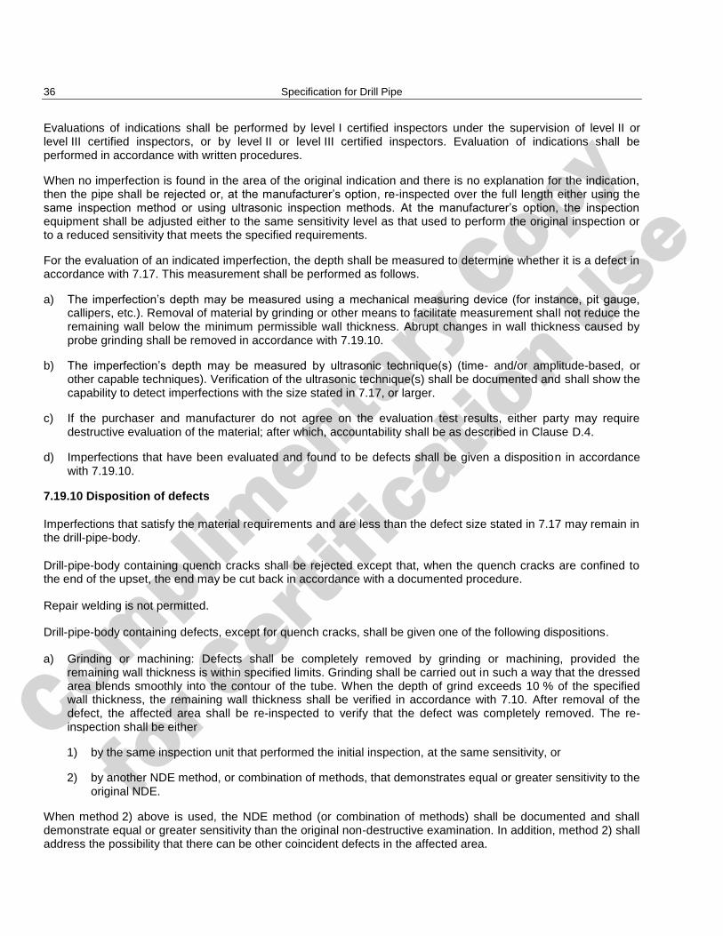
Complimenta
ry Copy
for C
ertific
ation Use
36 Specification for Drill Pipe
Evaluations of indications shall be performed by level I certified inspectors under the supervision of level II or level III certified inspectors, or by level II or level III certified inspectors. Evaluation of indications shall be performed in accordance with written procedures.
When no imperfection is found in the area of the original indication and there is no explanation for the indication, then the pipe shall be rejected or, at the manufacturer’s option, re-inspected over the full length either using the same inspection method or using ultrasonic inspection methods. At the manufacturer’s option, the inspection equipment shall be adjusted either to the same sensitivity level as that used to perform the original inspection or to a reduced sensitivity that meets the specified requirements.
For the evaluation of an indicated imperfection, the depth shall be measured to determine whether it is a defect in accordance with 7.17. This measurement shall be performed as follows.
a) The imperfection’s depth may be measured using a mechanical measuring device (for instance, pit gauge, callipers, etc.). Removal of material by grinding or other means to facilitate measurement shall not reduce the remaining wall below the minimum permissible wall thickness. Abrupt changes in wall thickness caused by probe grinding shall be removed in accordance with 7.19.10.
b) The imperfection’s depth may be measured by ultrasonic technique(s) (time- and/or amplitude-based, or other capable techniques). Verification of the ultrasonic technique(s) shall be documented and shall show the capability to detect imperfections with the size stated in 7.17, or larger.
c) If the purchaser and manufacturer do not agree on the evaluation test results, either party may require destructive evaluation of the material; after which, accountability shall be as described in Clause D.4.
d) Imperfections that have been evaluated and found to be defects shall be given a disposition in accordance with 7.19.10.
7.19.10 Disposition of defects
Imperfections that satisfy the material requirements and are less than the defect size stated in 7.17 may remain in the drill-pipe-body.
Drill-pipe-body containing quench cracks shall be rejected except that, when the quench cracks are confined to the end of the upset, the end may be cut back in accordance with a documented procedure.
Repair welding is not permitted.
Drill-pipe-body containing defects, except for quench cracks, shall be given one of the following dispositions.
a) Grinding or machining: Defects shall be completely removed by grinding or machining, provided the remaining wall thickness is within specified limits. Grinding shall be carried out in such a way that the dressed area blends smoothly into the contour of the tube. When the depth of grind exceeds 10 % of the specified wall thickness, the remaining wall thickness shall be verified in accordance with 7.10. After removal of the defect, the affected area shall be re-inspected to verify that the defect was completely removed. The re-inspection shall be either
1) by the same inspection unit that performed the initial inspection, at the same sensitivity, or
2) by another NDE method, or combination of methods, that demonstrates equal or greater sensitivity to the original NDE.
When method 2) above is used, the NDE method (or combination of methods) shall be documented and shall demonstrate equal or greater sensitivity than the original non-destructive examination. In addition, method 2) shall address the possibility that there can be other coincident defects in the affected area.
Complimenta
ry Copy
for C
ertific
ation Use
API Specification 5DP/ISO 11961 37
The removal of imperfections (including elephant hide) from the drill-pipe-body by grinding or machining more than 60 % of the circumference of the drill-pipe body shall not reduce the outside diameter below the specified minimum outside diameter.
b) Cutting off.
c) Rejection.
7.20 Marking
7.20.1 General
Marking of the drill-pipe-body shall be carried out by the drill-pipe-body manufacturer, as in 7.20.2, when this component is ordered as an individual part. When the drill-pipe-body is manufactured by the drill-pipe manufacturer, marking of the drill-pipe body may be done in a way different from that in 7.20.2 provided the requirements for traceability are maintained.
Additional markings, paint-stencilling or die stamping may be applied, including those for applicable compatible standards, at the option of the manufacturer or as specified by the purchaser. Die stamping shall be located only on the upset of the drill-pipe-body. Markings shall not overlap and shall be applied in such a manner as not to damage the drill-pipe body.
7.20.2 Paint-stencilled marking sequence
A paint-stencilled marking shall be placed on the outside surface of each length of drill-pipe-body starting not less than 0,6 m (24 in) from either end of the drill-pipe-body. The sequence of paint-stencilled markings on the drill-pipe-body shall be as follows:
a) The letters ―DPB‖;
NOTE These letters indicate that this marking relates to the drill-pipe-body.
b) drill-pipe-body manufacturer’s name or mark;
c) ―ISO 11961‖ and/or ―Specification 5DP‖, as applicable; marking to indicate compliance with API Spec 5DP is at the manufacturer’s option or as specified in the purchase agreement;
d) API monogram marking requirements (see Annex H), if applicable;
e) date of manufacture (month and year).
The date of manufacture shall be a three- or four-digit number consisting of a one- or two-digit number indicating the month followed by the last two digits of the year in which the markings of Clause 7 are completed. Products manufactured in accordance with this edition of ISO 11961 during the period of overlap of application with the previous edition (see Foreword) may be identified by ―00‖ as the overlap period designation rather than the month;
f) ―UF‖ if upset dimensions are different from those in Table A.13 or A.14 or Table C.13 or C.14;
g) size designation (label 1);
h) mass designation (label 2);
i) grade of drill-pipe body;
j) SR information;
k) L2 or L3 (indicating PSL-2 or PSL-3), as applicable;
l) traceability code (for traceability requirements, see 7.5).
Complimenta
ry Copy
for C
ertific
ation Use
38 Specification for Drill Pipe
EXAMPLE Label 1: 2-3/8, label 2: 6.65, grade E drill-pipe-body manufactured by company ZZ with traceability code YYYY in July 2007 and with special upset dimensions is paint stencilled as follows:
DPB ZZ ISO 11961 707 UF 2-3/8 6.65 E YYYY.
7.21 Minimum facility requirements for drill-pipe-body manufacturer
The drill-pipe-body manufacturer shall operate upsetting facilities and/or heat treatment facilities capable of heat treating full lengths of drill-pipe body and shall possess suitable equipment for, and be responsible for, weighing and marking the drill-pipe-body. If the drill-pipe-body manufacturer purchases upset pipe or subcontracts the upsetting or the heat treatment, the conduct of such operations shall be controlled and monitored by the drill-pipe-body manufacturer in accordance with a documented procedure.
The drill-pipe-body manufacturer shall have facilities for conducting all required tests and inspections, or any of these tests or inspections may be provided by a subcontractor and may be located offsite. In the event that a subcontractor performs any of these services, the conduct of such inspections and tests shall be controlled and monitored by the drill-pipe-body manufacturer in accordance with a documented procedure.
7.22 Documentation requirements
7.22.1 Certificate of inspection
The drill-pipe-body manufacturer shall provide a certificate of inspection containing the following data, as applicable, for each order item specified in the purchaser agreement:
a) ISO International Standard (or equivalent specification) and revision date thereof, to which the drill-pipe body was manufactured;
b) label 1, label 2, upset configuration, grade of drill-pipe-body, type of heat treatment, length and tolerances and any other special requirements specified in the purchase agreement;
c) statement that the drill-pipe-body was manufactured, inspected and tested in accordance with, and is in compliance with, this International Standard;
d) chemical analyses (heat, product and re-check, as applicable) showing the mass per cent of all elements whose limits or reporting requirements are stipulated in this International Standard and any other elements used by the manufacturer to control the mechanical properties;
e) test data for all tensile tests required by this International Standard, including yield strength, tensile strength and elongation; the type and size of specimens shall be shown;
f) where impact testing is required by the International Standard, reported data for each test shall include
the absorbed-energy requirement,
the size, location and orientation of the test specimens,
the specified temperature at which the test was performed,
the absorbed energy measured for each test specimen,
the average absorbed energy,
the percent shear area for each test specimen (for information only);
g) results of any other supplemental testing requirements specified in the purchase agreement.
Complimenta
ry Copy
for C
ertific
ation Use
API Specification 5DP/ISO 11961 39
7.22.2 Tally list
The drill-pipe-body manufacturer shall provide the purchaser with a tally list providing the length, Lpe, for each drill-pipe-body.
7.22.3 Electronic data interchange
The standard documents (see 7.22.1 and 7.22.2) printed from or used in electronic form from an electronic data interchange (EDI) transmission shall be regarded as having the same validity as a counterpart printed in the drill-pipe-body manufacturer's facility. The content of the EDI-transmitted document shall meet the requirements of this International Standard and conform to any existing EDI agreement between the purchaser and the drill-pipe-body manufacturer.
7.22.4 Retention of records
Table A.9 or Table C.9 specifies records which shall be retained. Such records shall be retained by the dril-pipe-body manufacturer and shall be available to the purchaser on request for a period of five years after the date of purchase from the drill-pipe-body manufacturer.
8 Requirements for tool joints
8.1 Information to be supplied when placing orders for tool joints
8.1.1 When placing orders for tool joints to be manufactured in accordance with this International Standard, the purchaser shall specify the following on the purchase agreement:
Requirements Reference
Document number(s) ISO 11961 or API Spec 5DP
Quantity
Drawing of the tool-joint pin, including any necessary details Figure B.12
Drawing of the tool-joint box, including any necessary details Figure B.12
Delivery date and shipping instructions
Inspection by purchaser Annex D
Documentation 8.15
8.1.2 The purchaser shall also specify in the purchase agreement his requirements concerning the following stipulations, which are optional with the purchaser:
Requirements Reference
Special surface treatment 8.4.5
Tool-joint break-in 8.4.6
Hard banding: type, location, dimensions and acceptance criteria 8.4.7
NOTE Hard banding reduces the length of tool-joint outside diameter available for tong placement.
Thread-protector type 8.4.8
Marking requirements 8.13
Alternative requirements for impact testing Clause E.5, SR20
PSL-2 or PSL-3 Annex G
Complimenta
ry Copy
for C
ertific
ation Use
40 Specification for Drill Pipe
8.2 Dimensional requirements
8.2.1 General
All dimensions shown without tolerances are related to the basis for design and are not subject to measurement to determine acceptance or rejection of the product. Tool-joint dimensions that are not specified in this International Standard are optional with the manufacturer unless otherwise specified in the purchase agreement.
8.2.2 Configuration
Tool-joint configuration shall correspond to Figure B.12.
8.2.3 Tool-joint type
Tool joints shall be produced with the rotary shouldered connections in Table A.1 or Table C.1 except as provided by 8.2.5.
8.2.4 Dimensions
Tool joints shall conform to the dimensions and the tolerances in Table A.1 or Table C.1 or in the purchase agreement. See Figure B.12.
The drill-pipe weld neck diameter, Dte, at the elevator shoulder, in Table A.1 or Table C.1 and Figure B.1, applies to the finished product after the tool joint is welded to the drill-pipe body. Dimensions prior to welding shall be specified by the drill-pipe manufacturer.
The tool-joint-box inside diameter is at the drill-pipe manufacturer’s discretion but shall not be less than the pin internal diameter, dp (see Figure B.1).
The outside and inside diameters, D and dp, respectively, in Table A.1 or Table C.1 result in a drill-pipe torsion-strength ratio of 0,8 or greater. Other OD and ID tool joints, such as in combination strings or tapered strings, may be specified in the purchase agreement but the drill-pipe torsion-strength ratio may be different.
8.2.5 Rotary shouldered connection
Rotary shouldered connections shall conform to the dimensions and tolerances in ISO 10424-2 or API Spec 7-2. Right-hand thread connections shall be considered standard. However, when specified in the purchase agreement, other connections are permitted. In this case, dimensions, tolerances and performance ratings shall be agreed between the purchaser and manufacturer.
8.3 Material requirements
8.3.1 Chemical composition
The chemical composition shall be as in Table A.4 or Table C.4.
8.3.2 Tensile requirements
The tool joint shall conform to the requirements in Table A.5 or Table C.5.
The yield strength of the pin shall be determined using the 0,2 % offset method.
NOTE Compliance with the requirements for tensile properties for the tool-joint box is verified by hardness testing.
Additional requirements for PSL-3 are in Annex G.
Complimenta
ry Copy
for C
ertific
ation Use
API Specification 5DP/ISO 11961 41
8.3.3 Hardness
The hardness for the tool-joint box shall be in the range 285 HBW to 341 HBW.
This requirement shall not apply to the through-wall hardness variation requirements in Clause G.3.
Additional requirements for PSL-3 are in Annex G.
8.3.4 Charpy V-notch absorbed-energy requirements
The minimum absorbed-energy requirements shall be as in Table A.8 or Table C.8. In addition, not more than one impact specimen shall exhibit an absorbed energy below the minimum average absorbed-energy requirement, and in no case shall an individual impact specimen exhibit an absorbed energy below the minimum specimen absorbed-energy requirement.
Additional requirements for PSL-3 are in Annex G.
8.4 Process of manufacture
8.4.1 Processes requiring validation
Final operations performed during tool-joint manufacturing that affect attribute compliance as required in this International Standard (except chemical composition and dimensions) shall have their process validated.
Those processes requiring validation are
heat treatment, and
hard banding, if applicable.
8.4.2 Material
Tool joints shall be manufactured from forgings or hot-rolled steel.
8.4.3 Heat treatment
Heat treatment shall be performed according to a documented procedure. The procedure shall address the permissible number of re-heat-treatments.
Tool joints shall be quenched and tempered.
8.4.4 Threading
Unless otherwise specified in the purchase agreement, tool-joint thread connections including benchmarks shall be manufactured in accordance with ISO 10424-2 or API Spec 7-2.
8.4.5 Surface treatment to minimize galling
Surface treatment of threads to minimize galling, such as phosphating, copper plating or any other appropriate method, shall be applied. Unless otherwise specified in the purchase agreement, the method is at the option of the manufacturer. The surface treatment shall be performed in accordance with a documented procedure.
8.4.6 Break-in procedure
When specified in the purchase agreement, tool-joint break-in shall be performed in accordance with a documented procedure.
Complimenta
ry Copy
for C
ertific
ation Use
42 Specification for Drill Pipe
8.4.7 Hard banding
Hard banding of tool joints may be agreed between the purchaser and the manufacturer. The type of hard banding, location, dimensions and tolerances shall be specified in the purchase agreement and the application shall be carried out in accordance with a documented procedure.
8.4.8 Thread protection
The tool-joint manufacturer shall be responsible for thread protection during storage and shipment to the purchaser, unless otherwise stipulated in the purchase agreement.
8.5 Traceability
The tool-joint manufacturer shall establish and follow procedures for maintaining heat identity of all tool joints covered by this International Standard. Lot identity shall be maintained until all required lot tests are performed and conformance with specification requirements has been documented. The procedures shall provide means for tracing the tool joint to the relevant heat and to the specified chemical, mechanical and test results.
NOTE Since a heat can be heat treated in more than one lot, there can be more than one set of mechanical test results for a heat.
8.6 Inspection and testing — General
8.6.1 Inspection and test-equipment calibration
The manufacturer shall determine and document the appropriate calibration frequency and procedures (including occurrences of out-of-calibration and the consequences on products) in order to be able to certify that all products conform to the requirements of this International Standard.
8.6.2 Heat-treatment lot
A lot shall consist of those pin or box tool joints with the same specified dimensions that are heat treated as part of a continuous operation (or batch), and are of a single heat of steel, or from different heats that are grouped according to a documented procedure that ensures that the appropriate requirements of this International Standard are met.
8.7 Testing of chemical composition
8.7.1 General
For tool joints, the analyses shall be made by the steel manufacturer or tool-joint manufacturer and shall be taken from material in finished, forged, tubular or bar form.
8.7.2 Product analyses
Each heat of steel used in the manufacture of tool-joints shall be analysed to provide the results of quantitative determinations of phosphorus and sulfur plus any other elements used by the manufacturer to control mechanical properties.
8.7.3 Test method
Chemical composition shall be determined by any of the procedures commonly used for determining chemical compositions, such as emission spectroscopy, X-ray emission, atomic absorption, combustion techniques or wet analytical procedures. The calibration methods used shall be traceable to established standards. In case of conflict, chemical analyses shall be made in accordance with ISO/TR 9769 or ASTM A751.
Complimenta
ry Copy
for C
ertific
ation Use
API Specification 5DP/ISO 11961 43
8.8 Tensile tests
8.8.1 Procedures
Tensile tests shall be performed at room temperature in accordance with ISO 6892 or ASTM A370.
8.8.2 Test-equipment calibration
Tensile test machines shall have been calibrated within a period of 15 months preceding any test, in accordance with the procedures in ISO 7500-1 or ASTM E4. Extensometers shall have been calibrated within a period of 15 months preceding any test, in accordance with the procedures in ISO 9513 or ASTM E83. Retention of records shall be in accordance with 6.17.4 and Table A.9 or Table C.9.
8.8.3 Test specimens
Tensile specimens shall be removed from the pin tool joint as in Figure B.13 after final heat treatment. Specimens may be taken from semi-finished products (that is, before threading, machining or hard banding operations).
By agreement between the purchaser and manufacturer, tensile tests shall also be undertaken on box tool joints. In such cases, details of testing shall also be agreed.
The test shall be conducted using a 12,7 mm (0,500 in) diameter round specimen.
If the pin section at the specified location is not sufficient to obtain a tensile specimen of 12,7 mm (0,500 in) diameter, an 8,9 mm (0,350 in) or 6,4 mm (0,250 in) diameter specimen may be used. The largest possible diameter specimen shall be used.
If the pin section at the specified location is not sufficient to obtain a 6,4 mm (0,250 in) diameter specimen [25 mm (1 in) gauge length], the tensile test is not required and a hardness test shall be carried out in accordance with 8.9.
8.8.4 Frequency of test
The tensile test frequency for the pin tool joint shall be as in Table A.10 or Table C.10.
Additional requirements for PSL-3 are in Annex G.
8.8.5 Heat control tensile tests
One tensile test shall be made as a control test from each heat of steel used by the manufacturer for the production of tool-joint pins under this International Standard. A record of such tests shall be available to the purchaser.
A heat control test may also be considered as a product test for the lot being tested.
8.8.6 Re-test
If the initial tensile test fails to conform to the specified requirements, the manufacturer may elect to test two additional specimens from the same piece. If both of the additional specimens pass, the lot shall be accepted.
If one or both of the additional specimens fail to conform to the requirements, the manufacturer may elect to test three additional pin tool joints from the same lot. If the specimens from all three pin tool joints conform to the requirements, the lot shall be accepted. If one or more of the specimens fails to conform to the requirement, the lot shall be rejected. Rejected lots may be re-heat-treated and tested as new lots.
8.8.7 Defective specimens
Specimens showing material imperfections or defective preparation, whether observed before or after testing, may be discarded, and replacements shall be considered as original specimens. Specimens shall not be judged defective simply because they fail to exhibit the minimum tensile requirements.
Complimenta
ry Copy
for C
ertific
ation Use
44 Specification for Drill Pipe
8.9 Hardness tests
8.9.1 Procedure
Hardness tests shall be performed at room temperature in accordance with ISO 6506-1 or ASTM E10 for Brinell hardness tests.
8.9.2 Test specimen
The specimen shall be removed from the box tool joint as in Figure B.13 after final heat treatment. The specimen may be taken on semi-finished product (that is, before threading, machining or hard banding operations).
If the specified location for the pin-tool-joint tensile test is not sufficient to obtain an acceptable tensile test specimen (see 8.8.3), a hardness test shall be performed on the pin tool joint as in Figure B.13.
8.9.3 Frequency of testing
The hardness-test frequency for the box tool joint shall be as in Table A.10 or Table C.10.
When hardness testing is required for pin tool joints due to insufficient material for tensile testing, the hardness testing of the pin tool joint shall be performed at the tensile testing frequency in Table A.10 or Table C.10.
8.9.4 Heat control hardness tests
One hardness test shall be made as a control test from each heat of steel used by the manufacturer for the production of tool-joint boxes (and, when necessary, pins) under this International Standard. A record of such tests shall be available to the purchaser.
A heat control test may also be considered as a product test for the lot being tested.
8.9.5 Re-tests
Any tool joint representing a lot that fails to meet the hardness requirements may be re-tested. Two additional tests shall be made approximately three impression diameters each side of the original test location. If both of the additional tests meet the requirements, the lot shall be accepted.
If one or both of the additional tests fail to conform to the requirements, the manufacturer may elect to test three additional tool joints from the same lot. If the tests on all three tool joints conform to the requirements, the lot shall be accepted. If one or more of the tests fails to conform to the requirement, the lot shall be rejected. Rejected lots may be re-heat-treated and tested as new lots.
8.10 Charpy V-notch impact tests
8.10.1 Procedures
A test shall consist of a set of three longitudinal specimens taken from a tool joint. Charpy V-notch impact tests as in ASTM A370 and ASTM E23 shall be conducted at a temperature of 21 °C 3 °C (70 °F 5 °F). For an alternative standardized test temperature, see Clause E.5, SR20, and PSL-3 in Table A.8 or Table C.8.
Tests conducted at a temperature lower than the specified temperature are acceptable provided the absorbed-energy requirements at the specified temperature are achieved.
Additional requirements for PSL-3 are in Annex G.
Complimenta
ry Copy
for C
ertific
ation Use
API Specification 5DP/ISO 11961 45
8.10.2 Specimen size and location
Charpy V-notch impact specimens shall be removed from the tool joint as in Figure B.13 after final heat treatment. Specimens may be taken from semi-finished product (that is, before threading, machining or hard banding operations).
The impact-test specimen shall not be smaller than the largest size shown in Table A.11 or Table C.11 based on the minimum material diameter (rounded to the next smaller diameter, if required) and the wall thickness in the test area. The smallest specimen permitted shall be 10 mm 5 mm.
The specimens shall be taken parallel to the axis of the tool joint with the notch oriented in a radial direction as in Figure B.13.
8.10.3 Frequency of testing
The Charpy V-notch impact-test frequency shall be as in Table A.10 or Table C.10.
Additional requirements for PSL-3 are in Annex G.
8.10.4 Heat control test
One impact test shall be made as a control on each heat of steel used by the tool-joint manufacturer. A record of such tests shall be available to the purchaser.
A heat control test may also be considered as a product test for the lot being tested.
8.10.5 Re-test
If the requirements of 8.3.4 are not met and not more than one specimen is below the minimum specimen absorbed-energy requirement, then the manufacturer may elect either to reject the lot or to re-test a set of three additional specimens from the same test piece. For all three of these specimens, the absorbed energy shall be equal to or greater than the minimum average absorbed energy in Table A.8 or Table C.8 or the lot shall be rejected. If insufficient material remains for the re-test specimens to be obtained from the original sample, then it is permitted to obtain specimens from a tool joint from the same lot.
If more than one specimen in the initial test is below the minimum specimen absorbed-energy requirement then the manufacturer may elect either to reject the lot or to re-test an additional set of three specimens from each of three additional tool joints from the same lot. If these additional sets of specimens do not meet the initial test requirements, then the lot shall be rejected.
Rejected lots may be re-heat-treated and tested as a new lot.
8.10.6 Defective specimens
Specimens showing material imperfections or defective preparation, whether observed before or after testing, may be discarded, and replacements shall be considered as original specimens. Specimens shall not be judged defective simply because they fail to exhibit the minimum absorbed-energy requirement.
8.11 Imperfections and defects
8.11.1 General
Tool joints shall be free from defects as defined in this International Standard. Die stamping shall not be considered a defect.
Complimenta
ry Copy
for C
ertific
ation Use
46 Specification for Drill Pipe
8.11.2 Surface breaking defects
In the threads, on the coincident opposite surfaces (that is, the outside surface of the internally threaded member and the inside surface of the externally threaded member) or on the ends of the threaded area, any imperfection shall be considered a defect.
On the surfaces not described above,
any linear imperfection shall be considered a defect;
non-linear imperfections that exceed 25 % of the circumference or exceed 3,2 mm (0.125 in) in depth shall be considered defects.
8.11.3 Quench cracks
Quench cracks shall be considered defects.
8.11.4 Process control plan
The manufacturer, based on knowledge of the production process and the requirements of 8.11, shall apply a process control plan that ensures that the above requirements are fulfilled.
8.12 Non-destructive examination
8.12.1 General
All NDE operations (except visual inspection) to which reference is made in this International Standard shall be conducted by NDE personnel qualified in accordance with ISO 11484 or ASNT SNT-TC-1A.
When specified in the purchase agreement, the provisions for purchaser inspection of tool joints and/or witnessing of NDE operations shall be in accordance with Annex D.
The inspections performed in accordance with 8.12 should not be construed as assuring that the material requirements in 8.11 have been met.
The manufacturer shall determine the appropriate NDE equipment verification frequency in order to be able to certify that all products conform to the requirements of this International Standard.
If equipment whose calibration or verification is required under the provisions of this International Standard is subject to unusual or severe conditions such as can make its accuracy questionable, re-calibration or re-verification shall be performed before further use of the equipment.
8.12.2 Wet magnetic-particle inspection
After heat treatment and threading, each tool joint shall be inspected for longitudinal and transverse imperfections on the inside and outside surfaces by the wet magnetic-particle method in accordance with ISO 13665 or ASTM E709. Inspection shall be performed in accordance with a written procedure. The wet-particle concentration shall be checked every 8 h or each shift change. The minimum black-light intensity at the examination surface shall not be less than 1 000 µw/cm2.
8.12.3 Disposition of defects
Defects shall be cause for rejection or shall be completely removed by grinding or machining in accordance with a written procedure, provided the requirements of 8.2 are met. All grinding shall be blended smooth. After grinding or machining to remove defects, the tool joint shall be re-inspected by the same method that detected the defect in order to verify removal of the defect.
Complimenta
ry Copy
for C
ertific
ation Use
API Specification 5DP/ISO 11961 47
8.13 Marking
8.13.1 General
Marking of the tool joint shall be carried out by the tool-joint manufacturer as in 8.13.2 when this component is ordered as an individual part. When the tool joint is manufactured by the drill-pipe manufacturer, marking of the tool joint may be done in a way different from that in 8.13.2, provided that the requirements for traceability are maintained.
Additional markings may be applied, including those for applicable compatible standards, at the option of the manufacturer or as specified by the purchaser. Marking of the tool joint with grooves and flats (see 6.15.5) may be applied at any time during the production process of the tool joint.
Markings shall not overlap and shall be applied in such a manner as not to damage the tool joint.
8.13.2 Die stamp marking
The tool-joint outside diameter shall be die stamped with the following:
a) tool-joint manufacturer’s name or mark;
b) tool-joint designation (RSC type or, for connections not in Table A.1 or Table C.1, designation as specified by the manufacturer); see Table A.1 or Table C.1;
c) ―ISO 11961‖ and/or ―Specification 5DP‖, as applicable. Marking to indicate compliance with API Spec 5DP is at the manufacturer’s option or as specified in the purchase agreement;
d) API monogram marking requirements (see Annex H), if applicable;
e) date of manufacture (month and year).
The date of manufacture shall be a three- or four-digit number consisting of a one- or two-digit number indicating the month followed by the last two digits of the year in which the markings of Clause 8 are completed. Products manufactured in accordance with this edition of ISO 11961 during the period of overlap of application (see Foreword) with the previous edition may be identified by ―00‖ as the overlap period designation rather than the month;
f) SR20, if applicable;
g) L2 or L3 (indicating PSL-2 or PSL-3), as applicable;
h) traceability code (for traceability requirements, see 8.5).
EXAMPLE NC50 tool joint manufactured by ZZ in August of 2007 in accordance with this International Standard with traceability code YYYY is die stamped as follows (one or more lines):
ZZ NC50 ISO 11961 807 YYYY
8.14 Minimum facility requirements for tool-joint manufacturers
The tool-joint manufacturer shall operate facilities for heat treating and/or threading tool joints and shall possess, and be responsible for, suitable equipment for marking the tool joint. If the tool-joint manufacturer purchases heat-treated material or subcontracts the heat treatment or the threading, the conduct of such operations shall be controlled and monitored by the tool-joint manufacturer in accordance with a documented procedure.
The tool-joint manufacturer shall either have facilities for conducting all required tests and inspections, or any of these tests or inspections may be provided by a subcontractor and may be located offsite. In the event that a subcontractor performs any of these services, the conduct of such inspections and tests shall be controlled and monitored by the tool-joint manufacturer in accordance with a documented procedure.
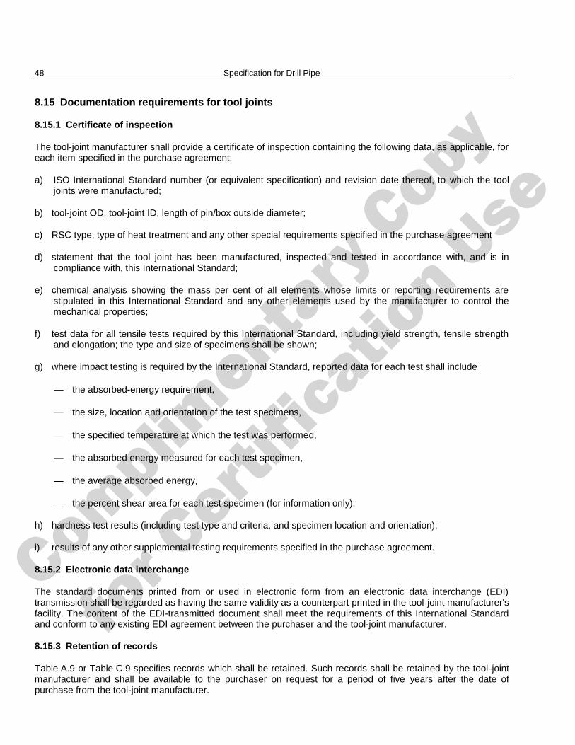
Complimenta
ry Copy
for C
ertific
ation Use
48 Specification for Drill Pipe
8.15 Documentation requirements for tool joints
8.15.1 Certificate of inspection
The tool-joint manufacturer shall provide a certificate of inspection containing the following data, as applicable, for each item specified in the purchase agreement:
a) ISO International Standard number (or equivalent specification) and revision date thereof, to which the tool joints were manufactured;
b) tool-joint OD, tool-joint ID, length of pin/box outside diameter;
c) RSC type, type of heat treatment and any other special requirements specified in the purchase agreement
d) statement that the tool joint has been manufactured, inspected and tested in accordance with, and is in compliance with, this International Standard;
e) chemical analysis showing the mass per cent of all elements whose limits or reporting requirements are stipulated in this International Standard and any other elements used by the manufacturer to control the mechanical properties;
f) test data for all tensile tests required by this International Standard, including yield strength, tensile strength and elongation; the type and size of specimens shall be shown;
g) where impact testing is required by the International Standard, reported data for each test shall include
the absorbed-energy requirement,
the size, location and orientation of the test specimens,
the specified temperature at which the test was performed,
the absorbed energy measured for each test specimen,
the average absorbed energy,
the percent shear area for each test specimen (for information only);
h) hardness test results (including test type and criteria, and specimen location and orientation);
i) results of any other supplemental testing requirements specified in the purchase agreement.
8.15.2 Electronic data interchange
The standard documents printed from or used in electronic form from an electronic data interchange (EDI) transmission shall be regarded as having the same validity as a counterpart printed in the tool-joint manufacturer's facility. The content of the EDI-transmitted document shall meet the requirements of this International Standard and conform to any existing EDI agreement between the purchaser and the tool-joint manufacturer.
8.15.3 Retention of records
Table A.9 or Table C.9 specifies records which shall be retained. Such records shall be retained by the tool-joint manufacturer and shall be available to the purchaser on request for a period of five years after the date of purchase from the tool-joint manufacturer.
Complimenta
ry Copy
for C
ertific
ation Use
49
Annex A (normative)
Tables in SI units
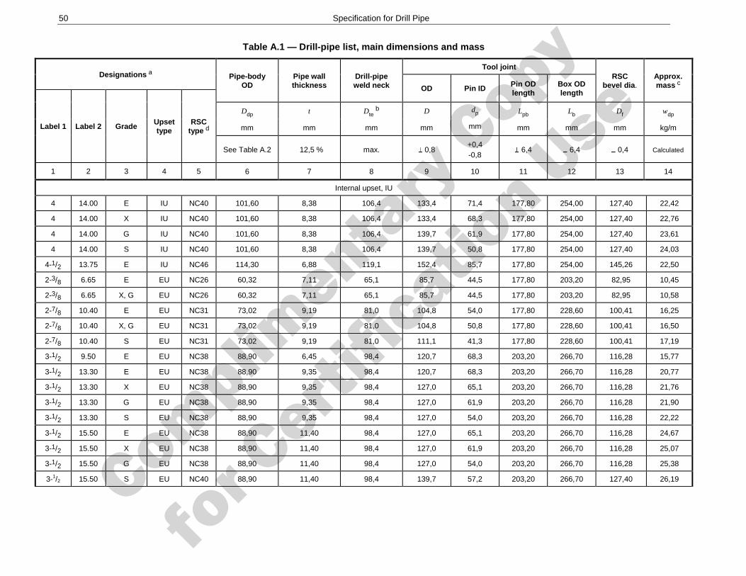
Complimenta
ry Copy
for C
ertific
ation Use
50 Specification for Drill Pipe
Table A.1 — Drill-pipe list, main dimensions and mass
Designations a Pipe-body OD
Pipe wall thickness
Drill-pipe weld neck
Tool joint RSC
bevel dia. Approx. mass c OD Pin ID
Pin OD length
Box OD length
Label 1 Label 2 Grade Upset type
RSC type d
Ddp t Dte b D dp Lpb Lb Df wdp
mm mm mm mm mm mm mm mm kg/m
See Table A.2 12,5 % max. 0,8 +0,4 -0,8
6,4 6,4 0,4 Calculated
1 2 3 4 5 6 7 8 9 10 11 12 13 14
Internal upset, IU
4 14.00 E IU NC40 101,60 8,38 106,4 133,4 71,4 177,80 254,00 127,40 22,42
4 14.00 X IU NC40 101,60 8,38 106,4 133,4 68,3 177,80 254,00 127,40 22,76
4 14.00 G IU NC40 101,60 8,38 106,4 139,7 61,9 177,80 254,00 127,40 23,61
4 14.00 S IU NC40 101,60 8,38 106,4 139,7 50,8 177,80 254,00 127,40 24,03
4-1/2 13.75 E IU NC46 114,30 6,88 119,1 152,4 85,7 177,80 254,00 145,26 22,50
2-3/8 6.65 E EU NC26 60,32 7,11 65,1 85,7 44,5 177,80 203,20 82,95 10,45
2-3/8 6.65 X, G EU NC26 60,32 7,11 65,1 85,7 44,5 177,80 203,20 82,95 10,58
2-7/8 10.40 E EU NC31 73,02 9,19 81,0 104,8 54,0 177,80 228,60 100,41 16,25
2-7/8 10.40 X, G EU NC31 73,02 9,19 81,0 104,8 50,8 177,80 228,60 100,41 16,50
2-7/8 10.40 S EU NC31 73,02 9,19 81,0 111,1 41,3 177,80 228,60 100,41 17,19
3-1/2 9.50 E EU NC38 88,90 6,45 98,4 120,7 68,3 203,20 266,70 116,28 15,77
3-1/2 13.30 E EU NC38 88,90 9,35 98,4 120,7 68,3 203,20 266,70 116,28 20,77
3-1/2 13.30 X EU NC38 88,90 9,35 98,4 127,0 65,1 203,20 266,70 116,28 21,76
3-1/2 13.30 G EU NC38 88,90 9,35 98,4 127,0 61,9 203,20 266,70 116,28 21,90
3-1/2 13.30 S EU NC38 88,90 9,35 98,4 127,0 54,0 203,20 266,70 116,28 22,22
3-1/2 15.50 E EU NC38 88,90 11,40 98,4 127,0 65,1 203,20 266,70 116,28 24,67
3-1/2 15.50 X EU NC38 88,90 11,40 98,4 127,0 61,9 203,20 266,70 116,28 25,07
3-1/2 15.50 G EU NC38 88,90 11,40 98,4 127,0 54,0 203,20 266,70 116,28 25,38
3-1/2 15.50 S EU NC40 88,90 11,40 98,4 139,7 57,2 203,20 266,70 127,40 26,19
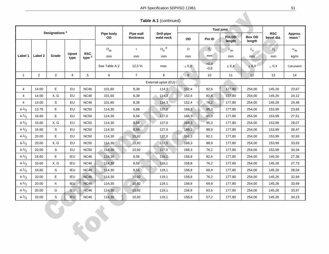
Complimenta
ry Copy
for C
ertific
ation Use
API Specification 5DP/ISO 11961 51
Table A.1 (continued)
Designations a Pipe body OD
Pipe wall thickness
Drill-pipe weld neck
Tool joint RSC
bevel dia. Approx. mass c OD Pin ID
Pin OD length
Box OD length
Label 1 Label 2 Grade Upset type
RSC type d
Ddp t Dte b D dp Lpb Lb Df wdp
mm mm mm mm mm mm mm mm kg/m
See Table A.2 12,5 % max. 0,8 +0,4 -0,8
6,4 6,4 0,4 Calculated
1 2 3 4 5 6 7 8 9 10 11 12 13 14
External-upset (EU)
4 14.00 E EU NC46 101,60 8,38 114,3 152,4 82,6 177,80 254,00 145,26 23,67
4 14.00 X, G EU NC46 101,60 8,38 114,3 152,4 82,6 177,80 254,00 145,26 24,12
4 14.00 S EU NC46 101,60 8,38 114,3 152,4 76,2 177,80 254,00 145,26 24,46
4-1/2 13.75 E EU NC50 114,30 6,88 127,0 168,3 95,3 177,80 254,00 153,99 23,65
4-1/2 16.60 E EU NC50 114,30 8,56 127,0 168,3 95,3 177,80 254,00 153,99 27,51
4-1/2 16.60 X, G EU NC50 114,30 8,56 127,0 168,3 95,3 177,80 254,00 153,99 28,07
4-1/2 16.60 S EU NC50 114,30 8,56 127,0 168,3 88,9 177,80 254,00 153,99 28,47
4-1/2 20.00 E EU NC50 114,30 10,92 127,0 168,3 92,1 177,80 254,00 153,99 32,93
4-1/2 20.00 X, G EU NC50 114,30 10,92 127,0 168,3 88,9 177,80 254,00 153,99 33,63
4-1/2 20.00 S EU NC50 114,30 10,92 127,0 168,3 76,2 177,80 254,00 153,99 34,34
4-1/2 16.60 E IEU NC46 114,30 8,56 119,1 158,8 82,6 177,80 254,00 145,26 27,36
4-1/2 16.60 X, G IEU NC46 114,30 8,56 119,1 158,8 76,2 177,80 254,00 145,26 27,73
4-1/2 16.60 S IEU NC46 114,30 8,56 119,1 158,8 69,9 177,80 254,00 145,26 28,04
4-1/2 20.00 E IEU NC46 114,30 10,92 119,1 158,8 76,2 177,80 254,00 145,26 32,94
4-1/2 20.00 X IEU NC46 114,30 10,92 119,1 158,8 69,9 177,80 254,00 145,26 33,69
4-1/2 20.00 G IEU NC46 114,30 10,92 119,1 158,8 63,5 177,80 254,00 145,26 33,97
4-1/2 20.00 S IEU NC46 114,30 10,92 119,1 158,8 57,2 177,80 254,00 145,26 34,23
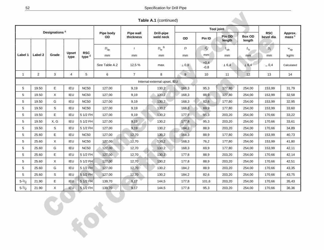
Complimenta
ry Copy
for C
ertific
ation Use
52 Specification for Drill Pipe
Table A.1 (continued)
Designations a Pipe body OD
Pipe wall thickness
Drill-pipe weld neck
Tool joint RSC
bevel dia. Approx. mass c OD Pin ID
Pin OD length
Box OD length
Label 1 Label 2 Grade Upset type
RSC type d
Ddp t Dte b D dp Lpb Lb Df wdp
mm mm mm mm mm mm mm mm kg/m
See Table A.2 12,5 % max. 0,8 +0,4 -0,8
6,4 6,4 0,4 Calculated
1 2 3 4 5 6 7 8 9 10 11 12 13 14
Internal-external upset, IEU
5 19.50 E IEU NC50 127,00 9,19 130,2 168,3 95,3 177,80 254,00 153,99 31,79
5 19.50 X IEU NC50 127,00 9,19 130,2 168,3 88,9 177,80 254,00 153,99 32,58
5 19.50 G IEU NC50 127,00 9,19 130,2 168,3 82,6 177,80 254,00 153,99 32,95
5 19.50 S IEU NC50 127,00 9,19 130,2 168,3 69,9 177,80 254,00 153,99 33,60
5 19.50 E IEU 5 1/2 FH 127,00 9,19 130,2 177,8 95,3 203,20 254,00 170,66 33,22
5 19.50 X, G IEU 5 1/2 FH 127,00 9,19 130,2 177,8 95,3 203,20 254,00 170,66 33,61
5 19.50 S IEU 5 1/2 FH 127,00 9,19 130,2 184,2 88,9 203,20 254,00 170,66 34,89
5 25.60 E IEU NC50 127,00 12,70 130,2 168,3 88,9 177,80 254,00 153,99 40,73
5 25.60 X IEU NC50 127,00 12,70 130,2 168,3 76,2 177,80 254,00 153,99 41,80
5 25.60 G IEU NC50 127,00 12,70 130,2 168,3 69,9 177,80 254,00 153,99 42,11
5 25.60 E IEU 5 1/2 FH 127,00 12,70 130,2 177,8 88,9 203,20 254,00 170,66 42,14
5 25.60 X IEU 5 1/2 FH 127,00 12,70 130,2 177,8 88,9 203,20 254,00 170,66 42,51
5 25.60 G IEU 5 1/2 FH 127,00 12,70 130,2 184,2 88,9 203,20 254,00 170,66 43,35
5 25.60 S IEU 5 1/2 FH 127,00 12,70 130,2 184,2 82,6 203,20 254,00 170,66 43,75
5-1/2 21.90 E IEU 5 1/2 FH 139,70 9,17 144,5 177,8 101,6 203,20 254,00 170,66 35,43
5-1/2 21.90 X IEU 5 1/2 FH 139,70 9,17 144,5 177,8 95,3 203,20 254,00 170,66 36,36
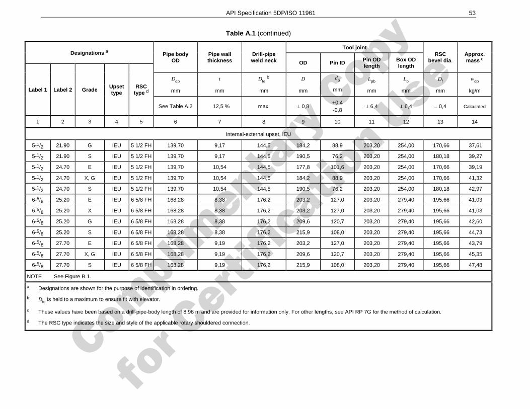
Complimenta
ry Copy
for C
ertific
ation Use
API Specification 5DP/ISO 11961 53
Table A.1 (continued)
Designations a Pipe body OD
Pipe wall thickness
Drill-pipe weld neck
Tool joint RSC
bevel dia. Approx. mass c OD Pin ID
Pin OD length
Box OD length
Label 1 Label 2 Grade Upset type
RSC type d
Ddp t Dte b D dp Lpb Lb Df wdp
mm mm mm mm mm mm mm mm kg/m
See Table A.2 12,5 % max. 0,8 +0,4 -0,8
6,4 6,4 0,4 Calculated
1 2 3 4 5 6 7 8 9 10 11 12 13 14
Internal-external upset, IEU
5-1/2 21.90 G IEU 5 1/2 FH 139,70 9,17 144,5 184,2 88,9 203,20 254,00 170,66 37,61
5-1/2 21.90 S IEU 5 1/2 FH 139,70 9,17 144,5 190,5 76,2 203,20 254,00 180,18 39,27
5-1/2 24.70 E IEU 5 1/2 FH 139,70 10,54 144,5 177,8 101,6 203,20 254,00 170,66 39,19
5-1/2 24.70 X, G IEU 5 1/2 FH 139,70 10,54 144,5 184,2 88,9 203,20 254,00 170,66 41,32
5-1/2 24.70 S IEU 5 1/2 FH 139,70 10,54 144,5 190,5 76,2 203,20 254,00 180,18 42,97
6-5/8 25.20 E IEU 6 5/8 FH 168,28 8,38 176,2 203,2 127,0 203,20 279,40 195,66 41,03
6-5/8 25.20 X IEU 6 5/8 FH 168,28 8,38 176,2 203,2 127,0 203,20 279,40 195,66 41,03
6-5/8 25.20 G IEU 6 5/8 FH 168,28 8,38 176,2 209,6 120,7 203,20 279,40 195,66 42,60
6-5/8 25.20 S IEU 6 5/8 FH 168,28 8,38 176,2 215,9 108,0 203,20 279,40 195,66 44,73
6-5/8 27.70 E IEU 6 5/8 FH 168,28 9,19 176,2 203,2 127,0 203,20 279,40 195,66 43,79
6-5/8 27.70 X, G IEU 6 5/8 FH 168,28 9,19 176,2 209,6 120,7 203,20 279,40 195,66 45,35
6-5/8 27.70 S IEU 6 5/8 FH 168,28 9,19 176,2 215,9 108,0 203,20 279,40 195,66 47,48
NOTE See Figure B.1.
a Designations are shown for the purpose of identification in ordering.
b Dte is held to a maximum to ensure fit with elevator.
c These values have been based on a drill-pipe-body length of 8,96 m and are provided for information only. For other lengths, see API RP 7G for the method of calculation.
d The RSC type indicates the size and style of the applicable rotary shouldered connection.
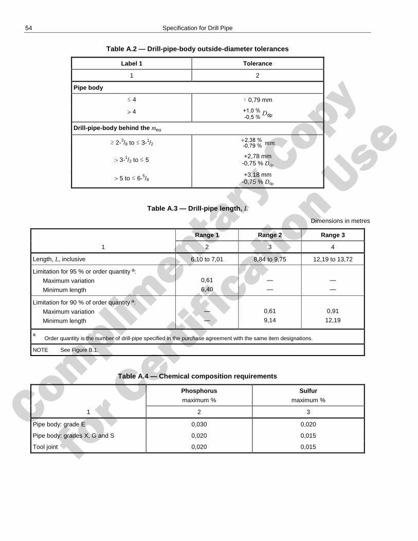
Complimenta
ry Copy
for C
ertific
ation Use
54 Specification for Drill Pipe
Table A.2 — Drill-pipe-body outside-diameter tolerances
Label 1 Tolerance
1 2
Pipe body
≤ 4 0,79 mm
4
Drill-pipe-body behind the meu
≥ 2-3/8 to ≤ 3-1/2
3-1/2 to ≤ 5 +2,78 mm
-0,75 % Ddp
5 to ≤ 6-5/8 +3,18 mm
-0,75 % Ddp
Table A.3 — Drill-pipe length, L
Dimensions in metres
Range 1 Range 2 Range 3
1 2 3 4
Length, L, inclusive 6,10 to 7,01 8,84 to 9,75 12,19 to 13,72
Limitation for 95 % or order quantity a:
Maximum variation
Minimum length
0,61
6,40
—
—
—
—
Limitation for 90 % of order quantity a:
Maximum variation
Minimum length
—
—
0,61
9,14
0,91
12,19
a Order quantity is the number of drill-pipe specified in the purchase agreement with the same item designations.
NOTE See Figure B.1.
Table A.4 — Chemical composition requirements
Phosphorus
maximum %
Sulfur
maximum %
1 2 3
Pipe body: grade E 0,030 0,020
Pipe body: grades X, G and S 0,020 0,015
Tool joint 0,020 0,015
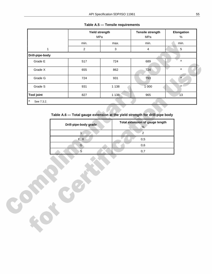
Complimenta
ry Copy
for C
ertific
ation Use
API Specification 5DP/ISO 11961 55
Table A.5 — Tensile requirements
Yield strength
MPa
Tensile strength
MPa
Elongation
%
min. max. min. min.
1 2 3 4 5
Drill-pipe-body
Grade E 517 724 689 a
Grade X 655 862 724 a
Grade G 724 931 793 a
Grade S 931 1 138 1 000 a
Tool joint 827 1 138 965 13
a See 7.3.2.
Table A.6 — Total gauge extension at the yield strength for drill-pipe body
Drill-pipe-body grade Total extension of gauge length
%
1 2
E, X 0,5
G 0,6
S 0,7
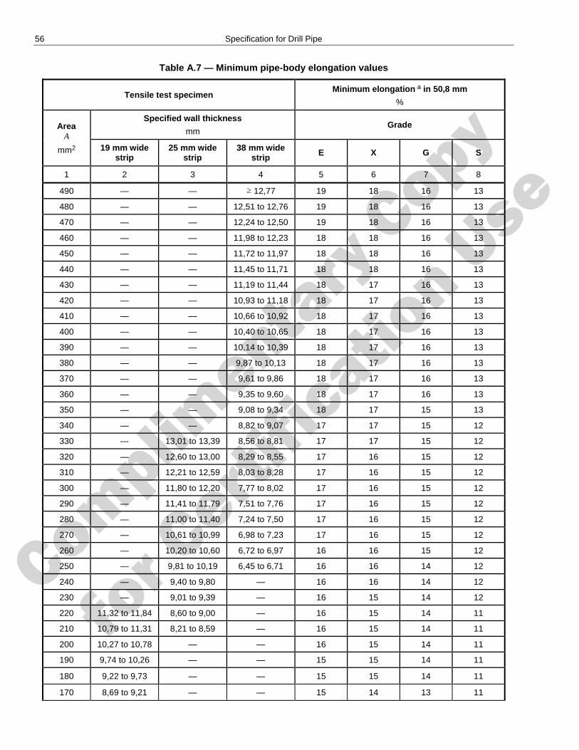
Complimenta
ry Copy
for C
ertific
ation Use
56 Specification for Drill Pipe
Table A.7 — Minimum pipe-body elongation values
Tensile test specimen Minimum elongation a in 50,8 mm
%
Area A
mm2
Specified wall thickness
mm Grade
19 mm wide strip
25 mm wide strip
38 mm wide strip E X G S
1 2 3 4 5 6 7 8
490 — — ≥ 12,77 19 18 16 13
480 — — 12,51 to 12,76 19 18 16 13
470 — — 12,24 to 12,50 19 18 16 13
460 — — 11,98 to 12,23 18 18 16 13
450 — — 11,72 to 11,97 18 18 16 13
440 — — 11,45 to 11,71 18 18 16 13
430 — — 11,19 to 11,44 18 17 16 13
420 — — 10,93 to 11,18 18 17 16 13
410 — — 10,66 to 10,92 18 17 16 13
400 — — 10,40 to 10,65 18 17 16 13
390 — — 10,14 to 10,39 18 17 16 13
380 — — 9,87 to 10,13 18 17 16 13
370 — — 9,61 to 9,86 18 17 16 13
360 — — 9,35 to 9,60 18 17 16 13
350 — — 9,08 to 9,34 18 17 15 13
340 — — 8,82 to 9,07 17 17 15 12
330 --- 13,01 to 13,39 8,56 to 8,81 17 17 15 12
320 — 12,60 to 13,00 8,29 to 8,55 17 16 15 12
310 — 12,21 to 12,59 8,03 to 8,28 17 16 15 12
300 — 11,80 to 12,20 7,77 to 8,02 17 16 15 12
290 — 11,41 to 11,79 7,51 to 7,76 17 16 15 12
280 — 11,00 to 11,40 7,24 to 7,50 17 16 15 12
270 — 10,61 to 10,99 6,98 to 7,23 17 16 15 12
260 — 10,20 to 10,60 6,72 to 6,97 16 16 15 12
250 — 9,81 to 10,19 6,45 to 6,71 16 16 14 12
240 — 9,40 to 9,80 — 16 16 14 12
230 — 9,01 to 9,39 — 16 15 14 12
220 11,32 to 11,84 8,60 to 9,00 — 16 15 14 11
210 10,79 to 11,31 8,21 to 8,59 — 16 15 14 11
200 10,27 to 10,78 — — 16 15 14 11
190 9,74 to 10,26 — — 15 15 14 11
180 9,22 to 9,73 — — 15 15 14 11
170 8,69 to 9,21 — — 15 14 13 11
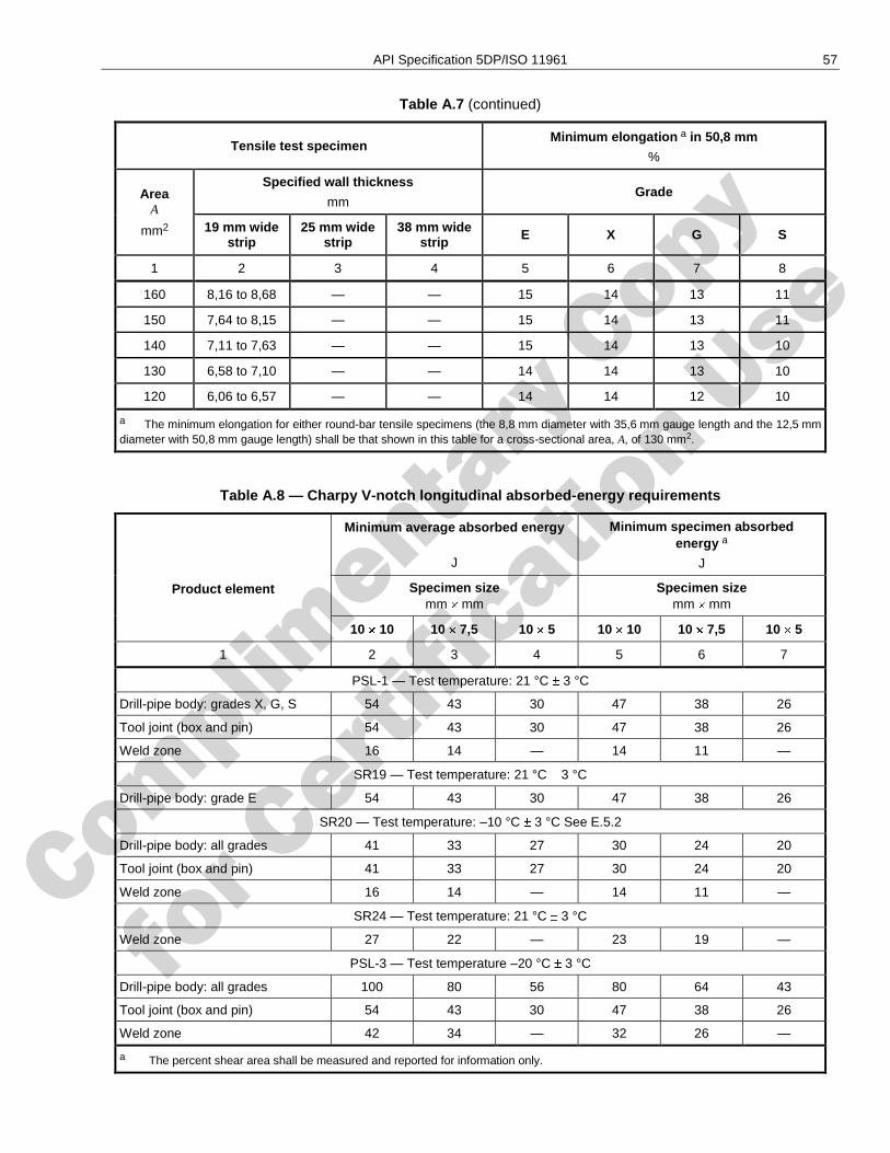
Complimenta
ry Copy
for C
ertific
ation Use
API Specification 5DP/ISO 11961 57
Table A.7 (continued)
Tensile test specimen Minimum elongation a in 50,8 mm
%
Area A
mm2
Specified wall thickness
mm Grade
19 mm wide strip
25 mm wide strip
38 mm wide strip E X G S
1 2 3 4 5 6 7 8
160 8,16 to 8,68 — — 15 14 13 11
150 7,64 to 8,15 — — 15 14 13 11
140 7,11 to 7,63 — — 15 14 13 10
130 6,58 to 7,10 — — 14 14 13 10
120 6,06 to 6,57 — — 14 14 12 10
a The minimum elongation for either round-bar tensile specimens (the 8,8 mm diameter with 35,6 mm gauge length and the 12,5 mm diameter with 50,8 mm gauge length) shall be that shown in this table for a cross-sectional area, A, of 130 mm2.
Table A.8 — Charpy V-notch longitudinal absorbed-energy requirements
Product element
Minimum average absorbed energy
J
Minimum specimen absorbed energy a
J
Specimen size mm mm
Specimen size mm mm
10 10 10 7,5 10 5 10 10 10 7,5 10 5
1 2 3 4 5 6 7
PSL-1 — Test temperature: 21 °C 3 °C
Drill-pipe body: grades X, G, S 54 43 30 47 38 26
Tool joint (box and pin) 54 43 30 47 38 26
Weld zone 16 14 — 14 11 —
SR19 — Test temperature: 21 °C 3 °C
Drill-pipe body: grade E 54 43 30 47 38 26
SR20 — Test temperature: –10 °C 3 °C See E.5.2
Drill-pipe body: all grades 41 33 27 30 24 20
Tool joint (box and pin) 41 33 27 30 24 20
Weld zone 16 14 — 14 11 —
SR24 — Test temperature: 21 °C 3 °C
Weld zone 27 22 — 23 19 —
PSL-3 — Test temperature –20 °C 3 °C
Drill-pipe body: all grades 100 80 56 80 64 43
Tool joint (box and pin) 54 43 30 47 38 26
Weld zone 42 34 — 32 26 —
a The percent shear area shall be measured and reported for information only.
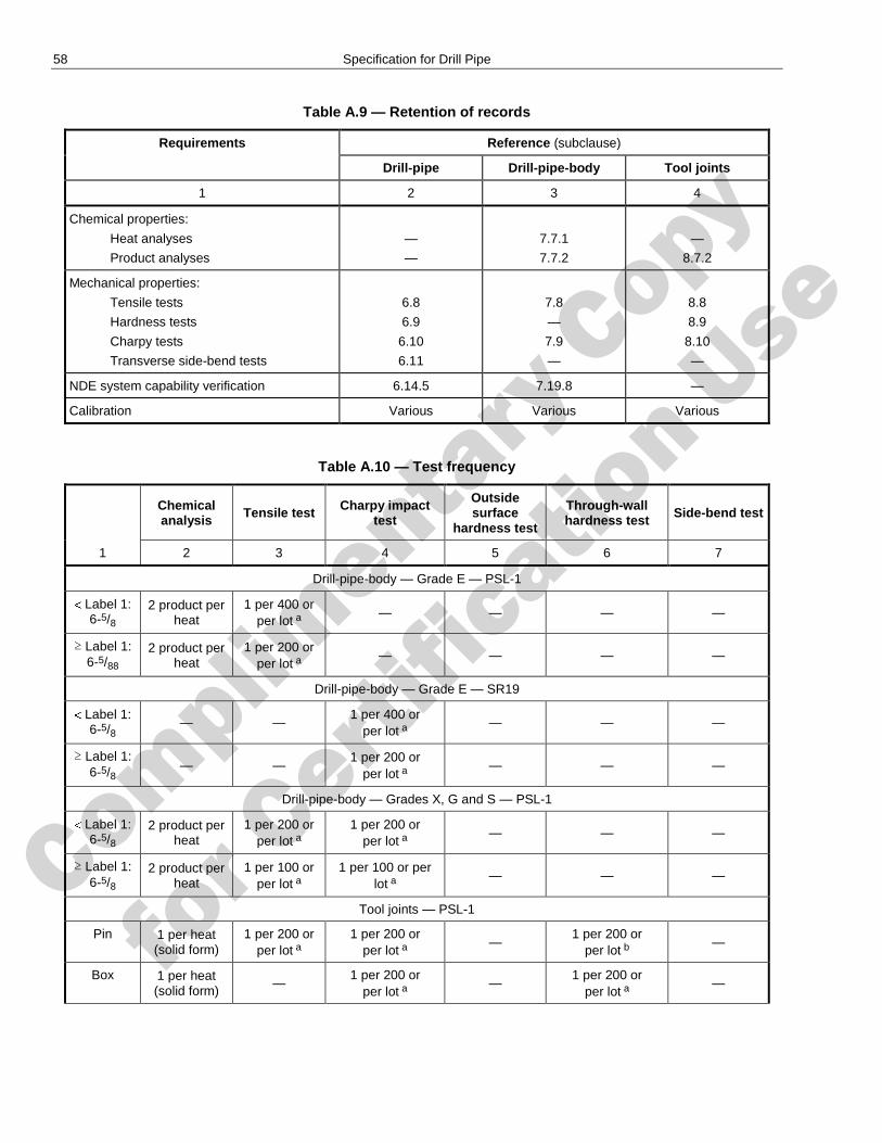
Complimenta
ry Copy
for C
ertific
ation Use
58 Specification for Drill Pipe
Table A.9 — Retention of records
Requirements Reference (subclause)
Drill-pipe Drill-pipe-body Tool joints
1 2 3 4
Chemical properties:
Heat analyses
Product analyses
—
—
7.7.1
7.7.2
—
8.7.2
Mechanical properties:
Tensile tests
Hardness tests
Charpy tests
Transverse side-bend tests
6.8
6.9
6.10
6.11
7.8
—
7.9
—
8.8
8.9
8.10
—
NDE system capability verification 6.14.5 7.19.8 —
Calibration Various Various Various
Table A.10 — Test frequency
Chemical analysis
Tensile test Charpy impact test
Outside surface
hardness test
Through-wall hardness test Side-bend test
1 2 3 4 5 6 7
Drill-pipe-body — Grade E — PSL-1
Label 1: 6-5/8
2 product per heat
1 per 400 or per lot a
— — — —
≥ Label 1: 6-5/88
2 product per heat
1 per 200 or per lot a
— — — —
Drill-pipe-body — Grade E — SR19
Label 1: 6-5/8 — —
1 per 400 or per lot a
— — —
≥ Label 1: 6-5/8 — —
1 per 200 or per lot a
— — —
Drill-pipe-body — Grades X, G and S — PSL-1
Label 1: 6-5/8
2 product per heat
1 per 200 or per lot a
1 per 200 or per lot a
— — —
≥ Label 1: 6-5/8
2 product per heat
1 per 100 or per lot a
1 per 100 or per lot a
— — —
Tool joints — PSL-1
Pin 1 per heat (solid form)
1 per 200 or per lot a
1 per 200 or per lot a
— 1 per 200 or
per lot b —
Box 1 per heat (solid form)
— 1 per 200 or
per lot a —
1 per 200 or per lot a
—
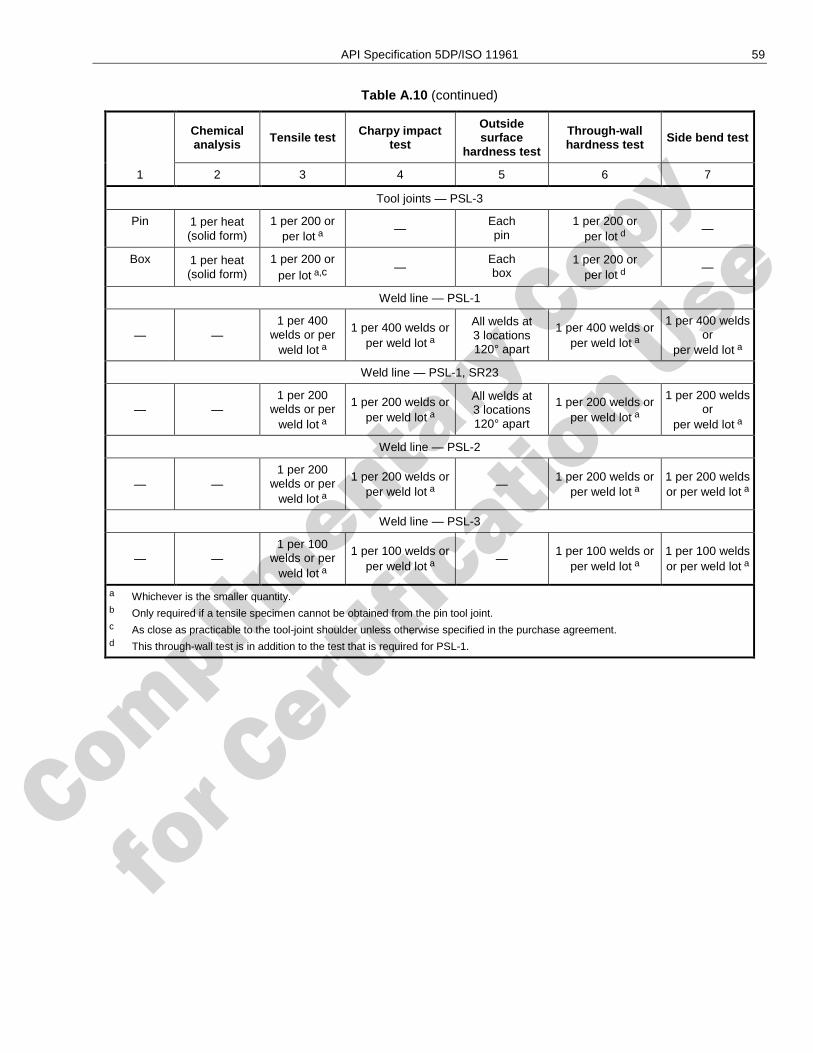
Complimenta
ry Copy
for C
ertific
ation Use
API Specification 5DP/ISO 11961 59
Table A.10 (continued)
Chemical analysis
Tensile test Charpy impact test
Outside surface
hardness test
Through-wall hardness test Side bend test
1 2 3 4 5 6 7
Tool joints — PSL-3
Pin 1 per heat (solid form)
1 per 200 or per lot a
— Each pin
1 per 200 or per lot d
—
Box 1 per heat (solid form)
1 per 200 or per lot a,c
— Each box
1 per 200 or per lot d
—
Weld line — PSL-1
— — 1 per 400
welds or per weld lot a
1 per 400 welds or per weld lot a
All welds at 3 locations 120° apart
1 per 400 welds or per weld lot a
1 per 400 welds or
per weld lot a
Weld line — PSL-1, SR23
— — 1 per 200
welds or per weld lot a
1 per 200 welds or per weld lot a
All welds at 3 locations 120° apart
1 per 200 welds or per weld lot a
1 per 200 welds or
per weld lot a
Weld line — PSL-2
— — 1 per 200
welds or per weld lot a
1 per 200 welds or per weld lot a
— 1 per 200 welds or
per weld lot a
1 per 200 welds or per weld lot a
Weld line — PSL-3
— — 1 per 100
welds or per weld lot a
1 per 100 welds or per weld lot a
— 1 per 100 welds or
per weld lot a
1 per 100 welds or per weld lot a
a Whichever is the smaller quantity. b Only required if a tensile specimen cannot be obtained from the pin tool joint. c As close as practicable to the tool-joint shoulder unless otherwise specified in the purchase agreement. d This through-wall test is in addition to the test that is required for PSL-1.
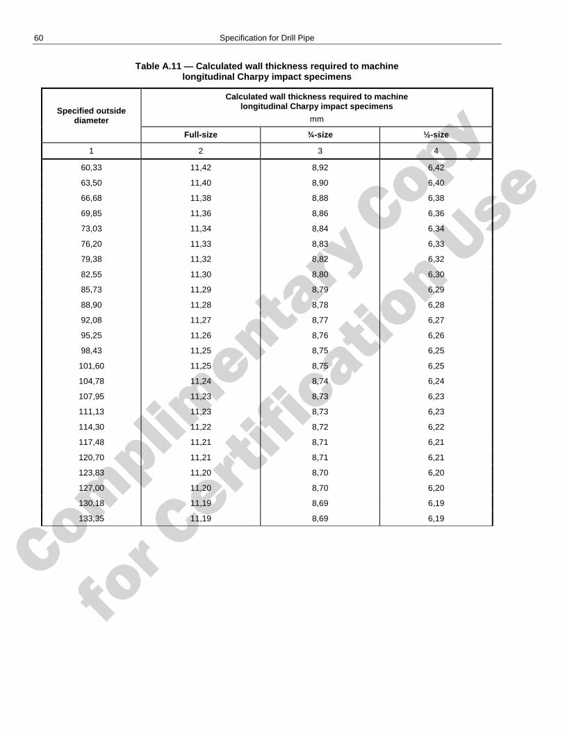
Complimenta
ry Copy
for C
ertific
ation Use
60 Specification for Drill Pipe
Table A.11 — Calculated wall thickness required to machine longitudinal Charpy impact specimens
Specified outside diameter
Calculated wall thickness required to machine longitudinal Charpy impact specimens
mm
Full-size ¾-size ½-size
1 2 3 4
60,33 11,42 8,92 6,42
63,50 11,40 8,90 6,40
66,68 11,38 8,88 6,38
69,85 11,36 8,86 6,36
73,03 11,34 8,84 6,34
76,20 11,33 8,83 6,33
79,38 11,32 8,82 6,32
82,55 11,30 8,80 6,30
85,73 11,29 8,79 6,29
88,90 11,28 8,78 6,28
92,08 11,27 8,77 6,27
95,25 11,26 8,76 6,26
98,43 11,25 8,75 6,25
101,60 11,25 8,75 6,25
104,78 11,24 8,74 6,24
107,95 11,23 8,73 6,23
111,13 11,23 8,73 6,23
114,30 11,22 8,72 6,22
117,48 11,21 8,71 6,21
120,70 11,21 8,71 6,21
123,83 11,20 8,70 6,20
127,00 11,20 8,70 6,20
130,18 11,19 8,69 6,19
133,35 11,19 8,69 6,19
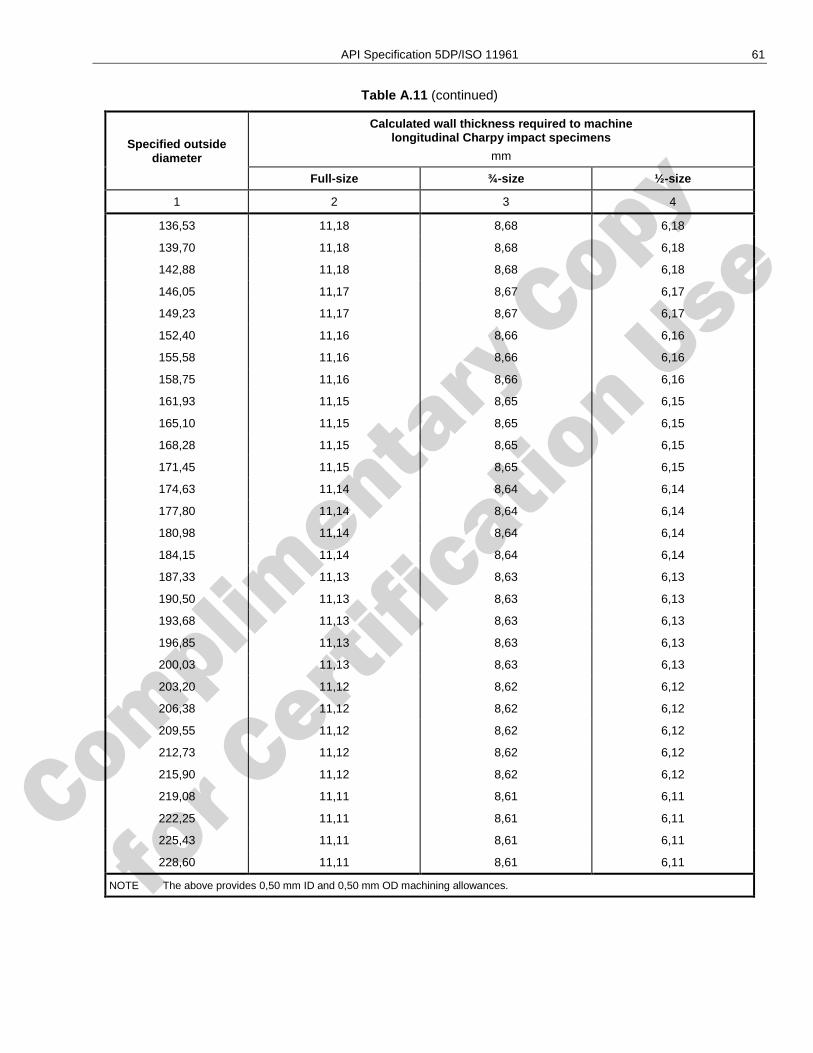
Complimenta
ry Copy
for C
ertific
ation Use
API Specification 5DP/ISO 11961 61
Table A.11 (continued)
Specified outside diameter
Calculated wall thickness required to machine longitudinal Charpy impact specimens
mm
Full-size ¾-size ½-size
1 2 3 4
136,53 11,18 8,68 6,18
139,70 11,18 8,68 6,18
142,88 11,18 8,68 6,18
146,05 11,17 8,67 6,17
149,23 11,17 8,67 6,17
152,40 11,16 8,66 6,16
155,58 11,16 8,66 6,16
158,75 11,16 8,66 6,16
161,93 11,15 8,65 6,15
165,10 11,15 8,65 6,15
168,28 11,15 8,65 6,15
171,45 11,15 8,65 6,15
174,63 11,14 8,64 6,14
177,80 11,14 8,64 6,14
180,98 11,14 8,64 6,14
184,15 11,14 8,64 6,14
187,33 11,13 8,63 6,13
190,50 11,13 8,63 6,13
193,68 11,13 8,63 6,13
196,85 11,13 8,63 6,13
200,03 11,13 8,63 6,13
203,20 11,12 8,62 6,12
206,38 11,12 8,62 6,12
209,55 11,12 8,62 6,12
212,73 11,12 8,62 6,12
215,90 11,12 8,62 6,12
219,08 11,11 8,61 6,11
222,25 11,11 8,61 6,11
225,43 11,11 8,61 6,11
228,60 11,11 8,61 6,11
NOTE The above provides 0,50 mm ID and 0,50 mm OD machining allowances.
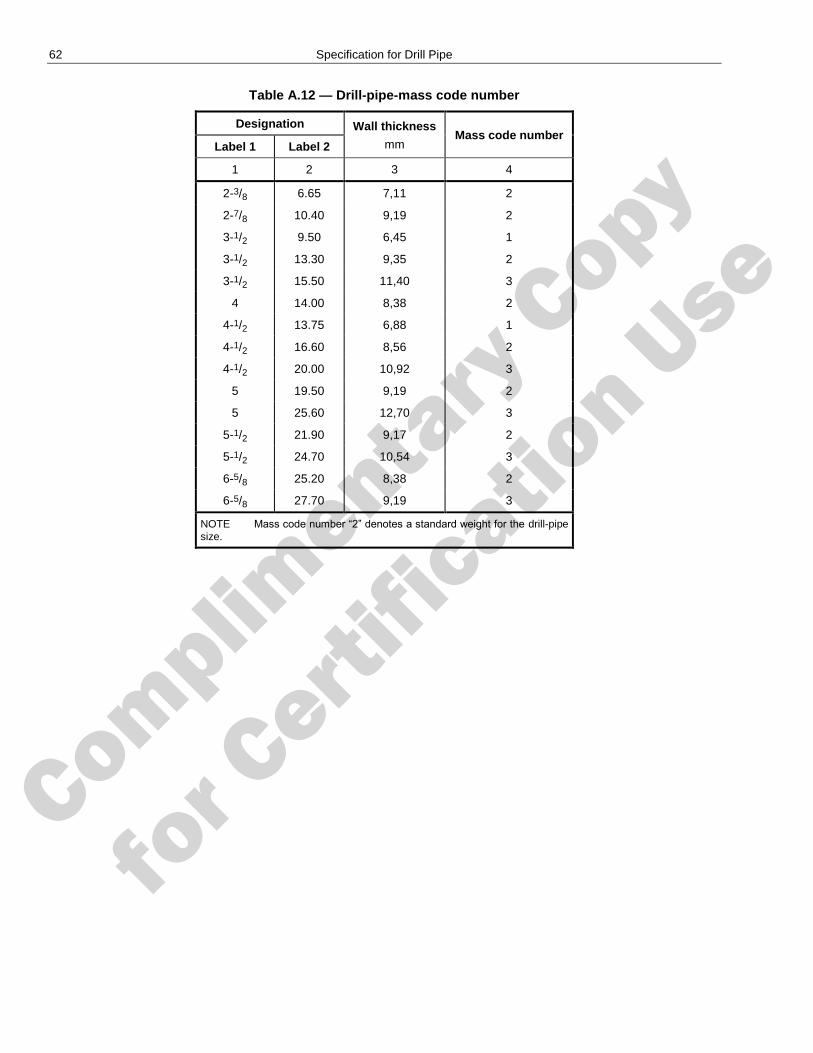
Complimenta
ry Copy
for C
ertific
ation Use
62 Specification for Drill Pipe
Table A.12 — Drill-pipe-mass code number
Designation Wall thickness
mm Mass code number
Label 1 Label 2
1 2 3 4
2-3/8 6.65 7,11 2
2-7/8 10.40 9,19 2
3-1/2 9.50 6,45 1
3-1/2 13.30 9,35 2
3-1/2 15.50 11,40 3
4 14.00 8,38 2
4-1/2 13.75 6,88 1
4-1/2 16.60 8,56 2
4-1/2 20.00 10,92 3
5 19.50 9,19 2
5 25.60 12,70 3
5-1/2 21.90 9,17 2
5-1/2 24.70 10,54 3
6-5/8 25.20 8,38 2
6-5/8 27.70 9,19 3
NOTE Mass code number ―2‖ denotes a standard weight for the drill-pipe size.
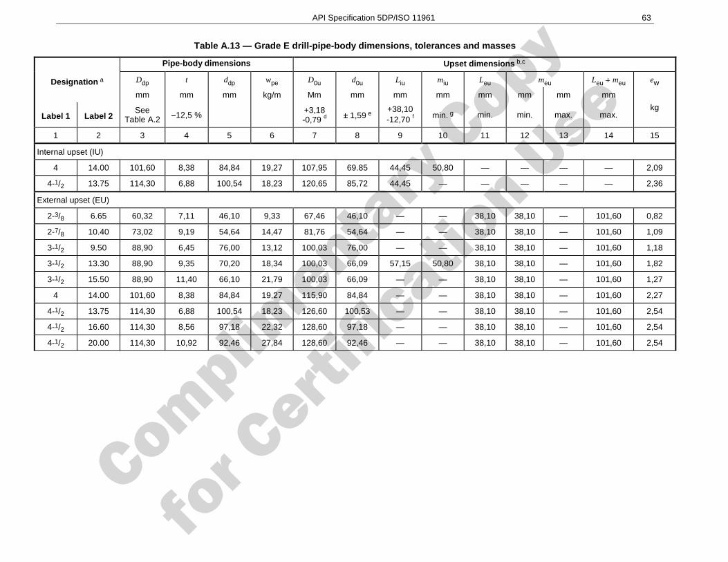
Complimenta
ry Copy
for C
ertific
ation Use
API Specification 5DP/ISO 11961 63
Table A.13 — Grade E drill-pipe-body dimensions, tolerances and masses
Designation a
Pipe-body dimensions Upset dimensions b,c
Ddp t ddp wpe D0u d0u Liu miu Leu meu Leu meu ew
mm mm mm kg/m Mm mm mm mm mm mm mm mm
kg Label 1 Label 2
See Table A.2 12,5 % +3,18
-0,79 d 1,59 e
+38,10 -12,70 f
min. g min. min. max. max.
1 2 3 4 5 6 7 8 9 10 11 12 13 14 15
Internal upset (IU)
4 14.00 101,60 8,38 84,84 19,27 107,95 69.85 44,45 50,80 — — — — 2,09
4-1/2 13.75 114,30 6,88 100,54 18,23 120,65 85,72 44,45 — — — — — 2,36
External upset (EU)
2-3/8 6.65 60,32 7,11 46,10 9,33 67,46 46,10 — — 38,10 38,10 — 101,60 0,82
2-7/8 10.40 73,02 9,19 54,64 14,47 81,76 54,64 — — 38,10 38,10 — 101,60 1,09
3-1/2 9.50 88,90 6,45 76,00 13,12 100,03 76,00 — — 38,10 38,10 — 101,60 1,18
3-1/2 13.30 88,90 9,35 70,20 18,34 100,03 66,09 57,15 50,80 38,10 38,10 — 101,60 1,82
3-1/2 15.50 88,90 11,40 66,10 21,79 100,03 66,09 — — 38,10 38,10 — 101,60 1,27
4 14.00 101,60 8,38 84,84 19,27 115,90 84,84 — — 38,10 38,10 — 101,60 2,27
4-1/2 13.75 114,30 6,88 100,54 18,23 126,60 100,53 — — 38,10 38,10 — 101,60 2,54
4-1/2 16.60 114,30 8,56 97,18 22,32 128,60 97,18 — — 38,10 38,10 — 101,60 2,54
4-1/2 20.00 114,30 10,92 92,46 27,84 128,60 92,46 — — 38,10 38,10 — 101,60 2,54
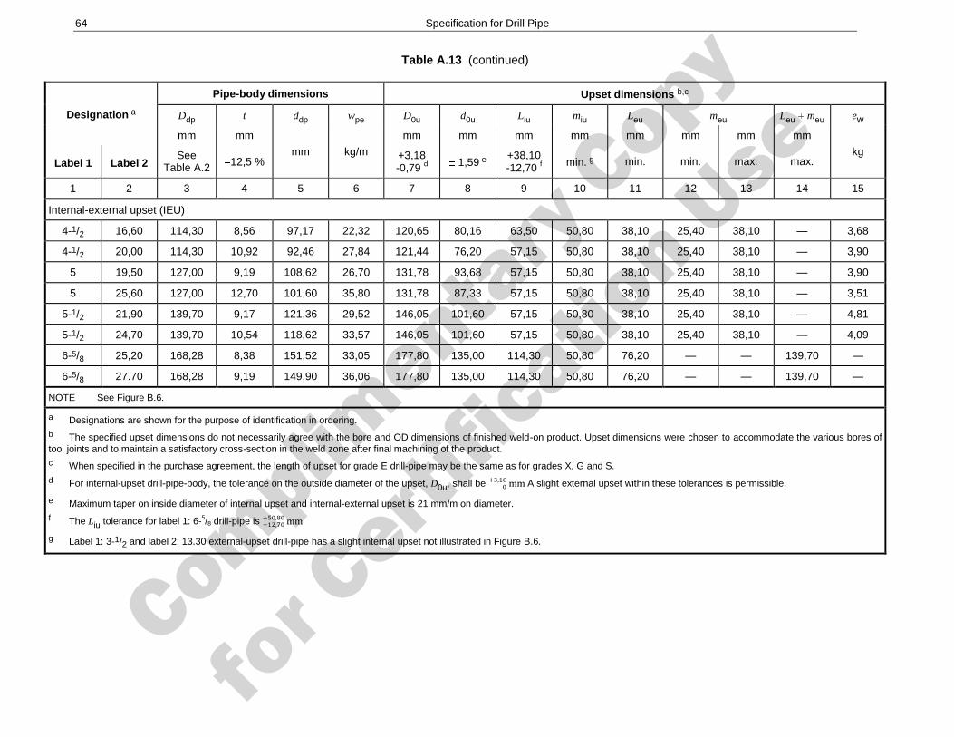
Complimenta
ry Copy
for C
ertific
ation Use
64 Specification for Drill Pipe
Table A.13 (continued)
Designation a
Pipe-body dimensions Upset dimensions b,c
Ddp t ddp wpe D0u d0u Liu miu Leu meu Leu meu ew
mm mm
mm kg/m
mm mm mm mm mm mm mm mm
kg Label 1 Label 2
See Table A.2 12,5 %
+3,18 -0,79 d
1,59 e +38,10 -12,70 f
min. g min. min. max. max.
1 2 3 4 5 6 7 8 9 10 11 12 13 14 15
Internal-external upset (IEU)
4-1/2 16,60 114,30 8,56 97,17 22,32 120,65 80,16 63,50 50,80 38,10 25,40 38,10 — 3,68
4-1/2 20,00 114,30 10,92 92,46 27,84 121,44 76,20 57,15 50,80 38,10 25,40 38,10 — 3,90
5 19,50 127,00 9,19 108,62 26,70 131,78 93,68 57,15 50,80 38,10 25,40 38,10 — 3,90
5 25,60 127,00 12,70 101,60 35,80 131,78 87,33 57,15 50,80 38,10 25,40 38,10 — 3,51
5-1/2 21,90 139,70 9,17 121,36 29,52 146,05 101,60 57,15 50,80 38,10 25,40 38,10 — 4,81
5-1/2 24,70 139,70 10,54 118,62 33,57 146,05 101,60 57,15 50,80 38,10 25,40 38,10 — 4,09
6-5/8 25,20 168,28 8,38 151,52 33,05 177,80 135,00 114,30 50,80 76,20 — — 139,70 —
6-5/8 27.70 168,28 9,19 149,90 36,06 177,80 135,00 114,30 50,80 76,20 — — 139,70 —
NOTE See Figure B.6.
a Designations are shown for the purpose of identification in ordering. b The specified upset dimensions do not necessarily agree with the bore and OD dimensions of finished weld-on product. Upset dimensions were chosen to accommodate the various bores of tool joints and to maintain a satisfactory cross-section in the weld zone after final machining of the product. c When specified in the purchase agreement, the length of upset for grade E drill-pipe may be the same as for grades X, G and S. d For internal-upset drill-pipe-body, the tolerance on the outside diameter of the upset, D0u, shall be A slight external upset within these tolerances is permissible.
e Maximum taper on inside diameter of internal upset and internal-external upset is 21 mm/m on diameter. f The Liu tolerance for label 1: 6-5/8 drill-pipe is
g Label 1: 3-1/2 and label 2: 13.30 external-upset drill-pipe has a slight internal upset not illustrated in Figure B.6.
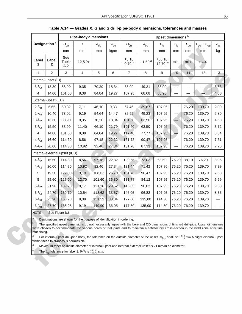
Complimenta
ry Copy
for C
ertific
ation Use
API Specification 5DP/ISO 11961 65
Table A.14 — Grades X, G and S drill-pipe-body dimensions, tolerances and masses
Designation a
Pipe-body dimensions Upset dimensions b
Ddp t ddp wpe D0u d0u Liu miu Leu Leu meu ew
mm mm mm kg/m mm mm mm mm mm mm kg
Label 1
Label 2
See Table A.2
12,5 % +3,18
-0,79 c 1,59 d
+38,10 -12,70 e
min. min. max.
1 2 3 4 5 6 7 8 9 10 11 12 13
Internal-upset (IU)
3-1/2 13.30 88,90 9,35 70,20 18,34 88,90 49,21 88,90 — — — 3,36
4 14.00 101,60 8,38 84,84 19,27 107,95 68,68 88,90 — — — 4,00
External-upset (EU)
2-3/8 6.65 60,32 7,11 46,10 9,33 67,46 39,67 107,95 — 76,20 139,70 2,09
2-7/8 10.40 73,02 9,19 54,64 14,47 82,55 49,23 107,95 — 76,20 139,70 2,80
3-1/2 13.30 88,90 9,35 70,20 18,34 101,60 63,50 107,95 — 76,20 139,70 4,63
3-1/2 15.50 88,90 11,40 66,10 21,79 101,60 63,50 107,95 — 76,20 139,70 3,72
4 14.00 101,60 8,38 84,84 19,27 117,48 77,77 107,95 — 76,20 139,70 6,54
4-1/2 16.60 114,30 8,56 97,18 22,32 131,78 90,47 107,95 — 76,20 139,70 7,81
4-1/2 20.00 114,30 10,92 92,46 27,84 131,78 87,33 107,95 — 76,20 139,70 7,26
Internal-external upset (IEU)
4-1/2 16.60 114,30 8,56 97,18 22,32 120,65 73,02 63,50 76,20 38,10 76,20 3,95
4-1/2 20.00 114,30 10,92 92,46 27,84 121,44 71,42 107,95 76,20 76,20 139,70 7,99
5 19.50 127,00 9,19 108,62 26,70 131,78 90,47 107,95 76,20 76,20 139,70 7,63
5 25.60 127,00 12,70 101,60 35,80 131,78 84,12 107,95 76,20 76,20 139,70 6,99
5-1/2 21.90 139,70 9,17 121,36 29,52 146,05 96,82 107,95 76,20 76,20 139,70 9,53
5-1/2 24.70 139,70 10,54 118,62 33,57 146,05 96,82 107,95 76,20 76,20 139,70 8,35
6-5/8 25.20 168,28 8,38 151,52 33,04 177,80 135,00 114,30 76,20 76,20 139,70 —
6-5/8 27.70 168,28 9,19 149,90 36,05 177,80 135,00 114,30 76,20 76,20 139,70 —
NOTE See Figure B.6.
a Designations are shown for the purpose of identification in ordering. b The specified upset dimensions do not necessarily agree with the bore and OD dimensions of finished drill-pipe. Upset dimensions were chosen to accommodate the various bores of tool joints and to maintain a satisfactory cross-section in the weld zone after final machining. c For internal-upset drill-pipe body, the tolerance on the outside diameter of the upset, D0u, shall be A slight external upset within these tolerances is permissible. d Maximum taper on inside diameter of internal upset and internal-external upset is 21 mm/m on diameter. e The Liu tolerance for label 1: 6-5/8 is .
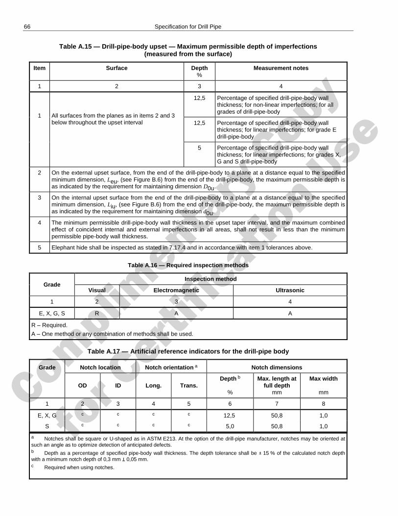
Complimenta
ry Copy
for C
ertific
ation Use
66 Specification for Drill Pipe
Table A.15 — Drill-pipe-body upset — Maximum permissible depth of imperfections (measured from the surface)
Item Surface Depth %
Measurement notes
1 2 3 4
1 All surfaces from the planes as in items 2 and 3 below throughout the upset interval
12,5 Percentage of specified drill-pipe-body wall thickness; for non-linear imperfections; for all grades of drill-pipe-body
12,5 Percentage of specified drill-pipe-body wall thickness; for linear imperfections; for grade E drill-pipe-body
5 Percentage of specified drill-pipe-body wall thickness; for linear imperfections; for grades X, G and S drill-pipe-body
2 On the external upset surface, from the end of the drill-pipe-body to a plane at a distance equal to the specified minimum dimension, Leu, (see Figure B.6) from the end of the drill-pipe-body, the maximum permissible depth is as indicated by the requirement for maintaining dimension D0u.
3 On the internal upset surface from the end of the drill-pipe-body to a plane at a distance equal to the specified minimum dimension, Liu, (see Figure B.6) from the end of the drill-pipe-body, the maximum permissible depth is as indicated by the requirement for maintaining dimension d0u.
4 The minimum permissible drill-pipe-body wall thickness in the upset taper interval, and the maximum combined effect of coincident internal and external imperfections in all areas, shall not result in less than the minimum permissible pipe-body wall thickness.
5 Elephant hide shall be inspected as stated in 7.17.4 and in accordance with item 1 tolerances above.
Table A.16 — Required inspection methods
Grade Inspection method
Visual Electromagnetic Ultrasonic
1 2 3 4
E, X, G, S R A A
R – Required.
A – One method or any combination of methods shall be used.
Table A.17 — Artificial reference indicators for the drill-pipe body
Grade Notch location Notch orientation a Notch dimensions
OD ID Long. Trans. Depth b
%
Max. length at full depth
mm
Max width
mm
1 2 3 4 5 6 7 8
E, X, G c c c c 12,5 50,8 1,0
S c c c c 5,0 50,8 1,0
a Notches shall be square or U-shaped as in ASTM E213. At the option of the drill-pipe manufacturer, notches may be oriented at such an angle as to optimize detection of anticipated defects. b Depth as a percentage of specified pipe-body wall thickness. The depth tolerance shall be 15 % of the calculated notch depth with a minimum notch depth of 0,3 mm 0,05 mm. c Required when using notches.
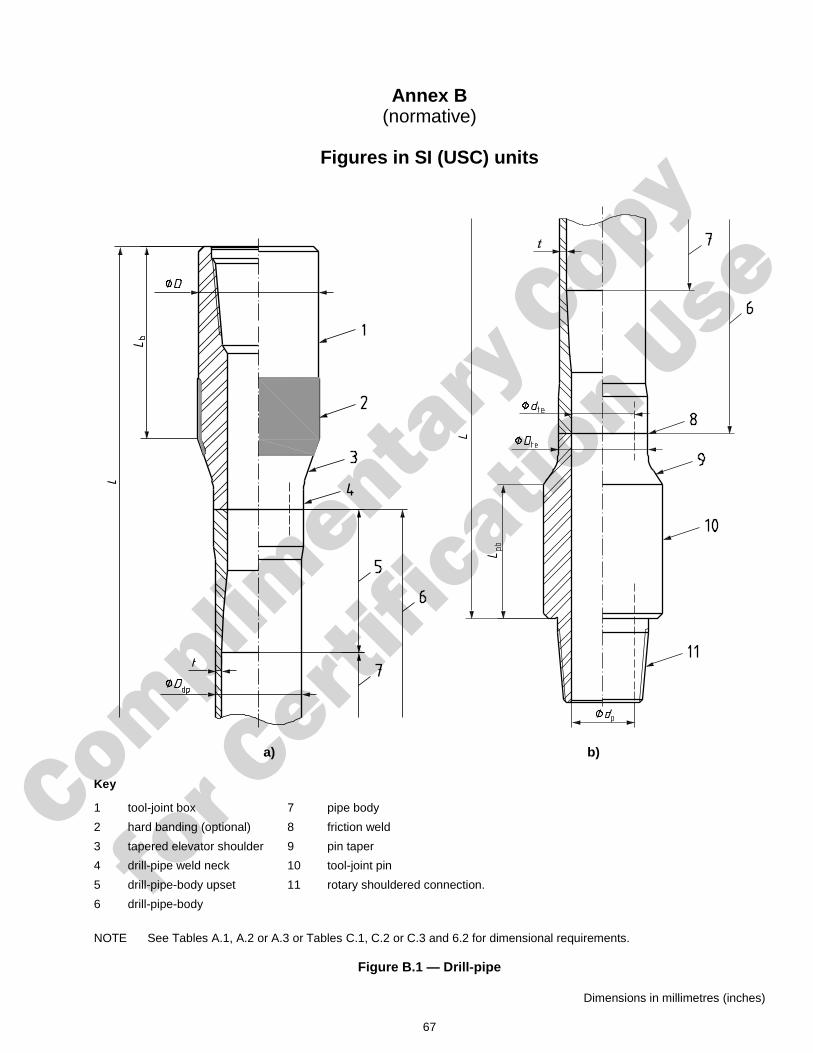
Complimenta
ry Copy
for C
ertific
ation Use
67
Annex B (normative)
Figures in SI (USC) units
a) b)
Key
1 tool-joint box 7 pipe body
2 hard banding (optional) 8 friction weld
3 tapered elevator shoulder 9 pin taper
4 drill-pipe weld neck 10 tool-joint pin
5 drill-pipe-body upset 11 rotary shouldered connection.
6 drill-pipe-body
NOTE See Tables A.1, A.2 or A.3 or Tables C.1, C.2 or C.3 and 6.2 for dimensional requirements.
Figure B.1 — Drill-pipe
Dimensions in millimetres (inches)
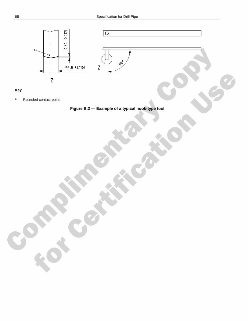
Complimenta
ry Copy
for C
ertific
ation Use
68 Specification for Drill Pipe
Key
a Rounded contact point.
Figure B.2 — Example of a typical hook-type tool
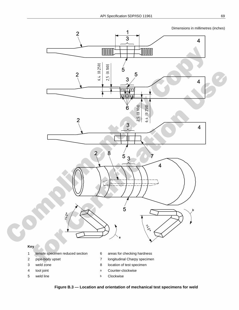
Complimenta
ry Copy
for C
ertific
ation Use
API Specification 5DP/ISO 11961 69
Dimensions in millimetres (inches)
Key
1 tensile specimen reduced section 6 areas for checking hardness
2 pipe-body upset 7 longitudinal Charpy specimen
3 weld zone 8 location of test specimen
4 tool joint a Counter-clockwise
5 weld line b Clockwise
Figure B.3 — Location and orientation of mechanical test specimens for weld
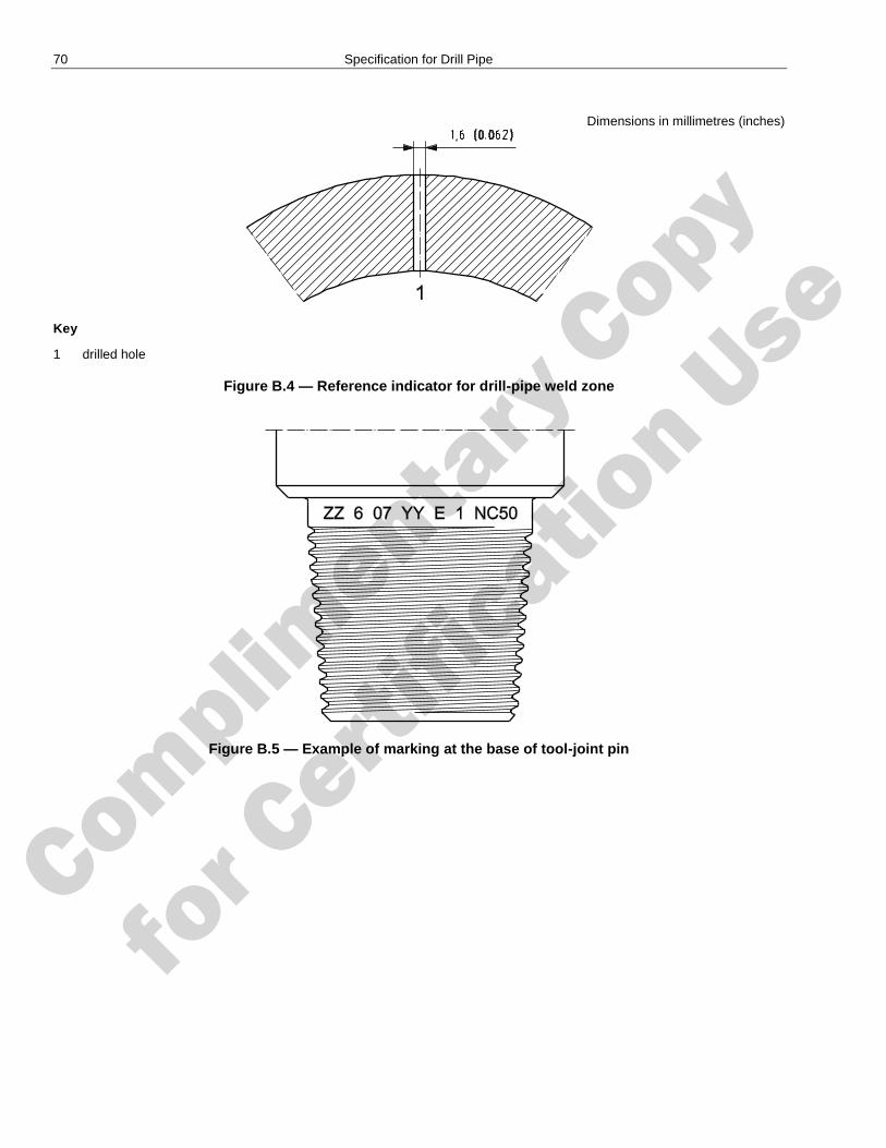
Complimenta
ry Copy
for C
ertific
ation Use
70 Specification for Drill Pipe
Dimensions in millimetres (inches)
Key
1 drilled hole
Figure B.4 — Reference indicator for drill-pipe weld zone
Figure B.5 — Example of marking at the base of tool-joint pin
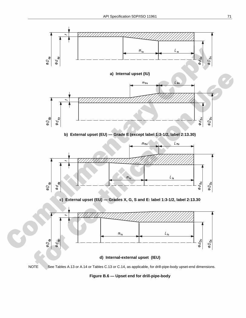
Complimenta
ry Copy
for C
ertific
ation Use
API Specification 5DP/ISO 11961 71
a) Internal upset (IU)
b) External upset (EU) — Grade E (except label 1:3-1/2, label 2:13.30)
c) External upset (EU) — Grades X, G, S and E: label 1:3-1/2, label 2:13.30
d) Internal-external upset (IEU)
NOTE See Tables A.13 or A.14 or Tables C.13 or C.14, as applicable, for drill-pipe-body upset-end dimensions.
Figure B.6 — Upset end for drill-pipe-body
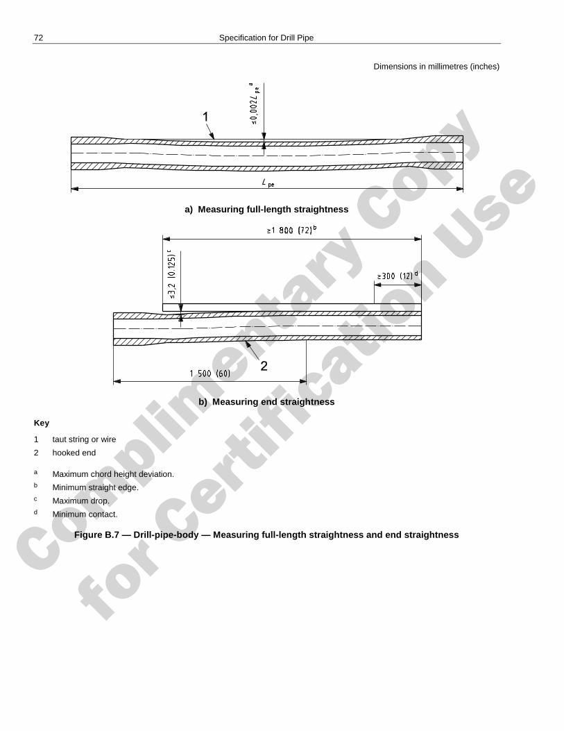
Complimenta
ry Copy
for C
ertific
ation Use
72 Specification for Drill Pipe
Dimensions in millimetres (inches)
a) Measuring full-length straightness
b) Measuring end straightness
Key
1 taut string or wire
2 hooked end
a Maximum chord height deviation. b Minimum straight edge. c Maximum drop. d Minimum contact.
Figure B.7 — Drill-pipe-body — Measuring full-length straightness and end straightness
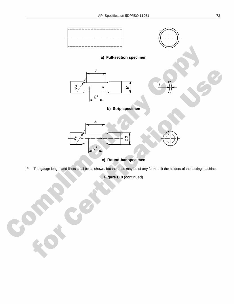
Complimenta
ry Copy
for C
ertific
ation Use
API Specification 5DP/ISO 11961 73
a) Full-section specimen
b) Strip specimen
c) Round-bar specimen
a The gauge length and fillets shall be as shown, but the ends may be of any form to fit the holders of the testing machine.
Figure B.8 (continued)
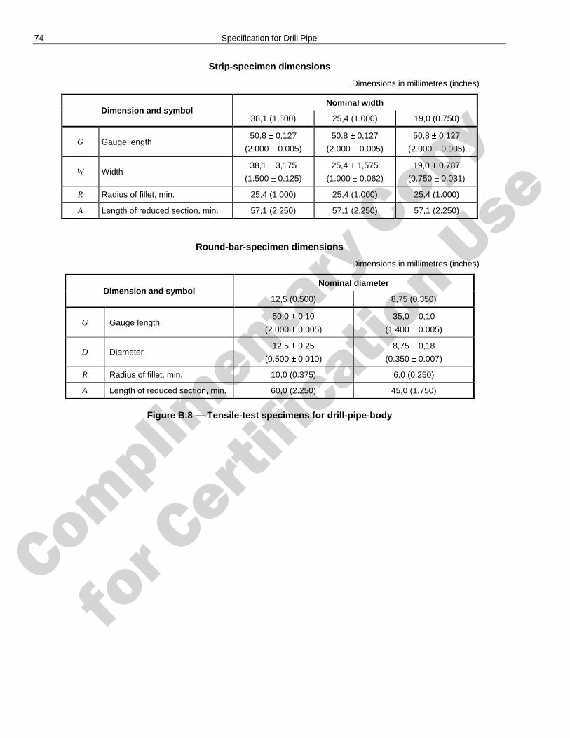
Complimenta
ry Copy
for C
ertific
ation Use
74 Specification for Drill Pipe
Strip-specimen dimensions
Dimensions in millimetres (inches)
Dimension and symbol Nominal width
38,1 (1.500) 25,4 (1.000) 19,0 (0.750)
G Gauge length 50,8 0,127
(2.000 0.005)
50,8 0,127
(2.000 0.005)
50,8 0,127
(2.000 0.005)
W Width 38,1 3,175
(1.500 0.125)
25,4 1,575
(1.000 0.062)
19,0 0,787
(0.750 0.031)
R Radius of fillet, min. 25,4 (1.000) 25,4 (1.000) 25,4 (1.000)
A Length of reduced section, min. 57,1 (2.250) 57,1 (2.250) 57,1 (2.250)
Round-bar-specimen dimensions
Dimensions in millimetres (inches)
Dimension and symbol Nominal diameter
12,5 (0.500) 8,75 (0.350)
G Gauge length 50,0 0,10
(2.000 0.005)
35,0 0,10
(1.400 0.005)
D Diameter 12,5 0,25
(0.500 0.010)
8,75 0,18
(0.350 0.007)
R Radius of fillet, min. 10,0 (0.375) 6,0 (0.250)
A Length of reduced section, min. 60,0 (2.250) 45,0 (1.750)
Figure B.8 — Tensile-test specimens for drill-pipe-body
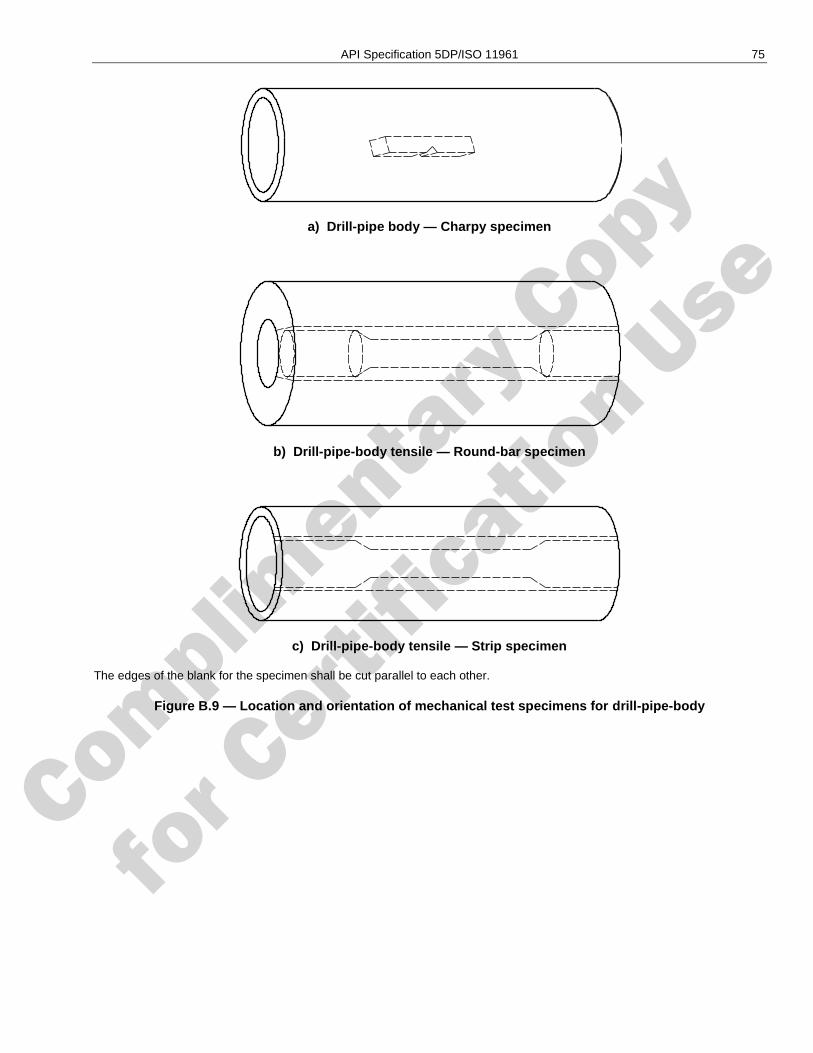
Complimenta
ry Copy
for C
ertific
ation Use
API Specification 5DP/ISO 11961 75
a) Drill-pipe body — Charpy specimen
b) Drill-pipe-body tensile — Round-bar specimen
c) Drill-pipe-body tensile — Strip specimen
The edges of the blank for the specimen shall be cut parallel to each other.
Figure B.9 — Location and orientation of mechanical test specimens for drill-pipe-body
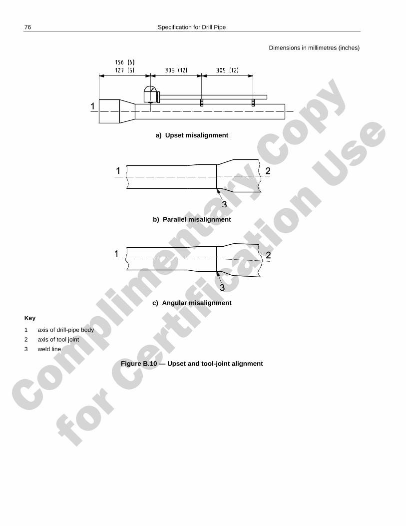
Complimenta
ry Copy
for C
ertific
ation Use
76 Specification for Drill Pipe
Dimensions in millimetres (inches)
a) Upset misalignment
b) Parallel misalignment
c) Angular misalignment
Key
1 axis of drill-pipe body
2 axis of tool joint
3 weld line
Figure B.10 — Upset and tool-joint alignment
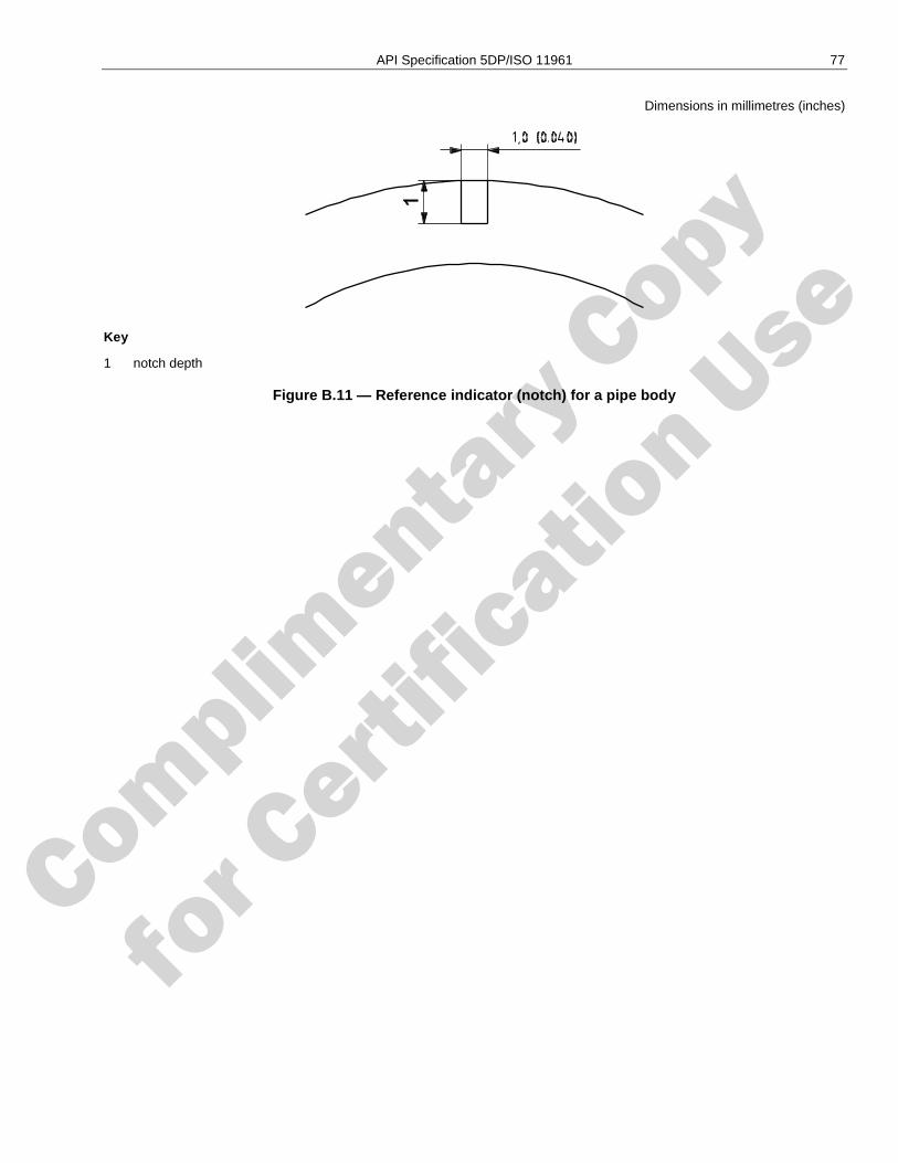
Complimenta
ry Copy
for C
ertific
ation Use
API Specification 5DP/ISO 11961 77
Dimensions in millimetres (inches)
Key
1 notch depth
Figure B.11 — Reference indicator (notch) for a pipe body
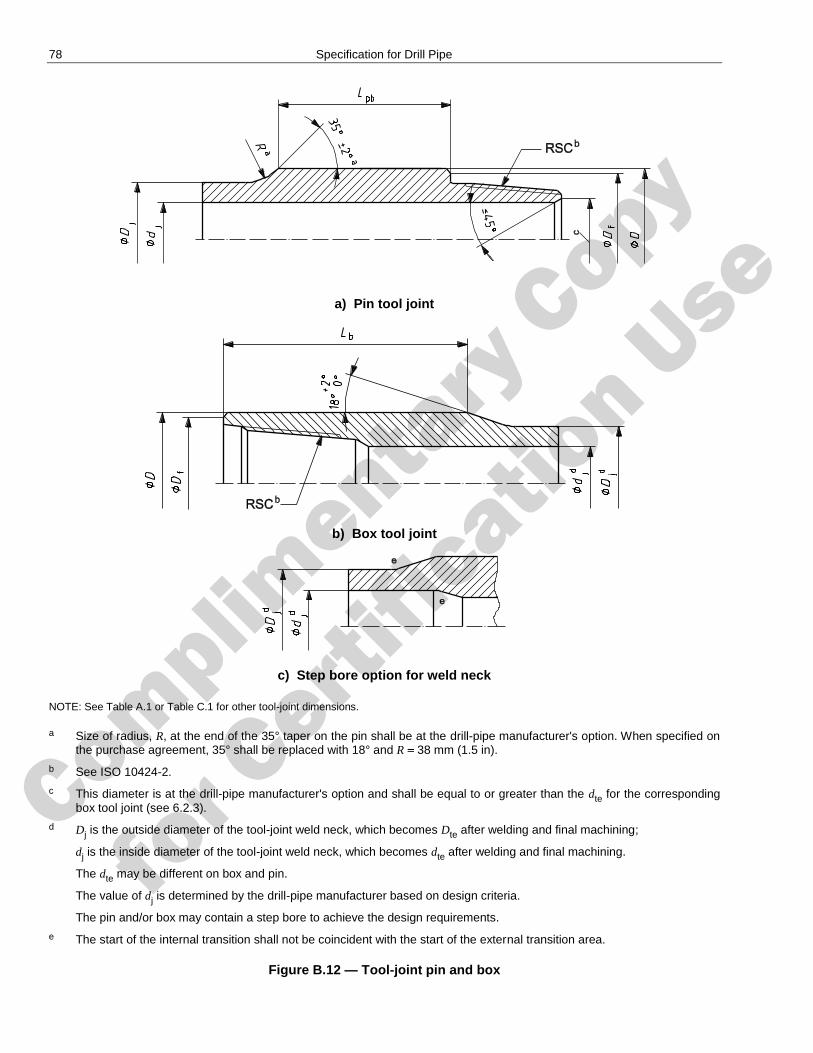
Complimenta
ry Copy
for C
ertific
ation Use
78 Specification for Drill Pipe
a) Pin tool joint
b) Box tool joint
c) Step bore option for weld neck
NOTE: See Table A.1 or Table C.1 for other tool-joint dimensions.
a Size of radius, R, at the end of the 35° taper on the pin shall be at the drill-pipe manufacturer's option. When specified on the purchase agreement, 35° shall be replaced with 18° and R 38 mm (1.5 in).
b See ISO 10424-2.
c This diameter is at the drill-pipe manufacturer's option and shall be equal to or greater than the dte for the corresponding box tool joint (see 6.2.3).
d Dj is the outside diameter of the tool-joint weld neck, which becomes Dte after welding and final machining;
dj is the inside diameter of the tool-joint weld neck, which becomes dte after welding and final machining.
The dte may be different on box and pin.
The value of dj is determined by the drill-pipe manufacturer based on design criteria.
The pin and/or box may contain a step bore to achieve the design requirements.
e The start of the internal transition shall not be coincident with the start of the external transition area.
Figure B.12 — Tool-joint pin and box
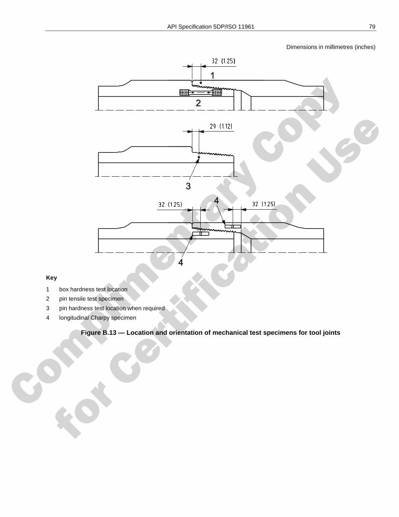
Complimenta
ry Copy
for C
ertific
ation Use
API Specification 5DP/ISO 11961 79
Dimensions in millimetres (inches)
Key
1 box hardness test location
2 pin tensile test specimen
3 pin hardness test location when required
4 longitudinal Charpy specimen
Figure B.13 — Location and orientation of mechanical test specimens for tool joints
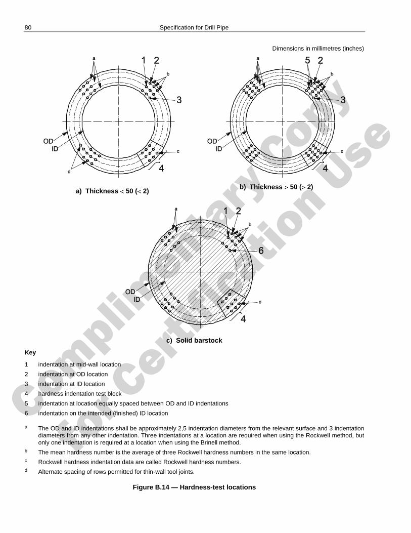
Complimenta
ry Copy
for C
ertific
ation Use
80 Specification for Drill Pipe
Dimensions in millimetres (inches)
a) Thickness 50 ( 2)
b) Thickness 50 ( 2)
c) Solid barstock
Key
1 indentation at mid-wall location
2 indentation at OD location
3 indentation at ID location
4 hardness indentation test block
5 indentation at location equally spaced between OD and ID indentations
6 indentation on the intended (finished) ID location
a The OD and ID indentations shall be approximately 2,5 indentation diameters from the relevant surface and 3 indentation diameters from any other indentation. Three indentations at a location are required when using the Rockwell method, but only one indentation is required at a location when using the Brinell method.
b The mean hardness number is the average of three Rockwell hardness numbers in the same location. c Rockwell hardness indentation data are called Rockwell hardness numbers. d Alternate spacing of rows permitted for thin-wall tool joints.
Figure B.14 — Hardness-test locations
Complimenta
ry Copy
for C
ertific
ation Use
81
Annex C (normative)
Tables in USC units
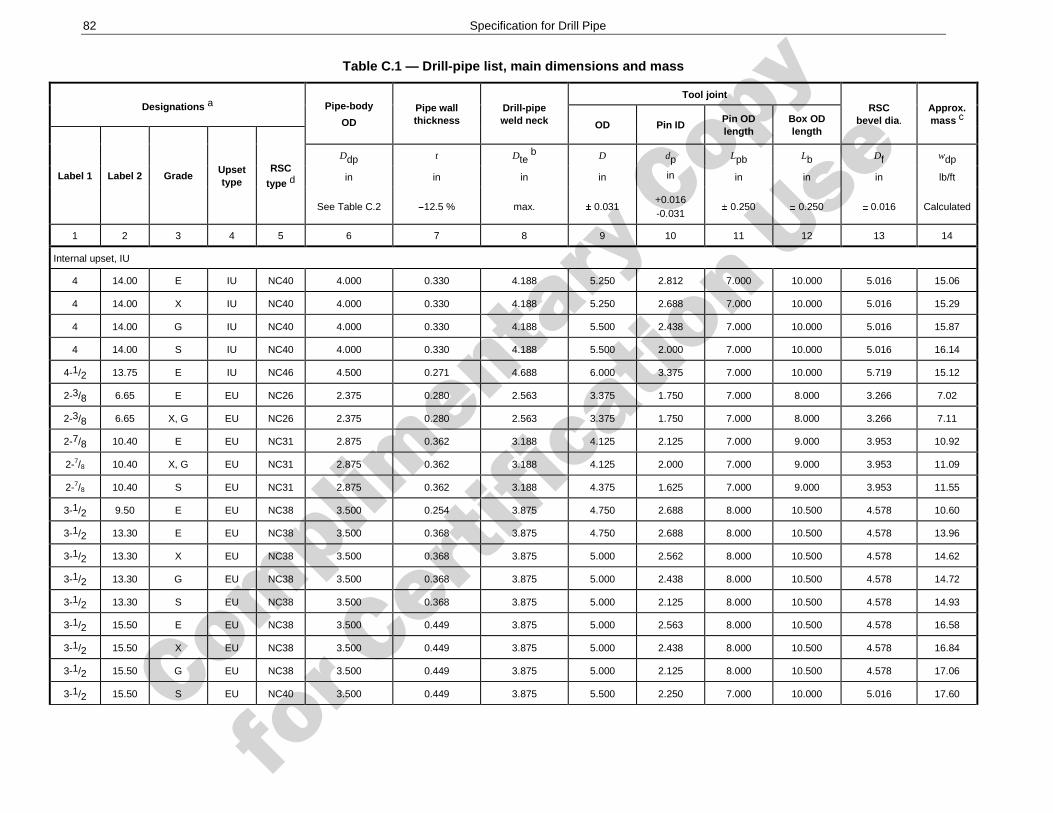
Complimenta
ry Copy
for C
ertific
ation Use
82 Specification for Drill Pipe
Table C.1 — Drill-pipe list, main dimensions and mass
Designations a Pipe-body
OD
Pipe wall thickness
Drill-pipe weld neck
Tool joint RSC
bevel dia. Approx. mass c OD Pin ID
Pin OD length
Box OD length
Label 1 Label 2 Grade Upset type
RSC
type d
Ddp t Dte b D dp Lpb Lb Df wdp
in in in in in in in in lb/ft
See Table C.2 12.5 % max. 0.031 +0.016 -0.031
0.250 0.250 0.016 Calculated
1 2 3 4 5 6 7 8 9 10 11 12 13 14
Internal upset, IU
4 14.00 E IU NC40 4.000 0.330 4.188 5.250 2.812 7.000 10.000 5.016 15.06
4 14.00 X IU NC40 4.000 0.330 4.188 5.250 2.688 7.000 10.000 5.016 15.29
4 14.00 G IU NC40 4.000 0.330 4.188 5.500 2.438 7.000 10.000 5.016 15.87
4 14.00 S IU NC40 4.000 0.330 4.188 5.500 2.000 7.000 10.000 5.016 16.14
4-1/2 13.75 E IU NC46 4.500 0.271 4.688 6.000 3.375 7.000 10.000 5.719 15.12
2-3/8 6.65 E EU NC26 2.375 0.280 2.563 3.375 1.750 7.000 8.000 3.266 7.02
2-3/8 6.65 X, G EU NC26 2.375 0.280 2.563 3.375 1.750 7.000 8.000 3.266 7.11
2-7/8 10.40 E EU NC31 2.875 0.362 3.188 4.125 2.125 7.000 9.000 3.953 10.92
2-7/8 10.40 X, G EU NC31 2.875 0.362 3.188 4.125 2.000 7.000 9.000 3.953 11.09
2-7/8 10.40 S EU NC31 2.875 0.362 3.188 4.375 1.625 7.000 9.000 3.953 11.55
3-1/2 9.50 E EU NC38 3.500 0.254 3.875 4.750 2.688 8.000 10.500 4.578 10.60
3-1/2 13.30 E EU NC38 3.500 0.368 3.875 4.750 2.688 8.000 10.500 4.578 13.96
3-1/2 13.30 X EU NC38 3.500 0.368 3.875 5.000 2.562 8.000 10.500 4.578 14.62
3-1/2 13.30 G EU NC38 3.500 0.368 3.875 5.000 2.438 8.000 10.500 4.578 14.72
3-1/2 13.30 S EU NC38 3.500 0.368 3.875 5.000 2.125 8.000 10.500 4.578 14.93
3-1/2 15.50 E EU NC38 3.500 0.449 3.875 5.000 2.563 8.000 10.500 4.578 16.58
3-1/2 15.50 X EU NC38 3.500 0.449 3.875 5.000 2.438 8.000 10.500 4.578 16.84
3-1/2 15.50 G EU NC38 3.500 0.449 3.875 5.000 2.125 8.000 10.500 4.578 17.06
3-1/2 15.50 S EU NC40 3.500 0.449 3.875 5.500 2.250 7.000 10.000 5.016 17.60
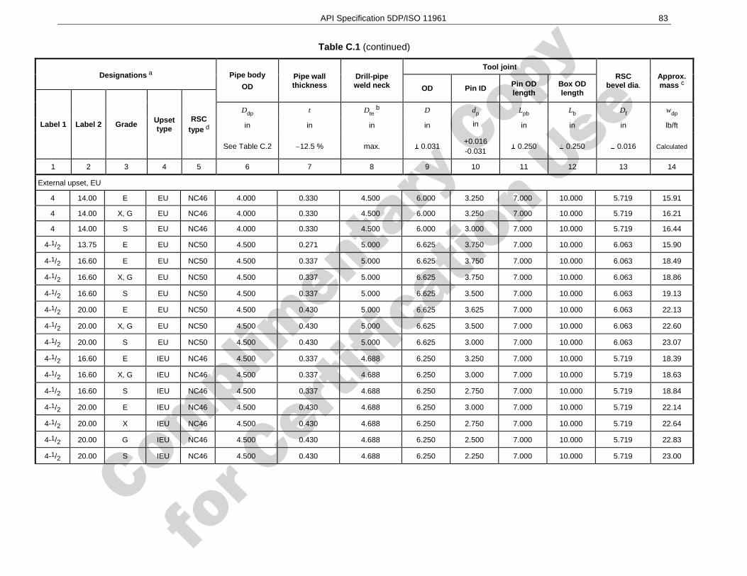
Complimenta
ry Copy
for C
ertific
ation Use
API Specification 5DP/ISO 11961 83
Table C.1 (continued)
Designations a Pipe body
OD Pipe wall thickness
Drill-pipe weld neck
Tool joint RSC
bevel dia. Approx. mass c OD Pin ID
Pin OD length
Box OD length
Label 1 Label 2 Grade Upset type
RSC type d
Ddp t Dte b D dp Lpb Lb Df wdp
in in in in in in in in lb/ft
See Table C.2 12.5 % max. 0.031 +0.016 -0.031
0.250 0.250 0.016 Calculated
1 2 3 4 5 6 7 8 9 10 11 12 13 14
External upset, EU
4 14.00 E EU NC46 4.000 0.330 4.500 6.000 3.250 7.000 10.000 5.719 15.91
4 14.00 X, G EU NC46 4.000 0.330 4.500 6.000 3.250 7.000 10.000 5.719 16.21
4 14.00 S EU NC46 4.000 0.330 4.500 6.000 3.000 7.000 10.000 5.719 16.44
4-1/2 13.75 E EU NC50 4.500 0.271 5.000 6.625 3.750 7.000 10.000 6.063 15.90
4-1/2 16.60 E EU NC50 4.500 0.337 5.000 6.625 3.750 7.000 10.000 6.063 18.49
4-1/2 16.60 X, G EU NC50 4.500 0.337 5.000 6.625 3.750 7.000 10.000 6.063 18.86
4-1/2 16.60 S EU NC50 4.500 0.337 5.000 6.625 3.500 7.000 10.000 6.063 19.13
4-1/2 20.00 E EU NC50 4.500 0.430 5.000 6.625 3.625 7.000 10.000 6.063 22.13
4-1/2 20.00 X, G EU NC50 4.500 0.430 5.000 6.625 3.500 7.000 10.000 6.063 22.60
4-1/2 20.00 S EU NC50 4.500 0.430 5.000 6.625 3.000 7.000 10.000 6.063 23.07
4-1/2 16.60 E IEU NC46 4.500 0.337 4.688 6.250 3.250 7.000 10.000 5.719 18.39
4-1/2 16.60 X, G IEU NC46 4.500 0.337 4.688 6.250 3.000 7.000 10.000 5.719 18.63
4-1/2 16.60 S IEU NC46 4.500 0.337 4.688 6.250 2.750 7.000 10.000 5.719 18.84
4-1/2 20.00 E IEU NC46 4.500 0.430 4.688 6.250 3.000 7.000 10.000 5.719 22.14
4-1/2 20.00 X IEU NC46 4.500 0.430 4.688 6.250 2.750 7.000 10.000 5.719 22.64
4-1/2 20.00 G IEU NC46 4.500 0.430 4.688 6.250 2.500 7.000 10.000 5.719 22.83
4-1/2 20.00 S IEU NC46 4.500 0.430 4.688 6.250 2.250 7.000 10.000 5.719 23.00
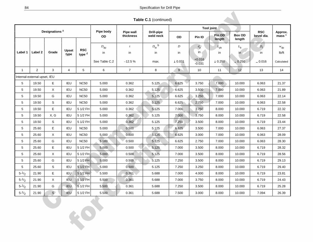
Complimenta
ry Copy
for C
ertific
ation Use
84 Specification for Drill Pipe
Table C.1 (continued)
Designations a Pipe body
OD Pipe wall thickness
Drill-pipe weld neck
Tool joint RSC
bevel dia. Approx. mass c OD Pin ID
Pin OD length
Box OD length
Label 1 Label 2 Grade Upset type
RSC type d
Ddp t Dte b D dp Lpb Lb Df wdp
in in in in in in in in lb/ft
See Table C.2 12.5 % max. 0.031 +0.016 -0.031
0.250 0.250 0.016 Calculated
1 2 3 4 5 6 7 8 9 10 11 12 13 14
Internal-external upset, IEU
5 19.50 E IEU NC50 5.000 0.362 5.125 6.625 3.750 7.000 10.000 6.063 21.37
5 19.50 X IEU NC50 5.000 0.362 5.125 6.625 3.500 7.000 10.000 6.063 21.89
5 19.50 G IEU NC50 5.000 0.362 5.125 6.625 3.250 7.000 10.000 6.063 22.14
5 19.50 S IEU NC50 5.000 0.362 5.125 6.625 2.750 7.000 10.000 6.063 22.58
5 19.50 E IEU 5 1/2 FH 5.000 0.362 5.125 7.000 3.750 8.000 10.000 6.719 22.32
5 19.50 X, G IEU 5 1/2 FH 5.000 0.362 5.125 7.000 3.750 8.000 10.000 6.719 22.58
5 19.50 S IEU 5 1/2 FH 5.000 0.362 5.125 7.250 3.500 8.000 10.000 6.719 23.44
5 25.60 E IEU NC50 5.000 0.500 5.125 6.625 3.500 7.000 10.000 6.063 27.37
5 25.60 X IEU NC50 5.000 0.500 5.125 6.625 3.000 7.000 10.000 6.063 28.09
5 25.60 G IEU NC50 5.000 0.500 5.125 6.625 2.750 7.000 10.000 6.063 28.30
5 25.60 E IEU 5 1/2 FH 5.000 0.500 5.125 7.000 3.500 8.000 10.000 6.719 28.32
5 25.60 X IEU 5 1/2 FH 5.000 0.500 5.125 7.000 3.500 8.000 10.000 6.719 28.56
5 25.60 G IEU 5 1/2 FH 5.000 0.500 5.125 7.250 3.500 8.000 10.000 6.719 29.13
5 25.60 S IEU 5 1/2 FH 5.000 0.500 5.125 7.250 3.250 8.000 10.000 6.719 29.40
5-1/2 21.90 E IEU 5 1/2 FH 5.500 0.361 5.688 7.000 4.000 8.000 10.000 6.719 23.81
5-1/2 21.90 X IEU 5 1/2 FH 5.500 0.361 5.688 7.000 3.750 8.000 10.000 6.719 24.43
5-1/2 21.90 G IEU 5 1/2 FH 5.500 0.361 5.688 7.250 3.500 8.000 10.000 6.719 25.28
5-1/2 21.90 S IEU 5 1/2 FH 5.500 0.361 5.688 7.500 3.000 8.000 10.000 7.094 26.39
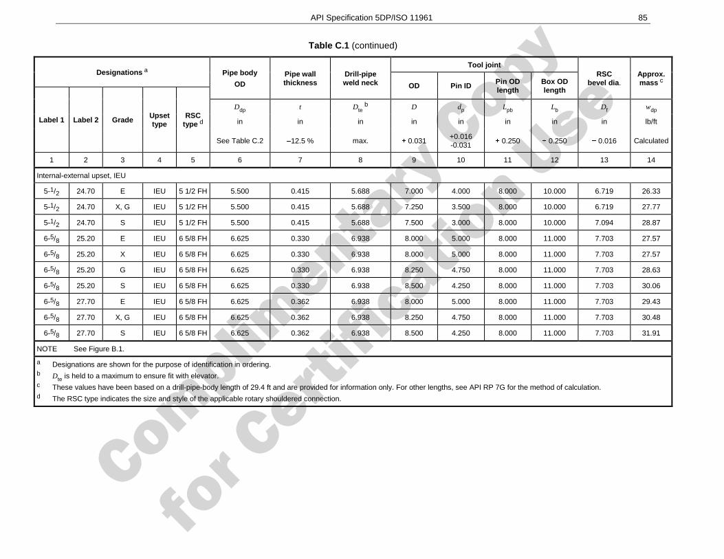
Complimenta
ry Copy
for C
ertific
ation Use
API Specification 5DP/ISO 11961 85
Table C.1 (continued)
Designations a Pipe body
OD Pipe wall thickness
Drill-pipe weld neck
Tool joint RSC
bevel dia. Approx. mass c OD Pin ID
Pin OD length
Box OD length
Label 1 Label 2 Grade Upset type
RSC type d
Ddp t Dte b D dp Lpb Lb Df wdp
in in in in in in in in lb/ft
See Table C.2 12.5 % max. 0.031 +0.016 -0.031
0.250 0.250 0.016 Calculated
1 2 3 4 5 6 7 8 9 10 11 12 13 14
Internal-external upset, IEU
5-1/2 24.70 E IEU 5 1/2 FH 5.500 0.415 5.688 7.000 4.000 8.000 10.000 6.719 26.33
5-1/2 24.70 X, G IEU 5 1/2 FH 5.500 0.415 5.688 7.250 3.500 8.000 10.000 6.719 27.77
5-1/2 24.70 S IEU 5 1/2 FH 5.500 0.415 5.688 7.500 3.000 8.000 10.000 7.094 28.87
6-5/8 25.20 E IEU 6 5/8 FH 6.625 0.330 6.938 8.000 5.000 8.000 11.000 7.703 27.57
6-5/8 25.20 X IEU 6 5/8 FH 6.625 0.330 6.938 8.000 5.000 8.000 11.000 7.703 27.57
6-5/8 25.20 G IEU 6 5/8 FH 6.625 0.330 6.938 8.250 4.750 8.000 11.000 7.703 28.63
6-5/8 25.20 S IEU 6 5/8 FH 6.625 0.330 6.938 8.500 4.250 8.000 11.000 7.703 30.06
6-5/8 27.70 E IEU 6 5/8 FH 6.625 0.362 6.938 8.000 5.000 8.000 11.000 7.703 29.43
6-5/8 27.70 X, G IEU 6 5/8 FH 6.625 0.362 6.938 8.250 4.750 8.000 11.000 7.703 30.48
6-5/8 27.70 S IEU 6 5/8 FH 6.625 0.362 6.938 8.500 4.250 8.000 11.000 7.703 31.91
NOTE See Figure B.1.
a Designations are shown for the purpose of identification in ordering. b Dte is held to a maximum to ensure fit with elevator. c These values have been based on a drill-pipe-body length of 29.4 ft and are provided for information only. For other lengths, see API RP 7G for the method of calculation. d The RSC type indicates the size and style of the applicable rotary shouldered connection.
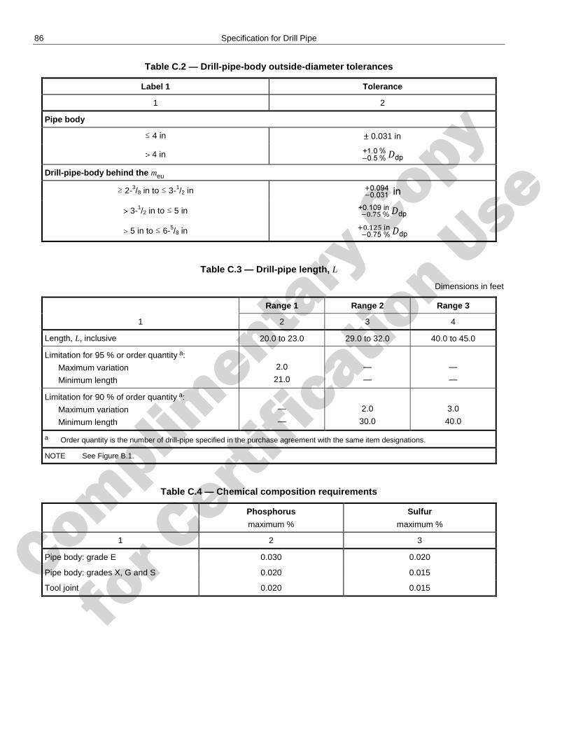
Complimenta
ry Copy
for C
ertific
ation Use
86 Specification for Drill Pipe
Table C.2 — Drill-pipe-body outside-diameter tolerances
Label 1 Tolerance
1 2
Pipe body
≤ 4 in 0.031 in
4 in
Drill-pipe-body behind the meu
≥ 2-3/8 in to ≤ 3-1/2 in
3-1/2 in to ≤ 5 in
5 in to ≤ 6-5/8 in
Table C.3 — Drill-pipe length, L
Dimensions in feet
1
Range 1 Range 2 Range 3
2 3 4
Length, L, inclusive 20.0 to 23.0 29.0 to 32.0 40.0 to 45.0
Limitation for 95 % or order quantity a:
Maximum variation
Minimum length
2.0
21.0
—
—
—
—
Limitation for 90 % of order quantity a:
Maximum variation
Minimum length
—
—
2.0
30.0
3.0
40.0
a Order quantity is the number of drill-pipe specified in the purchase agreement with the same item designations.
NOTE See Figure B.1.
Table C.4 — Chemical composition requirements
Phosphorus
maximum %
Sulfur
maximum %
1 2 3
Pipe body: grade E 0.030 0.020
Pipe body: grades X, G and S 0.020 0.015
Tool joint 0.020 0.015
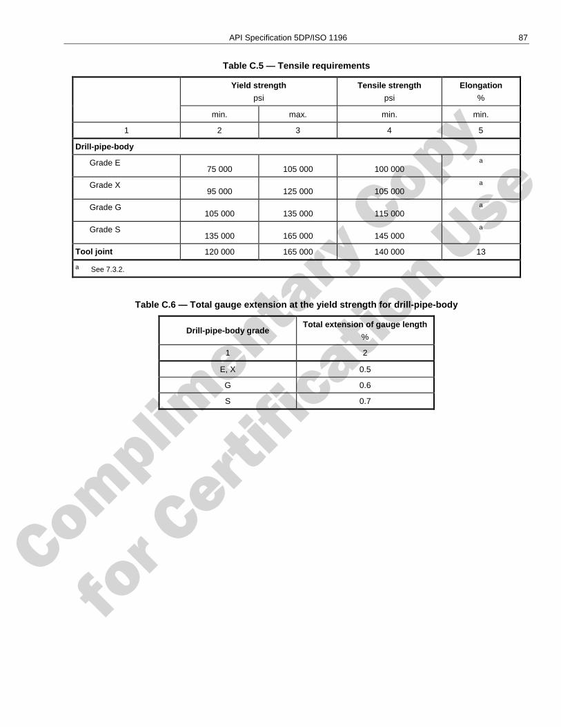
Complimenta
ry Copy
for C
ertific
ation Use
API Specification 5DP/ISO 1196 87
Table C.5 — Tensile requirements
Yield strength
psi
Tensile strength
psi
Elongation
%
min. max. min. min.
1 2 3 4 5
Drill-pipe-body
Grade E 75 000 105 000 100 000
a
Grade X 95 000 125 000 105 000
a
Grade G 105 000 135 000 115 000
a
Grade S 135 000 165 000 145 000
a
Tool joint 120 000 165 000 140 000 13
a See 7.3.2.
Table C.6 — Total gauge extension at the yield strength for drill-pipe-body
Drill-pipe-body grade Total extension of gauge length
%
1 2
E, X 0.5
G 0.6
S 0.7
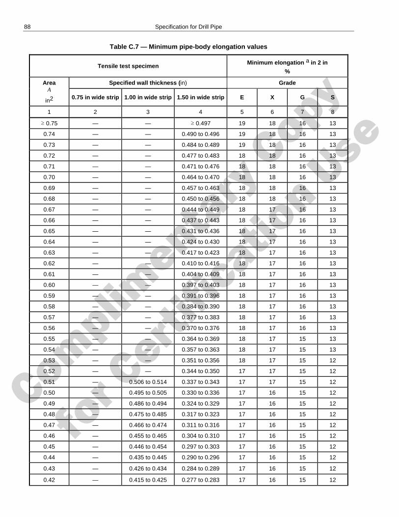
Complimenta
ry Copy
for C
ertific
ation Use
88 Specification for Drill Pipe
Table C.7 — Minimum pipe-body elongation values
Tensile test specimen Minimum elongation a in 2 in
%
Area A
in2
Specified wall thickness (in) Grade
0.75 in wide strip 1.00 in wide strip 1.50 in wide strip E X G S
1 2 3 4 5 6 7 8
≥ 0.75 — — ≥ 0.497 19 18 16 13
0.74 — — 0.490 to 0.496 19 18 16 13
0.73 — — 0.484 to 0.489 19 18 16 13
0.72 — — 0.477 to 0.483 18 18 16 13
0.71 — — 0.471 to 0.476 18 18 16 13
0.70 — — 0.464 to 0.470 18 18 16 13
0.69 — — 0.457 to 0.463 18 18 16 13
0.68 — — 0.450 to 0.456 18 18 16 13
0.67 — — 0.444 to 0.449 18 17 16 13
0.66 — — 0.437 to 0.443 18 17 16 13
0.65 — — 0.431 to 0.436 18 17 16 13
0.64 — — 0.424 to 0.430 18 17 16 13
0.63 — — 0.417 to 0.423 18 17 16 13
0.62 — — 0.410 to 0.416 18 17 16 13
0.61 — — 0.404 to 0.409 18 17 16 13
0.60 — — 0.397 to 0.403 18 17 16 13
0.59 — — 0.391 to 0.396 18 17 16 13
0.58 — — 0.384 to 0.390 18 17 16 13
0.57 — — 0.377 to 0.383 18 17 16 13
0.56 — — 0.370 to 0.376 18 17 16 13
0.55 — — 0.364 to 0.369 18 17 15 13
0.54 — — 0.357 to 0.363 18 17 15 13
0.53 — — 0.351 to 0.356 18 17 15 12
0.52 — — 0.344 to 0.350 17 17 15 12
0.51 — 0.506 to 0.514 0.337 to 0.343 17 17 15 12
0.50 — 0.495 to 0.505 0.330 to 0.336 17 16 15 12
0.49 — 0.486 to 0.494 0.324 to 0.329 17 16 15 12
0.48 — 0.475 to 0.485 0.317 to 0.323 17 16 15 12
0.47 — 0.466 to 0.474 0.311 to 0.316 17 16 15 12
0.46 — 0.455 to 0.465 0.304 to 0.310 17 16 15 12
0.45 — 0.446 to 0.454 0.297 to 0.303 17 16 15 12
0.44 — 0.435 to 0.445 0.290 to 0.296 17 16 15 12
0.43 — 0.426 to 0.434 0.284 to 0.289 17 16 15 12
0.42 — 0.415 to 0.425 0.277 to 0.283 17 16 15 12
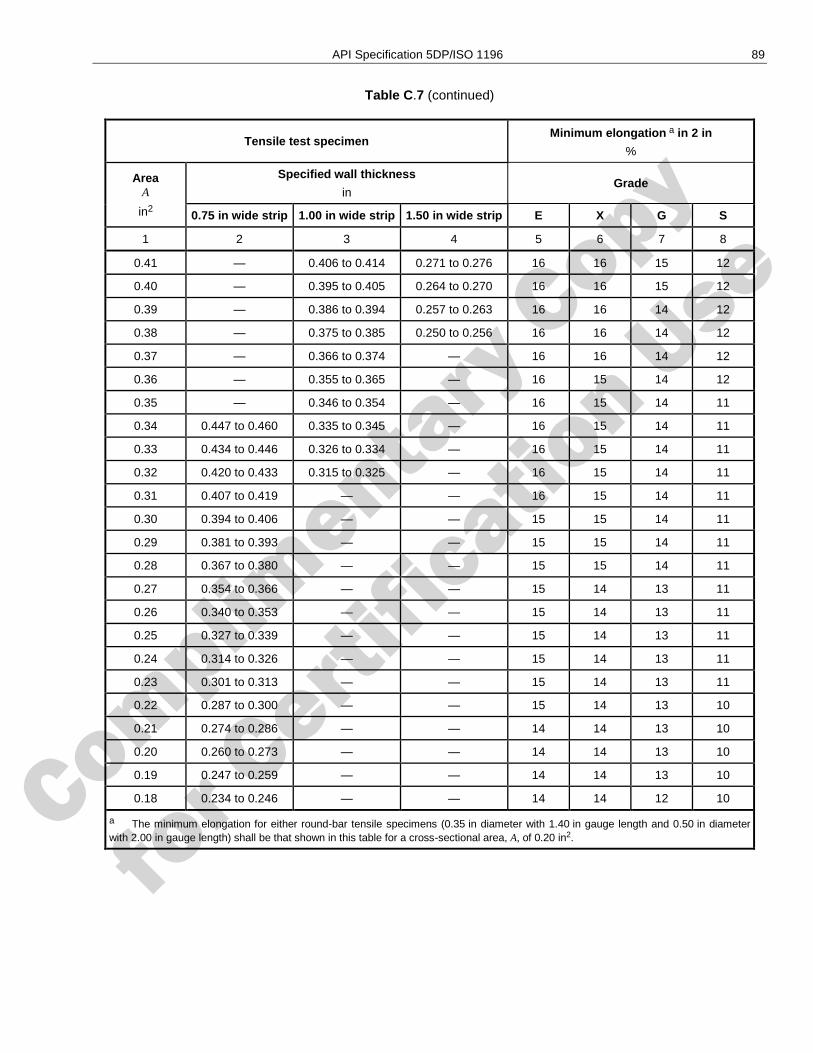
Complimenta
ry Copy
for C
ertific
ation Use
API Specification 5DP/ISO 1196 89
Table C.7 (continued)
Tensile test specimen Minimum elongation a in 2 in
%
Area A
in2
Specified wall thickness
in Grade
0.75 in wide strip 1.00 in wide strip 1.50 in wide strip E X G S
1 2 3 4 5 6 7 8
0.41 — 0.406 to 0.414 0.271 to 0.276 16 16 15 12
0.40 — 0.395 to 0.405 0.264 to 0.270 16 16 15 12
0.39 — 0.386 to 0.394 0.257 to 0.263 16 16 14 12
0.38 — 0.375 to 0.385 0.250 to 0.256 16 16 14 12
0.37 — 0.366 to 0.374 — 16 16 14 12
0.36 — 0.355 to 0.365 — 16 15 14 12
0.35 — 0.346 to 0.354 — 16 15 14 11
0.34 0.447 to 0.460 0.335 to 0.345 — 16 15 14 11
0.33 0.434 to 0.446 0.326 to 0.334 — 16 15 14 11
0.32 0.420 to 0.433 0.315 to 0.325 — 16 15 14 11
0.31 0.407 to 0.419 — — 16 15 14 11
0.30 0.394 to 0.406 — — 15 15 14 11
0.29 0.381 to 0.393 — — 15 15 14 11
0.28 0.367 to 0.380 — — 15 15 14 11
0.27 0.354 to 0.366 — — 15 14 13 11
0.26 0.340 to 0.353 — — 15 14 13 11
0.25 0.327 to 0.339 — — 15 14 13 11
0.24 0.314 to 0.326 — — 15 14 13 11
0.23 0.301 to 0.313 — — 15 14 13 11
0.22 0.287 to 0.300 — — 15 14 13 10
0.21 0.274 to 0.286 — — 14 14 13 10
0.20 0.260 to 0.273 — — 14 14 13 10
0.19 0.247 to 0.259 — — 14 14 13 10
0.18 0.234 to 0.246 — — 14 14 12 10
a The minimum elongation for either round-bar tensile specimens (0.35 in diameter with 1.40 in gauge length and 0.50 in diameter with 2.00 in gauge length) shall be that shown in this table for a cross-sectional area, A, of 0.20 in2.
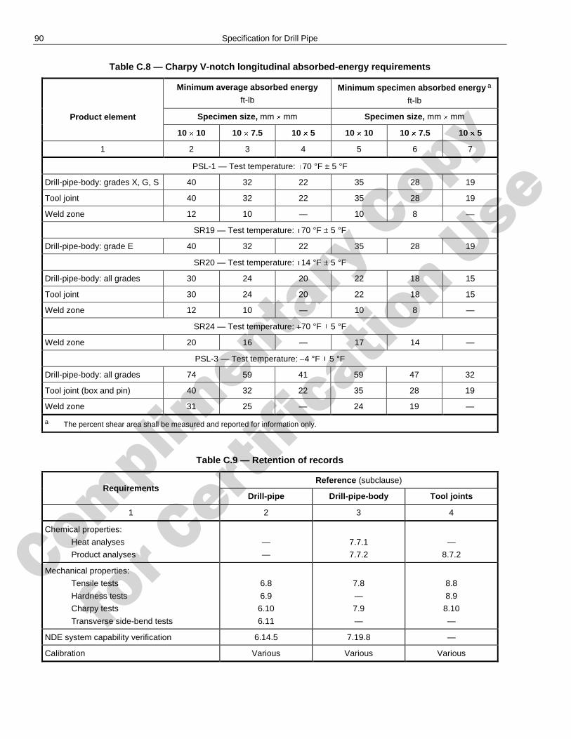
Complimenta
ry Copy
for C
ertific
ation Use
90 Specification for Drill Pipe
Table C.8 — Charpy V-notch longitudinal absorbed-energy requirements
Product element
Minimum average absorbed energy
ft-lb Minimum specimen absorbed energy a
ft-lb
Specimen size, mm mm Specimen size, mm mm
10 10 10 7.5 10 5 10 10 10 7.5 10 5
1 2 3 4 5 6 7
PSL-1 — Test temperature: 70 °F 5 °F
Drill-pipe-body: grades X, G, S 40 32 22 35 28 19
Tool joint 40 32 22 35 28 19
Weld zone 12 10 — 10 8 —
SR19 — Test temperature: 70 °F 5 °F
Drill-pipe-body: grade E 40 32 22 35 28 19
SR20 — Test temperature: 14 °F 5 °F
Drill-pipe-body: all grades 30 24 20 22 18 15
Tool joint 30 24 20 22 18 15
Weld zone 12 10 — 10 8 —
SR24 — Test temperature: 70 °F 5 °F
Weld zone 20 16 — 17 14 —
PSL-3 — Test temperature: 4 °F 5 °F
Drill-pipe-body: all grades 74 59 41 59 47 32
Tool joint (box and pin) 40 32 22 35 28 19
Weld zone 31 25 — 24 19 —
a The percent shear area shall be measured and reported for information only.
Table C.9 — Retention of records
Requirements Reference (subclause)
Drill-pipe Drill-pipe-body Tool joints
1 2 3 4
Chemical properties:
Heat analyses
Product analyses
—
—
7.7.1
7.7.2
—
8.7.2
Mechanical properties:
Tensile tests
Hardness tests
Charpy tests
Transverse side-bend tests
6.8
6.9
6.10
6.11
7.8
—
7.9
—
8.8
8.9
8.10
—
NDE system capability verification 6.14.5 7.19.8 —
Calibration Various Various Various
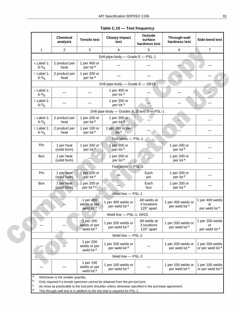
Complimenta
ry Copy
for C
ertific
ation Use
API Specification 5DP/ISO 1196 91
Table C.10 — Test frequency
Chemical analysis
Tensile test Charpy impact test
Outside surface
hardness test
Through-wall hardness test Side-bend test
1 2 3 4 5 6 7
Drill-pipe-body — Grade E — PSL-1
Label 1: 6-5/8
2 product per heat
1 per 400 or per lot a
— — — —
≥ Label 1: 6-5/8
2 product per heat
1 per 200 or per lot a
— — — —
Drill-pipe-body — Grade E — SR19
Label 1: 6-5/8
— — 1 per 400 or per lot a
— — —
≥ Label 1: 6-5/8
— — 1 per 200 or
per lot a — — —
Drill-pipe-body — Grades X, G and S — PSL-1
Label 1: 6-5/8
2 product per heat
1 per 200 or per lot a
1 per 200 or per lot a
— — —
≥ Label 1: 6-5/8
2 product per heat
1 per 100 or per lot a
1 per 100 or per lot a
— — —
Tool joints — PSL-1
Pin 1 per heat (solid form)
1 per 200 or per lot a
1 per 200 or per lot a
— 1 per 200 or
per lot b —
Box 1 per heat (solid form)
— 1 per 200 or per lot a
— 1 per 200 or per lot a
—
Tool joints — PSL-3
Pin 1 per heat (solid form)
1 per 200 or per lot a
— Each pin
1 per 200 or per lot d
—
Box 1 per heat (solid form)
1 per 200 or per lot a,c
— Each box
1 per 200 or per lot d
—
Weld line — PSL-1
— — 1 per 400
welds or per weld lot a
1 per 400 welds or per weld lot a
All welds at 3 locations 120° apart
1 per 400 welds or per weld lot a
1 per 400 welds or
per weld lot a
Weld line — PSL-1, SR23
— — 1 per 200
welds or per weld lot a
1 per 200 welds or per weld lot a
All welds at 3 locations 120° apart
1 per 200 welds or per weld lot a
1 per 200 welds or
per weld lot a
Weld line — PSL-2
— — 1 per 200
welds or per weld lot a
1 per 200 welds or per weld lot a
— 1 per 200 welds or
per weld lot a
1 per 200 welds or per weld lot a
Weld line — PSL-3
— — 1 per 100
welds or per weld lot a
1 per 100 welds or per weld lot a
— 1 per 100 welds or per weld lot a
1 per 100 welds or per weld lot a
a Whichever is the smaller quantity. b Only required if a tensile specimen cannot be obtained from the pin tool joint. c As close as practicable to the tool-joint shoulder unless otherwise specified in the purchase agreement. d This through-wall test is in addition to the test that is required for PSL-1.
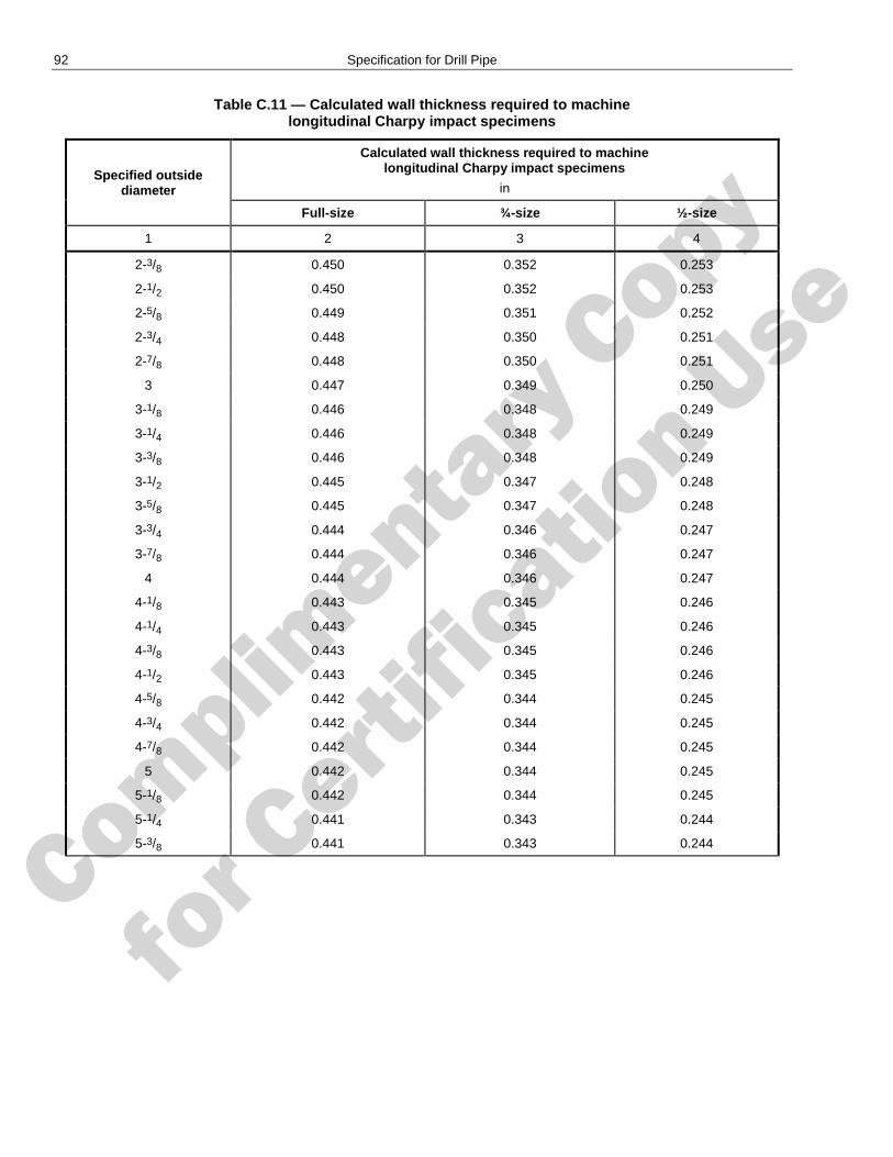
Complimenta
ry Copy
for C
ertific
ation Use
92 Specification for Drill Pipe
Table C.11 — Calculated wall thickness required to machine longitudinal Charpy impact specimens
Specified outside diameter
Calculated wall thickness required to machine longitudinal Charpy impact specimens
in
Full-size ¾-size ½-size
1 2 3 4
2-3/8 0.450 0.352 0.253
2-1/2 0.450 0.352 0.253
2-5/8 0.449 0.351 0.252
2-3/4 0.448 0.350 0.251
2-7/8 0.448 0.350 0.251
3 0.447 0.349 0.250
3-1/8 0.446 0.348 0.249
3-1/4 0.446 0.348 0.249
3-3/8 0.446 0.348 0.249
3-1/2 0.445 0.347 0.248
3-5/8 0.445 0.347 0.248
3-3/4 0.444 0.346 0.247
3-7/8 0.444 0.346 0.247
4 0.444 0.346 0.247
4-1/8 0.443 0.345 0.246
4-1/4 0.443 0.345 0.246
4-3/8 0.443 0.345 0.246
4-1/2 0.443 0.345 0.246
4-5/8 0.442 0.344 0.245
4-3/4 0.442 0.344 0.245
4-7/8 0.442 0.344 0.245
5 0.442 0.344 0.245
5-1/8 0.442 0.344 0.245
5-1/4 0.441 0.343 0.244
5-3/8 0.441 0.343 0.244
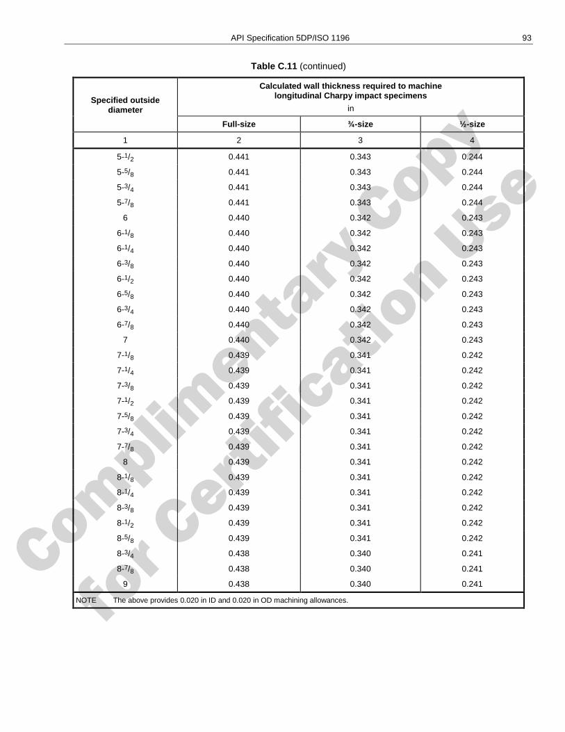
Complimenta
ry Copy
for C
ertific
ation Use
API Specification 5DP/ISO 1196 93
Table C.11 (continued)
Specified outside diameter
Calculated wall thickness required to machine longitudinal Charpy impact specimens
in
Full-size ¾-size ½-size
1 2 3 4
5-1/2 0.441 0.343 0.244
5-5/8 0.441 0.343 0.244
5-3/4 0.441 0.343 0.244
5-7/8 0.441 0.343 0.244
6 0.440 0.342 0.243
6-1/8 0.440 0.342 0.243
6-1/4 0.440 0.342 0.243
6-3/8 0.440 0.342 0.243
6-1/2 0.440 0.342 0.243
6-5/8 0.440 0.342 0.243
6-3/4 0.440 0.342 0.243
6-7/8 0.440 0.342 0.243
7 0.440 0.342 0.243
7-1/8 0.439 0.341 0.242
7-1/4 0.439 0.341 0.242
7-3/8 0.439 0.341 0.242
7-1/2 0.439 0.341 0.242
7-5/8 0.439 0.341 0.242
7-3/4 0.439 0.341 0.242
7-7/8 0.439 0.341 0.242
8 0.439 0.341 0.242
8-1/8 0.439 0.341 0.242
8-1/4 0.439 0.341 0.242
8-3/8 0.439 0.341 0.242
8-1/2 0.439 0.341 0.242
8-5/8 0.439 0.341 0.242
8-3/4 0.438 0.340 0.241
8-7/8 0.438 0.340 0.241
9 0.438 0.340 0.241
NOTE The above provides 0.020 in ID and 0.020 in OD machining allowances.
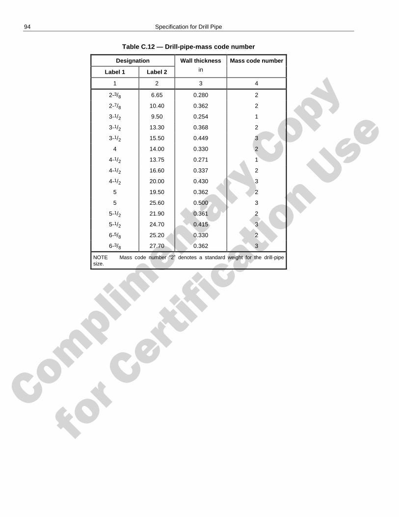
Complimenta
ry Copy
for C
ertific
ation Use
94 Specification for Drill Pipe
Table C.12 — Drill-pipe-mass code number
Designation Wall thickness
in
Mass code number
Label 1 Label 2
1 2 3 4
2-3/8 6.65 0.280 2
2-7/8 10.40 0.362 2
3-1/2 9.50 0.254 1
3-1/2 13.30 0.368 2
3-1/2 15.50 0.449 3
4 14.00 0.330 2
4-1/2 13.75 0.271 1
4-1/2 16.60 0.337 2
4-1/2 20.00 0.430 3
5 19.50 0.362 2
5 25.60 0.500 3
5-1/2 21.90 0.361 2
5-1/2 24.70 0.415 3
6-5/8 25.20 0.330 2
6-3/8 27.70 0.362 3
NOTE Mass code number ―2‖ denotes a standard weight for the drill-pipe size.
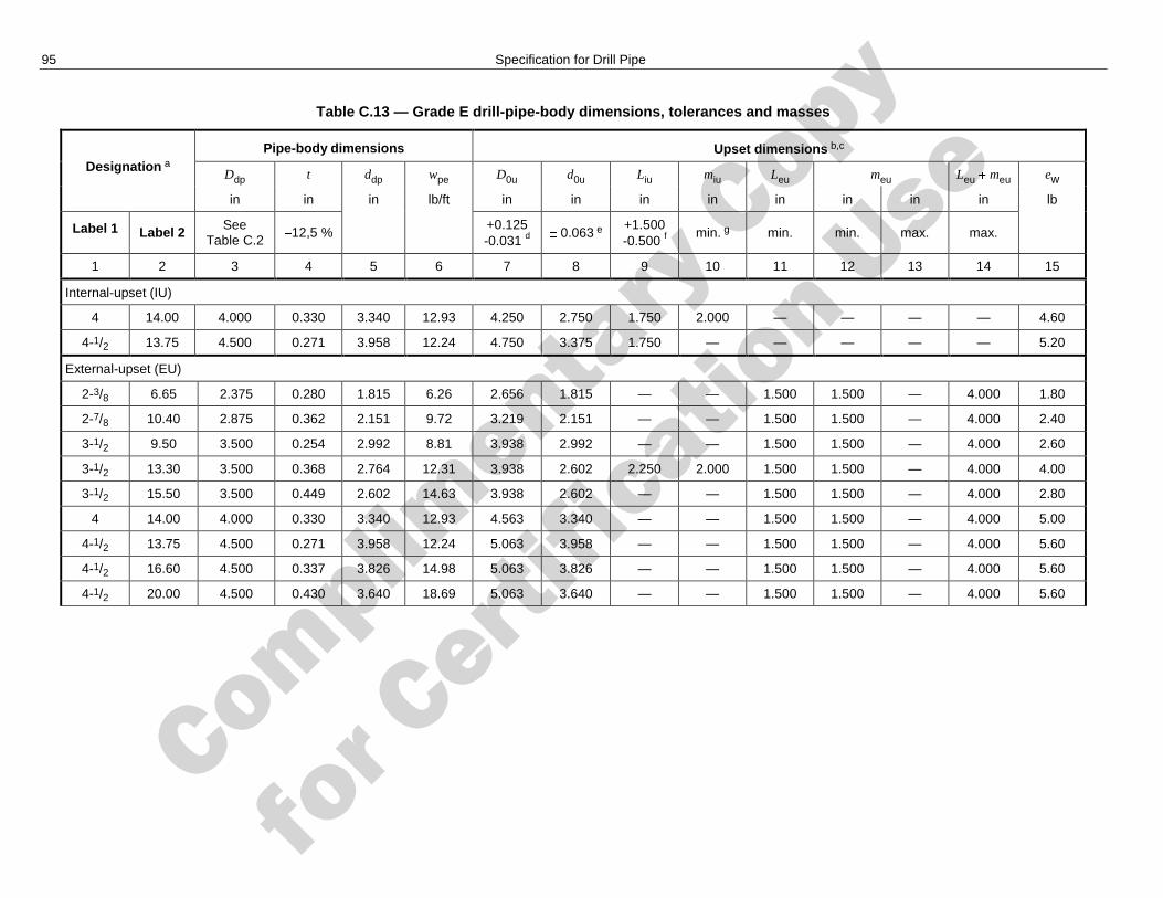
Complimenta
ry Copy
for C
ertific
ation Use
95 Specification for Drill Pipe
Table C.13 — Grade E drill-pipe-body dimensions, tolerances and masses
Designation a Pipe-body dimensions Upset dimensions b,c
Ddp t ddp wpe D0u d0u Liu miu Leu meu Leu meu ew
in in in lb/ft in in in in in in in in lb
Label 1 Label 2 See Table C.2
12,5 % +0.125 -0.031 d
0.063 e +1.500 -0.500 f
min. g min. min. max. max.
1 2 3 4 5 6 7 8 9 10 11 12 13 14 15
Internal-upset (IU)
4 14.00 4.000 0.330 3.340 12.93 4.250 2.750 1.750 2.000 — — — — 4.60
4-1/2 13.75 4.500 0.271 3.958 12.24 4.750 3.375 1.750 — — — — — 5.20
External-upset (EU)
2-3/8 6.65 2.375 0.280 1.815 6.26 2.656 1.815 — — 1.500 1.500 — 4.000 1.80
2-7/8 10.40 2.875 0.362 2.151 9.72 3.219 2.151 — — 1.500 1.500 — 4.000 2.40
3-1/2 9.50 3.500 0.254 2.992 8.81 3.938 2.992 — — 1.500 1.500 — 4.000 2.60
3-1/2 13.30 3.500 0.368 2.764 12.31 3.938 2.602 2.250 2.000 1.500 1.500 — 4.000 4.00
3-1/2 15.50 3.500 0.449 2.602 14.63 3.938 2.602 — — 1.500 1.500 — 4.000 2.80
4 14.00 4.000 0.330 3.340 12.93 4.563 3.340 — — 1.500 1.500 — 4.000 5.00
4-1/2 13.75 4.500 0.271 3.958 12.24 5.063 3.958 — — 1.500 1.500 — 4.000 5.60
4-1/2 16.60 4.500 0.337 3.826 14.98 5.063 3.826 — — 1.500 1.500 — 4.000 5.60
4-1/2 20.00 4.500 0.430 3.640 18.69 5.063 3.640 — — 1.500 1.500 — 4.000 5.60
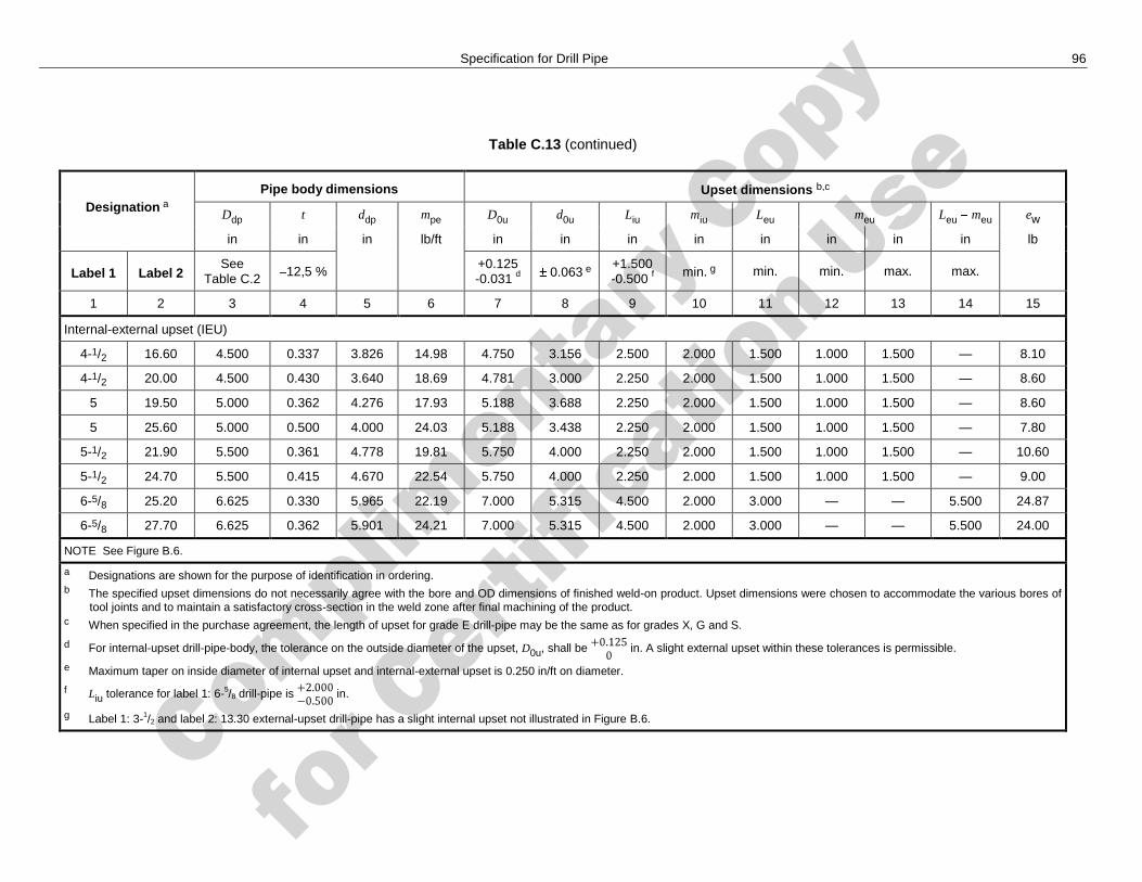
Complimenta
ry Copy
for C
ertific
ation Use
Specification for Drill Pipe 96
Table C.13 (continued)
Designation a Pipe body dimensions Upset dimensions b,c
Ddp t ddp mpe D0u d0u Liu miu Leu meu Leu meu ew
in in in lb/ft in in in in in in in in lb
Label 1 Label 2 See
Table C.2 12,5 % +0.125 -0.031 d 0.063 e
+1.500 -0.500 f min. g min. min. max. max.
1 2 3 4 5 6 7 8 9 10 11 12 13 14 15
Internal-external upset (IEU)
4-1/2 16.60 4.500 0.337 3.826 14.98 4.750 3.156 2.500 2.000 1.500 1.000 1.500 — 8.10
4-1/2 20.00 4.500 0.430 3.640 18.69 4.781 3.000 2.250 2.000 1.500 1.000 1.500 — 8.60
5 19.50 5.000 0.362 4.276 17.93 5.188 3.688 2.250 2.000 1.500 1.000 1.500 — 8.60
5 25.60 5.000 0.500 4.000 24.03 5.188 3.438 2.250 2.000 1.500 1.000 1.500 — 7.80
5-1/2 21.90 5.500 0.361 4.778 19.81 5.750 4.000 2.250 2.000 1.500 1.000 1.500 — 10.60
5-1/2 24.70 5.500 0.415 4.670 22.54 5.750 4.000 2.250 2.000 1.500 1.000 1.500 — 9.00
6-5/8 25.20 6.625 0.330 5.965 22.19 7.000 5.315 4.500 2.000 3.000 — — 5.500 24.87
6-5/8 27.70 6.625 0.362 5.901 24.21 7.000 5.315 4.500 2.000 3.000 — — 5.500 24.00
NOTE See Figure B.6.
a Designations are shown for the purpose of identification in ordering. b The specified upset dimensions do not necessarily agree with the bore and OD dimensions of finished weld-on product. Upset dimensions were chosen to accommodate the various bores of
tool joints and to maintain a satisfactory cross-section in the weld zone after final machining of the product. c When specified in the purchase agreement, the length of upset for grade E drill-pipe may be the same as for grades X, G and S.
d For internal-upset drill-pipe-body, the tolerance on the outside diameter of the upset, D0u, shall be in. A slight external upset within these tolerances is permissible.
e Maximum taper on inside diameter of internal upset and internal-external upset is 0.250 in/ft on diameter.
f Liu tolerance for label 1: 6-5/8 drill-pipe is in.
g Label 1: 3-1/2 and label 2: 13.30 external-upset drill-pipe has a slight internal upset not illustrated in Figure B.6.
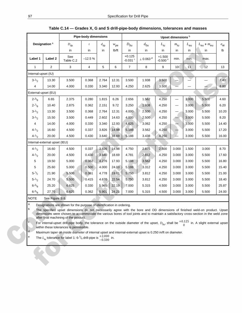
Complimenta
ry Copy
for C
ertific
ation Use
97 Specification for Drill Pipe
Table C.14 — Grades X, G and S drill-pipe-body dimensions, tolerances and masses
Pipe-body dimensions Upset dimensions b
Designation a Ddp t ddp wpe D0u d0u Liu miu Leu Leu meu ew
in in in lb/ft in in in in in in lb
Label 1 Label 2 See Table C.2
–12.5 % +0.125 -0.031 c
0.063 d +1.500 -0.500 e
min. min. max.
1 2 3 4 5 6 7 8 9 10 11 12 13
Internal-upset (IU)
3-1/2 13.30 3.500 0.368 2.764 12.31 3.500 1.938 3.500 — — — 7.40
4 14.00 4.000 0.330 3.340 12.93 4.250 2.625 3.500 — — — 8.80
External-upset (EU)
2-3/8 6.65 2.375 0.280 1.815 6.26 2.656 1.562 4.250 — 3.000 5.500 4.60
2-7/8 10.40 2.875 0.362 2.151 9.72 3.250 1.938 4.250 — 3.000 5.500 6.20
3-1/2 13.30 3.500 0.368 2.764 12.31 4.000 2.500 4.250 — 3.000 5.500 10.20
3-1/2 15.50 3.500 0.449 2.602 14.63 4.000 2.500 4.250 — 3.000 5.500 8.20
4 14.00 4.000 0.330 3.340 12.93 4.625 3.062 4.250 — 3.000 5.500 14.40
4-1/2 16.60 4.500 0.337 3.826 14.98 5.188 3.562 4.250 — 3.000 5.500 17.20
4-1/2 20.00 4.500 0.430 3.640 18.69 5.188 3.438 4.250 — 3.000 5.500 16.00
Internal-external upset (IEU)
4-1/2 16.60 4.500 0.337 3.826 14.98 4.750 2.875 2.500 3.000 1.500 3.000 8.70
4-1/2 20.00 4.500 0.430 3.640 18.69 4.781 2.812 4.250 3.000 3.000 5.500 17.60
5 19.50 5.000 0.362 4.276 17.93 5.188 3.562 4.250 3.000 3.000 5.500 16.80
5 25.60 5.000 0.500 4.000 24.03 5.188 3.312 4.250 3.000 3.000 5.500 15.40
5-1/2 21.90 5.500 0.361 4.778 19.81 5.750 3.812 4.250 3.000 3.000 5.500 21.00
5-1/2 24.70 5.500 0.415 4.670 22.54 5.750 3.812 4.250 3.000 3.000 5.500 18.40
6-5/8 25.20 6.625 0.330 5.965 22.19 7.000 5.315 4.500 3.000 3.000 5.500 25.87
6-5/8 27.70 6.625 0.362 5.901 24.21 7.000 5.315 4.500 3.000 3.000 5.500 24.00
NOTE See Figure B.6.
a Designations are shown for the purpose of identification in ordering. b The specified upset dimensions do not necessarily agree with the bore and OD dimensions of finished weld-on product. Upset
dimensions were chosen to accommodate the various bores of tool joints and to maintain a satisfactory cross-section in the weld zone after final machining of the product.
c For internal-upset drill-pipe body, the tolerance on the outside diameter of the upset, D0u, shall be in. A slight external upset
within these tolerances is permissible. d Maximum taper on inside diameter of internal upset and internal-external upset is 0.250 in/ft on diameter. e The Liu tolerance for label 1: 6-5/8 drill-pipe is
in.
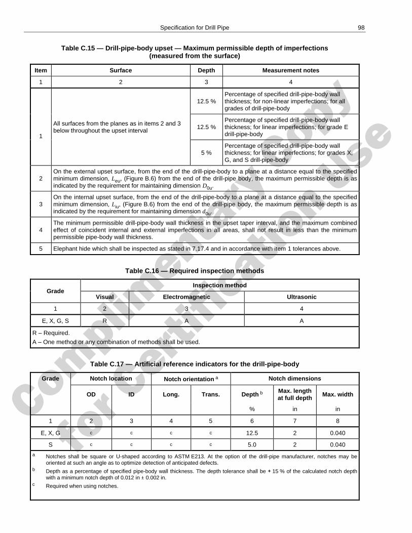
Complimenta
ry Copy
for C
ertific
ation Use
Specification for Drill Pipe 98
Table C.15 — Drill-pipe-body upset — Maximum permissible depth of imperfections (measured from the surface)
Item Surface Depth Measurement notes
1 2 3 4
1
All surfaces from the planes as in items 2 and 3 below throughout the upset interval
12.5 % Percentage of specified drill-pipe-body wall thickness; for non-linear imperfections; for all grades of drill-pipe-body
12.5 % Percentage of specified drill-pipe-body wall thickness; for linear imperfections; for grade E drill-pipe-body
5 % Percentage of specified drill-pipe-body wall thickness; for linear imperfections; for grades X, G, and S drill-pipe-body
2 On the external upset surface, from the end of the drill-pipe-body to a plane at a distance equal to the specified minimum dimension, Leu, (Figure B.6) from the end of the drill-pipe body, the maximum permissible depth is as indicated by the requirement for maintaining dimension D0u.
3 On the internal upset surface, from the end of the drill-pipe-body to a plane at a distance equal to the specified minimum dimension, Liu, (Figure B.6) from the end of the drill-pipe body, the maximum permissible depth is as indicated by the requirement for maintaining dimension d0u.
4 The minimum permissible drill-pipe-body wall thickness in the upset taper interval, and the maximum combined effect of coincident internal and external imperfections in all areas, shall not result in less than the minimum permissible pipe-body wall thickness.
5 Elephant hide which shall be inspected as stated in 7.17.4 and in accordance with item 1 tolerances above.
Table C.16 — Required inspection methods
Grade Inspection method
Visual Electromagnetic Ultrasonic
1 2 3 4
E, X, G, S R A A
R – Required.
A – One method or any combination of methods shall be used.
Table C.17 — Artificial reference indicators for the drill-pipe-body
Grade Notch location Notch orientation a Notch dimensions
OD ID Long. Trans. Depth b Max. length at full depth Max. width
% in in
1 2 3 4 5 6 7 8
E, X, G c c c c 12.5 2 0.040
S c c c c 5.0 2 0.040
a Notches shall be square or U-shaped according to ASTM E213. At the option of the drill-pipe manufacturer, notches may be oriented at such an angle as to optimize detection of anticipated defects.
b Depth as a percentage of specified pipe-body wall thickness. The depth tolerance shall be 15 % of the calculated notch depth with a minimum notch depth of 0.012 in 0.002 in.
c Required when using notches.
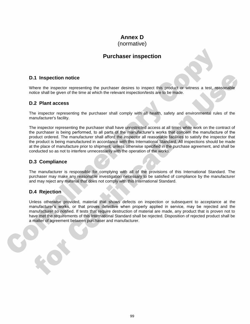
Complimenta
ry Copy
for C
ertific
ation Use
99
Annex D (normative)
Purchaser inspection
D.1 Inspection notice
Where the inspector representing the purchaser desires to inspect this product or witness a test, reasonable notice shall be given of the time at which the relevant inspection/tests are to be made.
D.2 Plant access
The inspector representing the purchaser shall comply with all health, safety and environmental rules of the manufacturer's facility.
The inspector representing the purchaser shall have unrestricted access at all times while work on the contract of the purchaser is being performed, to all parts of the manufacturer’s works that concern the manufacture of the product ordered. The manufacturer shall afford the inspector all reasonable facilities to satisfy the inspector that the product is being manufactured in accordance with this International Standard. All inspections should be made at the place of manufacture prior to shipment, unless otherwise specified in the purchase agreement, and shall be conducted so as not to interfere unnecessarily with the operation of the works.
D.3 Compliance
The manufacturer is responsible for complying with all of the provisions of this International Standard. The purchaser may make any reasonable investigation necessary to be satisfied of compliance by the manufacturer and may reject any material that does not comply with this International Standard.
D.4 Rejection
Unless otherwise provided, material that shows defects on inspection or subsequent to acceptance at the manufacturer’s works, or that proves defective when properly applied in service, may be rejected and the manufacturer so notified. If tests that require destruction of material are made, any product that is proven not to have met the requirements of this International Standard shall be rejected. Disposition of rejected product shall be a matter of agreement between purchaser and manufacturer.
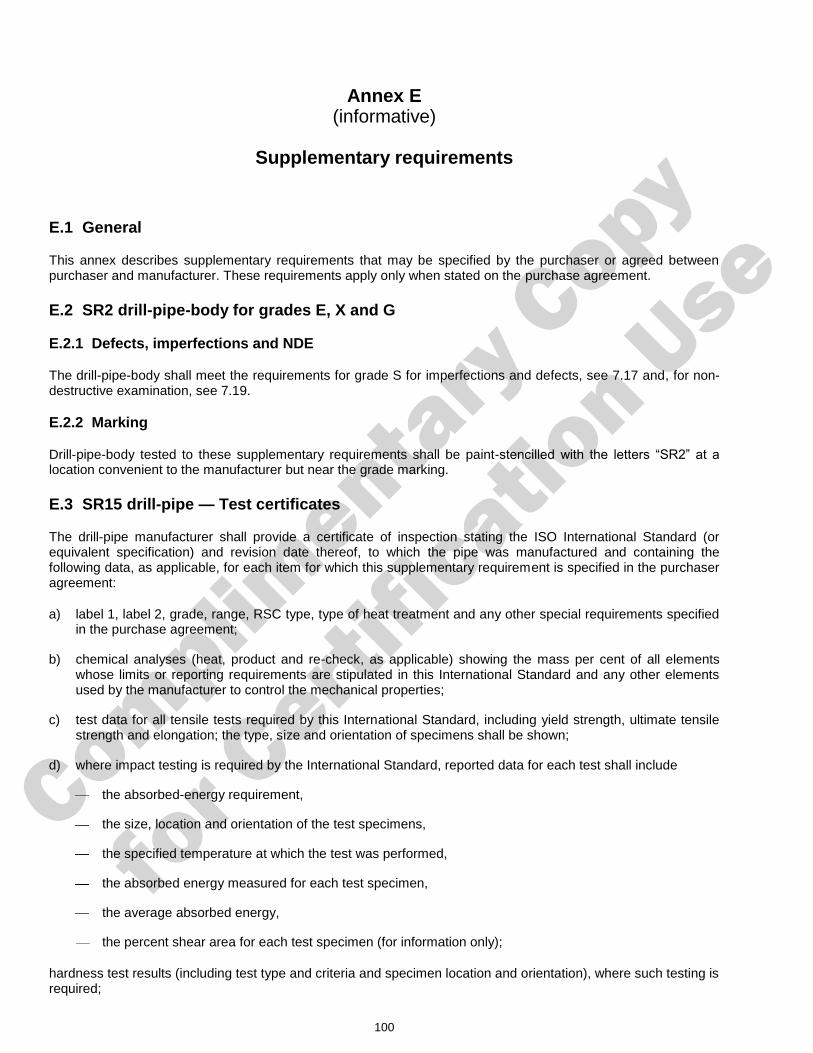
Complimenta
ry Copy
for C
ertific
ation Use
100
Annex E (informative)
Supplementary requirements
E.1 General
This annex describes supplementary requirements that may be specified by the purchaser or agreed between purchaser and manufacturer. These requirements apply only when stated on the purchase agreement.
E.2 SR2 drill-pipe-body for grades E, X and G
E.2.1 Defects, imperfections and NDE
The drill-pipe-body shall meet the requirements for grade S for imperfections and defects, see 7.17 and, for non-destructive examination, see 7.19.
E.2.2 Marking
Drill-pipe-body tested to these supplementary requirements shall be paint-stencilled with the letters ―SR2‖ at a location convenient to the manufacturer but near the grade marking.
E.3 SR15 drill-pipe — Test certificates
The drill-pipe manufacturer shall provide a certificate of inspection stating the ISO International Standard (or equivalent specification) and revision date thereof, to which the pipe was manufactured and containing the following data, as applicable, for each item for which this supplementary requirement is specified in the purchaser agreement:
a) label 1, label 2, grade, range, RSC type, type of heat treatment and any other special requirements specified in the purchase agreement;
b) chemical analyses (heat, product and re-check, as applicable) showing the mass per cent of all elements whose limits or reporting requirements are stipulated in this International Standard and any other elements used by the manufacturer to control the mechanical properties;
c) test data for all tensile tests required by this International Standard, including yield strength, ultimate tensile strength and elongation; the type, size and orientation of specimens shall be shown;
d) where impact testing is required by the International Standard, reported data for each test shall include
the absorbed-energy requirement,
the size, location and orientation of the test specimens,
the specified temperature at which the test was performed,
the absorbed energy measured for each test specimen,
the average absorbed energy,
the percent shear area for each test specimen (for information only);
hardness test results (including test type and criteria and specimen location and orientation), where such testing is required;
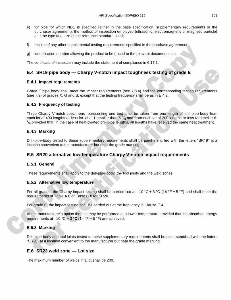
Complimenta
ry Copy
for C
ertific
ation Use
API Specification 5DP/ISO 119 101
e) for pipe for which NDE is specified (either in the base specification, supplementary requirements or the purchaser agreement), the method of inspection employed (ultrasonic, electromagnetic or magnetic particle) and the type and size of the reference standard used;
f) results of any other supplemental testing requirements specified in the purchase agreement;
g) identification number allowing the product to be traced to the relevant documentation.
The certificate of inspection may include the statement of compliance in 6.17.1.
E.4 SR19 pipe body — Charpy V-notch impact toughness testing of grade E
E.4.1 Impact requirements
Grade E pipe body shall meet the impact requirements (see 7.3.4) and the corresponding testing requirements (see 7.9) of grades X, G and S, except that the testing frequency shall be as in E.4.2.
E.4.2 Frequency of testing
Three Charpy V-notch specimens representing one test shall be taken from one length of drill-pipe-body from each lot of 400 lengths or less for label 1 smaller than 6-5/8 and from each lot of 200 lengths or less for label 1: 6-5/8 provided that, in the case of heat-treated drill-pipe lengths, all lengths have received the same heat treatment.
E.4.3 Marking
Drill-pipe-body tested to these supplementary requirements shall be paint-stencilled with the letters ―SR19‖ at a location convenient to the manufacturer but near the grade marking.
E.5 SR20 alternative low-temperature Charpy V-notch impact requirements
E.5.1 General
These requirements shall apply to the drill-pipe-body, the tool joints and the weld zones.
E.5.2 Alternative low temperature
For all grades, the Charpy impact testing shall be carried out at 10 °C 3 °C (14 °F 5 °F) and shall meet the requirements of Table A.8 or Table C.8 for SR20.
For grade E, the impact testing shall be carried out at the frequency in Clause E.4.
At the manufacturer's option the test may be performed at a lower temperature provided that the absorbed energy requirements at 10 °C 3 °C (14 °F 5 °F) are achieved.
E.5.3 Marking
Drill-pipe-body and tool joints tested to these supplementary requirements shall be paint-stencilled with the letters ―SR20‖ at a location convenient to the manufacturer but near the grade marking.
E.6 SR23 weld zone — Lot size
The maximum number of welds in a lot shall be 200.
Complimenta
ry Copy
for C
ertific
ation Use
102 Specification for Drill Pipe
E.7 SR24 Charpy V-notch — Increased weld-zone requirements
E.7.1 Requirements
The Charpy impact tests shall be made at 21 °C 3 °C ( 70 °F 5 °F) and shall meet the requirements in Table A.8 or Table C.8.
E.7.2 Marking
Product tested to this supplementary requirement shall be paint-stencilled with the letters ―SR24‖ at a location convenient to the manufacturer but near the grade marking.
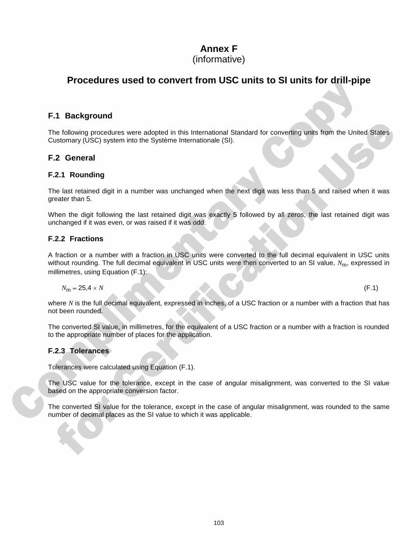
Complimenta
ry Copy
for C
ertific
ation Use
103
Annex F (informative)
Procedures used to convert from USC units to SI units for drill-pipe
F.1 Background
The following procedures were adopted in this International Standard for converting units from the United States Customary (USC) system into the Système Internationale (SI).
F.2 General
F.2.1 Rounding
The last retained digit in a number was unchanged when the next digit was less than 5 and raised when it was greater than 5.
When the digit following the last retained digit was exactly 5 followed by all zeros, the last retained digit was unchanged if it was even, or was raised if it was odd.
F.2.2 Fractions
A fraction or a number with a fraction in USC units were converted to the full decimal equivalent in USC units without rounding. The full decimal equivalent in USC units were then converted to an SI value, Nm, expressed in millimetres, using Equation (F.1):
Nm 25,4 N (F.1)
where N is the full decimal equivalent, expressed in inches, of a USC fraction or a number with a fraction that has not been rounded.
The converted SI value, in millimetres, for the equivalent of a USC fraction or a number with a fraction is rounded to the appropriate number of places for the application.
F.2.3 Tolerances
Tolerances were calculated using Equation (F.1).
The USC value for the tolerance, except in the case of angular misalignment, was converted to the SI value based on the appropriate conversion factor.
The converted SI value for the tolerance, except in the case of angular misalignment, was rounded to the same number of decimal places as the SI value to which it was applicable.
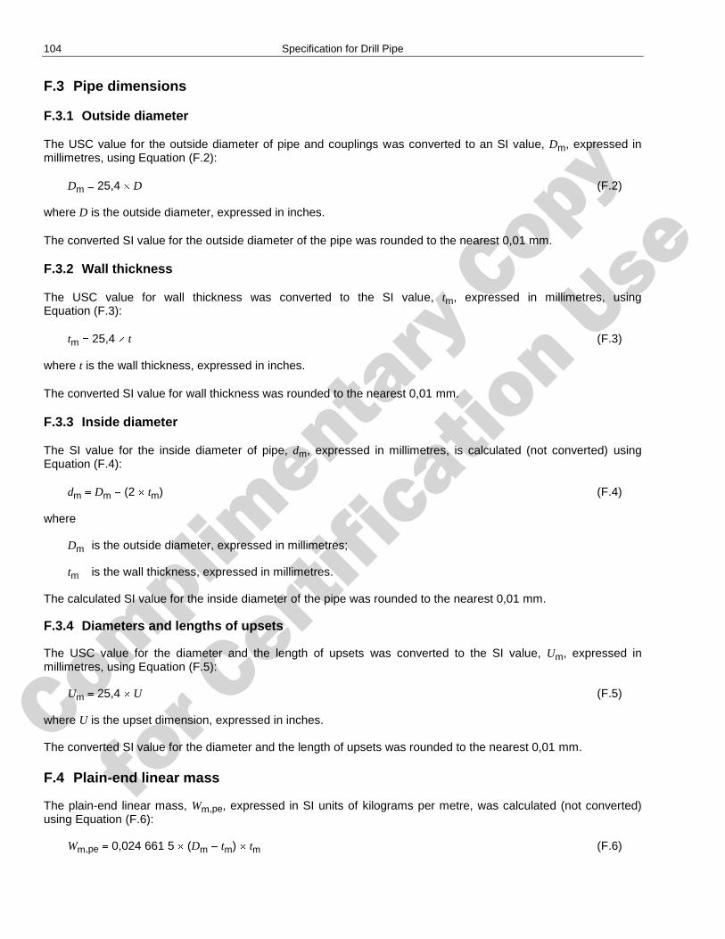
Complimenta
ry Copy
for C
ertific
ation Use
104 Specification for Drill Pipe
F.3 Pipe dimensions
F.3.1 Outside diameter
The USC value for the outside diameter of pipe and couplings was converted to an SI value, Dm, expressed in millimetres, using Equation (F.2):
Dm 25,4 D (F.2)
where D is the outside diameter, expressed in inches.
The converted SI value for the outside diameter of the pipe was rounded to the nearest 0,01 mm.
F.3.2 Wall thickness
The USC value for wall thickness was converted to the SI value, tm, expressed in millimetres, using Equation (F.3):
tm 25,4 t (F.3)
where t is the wall thickness, expressed in inches.
The converted SI value for wall thickness was rounded to the nearest 0,01 mm.
F.3.3 Inside diameter
The SI value for the inside diameter of pipe, dm, expressed in millimetres, is calculated (not converted) using Equation (F.4):
dm Dm (2 tm) (F.4)
where
Dm is the outside diameter, expressed in millimetres;
tm is the wall thickness, expressed in millimetres.
The calculated SI value for the inside diameter of the pipe was rounded to the nearest 0,01 mm.
F.3.4 Diameters and lengths of upsets
The USC value for the diameter and the length of upsets was converted to the SI value, Um, expressed in millimetres, using Equation (F.5):
Um 25,4 U (F.5)
where U is the upset dimension, expressed in inches.
The converted SI value for the diameter and the length of upsets was rounded to the nearest 0,01 mm.
F.4 Plain-end linear mass
The plain-end linear mass, Wm,pe, expressed in SI units of kilograms per metre, was calculated (not converted) using Equation (F.6):
Wm,pe 0,024 661 5 (Dm tm) tm (F.6)
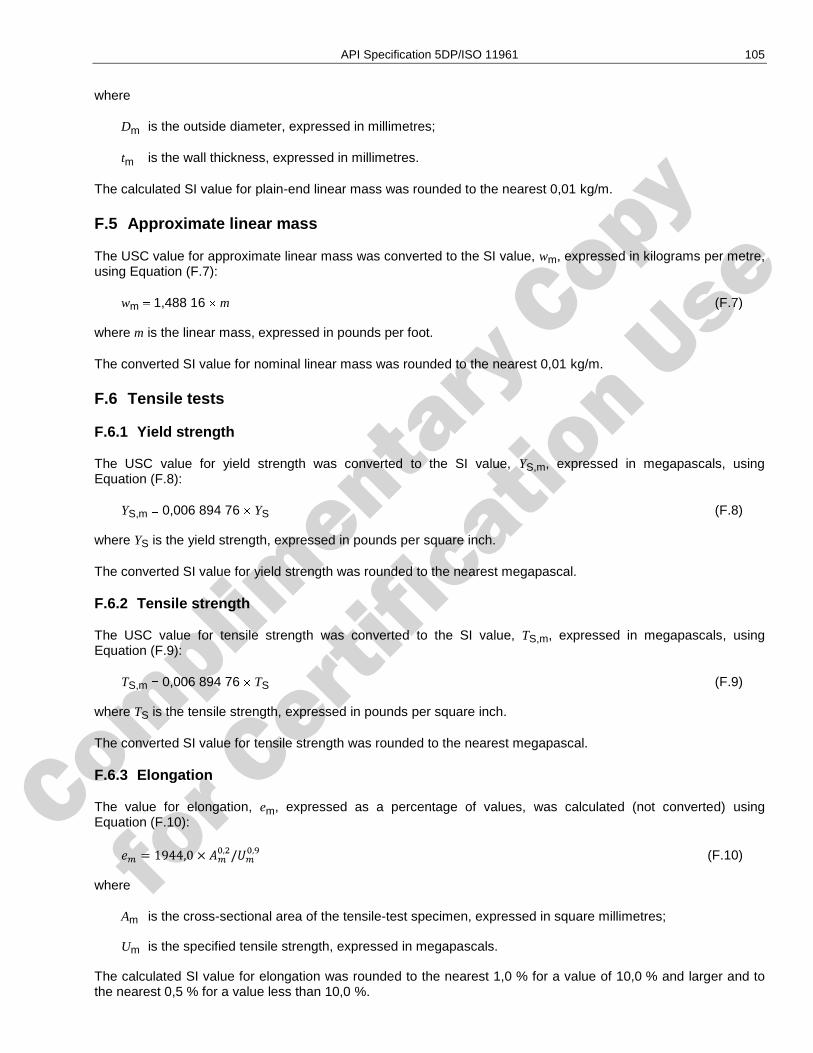
Complimenta
ry Copy
for C
ertific
ation Use
API Specification 5DP/ISO 11961 105 105
where
Dm is the outside diameter, expressed in millimetres;
tm is the wall thickness, expressed in millimetres.
The calculated SI value for plain-end linear mass was rounded to the nearest 0,01 kg/m.
F.5 Approximate linear mass
The USC value for approximate linear mass was converted to the SI value, wm, expressed in kilograms per metre, using Equation (F.7):
wm 1,488 16 m (F.7)
where m is the linear mass, expressed in pounds per foot.
The converted SI value for nominal linear mass was rounded to the nearest 0,01 kg/m.
F.6 Tensile tests
F.6.1 Yield strength
The USC value for yield strength was converted to the SI value, YS,m, expressed in megapascals, using Equation (F.8):
YS,m 0,006 894 76 YS (F.8)
where YS is the yield strength, expressed in pounds per square inch.
The converted SI value for yield strength was rounded to the nearest megapascal.
F.6.2 Tensile strength
The USC value for tensile strength was converted to the SI value, TS,m, expressed in megapascals, using Equation (F.9):
TS,m 0,006 894 76 TS (F.9)
where TS is the tensile strength, expressed in pounds per square inch.
The converted SI value for tensile strength was rounded to the nearest megapascal.
F.6.3 Elongation
The value for elongation, em, expressed as a percentage of values, was calculated (not converted) using Equation (F.10):
(F.10)
where
Am is the cross-sectional area of the tensile-test specimen, expressed in square millimetres;
Um is the specified tensile strength, expressed in megapascals.
The calculated SI value for elongation was rounded to the nearest 1,0 % for a value of 10,0 % and larger and to the nearest 0,5 % for a value less than 10,0 %.
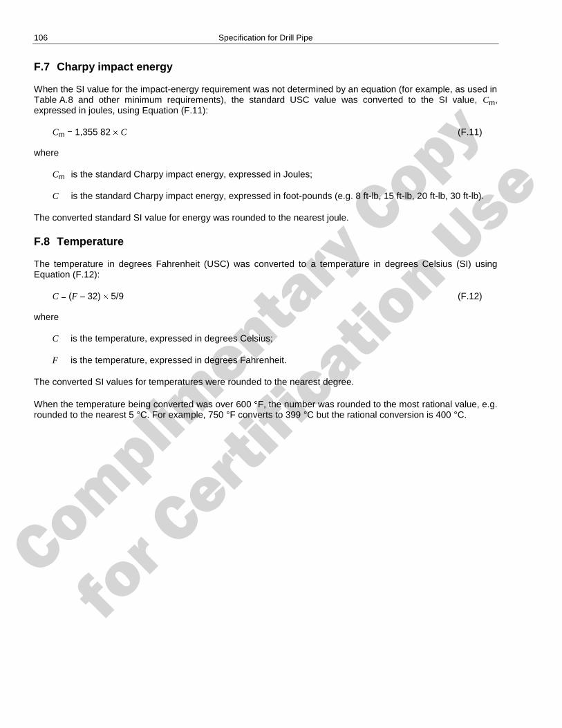
Complimenta
ry Copy
for C
ertific
ation Use
106 Specification for Drill Pipe
F.7 Charpy impact energy
When the SI value for the impact-energy requirement was not determined by an equation (for example, as used in Table A.8 and other minimum requirements), the standard USC value was converted to the SI value, Cm, expressed in joules, using Equation (F.11):
Cm 1,355 82 C (F.11)
where
Cm is the standard Charpy impact energy, expressed in Joules;
C is the standard Charpy impact energy, expressed in foot-pounds (e.g. 8 ft-lb, 15 ft-lb, 20 ft-lb, 30 ft-lb).
The converted standard SI value for energy was rounded to the nearest joule.
F.8 Temperature
The temperature in degrees Fahrenheit (USC) was converted to a temperature in degrees Celsius (SI) using Equation (F.12):
C (F 32) 5/9 (F.12)
where
C is the temperature, expressed in degrees Celsius;
F is the temperature, expressed in degrees Fahrenheit.
The converted SI values for temperatures were rounded to the nearest degree.
When the temperature being converted was over 600 F, the number was rounded to the most rational value, e.g. rounded to the nearest 5 °C. For example, 750 °F converts to 399 °C but the rational conversion is 400 °C.
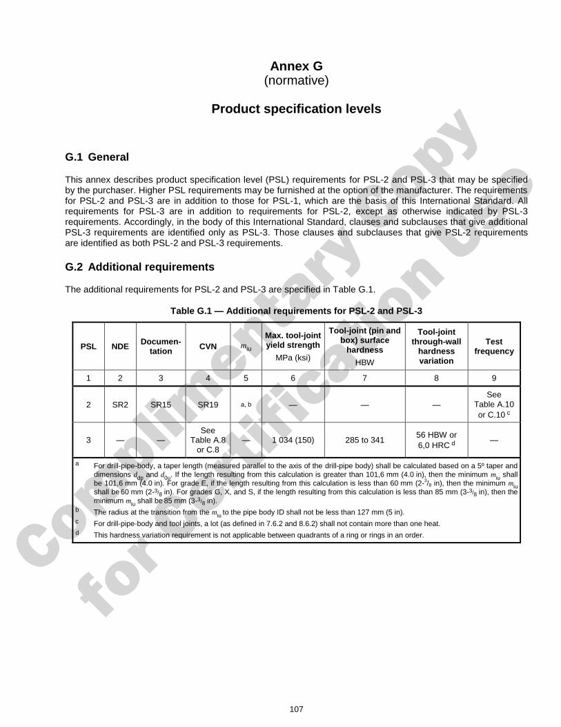
Complimenta
ry Copy
for C
ertific
ation Use
107
Annex G (normative)
Product specification levels
G.1 General
This annex describes product specification level (PSL) requirements for PSL-2 and PSL-3 that may be specified by the purchaser. Higher PSL requirements may be furnished at the option of the manufacturer. The requirements for PSL-2 and PSL-3 are in addition to those for PSL-1, which are the basis of this International Standard. All requirements for PSL-3 are in addition to requirements for PSL-2, except as otherwise indicated by PSL-3 requirements. Accordingly, in the body of this International Standard, clauses and subclauses that give additional PSL-3 requirements are identified only as PSL-3. Those clauses and subclauses that give PSL-2 requirements are identified as both PSL-2 and PSL-3 requirements.
G.2 Additional requirements
The additional requirements for PSL-2 and PSL-3 are specified in Table G.1.
Table G.1 — Additional requirements for PSL-2 and PSL-3
PSL NDE Documen-tation CVN miu
Max. tool-joint yield strength
MPa (ksi)
Tool-joint (pin and box) surface
hardness
HBW
Tool-joint through-wall
hardness variation
Test frequency
1 2 3 4 5 6 7 8 9
2 SR2 SR15 SR19 a, b — — — See
Table A.10 or C.10 c
3 — — See
Table A.8 or C.8
— 1 034 (150) 285 to 341 56 HBW or 6,0 HRC d
—
a For drill-pipe-body, a taper length (measured parallel to the axis of the drill-pipe body) shall be calculated based on a 5º taper and dimensions ddp and d0u. If the length resulting from this calculation is greater than 101,6 mm (4.0 in), then the minimum miu shall be 101,6 mm (4.0 in). For grade E, if the length resulting from this calculation is less than 60 mm (2-3/8 in), then the minimum miu shall be 60 mm (2-3/8 in). For grades G, X, and S, if the length resulting from this calculation is less than 85 mm (3-3/8 in), then the minimum miu shall be 85 mm (3-3/8 in).
b The radius at the transition from the miu to the pipe body ID shall not be less than 127 mm (5 in). c For drill-pipe-body and tool joints, a lot (as defined in 7.6.2 and 8.6.2) shall not contain more than one heat. d This hardness variation requirement is not applicable between quadrants of a ring or rings in an order.
Complimenta
ry Copy
for C
ertific
ation Use
108 Specification for Drill Pipe
G.3 Through-wall hardness testing of tool joints
G.3.1 Procedures
Hardness tests shall be performed at room temperature in accordance with ISO 6506-1 or ASTM E10 for Brinell hardness tests or ISO 6508-1 or in accordance with ASTM E18 for Rockwell hardness tests.
When testing using the Brinell method, one impression shall be made at each position OD, ID, and mid-wall(s).
When testing using the Rockwell method, three hardness impressions shall be made at each location OD, ID, and mid-wall(s) and averaged to give the mean hardness number at each location. The results of each hardness impression and the averages shall be reported to the nearest 0,1 HRC unit.
G.3.2 Hardness-test locations
Hardness testing of tool joints shall be carried out on a radial cross-section, taken at least one radius away from the end of the tool joint or blank (see Figure B.14). These tests may be made at the thickest point in the tool-joint material at the option of the manufacturer or when specified on the purchase agreement.
All four quadrants shall be tested. Testing on blocks is recommended rather than testing as a full ring to ensure ring overhang does not adversely affect the hardness test results.
When Rockwell testing is used, the first impression in each quadrant or test block shall be made near the centre of the test specimen to seat the test specimen. The result of this impression shall be ignored.
G.3.3 Hardness re-tests
When testing using the Brinell method, if any quadrant fails to meet the requirements, the lot shall be rejected. Re-testing is allowed as in 8.9.5.
When testing using the Rockwell method, if the difference between the maximum mean hardness number and the minimum mean hardness is greater than 6,0 HRC units, the lot shall be rejected. Before re-testing, the test surface shall be re-ground. If the difference between re-test mean hardness numbers does not exceed 6,0 HRC units, the lot shall be accepted.
If any re-test exceeds the maximum hardness variation, the lot of tool joints represented by the test piece shall be rejected. Rejected lots may be re-heat-treated as new lots.
G.4 Markings
Products meeting the PSL-2 requirements shall be marked L2 in the location specified in Clauses 6, 7 and 8, as applicable.
Products meeting the PSL-3 requirements shall be marked L3 in the location specified in Clauses 6, 7 and 8, as applicable.
Complimenta
ry Copy
for C
ertific
ation Use
109
Annex H (informative)
Use of the API Monogram by Licensees
H.1 Scope
The API Monogram Program allows an API Licensee to apply the API Monogram to products. The API Monogram Program delivers significant value to the international oil and gas industry by linking the verification of an organization's quality management system with the demonstrated ability to meet specific product specification requirements. The use of the Monogram on products constitutes a representation and warranty by the Licensee to purchasers of the products that, on the date indicated, the products were produced in accordance with a verified quality management system and in accordance with an API product specification.
When used in conjunction with the requirements of the API License Agreement, API Q1, in its entirety, defines the requirements for those organizations who wish to voluntarily obtain an API license to provide API monogrammed products in accordance with an API product specification.
API Monogram Program licenses are issued only after an on-site audit has verified that the Licensee conforms to the requirements described in API Q1 in total, and the requirements of an API product specification. Customers/users are requested to report to API all problems with API monogrammed products. The effectiveness of the API Monogram Program can be strengthened by customers/users reporting problems encountered with API monogrammed products. A nonconformance may be reported using the API Nonconformance Reporting System available at https://ncr.api.org. API solicits information on new product that is found to be nonconforming with API specified requirements, as well as field failures (or malfunctions), which are judged to be caused by either specification deficiencies or nonconformities with API specified requirements.
This annex sets forth the API Monogram Program requirements necessary for a supplier to consistently produce products in accordance with API specified requirements. For information on becoming an API Monogram Licensee, please contact API, Certification Programs, 1220 L Street, N. W., Washington, D.C. 20005 or call 202-962-4791 or by email at [email protected].
H.2 References
In addition to the referenced standards listed earlier in this document, this annex references the following standard:
API Specification Q1.
For Licensees under the Monogram Program, the latest version of this document shall be used. The requirements identified therein are mandatory.
H.3 API Monogram Program: Licensee Responsibilities
H.3.1 Maintaining a License to Use the API Monogram
For all organizations desiring to acquire and maintain a license to use the API Monogram, conformance with the following shall be required at all times:
a) the quality management system requirements of API Q1;
b) the API Monogram Program requirements of API Q1, Annex A;

Complimenta
ry Copy
for C
ertific
ation Use
110 Specification for Drill Pipe
c) the requirements contained in the API product specification(s) for which the organization desires to be licensed;
d) the requirements contained in the API Monogram Program License Agreement.
H.3.2 Monogrammed Product Conformance with API Q1
When an API-licensed organization is providing an API monogrammed product, conformance with API specified requirements, described in API Q1, including Annex A, is required.
H.3.3 Application of the API Monogram
Each Licensee shall control the application of the API Monogram in accordance with the following.
a) Each Licensee shall develop and maintain an API Monogram marking procedure that documents the marking/monogramming requirements specified by the API product specification to be used for application of the API Monogram by the Licensee. The marking procedure shall define the location(s) where the Licensee shall apply the API Monogram and require that the Licensee's license number and date of manufacture be marked on monogrammed products in conjunction with the API Monogram. At a minimum, the date of manufacture shall be two digits representing the month and two digits representing the year (e.g. 05-07 for May 2007) unless otherwise stipulated in the applicable API product specification. Where there are no API product specification marking requirements, the Licensee shall define the location(s) where this information is applied.
b) The API Monogram may be applied at any time appropriate during the production process but shall be removed in accordance with the Licensee’s API Monogram marking procedure if the product is subsequently found to be nonconforming with API specified requirements. Products that do not conform to API specified requirements shall not bear the API Monogram.
c) Only an API Licensee may apply the API Monogram and its license number to API monogrammable products. For certain manufacturing processes or types of products, alternative API Monogram marking procedures may be acceptable. The current API requirements for Monogram marking are detailed in the API Policy Document, Monogram Marking Requirements, available on the API Monogram Program website at http://www.api.org/certifications/monogram/.
d) The API Monogram shall be applied at the licensed facility.
e) The authority responsible for applying and removing the API Monogram shall be defined in the Licensee’s API Monogram marking procedure.
H.3.4 Records
Records required by API product specifications shall be retained for a minimum of five years or for the period of time specified within the product specification if greater than five years. Records specified to demonstrate achievement of the effective operation of the quality system shall be maintained for a minimum of five years.
H.3.5 Quality Program Changes
Any proposed change to the Licensee’s quality program to a degree requiring changes to the quality manual shall be submitted to API for acceptance prior to incorporation into the Licensee's quality program.
H.3.6 Use of the API Monogram in Advertising
Licensee shall not use the API Monogram on letterheads or in any advertising (including company-sponsored web sites) without an express statement of fact describing the scope of Licensee’s authorization (license number). The Licensee should contact API for guidance on the use of the API Monogram other than on products.
Complimenta
ry Copy
for C
ertific
ation Use
API Specification 5DP/ISO 11961 111
H.4 Marking Requirements for Products
H.4.1 General
These marking requirements apply only to those API Licensees wishing to mark their products with the API Monogram.
H.4.2 Product Specification Identification
The following marking shall be added into the marking requirements in 6.15.4 c) or 7.20.2 d) or 8.13.2 d).
The complete API monogram consists of the following:
a) Spec 5DP;
b) manufacturer's API licence number;
c) API monogram.
The API monogram shall be applied only to products complying with the requirements of the specification and only by licensed manufacturers.
H.4.3 Units
As a minimum, equipment should be marked with U.S. customary (USC) units. Use of dual units [metric (SI) units and USC units] is acceptable.
H.4.4 License Number
The API Monogram license number shall not be used unless it is marked in conjunction with the API Monogram.
H.5 API Monogram Program: API Responsibilities
The API shall maintain records of reported problems encountered with API monogrammed products. Documented cases of nonconformity with API specified requirements may be reason for an audit of the Licensee involved, (also known as audit for ―cause‖).
Documented cases of specification deficiencies shall be reported, without reference to Licensees, customers or users, to API Subcommittee 18 (Quality) and to the applicable API Standards Subcommittee for corrective actions.
Complimenta
ry Copy
for C
ertific
ation Use
112
Bibliography
[1] ISO 11960:2004, Specification for Casing and Tubing, Eighth Edition, Petroleum and natural gas industries — Steel pipes for use as casing or tubing for wells
[2] API Std 5T1, Standard on Imperfection Terminology
[3] API Spec Q1/ISO/TS 29001, Specification for Quality Programs for the Petroleum, Petrochemical and Natural Gas Industry, Eighth Edition
[4] API Spec 5D, Specification for Drill-pipe
[5] API Spec 7, Specification for Rotary Drill Stem Elements
Complimenta
ry Copy
for C
ertific
ation Use
Invoice To (� Check here if same as “Ship To”)
Name:
Title:
Company:
Department:
Address:
City: State/Province:
Zip/Postal Code: Country:
Telephone:
Fax:
Email:
� Payment Enclosed � P.O. No. (Enclose Copy)
� Charge My IHS Account No.
� VISA � MasterCard � American Express� Diners Club � Discover
Credit Card No.:
Print Name (As It Appears on Card):
Expiration Date:
Signature:
Quantity Title Total
Subtotal
Applicable Sales Tax (see below)
Rush Shipping Fee (see below)
Shipping and Handling (see below)
Total (in U.S. Dollars)
� To be placed on Standing Order for future editions of thispublication, place a check mark in the SO column and sign here:
Pricing and availability subject to change without notice.
Date:
SO� Unit Price
� API Member (Check if Yes)
Ship To (UPS will not deliver to a P.O. Box)Name:
Title:
Company:
Department:
Address:
City: State/Province:
Zip/Postal Code: Country:
Telephone:
Fax:
Email:
Mail Orders – Payment by check or money order in U.S. dollars is required except for established accounts. State and local taxes, $10 processing fee, and 5% shipping must be added.Send mail orders to: API Publications, IHS, 15 Inverness Way East, c/o Retail Sales, Englewood, CO 80112-5776, USA.
Purchase Orders – Purchase orders are accepted from established accounts. Invoice will include actual freight cost, a $10 processing fee, plus state and local taxes.Telephone Orders – If ordering by telephone, a $10 processing fee and actual freight costs will be added to the order.Sales Tax – All U.S. purchases must include applicable state and local sales tax. Customers claiming tax-exempt status must provide IHS with a copy of their exemption certificate.Shipping (U.S. Orders) – Orders shipped within the U.S. are sent via traceable means. Most orders are shipped the same day. Subscription updates are sent by First-Class Mail.Other options, including next-day service, air service, and fax transmission are available at additional cost. Call 1-800-854-7179 for more information.Shipping (International Orders) – Standard international shipping is by air express courier service. Subscription updates are sent by World Mail. Normal delivery is 3-4 days fromshipping date.Rush Shipping Fee – Next Day Delivery orders charge is $20 in addition to the carrier charges. Next Day Delivery orders must be placed by 2:00 p.m. MST to ensure overnight delivery.Returns – All returns must be pre-approved by calling the IHS Customer Service Department at 1-800-624-3974 for information and assistance. There may be a 15% restocking fee.Special order items, electronic documents, and age-dated materials are non-returnable.
Effective January 1, 2009.API Members receive a 30% discount where applicable.The member discount does not apply to purchases made for the purpose of resaleor for incorporation into commercial products, training courses, workshops, or othercommercial enterprises.
Available through IHS:Phone Orders: 1-800-854-7179 (Toll-free in the U.S. and Canada)
303-397-7956 (Local and International)Fax Orders: 303-397-2740Online Orders: global.ihs.com
2009PublicationsOrder Form

Complimenta
ry Copy
for C
ertific
ation Use
API provides additional resources and programs to the oil and natural gas industry which arebased on API Standards. For more information, contact:
API MONOGRAM® LICENSINGPROGRAMPhone: 202-962-4791Fax: 202-682-8070Email: [email protected]
API QUALITY REGISTRAR(APIQR®)> ISO 9001 Registration> ISO/TS 29001 Registration> ISO 14001 Registration> API Spec Q1® RegistrationPhone: 202-962-4791Fax: 202-682-8070Email: [email protected]
API PERFORATOR DESIGNREGISTRATION PROGRAMPhone: 202-682-8490Fax: 202-682-8070Email: [email protected]
API TRAINING PROVIDERCERTIFICATION PROGRAM(API TPCPTM)Phone: 202-682-8490Fax: 202-682-8070Email: [email protected]
API INDIVIDUAL CERTIFICATIONPROGRAMS (ICP®)Phone: 202-682-8064Fax: 202-682-8348Email: [email protected]
API ENGINE OIL LICENSING ANDCERTIFICATION SYSTEM (EOLCS)Phone: 202-682-8516Fax: 202-962-4739Email: [email protected]
API PETROTEAM (TRAINING,EDUCATION AND MEETINGS)Phone: 202-682-8195Fax: 202-682-8222Email: [email protected]
API UNIVERSITYTM
Phone: 202-682-8195Fax: 202-682-8222Email: [email protected]
Check out the API Publications, Programs,and Services Catalog online at www.api.org.
Copyright 2008 – API, all rights reserved. API, API monogram, APIQR, API Spec Q1,API TPCP, ICP, API University and the API logo are either trademarks or registeredtrademarks of API in the United States and/or other countries.
THERE’S MOREWHERE THIS CAME FROM.

Complimenta
ry Copy
for C
ertific
ation Use
Complimenta
ry Copy
for C
ertific
ation Use
Additional copies are available through IHSPhone Orders: 1-800-854-7179 (Toll-free in the U.S. and Canada)
303-397-7956 (Local and International)Fax Orders: 303-397-2740Online Orders: global.ihs.com
Information about API Publications, Programs and Servicesis available on the web at www.api.org
1220 L Street, NWWashington, DC 20005-4070USA
202.682.8000
Product No. GX5DP01
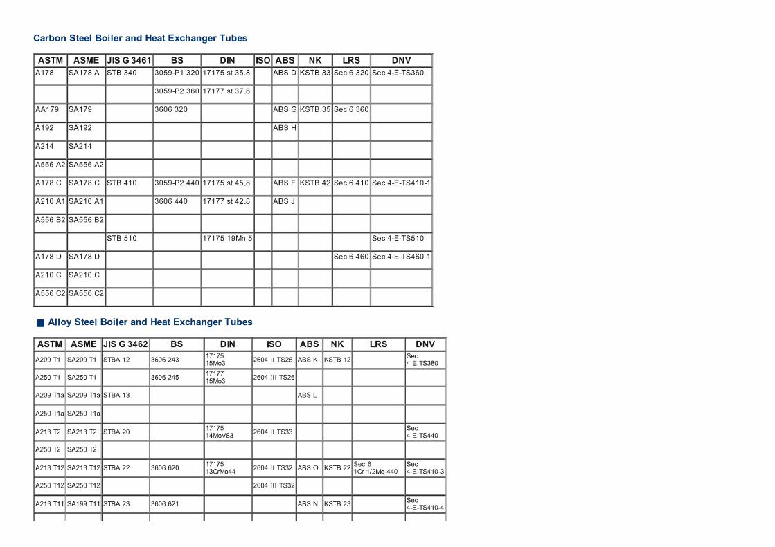
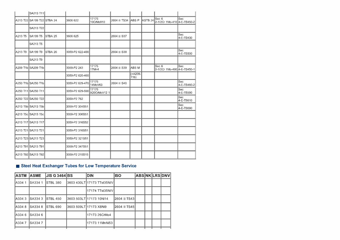
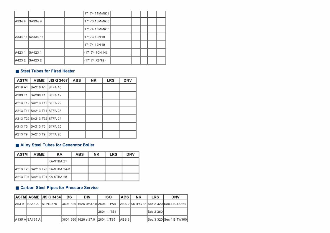
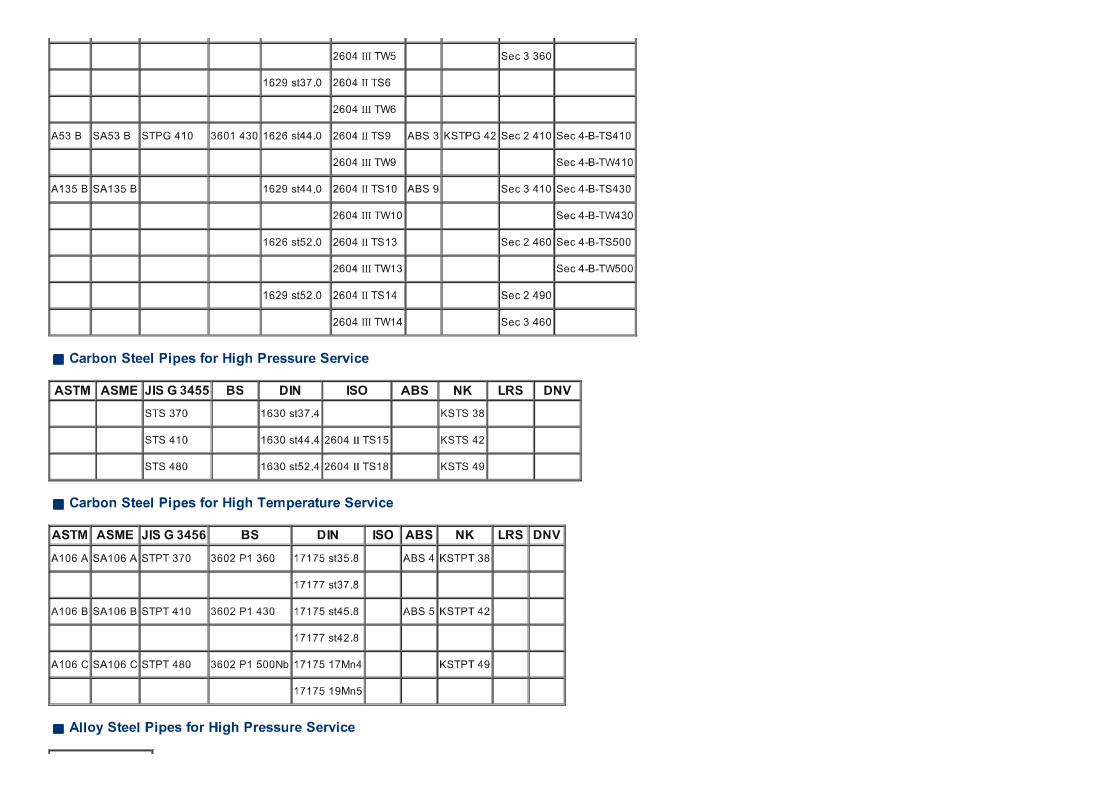
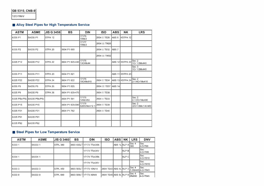
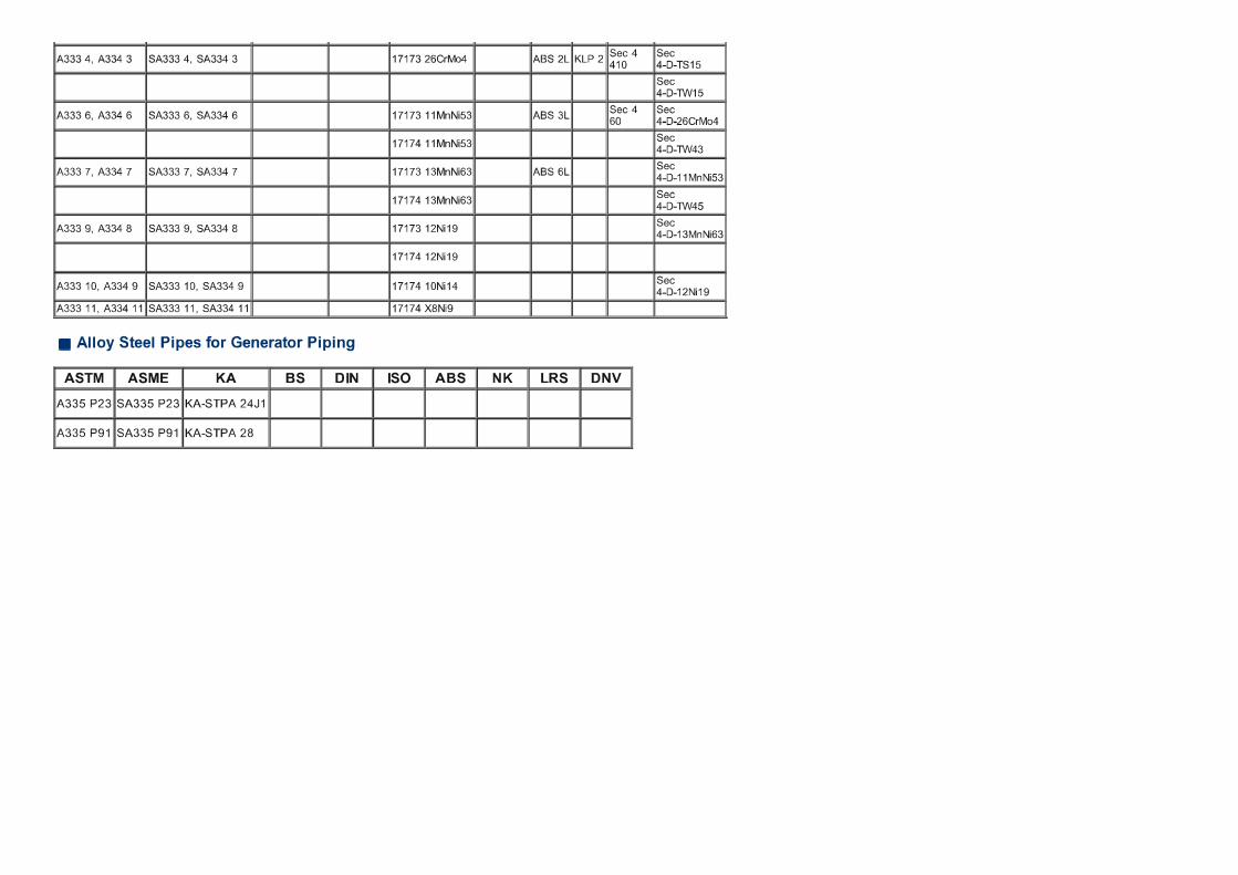

Disclosure to Promote the Right To Information
Whereas the Parliament of India has set out to provide a practical regime of right to information for citizens to secure access to information under the control of public authorities, in order to promote transparency and accountability in the working of every public authority, and whereas the attached publication of the Bureau of Indian Standards is of particular interest to the public, particularly disadvantaged communities and those engaged in the pursuit of education and knowledge, the attached public safety standard is made available to promote the timely dissemination of this information in an accurate manner to the public.
इटरनट मानक
“!ान $ एक न' भारत का +नम-ण”Satyanarayan Gangaram Pitroda
“Invent a New India Using Knowledge”
“प0रा1 को छोड न' 5 तरफ”Jawaharlal Nehru
“Step Out From the Old to the New”
“जान1 का अ+धकार, जी1 का अ+धकार”Mazdoor Kisan Shakti Sangathan
“The Right to Information, The Right to Live”
“!ान एक ऐसा खजाना > जो कभी च0राया नहB जा सकता ह”Bhartṛhari—Nītiśatakam
“Knowledge is such a treasure which cannot be stolen”
“Invent a New India Using Knowledge”
ह”ह”ह
IS 1239-1 (2004): Steel Tubes, Tubulars and Other WroughtSteel Fittings, Part 1: Steel Tubes (BI-LINGUAL) [MTD 19:Steel Tubes, Pipes abd Fittings]


© BIS 2009
B U R E A U O F I N D I A N S T A N D A R D SMANAK BHAVAN, 9 BAHADUR SHAH ZAFAR MARG
NEW DELHI 110002
tqykbZ@July 2009 ewY; oxZ@Price Group 4
vkbZ,l@IS 1239 (Hkkx@Part 1) : 2004
Hkkjrh; ekud
bLikr dh ufy;k¡] ufydkdkj lkefxz;k¡ rFkk fiVok¡bLikr dh vU; fQfVaxsa — fof'kf"V
Hkkx 1 bLikr dh ufy;k¡Hkkx 1 bLikr dh ufy;k¡Hkkx 1 bLikr dh ufy;k¡Hkkx 1 bLikr dh ufy;k¡Hkkx 1 bLikr dh ufy;k¡
¼ NBk iqujh{k.k ½
Indian Standard
STEEL TUBES, TUBULARS AND OTHER WROUGHTSTEEL FITTINGS — SPECIFICATION
PART 1 STEEL TUBES
( Sixth Revision )
vkbZlh,l@ICS 77.140.75
¼f}Hkk"kh@Bilingual½
© Hkk ek C;wjks 2009
Hkkjrh; ekud C;wjksekud Hkou] 9 cgknqj 'kkg T+kQj ekxZ
ubZ fnYyh 110002
bLikr dh ufydk,¡] ikbi vkSj fiQfVax fo"k; lfefr] ,eVhMh 19
izkDdFku
;g Hkkjrh; ekud (Hkkx 1) (NBk iqujh{k.k) bLikr dh ufydk,¡] ikbi vkSj fiQfVax fo"k; lfefr }kjk vafre :i fn, x, elkSnsdks èkkfRod bathfu;jh foHkkx ifj"kn }kjk vuqeksfnr fd, tkus ds i'pkr~ Hkkjrh; ekud C;wjks }kjk xzg.k fd;k x;kA
bl ekud dk izFke izdk'ku 1958 esa gqvk rFkk rnuarj Øe'k% 1964] 1968] 1973] 1979 rFkk 1990 esa bldk iqujh{k.k fd;kx;kA
bl iqujh{k.k esa fuEufyf[kr eq[; la'kksèku fd, x, gSa%
d) ikapos iqujh{k.k ls lacafèkr lHkh la'kksèku 'kkfey dj fy, x, gSaA
[k) lhoughu ufydkvksa (ysMy fo'ys"k.k) ds fy, jklk;fud la?kVu dks 'kkfey fd;k x;k gS rFkk osYMÑr ufy;ksa dsfuekZ.k ds fy, vkbZ,l 10748 osYMÑr ufy;ksa rFkk ibiksa ds fy, rRi&osfYyr bLikr fLVªi* ;k vkbZ,l 513 dksYMjksYM fuEu dkcZu bLikr 'khV rFkk fLVªi* dks 'kkfey fd;k x;k gSA
x) lHkh fu£n"V vo;oksa ds fy, lhoughu V~;wcksa ds mRikn fo'ys"k.k ds ekeys esa vuqer varj dks 'kkfey fd;k x;k gSA
?k) izo.kdksj Nksj okyh ufy;ksa dh vkiw£r ds izkoèkku dks 'kkfey dj fy;k x;k gSA
Steel Tubes, Pipes and Fittings Sectional Committee, MTD 19
FOREWORD
This Indian Standard (Part 1) (Sixth Revision) was adopted by the Bureau of Indian Standards, after the draftfinalized by the Steel Tubes, Pipes and Fittings Sectional Committee had been approved by the MetallurgicalEngineering Division Council.
This standard was first published in 1958 and subsequently revised in 1964, 1968, 1973, 1979 and 1990 respectively.
In this revision, the following main modifications have been made:
a) All the amendments on the fifth revision have been incorporated.
b) Chemical composition for seamless tubes (ladle analysis ) has been incorporated and for manufacturingof welded tubes, IS 10748 ‘Hot-rolled steel strip for welded tubes and pipes’ or IS 513 ‘Cold rolled lowcarbon steel sheets and strips’ have been included.
c) Permissible variation in case of product analysis of seamless tubes for all specified elements have beenincorporated.
d) Provision for supply of tubes with bevel end has been incorporated.
(Continued on third cover)
(rhljs doj ij tkjh)

AMENDMENT NO. 4 JUNE 2010 TO
IS 1239 (PART 1) : 2004 STEEL TUBES, TUBULARS AND OTHER WROUGHT STEEL FITTINGS —
SPECIFICATION
PART 1 STEEL TUBES
( Sixth Revision )
(Page 5, clause 10.1.1) — Substitute the following for the existing clause: ‘Each screwed tube shall be supplied with one socket conforming to IS 1239 (Part 2).’ (MTD 19)
Reprography Unit, BIS, New Delhi, India

AMENDMENT NO. 3 MAY 2008
TO
IS 1239 (PART 1) : 2004 STEEL TUBES, TUBULARS
AND OTHER WROUGHT STEEL FITTINGS ― SPECIFICATION
( Sixth Revision )
(Page 2, clause 6.1.1, first sentence) ― Substitute the following for the existing:
‘Chemical composition of steel to be used for seamless steel tubes, shall comply with Table 1 in Ladle sample
analysis.’
(Page 3, clause 8.1.1) ― Add the following Note at the end:
‘NOTE ― Mass of plain end tubes is also applicable for threaded tube without socket.’
(Page 6, clause 17.3) ― Delete the ‘Note’.
(Page 6, clause 17.4) ― Add the following Note at the end:
‘NOTE ― Additional colour bands, as given in 17.2 to 17.4 may also be applied.’
(MTD 19)
Reprography Unit, BIS, New Delhi, India

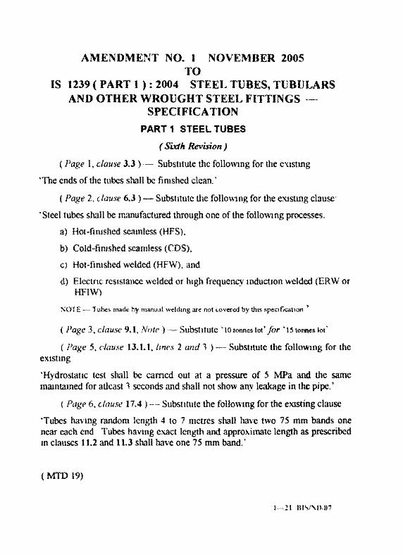
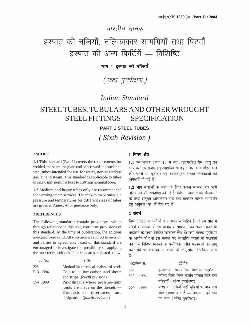
1
vkbZ,l@IS 1239 (Hkkx/Part 1) : 2004
Hkkjrh; ekud
bLikr dh ufy;k¡] ufydkdkj lkefxz;k¡ rFkk fiVok¡bLikr dh vU; fQfVaxsa — fof'kf"V
Hkkx 1 bLikr dh ufy;k¡Hkkx 1 bLikr dh ufy;k¡Hkkx 1 bLikr dh ufy;k¡Hkkx 1 bLikr dh ufy;k¡Hkkx 1 bLikr dh ufy;k¡
¼ NBk iqujh{k.k ½
Indian Standard
STEEL TUBES, TUBULARS AND OTHER WROUGHTSTEEL FITTINGS — SPECIFICATION
PART 1 STEEL TUBES
( Sixth Revision )
1 SCOPE
1.1 This standard (Part 1) covers the requirements forwelded and seamless plain end or screwed and socketedsteel tubes intended for use for water, non-hazardousgas, air and steam. This standard is applicable to tubesof size 6 mm nominal bore to 150 mm nominal bore.
1.2 Medium and heavy tubes only are recommendedfor carrying steam services. The maximum permissiblepressure and temperatures for different sizes of tubesare given in Annex A for guidance only.
2 REFERENCES
The following standards contain provisions, whichthrough reference in this text, constitute provisions ofthis standard. At the time of publication, the editionsindicated were valid. All standards are subject to revisionand parties to agreements based on this standard areencouraged to investigate the possibility of applyingthe most recent editions of the standards indicated below:
IS No. Title
228 Method for chemical analysis of steels513 : 1994 Cold-rolled low carbon steel sheets
and strips (fourth revision)554 : 1999 Pipe threads where pressure-tight
joints are made on the threads —Dimensions, tolerances anddesignation (fourth revision)
11111 fo"k; {ks=k fo"k; {ks=k fo"k; {ks=k fo"k; {ks=k fo"k; {ks=k
1-1 1-1 1-1 1-1 1-1 bl ekud (Hkkx 1) esa ty] [krjkjfgr xSl] ok;q ,oaHkki ds fy, iz;ksx gsrq vk'kf;r osYMÑr rFkk lhoujfgr lknsNksj okyh ;k pwM+hnkj ,oa lkWdsV;qDr bLikr ufydkvksa dhvis{kk,¡ nh xbZ gSaA
1-2 1-2 1-2 1-2 1-2 Hkki lsokvksa ds ogu ds fy, dsoy eè;e vkSj Hkkjhufydkvksa dh fliQkfj'k dh xbZ gSA fofHkUu vkdkjksa dh ufydkvkasds fy, vuqer vfèkdre nkc rFkk rkieku dsoy ekxZn'kZugsrq vuqcaèk ^d* esa fn, x, gSaA
22222 lanHkZ lanHkZ lanHkZ lanHkZ lanHkZ
fuEufyf[kr ekudksa esa os izkoèkku lfUufgr gSa tks bl ikB esalanHkZ ds ekè;e ls bl ekud ds izkoèkkuksa dk la?kVu djrs gSaAizdk'ku ds l;e fu£n"V laLdj.k oS| FksA lHkh ekud iqujh{k.kds vèkhu gSa rFkk bl ekud ij vkèkkfjr djkjksa ds i{kdkjksadks uhps fu£n"V ekudksa ds lokZfèkd uohu laLdj.kksa dks ykxwdjus dh laHkkouk dk irk yxkus ds fy, izksRlkfgr fd;k tkrkgS%
vkbZ,l l- 'kh"kZd228 bLikr dh jklk;fud fo'ys"k.k i¼fr513 % 1994 dksYM jksYM fuEu dkcZu bLikr 'khVsa rFkk
ifV~V;k¡ (pkSFkk iqujh{k.k)554 % 1999 ikbi dh pwfM+;k¡ tgk¡ pwfM+;ksa ij nkc dls
tksM+ yxk, tkrs gS — vk;ke] NwVsa rFkkin uke (pkSFkk iqujh{k.k)

2
�������IS 1239 (��/Part 1) : 2004
IS No. Title
1239 Mild steel tubes, tubulars and other(Part 2) : 1992 wrought steel fittings: Part 2 Mild
steel socket, tubulars and otherwrought steel pipe fittings (fourthrevision)
1387 : 1993 General requirements for the supplyof metallurgical materials (secondrevision)
1608 : 1995 Mechanical testing of metals —Tensile testing (second revision)
2328 : 1983 Method for flattening test on metallictubes (first revision)
2329 : 1985 Method for bend test on metallictubes (in full section) (firstrevision)
4711 : 1974 Methods for sampling of steel pipes,tubes and fittings (first revision)
4736 : 1986 Hot dip zinc coatings on mild steeltubes (first revision)
4740 : 1979 Code of practice for packaging ofsteel tubes (first revision)
8999 : 1979 Gauging practice for pipe threadswhere pressure tight joints arerequired on the threads
10748 : 1995 Hot rolled steel strip for welded tubesand pipes (first revision)
12278 : 1988 Method for ring tensile test onmetallic tubes
3 TERMINOLOGY
3.1 Black Tube
Tube as manufactured without any subsequent surfacetreatment.
3.2 Nominal Bore
A size reference denoting the approximate bore of thetube. For each size of tube, the outside diameter is fixedby the corresponding screw thread dimensions ofIS 554 and therefore, the actual bore of each size oftube will vary according to the thickness.
3.3 Plain End
The end of the tubes shall be finished clean.
3.4 Bevel End
The finished tube end shall be with a specified angleand root face as given in Fig. 1.
3.5 Tube, Pipe
A long, hollow, open-ended object of circular or othercross-section. The term tube is synonymous with theterm pipe.
vkbZ,l l- 'kh"kZd
1239 e`nq bLikr ufy;k¡] ufydkdkj lkexzh rFkk(Hkkx 2)% 1992 fiVok¡ bLikr dh vU; fiQfVax% Hkkx 2 enq
bLikr lkdsV] ufydkdkj lkexzh rFkk vU;fiVok¡ bLikr ikbi fiQfVaXl (pkSFkk iqujh{k.k)
1387 % 1993 èkkfRod lkexzh dh vkiw£r ds fy, lkekU;vis{kk,¡ (nwljk iqujh{k.k)
1608 % 1995 èkkrqvksa dk vfHk;kaf=kd ijh{k.k&ruu ijh{k.k(nwljk iqujh{k.k)
2328 % 1993 èkkfRod ufydkvksa ij piVkus lacaèkh ijh{k.kdh i¼fr (igyk iqujh{k.k)
2329 % 1985 èkkfRod ufydkvksa ij ueu ijh{k.k dhi¼fr (iw.kZ vuqHkkx esa) (igyk iqujh{k.k)
4711 % 1974 bLikr dh ikbikas] ufydkvksa rFkk fiQfVaXlds izfrp;u dh i¼fr (igyk iqujh{k.k)
4736 % 1986 e`nq bLikr ufydkvksa ij xeZ fMi tLrkysiu (igyk iqujh{k.k)
4740 % 1979 bLikr ufydkvksa ds iSd fd, tkus dhjhfr lafgrk (igyk iqujh{k.k)
8999 % 1979 ikbi dh pwfM+;ksa dk eki ysus dh jhfrtgk¡ pwfM+;ksa ij nkc dls tksM+ vko'd gSa
10748 % 1995 osYMÑr ufydkvksa ,oa ikbiksa ds fy, rIrosfYyr bLikr dh iV~Vh (igyk iqujh{k.k)
12278 % 1988 èkkfRod ufydkvksa ij fjax ruu ijh{k.kdh i¼fr
3 3 3 3 3 ikfjHkkf"kd 'kCnkoyhikfjHkkf"kd 'kCnkoyhikfjHkkf"kd 'kCnkoyhikfjHkkf"kd 'kCnkoyhikfjHkkf"kd 'kCnkoyh
3-1 3-1 3-1 3-1 3-1 dkyh ufydkdkyh ufydkdkyh ufydkdkyh ufydkdkyh ufydk
;Fkkfu£er ufydk ftlij dksbZ lrg mipkj u fd;k x;k gksA
3-23-23-23-23-2 vfHkfgr cksjvfHkfgr cksjvfHkfgr cksjvfHkfgr cksjvfHkfgr cksj
ufydk dk yxHkx cksj bafxr djus okyk vkdkj lanHkZA izR;sdvkdkj dh ufydk ds fy, cká O;kl dk fu|kZj.k vkbZ,l 554esa nh xbZ ln`'k pwM+h ekikas ds vuqlkj fd;k tkrk gS rFkkblfy, izR;sd vkdkj dh ufydk dk okLrfod cksj mldheksVkbZ ds vuqlkj gksxkA
3-3 3-3 3-3 3-3 3-3 lknk Nksjlknk Nksjlknk Nksjlknk Nksjlknk Nksj
ufydkvksa ds fljksa dh liQkbZ iwoZd vafre :i fn;k tk,xkA
3-4 3-4 3-4 3-4 3-4 csoy (ço.kdks.k) Nksjcsoy (ço.kdks.k) Nksjcsoy (ço.kdks.k) Nksjcsoy (ço.kdks.k) Nksjcsoy (ço.kdks.k) Nksj
ufydk dk vafre :i fn;k x;k Nksj vkÑfr 1 eas ;Fkk fn,x, fofu£"V dks.k rFkk vkèkkj iQyd okyk gksxkA
3-53-53-53-53-5 ufydk] ikbi ufydk] ikbi ufydk] ikbi ufydk] ikbi ufydk] ikbi
xksy ;k vU; varizZLFk dkV okyh yEch] [kks[kyh] nksuksa vksjls [kqys Nksjksa okyh oLrqA 'kCn ^V~;wc* ikbi 'kCn dk i;kZ;gSA
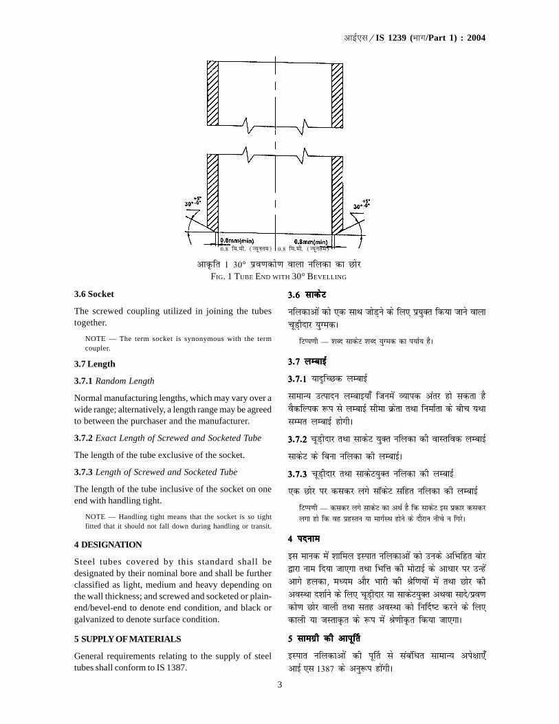
3
�������IS 1239 (��/Part 1) : 2004
3.6 Socket
The screwed coupling utilized in joining the tubestogether.
NOTE — The term socket is synonymous with the termcoupler.
3.7 Length
3.7.1 Random Length
Normal manufacturing lengths, which may vary over awide range; alternatively, a length range may be agreedto between the purchaser and the manufacturer.
3.7.2 Exact Length of Screwed and Socketed Tube
The length of the tube exclusive of the socket.
3.7.3 Length of Screwed and Socketed Tube
The length of the tube inclusive of the socket on oneend with handling tight.
NOTE — Handling tight means that the socket is so tightfitted that it should not fall down during handling or transit.
4 DESIGNATION
Steel tubes covered by this standard shall bedesignated by their nominal bore and shall be furtherclassified as light, medium and heavy depending onthe wall thickness; and screwed and socketed or plain-end/bevel-end to denote end condition, and black orgalvanized to denote surface condition.
5 SUPPLY OF MATERIALS
General requirements relating to the supply of steeltubes shall conform to IS 1387.
3-63-63-63-63-6 lkdsV lkdsV lkdsV lkdsV lkdsV
ufydkvksa dks ,d lkFk tksM+us ds fy, iz;qDr fd;k tkus okykpwM+hnkj ;qXedA
fVIi.kh — 'kCn lkdsV 'kCn ;qXed dk i;kZ; gSA
3-73-73-73-73-7 yEckbZ yEckbZ yEckbZ yEckbZ yEckbZ
3-7-13-7-13-7-13-7-13-7-1 ;kn`fPNd yEckbZ
lkekU; mRiknu yEckb;k¡ ftuesa O;kid varj gks ldrk gSoSdfYid :i ls yEckbZ lhek Øsrk rFkk fuekZrk ds chp ;FkklEer yEckbZ gksxhA
3-7-23-7-23-7-23-7-23-7-2 pwM+hnkj rFkk lkdsV ;qDr ufydk dh okLrfod yEckbZ
lkdsV ds fcuk ufydk dh yEckbZA
3-7-3 3-7-3 3-7-3 3-7-3 3-7-3 pwM+hnkj rFkk lkdsV;qDr ufydk dh yEckbZ
,d Nksj ij dldj yxs lkWdsV lfgr ufydk dh yEckbZ
fVIi.kh — dldj yxs lkdsV dk vFkZ gS fd lkdsV bl izdkj dldjyxk gks fd og izgLru ;k ekxZLFk gksus ds nkSjku uhps u fxjsA
44444 inuke inuke inuke inuke inuke
bl ekud esa 'kkfey bLikr ufydkvksa dks muds vfHkfgr cksj}kjk uke fn;k tk,xk rFkk fHkfÙk dh eksVkbZ ds vkèkkj ij mUgsavkxs gydk] eè;e vkSj Hkkjh dh Jsf.k;ksa esa rFkk Nksj dhvoLFkk n'kkZus ds fy, pwM+hnkj ;k lkdsV;qDr vFkok lkns@ço.kdks.k Nksj okyh rFkk lrg voLFkk dks fu£n"V djus ds fy,dkyh ;k tLrkÑr ds :i esa Js.khÑr fd;k tk,xkA
5 lkexzh dh vkiw£r5 lkexzh dh vkiw£r5 lkexzh dh vkiw£r5 lkexzh dh vkiw£r5 lkexzh dh vkiw£r
bLikr ufydkvksa dh iw£r ls lacafèkr lkekU; vis{kk,¡vkbZ ,l 1387 ds vuq:i gksaxhA
vkÑfr 1 30° izo.kdks.k okyk ufydk dk NksjFIG. 1 TUBE END WITH 30° BEVELLING
0-8 fe-eh- (U;wure) 0-8 fe-eh- (U;wure)

4
�������IS 1239 (��/Part 1) : 2004
6 MANUFACTURE
6.1 Seamless steel tube shall be made from testedquality steel manufactured by any approved processand shall be fully killed.
6.1.1 Chemical composition of the steel shall complywith Table 1 in Ladle Sample analysis.
Table 1 Chemical Composition (Ladle Analysis)Percent, Max
Carbon Manganese Sulphur Phosphorus
(1) (2) (3) (4)
0.20 1.30 0.040 0.040
6.2 The welded tubes shall be manufactured from hot-rolled steel strip for welded tubes and pipes conformingto IS 10748 or Cold-rolled low carbon steel sheets andstrips conforming to IS 513.
6.3 Steel tubes shall be manufactured through one ofthe following processes:
a) Hot finished seamless (HFS);b) Cold finished seamless (CDS);c) Hot finished welded (HFW); andd) Electric resistance welded or high frequency
induction welded (ERW or HFIW).
NOTE — Tubes made by manual welding are not coveredby this specification.
6.4 Light, medium and heavy tubes shall be eitherwelded or seamless as agreed to between the purchaserand the manufacturer.
6.5 For welded tubes, the height of the internal weld finshall not be greater than 60 percent of the specifiedwall thickness.
6.6 All electric wired tubes used for steam servicesshall be normalized. Only medium and heavy class oftube shall normally be used for steam services.
NOTE — HFS and HFW tubes need not be normalized.
7 CHEMICAL COMPOSITION
7.1 The analysis of steel shall be carried out either bythe method specified in IS 228 and its relevant parts orany other established instrumental/chemical methods.In case of dispute the procedure given in IS 228 and itsrelevant parts shall be the referee method. However,where method is not given in IS 228 and its relevantparts, the referee method shall be as agreed to betweenthe purchaser and the manufacturer.
7.1.1 Product Analysis
If so agreed between the purchaser and the
6 fuekZ.k6 fuekZ.k6 fuekZ.k6 fuekZ.k6 fuekZ.k
6-1 6-1 6-1 6-1 6-1 lhoujfgr ufydk dk fuekZ.k fdlh vuqeksfnr izfØ;k}kjk fu£er ijhf{kr xq.krk okys bLikr ls fd;k tk,xk rFkk blsiw.kZr% e`r fd;k tk,xkA
6-1-1 6-1-1 6-1-1 6-1-1 6-1-1 bLikr dk jklk;fud la?kVu ysMy uewuk fo'ys"k.k esalkj.kh 1 ds vuq:i gksxkA
lkj.kh 1 jklk;fud la?kVd (ysMy fo'ys"k.k)lkj.kh 1 jklk;fud la?kVd (ysMy fo'ys"k.k)lkj.kh 1 jklk;fud la?kVd (ysMy fo'ys"k.k)lkj.kh 1 jklk;fud la?kVd (ysMy fo'ys"k.k)lkj.kh 1 jklk;fud la?kVd (ysMy fo'ys"k.k)izfr'kr] izfr'kr] izfr'kr] izfr'kr] izfr'kr] vfèkdrevfèkdrevfèkdrevfèkdrevfèkdre
dkcZudkcZudkcZudkcZudkcZu eSaxuhteSaxuhteSaxuhteSaxuhteSaxuht lYiQjlYiQjlYiQjlYiQjlYiQj iQkLiQksjliQkLiQksjliQkLiQksjliQkLiQksjliQkLiQksjl(1) (2) (3) (4)
0.20 1.30 0.040 0.040
6-2 6-2 6-2 6-2 6-2 osYMd`r ufydkvksa dk fuekZ.k vkbZ,l 10748 ds vuq:iosYMd`r ufydkvksa rFkk ikbiksa ds fy, rIr osfYyr dh xbZbLikr iV~Vh vFkok vkbZ,l 513 ds vuq:i 'khr&jksy dh xbZfuEu dkcZu bLikr 'khVksa ls fd;k tk,xkA
6-3 6-3 6-3 6-3 6-3 bLikr ufydkvkas dk fuekZ.k fuEu esa ls fdlh ,d izfØ;k}kjk fd;k tk,xk%
d) rRi rS;kj lhou jfgr (,p,iQ,l)_[k) 'khr rS;kj lohu jfgr (lhMh,l)_x) r`Ir rS;kj osYMÑr (,p,iQMCY;w)_ rFkk?k) fo|qr izfrjksèkd osYMÑr vFkok mPp vko`fÙk izsj.k
osYMÑr (bZvkjMCY;w ;k ,p,iQvkbZMCY;w)A
fVIi.kh — gLr osfYMax }kjk fu£er ufydka, bl fof'k"V esa ufydkax
'kkfey ugha gSaA
6-4 6-4 6-4 6-4 6-4 gYdh] eè;e rFkk Hkkjh ufy;k¡ Øsrk rFkk fuekZrk ds chp gqbZlgefr ds vuqlkj ;k rks osYMÑr gksaxh vFkok lhoujfgr gksaxhA
6-56-56-56-56-5 osYMÑr ufydkvksa ds fy,] vkarfjd osYM fiQu dhm¡QpkbZ fu£n"V fHkfÙk eksVkbZ ds 60 izfr'kr ls vfèkd ugha gksxhA
6-66-66-66-66-6 Hkki lsokvksa ds fy, iz;qDr dh tkus okyh lHkh fo|qrosYMÑr ufy;k¡ izlkekU;Ñr gksaxhA Hkki lsokvksa ds fy,lkekU;r% dsoy eè;e rFkk Hkkjh Js.kh dh ufydk dk ghbLrseky fd;k tk,xkA
fVIi.kh μ ,p,iQl rFkk ,p,iQMCY;w ufydkvksa dks izlkekU;Ñr
fd;k tkuk vko';d ugha gSA
7 jklk;fud la?kVu7 jklk;fud la?kVu7 jklk;fud la?kVu7 jklk;fud la?kVu7 jklk;fud la?kVu
7-1 7-1 7-1 7-1 7-1 bLikr dk fo'ys"k.k vkbZ,l 228 rFkk blds laxr Hkkxksa esafu£n"V i¼fr }kjk ;k fdlh vU; LFkkfir ;k¡f=kd@jklk;fud i¼fr}kjk fd;k tk,xkA fookn ds ekeys esa vkbZ,l 228 rFkk blds laxrHkkxksa esa nh xbZ izfØ;kfofèk lanHkZ i¼fr gksxhA rFkkfi tgk¡ vkbZ,l228 rFkk blds laxr Hkkxksa esa i¼fr ugha nh xbZ gS ogk¡ lanHkZ i¼frØsrk rFkk fuekZrk ds chp ;Fkk lEer i¼fr gksxhA
7-1-17-1-17-1-17-1-17-1-1 mRikn fo'ys"k.k
;fn Øsrk rFkk fuekZrk ds chp ,slh lgefr gks rks mRikn
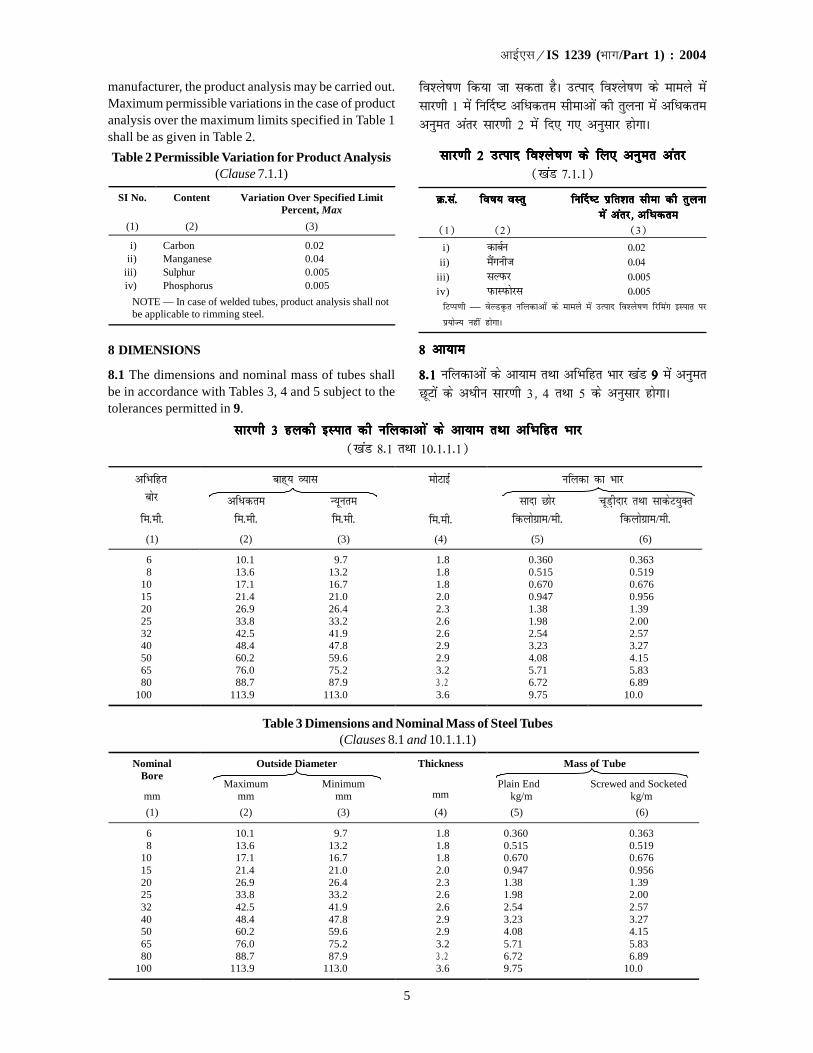
5
�������IS 1239 (��/Part 1) : 2004
manufacturer, the product analysis may be carried out.Maximum permissible variations in the case of productanalysis over the maximum limits specified in Table 1shall be as given in Table 2.
Table 2 Permissible Variation for Product Analysis(Clause 7.1.1)
SI No. Content Variation Over Specified Limit Percent, Max
(1) (2) (3)
i) Carbon 0.02 ii) Manganese 0.04
iii) Sulphur 0.005 iv) Phosphorus 0.005
NOTE — In case of welded tubes, product analysis shall not be applicable to rimming steel.
8 DIMENSIONS
8.1 The dimensions and nominal mass of tubes shallbe in accordance with Tables 3, 4 and 5 subject to thetolerances permitted in 9.
fo'ys"k.k fd;k tk ldrk gSA mRikn fo'ys"k.k ds ekeys esalkj.kh 1 esa fu£n"V vfèkdre lhekvksa dh rqyuk esa vfèkdrevuqer varj lkj.kh 2 esa fn, x, vuqlkj gksxkA
lkj.kh lkj.kh lkj.kh lkj.kh lkj.kh 22222 mRikn fo'ys"k.k ds fy, vuqer varj mRikn fo'ys"k.k ds fy, vuqer varj mRikn fo'ys"k.k ds fy, vuqer varj mRikn fo'ys"k.k ds fy, vuqer varj mRikn fo'ys"k.k ds fy, vuqer varj([kaM 7-1-1)
Ø-la-Ø-la-Ø-la-Ø-la-Ø-la- fo"k; oLrqfo"k; oLrqfo"k; oLrqfo"k; oLrqfo"k; oLrq fu£n"V izfr'kr lhek dh rqyukfu£n"V izfr'kr lhek dh rqyukfu£n"V izfr'kr lhek dh rqyukfu£n"V izfr'kr lhek dh rqyukfu£n"V izfr'kr lhek dh rqyukesa varj] esa varj] esa varj] esa varj] esa varj] vfèkdrevfèkdrevfèkdrevfèkdrevfèkdre
(1) (2) (3)i) dkcZu 0-02
ii) eSaxuht 0-04iii) lYiQj 0-005iv) iQkLiQksjl 0-005fVIi.kh — osYMÑr ufydkvksa ds ekeys esa mRikn fo'ys"k.k fjfeax bLikr ij
iz;ksT; ugha gksxkA
8 8 8 8 8 vk;kevk;kevk;kevk;kevk;ke
8-18-18-18-18-1 ufydkvksa ds vk;ke rFkk vfHkfgr Hkkj [kaM 99999 esa vuqerNwVksa ds vèkhu lkj.kh 3] 4 rFkk 5 ds vuqlkj gksxkA
lkj.kh 3 gydh bLikr dh ufydkvks a ds vk;ke rFkk vfHkfgr Hkkjlkj.kh 3 gydh bLikr dh ufydkvks a ds vk;ke rFkk vfHkfgr Hkkjlkj.kh 3 gydh bLikr dh ufydkvks a ds vk;ke rFkk vfHkfgr Hkkjlkj.kh 3 gydh bLikr dh ufydkvks a ds vk;ke rFkk vfHkfgr Hkkjlkj.kh 3 gydh bLikr dh ufydkvks a ds vk;ke rFkk vfHkfgr Hkkj([kaM 8-1 rFkk 10-1-1-1)
��������� � �� �� ������ ��������� �
���� � ������� �����
������� �
��������� �������������� ��������
������� ������� ������� ������� �������������� ��������������
(1) (2) (3) (4) (5) (6)
6 10.1 9.7 1.8 0.360 0.363 8 13.6 13.2 1.8 0.515 0.519
10 17.1 16.7 1.8 0.670 0.676 15 21.4 21.0 2.0 0.947 0.956 20 26.9 26.4 2.3 1.38 1.39 25 33.8 33.2 2.6 1.98 2.00 32 42.5 41.9 2.6 2.54 2.57 40 48.4 47.8 2.9 3.23 3.27 50 60.2 59.6 2.9 4.08 4.15 65 76.0 75.2 3.2 5.71 5.83 80 88.7 87.9 3 . 2 6.72 6.89
100 113.9 113.0 3.6 9.75 10.0
Table 3 Dimensions and Nominal Mass of Steel Tubes(Clauses 8.1 and 10.1.1.1)
Outside Diameter Mass of Tube Nominal Bore
Maximum Minimum
Thickness
Plain End Screwed and Socketed mm mm mm mm kg/m kg/m
(1) (2) (3) (4) (5) (6)
6 10.1 9.7 1.8 0.360 0.363 8 13.6 13.2 1.8 0.515 0.519
10 17.1 16.7 1.8 0.670 0.676 15 21.4 21.0 2.0 0.947 0.956 20 26.9 26.4 2.3 1.38 1.39 25 33.8 33.2 2.6 1.98 2.00 32 42.5 41.9 2.6 2.54 2.57 40 48.4 47.8 2.9 3.23 3.27 50 60.2 59.6 2.9 4.08 4.15 65 76.0 75.2 3.2 5.71 5.83 80 88.7 87.9 3 . 2 6.72 6.89
100 113.9 113.0 3.6 9.75 10.0

6
�������IS 1239 (��/Part 1) : 2004
lkj.kh 4 eè;e bLikr ufydkvks a ds vk;ke rFkk vfHkfgr Hkkjlkj.kh 4 eè;e bLikr ufydkvks a ds vk;ke rFkk vfHkfgr Hkkjlkj.kh 4 eè;e bLikr ufydkvks a ds vk;ke rFkk vfHkfgr Hkkjlkj.kh 4 eè;e bLikr ufydkvks a ds vk;ke rFkk vfHkfgr Hkkjlkj.kh 4 eè;e bLikr ufydkvks a ds vk;ke rFkk vfHkfgr Hkkj([kaM 8-1)
��������� � ������� � �� �� ������ �������� �
���� �������� ����� � ��������� �������������� ��������
������� ������� ������� ������� �������������� ��������������
(1) (2) (3) (4) (5) (6)
6 10.6 9.8 2.0 0.404 0.407
8 14.0 13.2 2.3 0.641 0.645
10 17.5 16.7 2.3 0.839 0.845
15 21.8 21.0 2.6 1.21 1.22
20 27.3 26.5 2.6 l.56 1.57
25 34.2 33.3 3.2 2.41 2.43
32 42.9 42.0 3.2 3.10 3.13
40 48.8 47.9 3.2 3.56 3.60
50 60.8 59.7 3.6 5.03 5.10
65 76.6 75.3 3.6 6.42 6.54
80 89.5 88.0 4.0 8.36 8.53
100 115.0 113.1 4.5 12.20 12.50
125 140.8 138.5 4.8 15.90 16.40
150 166.5 163.9 4.8 18.90 19.50
Table 4 Dimensions and Nominal Mass of Steel Tubes — Medium(Clause 8.1)
Outside Diameter Thickness Mass of Tube Nominal Bore
Maximum Minimum Plain End Screwed and Socketed
mm mm mm mm kg/m kg/m
(1) (2) (3) (4) (5) (6)
6 10.6 9.8 2.0 0.404 0.407
8 14.0 13.2 2.3 0.641 0.645
10 17.5 16.7 2.3 0.839 0.845
15 21.8 21.0 2.6 1.21 1.22
20 27.3 26.5 2.6 l.56 1.57
25 34.2 33.3 3.2 2.41 2.43
32 42.9 42.0 3.2 3.10 3.13
40 48.8 47.9 3.2 3.56 3.60
50 60.8 59.7 3.6 5.03 5.10
65 76.6 75.3 3.6 6.42 6.54
80 89.5 88.0 4.0 8.36 8.53
100 115.0 113.1 4.5 12.2 12.5
125 140.8 138.5 4.8 15.9 16.4
150 166.5 163.9 4.8 18.9 19.5
8.1.1 Thickness and mass mentioned in Tables 3, 4and 5 are applicable to both black and galvanizedtubes.
8-1-18-1-18-1-18-1-18-1-1 lkj.kh 3] 4 rFkk 5 esa mfYyf[kr eksVkbzZ rFkk Hkkjdkyh rFkk tLrkÑr nksuksa izdkj dh ufydkvksa ij iz;ksT;gksxkA
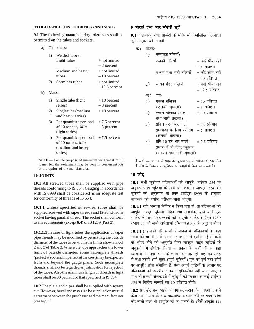
7
�������IS 1239 (��/Part 1) : 2004
9 TOLERANCES ON THICKNESS AND MASS
9.1 The following manufacturing tolerances shall bepermitted on the tubes and sockets:
a) Thickness:
1) Welded tubes:Light tubes + not limited
– 8 percentMedium and heavy + not limitedtubes – 10 percent
2) Seamless tubes + not limited– 12.5 percent
b) Mass:
1) Single tube (light + 10 percentseries) – 8 percent
2) Single tube (medium ± 10 percentand heavy series)
3) For quantities per load + 7.5 percentof 10 tonnes, Min – 5 percent(light series)
4) For quantities per load ± 7.5 percentof 10 tonnes, Min(medium and heavyseries)
NOTE — For the purpose of minimum weighment of 10tonnes lot, the weighment may be done in convenient lotsat the option of the manufacturer.
10 JOINTS
10.1 All screwed tubes shall be supplied with pipethreads conforming to IS 554. Gauging in accordancewith IS 8999 shall be considered as an adequate testfor conformity of threads of IS 554.
10.1.1 Unless specified otherwise, tubes shall besupplied screwed with taper threads and fitted with onesocket having parallel thread. The socket shall conformto all requirements (except 6.4) of IS 1239 (Part 2).
10.1.1.1 In case of light tubes the application of taperpipe threads may be modified by permitting the outsidediameter of the tubes to be within the limits shown in col2 and 3 of Table 3. Where the tube approaches the lowerlimit of outside diameter, some incomplete threads(perfect at root and imperfect at the crest) may be expectedfrom and beyond the gauge plane. Such incompletethreads, shall not be regarded as justification for rejectionof the tubes. Also the minimum length of threads in lighttubes shall be 80 percent of that specified in IS 554.
10.2 The plain end pipes shall be supplied with squarecut. However, bevel end may also be supplied on mutualagreement between the purchaser and the manufacturer(see Fig. 1).
9 eksVkbZ rFkk Hkkj lacaèkh NwVs a9 eksVkbZ rFkk Hkkj lacaèkh NwVs a9 eksVkbZ rFkk Hkkj lacaèkh NwVs a9 eksVkbZ rFkk Hkkj lacaèkh NwVs a9 eksVkbZ rFkk Hkkj lacaèkh NwVs a
9-1 9-1 9-1 9-1 9-1 ufydkvksa rFkk lkdsVksa ds lacaèk esa fuEufyf[kr mRiknuNwVsa vuqer dh tk,axh%
d) eksVkbZ%1) osYMd`r ufy;k¡%
gydh ufy;k¡ + dksbZ lhek ugha– 8 izfr'kr
eè;e rFkk Hkkjh ufy;k¡ + dksbZ lhek ugha– 10 izfr'kr
2) lhou jfgr ufy;k¡ + dksbZ lhek ugha– 12-5 izfr'kr
[k) Hkkj%1) ,dy ufydk + 10 izfr'kr
(gydh J`a[kyk) – 8 izfr'kr2) ,dy ufydk (eè;e ± 10 izfr'kr
rFkk Hkkjh J`a[kyk)3) izfr 10 Vu Hkkj okyh + 7-5 izfr'kr
izek=kkvksa ds fy, U;wure – 5 izfr'kr(gydh J`a[kyk)
4) izfr 10 Vu Hkkj okyh ± 7-5 izfr'krizek=kkvksa ds fy, U;wure(eè;e rFkk Hkkjh J`a[kyk)
fVIi.kh — 10 Vu ds lewg ds U;wure Hkkj ds iz;kstukFkZ] Hkkj rksyfuekZrk osQ fodYi ij lqfo/ktud lewgksa esa fd;k tk ldrk gSA
10 tksM+10 tksM+10 tksM+10 tksM+10 tksM+
10-110-110-110-110-1 lHkh pwM+hnkj ufydkvksa dh vkiw£r vkbZ,l 554 dsvuq:i ikbi pwfM+;ksa ds lkFk dh tk,xhA vkbZ,l 554 dhpwfM+;ksa dh vuq:irk ds fy, vkbZ,l 8999 ds vuqlkjekikadu dks i;kZIr ijh{k.k ekuk tk,xkA
10-1-110-1-110-1-110-1-110-1-1 ;fn vU;Fkk fu£n"V u fd;k x;k gks] rks ufydkvksa dhvkiw£r xkonqe pwfM+;ksa lfgr rFkk lekukarj pwM+h okys ,dlkdsV ds lkFk fiQV djds dh tk,xhA lkdsV vkbZ,l 1239(Hkkx 2) dh lHkh vis{kkvksa (flok, 6-46-46-46-46-4) ds vuq:i gksxkA
10-1-1-110-1-1-110-1-1-110-1-1-110-1-1-1 gydh ufydkvksa ds ekeys esa] ufydkvksa ds ckáO;kl dks lkj.kh 3 ds dkye 2 rFkk 3 eas n'kkZ;h xbZ lhekvksads Hkhrj gksus dh vuqefr nsdj xkonqe ikbi pwfM;k¡ dsvuqiz;ksx esa la'kksèku fd;k tk ldrk gSA tgk¡ ufydk ckáO;kl dh fuEure lhek ds yxHkx lfUudV gks] ogk¡ xst lrgls rFkk mlls vkxs dqN viw.kZ pwfM+;ksa (ewy ij iw.kZ rFkk 'kh"kZij vèkwjh) gksuk laHkkfor gS] ,slh viw.kZ pwfM;ksa ds vkèkkj ijufydkvkas dks vLohdkj djuk ;qfDrlaxr ugha ekuk tk,xkAlkFk gh gYdh ufydkvksa esa pwfM+;ksa dh U;wure yEckbZ vkbZ,l554 esa fu£n"V yEckbZ dk 80 izfr'kr gksxhA
10-210-210-210-210-2 lkns Nksj okyh ikbiksa dks oxkZdkj dVko fn;k tk,xkA rFkkfiØsrk rFkk fuekZrk ds chp ikjLifjd lgefr gksus ij izo.k dks.kNksj okyh ikbisa Hkh vkiwfjr dh tk ldrh gSaA (ns[kaas vkÑfr 1)A

8
�������IS 1239 (��/Part 1) : 2004
Table 5 Dimensions and Nominal Mass of Steel Tubes — Heavy
(Clauses 8.1 and 8.1.1)
Outside Diameter Thickness Mass of Tube Nominal Bore
Maximum Minimum Plain End Screwed and Socketed
mm mm mm mm kg/m kg/m
(1) (2) (3) (4) (5) (6)
6 10.5 9.8 2.6 0.487 0.490
8 14.0 13.2 2.9 0.765 0.769
10 17.5 16.7 2.9 1.02 1.03
15 21.8 21.0 3.2 1.44 1.45
20 27.3 26.5 3.2 1.87 1.88
25 34.2 33.3 4.0 2.93 2.95
32 42.9 42.0 4.0 3.79 3.82
40 48.8 47.9 4.0 4.37 4.41
50 60.8 59.7 4.5 6.19 6.26
65 76.6 75.3 4.5 7.93 8.05
80 89.5 88.0 4.8 9.90 10.10
100 115.0 113.1 5.4 14.50 14.80
125 140.8 138.5 5.4 17.90 18.40
150 166.5 163.9 5.4 21.30 21.90
lkj.kh 5 Hkkjh bLikr ufydkvks a ds vk;ke rFkk vfHkfgr Hkkjlkj.kh 5 Hkkjh bLikr ufydkvks a ds vk;ke rFkk vfHkfgr Hkkjlkj.kh 5 Hkkjh bLikr ufydkvks a ds vk;ke rFkk vfHkfgr Hkkjlkj.kh 5 Hkkjh bLikr ufydkvks a ds vk;ke rFkk vfHkfgr Hkkjlkj.kh 5 Hkkjh bLikr ufydkvks a ds vk;ke rFkk vfHkfgr Hkkj([kaM 8-1 vkSj 8-1-1)
��������� � ������� � �� �� ������ ������������ �
������� ����� � ��������� �������������� ��������
������� ������� ������� ������� �������������� ��������������
(1) (2) (3) (4) (5) (6)
6 10.5 9.8 2.6 0.487 0.490
8 14.0 13.2 2.9 0.765 0.769
10 17.5 16.7 2.9 1.02 1.03
15 21.8 21.0 3.2 1.44 1.45
20 27.3 26.5 3.2 1.87 1.88
25 34.2 33.3 4.0 2.93 2.95
32 42.9 42.0 4.0 3.79 3.82
40 48.8 47.9 4.0 4.37 4.41
50 60.8 59.7 4.5 6.19 6.26
65 76.6 75.3 4.5 7.93 8.05
80 89.5 88.0 4.8 9.90 10.10
100 115.0 113.1 5.4 14.50 14.80
125 140.8 138.5 5.4 17.90 18.40
150 166.5 163.9 5.4 21.30 21.90
11 LENGTHS
Following tolerances shall be applied on lengths oftubes.
11.1 Random Length
4 to 7 m, unless otherwise specified includes one socketfor screwed and socketed tubes.
1111111111 yEckbZ yEckbZ yEckbZ yEckbZ yEckbZ
ufydkvksa dh yEckbZ ds lacaèk esa fuEufyf[kr NwVsa iz;ksT; dhtk,axhA
11.1 ;kn`fPNd yEckbZ;kn`fPNd yEckbZ;kn`fPNd yEckbZ;kn`fPNd yEckbZ;kn`fPNd yEckbZ
4 ls 7 ehVj] tc rd fd vU;Fkk fu£n"V u fd;k x;k gksA blesapwM+hnkj rFkk lkWdsV;qDr ufydkvksa ds fy, ,d lkdsV 'kkfey gSA
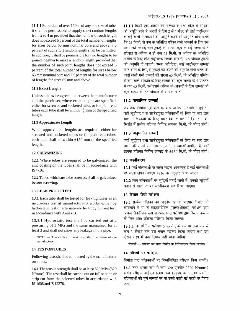
9
�������IS 1239 (��/Part 1) : 2004
11.1.1 For orders of over 150 m of any one size of tube,it shall be permissible to supply short random lengthsfrom 2 to 4 m provided that the number of such lengthdoes not exceed 5 percent of the total number of lengthsfor sizes below 65 mm nominal bore and above, 7.5percent of such short random length shall be permitted.In addition, it shall be permissible for two lengths to bejoined together to make a random length, provided thatthe number of such joint lengths does not exceed 5percent of the total number of lengths for sizes below65 mm nominal bore and 7.5 percent of the total numberof lengths for sizes 65 mm and above.
11.2 Exact Length
Unless otherwise agreed to between the manufacturerand the purchaser, where exact lengths are specified,either for screwed and socketed tubes or for plain-endtubes each tube shall be within 6
0+− mm of the specified
length.
11.3 Approximate Length
When approximate lengths are required, either forscrewed and socketed tubes or for plain end tubes,each tube shall be within ±150 mm of the specifiedlength.
12 GALVANIZING
12.1 Where tubes are required to be galvanized, thezinc coating on the tubes shall be in accordance withIS 4736.
12.2 Tubes, which are to be screwed, shall be galvanizedbefore screwing.
13 LEAK PROOF TEST
13.1 Each tube shall be tested for leak tightness as anin-process test at manufacturer’s works either byhydrostatic test or alternatively by Eddy current test,in accordance with Annex B.
13.1.1 Hydrostatic test shall be carried out at apressuring of 5 MPa and the same maintained for atleast 3 and shall not show any leakage in the pipe.
NOTE — The choice of test is at the discretion of themanufacturer.
14 TEST ON TUBES
Following tests shall be conducted by the manufactureron tubes.
14.1 The tensile strength shall be at least 320 MPa (320N/mm2). The test shall be carried out on full section orstrip cut from the selected tubes in accordance withIS 1608 and IS 12278.
11-1-1 11-1-1 11-1-1 11-1-1 11-1-1 fdlh ,d vkdkj dh ufydk ds 150 ehVj ls vfèkddh vkiw£r djus ds vkns'kksa ds fy, 2 ls 4 ehVj dh NksVh ;knfPNdyEckbZ okyh ufydkvksa dh vkiw£r djus dh vuqefr gksxh c'krsZfd 65 fe-eh- ls de ds vfHkfgr ifjosèk okys vkdkjksa ds fy, blizdkj dh yEckbZ oky VqdMs+ dh la[;k dqN yEckbZ la[;k ds 5izfr'kr ls vfèkd u gks rFkk 65 fe-eh- ls vfèkd ds vfHkfgrifjosèk ds fy, NksVh ;knfPNd yEckbZ oky ,sls 7-5 izfr'kr VqdMksadh vuqefr nh tk,xhA blds vfrfjDr] dksbZ ;knfPNd yEckbZizkIr djus ds fy, nks VqdM+ksa dks tksM+us dh vuqefr gksxh c'krsZ fdtksM+ksa okyh ,slh yEckbZ dh la[;k 65 fe-eh- ds vfHkfgr ifjosèkls de okys vkdkjksa ds fy, yEckbZ dh dqy la[;k ds 5 izfr'krls rFkk 65 fe-eh- ,oa mlls vfèkd ds vkdkjksa ds fy, yEckbZ dhdqy la[;k ds 7-5 izfr'kr ls vfèkd u gksA
11-2 okLrfod yEckbZ11-2 okLrfod yEckbZ11-2 okLrfod yEckbZ11-2 okLrfod yEckbZ11-2 okLrfod yEckbZ
tc rd fuekZrk ,oa Øsrk ds chp vU;Fkk lgefr u gqbZ gks]ogk¡ pwM+hnkj rFkk lkdsV;qDr ufydkvksa ds fy, ;k lkjs Nksjokyh ufydkvksa ds fy, okLrfod yEckbZ fu£n"V gksus dhfLFkfr esa izR;sd ufydk fu£n"V yxHkx fe-eh- ds Hkhrj gksxhA
11-3 vuqekfur yEckbZ11-3 vuqekfur yEckbZ11-3 vuqekfur yEckbZ11-3 vuqekfur yEckbZ11-3 vuqekfur yEckbZ
tgk¡ pwM+hnkj rFkk lkdsV;qDr ufydkvksa ds fy, ;k lkns Nksjokyh ufydkvksa ds fy, vuqekfur yEckb;k¡ visf{kr gSa] ogk¡izR;sd ufydk fu£n"V yEckbZ ds ±150 fe-eh- ds Hkhrj gksxhA
12 tLrhdj.k12 tLrhdj.k12 tLrhdj.k12 tLrhdj.k12 tLrhdj.k
12-112-112-112-112-1 tgk¡ ufydkvksa ij tLrk p<+kuk vko';d gS ogk¡ ufydkvksaij tLrk ysiu vkbZ,l 4736 ds vuqlkj fd;k tk,xkA
12-212-212-212-212-2 ftu ufydkvksa ij pwfM+;k¡ cukbZ tkuh gSa] mudh pwfM+;k¡cukus ls igys mudk tLrhdj.k dj fy;k tk,xkA
13 fjlko jksèkh ijh{k.k13 fjlko jksèkh ijh{k.k13 fjlko jksèkh ijh{k.k13 fjlko jksèkh ijh{k.k13 fjlko jksèkh ijh{k.k
13-113-113-113-113-1 izR;sd ufydk dk vuqcaèk [k ds vuqlkj fuekZrk dsdkj[kkus esa ;k rks gkbMªksLVsfVd (tyLFkSfrd) ijh{k.k }kjkvFkok oSdfYid :i ls varj èkkjk ijh{k.k }kjk fjlko dlkods fy, var% izfØ;k ijh{k.k fd;k tk,xkA
13-1-113-1-113-1-113-1-113-1-1 tyLFkSfrd ijh{k.k 5 ,eih, ds nkc ij rFkk de lsde 3 lSdsaM rd mls cuk, j[kdj fd;k tk,xk rFkk blnkSjku ikbi esa dksbZ fjlko ugha gksuk pkfg,A
fVIi.kh — ijh{k.k dk p;u fuekZrk ds foosdkuqlkj fd;k tk,xkA
14 ufy;ks a ij ijh{k.k14 ufy;ks a ij ijh{k.k14 ufy;ks a ij ijh{k.k14 ufy;ks a ij ijh{k.k14 ufy;ks a ij ijh{k.k
fuekZrk }kjk ufydkvksa ij fuEufyf[kr ijh{k.k fd, tk,axsA
14-114-114-114-114-1 ruu {kerk de ls de 320 ,eih, (320 N/mm2)gksxhA ijh{k.k vkbZ,l 1608 rFkk 12278 ds vuqlkj p;furufydkvksa dh iw.kZ yEckbZ ij ;k muls dkVh xbZ iV~Vh ij fd;ktk,xkA
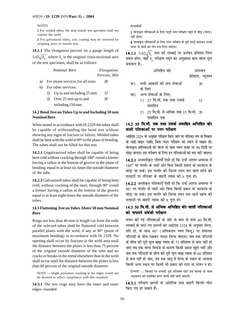
10
�������IS 1239 (��/Part 1) : 2004
NOTES
1 For welded tubes, the strip tensile test specimen shall notcontain the weld.
2 For galvanized tubes, zinc coating may be removed bystripping prior to tensile test.
14.1.1 The elongation percent on a gauge length of
o5.65 ,S where So is the original cross-sectional area
of the test specimen, shall be as follows:
Nominal Bore ElongationPercent, Min
a) For steam services for all sizes 20
b) For other services:
1) Up to and including 25 mm 12
2) Over 25 mm up to and 20
including 150 mm
14.2 Bend Test on Tubes Up to and Including 50 mmNominal Bore
When tested in accordance with IS 2329 the tubes shallbe capable of withstanding the bend test withoutshowing any signs of fracture or failure. Welded tubesshall be bent with the weld at 90° to the plane of bending.The tubes shall not be filled for this test.
14.2.1 Ungalvanized tubes shall be capable of beingbent cold without cracking through 180° round a formerhaving a radius at the bottom of groove in the plane ofbending, equal to at least six times the outside diameterof the tube.
14.2.2 Galvanized tubes shall be capable of being bentcold, without cracking of the steel, through 90° rounda former having a radius at the bottom of the grooveequal to at least eight times the outside diameter of thetubes.
14.3 Flattening Test on Tubes Above 50 mm NominalBore
Rings not less than 40 mm in length cut from the endsof the selected tubes shall be flattened cold betweenparallel plates with the weld, if any at 90° (point ofmaximum bending) in accordance with IS 2328. Noopening shall occur by fracture in the weld area untilthe distance between the plates is less than 75 percentof the original outside diameter of the tube and nocracks or breaks in the metal elsewhere than in the weldshall occur until the distance between the plates is lessthan 60 percent of the original outside diameter.
NOTE — Slight premature cracking at the edges would notbe deemed to affect compliance with this standard.
14.3.1 The test rings may have the inner and outeredges rounded.
fVIi.kh;k¡
11111 osYMÑr ufydkvksa ds fy, iV~Vh ruu ijh{k.k uewus esa tksM+ (osYM)ugha gksxkA
22222 tLrkÑr ufydkvksa ds fy, ruu ijh{k.k ds iwoZ iVV~h dkVdj mudsmQij ls tLrs dk ysi gVk fn;k tk,XkkA
14-1-1 14-1-1 14-1-1 14-1-1 14-1-1 o5.65 S eki dh yEckbZ ij izyacu izfr'kr fuEuizdkj gksxk] tgk¡ So ijh{k.k uewus dk vuqizlFk dkV okyk ewy{ks=kiQy gS%
vfHkfgr cksj çyEcuçfr'kr] U;wure
d) lHkh vkdkjksa dh eki lsokvksa 20ds fy,
[k) vU; lsokvksa ds fy,%1) 25 fe-eh- rd rFkk mlds 12
lekfgr
2) 25 fe-eh- ls vfèkd rFkk 15 fe-eh- 20lekfgr rd
14-2 50 fe-eh- rd rFkk mlds lekfgr vfHkfgr cksj14-2 50 fe-eh- rd rFkk mlds lekfgr vfHkfgr cksj14-2 50 fe-eh- rd rFkk mlds lekfgr vfHkfgr cksj14-2 50 fe-eh- rd rFkk mlds lekfgr vfHkfgr cksj14-2 50 fe-eh- rd rFkk mlds lekfgr vfHkfgr cksjokyh ufydkvks a ij ueu ijh{k.kokyh ufydkvks a ij ueu ijh{k.kokyh ufydkvks a ij ueu ijh{k.kokyh ufydkvks a ij ueu ijh{k.kokyh ufydkvks a ij ueu ijh{k.k
vkbZ,l 2329 ds vuqlkj ijh{k.k fd, tkus ij ufydk Hkax ;k fodkjds dksbZ okg~u n'kkZ, fcuk ueu ijh{k.k dks lgus esa l{ke gksAosYMÑr rkfydkvkas dks osYM ds lkFk ueu lrg ij 90 fMxzh ijeksM+k tk,xkA bl ijh{k.k ds fy, bu ufydkvksa dks Hkjk ugh tk,xkA
14-2-114-2-114-2-114-2-114-2-1 vtLrhÑr ufy;k¡ ,slh gksa fd mUgas vrIr voLFkk esa180° ij iQkeZj ds pkjksa vksj fcuk fdlh izdkj ds pVdk; dseksM+k tk ldsA bl iQkeZj dh f=kT;k ueu ry okys lkaps dhrygVh ij ufydk ds ckgjh O;kl dh 6 xquk gksA
14-2-2 14-2-2 14-2-2 14-2-2 14-2-2 tLrhÑr ufydk,¡ ,slh gksa fd mUgsa vrIr voLFkk esa90° ij iQkeZj ds pkjksa vksj fcuk fdlh izdkj ds pVdko dseksM+k tk ldsA bl iQkeZj dh f=kT;k ueu ry okys [kkap dhrygVh ij ckgjh O;kl dh 8 xquk gksA
14-3 50 fe-eh- ls vfèkd vfHkfgr cksj okyh ufydkvks a14-3 50 fe-eh- ls vfèkd vfHkfgr cksj okyh ufydkvks a14-3 50 fe-eh- ls vfèkd vfHkfgr cksj okyh ufydkvks a14-3 50 fe-eh- ls vfèkd vfHkfgr cksj okyh ufydkvks a14-3 50 fe-eh- ls vfèkd vfHkfgr cksj okyh ufydkvks adks piVkus lacaèkh ijh{k.kdks piVkus lacaèkh ijh{k.kdks piVkus lacaèkh ijh{k.kdks piVkus lacaèkh ijh{k.kdks piVkus lacaèkh ijh{k.k
p;u dh xbZ ufydkvksa ds Nksj ls de ls de 40 fe-eh-yEckbZ ds dkVs x, NYYkksa dks vkbZ,l 2328 ds vuqlkj osYM];fn gks] ds lkFk 90° (vfèkdre ueu fcUnq) ij lekUrjifVV;ksa ds chp j[kdj piVk fd;k tk,xkA tc rd ifVV;ksads chp dh nwjh ewy cká O;kl ds 75 izfr'kr ls de ugha gkstk, rc rd osYM foHkat ds dkj.k fdlh izdkj [kqys ugha vkSjtc rd ifVV~;ksa ds chp dh nwjh ewy cká O;kl ds 60 izfr'krls de ugha gks tk,] rc rd èkkrq esa osYM ds LFkku ds vykokfdlh vU; LFkku ij fdlh Hkh izdkj dh njkj ;k Hkatu u gksA
fVIi.kh — fdukjksa ij gydh iwoZ ifjiDo njkj bl ekud ds lkFkvuqikyu dks izHkkfor djus okyh ugha ekuh tk,xhA
14-3-114-3-114-3-114-3-114-3-1 ijh{k.k NYyksa ds vkarfjd rFkk ckgjh fdukjs xksyfd, x, gks ldrs gSaA

11
�������IS 1239 (��/Part 1) : 2004
14.4 Re-test
Should any one of the test pieces first selected fail topass any of the tests specified above, two furthersamples shall be selected for testing in respect of eachfailure. Should the test pieces from both these additionalsamples pass, the material shall be deemed to complywith the requirements of that particular test. Shouldthe test pieces from either of these additional samplesfail, the material represented by the test samples shallbe deemed as not complying with the standard.
15 WORKMANSHIP
All pipes shall be cleanly finished and reasonably freefrom injurious defects. The ends shall be free from sharpedges and burrs of the pipe. The tubes shall bereasonably straight.
16 SAMPLING FOR TUBES
16.1 Lot for the purpose of drawing samples all tubesbearing same designation and manufactured under asingle process shall be grouped together to constitutea lot. Each lot shall be sampled separately and assessedfor conformity to this specification.
16.2 Sampling and Criterion for Conformity
Unless otherwise agreed to between the manufacturerand the purchaser the procedure for sampling of tubesfor various tests and criteria for conformity, IS 4711shall be followed.
17 MARKING
17.1 Each tube shall be marked with manufacturer’sname or trade-mark, IS No. that is, IS 1239 (Part 1) andclass of tubes, that is, L, M, and H, for light, mediumand heavy class.
17.2 The different classes of tubes shall bedistinguished by colour bands, which shall be appliedas follows before the tubes leave the manufacturer’sworks:
a) Light tubes — Yellow
b) Medium tubes — Blue
c) Heavy tubes — Red
NOTE — For export purpose the colour band on the lighttubes may be painted yellow or brown.
17.3 Unless otherwise agreed to between themanufacturer and the purchaser a white colour bandshall be applied at each end of the tubes for steamservices.
NOTE — Additional colour bands, as given in 17.2 to 17.4may also be applied.
14-4 iqu% ijh{k.k14-4 iqu% ijh{k.k14-4 iqu% ijh{k.k14-4 iqu% ijh{k.k14-4 iqu% ijh{k.k
;fn igys pqus x, ijh{k.k [kaMksa esa ls dksbZ [kaM ekud esa fu£n"Vfdlh ijh{k.k esa ikl ugha gksrk rks gj vliQy [kaM ds fy,ijh{k.k gsrq nks vkSj uewuksa dk pquko fd;k tk,xkA ;fn bu nksuksauewuksa ds ijh{k.k [kaM ikl gks tkrs gSa rks ftl lkexzh ds osuewus gSa eku fy;k tk,xk fd og lkexzh ml ijh{k.k fo'ks"k dhvis{kkvksa dk ikyu djrh gSA ;fn bu vfrfjDr uewuksa esa ls fdlh,d ds ijh{k.k [kaM [kjs ugha mrjrs rks eku fy;k tk,xk fdftl lkexzh ds ;s uewus gSa og ekud ds vuq:i ugha gSA
15 dkjhxjh15 dkjhxjh15 dkjhxjh15 dkjhxjh15 dkjhxjh
lHkh ikbiksa dks liQkbZ ls vafre :i fn;k tk,xk rFkk oggkfudkjd nks"kksa ls ;qfDRlaxr :i ls eqDr gksxhA ikbi ds Nksj rh[ksfdukjksa rFkk daVdks ls eqDr gksaxsA ufy;k¡ ;qfDrlaxr :i ls lhèkh gksaxhA
16 ufydkvks a ds uewus ysuk16 ufydkvks a ds uewus ysuk16 ufydkvks a ds uewus ysuk16 ufydkvks a ds uewus ysuk16 ufydkvks a ds uewus ysuk
16-116-116-116-116-1 uewus ysus ds iz;kstukFkZ lewg cukus ds fy, lekuinuke okyh lHkh ufydkvksa rFkk ftUgsa ,dy izfØ;k ds rgrfu£er fd;k x;k gks] dks lewgc¼ fd;k tk,xkA izR;sd lewgls i`Fkd uewuk fy;k tk,xk rFkk mldk bl fof'kf"V ds izfrvuq:irk gsrq vkdyu fdk tk,xkA
16-2 uewus ysuk vkSj vuq:irk ds fy, dlkSVh16-2 uewus ysuk vkSj vuq:irk ds fy, dlkSVh16-2 uewus ysuk vkSj vuq:irk ds fy, dlkSVh16-2 uewus ysuk vkSj vuq:irk ds fy, dlkSVh16-2 uewus ysuk vkSj vuq:irk ds fy, dlkSVh
tc rd fuekZrk rFkk Øsrk ds chp vU;Fkk lgefr u gqbZ gks]fofHkUu ijh{k.k ds fy, uewus ysus rFkk vuq#irk gsrq dlkSVhosQ fy, vkbZ,l 4711 dh izfØ;koknh dk vuqlj.k fd;ktk,xkA
17 lwpuk vadu17 lwpuk vadu17 lwpuk vadu17 lwpuk vadu17 lwpuk vadu
17-117-117-117-117-1 izR;sd ufydk ij fuekZrk dk uke vFkok VªsMekoZQvkbZ,l la[;k vFkkZr~ vkbZ,l 1239 (Hkkx 1) rFkk ufydkvksadh Js.kh vFkkZr~ gydh] eè;e rFkk Hkkjh Js.kh ds fy, L, MrFkk H vafdr fd;k tk,xkA
17-2 17-2 17-2 17-2 17-2 ufy;k¡ dh fofHkUu Jsf.k;ksa esa jax dh ifV~V;ksa ds vuqlkjvarj fd;k tk,xk tks fuekZrk ds dkj[kkus ls ckgj fudyus lsigys ufydkvksa ij fuEu izdkj ls yxk nh tk,xh%
d) gydh ufy;k¡ — ihyh[k) eè;e ufy;k¡ — uhyhx) Hkkjh ufy;k¡ — yky
fVIi.kh — fu;kZr iz;kstu ds fy, gydh ufy;ksa ij iV~Vh dks ihyk ;kHkwjs jax dk isaV fd;k tk,xkA
17-3 17-3 17-3 17-3 17-3 fuekZrk vkSj Øsrk ds eè; dksbZ vU; ikjLifjd lgefrugha gksus ij Hkki lsokvksa ds fy, fu£er ufydkvksa ds izR;sdNksj ij liQsn jax dh iV~Vh cukbZ tk,xhA
fVIi.kh — 17-217-217-217-217-2 ls 17-417-417-417-417-4 esa fn, x, vfrfjDr jaxksa dh ifV~V;k¡ HkhyxkbZ tk ldrh gSaA
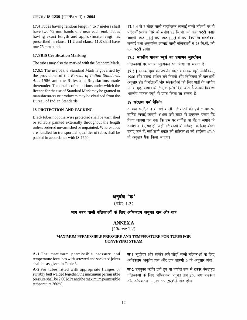
12
�������IS 1239 (��/Part 1) : 2004
17.4 Tubes having random length 4 to 7 meters shallhave two 75 mm bands one near each end. Tubeshaving exact length and approximate length asprescribed in clause 11.2 and clause 11.3 shall haveone 75 mm band.
17.5 BIS Certification Marking
The tubes may also the marked with the Standard Mark.
17.5.1 The use of the Standard Mark is governed bythe provisions of the Bureau of Indian StandardsAct, 1986 and the Rules and Regulations madethereunder. The details of conditions under which thelicence for the use of Standard Mark may be granted tomanufacturers or producers may be obtained from theBureau of Indian Standards.
18 PROTECTION AND PACKING
Black tubes not otherwise protected shall be varnishedor suitably painted externally throughout the lengthunless ordered unvarnished or unpainted. Where tubesare bundled for transport, all qualities of tubes shall bepacked in accordance with IS 4740.
17-417-417-417-417-4 4 ls 7 ehVj okyh ;kn`fPNd yEckbZ okyh ufy;ksa ij nksifV~V;k¡ izR;sd fljs ds lehi 75 fe-eh- dh ,d iV~Vh cukbZtk,xhA [kaM 11-211-211-211-211-2 rFkk [kaM 11-3 11-3 11-3 11-3 11-3 esa ;Fkk fuèkkZfjr okLrfodyEckbZ rFkk vuqekfur yEckbZ okyh ufydkvksa esa 75 fe-eh- dh,d iV~Vh gksxhA
17-5 Hkkjrh; ekud C;wjks dk izek.ku eqgjkadu17-5 Hkkjrh; ekud C;wjks dk izek.ku eqgjkadu17-5 Hkkjrh; ekud C;wjks dk izek.ku eqgjkadu17-5 Hkkjrh; ekud C;wjks dk izek.ku eqgjkadu17-5 Hkkjrh; ekud C;wjks dk izek.ku eqgjkadu
ufydkvksa ij ekud eqgjkadu Hkh fd;k tk ldrk gSA
17-5-1 17-5-1 17-5-1 17-5-1 17-5-1 ekud eqgj dk mi;ksx Hkkjrh; ekud C;wjks vfèkfu;e]1986 vkSj mlds vfèku cus fu;eksa vkSj fofu;eksa ds izkoèkkuksavuqlkj gksA fuekZrkvksa vkSj laLdÙkkZvksa dks ftu 'krks± osQ vèkhuekud eqgj yxkus ds fy, ykblsal fn;k tkrk gS mldk fooj.kHkkjrh; ekud C;wjks ls izkIr fd;k tk ldrk gSA
18 laj{k.k ,oa iSfdax18 laj{k.k ,oa iSfdax18 laj{k.k ,oa iSfdax18 laj{k.k ,oa iSfdax18 laj{k.k ,oa iSfdax
vU;Fkk lajf{kr u dh xbZ dkyh ufydkvksa dh iw.kZ yEckbZ ijok£u'k yxkbZ tk,xh vFkok mls ckgj ls mi;qDr izdkj isaVfd;k tk,xk tc rd fd ml ij ok£u'k ;k isaV u yxkus dsvkns'k u fn, x, gksaA tgk¡ ufydkvksa ds ifjogu ds fy, caMycuk, tkrs gSa] ogk¡ lHkh izdkj dh rkfydkvksa dks vkbZ,l 4740ds vuqlkj iSd fd;k tk,xkA
vuqcaèk ^d*vuqcaèk ^d*vuqcaèk ^d*vuqcaèk ^d*vuqcaèk ^d*([kaM 1-2)
Hkki ogu okyh ufydkvks a ds fy, vfèkdre vuqer nkc vkSj rkiHkki ogu okyh ufydkvks a ds fy, vfèkdre vuqer nkc vkSj rkiHkki ogu okyh ufydkvks a ds fy, vfèkdre vuqer nkc vkSj rkiHkki ogu okyh ufydkvks a ds fy, vfèkdre vuqer nkc vkSj rkiHkki ogu okyh ufydkvks a ds fy, vfèkdre vuqer nkc vkSj rki
ANNEX A(Clause 1.2)
MAXIMUM PERMISSIBLE PRESSURE AND TEMPERATURE FOR TUBES FORCONVEYING STEAM
A-1 The maximum permissible pressure andtemperature for tubes with screwed and socketed jointsshall be as given in Table 6.
A-2 For tubes fitted with appropriate flanges orsuitably butt welded together, the maximum permissiblepressure shall be 2.06 MPa and the maximum permissibletemperature 260°C.
ddddd-11111 pwM+hnkj vkSj lkWdsV yxs tksM+ksa okyh ufydkvksa ds fy,vfèkdre vuqKs; nkc vkSj rki lkj.kh 6 ds vuqlkj gksxkA
ddddd-2 2 2 2 2 mi;qDr ÝySat yxs gq, ;k i;kZIr :i ls VDDj osYMÑrufydkvksa ds fy, vfèkdre vuqer rki 260 esxk ikLdyvkSj vfèkdre vuqer rki 260ºlasVhxzsM gksxkA
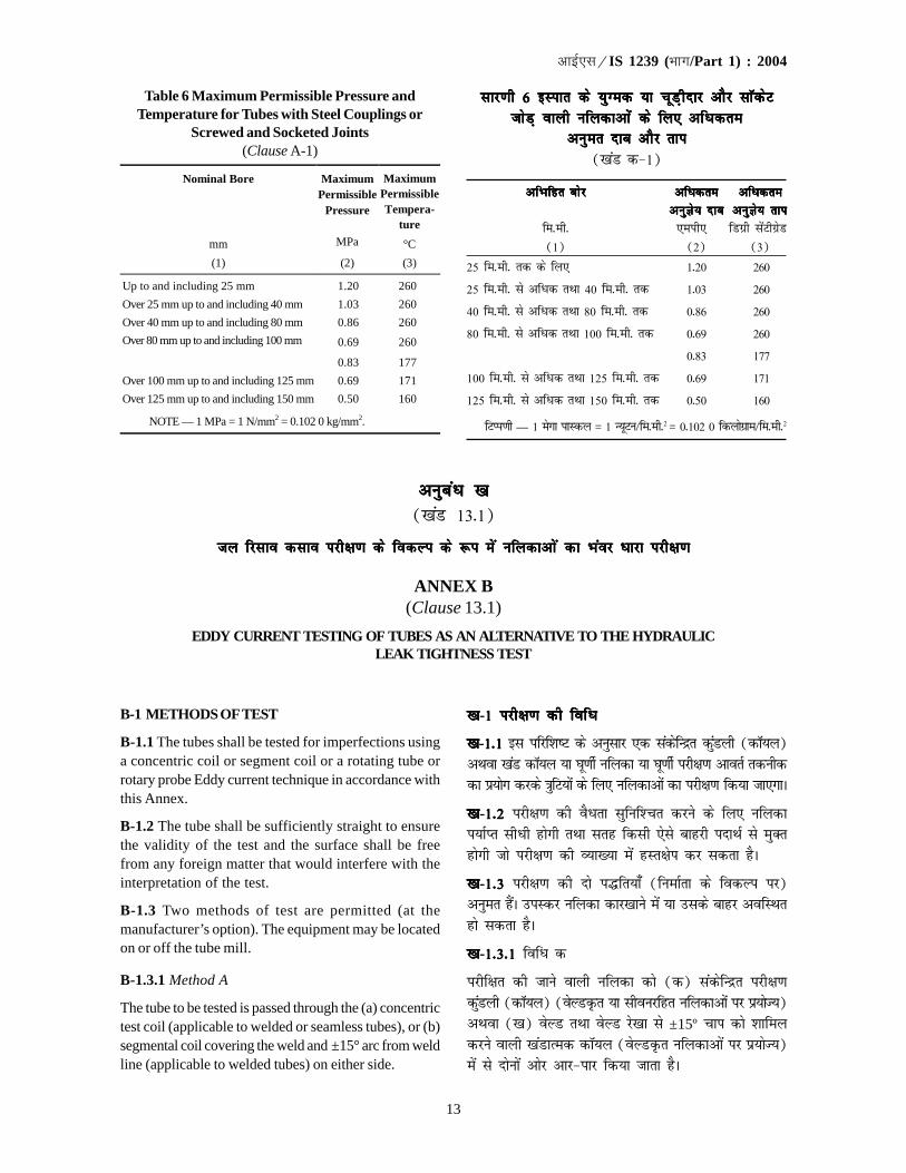
13
�������IS 1239 (��/Part 1) : 2004
vuqcaèk [kvuqcaèk [kvuqcaèk [kvuqcaèk [kvuqcaèk [k([kaM 13-1)
ty fjlko dlko ijh{k.k ds fodYi ds :i esa ufydkvks a dk Hkaoj èkkjk ijh{k.kty fjlko dlko ijh{k.k ds fodYi ds :i esa ufydkvks a dk Hkaoj èkkjk ijh{k.kty fjlko dlko ijh{k.k ds fodYi ds :i esa ufydkvks a dk Hkaoj èkkjk ijh{k.kty fjlko dlko ijh{k.k ds fodYi ds :i esa ufydkvks a dk Hkaoj èkkjk ijh{k.kty fjlko dlko ijh{k.k ds fodYi ds :i esa ufydkvks a dk Hkaoj èkkjk ijh{k.k
ANNEX B(Clause 13.1)
EDDY CURRENT TESTING OF TUBES AS AN ALTERNATIVE TO THE HYDRAULICLEAK TIGHTNESS TEST
B-1 METHODS OF TEST
B-1.1 The tubes shall be tested for imperfections usinga concentric coil or segment coil or a rotating tube orrotary probe Eddy current technique in accordance withthis Annex.
B-1.2 The tube shall be sufficiently straight to ensurethe validity of the test and the surface shall be freefrom any foreign matter that would interfere with theinterpretation of the test.
B-1.3 Two methods of test are permitted (at themanufacturer’s option). The equipment may be locatedon or off the tube mill.
B-1.3.1 Method A
The tube to be tested is passed through the (a) concentrictest coil (applicable to welded or seamless tubes), or (b)segmental coil covering the weld and ±15° arc from weldline (applicable to welded tubes) on either side.
[k[k[k[k[k-1 ijh{k.k dh fofèk1 ijh{k.k dh fofèk1 ijh{k.k dh fofèk1 ijh{k.k dh fofèk1 ijh{k.k dh fofèk
[k[k[k[k[k-1-11-11-11-11-1 bl ifjf'k"V ds vuqlkj ,d ladsfUnzr dqaMyh (dkW;y)vFkok [kaM dkW;y ;k ?kw.khZ ufydk ;k ?kw.khZ ijh{k.k vkorZ rduhddk iz;ksx djds =kqfV;ksa ds fy, ufydkvksa dk ijh{k.k fd;k tk,xkA
[k[k[k[k[k-1-2 1-2 1-2 1-2 1-2 ijh{k.k dh oSèkrk lqfuf'pr djus ds fy, ufydki;kZIr lhèkh gksxh rFkk lrg fdlh ,sls ckgjh inkFkZ ls eqDrgksxh tks ijh{k.k dh O;k[;k esa gLr{ksi dj ldrk gSA
[k[k[k[k[k-1-31-31-31-31-3 ijh{k.k dh nks i¼fr;k¡ (fuekZrk ds fodYi ij)vuqer gSaA miLdj ufydk dkj[kkus esa ;k mlds ckgj vofLFkrgks ldrk gSA
[k[k[k[k[k-1-3-1 1-3-1 1-3-1 1-3-1 1-3-1 fofèk d
ijhf{kr dh tkus okyh ufydk dks (d) ladsfUnzr ijh{k.kdqaMyh (dkW;y) (osYMÑr ;k lhoujfgr ufydkvksa ij iz;ksT;)vFkok ([k) osYM rFkk osYM js[kk ls ±15º pki dks 'kkfeydjus okyh [kaMkRed dkW;y (osYMÑr ufydkvksa ij iz;ksT;)esa ls nksuksa vksj vkj&ikj fd;k tkrk gSA
Table 6 Maximum Permissible Pressure andTemperature for Tubes with Steel Couplings or
Screwed and Socketed Joints(Clause A-1)
Nominal Bore
mm
MaximumPermissible
Pressure
MPa
Maximum Permissible Tempera-
ture
°C
(1) (2) (3)
Up to and including 25 mm 1.20 260
Over 25 mm up to and including 40 mm 1.03 260
Over 40 mm up to and including 80 mm 0.86 260
Over 80 mm up to and including 100 mm 0.69
0.83
260
177
Over 100 mm up to and including 125 mm 0.69 171
Over 125 mm up to and including 150 mm 0.50 160
NOTE — 1 MPa = 1 N/mm2 = 0.102 0 kg/mm2.
lkj.kh 6 bLikr ds ;qXed ;k pwM+hnkj vkSj lkWdsVlkj.kh 6 bLikr ds ;qXed ;k pwM+hnkj vkSj lkWdsVlkj.kh 6 bLikr ds ;qXed ;k pwM+hnkj vkSj lkWdsVlkj.kh 6 bLikr ds ;qXed ;k pwM+hnkj vkSj lkWdsVlkj.kh 6 bLikr ds ;qXed ;k pwM+hnkj vkSj lkWdsVtksM+ okyh ufydkvka s ds fy, vfèkdretksM+ okyh ufydkvka s ds fy, vfèkdretksM+ okyh ufydkvka s ds fy, vfèkdretksM+ okyh ufydkvka s ds fy, vfèkdretksM+ okyh ufydkvka s ds fy, vfèkdre
vuqer nkc vkSj rkivuqer nkc vkSj rkivuqer nkc vkSj rkivuqer nkc vkSj rkivuqer nkc vkSj rki([kaM d&1)
vfHkfgr cksjvfHkfgr cksjvfHkfgr cksjvfHkfgr cksjvfHkfgr cksj vfèkdrevfèkdrevfèkdrevfèkdrevfèkdre vfèkdrevfèkdrevfèkdrevfèkdrevfèkdrevuqKs; nkcvuqKs; nkcvuqKs; nkcvuqKs; nkcvuqKs; nkc vuqKs; rkivuqKs; rkivuqKs; rkivuqKs; rkivuqKs; rki
fe-eh- ,eih, fMxzh lasVhxzsM(1) (2) (3)
25 fe-eh- rd ds fy, 1-20 260
25 fe-eh- ls vfèkd rFkk 40 fe-eh- rd 1-03 260
40 fe-eh- ls vfèkd rFkk 80 fe-eh- rd 0-86 260
80 fe-eh- ls vfèkd rFkk 100 fe-eh- rd 0-69 260
0-83 177
100 fe-eh- ls vfèkd rFkk 125 fe-eh- rd 0-69 171
125 fe-eh- ls vfèkd rFkk 150 fe-eh- rd 0-50 160
fVIi.kh — 1 esxk ikLdy = 1 U;wVu@fe-eh-2 = 0-102 0 fdyksxzke@fe-eh-2

14
�������IS 1239 (��/Part 1) : 2004
B-1.3.2 Method B
The tube to be tested or the test coil assembly is rotatedand translated relative to each other so the test coildescribes a helical path over the tube surface. The pitchof the helical scan shall ensure that the whole of thetube surface is effectively covered. This method isapplicable to seamless tubes only.
B-2 CALIBRATION OF TEST EQUIPMENT
B-2.1 The equipment shall be calibrated using standardtube containing holes as defined in B-2 for Method A orstandard notches as defined in B-2.3 for Method B. Thestandard tube for offline equipment shall have similarelectromagnetic properties and same diameter andthickness as the tube to be tested. For online equipment,running tube may be considered as standard tube.
B-2.2 Method A
The standard defect shall be a circular hole drilledradically completely through the tube wall on thewelding. The diameters of the drills required to makethese holes shall be as follows:
Nominal Bore of the Tubes Drill Diametermm mm
Up to and including 15 1.220, 25 - 32 1.740 - 50 2.265 - 80 2.7100 - 125 3.2150 3.7
B-2.3 Method B
The standard test piece shall have a longitudinal notch0.8 mm or less in width machined parallel to the tube axison the outer surface of the tube. The depth of the notchshall not exceed 12½ percent of the specified thicknessof the tube or 0.3 mm whichever is greater. The length ofthe notch at full depth shall not exceed 50 mm.
B-3 CALIBRATION PROCEDURE
B-3.1 The equipment and test coils shall be adjustedto produce in a consistent manner a clearly identifiablesignal from the standard defect(s) on the standard tubeand this signal shall be used to set the triggrer alarmlevel of the equipment. For calibration purposes therelative speed between the standard tube containingstandard defect and the test coils shall be the same asthat used during the production.
B-3.2 The calibration of the equipment shall be checked
[k[k[k[k[k-1-3-2 1-3-2 1-3-2 1-3-2 1-3-2 fofèk [k
ijhf{kr dh tkus okyh ufydk ;k ijh{k.k dkW;y la;kstu dks,d nwljs ds lkis{k ?kw£.kr rFkk LFkkukarfjr fd;k tkrk gS rkfdijh{kk dkW;y ufydk dh lrg ij ,d l£iy ekxZ cuk,Al£iy LdSu dh <ky ;g lqfuf'pr djsxh fd laiw.kZ ufydklrg izHkkoh :i ls vkPNkfnr gks tk,A ;g i¼fr dsoylhoujfgr ufydkvksa ij iz;ksT; gSA
[k[k[k[k[k-2 ijh{k.k midj.k dk va'k'kksèku2 ijh{k.k midj.k dk va'k'kksèku2 ijh{k.k midj.k dk va'k'kksèku2 ijh{k.k midj.k dk va'k'kksèku2 ijh{k.k midj.k dk va'k'kksèku
[k[k[k[k[k-2-1 2-1 2-1 2-1 2-1 miLdj dk va'k'kksèku fofèk d ds fy, [k[k[k[k[k-22222 esa ;FkkifjHkkf"kr Nsnksa okyh ekud ufydk dk iz;ksx djds vFkokfofèk [k ds fy, [k[k[k[k[k-2-32-32-32-32-3 esa ;Fkk ifjHkkf"kr ekud [kakpksa dkiz;ksx djds fd;k tk,xkA vkWiQ ykbu miLdj ds fy, ekudufydk dh le:i oS|qr pqEcdh; fof'k"Vrk,¡ gksaxh rFkkmldk O;kl rFkk eksVkbZ Hkh ijhf{kr dh tkus okyh ufydk dsleku gksxkA vkWu ykbu miLdj ds fy, fo|eku ufydk dksgh ekud ufydk ekuk tk ldrk gSA
[k[k[k[k[k-2-2 fofèk d2-2 fofèk d2-2 fofèk d2-2 fofèk d2-2 fofèk d
ekud nks"k osfYMax ij ufydk dh fHkfÙk esa ls f=kT;h; :ils iw.kZr;k fMªy fd;k x;k ,d xksykdkj fNnz gSA bu Nsnks adks cukus ds fy, visf{kr fMªyksa ds O;kl fuEu izdkj gksaxs%
ufydkykvksa dk vfHkfgr cksj fMªy O;klfe-eh- fe-eh-
15 fe-eh- rd 1-220] 25&32 1-740&50 2-265&80 2-7100&125 3-2150 3-7
[k[k[k[k[k-2-3 fofèk [k2-3 fofèk [k2-3 fofèk [k2-3 fofèk [k2-3 fofèk [k
ekud ijh{k.k VqdMs+ ds ns'kkarjh; [kkaps dh pkSM+kbZ 0-8 fe-eh-;k mlls de gksxh ftls ufydk dh ckgjh lrg ij ufydk dsv{k ds lekukarj e'khuhÑr fd;k tk,xkA [kkaps dh xgjkbZufydk dh fu£n"V eksVkbZ ds 121/2
izfr'kr ;k 0-3 fe-eh- tksHkh vfèkd gS] ;s T;knk ugha gksxhA iw.kZ xgjkbZ ij [kkaps dhyEckbZ 50 fe-eh- ls vfèkd ugha gksxhA
[k[k[k[k[k-3 va'k'kksèku izfØ;k3 va'k'kksèku izfØ;k3 va'k'kksèku izfØ;k3 va'k'kksèku izfØ;k3 va'k'kksèku izfØ;k
[k[k[k[k[k-3-1 3-1 3-1 3-1 3-1 miLdj rFkk ijh{k.k dqaMfy;ksa dks bl izdkj leaftrfd;k tk,xk fd ekud ufydk dk ekud nks"kksa ls ,d Li"V:i ls vfHkKs; ladsr lqlaxr rjhds ls lftr gks rFkk bl ladsrdkk iz;ksx miLdj ds fVªxj@lapsrd Lij dks fuèkkZfjr djus dsfy, fd;k tk,xkA va'kk'kksèku iz;kstuksa ds fy, ekud nks"kokyh ekud ufydk rFkk ijh{k.k dqaMfy;ksa ds chp lkis{k xfrogh gksxh ftldk iz;ksx mRiknu ds nkSjku fd;k x;k FkkA
[k[k[k[k[k-3-23-23-23-23-2 miLdj ds va'k'kksèku dh tkap izR;sd dk;Zdkjh vofèk
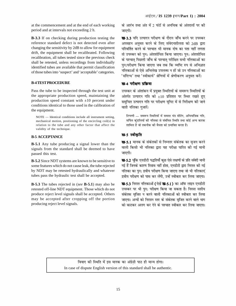
15
�������IS 1239 (��/Part 1) : 2004
at the commencement and at the end of each workingperiod and at intervals not exceeding 2 h.
B-3.3 If on checking during production testing thereference standard defect is not detected even afterchanging the sensitivity by 2dB to allow for equipmentdrift, the equipment shall be recalibrated. Followingrecalibration, all tubes tested since the previous checkshall be retested, unless recordings from individuallyidentified tubes are available that permit classificationof those tubes into ‘suspect’ and ‘acceptable’ categories.
B-4 TEST PROCEDURE
Pass the tube to be inspected through the test unit atthe appropriate production speed, maintaining theproduction speed constant with ±10 percent underconditions identical to those used in the calibration ofthe equipment.
NOTE — Identical conditions include all instrument setting,mechanical motion, positioning of the encircling coil(s) inrelation to the tube and any other factor that affect thevalidity of the technique.
B-5 ACCEPTANCE
B-5.1 Any tube producing a signal lower than thesignals from the standard shall be deemed to havepassed this test.
B-5.2 Since NDT systems are known to be sensitive tosome features which do not cause leak, the tube rejectedby NDT may be retested hydraulically and whatevertubes pass the hydraulic test shall be accepted.
B-5.3 The tubes rejected in (see B-5.1) may also beretested off-line NDT equipment. Those which do notproduce reject level signals shall be accepted. Othersmay be accepted after cropping off the portionproducing reject level signals.
ds vkjaHk rFkk var esa 2 ?kaVksa ls vufèkd ds varjkyksa ij dhtk,xhA
[k[k[k[k[k-3-33-33-33-33-3 ;fn mRiknu ijh{k.k ds nkSjku tk¡p djus ij miLdjviogu vuqer djus ds fy, laosnu'khyrk dks 2dB }kjkifjo£rr djus ds i'pkr Hkh ekud nks"k dk irk ugha yxrkrks miLdj dks iqu% va'k'kksfèkr fd;k tk,xkA iqu% va'k'kksfèkrds i'pkr~ fiNyh tk¡p ds i'pkr~ ijhf{kr lHkh ufydkvksa dkiqu%ijh{k.k fd;k tk,xk tc rd fd O;f"V #i ls vfHkKkrufydkvksa ls ,sls vfHkys[k miyCèk u gksa tks mu ufydkvksa dk^lafnXèk* rFkk ^Lohdk;Z* Jsf.k;ksa esa Js.khdj.k vuqer djsaA
[k[k[k[k[k-4 ijh{k.k izfØ;k4 ijh{k.k izfØ;k4 ijh{k.k izfØ;k4 ijh{k.k izfØ;k4 ijh{k.k izfØ;k
miLdj ds va'kkadu esa iz;qDr fLFkfr;ksa ds le:i fLFkfr;ksa dsvarxZr mRiknu xfr dks ±10 izfr'kr ij fLFkj j[krs gq,leqfpr mRiknu xfr ij ijh{k.k ;wfuV esa ls fujh{k.k dh tkusokrh ufydk xqtkjsaA
fVIi.kh — le:i fLFkfr;ksa esa leLr ;a=k lsfVax] vfHk;kaf=kd xfr]l£iy dqaMfy;ksa dh ufydk ls lacafèkr fLFkfr rFkk dksbZ vU; dkjd'kkfey gS tks rduhd dh oSèkrk dks izHkkfor djrk gSA
[k[k[k[k[k-5 LohÑfr5 LohÑfr5 LohÑfr5 LohÑfr5 LohÑfr
[k[k[k[k[k-5-15-15-15-15-1 ekud ds ladsrdksa ls fuEurj ladsrd dk l`tu djusokyh fdlh Hkh ufydk }kjk ;g ijh{kk ikfjr dh xbZ ekuhtk,xhA
[k[k[k[k[k-5-2 5-2 5-2 5-2 5-2 pwafd ,uMhVh i¼fr;k¡ dqN ,sls y{k.kksa ds izfr laosnh ekuhxbZ gSa ftuds dkj.k fjlko ugha gksrk] ,uMhVh }kjk fujLr dh xbZufydk dk iqu% nzoh; ijh{k.k fd;k tk,xk rFkk tks Hkh ufydk,anzoh; ijh{k.k dks ikl dj yasxh] mUgsa Lohdkj dj fy;k tk,xkA
[k[k[k[k[k-5-35-35-35-35-3 fujLr ufydkvksa (((((ns[ksa [k[k[k[k[k-5-1)5-1)5-1)5-1)5-1) dk vkWiQ ykbu ,uMhVhmiLdj ij Hkh iqu% ijh{k.k fd;k tk ldrk gSA fujLr Lrjh;ladsrd lftr u djus okyh ufydkvksa dks Lohdkj dj fy;ktk,xkA vU;ksa dks fujlu Lrj ds ladsrd lftr djus okys Hkkxdks dkVdj vyx dj nsus ds i'pkr Lohdkj dj fy;k tk,xkA
fookn dh fLFkfr esa bl ekud dk vaxzsT+kh ikB gh ekU; gksxkAIn case of dispute English version of this standard shall be authentic.
bl ns'k esa Hkki izokg ds fy, bLrseky dh tkus okyh ufy;ksa dks iz'kkflr djus okys fofu;e dsfUnz; ckW;yj cksMZ }kjk izdkf'krHkkjrh; ckW;yj fofu;eksa esa fuèkkZfjr fd, x, gSaA
bl ekud dk fuèkkZj.k djrs le;] ns'k esa bl {ks=k esa izpfyr O;kikj jhfr;ksa ij ;Fks"V è;ku fn;k x;k gSA fofHkUu ns'kksa esa izpfyrekudksa ds varjkZ"Vªh; leUo; ij Hkh ;Fks"V è;ku fn;k x;k gSA fuEufyf[kr izdk'kuksa ls lgk;rk izkIr dh xbZ gS%
vkbZ,lvks 65 % 1981 ekudhdj.k ds fy, vkbZ,lvks varjk"Vªh; laxBu ds vuqlkj pwM+h cukus ds fy, mi;qDr dkcZubLikr ufydk,¡
ch,l 1387 % 1985 pwM+hnkj ,oa lkdsV;qDr bLikr ufy;ksa rFkk ufydkdkj lkefxz;ksa ,oa osfYMax ds fy, mi;qDr lknsfljs okyh bLikr ufydkvksa ds fy, vFkok pwM+h cukus ds fy, ch,l 21 % 1985 ufydk,¡ ,oa fiQfVaxds fy, ikbi dh pwfM+;k¡] tgk¡ pwfM+;ksa ij nkc dls tksM+ cuk, tkrs gSa*
bl ekud esa [kaM 6-4] 7-1] 7-1-1] 11-2] 16-26-4] 7-1] 7-1-1] 11-2] 16-26-4] 7-1] 7-1-1] 11-2] 16-26-4] 7-1] 7-1-1] 11-2] 16-26-4] 7-1] 7-1-1] 11-2] 16-2 rFkk 17-3 17-3 17-3 17-3 17-3 fn, x, gSa ftlds fy, Øsrk vkSj fuekZrk ds chp djkj fd;ktkuk vko';d gSA
bl ekud dk nwljk Hkkx vkbZ,l 1239 (Hkkx 2) % 1992 ^e`nq bLikr ufydkvksa] ufydkdkj lkexzh rFkk vU; fiVok¡ bLikrfiQfVaXl ds fy, fof'kf"V% Hkkx 2 e`nq bLikr lkWdsV] ufydkdkj lkexzh rFkk vU; fiVok¡ bLikr fiQfVaxs (pkSFkk iqujh{k.k)* gSA
;g fuf'pr djus ds fy, fd bl ekud esa fdlh vis{kk fo'ks"k dk ikyu fd;k x;k gS ;k ugha] rks ijh{k.k ;k fo'ys"k.k esaifj.kke dks n'kkZus okys voyksdu ;k x.kuk }kjk izkIr vafre eku dks vkbZ,l 2 % 1960 ^la[;kRed ekuksa ds iw.kk±du lacaèkhfu;e (iqujhf{kr)* ds vuqlkj iw.kk±fdr dj fn;k tk,A iw.kk±fdr eku esa j[ks x, lkFkZd LFkkuksa dh la[;k mruh gh gks ftruhbl ekud esa fufnZ"V eku dh gSA
In this country, the regulations governing the use of tubes for conveying steam are laid down in the Indian BoilerRegulations published by the Central Boilers Board.
While formulating this standard, due consideration has been given to the trade practices followed in the countryin this field. Due consideration has also been given to international coordination among the standards prevailingin different countries. Assistance has been derived from the following publications:
ISO 65 : 1981 Carbon steel tubes suitable for screwing in accordance with ISO International Organizationfor Standardization
BS 1387 : 1985 Screwed and socketed steel tubes and tubulars and for plain end steel tubes suitable forwelding or for screwing to BS 21 : 1985 ‘Pipe threads for tubs and fitting where pressure-tightjoints are made on the threads’
This standard contains clauses 6.4, 7.1, 7.1.1, 11.2, 16.2 and 17.3 which call for an agreement between themanufacturer and the purchaser.
The other part of this standard is IS 1239 (Part 2) : 1992 ‘Specification for mild steel tubes, tubulars and otherwrought steel fittings: Part 2 Mild steel socket, tubulars and other wrought steel pipe fittings ( fourth revision )’.
For the purpose of deciding whether a particular requirement of this standard is complied with, the final value,observed or calculated, expressing the results of a test or analysis, shall be rounded off in accordance withIS 2 : 1960 ‘Rules for rounding off numerical values (revised )’. The number of significant places retained in therounded off value should be the same as that of the specified value in this standard.
(Continued from second cover)
(nwljs doj ls tkjh)
Bureau of Indian Standards
BIS is a statutory institution established under the Bureau of Indian Standards Act, 1986 to promoteharmonious development of the activities of standardization, marking and quality certification of goodsand attending to connected matters in the country.
Copyright
BIS has the copyright of all its publications. No part of these publications may be reproduced in any formwithout the prior permission in writing of BIS. This does not preclude the free use, in the course ofimplementing the standard, of necessary details, such as symbols and sizes, type or grade designations.Enquiries relating to copyright be addressed to the Director (Publications), BIS.
Review of Indian Standards
Amendments are issued to standards as the need arises on the basis of comments. Standards are also reviewedperiodically; a standard along with amendments is reaffirmed when such review indicates that no changes areneeded; if the review indicates that changes are needed, it is taken up for revision. Users of Indian Standardsshould ascertain that they are in possession of the latest amendments or edition by referring to the latest issue of‘BIS Catalogue’ and ‘Standards : Monthly Additions’.
This Indian Standard has been developed from Doc No.: MTD 19 (4264).
Amendments Issued Since Publication
Amend No. Date of Issue Text Affected
Laser Typeset by Sunshine Graphics
BUREAU OF INDIAN STANDARDS
Headquarters:
Manak Bhavan, 9 Bahadur Shah Zafar Marg, New Delhi 110002Telephones : 2323 0131, 2323 3375, 2323 9402 Website: www.bis.org.in
Regional Offices: Telephones
Central : Manak Bhavan, 9 Bahadur Shah Zafar Marg 2323 7617NEW DELHI 110002 2323 3841
Eastern : 1/14 C.I.T. Scheme VII M, V. I. P. Road, Kankurgachi 2337 8499, 2337 8561KOLKATA 700054 2337 8626, 2337 9120
Northern : SCO 335-336, Sector 34-A, CHANDIGARH 160022 60 384360 9285
Southern : C.I.T. Campus, IV Cross Road, CHENNAI 600113 2254 1216, 2254 14422254 2519, 2254 2315
Western : Manakalaya, E9 MIDC, Marol, Andheri (East) 2832 9295, 2832 7858MUMBAI 400093 2832 7891, 2832 7892
Branches: AHMEDABAD. BANGALORE. BHOPAL. BHUBANESHWAR. COIMBATORE. FARIDABAD.GHAZIABAD. GUWAHATI. HYDERABAD. JAIPUR. KANPUR. LUCKNOW. NAGPUR.PARWANOO. PATNA. PUNE. RAJKOT. THIRUVANANTHAPURAM. VISAKHAPATNAM.
�
��
��
• Dinesh Metal Industries is one of the leading Dealers / Distributors / Stockists for various types Steel Tubes and Pipes.
To cater to the need of the customers, we are having huge stocks readily available in our warehouses at Mumbai Warehouse Our firm has got registered with the Collectorate of Customs and Central Excise and obtained Central
Excise Registered Certificate in order to facilitate MODVAT BENEFIT to the buyers, those who have registered with Central Excise.
Our Firm has been associated with many esteemed organizations for over six decades and is fully conversant with quality and standards that you expect from your suppliers. We sincerely believe that we shall have your cooperation to enlist our name in your mailing list. Your placement of order with us, will
give you ample satisfaction and thus assure you that we will not fail in your expectations.
Nature of Business
Trading : Dealing in M.S. ERW Black & Gi Pipes / Carbon Steel, Alloy Steel, Stainless Steel Seamless / Welded Pipes & Tubes, Boiler Quanlity Tubes, square Tubes, Hydraulic Tubes and Pipe Fittings /
Flanges of all sizes with and without IBR
What we offer
• We take this opportunity to introduce ourselves as a one of the leading distributors in South India for the
following products
o GI & MS Pipe fittings.
o H-SAW / L-SAW / HFIW Pipes as per IS:1239 / IS:3589 size range from 1/2" to 64" NB, and more.
o Carbon Steel Seamless pipes as per ASTM A-106 Grade A & B / API 5l Grade A & Grade B from 1/2" to
24" NB, and more.
o High Temperature Alloy Steel Seamless pipe as per ASTM A335 P5, P9, p11, P22, P23, P91, etc.,
o Low temperature Carbon Steel pipes as per ASTM A333 Gr. 6 specification.
o Alloy Steel Super Heater Tubes and Economizer Tubes as per SA213 T11 / T22 and other grades.
o Heat Exchanger Tubes as per the SA-179 specification in seamless and also SA-214 specification in
Welded Pipe.
o CRCA Round Tube as per IS:3074, CRCA, SQuare & Rectangular Section as per IS:4923.
o Boiler Tube / Air Heater Tube as per BS:3059 / BS:6323 Part-v and equivalent Indian & american
standards.
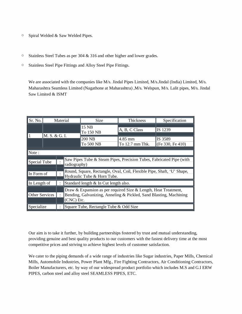
o Spiral Welded & Saw Welded Pipes.
o Stainless Steel Tubes as per 304 & 316 and other higher and lower grades.
o Stainless Steel Pipe Fittings and Alloy Steel Pipe Fittings.
We are associated with the companies like M/s. Jindal Pipes Limited, M/s.Jindal (India) Limited, M/s.
Maharashtra Seamless Limited (Nagathone at Maharashtra) ,M/s. Welspun, M/s. Lalit pipes, M/s. Jindal Saw Limited & ISMT
Sr. No. Material Size Thickness Specification
1 M. S. & G. I.
15 NB To 150 NB
A, B, C Class IS 1239
200 NB To 500 NB
4.85 mm To 12.7 mm Thk.
IS 3589 (Fe 330, Fe 410)
Note :
Special Tube : Saw Pipes Tube & Steam Pipes, Precision Tubes, Fabricated Pipe (with radiography)
In Form of : Round, Square, Rectangle, Oval, Coil, Flexible Pipe, Shaft, ‘U’ Shape, Hydraulic Tube & Horn Tube.
In Length of : Standard length & In Cut length also.
Other Services : Draw & Expansion as per required Size & Length, Heat Treatment, Bending, Galvanizing, Anneling & Pickled, Sand Blasting, Machining (CNC) Etc.
Specialize : Square Tube, Rectangle Tube & Odd Size
Our aim is to take it further, by building partnerships fostered by trust and mutual understanding, providing genuine and best quality products to our customers with the fastest delivery time at the most competitive prices and striving to achieve highest levels of customer satisfaction. We cater to the piping demands of a wide range of industries like Sugar industries, Paper Mills, Chemical Mills, Automobile Industries, Power Plant Mfg., Fire Fighting Contractors, Air Conditioning Contractors, Boiler Manufacturers, etc. by way of our widespread product portfolio which includes M.S and G.I ERW PIPES, carbon steel and alloy steel SEAMLESS PIPES, ETC.
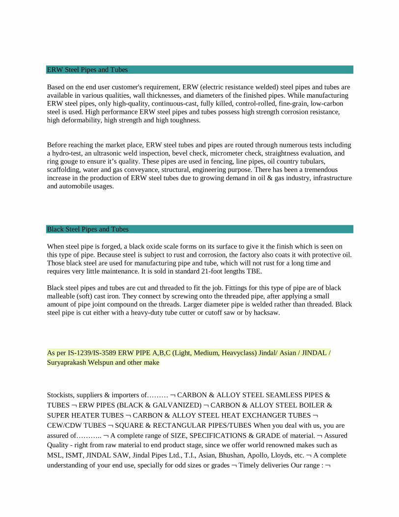
ERW Steel Pipes and Tubes
Based on the end user customer's requirement, ERW (electric resistance welded) steel pipes and tubes are available in various qualities, wall thicknesses, and diameters of the finished pipes. While manufacturing ERW steel pipes, only high-quality, continuous-cast, fully killed, control-rolled, fine-grain, low-carbon steel is used. High performance ERW steel pipes and tubes possess high strength corrosion resistance, high deformability, high strength and high toughness. Before reaching the market place, ERW steel tubes and pipes are routed through numerous tests including a hydro-test, an ultrasonic weld inspection, bevel check, micrometer check, straightness evaluation, and ring gouge to ensure it’s quality. These pipes are used in fencing, line pipes, oil country tubulars, scaffolding, water and gas conveyance, structural, engineering purpose. There has been a tremendous increase in the production of ERW steel tubes due to growing demand in oil & gas industry, infrastructure and automobile usages.
Black Steel Pipes and Tubes
When steel pipe is forged, a black oxide scale forms on its surface to give it the finish which is seen on this type of pipe. Because steel is subject to rust and corrosion, the factory also coats it with protective oil. Those black steel are used for manufacturing pipe and tube, which will not rust for a long time and requires very little maintenance. It is sold in standard 21-foot lengths TBE. Black steel pipes and tubes are cut and threaded to fit the job. Fittings for this type of pipe are of black malleable (soft) cast iron. They connect by screwing onto the threaded pipe, after applying a small amount of pipe joint compound on the threads. Larger diameter pipe is welded rather than threaded. Black steel pipe is cut either with a heavy-duty tube cutter or cutoff saw or by hacksaw.
As per IS-1239/IS-3589 ERW PIPE A,B,C (Light, Medium, Heavyclass) Jindal/ Asian / JINDAL / Suryaprakash Welspun and other make
Stockists, suppliers & importers of……… ¬ CARBON & ALLOY STEEL SEAMLESS PIPES &
TUBES ¬ ERW PIPES (BLACK & GALVANIZED) ¬ CARBON & ALLOY STEEL BOILER &
SUPER HEATER TUBES ¬ CARBON & ALLOY STEEL HEAT EXCHANGER TUBES ¬ CEW/CDW TUBES ¬ SQUARE & RECTANGULAR PIPES/TUBES When you deal with us, you are
assured of……….. ¬ A complete range of SIZE, SPECIFICATIONS & GRADE of material. ¬ Assured Quality - right from raw material to end product stage, since we offer world renowned makes such as
MSL, ISMT, JINDAL SAW, Jindal Pipes Ltd., T.I., Asian, Bhushan, Apollo, Lloyds, etc. ¬ A complete understanding of your end use, specially for odd sizes or grades ¬ Timely deliveries Our range : ¬

CARBON STEEL SEAMLESS PIPES AS PER ASTM A 106 GR.B/API 5L GR.B/ASTM A 53 GR.B ¬ CARBON STEEL SEAMLESS TUBES AS PER BS 3059, ASTM A 179, ASTM A 192, ASTM A 210 GR.A1, ¬ ALLOY STEEL SEAMLESS PIPES AS PER ASTM A 335 GR.P5, P11, P22 ¬ Low
temperature Pipes to ASTM A 333 GR.6 ¬ ALLOY STEEL SEAMLESS TUBES AS PER ASTM A 213 GR. T11, T22 ¬ ERW BLACK PIPES AS PER IS:1239/I, IS: 3589 GR.330 OR GR.410 ¬
GALVANISED PIPES AS PER IS:1239/I ¬ SQUARE & RECTANGULAR PIPES AS PER IS: 4923 ¬ ERW BOILER TUBES: BS 3059, ASTM A 214 ¬ AIR PRE HEATER TUBES to BS: 6323 PART V ¬
HYDRAULIC TUBES TO DIN 2391 ST. 35, ST. 45 & ST. 52 ¬ SEAMLESS HEAT EXCHANGER
TUBES ASTM A 179 ¬ CDW TUBES IS: 3074 OR BS 980 ¬ CRCA ERW TUBES TO IS 3601 OR IS 3074 ¬ SPECIAL SHAPED TUBES LIKE HEXAGONAL TUBES, OVAL TUBES, ELLIPTICAL TUBES, AS PER CUSTOMER REQUIREMENTS
We are Authorised Distributors and Stockist for JINDAL STAR, JINDAL, PRAKASH SURYA, APL
APOLLO, T.T.SWASTIK, TNT, SHREE, JINDAL (INDIA) AND VC.
We have sizes ranging from 15mm TO 300mm, confirming as per IS:1239 / IS:3589 / IS:1161 / IS: 4923,
for use in Water, Gas, Fire Fighting, Scaffolding and Structural purpose in all Light, Medium and Heavy
Series.
We are also stockist for M.S. Square & Rectangular pipes, used for Amusement Parks, Bridges, Industrial
Puproses, etc....
We are the fastest growing Steel Tubes and Pipes distributor in Tamilnadu.
We have met our target because of our timely response, better product availability and comparable market
price. We maintain a continous effort towards giving best quality with best service to all our clients.
We are the stockist of M.S ERW Black Pipes. We supply these pipes according to the client needs and specifications: Size Range : ½” to 24”, w.th. 2mm to 12.7mm Grades:
• IS:1239 Part I (1/2” to 6” NB – A CLASS, B CLASS OR C CLASS)
• IS: 3589 GR.330 OR GR.410 (6” NB AND ABOVE AS PER REQUIRED W.TH.)
• IS: 1161
• IS: 9295
• ASTM A 500 GR.A OR B
We can also supply odd sizes, i.e. non-standard sizes and sizes above 24" against specific order
We Dinesh Metal industries are one of the leading Manufacturer and Exporters of MS Pipes, Mild Steel Pipes from India. We offer the best quality Mild Steel Pipes & Tubes which are used widely and are demanded all over. MS Steel Pipes Confirm To IS : 1239 (Part I) - 1979 Big Diameter MS ERW Pipes Confirm To IS 3589-1991[Grade 330/410]
• IS 1239 Pipes Light Class
• IS1239 Pipes Medium Class
• IS1239 Pipes Heavy Class
• IS1239 ERW Pipes
• MS ERW Pipes as per IS 1239 Part 1
• GI Pipes as per IS1239 Part 1
• GI Pipes as per IS 3589 GR. 330 & GR. 410
• GI Pipes Heavy Duty
• GI ERW Pipes as per IS1239 PART 1
• GI ERW Pipes as per IS3589 GR. 330 & GR. 410
• Galvanized Pipes as per IS 1239
• Galvanized Pipes as per IS3589
• Galvanized Pipes Heavy Duty
Cities We Deliver To:
Mumbai, Bengaluru, Chennai, New Delhi, Pimpri-Chinchwad, Houston, Dubai, Seoul, Hyderabad,
Singapore, Abu Dhabi, Pune, Kolkata, Gurgaon, Navi Mumbai, Ahmedabad, Tehran, Calgary, Noida,
Riyadh, Vadodara, London, Coimbatore, Jakarta, Istanbul, Bangkok, Kuwait City, Thane, Sharjah,
Muscat, Edmonton, Busan, Mexico City, Doha, Jeddah, Aberdeen, Cairo, Geoje-si, Perth, Santiago,
Chandigarh, Indore, Kuala Lumpur, Rio de Janeiro, Dammam, Melbourne, Madrid, Surat, Bhopal, Ulsan,
Faridabad, La Victoria, Bogota, Lahore, Los Angeles, Algiers, Chiyoda, Ankara, Ho Chi Minh City,
Toronto, Hong Kong, Rajkot, Brisbane, Petaling Jaya, Ernakulam, Secunderabad, Gimhae-si, Al Jubail,
Port-of-Spain, Thiruvananthapuram, Milan, Atyrau, Lagos, Hanoi, Howrah, Sydney, Ahvaz, Karachi,
New York, Caracas, Vung Tau, Al Khobar, Manama, Montreal, Granada, Courbevoie, Visakhapatnam,
Ludhiana, Moscow, Dallas, Haryana, Colombo
Countries We Export To:
United States, United Arab Emirates, Canada, Pakistan, Peru, Chile, Spain, France, United Kingdom,
Indonesia, Israel, Iran, Kuwait, Mexico, Malaysia, Nigeria, Serbia, Singapore, Taiwan, Chile, Venezuela,
Ecuador, Saudi Arabia, Netherlands, Brazil, Colombia, Ghana, Iran, Denmark, Poland, Australia,
Afghanistan, Bahrain, Costa Rica, Egypt, Iraq, Jordan, South Korea, Kazakhstan, Sri Lanka, Lithuania,
Norway, Oman, Philippines, Poland, Qatar, Russia, Vietnam, South Africa, Nigeria, Mexico, Turkey,
Hungary, Algeria, Angola, Argentina, Austria, Azerbaijan, Bangladesh, Belarus, Belgium, Bhutan,
Bolivia, Bulgaria, Croatia, Czech Republic, Estonia, Finland, Greece, Italy, Japan, Libya, Romania,
Thailand, Trinidad & Tobago,Tunisia, Ukraine, Yemen, Hong Kong, Gabon, China, Portugal,
Switzerland, New Zealand, Sweden, Slovakia, Kenya, Lebanon, Morocco, Mongolia
Inspection & Approval Certificates : EN10204 3.1 / DIN 50049 3.1 / ISO 10474 3.1 Mill Test Certificate, NACE MR-0175 / ISO 15156, NACE MR-01-03 / NACE MR-01-75 / ISO 15156, European Pressure Equipment Directive PED-97/23/EC, AD-2000-W0, ASME Boiler & Pressure Vessel Code Sec.II Part A Ed. 2008, with 3.2 certificate duly Certified & Approved by LRS (Lloyd's Register), GL (Germanischer Lloyd), BV (Bureau Veritas), DNV (Det Norske Veritas), ABS (American Bureau of Shipping), SGS, TUV, RINA, IRS, NORSOK Approved Standard M-630, M-650 Rev.3
IBR PIPES
Price Jindal Pipes Jindal Steel Jindal Tubes, Excellent Quality in Jindal Pipes Jindal Steel Jindal Tubes, Jindal Pipes Jindal Steel Jindal Tubes Low Price, Best Price Jindal Pipes Jindal Steel Jindal Tubes Inquire, Wide Range Jindal Pipes Jindal Steel Jindal Tubes, Offer Price Jindal Pipes Jindal Steel Jindal Tubes, Jindal Pipes Jindal Steel Jindal Tubes Price List, Jindal Pipes Jindal Steel Jindal Tubes Exporter, Jindal Pipes Jindal Steel Jindal Tubes India, Price List for Jindal Pipes Jindal Steel Jindal Tubes, Jindal Pipes Jindal Steel Jindal Tubes Competitive Price Here
Dealers of steel pipes in Mumbai India | Dealers of steel pipes in Saudi Arabia | Dealers of steel pipes in Indonesia Russia | Dealers of steel pipes in Chennai | Exporters of steel pipes in Mumbai India | Exporters of seamless pipes in Mumbai India | Dealers of MS and GI pipes in Chennai | Dealers of MS and GI pipes in Saudi Arabia | Dealers of MS and GI pipes in Indonesia Russia | Dealers of MS and GI pipes in Saudi Arabia | Dealers of seamless pipes in Chennai | Dealers of seamless pipes in Saudi Arabia | Dealers of seamless pipes in Indonesia Russia | Dealers of seamless pipes in Saudi Arabia | Exporters of ERW Boiler and Air Heater tubes in Mumbai India | Jindal Pipes Jindal Steel Jindal Tubes | Jindal Pipes Jindal Steel Jindal Tubes Tubes | Exporters of MS ERW and GI pipes in Mumbai India | Jindal Pipes Jindal Steel Jindal Tubes Pipe dealers in Chennai | Jindal Pipes Jindal Steel Jindal Tubes Pipe dealers in Saudi Arabia | Jindal Pipes Jindal Steel Jindal Tubes Pipe dealers in Indonesia Russia | MSL pipe dealers in Saudi Arabia | Exporters of ERW Boiler and Air Heater Tubes | Exporters of Steel Pipes | Exporters of seamless pipes | Jindal Pipes Jindal Steel Jindal Tubes Pipe dealers in Saudi Arabia | Distributors of Jindal Pipes Jindal Steel Jindal Tubes Pipes in Iran | Distributors of Jindal Pipes Jindal Steel Jindal Tubes Pipes in Saudi Arabia | Distributors of Jindal Pipes Jindal Steel Jindal Tubes Pipes in Quatar Kuwait | Distributors of Jindal Pipes Jindal Steel Jindal Tubes Pipes in Saudi Arabia | Distributors of Jindal Pipes Jindal Steel Jindal Tubes Pipes in Mumbai India | Jindal Pipes Jindal Steel Jindal Tubes Pipe Dealers in Mumbai India | Dealers of MS pipes in Iran | Dealers of MS pipes in Saudi Arabia | Dealers of MS pipes in Indonesia Russia | Dealers of MS Pipes in Saudi Arabia | Exporters of MS pipes in Mumbai India | Dealers of GI Pipes in Chennai | Dealers of GI pipes in Saudi Arabia | Dealers of GI pipes in Indonesia Russia | Dealers of GI pipes in Saudi Arabia | Exporters of GI pipes in Mumbai India | Dealers of Galvanised pipes in Chennai | Dealers of galvanised pipes in Saudi Arabia | Dealers of galvanised pipes in Indonesia Russia | Dealers of galvanised pipes in Saudi Arabia | Exporters of galvanised pipes in Mumbai India
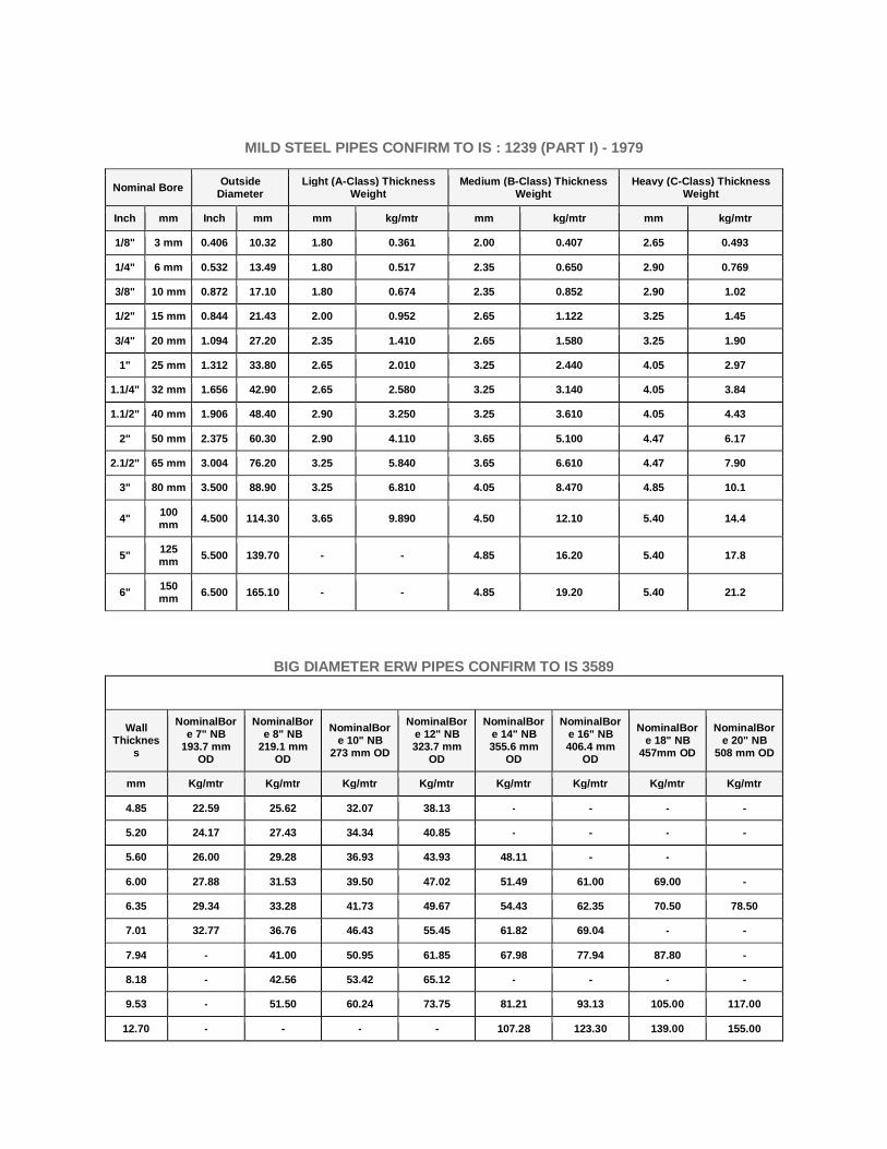
MILD STEEL PIPES CONFIRM TO IS : 1239 (PART I) - 1979
Nominal Bore Outside Diameter
Light (A-Class) Thickness Weight
Medium (B-Class) Thickness Weight
Heavy (C-Class) Thickness Weight
Inch mm Inch mm mm kg/mtr mm kg/mtr mm kg/mtr
1/8" 3 mm 0.406 10.32 1.80 0.361 2.00 0.407 2.65 0.493
1/4" 6 mm 0.532 13.49 1.80 0.517 2.35 0.650 2.90 0.769
3/8" 10 mm 0.872 17.10 1.80 0.674 2.35 0.852 2.90 1.02
1/2" 15 mm 0.844 21.43 2.00 0.952 2.65 1.122 3.25 1.45
3/4" 20 mm 1.094 27.20 2.35 1.410 2.65 1.580 3.25 1.90
1" 25 mm 1.312 33.80 2.65 2.010 3.25 2.440 4.05 2.97
1.1/4" 32 mm 1.656 42.90 2.65 2.580 3.25 3.140 4.05 3.84
1.1/2" 40 mm 1.906 48.40 2.90 3.250 3.25 3.610 4.05 4.43
2" 50 mm 2.375 60.30 2.90 4.110 3.65 5.100 4.47 6.17
2.1/2" 65 mm 3.004 76.20 3.25 5.840 3.65 6.610 4.47 7.90
3" 80 mm 3.500 88.90 3.25 6.810 4.05 8.470 4.85 10.1
4" 100 mm 4.500 114.30 3.65 9.890 4.50 12.10 5.40 14.4
5" 125 mm 5.500 139.70 - - 4.85 16.20 5.40 17.8
6" 150 mm 6.500 165.10 - - 4.85 19.20 5.40 21.2
BIG DIAMETER ERW PIPES CONFIRM TO IS 3589
Wall Thicknes
s
NominalBore 7" NB
193.7 mm OD
NominalBore 8" NB
219.1 mm OD
NominalBore 10" NB
273 mm OD
NominalBore 12" NB 323.7 mm
OD
NominalBore 14" NB 355.6 mm
OD
NominalBore 16" NB 406.4 mm
OD
NominalBore 18" NB
457mm OD
NominalBore 20" NB
508 mm OD
mm Kg/mtr Kg/mtr Kg/mtr Kg/mtr Kg/mtr Kg/mtr Kg/mtr Kg/mtr
4.85 22.59 25.62 32.07 38.13 - - - -
5.20 24.17 27.43 34.34 40.85 - - - -
5.60 26.00 29.28 36.93 43.93 48.11 - -
6.00 27.88 31.53 39.50 47.02 51.49 61.00 69.00 -
6.35 29.34 33.28 41.73 49.67 54.43 62.35 70.50 78.50
7.01 32.77 36.76 46.43 55.45 61.82 69.04 - -
7.94 - 41.00 50.95 61.85 67.98 77.94 87.80 -
8.18 - 42.56 53.42 65.12 - - - -
9.53 - 51.50 60.24 73.75 81.21 93.13 105.00 117.00
12.70 - - - - 107.28 123.30 139.00 155.00
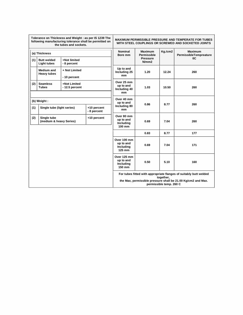
Tolerance on Thickness and Weight : as per IS 1239 The following manufacturing tolerance shall be permitted on
the tubes and sockets.
MAXIMUM PERMISSIBLE PRESSURE AND TEMPERATE FOR TUBES WITH STEEL COUPLINGS OR SCREWED AND SOCKETED JOINTS
(a) Thickness
(1) Butt welded Light tubes
+Not limited - 8 percent
Medium and Heavy tubes
+ Not Limited - 10 percent
(2) Seamless Tubes
+Not Limited - 12.5 percent
(b) Weight :
(1) Single tube (light series) +10 percent - 8 percent
(2) Single tube (medium & heavy Series)
+10 percent
Nominal Bore mm
Maximum Permissible
Pressure N/mm2
Kg./cm2 Maximum PermissibleTempreature
0C
Up to and Including 25
mm 1.20 12.24 260
Over 25 mm up to and
Including 40 mm
1.03 10.50 260
Over 40 mm up to and
Including 80 mm
0.86 8.77 260
Over 80 mm up to and Including 100 mm
0.69 7.04 260
0.83 8.77 177
Over 100 mm up to and Including 125 mm
0.69 7.04 171
Over 125 mm up to and Including 150 mm
0.50 5.10 160
For tubes fitted with appropriate flanges of suitably butt welded together,
the Max, permissible pressure shall be 21.00 Kg/cm2 and Max. permissible temp. 260 C
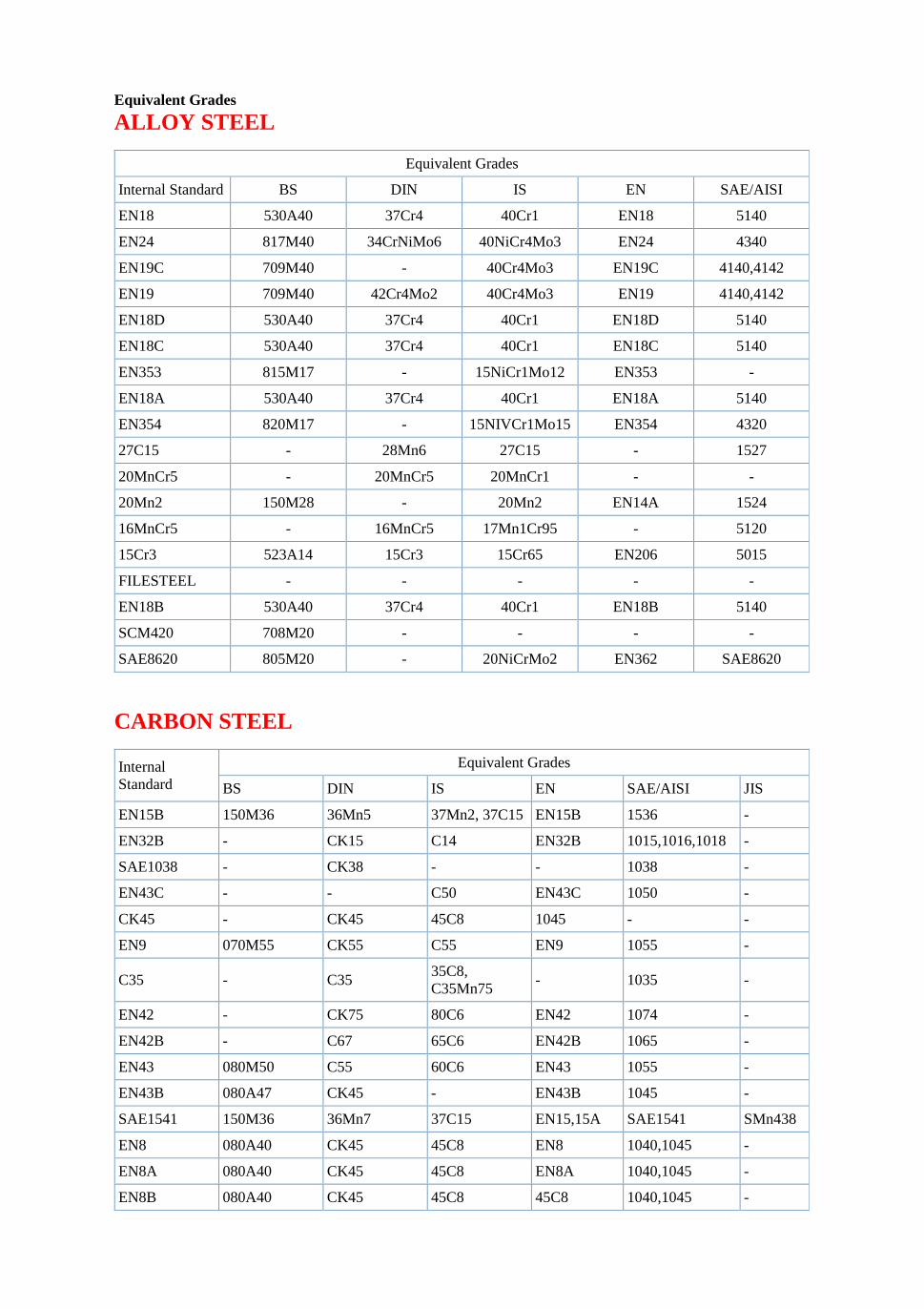
Equivalent Grades
ALLOY STEEL
Equivalent Grades
Internal Standard BS DIN IS EN SAE/AISI
EN18 530A40 37Cr4 40Cr1 EN18 5140
EN24 817M40 34CrNiMo6 40NiCr4Mo3 EN24 4340
EN19C 709M40 - 40Cr4Mo3 EN19C 4140,4142
EN19 709M40 42Cr4Mo2 40Cr4Mo3 EN19 4140,4142
EN18D 530A40 37Cr4 40Cr1 EN18D 5140
EN18C 530A40 37Cr4 40Cr1 EN18C 5140
EN353 815M17 - 15NiCr1Mo12 EN353 -
EN18A 530A40 37Cr4 40Cr1 EN18A 5140
EN354 820M17 - 15NIVCr1Mo15 EN354 4320
27C15 - 28Mn6 27C15 - 1527
20MnCr5 - 20MnCr5 20MnCr1 - -
20Mn2 150M28 - 20Mn2 EN14A 1524
16MnCr5 - 16MnCr5 17Mn1Cr95 - 5120
15Cr3 523A14 15Cr3 15Cr65 EN206 5015
FILESTEEL - - - - -
EN18B 530A40 37Cr4 40Cr1 EN18B 5140
SCM420 708M20 - - - -
SAE8620 805M20 - 20NiCrMo2 EN362 SAE8620
CARBON STEEL
Internal Standard
Equivalent Grades
BS DIN IS EN SAE/AISI JIS
EN15B 150M36 36Mn5 37Mn2, 37C15 EN15B 1536 -
EN32B - CK15 C14 EN32B 1015,1016,1018 -
SAE1038 - CK38 - - 1038 -
EN43C - - C50 EN43C 1050 -
CK45 - CK45 45C8 1045 - -
EN9 070M55 CK55 C55 EN9 1055 -
C35 - C35 35C8, C35Mn75
- 1035 -
EN42 - CK75 80C6 EN42 1074 -
EN42B - C67 65C6 EN42B 1065 -
EN43 080M50 C55 60C6 EN43 1055 -
EN43B 080A47 CK45 - EN43B 1045 -
SAE1541 150M36 36Mn7 37C15 EN15,15A SAE1541 SMn438
EN8 080A40 CK45 45C8 EN8 1040,1045 -
EN8A 080A40 CK45 45C8 EN8A 1040,1045 -
EN8B 080A40 CK45 45C8 45C8 1040,1045 -
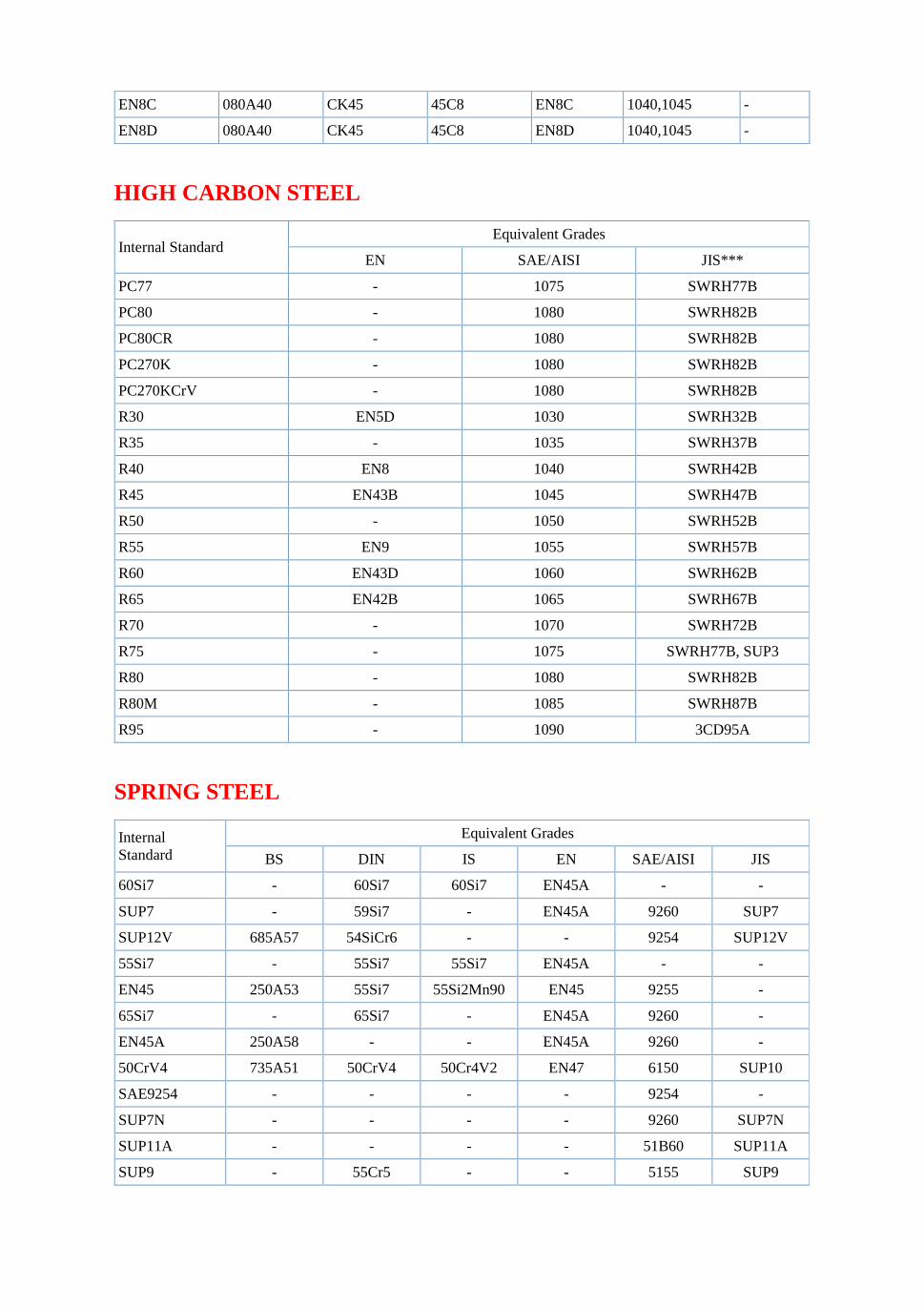
EN8C 080A40 CK45 45C8 EN8C 1040,1045 -
EN8D 080A40 CK45 45C8 EN8D 1040,1045 -
HIGH CARBON STEEL
Internal Standard Equivalent Grades
EN SAE/AISI JIS***
PC77 - 1075 SWRH77B
PC80 - 1080 SWRH82B
PC80CR - 1080 SWRH82B
PC270K - 1080 SWRH82B
PC270KCrV - 1080 SWRH82B
R30 EN5D 1030 SWRH32B
R35 - 1035 SWRH37B
R40 EN8 1040 SWRH42B
R45 EN43B 1045 SWRH47B
R50 - 1050 SWRH52B
R55 EN9 1055 SWRH57B
R60 EN43D 1060 SWRH62B
R65 EN42B 1065 SWRH67B
R70 - 1070 SWRH72B
R75 - 1075 SWRH77B, SUP3
R80 - 1080 SWRH82B
R80M - 1085 SWRH87B
R95 - 1090 3CD95A
SPRING STEEL
Internal Standard
Equivalent Grades
BS DIN IS EN SAE/AISI JIS
60Si7 - 60Si7 60Si7 EN45A - -
SUP7 - 59Si7 - EN45A 9260 SUP7
SUP12V 685A57 54SiCr6 - - 9254 SUP12V
55Si7 - 55Si7 55Si7 EN45A - -
EN45 250A53 55Si7 55Si2Mn90 EN45 9255 -
65Si7 - 65Si7 - EN45A 9260 -
EN45A 250A58 - - EN45A 9260 -
50CrV4 735A51 50CrV4 50Cr4V2 EN47 6150 SUP10
SAE9254 - - - - 9254 -
SUP7N - - - - 9260 SUP7N
SUP11A - - - - 51B60 SUP11A
SUP9 - 55Cr5 - - 5155 SUP9
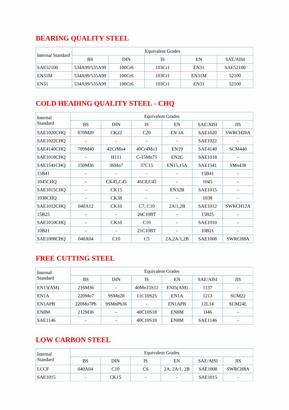
BEARING QUALITY STEEL
Internal Standard Equivalent Grades
BS DIN IS EN SAE/AISI
SAE52100 534A99/535A99 100Cr6 103Cr1 EN31 SAE52100
EN31M 534A99/535A99 100Cr6 103Cr1 EN31M 52100
EN31 534A99/535A99 100Cr6 103Cr1 EN31 52100
COLD HEADING QUALITY STEEL - CHQ
Internal Standard
Equivalent Grades
BS DIN IS EN SAE/AISI JIS
SAE1020CHQ 070M20 CK22 C20 EN 3A SAE1020 SWRCH20A
SAE1022CHQ - - - - SAE1022 -
SAE4140CHQ 709M40 42CrMo4 40Cr4Mo3 EN19 SAE4140 SCM440
SAE1018CHQ - H111 C-15Mn75 EN2C SAE1018 -
SAE1541CHQ 150M36 36Mn7 37C15 EN15,15A SAE1541 SMn438
15B41 - - - - 15B41 -
1045CHQ - CK45,C45 45C8,C45 - 1045 -
SAE1015CHQ - CK15 - EN32B SAE1015 -
1038CHQ - CK38 - - 1038 -
SAE1012CHQ 040A12 CK10 C7, C10 2A/1,2B SAE1012 SWRCH12A
15B25 - - 26C10BT - 15B25 -
SAE1010CHQ - CK10 C10 - SAE1010 -
10B21 - - 21C10BT - 10B21 -
SAE1008CHQ 040A04 C10 C5 2A,2A/1,2B SAE1008 SWRCH8A
FREE CUTTING STEEL
Internal Standard
Equivalent Grades
BS DIN IS EN SAE/AISI JIS
EN15(AM) 216M36 - 40Mn15S12 ENI5(AM) 1137 -
EN1A 220Mo7 9SMn28 11C10S25 EN1A 1213 SUM22
EN1APB 220Mo7Pb 9SMnPb36 - EN1APB 12L14 SUM24L
EN8M 212M36 - 40C10S18 EN8M 1I46 -
SAE1146 - - 40C10S18 EN8M SAE1146 -
LOW CARBON STEEL
Internal Standard
Equivalent Grades
BS DIN IS EN SAE/AISI JIS
LCCF 040A04 C10 CS 2A, 2A/1, 2B SAE1008 SWRCH8A
SAE1015 - CK15 - - SAE1015 -
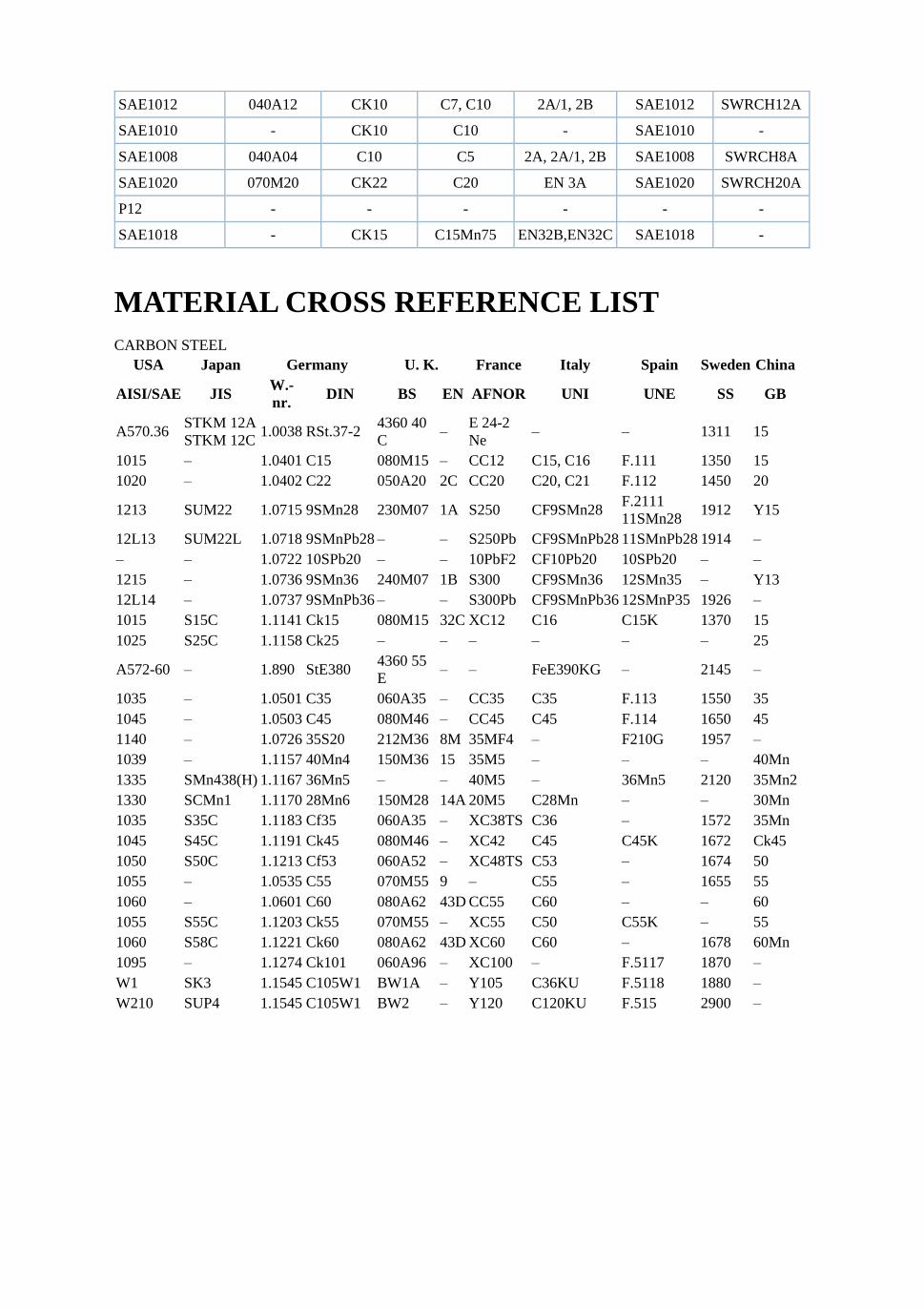
SAE1012 040A12 CK10 C7, C10 2A/1, 2B SAE1012 SWRCH12A
SAE1010 - CK10 C10 - SAE1010 -
SAE1008 040A04 C10 C5 2A, 2A/1, 2B SAE1008 SWRCH8A
SAE1020 070M20 CK22 C20 EN 3A SAE1020 SWRCH20A
P12 - - - - - -
SAE1018 - CK15 C15Mn75 EN32B,EN32C SAE1018 -
MATERIAL CROSS REFERENCE LIST CARBON STEEL
USA Japan Germany U. K. France Italy Spain Sweden China
AISI/SAE JIS W.-nr. DIN BS EN AFNOR UNI UNE SS GB
A570.36 STKM 12A STKM 12C
1.0038 RSt.37-2 4360 40 C
– E 24-2 Ne
– – 1311 15
1015 – 1.0401 C15 080M15 – CC12 C15, C16 F.111 1350 15 1020 – 1.0402 C22 050A20 2C CC20 C20, C21 F.112 1450 20
1213 SUM22 1.0715 9SMn28 230M07 1A S250 CF9SMn28 F.2111 11SMn28
1912 Y15
12L13 SUM22L 1.0718 9SMnPb28 – – S250Pb CF9SMnPb28 11SMnPb28 1914 – – – 1.0722 10SPb20 – – 10PbF2 CF10Pb20 10SPb20 – – 1215 – 1.0736 9SMn36 240M07 1B S300 CF9SMn36 12SMn35 – Y13 12L14 – 1.0737 9SMnPb36 – – S300Pb CF9SMnPb36 12SMnP35 1926 – 1015 S15C 1.1141 Ck15 080M15 32C XC12 C16 C15K 1370 15 1025 S25C 1.1158 Ck25 – – – – – – 25
A572-60 – 1.890 StE380 4360 55 E
– – FeE390KG – 2145 –
1035 – 1.0501 C35 060A35 – CC35 C35 F.113 1550 35 1045 – 1.0503 C45 080M46 – CC45 C45 F.114 1650 45 1140 – 1.0726 35S20 212M36 8M 35MF4 – F210G 1957 – 1039 – 1.1157 40Mn4 150M36 15 35M5 – – – 40Mn 1335 SMn438(H) 1.1167 36Mn5 – – 40M5 – 36Mn5 2120 35Mn2 1330 SCMn1 1.1170 28Mn6 150M28 14A 20M5 C28Mn – – 30Mn 1035 S35C 1.1183 Cf35 060A35 – XC38TS C36 – 1572 35Mn 1045 S45C 1.1191 Ck45 080M46 – XC42 C45 C45K 1672 Ck45 1050 S50C 1.1213 Cf53 060A52 – XC48TS C53 – 1674 50 1055 – 1.0535 C55 070M55 9 – C55 – 1655 55 1060 – 1.0601 C60 080A62 43D CC55 C60 – – 60 1055 S55C 1.1203 Ck55 070M55 – XC55 C50 C55K – 55 1060 S58C 1.1221 Ck60 080A62 43D XC60 C60 – 1678 60Mn 1095 – 1.1274 Ck101 060A96 – XC100 – F.5117 1870 – W1 SK3 1.1545 C105W1 BW1A – Y105 C36KU F.5118 1880 – W210 SUP4 1.1545 C105W1 BW2 – Y120 C120KU F.515 2900 –

Disclosure to Promote the Right To Information
Whereas the Parliament of India has set out to provide a practical regime of right to information for citizens to secure access to information under the control of public authorities, in order to promote transparency and accountability in the working of every public authority, and whereas the attached publication of the Bureau of Indian Standards is of particular interest to the public, particularly disadvantaged communities and those engaged in the pursuit of education and knowledge, the attached public safety standard is made available to promote the timely dissemination of this information in an accurate manner to the public.
इटरनट मानक
“!ान $ एक न' भारत का +नम-ण”Satyanarayan Gangaram Pitroda
“Invent a New India Using Knowledge”
“प0रा1 को छोड न' 5 तरफ”Jawaharlal Nehru
“Step Out From the Old to the New”
“जान1 का अ+धकार, जी1 का अ+धकार”Mazdoor Kisan Shakti Sangathan
“The Right to Information, The Right to Live”
“!ान एक ऐसा खजाना > जो कभी च0राया नहB जा सकता ह”Bhartṛhari—Nītiśatakam
“Knowledge is such a treasure which cannot be stolen”
“Invent a New India Using Knowledge”
ह”ह”ह
IS 1239-1 (2004): Steel Tubes, Tubulars and Other WroughtSteel Fittings, Part 1: Steel Tubes (BI-LINGUAL) [MTD 19:Steel Tubes, Pipes abd Fittings]


© BIS 2009
B U R E A U O F I N D I A N S T A N D A R D SMANAK BHAVAN, 9 BAHADUR SHAH ZAFAR MARG
NEW DELHI 110002
tqykbZ@July 2009 ewY; oxZ@Price Group 4
vkbZ,l@IS 1239 (Hkkx@Part 1) : 2004
Hkkjrh; ekud
bLikr dh ufy;k¡] ufydkdkj lkefxz;k¡ rFkk fiVok¡bLikr dh vU; fQfVaxsa — fof'kf"V
Hkkx 1 bLikr dh ufy;k¡Hkkx 1 bLikr dh ufy;k¡Hkkx 1 bLikr dh ufy;k¡Hkkx 1 bLikr dh ufy;k¡Hkkx 1 bLikr dh ufy;k¡
¼ NBk iqujh{k.k ½
Indian Standard
STEEL TUBES, TUBULARS AND OTHER WROUGHTSTEEL FITTINGS — SPECIFICATION
PART 1 STEEL TUBES
( Sixth Revision )
vkbZlh,l@ICS 77.140.75
¼f}Hkk"kh@Bilingual½
© Hkk ek C;wjks 2009
Hkkjrh; ekud C;wjksekud Hkou] 9 cgknqj 'kkg T+kQj ekxZ
ubZ fnYyh 110002

bLikr dh ufydk,¡] ikbi vkSj fiQfVax fo"k; lfefr] ,eVhMh 19
izkDdFku
;g Hkkjrh; ekud (Hkkx 1) (NBk iqujh{k.k) bLikr dh ufydk,¡] ikbi vkSj fiQfVax fo"k; lfefr }kjk vafre :i fn, x, elkSnsdks èkkfRod bathfu;jh foHkkx ifj"kn }kjk vuqeksfnr fd, tkus ds i'pkr~ Hkkjrh; ekud C;wjks }kjk xzg.k fd;k x;kA
bl ekud dk izFke izdk'ku 1958 esa gqvk rFkk rnuarj Øe'k% 1964] 1968] 1973] 1979 rFkk 1990 esa bldk iqujh{k.k fd;kx;kA
bl iqujh{k.k esa fuEufyf[kr eq[; la'kksèku fd, x, gSa%
d) ikapos iqujh{k.k ls lacafèkr lHkh la'kksèku 'kkfey dj fy, x, gSaA
[k) lhoughu ufydkvksa (ysMy fo'ys"k.k) ds fy, jklk;fud la?kVu dks 'kkfey fd;k x;k gS rFkk osYMÑr ufy;ksa dsfuekZ.k ds fy, vkbZ,l 10748 osYMÑr ufy;ksa rFkk ibiksa ds fy, rRi&osfYyr bLikr fLVªi* ;k vkbZ,l 513 dksYMjksYM fuEu dkcZu bLikr 'khV rFkk fLVªi* dks 'kkfey fd;k x;k gSA
x) lHkh fu£n"V vo;oksa ds fy, lhoughu V~;wcksa ds mRikn fo'ys"k.k ds ekeys esa vuqer varj dks 'kkfey fd;k x;k gSA
?k) izo.kdksj Nksj okyh ufy;ksa dh vkiw£r ds izkoèkku dks 'kkfey dj fy;k x;k gSA
Steel Tubes, Pipes and Fittings Sectional Committee, MTD 19
FOREWORD
This Indian Standard (Part 1) (Sixth Revision) was adopted by the Bureau of Indian Standards, after the draftfinalized by the Steel Tubes, Pipes and Fittings Sectional Committee had been approved by the MetallurgicalEngineering Division Council.
This standard was first published in 1958 and subsequently revised in 1964, 1968, 1973, 1979 and 1990 respectively.
In this revision, the following main modifications have been made:
a) All the amendments on the fifth revision have been incorporated.
b) Chemical composition for seamless tubes (ladle analysis ) has been incorporated and for manufacturingof welded tubes, IS 10748 ‘Hot-rolled steel strip for welded tubes and pipes’ or IS 513 ‘Cold rolled lowcarbon steel sheets and strips’ have been included.
c) Permissible variation in case of product analysis of seamless tubes for all specified elements have beenincorporated.
d) Provision for supply of tubes with bevel end has been incorporated.
(Continued on third cover)
(rhljs doj ij tkjh)
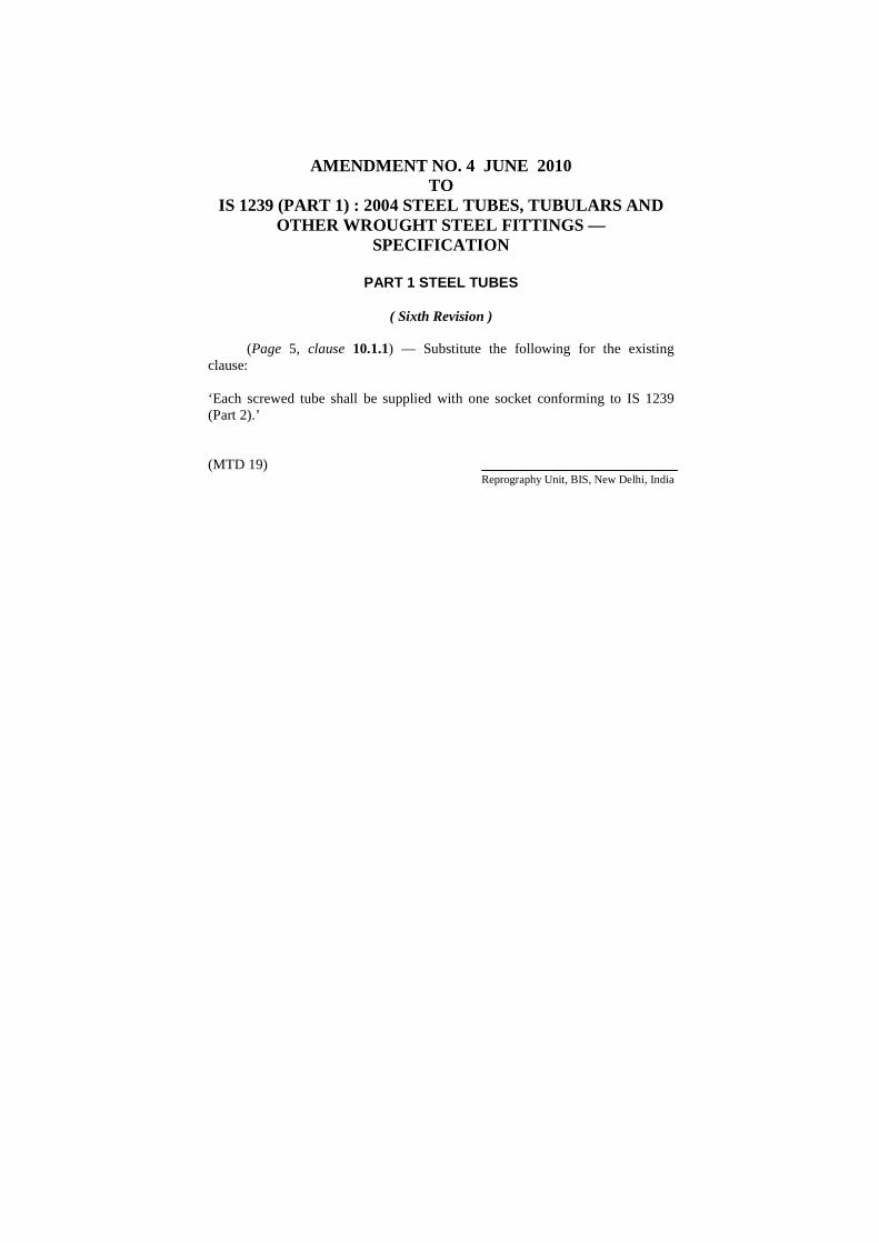
AMENDMENT NO. 4 JUNE 2010 TO
IS 1239 (PART 1) : 2004 STEEL TUBES, TUBULARS AND OTHER WROUGHT STEEL FITTINGS —
SPECIFICATION
PART 1 STEEL TUBES
( Sixth Revision )
(Page 5, clause 10.1.1) — Substitute the following for the existing clause: ‘Each screwed tube shall be supplied with one socket conforming to IS 1239 (Part 2).’ (MTD 19)
Reprography Unit, BIS, New Delhi, India
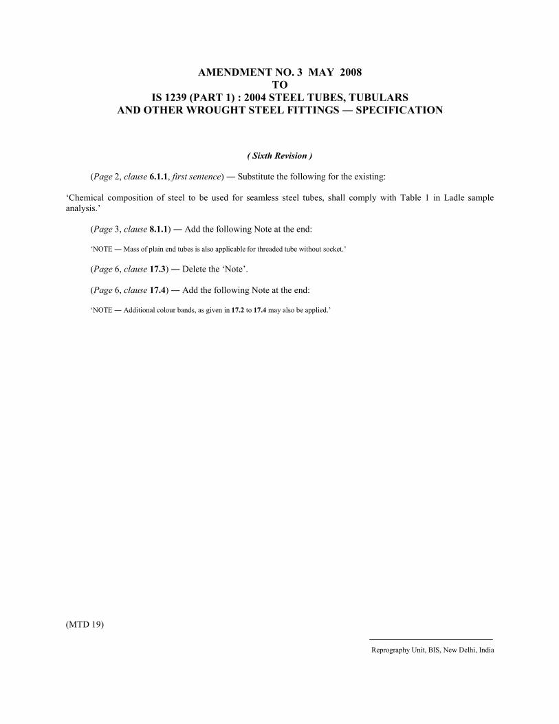
AMENDMENT NO. 3 MAY 2008
TO
IS 1239 (PART 1) : 2004 STEEL TUBES, TUBULARS
AND OTHER WROUGHT STEEL FITTINGS ― SPECIFICATION
( Sixth Revision )
(Page 2, clause 6.1.1, first sentence) ― Substitute the following for the existing:
‘Chemical composition of steel to be used for seamless steel tubes, shall comply with Table 1 in Ladle sample
analysis.’
(Page 3, clause 8.1.1) ― Add the following Note at the end:
‘NOTE ― Mass of plain end tubes is also applicable for threaded tube without socket.’
(Page 6, clause 17.3) ― Delete the ‘Note’.
(Page 6, clause 17.4) ― Add the following Note at the end:
‘NOTE ― Additional colour bands, as given in 17.2 to 17.4 may also be applied.’
(MTD 19)
Reprography Unit, BIS, New Delhi, India


1
vkbZ,l@IS 1239 (Hkkx/Part 1) : 2004
Hkkjrh; ekud
bLikr dh ufy;k¡] ufydkdkj lkefxz;k¡ rFkk fiVok¡bLikr dh vU; fQfVaxsa — fof'kf"V
Hkkx 1 bLikr dh ufy;k¡Hkkx 1 bLikr dh ufy;k¡Hkkx 1 bLikr dh ufy;k¡Hkkx 1 bLikr dh ufy;k¡Hkkx 1 bLikr dh ufy;k¡
¼ NBk iqujh{k.k ½
Indian Standard
STEEL TUBES, TUBULARS AND OTHER WROUGHTSTEEL FITTINGS — SPECIFICATION
PART 1 STEEL TUBES
( Sixth Revision )
1 SCOPE
1.1 This standard (Part 1) covers the requirements forwelded and seamless plain end or screwed and socketedsteel tubes intended for use for water, non-hazardousgas, air and steam. This standard is applicable to tubesof size 6 mm nominal bore to 150 mm nominal bore.
1.2 Medium and heavy tubes only are recommendedfor carrying steam services. The maximum permissiblepressure and temperatures for different sizes of tubesare given in Annex A for guidance only.
2 REFERENCES
The following standards contain provisions, whichthrough reference in this text, constitute provisions ofthis standard. At the time of publication, the editionsindicated were valid. All standards are subject to revisionand parties to agreements based on this standard areencouraged to investigate the possibility of applyingthe most recent editions of the standards indicated below:
IS No. Title
228 Method for chemical analysis of steels513 : 1994 Cold-rolled low carbon steel sheets
and strips (fourth revision)554 : 1999 Pipe threads where pressure-tight
joints are made on the threads —Dimensions, tolerances anddesignation (fourth revision)
11111 fo"k; {ks=k fo"k; {ks=k fo"k; {ks=k fo"k; {ks=k fo"k; {ks=k
1-1 1-1 1-1 1-1 1-1 bl ekud (Hkkx 1) esa ty] [krjkjfgr xSl] ok;q ,oaHkki ds fy, iz;ksx gsrq vk'kf;r osYMÑr rFkk lhoujfgr lknsNksj okyh ;k pwM+hnkj ,oa lkWdsV;qDr bLikr ufydkvksa dhvis{kk,¡ nh xbZ gSaA
1-2 1-2 1-2 1-2 1-2 Hkki lsokvksa ds ogu ds fy, dsoy eè;e vkSj Hkkjhufydkvksa dh fliQkfj'k dh xbZ gSA fofHkUu vkdkjksa dh ufydkvkasds fy, vuqer vfèkdre nkc rFkk rkieku dsoy ekxZn'kZugsrq vuqcaèk ^d* esa fn, x, gSaA
22222 lanHkZ lanHkZ lanHkZ lanHkZ lanHkZ
fuEufyf[kr ekudksa esa os izkoèkku lfUufgr gSa tks bl ikB esalanHkZ ds ekè;e ls bl ekud ds izkoèkkuksa dk la?kVu djrs gSaAizdk'ku ds l;e fu£n"V laLdj.k oS| FksA lHkh ekud iqujh{k.kds vèkhu gSa rFkk bl ekud ij vkèkkfjr djkjksa ds i{kdkjksadks uhps fu£n"V ekudksa ds lokZfèkd uohu laLdj.kksa dks ykxwdjus dh laHkkouk dk irk yxkus ds fy, izksRlkfgr fd;k tkrkgS%
vkbZ,l l- 'kh"kZd228 bLikr dh jklk;fud fo'ys"k.k i¼fr513 % 1994 dksYM jksYM fuEu dkcZu bLikr 'khVsa rFkk
ifV~V;k¡ (pkSFkk iqujh{k.k)554 % 1999 ikbi dh pwfM+;k¡ tgk¡ pwfM+;ksa ij nkc dls
tksM+ yxk, tkrs gS — vk;ke] NwVsa rFkkin uke (pkSFkk iqujh{k.k)
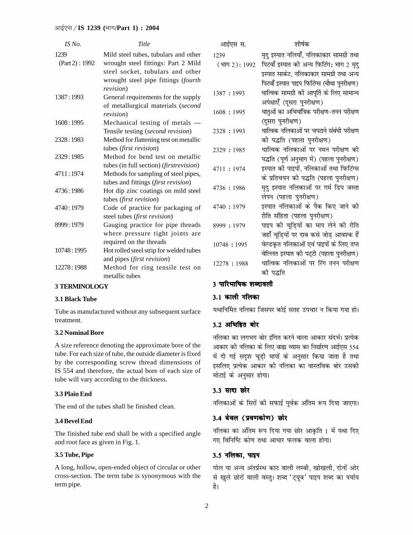
2
�������IS 1239 (��/Part 1) : 2004
IS No. Title
1239 Mild steel tubes, tubulars and other(Part 2) : 1992 wrought steel fittings: Part 2 Mild
steel socket, tubulars and otherwrought steel pipe fittings (fourthrevision)
1387 : 1993 General requirements for the supplyof metallurgical materials (secondrevision)
1608 : 1995 Mechanical testing of metals —Tensile testing (second revision)
2328 : 1983 Method for flattening test on metallictubes (first revision)
2329 : 1985 Method for bend test on metallictubes (in full section) (firstrevision)
4711 : 1974 Methods for sampling of steel pipes,tubes and fittings (first revision)
4736 : 1986 Hot dip zinc coatings on mild steeltubes (first revision)
4740 : 1979 Code of practice for packaging ofsteel tubes (first revision)
8999 : 1979 Gauging practice for pipe threadswhere pressure tight joints arerequired on the threads
10748 : 1995 Hot rolled steel strip for welded tubesand pipes (first revision)
12278 : 1988 Method for ring tensile test onmetallic tubes
3 TERMINOLOGY
3.1 Black Tube
Tube as manufactured without any subsequent surfacetreatment.
3.2 Nominal Bore
A size reference denoting the approximate bore of thetube. For each size of tube, the outside diameter is fixedby the corresponding screw thread dimensions ofIS 554 and therefore, the actual bore of each size oftube will vary according to the thickness.
3.3 Plain End
The end of the tubes shall be finished clean.
3.4 Bevel End
The finished tube end shall be with a specified angleand root face as given in Fig. 1.
3.5 Tube, Pipe
A long, hollow, open-ended object of circular or othercross-section. The term tube is synonymous with theterm pipe.
vkbZ,l l- 'kh"kZd
1239 e`nq bLikr ufy;k¡] ufydkdkj lkexzh rFkk(Hkkx 2)% 1992 fiVok¡ bLikr dh vU; fiQfVax% Hkkx 2 enq
bLikr lkdsV] ufydkdkj lkexzh rFkk vU;fiVok¡ bLikr ikbi fiQfVaXl (pkSFkk iqujh{k.k)
1387 % 1993 èkkfRod lkexzh dh vkiw£r ds fy, lkekU;vis{kk,¡ (nwljk iqujh{k.k)
1608 % 1995 èkkrqvksa dk vfHk;kaf=kd ijh{k.k&ruu ijh{k.k(nwljk iqujh{k.k)
2328 % 1993 èkkfRod ufydkvksa ij piVkus lacaèkh ijh{k.kdh i¼fr (igyk iqujh{k.k)
2329 % 1985 èkkfRod ufydkvksa ij ueu ijh{k.k dhi¼fr (iw.kZ vuqHkkx esa) (igyk iqujh{k.k)
4711 % 1974 bLikr dh ikbikas] ufydkvksa rFkk fiQfVaXlds izfrp;u dh i¼fr (igyk iqujh{k.k)
4736 % 1986 e`nq bLikr ufydkvksa ij xeZ fMi tLrkysiu (igyk iqujh{k.k)
4740 % 1979 bLikr ufydkvksa ds iSd fd, tkus dhjhfr lafgrk (igyk iqujh{k.k)
8999 % 1979 ikbi dh pwfM+;ksa dk eki ysus dh jhfrtgk¡ pwfM+;ksa ij nkc dls tksM+ vko'd gSa
10748 % 1995 osYMÑr ufydkvksa ,oa ikbiksa ds fy, rIrosfYyr bLikr dh iV~Vh (igyk iqujh{k.k)
12278 % 1988 èkkfRod ufydkvksa ij fjax ruu ijh{k.kdh i¼fr
3 3 3 3 3 ikfjHkkf"kd 'kCnkoyhikfjHkkf"kd 'kCnkoyhikfjHkkf"kd 'kCnkoyhikfjHkkf"kd 'kCnkoyhikfjHkkf"kd 'kCnkoyh
3-1 3-1 3-1 3-1 3-1 dkyh ufydkdkyh ufydkdkyh ufydkdkyh ufydkdkyh ufydk
;Fkkfu£er ufydk ftlij dksbZ lrg mipkj u fd;k x;k gksA
3-23-23-23-23-2 vfHkfgr cksjvfHkfgr cksjvfHkfgr cksjvfHkfgr cksjvfHkfgr cksj
ufydk dk yxHkx cksj bafxr djus okyk vkdkj lanHkZA izR;sdvkdkj dh ufydk ds fy, cká O;kl dk fu|kZj.k vkbZ,l 554esa nh xbZ ln`'k pwM+h ekikas ds vuqlkj fd;k tkrk gS rFkkblfy, izR;sd vkdkj dh ufydk dk okLrfod cksj mldheksVkbZ ds vuqlkj gksxkA
3-3 3-3 3-3 3-3 3-3 lknk Nksjlknk Nksjlknk Nksjlknk Nksjlknk Nksj
ufydkvksa ds fljksa dh liQkbZ iwoZd vafre :i fn;k tk,xkA
3-4 3-4 3-4 3-4 3-4 csoy (ço.kdks.k) Nksjcsoy (ço.kdks.k) Nksjcsoy (ço.kdks.k) Nksjcsoy (ço.kdks.k) Nksjcsoy (ço.kdks.k) Nksj
ufydk dk vafre :i fn;k x;k Nksj vkÑfr 1 eas ;Fkk fn,x, fofu£"V dks.k rFkk vkèkkj iQyd okyk gksxkA
3-53-53-53-53-5 ufydk] ikbi ufydk] ikbi ufydk] ikbi ufydk] ikbi ufydk] ikbi
xksy ;k vU; varizZLFk dkV okyh yEch] [kks[kyh] nksuksa vksjls [kqys Nksjksa okyh oLrqA 'kCn ^V~;wc* ikbi 'kCn dk i;kZ;gSA

3
�������IS 1239 (��/Part 1) : 2004
3.6 Socket
The screwed coupling utilized in joining the tubestogether.
NOTE — The term socket is synonymous with the termcoupler.
3.7 Length
3.7.1 Random Length
Normal manufacturing lengths, which may vary over awide range; alternatively, a length range may be agreedto between the purchaser and the manufacturer.
3.7.2 Exact Length of Screwed and Socketed Tube
The length of the tube exclusive of the socket.
3.7.3 Length of Screwed and Socketed Tube
The length of the tube inclusive of the socket on oneend with handling tight.
NOTE — Handling tight means that the socket is so tightfitted that it should not fall down during handling or transit.
4 DESIGNATION
Steel tubes covered by this standard shall bedesignated by their nominal bore and shall be furtherclassified as light, medium and heavy depending onthe wall thickness; and screwed and socketed or plain-end/bevel-end to denote end condition, and black orgalvanized to denote surface condition.
5 SUPPLY OF MATERIALS
General requirements relating to the supply of steeltubes shall conform to IS 1387.
3-63-63-63-63-6 lkdsV lkdsV lkdsV lkdsV lkdsV
ufydkvksa dks ,d lkFk tksM+us ds fy, iz;qDr fd;k tkus okykpwM+hnkj ;qXedA
fVIi.kh — 'kCn lkdsV 'kCn ;qXed dk i;kZ; gSA
3-73-73-73-73-7 yEckbZ yEckbZ yEckbZ yEckbZ yEckbZ
3-7-13-7-13-7-13-7-13-7-1 ;kn`fPNd yEckbZ
lkekU; mRiknu yEckb;k¡ ftuesa O;kid varj gks ldrk gSoSdfYid :i ls yEckbZ lhek Øsrk rFkk fuekZrk ds chp ;FkklEer yEckbZ gksxhA
3-7-23-7-23-7-23-7-23-7-2 pwM+hnkj rFkk lkdsV ;qDr ufydk dh okLrfod yEckbZ
lkdsV ds fcuk ufydk dh yEckbZA
3-7-3 3-7-3 3-7-3 3-7-3 3-7-3 pwM+hnkj rFkk lkdsV;qDr ufydk dh yEckbZ
,d Nksj ij dldj yxs lkWdsV lfgr ufydk dh yEckbZ
fVIi.kh — dldj yxs lkdsV dk vFkZ gS fd lkdsV bl izdkj dldjyxk gks fd og izgLru ;k ekxZLFk gksus ds nkSjku uhps u fxjsA
44444 inuke inuke inuke inuke inuke
bl ekud esa 'kkfey bLikr ufydkvksa dks muds vfHkfgr cksj}kjk uke fn;k tk,xk rFkk fHkfÙk dh eksVkbZ ds vkèkkj ij mUgsavkxs gydk] eè;e vkSj Hkkjh dh Jsf.k;ksa esa rFkk Nksj dhvoLFkk n'kkZus ds fy, pwM+hnkj ;k lkdsV;qDr vFkok lkns@ço.kdks.k Nksj okyh rFkk lrg voLFkk dks fu£n"V djus ds fy,dkyh ;k tLrkÑr ds :i esa Js.khÑr fd;k tk,xkA
5 lkexzh dh vkiw£r5 lkexzh dh vkiw£r5 lkexzh dh vkiw£r5 lkexzh dh vkiw£r5 lkexzh dh vkiw£r
bLikr ufydkvksa dh iw£r ls lacafèkr lkekU; vis{kk,¡vkbZ ,l 1387 ds vuq:i gksaxhA
vkÑfr 1 30° izo.kdks.k okyk ufydk dk NksjFIG. 1 TUBE END WITH 30° BEVELLING
0-8 fe-eh- (U;wure) 0-8 fe-eh- (U;wure)
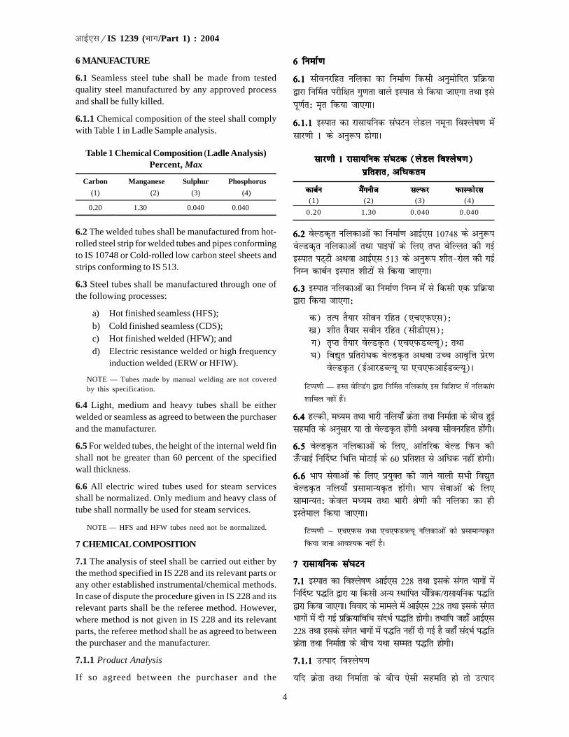
4
�������IS 1239 (��/Part 1) : 2004
6 MANUFACTURE
6.1 Seamless steel tube shall be made from testedquality steel manufactured by any approved processand shall be fully killed.
6.1.1 Chemical composition of the steel shall complywith Table 1 in Ladle Sample analysis.
Table 1 Chemical Composition (Ladle Analysis)Percent, Max
Carbon Manganese Sulphur Phosphorus
(1) (2) (3) (4)
0.20 1.30 0.040 0.040
6.2 The welded tubes shall be manufactured from hot-rolled steel strip for welded tubes and pipes conformingto IS 10748 or Cold-rolled low carbon steel sheets andstrips conforming to IS 513.
6.3 Steel tubes shall be manufactured through one ofthe following processes:
a) Hot finished seamless (HFS);b) Cold finished seamless (CDS);c) Hot finished welded (HFW); andd) Electric resistance welded or high frequency
induction welded (ERW or HFIW).
NOTE — Tubes made by manual welding are not coveredby this specification.
6.4 Light, medium and heavy tubes shall be eitherwelded or seamless as agreed to between the purchaserand the manufacturer.
6.5 For welded tubes, the height of the internal weld finshall not be greater than 60 percent of the specifiedwall thickness.
6.6 All electric wired tubes used for steam servicesshall be normalized. Only medium and heavy class oftube shall normally be used for steam services.
NOTE — HFS and HFW tubes need not be normalized.
7 CHEMICAL COMPOSITION
7.1 The analysis of steel shall be carried out either bythe method specified in IS 228 and its relevant parts orany other established instrumental/chemical methods.In case of dispute the procedure given in IS 228 and itsrelevant parts shall be the referee method. However,where method is not given in IS 228 and its relevantparts, the referee method shall be as agreed to betweenthe purchaser and the manufacturer.
7.1.1 Product Analysis
If so agreed between the purchaser and the
6 fuekZ.k6 fuekZ.k6 fuekZ.k6 fuekZ.k6 fuekZ.k
6-1 6-1 6-1 6-1 6-1 lhoujfgr ufydk dk fuekZ.k fdlh vuqeksfnr izfØ;k}kjk fu£er ijhf{kr xq.krk okys bLikr ls fd;k tk,xk rFkk blsiw.kZr% e`r fd;k tk,xkA
6-1-1 6-1-1 6-1-1 6-1-1 6-1-1 bLikr dk jklk;fud la?kVu ysMy uewuk fo'ys"k.k esalkj.kh 1 ds vuq:i gksxkA
lkj.kh 1 jklk;fud la?kVd (ysMy fo'ys"k.k)lkj.kh 1 jklk;fud la?kVd (ysMy fo'ys"k.k)lkj.kh 1 jklk;fud la?kVd (ysMy fo'ys"k.k)lkj.kh 1 jklk;fud la?kVd (ysMy fo'ys"k.k)lkj.kh 1 jklk;fud la?kVd (ysMy fo'ys"k.k)izfr'kr] izfr'kr] izfr'kr] izfr'kr] izfr'kr] vfèkdrevfèkdrevfèkdrevfèkdrevfèkdre
dkcZudkcZudkcZudkcZudkcZu eSaxuhteSaxuhteSaxuhteSaxuhteSaxuht lYiQjlYiQjlYiQjlYiQjlYiQj iQkLiQksjliQkLiQksjliQkLiQksjliQkLiQksjliQkLiQksjl(1) (2) (3) (4)
0.20 1.30 0.040 0.040
6-2 6-2 6-2 6-2 6-2 osYMd`r ufydkvksa dk fuekZ.k vkbZ,l 10748 ds vuq:iosYMd`r ufydkvksa rFkk ikbiksa ds fy, rIr osfYyr dh xbZbLikr iV~Vh vFkok vkbZ,l 513 ds vuq:i 'khr&jksy dh xbZfuEu dkcZu bLikr 'khVksa ls fd;k tk,xkA
6-3 6-3 6-3 6-3 6-3 bLikr ufydkvkas dk fuekZ.k fuEu esa ls fdlh ,d izfØ;k}kjk fd;k tk,xk%
d) rRi rS;kj lhou jfgr (,p,iQ,l)_[k) 'khr rS;kj lohu jfgr (lhMh,l)_x) r`Ir rS;kj osYMÑr (,p,iQMCY;w)_ rFkk?k) fo|qr izfrjksèkd osYMÑr vFkok mPp vko`fÙk izsj.k
osYMÑr (bZvkjMCY;w ;k ,p,iQvkbZMCY;w)A
fVIi.kh — gLr osfYMax }kjk fu£er ufydka, bl fof'k"V esa ufydkax
'kkfey ugha gSaA
6-4 6-4 6-4 6-4 6-4 gYdh] eè;e rFkk Hkkjh ufy;k¡ Øsrk rFkk fuekZrk ds chp gqbZlgefr ds vuqlkj ;k rks osYMÑr gksaxh vFkok lhoujfgr gksaxhA
6-56-56-56-56-5 osYMÑr ufydkvksa ds fy,] vkarfjd osYM fiQu dhm¡QpkbZ fu£n"V fHkfÙk eksVkbZ ds 60 izfr'kr ls vfèkd ugha gksxhA
6-66-66-66-66-6 Hkki lsokvksa ds fy, iz;qDr dh tkus okyh lHkh fo|qrosYMÑr ufy;k¡ izlkekU;Ñr gksaxhA Hkki lsokvksa ds fy,lkekU;r% dsoy eè;e rFkk Hkkjh Js.kh dh ufydk dk ghbLrseky fd;k tk,xkA
fVIi.kh μ ,p,iQl rFkk ,p,iQMCY;w ufydkvksa dks izlkekU;Ñr
fd;k tkuk vko';d ugha gSA
7 jklk;fud la?kVu7 jklk;fud la?kVu7 jklk;fud la?kVu7 jklk;fud la?kVu7 jklk;fud la?kVu
7-1 7-1 7-1 7-1 7-1 bLikr dk fo'ys"k.k vkbZ,l 228 rFkk blds laxr Hkkxksa esafu£n"V i¼fr }kjk ;k fdlh vU; LFkkfir ;k¡f=kd@jklk;fud i¼fr}kjk fd;k tk,xkA fookn ds ekeys esa vkbZ,l 228 rFkk blds laxrHkkxksa esa nh xbZ izfØ;kfofèk lanHkZ i¼fr gksxhA rFkkfi tgk¡ vkbZ,l228 rFkk blds laxr Hkkxksa esa i¼fr ugha nh xbZ gS ogk¡ lanHkZ i¼frØsrk rFkk fuekZrk ds chp ;Fkk lEer i¼fr gksxhA
7-1-17-1-17-1-17-1-17-1-1 mRikn fo'ys"k.k
;fn Øsrk rFkk fuekZrk ds chp ,slh lgefr gks rks mRikn

5
�������IS 1239 (��/Part 1) : 2004
manufacturer, the product analysis may be carried out.Maximum permissible variations in the case of productanalysis over the maximum limits specified in Table 1shall be as given in Table 2.
Table 2 Permissible Variation for Product Analysis(Clause 7.1.1)
SI No. Content Variation Over Specified Limit Percent, Max
(1) (2) (3)
i) Carbon 0.02 ii) Manganese 0.04
iii) Sulphur 0.005 iv) Phosphorus 0.005
NOTE — In case of welded tubes, product analysis shall not be applicable to rimming steel.
8 DIMENSIONS
8.1 The dimensions and nominal mass of tubes shallbe in accordance with Tables 3, 4 and 5 subject to thetolerances permitted in 9.
fo'ys"k.k fd;k tk ldrk gSA mRikn fo'ys"k.k ds ekeys esalkj.kh 1 esa fu£n"V vfèkdre lhekvksa dh rqyuk esa vfèkdrevuqer varj lkj.kh 2 esa fn, x, vuqlkj gksxkA
lkj.kh lkj.kh lkj.kh lkj.kh lkj.kh 22222 mRikn fo'ys"k.k ds fy, vuqer varj mRikn fo'ys"k.k ds fy, vuqer varj mRikn fo'ys"k.k ds fy, vuqer varj mRikn fo'ys"k.k ds fy, vuqer varj mRikn fo'ys"k.k ds fy, vuqer varj([kaM 7-1-1)
Ø-la-Ø-la-Ø-la-Ø-la-Ø-la- fo"k; oLrqfo"k; oLrqfo"k; oLrqfo"k; oLrqfo"k; oLrq fu£n"V izfr'kr lhek dh rqyukfu£n"V izfr'kr lhek dh rqyukfu£n"V izfr'kr lhek dh rqyukfu£n"V izfr'kr lhek dh rqyukfu£n"V izfr'kr lhek dh rqyukesa varj] esa varj] esa varj] esa varj] esa varj] vfèkdrevfèkdrevfèkdrevfèkdrevfèkdre
(1) (2) (3)i) dkcZu 0-02
ii) eSaxuht 0-04iii) lYiQj 0-005iv) iQkLiQksjl 0-005fVIi.kh — osYMÑr ufydkvksa ds ekeys esa mRikn fo'ys"k.k fjfeax bLikr ij
iz;ksT; ugha gksxkA
8 8 8 8 8 vk;kevk;kevk;kevk;kevk;ke
8-18-18-18-18-1 ufydkvksa ds vk;ke rFkk vfHkfgr Hkkj [kaM 99999 esa vuqerNwVksa ds vèkhu lkj.kh 3] 4 rFkk 5 ds vuqlkj gksxkA
lkj.kh 3 gydh bLikr dh ufydkvks a ds vk;ke rFkk vfHkfgr Hkkjlkj.kh 3 gydh bLikr dh ufydkvks a ds vk;ke rFkk vfHkfgr Hkkjlkj.kh 3 gydh bLikr dh ufydkvks a ds vk;ke rFkk vfHkfgr Hkkjlkj.kh 3 gydh bLikr dh ufydkvks a ds vk;ke rFkk vfHkfgr Hkkjlkj.kh 3 gydh bLikr dh ufydkvks a ds vk;ke rFkk vfHkfgr Hkkj([kaM 8-1 rFkk 10-1-1-1)
��������� � �� �� ������ ��������� �
���� � ������� �����
������� �
��������� �������������� ��������
������� ������� ������� ������� �������������� ��������������
(1) (2) (3) (4) (5) (6)
6 10.1 9.7 1.8 0.360 0.363 8 13.6 13.2 1.8 0.515 0.519
10 17.1 16.7 1.8 0.670 0.676 15 21.4 21.0 2.0 0.947 0.956 20 26.9 26.4 2.3 1.38 1.39 25 33.8 33.2 2.6 1.98 2.00 32 42.5 41.9 2.6 2.54 2.57 40 48.4 47.8 2.9 3.23 3.27 50 60.2 59.6 2.9 4.08 4.15 65 76.0 75.2 3.2 5.71 5.83 80 88.7 87.9 3 . 2 6.72 6.89
100 113.9 113.0 3.6 9.75 10.0
Table 3 Dimensions and Nominal Mass of Steel Tubes(Clauses 8.1 and 10.1.1.1)
Outside Diameter Mass of Tube Nominal Bore
Maximum Minimum
Thickness
Plain End Screwed and Socketed mm mm mm mm kg/m kg/m
(1) (2) (3) (4) (5) (6)
6 10.1 9.7 1.8 0.360 0.363 8 13.6 13.2 1.8 0.515 0.519
10 17.1 16.7 1.8 0.670 0.676 15 21.4 21.0 2.0 0.947 0.956 20 26.9 26.4 2.3 1.38 1.39 25 33.8 33.2 2.6 1.98 2.00 32 42.5 41.9 2.6 2.54 2.57 40 48.4 47.8 2.9 3.23 3.27 50 60.2 59.6 2.9 4.08 4.15 65 76.0 75.2 3.2 5.71 5.83 80 88.7 87.9 3 . 2 6.72 6.89
100 113.9 113.0 3.6 9.75 10.0
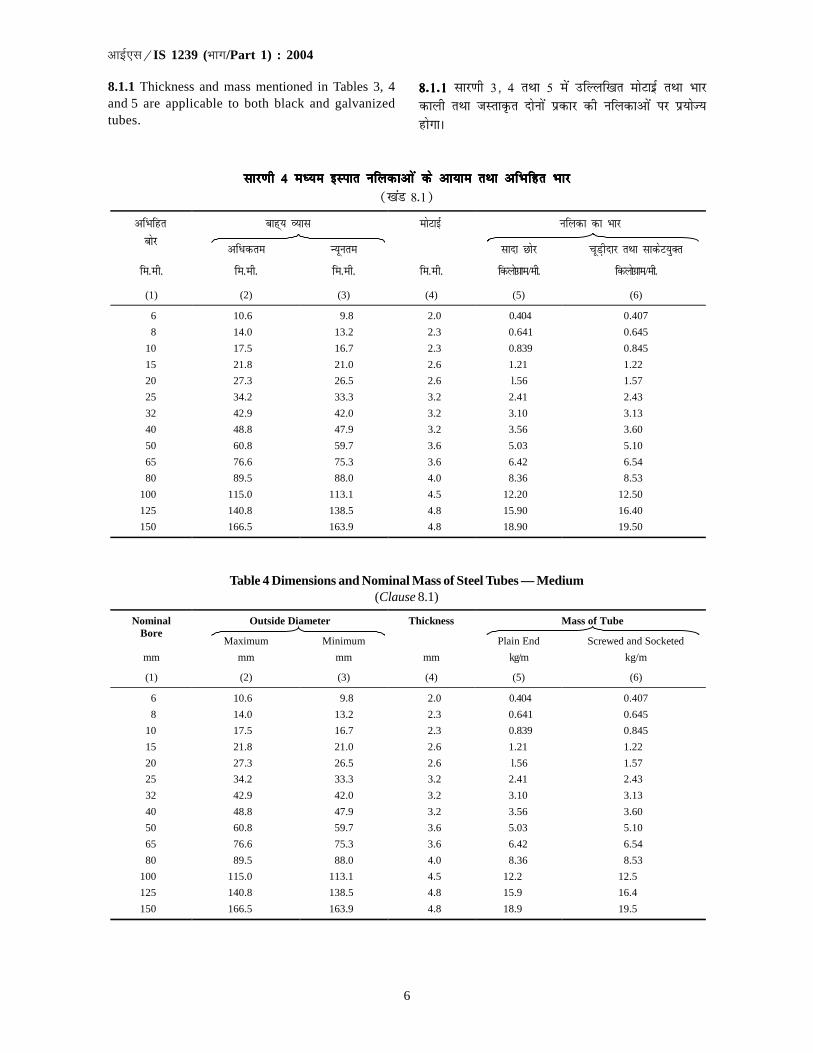
6
�������IS 1239 (��/Part 1) : 2004
lkj.kh 4 eè;e bLikr ufydkvks a ds vk;ke rFkk vfHkfgr Hkkjlkj.kh 4 eè;e bLikr ufydkvks a ds vk;ke rFkk vfHkfgr Hkkjlkj.kh 4 eè;e bLikr ufydkvks a ds vk;ke rFkk vfHkfgr Hkkjlkj.kh 4 eè;e bLikr ufydkvks a ds vk;ke rFkk vfHkfgr Hkkjlkj.kh 4 eè;e bLikr ufydkvks a ds vk;ke rFkk vfHkfgr Hkkj([kaM 8-1)
��������� � ������� � �� �� ������ �������� �
���� �������� ����� � ��������� �������������� ��������
������� ������� ������� ������� �������������� ��������������
(1) (2) (3) (4) (5) (6)
6 10.6 9.8 2.0 0.404 0.407
8 14.0 13.2 2.3 0.641 0.645
10 17.5 16.7 2.3 0.839 0.845
15 21.8 21.0 2.6 1.21 1.22
20 27.3 26.5 2.6 l.56 1.57
25 34.2 33.3 3.2 2.41 2.43
32 42.9 42.0 3.2 3.10 3.13
40 48.8 47.9 3.2 3.56 3.60
50 60.8 59.7 3.6 5.03 5.10
65 76.6 75.3 3.6 6.42 6.54
80 89.5 88.0 4.0 8.36 8.53
100 115.0 113.1 4.5 12.20 12.50
125 140.8 138.5 4.8 15.90 16.40
150 166.5 163.9 4.8 18.90 19.50
Table 4 Dimensions and Nominal Mass of Steel Tubes — Medium(Clause 8.1)
Outside Diameter Thickness Mass of Tube Nominal Bore
Maximum Minimum Plain End Screwed and Socketed
mm mm mm mm kg/m kg/m
(1) (2) (3) (4) (5) (6)
6 10.6 9.8 2.0 0.404 0.407
8 14.0 13.2 2.3 0.641 0.645
10 17.5 16.7 2.3 0.839 0.845
15 21.8 21.0 2.6 1.21 1.22
20 27.3 26.5 2.6 l.56 1.57
25 34.2 33.3 3.2 2.41 2.43
32 42.9 42.0 3.2 3.10 3.13
40 48.8 47.9 3.2 3.56 3.60
50 60.8 59.7 3.6 5.03 5.10
65 76.6 75.3 3.6 6.42 6.54
80 89.5 88.0 4.0 8.36 8.53
100 115.0 113.1 4.5 12.2 12.5
125 140.8 138.5 4.8 15.9 16.4
150 166.5 163.9 4.8 18.9 19.5
8.1.1 Thickness and mass mentioned in Tables 3, 4and 5 are applicable to both black and galvanizedtubes.
8-1-18-1-18-1-18-1-18-1-1 lkj.kh 3] 4 rFkk 5 esa mfYyf[kr eksVkbzZ rFkk Hkkjdkyh rFkk tLrkÑr nksuksa izdkj dh ufydkvksa ij iz;ksT;gksxkA

7
�������IS 1239 (��/Part 1) : 2004
9 TOLERANCES ON THICKNESS AND MASS
9.1 The following manufacturing tolerances shall bepermitted on the tubes and sockets:
a) Thickness:
1) Welded tubes:Light tubes + not limited
– 8 percentMedium and heavy + not limitedtubes – 10 percent
2) Seamless tubes + not limited– 12.5 percent
b) Mass:
1) Single tube (light + 10 percentseries) – 8 percent
2) Single tube (medium ± 10 percentand heavy series)
3) For quantities per load + 7.5 percentof 10 tonnes, Min – 5 percent(light series)
4) For quantities per load ± 7.5 percentof 10 tonnes, Min(medium and heavyseries)
NOTE — For the purpose of minimum weighment of 10tonnes lot, the weighment may be done in convenient lotsat the option of the manufacturer.
10 JOINTS
10.1 All screwed tubes shall be supplied with pipethreads conforming to IS 554. Gauging in accordancewith IS 8999 shall be considered as an adequate testfor conformity of threads of IS 554.
10.1.1 Unless specified otherwise, tubes shall besupplied screwed with taper threads and fitted with onesocket having parallel thread. The socket shall conformto all requirements (except 6.4) of IS 1239 (Part 2).
10.1.1.1 In case of light tubes the application of taperpipe threads may be modified by permitting the outsidediameter of the tubes to be within the limits shown in col2 and 3 of Table 3. Where the tube approaches the lowerlimit of outside diameter, some incomplete threads(perfect at root and imperfect at the crest) may be expectedfrom and beyond the gauge plane. Such incompletethreads, shall not be regarded as justification for rejectionof the tubes. Also the minimum length of threads in lighttubes shall be 80 percent of that specified in IS 554.
10.2 The plain end pipes shall be supplied with squarecut. However, bevel end may also be supplied on mutualagreement between the purchaser and the manufacturer(see Fig. 1).
9 eksVkbZ rFkk Hkkj lacaèkh NwVs a9 eksVkbZ rFkk Hkkj lacaèkh NwVs a9 eksVkbZ rFkk Hkkj lacaèkh NwVs a9 eksVkbZ rFkk Hkkj lacaèkh NwVs a9 eksVkbZ rFkk Hkkj lacaèkh NwVs a
9-1 9-1 9-1 9-1 9-1 ufydkvksa rFkk lkdsVksa ds lacaèk esa fuEufyf[kr mRiknuNwVsa vuqer dh tk,axh%
d) eksVkbZ%1) osYMd`r ufy;k¡%
gydh ufy;k¡ + dksbZ lhek ugha– 8 izfr'kr
eè;e rFkk Hkkjh ufy;k¡ + dksbZ lhek ugha– 10 izfr'kr
2) lhou jfgr ufy;k¡ + dksbZ lhek ugha– 12-5 izfr'kr
[k) Hkkj%1) ,dy ufydk + 10 izfr'kr
(gydh J`a[kyk) – 8 izfr'kr2) ,dy ufydk (eè;e ± 10 izfr'kr
rFkk Hkkjh J`a[kyk)3) izfr 10 Vu Hkkj okyh + 7-5 izfr'kr
izek=kkvksa ds fy, U;wure – 5 izfr'kr(gydh J`a[kyk)
4) izfr 10 Vu Hkkj okyh ± 7-5 izfr'krizek=kkvksa ds fy, U;wure(eè;e rFkk Hkkjh J`a[kyk)
fVIi.kh — 10 Vu ds lewg ds U;wure Hkkj ds iz;kstukFkZ] Hkkj rksyfuekZrk osQ fodYi ij lqfo/ktud lewgksa esa fd;k tk ldrk gSA
10 tksM+10 tksM+10 tksM+10 tksM+10 tksM+
10-110-110-110-110-1 lHkh pwM+hnkj ufydkvksa dh vkiw£r vkbZ,l 554 dsvuq:i ikbi pwfM+;ksa ds lkFk dh tk,xhA vkbZ,l 554 dhpwfM+;ksa dh vuq:irk ds fy, vkbZ,l 8999 ds vuqlkjekikadu dks i;kZIr ijh{k.k ekuk tk,xkA
10-1-110-1-110-1-110-1-110-1-1 ;fn vU;Fkk fu£n"V u fd;k x;k gks] rks ufydkvksa dhvkiw£r xkonqe pwfM+;ksa lfgr rFkk lekukarj pwM+h okys ,dlkdsV ds lkFk fiQV djds dh tk,xhA lkdsV vkbZ,l 1239(Hkkx 2) dh lHkh vis{kkvksa (flok, 6-46-46-46-46-4) ds vuq:i gksxkA
10-1-1-110-1-1-110-1-1-110-1-1-110-1-1-1 gydh ufydkvksa ds ekeys esa] ufydkvksa ds ckáO;kl dks lkj.kh 3 ds dkye 2 rFkk 3 eas n'kkZ;h xbZ lhekvksads Hkhrj gksus dh vuqefr nsdj xkonqe ikbi pwfM;k¡ dsvuqiz;ksx esa la'kksèku fd;k tk ldrk gSA tgk¡ ufydk ckáO;kl dh fuEure lhek ds yxHkx lfUudV gks] ogk¡ xst lrgls rFkk mlls vkxs dqN viw.kZ pwfM+;ksa (ewy ij iw.kZ rFkk 'kh"kZij vèkwjh) gksuk laHkkfor gS] ,slh viw.kZ pwfM;ksa ds vkèkkj ijufydkvkas dks vLohdkj djuk ;qfDrlaxr ugha ekuk tk,xkAlkFk gh gYdh ufydkvksa esa pwfM+;ksa dh U;wure yEckbZ vkbZ,l554 esa fu£n"V yEckbZ dk 80 izfr'kr gksxhA
10-210-210-210-210-2 lkns Nksj okyh ikbiksa dks oxkZdkj dVko fn;k tk,xkA rFkkfiØsrk rFkk fuekZrk ds chp ikjLifjd lgefr gksus ij izo.k dks.kNksj okyh ikbisa Hkh vkiwfjr dh tk ldrh gSaA (ns[kaas vkÑfr 1)A
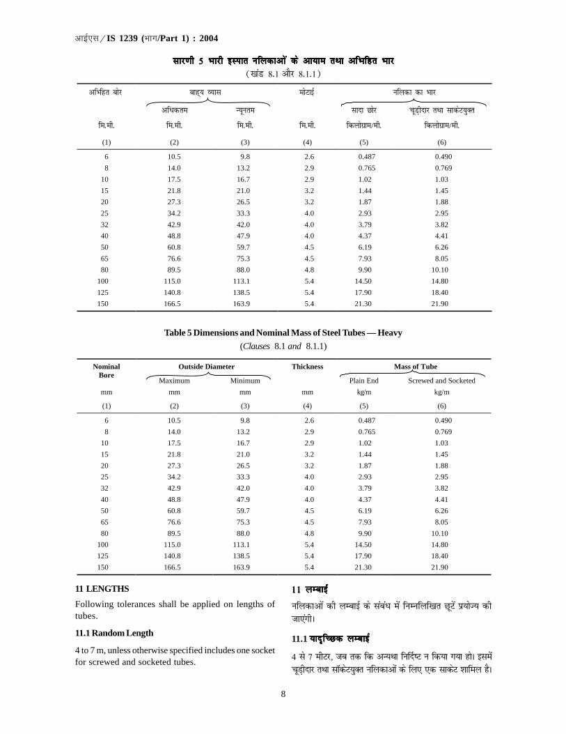
8
�������IS 1239 (��/Part 1) : 2004
Table 5 Dimensions and Nominal Mass of Steel Tubes — Heavy
(Clauses 8.1 and 8.1.1)
Outside Diameter Thickness Mass of Tube Nominal Bore
Maximum Minimum Plain End Screwed and Socketed
mm mm mm mm kg/m kg/m
(1) (2) (3) (4) (5) (6)
6 10.5 9.8 2.6 0.487 0.490
8 14.0 13.2 2.9 0.765 0.769
10 17.5 16.7 2.9 1.02 1.03
15 21.8 21.0 3.2 1.44 1.45
20 27.3 26.5 3.2 1.87 1.88
25 34.2 33.3 4.0 2.93 2.95
32 42.9 42.0 4.0 3.79 3.82
40 48.8 47.9 4.0 4.37 4.41
50 60.8 59.7 4.5 6.19 6.26
65 76.6 75.3 4.5 7.93 8.05
80 89.5 88.0 4.8 9.90 10.10
100 115.0 113.1 5.4 14.50 14.80
125 140.8 138.5 5.4 17.90 18.40
150 166.5 163.9 5.4 21.30 21.90
lkj.kh 5 Hkkjh bLikr ufydkvks a ds vk;ke rFkk vfHkfgr Hkkjlkj.kh 5 Hkkjh bLikr ufydkvks a ds vk;ke rFkk vfHkfgr Hkkjlkj.kh 5 Hkkjh bLikr ufydkvks a ds vk;ke rFkk vfHkfgr Hkkjlkj.kh 5 Hkkjh bLikr ufydkvks a ds vk;ke rFkk vfHkfgr Hkkjlkj.kh 5 Hkkjh bLikr ufydkvks a ds vk;ke rFkk vfHkfgr Hkkj([kaM 8-1 vkSj 8-1-1)
��������� � ������� � �� �� ������ ������������ �
������� ����� � ��������� �������������� ��������
������� ������� ������� ������� �������������� ��������������
(1) (2) (3) (4) (5) (6)
6 10.5 9.8 2.6 0.487 0.490
8 14.0 13.2 2.9 0.765 0.769
10 17.5 16.7 2.9 1.02 1.03
15 21.8 21.0 3.2 1.44 1.45
20 27.3 26.5 3.2 1.87 1.88
25 34.2 33.3 4.0 2.93 2.95
32 42.9 42.0 4.0 3.79 3.82
40 48.8 47.9 4.0 4.37 4.41
50 60.8 59.7 4.5 6.19 6.26
65 76.6 75.3 4.5 7.93 8.05
80 89.5 88.0 4.8 9.90 10.10
100 115.0 113.1 5.4 14.50 14.80
125 140.8 138.5 5.4 17.90 18.40
150 166.5 163.9 5.4 21.30 21.90
11 LENGTHS
Following tolerances shall be applied on lengths oftubes.
11.1 Random Length
4 to 7 m, unless otherwise specified includes one socketfor screwed and socketed tubes.
1111111111 yEckbZ yEckbZ yEckbZ yEckbZ yEckbZ
ufydkvksa dh yEckbZ ds lacaèk esa fuEufyf[kr NwVsa iz;ksT; dhtk,axhA
11.1 ;kn`fPNd yEckbZ;kn`fPNd yEckbZ;kn`fPNd yEckbZ;kn`fPNd yEckbZ;kn`fPNd yEckbZ
4 ls 7 ehVj] tc rd fd vU;Fkk fu£n"V u fd;k x;k gksA blesapwM+hnkj rFkk lkWdsV;qDr ufydkvksa ds fy, ,d lkdsV 'kkfey gSA

9
�������IS 1239 (��/Part 1) : 2004
11.1.1 For orders of over 150 m of any one size of tube,it shall be permissible to supply short random lengthsfrom 2 to 4 m provided that the number of such lengthdoes not exceed 5 percent of the total number of lengthsfor sizes below 65 mm nominal bore and above, 7.5percent of such short random length shall be permitted.In addition, it shall be permissible for two lengths to bejoined together to make a random length, provided thatthe number of such joint lengths does not exceed 5percent of the total number of lengths for sizes below65 mm nominal bore and 7.5 percent of the total numberof lengths for sizes 65 mm and above.
11.2 Exact Length
Unless otherwise agreed to between the manufacturerand the purchaser, where exact lengths are specified,either for screwed and socketed tubes or for plain-endtubes each tube shall be within 6
0+− mm of the specified
length.
11.3 Approximate Length
When approximate lengths are required, either forscrewed and socketed tubes or for plain end tubes,each tube shall be within ±150 mm of the specifiedlength.
12 GALVANIZING
12.1 Where tubes are required to be galvanized, thezinc coating on the tubes shall be in accordance withIS 4736.
12.2 Tubes, which are to be screwed, shall be galvanizedbefore screwing.
13 LEAK PROOF TEST
13.1 Each tube shall be tested for leak tightness as anin-process test at manufacturer’s works either byhydrostatic test or alternatively by Eddy current test,in accordance with Annex B.
13.1.1 Hydrostatic test shall be carried out at apressuring of 5 MPa and the same maintained for atleast 3 and shall not show any leakage in the pipe.
NOTE — The choice of test is at the discretion of themanufacturer.
14 TEST ON TUBES
Following tests shall be conducted by the manufactureron tubes.
14.1 The tensile strength shall be at least 320 MPa (320N/mm2). The test shall be carried out on full section orstrip cut from the selected tubes in accordance withIS 1608 and IS 12278.
11-1-1 11-1-1 11-1-1 11-1-1 11-1-1 fdlh ,d vkdkj dh ufydk ds 150 ehVj ls vfèkddh vkiw£r djus ds vkns'kksa ds fy, 2 ls 4 ehVj dh NksVh ;knfPNdyEckbZ okyh ufydkvksa dh vkiw£r djus dh vuqefr gksxh c'krsZfd 65 fe-eh- ls de ds vfHkfgr ifjosèk okys vkdkjksa ds fy, blizdkj dh yEckbZ oky VqdMs+ dh la[;k dqN yEckbZ la[;k ds 5izfr'kr ls vfèkd u gks rFkk 65 fe-eh- ls vfèkd ds vfHkfgrifjosèk ds fy, NksVh ;knfPNd yEckbZ oky ,sls 7-5 izfr'kr VqdMksadh vuqefr nh tk,xhA blds vfrfjDr] dksbZ ;knfPNd yEckbZizkIr djus ds fy, nks VqdM+ksa dks tksM+us dh vuqefr gksxh c'krsZ fdtksM+ksa okyh ,slh yEckbZ dh la[;k 65 fe-eh- ds vfHkfgr ifjosèkls de okys vkdkjksa ds fy, yEckbZ dh dqy la[;k ds 5 izfr'krls rFkk 65 fe-eh- ,oa mlls vfèkd ds vkdkjksa ds fy, yEckbZ dhdqy la[;k ds 7-5 izfr'kr ls vfèkd u gksA
11-2 okLrfod yEckbZ11-2 okLrfod yEckbZ11-2 okLrfod yEckbZ11-2 okLrfod yEckbZ11-2 okLrfod yEckbZ
tc rd fuekZrk ,oa Øsrk ds chp vU;Fkk lgefr u gqbZ gks]ogk¡ pwM+hnkj rFkk lkdsV;qDr ufydkvksa ds fy, ;k lkjs Nksjokyh ufydkvksa ds fy, okLrfod yEckbZ fu£n"V gksus dhfLFkfr esa izR;sd ufydk fu£n"V yxHkx fe-eh- ds Hkhrj gksxhA
11-3 vuqekfur yEckbZ11-3 vuqekfur yEckbZ11-3 vuqekfur yEckbZ11-3 vuqekfur yEckbZ11-3 vuqekfur yEckbZ
tgk¡ pwM+hnkj rFkk lkdsV;qDr ufydkvksa ds fy, ;k lkns Nksjokyh ufydkvksa ds fy, vuqekfur yEckb;k¡ visf{kr gSa] ogk¡izR;sd ufydk fu£n"V yEckbZ ds ±150 fe-eh- ds Hkhrj gksxhA
12 tLrhdj.k12 tLrhdj.k12 tLrhdj.k12 tLrhdj.k12 tLrhdj.k
12-112-112-112-112-1 tgk¡ ufydkvksa ij tLrk p<+kuk vko';d gS ogk¡ ufydkvksaij tLrk ysiu vkbZ,l 4736 ds vuqlkj fd;k tk,xkA
12-212-212-212-212-2 ftu ufydkvksa ij pwfM+;k¡ cukbZ tkuh gSa] mudh pwfM+;k¡cukus ls igys mudk tLrhdj.k dj fy;k tk,xkA
13 fjlko jksèkh ijh{k.k13 fjlko jksèkh ijh{k.k13 fjlko jksèkh ijh{k.k13 fjlko jksèkh ijh{k.k13 fjlko jksèkh ijh{k.k
13-113-113-113-113-1 izR;sd ufydk dk vuqcaèk [k ds vuqlkj fuekZrk dsdkj[kkus esa ;k rks gkbMªksLVsfVd (tyLFkSfrd) ijh{k.k }kjkvFkok oSdfYid :i ls varj èkkjk ijh{k.k }kjk fjlko dlkods fy, var% izfØ;k ijh{k.k fd;k tk,xkA
13-1-113-1-113-1-113-1-113-1-1 tyLFkSfrd ijh{k.k 5 ,eih, ds nkc ij rFkk de lsde 3 lSdsaM rd mls cuk, j[kdj fd;k tk,xk rFkk blnkSjku ikbi esa dksbZ fjlko ugha gksuk pkfg,A
fVIi.kh — ijh{k.k dk p;u fuekZrk ds foosdkuqlkj fd;k tk,xkA
14 ufy;ks a ij ijh{k.k14 ufy;ks a ij ijh{k.k14 ufy;ks a ij ijh{k.k14 ufy;ks a ij ijh{k.k14 ufy;ks a ij ijh{k.k
fuekZrk }kjk ufydkvksa ij fuEufyf[kr ijh{k.k fd, tk,axsA
14-114-114-114-114-1 ruu {kerk de ls de 320 ,eih, (320 N/mm2)gksxhA ijh{k.k vkbZ,l 1608 rFkk 12278 ds vuqlkj p;furufydkvksa dh iw.kZ yEckbZ ij ;k muls dkVh xbZ iV~Vh ij fd;ktk,xkA

10
�������IS 1239 (��/Part 1) : 2004
NOTES
1 For welded tubes, the strip tensile test specimen shall notcontain the weld.
2 For galvanized tubes, zinc coating may be removed bystripping prior to tensile test.
14.1.1 The elongation percent on a gauge length of
o5.65 ,S where So is the original cross-sectional area
of the test specimen, shall be as follows:
Nominal Bore ElongationPercent, Min
a) For steam services for all sizes 20
b) For other services:
1) Up to and including 25 mm 12
2) Over 25 mm up to and 20
including 150 mm
14.2 Bend Test on Tubes Up to and Including 50 mmNominal Bore
When tested in accordance with IS 2329 the tubes shallbe capable of withstanding the bend test withoutshowing any signs of fracture or failure. Welded tubesshall be bent with the weld at 90° to the plane of bending.The tubes shall not be filled for this test.
14.2.1 Ungalvanized tubes shall be capable of beingbent cold without cracking through 180° round a formerhaving a radius at the bottom of groove in the plane ofbending, equal to at least six times the outside diameterof the tube.
14.2.2 Galvanized tubes shall be capable of being bentcold, without cracking of the steel, through 90° rounda former having a radius at the bottom of the grooveequal to at least eight times the outside diameter of thetubes.
14.3 Flattening Test on Tubes Above 50 mm NominalBore
Rings not less than 40 mm in length cut from the endsof the selected tubes shall be flattened cold betweenparallel plates with the weld, if any at 90° (point ofmaximum bending) in accordance with IS 2328. Noopening shall occur by fracture in the weld area untilthe distance between the plates is less than 75 percentof the original outside diameter of the tube and nocracks or breaks in the metal elsewhere than in the weldshall occur until the distance between the plates is lessthan 60 percent of the original outside diameter.
NOTE — Slight premature cracking at the edges would notbe deemed to affect compliance with this standard.
14.3.1 The test rings may have the inner and outeredges rounded.
fVIi.kh;k¡
11111 osYMÑr ufydkvksa ds fy, iV~Vh ruu ijh{k.k uewus esa tksM+ (osYM)ugha gksxkA
22222 tLrkÑr ufydkvksa ds fy, ruu ijh{k.k ds iwoZ iVV~h dkVdj mudsmQij ls tLrs dk ysi gVk fn;k tk,XkkA
14-1-1 14-1-1 14-1-1 14-1-1 14-1-1 o5.65 S eki dh yEckbZ ij izyacu izfr'kr fuEuizdkj gksxk] tgk¡ So ijh{k.k uewus dk vuqizlFk dkV okyk ewy{ks=kiQy gS%
vfHkfgr cksj çyEcuçfr'kr] U;wure
d) lHkh vkdkjksa dh eki lsokvksa 20ds fy,
[k) vU; lsokvksa ds fy,%1) 25 fe-eh- rd rFkk mlds 12
lekfgr
2) 25 fe-eh- ls vfèkd rFkk 15 fe-eh- 20lekfgr rd
14-2 50 fe-eh- rd rFkk mlds lekfgr vfHkfgr cksj14-2 50 fe-eh- rd rFkk mlds lekfgr vfHkfgr cksj14-2 50 fe-eh- rd rFkk mlds lekfgr vfHkfgr cksj14-2 50 fe-eh- rd rFkk mlds lekfgr vfHkfgr cksj14-2 50 fe-eh- rd rFkk mlds lekfgr vfHkfgr cksjokyh ufydkvks a ij ueu ijh{k.kokyh ufydkvks a ij ueu ijh{k.kokyh ufydkvks a ij ueu ijh{k.kokyh ufydkvks a ij ueu ijh{k.kokyh ufydkvks a ij ueu ijh{k.k
vkbZ,l 2329 ds vuqlkj ijh{k.k fd, tkus ij ufydk Hkax ;k fodkjds dksbZ okg~u n'kkZ, fcuk ueu ijh{k.k dks lgus esa l{ke gksAosYMÑr rkfydkvkas dks osYM ds lkFk ueu lrg ij 90 fMxzh ijeksM+k tk,xkA bl ijh{k.k ds fy, bu ufydkvksa dks Hkjk ugh tk,xkA
14-2-114-2-114-2-114-2-114-2-1 vtLrhÑr ufy;k¡ ,slh gksa fd mUgas vrIr voLFkk esa180° ij iQkeZj ds pkjksa vksj fcuk fdlh izdkj ds pVdk; dseksM+k tk ldsA bl iQkeZj dh f=kT;k ueu ry okys lkaps dhrygVh ij ufydk ds ckgjh O;kl dh 6 xquk gksA
14-2-2 14-2-2 14-2-2 14-2-2 14-2-2 tLrhÑr ufydk,¡ ,slh gksa fd mUgsa vrIr voLFkk esa90° ij iQkeZj ds pkjksa vksj fcuk fdlh izdkj ds pVdko dseksM+k tk ldsA bl iQkeZj dh f=kT;k ueu ry okys [kkap dhrygVh ij ckgjh O;kl dh 8 xquk gksA
14-3 50 fe-eh- ls vfèkd vfHkfgr cksj okyh ufydkvks a14-3 50 fe-eh- ls vfèkd vfHkfgr cksj okyh ufydkvks a14-3 50 fe-eh- ls vfèkd vfHkfgr cksj okyh ufydkvks a14-3 50 fe-eh- ls vfèkd vfHkfgr cksj okyh ufydkvks a14-3 50 fe-eh- ls vfèkd vfHkfgr cksj okyh ufydkvks adks piVkus lacaèkh ijh{k.kdks piVkus lacaèkh ijh{k.kdks piVkus lacaèkh ijh{k.kdks piVkus lacaèkh ijh{k.kdks piVkus lacaèkh ijh{k.k
p;u dh xbZ ufydkvksa ds Nksj ls de ls de 40 fe-eh-yEckbZ ds dkVs x, NYYkksa dks vkbZ,l 2328 ds vuqlkj osYM];fn gks] ds lkFk 90° (vfèkdre ueu fcUnq) ij lekUrjifVV;ksa ds chp j[kdj piVk fd;k tk,xkA tc rd ifVV;ksads chp dh nwjh ewy cká O;kl ds 75 izfr'kr ls de ugha gkstk, rc rd osYM foHkat ds dkj.k fdlh izdkj [kqys ugha vkSjtc rd ifVV~;ksa ds chp dh nwjh ewy cká O;kl ds 60 izfr'krls de ugha gks tk,] rc rd èkkrq esa osYM ds LFkku ds vykokfdlh vU; LFkku ij fdlh Hkh izdkj dh njkj ;k Hkatu u gksA
fVIi.kh — fdukjksa ij gydh iwoZ ifjiDo njkj bl ekud ds lkFkvuqikyu dks izHkkfor djus okyh ugha ekuh tk,xhA
14-3-114-3-114-3-114-3-114-3-1 ijh{k.k NYyksa ds vkarfjd rFkk ckgjh fdukjs xksyfd, x, gks ldrs gSaA
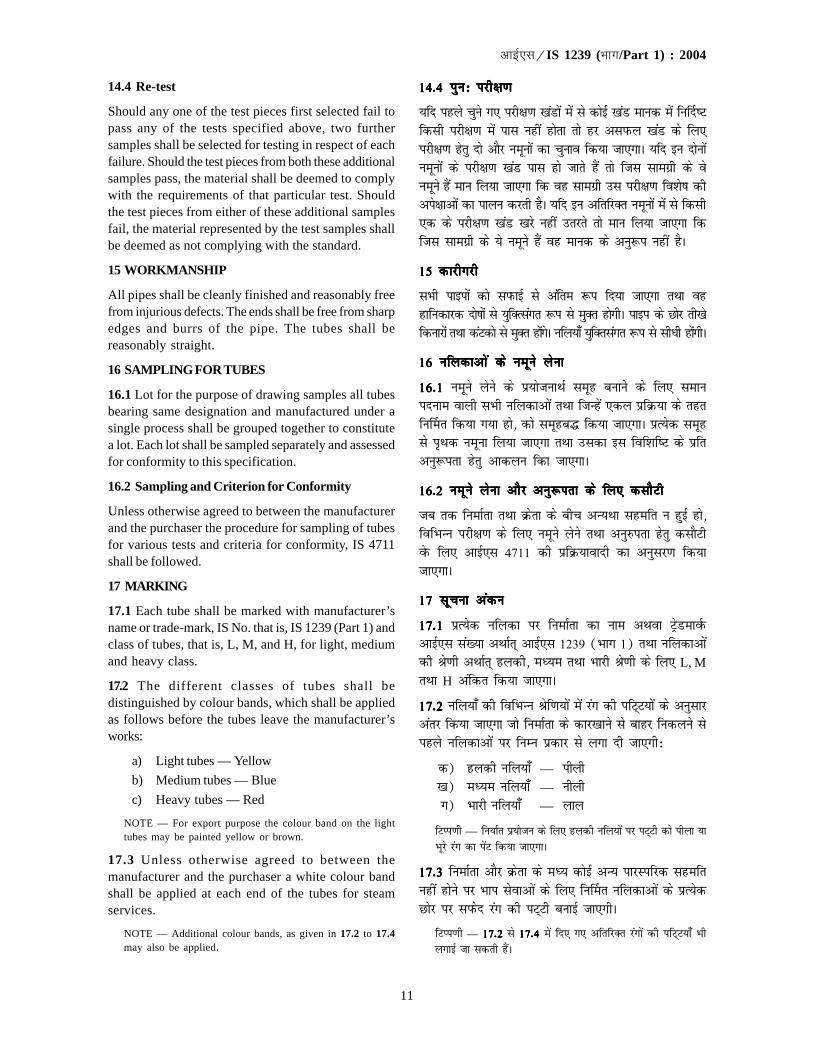
11
�������IS 1239 (��/Part 1) : 2004
14.4 Re-test
Should any one of the test pieces first selected fail topass any of the tests specified above, two furthersamples shall be selected for testing in respect of eachfailure. Should the test pieces from both these additionalsamples pass, the material shall be deemed to complywith the requirements of that particular test. Shouldthe test pieces from either of these additional samplesfail, the material represented by the test samples shallbe deemed as not complying with the standard.
15 WORKMANSHIP
All pipes shall be cleanly finished and reasonably freefrom injurious defects. The ends shall be free from sharpedges and burrs of the pipe. The tubes shall bereasonably straight.
16 SAMPLING FOR TUBES
16.1 Lot for the purpose of drawing samples all tubesbearing same designation and manufactured under asingle process shall be grouped together to constitutea lot. Each lot shall be sampled separately and assessedfor conformity to this specification.
16.2 Sampling and Criterion for Conformity
Unless otherwise agreed to between the manufacturerand the purchaser the procedure for sampling of tubesfor various tests and criteria for conformity, IS 4711shall be followed.
17 MARKING
17.1 Each tube shall be marked with manufacturer’sname or trade-mark, IS No. that is, IS 1239 (Part 1) andclass of tubes, that is, L, M, and H, for light, mediumand heavy class.
17.2 The different classes of tubes shall bedistinguished by colour bands, which shall be appliedas follows before the tubes leave the manufacturer’sworks:
a) Light tubes — Yellow
b) Medium tubes — Blue
c) Heavy tubes — Red
NOTE — For export purpose the colour band on the lighttubes may be painted yellow or brown.
17.3 Unless otherwise agreed to between themanufacturer and the purchaser a white colour bandshall be applied at each end of the tubes for steamservices.
NOTE — Additional colour bands, as given in 17.2 to 17.4may also be applied.
14-4 iqu% ijh{k.k14-4 iqu% ijh{k.k14-4 iqu% ijh{k.k14-4 iqu% ijh{k.k14-4 iqu% ijh{k.k
;fn igys pqus x, ijh{k.k [kaMksa esa ls dksbZ [kaM ekud esa fu£n"Vfdlh ijh{k.k esa ikl ugha gksrk rks gj vliQy [kaM ds fy,ijh{k.k gsrq nks vkSj uewuksa dk pquko fd;k tk,xkA ;fn bu nksuksauewuksa ds ijh{k.k [kaM ikl gks tkrs gSa rks ftl lkexzh ds osuewus gSa eku fy;k tk,xk fd og lkexzh ml ijh{k.k fo'ks"k dhvis{kkvksa dk ikyu djrh gSA ;fn bu vfrfjDr uewuksa esa ls fdlh,d ds ijh{k.k [kaM [kjs ugha mrjrs rks eku fy;k tk,xk fdftl lkexzh ds ;s uewus gSa og ekud ds vuq:i ugha gSA
15 dkjhxjh15 dkjhxjh15 dkjhxjh15 dkjhxjh15 dkjhxjh
lHkh ikbiksa dks liQkbZ ls vafre :i fn;k tk,xk rFkk oggkfudkjd nks"kksa ls ;qfDRlaxr :i ls eqDr gksxhA ikbi ds Nksj rh[ksfdukjksa rFkk daVdks ls eqDr gksaxsA ufy;k¡ ;qfDrlaxr :i ls lhèkh gksaxhA
16 ufydkvks a ds uewus ysuk16 ufydkvks a ds uewus ysuk16 ufydkvks a ds uewus ysuk16 ufydkvks a ds uewus ysuk16 ufydkvks a ds uewus ysuk
16-116-116-116-116-1 uewus ysus ds iz;kstukFkZ lewg cukus ds fy, lekuinuke okyh lHkh ufydkvksa rFkk ftUgsa ,dy izfØ;k ds rgrfu£er fd;k x;k gks] dks lewgc¼ fd;k tk,xkA izR;sd lewgls i`Fkd uewuk fy;k tk,xk rFkk mldk bl fof'kf"V ds izfrvuq:irk gsrq vkdyu fdk tk,xkA
16-2 uewus ysuk vkSj vuq:irk ds fy, dlkSVh16-2 uewus ysuk vkSj vuq:irk ds fy, dlkSVh16-2 uewus ysuk vkSj vuq:irk ds fy, dlkSVh16-2 uewus ysuk vkSj vuq:irk ds fy, dlkSVh16-2 uewus ysuk vkSj vuq:irk ds fy, dlkSVh
tc rd fuekZrk rFkk Øsrk ds chp vU;Fkk lgefr u gqbZ gks]fofHkUu ijh{k.k ds fy, uewus ysus rFkk vuq#irk gsrq dlkSVhosQ fy, vkbZ,l 4711 dh izfØ;koknh dk vuqlj.k fd;ktk,xkA
17 lwpuk vadu17 lwpuk vadu17 lwpuk vadu17 lwpuk vadu17 lwpuk vadu
17-117-117-117-117-1 izR;sd ufydk ij fuekZrk dk uke vFkok VªsMekoZQvkbZ,l la[;k vFkkZr~ vkbZ,l 1239 (Hkkx 1) rFkk ufydkvksadh Js.kh vFkkZr~ gydh] eè;e rFkk Hkkjh Js.kh ds fy, L, MrFkk H vafdr fd;k tk,xkA
17-2 17-2 17-2 17-2 17-2 ufy;k¡ dh fofHkUu Jsf.k;ksa esa jax dh ifV~V;ksa ds vuqlkjvarj fd;k tk,xk tks fuekZrk ds dkj[kkus ls ckgj fudyus lsigys ufydkvksa ij fuEu izdkj ls yxk nh tk,xh%
d) gydh ufy;k¡ — ihyh[k) eè;e ufy;k¡ — uhyhx) Hkkjh ufy;k¡ — yky
fVIi.kh — fu;kZr iz;kstu ds fy, gydh ufy;ksa ij iV~Vh dks ihyk ;kHkwjs jax dk isaV fd;k tk,xkA
17-3 17-3 17-3 17-3 17-3 fuekZrk vkSj Øsrk ds eè; dksbZ vU; ikjLifjd lgefrugha gksus ij Hkki lsokvksa ds fy, fu£er ufydkvksa ds izR;sdNksj ij liQsn jax dh iV~Vh cukbZ tk,xhA
fVIi.kh — 17-217-217-217-217-2 ls 17-417-417-417-417-4 esa fn, x, vfrfjDr jaxksa dh ifV~V;k¡ HkhyxkbZ tk ldrh gSaA

12
�������IS 1239 (��/Part 1) : 2004
17.4 Tubes having random length 4 to 7 meters shallhave two 75 mm bands one near each end. Tubeshaving exact length and approximate length asprescribed in clause 11.2 and clause 11.3 shall haveone 75 mm band.
17.5 BIS Certification Marking
The tubes may also the marked with the Standard Mark.
17.5.1 The use of the Standard Mark is governed bythe provisions of the Bureau of Indian StandardsAct, 1986 and the Rules and Regulations madethereunder. The details of conditions under which thelicence for the use of Standard Mark may be granted tomanufacturers or producers may be obtained from theBureau of Indian Standards.
18 PROTECTION AND PACKING
Black tubes not otherwise protected shall be varnishedor suitably painted externally throughout the lengthunless ordered unvarnished or unpainted. Where tubesare bundled for transport, all qualities of tubes shall bepacked in accordance with IS 4740.
17-417-417-417-417-4 4 ls 7 ehVj okyh ;kn`fPNd yEckbZ okyh ufy;ksa ij nksifV~V;k¡ izR;sd fljs ds lehi 75 fe-eh- dh ,d iV~Vh cukbZtk,xhA [kaM 11-211-211-211-211-2 rFkk [kaM 11-3 11-3 11-3 11-3 11-3 esa ;Fkk fuèkkZfjr okLrfodyEckbZ rFkk vuqekfur yEckbZ okyh ufydkvksa esa 75 fe-eh- dh,d iV~Vh gksxhA
17-5 Hkkjrh; ekud C;wjks dk izek.ku eqgjkadu17-5 Hkkjrh; ekud C;wjks dk izek.ku eqgjkadu17-5 Hkkjrh; ekud C;wjks dk izek.ku eqgjkadu17-5 Hkkjrh; ekud C;wjks dk izek.ku eqgjkadu17-5 Hkkjrh; ekud C;wjks dk izek.ku eqgjkadu
ufydkvksa ij ekud eqgjkadu Hkh fd;k tk ldrk gSA
17-5-1 17-5-1 17-5-1 17-5-1 17-5-1 ekud eqgj dk mi;ksx Hkkjrh; ekud C;wjks vfèkfu;e]1986 vkSj mlds vfèku cus fu;eksa vkSj fofu;eksa ds izkoèkkuksavuqlkj gksA fuekZrkvksa vkSj laLdÙkkZvksa dks ftu 'krks± osQ vèkhuekud eqgj yxkus ds fy, ykblsal fn;k tkrk gS mldk fooj.kHkkjrh; ekud C;wjks ls izkIr fd;k tk ldrk gSA
18 laj{k.k ,oa iSfdax18 laj{k.k ,oa iSfdax18 laj{k.k ,oa iSfdax18 laj{k.k ,oa iSfdax18 laj{k.k ,oa iSfdax
vU;Fkk lajf{kr u dh xbZ dkyh ufydkvksa dh iw.kZ yEckbZ ijok£u'k yxkbZ tk,xh vFkok mls ckgj ls mi;qDr izdkj isaVfd;k tk,xk tc rd fd ml ij ok£u'k ;k isaV u yxkus dsvkns'k u fn, x, gksaA tgk¡ ufydkvksa ds ifjogu ds fy, caMycuk, tkrs gSa] ogk¡ lHkh izdkj dh rkfydkvksa dks vkbZ,l 4740ds vuqlkj iSd fd;k tk,xkA
vuqcaèk ^d*vuqcaèk ^d*vuqcaèk ^d*vuqcaèk ^d*vuqcaèk ^d*([kaM 1-2)
Hkki ogu okyh ufydkvks a ds fy, vfèkdre vuqer nkc vkSj rkiHkki ogu okyh ufydkvks a ds fy, vfèkdre vuqer nkc vkSj rkiHkki ogu okyh ufydkvks a ds fy, vfèkdre vuqer nkc vkSj rkiHkki ogu okyh ufydkvks a ds fy, vfèkdre vuqer nkc vkSj rkiHkki ogu okyh ufydkvks a ds fy, vfèkdre vuqer nkc vkSj rki
ANNEX A(Clause 1.2)
MAXIMUM PERMISSIBLE PRESSURE AND TEMPERATURE FOR TUBES FORCONVEYING STEAM
A-1 The maximum permissible pressure andtemperature for tubes with screwed and socketed jointsshall be as given in Table 6.
A-2 For tubes fitted with appropriate flanges orsuitably butt welded together, the maximum permissiblepressure shall be 2.06 MPa and the maximum permissibletemperature 260°C.
ddddd-11111 pwM+hnkj vkSj lkWdsV yxs tksM+ksa okyh ufydkvksa ds fy,vfèkdre vuqKs; nkc vkSj rki lkj.kh 6 ds vuqlkj gksxkA
ddddd-2 2 2 2 2 mi;qDr ÝySat yxs gq, ;k i;kZIr :i ls VDDj osYMÑrufydkvksa ds fy, vfèkdre vuqer rki 260 esxk ikLdyvkSj vfèkdre vuqer rki 260ºlasVhxzsM gksxkA

13
�������IS 1239 (��/Part 1) : 2004
vuqcaèk [kvuqcaèk [kvuqcaèk [kvuqcaèk [kvuqcaèk [k([kaM 13-1)
ty fjlko dlko ijh{k.k ds fodYi ds :i esa ufydkvks a dk Hkaoj èkkjk ijh{k.kty fjlko dlko ijh{k.k ds fodYi ds :i esa ufydkvks a dk Hkaoj èkkjk ijh{k.kty fjlko dlko ijh{k.k ds fodYi ds :i esa ufydkvks a dk Hkaoj èkkjk ijh{k.kty fjlko dlko ijh{k.k ds fodYi ds :i esa ufydkvks a dk Hkaoj èkkjk ijh{k.kty fjlko dlko ijh{k.k ds fodYi ds :i esa ufydkvks a dk Hkaoj èkkjk ijh{k.k
ANNEX B(Clause 13.1)
EDDY CURRENT TESTING OF TUBES AS AN ALTERNATIVE TO THE HYDRAULICLEAK TIGHTNESS TEST
B-1 METHODS OF TEST
B-1.1 The tubes shall be tested for imperfections usinga concentric coil or segment coil or a rotating tube orrotary probe Eddy current technique in accordance withthis Annex.
B-1.2 The tube shall be sufficiently straight to ensurethe validity of the test and the surface shall be freefrom any foreign matter that would interfere with theinterpretation of the test.
B-1.3 Two methods of test are permitted (at themanufacturer’s option). The equipment may be locatedon or off the tube mill.
B-1.3.1 Method A
The tube to be tested is passed through the (a) concentrictest coil (applicable to welded or seamless tubes), or (b)segmental coil covering the weld and ±15° arc from weldline (applicable to welded tubes) on either side.
[k[k[k[k[k-1 ijh{k.k dh fofèk1 ijh{k.k dh fofèk1 ijh{k.k dh fofèk1 ijh{k.k dh fofèk1 ijh{k.k dh fofèk
[k[k[k[k[k-1-11-11-11-11-1 bl ifjf'k"V ds vuqlkj ,d ladsfUnzr dqaMyh (dkW;y)vFkok [kaM dkW;y ;k ?kw.khZ ufydk ;k ?kw.khZ ijh{k.k vkorZ rduhddk iz;ksx djds =kqfV;ksa ds fy, ufydkvksa dk ijh{k.k fd;k tk,xkA
[k[k[k[k[k-1-2 1-2 1-2 1-2 1-2 ijh{k.k dh oSèkrk lqfuf'pr djus ds fy, ufydki;kZIr lhèkh gksxh rFkk lrg fdlh ,sls ckgjh inkFkZ ls eqDrgksxh tks ijh{k.k dh O;k[;k esa gLr{ksi dj ldrk gSA
[k[k[k[k[k-1-31-31-31-31-3 ijh{k.k dh nks i¼fr;k¡ (fuekZrk ds fodYi ij)vuqer gSaA miLdj ufydk dkj[kkus esa ;k mlds ckgj vofLFkrgks ldrk gSA
[k[k[k[k[k-1-3-1 1-3-1 1-3-1 1-3-1 1-3-1 fofèk d
ijhf{kr dh tkus okyh ufydk dks (d) ladsfUnzr ijh{k.kdqaMyh (dkW;y) (osYMÑr ;k lhoujfgr ufydkvksa ij iz;ksT;)vFkok ([k) osYM rFkk osYM js[kk ls ±15º pki dks 'kkfeydjus okyh [kaMkRed dkW;y (osYMÑr ufydkvksa ij iz;ksT;)esa ls nksuksa vksj vkj&ikj fd;k tkrk gSA
Table 6 Maximum Permissible Pressure andTemperature for Tubes with Steel Couplings or
Screwed and Socketed Joints(Clause A-1)
Nominal Bore
mm
MaximumPermissible
Pressure
MPa
Maximum Permissible Tempera-
ture
°C
(1) (2) (3)
Up to and including 25 mm 1.20 260
Over 25 mm up to and including 40 mm 1.03 260
Over 40 mm up to and including 80 mm 0.86 260
Over 80 mm up to and including 100 mm 0.69
0.83
260
177
Over 100 mm up to and including 125 mm 0.69 171
Over 125 mm up to and including 150 mm 0.50 160
NOTE — 1 MPa = 1 N/mm2 = 0.102 0 kg/mm2.
lkj.kh 6 bLikr ds ;qXed ;k pwM+hnkj vkSj lkWdsVlkj.kh 6 bLikr ds ;qXed ;k pwM+hnkj vkSj lkWdsVlkj.kh 6 bLikr ds ;qXed ;k pwM+hnkj vkSj lkWdsVlkj.kh 6 bLikr ds ;qXed ;k pwM+hnkj vkSj lkWdsVlkj.kh 6 bLikr ds ;qXed ;k pwM+hnkj vkSj lkWdsVtksM+ okyh ufydkvka s ds fy, vfèkdretksM+ okyh ufydkvka s ds fy, vfèkdretksM+ okyh ufydkvka s ds fy, vfèkdretksM+ okyh ufydkvka s ds fy, vfèkdretksM+ okyh ufydkvka s ds fy, vfèkdre
vuqer nkc vkSj rkivuqer nkc vkSj rkivuqer nkc vkSj rkivuqer nkc vkSj rkivuqer nkc vkSj rki([kaM d&1)
vfHkfgr cksjvfHkfgr cksjvfHkfgr cksjvfHkfgr cksjvfHkfgr cksj vfèkdrevfèkdrevfèkdrevfèkdrevfèkdre vfèkdrevfèkdrevfèkdrevfèkdrevfèkdrevuqKs; nkcvuqKs; nkcvuqKs; nkcvuqKs; nkcvuqKs; nkc vuqKs; rkivuqKs; rkivuqKs; rkivuqKs; rkivuqKs; rki
fe-eh- ,eih, fMxzh lasVhxzsM(1) (2) (3)
25 fe-eh- rd ds fy, 1-20 260
25 fe-eh- ls vfèkd rFkk 40 fe-eh- rd 1-03 260
40 fe-eh- ls vfèkd rFkk 80 fe-eh- rd 0-86 260
80 fe-eh- ls vfèkd rFkk 100 fe-eh- rd 0-69 260
0-83 177
100 fe-eh- ls vfèkd rFkk 125 fe-eh- rd 0-69 171
125 fe-eh- ls vfèkd rFkk 150 fe-eh- rd 0-50 160
fVIi.kh — 1 esxk ikLdy = 1 U;wVu@fe-eh-2 = 0-102 0 fdyksxzke@fe-eh-2
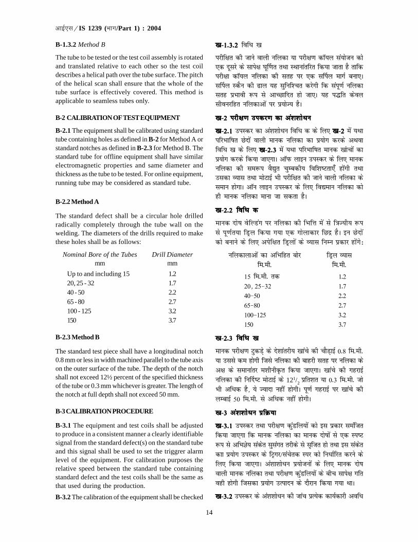
14
�������IS 1239 (��/Part 1) : 2004
B-1.3.2 Method B
The tube to be tested or the test coil assembly is rotatedand translated relative to each other so the test coildescribes a helical path over the tube surface. The pitchof the helical scan shall ensure that the whole of thetube surface is effectively covered. This method isapplicable to seamless tubes only.
B-2 CALIBRATION OF TEST EQUIPMENT
B-2.1 The equipment shall be calibrated using standardtube containing holes as defined in B-2 for Method A orstandard notches as defined in B-2.3 for Method B. Thestandard tube for offline equipment shall have similarelectromagnetic properties and same diameter andthickness as the tube to be tested. For online equipment,running tube may be considered as standard tube.
B-2.2 Method A
The standard defect shall be a circular hole drilledradically completely through the tube wall on thewelding. The diameters of the drills required to makethese holes shall be as follows:
Nominal Bore of the Tubes Drill Diametermm mm
Up to and including 15 1.220, 25 - 32 1.740 - 50 2.265 - 80 2.7100 - 125 3.2150 3.7
B-2.3 Method B
The standard test piece shall have a longitudinal notch0.8 mm or less in width machined parallel to the tube axison the outer surface of the tube. The depth of the notchshall not exceed 12½ percent of the specified thicknessof the tube or 0.3 mm whichever is greater. The length ofthe notch at full depth shall not exceed 50 mm.
B-3 CALIBRATION PROCEDURE
B-3.1 The equipment and test coils shall be adjustedto produce in a consistent manner a clearly identifiablesignal from the standard defect(s) on the standard tubeand this signal shall be used to set the triggrer alarmlevel of the equipment. For calibration purposes therelative speed between the standard tube containingstandard defect and the test coils shall be the same asthat used during the production.
B-3.2 The calibration of the equipment shall be checked
[k[k[k[k[k-1-3-2 1-3-2 1-3-2 1-3-2 1-3-2 fofèk [k
ijhf{kr dh tkus okyh ufydk ;k ijh{k.k dkW;y la;kstu dks,d nwljs ds lkis{k ?kw£.kr rFkk LFkkukarfjr fd;k tkrk gS rkfdijh{kk dkW;y ufydk dh lrg ij ,d l£iy ekxZ cuk,Al£iy LdSu dh <ky ;g lqfuf'pr djsxh fd laiw.kZ ufydklrg izHkkoh :i ls vkPNkfnr gks tk,A ;g i¼fr dsoylhoujfgr ufydkvksa ij iz;ksT; gSA
[k[k[k[k[k-2 ijh{k.k midj.k dk va'k'kksèku2 ijh{k.k midj.k dk va'k'kksèku2 ijh{k.k midj.k dk va'k'kksèku2 ijh{k.k midj.k dk va'k'kksèku2 ijh{k.k midj.k dk va'k'kksèku
[k[k[k[k[k-2-1 2-1 2-1 2-1 2-1 miLdj dk va'k'kksèku fofèk d ds fy, [k[k[k[k[k-22222 esa ;FkkifjHkkf"kr Nsnksa okyh ekud ufydk dk iz;ksx djds vFkokfofèk [k ds fy, [k[k[k[k[k-2-32-32-32-32-3 esa ;Fkk ifjHkkf"kr ekud [kakpksa dkiz;ksx djds fd;k tk,xkA vkWiQ ykbu miLdj ds fy, ekudufydk dh le:i oS|qr pqEcdh; fof'k"Vrk,¡ gksaxh rFkkmldk O;kl rFkk eksVkbZ Hkh ijhf{kr dh tkus okyh ufydk dsleku gksxkA vkWu ykbu miLdj ds fy, fo|eku ufydk dksgh ekud ufydk ekuk tk ldrk gSA
[k[k[k[k[k-2-2 fofèk d2-2 fofèk d2-2 fofèk d2-2 fofèk d2-2 fofèk d
ekud nks"k osfYMax ij ufydk dh fHkfÙk esa ls f=kT;h; :ils iw.kZr;k fMªy fd;k x;k ,d xksykdkj fNnz gSA bu Nsnks adks cukus ds fy, visf{kr fMªyksa ds O;kl fuEu izdkj gksaxs%
ufydkykvksa dk vfHkfgr cksj fMªy O;klfe-eh- fe-eh-
15 fe-eh- rd 1-220] 25&32 1-740&50 2-265&80 2-7100&125 3-2150 3-7
[k[k[k[k[k-2-3 fofèk [k2-3 fofèk [k2-3 fofèk [k2-3 fofèk [k2-3 fofèk [k
ekud ijh{k.k VqdMs+ ds ns'kkarjh; [kkaps dh pkSM+kbZ 0-8 fe-eh-;k mlls de gksxh ftls ufydk dh ckgjh lrg ij ufydk dsv{k ds lekukarj e'khuhÑr fd;k tk,xkA [kkaps dh xgjkbZufydk dh fu£n"V eksVkbZ ds 121/2
izfr'kr ;k 0-3 fe-eh- tksHkh vfèkd gS] ;s T;knk ugha gksxhA iw.kZ xgjkbZ ij [kkaps dhyEckbZ 50 fe-eh- ls vfèkd ugha gksxhA
[k[k[k[k[k-3 va'k'kksèku izfØ;k3 va'k'kksèku izfØ;k3 va'k'kksèku izfØ;k3 va'k'kksèku izfØ;k3 va'k'kksèku izfØ;k
[k[k[k[k[k-3-1 3-1 3-1 3-1 3-1 miLdj rFkk ijh{k.k dqaMfy;ksa dks bl izdkj leaftrfd;k tk,xk fd ekud ufydk dk ekud nks"kksa ls ,d Li"V:i ls vfHkKs; ladsr lqlaxr rjhds ls lftr gks rFkk bl ladsrdkk iz;ksx miLdj ds fVªxj@lapsrd Lij dks fuèkkZfjr djus dsfy, fd;k tk,xkA va'kk'kksèku iz;kstuksa ds fy, ekud nks"kokyh ekud ufydk rFkk ijh{k.k dqaMfy;ksa ds chp lkis{k xfrogh gksxh ftldk iz;ksx mRiknu ds nkSjku fd;k x;k FkkA
[k[k[k[k[k-3-23-23-23-23-2 miLdj ds va'k'kksèku dh tkap izR;sd dk;Zdkjh vofèk

15
�������IS 1239 (��/Part 1) : 2004
at the commencement and at the end of each workingperiod and at intervals not exceeding 2 h.
B-3.3 If on checking during production testing thereference standard defect is not detected even afterchanging the sensitivity by 2dB to allow for equipmentdrift, the equipment shall be recalibrated. Followingrecalibration, all tubes tested since the previous checkshall be retested, unless recordings from individuallyidentified tubes are available that permit classificationof those tubes into ‘suspect’ and ‘acceptable’ categories.
B-4 TEST PROCEDURE
Pass the tube to be inspected through the test unit atthe appropriate production speed, maintaining theproduction speed constant with ±10 percent underconditions identical to those used in the calibration ofthe equipment.
NOTE — Identical conditions include all instrument setting,mechanical motion, positioning of the encircling coil(s) inrelation to the tube and any other factor that affect thevalidity of the technique.
B-5 ACCEPTANCE
B-5.1 Any tube producing a signal lower than thesignals from the standard shall be deemed to havepassed this test.
B-5.2 Since NDT systems are known to be sensitive tosome features which do not cause leak, the tube rejectedby NDT may be retested hydraulically and whatevertubes pass the hydraulic test shall be accepted.
B-5.3 The tubes rejected in (see B-5.1) may also beretested off-line NDT equipment. Those which do notproduce reject level signals shall be accepted. Othersmay be accepted after cropping off the portionproducing reject level signals.
ds vkjaHk rFkk var esa 2 ?kaVksa ls vufèkd ds varjkyksa ij dhtk,xhA
[k[k[k[k[k-3-33-33-33-33-3 ;fn mRiknu ijh{k.k ds nkSjku tk¡p djus ij miLdjviogu vuqer djus ds fy, laosnu'khyrk dks 2dB }kjkifjo£rr djus ds i'pkr Hkh ekud nks"k dk irk ugha yxrkrks miLdj dks iqu% va'k'kksfèkr fd;k tk,xkA iqu% va'k'kksfèkrds i'pkr~ fiNyh tk¡p ds i'pkr~ ijhf{kr lHkh ufydkvksa dkiqu%ijh{k.k fd;k tk,xk tc rd fd O;f"V #i ls vfHkKkrufydkvksa ls ,sls vfHkys[k miyCèk u gksa tks mu ufydkvksa dk^lafnXèk* rFkk ^Lohdk;Z* Jsf.k;ksa esa Js.khdj.k vuqer djsaA
[k[k[k[k[k-4 ijh{k.k izfØ;k4 ijh{k.k izfØ;k4 ijh{k.k izfØ;k4 ijh{k.k izfØ;k4 ijh{k.k izfØ;k
miLdj ds va'kkadu esa iz;qDr fLFkfr;ksa ds le:i fLFkfr;ksa dsvarxZr mRiknu xfr dks ±10 izfr'kr ij fLFkj j[krs gq,leqfpr mRiknu xfr ij ijh{k.k ;wfuV esa ls fujh{k.k dh tkusokrh ufydk xqtkjsaA
fVIi.kh — le:i fLFkfr;ksa esa leLr ;a=k lsfVax] vfHk;kaf=kd xfr]l£iy dqaMfy;ksa dh ufydk ls lacafèkr fLFkfr rFkk dksbZ vU; dkjd'kkfey gS tks rduhd dh oSèkrk dks izHkkfor djrk gSA
[k[k[k[k[k-5 LohÑfr5 LohÑfr5 LohÑfr5 LohÑfr5 LohÑfr
[k[k[k[k[k-5-15-15-15-15-1 ekud ds ladsrdksa ls fuEurj ladsrd dk l`tu djusokyh fdlh Hkh ufydk }kjk ;g ijh{kk ikfjr dh xbZ ekuhtk,xhA
[k[k[k[k[k-5-2 5-2 5-2 5-2 5-2 pwafd ,uMhVh i¼fr;k¡ dqN ,sls y{k.kksa ds izfr laosnh ekuhxbZ gSa ftuds dkj.k fjlko ugha gksrk] ,uMhVh }kjk fujLr dh xbZufydk dk iqu% nzoh; ijh{k.k fd;k tk,xk rFkk tks Hkh ufydk,anzoh; ijh{k.k dks ikl dj yasxh] mUgsa Lohdkj dj fy;k tk,xkA
[k[k[k[k[k-5-35-35-35-35-3 fujLr ufydkvksa (((((ns[ksa [k[k[k[k[k-5-1)5-1)5-1)5-1)5-1) dk vkWiQ ykbu ,uMhVhmiLdj ij Hkh iqu% ijh{k.k fd;k tk ldrk gSA fujLr Lrjh;ladsrd lftr u djus okyh ufydkvksa dks Lohdkj dj fy;ktk,xkA vU;ksa dks fujlu Lrj ds ladsrd lftr djus okys Hkkxdks dkVdj vyx dj nsus ds i'pkr Lohdkj dj fy;k tk,xkA
fookn dh fLFkfr esa bl ekud dk vaxzsT+kh ikB gh ekU; gksxkAIn case of dispute English version of this standard shall be authentic.

bl ns'k esa Hkki izokg ds fy, bLrseky dh tkus okyh ufy;ksa dks iz'kkflr djus okys fofu;e dsfUnz; ckW;yj cksMZ }kjk izdkf'krHkkjrh; ckW;yj fofu;eksa esa fuèkkZfjr fd, x, gSaA
bl ekud dk fuèkkZj.k djrs le;] ns'k esa bl {ks=k esa izpfyr O;kikj jhfr;ksa ij ;Fks"V è;ku fn;k x;k gSA fofHkUu ns'kksa esa izpfyrekudksa ds varjkZ"Vªh; leUo; ij Hkh ;Fks"V è;ku fn;k x;k gSA fuEufyf[kr izdk'kuksa ls lgk;rk izkIr dh xbZ gS%
vkbZ,lvks 65 % 1981 ekudhdj.k ds fy, vkbZ,lvks varjk"Vªh; laxBu ds vuqlkj pwM+h cukus ds fy, mi;qDr dkcZubLikr ufydk,¡
ch,l 1387 % 1985 pwM+hnkj ,oa lkdsV;qDr bLikr ufy;ksa rFkk ufydkdkj lkefxz;ksa ,oa osfYMax ds fy, mi;qDr lknsfljs okyh bLikr ufydkvksa ds fy, vFkok pwM+h cukus ds fy, ch,l 21 % 1985 ufydk,¡ ,oa fiQfVaxds fy, ikbi dh pwfM+;k¡] tgk¡ pwfM+;ksa ij nkc dls tksM+ cuk, tkrs gSa*
bl ekud esa [kaM 6-4] 7-1] 7-1-1] 11-2] 16-26-4] 7-1] 7-1-1] 11-2] 16-26-4] 7-1] 7-1-1] 11-2] 16-26-4] 7-1] 7-1-1] 11-2] 16-26-4] 7-1] 7-1-1] 11-2] 16-2 rFkk 17-3 17-3 17-3 17-3 17-3 fn, x, gSa ftlds fy, Øsrk vkSj fuekZrk ds chp djkj fd;ktkuk vko';d gSA
bl ekud dk nwljk Hkkx vkbZ,l 1239 (Hkkx 2) % 1992 ^e`nq bLikr ufydkvksa] ufydkdkj lkexzh rFkk vU; fiVok¡ bLikrfiQfVaXl ds fy, fof'kf"V% Hkkx 2 e`nq bLikr lkWdsV] ufydkdkj lkexzh rFkk vU; fiVok¡ bLikr fiQfVaxs (pkSFkk iqujh{k.k)* gSA
;g fuf'pr djus ds fy, fd bl ekud esa fdlh vis{kk fo'ks"k dk ikyu fd;k x;k gS ;k ugha] rks ijh{k.k ;k fo'ys"k.k esaifj.kke dks n'kkZus okys voyksdu ;k x.kuk }kjk izkIr vafre eku dks vkbZ,l 2 % 1960 ^la[;kRed ekuksa ds iw.kk±du lacaèkhfu;e (iqujhf{kr)* ds vuqlkj iw.kk±fdr dj fn;k tk,A iw.kk±fdr eku esa j[ks x, lkFkZd LFkkuksa dh la[;k mruh gh gks ftruhbl ekud esa fufnZ"V eku dh gSA
In this country, the regulations governing the use of tubes for conveying steam are laid down in the Indian BoilerRegulations published by the Central Boilers Board.
While formulating this standard, due consideration has been given to the trade practices followed in the countryin this field. Due consideration has also been given to international coordination among the standards prevailingin different countries. Assistance has been derived from the following publications:
ISO 65 : 1981 Carbon steel tubes suitable for screwing in accordance with ISO International Organizationfor Standardization
BS 1387 : 1985 Screwed and socketed steel tubes and tubulars and for plain end steel tubes suitable forwelding or for screwing to BS 21 : 1985 ‘Pipe threads for tubs and fitting where pressure-tightjoints are made on the threads’
This standard contains clauses 6.4, 7.1, 7.1.1, 11.2, 16.2 and 17.3 which call for an agreement between themanufacturer and the purchaser.
The other part of this standard is IS 1239 (Part 2) : 1992 ‘Specification for mild steel tubes, tubulars and otherwrought steel fittings: Part 2 Mild steel socket, tubulars and other wrought steel pipe fittings ( fourth revision )’.
For the purpose of deciding whether a particular requirement of this standard is complied with, the final value,observed or calculated, expressing the results of a test or analysis, shall be rounded off in accordance withIS 2 : 1960 ‘Rules for rounding off numerical values (revised )’. The number of significant places retained in therounded off value should be the same as that of the specified value in this standard.
(Continued from second cover)
(nwljs doj ls tkjh)

Bureau of Indian Standards
BIS is a statutory institution established under the Bureau of Indian Standards Act, 1986 to promoteharmonious development of the activities of standardization, marking and quality certification of goodsand attending to connected matters in the country.
Copyright
BIS has the copyright of all its publications. No part of these publications may be reproduced in any formwithout the prior permission in writing of BIS. This does not preclude the free use, in the course ofimplementing the standard, of necessary details, such as symbols and sizes, type or grade designations.Enquiries relating to copyright be addressed to the Director (Publications), BIS.
Review of Indian Standards
Amendments are issued to standards as the need arises on the basis of comments. Standards are also reviewedperiodically; a standard along with amendments is reaffirmed when such review indicates that no changes areneeded; if the review indicates that changes are needed, it is taken up for revision. Users of Indian Standardsshould ascertain that they are in possession of the latest amendments or edition by referring to the latest issue of‘BIS Catalogue’ and ‘Standards : Monthly Additions’.
This Indian Standard has been developed from Doc No.: MTD 19 (4264).
Amendments Issued Since Publication
Amend No. Date of Issue Text Affected
Laser Typeset by Sunshine Graphics
BUREAU OF INDIAN STANDARDS
Headquarters:
Manak Bhavan, 9 Bahadur Shah Zafar Marg, New Delhi 110002Telephones : 2323 0131, 2323 3375, 2323 9402 Website: www.bis.org.in
Regional Offices: Telephones
Central : Manak Bhavan, 9 Bahadur Shah Zafar Marg 2323 7617NEW DELHI 110002 2323 3841
Eastern : 1/14 C.I.T. Scheme VII M, V. I. P. Road, Kankurgachi 2337 8499, 2337 8561KOLKATA 700054 2337 8626, 2337 9120
Northern : SCO 335-336, Sector 34-A, CHANDIGARH 160022 60 384360 9285
Southern : C.I.T. Campus, IV Cross Road, CHENNAI 600113 2254 1216, 2254 14422254 2519, 2254 2315
Western : Manakalaya, E9 MIDC, Marol, Andheri (East) 2832 9295, 2832 7858MUMBAI 400093 2832 7891, 2832 7892
Branches: AHMEDABAD. BANGALORE. BHOPAL. BHUBANESHWAR. COIMBATORE. FARIDABAD.GHAZIABAD. GUWAHATI. HYDERABAD. JAIPUR. KANPUR. LUCKNOW. NAGPUR.PARWANOO. PATNA. PUNE. RAJKOT. THIRUVANANTHAPURAM. VISAKHAPATNAM.
�
��
��
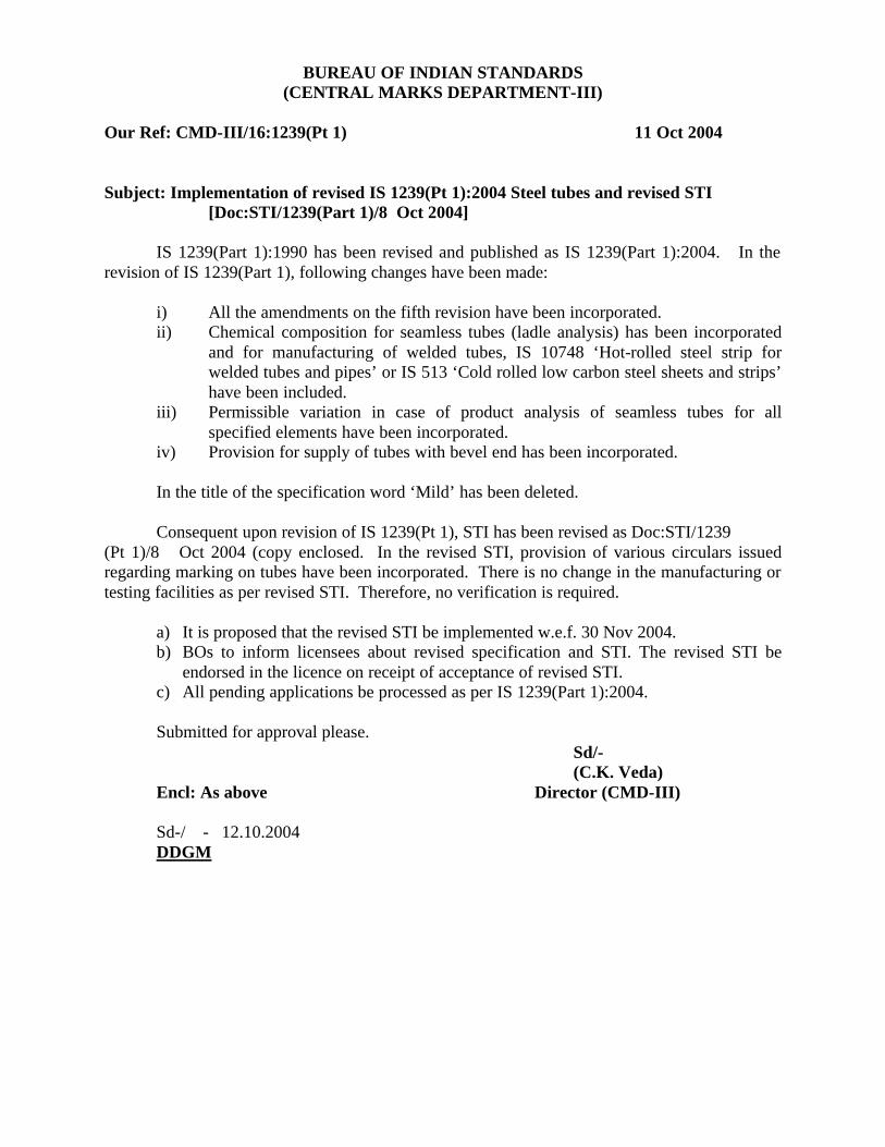
BUREAU OF INDIAN STANDARDS (CENTRAL MARKS DEPARTMENT-III)
Our Ref: CMD-III/16:1239(Pt 1) 11 Oct 2004 Subject: Implementation of revised IS 1239(Pt 1):2004 Steel tubes and revised STI
[Doc:STI/1239(Part 1)/8 Oct 2004] IS 1239(Part 1):1990 has been revised and published as IS 1239(Part 1):2004. In the revision of IS 1239(Part 1), following changes have been made:
i) All the amendments on the fifth revision have been incorporated. ii) Chemical composition for seamless tubes (ladle analysis) has been incorporated
and for manufacturing of welded tubes, IS 10748 ‘Hot-rolled steel strip for welded tubes and pipes’ or IS 513 ‘Cold rolled low carbon steel sheets and strips’ have been included.
iii) Permissible variation in case of product analysis of seamless tubes for all specified elements have been incorporated.
iv) Provision for supply of tubes with bevel end has been incorporated.
In the title of the specification word ‘Mild’ has been deleted.
Consequent upon revision of IS 1239(Pt 1), STI has been revised as Doc:STI/1239 (Pt 1)/8 Oct 2004 (copy enclosed. In the revised STI, provision of various circulars issued regarding marking on tubes have been incorporated. There is no change in the manufacturing or testing facilities as per revised STI. Therefore, no verification is required.
a) It is proposed that the revised STI be implemented w.e.f. 30 Nov 2004. b) BOs to inform licensees about revised specification and STI. The revised STI be
endorsed in the licence on receipt of acceptance of revised STI. c) All pending applications be processed as per IS 1239(Part 1):2004. Submitted for approval please. Sd/- (C.K. Veda) Encl: As above Director (CMD-III) Sd-/ - 12.10.2004 DDGM
DOC:STI/1239(Pt.1)/8 Oct 2004
SCHEME OF TESTING AND INSPECTION
FOR CERTIFICATION OF STEEL TUBES
ACCORDING TO IS 1239 (Pt.1):2004 (Six Revision)
1. LABORATORY – A laboratory shall be maintained which shall be suitably equipped and staffed where different tests given in the specification shall be carried out in accordance with the methods given in the specification. 2. TEST RECORDS - All records of tests, inspection and calibration shall be kept in suitable forms approved by the Bureau. 2.1 All testing apparatus/measuring instruments shall be periodically checked and calibrated and records of such checks/calibration shall be maintained. 2.2 Copies of any records and other connected papers that may be required by the Bureau shall be made available at any time on request. 3. QUALITY CONTROL – It is recommended that, as far as possible, Statistical Quality Control (SQC) methods may be used for controlling the quality of the product during production as envisaged in this Scheme [See IS 397(Part I):1972, IS 397(Part 2):1985 and IS 397(Part 3):1980]. 3.1 In addition, effort should be made to gradually introduce a Quality Management System in accordance with IS/ISO 9000 series as appropriate to the activities of the organization. 4. STANDARD MARK – The Standard Mark, as given in Column (1) of the First Schedule of the licence, as applicable, shall be embossed at a suitable place on the outside of each tube provided always that the tubes so marked conform to all the requirements of the specification. 4.1 The different classes of tubes shall be distinguished by colour bands which shall be applied as per clause 17.2, 17.3 and 17.4 of the specification before the tubes leave the factory. 4.2 Each tube shall be embossed with the manufacturer’s name or trade mark, IS No. (i.e. IS 1239) (Pt.1) and class of tubes i.e. L, M or H for Light, Medium and Heavy class as applicable at regular interval of say one metre. 4.3 Each tube of size 25 mm NB and above shall be marked with batch number by embossing/stencilling/transfix label/etching. For sizes upto and including 20 mm NB, batch number shall be marked on the tag attached to the bundle of steel tubes. NOTE : Effort should be made to mark the batch number on individual tubes upto 20 mm NB also. Based on the experience gained in marking of batch number, the marking clause would be reviewed.
DOC:STI/1239(Pt.1)/8 Oct 2004
4.4 Licence number (CM/L…..) shall be marked on each tube by embossing/ stencilling/transfix labels/etching. 4.5 In addition the following information shall be included in the durable tag (metal/plastic) attached to each bundle :
a) The class of tubes/ process of manufacture (Cl. 6.3); b) Identity of the source of manufacture; c) Size; d) Batch number or Identification mark in code or otherwise to enable the date of
manufacture and control unit no. to be traced back to factory records; e) Made in India (if required);and f) Licence number (CM/L…..).
5.0 Test Certificate – If so desired by the purchaser, for each consignment of BIS certified material conforming to IS 1239 (Part I):2004, test certificate may be issued which shall contain the Standard Mark, cast/control unit number, type, class, size of tubes and corresponding test results as given in Annex 1. 6.0 LEVELS OF CONTROL - The tests, as indicated in Table 1 attached and at the levels of control specified therein, shall be carried out on the whole production of the factory which is covered by this scheme and appropriate records and charts maintained in accordance with paragraph 2.0 above. All the production which conforms to the Indian Standards and covered by the licence shall be marked with certification mark of the Bureau. 6.1 CONTROL UNIT - For the purpose of this scheme of Testing & Inspection, one shift production of one size & class of tubes on each tube mill shall constitute one control unit. 6.2 No manufacturer shall produce tubes of wall thickness less than the wall thickness of ‘Light’class tubes as stipulated, under the Mild Steel Tubes (Quality Control ) Order 1978 issued by the Government of India, Ministry of Industry (Department of Heavy Industry) dated 18 July 1978. 7.0 SOCKET – Unless specified otherwise, each screwed tube shall be supplied with one socket conforming to all requirements (except 6.4) of IS 1239(Pt.2):1992 and a thread protecting cap on the other end of the pipe. 7.1 SOCKET INSPECTION : The socket supplied with the tube shall either bear BIS Standard Mark or samples drawn from each consignment of sockets shall be tested as per Table 2 for its conformity to the standard [except 6.4 of IS 1239(Pt.2)] and shall be used when found satisfactory. Licensee shall ensure tracebility and identification of sockets. 8.0 In respect of all other clauses of the specification the factory will maintain appropriate control and checks to ensure that their product conforms to the various requirements of this specification.
DOC:STI/1239(Pt.1)/8 Oct 2004
9.0 REJECTIONS – A separate record shall be maintained giving information relating to the rejection of tubes and method of their disposal which do not conform to the specification. Rejected pipes shall be either punched with holes of minimum 5 mm diameter to be clear and through at an interval of maximum 1.5 mt or cut into lengths not in excess of 1.5 meters before being sold [please refer to para 4 of Mild Steel Tubes (Quality Control) Order 1978 issued by Government of India, Ministry of Industry (Department of Heavy Industry) dated 18 July 1978 as amended on 1st Jan 1983]. Rejected tubes shall not be colour coded and Standard Mark (if already applied) should be defaced. 10 SAMPLES – The licensee shall supply, free of charge, the samples required in accordance with the Bureau of Indian Standards (Certification) Regulations, 1988, as subsequently amended, from the factory or godowns. The Bureau shall pay for the samples taken by it from the open market. 110 REPLACEMENT – Whenever a complaint is received soon after the goods with Standard Marks have been purchased and used, and if there is adequate evidence that the goods have not been misused, defective goods or their components are replaced or repaired free of cost by the licensee in case the complaint is proved to be genuine and the warranty period (where applicable) has not expired. The final authority to judge the conformity of the product to the Indian Standard shall be with the Bureau. A record of complaints shall be maintained as per proforma enclosed at Annexure II. 11.1 In the event of any damages caused by the goods bearing the Standard Mark, or claim being filed by the consumers against BIS Standard Mark and not “conforming to” the relevant Indian Standard, entire liability arising out of such non conforming product shall be of licensee and BIS shall not in any way be responsible in such cases. 12.0 STOP MARKING – The marking of the product shall be stopped under intimation to the Bureau if, at any time, there is some difficulty in maintaining the conformity of their product to the specification, or the testing equipment goes out of order. The marking may be resumed as soon as the defects are removed under intimation to Bureau. 12.1 The marking of the product shall be stopped immediately if directed to do so by Bureau for any reason. The marking may then be resumed only after permission by the Bureau. The information regarding resumption of markings shall also be sent to the Bureau.
13.0 PRODUCTION DATA – The licensee shall send to BIS as per the enclosed proforma-1 to be authenticated by a Chartered Accountant or by the manufacturer by giving an affidavit/undertaking, a statement of quantity produced, marked and exported by him and the trade value thereof at the end of each operative year of the licence. Table 1………
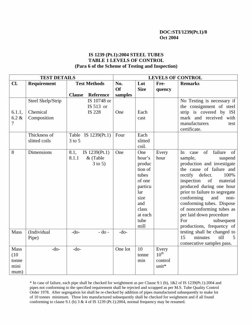
DOC:STI/1239(Pt.1)/8 Oct 2004
IS 1239 (Pt.1):2004 STEEL TUBES TABLE 1 LEVELS OF CONTROL
(Para 6 of the Scheme of Testing and Inspection)
TEST DETAILS LEVELS OF CONTROL Cl. Requirement Test Methods
Clause Reference
No. Of samples
Lot Size
Fre-quency
Remarks
6.1.1, 6.2 & 7
Steel Skelp/Strip Chemical Composition
IS 10748 or IS 513 or IS 228
One
Each cast
No Testing is necessary if the consignment of steel strip is covered by ISI mark and received with manufacturers test certificate.
Thickness of slitted coils
Table IS 1239(Pt.1) 3 to 5
Four Each slitted coil.
8 Dimensions 8.1, IS 1239(Pt.1) 8.1.1 & (Table 3 to 5)
One One hour’s production of tubes of one particular size and class at each tube mill
Every hour
Mass (Individual Pipe)
-do- - do - -do-
In case of failure of sample, suspend production and investigate the cause of failure and rectify defect. 100% inspection of material produced during one hour prior to failure to segregate conforming and non-conforming tubes. Dispose of nonconforming tubes as per laid down procedure For subsequent productions, frequency of testing shall be changed to 15 minutes till 5 consecutive samples pass.
Mass (10 tonne minimum)
-do- -do- One lot 10 tonne min
Every 10th control unit*
* In case of failure, each pipe shall be checked for weightment as per Clause 9.1 (b), 1&2 of IS 1239(Pt.1):2004 and pipes not conforming to the specified requirement shall be rejected and scrapped as per M.S. Tube Quality Control Order 1978. After segregation lot shall be re-checked by addition of pipes manufactured subsequently to make lot of 10 tonnes minimum. Three lots manufactured subsequently shall be checked for weighment and if all found conforming to clause 9.1 (b) 3 & 4 of IS 1239 (Pt.1):2004, normal frequency may be resumed.
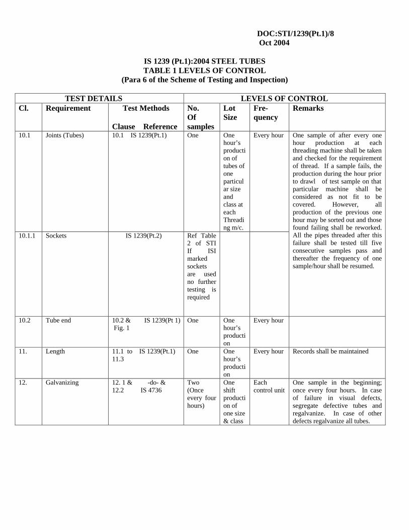
DOC:STI/1239(Pt.1)/8 Oct 2004
IS 1239 (Pt.1):2004 STEEL TUBES TABLE 1 LEVELS OF CONTROL
(Para 6 of the Scheme of Testing and Inspection)
TEST DETAILS LEVELS OF CONTROL Cl. Requirement Test Methods
Clause Reference
No. Of samples
Lot Size
Fre-quency
Remarks
10.1 Joints (Tubes) 10.1 IS 1239(Pt.1) One One hour’s production of tubes of one particular size and class at each Threading m/c.
Every hour
10.1.1
Sockets IS 1239(Pt.2) Ref Table 2 of STI If ISI marked sockets are used no further testing is required
One sample of after every one hour production at each threading machine shall be taken and checked for the requirement of thread. If a sample fails, the production during the hour prior to drawl of test sample on that particular machine shall be considered as not fit to be covered. However, all production of the previous one hour may be sorted out and those found failing shall be reworked. All the pipes threaded after this failure shall be tested till five consecutive samples pass and thereafter the frequency of one sample/hour shall be resumed.
10.2 Tube end 10.2 & IS 1239(Pt 1) Fig. 1
One One hour’s production
Every hour
11. Length 11.1 to IS 1239(Pt.1) 11.3
One One hour’s production
Every hour Records shall be maintained
12. Galvanizing 12. 1 & -do- & 12.2 IS 4736
Two (Once every four hours)
One shift production of one size & class
Each control unit
One sample in the beginning; once every four hours. In case of failure in visual defects, segregate defective tubes and regalvanize. In case of other defects regalvanize all tubes.
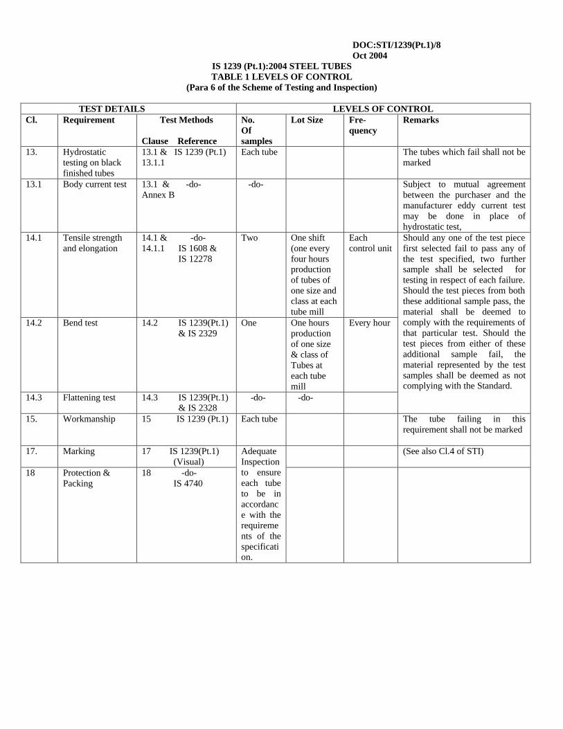
DOC:STI/1239(Pt.1)/8 Oct 2004
IS 1239 (Pt.1):2004 STEEL TUBES TABLE 1 LEVELS OF CONTROL
(Para 6 of the Scheme of Testing and Inspection)
TEST DETAILS LEVELS OF CONTROL Cl. Requirement Test Methods
Clause Reference
No. Of samples
Lot Size Fre-quency
Remarks
13. Hydrostatic testing on black finished tubes
13.1 & IS 1239 (Pt.1) 13.1.1
Each tube The tubes which fail shall not be marked
13.1 Body current test 13.1 & -do- Annex B
-do- Subject to mutual agreement between the purchaser and the manufacturer eddy current test may be done in place of hydrostatic test,
14.1 Tensile strength and elongation
14.1 & -do- 14.1.1 IS 1608 &
IS 12278
Two One shift (one every four hours production of tubes of one size and class at each tube mill
Each control unit
14.2 Bend test 14.2 IS 1239(Pt.1) & IS 2329
One One hours production of one size & class of Tubes at each tube mill
Every hour
14.3 Flattening test 14.3 IS 1239(Pt.1) & IS 2328
-do- -do-
Should any one of the test piece first selected fail to pass any of the test specified, two further sample shall be selected for testing in respect of each failure. Should the test pieces from both these additional sample pass, the material shall be deemed to comply with the requirements of that particular test. Should the test pieces from either of these additional sample fail, the material represented by the test samples shall be deemed as not complying with the Standard.
15.
Workmanship 15 IS 1239 (Pt.1)
Each tube The tube failing in this requirement shall not be marked
17. Marking 17 IS 1239(Pt.1) (Visual)
(See also Cl.4 of STI)
18 Protection & Packing
18 -do- IS 4740
Adequate Inspection to ensure each tube to be in accordance with the requirements of the specification.
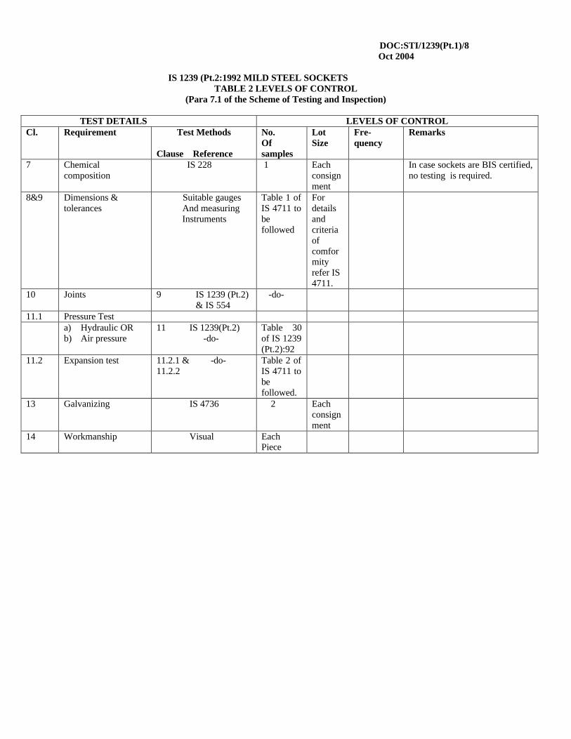
DOC:STI/1239(Pt.1)/8 Oct 2004
IS 1239 (Pt.2:1992 MILD STEEL SOCKETS
TABLE 2 LEVELS OF CONTROL (Para 7.1 of the Scheme of Testing and Inspection)
TEST DETAILS LEVELS OF CONTROL Cl. Requirement Test Methods
Clause Reference
No. Of samples
Lot Size
Fre-quency
Remarks
7 Chemical composition
IS 228 1 Each consignment
In case sockets are BIS certified, no testing is required.
8&9 Dimensions & tolerances
Suitable gauges And measuring Instruments
Table 1 of IS 4711 to be followed
For details and criteria of comformity refer IS 4711.
10 Joints 9 IS 1239 (Pt.2) & IS 554
-do-
11.1 Pressure Test a) Hydraulic OR
b) Air pressure 11 IS 1239(Pt.2) -do-
Table 30 of IS 1239 (Pt.2):92
11.2 Expansion test 11.2.1 & -do- 11.2.2
Table 2 of IS 4711 to be followed.
13 Galvanizing IS 4736 2 Each consignment
14 Workmanship Visual Each Piece
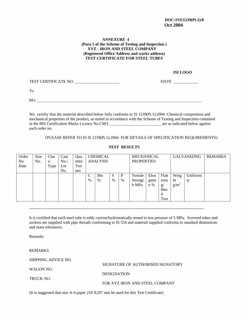
DOC:STI/1239(Pt.1)/8 Oct 2004
ANNEXURE -I
(Para 5 of the Scheme of Testing and Inspection ) XYZ - IRON AND STEEL COMPANY
(Registered Office Address and works address) TEST CERTIFICATE FOR STEEL TUBES
ISI LOGO
TEST CERTIFICATE NO. ______________________ DATE ____________
To M/s _________________________________________________________________________________ We certifiy that the material described below fully conforms to IS 1239(Pt.1):2004 Chemical composition and mechanical properties of the product, as tested in accordance with the Scheme of Testing and Inspection contained in the BIS Certification Marks Licence No.CM/L _________________________ are as indicated below against each order no.
{PLEASE REFER TO IS IS 1239(Pt.1):2004 FOR DETAILS OF SPECIFICATION REQUIREMENTS}
TEST RESULTS
Order No. Date
Size No.
Class/ Type
Cast No./ Lot No.
Quantity Tonnes
CHEMICAL ANALYSIS
MECHANICAL PROPERTIES
GALVANIZING REMARKS
C %
Mn %
S %
P %
Tensile Strength MPa
Elongation %
Flattening/ Bend Test
Weight g/m2
Uniformity
--------------------------------------------------------------------------------------------------------------------------------- It is certified that each steel tube is eddy current/hydrostatically tested to test pressure of 5 MPa. Screwed tubes and sockets are supplied with pipe threads conforming to IS 554 and material supplied conforms to standard dimensions and mass tolerances. Remarks REMARKS SHIPPING ADVICE NO. SIGNATURE OF AUTHORISED SIGNATORY WAGON NO. DESIGNATION TRUCK NO. FOR XYZ IRON AND STEEL COMPANY (It is suggested that size A-4 paper 210 X297 mm be used for this Test Certificate)
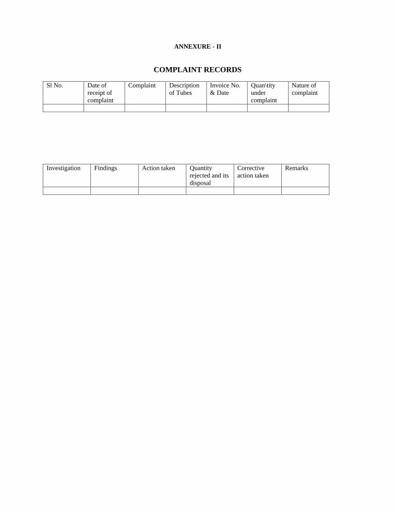
ANNEXURE - II
COMPLAINT RECORDS Sl No. Date of
receipt of complaint
Complaint Description of Tubes
Invoice No. & Date
Quan\tity under complaint
Nature of complaint
Investigation Findings Action taken Quantity
rejected and its disposal
Corrective action taken
Remarks

By Authority OfTHE UNITED STATES OF AMERICA
Legally Binding Document
By the Authority Vested By Part 5 of the United States Code § 552(a) and Part 1 of the Code of Regulations § 51 the attached document has been duly INCORPORATED BY REFERENCE and shall be considered legally binding upon all citizens and residents of the United States of America. HEED THIS NOTICE: Criminal penalties may apply for noncompliance.
Official Incorporator:THE EXECUTIVE DIRECTOROFFICE OF THE FEDERAL REGISTERWASHINGTON, D.C.
Document Name:
CFR Section(s):
Standards Body:
e
American Society for Testing and Materials
49 CFR 192.113
ASTM A106: Standard Specification for SeamlessCarbon Steel Pipe for High-Temperature Service

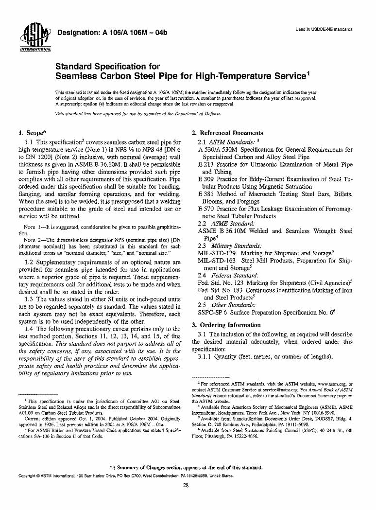
a Designation: A 106/A 106M - 04b ~U .. 1
INTERNATIONAL
Standard Specification for
Used in USDOE·NE standards
Seamless Carbon Steel Pipe for High-Temperature Service1
This standard is issued under the fixed designation A 1061 A 106M; the number immediately following the designation indicates the year of original adoption or, in the case of revision, the year of last revision. A number in parentheses indicates the year of last reapproval. A superscript epsilon (e) indicates an editorial change since the last revision or reapproval.
This standard has been approved for use by agencies of the Department of Defense.
1. Scope*
1.1 This specification2 covers seamless carbon steel pipe for high-temperature service (Note 1) in NPS Vs to NPS 48 [DN 6 to DN 1200] (Note 2) inclusive, with nominal (average) wall thickness as given in ASME B 36.lOM. It shall be permissible to furnish pipe having other dimensions provided such pipe complies with all other requirements of this specification. Pipe ordered under this specification shall be suitable for bending, flanging, and similar forming operations, and for welding. When the steel is to be welded, it is presupposed that a welding procedure suitable to the grade of steel and intended use or service will be utilized.
NOTE I-It is suggested, consideration be given to possible graphitiza· tion.
NOTE 2-The dimensionless designator NPS (nominal pipe size) [DN (diameter nominal)] has been substituted in this standard for such traditional terms as "nominal diameter," "size," and "nominal size."
1.2 Supplementary requirements of an optional nature are provided for seamless pipe intended for use in applications where a superior grade of pipe is required. These supplementary requirements call for additional tests to be made and when desired shall be so stated in the order.
1.3 The values stated in either SI units or inch-pound units are to be regarded separately as standard. The values stated in each system may not be exact equivalents. Therefore, each system is to be used independently of the other.
1.4 The following precautionary caveat pertains only to the test method portion, Sections 11, 12, 13, 14, and 15, of this specification: This standard does not purport to address all of the safety concerns, if any, associated with its use. It is the responsibility of the user of this standard to establish appropriate safety and health practices and determine the applicability of regulatory limitations prior to use.
1 This specification is under the jurisdiction of Committee AOI on Steel, Stainless Steel and Related Alloys and is the direct responsibility of Subcommittee AOl.09 on Carbon Steel Tubular Products.
Current edition approved Oct. I, 2004. Published October 2004. Originally approved in 1926. Last previous edition in 2004 as A 1061 A 106M - 04a.
2 For ASME Boiler and Pressure Vessel Code applications see related Specifi· cations SA-106 in Section II of that Code.
2. Referenced Documents
2.1 ASTM Standards: 3
A 530lA 530M Specification for General Requirements for Specialized Carbon and Alloy Steel Pipe
E 213 Practice for Ultrasonic Examination of Metal Pipe and Tubing
E 309 Practice for Eddy-Current Examination of Steel Tubular Products Using Magnetic Saturation
E 381 Method of Macroetch Testing Steel Bars, Billets, Blooms, and Forgings
E 570 Practice for Flux Leakage Examination of Ferromagnetic Steel Tubular Products
2.2 ASME Standard: ASME B 36.lOM Welded and Seamless Wrought Steel
Pipe4
2.3 Military Standards: MIL-STD-129 Marking for Shipment and Storage5
MIL-STD-163 Steel Mill Products, Preparation for Ship-ment and Storage5
2.4 Federal Standard: Fed. Std. No. 123 Marking for Shipments (Civil Agencies)5 Fed. Std. No. 183 Continuous Identification Marking ofIron
and Steel Products5
2.5 Other Standards: SSPC-SP 6 Surface Preparation Specification No. 66
3. Ordering Information
3.1 The inclusion of the following, as required will describe the desired material adequately, when ordered under this specification:
3.1.1 Quantity (feet, metres, or number oflengths),
3 For referenced ASTM standards, visit the ASTM website, www.astm.org, or contact ASTM Customer Service at [email protected]. For Annual Book of ASTM Standards volume information, refer to the standard's Document Summary page on the ASTM website.
4 Available from American Society of Mechanical Engineers (ASME), ASME International Headquarters, Three Park Ave., New York, NY 10016·5990.
5 Available from Standardization Documents Order Desk, DODSSP, Bldg. 4, Section D, 700 Robbins Ave., Philadelphia, PA 19IIl·5098.
6 Available from Steel Structures Painting Council (SSPC), 40 24th St., 6th Floor, Pittsburgh, PA 15222-4656.
* A Summary of Changes section appears at the end of this standard.
Copyright © ASTM International, 100 Barr Harbor Drive, PO Box C700, West Conshohocken, PA 19428·2959, United States.
28
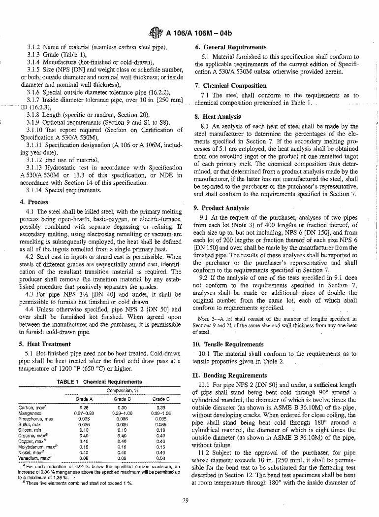
~ A 106/A 106M - 04b
3.1.2 Name of material (seamless carbon steel pipe), 3.1.3 Grade (Table 1), 3.1.4 Manufacture (hot-finished or cold-drawn), 3.1.5 Size (NPS [DN] and weight class or schedule number,
or both; outside diameter and nominal wall thickness; or inside diameter and nominal wall thickness),
3.1.6 Special outside diameter tolerance pipe (16.2.2), 3.1.7 Inside diameter tolerance pipe, over 10 in. [250 mm]
ID (16.2.3), 3.1.8 Length (specific or random, Section 20), 3.1.9 Optional requirements (Section 9 and Sl to S8), 3.1.1 0 Test report required (Section on Certification of
Specification A 530/ A 530M), 3.1.11 Specification designation (A 106 or A 106M, includ
ing year-date), 3.1.12 End use of material, 3.1.13 Hydrostatic test in accordance with Specification
A 530lA 530M or 13.3 of this specification, or NDE in accordance with Section 14 of this specification.
3.1.14 Special requirements.
4. Process
4.1 The steel shall be killed steel, with the primary melting process being open-hearth, basic-oxygen, or electric-furnace, possibly combined with separate degassing or refining. If secondary melting, using electroslag remelting or vacuum-arc remelting is subsequently employed, the heat shall be defined as all of the ingots remelted from a single primary heat.
4.2 Steel cast in ingots or strand cast is permissible. When steels of different grades are sequentially strand cast, identification of the resultant transition material is required. The producer shall remove the transition material by any established procedure that positively separates the grades.
4.3 For pipe NPS 1 V2 [DN 40] and under, it shall be permissible to furnish hot finished or cold drawn.
4.4 Unless otherwise specified, pipe NPS 2 [DN 50] and over shall be furnished hot finished. When agreed upon between the manufacturer and the purchaser, it is permissible to furnish cold-drawn pipe.
5. Heat Treatment
5.1 Hot-finished pipe need not be heat treated. Cold-drawn pipe shall be heat treated after the final cold draw pass at a temperature of 1200 of (650°C) or higher.
TABLE 1 Chemical Requirements
Composition, %
Grade A Grade B Grade C
Carbon, maxA 0.25 0.30 0.35 Manganese 0.27-0.93 0.29-1.06 0.29-1.06 Phosphorus, max 0.035 0.035 0.035 Sulfur, max 0.035 0.035 0.035 Silicon, min 0.10 0.10 0.10 Chrome, maxB 0.40 0.40 0.40 Copper, maxB 0.40 0.40 0.40 Molybdenum, maxB 0.15 0.15 0.15 Nickel, maxB 0.40 0.40 0.40 Vanadium, maxB 0.08 0.08 0.08
A For each reduction of 0.01 % below the specified carbon maximum, an increase of 0.06 % manganese above the specified maximum will be permitted up to a maximum of 1.35 %. '
B These five elements combined shall not exceed 1 %.
29
6. General Requirements
6.1 Material furnished to this specification shall conform to the applicable requirements of the current edition of Specification A 530/ A 530M unless otherwise provided herein.
7. Chemical Composition
7.1 The steel shall conform to the requirements as to chemical composition prescribed in Table 1.
8. Heat Analysis
8.1 An analysis of each heat of steel shall be made by the steel manufacturer to determine the percentages of the elements specified in Section 7. If the secondary melting processes of 5.1 are employed, the heat analysis shall be obtained from one remelted ingot or the product of one remelted ingot of each primary melt. The chemical composition thus determined, or that determined from a product analysis made by the manufacturer, if the latter has not manufactured the steel, shall be reported to the purchaser or the purchaser's representative, and shall conform to the requirements specified in Section 7.
9. Product Analysis
9.1 At the request of the purchaser, analyses of two pipes from each lot (Note 3) of 400 lengths or fraction thereof, of each size up to, but not including, NPS 6 [DN 150], and from each lot of 200 lengths or fraction thereof of each size NPS 6 [DN 150] and over, shall be made by the manufacturer from the finished pipe. The results of these analyses shall be reported to the purchaser or the purchaser's representative and shall conform to the requirements specified in Section 7:
9.2 If the analysis of one of the tests specified in 9.1 does not conform to the requirements specified in Section 7, analyses shall be made on additional pipes of double the original number from the same lot, each of which shall conform to requirements specified.
NOTE 3-A lot shall consist of the number of lengths specified in Sections 9 and 21 of the same size and wall thickness from anyone heat of steel.
10. Tensile Requirements
10.1 The material shall conform to the requirements as to tensile properties given in Table 2.
11. Bending Requirements
11.1 For pipe NPS 2 [DN 50] and under, a sufficient length of pipe shall stand being bent cold through 90° around a cylindrical mandrel, the diameter of which is twelve times the outside diameter (as shown in ASME B36.lOM) of the pipe, without developing cracks. When ordered for close coiling, the pipe shall stand being bent cold through 180° around a cylindrical mandrel, the diameter of which is eight times the outside diameter (as shown in ASME B 36.lOM) of the pipe, without failure.
11.2 Subject to the approval of the purchaser, for pipe whose diameter exceeds 10 in. [250 mm], it shall be permissible for the bend test to be substituted for the flattening test described in Section 12. The bend test specimens shall be bent at room temperature through 180° with the inside diameter of
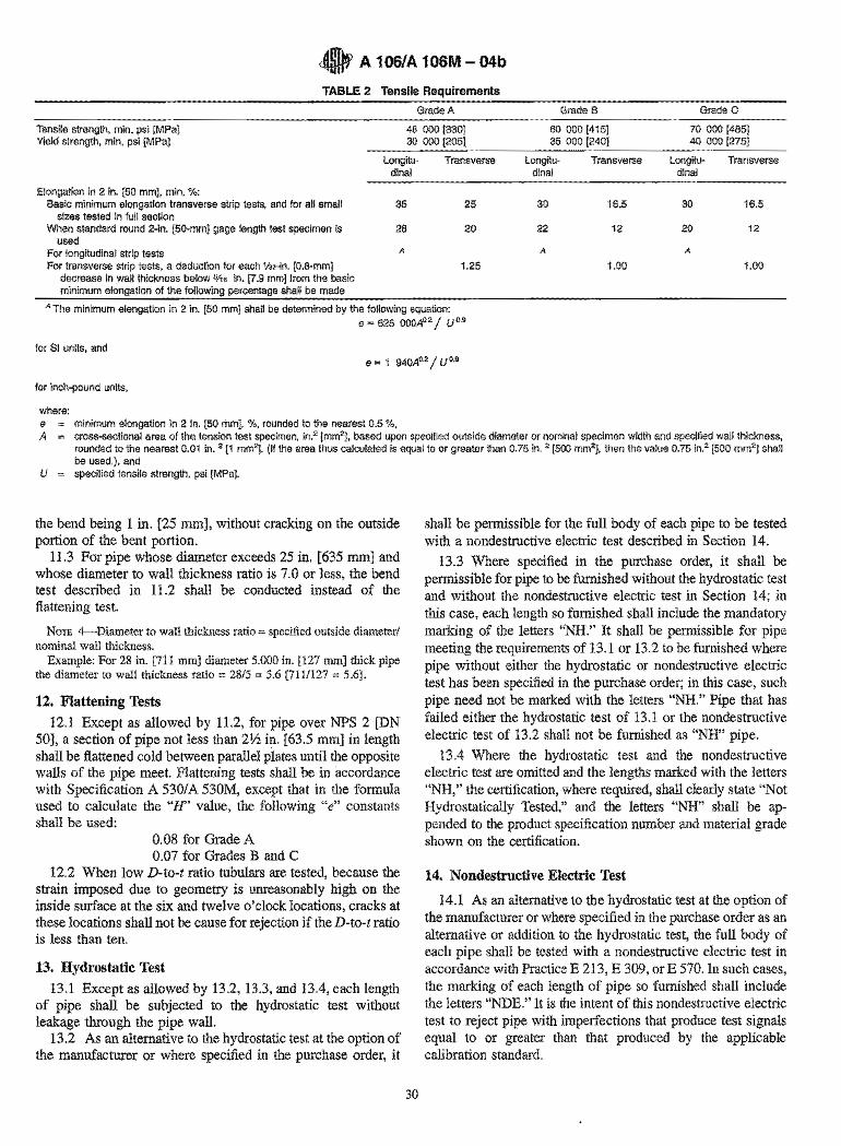
o A 106/A 106M - 04b
TABLE 2 Tensile Requirements
Grade A Grade B Grade C
Tensile strength, min, psi [MPa] Yield strength, min, psi [MPa]
48 000 [330] 30 000 [205]
60 000 [415] 70 000 [485] 35 000 [240] 40 000 [275]
Elongation in 2 in. [50 mm], min, 'Yo: Basic minimum elongation transverse strip tests, and for all small
sizes tested in full section When standard round 2-in. [50-mm] gage length test specimen is
used For longitudinal strip tests For transverse strip tests, a deduction for each Vs2-in. [0.8-mm]
decrease in wall thickness below 5/,6 in. [7.9 mm] from the basic minimum elongation of the following percentage shall be made
Longitudinal
35
28
A
Transverse Longitu-dinal
25 30
20 22
A
1.25
Transverse Longitu- Transverse dinal
16.5 30 16.5
12 20 12
A
1.00 1.00
A The minimum elongation in 2 in. [50 mm] shall be determined by the following equation: e = 625 000A0 2 / U 0.9
for 81 units, and e = 1 940Ao.2 / U 0.9
for inch-pound units,
where: e minimum elongation in 2 in. [50 mm], %, rounded to the nearest 0.5 %, A cross-sectional area of the tension test specimen, in.2 [mm2], based upon specified outside diameter or nominal specimen width and specified wall thickness,
rounded to the nearest 0.01 in. 2 [1 mm2]. (If the area thus calculated is equal to or greater than 0.75 in. 2 [500 mm2], then the value 0.75 in.2 [500 mm2] shall be used.), and
U specified tensile strength, psi [MPa].
the bend being 1 in. [25 mm], without cracking on the outside portion of the bent portion.
11.3 For pipe whose diameter exceeds 25 in. [635 mm] and whose diameter to wall thickness ratio is 7.0 or less, the bend test described in 11.2 shall be conducted instead of the flattening test.
NOTE 4--Diameter to wall thickness ratio = specified outside diameter/ nominal wall thickness.
Example: For 28 in. [711 mm] diameter 5.000 in. [127 mm] thick pipe the diameter to wall thickness ratio = 28/5 = 5.6 [711/127 = 5.6].
12. Flattening Tests
12.1 Except as allowed by 11.2, for pipe over NPS 2 [DN 50], a section of pipe not less than 21/2 in. [63.5 mm] in length shall be flattened cold between parallel plates until the opposite walls of the pipe meet. Flattening tests shall be in accordance with Specification A 530/ A 530M, except that in the formula used to calculate the "H' value, the following "e" constants shall be used:
0.08 for Grade A 0.07 for Grades B and C
12.2 When low D-to-t ratio tubulars are tested, because the strain imposed due to geometry is unreasonably high on the inside surface at the six and twelve o'clock locations, cracks at these locations shall not be cause for rejection if the D-to-t ratio is less than ten.
13. Hydrostatic Test
13.1 Except as allowed by 13.2, 13.3, and 13.4, each length of pipe shall be subjected to the hydrostatic test without leakage through the pipe wall.
13.2 As an alternative to the hydrostatic test at the option of the manufacturer or where specified in the purchase order, it
30
shall be permissible for the full body of each pipe to be tested with a nondestructive electric test described in Sectien 14.
13.3 Where specified in the purchase order, it shall be permissible for pipe to be furnished without the hydrostatic test and without the nondestructive electric test in Section 14; in this case, each length so furnished shall include the mandatory marking of the letters "NH." It shall be permissible for pipe meeting the requirements of 13.1 or 13.2 to be furnished where pipe without either the hydrostatic or nondestructive electric test has been specified in the purchase order; in this case, such pipe need not be marked with the letters "NH." Pipe that has failed either the hydrostatic test of 13.1 or the nondestructive electric test of 13.2 shall not be furnished as "NH" pipe.
13.4 Where the hydrostatic test and the nondestructive electric test are omitted and the lengths marked with the letters "NH," the certification, where required, shall clearly state "Not Hydrostatically Tested," and the letters "NH" shall be appended to the product specification number and material grade shown on the certification.
14. Nondestructive Electric Test
14.1 As an alternative to the hydrostatic test at the option of the manufacturer or where specified in the purchase order as an alternative or addition to the hydrostatic test, the full body of each pipe shall be tested with a nondestructive electric test in accordance with Practice E 213, E 309, or E 570. In such cases, the marking of each length of pipe so furnished shall include the letters "NDE." It is the intent of this nondestructive electric test to reject pipe with impelfections that produce test signals equal to or greater than that produced by the applicable calibration standard.
1 !
\ \ .I
)
cO A 106/A 106M - 04b
14.2 Where the nondestructive electric test is peIiormed, the lengths shall be marked with the letters "NDE." The certification, where required, shall state "Nondestructive Electric Tested" and shall indicate which of the tests was applied. Also, the letters "NDE" shall be appended to the product specification number and material grade shown on the certification.
14.3 The following information is for the benefit of the user of this specification:
14.3.1 The reference standards defined in 14.4 through 14.6 are convenient standards for calibration of nondestructive testing equipment. The dimensions of such standards are not to be construed as the minimum sizes of impeIiections detectable by such equipment.
14.3.2 The ultrasonic testing referred to in this specification is capable of detecting the presence and location of significant longitudinally or circumferentially oriented imperfections: however, different techniques need to be employed for the detection of such differently oriented impeIiections. Ultrasonic testing is not necessarily capable of detecting short, deep imperfections.
14.3.3 The eddy current examination referenced in this specification has the capability of detecting significant imperfections, especially of the short abrupt type.
14.3.4 The flux leakage examination referred to in this specification is capable of detecting the presence and location of significant longitudinally or transversely oriented impeIiections: however, different techniques need to be employed for the detection of such differently oriented impeIiections.
14.3.5 The hydrostatic test referred to in Section 13 has the capability of finding defects of a size permitting the test fluid to leak through the tube wall and may be either visually seen or detected by a loss of pressure. Hydrostatic testing is not necessarily capable of detecting very tight, through-the-wall impeIiections or impeIiections that extend an appreciable distance into the wall without complete penetration.
14.3.6 A purchaser interested in ascertaining the nature (type, size, location, and orientation) of discontinuities that can be detected in the specific applications of these examinations is directed to discuss this with the manufacturer of the tubular product.
14.4 For ultrasonic testing, the calibration reference notches shall be, at the option of the producer, anyone of the three common notch shapes shown in Practice E 213. The depth of notch shall not exceed 12V2 % of the specified wall thickness of the pipe or 0.004 in. [0.1 mm], whichever is greater.
14.5 For eddy current testing, the calibration pipe shall contain, at the option of the producer, anyone of the following discontinuities to establish a minimum. sensitivity level for rejection:
14.5.1 Drilled Hole-The calibration pipe shall contain depending upon the pipe diameter three holes spaced 120° apart or four holes spaced 90° apart and sufficiently separated longitudinally to ensure separately distinguishable responses. The holes shall be drilled radially and completely through the pipe wall, care being taken to avoid distortion of the pipe while drilling. Depending upon the pipe diameter the calibration pipe shall contain the following hole:
31
Diameter of NPS DN Drilled Hole
:5% :5 15 0.039 in. [1 mmJ >V2:51% >15:532 0.055 in. [1.4
mmJ >1%:52 > 32 :5 50 0.071 in. [1.8
mmJ >2:55 > 50 :5 125 0.087 in. [2.2
mmJ >5 > 125 0.106 in. [2.7
mmJ
14.5.2 Transverse Tangential Notch-Using a round tool or file with a V4-in. [6-mm] diameter, a notch shall be filed or milled tangential to the surface and transverse to the longitudinal axis of the pipe. The notch shall have· a depth not exceeding 12 112 % of the specified wall thickness of the pipe or 0.004 in. [0.1 mm], whichever is greater.
14.5.3 Longitudinal Notch-A notch 0.031 in. [0.8 mm] or less in width shall be machined in a radial plane parallel to the tube axis on the outside suIiace of the pipe, to have a depth not exceeding 12 112 % of the specified wall thickness of the tube or 0.004 in. [0.1 mm], whichever is greater. The length of the notch shall be compatible with the testing method.
14.5.4 Compatibility-The discontinuity in the calibration pipe shall be compatible with the testing equipment and the method being used.
14.6 For flux leakage testing, the longitudinal calibration reference notches shall be straight-sided notches machined in a radial plane parallel to the pipe axis. For wall thicknesses under V2 in. [12.7 mm], outside and inside notches shall be used; for wall thicknesses equal to and above V2 in. [12.7 mm], only an outside notch shall be used. Notch depth shall not exceed 121/2 % of the specified wall thickness, or 0.004 in. [0.1 mm],
whichever is greater. Notch length shall not exceed 1 in. [25 mm], and the width shall not exceed the depth. Outside diameter and inside diameter notches shall be located sufficiently apart to allow separation and identification of the signals.
14.7 Pipe containing one or more impeIiections that produce a signal equal to or greater than the signal produced by the calibration standard shall be rejected or the area producing the signal shall be reexamined.
14.7.1 Test signals produced by impeIiections which cannot be identified, or produced by cracks or crack-like impeIiections shall result in rejection of the pipe, unless it is repaired and retested. To be accepted, the pipe must pass the same specification test to which it was originally subjected, provided that the remaining wall thickness is not decreased below that permitted by this specification. The OD at the point of grinding may be reduced by the amount so reduced.
14.7.2 Test signals produced by visual impeIiections such as those listed below may be evaluated in accordance with the provisions of Section 18:
14.7.2.1 Dinges, 14.7.2.2 Straightener marks, 14.7.2.3 Cutting chips, 14.7.2.4 Scratches, 14.7.2.5 Steel die stamps, 14.7.2.6 Stop marks, or
~ A 10S/A 10SM - 04b
14.7.2.7 Pipe reducer ripple. 14.8 The test methods described in this section are not
necessarily capable of inspecting the end portion of pipes, a condition referred to as "end effect." The length of such end effect shall be determined by the manufacturer and, when specified in the purchase order, reported to the purchaser.
15. Nipples
15.1 Nipples shall be cut from pipe of the same dimensions and quality described in this specification.
16. Dimensions, Mass, and Permissible Variations
16.1 Mass-The mass of any length of pipe shall not vary more than 10 % over and 3.5 % under that specified. Unless otherwise agreed upon between the manufacturer and the purchaser, pipe in NPS 4 [DN 100] and smaller may be weighed in convenient lots; pipe larger than NPS 4 [DN 100] shall be weighed separately.
16.2 Diameter-The tolerances for diameter shall be in accordance with the following:
16.2.1 Except for pipe ordered as special outside diameter tolerance pipe or as inside diameter tolerance pipe, variations in outside diameter shall not exceed those given in Table 3.
16.2.2 For pipe over 10 in. [250 mm] OD ordered as special outside diameter tolerance pipe, the outside diameter shall not vary more than 1 % over or 1 % under the specified outside diameter.
16.2.3 For pipe over 10 in. [250 mm] ID ordered as inside diameter tolerance pipe, the inside diameter shall not vary more than 1 % over or 1 % under the specified inside diameter.
16.3 Thickness-The minimum wall thickness at any point shall not be more than 12.5 % under the specified wall thickness.
17. Lengths
17.1 Pipe lengths shall be in accordance with the following regular practice:
17.1.1 The lengths required shall be specified in the order, and
17.1.2 No jointers are permitted unless otherwise specified.
TABLE 3 Variations in Outside Diameter
Permissible Variations in Outside Diameter
NPS [ON Designator] Over Under
in. mm in. mm
Va to 1'h [6 to 40]. Va. (0.015) 0.4 Va. (0.015) 0.4 incl Over 1'12 to 4 [40 to '/32 (0.031) 0.8 V32 (0.031) 0.8 100]. incl Over 4 to 8 [100 to V'6 (0.062) 1.6 %2 (0.031) 0.8 200], incl Over 8 to 18 [200 to %2 (0.093) 2.4 %2 (0.031) 0.8 450]. incl Over 18 to 26 [450 to '/s (0.125) 3.2 %2 (0.031) 0.8 650]. incl Over 26 to 34 [650 to %2 (0.156) 4.0 %2 (0.031) 0.8 850]. incl Over 34 to 48 [850 to 3/'6 (0.187) 4.8 '/32 (0.031) 0.8 1200]. incl
32
17.1.3 If definite lengths are not required, pipe may be ordered in single random lengths of 16 to 22 ft [4.8 to 6.7 m] with 5 % 12 to 16 ft [3.7 to 4.8 m], or in double random lengths with a minimum average of 35 ft [10.7 m] and a minimum length of 22 ft [6.7 m] with 5 % 16 to 22 ft [4.8 to 6.7 m].
18. Workmanship, Finish and Appearance
18.1 The pipe manufacturer shall explore a sufficient number of visual surface imperfections to provide reasonable assurance that they have been properly evaluated with respect to depth. Exploration of all surface imperfections is not required but consideration should be given to the necessity of exploring all surface imperfections to assure compliance with 18.2.
18.2 Surface imperfections that penetrate more than 121/2 % of the nominal wall thickness or encroach on the minimum wall thickness shall be considered defects. Pipe with such defects shall be given one of the following dispositions:
18.2.1 The defect shall be removed by grinding, provided that the remaining wall thickness is within the limits specified in 16.3.
18.2.2 Repaired in accordance with the repair welding provisions of 18.6.
18.2.3 The section of pipe containing the defect may be cut off within the limits of requirements on length.
18.2.4 Rejected. 18.3 To provide a workmanlike finish and basis for evalu
ating conformance with 18.2 the pipe manufacturer shall remove by grinding the following noninjurious imperfections:
18.3.1 Mechanical marks, abrasions (Note 5) and pits, any of which imperfections are deeper than 1/16 in. [1.6 mm].
18.3.2 Visual imperfections commonly referred to as scabs, seams, laps, tears, or s).ivers found by exploration in accordance with 18.1 to be deeper than 5 % of the nominal wall thickness.
18.4 At the purchaser's discretion, pipe shall be subjected to rejection if surface imperfections acceptable under 18.2 are not scattered, but appear over a large area in excess of what is considered a workmanlike finish. Disposition of such pipe shall be a matter of agreement between the manufacturer and the purchaser.
18.5 When imperfections or defects are removed by grinding, a smooth curved surface shall be maintained, and the wall thickness shall not be decreased below that permitted by this specification. The outside diameter at the point of grinding is permitted to be reduced by the amount so removed.
18.5.1 Wall thickness measurements shall be made with a mechanical caliper or with a properly calibrated nondestructive testing device of appropriate accuracy. In case of dispute, the measurement determined by use of the mechanical caliper shall govern.
18.6 Weld repair shall be permitted only subject to the approval of the purchaser and in accordance with Specification A 530/ A 530M.
18.7 The finished pipe shall be reasonably straight.
NOTE 5-Marks and abrasions are defined as cable marks, dinges, guide marks, roll marks, ball scratches, scores, die marks, etc.
• A 106/A 106M - 04b
19. End Finish
19.1 The Pipe shall be furnished to the following practice, unless otherwise specified.
19.1.1 NPS 11/2 [DN 40J and Smaller-All walls shall be either plain-end square cut, or plain-end beveled at the option of the manufacturer.
19.1.2 NPS 2 [DN 50J and Larger-Walls through extra strong weights, shall be plain-end-beveled._
19.1.3 NPS 2 [DN 50J and Larger-Walls over extra strong weights, shall be plain-end square cut.
NOTE 6-Plain-end beveled is defined as plain-end pipe having a bevel angle of 30°, +5° or _0°, as measured from a line drawn perpendicular to the axis of the pipe with a root face of 1/16 ± Y32 in. [1.6 ± 0.8 mm]. Other bevel angles may be specified by agreement between the purchaser and the manufacturer.
20. Number of Tests
20.1 The tensile requirements specified in Section 7 shall be determined on one length of pipe from each lot (Note 3) of 400 lengths or fraction thereof of each size under NPS 6 [DN 150], and from each lot of 200 lengths or fraction thereof of each size NPS 6 [DN 150] and over.
20.2 For pipe NPS 2 [DN 50] and under, the bend test specified in 11.1 shall be made on one pipe from each lot of 400 lengths or fraction thereof of each size. The bend test, where used as permitted by 11.2 or required by 11.3, shall be made on one end of 5 % of the pipe from each lot. For small lots, at least one pipe shall be tested.
20.3 The flattening test specified in Section 12 shall be made on one length of pipe from each lot of 400 lengths or fraction thereof of each size over NPS 2 [DN 50], up to but not including NPS 6 [DN 150], and from each lot of 200 lengths or fraction thereof, of each size NPS 6 [DN 150] and over.
20.4 If any test specimen shows flaws or defective machining, it shall be permissible to discard it and substitute another test specimen.
21. Retests
21.1 If the percentage of elongation of any tension test specimen is less than that given in Table 1 and any part of the fracture is more than % in. [19 mm] from the center of the gage length of a 2-in. [50-mm] specimen as indicated by scribe scratches marked on the specimen before testing, a retest shall be allowed. If a specimen breaks in an inside or outside surface flaw, a retest shall be allowed.
21.2 Should a crop end of a finished pipe fail in the flattening test, one retest is permitted to be made from the failed end. Pipe shall be normalized either before or after the first test, but pipe shall be subjected to only two normalizing treatments.
22. Test Specimens and Test Methods
22.1 On NPS 8 [DN 200] and larger, specimens cut either longitudinally or transversely shall be acceptable for the tension test. On sizes smaller than NPS 8 [DN 200], the longitudinal test only shall be used.
22.2 When round tension test specimens are used for pipe wall thicknesses over 1.0 in. [25.4 mm], the mid-length of the
33
longitudinal axis of such test specimens shall be from a location midway between the inside and outside surfaces of the pipe.
22.3 Test specimens for the bend test specified in Section 11 and for the flattening tests shall consist of sections cut from a pipe. Specimens for flattening tests shall be smooth on the ends and free from burrs, except when made on crop ends.
22.4 Test specimens for the bend test specified in 11.2 and 11.3 shall be cut from one end of the pipe and, unless otherwise specified, shall be taken in a transverse direction. One test specimen shall be taken as close to the outer surface as possible and another from as close to the inner surface as possible. The specimens shall be either liz by V2 in. [12.5 by 12.5 mm] in section or 1 by liz in. [25 by 12.5 mm] in section with the corners rounded to a radius not over VI6 in. [1.6 rom] and need not exceed 6 in. [150 mm] in length. The side of the samples placed in tension during the bend shall be the side closest to the inner and outer surface of the pipe respectively.
22.5 All routine check tests shall be made at room temperature.
23. Certification
23.1 When test reports are requested, in addition to the requirements of Specification A 5301 A 530M, the producer or supplier shall furnish to the purchaser a chemical analysis report for the elements specified in Table 1.
24. Product Marking
24.1 In addition to the marking prescribed in Specification A 530lA 530M, the marking shall include heat number, the information as per Table 4, an additional symbol "S" if one or more of the supplementary requirements apply; the length, aD 1 %, if ordered as special outside diameter tolerance pipe; ill 1 %, if ordered as special inside diameter tolerance pipe; the schedule number, weight c~ass, or nominal wall thickness; and, for sizes larger than NPS 4 [DN 100], the weight. Length shall be marked in feet and tenths of a foot [metres to two decimal places], depending on the units to which the material was ordered, or other marking subject to agreement. For sizes NPS 11/2, 11/4, 1, and % [DN 40,32,25, and 20], each length shall be marked as prescribed in Specification A 5301 A 530M. These sizes shall be bundled in accordance with standard mill practice and the total bundle footage marked on the bundle tag; individual lengths of pipe need not be marked with footage. For sizes less than NPS % [DN 20], all the required markings shall be on the bundle tag or on each length of pipe and shall include the total footage; individual lengths of pipe need not be marked with footage. If not marked on the bundle tag, all required marking shall be on each length.
24.2 When pipe sections are cut into shorter lengths by a subsequent processor for resale as material, the processor shall
TABLE 4 Marking
Hydro NDE Marking
Yes No Test Pressure No Yes NDE No No NH Yes Yes Test Pressure/NDE
~ A 106/A 106M - 04b
transfer complete identifying information, including the name or brand of the manufacturer to each unmarked cut length, or to metal tags securely attached to bundles of unmarked small diameter pipe. The same material designation shall be included with the information transferred, and the processor's name, trademark, or brand shall be added.
24.3 Bar Coding-In addition to the requirements in 24.1 and 24.2, bar coding is acceptable as a supplementary identification method. The purchaser may specify in the order a specific bar coding system to be used.
25. Government Procurement
25.1 When specified in the contract, material shall be preserved, packaged, and packed in accordance with the requirements of MIL-STD-163. The applicable levels shall be as specified in the contract. Marking for the shipment of such
material shall be in accordance with Fed. Std. No. 123 for civil agencies and MIL-STD-129 or Fed. Std. No. 183 if continuous marking is required for military agencies.
25.2 Inspection-Unless otherwise specified in the contract, the producer is responsible for the performance of all inspection and test requirements specified herein. Except as otherwise specified in the contract, the producer shall use his own, or any other suitable facilities for the performance of the inspection and test requirements specified herein, unless disapproved by the purchaser. The purchaser shall have the right to perform any of the inspections and tests set forth in this specification where such inspections are deemed necessary to ensure that the material conforms to the prescribed requirements.
26. Keywords
26.1 carbon steel pipe; seamless steel pipe; steel pipe
SUPPLEMENTARY REQUIREMENTS
One or more of the following supplementary requirements shall apply only when specified in the purchase order. The purchaser may specify a different frequency of test or analysis than is provided in the supplementary requirement. Subject to agreement between the purchaser and manufacturer, retest and retreatment provisions of these supplementary requirements may also be modified.
S1. Product Analysis
S 1.1 Product analysis shall be made on each length of pipe. Individual lengths 'failing to conform to the chemical composition requirements shall be rejected,
S2. Transverse Tension Test
S2.1 A transverse tension test shall be made on a specimen from one end. or both ends of each pipe NPS 8 [DN 200] and over. If this supplementary requirement is specified, the number of tests per pipe shall also be specified. If a specimen from any length fails to meet the required tensile properties (tensile, yield, and elongation), that length shall be rejected subject to retreatment in accordance with Specification A 5301 A 530M and satisfactory retest.
S3. Flattening Test
S3.1 The flattening test of Specification A 530/A 530M shall be made on a specimen from one end or both ends of each pipe. Crop ends may be used. If this supplementary requirement is specified, the number of tests per pipe shall also be specified. If a specimen from any length fails because of lack of ductility prior to satisfactory completion of the first step of the flattening test requirement, that pipe shall be rejected subject to retreatment in accordance with Specification A 5301 A 530M and satisfactory retest. If a specimen from any length of pipe fails because of a lack of soundness, that length shall be rejected, unless subsequent retesting indicates that the remaining length is sound.
S4. Metal Structure and Etching Test
S4.1 The steel shall be homogeneous as shown by etching tests conducted in accordance with the appropriate sections of Method E 381. Etching tests shall be made on a cross section
34
from one end or both ends of each pipe and shall show sound and reasonably uniform material free from injurious laminations, cracks, and similar objectionable defects. If this supplementary requirement is specified, the number of tests per pipe required shall also be specified. If a specimen from any length shows objectionable defects, the length shall be rejected, subject to removal of the defective end and subsequent retests indicating the remainder of the length to be sound and reasonably uniform material.
S5. Carbon Equivalent
S5.1 The steel shall conform to a carbon equivalent (CE) of 0.50 maximum as determined by the following formula:
%Mn %Cr + %Mo + %V %Ni + %Cu CE = %C + -6- + 5 + 15
S5.2 A lower CE maximum may be agreed upon between the purchaser and the producer.
S5.3 The CE shall be reported on the test report.
S6. Heat Treated Test Specimens
S6.1 At the request of the purchaser, one tensile test shall be performed by the manufacturer on a test· specimen from each heat of steel furnished which has been either stress relieved at 1250 OF or normalized at 1650 OF, as specified by the purchaser. Other stress relief or annealing temperatures, as appropriate to the analysis, may be specified by agreement between the purchaser and the manufacturer. The results of this test shall meet the requirements of Table 1.
S7. Internal Cleanliness-Government Orders
S7.1 The internal surface of hot finished ferritic steel pipe and tube shall be manufactured to a free of scale condition
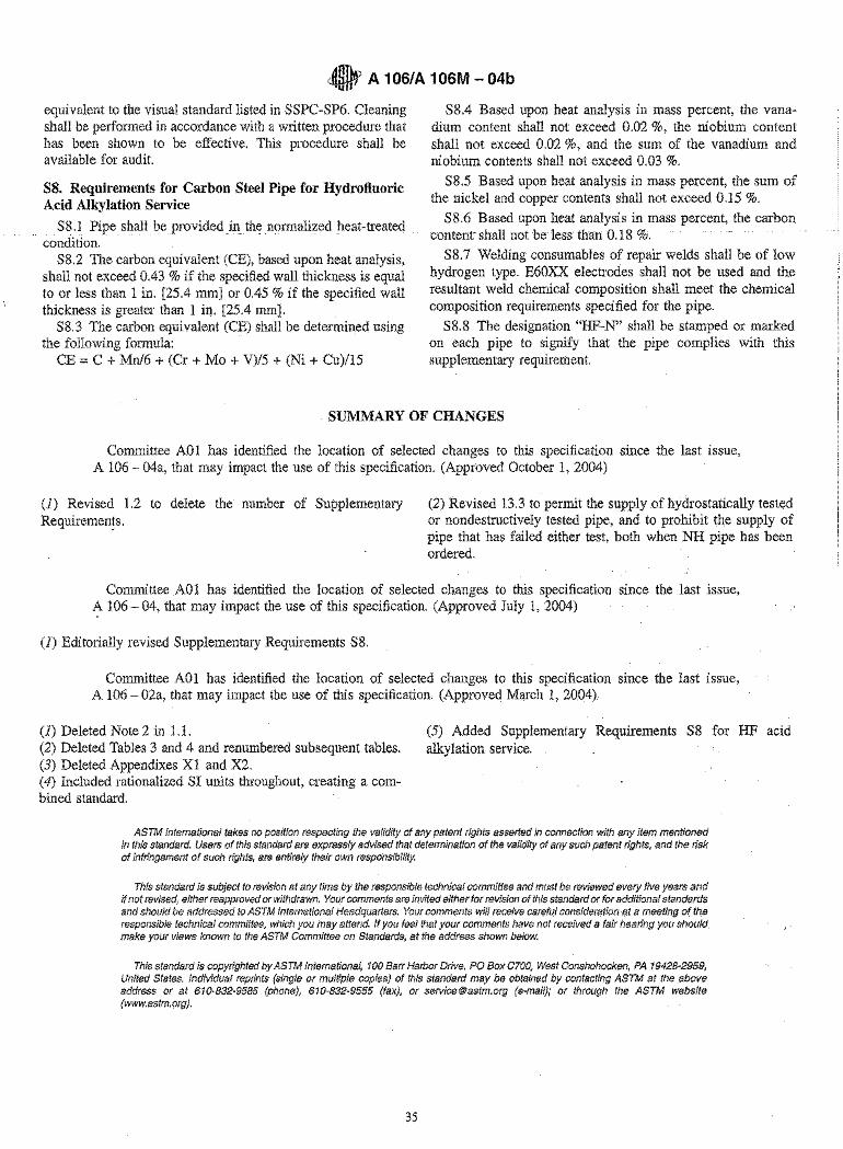
• A 106/A 106M - 04b
equivalent to the visual standard listed in SSPC-SP6. Cleaning shall be performed in accordance with a written procedure that has been shown to be effective. This procedure shall be available for audit.
S8. Requirements for Carbon Steel Pipe for Hydrofluoric Acid Alkylation Service
S8.1 Pipe shall be provided inthe normalized heat-treated - condition.
S8.2 The carbon equivalent (CE), based upon heat analysis, shall not exceed 0.43 % if the specified wall thickness is equal to or less than 1 in. [25.4 mm] or 0.45 % if the specified wall thickness is greater than 1 in. [25.4 mm].
S8.3 The carbon equivalent (CE) shall be determined using the following formula: -
CE = C + Mn/6 + (Cr + Mo + V)/5 + (Ni + Cu)/15
S8.4 Based upon heat analysis in mass percent, the vanadium content shall not exceed 0.02 %, the niobium content shall not exceed 0.02 %, and the sum of the vanadium and niobium contents shall not exceed 0.03 %.
S8.5 Based upon heat analysis in mass percent, the sum of the nickel and copper contents shall not exceed 0.15 %.
S8.6 Based upon heat analysis in mass percent, the carbon contentshall not be less than 0.18 %.
S8.7 Welding consumables of repair welds shall be of low hydrogen type. E60XX electrodes shall not be used and the resultant weld chemical composition shall meet the chemical composition requirements specified for the pipe.
S8.8 The designation "HF-N" shall be stamped or marked on each pipe to signify that the pipe complies with this supplementary requirement.
SUMMARY OF CHANGES
Committee A01 has identified the location of selected changes to this specification since the last issue, A 106 - 04a, that may impact the use of this specification. (Approved October 1, 2004)
(1) Revised 1.2 to delete the number of Supplementary Requiremen!s.
(2) Revised 13.3 to permit the supply of hydrostatically tested or nondestructively tested pipe, and to prohibit the supply of pipe that has failed either test, both when NH pipe has been ordered.
Committee A01 has identified the location of selected changes to this specification since the last issue, A 106 - 04, that may impact the use of this specification. (Approved July 1, 2004)
(1) Editorially revised Supplementary Requirements S8.
Committee A01 has identified the location of selected changes to this specification since the last issue, A 106 - 02a, that may impact the use of this specification, (Approved March 1, 2004)
(1) Deleted Note 2 in 1.1. (2) Deleted Tables 3 and 4 and renumbered subsequent tables. (3) Deleted Appendixes Xl and X2. (4) Included rationalized SI units throughout, creating a combined standard.
(5) Added Supplementary Requirements S8 for HF acid alkylation service.
ASTM International takes no position respecting the validity of any patent rights asserted in connection with any item mentioned in this standard. Users of this standard are expressly advised that determination of the validity of any such patent rights, and the risk of infringement of such rights, are entirely their own responsibility.
This standard is subject to revision at any time by the responsible technical committee and must be reviewed evelJl five years and if not revised, either reapproved or withdrawn. Your comments are invited either for revision of this standard or for additional standards and should be addressed to ASTM International Headquarters. Your commf!nts will receive careful consideration at a meeting of the responsible technical committee, which you may attend. If you feel that your comments have not received a fair hearing you should make your views known to the ASTM Committee on Standards, at the address shown below.
This standard is copyrighted by ASTM International, 100 Barr Harbor Drive, PO Box C700, West Conshohocken, PA 19428-2959, United States. Individual reprints (single or multiple copies) of this standard may be obtained by contacting ASTM at the above address or at 610-832-9585 (phone), 610-832-9555 (fax), or [email protected] (e-mail); or through the ASTM website (www.astm.org).
35
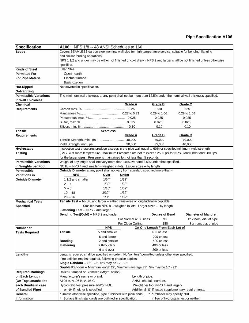
Pipe Specification A106
Specification A106 NPS 1/8 -- 48 ANSI Schedules to 160Scope Covers SEAMLESS carbon steel nominal wall pipe for high-temperature service, suitable for bending, flanging
and similar forming operations.NPS 1 1/2 and under may be either hot finished or cold drawn. NPS 2 and larger shall be hot finished unless otherwisespecified.
Kinds of Steel Killed SteelPermitted For Open-hearthFor Pipe Material Electric-furnace
Basic-oxygenHot-Dipped Not covered in specification.Galvanizing Permissible Variations The minimum wall thickness at any point shall not be more than 12.5% under the nominal wall thickness specified.in Wall ThicknessChemical Grade A Grade B Grade CRequirements Carbon max. %………………………………….. 0.25 0.30 0.35
Manganese %………………………………… 0.27 to 0.93 0.29 to 1.06 0.29 to 1.06Phosporous, max. %……………………………. 0.025 0.025 0.025Sulfur, max. %…………………………………… 0.025 0.025 0.025Silicon, min. %…………………………………… 0.10 0.10 0.10
Tensile SeamlessRequirements Grade A Grade B Grade C
Tensile Strength, min., psi…………………….. 48,000 60,000 70,000Yield Strength, min., psi………………………. 30,000 35,000 40,000
Hydrostatic Inspection test pressures produce a stress in the pipe wall equal to 60% or specified minimum yield strengthTesting (SMYS) at room temperature. Maximum Pressures are not to exceed 2500 psi for NPS 3 and under and 2800 psi
for the larger sizes. Pressure is maintained for not less than 5 seconds. Permissible Variations Weight of any length shall not vary more than 10% over and 3.5% under that specified.in Weights per Foot NOTE -- NPS 4 and smaller -- weighed in lots. Larger sizes -- by lengthPermissible Outside Diameter at any point shall not vary from standard specified more than--
Variations in NPS Over UnderOutside Diameter 1 1/2 and smaller 1/64" 1/32"
2 -- 4 1/32" 1/32" 5 -- 8 1/16" 1/32" 10 -- 18 3/32" 1/32" 20 -- 26 1/8" 1/32"
Mechanical Tests Tensile Test -- NPS 8 and larger -- either transverse or longitudinal acceptable
Specified Smaller than NPS 8 -- weighed in lots. Larger sizes -- by length. Flattening Test -- NPS 2 and larger.Bending Test(Cold) -- NPS 2 and under. Degree of Bend Diameter of Mandrel For Normal A106 uses 90 12 x nom. dia. of pipe For Close Coiling 180 8 x nom. dia. of pipe
Number of NPS On One Length From Each Lot ofTests Required Tensile 5 and smaller 400 or less
6 and larger 200 or lessBonding 2 and smaller 400 or lessFlattening 2 through 5 400 or less 6 and over 200 or less
Lengths Lengths required shall be specified on order. No "jointers" permitted unless otherwise specified.If no definite lengths required, following practice applies:Single Random -- 16' - 22'. 5% may be 12' - 16'Double Random -- Minimum length 22', Minimum average 35'. 5% may be 16' - 22'.
Required Markings Rolled Stamped or Stenciled (Mfgrs. option)on Each Length Manufacturer's name or brand. Length of pipe.(On Tags attached to A106 A, A106 B, A106 C. ANSI schedule number.each Bundie in case Hydrostatic test pressure and/or NDE. Weight per foot (NPS 4 and larger)of Bundled Pipe) or NH if neither is specified. Additional "S" if tested supplementary requirements.General * Unless otherwise specified, pipe furnished with plain ends. * Purchaser may specify NDEInformation * Surface finish standards are outlined in specification. in lieu of hydrostatic test or neither
By Authority OfTHE UNITED STATES OF AMERICA
Legally Binding Document
By the Authority Vested By Part 5 of the United States Code § 552(a) and Part 1 of the Code of Regulations § 51 the attached document has been duly INCORPORATED BY REFERENCE and shall be considered legally binding upon all citizens and residents of the United States of America. HEED THIS NOTICE: Criminal penalties may apply for noncompliance.
Official Incorporator:THE EXECUTIVE DIRECTOROFFICE OF THE FEDERAL REGISTERWASHINGTON, D.C.
Document Name:
CFR Section(s):
Standards Body:
e
American Society for Testing and Materials
46 CFR 56.50-105
ASTM A333: Standard Specification for Seamlessand Welded Steel Pipe for Low-TemperatureService

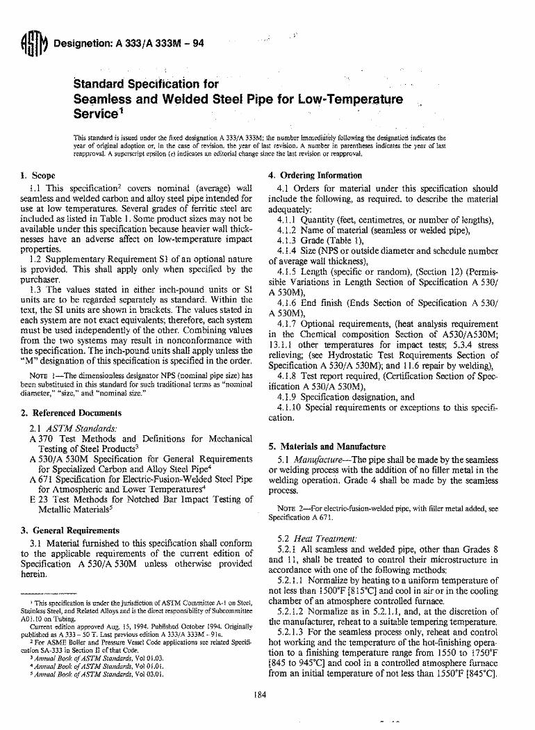
~~l~ Designation: A 333/A 333M - 94
Standard Specification for SeC;lmless and Welded Steel Pipe for Low-Temperature Service1
This standard is issued under the fixed designation A 333/ A 333M; the number immediately following the designatiort indicates the year of original adoption or, in the case of revision, the year of last revision. A number in parentheses indicates the year of last reapproval. A superscript epsilon (E) indicates an editorial change since the last revision or reapproval.
1. Scope 1.1 This specification2 covers nominal (average) wall
seamless and welded carbon and alloy steel pipe intended for use at low temperatures. Several grades of ferritic steel are included as listed in Table 1. Some product sizes may not be available under this specification because heavier wall thicknesses have an adverse affect on low-temperature impact properties.
1.2 Supplementary Requirement S 1 of an optional nature is provided. This shall apply only when specified by the purchaser.
1.3 The values stated in either inch-pound units or SI units are to be regarded separately as standard. Within the text, the SI units are shown in brackets. The values stated in each system are not exact equivalents; therefore, each system must be used independently of the other. Combining values from the two systems may result in nonconformance with the specification. The inch-pound units shall apply unless the .oM" designation of this specification is specified in the order.
NOTE I-The dimensionless designator NPS (nominal pipe size) has been substituted in this standard for such traditional terms as "nominal diameter," "size," and "nominal size."
2. Referenced Documents
2.1 ASTM Standards: A 370 Test Methods and Definitions for Mechanical
Testing of Steel Products3
A 530/A 530M Specification for General Requirements for Specialized Carbon and Alloy Steel Pipe4
A 671 Specification for Electric-Fusion-Welded Steel Pipe for Atmospheric and Lower Temperatures4
E 23 Test Methods for Notched Bar Impact Testing of Metallic Materials5
3. General Requirements 3.1 Material furnished to this specification shall conform
to the applicable requirements of the current edition of Specification A 530/A 530M unless otherwise provided herein.
I This specification is under the jurisdiction of ASTM Committee A-Ion Steel, Stainless Steel, and Related Alloys and is the direct responsibility of Subcommittee A01.10 on Tubing.
Current edition approved Aug. IS, 1994. Published October 1994. Originally published as A 333 - 50 T. Last previous edition A 333/A 333M - 91a.
2 For ASME Boiler and Pressure Vessel Code applications see related Specifi-cation SA-333 in Section II of that Code.
3 Annual Book oj ASTM Standards, Vol 01.03. 4 Annual Book oj ASTM Standards, Vol 01.01. 5 Annual Book oj ASTM Standards, Vol 03.01.
184
4. Ordering Information
4.1 Orders for material under this specification should include the following, as required, to describe the material adequately:
4.1.1 Quantity (feet, centimetres, or number of lengths), 4.1.2 Name of material (seamless or welded pipe), 4.1.3 Grade (Table 1), 4.1.4 Size (NPS or outside diameter and schedule number
of average wall thickness), 4.1.5 Length (specific or random), (Section 12) (Permis
sible Variations in Length Section of Specification A 530/ A 530M),
4.1.6 End finish (Ends Section of Specification A 530/ A 530M),
4.1.7 Optional requirements, (heat analysis requirement in the Chemical composition Section of A530/A530M; 13.1.1 other temperatures for impact tests; 5.3.4 stress relieving; (see Hydrostatic Test Requirements Section of Specification A 530/A 530M); and 11.6 repair by welding),
4.1.8 Test report required, (Certification Section of Specification A 530/A 530M),
4.1.9 Specification designation, and 4.1.1 0 Special requirements or exceptions to this specifi
cation.
5. Materials and Manufacture
5.1 Manu/acture-The pipe shall be made by the seamless or welding process with the addition of no filler metal in the welding operation. Grade 4 shall be made by the seamless process.
NOTE 2-For electric-fusion-welded pipe, with filler metal added, see Specification A 671.
5.2 Heat Treatment: 5.2.1 All seamless and welded pipe, other than Grades 8
and 11, shall be treated to control their microstructure in accordance with one of the following methods:
5.2.1.1 Normalize by heating to a uniform temperature of not less than 1500°F [815°C] and cool in air or in the cooling chamber of an atmosphere controlled furnace.
S.2.l.2 Normalize as in 5.2.1.1, and, at the discretion of the manufacturer, reheat to a suitable tempering temperature.
5.2.1.3 For the seamless process only, reheat and control hot working and the temperature of the hot-finishing operation to a finishing temperature range from 1550 to 1750°F [845 to 945°C] and cool in a controlled atmosphere furnace from an initial temperature of not less than 1550°F [845°C].
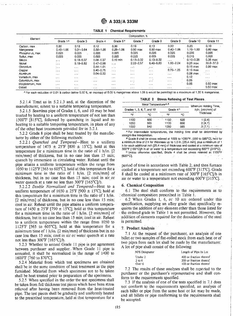
~t A 33.3/ A 333M
TABLE 1 Chemical Requirements
Element Composition, %
Grade 1 A Grade 3 Grade 4 Grade 6A Grade 7 Grade 8 Grade 9 Grade 10 Grade 11
0.30 0.19 0.12 0.30 0.19 0.13 0.20 0.20 0.10 Carbon, max Manganese Phosphorus, max Sulfur, max Silicon
0.40-1.06 0.31-0.64 0.50-1.05 0.29-1.06 0.90 max 0.90 max 0.40-1.06 1.15-1.50 0.60 max 0.025 0.025 0.35 max 35.0-37.0 0.50 max
0.025 0.025 0.025 0.025 0.025 0.025 0.025 0.035 0.025 0.025 0.025 0.025 0.025 0.025 0.025 0.015
0.18-0.37 0.08-0.37 0.10 min 0.13-0.32 0.13-0.32 0.10-0.35 Nickel Chromium Copper Aluminum Vanadium, max Columbium, max Molybdenum, max Cobalt
... 3.18-3.82 0.47-0.98
0.44-1.01 0.40-0.75 0.04-0.30
2.03-2.57 8.40-9.60 1.60-2.24
0.75-1.25
0.25 max 0.15 max 0.15 max 0.06 max 0.12 0.05 0.05 0.50 max
0.50 max
A For each reduction of 0.01 % carbon below 0.30 %, an increase of 0.05 % manganese above 1.06 % wo~ld be permitted to a maximum of 1.35 % mangan~se.
5.2.1.4 Treat as in 5.2.1.3 and, at the discretion of the manufacturer, reheat to a suitable tempering temperature.
5.2.1.5 Seamless pipe of Grades I, 6, and 10 may be heat treated by heating to a uniform temperature of not less than 1500°F [815°C), followed by quenching in liquid and reheating to a suitable tempering temperature, in place of any of the other heat treatments provided for in 5.2.1.
5.2.2 Grade 8 pipe shall be heat treated by the manufacturer by either of the following methods:
5.2.2.1 Quenched and Tempered-Heat to a uniform temperature of 1475 ± 2S"F [800 ± 15°C]; hold at this temperature for a minimum time in the ratio of 1 h/in. [2 min/mm] of thickness, but in no case less than 15 min; quench by immersion in circulating water. Reheat until the pipe attains a uniform temperature within the range from 1050 to 1125°F [565 to 60S"C]; hold at this temperature for a minimum time in the ratio of 1 h/in. [2 min/mm] of thickness, but in no case less than 15 min; cool in air or water quench at a rate no less than 300°F [165°C]/h. ..
5.2.i2 Double Normalized and Tempered-Heat to a uniform temperature of 1650± 25°F [900 ± 15°C]; hold at this temperature for a minimum time in the ratio of 1 h/in. [2 min/mm] of thickness, but in no case less than 15 min; cool in air. Reheat until the pipe attains a uniform temperature of 1450 ± 25°F [790 ± 15°C]; hold at this temperature for a minimum time in the ratio of 1 h/in. [2 min/mm] of thickness, but in no case less than 15 min; cool in air. Reheat to a uniform temperature within the range from 1050 to 1125°F [565 to 605°C]; hold at this temperature for a minimum time of 1 h/in. [2 min/mm] of thickness but in no case less than 15 min; cool in air or water quench at a rate not less than 300°F [16S"C]/h.
5.2.3 Whether to anneal Grade 11 pipe is per agreement between purchaser and supplier. When Grade 11 pipe is annealed, it shall be normalized in the range' of 1400 to 1600°F [760 to 870°C].
5.2.4 Material from which test specimens are obtained shall be in the same condition of heat treatment as the pipe furnished. Material from which specimens are to be taken shall be heat treated prior to preparation of the specimens.
5.2.5 When specified in the order the test specimens shall be taken from full thickness test pieces which have been stress relieved after having been removed from the heat-treated pipe. The test pieces shall be gradually and uniformly heated to the prescribed temperature, held at that temperature for a
TABLE 2 Stress Relieving of Test Pieces
Metal TemperatureA• B Minimum Holding Time,
Grades 1, 3, 6, 7, and 10 Grade 4c h/in. [min/mm] of
OF °C OF °C Thickness
1100 600 1150. 620 1 [2.4] 1050 565 1100 600 2[4.7] 1000 540 1050 565 .3 [7.1]
A For intermediate temperatures, the holding time shall b~' determined by straight-line interpolation:
B Grade 8 shall be stress relieved at 1025 to 1085°F, [550 to 585°C], held for a minimum time of 2 h for thickness up to 1.0 in. [25.4 mm], plus a minimum of 1 h for each additional inch [25.4 mm] of thickness and cooled at a minimum rate of 300°F [165°C]/h in air or water to a temperature not exceeding 600°F [315°C].
c Unless otherwise specified, Grade 4 shall be stress relieved at 1150°F [620°C].
period of time in accordance with Table 2, and then furnace cooled at a temperature not exceeding 600°F [315°C]. Grade 8 shall be cooled at a minimum rate of 300°F [165°C]/h in air or water to a. teP1perature not exceeding 600°F [315°C].
6. Chemical Composition 6.1 The steel shall conform to the requirements as to
• chemical composition prescribed in Table 1. 6.2 When Grades 1, 6, or 10 are ordered under this
specification, supplying an alloy grade that specifically requires the addition of any element other than those listed for
. the ordered grade in Table 1 is not permitted. However, the addition of elements required for the deoxidation of the steel is permitted. . .
7. Product Analysis 7.1 At the request of the' purchaser, an analysis of one
billet or two samples of flat-rolled stock from each heat or of two pipes from each lot shall be made by the manufacturer. A lot of pipe shall consist of the following:
NPS Designator
Under 2 2 to 6 Over 6
Length of Pipe in Lot
400 or fraction thereof 200 or fraction thereof 100 or fraction thereof
7.2 The results of these analyses shall be reported to the purchaser or the purchaser's representative and shall conform to the requirements specified.
7.3 If the analysis of one of the tests specified in 7.1 does not conform to the requirements specified, an analysis of each billet or pipe from the same heat or lot may be made, and all billets or pipe conforming to the requirements shall be accepted.
185
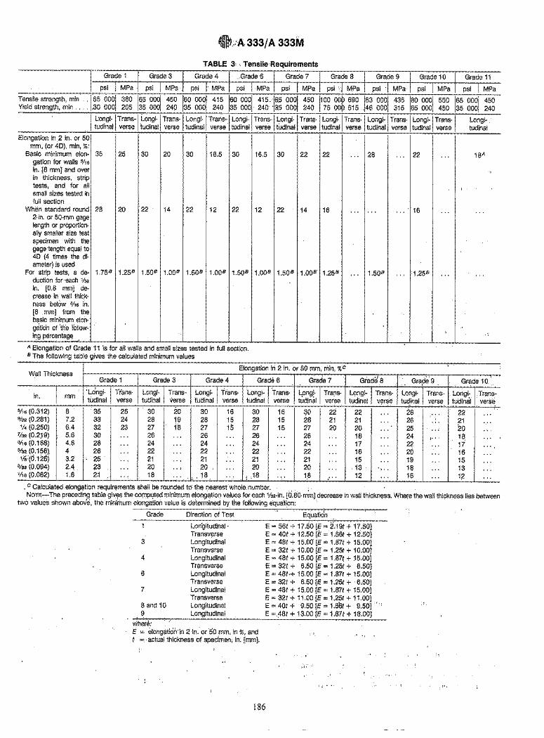
~mtt.·A. 333/ A 333M
TABLE 3" TensilecRequirements
1 Longi-I Trans-I Longi-I Trans-I Longi-I Trans" 1 Longi-I Trans-I Longi-I Tran9-1 Longi-I Trans~ 1 Longi-I Trans-I Longi-I Trans-I tudinal verse tUdinal verse tudinal verse tudinal verse tudinal verse tudinal verse tudinal verse tudinal verse
Longitudinal
Elongation in 2 in. or 50 mm, (or 4D), min, %:
Basic minimum elon- 35 25 30 20 30 16.5 30 gation for walls 5/'6 in. [8 mm] and over in thickness, strip tests, and for all small sizes tested in full section
When standard round 28 20 22 14 22 12 22 2-in. or 50-mm gage length or proportion-ally smaller size test specimen with the gage 'length equal to 4D (4 times the di-ameter) is used
For strip tests, a de- 1.75B 1.25B 1.50B 1.00B 1.50B 1.00B 1.50B
duction for each 1/32 in. [0.8 mm] de-crease in wall thick-ness below 5/'6 in. [8 mm] from the basic minimum eloh-g~tio'n ot'the follow-ing percentage.
A Elongation of Grade 11 is for all walls and small sizes teSted in full section. B The following table gives the calculated minimum values
16.5 30 22 22
12 22 14 16
1.00B 1.50B 1.00B 1.25B
Wall Thickness Elongation in 2 in. or 50 mm, min, %c
Grade 1 Grade 3 Grade 4 Grade 6 Grad'e 7
in. 'Longi- Trans- Longi- Trans- Longi- Trans- Longi- Trans- ~ongi- Tra[ls-
mm tudinal verse tudinal verse tudinal verse tudinal verse tudinal verse
5/'6 (0.312) 8 35 25 30 20 30 16 30 16 30 22 %2 (0.281) 7.2 33 24 28 19 28 15 28 15 28 21 V. (0.250) 6.4 32 23 27 18 27 15 27 15 27 20
'ls2 (0.2' 9) 5.6 30 ... 26 ... 26 ." 26 ... 26 ... 3/'6 (0.188) 4.8 28 ... 24 ... 24 ... 24 . .. 24 ... %2 (0.156) 4 26 ... 22 ... 22 ... 22 ... 22 ... 1/8:(6.125) 3.2 25 ... 21 ... 21 ... 21 ... 21 ...
3/32 (0.094) 2.4 23 ... 20 .. , 20 ... 20 ... 20 .. . '/'6 (0.062) 1.6 21 ... 18 '" ,., 18 .,. , ;18 ... 18 ...
. C Calculated elong~tion requirements shall be rounded to the nearest whole, number. , , '
... 28 .. , 22 . .. 18A
"
,
... ... .., 16 ... ...
... 1.50B ., . :1.25B ... . ..
I ;
Grad~ 8 Grape 9 Grade 10.
LQngi- Trans- Longi- Trans- Longi~ Trans-tudinal verse tudinal verse tudinal verse
22 ... 28 ... 22 ... 21 ... 26 ... 21 20 ... 25 ... 20 ... 18 ... 24 I'" 18 ... 17 .. . 22 .. . 17 . .. 16 ... 20 ... 16 . .. 15 ... 19 ... 15 ... 13 ... 18 .. . 13 . .. 12 ... 16 ... 112 ...
NOTE-The preceding table gives the cO(llputed minimum elong~tiol) values for each 1/s2-in. [0.80-mm] decrease in wall thickness. Where the wall thickness lies between two valu~s shown above, the minimum elongation value is determined by the foliowing equation:
, ,
Grade Direction of Test Equation
3
4
6
7
8 and 10 9
where:
Lon'gitudinal . Transverse Longitudinal Transverse Longitudinal Transverse Longitudinal Transverse Longitudinal Transverse Longitudinal Longitudinal
E = eldngaticih'in 2in. or50 mm, in %, and t =, actual thickness of specimen, in. [mm].
" ,
E = 56t + 17.50 [E = 2.19t + 17.50] E = 40t + 12.50 [E = 1.56t + 12.50] E = 48t + 15.00 [E = 1.87t + 15.00] E = 32t + 10.00 [E = 1.25t + 10.00] E = 48t + 15.00 [E = 1.87( + 15.00] E = 32t + 6.50 [E = 1.25t + 6.50] E = 48H 15.00 [E = 1.87t + 15.00] E = 32t + 6.50 [E = 1.25t + '6;50] E = 48t + 15.00 [E = 1.87t + 15.00] E = 32t + 11.00 [E = 1.25t + 11.00] E=40t+ 9.50[£=1.56t+ 9.50] "I.
E =.48t + 13.00 [E = 1.87t + 13.00]
.. ,
186
I ~. I
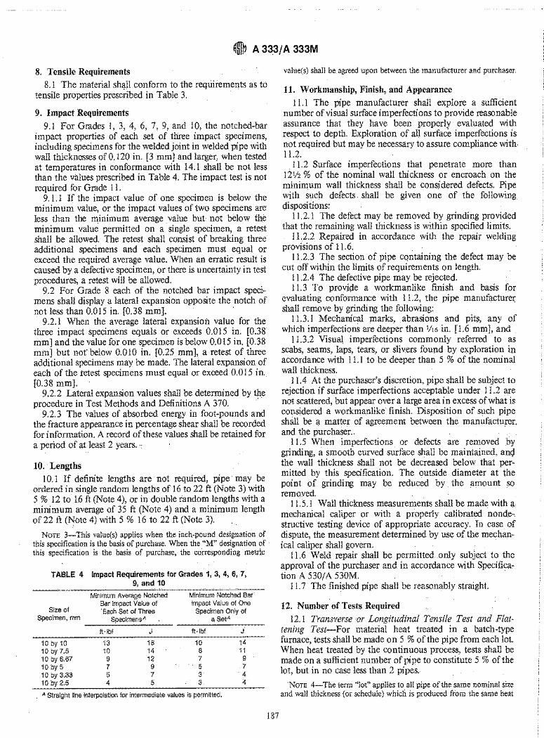
~t A 33.3/ A 333M
8. Tensile Requirements 8.1 The material sh~ll conform to the requirements as t6
tensile properties prescribed in Table 3.
9. Impact Requirements 9.1 For Grades 1, 3, 4, 6, 7, 9, and 10, the notched-bar
impact properties of each set of three impact specimens, including specimens for the welded joint in welded pipe with wall thicknesses of 0.120 in. [3 mm] and larger, when tested at temperatures in conformance with 14.1 shall be not less than the values prescribed in Table 4. The impact test is not required for Grade 11.
9.1.1 If the impact value of one specimen is below the minimum value, or the impact values of two specimens are less than the minimum average value but not below the minimum value permitted on a single specimen, a retest shall be allowed. The retest shall consist of breaking three additional specimens and each specimen must equal or exceed the required average value. When an erratic result is caused by a defective specimen, or there is uncertainty in test procedures, a retest will be allowed.
9.2 For Grade 8 each of the notched bar impact specimens shall display a lateral expansion opposite the notch of not less than 0.Q15 in. [0.38 mm].
9.2.1 When the average lateral expansion value for the three impact specimens equals or exceeds 0.015 in. [0.38 mm] and the value for one specimen is below 0.015 in. [0.38 mm] but not below 0.010 in. [0.25 mm], a retest of three additional specimens may be made. The lateral expansion of each of the retest specimens must equal or exceed 0.015 in. [0.38 mm].
9.2.2 Lateral expansion values shall be determined by the procedure in Test Methods and Definitions A 370. .
9.2.3 The values of absorbed energy in foot-pounds and the fracture appearance in percentage shear shall be recorded for information. A record of these values shall be retained for a period of at least 2 years ..
10. Lengths 10.1 If definite lengths are not required, pipe may be
ordered in single random lengths of 16 to 22 ft (Note 3) with 5 % 12 to 16 ft (Note 4), or in double random lengtl).s with a minimum average of 35 ft (Note 4) and a minimum length of 22 ft (Note 4) with 5 % 16 to 22 ft (Note 3).
i
NOTE 3-This value(s) applies when the inch-pound designation of this specification is the basis of purchase. When the "M" designation of ' this specification is the basis of purchase, the corresponding metric
TABLE 4 Impact Requirements for Grades 1, 3, 4, 6, 7, 9, and 10
Minimum Average Notched Minimum Notched Bar
Size of Bar Impact Value of Impact Value of One . Each Set of Three Specimen Only of
Specimen, mm Specimens A a SetA
ft·lbf J ft·lbf J
10 by 10 13 18 10 14 10 by 7.5 10 14 8 11 10 by 6.67 9 12 7 9 10 by 5 7 9 5 7 10 by 3.33 5 7 3 4 10 by 2.5 4 5 3 4
. A Straight line interpolation for intermediate values is permitted.
187
value(s) shall be. agreed upon between the manufacturer and purchaser.
11. Workmanship, Finish, and Appearance
11.1 The pipe manufacturer shall explore a sufficient number of visual surface imperfections to provide reasonable assurance that they have been properly evaluated with respect to depth. Exploration of all surface imperfections is not required but may be necessary to assure compliance with 11.2.
11.2 Surface imperfections that penetrate more than 12112 % of the nominal wall thickness or encroach on the minimum wall thickness shall be considered defects. Pipe with such defects shall be given one of the following dispositions:
11.2.1 The defect may be removed by grinding provided that the remaining wall thickness is within specified limits.
112.2 Repaired in accordance with the repair welding provisions of 11.6.
11.2.3 The section of pipe cqntaining the defect may be cut off within the limits of requirements on length.
11.2.4 The defective pipe may be rejected. 11.3 To provi(ie a workmanlike finish and basis for
evaluating conformance with 11.2, the pipe manufacturer: shall remove by grinding the following:
11.3.1 Mechanical marks, . abrasions and pits, any of which imperfections are deeper than 1/16 in. [1.6 mm], and
11.3.2 Visual imperfections commonly referred to as scabs, seams, laps, tears, or slivers found by exploration in accordance with 11.1 to be deeper than 5 % of the nominal wall thickness.
11.4 At the purchaser's discretion, pipe shall be subject to rejection if surface imperfections acceptable under 11.2 are not scattered, but appear over a large area in excess of what is considered a workmanlike finish. Disposition of such pipe shall be a matter of agreement between the manufacturer. and the purchaser ..
11.5 When imperfections or defects are removed by grinding, a smooth curved surface shall be maintained, an<;i the wall thickness shall not be decreased below that permitted by this specification. The outside diameter at the point of grinding may be reduced by the amount so removed.
11.5.1 Wall thickness measurements shall be made with a mechanical caliper or with a properly calibrated nondestructive testing device of appropriate accuracy. In case of dispute, the measurement determined by use of the mechanical caliper shall govern.
11.6 Weld repair shall be permitted only subject to the approval of the purchaser and in accordance with Specification A 530jA 530M.
11.7 The finished pipe shall be reasonably straight.
12. Number of Tests Required 12.1 Transverse 'or Longitudinal Tensile Test and Flat
tening Test-For material heat treated in a batch-type furnace, tests shall be made on 5 % of the pipe from each lot. When heat treated by the continuous process, tests shall be made on a sufficient number of pipe to constitute 5 % of the lot, but in no case less than 2 pipes.
'NOTE 4-The term "lot" applies to all pipe of the same nominal size and wall thickness (or schedule) which is produced from the same heat
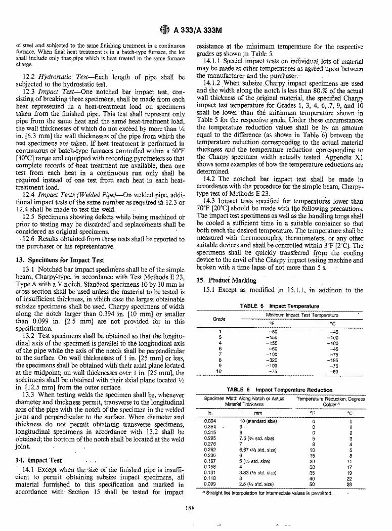
~t A 333/ A 333M
of steel and subjected to the same finishing treatment in a continuous furnace. When final heat treatment is in a batch-type furnace, the lot shall include only that, pipe which is heat treated in the same furnace charge. ' "
12.2 Hydrostatic Test-Each length of pipe shall be subjected to the hydrostatic test.
12.3 Impact Test-One notched bar impact test, consisti:ng of breaking three specimens, shall be ma& from each heat represented in a heat-treatment load on specimens taken from the finished pipe. This test shall represent only pipe from the same heat and the same heat-treatment load, the wall thicknesses of which do not exceed by more than 1/4
in. [6.3 mm] the wall thicknesses of the pipe from which the test specimens are taken. If heat treatment is performed in continuous or batch-type furnaces controlied within a 50°F [30°C] range and equipped with recording pyroineters so that complete records of heat treatment are available, then one test from each heat in a continuous run only shall be required instead of one test from each heat in each heattreatment load.
12.4 Impact Tests (Welded Pipe/-On welded pipe, additional impact tests of the same number as required iii 12.3 or 12.4 shall be made totest the weld.
12.5 Specimens showing defects while being machined or prior to testing may be discarded' and replacements shall be co:nsidered as original specimens.
12.6 Results obtained from these tests shall be reported to the purchaser or his representative.
13. Specimens for Impact Test 13.1 Notched bar impact specimens shall be of the simple
beam, Charpy~type, in accordance with Test Methods E 23, Type A with a V :natcli. Standard specimens 10 by 10 mm in cross section shall be used unless the material to be tested is of insufficient thickness, in whiCh case the largest obtainable subsize specimens shall be used. Charpy specimens of width along the notch larger than 0.394 in. [10 mm] or smaller than 0.099 in. [2.5 min] ate not provided for in this specification.
13.2 Test specimens shall be obtained so that the longitudinal axis of the specimen is parallel to the longitudinal axis of the pipe while the axis of the notch shall be perpendicular to the surface. On wall thicknesses of 1 in. [25 mm] or less, the specimens shall be obtained with their axial plane located at the midpoint; on wall thicknesses oVer 1 in. [25 mm], the specimens shall be obtained with their a'xial plane located liz in. [12.5 mm] from the outer surface.
13.3 When testing welds the specimen shan be, whenever diameter and thickness permit, transverse to the longitudinal axis of the pipe with the notch of the specimen in the welded joint and perpendicular to the surface. When diameter and thickness do not permit obtaining transverse specimens, longitudinal specimens in accdrdance with 13.2 shall be obtained; the bottom of the notch shall be located at the weld joint.
14. Impact Test
14.1 Except when the 'size of the finished pipe is insufficient to permit obtaining subsize impact specimens, ali material furnished to this specification and marked in accordance with Section 15 shall be tested for impact
188
resistance at the minimum temperature for the respective grades as shown in Table 5.
14.1. i Special impact 'tests on indIvidual lots of material may be made at other temperatures as agre~d upon between the manufacturer and the purchaser.
14.1.2 When subsizeCharpy impact specimens are used and the width along the notch is less than 80, % of the actual wall thickness of the ,original material, the specified Charpy impact test temperature for Grades 1, 3, 4, 6,,7, 9, and 10 shall be lower than the minimum temperature shown in Table 5 for the respective grade. Under these circumstances the temperature reduction values shall be by an amount equal to the difference (as shown in Table '6) between the temperature reduction corresponding to the actual material thickn~ss and the temperature reduction correspol1ding to the Charpy specimen width actually tested. Appendix XI shows some examples of how the temperature reductions are determined.
14.2 The notched bar impact test shall be made in accordance with the procedure for the simple beam, Charpytype test of Methods E 23.
1;4.3 Impact tests specified for temperatures lower than 70°F [20°C] should be made with t~e followipg precautions. The impact test specimens as well as the handling tongs shall be cooled a sufficient time in a suitable container so that both reach the desired temperature. The temperature shall be measured with thermocouples, thermometers, or any other suitable devices and shall be controlled within 3°F [2°C]. The specimens shall be quickly transferred fro~, the cooling device to the anvil of the Charpy impact testing machine and broken with a time lapse of not more than 5 s.
15. Product Marking
15.1 Except as modified jn )5.1.1, in addition to the
Grade
1 3 4 6 7 8 9
10
TABLE 5 Impact Temperature
Minimum Impact Test Temperature
-50 -150 -150 -50
-100 -320 ~100
-75
-45 -100 -100 -45 -75
-195 -75 -60
TABLE 6 Impact Temperature Reduction
Specimen Width Along Notch or Actual Material Thickness
Temperature Reduction, Degrees Colder A
in. mm OF °C 0.394 10 (standard size) 0 0 0.354 9 0 0 0.315 8 0 0 0.295 7.5 (3/4 std. size) 5 3 0.276 7 8 4 0.262 6.67 (213 ,std. size) 10 5 0.236 6 15 8 0.197 5 (112 std. size) 20 11 0.158 4 30 17 0.131 3.33 ('13 std. size) 35 19 0.118 3 40 22 0.099 2.5 (1/4 std. size) 50 28
A Straight line interpolation for intermediate values is permitted.
~m~ A 333/ A 333M
marking prescribed in Specification A 530/A 530M, the marking shall include whether hot finished, cold drawn, seamless or welded, the schedule number and the letters "LT" followed by the temperature at which the impact tests were made, except when a lower test temperature is required because of reduced specimen size, in which case, the higher impact test temperature applicable to a full-size specimen should be marked.
15.1.1 When the size of the finished pipe is insufficient to obtain subsize impact specimens, the marking shall not
include the letters LT followed by an indicated test temperature unless Supplementary Requirement SI is specified.
15.1.2 When the pipe is furnished in the quenched and tempered condition, the marking shall include the letters "QT", and the heat treatment condition shall be reported to the purchaser or his representative.
16. Keywords
16.1 low temperature service; seamless steel pipe; stainless steel pipe; steel pipe; temperature service applications, low
SUPPLEMENTARY REQUIREMENTS
The following supplementary requirement shall apply only when specified by the purchaser in the contract or order. .
SI. Subsize Impact Specimens
S 1.1 When the size of the finished pipe is insufficient to permit obtaining subsize impact specimens, testing shall be a
matter of agreement between the manufacturer and the purchaser.
APPENDIX
(Non mandatory Information)
Xl. DETERMINATION OF TEMPERATURE REDUCTIONS
XU Under the circumstances stated in 14.1.2, the impact test temperatures specified in Table 5 must be lowered. The following examples are offered to describe the application of the provisions of 14.1.2.
X 1.1.1 When subsize specimens are used (see 11.1) 'and the width along the notch of the subsize specimen in 80 % or greater of the actual wall thickness of the original material, the provisions of 14.1.2 do not apply.
X 1.1.1.1 For example, if the actual wall thickness of pipe was 0.200 in. [5.0 mm] and the width along the notch of the ' largest subsize specimen obtainable is 0.160 in. [4 mm] or greater, no reduction in test temperature is required.
X 1.1.2 When the width along the subsize specimen notch
is less than 80 % of the actual wall thickness of the pipe, the required reduction in test temperature is computed by taking the difference between the temperature reduction values. shown in Table 6 for the actual pipe thickness and the specimen width used. ' ." .
X1.1.2.1 For example, if the pipe were 0.262 in. [6.67 mm] thick and the width along the Charpy specimen notch was 3.33 mm (1/3 standard size), the test temperature would have to be lowered by 25°F [14°C]. That is,the temperature reduction corresponding to the subsize specimen is 35°F [19°C]; the temperature reduction ,corresponding to the actual pipe thickness is 10°F [SOC]; the difference between these two values is the required reduction in test temperature.
The American Society for Testing and Materials takes no position respecting the validity of any patent rights asserted in connection with any item mentioned in this standard. Users of this standard are expressly advised that determination of the validity of any such patent rights, and the risk of infringement of $uch rights, are entirely their own responsibility.
This standard is subject to revision at any time by the responsible technical committee and must be reviewed every five years and if not revised, either reapproved or withdrawn. Your comments are invited either for revision of this standard or for additional standards
.' and should be addressed to ASTM Headquarters. Your comments will receive careful consideration at a meeting of the responsible technical committee, which you may attend. If you feel that your comments have not received a fair hearing you should make your views known to the ASTM Committee oh Standarfis, 1916 Race St., Philadelphia, PA 19103.
l.
189
Designation: A335/A335M – 11
Standard Specification forSeamless Ferritic Alloy-Steel Pipe for High-TemperatureService 1
This standard is issued under the fixed designation A335/A335M; the number immediately following the designation indicates the yearof original adoption or, in the case of revision, the year of last revision. A number in parentheses indicates the year of last reapproval.A superscript epsilon () indicates an editorial change since the last revision or reapproval.
This standard has been approved for use by agencies of the Department of Defense.
1. Scope*
1.1 This specification2 covers nominal wall and minimumwall seamless ferritic alloy-steel pipe intended for high-temperature service. Pipe ordered to this specification shall besuitable for bending, flanging (vanstoning), and similar form-ing operations, and for fusion welding. Selection will dependupon design, service conditions, mechanical properties, andhigh-temperature characteristics.
1.2 Several grades of ferritic steels (seeNote 1) are covered.Their compositions are given inTable 1.
NOTE 1—Ferritic steels in this specification are defined as low- andintermediate-alloy steels containing up to and including 10 % chromium.
1.3 Supplementary requirements (S1 to S7) of an optionalnature are provided. These supplementary requirements call foradditional tests to be made, and when desired, shall be so statedin the order together with the number of such tests required.
1.4 The values stated in either SI units or inch-pound unitsare to be regarded separately as standard. Within the text, theSI units are shown in brackets. The values stated in eachsystem may not be exact equivalents; therefore, each systemshall be used independently of the other. Combining valuesfrom the two systems may result in non-conformance with thestandard. The inch-pound units shall apply unless the “M”designation of this specification is specified in the order.
NOTE 2—The dimensionless designator NPS (nominal pipe size) hasbeen substituted in this standard for such traditional terms as “nominaldiameter,” “size,” and “nominal size.”
2. Referenced Documents
2.1 ASTM Standards:3
A999/A999M Specification for General Requirements forAlloy and Stainless Steel Pipe
E92 Test Method for Vickers Hardness of Metallic Materi-als4
E213 Practice for Ultrasonic Testing of Metal Pipe andTubing
E309 Practice for Eddy-Current Examination of Steel Tu-bular Products Using Magnetic Saturation
E381 Method of Macroetch Testing Steel Bars, Billets,Blooms, and Forgings
E527 Practice for Numbering Metals and Alloys in theUnified Numbering System (UNS)
E570 Practice for Flux Leakage Examination of Ferromag-netic Steel Tubular Products
2.2 ASME Standard:B36.10M Welded and Seamless Wrought Steel Pipe2.3 AWS Specifications5
A5.5/A5.5M Specification for Low-Alloy Steel Electrodesfor Shielded Metal Arc Welding
A5.23/A5.23M Specification for Low-Alloy Steel Elec-trodesand Fluxes for Submerged Arc Welding
A5.28/A5.28M Specification for Low-Alloy Steel Elec-trodesfor Gas Shielded Arc Welding
A5.29/A5.29M Low-Alloy Steel Electrodes for Flux CoredArc Welding
2.4 Other Documents:SNT-TC-1A Recommended Practice for Nondestructive
Personnel Qualification and Certification6
SAE J 1086Practice for Numbering Metals and Alloys(UNS)7
1 This specification is under the jurisdiction of ASTM CommitteeA01 on Steel,StainlessSteel and Related Alloys and is the direct responsibility of SubcommitteeA01.10on Stainless and Alloy Steel Tubular Products.
Currentedition approved Oct. 1, 2011. Published November 2011. Originallyapproved in 1951. Last previous edition approved in 2010 as A335/A335M–10b.DOI: 10.1520/A0335_A0335M-11.
2 For ASME Boiler and Pressure Vessel Code applications see related Specifi-cation SA-335 in Section II of that Code.
3 For referenced ASTM standards, visit the ASTM website, www.astm.org, orcontact ASTM Customer Service at [email protected]. ForAnnual Book of ASTMStandards volume information, refer to the standard’s Document Summary page onthe ASTM website.
4 Withdrawn. The last approved version of this historical standard is referencedon www.astm.org.
5 Available from American Welding Society (AWS), 550 NW LeJeune Rd.,Miami, FL 33126, http://www.aws.org.
6 Available from American Society for Nondestructive Testing (ASNT), P.O. Box28518, 1711 Arlingate Ln., Columbus, OH 43228-0518, http://www.asnt.org.
7 Available from SAE International (SAE), 400 Commonwealth Dr., Warrendale,PA 15096-0001, http://www.sae.org.
1
*A Summary of Changes section appears at the end of this standard.
Copyright. © ASTM International, 100 Barr Harbour Dr., PO box C-700, West Conshohocken, Pennsylvania 19428-2959, United States
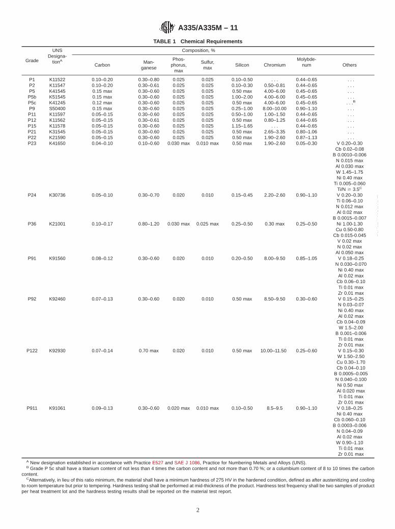
TABLE 1 Chemical Requirements
Grade
UNSDesigna-
tionA
Composition, %
CarbonMan-
ganese
Phos-phorus,
max
Sulfur,max
Silicon ChromiumMolybde-
num Others
P1 K11522 0.10–0.20 0.30–0.80 0.025 0.025 0.10–0.50 . . . 0.44–0.65 . . .P2 K11547 0.10–0.20 0.30–0.61 0.025 0.025 0.10–0.30 0.50–0.81 0.44–0.65 . . .P5 K41545 0.15 max 0.30–0.60 0.025 0.025 0.50 max 4.00–6.00 0.45–0.65 . . .
P5b K51545 0.15 max 0.30–0.60 0.025 0.025 1.00–2.00 4.00–6.00 0.45–0.65 . . .P5c K41245 0.12 max 0.30–0.60 0.025 0.025 0.50 max 4.00–6.00 0.45–0.65 . . .B
P9 S50400 0.15 max 0.30–0.60 0.025 0.025 0.25–1.00 8.00–10.00 0.90–1.10 . . .P11 K11597 0.05–0.15 0.30–0.60 0.025 0.025 0.50–1.00 1.00–1.50 0.44–0.65 . . .P12 K11562 0.05–0.15 0.30–0.61 0.025 0.025 0.50 max 0.80–1.25 0.44–0.65 . . .P15 K11578 0.05–0.15 0.30–0.60 0.025 0.025 1.15–1.65 . . . 0.44–0.65 . . .P21 K31545 0.05–0.15 0.30–0.60 0.025 0.025 0.50 max 2.65–3.35 0.80–1.06 . . .P22 K21590 0.05–0.15 0.30–0.60 0.025 0.025 0.50 max 1.90–2.60 0.87–1.13 . . .P23 K41650 0.04–0.10 0.10–0.60 0.030 max 0.010 max 0.50 max 1.90–2.60 0.05–0.30 V 0.20–0.30
Cb 0.02–0.08B 0.0010–0.006
N 0.015 maxAl 0.030 maxW 1.45–1.75Ni 0.40 max
Ti 0.005–0.060Ti/N $ 3.5C
P24 K30736 0.05–0.10 0.30–0.70 0.020 0.010 0.15–0.45 2.20–2.60 0.90–1.10 V 0.20–0.30Ti 0.06–0.10N 0.012 maxAl 0.02 max
B 0.0015–0.007P36 K21001 0.10–0.17 0.80–1.20 0.030 max 0.025 max 0.25–0.50 0.30 max 0.25–0.50 Ni 1.00-1.30
Cu 0.50-0.80Cb 0.015-0.045
V 0.02 maxN 0.02 max
Al 0.050 maxP91 K91560 0.08–0.12 0.30–0.60 0.020 0.010 0.20–0.50 8.00–9.50 0.85–1.05 V 0.18–0.25
N 0.030–0.070Ni 0.40 maxAl 0.02 max
Cb 0.06–0.10Ti 0.01 maxZr 0.01 max
P92 K92460 0.07–0.13 0.30–0.60 0.020 0.010 0.50 max 8.50–9.50 0.30–0.60 V 0.15–0.25N 0.03–0.07Ni 0.40 maxAl 0.02 max
Cb 0.04–0.09W 1.5–2.00
B 0.001–0.006Ti 0.01 maxZr 0.01 max
P122 K92930 0.07–0.14 0.70 max 0.020 0.010 0.50 max 10.00–11.50 0.25–0.60 V 0.15–0.30W 1.50–2.50Cu 0.30–1.70Cb 0.04–0.10
B 0.0005–0.005N 0.040–0.100Ni 0.50 maxAl 0.020 maxTi 0.01 maxZr 0.01 max
P911 K91061 0.09–0.13 0.30–0.60 0.020 max 0.010 max 0.10–0.50 8.5–9.5 0.90–1.10 V 0.18–0.25Ni 0.40 max
Cb 0.060–0.10B 0.0003–0.006
N 0.04–0.09Al 0.02 maxW 0.90–1.10Ti 0.01 maxZr 0.01 max
A New designation established in accordance with Practice E527 and SAE J 1086, Practice for Numbering Metals and Alloys (UNS).B Grade P 5c shall have a titanium content of not less than 4 times the carbon content and not more than 0.70 %; or a columbium content of 8 to 10 times the carbon
content.CAlternatively, in lieu of this ratio minimum, the material shall have a minimum hardness of 275 HV in the hardened condition, defined as after austenitizing and cooling
to room temperature but prior to tempering. Hardness testing shall be performed at mid-thickness of the product. Hardness test frequency shall be two samples of productper heat treatment lot and the hardness testing results shall be reported on the material test report.
A335/A335M – 11
2
--`,,```,,,,````-`-`,,`,,`,`,,`---
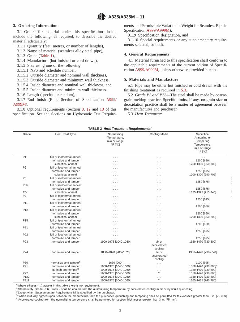
3. Ordering Information
3.1 Orders for material under this specification shouldinclude the following, as required, to describe the desiredmaterial adequately:
3.1.1 Quantity (feet, metres, or number of lengths),3.1.2 Name of material (seamless alloy steel pipe),3.1.3 Grade (Table 1),3.1.4 Manufacture (hot-finished or cold-drawn),3.1.5 Size using one of the following:3.1.5.1 NPS and schedule number,3.1.5.2 Outside diameter and nominal wall thickness,3.1.5.3 Outside diameter and minimum wall thickness,3.1.5.4 Inside diameter and nominal wall thickness, and3.1.5.5 Inside diameter and minimum wall thickness.3.1.6 Length (specific or random),3.1.7 End finish (Ends Section of SpecificationA999/
A999M),3.1.8 Optional requirements (Section8, 12 and 13 of this
specification. See the Sections on Hydrostatic Test Require-
ments and Permissible Variation in Weight for Seamless Pipe inSpecificationA999/A999M),
3.1.9 Specification designation, and3.1.10 Special requirements or any supplementary require-
ments selected, or both.
4. General Requirements
4.1 Material furnished to this specification shall conform tothe applicable requirements of the current edition of Specifi-cationA999/A999M, unless otherwise provided herein.
5. Materials and Manufacture
5.1 Pipe may be either hot finished or cold drawn with thefinishing treatment as required in5.3.
5.2 Grade P2 and P12—The steel shall be made by coarse-grain melting practice. Specific limits, if any, on grain size ordeoxidation practice shall be a matter of agreement betweenthe manufacturer and purchaser.
5.3 Heat Treatment:
TABLE 2 Heat Treatment Requirements A
Grade Heat Treat Type NormalizingTemperature,min or range
°F [°C]
Cooling Media SubcriticalAnnealing orTempering
Temperature,min or range
°F [°C]
P1 full or isothermal anneal . . . . . . . . .normalize and temper . . . . . . 1200 [650]
subcritical anneal . . . . . . 1200-1300 [650-705]P2 full or isothermal anneal . . . . . . . . .
normalize and temper . . . . . . 1250 [675]subcritical anneal . . . . . . 1200-1300 [650-705]
P5 full or isothermal anneal . . . . . . . . .normalize and temper . . . . . . 1250 [675]
P5b full or isothermal anneal . . . . . . . . .normalize and temper . . . . . . 1250 [675]
P5c subcritical anneal . . . . . . 1325-1375 [715-745]P9 full or isothermal anneal . . . . . . . . .
normalize and temper . . . . . . 1250 [675]P11 full or isothermal anneal . . . . . . . . .
normalize and temper . . . . . . 1200 [650]P12 full or isothermal anneal . . . . . . . . .
normalize and temper . . . . . . 1200 [650]subcritical anneal . . . . . . 1200-1300 [650-705]
P15 full or isothermal anneal . . . . . . . . .normalize and temper . . . . . . 1200 [650]
P21 full or isothermal anneal . . . . . . . . .normalize and temper . . . . . . 1250 [675]
P22 full or isothermal anneal . . . . . . . . .normalize and temper . . . . . . 1250 [675]
P23 normalize and temper 1900-1975 [1040-1080] air oraccelerated
cooling
1350-1470 [730-800]
P24 normalize and temper 1800–1870 [980–1020] air oraccelerated
cooling
1350–1420 [730–770]
P36 normalize and temperB 1650 [900] . . . 1100 [595]P91 normalize and temper 1900-1975 [1040-1080] . . . 1350-1470 [730-800]C
quench and temperD 1900-1975 [1040-1080] . . . 1350-1470 [730-800]P92 normalize and temper 1900-1975 [1040-1080] E 1350-1470 [730-800]P122 normalize and temper 1900-1975 [1040-1080] . . . 1350-1470 [730-800]P911 normalize and temper 1900-1975 [1040-1080] E 1365-1435 [740-780]
AWhere ellipses (…) appear in this table there is no requirement.BAlternatively, Grade P36, Class 2 shall be cooled from the austenitizing temperature by accelerated cooling in air or by liquid quenching.CExcept when Supplementary Requirement S7 is specified by the purchaser.D When mutually agreed upon between the manufacturer and the purchaser, quenching and tempering shall be permitted for thicknesses greater than 3 in. [75 mm].E Accelerated cooling from the normalizing temperature shall be permitted for section thicknesses greater than 3 in. [75 mm].
A335/A335M – 11
3
--`,,```,,,,````-`-`,,`,,`,`,,`---
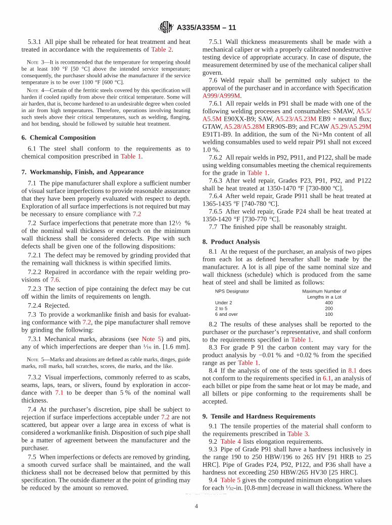
5.3.1 All pipe shall be reheated for heat treatment and heattreated in accordance with the requirements ofTable 2.
NOTE 3—It is recommended that the temperature for tempering shouldbe at least 100 °F [50 °C] above the intended service temperature;consequently, the purchaser should advise the manufacturer if the servicetemperature is to be over 1100 °F [600 °C].
NOTE 4—Certain of the ferritic steels covered by this specification willharden if cooled rapidly from above their critical temperature. Some willair harden, that is, become hardened to an undesirable degree when cooledin air from high temperatures. Therefore, operations involving heatingsuch steels above their critical temperatures, such as welding, flanging,and hot bending, should be followed by suitable heat treatment.
6. Chemical Composition
6.1 The steel shall conform to the requirements as tochemical composition prescribed inTable 1.
7. Workmanship, Finish, and Appearance
7.1 The pipe manufacturer shall explore a sufficient numberof visual surface imperfections to provide reasonable assurancethat they have been properly evaluated with respect to depth.Exploration of all surface imperfections is not required but maybe necessary to ensure compliance with7.2
7.2 Surface imperfections that penetrate more than 121⁄2 %of the nominal wall thickness or encroach on the minimumwall thickness shall be considered defects. Pipe with suchdefects shall be given one of the following dispositions:
7.2.1 The defect may be removed by grinding provided thatthe remaining wall thickness is within specified limits.
7.2.2 Repaired in accordance with the repair welding pro-visions of7.6.
7.2.3 The section of pipe containing the defect may be cutoff within the limits of requirements on length.
7.2.4 Rejected.7.3 To provide a workmanlike finish and basis for evaluat-
ing conformance with7.2, the pipe manufacturer shall removeby grinding the following:
7.3.1 Mechanical marks, abrasions (seeNote 5) and pits,any of which imperfections are deeper than1⁄16 in. [1.6 mm].
NOTE 5—Marks and abrasions are defined as cable marks, dinges, guidemarks, roll marks, ball scratches, scores, die marks, and the like.
7.3.2 Visual imperfections, commonly referred to as scabs,seams, laps, tears, or slivers, found by exploration in accor-dance with7.1 to be deeper than 5 % of the nominal wallthickness.
7.4 At the purchaser’s discretion, pipe shall be subject torejection if surface imperfections acceptable under7.2 are notscattered, but appear over a large area in excess of what isconsidered a workmanlike finish. Disposition of such pipe shallbe a matter of agreement between the manufacturer and thepurchaser.
7.5 When imperfections or defects are removed by grinding,a smooth curved surface shall be maintained, and the wallthickness shall not be decreased below that permitted by thisspecification. The outside diameter at the point of grinding maybe reduced by the amount so removed.
7.5.1 Wall thickness measurements shall be made with amechanical caliper or with a properly calibrated nondestructivetesting device of appropriate accuracy. In case of dispute, themeasurement determined by use of the mechanical caliper shallgovern.
7.6 Weld repair shall be permitted only subject to theapproval of the purchaser and in accordance with SpecificationA999/A999M.
7.6.1 All repair welds in P91 shall be made with one of thefollowing welding processes and consumables: SMAW,A5.5/A5.5M E90XX-B9; SAW,A5.23/A5.23MEB9 + neutral flux;GTAW, A5.28/A5.28MER90S-B9; and FCAWA5.29/A5.29ME91T1-B9. In addition, the sum of the Ni+Mn content of allwelding consumables used to weld repair P91 shall not exceed1.0 %.
7.6.2 All repair welds in P92, P911, and P122, shall be madeusing welding consumables meeting the chemical requirementsfor the grade inTable 1.
7.6.3 After weld repair, Grades P23, P91, P92, and P122shall be heat treated at 1350-1470 ºF [730-800 ºC].
7.6.4 After weld repair, Grade P911 shall be heat treated at1365-1435 ºF [740-780 ºC].
7.6.5 After weld repair, Grade P24 shall be heat treated at1350-1420 °F [730-770 °C].
7.7 The finished pipe shall be reasonably straight.
8. Product Analysis
8.1 At the request of the purchaser, an analysis of two pipesfrom each lot as defined hereafter shall be made by themanufacturer. A lot is all pipe of the same nominal size andwall thickness (schedule) which is produced from the sameheat of steel and shall be limited as follows:
NPS Designator Maximum Number ofLengths in a Lot
Under 2 4002 to 5 2006 and over 100
8.2 The results of these analyses shall be reported to thepurchaser or the purchaser’s representative, and shall conformto the requirements specified inTable 1.
8.3 For grade P 91 the carbon content may vary for theproduct analysis by −0.01 % and +0.02 % from the specifiedrange as perTable 1.
8.4 If the analysis of one of the tests specified in8.1 doesnot conform to the requirements specified in6.1, an analysis ofeach billet or pipe from the same heat or lot may be made, andall billets or pipe conforming to the requirements shall beaccepted.
9. Tensile and Hardness Requirements
9.1 The tensile properties of the material shall conform tothe requirements prescribed inTable 3.
9.2 Table 4lists elongation requirements.9.3 Pipe of Grade P91 shall have a hardness inclusively in
the range 190 to 250 HBW/196 to 265 HV [91 HRB to 25HRC]. Pipe of Grades P24, P92, P122, and P36 shall have ahardness not exceeding 250 HBW/265 HV30 [25 HRC].
9.4 Table 5gives the computed minimum elongation valuesfor each1⁄32-in. [0.8-mm] decrease in wall thickness. Where the
A335/A335M – 11
4
--`,,```,,,,````-`-`,,`,,`,`,,`---
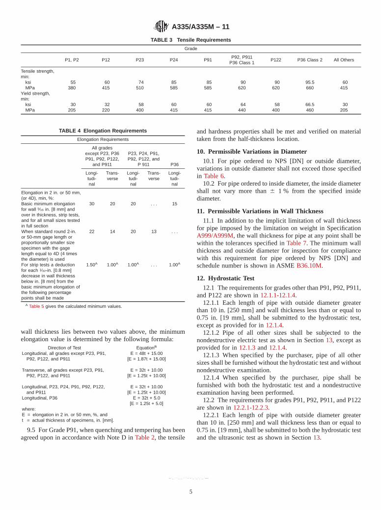
wall thickness lies between two values above, the minimumelongation value is determined by the following formula:
Direction of Test EquationB
Longitudinal, all grades except P23, P91,P92, P122, and P911
E = 48t + 15.00[E = 1.87t + 15.00]
Transverse, all grades except P23, P91,P92, P122, and P911
E = 32t + 10.00[E = 1.25t + 10.00]
Longitudinal, P23, P24, P91, P92, P122,and P911
E = 32t + 10.00[E = 1.25t + 10.00]
Longitudinal, P36 E = 32t + 5.0[E = 1.25t + 5.0]
where:E = elongation in 2 in. or 50 mm, %, andt = actual thickness of specimens, in. [mm].
9.5 For Grade P91, when quenching and tempering has beenagreed upon in accordance with Note D inTable 2, the tensile
and hardness properties shall be met and verified on materialtaken from the half-thickness location.
10. Permissible Variations in Diameter
10.1 For pipe ordered to NPS [DN] or outside diameter,variations in outside diameter shall not exceed those specifiedin Table 6.
10.2 For pipe ordered to inside diameter, the inside diametershall not vary more than6 1 % from the specified insidediameter.
11. Permissible Variations in Wall Thickness
11.1 In addition to the implicit limitation of wall thicknessfor pipe imposed by the limitation on weight in SpecificationA999/A999M, the wall thickness for pipe at any point shall bewithin the tolerances specified inTable 7. The minimum wallthickness and outside diameter for inspection for compliancewith this requirement for pipe ordered by NPS [DN] andschedule number is shown in ASMEB36.10M.
12. Hydrostatic Test
12.1 The requirements for grades other than P91, P92, P911,and P122 are shown in12.1.1-12.1.4.
12.1.1 Each length of pipe with outside diameter greaterthan 10 in. [250 mm] and wall thickness less than or equal to0.75 in. [19 mm], shall be submitted to the hydrostatic test,except as provided for in12.1.4.
12.1.2 Pipe of all other sizes shall be subjected to thenondestructive electric test as shown in Section13, except asprovided for in12.1.3and12.1.4.
12.1.3 When specified by the purchaser, pipe of all othersizes shall be furnished without the hydrostatic test and withoutnondestructive examination.
12.1.4 When specified by the purchaser, pipe shall befurnished with both the hydrostatic test and a nondestructiveexamination having been performed.
12.2 The requirements for grades P91, P92, P911, and P122are shown in12.2.1-12.2.3.
12.2.1 Each length of pipe with outside diameter greaterthan 10 in. [250 mm] and wall thickness less than or equal to0.75 in. [19 mm], shall be submitted to both the hydrostatic testand the ultrasonic test as shown in Section13.
TABLE 3 Tensile Requirements
Grade
P1, P2 P12 P23 P24 P91P92, P911
P36 Class 1P122 P36 Class 2 All Others
Tensile strength,min:
ksiMPa
55380
60415
74510
85585
85585
90620
90620
95.5660
60415
Yield strength,min:
ksiMPa
30205
32220
58400
60415
60415
64440
58400
66.5460
30205
TABLE 4 Elongation Requirements
Elongation Requirements
All gradesexcept P23, P36P91, P92, P122,
and P911
P23, P24, P91,P92, P122, and
P 911 P36
Longi-tudi-nal
Trans-verse
Longi-tudi-nal
Trans-verse
Longi-tudi-nal
Elongation in 2 in. or 50 mm,(or 4D), min, %:Basic minimum elongationfor wall 5⁄16 in. [8 mm] andover in thickness, strip tests,and for all small sizes testedin full section
30 20 20 . . . 15
When standard round 2-in.or 50-mm gage length orproportionally smaller sizespecimen with the gagelength equal to 4D (4 timesthe diameter) is used
22 14 20 13 . . .
For strip tests a deductionfor each 1⁄32-in. [0.8 mm]decrease in wall thicknessbelow in. [8 mm] from thebasic minimum elongation ofthe following percentagepoints shall be made
1.50A 1.00A 1.00A . . . 1.00A
A Table 5 gives the calculated minimum values.
A335/A335M – 11
5
--`,,```,,,,````-`-`,,`,,`,`,,`---
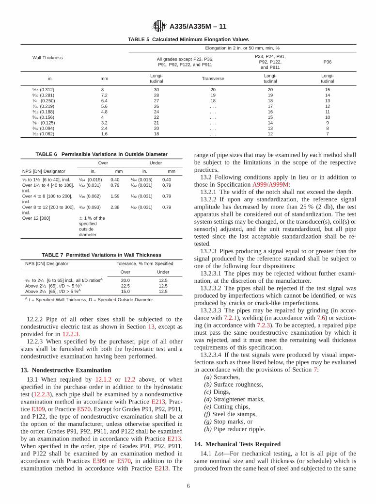
12.2.2 Pipe of all other sizes shall be subjected to thenondestructive electric test as shown in Section13, except asprovided for in12.2.3.
12.2.3 When specified by the purchaser, pipe of all othersizes shall be furnished with both the hydrostatic test and anondestructive examination having been performed.
13. Nondestructive Examination
13.1 When required by12.1.2 or 12.2 above, or whenspecified in the purchase order in addition to the hydrostatictest (12.2.3), each pipe shall be examined by a nondestructiveexamination method in accordance with PracticeE213, Prac-ticeE309, or PracticeE570. Except for Grades P91, P92, P911,and P122, the type of nondestructive examination shall be atthe option of the manufacturer, unless otherwise specified inthe order. Grades P91, P92, P911, and P122 shall be examinedby an examination method in accordance with PracticeE213.When specified in the order, pipe of Grades P91, P92, P911,and P122 shall be examined by an examination method inaccordance with PracticesE309 or E570, in addition to theexamination method in accordance with PracticeE213. The
range of pipe sizes that may be examined by each method shallbe subject to the limitations in the scope of the respectivepractices.
13.2 Following conditions apply in lieu or in addition tothose in SpecificationA999/A999M:
13.2.1 The width of the notch shall not exceed the depth.13.2.2 If upon any standardization, the reference signal
amplitude has decreased by more than 25 % (2 db), the testapparatus shall be considered out of standardization. The testsystem settings may be changed, or the transducer(s), coil(s) orsensor(s) adjusted, and the unit restandardized, but all pipetested since the last acceptable standardization shall be re-tested.
13.2.3 Pipes producing a signal equal to or greater than thesignal produced by the reference standard shall be subject toone of the following four dispositions:
13.2.3.1 The pipes may be rejected without further exami-nation, at the discretion of the manufacturer.
13.2.3.2 The pipes shall be rejected if the test signal wasproduced by imperfections which cannot be identified, or wasproduced by cracks or crack-like imperfections.
13.2.3.3 The pipes may be repaired by grinding (in accor-dance with7.2.1), welding (in accordance with7.6) or section-ing (in accordance with7.2.3). To be accepted, a repaired pipemust pass the same nondestructive examination by which itwas rejected, and it must meet the remaining wall thicknessrequirements of this specification.
13.2.3.4 If the test signals were produced by visual imper-fections such as those listed below, the pipes may be evaluatedin accordance with the provisions of Section7:
(a) Scratches,(b) Surface roughness,(c) Dings,(d) Straightener marks,(e) Cutting chips,(f) Steel die stamps,(g) Stop marks, or(h) Pipe reducer ripple.
14. Mechanical Tests Required
14.1 Lot—For mechanical testing, a lot is all pipe of thesame nominal size and wall thickness (or schedule) which isproduced from the same heat of steel and subjected to the same
TABLE 5 Calculated Minimum Elongation Values
Wall Thickness
Elongation in 2 in. or 50 mm, min, %
All grades except P23, P36,P91, P92, P122, and P911
P23, P24, P91,P92, P122,and P911
P36
in. mmLongi-tudinal
TransverseLongi-tudinal
Longi-tudinal
5⁄16 (0.312) 8 30 20 20 159⁄32 (0.281) 7.2 28 19 19 141⁄4 (0.250) 6.4 27 18 18 137⁄32 (0.219) 5.6 26 . . . 17 123⁄16 (0.188) 4.8 24 . . . 16 115⁄32 (0.156) 4 22 . . . 15 101⁄8 (0.125) 3.2 21 . . . 14 93⁄32 (0.094) 2.4 20 . . . 13 81⁄16 (0.062) 1.6 18 . . . 12 7
TABLE 6 Permissible Variations in Outside Diameter
Over Under
NPS [DN] Designator in. mm in. mm
1⁄8 to 11⁄2 [6 to 40], incl. 1⁄64 (0.015) 0.40 1⁄64 (0.015) 0.40Over 11⁄2 to 4 [40 to 100],incl.
1⁄32 (0.031) 0.79 1⁄32 (0.031) 0.79
Over 4 to 8 [100 to 200],incl.
1⁄16 (0.062) 1.59 1⁄32 (0.031) 0.79
Over 8 to 12 [200 to 300],incl.
3⁄32 (0.093) 2.38 1⁄32 (0.031) 0.79
Over 12 [300] 6 1 % of thespecifiedoutsidediameter
TABLE 7 Permitted Variations in Wall Thickness
NPS [DN] Designator Tolerance, % from Specified
Over Under
1⁄8 to 21⁄2 [6 to 65] incl., all t/D ratiosA 20.0 12.5Above 21⁄2 [65], t/D # 5 %A 22.5 12.5Above 21⁄2 [65], t/D > 5 %A 15.0 12.5A t = Specified Wall Thickness; D = Specified Outside Diameter.
A335/A335M – 11
6
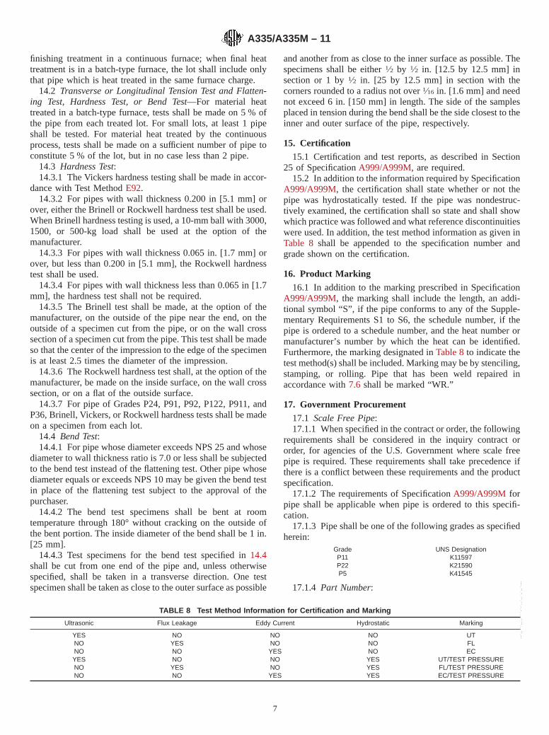
finishing treatment in a continuous furnace; when final heattreatment is in a batch-type furnace, the lot shall include onlythat pipe which is heat treated in the same furnace charge.
14.2 Transverse or Longitudinal Tension Test and Flatten-ing Test, Hardness Test, or Bend Test—For material heattreated in a batch-type furnace, tests shall be made on 5 % ofthe pipe from each treated lot. For small lots, at least 1 pipeshall be tested. For material heat treated by the continuousprocess, tests shall be made on a sufficient number of pipe toconstitute 5 % of the lot, but in no case less than 2 pipe.
14.3 Hardness Test:14.3.1 The Vickers hardness testing shall be made in accor-
dance with Test MethodE92.14.3.2 For pipes with wall thickness 0.200 in [5.1 mm] or
over, either the Brinell or Rockwell hardness test shall be used.When Brinell hardness testing is used, a 10-mm ball with 3000,1500, or 500-kg load shall be used at the option of themanufacturer.
14.3.3 For pipes with wall thickness 0.065 in. [1.7 mm] orover, but less than 0.200 in [5.1 mm], the Rockwell hardnesstest shall be used.
14.3.4 For pipes with wall thickness less than 0.065 in [1.7mm], the hardness test shall not be required.
14.3.5 The Brinell test shall be made, at the option of themanufacturer, on the outside of the pipe near the end, on theoutside of a specimen cut from the pipe, or on the wall crosssection of a specimen cut from the pipe. This test shall be madeso that the center of the impression to the edge of the specimenis at least 2.5 times the diameter of the impression.
14.3.6 The Rockwell hardness test shall, at the option of themanufacturer, be made on the inside surface, on the wall crosssection, or on a flat of the outside surface.
14.3.7 For pipe of Grades P24, P91, P92, P122, P911, andP36, Brinell, Vickers, or Rockwell hardness tests shall be madeon a specimen from each lot.
14.4 Bend Test:14.4.1 For pipe whose diameter exceeds NPS 25 and whose
diameter to wall thickness ratio is 7.0 or less shall be subjectedto the bend test instead of the flattening test. Other pipe whosediameter equals or exceeds NPS 10 may be given the bend testin place of the flattening test subject to the approval of thepurchaser.
14.4.2 The bend test specimens shall be bent at roomtemperature through 180° without cracking on the outside ofthe bent portion. The inside diameter of the bend shall be 1 in.[25 mm].
14.4.3 Test specimens for the bend test specified in14.4shall be cut from one end of the pipe and, unless otherwisespecified, shall be taken in a transverse direction. One testspecimen shall be taken as close to the outer surface as possible
and another from as close to the inner surface as possible. Thespecimens shall be either1⁄2 by 1⁄2 in. [12.5 by 12.5 mm] insection or 1 by1⁄2 in. [25 by 12.5 mm] in section with thecorners rounded to a radius not over1⁄16 in. [1.6 mm] and neednot exceed 6 in. [150 mm] in length. The side of the samplesplaced in tension during the bend shall be the side closest to theinner and outer surface of the pipe, respectively.
15. Certification
15.1 Certification and test reports, as described in Section25 of SpecificationA999/A999M, are required.
15.2 In addition to the information required by SpecificationA999/A999M, the certification shall state whether or not thepipe was hydrostatically tested. If the pipe was nondestruc-tively examined, the certification shall so state and shall showwhich practice was followed and what reference discontinuitieswere used. In addition, the test method information as given inTable 8 shall be appended to the specification number andgrade shown on the certification.
16. Product Marking
16.1 In addition to the marking prescribed in SpecificationA999/A999M, the marking shall include the length, an addi-tional symbol “S”, if the pipe conforms to any of the Supple-mentary Requirements S1 to S6, the schedule number, if thepipe is ordered to a schedule number, and the heat number ormanufacturer’s number by which the heat can be identified.Furthermore, the marking designated inTable 8to indicate thetest method(s) shall be included. Marking may be by stenciling,stamping, or rolling. Pipe that has been weld repaired inaccordance with7.6 shall be marked “WR.”
17. Government Procurement
17.1 Scale Free Pipe:17.1.1 When specified in the contract or order, the following
requirements shall be considered in the inquiry contract ororder, for agencies of the U.S. Government where scale freepipe is required. These requirements shall take precedence ifthere is a conflict between these requirements and the productspecification.
17.1.2 The requirements of SpecificationA999/A999M forpipe shall be applicable when pipe is ordered to this specifi-cation.
17.1.3 Pipe shall be one of the following grades as specifiedherein:
Grade UNS DesignationP11 K11597P22 K21590P5 K41545
17.1.4 Part Number:
TABLE 8 Test Method Information for Certification and Marking
Ultrasonic Flux Leakage Eddy Current Hydrostatic Marking
YES NO NO NO UTNO YES NO NO FLNO NO YES NO ECYES NO NO YES UT/TEST PRESSURENO YES NO YES FL/TEST PRESSURENO NO YES YES EC/TEST PRESSURE
A335/A335M – 11
7
--`,,```,,,,````-`-`,,`,,`,`,,`---
17.1.4.1 Pipe shall be ordered to nominal pipe size andschedule specified in ASMEB36.10MExample: A335/A335M Pipe P-11 NPS 12 Sch 40
Specification Number ASTM A335/A335MPipe PGrade P-11NPS 12Wall 0.375
17.1.4.2Specification Number ASTM A335/A 335 MTube TGrade P-11Outside Diameter 0.250Wall 0.035
17.1.5 Ordering Information—Orders for material underthis specification shall include the following in addition to therequirements of Section3:
17.1.5.1 Pipe or tube,17.1.5.2 Part number,17.1.5.3 Ultrasonic inspection, if required,17.1.5.4 If shear wave test is to be conducted in two
opposite circumferential directions, and17.1.5.5 Level of preservation and packing required.
18. Keywords
18.1 alloy steel pipe; high temperature service; seamlesssteel pipe; steel pipe; temperature service applications
SUPPLEMENTARY REQUIREMENTS
One or more of the following supplementary requirements shall apply only when specified in thepurchase order. The purchaser may specify a different frequency of test or analysis than is providedin the supplementary requirement. Subject to agreement between the purchaser and manufacturer,retest and retreatment provisions of these supplementary requirements may also be modified.
S1. Product Analysis
S1.1 Product analysis shall be made on each length of pipe.Individual lengths failing to conform to the chemical compo-sition requirements shall be rejected.
S2. Transverse Tension Tests
S2.1 A transverse tension test shall be made on a specimenfrom one end or both ends of each pipe NPS 8 and over. If thissupplementary requirement is specified, the number of tests perpipe shall also be specified. If a specimen from any length failsto meet the required tensile properties (tensile, yield, andelongation), that length shall be rejected subject to retreatmentin accordance with SpecificationA999/A999Mand satisfactoryretest.
S3. Flattening Test
S3.1 The flattening test of SpecificationA999/A999Mshallbe made on a specimen from one end or both ends of each pipe.Crop ends may be used. If this supplementary requirement isspecified, the number of tests per pipe shall also be specified.If a specimen from any length fails because of lack of ductilityprior to satisfactory completion of the first step of the flatteningtest requirement, that pipe shall be rejected subject to retreat-ment in accordance with SpecificationA999/A999M andsatisfactory retest. If a specimen from any length of pipe failsbecause of a lack of soundness that length shall be rejected,unless subsequent retesting indicates that the remaining lengthis sound. The bend test of13.2 shall be substituted for theflattening test for pipe whose diameter exceeds NPS 25 andwhose diameter to wall thickness ratio is 7.0 or less.
S4. Metal Structure and Etching Tests
S4.1 The steel shall be homogeneous as shown by etchingtests conducted in accordance with the appropriate portions ofMethodE381. Etching tests shall be made on a cross sectionfrom one end or both ends of each pipe and shall show sound
and reasonably uniform material free from injurious lamina-tions, cracks, and similar objectionable defects. If this supple-mentary requirement is specified, the number of tests per piperequired shall also be specified. If a specimen from any lengthshows objectionable defects, the length shall be rejected,subject to removal of the defective end and subsequent retestsindicating the remainder of the length to be sound andreasonably uniform material.
NOTE S4.1—Pending development of etching methods applicable to theproduct covered by this specification, it is recommended that the Recom-mended Practice for a Standard Macro Etch Test for Routine Inspection ofIron and Steel, described in theMetals Handbook, Am. Soc. for Metals,1948 edition, p. 389, be followed.
S5. Photomicrographs
S5.1 When requested by the purchaser and so stated in theorder, the manufacturer shall furnish one photomicrograph at100 diameters from a specimen of pipe in the as-finishedcondition for each individual size and wall thickness from eachheat, for pipe NPS 3 and over. Such photomicrographs shall besuitably identified as to pipe size, wall thickness, and heat. Nophotomicrographs for the individual pieces purchased shall berequired except as specified in Supplementary Requirement S6.Such photomicrographs are for information only, to show theactual metal structure of the pipe as finished.
S6. Photomicrographs for Individual Pieces
S6.1 In addition to the photomicrographs required in accor-dance with Supplementary Requirement S5, the purchaser mayspecify that photomicrographs shall be furnished from eachend of one or more pipes from each lot of pipe NPS 3 andlarger in the as-finished condition. The purchaser shall state inthe order the number of pipes to be tested from each lot. Whenphotomicrographs are required on each length, the photomi-crographs from each lot of pipe in the as-finished conditionwhich may be required under Supplementary Requirement S5
A335/A335M – 11
8
may be omitted. All photo-micrographs required shall beproperly identified as to heat number, size, and wall thicknessof pipe from which the section was taken. Photomicrographsshall be further identified to permit association of each photo-micrograph with the individual length of pipe it represents.
S7. Alternative Heat Treatment—Grade P91
S7.1 Grade P91 shall be normalized in accordance withTable 2and tempered at a temperature, to be specified by the
purchaser, less than 1350 °F [730 °C]. It shall be purchaser’sresponsibility to subsequently temper at 1350-1470 °F [730-800 °C] minimum. All mechanical tests shall be made onmaterial heat treated in accordance withTable 2. The certifi-cation shall reference this supplementary requirement indicat-ing the tempering temperature applied. The notation “S7” shallbe included with the required marking of the pipe.
SUMMARY OF CHANGES
Committee A01 has identified the location of selected changes to this specification since the last issue,A335/A335M–10b, that may impact the use of this specification. (Approved October 1, 2011)
(1) Added new2.3 to Referenced Documents to add AWSspecifications and renumbered subsequent paragraphs.
(2) Inserted new7.6.1and7.6.2to add process and consumablechemistry restrictions for P91 weld repairs and weld consum-able chemistry restrictions for P92, P122, and P911, andrenumbered subsequent paragraphs.
Committee A01 has identified the location of selected changes to this specification since the last issue,A335/A335M–10a, that may impact the use of this specification. (Approved November 1, 2010)
(1) Rewrote Section12 Hydrostatic Test and Section13Nondestructive Examination, thus making the nondestructivetest mandatory and the hydrotest optional. RevisedTable 8toensure coherence with these changes.
(2) Modified the chemical composition of grade P23 inTable 1.
Committee A01 has identified the location of selected changes to this specification since the last issue,A335/A335M–10, that may impact the use of this specification. (Approved May 1, 2010)
(1) Added new9.5 dealing with compliance of the tensile andhardness properties at mid-thickness for Grade P91 quenchedand tempered.
(2) Added a citation for Footnote E to Grade P92 inTable 2.
(3) Added new Grade P24 to7.6.5, 9.3, 14.3.7, andTables 1-5.
Committee A01 has identified the location of selected changes to this specification since the last issue,A335/A335M–09a, that may impact the use of this specification. (Approved April 1, 2010)
(1) Added new15.1 to make the certification and test reportsmandatory in all cases and renumbered subsequent paragraphs.(2) Revised14.3to permit performance of the hardness testing.
(3) Moved the text of Notes 6 and 7 into the main body of thestandard.
ASTM International takes no position respecting the validity of any patent rights asserted in connection with any item mentionedin this standard. Users of this standard are expressly advised that determination of the validity of any such patent rights, and the riskof infringement of such rights, are entirely their own responsibility.
This standard is subject to revision at any time by the responsible technical committee and must be reviewed every five years andif not revised, either reapproved or withdrawn. Your comments are invited either for revision of this standard or for additional standardsand should be addressed to ASTM International Headquarters. Your comments will receive careful consideration at a meeting of theresponsible technical committee, which you may attend. If you feel that your comments have not received a fair hearing you shouldmake your views known to the ASTM Committee on Standards, at the address shown below.
This standard is copyrighted by ASTM International, 100 Barr Harbor Drive, PO Box C700, West Conshohocken, PA 19428-2959,United States. Individual reprints (single or multiple copies) of this standard may be obtained by contacting ASTM at the aboveaddress or at 610-832-9585 (phone), 610-832-9555 (fax), or [email protected] (e-mail); or through the ASTM website(www.astm.org). Permission rights to photocopy the standard may also be secured from the ASTM website (www.astm.org/COPYRIGHT/).
A335/A335M – 11
9
--`,,```,,,,````-`-`,,`,,`,`,,`---
主营业务范围:ASTMASTMASTMASTM、NASNASNASNAS、NASMNASMNASMNASM、MILMILMILMIL、ISOISOISOISO、ENENENEN、
DINDINDINDIN、JISJISJISJIS等技术标准翻译;技术资料翻译;NADCAPNADCAPNADCAPNADCAP认证
标准资料翻译;国外技术标准中文版优惠低价代购等。
业务 QQQQQQQQ:2298175560229817556022981755602298175560
专业
专注于技术翻译
诚信 实惠
物超所值的服务可靠的质量保证

Disclosure to Promote the Right To Information
Whereas the Parliament of India has set out to provide a practical regime of right to information for citizens to secure access to information under the control of public authorities, in order to promote transparency and accountability in the working of every public authority, and whereas the attached publication of the Bureau of Indian Standards is of particular interest to the public, particularly disadvantaged communities and those engaged in the pursuit of education and knowledge, the attached public safety standard is made available to promote the timely dissemination of this information in an accurate manner to the public.
इटरनट मानक
“!ान $ एक न' भारत का +नम-ण”Satyanarayan Gangaram Pitroda
“Invent a New India Using Knowledge”
“प0रा1 को छोड न' 5 तरफ”Jawaharlal Nehru
“Step Out From the Old to the New”
“जान1 का अ+धकार, जी1 का अ+धकार”Mazdoor Kisan Shakti Sangathan
“The Right to Information, The Right to Live”
“!ान एक ऐसा खजाना > जो कभी च0राया नहB जा सकता ह”Bhartṛhari—Nītiśatakam
“Knowledge is such a treasure which cannot be stolen”
“Invent a New India Using Knowledge”
ह”ह”ह
IS 1161 (1998): Steel Tubes for Structural Purposes [MTD19: Steel Tubes, Pipes abd Fittings]


IS1161:1998
STEEL TUBES FOR STRUCTURAL PURPOSES - SPECIFICATION
( Fourth Revision )
First Reprint NOVEMBER 1998
ICS 77.140.75 ; 91.220
Q BIS 1998
BUREAU OF INDIAN STANDARDS MANAK BHAVAN, 9 BAHADUR SHAH ZAFAR MARG
NEW DELHI 110002
Junuary 1998 Price Group 3
Steel Tubes, Pipes and Fittings Sectional Committee, MTD 19
FOREWORD
This Indian Standard ( Fourth Revision ) was adopted by the Bureau of Indian Standards, after the draft finalized by the Steel Tubes, Pipes and Fittings Sectional Committee had been approved by the Metallurgical Engineering Division Council
This standard was first published in 1958 and its first, second and third revisions were issued in 1963. 1968 and 1979 respectively. While reviewing the standard, the Committee has felt it necessary to revise this Indian Standard with the following modifications:
a) Thickness andmass is aligned with IS 1239 (Part 1) : 1990.
b) All amendments have been incorporated.
In the formulation of this standard, due consideration has been given to the trade practices followed in the country in this field. Due consideration has also been given to international co-ordination among the standards prevailing in different countries. Assistance has been derived from the following publications:
ISO/R 336 : 1976 Plain end steel tubes, welded or seamless; general table of dimensions and masses per unit length. International Organization for Standardization.
BS 6323 : 1982 Steel tubes for-mechanical and general engineering purposes. British Standards Institution.
This standard contains clauses 8.1 and X2.1 which call for agreement between the purchaser and the manufacturer.
For the purpose of deciding whether a particular requirement of this standard is complied with, the final value, observed or calculated, expressing the result of a test or analysis, shall be rounded off in accordance with IS 2 : 1960 ‘Rules for rounding off numerical values (revised)‘. The number of significant places retained in the rounded off value should be the same as that of the specified value in this standard.
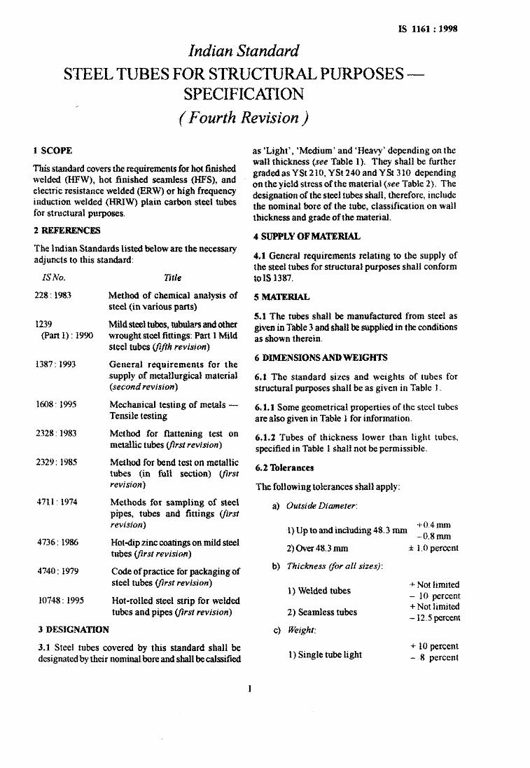
IS 1161 : 1998
Indian Standard
STEEL TUBES FOR STRUCTURAL PURPOSES - SPECIFICATION
-(-Fourth Revision )
1 SCOPE
This standard covers the requirements for hot finished welded (HFW), hot finished seamless @IFS), and electric resistance welded (ERW) or high frequency induction welded (HRIW) plain carbon steel tubes for structural purposes.
2 REPERENCES
The Indian-Standards listed below are the necessary adjuncts to this standard:
IS No.
228 : 1983
1239 (Part 1) : 1990
1387: 1993
1608: 1995
2328: 1983
2329: 1985
4711: 1974
4736: 1986
4740 : 1979
10748 : 1995
Title
Method of chemical analysis of steel (in various parts)
Mild steel tubes, tubulars and other wrought steel fittings: Part 1 Mild steel tubes (#ifth revision)
General requirements for the supply of metallurgical material (second revision)
Mechanical testing of metals - Tensile testing
Method for flattening test on metallic tubes #rst revision)
Method for bend test on metallic tubes (in full section) (fwst revision)
Methods for sampling of steel pipes, tubes and fittings (first revision)
Hot-dip zinc coatings on mild steel tubes (jkst revision)
Code of practice for packaging of steel tubes @rst revision)
Hot-rolled steel strip for welded tubes and pipes yirst revision)
3 DESIGNATION
3.1 Steel tubes covered by this standard shall be designated by their nominal bore and shall be calssified
as ‘Light’, ‘Medium’ and ‘Heavy’ depending on the wall thickness (see Table 1). They shall be further graded as Y St 2 10, Y St 240 and Y St 3 10 depending on the yield stress of the material (see Table 2). The designation of the steel tubes shall, therefore, include the nominal bore ofthe tube, classification on wall thickness and grade of the material.
4 SUPPLY OF MATERIAL
4.1 General requirements relating to the supply of the steel tubes for structural purposes shall conform to IS 1387.
5 MATERIAL
5.1 The tubes shall be manufactured from steel as given in Table 3 and shall be supplied in the conditions as shown therein.
6 DIMENSIONS AND WEIGHTS
6.1 The standard sizes and weights of tubes for structural purposes shall be as given in Table 1.
6.1.1 Some geometrical properties of the steel tubes are also given in Table 1 for information.
6.1.2 Tubes of thickness lower than light tubes, specified in Table 1 shall not be permissible.
6.2 Tolerances
The following tolerances shall apply:
a) Outside Diameter:
1) Up to and including 48.3 mm +0.4mm _ o, 8 _
b)
2)Gver48.3mm
Thickness flor all sizes):
1) Welded tubes
2) Seamless tubes
cl
1
Weight:
1) Single tube light
f 1 .O percent
+ Not limited - 10 percent + Not limited - 12.5 percent
+ 10 percent - ~8 percent

Table 1 Sizes and Properties of Steel ‘hbes for Structural Purposes
(Clauses3.1,6.1,6.1.1and6.1.2)
B
5 Y . .
Nominal Outside Bore Diameter
mm
(1)
15
20 26.9
25
N
32 42.4
40
50 60.3
65 76.1
80 88.9
90 101.6
mm
(2)
21.3
33.7
48.3
Thickness Weight Area of Cross
Section
Internal Volume
Surface
Internal
Moment Modulus Radius of of of
Inertia Section Gyration
(3) mm
(4)
kg/m
(5)
cm’
(6)
1.21 1.53 1.82
cm3/m
(7)
External
cm3/m
(8)
cm3/m (9)
4
(“;“o,
3
(“II,
Square of g Radius of Gyration
2
(“1”)
Light 2.0 0.947 Medium 2.6 1 .21 Heavy 3.2 1.44
235 203 174
669 543 0.57 0.54 0.69 0.47 506 0.69 0.64 0.66 0.44 468 0.75 0.70 0.55 0.42
Light 2.3 1.38 1.78 390 Medium 2.6 1.56 1.98 370 Heavy 3.2 1.87 2.38 330
845 700 1.36 1 .Ol 0.87 0.76 681 1.48 1.10 0.86 0.74 644 1.70 1.26 0.84 0.71
Light 2.6 1.98 2.54 638 Medium 3.2 2.41 3.06 585 Heavy 4.0 2.93 3.73 518
1 059 895 3.09 1.83 1.10 1.21 857 3.61 2.14 1.08 1.17 807 4.19 2.48 1.05 1.11
Light 2.6 2.54 3.25 1 086 Medium 3.2 3.10 3.94 1 017 Heavy 4.0 3.79 4.82 929
1 332 1 168 6.47 3.05 1.41 1.98 1 130 7.62 3.59 1.39 1.93 1 080 8.99 4.24 1.36 1.86
Light 2.9 3.23 4.13 1 418 Medium 3.2 3.56 4.53 1 378 Heavy 4.b 4.37 5.56 1 275
1 517 1 335 10.70 4.43 1.61 2.59 1 316 11.59 4.80 1.59 2.54 1 265 13.77 5.70 1.57 2.41
Light 2.9 4.08 5.23 2 332 1 711 21.59 7.16 2.03 4.13 Medium 3.6 5.03 6.41 2 213 1 667 25.88 8.58 2.00 4.02 Heavy 4.5 6.19 7.88 2 066 1 611 30.90 10.2 1.98 3.92
Light 3.2 5.71 7.32 3 814 Medium 3.6 6.42 8.20 3 727 Heavy 4.5 7.9j 10.1 3 534
2 391 2 189 48.79 12.82 2.58 6.66 2 163 54.02 14.20 2.57 6.60 2 107 65.12 17.1 2.54 6.43
Light 3.2 6.72 8.61 5 343 Medium 4.0 8.36 10.7 5 138 Heavy 4.8 9.90 12.7 4 936
2 793 2 591 751.23 17.82 3.03 9.19 2 540 96.36 21.68 3.00 9.00 2 490 112.52 25.31 2.98 8.88
Light 3.6 8.70 11.1 6 995 Medium 4.0 9.63 12.3 6 877 Heavy 4.8 11.5 14.6 6 644
3 192 2 964 133.27 26.23 3.41 12.03 2 939 146.32 28.80 3.45 11.91 2 889 171.44 33.75 3.43 11.76
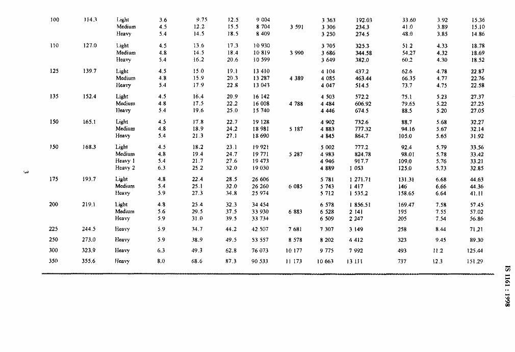
100 114.3
110 127.0
125 139.7
135 152.4
150 165.1
150 168.3
w
175 193.7
200 219.1
225 244.5
250 273.0
300 323.9
350 355.6
Light 3.6 9.75 12.5 9 004 Medium 4.5 12.2 15.5 8 704 Heavy 5.4 14.5 18.5 8 409
Light 4.5 13.6 17.3 10 930 Medium 4.8 14.5 18.4 10 819 Heavy 5.4 16.2 20.6 10 599
Light 4.5 15.0 19.1 13 410 Medium 4.8 15.9 20.3 13 287 Heavy 5.4 17.9 22.8 13 043
Light 4.5 16.4 20.9 16 142 Medium 4.8 17.5 22.2 16 008
Heavy 5.4 19.6 25.0 15 740
Light 4.5 17.8 22.7 19 128 Medium 4.8 18.9 24.2 18 981
HeaY 5.4 21.3 27.1 18690
Light 4.5 18.2 23.1 19 921 Medium 4.8 19.4 24.7 19 771 Heavy 1 5.4 21.7 27.6 19 473 Heavy 2 6.3 25.2 32.0 19 030
Light 4.8 22.4 28.5 26 606 Medium 5.4 25.1 32.0 26 260
H=T 5.9 27.3 34.8 25 974
Light 4.8 25.4 32.3 34 454 Medium 5.6 29.5 37.5 33 930 Heavy 5.9 31 .o 39.5 33 734
Heavy 5.9 34.7 44.2 42 507
Heavy 5.9 38.9 49.5 53 557
Heavy 6.3 49.3 62.8 76 073
Heavy 8.0 68.6 87.3 90 533
3 591
3 990
4 389
4 788
5 187
5 287
6 085
6 883
7 681
8 578
10 177
11 173
3 363 192.03 33.60 3.92 15.36 3 306 234.3 41.0 3.89 15.10 3 250 274.5 48.0 3.85 14.86
3 705 325.3 51.2 4.33 3 686 344.58 54.27 4.32 3 649 382.0 60.2 4.30
4 104 437.2 62.6 4.78 4 085 463.44 66.35 4.77 4 047 514.5 73.7 4.75
18.78 18.69 18.52
22.89 22.76 22.58
4 503 572.2 75.1 5.23 27.37 4 484 606.92 79.65 5.22 27.25 4446 674.5 88.5 5.20 27.05
4 902 732.6 88.7 5.68 32.27 4 883 777.32 94.16 5.67 32.14 4 845 864.7 105.0 5.65 31.92
5 002 777.2 92.4 4 983 824.78 98.01 4 946 917.7 109.0 4 889 1 053 125.0
33.56 33.42 33.21 32.85
5 781 1271.71 131.31 5 743 1 417 146 5 712 1 535.2 158.65
5.79 5.78 5.76 5.73
6.68 6.66 6.64
44.63 44.36 41.11
6 578 1 856.51 169.47 7.58 6 528 2 141 195 7.55 6 509 2 247 205 7.54
7 307 3 149 258 8.44
8 202 4 412 323 9.45
9 775 7 992 493 11.2
10 663 13 111 737 12.3
57.45 57.02 56.86
71.21
89.30
125.44
151.29
t:
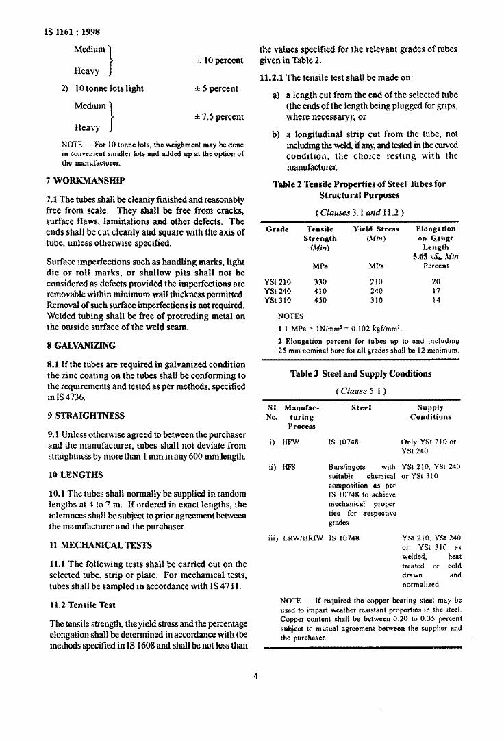
IS 1161 : 1998
Medium
Heavy f 10 percent
the values specified for the relevant grades of tubes given in Table 2.
11.2.1 The tensile test shall be made on: 2) 10 tonne lots light l 5 percent
a) a length cut from the end of the selected tube Medium (the ends of the length being plugged for grips,
f 7.5 percent where necessary); or Heavy j
NOTE - For 10 tonne lots, the weighment may-be done in convenient smaller lots and added up at the option of the manufacturer.
7 woRKMANsHIP
7-l The tubes shall be cleanly finished and reasonably free from scale. They shall be free from cracks, surface flaws, laminations and other defects. The ends shall be cut cleanly and square with the axis of tube, unless otherwise specified.
Surface imperfections such as handling marks, light die or ~011 marks, or shallow pits shall not be considered as defects provided the imperfections are removable within minimum wall thickness permitted. Removal of such surface imperfections is not required. Welded tubing shall be free of protruding metal on the outside surface of the weld seam.
8 GAW.ANIZING
8.1 If the tubes are required in galvanized condition the zinc coating on the tubes shall be conforming to the requirements and tested as per methods, specified in IS 4736.
9 STRAIGHTNESS
9.1 Unless otherwise agreed to between the purchaser and the manufacturer, tubes shall not deviate from straightness by more than 1 mm in any 600 mm length.
10 LENGTHS
10.1 The tubes shall normally be supplied in random lengths at 4 to 7 m. If ordered in exact lengths, the tolerances shall be subject to prior agreement between the manufacturer and the purchaser.
b) a longitudinal strip cut from the tube, not including the weld, ifany, and tested in the curved condition, the choice resting with the manufacturer.
Table 2 Tensile Properties of Steel ‘lhbes for Structural Purposes
( Clauses 3.1 and 11.2 )
Grade Tensile Yield Stress Elongation
Strength (Min) on Gxuge
(Min) Length 5.65 \iS, Min
MPa MPa Percent
Yst 2~10 330 210 20 YSt 240 410 240 17 Yst 310 450 310 14
NOTES
1 1 MPa = lN/mml= 0.102 kgflmm’
2 Elongation percent for tubes up to and including 25 mm nominal bore for all grades shall be 12 mmimum.
Table 3 Steel and Supply Conditions
( Clause 5.1)
Sl Manufac-
No. turing Process
Steel SUPPlY Conditions
i) HPW IS 10748 Only YSt 210 or YSt 240
ii) HFS Bars/ingots with YSt 210, YSt 240 suitable chemical or YSt 310 composition as per IS 10748 to achieve mechanical proper ties .for respective grades
11 MECHANICALTESTS iii) ERW/HRIW IS 10748
11.1 The following tests shall be carried out on the selected tube, strip or plate. For mechanical tests, tubes shall be sampled in accordance with IS 47 11.
YSt 210, YSt 240 or YSt 310 as welded, heat treated or cold drawn and normalized
11.2 Tensile Test NOTE - If required the copper bearing steel may be used to impart weather resistant properties in the steel.
The tensile strength, the yield stress and the percentage elongation shall be determined in accordance with the methods specifiedin IS 1608 and shall be not less than
Copper content shall be between 0.20 to 0.35 percent subject to mutual agreement between the supplier and the purchaser.
4
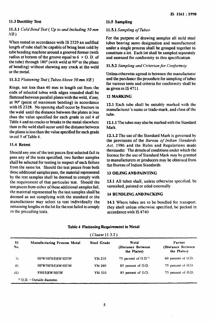
11.3 Ductility Test 11.5 Sampling
11.3.1 Cold Bend Test ( Up to and Including 50 mm
NB) 11.5.1 Sampling ofTubes
When tested in accordance with IS 2329 an unfilled length of tube shall be capable of being bent cold by tube bending machine around a grooved former (with radius at bottom of the groove equal to 6 x 0. D. of the tube) through 180” (with weld at 90” to the plane of bending) without showing any crack at the weld or themetal.
For the purpose of drawing samples all mild steel tubes bearing same designation and manufactured under a single process shall be grouped together to constitute a lot. Each lot shall be sampled separately and assessed for conformity to this specification.
11.5.2 Sampling and Criterion for Conformity
11.3.2 Flattening Test ( TubesAbove 5Omm NB )
Rings, not less than 40 mm in length cut from the ends of selected tubes with edges rounded shall be flattened between parallel plates with the weld, if any, at 90“ (point of maximum bending) in accordance with IS 2328. No opening shall occur by fracture in the weld until the distance between the plates is less than the value specified for each grade in co1 4 of Table 4 and no cracks or breaks in the metal elsewhere than in the weld shall occur until the distance between the plates is iess than the value specified for each grade incol5 ofTable4.
Unless otherwise agreed to between the manufacturer and the purchaser the procedure for sampling of tubes for various tests and criteria for conformity shall be asgiven in IS 47 11.
12 MARKING
12.1 Each tube shall be suitably marked with the manufacturer’s name or trade-mark, and class of the tube.
12.1.1 The tubes may also be marked with the Standard Mark.
11.4 Retest
Should any one of the test pieces first selected fail to pass any of the tests specified, two further samples shall be selected for testing in respect of each failure from the same lot. Should the test pieces from both these additional samples pass, the material represented by the test samples shall be deemed to comply with the requirement of that particular test. Should the test pieces from either of these additional samples fail, the material represented by the test samples shall be deemed as not complying with the standard or the manufacturer may select to test individually the remaining lengths in the lot for the test failed to comply in the preceding tests.
12.1.2 The use of the Standard Mark is governed by the provisions of the Bureau of Indian Standards Act, 1986 and the Rules and Regulations made thereunder. The details of conditions under which~the licence for the use of Standard Mark may be granted to manufacturers or producers may be obtained from the Bureau of Indian Standards.
13 OILINGANDPAINTING
13.1 All tubes shall, unless otherwise specified, bc varnished, painted or oiled externally.
14 BUNDLING AND PACKING
14.1 Where tubes are to be bundled for transport, they shall unless otherwise specified, be packed in accordance with IS 4740.
IS 1161 : 1998
Table 4 Flattening Requirement in Metal
(Clause 11.3.2)
Sl Manufacturing Process Metal Steel Grade Weld
NO. (Distance Between
the Plates)
i) HFWIHFSIERWIHFIW Yst 210 75 percent of 0.D.”
ii) HFWIHFSIERWIHFIW YSt 240 85 percent of O.D.
iii) ~FHS/ERW/HFIW Yst 310 85 percent of O.D.
I) O.D. = Outside diameter.
Parent
(Distance between
the Plates)
60 percent of 0.1).
75 percent of 0.11.
75 percent of O.D.
5
Bureau of Indian Standards
BIS is a statutory institution established under the Bureau oflndian Standards Act, 1986 to promote harmonious development of the activities of standardization, marking and quality certification of goods and attending to connected matters in the country.
Copyright
BIS has the copyright of all its publications. No part of these publications may be reproduced in any form without the prior permission in writing of BIS. This does not preclude the free use, in the course of implementing the standard, of necessary details, such as symbols and sizes, type or grade designations. Enquiries relating to copyright be addressed to the Director (Publications), BIS.
Review of Indian Standards
Amendments are issued to standards as the need arises on the basis of comments. Standards are also reviewed periodically; a standard along with amendments is reaffirmed when such review indicates that no changes are needed; if the review indicates that changes are needed, it is taken up for revision. Users of Indian Standards should ascertain that they-are in possession of the latest amendments or edition by referring to the latest issue of ‘BlS Handbook’ and ‘Standards : Monthly Additions’.
This Indian Standard has been developed from Dot : No. MTD 19 ( 4099 ).
Amendments Issued Since Publication
Amend No. Date of Issue Text Affected
-Headquarters:
BUREAU OF INDIAN STANDARDS
Manak-Bhavan, 9 Bahadur Shah Zafar Marg, New Delhi 110002 Telephones : 323 01 31, 323 94 02, 323 33 75
Regional Offices:
Central : Manak Bhavan, 9 Bahadur Shah Zafar Marg NEW DELHI 110002
Telegrams: Manaksanstha ( Common to
all offices )
Telephone
323 76 17 323384:
Eastern : l/14 C. I. T. Scheme VII M, V. I. P. Road, Maniktola CALCUTTA 700054
Northern : SC0 335-336, Sector 34-A, CHANDIGARH 160022
I
337 84 99,331 85 61 337 86 26, 337 86 62
I
60 38 43 60 20 25
Southern : C. I. T. Campus, IVCross Road, CHENNAI 600113 235 02 16,235 04 42 235 15 19,235 23 15
Western : Manakalaya, E9 MIDC, Marol, Andheri (East) MUMBAI 400093 I
832 92 95,832 78 58 8327891,8327892
Branches : AHMADABAD. BANGALORE. BHOPAL. BHUBANESHWAR. COIMBATORE. FARIDABAD. GHAZIABAD. GUWAHATI. HYDERABAD. JAIPUR. KANPUR. LUCKNOW. NAGPUR. PATNA. PUNE. THIRUVANANTHAPURAM.
Printed at New India Printing Press, Khwja, Indm
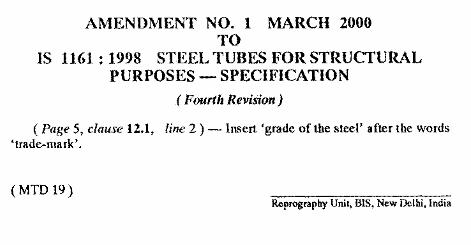
AMENDMENT NO. 1 MARCH 2000 TO
IS 1161 : 1998 STEEL TUBES FOR STRUCTURAL PURPOSES - SPECIFICATION
(Fourth Revision)
( Pqe 5, clause 12.1, line 2 ) - Insert ‘grade of the steel’ after the words ‘trade-mark’.
(MTD 19) Reprography Unit, BE, New Delhi, India
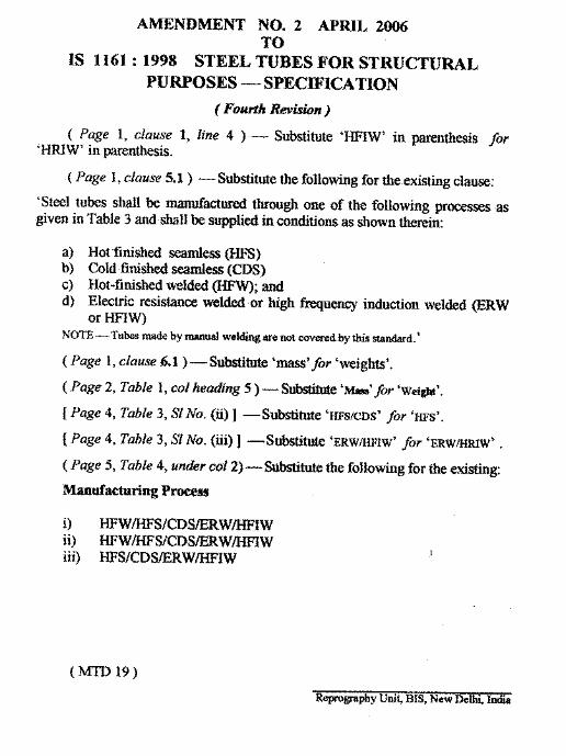
AMENDMENT NO. 2 APRIL 2M6TO
1S 1161:1998 STEEL TUBES FOR STRUCTURALPURPOSES — SPEC~ICATION
( Foutih Rwtiwn )
( Page 1, clause 1, line 4 ) — Substitute ‘WIW’ in parenthesis for‘~W’ in parenthesis.
.( Page 1, clause 5.1) — Substitutethe following for the.existing clause:
‘Steel tubs shall be manuftiured tiough one of the following processes asgiven in Table 3 and shall be supplied in conditions as shown therein
a) Hot finished seandess @S)b) Cold finished s~ess (CDS)c) Hot-finished welded ~~; andd) Electric resistance welded or high ~uenq induction welded @RW
or ~1~NOTE — Tuk -de by -d welding we not covmedby his ~ntid.’
( Page 1, clause 6.1) — Substitute ‘mass’ for ‘weights’.
( Page 2, Table 1, CO1heading 5 ) — S~ ‘~’ for ‘wei~’.
[ Page 4, Table 3, S1 No. (ii)] — Substitute ‘HFS/CDS’ for ‘HFS’.
[ Page 4, Table 3, S1 No. (M)] — Substitute ‘ERWMFIW’ for ‘ERWMWW’ .
( Page 5, Table 4, under col 2] — Substitute tie following for the existing
Manufacturing Pruss
.,
(m19)
Repm~phy Uni~ BIS, New Del~ India
?
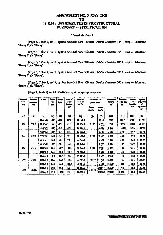
AMENDMENT NO.3 MAY 2008TO
IS 1161 : 1998STEELTUBES FOR STRUCTURALPURPOSES - SPECIFICATION
( FOIl'" llnl.rlDlI )
(Pag,3, Table I, col 3, Dla;",1 Nominal Bore ISO .m, 0ut81tJ. Dlam«er 165.t ",m) - Substitute'Heavy 1'101' 'Heavy'.
(Pag, 3, Table 1, col 3, agallU' NomlnDl Bore200 "''''. DutIl. DltIm.,.,.219.1 "",,) - Substitute'Heavy 1'./or 'Heavy'.
(Page 3, Tabl. I, col 3, agai",' Noml",,1 Bore250 """, Oual. Dltllllel.. 273.0"",,) - Substitute'Heavy 1t for 'Heavy'.
(Page 3, Tabl. I, col 3, against Nominal Bor, 300 1II1II, 0lIl81. Diameter 323.9"'",) - Substitute'HeavyI' for 'Heavy'.
(Pag, 3, Tabl, l, col 3, agalnsl Nominal Bor, 350"'''', o.lde DltIIII•• 355.6 mill) - Substitute'Heavy 1t for 'Heavy'. ..
(Pag.3, Table I) - Add thefollowing at theappropriate place:
NHIIuI 0...... a- TWc.... W.... ANI'" I...... .......A.. M..-fJI ....... .... .......... ........ - ..... c... v.... ,...-A-- .... ....... ., er....DIM - IDIII SectIH eml,. ..4 .' GrnII- ..
era' .... ...... -~pi,. oJ,.
(I) (2) (3) (4) (5) (6) (7) (I) (9) (10) (II) (12) (II)
Hel¥y2 5.9 23.2 29.5 1.465.0 411. 931 113.4 5.63 31.12
15O 165.1 Hel¥yJ 6J 24.7 31.4 11272.1 5119 4793 993 120.3 5.62 31.51
Hawy4 1.0 31.0 39.5 17~7.J 4616 1222 141.0 5.56 30.93
HeaYy2 1.0 41.6 53.1 324l0.4 6313 2960 270 1.47 55.71
200 219.1 Heavy) 10.0 51.6 65.7 31146.4 6116 6157 ]5. 311 7.40 54.11
Hcavy4 12.0 6l.J 78.1 29907.4 6132 4200 383 7.3) 53.19
Heavy 2 1.0 52.3 66.6 51895.6 1071 5152 429 9.37 87.16
250 273.0 Heavy 3 10.0 64.9 82.6 50292.• .S80 7951 7154 524 9.31 86.59
Heavy 4 12.0 77.2 91.4 48715.1 7. 13M 615 9.24 .5.33
Hcavy2 1.0 62.3 79.4 74417.6 9171 9910 612 11.2 124.12
300 323.9 Heavy 3 10.0 11.4 98.6 72564.1 10110 955. 121. 151 11.1 123.29
Heavy 4 12.0 92.3 111.0 70667.2 9425 14320 114 11.0 121.71
HeaYy2 10.0 '5.2 109 .1491.9 10547 16220 912 112 149.0350 355.6 11176
Heay:J 12.0 102.0 130 86396.0 10422 191. 1076 112 147.76
(MTD 19)RtiiiOiiiPiIY 0....liS:NeW Deiilt IilCHi
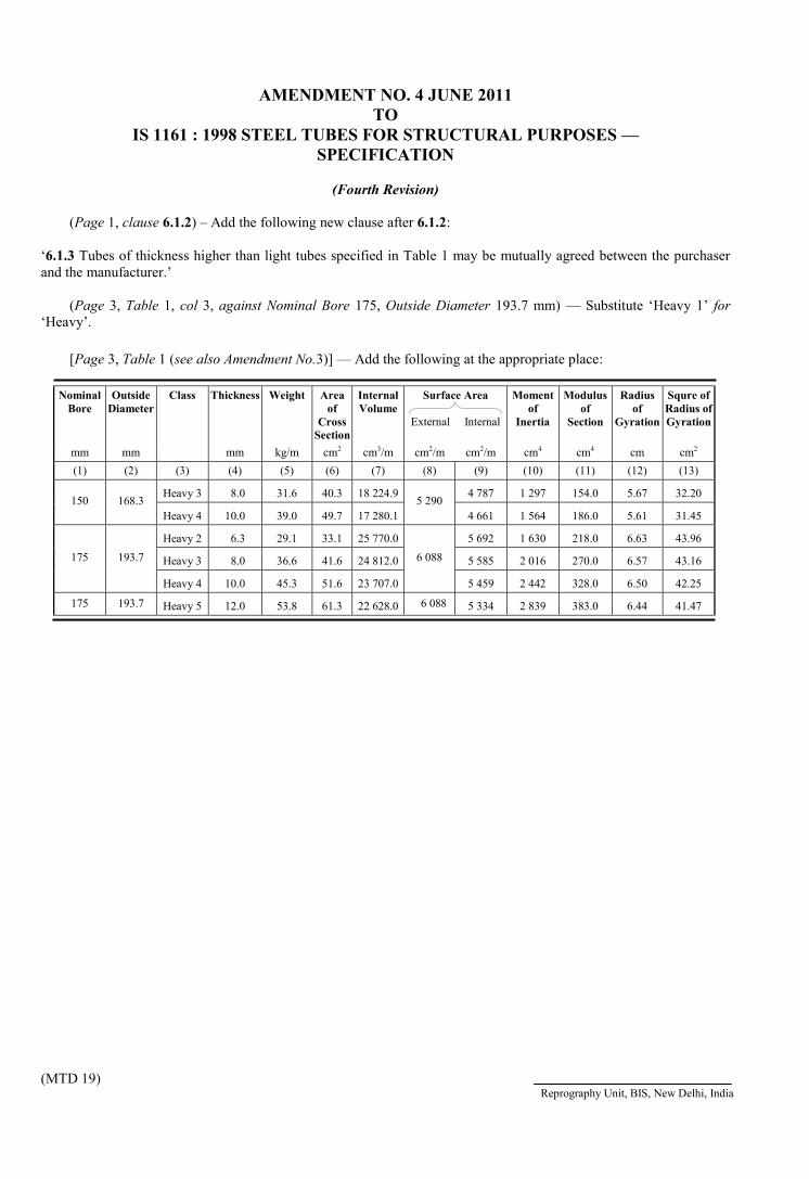
AMENDMENT NO. 4 JUNE 2011TO
IS 1161 : 1998 STEEL TUBES FOR STRUCTURAL PURPOSES —SPECIFICATION
(Fourth Revision)
(Page 1, clause 6.1.2) – Add the following new clause after 6.1.2:
‘6.1.3 Tubes of thickness higher than light tubes specified in Table 1 may be mutually agreed between the purchaserand the manufacturer.’
(Page 3, Table 1, col 3, against Nominal Bore 175, Outside Diameter 193.7 mm) — Substitute ‘Heavy 1’ for‘Heavy’.
[Page 3, Table 1 (see also Amendment No.3)] — Add the following at the appropriate place:
NominalBore
OutsideDiameter
Class Thickness Weight Areaof
CrossSection
InternalVolume
Surface Area
External Internal
Momentof
Inertia
Modulusof
Section
Radiusof
Gyration
Squre ofRadius ofGyration
mm mm mm kg/m cm2 cm3/m cm2/m cm2/m cm4 cm4 cm cm2
(1) (2) (3) (4) (5) (6) (7) (8) (9) (10) (11) (12) (13)
Heavy 3 8.0 31.6 40.3 18 224.9 4 787 1 297 154.0 5.67 32.20150 168.3
Heavy 4 10.0 39.0 49.7 17 280.15 290
4 661 1 564 186.0 5.61 31.45
Heavy 2 6.3 29.1 33.1 25 770.0 5 692 1 630 218.0 6.63 43.96
Heavy 3 8.0 36.6 41.6 24 812.0 5 585 2 016 270.0 6.57 43.16175 193.7
Heavy 4 10.0 45.3 51.6 23 707.0
6 088
5 459 2 442 328.0 6.50 42.25
175 193.7 Heavy 5 12.0 53.8 61.3 22 628.0 6 088 5 334 2 839 383.0 6.44 41.47
(MTD 19)Reprography Unit, BIS, New Delhi, India
AMENDMENT NO. 5 SEPTEMBER 2012TO
IS 1161 : 1998 STEEL TUBES FOR STRUCTURALPURPOSES ― SPCIFICATION
( Fourth Revision )
(Second cover page, FOREWORD) ― Substitute ‘ISO 4200 : 1991 Plainend steel tubes, welded and seamless – General tables of dimension and massesper unit length’ for ‘ISO/R 336 : 1976 Plain end steel tubes, welded and seamless– General table of dimensions and masses per unit length. InternationalOrganization for Standardization’.
(Page 4, clause 6.2, Note, line 1) ― Substitute ‘10 tonne (Min)’ for ‘10tonne’.
(MTD 19)
Reprography Unit, BIS, New Delhi, India

Disclosure to Promote the Right To Information
Whereas the Parliament of India has set out to provide a practical regime of right to information for citizens to secure access to information under the control of public authorities, in order to promote transparency and accountability in the working of every public authority, and whereas the attached publication of the Bureau of Indian Standards is of particular interest to the public, particularly disadvantaged communities and those engaged in the pursuit of education and knowledge, the attached public safety standard is made available to promote the timely dissemination of this information in an accurate manner to the public.
इटरनट मानक
“!ान $ एक न' भारत का +नम-ण”Satyanarayan Gangaram Pitroda
“Invent a New India Using Knowledge”
“प0रा1 को छोड न' 5 तरफ”Jawaharlal Nehru
“Step Out From the Old to the New”
“जान1 का अ+धकार, जी1 का अ+धकार”Mazdoor Kisan Shakti Sangathan
“The Right to Information, The Right to Live”
“!ान एक ऐसा खजाना > जो कभी च0राया नहB जा सकता ह”Bhartṛhari—Nītiśatakam
“Knowledge is such a treasure which cannot be stolen”
“Invent a New India Using Knowledge”
ह”ह”ह
IS 3589 (2001): Steel Pipes for Water and Sewage (168.3 to2 540 mm Outside Diameter) [MTD 19: Steel Tubes, Pipes abdFittings]


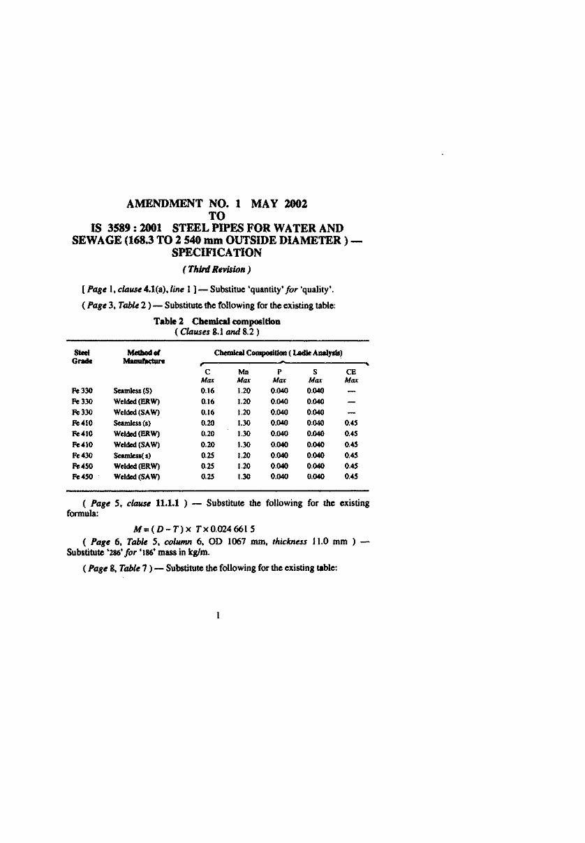
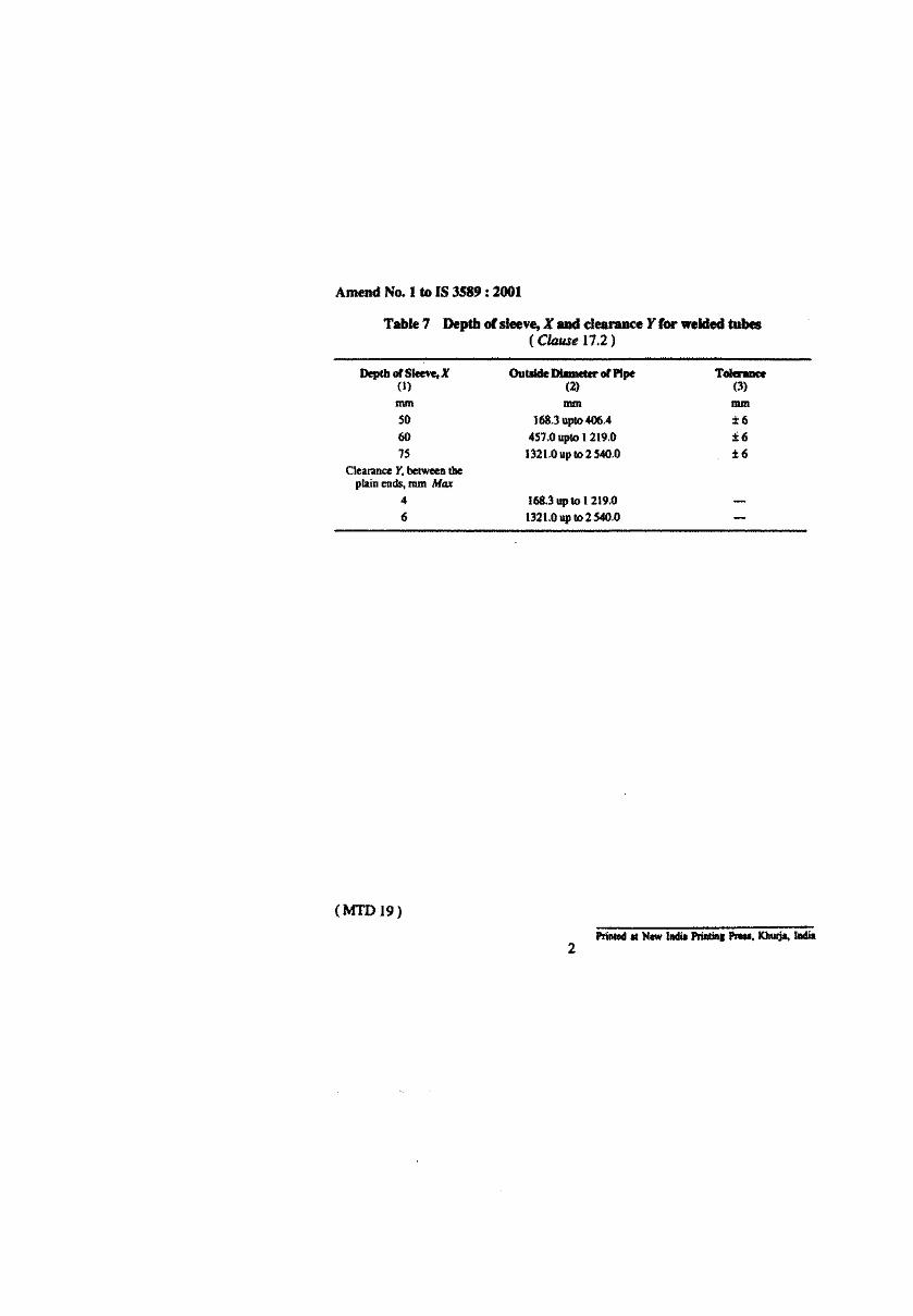


AMENDMENT NO. 4 JUNE 2010 TO
IS 3589 : 2001 STEEL PIPES FOR WATER AND SEWAGE (168.3 TO 2 540 mm OUTSIDE DIAMETER) —
SPECIFICATION
( Third Revision )
(Page 3, Table 2, read with Amendment No. 1) — Add the following Note below the table. ‘NOTE — For each reduction by 0.01 percent Carbon below the specified maximum, an increase of 0.05 percent above the maximum of manganese is permissible up to a maximum of 1.50 for grades Fe410 and 450.’
(MTD 19) Reprography Unit, BIS, New Delhi, India
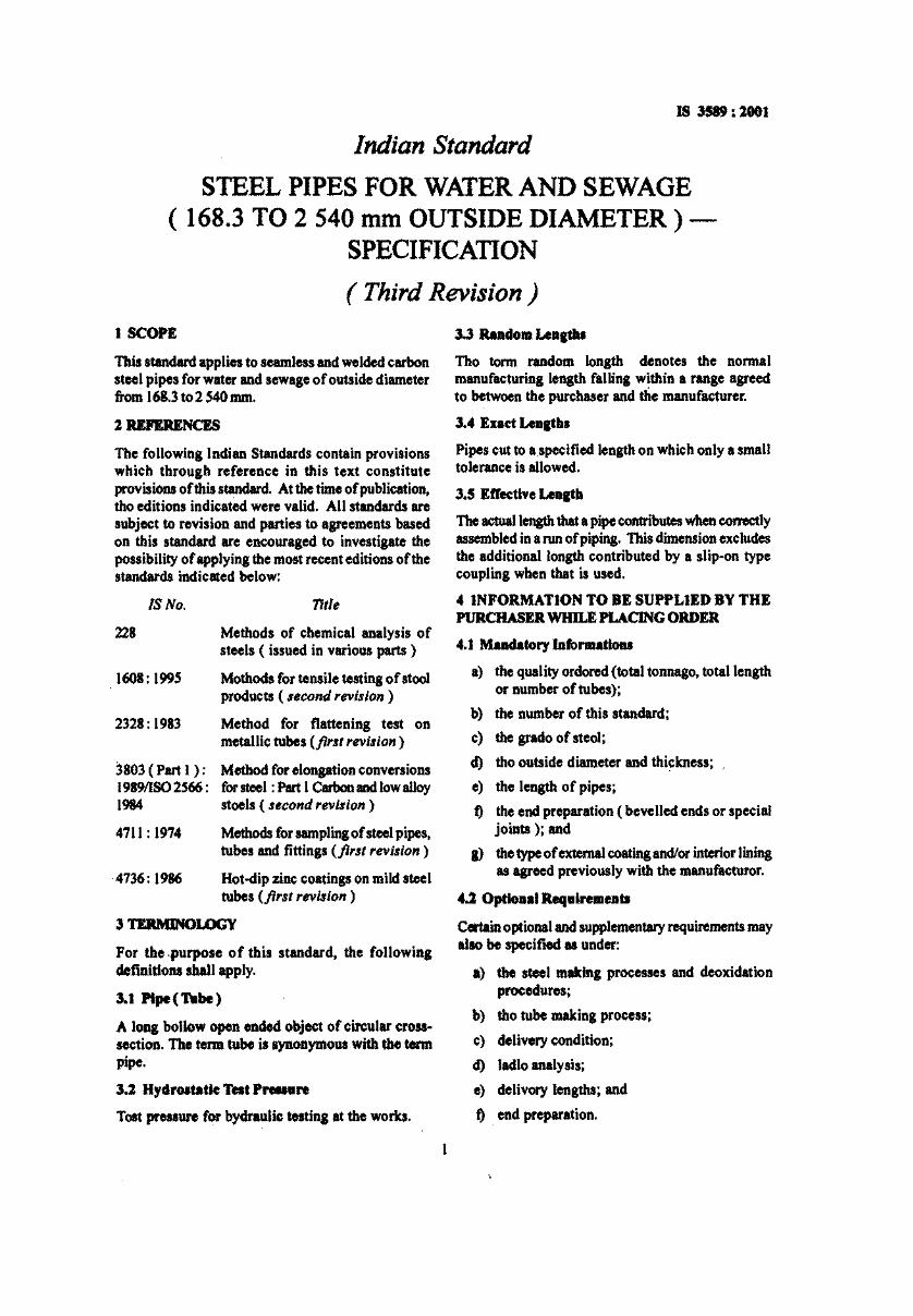
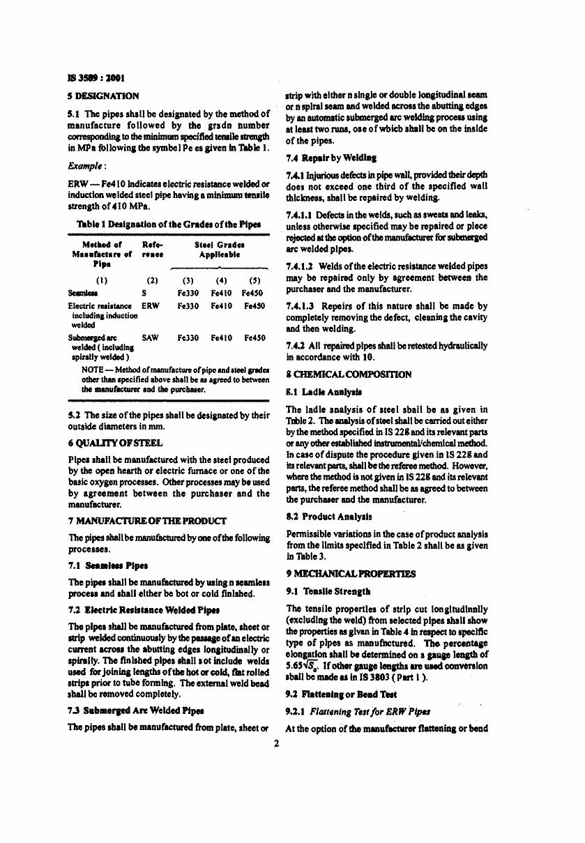
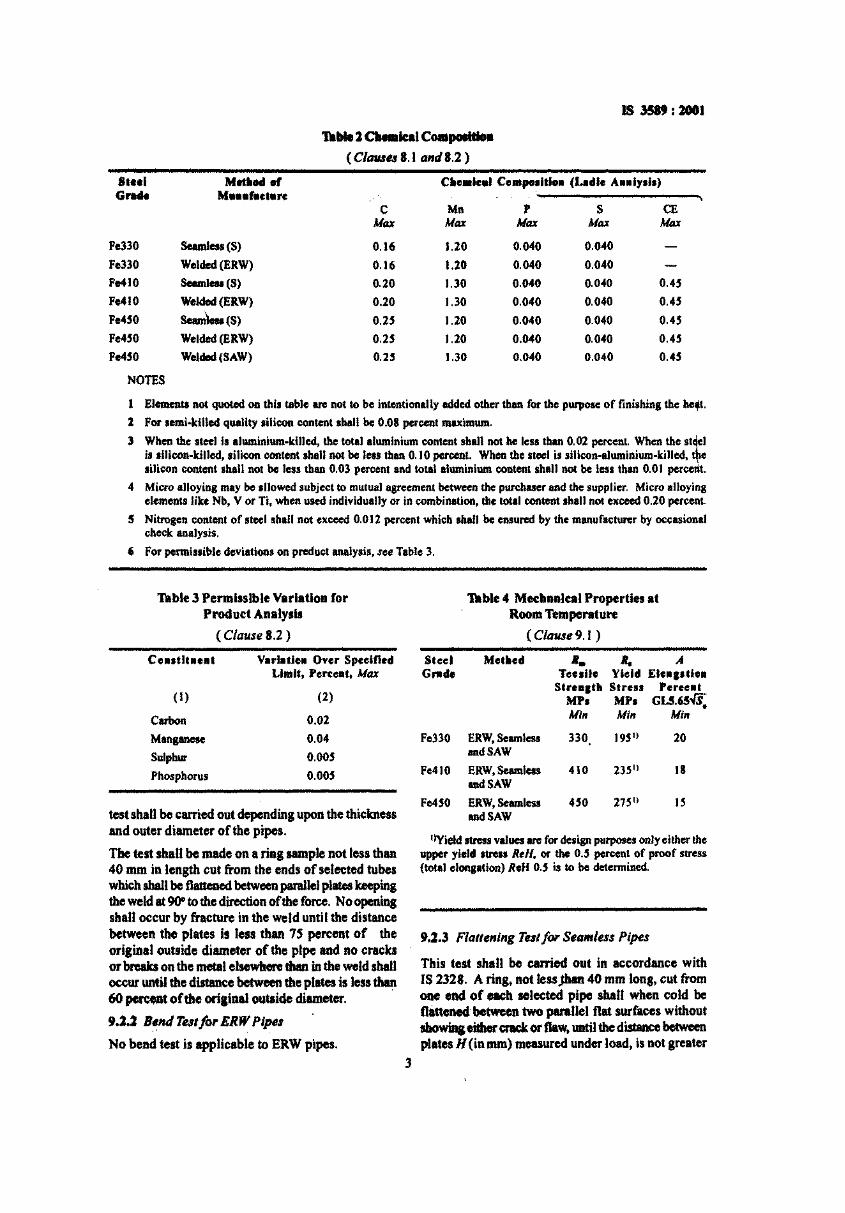
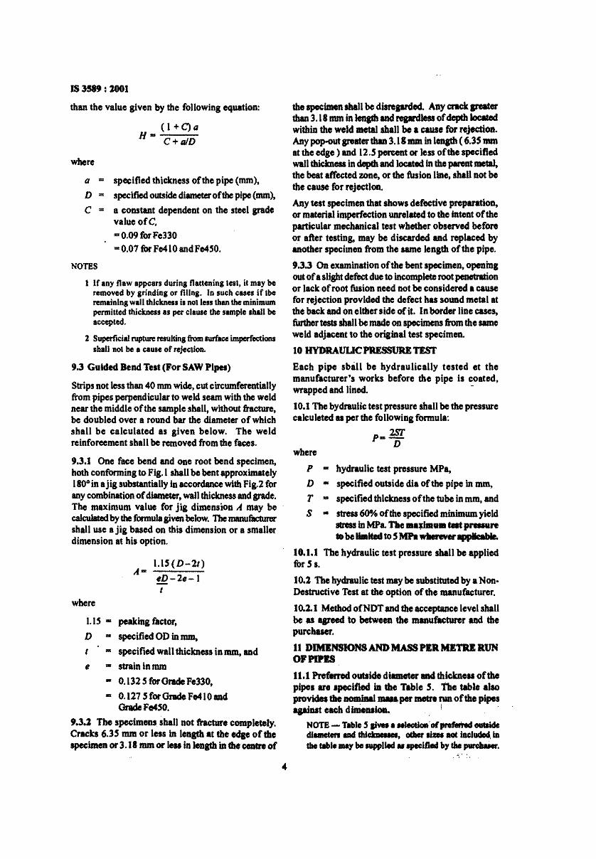
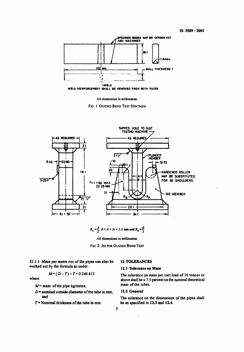
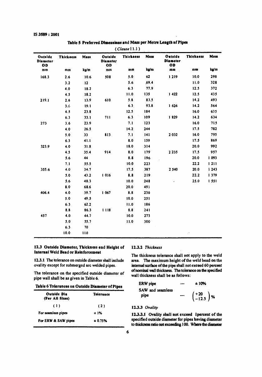
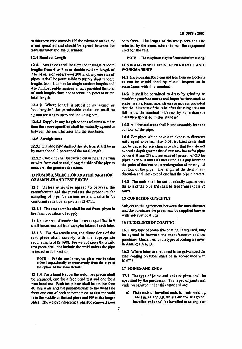
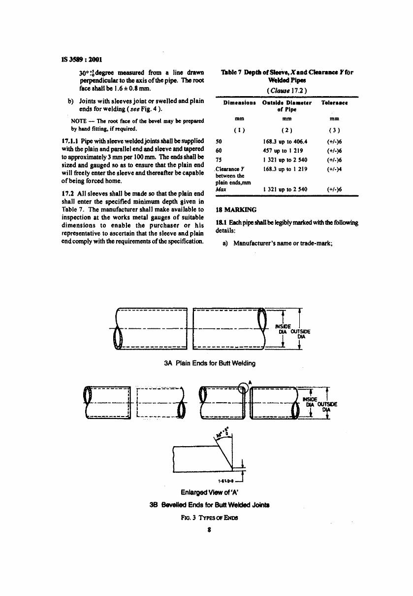
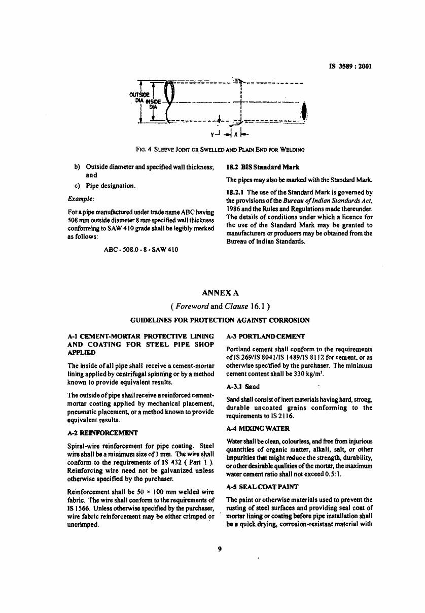
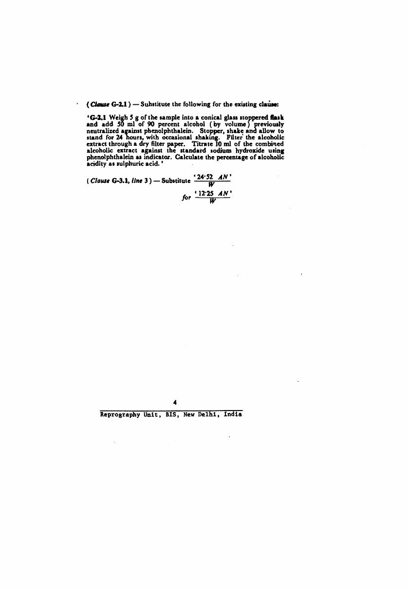

By Authority OfTHE UNITED STATES OF AMERICA
Legally Binding Document
By the Authority Vested By Part 5 of the United States Code § 552(a) and Part 1 of the Code of Regulations § 51 the attached document has been duly INCORPORATED BY REFERENCE and shall be considered legally binding upon all citizens and residents of the United States of America. HEED THIS NOTICE: Criminal penalties may apply for noncompliance.
Official Incorporator:THE EXECUTIVE DIRECTOROFFICE OF THE FEDERAL REGISTERWASHINGTON, D.C.
Document Name:
CFR Section(s):
Standards Body:
e

Specification for Line Pipe
Upstream Segment
API SPECIFICATION 5L FORTY-THIRD EDITION, MARCH 2004 EFFECTIVE DATE: OCTOBER 2004 ERRATA DECEMBER 2004
American Petroleum Institute
Helping You Get The Job Done Right~M
SPECIAL NOTES
API publications necessarily address problems of a general nature. With respect to particular circumstances, local, state, and federal laws and regulations should be reviewed.
API is not undertaking to meet the duties of employers, manufacturers, or suppliers to warn and properly train and equip their employees, and others exposed, concerning health and safety risks and precautions, nor undertaking their obligations under local, state, or federallaws.
Information concerning safety and health risks and proper precautions with respect to particular materials and conditions should be obtained from the employer, the manufacturer or supplier of that material, or the material safety data sheet.
Nothing contained in any API publication is to be construed as granting any right, by impl ication or otherwise, for the manufacture, sale, or use of any method, apparatus, or product covered by letters patent. Neither should anything contained in the publication be construed as insuring anyone against liability for infringement of letters patent.
Generally, API standards are reviewed and revised, reaffirmed, or withdrawn at least every five years. Sometimes a one-time extension of up to two years will be added to this review cycle. This publication will no longer be in effect five years after its publication date as an operative API standard or, where an extension has been granted, upon republication. Status of the publication can be ascertained from the API Standards department telephone (202) 682-8000. A catalog of API publications, programs and services is published annually and updated biannually by API, and available through Global Engineering Documents, 15 Inverness Way East, MIS C303B, Englewood, CO 80112-5776.
This document was produced under API standardization procedures that ensure appropriate notification and participation in the developmental process and is designated as an API standard. Questions concerning the interpretation of the content of this standard or comments and questions concerning the procedures under which this standard was developed should be directed in writing to the Director of the Standards department, American Petroleum Institute, 1220 L Street, N.W., Washington, D.C. 20005. Requests for permission to reproduce or translate all or any part of the material published herein should be addressed to the Director, Business Services.
API standards are published to facilitate the broad availability of proven, sound engineering and operating practices. These standards are not intended to obviate the need for applying sound engineering judgment regarding when and where these standards should be utilized. The formulation and publication of API standards is not intended in any way to inhibit anyone from using any other practices.
Any manufacturer marking equipment or materials in conformance with the marking requirements of an API standard is solely responsible for complying with all the applicable requirements of that standard. API does not represent, warrant, or guarantee that such products do in fact conform to the applicable API standard.
All rights reserved. No part of this work may be reproduced, stored in a retrieval system, or transmitted by any means, electronic, mechanical, photocopying, recording, or otherwise,
wi/hout prior written permission from the publisher. Contact the Publisher, API Publishing Services, 1220 L Street, N. W, Washington, D.C. 20005.
Copyright © 2004 American Petroleum Institute
FOREWORD
API publications may be used by anyone desiring to do so. Every effort has been made by the Institute to assure the accuracy and reliability of the data contained in them; however, the Institute makes no representation, warranty. or guarantee in connection with this publication and hereby expressly disclaims any liability or responsibility for loss or damage resulting from its use or for the violation of any federal, state, or municipal regulation with which this publication may conflict.
Suggested revisions are invited and should be submitted to API, Standards department, 1220 L Street, NW, Washington, DC 20005.
iii

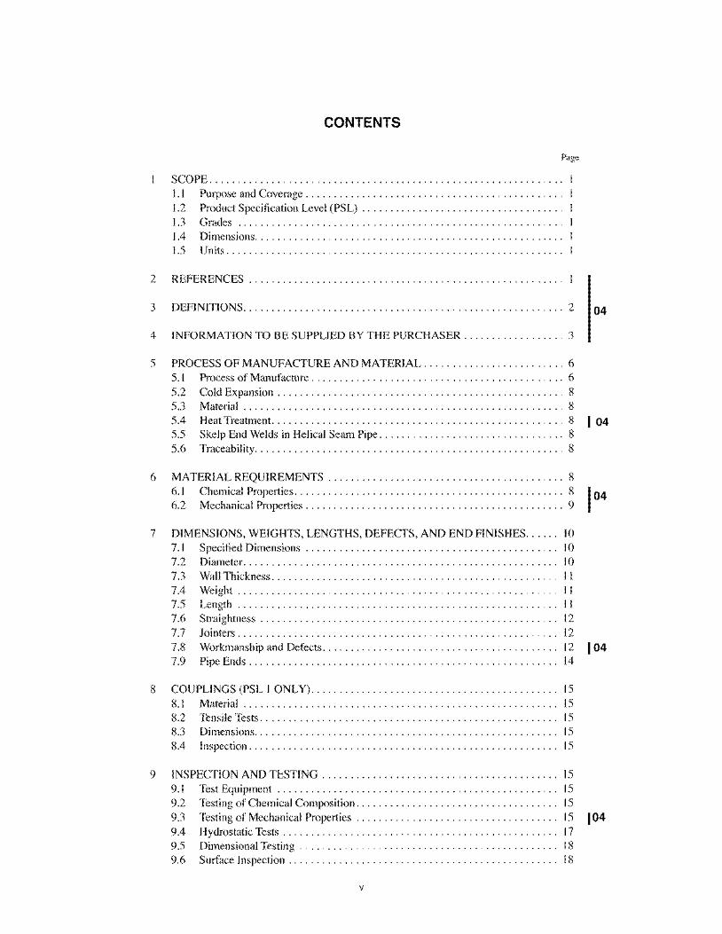
CONTENTS
Page
SCOPE .............................................................. . 1.1 Purpose and Coverage ............................................. . 1.2 Product Specification Level (PSL) ................................... . 1.3 Grades ......................................................... . 1.4 Dimensions ...................................................... . 1.5 Units ........................................................... .
2 REFERENCES ....................................................... .
3 DEFINITIONS ......................................................... 2 04
4 INFORMATION TO BE SUPPLIED BY THE PURCHASER .................. 3
5 PROCESS OF MANUFACTURE AND MATERIAL ......................... 6 5.1 Process of Manufacture ............................................. 6 5.2 Cold Expansion ................................................... 8 5.3 Material. . . . . . . . . . . . . . . . . . . . . . . . . . . . . . . . . . . . . . . . . . . . . . . . . . . . . . . .. 8 5.4 Heat Treatment. ................................................... 8 1 04
6
5.5 Skelp End Welds in Helical Seam Pipe ................................. 8 5.6 Traceability ....................................................... 8
MATERIAL REQUIREMENTS .......................................... 8 6.1 Chemical Properties. . . . . . . . . . . . . . . . . . . . . . . . . . . . . . . . . . . . . . . . . . . . . . .. 8 6.2 Mechanical Properties. . . . . . . . . . . . . . . . . . . . . . . . . . . . . . . . . . . . . . . . . . . . .. 9
7 DIMENSIONS, WEIGHTS, LENGTHS, DEFECTS, AND END FINISHES ..... . 10 7.1 Specified Dimensions ............................................ . 10 7.2 Diameter. ...................................................... . 10 7.3 Wall Thickness .................................................. . II 7.4 Weight ........................................................ . II 7.5 Length ........................................................ . II 7.6 Straightness .................................................... . 12 7.7 Jointers ........................................................ . 12 7.8 Workmanship and Defects ......................................... . 12 7.9 Pipe Ends ...................................................... . 14
8 COUPLINGS (PSL 1 ONLY) ........................................... . 15 8.1 Material ....................................................... . 15 8.2 Tensile Tests .................................................... . 15 8.3 Dimensions ..................................................... . 15 8.4 Inspection ...................................................... . 15
9 INSPECTION AND TESTING ......................................... . 15 9.1 Test Equipment ................................................. . 15 9.2 Testing of Chemical Composition ................................... . 15 9.3 Testing of Mechanical Properties ................................... . 15 9.4 Hydrostatic Tests ................................................ . 17 9.5 Dimensional Testing ............................................. . 18 9.6 Surface Inspection ............................................... . 18
v
104
104
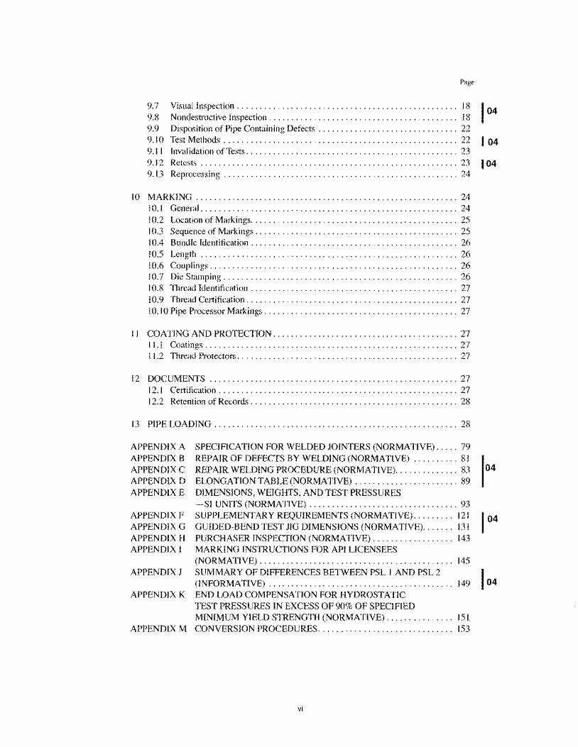
Page
9.7 Visual Inspection . . . . . . . . . . . . . . . . . . . . . . . . . . . . . . . . . . . . . . . . . . . . . . . .. 18 9.8 Nondestructive Inspection .......................................... 18 9.9 Disposition of Pipe Containing Defects ............................... 22 9.10 Test Methods ........................... , ........................ 22 I 04 9.11 Invalidation of Tests ............................................... 23 9.12 Retests ......................................................... 23 104 9.13 Reprocessing .................................................... 24
10 MARKING .......................................................... 24 10.1 General ......................................................... 24 10.2 Location of Markings .............................................. 25 10.3 Sequence of Markings ....... , ..................................... 25 10.4 Bundle Identification ........ , ..................................... 26 10.5 Length ................... , .................. , .................. 26 10.6 Couplings ................. , .................. , .................. 26 10.7 Die Stamping .............. , .................. , .................. 26 10.8 Thread Identification ........ , ..................................... 27 10.9 Thread Certification ......... , ..................................... 27 10. 10 Pipe Processor Markings ..... , ..................................... 27
I I COATING AND PROTECTION ... , ..................................... 27 I 1.1 Coatings ........................................................ 27 t t.2 Thread Protectors. . . . . . . . . . . . . . . . . . . . . . . . . . . . . . . . . . . . . . . . . . . . . . . . . 27
12 DOCUMENTS ....................................................... 27 12.1 Certification ..................................................... 27 12.2 Retention of Records ........ , ..................................... 28
13 PIPE LOADING ................ , ..................................... 28
APPENDIX A SPECIFfCA TION FOR WELDED JOINTERS (NORMATIVE) ..... 79 APPENDIX B REPAIR OF DEFECTS BY WELDING (NORMATIVE) .......... 81 APPENDIX C REPAIR WELDING PROCEDURE (NORMATiVE) .............. 83 APPENDIX D ELONGATION TABLE (NORMATIVE) ....................... 89 APPENDIX E DIMENSIONS, WEIGHTS, AND TEST PRESSURES
-Sf UNITS (NORMATIVE) ..................... , ........... 93 APPENDIX F SUPPLEMENTARY REQUIREMENTS (NORMATIVE) ......... 121 APPENDIX G GUIDED-BEND TEST JIG DIMENSIONS (NORMATIVE) ....... 131 APPENDIX H PURCHASER INSPECTION (NORMATIVE) ............. , .... 143 APPENDIX I MARKING INSTRUCTIONS FOR API LICENSEES
(NORMATIVE) ................... , ....................... 145 APPENDIX J SUMMARY OF DIFFERENCES BETWEEN PSL 1 AND PSL 2
(INFORMATIVE) .................................... , . . .. 149 APPENDIX K END LOAD COMPENSATION FOR HYDROSTATIC
TEST PRESSURES IN EXCESS OF 90% OF SPECIFIED MINIMUM YIELD STRENGTH (NORMATIVE) . . . . . . . . . . . . . .. 151
APPENDIX M CONVERSION PROCEDURES ...... , ....................... 153
vi
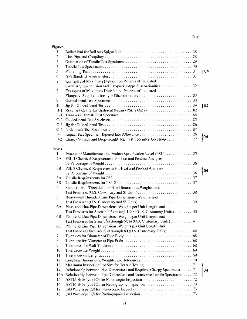
Figures I 2 3 4 5 6 7
8
9 10 B-1 C-I C-2 C-3 C-4 F-I F-2
Tables I 2A
2B
3A 3B
4
5
6A
6B
6C
7 8 9 10 II 12 13 14 14A 15 16 17 18
Page
Belled End for Bell and Spigot Joint ................................... 28 Line Pipe and Couplings ............................................. 28 Orientation of Tensile Test Specimens .................................. 29 Tensile Test Specimens .............................................. 30 Flattening Tests . . . . . . . . . . . . . . . . . . . . . . . . . . . . . . . . . . . . . . . . . . . . . . . . . . . . 3 I API Standard penetrameter ........................................... 31 Examples of Maximum Distribution Patterns of Indicated Circular Slag-inclusion and Gas-pocket-type Discontinuities ................ 32 Examples of Maximum Distribution Patterns of Indicated Elongated Slag-inclusion-type Discontinuities ........................... 33 Guided-bend Test Specimen .......................................... 33 Jig for Guided-bend Test. . . . . . . . . . . . . . . . . . . . . . . . . . . . . . . . . . . . . . . . . . . . . 34 Resultant Cavity for Undercut Repair (PSL 2 Only) ....................... 82 Transverse Tensile Test Specimen ..................................... 85 Guided-bend Test Specimen .......................................... 85 Jig for Guided-bend Test ............................................. 86 Nick-break Test Specimen ........................................... 87 Impact Test Specimen Tapered End Allowance. . . . . . . . . . . . . . . . . . . . . . . . .. 126 Charpy V-notch and Drop-weight Tear Test Specimen Locations ............ 127
Process of Manufacture and Product Specification Level (PSL) .............. 35 PSL I Chemical Requirements for heat and Product Analyses by Percentage of Weight ............................................. 36 PSL 2 Chemical Requirements for Heat and Product Analyses by Percentage of Weight ............................................. 36 Tensile Requirements for PSL I ....................................... 37 Tensile Requirements for PSL 2 ....................................... 37 Standard-wall Threaded line Pipe Dimensions, Weights, and Test Pressures (U.S. Customary and SI Units) ............................ 38 Heavy-wall Threaded Line Pipe Dimensions, Weights, and Test Pressures (U.S. Customary and SI Units) ............................ 39 Plain-end Line Pipe Dimensions, Weights per Unit Length, and Test Pressures for Sizes 0.405 through 1.900 (U.S. Customary Units) ......... 40 Plain-end Line Pipe Dimensions, Weights per Unit Length, and Test Pressures for Sizes 23/8 through 59/16 (U.S. Customary Units) ........... 41 Plain-end Line Pipe Dimensions, Weights per Unit Length, and Test Pressures for Sizes 65/8 through 80 (U.S. Customary Units) ............. 44 Tolemces for Diameter of Pipe Body. . . . . . . . . . . . . . . . . . . . . . . . . . . . . . . . . .. 68 Tolerance for Diameter at Pipe Ends ................................... 68 Tolerances for Wall Thickness . . . . . . . . . . . . . . . . . . . . . . . . . . . . . . . . . . . . . . .. 68 Tolerances for Weight. . . . . . . . . . . . . . . . . . . . . . . . . . . . . . . . . . . . . . . . . . . . . .. 69
Tolerances on Lengths ............................................... 69 Coupling Dimensions, Weights, and Tolerances .......................... 70 Maximum Inspection Lot Size for Tensile Testing ......................... 71 Relationship between Pipe Dimensions and Required Charpy Specimens ...... 71 Relationship between Pipe Dimensions and Transverse Tensile Specimens ..... 72 ASTM Hole-type IQI for F1uorscopic Inspection ......................... 72 ASTM Hole-type IQI for Radiographic Inspection ........................ 73 ISO Wire-type IQI for Fluroscopic Inspection ............................ 73 ISO Wire-type IQI for Radiographic Inspection .......................... 73
vii
104
Page
19 ASTM Wire-type IQI for Fluoroscopic Inspection ........................ 74 20 ASTM Wire-type IQI for Radiographic Inspection ........................ 74 21 Elongated Slag-inclusion-type Discontinuities ........................... 74 22 Circular Slag-inclusion-type and Gas-pocket-type Discontinuities ............ 75 23 Acceptance Limits .................................................. 75 24 Pipe Weld Seam Nondestructive Inspection Methods ...................... 75 25 Pipe Body Nondestructive Inspection Methods-Seamless ................. 76 26 Reference Indicators ................................................ 76 27 Retention of Records. . . . . . . . . . . . . . . . . . . . . . . . . . . . . . . . . . . . . . . . . . . . . . . . 77 C-l Guided-bend Test Jig Dimensions ..................................... 87 D-I Elongation Table (U.S. Customary Units) ............................... 89 D-2 Elongation Table (SI Units) ........................................... 91 E-6A Plain-end Line Pipe Dimensions, Weights per Unit Length,
and Test Pressures for Sizes 0.405 Through 1.900 (Sl Units) ................ 93 E-6B Plain-end Line Pipe Dimensions, Weights per Unit Lenght,
and test Pressures for Sizes 23/8 through 59/16 (SI Units) ................... 94 E-6C Plain-end Line Pipe Dimensions, Weights per Unit Length,
and Test Pressures for Sizes 65/8 through 80 (SI Units) ..................... 97 F-I Minimum Wall Thickness to Obtain Transverse Charpy V-notch
Test Specimens . . . . . . . . . . . . . . . . . . . . . . . . . . . . . . . . . . . . . . . . . . . . . . . . . .. 127 F-2 Dimensions, Weights per Unit Length, and Test Pressures for TFL Pipe. . . . .. 128 F-3 Minimum All-heat Average Absorbed Energy Requirements for
Stress FractorfofO.72 ............................................. 128 G-I Guided-bend Test Jig Dimensions . . . . . . . . . . . . . . . . . . . . . . . . . . . . . . . . . . .. 131
viii
104
Specification for Line Pipe
1 Scope
1.1 PURPOSE AND COVERAGE
The purpose of this specification is to provide standards for pipe suitable for use in conveying gas, water, and oil in both the oil and natural gas industries.
This specification covers seamless and welded steel line pipe. It includes plain-end, threaded-end, and belled-end pipe, as well as through-the-ftowline (TFL) pipe and pipe with ends prepared for use with special couplings.
Although the plain-end line pipe meeting this specification is primarily intended for field makeup by circumferential welding, the manufacturer will not assume responsibility for field welding.
1.2 PRODUCT SPECIFICATION LEVEL (PSL)
This specification establishes requirements for two product specification levels (PSL I and PSL 2). These two PSL designations define different levels of standard technical requirements. PSL 2 has mandatory requirements for carbon equivalent, notch toughness, maximum yield strength, and maximum tensile strength. These and other differences are summarized in Appendix 1.
Requirements that apply to only PSL I or only PSL 2 are so designated. Requirements that are not designated to a specific PSL apply to both PSL I and PSL 2.
The purchaser may add requirements to purchase orders for either PSL I or PSL 2, as provided by the supplementary requirements (Appendix F) and other options (4.2 and 4.3).
1.3 GRADES
The grades (see the note) covered by this specification are the standard Grades A25, A, B, X42, X46, X52, X56, X60, X65, X70 and X80; and any intermediate grades (grades that are higher than X42, intermediate to two sequential standard grades, and agreed upon by the purchaser and manufacturer).
PSL I pipe can be supplied in Grades A25 through X70. PSL 2 pipe can be supplied in Grades B through X80. Class II (CI II) steel is rephosphorized and probably has
better threading properties than Class I (CI l). Because Class II (CI II) has higher phosphorus content than Class I (CI l), it may be somewhat more difficult to bend.
Pipe manufactured as Grade X60 or higher shall not be substituted for pipe ordered as Grade X52 or lower without purchaser approval.
Note: The grade designations are dimensionless. Grades A and B do not include reference to the specified minimum yield strength; however, other grade designations are composed of the letter A or X, followed by the first two digits of the specified minimum yield strength in U.S. Customary units.
1.4 DIMENSIONS
The sizes used herein are dimensionless designations, which are derived from the specified outside diameter as measured in U.S. Customary units, and provide a convenient method of referencing pipe size within the text and tables (but not for order descriptions). Pipe sizes 23/8 and larger are expressed as integers and fractions; pipe sizes smaller than 23/8 are expressed to three decimal places. These sizes replace the "size designation" and the "nominal size designation" used in the previous edition of this specification. Users of this specification who are accustomed to specifying nominal sizes rather than 00 sizes are advised to familiarize themselves with these new size designations used in this specification, especially the usage in Tables 4, 5, and 6A.
PSL I pipe can be supplied in sizes ranging from 0.405 through 80.
PSL 2 pipe can be supplied in sizes ranging from 4'/2 through 80.
Dimensional requirements on threads and thread gages, stipulations on gaging practice, gage specifications and certification, as well as instruments and methods for inspection of threads are given in API Standard 5B and are applicable to threaded products covered by this specification.
1.5 UNITS
U.S. Customary units are used in this specification; SI (metric) units are shown in parentheses in the text and in many tables. The values stated in either U.S. Customary units or SI units are to be regarded separately as standard. The values stated are not necessarily exact equivalents; therefore, each system is to be used independently of the other, without combining values for any specific order item.
See Appendix M for specific information about rounding procedures and conversion factors.
2 References 2.1 This specification includes by reference, either in total or in part, the latest editions of the following API and industry standards:
API RP5A3
Spec 5B
RP5Ll
RP5L3
Thread Compounds for Casing, Tubing, and Line Pipe Specification for Threading, Gauging, and Thread Impection (){ Casing. Tuhing, and Line Pipe Threads Recommended Practice for Railroad Transportation of Line Pipe Recommended Practice for Conducting Drop-Weight Tear Tests on Line Pipe
041
2 API SPECIFICATION 5L
RP5LW
Std 1104
AARI
Section I
Section 2
ASNT3
SNT-TC-IA
ASTM4
A 370
A 751
E4
E8
E29
E 83
E94
E 165
E213
E273
Recommended Practice for Transportation ()l Line Pipe on Barges and Marine Vessels
Welding oj'Pipelines and Related Facilities
General Rules Governing the Loading of Commodities on Open Top Cars
Rules Governing the Loading of Steel Products Including Pipe on Open Top Cars
ASME Boiler and Pressure Vessel Code, Section IX, Welding & Brazing Qual(fications
ASME Code for Pressure Piping B31.8, Gas Transmission and Distrihution Piping Systems
Recommended Practice No. SNT-TC-JA
Methods and Definitions for Mechanical Testing olSteel Products
Test Methods, Practices, and Definitions for Chemical Analysis ()fSteel Products
Practices for Force Verification ()f Testing Machines
Test Methods for Tension Testing of Metallic Materials
Praclice for Using Significant Digits in Test Data to Determine Conformance with Spec!fications
Practice for Verification and Classification of Extenso meters
Standard Guide for Radiographic Examination
Standard Test Methodfor Liquid Penetrant Examination
Standard Practice for Ultrasonic Examination of Metal Pipe and Tubing
Standard Practice for Ultrasonic Examination ()f the Welded Zone (){ Welded Pipe (lnd Tubing
IAmerican Association of Railroads, Operations and Maintenance Department, Mechanical Division, 50 F Street, N.W. Washington, D.C. 20001. 2ASME International, 3 Park Avenue, New York, New York 10016-5990. 3American Society for Nondestructive Testing, Inc., 1711 Arlington Lane, P.O. Box 28518, Columbus, Ohio 43228-0518. 4 American Society for Testing and Materials, 100 Barr Harbor Drive, West Conshohocken, Pennsylvania 19428-2959.
E309
E570
E709
Standard Practice for Eddy-Current Examination of Steel Tubular Products Using Magnetic Saturation Standard Practice for Flux Leakage Examination of Ferromagnetic Steel Tubular Products Standard Guide for Magnetic Particle Examination
2.2 Requirements of standards included by reference in this specification are essential to the safety and interchangeability of the equipment produced.
2.3 Standards referenced in this specification may be replaced by other international or national standards that can be shown to meet the requirements of the referenced standard. Manufacturers who use other standards in lieu of standards referenced herein are responsible for documenting the equivalency of the standards.
3 Definitions For the purposes of this specification, the following defini
tions apply:
3.1 calibration: The adjustment of instruments to a known basic reference, often traceable to the National rnstitute of Standards and Technology or an equivalent organization.
3.2 carload: The quantity of pipe loaded on a rail car for shipment from the pipe-making facilities.
3.3 cold expanded pipe: Pipe that, while at ambient mill temperature, has received a permanent increase in outside diameter or circumference of at least 0.3%, throughout its length, by internal hydrostatic pressure in closed dies or by an internal expanding mechanical device.
3.4 defect: An imperfection of sufficient magnitude to warrant rejection of the product based on the stipulations of this specification.
3.5 heat: The metal produced by a single cycle of a batch melting process.
3.6 heat analysis: The chemical analysis representative of a heat as reported by the metal producer.
3.7 imperfection: A discontinuity or irregularity in the product detected by methods outlined in this specification.
3.8 inspection lot: A definite quantity of product manufactured under conditions that are considered uniform for the attribute to be inspected.
3.9 manufacturer: A firm, company, or corporation responsible for marking the product to warrant that it conforms to this specification. The manufacturer may be, as applicable, a pipe mill or processor; a maker of couplings; or
041
SPECIFICATION FOR LINE PIPE 3
a threader. The manufacturer is responsible for compliance
with all of the applicable provisions of this specification.
3.10 may: Used as a verb to indicate that a provision is optional.
3.11 pipe mill: A firm, company, or corporation that oper
ates pipe-making facilities.
3.12 processor: A firm, company, or corporation that
operates facilities capable of heat treating pipe made by a
pipe mill.
3.13 product analysis: A chemical analysis of the pipe,
plate, or skelp.
Manufacturing Condition
a. Seamless:
3.14 PSL: Abbreviation for product specification level.
3.15 shall: Used to indicate that a provision is mandatory.
3.16 should: Used to indicate that a provision is not man
datory but is recommended as good practice.
3.17 special processes: Final operations performed
during pipe manufacturing that affect attribute compliance required in this specification (except chemistry and dimen
sions). The applicable special processes are as follows:
Special Processes
I. As-rolled (nonexpanded) Final reheating and hot sizing or stretch reduction. Cold finishing, if appl ied, and repair welding. Nondestructive inspection
2. As-rolled (expanded) 3. Heat treated
b. Welded without filler metal: I. As-rolled (nonexpanded)
Cold expansion, nondestructive inspection, and repair welding. Heat treatment, nondestructive inspection, and repair welding.
Seam welding, nondestructive inspection and sizing. If applicable, seam heat treatment and repail welding.
104
2. As-rolled (cold expanded) Seam welding, cold expansion, and nondestructive inspection. If applicable, seam heat treatment, I 04 and repair welding.
3. Heat treated Seam welding, full body heat treatment, and nondestructive inspection. If appl icable, repair welding.
c. Welded with filler metal: I. As-rolled (nonexpanded) 2. As-rolled (expanded)
Pipe forming, seam welding, nondestructive inspection, and repair welding. Seam welding, expansion, nondestructive inspection, and repair welding.
3. Heat treated Seam welding, nondestructive inspection, repair welding, and full body heat treatment.
3.18 standardization: The adjustment of a nondestruc
tive inspection instrument to an arbitrary reference value.
3.19 undercut: A groove melted into the parent metal
adjacent to the weld toe and left unfilled by the deposited
weld metal.
Information
Certificat e of compliance, general Certificate of compliance, with test results
Cold expanded or nonexpanded pipe High carbon equivalent pipe
4 Information to be Supplied by the Purchaser (See Note 1)
4.1 In placing orders for line pipe to be manuhlctured in accordance with API Spec 5L, the purchaser should specify
the following on the purchase order:
4.2 The purchaser should also state on the purchase order his requirements concerning the following stipulations, which
are optional with the purchaser:
Reference
Paragraph 12. I Paragraph 12.1 and S R 15
Paragraph 5.2 Paragraph 6.1.3.2
Optional fracture toughness: test type, temperature, and Charpy energy value Acceptance and maximum percent of jointers
Paragraph 6.2.5 and SR5, SR6, and SRI9 Paragraph 7.7
Jointers for threaded pipe Thread compound Reduced negative tolerance for wall thickness Power-tight makeup Specific edition of Spec 5L for pipe and couplings Alternative bevel or end preparation, plain-end pipe
Paragraph 7.7 Paragraph 7.9.2 Tables 9 and 10 Paragraph 7.9.2 Paragraph 7.9.2 Paragraph 7.9.3
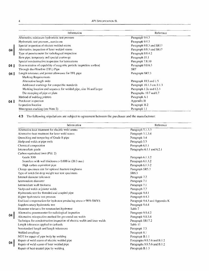
04 I
041
4
Infonnation
Alternative minimum hydrostatic test pressure
Hydrostatic test pressure" maximum Special inspection of electric welded seams Alternative inspection of laser welded seams Type of penetrameter for radiological inspection
Bare pipe; temporary and special coatomgs Special nondestmctive inspection for laminations
API SPECIFICATION 5L
Demonstration of capability of magnetic particle inspection method Through-the-Flowl ine (TFL) Pipe
Length tolerance and jointer allowance for TFL pipe Marking Requirements Alternative length units Additional markings for compatible standards
Marking location and sequence for welded pipe, size 16 and larger Die stamping of pipe or plate
Method of welding jointers
04 I Purchaser inspection Inspection location Monogram marking (see Note 2)
Paragraph 9.4.3
Paragraph 9.4.3
Reference
Paragraph 9.S.3 and SR 17 Paragraph 9.S.3 and SR 17 Paragraph 9,S.4.2
Paragraph 11.1 Paragraph 7.S.1 0
Paragraph 9.S.6.3 SR7
Paragraph SR7.3
Paragraph 10.5 and 1.5 Paragraph 10.1.3 and 1.1.3
Paragraph 1.2c and 1.2.3 Paragraphs 10.7 and 1.7 Paragraph A. I
Appendix H Paragraph H.2 Paragraph 1.1
4.3 The following stipulations are subject to agreement between the purchaser and the manufacturer:
Information
Alternative heat treatment for electric weld seams Alternative heat treatment for laser weld seams
Quenching and tempering of Grade 8 pipe Skelp end welds at pipe ends Chemical composition Intermediate grade Carbon equivalent limit (PSL 2)
Grade XSO Seamless with wall thickness> 0.800 in (20.3 mm) High carbon equivalent pipe
Charpy specimen size for optional fracture toughness Type of notch for drop weight tear test specimens Internal diameter tolerance
Intermediate diameter
Intermediate wall thickness Skelp end welds at jointer welds Hydrostatic test for threaded and coupled pipe
Higher hydrostatic test pressure End load compensation for hydrotest producing stress> 90% SMYS
Supplementary hydrostatic test Diameter tolerance for nonstandard hydrotest Alternative penetrameter for radiological inspection
Alternative reinspection method for gas-metal-arc welds Technique for nondestructive inspection of electric welds and laser welds Length tolerances applied to carloads Nonstandard length and length tolerances
Welded couplings NDT for repair of pipe body by welding Repair of weld seams of electric welded pipe Repair of weld seams of laser welded pipe
Repair of heat-treated pipe by welding
Paragraph 5.1.3.3 Paragraph 5.1.3.4
Paragraph 5.4 Paragraph 5.5
Reference
Paragraph 6.1. l Paragraphs 6.1.1 and 6.2.1
Paragraph 6.1.3.2 Paragraph 6.1.3.2 Paragraph 6.1.3.2
Paragraph SR5.3 SR6.3 Paragraph 7.2
Paragraph 7. I
Paragraph 7.1 Paragraph 7.7 Paragraph 9.4.1 Paragraph 9.4.3
Paragraph 9.4.3 and Appendix K
Paragraph 9.4.4 Table 7 Paragraph 9.8.4.2
Paragraph 9.8.5.4 Paragraph SR17.2 Table II Paragraph 7.5
Paragraph S.I Paragraph B.I.I Paragraphs 9.S.5.6 and 8.1.2 Paragraphs 9.S.5.6 and 8.1.2
Paragraph B.l.3
Information
Reprocessing by heat-treatment
Disposition of product rejected by purchaser Marking requirements
Marking of couplings without die stamping
SPECIFICATION FOR liNE PIPE
Marking on interior instead of exterior (welded pipe < size 16, and seamless pipe) Color code marking for grade Nonstandard units of length Location for length markings
Use of cold die stamping
Note:
Reference
Paragraphs 9.13 and SR5.5
Paragraph HA
Paragraphs 10.1.2 and 1.1.2 Paragraphs I 0.2b and 1.2.2 Paragraphs 10.3.5 and 1.3.5; SR3
Paragraphs 10.5 and 1.5 Paragraphs I 0.5a and 1.5a
Paragraphs 10.7 and 1.7
5
1. Nothing in this specification should be interpreted as indicating a preference by the committee for any material or process or as indicating equality between the various materials or processes. In the selection of materials and processes, the purchaser has to be guided by experience and by the service for which the pipe is intended.
2. Users of this specification should note that there is no longer a requirement for marking a product with the API monogram. The American Petroleum Institute continues to I icense use of the monogram on products covered by this specification, but it is administered by the staff of the Institute separately from the specification. The policy describing use of the monogram is contained in Appendix I. No other use of the monogram is permitted. Licensees mark products in accordance with Appendix I or Section 10, and nonlicensees mark products in accordance with Section 10.
104
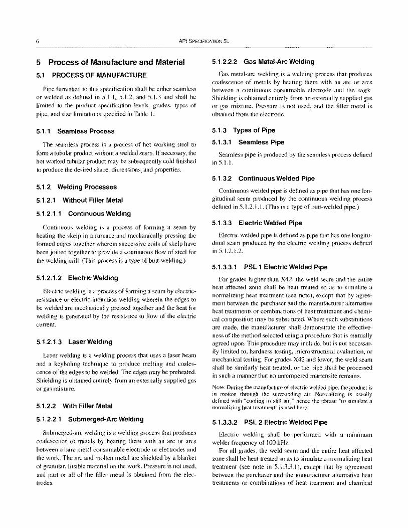
6 API SPECIFICATION 5L
5 Process of Manufacture and Material
5.1 PROCESS OF MANUFACTURE
Pipe furnished to this specification shall be either seamless or welded as defined in 5.1.1, 5.1.2, and 5.1.3 and shall be limited to the product specification levels, grades, types of pipe, and size limitations specified in Table I.
5.1.1 Seamless Process
The seamless process is a process of hot working steel to form a tubular product without a welded seam. If necessary, the hot worked tubular product may be subsequently cold finished to produce the desired shape, dimensions, and properties.
5.1.2 Welding Processes
5.1.2.1 Without Filler Metal
5.1.2.1.1 Continuous Welding
Continuous welding is a process of forming a seam by heating the skelp in a furnace and mechanically pressing the formed edges together wherein successive coils of skelp have been joined together to provide a continuous flow of steel for the welding mill. (This process is a type of butt-welding.)
5.1.2.1.2 Electric Welding
Electric welding is a process offorming a seam by electricresistance or electric-induction welding wherein the edges to be welded are mechanically pressed together and the heat for welding is generated by the resistance to flow of the electric current.
5.1.2.1.3 Laser Welding
Laser welding is a welding process that uses a laser beam and a keyholing technique to produce melting and coalescence of the edges to be welded. The edges may be preheated. Shielding is obtained entirely from an externally supplied gas or gas mixture.
5.1.2.2 With Filler Metal
5.1.2.2.1 Submerged-Arc Welding
Submerged-arc welding is a welding process that produces coalescence of metals by heating them with an arc or arcs between a bare metal consumable electrode or electrodes and the work. The arc and molten metal are shielded by a blanket of granular, fusible material on the work. Pressure is not used, and part or all of the filler metal is obtained from the electrodes.
5.1.2.2.2 Gas Metal-Arc Welding
Gas metal-arc welding is a welding process that produces coalescence of metals by heating them with an arc or arcs between a continuous consumable electrode and the work. Shielding is obtained entirely from an externally supplied gas or gas mixture. Pressure is not used, and the filler metal is obtained from the electrode.
5.1.3 Types of Pipe
5.1.3.1 Seamless Pipe
Seamless pipe is produced by the seamless process defined in 5.1.1.
5.1.3.2 Continuous Welded Pipe
Continuous welded pipe is defined as pipe that has one longitudinal seam produced by the continuous welding process defined in 5.1.2.1.1. (This is a type of butt-welded pipe.)
5.1.3.3 Electric Welded Pipe
Electric welded pipe is defined as pipe that has one longitudinal seam produced by the electric welding process defined in 5.1.2.1.2.
5.1.3.3.1 PSL 1 Electric Welded Pipe
For grades higher than X42, the weld seam and the entire heat affected zone shall be heat treated so as to simulate a normalizing heat treatment (see note), except that by agreement between the purchaser and the manufacturer alternative heat treatments or combinations of heat treatment and chemical composition may be substituted. Where such substitutions are made, the manufacturer shall demonstrate the effectiveness of the method selected using a procedure that is mutually agreed upon. This procedure may include, but is not necessarily limited to, hardness testing, microstructural evaluation, or mechanical testing. For grades X42 and lower, the weld seam shall be similarly heat treated, or the pipe shall be processed in such a manner that no untempered martensite remains.
Note: During the manufacture of electric welded pipe, the product is in motion through the sUITOllllding air. Normalizing is usually defined with "cooling in still air;" hence the phrase "to simulate a normalizing heat treatment" is used here.
5.1.3.3.2 PSL 2 Electric Welded Pipe
Electric welding shall be perfonned with a minimum welder frequency of 100 kHz.
For all grades, the weld seam and the entire heat affected zone shall be heat treated so as to simulate a normalizing heat treatment (see note in 5.1.3.3.1), except that by agreement between the purchaser and the manufacturer alternative heat treatments or combinations of heat treatment and chemical
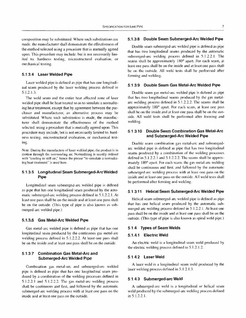
SPECIFICATION FOR LINE PIPE 7
composition may be substituted. Where such substitutions are made, the manufacturer shall demonstrate the effectiveness of the method selected using a procedure that is mutually agreed upon. This procedure may include, but is not necessarily limited to, hardness testing, microstructural evaluation, or mechanical testing.
5.1.3.4 Laser Welded Pipe
Laser welded pipe is defined as pipe that has one longitudinal seam produced by the laser welding process defined in 5.1.2.1.3.
The weld seam and the entire heat affected zone of laser welded pipe shall be heat treated so as to simulate a normalizing heat treatment, except that by agreement between the purchaser and manufacturer, an altemative process may be substituted. Where such substitution is made, the manufacturer shall demonstrate the effectiveness of the method selected, using a procedure that is mutually agreed upon. This procedure may include, but is not necessarily limited to, hardness testing, microstructural evaluation, or mechanical testing.
Note: During the manufacture of laser welded pipe, the product is in motion through the surrounding air. Normalizing is usually defined with "cooling in still air;" hence the phrase "to simulate a normalizing heat treatment" is used here.
5.1.3.5 Longitudinal Seam Submerged-Arc Welded Pipe
Longitudinal seam submerged-arc welded pipe is defined as pipe that has one longitudinal seam produced by the automatic submerged-arc welding process defined in 5.1.2.2.1. At least one pass shall be on the inside and at least one pass shall be on the outside. (This type of pipe is also known as submerged-arc welded pipe.)
5.1.3.6 Gas Metal-Arc Welded Pipe
Gas metal-arc welded pipe is defined as pipe that has one longitudinal seam produced by the continuous gas metal-arc welding process defined in 5.1.2.2.2. At least one pass shall be on the inside and at least one pass shall be on the outside.
5.1.3.7 Combination Gas Metal-Arc and Submerged-Arc Welded Pipe
Combination gas metal-arc and submerged-arc welded pipe is defined as pipe that has one longitudinal seam produced by a combination of the welding processes defined in 5.1.2.2.1 and 5.1.2.2.2. The gas metal-arc welding process shall be continuous and first, and followed by the automatic submerged-arc welding process with at least one pass on the inside and at least one pass on the outside.
5.1.3.8 Double Seam Submerged-Arc Welded Pipe
Double seam submerged-arc welded pipe is defined as pipe that has two longitudinal seams produced by the automatic submerged-arc welding process defined in 5.1.2.2.1. The seams shall be approximately 1800 apart. For each seam, at least one pass shall be on the inside and at least one pass shall be on the outside. All weld tests shall be performed after forming and welding.
5.1.3.9 Double Seam Gas Metal-Arc Welded Pipe
Double seam gas metal-arc welded pipe is defined as pipe that has two longitudinal seams produced by the gas metalarc welding process defined in 5.1.2.2.2. The seams shall be approximately 1800 apart. For each seam, at least one pass shall be on the inside and at least one pass shall be on the outside. All weld tests shall be performed after forming and welding.
5.1.3.10 Double Seam Combination Gas Metal-Arc and Submerged-Arc Welded Pipe
Double seam combination gas metal-arc and submergedarc welded pipe is defined as pipe that has two longitudinal seams produced by a combination of the welding processes defined in 5.1.2.2.1 and 5.1.2.2.2. The seams shall be approximately 1800 apart. For each seam, the gas metal-arc welding shall be continuous and first, and followed by the automatic submerged-arc welding process with at least one pass on the inside and at least one pass on the outside. All weld tests shall be performed after forming and welding.
5.1.3.11 Helical Seam Submerged-Arc Welded Pipe
Helical seam submerged-arc welded pipe is defined as pipe that has one helical seam produced by the automatic submerged-arc welding process defined in 5.1.2.2.1. At least one pass shall be on the inside and at least one pass shall be on the outside. (This type of pipe is also known as spiral weld pipe.)
5.1.4 Types of Seam Welds
5.1.4.1 Electric Weld
An electric weld is a longitudinal seam weld produced by the electric welding process defined in 5.1.2.1.2.
5.1.4.2 Laser Weld
A laser weld is a longitudinal seam weld produced by the laser welding process defined in 5.1.2.1.3.
5.1.4.3 Submerged-arc Weld
A submerged-arc weld is a longitudinal or helical seam weld produced by the submerged-arc welding process defined in 5.1.2.2.1.

8 API SPECIFICATION 5L
5.1.4.4 Gas Metal-arc Weld
A gas metal-arc weld is a longitudinal seam weld produced in whole or in part by the continuous gas metal-arc welding process defined in 5.1.2.2.2.
5.1.4.5 Skelp End Weld
A skelp end weld is a seam weld that joins plate or skelp ends together in helical seam pipe.
5.1.4.6 Jointer Weld
A jointer weld is a circumferential seam weld that joins two pieces of pipe together.
5.1.4.7 Tack Weld
A tack weld is a seam weld used to align the abutting edges until the final seam welds are produced. Tack welds shall be made by the following: (a) manual or semi-automatic submerged-arc welding, (b) electric welding, (c) gas metal-arc welding, (d) flux cored arc welding, or (e) shielded metal-arc welding using low hydrogen electrodes. Tack welds shall be removed by machining or remelting during subsequent welding of the seam.
5.2 COLD EXPANSION
Pipe furnished to this specification, except continuous welded, shall be either nonexpanded or cold expanded (see 3.3) at the option of the manufacturer, unless otherwise specified on the purchase order. Suitable provision shall be incorporated to protect the weld from contact with the internal expanding mechanical device during mechanical expansion.
5.3 MATERIAL
5.3.1 Plate and Skelp for Helical Seam Pipe
The width of plate or skelp used to manufacture helical seam pipe shall not be less than 0.8 or more than 3.0 times the outside diameter of the pipe.
5.3.2 Repairs by Welding of Plate or Skelp (PSL 2 Only)
The plate or skelp used for PSL 2 pipe shall not contain any repair welds.
5.4 HEAT TREATMENT
The heat treating process shall be performed in accordance with a documented procedure. Pipe furnished to this specification may be as-rolled, normalized, normalized and
tempered, subcritically stress relieved, or subcritically age hardened; and X Grades may be quenched and tempered. Grade B pipe that is quenched and tempered shall be seamless and shall be by agreement between the purchaser and the manufacturer. See Section 10 for applicable marking requiremments.
5.5 SKELP END WELDS IN HELICAL SEAM PIPE
Junctions of skelp end welds and helical seam welds in finished pipe shall be permitted only at distances greater than 12 in. (305 mm) from the pipe ends. By agreement between the purchaser and the manufacturer, skelp end welds shall be permitted at the pipe ends, provided there is a circumferential separation of at least 6 in. (152 mm) between the skelp end weld and the helical seam weld at the applicable pipe ends. Skelp end welds in finished pipe shall be properly prepared for welding and shall be made by automatic submerged-arc welding, automatic gas metal-arc welding, or a combination of both processes.
5.6 TRACEABILITY
5.6.1 PSL 1 Traceability Requirements
The manufacturer shall establish and follow procedures for maintaining heat and/or lot identity until all required heat and/or lot tests are periormed and conformance with specification requirements is shown.
5.6.2 PSL 2 Heat and Lot Traceability Requirements
The manufacturer shall comply with SR 15.2.
6 Material Requirements 6.1 CHEMICAL PROPERTIES
6.1.1 Chemical Composition
The composition of steel used for the manufacture of pipe furnished to this specification shall conform to the chemical requirements given in Table 2A (for PSL I) or Table 2B (for PSL 2). The composition of intermediate grades (higher than X42) shall conform to the chemical requirements of the next higher standard grade. For Grades X42 and higher, by agreement between the purchaser and the manufacturer, elements other those listed in Tables 2A and 2B (which include columbium [niobium], vanadium, and titanium via the notes to the tables) may be used; however, care should be exercised in determining the alloying content for any given size and wall thickness of pipe, because the addition of such otherwise desirable elements may affect the weldability of the pipe.
04
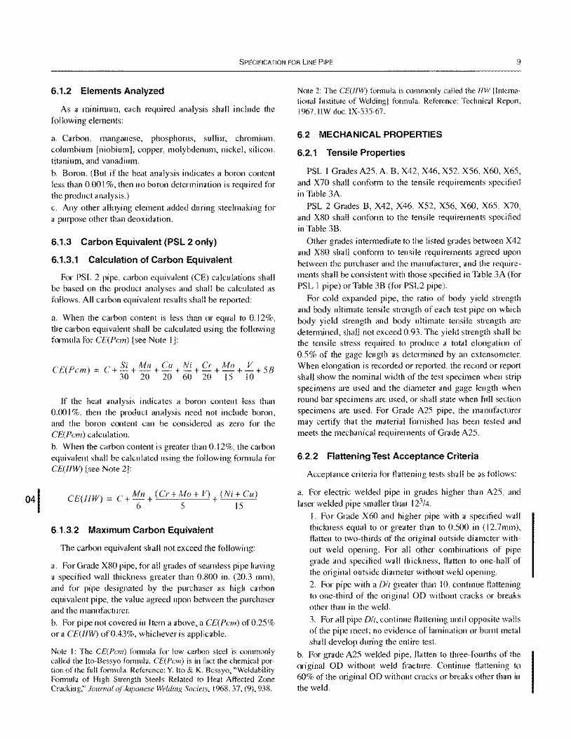
SPECIFICATION FOR LINE PIPE 9
6.1.2 Elements Analyzed
As a minimum, each required analysis shall include the following elements:
a. Carbon, manganese, phosphorus, sulfur, chromium, columbium [niobium], copper, molybdenum, nickel, silicon, titanium, and vanadium.
b. Boron. (But if the heat analysis indicates a boron content less than 0.00 I %, then no boron determination is required for the product analysis.)
c. Any other alloying element added during steelmaking for a purpose other than deoxidation.
6.1.3 Carbon Equivalent (PSL 2 only)
6.1.3.1 Calculation of Carbon Equivalent
For PSL 2 pipe, carbon equivalent (CE) calculations shall be based on the product analyses and shall be calculated as follows. All carbon equivalent results shall be reported:
a. When the carbon content is less than or equal to 0.12%, the carbon equivalent shall be calculated using the following formula for CE(Pcm) [see Note I]:
C+Si + Mn Cu Ni Cr Mo V 58 CE(Pcm) = - -+-+-+-+-+-+ 30 20 20 60 20 15 10
If the heat analysis indicates a boron content less than 0.00 I %, then the product analysis need not include boron, and the boron content can be considered as zero for the CE(Pcm) calculation. b. When the carbon content is greater than 0.12%, the carbon equivalent shall be calculated using the following formula for CE(lIW) [see Note 2]:
CE(lIW) C+Mn+(Cr+Mo+ V)+(Ni+Cu) 6 5 15
6.1.3.2 Maximum Carbon Equivalent
The carbon equivalent shall not exceed the following:
a. For Grade X80 pipe, for all grades of seamless pipe having a specified wall thickness greater than 0.800 in. (20.3 mm), and for pipe designated by the purchaser as high carbon equivalent pipe, the value agreed upon between the purchaser and the manufacturer. b. For pipe not covered in Item a above, a CE(Pcm) of 0.25% or a CE(IHV) of 0.43%, whichever is applicable.
Note \: The CE(Pcm) formula for low carbon steel is commonly called the Ito-Bessyo formula. CE(Pcm) is in fact the chemical portion of the full formula. Reference: Y. [to & K. Bessyo, "Weldability Formula of High Strength Steels Related to Heat Affected Zone Cracking," Journal rJj'Japanese Welding Society, 1968,37, (9), 938.
Note 2: The CE(/JW) formula is commonly called the IIW IInternational Institute of Welding I formula. Reference: Technical Report, 1967, IlW doc. IX-535-67.
6.2 MECHANICAL PROPERTIES
6.2.1 Tensile Properties
PSL I Grades A25, A, B, X42, X46, X52, X56, X60, X65, and X70 shall conform to the tensile requirements specified in Table 3A.
PSL 2 Grades B, X42, X46, X52, X56, X60, X65, X70, and X80 shall conform to the tensile requirements specified in Table 3B.
Other grades intermediate to the listed grades between X42 and X80 shall conform to tensile requirements agreed upon between the purchaser and the manufacturer, and the requirements shall be consistent with those specified in Table 3A (for PSL 1 pipe) or Table 3B (for PSL2 pipe).
For cold expanded pipe, the ratio of body yield strength and body ultimate tensile strength of each test pipe on which body yield strength and body ultimate tensile strength are determined, shall not exceed 0.93. The yield strength shall be the tensile stress required to produce a total elongation of 0.5% of the gage length as determined by an extensometer. When elongation is recorded or reported, the record or report shall show the nominal width of the test specimen when strip specimens are used and the diameter and gage length when round bar specimens are used, or shall state when full section specimens are used. For Grade A25 pipe, the manuhlcturer may certify that the material furnished has been tested and meets the mechanical requirements of Grade A25.
6.2.2 Flattening Test Acceptance Criteria
Acceptance criteria for flattening tests shall be as follows:
a. For electric welded pipe in grades higher than A25, and laser welded pipe smaller than 123/4.
l. For Grade X60 and higher pipe with a specified wall thickness equal to or greater than to 0.500 in (12.7mm), flatten to two-thirds of the original outside diameter without weld opening. For all other combinations of pipe grade and specified wall thickness, flatten to one-half of the original outside diameter without weld opening.
2. For pipe with a Dit greater than 10, continue flattening to one-third of the original OD without cracks or breaks other than in the weld.
3. For all pipe Dlt, continue flattening until opposite walls of the pipe meet; no evidence of lamination or burnt metal shall develop during the entire test.
b. For grade A25 welded pipe, flatten to three-fourths of the original OD without weld fracture. Continue flattening to 60% of the original 00 without cracks or breaks other than in the weld.
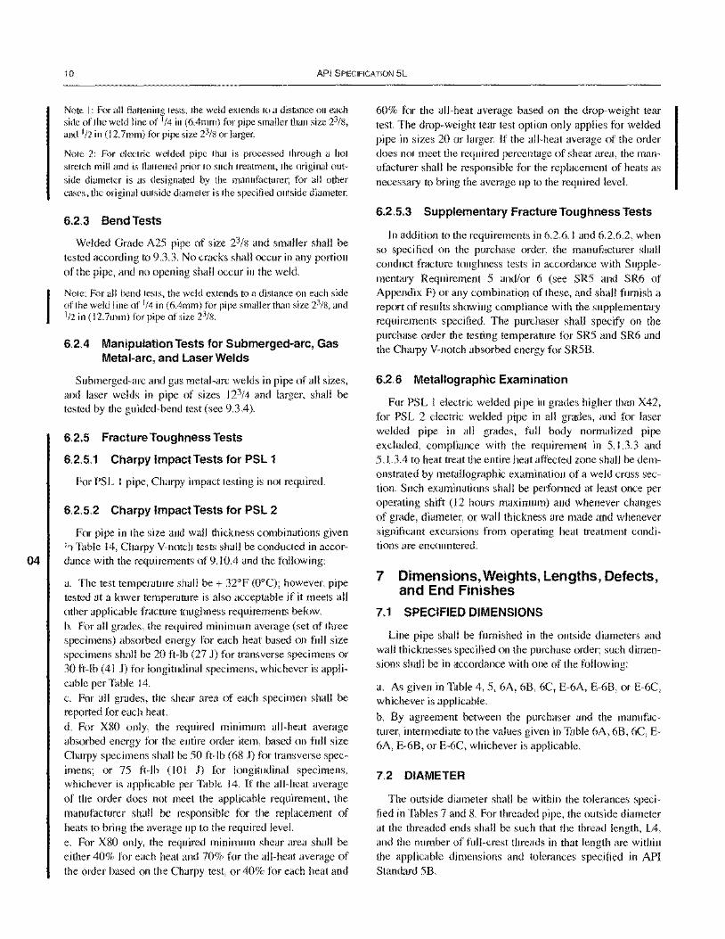
04
10 API SPECIFICATION 5L
Note I: For all flattening tests, the weld extends to a distance on each side of the weld line of 1/4 in (6.4mm) for pipe smaller than size 23/8, and 1/2 in (12.7mm) for pipe size 23/8 or larger.
Note 2: For electric welded pipe that is processed through a hot stretch mill and is flattened prior to such treatment, the original outside diameter is as designated by the manufacturer; for all other cases, the original outside diameter is the specified outside diameter.
6.2.3 Bend Tests
Welded Grade A25 pipe of size 23/8 and smaller shall be tested according to 9.3.3. No cracks shall occur in any portion of the pipe, and no opening shall occur in the weld.
Note: For all bend tests, the weld extends to a distance on each side of the weld line of 1/4 in (6.4mm) for pipe smaller than size 23/8, and 1/2 in (12.7mm) for pipe of size 23/'6.
6.2.4 Manipulation Tests for Submerged-arc, Gas Metal-arc, and Laser Welds
Submerged-arc and gas metal-arc welds in pipe of all sizes, and laser welds in pipe of sizes 123/4 and larger, shall be tested by the guided-bend test (see 9.3.4).
6.2.5 Fracture Toughness Tests
6.2.5.1 Charpy Impact Tests for PSL 1
For PSL I pipe, Charpy impact testing is not required.
6.2.5.2 Charpy Impact Tests for PSL 2
For pipe in the size and wall thickness combinations given :'1 Table 14, Charpy V-notch tests shall be conducted in accordance with the requirements of 9.10.4 and the following:
a. The test temperature shall be + 32DF (ODC); however, pipe tested at a lower temperature is also acceptable if it meets all other applicable fracture toughness requirements below. b. For all grades, the required minimum average (set of three specimens) absorbed energy for each heat based on full size specimens shall be 20 ft-Ib (27 J) for transverse specimens or 30 ft-Ib (41 J) for longitudinal specimens, whichever is applicable per Table 14. c. For all grades, the shear area of each specimen shall be reported for each heat. d. For XSO only, the required minimum all-heat average absorbed energy for the entire order item, based on full size Charpy specimens shall be 50 ft-lb (68 J) for transverse specimens; or 75 ft-lb (101 J) for longitudinal specimens, whichever is applicable per Table 14. If the all-heat average of the order does not meet the applicable requirement, the manufacturer shall be responsible for the replacement of heats to bring the average up to the required level. e. For XSO only, the required minimum shear area shall be either 40% for each heat and 70% for the all-heat average of the order based on the Charpy test, or 40% for each heat and
60% for the all-heat average based on the drop-weight tear test. The drop-weight tear test option only applies for welded pipe in sizes 20 or larger. If the all-heat average of the order does not meet the required percentage of shear area, the manufacturer shall be responsible for the replacement of heats as necessary to bring the average up to the required level.
6.2.5.3 Supplementary Fracture Toughness Tests
In addition to the requirements in 6.2.6.1 and 6.2.6.2, when so specified on the purchase order, the manufacturer shall conduct fracture toughness tests in accordance with Supplementary Requirement 5 and/or 6 (see SR5 and SR6 of Appendix F) or any combination of these, and shall furnish a report of results showing compliance with the supplementary requirements specified. The purchaser shall specify on the purchase order the testing temperature for SR5 and SR6 and the Charpy V-notch absorbed energy for SR58.
6.2.6 Metallographic Examination
For PSL 1 electric welded pipe in grades higher than X42, for PSL 2 electric welded pipe in all grades, and for laser welded pipe in all grades, full body normalized pipe excluded, compliance with the requirement in 5.1.3.3 and 5.1.3.4 to heat treat the entire heat affected zone shall be demonstrated by metallographic examination of a weld cross section. Such examinations shall be performed at least once per operating shift (12 hours maximum) and whenever changes of grade, diameter, or wall thickness are made and whenever significant excursions from operating heat treatment conditions are encountered.
7 Dimensions, Weights, Lengths, Defects, and End Finishes
7.1 SPECIFIED DIMENSIONS
Line pipe shall be furnished in the outside diameters and wall thicknesses specified on the purchase order; such dimensions shall be in accordance with one of the following:
a. As given in Table 4, 5, 6A, 6B, 6C, E-6A, E-68, or E-6C, whichever is applicable.
b. By agreement between the purchaser and the manufacturer, intermediate to the values given in Table 6A, 68, 6C, E-6A, E-68, or E-6C, whichever is applicable.
7.2 DIAMETER
The outside diameter shall be within the tolerances specified in Tables 7 and S. For threaded pipe, the outside diameter at the threaded ends shall be such that the thread length, L4, and the number of full-crest threads in that length are within the applicable dimensions and tolerances specified in API Standard 5B.
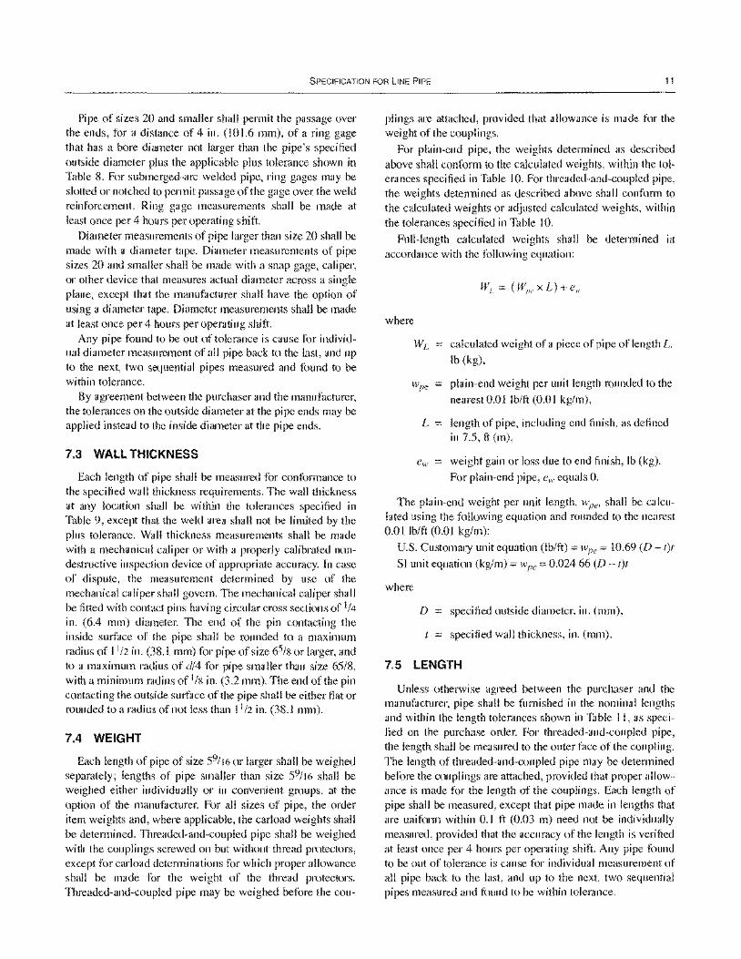
SPECIFICATION FOR LINE PIPE 11
Pipe of sizes 20 and smaller shall permit the passage over the ends, for a distance of 4 in. (101.6 mm), of a ring gage that has a bore diameter not larger than the pipe's specified outside diameter plus the applicable plus tolerance shown in Table 8. For submerged-arc welded pipe, ring gages may be slotted or notched to permit passage of the gage over the weld reinforcement. Ring gage measurements shall be made at least once per 4 hours per operating shift.
Diameter measurements of pipe larger than size 20 shall be made with a diameter tape. Diameter measurements of pipe sizes 20 and smaller shall be made with a snap gage, caliper, or other device that measures actual diameter across a single plane, except that the manufacturer shall have the option of using a diameter tape. Diameter measurements shall be made at least once per 4 hours per operating shift.
Any pipe found to be out of tolerance is cause for individual diameter measurement of all pipe back to the last, and up to the next, two sequential pipes measured and found to be within tolerance.
By agreement between the purchaser and the manufacturer, the tolerances on the outside diameter at the pipe ends may be applied instead to the inside diameter at the pipe ends.
7.3 WALL THICKNESS
Each length of pipe shall be measured for conformance to the specified wall thickness requirements. The wall thickness at any location shall be within the tolerances specified in Table 9, except that the weld area shall not be limited by the plus tolerance. Wall thickness measurements shall be made with a mechanical caliper or with a properly calibrated nondestructive inspection device of appropriate accuracy. In case of dispute, the measurement determined by use of the mechanical caliper shall govern. The mechanical caliper shall be fitted with contact pins having circular cross sections of 1/4
in. (6.4 mm) diameter. The end of the pin contacting the inside surface of the pipe shall be rounded to a maximum radius of 1112 in. (38.1 mm) for pipe of size 65/8 or larger, and to a maximum radius of dl4 for pipe smaller than size 65/8, with a minimum radius of 118 in. (3.2 mm). The end of the pin contacting the outside surface of the pipe shall be either fiat or rounded to a radius of not less than 1112 in. (38.1 mm).
7.4 WEIGHT
Each length of pipe of size 59/16 or larger shall be weighed separately; lengths of pipe smaller than size 59/16 shall be weighed either individually or in convenient groups, at the option of the manufacturer. For all sizes of pipe, the order item weights and, where applicable, the carload weights shall be determined. Threaded-and-coupled pipe shall be weighed with the couplings screwed on but without thread protectors, except for carload determinations for which proper allowance shall be made for the weight of the thread protectors. Threaded-and-coupled pipe may be weighed before the cou-
plings are attached, provided that allowance is made for the weight of the couplings.
For plain-end pipe, the weights determined as described above shall conform to the calculated weights, within the tolerances specified in Table 10. For threaded-and-coupled pipe, the weights determined as described above shall conform to the calculated weights or adjusted calculated weights, within the tolerances specified in Table 10.
Full-length calculated weights shall be determined in accordance with the following equation:
where
W L calculated weight of a piece of pipe of length L,
Ib (kg),
Wpe = plain-end weight per unit length rounded to the
nearest 0.0 I Ib/ft (0.0 I kg/m),
L length of pipe, including end finish, as defined in 7.5, ft (m),
weight gain or loss due to end finish, lb (kg).
For plain-end pipe, e", equals O.
The plain-end weight per unit length, wpe' shall be calculated using the following equation and rounded to the nearest 0.0 I Iblft (0.01 kg/m):
U.S. Customary unit equation (tb/ft) = wee = 10.69 (D - t)t
SI unit equation (kg/m) = wpe = 0.02466 (D - t)t
where
D specified outside diameter, in. (mm),
specified wall thickness, in. (mm).
7.5 LENGTH
Unless otherwise agreed between the purchaser and the manufacturer, pipe shall be furnished in the nominal lengths and within the length tolerances shown in Table I I, as specified on the purchase order. For threaded-and-coupled pipe, the length shall be measured to the outer face of the coupling. The length of threaded-and-coupled pipe may be determined before the couplings are attached, provided that proper allowance is made for the length of the couplings. Each length of pipe shall be measured, except that pipe made in lengths that are uniform within 0.1 ft (0.03 m) need not be individually measured, provided that the accuracy of the length is verified at least once per 4 hours per operating shift. Any pipe found to be out of tolerance is cause for individual measurement of all pipe back to the last, and up to the next, two sequential pipes measured and found to be within tolerance.
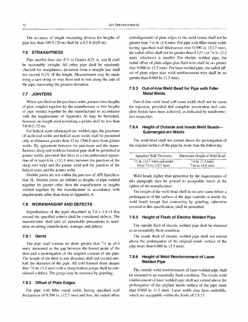
12 API SPECIFICATION 5L
The accuracy of length measuring devices for lengths of pipe less than 100 ft (30 m) shall be ± 0.1 ft (0.03 m).
7.6 STRAIGHTNESS
Pipe smaller than size 4 1/2 in Grades A25, A, and B shall be reasonably straight. All other pipe shall be randomly checked for straightness; deviation from a straight line shall not exceed 0.2% of the length. Measurement may be made using a taut string or wire from end to end along the side of the pipe, measuring the greatest deviation.
7.7 JOINTERS
When specified on the purchase order, jointers (two lengths of pipe coupled together by the manufacturer or two lengths of pipe welded together by the manufacturer in accordance with the requirements of Appendix A) may be furnished; however, no length used in making a jointer shall be less than 5.0 ft (1.52 m).
For helical seam submerged-arc welded pipe, the junctions of skelp end welds and helical seam welds shall be permitted only at distances greater than 12 in. (304.8 mm) from jointer welds. By agreement between the purchaser and the manufacturer, skelp end welds in finished pipe shall be permitted at jointer welds, provided that there is a circumferential separation of at least 6 in. (152.4 mm) between the junction of the skelp end weld and the jointer weld and the junction of the helical seam and the jointer weld.
Double joints are not within the purview of API Specification 5L. Double joints are defined as lengths of pipe welded together by parties other than the manufacturer or lengths welded together by the manufacturer in accordance with requirements other than those in Appendix A.
7.8 WORKMANSHIP AND DEFECTS
Imperfections of the types described in 7.8.1-7.8.14 that exceed the specified criteria shall be considered defects. The manufacturer shall take all reasonable precautions to minimize recurring imperfections, damage, and defects.
7.8.1 Dents
The pipe shall contain no dents greater than 1/4 in. (6.4 mm), measured as the gap between the lowest point of the dent and a prolongation of the original contour of the pipe. The length of the dent in any direction shall not exceed onehalf the diameter of the pipe. All cold-formed dents deeper than 1/8 in. (3.2 mm) with a sharp bottom gouge shall be considered a defect. The gouge may be removed by grinding.
7.8.2 Offset of Plate Edges
For pipe with filler metal welds having specified wall thicknesses of 0.500 in. (12.7 mm) and less, the radial offset
(misalignment) of plate edges in the weld seams shall not be greater than 1/16 in. (1.6 mm). For pipe with filler metal welds having specified wall thicknesses over 0.500 in. (12.7 mm), the radial offset shall not be greater than 0.125 tor 1/8 in. (3.2 mm), whichever is smaller. For electric welded pipe, the radial offset of plate edges plus flash trim shall be no greater than 0.060 in. (1.5 mm). For laser welded pipe, the radial offset of plate edges plus weld reinforcement trim shall be no greater than 0.060 in. (1.5 mm).
7.8.3 Out-of-line Weld Bead for Pipe with Filler Metal Welds
Out-of-line weld bead (off-seam weld) shall not be cause for rejection, provided that complete penetration and complete fusion have been achieved, as indicated by nondestructive inspection.
7.8.4 Height of Outside and Inside Weld BeadsSubmerged-arc Welds
The weld bead shall not extend above the prolongation of the original surface of the pipe by more than the following:
Specified Wall Thickness
1/2 in. (12.7 mm) and under Over 1/2 in. (12.7 mm)
Maximum Height of Weld Bead
'Ill in. (3.2 mm) 3/ 16 in. (4.8 mm)
Weld beads higher than permitted by the requirements of this paragraph may be ground to acceptable limits at the option of the manufacturer.
The height of the weld bead shall in no case come below a prolongation of the surface of the pipe (outside or inside the weld bead) except that contouring by grinding, otherwise covered in this specification, shall be permitted.
7.8.5 Height of Flash of Electric Welded Pipe
The outside flash of electric welded pipe shall be trimmed to an essentially flush condition.
The inside flash of electric welded pipe shall not extend above the prolongation of the original inside surface of the pipe more than 0.060 in. (1.5 mm).
7.8.6 Height of Weld Reinforcement of Laser Welded Pipe
The outside weld reinforcement of laser welded pipe shall be trimmed to an essentially flush condition. The inside weld reinforcement of laser welded pipe shall not extend above the prolongation of the original inside surface of the pipe more than 0.060 in. (1.5 mm). Laser welds may have underfills, which are acceptable within the limits of7.8.13.
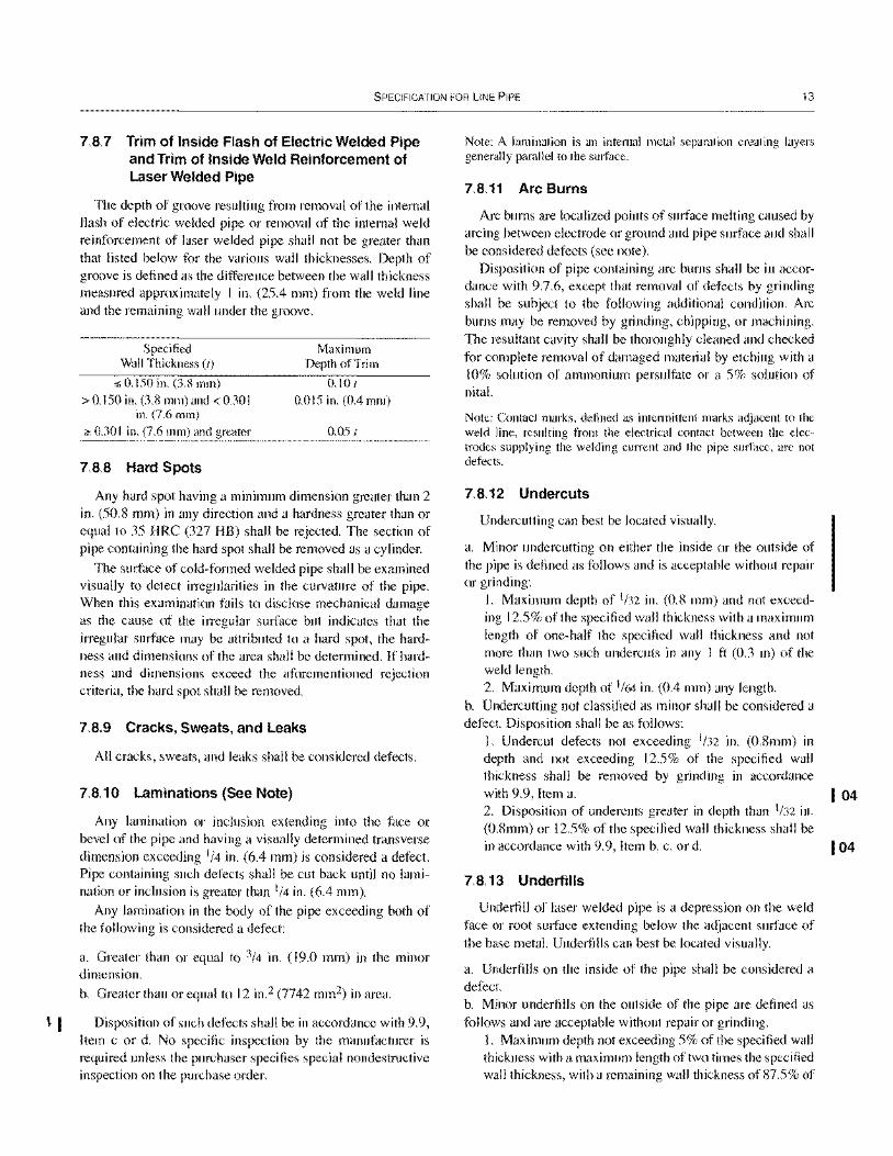
SPECIFICATION FOR liNE PIPE 13
7.8.7 Trim of Inside Flash of Electric Welded Pipe and Trim of Inside Weld Reinforcement of Laser Welded Pipe
The depth of groove resulting from removal of the intemal flash of electric welded pipe or removal of the internal weld reinforcement of laser welded pipe shall not be greater than that listed below for the various wall thicknesses. Depth of groove is defined as the difference between the wall thickness measured approximately I in. (25.4 mm) from the weld line and the remaining wall under the groove.
Specified Wall Thickness (I)
:5 0.150 in. (3.8 mm) > 0.150 in. (3.8 mm) and < 0.30 I
in. (7.6 mm) ;,,: 0.301 in. (7.6 mm) and greater
7.8.8 Hard Spots
Maximum Depth of Trim
0.10 t
0.015 in. (0.4 mm)
0.05 t
Any hard spot having a minimum dimension greater than 2 in. (50.8 mm) in any direction and a hardness greater than or equal to 35 HRC (327 HB) shall be rejected. The section of pipe containing the hard spot shall be removed as a cylinder.
The surface of cold-formed welded pipe shall be examined visually to detect irregularities in the curvature of the pipe. When this examination fails to disclose mechanical damage as the cause of the irregular surface but indicates that the irregular surface may be attributed to a hard spot, the hardness and dimensions of the area shall be determined. If hardness and dimensions exceed the aforementioned rejection criteria, the hard spot shall be removed.
7.8.9 Cracks, Sweats, and Leaks
All cracks, sweats, and leaks shall be considered defects.
7.8.10 Laminations (See Note)
Any lamination or inclusion extending into the face or bevel of the pipe and having a visually determined transverse dimension exceeding 1/4 in. (6.4 mm) is considered a defect. Pipe containing such defects shall be cut back until no lamination or inclusion is greater than 1/4 in. (6.4 mm).
Any lamination in the body of the pipe exceeding both of the following is considered a defect:
a. Greater than or equal to 3/4 in. (19.0 mm) in the minor dimension.
b. Greater than or equal to 12 in.2 (7742 mm2) in area.
l I Disposition of such defects shall be in accordance with 9.9, Item c or d. No specific inspection by the manufacturer is required unless the purchaser specifies special nondestructive inspection on the purchase order.
Note: A lamination is an internal metal separation creating layers generally parallel to the surface.
7.8.11 Arc Burns
Arc bums are localized points of surface melting caused by arcing between electrode or ground and pipe surface and shall be considered defects (see note).
Disposition of pipe containing arc burns shall be in accordance with 9.7.6, except that removal of defects by grinding shall be subject to the following additional condition. Arc bums may be removed by grinding, chipping, or machining. The resultant cavity shall be thoroughly cleaned and checked for complete removal of damaged material by etching with a 10% solution of ammonium persulfate or a 5% solution of nital.
Note: Contact marks, defined as intermittent marks adjacent to the weld line, resulting from the electrical contact between the electrodes supplying the welding current and the pipe surface, are not defects.
7.8.12 Undercuts
Undercutting can best be located visually.
a. Minor undercutting on either the inside or the outside of the pipe is defined as follows and is acceptable without repair or grinding:
1. Maximum depth of 1/32 in. (0.8 mm) and not exceeding 12.5% of the specified wall thickness with a maximum length of one-half the specified wall thickness and not more than two such undercuts in any I ft (0.3 m) of the weld length. 2. Maximum depth of 1/64 in. (0.4 mm) any length.
b. Undercutting not classified as minor shall be considered a defect. Disposition shall be as follows:
1. Undercut defects not exceeding 1/32 in. (O.Smm) in depth and not exceeding 12.5% of the specified wall thickness shall be removed by grinding in accordance
with 9.9, Item a. I 04 2. Disposition of undercuts greater in depth than 1/32 in. (O.Smm) or 12.5% of the specified wall thickness shall be in accordance with 9.9, Item b, c, or d. I 04
7.8.13 Underfills
Underfill of laser welded pipe is a depression on the weld face or root surface extending below the adjacent surface of the base metal. Underfills can best be located visually.
a. Underfills on the inside of the pipe shall be considered a defect. b. Minor underfills on the outside of the pipe are defined as follows and are acceptable without repair or grinding.
1. Maximum depth not exceeding 5% of the specified wall thickness with a maximum length of two times the specified wall thickness, with a remaining wall thickness of87.5% of
04 I
04
14 API SPECIFICATION 5L
the specified wall thickness, and not more than two such underfills in any I ft (0.3 m) of weld length. Furthennore, the coincident combination of underfills, other imperfections, grinds, and weld trim on the outside and inside surfaces of laser welded pipe shall not reduce the remaining wall thickness to less than that pennitted in Table 9. 2. Maximum depth of '/64 in. (0.4 mm), any length.
c. Disposition of external underfills that are not classified as minor shall be in accordance with 9.9 except that the length of grind to remove underfills shall not exceed 6 in. (152.4 mm) in any I ft (0.30 m) of weld length or 12 in. (0.30 m) in .. ny 5 ft (1.52 m) of weld length. Disposition of internal underfills shall be in accordance with 9.9, Items b, c, or d.
7.8.14 Other Defects
Any 00 or 10 suti'ace impeti'ection that has a depth greater than 12.5% of the specified wall thickness shall be considered a defect.
7.9 PIPE ENDS
7.9.1 General
The pipe ends shall be plain, threaded, belled, or prepared for special couplings, as specified on the purchase order. Helical seam pipe shall not be threaded. The inside and outside edges of the ends of all pipe shall be free of burrs.
7.9.2 Threaded Ends (PSL 1 only)
Threaded ends shall confonn to the threading, thread inspection, and gaging requirements specified in API Standard 58. One end of each length of threaded pipe shall be provided with a coupling confonning to the requirements of Section 8, in effect at the date of manufacture of each coupling (see Note I), and the other end with thread protection conforming to the requirements of I 1.2. Couplings shall be screwed onto the pipe handling-tight (see Note 2), except that they shall be applied power-tight if so specified on the purchase order. A thread compound shall be applied to cover the full surface of either the coupling or pipe engaged thread before making up the joint. All exposed threads shall be coated with this thread compound. Unless otherwise specified on the purchase order, the manufacturer may use any thread compound that meets the petiormance objectives set forth in API RP 5A3. A storage compound of distinct color may be substituted for this thread compound on all exposed threads. Whichever compound is used shall be applied to a sutiace that is clean and reasonably free of moisture and cutting fluids.
Notes:
I. Unless otherwise specified on the purchase order, it is not mandatory that both the pipe and coupling of each threaded and coupled product be manufactured to the same edition of this specification.
2. Handling-tight shall be defined as sufficiently tight that the coupling cannot be removed except by using a wrench. The purpose of making up couplings handling-tight is to facilitate removal of the couplings for cleaning and inspecting threads and applying fresh thread compound before laying the pipe. This procedure has been found necessary to prevent thread leakage, especially in gas lines, because manufacturer-applied couplings made up power-tight, although leak-proof at the time of makeup, may not always remain so after transportation, handling, and laying.
7.9.3 Plain Ends
Unless otherwise specified on the purchase order, plain-end pipe shall be furnished with ends beveled to an angle of 30 degrees (+ 5 degrees, - 0 degrees) measured from a line drawn perpendicular to the axis of the pipe, and with a root face of 1/16
in. ± '/32 in. (1.6 ± 0.8 mm) (see Note). For seamless pipe where internal machining is required to maintain the root face tolerance, the angle of the internal taper, measured from the longitudinal axis, shall be no larger than the following:
Specified Wall Thickness, in. (mm)
Less than 00418 (10.6)
00418 through 0.555 (LO.6 through 14. I)
0.556 through 0.666 (Greater than 14.1 through 16.9)
Over 0.666 (16.9)
Maximum Angle of Taper (degrees)
7
II
14
For the removal of an internal burr on welded pipe larger than size 4'/2, the internal taper, measured from the longitudinal axis, shall be no larger than 7°.
For pipe sizes 23/8 and larger, the pipe ends shall be cut square within '/'6 in. (1.6 mm). Pipe ends from each end-finishing machine shall be checked for compliance at least once per 4 hours per operating shift.
Both ends of pipe with filler metal welds shall have the inside reinforcement removed for a distance of approximately 4 in. (101.6 mm) from the end of the pipe.
Note: The purchaser is directed to the applicable code for the recommended angle of pipe bevel.
7.9.4 Belled Ends (PSL 1 only)
When so specified on the purchase order, pipe with specified wall thickness 0.141 in. (3.6 mm) and less shall be furnished with one end belled for bell and spigot joints in accordance with Figure 1. The belled end shall be visually inspected for workmanship and defects.
SPECIFICATION FOR LINE PIPE 15
7.9.5 Ends Prepared for Special Couplings (PSL 1 only)
When so specified on the purchase order, pipe shall be furnished with ends suitable for use with special couplings such as Dresser, Victaulic, or other equivalent special couplings. Such pipe shall be sufficiently free from indentations, projections, or roll marks for a distance of 8 in. (203 mm) from the end of the pipe to permit proper makeup of coupling.
8 Couplings (PSL 1 only)
8.1 MATERIAL
Couplings for Grades A and B pipe shall be seamless and shall be made of a grade of material at least equal in mechanical properties to that of the pipe. Couplings for Grade A25 pipe shall be seamless or welded and shall be made of steel. By agreement between the purchaser and the manufacturer, welded couplings may be supplied on pipe of sizes 14 and larger, if the couplings are properly marked.
8.2 TENSILE TESTS
A tensile test shall be made on each heat of steel from which couplings are produced, and the coupling manufacturer shall maintain a record of such tests. This record shall be open to inspection by the purchaser. If such a test is made on finished couplings, either round specimens proportioned as specified in ASTM E 8, Test Methods for Tension Testing of Metallic Materials, or strip specimens shall be used at the option of the manufacturer.
8.3 DIMENSIONS
Couplings shall conform to the dimensions and tolerances shown in Table 12 (see note) and Figure 2.
Note: Couplings given in Table 12 are suitable for pipe having dimensions as given in Tables 4 and S.
8.4 INSPECTION
Couplings shall be free from blisters, pits, cinder marks, and other defects that would impair the efficiency of the coupling or break the continuity of the thread.
9 Inspection and Testing
9.1 TEST EQUIPMENT
If test equipment, whose calibration or verification is required under the provisions of the specification, is subjected to unusual or severe conditions sufficient to make its accuracy questionable, recalibration or reverification shall be performed prior to further use of the equipment.
9.2 TESTING OF CHEMICAL COMPOSITION
9.2.1 Heat Analyses
The steel manufacturer shall determine the analysis of each heat of steel used in the manufacture of pipe specified on the purchase order. The analysis so determined shall conform to the requirements of 6.1.1.
For Grade X80, heat analysis limits have not been defined, only product analysis limits.
9.2.2 Product Analyses
9.2.2.1 Sampling Frequency
The manufacturer shall determine the analysis of two samples representing each heat of steel used for the production of pipe under this specification.
9.2.2.2 Sampling Methods
9.2.2.2.1 Seamless Pipe
At the option of the manufacturer, samples used for product analyses shall be taken either from tensile test specimens or from the finished pipe.
9.2.2.2.2 Welded Pipe
At the option of the manufacturer, samples used for product analyses shall be taken from either finished pipe, plate, skelp, tensile test specimens, or flattening test specimens. The location of the samples shall be a minimum of 90° from the weld of longitudinally welded pipe. For helical seam pipe, the sample location shall be at a position not less than one quarter of the distance between adjacent weld convolutions as measured from either edge of the weld. For pipe manufactured from plate or skelp, the product analyses may be made by the supplier of the plate or skelp providing the analyses are made in accordance with the frequency requirement of this specification.
9.2.3 Test Reports
9.2.3.1 When required by the purchaser, for Grade A25, the manufacturer shall certify that the pipe furnished was produced in conformance with the requirements for chemical properties and tests of API Specification 5L.
9.2.3.2 Chemical analyses required by this specification shall be reported to the purchaser when SRI5 or PSL 2 is specified.
9.3 TESTING OF MECHANICAL PROPERTIES
9.3.1 Tensile Tests
9.3.1.1 Tensile Test Specimens
As shown in Figure 3, tensile test orientation shall be in the longitudinal direction for all sizes of hot worked or heat treated
16 API SPECIFICATION 5L
seamless pipe and all welded pipe less than size 85/R. For seamless pipe, a transverse round bar or ring expansion specimen may be substituted for the longitudinal specimen by agreement between the purchaser and manufacturer. For weld pipe and cold expanded seamless pipe size 85/8 and larger, tensile test orientation shall be in the transverse direction. At the option of the manufacturer, the specimen may be either full section, strip specimen, or round bar specimens as specified in 9.3.1.3,9.3.1.4, and Figure 4. The type, size, and orientation of the specimens shall be reported. Testing of strip specimens shall be with suitable curved-face testing grips, or flat-face testing grips if the grip areas of the specimens have been machined to reduce the curvature or have been flattened without heating. For strip specimens, the specified width in the gage length shall be either 1'/2 in. (38.1 mm) or 3/4 in. (19.0 mm) for pipe of size 31/2 or smaller; either I 1/2 in. (38.1 mm) or I in. (25.4 mm) for pipe of size larger than 31/2 up to size 65/8, inclusive; and 11/2 in. (38.1 mm) for pipe larger than size 65/8.
Note: Conventionally produced seamless line pipe has been demonstrated to exhibit isotropic behavior with similar mechanical properties in the longitudinal and transverse directions (see API SCS Agenda Item 4191, Task Group on Line Pipe Minutes, June 2003). However, transverse test results on an individual pipe may exhibit yield and tensile properties different from the longitudinal values. Be aware that flattening of seamless strip tensile specimens will affect the transverse test results and will not reflect the actual transverse properties. The purchaser should determine at the time of purchase whether additional testing iin the transverse direction is necessary to meet the design requirements for the specific pipeline design in question.
9.3.1.2 Tensile Testing Frequency
Tensile tests shall be made at the frequency of one test per inspection lot as shown in Table 13.
9.3.1.3 Longitudinal Tensile Tests
At the option of the manufacturer, longitudinal tests may utilize a full section specimen (see Figure 4, Subfigure 8), a strip specimen (see Figure 4, Subfigure C), or for pipe with wall thickness greater than 0.750 in. (19.1 mm) a 0.500-in. (12.7-mm) diameter round bar specimen (see Figure 4, Subfigure D). The strip specimen shall be tested without flattening.
9.3.1.4 Transverse Tensile Tests
The transverse tensile properties shall be determined, at the option of the manut~lcturer, by one of the following methods:
a. The yield strength, ultimate tensile strength, and elongation values shall be determined on either a flattened rectangular specimen (see Figure 4, Subfigure E) or on a round bar specimen (see Figure 4, Subfigure G).
b. The yield strength shall be determined by the ring expansion method (see Figure 4, Subfigure A) with the ultimate
strength and elongation values determined from a flattened rectangular specimen.
The same method of testing shall be employed for all lots in an order item. All transverse tensile specimens shall be as shown in Figure 4. All specimens shall represent the full wall thickness of the pipe from which the specimen was cut, except for round bar tensile specimens.
Transverse round bar specimens are to be secured from nonflattened pipe sections. The test specimen size shall be as given in Table 14A, unless the next larger test specimen size is used or unless the manufacturer and purchaser agree to the use of the next smaller test specimen size. For pipe sizes too small to obtain a 0.250 in. (6.4 mm) specimen, round bar tensile test specimens shall not be used.
9.3.1.5 Weld Tensile Tests
Weld tensile test specimens shall be taken at 90° to the weld with the weld at the center as shown in Figures 3 and 4 and shall represent the full wall thickness of the pipe from which the specimen was cut. Weld reinforcement may be removed at the manufacturer's option. Weld tensile tests need not include determination of yield strength and elongation.
9.3.2 Flattening Tests
Flattening tests shall be performed for electric welded, continuous welded, and laser welded pipe. Test specimens shall be at least 21/2 in (63.5mm) long. Frequency of testing, sample location, test orientation, and applicable pipe sizes shall be as shown in Figure 5. For electric welded pipe that is to be processed through a hot stretch mill, the flattening test specimens shall be obtained either prior to or after such treatment, at the option of the manufacturer.
9.3.3 Bend Tests
One full section specimen of appropriate length, cut from a length of pipe from each lot of 25 tons (22.7 Mg), or fraction thereof, for pipe of nominal size 1.900 and smaller, and from each lot of 50 tons (45.5 Mg), or fraction thereof, for pipe of size 23/8 shall be bent cold through 90°, around a mandrel having a diameter not greater than twelve times the outside diameter of the pipe being tested, with the weld located approximately 4SO from the point of contact of the specimen with the mandrel.
9.3.4 Guided-Bend Tests
The test specimens shall be taken from the helical or each longitudinal seam weld in a length of pipe from each lot of 50 lengths or less of each combination of specified outside diameter, specified wall thickness, and grade; and from a skelp end weld in a length of pipe from each lot of 50 lengths or less of each combination of specified outside diameter, specified
04
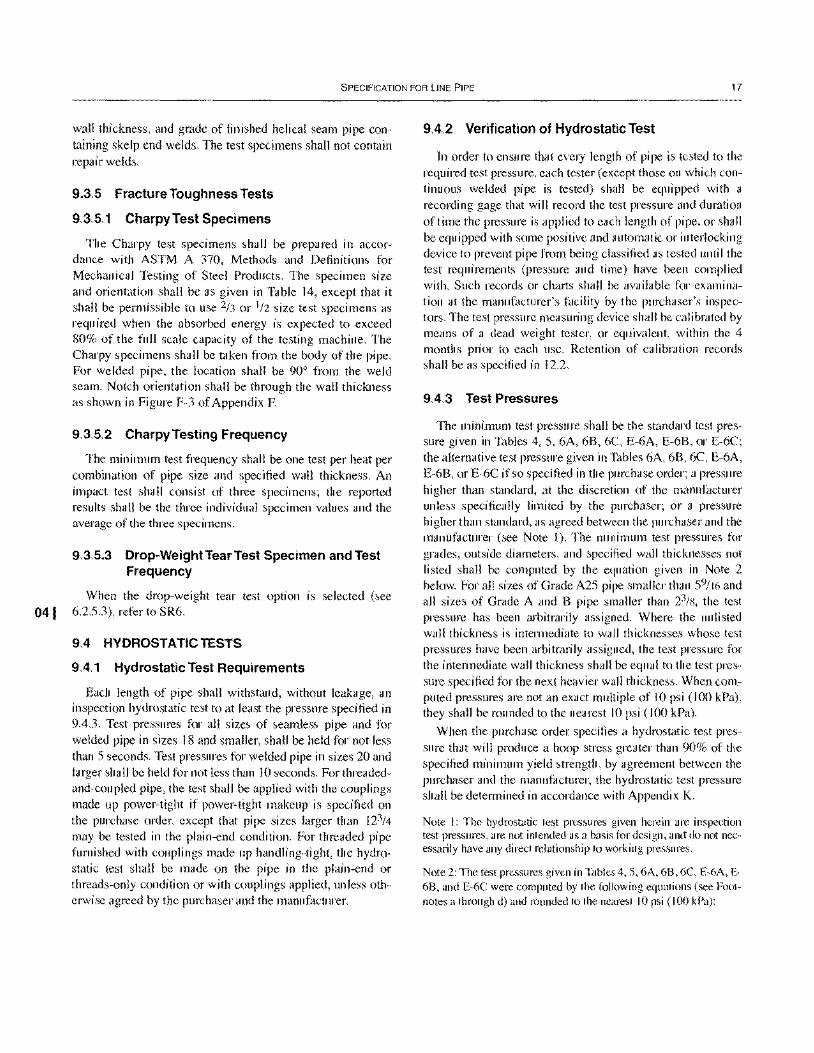
SPECIFICATION FOR LINE PIPE 17
wall thickness, and grade of finished helical seam pipe containing skelp end welds. The test specimens shall not contain repair welds.
9.3.5 Fracture Toughness Tests
9.3.5.1 Charpy Test Specimens
The Charpy test specimens shall be prepared in accordance with ASTM A 370, Methods and Definitions for Mechanical Testing of Steel Products. The specimen size and orientation shall be as given in Table 14, except that it shall be permissible to use 2/3 or 1/2 size test specimens as required when the absorbed energy is expected to exceed 80% of the full scale capacity of the testing machine. The Charpy specimens shall be taken from the body of the pipe. For welded pipe, the location shall be 90° from the weld seam. Notch orientation shall be through the wall thickness as shown in Figure F-3 of Appendix F.
9.3.5.2 CharpyTesting Frequency
The minimum test frequency shall be one test per heat per combination of pipe size and specified wall thickness. An impact test shall consist of three specimens; the reported results shall be the three individual specimen values and the average of the three specimens.
9.3.5.3 Drop-Weight Tear Test Specimen and Test Frequency
When the drop-weight tear test option is selected (see 041 6.2.5.3), refer to SR6.
9.4 HYDROSTATIC TESTS
9.4.1 HydrostatiC Test Requirements
Each length of pipe shall withstand, without leakage, an inspection hydrostatic test to at least the pressure specified in 9.4.3. Test pressures for all sizes of seamless pipe and for welded pipe in sizes 18 and smaller, shall be held for not less than 5 seconds. Test pressures for welded pipe in sizes 20 and larger shall be held for not less than 10 seconds. For threadedand-coupled pipe, the test shall be applied with the couplings made up power-tight if power-tight makeup is specified on the purchase order, except that pipe sizes larger than 123/4
may be tested in the plain-end condition. For threaded pipe furnished with couplings made up handling-tight, the hydrostatic test shall be made on the pipe in the plain-end or threads-only condition or with couplings applied, unless otherwise agreed by the purchaser and the manufacturer.
9.4.2 Verification of HydrostatiC Test
In order to ensure that every length of pipe is tested to the required test pressure, each tester (except those on which continuous welded pipe is tested) shall be equipped with a recording gage that will record the test pressure and duration of time the pressure is applied to each length of pipe, or shall be equipped with some positive and automatic or interlocking device to prevent pipe from being classified as tested until the test requirements (pressure and time) have been complied with. Such records or charts shall be available for examination at the manufacturer's facility by the purchaser's inspectors. The test pressure measuring device shall be calibrated by means of a dead weight tester, or equivalent, within the 4 months prior to each use. Retention of calibration records shall be as specified in J 2.2.
9.4.3 Test Pressures
The minimum test pressure shall be the standard test pressure given in Tables 4, 5, 6A, 6B, 6C, E-6A, E-6B, or E-6C; the alternative test pressure given in Tables 6A, 6B, 6C, E-6A, E-6B, or E-6C if so specified in the purchase order; a pressure higher than standard, at the discretion of the manufacturer unless specifically limited by the purchaser; or a pressure higher than standard, as agreed between the purchaser and the manufacturer (see Note I). The minimum test pressures for grades, outside diameters, and specified wall thicknesses not listed shall be computed by the equation given in Note 2 below. For all sizes of Grade A25 pipe smaller than 59/16 and all sizes of Grade A and B pipe smaller than 23/x, the test pressure has been arbitrarily assigned. Where the unlisted wall thickness is intermediate to wall thicknesses whose test pressures have been arbitrarily assigned, the test pressure for the intermediate wall thickness shall be equal to the test pressure specified for the next heavier wall thickness. When computed pressures are not an exact multiple of 10 psi (100 kPa), they shall be rounded to the nearest 10 psi (100 kPa).
When the purchase order specifies a hydrostatic test pressure that will produce a hoop stress greater than 90% of the specified minimum yield strength, by agreement between the purchaser and the manufacturer, the hydrostatic test pressure shall be determined in accordance with Appendix K.
Note 1: The hydrostatic test pressures given herein are inspection test pressures, are not intended as a basis for design, and do not necessarily have any direct relationship to working pressures.
Note 2: The test pressures given in Tables 4, S, 6A, 68, 6C, E-6A, E-68, and E-6C were computed by the following equations (see Footnotes a through d) and rounded to the nearest 10 psi (100 kPa):
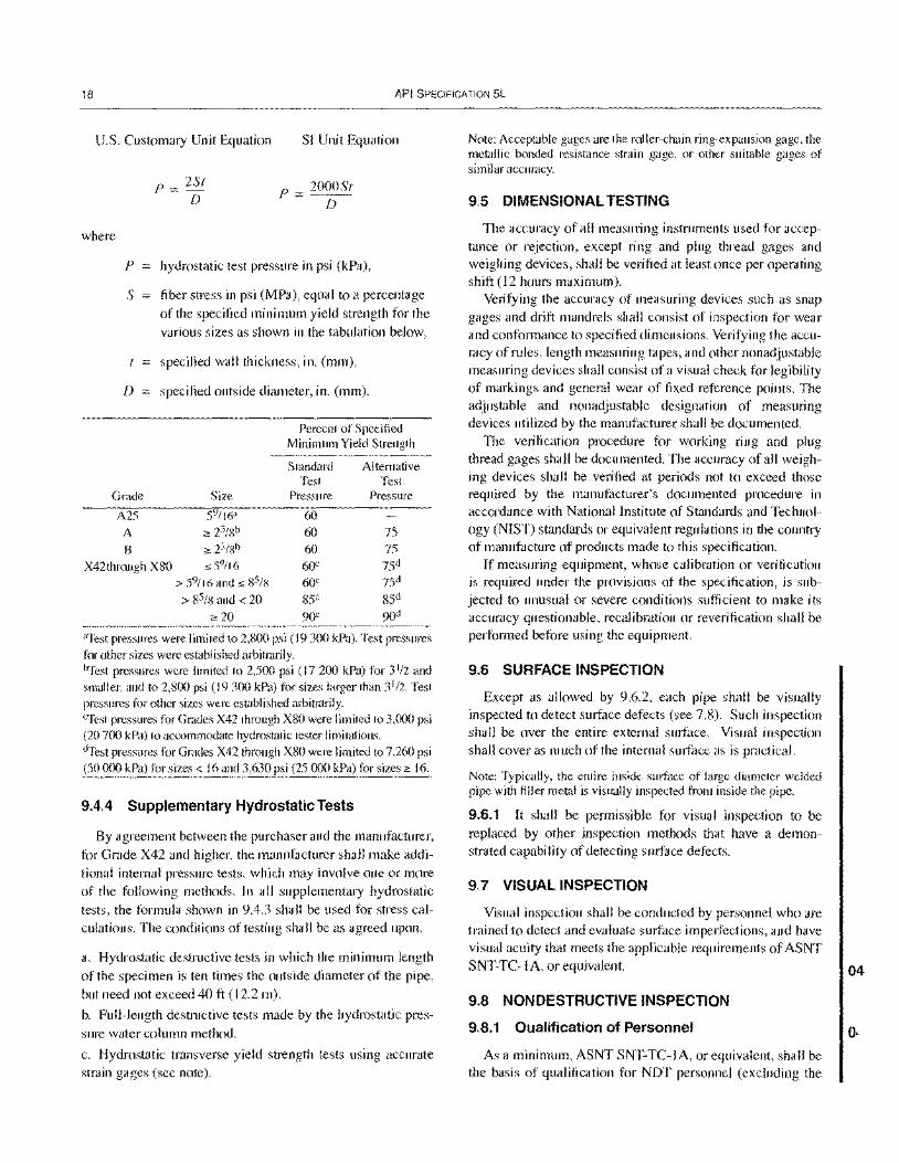
18 API SPECIFICATION 5L
U.S. Customary Unit Equation S[ Unit Equation
where
p
s
D
Grade
A25 A B
p = 2St D
p = 2000St D
hydrostatic test pressure in psi (kPa),
fiber stress in psi (MPa), equal to a percentage
of the specified minimum yield strength for the various sizes as shown in the tabulation below,
specified wall thickness, in. (mm),
specified outside diameter, in. (mm).
Size
59/16"
:! 23/Sb
:! 23/S b
Percent of Specified Minimum Yield Strength
Standard Alternative Test Test
Pressure Pressure
60 60 75 60 75
X42through XSO :5 59116 60c 75d
> 59/16 and,; 85/S 60e 75d
> 85/8 and < 20 85e 85d
2: 20 90e 90d
"Test pressures were lim ited to 2,800 psi (19 300 kPa). Test pressures for other sizes were established arbitrarily. ~est pressures were limited to 2,500 psi (17200 kPa) for 31/2 and smaller, and to 2,800 psi (19300 kPa) for sizes larger than 31/2. Test pressures for other sizes were established arbitrarily. CTest pressures for Grades X42 through X80 were limited to 3,000 psi (20700 kPa) to accommodate hydrostatic tester limitations. dTest pressures for Grades X42 through X80 were limited to 7,260 psi (SO 000 kPa) for sizes < 16 and 3,630 psi (25 000 kPa) for sizes 2: 16.
9.4.4 Supplementary Hydrostatic Tests
By agreement between the purchaser and the manufacturer, for Grade X42 and higher, the manufacturer shall make addi
tional internal pressure tests, which may involve one or more of the following methods. [n all supplementary hydrostatic tests, the formula shown in 9.4.3 shall be used for stress ca[culations. The conditions of testing shall be as agreed upon.
a. Hydrostatic destructive tests in which the minimum length
of the specimen is ten times the outside diameter of the pipe,
but need not exceed 40 ft (12.2 m).
b. Full-length destructive tests made by the hydrostatic pressure water column method.
c. Hydrostatic transverse yield strength tests using accurate strain gages (see note).
Note: Acceptable gages are the roller-chain ring-expansion gage, the metallic bonded resistance strain gage, or other suitable gages of similar accuracy.
9.5 DIMENSIONAL TESTING
The accuracy of all measuring instruments used for acceptance or rejection, except ring and plug thread gages and weighing devices, shall be verified at least once per operating shift (12 hours maximum).
Verifying the accuracy of measuring devices such as snap gages and drift mandrels shall consist of inspection for wear and conformance to specified dimensions. Verifying the accuracy of rules, length measuring tapes, and other nonadjustable measuring devices shall consist of a visual check for legibility of markings and general wear of fixed reference points. The adjustable and nonadjustable designation of measuring devices utilized by the manufacturer shall be documented.
The verification procedure for working ring and plug thread gages shall be documented. The accuracy of all weighing devices shall be verified at periods not to exceed those required by the manufacturer's documented procedure in accordance with National Institute of Standards and Technology (NIST) standards or equivalent regulations in the country of manufacture of products made to this specification.
If measuring equipment, whose calibration or verification is required under the provisions of the specification, is subjected to unusual or severe conditions sufficient to make its accuracy questionable, recalibration or reverification shall be performed before using the equipment.
9.6 SURFACE INSPECTION
Except as allowed by 9.6.2, each pipe shall be visually inspected to detect surface defects (see 7.8). Such inspection shall be over the entire external surface. Visual inspection shall cover as much of the internal surface as is practical.
Note: Typically, the entire inside surface of large diameter welded pipe with filler metal is visually inspected from inside the pipe.
9.6.1 It shall be permissible for visual inspection to be replaced by other inspection methods that have a demonstrated capability of detecting surface defects.
9.7 VISUAL INSPECTION
Visual inspection shall be conducted by personnel who are trained to detect and evaluate surface imperfections, and have visual acuity that meets the applicable requirements of ASNT SNT-TC-l A, or equivalent.
9.8 NONDESTRUCTIVE INSPECTION
9.8.1 Qualification of Personnel
As a minimum, ASNT SNT-TC-lA, or equivalent, shall be the basis of qualification for NDT personnel (excluding the
04
o·
04
SPECIFICATION FOR LINE PIPE 19
visual method). Personnel shall be requalified for any method previously qualified, if they have not performed NDT in that method for a period exceeding 12 months. NDT shall be conducted by Level T, II, or III personnel.
Evaluation of indications shall be performed by Level I personnel under the supervision of Level II or 1Il personnel, or by Level II or III personnel.
9.8.2 Standard Practices for Inspection
Except as allowed in Table 26, for other than surface inspection (see 9.6) and wall thickness verification, the required inspections shall be performed in accordance with the applicable ASTM standards, or equivalent, as follows:
a. Electromagnetic (fl ux leakage) E570
b. Electromagnetic (eddy-current) E309
c. Ultrasonic E213
d. Ultrasonic (weld seam) E273
e. Magnetic Particle E 709
f. Radiographic E 94
g. Liquid Penetrant E 165
9.8.3 Methods of Inspection
Except for Grade A25 pipe, the weld seams of welded pipe of sizes 23/8 and larger shall be nondestructively inspected full length (100%) for the entire thickness, in accordance with the applicable methods given in Table 24. In addition, the skelp end weld in finished helical seam pipe shall be nondestructively inspected in accordance with the applicable methods given in Table 24.
All PSL 2 seamless pipe and PSL 1 Grade B quenched and tempered seamless pipe (see 5.4) shall be nondestructively inspected full length (100%) in accordance with the applicable methods given in Table 25. When specified on the purchase order, other PSL 1 seamless pipe shall be nondestructively inspected in accordance with the applicable methods given in Table 25.
By agreement between the purchaser and the manufacturer and when specified on the purchase order, electric welds and laser welds shall be nondestructively inspected in accordance with SR 17 (see Appendix F).
The location of equipment in the manufacturer's facility shall be at the discretion of the manufacturer, except that
a. required nondestructive inspection of weld seams of cold expanded pipe shall be performed after cold expansion; and
b. \required nondestructive inspection of seamless pipe shall take place after all heat treating and cold expansion operations, if performed, but may take place before cropping, beveling, and end sizing.
9.8.3.1 Pipe End Weld Inspection
When an automated ultrasonic or electromagnetic inspection system (combined equipment, operating procedures, and personnel) is applied to meet the requirements of9.8.3, the weld at the end of the pipe that is not covered by the automated inspection system shall be inspected for defects by ultrasonic angle beam or radiographic methods as appropriate.
For submerged-arc welded pipe and gas metal-arc welded pipe, the weld at each pipe end for a minimum distance of 8 in. (200 mm) shall be inspected by radiographic methods. The results of such radiographic inspection shall be recorded on either film or another imaging medium.
9.8.3.2 Pipe End Inspection-Seamless
When an automated ultrasonic or electromagnetic inspection system (combined equipment, operating procedures, and personnel) is applied to meet the requirements of 9.8.3, the end of the pipe that is not covered by the automated inspection system shall be inspected for defects either by ultrasonic angle beam or magnetic particle methods, at the option of the manufacturer.
9.8.4 Radiological Inspection-Weld Seams
9.8.4.1 Radiological Inspection Equipment
The homogeneity of weld seams examined by radiological methods shall be determined by means of X-rays directed through the weld material in order to create a suitable image on a radiographic film, a fluorescent screen, or another X-ray imaging medium, provided that the required sensitivity is demonstrated.
9.8.4.2 Radiological Sensitivity Reference Standard
Unless otherwise specified on the purchase order, the reference standard shall be the ASTM hole-type image quality indicator (lQl) described in 9.8.4.3, the ASTM wire-type image quality indicator described in 9.8.4.4, or the ISO wiretype image quality indicator described in 9.8.4.4. By agreement between the purchaser and the manufacturer, other standard image quality indicators may be used, provided that an equivalent or better sensitivity is achieved.
9.8.4.3 ASTM Hole-type Image Quality Indicator
When ASTM hole-type image quality indicators are used, they shall be in accordance with ASTM Standard E 1025. The image quality indicator shall be placed parallel and adjacent to the weld, on shim material that is radiologically similar to the pipe material and is sufficiently thick to be capable of providing a film density at the IQI location that approximates the film density at the adjacent weld seam location. For fluoro-
20 API SPECIFICATION 5L
scopic inspection, the thickness of the image quality indicator used shall be as given in Table 15 for the applicable weld thickness. For radiographic inspection, the thickness of the image quality indicator used shall be as given in Table 16 for the applicable weld thickness.
9.8.4.4 Wire-type Image Quality Indicators
When ISO wire-type image quality indicators are used, they shall be Fe 1/7, Fe 6/12, or Fe 10/16, in accordance with ISO Standard 1027, and the essential wire diameters shall be as given in Tables 17 and 18 for the applicable weld and wall thicknesses. When ASTM wire-type image quality indicators are used, they shall be in accordance with ASTM Standard E 747, and the essential wire diameters shall be as given in Tables 19 and 20 for the applicable weld and wall thicknesses. The image quality indicator used shall be placed across the weld at a location representative of full weld reinforcement and shall contain both essential wire diameters; alternatively, two image quality indicators shall be used, one placed across the weld and the other placed on the base metal.
9.8.4.5 Verification of Standardization
For dynamic methods at operational speeds, an image quality indicator shall be used to check the sensitivity and adequacy of the technique on one pipe in every lot of 50 pipe, but at least once per 4 hours per operating shift. For initial adjustment of the technique using the image quality indicator, the pipe may be held in a stationary position. For film radiographic methods, an image quality indicator shall appear on each exposure.
For hole-type lQls, proper definition and sensitivity is attained when the essential hole is clearly visible to the operator. For wire-type IQls, proper definition and sensitivity is attained when the essential wire diameters of the image quality indicator used are clearly visible to the operator in the applicable area (weld or pipe body).
9.8.4.6 Acceptance Limits for Radiological Inspection
Radiological inspection shall be capable of detecting weld imperfections and defects as described in 9.8.4.7 and 9.8.4.8.
9.8.4.7 Imperfections Observed During Radiological Inspection
The maximum acceptable size and distribution of slag inclusion and/or gas pocket imperfections are given in Tables 21 and 22 and Figures 7 and 8 (see note).
The important factors to be considered in determining if imperfections are acceptable are the size and spacing of the imperfections and the sum of their diameters in an established distance. For simplicity, the distance is established as any 6-in. (I 50-mm) length. Imperfections of this type usually occur
in an aligned pattern, but no distinction is made between aligned and scattered patterns. Also, the distribution pattern may be of assorted sizes.
Note: Unless the imperfections are elongated, it cannot be determined with assurance whether the radiological indications represent slag inclusions or gas pockets. Therefore, the same limits apply to all circular-type imperfections.
9.8.4.8 Defects Observed During Radiological Inspection
Cracks, lack of complete penetration, lack of complete fusion, and imperfections greater in size and/or distribution than shown in Tables 2 I and 22 and Figures 7 and 8, as indicated by radiological inspection, shall be considered defects.
Pipe containing such defects shall be given any of the dispositions specified in 9.9.
9.8.4.9 Traceability of Film Radiographs
Radiographs shall be traceable to the pipe identity.
9.8.5 Ultrasonic and Electromagnetic Inspection
9.8.5.1 Equipment
Equipment utilizing ultrasonic or electromagnetic principles and capable of continuous and uninterrupted inspection of the weld seam of welded pipe or the outside and/or inside surfaces of seamless pipe shall be used, as appropriate. The equipment shall be standardized with an applicable reference standard as described in 9.8.5.2 at least once per 8 hours per operating shift to demonstrate its effectiveness and the inspection procedures. The equipment shall be adjusted to produce well-defined indications when the reference standard is inspected in accordance with 9.8.5.2.
For welded pipe, the equipment shall be capable of inspecting through the entire thickness of the weld seam as follows:
a. for electric welded pipe and laser welded pipe, the weld line plus 1/16 inch (1.6 mm) of adjacent parent metal on each side of the weld line.
b. for pipe welded with filler metal, the weld metal plus 1/16
in. (1.6 mm) of adjacent parent metal on each side of the weld metal.
Note: Restrictions on residual magnetism in pipe are given in 9.8.7.
9.8.5.2 Ultrasonic and Electromagnetic Inspection Reference Standards
Each reference standard shall have its outside diameter and wall thickness within the tolerances specified for the production pipe to be inspected and may be of any convenient length as determined by the manufacturer.
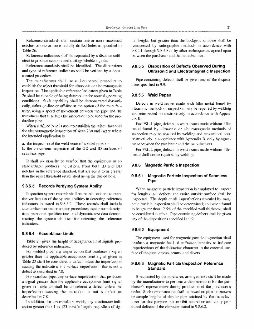
SPECIFICATION FOR LINE PIPE 21
Reference standards shall contain one or more machined notches or one or more radially drilled holes as specified in Table 26.
Reference indicators shall be separated by a distance sufficient to produce separate and distinguishable signals.
Reference standards shall be identified. The dimensions and type of reference indicators shall be verified by a documented procedure.
The manufacturer shall use a documented procedure to establish the reject threshold for ultrasonic or electromagnetic inspection. The applicable reference indicators given in Table 26 shall be capable of being detected under normal operating conditions. Such capability shall be demonstrated dynamically, either on-line or off-line at the option of the manufacturer, using a speed of movement between the pipe and the transducer that simulates the inspection to be used for the production pipe.
When a drilled hole is used to establish the reject threshold for electromagnetic inspection of sizes 23/8 and larger where the intended application is
a. the inspection of the weld seam of welded pipe; or b. the concurrent inspection of the 00 and 10 surfaces of seamless pipe.
It shall additionally be verified that the equipment as so standardized produces indications, from both 10 and 00 notches in the reference standard, that are equal to or greater than the reject threshold established using the drilled hole.
9.8.5.3 Records Verifying System Ability
Inspection system records shall be maintained to document the verification of the system abilities in detecting reference indicators as stated in 9.8.5.2. These records shall include standardization and operating procedures, equipment description, personnel qualifications, and dynamic test data demonstrating the system abilities for detecting the reference indicators.
9.8.5.4 Acceptance Limits
Table 23 gives the height of acceptance limit signals produced by reference indicators.
For welded pipe, any imperfection that produces a signal greater than the applicable acceptance limit signal given in Table 23 shall be considered a defect unless the imperfection causing the indication is a surface imperfection that is not a defect as described in 7.8.
For seamless pipe, any surface imperfection that produces a signal greater than the applicable acceptance limit signal given in Table 23 shall be considered a defect unless the imperfection causing the indication is not a defect as described in 7.8.
In addition, for gas metal-arc welds, any continuous indication greater than I in. (25 mm) in length, regardless of sig-
nal height, but greater than the background noise shall be reinspected by radiographic methods in accordance with 9.8.4.1 through 9.8.4.8 or by other techniques as agreed upon between the purchaser and the manufacturer.
9.8.5.5 Disposition of Defects Observed During Ultrasonic and Electromagnetic Inspection
Pipe containing defects shall be given any of the dispositions specified in 9.9.
9.8.5.6 Weld Repair
Defects in weld seams made with filler metal found by ultrasonic methods of inspection may be repaired by welding and reinspected nondestructively in accordance with Appendix B.
For PSL 1 pipe, defects in weld seams made without filler metal found by ultrasonic or electromagnetic methods of inspection may be repaired by welding and reexamined nondestructively in accordance with Appendix B, only by agreement between the purchaser and the manufacturer.
For PSL 2 pipe, defects in weld seams made without filler metal shall not be repaired by welding.
9.8.6 Magnetic Particle Inspection
9.8.6.1 Magnetic Particle Inspection of Seamless Pipe
When magnetic particle inspection is employed to inspect for longitudinal defects, the entire outside surface shall be inspected. The depth of all imperfections revealed by magnetic particle inspection shall be determined; and when found to be greater than 12.5% of the specified wall thickness, shall be considered a defect. Pipe containing defects shall be given any of the dispositions specified in 9.9.
9.8.6.2 Equipment
The equipment used for magnetic particle inspection shall produce a magnetic field of sufficient intensity to indicate imperfections of the following character in the external surface of the pipe: cracks, seams, and slivers.
9.8.6.3 Magnetic Particle Inspection Reference Standard
If requested by the purchaser, arrangements shall be made by the manufacturer to perform a demonstration for the purchaser's representative during production of the purchaser's order. Such demonstration shall be based on pipe in process or sample lengths of similar pipe retained by the manufacturer for that purpose that exhibit natural or artificially produced defects of the character stated in 9.8.6.2.
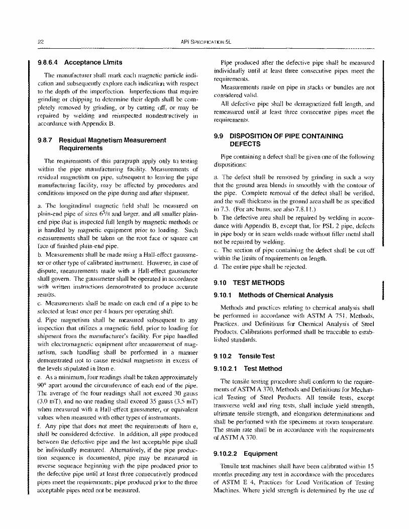
22 API SPECIFICATION 5L
9.8.6.4 Acceptance Limits
The manufacturer shall mark each magnetic particle indication and subsequently explore each indication with respect to the depth of the imperfection. Imperfections that require grinding or chipping to determine their depth shall be completely removed by grinding, or by cutting off, or may be repaired by welding and reinspected nondestructively in accordance with Appendix B.
9.8.7 Residual Magnetism Measurement Requirements
The requirements of this paragraph apply only to testing within the pipe manufacturing facility. Measurements of residual magnetism on pipe, subsequent to leaving the pipe manufacturing facility, may be affected by procedures and conditions imposed on the pipe during and after shipment.
a. The longitudinal magnetic field shall be measured on plain-end pipe of sizes 65/8 and larger, and all smaller plainend pipe that is inspected full length by magnetic methods or is handled by magnetic equipment prior to loading. Such measurements shall be taken on the root face or square cut face of finished plain-end pipe.
b. Measurements shall be made using a Hall-effect gauss meter or other type of calibrated instrument. However, in case of dispute, measurements made with a Hall-effect gaussmeter shall govern. The gaussmeter shall be operated in accordance with written instructions demonstrated to produce accurate results. c. Measurements shall be made on each end of a pipe to be selected at least once per 4 hours per operating shift.
d. Pipe magnetism shall be measured subsequent to any inspection that utilizes a magnetic field, prior to loading for shipment from the manufacturer's facility. For pipe handled with electromagnetic equipment after measurement of magnetism, such handling shall be performed in a manner demonstrated not to cause residual magnetism in excess of the levels stipulated in Item e.
e. As a minimum, four readings shall be taken approximately 90° apart around the circumference of each end of the pipe. The average of the four readings shall not exceed 30 gauss (3.0 mT), and no one reading shall exceed 35 gauss (3.5 mT) when measured with a Hall-effect gaussmeter, or equivalent values when measured with other types of instruments. f. Any pipe that does not meet the requirements of Item e, shall be considered defective. In addition, all pipe produced between the defective pipe and the last acceptable pipe shall be individually measured. Alternatively, if the pipe production sequence is documented, pipe may be measured in reverse sequence beginning with the pipe produced prior to the defective pipe until at least three consecutively produced pipes meet the requirements; pipe produced prior to the three acceptable pipes need not be measured.
Pipe produced after the defective pipe shall be measured individually until at least three consecutive pipes meet the requirements.
Measurements made on pipe in stacks or bundles are not considered valid.
All defective pipe shall be demagnetized full length, and remeasured until at least three consecutive pipes meet the requirements.
9.9 DISPOSITION OF PIPE CONTAINING DEFECTS
Pipe containing a defect shall be given one of the following dispositions:
a. The defect shall be removed by grinding in such a way that the ground area blends in smoothly with the contour of the pipe. Complete removal of the defect shall be verified, and the wall thickness in the ground area shall be as specified in 7.3. (For arc bums, see also 7.S.ll.) b. The defective area shall be repaired by welding in accordance with Appendix B, except that, for PSL 2 pipe, defects in pipe body or in seam welds made without filler metal shall not be repaired by welding. c. The section of pipe containing the defect shall be cut off within the limits of requirements on length. d. The entire pipe shall be rejected.
9.10 TEST METHODS
9.10.1 Methods of Chemical Analysis
Methods and practices relating to chemical analysis shall be performed in accordance with ASTM A 751, Methods, Practices, and Definitions for Chemical Analysis of Steel Products. Calibrations performed shall be traceable to established standards.
9.10.2 Tensile Test
9.10.2.1 Test Method
The tensile testing procedure shall conform to the requirements of ASTM A 370, Methods and Definitions for Mechanical Testing of Steel Products. All tensile tests, except transverse weld and ring tests, shall include yield strength, ultimate tensile strength, and elongation determinations and shall be performed with the specimens at room temperature. The strain rate shall be in accordance with the requirements of ASTM A 370.
9.10.2.2 Equipment
Tensile test machines shall have been calibrated within 15 months preceding any test in accordance with the procedures of ASTM E 4, Practices for Load Verification of Testing Machines. Where yield strength is determined by the use of
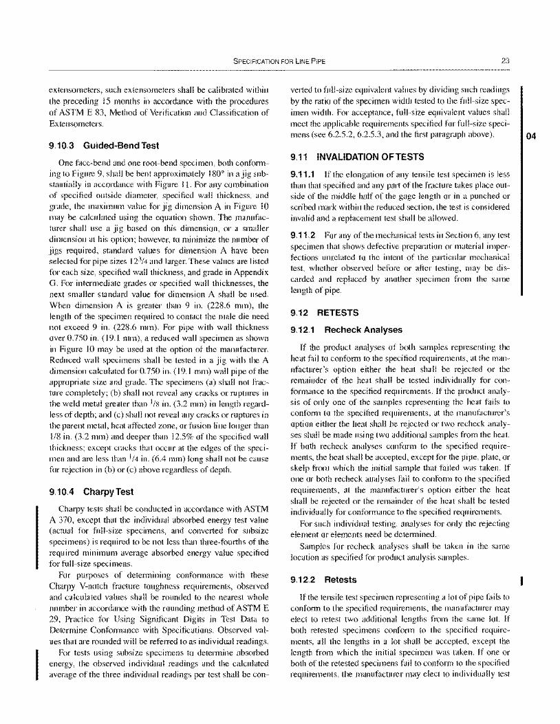
SPECIFICATION FOR LINE PIPE 23
extensometers, such extensometers shall be calibrated within the preceding IS months in accordance with the procedures of ASTM E 83, Method of Verification and Classification of Extensometers.
9.10.3 Guided-Bend Test
One face-bend and one root-bend specimen, both conforming to Figure 9, shall be bent approximately 1800 in a jig substantially in accordance with Figure I 1. For any combination of specified outside diameter, specified wall thickness, and grade, the maximum value for jig dimension A in Figure 10 may be calculated using the equation shown. The manufacturer shall use a jig based on this dimension, or a smaller dimension at his option; however, to minimize the number of jigs required, standard values for dimension A have been selected for pipe sizes 123/4 and larger. These values are listed for each size, specified wall thickness, and grade in Appendix G. For intermediate grades or specified wall thicknesses, the next smaller standard value for dimension A shall be used. When dimension A is greater than 9 in. (228.6 mm), the length of the specimen required to contact the male die need not exceed 9 in. (228.6 mm). For pipe with wall thickness over 0.750 in. (19.1 mm), a reduced wall specimen as shown in Figure 10 may be used at the option of the manufacturer. Reduced wall specimens shall be tested in a jig with the A dimension calculated for 0.750 in. (19.1 mm) wall pipe of the appropriate size and grade. The specimens (a) shall not fracture completely; (b) shall not reveal any cracks or ruptures in the weld metal greater than I/S in. (3.2 mm) in length regardless of depth; and (c) shall not reveal any cracks or ruptures in the parent metal, heat affected zone, or fusion line longer than 1/8 in. (3.2 mm) and deeper than 12.5% of the specified wall thickness; except cracks that occur at the edges of the specimen and are less than 1/4 in. (6.4 mm) long shall not be cause for rejection in (b) or (c) above regardless of depth.
9.10.4 CharpyTest
Charpy tests shall be conducted in accordance with ASTM A 370, except that the individual absorbed energy test value (actual for full-size specimens, and converted for subsize specimens) is required to be not less than three-fourths of the required minimum average absorbed energy value specified for full-size specimens.
For purposes of determining conformance with these Charpy V-notch fracture toughness requirements, observed and calculated values shall be rounded to the nearest whole number in accordance with the rounding method of ASTM E 29, Practice for Using Significant Digits in Test Data to Determine Conformance with Specifications. Observed values that are rounded will be referred to as individual readings.
For tests using subsize specimens to determine absorbed energy, the observed individual readings and the calculated average of the three individual readings per test shall be con-
verted to full-size equivalent values by dividing such readings by the ratio of the specimen width tested to the full-size specimen width. For acceptance, full-size equivalent values shall meet the applicable requirements specified for full-size specimens (see 6.2.5.2, 6.2.5.3, and the first paragraph above).
9.11 INVALIDATION OFTESTS
9.11.1 If the elongation of any tensile test specimen is less than that specified and any part of the fracture takes place outside of the middle half of the gage length or in a punched or scribed mark within the reduced section, the test is considered invalid and a replacement test shall be allowed.
9.11.2 For any of the mechanical tests in Section 6, any test specimen that shows defective preparation or material imperfections unrelated to the intent of the particular mechanical test, whether observed before or after testing, may be discarded and replaced by another specimen from the same length of pipe.
9.12 RETESTS
9.12.1 Recheck Analyses
If the product analyses of both samples representing the heat fail to conform to the specified requirements, at the manufacturer's option either the heat shall be rejected or the remainder of the heat shall be tested individually for conformance to the specified requirements. If the product analysis of only one of the samples representing the heat fails to conform to the specified requirements, at the manufacturer's option either the heat shall be rejected or two recheck analyses shall be made using two additional samples from the heat. If both recheck analyses conform to the specified requirements, the heat shall be accepted, except for the pipe, plate, or skelp from which the initial sample that failed was taken. If one or both recheck analyses fail to conform to the specified requirements, at the manufacturer's option either the heat shall be rejected or the remainder of the heat shall be tested individually for conformance to the specified requirements.
For such individual testing, analyses for only the rejecting element or elements need be determined.
Samples for recheck analyses shall be taken in the same location as specified for product analysis samples.
9.12.2 Retests
If the tensile test specimen representing a lot of pipe fails to conform to the specified requirements, the manufacturer may elect to retest two additional lengths from the same lot. If both retested specimens conform to the specified requirements, all the lengths in a lot shall be accepted, except the length from which the initial specimen was taken. If one or both of the retested specimens fail to conform to the specified requirements, the manufacturer may elect to individually test
04
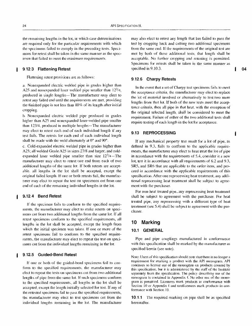
24 API SPECIFICATION 5L
the remaining lengths in the lot, in which case determinations are required only for the particular requirements with which the specimens failed to comply in the preceding tests. Specimens for retest shall be taken in the same manner as the specimen that failed to meet the minimum requirements.
9.12.3 Flattening Retest
Flattening retest provisions are as follows:
a. Nonexpanded electric welded pipe in grades higher than A25 and nonexpanded laser welded pipe smaller than 123/4,
produced in single lengths- The manufacturer may elect to retest any failed end until the requirements are met, providing the finished pipe is not less than 80% of its length after initial cropping.
b. Nonexpanded electric welded pipe produced in grades higher than A25 and nonexpanded laser-welded pipe smaller than 123/4, produced in multiple lengths-The manufacturer may elect to retest each end of each individual length if any test fails. The retests for each end of each individual length shall be made with the weld altemately at 0° and 90°.
c. Cold-expanded electric welded pipe in grades higher than A25; all welded Grade A25 in sizes 27/8 and larger; and coldexpanded laser welded pipe smaller than size 123/4-The manufacturer may elect to retest one end from each of two additional lengths of the same lot. If both retests are acceptable, all lengths in the lot shall be accepted, except the original failed length. If one or both retests fail, the manufacturer may elect to repeat the test on specimens cut from one end of each of the remaining individual lengths in the lot.
9.12.4 Bend Retest
If the specimen fails to conform to the specified requirements, the manufacturer may elect to make retests on specimens cut from two additional lengths from the same lot. If all retest specimens conform to the specified requirements, all lengths in the lot shall be accepted, except the length from which the initial specimen was taken. If one or more of the retest specimens fail to conform to the specified requirements, the manut:1cturer may elect to repeat the test on specimens cut from the individual lengths remaining in the lot.
9.12.5 Guided-Bend Retest
If one or both of the guided-bend specimens fail to conform to the specified requirements, the manufacturer may elect to repeat the tests on specimens cut from two additional lengths of pipe from the same lot. If such specimens conform to the specified requirements, all lengths in the lot shall be accepted, except the length initially selected for test. If any of the retested specimens fail to pass the specified requirements, the manufacturer may elect to test specimens cut from the individual lengths remaining in the lot. The manufacturer
may also elect to retest any length that has failed to pass the test by cropping back and cutting two additional specimens from the same end. If the requirements of the original test are met by both of these additional tests, that length shall be acceptable. No further cropping and retesting is permitted. Specimens for retests shall be taken in the same manner as specified in 9.10.3.
9.12.6 Charpy Retests
In the event that a set of Charpy test specimens fails to meet the acceptance criteria, the manufacturer may elect to replace the lot of material involved or altematively to test two more lengths from that lot. If both of the new tests meet the acceptance criteria, then all pipe in that heat, with the exception of the original selected length, shall be considered to meet the requirement. Failure of either of the two additional tests shall require testing of each length in the lot for acceptance.
9.13 REPROCESSING
If any mechanical property test result for a lot of pipe, as defined in 9.3, fails to conform to the applicable requirements, the manufacturer may elect to heat treat the lot of pipe in accordance with the requirements of 5.4, consider it a new lot, test it in accordance with all requirements of 6.2 and 9.3, SR5, and SR6 that are applicable to the order item, and proceed in accordance with the applicable requirements of this specification. After one reprocessing heat treatment, any additional reprocessing heat treatment shall be subject to agreement with the purchaser.
For non-heat treated pipe, any reprocessing heat treatment shall be subject to agreement with the purchaser. For heat treated pipe, any reprocessing with a different type of heat treatment (see 5.4) shall be subject to agreement with the purchaser.
10 Marking
10.1 GENERAL
Pipe and pipe couplings manufactured in conformance with this specification shall be marked by the manufacturer as specified herein (see note).
Note: Users of this specification should note that there is no longer a requirement for marking a product with the API monogram. APr continues to license use of the monogram on products covered by this specification, but it is administered by the staff of the Institute separately from the specification. The policy describing use of the monogram is contained in Appendix I. No other use of the monogram is permitted. Licensees mark products in conformance with Section 10 or Appendix I and nonlicensees mark products in conformance with Section 10.
10.1.1 The required marking on pipe shall be as specified hereinafter.
04
SPECIFICATION FOR LINE PIPE 25
10.1.2 The required marking on couplings shall be die stamped unless otherwise agreed between the purchaser and the manufacturer, in which case it shall be paint stenciled.
10.1.3 Additional markings including those for compatible standards following the specification marking are allowed and may be applied as desired by the manufacturer or as requested by the purchaser.
10.2 LOCATION OF MARKINGS
The location of identification markings shall be as follows:
a. Size 1.900 or smaller- Die stamped on a metal tag fixed to the bundle or may be printed on the straps or banding clips used to tie the bundle. b. Seamless pipe in all other sizes and welded pipe smaller than size 16 - Paint stencil on the outside surface starting at a point between 18 in. and 30 in. (457.2 mm and 762 mm) from the end of the pipe in the sequence shown in 10.3, except when agreed between the purchaser and the manufacturer some or all of the markings may be placed on the inside surface in a sequence convenient to the manufacturer. c. Welded pipe size 16 or larger- Paint stencil on the inside surface starting at a point no less than 6 in. (152.4 mm) from the end of the pipe in a sequence convenient to the manufacturer, unless otherwise specified by the purchaser.
10.3 SEQUENCE OF MARKINGS
The sequence of identification markings shall be as specified in 10.3.1 through 10.3.10.
10.3.1 Manufacturer
Manufacturer's name or mark shall be the first identifying mark.
10.3.2 Specification
"Spec 5L" shall be marked when the product is in complete compliance with this specification.
1 0.3.3 Compatible Standards
Products in compliance with multiple compatible standards may be marked with the name of each standard.
1 0.3.4 Specified Dimensions
The specified Olltside diameter and the specified wall thickness shall be marked, except that, for the specified outside diameter, any ending zero digits to the right of the decimal need not be included in such markings.
10.3.5 Grade and Class
The symbols to be used are as follows:
Grade (see Note) Symbol
A25, Class I A25 A25, Class II A25R
A A B B
X42 X42 X46 X46 X52 X52 X56 X56 X60 X60 X65 X65 X70 X70 X80 X80
For grades intermediate to X42 and X80, the symbol shall be X followed by the first two digits of the specified minimum yield strength in U.S. Customary units.
By agreement between the purchaser and the manufacturer and when so specified on the purchase order, the grade shall be identified by color in accordance with SR3 (see Appendix F).
Note: See 1.3 for limitations on downgrading.
10.3.6 Product Specification Level
The symbols to be used are as follows:
a. PSL I b. PSL 2
PSLI PSL2
The PSL marking shall be placed immediately after the grade symbol.
10.3.7 Process of Manufacture
The symbols to be used are as follows:
a. Seamless pipe S b. Welded pipe, except continuous E c. Welded and laser welded d. Continuous welded pipe F e. Laser welded pipe L
10.3.8 Heat Treatment
The symbols to be used are as follows:
a. Normalized or normalized and HN tempered
b. Subcritical stress relieved HS c. Subcritical age hardened HA d. Quench and tempered HQ
10.3.9 Test Pressure
When the specified hydrostatic test pressure is higher than the tabulated pressure (Tables 4, 5, 6A, 6B, 6C, E-6A, E-6B, or E-6C, whichever is applicable), the word "TESTED" shall be marked, immediately followed by the specified test pres-
26 API SPECIFICATION 5L
sure (in pounds per square inch for pipe ordered in U.S. Customary units, or in hundreds of kilopascals for pipe ordered in SI units).
10.3.10 Supplementary Requirements
See Appendix F for supplementary requirements.
10.3.11 Examples
a. Size 14, 0.375 in. (9.5 mm) specified wall thickness, Grade B, PSL 2, seamless, plain-end pipe should be paint stenciled as follows, using the values that are appropriate for the pipe dimensions specified on the purchase order:
AB CO Spec 5L 140.375 B PSL2 S
or
AB CO Spec 5L 355.6 9.5 B PSL2 S
b. Size 65/8, 0.280 in. (7.1 mm) specified wall thickness, Grade B, PSL I, electric welded, plain-end pipe should be paint stenciled as follows. using the values that are appropriate for the pipe dimensions specified on the purchase order:
AB CO Spec 5L 6.625 0.280 B PSLl E
or
AB CO Spec 5L 168.37.1 B PSLl E c. Size 4'/2, 0.237 in. (6.0 mm) specified wall thickness, Grade A25, Class r, continuous welded, threaded-end pipe should be paint stenciled as follows, using the values that are appropriate for the pipe dimensions specified on the purchase order:
AB CO Spec 5L 4.5 0.237 A25 PSLl F
or
AB CO Spec 5L 114.36.0 A25 PSLl F
d. Size 14, 0.375 in. (9.5 mm) specified wall thickness, Grade X70, PSL 2. seamless, quenched and tempered, plainend pipe should be paint stenciled as follows, using the values that are appropriate for the pipe dimensions specified on the purchase order:
AB CO Spec 5L 140.375 X70 PSL2 S HQ or
AB CO Spec 5L 355.6 9.5 X70 PSL2 S HQ
e. Size 123/4, 0.330 in. (8.4 mm) specified wall thickness, Grade X42, PSL I, seamless plain-end pipe should be paint stenciled as follows, using the values that are appropriate for the pipe dimensions specified on the purchase order:
AB CO Spec 5L 12.750.330 X42 PSLl S
or
AB CO Spec 5L 323.9 8.4 X42 PSLl S
f. Size 65/8. 0.216 in. (5.5 mm) specified wall thickness. Grade X42, PSL I, laser welded, plain-end pipe should be paint stenciled as follows, using the values that are appropriate for the pipe dimensions specified on the purchase order:
AB CO Spec 5L 6.6250.216 X42 PSLl L
or
AB CO Spec 5L 168.3 5.5 X42 PSL I L g. Size 24, 0.406 in. (10.3 mm) specified wall thickness, Grade X42, PSL 2 helical seam submerged-arc welded plainend pipe should be paint stenciled as follows, using the values that are appropriate for the pipe dimensions specified on the purchase order:
AB CO Spec 5L 24 0.406 X42 PSL2 E or
AB CO Spec 5L 610 10.3 X42 PSL2 E
10.4 BUNDLE IDENTIFICATION
For pipe of size 1.900 or smaller, the identification markings specified in 10.3 shall be placed on the tag, strap, or clip used to tie the bundle. For example, size 1.900,0.145 in. (3.7 mm) specified wall thickness, Grade B, electric welded, plain-end pipe should have the following marking, using the values that are appropriate for the pipe dimensions specified on the purchase order:
AB CO Spec 5L 1.90.145 B PSLl E or
AB CO Spec 5L 48.3 3.7 B PSLl E
10.5 LENGTH
In addition to the identification markings stipulated in 10.2, 10.3, and 10.4, the length shall be marked as follows, using feet and tenths of a foot for pipe ordered in U.S. Customary units, or meters to two decimal places for pipe ordered in SI units, unless a different measuring and marking format has been agreed upon by the purchaser and the manufacturer:
a. For pipe larger than size 1.900, the length, as measured on the finished pipe, shall be paint stenciled on the outside surface at a location convenient to the manufacturer, or by agreement between the purchaser and the manufacturer, on the inside surface at a convenient location. b. For pipe of size 1.900 or smaller, the total length of pipe in the bundle shall be marked on the tag, band, or clip.
10.6 COUPLINGS
All couplings in sizes 23/8 and larger shall be identified with the manufacturer's name or mark and "Spec 5L".
10.7 DIE STAMPING
Cold die stamping is prohibited on all pipe with specified wall thickness of 0.156 in. (4.0 mm) or less and all pipe of grades higher than A25 and not subsequently heat treated, except by agreement between the purchaser and the manufacturer and when so specified on the purchase order, pipe or plate may be cold die stamped. The manufacturer at his option may hot die stamp [200°F (93°C) or higher] plate or pipe, cold die stamp plate or pipe if it is subsequently heat treated, and cold die stamp couplings. Cold die stamping
SPECIFICATION FOR LINE PIPE 27
shall be done with rounded or blunt dies. All die stamping shall be at least I in. (25A mm) from the weld for all grades except Grade A25.
10.8 THREAD IDENTIFICATION
At the manufacturer's option, threaded-end pipe may be identified by stamping or stenciling the pipe adjacent to the threaded ends, with the manufacturer's name or mark, "Spec 58" (to indicate the applicable threading specification), the specified outside diameter of the pipe, and the letters "LP" (to indicate the type of thread). The thread marking may be applied to products that do or do not bear the API monogram. For example, size 65/8 threaded-end pipe may be marked as follows, using the value that is appropriate for the pipe outside diameter specified on the purchase order:
AB CO Spec 5B 6.625 LP or
AB CO Spec 5B 168.3 LP If the product is clearly marked elsewhere with the manu
facturer's identification, his name or mark, as above, may be omitted.
10.9 THREAD CERTIFICATION
The use of the letters "Spec SB" as provided in 10.8 shall constitute a certification by the manufacturer that the threads so marked comply with the requirements in API Standard S8 but should not be construed by the purchaser as a representation that the product so marked is, in its entirety, in accordance with any API specification. Manufacturers who use the letters "Spec SB" for thread identification are required to have access to properly certified API master pipe gages.
10.10 PIPE PROCESSOR MARKINGS
Pipe heat treated by a processor other than the original pipe manufacturer shall be marked as stipulated in 10.1, 10.2, 10.3, lOA, 10.5, 10.6, and 10.7. The processor shall remove any marking that does not indicate the new condition of the product as a result of heat treating (such as prior grade identity and original pipe manufacturer's name or logo).
11 Coating and Protection 11.1 COATINGS
Unless otherwise specified in the purchase order, pipe shall be supplied either uncoated (bare) or with a temporary external coating to minimize rusting in transit, at the option of the manufacturer. Temporary coatings should be hard to the touch and smooth, with minimum sags.
If the purchaser requires pipe to be uncoated, or to have a temporary or special coating, the purchase order should so state.
For special coatings, the purchase order should state whether the coating is to be applied full length, or with a specified cutback (uncoated distance at each pipe end). Unless otherwise specified, the manufacturer has the option to leave the pipe ends either coated or uncoated, and the option to apply a temporary coating to the pipe ends.
11.2 THREAD PROTECTORS
On pipe smaller than size 23/8, the thread protectors shall be suitable fabric wrappings or suitable metal, fiber, or plastic protectors. On pipe of sizes 23/8 and larger, the thread protectors shall be of such design, material, and mechanical strength to protect the thread and end of the pipe from damage under normal handling and transportation conditions. The thread protectors shall cover the full length of the thread on the pipe and exclude water and dirt from the thread during transportation and the period of normal storage. The normal storage period shall be considered approximately one year. The thread forms in protectors shall be such that the pipe threads are not damaged by the protectors. Protector material shall contain no compounds capable of causing corrosion or promoting adherence of the protectors to the threads and shall be suitable for service temperatures of- 50°F to + ISO°F (- 46°C to + 66°C).
12 Documents
12.1 CERTIFICATION
12.1.1 PSL 1 Certification Requirements
The manufacturer shall, upon request by the purchaser, furnish to the purchaser a certificate of compliance stating that the material has been manufactured, sampled, tested, and inspected in accordance with this specification and has been found to meet the requirements.
A Material Test Report, Certificate of Compliance or similar document printed from or used in electronic form from an electronic data interchange (EDI) transmission shall be regarded as having the same validity as a counterpart printed in the certifier's facility. The content of the EOI transmitted document must meet the requirements of this specification and conform to any existing EOI agreement between the purchaser and supplier.
Where additional information is required, including the results of mechanical testing, SR15 shall be specified on the purchase order (see Appendix F).
12.1.2 PSL 2 Certification Requirements
The manufacturer shall provide to the purchaser certificates of compliance and test results in compliance with SR IS.1 (see Appendix F).
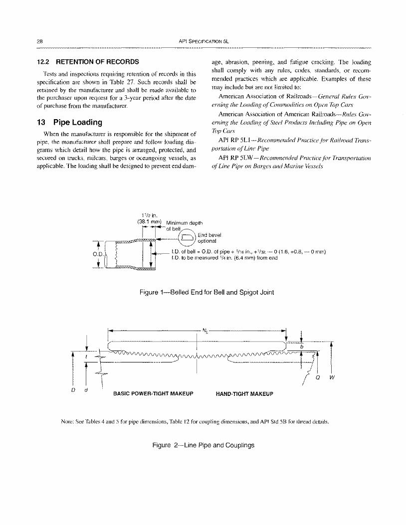
28 API SPECIFICATION 5L
12.2 RETENTION OF RECORDS
Tests and inspections requiring retention of records in this specification are shown in Table 27. Such records shall be retained by the manuhlcturer and shall be made available to the purchaser upon request for a 3-year period after the date of purchase from the manufacturer.
13 Pipe Loading When the manufacturer is responsible for the shipment of
pipe, the manufacturer shall prepare and follow loading diagrams which detail how the pipe is arranged, protected, and secured on tmcks, railcars, barges or oceangoing vessels, as applicable. The loading shall be designed to prevent end dam-
11/2 in.
(38.1 mm) Minimum depth
age, abrasion, peening, and fatigue cracking. The loading shall comply with any mles, codes, standards, or recommended practices which are applicable. Examples of these may include but are not limited to:
American Association of Railroads-General Rules Governing the Loading of Commodities on Open Top Cars
American Association of American Railroads-Rules Governing the Loading of Steel Products Including Pipe on Open Top Cars
API RP 5Ll-Recommended Practice for Railroad Transportation oj Line Pipe
API RP 5LW - Recommended Practice for Transportation ojLine Pipe on Barges and Marine Vessels
rTofbell
--==-zfl~~tz1----1 0 End bevel T' optional
0.0. 1.0. of bell = 0.0. of pipe + 1116 in., +1/32, - 0 (1.6, +0.8, - 0 mm) ---±- 1.0. to be measured 1/4 in. (6.4 mm) from end
Figure 1-Belled End for Bell and Spigot Joint
w
o d BASIC POWER-TIGHT MAKEUP HAND-TIGHT MAKEUP
Note: See Tables 4 and 5 for pipe dimensions, Table 12 for coupling dimensions, and API Std 58 for thread details.
Figure 2-Line Pipe and Couplings
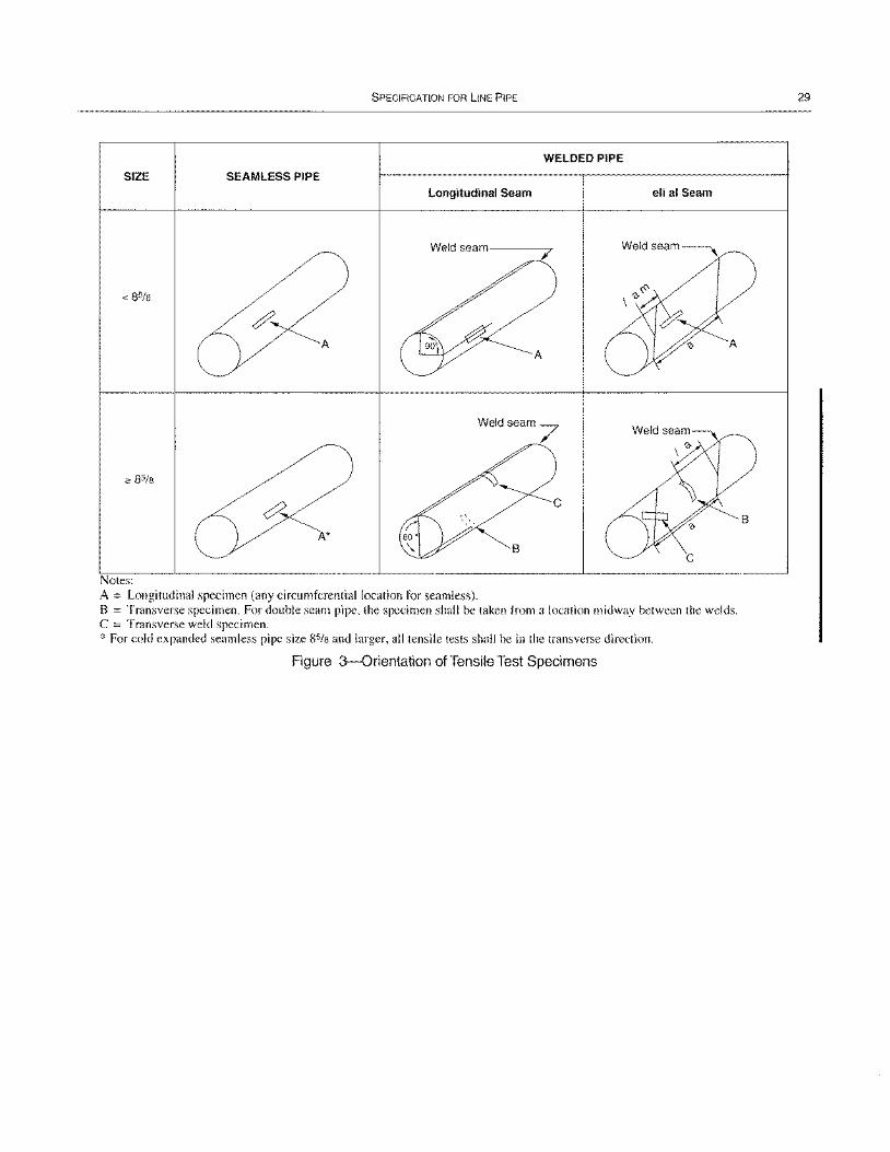
SPECIFICATION FOR LINE PIPE
WELDED PIPE
SIZE SEAMLESS PIPE
Longitudinal Seam eli al Seam
Weldseam~
A A
Weld seam 7
A*
Notes: A = Longitudinal specimen (any circumferential location for seamless). B = Transverse specimen. For double seam pipe, the specimen shall be taken from a location midway between the welds. C = Transverse weld specimen. * For cold expanded seamless pipe size 85/8 and larger, all tensile tests shall be in the transverse direction.
Figure 3-0rientation of Tensile Test Specimens
29
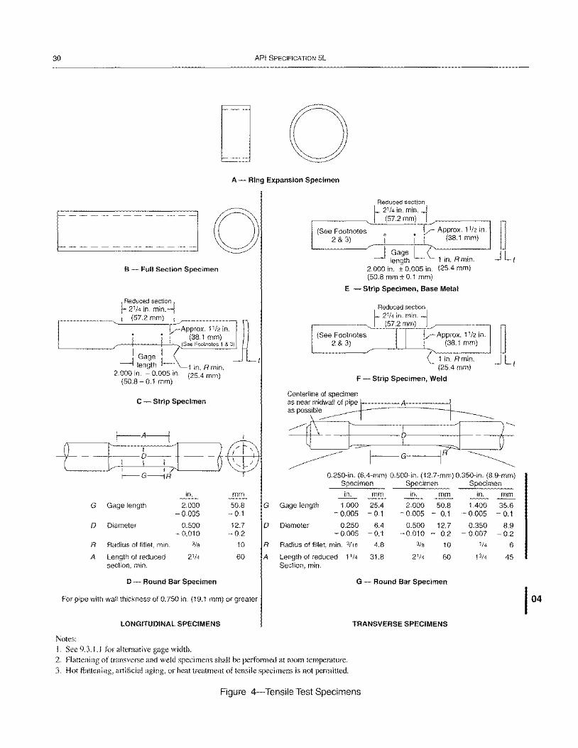
30 API SPECIFICATION 5L
D 0 A - Ring Expansion Specimen
r--~~----~~~~I 0 -------------
(See Footnotes 2 & 3)
Reduced section l- 21/4 in. min. j I (572 mm) I
V Approx. 11/2 in. I i ~ (38.1 mm)
~ Gage LC B - Full Section Specimen
I Reduced section I 121/4 in. min. I I (57.2 mm) I
y--Approx. 1112 in. ~ ! (38.1 mm) , (See Footnotes 1 & 3)
I Gage I ----llength I--
2.000 in. - 0.005 in. (50.8 - 0.1 mm)
1 in. Rmin. (25.4 mm)
C - Strip Specimen
length 1 In. R min. 2.000 in. ± 0.005 in. (25.4 mm) (50.8 mm ± 0.1 mm)
E - Strip Specimen, Base Metal
Reduced section l- 21/4 in. min. j I (57.2 mm) I
(See Footnotes II V Approx. 11/2 in. 2 & 3) ! (38.1 mm)
L--~-~------'-'-----'.r( 1 in. R min.
(25.4 mm)
F - Strip Specimen, Weld
Centerline of specimen
1- t r-A-----l
: f-r-] -~
as near mi~wall of pipe rL===:.A~====jJ aspossibl~ ~
~~ -+--f ~--?'-;--+--j - r~ ~ I-G I ~
r--- G -----j R 0.250-in. (6.4-mm) 0.500-in. (12.7-mm) 0.350-in. (B.9-mm) Specimen Specimen Specimen
in. mm in. mm in. mm in. mm
G Gage length 2.000 50.8 G Gage length 1.000 25.4 2.000 50.8 1.400 35.6 - 0.005 - 0.1 -0.005 - 0.1 -0.005 - 0.1 - 0.005 - 0.1
0 Diameter 0.500 12.7 0 Diameter 0.250 6.4 0.500 12.7 0.350 8.9 -0.010 - 0.2 - 0.005 - 0.1 -0.010 - 0.2 - 0.007 -0.2
R Radius of fillet, min. 3/8 10 R Radius of fillet, min. 3116 4.8 3/8 10 1/4 6
A Length of reduced 21/4 60 A Length of reduced 11/4 31.8 21/4 60 1314 45 section, min. Section, min.
D - Round Bar Specimen G - Round Bar Specimen
For pipe with wall thickness of 0.750 in. (19.1 mm) or greater
LONGITUDINAL SPECIMENS TRANSVERSE SPECIMENS
Notes:
I. See 9.3.1.1 for alternative gage width.
2. Flattening of transverse and weld specimens shall be perfonned at room temperature.
3. Hot flattening, artificial aging, or heat treatment of tensile specimens is not pennitted.
Figure 4-Tensile Test Specimens
I 04
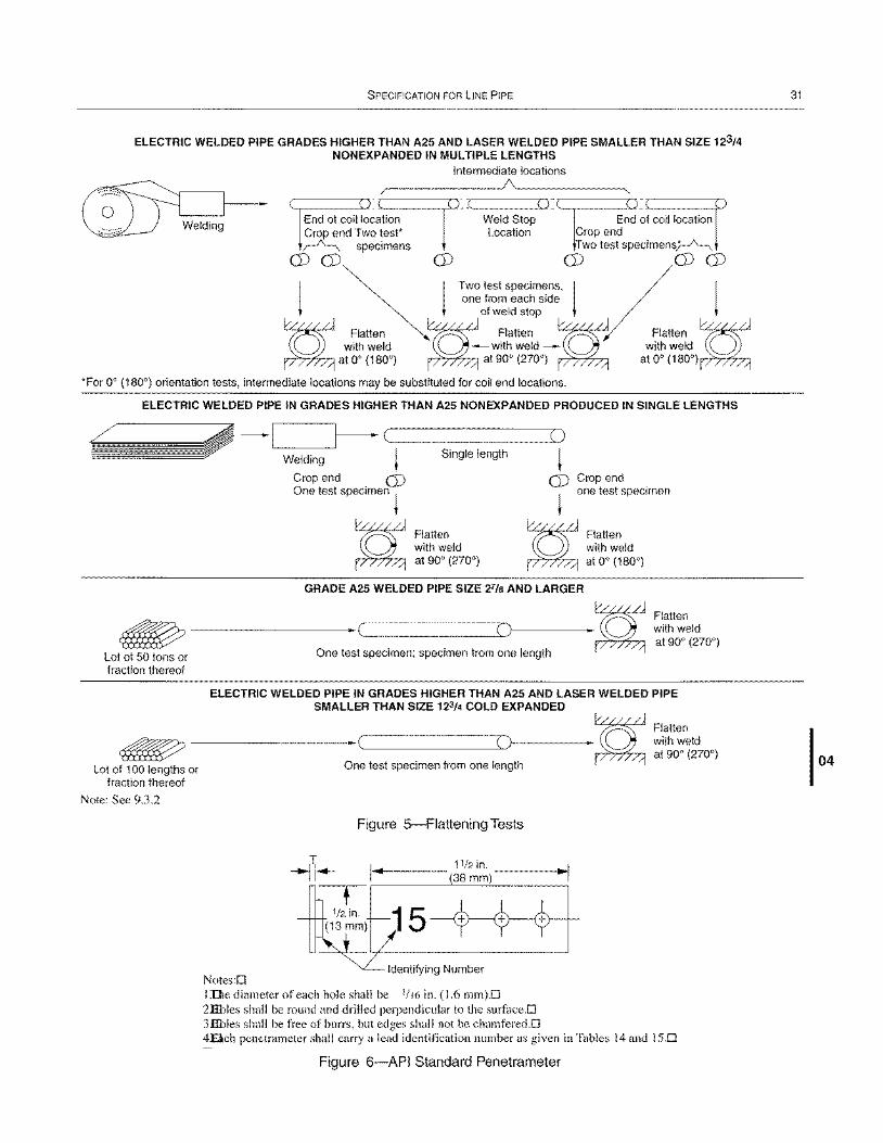
SPECIFICATION FOR LINE PIPE
ELECTRIC WELDED PIPE GRADES HIGHER THAN A25 AND LASER WELDED PIPE SMALLER THAN SIZE 123/4 NON EXPANDED IN MULTIPLE LENGTHS
Intermediate locations /~ ______________ J/\L ____________ ~
~ ______ ~~ ~ ________ ~:S~ ________ (~):~.-____ ~~ ~ ________ ~ End of coil location Weld Stop End of coil location Crop end Two test* Location Crop end ~ specimens :fwo test specimens~
O)! CD ~ CD! :~~ \:;~'~:~~m,~~:m! / CD CD! Flatten ~ of weld stop V Flall
~ ;i~~e~d ~-~I~~e~d-~ ~I~~e~d ~ ~atOO(1800) ~at900(2700) ~ atOO(1800)~
*For 0° (180°) orientation tests, intermediate locations may be substituted for coil end locations.
ELECTRIC WELDED PIPE IN GRADES HIGHER THAN A25 NON EXPANDED PRODUCED IN SINGLE LENGTHS
-I'-----_-'~ (------~( ) ~ Single length ~ Welding
Crop end 0) 0) One test specimen ~ ~
Crop end one test specimen
g Flatten ~ Flatten with weld with weld at 90° (270°) at 0° (180°)
GRADE A25 WELDED PIPE SIZE 27/8 AND LARGER
~-------~----~(~)---~ Lot of 50 tons or One test specimen; specimen from one length
Flatten with weld at 90° (270°)
fraction thereof
ELECTRIC WELDED PIPE IN GRADES HIGHER THAN A25 AND LASER WELDED PIPE SMALLER THAN SIZE 123/4 COLD EXPANDED
g Flatten ~ ----------~ ______________ __..l.(.J)~------- with weld ~ at 90° (270°)
Lot of 100 lengths or One test specimen from one length fraction thereof
Note: See 9.3.2
Notes:D
Figure 5--Flattening Tests
I ....... t--------- 11/2 in.
(38mm)
15 Identifying Number
I The diameter of each hole shall be 1/16 in. (1.6 mm)D 2Ebles shall be round and drilled perpendicular to the surfaceD 3Ebles shall be free of burrs, but edges shall not be chamfered.D
~I
4.El.ch penetrameter shall carry a lead identification number as given in Tables 14 and I S.D
Figure 6--API Standard Penetrameter
31
04
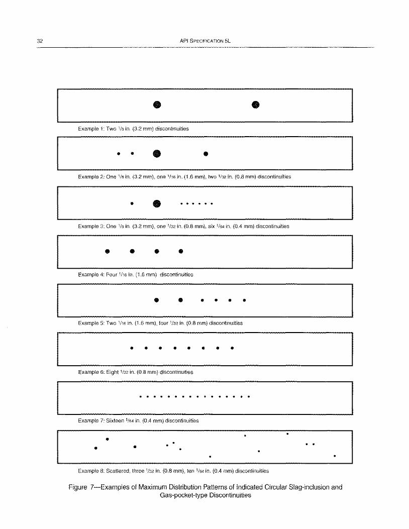
32 API SPECIFICATION 5L
• • Example 1: Two 1/8 in. (3.2 mm) discontinuities
• • • • Example 2: One 1/8 in. (3.2 mm), one 1116 in. (1.6 mm), two 1/32 in. (0.8 mm) discontinuities
• • . . . . . . Example 3: One 1/8 in. (3.2 mm), one 1/32 in. (0.8 mm), six 1/64 in. (0.4 mm) discontinuities
• • • • Example 4: Four 1116 in. (1.6 mm) discontinuities
• • • • • •
Example 5: Two 1116 in. (1.6 mm), four 1/32 in. (0.8 mm) discontinuities
• • • • • • • •
Example 6: Eight 1/32 in. (0.8 mm) discontinuities
. . . . . . . . . . . . . . . . Example 7: Sixteen 1/64 in. (0.4 mm) discontinuities
• • •
Example 8: Scattered, three 1/32 in. (0.8 mm), ten 1/64 in. (0.4 mm) discontinuities
Figure 7-Examples of Maximum Distribution Patterns of Indicated Circular Slag-inclusion and Gas-packet-type Discontinuities
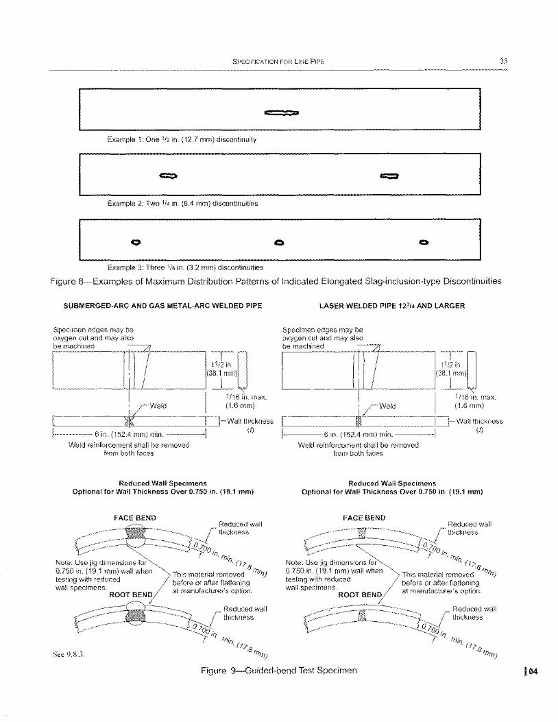
SPECIFICATION FOR LINE PIPE 33
; »
Example 1: One 1/2 in. (12.7 mm) discontinuity
Example 2: Two 1/4 in. (6.4 mm) discontinuities
o
Example 3: Three 1/8 in. (3.2 mm) discontinuities
Figure 8-Examples of Maximum Distribution Patterns of Indicated Elongated Siag-inciusion-type Discontinuities
SUBMERGED-ARC AND GAS METAL-ARC WELDED PIPE
Specimen edges may be oxygen cut and may also be machined
~[ '--_____ -->.-+-'--<-_____ ---'(3I)
I
1/16 in. max. , rweld (1.6 mm)
r-----------o~~'~+. --------.I~Wall thickness
----6 in. (152.4 mm) min. _ __ ._1 (I)
Weld reinforcement shall be removed from both faces
Reduced Wall Specimens Optional for Wall Thickness Over 0.750 in. (19.1 mm)
FACE BEND
Note: Use jig dimensions for 0.750 in. (19.1 mm) wall when testing with reduced wall specimens.
ROOT BEND
Sec 9.8.3.
Reduced wall Jthickness
-2;:00 i / I). It).
II). (7;> 8 It)
This material removed It))
before or after flattening at manufacturer's option.
Reduced wall r thickness
0. 100 . II).
It) fl). (1;>
.8 0 0)
LASER WELDED PIPE 123/4 AND LARGER
Specimen edges may be oxygen cut and may also be machined
11/~in. n L-__________ ~~----______ ~(381Imm)lJ
I
1/16 in. max. , rweld (1.6 mm)
.--------dorfl,-L---------,I:=J_ Wall thickness
----6 in. (152.4 mm) min. _ ___ I (I)
Weld reinforcement shall be removed from both faces
Reduced Wall Specimens Optional for Wall Thickness Over 0.750 in. (19.1 mm)
FACE BEND Reduced wall r thickness
Q--l~OO'
Note: Use jig dimensions for 0.750 in. (19.1 mm) wall when testing with reduced wall specimens.
ROOT BEND
/ fl). 0' II). (7;>
·8 ( This material removed f71t)) before or after flattening at manufacturer's option.
~ =-~~1~ Reduced wall V. ____ --ki~l _. r thickness
~ 0.;>00.' fl)
/ . 0il)
. (1?'8tr. . 'lID)
Figure 9-Guided-bend Test Specimen 104
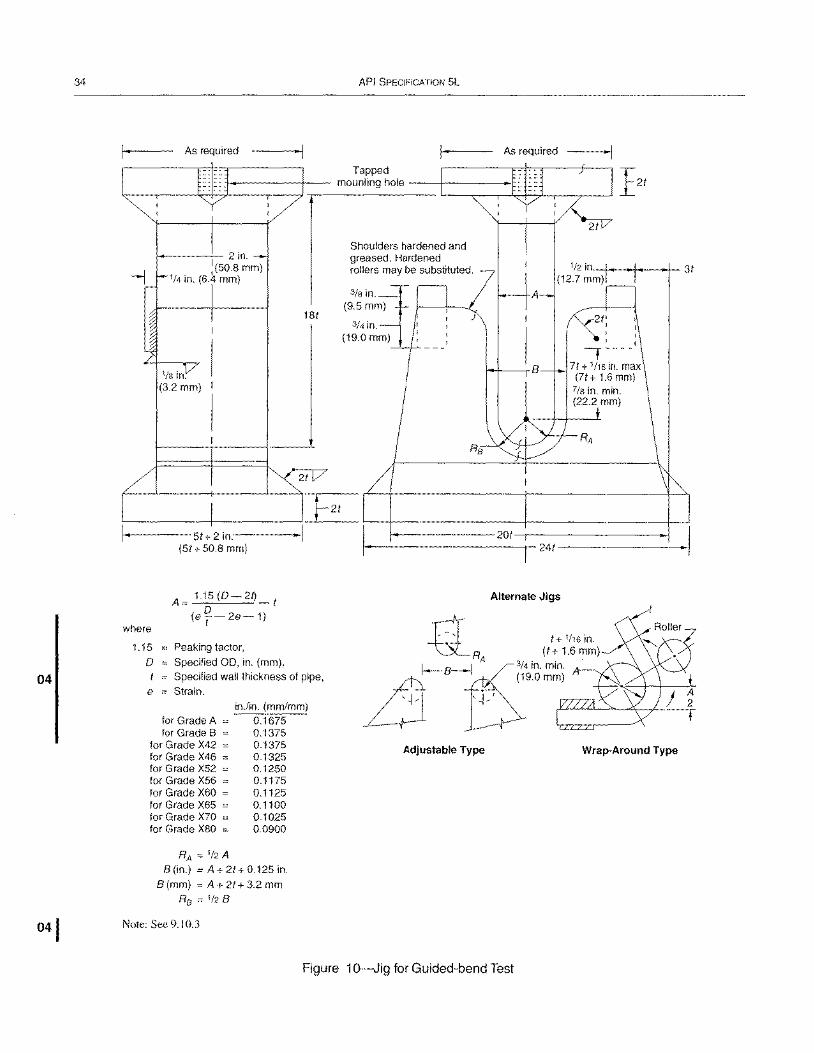
34
04
API SPECIFICATION 5L
l- As required -I l- As required -I Tapped
121 mounting hole
21
Shoulders hardened and 2 in. greased. Hardened
. :(508 mm) 1/2 in. 31 rollers may be SUbstituted. --j 1/4 In. (6.4 mm) (12.7 mm)
3/8 in.
181 (9.5mm)
3/4 in.
I
(19.0 mm) I
'- - - - I
1/8 in. B
(3.2 mm)
L-________ ~--------~~L--+----------------+_----------------+_~ 51 + 2 in.-----I I ~------------201~--------------------1
(51 + 50.8 mm) 1->-----------.,--241 ---------
A= 1.15(0-21)_1 o
(e T-2e-1) where
1.15
o Peaking factor,
e
Specified 00, in. (mm),
Specified wall thickness of pipe, Strain.
for Grade A for Grade B
for Grade X42 for Grade X46 = for Grade X52 = for Grade X56 = for Grade X60 = for Grade X65 = for Grade X70 for Grade X80 =
RA = 1/2 A
in.lin. (mm/mm) 0.1675 0.1375 0.1375 0.1325 0.1250 0.1175 0.1125 0.1100 0.1025 0.0900
8(in.) = A+21+0.125in.
B (mm) = A + 21 + 3.2 mm Ra = 1/28
Note: See 9. J 0.3
Alternate Jigs
Adjustable Type
Figure 1 O-Jig for Guided-bend Test
Wrap-Around Type
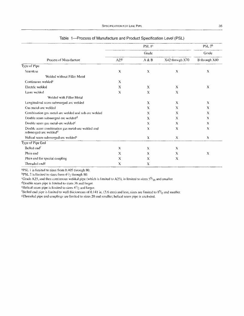
SPECIFICATION FOR liNE PIPE
Table 1-Process of Manufacture and Product Specification Level (PSL)
Grade
Process of Manufacture A25C A&B X42 through X70
Type of Pipe
Seamless
Welded without Filler Metal
Continuous weldedc
Electric welded
Laser welded
Welded with Filler Metal
Longitudinal seam submerged-arc welded
Gas metal-arc welded
Combination gas metal-arc welded and sub-arc welded
Double seam submerged-arc weldedu
Double seam gas metal-arc weldedd
Double seam combination gas metal-arc welded and submerged-arc weldedu
Helical seam submerged-arc weldede
Type of Pipe End
Belled end f
Plain end
Plain end for special coupling
Threaded endg
"PSL I is limited to sizes from 0.405 through SO. bpSL 2 is limited to sizes from 4 1/2 through SO.
x
x X X
X
X
X
X
x
X
X
X
X X
X
X
X
X
X
X
X
X
cGrade A25, and thus continuous welded pipe (which is limited to A25), is limited to sizes 59/ 16 and smaller. dDouble seam pipe is limited to sizes 36 and larger. eHelical seam pipe is limited to sizes 41/2 and larger.
x
X
X
X
X X
X
X
X
X
X
X
X
fBelled end pipe is limited to wall thicknesses of 0.141 in. (3.6 mm) and less; sizes are limited to S5/8 and smaller. gThreaded pipe and couplings are limited to sizes 20 and smaller; helical seam pipe is excluded.
Grade
B through XSO
x
X
X
X
X
X
X
X
X
X
35
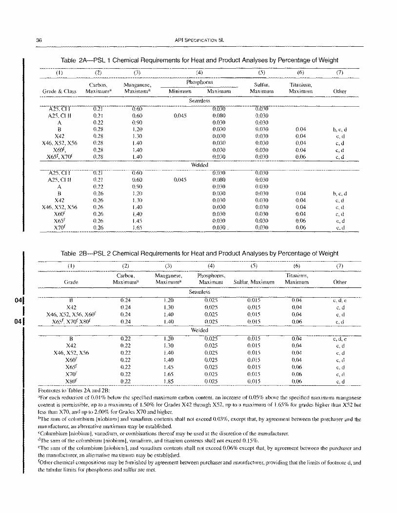
041
I 041
36 API SPECIFICATION 5L
Table 2A-PSL 1 Chemical Requirements for Heat and Product Analyses by Percentage of Weight
(I) (2) (3) (4) (5) (6) (7)
Carbon, Manganese, Phosphorus Sulfur, Titanium, Grade & Class Maximuma Maximuma Minimum Maximum Maximum Maximum Other
Seamless
A25,CII 0.21 0.60 0.030 0.030 A25, CIII 0.21 0.60 0045 0.080 0.030
A 0.22 0.90 0.030 0.030 B 0.28 1.20 0.030 0.030 0.04 b, c, d
X42 0.28 1.30 0.030 0.030 0.04 c,d X46, X52, X56 0.28 lAO 0.030 0.030 0.04 c,d
X60 f, 0.28 lAO 0.030 0.030 0.04 c,d X65 f , X70f 0.28 lAO 0.030 0.030 0.06 c,d
Welded
A25, C11 0.21 0.60 0.030 0.030 A25, C111 0.21 0.60 0.045 0.080 0.030
A 0.22 0.90 0.030 0.030 B 0.26 1.20 0.030 0.030 0.04 b,c,d
X42 0.26 1.30 0.030 0.030 0.04 c,d X46, X52, X56 0.26 lAO 0.030 0.030 0.04 c,d
X60f 0.26 1.40 0.030 0.030 0.04 c,d X65 f 0.26 lAS 0.030 0.030 0.06 c,d X70 f 0.26 1.65 0.030 0.030 0.06 c,d
Table 2B-PSL 2 Chemical Requirements for Heat and Product Analyses by Percentage of Weight
(I) (2) (3) (4) (5) (6) (7)
Carbon, Manganese, Phosphorus, Titanium, Grade Maximuma Maximuma Maximum Sulfur, Maximum Maximum Other
Seamless
B 0.24 1.20 0.025 0.015 0.04 c,d,e X42 0.24 1.30 0.025 0.015 0.04 c,d
X46, X52, X56, X60 f 0.24 lAO 0.025 0.015 0.04 c,d X65 f , X70f X80 f 0.24 lAO 0.025 0.015 0.06 c,d
Welded
B 0.22 1.20 0.025 0.015 0.04 c,d,e X42 0.22 1.30 0.025 0.015 0.04 c,d
X46, X52, X56 0.22 lAO 0.025 0.015 0.04 c,d X60 f 0.22 lAO oms 0.015 0.04 c,d X65 f 0.22 lAS 0.025 0.015 0.06 c,d X70 f 0.22 1.65 0.025 0.015 0.06 c,d X80f 0.22 1.85 0.025 0.015 0.06 c,d
Footnotes to Tables 2A and 2B: aFor each reduction of 0.0 I % below the specified maximum carbon content, an increase of 0.05% above the specified maximum manganese content is permissible, up to a maximum of 1.50% for Grades X42 through X52, up to a maximum of 1.65% for grades higher than X52 but less than X70, and up to 2.00% for Grades X70 and higher. iYfhe sum of columbium Iniobiuml and vanadium contents shall not exceed 0.03%, except that, by agreement between the purchaser and the manufacturer, an alternative maximum may be established. cColumbium 1 niobium I, vanadium, or combinations thereof may be used at the discretion of the manufacturer. dThe sum of the columbium 1 niobium J, vanadium, and titanium contents shall not exceed 0.15%. eThe sum of the columbium I niobium I, and vanadium contents shall not exceed 0.06% except that, by agreement between the purchaser and the manufacturer, an alternative maximum may be established. father chemical compositions may be furnished by agreement between purchaser and manufacturer, providing that the limits of footnote d, and the tabular I imits for phosphorus and sulfur are met.
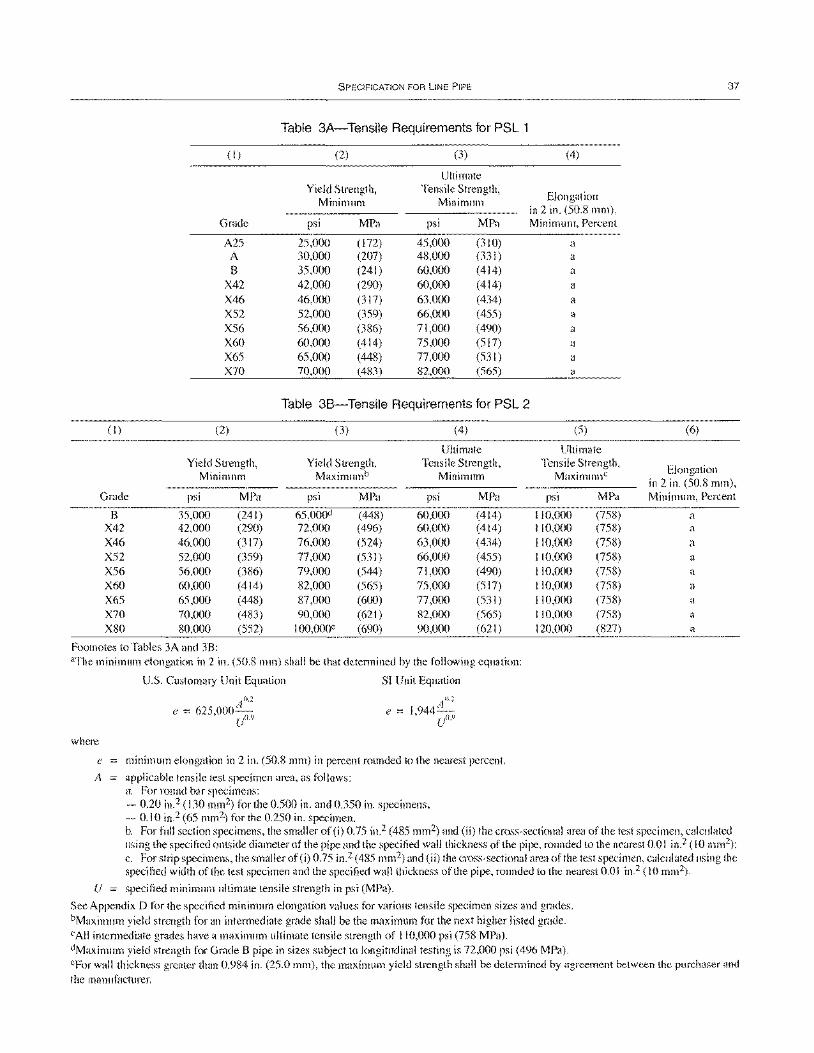
(I)
Grade
8 X42 X46 X52 X56 X60 X65 X70 X80
(I)
Grade
A25 A 8
X42 X46 X52 X56 X60 X65 X70
(2)
Yield Strength, Minimum
psi MPa
35,000 (241) 42,000 (290) 46,000 (317) 52,000 (359) 56,000 (386) 60,000 (414) 65,000 (448) 70,000 (483) 80,000 (552)
SPECIFICATION FOR LINE PIPE
Table 3A-Tensile Requirements for PSL 1
(2) (3)
Ultimate Yield Strength, Tensile Strength,
Minimum Minimum
psi MPa psi MPa
25,000 (172) 45,000 (310) 30,000 (207) 48,000 (331 ) 35,000 (241) 60,000 (414) 42,000 (290) 60,000 (414)
46,000 (317) 63,000 (434) 52,000 (359) 66,000 (455) 56,000 (386) 71,000 (490) 60,000 (414) 75,000 (517)
65,000 (448) 77,000 (531) 70,000 (483) 82,000 (565)
Table 38-Tensile Requirements for PSL 2
(3) (4)
Ultimate Yield Strength, Tensile Strength,
Maximumb Minimum
psi MPa psi MPa
65,000d (448) 60,000 (414) 72,000 (496) 60,000 (414) 76,000 (524) 63,000 (434) 77,000 (531 ) 66,000 (455) 79,000 (544) 71,000 (490) 82,000 (565) 75,000 (517) 87,000 (600) 77,000 (531 )
90,000 (621) 82,000 (565) 100,000e (690) 90,000 (621)
Footnotes to Tables 3A and 38: aThe minimum elongation in 2 in. (50.8 mm) shall be that determined by the following equation:
U.S. Customary Unit Equation SI Unit Equation
where
Ao. 2
e = 625,000---o<! U
Ao.2
e = 1,944-Uo.')
e minimum elongation in 2 in. (50.8 mm) in percent rounded to the nearest percent.
A applicable tensile test specimen area, as follows: a. For round bar specimens: - 0.20 in.2 (130 mm2) for the 0.500 in. and 0.350 in. specimens, - 0.10 in.2 (65 mm2) for the 0.250 in. specimen.
37
(4)
Elongation in 2 in. (50.8 mm). Minimum, Percent
a a a a a a a a a a
(5) (6)
Ultimate Tensile Strength,
Elongation Maximumc
in 2 in. (50.8 mm), psi MPa Minimum, Percent
110,000 (758) a 110,000 (758) a 110,000 (758) a 110,000 (758) a 110,000 (758) a 110,000 (758) a 110,000 (758) a 110,000 (758) a 120,000 (827) a
b. For full section specimens, the smaller of (i) 0.75 in? (485 mm2) and (ii) the cross-sectional area of the test specimen, calculated using the specified outside diameter of the pipe and the specified wall thickness of the pipe, rounded to the nearest 0.0 I in2 (10 mm2); c. For strip specimens, the smaller of (i) 0.75 in.2 (485 mm2) and (ii) the cross-sectional area of the test specimen, calculated using the specified width of the test specimen and the specified wall thickness of the pipe, rounded to the nearest 0.0 I in2 (10 mm2).
U = specified minimum ultimate tensile strength in psi (MPa).
See Appendix 0 for the specified minimum elongation values for various tensile specimen sizes and grades.
bMaximum yield strength for an intermediate grade shall be the maximum for the next higher listed grade. CAll intermediate grades have a maximum ultimate tensile strength of 110,000 psi (758 MPa). dMaximum yield strength for Grade B pipe in sizes subject to longitudinal testing is 72,000 psi (496 MPa). eFor wall thickness greater than 0.984 in. (25.0 mm), the maximum yield strength shall be determined by agreement between the purchaser and
the manufacturer.
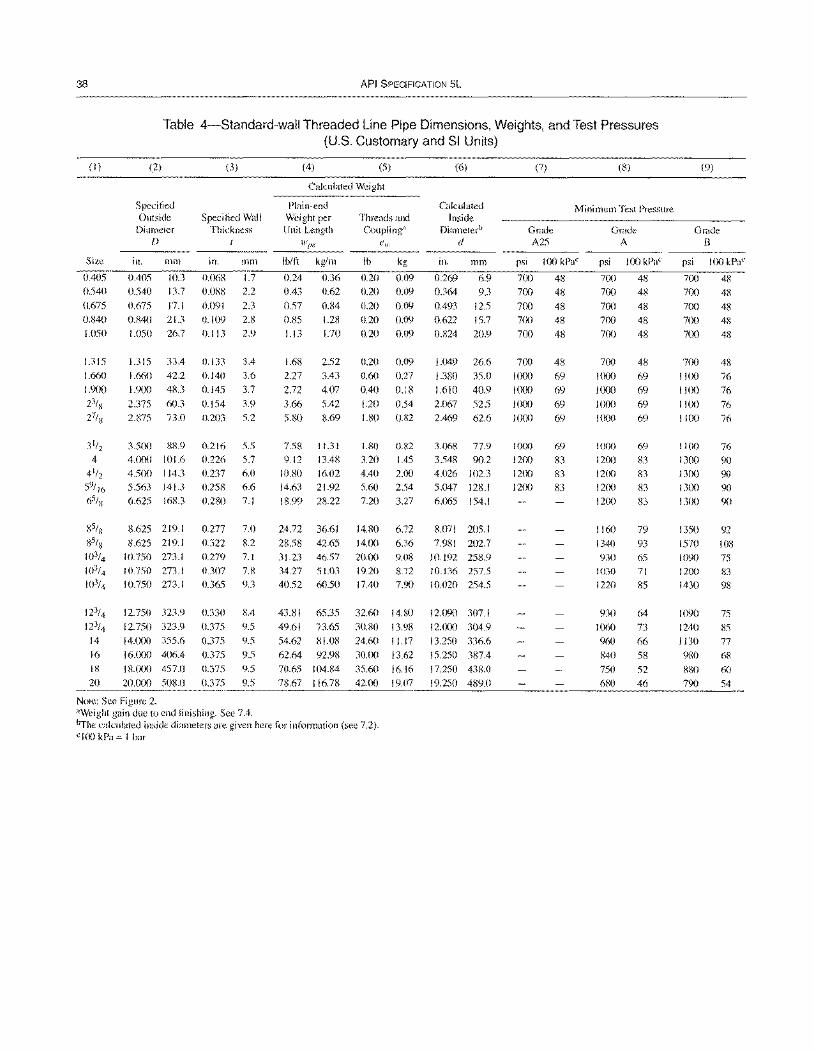
38 API SPECIFICATION 5L
Table 4-Standard-wall Threaded Line Pipe Dimensions, Weights, and Test Pressures (U.S. Customary and SI Units)
(I)
Size
0.405
0.540
0.675 (UW)
1.050
1.315
1.660
1.900 2}/x
27/R
3 1/2
4
4 1/2
59/ 16
6S/ x
gSlx SS/x 103/4
]()3/4
103/4
12}/4 123/4
14
16
IS
20
(2)
Specified Outside
Diameter D
in. mill
0.405 10.3
0.540 13.7
0.675 17.1 0.840 21.3
1.050 26.7
1.315 33.4
1.660 42.2
1.9(X) 48.3
2.375 60.3
2.875 73.0
3.500 gS.9
4.000 101.6 4.500 114.3
5.563 141.3
6.625 168.3
8.625 219.1
8.625 219.1
10.750 273.1
10.750 273.1 10.750 273.1
12.750 323.9
12.750 323.9 14.lXX) 355.6 16'(XX) 406.4
18.cXX) 457.0
20.(XXl 508.0
Note: See Figure 2.
(3)
Specified Wall Thickness
I
in. min
0.068 1.7
0.088 2.2
0.091 2.3 0.109 2.8
0.113 2.9
0.133 3.4
0.140 3.6
0.145 3.7
0.154 3.9 0.203 5.2
0.216
0.226 0.237
0.258 0.280
5.5 5.7 6.0
6.6
7.1
0.277 7.0
0.322 8.2
0.279 7.1
0.307 7.8 0.365 9.3
0.330
0.375
0.375
0.375
0.375
0.375
8.4
9.5
9.5
9.5
9.5
9.5
"Weight gain due to end finishing. See 7.4.
(4) (5)
Calculated Weight
Plain-end Weight per Unit Length
Ib/ft kg/m
0.24 0.36
0.43 0.62
0.57 0.84 0.85 1.28 1.13 1.70
1.68 2.52
2.27 3.43
2.72 4.07
3.66 5.42
5.80 8.69
7.58 11.31 9.12 13.48
10.80 14.63
18.99
16.02
21.92
28.22
Threads and Coupling"
ew
Ib kg
0.20 0.09
0.20 0.09
0.20 0.09 0.20 0.09
0.20 0.09
0.20 0.09
0.60 0.27
0.40 0.18
1.20 0.54 1.80 0.82
1.80
3.20 4.40
5.60 7.20
0.82
1.45 2.00
2.54 3.27
(6)
Calculated Inside
Diameterb
d
in. mm
0.269 6.9
0.364 9.3
0.493 12.5 0.622 15.7
0.824 20.9
1.049 26.6
1.380 35.0
1.610 40.9
2.067 52.5
2.469 62.6
3.068 77.9
3.548 90.2 4.026 102.3
5.047 128.1 6.065 154.1
24.72 36.61 14.80 6.72 8.071 205.1
28.58 42.65 14.00 6.36 7.981 202.7
31.23 46.57 20.00 9.08 10.192 258.9 34.27 51.03 19.20 S.72 10.136 257.5 40.52 60.50 17.40 7.90 10.020 254.5
43.SI 65.35 32.60 14.80
49.61 73.65 30.80 13.98
54.62 SI.08 24.60 11.17
62.64 92.98 30.00 13.62
70.65 104.84 35.60 16.16
78.67 116.78 42.00 19.07
12.090 307.1
12.000 304.9
13.250 336.6 15.250 387.4
17.250 438.0
19.250 489.0
brhe calculated inside diameters are given here for information (see 7.2). clOO kPa = I bar
(7) (8)
Minimum Test Pressure
Grade A25
psi 100 kPac
700 48
700 48
700 48 7(X) 48
700 48
700 48
1000 69
1000 69
1000 69
1000 69
1000
1200 1200
1200
69
83 83
83
Grade A
psi 100 kPac
7(X) 48
700 48
700 48 7(Xl 48 7(X) 48
700 48
1000 69
1000 69
1000 69
1000 69
1000 1200
1200 12(x)
1200
1160
1340
930
1030 1220
930
1060 960
840
750
680
69
83
83 83
83
79
93 65
71
85
64
73
66
58
52
46
(9)
Grade B
psi 100 kPac
700 48
700 48
700 48 700 48
700 48
700 48 IICx) 76
1100 76
1100 76 1100 76
1100 13Cx)
1300
1300 13Cx)
1350
1570 1090
1200
1430
]()90
1240
1130
980
880
790
76
90 90 9() 9()
92 108 75
83
98
75
85
77
68
60
54
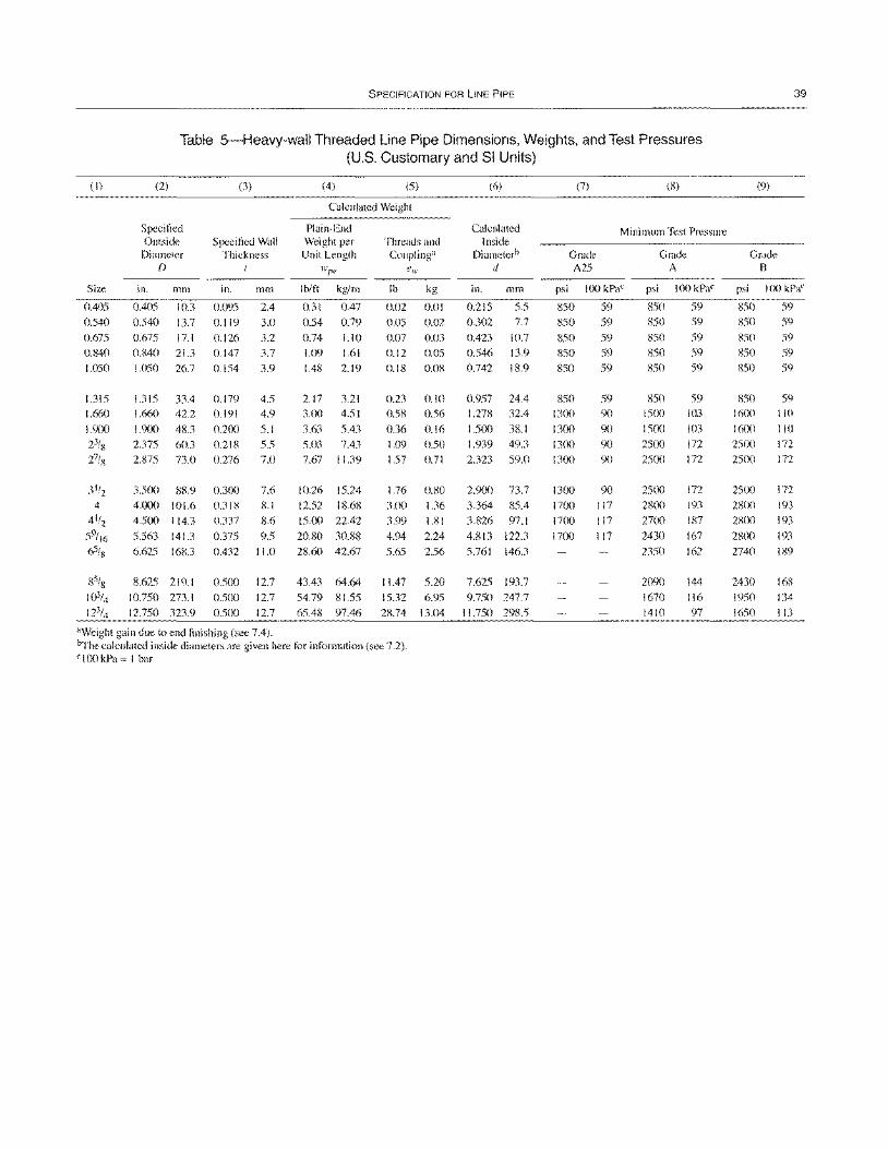
SPECIFICATION FOR LINE PIPE
Table 5-Heavy-wall Threaded Line Pipe Dimensions, Weights, and Test Pressures (U.S. Customary and SI Units)
(I)
Size
0.405
0.540
0.675 0.840
1.050
1.315 1.660
1.900 23/8 27/g
31/2
4
4 1/2
59/ 16 65/8
(2)
Specified Outside
Diameter D
in. mm
0.405 10.3
0.540 13.7
0.675 17.1 0.840 21.3
1.050 26.7
1.315 33.4 1.660 42.2
1.900 48.3 2.375 60.3
2.875 73.0
3.500 88.9 4.000 101.6
4.500 114.3
5.563 141.3 6.625 16K3
8.625 219.1
10.750 273.1
12.750 323.9
(3)
Specified Wall Thickness
in. mm
0.095 2.4
0.119 3.0
0.126 3.2
0.147 3.7
0.154 3.9
0.179 4.5 0.191 4.9
0.200 5.1
0.218 5.5 0.276 7.0
0.300 7.6 0.318 8.1
0.337 8.6
0.375 9.5
0.432 11.0
0.500 12.7 0.500 12.7
0.500 12.7
aWeight gain due to end finishing (see 7.4).
(4) (5)
Calculated Weight
Plain-End Weight per Unit Length
I bitt kglm
0.31 0.47
0.54 0.79
0.74 1.10 1.09 1.61
1.48 2.19
2.17 3.21 3.00 4.51
3.63 5.43 5.03 7.43
7.67 11.39
10.26 15.24
12.52 18.68
15.00 22.42
20.80 30.88 28.60 42.67
43.43 64.64
54.79 81.55
65.48 97.46
Threads and Coupling"
lb
0.02
0.05 0.07
0.12
0.18
0.23 0.58
0.36 1.09
1.57
kg
0.01
0.02
0.03
0.05
0.08
0.10 0.56
0.16
0.50 0.71
1.76 0.80 3.00 1.36
3.99 1.81
4.94 2.24
5.65 2.56
11.47 5.20
15.32 6.95
28.74 13.04
~he calculated inside diameters are given here for information (see 7.2). clOO kPa = I bar
(6)
Calculated Inside
Diameterb
" in. mm
0.215 5.5 0.302 7.7
0.423 10.7 0.546 13.9
0.742 18.9
0.957 24.4 1.278 32.4
1.500 38.1 1.939 49.3
2.323 59.0
2.900 73.7
3.364 85.4
3.826 97.1
4.813 122.3
5.761 146.3
7.625 193.7 9.750 247.7
11.750 29ll.5
(7) (8)
Minimum Test Pressure
Grade A25
psi 100 kPaC
850 59 850 59
850 59 850 59
850 59
850 59 1300 90
1300 90
1300 90 1300 90
1300 1700
1700
1700
90
117 117 117
Grade A
psi 100 kPaC
850 59 850 59
850 59
850 59 850 59
850 59 1500 103
1500 103
2500 172
2500 172
2500 2800
2700
2430
2350
2090
1670
1410
172
193
187
167
162
144 116 97
(9)
Grade B
39
psi 100 kPaC
850 59 850 59
850 59 850 59 850 59
850 59 1600 110
1600 110
2500 172
2500 172
2500 2800
2~mO
2800
2740
2430
1950
1650
172
193
193
193
189
16ll
134
113
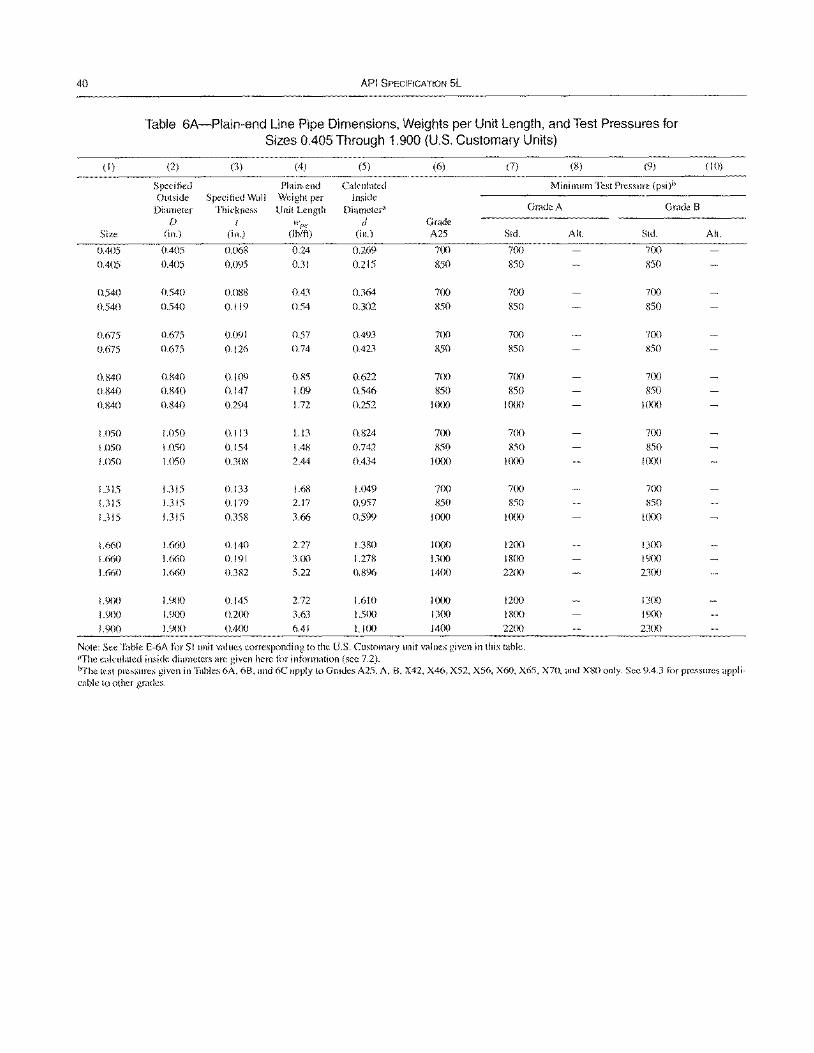
40 API SPECIFICATION 5L
Table 6A-Plain-end Line Pipe Dimensions, Weights per Unit Length, and Test Pressures for Sizes 0.405 Through 1.900 (U.S. Customary Units)
(I) (2) (3) (4) (5) (6) (7) (8) (9) (10)
Specified Plain-end Calculated Minimum Test Pressure (psi)b Outside Specified Wall Weight per Inside
Diameter Thickness Unit Length Diameter" Grade A Grade B f) I wlJe d Grade
Size (in.) (in.) (lb/ft) (in.) A25 Std. All. Std. All.
0.405 0.405 0.068 0.24 0.269 700 700 700
0.405 0.405 0.095 0.31 0.215 850 850 R50
0.540 0.540 0.088 0.43 0.364 700 700 700
0.540 0.540 0.119 0.54 0.302 850 850 850
0.675 0.675 0.091 0.57 0.493 700 700 7(X)
0.675 0.675 0.126 0.74 0.423 850 850 850
0.840 0.R40 0.109 0.85 0.622 700 700 700
0.840 0.840 0.147 1.09 0.546 850 850 850
0.840 0.840 0.294 1.72 0.252 1000 1000 1000
1.050 1.050 0.113 1.13 0.824 700 700 700
1.050 1.050 0.154 L.48 0.742 850 850 850
1.050 1.050 0.308 2.44 0.434 1000 1000 1000
1.315 1.315 0.133 1.68 1.049 700 700 7(X)
1.315 1.315 0.179 2.17 0.957 850 850 850
1.315 1.315 0.358 3.66 0.599 1000 1000 1000
1.660 1.660 0.140 2.27 1.380 1000 1200 1300
1.660 1.660 0.191 3.00 1.278 1300 1800 1900
1.660 1.660 0.382 5.22 0.896 1400 2200 2300
1.900 1.900 0.145 2.72 1.610 1000 1200 1300
1.900 1.900 0.2(X) 3.63 1.5(X) 1300 1800 1900
1.900 1.900 0.400 6.41 1.100 1400 2200 2300
Note: See Table E-6A for SI unit values corresponding to the U.S. Customary unit values given in this table. "The calculated inside diameters are given here f()r information (see 7.2). ~he test pressures given in T"bles 6A, 6B, "nd 6C apply to Grades A25, A, B, X42, X46, X52, X56, X60, X65, X70, and X80 only. See 9.4.3 t(,r pressures appli-cable to other grades.
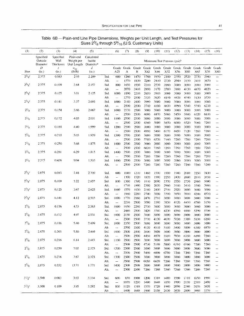
SPECIFICATION FOR LINE PIPE 41
Table 68 -Plain-end Line Pipe Dimensions, Weights per Unit Length, and Test Pressures for Sizes 23/8 through 59/16 (U.S. Customary Units)
(I) (2) (3) (4) (5)
Specified Specified Plain-end Calculated Outside Wall Weight per Inside
Diameter Thickness Unit Length Diameter" f) { w(le d
Size (in.) (in.) (Ib/ft) (in.)
23/8" 2.375 0.083 2.03 2.209
23/8" 2.375 0.109 2.64 2.157
23/8C 2.375 0.125 3.01 2.125
23/8" 2.375 0.141 3.37 2.093
23/8 2.375 0.154 3.66 2.067
2.375 0.172 4.05 2.031
2.375 0.188 4.40 1.999
2.375 0.218 5.03 1.939
2.375 0.250 5.68 1.875
2.375 0.281 6.29 1.813
2.375 0.436 9.04 1.503
2.875 o.mn 2.48 2.709
2.875 0.109 3.22 2.657
2.875 0.125 3.67 2.625
2.875 0.141 4.12 2.593
2.875 0.156 4.53 2.563
2.875 0.172 4.97 2.531
2.875 0.188 5.40 2.499
2.875 0.203 5.80 2.469
2.875 0.216 6.14 2.443
2.875 0.250 7.02 2.375
2.875 0.276 7.67 2.323
2.875 0.552 13.71 1.771
3.500 0.083 3.03 3.334
3.500 0.109 3.95 3.282
(6) (7) (8) (9) (10) (II) (12) (13) (14) (IS) (16)
Minimum Test Pressure (psi)b
G~~~G~G~G~G~G~G~G~G~G~
A25 A B X42 X46 X52 X56 X60 X65 X70 X80
Std. 600 1260 1470 1760 1930 2180 2350 2520 2730 2940
All. 1570 1830 2200 2410 2730 2940 3150 34lO 3670
Std. 800 1650 1930 2310 2530 2860 30m 3000 3000 30m
All. 2070 2410 2890 3170 3580 3860 4130 4470 4820
Std. 1000 1890 2210 2650 2910 3000 3000 3(X)0 3000 30m
All. 2370 2500 3320 3630 4110 4420 4740 5130 5530 Std. 1000 2140 2490 2990 3000 3000 3000 3(XX) 30m 3000
All. 2500 2500 3740 4100 4630 4990 5340 5790 6230
Std. 1000 2330 2500 3000 3000 3000 3000 3000 3000 3000 All. 2500 2500 4090 4470 5060 5450 5840 6320 6810 Std. I 100 2500 2500 3(x)() 3000 3000 3000 3(x)() 3000 3(x)()
All. 25()() 2500 4560 5000 5650 6080 6520 7060 7260
Std. 1200 2500 2500 3000 3000 3000 3()()() 3(x)() 3()()() 3000
All. 2500 2500 4990 5460 6170 6650 7120 7260 7260 Std. 1300 2500 2500 3(X)0 3000 3()()() 3000 3(x)() 3()()() 3()()()
All. 2500 2500 5780 6330 7160 7260 7260 7260 7260 Std. 1400 2500 2500 3000 3000 3000 3(){)() 3(){){) 3()()() 3(x)()
All. 2500 2500 6630 7260 7260 7260 7260 7260 7260 Std. 1400 2500 2500 3()()() 3()()() 3000 3(){)() 3(){){) 3(){)() 3()()()
All. 2500 2500 7260 7260 7260 7260 7260 7260 7260 Std. 1400 25(){) 2500 3(){)() 3()()() 3(){){) 3(x)() 3(){)() 30()() 3()()()
All. 2500 2500 7260 7260 7260 7260 7260 7260 7260
Std. 6(x) 1040 1210 1460 1590 18(X) 1940 2080 2250 2430 All. 13()() 1520 1820 1990 2250 2430 26(){) 2810 3030
Std. 800 1360 1590 1910 2090 2370 2550 2730 2%0 3000 All. 1710 1990 2390 2620 2960 3180 3410 37(){) 3980 Std. 1000 1570 1830 2190 2400 2710 2920 3()()() 3(){){) 3()()()
All. 1960 2280 2740 3000 3390 3650 3910 4240 4570 Std. 1000 1770 2060 2470 2710 3000 3(){){) 3(x)() 3()()() 3()()()
All. 2210 25()() 3090 3380 3830 4120 4410 4780 5150 Std. 1000 1950 2280 2730 3()()() 3(){){) 3(){){) 3()(){) 3(){){) 3()()()
All. 2440 25()() 3420 3740 4230 4560 4880 5290 57()() Std. 1000 2150 2500 3000 3000 3()()() 3(){)() 3()()() 30()() 3(){)()
All. 2500 2500 3770 4130 4670 5030 5380 5830 6280 Std. 1000 2350 2500 3000 3000 3000 3(){){) 3(){)() 3(XX) 3(){){)
All. 2500 2500 4120 4510 5100 5490 5890 6380 6870 Std. 1000 2500 2500 3(x)() 3(){)() 3()()() 30(X) 3(X)() 30(X) 3(XX)
All. 25()() 2500 4450 4870 5510 5930 6350 6880 7260 Std. I 100 25(){) 2500 3(){){) 3(){)() 3000 30()() 3()()() 30()() 3()()()
All. 2500 2500 4730 5180 5860 6310 6760 7260 7260 Std. 1200 2500 2500 3(){){) 3(){)() 3(){){) 3(X)() 3(){){) 3l)(X) 3()()()
All. 25()() 2500 5480 6(){)() 6780 7260 7260 7260 7260
Std. 1300 2500 2500 3000 3000 3(){)() 3(){)() 3000 3(){){) 3(XX)
All. 25(){) 2500 6050 6620 7260 7260 7260 7260 7260 Std. 1400 2500 2500 3000 3()()() 3000 3(){){) 3(){X) 3(){){) 3(X)()
All. 2500 2500 7260 7260 7260 7260 7260 7260 72(i0
Std.
All.
Std.
All.
600 850 1000
1070 1250
800 1120 1310
1400 1640
1200 1310 1480 1590 1710 1850 1990
1490 1640 IR50 1990 2130 2310 2490
1570 1720 1940 2090 2240 2430 2620 1960 2150 2430 2620 2800 3040 3270
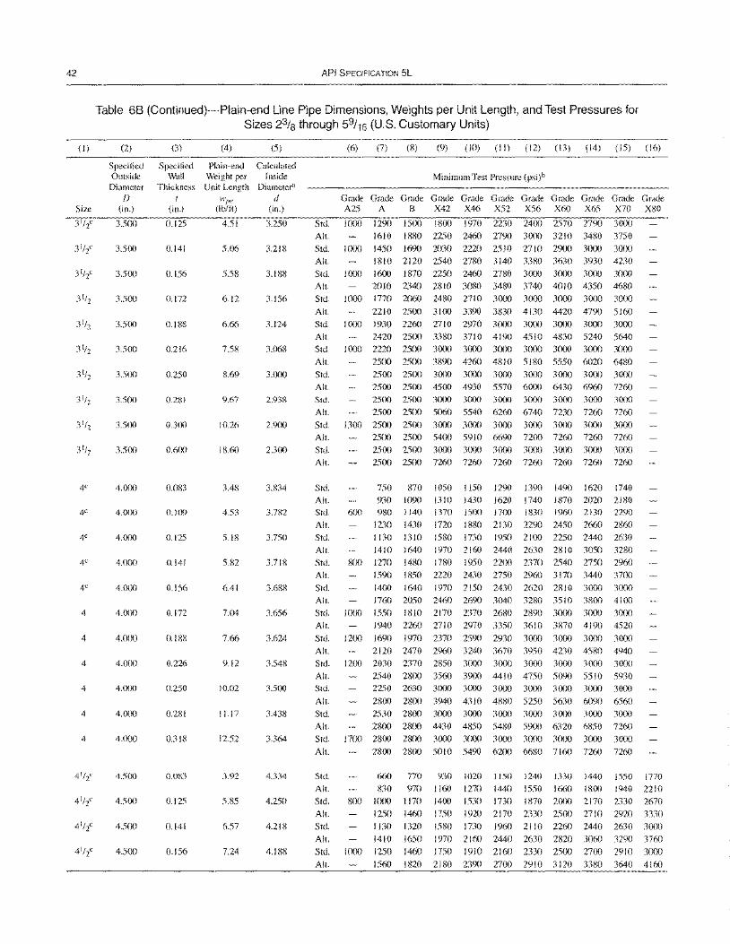
42
(I)
Size
4C
4"
4C
4"
4C
4
4
4
4
4
4
API SPECIFICATION 5L
Table 68 (Continued)-Plain-end Line Pipe Dimensions, Weights per Unit Length, and Test Pressures for Sizes 23/8 through 59/16 (U.S. Customary Units)
(2) (3) (4) (5)
Specified Specified Plain-end Calculated Outside Wall Weight per Inside
Diameter Thickness Unit Length Diameter" [)
(in.) (in.)
3.500 0.125
3.5(X) 0.141
3.5(X) 0.156
3.5(X) 0.172
3.5(X) 0.188
3.500 0.216
3.500 0.250
3.50() 0.281
3.5(X) O.3(J0
3.5(x) 0.600
4.000 0.083
4.0()() 0.109
4'()()() 0.125
4.0()() 0.141
4.0(X) 0.156
4.000 (J.I72
4.000 0.188
4.0C)() 0.226
4.0()() 0.250
4'()(x) 0.281
4.000 0.318
4.500 0.083
4.500 0.125
4.5C)() 0.141
4.5()() 0.156
4.51
5.06
5.58
6.12
6.66
7.58
8.69
9.67
10.26
18.60
3.48
4.53
5.18
5.82
6.41
7.04
7.66
9.12
10.02
11.17
12.52
3.92
5.85
6.57
7.24
d (in.)
3.250
3.218
3.188
3.156
3.124
3.068
3.0(x)
2.938
2.900
2.300
3.834
3.782
3.750
3.718
3.688
3.656
3.624
3.548
3.5(x)
3.438
3.364
4.334
4.250
4.218
4.188
(6) (7) (8) (9) (10) (II) (12) (13) (14) (15) (16)
Minimum Test Pressure (psi)b
G~~~G~G~G~G~G~G~G~G~G~ A25 A B X42 X46 X52 X56 X60 X65 X70 X80
Std. 1000 1290 1500 1800 1970 2230 2400 2570 2790 3000
All. 1610 1880 2250 2460 2790 3000 3210 3480 3750
Std. 1000 1450 1690 2030 2220 2510 2710 2900 3(xx) 3000
All. ISIO 2120 2540 2780 3140 33S0 3630 3930 4230
Std. I (xX) 1600 1870 2250 2460 27S0 3000 3000 3(x)() 3000
All. 2010 2340 2810 3080 3480 3740 4010 4350 4680 Std. 1000 1770 2060 2480 2710 3000 3(XlO 3(x)() 3(xX) 3(x)()
All. 2210 2500 3100 3390 3830 4130 4420 4790 5160
Std. 1000 1930 2260 2710 2970 3000 3000 3000 3CXlO 3000
All 2420 2500 3380 3710 4190 4510 4830 5240 5640 Std. 1000 2220 25(x) 3(x)() 3000 3000 3CXlO 3(0) 3000 3000
All 2500 2500 3S90 4260 4S1O 51S0 5550 6020 6480 Std. 2500 2500 3(XlO 3000 3000 3000 3(xx) 3000 3000
All 2500 2500 45C)() 4930 5570 6000 6430 6960 7260 Std. 2500 25C)() 3000 3000 3000 3(XlO 3()()() 3()()() 3(x)()
All 25()() 2500 5060 5540 6260 6740 7230 7260 7260
Std 1300 2500 2500 3000 3(0) 3()()() 3000 3000 3(0) 3(x)()
All. 2500 2500 5400 5910 6690 72()() 7260 7260 7260 Std. 25(x) 2500 3000 3000 3000 3000 3000 3000 3(xX)
All. 2500 2500 7260 7260 7260 7260 7260 7260 7260
Std. All Std.
All. Std.
All Std.
750 870
930 1090 6(x) 980 I 140
1230 1430
1130 1310
1410 1640
800 1270 1480
1050 1150 1290 1390 1490 1620 1740 1310 1430 1620 1740 1870 2020 2180 1370 15()() 17(x) 1830 1960 2130 2290
1720 1880 2130 2290 2450 2660 2860
1580 1730 1950 2 \(X) 2250 2440 2630
1970 2160 2440 2630 2810 3050 3280
1780 1950 2200 2370 2540 2750 2960 All. 1590 1850 2220 2430 2750 2960 3170 3440 37C)()
Std.
All
1400 1640 1970 2150 2430 2620 2810 3()()() 3(XlO
1760 2050 2460 2690 3040 3280 3510 3800 41()()
Std. 1000 1550 1810 2170 2370 2680 2890 3000 3(x)() 3000
All 1940 2260 2710 2970 3350 3610 3870 4190 4520
Std. 1200 1690 1970 2370 2590 2930 3(x)() 3(XlO 3(xX) 3()()()
All 2120 2470 2960 3240 3670 3950 4230 4580 4940 Std. 1200 2030 2370 2850 3000 3000 3000 3(x)() 3(xx) 3(0)
All. 2540 2800 3560 3900 4410 4750 5090 5510 5930 Std. 2250 2630 3000 3000 3(XlO 3000 3()()() 3(XlO 3(XlO
All. 28(x) 2800 3940 4310 4880 5250 5630 6090 6560
Std. 2530 28()() 3000 3000 3000 3000 3(XlO 3000 3000
All. 2800 28(x) 4430 4850 5480 5900 6320 6850 7260 Std. 1700 2800 2800 3000 3C)()() 3(x)() 3C)()() 3C)()() 3000 3C)()()
All. 2800 2800 5010 5490 6200 6680 7160 7260 7260
Std.
All. Std.
All.
Stel.
All. Std.
660 770 930
830 970 1160 800 l(x)() 1170 1400
1250 1460 1750
1020 1150 1240 1330 1440 1550 1770
1270 1440 1550 1660 1800 1940 2210 1530 1730 1870 2(0) 2170 2330 2670
1920 2170 2330 25()() 2710 2920 3330
1130 1320
1410 1650
1000 1250 1460
1580 1730 1960 21 10 2260 2440 2630 3(x)()
1970 2160 2440 2630 2820 3060 3290 3760
1750 1910 2160 2330 25(x) 2700 2910 3000
All. 1560 1820 2180 2390 2700 2910 3120 3380 3640 4160

(1)
Size
SPECIFICATION FOR LINE PIPE 43
Table 68 (Continued)-Plain-end Line Pipe Dimensions, Weights per Unit Length, and Test Pressures for Sizes 23/8 through 59/16 (U.S. Customary Units)
(2)
Specified Outside
Diameter D
(in.)
4.500
4.500
4.500
4.500
4.500
4.500
4.500
4.500
4.500
4.500
4.500
4.500
5.563
5.563
5.563
5.563
5.563
5.563
5.563
5.563
5.563
5.563
5.563
5.563
(3)
Specified Wall
Thickness I
(in.)
0.172
0.188
0.203
0.219
0.237
0.250
0.281
0.312
0.337
0.438
0.531
0.674
0'()83
0.125
0.156
0.188
0.219
0.258
0.281
0.312
0.344
0.375
0.500
0.625
(4) (5)
Plain-end Calculated Weight per Inside Unit Length Diameter"
H'pe d (lblt!) (in.)
7.96 4.156
8.67 4.124
9.32 4.094
10.02 4.062
10.80 4.026
11.36 4.000
12.67 3.938
13.97 3.876
15.00 3.826
19.02 3.624
22.53 3.438
27.57 3.152
4.86 5.397
7.27 5.313
9.02 5.251
10.80 5.187
12.51 5.125
14.63 5.047
15.87 5.001
17.5 1 4.939
19.19 4.875
20.80 4.813
27.06 4.563
32.99 4.313
Std.
All. Std.
(6) (7) (8) (9) (10) (11) (12) (13) (14) (15) (16)
Minimum Test Pressure (psi)h
~~G~G~G~G~G~G~G~G~G~G~
A25 A B X42 X46 X52 X56 X60 X65 X70 XXO
1380 1610 1930 2110 2390 2570 2750 2980 3000 3(XX)
1720 2010 2410 2640 2980 3210 3440 3730 4010 4590
1200 1500 1750 2110 2310 2610 2810 3000 3000 3000 3000
All. 1880 2190 2630 2880 3260 3510 3760 4070 4390 5010
Std. 1620 1890 2270 2490 2810 3000 3000 3000 3000 3000 All. 2030 2370 2840 3110 3520 3790 4060 4400 4740 5410
Std. 1200 1750 2040 2450 2690 3000 3000 3000 3000 3000 3000
All. 2190 2560 3070 3360 3800 4090 4380 4750 5110 5840 Std. 1200 1900 2210 2650 2910 3000 3000 3(XX) 3(XX) 3(XX) 3(XX)
All. 2370 2770 3320 3630 4110 4420 4740 5140 5530 6320 Std. 2000 2330 2800 3000 30m 3()(x) 3(x)() 3(X)0 3(X)0 3()(x)
All. 2500 2800 3500 3830 4330 4670 5(XX) 5420 5830 6670 Std. 2250 2620 3000 3000 3()(X) 3()(x) 3()(X) 3(XX) 3()()() 3lXX)
All. 2800 2800 3930 4310 4870 5250 5620 6090 6560 7260 Std. 2500 2800 3()()() 3000 3(Xx) 3()(X) 30m 3(X)() 3(X)() 3(XX)
All. 2800 28()() 4370 4780 5410 5820 6240 6760 7260 7260 Std. 1700 2700 2800 3000 3000 3000 3(Xx) 3000 30m 3(XX) 3(XX)
All.
Std.
All. Std.
All. Std.
All.
Std. All.
Std.
All.
Std. All.
Std.
670
2800 2800 4720 5170 5840 6290 6740 7260 7260 7260 2800 2800 3000 3()()() 3000 3(XX) 3(XX) 30m 3(X10 3lXX)
2800 2800 6130 6720 7260 7260 7260 7260 7260 7260 2800 2800 3()()() 3()(X) 3000 3(XX) 3()(X) 3(XX) 3(X)0 3(XX)
2800 2S(x) 7260 7260 7260 7260 7260 7260 7260 7260 2800 2S00 3()(X) 3()()() 3()(X) 3()()() 3(XX) 3(x)() 3(XX) 3(XX)
2S00 2S()() 7260 7260 7260 7260 7260 7260 7260 7260
540 670
S10
630 750 820
780 940 1030
940 1130 1240
930 I (XX) 1070
1160 1250 1340
1400 1510 1620
1160
1450
1750
1250 1430 1570 1790
1890 2160
1010 I1S0 1420
840 1010 1180 1410 1260 1470 1770
1010 1220 1420 1700
1550 1750 1890 2020 2190 2360 2700
1550 1750 1880 2020 2190 2360 2690
1930 2190 2360 2520 2730 2940 3370
1870 21 10 2270 2430 2640 2840 3(x)()
All. 1520 1770 2130 2330 2640 2840 3040 3290 3550 4060
Std. 1180 1420 1650 1980 2170 2460 2650 2830 3()(x) 3000 3(XX)
All. 1770 2070 2480 2720 3070 3310 3540 3840 4130 4720
Std. 1200 1670 1950 2340 2560 2890 3000 3()()() 3(X)0 3(XX) 30lX)
All. 2090 2430 2920 32()() 3620 39()() 4170 4520 4870 5570 Std. 1520 1820 2120 2550 2790 3()(X) 3(XX) 3(XX) 3(XX) 3(X)() 3000
All. 2270 2650 3180 3490 3940 4240 4550 4920 53(X) 6060 Std. 1680 2020 2360 2830 3()(x) 3000 3(XX) 3(X)() 3()(X) 30(X) 3(X)()
All. 2520 2800 3530 3870 4370 4710 5050 5470 5890 6730 Std. 1860 2230 2600 3()()() 3()()() 3()()() 3(x)() 3000 3()()O 3()(X) 3(XX)
All. 2780 2S00 39(XJ 4270 4820 5190 5570 6030 6490 7260 Std. 2020 2430 2800 3000 3()()() 3()()() 3()()() 3(XX) 3(XX) 3(XX) 3(X)()
All. 2800 2800 4250 4650 5260 5660 6070 6570 7080 7260 Std. 2700 2800 2800 3000 3(x)() 3(Xx) 3000 3(XX) 3(XX) 3(XX) 3(XX)
All. 2800 28(x) 5660 6200 70 I 0 7260 7260 7260 7260 7260
Std. 2800 28()() 2S00 3000 3000 3000 3(Xx) 3()(X) 3(X)O 3(XX) 3000
All. 2800 2800 7080 7260 7260 7260 7260 7260 7260 7260
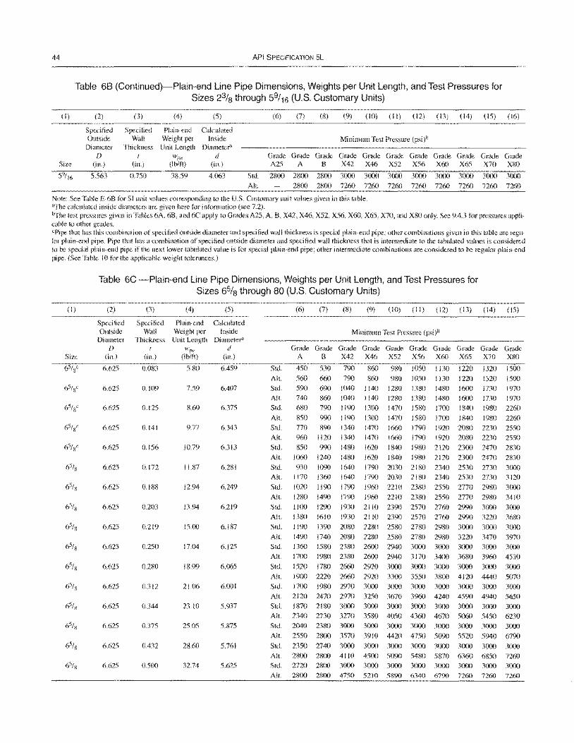
44
(I)
API SPECIFICATION 5L
Table 68 (Continued)-Plain-end Line Pipe Dimensions, Weights per Unit Length, and Test Pressures for Sizes 2% through 59/16 (U.S. Customary Units)
(2)
Specified Outside
Diameter
(3)
Specilied Wall
Thickness 1
(4) (5)
Plain-end Calculated Weight per Inside Unit Length
wpe
(6) (7) (8) (9) (10) (II) (12) (13) (14) (15) (16)
Minimum Test Pressure (psi)b
Size f)
(in.) (in.) (lb/ft)
Diameter" d
(in.) Grade Grade Grade Grade Grade Grade Grade Grade Grade Grade Grade A25 A B X42 X46 X52 X56 X60 X65 X70 X80
5.563 0.750 38.59 4.063 Std. 2800 2800 2800 3000 3000 3000 3000 3000 3000 3000 3000
All. 2800 2800 7260 7260 7260 7260 7260 7260 7260 7260
Note: See Table E-6B for SI unit values corresponding to the U.S. Customary unit values given in this table. aThe calculated inside diameters are given here for information (see 7.2). b"fhe test pressures given in Tables 6A. 6B, and 6C apply to Grades A25, A. B. X42, X46, X52, X56, X60, X65, X70, and X80 only. See 9.4.3 for pressures applicable to other grades. cPipe that has this combination of specified outside diameter and specified wall thickness is special plain-end pipe: other combinations given in this table are regular plain-end pipe. Pipe that has a combination of specified outside diameter and specified wall thickness that is intermediate to the tabulated values is considered to be special plain-end pipe if the next lower tabulated value is for special plain-end pipe; other intermediate combinations are considered to be regular plain-end pipe. (See Table 10 for the applicable weight tolerances.)
(I)
Size
Table 6C -Plain-end Line Pipe Dimensions, Weights per Unit Length, and Test Pressures for Sizes 6% through 80 (U,S. Customary Units)
(2)
Specified Outside
Diameter f)
(in.)
6.625
6.625
6.625
6.625
6.625
6.625
6.625
6.625
6.625
6.625
6.625
6.625
6.625
6.625
6.625
6.625
(3)
Specified Wall
Thickness I
(in.)
0.083
0.109
0.125
0.141
0.156
0.172
0.188
0.203
0.219
0.250
0.280
0.312
0.344
0.375
0.432
0.500
(4) (5)
Plain-end Calculated Weight per Inside Unit Length Diameter'
wpe d (Ib/ft) (in.)
5.80 6.459
7.59 6.407
8.69 6.375
9.77 6.343
10.79 6.313
11.87 6.281
12.94 6.249
13.94 6.219
15.00 6.187
17.04 6.125
18.99 6.065
21.06 6.001
23.10 5.937
25.05 5.875
28.60 5.761
32.74 5.625
(6) (7) (8) (9) (10) (II) (12) (13) (14) (15)
Minimum Test Pressure (psi)b
G~G~~~~~G~G~G~G~~~G~ A B X42 X46 X52 X56 X60 X65 X70 X80
Std. 450 530 790 860 980 1050 I J 30 1220 1320 1500
All. 560 660 790 860 980 1050 1130 1220 1320 1500
Std.
All.
Std.
590
740
680
690
860
790
1040 1140
1040 1140
1190 1300
1280
1280
1470
1380
1380
1580
1480 1600
1480 1600
1700 1840
1730 1970
1730 1970
1980 2260
All. 850 990 1190 1300 1470 1580 1700 1840 1980 2260
Std.
All.
Std.
All.
Std.
All.
Std.
All.
Std.
All.
Std.
770
960
850
1060
930
1170
1020
1280
1100
1380
1190
890
1120
990
1240
1090
1360
1190
1490
1290
1610
1390
1340
1340
1480
1480
1640
1640
1790
1790
1930
1930
2080
1470
1470
1620
1620
1790
1790
1960
1960
2110
2110
2280
1660
1660
1840
1840
2030
2030
2210
2210
2390
2390
2580
1790
1790
1980
1980
2180
2180
2380
2380
2570
2570
2780
1920
1920
2120
2120
2340
2340
2550
2550
2760
2760
2980
2080
2080
2300
2300
2530
2530
2770
2770
2990
2990
3000
2230
2230
2470
2470
2730
2730
2980
2980
3000
3220
3000
2550
2550
2830
2830
3000
3120
3000
3410
3000
3680
3000 All. 1490 1740 2080 2280 2580 2780 2980 3220 3470 3970
Std.
All.
Std.
All.
Std.
All.
Std.
All.
Std.
All.
Std.
All.
Std.
All.
1360
1700
1520
1900
1700
2120
1870
2340
2040
2550
2350 2800
2720 2800
1580
1980
1780 2220
1980
2470
2180
2730 2380
2800
2740
2800
2800
2800
2380
2380 2660
2660
2970
2970
3000
3270
3000
3570
3000
4110
3000
4750
2600
2600
2920
2920
3000
3250
3000
3580
3000
3910
3000
4500
3000
5210
2940
2940
3000
3300
3000
3670
3000
4050
3000
4420 3000
5090
3000
5890
3000
3170
3000
3550
3000
3960
3000
4360
3000
4750
3000
5480
3000
6340
3000
3400
3000
3800
3000
4240
3000
4670
3000
5090
3000
5870
3000
6790
3000
3680
3000
4120
3(XlO
4590
3000
5060
3000
5520
3000
6360
3000
7260
3000
3960
3000
4440
3000
4940
3000
5450
3000
5940
3000
6850
3000
7260
3000
4530
3000
5070
3000
5650
3000
6230
3000
6790
3000
7260
3000
7260
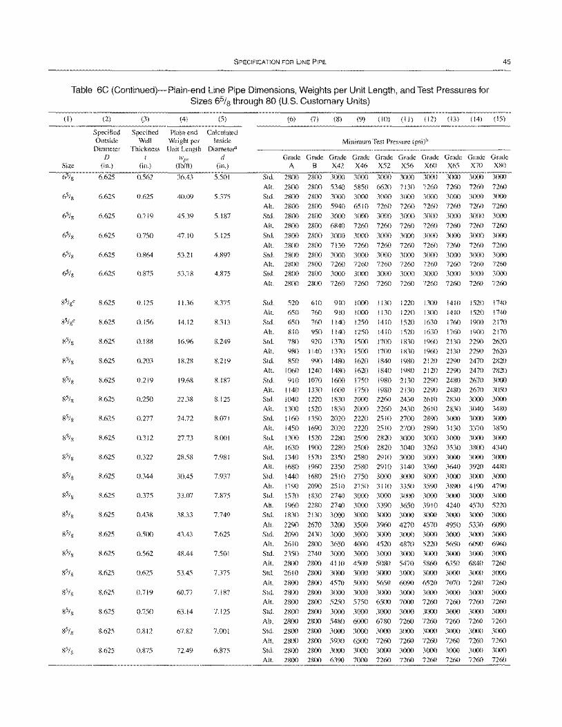
SPECIFICATION FOR LINE PIPE 45
Table 6C (Continued)-Plain-end Line Pipe Dimensions, Weights per Unit Length, and Test Pressures for Sizes 65/8 through 80 (U.S. Customary Units)
(I)
Size
(2)
Specified Outside
Diameter D
(in.)
6.625
6.625
6.625
6.625
6.625
6.625
8.625
8.625
R.625
8.625
8.625
8.625
8.625
8.625
8.625
8.625
8.625
8.625
8.625
8.625
8.625
8.625
8.625
8.625
8.625
(3)
Specified Wall
Thickness t
(in.)
0.562
0.625
0.719
0.750
0.864
0.875
0.125
0.156
0.188
0.203
0.219
0.250
0.277
0.312
0.322
0.344
0.375
0.438
0.500
0.562
0.625
0.719
0.750
0.812
0.875
(4) (5)
Plain-end Calculated Weight per Inside
Unit Length Diameter" wpe d
(Ib/ft) (in.)
36.43 5.501
40.09 5.375
45.39 5.187
47.10 5.125
53.21 4.897
53.78 4.875
11.36 8.375
14.12 8.313
16.96 8.249
18.28 8.219
19.68 8.187
22.38 8.125
24.72 8.071
27.73 8.001
28.58 7.981
30.45 7.937
33.07 7.875
38.33 7.749
43.43 7.625
48.44 7.501
53.45 7.375
60.77 7.187
63.14 7.125
67.82 7.001
72.49 6.875
Std.
All.
Std.
(6) (7)
Grade Grade A B
2800 2800
2800 2800
2800 2800
(8) (9) (10) (II) (12) (13) (14) (15)
Minimum Test Pressure (psi)b
Grade Grade Grade Grade Grade Grade Grade Grade X42 X46 X52 X56 X60 X65 X70 X80
3000 3000 3000 30()0 3000 3000 3000 3000
5340 5850 6620 7130 7260 7260 7260 7260 3(XlO 3(xx) 3000 3000 3eXX) 3(XX) 3000 3eXX)
All. 2800 28(x) 5940 6510 7260 7260 7260 7260 7260 7260
Std. 2800 2800 3000 3000 3000 3(xlO 3000 3000 3(xX) 3eXX)
All. 2800 2800 6840 7260 7260 7260 7260 7260 7260 7260
Std. 2800 2800 3(xlO 3000 30(x) 3CXX) 3(X)0 3eXX) 3(XX) 3(XX)
All. 2800 2800 7130 7260 7260 7260 7260 7260 7260 7260 Std. 2800 2800 3(xx) 3000 3(XX) 3(X)() 3(xX) 3eXX) 3(XX) 3(XX)
All. 2800 2800 7260 7260 7260 7260 7260 7260 7260 7260 Std. 2800 28(Xl 3000 3(x)() 3(X)() 30(x) 3(XXl 30(x) 3eXX) 30eX)
All. 28(x) 2800 7260 7260 7260 7260 7260 7260 7260 7260
Std.
All.
Std.
All.
Std.
All.
Std. All.
Std.
520
650
650
810
780
980
850 1060
910
610
760
760
950
920 1140
990 1240
1070
910
910
1140
1140
1370 1370
1480
leXX)
1000
1250
1250
1500
1500
1620 1480 1620
1600 1750
1130
1130
1410
1410
1700 17(x)
1840
1220 13(x) 1410 1220 13()() 1410
1520 1630 1760
1520 1630 1760
1830 1960 2130
1830 1%0 2130 1980 2120 2290
1520 1740
1520 1740 19(X) 2170
19(X) 2170
2290 2620
2290 2620
2470 2820 1840 1980 2120 2290 2470 2820
1980 2130 2290 2480 2670 30()O
All. 1 140 1330 16m 1750 1980 2130 2290 2480 2670 3050 Std. 1040 1220 1830 2000 2260 2430 2610 2830 3(X)0 3000 Alt. 1300 1520 1830 2000 2260 2430 2610 2830 3040 3480
Std. 1 160 1350 2020 2220 2510 2700 2890 30m 3eXX) 3OCX)
All. 1450 1690 2020 2220 2510 27()() 2890 3130 3370 3850 Std. 1300 1520 2280 2500 2820 3()()() 3(XX) 3()()() 3(XX) 30m
All. 1630 1900 2280 2500 2820 3040 3260 3530 3800 4340 Std. 1340 1570 2350 2580 2910 3000 3(XX) 3eXX) 3(X)0 3(XX)
Alt. 1680 1960 2350 2580 2910 3140 3360 3640 3920 44XO Std. 1440 16RO 2510 2750 3(x)() 3exXl 3(XX) 3()()() 3000 3CXX)
AI!. 1790 2090 25 10 2750 31 10 3350 3590 3890 4190 4790 Std. 1570 1830 2740 3CXXl 3000 3(xX) 3()()() 3(X)0 3(0) 3eX)O
Alt. 1960 2280 2740 3(xx) 3390 3650 3910 4240 4570 5220 Std. 1830 2130 3(x)() 3()()() 3(x)() 30eX) 3(X)() 3(XX) 3000 3(XX)
All. 2290 2670 3200 35OC) 3960 4270 4570 4950 5330 6090 Std. 2090 2430 3000 3CXX) 3(XX) 3000 3eX)0 3000 3(XX) 3ClOO
All. 2610 2800 3650 4(xXl 4520 4870 5220 5650 6090 6960 Std. 2350 2740 3000 3000 3CXX) 30()() 3CXX) 3e)()() 3eXX) 3eXX)
All. 28OC) 2800 4110 45(x) 5080 5470 5860 6350 6840 7260 Std. 26 I 0 2800 3(xX) 3000 3()()() 3(X)() 3(xX) 3()()0 3eXX) 3(X)O
Alt. 2800 2800 4570 5eXX) 5650 6090 6520 7070 7260 7260 Std. 2800 2800 3000 3(xx) 3(XX) 3C)()() 30(X) 3(xX) 3000 3eXX)
Alt. 28(x) 2800 5250 5750 6500 7CXX) 7260 7260 7260 7260
M ~ ~ ~ ~ ~ ~ ~ ~ ~ ~ All. 2800 28()() 5480 6CXX) 6780 7260 7260 7260 7260 7260 Std. 2800 2800 3000 3000 3()()() 3()()() 3(XX) 3(XX) 3(XX) 3eXX)
All. 2800 28()() 5930 6500 7260 7260 7260 7260 7260 7260 Std. 28(Xl 2800 3(xx) 3CXX) 3000 3(X)0 3(x)() 3eXX) 3(X)O 3(x)()
All. 28()() 2800 6390 7000 7260 7260 7260 7260 7260 7260
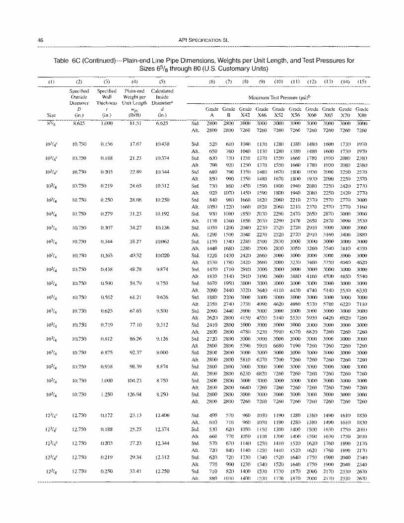
46 API SPECIFICATION 5L
Table 6C (Continued)-Plain-end Line Pipe Dimensions, Weights per Unit Length, and Test Pressures for Sizes 65/8 through 80 (U.S. Customary Units)
(I)
Size
(2)
Specified Outside
Diameter D
(in.)
8.625
10.750
10.750
10.750
10.750
10.750
10.750
10.750
10.750
10.750
10.750
10.750
10.750
10.750
10.750
10.750
10.750
10.750
10.750
10.750
12.750
12.750
12.750
12.750
12.750
(3)
Specified Wall
Thickness I
(in.)
1.000
0.156
0.188
0.203
0.219
0.250
0.279
0.307
0.344
0.365
0.438
0.500
0.562
0.625
0.719
0.812
0.875
0.938
1.000
1.250
0.172
0.188
0.203
0.219
0.250
(4) (5)
Plai n-end Calculated Weight per Inside
Unit Length Diameter"
wI'" d (Ib/ft) (in.)
81.51 6.625
17.67 10.438
21.23 10.374
22.89 10.344
24.65 LO.312
28.06 10.250
31.23 10.192
34.27 10.136
38.27 10.062
40.52 10.020
48.28 9.874
54.79 9.750
61.21 9.626
67.65 9.500
77.10 9.312
86.26 9.126
92.37 9.000
98.39 8.874
104.23 8.750
126.94 8.250
23.13 12.406
25.25 12.374
27.23 12.344
29.34 12.312
33.41 12.250
Std.
All.
(6) (7) (8) (9) (10) (II) (12) (13) (14) (15)
Minimum Test Pressure (psi)b
G~G~~~G~~~G~G~G~G~G~ A B X42 X46 X52 X56 X60 X65 X70 X80
~ ~ ~ ~ ~ ~ ~ ~ ~ ~
~ ~ ~ ~ ~ ~ ~ ~ ~ ~
Std. 520 610 1040 1130 1280 1380 1480 1600 1730 1970
All. 650 760 1040 I 130 1280 1380 1480 1600 1730 1970 Std.
All.
Std.
All.
Std.
630 790
680 850
730
730 1250 I 370 920 1250 1370 790 1350 1480 990 1350 1480
860 1450 1590
1550 1660 1780 1930 2080 2380 1550 1660 1780 1930 2080 2380 1670 1800 1930 2090 2250 2570 1670 1800 1930 2090 2250 2570
1800 1940 2080 2250 2420 2770 All. 920 1070 1450 1590 1800 1940 2080 2250 2420 2770 Std. 840 980 1660 1820 2060 2210 2370 2570 2770 3000 All.
Std.
1050 1220 930 1090
1660 1820 2060 2210 2370 2570 2770 3160 1850 2030 2290 2470 2650 2870 3000 3000
Alt. 1170 1360 1850 2030 2290 2470 2650 2870 3090 3530 Std. 1030 1200 2040 2230 2520 2720 2910 3000 3000 3000 All. 1290 1500 2040 2230 2520 2720 2910 3160 3400 3880 Std. 1150 1340 2280 2500 2830 3000 3000 3000 3000 3000 All. 1440 1680 2280 2500 2830 3050 3260 3540 3810 4350
Std. 1220 1430 2420 2660 3000 3000 3000 3000 3000 3000 Alt. 1530 1780 2420 2660 3000 3230 3460 3750 4040 4620 Std. 1470 1710 2910 3000 3000 3000 3000 3(0) 3000 3000 All. 1830 2140 2910 3190 3600 3880 4160 4500 4850 5540 Std. 1670 1950 3000 3000 3000 3000 3000 3000 3000 3000
All. 2090 2440 3320 3640 4110 4430 4740 5140 5530 6330 Std. 1880 2200 3000 3(0) 3000 3000 3000 3000 3000 3(0) All. 2350 2740 3730 4090 4620 4980 5330 5780 6220 7110 Std. 2090 2440 3000 3000 3000 3000 3000 3(X)() 3(X)0 3(xX)
All. 2620 2800 4150 4550 5140 5530 5930 6420 6920 7260 Std. 2410 2800 3000 30(x) 3000 3000 3(0) 3000 3(XlO 3000 All. 2800 2800 4780 5230 5910 6370 6820 7260 7260 7260 Std. 2720 2800 3000 3000 3000 3000 3000 3(x)O 3000 3000 All. 2800 28(x) 5390 5910 6680 7190 7260 7260 7260 7260 Std. 2800 2800 3000 3(0) 3000 3()()() 3000 3(x)() 3(0) 3000
AI!. 2800 2800 5810 6370 7200 7260 7260 7260 7260 7260 Std. 2800 2800 3000 3(0) 3()()() 3(XX) 3000 3(0) 3(0) 3(X)()
AI!. 2800 28(X) 6230 6820 7260 7260 7260 7260 7260 7260 Std. 2800 2800 3()()() 3000 3()()() 3()(X) 3000 3000 3()()() 3()()()
All. 2800 2800 6640 7260 7260 7260 7260 7260 7260 7260 Std. 2800 2800 3000 3(XlO 3000 3000 3()()() 3(0) 3()(X) 3()()()
All. 2800 2800 7260 7260 7260 7260 7260 7260 7260 7260
Std.
All.
Std.
Alt.
Std.
All.
Std.
AI!. Std.
490 610 530
660
570 720
620 770
710
570 960 1050 710 960 1050
620 1050 1150 770 1050 1150 670 1140 1250
1190 1280 1380 1490 1190 1280 1380 1490 1300 14()() 1500 1630
I 300 1400 15()() I 630
1410 1520 1620 1760
1610 1830 1610 1830 1750 2010
1750 2010
1890 2170 840 1140 1250 1410 720 1230 1340 1520
900 1230 1340 1520 820 1400 1530 1730
1520 1620 1760 1890 2170
1640 1750 1900 2040 2340 1640 1750 19()() 2040 2340
1870 2000 2170 2330 2670 All. 880 1030 1400 1530 1730 1870 2()()() 2170 2330 2670
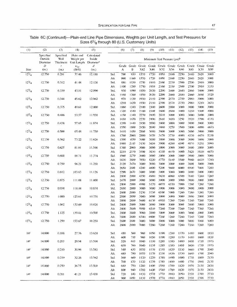
SPECIFICATION FOR LINE PIPE 47
Table 6C (Continued)-Plain-end Line Pipe Dimensions, Weights per Unit Length, and Test Pressures for Sizes 65/8 through 80 (U.S. Customary Units)
(I)
Size
14C
14C
14C
14C
14C
14C
(2)
Specified Outside
Diameter D
(in.)
12.750
12.750
12.750
12.750
12.750
12.750
12.750
12.750
12.750
12.750
12.750
12.750
12.750
12.750
12.750
12.750
12.750
12.750
12.750
14.000
14.000
14.000
14.000
14.000
14.000
(3)
Specified Wall
Thickness t
(in.)
0.281
0.312
0.330
0.344
0.375
0.406
0.438
0.500
0.562
0.625
0.688
0.750
0.812
0.875
0.938
1.000
1.062
1.125
1.250
0.188
0.203
0.210
0.219
0.250
0.281
(4) (5)
Plain-end Calculated Weight per Inside Unit Length Diameter'
w,w d (lb/ft) (in.)
37.46 12.188
41.48 12.126
43.81 12.090
45.62 12.fJ62
49.61 12.000
53.57 11.938
57.65 11.874
65.48 11.750
73.22 11.626
81.01 11.500
88.71 11.374
96.21 11.250
103.63 11.126
111.08 11.000
118.44 10.874
125.61 10.750
132.69 10.626
139.81 10.500
153.67 10.250
27.76 13.624
29.94 13.594
30.96 13.580
32.26 13.562
36.75 13.500
41.21 13.438
Std.
All.
Std.
All. Std.
All. Std.
All.
Std. All.
Std. All.
Std.
All.
(6) (7) (8) (9) (10) (II) (12) (13) (14) (15)
Minimum Test Pressure (psi)b
~~G~G~G~G~G~G~G~G~G~ A B X42 X46 X52 X56 X60 X65 X70 XRO
790 930 1570 1720 1950 2100 2250 2440 2620 3000
990 I 160 1570 1720 1950 2100 2250 2440 2620 3000
880 1030 1750 1910 2160 2330 2500 2700 2910 3000
1100 1280 1750 1910 2160 2330 2500 27m 2910 3330
930 1090 1850 2020 2290 2460 2640 2860 3000 3000
1160 1360 1850 2020 2290 2460 2640 2860 3080 3520
970 I 130 1930 21 10 2390 2570 2750 2980 3000 3000
1210 1420 1930 2110 2390 2570 2750 2980 3210 3670
1060 1240 2100 2300 2600 2800 3000 3000 3000 3000
1320
1150
1430
1240
1550
1540 2100 2300 2600 2800
1340 2270 2490 2810 3000
1670 2270 2490 2810 3030
1440 2450 2690 3000 3(X){)
1800 2450 2690 3040 3270
3000 3250 3500 4(X)0
3()(){) 3()()() 3()()() 3()()()
3250 3520 3790 4330 3()(x) 3()(){) 3()()() 3()(X)
35{)() 38(X) 4090 4670
Std. 1410 1650 2800 3()(lO 3()(){) 3000 3(X){) 3(XX) 3(X)() 3(){)()
All. Std.
1760 2060 2800
1590 1850 3000
3070 3470 3730 4()(X) 4330 4670 5330
3000 3()(){) 3000 3()(){) 3()()() 3()(){) 3()(X)
All. 1980 2310 3150 3450 3900 4200 45(X) 4870 5250 5990
Std. 1760 2060 3()()() 3000 3(X)() 3000 3{X)() 3()(X) 3(X)() 3()()()
All. 2210 2570 3500 3830 4330 4670 5(X){) 5420 5830 6670
Std. 1940 2270 3000 3000 3000 3(X){) 3(XX) 3()(X) 3(XX) 3()()()
All. 2430 2800 3850 4220 4770 5140 55(X) 5960 6420 7260
Std. 2120 2470 3000 3()(){) 3000 3(x){) 3()()() 3()()() 3()(X) 3000
All. 2650 2800 42()() 4600 52(X) 5600 6()(X) 6500 7()()() 7260
Std. 2290 2670 3000 3000 3(){)() 3()(){) 3{XX) 3(X)() 30()() 3()()()
All. 2800 28()() 4550 4980 5630 6060 65(X) 7040 7260 7260
Std. 2470 2800 3000 3(x){) 3000 3()()() 3()()() 3(XX) 3()()() 3()()()
All.
Std.
28(){) 28(){) 4900
2650 2800 3000
5370 6070 6530 7000 7260 7260 7260
3000 3{){)() 3000 30m 3()()() 3(X)() 3{XX)
All. 2800 2800 5250 5750 6500 7(X)() 7260 7260 7260 7260
Std. 2800 2800 3000 3000 3()()0 3()(X) 3()(x) 30()() 3000 3()()()
All. 2800 2800 56()() 6130 6930 7260 7260 7260 7260 7260
Std. 2800 28()() 3()(){) 3()()() 3()()() 3000 3(XX) 3()(){) 30()() 3(X){)
All. 2800 28(){) 5950 6510 7260 7260 7260 7260 7260 7260
Std. 2800 2800 3(){)() 3000 3()(){) 3000 3(){)() 3()(){) 3(XX) 3(XX)
All. 2800 2800 63(X) 6900 7260 7260 7260 7260 7260 7260
Std. 2800 2800 3{)(){) 3000 3()()() 3(){){) 3()()() 3000 3()()() 30()()
All. 28(){) 2800 7000 7260 7260 7260 7260 7260 7260 7260
Std. All. Std.
All.
Std.
All.
Std.
All.
Std.
All.
Std.
All.
480
600 520
650
540
680
560
560 960
710 960
610 1040
760 1040
630 1070
790 1070
660 1120
700 820 1120
640 750 1280
SOO 940 1280
720 840 1430
900 1050 1430
1050 1190
1050 1190
1130 1280
1130 1280
1170 1330
1280
1280
1380
1380
1430
1370
1370
1480
1480
1530
1480
1480 16()()
IIi()O
1660
1170 1330 1430 1530 1660
1220 1380 1490 16(X) 1730
16()() 1830
1600 1830
1730 1970
1730 1970
1790 2040
1790 2040
18m 2130
1220 1380 1490 16()() 1730 18m 2130
14(){) 1580 1700 1820 1970 2130 2430
1400 1580 17()() 1820 1970 2130 2430
1570 1770 1910 2050 2220 2390 2730
1570 1770 1910 2050 2220 2390 2730
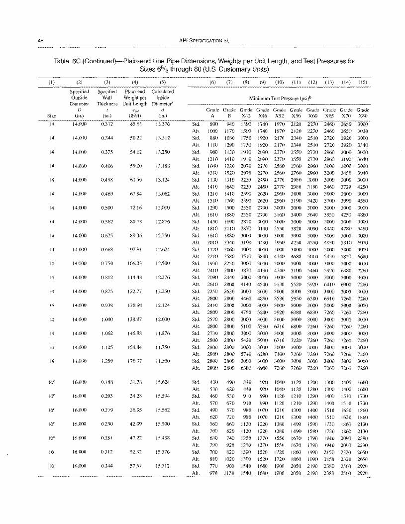
48 API SPECIFICATION 5L
Table 6C (Continued)-Plain-end Line Pipe Dimensions, Weights per Unit Length, and Test Pressures for Sizes 65/8 through 80 (U.S. Customary Units)
(I)
Size
14
14
14
14
14
14
14
14
14
14
14
14
14
14
14
14
14
14
16C
16C
16C
16C
16C
16
16
(2)
Specified Outside
Diameter f)
(in.)
14.000
14.(Xl0
14.(Xl0
14.000
14.()()()
14.000
14.()()0
14.000
14.000
14.()()()
14.(XXl
14.000
14.(X)0
14.000
14.()()0
14.000
14.(X)()
14.(X)0
16.(XX)
16.()(X)
16'()()()
16.000
16'()()()
16.()()0
16.000
(3)
Specified Wall
Thickness I
(in.)
0.312
0.344
0.375
0.406
0.438
0.469
0.500
0.562
0.625
0.688
0.750
0.812
0.875
0.938
I.tX)O
1.062
1.125
1.250
0.188
0.203
0.219
0.250
0.281
0.312
0.344
(4)
Plain-end Weight per Unit Length
H,'pe
(lb/ft)
45.65
50.22
54.62
59.00
63.50
67.84
72.16
80.73
89.36
97.91
106.23
114.48
122.77
130.98
138.97
146.88
154.84
170.37
31.78
34.28
36.95
42.09
47.22
52.32
57.57
(5)
Calculated Inside
Diameter" d
(in.)
13.376
13.312
13.250
13.188
13.124
13.062
13.000
12.876
12.750
12.624
12.500
12.376
12.250
12.124
12.000
11.876
11.750
11.500
15.624
15.594
15.562
15.500
15.438
15.376
15.312
Std.
All.
Std.
All.
Std.
All. Std.
All.
Std.
(6) (7) (8) (9) (10) (II) (12) (13) (14) (15)
Minimum Test Pressure (psi)b
Grade Grade Grade Grade Grade Grade Grade Grade Grade Grade A B X42 X46 X52 X56 X60 X65 X70 X80
800 940 1590 1740 1970 2120 2270 2460 2650 3000
1000 I 170 1590 1740 1970 2 I 20 2270 2460 2650 3030 880 1030 1750 1920 2170 2340 2510 2720 2920 3000
I I 10 1290 1750 1920 2170 2340 2510 2720 2920 3340
960 II 30 1910 2090 2370 2550 2730 2960 3000 3000 1210 1410 1910 2090 2370 2550 2730 2%0 3190 3640 1040 1220 2070 2270 2560 2760 2960 3000 30(X) 3000 1310 1520 2070 2270 2560 2760 2960 3200 3450 3940
1130 1310 2230 2450 2770 2980 3000 3000 3000 3000 All. 1410 1640 2230 2450 2770 2980 3190 3460 3720 4250 Std. 1210 1410 2390 2620 2960 3000 3000 3000 3000 3000 All. 1510 1760 2390 2620 2960 3190 3420 3700 3990 4560 Std. 1290 1500 2550 2790 3000 3()(Xl 3(XlO 3000 3(XlO 3000
All. 1610 1880 2550 2790 3160 3400 3640 3950 4250 4860 Std. 1450 1690 2870 3000 3000 3()()() 3()(x) 3000 3()(X) 3()()()
All. 1810 2110 2870 3140 3550 3820 4090 4440 4780 5460 Std. 1610 1880 3000 3()()() 3000 3000 3000 3(XlO 3()(x) 3()()()
All. 20 I 0 2340 3190 3490 3950 4250 4550 4930 5310 6070 Std. 1770 2060 3000 3000 3()()() 3()(Xl 3000 3000 3()()() 3()()()
All. 2210 2580 3510 3840 4340 4680 5010 5430 5850 6680 Std. 1930 2250 3000 3000 3()()() 3000 3000 3()()() 3000 3000
All. 2410 2800 3830 4190 4740 5100 5460 5920 6380 7260 Std. 2090 2440 3000 3()()() 3000 3(X)() 3000 3()(Xl 3000 3()()()
All. 2610 28()() 4140 4540 5130 5520 5920 6410 6900 7260
Std. 2250 2630 3000 3000 3000 3000 3000 3()(Xl 3000 3000
All. 2800 2800 4460 4890 5530 5950 6380 6910 7260 7260 Std. 2410 2800 3000 3(XXl 3()()() 3()(x) 3000 3(XlO 3()(x) 3000
All. 2800 2800 4780 5240 5920 6380 6830 7260 7260 7260 Std. 2570 2800 3000 3000 3()()() 3000 3000 3000 3000 3000 Al I. 2800 2800 5100 5590 63 10 6800 7260 7260 7260 7260 Std. 2730 2800 3000 3000 3000 3(XlO 3()(x) 3()(x) 3()(x) 3()()()
All. 2800 2800 5420 5930 6710 7220 7260 7260 7260 7260 Std. 28()() 2800 3000 3()(x) 3()()() 3000 3()()() 3()(x) 3000 3()()()
All. 2800 2800 5740 6280 7100 7260 7260 7260 7260 7260 Std. 28(Xl 2800 3000 3()()() 3000 3()(Xl 3000 3000 3()()() 3000
All. 2800 2800 6380 6980 7260 7260 7260 7260 7260 7260
Std. 420 490 840 920 1040 1120 1200 1300 14(X) 1600
All.
Std.
All.
Std.
All.
Std.
All.
Std.
All.
Std. All.
Std.
All.
530 460
570 490 620 560 7(Xl
630 790
700
620 840 920 1040
530 910 990 1120 670 910 990 1120 570 980 1070 1210 720 980 1070 1210 660 1120 1220 1380 820
740
1120 1250
1220 1370
1380
1550 920 1250 1370 1550
820 1390 1520 1720
1120 1200 1300
1210 1290 1400 1210 1290 1400 13()() 1400 1510 1300 14()() 1510
1490 1590 1730
14()() 1600
1510 1730 1510 1730 1630 1860 1630 1860
1860 2130 1490 1590
1670 1790
1730 I 860 2130
1940 2090 2390 1670 1790 1940 2090 2390
1860 1990 2150 2320 2650 880 1020 1390 1520
770 900 1540 1680 970 1130 1540 1680
1720 1860 1990 2150 2320 2650
1900 2050 2190 2380 2560 2920 1900 2050 2190 2380 2560 2920

SPECIFICATION FOR LINE PIPE 49
Table 6C (Continued)-Plain-end Line Pipe Dimensions, Weights per Unit Length, and Test Pressures for Sizes 65/8 through 80 (U.S. Customary Units)
(1)
Size
16
16
16
16
16
16
16
16
16
16
16
16
16
16
16
16
16
18e
18e
18e
18e
18
18
18
18
(2)
Specified Outside Diameter
f)
(in.)
16.000
16.000
16.000
16.000
16.000
16.000
16'(lOO
16.()()0
16.()()0
16.000
16'(X)0
16.000
16.000
16'()()()
I 6. (X)O
16.000
16.(lOO
18.000
18.(X)0
IS.()(X)
18.000
18.()()0
18.(lOO
18.()(lO
18.(X)O
(3) (4)
Specified Plain-end Wall Weight per
Thickness Unit Length t wpe
(in.) (lb/ft)
0.375 62.64
0.406 67.68
0.438 72.86
0.469 77.87
0.500 82.85
0.562 92.75
0.625 102.72
0.688 112.62
0.750 122.27
(Ul12 131.84
0.875 141.48
0.938 151.03
1.000 160.35
1.062 169.59
1.125 178.89
1.188 188.11
1.250 197.10
0.188 35.S0
0.219 41.63
0.250 47.44
0.281 53.23
0.312 5S.99
0.344 64.93
0.375 70.65
0.406 76.36
(5)
Calculated Inside
Diameter" d
(in.)
15.250
15.IS8
15.124
15.062
15.000
14.876
14.750
14.624
14.500
14.376
14.250
14.124
14.000
13.876
13.750
13.624
13.500
17.624
17.562
17.500
17.438
17.376
17.312
17.250
17.188
Std.
All.
Std.
All.
Std.
All.
Std.
All.
Std.
(6) (7) (8) (9) (10) (11) (12) (13) (14) (15)
Minimum Test Pressure (psi)b
G~G~G~G~G~G~G~G~G~G~ A B X42 X46 X52 X56 X60 X65 X70 X80
840 980 1670 I 830 2070 2230 2390 2590 2790 3000
1050 1230 1670 1830 2070 2230 2390 2590 2790 3 190 910 1070 1810 1980 2240 2420 2590 28()() 3000 3000
I 140 1330 ISIO 1980 2240 2420 2590 28()() 3020 3450
990 1150 1950 2140 2420 2610 2790 3000 3000 3000
1230 1440 1950 2140 2420 2610 2790 3020 3260 3630
1060 1230 2090 2290 2590 2790 2990 3lX)() 3000 3000
1320 1540 2090 2290 2590 2790 2990 3240 3490 3630 1130 1310 2230 2440 2760 2980 3000 3(XX) 3(XX) 3(XX)
All. 1410 1640 2230 2440 2760 2980 3190 3450 3630 3630 Std. 1260 1480 2510 2750 3CXlO 3(XlO 3(X)() 3()(lO 3()(X) 3(XX)
All. 1580 1840 2510 2750 31 10 3340 3580 3630 3630 3630 Std. 1410 1640 2790 3000 3000 3(XlO 3()()() 3()(X) 3(XX) 3()(X)
All. 1760 2050 2790 3050 3450 3630 3630 3630 3630 3630 Std. 1550 1810 3()()() 3CXX) 3()(X) 3()()() 3(XX) 3(XlO 3(XX) 3()(X)
All. 1940 2260 3070 3360 3630 3630 3630 3630 3630 3630
Std. 1690 1970 3000 3000 3000 3(XX) 3()()() 3()()() 3000 3()(lO
All. 2110 2460 3350 3630 3630 3630 3630 3630 3630 3630 Std. 1830 2130 3000 3000 3()()() 3()()() 3000 3()(X) 3(X)() 30()()
All. 2280 2660 3620 3630 3630 3630 3630 3630 3630 3630 Std. 1970 23()() 3000 3000 3(X)() 3lXlO 3(XlO 3()(X) 3lX)0 3(XX)
All. 2460 2800 3630 3630 3630 3630 3630 3630 3630 3630 Std. 2110 2460 3()()() 3()()() 3000 3(XX) 3000 3(XX) 30()() 3(XX)
All. 2640 2800 3630 3630 3630 3630 3630 3630 3630 3630 Std. 2250 2630 3000 3000 3000 3()()O 3(XX) 3(XX) 3000 3lX)()
All. 2800 2S()() 3630 3630 3630 3630 3630 3630 3630 3630 Std. 2390 2790 3()()() 3()(X) 3000 3(X)() 3lXX) 30(X) 3000 3(X)O
All. 2S(lO 28(lO 3630 3630 3630 3630 3630 3630 3630 3630 Std. 2530 2S(lO 3000 3000 3000 3()()() 3()(X) 3()()() 3()()() 30m
All. 2800 2800 3630 3630 3630 3630 3630 3()30 3630 3630 Std. 2670 2S00 3000 3000 3000 3(X)() 3()()() 3()(X) 3(X)() 3()(lO
All. 2S00 2800 3630 3630 3630 3630 3630 3630 3630 3630 Std. 28()() 28(lO 3000 3000 3()()() 3()(X) 3(XK) 3000 3(X)() 3(X)()
All. 2ROO 2R()() 3630 3630 3630 3630 3630 3630 3630 3630
Std.
All.
Std. All.
Std. All.
Std.
All.
Std.
All.
Std.
All.
Std.
Alt.
Std. All.
380
470
440
550
500 630
560
700
620
440
550 510
750
750
870
820 920 990 1070
990 1070
1160 1240
1150
1150
1340
1240
1240
1450
1420
1420
1650
820 920
950 1080
640 870 950 580 990 lOW
730 990 1090
660 1110 1220
820 1110 1220
730 1240 1360
780 910 1240 1360 690 S(X) 1360 1490
860 ](XX) 1360 1490
750 880 1490 1630 940 1090 1490 1630
810 950 1610 1760
1020 1180 1610 1760
10S0 1160 1240
1230 1320 1420
1230 1320 1420 1380 1490 1590
1380 1490 1590
1530 1650 1770
1340 1450 1650 1530 1650 1890
1530 1650 1890 1730 1860 2120
1730 1860 2120
I 920 2060 2360 1530 1650 1770 1920 2060 2360
1690 I R20 1950 21 10 2270 2600 1690 I 820 1950 21 10 2270 26(X)
1840 1980 2130 23()() 2480 2830
IS40 1980 2130 2300 2480 2830 1990 2150 23(X) 2490 2680 3()(lO
1990 2150 23(X) 2490 2680 3070
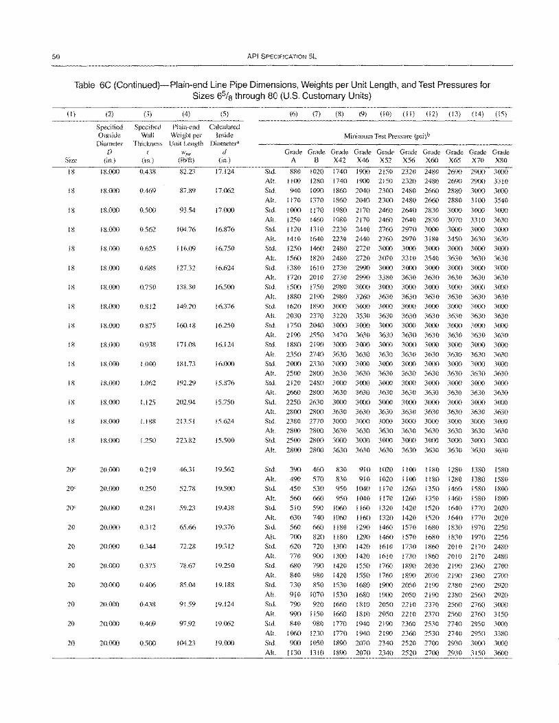
50 API SPECIFICATION 5L
Table 6C (Continued)-Plain-end Line Pipe Dimensions, Weights per Unit Length, and Test Pressures for Sizes 6% through 80 (U.S. Customary Units)
(I) (2) (3) (4) (5)
Specified Specified Plain-end Calculated Outside Wall Weight per Inside
Diameter Thickness Unit Length Diameter" D I ~. d
Size (in.) (in.) (Ib/ft) (in.)
18 18.000 0.438 82.23 17.124
18 18.000 0.469 87.89 17.062
18 IS.OOO 0.500 93.54 17.000
18 IX.OOO 0.562 104.76 16876
I KOOO 0.625 116.09 16750
18 18.000 0.688 127.32 16.624
18 18.000 0.750 138.30 16.500
18 18.000 0.812 149.20 16.376
18 IS.OOO 0.R75 160.18 16.250
18 18.<Xl0 0.938 171.08 16.124
18 18.000 1.000 181.73 16.000
18 18.000 1.062 192.29 15.876
18 18.000 1.125 202.94 15.750
18 18.000 1.188 213.51 15.624
IS 18.()()0 1.250 223.82 15.500
20" 20.000 0.219 46.31 19.562
20" 20.0()() 0.250 52.78 19.500
20e 20.()()() 0.281 59.23 19.438
20 20.000 0.312 65.66 19.376
20 20.000 0.344 72.28 19.312
20 20.l)()0 0.375 78.67 19.250
20 2(1.()()0 0.406 85.04 19.IS8
20 20.000 0.438 91.59 19.124
20 20.()()0 0.469 97.92 19.062
20 2(J.(X)() 0.500 104.23 19.000
(6) (7) (8) (9) (10) (II) (12) (13) (14) (15)
Minimum Test Pressure (psi)b
G~G~~~G~G~G~G~G~G~G~
A B X42 X46 X52 X56 X60 X65 X70 X80
Std. 880 1020 1740 1900 2150 2320 2480 2690 2900 3000 All.
Std. Alt.
Std.
1100 1280
940 1090 1170 1370
1000 1170
1740 1900 2150 2320 2480 2690 2900 3310
1860 2040 2300 2480 2660 2880 3000 3000
1860 2040 2300 2480 2660 28S0 3100 3540
1980 2170 2460 2640 2830 3000 3000 3000
All. 1250 1460 1980 2170 2460 2640 2830 3070 3310 3630 Std. 1120 1310 2230 2440 2760 2970 3000 3000 3000 3000
All. 1410 1640 2230 2440 2760 2970 3180 3450 3630 3630 Std. 1250 1460 2480 2720 30(X) 3000 3000 3000 3000 3000
All. 1560 1820 2480 2720 3070 3310 3540 3630 3630 3630
Std. 1380 1610 2730 2990 3000 3000 3000 3000 3000 3000 All. 1720 2010 2730 2990 3380 3630 3630 3630 3630 3630
Std. 1500 1750 29S0 3000 3000 3()(X) 3000 3000 3CXXl 3000
All. 1880 2190 2980 3260 3630 3630 3630 3630 3630 3630
Std. 1620 I 890 3000 3000 3000 3()()() 3()()() 3000 3CXXl 3000
All. 2030 2370 3220 3530 3630 3630 3630 3630 3630 3630 Std. 1750 2040 3(XXl 3000 3000 3000 3()(x) 3()()() 3()(x) 30C)()
AI!. 2190 2550 3470 3630 3630 3630 3630 3630 3630 3630 Std. 1880 2190 3000 3000 3()()() 3000 3CJOO 3C)()() 3()(x) 3000
AI!. 2350 2740 3630 3630 3630 3630 3630 3630 3630 3630 Std. 2()()() 2330 3000 3CXXl 3000 3()(x) 3()()() 3CXXl 3000 3000
AI!. 2500 2800 3630 3630 3630 3630 3630 3630 3630 3630 Std. 2120 2480 3000 3000 3000 3()()() 3()()() 3000 3CXXl 3000
All. 2660 2800 3630 3630 3630 3630 3630 3630 3630 3630 Std. 2250 2630 3000 3()(x) 3()()() 3()(x) 3C)()() 3000 3000 3000
All. 2800 28C)() 3630 3630 3630 3630 3630 3630 3630 3630 Std. 2380 2770 3000 3000 3000 3000 3(XXl 3000 3()(X) 3000
All. 2800 2800 3630 3630 3630 3630 3630 3630 3630 3630 Std. 2500 2S()() 3(XXl 3000 3000 3000 3000 3()()() 3C)()() 3000
All. 28()() 2800 3630 3630 3630 3630 3630 3630 3630 3630
Std. All.
Std.
All.
Std.
All.
Std.
All.
Std.
All.
Std.
All.
Std.
AI!.
Std.
All.
Std.
All.
Std.
Alt.
390 460 830
490 570 830
450 530 950
560 660 950
510 590 1060
630 740 1060
560 660 1180
700 820 1180
620 720 1300
770 900 1300 680 790 1420
840 980 1420
730 850 1530
910 1070 1530
790 920 1660
910 1020 1100 1180 1280 1380 1580
910 1020 1100 1180 1280 1380 1580 1040 1170 1260 1350 1460 1580 1800
1040
1160
1160
1290
1290
1170 1260 1350 1460
1320 1420 1520 1640
1320 1420 1520 1640
1460 1570 1680 1830
1460 1570 1680 1830
1580 18C)()
1770 2020
1770 2020
1970 2250 1970 2250
1420 1610
1420 1610 1730 1860 2010 2170 2480
1730 1860 2010 2170 2480 1550 1760 1890 2030 2190 2360 2700
1550 1760 1890 2030 2190 2360 2700
1680 1900 2050 2190 2380 2560 2920
1680 19()() 2050 2190 2380 2560 2920
1810 2050 2210 2370 2560 2760 3000 990 1150
S40 980
1060 1230 9()() 1050
1130 1310
1660 1810 2050 2210 2370 2560 2760 3150 1770 1940 2190 2360 2530 2740 2950 3(X)()
1770 1940 2190 2360 2530 2740 2950 3380 1890 2070 2340 2520 27()() 2930 3(XXl 3000
189() 2070 2340 2520 2700 2930 3150 3600
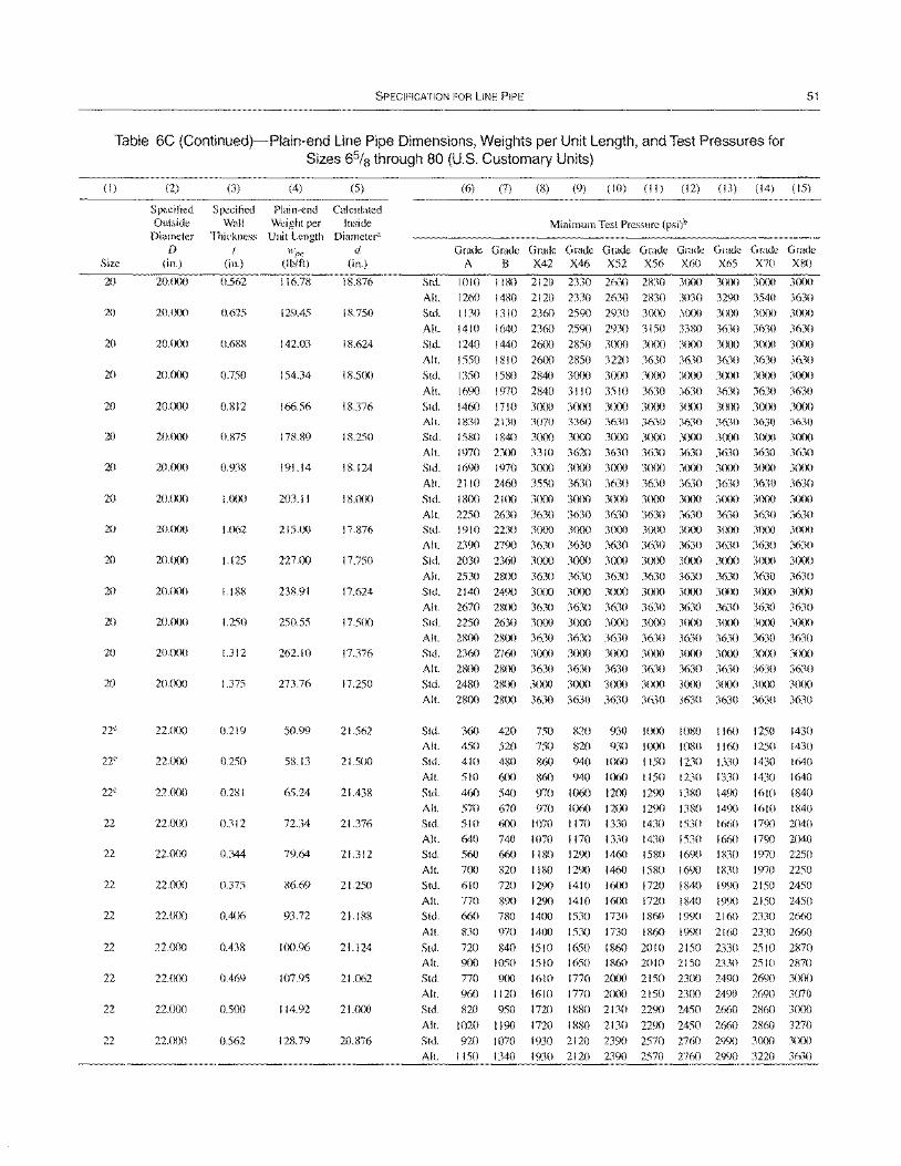
SPECIFICATION FOR LINE PIPE 51
Table 6C (Continued)-Plain-end Line Pipe Dimensions, Weights per Unit Length, and Test Pressures for Sizes 65/8 through 80 (U.S. Customary Units)
(I)
Size
20
20
20
20
20
20
20
20
20
20
20
20
20
20
22C
22C
22C
22
22
22
22
22
22
22
22
(2)
Specified Outside
Diameter o
(in.)
20.000
20. (xX)
20.000
20.(X)0
20.000
20.(X)0
20.000
20.000
20.000
20.lxx)
20.000
20.(X)0
20.000
20.fXlO
22.(XX)
22. (xX)
22.(xx)
22.(X~
22.tX)0
22.l~0
22.000
22.lXlO
22.fXXl
22.000
22.(XX)
(3)
Specified Wall
Thickness (
(in.)
0.562
0.625
0.688
0.750
0.812
(Un5
0.938
1.000
1.062
1.125
1.188
1.250
1.312
1.375
0.219
0.250
0.281
0.312
0.344
0.375
0.406
0.438
0.469
0.500
0.562
(4) (5)
Plain-end Calculated Weight per Inside
Unit Length Diameter" wI)e d
(lb/ft) (in.)
116.78 18.876
129.45 18.750
142.03 18.624
154.34 18.500
166.56 18.376
178.89 18.250
191.14 18.124
203.11 18.000
215.00 17.876
227.00 17.750
238.91 17.624
250.55 17.500
262.10 17.376
273.76 17.250
50.99 21.562
58.13 21.500
65.24 21.438
72.34 21.376
79.64 21.312
86.69 21.250
93.72 21.188
100.96 21.124
107.95 21.062
114.92 21.000
128.79 20.876
Std.
All.
Std.
All.
Std.
All.
Std.
All.
Std. All.
Std. All.
Std.
All.
Std.
(6) (7) (8) (9) (10) (II) (12) (13) (14) (15)
Minimum Test Pressure (psi)b
G~G~G~G~G~G~G~G~G~G~
A B X42 X46 X52 X56 X60 X65 X70 X80
1010 1180 2120 2330 2630 2830 3000 30()() 3000 3000 1260 1480 2120 2330 2630 2830 3030 3290 3540 3630 1 I 30 1310 2360 2590 2930 3000 30m 3(XX) 3000 3000
1410 1640 2360 2590 2930 3150 3380 3630 3630 3630 1240 1440 2600 2850 3(xx) 3000 3000 3(x)0 30()() 30(~)
1550 1810 26(x) 2850 3220 3630 3630 3630 3630 3630 1350 1580 2840 3000 30(X) 3000 3(XX) 3(X)0 3000 3(X)O
1690 1970 2840 3110 3510 3630 3630 3630 3630 3630 1460 17l 0 3000 3(x)() 3000 3000 3000 3000 3000 3000 1830 2130 1580 1840 1970 2300 1690 1970
2110 2460 1800 2100
3070 3360 3630 3630 3000 3000 30m 3000 3310 3620 3630 3630 3000 3000 3m) 3(xx)
3550 3630 3630 3630 3000 3(xx) 30m 3m)
3630 3630 3000 3000 3630 3630 3000 3000
3630 3630 30(X) 30m
3630 3(n)
3630 3000 3630 3(X)0
3630 30(~
3630 3(XX)
3630 3(X)0
All. 2250 2630 3630 3630 3630 3630 3630 3630 3630 3630 Std. 1910 2230 3(xx) 3(xx) 3000 30(x) 3m) 3(~) 3000 3(X)0
Alt. 2390 2790 3630 3630 3630 3630 3630 3630 3630 3630 Std. 2030 2360 3(XX) 3m) 30(x) 3(xx) 3(X)O 3(~) 3000 30(X)
Alt. 2530 2800 3630 3630 3630 3630 3630 3630 3630 3630 Std. 2140 2490 3000 3(xx) 3m) 3000 3(x~ 3000 3(X)0 3(XX)
All. 2670 2800 3630 3630 3630 3630 3630 3630 3630 3630 Std. 2250 2630 3m) 3(x)() 3000 3(xx) 3(XX) 3(XX) 30()() 3(XX)
All. 2800 28(~ 3630 3630 3630 3630 3630 3630 3630 3630 Std. 2360 2760 3m) 3000 3000 3(X~ 30(~ 3fKX) 3m) 3(Xx) All. 28(~ 2800 3630 3630 3630 3630 3630 3630 3630 3630 Std. 2480 2800 3000 3fXXl 3000 3(X~ 3(xx) 3()(x) 3(x)() 3(X~
Alt. 2800 2800 3630 3630 3630 3630 3630 3630 3630 3630
Std.
All.
Std.
All.
Std.
All. Std.
All.
Std.
All.
Std.
Alt. Std.
Alt.
Std.
Alt.
Std.
Alt.
Std.
Alt.
Std.
All.
360 420 750 820 930 I (XX) 1080 I 160 1250 1430 450 520 750 820 930 1000 1080 I 160 1250 1430 410 480 860 940 1060 1150 1230 1330 1430 1640 510 6(x) 860 940 1060 1150 1230 1330 1430 1640
460 540 970 1060 1200 1290 1380 1490 1610 1840 570 510 640 560 700 610 770 660 830
720
670 970 1060 600 1070 I 170 740 1070 1170 660 1180 1290 820 1180 1290
12(x) 1290 1380
1330 1430 1530 1330 1430 1530 1460 1580 1690 1460 1580 1690
1490 1660 1660 1830 1830
1610 1840 1790 2040 1790 2040 1970 2250 1970 2250
720
890 780 970
840 900 1050 770 900 960 1120 820 950
1020 1190 920 1070
1150 1340
1290 1290 1400 14(X)
1510
1410 1410 1530
1530
1650
16(x) 1720
1600 1720 1730 1860
1730 1860
1860 2010
1840 1990 2150 2450 1840 1990 2150 2450 1990 2160 2330 2660
1990 2160 2330 2660
2150 2330 2510 2870 1510 1650 1860 2010 2150 2330 2510 2870 1610 1770 2(XX) 2150 23(X) 2490 2690 3(x)() 1610 1770 2(Xx) 2150 23(X) 2490 2690 3070
1720 1880 2130 2290 2450 2660 2860 3(XX)
1720 1880 2130 2290 2450 2660 2860 3270 1930 2120 2390 2570 2760 29<X) 3CX)() 3(XX)
1930 2120 2390 2570 2760 2990 3220 3630
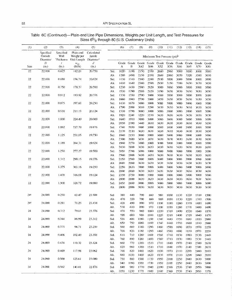
52 API SPECIFICATION 5L
Table 6C (Continued)-Plain-end Line Pipe Dimensions, Weights per Unit Length, and Test Pressures for Sizes 6% through 80 (U.S. Customary Units)
(I)
Size
22
22
22
22
22
22
22
22
22
22
22
22
22
22
22
24C
24C
24
24
24
24
24
24
24
24
(2)
Specified Outside
Diameter [)
(in.)
22.000
22.()(}O
22.()()()
22.000
22.()(}0
22'()(}O
22.()()0
22.()(lO
22.000
22.()(}O
22.()(}O
22.000
22.000
22'()()0
22.()()0
24.()(}()
24.000
24.000
24.000
24.0()0
24.()()0
24.000
24.000
24.()()()
24.()()()
(3)
Specified Wall
Thickness I
(in.)
0.625
0.688
0.750
0.812
0.875
0.938
I.om
1.062
1.125
1.188
1.250
1.312
1.375
1.438
1.500
0.250
0.281
0.312
0.344
0.375
0.406
0.438
0.469
0.500
0.562
(4)
Plain-end Weight per Unit Length
wI}£' (I bitt)
142.81
156.74
170.37
183.92
197.60
211.19
224.49
237.70
251.05
264.31
277.27
290.15
303.16
316.08
328.72
63.47
71.25
79.01
86.99
94.71
102.40
110.32
117.98
125.61
140.81
(5)
Calculated Inside
Diameter'l d
(in.)
20.750
20.624
20500
20.376
20.250
20.124
20.O<XJ
19.876
19.750
19.624
19.500
19.376
19.250
19.124
19.000
23.500
23.438
23.376
23.312
23.250
23.188
23.124
23.062
23.000
22.876
(6) (7) (8) (9) (10) (II) (12) (13) (14) (15)
Minimum Test Pressure (psi)b
Grade Grade Grade Grade Grade Grade Grade Grade Grade Grade A B X42 X46 X52 X56 X60 X65 X70 X80
Std. 1020 1190 2150 2350 2660 2860 3000 3000 3000 3000 All. 1280 1490 2150 2350 2660 2860 3070 3320 3580 3630
Std. I 130 I 31 0 2360 2590 2930 30m 3(X)() 3(XlO 3000 3000
All. 1410 1640 2360 2590 2930 3150 3380 3630 3630 3630
Std. 1230 1430 2580 2820 3000 3(X)0 3(lOO 3(lOO 3(lOO 3000
All. 1530 1790 2580 2820 3190 3630 3630 3630 3630 3630 Std. 1330 1550 2790 3000 3(0) 3000 3000 3000 3000 3()()()
All. 1660 1940 2790 3060 3450 3630 3630 3630 3630 3630
Std. 1430 1670 3000 3000 3000 3000 3000 3000 3()(x) 3000
All. 1790 2090 30 I 0 3290 3630 3630 3630 3630 3630 3630 Std. 1530 1790 3000 3()()() 3()()() 3000 3()()() 3000 3()()() 3()()()
All. 1920 2240 3220 3530 3630 3630 3630 3630 3630 3630
Std. 1640 1910 3000 3(lOO 3000 3000 3(XlO 3000 3(lOO 3()()()
All. 2050 2390 3440 3630 3630 3630 3630 3630 3630 3630 Std. 1740 2030 3()()() 3()()() 3()()() 3()()() 3(lOO 3000 3()()() 3()(x)
All. 2170 2530 3630 3630 3630 3630 3630 3630 3630 3630 Std. 1840 2150 3()()() 3()()() 3()()() 3()(X) 3()()() 3()()() 3(X)() 3()()()
All. 2300 2680 3630 3630 3630 3630 3630 3630 3630 3630 Std. 1940 2270 3000 3()()() 3(lOO 30m 3()()() 3(lOO 3(lOO 3()()()
All. 2430 28m 3630 3630 3630 3630 3630 3630 3630 3630 Std. 2050 2390 3()()() 3(lOO 3(lOO 3()()() 3()(x) 3(lOO 3()()0 3000
All. 2560 2800 3630 3630 3630 3630 3630 3630 3630 3630 Std. 2150 2500 3()()() 3()()() 3()()() 3()()() 3()(x} 3()()() 3(lOO 3(XX)
All. 2680 2800 3630 3630 3630 3630 3630 3630 3630 3630 Std. 2250 2630 3000 3()()() 3()(x) 3()()() 3()()() 3(lOO 3()()() 3()(x)
All. 2800 2800 3630 3630 3630 3630 3630 3630 3630 3630 Std. 2350 2750 3()()() 3()()() 3()()() 3()()() 3()()() 3(lOO 3()()() 3()()()
All. 2800 2800 3630 3630 3630 3630 3630 3630 3630 3630 Std. 2450 2800 3()()() 3()()() 3()()() 3()()() 3()(x) 3()(x} 3(lOO 3(lOO
All. 28(X} 2800 3630 3630 3630 3630 3630 3630 3630 3630
Std.
All.
Std. All.
Std.
All.
Std. All.
Std.
All.
Std.
All.
Std.
All.
Std.
All.
Std.
All.
Std.
All.
380
470
420
530 470
590
520 650
560
700
610
760
660
440
550
490 610
550
790 860 980
790 860 980 890 970 1100 890 970 I I ()()
980 1080 1220
680 980 1080 1220
600 1080 1190 1340 750 1080 1190 1340
660 1180 1290 1460
1050 1130 1220
1050 1130 1220
1180 1260 1370
1180 1260 1370 1310 14(lO 1520
1310 14()(} 1520
1440 1550 1680 1440 1550 1680
1580 1690 1830
1310
1310 1480
1480
1640
1500
1500
1690
1690
1870
1640 1870
1810 2060 1810 2060
1970 2250 820 1180 1290 1460 1580 1690 I 830 1970 2250
1830 1980 2130 2440 1830 1980 2130 2440
1970 2140 2300 2630
710 1280 14()(} 1580 1710
890 1280 1400 1580 1710
770 1380 1510 1710 1840
820 960 1380 1510 1710 1840 1970 2140 2300 2630 700 820 1480
880 1030 1480
750 880 1580
940 1090 1580
840 980 1770
1050 1230 1770
1620 1830 1970 2110 2290 2460 2810
1620 1830 1970 2110 2290 2460 2810
1730 1950 21 ()() 2250 2440 2630 3()(x)
1730 1950 2100 2250 2440 2630 3(lOO
1940 2190 2360 2530 2740 2950 3()()()
1940 2190 2360 2530 2740 2950 3370
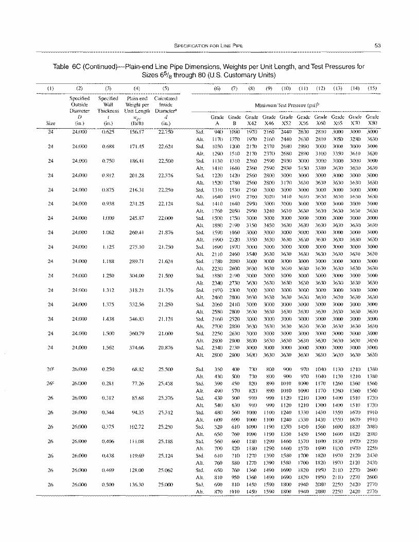
SPECIFICATION FOR LINE PIPE 53
Table 6C (Continued)-Plain-end Line Pipe Dimensions, Weights per Unit Length, and Test Pressures for Sizes 6% through 80 (U.S. Customary Units)
(1)
Size
24
24
24
24
24
24
24
24
24
24
24
24
24
24
24
24
26C
26C
26
26
26
26
26
26
26
(2)
Specified Outside
Diameter f)
(in.)
24.000
24.lx)0
24.cX)0
24.000
24.000
24.000
24.000
24.000
24.lX)0
24.(X)0
24.000
24.cX)0
24.000
24.000
24.00c)
24.lx)0
26.(Xx)
26.000
26.000
26.()()0
26.000
26.(XX)
26.000
26.(X)0
26.000
(3)
Specified Wall
Thickness I
(in.)
0.625
0.61;8
0.750
0.812
0.875
0.938
1.000
1.062
1.125
1.188
1.250
1.312
1.375
1.438
1.500
1.562
0.250
0.21;1
0.312
0.344
0.375
0.406
0.438
0.469
0.500
(4) (5)
Plain-end Calculated Weight per Inside Unit Length Diameter'
}Vpe d (lb/ft) (in.)
156.17 22.750
171.45 22.624
186.41 22.500
201.28 22.376
216.31 22.250
231.25 22.124
245.87 22.000
260.41 21.876
275.10 21.750
289.71 21.624
304.00 21.500
318.21 21.376
332.56 21.250
346.83 21.124
360.79 21.000
374.66 20.876
68.82 25.500
77.26 25.438
85.68 25.376
94.35 25.312
102.72 25.250
111.08 25.188
119.69 25.124
128.00 25.062
136.30 25.000
Std.
Alt.
Std.
Alt.
(6) (7) (8) (9) (10) (II) (12) (13) (14) (15)
Minimum Test Pressure (psi)b
G~G~G~G~G~G~G~G~G~G~ A B X42 X46 X52 X56 X60 X65 X70 X1;O
940 1090 1970 2160 2440 2630 28 I 0 3000 3000 3000
1170 1370 1970 2160 2440 2630 2810 3050 3280 3630
1030 1200 2170 2370 2680 2890 3000 3000 3000 3000
1290 1510 2170 2370 261;0 2890 3 J(X) 3350 3610 3630
Std. 1130 1310 2360 2590 2930 3000 3(X)O 3000 3000 3(XX)
Alt. 1410 1640 2360 2590 2930 3150 3380 3630 3630 3630
Std. 1220 1420 2560 2800 3000 3000 3000 3000 3(X)0 3000
Alt. 1520 1780 2560 280a 3170 3630 3630 3630 3630 3630 Std. 1310 1530 2760 3000 30aO 3000 3(XlO 3000 3000 3(XX) All.
Std.
Alt.
Std.
Alt.
Std.
Alt.
Std.
1640 1910 2760 1410 1640 2950
1760 2050 2950 1500 1750 3000
1880 2190 3150
1590 1860 3000
1990 2320 3350
1690 1970 3000
3020 3410 3630 3OClO 3()(x) 3CXX)
3240 3630 3630
3000 3000 3000 3450 3630 3630 3OClO 3000 3(XX)
3630 3630 3630
3OClO 3000 3OClO
3630 3(XlO
3630 3000
3630
3000
3630
3000
3630 3mO
3630 3000
3630
3000
3630
3000
3630 3000
3630 3(XX)
3630
3000 3630
3000
3630
3000
3630 3(XX)
3630 3(X)O
3630 3(XX)
All. 2110 2460 3540 3630 3630 3630 3630 3630 3630 3630 Std. 1780 2080 3000 3000 3()(x) 3CXX) 3(XX) 3(XX) 3(XX) 3000
Alt. 2230 2600 3630 3630 3630 3630 3630 3630 3630 3630 Std. 1880 2190 3(lOO 3000 3(XX) 3(XX) 3(XlO 3(XX) 3000 3(XX)
Alt. 2340 2730 3630 3630 3630 3630 3630 3630 3630 3630 Std. 1970 2300 3000 3(Xx) 3000 3(XlO 3(XX) 3(X)0 3(X)() 3(X)0
All. 2460 2800 3630 3630 3630 3630 3630 3630 3630 3630 Std. 2060 2410 3000 3000 3OCX) 3000 3(XX) 3(XX) 3(X)0 3OCX)
Alt.
Std.
Alt.
Std.
All.
Std.
Alt.
Std.
Alt.
Std.
Alt.
Std.
All.
Std.
All.
Std.
Alt.
Std.
All.
Std.
Alt.
Std.
Alt.
Std.
All.
2580 2800 3630
2160 2520 3000
2700 2800 3630
2250 2630 3000 2800 28OC) 3630 2340 2730 3CXX)
2800 2800 3630
350 400 730
430 500 730 390 450 820
490 570 820
430 500 910
540
480
600
520
650
560
700
610
760
650
810
630 910
560 1000
690 IClOO
610 1090
760 1090
660 1180
820 1180
710 1270
880 1270 760 1360
950 1360
3630 3630 3630 3000 3OCX) 3(XlO
3630 3CXX)
3630 3OCX)
3630 3lXX)
3630 3OC)0
3630 3630 3630 3630 3630 3630 363{) 3000 3(XX) 3lXX) 30m 3(XX) 3000 3(Xx)
3630 3630 3630 3630 3630 3630 3630 3000 3(Xx) 3()(lO 3(XX) 3(XX) 3(XX) 3(XX)
3630 3630 3630 3630 3630 3630 3630
800 9(X) 970 1040 I 130 1210 1380
800 9()() 970 1040 I 130 1210 1380 890 10 10 1090 I 170 1260 1360 1560
890 1010 1090 1170 1260 1360 1560 990 1120 1210 I 3 (X) 14(X) 1510 1730
990 1120 1210 I I(X) 1240 1330
I I (X) 1240 1330
119() 1350 1450
1190 1350 1450
1290 1460 1570 1290 1460 1570
1390 1580 17lX) 1390 1580 17(X)
149() 1690 1820
1490 1690 1820
13(X) 14(x) 1510 1730
1430 1550 1670 1910
1430 1550 1670 1910 1560 169() 1820 2080
1560 1690 I 820 2080
169() liDO 1970 2250 169() 1830 1970 2250
1820 1970 2120 2430
1820 1970 2120 2430 1950 2 I 10 2270 26(X)
1950 2 I 10 2270 26(X)
690 810 1450 1590 870 1010 1450 159()
1800 1940 2080 2250 2420 2770 18OC) 1940 2080 2250 2420 2770
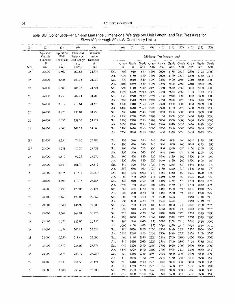
54 API SPECIFICATION 5L
Table 6C (Continued)-Plain-end Line Pipe Dimensions, Weights per Unit Length, and Test Pressures for Sizes 6% through 80 (U.S. Customary Units)
(I)
Size
26
26
26
26
26
26
26
26
28"
28"
2S
28
28
28
28
28
28
28
28
28
28
28
28
2S
28
(2)
Specified Outside
Diameter f)
(in.)
26.(X){)
26.000
26.cX)O
26.<Xl0
26.000
26.000
26.(){)0
26J){)O
28.000
2S.(){){)
28.ex){)
28.000
28.(){)0
28.(){)0
28.(){)O
28.(){)0
28J){)0
28.(){)O
28'()()()
28.(){)0
28.(){)O
28.000
28.f){)O
28.f){){)
28.(){)O
(3) (4) (5)
Specified Plain-end Calculated Wall Weight per Inside
Thickness Unit Length Diameter"
I WI>e d (in.) (Ib/ft) (in.)
0.562 152.83 24.876
0.625 169.54 24.750
0.688 186.16 24.624
0.750 202.44 24.500
0.812 218.64 24.376
0.875 235.01 24.250
0.938 251.30 24.124
1.000 267.25 24.000
0.250 74.16 27.500
0.281 83.26 27.438
0.312 92.35 27.376
0.344 101.70 27.312
0.375 110.74 27.250
0.406 119.76 27.188
0.438 129.05 27.124
0.469 138.03 27.(l62
0.5C){) 146.99 27.000
0.562 164.84 26.876
0.625 182.90 26.750
0.688 200.S7 26.624
0.750 21S.48 26.500
0.812 236.(){) 26.376
0.875 253.72 26.250
0.938 271.36 26.124
1.000 288.63 26.000
(6) (7) (8) (9) (10) (II) (12) (13) (14) (15)
Minimum Test Pressure (psi)b
G~~~G~G~G~G~G~G~G~G~ A B X42 X46 X52 X56 X60 X65 X70 X80
Std. 780 910 1630 1790 2020 2180 2330 2530 2720 3000
All.
Std.
970 1130
870 1010
1630 1790 2020 2180 2330 2530 2720 3110
1820 1990 2250 2420 26C){) 2810 3000 3000
AI I. 1080 1260 1820 1990 2250 2420 2600 2810 3030 3460
Std. 950 1110 2000 2190 2480 2670 2860 3000 30ex) 3000
All. 1190 1390 2CXX) 2190 2480 2670 2860 3100 3330 3630 Std. 1040 1210 21 80 2390 2700 2910 3(XX) 3ex){) 3000 3000
All. 1300 1510 2180 2390 2700 2910 3120 3380 3630 3630 Std. 1120 1310 2360 2590 2920 3CXX) 3000 3(){){) 3(X){) 3000
All. 1410 1640 2360 2590 2920 3150 3370 3630 3630 3630 Std. 1210 1410 2540 2790 3000 3000 3000 3CXX) 3exX) 3000
AI I. 1510 1770 2540 2790 3150 3630 3630 3630 3630 3630 Std. 1300 1520 2730 2990 3000 3000 3(X){) 3(X){) 3CXX) 3000
All. 1620 1890 2730 2990 3380 3630 3630 3630 3630 3630 Std. 1380 1620 2910 3000 3000 3000 3000 3000 3CXX) 3000
All. 1730 2020 2910 31S0 3600 3630 3630 3630 3630 3630
Std.
All.
Std.
All.
Std.
All.
Std.
All. Std.
All.
Std. All.
Std. All.
Std.
All.
Std.
All.
Std.
All.
Std.
320
400
360
450
400
500
440
550
480 6(X)
520 650
560
700 6(){)
750
640
380 470
420
530
470
590
520
650 560
700
610 760
660 820
700
680 740 840 680 740 840
760 830 940
760 830 940
840 920 1040
840 920 1040
930 1020 1150
930 1020 1150
1010
1010 IJ(){)
1100
1180 1180
1270
1110 1250
1110 1250
1200 1360 12l){) 1360
1300 1460 13ex) 1460
880 1270 1390 1570
1390 1570
1480 1670 750 1350
900 960 1040 11 30 9(X) 960 1040 1130
1010 1080 1170 1260
1010 1080 1170 1260
1120 1200 1300 1400
1120 1200 1300 1400
1240 1330 1440 1550
1240 1330 1440 1550
1290
1290
1450
1450
16ex)
1600
1770
1770 1350 1450
1350 1450
1460 1570
1460 1570
1580 1690 1580 1690
1690 1810
1570 1690 1930 1570 1690 1930
17ex) 1830 2090 17ex) 1830 2090
1830 1970 2250 1830 1970 2250
1%0 2110 2410 1690 1810 1960 2110 2410
1800 1930 2090 2250 2570 sex) 940 1350 1480 1670 1800 1930 2090 2250 2570 720 840 1520 1660 1880 2020 2170 2350 2530 2890
900 1050 1520 1660 1880 2020 2170 2350 2530 2890 8(){) 940 1690 1850 2090 2250 2410 2610 2810 3ex){)
All. 1000 1170 1690 1850 2090 2250 2410 2610 2810 3210 Std. 880 1030 1860 2030 23ex) 2480 2650 2870 3CXX) 3(){){)
All. 1110 1290 1860 2030 23(X) 2480 2650 2870 31(){) 3540
Std. 960 I 1 30 2030 2220 2510 2700 2890 3000 3000 3000
All. 1210 1410 2030 2220 2510 2700 2890 3130 3380 3630
Std. 1040 1220 2190 2400 2710 2920 3(){){) 3000 30(){) 3000
All. 1310 1520 2190 24(){) 2710 2920 3130 3390 3630 3630
Std. 1130 1310 2360 2590 2930 3CXX) 3000 3000 3(){){) 3000
All. 1410 1640 2360 2590 2930 3150 3380 3630 3630 3630 Std. 1210 1410 2530 2770 3CXX) 3CXX) 3CXX) 3000 3lX)0 3CXX)
All. 1510 1760 2530 2770 3140 3630 3620 3630 3630 3630 Std. 1290 1500 2700 2960 3000 3(){){) 3(XX) 3000 3000 3()(){)
All. 1610 1880 2700 2960 3340 3630 3630 3630 3630 3630
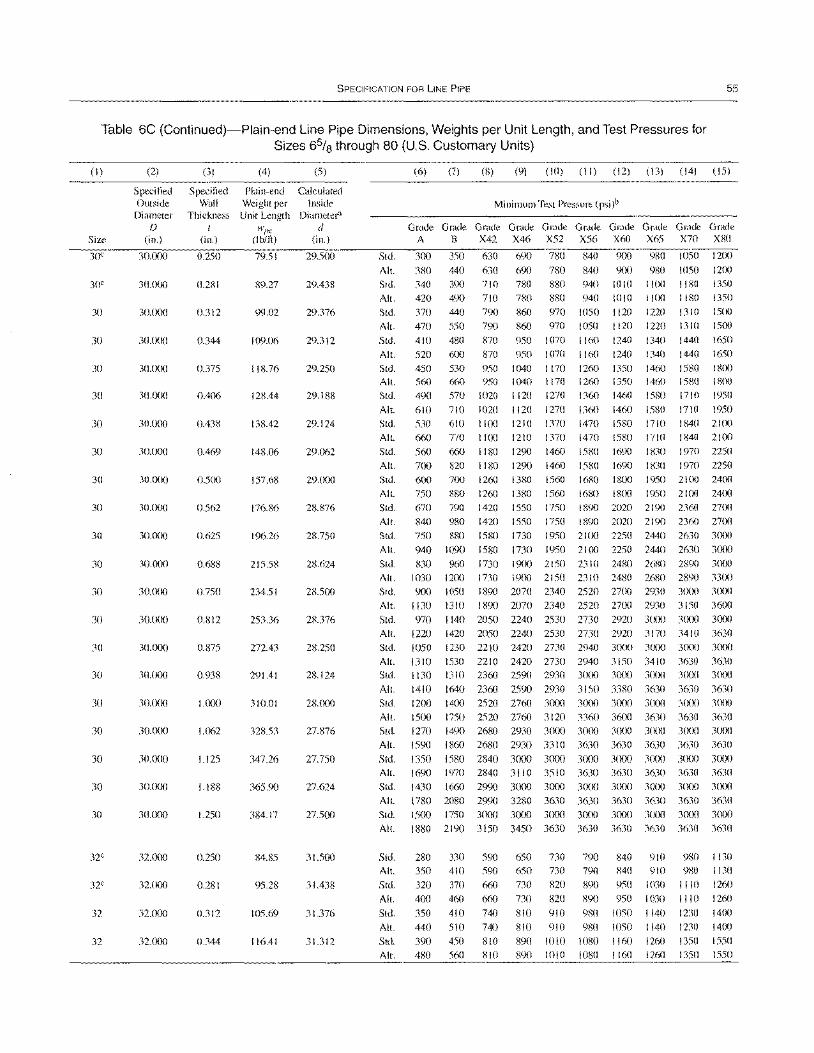
SPECIFICATION FOR liNE PIPE 55
Table 6C (Continued)-Plain-end Line Pipe Dimensions, Weights per Unit Length, and Test Pressures for Sizes 6% through 80 (U.S. Customary Units)
(I)
Size
30e
30e
30
30
30
30
30
30
30
30
30
30
30
30
30
30
30
30
30
30
30
32C
32C
32
32
(2)
Specified Outside
Diameter f)
(in.)
30.000
30.()()()
30.000
30'()()0
30.000
30.000
30.()()0
30.()()0
30.()()()
30.000
30.000
30.000
30.000
30.000
30.000
30.()()0
30.000
30.000
30'()()O
30.()()O
30.000
32.()()()
32.000
32.000
32.000
(3)
Specified Wall
Thickness /
(in.)
0.250
0.281
0.312
0.344
0.375
0.406
0.438
0.469
0.500
0.562
0.625
0.688
0.750
0.812
0.875
0.938
1.000
1.062
1.125
1.188
1.250
0.250
0.281
0.312
0.344
(4) (5)
Plain-end Calculated Weight per Inside Unit Length Diamete['"
wpc d (lb/ft) (in.)
79.51 29.500
89.27 29.438
99.02 29.376
109.06 29.312
118.76 29.250
128.44 29.188
138.42 29.124
148.06 29.062
157.68 29.000
176.86 28.876
196.26 28.750
215.58 28.624
234.51 28.500
253.36 28.376
272.43 28.250
291.41 28.124
310.01 28.000
328.53 27.876
347.26 27.750
365.90 27.624
384.17 27.500
84.85 31.500
95.28 31.438
105.69 31.376
116.41 31.312
Std.
All.
Std.
All.
Std.
All.
Std.
All.
Std.
(6) (7) (8) (9) (10) (II) (12) (13) (14) (15)
Minimum Test Pressure (psi)b
G~~~G~G~G~G~~~G~G~G~ A B X42 X46 X52 X56 X60 X65 X70 XRO
300 350 630 690 780 840 900 980 1050 1200
380 440 630 690 780 840 900 980 1050 1200
340 390 710 780 880 940 1010 1100 1180 1350
420 490 710 780 880 940 1010 11m 1180 1350
370 440 790 860 970 1050 1120 1220 1310 1500 470 550 790 860 970 1050 1120 1220 1310 1500
410 480 870 950 1070 I 160 1240 I 340 1440 1650
520 600 870 950 1070 1160 1240 1340 1440 1650
450 530 950 1040 1170 1260 1350 1460 1580 1800 All. 560 660 950 1040 I 170 1260 1350 1460 1580 1800
Std.
All.
Std.
All.
Std.
All.
Std.
All.
Std.
All.
Std.
All.
490
610
530
660
560
700
600
750 670
840
750
940
570
710
610
770
660 820
7m
880
790
980
880
1090
1020
1020
1100
1100
1180
1180
1260
1260
1420 1420
1580
1580
1120
1120 1210
1210
1290
1290
1380
1380
1550
1550
1730
1730
1270 1360
1270 1360
1370 1470
1370 1470
1460 1580
1460 1580
1560 1680
1560 1680
1750 1890 1750 1890
1950 2100 1950 21(X)
1460 1580 1710 1950
1460 1580 1710 1950 1580 1710 1840 2100
1580 1710 1840 2100
1690 I 830 1970 2250
1690 I 830 1970 2250
1800 1950 2100 24(X)
1800 1950 2100 2400
2020 2190 2360 2700
2020 2190 2360 2700 2250 2440 2630 3(X)0
2250 2440 2630 3(XX)
Std. 830 960 1730 1900 2 150 23 I 0 2480 26RO 2890 3()(X)
All. 1030 1200 1730 1900 2150 2310 2480 2680 2890 33m Std. 900 1050 1890 2070 2340 2520 2700 2930 3()()() 3()()()
All. 1130 1310 1890 2070 2340 2520 2700 2930 3150 3600 Std. 970 1140 2050 2240 2530 2730 2920 3000 3()(X) 3()()()
All. 1220 1420 2050 2240 2530 2730 2920 3170 3410 3630 Std. 1050 1230 2210 2420 2730 2940 30t)() 3()()() 3(XX) 30()()
All. 1310 1530 2210 2420 2730 2940 3150 3410 3630 3630 Std. 1130 1310 2360 2590 2930 3()(X) 3()()() 3()()() 3(XX) 3()()()
All. 1410 1640 2360 2590 2930 3150 3380 3630 3630 3630 Std. 1200 1400 2520 2760 3000 3000 3()()() 3(XX) 3()()() 3C)()()
All.
Std.
All.
Std.
1500 1270 1590
1350
1750 2520 2760 3120 3360 3600 1490 2680 2930 3()()() 3()()() 3()()()
1860 2680 2930 3310 3630 3630
1580 2840 3000 3000 3()()() 3C)()()
3630 3630 3()()() 3()()()
3630 3630 3 ()()() 3 ()()()
3630 3()()()
3630 3(XX)
All. 1690 1970 2840 31 10 3510 3630 3630 3630 3630 3630 Std. 1430 1660 2990 3()()() 3000 3()()() 3()(X) 3()()() 3()()() 3()()()
All. 1780 2080 2990 3280 3630 3630 3630 3630 3630 3630 Std. 1500 1750 3()()() 3000 3()()() 3()()() 3()()() 3()()() 3(XX) 3000
All. 1880 2190 3150 3450 3630 3630 3630 3630 363() 3630
Std.
All.
Std.
Alt.
Std.
All.
Std.
All.
280 350
320
400
350
440
390 480
330 410
370 460
410
510 450
560
590 590
660 660
740
740
810
SIO
650 730 790 840 650 730 790 840
730 820 890 950
730 820 890 950
810 910 980 1050
810 910 980 1050
890 1010 1080 1160 890 1010 IOS0 1160
910 9HO 1130 910 980 1130
1030 1110 1260
1030 1110 1260
1140 1230 14(X)
1140 1230 14()()
1260 1350 1550 1260 1350 1550
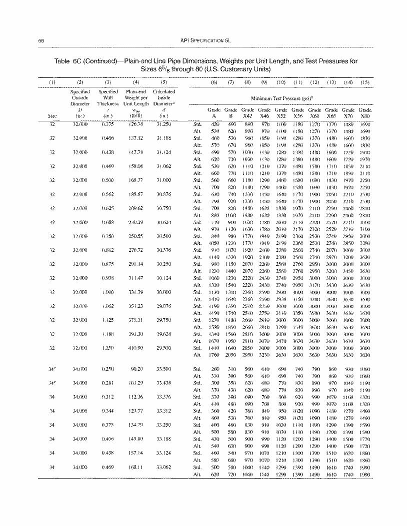
56 API SPECIFICATION 5L
Table 6C (Continued)-Plain-end Line Pipe Dimensions, Weights per Unit Length, and Test Pressures for Sizes 65/8 through 80 (U.S. Customary Units)
(I)
Size
32
32
32
32
32
32
32
32
32
32
32
32
32
32
32
32
32
34C
34"
34
34
34
34
34
34
(2)
Specified Outside
Diameter D
(in.)
32.000
32.000
32.000
32.000
32.000
32.000
32.000
32.000
32.000
32.000
32.000
32.(X)0
32.000
32.000
32.000
32.000
32.000
34.000
34.000
34.000
34.000
34.000
34.000
34.000
34.000
(3)
Specified Wall
Thickness I
(in.)
0.375
0.406
0.438
0.469
0.500
0.562
0.625
0.688
0.750
0.812
0.S75
0.938
1.000
1.062
1.125
1.188
1.250
0.250
0.281
0.312
0.344
0.375
0.406
0.438
0.469
(4) (5)
Plain-end Calculated Weight per Inside Unit Length Diameter"
wpe d (Ib/ft) (in.)
126.78 31.250
137.12 31.188
147.78 31.124
158.08 31.062
168.37 31.000
188.87 30,876
209.62 30,750
230.29 30,624
250.55 30.500
270.72 30.376
291.14 30,250
311.47 30,124
331.39 30,000
351.23 29,876
371.31 29,750
391.30 29,624
410.90 29.500
90.20 33.500
101.29 33,438
112.36 33.376
123.77 33.312
134.79 33,250
145.80 33.188
157.14 33,124
168.11 33'(J62
Std,
All. Std,
(6) (7) (8) (9) (10) (II) (12) (13) (14) (15)
Minimum Test Pressure (psi)b
~~G~G~G~~~G~G~G~G~~~
A B X42 X46 X52 X56 X60 X65 X70 XSO
420 490 890 970 1100 1180 1270 1370 1480 1690 530 460
620 530
890 970 1100 960 1050 1190
1180 1270 1370 1480 1690 1280 1370 1480 1600 1830
All. 570 670 960 1050 1190 1280 1370 1480 1600 1830
Std. 490 570 1030 I 130 1280 1380 1480 1600 1720 1970 All. 620 720 1030 1130 1280 1380 1480 1600 1720 1970 Std,
AI!.
Std.
AI!.
Std,
All. Std,
All.
530 620 1110 1210 1370 660 770 1110 1210 1370 560 660 1180 1290 1460
700 820 1180 1290 1460 630 740 1330 1450 1640 790 920 1330 1450 1640 700 820 1480 1620 1830 880 1030 1480 1620 1830
1480 1580 1710 1480 1580 1710 1580 1690 1830
1580 1690 1830
1850 2110 1850 2110 1970 2250 1970 2250
1770 1900 2050 2210 2530 1770 1900 2050 2210 2530 1970 21 10 2290 2460 2810 1970 2110 2290 2460 2810
Std, 770 900 1630 1780 2010 2170 2320 2520 2710 3000 All. 970 1130 1630 1780 2010 2170 2320 2520 2710 3100 Std. 840 980 1770 1940 2190 2360 2530 2740 2950 3000 All. 1050 1230 1770 1940 2190 2360 2530 2740 2950 3380 Std, 910 1070 1920 2100 23S0 2560 2740 2970 3000 3000 AI!. 1140 1330 1920 2100 2380 2560 2740 2970 3200 3630 Std. 980 I 150 2070 2260 2560 2760 2950 3000 3000 3000
All. 1230 1440 2070 2260 2560 2760 2950 3200 3450 3630 Std, 1060 1230 2220 2430 2740 2950 3000 3000 3000 3000
All. 1320 1540 2220 2430 2740 2950 3170 3430 3630 3630
Std. 1130 13 10 2360 2590 2930 3000 3000 3000 3000 3000 All. 1410 1640 2360 2590 2930 3150 3380 3630 3630 3630 Std, I 190 1390 2510 2750 3000 3000 3000 3000 3000 3000 All. 1490 1740251027503110 3350 3580 3630 3630 3630 Std, 1270 1480 2660 2910 3000 3000 3000 3000 3000 3000
All. 1580 1850 2660 2910 3290 3540 3630 3630 3630 3630 Std. 1340 1560 2810 30(X) 3000 3000 3000 3000 3000 3000 All. 1670 1950 2810 3070 3470 3630 3630 3630 3630 3630 Std, 1410 1640 2950 3000 3000 3000 3000 3000 3000 3000 All. 1760 2050 2950 3230 3630 3630 3630 3630 3630 3630
Std,
All. Std.
All. Std,
All. Std,
All. Std,
All. Std,
All. Std,
AIL
Std,
All.
260 330 300 370
330 410 360 460 400
500 430 540 460
580
500 620
310 560 610 390 560 610 350 620 680 430 620 680
390 690 760 480 690 760 420 760 840 530 760 840 460 830 910
580 830 910 500 900 990 630 900 990 540 970 1070
680 970 1070
580 1040 1140 720 1040 1140
690 740 790 860 930 1060 690 740 790 860 930 1060 770 830 890 970 1040 I 190 770 830 890 970 1040 1190
860 920 990 1070 1160 1320 860 920 990 1070 1160 1320 950 1020 1090 1180 1270 1460 950 1020 1090 I 180 1270 1460
1030 1110 1190 1290 1390 1590
1030 1110 1190 1290 1390 1590 1120 1200 1290 1400 1500 1720 1120 1200 1290 1400 1500 1720 1210 1300 1390 1510 1620 1860
1210 1300 1390 1510 1620 1860
1290 1390 1490 1610 1740 1990 1290 1390 1490 1610 1740 1990
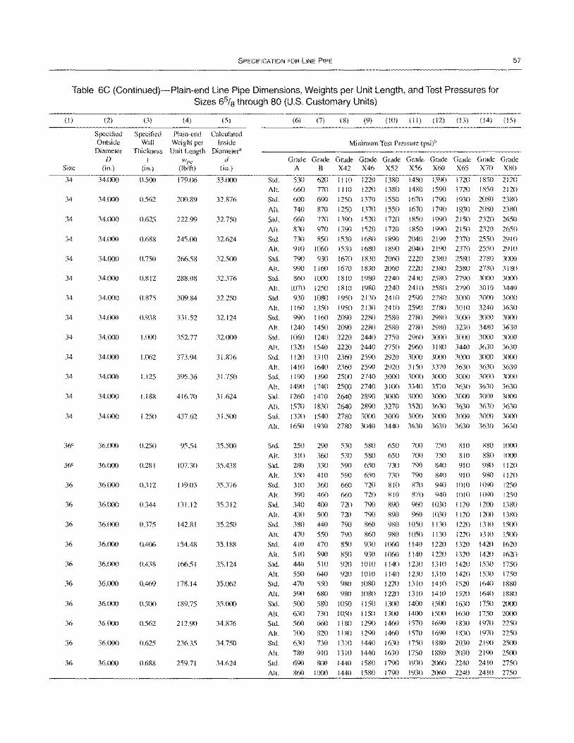
SPECIFICATION FOR LINE PIPE 57
Table 6C (Continued)-Plain-end Line Pipe Dimensions, Weights per Unit Length, and Test Pressures for Sizes 65fs through 80 (U.S. Customary Units)
(1)
Size
34
34
34
34
34
34
34
34
34
34
34
34
34
36e
36e
36
36
36
36
36
36
36
36
36
36
(2)
Specified Outside
Diameter D
(in.)
34.000
34.000
34.000
34.CXlO
34.000
34.000
34.(XlO
34.CXlO
34.000
34.lXlO
34.000
34.000
34.000
36.(0)
36.lXX)
36.000
36.()()0
36.()()0
36'(X)O
36.000
36.(XlO
36.000
36.000
36.000
36.00()
(3)
Specified Wall
Thickness I
(in.)
0.500
0.562
0.625
0.688
0.750
0.812
0.875
0.938
1.000
1.062
1.125
1.188
1.250
0.250
0.281
0.312
0.344
0.375
0.406
0.438
0.469
0.500
0.562
0.625
0.688
(4) (5)
Plain-end Calculated Weight per Inside Unit Length Diameter"
w"e d (Ib/ft) (in.)
179.06 33.000
200.89 32.876
222.99 32.750
245.00 32.624
266.58 32.500
288.08 32.376
309.84 32.250
331.52 32.124
352.77 32.000
373.94 31.876
395.36 31.750
416.70 31.624
437.62 31.500
95.54 35.500
107.30 35.438
119.03 35.376
131.12 35.312
142.81 35.250
154.48 35.188
166.51 35.124
178.14 35.062
189.75 35.000
212.90 34.876
236.35 34.750
259.71 34.624
Std.
All.
Std.
All.
Std.
(6) (7) (8) (9) (10) (II) (12) (13) (14) (15)
Minimum Test Pressure (psi)b
G~G~G~~~G~G~G~G~G~G~ A B X42 X46 X52 X56 X60 X65 X70 X80
530 660
600
740 660
620 1110 1220 1380 1480 770 1110 1220 1380 1480 690 1250 1370 1550 1670
870 1250 1370 1550 1670 770 1390 1520 1720 1850
1590 1720 1850 2120 1590 1720 1850 2120 1790 1930 2080 2380
1790 1930 2080 2380 1990 2150 2320 2650
All. 830 970 1390 1520 1720 1850 1990 2150 2320 2650
Std.
All.
Std.
All.
730 850 910 1060
790 930 990 1160
1530 1680 1890 2040 2190 2370 2550 2910 1530 1680 1890 2040 2190 2370 2550 2910
1670 1830 2060 2220 2380 2580 2780 3000 1670 1830 2060 2220 2380 2580 2780 3180
Std. 860 1000 1810 1980 2240 2410 2580 2790 3000 3000 Alt. 1070 1250 1810 1980 2240 2410 2580 2790 3010 3440 Std. 930 1080 1950 2130 2410 2590 2780 3()(X) 30m 3000
All. 1160 1350 1950 2130 2410 2590 2780 3010 3240 3630 Std. 990 1160 2090 2280 2580 2780 2980 3()(X) 3000 3(X)O All. 1240 1450 2090 2280 2580 2780 2980 3230 34S0 3630 Std. 1060 1240 2220 2440 2750 2960 3(X)0 3000 30m 3000 All. 1320 1540 2220 2440 2750 2960 31S0 3440 3630 3630 Std. I 120 1310 2360 2590 2920 3()()() 3000 3()()() 3()()() 30m
All. 1410 1640 2360 2590 2920 3150 3370 3630 3630 3630 Std. I 190 1390 2500 2740 3(XX) 3(0) 3lX)0 3(X)() 3()(X) 3(XX)
All. 1490 1740 2500 2740 3100 3340 3570 3630 3630 3630 Std. 1260 1470 2640 2890 3()(Xl 3lrn 3(XX) 3(X)0 30m 30()0
All. 1570 1830 2640 2890 3270 3520 3630 3630 3630 3630 Std. 1320 1540 2780 3(rn 3()(Xl 3(XX) 3000 3000 3(XX) 3(XXl
Alt. 1650 1930 2780 3040 3440 3630 3630 3630 3630 3630
Std.
All.
Std.
All.
Std.
Alt.
Std.
All.
Std.
All.
Std.
All.
Std.
All.
Std.
All.
Std.
All.
Std.
All.
Std.
All.
Std.
All.
250 290 310 360 280 330 350 410 310 360 390 460
340 400 430 500 380 440 470 550
410 470
510 590 440 510 550 640 470 550
530 580 650 7()() 750 810 880 I (XX) 530 580 650 700 750 RIO 8S0 I (XX) 590 650 730 790 840 910 980 I 120 590 650 730 790 840 910 980 I 120 660 720 SIO 870 940 1010 1090 1250 660 720 810 870 940 1010 1090 1250
720 790 890 960 1030 I 120 12m 13S0 720 790 890 960 1030 I 120 1200 1380 790 860 980 1050 1130 1220 1310 15(X) 790 860 980 1050 1130 1220 1310 15(X) 850 930 1060 1140 1220 1320 1420 1620
850 930 1060 1140 1220 1320 1420 1620 920 1010 1140 1230 1310 1420 1530 1750 920 1010 1140 1230 1310 1420 1530 1750 9S0 1080 1220 1310 1410 1520 1640 1880
590
500
680 980
580 1050
1080 1220 1310 1410 1150 1300 14()() IS()()
1520
1630
1640 18S0 1750 2(X)()
630 730 1050 I 150 13()() 1400 1500 1630 1750 2(X)()
1290 1460 1570 1690 1830 1970 2250 1290 1460 1570 1690 1830 1970 2250 1440 1630 1750 188() 2030 2190 25(X)
1440 1630 1750 1880 2030 2190 25(X) 1580 1790 1930 2060 2240 2410 2750 1580 1790 1930 2060 2240 2410 2750
560 660 1180 700 82() IISO 630 730 1310
780 910 1310 690 800 1440 860 1000 1440
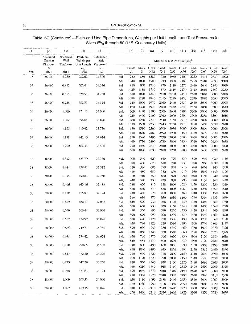
58 API SPECIFICATION 5L
Table 6C (Continued)-Plain-end Line Pipe Dimensions, Weights per Unit Length, and Test Pressures for Sizes 65/8 through 80 (U.S. Customary Units)
(I)
Size
36
36
36
36
36
36
36
36
36
38
38
38
38
38
38
38
38
38
38
38
38
38
38
38
38
(2)
Specifieu Outside
Diameter D
(in.)
36.000
36.000
36.000
36.()(X)
36.()()()
36.000
36.()()0
36'()()()
36.()()O
38.(X)O
38.()OO
38.()()O
38'()()0
38.00()
38'()()0
38'<)()0
38.000
38.()()O
3R.()()0
38.()()O
38.()()()
38'()()()
38.()()()
38'()()O
38'()(X)
(3) (4) (5)
Specified Plain-end Calculated Wall Weight per Inside
Thickness Unit Length Diameter' { wpe d
(in.) (Ib/ftJ (in.)
0.750 282.62 34.500
0.812 305.44 34.376
0.875 328.55 34.250
0.938 351.57 34.124
1.000 374.15 34.000
1.062 396.64 33.876
1.125 419.42 33.750
1.188 442.10 33.624
1.250 464.35 33.500
0.312 125.70 37.376
0.344 138.47 37.312
0.375 150.83 37.250
0.406 163.16 37.188
0.438 175.87 37.124
0.469 188.17 37.062
0.500 2(X).44 37.000
0.562 224.92 36.876
0.625 249.71 36.750
O.68R 274.42 36.624
0.750 298.65 36.500
0.812 322.80 36.376
0.875 347.26 36.250
0.938 371.63 36.124
1.000 395.53 36.000
1.062 419.35 35.876
(6) (7) (8) (9) (10) (II) (12) (13) (14) (15)
Minimum Test Pressure (psi)b
~~G~G~~~G~G~G~G~G~~~ A B X42 X46 X52 X56 X60 X65 X70 X80
Std. 750 880 1580 1730 1950 2100 2250 2440 2630 3(XlO All. 940 1090 1580 1730 1950 2100 2250 2440 2630 3000 Std. 810 950 1710 1870 21 10 2270 2440 2640 2840 3000 All. 1020 1180 1710 1870 2110 2270 2440 2640 2840 3250
Std. 880 1020 1840 20 I 0 2280 2450 2630 2840 3(XlO 3000 All. 1090 1280 1840 20 I 0 2280 2450 2630 2840 3060 3500 Std. 940 1090 1970 2160 2440 2630 2810 3tXlO 3000 3000 All. 1170 1370 1970 2160 2440 2630 2810 3050 3280 3630
Std. 1000 1170 2100 2300 2600 2800 3000 3000 3tXlO 3000 All. 1250 1460 2100 2300 2600 2800 3000 3250 3500 3630 Std. 1060 1240 2230 2440 2760 2970 3000 3000 3000 3000 All. 1330 1550 2230 2440 2760 2970 3190 3450 3630 3630 Std. 1130 1310 2360 2590 2930 3000 3000 3000 3000 3000 Alt. 1410 1640 2360 2590 2930 3150 3380 3630 3630 3630 Std. 1190 1390 2490 2730 3000 3000 3000 3tXlO 3000 3000 All. 1490 1730 2490 2730 3090 3330 3560 3630 3630 3630
Std. 1250 1460 2630 2880 3000 3000 3000 3000 3tXlO 3000 All. 1560 1820 2630 2880 3250 3500 3630 3630 3630 3630
Std.
All. Std.
All. Stu.
All. Std.
All. Stu.
All. Std.
All. Stu.
Alt. Stu.
All. Stu.
All. Std.
All. Stu.
All. Std.
Alt.
Std.
Alt.
Std.
All.
Std.
300
370 330 410 360
440 380 480 410
520 440 560 470
590 530
670 590
740 650 810 710
340
430 380 480 410
520 450
560 480
610
520 650 550
690 620 780 690
860
620
620 680 680 750
750 810 810 870
870
930 930 990
680 770
680 770 750 850 750 850 820 920
820 920 880 1000 880 1000 950 1080
950 1080 1020 1160 1020 1160 1090 1230
990 1090 1230 1120 1220 I 380 1120 1220 1380 1240 1360 1540
1240 1360 1540
830 890 960 1030
830 890 960 1030 910 980 1060 1140 910 980 1060 1140 990 1070 I 150 1240
990 1070 1150 1240 1080 1150 1250 1350 1080 I 150 1250 1350 1160 1240 1350 1450
1160 1240 1350 1450 1240 1330 1440 1560 1240 1330 1440 1560 1330 1420 1540 1660
1180
1180 1300 1300 1420
1420 1540 1540 1660
1660 1780 1780
1890 1330 1420 1490 1600 1490 1600
1660 1780 1660 1780
1540 1660 1890 1730 1860 2130 1730 1860 2130
1920 2070 2370 1920 2070 2370
760 1370 1500 950 1370 1500
830 1490 1630
1690 1830 1960 2120 2280 2610 1690 1830 1960 2120 2280 2610
1850 1990 2130 2310 2490 2840 890 1040 1490 770 900 1620 960 1120 1620
830 970 1740
1630 1850 1990 2130 2310 2490 2840 1770 2000 2150 23 10 2500 2690 3000 1770 2000 21 50 23 I 0 2500 2690 3080 1910 2160 2320 2490 2690 2900 3000
1040 1210
890 1040 1110 1300
950 1110
1740 1910 2160 2320 2490 2690 2900 3320 1870 2040 2310 2490 2670 2890 30(X) 3(X)() 1870 2040 2310 2490 2670 2890 3110 3550 1990 2180 2460 2650 2840 3(X)() 3000 3000
All. 118013801990 2180 2460 2650 2840308033203630 Std. 1010 1170 2110 2310 2620 2820 3()(X) 3000 3000 3000 All. 1260 1470 211 0 2310 2620 2820 3020 3270 3520 3630
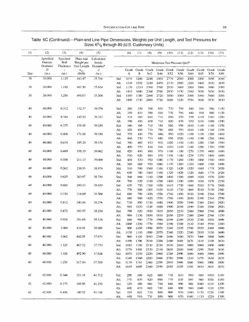
SPECIFICATION FOR LINE PIPE 59
Table 6C (Continued)-Plain-end Line Pipe Dimensions, Weights per Unit Length, and Test Pressures for Sizes 65/8 through 80 (U.S. Customary Units)
(I)
Size
38
38
38
40
40
40
40
40
40
40
40
40
40
40
40
40
40
40
40
40
40
40
42
42
42
(2)
Specified Outside
Diameter f)
(in.)
38.000
38.000
38.(){){)
40.00{)
40.()(X)
4(J.(XlO
40.000
40.000
40.(X)0
40.()()()
40.000
40.()()()
40.000
40.000
40.()()0
40.000
40.cX)O
40.000
40.c)()O
40.000
40.()()0
40.(X)0
42.()()0
42.000
42J)(){)
(3) (4)
Specified Plain-end Wall Weight per
Thickness Unit Length f wee
(in.) (lb/ti)
1.125 443.47
1.188 467.50
1.250 491.07
0.312 132.37
0.344 145.83
0.375 158.85
0.406 171.84
0.438 185.24
0.469 198.19
0.500 211.13
0.562 236.93
0.625 263.07
0.688 289.13
0.750 314.69
0.812 340.16
0.875 365.97
0.938 391.68
1.000 416.91
1.062 442.05
1.125 467.52
1.188 492.90
1.250 517.80
0.344 153.18
0.375 166.86
0.406 180.52
(5)
Calculated Inside
Diameter" d
(in.)
35.750
35.624
35.500
39.376
39.312
39.250
39.188
39.124
39.062
39.000
38.876
38.750
38.624
38.500
38.376
38.250
38.124
38.000
37.876
37.750
37.624
37.500
41.312
41.250
41.188
Std.
Alt. Std. Alt. Std. Alt.
Std. Alt. Std. Alt.
Std. Alt.
Std. Alt.
Std. Alt.
Std. Alt.
Std. Alt.
Std. Alt.
Std. Alt. Std.
Alt. Std. Alt.
Std. Alt.
Std. All. Std. All. Std.
AI!. Std. All. Std. All.
Std.
(6) (7) (8) (9) (10) (11) (12) (13) (14) (15)
Minimum Test Pressure (psi)b
~~G~G~G~G~G~G~G~G~G~ A B X42 X46 X52 X56 X60 X65 X70 X80
1070 1240 2240 2450 2770 2980 3000 30(x) 30m 3000
1330 1550 2240 2450 2770 2980 32m 3460 3630 3630 1130 1310 2360 2590 2930 3000 3(X)0 3000 3(x)O 3(XX)
1410 1640 2360 2590 2930 3150 33g0 3630 3630 3630 1180 1380 2490 2720 3()(X) 3(X)0 3(XX) 3000 3(XX) 3(XX)
1480 1730 2490 2720 3080 3320 3550 3630 3630 3630
280
350 310
390
340
420
370 460
390
490
420
530 450
560
510
630
560 700 620
770
680 840
730
910
790
330
410 360
450
390 490
430
530 460
570
490
620
530
660
590
590 650
590 650 650 710
650 710
710 780 710 780
770 840 770 840
830 910
830 910
890 970
890 970 950 1040
950 1040
1060 1160
730 790
730 790 8(x) 870
8(){) 870
880 950 880 950
950 1020 950 1020
1020 I )(X)
1020 1 I (X)
1100 1180 1 I (X) 1180
1170 1260
1170 1260
1320 1420 1160 1320 1420
1290 1460 1580 1290 1460 1580 1420 1610 1730
1420 1610 1730
840
840 930
930
1010 1010 1 J(X)
II()()
1180
1180
1270
1270
1350 1350
1520
910
910 1010 1010 I J(X) I )()()
1190 1190
1280
1280
1370
1370
1460 14(,0
1640
980 1120
980 1120 1080 1240
1080 1240
1180 1350 1180 1350
1280 1460
1280 1460
1380 1580
1380 1580
1480 1690
1480 1690 1580 18(X)
15RO 18(X)
1770 2020
1520 1640 1770 2020
1690 1830 1970 2250 1690 I 830 1970 2250
1860 2010 2170 2480
1860 2010 2170 2480
740 1060
660 1180
820 1180 720 1300
900 1300 790 1420
980 1420
850 1530
1070 1530
920 1650
1550 1760 1890 2030 2190 2360 2700 1550 1760 1890 2030 2190 2360 27(X)
1680 19(x) 2050 2190 231;0 2560 2920
1680 1900 2050 2190 2380 2560 2920
1810 2050 2210 2360 2560 2760 3000 980 1150 840 980
1060 1230
900 1050
1130 1310
1650 1810 2050 2210 2360 2560 2760 3150 1770 1940 2190 2360 2530 2740 2950 3(XX)
1770 1940 2190 2360 2530 2740 2950 3380 1890 2070 2340 2520 27(){) 2930 3(X)() 3(XX)
1890 2070 2340 2520 27(X) 2930 3150 3600
960
1190 1010 1270
1070
1120 2010 2200 2490 2680 2870 3(XX) 3000
1390 20 I 0 2200 2490 2680 2870 3 II 0 3350 I 180 2130 2330 2630 2840 3000 30(X) 3(XX)
1480 2130 2330 2630 2840 3040 3290 3540 1250 2250 2460 27t>0 2990 3(){){) 3(XX) 3(XX)
3()(X)
3630 3(XX)
3630 3(X)()
All. 1340 1560 2250 2460 2780 2990 3210 3470 3630 3630
Std. 1 130 1310 2360 2590 2930 3000 3000 3000 3(XX) 3()(X)
All. 1410 1640 23(,0 2590 2930 3150 3380 3630 3630 3630
Std. All.
Std. All.
Std.
All.
290 370
320
400
350
440
340 430
380 470
410 510
620
620
680
680 730
730
680 680
740
740 8(){)
800
770 770
840
840
900 9(X)
830 880
830 880 9(X) 960
900 960
970 1040 970 1040
960 1 030 I I 80
960 1030 1180 1040 I 130 I 29()
1040 1130 129()
1130 1220 1390
1130 1220 1390
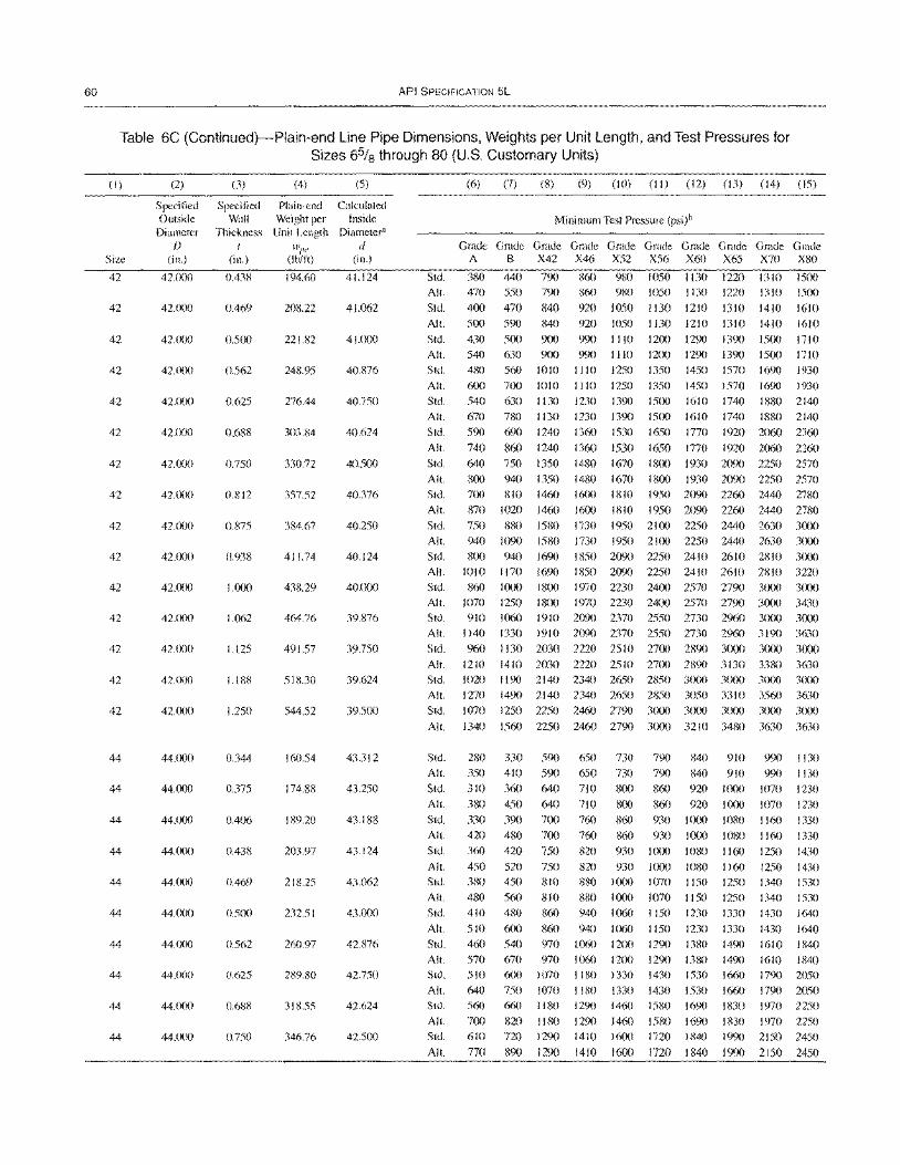
60 API SPECIFICATION 5L
Table 6C (Continued)-Plain-end Line Pipe Dimensions, Weights per Unit Length, and Test Pressures for Sizes 6% through 80 (U.S. Customary Units)
(I)
Size
42
42
42
42
42
42
42
42
42
42
42
42
42
42
42
44
44
44
44
44
44
44
44
44
44
(2)
Specified Outside Diameter
f)
(in.)
42.000
42.000
42.000
42.000
42.000
42.000
42.000
42.000
42.000
42.(lOO
42.lX)0
42.(X)O
42.000
42.000
42.000
44.000
44.000
44.llO0
44.(xlO
44.oo0
44.lXlO
44.lXX)
44.(X)0
44.lX)O
44.lXlO
(3) (4)
Specified Plain-end Wall Weight per
Thickness Unit Length I wlJe
(in.) (Ib/ft)
0.438 194.60
0.469 208.22
0.500 221.82
0.562 248.95
0.625 276.44
0.688 303.S4
0.750 330.72
0.812 357.52
0.875 384.67
0.938 411.74
1.000 438.29
1.062 464.76
1.125 491.57
1.188 518.30
1.250 544.52
0.344 160.54
0.375 174.88
0.406 189.20
0.438 203.97
0.469 218.25
O.5(Xl 232.51
0.562 260.97
0.625 289.80
0.688 318.55
0.750 346.76
(5)
Calculated Inside
Diameter" d
(in.)
41.124
41.062
41.000
40.876
40.750
40.624
40.500
40.376
40.250
40.124
40.000
39.876
39.750
39.624
39.500
43.312
43.250
43.188
43.124
43.062
43.0(xl
42.876
42.750
42.624
42.500
Std. All.
Std.
Alt.
Std. All.
Std.
All.
Std. All.
Std.
All.
Std.
(6) (7) (8) (9) (10) (II) (12) (13) (14) (15)
Minimum Test Pressure (psi)b
Grade Grade Grade Grade Grade Grade Grade Grade Grade Grade A B X42 X46 X52 X56 X60 X65 X70 X80
380 440 790 860 980 1050 I 130 1220 1310 1500 470 550 790
400 470 840 500 590 840 430 500 900
630 900 560 1010
700 1010 630 1130
860 980 1050 1130 1220 1310 1500
920 1050 1130 1210 1310 1410 1610 920 1050 1130 1210 1310 1410 1610
990 1110 1200 1290 1390 1500 1710 990 1110
1110 1250
1110 1250 1230 1390
540 480
600 540 670
590 740
640
780 I 130 1230 1390 690 1240 1360 1530
860 1240 1360 1530 750 1350 1480 1670
12(xl 1290 1390 1500 1710 1350 1450 1570 1690 1930
1350 1450 1570 1690 1930 1500 1610 1740 1880 2140 1500 1610 1740 1880 2140 1650 1770 1920 2060 2360
1650 1770 1920 2060 2360 1800 1930 2090 2250 2570
All. 800 940 1350 1480 1670 1800 1930 2090 2250 2570 Std. All.
700 810 1460
870 1020 1460 1600 1810 1600 1810
1950 2090 2260 2440 2780
1950 2090 2260 2440 2780 Std. 750 880 1580 1730 1950 2100 2250 2440 2630 3000 All.
Std.
All.
Std.
940 1090 1580 800 940 1690
1010 1170 1690 860 1000 18(X)
1730 1950 2100 2250 2440 2630 3000 1850 2090 2250 2410 2610 2810 3000 1850 2090 2250 2410 2610 2810 3220
1970 2230 2400 2570 2790 3(xxl 3000 All. 1070 1250 18(xl 1970 2230 2400 2570 2790 3000 3430 Std. 910 1060 1910 2090 2370 2550 2730 2%0 3000 3000 All. 1140 1330 1910 2090 2370 2550 2730 2960 3190 3630
Std. %0 1130 2030 2220 2510 2700 2890 3(XlO 3(xx) 3000 All. 1210 1410 2030 2220 2510 27(xl 2890 3130 3380 3630 Std. 1020 1190 2140 2340 2650 2850 3000 3000 3(XXl 3(xlO All. 1270 1490 2140 2340 2650 2850 3050 3310 3560 3630 Std. 1070 1250 2250 2460 2790 3000 3000 3000 3000 3(xlO
All. 1340 1560 2250 2460 2790 3(XlO 3210 3480 3630 3630
Std. All.
Std. All.
Std.
All. Std.
All. Std.
All.
Std.
All.
Std. All.
Std.
All. Std.
All. Std.
All.
280 350
310
380 330 420 360
450 380 480 410
510 460 570 510
640 560
700 610 770
330 410
360 450
390 480 420
520 450
560
590 590
640 640 700 7(lO
750
750 810 810
650 650 710
710 760 760
820 820 880 880
480 860 940
600 860 940 540 970 1060 670 970 1060 600 1070 I ISO 750 1070 1180
730 790 840 910 730 790 840 910 800 860 920 I (xlO 8(lO 860 920 1000
860 930 1000 1080 860 930 1000 1080
930 1000 1080 1160 930 I (XX) 1080 1160
10oo 1070 1150 1250 1000 1070 1150 1250 1060 1150 1230
1060 1150 1230 1200 1290 13S0 12(x) 1290 1380 1330 1430 1530
1330 1430 1530
1330
1330 1490 1490 1660 1660
990 1130 990 1130
1070 1230
1070 1230 1160 1330 1160 1330
1250 1430 1250 1430 1340 1530 1340 1530 1430 1640
1430 1640 1610 1840 1610 1840 1790 2050
1790 2050 660 1180
820 1180 720 1290
890 1290
1290 1460
1290 1460 1410 1600
1410 16oo
1580 1690 1580 1690 1720 1840
1720 1840
1830 1970 2250 I 830 1970 2250 1990 2150 2450
1990 2150 2450
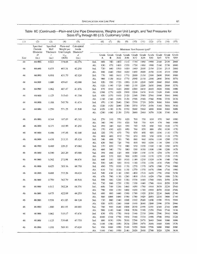
SPECIFICATION FOR LINE PIPE 61
Table 6C (Continued)-Plain-end Line Pipe Dimensions, Weights per Unit Length, and Test Pressures for Sizes 6% through 80 (U.S. Customary Units)
(I)
Size
44
44
44
44
44
44
44
44
46
46
46
46
46
46
46
46
46
46
46
46
46
46
46
46
46
(2)
Specified Outside
Diameter D
(in.)
44.000
44.000
44.000
44.~)0
44.000
44.(lOO
44.000
44.000
46.000
46.000
46.(X)()
46.000
46.cXX)
46.ClOO
46.~)0
46.~)0
46.000
46.(lOO
46.000
46.(lOO
46.000
46.000
46.mo
46.000
46.~X)
(3)
Specified Wall
Thickness (
(in.)
0.812
0.875
0.938
1.000
1.062
1.125
1.188
1.250
0.344
0.375
OA06
OA38
OA69
0.500
0.S62
0.625
0.688
0.750
0.812
0.875
0.938
1.000
1.062
1.125
1.188
(4) (5)
Plain-end Calculated Weight per Inside Unit Length Diameter"
wile d (tb/ft) (in.)
374.88 42.376
403.38 42.250
431.79 42.124
459.67 42.000
487A7 41.876
515.63 41.750
543.70 41.624
571.25 41.500
167.89 45.312
182.90 45.250
197.88 45.188
213.33 45.124
228.27 45.062
243.20 45.000
272.98 44.876
303.16 44.750
333.26 44.624
362.79 44.500
392.24 44.376
422.09 44.250
451.85 44.124
481.05 44.000
510.17 43.876
539.68 43.7S0
569.10 43.624
Std.
All.
Std.
All.
Std.
All.
Std.
All.
Std. All. Std.
All.
Std.
(6) (7) (8) (9) (10) (II) (12) (13) (14) (15)
Minimum Test Pressure (psi)b
G~G~G~G~G~G~G~G~G~G~
A B X42 X46 X52 X56 X60 X65 X70 X80
660
830
no
890
770 %0
820
1020
870 1090 920
1150 970
780
970
840
1040 900
1120
950 1190
1010 1270
1070
1340
1130
1400
1400
ISOO
1500
1610
1610
1530
1530
1650
1730 1860
1730 1860 1860 2(XX)
1990 2160 2330
1990 2160 2330
2150 2330 2510
1650 1860 2000 2150 2330 2SIO
1770 2000 2150 23(X) 2490 2690
1770 2000 21S0 2300 2490 2690
2660
2660
2860
2860 3(XlO
3070
Ino 1880 2130 2290 2450 2660 2860 3(XX)
Ino 1880 2130 2290 2450 2660 2860 3270
1820 2000 2260 2430 2610 2820 3(XlO 3(XX) 1820 2000 2260 2430 2610 2820 3040 3480 1930 2120 2390 2580 2760 2990 30m 30(X)
1930 2120 2390 2580 2760 2990 3220 3630 2040 2240 2530 2no 2920 3(XX) 3000 3(lOO
Alt. 1220 1420 2040 2240 2530 2no 2920 3160 3400 3630
Std. 1020 1190 2150 2350 2660 2860 3CXlO 3(~X) 30m 3(lOO
All. 1280 1490 2150 2350 2660 2860 3070 3320 351-m 3630
Std.
All. Std.
Alt.
Std. Alt. Std.
Alt. Std.
Alt. Std.
All.
Std.
Alt.
Std.
All.
Std. All.
Std.
All.
Std.
All.
Std. Alt.
Std. All.
Std.
All.
Std.
All.
Std.
270
340 290
370
320 400 340
430 370
460
390 490
440
550
490
610
540 670
590
730
310 570 620 700 750 810 390 570 620 700 750 810
340 620 680 760 820 880 430 620 680 760 820 880
370 670 730 830 890 950
460 670 730 830 890 950 400 no 790 890 960 1030 500 no 790 890 960 1030 430 770 840 950 1030 I I(X)
540 770 840 950 1030 I I (X)
460 820 900 1020 I 100 I 170
570 820 9ClO 1020 1100 1170 510 920 1010 1140 1230 1320
640 920 1010 1140 1230 1320
570 1030 1130 1270 1370 1470
710
630 790
680
860
1030 1130
1130 1240
1130 1240 1230 1350
1230 1350
1270 1370 1470
1400 1510 1620
1400 1510 1620 1530 1640 1760
1530 1640 1760
870 940 1080
870 940 1080 950 1030 1170
950 1030 1170
1030 1110 1270
1030 1110 1270 1110 12m 1370 1110 1200 1370
I 190 1280 1470
1190 1280 1470 1270 1370 1570
1270 1370 1570
1430 1540 1760
1430 1540 1760
1590 1710 1960
1590 1710 1960
1750 1880 2150
1750 1880 2150 1910 2050 2350
1910 2050 2350
640 740 1330 1460 1650 1780 1910 2070 2220 2540
790 930
680 800 860 I ()()()
730 860 920 1070
780 910
980 1140
830 970
1040 1210
880 1030
1330 1460 1650 1780 1910 2070 2220 2540
1440 1580 1780 1920 2050 2230 24(X) 2740 1440 1580 1780 1920 2050 2230 2400 2740
1540 1690 1910 2060 22(X) 2390 2570 2940
1540 1690 1910 2060 22(X) 2390 2570 2940
1640 1800 2030 2190 2350 2540 2740 3000 1640 ISOO 2030 219C) 2350 2540 2740 3 I 30 1750 1910 2160 2330 249C) 27(X) 2910 3(XXl
1750 1910 2160 2330 249C) 27~) 2910 3320
1850 2030 229C) 2470 2640 2860 3000 3000
Alt. I 100 1280 1850 2030 2290 2470 2640 2860 30XO 3520 Std. 930 1080 1950 2140 2420 26~) 2790 3{X)O 3(XX) 3~lO
All. 1160 1360 1950 2140 2420 26(lO 2790 3020 3250 3630
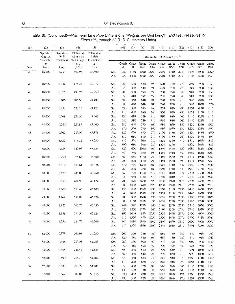
62 API SPECIFICATION 5L
Table 6C (Continued)-Plain-end Line Pipe Dimensions, Weights per Unit Length, and Test Pressures for Sizes 65/8 through 80 (U.S. Customary Units)
(I)
Size
46
48
48
48
48
48
48
48
48
48
48
4S
48
48
48
4R
48
48
48
52
52
52
52
52
52
(2)
Specified Outside
Diameter D
(in.)
46.000
48.(){)()
48.()()()
48.000
48.000
48.000
48.000
48.000
48.000
48.000
48.000
48.000
48.000
4RO()()
4KOOO
48.000
48.(X){)
4R.OOO
48.lX)O
52.000
52.000
52.000
52.(){)0
52.000
52'(X)O
(3)
Specified Wall
Thickness I
(in.)
1.250
0.344
0.375
0.406
0.438
0.469
0.500
0.562
0.625
0.688
0.750
0.812
0.875
0.938
1.000
1.062
1.125
1.188
1.250
0.375
0.406
0.438
0.469
0500
0562
(4) (5)
Plain-end Calculated Weight per Inside Unit Length Diameter'
wl'!' d (Ibm) (in.)
597.97 43.500
175.25 47.312
190.92 47.250
206.56 47.188
222.70 47.124
238.30 47.062
253.89 47.000
285.00 46.876
31652 46.750
347.97 46.624
378.83 46.500
409.61 46.376
440.80 46.250
471.90 46.124
502.43 46.000
532.88 45.876
563.73 45.750
594.50 45.624
624.70 45.500
206.95 51.250
223.93 51.188
241.42 51.124
258.36 51.062
275.27 51.000
309.03 50.876
Std.
All.
Std.
All.
Std.
All.
Std.
All.
Std.
All.
Std.
All.
Std.
Alt.
Std.
(6) (7) (8) (9) (10) (II) (12) (13) (14) (15)
Minimum Test Pressure (psi)b
G~G~G~~~G~G~G~G~G~~~ A B X42 X46 X52 X56 X60 X65 X70 X80
980 1140 2050 2250 2540 2740 2930 3000 3()(X) 3000
1220 1430 2050 2250 2540 2740 2930 3180 3420 3630
260 300 540 590 670 720 770 840 900 1030 320 380 540 590 670 720 770 840 900 1030 280 330 590 650 730 790 840 910 980 I 130 350 410 590 650 730 790 840 910 980 1130 300 360 640 700 790 850 910 990 1070 1220 380 440 640 700 790 850 910 990 1070 1220 330 380 690 760 850 920 990 1070 1150 1310 410 480 690 760 850 920 990 1070 1150 1310 350 410 740 810 910 980 1060 1140 1230 1410 440 510 740 810 910 980 1060 1140 1230 1410 380 440 790 860 980 1050 I 130 1220 13 10 1500 470 550 790 860 980 1050 1130 1220 1310 1500 420 490 890 970 11 ()() 1180 1260 1370 1480 1690
All. 530 610 890 970 1100 1180 1260 1370 1480 1690 Std. 470 550 980 1080 1220 1310 1410 1520 1640 1880 All. 590 680 980 1080 1220 1310 1410 1520 1640 1880 Std. 520 600 1080 1190 1340 1440 1550 1680 1810 2060
All.
Std.
All.
Std.
All.
Std.
All.
Std.
All.
Std.
All.
Std.
All.
Std.
All.
Std.
All.
Std.
All.
Std.
All.
Std.
All.
Std.
All.
Std. All.
Std.
All.
Std.
650
560 700 610
760 660 820
700 880
750 940 800
1000
840
750 1080 1190 660 1180 1290 820 1180 1290 710 1280 14()()
890 1280 1400
1340 1460 1460 1580
1580 770 1380 1510 1710 960 1380 1510 1710 820 1480 1620 1830
1440 1550 1580 1690 1580 1690 1710 1830
1710 1830
1680 1810 2060 I 830 1970 2250 I 830 1970 2250 1980 2130 2440
1980 2130 2440 1840 1970 2 I 30 2300 2630 1840 1970 2130 2300 2630 1970 2110 2290 2460 2810
1030 1480
880 1580 1090 1580 930 1670
1160 1670
980 1770
1620 1830 1970 2110 2290 2460 2810
1730 1950 2100 2250 2440 2630 3000
1730 1950 2100 2250 2440 2630 3000 I 830 2070 2230 2390 2590 2790 3000 1830 2070 2230 2390 2590 2790 3190
1940 2190 2360 2530 2740 2950 3()(x) 1050 1230 1770 1940 2190 2360 2530 2740 2950 3380
1870 2050 2320 2490 2670 29(X) 3000 3()(x) 1870 2050 2320 2490 2670 2'XX) 3120 3560
1970 2160 2440 2630 2810 3000 3000 3()(){) 1970 2160 2440 2630 2810 3050 3280 3630
890 1040 1110 1300 940 1090
1170 1370
260 320
280 350 3()()
380
320 410
350 430 39()
3()()
380
330 410 350
440
380 470 400 500
450
550 550
590 590 640 640
680 680 730 730
820
600 680 730 780 600 680 730 780
650 730 790 840 650 730 790 840 700 790 850 910 700 790 850 910
750 840 910 970 750 840 910 970 800 900 970 1040 800 900 970 1040
890 1010 1090 1170
840 910 1040 840 910 1040
910 980 1120 910 980 1120 990 1060 1210 990 1060 1210
1060 1140 1300 1060 1140 1300 1130 1210 1380 1130 1210 1380
1260 1360 1560 All. 49() 570 820 890 1010 1090 I 170 1260 1360 1560
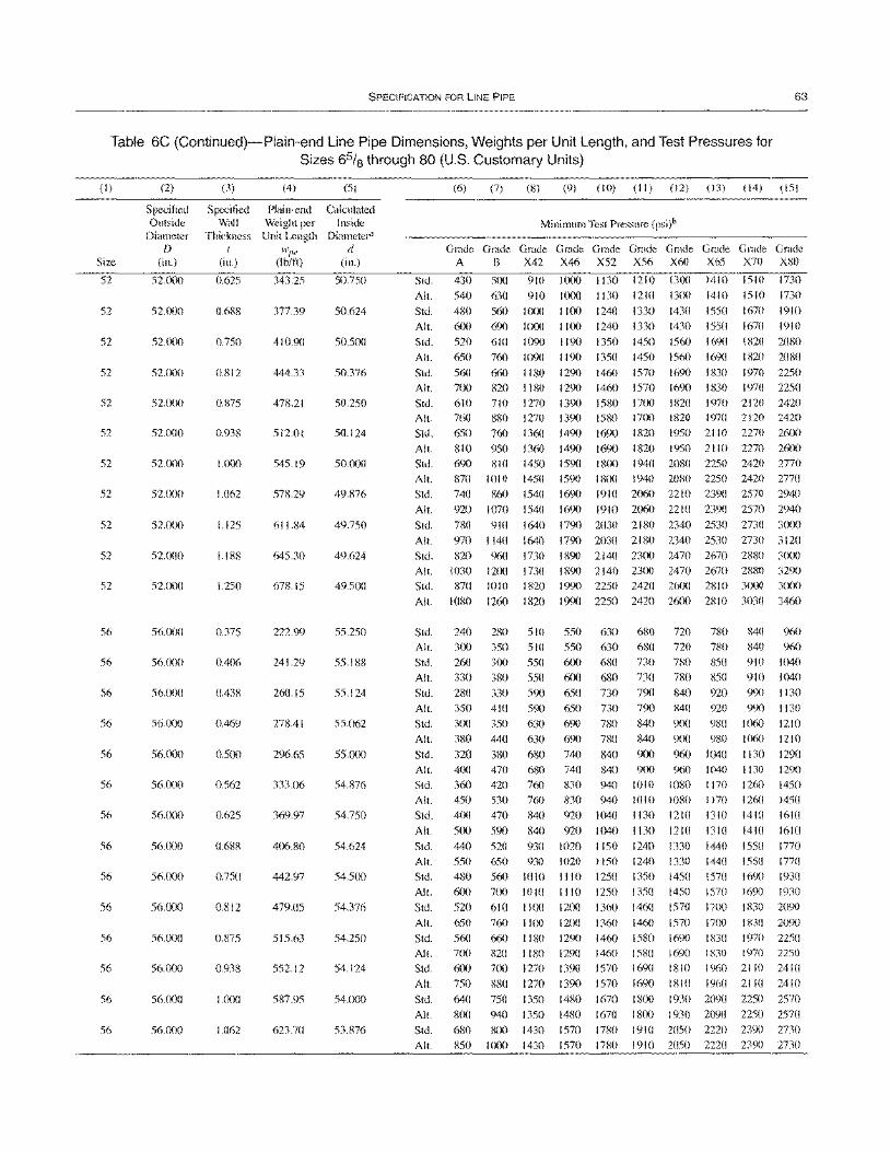
SPECIFICATION FOR LINE PIPE 63
Table 6C (Continued)-Plain-end Line Pipe Dimensions, Weights per Unit Length, and Test Pressures for Sizes 65/8 through 80 (U.S. Customary Units)
(I)
Size
52
52
52
52
52
52
52
52
52
52
52
56
56
S6
56
56
56
56
56
56
56
56
56
56
56
(2)
Specified Outside
Diameter D
(in.)
52.000
52.000
52.000
52.()(X)
52.000
52.000
52.fX)0
52.000
52.000
52.000
52.()()O
56.000
56.000
56.000
56.fXlO
56.000
56.000
56.000
56.000
56.fXlO
56.000
56.000
56.000
56.CXlO
56.()()0
(3)
Specified Wall
Thickness I
(in.)
0.625
0.688
0.750
0.812
0.875
0.938
1.000
1.062
1.125
1.188
1.250
0.375
0.406
0.438
0.469
0.500
0.562
0.625
0.688
0.750
0.812
0.875
0.938
1.000
1.062
(4) (5)
Plain-end Calculated Weight per Inside Unit Length Diameter"
wI''' d Obit!) (in.)
343.25 50.750
377.39 50.624
410.90 50.500
444.33 50.376
478.21 50.250
512.01 50.124
545.19 50.000
518.29 49.876
611.84 49.750
645.30 49.624
678.15 49.500
222.99 55.250
241.29 55.188
260.15 55.124
278.41 55.()62
296.65 55.000
333.06 54.876
369.97 54.750
406.80 54.624
442.97 54.500
479.05 54.376
515.63 54.250
552.12 54.124
587.95 54.000
623.70 53.876
Std.
Alt.
Std.
Alt.
Std.
Alt.
Std.
Alt.
Std. Alt.
Std.
Alt.
Std.
Alt.
Std.
Alt.
Std.
Alt.
Std.
Alt.
Std.
Alt.
Std. Alt.
Std.
Alt.
Std. Alt.
Std.
Alt.
Std.
Alt.
Std. Alt.
Std.
Alt.
Std.
Alt.
Std.
Alt.
Std. All.
Std. Alt.
Std.
Alt.
Std.
Alt.
Std.
Alt.
(6) (7) (8) (9) (10) (II) (12) (13) (14) (15)
Minimum Test Pressure (psi)b
G~~~G~G~G~G~G~G~G~G~ A B X42 X46 X52 X56 X60 X65 X70 X80
430
540
480
600
520
650
560
700
610 760
650
810 690
870
740
920
780
970
500 910
630 910
560 1000 690 1000
610 1090
760 1090
660 1180
820 1180 710 1270 880
760
950 810
1010
860
1070
910
1140
1270
1360
1360 1450
1450
1540
1540
1640
1640 820 960 1730
1030 1200 1730
870 1010 1820
1080 1260 1820
1000 1130
1000 1130
1100 1240
1100 1240
1190 1350
1190 1350
1290 1460
1290 1460
1390 1580 1390 1580 1490 1690
1490 1690 1590 1800
1590 1800
1690 1910
1690 1910
1790 2030
1790 2030
1210
1210
1330 1330
1450 1450
1570
1570
1700
13(X)
1300
1430
1430
1560
1560
1690
1690
1820
1410 1510 1730
1410 1510 1730
1550 1670 1910
1550 1670 1910
1690 1820 2080
1690 I 820 2080
I 830 1970 2250
1830 1970 2250 1970 2120 2420
1700 1820 1970 2120 2420
1820 1950 21 10 2270 26(X)
I 820 1950 21 10 2270 2600 1940 2080 2250 2420 2770
1940 2080 2250 2420 2770 2()60 2210 2390 2570 2940
2060 2210 2390 2570 2940
2180 2340 2530 2730 3(XX)
2180 2340 2530 2730 3120 1890 2140 2300 2470 2670 2880 3(X)0
1890 2140 2300 2470 2670 2880 3290 1990 2250 2420 26(X) 2810 30m 3000
1990 2250 2420 2600 2810 3030 3460
240 280 5 10 550 630 680 720 780 840 960
300 350 510 550 630 680 720 780 840 960
260 300 550 600 680 730 780 850 910 1040
330 380 550 600 680 730 780 850 910 1040
280 330 590 650 730 790 840 920 990 1 130
350 410 590 650 730 790 840 920 990 1 130
300 350 630 690 780 840 9(X) 980 I ()6() 1210
380 440 630 690 no 840 9()O 980 J()60 I 21 0
320 380 680 740 840 900 960 1040 1130 1290
400 470 680 740 840 900 96() 1040 I 130 1290
360 420 760 830 940 1010 1080 1170 1260 1450 450 530 760 830 940 1010 10RO 1170 1260 1450
400 470 840 920 1040 1130 1210 1310 1410 1610
500 590 840 920 1040 1130 1210 1310 1410 1610
440 520 930 1020 1150 1240 1330 1440 1550 1770
550
480
600
520
650
560 700
600
750
640
800
680 850
650 930
560 1010
700 1010
610 1100
1020 1150 1240
1110 1250 1350
1110 1250 1350
1200 1360 1460
1330
1450 1450
1570
1440
1570
1570 17(X)
1550 1770
1690 1930 169() 1930
I R30 2090 1830 209()
1970 2250
76()
660
820
700
880
750
940
SOO 1000
1100
1180 1180
1270
1270
1350
1350 1430
1430
1200
1290 1290
1390
1390 1480
1480
1570
1570
1360
1460 1460
1570
1570
1670
1670
InO
1780
1460
1580 1580 169()
1690
1800 18(X)
1910 1910
1570 1700
1690 1830 169() I 830 1970 2250
1810 1960 2110 2410
1810 1960 2110 2410
1930 2()<'X) 2250 2570
1930 2090 2250 2570 2050 2220 239() 2730
2050 2220 2390 2730
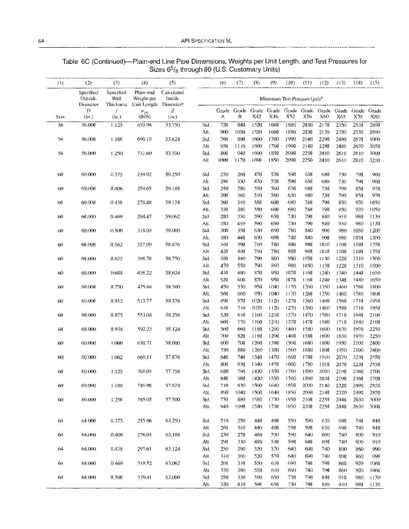
64 API SPECIFICATION 5L
Table 6C (Continued)-Plain-end Line Pipe Dimensions, Weights per Unit Length, and Test Pressures for Sizes 6% through 80 (U.S. Customary Units)
(I) (2) (3) (4) (5)
Specified Specified Plain-end Calculated Outside Wall Weight per Inside
Diameter Thickness Unit Length Diameter"
f) wI''' d Size (in.) (in.) (Ib/ft) (in.)
56 56.000 1.125 659.94 53.750
56 56.000 1.188 696.10 53.624
56 56.000 1.250 731.60 53.500
60 60.000 0.375 239.02 59.250
60 60.fXlO 0.406 258.65 59.188
60 60.(X10 0.438 278.88 59.124
60 60.000 0.469 298.47 59.062
60 60.000 0.500 318.03 59.000
60 60.000 0.562 357.09 58.876
60 60.000 0.625 396.70 58.750
60 60.000 0.688 436.22 58.624
60 60.lXl0 0.750 475,(14 58.500
60 60.000 0.812 513.77 5S.376
60 60.000 0.875 553.(14 58.250
60 60.(XlO 0.938 592.23 58.124
60 60.000 1.000 630.71 5S.000
60 60.000 1.062 669.11 57.876
60 60.000 1.125 708.05 57.750
60 60.0()0 1.188 746.90 57.624
60 60.000 1.250 785.05 57.500
64 64.000 0.375 255.06 63.250
64 64.000 0.406 276.01 63.188
64 64.000 0.438 297.61 63.124
64 64.000 0.469 31S.52 63.062
64 64.000 0.500 339.41 63.000
(6) (7) (8) (9) (10) (II) (12) (13) (14) (15)
Minimum Test Pressure (psi)b
Grade Grade Grade Grade Grade Grade Grade Grade Grade Grade A B X42 X46 X52 X56 X60 X65 X70 X80
Std. 720 840 1520 1660 1880 2030 2170 2350 2530 2890 All. 900 1050 1520 1660 1880 2030 2170 2350 2530 2890
Std. 760 890 1600 1760 1990 2140 2290 2480 2670 3000
All. 950 1110 1600 1760 1990 2140 2290 2480 2670 3050 Std. 800 940 1690 1850 2090 2250 2410 2610 2810 3000 All. 1000 1170 1690 1850 2090 2250 2410 2610 2810 3210
Std.
All. Std. All.
Std.
All. Std. All. Std.
230 260 470 520 590 630
280 330 470 520 590 630 240 280 510 560 630 680 300 360 510 560 630 680
260 310 550 600 680 740 330 380 550 600 680 740 280 330 590 650 730 790 350 410 590 650 730 790 300 350 630 690 780 840
680 730 790 900
680 730 790 900
730 790 850 970 730 790 850 970 790 850 920 1050 790 850 920 1050 840 910 980 1130 840 910 980 1130
900 980 1050 1200 All. 380 440 630 690 780 840 900 980 1050 1200 Std.
All. Std.
All.
Std. All. Std.
All. Std.
All. Std. Alt.
Std.
All. Std.
All.
Std.
340 420 380
470
410 520 450
560 490
610 530 660 560 700
390 710 780 880 940 1010 I 100 490 710 780 880 940 1010 1100 440 790 860 980 1050 I 130 1220
550 790 860 980 1050 I 130 1220 480 870 950 1070 I 160 1240 I 340 600 870 950 1070 I 160 I 240 1340 530 950 1040 1170 1260 1350 1460
660 950 1040 1170 1260 1350 1460 570 1020 1120 1270 1360 1460 1580 710 1020 I 120 1270 1360 1460 1580
1180 1350 1180 1350 1310 1500
1310 1500 1440 1650 1440 1650 15S0 ISOO
1580 1800 1710 1950 1710 1950
610 1100 1210 1370 1470 770 1100 1210 1370 1470
660 1180 1290 1460 1580 820 1180 1290 1460 1580
1580 1710 1840 2100 1580 1710 1840 2100
1690 I 830 1970 2250 1690 1830 1970 2250
600 700 1260 1380 1560 1680 1800 1950 2100 2400 750
640
880 1260 1380
740 1340 1470
1560 1680
1660 1780 IS00 1950 2100 2400
1910 2070 2230 2550 All. 800 930 1340 1470 1660 1780 1910 2070 2230 2550 Std.
All. Std.
All. Std. All.
Std.
All. Std.
All.
Std.
All. Std.
All. Std.
All.
680 790 1420 1550 1760 1890 2030 2190 2360 2700 840 980 1420 1550 710 830 1500 1640
890 1040 I 500 1640 750 880 1580 1730 940 1090 1580 1730
1760 1890 2030 2190 2360 2700
1850 2000 2140 2320 2490 2850 1850 2000 2140 2320 2490 2850 1950 2 J(X) 2250 2440 2630 3(XXl 1950 2100 2250 2440 2630 3000
210
260 230 290
250
310 260 330 280
350
250 440 490 550 310 440 490 550
270 480 530 590 330 480 530 590
290 520 570 640
360 520 570 640 310 550 610 690 380 550 610 690 330 590 650 730
410 590 650 730
590 590 640 640
690 690 740 740
790
790
630 690 630 690 690 740
690 740
740 800
740 800 790 860 790 860 840 910
840 910
740 840
740 840 800 910 800 910
860 990 860 990 920 1060 920 1060 980 1130
980 1130
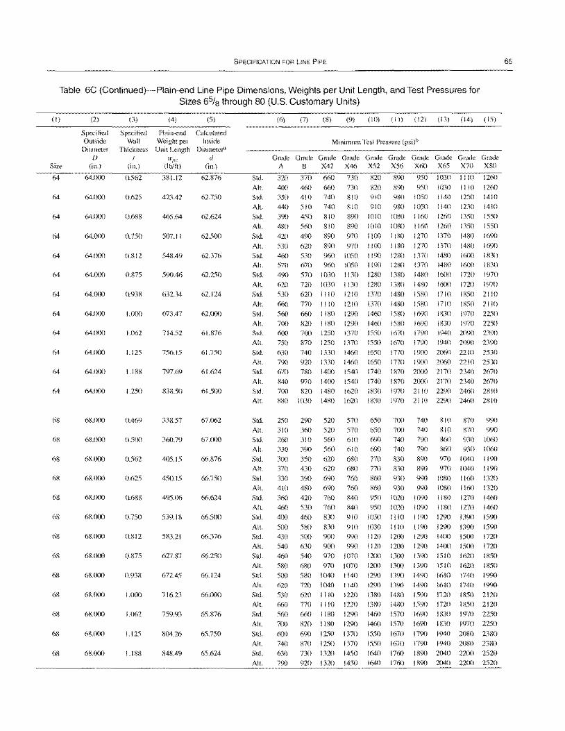
SPECIFICATION FOR LINE PIPE
Table 6C (Continued)-Plain-end Line Pipe Dimensions, Weights per Unit Length, and Test Pressures for Sizes 65/8 through 80 (U.S. Customary Units)
(I)
Size
64
64
64
64
64
64
64
64
64
64
64
64
68
68
68
68
68
68
68
68
68
68
68
68
68
(2)
Specified Outside
Diameter D
(in.)
64.fX)O
64.CX)O
64.000
64.CXlO
64.000
64.000
64.(X)O
64.000
64.(X)0
64.CXlO
64.(X)0
64.(X)0
68.CXlO
68.(X)0
68.000
68.CXX)
68.000
68.(X)0
68.000
68.000
68.000
68.(lOO
68.000
68.CXX)
68.000
(3)
Specified Wall
Thickness I
(in.)
0.562
0.625
0.688
0.750
0.812
0.875
0.938
1.000
1.062
1.125
1.IS8
1.250
0.469
0.500
0.562
0.625
0.688
0.750
0.812
0.875
0.938
1.000
1.062
1.125
1.188
(4) (5)
Plai n-end Calculated Weight per Inside Unit Length Diameter'l
wI'" d (Ib/ft) (in.)
381.12 62.876
423.42 62.750
465.64 62.624
507.11 62.500
548.49 62.376
590.46 62.250
632.34 62.124
673.47 62.000
714.52 61.876
756.15 61.750
797.69 61.624
838.50 61.500
338.57 67.062
360.79 67.000
405.15 66.876
450.15 66.750
495()6 66.624
539.18 66.500
583.21 66.376
627.87 66.250
672.45 66.124
716.23 66.000
759.93 65.876
804.26 65.750
848.49 65.624
Std.
AI!.
Std.
AI!.
Std.
AI!.
Std.
AI!.
Std. AI!.
Std. AI!.
Std.
(6) (7) (8) (9) (10) (II) (12) (13) (14) (15)
Minimum Test Pressure (psi)b
G~G~G~G~G~G~G~G~G~G~
A B X42 X46 X52 X56 X60 X65 X70 X80
320 370 660 730 820 890 950 1030 I I 10 1260
400 460 660 730 820 890 950 1030 I I 10 1260
350 410 740 810 910 980 1050 1140 1230 1410
440 510 740 810 910 980 1050 1140 1230 1410
390 450 810 890 1010 10S0 1160 1260 1350 1550
480 560 810 890 1010 1080 1160 1260 1350 1550
420 490 890 970 1100 1180 1270 1370 1480 1690
530 620 890 9701100 1180 1270 1370 1480 1690
460 530 960 1050 1190 1280 1370 1480 1600 1 ~{30 570 670 960 1050 1190 1280 1370 1480 1600 1830
490 570 1030 1130 1280 1380 1480 1600 1720 1970
620 720 1030 1130 1280 1380 1480 1600 1720 1970
530 620 litO 1210 1370 1480 1580 1710 18502110
AI!. 660 770 1110 1210 1370 1480 15S0 1710 1850 2110
Std.
AI!. Std.
AI!.
Std.
AI!.
Std. AI!.
Std.
AI!.
Std. AI!.
Std. AI!.
Std. AI!.
Std. AI!. Std.
AI!.
Std.
AI!.
Std.
AI!.
Std. AI!.
Std. AI!.
Std.
AI!.
Std. AI!.
Std.
AI!.
Std.
AI!.
560 660 1180 1290 1460
1460
1550 1550
1650 1650
1740
1740 1830
1830
1580 1690 1830 1970 2250 1830 1970 2250
1940 2090 2390 700 820 1180 1290 1580 1690
600 700 1250 1370 1670 1790
750 870 1250 1370
630 740 1330 1460
790 920 1330 1460 670 780 1400 1540
840 970 1400 1540
700 820 1480 1620
880 1030 1480 1620
1670 1790 1940 2090 2390 1770 1900 2()60 2210 2530
1770 1900 2060 2210 2530 1 870 2(X)0 2170 2340 2670
1870 2000 2170 2340 2670
1970 2110 2290 2460 2810
1970 21 10 2290 2460 2810
250 310
260 330
300 370
330 410 360
460
400
500
430
540
460
580
500 620
530
660 560 700
600 740
630
790
290
360 310
390
350
430
390 480
420
530
460
580
500 630
540
520 570
520 570 560 610
560 610
620 680
620 6S0
690 760 690 760 760 840
760 840
830 910
830 910
900 990
900 990 970 1070
650 7(X)
650 7(X)
690 740
690 740
770 830
770 830
860 930
860 930 950 1020
950 1020
1030 1110
1030 1110
1120 1200
1120 1200 12CX) 13(x)
680 970 1070 1200 1300
580 1040 1 140 1290 1390
720 1040 1140 1290 1390
620 1110 1220 1380 1480
770 1110 1220 1380 1480
660 1180 1290 1460 1570
820 1180 1290 1460 1570
690 1250 1370 1550 1670
870 1250 1370 1550 1670 730 1320 1450 1640 1760
920 1320 1450 1640 1760
740 740
790 790
890
890
990 990
1090
1090
1190
1190
1290
1290
1390
810 870 990
810 870 990 860 930 I ()60
860 930 )()60
970 1040 1190
970 1040 1190
1080 1160 1320
1080 1160 1320 1180 1270 1460
1180 1270 1460
1290 1390 1590
1290 1390 1590 14(X) 1500 1720 14CX) 15(X) 1720
15 10 1620 1850 1390 1510 1620 1850
1490 1610 1740 1990
1490 1610 1740 I9'X)
1590 1720 1850 2120
1590 1720 1850 2120
1690 1830 1970 2250
1690 1830 1970 2250
1790 1940 2080 2380
1790 1940 2080 2380 1890 2040 22(X) 2520
1890 2040 2200 2520
65
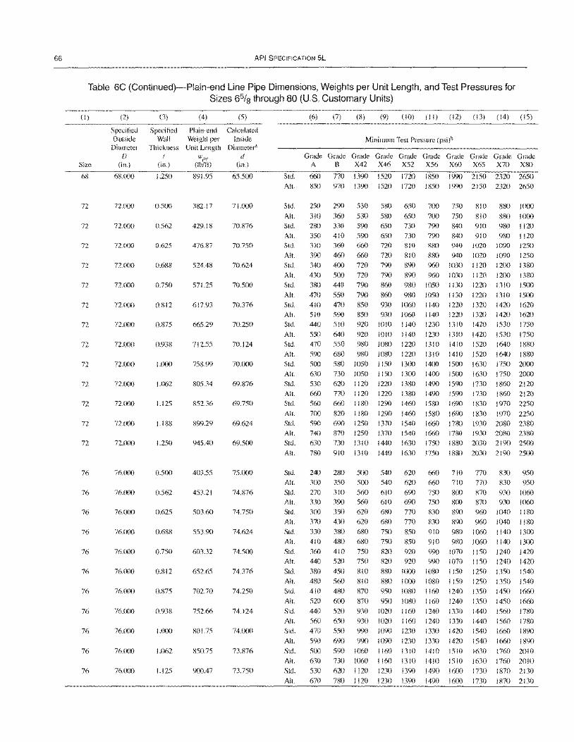
66 API SPECIFICATION 5L
Table 6C (Continued)-Plain-end Line Pipe Dimensions, Weights per Unit Length, and Test Pressures for Sizes 65/8 through 80 (U.S. Customary Units)
(I)
Size
6R
71
72
72
72
72
72
72
72
72
72
72
71
71
76
76
76
76
76
70
76
76
76
76
76
(2)
Specified Outside
Diameter f)
(in.)
68.000
72.(XlO
72.000
72.000
72.(XXl
72.000
72.000
72.000
72.000
72.000
72.000
72.000
72.000
72.(X)O
76.000
76.000
76.(X)0
76.000
76.000
76.(x)O
70.000
76.000
76.000
76.000
70.000
(3)
Specified Wall
Thickness {
(in.)
1.250
0.500
0.562
0.625
0.688
0.750
0.812
0.875
0.938
1.000
1.062
1.125
1.188
1.250
0.500
0.562
0.625
0.688
0.750
0.812
0.875
0.938
I.(X)O
1.062
1.125
(4)
Plain-end Weight per Unit Length
\Vpe
(Ib/ft)
891.95
382.17
429.18
476.87
524.48
571.25
617.93
665.29
712.55
758.99
805.34
852.36
899.29
945.40
403.55
453.21
503.60
553.90
603.32
652.65
702.70
752.66
801.75
850.75
900.47
(5)
Calculated Inside
Diameter" d
(in.)
65.500
71.000
70.876
70.750
70.624
70.500
70.376
70.250
70.124
70.000
69.876
69.750
69.624
69.500
75.000
74.876
74.750
74.624
74.5(X)
74.376
74.250
74.124
74.000
73.876
73.750
(6) (7) (8) (9) (10) (II) (12) (13) (14) (15)
Minimum Test Pressure (psi)b
~~G~G~~~~~G~G~G~~~G~ A B X42 X46 X52 X56 X60 X65 X70 X80
Std. 660 770 1390 1520 1710 1850 1990 2150 2320 2650 All. 830 970 1390 1520 1710 1850 1990 2150 2320 2650
Std.
Alt.
Std.
All.
Std.
All.
Std.
All.
Std.
Alt.
Std.
All.
Std.
All.
Std.
All.
Std.
All.
Std.
All.
Std.
All.
Std.
All.
Std.
250
310 280 350 310 390 340 430 380
470 410 510 440
550 470
290
360 330
410 360
460 400 500 440
550 470 590 510 640 550
530 580 650 700
530 580 650 700 590 650 730 790 590 650 730 790 660 no 810 880
660 no 810 880 no 790 890 960 no 790 890 960 790 860 980 1050
790 860 980 1050 850 930 1060 1140 850 930 1060 1140 920 1010 1140 1230 920 1010 1140 1230 980 1080 1220 1310
750 810 880 1000
750 810 880 1000 840 910 980 1120 840 910 980 1120 940 1020 1090 1250
940 1020 1090 1250 1030 1120 1200 1380 1030 1120 1200 1380 1130 1220 1310 1500
1130 1220 1310 1500 1220 1320 1420 1620 1220 1320 1420 1620 1310 1420 1530 1750 1310 1420 1530 1750 1410 1520 1640 1880
590 680 980 1080 1220 1310 1410 1520 1640 1880 500 580 1050 1150 13(Xl 1400 1500 1630 1750 2(XlO
630 530 660
560 700 590 740 630
730 1050 I 150 1300 1400 620 1120 1220 1380 1490 770 1120 1220 1380 1490 660 1180 1290 1460 1580
820 1180 1290 1460 1580 690 1250 1370 1540 1660 870 1250 1370 1540 1660 730 1310 1440 1630 1750
1500 1630 1750 2000 1590 1730 1860 2120 1590 1730 1860 2120 1690 I 830 1970 2250
1690 1830 1970 2250 1780 1930 2080 2380 1780 1930 2080 2380 1880 2030 2190 2500
All. 780 910 1310 1440 1630 1750 1880 2030 2190 2500
Std.
All.
Std.
All.
Std.
All.
Std.
Alt.
Std.
Alt.
Std.
Alt.
Std.
Alt.
Std.
All.
Std.
Alt.
Std.
Alt.
Std.
Alt.
240 280 500 540 620 660 300 350 500 540 620 660 270 310 560 610 690 750 330 390 560 610 690 750 300 350 620 680 770 830 370 430 620 680 770 830
330 380 680 750 850 910 410 480 680 750 850 910
710 770 830 950 710 770 830 950 800 870 930 1060 800 870 930 1060 890 %0 1040 1180 890 960 1040 1180 980 1060 1140 1300
980 1060 1140 1300 360 440
380 480 410 520
440
560 470
590
500 630 530
670
410 520
450 560 480
600 520
650 550
690
750 750
810
810
820 920 990 1070 1150 1240 1420
1150 1240 1420 1250 1350 1540
1250 1350 1540 1350 1450 1660
1350 1450 1660 1440 1560 1780
1440 1560 1780 1540 1660 1890
1540 1660 1890
820 920 990 1070 880 I (XlO 1080 I 150
880 ](XlO 1080 I 150 870 950
870 950 930 1020
930 1020 990 1090
990 1090
1080 1160
1080 1160 1160 1240
1160 1240 1230 1330
1230 1330 590 1060 1160 1310 1410
730 1060 1160 1310 1410 620 1120 1230 1390 1490
780 1120 1230 1390 1490
1240
1240 1330
1330 1420
1420 1510 1630 1760 2010
1510 1630 1760 2010 1600 1730 1870 2130
1600 1730 1870 2130
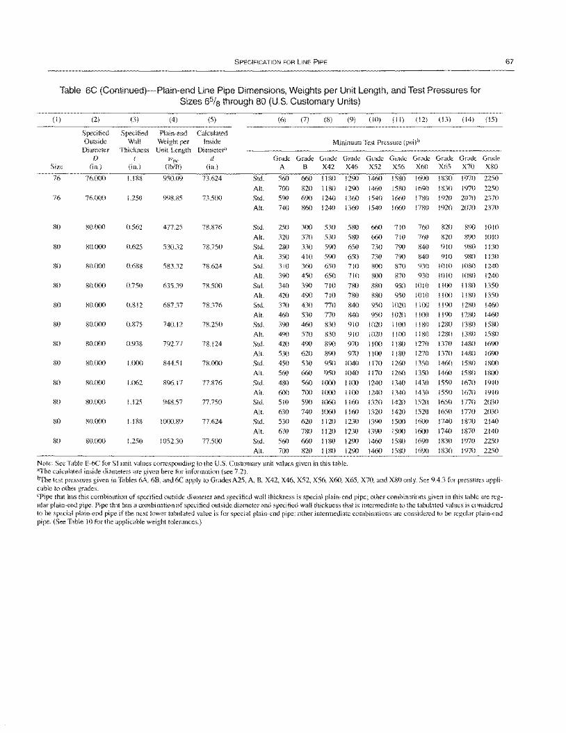
SPECIFICATION FOR LINE PIPE
Table 6C (Continued)-Plain-end Line Pipe Dimensions, Weights per Unit Length, and Test Pressures for Sizes 65/8 through 80 (U.S. Customary Units)
(I)
Size
76
76
80
80
80
so
80
80
80
80
so
80
80
80
(2)
Specified Outside
Diameter [)
(in.)
76.000
76.000
SO.OOO
80.000
80.000
80.000
80.000
SO.OOO
80.000
so.ooo
SO.OOO
80.000
80. (X)O
80.000
(3) (4)
Specified Plain-end Wall Weight per
Thickness Unit Length t
(in.)
1.188
1.250
0.562
0.625
0.688
0.750
0.812
0.875
0.938
1.000
1.062
1.125
1.188
1.250
W,k'
(Iblft)
950.09
998.85
477.25
530.32
583.32
635.39
687.37
740.12
792.77
844.51
896.17
948.57
I ()(X).89
1052.30
(5)
Calculated Inside
Diameter' d
(in.)
73.624
73.500
78.876
78.750
78.624
7S.500
78.376
78.250
78.124
78.000
77.876
77.750
77.624
77.500
Std.
AIL
Std.
AlL
Std.
AlL
Std.
AI!. Std.
AI!.
Std.
AI!.
Std.
AI!. Std.
AI!.
Std.
AI!. Std.
AI!.
Std. AI!.
Std.
AI!. Std.
AI!.
Std.
AI!.
(6) (7) (8) (9) (10) (I I) (12) (13) (14) (15)
Minimum Test Pressure (psi)b
~~G~G~G~G~G~G~G~G~G~
A B X42 X46 X52 X56 X60 X65 X70 X80
560
700
590
740
250
320
280 350
310 390
340 420
370 460
390
490
420 530
450
560
480
600 510
630 530
670
660
820
690
860
1180
1180
1240
1240
1290
1290
1360 1360
300 530 580
370 530 580
330 590 650 410 590 650
360 650 710 450 650 710
390 710 780
490 710 780
430 770 840 530 770 840
460 830 910
570 830 910
490 890 970 620 890 970
530 950 1040
660 950 1040 560 t ()(X) I J(X) 700 I()()()
590 1060 740 1060
620 1120
780 1120
1100
1160
1160 1230
1230
1460
1460 1540
1540
660
660
730
730 800
800
SSO
880
950
950 1020
1020
1100
1100 1170
1170
1240 1240
1320
1320
1390
1390
1580
1580
1660
1660
710
710
790
790 870 870
950 950
1020
1020 1100
1100 I ISO
1180
1260
1260
1340
1340
1420 1420
1500
1500
1690
1690
1780
17S0
1830 1970
1830 1970
1920 2070
1920 2070
2250
2250
2370
2370
760 820
760 820
840 910
840 910 930 1010 930 1010
1010 I I ()()
1010 1100
I1lXI 1190 1100 1190
1180 1280
IISO 1280
1270 1370
1270 1370 1350 1460
1350 1460
1430 1550
1430
1520
1520 1600
1600
1550
1650
1650 1740
1740
890
890
980
980 1080
1080
IIRO 1180
12S0 12S0
1380
1380
1480
1480 1580
1580
1670
1010
1010
1130
1130 1240
1240
1350
1350
1460 1460
1580
1580
1690
1690 1800 IS(X)
1910 1670 1910
1770 2030
1770 2030 1870 2140
1870 2140
560 660 1180 1290 1460 1580 1690 1830 1970 2250
700 820 1180 1290 1460 1580 1690 IS30 1970 2250
Note: See Table E-6C for Siunit values corresponding to the U.S. Customary unit values given in this table. aThe calculated inside diameters are given here for information (see 7.2). ~he test pressures given in Tables 6A. 68, and6C apply to Grades A25, A, B, X42, X46, X52, X56. X60, X65, X70, and X80 only. See 9.4.3 for pressures applicable to other grades. cPipe that has this combination of specified outside diameter and specified wall thickness is special plain-end pipe; other combinations given in this table arc regular plain-end pipe. Pipe that has a combination of specified outside diameter and specified wall thickness that is intermediate to the tabulated values is considered to be special plain-end pipe if the next lower tabulated value is for special plain-end pipe; other intermediate combinations are considered to be regular plain-end pipe. (See Table 10 for the applicable weight tolerances.)
67
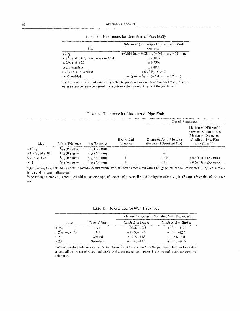
68
Size
:s 103/4
> 103/4 and:s 20 > 20 and:s 42 >42
API SPECIFICATION 5L
Table 7-Tolerances for Diameter of Pipe Body
Size
<2% 2: 23/8 and:s 4 1/2, continuous welded
2: 23/8 and < 20 2: 20, seamless
2: 20 and :s 36, welded
> 36, welded
Tolerancea (with respect to specified outside diameter)
+ 0.016 in., - 0.031 in. (+ 0.41 mm, - 0.8 mm)
± 1.00% ±0.75% ± 1.00%
+ 0.75%, - 0.25% + 1/4 in., - I/S in. (+ 6.4 mm, - 3.2 mm)
"In the case of pipe hydrostatically tested to pressures in excess of standard test pressures, other tolerances may be agreed upon between the manufacturer and the purchaser.
Minus Tolerance
1/64 (0.4 mm)
1/32 (0.8 mm) 1/32 (0.8 mm)
1/32 (0.8 mm)
Table 8-Tolerance for Diameter at Pipe Ends
End-to-End Plus Tolerance Tolerance
1/16 (1.6 mm)
3/32 (2.4 mm)
3/32 (2.4 mm) b 3/32 (2.4 mm) b
Out-of-Roundness
Diameter, Axis Tolerance (Percent of Specified 00)"
± 1% ±1%
Maximum Differential Between Minimum and Maximum Diameters (Applies only to Pipe
with D/f:s 75)
:S 0.500 in. (12.7 mm)
:S 0.625 in. (15.9 mm)
"Out-of-roundness tolerances apply to maximum and minimum diameters as measured with a bar gage, caliper, or device measuring actual max
imum and minimum diameters. lYfhe average diameter (as measured with a diameter tape) of one end of pipe shall nol differ by more than 3/32 in. (2.4 mm) from that of the other end.
Table 9-Tolerances for Wall Thickness
Tolerancea (Percent of Specified Wall Thickness)
Size Type of Pipe Grade B or Lower Grade X42 or Higher
:S 27/8 All + 20.0, - 12.5 + 15.0,-12.5 > 27/8 and < 20 All + 15.0, - 12.5 + 15.0,-12.5 2: 20 Welded + 17.5,-12.5 + 19.5, -8.0 2: 20 Seamless + 15.0,-12.5 + 17.5,-10.0
"Where negative tolerances smaller than those listed are specified by the purchaser, the positive tolerance shall be increased to the applicable total tolerance range in percent less the wall thickness negative tolerance.
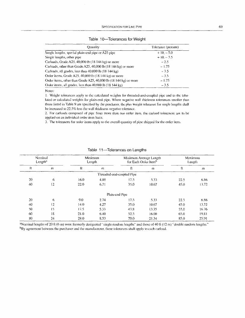
ft
20 40
20 40 50 60 80
SPECIFICATION FOR LINE PIPE
Table 10-Tolerances for Weight
Quantity
Single lengths, special plain-end pipe or A25 pipe Single lengths, other pipe Carloads, Grade A25, 40,000 Ib (18 144 kg) or more Carloads, other than Grade A25, 40,000 Ib (18 144 kg) or more Carloads, all grades, less than 40,000 Ib (18 144 kg) Order items, Grade A25, 40,000 Ib (18 144 kg) or more Order items, other than Grade A25, 40,000 Ib (18 144 kg) or more Order items, all grades, less than 40,000 Ib (18 144 kg)
Notes:
Tolerance (percent)
+ 10,-5.0 + 10, - 3.5
-2.5 - 1.75 -3.5 -3.5 -1.75 - 3.5
I. Weight tolerances apply to the calculated weights for threaded-and-coupled pipe and to the tabulated or calculated weights for plain-end pipe. Where negative wall thickness tolerances smaller than those listed in Table 9 are specified by the purchaser, the plus weight tolerance for single lengths shall be increased to 22.5% less the wall thickness negative tolerance. 2. For carloads composed of pipe from more than one order item, the carload tolerances are to be applied on an individual order item basis. 3. The tolerances for order items apply to the overall quantity of pipe shipped for the order item.
Nominal Lengtha
m
6 12
ft
16.0 22.0
Table 11-Tolerances on Lengths
Minimum Length
Minimum Average Length for Each Order Itemb
m ft
Threaded-and-coupled Pipe
4.88 17.5 6.71 35.0
Plain-end Pipe
2.74 17.5
4.27 35.0
m
5.33 10.67
5.33 10.67 13.35 16.00
ft
22.5 45.0
22.5 45.0 55.0 65.0
Maximum Length
m
6.86 13.72
6.86 13.72 16.76 19.81
6
12 15 18 24
9.0 14.0 17.5 21.0 28.0
5.33 6.40 8.53
43.8 52.5 70.0 21.34 85.0 25.91
aNominallengths of 20 ft (6 m) were formerly designated "single random lengths" and those of 40 ft (12 m) "double random lengths." bSy agreement between the purchaser and the manufacturer, these tolerances shall apply to each carload.
69
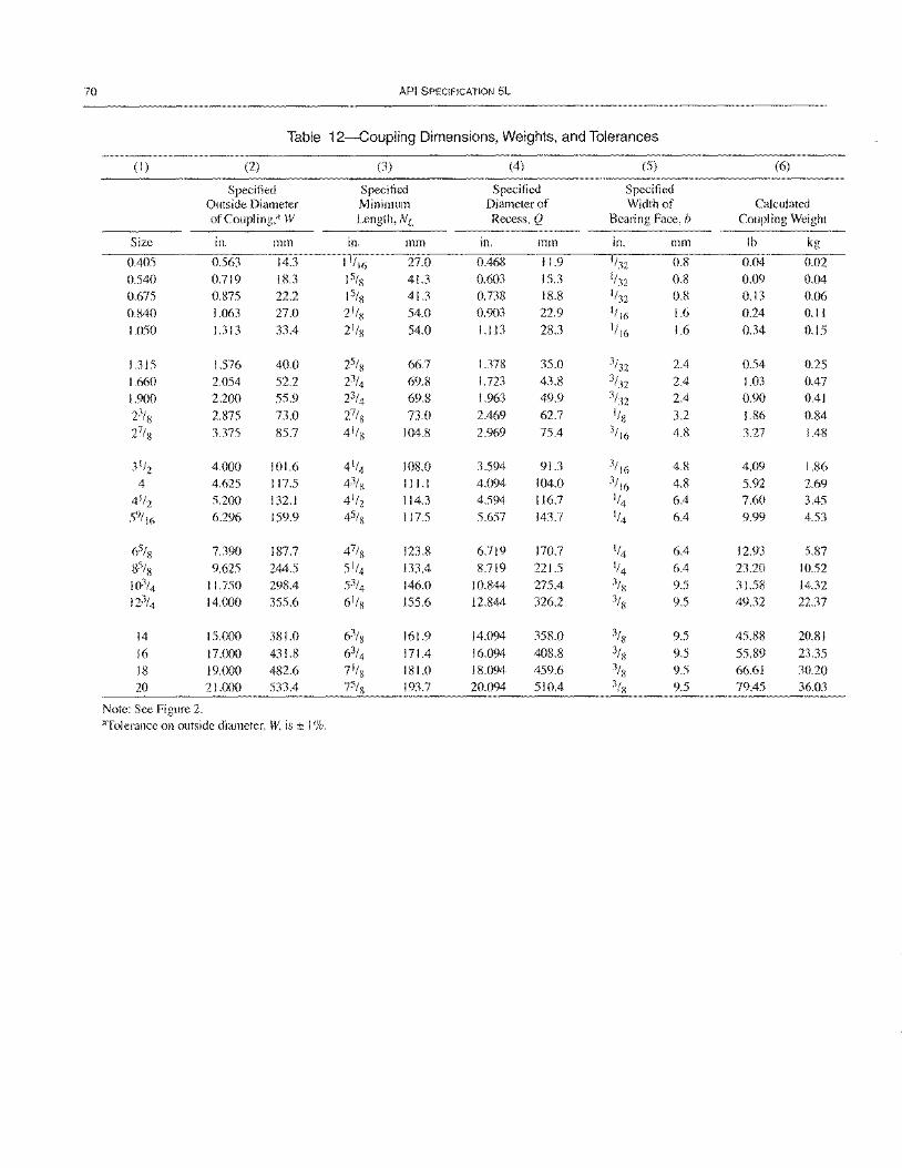
70 API SPECIFICATION 5L
Table 12-Coupling Dimensions, Weights, and Tolerances
(I) (2) (3) (4) (5) (6)
Specified Specified Specified Specified Outside Diameter Minimum Diameter of Width of Calculated ofCoupling,a W Length, NL Recess, Q Bearing Face, b Coupling Weight
Size In. mm in. mm in. mm in. mm Ib kg
0.405 0.563 14.3 11/ 16 27.0 0.468 11.9 1/32 0.8 0.04 0.02
0.540 0.719 18.3 15/8 41.3 0.603 15.3 1/32 0.8 0.09 0.04
0.675 0.875 22.2 15/s 41.3 0.738 18.8 1/32 0.8 0.13 0.06
0.840 1.063 27.0 21/S 54.0 0.903 22.9 1/16 1.6 0.24 0.11
1.050 1.313 33.4 21/8 54.0 1.113 28.3 1/16 1.6 0.34 0.15
1.315 1.576 40.0 25/8 66.7 1.378 35.0 3/32 2.4 0.54 0.25
1.660 2.054 52.2 23/4 69.8 1.723 43.8 3/32 2.4 1.03 0.47
1.900 2.200 55.9 23/4 69.8 1.963 49.9 3/32 2.4 0.90 0.41
23/8 2.875 73.0 27/8 73.0 2.469 62.7 I/s 3.2 1.86 0.84
27/8 3.375 85.7 4 1/8 104.8 2.969 75.4 3/ 16 4.8 3.27 1.48
3 1/2 4.000 101.6 4 1/4 108.0 3.594 91.3 3/ 16 4.8 4.09 1.86
4 4.625 117.5 4% 11l.l 4.094 104.0 3/ 16 4.8 5.92 2.69
4 1/2 5.200 132.1 4 1/2 114.3 4.594 116.7 1/4 6.4 7.60 3.45
59/16 6.296 159.9 45/8 117.5 5.657 143.7 1/4 6.4 9.99 4.53
65/8 7.390 187.7 47/8 123.8 6.719 170.7 1/4 6.4 12.93 5.87
85/8 9.625 244.5 5 1/4 133.4 8.719 221.5 1/4 6.4 23.20 10.52
103/4 11.750 298.4 53/4 146.0 10.844 275.4 3/s 9.5 31.58 14.32 123/4 14.000 355.6 6 1/8 155.6 12.844 326.2 3/8 9.5 49.32 22.37
14 15.000 381.0 63/ 8 161.9 14.094 358.0 3/8 9.5 45.88 20.81
16 17.000 431.8 63/4 171.4 16.094 408.8 3/8 9.5 55.89 23.35
18 19.000 482.6 7 1/8 181.0 18.094 459.6 3/8 9.5 66.61 30.20
20 21.000 533.4 75/8 193.7 20.094 510.4 3/8 9.5 79.45 36.03
Note: See Figure 2. 'lTolerance on outside diameter, W, is ± 1 %.
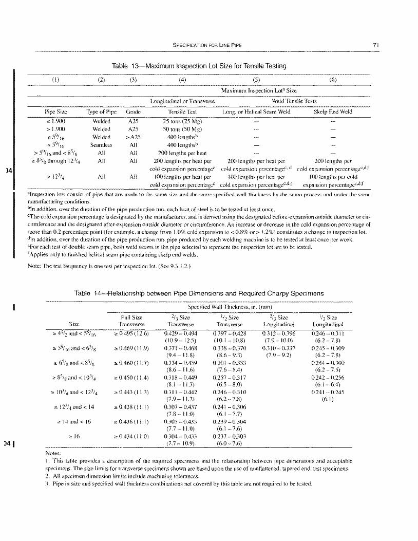
)4
)41
SPECIFICATION FOR LINE PIPE
Table 13-Maximum Inspection Lot Size for Tensile Testing
(I) (2) (3) (4) (5) (6)
Maximum Inspection Lota Size
Longitudinal or Transverse Weld Tensile Tests
Pipe Size Type of Pipe
" 1.900 Welded
> 1.900 Welded
" 59
/ 16 Welded
" 59
/ 16 Seamless
> 59/ 16 and < 85/~ All <! 85/8 through 123/4 All
> 123/4 All
Grade
A25
A25 >A25
All
All All
All
Tensile Test
25 tons (25 Mg) 50 tons (50 Mg)
400lengthsb
400lengthsb
200 lengths per heat 200 lengths per heat per
cold expansion percentageC
100 lengths per heat per cold expansion percentageC
Long. or Helical Seam Weld
200 lengths per heat per cold expansion percentageC
, d
100 lengths per heat per cold expansion percentagec.d,e
Skelp End Weld
200 lengths per cold expansion percentagec.d,f
100 lengths per cold expansion percentagec,d,f
"Inspection lots consist of pipe that are made to the same size and the same specified wall thickness by the same process and under the same manufacturing conditions. bIn addition, over the duration of the pipe production run, each heat of steel is to be tested at least once. cThe cold expansion percentage is designated by the manufacturer, and is derived using the designated before-expansion outside diameter or circumference and the designated after-expansion outside diameter or circumference. An increase or decrease in the cold expansion percentage of more than 0.2 percentage point (for example, a change from 1.0% cold expansion to < 0.8% or> 1.2%) constitutes a change in inspection lot. din addition, over the duration of the pipe production run, pipe produced by each welding machine is to be tested at least once per week. eFor each test of double seam pipe, both weld seams in the pipe selected to represent the inspection lot are to be tested. tApplies only to finished helical seam pipe containing skelp end welds.
Note: The test frequency is one test per inspection lot. (See 9.3.1.2.)
Table 14-Relationship between Pipe Dimensions and Required Charpy Specimens
Specified Wall Thickness, in. (mm)
Full Size 2/3 Size 1/2 Size 2h Size 1/2 Size Size Transverse Transverse Transverse Longitudinal Longitudinal
<! 4 1/2 and< 59/ 16 <! 0.495 (12.6) 0.429 - 0.494 0.397 - 0.428 0.312 - 0.396 0.246 - 0.31 I (10.9-12.5) (10.1 -10.8) (7.9-10.0) (6.2 - 7.8)
<! 59/ 16 and < 65/8 <! 0.469 (II. 9) 0.371 - 0.468 0.338 - 0.370 0.310 - 0.337 0.245 - 0.309 (9.4-11.8) (8.6 - 9.3) (7.9- 9.2) (6.2 -7.8)
<! 65/8 and < 85/8 <! 0.460 (11.7) 0.334 - 0.459 0.30 I - 0.333 0.244 - 0.300 (8.6 - 11.6) (7.6 - 8.4) (6.2 -7.5)
<! 85/8 and < 103/4 <! 0.450 (11.4) 0.318-0.449 0.257 - 0.317 0.242 - 0.256 (8.1 - 11.3) (6.5 - 8.0) (6.1 -6.4)
<! 103/4 and < 123/4 <! 0.443 (11.3) 0.311 - 0.442 0.246 - 0.31 0 0.241 - 0.245 (7.9 - 11.2) (6.2 -7.8) (6.1)
<! 123/4 and < 14 <! 0.438 (l1.I) 0.307 - 0.437 0.241 -0.306 (7.8 - 11.0) (6.1 - 7.7)
<! 14 and < 16 <! 0.436 (I I. I) 0.305 - 0.435 0.239 - 0.304 (7.7 - 11.0) (6.1-7.6)
<!16 <! 0.434 (I 1.0) 0.304 - 0.433 0.237 - 0.303 (7.7 - 10.9) (6.0 - 7.6)
Notes: I. This table provides a description of the required specimens and the relationship between pipe dimensions and acceptable specimens. The size limits for transverse specimens shown are based upon the use of non flattened, tapered end, test specimens. 2. All specimen dimension limits include machining tolerances. 3. Pipe in size and specified wall thickness combinations not covered by this table are not required to be tested.
71
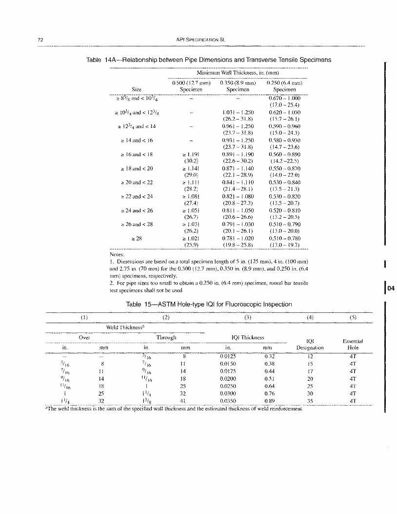
72
in.
5/ 16 7/ 16 "/16 "/16
1
1'/4
API SPECIFICATION 5L
Table 14A-Relationship between Pipe Dimensions and Transverse Tensile Specimens
(I)
Over
Minimum Wall Thickness, in. (mm)
0.500 (12.7 mm) 0.350 (S.9 mm) 0.250 (6.4 mm) Size Specimen Specimen Specimen
2: S5/8 and < 103/4 0.670 - 1.000 (17.0 - 25.4)
2: 103/4 and < 123/4 1.03 I - l.250 0.620 - 1.030 (26.2 - 31.S) (15.7 -26.1)
2: 123/4 and < 14 0.961 - l.250 0.590 - 0.960 (23.7 - 31.S) (15.0 - 24.3)
2: 14 and < 16 0.931 - 1.250 0.5S0 - 0.930 (23.7 - 31.S) (14.7 - 23.6)
2: 16 and < IS 2: 1.191 0.S91 -1.190 0.560 - 0.S90 (30.2) (22.6 - 30.2) (14.2 -22.5)
2: IS and < 20 2: 1.141 0.S71 - I.I40 0.550 - 0.S70 (29.0) (22.1 - 2S.9) (14.0 - 22.0)
2: 20 and < 22 2: 1.1 II 0.S41 - !.l10 0.530 - 0.S40 (2S.2) (21.4-2S.I) (13.5-21.3)
2: 22 and < 24 2: 1.081 0.821 - I.OSO 0.530 - 0.820 (27.4) (20.8 - 27.3) (13.5 - 20.7)
2: 24 and < 26 2: 1.05 I 0.81 I - 1.050 0.520 - 0.810 (26.7) (20.6 - 26.6) (13.2-20.5)
2: 26 and < 28 2: 1.031 0.791 - 1.030 0.510-0.790 (26.2) (20.1 - 26. I) (13.0 - 20.0)
2: 28 2: 1.021 0.781 - 1.020 0.510- 0.780 (25.9) (19.S - 25.8) (13.0-19.7)
Notes: I. Dimensions are based on a total specimen length of 5 in. (125 mm), 4 in. (100 mm) and 2.75 in. (70 mm) for the 0.500 (12.7 mm), 0.350 in. (8.9 mm), and 0.250 in. (6.4 mm) specimens, respectively. 2. For pipe sizes too small to obtain a 0.250 in. (6.4 mm) specimen, round bar tensile test specimens shall not be used.
Table 15-ASTM HOle-type IQI for Fluoroscopic Inspection
(2) (3 ) (4)
Weld Thicknessa
Through IQI Thickness IQI
mm in. mm in. mm Designation 5/ 16 8 0.0125 0.32 12
8 7/ 16 II 0.0150 0.38 15 II 9/'6 14 0.0175 0.44 17 14 11/16 18 0.0200 0.51 20 18 1 25 0.0250 0.64 25 25 11/4 32 0.0300 0.76 30 32 I S/8 41 0.0350 0.89 35
"The weld thickness is the sum of the specified wall thickness and the estimated thickness of weld reinforcement.
(5)
Essential Hole
4T 4T 4T 4T 4T 4T 4T
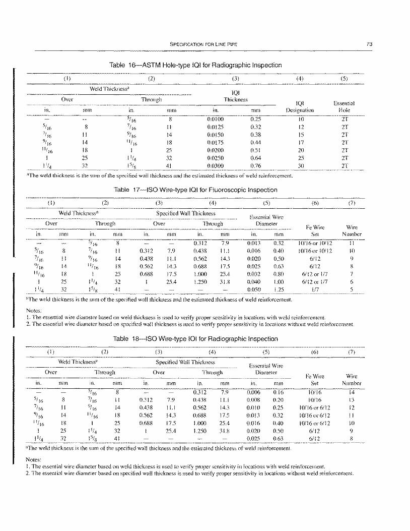
SPECIFICATION FOR liNE PIPE
Table 16-ASTM Hole-type 101 for Radiographic Inspection
(1 ) (2) (3) (4)
Weld Thickness" IQI
Over Through Thickness IQI
in. mm In. mm in. mm Designation
5/ 16 8 0.0100 0.25 5/ 16 8 7/ 16 11 0.0125 0.32 7/16 II 9/ 16 14 0.0150 0.38 9/ 16 14 11/ 16 18 0.0175 0.44 11/16 18 I 25 0.0200 0.51
I 25 11/4 32 0.0250 0.64 11/4 32 15/s 41 0.0300 0.76
"The weld thickness is the sum of the specified wall thickness and the estimated thickness of weld reinforcement.
Table 17-ISO Wire-type 101 for Fluoroscopic Inspection
(I) (2) (3) (4) (5)
Weld Thickness" Specified Wall Thickness Essential Wire
Over Through Over Through Diameter
in. mm in. mm in. mm in. mm in. mm
5/ 16 8 0.312 7.9 0.013 0.32 5/ I (i 8 7/ 16 II 0.312 7.9 0.438 11.1 0.016 0.40 7/ 16 II 9/ 16 14 0.438 11.1 0.562 14.3 0.020 0.50 9/ 16 14 11/ 16 18 0.562 14.3 0.688 17.5 0.025 0.63 11/ 16 18 1 25 0.688 17.5 1.000 25.4 0.032 0.80
I 25 11/4 32 25.4 1.250 31.8 0.040 1.00 11/4 32 15/S 41 0.050 1.25
aThe weld thickness is the sum of the specified wall thickness and the estimated thickness of weld reinforcement.
Notes:
10 12
15 17 20 25
30
(6)
Fe Wire Set
10/16 or I 0/ I 2 10/16 or 10/12
6/12
6/12 6/12 or 117 6/12 or 117
117
I. The essential wire diameter based on weld thickness is used to verify proper sensitivity in locations with weld reinforcement.
(5)
Essential Hole
2T 2T
2T 2T 2T 2T 2T
(7)
Wire Number
II 10 9
8 7
6 5
2. The essential wire diameter based on specified wall thickness is used to verify proper sensitivity in locations without weld reinforcement.
Table 18-ISO Wire-type 101 for Radiographic Inspection
(I) (2) (3) (4) (5) (6) (7)
Weld Thickness" Specified Wall Thickness Essential Wire
Over Through Over Through Diameter Fe Wire Wire
in. mm in. mm Ill. mm in. mm in. mm Set Number
5/16 8 0.312 7.9 0.006 0.16 10/16 14 5/ 16 8 7/ 16 II 0.312 7.9 0.438 11.1 0.008 0.20 10/16 13 7/16 II 9/ 16 14 0.438 11.1 0.562 14.3 0.010 0.25 10/16 or 6/12 12 9/ 16 14 11/ 16 18 0.562 14.3 0.688 17.5 0.013 0.32 I 0/16 or 6/12 II 11/ 16 18 I 25 0.688 17.5 1.000 25.4 0.016 0.40 1 0/16 or 6/1 2 10
I 25 11/4 32 25.4 1.250 31.8 0.020 0.50 6/12 9 11/4 32 15/S 41 0.025 0.63 6/12 8
"The weld thickness is the sum of the specified wall thickness and the estimated thickness of weld reinforcement.
Notes: 1. The essential wire diameter based on weld thickness is used to verify proper sensitivity in locations with weld reinforcement. 2. The essential wire diameter based on specified wall thickness is used to verify proper sensitivity in locations without weld reinforcement.
73
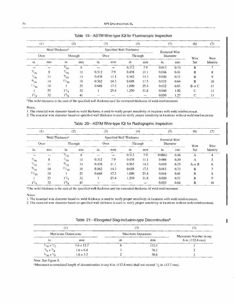
74 API SPECIFICATION 5L
Table 19-ASTM Wire-type IQI for Fluoroscopic Inspection
(I) (2) (3) (4) (5) (6) (7)
Weld Thickness" Specified Wall Thickness Essential Wire
Over Through Over Through Diameter Wire Wire
in. mm in. mm In. mm in. mm in. mm Set Identity
5/ 16 8 0.312 7.9 0.013 0.33 8 7 5/ 16 8 7/ 16 11 0.312 7.9 0.438 Il.l 0.016 0.41 B 8 7/ 16 11 9/ 16 14 0.438 11.1 0.562 14.3 0.020 0.51 8 9 9/ 16 14 11/
16 18 0.562 14.3 0.688 17.5 0.025 0.64 8 10 11/16 18 I 25 0.688 17.5 1.000 25.4 0.032 0.81 B orC 1 I
I 25 11/4 32 25.4 1.250 31.8 0.040 1.02 C 12
11;4 32 ISis 41 0.050 1.27 C 13
"The weld thickness is the sum of the specified wall thickness and the estimated thickness of weld reinforcement.
Notes: I. The essential wire diameter based on weld thickness is used to verify proper sensitivity in locations with weld reinforcement. 2. The essential wire diameter based on specified wall thickness is L1sed to verify proper sensitivity in locations without weld reinforcement.
Table 20-ASTM Wire-type IQI for Radiographic Inspection
(I) (2) (3) (4) (5) (6) (7)
Weld Thickness" Specified Wall Thickness Essential Wire
Over Through Over Through Diameter Wire Wire
in. mm in. mm in. mm in. mm in. mm Set Identity
5/ 16 8 0.312 7.9 0.0063 0.16 A 4 5/ 16 8 7/ 16 11 0.312 7.9 0.438 11.1 0.008 0.20 A 5 7/ 16 II 9/ 16 14 0.438 11.1 0.562 14.3 0.010 0.25 AorB 6 'J/ 16 14 11/ 16 18 0.562 14.3 0.688 17.5 0.013 0.33 8 7 11/16 18 I 25 0.688 17.5 1.000 25.4 0.016 0.41 8 8
I 25 11/4 32 25.4 1.250 31.8 0.020 0.51 B 9 32 41 0.025 0.64 8 10
"The weld thickness is the sum of the specified wall thickness and the estimated thickness of weld reinforcement.
Notes: I. The essential wire diameter based on weld thickness is used to verify proper sensitivity in locations with weld reinforcement. 2. The essential wire diameter based on specified wall thickness is used to verify proper sensitivity in locations without weld reinforcement.
Table 21-Elongated Slag-inclusion-type Discontinuitiesa
(I)
Maximum Dimensions
Ill. mm
1/16X 1/2 1.6 x 12.7
1/6 x 1/4 1.6 x 6.4
1/16X lis 1.6 x 3.2
Note: See Figure 8.
(2)
Minimum Separation
in. mm
6 152.4
3
2
76.2
50.8
(3)
Maximum Number in any 6 in. (152.4 mm)
I 2
3
"Maximul11 accumulated length of discontinuities in any 6 in. (152.4 mm) shall not exceed 112 in. (12.7 mm).
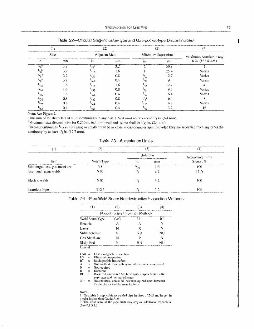
SPECIFICATION FOR liNE PIPE
Table 22-Circular Slag-inclusion-type and Gas-pocket-type Discontinuitiesa
(I) (2) (3)
Size Adjacent Size Minimum Separation
in. mm in. mm in. mm
1/85 3.2 I/s5 3.2 2 50.8 I/sb 3.2 1/ 16 1.6 I 25.4 I/Sb 3.2 1/32 0.8 1/2 12.7 11gb 3.2 1/64 0.4 3/S 9.5 1/ 16 1.6 1/16 1.6 1/2 12.7 1/16 1.6 1/32 0.8 3/S 9.5 1/ 16 1.6 1/64 0.4 1/4 6.4 1/32 0.8 1/32 0.8 1/4c 6.4 1/32 0.8 1/64 0.4 3/ 16 4.8 1/64 0.4 1/64 0.4 1/8 3.2
Note: See Figure 7. aThe sum of the diameters of all discontinuities in any 6 in. (152.4 mm) not to exceed 1/4 in. (6.4 mm). bMaximum size discontinuity for 0.250 in. (6.4 mm) wall and lighter shall be 3/32 in. (2.4 mm).
(4)
Maximum Number in any 6 in. (152.4 mm)
2 Varies Varies
Varies
4 Varies Varies
8 Varies
16
"Two discontinuities 1/32 in. (0.8 mm) or smaller may be as close as one diameter apart provided they are separated from any other discontinuity by at least 1/2 in. (12.7 mm).
Table 23-Acceptance Limits
(I) (2) (3)
Hole Size
Item Notch Type in. mm
Submerged-arc, gas-metal arc, NS 1/16 1.6 laser, and repair welds NIO I/S 3.2
Electric welds NIO I/S 3.2
Seamless Pipe NI2.S I/S 3.2
Table 24-Pipe Weld Seam Nondestructive Inspection Methods
(I) (2) (3) (4)
Nondestructive Inspection Methods
Weld Seam Type EM! UT RT Electric A A N Laser N R N Submerged-arc N RU NU
Gas Metal-arc N R N
Skelp End N RU NU Legend:
EMI Electromagnetic inspection UT Ultrasonic inspection RT Radiographic inspection A One method or a combination of methods are required N Not required R Required RU Required, unless RT has been agreed upon between the
purchaser and the manufacturer NU Not required, unless RT has been agreed upon between
the purchaser and the manufacturer
Notes: I. This table is applicable to welded pipe in sizes of 23/8 and larger, in grades higher than Grade A 25. 2. The weld seam at the pipe ends may require additional inspection. (See 9.8.3.1.)
(4)
Acceptance Limit Signal, %
100
100
75
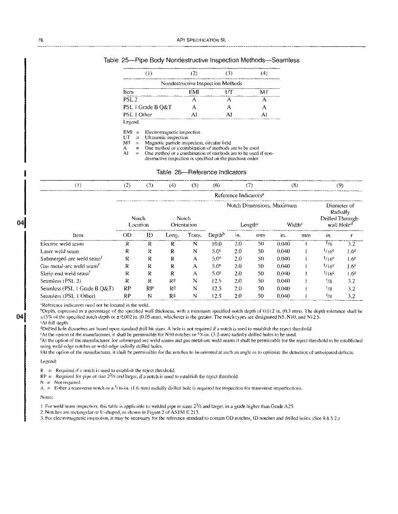
041
76
(I)
API SPECIFICATION 5L
Table 25-Pipe Body Nondestructive Inspection Methods-Seamless
(I) (2) (3) (4)
Nondestructive Inspection Methods
Item EMI UT MT
PSL2 A A A
PSL I Grade B Q&T A A A PSL I Other AI AI AI Legend:
EMI Electromagnetic inspection UT Ultrasonic inspection MT Magnetic particle inspection, circl~ar field A One method or a combination of methods are to be used Al One method or a combination of methods are to be used if nou
destructive inspection is specified on the purchase order.
Table 26-Reference Indicators
(2) (3) (4) (5) (6) (7)
Reference Indicators"
(8)
Notch Dimensions, Maximum
Notch Notch Location Orientation Length" WidthC
Item OD ID Long. Trans. Depthb in. mm in. mm
Electric weld seam R R R N 10.0 2.0 50 0.040
Laser weld seam R R R N 5.0e 2.0 50 0.040
Submerged-arc weld seamf R R R A 5.0e 2.0 50 0.040
Gas metal-arc weld seam f R R R A 5.0e 2.0 50 0.040
Skelp end weld seam f R R R A 5.0e 2.0 50 0.040
Seamless (PSL 2) R R Rg N 12.5 2.0 50 0.040
Seamless (PSL I Grade B Q&T) RP RP Rg N 12.5 2.0 50 0.040
Seamless (PSL I Other) RP N Rg N 12.5 2.0 50 0.040
"Reference indicators need not be located in the weld.
(9)
Diameter of
Radially Drilled Through-
wall Holed
in.
l/S 3.2
1/16e 1.6e
1/16e 1.6e
1/16c 1.6e
1/16e 1.6e
I/S 3.2
1/8 3.2
1/8 3.2
bDepth, expressed as a percentage of the specified wall thickness, with a minimum specified notch depth of 0.012 in. (0.3 mm). The depth tolerance shall be ± 15% of the specified notch depth or ± 0.002 in. (0.05 mm), whichever is the greater. The notch types are designated N5, N 10, and N 12.5. CAt full depth. clDrilled hole diameters are based upon standard drill bit sizes. A hole is not required if a notch is used to establish the reject threshold. CAt the option of the manufacturer, it shall be permissible for NIO notches or liS-in. (3.2-mm) radially drilled holes to be used. IAt the option of the manufacturer, for submerged-arc weld seams and gas metal-arc weld seams it shall be permissible for the reject threshold to be established using weld-edge notches or weld-edge radially drilled holes. gAt the option of the manufacturer, it shall be permissible for the notches to be oriented at such an angle as to optimize the detection of anticipated defects.
Legend:
R = Required if a notch is used to establish the reject threshold. RP = Required for pipe of size 23/8 and larger, if a notch is used to establish the reject threshold. N = Not required. A = Either a transverse notch or a 1/ 16-in. (1.6-mm) radially drilled hole is required for inspection for transverse imperfections.
Notes:
I. For weld seam inspection, this table is applicable to welded pipe in sizes 23/8 and larger, in a grade higher than Grade A25. 2. Notches are rectangular or U-shaped, as shown in Figure 2 of ASTM E 213. 3. For electromagnetic inspection, it may be necessary for the reference standard to contain OD notches, ID notches and drilled holes. (See 9.8.5.2.)
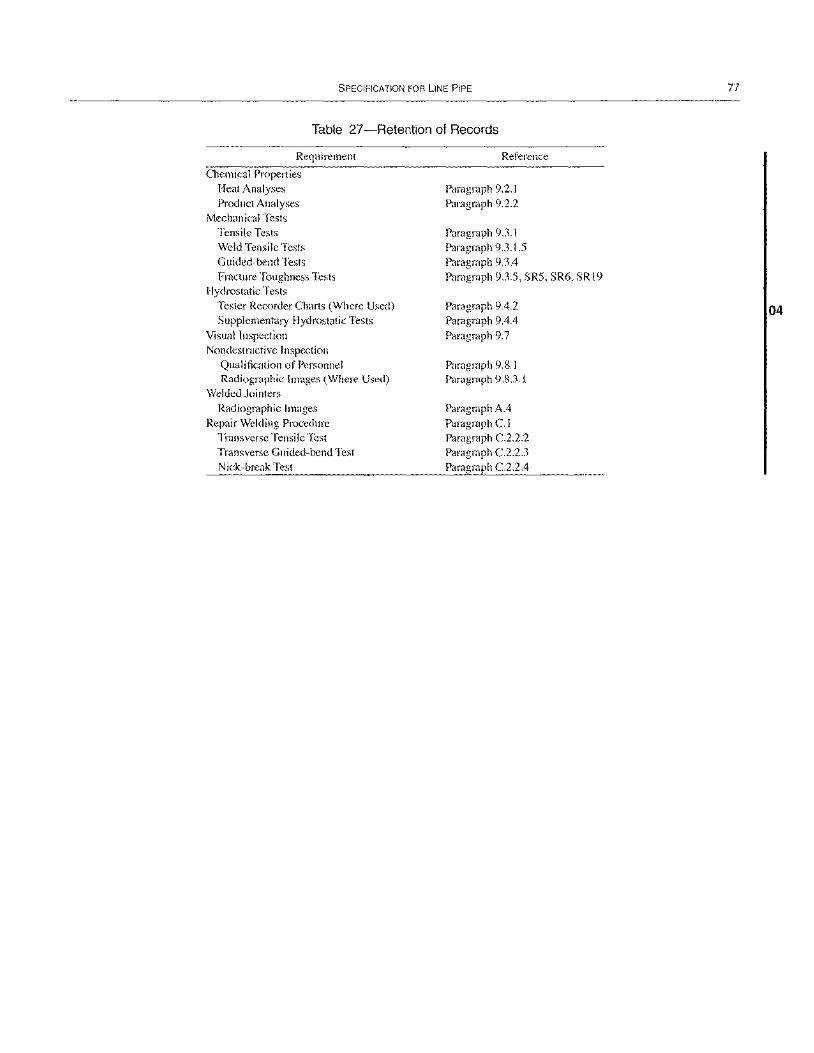
SPECIFICATION FOR LINE PIPE
Table 27-Retention of Records
Requirement
Chemical Properties Heat Analyses Product Anal yses
Mechanical Tests Tensile Tests Weld Tensile Tests Guided-bend Tests Fracture Toughness Tests
Hydrostatic Tests Tester Recorder Charts (Where Used) Supplementary Hydrostatic Tests
Visual Inspection Nondestructive Inspection
Qualification of Personnel Radiographic Images (Where Used)
Welded Jointers Radiographic Images
Repair Welding Procedure Transverse Tensile Test Transverse Guided-bend Test Nick-break Test
Reference
Paragraph 9.2.1 Paragraph 9.2.2
Paragraph 9.3.1 Paragraph 9.3.1.5 Paragraph 9.3.4 Paragraph 9.3.5, SR5, SR6, SR 19
Paragraph 9.4.2 Paragraph 9.4.4 Paragraph 9.7
Paragraph 9.8. I Paragraph 9.8.3.1
Paragraph A.4 Paragraph C. I Paragraph C.2.2.2 Paragraph C.2.2.3 Paragraph C.2.2.4
77
04

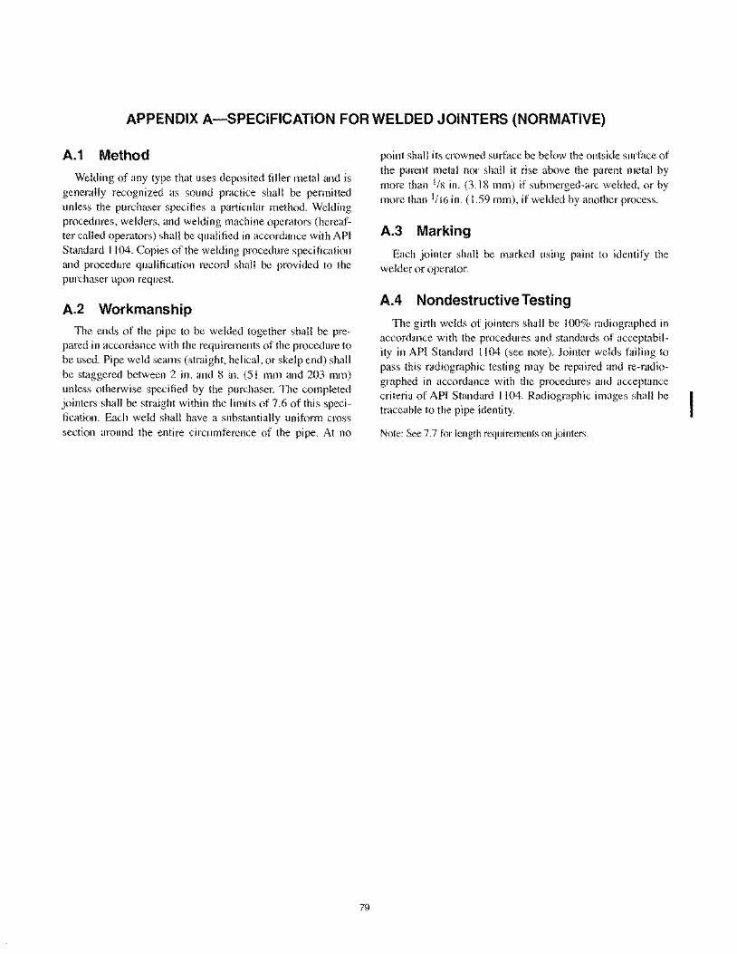
APPENDIX A-SPECIFICATION FOR WELDED JOINTERS (NORMATIVE)
A.1 Method
Welding of any type that uses deposited filler metal and is generally recognized as sound practice shall be permitted unless the purchaser specifies a particular method. Welding procedures, welders, and welding machine operators (hereafter called operators) shall be qualified in accordance with API Standard 1104. Copies of the welding procedure specification and procedure qualification record shall be provided to the purchaser upon request.
A.2 Workmanship The ends of the pipe to be welded together shall be pre
pared in accordance with the requirements of the procedure to be used. Pipe weld seams (straight, helical, or skelp end) shall be staggered between 2 in. and 8 in. (51 mm and 203 mm) unless otherwise specified by the purchaser. The completed jointers shall be straight within the limits of 7.6 of this specification. Each weld shall have a substantially uniform cross section around the entire circumference of the pipe. At no
79
point shall its crowned surface be below the outside surface of the parent metal nor shall it rise above the parent metal by more than 1/8 in. (3.18 mm) if submerged-arc welded, or by more than 1/16 in. (1.59 mm), if welded by another process.
A.3 Marking
Each jointer shall be marked using paint to identify the weIder or operator.
A.4 Nondestructive Testing
The girth welds of jointers shall be 100% radiographed in accordance with the procedures and standards of acceptability in API Standard 1104 (see note). Jointer welds failing to pass this radiographic testing may be repaired and re-radiographed in accordance with the procedures and acceptance criteria of API Standard I 104. Radiographic images shall be traceable to the pipe identity.
Note: See 7.7 for length requirements on jointers.

04 I
APPENDIX B-REPAIR OF DEFECTS BY WELDING (NORMATIVE)
B.1 Types Of Pipe
B.1.1 SEAMLESS PIPE AND PARENT METAL OF WELDED PIPE
For PSL I pipe, the repair of defects in seamless pipe and parent metal of welded pipe is permissible except (a) when the depth of the defect exceeds 33' /3% of the specified wall thickness of the pipe and the length of that portion of the defect in which the depth exceeds 12' /2% is greater than 25% of the specified outside diameter of the pipe; or (b) when more than one repair is required in any length equivalent to 10 times the specified outside diameter of the pipe. Repairs shall be made in accordance with B.2. Repair welds shall be inspected by the magnetic particle method in accordance with 9.7.5.1 through 9.7.5.3; by liquid penetrant; or by other NOT methods as agreed start between purchaser and the manufacturer.
For PSL 2, seamless pipe, the parent metal (body) of welded pipe, plate, and skelp shall not be repaired by welding.
B.1.2 WELD SEAM OF WELDED PIPE
B.1.2.1 Defects in filler metal welds may be repaired at the option of the manufacturer; such repairs shall be in accordance with 8.3. All repair welds shall be inspected by ultrasonic methods in accordance with 9.8.5.1, 9.8.5.2, and 9.8.SA., except that the equipment need not be capable of continuous and uninterrupted operation and, at the option of the manufacturer, repairs made by submerged-arc welding or by shielded metal-arc welding may alternatively be inspected by radiological methods in 9.8A.
B.1.2.2 For PSL I pipe, weld seams made without filler metal (electric and laser welds) may be repaired by welding only by agreement between the purchaser and the manufacturer; such repairs shall be in accordance with BA.
B.1.2.3 For PSL 2 pipe, weld seams made without filler metal shall not be repaired by welding.
B.1.3 HEATTREATED PIPE
When heat treated pipe has been repaired by welding, the need for and type of reheat treatment shall be based on the effect of the repair on the structure and properties of the heat treated pipe, by agreement between the purchaser and the manufacturer.
B.2 Procedure for Repair by Welding of Seamless Pipe and Parent Metal of Welded Pipe (PSL 1 Only)
The repair of defects in seamless pipe and parent metal of welded pipe shall conform to the requirements listed in 8.2.1-
81
B.2.5. Conformance to the repair procedure is subject to approval of the purchaser's inspector.
B.2.1 The defect shall be removed completely by chipping and/or grinding. The resulting cavity shall be thoroughly cleaned and shall be inspected before welding by magnetic particle methods in accordance with 9.8.6 to ensure complete removal of the defect.
B.2.2 The minimum length of repair weld shall be 2 in. (50.8 mm). Where the orientation of the defect permits, the repair weld shall be placed in the circumferential direction.
B.2.3 The repair weld shall be made either by automatic submerged-arc welding, gas metal-arc welding, or manual shielded metal-arc welding using low-hydrogen electrodes. The metal temperature in the area to be repaired shall be a minimum of 50°F (10°C). The welding procedure and performance shall be qualified in accordance with Appendix C.
B.2.4 The repair weld shall be ground to merge smoothly into the original contour of the pipe.
B.2.5 Repaired pipe shall be tested hydrostatically after repairing, in accordance with 9A.
B.3 Procedure for Repair of SubmergedArc and Gas Metal-Arc Welds
The repair of submerged-arc and gas metal-arc welds shall conform to the requirements listed in B.3.I-B.3.3. Conformance is subject to approval of purchaser's inspector.
B.3.1 The defect shall be completely removed and the cavity thoroughly cleaned. Where multiple pass repairs are used, the size of the cavity shall be sufficiently large [at least 2 in. (50.8 mm) in length] to avoid coincidence of starts and stops of individual passes.
B.3.2 The minimum length of each repair weld shall be 2 in. (50.8 mm). The repair weld shall be made either by automatic submerged-arc welding, gas metal-arc welding, or manual shielded metal-arc welding using low-hydrogen electrodes. The welding procedure and performance shall be qualified in accordance with Appendix C.
B.3.3 Each length of repaired pipe shall be tested hydrostatically in accordance with 9A.
B.4 Procedure for Repair of Electric and Laser Welds (PSL 1 Only)
The repair of electric and laser welds shall conform to the requirements in BA.I through BA.6 and shall include the weld zone, which is defined for the purposes of repair as '/2 in. (\ 2.7 mm) on each side of the fusion line. Conformance to
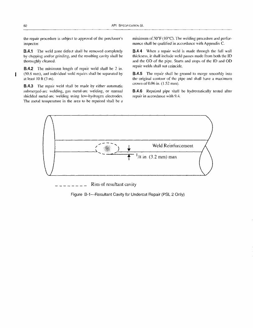
82 API SPECIFICATION 5L
the repair procedure is subject to approval of the purchaser's inspector.
8.4.1 The weld zone defect shall be removed completely by chipping and/or grinding, and the resulting cavity shall be thoroughly cleaned.
8.4.2 The minimum length of repair weld shall be 2 in. (50.8 mm), and individual weld repairs shall be separated by at least 10 ft (3 m).
8.4.3 The repair weld shall be made by either automatic submerged-arc welding, gas metal-arc welding, or manual shielded metal-arc welding using low-hydrogen electrodes. The metal temperature in the area to be repaired shall be a
."",..---, / )
I---------~ ....
minimum of 50°F (10°C). The welding procedure and performance shall be qualified in accordance with Appendix C.
8.4.4 When a repair weld is made through the full wall thickness, it shall include weld passes made from both the ID and the OD of the pipe. Starts and stops of the ID and OD repair welds shall not coincide.
8.4.5 The repair shall be ground to merge smoothly into the original contour of the pipe and shall have a maximum crown of 0.06 in. (1.52 mm).
8.4.6 Repaired pipe shall be hydrostatically tested after repair in accordance with 9.4.
Weld Reinforcement
t 1/8 in. (3.2 mm) max
Rim of resultant cavity
Figure B-1-Resultant Cavity for Undercut Repair (PSL 2 Only)
041
APPENDIX C-REPAIR WELDING PROCEDURE (NORMATIVE)
C.1 General
All repair welds shall be made in the flat position according to a qualified procedure and by a welding machine operator (hereafter called operator) or repair welder who is qualified in a flat position as specified in C.3. Repair welds may be made by one of the following methods:
a. Automatic submerged arc.
b. Automatic or semi-automatic gas metal arc.
c. Manual shielded metal arc using low-hydrogen electrodes.
All welding materials shall be properly handled and stored in accordance with the manufacturer's recommendations so as to preclude moisture or other contamination. Test welds may be made on either plate stock or pipe stock at the option of the manufacturer.
The manufacturer shall maintain a record of the welding procedure and procedure qualification test results. Copies of the welding procedure specification and procedure qualification record shall be provided to the purchaser upon request.
C.2 Repair Welding Procedure Qualification
Welding procedures shall be qualified by preparing and testing welds in accordance with this appendix. At the option of the manufacturer, the tests specified in the ASME Boiler and Pressure Vessel Code, Section IX, may be substituted herein. For the purpose of this appendix, the term automatic welding includes both machine welding and automatic welding as defined in the ASME Boiler and Pressure Vessel Code, Section IX.
C.2.1 ESSENTIAL VARIABLES
An existing procedure shall not be applicable and new procedure shall be qualified when any of the following essential variables is changed beyond the stated limits:
a. Welding process:
I. A change in the welding process, such as submerged arc to gas metal arc.
2. A change in the method, such as manual to semiautomatic.
b. Pipe material:
1. A change in grade category. When different alloying systems are used within one grade category, each alloying composition shall be separately qualified. Grade categories are as follows:
,; X42
> X42 and < X65
each grade ~ X65
83
2. Within each grade category, a thicker material than the material qualified. 3. Within the grade category and thickness range, a carbon equivalent, CE (see note), based on product analysis for the material to be repaired, that is more than 0.04% greater than the CE of the material qualified.
Note:
CE = C + Mn + Cr + Mo + V + Ni + Cu 6 5 15
c. Welding materials: 1. A change in filler metal classification. 2. A change in electrode diameter. 3. A change of more than 5% in the composition of shielding gas. 4. A change of more than 10% in the flow rate of shielding gas. 5. A change in submerged-arc welding flux from one designation to another.
d. Welding parameters: I. A change in the type of current (such as AC versus DC). 2. A change in polarity. 3. For automatic and semi-automatic welding, schedules of welding current, voltage, and speed may be established to cover ranges of wall thicknesses. Within the schedule, appropriately selected points shall be tested to qualify the entire schedule. Thereafter, a new qualification is required if there is a deviation from the qualified schedule greater than the following: 10% in amperage 7% in voltage 10% in travel speed for automatic welding
e. Weld bead: For manual and semi-automatic welding, a change in bead width greater than 50%. f. Preheat and post-weld heat treatment:
l. Repair welding at a pipe temperature lower than the pipe temperature of the qual ification test. 2. The addition or deletion of post-weld heat treatment.
C.2.2 MECHANICAL TESTING
C.2.2.1 Number of Tests
Two specimens of each type are required from each procedure qualification test.
C.2.2.2 Transverse Tensile Test
The transverse tensile test specimens shall be approximately 1.5 in. (38.1 mm) wide and shall have the transverse
104
84 API SPECIFICATION 5L
butt weld perpendicular to the longitudinal axis at the center of the test specimen (See Figure Col or Figure 4.) The weld reinforcement shall be removed from both faces. The ultimate tensile strength shall be at least equal to the minimum specified for the pipe grade.
C.2.2.3 Transverse Guided-Bend Test
The transverse guided-bend test specimens shall conform to Figure C-2. The weld shall be made in a groove as shown. Each specimen shall be placed on the die with the weld at mid-span and shall be bent approximately 1800 in a jig in accordance with Figure C-3 and Table C-l, with the exposed sLllt~lce of the weld in tension. The bend test shall be considered acceptable if no crack or other defect exceeding I/S in. (3.18 mill) in any direction is present in the weld metal or base metal after bending. Cracks that both originate along the edges of the specimen during testing and measure less than 1/4
in. (6.35 mm) in all directions shall not be considered.
C.2.2.4 Nick-Break Test
The nick-break specimens shall conform to Figure C-4. The weld shall be made in a groove as shown. Each specimen shall be saw-notched from both edges at the center of the weld and shall be broken by pulling or hammer blows at the center of one end. The exposed surface of the specimen shall be visually examined and shall be considered acceptable if it meets the following criteria:
a. No gas pockets exceeding 1/ 16 in. (1.59 mm) in any direction. b. Not more than one gas pocket of any size for specified wall thicknesses of 0.250 in. (6.4 mm) and less. c. Not more than two gas pockets of any size for specified wall thicknesses of 0.500 in. (12.7 mm) or less but greater than 0.250 in. (6.4 mm). d. Not more than three gas pockets of any size for specified wall thicknesses greater than 0.500 in. (12.7 mm). e. Slag inclusions shall be separated by at least 1/2 in. (12.7 mm) of sound metal and shall appear no greater than 1/16 in. (1.59 mm) in width or 3/16 in. (4.76 mm) in length.
C.3 Welding Personnel Performance Qualification
C.3.1 QUALIFICATION
C.3.1.1 General
Each repair welder and operator is required to qualify. A repair welder or operator qualified on one grade category is qualified for any lower grade category provided the same welding process is used.
C.3.1.2 Testing
To qualify, a repair welder or operator shall produce welds that are acceptable in the following tests:
a. Film radiographic examination per Section 9 of this specification.
b. Two transverse guided-bend tests per C2.2.3 of this appendix.
c. Two nick-break tests per C2.2.4 of this appendix.
C.3.1.3 Test Failures
If one or more of the tests in C3.1.2 fail to meet the specified requirements, the welder or operator may make one additional qualification weld. If that weld fails one or more of the tests in C3.1.2, the welder or operator is disqualified. No further retests shall be permitted until the welder has completed additional training.
C.3.2 REQUALIFICATION
Requalification in accordance with C.3.l is required under the following circumstances:
a. One year has elapsed since the last prior applicable qualification.
b. The individual has not been welding using qualified procedures for a period of 3 months.
c. There is reason to question the individual's ability.
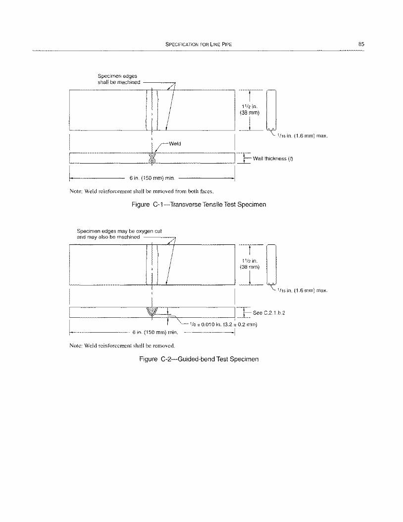
SPECIFICATION FOR LINE PIPE
Specimen edges h II b . d s a e machine
/l
I ! I I
6 in. (150 mm) min.
Note: Weld reinforcement shall be removed from both faces.
11/2 in. (38 mm)
~
Figure C-1-Transverse Tensile Test Specimen
Specimen edges may be oxygen cut d I b h· d an maya so e mac me
I
I I
//
! 11/2 in. (38 mm)
~
1116 in. (1.6 mm) max.
1116 in. (1.6 mm) max.
, F I:E S"C21b'
C 1/8 ± 0.010 in. (3.2 ~ 0.2 mm)
--------- 6 in. (150 mm) min. I
Note: Weld reinforcement shall be removed.
Figure C-2-Guided-bend Test Specimen
85
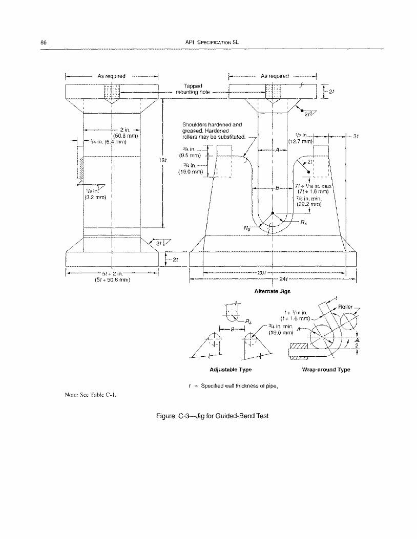
86
As required
1------'-- 2 in. 1(50.8 mm)
1/4 in. (6.4 mm)
1/8 in. (3.2 mm)
• I
1------51+ 2 in.----(51 + 50.8 mm)
Note: See Table C-I.
181
API SPECIFICATION 5L
As required
Tapped mounting hole ---I----------r
Shoulders hardened and greased. Hardened rollers may be substituted.
3/8 in. (9.5 mm)
3/4 in. (19.0mm)
21
-+--J-.o---J.- 31
-. ,---
71 + 1/16 in. max (71+ 1.6 mm)
7/8 in. min. (22.2 mm)
•
1---------201-T1-----------1 1-------------r-241-----------
Alternate Jigs
rt 1+1/16in. ~RA (t+1.6mm)
~ S------e;:14 in. min. 0::l (19.0 mm)
L:1 '1·' ~:::=~~\~-T-Adjustable Type Wrap-around Type
Specified wall thickness of pipe,
Figure C-3-Jig for Guided-Bend Test
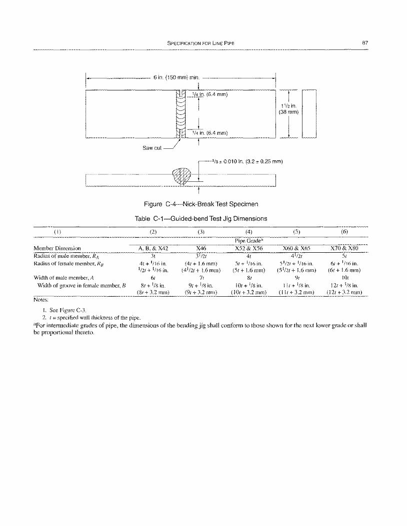
SPECIFICATION FOR liNE PIPE
_-------- 6 in. (150 mm) min. ----------1
(6.4 mm)
-( 11/2 in.
(38 mm)
~ r/8 ± 0.010 in. (3.2 ± 0.25 mm)
~ Figure C-4-Nick-Break Test Specimen
Table C-1-Guided-bend Test Jig Dimensions
(I) (2) (3) (4) (S)
Pipe Grade" Member Dimension A, 8, & X42 X46 XS2& XS6 X60 & X6S
Radius of male member, R;\ 3t 3 1/21 41 4 1/21
Radius of female member, RB 4t+ 1/16in. (4t+I.6mm) St+1/16in. SI/21 + 1116 in. 1/2t + 1/16 in. (4 1/21+ 1.6mm) (St+ 1.6 mm) (SI/2t+ 1.6mm)
Width of male member, A 61 7t 81 9t
Width of groove in female member, B 8t + 1/8 in. 9t + I/S in. 10t+I/Sin. lit + liS in. (8t + 3.2 mm) (9/ + 3.2 mm) (lOt + 3.2 mm) (lIt + 3.2 mm)
Notes:
I. See Figure C-3. 2. t = specified wall thickness of the pipe.
87
(6)
X70&X80
SI 6t+ 1/16in.
(6t + 1.6 mm) lOt
12t + Ilx in. (12t + 3.2 mm)
aFor intennediate grades of pipe, the dimensions of the bending jig shall conform to those shown for the next lower grade or shall be proportional thereto.

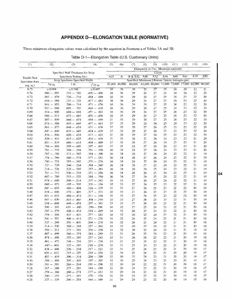
APPENDIX D-ELONGATION TABLE (NORMATIVE)
These minimum elongation values were calculated by the equation in Footnote a of Tables 3A and 38.
Table D-1-Elongation Table (U.S. Customary Units)
(I) (2) (3) (4) (5) (6) (7) (8) (9) (10) (II) (12) (13) (14)
Elongation in 2 in .• Minimul1l (percent) Specified Wall Thickness for Strip Gracie
Tensile Test Specimen Testing (in.) A25 A B & X42 X46 X52 X56 X60 X65 X70 X80
S peci men Area _~,.,,--:_S_t_ri P,---S p:...e_c_i m_e,n~S:'..p_ec_i fi_" e_c1_W_i_clt_h;-:-__ --."""iV"C"---.-o-;vo;"..--S.:"pe"'c"ifi"'e"c1_M"7i"nir;:I1lNll"m"7U7 1r;:tiNI1l""."te,Tr;:en",s,,i I."e FS",treNn~g."th"",(7;ps",i ),,",,""'"iV"C"-,-;;';"~ (sq. in.) 3/4 in. I in. 11/2 in. 45,000 48,000 60,000 63,000 66,000 71,000 75,000 77.000 82,000 90,000
0.75 '" 0.994 '" 0.746 '" 0.497 38 36 30 28 27 25 24 24 22 21 0.74 .980 - .993 .735 - .745 .490 - .496 38 36 29 28 27 25 24 24 22 20 0.73 .967 - .979 .726 - .734 .484 - .489 38 36 29 28 27 25 24 23 22 20 0.72 .954 - .966 .715 - .725 .477 - .483 38 36 29 28 27 25 24 23 22 20 0.71 .941 - .953 .706 - .714 .471 - .476 38 36 29 28 27 25 24 23 22 20 0.70 .927 - .940 .695 .705 .464 - .470 0.69 .914 - .926 .686 - .694 .457 - .463 0.68 .900 - .913 .675 - .685 .450 - .456 0.67 .887 - .899 .666 - .674 .444 - .449 0.66 .874 - .886 .655 - .665 .437 - .443 0.65 .861 - .873 .646 - .654 .431 - .436 0.64 .847 - .860 .635 - .645 .424 - .430 0.63 .834 - .846 .626 - .634 .417 - .423 0.62 .820 - .833 .615 - .625 .410 - .416 0.61 .807 - .819 .606 - .614 .404 - .409 0.60 .794 - .806 .595 - .605 .397 - .403 0.59 .781 - .793 .586 - .594 .391 - .396 0.58 .767 - .780 .575 - .585 .384 - .390 0.57 .754 - .766 .566 - .574 .377 - .383 0.56 .740 - .753 .555 - .565 .370 - .376 0.55 .727 - .739 .546 - .554 .364 - .369 0.54 .714 - .726 .535 - .545 .357 - .363 0.53 .70 I - .713 .526 - .534 .351 - .356 0.52 .687 - .700 .515 - .525 .344 - .350 0.51 .674 - .686 .506 - .514 .337 - .343 0.50 .660 - .673 .495 - .505 .330 - .336 0.49 .647 - .659 .486 - .494 .324 - .329 0.48 .634 - .646 .475 - .485 .317 - .323 0.47 .621 - .633 .466 - .474 .311 - .316 0.46 .607 - .620 .455 - .465 .304 - .310 0.45 .594 - .606 .446 - .454 .297 - .303 0.44 .580 - .593 .435 - .445 .290- .296 0.43 .567 - .579 .426 - .434 .284 - .289 0.42 .554 - .566 .415 - .425 .277 - .283 0.41 .541 - .553 .406 - .414 .271 - .276 0.40 .527 .540 .395 - .405 .264 - .270 0.39 .514 - .526 .386 - .394 .257 - .263 0.38 .500 - .513 .375 - .385 .250 - .256 0.37 .487 - .499 .366 - .374 .244 - .249 0.36 .474 - .486 .355 - .365 .237 - .243 0.35 .461 - .473 .346 - .354 .231 - .236 0.34 .447 - .460 .335 - .345 .224 - .230 0.33 .434 - .446 .326 - .334 .217 - .223 0.32 420 - .433 .315 - .325 .210 - .216 0.31 .407 - .419 .306 - .314 .204 - .209 0.30 .394 - .406 .295 - .305 .197 - .203 0.29 .381 - .393 .286 - .294 .191 - .196 0.28 .367 - .380 .275 - .285 .184 - .190 0.27 .354-.366 .266-.274 .177-.183 0.26 .340 - .353 .255 - .265 .170 - .176 0.25 .327 - .339 .246 - .254 .164 - .169
38 38 38 37 37 37 37 37 37 37 37 36 36 36 36 36 36 36 36 35 35 35 35 35 35 35 34 34 34 34 34 34 33 33 33 33 33 32 32 32 32 32 31 31 31 31
89
36 36 35 35 35 35 35 35 35 35 35 34 34 34 34 34 34 34 34 33 33 33 33 33 33 33 32 32 32 32 32 32 32 31 31 31 31 31 30 30 30 30 30 29 29 29
29 29 29 29 29 29 29 29 28 28 28 28 28 28 28 28 28 28 27 27 27 27 27 27 27 27 27 26 26 26 26 26 26 26 26 25 25 25 25 25 25 24 24 24 24 24
28 28 28 28 28 27 27 27 27 27 27 27 27 27 27 27 26 26 26 26 26 26 26 26 26 26 25 25 25 25 25 25 25 25 24 24 24 24 24 24 24 23 23 23 23 23
27 27 27 27 26 26 26 26 26 26 26 26 26 26 26 25 25 25 25 25 25 25 25 25 25 24 24 24 24 24 24 24 24 24 23 23 23 23 23 23 23 22 22 22 22 22
25 25 25 25 25 25 25 25 24 24 24 24 24 24 24 24 24 24 24 24 23 23 23 23
23 23 23 23 23 23 22 22 22 22 22 22 22 22 21 21 21 21 21 21 21 20
24 24 24 24 24 23 23 23 23 23 23 23 23 23 23 23 23 23 22 22 22 22 22 22 22 22 22 22 22 21 21 21 21 21 21 21 21 21 20 20 20 20 20 20 20 19
23 23 23 23 23 23 23 23 23
23 23 23 22 22 22 22 22 22 22 22 22 22 22 22 21 21 21 21 21 21 21 21 21 20 20 20 20 20 20 20 20 20 19 19 19 19
22 22 22 22 22 22 22 22 21 21 21 21 21 21 21 21 21 21 21 21 21 20 20 20 20 20 20 20 20 20 20 20 19 19 19 19 19 19 19 19 19 18 18 18 18 18
20 20 20 20 20 20 20 20 20 20 20 20 19 19 19 19 19 19 19 19 19 19 19 19 19 19 18 18 18 18 18 18 18 18 18 18 18 17 17 17 17 17 17 17 17 16
04
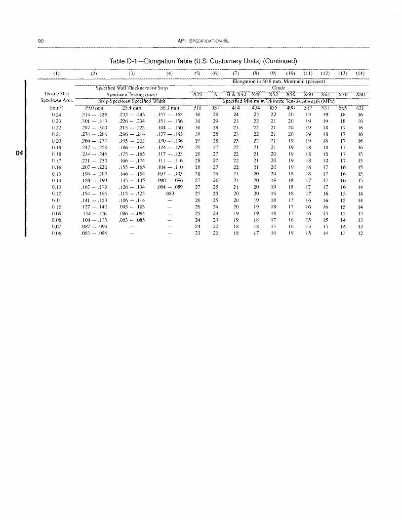
90 API SPECIFICATION 5L
Table D-1-Elongation Table (U.S. Customary Units) (Continued)
(I) (2) (3) (4) (5) (6) (7) (8) (9) (10) (11) (12) (13) (14)
Elongation in 50.8 mm, Minimum (percent) Specified Wall Thickness for Strip Grade
Tensile Test Specimen Testing (mm) A25 A B&X42 X46 X52 X56 X60 X65 X70 X80 Specimen Area Strip Specimen Specified Width Specified Minimum Ultimate Tensile Strength (MPa)
(mm2) 19.0111111 25.4mm 38.1 mm 310 331 414 434 455 490 517 531 565 621 0.24 .314 - .326 .235 - .245 .157 - .163 30 29 24 23 22 20 19 19 18 16 0.23 .301 - .313 .226 - .234 .151 - .156 30 29 23 22 21 20 19 19 18 16 0.22 .287 - .300 .215 - .225 .144 - .150 30 28 23 22 21 20 19 18 17 16 0.21 .274 - .286 .206 - .214 .137 - .143 30 28 23 22 21 20 19 18 17 16
0.20 .260 - .273 .195 - .205 .130 - .136 29 28 23 22 21 19 19 18 17 16 0.19 .247 - .259 .186 - .194 .124 - .129 29 27 22 21 21 19 18 18 17 16
04 O.IB .234 - .246 .175 - .IB5 .117 - .123 29 27 22 21 20 19 18 18 17 15
0.17 .221 - .233 .166 - .174 .111 - .116 28 27 22 21 20 19 18 18 17 15 0.16 .207 - .220 .155 - .165 .104 - .110 28 27 22 21 20 19 18 17 16 15 0.15 .194 - .206 .146 - .154 .097 - .103 28 26 21 20 20 18 18 17 16 15 0.14 .180 - .193 .135 - .145 .090 - .096 27 26 21 20 19 18 17 17 16 15 0.13 .167 - .179 .126 - .134 .084 - .089 27 25 21 20 19 18 17 17 16 14 0.12 .154 - .166 .115 - .125 .083 27 25 20 20 19 18 17 16 15 14 0.11 .141 - .153 .106 - .114 26 25 20 19 18 17 16 16 15 14 0.10 .127 - .140 .095 - .105 26 24 20 19 18 17 16 16 15 14 0.09 .114 - 126 .086 - .094 25 24 19 19 18 17 16 15 15 13 0.08 .100 - .113 .083 - .085 24 23 19 18 17 16 15 15 14 13 0.D7 .087 - .099 24 22 18 18 17 16 15 15 14 13 0.06 .083 - .086 23 22 18 17 16 15 15 14 13 12
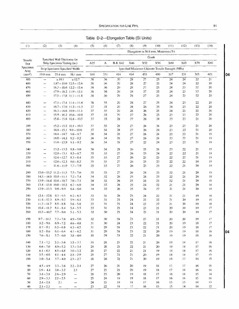
(1)
Tensile Test
Specimen Area
(mm2)
485
480 470
460 450
440 430 420
410
400
390 380
370
360
350
340
330 320 310
300
290 280
270
260 250
240
230
220
210 200
190 180
170
160
150
140
130 120 1\0
100
90 80
70
60 50
40
(2) (3) (4)
Specified Wall Thickness for Strip Specimen Testing (in.)
Strip Specimen Specified Width
19.0 mm 25.4 mm 38.1 mm
" 19.1 ,,12.7 1.87-19.0 12.5-12.6 IS.3 -18.6 12.2-12.4
17.9-18.2 11.9-12.1 17.5 - 17.8 11.7 - 11.8
17.1-17.4 11.4-11.6 16.7 - 17.0 11.2- 11.3
16.3 - 16.6 10.9- 11.1 15.9-16.2 10.6-10.8
15.6 - 15.8 10.4 - 10.5
15.2-15.5 10.1-10.3 14.8-15.1 9.8-10.0
14.4-14.7 9.6-9.7
14.0 - 14.3 9.3 - 9.5
13.6 - 13.9 9. I - 9.2
13.2-13.5 8.8-9.0
12.8 - 13.1 8.5 - 8.7 12.4 - 12.7 8.3 - 8.4
12.0 -12.3 8.0 - 8.2 11.6 - 11.9 7.7 - 7.9
15.0-15.211.2-11.5 7.5-7.6 14.5-14.9 10.8-11.1 7.2-7.4
\3.9-14.4 10.4-10.7 7.0-7.1 13.4-13.S 10.0-10.3 6.7 -6.9 12.9 - 13.3 9.6 - 9.9 6.4 - 6.6
12.4 - 12.8 9.3 - 9.5 6.2 - 6.3
11.8 - 12.3 8.9 - 9.2 5.9 - 6.1
11.3 - 1\.7 8.5 - S.8 5.6 - 5.S 10.8 - 11.2 8.1 - 8.4 5.4 - 5.5
10.3 - 10.7 7.7 - 8.0 5.1 - 5.3
9.7 - 10.2
9.2 -9.6
R.7 -9.1
8.2 - 8.6
7.6-8.1
7.3 -7.6
6.9-7.2
6.5 -6.8
6.1 -6.4
5.7 -6.0
7.1-7.55.3-5.6
6.6 -7.0 4.9 - 5.2 6.1 - 6.5 4.5 -4.8
5.5 -6.0 4.1 -4.4
5.0 - 5.4 3.7 - 4.0
4.5 - 4.9 3.3 - 3.6
3.9 - 4.4 3.0 - 3.2
3.4-3.8 2.6-2.9
2.9 - 3.3 2.2 - 2.5
2.4 - 2.8 2.1
2.1 -2.3
4.9-5.0
4.6-4.8
4.3 -4.5
4.1 -4.2
3.8 -4.0
3.5 - 3.7
3.3 - 3.4 3.0-3.2
2.8 - 2.9
2.5 -2.7
2.2 - 2.4
2.1
SPECIFICATION FOR LINE PIPE
Table D-2-Elongation Table (SI Units)
(5) (6) (7) (8) (9) (10) (11) (12)
Elongation in 50.8 mm, Minimum (%)
Grade
A25 A B & X42 X46 X52 X56 X60 X65
Specified Minimum Ultimate Tensile Strength (MPa)
310
38 38
38
38 38
38 37 37
37
37
37
37
36
36
36
36
35 35
35 35
35 34 34
34 34
33 33
33 32
32
32 31
31 31 30
30
29
29 28
28
27
27
26 25
24
23
331
36
36
36 36
36
35 35 35
35
35
35 34 34 34 34
34 33 33 33 33
33 32 32 32 32
31 31
31
31
30
30
30
29
29
29
28
28
27 27
26
26 25
25
24
23 22
414
30
29 29
29
29
29 29 29
29
28
28
28
28
28
28
28
27 27
27
27
27
26
26 26
26
26 25
25
25
25
24
24 24
24
23
23 23 22 22 22
21 21 20 19
19
18
434
28
28
28
28 28
28
28 28
27
27
27
27
27
27
27
26
26 26
26
26
26 25
25
25
25
25
24
24
24 24
23 23 23 23 22
22 22
21 21 21
20 20 19 19
18
17
455
27
27 27
27
27
27 26 26
26
26
26
26
26
26
25
25
25
25
25
25
24
24
24
24 24
24
23 23 23 23
23 22 22
22 21
21 21 21 20 20
19
19
18
18
17
16
490
25
25 25
25
25
25 25 25
25
24
24
24
24 24
24
24
24
23 23
23
23 23 23 22 22
22 22 22 21 21
21 21 21
20 20
20 20 19 19
19
18
18
17
17
16 15
517
24
24
24
24
24
24
24 24
23
23
23
23
23
23
23
23
22 22 22 22
22
22 22 21 21
21
21
21
20 20
20 20 20 19
19
19
19
18 18
18
17
17
16
16
15
15
531
24
24
23
23
23
23
23 23
23
23
23
22 22
22
22
22 22 22 22 21
21
21 21
21 21
21
20 20 20 20
20
19
19
19
19
18
18
18 18
17
17
16 16 16 15
14
(13)
X70
565
22 22 22 22
22
22 22 22 22
21
21 21
21
21
21
21 21
21
20
20
20 20 20 20 20
19
19
19
19
19
19
18
18 18
18
17
17 17 17
16
16 16 15
15
14 14
(14)
X80
621
21
20 20 20
20
20
20 20 20
20
20 20 19
19
19
19
19 19
19
19
19
18
18
18
18
18 18
18
17 17
17
17
17
16
16
16
16
16 15
15
15
14 14 14 13 12
91
04
04

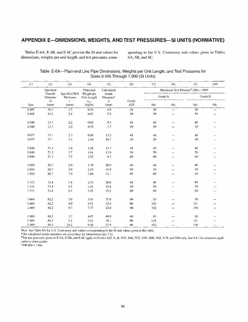
APPENDIX E-DIMENSIONS, WEIGHTS, AND TEST PRESSURES--SI UNITS (NORMATIVE)
Tables E-6A, E-68, and E-6C provide the Sf unit values for sponding to the U.S. Customary unit values given in Tables dimensions, weights per unit length, and test pressures, corre- 6A, 6B, and 6C.
Table E-6A-Plain-end Line Pipe Dimensions, Weights per Unit Length, and Test Pressures for Sizes 0.405 Through 1.900 (SI Units)
(l) (2) (3) (4) (5) (6) (7) (8) (9) (10)
Specified Plain-end Calculated Minimum Test Pressure b (kPa x loo)e Outside Specified Wall Weight per Inside Diameter Thickness Unit Length Diameter' Grade A Grade B
D t Hlpe d Grade Size (mm) (mm) (kg/m) (mm) A25 Std. All. Std. All.
0.405 10.3 1.7 0.36 6.9 48 48 48 0.405 10.3 2.4 0.47 5.5 59 59 59
0.540 13.7 2.2 0.62 9.3 48 48 48
n.540 13.7 3.n 0.79 7.7 59 59 59
0.675 17.1 2.3 0.84 12.5 48 48 48
0.675 17.1 3.2 1.\0 10.7 59 59 59
0.840 21.3 2.8 1.28 15.7 48 48 48 0.840 21.3 3.7 1.61 13.9 59 59 59 0.840 21.3 7.5 2.55 6.3 69 69 69
1.050 26.7 2.9 1.70 20.9 48 48 48
1.050 26.7 3.9 2.19 18.9 59 59 59
1.050 26.7 7.8 3.64 11.1 69 69 69
1.315 33.4 3.4 2.52 26.6 48 48 48
1.315 33.4 4.5 3.21 24.4 59 59 59
1.315 33.4 9.1 5.45 15.2 69 69 69
1.660 42.2 3.6 3.43 35.0 69 83 90 1.660 42.2 4.9 4.51 32.4 90 124 131 1.660 42.2 9.7 7.77 22.8 96 152 158
1.900 48.3 3.7 4.07 40.9 69 83 90 1.900 48.3 5.1 5.43 38.1 90 124 131 1.900 48.3 10.2 9.58 27.9 96 152 158
Note: See Table 6A for U.S. Customary unit values corresponding to the SI unit values given in this table. aThe calculated inside diameters are given here for information (see 7.2). "The test pressures given in E-6A, E-6B, and E-6C apply to Grades A25, A, B, X42. X46, X52, X56, X60, X65, X70, and X80 only. See 9.4.3 for pressures appli-cable to other grades. cl00 kPa = 1 bar.
93
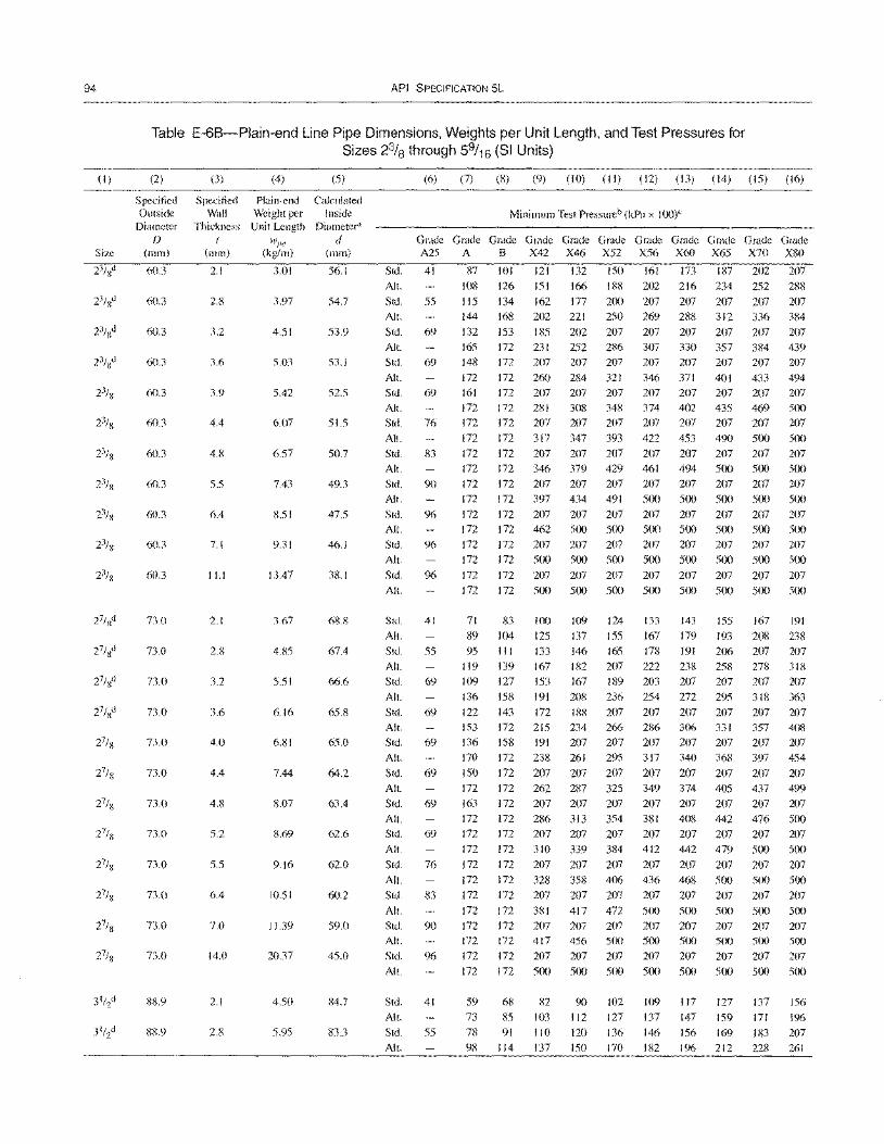
94
(I)
API SPECIFICATION 5L
Table E-6B-Plain-end Line Pipe Dimensions, Weights per Unit Length, and Test Pressures for Sizes 23/8 through 59/16 (SI Units)
(2) (3) (4) (5) (6) (7) (8) (9) (10) (II) (12) (13) (14) (15) (16)
Specified Specitied Plain-end Calculated Outside Wall Weight per Inside Minimum Test Pressureb (kPa x 100)C
Diameter Thickness Unit Length Diameter"
f) tv"e d Size (mm) (mm) (kg/m) (mm)
Grade Grade Grade Grade Grade Grade Grade Grade Grade Grade Grade A25 A B X42 X46 X52 X56 X60 X65 X70 X80
60.3 2.1
60.3 2.8
60.3 3.2
60.3 3.6
60.3 3.9
60.3 4.4
60.3 4.8
60.3 5.5
60.3 6.4
60.3 7.1
60.3 11.1
73.0 2.1
73.0 2.8
73.0 3.2
73.0 3.6
73.0 4.0
73.0 4.4
73.0 4.8
73.0 5.2
73.0 5.5
73.0 6.4
73.0 7.0
73.0 14.0
88.9 2.1
88.9 2.8
3.01
3.97
4.51
5.03
5.42
6.07
6.57
7.43
8.51
9.31
13.47
3.67
4.85
5.51
6.16
6.81
7.44
8.07
8.69
9.16
10.51
11.39
20.37
4.50
5.95
56.1
54.7
53.9
53.1
52.5
51.5
50.7
49.3
47.5
46.1
38.1
68.8
67.4
66.6
65.8
65.0
64.2
63.4
62.6
62.0
60.2
59.0
45.0
84.7
83.3
Std.
AI!.
Std.
Alt.
Std.
AI!.
Std.
AI!.
Std.
AI!.
Std.
AI!.
Std.
AI!.
Std.
All.
Std.
All.
Std.
AI!.
Std.
Alt.
Std.
Alt. Std.
AI!.
Std.
AI!.
Std.
AI!.
Std.
AI!.
Std.
All.
Std.
AI!.
Std.
Alt
Std.
All.
Std.
AI!.
Std.
Alt.
Std.
All.
Std.
AI!.
Std.
AI!.
41
55
69
69
69
76
83
90
96
96
96
41
55
69
69
69
69
69
69
76
83
90
96
41
55
87
108
liS 144
132
165 148
172
161 172
172
172
172
172 172
172
172
172
172
172
172
172
71
89
95 119
109
136
122
153
136
170
150
172
163
172
172
172
172
172
172
172
172
172
172
172
59
73
78
98
101 121 132 150
126 151 166 188
134 162 177 200 168 202 221 250
153 185 202 207
172 231 252 286 172 207 207 207
172 260 284 321
172 207 207 207 172 281 308 348
172 207 207 207
172 317 347 393
172 207 207 207
172 346 379 429 172 207 207 207
172 397 434 491
172 207 207 207
172 462 500 500
172 207 207 207
172 500 500 500
172 207 207 207
172 500 500 500
83 100 109 124
104 125 137 155
III 133 146 165
139 167 182 207
127 153 167 189
158 191 208 236
143 172 188 207
172 215 234 266
158 191 207 207
172 238 261 295
172 207 207 207
172 262 287 325
172 207 207 207
172 286 313 354
172 207 207 207
172 310 339 384
172 207 207 207
172 328 358 406 172 207 207 207
172 381 417 472
172 207 207 207
172 417 456 500
172 207 207 207
172 500 500 500
68 82 90 102
85 103 112 127
91 110 120 136
114 137 150 170
161 173 187 202
202 216 234 252
207 207 207 207
269 288 312 336
207 207 207 207 307 330 357 384 207 207 207 207
346 371 401 433
207 207 207 207 374 402 435 469
207 207 207 207
422 453 490 500
207 207 207 207
461 494 500 500 207 207 207 207
500 500 500 500
207 207 207 207
500 500 500 500 207 207 207 207
500 500 500 500
207 207 207 207
500 500 500 500
133 143 155 167
167 179 193 208 178 191 206 207
222 238 258 278
203 207 207 207
254 272 295 318
207 207 207 207
286 306 331 357
207 207 207 207
317 340 368 397
207 207 207 207 349 374 405 437
207 207 207 207
381 408 442 476
207 207 207 207
412 442 479 500
207 207 207 207
436 468 500 500
207 207 207 207
500 500 500 500 207 207 207 207
500 500 500 500
207 207 207 207
500 500 500 500
109 117 127 137
137 147 159 171
146 156 169 183
182 196 212 228
207
288
207
384
207
439 207
494 207
500
207
500
207
500 207
500
207
500 207
500
207
500
191
238
207 318
207
363
207 408
207
454
207 499
207
500
207
500
207
500
207
500
207
500
207
500
156
196
207
261
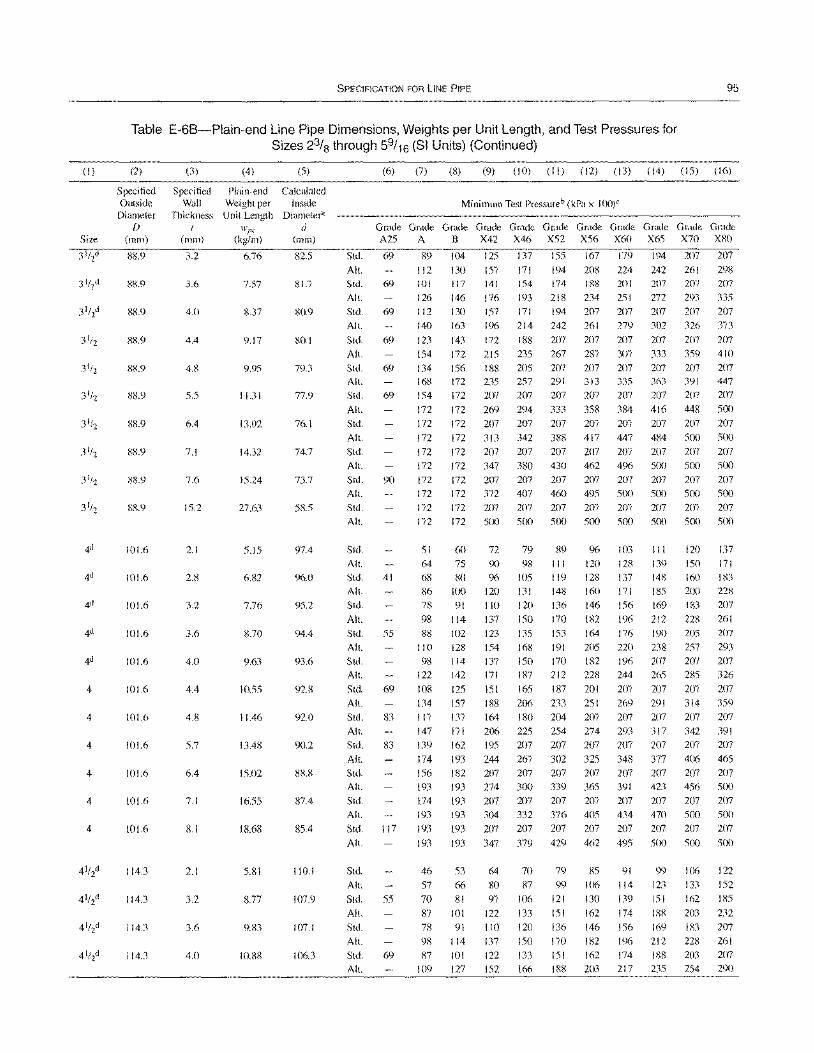
(1)
Size
4
4
4
4
4
4
SPECIFICATION FOR LINE PIPE 95
Table E-6B-Plain-end Line Pipe Dimensions, Weights per Unit Length, and Test Pressures for Sizes 23/8 through 59/16 (SI Units) (Continued)
(2)
Specified Outside
Diameter D
(mm)
88.9
88.9
88.9
88.9
88.9
88.9
8S.9
88.9
88.9
88.9
101.6
101.6
101.6
101.6
101.6
101.6
101.6
101.6
101.6
101.6
101.6
114.3
114.3
114.3
114.3
(3) (4)
Specified Plain-end Wall Weight per
Thickness Unit Length t
(mm)
3.2
Wpc
(kg/m)
6.76
3.6 7.57
4.0 8.37
4.4 9.17
4.8 9.95
5.5 11.31
6.4 13.02
7.1 14.32
7.6 15.24
15.2 27.63
2.1 5.15
2.8 6.82
3.2 7.76
3.6 8.70
4.0 9.63
4.4 10.55
4.8 11.46
5.7 13.48
6.4 15.02
7.1 16.55
8.1 18.68
2.1 5.81
3.2 8.77
3.6 9.83
4.0 10.88
(5)
Calculated Inside
Diameter" d
(mm)
82.5
81.7
80.9
80.1
79.3
77.9
76.1
74.7
73.7
58.5
97.4
96.0
95.2
94.4
93.6
92.8
92.0
90.2
88.8
87.4
85.4
110.1
107.9
107.1
106.3
Std.
All.
Std.
All.
Std.
Alt.
Std.
All.
Std.
All.
Std.
All.
Std.
All.
Std.
All.
Std.
All.
Std.
All.
Std.
All.
Std.
All.
Std.
All.
Std.
All.
Std.
Alt.
Std.
All.
Std.
All.
Std.
All.
Std.
All.
Std.
All.
(6) (7) (8) (9) (10) (II) (12) (13) (14) (15) (16)
Minimum Test Pressureb (kPa x 100)"
~~G~G~G~G~G~G~G~G~G~G~ A25 A B X42 X46 X52 X56 X60 X65 X70 XSO
69
69
69
69
69
69
90
41
55
69
83
83
89 104 125 137 155 167 179 194 207 207
112 130 157 171 194 208 224 242 261 298
101 117 141 154 174 188 201 207 207 207
126 146 176 193 218 234 251 272 293 335
112 130 157 171 194 207 207 207 207 207
140
123
154 134 168 154
172
172
172
172
172
172
172
172
172
51
64
68 86 78
98
88 110
98 122
108 134
117
147
139
174
156
163 196 214 242 261 279 302
143 172 188 207 207 207 207
172 215 235 267 287 307 333
156 188 205 207 207 207 207 172 235 257 291 313 335 363
172 207 207 207 207 207 207
172 269 294 333 358 384 416
172 207 207 207 207 207 207
172 313 342 388 417 447 484
172 207 207 207 207 207 207
172 347 380 430 462 496 5(X)
172 207 207 207 207 207 207
172 372 407 460 495 500 500
172
172
60 75
80 100 91
114
102
128 114
142
125
157
207 207 207 500 500 seX)
72
90
96
120
110
137
123
154 \37
171
151
79 89 98 III
lOS 119 131 148
120 136
150 170 135 153
168 191
150 170 187 212
165 187
207 207 sex) 500
96 103 120 128
128 137 160 171
146 156
182 196
164 176
205 220 182 196
228 244
201 207
207
500
III 139
148 185
169
212
190
238 207
265
207
188 206 233 251 269 291
137 164 180 204 207 207 207
171 206 225 254 274 293 317 162 195 207 207 207 207 207
193 244 267 302 325 348 377
182 207 207 207 207 207 207
326 373
207 207
359 410
207 207 391 447
207 207
448 500
207 207 500 5(X)
207 207
500 500 207 207 5(X) sex) 207
500
120
ISO
160 200 183
228
205
257 207
285
207
207 500
137 171
183 228
207
261
207 293 207
326
207 314 359
207 207
342 391 207 207
406 465
207 207
193 193 274 300 339 365 391 423 456 SIX)
174 193 207 207 207 207 207 207 207 207 193 304 332 376 405 434 470 500 5(X)
Std. 117
193
193
193
193 207 207 207 207 207 207 207 207
All.
Std.
All.
Std.
All.
Std.
All.
Std.
All.
55
69
193 347 379 429 462 495 500 500 5CX)
46 53 64 70 79 85 91 99 106 122
57 66 80 87 99 \06 114 123 133 152
70 81 97 106 121 I 30 139 151 162 185
87 101 122 133 151 162 174 188 203 232
78 91 110120 136 146 156 169 183 207
98 114 137 150 170 182 196 212 228 261
87 101 122 133 151 162 174 188 203 207
109 127 152 166 188 203 217 235 254 290
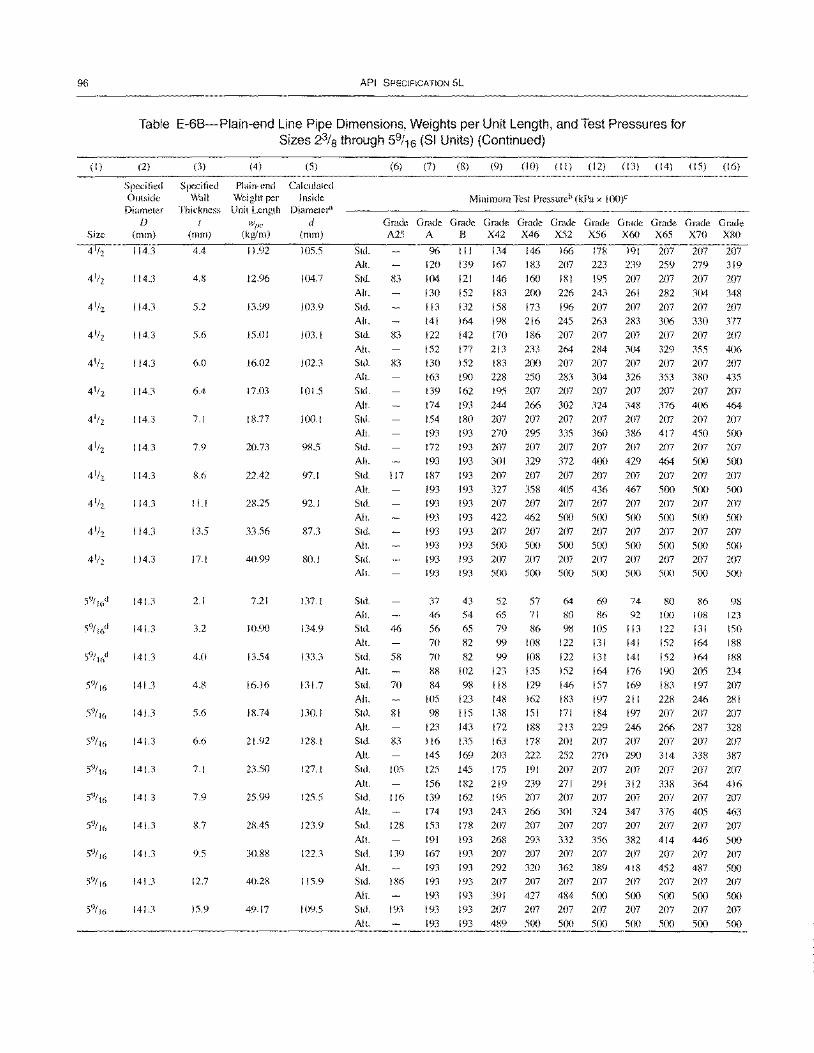
96
(I)
Size
API SPECIFICATION 5L
Table E-6B-Plain-end Line Pipe Dimensions, Weights per Unit Length, and Test Pressures for Sizes 2% through 59/ 16 (SI Units) (Continued)
(2)
Specified Outside
Diameter f)
(mm)
114.3
114.3
114.3
114.3
114.3
114.3
114.3
114.3
114.3
114.3
114.3
114.3
141.3
141.3
141.3
141.3
141.3
141.3
141.3
141.3
141.3
141.3
141.3
141.3
(3)
Specified Wall
Thickness I
(mm)
4.4
4.8
5.2
5.6
6.0
6.4
7.1
7.9
8.6
11.1
13.5
17.1
2.1
3.2
4.0
4.8
5.6
6.6
7.1
7.9
8.7
9.5
12.7
15.9
(4) (5)
Plain-end Calculated Weight per Inside
Unit Length Diameter"
wl'l' d (kg/m) (mm)
11.92 105.5
12.96 104.7
13.99 103.9
15.01 103.1
16.02 102.3
17.03 101.5
18.77 100.1
20.73 98.5
22.42 97.1
28.25 92.1
33.56 87.3
40.99 80.1
7.21 137.1
10.90 134.9
13.54 133.3
16.16 131.7
18.74 130.1
21.92 128.1
23.50 127.1
25.99 125.5
28.45 123.9
30.88 122.3
40.28 115.9
49.17 109.5
Std.
All.
Std.
All.
Std.
All.
Std.
All.
Std.
All.
Std.
All.
Std.
All.
Std.
All.
(6) (7) (8) (9) (10) (II) (12) (13) (14) (15) (16)
Minimum Test PresslLreb (kPa x 100)C
Grade Grade Grade Grade Grade Grade Grade Grade Grade Grade Grade A25 A B X42 X46 X52 X56 X60 X65 X70 X80
83
83
83
96 III 134 146 166 178 191 207 207 207 120
104 130
113 141 122
152 130
139 167 183 207 223
121 146 160 181 195 152 183 200 226 243
132 158 173 196 207 164 198 216 245 263 142 170 186 207 207
177 213 233 264 284 152 183 200 207 207
239 259 279 319
207 207 207 207 261 282 304 348 207 207 207 207 283 306 330 377 207 207 207 207
304 329 355 406 207 207 207 207
163 190 228 250 283 304 326 353 380 435 139
174 154 193 172 193
162 195 207
193 244 266 180 207 207 193 270 295 193 207 207
193 301 329
207 207
302 324 207 207 335 360 207 207
372 400
207 207 207 348 376 406 207 207 207 386 417 450 207 207 207
429 464 500
207 464
207 500 207
500 Std. 117 187 193 207 207 207 207 207 207 207 207 All.
Std.
All.
Std.
All.
Std.
Alt.
Std.
All.
Std.
All.
Std.
All.
Std.
All.
Std.
All.
Std.
All.
Std.
All.
Std.
All.
Std.
All.
Std.
All.
Std.
All.
Std.
All.
46
58
70
81
83
105
116
128
139
186
193
193 193 193
193 193 193 193
37 46 56 70 70
88 84
105
98 123 116 145 125
156 139 174 153
191 167 193 193
193 193 193
193 327 358 405 436 467 500 500 193 207 207 207 207 207 207 207 193 422 462 500 500 500 500 500 193 207 207 207 207 207 207 207 193 500 500 500 500 500 500 500 193 207 207 207 207 207 207 207 193 500 500 500 500 500 500 500
43 52 57 64 54 65 71 80 65 79 86 98 82 99 108 122
82 99 108 122
102 123 135 152 98 118 129 146
123 148 162 1 83
115 138 151 171 143 172 188 213 135 163 178 201 169 203 222 252
145 175 191 207
182 219 239 271 162 195 207 207 193 243 266 301 178 207 207 207
193 268 293 332 193 207 207 207 193 292 320 362 193 207 207 207
193 391 427 484 193 207 207 207 193 489 500 500
69 74 80 86 92 100
105 113 122 131 141 152
131 141 152 164 176 190 157 169 183 197 211 228
184 197 207 229 246 266 207 207 207 270 290 314
207 207 207 291 312 338 207 207 207 324 347 376 207 207 207 356 382 414 207 207 207 389 418 452 207 207 207
500 500 500 207 207 207 500 500 500
86 108 131 164
164
205 197 246
207
287 207
338 207
364 207 405 207
446 207 487 207
500 207 500
500 207 500
207 500 207 500
98 123 150 188
188
234 207 281
207
328 207
387
207 416 207 463 207
500 207
500 207
500 207 500
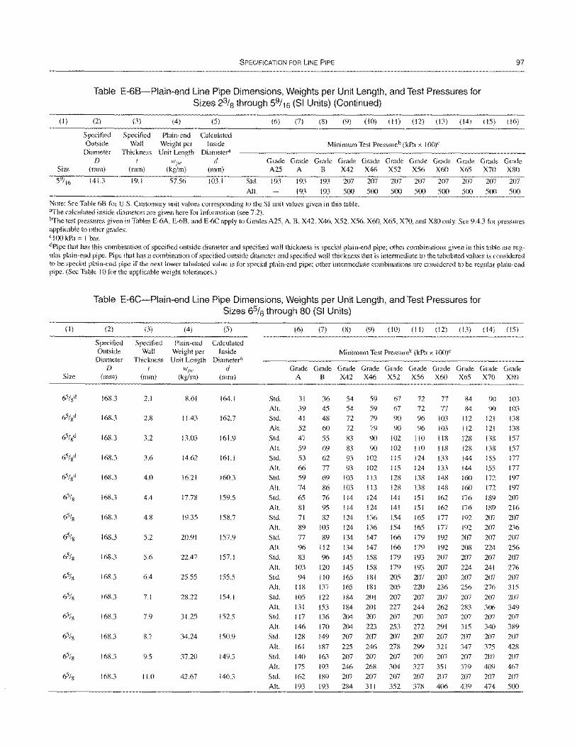
(1)
Size
SPECIFICATION FOR LINE PIPE 97
Table E-6B-Plain-end Line Pipe Dimensions, Weights per Unit Length, and Test Pressures for Sizes 23/8 through 59/1 6 (SI Units) (Continued)
(2)
Specified Outside
Diameter D
(mm)
141.3
(3)
Specified Wall
Thickness I
(mm)
19.1
(4) (5)
Plain-end Calculated Weight per Inside Unit Length Diameter'
wpe d (kg/m) (mm)
57.56 103.1 Std.
AI!.
(6) (7) (8) (9) (10) (II) (12) (13) (14) (15) (16)
Minimum Test Pressureb (kPa x 100)"
~~G~G~G~G~G~G~G~G~G~G~
A25 A B X42 X46 X52 X56 X60 X65 X70 X80
193 193
193
193
193
207 207 207 207 207 207 207 207
500 500 500 500 500 500 500 500
Note: See Table 6B for U.S. Customary unit values corresponding to the SI unit values given in this table. aThe calculated inside diameters are given here for information (see 7.2). hThe test pressures given in Tables E-6A, E-6B, and E-6C apply to Grades A25, A, B, X42, X46, X52, X56, X60, X65, X70, and X80 only. See 9.4.3 t()r pressures applicable to other grades. c 100 kPa = I bar. dPipe that has this combination of specified outside diameter and specified wall thickness is special plain-end pipe; other combinations given in this table are regular plain-end pipe. Pipe that has a combination of specified outside diameter and specified wall thickness that is intermediate to the tabulated values is considered to be special plain-end pipe if the next lower tabulated value is for special plain-end pipe; other intermediate combinations are considered to be regular plain-end pipe. (See Table 10 for the applicable weight tolerances.)
(I)
Size
Table E-6C-Plain-end Line Pipe Dimensions, Weights per Unit Length, and Test Pressures for Sizes 6% through 80 (SI Units)
(2)
Specified Outside
Diameter D
(mm)
168.3
168.3
168.3
168.3
168.3
16S.3
168.3
168.3
168.3
168.3
168.3
168.3
168.3
168.3
168.3
(3)
Specified Wall
Thickness I
(mm)
2.1
2.8
3.2
3.6
4.0
4.4
4.8
5.2
5.6
6.4
7.1
7.9
8.7
9.5
11.0
(4) (5)
Plain-end Calculated Weight per Inside Unit Length Diameter"
H'p(! d (kg/m) (mm)
8.61 164.1
11.43 162.7
13.03 161.9
14.62 161.1
16.21 160.3
17.78 159.5
19.35 158.7
20.91 157.9
22.47 157.1
25.55 155.5
28.22 154.1
31.25 152.5
34.24 150.9
37.20 149.3
42.67 146.3
Std. All.
Std.
All.
Std.
All.
Std. All.
Std.
AI!. Std.
All. Std.
All.
Std.
All.
Std.
All.
Std. All.
Std.
All.
Std.
All. Std.
All.
Std.
All.
Std.
All.
(6) (7) (8) (9) (10) (II) (12) (13) (14) (15)
Minimum Test Pressureb (kPa x 100)t
G~G~G~G~G~G~G~G~G~G~
A B X42 X46 X52 X56 X60 X65 X70 X80
31
39 41
52
47
59 53
66
59
74
65 81
71
89
77
96
83 103
94 118
105
131
117
146
128
161
140
175 162
193
36 54 45 54 48 71
60 71
55 83
69 83 62 93
77 93 69 103
86 103
76 114
95 114
82 124 103 124
89 134
112 134
96 145
120 145
110 165 137 165
122 184
153 184
136 204
170 204 149 207
187 225
163 207
193 246
189 207
193 284
59 67 59 67
79 90
79 90
90 102 90 102
102 115 102 115
113 128
113 128
124 141
124 141 136 154
136 154
147 166
147 166
158 179
158 179
181 205 181 205
201 207
201 227
207 207
223 253 207 207
246 278
207 207
268 304 207 207
311 352
71 77 71 77
96 103 96 103
110 118 110 118
124 133
124 133
13S 148
138 148 151 162
lSI 162
165 177 165 177
179 192
179 192
193 207
193 207 207 207 220 236
207 207
244 262 207 207
272 291 207 207
299 321 207 207
327 351
207 207
378 406
84 90 84 90
112 121
112 121
128 138
128 138
144 155 144 155
160 In 160 In 176 189 176 189
192 207 192 207
207 207
208 224
207 207
224 241
207 207 256 276
207 207
283 306 207 207
315 340
207 207
347 375 207 207
379 409 207 207
439 474
103 103
138 138
157
157 177
177
197 197
207
216
207 236
207
256
207
276
207 315
207
349 207
389
207
428
207 467
207
500
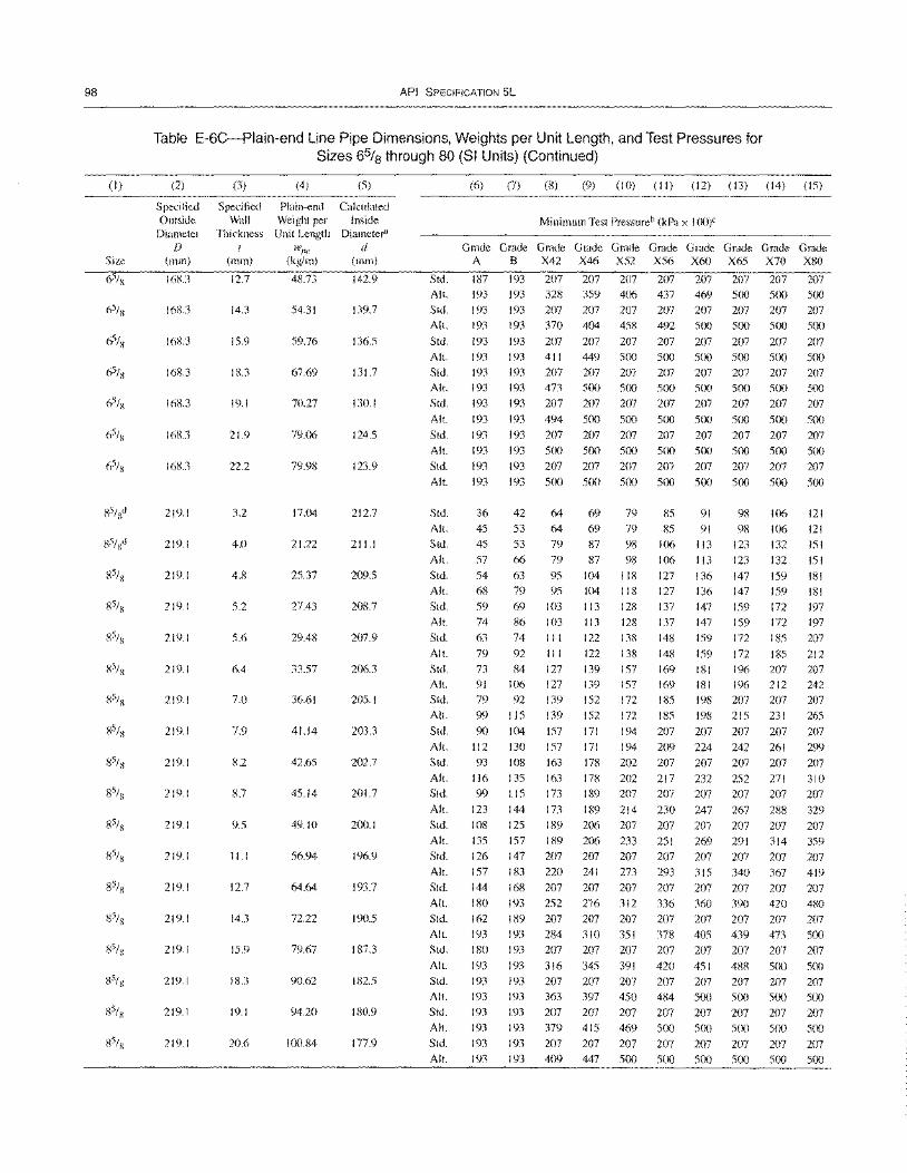
98
(I)
Size
API SPECIFICATION 5L
Table E-6C-Plain-end Line Pipe Dimensions, Weights per Unit Length, and Test Pressures for Sizes 6% through 80 (SI Units) (Continued)
(2)
Specified Outside
Diameter D
(mm)
168.3
168.3
168.3
16K3
16K3
168.3
16K3
219.1
219.1
219.1
219.1
219.1
219.1
219.1
219.1
219.1
219.1
219.1
219.1
219.1
219.1
219.1
219.1
219.1
219.1
(3) (4) (5)
Specified Plain-end Calculated Wall Weight per Inside
Thickness Unit Length Diameter'
I wl'C d (mm) (kg/m) (mm)
12.7 48.73 142.9
14.3 S4.31 139.7
15.9 59.76 136.5
18.3 67.69 131.7
19.1 70.27 130.1
21.9 79.06 124.5
22.2 79.98 123.9
3.2 17.04 212.7
4.0 21.22 211.1
4.8 25.37 209.5
S.2 27.43 208.7
S.6 29.48 207.9
6.4 33.57 206.3
7.0 36.61 20S.1
7.9 41.14 203.3
8.2 42.6S 202.7
8.7 45.14 201.7
9.S 49.10 200.1
11.1 56.94 196.9
12.7 64.64 193.7
14.3 72.22 190.5
IS.9 79.67 187.3
18.3 90.62 182.S
19.1 94.20 180.9
20.6 100.84 177.9
Std.
All.
Std.
All.
Std.
All.
Std.
Alt.
Std.
Alt.
Std.
Alt.
Std.
All.
Std.
All.
Std.
All.
Std.
All.
Std.
All.
Std.
All.
Std.
All.
Std.
All.
Std.
All.
Std.
All.
Std.
All.
Std.
All.
Std.
All.
Std.
All.
Std.
All.
Std.
All.
Std.
All.
Std.
All.
Std.
All.
(6) (7) (8) (9) (10) (II) (12) (13) (14) (IS)
Minimum Test Pressureb (kPa x I OO)C
~~G~G~G~~~G~G~G~~~G~ A B X42 X46 XS2 XS6 X60 X6S X70 X80
187 193 207 207 207 207 207 207 207 207
193 193 328 3S9 406 437 469 500 500 SOO
193 193 207 207 207 207 207 207 207 207
193
193
193
193
193
193
193
193
193
193
193
36
45
45
S7
54
68
59
74
63
79
73
91
79
99
90
112
93
116
99
123
108
13S
126
157
144
180
162
193
180
193
193
193
193
193
193
193
193 370 404 458 492 SOO SOO 500 500
193 207 207 207
193 411 449 SOO
193 207 207 207
193 473 500 500
193 207 207 207
193 494 500 500
193 207 207 207
193 500 500 500
193 207 207 207
193 500 500 500
42 64 69 79
53 64 69 79
S3 79 87 98
66 79 87 98
63 95 104 118
79 9S 104 118
69 103 113 128
86 1m 74
92
84
106
92
liS
104
130
108
135
liS
144
125
IS7
147
183
168
193
189
193
193
193
193
193
193
193
193
193
III
III
127
127
139
139
157
157
163
163
173
173
189
189
207
220
207
2S2
207
284
207
316
207
363
207
379
207
409
113 128
122 138
122 138
139 157
139 157
152 172
152 172
17I 194
17I 194
178 202
178 202
189 207
189 214
206 207
206 233
207 207
241 273
207 207
276 312
207 207
310 351
207 207
345 391
207 207
397 450
207 207
41S 469
207 207
447 SOO
207 207 207 207 207
SOO SOO SOO SOO 500
207 207 207 207 207
SOO 500 SOO SOO 500
207 207 207 207 207
SOO SOO SOO SOO SOO
207 207 207 207 207
SOO SOO SOO SOO SOO
207 207 207 207 207
SOO SOO SOO SOO SOO
8S 91 98 106 121
8S 91 98 106 121
106 113 123 132 151
106 113 123 132 151
127 136 147 IS9 181
127 136 147 IS9 181
137 147 IS9 172 197
137 147
148 IS9
148 IS9
169 181
169 181
18S 198
18S 198
207 207
209 224
207 207
217 232
207 207
230 247
207 207
2S1 269
207 207
293 31S
207 207
336 360
207 207
378 40S
207 207
420 4S1
207 207
484 SOO
207 207
SOO SOO
207 207
SOO 500
159 172
172
172
196
196
207
215
207
242
207
252
207
267
207
291
207
340
207
390
207
439
207
488
207
SOO
207
SOO
207
SOO
18S
18S
207
212
207
231
207
261
207
271
207
288
207
314
207
367
207
420
207
473
207
500
207 5IX)
207
500
207
500
197
207
212
207
242
207
26S
207
299
207
310
207
329
207
359
207
419
207
480
207
SOO
207
SOO
207
SOO
207
SOO
207
SOO
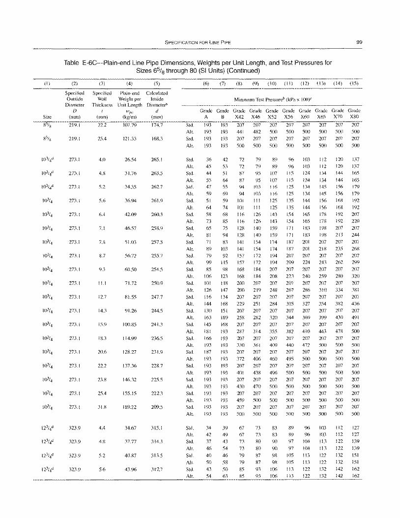
(I)
Size
SPECIFICATION FOR liNE PIPE 99
Table E-6C-Plain-end Line Pipe Dimensions, Weights per Unit Length, and Test Pressures for Sizes 65/8 through 80 (SI Units) (Continued)
(2)
Specified Outside
Diameter f)
(mm)
219.1
219.1
273.1
273.1
273.1
273.1
273.1
273.1
273.1
273.1
273.1
273.1
273.1
273.1
273.1
273.1
273.1
273.1
273.1
273.1
273.1
323.9
323.9
323.9
323.9
(3)
Specified Wall
Thickness t
(mm)
22.2
25.4
4.0
4.8
5.2
5.6
6.4
7.1
7.R
8.7
9.3
11.1
127
14.3
15.9
18.3
20.6
22.2
23.8
25.4
31.8
4.4
4.8
5.2
5.6
(4)
Plain-end Weight per Unit Length
tVpe (kg/m)
107.79
121.33
26.54
31.76
34.35
36.94
42.09
46.57
51.03
56.72
60.50
71.72
81.55
91.26
100.85
114.99
128.27
137.36
146.32
155.15
189.22
34.67
37.77
40.87
43.96
(5)
Calculated Inside
Diametera
d (mm)
174.7
168.3
265.1
263.5
262.7
261.9
260.3
258.9
257.5
255.7
254.5
250.9
247.7
244.5
241.3
236.5
231.9
228.7
225.5
222.3
209.5
315.1
314.3
313.5
312.7
Std.
Alt.
Std.
Alt.
Std.
Alt.
Std.
Alt.
Std.
Alt.
Std.
Alt.
Std.
Alt.
Std.
Alt.
Std. Alt.
Std. Alt.
Std.
Alt.
Std. Alt.
Std.
Alt.
Std. Alt.
Std.
Alt.
Std.
Alt.
Std.
Alt.
Std.
AIL
Std. Alt.
Std.
Alt.
Std.
Alt.
Std.
Alt.
Std.
Alt.
Std.
Alt.
Std.
Alt.
(6) (7) (8) (9) (10) (II) (12) (13) (14) (15)
Minimum Test Pressureb (kPa x 1(0)"
~~G~G~G~G~G~G~G~G~G~
A B X42 X46 X52 X56 X60 X65 X70 XRO
193 193 207 207 207 207 207 207 207 207
193 193 441 482 500 500 500 500 500 500 193 193 207 207 207 207 207 207 207 207
193 193 500 500 500 500 500 500 500 500
36 45
44
55 47
59 51
64 58
73
65
81
71
89 79
99
85
106 101
126
116 144
130
163
145
181
166 193
187
193
193
193
193
193
193 193
193
193
34
42
37
46
40
50
43 54
42 72
53 72
51 87
64 87 55 94
69 94 59 101
74 101 68 116
85 116
75 128
94 128
83 141
103 141 92 157
liS 157
98 168
123 168 118 200
147 200
134 207
168 229 lSI 207
189 258
168 207
193 287
193 207 193 330
193 207
193 372 193 207
193 401
193 207 193 430
193 207 193 459
193 207
193 500
39 67
49 67 43 73
54 73
46 79
58 79
50 85
63 85
79 89 96 103 79 89 96 103
95 107 liS 124
95 107 liS 124 103 116 125 134
103 116 125 134
III 125 135 144
III 125 135 144 126 143 154 165
126 143 154 165
140 159 171 183
140 159 171 183
154 174 187 201 154 174 187 201
172 194 207 207
172 194 209 224
184 207 207 207
184 208 223 240
207 207 207 207 219 248 267 286
207 207 207 207
251 284 305 327
207 207 207 207
282 320 344 369
207 207 207 207
314 355 382 410
207 207 207 207
361 409 440 472
207 207 207 207
406 460 495 5(x)
207 207 207 207
438 496 500 500
207 207 207 207 470 500 500 5(X)
207 207 207 207 500 500 5(x) 500
207 207 207 207
500 500 5(X) 500
73 83 89 96
73 83 89 96
80 90 97 104 80 90 97 104
87 98 \05 113
87 98 105 113 93 106 113 122
93 106 113 122
112
112
134
134 14S
145
156
156 178
17ll 198
198
207 218
207 243
207
259 207 310
207
354
207
399 207
443
207
500
207 5(X)
207 5(X)
207 500 207 5(x)
207
500
103
103
113 113 122
122 132
132
120 120
144
144 156
156
168
16X
192
192
207
213
207 235
207 262
207
280
207 334
207
382
207 430
207
47ll 207
500
207 5m 207
500 207 5m 207 5(x)
207 SeX)
112 112 122
122
132 132 142 142
137 137
165
165 179 179
192
192
207 220
207 244
207
268 207
299
207
320 207
381
207
436
207 491
207 5(x)
207 5(X)
207
500 207 5Cx)
207 500
207 5(X)
207 5(x)
127
127
139
139
lSI
151
162 162
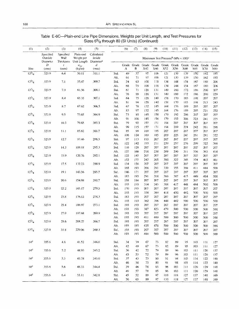
100
(I)
Size
API SPECIFICATION 5L
Table E-6C-Plain-end Line Pipe Dimensions, Weights per Unit Length, and Test Pressures for Sizes 6% through 80 (SI Units) (Continued)
(2)
Specified Outside Diameter
D (111m)
323.9
323.9
323.9
323.9
323.9
323.9
323.9
323.9
323.9
323.9
323.9
323.9
323.9
323.9
323.9
323.9
323.9
323.9
323.9
323.9
355.6
355.6
355.6
355.6
355.6
(3) (4) (5)
Specified Plain-end Calculated Wall Weight per Inside
Thickness Unit Length Diameter' 1 wl'C d
(mm) (kg/m) (mm)
6.4 50.11 311.1
7.1 55.47 309.7
7.9 61.56 30S.1
8.4 65.35 307.1
8.7 67.62 306.5
9.5 73.65 304.9
10.3 79.65 303.3
11.1 85.62 301.7
12.7 97.46 298.5
14.3 109.18 295.3
15.9 120.76 292.1
17.5 132.23 288.9
19.1 143.56 285.7
20.6 154.08 282.7
22.2 165.17 279.5
23.8 176.13 276.3
25.4 186.97 273.1
27.0 197.68 269.9
28.6 208.27 266.7
31.8 229.06 260.3
4.8 41.52 346.0
5.2 44.93 345.2
5.3 45.78 345.0
5.6 48.33 344.4
6.4 55.11 342.8
Std.
All.
Std.
All.
Std. All. Std.
All.
Std.
All.
Std.
All.
Std.
All. Std.
All.
Std.
All.
Std. All.
Std.
All.
Std.
Alt.
Std.
All.
Std.
All. Std.
All.
Std.
All.
Std.
All.
Std. All.
Std.
Alt.
Std.
All.
Std.
All.
Std. All.
Std.
All.
Std.
All.
Std.
All.
(6) (7) (S) (9) (10) (II) (12) (13) (14) (is)
Minimum Test Pressureb (kPa x 100)C
Grade Grade Grade Grade Grade Grade Grade Grade Grade Grade A B X42 X46 X52 X56 X60 X65 X70 XSO
49
61
54
68
61 76
64
81 67
83 73
91
79
99
85
106
97 122 110
137
122
152 134
168
146
183 158
193 170
193
183
193
193
193 193
193
193
193
193 193
34
42
36
45
37
46
39
49
45
56
57 97 106 106
118
118
131
131 140
140
145
145
158
158
171
171 185
185 207
211 207
121
121
134
134
149
149 158
158
130 139 ISO 162 185 71 97 130 139 150 162 185
63 108 144 154 167 180 206 79 108 144 154 167 180 206
71 120 160 172 186 200 207 88 120 160 172 186 200 229 75 128 170 183 198 207 207
94 128 170 183 198 213 243 78 132 164 176
97 132 164 176
85 145 179 192
106 145 179 192
92 157 194 207
115 157 194 209 99 169 207 207
124 169 209 225 113 193 207 207
142 193 239 257
128 207 207 207
189 205
189 205 206 207
206 223
207 207
224 242 207 207
241 261
207 207 276 299
207 207
207
221 207
241
207
261 207
281
207 322
207
207
252
207
275
207
298 207
322
207 368
207 160 218 238 269 290 311 336 363 414
142 207 207 207 207 207 207 207 207 177 242 265 300 322 345 374 403 461 156 207 207 207 207 207 207 207 207 193 266 291 330 355 380 411 444 500
171 207 207 207 207 207 207 207 207 193 291 318 360 387 415 449 484 500 184 207 207 207
193 314 343 388 193 207 207 207
193 338 369 418
193 207 207 207
193 362 396 448
193 207 207 207
193 387 423 479 193 207 207 207
193 411 449 500
193 207 207 207
193 435 476 500
193 207 207 207
193 484 500 500
39 67 73 82
49 67 73 82
42 72 79 89
53 72 79 89
43 73 80 91
54 73 80 91
46 78 85 96
57 78 85 96
52 89 97 110
65 89 97 110
207 207 207 207 417 448 484 500
207 207 207 207
450 482 500 500 207 207 207 207
482 500 500 500 207 207 207 207
500 500 500 500
207 207 207 207
500 500 500 500
207 207 207 207
500 500 500 500 207 207 207 207
500 500 500 500
89 95103 III
89 95 103 111
96 103 111 120
96 103 III 120
98 105 114 122
98 105 114 122
103 11 I 120 129
103 I I 1 120 129
118 127 137 148
118 127 137 148
207
500 207
500
207
500
207
500
207
500
207
500
207
500
127
127
137
137 140
140
148
148
169
169
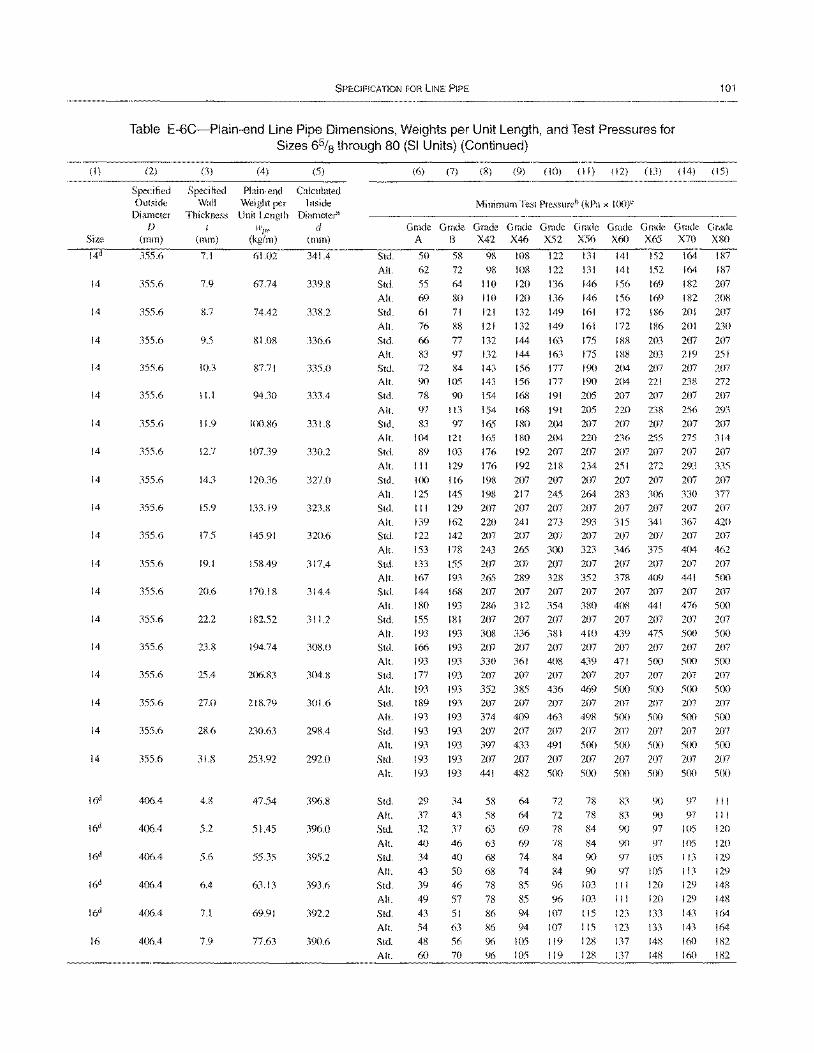
(I)
Size
14
14
14
14
14
14
14
14
14
14
14
14
14
14
14
14
14
14
16
SPECIFICATION FOR liNE PIPE 101
Table E-6C-Plain-end Line Pipe Dimensions, Weights per Unit Length, and Test Pressures for Sizes 65/8 through 80 (81 Units) (Continued)
(2)
Specified Outside
Diameter D
(mm)
355.6
355.6
355.6
355.6
355.6
355.6
355.6
355.6
355.6
355.6
355.6
355.6
355.6
355.6
355.6
355.6
355.6
355.6
355.6
406.4
406.4
406.4
406.4
406.4
406.4
(3)
Specified Wall
Thickness I
(mm)
7.1
7.9
S.7
9.5
10.3
11.1
11.9
12.7
14.3
15.9
17.5
19.1
20.6
22.2
23.S
25.4
27.0
28.6
31.8
4.8
5.2
5.6
6.4
7.1
7.9
(4)
Plain-end Weight per Unit Length
wpe (kg/m)
61.02
67.74
74.42
81.0S
87.71
94.30
100.S6
107.39
120.36
133.19
145.91
158.49
170.18
182.52
194.74
206.83
218.79
230.63
253.92
47.54
51.45
55.35
63.13
69.91
77.63
(5)
Calculated Inside
Diameter<" d
(mm)
341.4
339.8
338.2
336.6
335.0
333.4
331.8
330.2
327.0
323.8
320.6
317.4
314.4
311.2
308.0
304.8
301.6
298.4
292.0
396.8
396.0
395.2
393.6
392.2
390.6
Std.
Alt.
Std.
Alt.
Std.
Alt.
Std.
Alt.
Std. Alt.
Std.
AI!.
Std.
Alt.
Std.
AI!.
Std.
AI!. Std.
AI!.
Std.
AI!.
Std.
Alt.
Std.
AI!.
Std.
AI!. Std.
AI!. Std.
Alt.
Std.
AI!.
Std.
AI!.
Std.
AI!.
Std.
Alt.
Std.
AI!.
Std.
Alt.
Std.
All.
Std.
AI!.
Std.
AI!.
(6) (7) (8) (9) (10) (II) (12) (13) (14) (15)
Minimum Test Pressureb (kPa x loo)e
~~~~G~G~G~G~G~G~G~G~ A B X42 X46 X52 X56 X60 X65 X70 XRO
50 58 98 108 122 131 141 152 164 IR7
62 72 98 108 122 131 141 152 164 187
55 64 110 120 136 146 156 169 182 207 69 80 110 120 136 146 156 169 182 208
61 71 121 132 149 161 172 186 201 207
76 88 121 132 149 161 172 186 201 230
66 77 132 144 163 175 188 203 207 207 83 97 132 144 163 175 188 203 219 251
72 90
78
97
83
104
89 111
100
125 III
139 122
153
133
167 144
180
155 193
166 193
177
193
189
193
193
193
193
193
29
37
32
40 34
43
39
49 43
54
48
60
84 143 105 143
90 154
113 154
97 165
121 165
103 176
129 176
116 198
145 198
129 207 162 220
142 207
178 243
155 207
193 265 168 207
193 286
181 207 193 308
193 207 193 330
193 207
193 352
193 207
193 374
193 207
193 397
193 207
156 177 190 204 156 177 190 204
168 191 205 207
168 191 205 220
180 204 207 207
I 80 204 220 236
192 207 207 207
192 218 234 251
207 207 207 207
217 245 264 283 207 207 207 207
241 273 293 315
207 207 207 207
265 300 323 346
207 207 207 207 289 328 352 378
207 207 207 207
312 354 380 408
207 207 207 207
336 381 410 439
207 207 207 207 361 408 439 471
207 207 207 207
385 436 469 500
207 207 207 207
409 463 498 500
207 207 207 207 433 491 5(X) 5(X)
207 207 207 207
207 221
207
238
207
25S
207
272
207
306
207 341
207
375
207
409 207
441
207 475
207
500 207
500 207 SeX)
207 5(x)
207
207 238
207
256
207 275
207
293
207
330 207
367 207
404 207
441
207
476
207 5(X)
207 5(x)
207 5(X)
207 sex) 207 5(X)
207
207 272
207
293
207
314
207
335
207
377
207
420
207
462
207 5(X)
207 S(X)
207 S(X)
207 500
207 5(x)
207 5(x)
207 5(X)
207 193 441 482 500 500 5(x) 5eX) 500 5(X)
34
43
37
46
40 50
46
57
51
63
56 70
58 64 72
58 64 72
63 69 78
63 69 78
68 74 84
68 74 84
78 85 96
78 85 96 86 94 107
86 94 107
96105119
96105119
78 83
78 83
84 90
84 90
90 97
90 97
103 111
103 111
115 123
liS 123
128 137
128 137
90 90 97
97
105 105
120
120
133
133
148 148
97
97
105
105
113
113
129
129
143
143
160 160
III
III
120
120
129
129
148
148
164
164 182
182
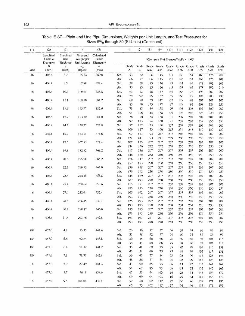
102
(I)
Size
16
16
16
16
16
16
16
16
16
16
16
16
16
16
16
16
16
16
18
18
18
API SPECIFICATION 5L
Table E-6C-Plain-end Line Pipe Dimensions, Weights per Unit Length, and Test Pressures for Sizes 6% through 80 (SI Units) (Continued)
(2)
Specified Outside Diameter
D (mm)
406.4
406.4
406.4
406.4
406.4
406.4
406.4
406.4
406.4
406.4
400.4
406.4
406.4
406.4
406.4
406.4
406.4
406.4
457.0
457.0
457.0
457.0
457.0
457.0
457.0
(3)
Specified Wall
Thickness I
(mm)
g.7
9.5
10.3
II. I
11.9
12.7
14.3
15.9
17.5
19.1
20.6
22.2
23.8
25.4
27.0
28.6
30.2
31.8
4.8
5.6
6.4
7.1
7.9
8.7
9.5
(4) (5)
Plai n-end Calculated Weight per Inside Unit Length Diameter"
H.J1}e d (kg/m) (mm)
85.32 389.0
92.98 387.4
100.61 385.8
108.20 384.2
115.77 382.6
123.30 381.0
138.27 377.8
153.11 374.6
167.83 371.4
182.42 368.2
195.98 365.2
210.33 362.0
224.55 358.8
238.64 355.6
252.61 352.4
266.45 349.2
280.17 346.0
293.76 342.8
53.53 447.4
62.34 445.8
71.12 444.2
78.77 442.8
87.49 441.2
96.18 439.6
104.84 438.0
Std.
All.
Std.
All.
Std.
All.
Std.
All.
Std.
All.
Std.
All.
Std.
All.
Std.
All.
Std.
All.
Std.
All.
Std.
All.
Std.
All.
Std.
(6) (7) (8) (9) (10) (II) (12) (13) (14) (15)
Minimum Test Pressureb (kPa x loo)e
G~G~G~G~G~G~G~~~G~~~
A B X42 X46 X52 X56 X60 X65 X70 X80
53
66 58
73
63 79
68 85 73
91
78
97
87
109
97 121
107
134 117
146
126
157
136
170
145
62
77
68 85
73
92 79
99 85
106
106
106
115
115
125 125
135
135 144
144
154
115
115
126
126
137 137
147
147 158
158
168
131 140 151 163 176
176 192
192
207
208
207 224
207
240
207
131 140 151 163
143 153 165 178
143 153 165 178
155 166 178 193 155 166 178 193 167 179 192 207 167 179 192 208 179 192 206 207
179 192 206 223
90 191 205 207 207 113 154 168 191 205 220 238 250 102 173 190 207 207 207 207 207 127 173 190 215 231 248 250 250
113 193 207 207 207 207 207 207 141 193 211 239 250 250 250 250 125 207 207 207 207 207 207 207 156 212 232 250 250 250 250 250 I 36 207 207 207 207 207 207 207
170 232 250 250 250 250 250 250 147 207 207 207 207 207 207 207 183 250 250 250 250 250 250 250 158 207 207 207 207 207 207 207 193 250 250 250 250 250 250 250
169 207 207 207 207 207 207 207
201
201
207
219
207 238
207
250 207
250
207
250
207
250
207
250
207 250
207
250 207
250
207 250
207 All. 182 193 250 250 250 250 250 250 250 250 Std.
All.
Std.
All.
Std.
All.
Std.
All.
Std.
155
193 165
193
175
193 185
193
193
181 207 207
193 250 250 192 207 207
193 250 250 193 207 207
193 250 250 193 207 207
193 250 250
193 207 207
207 207 207 207 207
250 250 250 250 250 207 207 207 207 207
~O ~O ~O ~O ~O
207 207 207 207 207
~O ~O ~O ~O ~O
207 207 207 207 207
250 250 250 250 250
207 207 207 207 207
207 250
207
250
207
250
207 ~O
207 All. 193 193 250 250 250 250 250 250 250 250
Std.
All.
Std.
All.
Std.
All.
Std.
All.
Std.
Alt.
Std.
All.
Std.
All.
26
33
30 38
35 43
39
48
43
54
47
59
52
65
30 52
38 52
35 60 44 60 41 69 51 69
45 77
56 77
50 85
62 85
55 94
69 94
60 102
75 102
57
57
66
66 75
75
84
84
93
93
103
103
112
112
64 69 74
64 69 74
75 80 86 75 80 86 85 92 99
85 92 99
95 102 109
95 102 109
106 1/3 122
106 113 122
116 125 134
116 125 134
127 136 146
127 136 146
80 86 80 86
93 101
93 101 107 115
107 115
118 128
118 128
132 142
132 142
145 156
145 156
158 171
158 171
99
99
1/5
115 131
131
146
146
162
162 179
179
195
195
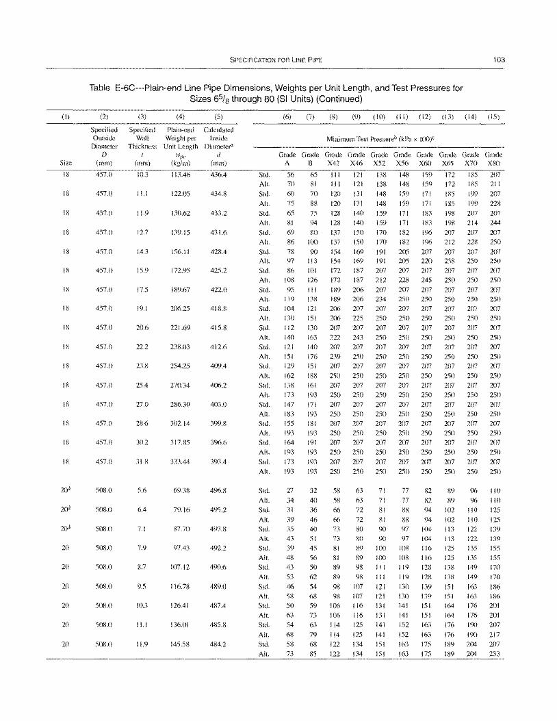
(I)
Size
18
18
18
18
18
18
18
18
18
18
18
18
18
18
18
18
20
20
20
20
20
20
SPECIFICATION FOR liNE PIPE 103
Table E-6C-Plain-end Line Pipe Dimensions, Weights per Unit Length, and Test Pressures for Sizes 6% through 80 (SI Units) (Continued)
(2)
Specified Outside
Diameter D
(mm)
457.0
457.0
457.0
457.0
457.0
457.0
457.0
457.0
457.0
457.0
457.0
457.0
457.0
457.0
457.0
457.0
508.0
508.0
508.0
508.0
508.0
508.0
508.0
508.0
508.0
(3) (4)
Specified Plain-end Wall Weight per
Thickness Unit Length I wpe
(mm) (kg/m)
10.3 113.46
11.1 122.05
11.9 130.62
12.7 139.15
14.3 156.11
15.9 172.95
17.5 189.67
19.1 206.25
20.6 221.69
22.2 238.03
23.8 254.25
25.4 270.34
27.0 286.30
28.6 302.14
30.2 317.85
318 333.44
5.6 69.38
6.4 79.16
7.1 87.70
7.9 97.43
8.7 107.12
9.5 116.78
10.3 126.41
11.1 136.01
119 145.58
(5)
Calculated Inside
Diameter" d
(mm)
436.4
434.8
433.2
431.6
428.4
425.2
422.0
418.8
415.8
412.6
409.4
406.2
403.0
399.8
396.6
393.4
496.8
495.2
493.8
492.2
490.6
489.0
487.4
485.8
484.2
Std.
All.
Std.
All.
Std.
All.
Std.
All.
Std. All.
Std.
All.
Std.
All.
Std.
All.
Std.
All.
Std.
All.
Std.
All.
Std.
All.
Std.
All.
Std.
All.
Std.
All.
Std.
All.
Std.
All.
Std.
All.
Std.
All.
Std.
All.
Std.
All.
Std.
All.
Std.
All.
Std.
All.
Std.
All.
(6) (7) (8) (9) (10) (II) (12) (13) (14) (15)
Minimum Test Pressureb (kPa x lOO)C
Grade Grade Grade Grade Grade Grade Grade Grade Grade Grade A B X42 X46 X52 X56 X60 X65 X70 X80
56 65 II I 121 138 148 159 172 185 207
70 81 III 121 138 148 159 172 185 211
60 70 120 13 I 148 159 171 185 199 207
75 88 120 131 148 159 171 185 199 228
65 81
69
86
78 97
86 108
95 119
104 130
112 140
121
151
129
162
138 173
147
183 155 193
164
193
173
193
27
34 31
39 35
43
39 48 43
53
46
58
50 63
54
68
58 73
75
94
80
100
90
128
128
137
137
154
140
140
150
150
169
159 171
159 171
170 182
170 182
191 205
IS3 198
183 198
196 207
196 212
207 207
207
214
207
228
207
207 244
207
250
207 113 154 169 191 205 220 tOl 172 187 207 207 207
126 172 187 212 228 245
II I I 89 206 207 207 207 138 189 206 234 250 250
121 206 207 207 207 207 151 206 225 250 250 250
130 207 207 207 207 207
163 222 243 250 250 250 140 207 207 207 207 207
176 239 250 250 250 250
151 207 207 207 207 207
188 250 250 250 250 250
161 207 207 207 207 207 193 250 250 250 250 250
171 207 207 207 207 207
193 250 250 250 250 250 18 I 207 207 207 207 207 193 250 250 250 250 250
191 207 207 207 207 207
193 250 250 250 250 250
193 207 207 207 207 207
238 250 250
207 207 207
250 250 250
207 207 207 250 250 250
207 207 207 250 250 250
207 207 207
250 250 250
207 207 207
250 250 250 207 207 207
250 250 250
207 207 207 250 250 250
207 207 207
250 250 250
207 207 207 250 250 250
207 207 207 250 250 250
207 207 207
193 250 250 250 250 250 250 250 250
32 58
40 58
36 66
46 66
40 73 51 73
45 81
56 81 50 89
62 89
54 98
68 98
59 106 73 106
63 114
79 114
68 122
85 122
63 71 77
63 71 77 72 81 88
72 81 88 80 90 97
80 90 97
89 100 108
89 100 108
98 111119
98 111119
107 121 130 107 121 130
116 131 141
116 131 141
125 141 152
125 141 152
134 151 163
134 151 163
82
82 94
94
104 104
116
116 128
128
139 139
151 151
163
163 175
175
89 96 110
89 96 110
102 110 125
102 110 125
113 122 139
113 122 139
125 135 155
125 135 155 138 149 170
138 149 170
151 163 186 151 163 186 164 176 201
164 176 201
176 190 207
176 190 217
189 204 207
189 204 233
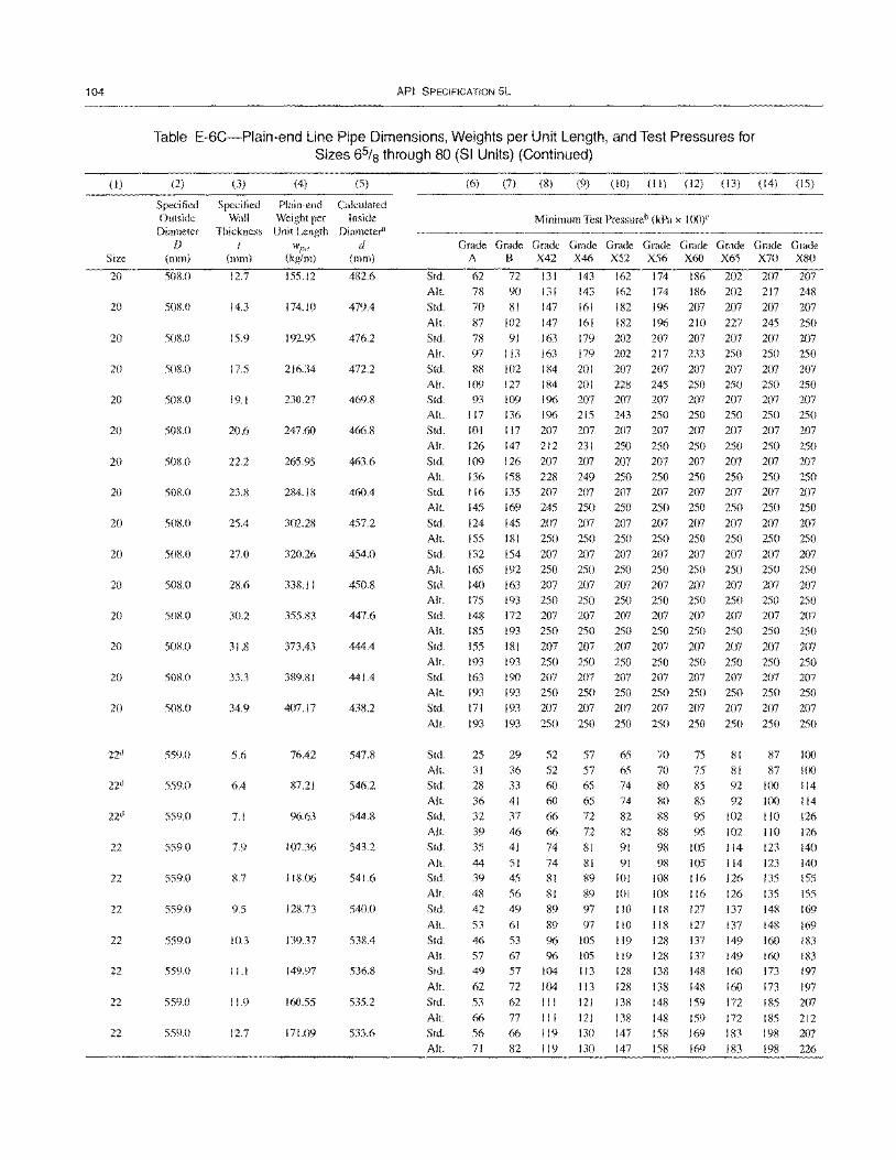
104
(I)
Size
20
20
20
20
20
20
20
20
20
20
20
20
20
20
20
22d
22d
22d
22
22
22
22
22
22
22
API SPECIFICATION 5L
Table E-6C-Plain-end Line Pipe Dimensions, Weights per Unit Length, and Test Pressures for Sizes 65/8 through 80 (SI Units) (Continued)
(2) (3) (4) (5)
Specified Specified Plain-end Calculated Outside Wall Weight per Inside
Diameter Thickness Unit Length Diameter"
D wI''' d (111m) (mm) (kg/m) (mm)
50g'(l 12.7 155.12 482.6
508.0 14.3 174.10 479.4
508.0 15.9 192.95 476.2
508.0 17.5 216.34 472.2
50B.O 19.1 230.27 469.8
508.0 20.6 247.60 466.8
508.0 22.2 265.95 463.6
508.0 23.8 284.18 460.4
508.0 25.4 302.28 457.2
50S.0 27.0 320.26 454.0
508.0 338.11 450.8
508.0 30.2 355.83 447.6
508.0 31.8 373.43 444.4
508.0 33.3 389.81 441.4
508.0 34.9 407.17 438.2
559.0 5.6 76.42 547.8
559.0 6.4 87.21 546.2
559.0 7.1 96.63 544.8
559.0 7.9 107.36 543.2
559.0 8.7 118.C)6 541.6
559.0 9.5 128.73 540.0
559.0 10.3 139.37 538.4
559.0 11.1 149.97 536.8
559.0 11.9 160.55 535.2
559.0 12.7 171.09 533.6
(6) (7) (8) (9) (10) (II) (12) (13) (14) (15)
Minimum Test Pressureb (kPa x 1(0)C
Grade Grade Grade Grade Grade Grade Grade Grade Grade Grade A B X42 X46 X52 X56 X60 X65 X70 X80
Std. 62 72 131 143 162 174 186 202 207 207 All. 78 90 13/ 143 162 174 liS6 202 217 248
Std. 70 81 147 161 182 196 207 207 207 207 All.
Std.
All.
Std.
All.
Std.
All.
Std.
All.
Std.
All.
Std.
All.
Std.
All.
Std.
All.
Std.
All.
Std.
All.
Std.
All.
Std.
All.
Std.
All.
Std.
All.
Std.
All.
Std.
All.
Std.
All.
Std.
All.
Std.
All.
Std.
Alt.
Std.
All.
Std.
All.
Std.
All.
87 78 97
88 109 93
117
101 126 109 136 116 145
124 155
132 165
140 175 148 185
155 193 163 193 171
193
25 31 28 36 32 39 35
44 39 48 42
53 46 57 49
62 53
66 56 71
102 147 161 182
91 163 179 202 113 163 179 202 102 184 201 207
127 184 201 228 109 196 207 207 136 1% 215 243 117 207 207 207 147 212 231 250 126 207 207 207 158 228 249 250 135 207 207 207
169 245 250 250 145 207 207 207 181 250 250 250
I 54 207 207 207 192 250 250 250
163 207 207 207 193 250 250 250 172 207 207 207 193 250 250 250
181 207 207 207 193 250 250 250 190 207 207 207 193 250 250 250 193 207 207 207
193 250 250 250
29 52 57 65 36 52 57 65 33 60 65 74 41 60 65 74 37 66 72 82 46 66 72 82 41 74 81 91
51 74 81 91 45 81 89 101
56 81 89 101 49 89 97 110
61 89 97 110 53 % 105 119 67 96 105 119 57 104 113 128
72 104 113 128 62 III 121 138 77 III 121 138 66 119 130 147 82 119 130 147
196 210 227 245 207 207 207 207 217 233 250 250
207 207 207 207 245 250 250 250 207 207 207 207 250 250 250 250 207 207 207 207 250 250 250 250 207 207 207 207 250 250 250 250 207 207 207 207
250 250 250 250
207 207 207 207 250 250 250 250
207 207 207 207 250 250 250 250
207 207 207 207 250 250 250 250 207 207 207 207 250 250 250 250
207 207 207 207 250 250 250 250 207 207 207 207 250 250 250 250 207 207 207 207
250 250 250 250
70 75 81 87 70 75 81 87 80 iS5 92 100 80 85 92 100 88 95102110 88 95 102 110
98 105 114 123 98 105 114 123
108 116 126 135 108 116 126 135 118 127 137 148
118 127 137 148 128 137 149 160 128 137 149 160 138 148 160 173
138 148 160 173 148 159 172 185
148 159 172 185 158 169 183 198 158 169 183 198
250
207 250
207 250 207 250 207 250
207 250 207 250
207 250 207 250
207 250 207 250
207 250 207 250 207
250
100 100 114 114
126 126
140
140
155 155
169
169 183 183
197
197 207 212 207
226
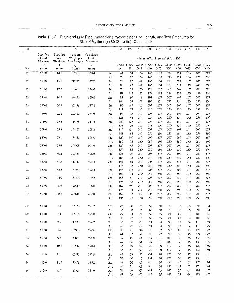
(I)
Size
22
22
22
22
22
22
22
22
22
22
22
22
22
22
22
22
24
24
24
24
24
24
24
SPECIFICATION FOR liNE PIPE 105
Table E-6C-Plain-end Line Pipe Dimensions, Weights per Unit Length, and Test Pressures for Sizes 65/8 through 80 (81 Units) (Continued)
(2)
Specified Outside
Diameter D
(mm)
559.0
559.0
559.0
559.0
559.0
559.0
559.0
559.0
559.0
559.0
559.0
559.0
559.0
559.0
559.0
559.0
610.0
610.0
610.0
610.0
610.0
610.0
610.0
610.0
610.0
(3)
Specified Wall
Thickness t
(mm)
14.3
15.9
17.5
19.1
20.6
22.2
23.8
25.4
27.0
28.6
30.2
31.8
33.3
34.9
36.5
38.1
6.4
7.1
7.9
8.7
9.5
10.3
ILl
11.9
12.7
(4) (5)
Plain-end Calculated Weight per Inside Unit Length Diameter"
w"e d (kg/m) (mm)
192.08 530.4
212.95 527.2
233.6S 524.0
254.30 520.8
273.51 517.8
293.87 514.6
314.11 511.4
334.23 508.2
354.22 505.0
374.08 501.8
393.81 498.6
413.42 495.4
431.69 492.4
451.06 489.2
470.30 486.0
489.41 482.8
95.26 597.2
105.56 595.8
117.30 594.2
129.00 592.6
140.68 591.0
152.32 589.4
163.93 587.8
175.51 586.2
187.06 584.6
Std.
All.
Stel.
All.
Std.
All.
Std.
All.
Std. All.
Std.
All.
Std. All.
Std.
All.
Std. All.
Stel.
All.
Std.
All.
Stel.
All.
Std. All.
Std.
All.
Std.
All.
Std.
All.
Std.
All.
Stel.
All.
Stel. All.
Std.
Alt.
Std.
All.
Std.
All.
Std.
All.
Stel.
All.
Std.
All.
(6) (7) (8) (9) (10) (II) (12) (13) (14) (IS)
Minimum Test Pressureb (kPa x 100)"
Grade Grade Grade Grade Grade Grade Grade Grade Graele Grade A B X42 X46 X52 X56 X60 X65 X70 X80
64 74 134 146 165 178 191 206 207 207
79 92 134 146 165 178 191 206 222 250
71 82 148 162 184 198 207 207 207 207 88 103 148 162 184 198 212 229 247 250
78 91 163 179 202 207 207 207 207 207
97 113 163 179 202 218 233 250 250 250
85 99 178 195 207 207 207 207 207 207
106
92 114
99
123
106 132
113
141
120
150 127
159 134
168
141
177
148 185
155
193
162
193
169
193
26
33
29
36
32 40
35 44
39
48
42
52
45
57
48 61
52
65
124 178
107 192 133 192
lIS 207
144 207
123 207 154 222
131 207
164 237
140 207
175 250 148 207
185 250
156 207
193 250
165 207
193 250
172 207
193 250
181 207
193 250
189 207
193 250 193 207
193 250
30 55 38 55
34 61
42 61
37 68
47 68
41 74 52 74
45 81
56 81
49 88
61 88
53 95
66 95
56 102
71 102 60 109
75 109
195 221 237 250 250 250 250
207 207 207 207 207 207 207 210 238 250 250 250 250 250
207 207 207 207 207 207 207
227 250 250 250 250 250 250
207 207 207 207 207 207 207
243 250 250 250 250 250 250
207 207 207 207 207 207 207
250 250 250 250 250 250 250
207 207 207 207 207 207 207
250 250 250 250 250 250 250 207 207 207 207 207 207 207
250 250 250 250 250 250 250 207 207 207 207 207 207 207
250 250 250 250 250 250 250
207 207 207 207 207 207 207
250 250 250 250 250 250 250
207 207 207 207 207 207 207
250 250 250 250 250 250 250
207 207 207 207 207 207 207
250 250 250 250 250 250 250
207 207 207 207 207 207 207
250 250 250 250 250 250 250 207 207 207 207 207 207 207
250 250 250 250 250 250 250
60 68 73 78 85 91 104
60 68 73 78 85 91 104 66 75 81 87 94 101 116
66 75 81 87 94 101 116
74 84 90 97 104 113 129 74 84 9{) 97 104 113 129
81 92 99 106 liS 124 142
81 92 99 106 115 124 142 89 101 108 116 126 135 ISS
89 101 108 116 126 135 ISS
96 109 117 126 136 147 168
96 109 117 126 136 147 168
104 118 126 136 147 158 181
104 118 126 136 147 158 181
III 126 136 145 157 170 194
III 126 136 145 157 170 194
119 135 145 ISS 168 181 207
119 135 145 155 168 181 207
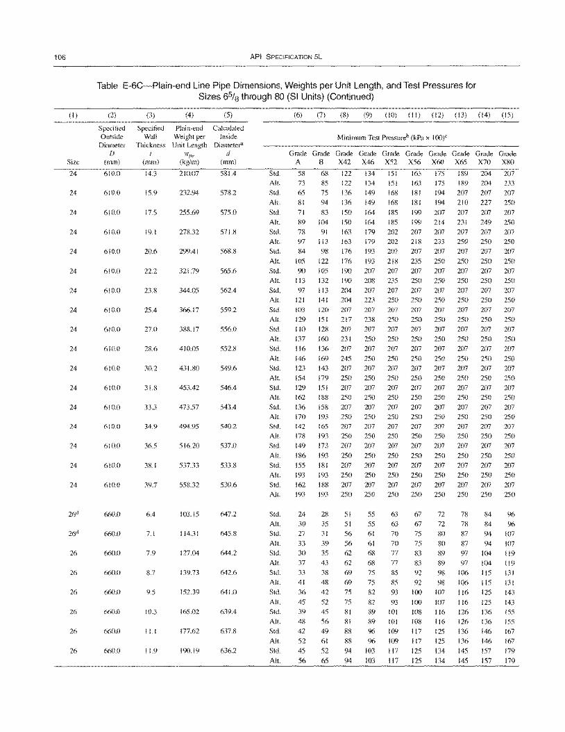
106
(I)
Size
24
24
24
24
24
24
24
24
24
24
24
24
24
24
24
24
24
26ci
26
26
26
26
26
26
API SPECIFICATION 5L
Table E-6C-Plain-end Line Pipe Dimensions, Weights per Unit Length, and Test Pressures for Sizes 6% through 80 (SI Units) (Continued)
(2)
Specified Outside
Diameter D
(mm)
610.0
610.0
610.0
610.0
610.0
610.0
610.0
610.0
610.0
610.0
610.0
610.0
610.0
610.0
610.0
61no
610.0
660.0
660.0
MO.O
660.0
660.0
660.0
660.0
660.0
(3) (4) (5)
Specified Plain-end Calculated Wall Weight per Inside
Thickness Unit Length Diameter" I w!'/, d
(mm) (kg/Ill) (mm)
14.3 210.07 581.4
15.9 232.94 578.2
17.5 255.69 575.0
19.1 278.32 571.8
20.6 299.41 568.8
22.2 321.79 565.6
23.8 344.05 562.4
25.4 366.17 559.2
27.0 388.17 556.0
28.6 410.05 552.8
30.2 431.80 549.6
31.8 453.42 546.4
33.3 473.57 543.4
34.9 494.95 540.2
36.5 516.20 537.0
38.1 537.33 533.8
39.7 558.32 530.6
6.4 103.15 647.2
7.1 114.31 645.8
7.9 127.04 644.2
8.7 139.73 642.6
9.5 152.39 641.0
10.3 165.02 639.4
I I. I 177.62 637.8
11.9 190.19 636.2
Std. All.
Std.
All.
Std.
Alt.
Std.
All.
Std.
All.
Std. All.
Std. All.
Std. All.
Std.
All.
Std.
All.
Std.
All.
Std. All.
Std.
All.
Std. All.
Std.
AI!.
Std. All.
Std.
(6) (7) (8) (9) (10) (II) (12) (13) (14) (15)
Minimum Test Pressureb (kPa x 10(l)C
Grade Grade Grade Grade Grade Grade Grade Grade Grade Grade A B X42 X46 X52 X56 X60 X65 X70 X80
58 73
65 81
71 89 78 97 84
105 90
113 97
121 103 129 110 137 116 146
123 154 129 162 136 170 142 178 149
186 155 193 162
68 122 134 151 163 175 189 204 207 85 122 134 151 163 175 189 204 233 75 136 149 168 181 194 207 207 207 94 136 149 168 181 194 210 227 250 83 150 164 185 199 207 207 207 207
104 150 164 185 199 214 231 249 250 91 163 179 202 207 207 207 207 207
113 163 179 202 218 233 250 250 250 98 176 193 207 207 207 207 207 207
122 176 193 218 235 250 250 250 250 105 190 207 207 207 207 207 207 207 132 190 208 235 250 250 250 250 250 113 204 207 207 207 207 207 207 207 141 204 223 250 250 250 250 250 250 120 207 207 207 151 217 238 250 128 207 207 207 160 231 250 250 I 36 207 207 207 169 245 250 250
143 207 207 207 179 250 250 250 151 207 207 207 I 88 250 250 250 158 207 207 207 193 250 250 250 165 207 207 207 193 250 250 250 173 207 207 207 193 250 250 250
181 207 207 207 193 250 250 250 188 207 207 207
207 207 207 207 250 250 250 250 207 207 207 207 250 250 250 250 207 207 207 207
250 250 250 250
207 207 207 207 250 250 250 250 207 207 207 207 250 250 250 250
207 207 207 207 250 250 250 250 207 207 207 207 250 250 250 250 207 207 207 207
250 250 250 250 207 207 207 207 250 250 250 250 207 207 207 207
207 250 207 250 207
250
207 250 207 250
207 250 207 250 207 250
207 250 207
All. 193 193 250 250 250 250 250 250 250 250
Stel.
All.
Std.
All.
Std.
All.
Std.
All.
Std.
All.
Std.
All.
Std.
All.
Stel.
Alt.
24
30 27
33 30 37 33 41 36
45 39 48 42 52 45
56
28
35 31
39 35 43 38 48 42
52 45 56 49 61
52
65
51 51 56
56 62
62 69
69 75
75
81 81
88 88 94
94
55 63 67 55 63 67 61 70 75
61 70 75
68 77 83 68 77 83 75 85 92 75 85 92 82 93 100
82 93 I()()
89 101 108 89 101 108 96 109 117 96109117
103 117 125
103 117 125
72 78 84 72 78 84 SO 87 94 80 87 94
89 97 104 89 97 104 98106115 98106 115
107 116 125
107 116 125 116 126 136 116 126 136 125 136 146 125 136 146
134 145 157
134 145 157
96 %
107
107 119 119 131 131 143
143 155 155 167 167 179
179
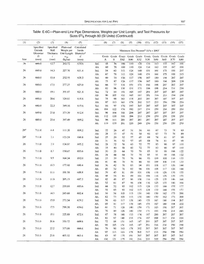
(I)
Size
26
26
26
26
26
26
26
26
26
28
28
28
28
28
28
28
28
28
28
28
28
28
28
SPECIFICATION FOR liNE PIPE 107
Table E-6C-Plain-end Line Pipe Dimensions, Weights per Unit Length, and Test Pressures for Sizes 6% through 80 (SI Units) (Continued)
(2)
Specified Outside
Diameter f)
(mm)
660.0
660.0
660.0
660.0
660.0
660.0
660.0
660.0
660.0
711.0
711.0
711.0
711.0
711.0
711.0
711.0
711.0
711.0
711.0
711.0
711.0
711.0
711.0
711.0
711.0
(3) (4) (5)
Specified Plain-end Calculated Wall Weight per Inside
Thickness Unit Length Diameter"
I wI''' d (mm) (kg/m) (mm)
12.7 202.72 634.6
14.3 227.70 631.4
15.9 25255 628.2
175 277.27 625.0
19.1 301.87 621.8
20.6 324.81 618.8
22.2 349.16 615.6
23.8 373.39 612.4
25.4 397.49 609.2
6.4 111.20 698.2
7.1 123.24 696.8
7.9 136.97 695.2
8.7 150.67 693.6
9.5 164.34 692.0
10.3 177.98 690.4
11.1 191.58 688.8
11.9 205.15 687.2
12.7 218.69 685.6
14.3 245.68 682.4
15.9 272.54 679.2
17.5 299.28 676.0
19.1 325.89 672.8
20.6 350.72 669.8
22.2 377.08 666.6
23.8 403.32 663.4
Std.
All.
Std.
All.
Std.
All.
Std.
All.
Std. All.
Std. All.
Std. All.
Std.
Alt.
Std. All.
Std. All.
Std.
All. Std.
All.
Std.
All.
Std.
All.
Std.
All.
Std. All.
Std.
All.
Std. All.
Std.
All.
Std.
All. Std.
All.
Std. All.
Std.
All. Std.
All.
Std.
All.
(6) (7) (8) (9) (10) (II) (12) (13) (14) (15)
Minimum Test Pressureb (kPa x 1(0)C
Grade Grade Grade Grade Grade Grade Grade Grade Grade Grade A B X42 X46 X52 X56 X60 X65 X70 X80
48
60 54
67
60
75
66
82
72 90 78 97
84 104
90 112
96 119
22
28
25
31 28
35
30
38
33 41
36
45
39 48
42
52 44
55
50 62
56
69 61
76
67
83
72
90
78
97
83 104
56 100
70 100
63 113
78 113
70
87
77 96
84 105
90 1\3
97
122
104
130
III 139
26
33
29
36 32
40
35 44
39
48 42
52 45
56 48
61 52
65
58
73
65 8[ 71
89
78 97
84
105
90
1\3
97 [2[
126
126
138 138
151 151
163
163
176
176
188
188
201
201
47
47
52
52
58
58
64 64 70
70
76
76
81 81
87
87
93
93 lOS
lOS
117
117
128 128
140 140
151
151 163
163
175 175
110 124 \34 [10 124 134
[24 140 151
[24 [40 15[
143 [43 [6[
[61
155
155 [75
[75
137 156 167 ISO 194
137 156 167 180 194
151 171 184 198 207
151 171 184 198 214
165 187 201 207 207 165 187 201 216 233
178 202 207 207 207
178 202 217 233 250
192 207 207 207 207 192 217 234 250 250
206 207 207 207 207 206 233 250 250 250
207 207 207 207 207
220 249 250 250 250
51 58 63 67 73
51 58 63 67 73
57 65 69 74 81 57 65 69 74 81
63 72 77 83 90
63 72 77 83 90 70 79 85 91 99
70 79 85 91 99
76 86 93 100 108 76 86 93 I (X) 108
83 94 101 lOS 117
83 94 101 108 117
89 101 108 116 126
89 101 108 116 126 96 108 116 125 135
96 108 116 125 135 102 115 124 133 144
102 115 124 133 144
liS 130 140 ISO 162 liS 130 140 ISO 162
128 145 ISS 167 180
128 145 155 167 180
140 159 171 183 198
140 159 171 183 198
153 174 187 2(X) 207 153 174 187 2(X) 217
165 187 201 207 207
165 187 201 216 234
178 202 207 207 207
178 202 217 233 250
191 207 207 207 207
191 216 233 249 250
[67 191
167 191
188 207
188 215
207 207
209 239
207 207 231 250
207 207 250 250
207 207
250 250
207 207
250 250
207 207 250 250
207 207
250 250
n 89
n 89
87 99 87 l)l)
97 110
97 110 106 122
106 122
116 133 116 133
126 144
126 144
136 155
136 155 146 166
146 166
155 177
155 177
175 200
175 200
194 207 194 222
207 207
214 245
207 207 234 250
207 207
250 250
207 207
250 250
207 207
250 250
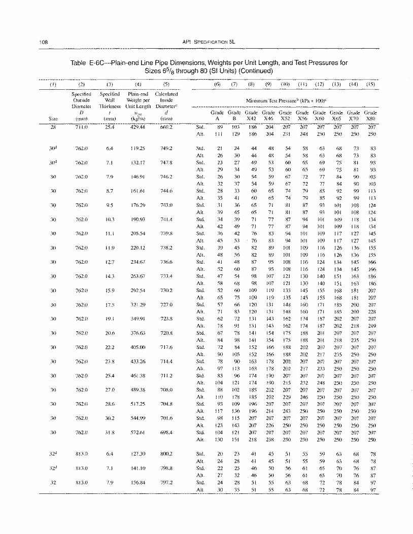
108
(I)
Size
28
30
30
30
30
30
30
30
30
30
30
30
30
30
30
30
30
30
30
30
32
API SPECIFICATION 5L
Table E-6C-Plain-end Line Pipe Dimensions, Weights per Unit Length, and Test Pressures for Sizes 65/8 through 80 (SI Units) (Continued)
(2) (3) (4) (5)
Specified Specified Plain-end Calculated Outside Wall Weight per Inside
Diameter Thickness Unit Length Diameter"
f) wI''' d (mm) (mm) (kg/m) (mm)
711.0 25.4 429.44 660.2
762.0 6.4 119.25 749.2
762.0 7.1 132.17 747.8
762.0 7.9 146.91 746.2
762.0 8.7 161.61 744.6
762.0 9.5 176.29 743.0
762.0 10.3 190.93 741.4
762.0 11.1 205.54 739.8
762.0 11.9 220.12 738.2
762.0 12.7 234.67 736.6
762.0 14.3 263.67 733.4
762.0 15.9 292.54 730.2
762.0 17.5 321.29 727.0
762.0 19.1 349.91 723.8
762.0 20.6 376.63 720.8
762.0 22.2 405.00 717.6
762.0 23.8 433.26 714.4
762.0 25.4 461.38 711.2
762.0 27.0 489.38 708.0
762.0 2K6 517.25 704.8
762.0 30.2 544.99 701.6
762.0 31.8 572.61 698.4
813.0 6.4 127.30 800.2
813.0 7.1 141.10 79~.8
813.0 7.9 156.84 797.2
(6) (7) (8) (9) (10) (II) (12) (13) (14) (15)
Minimum Test Pressureb (kPa x 100)"
Grade Grade Grade Grade Grade Grade Grade Grade Grade Grade A B X42 X46 X52 X56 X60 X65 X70 X80
Std. 89 103 186 204 207 207 207 207 207 207
All. 111 129 186 204 231 248 250 250 250 250
Std.
All.
Std. All.
Std.
All.
Std.
All.
Std. All.
Std.
Alt. Std.
All.
Std.
All.
Std.
All.
Std.
All.
Std.
All. Std. All.
Std.
All.
Std. All.
Std.
All.
Std. All.
Std. All.
Std.
All.
Std. All.
Std.
All.
Std. Alt.
Std.
Alt.
Std. All.
Std.
All.
21
26
23 29
26
32
28
35
31
39 34
42 36
45
39
48
41
52
47
58
52
65 57 71
62
78
67
84
72
90
78 97
83 104
88
110
93
117
98
123
104
24 44 48 54
30 44 48 54 27 49 53 60 34 49 53 60
30 54 59 67
37 54 59 67
33 60 65 74
41 60 65 74
36 65 71 81 45 65 71 81
39 71 77 87
49 71 77 87
42 76 83 94
53 76 83 94
45 82 89 101
56 82 89 101
48 87 95 108
60 87 95 108
54 98 107 121
68 98 107 121
60 109 119 135
75 109 119 135 66 120 131 14il 83 120 131 148
72 131 143 162
91 131 143 162
78 141 154 175
98 141 154 175
84 152 166 188
105 152 166 188
90 163 178 202
113 163 178 202
96 174 190 207 121 174 190 215
102 185 202 207 128 185 202 229
109 1% 207 207
136 196 214 243 115 207 207 207
143 207 226 250
121 207 207 207
58 63 68
58 63 68 65 69 75
65 69 75
72 77 84
72 77 84
79 85 92 79 85 92
87 93 101
87 93 101
94 101 109
94 101 109
101 109 117
101 109 117
109 116 126 109 116 126
116 124 134
116 124 134
130 140 151
130 140 151
145 155 168
145 155 168 160 171 185
160 171 185
174 187 202 174 187 202
188 201 207
188 201 218
202 207 207
202 217 235
207 207 207 217 233 250
207 207 207
232 248 250
207 207 207 246 250 250
207 207 207
250 250 250 207 207 207
250 250 250
207 207 207
73
73 81
81
90
90
99
99
108
108 118
118
127
127
136
136
145
145
163
163
181
181 200
200 207
218
207
235
207
250
207
250
207 250
207 250
207 250
207
250
207
83
83 93
93
103
103
113
113
124
124
134 134
145
145
155
155
166
166
186
186
207
207 207
228
207
249
207
250
207
250
207
250
207
250
207 250
207 250
207
250
207 130 151 218 238 250 250 250 250 250 250
20
24
22 27
24
30
23
28
25
32
28
35
41
41
46 46
51
51
45
45
50 50
55
55
51
51
56 56
63
63
55
55
61
61
68
68
59
59
65 65
72
72
63
63 70
70
78
78
68
68
76
76
84
84
78
78
87
87
97 97
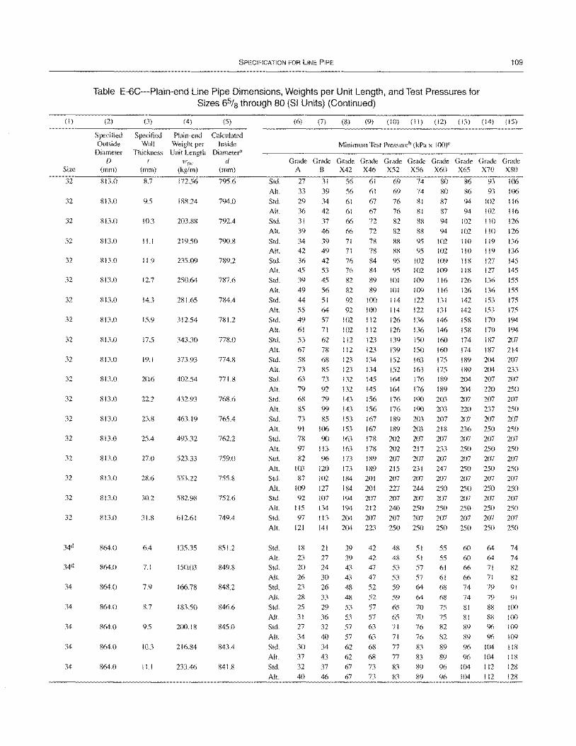
(I)
Size
32
32
32
32
32
32
32
32
32
32
32
32
32
32
32
32
32
32
34
34
34
34
34
SPECIFICATION FOR LINE PIPE 109
Table E-6C-Plain-end Line Pipe Dimensions, Weights per Unit Length, and Test Pressures for Sizes 65fs through 80 (SI Units) (Continued)
(2)
Specified Outside
Diameter D
(mm)
813.0
813.0
813.0
813.0
813.0
S13.0
813.0
813.0
813.0
813.0
813.0
813.0
813.0
813.0
813.0
813.0
813.0
S13.0
864.0
864.0
864.0
864.0
864.0
864.0
864.0
(3)
Specified Wall
Thickness I
(mm)
8.7
9.5
103
11.1
11.9
12.7
143
15.9
17.5
19.1
20.6
22.2
23.8
25.4
27.0
28.6
30.2
31.8
6.4
7.1
7.9
8.7
9.5
10.3
11.1
(4) (5)
Plain-end Calculated Weight per Inside Unit Length Diameter"
wI'£' d (kg/m) (mm)
172.56 795.6
188.24 794.0
203.88 792.4
219.50 790.8
235.09 189.2
250.64 787.6
281.65 784.4
312.54 781.2
343.30 778.0
373.93 774.8
402.54 771.8
432.93 768.6
463.19 765.4
493.32 762.2
523.33 759.0
553.22 755.8
582.98 752.6
612.61 749.4
135.35 851.2
150.03 849.8
166.78 848.2
183.50 846.6
200.18 845.0
216.84 843.4
233.46 841.8
Std.
AI!.
Std. AI!.
Std.
AI!.
Std.
AI!.
Std. AI!.
Std.
AI!.
Std.
AI!.
Std.
AI!.
Std.
AI!.
Std.
AI!.
Std.
AI!.
Std.
AI!.
Std.
AI!.
Std.
(6) (7) (8) (9) (10) (II) (12) (13) (14) (15)
Minimum Test Pressureb (kPa x 1(0)"
G~G~G~G~G~G~G~G~G~G~ A B X42 X46 X52 X56 X60 X65 X70 X80
27 31 56 61 69 74 80 86 93 106
33 39 56 61 69 74 80 86 93 106
29
36
31
39
34
42
36 45
39
49
44
55
49
61
53 67
58
73 63
79 68
85 73
91
78
34 42
37
46
39 49
42 53
45
56 51
64 57
71
62
78 68
85
73
92
79
99
85
106
90
61
61
66
66
71 71 76 76 82
82
92
92
102 102
112 112
123
123
132
132
143
143
153
153
163
67 67
72
72
76
76
82
82
81
81
88
88
87 94 87 94
94 102
94 102
78 88 95 102 110
78 88 95 102 110 84 95 102 109 118 84 95 102 109 118
89 101 109 116 126
89 101 109 116 126 100 114 122 131 142
100 114 122 131 142
112 126 136 146 158
112 126 136 146 158
123 139 150 160 174
123 139 ISO 160 174
134 152 163 175 189 134 152 163 175 189
145 164 176 189 204
145 164 176 189 204
156 176 190 203 207
156 176 190 203 220
167 189 203 207 207
167 189 203 21R 236
17R 202 207 207 207
102 116 102 116
110 126
110 126
119 136 119 136
127 145 127 145
136 155
136 155
153 175
153 175
170 194
170 194
187 207
187 214 204 207
204 233
207 207
220 250 2(J7 207
237 250
207 207
250 250
207 207
AI!. 97 113 163 178 202 217 233 250 250 250
Std.
AI!.
Std.
AI!.
Std. AI!.
Std.
AI!.
Std. AI!.
Std.
AI!.
Std.
AI!.
Std.
AI!.
Std.
AI!.
Std.
AI!.
Std.
AI!.
82
103 87
109
92
115
97
121
18
23 20
26
23
28
25
31
27
34
30
37
32
40
96 173
120 173 102 184
127 184
107 194
134 194
113 204
141 204
21 39 27 39
24 43
30 43
26 48
33 48
29 53
36 53
32 57
40 57
34 62
43 62
37 67 46 67
189 207 207 207 207 207 207
189 215 231 247 250 250 250 20 I 207 207 207 207 207 207
20 I 227 244 250 250 250 250
207 207 207 207 207 207 207 212 240 250 250 250 250 250
207 207 207 207 207 207 207
223 250 250 250 250 250 250
42 48 51 55 6(J 64 74 42 48 51 55 60 64 74 47 53 57 61 66 71 82
47 53 57 61 66 71 82 52 59 64 (1) 74 79 91
52 59 64 68 74 79 91
57 65 7(J 75 81 88 100 57 65 7(J 75 RI 88 100
63 71 76 82 89 90 \09
63 71 76 82 89 96 109
68 77 83 89 96 104 118
68 77 83 89 90 104 118
73 83 89 96 104 112 128 73 83 89 96 \04 112 128
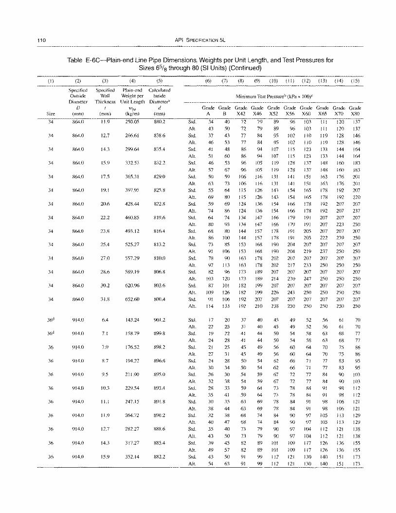
110
(I)
Size
34
34
34
34
34
34
34
34
34
34
34
34
34
34
36
36
36
36
36
36
36
36
36
API SPECIFICATION 5L
Table E-6C-Plain-end Line Pipe Dimensions, Weights per Unit Length, and Test Pressures for Sizes 65/8 through 80 (SI Units) (Continued)
(2) (3) (4) (5)
Specified Specified Plain-end Calculated Outside Wall Weight per Inside
Diameter Thickness Unit Length Diameter" D IVpe d
(Imn) (mm) (kg/m) (mm)
864.0 11.9 250.05 840.2
864.0 12.7 266.61 838.6
864.0 14.3 299.64 835.4
864.0 15.9 332.53 832.2
864.0 17.5 365.31 829.0
864.0 19.1 397.95 825.8
864.0 20.6 428.44 822.8
864.0 22.2 460.85 819.6
864.0 23.8 493.12 816.4
864.0 25.4 525.27 8\3.2
864.0 27.0 557.29 810.0
864.0 28.6 589.19 806.8
864.0 30.2 620.96 803.6
864.0 31.8 652.60 800.4
914.0 6.4 143.24 901.2
914.0 7.1 158.79 899.8
914.0 7.9 176.52 898.2
914.0 8.7 194.22 896.6
914.0 9.5 211.90 895.0
914.0 10.3 229.54 893.4
914.0 11.1 247.15 891.8
914.0 11.9 264.72 890.2
914.0 12.7 282.27 888.6
914.0 14.3 317.27 885.4
914.0 15.9 352.14 882.2
(6) (7) (8) (9) (10) (II) (12) (13) (14) (15)
Minimum Test Pressureb (kPa x 100)C
Grade Grade Grade Grade Grade Grade Grade Grade Grade Grade A B X42 X46 X52 X56 X60 X65 X70 X80
Std. 34 40 72 79 89 96 103 III 120 137
AI!. 43 50 72 79 89 96 103 III 120 137
Std. 37 43 77 84 95 102 110 119 128 146
AI!.
Std. AI!.
Std.
AI!.
Std.
AI!.
Std.
AI!.
Std.
AI!.
Std. AI!.
Std. All.
Std. Alt.
Std.
AI!.
Std.
All.
Std. All.
Std.
46
41
51 46
57
50 63
55
69 59
74
64 80
68 86 73 91
78
97 82
103
87
109
91
53
48
60 53
67
59
73
64
80 69
86 74
93
80 100 85
106
90
113 96
120
101
126
106
77
86
86 96
% 106
106 115
115
124
124 134
134
144 144 153
153
163
163
173 173
182
182
192
84 95
94 107
94 107
105 119
105 119
116 131
116 131 126 143
126 143
136 154
136 154 147 166
147 166
157 178 157 178
168 190 168 190
178 202
178 202 189 207 189 214
199 207
199 226
207 207
102 I 10 1 19 128
115 123 133 144
115 123 133 144
128 137 148 160
128 137 148 160
141 151 163 176
141 151 163 176
154 165 178 192
154 165 178 192
166 178 192 207
166 In 192 207 179 191 207 207
179 191 207 223 191 205 207 207 191 205 222 239
204 207 207 207 204 219 237 250
207 207 207 207
217 233 250 250 207 207 207 207
230 247 250 250
207 207 207 207
243 250 250 250
207 207 207 207
146
164
164
183
183
201 201
207
220
207 237
207
250
207 250 207
250
207
250
207
250
207
250
207 AI!. 114 133 192 210 238 250 250 250 250 250
Std.
AI!.
Std.
AI!.
Std. AI!.
Std.
AI!.
Std.
AI!.
Std. All.
Std.
All.
Std.
AI!.
Std.
All.
Std.
All.
Std.
AI!.
17
22
19
24
21
27 24
30
26
32
28 35 30
38 32
40
35
43
39
49
43
54
20
25
22
28
25
31 28
34
30
38
33 41
35
44 38
47
40
50
45
57
50
63
37
37 41
41
45
45
50
50
54
54
59 59 63
63 68
68
73
73 82
82
91
91
40 45
40 45
44 50
44 50
49 56
49 56
54 62
54 62
59 67
59 67 64 73
64 73 69 78
69 78 74 84
74 84
79 90
79 90
89 101
89 101
99 112
99 112
49 52
49 52
54 58
54 58
60 64
60 64 66 71
66 71
72 77
72 77
78 84 78 84
84 91
84 91
90 97
90 97
97 104
97 104
109 117
109 117
121 130
121 130
56 61
56 61
63 68
63 68
70 75
70 75
77 83
77 83
84 90
84 90
91 98 91 98 98 106
98 106 105 113
105 113
112 121
112 121
126 136
126 136
140 151
140 151
70
70
77
77
86 86
95
95
!O3 103 112
112
121
121
129
129
138
138
155
155 173
173
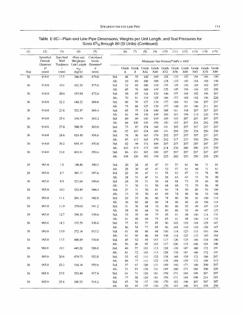
(1)
Size
36
36
36
36
36
36
36
36
36
36
38
38
38
38
38
38
38
38
38
38
38
38
38
38
38
SPECIFICATION FOR LINE PIPE 111
Table E-6C-Plain-end Line Pipe Dimensions, Weights per Unit Length, and Test Pressures for Sizes 6% through 80 (SI Units) (Continued)
(2)
Specified Outside
Diameter D
(mm)
914.0
914.0
914.0
914.0
914.0
914.0
914.0
914.0
914.0
914.0
965.0
965.0
965.0
965.0
965.0
965.0
965.0
965.0
965.0
965.0
965.0
965.0
965.0
965.0
965.0
(3) (4)
Specified Plain-end Wall Weight per
Thickness Unit Length { }Vpc
(mm) (kg/m)
17.5 386.S8
19.1 421.50
20.6 453.84
22.2 488.22
23.8 522.47
25.4 556.59
27.0 590.58
28.6 624.45
30.2 658.19
31.8 691.81
7.9 186.46
8.7 205.17
9.5 223.84
10.3 242.49
11.1 261.11
11.9 279.69
12.7 298.24
14.3 335.25
15.9 372.14
17.5 408.89
19.1 445.52
20.6 479.75
22.2 516.14
23.8 552.40
25.4 588.53
(5)
Calculated Inside
Diameter" d
(mm)
879.0
875.8
872.8
869.6
866.4
863.2
860.0
856.8
853.6
850.4
949.2
947.6
946.0
944.4
942.8
941.2
939.6
936.4
933.2
930.0
926.8
923.8
920.6
917.4
914.2
Stel.
All.
Stel.
All.
Std.
All.
Std.
All.
Stel. All.
Std.
All.
Stel.
All.
Stel.
All.
Std.
All.
Std.
All.
Std.
All.
Std.
Alt.
Std.
All.
Std.
All.
Stel.
All.
Std.
All.
Std.
All.
Std.
All.
Stel.
All.
Std.
All.
Stel.
Alt.
Stel.
Alt.
Std.
All.
Std.
All.
Stel.
All.
(6) (7) (8) (9) (10) (II) (12) (13) (14) (15)
Minimum Test Pressureb (kPa x loo)e
Grade Grade Grade Graele Graele Graele Graele Graele Graele Grade A B X42 X46 X52 X56 X60 X65 X70 XSO
48
59 52 65 56 70 60 75
65 81
69 86 73 92 78 97
82 103
S6 108
20 25 22
28 24 31 27
33 29 36 31 38 33 41 37 46 41 51 45 56 49 61
53 66 57 71
61 77
65 82
55
69
60 76 65 81
70 88 75 94 80
100
85 107
90 113
96 119
101 126
24
30 26
33 28 36 31 39 33 42 36 45 38 48
43 54 48 60 52
66 57
72 62 77 67 83
71
89 76 95
100 109 124 133 143
100 109
109
118
118
127 127
136 136
145 145
154 154 163 163 172 172
182 182
109 124 133 143
119 135 145 156 119 135 145 156 129 146 157 168 129 146 157 168
139 157 169 181 139 157 169 181 149 168 181 194 149 168 lSI 194 159 180 193 207 159 180 193 207
169 191 205 207 169 191 205 220 179 202 207 207 179 202 217 233 1 89 207 207 207 189 214 230 246
199 207 207 207 199 225 242 250
47 53 57 61
47 53 57 61 51 58 63 67 51 58 63 67 56 64 68 73 56 64 68 73
61 69 74 80 61 69 74 80 66 74 80 86 66 74 80 86 70 80 86 92 70 80 86 92 75 85 91 98 75 85 91 98 85 96 103 110
85 96 103 1\0
94 106 114 123 94 106 114 123
103 117 126 135 \03 I 17 126 135 113 128 138 147 113 128 138 147
122 138 148 159 122 138 148 159 131 149 160 171 131 149 160 171 141 159 171 184
141 159 171 184 150 170 183 196
154 166
154 166
169 182 169 182 182 196 182 196
196 207 196 211 207 207 210 226 207 207 224 242
207 207 238 250 207 207 250 250 207 207 250 250
207 207 250 250
66 71
66 71 73 78
73 78
79 86 79 86 86 93 86 93
93 100 93 100 99 107 99 107
106 114 106 114
119 129 119 129 133 143 133 143 146 158 146 158 160 172
160 172 172 186 172 186 186 2(X)
186 200
199 207 199 214
207 207
190
190
207
208 207 224
207 241
207 250 207 250
207 250 207 250 207 250
207 250
81 81 90
90 98 98
106 106 114
114
123 123 131 131
147 147 164
164
180
180 197
197 207 212 207 229
207 245 207
43
43 47 47 51 51 56 56 60 60 64
64
69 69
77
77 86 86 95 95
103 103
III
III
120 120
129 129
137 137 150 170 IfD 196 212 229 250
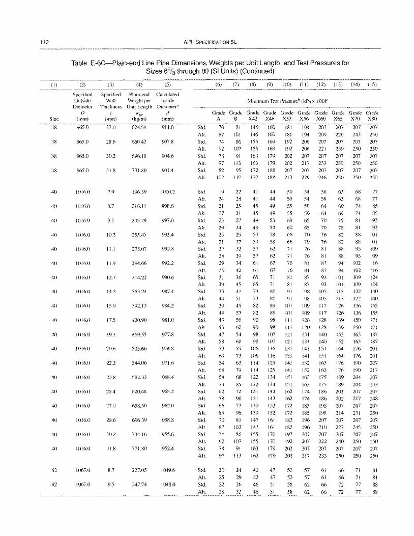
112
(I)
Size
38
38
38
38
40
40
40
40
40
40
40
40
40
40
40
40
40
40
40
40
40
40
40
42
42
API SPECIFICATION 5L
Table E-6C-Plain-end Line Pipe Dimensions, Weights per Unit Length, and Test Pressures for Sizes 65/8 through 80 (SI Units) (Continued)
(2) (3) (4) (5)
Specified Specified Plain-end Calculated Outside Wall Weight per Inside
Diameter Thickness Unit Length Diameter<' f) Hlp£:' d
(mm) (111m) (kg/m) (111m)
965.0 27.0 624.54 911.0
965.0 28.6 660.42 907.8
965.0 30.2 696.18 904.6
965.0 31.8 731.80 901.4
1016.0 7.9 196.39 1000.2
1016.0 8.7 216.11 998.6
1016.0 9.5 235.79 997.0
1016.0 10.3 255.45 995.4
1016.0 11.1 275.07 993.8
1016.0 11.9 294.66 992.2
1016.0 12.7 314.22 990.6
1016.0 14.3 353.24 987.4
1016.0 15.9 392.13 984.2
1016.0 17.5 430.90 981.0
1016.0 19.1 469.55 977.8
1016.0 20.6 505.66 974.8
1016.0 22.2 544.06 971.6
1016.0 23.8 582.33 968.4
1016.0 25.4 620.48 965.2
1016.0 27.0 658.50 962.0
]()16.0 28.6 696.39 958.8
1016.0 30.2 734.16 955.6
1016.0 31.8 771.80 952.4
1067.0 8.7 227.05 1049.6
1067.0 9.5 247.74 1048.0
(6) (7) (8) (9) (10) (II) (12) (13) (14) (15)
Minimul11 Test Pressureb (kPa x I OO)C
~~~~~~~~G~G~G~G~G~~~ A B X42 X46 X52 X56 X60 X65 X70 X80
Std. 70 81 146 160 181 194 207 207 207 207
All.
Std.
All.
Std. All.
Std.
All.
Std.
All.
Std.
All.
Std. All.
Std.
All.
Std. All.
Std.
All. Std. All.
Std.
Alt. Std.
All.
Std.
All.
Std. All.
Std.
All.
Std. All.
Std.
All.
Std.
All.
Std.
All.
Std. All.
Std. All.
Std.
87 101
74
92
78
97
82
102
19
24
21
27
23
29
25
31 27
34
29
36 31 39
35
44 39
49
43
53 47
58
50
63
54 68
58
73
62
78
66
83
70
87
74
92
78
86
107
91
113
95 119
22
28
25
31
27
34
29
37
32
39 34
42
36 45 41
51
45
57
50
62
54
68
59
73
63 79
68
85
72
90 77
96
81 102
86 107
91
146 160 181
155
155
163
163 172
172
41
41
45
45
49 49
53
53
57
57 61
61
65 65 73
73
82
82
90
90
98 98
106
106
114 114
122
122 131
131 139
139
147 147
155 155
163
169 192
169 192
179 202 179 202
188 207
188 213
44 50
44 50
49 55
49 55
53 60
53 60 58 66
58 66
62 71
62 71
67 76
67 76 71 81 71 81
80 91
80 91
89 101
89 101
98 III
98 III
107 121
107 121 116 131
116 131
125 141 125 141
134 151
134 lSI 143 162
143 162
152 172
152 172
161 182 161 182
170 192 170 192
179 202
194 209 226 243 250
206 207 207 207
206 221 239 250
207 207 207 207 217 233 250 250
207 207 207 207
229 246 250 250
54 58 63 68
54 58 63 68 59 64 69 74
59 64 69 74
65 70 75 81 65 70 75 81
70 76 82 88
70 76 82 88 76 81 88 95
76 81 88 95 81 87 94 102
81 87 94 102 87 93 101 109
87 93 101 109
98 105 113 122
98 105 113 122
109 117 126 136
109 117 126 136
120 128 139 150
120 128 139 150 131 140 152 163
131 140 152 163
141 151 164 176
141 151 164 176
152 163 176 190
152 163 176 190
163 175 189 204
163 175 189 204
174 186 202 207 174 186 202 217
185 198 207 207
185 198 214 231
196 207 207 207
196 210 227 245
207 207 207 207 207 222 240 250
207 207 207 207
207
250
207
250
207
250
77 77
85
85 93
93
101
101
109
109
\16
\16 124
124 140
140
155
155 171
171
187 187
201
201
207 217
207 233
207
248
207
250
207 250
207
250
207 All. 97 113 163 179 202 217 233 250 250 250
Std.
All.
Std.
All.
20
25
22
28
24
29
26
32
43
43
46 46
47
47
51
51
53
53
58
58
57
57
62
62
61
61
66 66
66
66
72 72
71
71
77 77
81
81
88 88
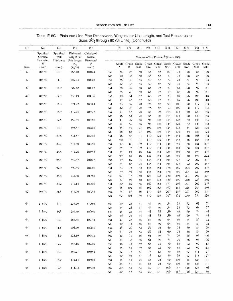
(I)
Size
42
42
42
42
42
42
42
42
42
42
42
42
42
42
42
42
44
44
44
44
44
44
44
44
44
SPECIFICATION FOR liNE PIPE 113
Table E-6C-Plain-end Line Pipe Dimensions, Weights per Unit Length, and Test Pressures for Sizes 65/8 through 80 (SI Units) (Continued)
(2)
Specified Outside
Diameter D
(mm)
1067.0
1067.0
1067.0
1067.0
1067.0
1067.0
1067.0
1067.0
1067.0
1067.0
1067.0
1067.0
1067.0
1067.0
1067.0
1067.0
1118.0
IIIS.O
1118.0
1118.0
IIIS.O
1118.0
IIIS.O
1118.0
1118.0
(3)
Specified Wall
Thickness I
(mm)
10.3
11.1
11.9
12.7
14.3
15.9
17.5
19.1
20.6
22.2
23.8
25.4
27.0
28.6
30.2
31.8
8.7
9.5
\0.3
11.1
11.9
12.7
14.3
15.9
17.5
(4) (5)
Plain-end Calculated Weight per Inside
Unit Length Diameter" wl)e d
(kglm) (mm)
268.40 1046.4
289.03 1044.8
309.62 1043.2
330.19 1041.6
371.22 1038.4
412.13 1035.2
452.91 1032.0
493.57 \028.8
531.57 1025.8
571.98 1022.6
612.26 1019.4
652.42 1016.2
692.45 \013.0
732.36 1009.8
772.14 1006.6
811.79 1003.4
237.99 1100.6
259.69 1099.0
281.35 1097.4
302.99 1095.8
324.59 1094.2
346.16 1092.6
389.21 1089.4
432.13 1086.2
474.92 1083.0
Std.
All. Std.
All.
Std.
All.
Std.
All.
Std. All.
Std.
All. Std.
Alt. Std.
All.
Std. All.
Std.
All.
Std.
All.
Std. All.
Std.
All.
Std. All. Std.
All. Std. All.
Std.
All.
Std.
All.
Std.
All.
Std.
All. Std.
All.
Std. All.
Std.
All.
Std. All.
Std.
Alt.
(6) (7) (8) (9) (10) (II) (12) (13) (14) (15)
Minimum Test Pressureb (kPa x 100)"
Grade Grade Grade A B X42
24
30
26 32
28
35
30 37
33 42
37
46 41
51 44
56
48
60 52
65
55 69
59 74
63 79
67 83
70 88 74
93
19
24
21
26
23
29 25
31 26
33
28
35 32
40
35 44
39 49
28
35
30
38 32
40
34
43
39 48
43
54 47
59
52
65
56
70
60 75
65
81
69
86
73 91
78 97
82 102 86
108
23
28 25
31
27
33 29
36 31
38 33
41 37
46
41
51
45 57
50
50
54
54
58
58
62 62
70 70
78
78
86
86 93
93
101
101
109
109 116
116 124
124
132
132
140
140 148
148 156
156
41
41 44
44
48
48
52
52 56
56
59 59 67
67
74
74
82 82
Grade X46
55 55 59
59
64
64
68
68 76 76
85
85
94 94
102
102
110
110
119
119
127
127
136 136
144
144
153 153 162 162
170 170
44
44
48
48
53
53
57
57 61
61
65 65
73 73
81
81
89
89
Grade X52
Grade Grade Grade Grade Grade X56 X60 X65 X70 X80
62
62 67
67
67
72
72
72
78
67 72 78 72 77 83
72 77 83
77 83 89 77 83 S9
87 93 100 87 93 100
96 104 III
96104 III
106 114 122 \06 114 122
116 124 133
116 124 133
125 134 144
125 134 144
134 145 155 134 145 155
144 155 166
144 155 166
154 165 177
154 165 177
164 176 189 164 176 189
173 186 200 173 186 200
183 197 207 183 197 211
193 207 207 193 207 222
50 54 58
50 54 58 55 59 63
55 59 63
60 64 69
60 64 69
64 69 74
64 69 74 69 74 79
69 74 79
73 79 85
73 79 85 83 89 95
83 89 95
92 99 106
92 99 106 101 109 117
\01 109 117
78
78 84
84 96
84 96
90 103
84 90 103
90 97 III
90 97 III
96 103 118
96 103 118 108 117 133 lOS 117 133
120 130 148
120 130 148
132 143 163
132 143 163 144 156 178
144 156 17S
156 168 192
156 168 192
168 181 207 168 181 207
ISO 194 207
ISO 194 222
192 207 207 192 207 237
204 207 207
204 220 250
207 207 207
216 233 250 207 207 207
228 246 250 207 207 207
240 250 250
63 68 77 63 68 77
69 74 84
69 74 84
74 80 92
74 80 92
SO 86 99
80 86 99 86 93 \06
86 93 \06 92 99113
92 99113 103 III 127 103 III 127
115 124 141 115 124 141
126 136 156
126 136 156
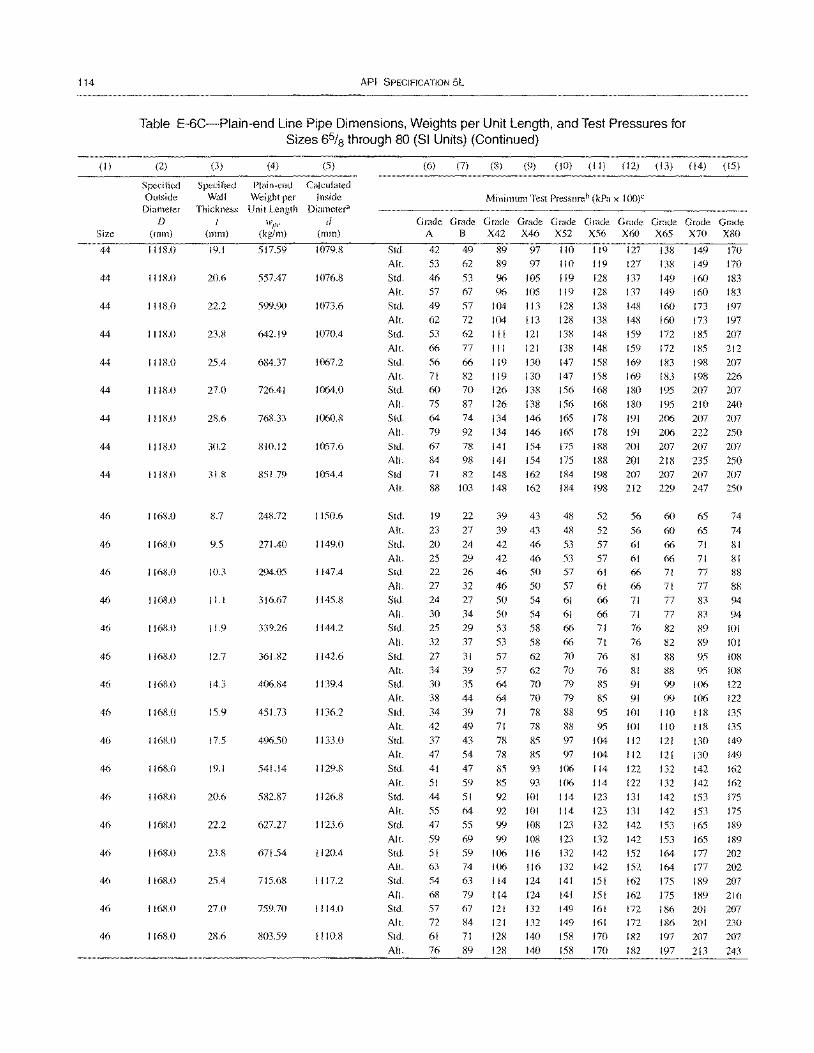
114
(I)
Size
44
44
44
44
44
44
44
44
44
46
46
46
46
46
46
46
46
46
46
46
46
46
46
46
46
API SPECIFICATION 5L
Table E-6C-Plain-end Line Pipe Dimensions, Weights per Unit Length, and Test Pressures for Sizes 6% through 80 (SI Units) (Continued)
(2) (3) (4) (5)
Specified Specified Plain-end Calculated Outside Wall Weight per Inside
Diameter Thickness Unit Length Diameter1
/) t IVp,- d (mm) (mm) (kg/m) (mm)
I I 18.0 19.1 517.59 1079.8
I I 18.0 20.6 557.47 1076.8
I I 18.0 22.2 599.90 1073.6
I I 18.0 23.8 642.19 1070.4
1118.0 25.4 684.37 1067.2
1118.0 27.0 726.41 1064.0
I I 18.0 28.6 768.33 1060.8
1118.0 30.2 810.12 1057.6
I I 18.0 31.8 851.79 1054.4
1168.0 8.7 248.72 1150.6
1168.0 9.5 271.40 1149.0
1168.0 10.3 294.05 1147.4
1168.0 11.1 316.67 1145.8
1168.0 11.9 339.26 1144.2
1168.0 12.7 361.82 1142.6
1168.0 14.3 406.84 1139.4
1168.0 15.9 451.73 1136.2
1168.0 17.5 496.50 1133.0
116KO 19.1 541.14 1129.8
1168.0 20.6 582.87 1126.8
1168.0 22.2 627.27 1123.6
1168.0 23.8 671.54 1120.4
1168.0 25.4 715.68 I I 17.2
1168.0 27.0 759.70 I I 14.0
11680 28.6 803.59 1110.8
(6) (7) (8) (9) (10) (II) (12) (13) (14) (15)
Minimum Test Pressureb (kPa x I OO)C
G~~~G~~~G~G~G~G~G~~~ A B X42 X46 X52 X56 X60 X65 X70 X80
Std. 42 49 89 97 110 119 127 138 149 170
All. 53 62 89 97 110 119 127 138 149 170
Std. 46 53 96 105 119 128 137 149 160 183
All.
Std.
All.
Std.
All.
Std.
All.
Std.
All.
Std.
All.
Std.
All.
Std.
All.
Std.
All.
Std.
All.
Std.
All.
Std.
All.
Std.
All.
Std.
All.
Std.
All.
Std.
All.
Std.
All.
Std.
All.
Std.
Alt.
Std.
All.
Std.
All.
Std.
All. Std.
All.
Std.
All.
57
49
62
53
66
56
71
60
75
64
79
67
84
71
88
19
23
20
25
22
27
24
30
25
32
27
34
30
38
34
42
37
47
41
51
44
55
47
59
51
63
54
68 57
72
61
76
67
57
72
62
77
66
82
70
87
74
92
78
98
82
103
22
27
24
29
26
32
27
34
29
37
31
39
35
44
39
49
43
54
47
59
51
64
55
69
59
74
63
79
67
84
71
89
96
104
104
III
III
119
119
126
126
134
134
141
141
148
148
39
39
42
42
46
46
50
50
53
53
57
57
64
64
71
71
78
78
85
85
92
92
99
99
106
106
114 114
121
121
128
128
105
113
113
121
121
130
130
138
138
146
146
154
154
162
162
43
43
46
46
50
50
54
54
58
58
62
62
70
70
78
78
85
85
93
93
lOl
101
108
108
116 116 124
124
132
132
140
140
119
128
128
138
138
147
147
156
156
165
165
175
175
184
184
48
48
53
53
57
57
61
61
66
66
70
70
79
79
88
88
97
97
106
106
114
114
123
123
132
132
141
141
149
149
158 158
128 137
138 148
138 148
148 159
148 159
158 169
158 169
168 180
168 180
178 191
178 191
188 201
188 201
198 207
198 212
52 56
52 56
57 61
57 61
61 66
61 66
66 71
66 71
71 76
71 76
76 81
76 81
85 91
85 91
95 101
95 101
104 112
104 112
114 122
114 122
123 131
123 131
132 142
132 142
142 152
142 152
151 162
lSI 162
161 172
161 172
170 182
170 182
149 160 183
160 173
160 173
172 185
172 185
183 198
183 198
195 207
195 210
206 207
206 222
207 207
218 235
207 207
229 247
60 65
60 65
66 71
66 71
71 77
71 77
77 83
77 83
82 89
82 89
88 95
88 95
99 106
99 106
110 118
110 118
121 130
121 130
132 142
132 142
142 153
142 153
153 165
153 165
164 177
164 177
175 189
175 189
186 201
186 201
197 207
197 213
197
197
207
212
207
226
207
240
207
250
207
250
207
250
74
74
81
81
88
88
94
94
lOl
101
108
108
122
122
135 135
149
149
162
162
175
175
189
189
202
202
207
216
207
230
207
243
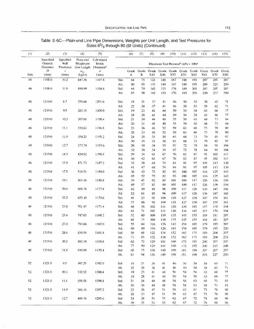
(1)
Size
46
46
48
48
48
48
48
48
48
48
48
48
48
48
48
48
48
48
48
48
52
52
52
52
52
SPECIFICATION FOR LINE PIPE 115
Table E-6C-Plain-end Line Pipe Dimensions, Weights per Unit Length, and Test Pressures for Sizes 6% through 80 (SI Units) (Continued)
(2)
Specified Outside
Diameter D
(mm)
1168.0
1168.0
1219.0
1219.0
1219.0
1219.0
1219.0
1219.0
1219.0
1219.0
1219.0
1219.0
1219.0
1219.0
1219.0
1219.0
1219.0
1219.0
1219.0
1219.0
1321.0
1321.0
1321.0
1321.0
1321.0
(3)
Specified Wall
Thickness t
(mm)
30.2
31.8
8.7
9.5
10.3
11.1
11.9
12.7
14.3
15.9
17.5
19.1
20.6
22.2
23.8
25.4
27.0
28.6
30.2
31.8
9.5
10J
11.1
11.9
12.7
(4)
Plain-end Weight per Unit Length
wl'C (kg/m)
847.36
890.99
259.66
283.35
307.01
330.63
354.23
377.79
424.82
471.73
518.51
565.16
608.78
655.19
701.47
747.63
793.66
839.56
885.34
930.99
307.25
332.92
358.55
384.16
409.74
(5)
Calculated Inside
Diameter1
d (mm)
1107.6
1104.4
1201.6
1200.0
1198.4
1196.8
1195.2
1193.6
1190.4
1187.2
1184.0
1180.8
1177.8
1174.6
1171.4
1168.2
1165.0
1161.8
1158.6
1155.4
1302.0
1300.4
1298.8
1297.2
1295.6
Std.
AI!.
Std. AI!.
Std.
AI!.
Std.
AI!.
Std.
AI!.
Std.
AI!.
Std.
AI!.
Std.
AI!.
Std. All.
Std.
AI!.
Std. AI!.
Std.
Alt.
Std.
AI!.
Std.
All.
Std.
AI!.
Std. All.
Std.
All.
Std.
AI!.
Std. AI!.
Std.
AI!.
Std.
All.
Std.
All.
Std. All.
Std.
AI!.
Std.
AI!.
(6) (7) (8) (9) (10) (11) (12) (13) (14) (15)
Minimum Test Pressureb (kPa x 100)C
~~G~G~G~G~G~G~G~G~G~
A B X42 X46 X52 X56 X60 X65 X70 X80
64 75 135 148 167 180 193 207 207 207
80 93 135 148 167 180 193 209 225 250
68 79 142 155 176 189 203 207 207 207 85 98 142 155 176 189 203 220 237 250
18
22
19 24 21
26
23
28 24
30
26
32
29 36
32 41
36 45
39 49
42
52
45 57
48
61
52 65
55
69 58 73 62
77
65
81
18
22
19
24
21
26
22
28
24
30
21
26
23
28 24
31
26
33 28
35 30
38 34 42
38
47
42 52 45
57
49
61
53
66
56
71
60 75
64
80
68
85 72
90 75
94
21
26
23
28 24
30
26
33 28
35
37
37
41 41 44
44
48 48
51
51
54
54
61 61
68 68
75 75
82
82
88
88 95
95
102 102
109 109
116 116 122
122
129 129
136
136
38
38 41
41
44
44
47
47
50
50
41
41
44
44
48
48
52
52 56
56
59
59 67
67 74
74
82 82
89 89
96
96 104
104
III
III
119
119 126
126 134
134
141
141
149
149
41
41
44
44
48
48
51
51
55 55
46
46
50 50 55
55
59
59 63
63
67
67
76 76
84 84
93 93
101
101
109
109
118
118
126
126
135 135
143 143
152
152
160 160
169
169
46
46
50
50 54
54
58 58 62 62
50
50
54
54 59
59
63
63 68
68 72
72 82
82
91 91
100 100
109
109 117
117
127 127
136 136
145
145 154
154
163
163 172
172
181
181
50
50 54
54
58 58 63
63 67
67
53 58
53 58
58 63
58 63 63 68
63 68
68 73
68 73 73 79
73 79
78 84
78 84
87 95
87 95 97 IDS
97 105
107 116 107 116 117 126
117 126
126 136
126 136 136 147
136 147
145 157
145 157
155 168
155 168 165 179
165 179
175 189
175 189 185 200
185 200
194 207 194 210
54 58
54 58
58 63
58 63
63 68
63 68
67 73
67 73
72 78
72 78
62 71
62 71
68 77
68 77
73 84
73 84
79 90
79 90 85 97
85 97
91 104
91 104
102 117
102 117
113 130 113 130
125 143 125 143 136 156
136 156
147 168
147 168 158 181
158 181
170 194
170 194
lSI 207 181 207
193 207
193 220 204 207
204 233
207 207
215 246
207 207
227 250
63 71
63 71
68 77
68 77
73 83
73 83
n 90
n 90
84 96 84 96
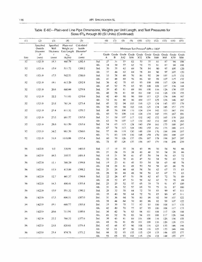
116
(I)
Size
52
52
52
52
52
52
52
52
52
52
52
52
56
56
56
56
56
56
56
56
56
56
56
56
56
API SPECIFICATION 5L
Table E-6C-Plain-end Line Pipe Dimensions, Weights per Unit Length, and Test Pressures for Sizes 65/8 through 80 (SI Units) (Continued)
(2) (3) (4) (5)
Specified Specified Plain-end Calculated Outside Wall Weight per Inside
Diameter Thickness Unit Length Diameter"
f) WI'" d (mm) (mm) (kg/m) (mm)
1321.0 14.3 460.79 1292.4
1321.0 15.9 511.72 1289.2
1321.0 17.5 562.53 1286.0
1321.0 19.1 613.20 1282.8
1321.0 20.6 660.60 1279.8
1321.0 22.2 711.03 1276.6
1321.0 23.8 761.34 1273.4
1321.0 25.4 811.52 1270.2
1321.0 27.0 861.57 1267.0
1321.0 28.6 911.50 1263.8
1321.0 30.2 961.30 1260.6
1321.0 31.8 1010.98 1257.4
1422.0 9.5 330.91 1403.0
1422.0 10.3 358.57 1401.4
1422.0 11.1 386.20 1399.8
1422.0 11.9 413.80 1398.2
1422.0 12.7 441.37 1396.6
1422.0 14.3 496.41 1393.4
1422.0 15.9 551.32 1390.2
1422.0 17.5 606.11 1387.0
1422.0 19.1 660.77 1383.8
1422.0 20.6 711.91 1380.8
1422.0 22.2 766.32 1377.6
1422.0 23.8 820.61 1374.4
1422.0 25.4 874.78 1371.2
(6) (7) (8) (9) (10) (II) (12) (13) (14) (15)
Minimum Test Pressureb (kPa x loo)e
Grade Grade Grade Grade Grade Grade Grade Grade Grade Grade A B X42 X46 X52 X56 X60 X65 X70 X80
Std. 27 31 57 62 70 75 81 87 94 108
All. 34 39 57 62 70 75 81 87 94 108
Std. 30 35 63 69 78 84 90 97 105 120 All.
Std. All.
Std.
All.
Std.
All.
Std.
All.
Std.
All.
Std.
All.
Std.
Alt.
Std. All.
Std. All.
Stcl. All.
Stcl. All.
Std.
All.
Stcl.
All.
Std.
All.
Stcl. All.
Stcl. All.
Std.
Alt.
Stcl. All.
Stcl.
All. Stcl. All.
Std. All.
Stcl. All. Std.
All.
37
33 41
36
45
39
48
42
52
45
56
48 60
51
63
54
67
57
71
60 75
17 21
18
22
19
24
21
26
22
28
25
31
28
35 31
38
33
42
36 45
39
48 42
52 44
55
44 63 69
38 69 76 48 69 76
42 75 83
52 75 83
45 81 89
56 81 89
49 88 96
61 88 96
52 94 103
65 94 103
56 100 110
70 100 110
59 107 117
74 107 117
63 113 124
78 113 124
66 119 130
83 119 130 70 126 137 87 126 137
19 35 38
24 35 38
21 38 41 26 38 41
23 41 45
28 41 45
24 44 48
30 44 48
26 47 51
32
29
36
32
40
36
44 39
49 42
52
45
56
48
61 52
65
47
52
52 58
58
64
64 70
70
76
76
81
81
87
87 93
93
51
57
57
64
64
70
70
77
77
83
83
89
89
96
96 102
102
78 84 90 97 105 120
86 92 99 107 115 132
86 92 99 107 115 132 93 100 108 117 126 144
93 100 108 117 126 144
101 108 116 126 136 155 101 108 116 126 136 155
109 117 125 136 146 167
109 117 125 136 146 167
116 125 134 145 157 179 116 125 134 145 157 179 124 134 143 155 167 191
124 134 143 155 167 191
132 142 152 165 178 203
132 142 152 165 178 203 140 150 161 175 188 207 140 150 161 175 188 215
148 159 170 184 199 207 148 159 170 184 199 227 156 167 179 194 207 207 156 167 179 194 209 239
43 46 50 54 58 66 43 46 50 54 58 66 47 50 54 58 63 72 47 50 54 58 63 72
50 54 58 63 68 78 50 54 58 63 68 78 54 58 62 67 73 83
54 58 62 67 73 83
58 62 67 72 78 89
62 67 72 78 58
65
65 72
72
80
80
87
87
94
94
70 75 81 87 89
100
100
III
III
122
122
133
133 144
144
155
155
166
166 177
177
101
101
lOS 108 115
115
70 75
78 83
78 83
86 92
86 92
93 100
93 100
101 108
101 108
108 116
108 116
116 125 116 125 124 133
124 133
81 87
90 97
90 97
99 107
99 107
108 117
108 117 117 126
117 126
126 136
126 136
135 146 135 146
144 155
144 155
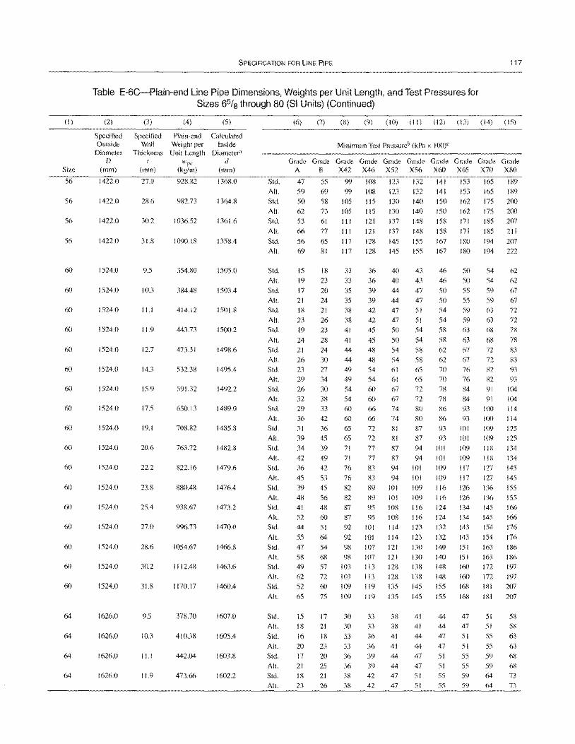
(I)
Size
56
56
56
56
60
60
60
60
60
60
60
60
60
60
60
60
60
60
60
60
60
64
64
64
SPECIFICATION FOR liNE PIPE 117
Table E-6C-Plain-end Line Pipe Dimensions, Weights per Unit Length, and Test Pressures for Sizes 65/8 through 80 (SI Units) (Continued)
(2)
Specified Outside Diameter
D (mm)
1422.0
1422.0
1422.0
1422.0
1524.0
1524.0
1524.0
1524.0
1524.0
1524.0
1524.0
1524.0
1524.0
1524.0
1524.0
1524.0
1524.0
1524.0
1524.0
1524.0
1524.0
1626.0
1626.0
1626.0
1626.0
(3) (4)
Specified Plain-end Wall Weight per
Thickness Unit Length t l'Vpc
(mm) (kg/m)
27.0 928.82
28.6 982.73
30.2 1036.52
31.8 1090.18
9.5 354.80
10.3 384.48
11.1 414.12
11.9 443.73
12.7 473.31
14.3 532.38
15.9 591.32
17.5 650.13
19.1 708.82
20.6 763.72
22.2 822.16
23.8 880.48
25.4 938.67
27.0 996.73
28.6 1054.67
30.2 1112.48
31.8 1170.17
9.5 378.70
10.3 410.38
11.1 442.04
11.9 473.66
(5)
Calculated Inside
Diameter'l J
(mm)
1368.0
1364.8
1361.6
1358.4
1505.0
1503.4
1501.8
1500.2
1498.6
1495.4
1492.2
1489.0
1485.8
1482.8
1479.6
1476.4
1473.2
1470.0
1466.8
1463.6
1460.4
1607.0
1605.4
1603.8
1602.2
Std.
AI!.
Std.
AI!.
Std.
AI!.
Std.
AI!.
Std.
AI!.
Std.
AI!.
Std.
AI!.
Std.
All.
Std. AI!.
Std. All.
Std.
All.
Std.
All.
Std.
AI!.
Std. All.
Std.
All.
Std.
AI!.
Std.
All.
Std.
AI!.
Std.
All.
Std. All.
Std.
All.
Std.
AI!.
Std.
All.
Std.
AI!.
Std.
AI!.
(6) (7) (9) (10) (I I) (12) (13) (14) (15)
Minimum Test Pressureb (kPa x 100)"
Grade Grade Grade Grade Grade Grade Grade Grade Grade Grade A B X42 X46 X52 X56 X60 X65 X70 X80
47 55 99 108 123 132 141 153 165 189
59 69 99 108 123 132 141 153 165 189
50 58 lOS 115 130 140 150 162 175 200
62
53
66
56
69
IS 19
17
21
18
23
19
24 21
26
23 29
26
32 29
36 31
39 34
42
36 45 39
48 41 52
44
55 47 58 49
62
52
65
IS 18
16
20
17
21
18
23
73 105 115 130 140 150 162 175 200
61 III 121 137 148 158 171 185 207
77 III 121 137 148 158 171 185 211
65 117 128 145 155 167 180 194 207
81 117 128 145 155 107 180 194 222
18 33 36 40 43 46 50 54 62
23 33 36 40 43 46 50 54 62
20 35 39 44 47 50 55 59 67
24 35 39 44 47 50 55 59 67
21 38 42 47 51 54 59 63 72
26 38 42 47 51 54 59 63 72
23 41 45 50 54 58 63 68 78
28 41 45 50 54 58 63 68 78
24 44 48 54 58 62 67 72 83
30 44 48 54 58 62 67 72 83
27 49 54 61 65 70 76 82 93
34 49 54 61 65 70 76 82 93
30 54 60 67 72 78 84 91 104
38 54 60 67 72 78 84 91 104 33 60 66 74 80 86 93 100 114
42 60 66 74 80 86 93 I(X) 114
36 65 72 81 R7 93 101 109 125
45 65 72 81 87 93 10/ 109 125
39 71 77 87 94 101 109 118 134
49 71 77 87 94 101 109 118 134
42 76 83 94 101 109 117 127 145
53 76 R3 94 101 109 117 127 145
45 82 89 10/ 109 116 126 136 155
56 82 89 101 109 116 126 136 155
48 87 95 108 116 124 134 145 166 60 87 95 108 116 124 134 145 166
51 92 101 114 123 132 143 154 176
64 92 101 114 123 132 143 154 176
54 98 107 121 130 140 151 163 186
68 98 107 121 130 140 151 163 186
57 103 113 128 13R 14R 160 172 197
72 103 113 128 138 148 160 172 197
60 109 119 135 145 155 168 181 207
75 109 119 135 145 155 168 181 207
17
21
18
23
20 25
21
26
30
30
33
33
36
36
38 38
33
33
36
36
39
39 42
42
38
38
41
41
44
44
47 47
41
41
44
44
47 47 51 51
44
44
47 47 51 51
55 55
47 47 51
51
55 55
59
59
51
51
55
55
59
59 64
64
58 58
63
63
68
68 73
73
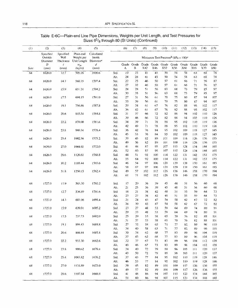
118
(I)
Size
64
64
64
64
64
64
64
64
64
64
64
64
64
68
68
68
68
68
68
68
68
68
68
68
API SPECIFICATION 5L
Table E-6C-Plain-end Line Pipe Dimensions, Weights per Unit Length, and Test Pressures for Sizes 65/8 through 80 (SI Units) (Continued)
(2)
Specified Outside
Diameter f)
(111m)
1626.0
1626.0
1626.0
1626.0
1626.0
1626.0
1626.0
1626.0
1626.0
1626.0
1626.0
1626.0
1626.0
1727.0
1727.0
1727.0
1727.0
1727.0
1727.0
1727.0
1727.0
1727.0
1727.0
1727.0
1727.0
(3)
Specified Wall
Thickness I
(mm)
12.7
14.3
15.9
17.5
19.1
20.6
22.2
23.8
25.4
27.0
28.6
30.2
31.8
11.9
12.7
14.3
15.9
17.5
19.1
20.6
22.2
23.8
25.4
27.0
28.6
(4)
Plain-end Weight per Unit Length
wpe (kg/m)
505.26
568.35
631.31
694.15
756.86
815.54
878.00
940.34
1002.56
1064.65
1126.61
1188.44
1250.15
503.30
536.89
603.96
670.91
737.73
804.43
866.84
933.30
999.62
1065.82
1131.89
1197.84
(5)
Calculated Inside
Diameter" Ii
(mm)
1600.6
1597.4
1594.2
1591.0
1587.8
1584.8
1581.6
1578.4
1575.2
1572.0
1568.8
1565.6
1562.4
1703.2
1701.6
1698.4
1695.2
1692.0
1688.8
1685.8
1682.6
1679.4
1676.2
1673.0
1669.8
Std.
All.
Std.
All.
Std. All.
Std.
All.
Std.
Alt. Std.
All.
Std.
All.
Std.
All.
Std.
All.
Std.
All.
Std.
All.
Std.
All.
Std.
All.
Std.
All.
Std.
All.
Std.
Alt.
Std.
Alt.
Std.
Alt.
Std.
Alt.
Std.
Alt.
Std.
All.
Std.
All.
Std.
Alt.
Std.
Alt.
Std.
All.
(6) (7) (8) (9) (10) (II) (12) (13) (14) (15)
Minimum Test Pressureb (kPa x 1(0)"
~~G~G~~~~~G~G~G~G~G~ A B X42 X46 X52 X56 X60 X65 X70 X80
19 23 41 45 50 54 58 63 68 78
24 28 41 45 50 54 58 63 68 78
22 25 46 50 57 61 66 71 76 87
27
24 30
27
33 29
36 31
39
34
42
36
45
39
49 41
52
44
55 46
58
49
61
17 21
18 23
21
26
23
29
25
31
27
34
30 37
32
40
34
43
37
46
39
49 41
51
32 46 50 57
28 51 56 63 35 51 56 63
31 56 61 70
39 56 61 70
34 61 67 76
42 61 67 76
37 66 72 82
46 66 72 82
39 71 78 88
49 71 78 88
42 76 84 95
53 76 84 95
45 82 89 JOI 56 82 89 101 48 87 95 J07
60 87 95 107
51 92 100 114
64 92 100 114
54 97 106 120
67 97 106 120
57 102 112 126
61 66 71 76
68 73 79 85 68 73 79 85 75 80 87 94
75 80 87 94
82 88 95 102
82 88 95 102
88 94 102 110
88 94 102 110
95102110119
95102110 119 102 109 118 127
102 109 118 127
109 116 126 136
109 116 126 136
115 124 134 144
115 124 134 144
122 131 142 153
122 131 142 153 129 138 150 161
129 138 150 161
136 146 158 170
87
97 97
107
107 117
117 126
126
136
136 145
145
155
ISS
165
165
175
175 185
185
194 71 102 112 126 136 146 158 170 194
20 25
21 27
24
30
27
33
29
37
32
40
34 43
37
46
40
50
43
53
45
57 48
60
36 36
38
38
43
43
48 48
53 53
58
58
62
62
67
67 72
72
77
77
82
82
86
86
39 45
39 45
42 48
42 48
47 54
47 54
53 59
53 59
58 65
58 65
63 71
63 71
68 77 68 77 73 83
73 83
79 89
79 89
84 95
84 95
89 101
89 101 94 107
94 107
48 51 56 60 68 48 51 56 60 68
51 55 59 64 73
51 55 59 64 73
58 62 67 72 82
58 62 67 72 82
64 69 74 80 91
64 69 74 80 91
70 76 82 88 101
70 76 82 88 101
77 82 89 % 110
77 82 89 96 110
83 89 96 104 I 19 83 89 96 104 1 19
89 96 104 112 128
89 96 104 112 128
96 103 III 120 137
96 103 111 120 137
102 110 119 128 146
102 110 119 128 146
109 117 126 136 155
109 117 126 136 155 liS 123 134 144 165
115 123 134 144 165
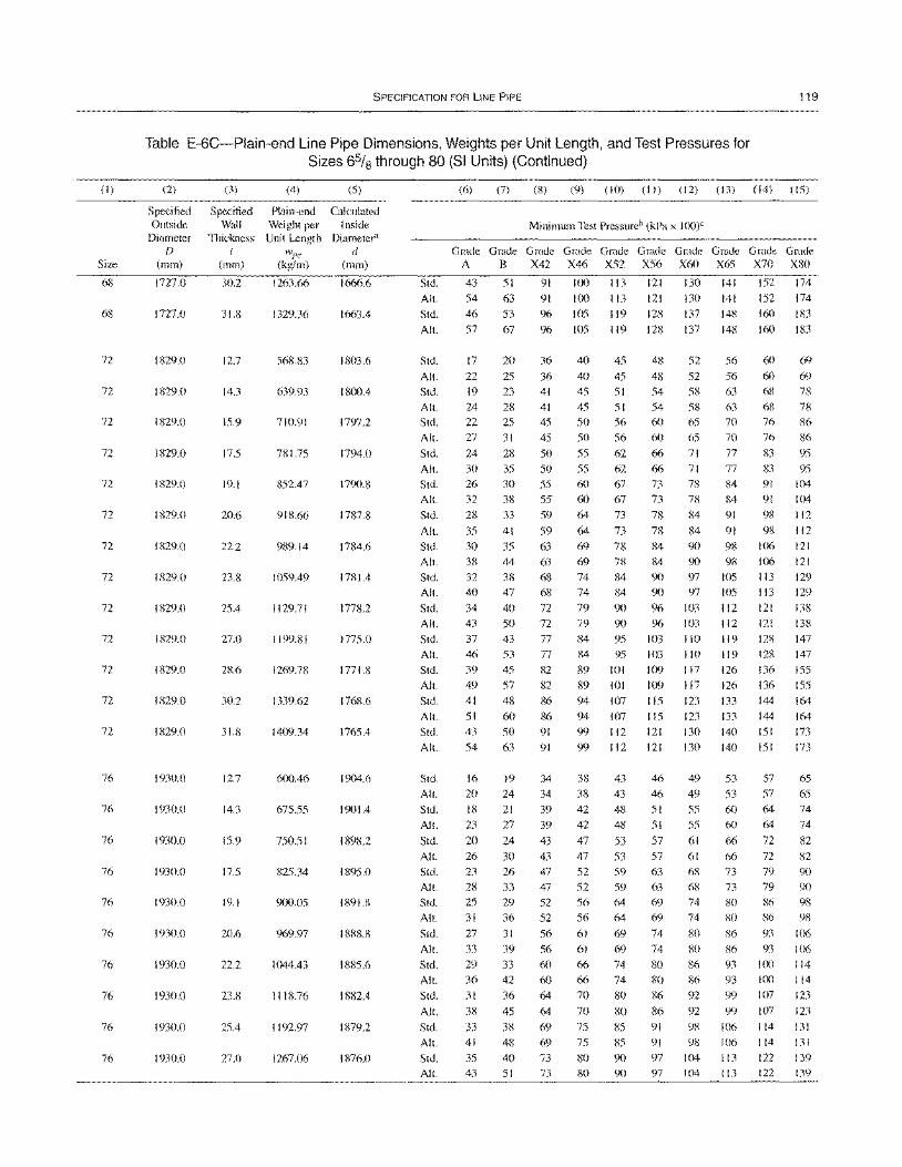
(I)
Size
68
68
72
72
72
72
72
72
72
72
72
72
72
72
72
76
76
76
76
76
76
76
76
76
76
SPECIFICATION FOR liNE PIPE 119
Table E-6C-Plain-end Line Pipe Dimensions, Weights per Unit Length, and Test Pressures for Sizes 6% through 80 (SI Units) (Continued)
(2)
Specified Outside
Diameter [)
(mm)
1727.0
1727.0
1829.0
1829.0
1829.0
1829.0
1829.0
1829.0
1829.0
1829.0
1829.0
1829.0
1829.0
1829.0
1829.0
1930.0
1930.0
1930.0
1930.0
1930.0
1930.0
1930.0
1930.0
1930.0
1930.0
(3) (4)
Specified Plain-end Wall Weight per
Thickness Unit Length t w1Je
(mm) (kg/m)
30.2 1263.66
31.8 1329.36
12.7 568.83
14.3 639.93
15.9 710.91
17.5 781.75
19.1 852.47
20.6 918.66
222 989.14
23.8 1059.49
25.4 1129.71
27.0 1199.81
28.6 1269.78
30.2 1339.62
31.8 1409.34
12.7 600.46
14.3 675.55
15.9 750.51
17.5 825.34
19.1 900.05
20.6 969.97
22.2 1044.43
23.8 1118.76
25.4 1192.97
27.0 1267.06
(5)
Calculated Inside
Diameter" d
(mm)
1666.6
1663.4
1803.6
1800.4
1797.2
1794.0
1790.8
1787.8
1784.6
1781.4
1778.2
1775.0
1771.8
1768.6
1765.4
1904.6
1901.4
1898.2
1895.0
1891.8
1888.8
1885.6
1882.4
1879.2
1876.0
Std.
All.
Std.
All.
Std.
All.
Std.
All.
Std.
All.
Std.
All.
Std.
All.
Std.
All.
Std.
All.
Std.
All.
Std.
All.
Std.
All.
Std.
All.
Std.
All.
Std.
All.
Std.
All.
Std.
All.
Std.
All.
Std.
All.
Std.
All.
Std.
All.
Std.
All.
Std.
All.
Std.
All.
Std.
All.
(6) (7) (8) (9) (10) (II) (12) (13) (14) (15)
Minimum Test Pressureb (kPa x 100)e
G~G~G~G~G~G~G~G~G~G~
A B X42 X46 X52 X56 X60 X65 X70 X80
43
54
46
57
17
22
19 24 22
27
24
30
26
32
28
35
30 38 32
40
34 43
37 46
39
49
41 51
43
54
16
20
18
23
20
26
23
28 25
31
27
33 29
36 31
38
33 41
35
43
51
63
53
67
20
25
23
28 25
31
28 35
30 38
33
41
35 44
38 47
40
50 43
53 45
57
48
60
50 63
19
24 21
27
24
30
26 33 29
36 31
39
33
42
36
45
38
48 40
51
91
91
96
96
36
36 41
41 45
45
50
50
55
55
59
59 63
63
68 68
72
72 77
77
82
82 86
86 91
91
34
34
39
39
43
43
47 47
52
52
56
56
60
60
64
64
69
69
73 73
100 113 121 130 141 152 174
100 113 121 130 141 152 174
105 119 128 137 148 160 183
105 119 128 137 148 160 183
40 45 48 52 56 60 69
40 45 48 52 56 60 69
45 51 54 58 63 68 78
45 51 54 58 63 68 7X
50 56 60 65 70 76 86 50 56 60 65 70 76 86
55 62 66 71 77 83 95
55 62 66 71 77 83 95
60 67 73 78 84 91 104
60 67 73 78 84 91 104
64 73 78 84 91 98 112
64 73 78 84 91 98 112
69 78 84 90 98 106 121
69 78 84 90 98 106 121
74 84 90 97 105 113 129
74 84 90 97 lOS 113 129
79 90 90 103 112 121 138
79 90 96 103 112 121 138
84 95 103 110 119 128 147
84 95103 110 119 128 147
89 101 109 117 126 136 155
89 101 109 117 126 136 155
94 107 115 123 133 144 164
94 107 115 123 133 144 164
99 112 121 130 140 151 173
99 112 121 130 140 151 173
38 43 46 49 53 57 65
38 43 46 49 53 57 65 42 48 51 55 60 64 74
42 48 51 55 60 64 74
47 53 57 61 66 72 82
47 53 57 61 66 72 82
52 59 63 68 73 79 90
52 59 63 68 73 79 90 56 64 69 74 80 86 98 56 64 69 74 80 86 98
61 69 74 80 86 93 106
61 69 74 80 86 93 106
66 74 80 86 93 J(X) 114
66 74 80 86 93 J(X) 114
70 80 86 92 99 107 123
70 80 86 92 99 107 123
75 85 91 98 106 114 131
75 85 91 98 106 114 131
80 90 97 104 113 122 139
80 90 97 104 113 122 139
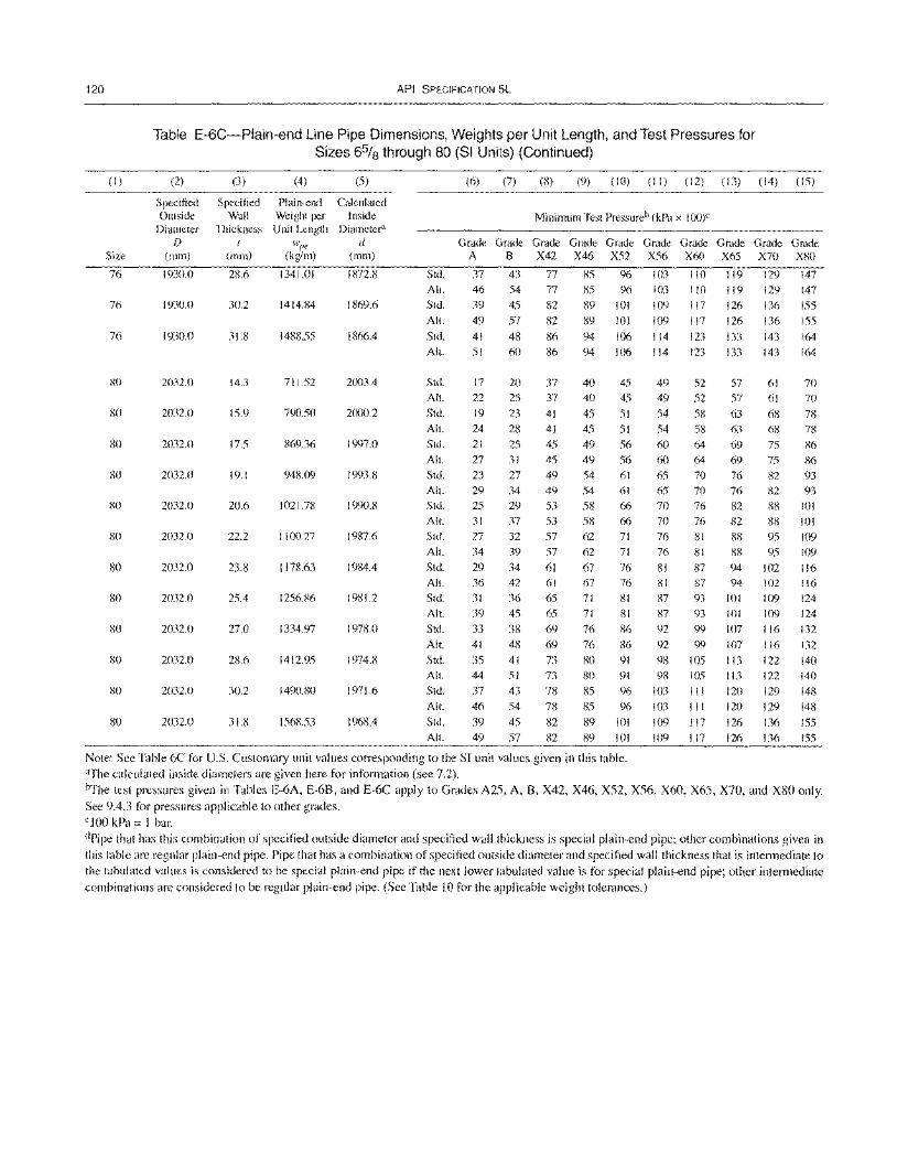
120
(I)
Size
76
76
76
80
80
so
so
80
so
so
80
80
so
80
API SPECIFICATION 5L
Table E-6C-Plain-end Line Pipe Dimensions, Weights per Unit Length, and Test Pressures for Sizes 65/8 through 80 (SI Units) (Continued)
(2)
Specified Outside
Diameter f)
(mm)
1930.0
1930.0
1930.0
2032.0
2032.0
2032.0
2032.0
2032.0
2032.0
2032.0
2032.0
2032.0
2032.0
2032.0
2032.0
(3) (4) (5)
Specified Plain-end Calculated Wall Weight per Inside
Thickness Unit Length Diameter"
wI'£' d (mm) (kg/m) (mm)
28.6 1341.01 1872.8
30.2 1414.84 1869.6
31.S 14S8.55 1866.4
14.3 711.52 2(Xl3.4
15.9 790.50 2000.2
17.5 869.36 1997.0
19.1 948.09 1993.8
20.6 1021.78 1990.8
22.2 1100.27 1987.6
23.8 1178.63 1984.4
25.4 1256.86 1981.2
27.0 1334.97 1978.0
28.6 1412.95 1974.8
30.2 1490.80 1971.6
31.8 1568.53 1968.4
Std.
All.
Std.
All.
Std.
All.
Std.
All.
Std.
All.
Std.
All.
Std.
All.
Std.
All.
Std.
All.
Std.
Alt. Std.
All.
Std.
All.
Std.
All.
Std.
All.
Std.
All.
(6) (7) (8) (9) (10) (II) (12) (13) (14) (15)
Minimum Test Pressureb (kPa x loo)e
~~G~G~~~G~~~G~G~G~G~ A B X42 X46 X52 X56 X60 X65 X70 X80
37
46
39
49
41 51
17
22
19
24
21
27
23
29 25
31
27
34
29
36
31
39
33
41
35
44
37
46
39
49
43
54
45
57
48
60
20
25
23
28
25 31
27
34
29 37
32 39
34 42
36
45
38
48
41
51
43
54
45
57
77 77
82
82
86 86
37 37
41
41
45 45
49
49
53 53
57
57
61
61
65
65 69
69
73 73
78 78
82
82
85 96 103 110 119 129
129
136
136
143
147
147
155
155
164
164
85 96 103 110 119
89 101 109 117 126
89 101 109 117 126
94106 114 123 133 94
40 40
45
45
49 49
54
54
58 58
62
62
67 67
71
71
76
76
80
80
85
85
89
89
106 114 123 133 143
45 49 52 57 61 70
45 49 52 57 61 70
51 54 58 63 68 78
51 54 58 63 68 78
56 60 64 69 75 86 56 60 64 69 75 86
61 65 70 76 82 93 61 65 70 76 82 93
66 70 76 82 88 101
66 70 76 82 88 101 71 76 81 88 95 109
71 76 81 88 95 109
76 81 87 94 102 116
76 81 87 94 102 116
81 87 93 101 109 124 81 87 93 101 109 124
86 92 99 107 116 132
86 92 99 107 116 132
91 98 105 113 122 140
91 98 105 113 122 140
96 103 III 120 129 148
96 103 III 120 129 148
101 109 117 126 136 155
101 109 117 126 136 155
Note: See Table 6C for U.S. Customary unit values corresponding to the SI unit values given in this table. "The calculated inside diameters are given here for infonnation (see 7.2). iYfhe test pressures given in Tables E-6A, E-6B, and E-6C apply to Grades A25, A, B, X42, X46, X52, X56, X60, X65, X70, and X80 only. See 9.4.3 for pressures applicable to other grades. ciao kPa = I bar. dPipe that has this combination of specified outside diameter and specified wall thickness is special plain-end pipe; other combinations given in this table are regular plain-end pipe. Pipe that has a combination of specified outside diameter and specified wall thickness that is intennediate to the tabulated values is considered to be special plain-end pipe if the next lower tabulated value is for special plain-end pipe; other intermediate combinations are considered to be regular plain-end pipe. (See Table 10 for the applicable weight tolerances.)
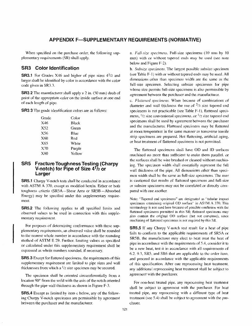
APPENDIX F-SUPPLEMENTARY REQUIREMENTS (NORMATIVE)
When specified on the purchase order, the following supplementary requirements (SR) shall apply.
SR3 Color Identification
SR3.1 For Grades X46 and higher of pipe sizes 4 1/2 and larger shall be identified by color in accordance with the color code given in SR3.3.
SR3.2 The manufacturer shall apply a 2 in. (SO mm) daub of paint of the appropriate color on the inside surface at one end of each length of pipe.
SR3.3 The grade identification colors are as follows:
Grade Color X46 Black XS2 Green XS6 Blue X60 Red X6S White X70 Purple X80 Yellow
SR5 Fracture Toughness TestinJ1 (Charpy V-notch) for Pipe of Size 4 h or Larger
SRS.1 Charpy V-notch tests shall be conducted in accordance with ASTM A 370, except as modified herein. Either or both toughness criteria (SRSA-Shear Area or SRSB-Absorbed Energy) may be specified under this supplementary requirement.
SRS.2 The following applies to all specified limits and observed values to be used in connection with this supplementary requirement.
For purposes of determining conformance with these supplementary requirements, an observed value shall be rounded to the nearest whole number in accordance with the rounding method of ASTM E 29. Further, limiting values as specified or calculated under this supplementary requirement shall be expressed as whole numbers rounded, if necessary.
SRS.3 Except for flattened specimens, the requirements of this supplementary requirement are limited to pipe sizes and wall thicknesses from which a 1/2 size specimen may be secured.
The specimen shall be oriented circumferentially from a location 90° from the weld with the axis of the notch oriented through the pipe wall thickness as shown in Figure F-3.
SRS.4 Except as limited by item c below, any of the following Charpy V-notch specimens are permissible by agreement between the purchaser and the manufacturer.
121
a. Full-size specimens. Full-size specimens (10 mm by 10 mm) with or without tapered ends may be used (see note below and Figure F-2).
b. Subsize specimens. The largest possible subsize specimen (see Table F-l) with or without tapered ends may be used. All dimensions other than specimen width are the same as the full-size specimen. Selecting subsize specimens for pipe whose size permits full-size specimens is also permissible by agreement between the purchaser and the manufacturer.
c. Flattened specimens. When because of combinations of diameter and wall thickness the use of 2/3 size tapered end specimens is not practicable (see Table F-I), flattened specimens, 1/2 size conventional specimens, or 1/2 size tapered end specimens shall be used by agreement between the purchaser and the manufacturer. Flattened specimens may be flattened at room temperature in the same manner as transverse tensile strip specimens are prepared. Hot flattening, artificial aging, or heat treatment of flattened specimens is not permitted.
The flattened specimens shall have 00 and ID surfaces machined no more than sufficient to make them parallel, or the surfaces shall be wire bmshed or cleaned without machining. The specimen width shall essentially represent the full wall thickness of the pipe. All dimensions other than specimen width shall be the same as full-size specimens. The user is cautioned that results of flattened specimens and full-size or subsize specimens may not be correlated or directly compared with one another.
Note: "Tapered end specimens" are designated as "tubular impact specimens containing original OD surface" in ASTM A 370. This terminology is not used here because of possible confusion with the flattened specimens permitted in this SR; flattened specimens may also contain the original OD surface (but not curvature), since machining of flattened specimens is not required by this SR.
SR5.S If any Charpy V-notch test result for a heat of pipe fails to conform to the applicable requirements of SRSA or SRSB, the manufacturer may elect to heat treat the heat of pipe in accordance with the requirements of S.4, consider it to be a new heat, test it in accordance with all requirements of 6.2, 9.3, SRS, and SR6 that are applicable to the order item, and proceed in accordance with the applicable requirements of this specification. After one reprocessing heat treatment, any additional reprocessing heat treatment shall be subject to agreement with the purchaser.
For non-heat treated pipe, any reprocessing heat treatment shall be subject to agreement with the purchaser. For heat treated pipe, any reprocessing with a different type of heat treatment (see S.4) shall be subject to agreement with the purchaser.
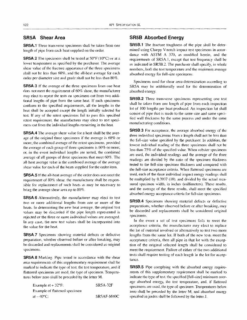
122 API SPECIFICATION 5L
SR5A Shear Area
SR5A.1 Three transverse specimens shall be taken from one length of pipe from each heat supplied on the order.
SR5A.2 The specimens shall be tested at 50°F (lO°C) or at a lower temperature as specified by the purchaser. The average shear value of the fracture appearance of the three specimens shall not be less than 60%, and the all-heat average for each order per diameter size and grade shall not be less than 80%.
SR5A.3 If the average of the three specimens from one heat does not meet the requirement of 60% shear, the manufacturer may elect to repeat the tests on specimens cut from two additional lengths of pipe from the same heat. If such specimens conform to the specified requirements, all the lengths in the heat shall be accepted except the length initially selected for test. If any of the retest specimens fail to pass this specified retest requirement, the manufacturer may elect to test specimens cut from the individual lengths remaining in the heat.
SR5A.4 The average shear value for a heat shall be the average of the original three specimens if the average is 60% or more; the combined average of the retest specimens, provided the average of each group of three specimens is 60% or more; or, in the event individual lengths are tested, the combined average of all groups of three specimens that meet 60%. The all-heat average value is the combined average of the average shear value for each of the heats supplied for the order item.
SR5A.5 If the all-heat average of the order does not meet the requirement of 80% shear, the manufacturer shall be responsible for replacement of such heats as may be necessary to bring the average shear area up to 80%.
SR5A.6 Alternatively, the manufacturer may elect to test two or more additional lengths from one or more of the heats. In determining the new heat average, the original test values may be discarded if the pipe length represented is rejected or the three or more individual values are averaged. In any case, the new test values shall be incorporated into the value for the heat.
SR5A.7 Specimens showing material defects or defective preparation, whether observed before or after breaking, may be discarded and replacements shall be considered as original specimens.
SR5A.8 Marking. Pipe tested in accordance with the shear area requirements of this supplementary requirement shall be marked to indicate the type of test, the test temperature, and if flattened specimens are used, the type of specimen. Temperatures below zero shall be preceded by the letter M.
Example at + 32°F:
Example of flattened specimen
at -40°C:
SR5A-32F
SR5AF-M40C
SR58 Absorbed Energy SR5B.1 The fracture toughness of the pipe shall be determined using Charpy V-notch impact test specimens in accordance with ASTM A 370, as modified herein, and the requirements of SR5A.1, except that test frequency shall be as indicated in SR5B.2. The purchaser shall specify, in whole numbers, both the test temperature and the minimum average absorbed energy for full-size specimens.
Specimens used for shear area determination according to SRSA may be additionally used for the determination of absorbed energy.
SR5B.2 Three transverse specimens representing one test shall be taken from one length of pipe from each inspection lot of 100 lengths per heat produced. An inspection lot shall consist of pipe that is made to the same size and same specified wall thickness by the same process and under the same manufacturing conditions.
SR5B.3 For acceptance, the average absorbed energy of the three individual specimens from a length shall not be less than the full-size value specified by the purchaser. In addition, the lowest individual reading of the three specimens shall not be less than 75% of the specified value. When subsize specimens are used, the individual readings and the average of the three readings are divided by the ratio of the specimen thickness tested to the full-size specimen thickness and compared with the full-size acceptance criteria. When flattened specimens are used, each of the three individual impact energy readings shall be multiplied by 0.3937 (10), and divided by the actual measured specimen width, in inches (millimeters). These results, and the average of the three results, shall meet the specified absorbed energy acceptance criteria for full-size specimens.
SR5B.4 Specimens showing material defects or defective preparations, whether observed before or after breaking, may be discarded and replacements shall be considered original specimens.
In the event a set of test specimens fails to meet the acceptance criteria, the manufacturer may elect to replace the lot of material involved or alternatively to test two more lengths from the same lot. If both of the new tests meet the acceptance criteria, then all pipe in that lot with the exception of the original selected length shall be considered to meet the requirement. Failure of either of the two additional tests shall require testing of each length in the lot for acceptance.
SR5B.5 Pipe complying with the absorbed energy requirements of this supplementary requirement shall be marked to indicate the type of test, the specified [full-size] minimum average absorbed energy, the test temperature, and, if flattened specimens are used, the type of specimen. Temperatures below zero shall be preceded by the letter M, and absorbed energy specified in joules shall be followed by the letter J.
SPECIFICATION FOR LINE PIPE 123
Example for 20 ft-Ib at +32°F:
Example of flattened specimens for
20 ft-Ib at - 40°F:
Example of flattened specimens for
both SRSA and SRSB for 27 joules
at O°C:
SRS8-20-32F
SRSBF-20-M40F
SRSABF-27J-OC
SRG Drop-weight Tear Testing on Welded Pipe of Size 20 or Larger, Grade X52 or Higher
SR6.1 Fracture toughness of pipe sizes 20 and larger, Grade XS2 and higher, shall be determined by the manufacturer using drop-weight tear tests in accordance with the following requirements in SR6.2 through SR6.8.
SR6.2 Two transverse specimens shall be taken from one length of pipe from each heat supplied on the order. The specimens shall be oriented circumferentially from a location 90° from the weld with the axis of the notch oriented through the pipe wall thickness as shown in Figure F-3. The specimens shall be tested at SO°F (10°C) or at a lower temperature as specified by the purchaser.
SR6.3 The test specimens, testing procedure, and rating of the specimens shall be in accordance with API RP SL3. The type of notch (pressed or chevron) shall be selected by agreement between the manufacturer and the purchaser.
SR6.4 At least 80% of the heats shall exhibit a fracture appearance shear area of 40% or more for the specified test temperature (see note).
Note: Due to manufacturing difficulties encountered with thicker materials, pipe manufacturers may not be able to offer pipe in all grades that meet this requirement.
SR6.5 In the event the average value of the two specimens from the length selected to represent the heat is less than 40%, the manufacturer may elect to establish the heat average by testing two specimens from each of two or more additional lengths of pipe in the heat. In establishing the new heat average, the manufacturer may elect (a) to employ the combined average of the three tests or more; or (b) to discard the result of the first test, reject the pipe from which it was taken, and employ the combined average of the two or more additional tests. Alternatively, the manufacturer may elect to test all the pipe in the heat, in which case 80% or more of the lengths tested and applied to the order shall exhibit an average of 40% or more shear.
SR6.6 Specimens showing material defects or defective preparation, whether observed before or after breaking, may be discarded, and replacements shall be considered as original specimens.
SR6.7 The manufacturer shall be responsible for replacement of such heats as may be necessary to meet the above requirements.
SR6.8 Pipe tested in accordance with SR6 shall be marked to indicate the type of test, the type of notch, and the testing temperature. Temperatures below zero shall be preceded by the letter M.
Example for chevron notch at 32°F: Example for pressed notch at - 10°C:
SR6C-32F SR6P-MIOC
SR7 Through-the-Flowline (TFL) Pipe
SR7.1 GENERAL
TFL pipe shall comply with all requirements of this specification and the additional requirements specified in SR7.2 through SR7.6.
SR7.2 DIMENSION AND GRADES
TFL pipe shall be seamless or longitudinal seam pipe in the outside diameters, wall thicknesses, and grades listed in Table F-2.
SR7.3 LENGTH
Unless otherwise specified, TFL pipe shall be furnished only in double random lengths with no jointers (girth welds).
SR7.4 DRIFTTESTS
Each length of TFL pipe shall be tested throughout its entire length with a cylindrical drift mandrel conforming to the requirements listed below. The leading edge of the drift mandrel shall be rounded to permit easy entry into the pipe. The drift mandrel shall pass freely through the pipe with a reasonable exerted force equivalent to the weight of the mandrel being used for the test. Pipe shall not be rejected until it has been drift tested when it is free of all foreign matter and properly supported to prevent sagging.
Drift Mandrel Size
Size in.
42
42
Length
mm
1066
1066
SR7.5 HYDROSTATIC TESTS
Diam., min.
in.
d - 3/32
d - Ilx
mm
£1-2.4
£1-3.2
TFL pipe shall be hydrostatically tested in accordance with the requirements of 9.4, except that the minimum test pressures shall be as shown in Table F-2. These test pressures in Table F-2 represent the lesser of 10,000 psi (68 900 kPa) and
04
124 API SPECIFICATION 5L
the pressure calculated with the equation given in 9.4.3, using a fiber stress (S) equal to 80% of the specified minimum yield strength.
SR7.6 MARKING
TFL pipe manufactured in accordance with SR7 shall be marked with the letters TFL in addition to the marking required in Section 10 or Appendix I.
SR15 Test Certificates and Traceability for Line Pipe
SR1S.1 The manufacturer shall provide the following data, as applicable, for each order item for which this supplementary requirement is specified on the purchase order. The manufacturer's certificate of compliance shall state the API specification and date of revision to which pipe was manufactured. A Material Test Report, Certificate of Compliance, or similar document printed from or used in electronic form from an electronic data interchange (EDI) transmission shall be regarded as having the same validity as a counterpart printed in the manufacturer's facility. The content of the EDI transmitted document must meet the requirements of this specification and conform to any existing EDI agreement between the purchaser and the manufacturer.
a. Specified outside diameter, specified wall thickness, grade, process of manufacture, and type of heat treatment.
b. Chemical analyses (heat, product, control, and recheck) showing the weight percent of all elements whose limits or reporting requirements are set in this specification; for PSL 2 pipe, carbon equivalent and applicable maximum allowable value. If order is for by-agreement "high carbon equivalent pipe," that designation shall be included.
c. Test data for all tensile tests required by this specification, including yield strength, ultimate tensile strength, and elongation. The type, size, and orientation of specimens shall be shown.
d. Fracture toughness test results (including test type and criteria and the size, location, and orientation of the specimen) where such testing is required.
e. Minimum hydrostatic test pressure and duration.
f. For welded pipe for which nondestructive inspection of the weld seam is required by this specification, the method of nondestructive inspection employed (radiological, ultrasonic, electromagnetic, and/or magnetic particle), and the type and size of all penetrameters and reference standards used.
g. For seamless pipe for which nondestructive inspection is required, the method of inspection employed (ultrasonic, electromagnetic, or magnetic particle) and the type and size of the reference indicators used.
h. For electric welded pipe and laser welded pipe, the minimum temperature for heat treatment of the weld seam. Where
such heat treatment is not performed, the words "No Seam Heat Treatment" shall be stated on the certificate. i. Results of any supplemental testing required by the purchaser.
SR1S.2 The manufacturer shall establish and follow procedures for maintaining heat and lot identity of all pipe covered by this supplementary requirement. The procedures shall provide means for tracing any length of pipe or coupling to the proper heat and lot and to all applicable chemical and mechanical test results.
SR17 Nondestructive Inspection of Welds in Electric Welded Pipe and Laser Welded Pipe
SR17.1 SUPPLEMENTARY NONDESTRUCTIVE INSPECTION
The weld in electric welded pipe shall be inspected full length for surface and subsurface defects by either ultrasonic or electromagnetic methods. The weld in laser-welded pipe shall be inspected full length for surface and subsurface defects by ultrasonic methods. The location of the equipment in the mill shall be at the discretion of the manufacturer. However, the nondestructive inspection shall take place after all heat treating, hydrostatic testing, expansion, and rotary straightening operations, if performed, but may take place before cropping, beveling, and sizing of pipe.
SR17.2 EQUIPMENT AND REFERENCE STANDARDS
The ultrasonic or electromagnetic inspection equipment requirements are given in 9.7.4.1, and the reference standards are described in 9.7.4.2. Details of the specific techniques (such as method, reference indicators, transducer properties, and sensitivity) shall be agreed upon between the purchaser and the manufacturer for the implementation of this supplementary requirement.
SR17.3 ACCEPTANCE LIMITS AND EMI INSPECTIONS
Table 21 gives the height of acceptance limit signals in percent of height of signals produced by reference standards. An imperfection that produced a signal greater than the acceptance limit signal given in Table 21 shall be classified as a defect.
SR17.4 DISPOSITION
Disposition of defects shall be in accordance with 9.9, item a, c, or d. Repair by welding is not permitted. If a defect is removed by grinding, the ground area shall be reinspected by the same method originally used.
SR17.S MARKING
Pipe nondestructively inspected in accordance with this supplementary requirement shall be marked SR 17.
04
L
SPECIFICATION FOR LINE PIPE 125
SR18 Carbon Equivalent
SR18.1 For pipe grades up to Grade X70 inclusive, the carbon equivalent, CE, calculated using product analysis and the following equation shall not exceed 0.43%:
CE = C + Mn + Cr + Mo + V + Ni + Cu 6 5 15
SR18.2 The elements analyzed for product analysis shall include all elements contained in the carbon equivalent equation.
SR19 Additional Fracture Toughness Requirements (Transverse Charpy V-notch) for PSL 2 Pipe
SR19.1 Except as allowed by SR 19.2, fracture toughness testing shall be performed in accordance with the requirements of 9.3.5.1 and 9.3.5.2, with a test temperature of 32°F (O°C) or a lower temperature as specified on the purchase order. The required minimum all-heat average full-size absorbed energy value shall be the greater of
a. 30 ft-Ib (40 J) for grades below Grade X80, 60 ft-Ib (80 J)
for Grade X80 pipe; and b. The value obtained from the following equation, using a stress factor (F) of 0.72 or a higher value if specified on the purchase order, and rounding the calculated value to the nearest foot-pound (joule):
u.s. Customary Unit Equation SI Unit Equation
J 3 - D 2
CV = 0.0345(Fo,i( 2) CV = O.000512(FOy)2(~r
where
cv
F
oy
D
Notes:
minimum all-heat average full-size Charpy Vnotch absorbed energy requirement, ft-Ib (1),
stress factor,
specified minimum yield strength, ksi (MPa),
specified outside diameter, in. (mm).
I. See Table F-3 for the required minimum all heat-average absorbed energy values for pipe having a standard size and grade, and a stress factor of 0.72. 2. The above equation is one of a number of such relationships derived from full-scale burst test data for a limited number of sizes and grades (see ASME B31.8). It is also judged to be conservative for initiation conditions in pipelines.
SR19.2 Pipe tested at a lower temperature than is required in SR 19.1 shall be acceptable if it meets the required absorbed energy values.
SR19.3 Pipe tested in accordance with SR 19 shall be marked to indicate the specified (full-size) minimum all-heat average absorbed energy value and the specified test temperature. Temperatures below zero shall be preceded by the letter M, and the absorbed energy specified in joules shall be followed by the letter J.
Example for 30 ft-Ib at + 32°F: Example for 70 J at - 5°C:
SR 19-30-32F SR 19-70J-MSC
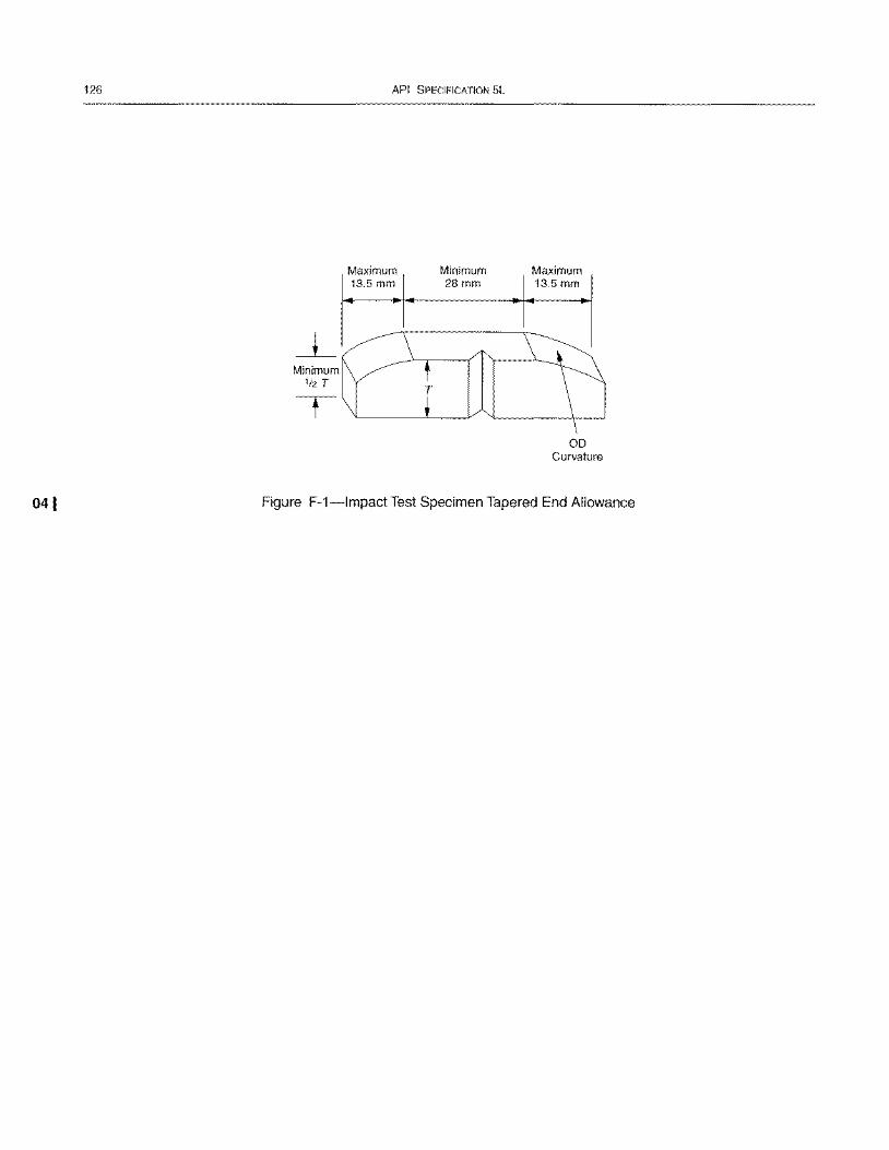
126
041
Minimum 1/2 T
API SPECIFICATION 5L
Maximum 13.5 mm
Minimum 28mm
Maximum 13.5 mm
00 Curvature
Figure F-1-lmpact Test Specimen Tapered End Allowance
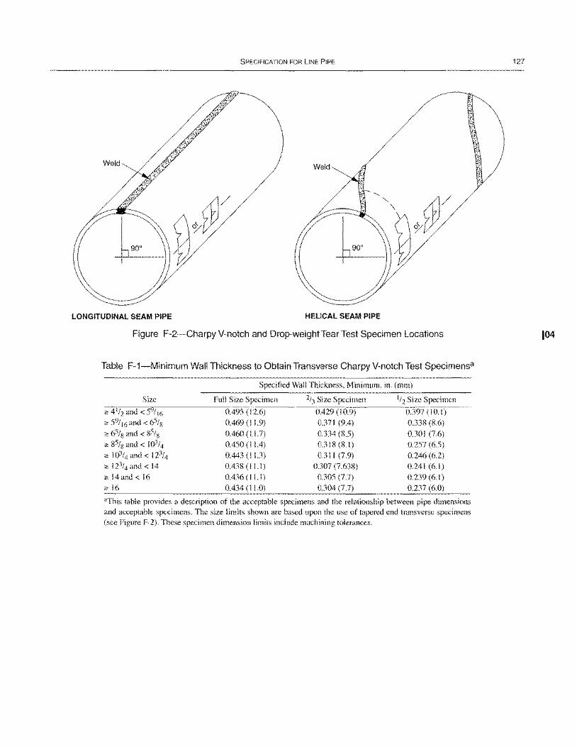
SPECIFICATION FOR LINE PIPE
LONGITUDINAL SEAM PIPE HELICAL SEAM PIPE
Figure F-2-Charpy V-notch and Drop-weight Tear Test Specimen Locations
Table F-1-Minimum Wall Thickness to Obtain Transverse Charpy V-notch Test Specimensa
Size
;" 4 1/2 and < 59/16
;" 59/ 16 and < 65/ 8
;" 65/8 and < 85/8 ;" 85/8 and < 103/4
;" 103/4 and < 123/4
;" 123/4 and < 14
;" 14and < 16 ;,,16
Specified Wall Thickness, Minimum, in. (mm)
Full Size Specimen
0.495 (12.6) 0.469 (I 1.9) 0.460 (11.7) 0.450 (I 1.4) 0.443 (11.3)
0.438 (11.1) 0.436 (I I. I ) 0.434 (I I .0)
2/3 Size Specimen
0.429 (10.9) 0.371 (9.4) 0.334 (8.5) 0.318 (8.1) 0.311 (7.9)
0.307 (7.638) 0.305 (7.7) 0.304 (7.7)
1/2 Size Specimen
0.397 (10.1) 0.338 (8.6) 0.30 I (7.6) 0.257 (6.5) 0.246 (6.2) 0.241 (6.1) 0.239(6.1) 0.237 (6.0)
"This table provides a description of the acceptable specimens and the relationship between pipe dimensions and acceptable specimens. The size limits shown are based upon the use of tapered end transverse specimens (see Figure F-2). These specimen dimension limits include machining tolerances.
127
104
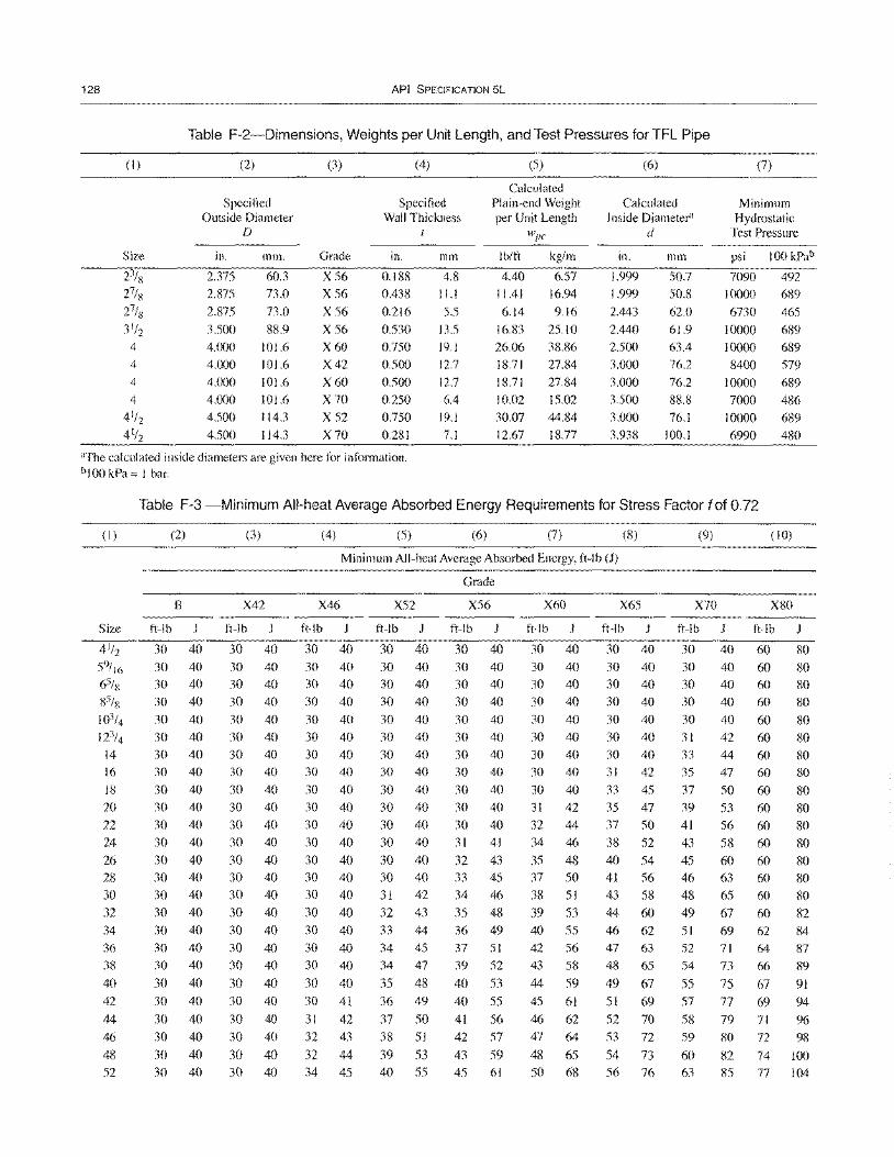
128 API SPECIFICATION 5L
Table F-2-Dimensions, Weights per Unit Length, and Test Pressures for TFL Pipe
(I)
Size
(2)
Specified Outside Diameter
D
in.
2.375
2.875 2.875
3.500 4.000 4.000
4.000 4.000 4.500
4.500
mm.
60.3
73.0
73.0
88.9 101.6 101.6
101.6 101.6 114.3 114.3
(3)
Grade
X56 X56
X56
X56 X60 X42
X60 X70 X 52
X70
(4)
Specified Wall Thickness
in.
0.188
0.438
0.216 0.530 0.750 0.500
0.500 0.250 0.750
0.281
mm
4.8
11.1
5.5
13.5 19.1 12.7
12.7
6.4 19.1
7.1
"The calculated inside diameters are given here for information. b 100 kPa = I bar.
(5)
Calculated Plain-end Weight per Unit Length
wpe
Ib/ft
4.40 11.41
6.14 16.83 26.06 18.71
18.71 10.02
30.07 12.67
kg/m
6.57 16.94
9.16
25.10 38.86 27.84
27.84 15.02 44.84 18.77
(6)
Calculated Inside Diameter"
d
m.
1.999 1.999
2.443
2.440 2.500 3.000
3.000 3.500
3.000 3.938
mm
50.7
50.8
62.0
61.9 63.4 76.2
76.2
88.8 76.1
100.1
(7)
Minimum Hydrostatic
Test Pressure
psi 100 kPab
7090 492 10000 689
6730 465
10000 689 10000 689 8400 579
10000 689
7000 486 10000 689
6990 480
Table F-3 -Minimum All-heat Average Absorbed Energy Requirements for Stress Factor fof 0.72
(I)
Size
4 1/2
59/ 16
65/x
85/ x 103/4 123/4
14 16
18 20
22
24
26 28 30 32
34 36 38
40
42
44 46
48
52
(2)
B
ft-Ib J
30 40 30 40 30 40 30 40
30 40 30 40 30 40 30 40
30 40 30 40 30 40 30 40
30 40 30 40 30 40 30 40 30 40 30 40
30 40
30 40
30 40
30 40 30 40
30 40 30 40
(3)
X42
ft-Ib
30 40 30 40 30 40 30 40
30 40 30 40 30 40 30 40
30 40 30 40 30 40 30 40
30 40 30 40 30 40 30 40
30 40 30 40 30 40
30 40
30 40
30 40 30 40
30 40
30 40
(4) (5) (6) (7) (8) (9) (10)
Minimum All-heat Average Absorbed Energy, ft-Ib (1)
Grade
X46 X52 X56 X60 X65 X70 X80
ft-Ib J ft-Ib J ft-Ib J ft-Ib J ft-Ib ft-Ib J ft-Ib J
30 40 30 40 30 40 30 40 30 40 30 40 60 80 30 40 30 40 30 40 30 40 30 40 30 40 60 80 30 40 30 40 30 40 30 40 30 40 30 40 60 80 30 40 30 40 30 40 30 40 30 40 30 40 60 80 30 40 30 40 30 40 30 40 30 40 30 40 60 80 30 40 30 40 30 40 30 40 30 40 31 42 60 80 30 40 30 40 30 40 30 40 30 40 33 44 60 80 30 40 30 40 30 40 30 40 31 42 35 47 60 80 30 40 30 40 30 40 30 40 33 45 37 50 60 80 30 40 30 40 30 40 31 42 35 47 39 53 60 80 30 40 30 40 30 40 32 44 37 50 41 56 60 80 30 40 30 40 31 41 34 46 38 52 43 58 60 80 30 40 30 40 32 43 35 48 40 54 45 60 60 80 30 40 30 40 33 45 37 50 41 56 46 63 60 80 30 40 31 42 34 46 38 51 43 58 48 65 60 80 30 40 32 43 35 48 39 53 44 60 49 67 60 82 30 40 33 44 36 49 40 55 46 62 51 69 62 84 30 40 34 45 37 51 42 56 47 63 52 71 64 87 30 40 34 47 39 52 43 58 48 65 54 73 66 89 30 40 35 48 40 53 44 59 49 67 55 75 67 91 30 41 36 49 40 55 45 61 51 69 57 77 69 94 31 42 37 50 41 56 46 62 52 70 58 79 71 96 32 43 38 51 42 57 47 64 53 72 59 80 72 98 32 44 39 53 43 59 48 65 54 73 60 82 74 100 34 45 40 55 45 61 50 68 56 76 63 85 77 104
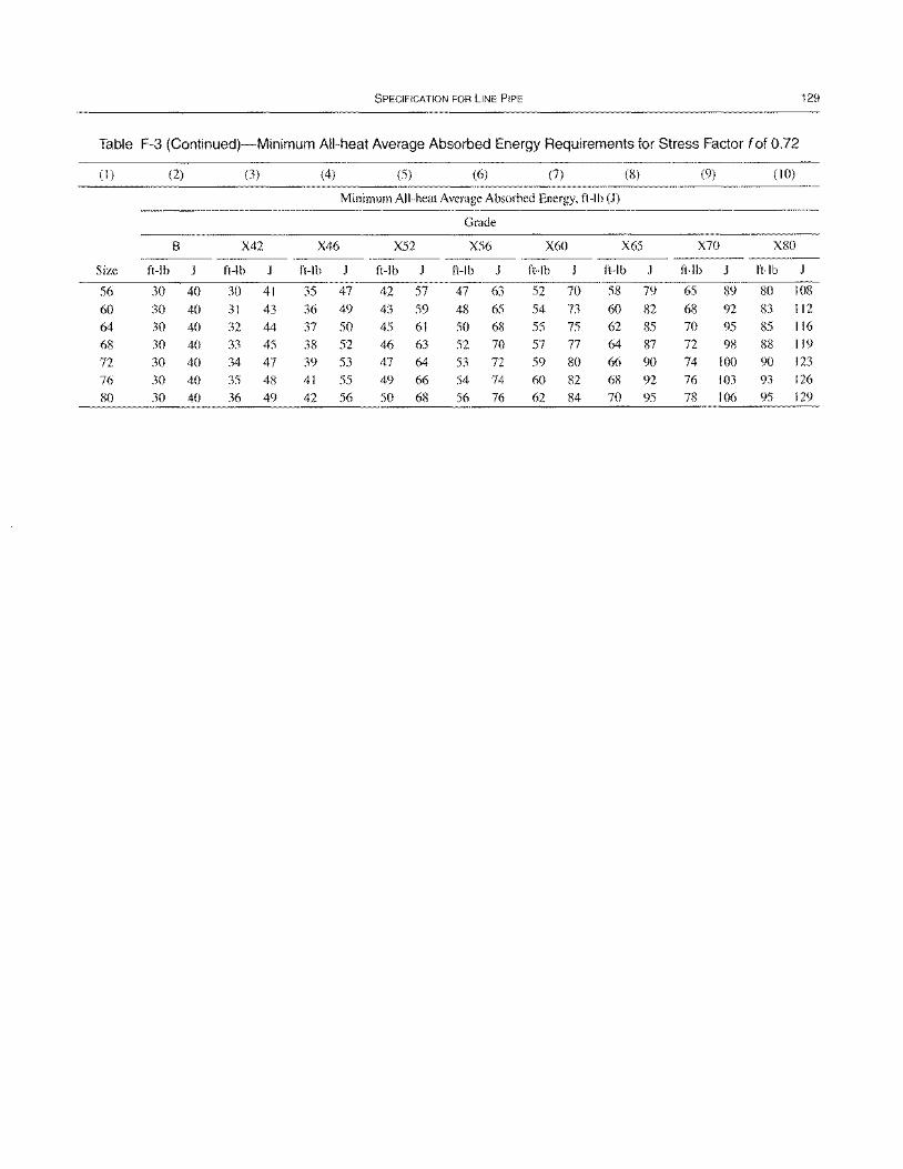
SPECIFICATION FOR LINE PIPE 129
Table F-3 (Continued)-Minimum All-heat Average Absorbed Energy Requirements for Stress Factor fof 0.72
(1 ) (2) (3) (4) (5) (6) (7) (8) (9) (10)
Minimum All-heat Average Absorbed Energy, ft-lb (1)
Grade
B X42 X46 X52 X56 X60 X65 X70 X80
Size ft-lb J ft-Ib ft-Ib ft-Ib J ft-Ib J ft-Ib J ft-Ib J ft-Ib J ft-Ib
56 30 40 30 41 35 47 42 57 47 63 52 70 58 79 65 89 80 108 60 30 40 31 43 36 49 43 59 48 65 54 73 60 82 68 92 83 112 64 30 40 32 44 37 50 45 61 50 68 55 75 62 85 70 95 85 116 68 30 40 33 45 38 52 46 63 52 70 57 77 64 87 72 98 88 119 72 30 40 34 47 39 53 47 64 53 72 59 80 66 90 74 100 90 123 76 30 40 35 48 41 55 49 66 54 74 60 82 68 92 76 103 93 126 80 30 40 36 49 42 56 50 68 56 76 62 84 70 95 78 106 95 129

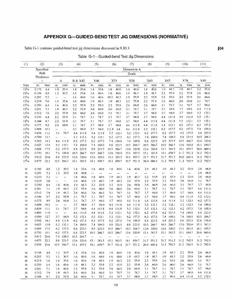
APPENDIX G-GUIDED-BEND TEST JIG DIMENSIONS (NORMATIVE)
Table G-l contains guided-bend test jig dimensions discussed in 9.10.3.
(I) (2)
Specified Wall
Thickness t
(3)
A
Table G-1-Guided-bend Test Jig Dimensions
(4) (5) (6) (7) (8)
Dimension A
Grade
B&X42 X46 X52 X56 X60
(9) (10) (II )
X65 X70 X80
Size in. mm in. mm in. mm in. mm in. mm in. mm in. mm in. mm Ill. mm Ill. mill 123/4
123/4
123/4
123/4
123/4
123/4
123/4
123/4
123/4
123/4
123/4
123/4
123/4
123/4
123/4
123/4
123/4
123/4
123/4
14
14 14
14 14
14
14
14 14
14
14
14
14
14
14
14
14
14
14
14
16
16
16
16 16
16
16
0.172 4.4 0.188 4.8
0.203 5.2
0.219 5.6 0.250 6.4 0.281 7.1
0.312 7.9
0.330 8.4
0.344 8.7
0.375 9.5
0.406 10.3
0.438 11.1
0.500 12.7
0.562 14.3
0.625 15.9
0.688 17.5
0.750 19.1
0.812 20.6
0.875 22.2
0.188 4.8
0.203 5.2 0.210 5.3
0.219 5.6 0.250 6.4 0.281 7.1
0.312 7.9
0.344 8.7 0.375 9.5
0.406 10.3
OA38 11.1
OA69 11.9
0.500 12.7
0.562 14.3
0.625 15.9
0.688 17.5
0.750 19.1 0.812 20.6
0.875 22.2
0.938 23.8
0.188 4.8
0.203 5.2
0.219 5.6
0.250 6A
0.281 7.1
0.312 7.9
0.344 8.7
1.0 25.4
1.2 30.5
1.4 35.6 1.6 40.6 1.9 48.3
2.2 55.9
2.2 55.9
2.2 55.9 2.6 66.0
3.1 78.7
4.4 111.8 5.2 132.1
6.2 157.5
7.4 188.0
8.8 223.5
10.5 266.7
1.2 30.5
1.2 30.5
1.4 35.6 1.4 35.6
1.6 40.6
1.6 40.6 2.2 55.9 2.2 55.9
2.6 66.0
3.1 78.7
3.1 78.7 3.1 78.7
3.7 94.0
4.4 111.8
5.2 132.1
6.2 157.5
7.4 188.0
8.8 223.5
10.5 266.7
12.6 320.0
15.1 383.5
1.4 35.6
1.6 40.6
1.4 35.6 1.6 40.6 1.6 40.6
1.9 48.3 2.2 55.9 2.6 66.0
2.6 66.0
3.1 78.7
3.1 78.7
3.7 94.0
3.7 94.0
4.4 111.8
5.2 132.1
6.2 157.5 7.4 188.0
8.8 223.5
10.5 266.7
12.6 320.0
18.1 459.7
1.6 40.6 1.6 40.6 1.6 40.6
1.6 40.6 1.9 48.3 1.9 48.3 48.3 48.3
1.9 48.3
1.9 55.9
2.2 55.9
2.2 55.9
2.2 55.9
2.2 55.9 2.6 66.0 2.6 66.0 2.6 66.0 3.1 78.7
3.1 78.7 3.1 78.7
3.1 78.7
3.7 94.0
3.1 78.7 3.7 94.0 3.7 94.0
3.7 94.0 3.7 94.0
111.8 4.4
5.2 132.1
6.2 157.5
7.4 188.0
8.8 223.5
10.5 266.7
12.6 320.0
3.7 94.0
4.4 111.8
4.4 111.8
5.2 132.1
6.2 157.5
7.4 188.0 10.5 266.7
12.6 320.0
15.1 383.5
4.4 111.8
4.4 111.8
5.2 132.1
6.2 157.5
7.4 188.0
8.8 223.5 10.5 266.7
12.6 320.0
15.1 383.5
15.1 383.5 18.1 459.7 21.7 551.2
18.1 459.7 21.7 551.2 26.0 660.4
1.6 40.6 1.6 40.6 1.6 40.6 1.9 48.3
1.6 40.6 1.6 40.6 1.9 48.3 1.9 48.3 2.2 55.9
1.6 40.6 1.9 48.3 1.9 48.3 2.2 55.9 2.2 55.9 1.6 40.6 1.9 48.3 2.2 55.9 2.2 55.9 2.6 66.0 2.6 66.0
1.9 48.3 2.2 55.9 2.6 66.0 2.6 66.0
1.9 48.3 2.6 66.0 2.6 66.0 3.1 78.7
2.2 55.9 3.1 78.7 3.1 78.7 3.1 78.7 2.6 66.0
3.1 78.7
3.1 78.7
3.7 94.0
3.7 94.0
4.4 111.8
5.2 132.1
6.2 157.5
7.4 188.0
8.8 223.5
8.8 223.5
10.5 266.7
3.7 94.0
3.7 94.0
4.4 111.8 4.4 111.8
5.2 132.1
6.2 157.5 7.4 188.0
8.8 223.5
10.5 266.7
3.7 94.0
4.4 111.8
4.4 111.8
5.2 132.1
5.2 132.1
6.2 157.5
8.8 223.5
10.5 266.7
10.5 266.7
2.6 66.0 3.1 78.7
3.1 78.7 3.7 94.0
3.7 94.0 3.7 94.0
4A 111.8
4A II I.l' 5.2 132.1
4.4 111.8 5.2 132.1
5.2 132.1
5.2 132.1 6.2 157.5
6.2 157.5 6.2 157.5
7.4 188.0 8.8 223.5 8.8 223.5 10.5 266.7
10.5 266.7
12.6 320.0
12.6 320.0
15.1 383.5
1.9 48.3
2.2 55.9 2.2 55.9
2.6 66.0
3.1 78.7 3.7 94.0
3.7 94.0
4.4 111.8
4.4 111.8 5.2 132.1
6.2 157.5 6.2 157.5
7.4 188.0
1.9 48.3 2.2 55.9
2.2 55.9
2.6 66.0 3.1 78.7 3.7 94.0
3.7 94.0
4.4 111.8
5.2 132.1
6.2 157.5
6.2 157.5
6.2 157.5
8.8 223.5
2.2 55.9 2.6 66.0 2.6 66.0
3.1 78.7
3.7 94.0 4.4 111.8
5.2 132.1
5.2 132.1
5.2 132.1
6.2 157.5
7.4 188.0
8.8 223.5
10.5 266.7
8.8 223.5 10.5 266.7 12.6 320.0 10.5 266.7 12.6 320.0 18.1 459.7
15.1 383.5 18.1 459.7 26.0 660.4 18.1 459.7 21.7 551.2 31.2 792.5
21.7 551.2 26.0 660.4 31.2 792.5
31.2 792.5 31.2 792.5 31.2 792.5
1.9 48.3 2.2 55.9 2.6 66.0
2.6 66.0 2.2 55.9
2.2 55.9 2.6 66.0
3.1 78.7
3.7 94.0
3.7 94.0 4.4 111.8
5.2 132.1
5.2 132.1
6.2 157.5
7.4 188.0
8.8 223.5
10.5 266.7
12.6 320.0 15.1 383.5
2.2 55.9 2.6 66.0
3.1 7R.7 3.1 n.7
3.7 94.0
4.4 111.8
5.2 132.1
5.2 132.1
6.2 157.5
2.6 66.0 3.1 n.7
3.7 94.0 4.4 111.8
4.4 I I 1.8
5.2 132.1 6.2 157.5
7.4 188.0
7.4 188.0
7.4 188.0 8.8 223.5
7.4 188.0 10.5 266.7
8.8 223.5 12.6 320.0 12.6 320.0 15.1 383.5
15.1 383.5 Ill-I 459.7
18.1 459.7 26.0 660A
3.7 94.0 4.4 111.8
5.2 132.1
6.2 157.5
6.2 157.5 7.4 188.0
8.8 223.5
10.5 266.7
12.6 320.0
15.1 383.5
15.1 383.5 15.1 383.5 18.1 459.7 21.7 551.2 21.7 551.2 31.2 792.5 31.2 792.5
18.1 459.7 21.7 551.2 21.7 551.2 26.0 660.4 31.2 792.5 31.2 792.5 31.2 792.5
1.2 30.5
1.2 30.5
1.4 35.6
1.6 40.6
1.6 40.6
1.9 48.3 2.2 55.9
1.4 35.6
1.6 40.6
1.6 40.6
1.9 48.3
2.2 55.9
2.6 66.0
2.6 66.0
1.6 40.6
1.6 40.6
1.9 48.3
2.2 55.9 2.2 55.9
2.6 66.0 3.1 78.7
1.6 40.6
1.6 40.6
1.9 48.3
2.2 55.9
2.6 66.0 3.1 78.7
3.1 78.7
131
1.6 40.6 1.9 48.3
2.2 55.9
2.2 55.9
2.6 66.0
3.1 78.7
3.7 94.0
1.9 48.3
1.9 48.3
2.2 55.9
2.6 66.0
3.1 78.7 3.1 78.7
3.7 94.0
1.9 48.3
1.9 48.3
2.6 55.9
2.6 66.0
3.1 78.7
3.1 78.7
3.7 94.0
2.2 55.9
2.2 55.9
2.6 66.0
2.6 66.0
3.1 78.7 3.7 94.0
4.4 111.8
2.6 66.0 2.6 66.0
3.1 78.7
3.1 78.7 3.7 94.0
4.4 111.8
5.2 132.1
104
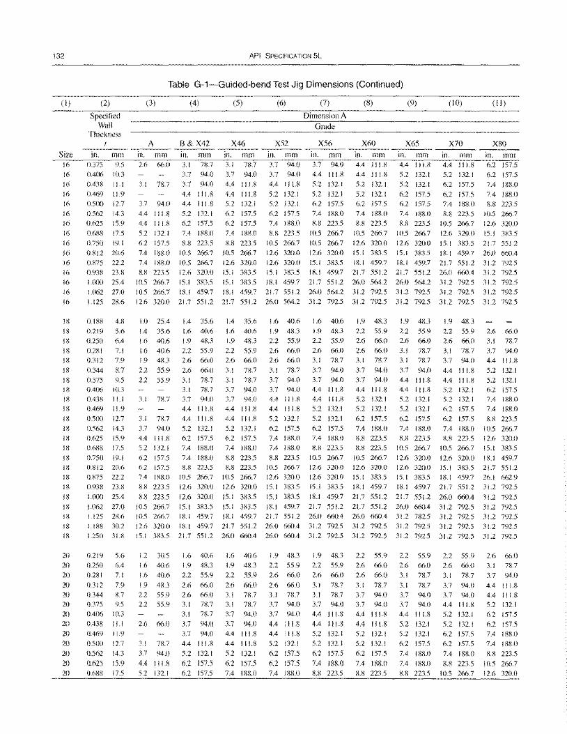
132
(I)
Size 16 16 16 16
16
16 16
16 16
16 16 16
16 16 16
IS
18 18
18 18
18 18 18 18 18 18 18 18 18
18 18 18 18
18 18 18
18 18
20 20 20
20 20 20 20 20 20
20 20
20
20
(2)
Specified Wall
Thickness
in. mm 0.375 9.5 0.406 10.3 0.43g 11.1
0.469 11.9 0.500 12.7
0.562 14.3 0.625 15.9 0.6g8 17.5
0.750 19.1 0.812 20.6 0.g75 22.2 0.938 23.8 I.O()() 25.4
1.062 27.0 1.125 28.6
0.188 4.8
0.219 5.6 0.250 6.4 0.281 7.1 0.312 7.9
0.344 8.7 0.375 9.5 0.406 10.3 0.438 11.1 0.469 11.9 0.500 12.7 0.562 14.3 0.625 15.9 0.688 17.5
0.750 19.1 0.812 20.6 0.875 22.2 0.938 23.X I,()()() 25.4
1.062 27.0 1.125 28.6 I. I 88 30.2 1.250 31.8
0.219 5.6 0.250 6.4 0.281 7.1
0.312 7.9 0.344 8.7 0.375 0.406 0.438 0.469
0.500
0.562 0.625 0.688
9.5 10.3 11.1 11.9 12.7
14.3
15.9
17.5
API SPECIFICATION 5L
Table G-1-Guided-bend Test Jig Dimensions (Continued)
(3)
A
in. mm 2.6 66.0
3.1 78.7
3.7 94.0 4.4 111.8 4.4 111.8 5.2 132.1
6.2 157.5 7.4 188.0 7.4 188.0 K8 223.5
10.5 266.7
(4)
B &X42
In. mm 3.1 78.7 3.7 94.0 3.7 94.0
4.4 111.8 4.4 111.8 5.2 132.1 6.2 157.5 7.4 188.0
8.8 223.5 10.5 266.7 10.5 266.7 12.6 320.0
15.1 383.5
(5)
X46
In. mm 3.1 78.7 3.7 94.0 4.4 111.8
4.4 111.8 5.2 132.1 6.2 157.5 6.2 157.5 7.4 188.0
8.8 223.5 10.5 266.7 12.6 320.0 15.1 383.5
15.1 383.5
(6) (7) (8) (9)
Dimension A
Grade
X52 X56 X60 X65
in. mm in. mm in. mm in. mm 3.7 94.0 3.7 94.0 4.4 111.8 5.2 132.1
5.2 132.1 6.2 157.5 7.4 188.0 8.8 223.5
10.5 266.7
3.7 94.0 4.4 111.8 5.2 132.1
5.2 132.1
6.2 157.5 7.4 188.0 8.8 223.5
10.5 266.7
10.5 266.7
4.4 111.8 4.4 111.8 5.2 132.1
5.2 132.1 6.2 157.5 7.4 188.0 8.8 223.5
10.5 266.7
12.6 320.0
4.4 111.8 5.2 132.1 5.2 132.1
6.2 157.5
6.2 157.5 7.4 188.0 8.8 223.5
10.5 266.7
12.6 320.0 12.6 320.0 12.6 3200 15.1 383.5 15.1 383.5 12.6 320.0 15.1 383.5 18.1 459.7 IS.I 459.7
15.1 383.5 18.1 4597 21.7 551.2 21.7 551.2 18.1 459.7 21.7 551.2 26.0 564.2 26.0 564.2
(10) (11)
X70 X80
in. mm in. mm 4.4 111.8 5.2 132.1 6.2 157.5
6.2 157.5
7.4 188.0 S.8 223.5
10.5 266.7 12.6 320.0
6.2 157.5 6.2 157.5 7.4 18S.0
7.4 188.0
8.8 223.5 10.5 266.7 12.6 320.0
15.1 383.5 15.1 383.5 21.7 551.2 18.1 459.7 26.0 660.4 21.7 551.2 31.2 792.5 26.0 660.4 31.2 792.5 31.2 792.5 31.2 792.5
10.5 266.7 18.1 459.7 18.1 459.7 21.7 551.2 26.0 564.2 31.2 792.5 31.2 792.5 31.2 792.5 31.2 792.5 12.6 320.0 21.7 551.2 21.7 551.2 26.0 564.2 31.2 792.5 31.2 792.5 31.2 792.5 31.2 792.5 31.2 792.5
1.0 25.4
1.4 35.6 1.6 40.6 1.6 40.6 1.9 48.3 2.2 55.9
1.4 35.6
1.6 40.6 1.9 48.3 2.2 55.9 2.6 66.0 2.6 66.0
1.4 35.6
1.6 40.6 1.9 48.3 2.2 55.9 2.6 66.0
3.1 78.7
1.6 40.6
1.9 48.3 2.2 55.9 2.6 66.0 2.6 66.0
3.1 78.7
1.6 40.6 1.9 48.3 2.2 55.9 2.6 66.0 3.1 78.7
3.7 94.0
1.9 48.3
2.2 55.9 2.6 66.0 2.6 66.0 3.1 78.7
3.7 94.0
1.9 48.3 2.2 55.9 2.6 66.0 3.1 78.7 3.1 78.7
3.7 94.0
1.9 48.3
2.2 55.9 2.6 66.0 2.6 66.0 3.1 78.7 3.1 78.7 3.7 94.0 3.7 94.0 4.4 111.8
4.4 111.8 5.2 132.1 2.2 55.9 3.1 78.7 3.1 78.7 3.7 94.0 3.7 94.0 3.7 94.0 4.4 111.8 4.4 111.8 5.2 132.1
3.1 78.7 3.7 94.0 3.7 94.0 4.4 111.8 4.4 111.8 4.4 111.8 5.2 132.1 6.2 157.5 3.1 78.7 3.7 94.0 3.7 94.0 4.4 111.8 4.4 111.8 5.2 132.1 5.2 132.1 5.2 132.1 7.4 188.0
4.4 111.8 4.4 111.8 4.4 111.8 5.2 132.1 5.2 132.1 5.2 132.1 6.2 157.5 7.4 188.0 3.1 78.7 4.4 111.8 4.4 111.8 5.2 132.1 5.2 132.1 6.2 157.5 6.2 157.5 6.2 157.5 8.8 223.5 3.7 94.0 5.2 132.1 5.2 132.1 6.2 157.5 6.2 157.5 7.4 188.0 7.4 188.0 7.4 188.0 10.5 266.7 4.4 111.8 6.2 157.5 6.2 157.5 7.4 188.0 7.4 18S.0 8.8 223.5 8.8 223.5 S.8 223.5 12.6 320.0 5.2 132.1 7.4 188.0 7.4 188.0 7.4 18S.0 8.8 223.5 8.8 223.5 10.5 266.7 10.5 266.7 15.1 383.5
6.2 157.5 7.4 188.0 8.8 223.5 8.8 223.5 10.5 266.7 10.5 266.7 12.6 320.0 12.6 320.0 18.1 459.7 6.2 157.5 8.8 223.5 8.8 223.5 10.5 266.7 12.6 320.0 12.6 320.0 12.6 320.0 15.1 383.5 21.7 551.2 7.4 188.0 10.5 266.7 10.5 266.7 12.6 320.0 12.6 320.0 15.1 383.5 15.1 383.5 18.1 459.7 26.1 662.9 8.8 223.5 12.6 320.0 12.6 320.0 15.1 383.5 15.1 383.5 18.1 459.7 18.1 459.7 21.7 551.2 31.2 792.5
x,S 223.5 12.6 320.0 15.1 383.5 15.1 383.5 18.1 459.7 21.7 551.2 21.7 551.2 26.0 660.4 31.2 792.5
10.5 266.7 15.1 383.5 15.1 383.5 18.1 459.7 21.7 551.2 21.7 551.2 26.0 660.4 31.2 792.5 31.2 792.5 10.5 266.7 18.1 459.7 18.1 459.7 21.7 551.2 26.0 660.4 26.0 660.4 31.2 782.5 31.2 792.5 31.2 792.5 12.6 320.0 18.1 459.7 21.7 551.2 26.0 660.4 31.2 792.5 31.2 792.5 31.2 792.5 31.2 792.5 31.2 792.5
15.1 383.5 21.7 551.2 26.0 660.4 26.0 660.4 31.2 792.5 31.2 792.5 31.2 792.5 31.2 792.5 31.2 792.5
1.2 30.5 1.6 40.6 1.6 40.6
1.9 48.3 2.2 55.9 2.2 55.9
2.6 66.0
3.1 78.7
3.7 94.0
4.4 111.8
5.2 132.1
1.6 40.6 1.9 48.3 2.2 55.9
2.6 66.0 2.6 66.0 3.1 78.7 3.1 78.7 3.7 94.0 3.7 94.0 4.4 111.8
5.2 132.1
6.2 157.5
6.2 157.5
1.6 40.6 1.9 48.3 2.2 55.9
2.6 66.0 3.1 78.7 3.1 78.7 3.7 94.0 3.7 94.0 4.4 111.8 4.4 111.8
5.2 132.1
6.2 157.5
7.4 188.0
1.9 48.3 2.2 55.9 2.6 66.0
2.6 66.0 3.1 n.7 3.7 94.0 3.7 94.0 4.4 111.8 4.4 111.8 5.2 132.1
6.2 157.5
6.2 157.5
7.4 188.0
1.9 48.3 2.2 55.9
2.6 66.0 3.1 78.7
3.1 78.7 3.7 94.0 4.4 111.8
4.4 111.8 5.2 132.1 5.2 132. I
6.2 157.5
7.4 188.0
8.8 223.5
2.2 55.9 2.6 66.0 2.6 66.0
3.1 78.7 3.7 94.0 3.7 94.0 4.4 111.8 4.4 111.8 5.2 132.1 5.2 132.1
6.2 157.5
7.4 188.0
8.8 223.5
2.2 55.9 2.6 660
3.1 78.7 3.1 78.7 3.7 94.0 3.7 94.0 4.4 111.8
5.2 132.1 5.2 132.1
6.2 157.5 7.4 188.0
7.4 188.0
8.8 223.5
2.2 55.9 2.6 66.0 3.1 78.7
3.7 94.0 3.7 94.0 4.4 I I 1.8 5.2 132.1
5.2 132.1 6.2 157.5 6.2 157.5
7.4 188.0
8.8 223.5
10.5 266.7
2.6 66.0 3.1 78.7
3.7 94.0 4.4 111.8
4.4 I I 1.8 5.2 132.1 6.2 157.5
6.2 157.5 7.4 188.0 7.4 188.0 8.8 223.5
10.5 266.7 12.6 320.0
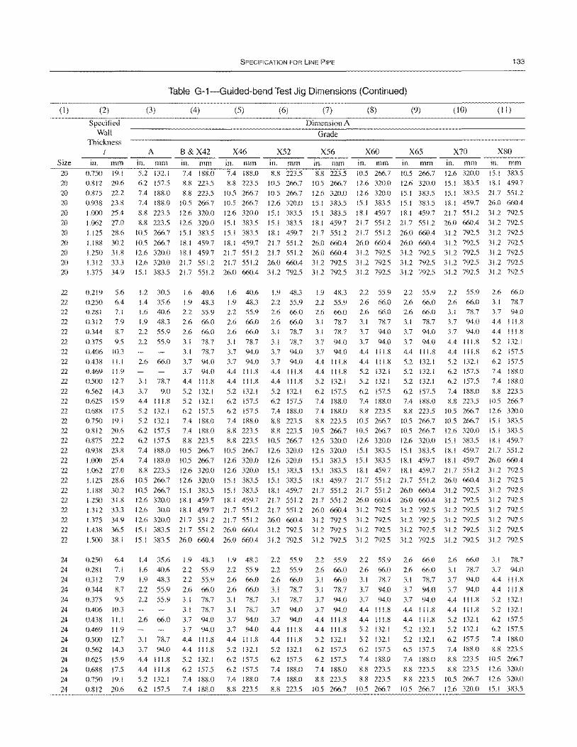
(I)
Size 20 20
20 20 20 20
20 20
20 20 20
22 22 22 22 22 22 22 22 22 22 22 22 22 22 22
22 22 22 22 22 22 22 22 22 22
22
24 24 24 24 24
24
24 24
24 24
24 24 24
24
(2)
Specified Wall
Thickness
in. mm 0.750 19.1 0.812 20.6
0.R75 22.2 0.93R 23.8
1.000 25.4 1.062 27.0 1.125 28.6
1.188 30.2 1.250 31.8 1.312 33.3 1.375 34.9
0.219 5.6 0.250 6.4 0.281 7.1 0.312 7.9 0.344 8.7
0.375 9.5 0.406 10.3 OA38 11.1 OA6l) 11.9 0.500 12.7
0.562 14.3 0.625 15.9 0.688 17.5 0.750 19.1 0.812 20.6 0.875 22.2 0.938 23.8 1.000 25.4
1.062 27.0 1.125 28.6
1.188 30.2 1.250 31.8 1.312 33.3 1.375 34.9 1.438 36.5
1.500 38.1
0.250 6.4 0.281 7.1 0.312 7.9
0.344 8.7 0.375 9.5
0.406 10.3
0.438 11.1 0.469 11.9
0.500 12.7 0.562 14.3 0.625 15.9
0.688 17.5 0.750 19.1
0.812 20.6
SPECIFICATION FOR LINE PIPE 133
Table G-1-Guided-bend Test Jig Dimensions (Continued)
(3) (4) (5) (6) (7) (8) (9) (10) (II )
Dimension A
Grade
A B&X42 X46 X52 X56 X60 X65 X70 X80
in. mm in. mm in. mm in. mm in. mm in. mm in. mm in. mm in. mm 5.2 132.1 6.2 157.5
7.4 188.0 7.4 188.0
8.8 223.5 8.8 223.5
7.4 188.0 8.8 223.5 8.8 223.5
10.5 266.7 12.6 320.0 12.6 320.0
7.4 188.0 8.8 223.5
10.5 266.7 10.5 266.7 12.6 320.0 15.1 383.5
8.8 223.5 10.5 266.7 10.5 266.7 12.6 320.0 15.1 383.5 15.1 383.5
8.8 223.5 10.5 266.7 10.5 266.7 12.6 320.0
12.6 320.0 12.6 320.0 15.1 383.5 15.1 383.5 15.1 383.5 I ll.1 459.7 18.1 459.7 21.7 551.2
10.5 266.7 12.6 320.0 15.1 383.5 12.6 320.0 15.1 383.5 18. I 459.7 15.1 383.5 15.1 3~n.5 21.7 551.2 15.1383.5 18.1459.7 26.0 660.4 18.1 459.7 21.7 551.2 31.2 792.5 21.7 551.2 26.0 660.4 31.2 792.5
10.5 266.7 15.1 383.5 15.1 383.5 18.1 459.7 21.7 551.2 21.7 551.2 26.0 660.4 31.2 792.5 31.2 792.5
10.5 266.7 18.1 459.7 18.1 459.7 21.7 551.2 26.0 660.4 26.0 660.4 26.0 660.4 31.2 792.5 31.2 792.5 12.6 320.0 18.1 459.7 21.7 551.2 21.7 551.2 26.0 660.4 31.2 792.5 31.2 792.5 31.2 792.5 31.2 792.5 12.6 320.0 21.7 551.2 21.7 551.2 26.0 660.4 31.2 792.5 31.2 792.5 31.2 792.5 31.2 792.5 31.2 792.5 15.1 383.5 21.7 551.2 26.0 660.4 31.2 792.5 31.2 792.5 31.2 792.5 31.2 792.5 31.2 792.5 31.2 792.5
1.2 30.5 1.4 35.6 1.6 40.6 1.9 48.3 2.2 55.9
2.2 55.9
1.6 40.6 1.9 48.3 2.2 55.9 2.6 66.0 2.6 66.0 3.1 78.7 3.1 78.7
1.6 40.6 1.9 48.3 2.2 55.9 2.6 66.0 2.6 66.0
3.1 78.7 3.7 94.0
1.9 48.3 2.2 55.9 2.6 66.0 3.1 78.7
2.2 55.9 2.6 66.0 2.6 66.0 3.1 78.7
3.1 78.7 3.7 94.0
3.7 94.0 3.7 94.0 3.7 94.0 4A 111.8
2.6 66.0 3.7 94.0 3.7 94.0
1.9 48.3 2.2 55.9 2.6 66.0 2.6 66.0 3.1 78.7
3.1 78.7 3.7 94.0 3.7 94.0 4.4 111.8 4A 111.8
5.2 132.1 6.2 157.5 7A 188.0
8.8 223.5 8.8 223.5
4A 111.8
4A 111.8
5.2 132.1 6.2 157.5 7.4 188.0 7.4 188.0 8.8 223.5
4.4 111.8 5.2 132.1 5.2 132.1 6.2 157.5 7.4 188.0 8.8 223.5
2.2 55.9 2.6 66.0 2.6 66.0 3.1 78.7 3.7 94.0
3.7 94.0 4A 111.8
5.2 132.1 5.2 132.1 5.2 132.1
6.2 157.5 7A IS8.0 8.S 223.5
1(l.5 266.7
2.2 55.9 2.6 66.0 3.1 78.7 3.7 94.0 3.7 94.0
4A 111.8
4A 111.8
5.2 132.1 6.2 157.5 6.2 157.5
2.6 66.0 3.1 78.7 3.7 94.0 4.4 111.8 4.4 111.8
5.2 132.1 6.2 157.5 6.2 157.5 7A 188.0
7.4 188.0 3.7 94.0 4.4 111.8
3.1 78.7 4.4 111.8 4.4 111.8 3.7 9.0 4.4 111.8 5.2 132.1 5.2 132.1 6.2 157.5 6.2 157.5 7.4 188.0 7.4 188.0
5.2 132.1 5.2 132.1 6.2 157.5 7.4 188.0 7A 188.0
8.8 223.5 10.5 266.7 10.5 266.7
8.8 223.5 12.6 320.0 10.5 266.7 12.6 320.0
10.5 266.7 15.1 383.5 12.6 320.0 18.1 459.7
5.2 132.1 6.2 157.5 6.2 157.5 7.4 188.0 8.8 223.5
8.8 223.5 10.5 266.7 12.6 320.0
10.5 266.7 12.6 320.0 12.6 320.0
10.5 266.7 12.6 320.0 12.6 320.0 15.1 383.5
10.5 266.7 10.5 266.7
12.6 320.0 15.1 383.5 15.1 383.5
10.5 266.7
12.6 320.0 15.1 383.5 IS.1 459.7
7A 188.0 8.8 223.5 8.8 223.5 10.5 266.7
10.5 266.7 12.6 320.0 10.5 266.7 15.1 383.5 12.6 320.0 15.1 383.5
15.1 383.5 18.1 459.7 18.1 459.7 21.7 551.2
18.1 459.7 26.0 660A 12.6 320.0 15.1 383.5 15.1 383.5 18.1 459.7 18.1 459.7 21.7 551.2 31.2 792.5 15.1 383.5 15.1 383.5 IS.1 459.7 21.7 551.2 21.7 551.2 26.0 660A 31.2 792.5 15.1 3S3.5 IS.I 459.7 21.7 551.2 21.7 551.2 26.0 660.4 31.2 792.5 31.2 792.5 18.1 459.7 21.7 551.2 21.7 551.2 26.0 660A 26.0 660.4 31.2 792.5 31.2 792.5
12.6 30.0 18.1 459.7 21.7 551.2 2l.7 551.2 26.0 660A 31.2 792.5 31.2 792.5 31.2 792.5 31.2 792.5 12.6 320.0 21.7 551.2 21.7 551.2 26.0 660.4 31.2792.5 31.2 792.5 31.2792.5 31.2 792.5 31.2 792.5 15.1 383.5 21.7 551.2 26.0 660.4 31.2 792.5 31.2 792.5 3l.2 792.5 31.2 792.5 31.2 792.5 31.2 792.5
15.1 383.5 26.0 660A 26.0 660A 31.2 792.5 31.2 792.5 31.2 792.5 31.2 792.5 31.2 792.5 31.2 792.5
IA 35.6
1.6 40.6 1.9 48.3
2.2 55.9 2.2 55.9
2.6 66.0
3.1 78.7
3.7 94.0 4.4 111.8 4.4 IlLS 5.2 132.1
6.2 157.5
1.9 48.3 2.2 55.9 2.2 55.9 2.6 66.0 3.1 n.7 3.1 78.7
3.7 94.0 3.7 94.0 4A 111.8
4A 111.8
5.2 132.1 6.2 157.5 7.4 188.0
7.4 188.0
1.9 48.3
2.2 55.9 2.6 66.0
2.6 66.0 3.1 78.7
3.1 78.7 3.7 94.0 3.7 94.0
4A 111.8
5.2 132.1 6.2 157.5 6.2 157.5 7.4 188.0
8.8 223.5
2.2 55.9 2.2 55.9 2.6 66.0 3.1 78.7 3.1 78.7 3.7 94.0 3.7 94.0 4.4 11l.8
4.4 111.8 5.2 132.1 6.2 157.5 7A 188.0
7A 188.0
8.8 223.5
2.2 55.9 2.6 66.0 3.1 66.0
3.1 78.7 3.7 94.0 3.7 94.0
4A 111.8
4A 111.8
5.2 132.1 6.2 157.5 6.2 157.5 7A 188.0
8.8 223.5
10.5 266.7
2.2 55.9 2.6 66.0 3.1 78.7
3.7 94.0 3.7 94.0
4A 111.8
4A 111.8
5.2 132.1
5.2 132.1 6.2 157.5 7A 188.0
8.8 223.5 8.8 223.5
10.5 266.7
2.6 66.0 2.6 66.0 3.1 78.7 3.7 94.0 3.7 94.0 4A 111.8
4A 111.8
5.2 132.1
5.2 132.1 6.5 157.5 7.4 188.0 88 223.5
8.8 223.5 10.5 266.7
2.6 66.0 3.1 78.7 3.7 94.0
3.7 94.0 4.4 111.8 4.4 111.8 5.2 132.1 5.2 132.1
6.2 157.5 7.4 188.0 8.8 223.5 8.8 223.5
10.5 266.7
12.6 320.0
3.1 78.7 3.7 94.0 4.4 111.8
4A 111.8
5.2 132.1 5.2 132.1 6.2 157.5
6.2 157.5
7.4 188.0 X.8 223.5
10.5 266.7 12.6 320.0 12.6 320.0
15.1 383.5
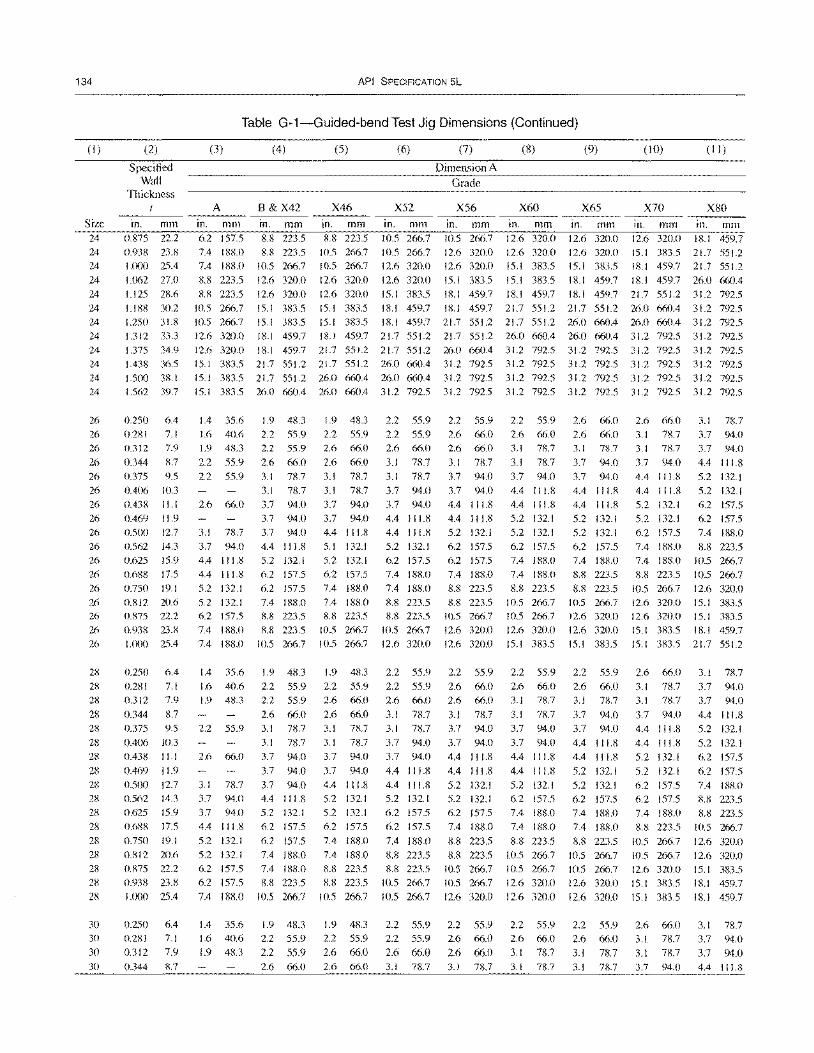
134
(I)
Size 24 24 24
24 24 24 24 24
24 24 24 24
26 26 26
26 26 26 26 26
26 26 26 26
26 26 26 26 26
28 28 28
28 28 28 28
28
28 28 28 28
28 28 28
28 28
30 30
30
30
(2)
Specified Wall
Thickness
in. mOl 0.875 22.2 0.938 23.8 1.000 25.4
1.062 27.0 1.125 28.6
1.188 30.2 1.250 31.8 1.312 33.3
1.375 34.9 1.438 36.5 1.500 38.1 1.562 39.7
0.250 6.4 0.281 7.1 0.312 7.9
0.344 8.7 0.375 9.5 0.406 10.3 0.438 11.1 0.469 11.9
0.500 12.7 0.562 14.3 0.625 15.9 0.688 17.5 0.750 19.1 0.812 20.6 0.875 22.2 0.938 23.8 1.000 25.4
0.250 6.4 0.281 7.1 0.312 7.9
0.344 8.7 0.375 9.5
0.406 10.3 0.438 11.1
0.469 11.9 0.500 12.7 0.562 14.3 0.625 15.9 0.688 17.5
0.750 19.1 0.812 20.6 0.875 22.2 0.938 23.8
1.000 25.4
0.250 6.4 0.281 7.1 0.312 7.9
0.344 8.7
API SPECIFICATION 5L
Table G-1-Guided-bend Test Jig Dimensions (Continued)
(3)
A
in. mOl 6.2 157.5 7.4 188.0 7.4 188.0
8.8 223.5 8.8 223.5
10.5 266.7
(4)
B&X42
In. mOl 8.8 223.5 8.8 223.5
10.5 266.7
12.6 320.0 12.6 320.0 15.1 383.5
(5)
X46
in. mOl 8.8 223.5
10.5 266.7 10.5 266.7
12.6 320.0 12.6 320.0 15.1 383.5
(6)
X52
in. mOl 10.5 266.7 10.5 266.7 12.6 320.0
12.6 320.0 15.1 383.5 18.1 459.7
(7) (8) (9) (10) (1 1)
Dimension A Grade
X56 X60 X65 X70 X80
in. mOl In. mm in. mm in. mOl in. mOl 10.5 266.7 12.6 320.0 12.6 320.0 12.6 320.0 18.1 459.7 12.6 320.0 12.6 320.0 15.1 383.5
12.6 320.0 15.1 383.5
15.1 383.5
12.6 320.0 15.1 383.5 18.1 459.7
15.1 383.5 21.7 551.2 18.1 459.7 21.7 551.2
18.1 459.7 26.0 660.4 18.1 459.7 18.1 459.7 18.1 459.7 21.7 551.2 31.2 792.5 18.1 459.7 21.7 551.2 21.7 551.2 26.0 660.4 31.2 792.5
10.5 266.7 15.1 383.5 15.1 383.5 18.1 459.7 21.7 551.2 21.7 551.2 26.0 660.4 26.0 660.4 31.2 792.5 12.6 320.0 18.1 459.7 18.1 459.7 21.7 551.2 21.7 551.2 26.0 660.4 26.0 660.4 31.2 792.5 31.2 792.5
12.6 320.0 18.1 459.7 21.7 551.2 21.7 551.2 26.0 660.4 31.2 792.5 31.2 792.5 31.2 792.5 31.2 792.5 15.1 383.5 21.7 551.2 21.7 551.2 26.0 660.4 31.2 792.5 31.2 792.5 31.2 792.5 31.2 792.5 31.2 792.5 15.1 383.5 21.7 551.2 26.0 660.4 26.0 660.4 31.2 792.5 31.2 792.5 31.2 792.5 31.2 792.5 31.2 792.5 15.1 383.5 26.0 660.4 26.0 660.4 31.2 792.5 31.2 792.5 31.2 792.5 31.2 792.5 31.2 792.5 3 1.2 792.5
1.4 35.6 1.6 40.6 1.9 48.3
2.2 55.9 2.2 55.9
2.6 66.0
3.1 78.7 3.7 94.0 4.4 111.8 4.4 111.8 5.2 132.1 5.2 132.1 6.2 157.5
1.9 48.3
2.2 55.9 2.2 55.9
2.6 66.0 3.1 78.7 3.1 78.7 3.7 94.0 3.7 94.0 3.7 94.0 4.4 111.8 5.2 132.1 6.2 157.5 6.2 157.5 7.4 188.0 8.8 223.5
7.4 188.0 8.8 223.5 7.4 188.0 10.5 266.7
1.4 35.6 1.6 40.6 1.9 48.3
2.2 55.9
2.6 66.0
3.1 78.7 3.7 94.0 3.7 94.0 4.4 111.8
5.2 132.1 5.2 132.1 6.2 157.5
6.2 157.5 7.4 188.0
1.4 35.6 1.6 40.6
1.9 48.3
1.9 48.3 2.2 55.9 2.2 55.9
2.6 66.0 3.1 78.7
3.1 78.7 3.7 94.0
3.7 94.0 3.7 94.0 4.4 111.8 5.2 132.1 6.2 157.5
6.2 157.5 7.4 188.0 7.4 188.0 8.8 223.5
10.5 266.7
1.9 48.3 2.2 55.9 2.2 55.9
1.9 48.3 2.2 55.9 2.6 66.0
2.6 66.0 3.1 78.7 3.1 78.7 3.7 94.0 3.7 94.0
4.4 111.8 5.1 132.1 5.2 132.1 6.2 157.5 7.4 188.0 7.4 188.0 8.8 223.5
10.5 266.7 10.5 266.7
1.9 48.3 2.2 55.9 2.6 66.0
2.6 66.0 3.1 78.7 3.1 78.7 3.7 94.0
3.7 94.0 4.4 111.8 5.2 132.1 5.2 132.1 6.2 157.5
7.4 188.0 7.4 188.0 8.8 223.5 8.8 223.5
10.5 266.7
1.9 48.3 2.2 55.9
2.6 66.0
2.2 55.9 2.2 55.9 2.6 66.0
3.1 78.7 3.1 78.7 3.7 94.0 3.7 94.0 4.4 111.8
4.4 111.8 5.2 132.1 6.2 157.5 7.4 188.0
7.4 188.0 8.8 223.5 8.8 223.5
10.5 266.7 12.6 320.0
2.2 55.9 2.2 55.9 2.6 66.0
3.1 78.7 3.1 78.7 3.7 94.0 3.7 94.0
4.4 111.8 4.4 111.8 5.2 132.1 6.2 157.5 6.2 157.5
7.4 188.0 8.8 223.5 8.8 223.5
10.5 266.7
10.5 266.7
2.2 55.9 2.2 55.9 2.6 66.0
2.2 55.9
2.6 66.0 2.6 66.0
3.1 78.7
2.2 55.9 2.6 66.0 3.1 78.7
3.1 78.7 3.7 94.0 3.7 94.0 3.7 94.0 4.4 111.8 4.4 I I 1.8 4.4 1 11.8 4.4 111.8 5.2 132.1
5.2 132.1 5.2 132.1 6.2 157.5 6.2 157.5 6.2 157.5 7.4 188.0 7.4 188.0 7.4 188.0 8.8 223.5 8.8 223.5 8.8 223.5 10.5 266.7
10.5 266.7 10.5 266.7 12.6 320.0 12.6 320.0 12.6 320.0 15.1 383.5
2.2 55.9 2.6 66.0 2.6 66.0
3.1 78.7 3.7 94.0
3.7 94.0 4.4 111.8
4.4 111.8 5.2 132.1 5.2 132.1 6.2 157.5 7.4 188.0
8.8 223.5 8.8 223.5
10.5 266.7
10.5 266.7 12.6 320.0
2.2 55.9 2.6 66.0
2.6 66.0
2.2 55.9 2.6 66.0 3.1 78.7
3.1 78.7 3.7 94.0
3.7 94.0 4.4 111.8
4.4 111.8 5.2 132.1 6.2 157.5 7.4 188.0 7.4 188.0
8.8 223.5 10.5 266.7 10.5 266.7 12.6 320.0
12.6 320.0
2.2 55.9 2.6 66.0
3.1 78.7
2.6 66.0
2.6 66.0 3.1 78.7
3.7 94.0 3.7 94.0 4.4 111.8 4.4 111.8 5.2 132.1
5.2 132.1 6.2 157.5 7.4 188.0 8.8 223.5 8.8 223.5
10.5 266.7 12.6 320.0 12.6 320.0 15.1 383.5
2.2 55.9
2.6 66.0 3.1 78.7
3.7 94.0 3.7 94.0 4.4 111.8 4.4 111.8
5.2 132.1 5.2 132.1 6.2 157.5 7.4 188.0 7.4 188.0
8.8 223.5 10.5 266.7 10.5 266.7 12.6 320.0
12.6 320.0
2.2 55.9 2.6 66.0 3.1 78.7
2.6 66.0 3.1 78.7 3.1 78.7 3.7 94.0 3.1 78.7 3.7 94.0
3.7 94.0 4.4 I 11.8 4.4 111.8 4.4 111.8 5.2 132.1 5.2 132.1
6.2 157.5 7.4 188.0 7.4 188.0 8.8 223.5
10.5 266.7 12.6 320.0 12.6 320.0
5.2 132.1 5.2 132.1 6.2 157.5 6.2 157.5
7.4 188.0 8.8 223.5
10.5 266.7 10.5 266.7 12.6 320.0 15.1 383.5 15.1 383.5
15.1 383.5 18.1 459.7 15.1 383.5 21.7 551.2
2.6 66.0 3.1 78.7 3.1 78.7
3.7 94.0 4.4 111.8 4.4 111.8 5.2 132.1
5.2 132.1 6.2 157.5 6.2 157.5 7.4 188.0 8.8 223.5
10.5 266.7 10.5 266.7 12.6 320.0 15.1 383.5 15.1 383.5
2.6 66.0 3.1 78.7 3.1 78.7
3.1 78.7 3.7 94.0
3.7 94.0
4.4 111.8 5.2 132.1
5.2 132.1 6.2 157.5
6.2 157.5 7.4 188.0 8.8 223.5 8.8 223.5
10.5 266.7 12.6 320.0 12.6 320.0 15.1 383.5 18.1 459.7
18.1 459.7
3.1 78.7 3.7 94.0
3.7 94.0 2.6 66.0 2.6 66.0 3.1 78.7 3.1 78.7 3.1 78.7 3.1 78.7 3.7 94.0 4.4 111.8
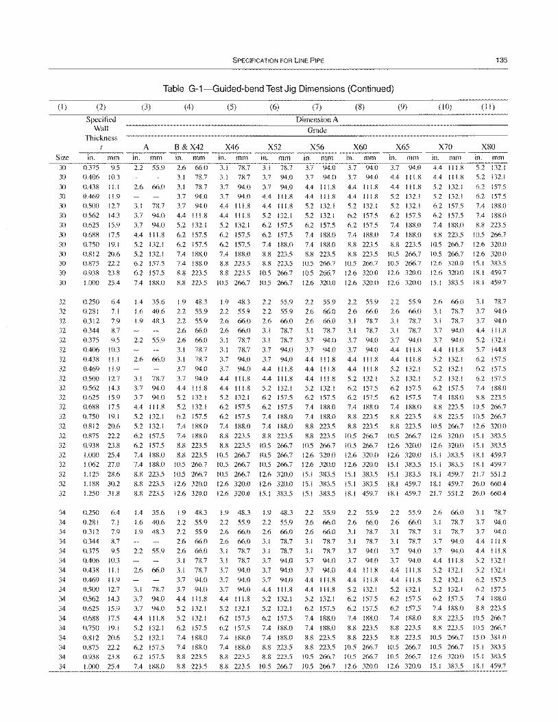
(I)
Size
30 30
30
30 30
30
30
30
30
30 30
30
30
32
32 32
32
32 32
32
32
32
32 32
32 32
32
32
32
32
32
32
32
32
34
34 34
34
34
34
34
34
34
34 34
34
34
34
34
34
34
(2)
Specified Wall
Thickness
in. mm
0.375 9.5 0.406 10.3
0.438 11.1
0.469 11.9 0.500 12.7
0.562 14.3
0.625 15.9
0.688 17.5
0.750 19.1 0.812 20.6
0.875 22.2
0.938 23.8
1.000 25.4
0.250 6.4
0.281 7.1 0.312 7.9
0.344 8.7
0.375 9.5 0.406 10.3
0.438 11.1
0.469 11.9
O.SOO 12.7
0.562 14.3 0.625 15.9
0.688 17.5 0.750 19.1
0.812 20.6
0.875 22.2
0.938 23.8
1.000 25.4 1.062 27.0
1.125 28.6
1.188 30.2
1.250 31.8
0.250 6.4
0.281 7.1 0.312 7.9
0.344 'X.7
0.375 9.5
0.406 10.3
0.438 11.1
0.469 11.9
0.500 12.7
0.562 14.3
0.625 15.9
0.688 17.5
0.750 19.1
0.812 20.6
0.875 22.2
0.938 23.8
1.000 25.4
SPECIFICATION FOR LINE PIPE
Table G-1-Guided-bend Test Jig Dimensions (Continued)
(3)
A in. mm
2.2 55.9
2.6 66.0
3.1 7/:',.7
3.7 94.0
3.7 94.0
4.4 111.8
5.2 132.1 5.2 132.1
6.2 157.5 6.2 157.5
7.4 188.0
1.4 35.6
1.6 40.6 1.9 4il.3
2.2 55.9
(4)
B&X42 in. mm
2.6 66.0 3.1 78.7
3.1 78.7 3.7 94.0
3.7 94.0
4.4 111.8
5.2 132.1
6.2 157.5
6.2 157.5 7.4 188.0
7.4 188.0
8.8 223.5
8.8 223.5
1.9 48.3
2.2 55.9 2.2 55.9
2.6 66.0
2.6 66.0 3.1 78.7
2.6 66.0 3.1 7/:',.7
3.7 94.0
3.1 78.7
3.7 94.0 3.7 94.0
4.4 111.8
5.2 132.1
5.2 132.1
6.2 157.5
6.2 157.5
7.4 188.0
7.4 188.0
8.8 223.5
3.7 94.0
4.4 111.8 5.2 132.1
5.2 132.1
6.2 157.5
7.4 188.0
7.4 188.0
8.8 223.5
8.8 223.5
10.5 266.7
10.5 266.7
(5)
X46 in. mm 3.1 7/:',.7 3.1 7/:',.7
3.7 94.0
3.7 94.0 4.4 111.8
4.4 111.8
5.2 132.1
6.2 157.5
6.2 157.5
7.4 188.0 8.8 223.5
8.8 223.5
10.5 266.7
1.9 48.3
2.2 55.9 2.6 66.0
2.6 66.0
3.1 78.7
3.1 78.7
(6)
X52 in. mm 3.1 78.7 3.7 94.0
3.7 94.0 4.4 111.8
4.4 111.8
5.2 132.1 6.2 157.5
6.2 157.5
7.4 188.0
8.8 223.5 8.8 223.5
10.5 266.7
10.5 266.7
2.2 55.9
2.2 55.9
2.6 66.0
3.1 78.7
3.1 78.7
3.7 94.0
(7)
Dimension A
Grade
X56 in. mm 3.7 94.0 3.7 94.0
4.4 111.8 4.4 111.8
5.2 132.1
5.2 132.1 6.2 157.5
7.4 188.0
7.4 188.0 8.8 223.5
10.5 266.7
10.5 266.7
12.6 320.0
(8)
X60 in. mm
3.7 94.0 3.7 94.0
4.4 111.8
4.4 111.8
5.2 132.1
6.2 157.5 6.2 157.5
7.4 188.0
8.8 223.5 8.8 223.5
10.5 266.7
12.6 320.0
12.6 320.0
2.2 55.9 2.2 55.9
2.6 66.0 2.6 66.0 2.6 66.0 3.1 78.7
3.1 78.7 3.1 78.7
3.7 94.0 3.7 94.0
3.7 94.0 3.7 94.0 3.7 94.0 3.7 94.0 4.4 111.8 4.4 111.8
3.7 94.0 4.4 1 11.8 4.4 111.8 4.4 111.8
4.4 111.8
4.4 111.8
5.2 132.1 6.2 157.5
6.2 157.5
7.4 188.0 8.8 223.5
8.8 223.5
10.5 266.7
10.5 266.7
10.5 266.7
4.4 111.8 5.2 132.1
6.2 157.5
6.2 157.5 7.4 188.0
7.4 188.0 8.8 223.5
10.5 266.7
10.5 266.7
10.5 266.7
12.6 320.0
4.4 111.8 5.2 132.1
6.2 157.5
7.4 188.0 7.4 188.0
8.8 223.5
8.8 223.5 10.5 266.7
12.6 320.0
12.6 320.0
15.1 383.5
5.2 132.1 6.2 157.5
6.2 157.5
7.4 188.0 8.8 223.5
8.8 223.5 10.5 266.7
10.5 266.7
12.6 320.0
12.6 320.0
15.1 383.5
(9)
X65 in. mm 3.7 94.0
4.4 111.8
4.4 111.8
5.2 132.1 5.2 132.1
6.2 157.5
7.4 188.0
7.4 188.0
8.8 223.5 10.5 266.7 10.5 266.7
12.6 320.0
12.6 320.0
2.2 55.9 2.6 66.0
3.1 78.7
3.1 78.7
3.7 94.0 4.4 111.8
( 10)
X70 in. mm 4.4 111.8 4.4 111.8
5.2 132.1 5.2 132.1
6.2 157.5
6.2 157.5
7.4 188.0
8.8 223.5
10.5 266.7
10.5 266.7 12.6 320.0
12.6 320.0
15.1 383.5
2.6 66.0
3.1 78.7 3.1 78.7
3.7 94.0
3.7 94.0
4.4 111.8
4.4 111.8 5.2 132.1
5.2 132.1 5.2 132.1
5.2 132.1
6.2 157.5 6.2 157.5
7.4 188.0
8.8 223.5
8.8 223.5 10.5 266.7
12.6 320.0
12.6 320.0
15.1 383.5
15.1 383.5
5.2 132.1
6.2 157.5 7.4 188.0
8.8 223.5
8.8 223.5
10.5 266.7
12.6 320.0
12.6 320.0
15.1 383.5
15.1 383.5
18.1 459.7
135
(II )
X80 in. mm
5.2 132.1 5.2 132.1
h.2 157.5
h.2 157.5
7.4 188.0 7.4 188.0
8.8 223.5
10.5 266.7
12.h 320.0
12.6 320.0 15.1 383.5 18.1 459.7
18.1 459.7
3.1 78.7 3.7 94.0
3.7 94.0
4.4 111.8
5.2 132.1
5.7 144.8
h.2 157.5
h.2 157.5
h.2 157.5
7.4 188.0 8.8 223.S
10.5 266.7 10.5 266.7
12.6 320.0
15.1 383.5
IS.1 383.5 18.1 459.7 11).1 459.7
21.7 551.2
8.8 223.5 12.6 320.0 12.6 320.0 12.6 320.0 15.1 383.5 15.1 383.5 18.1 459.7 18.1 459.7 26.0 660.4
8.8 223.5 12.6 320.0 12.6 320.0 15.1 383.5 15.1 383.5 18.1 459.7 18.1 459.7 21.7 551.2 26.0 660.4
1.4 35.6
1.6 40.6 1.9 48.3
2.2 55.9
2.6 66.0
3.1 78.7
3.7 94.0
3.7 94.0
4.4 111.8
5.2 132.1
5.2 132.1
6.2 157.5
6.2 157.5
7.4 188.0
1.9 48.3
2.2 55.9 2.2 5S.9
2.6 66.0
2.6 66.0
3.1 78.7
3.1 78.7
3.7 94.0
3.7 94.0
4.4 111.8
5.2 132.1
5.2 132.1
6.2 157.5
7.4 188.0
7.4 188.0
8.8 223.5
8.8 223.5
1.9 48.3
2.2 55.9
2.6 66.0
2.6 66.0 3.1 78.7
3.1 78.7
3.7 94.0
3.7 94.0
3.7 94.0
4.4 111.8
5.2 132.1
6.2 157.5
6.2 157.5
7.4 188.0
7.4 188.0
8.8 223.5
8.8 223.5
1.9 48.3
2.2 55.9
2.6 66.0
3.1 78.7 3.1 78.7
3.7 94.0
3.7 94.0 3.7 94.0
4.4 111.R
5.2 132.1
5.2 132.1
6.2 157.5
7.4 188.0
7.4 188.0
8.8 223.5
8.8 223.5
10.5 266.7
2.2 55.9
2.6 66.0
2.6 66.0
3.1 78.7 3.1 78.7
3.7 94.0
3.7 94.0 4.4 111.8
4.4 111.8
5.2 132.1
6.2 157.5
7.4 188.0
7.4 188.0
8.8 223.5
8.8 223.5
10.5 266.7
10.5 266.7
2.2 55.9
2.6 66.0
3.1 78.7
3.1 78.7 3.7 94.0
3.7 94.0
4.4 111.8
4.4 111.8
5.2 132.1
6.2 157.5
6.2 157.5
7.4 188.0
8.8 223.5
8.8 223.5
10.5 266.7 10.5 266.7
12.6 320.0
2.2 55.9
2.6 66.0 3.1 78.7 3.1 7/1,.7
3.7 94.0
3.7 94.0
4.4 111.8
4.4 111.8
5.2 132.1 6.2 157.5
6.2 157.5
7.4 188.0
8.8 223.5 8.g 223.5
10.5 266.7
10.5 266.7
12.6 320.0
2.6 66.0
3.1 78.7
3.1 n.7
3.7 94.0
3.7 94.0
4.4 111.8
5.2 132.1
5.2 132.1 5.2 132.1
6.2 157.5
7.4 188.0
8.8 223.5
8.8 223.5
10.5 266.7
10.5 266.7 12.6 320.0
15.1 383.5
3.1 78.7
3.7 94.0
3.7 94.0
4.4 111.8 4.4 111.8
5.2 132.1
5.2 132.1 6.2 157.5
h.2 157.5
7.4 188.0
8.8 223.5
10.5 266.7
10.5 266.7 15.0 381.0
15.1 383.5
15.1 383.5
18.1 459.7
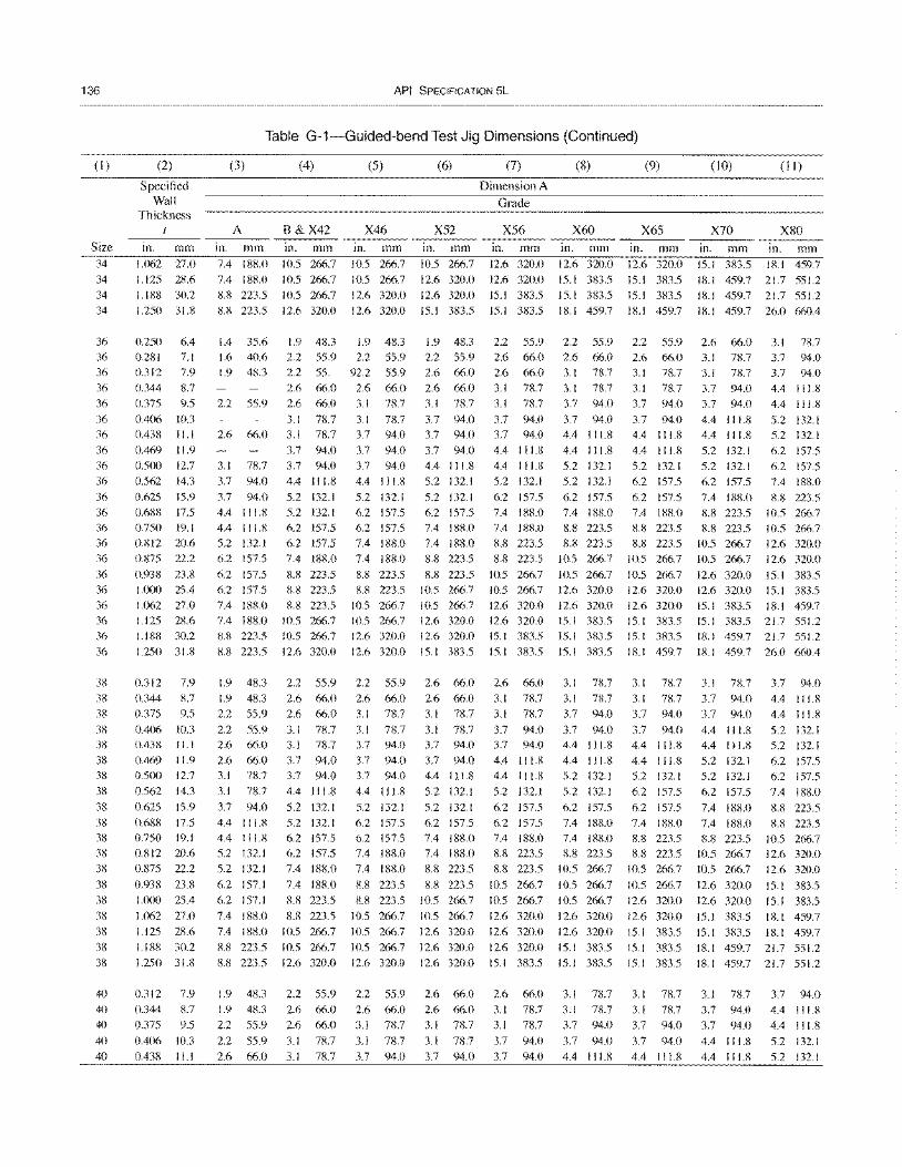
136
(I)
Size 34 34 34 34
36 36 36 36 36
36 36
36 36 36 36 36 36 36 36
36 36 36 36 36
36
38 38 38
38 38 38 38 38
38 38 38 38 38
38 38
38 38 38
38
40 40
40
40 40
(2)
Specified Wall
Thickness I
111. mm
1.062 27.0 1.125 28.6 1.188 30.2 1.250 31.8
0.250 6.4 0.281 7.1 0.312 7.9 0.344 8.7 0.375 9.5
0.406 10.3 0.438 11.1 0.469 11.9 0.500 12.7 0.562 14.3 0.625 15.9 0.688 17.5 0.750 19.1 0.812 20.6 0.875 22.2
0.938 23.8 1.000 25.4 1,(162 27.0 1.125 28.6 1.188 30.2
1.250 31.8
0.312 7.9 0.344 8.7 0.375 9.5
0.406 10.3 0.438 11.1 0.469 11.9 0.500 12.7 0.562 14.3
0.625 15.9 0.688 17.5 0.750 19.1 0.812 20.6 0.875 22.2 0.938 23,R
1.000 25.4
U162 27.0 1.125 28.6 1.188 30.2
1.250 31.8
0.312 7.9 0.344 8.7 0.375 9.5
0.406 10.3 0.438 11.1
API SPECIFICATION 5L
Table G-1-Guided-bend Test Jig Dimensions (Continued)
(3) (4) (5) (6) (7) (8) (9)
Dimension A
Grade
A B &X42 X46 X52 X56 X60 X65 111. mm in. mm in. mm in. mm in. mm in. mm in. mm 7.4 188.0 10.5 266.7 10.5 266.7 10.5 266.7 12.6 320.0 12.6 320.0 12.6 320.0 7.4 188.0 10.5 266.7 10.5 266.7 12.6 320.0 12.6 320.0 15.1 383.5 15.1 383.5 8.8 223.5 10.5 266.7 12.6 320.0 12.6 320.0 15.1 383.5 15.1 383.5 15.1 383.5 8.8 223.5 12.6 320.0 12.6 320.0 15.1 383.5 15.1 383.5 18.1 459.7 18.1 459.7
(10) (11 )
X70 X80 111. mm in. mm 15.1 383.5 18.1 459.7 18.1 459.7 21.7 551.2 18.1 459.7 21.7 551.2 18.1 459.7 26.0 660.4
1.4 35.6 1.9 48.3 1.9 48.3 1.9 48.3 2.2 55.9 2.2 55.9 2.2 55.9 2.6 66.0 3.1 78.7 1.6 40.6 2.2 55.9 2.2 55.9 2.2 55.9 2.6 66.0 2.6 66.0 2.6 66.0 3.1 78.7 3.7 94.0 1.9 48.3
2.2 55.9
2.6 66.0
3.1 78.7 3.7 94.0
3.7 94.0 4.4 111.8 4.4 111.8 5.2 132.1 6.2 157.5
6.2 157.5 6.2 157.5 7.4 188.0 7.4 188.0 8.8 223.5
8.8 223.5
1.9 48.3 1.9 48.3 2.2 55.9
2.2 55.9 2.6 66.0 2.6 66.0 3.1 78.7 3.1 78.7
3.7 94.0 4.4 111.8 4.4 111.8 5.2 132.1 5.2 132.1
6.2 157.1 6.2 157.1
7.4 188.0 7.4 188.0
8.8 223.5 8.8 223.5
2.2 55. 92.2 55.9 2.6 66.0 2.6 66.0 2.6 66.0 3.1 78.7
3.1 78.7 3.1 78.7 3.1 78.7 3.7 94.0 3.7 94.0 3.7 94.0 3.7 94.0 3.7 94.0 4.4 111.8 4.4 1 1 1.8
5.2 132.1 5.2 132.1 6.2 157.5 6.2 157.5 7.4 188.0
8.8 223.5 8.8 223.5 8.8 223.5
10.5 266.7 10.5 266.7
12.6 320.0
2.2 55.9 2.6 66.0 2.6 66.0 3.1 78.7 3.1 78.7 3.7 94.0 3.7 94.0
4.4 111.8 5.2 132.1
5.2 132.1 6.2 157.5 6.2 157.5 7.4 188.0
7.4 188.0 8.8 223.5 8.8 223.5
10.5 266.7 10.5 266.7 12.6 320.0
5.2 132.1 6.2 157.5 6.2 157.5 7.4 188.0 7.4 188.0
8.8 223.5 8.8 223.5
10.5 266.7 10.5 266.7 12.6 320.0
12.6 320.0
2.2 55.9 2.6 66.0 3.1 78.7
3.1 78.7 3.7 94.0 3.7 94.0 3.7 94.0
4.4 111.8
5.2 132.1 6.2 157.5 6.2 157.5 7.4 188.0 7.4 188.0
8.8 223.5 8.8 223.5
10.5 266.7
10.5 266.7 10.5 266.7
12.6 320.0
1.9 48.3 2.2 55.9 2.2 55.9 2.6 66.0 3.1 78.7
3.1 78.7
3.7 94.0
1.9 48.3 2.6 66.0 2.2 55.9 2.6 66.0
2.2 55.9
2.6 66.0
3.1 78.7
3.1 78.7
2.6 66.0 2.6 66.0 3.1 78.7
3.7 94.0 3.7 94.0
3.7 94.0 4.4 111.8 5.2 132.1
5.2 132.1 6.2 157.5 7.4 188.0 7.4 188.0 8.8 223.5
8.8 223.5 10.5 266.7 10.5 266.7 12.6 320.0 12.6 320.0
15.1 383.5
2.6 66.0 2.6 66.0 3.1 78.7
3.1 78.7 3.7 94.0 3.7 94.0 4.4 111.8 5.2 132.1
5.2 132.1 6.2 157.5 7.4 188.0 7.4 188.0 8.8 223.5
8.8 223.5 10.5 266.7
10.5 266.7 12.6 320.0 12.6 320.0
12.6 320.0
2.6 66.0 2.6 66.0 3.1 78.7
3.1 78.7
3.7 94.0
2.6 66.0 3.1 78.7 3.1 78.7
3.7 94.0 3.7 94.0
4.4 111.8 4.4 111.8 5.2 132.1
6.2 157.5 7.4 188.0 7.4 188.0 8.8 223.5 8.8 223.5
10.5 266.7 10.5 266.7 12.6 320.0 12.6 320.0 15.1 383.5
15.1 383.5
2.6 66.0 3.1 78.7 3.1 78.7
3.7 94.0 3.7 94.0 4.4 111.8 4.4 111.8
5.2 132.1
6.2 157.5 6.2 157.5 7.4 188.0 8.8 223.5 8.8 223.5
10.5 266.7 10.5 266.7
12.6 320.0 12.6 320.0 12.6 320.0
15.1 383.5
2.6 66.0 3.1 78.7 3.1 78.7
3.7 94.0
3.7 94.0
3.1 78.7 3.1 78.7 3.7 94.0
3.7 94.0 4.4 111.8
4.4 111.8 5.2 132.1 5.2 132.1
6.2 157.5 7.4 188.0 8.8 223.5 8.8 223.5
10.5 266.7
10.5 266.7 12.6 320.0 12.6 320.0 15.1 383.5 15.1 383.5
15.1 383.5
3.1 78.7 3.1 78.7 3.7 94.0
3.7 94.0 4.4 111.8 4.4 111.8 5.2 132.1 5.2 132.1
6.2 157.5 7.4 188.0 7.4 188.0 8.8 223.5
10.5 266.7
10.5 266.7 10.5 266.7
12.6 320.0 12.6 320.0 15.1 383.5
15.1 383.5
3.1 78.7 3.1 78.7 3.7 94.0
3.7 94.0
4.4 111.8
3.1 78.7 3.1 78.7 3.7 94.0
3.7 94.0 4.4 111.8 4.4 111.8 5.2 132.1 6.2 157.5 6.2 157.5 7.4 188.0 8.8 223.5 8.8 223.5
10.5 266.7
10.5 266.7 12.6 320.0 12.6 320.0 15.1 383.5 15.1 383.5 18.1 459.7
3.1 78.7 3.1 78.7 3.7 94.0
3.7 94.0 4.4 111.8 4.4 111.8 5.2 132.1
6.2 157.5
6.2 157.5 7.4 188.0 8.8 223.5 8.8 223.5
10.5 266.7
10.5 266.7 12.6 320.0 12.6 320.0
15.1 383.5 15.1 383.5
15.1 383.5
3.1 78.7 3.1 78.7
3.7 94.0
3.7 94.0 4.4 111.8
3.1 78.7 3.7 94.0 3.7 94.0
4.4 111.8 4.4 111.8
5.2 132.1 5.2 132.1 6.2 157.5
3.7 94.0 4.4 111.8 4.4 111.8
5.2 132.1 5.2 132.1 6.2 157.5 6.2 157.5 7.4 188.0
7.4 188.0 8.8 223.5 8.8 223.5 10.5 266.7 8.8 223.5 10.5 266.7
10.5 266.7 12.6 320.0 10.5 266.7 12.6 320.0
12.6 320.0 15.1 383.5 12.6 320.0 15.1 383.5 15.1 383.5 18.1 459.7 15.1 383.5 21.7 551.2 18.1 459.7 21.7 551.2
18.1 459.7 26.0 660.4
3.1 78.7
3.7 94.0 3.7 94.0
4.4 111.8 4.4 111.8 5.2 132.1 5.2 132.1 6.2 157.5
7.4 188.0 7.4 188.0 8.8 223.5
10.5 266.7 10.5 266.7
12.6 320.0 12.6 320.0
15.1 383.5 15.1 383.5
3.7 94.0 4.4 111.8 4.4 111.8
5.2 132.1 5.2 132.1 6.2 157.5 6.2 157.5 7.4 188.0
8.8 223.5 8.8 223.5
10.5 266.7 12.6 320.0 12.6 320.0
15.1 383.5 15.1 383.5
18.1 459.7 18.1 459.7
18.1 459.7 21.7 551.2 18.1 459.7 21.7 551.2
3.1 78.7 3.7 94.0 3.7 94.0
4.4 111.8
4.4 111.8
3.7 94.0 4.4 I 11.8
4.4 111.8
5.2 132.1
5.2 132.1
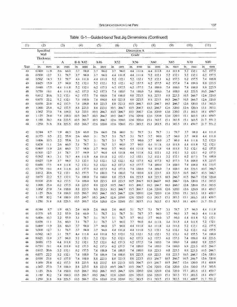
(I)
Size 40
40
40
40
40
40
40
40
40 40 40
40 40
40
42
42
42
42
42 42
42
42 42
42
42
42
42 42
42 42
42 42
44
44 44
44 44
44
44
44 44
44
44
44
44
44
44
44
44
44
(2)
Specified Wall
Thickness t
in. mm 0.469 11.9 0.500 12.7
0.562 14.3
0.625 15.9
0.688 17.5
0.750 19.1
0.812 20.6 0.875 22.2
0.938 23.8 1.000 25.4 1.062 27.0
1.125 28.6 1.188 30.2
1.250 31.8
0.344 8.7
0.375 9.5
0.406 10.3
0.438 11.1 0.469 11.9
0.500 12.7 0.562 14.3
0.625 15.9 0.688 17.5
0.750 19.1 0.812 20.6
0.875 22.2
0.938 23.8 1.000 25.4
1.062 270 1.125 28.6
1.188 30.2
1.250 31.8
0.344
0.375
8.7
9.5 0.406 10.3
0.438 11.1
0.469 11.9
0.500 12.7
0.562 14.3
0.625 15.9 0.688 17.5 0.750 19.1
0.812 20.6
0.875 22.2
0.938 23.8
1.000 25.4
1.062 270
1.125 28.6
1.188 30.2
1.250 31.8
SPECIFICATION FOR LINE PIPE
Table G-1-Guided-bend Test Jig Dimensions (Continued)
(3)
A
in. mm 2.6 66.0
3.1 78.7
3.1 78.7
3.7 94.0
4.4 111.8 4.4 111.8
5.2 132.1
5.2 132.1
6.2 157.5
(4)
B&X42 in. mm 3.7 94.0
3.7 94.0
4.4 111.8
5.2 132.1
5.2 132.1 6.2 157.5
6.2 157.5
7.4 188.0
7.4 188.0
6.2 157.5 8.8 223.5 7.4 188.0 8.8 223.5
7.4 188.0 10.5 266.7
8.8 223.5 to.5 266.7
8.8 223.5 10.5 266.7
(5)
X46 in. mm 3.7 94.0
3.7 94.0
4.4 111.8
5.2 132.1
6.2 157.5
6.2 157.5
7.4 188.0
7.4 188.0
8.8 223.5
(6)
X52 in. mm 3.7 94.0
4.4 111.8
5.2 132.1
5.2 132.1
6.2 157.5
7.4 188.0
7.4 188.0
8.8 223.5
8.8 223.5
(7)
Dimension A
Grade
X56
in. mm 4.4 111.8
4.4 111.8 5.2 132.1
6.2 157.5
6.2 157.5 7.4 188.0
8.8 223.5
8.8 223.5
10.5 266.7
8.8 223.5 10.5 266.7 to.5 266.7 10.5 266.7 10.5 266.7 10.5 266.7
10.5 266.7 to.5 266.7 12.6 320.0
10.5 266.7 12.6 320.0 12.6 320.0
12.6 320.0 12.6 320.0 15.1 383.5
(8)
X60
in. mm 4.4 111.8
5.2 132.1
5.2 132.1 6.2 157.5
7.4 188.0
7.4 188.0
8.8 223.5 8.8 223.5
10.5 266.7
10.5 266.7 12.6 320.0
12.6 320.0
15.1 383.5
15.1 383.5
(9)
X65
in. mm 4.4 111.8
S.2 132.1
6.2 157.5
6.2 157.4
7.4 188.0
7.4 188.0
K8 223.5 to.5 266.7
10.5 266.7
12.6 320.0 12.6 320.0
12.6 320.0
15.1 383.5
15.1 383.5
( 10)
X70
in. mm 5.2 132.1
5.2 132.1
6.2 157.5
7.4 188.0
7.4 188.0
8.8 223.5
Itl5 266.7 10.5 266.7
12.6 320.0
137
(II)
X80
in. mm 6.2 157.5
6.2 157.5 7.4 188.0
8.8 223.5
8.8 223.5
10.5 266.7
12.6 320.0 12.6 320.0
15.1 383.5
12.6 320.0 15. I 383.5 15.1 383.5 18.1 459.7 15.1 383.5 18.1 459.7
15.1 383.5 21.7 551.2
18.1 459.7 21.7 551.2
1.9 48.3 2.6 66.0 2.6 66.0 2.6 66.0 3.1 78.7 3.1 78.7 3.1 78.7 3.7 94.0 4.4 111.8
2.2 55.9
2.2 55.9 2.6 66.0
2.6 66.0 3.1 78.7
3.1 78.7
3.7 94.0
4.4 111.8
4.4 111.8 5.2 132.1
5.2 132.1 6.2 157.5
6.2 157.5 7.4 188.0
7.4 188.0
7.4 188.0 8.8 223.5
1.9 48.3
2.2 55.9
2.6 66.0
3.1 78.7 3.1 78.7
3.7 94.0 3.7 94.0
4.4 111.8
5.2 132.1
5.2 132.1
6.2 157.5 6.2 157.5
7.4 188.0
7.4 188.0
8.8 223.5
8.8 223.5 10.5 266.7
to.5 266.7 10.5 266.7
2.6 66.0
2.6 66.0
2.2 55.9 3.1 78.7
2.6 66.0 3.1 78.7
2.6 66.0 3.7 94.0
3.1 78.7 3.7 94.0
3.1 78.7 4.4 111.8 3.7 94.0 5.2 132.1
4.4 111.8 5.2 132.1 4.4 111.8
5.2 132.1
5.2 132.1
6.2 157.5
6.2 157.5
7.4 188.0
7.4 188.0
7.4 188.0
8.8 223.5
6.2 157.5
6.2 157.5
7.4 188.0
7.4 188.0
8.8 223.5
8.8 223.5
10.5 266.7
10.5 266.7 10.5 266.7
3.1 78.7
3.1 78.7
3.1 78.7 3.7 94.0
3.7 94.0 4.4 111.8
5.2 132.1 5.2 132.1
6.2 157.5
7.4 188.0
7.4 188.0
8.8 223.5 8.8 223.5
8.8 223.5
10.5 266.7
10.5 266.7 12.6 320.0
2.6 66.0
3.1 78.7 3.1 78.7
3.1 78.7 3.7 94.0
3.7 94.0
4.4 111.8
5.2 132.1 5.2 132.1 6.2 157.5
7.4 188.0
7.4 188.0
8.8 223.5
8.8 223.5
8.8 223.5
10.5 266.7
10.5 266.7 12.6 320.0
3.1 78.7
3.1 78.7
3.7 94.0 3.7 94.0
4.4 111.8 5.2 132.1
5.2 132.1 6.2 157.5
6.2 157.5
7.4 188.0
8.8 223.5
8.8 223.5 10.5 266.7
10.5 266.7
10.5 266.7
12.6 320.0
12.6 320.0
2.6 66.0
3.1 78.7
3.1 78.7
3.7 94.0 3.7 94.0
4.4 111.8
5.2 132.1
5.2 132.1 6.2 157.5 6.2 157.5
7.4 188.0
7.4 188.0
8.8 223.5
8.8 223.5
10.5 266.7
10.5 266.7
12.6 320.0
12.6 320.0
3.1 78.7
3.7 94.0 3.7 94.0
4.4 111.8 4.4 111.8
5.2 132.1
6.2 157.5 6.2 157.5
7.4 188.0 7.4 188.0
8.8 223.5
to.5 266.7 10.5 266.7
to.5 266.7 12.6 320.0
12.6 320.0
15.1 383.5
3.1 78.7
3.1 78.7
3.7 94.0
3.7 94.0
4.4 11 1.8
4.4 111.8
5.2 132.1
6.2 157.5
6.2 157.5 7.4 188.0
7.4 188.0
8.8 223.5
8.8 223.5 10.5 266.7
10.5 266.7
12.6 320.0
12.6 320.0
15.1 383.5
3.7 94.0
3.7 94.0
4.4 111.8 4.4 111.8 5.2 132.1
5.2 132.1
6.2 157.5 7.4 188.0
7.4 188.0
8.8 223.5
8.8 223.5
10.5 26637 10.5 266.7
12.6 320.0
12.6 320.0
15.1 383.5
15.1 383.5
3.1 78.7
3.7 94.0 3.7 94.0
4.4 111.8 4.4 111.8
5.2 132.1
5.2 132.1
6.2 157.5 7.4 188.0 7.4 188.0
8.8 223.5
8.8 223.5
10.5 266.7 10.5 266.7
12.6 320.0
12.6 320.0
12.6 320.0 15.1 383.5
3.7 94.0
3.7 94.0
4.4 111.8 4.4 111.8
5.2 132.1 5.2 132.1
6.2 157.5
7.4 188.0 7.4 188.0
8.8 223.5
10.5 266.7
10.5 266.7
10.5 266.7
12.6 320.0 12.6 320.0
15.1 383.5 15.1 383.5
3.1 78.7
3.7 94.0 3.7 94.0
4.4 I I 1.8
4.4 111.8
5.2 132.1
5.2 132.1
6.2 157.5 7.4 188.0
7.4 188.0
8.8 223.5
8.8 223.5
10.5 266.7
10.5 266.7
12.6 320.0
12.6 320.0
15.1 383.5 15.1 383.5
3.7 94.0
4.4 111.8
4.4 111.8 5.2 132.1
5.2 132.1
6.2 157.5
7.4 188.0 7.4 I XR.O
8.8 223.5
10.5 266.7
10.5 266.7 12.6 320.0
12.6 320.0
12.6 320.0 15.1 383.5
15.1 383.5 18.1 459.7
3.7 94.0
3.7 94.0 4.4 111.8
4.4 111.8
5.2 132.1
5.2 132.1
6.2 157.5
7.4 188.0 7.4 188.0
8.8 223.5
8.8 223.5
10.5 266.7
10.5 266.7
12.6 320.0
12.6 320.0
15.1 383.5
15.1 383.5
4.4 111.8
5.2 132.1
5.2 132.1 6.2 157.5
6.2 157.5 7.4 188.0
K8 223.5 8.8 223.5
10.5 266.7
10.5 266.7
12.6 320.0 15.1 383.5
15.1 383.5 18.1 459.7
18.1 459.7
18.1 459.7 21.7 551.2
4.4 111.8
4.4 111.8 5.2 132.1
5.2 132.1
6.2 157.5
6.2 157.5
7.4 188.0
8.8 223.5 8.8 223.5
10.5 266.7
10.5 266.7
12.6 320.0
12.6 320.0 15.1 408.9
15.1 383.5
18.1 459.7
18.1 459.7
18.1 489.7 21.7 551.2
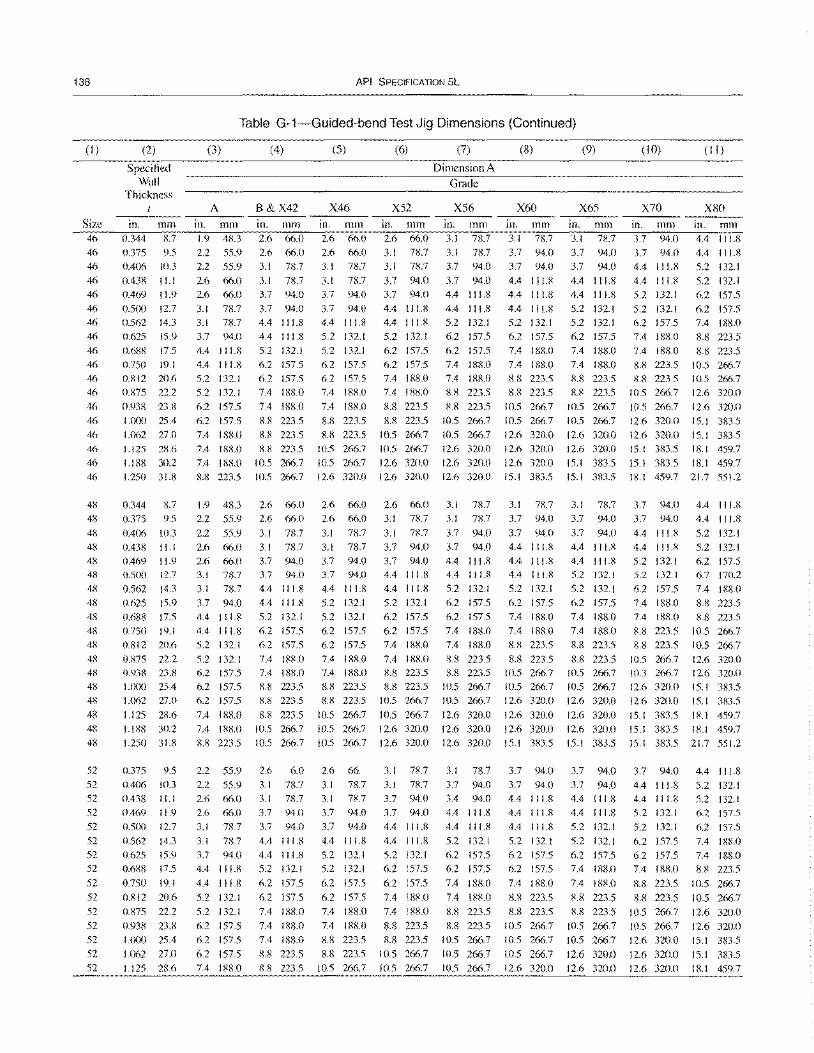
138
(I)
Size 46 46 46
46
46 46 46 46
46 46 46 46
46 46 46 46
46 46
48 48
48 48 48 48 48 48 48 48 48
48 48 48 48
48 48 48
52 52 52 52 52
52 52 52
52
52 52
52 52 52
52
(2)
Specified Wall
Thickness
In. mm 0.344 8.7
0.375 9.5 0.406 10.3
0.438 I I. I 0.469 I 1.9 0.500 12.7 0.562 14.3 0.625 15.9 0.688 17.5 0.750 19.1 0.812 20.6
0.875 22.2
0.938 23.8 1.000 25.4 1.062 27.0 1.125 28.6 1.188 30.2 1.250 31.8
0.344 8.7 0.375 9.5
0.406 10.3 0.438 II. I
0.469 I 1.9 0.500 12.7 0.562 14.3 0.625 15.9 0.688 17.5 0.750 19.1 0.812 20.6 0.875 22.2 0.938 23.8 1.000 25.4 1.{162 27.0
1.125 28.6 1.188 30.2 1.250 31.8
0.375 9.5 0.406 10.3 0.438 11.1 0.469 11.9 0.500 12.7
0.562 14.3 0.625 15.9 0.688 17.5
0.750 19.1
0.812 20.6 0.875 22.2
0.938 23.8 1.000 25.4 1.062 27.0
1.125 28.6
API SPECIFICATION 5L
Table G-1-Guided-bend Test Jig Dimensions (Continued)
(3)
A
In. mm 1.9 48.3 2.2 55.9 2.2 55.9
2.6 66.0 2.6 66.0
3.1 78.7 3.1 78.7 3.7 94.0 4.4 I I 1.8 4.4 I I 1.8 5.2 132.1 5.2 132. I
6.2 157.5 6.2 157.5 7.4 188.0
(4)
B&X42 in. mm 2.6 66.0 2.6 66.0 3.1 78.7
3.1 78.7 3.7 94.0 3.7 94.0 4.4 111.8 4.4 111.8
5.2 132.1 6.2 157.5 6.2 157.5 7.4 188.0 7.4 188.0
K8 223.5 8.8 223.5
7.4 188.0 8.8 223.5 7.4 188.0 10.5 266.7 8.8 223.5 10.5 266.7
1.9 48.3 2.2 55.9
2.2 55.9 2.6 66.0 2.6 66.0 3.1 7fl..7
3.1 78.7 3.7 94.0 4.4 111.8 4.4 I I 1.8 5.2 132.1
5.2 132. I 6.2 157.5 6.2 157.5 6.2 157.5
7.4 188.0
2.6 66.0 2.6 66.0
3.1 78.7 3. I 78.7 3.7 94.0 3.7 94.0 4.4 II 1.8 4.4 I I 1.8 5.2 132.1 6.2 157.5 6.2 157.5 7.4 188.0 7.4 188.0 8.8 223.5 8.8 223.5
8.8 223.5 7.4 18KO 10.5 266.7 8.8 223.5 10.5 266.7
2.2 55.9 2.2 55.9 2.6 66.0 2.6 66.0 3.1 78.7 3.1 78.7 3.7 94.0 4.4 I I 1.8
4.4 I I 1.8 5.2 132.1
5.2 132.1
6.2 157.5 6.2 157.5
6.2 157.5
7.4 188.0
2.6 6.0 3.1 78.7 3. I 78.7 3.7 94.0 3.7 94.0
4.4 I 11.8 4.4 111.8 5.2 132.1
6.2 157.5
6.2 157.5 7.4 188.0
7.4 188.0 7.4 188.0
8.8 223.5
8.8 223.5
(5)
X46 in. mm 2.6 66.0 2.6 66.0 3.1 78.7 3.1 78.7
3.7 94.0 3.7 94.0 4.4 I I 1.8 5.2 132.1 5.2 132.1
6.2 157.5 6.2 157.5 7.4 188.0
7.4 188.0
8.8 223.5 8.8 223.5
10.5 266.7
10.5 266.7 12.6 320.0
2.6 66.0 2.6 66.0
3.1 78.7 3.1 78.7 3.7 94.0 3.7 94.0
4.4 111.8 5.2 132.1 5.2 132.1 6.2 157.5 6.2 157.5
7.4 188.0 7.4 188.0 8.8 223.5 8.8 223.5
10.5 266.7
(6)
X52 In. mm 2.6 66.0 3.1 78.7 3.1 78.7
3.7 94.0 3.7 94.0
4.4 111.8 4.4 111.8 5.2 132.1 6.2 157.5 6.2 157.5 7.4 188.0 7.4 188.0
8.8 223.5 8.8 223.5
10.5 266.7 10.5 266.7
12.6 320.0 12.6 320.0
2.6 66.0 3.1 78.7
3.1 78.7 3.7 94.0 3.7 94.0 4.4 111.8
4.4 111.8 5.2 132.1 6.2 157.5 6.2 157.5 7.4 188.0
7.4 188.0 8.8 223.5 8.8 223.5
10.5 266.7
10.5 266.7
(7)
Dimension A
Grade
X56 in. mm 3. I 78.7 3.1 78.7 3.7 94.0
3.7 94.0 4.4 111.8 4.4 111.8 5.2 132.1 6.2 157.5
6.2 157.5 7.4 188.0 7.4 188.0 8.8 223.5
8.8 223.5 10.5 266.7
10.5 266.7 12.6 320.0
12.6 320.0 12.6 320.0
3.1 78.7 3.1 78.7
3.7 94.0 3.7 94.0 4.4 111.8 4.4 111.8
5.2 132.1 6.2 157.5 6.2 157.5 7.4 188.0 7.4 188.0
8.8 223.5 8.8 223.5
10.5 266.7 10.5 266.7
12.6 320.0
(8)
X60
in. mm 3. I 78.7 3.7 94.0 3.7 94.0
4.4 111.8 4.4 111.8 4.4 I I 1.8 5.2 132.1 6.2 157.5 7.4 188.0 7.4 188.0 8.8 223.5 8.8 223.5
10.5 266.7 10.5 266.7
12.6 320.0 12.6 320.0
12.6 320.0 15.1 383.5
3.1 78.7 3.7 94.0
3.7 94.0 4.4 111.8 4.4 111.8 4.4 I I 1.8
5.2 132.1 6.2 157.5 7.4 188.0 7.4 188.0 8.8 223.5 8.8 223.5
10.5 266.7 10.5 266.7 12.6 320.0
12.6 320.0 10.5 266.7 12.6 320.0 12.6 320.0 12.6 320.0 10.5 266.7 12.6 320.0 12.6 320.0 15.1 383.5
2.6 66. 3.1 78.7 3.1 78.7 3.7 94.0 3.7 94.0
4.4 111.8 5.2 132.1 5.2 132.1
6.2 157.5
6.2 157.5 7.4 188.0
7.4 188.0 8.8 223.5 88 223.5
10.5 266.7
3.1 78.7 3.1 78.7 3.7 94.0 3.7 94.0 4.4 111.8
4.4 I 11.8 5.2 132.1 6.2 157.5
6.2 157.5
7.4 188.0 7.4 188.0
8.8 223.5 8.8 223.5
10.5 266.7
10.5 266.7
3.1 78.7 3.7 94.0 3.4 94.0 4.4 I I 1.8 4.4 111.8
5.2 132.1 6.2 157.5 6.2 157.5
7.4 188.0 7.4 188.0 8.8 223.5
8.8 223.5 10.5 266.7 10.5 266.7
10.5 266.7
3.7 94.0 3.7 94.0 4.4 111.8 4.4 II 1.8
4.4 111.8 5.2 132.1 6.2 157.5 6.2 157.5
7.4 188.0
8.8 223.5 8.8 223.5
10.5 266.7 10.5 266.7
10.5 266.7
12.6 320.0
(9)
X65 In. mm 3.1 78.7 3.7 94.0 3.7 94.0
4.4 111.8 4.4 I I 1.8
5.2 132.1 5.2 132.1 6.2 157.5 7.4 188.0 7.4 188.0 8.8 223.5 8.8 223.5
10.5 266.7 10.5 266.7 12.6 320.0 12.6 320.0
15.1 383.5 15.1 383.5
3.1 78.7 3.7 94.0
3.7 94.0 4.4 111.8 4.4 111.8 5.2 132.1
5.2 132.1 6.2 157.5 7.4 188.0 7.4 188.0 8.8 223.5
8.8 223.5 10.5 266.7 10.5 266.7 12.6 320.0
12.6 320.0
(10)
X70
In. mm 3.7 94.0 3.7 94.0 4.4 111.8
4.4 111.8
5.2 132.1 5.2 132.1 6.2 157.5 7.4 188.0 7.4 188.0 8.8 223.5 3.8 223.5
10.5 266.7
10.5 266.7 12.6 320.0
12.6 320.0 15. I 383.5
15.1 383.5
(11)
X80
In. mm 4.4 111.8 4.4 111.8 5.2 132.1
5.2 132.1 6.2 157.5
6.2 157.5 7.4 188.0 8.8 223.5 8.8 223.5
10.5 266.7 10.5 266.7 12.6 320.0
12.6 320.0 15.1 383.5 15.1 383.5 18. I 459.7
18.1 459.7 13.1 459.7 21.7 551.2
3.7 94.0 3.7 94.0
4.4 111.8 4.4 111.8 5.2 132.1 5.2 132.1 6.2 157.5
7.4 188.0 7.4 188.0
8.8 223.5 8.8 223.5
10.5 266.7 10.3 266.7 12.6 320.0 12.6 320.0
15.1 383.5
4.4 111.8 4.4 111.8
5.2 132.1 5.2 132.1 6.2 157.5 6.7 170.2
7.4 188.0 8.8 223.5 8.8 223.5
10.5 266.7 10.5 266.7 12.6 320.0 12.6 320.0 15.1 383.5 15.1 383.5
13.1 459.7 12.6 320.0 15.1 383.5 18.1 459.7 15.1 383.5 15.1 383.5 21.7 551.2
3.7 94.0 3.7 940 4.4 111.8 4.4 111.8 5.2 132.1 5.2 132.1
6.2 157.5 7.4 1880
7.4 188.0
8.8 223.5 8.8 223.5
10.5 266.7 10.5 266.7
12.6 320.0 12.6 320.0
3.7 94.0 4.4 111.8 4.4 I I 1.8 5.2 132.1 5.2 132.1
6.2 157.5 6.2 157.5 7.4 188.0
8.8 223.5
8.8 223.5 10.5 266.7 10.5 266.7
4.4 111.8 5.2 132.1 5.2 132.1 6.2 157.5 6.2 157.5
7.4 188.0 7.4 188.0 8.8 223.5
10.5 266.7
10.5 266.7 12.6 320.0 12.6 320.0
12.6 320.0 15.1 383.5
12.6 320.0 15.1 383.5 12.6 320.0 18. I 459.7
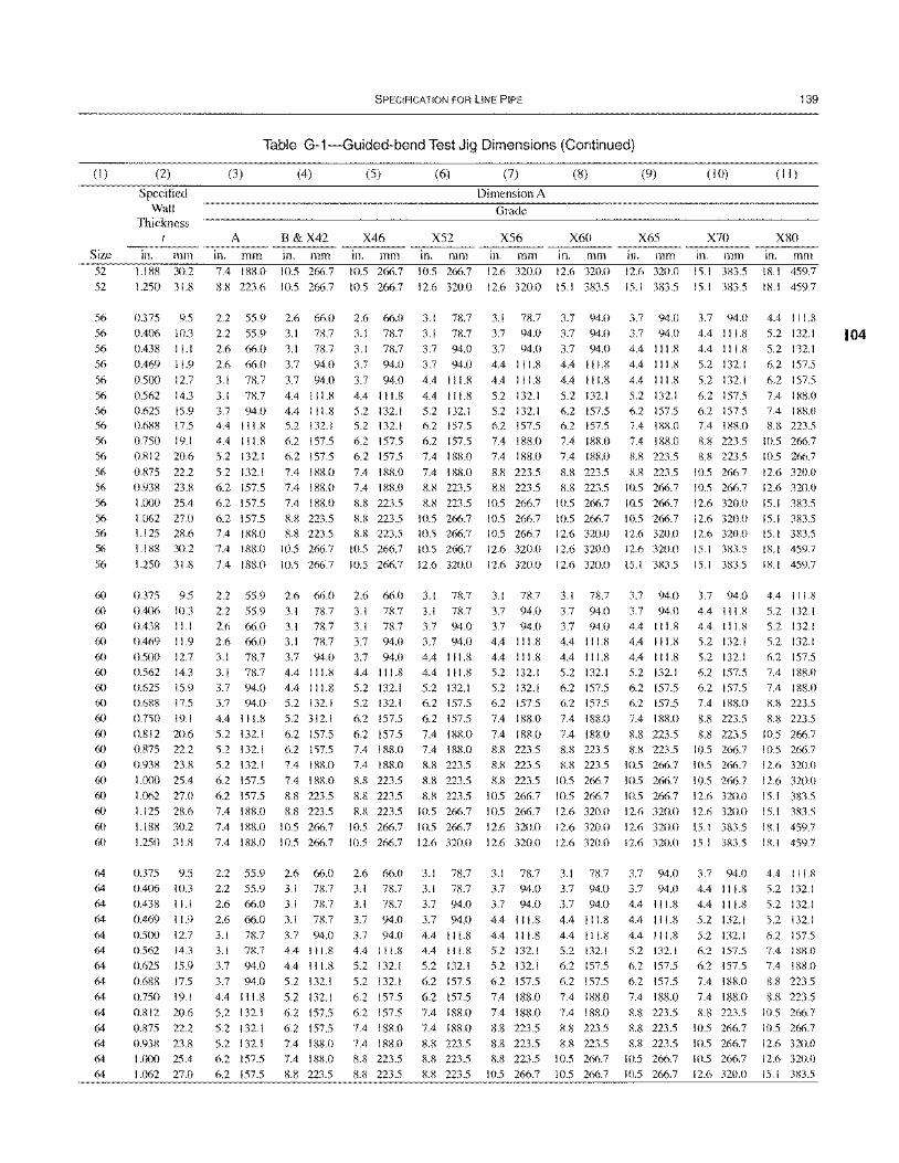
(1)
Size 52
52
56
56
56
56
56
56 56 56
56
56
56
56
56
56
56 56
56
60 60
60
60
60 60
60 60
60
60
60
60
60
60 60
60
60
64 64 64
64 64 64
64 64 64
64 64 64 64 64
(2)
Specified Wall
Thickness
in. mm 1.188 30.2
1.250 31.8
0.375 9.5
0.406 10.3
0.438 11.1
0.469 11.9
0.500 12.7
0.562 14.3 0.625 15.9 0.688 17.5
0.750 19.1 0.812 20.6
0.875 22.2
0.938 23.8
1.000 25.4
1.062 27.0 1.125 28.6
1.188 30.2
1.250 31.8
0.375 9.5
0.406 10.3
0.438 11.1
0.469 11.9 O.5(X) 12.7
0.562 14.3
0.625 15.9 0.688 17.5
0.750 19.1
0.812 20.6
0.875 22.2 0.938 23);
1.000 25.4
1.062 27.0 1.125 28.6
1.188 30.2
1.250 31.8
0.375 9.5 0.406 10.3
0.438 11.1
0.469 11.9
0.500 12.7
0.562 14.3
0.625 15.9 0.688 17.5
0.750 19.1
0.812 20.6 (l.S75 22.2
0.938 23.8
1.000 25.4
1.062 27.0
SPECIFICATION FOR LINE PIPE
Table G-1-Guided-bend Test Jig Dimensions (Continued)
(3)
A in. mm 7.4 188.0
8.8 223.6
(4)
B&X42 in. mm 10.5 266.7
10.5 266.7
2.2 55.9 2.6 66.0
2.2 55.9 3.1 78.7
2.6 66.0 3.1 78.7
2.6 66.0
3.1 78.7
3.1 78.7 3.7 94.0 4.4 111.8
4.4 111.8 5.2 132.1
5.2 132.1
6.2 157.5
6.2 157.5 6.2 157.5
7.4 188.0 7.4 188.0
7.4 188.0
2.2 55.9
2.2 55.9
2.6 66.0
2.6 66.0
3.1 78.7 3.1 78.7 3.7 94.0
3.7 94.0
4.4 111.8
5.2 132.1
5.2 132.1
5.2 132.1
6.2 157.5
6.2 157.5
7.4 188.0
7.4 188.0
7.4 188.0
2.2 55.9 2.2 55.9
2.6 66.0
2.6 66.0
3.1 78.7
3.1 78.7
3.7 94.0
3.7 94.0
4.4 111.8
5.2 132.1
5.2 132.1 5.2 132.1
6.2 157.5
6.2 157.5
3.7 94.0
3.7 94.0
4.4 111.8 4.4 111.8 5.2 132.1
6.2 157.5 6.2 157.5
7.4 188.0
7.4 188.0
7.4 188.0
8.8 223.5 8.8 223.5
10.5 266.7
10.5 266.7
2.6 66.0
3.1 78.7
3.1 78.7
3.1 78.7
3.7 94.0 4.4 111.8
4.4 111.8 5.2 132.1
5.2 312.1
6.2 157.5
6.2 157.5 7.4 188.0
7.4 188.0
8.8 223.5 8.11 223.5
10.5 266.7
10.5 266.7
2.6 66.0 3.1 7S.7
3.1 78.7
3.1 78.7
3.7 94.0 4.4 111.8
4.4 111.8
5.2 132.1
5.2 132.1
6.2 157.5
6.2 157.5 7.4 18S.0
7.4 I IlS.O
8.8 223.5
(5)
X46 in. mm 10.5 266.7
10.5 266.7
2.6 66.0
3.1 78.7
3.1 78.7
3.7 94.0
3.7 94.0
4.4 111.8 5.2 132.1 5.2 132.1
6.2 157.5 6.2 157.5
7.4 188.0
7.4 188.0
8.8 223.5
8.8 223.5 1l.8 223.5
10.5 266.7
10.5 266.7
2.6 66.0
3.1 78.7 3.1 78.7
3.7 94.0
3.7 94.0 4.4 111.8
5.2 132.1 5.2 132.1
6.2 157.5
6.2 157.5
7.4 188.0
7.4 188.0
8.8 223.5
8.8 223.5 8.8 223.5
10.5 266.7
10.5 266.7
2.6 66.0 3.1 78.7
3.1 78.7
3.7 94.0
3.7 94.0 4.4 111.8
5.2 132.1
5.2 132.1
6.2 157.5 6.2 157.5
7.4 188.0
7.4 188.0
8.8 223.5
8.8 223.5
(6)
X52 in. mm 10.5 266.7
12.6 320.0
3.1 78.7
3.1 711.7
3.7 94.0
3.7 94.0
4.4 111.8
4.4 111.8 5.2 132.1 6.2 157.5
6.2 157.5 7.4 188.0
7.4 188.0
8.8 223.5
8.8 223.5
10.5 266.7 10.5 266.7
10.5 266.7
12.6 320.0
3.1 78.7
3.1 78.7
3.7 94.0
3.7 94.0
4.4 111.8 4.4 111.8
5.2 132.1 6.2 157.5
6.2 157.5
7.4 188.0
7.4 188.0
8.8 223.5
8.8 223.5
8.8 223.5 10.5 266.7
10.5 266.7
12.6 320.0
3.1 78.7
3.1 78.7 3.7 94.0
3.7 94.0
4.4 111.8
4.4 111.8
5.2 132.1
6.2 157.5
6.2 157.5 7.4 188.0
7.4 188.0
8.8 223.5
8.8 223.5
8.8 223.5
(7)
Dimension A
Grade
X56 in. mm 12.6 320.0
12.6 320.0
3.1 78.7
3.7 94.0
3.7 94.0
4.4 111.8
4.4 111.8
5.2 132.1 5.2 132.1 6.2 157.5
7.4 188.0 7.4 188.0
8.8 223.5 8.8 223.5
10.5 266.7
10.5 266.7 10.5 266.7
12.6 320.0
12.6 320.0
3.1 78.7
3.7 94.0
3.7 94.0
4.4 11l.8
4.4 111.8 5.2 132.1
5.2 132.1 6.2 157.5
7.4 188.0
7.4 188.0
8.8 223.5
8.8 223.5
8.8 223.5
10.5 266.7
10.5 266.7
12.6 320.0
12.6 320.0
3.1 78.7
3.7 94.0 3.7 94.0
4.4 11l.8
4.4 111.8
5.2 132.1
5.2 132.1
6.2 157.5
7.4 188.0
7.4 188.0
8.8 223.5
8.8 223.5
8.8 223.5 10.5 266.7
(8)
X60 in. mm 12.6 320.0
15.1 383.5
3.7 94.0
3.7 94.0
3.7 94.0
4.4 111.8
4.4 11l.8
5.2 132.1 6.2 157.5 6.2 157.5
7.4 188.0 7.4 188.0
8.8 223.5 8.8 223.5
10.5 266.7
10.5 266.7 12.6 320.0
12.6 320.0
12.6 320.0
3.1 78.7
3.7 94.0 3.7 94.0
4.4 11l.8
4.4 11l.8 5.2 132.1
6.2 157.5 6.2 157.5
7.4 188.0
7.4 188.0
8.8 223.5
8.8 223.5
10.5 266.7
10.5 266.7
12.6 320.0
12.6 320.0
12.6 320.0
3.1 78.7
3.7 94.0 3.7 94.0
4.4 11l.8
4.4 111.8
5.2 132.1 6.2 157.5
6.2 157.5
7.4 188.0
7.4 188.0
8.8 223.5
8.8 223.5 10.5 266.7
10.5 266.7
(9)
X65 in. mm 12.6 320.0
15.1 383.5
3.7 94.0
3.7 94.0
4.4 111.8
4.4 111.8
4.4 111.8
5.2 132.1 6.2 157.5 7.4 188.0
7.4 188.0 8.8 223.5
8.11 223.5
10.5 266.7
10.5 266.7
10.5 266.7 12.6 320.0
12.6 320.0
15.1 383.5
3.7 94.0
3.7 94.0 4.4 111.8
4.4 111.8 4.4 111.8
5.2 132.1
6.2 157.5 6.2 157.5
7.4 188.0
8.8 223.5
8.8 223.5 10.5 266.7
10.5 266.7
10.5 266.7
12.6 320.0
12.6 320.0
12.6 320.0
3.7 94.0
3.7 94.0 4.4 111.8
4.4 111.8
4.4 111.8
5.2 132.1 6.2 157.5
6.2 157.5
7.4 188.0
8.8 223.5
8.8 223.5
8.8 223.5 10.5 266.7
10.5 266.7
(10)
X70 in. mm 15.1 383.5
15.1 383.5
3.7 94.0
4.4 111.8
4.4 111.8
5.2 132.1
5.2 132.1
6.2 157.5 6.2 157.5 7.4 188.0
8.8 223.5
8.8 223.5
10.5 266.7
10.5 266.7
12.6 320.0
12.6 320.0 12.6 320.0
15.1 383.5
15.1 383.5
3.7 94.0
4.4 111.8 4.4 111.8
5.2 132.1 5.2 132.1
6.2 157.5
6.2 157.5 7.4 188.0
8.8 223.5
8.8 223.5
10.5 266.7
10.5 266.7
10.5 266.7
12.6 320.0
12.6 320.0
15.1 383.5
15.1 383.5
3.7 94.0
4.4 111.8 4.4 111.8
5.2 132.1
5.2 132.1
6.2 157.5 6.2 157.5
7.4 188.0
7.4 188.0
8.8 223.5
10.5 266.7
10.5 266.7 10.5 266.7
12.6 320.0
139
(II )
X80 in. mm 18.1 459.7
18.1 459.7
4.4 111.8
5.2 132.1
5.2 132.1
6.2 157.5
6.2 157.5
7.4 IS8.0 7.4 188.0 8.8 223.5
10.5 266.7 10.5 266.7
12.6 320.0
12.6 320.0
15.1 383.5
15.1 383.5 15.1 383.5
18.1 459.7
IS.1 459.7
4.4 111.8
5.2 132.1 5.2 132.1
5.2 132.1 6.2 157.5
7.4 188.0
7.4 188.0 8.8 223.5
8.8 223.5
10.5 266.7
10.5 266.7
12.6 320.0
12.6 320.0
15.1 383.5
15.1 383.5
18.1 459.7
18.1 459.7
4.4 111.8
5.2 132.1
5.2 132.1
5.2 132.1
6.2 157.5
7.4 188.0 7.4 188.0
8.8 223.5
8.8 223.5
10.5 266.7
10.5 266.7 12.6 320.0
12.6 320.0
15.1 383.5
104
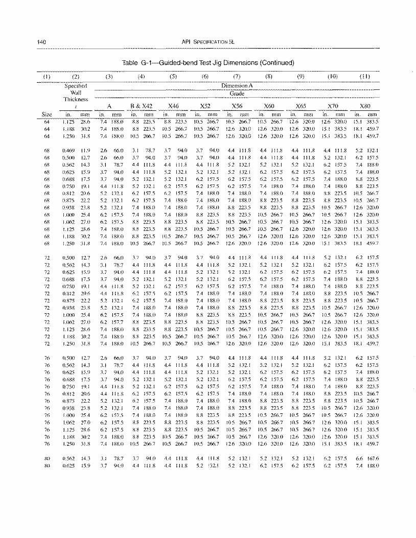
140
(I)
Size 64 64 64
68
68
68
68
68 68
68
68
68
68
68 6S
68
6S
72
72
72
72 72
72
72
72 72
72
72
72
72
76
76
76
76
76
76 76
76 76
76
76
76
76
80
80
(2)
Specified Wall
Thickness 1
111. mm 1.125 28.6
1.188 30.2
1.250 31.8
0.469 11.9 0.5(X) 12.7
0.562 14.3
0.625 15.9
O.68S 17.5 0.750 19.1 0.812 20.6
0.875 22.2
0.938 23.8 I.lX)O 25.4
1.062 27.0 1.125 28.6
1.188 30.2 1.250 31.8
0.500 12.7
0.562 14.3 0.625 15.9
0.688 17.5 0.750 19.1
0.812 20.6 0.875 22.2
0.938 23.8
1.000 25.4
1.ll62 27.0
1.125 28.6
1.188 30.2
1.250 31.8
0.500 12.7
0.562 14.3 0.625 15.9
0.688 17.5 0.750 19.1
0.812 20.6
0.875 22.2
0.938 23.8 1.000 25.4
I.Cl62 27.0
1.125 28.6
1.188 30.2 1.250 31.8
0.562 14.3
0.625 15.9
API SPECIFICATION 5L
Table G-1-Guided-bend Test Jig Dimensions (Continued)
(3)
A 111. mm 7.4 188.0
7.4 188.0
7.4 188.0
2.6 66.0
2.6 66.0 3.1 78.7
3.7 94.0 3.7 94.0
4.4 111.8 5.2 132.1
5.2 132. I
5.2 132.1
6.2 157.5
6.2 157.5 7.4 188.0
7.4 188.0 7.4 188.0
2.6 66.0
3.1 78.7
3.7 94.0
3.7 94.0
4.4 1 I 1.8
4.4 II 1.8 5.2 132. I
5.2 132.1
6.2 157.5
6.2 157.7
7.4 188.0
7.4 188.0
7.4 188.0
(4)
B&X42 in. mm 8.8 223.5
8.8 223.5
10.5 266.7
3.1 78.7
3.7 94.0 4.4 I I 1.8
4.4 I I 1.8
5.2 132. I
5.2 132.1 6.2 157.5
6.2 157.5
7.4 188.0
7.4 188.0
8.8 223.5 8.8 223.5
8.8 223.5 10.5 266.7
3.7 94.0
4.4 I I 1.8
4.4 I I 1.8
5.2 132.1 5.2 132.1
6.2 157.5
6.2 157.5
7.4 188.0 7.4 188.0
8.8 223.5
8.8 233.5
8.8 223.5 10.5 266.7
(5)
X46
in. mm 8.8 223.5
10.5 266.7
10.5 266.7
3.7 94.0
3.7 94.0 4.4 111.8
5.2 132.1
5.2 132.1 6.2 157.5
6.2 157.5
7.4 188.0
7.4 188.0
7.4 188.0
8.8 223.5 8.8 223.5
10.5 266.7 10.5 266.7
3.7 94.0
4.4 111.8 4.4 I I 1.8
5.2 132.1 6.2 157.5
6.2 157.5
7.4 188.0 7.4 188.0
7.4 188.0
8.8 223.5
8.8 223.5
10.5 266.7
10.5 266.7
(6)
X52 111. mm 10.5 266.7
10.5 266.7
10.5 266.7
3.7 94.0
3.7 94.0 4.4 111.8
5.2 132.1
6.2 157.5 6.2 157.5 7.4 188.0
7.4 188.0 7.4 188.0
8.8 223.5
8.8 223.5 10.5 266.7
10.5 266.7
10.5 266.7
3.7 94.0
4.4 111.8 5.2 132.1
5.2 132.1
6.2 157.5
7.4 188.0 7.4 188.0
7.4 188.0
8.8 223.5
8.8 223.5
10.5 266.7
10.5 266.7
10.5 266.7
2.6 66.0 3.7 94.0 3.7 94.0 3.7 94.0
3.1 78.7 4.4 111.8 4.4 111.8 4.4 111.8
3.7 94.0
3.7 94.0
4.4 I I 1.8
4.4 111.8
5.2 132. I
5.2 132.1
6.2 157.5
6.2 157.5
6.2 157.5
7.4 188.0 7.4 188.0
4.4 111.8
5.2 132.1
5.2 132.1
6.2 157.5
6.2 157.5
7.4 188.0 7.4 188.0
8.8 223.5 8.8 223.5
8.8 223.5 10.5 266.7
4.4 111.8
5.2 132.1 6.2 157.5
6.2 157.5 7.4 188.0
7.4 188.0 7.4 188.0
8.8 223.5
8.8 223.5
10.5 266.7
10.5 266.7
5.2 132.1
5.2 132.1 6.2 157.5
6.2 157.5
7.4 188.0
7.4 188.0
8.8 223.5
8.8 223.5
10.5 266.7
10.5 266.7
10.5 266.7
(7)
Dimension A
Grade
X56 in. mm 10.5 266.7
12.6 320.0
12.6 320.0
4.4 111.8
4.4 I I 1.8
5.2 132.1
5.2 132.1
6.2 157.5
6.2 157.5 7.4 188.0
7.4 188.0
8.8 223.5
8.8 223.5
10.5 266.7 10.5 266.7
10.5 266.7
12.6 320.0
4.4 111.8
5.2 132.1
5.2 132.1
6.2 157.5 6.2 157.5
7.4 188.0
7.4 188.0
8.8 223.5
8.8 223.5
10.5 266.7
10.5 266.7
10.5 266.7
12.6 320.0
4.4 111.8
5.2 132.1 5.2 132.1
6.2 157.5 6.2 157.5
7.4 188.0 7.4 188.0
8.8 223.5 8.8 223.5
10.5 266.7
10.5 266.7
10.5 266.7 12.6 320.0
(8)
X60
in. mm 10.5 266.7
12.6 320.0
12.6 320.0
4.4 111.8
4.4 1 I 1.8 5.2 132.1
6.2 157.5
6.2 157.5 7.4 188.0
7.4 188.0
8.8 223.5
8.8 223.5
10.5 266.7
10.5 266.7
10.5 266.7
12.6 320.0
12.6 320.0
4.4 111.8
5.2 132.1 6.2 157.5
6.2 157.5 7.4 188.0
7.4 188.0
8.8 223.5
8.8 223.5 10.5 266.7
10.5 266.7
10.5 266.7
12.6 320.0
12.6 320.0
4.4 111.8
5.2 132.1
6.2 157.5
6.2 157.5 7.4 188.0
7.4 188.0
8.8 223.5
8.8 223.5 10.5 266.7
10.5 266.7
10.5 266.7
12.6 320.0
12.6 320.0
(9)
X65 in. mm 12.6 320.0
12.6 320.0
12.6 320.0
4.4 111.8
4.4 111.8 5.2 132.1
6.2 157.5
6.2 157.5 7.4 188.0
7.4 188.0
8.8 223.5
8.8 223.5
10.5 266.7
10.5 266.7
12.6 320.0
12.6 320.0
12.6 320.0
4.4 I I 1.8
5.2 132.1 6.2 157.5
6.2 157.5
7.4 188.0
7.4 188.0
8.8 223.5
8.8 223.5 10.5 266.7
10.5 266.7
12.6 320.0
12.6 320.0
12.6 320.0
4.4 111.8
5.2 132.1 6.2 157.5
6.2 157.5
7.4 188.0
7.4 188.0
8.8 223.5
8.8 223.5 10.5 266.7
10.5 266.7
10.5 266.7
12.6 320.0
12.6 320.0
(10)
X70
in. mm 12.6 320.0
15.1 383.5
15.1 383.5
4.4 111.8
5.2 132.1 6.2 157.5
6.2 157.5 7.4 188.0 7.4 188.0
8.8 223.5
8.8 223.5
10.5 266.7
10.5 266.7
12.6 320.0 12.6 320.0
12.6 320.0
15. I 383.5
5.2 132.1
6.2 157.5 6.2 157.5
7.4 188.0 7.4 188.0
8.8 223.5
8.8 223.5
10.5 266.7 10.5 266.7
12.6 320.0
12.6 320.0
12.6 320.0 15.1 383.5
5.2 132.1
6.2 157.5 6.2 157.5
7.4 188.0
7.4 188.0
8.8 223.5 8.8 223.5
10.5 266.7 10.5 266.7
12.6 320.0
12.6 320.0
12.6 320.0 15.1 383.5
(ll)
X80
111. mm 15.1 383.5
18.1 459.7
18.1 459.7
5.2 132.1
6.2 157.5
7.4 188.0
7.4 188.0 8.8 223.5 8.8 223.5
10.5 266.7
10.5 266.7
12.6 320.0
12.6 320.0
15.1 383.5
15. I 383.5
15.1 383.5
18.1 459.7
6.2 157.5
6.2 157.5
7.4 188.0
8.8 223.5 8.8 223.5
10.5 266.7 10.5 266.7
12.6 320.0 12.6 320.0
15.1 383.5
15.1 383.5
15.1 383.5
18.1 459.7
6.2 157.5
6.2 157.5 7.4 188.0
8.8 223.5
8.8 223.5
10.5 266.7
10.5 266.7
12.6 320.0
12.6 320.0
15.1 383.5
15. I 383.5
15.1 383.5 18.1 459.7
3.1 78.7 3.7 94.0 4.4 111.8 4.4 111.8 5.2 132.1 5.2 132.1 5.2 132.1 6.2 157.5 6.6 167.6
3.7 94.0 4.4 111.8 4.4 111.8 5.2 132.1 5.2 132.1 6.2 157.5 6.2 157.5 6.2 157.5 7.4 188.0
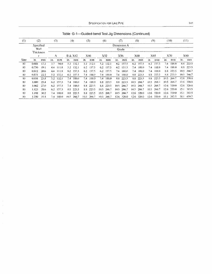
SPECIFICATION FOR liNE PIPE 141
Table G-1-Guided-bend Test Jig Dimensions (Continued)
(1 ) (2) (3) (4) (5) (6) (7) (8) (9) (10) (1 1)
Specified Dimension A Wall Grade
Thickness t A B&X42 X46 X52 X56 X60 X65 X70 X80
Size in. mm in. mm In. mm In. mm in. mm in. mm in. mm in. mm in. mm in. mm 80 0.6R8 17.5 3.7 94.0 5.2 132.1 5.2 312.1 5.2 132.1 6.2 157.5 6.2 157.5 6.2 157.5 7.4 I R!W K8 223.5
80 0.750 19.1 4.4 111.8 5.2 132.1 6.2 157.5 6.2 157.5 6.2 157.5 7.4 188.0 7.4 188.0 7.4 188.0 K8 223.5
80 0.812 20.6 4.4 111.8 6.2 157.5 6.2 157.5 6.2 157.5 7.4 188.0 7.4 188.0 7.4 188.0 8.8 223.5 10.5 266.7
80 0.875 22.2 5.2 132.1 6.2 157.5 7.4 188.0 7.4 188.0 7.4 188.0 8.8 223.5 8.8 223.5 8.8 223.5 10.5 266.7
80 0.938 23.8 5.2 132.1 7.4 188.0 7.4 188.0 7.4 188.0 8.8 223.5 8.8 223.5 8.8 223.5 10.5 266.7 12.6 320.0
80 1.000 25.4 6.2 157.5 7.4 188.0 7.4 188.0 8.8 223.5 8.8 223.5 10.5 266.7 10.5 266.7 10.5 266.7 12.6 320.0
80 1.062 270 6.2 157.5 7.4 188.0 8.8 223.5 8.8 223.5 10.5 266.7 10.5 266.7 10.5 266.7 12.6 320.0 12.6 320.0
80 1.125 28.6 6.2 157.5 K8 223.5 8.S 223.5 10.5 266.7 10.5 266.7 10.5 266.7 10.5 266.7 12.6 320.0 15.1 383.5
80 1.188 30.2 7.4 188.0 8.8 223.5 8.8 223.5 10.5 266.7 10.5 266.7 12.6 320.0 12.6 320.0 12.6 320.0 15.1 383.5
SO 1.250 31.8 7.4 18S.0 10.5 266.7 10.5 266.7 10.5 266.7 12.6 320.0 12.6 320.0 12.6 320.0 15.1 383.5 18.1 459.7

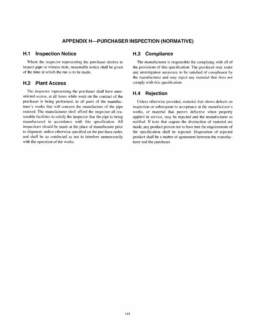
APPENDIX H-PURCHASER INSPECTION (NORMATIVE)
H.1 Inspection Notice
Where the inspector representing the purchaser desires to inspect pipe or witness tests, reasonable notice shall be given of the time at which the run is to be made.
H.2 Plant Access
The inspector representing the purchaser shall have unrestricted access, at all times while work on the contract of the purchaser is being performed, to all parts of the manufacturer's works that will concern the manufacture of the pipe ordered. The manufacturer shall afford the inspector all reasonable facilities to satisfy the inspector that the pipe is being manufactured in accordance with this specification. All inspections should be made at the place of manufacture prior to shipment, unless otherwise specified on the purchase order, and shall be so conducted as not to interfere unnecessarily with the operation of the works.
143
H.3 Compliance
The manufacturer is responsible for complying with all of the provisions of this specification. The purchaser may make any investigation necessary to be satisfied of compliance by the manufacturer and may reject any material that does not comply with this specification.
H.4 Rejection
Unless otherwise provided, material that shows defects on inspection or subsequent to acceptance at the manufacturer's works, or material that proves defective when properly applied in service, may be rejected and the manufacturer so notified. If tests that require the destruction of material are made, any product proven not to have met the requirements of the specification shall be rejected. Disposition of rejected product shall be a matter of agreement between the manufacturer and the purchaser.

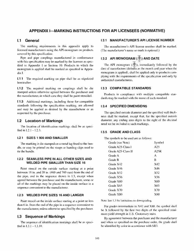
APPENDIX I-MARKING INSTRUCTIONS FOR API LICENSEES (NORMATIVE)
1.1 General The marking requirements in this appendix apply to
licensed manufacturers using the API monogram on products covered by this specification.
Pipe and pipe couplings manufactured in conformance with this specification may be marked by the licensee as specified in Appendix I or Section 10. Products to which the monogram is applied shall be marked as specified in Appendix I.
1.1.1 The required marking on pipe shall be as stipulated hereinafter.
1.1.2 The required marking on couplings shall be die stamped unless otherwise agreed between the purchaser and the manufacturer, in which case they shall be paint stenciled.
1.1.3 Additional markings, including those for compatible standards following the specification marking, are allowed and may be applied as desired by the manufacturer or as requested by the purchaser.
1.2 Location of Markings The location of identification markings shall be as speci
fied in 1.2.1 - I.2.3.
1.2.1 SIZES 1.900 AND SMALLER
The marking is die stamped on a metal tag fixed to the bundle, or may be printed on the straps or banding clips used to tie the bundle.
1.2.2 SEAMLESS PIPE IN ALL OTHER SIZES AND WELDED PIPE SMALLER THAN SIZE 16
Paint stencil on the outside surface starting at a point between 18 in. and 30 in. (460 and 760 mm) from the end of the pipe, and in the sequence shown in 1.3, except when agreed between the purchaser and the manufacturer, some or all of the markings may be placed on the inside surface in a sequence convenient to the manufacturer.
1.2.3 WELDED PIPE SIZES 16 AND LARGER
Paint stencil on the inside sllli"ace starting at a point no less than 6 in. from the end of the pipe in a sequence convenient to the manufacturer, unless otherwise specified by the purchaser.
1.3 Sequence of Markings
The sequence of identification markings shall be as specified in 1.3.1 - I.3.IO.
145
1.3.1 MANUFACTURER'S API LICENSE NUMBER
The manufacturer's API license number shall be marked. (The manufacturer's name or mark is optional.)
1.3.2 API MONOGRAM (t) AND DATE
The API monogram (~), immediately followed by the date of manufacture (defi~ as the month and year when the monogram is applied), shall be applied only to products complying with the requirements of the specification and only by authorized manufacturers.
1.3.3 COMPATIBLE STANDARDS
Products in compliance with mUltiple compatible standards may be marked with the name of each standard.
1.3.4 SPECIFIED DIMENSIONS
The specified outside diameter and the specified wall thickness shall be marked, except that, for the specified outside diameter, any ending zero digits to the right of the decimal need not be included in such markings.
1.3.5 GRADE AND CLASS
The symbols to be used are as follows:
Grade (see Note) Symbol
Grade A25-Class I A25
Grade A25-Class II A25R
Grade A A
Grade B B
Grade X42 X42
Grade X46 X46
Grade X52 X52
Grade X56 X56
Grade X60 X60
Grade X65 X65
Grade X70 X70
Grade X80 X80
Note: See 1.3 for limitations on downgrading.
For grades intermediate to X42 and X80, the symbol shall be X followed by the first two digits of the specified minimum yield strength in U.S. Customary units.
By agreement between the purchaser and the manufacturer and when so specified on the purchase order, the grade shall be identified by color in accordance with SR3.
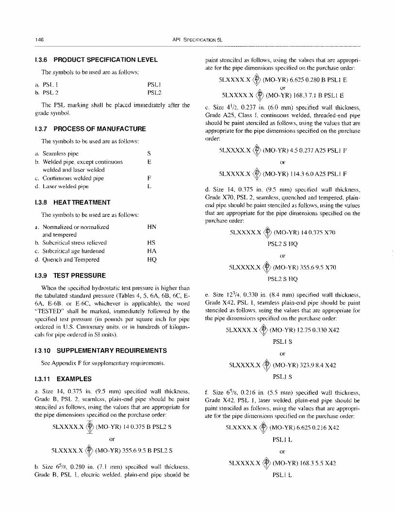
146 API SPECIFICATION 5L
1.3.6 PRODUCT SPECIFICATION LEVEL
The symbols to be used are as follows:
a. PSL I b. PSL 2
PSLl PSL2
The PSL marking shall be placed immediately after the grade symbol.
1.3.7 PROCESS OF MANUFACTURE
The symbols to be used are as follows:
a. Seamless pipe S
b. Welded pipe, except continuous E welded and laser welded
c. Continuous welded pipe F d. Laser welded pipe L
1.3.8 HEAT TREATMENT
The symbols to be used are as follows:
a. Normalized or normalized and tempered
b. Subcritical stress relieved c. Subcritical age hardened
d. Quench and Tempered
1.3.9 TEST PRESSURE
HN
HS HA
HQ
When the specified hydrostatic test pressure is higher than the tabulated standard pressure (Tables 4, 5, 6A, 6B, 6C, E-6A, E-68, or E-6C, whichever is applicable), the word "TESTED" shall be marked, immediately followed by the specified test pressure (in pounds per square inch for pipe ordered in U.S. Customary units, or in hundreds of kilopascals for pipe ordered in SI units).
1.3.10 SUPPLEMENTARY REQUIREMENTS
See Appendix F for supplementary requirements.
1.3.11 EXAMPLES
a. Size 14, 0.375 in. (9.5 mm) specified wall thickness, Grade 8, PSL 2, seamless, plain-end pipe should be paint stenciled as follows, using the values that are appropriate for the pipe dimensions specified on the purchase order:
5LXXXX.x ~ (MO-YR) 140.375 B PSL2 S
or
5LXXXX.X ~ (MO-YR) 355.69.5 B PSL2 S
b. Size 65/8, 0.280 in. (7.1 mm) specified wall thickness, Grade B, PSL I, electric welded, plain-end pipe should be
paint stenciled as follows, using the values that are appropriate for the pipe dimensions specified on the purchase order:
5LXXXX.X ~ (MO-YR) 6.625 0.280 B PSLl E or
5LXXXX.X ~ (MO-YR) 168.37.1 B PSLl E
c. Size 4 1/2, 0.237 in. (6.0 mm) specified wall thickness, Grade A25, Class I, continuous welded, threaded-end pipe should be paint stenciled as follows, using the values that are appropriate for the pipe dimensions specified on the purchase order:
5LXXXX.X ~ (MO-YR) 4.5 0.237 A25 PSLl F
or
5LXXXX.X ~ (MO-YR) 114.3 6.0 A25 PSLI F
d. Size 14, 0.375 in. (9.5 mm) specified wall thickness, Grade X70, PSL 2, seamless, quenched and tempered, plainend pipe should be paint stenciled as follows, using the values that are appropriate for the pipe dimensions specified on the purchase order:
5LXXXX.X ~ (MO-YR) 140.375 X70
PSL2 S HQ
or
5LXXXX.x ~ (MO-YR) 355.69.5 X70
PSL2 S HQ
e. Size 123/4, 0.330 in. (8.4 mm) specified wall thickness, Grade X42, PSL 1, seamless plain-end pipe should be paint stenciled as follows, using the values that are appropriate for the pipe dimensions specified on the purchase order:
5LXXXX.X ~ (MO-YR) 12.750.330 X42
PSLI S
or
5LXXXX.x ~ (MO-YR) 323.9 8.4 X42
PSLl S
f. Size 65/8, 0.216 in. (5.5 mm) specified wall thickness, Grade X42, PSL 1, laser welded, plain-end pipe should be paint stenciled as follows, using the values that are appropriate for the pipe dimensions specified on the purchase order:
5LXXXX.X ~ (MO-YR) 6.625 0.216 X42
PSLl L
or
5LXXXX.x ~ (MO-YR) 168.35.5 X42
PSLI L
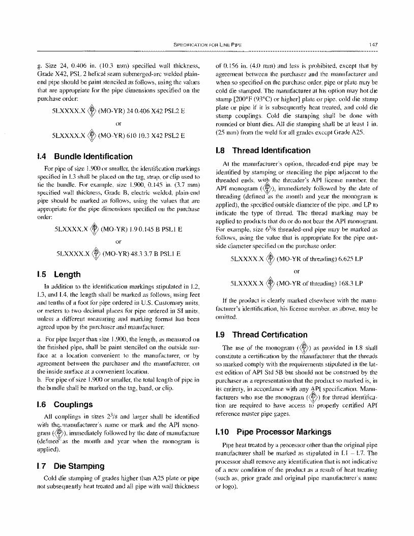
SPECIFICATION FOR liNE PIPE 147
g. Size 24, OA06 in. (10.3 mm) specified wall thickness, Grade X42, PSL 2 helical seam submerged-arc welded plainend pipe should be paint stenciled as follows, using the values that are appropriate for the pipe dimensions specified on the purchase order:
5LXXXX.X <t> (MO-YR) 24 OA06 X42 PSL2 E
or
5LXXXX.X <t> (MO-YR) 610 10.3 X42 PSL2 E
1.4 Bundle Identification For pipe of size 1.900 or smaller, the identification markings
specified in 1.3 shall be placed on the tag, strap, or clip used to tie the bundle. For example, size 1.900, 0.145 in. (3.7 mm) specified wall thickness, Grade 8, electric welded, plain-end pipe should be marked as follows, using the values that are appropriate for the pipe dimensions specified on the purchase order:
5LXXXX.X <t> (MO-YR) 1.90.1458 PSLl E
or
5LXXXX.X <t> (MO-YR) 48.3 3.7 8 PSLl E
1.5 Length In addition to the identification markings stipulated in 1.2,
1.3, and [A, the length shall be marked as follows, using feet and tenths of a foot for pipe ordered in U.S. Customary units, or meters to two decimal places for pipe ordered in SI units, unless a different measuring and marking format has been agreed upon by the purchaser and manufacturer:
a. For pipe larger than size 1.900, the length, as measured on the finished pipe, shall be paint stenciled on the outside surface at a location convenient to the manufacturer, or by agreement between the purchaser and the manufacturer, on the inside surface at a convenient location. b. For pipe of size 1.900 or smaller, the total length of pipe in the bundle shall be marked on the tag, band, or clip.
1.6 Couplings All couplings in sizes 23/8 and larger shall be identified
with tJrnanufacturer's name or mark and the API monogram ( W ), immediately followed by the date of manufacture (define as the month and year when the monogram is applied).
1.7 Die Stamping Cold die stamping of grades higher than A25 plate or pipe
not subsequently heat treated and all pipe with wall thickness
of 0.156 in. (4.0 mm) and less is prohibited, except that by agreement between the purchaser and the manufacturer and when so specified on the purchase order, pipe or plate may be cold die stamped. The manufacturer at his option may hot die stamp [200°F (93°C) or higher] plate or pipe, cold die stamp plate or pipe if it is subsequently heat treated, and cold die stamp couplings. Cold die stamping shall be done with rounded or blunt dies. All die stamping shall be at least I 111.
(25 mm) from the weld for all grades except Grade A25.
1.8 Thread Identification
At the manufacturer's option, threaded-end pipe may be identified by stamping or stenciling the pipe adjacent to the threaded ends, wi~ the threader's API license number, the API monogram (<&», immediately followed by the date of threading (defined Qas the month and year the monogram is applied), the specified outside diameter of the pipe, and LP to indicate the type of thread. The thread marking may be applied to products that do or do not bear the AP[ monogram. For example, size 65/8 threaded-end pipe may be marked as follows, using the value that is appropriate for the pipe outside diameter specified on the purchase order:
5LXXXX.X ~ (MO-YR of threading) 6.625 LP
or
5LXXXX.X <t> (MO-YR of threading) 168.3 LP
If the product is clearly marked elsewhere with the manufacturer's identification, his license number, as above, may be omitted.
1.9 Thread Certification
The use of the monogram (<t» as provided in 1.8 shall constitute a certification by the manufacturer that the threads so marked comply with the requirements stipulated in the latest edition of AP[ Std 58 but should not be construed by the purchaser as a representation that the product so marked is, in its entirety, in accordance with any ~[ specification. Manufacturers who use the monogram (t) for thread identification are required to have access to properly certified API reference master pipe gages.
1.10 Pipe Processor Markings
Pipe heat treated by a processor other than the original pipe manufacturer shall be marked as stipulated in 1.1 - 1.7. The processor shall remove any identification that is not indicative of a new condition of the product as a result of heat treating (such as, prior grade and original pipe manufacturer's name or logo).

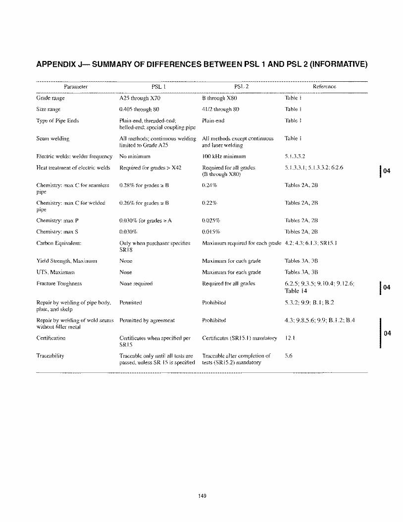
APPENDIX J- SUMMARY OF DIFFERENCES BETWEEN PSL 1 AND PSL 2 (INFORMATIVE)
Parameter
Grade range
Size range
Type of Pipe Ends
Seam welding
Electric welds: welder frequency
PSL I
A25 through X70
0.405 through 80
Plain-end, threaded-end; belled-end; special coupling pipe
All methods; continuous welding limited to Grade A25
No minimum
Heat treatment of electric welds Required for grades> X42
Chemistry: max C for seamless pipe
Chemistry: max C for welded pipe
Chemistry: max P
Chemistry: max S
Carbon Equivalent:
Yield Strength, Maximum
UTS, Maximum
Fracture Toughness
0.28% for grades;;, B
0.26% for grades;;, B
0.030% for grades eo A
0.030%
Only when purchaser specifies SRI8
None
None
None required
Repair by welding of pipe body, Permitted plate, and skelp
Repair by welding of weld seams Permitted by agreement without filler metal
Certification
Traceability
Certificates when specified per SRI5
Traceable only until all tests are passed, unless SR IS is specified
PSL2
B through X80
4112 through 80
Plain-end
All methods except continuous and laser welding
100 kHz minimum
Required for all grades (B through X80)
0.24%
0.22%
0.025%
0.015%
Reference
Table I
Table I
Table I
Table I
5.1.3.3.2
5.1.3.3.1; 5.1.3.3.2; 6.2.6
Tables 2A, 2B
Tables 2A, 2B
Tables 2A, 28
Tables 2A, 28
Maximum required for each grade 4.2; 4.3; 6.1.3; SR I 5.1
Maximum for each grade
Maximum for each grade
Required for all grades
Prohibited
Prohibited
Tables 3A, 38
Tables 3A, 38
6.2.5; 9.3.5; 9.10.4; 9.12.6; Table 14
5.3.2; 9.9; B.I; B.2
4.3; 9.8.5.6; 9.9; B.I.2; B.4
Certificates (SRI 5.1) mandatory 12.1
Traceable after completion of tests (SRI5.2) mandatory
149
5.6
04

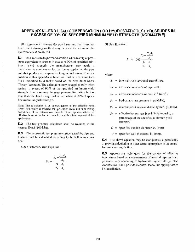
APPENDIX K-END LOAD COMPENSATION FOR HYDROSTATIC TEST PRESSURES IN EXCESS OF 90% OF SPECIFIED MINIMUM YIELD STRENGTH (NORMATIVE)
(By agreement between the purchaser and the manufacturer, the following method may be used to determine the hydrostatic test pressure.)
K.1 As a measure to prevent distortion when testing at pressures equivalent to stresses in excess of90% of specified minimum yield strength, the manufacturer may apply a calculation to compensate for the forces applied to the pipe end that produce a compressive longitudinal stress. The calculation in this appendix is based on Barlow's equation (see 9.4.3) modified by a factor based on the Maximum Shear Theory (see note). The calculation may be applied only when testing in excess of 90% of the specified minimum yield strength. In no case may the gage pressure for testing be less than that calculated using Barlow's equation at 90% of specified minimum yield strength.
Note: The calculation is an approximation of the effective hoop stress (SE), which is practical for application under mill pipe testing conditions. Other calculations provide closer approximations of effective hoop stress but are complex and therefore impractical for application.
K.2 The test pressure calculated shall be rounded to the nearest 10 psi (100 kPa).
K.3 The hydrostatic test pressure compensated for pipe end loading shall be calculated according to the following equation:
U.S. Customary Unit Equation:
SF_ PRAR " AI'
D AI
2t AI'
151
SI Unit Equation:
where
SF- PRA R
1000' Ap D AI
2t A/i
A I internal cross-sectional area of pipe,
Ap cross-sectional area of pipe wall,
AR cross-sectional area of ram, in.2 (mm2),
PI hydrostatic test pressure in psi (kPa),
D
internal pressure on end-sealing ram, psi (kPa),
effective hoop stress in psi (MPa) equal to a
percentage of the specified minimum yield strength,
specified outside diameter, in. (mm),
specified wall thickness, in. (mm).
K.4 The above equation may be manipulated algebraically to provide calculation in other terms appropriate to the manufacturer's testing facility.
K.S Appropriate techniques for the control of effective hoop stress based on measurements of intemal pipe and ram pressures vary according to hydrotester system design. The manufacturer shall provide a control technique appropriate to his installation.

APPENDIX M-CONVERSION PROCEDURES
The following procedures were used to make the soft metric conversions of U.S. Customary units to SI units in the metric conversion of API Spec 5L.
M.1 Fractions Fractions and numbers with fractions in U.S. Customary
units were converted to the full decimal equivalent in U.S. Customary units without rounding, and the full decimal equivalents in U.S. Customary units were then converted to Sl values using the following formula:
where
N
Nm = 25.4· N
the SI equivalent of dimensions with fractions
in U.S. Customary units, mm,
the full decimal equivalent of dimensions with fractions without rounding, in.
The SI equivalents of dimensions with fractions in U.S. Customary units were then rounded to the appropriate number of places in mm.
M.2 Outside Diameter The U.S. Customary values for outside diameters of pipe
and couplings were converted to SI values using the following formula:
Dm = 25.4· D
where
SI outside diameter, mm,
D outside diameter, in.
The SI outside diameters of pipe and couplings smaller than size 18 were rounded to the nearest 0.1 mm. The SI outside diameters of pipe and couplings size 18 and larger were rounded to the nearest 1.0 mm.
M.3 Wall Thickness The U.S. Customary values for wall thickness were con
verted to S[ values using the following formula:
tm = 25.4· t
153
where
SI wall thickness, mm,
wall thickness, in.
The Sf wall thicknesses were rounded to the nearest 0.1 mm.
M.4 Inside Diameter The Sl inside diameters of pipe were calculated (not con
verted) using the following formula:
where
SI inside diameter, mm,
Sl outside diameter, mm,
SI wall thickness, mm.
The SI inside diameters were rounded to the nearest 0.1 mm.
M.S Plain-end Mass Per Unit Length The S[ plain-end mass per unit length were calculated (not
converted) using the following formula:
Wl'em = 0.024 66(Dm - tm)l",
where
SI plain-end mass per unit length, kg/m,
SI outside diameter, mm,
SI wall thickness, mm.
The SI plain-end mass per unit length were rounded to the nearest 0.0 I kg/m.
M.6 Yield Strength and Tensile Strength
The U.S. Customary values for yield strength and tensile strength were converted to SI values using the following formula:
ys", = 0.006 894 76 • ys
Is", = 0.006 894 76 • Is
154 API SPECIFICATION 5L
where
SI yield strength, MPa,
Ys yield strength, psi,
1.1'/1/ SI tensile strength, MPa,
t l· tensile strength, psi.
The converted SI strengths were rounded to the nearest 1 MPa.
M.7 Hydrostatic Test Pressure
The U.S. Customary values for hydrostatic test pressures for all sizes of threaded pipe, all Grade A25 plain-end pipe smaller than size 59/16, and all Grade A and Grade B plainend pipe smaller than size 23/8 were converted to SI values using the following formula:
Pili = 0.006 894 76 - P
The converted hydrostatic test pressures were rounded to the nearest 100 kPa.
The SI hydrostatic test pressures for plain-end size 59/16,
Grade A25 and for sizes 23/8 and larger Grades A and higher were calculated (not converted) using the following formula:
P'" = 2 000 -I- YSIII - tn/ Dill
where
SI hydrostatic test pressure, kPa,
P hydrostatic test pressure, psi,
f = stress factor, see table below,
yS/II SI yield strength, MPa,
1/11 SI wall thickness, mm,
Dill SI outside diameter, mm.
The calculated hydrostatic test pressure were rounded to the nearest 100 kPa, not to exceed 17 200 kPa for sizes 31/2
and smaller or 19 300 kPa for sizes larger than 31/2.
The calculated standard hydrostatic test pressures for Grades X42 and higher were rounded to the nearest 100 kPa, not to exceed 20 700 kPa. The calculated altemative hydrostatic test pressure for Grades X42 and higher were rounded to the nearest 100 kPa, not to exceed 50 000 kPa for pipes smaller than size 16, or 25 000 kPa for pipes sizes 16 and larger.
f Factor
Standard Alternative Grade Size Test Pressure Test Pressure
A25 59/ 16 0.60 A&B 2: 23/8 0.60 0.75
X42 & higher :559/16 0.60 0.75 > 59! 16 and:5 85/ 8 0.75 0.75
> 85/ 8 and < 20 0.85 0.85 2: 20 0.90 0.90
M.B Temperature The U.S. Customary values for temperatures were con
verted to SI values using the following formula:
where
°C SI temperature, degrees Celsius,
temperature, degrees Fahrenheit.
The SI temperatures were rounded to the nearest 1°C.
M.9 Charpy Impact Energy The U.S. Customary values for impact energy were con
verted to SI values using the following formula:
EIII = 1.355 82 - E
where
E /II energy, J,
E energy, ft-Ib.
The SI energy values were rounded to the nearest I J.
M.10 Minimum Length of Couplings The U.S. Customary values for the minimum lengths of
couplings in inches and fractions were converted to full decimal equivalents in U.S. Customary units without rounding, and then the full decimal equivalents were converted to Sl values using the following formula:
where
NLm SI minimum length of couplings, mm,
NL the full decimal equivalent, without rounding,
of the minimum lengths of couplings, in.
SPECIFICATION FOR LINE PIPE 155
The Sf minimum lengths of coupling were rounded to the nearest 0.0 I mm.
M.11 Diameter of Coupling Recess
The U.S. Customary values for diameters of the coupling recess's were converted to Sl values using the following formula:
QIII = 25.4· Q
where
Sf diameter of the coupling recess, mm,
Q diameter of the coupling recess, in.
The Sl diameter of the couplings recesses were rounded to the nearest 0.0 I mm.
M.12 Width of the Coupling Bearing Face
The U.S. Customary values for widths of the bearing face of couplings were converted to SI values using the following formula:
bill = 25.4· b
where
SI width of the coupling bearing face, mm,
b width of the coupling bearing face, in.
The SI width of the coupling bearing face were rounded to the nearest 0.1 mm.
M.13 Coupling Weights
The u.s. Customary values for calculated coupling weights were converted to SI values using the following formula:
Will = 0.453 5924 • w
where
SI calculated coupling weight, kg,
w calculated coupling weight, lb.
The SI calculated coupling weights were rounded to the nearest 0.0 I kg.


Disclosure to Promote the Right To Information
Whereas the Parliament of India has set out to provide a practical regime of right to information for citizens to secure access to information under the control of public authorities, in order to promote transparency and accountability in the working of every public authority, and whereas the attached publication of the Bureau of Indian Standards is of particular interest to the public, particularly disadvantaged communities and those engaged in the pursuit of education and knowledge, the attached public safety standard is made available to promote the timely dissemination of this information in an accurate manner to the public.
इटरनट मानक
“!ान $ एक न' भारत का +नम-ण”Satyanarayan Gangaram Pitroda
“Invent a New India Using Knowledge”
“प0रा1 को छोड न' 5 तरफ”Jawaharlal Nehru
“Step Out From the Old to the New”
“जान1 का अ+धकार, जी1 का अ+धकार”Mazdoor Kisan Shakti Sangathan
“The Right to Information, The Right to Live”
“!ान एक ऐसा खजाना > जो कभी च0राया नहB जा सकता ह”Bhartṛhari—Nītiśatakam
“Knowledge is such a treasure which cannot be stolen”
“Invent a New India Using Knowledge”
ह”ह”ह
IS 1239-2 (2011): Steel Tubes, Tubulars and Other SteelFittings, Part 2: Steel Pipe Fittings [MTD 19: Steel Tubes,Pipes abd Fittings]

© BIS 2011
B U R E A U O F I N D I A N S T A N D A R D SMANAK BHAVAN, 9 BAHADUR SHAH ZAFAR MARG
NEW DELHI 110002
September 2011 Price Group 10
IS 1239 (Part 2) : 2011
Hkkjrh; ekud
bLikr dh ufy;k¡] ufydkdkj lkefxz;k¡ rFkk bLikr dhvU; fQfVaxsa — fof'kf"VHkkx 2 bLikr dh ikbZi fQfVaxsa
( ik¡pok iqujh{k.k )
Indian Standard
STEEL TUBES, TUBULARS AND OTHER STEELFITTINGS — SPECIFICATION
PART 2 STEEL PIPE FITTINGS
( Fifth Revision )
ICS 77.140.75
Steel Tubes, Pipes and Fittings Sectional Committee, MTD 19
FOREWORD
This Indian Standard (Part 2) (Fifth Revision) was adopted by the Bureau of Indian Standards, after the draftfinalized by the Steel Tubes, Pipes and Fittings Sectional Committee had been approved by the MetallurgicalEngineering Division Council.
This standard was first published in 1969 and fourth revision of this standard was published in 1992. Whilereviewing this standard in the light of experience gained during these years, the Committee decided to furtherrevise this standard.
In this revision the following modifications have been made:
a) All amendments (Amendment Nos. 1 to 6) have been incorporated.b) The requirement of approximate radius for 125 and 150 NB bends have been incorporated in Table 4.c) Additional column for maximum inside diameter of internal parallel thread for steel socket have been
incorporated in Table 6.
This standard is published in two parts. The other part in the series is:
Part 1 Steel tubes
The nominal bores specified in this standard and the corresponding nominal sizes of pipe threads according toIS 554 : 1999/ISO 7-1 : 1994 ‘Pipe thread where pressure tight joints are made on the threads — Dimension,tolerance and designation (fourth revision)’ are given in Annex A.
The standard keeps in view the manufacturing and trade practices followed in the country in this field. In formulatingthis standard assistance has been derived from the following publications:
BS 1387 : 1967 ‘Specification for steel tubes and tubulars (suitable for screwing to B. S. 21 pipethreads)’, issued by the British Standards Institution (BSI).
BS 1740 : 1965 ‘Specification for wrought pipe fitting, iron and steel (screwed B. S. P. thread)’,issued by the British Standards Institution (BSI ).
For the purpose of deciding whether a particular requirement of this standard is complied with, the final value,observed or calculated, expressing the result of a test or analysis, shall be rounded off in accordance with IS 2 : 1960‘Rules for rounding off numerical values (revised)’. The number of significant places retained in the rounded offvalue should be same as that of the specified value in this standard.
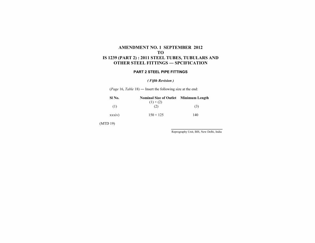
AMENDMENT NO. 1 SEPTEMBER 2012TO
IS 1239 (PART 2) : 2011 STEEL TUBES, TUBULARS ANDOTHER STEEL FITTINGS ― SPCIFICATION
PART 2 STEEL PIPE FITTINGS
( Fifth Revision )
(Page 16, Table 18) ― Insert the following size at the end:
Sl No. Nominal Size of Outlet Minimum Length(1) × (2)
(1) (2) (3)
xxxiv) 150 × 125 140
(MTD 19)
Reprography Unit, BIS, New Delhi, India
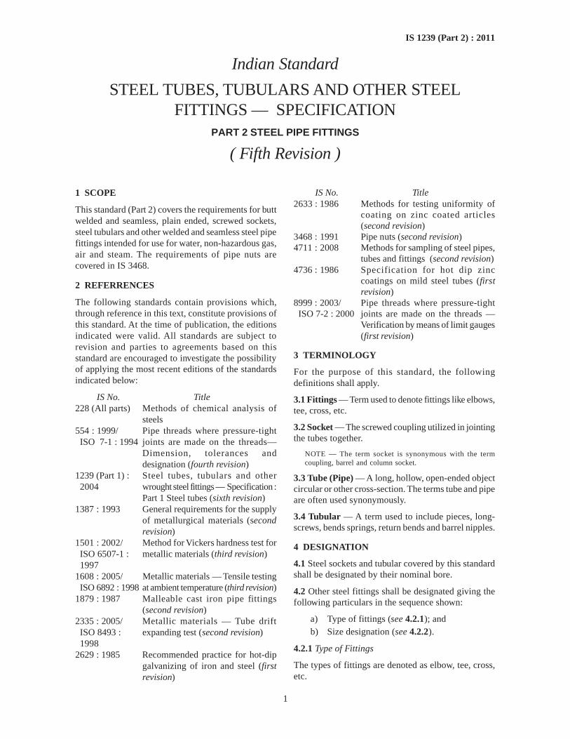
1
IS 1239 (Part 2) : 2011
Indian Standard
STEEL TUBES, TUBULARS AND OTHER STEELFITTINGS — SPECIFICATION
PART 2 STEEL PIPE FITTINGS
( Fifth Revision )
1 SCOPE
This standard (Part 2) covers the requirements for buttwelded and seamless, plain ended, screwed sockets,steel tubulars and other welded and seamless steel pipefittings intended for use for water, non-hazardous gas,air and steam. The requirements of pipe nuts arecovered in IS 3468.
2 REFERRENCES
The following standards contain provisions which,through reference in this text, constitute provisions ofthis standard. At the time of publication, the editionsindicated were valid. All standards are subject torevision and parties to agreements based on thisstandard are encouraged to investigate the possibilityof applying the most recent editions of the standardsindicated below:
IS No. Title228 (All parts) Methods of chemical analysis of
steels554 : 1999/ Pipe threads where pressure-tight
ISO 7-1 : 1994 joints are made on the threads—Dimension, tolerances anddesignation (fourth revision)
1239 (Part 1) : Steel tubes, tubulars and other2004 wrought steel fittings — Specification :
Part 1 Steel tubes (sixth revision)1387 : 1993 General requirements for the supply
of metallurgical materials (secondrevision)
1501 : 2002/ Method for Vickers hardness test forISO 6507-1 : metallic materials (third revision)1997
1608 : 2005/ Metallic materials — Tensile testingISO 6892 : 1998 at ambient temperature (third revision)
1879 : 1987 Malleable cast iron pipe fittings(second revision)
2335 : 2005/ Metallic materials — Tube driftISO 8493 : expanding test (second revision)1998
2629 : 1985 Recommended practice for hot-dipgalvanizing of iron and steel (firstrevision)
IS No. Title2633 : 1986 Methods for testing uniformity of
coating on zinc coated articles(second revision)
3468 : 1991 Pipe nuts (second revision)4711 : 2008 Methods for sampling of steel pipes,
tubes and fittings (second revision)4736 : 1986 Specification for hot dip zinc
coatings on mild steel tubes (firstrevision)
8999 : 2003/ Pipe threads where pressure-tightISO 7-2 : 2000 joints are made on the threads —
Verification by means of limit gauges(first revision)
3 TERMINOLOGY
For the purpose of this standard, the followingdefinitions shall apply.
3.1 Fittings — Term used to denote fittings like elbows,tee, cross, etc.
3.2 Socket — The screwed coupling utilized in jointingthe tubes together.
NOTE — The term socket is synonymous with the termcoupling, barrel and column socket.
3.3 Tube (Pipe) — A long, hollow, open-ended objectcircular or other cross-section. The terms tube and pipeare often used synonymously.
3.4 Tubular — A term used to include pieces, long-screws, bends springs, return bends and barrel nipples.
4 DESIGNATION
4.1 Steel sockets and tubular covered by this standardshall be designated by their nominal bore.
4.2 Other steel fittings shall be designated giving thefollowing particulars in the sequence shown:
a) Type of fittings (see 4.2.1); andb) Size designation (see 4.2.2).
4.2.1 Type of Fittings
The types of fittings are denoted as elbow, tee, cross,etc.
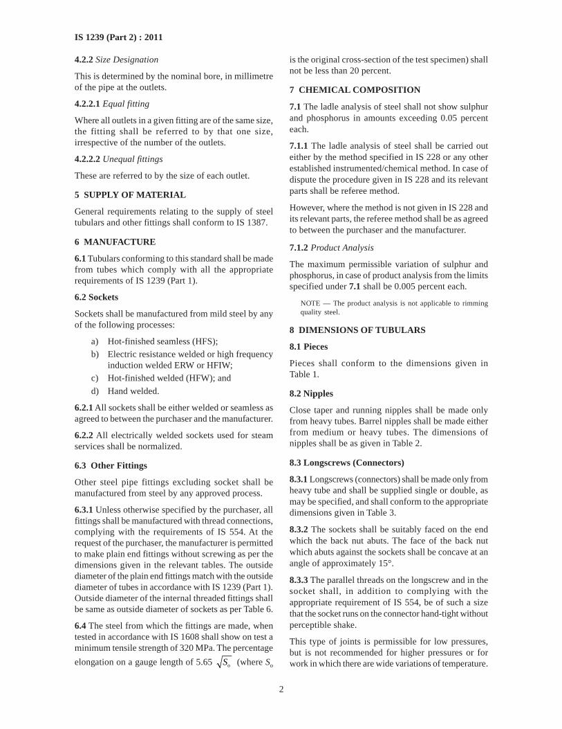
2
IS 1239 (Part 2) : 2011
4.2.2 Size Designation
This is determined by the nominal bore, in millimetreof the pipe at the outlets.
4.2.2.1 Equal fitting
Where all outlets in a given fitting are of the same size,the fitting shall be referred to by that one size,irrespective of the number of the outlets.
4.2.2.2 Unequal fittings
These are referred to by the size of each outlet.
5 SUPPLY OF MATERIAL
General requirements relating to the supply of steeltubulars and other fittings shall conform to IS 1387.
6 MANUFACTURE
6.1 Tubulars conforming to this standard shall be madefrom tubes which comply with all the appropriaterequirements of IS 1239 (Part 1).
6.2 Sockets
Sockets shall be manufactured from mild steel by anyof the following processes:
a) Hot-finished seamless (HFS);b) Electric resistance welded or high frequency
induction welded ERW or HFIW;c) Hot-finished welded (HFW); and
d) Hand welded.
6.2.1 All sockets shall be either welded or seamless asagreed to between the purchaser and the manufacturer.
6.2.2 All electrically welded sockets used for steamservices shall be normalized.
6.3 Other Fittings
Other steel pipe fittings excluding socket shall bemanufactured from steel by any approved process.
6.3.1 Unless otherwise specified by the purchaser, allfittings shall be manufactured with thread connections,complying with the requirements of IS 554. At therequest of the purchaser, the manufacturer is permittedto make plain end fittings without screwing as per thedimensions given in the relevant tables. The outsidediameter of the plain end fittings match with the outsidediameter of tubes in accordance with IS 1239 (Part 1).Outside diameter of the internal threaded fittings shallbe same as outside diameter of sockets as per Table 6.
6.4 The steel from which the fittings are made, whentested in accordance with IS 1608 shall show on test aminimum tensile strength of 320 MPa. The percentage
elongation on a gauge length of 5.65 oS (where So
is the original cross-section of the test specimen) shallnot be less than 20 percent.
7 CHEMICAL COMPOSITION
7.1 The ladle analysis of steel shall not show sulphurand phosphorus in amounts exceeding 0.05 percenteach.
7.1.1 The ladle analysis of steel shall be carried outeither by the method specified in IS 228 or any otherestablished instrumented/chemical method. In case ofdispute the procedure given in IS 228 and its relevantparts shall be referee method.
However, where the method is not given in IS 228 andits relevant parts, the referee method shall be as agreedto between the purchaser and the manufacturer.
7.1.2 Product Analysis
The maximum permissible variation of sulphur andphosphorus, in case of product analysis from the limitsspecified under 7.1 shall be 0.005 percent each.
NOTE — The product analysis is not applicable to rimmingquality steel.
8 DIMENSIONS OF TUBULARS
8.1 Pieces
Pieces shall conform to the dimensions given inTable 1.
8.2 Nipples
Close taper and running nipples shall be made onlyfrom heavy tubes. Barrel nipples shall be made eitherfrom medium or heavy tubes. The dimensions ofnipples shall be as given in Table 2.
8.3 Longscrews (Connectors)
8.3.1 Longscrews (connectors) shall be made only fromheavy tube and shall be supplied single or double, asmay be specified, and shall conform to the appropriatedimensions given in Table 3.
8.3.2 The sockets shall be suitably faced on the endwhich the back nut abuts. The face of the back nutwhich abuts against the sockets shall be concave at anangle of approximately 15°.
8.3.3 The parallel threads on the longscrew and in thesocket shall, in addition to complying with theappropriate requirement of IS 554, be of such a sizethat the socket runs on the connector hand-tight withoutperceptible shake.
This type of joints is permissible for low pressures,but is not recommended for higher pressures or forwork in which there are wide variations of temperature.
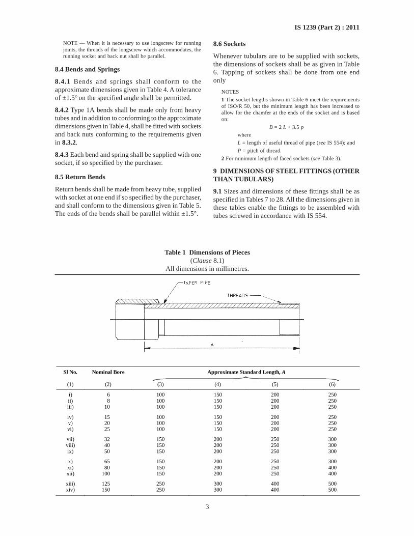
3
IS 1239 (Part 2) : 2011
NOTE — When it is necessary to use longscrew for runningjoints, the threads of the longscrew which accommodates, therunning socket and back nut shall be parallel.
8.4 Bends and Springs
8.4.1 Bends and springs shall conform to theapproximate dimensions given in Table 4. A toleranceof ±1.5° on the specified angle shall be permitted.
8.4.2 Type 1A bends shall be made only from heavytubes and in addition to conforming to the approximatedimensions given in Table 4, shall be fitted with socketsand back nuts conforming to the requirements givenin 8.3.2.
8.4.3 Each bend and spring shall be supplied with onesocket, if so specified by the purchaser.
8.5 Return Bends
Return bends shall be made from heavy tube, suppliedwith socket at one end if so specified by the purchaser,and shall conform to the dimensions given in Table 5.The ends of the bends shall be parallel within ±1.5°.
Table 1 Dimensions of Pieces(Clause 8.1)
All dimensions in millimetres.
Sl No. Nominal Bore Approximate Standard Length, A
(1) (2) (3) (4) (5) (6)
i) 6 100 150 200 250 ii) 8 100 150 200 250 iii) 10 100 150 200 250
iv) 15 100 150 200 250 v) 20 100 150 200 250 vi) 25 100 150 200 250
vii) 32 150 200 250 300 viii) 40 150 200 250 300 ix) 50 150 200 250 300
x) 65 150 200 250 300 xi) 80 150 200 250 400 xii) 100 150 200 250 400
xiii) 125 250 300 400 500 xiv) 150 250 300 400 500
8.6 Sockets
Whenever tubulars are to be supplied with sockets,the dimensions of sockets shall be as given in Table6. Tapping of sockets shall be done from one endonly
NOTES
1 The socket lengths shown in Table 6 meet the requirementsof ISO/R 50, but the minimum length has been increased toallow for the chamfer at the ends of the socket and is basedon:
B = 2 L + 3.5 p
where
L = length of useful thread of pipe (see IS 554); and
P = pitch of thread.
2 For minimum length of faced sockets (see Table 3).
9 DIMENSIONS OF STEEL FITTINGS (OTHERTHAN TUBULARS)
9.1 Sizes and dimensions of these fittings shall be asspecified in Tables 7 to 28. All the dimensions given inthese tables enable the fittings to be assembled withtubes screwed in accordance with IS 554.
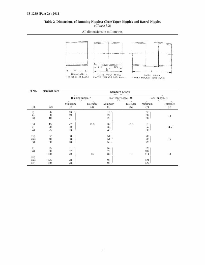
4
IS 1239 (Part 2) : 2011
Table 2 Dimensions of Running Nipples; Close Taper Nipples and Barrel Nipples(Clause 8.2)
All dimensions in millimetres.
Sl No. Nominal Bore Standard Length Running Nipple, A Close Taper Nipple, B Barrel Nipple, C Minimum Tolerance Minimum Tolerance Minimum Tolerance
(1) (2) (3) (4) (5) (6) (7) (8)
i) 6 13 19 32 ii) 8 19 27 38 iii) 10 21 28 38
+3
iv) 15 27 37 51 v) 20 30 39 54 vi) 25 33
+1.5
46
+1.5
60
+4.5
vii) 32 38 51 70 viii) 40 38 51 70 ix) 50 48
60
79
+6
x) 65 51 69 89 xi) 80 57 75 102
100 70 87 114 xii) xiii) 125 78 96 124 xiv) 150 78
+3
96
+3
127
+8
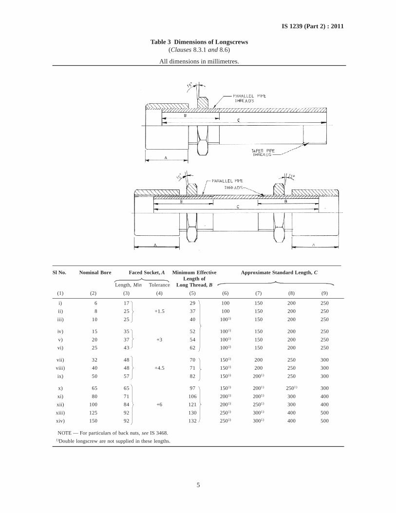
5
IS 1239 (Part 2) : 2011
Sl No. Nominal Bore Faced Socket, A Minimum Effective Approximate Standard Length, CLength of
Length, Min Tolerance Long Thread, B
(1) (2) (3) (4) (5) (6) (7) (8) (9)
i) 6 17 29 100 150 200 250
ii) 8 25 +1.5 37 100 150 200 250
iii) 10 25 40 1001) 150 200 250
iv) 15 35 52 1001) 150 200 250
v) 20 37 +3 54 1001) 150 200 250
vi) 25 43 62 1001) 150 200 250
vii) 32 48 70 1501) 200 250 300
viii) 40 48 +4.5 71 1501) 200 250 300
ix) 50 57 82 1501) 2001) 250 300
x) 65 65 97 1501) 2001) 2501) 300
xi) 80 71 106 2001) 2001) 300 400
xii) 100 84 +6 121 2001) 2501) 300 400
xiii) 125 92 130 2501) 3001) 400 500
xiv) 150 92 132 2501) 3001) 400 500
NOTE — For particulars of back nuts, see IS 3468.1)Double longscrew are not supplied in these lengths.
Table 3 Dimensions of Longscrews(Clauses 8.3.1 and 8.6)
All dimensions in millimetres.
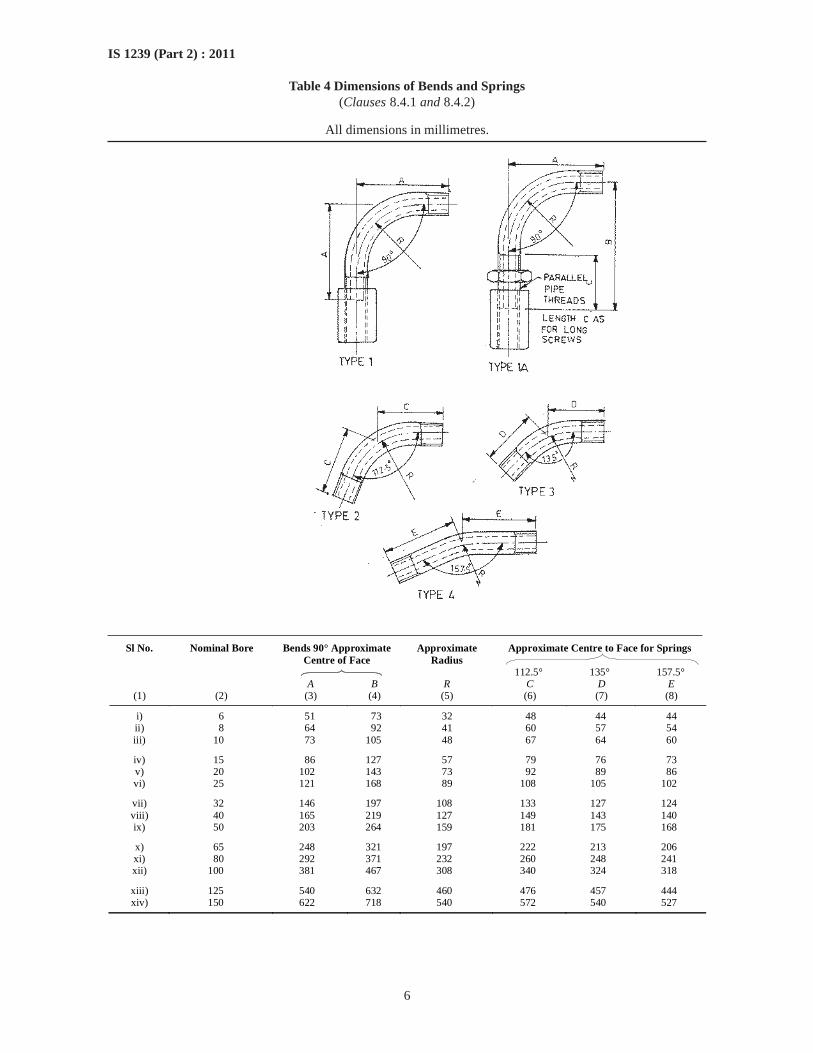
6
IS 1239 (Part 2) : 2011
Table 4 Dimensions of Bends and Springs(Clauses 8.4.1 and 8.4.2)
All dimensions in millimetres.
Sl No. Nominal Bore Bends 90° Approximate Centre of Face
Approximate Radius
Approximate Centre to Face for Springs
112.5° 135° 157.5°
A B R C D E (1) (2) (3) (4) (5) (6) (7) (8)
i) 6 51 73 32 48 44 44 ii) 8 64 92 41 60 57 54 iii) 10 73 105 48 67 64 60
iv) 15 86 127 57 79 76 73 v) 20 102 143 73 92 89 86 vi) 25 121 168 89 108 105 102
vii) 32 146 197 108 133 127 124 viii) 40 165 219 127 149 143 140 ix) 50 203 264 159 181 175 168
x) 65 248 321 197 222 213 206 xi) 80 292 371 232 260 248 241 xii) 100 381 467 308 340 324 318
xiii) 125 540 632 460 476 457 444 xiv) 150 622 718 540 572 540 527
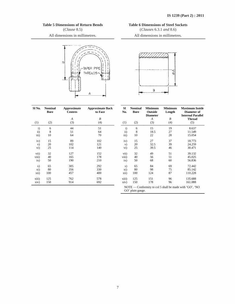
7
IS 1239 (Part 2) : 2011
Table 5 Dimensions of Return Bends Table 6 Dimensions of Steel Sockets(Clause 8.5) (Clauses 6.3.1 and 8.6)
All dimensions in millimetres. All dimensions in millimetres.
Sl No. Nominal Bore
Approximate Centres
Approximate Back to Face
Sl No.
Nominal Bore
Minimum Outside
Diameter
Minimum Length
A B A B
Maximum Inside Diameter of
Internal Parallel Thread
(1) (2) (3) (4) (1) (2) (3) (4) (5)
i) 6 44 51 i) 6 15 19 8.637 ii) 8 51 64 ii) 8 18.5 27 11.549
iii) 10 64 70 iii) 10 22 28 15.054
iv) 15 89 102 iv) 15 27 37 18.773 v) 20 102 121 v) 20 32.5 39 24.259
vi) 25 114 140 vi) 25 39.5 46 30.471
vii) 32 127 152 vii) 32 49 51 39.132 viii) 40 165 178 viii) 40 56 51 45.025
ix) 50 190 210 ix) 50 68 60 56.836
x) 65 305 292 x) 65 84 69 72.442 xi) 80 356 330 xi) 80 98 75 85.142
xii) 100 457 400 xii) 100 124 87 110.228
xiii) 125 762 578 xiii) 125 151 96 135.688 xiv) 150 914 692 xiv) 150 178 96 161.088
NOTE — Conformity to col 5 shall be made with ‘GO’, ‘NO GO’ plain gauge.
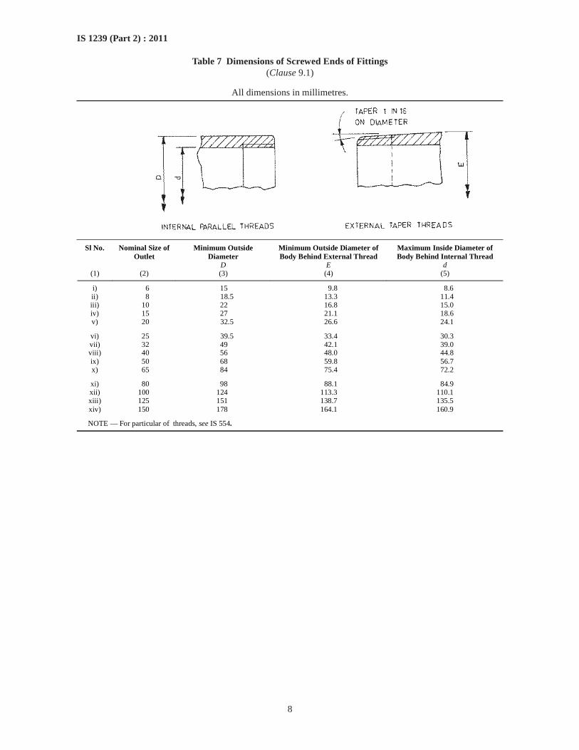
8
IS 1239 (Part 2) : 2011
Table 7 Dimensions of Screwed Ends of Fittings(Clause 9.1)
All dimensions in millimetres.
Sl No. Nominal Size of Outlet
Minimum Outside Diameter
Minimum Outside Diameter of Body Behind External Thread
Maximum Inside Diameter of Body Behind Internal Thread
D E d (1) (2) (3) (4) (5)
i) 6 15 9.8 8.6 ii) 8 18.5 13.3 11.4 iii) 10 22 16.8 15.0 iv) 15 27 21.1 18.6 v) 20 32.5 26.6 24.1
vi) 25 39.5 33.4 30.3 vii) 32 49 42.1 39.0 viii) 40 56 48.0 44.8 ix) 50 68 59.8 56.7 x) 65 84 75.4 72.2
xi) 80 98 88.1 84.9 xii) 100 124 113.3 110.1 xiii) 125 151 138.7 135.5 xiv) 150 178 164.1 160.9
NOTE — For particular of threads, see IS 554.
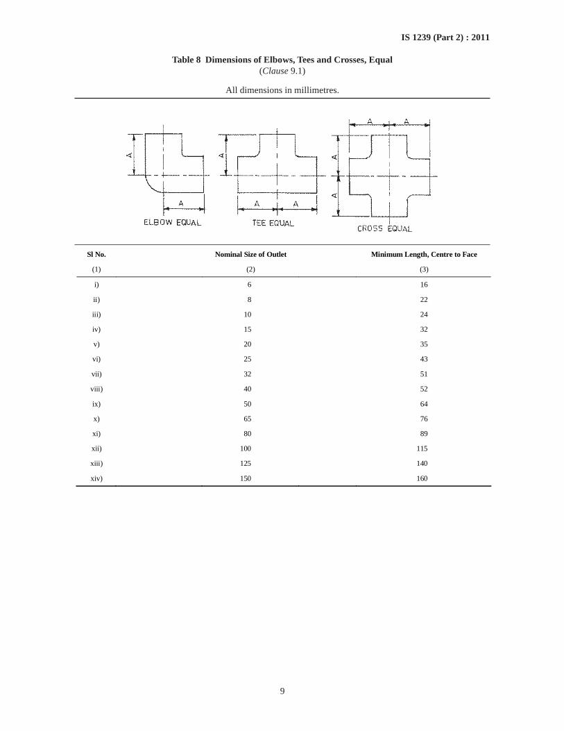
9
IS 1239 (Part 2) : 2011
Table 8 Dimensions of Elbows, Tees and Crosses, Equal(Clause 9.1)
All dimensions in millimetres.
Sl No. Nominal Size of Outlet Minimum Length, Centre to Face
(1) (2) (3)
i) 6 16
ii) 8 22
iii) 10 24
iv) 15 32
v) 20 35
vi) 25 43
vii) 32 51
viii) 40 52
ix) 50 64
x) 65 76
xi) 80 89
xii) 100 115
xiii) 125 140
xiv) 150 160
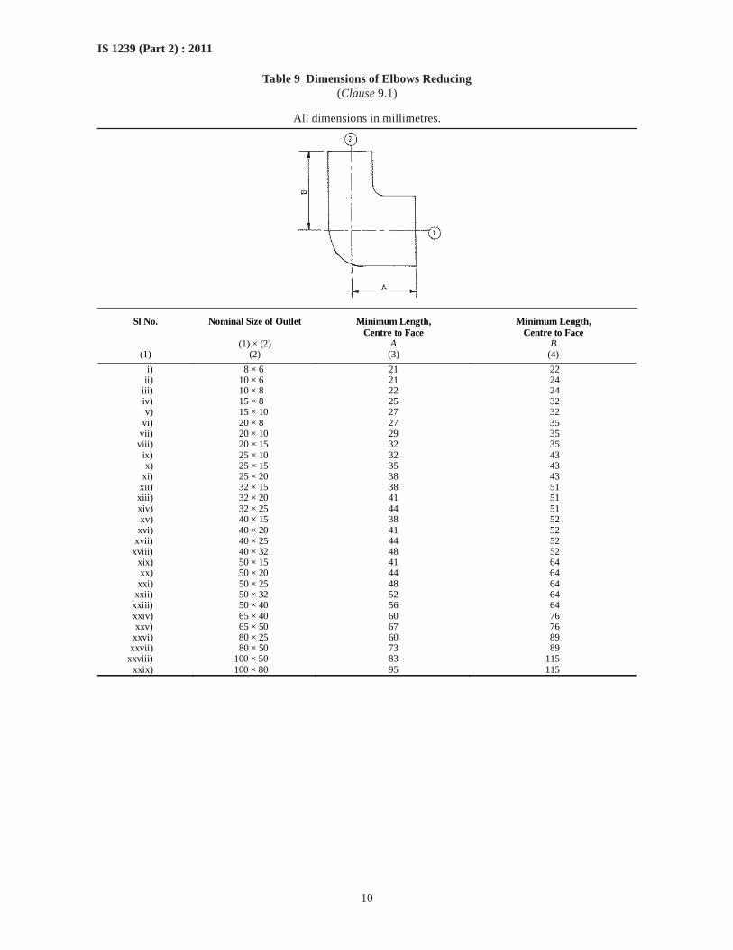
10
IS 1239 (Part 2) : 2011
Table 9 Dimensions of Elbows Reducing(Clause 9.1)
All dimensions in millimetres.
Sl No. Nominal Size of Outlet Minimum Length, Centre to Face
Minimum Length, Centre to Face
(1) × (2) A B (1) (2) (3) (4)
i) 8 × 6 21 22 ii) 10 × 6 21 24 iii) 10 × 8 22 24 iv) 15 × 8 25 32 v) 15 × 10 27 32 vi) 20 × 8 27 35 vii) 20 × 10 29 35 viii) 20 × 15 32 35 ix) 25 × 10 32 43 x) 25 × 15 35 43 xi) 25 × 20 38 43 xii) 32 × 15 38 51 xiii) 32 × 20 41 51 xiv) 32 × 25 44 51 xv) 40 × 15 38 52 xvi) 40 × 20 41 52 xvii) 40 × 25 44 52 xviii) 40 × 32 48 52 xix) 50 × 15 41 64 xx) 50 × 20 44 64 xxi) 50 × 25 48 64 xxii) 50 × 32 52 64 xxiii) 50 × 40 56 64 xxiv) 65 × 40 60 76 xxv) 65 × 50 67 76 xxvi) 80 × 25 60 89 xxvii) 80 × 50 73 89 xxviii) 100 × 50 83 115 xxix) 100 × 80 95 115
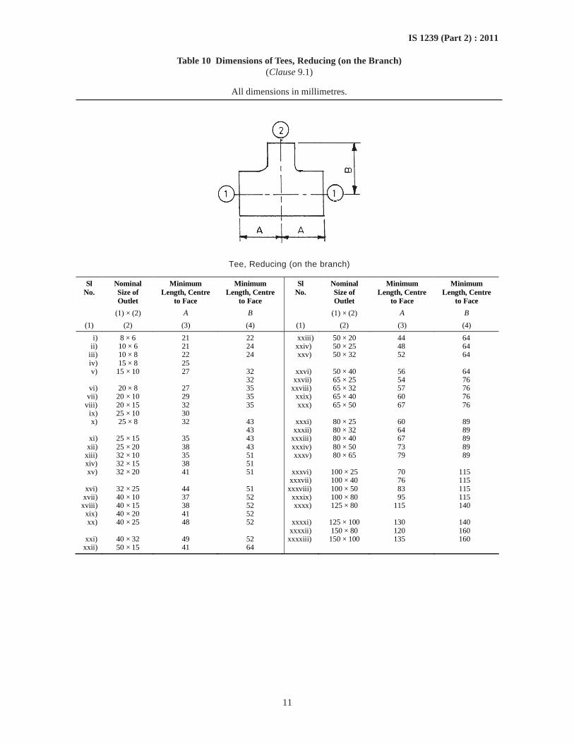
11
IS 1239 (Part 2) : 2011
Table 10 Dimensions of Tees, Reducing (on the Branch)(Clause 9.1)
All dimensions in millimetres.
Tee, Reducing (on the branch)
Sl No.
Nominal Size of Outlet
Minimum Length, Centre
to Face
Minimum Length, Centre
to Face
Sl No.
Nominal Size of Outlet
Minimum Length, Centre
to Face
Minimum Length, Centre
to Face
(1) × (2) A B (1) × (2) A B
(1) (2) (3) (4) (1) (2) (3) (4)
i) 8 × 6 21 22 xxiii) 50 × 20 44 64 ii) 10 × 6 21 24 xxiv) 50 × 25 48 64
iii) 10 × 8 22 24 xxv) 50 × 32 52 64 iv) 15 × 8 25 v) 15 × 10 27 32 xxvi) 50 × 40 56 64
32 xxvii) 65 × 25 54 76 vi) 20 × 8 27 35 xxviii) 65 × 32 57 76
vii) 20 × 10 29 35 xxix) 65 × 40 60 76 viii) 20 × 15 32 35 xxx) 65 × 50 67 76
ix) 25 × 10 30 x) 25 × 8 32 43 xxxi) 80 × 25 60 89
43 xxxii) 80 × 32 64 89 xi) 25 × 15 35 43 xxxiii) 80 × 40 67 89
xii) 25 × 20 38 43 xxxiv) 80 × 50 73 89 xiii) 32 × 10 35 51 xxxv) 80 × 65 79 89 xiv) 32 × 15 38 51 xv) 32 × 20 41 51 xxxvi) 100 × 25 70 115
xxxvii) 100 × 40 76 115 xvi) 32 × 25 44 51 xxxviii) 100 × 50 83 115
xvii) 40 × 10 37 52 xxxix) 100 × 80 95 115 xviii) 40 × 15 38 52 xxxx) 125 × 80 115 140
xix) 40 × 20 41 52 xx) 40 × 25 48 52 xxxxi) 125 × 100 130 140
xxxxii) 150 × 80 120 160 xxi) 40 × 32 49 52 xxxxiii) 150 × 100 135 160
xxii) 50 × 15 41 64
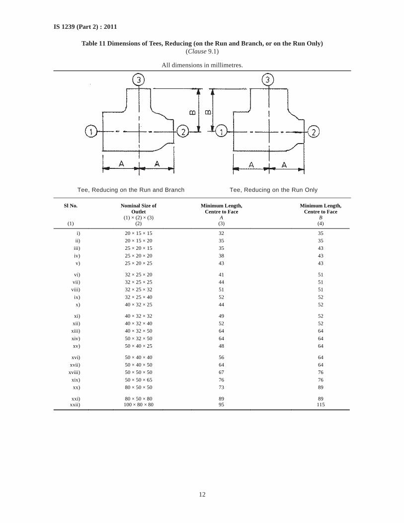
12
IS 1239 (Part 2) : 2011
Table 11 Dimensions of Tees, Reducing (on the Run and Branch, or on the Run Only)(Clause 9.1)
All dimensions in millimetres.
Tee, Reducing on the Run and Branch Tee, Reducing on the Run Only
Sl No. Nominal Size of Outlet
Minimum Length, Centre to Face
Minimum Length, Centre to Face
(1) × (2) × (3) A B (1) (2) (3) (4)
i) 20 × 15 × 15 32 35
ii) 20 × 15 × 20 35 35
iii) 25 × 20 × 15 35 43
iv) 25 × 20 × 20 38 43
v) 25 × 20 × 25 43 43
vi) 32 × 25 × 20 41 51
vii) 32 × 25 × 25 44 51
viii) 32 × 25 × 32 51 51
ix) 32 × 25 × 40 52 52
x) 40 × 32 × 25 44 52
xi) 40 × 32 × 32 49 52
xii) 40 × 32 × 40 52 52
xiii) 40 × 32 × 50 64 64
xiv) 50 × 32 × 50 64 64
xv) 50 × 40 × 25 48 64
xvi) 50 × 40 × 40 56 64
xvii) 50 × 40 × 50 64 64
xviii) 50 × 50 × 50 67 76
xix) 50 × 50 × 65 76 76
xx) 80 × 50 × 50 73 89
xxi) 80 × 50 × 80 89 89 xxii) 100 × 80 × 80 95 115
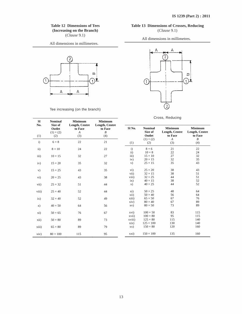
13
IS 1239 (Part 2) : 2011
Table 12 Dimensions of Tees(Increasing on the Branch)
(Clause 9.1)
All dimensions in millimetres.
Tee increasing (on the branch)
Sl No.
Nominal Size of Outlet
Minimum Length, Centre
to Face
Minimum Length, Centre
to Face (1) × (2) A B
(1) (2) (3) (4)
i) 6 × 8 22 21
ii) 8 × 10 24 22
iii) 10 × 15 32 27
iv) 15 × 20 35 32
v) 15 × 25 43 35
vi) 20 × 25 43 38
vii) 25 × 32 51 44
viii) 25 × 40 52 44
ix) 32 × 40 52 49
x) 40 × 50 64 56
xi) 50 × 65 76 67
xii) 50 × 80 89 73
xiii) 65 × 80 89 79
xiv) 80 × 100 115 95
Table 13 Dimensions of Crosses, Reducing(Clause 9.1)
All dimensions in millimetres.
Cross, Reducing
Sl No. Nominal Size of Outlet
Minimum Length, Centre
to Face
Minimum Length, Centre
to Face (1) × (2) A B
(1) (2) (3) (4)
i) 8 × 6 21 22 ii) 10 × 8 22 24 iii) 15 × 10 27 32 iv) 20 × 15 32 35 v) 25 × 15 35 43
vi) 25 × 20 38 43 vii) 32 × 15 38 51 viii) 32 × 25 44 51 ix) 40 × 15 38 52 x) 40 × 25 44 52
xi) 50 × 25 48 64 xii) 50 × 40 56 64 xiii) 65 × 50 67 76 xiv) 80 × 40 67 89 xv) 80 × 50 73 89
xvi) 100 × 50 83 115 xvii) 100 × 80 95 115 xviii) 125 × 80 115 140 xix) 125 × 100 130 140 xx) 150 × 80 120 160
xxi) 150 × 100 135 160
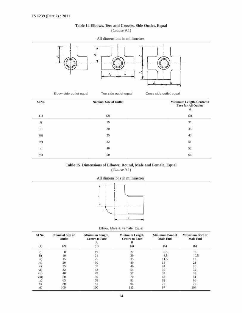
14
IS 1239 (Part 2) : 2011
Table 14 Elbows, Tees and Crosses, Side Outlet, Equal(Clause 9.1)
All dimensions in millimetres.
Elbow side outlet equal Tee side outlet equal Cross side outlet equal
Sl No. Nominal Size of Outlet Minimum Length, Centre to Face for All Outlets
A
(1) (2) (3)
i) 15 32
ii) 20 35
iii) 25 43
iv) 32 51
v) 40 52
vi) 50 64
Table 15 Dimensions of Elbows, Round, Male and Female, Equal(Clause 9.1)
All dimensions in millimetres.
Elbow, Male & Female, Equal
Sl No. Nominal Size of Outlet
Minimum Length, Centre to Face
Minimum Length, Centre to Face
Minimum Bore of Male End
Maximum Bore of Male End
A B (1) (2) (3) (4) (5) (6)
i) 8 19 27 6.5 8 ii) 10 21 29 8.5 10.5 iii) 15 25 35 11.5 13 iv) 20 30 40 18 21 v) 25 37 46 24 26 vi) 32 43 54 30 32 vii) 40 49 57 37 39 viii) 50 59 70 48 51 ix) 65 68 83 62 66 x) 80 81 94 75 79 xi) 100 100 115 97 104
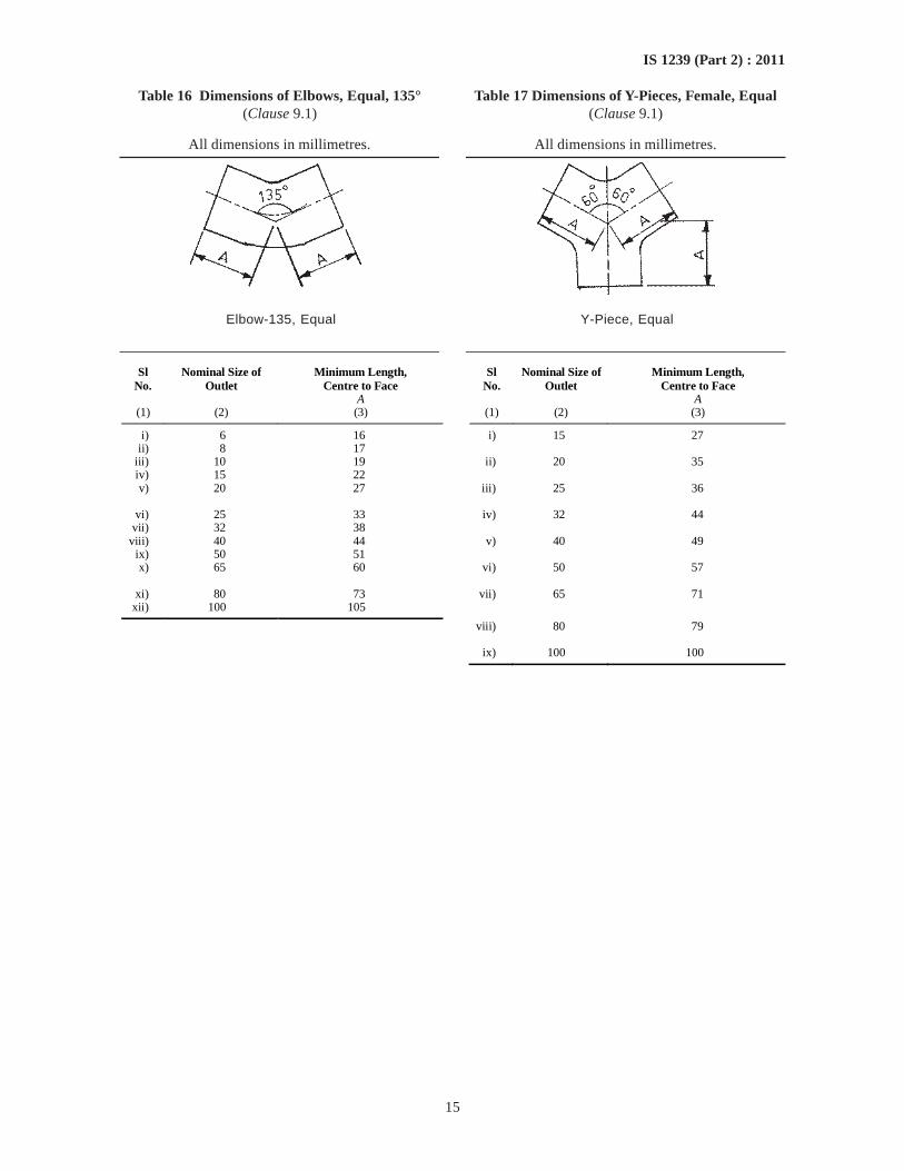
15
IS 1239 (Part 2) : 2011
Table 16 Dimensions of Elbows, Equal, 135° Table 17 Dimensions of Y-Pieces, Female, Equal(Clause 9.1) (Clause 9.1)
All dimensions in millimetres. All dimensions in millimetres.
Elbow-135, Equal Y-Piece, Equal
Sl No.
Nominal Size of Outlet
Minimum Length, Centre to Face
Sl No.
Nominal Size of Outlet
Minimum Length, Centre to Face
A A (1) (2) (3) (1) (2) (3)
i) 6 16 i) 15 27 ii) 8 17
iii) 10 19 ii) 20 35 iv) 15 22 v) 20 27 iii) 25 36
vi) 25 33 iv) 32 44
vii) 32 38 viii) 40 44 v) 40 49
ix) 50 51 x) 65 60 vi) 50 57
xi) 80 73 vii) 65 71
xii) 100 105
viii) 80 79 ix) 100 100
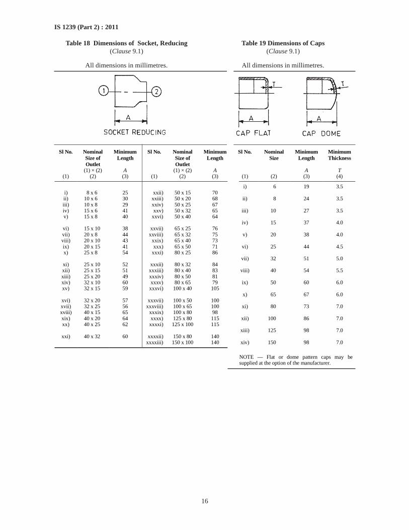
16
IS 1239 (Part 2) : 2011
Table 18 Dimensions of Socket, Reducing Table 19 Dimensions of Caps(Clause 9.1) (Clause 9.1)
All dimensions in millimetres. All dimensions in millimetres.
Sl No. Nominal Size of Outlet
Minimum Length
Sl No. Nominal Size of Outlet
Minimum Length
Sl No. Nominal Size
Minimum Length
Minimum Thickness
(1) × (2) A (1) × (2) A A T (1) (2) (3) (1) (2) (3) (1) (2) (3) (4)
i) 6 19 3.5 i) 8 x 6 25 xxii) 50 x 15 70 ii) 10 x 6 30 xxiii) 50 x 20 68 iii) 10 x 8 29 xxiv) 50 x 25 67
ii) 8 24 3.5
iv) 15 x 6 41 xxv) 50 x 32 65 v) 15 x 8 40 xxvi) 50 x 40 64
iii) 10 27 3.5
vi) 15 x 10 38 xxvii) 65 x 25 76
iv) 15 37 4.0
vii) 20 x 8 44 xxviii) 65 x 32 75 viii) 20 x 10 43 xxix) 65 x 40 73
v) 20 38 4.0
ix) 20 x 15 41 xxx) 65 x 50 71 x) 25 x 8 54 xxxi) 80 x 25 86
vi) 25 44 4.5
xi) 25 x 10 52 xxxii) 80 x 32 84
vii) 32 51 5.0
xii) 25 x 15 51 xxxiii) 80 x 40 83 xiii) 25 x 20 49 xxxiv) 80 x 50 81
viii) 40 54 5.5
xiv) 32 x 10 60 xxxv) 80 x 65 79 xv) 32 x 15 59 xxxvi) 100 x 40 105
ix) 50 60 6.0
xvi) 32 x 20 57 xxxvii) 100 x 50 100
x) 65 67 6.0
xvii) 32 x 25 56 xxxviii) 100 x 65 100 xviii) 40 x 15 65 xxxix) 100 x 80 98
xi) 80 73 7.0
xix) 40 x 20 64 xxxx) 125 x 80 115 xx) 40 x 25 62 xxxxi) 125 x 100 115
xii) 100 86 7.0
xxi) 40 x 32 60 xxxxii) 150 x 80 140
xiii) 125 98 7.0
xxxxiii) 150 x 100 140 xiv) 150 98 7.0
NOTE — Flat or dome pattern caps may be supplied at the option of the manufacturer.
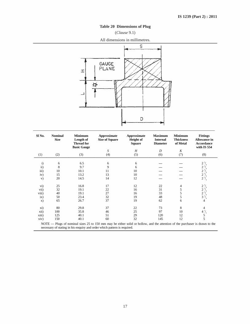
17
IS 1239 (Part 2) : 2011
Table 20 Dimensions of Plug
(Clause 9.1)
All dimensions in millimetres.
Sl No. Nominal Size
Minimum Length of
Thread for Basic Gauge
Approximate Size of Square
Approximate Height of Square
Maximum Internal Diameter
Minimum Thickness of Metal
Fittings Allowance in Accordance with IS 554
S H D K (1) (2) (3) (4) (5) (6) (7) (8)
i) 6 6.5 6 6 — — 2 3/
4
ii) 8 9.7 9 6 — — 2 3/4
iii) 10 10.1 11 10 — — 2 3/4
iv) 15 13.2 13 10 — — 2 3/4
v) 20 14.5 14 12 — — 2 3/4
vi) 25 16.8 17 12 22 4 2 3/4
vii) 32 19.1 22 16 31 5 2 3/4
viii) 40 19.1 27 16 33 5 2 3/4
ix) 50 23.4 32 19 48 5 3 1/4
x) 65 26.7 37 19 62 6 4
xi) 80 29.8 37 22 73 8 4 xii) 100 35.8 46 25 97 10 4 1/2
xiii) 125 40.1 51 29 120 12 5 xiv) 150 40.1 60 32 145 12 5
NOTE — Plugs of nominal sizes 25 to 150 mm may be either solid or hollow, and the attention of the purchaser is drawn to the necessary of stating in his enquiry and order which pattern is required.
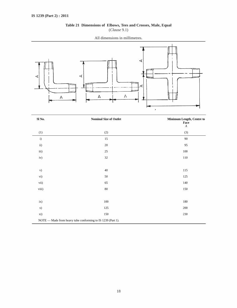
18
IS 1239 (Part 2) : 2011
Table 21 Dimensions of Elbows, Tees and Crosses, Male, Equal(Clause 9.1)
All dimensions in millimetres.
Sl No. Nominal Size of Outlet Minimum Length, Centre to Face
A
(1) (2) (3)
i) 15 90
ii) 20 95
iii) 25 100
iv) 32 110
v) 40 115
vi) 50 125
vii) 65 140
viii) 80 150
ix) 100 180
x) 125 200
xi) 150 230
NOTE — Made from heavy tube conforming to IS 1239 (Part 1).
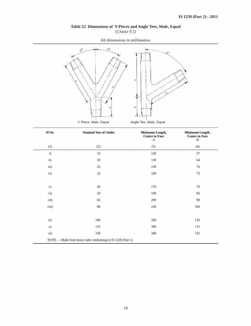
19
IS 1239 (Part 2) : 2011
Table 22 Dimensions of Y-Pieces and Angle Tees, Male, Equal(Clause 9.1)
All dimensions in millimetres.
Y Piece, Male, Equal Angle Tee, Male, Equal
Sl No. Nominal Size of Outlet Minimum Length, Centre to Face
A
Minimum Length, Centre to Face
B
(1) (2) (3) (4)
i) 15 120 57
ii) 20 130 64
iii) 25 150 70
iv) 32 160 73
v) 40 170 76
vi) 50 190 83
vii) 65 200 90
viii) 80 220 100
ix) 100 260 110
x) 125 300 115
xi) 150 340 125
NOTE — Made from heavy tube conforming to IS 1239 (Part 1).
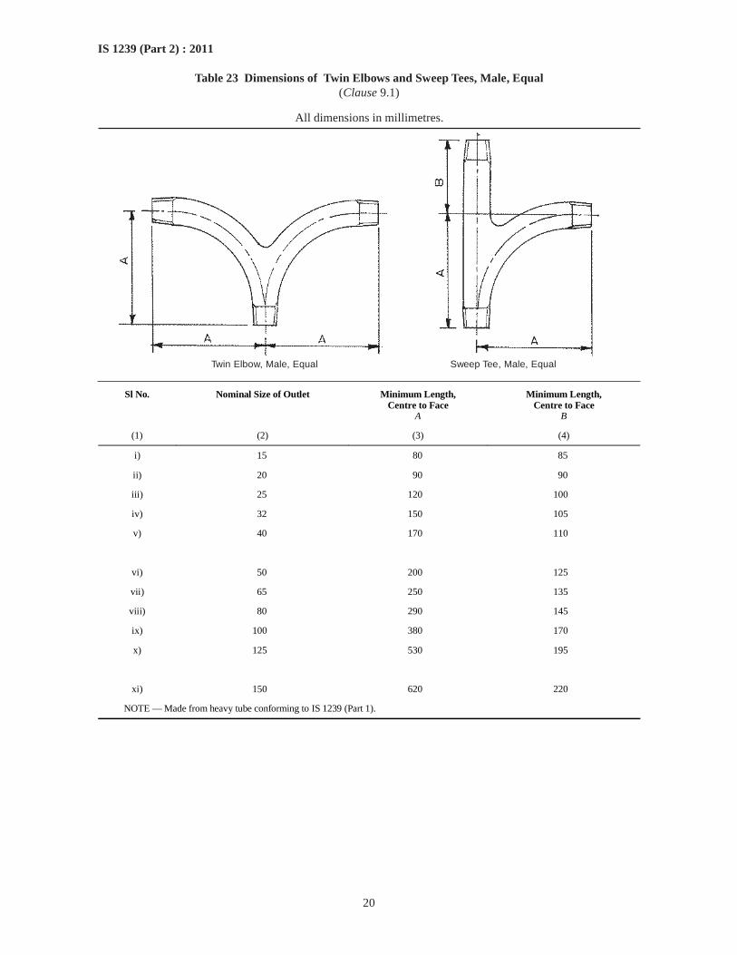
20
IS 1239 (Part 2) : 2011
Table 23 Dimensions of Twin Elbows and Sweep Tees, Male, Equal(Clause 9.1)
All dimensions in millimetres.
Twin Elbow, Male, Equal Sweep Tee, Male, Equal
Sl No. Nominal Size of Outlet Minimum Length, Centre to Face
A
Minimum Length, Centre to Face
B
(1) (2) (3) (4)
i) 15 80 85
ii) 20 90 90
iii) 25 120 100
iv) 32 150 105
v) 40 170 110
vi) 50 200 125
vii) 65 250 135
viii) 80 290 145
ix) 100 380 170
x) 125 530 195
xi) 150 620 220
NOTE — Made from heavy tube conforming to IS 1239 (Part 1).
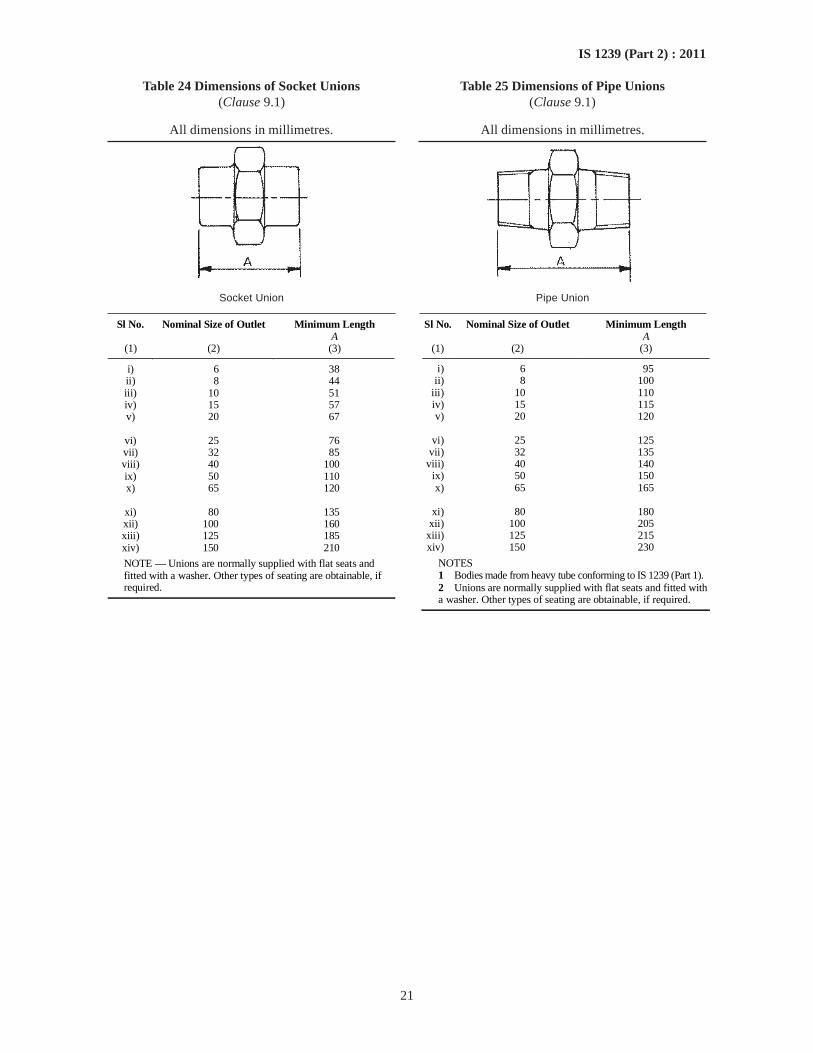
21
IS 1239 (Part 2) : 2011
Table 24 Dimensions of Socket Unions(Clause 9.1)
All dimensions in millimetres.
Socket Union
Sl No. Nominal Size of Outlet Minimum Length A
(1) (2) (3)
i) 6 38 ii) 8 44 iii) 10 51 iv) 15 57 v) 20 67
vi) 25 76 vii) 32 85 viii) 40 100 ix) 50 110 x) 65 120
xi) 80 135 xii) 100 160 xiii) 125 185 xiv) 150 210
NOTE — Unions are normally supplied with flat seats and fitted with a washer. Other types of seating are obtainable, if required.
Table 25 Dimensions of Pipe Unions(Clause 9.1)
All dimensions in millimetres.
Pipe Union
Sl No. Nominal Size of Outlet Minimum Length A
(1) (2) (3)
i) 6 95 ii) 8 100
iii) 10 110 iv) 15 115 v) 20 120
vi) 25 125
vii) 32 135 viii) 40 140
ix) 50 150 x) 65 165
xi) 80 180
xii) 100 205 xiii) 125 215 xiv) 150 230
NOTES 1 Bodies made from heavy tube conforming to IS 1239 (Part 1). 2 Unions are normally supplied with flat seats and fitted with a washer. Other types of seating are obtainable, if required.
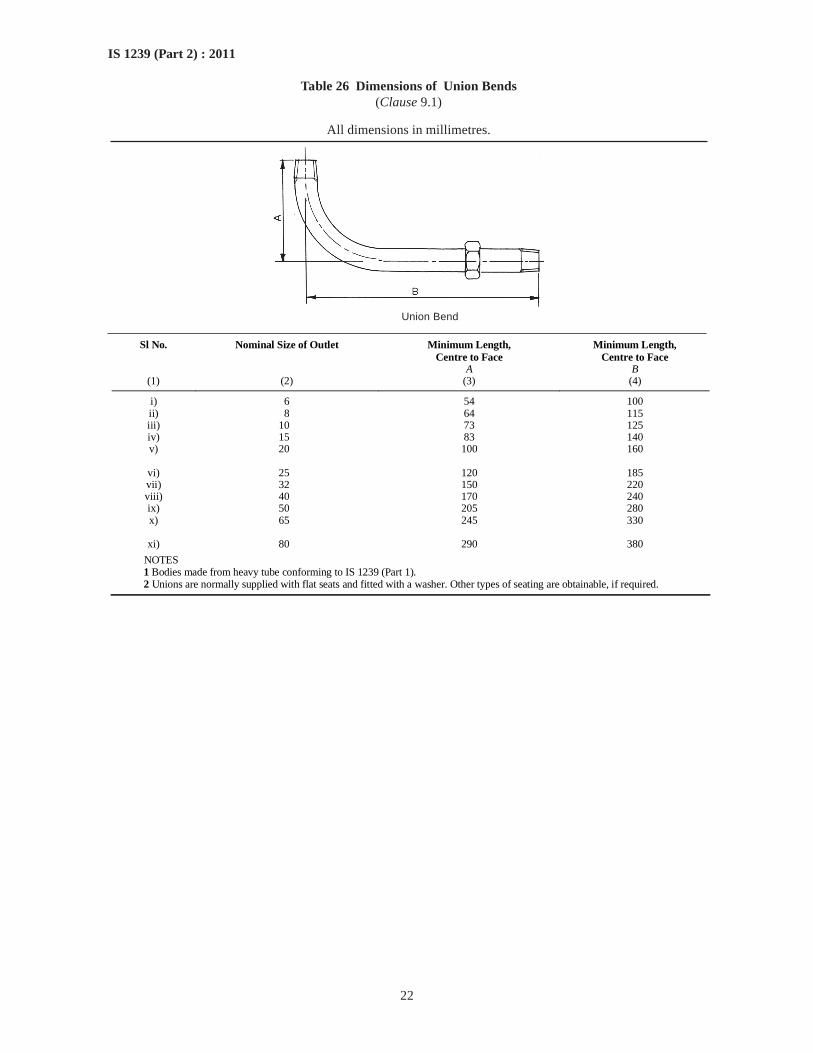
22
IS 1239 (Part 2) : 2011
Table 26 Dimensions of Union Bends(Clause 9.1)
All dimensions in millimetres.
Union Bend
Sl No. Nominal Size of Outlet Minimum Length, Centre to Face
A
Minimum Length, Centre to Face
B (1) (2) (3) (4)
i) 6 54 100 ii) 8 64 115 iii) 10 73 125 iv) 15 83 140 v) 20 100 160
vi) 25 120 185 vii) 32 150 220 viii) 40 170 240 ix) 50 205 280 x) 65 245 330
xi) 80 290 380
NOTES 1 Bodies made from heavy tube conforming to IS 1239 (Part 1). 2 Unions are normally supplied with flat seats and fitted with a washer. Other types of seating are obtainable, if required.
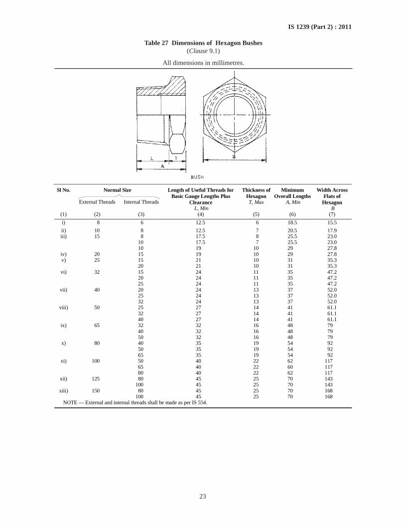
23
IS 1239 (Part 2) : 2011
Table 27 Dimensions of Hexagon Bushes(Clause 9.1)
All dimensions in millimetres.
Normal Size
Sl No.
External Threads Internal Threads
Length of Useful Threads for Basic Gauge Lengths Plus
Clearance L, Min
Thickness of Hexagon T, Max
Minimum Overall Lengths
A, Min
Width Across Flats of
Hexagon B
(1) (2) (3) (4) (5) (6) (7)
i) 8 6 12.5 6 18.5 15.5
ii) 10 8 12.5 7 20.5 17.9 iii) 15 8 17.5 8 25.5 23.0
10 17.5 7 25.5 23.0 10 19 10 29 27.8
iv) 20 15 19 10 29 27.8 v) 25 15 21 10 31 35.3 20 21 10 31 35.3
vi) 32 15 24 11 35 47.2 20 24 11 35 47.2 25 24 11 35 47.2
vii) 40 20 24 13 37 52.0 25 24 13 37 52.0 32 24 13 37 52.0
viii) 50 25 27 14 41 61.1 32 27 14 41 61.1 40 27 14 41 61.1
ix) 65 32 32 16 48 79 40 32 16 48 79 50 32 16 48 79
x) 80 40 35 19 54 92 50 35 19 54 92 65 35 19 54 92
xi) 100 50 40 22 62 117 65 40 22 60 117 80 40 22 62 117
xii) 125 80 45 25 70 143 100 45 25 70 143
xiii) 150 80 45 25 70 168 100 45 25 70 168 NOTE — External and internal threads shall be made as per IS 554.
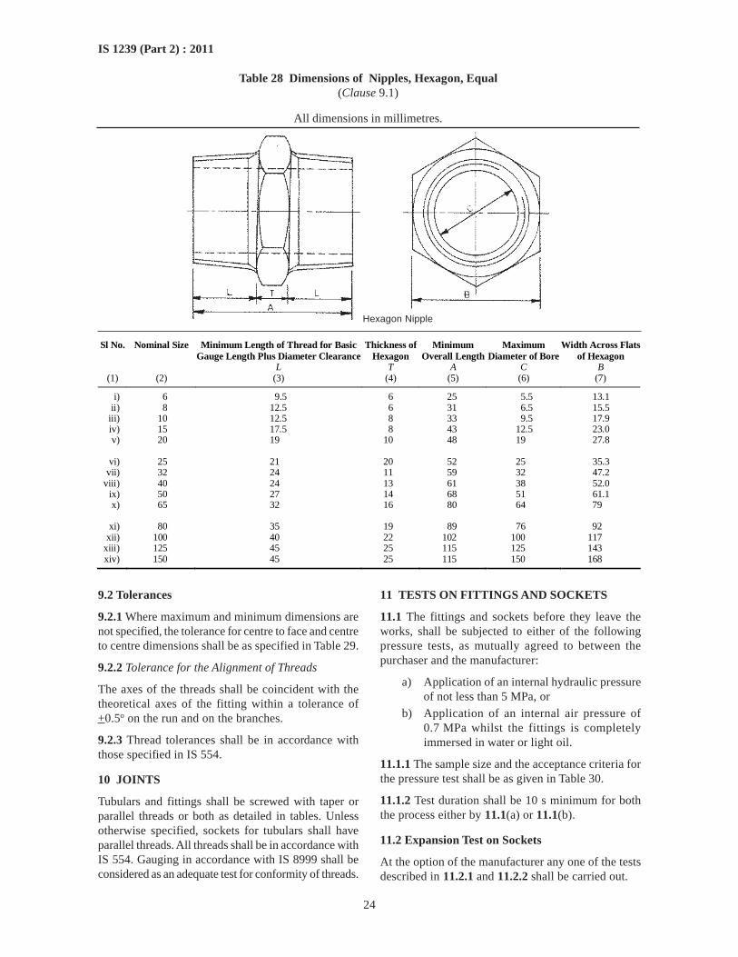
24
IS 1239 (Part 2) : 2011
Table 28 Dimensions of Nipples, Hexagon, Equal(Clause 9.1)
All dimensions in millimetres.
Sl No. Nominal Size Minimum Length of Thread for Basic Gauge Length Plus Diameter Clearance
Thickness of Hexagon
Minimum Overall Length
Maximum Diameter of Bore
Width Across Flats of Hexagon
L T A C B (1) (2) (3) (4) (5) (6) (7)
i) 6 9.5 6 25 5.5 13.1 ii) 8 12.5 6 31 6.5 15.5
iii) 10 12.5 8 33 9.5 17.9 iv) 15 17.5 8 43 12.5 23.0 v) 20 19 10 48 19 27.8
vi) 25 21 20 52 25 35.3
vii) 32 24 11 59 32 47.2 viii) 40 24 13 61 38 52.0
ix) 50 27 14 68 51 61.1 x) 65 32 16 80 64 79
xi) 80 35 19 89 76 92
xii) 100 40 22 102 100 117 xiii) 125 45 25 115 125 143 xiv) 150 45 25 115 150 168
9.2 Tolerances
9.2.1 Where maximum and minimum dimensions arenot specified, the tolerance for centre to face and centreto centre dimensions shall be as specified in Table 29.
9.2.2 Tolerance for the Alignment of Threads
The axes of the threads shall be coincident with thetheoretical axes of the fitting within a tolerance of+0.5o on the run and on the branches.
9.2.3 Thread tolerances shall be in accordance withthose specified in IS 554.
10 JOINTS
Tubulars and fittings shall be screwed with taper orparallel threads or both as detailed in tables. Unlessotherwise specified, sockets for tubulars shall haveparallel threads. All threads shall be in accordance withIS 554. Gauging in accordance with IS 8999 shall beconsidered as an adequate test for conformity of threads.
11 TESTS ON FITTINGS AND SOCKETS
11.1 The fittings and sockets before they leave theworks, shall be subjected to either of the followingpressure tests, as mutually agreed to between thepurchaser and the manufacturer:
a) Application of an internal hydraulic pressureof not less than 5 MPa, or
b) Application of an internal air pressure of0.7 MPa whilst the fittings is completelyimmersed in water or light oil.
11.1.1 The sample size and the acceptance criteria forthe pressure test shall be as given in Table 30.
11.1.2 Test duration shall be 10 s minimum for boththe process either by 11.1(a) or 11.1(b).
11.2 Expansion Test on Sockets
At the option of the manufacturer any one of the testsdescribed in 11.2.1 and 11.2.2 shall be carried out.
Hexagon Nipple
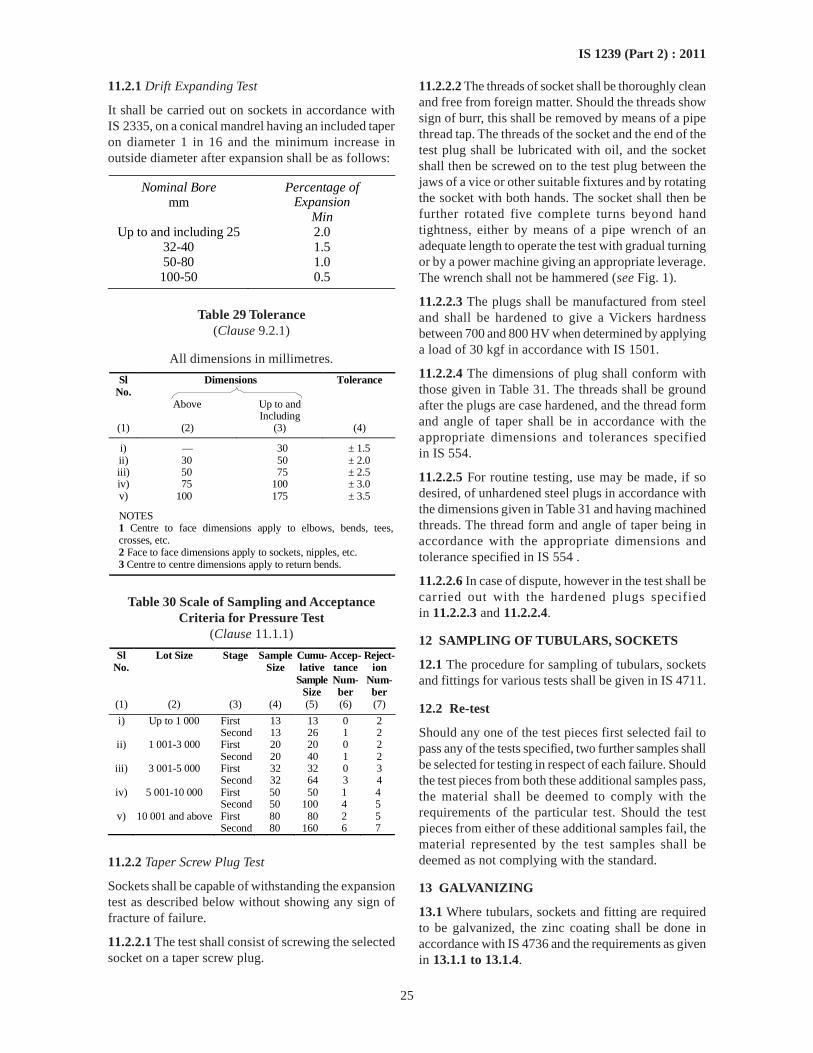
25
IS 1239 (Part 2) : 2011
11.2.1 Drift Expanding Test
It shall be carried out on sockets in accordance withIS 2335, on a conical mandrel having an included taperon diameter 1 in 16 and the minimum increase inoutside diameter after expansion shall be as follows:
Nominal Bore Percentage of mm Expansion
Min Up to and including 25 2.0
32-40 1.5 50-80 1.0 100-50 0.5
Table 29 Tolerance(Clause 9.2.1)
All dimensions in millimetres.
Dimensions Sl No.
Tolerance
Above Up to and Including
(1) (2) (3) (4)
i) — 30 ± 1.5 ii) 30 50 ± 2.0 iii) 50 75 ± 2.5 iv) 75 100 ± 3.0 v) 100 175 ± 3.5
NOTES 1 Centre to face dimensions apply to elbows, bends, tees, crosses, etc. 2 Face to face dimensions apply to sockets, nipples, etc. 3 Centre to centre dimensions apply to return bends.
Table 30 Scale of Sampling and AcceptanceCriteria for Pressure Test
(Clause 11.1.1)
Sl No.
Lot Size Stage Sample Size
Cumu-lative
Sample Size
Accep-tance Num-ber
Reject-ion
Num-ber
(1) (2) (3) (4) (5) (6) (7)
i) Up to 1 000 First 13 13 0 2 Second 13 26 1 2
ii) 1 001-3 000 First 20 20 0 2 Second 20 40 1 2
iii) 3 001-5 000 First 32 32 0 3 Second 32 64 3 4
iv) 5 001-10 000 First 50 50 1 4 Second 50 100 4 5
v) 10 001 and above First 80 80 2 5 Second 80 160 6 7
11.2.2 Taper Screw Plug Test
Sockets shall be capable of withstanding the expansiontest as described below without showing any sign offracture of failure.
11.2.2.1 The test shall consist of screwing the selectedsocket on a taper screw plug.
11.2.2.2 The threads of socket shall be thoroughly cleanand free from foreign matter. Should the threads showsign of burr, this shall be removed by means of a pipethread tap. The threads of the socket and the end of thetest plug shall be lubricated with oil, and the socketshall then be screwed on to the test plug between thejaws of a vice or other suitable fixtures and by rotatingthe socket with both hands. The socket shall then befurther rotated five complete turns beyond handtightness, either by means of a pipe wrench of anadequate length to operate the test with gradual turningor by a power machine giving an appropriate leverage.The wrench shall not be hammered (see Fig. 1).
11.2.2.3 The plugs shall be manufactured from steeland shall be hardened to give a Vickers hardnessbetween 700 and 800 HV when determined by applyinga load of 30 kgf in accordance with IS 1501.
11.2.2.4 The dimensions of plug shall conform withthose given in Table 31. The threads shall be groundafter the plugs are case hardened, and the thread formand angle of taper shall be in accordance with theappropriate dimensions and tolerances specifiedin IS 554.
11.2.2.5 For routine testing, use may be made, if sodesired, of unhardened steel plugs in accordance withthe dimensions given in Table 31 and having machinedthreads. The thread form and angle of taper being inaccordance with the appropriate dimensions andtolerance specified in IS 554 .
11.2.2.6 In case of dispute, however in the test shall becarried out with the hardened plugs specifiedin 11.2.2.3 and 11.2.2.4.
12 SAMPLING OF TUBULARS, SOCKETS
12.1 The procedure for sampling of tubulars, socketsand fittings for various tests shall be given in IS 4711.
12.2 Re-test
Should any one of the test pieces first selected fail topass any of the tests specified, two further samples shallbe selected for testing in respect of each failure. Shouldthe test pieces from both these additional samples pass,the material shall be deemed to comply with therequirements of the particular test. Should the testpieces from either of these additional samples fail, thematerial represented by the test samples shall bedeemed as not complying with the standard.
13 GALVANIZING
13.1 Where tubulars, sockets and fitting are requiredto be galvanized, the zinc coating shall be done inaccordance with IS 4736 and the requirements as givenin 13.1.1 to 13.1.4.
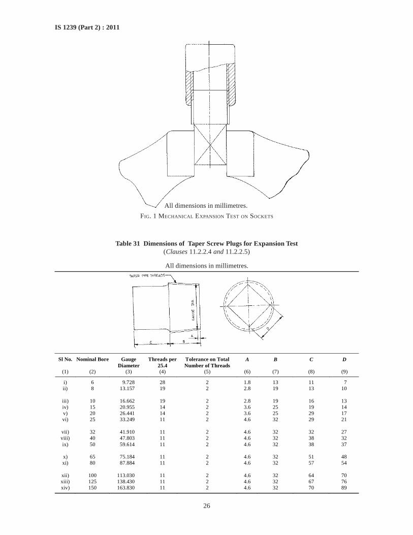
26
IS 1239 (Part 2) : 2011
FIG. 1 MECHANICAL EXPANSION TEST ON SOCKETS
Table 31 Dimensions of Taper Screw Plugs for Expansion Test(Clauses 11.2.2.4 and 11.2.2.5)
All dimensions in millimetres.
Sl No. Nominal Bore Gauge Diameter
Threads per 25.4
Tolerance on Total Number of Threads
A B C D
(1) (2) (3) (4) (5) (6) (7) (8) (9)
i) 6 9.728 28 2 1.8 13 11 7 ii) 8 13.157 19 2 2.8 19 13 10
iii) 10 16.662 19 2 2.8 19 16 13 iv) 15 20.955 14 2 3.6 25 19 14 v) 20 26.441 14 2 3.6 25 29 17 vi) 25 33.249 11 2 4.6 32 29 21
vii) 32 41.910 11 2 4.6 32 32 27 viii) 40 47.803 11 2 4.6 32 38 32 ix) 50 59.614 11 2 4.6 32 38 37
x) 65 75.184 11 2 4.6 32 51 48 xi) 80 87.884 11 2 4.6 32 57 54
xii) 100 113.030 11 2 4.6 32 64 70 xiii) 125 138.430 11 2 4.6 32 67 76 xiv) 150 163.830 11 2 4.6 32 70 89
All dimensions in millimetres.
27
IS 1239 (Part 2) : 2011
13.1.1 Mass of Zinc Coating
Mass of zinc coating shall be determined beforethreading on full length test piece in case the length ofthe fittings are less than 100 mm and on 100 mm lengthin case of the fittings are more that 100 mm inaccordance with IS 4736 and shall not be less than360 g/m2.
13.1.2 Uniformity of Zinc Coating
The test for uniformity of zinc coating shall be doneon full length fittings in case the length of the fittingsare less than 100 mm and on 100 mm length in thelength of the fittings are more 100 mm in accordancewith IS 2633 and shall withstand 5 one minute dips.
13.1.3 Adhesion Test
The adhesion of zinc coating on fittings shall bedetermined by pivoted hammer test in accordance withIS 2629.
13.1.4 The zinc coating shall be reasonably smoothand free from such imperfections as flux, ash and drossinclusions, bare patches, black spots, pimples,lumpiness, runs, rust stains, bulky white deposits andblisters.
13.1.5 Tubulars, sockets and fittings shall be galvanizedbefore screwing.
14 WORKMANSHIP
Tubulars, sockets and fitting shall be clearly finishedand reasonably free from scale, surface flaws,laminations and other defects. The screw threads oftubulars, sockets and fittings shall be clean and wellcut. The ends shall be cut clearly and square unlessotherwise specified.
15 MARKING
15.1 Tubulars, sockets and fittings shall be suitablypacked and threads protected from damage and markedwith the following details:
a) Manufacturer’s name or trade-mark; and
b) Size designation.
15.2 BIS Certification Marking
The tubulars, sockets and fittings may also be markedwith the Standard Mark.
15.2.1 The use of the Standard Mark is governed bythe provision of the Bureau of Indian Standards Act,1986 and the Rules and Regulations made thereunder.The details of conditions under which the licence forthe use of the Standard Mark may be granted to themanufacturers or producers may be obtained from theBureau of Indian Standards.
ANNEX A(Foreword)
NOMINAL SIZE OF PIPE THREADS AND CORRESPONDING NOMINAL BORES OF PIPES
Sl No. Nominal Size of Pipe Threads
(As per IS 554)
Corresponding Nominal Bore
[As per IS 1239 (Part 1)] (1) (2) (3)
i) 1/16 — ii) 1/8 6
iii) 1/4 8 iv) 3/8 10 v) 1/2 15
vi) 3/4 20 vii) 1 25
viii) 1 ¼ 32 ix) 1 ½ 40 x) 2 50
xi) 2 ½ 65 xii) 3 80
xiii) 3 ½ — xiv) 4 100 xv) 5 125
xvi) 6 150
Bureau of Indian Standards
BIS is a statutory institution established under the Bureau of Indian Standards Act, 1986 to promoteharmonious development of the activities of standardization, marking and quality certification of goodsand attending to connected matters in the country.
Copyright
BIS has the copyright of all its publications. No part of these publications may be reproduced in any formwithout the prior permission in writing of BIS. This does not preclude the free use, in the course ofimplementing the standard, of necessary details, such as symbols and sizes, type or grade designations.Enquiries relating to copyright be addressed to the Director (Publications), BIS.
Review of Indian Standards
Amendments are issued to standards as the need arises on the basis of comments. Standards are also reviewedperiodically; a standard along with amendments is reaffirmed when such review indicates that no changes areneeded; if the review indicates that changes are needed, it is taken up for revision. Users of Indian Standardsshould ascertain that they are in possession of the latest amendments or edition by referring to the latest issue of‘BIS Catalogue’ and ‘Standards : Monthly Additions’.
This Indian Standard has been developed from Doc No.: MTD 19 (4999).
Amendments Issued Since Publication
Amend No. Date of Issue Text Affected
BUREAU OF INDIAN STANDARDS
Headquarters:
Manak Bhavan, 9 Bahadur Shah Zafar Marg, New Delhi 110 002Telephones : 2323 0131, 2323 3375, 2323 9402 Website: www.bis.org.in
Regional Offices: Telephones
Central : Manak Bhavan, 9 Bahadur Shah Zafar Marg 2323 7617NEW DELHI 110002 2323 3841
Eastern : 1/14 C.I.T. Scheme VII M, V. I. P. Road, Kankurgachi 2337 8499, 2337 8561KOLKATA 700054 2337 8626, 2337 9120
Northern : SCO 335-336, Sector 34-A, CHANDIGARH 160022 60 384360 9285
Southern : C.I.T. Campus, IV Cross Road, CHENNAI 600113 2254 1216, 2254 14422254 2519, 2254 2315
Western : Manakalaya, E9 MIDC, Marol, Andheri (East) 2832 9295, 2832 7858MUMBAI 400093 2832 7891, 2832 7892
Branches: AHMEDABAD. BANGALORE. BHOPAL. BHUBANESHWAR. COIMBATORE. DEHRADUN.FARIDABAD. GHAZIABAD. GUWAHATI. HYDERABAD. JAIPUR. KANPUR. LUCKNOW.NAGPUR. PARWANOO. PATNA. PUNE. RAJKOT. THIRUVANANTHAPURAM.VISAKHAPATNAM.
�
��
��
Published by BIS, New Delhi