construction of safety grill for outdoor units of split ac of
TRANSCRIPT

Specifications Page i
MAZAGON DOCK SHIPBUILDERS LIMITED (Formerly known as Mazagon Dock Ltd.)
CIN : U35100MH1934GOI002079 (A Government of India Undertaking)
Dockyard Road, Mazagon,
Mumbai 400 010.
INDIA
Construction of safety Grill for outdoor units of split AC
of Mogul House, South Yard., MDL, Mumbai.
Specification for Civil Works
Specifications Page 1
TECHNICAL SPECIFICATIONS FOR CIVIL WORKS
SECTION-I– (CIVIL WORK)
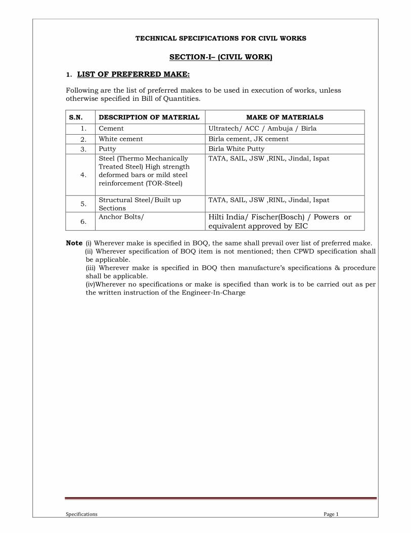
1. LIST OF PREFERRED MAKE:
Following are the list of preferred makes to be used in execution of works, unless otherwise specified in Bill of Quantities.
S.N. DESCRIPTION OF MATERIAL MAKE OF MATERIALS
1. Cement Ultratech/ ACC / Ambuja / Birla
2. White cement Birla cement, JK cement
3. Putty Birla White Putty
4.
Steel (Thermo Mechanically
Treated Steel) High strength
deformed bars or mild steel
reinforcement (TOR-Steel)
TATA, SAIL, JSW ,RINL, Jindal, Ispat
5. Structural Steel/Built up
Sections
TATA, SAIL, JSW ,RINL, Jindal, Ispat
6. Anchor Bolts/ Hilti India/ Fischer(Bosch) / Powers or
equivalent approved by EIC Note (i) Wherever make is specified in BOQ, the same shall prevail over list of preferred make. (ii) Wherever specification of BOQ item is not mentioned; then CPWD specification shall
be applicable. (iii) Wherever make is specified in BOQ then manufacture’s specifications & procedure
shall be applicable.
(iv)Wherever no specifications or make is specified than work is to be carried out as per
the written instruction of the Engineer-In-Charge
Specifications Page 2
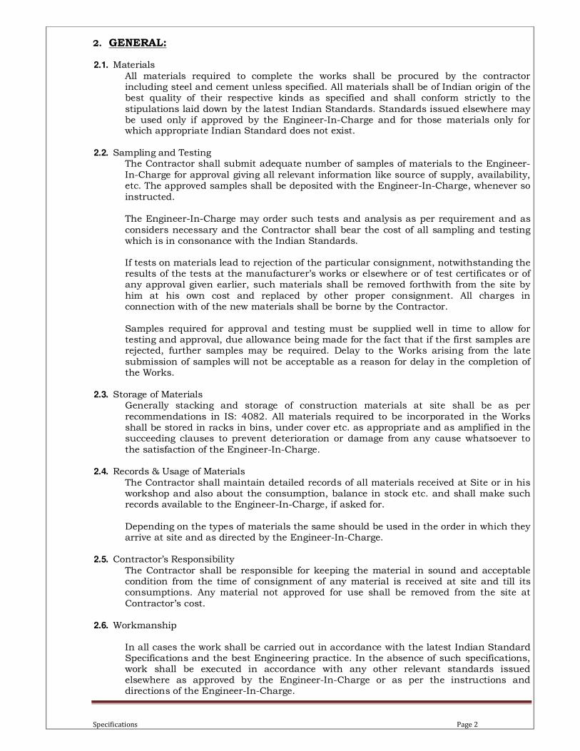
2. GENERAL:
2.1. Materials
All materials required to complete the works shall be procured by the contractor including steel and cement unless specified. All materials shall be of Indian origin of the best quality of their respective kinds as specified and shall conform strictly to the
stipulations laid down by the latest Indian Standards. Standards issued elsewhere may be used only if approved by the Engineer-In-Charge and for those materials only for which appropriate Indian Standard does not exist.
2.2. Sampling and Testing
The Contractor shall submit adequate number of samples of materials to the Engineer-
In-Charge for approval giving all relevant information like source of supply, availability, etc. The approved samples shall be deposited with the Engineer-In-Charge, whenever so
instructed. The Engineer-In-Charge may order such tests and analysis as per requirement and as
considers necessary and the Contractor shall bear the cost of all sampling and testing which is in consonance with the Indian Standards. If tests on materials lead to rejection of the particular consignment, notwithstanding the results of the tests at the manufacturer’s works or elsewhere or of test certificates or of any approval given earlier, such materials shall be removed forthwith from the site by
him at his own cost and replaced by other proper consignment. All charges in connection with of the new materials shall be borne by the Contractor.
Samples required for approval and testing must be supplied well in time to allow for testing and approval, due allowance being made for the fact that if the first samples are rejected, further samples may be required. Delay to the Works arising from the late
submission of samples will not be acceptable as a reason for delay in the completion of the Works.
2.3. Storage of Materials
Generally stacking and storage of construction materials at site shall be as per
recommendations in IS: 4082. All materials required to be incorporated in the Works shall be stored in racks in bins, under cover etc. as appropriate and as amplified in the succeeding clauses to prevent deterioration or damage from any cause whatsoever to
the satisfaction of the Engineer-In-Charge. 2.4. Records & Usage of Materials
The Contractor shall maintain detailed records of all materials received at Site or in his workshop and also about the consumption, balance in stock etc. and shall make such records available to the Engineer-In-Charge, if asked for.
Depending on the types of materials the same should be used in the order in which they arrive at site and as directed by the Engineer-In-Charge.
2.5. Contractor’s Responsibility
The Contractor shall be responsible for keeping the material in sound and acceptable condition from the time of consignment of any material is received at site and till its consumptions. Any material not approved for use shall be removed from the site at
Contractor’s cost.
2.6. Workmanship
In all cases the work shall be carried out in accordance with the latest Indian Standard Specifications and the best Engineering practice. In the absence of such specifications, work shall be executed in accordance with any other relevant standards issued elsewhere as approved by the Engineer-In-Charge or as per the instructions and directions of the Engineer-In-Charge.

Specifications Page 3
2.7. Constructional Plant (s)
The Contractor shall be responsible for the supply, use and maintenance of all Constructional Plant and Equipment so as to ensure smooth and efficient working of
the job at his own cost. The Engineer-In-Charge shall have access to the Plant at all times.
2.8. Workmen and Staff
The Contractor shall ensure that they employs only capable and experienced labour force, foremen, other tradesmen and supervisory staff on the job capable of handling the
types of work assigned to them in a workmanlike and efficient manner to the satisfaction of the Engineer-In-Charge. They shall also ensure that his Sub-contractors or nominated Sub-contractors also employ all workmen and supervisory staff capable of delivering work of a high standard.
For all concrete work trained and experienced personnel at site shall be deployed. 2.9. Method of Measurement
Mode of measurement shall be in accordance with the relevant parts of IS: 1200 “Method of Measurement of Building and Civil Works” only, unless otherwise specified in various item wise specifications describes herein below.
2.10. Rates and Prices
Unless otherwise mentioned, the rates and prices set against items in the bill of
quantities or which can be reasonably inferred there from complete as a functioning entity shall include all costs and expenses which may be required in and for the construction of the work such as- material to be incorporated in the works (permanent/
temporary), labour required for all operations, temporary works, tools and equipments as required, all operations required for the completion and or maintenance of the relevant items as per specifications, all leads and lifts unless otherwise specifically
mentioned in the items, including all general risks, liabilities and obligations set forth or implied in the documents on which the tender is based.
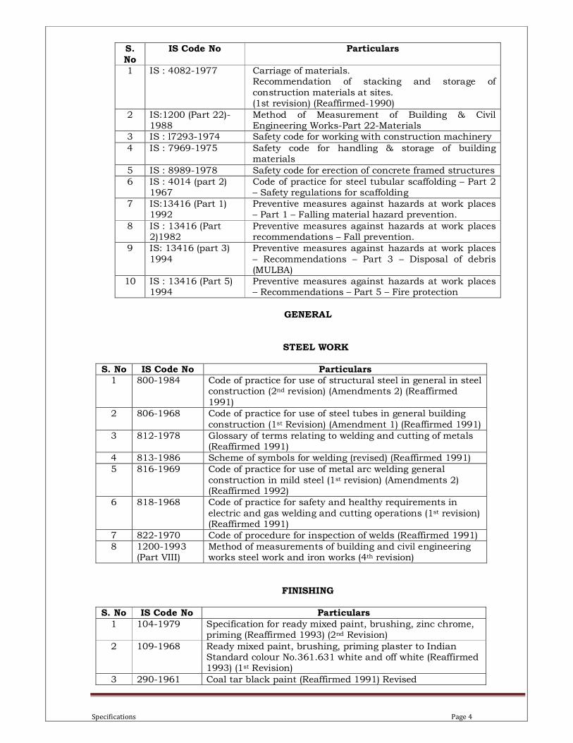
2.11. List of Bureau of Indian Standard Codes (BIS)
Following is the consolidated list of various Indian Standards relevant to the civil works appearing in this specification.
Specifications Page 4
GENERAL
STEEL WORK
S. No IS Code No Particulars 1 800-1984 Code of practice for use of structural steel in general in steel
construction (2nd revision) (Amendments 2) (Reaffirmed
1991)
2 806-1968 Code of practice for use of steel tubes in general building
construction (1st Revision) (Amendment 1) (Reaffirmed 1991)
3 812-1978 Glossary of terms relating to welding and cutting of metals (Reaffirmed 1991)
4 813-1986 Scheme of symbols for welding (revised) (Reaffirmed 1991)
5 816-1969 Code of practice for use of metal arc welding general
construction in mild steel (1st revision) (Amendments 2) (Reaffirmed 1992)
6 818-1968 Code of practice for safety and healthy requirements in
electric and gas welding and cutting operations (1st revision) (Reaffirmed 1991)
7 822-1970 Code of procedure for inspection of welds (Reaffirmed 1991)
8 1200-1993 (Part VIII)
Method of measurements of building and civil engineering works steel work and iron works (4th revision)
FINISHING
S. No IS Code No Particulars
1 104-1979 Specification for ready mixed paint, brushing, zinc chrome, priming (Reaffirmed 1993) (2nd Revision)
2 109-1968 Ready mixed paint, brushing, priming plaster to Indian Standard colour No.361.631 white and off white (Reaffirmed 1993) (1st Revision)
3 290-1961 Coal tar black paint (Reaffirmed 1991) Revised
S. No
IS Code No Particulars
1 IS : 4082-1977 Carriage of materials. Recommendation of stacking and storage of
construction materials at sites. (1st revision) (Reaffirmed-1990)
2 IS:1200 (Part 22)-1988
Method of Measurement of Building & Civil Engineering Works-Part 22-Materials
3 IS : l7293-1974 Safety code for working with construction machinery
4 IS : 7969-1975 Safety code for handling & storage of building materials
5 IS : 8989-1978 Safety code for erection of concrete framed structures
6 IS : 4014 (part 2) 1967
Code of practice for steel tubular scaffolding – Part 2 – Safety regulations for scaffolding
7 IS:13416 (Part 1) 1992
Preventive measures against hazards at work places – Part 1 – Falling material hazard prevention.
8 IS : 13416 (Part 2)1982
Preventive measures against hazards at work places recommendations – Fall prevention.
9 IS: 13416 (part 3)
1994
Preventive measures against hazards at work places
– Recommendations – Part 3 – Disposal of debris (MULBA)
10 IS : 13416 (Part 5) 1994
Preventive measures against hazards at work places – Recommendations – Part 5 – Fire protection

Specifications Page 5
4 419-1967 Putty for use on window frames (Reaffirmed 1992) (Revised)
5 428-1969 Distemper, oil emulsion, colour as required (Reaffirmed 1993) (1st Revision)
6 1200-1976 (Part XII)
Method of measurements of building and civil engineering works: Part XII – Plastering and pointing (Reaffirmed 1992)
(3rd Revision)
7 1200-1994(Part
XIII)
Method of measurements of building and civil engineering works: Part XIII – white washing, colour washing,
distempering and painting of building surfaces (5th Revision)
8 1200-1987
(Part XV)
Methods of measurements of building and civil engineering
works: Part XV – Painting, polishing, varnishing etc. (Reaffirmed 1992) (4th Revision)
9 2932-1994 Enamel, synthetic, exterior (a) undercoating (b) Finishing
(2nd Revision)
10 5410-1992 Cement paint (1st Revision)
11 1661 Application of plaster
12 1542 Plaster for sand
13 2645 Integral waterproofing compound
14 2395 (Part I & II)
Painting workmanship
DISMANTLING AND DEMOLITION
S. No IS Code No Particulars
1 1200-1974 Method of measurements of building and civil engineering works: Part XVII: Demolition and dismantling (Reaffirmed 1992) (3rd Revision)

Specifications Page 6
3. MORTARS:
3.1. Cement
Standard
Cement to be used in the Works shall be conforming to the following IS standards codes-
• 43 Grade Ordinary Portland Cement : IS 8112
• Portland Pozzolana Cement ( fly ash based) : IS 1489 (part-I)
Supply & Storage
The cement to be used on works shall be OPC or PPC (fly ash based) as specified. Unless otherwise specified, Ordinary Portland Cement or PPC shall be supplied in bags containing 50 Kg. each. Stacking of cement rejected due to aging or not fulfilling IS requirements shall be at the cost of the Contractor. Cement held in storage for a long period shall be re-tested before its use, if directed by Engineer in charge.
Tests
A certified report, attesting the conformance of the cement to IS Specifications by the cement manufacturer shall be furnished to the Engineer-In-Charge, by the contractor.
Samples of cement shall be taken immediately on receipt of cement at site. The methods and
procedure of sampling shall be as per IS 3535. Tests shall be carried out for fineness, initial
and final setting time and compressive strength as per IS 4031. Supplier of cement shall furnish the following documents before the cement is delivered to site
– Certificate conforming that chemical composition and physical characteristics are within the stipulated values for types of cement supplied as per relevant codes.
Certificate conforming that the chloride content in the cement is not in excess of 0.05 per cent of mass of cement.
If during subsequent testing of cement supplied in lots any of the properties are found to be outside the acceptable limits, the lot of cement shall be rejected.
Each 1000 bags or part thereof of cement or each wagon load of cement shall constitute one lot of cement for the purpose of conducting tests at site.
Samples for testing at site shall be taken at random from 2% of the total quantity supplied in one lot. For cement supplied in bags, samples shall be drawn from minimum of 5 bags and the
2% value shall be rounded to the next higher integer. For bulk cement, sampling shall be done with the help of slotted sampler to be as per IS 3535.
Results of test conducted on samples drawn shall be submitted to the Engineer-In-Charge for his approval. If in the opinion of the Engineer-In-Charge, the test results are not within
permissible limits, the lot of cement from which samples have been obtained for testing shall stand rejected and the material shall be removed from site.
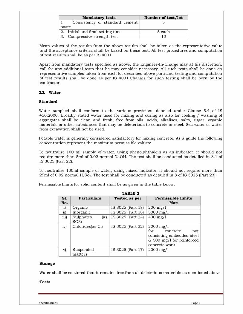
Following tests shall be conducted at site on each lot of cement delivered if required as per the instructions of Engineer – In – Charge.
TABLE 1
Specifications Page 7
Mandatory tests Number of test/lot 1 Consistency of standard cement paste
5
2. Initial and final setting time 5 each
3. Compressive strength test 10
Mean values of the results from the above results shall be taken as the representative value and the acceptance criteria shall be based on these test. All test procedures and computation
of test results shall be as per IS 4031.
Apart from mandatory tests specified as above, the Engineer-In-Charge may at his discretion, call for any additional tests that he may consider necessary. All such tests shall be done on representative samples taken from each lot described above para and testing and computation
of test results shall be done as per IS 4031.Charges for such testing shall be born by the contractor.
3.2. Water
Standard Water supplied shall conform to the various provisions detailed under Clause 5.4 of IS 456:2000. Broadly stated water used for mixing and curing as also for cooling / washing of
aggregates shall be clean and fresh, free from oils, acids, alkalises, salts, sugar, organic materials or other substances that may be deleterious to concrete or steel. Sea water or water from excavation shall not be used. Potable water is generally considered satisfactory for mixing concrete. As a guide the following
concentration represent the maximum permissible values: To neutralize 100 ml sample of water, using phenolphthalein as an indicator, it should not
require more than 5ml of 0.02 normal NaOH. The test shall be conducted as detailed in 8.1 of IS 3025 (Part 22).
To neutralize 100ml sample of water, using mixed indicator, it should not require more than 25ml of 0.02 normal H2So4. The test shall be conducted as detailed in 8 of IS 3025 (Part 23).
Permissible limits for solid content shall be as given in the table below:
TABLE 2
SI. No.
Particulars Tested as per Permissible limits Max
i) Organic IS 3025 (Part 18) 200 mg/l
ii) Inorganic IS 3025 (Part 18) 3000 mg/l
iii) Sulphates (as SO3)
IS 3025 (Part 24) 400 mg/l
iv) Chlorides(as Cl) IS 3025 (Part 32) 2000 mg/l for concrete not consisting embedded steel
& 500 mg/l for reinforced concrete work
v) Suspended matters
IS 3025 (Part 17) 2000 mg/l
Storage
Water shall be so stored that it remains free from all deleterious materials as mentioned above.
Tests
Specifications Page 8
No water shall be used until tested for its chemical and other impurities in accordance with IS 3025 to ascertain its suitability. Tests shall be conducted whenever the source is changed or during seasonal variation.
3.3. Mortar Mixing
Cement and sand in the specified proportion shall be mixed in dry thoroughly by using mechanical mixer or by hand mixing, if permitted. Composition (cement and sand mortar, or
lime and sand mortar or cement, lime and sand mortar) and proportions of mortars shall be as specified in the respective items of work. The ingredients of the mortar shall be accurately gauged by measure.
Precaution Mortar shall be used as soon as possible after mixing and before it begins to set, and in any case within half hour, after the water is added to the dry mixture.

Specifications Page 9

Specifications Page 10
4. STEEL WORKS:
4.1. Structural Work in built-up section (Welded/ bolted)
Although Broad Specifications for Structural Steel Works are as indicated below, the entire work shall be executed strictly in keeping with the working methodology, sequence of
operations, safety and security etc. as approved by the Engineer-In-Charge, in best workmanship in conformity with relevant IS codes and the specifications of this tender document.
The Tenderer shall submit his own fabrication / erection methodology comprising sequence of operations to suit the works requirement such as –
• Material movement / storage of material
• Fabrication scheme considering space constraints
• Scheme for erection to be done at about 24 mtr. height for trusses
General In addition to the requirements contained in this Specification, all materials shall conform to the
latest edition of the relevant Indian Standard or its equivalent standard approved by the Engineer-In-Charge and shall, if required, be tested as prescribed therein.
In the event of conflict between this Specification and recognised standards, then the requirement of this Specification shall govern.
The work shall be carried out by competent personnel skilled in their various trades. All work shall be of the highest quality and the work shall be the subject of inspection and approval of the
Engineer-In-Charge and the Employer. All material shall be obtained from an approved supplier and manufacturer's appropriate test
certificates shall be available upon request by the Engineer-In-Charge or the Employer. All Steelwork shall be straightened or curved as necessary by pressure and not by hammering.
When bolt heads or nuts bear upon bevelled surfaces they shall be provided with square
tapered washers to afford seating for the nut square with the axis of the bolt. All nuts and bolts specified on the Drawings shall be to the required size with correct threaded length, and be supplied with matching nuts and washers also of the same material, except where electrolytic action is to be avoided.
Where small parts such as bolts and nuts etc. are to be sherardised, they shall be treated to receive a coating of finished thickness not less than 30 microns.
Where bolts, nuts and washers etc. are to be hot dip galvanised, they shall be treated to receive a finished thickness of zinc coating of not less than 80 microns thickness.
The Contractor shall give due notice to the Engineer-In-Charge in advance of the materials or workmanship getting ready for inspection. The Engineer-In-Charge shall have free access at all reasonable times to those parts of the contractor’s work which are concerned with the fabrication of the steel work and those portions
of the site where assembly or erection is being carried out. The contractor shall give all reasonable assistance required in connection with the inspection and testing of the work.
No part of the work shall be treated as approved unless so informed by the Engineer-In-Charge in writing. However, approval of any material fabricated at shop / field shall not invalidate final rejection at site by the Engineer-In-Charge if it fails to be in proper condition or has

Specifications Page 11
fabrication inaccuracies, which prevents proper assembly. Similarly any approval of the fabrication and / or erection by the Engineer-In-Charge shall not relieve the Contractor of his responsibility for furnishing material and / or workmanship conforming to the requirements of
the specifications. All sections shall be free from surface defects such as pitting, cracks, laminations, twists,
bends etc. The use of defective sections shall not be permitted and all such rejected material shall be immediately removed away from the store / site at contractor’s cost.
All sections shall be marked for identifications and each lot shall be accompanied by manufacturers quality certificate, chemical analysis and mechanical characteristics as specified in relevant IS Codes. Each lot of electrodes, bolts, nuts etc. shall be accompanied by manufacturer’s quality test
certificate conforming to relevant IS codes. Materials at the shops shall be kept clean and protected from weather.
All members likely to collect rain water shall have drain holes.
Not more than one shop shall be provided to make the full length of a member. All bolts, nuts, washers, rivets, electrodes, screws, etc. shall be supplied 10% in excess of the
requirement in each category and size. Materials - Unless specified other wise various materials shall conform to the following IS Codes and Standards –
• Structural steel ( Standard quality) : IS:226
• Rolled steel sections : IS: 808
• Steel tubes for structural purpose : IS: 1161
• Structural steel (for walkways, ladder, hand rails) : IS: 1977
• Welded Electrodes : IS: 811
• Threaded fasteners : IS 1367 Supply
Supply of structural steel and all required material for the works shall be arranged by the Contractor.
Receipts and storing of materials
All steel shall be carefully off-loaded and stacked on timber or concrete supports suitably spaced on a firm level surface, and of sufficient height to keep steel clear of the ground and water. The steel shall be stored separately, by section size or thickness.
All sections shall be checked, sorted out and arranged by grade and quality in the store as per instructions of the Engineer-In-Charge. All bolts including nuts and washers shall be thoroughly checked, sorted out and arranged diameter wise by grade and quality in the store.
All materials shall be kept protected from corrosion. Storing shall be generally in accordance with IS: 4082.
Welding electrodes and welding wires if used shall be stored separately in their original
bundles or cartons, in a dry place adequately protected from weather and other effects as per IS :9595 and as per instructions given by Engineer-In-Charge. Electrodes shall be kept dry.
Specifications Page 12
Shop Drawings If instructed by Engineer – In – Charge, the Contractor shall prepare all the fabrication and erection drawings for the structural steel work. These shall be prepared on the basis of the Engineer’s design drawings ‘released for preparation of shop drawings or approved for
construction (AFC) drawings and shall be used for further work on the written approval to these drawings by the Engineer-In-Charge to the Contractor. Such approval shall constitute approval of the size of members, dimensions and general arrangement but shall not constitute
approval of the connections between members and other details. Furthermore any approval shall not relieve the Contractor from the responsibility for correctness of engineering, design of connections, workmanship, fit of parts, details, materials, errors or omissions of any and all work shown thereon.
The Contractor should check for erection clearance and ensure that detailing of connections is carefully planned to obtain ease in erection of structures, including field welded connections and bolting. Particular care is required when detailing joints with the use of high strength
friction grip bolts as this involves clearances for use of sockets with torque wrench. The contractor shall submit design calculations for substitution, if any and for the connection
details proposed by him. The fabrication drawings shall be revised by Contractor to reflect all revisions in design
drawings as and when such revisions are made by the Engineer-In-Charge. The revised fabrication drawings shall be submitted to the Engineer-In-Charge for approval. Only approved and marked for construction drawings with appropriate revisions marking drawings
shall be used for carrying out the fabrication work. Unchecked, unsigned and drawings without any stamp of (AFC) shall not be used for the purpose of proceeding with the work. If it is found that the contractor has not adhered to these stipulations, the fabrication work shall
be liable for rejection.
The details regarding the reproducible, number of prints to be furnished etc. shall be as per the tender provisions.
Laying Out As shown on drawings or as directed by the Engineer-In-Charge.
Fabrication Standard All fabrication shall be done strictly as per the (AFC) drawings with latest revision in
accordance with IS: 800 (Code of Practice for use of Structural Steel in general Building Construction) and IS: 1915 (Code of Practice for Steel Bridges) and also in accordance with IS:
9595 and other relevant IS Codes and ISI Hand book SP-6 (1), subject to approval of the Engineer-In-Charge.
No holes or notches shall be made in the steel work other than those shown on the drawings without approval of the Engineer-In-Charge. Similar approval must be obtained prior to the enlargement of any hole.
The butting end of members shall be faced in a milling or ending machine after the members have been completely fabricated so as to butt in close contact over the entire surface.
Templates
Extensive use of templates shall be made. The templates shall be steel bushed where considered necessary by the Engineer-In-Charge. In case actual members are used as templates for drilling similar pieces it will be at the discretion of the Engineer-In-Charge to

Specifications Page 13
decide whether such pieces are fit to be incorporated in the finished structure. The Contractor shall arrange for corresponding parts of each unit manufactured from the same drawings, to be interchangeable, as far as economic manufacturing conditions permit and shall advise the
Engineer-In-Charge of the precise arrangements made in this respect.
Connections Shop/field connections shall be effected either by welding or by high strength friction grip bolts as specified. High tensile bolts shall be used for field connections and standard MS bolts
conforming to IS: 1363 may be used for field connections for light members such as purlins, girths, staircase stringers and landing beams or for other connections also, if permitted by the Engineer-In-Charge. Where necessary, tapered washers or flat washers or spring washers shall be used with bolts.
In case of high strength friction grip bolts, hardened washers shall be used under the nuts or the heads depending upon whether the nuts or the heads are turned to tighten the bolts. The length of the bolts shall be such that at least one thread of the bolt projections beyond the nut
except in case of high strength friction grip bolts where this projection shall be at least three times the thread pitch.
All connections and splices shall be designed for full strength of members or loads indicated unless otherwise approved.
All connections shall be precisely shown on the drawings and shall be strong enough to develop the full strength of the member and shall be subject to the approval of the Engineer-In-Charge.
All field connections shall be made with black steel bolts. All surfaces of steel and bolts shall be entirely free of paint, lacquer or other protective substance. All shop connections shall be
welded as approved by the Engineer-In-Charge. As far as possible, it should be ensured to have down hand welding for all shop joints.
In all cases where bearing is critical, the unthreaded bolt shall bear on the members assembled. A washer of adequate thickness may be provided to exclude the threads from the
bearing thickness, if no longer grip bolt has to be used for this purpose. Column splices shall be designed for the full tensile strength of the minimum cross section at the splice. Unless otherwise noted, beam end connections shall be designed for 60% of the shear capacity of the beam section plus additional axial forces, if any, shown on the Engineer’s design drawings. Materials at the shops shall be kept clean and protected from weather.
Not more than one shop splice shall be provided to make the full length of a member.
All bolts, nuts, washers, rivets, electrodes, screws etc. shall be supplied 10% in excess of the requirement in each category and size.
Straightening All material shall be straight and if necessary shall be straightened and/or flattened by pressure, unless required to be of curvilinear form and shall be free from twists. Straightening will be done by methods that will not injure the materials. Long plates shall be straightened by
passing through a mangle or levelling rolls and structural shapes by hydraulic or mechanical bar straightening machines. Heating of rolled sections and plates for purposes of straightening shall not be permitted. Limited applications of heat with a gas-torch shall be permitted on
approval of Engineer-In-Charge in writing. Sharp kinks or bends shall be the cause for rejection.
Rolling and Forming

Specifications Page 14
Plates for circular structural members shall be accurately laid off and rolled or formed to required profile/shape as called for on the drawings. Adjacent sections shall be match-marked to facilitate accurate assembly, welding and erection in the field.
Cutting Rolled sections shall be sawed or milled to length. Small plate pieces like gussets may be sheared or cropped to size. Sawing, shearing and cropping shall be clean, reasonably square and free from any distortion. All re-entrant corners shall be shaped notch-free to a radius of at
least 12mm. Gas-cutting shall preferably be done by a mechanically guided torch. Hand flame cutting may, however, be permitted where the part being cut shall not be subjected to substantial tensile stresses and only when approved by the Engineer-In-Charge. Gas-cut edges shall be free of
gouges. Any gauges that remain after cutting shall be removed by grinding. Gas-cutting shall normally only be permitted for mild steel though gas cutting of high tensile
steel may also be permitted, provided special care is taken to leave sufficient metal to be removed by machining so that all metal that has been hardened by flame is removed except where the material is subsequently joined by welding, no loading shall be transmitted into
metal through a gas cut surface. Edge plaining of sheared, cropped or gas cut edges is not intended unless the edges warrant
such plaining or is specifically called for by the Engineer-In-Charge. Punching shall not be resorted to unless previously approved by the Engineer-In-Charge.
Where permitted in secondary members such as purlins, side sheeting runners, packing plates and lacing bars, holes may be punched full size through material not over 12 mm thick except where required for close tolerance bolts or barrel bolts. Holes must be clean cut, without burr
or ragged edges. Holes through more than one thickness of material (e.g. compound stanchions and girder flanges) shall be drilled after assembling and tightly clamping or bolting the
members together. The various thickness shall then be separated, burrs formed by the drill removed and the members reassembled.
Sub-punching may be permitted before assembly provided the holes are punched 3 mm less in diameter than the required size and reamed after assembly to the full diameter. The thickness of material punched shall not exceed 16 mm. Holes for all other connections shall be drilled accurately and burrs removed effectively.
Punching shall not be adopted for dynamically loaded structure or its part. Holes for bolts shall not be more than 1.5 mm larger in diameter than the nominal diameter of
the bolt. Holes for turned and fitted bolts shall be drilled to a slightly smaller diameter and remade to a diameter equal to the nominal diameter of the shank or barrel. This shall be
subject to tolerance specified in IS 919. Parts to be connected with close tolerance or barrel bolts shall be firmly held together by tacking bolts or clamps and the holes drilled through one operation shall be drilled to a smaller size and reamed out after assembly. Where this is not
possible the parts shall be drilled and reamed separately. Where reamed members are taken apart for stripping or handling, the respective pieces reamed
together shall be so marked that they may be reassembled in the same position in the final setting up. No interchange of reamed parts will be permitted.
Gas-cutting of holes shall be strictly prohibited. Poor matching, over drilling and ovality in holes shall be a cause for rejection.
When batch-drilling is carried out in the operation through two or more separable parts, these parts shall be separated after drilling and the burrs removed.

Specifications Page 15
Machining Column splices and butt joints of struts and compression members depending on contact for
load transmission shall be accurately machined and close butted over the whole section with a tolerance not exceeding 0.2mm locally at any place.
In column caps and bases, the ends of shafts together with attached gussets, angles, channels, etc. after welding together shall be accurately machined so that the parts connected, butt over the entire surfaces of contract. In no case the parts connected butt less than 90% of the
surface of contract. Care shall be taken that these connecting angles or channels are fixed with such accuracy that they are not reduced unduly in thickness in machining. Ends of all bearing stiffeners shall be machined or ground to fit tightly at both top and bottom.
Where sufficient gussets or welding are provided to transmit the entire loading, the column ends need not be machined.
Splicing Splicing of built up/compound/latticed sections shall be done in such a fashion that each
component of the section is joined in a staggered manner. Where no butt weld is used for splicing, the meeting ends of two pieces of joist/channel/built
up section shall be ground flush for bearing on each other and suitable flange and web splice plates shall be designed and provided for the full strength of the flange/web of the section and welds designed accordingly.
Where full strength butt weld is used for splicing (after proper edge preparation of the web and flange plates) of members fabricated out of joist/channel/built up section, additional flange
and web plates shall be provided, over and above the full strength butt welds, to have 40 % strength of the flange and web.
Where a cover plate is used over a joist/channel section the splicing of the cover plate and channel/joist sections shall be staggered by minimum 500 mm. Extra splice plate shall be
used for the cover plate and joist/channel section as per provision of relevant IS Codes. Bolting All turned and fitted bolts shall be parallel throughout the barrel and within the tolerance of only minus (-1/8) mm. unless otherwise specified and faces of heads and nuts bearing on steel
work shall be machined. All such bolts shall be provided with washers not less than 6 mm thick so that when the nut is tightened, it shall not bear on the unthreaded body of the bolt. In all cases, where the full bearing area of the bolt is to be developed, the threaded portion of
the bolt should not be within the thickness of the parts bolted together. The threaded portion of each bolt shall project through the nut by at least one thread. Tapered washers of suitable
thickness shall be provided for all heads and nuts to afford a seating square with the axis of the bolt.
4.2. Welding
Welding shall generally be done by electric arc process and shall conform to the respective IS Codes and Standards as listed above.
Welding Procedures The Contractor shall make necessary arrangement for providing sufficient number of welding sets of required capacity, all consumables, cutting & grinding equipment with requisite accessories/auxiliaries, equipment etc.

Specifications Page 16
The Contractor shall submit the welding procedure for each type of joint for the approval of the Engineer-In-Charge and shall ensure that copies of the same are at all times, readily available to the welders employed on the Works. The procedure shall include all details with reference to
provisions of IS 823 and IS 4353. It should be specifically ensured that filter glass used in welding helmets shall be of internationally accepted quality and make.
The welding procedure shall be such as to ensure that the weld metal can be fully and satisfactorily deposited throughout the length and thickness of all joints and that distortion and shrinkage stresses are reduced to a minimum and that the welds meet the requirements of
quality specified. Welding plant and accessories shall have capacity adequate for the welding procedure laid down and shall satisfy appropriate standards and be of approved make and quality. The Contractor shall maintain all welding plants in good working order. All the electrical plant in
connection with the welding operation shall be properly and adequately earthed and adequate means of measuring the current shall be provided.
Welding of various materials under this specification shall be carried out using one or more of the following processes –
a) Manual metal arc welding process (MMAW) b) Submerged arc welding process (SAW)
Submerged arc, automatic or semi-automatic welding shall be generally be employed. Only where it is not practicable to use submerged arc welding, manual arc welding maybe resorted to.
Voltage and current (and polarity if direct current is used) shall be set according to the recommendations of the manufacturer of the electrode being used and suitability to thickness
of material, joint form etc. Adequate means of measuring the current shall be available either as part of the welding plant or by the provision of a portable ammeter. In checking the welding
current, a tolerance of 10% or 30 Amperes from the specified value whichever is less shall be permitted.
The welding procedure adopted and the consumables used shall be specifically approved by Engineer-In-Charge. Welding electrodes used shall conform to IS : 814 (latest) and shall be supplied by manufacturer approved by the Engineer-In-Charge. Any electrode which has part of its flux coating broken or is damaged shall be rejected. No welding shall be done on base metal at a temperature below 5 Deg. C. Base metal shall be
preheated as required to the temperature given in the table below prior to tack welding or welding. When base metal not otherwise required to be preheated is at a temperature below 0 deg. C, it shall be preheated to at least 20 Deg. C prior to tack welding or welding. Preheating
shall be done of the surface of the base metal on which the weld metal is being deposited within 75 mm on each side of the point of welding to the specified preheated temperature and
this temperature shall be maintained as minimum inter-pass temperature while welding is in progress. The temperature shall be measured on the face opposite to that heated. However there is access to only one face, the heat source shall be removed to allow for temperature
equalization (one minute for each 25 mm of plate thickness) before measuring the temperature.
TABLE - 14
Thickness of Minimum preheat and inter-pass temperature

Specifications Page 17
thickest part at point of welding
Other than low hydrogen welding
electrodes
Low hydrogen welding electrodes
IS:226 steel or IS:2062 steel
IS: 961 steel
IS:226 steel, IS
2062 steel
IS: 961 steel
Upto 20 mm. None Welding with this
process not
allowed
None 10 Deg. C
Over 20 mm. to 40 mm. incl.
65 Deg. C 10 Deg. C 65 Deg. C
95 Deg. C 110 Deg C Over 40 mm. to 63 mm. incl.
110 Deg. C 110 Deg. C 65 Deg. C
Over 63 mm 150 Deg. C
Welding shall be done with the structural in flat position in a down hand manner wherever possible. Adequate care shall be taken to maintain the current and polarity for the type of electrode used and nature of work.
No welding shall be done when the surface of the members is wet nor during periods of high
wind unless the welding operation and the work are properly protected. Before commencing fabrication of member or structure in which welding is likely to result in
distortion and/or locked up stresses, a complete programme of fabrication, assembly and welding shall be made and submitted to the Engineer-In-Charge for approval. Such a programme shall include besides other appropriate details, full particulars in regard to the
following: a) Proposed pre bending in components such as flanges and presetting of joints to offset
expected distortion. b) Make up of sub-assemblies proposed to be welded before incorporation in the final
assembly. c) Proposed joint forms, classification of wire and flux or covered electrodes, welding
process including fitting and welding sequence with directions in which freedom of movement is to be allowed.
d) Proposed number, spacing and type of strong backs and details of jigs and fixtures for maintaining proper fit up and alignment during welding.
e) Any other special features like assembling similar members back to back or stress relief.
Sequencing of welding a) The contractor shall choose the welding sequence after carefully studying each case such
as to minimize distortion and shrinkage and submit the same to the Engineer-In-Charge for comments and approval.
b) As far as practicable, all welds shall be made in sequence that will balance the applied heat of welding while the welding progresses.
c) The direction of the general progression in welding on a member shall be from points where
the parts relatively fixed in position with respect to each other towards points where they have a greater relative freedom of movement.
d) All splices in each component part of a cover-plated beam or built up member shall be made before the component part is welded to other component parts of the member.
Specifications Page 18
e) Joints expected to have significant shrinkage shall be welded before joints expected to have lesser shrinkage.
f) Welding shall be carried continuously to completion with correct number of runs.
Preparation of fusion faces Preparation of fusion faces shall be done in accordance with the approved fabrication drawings by shearing, chipping, machining or gas cutting (except that shearing shall not be used for
thickness over 8 mm). The faces shall be smooth, uniform and free from irregularities such as fins, tears, laminations etc. as would interfere with the deposition of the specified size of weld to be the cause of defects. Surfaces to be welded shall be free from loose scale, slag, rust, grease, paint, moisture and any
other foreign material, which might affect the quality of weld. Surfaces shall be wire-brushed vigorously or machined/ground, if found necessary by the Engineer-In-Charge.
Welding of joints shall be undertaken only on approval by the Engineer-In-Charge of the alignment, levels etc. of the members to be jointed.
Gaps for Joints Parts to be fillet welded shall be brought in as close contact as possible and in no event shall
they be separated by more than 1.5 mm. In case of a gap of more than 1.5 mm the size of the fillet weld shall be increased by the amount of the gap. A gap greater than 3 mm. wide shall be packed with MS shims and the weld increased by the amount of the gap.
Abutting parts to be butt welded shall be carefully aligned together within a gap of 3 mm and correct root gap shall be maintained throughout the welding operation.
Gaps shall be set by means of suitable jigs and the steel work held firmly in position by clamps
or bolts until the welded joint is sufficiently rigid to be freed of clamps without causing strain or distortion.
Misalignment greater than 25 percent of the thickness of the thinner plate or 3 mm. whichever is smaller shall be corrected and in making the correction the parts shall not be drawn into a slope sharper than 2 Deg. (1 in 27.5)
Fillet Welds
The minimum leg length of a fillet weld as deposited should not be less then the specified size and the throat thickness as deposited should not be less than that tabulated below –
Angle between fusion faces Throat thickness
60 Deg. C 90 Deg. C 48 mm
91 Deg. C 100 Deg. C 16.5 mm
101 Deg. C 106 Deg. C 15 mm.
107 Deg. C 113 Deg. C 14 mm
114 Deg. C 120 Deg. C 12.5 mm.
In no case should a concave weld be deposited without the specific approval of the Engineer-In-Charge unless the leg length is increased from the above specified so that the resultant throat thickness is as great as would have been obtained by the deposition of a flat. Welding
sequence should be such as to have minimized shrinkage stresses. After each run of weld, all slag shall be removed and final run shall be protected by clean boiled linseed oil till approved.
Butt Welds

Specifications Page 19
All main butt welds shall be full penetration butt welds, unless otherwise specified with complete fusion of the root edges. The ends of the welds shall have full throat thickness. This
shall be obtained on all main welds by use of extension pieces adequately secured on either side of the main plates. Additional metal remaining after the removal of the extension pieces shall be removed by machining or by other approved means and the ends and surfaces of the
weld shall be smoothly finished by machining or other approved means. Where the abutting parts are thinner than 20 mm, the extension pieces may be omitted but the ends of butt welds shall then be chipped or gouged out to sound metal and side welded to fill up the ends to the
required reinforcement.
Quality of Weld The weld metal as deposited shall be free from blow holes, cracks, slag inclusions, excessive
porosity, cavities and other faults. It shall be properly fused with the parent material without overlapping or serious under-cutting at the toes of the weld. The weld surfaces shall be cleaned of slag or flux and show a uniform and consistent contour and regular appearance.
Faulty Works
In the event of excessive convexity, weld size is to be reduced by removing the excess weld metal. In the event of faulty work the defective portions shall be cut out and re-welded. Where serious under-cutting occurs, additional weld metal shall be deposited to make good the
reduction. In case of members getting distorted due to heat of welding, the members are to be straightened out by mechanical means or by careful applications of limited amount of heat when temperature of the areas affected more than 650 C.
Protection
Immediately after dislodging, inspection and approval, all site welds and the surrounding surfaces shall be painted to protect the metal.
Tolerances The dimensional and weight tolerances for rolled shapes shall be in accordance with IS: 1852 and/or ASTM A6. No rolled or fabricated member shall deviate from straightness by more than 1/1000 of the axial length or 100 mm whichever is smaller.
The length of members with both ends finished for contact shall have a tolerance of ± 1 mm. Members without ends finished for contact bearing shall have a tolerance of ± 1.5 mm for
members upto 10 meters long and a tolerance of ± 3 mm for members over 10 meters in length.
Lateral deviation between centre line of web plate and centre line of flange plate at contact surface in the case of built up sections shall not exceed 3mm.
The combined warp age and tilt of flanges in welded built up sections shall not exceed 1/200th of the flange width or 3 mm whichever is smaller.
The deviation from flatness of welded plate girder web in the length between stiffeners or a length equal to the depth of the girder shall not exceed 1/150th of such length.
Deviations from the specified depth of welded girders measured at the centre line of the web shall not exceed ± 3 mm upto a depth of 1000 mm, ± 5 mm for depths above 1000mm, upto
2000mm and + 8mm and – 5mm for depths over 2000mm.

Specifications Page 20
4.3. Inspection and testing of weld:
The Contractor shall carry out procedure tests in accordance with IS: 7307 to demonstrate by means of a specimen weld of adequate length on steel sample of that to be used that he can
make welds with the welding procedure to be used for the work for the complete satisfaction of the Engineer-In-Charge. The test weld shall include weld details from the actual construction and it shall be welded in a manner simulating the most unfavourable instances of fit-up,
electrode condition etc. which are anticipated to occur on the particular fabrication. Where material analysis are available, the welding procedure shall be carried out on material with the highest carbon equivalent value.
After welding, but before the relevant tests given in IS: 7307 are carried out, the test weld shall be held as long as possible at room temperature, but in any case not less than 72 hours and shall then be examined for cracking. The examination procedure shall be sufficiently rigorous to be capable of revealing significant defects in both parent metal and weld metal.
After establishing the welding method, the Contractor shall finally submit to the Engineer-In-Charge for his approval the welding procedure specification in standard format given in IS:
9595 before starting the fabrication. Approval to the welding procedure by the Engineer-In-Charge shall not relieve the Contractor
of his responsibility for correct and sound welding without undue distortion in the finished structure.
The Contractor shall satisfy the Engineer-In-Charge that the welders are suitable for the work upon which they shall be employed. For this purpose welders shall have satisfied the relevant requirements of IS 7318. If the welders shall be working to approved welding procedures, they
shall have satisfied the relevant requirements of IS 7310. Unless specified otherwise, inspection of steel work shall be made at the place of manufacture
prior to dispatch and shall be conducted so as not to interfere unnecessarily with the operation of the work. Stage inspection during the progress of the work shall be carried out during final
assembly and erection at the Site.
The method of inspection shall be according to IS: 822 and extent of inspection and testing
shall be in accordance with the relevant application standard or in the absence of such a standard as specified by the Engineer-In-Charge. Welds shall not be painted or otherwise obscured until they have been inspected, approved and accepted. The Engineer-In-Charge or his representative shall have access to the Contractor’s work at all reasonable times and the Contractor shall provide him with all facilities necessary for
inspection during all stages of fabrication and erection with but not limited to the following: i) To check the conformity with the relevant standards and suitability to various welding
equipments & their performance
ii) To witness/approve the welding procedure qualification. iii) To witness/approve the welders performance qualification.
iv) To check whether shop/field welding being executed is in conformity with the relevant
specifications and codes of practice.
All welding shall be subject to inspection and tests as specified by the Engineer-In-Charge.
The Engineer-In-Charge may require test plates to be prepared in accordance with IS: 1181 “Qualifying Test for Metal Arc Welding (Engaged in welding structures other than pipes)”. At main butt welds, these may be taken from plates cut from extensions of the main plates and
fixed as extensions at the butt joints, so that the direction of rolling is parallel to that of the main plates and the welds continuous with the main welds.
Specifications Page 21
The Engineer-In-Charge may require radiographic tests and ultrasonic tests to be carried out to check full strength butt welds at contractor’s cost. These shall be in accordance with the
recommended U.W. 51 of ASME Code Section VIII. Other non-destructive tests could be as follows –
Magnetic Particle Test This is carried out to examine the root and intermediate passes of weld in accordance with the
following as decided by the Engineer-In-Charge –
• ASTM Specification. E-109
• ASTM Specification E-138 If heat treatment is performed, the completed weld shall be examined after the heat treatment. Magnetic particle test shall be carried out using alternating current. Direct current may be
used with the permission of the Engineer-In-Charge.
Liquid Penetrate Inspection In the case of welds examined by Liquid Penetrate Inspection, such tests shall be carried out in accordance with ASTM-E-165 or IS: 3658.
The above tests are generally not required to be carried out but if and when required, they
shall be paid done as specified at contractor’s cost.
Radiography Test Ultrasonic Testing
(a) Testing of welds shall be undertaken by an independent accredited testing authority selected by the Contractor and approved by Engineer-In-Charge. The Contractor shall be responsible for all costs of such testing. All welds shall be tested as specified.
(b) The Contractor shall inspect each welded joint & they shall be inspected for edge fusion
and the possibility of cracking. Testing of welds shall be by ultrasonic examination and
they shall be carried out by the Contractor in accordance with standards to the approval of the Engineer-In-Charge. The Engineer-In-Charge shall have the opportunity
to witness any or all of the tests. The Contractor shall give adequate prior notice before the commencement of any tests. All ultrasonic operators shall be fully qualified, and each weld shall be examined with sufficient probe angles to guarantee full coverage of
the joint. (c) The Contractor shall produce a test report for each weld joint or weld repair examined,
comprising: � a sketch of all flaws � the location and size of each flaw
� dB level used � conclusions as to acceptance or rejection of the flaw with reference to these requirements
(d) The Engineer-In-Charge along with the Contractor shall make an initial assessment of defects against acceptance criteria. All ultrasonic reports including recommendations shall be reviewed by the Engineer-In-Charge. Acceptance criteria shall be in accordance
with the approved standard. The standard on which the slag indication acceptability is to be finally determined and this is to be agreed and confirmed prior to any ultrasonic
testing. When positive flaw type interpretations cannot be ascertained in any instance, the flaw shall be considered planar and in need of repair.

Specifications Page 22
4.4. Assembly
Steel work shall be temporarily shop-erected completely or as directed by the Engineer-In-Charge, so that the accuracy of fit may be checked before dispatch. Due notice shall be given
to the Engineer-In-Charge in all cases when the work is ready for inspection and the assembly shall not be dismantled until it has been inspected and approved by the Engineer-In-Charge. However, such approval shall not relieve the Contractor of his responsibility for carrying out a
precise job in a workmanlike manner. The parts shall be assembled with a sufficient number of parallel drifts to bring and keep the components in place. In the case of parts drilled or punched through steel jigs with bushes resulting in similar parts being interchangeable for
portions of the steel work, trial assembly shall be carried out to the extent required by IS: 1915. All steel work, which is bolted together, shall be in perfect contact over the whole surface. All bearing stiffeners shall bear tightly at top and bottom without being drawn or caulked. When
two bolted surfaces are to be in permanent contact after assembly, each shall be thoroughly scraped to remove loose scales, dirt, burrs and any foreign matter and cleaned and dried and a coat of yellow zinc chromate or other approved primer paint shall be applied after cleaning and
drying. The surfaces shall be brought together while the paint is still wet. Drilling done during assembly shall not distort the metal or enlarge the holes. Holes that must
be enlarged due to miss-matching shall be reamed. Poor matching of holes shall be cause for rejection. Enlarging of holes with gas trench shall not be allowed. Enlargement of holes by gas trench shall be cause for rejection.
Erection
All structural steel work shall be erected in accordance with IS: 800 and IS: 1915.
Detailed Scheme The Contractor shall furnish a detailed scheme for erection of structural steel work for the
approval of the Engineer-In-Charge. Such scheme shall indicate the type, capacity and the quality of equipment that the Contractor proposes to deploy for handling, hoisting and erecting the steel work including staging, temporary bracing, guying etc. The scheme shall also
indicate the strength and trade-wise composition of the work force and supervising personnel that the Contractor would deploy on the job. The scheme shall be accompanied by a layout plan identifying the areas proposed for unloading, main storage, subsidiary storage, assembly and the transportation of equipment and fabricated materials between the storage and work areas. The layout shall clearly indicate
the points at which proposed erection begins, the directions in which it is proposed to progress, the deployment of equipments etc. The locations and extent of site offices and stores, labour quarters if any, layout of electrical cables and water pipes from the tap-off points
indicated on drawings shall also be indicted in detail on the above layout.
Any modifications to the erection programme directed by Engineer-In-Charge for the reasons of inadequacy of the quality and/or capacity of the erection equipment, temporary bracing, guying etc. or safety of the erection methods or stability of the erected portions of structures or
unsuitability of the erection sequence due to interference with the work of other shall be incorporated by the Contractor and the work shall be carried out in accordance with the revised programme. The approval by Engineer-In-Charge shall not relieve Contractor from his
responsibility for the safe, sound, accurate and timely erection of structural steel work as required by the Engineer-In-Charge. The Contractor shall be deemed to have visualized all erection problems prior to submission of bid documents for the work and no additional
compensation shall be claimed on this account. The Contractor shall fully mobilize at site prior to the actual operation of erection commences
at site. Such mobilization shall include items like establishment of offices, stores, unloading gantry / handling equipments, labour quarters if any, electrical and water connections,
Specifications Page 23
compressors, all tools and tackle, rivet guns, welding sets, torque wrenches, spud wrenches, non-inflammable staging as a part of his contract and any other work that may be necessary to start the erection work. The passageways, fences, safety belts, helmets, lights and other fittings
to be to the satisfaction of Engineer-In-Charge and to meet the rules of local authorities and for protection of his men and materials. A licensed electrician shall be kept on the job for full period to maintain the Contractor’s electrical equipment and connection.
The Contractor shall protect all existing plant structures, piping, conduits, equipment and facilities against any damage during erection. Any damage caused by the Contractor shall be
rectified entirely at the Contractor’s cost to the satisfaction of Engineer-In-Charge. When lifting and fitting steel work in position, care shall be taken that the parts thereof are not strained, twisted, bent or damaged in any manner whatsoever. Should any part be strained, twisted, bent or damaged, it shall be reinstated in a manner approved by the Engineer-In-
Charge by gentle heating & bending & not by hammering. Any parts that are badly damaged shall be replaced with new materials at the Contractor’s expense.
No permanent bolting or welding shall be done until proper alignment has been obtained and approved by the Engineer-In-Charge.
Any errors in the fabrication, which prevent the proper assembling and erection of the parts with moderate amount of reaming, chipping or cutting is likely to render the steel work for rejection unless corrective action, only if permitted by the Engineer-In-Charge, is taken. Any
expenditure involved in executing the corrective measures shall be borne by the Contractor. All erection holes shall be plugged either by weld or bolts, nuts, washers shall be provided as
directed by the Engineer-In-Charge, without extra cost. The Contractor shall be responsible for accurately positioning, levelling and plumbing of all
steel work and placing of every part of the structure in accordance with the approved fabrications drawings to the entire satisfaction of Engineer-In-Charge.
Dispatch of materials stacking and handling
Each structural member either knocked down or a single composite each loose item (like splices pack plates etc.) shall have “Mark number” painted on each item before it is dispatched from the SHOP. The Contractor shall deliver the fabricated steel work to the site as far as possible in the same sequence as that which he wishes to allow for the erection. Dispatches should be scheduled to
avoid clustering up of the site.
Transportation Loading & transportation shall be done in compliance with transportation rules. In case
certain parts can not be transported in the lengths stipulated in the drawings the position and type of additional splice joints shall be got approved by the Engineer-In-Charge.
The bolts required for erection shall be bagged according to size prior to dispatch. The Contractor shall ensure that steel work is not damaged due to careless or haphazard
stacking. The steel work shall be stacked at site in such a manner that it shall be free from dirt, oil and other injurious elements and erection marks remain visible. Stacking shall, as far as practicable be done in the sequence of erection but heavy members shall not be stacked on
top of light ones. Material shall also not be stacked in the vicinity of excavations for pits, foundations etc. already done or proposed to be done.
Arrangement shall always be made at the time of handling to make sure that damage to steel work is avoided. No dragging of steel shall be permitted.

Specifications Page 24
Scratched or abraded steel shall be given a coat of yellow zinc chromate primer prior to erection. All milled and machined surfaces shall be properly protected from rust/corrosion by suitable coating and also from getting damaged. In the event of damage due to improper
stacking and careless handling, the damaged piece will be rejected and shall be replaced by the Contractor at his own expense.
Precautions All operations connected with welding and cutting equipment shall conform to the safety
requirements and Health Provisions in Electric and Gas welding and cutting operations.
Safety & Security during erection The Contractor is entirely responsible for the safety and stability of the structure during
erection. The Contractor shall comply with IS: 7205 for necessary safety and adhere to safe erection
practices and guard against hazardous as well as unsafe working conditions during all stages of erection.
During erection, the steel work shall be securely bolted or otherwise fastened and when necessary temporarily braced/guyed till the completion including those due to the wind, erection equipment and its operation etc. For the purpose of guying, the Contractor shall not
use other structure in the vicinity. No permanent bolting or welding shall be done until proper alignment has been achieved.
Proper access, platform and safety arrangement shall be provided for working and inspection (at no extra cost) whenever required.
Erection Clearance and Tolerances Unless otherwise specified, the underside of base plates shall be within ±3 mm from the elevations shown on the drawing. The lateral deviations of the base plates shall not exceed 5
mm from the theoretical centre line. Maximum permissible erection tolerance A) Columns
1 Deviation of column axes at foundation top level with respect to true axes.
i) In longitudinal direction ii) In lateral direction
± 5 mm ± 5 mm
2 Deviation in the level of bearing surface of
columns at foundation top with respect to true level
± 5 mm
3 Out of plumbness (verticality) of column axis
from true vertical axis as measured at top
i) Upto and including 30 m. height ± H or ± 25 mm
1000 whichever is less
ii) Over 30 m. height ± H or ± 35 mm
1200 whichever is less
4 Deviation in straightness in longitudinal & transverse planes of column at any point along the height.
± H or ± 10 mm 1000 whichever is less
5 Difference in the erection positions of adjacent pairs of columns along length or
± 5 mm
Specifications Page 25
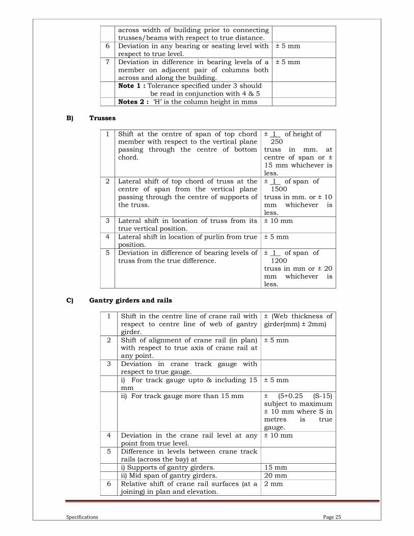
across width of building prior to connecting trusses/beams with respect to true distance.
6 Deviation in any bearing or seating level with
respect to true level.
± 5 mm
7 Deviation in difference in bearing levels of a
member on adjacent pair of columns both across and along the building.
± 5 mm
Note 1 : Tolerance specified under 3 should be read in conjunction with 4 & 5
Notes 2 : ‘H’ is the column height in mms
B) Trusses
1 Shift at the centre of span of top chord member with respect to the vertical plane passing through the centre of bottom
chord.
± 1 of height of 250 truss in mm. at
centre of span or ± 15 mm whichever is
less.
2 Lateral shift of top chord of truss at the centre of span from the vertical plane
passing through the centre of supports of the truss.
± 1 of span of 1500
truss in mm. or ± 10 mm whichever is less.
3 Lateral shift in location of truss from its true vertical position.
± 10 mm
4 Lateral shift in location of purlin from true position.
± 5 mm
5 Deviation in difference of bearing levels of
truss from the true difference.
± 1 of span of
1200 truss in mm or ± 20 mm whichever is less.
C) Gantry girders and rails
1 Shift in the centre line of crane rail with
respect to centre line of web of gantry girder.
± (Web thickness of
girder(mm) ± 2mm)
2 Shift of alignment of crane rail (in plan) with respect to true axis of crane rail at any point.
± 5 mm
3 Deviation in crane track gauge with respect to true gauge.
i) For track gauge upto & including 15 mm
± 5 mm
ii) For track gauge more than 15 mm ± (5+0.25 (S-15) subject to maximum ± 10 mm where S in metres is true
gauge.
4 Deviation in the crane rail level at any
point from true level.
± 10 mm
5 Difference in levels between crane track rails (across the bay) at
i) Supports of gantry girders. 15 mm
ii) Mid span of gantry girders. 20 mm
6 Relative shift of crane rail surfaces (at a joining) in plan and elevation.
2 mm

Specifications Page 26
Alignment of individual beams, girders etc. shall not deviate more than ±5 mm from the location given on the drawings.
The actual levels of trusses, collar beams, roofing beams, purlins etc. shall not vary more than 20mm. from their marked levels. The sweep of trusses, beams etc. in the horizontal plane shall
not exceed 1/1500 of their span, subject to a maximum of 10mm. The deviation of the upper chords of trusses from vertical plane through centres of supports shall be within 1/250th of the truss height. Deviation in spacing of purlins shall be within 5mm.
For Crane rail alignment, the maximum vertical and horizontal deviations permitted shall be ± 2 mm gauge variation shall also be ± 2 mm.
Anchor Bolts & Foundations:-
The holding down and anchor bolts shall conform to the requirements laid down in IS : 5624 or
as directed by Engineer-In-Charge. The Contractor shall carefully check the location and layout of anchor bolts / HD bolts embedded in foundations constructed to ensure that the structures can be properly erected as shown on the drawings. Any discrepancy in the anchor
bolts/foundations shall be reported to the Engineer-In-Charge. All tolerance shall be as per IS: 7215 unless stated otherwise.
Anchor bolts / HD bolts may be provided with three nuts on upper threaded portion, one of which may be used for levelling the column base to the required elevation and one will be a lock nut. All shims shall be supplied by the Contractor at his own cost.
During casting of concrete Contractor shall ensure that space between the bolts or bolts and sleeves is kept clean after removal of shuttering. Contractor shall fix timber plugs to maintain this space in a clean condition. The projecting threads of bolts shall be protected by approved
wrapping materials. A certain amount of cleaning of foundations and preparing the area is considered normal and shall be carried out by the Contractor at no extra cost.
Grouting under base plates
Grouting shall be done after erection and making proper alignment of the structural steel, unless otherwise approved by the Engineer-In-Charge. The Contractor shall furnish all
shims/pack plates/wedges etc. and level all base plates to the proper elevations as shown on the fabrication drawings before grouting as specified.
Contractor shall keep holes on the stanchion bases for escape of air. Unless specified the grout to be used in bases shall be proportioned to 1:2 cement / sand along with non-shrinkage agents of approved quality and dosage as recommended by the manufacturers & as approved
by Engineer-In-Charge & shall have a 28 days compressive strength of at least 300 kg/sq.cm. The grout mixture shall be poured continuously (without any interruption till completion) by grouting pumps from one side of the base plate. The pedestal/column surfaces, which are to
receive the grout shall be thoroughly cleaned of all dirt, mud, water, oil or other extraneous matter using compressed air immediately prior to the grouting operation. The grout shall be
carefully worked under the base plates and shall completely fill the space between the underside of the base plate and the concrete pedestal including voids around anchor bolts. If the bolt sleeves have been provided for the flexible positioning of bolts, neat cement grout of
heavy consistency along with non shrink additives of approved make shall be poured in the sleeves so as to completely fill the sleeve hole. After the grout has had its initial set, the grout shall be cut back flush with the base plate and the surplus grout shall be removed. Before
leaving the site, the Contractor shall re-tighten the nuts of all anchor bolts / H.D. bolts. The alignment of the structure shall now be rechecked and if found correct, the voids left by removal of shims/wedges/pack plates (if removed) shall be filled up with the same grout. If
serious misalignment is found after checking the alignment, the grout shall be removed completely and fresh grouting to be done as explained above after carrying out appropriate
Specifications Page 27
corrections to the alignment. All the form work should be made water tight to prevent the leakage from the joints.
4.5. Painting
Painting work shall be carried out in accordance with IS: 8629 (Parts I to III)
� All preparation, priming and painting, in colours selected by the Employer, shall be deemed to be included in the Contract price.
� Painting shall generally be in accordance with IS : 1477 � All items of equipment shall be suitably protected and packed to resist corrosion and impact
damage. Machined surfaces are to be treated with a proprietary sealing agent for transportation and storage.
� Paint materials shall be in accordance with the appropriate Indian Standard and shall be
obtained from approved manufacturers and applied in accordance with the manufacturers'
instructions or as ordered by the Engineer-In-Charge. All materials shall be delivered to the Site in sealed and labelled containers.
� The paint for each coat shall be from the same manufacturer, compatible with the underlying coat and shall be a different colour for ease of identification.
� Particular regard shall be paid to the maintenance of the recommended temperature and humidity during application and curing. Painted steelwork shall not be over coated or handled until the recommended curing period has elapsed. No finished paint coating will
be accepted until the specified dry film thickness has been achieved to the entire surface including edges.
� All steel surfaces shall be completely dry and free from oil and grease and all welds ground smooth and weld spatter removed. All fins at saw cuts, burrs and sharp edges shall be
removed, and the edges shall be rounded off. � For all painted items, the Contractor shall submit for approval a `Paint System Sheet' stating
full details of each paint system proposed indicating the following information, with reference to IS : 1477
− surface preparation
− system reference together with manufacturer's brand name and product reference
− dry film thickness
− colour
− time to repaint
Items to be painted
All structural steel work and metals including floor plates, floor gratings, stair treads, hand rails, brackets,trusses,columns and steel inserts shall be painted except if otherwise specified.
No black bolts, nuts, washers and welds shall be painted before assembly or erection and approved by Engineer-In-Charge. They shall be thoroughly cleaned and dipped into boiling
linseed oil and after erection, painted as specified herein. Standard The operations, workmanship, schedules and equipment for painting shall be generally comply with the requirement to IS: 1477 (Parts I & II) “Code of Practice for Finishing of Iron and Steel
in Building – Painting and Allied Finishes”. All painting shall be carried out by brushing, spraying and roller application of paint shall not
be allowed without the written permission of the Engineer-In-Charge.
Specifications Page 28
No painting shall commence until the cleaned surfaces are approved by the Engineer-In-Charge.
No exterior or exposed painting shall be carried out under adverse weather conditions such as rain, extreme humidity, dust storms etc.
Shop Painting
After inspection of the fabricated work and before leaving the shop, all steel work shall be thoroughly cleaned by approved means to remove all rust, loose mill scales, drift and other foreign material by hand tool cleaning, power tool cleaning, frame cleaning or sand blasting as found appropriate and approved by Engineer-In-Charge. Greasy and oily surfaces shall be cleaned with solvent and dry rags. Unless otherwise specified, the Contractor shall not flame,
clean or pickle the steel work prior to painting. Painting shall generally be done immediately after the cleaning and to thorough dry surfaces as per IS: 1477.
All steel work shall be given one shop coat of approved metal primer as specified unless otherwise it shall be yellow Zinc Chromate primer conforming to IS: 2074 in two coats and shall be applied before any member of steel structure are placed on position or taken out of
workshop. A primer coat shall be applied thoroughly and evenly and well worked into joints and other open spaces in order to ensure a continuous and uniform film without ‘holidaying’. The primer coat shall be air dried and shall have a minimum thickness of 25 microns
(tolerance ± 10 % after drying), unless specified. Surfaces which are inaccessible or not easily accessible after shop assembly shall receive the
full specified protective treatment before assembly (This shall not apply to the interior of tube/pipe sealed hollow sections).
All rivets, bolts (except high strength bolts), nuts, washers etc. shall be thoroughly cleaned and dipped in boiled linseed oil.
Parts to be encased in concrete and edges and surface areas adjacent to edges to be field-welded shall be thoroughly cleaned but shall not be painted or oiled.
Parts inaccessible after assembly shall be given two coats of shop paints of approved epoxy paint of approved shades, unless specified.. Machine finished surfaces shall be protected against corrosion by a suitable coating.
Where galvanized surfaces are to be painted, they shall be cleaned and washed with a solution of copper sulphate before the application of the first coat of primer.
Steel surfaces shall not be painted within a suitable distance of any edges to be welded if the paint specified would turn out to be harmful to welders or impair the quality of the welds.
Welds and adjacent parent metal shall not be painted prior to dislagging inspection and approval by Engineer-In-Charge.
Site Painting
After erection, the whole of the steel work shall be thoroughly cleaned and all dirt, marks, grease overspills of primer paint and other foreign matter shall be removed by hand, cleaning tool (power tool cleaning) using compressed water jet etc. Areas, where the shop coat has
suffered damage or deterioration, shall be cut back and repainted with primer in the same manner as in the shop. All exposed surfaces of metal bolt heads and connections left unpainted in the shop shall be similarly treated. After this preliminary work of making good
has been approved by the Engineer-In-Charge, all surfaces shall be thoroughly cleaned and when dry two finishing coats of approved paint shall be applied. Each coat shall be allowed to
Specifications Page 29
dry and harden thoroughly before the next coat is applied. The paint manufacturer’s instructions shall be followed strictly. Also proper attention shall be paid to the following:
• Proper storage to avoid exposure and extremes of temperature
• Surface preparation prior to painting.
• Mixing and thinning.
• Application of paint and the recommended limit on time intervals between consecutive coats.
Primers and finish coat paints shall be from the same manufacture in order to ensure compatibility. Unless specified and approved, painting colour code shall be tentatively as follows:
1. MS Railing Black/Navi Blue
Rub down and primer application
The shop coated surfaces shall be rubbed down thoroughly with emery/abrasive paper to remove dust, rust, other foreign matters and degreased, if required, in accordance with IS: 1477, cleaned with warm fresh water and air dried. The portions, from where the shop coat
has peeled off, shall be touched up and allowed to dry. Primer coat of yellow zinc chromate primer (conforming to IS: 2074) shall be applied by brushing/spraying in a manner so as to ensure a continuous and uniform film throughout. Special care shall be taken to cover all the
crevices, corners, edges etc. The each primer coat shall be air dried and shall have a minimum film thickness of 25 microns (tolerance ± 10 %) after drying, unless specified.
Final paint application
After the primer is dry, the surfaces shall be dusted off and one coat of synthetic enamel paint of approved colour and shade (conforming to IS: 2932) shall be applied by brushing/spraying so that a film free from “holidaying” is obtained. The colour and shade of first coat of paint
shall be slightly lighter than the second coat in order to identify the application of each coat. The second coat of paint shall be applied after the first coat is hard dry. The minimum thickness of each film shall be 20 microns (± 10 % tolerance) after drying, unless specified.
Inspection & testing of painting material All painting materials including primer and thinners brought to site by the Contractor for
application shall be procured directly form reputed and approved manufacturers as per specifications and shall be accompanied by manufacturer’s test certificates. Paint formulations
without certificates shall not be accepted.
Guarantee The Contractor shall guarantee that the chemical & physical properties of paint materials used are in accordance with the requisite specifications.
4.6. Mode of Measurement
Generally Structural steel painting is included in structural steel fabrication work. If specified
separately the same will be measured as per IS 1200. 4.7. Rate
As specified in structural steel work.
4.8. Structural steel work in motorized doors
i) Horizontal moving panel sliding door

Specifications Page 30
Materials Structural steel shall be as described under-Steel work specifications.
Fabrication and Erection
Fabrication and erection shall be as described under –Steel work specifications and in accordance with approved fabrication drawing.
Moving Panel The horizontal moving panel of the door shall be suspended from 2 Nos. ‘4’ wheel trolleys, unless specified. The trolley shall have single flanged wheels capable of moving on bottom flange of rolled steel beam. The size of beam will be ISMB 200 to ISMB 400 unless otherwise
shown on the drawing or specified elsewhere. One of the trolleys shall have all the ‘ 4 ‘ wheels driven by Electric motor through gear
reduction to get travel speed of ‘ 8 to 10 ‘ mtrs. per min. the other trolley shall be idler / follower type.
Panel of the trolley drive motor shall be wall mounted with pushbuttons for selecting the direction of movement e.g. open / close. These pushbuttons shall have identification on it. In case of ‘2’ panel door the control panel shall be one for both the motors with separate switches
for moving the door panels. Limit switches to avoid excess travel shall control the travel of door. The travel motor shall
have DC disc brake to stop the travel in case of power shutoff. The drive shall have facility for manual operation in case of power failure.
Power supply to the travel drive motor shall be through festoon cable arrangement depending upon travel distance.
Painting
Doors shall be sand blasted and primer coat and final coat shall be as specified in the item described and in accordance with specifications as described under –Steel work specifications.
Measurement
Mode of measurement shall be actual structural member fixed in place and measured in running metres correct to a millimetre in case of channels / beams / channels / angels, etc while MS plates shall be measured in square meter nearest to two place of decimal and weights
calculated on the basis of Bureau of Indian Standard’s Structural Engineer’s Handbook No. 1 latest issue correct to the nearest kilogram.
a) Unless otherwise specified, weight of cleats, brackets, placing pieces, bolts, nuts, washers,
distance pieces, separators, diaphragm gussets, fish plates, etc. shall be added to the weight of respective items.
b) No deductions shall be made for rivet / or bolt holes paints or finishes. c) The weight of steel sheets, plates and strips shall be taken from relevant Indian Standards.
For rolled sections, steel rods and steel strips, weight given in relevant Indian Standards shall be used.
d) Unless otherwise specified weight of welding material shall not be added in the weight of members for payment and nothing extra shall be paid for making and filling holes for temporary fastening of members during erection before welding.

Specifications Page 31
ii)
4.9. MS Anchor bolts
Materials Anchor bolts shall be tuned from plain mild steel rounds conforming to IS : 432 Grade I. Nuts and lock nuts (hexagonal type) shall be of grade ‘B’ as per IS : 1367 and conform to IS : 1363 and IS : 3138
Punched washers shall be of mild steel as per IS: 226 and conform to IS : 2016.
Pipe sleeves shall be of mild steel tubes (medium duty) conforming to IS : 1239 Anchor plates and ribs shall conform to IS: 226
Fabrication
Fabrication of anchor bolts (diameter and length as specified in the item description) and their complete assembles shall be strictly in compliance with the specifications and drawings / standards. Anchor bolts shall have coarse type threads conforming to IS : 4218.
Placement
Anchor bolt assemblies shall be placed in position strictly as per drawings and securely held during pouring and vibrating of concrete with necessary templates and other dummy
structures to prevent their dislocation.
Tolerances Tolerances allowed for anchor bolts positioning shall be : a) For sleeved bolts, one tenth of the bolt nominal diameter. b) For bolts without sleeves, one twentieth of the bolt nominal diameter.
Protection
The exposed surface of bolts shall be properly covered (after greasing of bolts and packing of sleeves) with jute cloth so as to protect them from damage.
Measurement
Anchor bolt shall be measured on the basis of actual weight in metric tons of the anchor bolt assembly correct up to two decimal.
Rate The rate shall include supply of all material and labour involved in above operations including
handling, transporting, fixing in position, welding if required, providing necessary templates, greasing, packing of sleeves, covering with jute cloth etc. all complete.

Specifications Page 32
4.10. M.S. Inserts
Materials
Metal inserts shall be of mild steel conforming to IS: 226 and IS : 2062 Lugs shall be of either mild steel bars / flats.
Mild steel rounds shall conform to IS: 432 (Grade I)
High yield deformed bars shall conform to IS: 1786 Mild steel flats shall conform to IS: 226
Fabrication Fabrication of inserts shall be done strictly as per drawings / standards and in compliance with the requirements given in relevant specifications.
Placement
Metal inserts shall be correctly embedded (in plain concrete / reinforced concrete and masonry works) as per their location shown in the drawings. Care shall be taken that these are securely held in position and do not get disturbed during concreting. Where necessary, these may be
welded to the reinforcement bars. Suitable templates, spacers, dummy structures and temporary staging shall be provided. Necessary cutting in the formwork and adjustment of reinforcement bars shall be affected for the placement of metal inserts where required.
Painting
The exposed surfaces of inserts shall be cleaned (all the surfaces) with wire brush and application of two coats of yellow zinc chromate primer on the plain surface after fabrication
conforming to IS: 2074 shall be given as described under- Steel work specifications.
Measurement MS inserts shall be measured on the basis of actual weight in metric tones of the metal inserts correct upto two decimal.
Rate
The rate shall include supply of all materials handling, transporting, fabrication, welding, fixing in position, providing necessary templates, spacers, dummy structures, adjusting the formwork & reinforcement, staging, applying two coat of yellow zinc chromate primer, etc. all
complete.
M.S. Rolling Grills
Material
Rolling grills are similar in design, construction and operation to rolling shutters and all the provisions as described under Section Clause 3010.22 above shall be applicable to rolling
grills except in respect of the shutter portion, and shall conform to IS:6248.

Specifications Page 33
5. FINISHING WORKS:
5.1. Cement Plastering
Cement plaster shall be of 6, 12, or 20 mm thick as specified in the respective item.
Materials Cement mortar shall be as described under- Mortar specifications. However, cement used in the plaster shall be Portland Pozzolana Cement (PPC) Fly ash based conforming to IS: 1489
(Part-I.) unless other wise specified. Only river washed sand shall be used. Pan type mixer for mortar should preferably be used.
Application
Unless otherwise specified all plaster work shall be carried out in accordance with IS 1661. The thickness and proportion of cement mortar shall be as specified or directed.
Unless permitted otherwise by the Engineer-In-Charge, only double scaffolding of adequate strength shall be provided by the Contractor. No holes shall be made in the masonry for supporting the scaffolding. Scaffolding members shall not be tied to windows, doors, other members provided in the walls.
No plastering work shall commence until the surface preparatory work is approved by the Engineer-In-Charge.
The sand shall be as approved by Engineer-In-Charge and in accordance with IS 1542 specification for plaster.
Preparation of Surface
Joints of all masonry work shall be carefully raked out for a depth of about 12 mm. without causing any damage to the masonry. Surfaces of concrete work shall be thoroughly roughened with chisel by pricks prior to application of plaster. For materials, which are not able to receive
plaster directly, the necessary procedures shall be carried out as per the directions of the Engineer-In-Charge
All surfaces shall be thoroughly cleaned of all dirt, soot, oil, grease and any other material preventing proper bonding etc. and any efflorescence shall be removed by brushing and scraping. The surface shall then be soaked with water for at-least 6 hours prior to application
of plaster to ensure proper adhesion between the surface and plaster. If any surfaces become dry in spots, such area shall be moistened again to restore uniform suction.
Procedures / Precautions Applicable to Workmanship Plaster work shall proceed from top to bottom in one operation on an entirely unobstructed surface or on areas up to break against openings.
Long straight edge shall be used to ensure perfectly even surface. All corners, angles and junctions shall be truly vertical and horizontal as the case may be and shall be carefully and
neatly finished. All soffits, exposed angles with door and window frames shall be carefully finished. Internal angles shall be rounded if so directed and arises shall be rounded, splayed or beaded as directed. The mortar shall adhere to the surface intimately when set and there
should be no hollow sound when struck. All plaster work shall be kept cured for a minimum period of 10 days after the application of finishing coat to prevent excessive evaporation. Matting of gunny bags should be hung over the outside of the plaster in a hot dry weather.
Specifications Page 34
1st Coat
The thickness shall be about 12 mm. thick in case of brick walls, RC walls and columns and 6 mm. thick for ceiling, soffit of beams etc. Before this coat hardens, the surface shall be cross scratched to provide a mechanical key for the 1st coat. The cross-scratch shall be horizontal as
far as possible to aid curing which will be done for at least 2 days immediately following the application.
Chicken Mesh Chicken wire mesh of 22 gauge unless specified at junction of RCC and masonry work 15 cm. (at 6”) overlap on either side shall be fixed with nails.
Finish Coat At least a period of 3 days should elapse between the application of the first coat and the finish
coat. Finish coat shall be applied as specified in the item description unless other wise, stated neeru finish shall apply as described under the neeru finish specifications given below.
Curing Curing shall be started as soon as the plaster has hardened sufficiently not to be damaged
when watered. The plaster shall be kept wet for a period of at least 7 days. During this period, it shall be
suitably protected from all damages at the contractor’s expenses by such means as the Engineer-In-Charge may approve. The Dates on which the plastering is done shall be legibly marked on the various sections so that for the specified period r can be watched.
Measurement For plastering, the measurement shall be on area superficial for the unfinished surfaces as actually covered. Length and breadth shall be measured correct to a cm and its area shall be
calculated in Sq.m. correct to two places of decimal. Dimensions before plastering shall be taken. The areas shall include (all the actual pointed / plastered areas for jambs, sills, soffits of openings etc.
No deductions shall be made for ends of joints, beams etc. No extra shall be allowed for beaded, chamfered or rounded arrises or curved angles.
Rate The rate shall include the cost of all labour and materials involved in all the operations
described above excluding chicken mesh, which shall be measured separately.
Scaffolding, Finishing, Precaution and Curing Bamboo’s Double Scaffolding
For all exposed brick work, for fixing window grills or tile work double scaffolding independent of the work having two sets of vertical supports shall be provided. The supports
shall be sound and strong, tied together with horizontal pieces over which scaffolding planks shall be fixed up 24 M Height.

Specifications Page 35
For all other work in buildings, single scaffolding shall be permitted. In such cases the inner end of the horizontal scaffolding pole shall rest in a hole provided only in the header course for the purpose.
Only one header for each pole shall be left out. Such holes for scaffolding shall, however, not be allowed in pillars/columns less than one metre in width or immediately near the skew backs of arches. The holes left in masonry works for scaffolding purposes shall be filled and made good
before plastering. Note: In case of special type of brick work, scaffolding shall be got approved from Engineer-in-charge in advance.
Specifications for these shall be as described under-Plastering specifications.
5.2. Sand Faced Cement Plaster:
General This shall be done in two coats. Backing coat shall be 12 mm. thick in 1:4 cement mortar with 2% by weight of cement of approved integral cement waterproofing admixture added to it,
unless specified. The second and finishing coat shall be 8 mm. thick in 1:3 CM, unless specified.
Materials
Cement mortar shall be as described under- Mortar specifications. However, cement used in the plaster shall be Portland Pozzolana Cement (Fly ash based) conforming to IS: 1489 (Part - I) unless other wise specified Only river washed sand shall be used. Pan type mixer for mortar
shall preferably be used.
Integral waterproofing compound conforming to IS: 2645 and of approved brand and manufactured, enlisted by the Engineer-In-Charge from time to time shall be used. The
Contractor shall bring the materials to the site in their original packing. The containers will be opened and the material mixed with dry cement in the proportion by weight, recommended by the manufacturers or as specifically described in the description of the item. Care shall be
taken in mixing, to see that the water proofing material gets well and integrally mixed with the cement that does not run out separately when water is added.
Chicken wire mesh 22 gauge at junction of RCC and masonry work 150 mm. (at 6”) overlap on either side shall be fixed with nails. (Chicken wire Shall be measured separately under relevant item)
Application
This shall be applied in 2 coats. The first coat or the base coat shall be approximately 12 mm and shall be continuously carried out without break to the full length of wall or natural breaking points such as doors, windows etc. The base coat shall be splashed on to the prepared surface with heavy pressures, brought to true and even surface and then lightly roughened by cross scratch lines, to provide bond for the finishing coat. The base coat shall be
cured for at least seven days. For backing coat about 15 cm. x 15 cm. plaster patches shall be prepared as gauges at
convenient distance apart to ensure even plastering in one plane. The mortar shall be firmly applied with somewhat more than the required thickness and well pressed into the joint and on the surface by wooden floats to produce an even and uniform surface. The surface shall be
roughened with wire brushes to give a good bond to the finishing coat. The backing coat shall be cured for 4-5 day. For the finishing coat, sand used shall be screened to pass through 3 mm. mesh sieve (all material passing through 1.5 mm. mesh sieve shall be eliminated). The coat shall be applied
uniformly with wooden float and the entire surface shall be rubbed with approved sponges (e.g.
Specifications Page 36
wooden float lined with cork) to expose the sand grains uniformly and predominantly, while finishing steel trowel shall not be used and overworking shall be avoided.
Measurement Measurement shall be as described under- Plastering specifications.
Rate
The rate shall include the cost of all labour and materials involved in all the operations described above including integral waterproofing compound but excluding chicken mesh which shall be measured separately.
5.3. White / Colour Washing:
Materials The materials for preparing lime wash shall be freshly burnt fat lime of good quality free from
unburnt stone or other foreign matter. Lime shall be of “C” type as mentioned in IS 712. Lime shall be slaked on the spot, mixed and stirred thoroughly with sufficient quantity of water
(about 4.5 litres per Kg. of lime) to make a thin cream. This shall be allowed to stand for a period of 24 hours and then strained through a clean coarse cloth. Clean gum dissolved in hot water shall then be added in the proportion of 4 gm. of gum Arabic to one litre of lime cream to
prevent lime wash coming off easily when rubbed. Indigo (Neel) up to 3 gm per Kg of lime dissolved in water shall be added and stirred well. Water
at 5 litres per Kg. of lime is then added to produce a milky solution. Alternatively ready made whiting (ground white chalk) complying to IS 63 can be used. In this
case whiting shall be dissolved in sufficient quality of warm water to form thin slurry, which shall then be screened through a clean coarse cloth. 2 gm. of gum and 0.4 gm. of copper
sulphate dissolved separately in hot water shall be added for every litre of the slurry, which shall then be diluted with water to the consistency of milk for use. Rice size may be allowed instead of gum.
Colour wash shall be lime wash as above to which a solution of water and lime fast pigment, boiled if directed, shall be gradually added and stirred until the required tinge is available.
Preparation of surface
The surface shall be prepared by removing all mortar dropping and foreign matter and thoroughly cleaned with wire or fibre brush or other means to be approved by the Engineer-In-Charge. All loose pieces and scales shall be stuffed with mortar and cured.
Application Lime wash shall be applied with a brush. Each coat must be allowed to dry and shall be subject to an inspection before the next coat is applied. When dry, the surface shall not show
any signs of cracking and shall present a smooth and uniform finish easily when rubbed with a finger. Patchy or streaky work will be rejected. No colour wash shall be done with a sample of the colour wash to the required tint or shade unless it is approved by the Engineer-In-Charge.
Precautions
Doors, Windows, floors etc., shall be protected form being splashed upon. Any splashing and droppings shall be removed and surfaces cleaned.

Specifications Page 37
Scaffolding
Single or double scaffolding shall be provided by the Contractor as and when required.
Measurements Cornices and other such wall or ceiling features shall be measured along the girth and
included in the measurements. The number of coats shall be 3 coats unless otherwise specified. The item to include removing nails making good holes, cracks, patches etc. not exceeding 50 sq.m. each with material similar in composition to the surface to be prepared.
5.4. Painting
All the water base and oil base paints such as distemper, cement paint, enamel paint, flat oil
paint etc. shall be of approved manufacturers and shall conform to the respective IS Codes and Standards.
Colour and Shade shall be as approved by the Engineer-In-Charge.
Supply All paint materials shall be supplied to the Site in the manufacturer’s sealed and branded containers. Any containers reaching site with broken seals are liable for instant rejection by
the Engineer-In-Charge.
Storage All paint materials shall be stored in cool dry conditions clear of other stores to the satisfaction
of the Engineer-In-Charge.
Usage The mixing of materials of different brands before or during application shall not be permitted. Brushes, pails, kettles and other implements and tools used in painting or preparation of the work shall be clean and free from foreign matter.
The instructions of the manufacturer shall be followed regarding preparation of surface and application of priming and finishing coats. In any event the following engineering practices shall always be followed while carrying out work as specified in IS 2395 Part-I & Part-II.
a) No exterior or exposed painting shall be carried out under adverse weather conditions
such as rains, extreme humidity, dust storms etc., b) The work shall preferably be carried out in shade to avoid blistering or wrinkling due to
direct sunlight. c) All surfaces to be painted shall be free of loose matter, efflorescence, dust etc. before
application of each coat. d) No paint shall be applied to works, which are internally or superficially damp.
Preparation of Surfaces
General
Specifications Page 38
All surfaces requiring paint shall be thoroughly cleaned of all dirt, dust, grease or oil before spotting or priming. Oil or grease film shall be washed off with an acid that is non-injurious to the surface or shop primers and rinsed off completely with plain or soapy water. Surfaces shall
be dry unless dampening is required for a particular finished material. Before starting the work, the Contractor shall obtain the approval of the Engineer-In-Charge
regarding the soundness and readiness of the surface to be painted on.
Masonry, Concrete and Plastered Surfaces Surface shall be free from all efflorescence, mildew, loose paint or other foreign and loose materials. Surface with mildew or efflorescence shall be treated as follows:
• All mildewed surfaces shall be treated with an approved fungicide such as ammonical wash consisting of 7 gm. of copper carbonate dissolved in 80 ml. liquor ammonia and silica
fluoride solution and allowed to dry thoroughly before paint is applied.
• All efflorescence shall be removed by scrubbing and affected surfaces shall be treated with a solution of muriatic acid in water (1:6 to 1:8) and washed fully with clean water and
allowed to dry thoroughly. Masonry cracks shall be cleaned out and patch filled with mortar similar to the original
surfaces uniformly textured. Where this type of re-surfacing may lead to the finishing paint being different in shade from the original surface, the surfaced area shall be treated with
minimum one coat of cement primer, which shall be continued to the surrounding area from a distance of 100mm.
The plastered surface shall be carefully rubbed smooth and thoroughly cleaned with clean fresh water.
Metal All metal surfaces shall be absolutely clean, dry and free from wax, grease or dried soap films. Grease shall be removed by proprietary brands of approved solvent cleaner or other solutions or detergents. In addition all steel and iron surfaces shall be free from dust, rust and scales. This shall be done by wire brushing and scraping. All galvanised surface shall be pre-treated
with a compatible primer according to the manufacturer’s direction. Any abrasion in ship coats shall be touched with the same quality of paint as the original coat. The cleaning and operation
of priming paint at site shall be carried out after the erection of steelwork. As required single or double scaffolding or ladder shall be used without damaging or scratching
the surfaces to be painted.
Woodwork Surfaces to be painted shall be thoroughly dry, clean and smooth, properly sand papered to a fresh surface. Resinous exudation and large knots shall be removed and replaced with filler
(sound wood). Small knots that do not justify cutting and sap tracks shall be covered with minimum two coats of pure shellac coating applied thinly and extended 25 mm. beyond the area.
Parts of timber to be enclosed shall always be primed unless already impregnated. When the priming is hard, all cracks, holes, open joints etc. shall be made good with hard stopping and
rubbed down with fine abrasive paper.
Primer of joinery shall be applied only on site after the Engineer-In-Charge has approved the joinery.
Application
Specifications Page 39
The method of application shall be as per the recommendations of the manufacturer, wherever relevant. Applications shall be by hand brushing, rolling or air spray. All priming undercoats shall be applied by brush only. Rollers and spray equipments shall not be used for the
purpose. All materials shall be evenly applied, shall be free of sags, runs crawls or other defects. All
coats shall be of proper consistency. All primer and undercoats shall be tinted to approximate the colour of the finishing coats. Finished coats shall be of exact colour and shade as per approved samples and all finish shall be uniform in colour and texture. All parts of mouldings
and ornaments shall be left clean and true to finish.
All coats shall be thoroughly dry before being papered or before the succeeding coat is applied. Coats of paint as specified are intended to cover surfaces perfectly. In case the surface is not covered properly by applying the specifying number of coats, further coats shall be applied by the Contractor when so directed by the Engineer-In-Charge.
In case of selection of special shades and colour (not available in standard shades) the contractor shall mix different shades and prepare test panels of minimum size 1 metre square
as per instructions of the Engineer-In-Charge and obtain his approval prior to application of finishing paints.
Equipment and Protection All brushes used for the job shall be clean and in good condition.
Spray painting equipment shall be a type that will produce full, even coatings, shall be equipped with grease and water separators and kept properly clean and well maintained at all
times. Sufficient drop cloths, shields and other protective equipment shall be used to prevent sprays
or droppings from fouling surfaces not being painted. Empty containers, saturated rages and waste shall not be allowed to accumulate. Any required ventilating or isolating measures for
protecting his workmen and others from toxic or unhealthy conditions due to painting shall be provided by the Contractor.
Cleaning up Cleaning of paint droppings and spilling, splashed or splattered, films and smudges from finished surfaces and areas not to be painted shall be carried out concurrently with the work to the satisfaction of the Engineer-In-Charge. At completion, all equipments, excess materials and containers shall be removed and the premises shall be cleaned of all painting waste and
debris.
Measurements Length and breadth shall be measured correct to a cm and area shall be calculated in sq.m.
correct to two places of decimals. Corrugated surfaces shall be measured flat as fixed and the area so measured shall be
increased by the percentage as described in above para to allow for girthed area. Cornices and other such wall or ceiling features, shall be measured along the girth and
included in the measurements. The number of coats shall be 3 coats unless otherwise specified. The item to include removing
nails making good holes, cracks, patches etc. not exceeding 50 sq.m each material similar in composition to the surface to be prepared.
• Timber doors, windows etc. shall be measured flat (not girthed) overall including frames and all edges, cleats etc. shall be deemed to be included in the item.
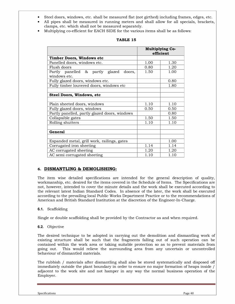
Specifications Page 40
• Steel doors, windows, etc. shall be measured flat (not girthed) including frames, edges, etc.
• All pipes shall be measured in running meters and shall allow for all specials, brackets, clamps, etc. which shall not be measured separately.
• Multiplying co-efficient for EACH SIDE for the various items shall be as follows:
TABLE 15
Multiplying Co-
efficient
Timber Doors, Windows etc
Panelled doors, windows etc. 1.00 1.30
Flush doors 0.80 1.20
Partly panelled & partly glazed doors,
windows etc.
1.50 1.00
Fully glazed doors, windows etc. 0.80
Fully timber louvered doors, windows etc 1.80
Steel Doors, Windows, etc
Plain sheeted doors, windows 1.10 1.10
Fully glazed doors, windows 0.50 0.50
Partly panelled, partly glazed doors, windows 0.80
Collapsible gates 1.50 1.50
Rolling shutters 1.10 1.10
General
Expanded metal, grill work, railings, gates 1.00
Corrugated iron sheeting 1.14 1.14
AC corrugated sheeting 1.20 1.20
AC semi corrugated sheeting 1.10 1.10
6. DISMANTLING & DEMOLISHING:
The item wise detailed specifications are intended for the general description of quality, workmanship, etc. desired for the items covered in the Schedule of Items. The Specifications are
not, however, intended to cover the minute details and the work shall be executed according to the relevant latest Indian Standard Codes. In absence of the later, the work shall be executed
according to the prevailing local Public Works Department Practice or to the recommendations of American and British Standard Institution at the discretion of the Engineer-In-Charge.
6.1. Scaffolding
Single or double scaffolding shall be provided by the Contractor as and when required.
6.2. Objective
The desired technique to be adopted in carrying out the demolition and dismantling work of existing structure shall be such that the fragments falling out of such operation can be
contained within the work area or taking suitable protection so as to prevent materials from going out. This would relieve the surrounding area from any uncertain or uncontrolled behaviour of dismantled materials.
The rubbish / materials after dismantling shall also be stored systematically and disposed off immediately outside the plant boundary in order to ensure no major formation of heaps inside /
adjacent to the work site and not hamper in any way the normal business operation of the Employer.
Specifications Page 41
The term demolition implies breaking up. This shall consist of demolishing whole or part of work including all relevant items as specified or shown on the drawings.
The term ‘Dismantling’ implies carefully removing without damage (up or down). This shall consist of dismantling one or more part of the structures / facilities as specified or shown on the drawings.
6.3. Precautions
All materials obtained from dismantling or demolition shall be the property of the Contractor
once the materials are taken out of the boundary of MDL after completion of the necessary gate pass and other formalities. But till such time the materials shall be kept in safe custody as per the directives of the Engineer-In-Charge. The demolition shall always be planned beforehand and shall be done in reverse order of the
one in which the structure was constructed. The scheme shall be got approved from the Engineer-In-Charge before starting the work.
Necessary propping, shoring and / or underpinning shall be provided for the safety of the adjoining work or property before dismantling and demolishing is taken up and the work shall be carried out in such a way that no damage is caused to the adjoining work or property.
Wherever required, as per the opinion of the Engineer-In-Charge, temporary enclosures or partitions shall be provided at the Contractor’s cost.
Necessary precautions shall be taken to keep down the dust nuisance. Dismantling shall be done in a systematic manner. All materials which are likely to be
damaged by dropping from a height or demolishing roofs, masonry, etc. shall be carefully removed first. The dismantled articles shall be passed by hand, where necessary, lowered to the ground (and not thrown) and then properly stacked as directed by the Engineer-In-Charge.
Where fixing is done by nails, screws, bolts, rivets, etc. dismantling shall be done by taking out
the fixed items with proper tools and not by tearing or ripping of. Any serviceable material, obtained during dismantling or demolition, shall be separated out
and stacked properly as directed by the Engineer-In-Charge within work site for verification required for gate pass and other formalities for taking outside the boundary. All unserviceable materials, rubbish, etc. shall be disposed off immediately outside the Owner’s premises as directed by the Engineer-In-Charge. 6.4. General
Necessary data such as building size, wall thickness, construction materials, etc. that may be required shall have to be collected by the Tenderer from MDL site at his own expenses.
6.5. Information to be supplied by the Tenderer along with Tender
The information to be provided for by the Tenderer, unless otherwise specified, shall include
the following: To submit his method of demolition duly supported by specifications and drawings and sequence
of operation along with a list of equipment, plants and machineries to be employed during such operation, to meet the above mentioned objective.
6.6. Work to be provided by the Contractor
a) To arrange all the formalities as per requirement of statutory rules, if his method involves use of explosives. He has to obtain permission from appropriate authority of buying, storing,
handling & making use of explosives.
Specifications Page 42
b) To notify, the Employer for arranging to shut off all gas, water, electricity, steam and other service lines running over ground or underground. Any temporary service connections required for the demolition work shall be separately taken and arranged by the Contractor.
c) Any preliminary work, necessary for Contractor’s method of demolition.
d) To furnish all materials, labour, tools and plant and all consumables required for this work and its related temporary work such as cordoning the area, staging etc.
e) To furnish the details of safety measures for human life / property / structures, the Contractor proposes to take during the blasting operation of explosives, if he proposes to use on this demolition work. This should be strictly as per rules and regulations laid down by the concerned authority for explosives to be used in this work.
6.7. Work by Others
No work under this specification will be provided for by any agency other than the Contractor, unless specifically mentioned otherwise elsewhere in the Contract or approved by the
Engineer-In-Charge / Employer. 6.8. Codes & Standards
The demolition work shall be carried out as per Indian Standard Code of Practice No. IS 4130 - 1970 (Safety Code for demolition of buildings) or any other relevant Indian Standard Specifications and Codes of Practice. If demolition by blasting is adopted IS 4081 (Safety Code
for blasting and related drilling operations) shall be followed. However, if any, particular aspect of the work is not specifically covered by any Indian Standard Specifications or any other standard practices, Engineer-In-Charge’s instruction shall be followed.