computer technology - winmeen
TRANSCRIPT

HIGHER SECONDARY SECOND YEAR
COMPUTER TECHNOLOGY
A Publication Under Free Textbook Programme of Government of Tamil Nadu
Department of School Education
Theory & Practical
Untouchability is Inhuman and a Crime
VOCATIONAL EDUCATION
GOVERNMENT OF TAMIL NADU
1_XII CompTech_English version FM.indd 1 01-03-2020 13:01:45
ii
Government of TamilNaduFirst Edition - 2019Revised Edition - 2020(Published under New Syllabus)
Tamil NaduTextbook and Educational Services Corporationwww.textbooksonline.tn.nic.in
State Council of Educational Research and Training© SCERT 2019
Printing & Publishing
Content Creation
The wisepossess all
NOT FOR SALE
1_XII CompTech_English version FM.indd 2 01-03-2020 13:01:45
PREFACE
Human civilization achieved the highest peak with the development of computer known as “Computer era”. Literate are those who have the knowledge in using the
computerwhereas others are considered illiterate inspite of the other degrees obtained. The growth of the nation at present lies in the hands of the youth, hence the content of this book is prepared in such a way so as to attain utmost knowledge considering the future needs of the youth.
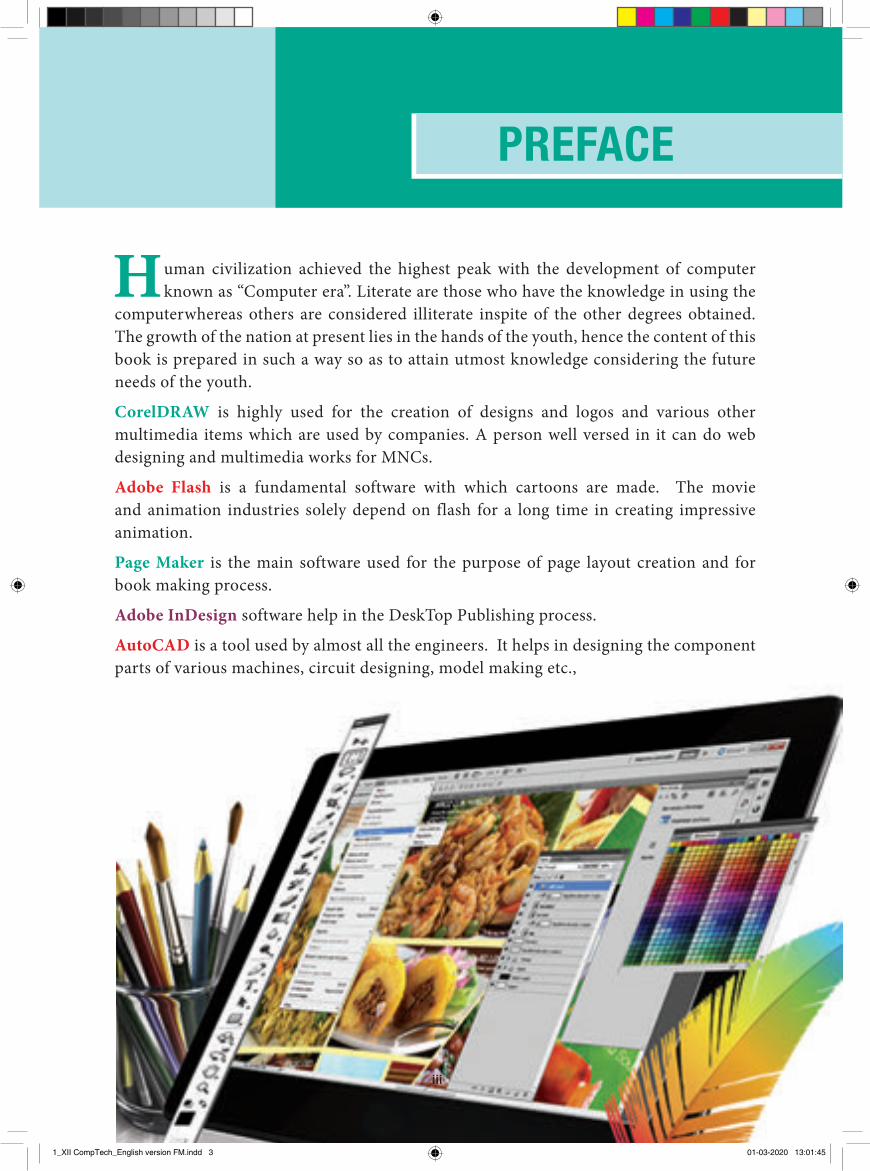
CorelDRAW is highly used for the creation of designs and logos and various other multimedia items which are used by companies. A person well versed in it can do web designing and multimedia works for MNCs.
Adobe Flash is a fundamental software with which cartoons are made. The movie and animation industries solely depend on flash for a long time in creating impressive animation.
Page Maker is the main software used for the purpose of page layout creation and for book making process.
Adobe InDesign software help in the DeskTop Publishing process.
AutoCAD is a tool used by almost all the engineers. It helps in designing the component parts of various machines, circuit designing, model making etc.,
iii
1_XII CompTech_English version FM.indd 3 01-03-2020 13:01:45
iviv
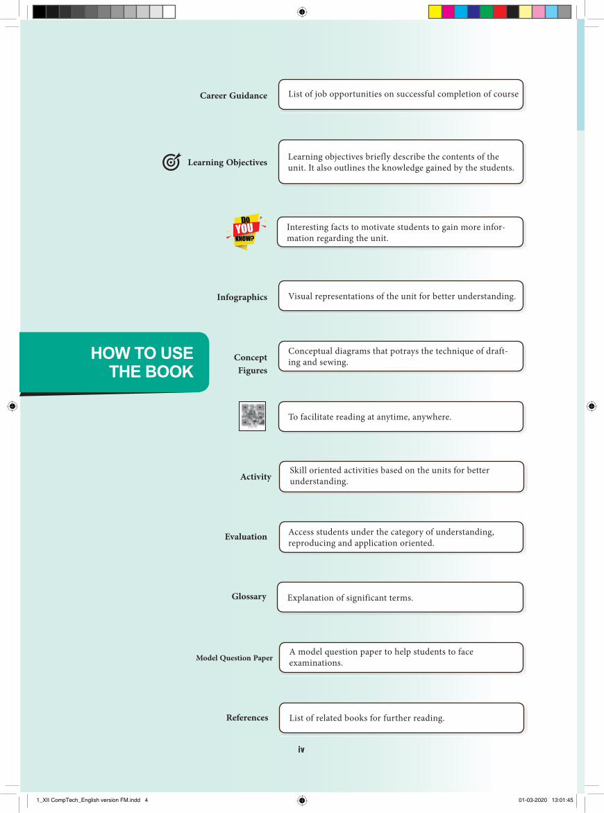
HOW TO USETHE BOOK
A model question paper to help students to face examinations.Model Question Paper
Explanation of significant terms.Glossary
Access students under the category of understanding, reproducing and application oriented.
Evaluation
Visual representations of the unit for better understanding.Infographics
Conceptual diagrams that potrays the technique of draft-ing and sewing. Concept
Figures
To facilitate reading at anytime, anywhere.
Learning objectives briefly describe the contents of the unit. It also outlines the knowledge gained by the students.Learning Objectives
Interesting facts to motivate students to gain more infor-mation regarding the unit.
Skill oriented activities based on the units for better understanding.Activity
List of related books for further reading.References
List of job opportunities on successful completion of courseCareer Guidance
1_XII CompTech_English version FM.indd 4 01-03-2020 13:01:45
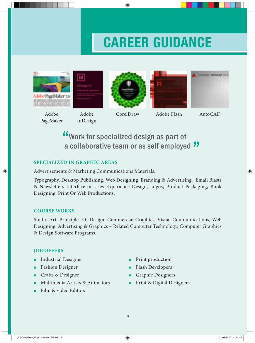
CAREER GUIDANCE
Adobe PageMaker
Adobe InDesign
CorelDraw Adobe Flash AutoCAD
Work for specialized design as part of a collaborative team or as self employed
SPECIALIZED IN GRAPHIC AREAS
Advertisements & Marketing Communications Materials.
Typography, Desktop Publishing, Web Designing, Branding & Advertising. Email Blasts & Newsletters Interface or Uses Experience Design, Logos, Product Packaging, Book Designing, Print Or Web Productions.
COURSE WORKS
Studio Art, Principles Of Design, Commercial Graphics, Visual Communications, Web Designing, Advertising & Graphics – Related Computer Technology, Computer Graphics & Design Software Programs.
JOB OFFERS
●● Industrial Designer●● Fashion Designer●● Crafts & Designer●● Multimedia Artists & Animators●● Film & video Editors
●● Print production●● Flash Developers ●● Graphic Designers●● Print & Digital Designers
v
1_XII CompTech_English version FM.indd 5 01-03-2020 13:01:45
CONTENTS
E-book Assessment DIGI-LinksLets use the QR code in the text books ! How ?• Download the QR code scanner from the Google PlayStore/ Apple App Store into your smartphone• Open the QR code scanner application• Once the scanner button in the application is clicked, camera opens and then bring it closer to the QR code in the text book. • Once the camera detects the QR code, a url appears in the screen.Click the url and goto the content page.
vi
Computer Technology-II Year
CHAPTER COMPUTER SCIENCE PAGE NO MONTH
1 An Introduction to Adobe Pagemaker 1 June
2 Adobe InDesign CC 2019 41 July
3 CorelDRAW 2018 85 August
4 Multimedia and Desktop Publishing 129 September
5 Adobe Flash Professional CS6 145 October
6 AutoCAD 2016 169 November
Practicals 208
1_XII CompTech_English version FM.indd 6 01-03-2020 13:01:45
1Chapter 01 Adobe Pagemaker
1.2 Introduction to Adobe PageMaker
Adobe PageMaker is a page layout software. It is used to design and produce documents that can be printed. You can create anything from a simple business card to a large book.
Page layout software includes tools that allow you to easily position text and graphics on document pages. For example, using PageMaker, you could create a newsletter that includes articles and pictures on each page. You can place
1.1 Desktop Publishing We hear and see the term ‘Desktop publishing’ a lot these days. What exactly is it? What does it mean? Desktop publishing (abbreviated DTP) is the creation of page layouts for documents using DTP software.
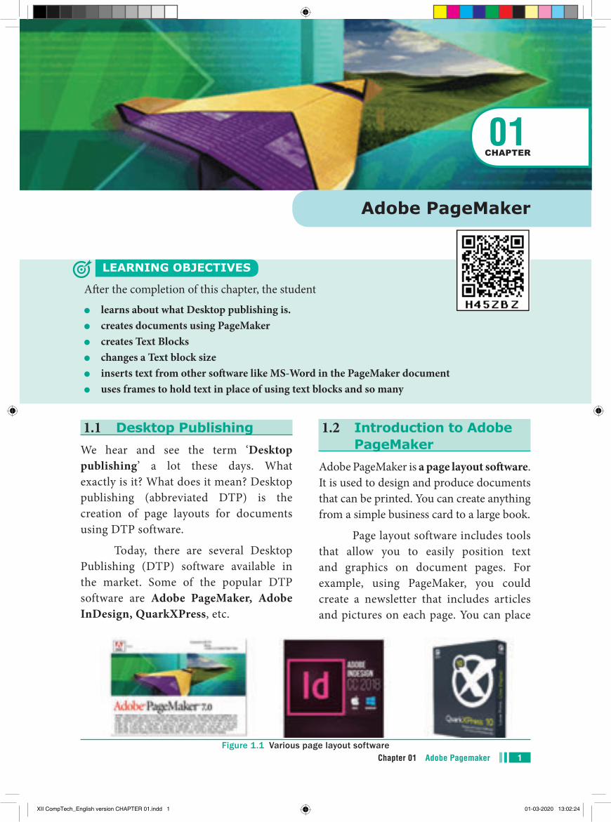
Today, there are several Desktop Publishing (DTP) software available in the market. Some of the popular DTP software are Adobe PageMaker, Adobe InDesign, QuarkXPress, etc.
Figure 1.1 Various page layout software
Adobe PageMaker
LEARNING OBJECTIVES
After the completion of this chapter, the student
●● learns about what Desktop publishing is.●● creates documents using PageMaker●● creates Text Blocks●● changes a Text block size●● inserts text from other software like MS-Word in the PageMaker document●● uses frames to hold text in place of using text blocks and so many
01CHAPTER
XII CompTech_English version CHAPTER 01.indd 1 01-03-2020 13:02:24
Chapter 01 Adobe Pagemaker2
1.4 Creating a New Document To create a new document,
1. Choose File > New in the menu bar. (or) Press Ctrl + N in the keyboard. Now Document Setup dialog box appears.(Figure 1.3)
2. Enter the appropriate settings for your new document in the Document Setup dialog box.
3. Click on OK button.
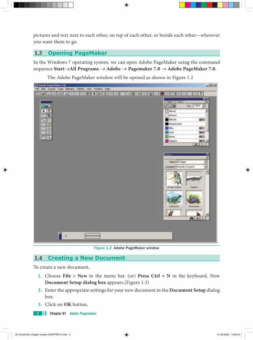
Figure 1.2 Adobe PageMaker window
pictures and text next to each other, on top of each other, or beside each other—wherever you want them to go.
1.3 Opening PageMakerIn the Windows 7 operating system, we can open Adobe PageMaker using the command sequence Start→All Programs → Adobe → Pagemaker 7.0 → Adobe PageMaker 7.0.
The Adobe PageMaker window will be opened as shown in Figure 1.2
XII CompTech_English version CHAPTER 01.indd 2 01-03-2020 13:02:24
3Chapter 01 Adobe Pagemaker
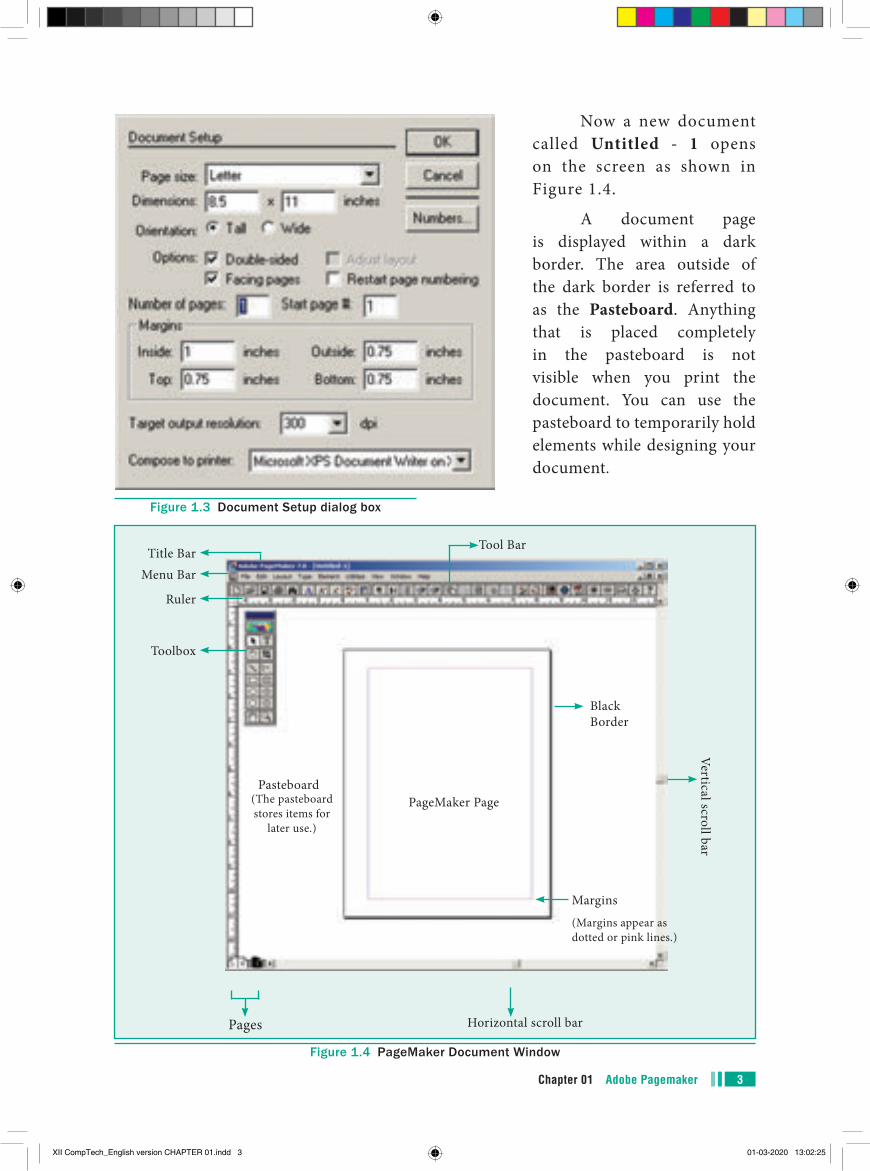
Now a new document called Untitled - 1 opens on the screen as shown in Figure 1.4.
A document page is displayed within a dark border. The area outside of the dark border is referred to as the Pasteboard. Anything that is placed completely in the pasteboard is not visible when you print the document. You can use the pasteboard to temporarily hold elements while designing your document.
Figure 1.3 Document Setup dialog box
Title BarMenu Bar
Tool Bar
Black Border
Margins
(Margins appear as dotted or pink lines.)
Ruler
Toolbox
Vertical scroll bar
PageMaker PagePasteboard
Horizontal scroll bar
(The pasteboard stores items for
later use.)
Pages
Figure 1.4 PageMaker Document Window
XII CompTech_English version CHAPTER 01.indd 3 01-03-2020 13:02:25
Chapter 01 Adobe Pagemaker4
The main components of the above window are Title bar, Menu bar, Toolbar, Ruler, Scroll bars and Text area. Let us have a look at these components.
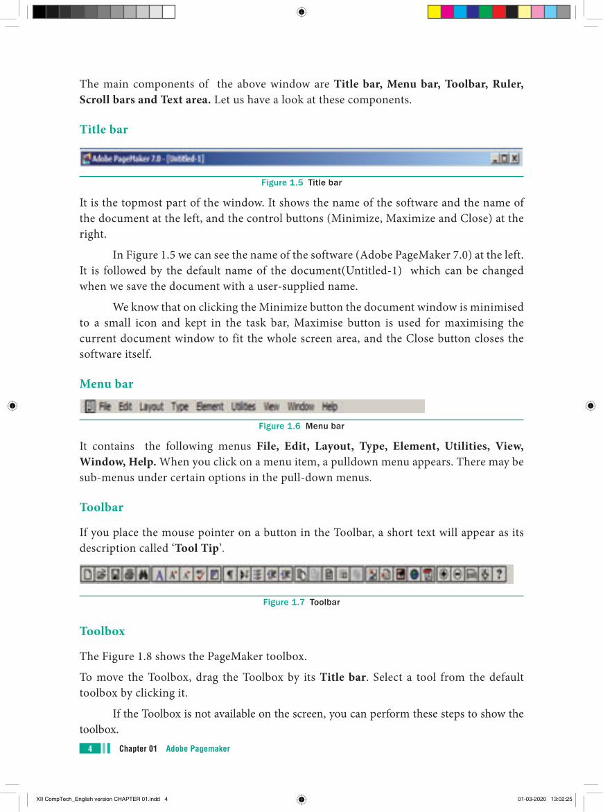
Title bar
Figure 1.5 Title bar
It is the topmost part of the window. It shows the name of the software and the name of the document at the left, and the control buttons (Minimize, Maximize and Close) at the right.
In Figure 1.5 we can see the name of the software (Adobe PageMaker 7.0) at the left. It is followed by the default name of the document(Untitled-1) which can be changed when we save the document with a user-supplied name.
We know that on clicking the Minimize button the document window is minimised to a small icon and kept in the task bar, Maximise button is used for maximising the current document window to fit the whole screen area, and the Close button closes the software itself.
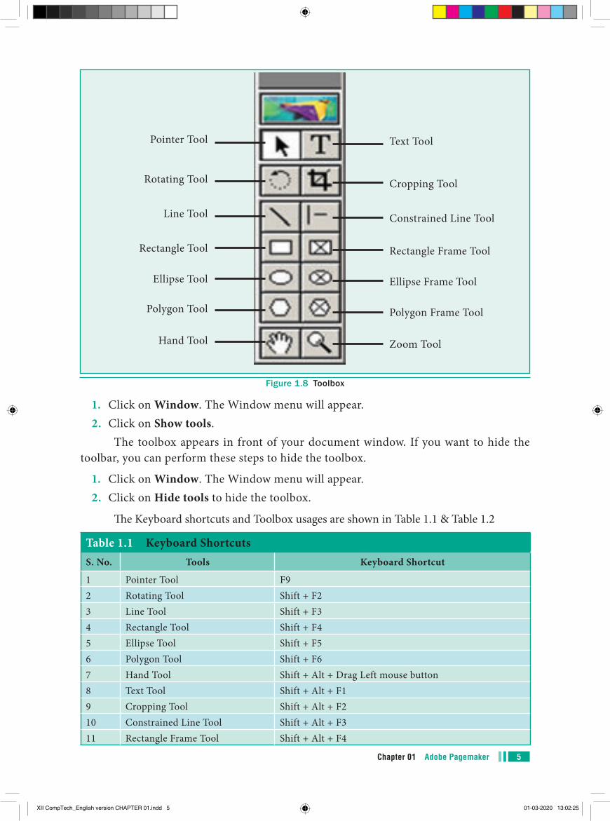
Menu bar
Figure 1.6 Menu bar
It contains the following menus File, Edit, Layout, Type, Element, Utilities, View, Window, Help. When you click on a menu item, a pulldown menu appears. There may be sub-menus under certain options in the pull-down menus.
Toolbar
If you place the mouse pointer on a button in the Toolbar, a short text will appear as its description called ‘Tool Tip’.
Figure 1.7 Toolbar
Toolbox
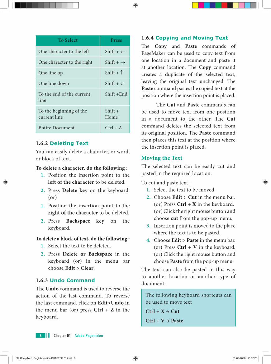
The Figure 1.8 shows the PageMaker toolbox.
To move the Toolbox, drag the Toolbox by its Title bar. Select a tool from the default toolbox by clicking it.
If the Toolbox is not available on the screen, you can perform these steps to show the toolbox.
XII CompTech_English version CHAPTER 01.indd 4 01-03-2020 13:02:25
5Chapter 01 Adobe Pagemaker
1. Click on Window. The Window menu will appear.2. Click on Show tools.
The toolbox appears in front of your document window. If you want to hide the toolbar, you can perform these steps to hide the toolbox.
1. Click on Window. The Window menu will appear. 2. Click on Hide tools to hide the toolbox.
The Keyboard shortcuts and Toolbox usages are shown in Table 1.1 & Table 1.2
Table 1.1 Keyboard ShortcutsS. No. Tools Keyboard Shortcut
1 Pointer Tool F92 Rotating Tool Shift + F23 Line Tool Shift + F34 Rectangle Tool Shift + F45 Ellipse Tool Shift + F56 Polygon Tool Shift + F67 Hand Tool Shift + Alt + Drag Left mouse button8 Text Tool Shift + Alt + F19 Cropping Tool Shift + Alt + F210 Constrained Line Tool Shift + Alt + F311 Rectangle Frame Tool Shift + Alt + F4
Pointer Tool
Rotating Tool
Line Tool
Rectangle Tool
Ellipse Tool
Polygon Tool
Hand Tool
Text Tool
Cropping Tool
Constrained Line Tool
Rectangle Frame Tool
Ellipse Frame Tool
Polygon Frame Tool
Zoom Tool
Figure 1.8 Toolbox
XII CompTech_English version CHAPTER 01.indd 5 01-03-2020 13:02:25

Chapter 01 Adobe Pagemaker6
Table 1.2 Toolbox Usage
Tool Toolbox Cursor Use
Pointer ToolUsed to select, move, and resize text objects and graphics.
Text tool Used to type, select, and edit text.
Rotating tool Used to select and rotate objects.
Cropping tool Used to trim imported graphics.
Line tool Used to draw straight lines in any direction.
Constrained line tool
Used to draw vertical or horizontal lines.
Rectangle tool Used to draw squares and rectangles.
Rectangle frame tool
Used to create rectangular placeholders for text and graphics.
Ellipse tool Used to draw circles and ellipses.
Ellipse frame toolUsed to create elliptical placeholders for text and graphics.
Polygon tool Used to draw polygons.
Polygon frame toolUsed to create polygonal placeholders for text and graphics.
Hand toolUsed to scroll the page (an alternative to the scroll bar)
Zoom toolUsed to magnify or reduce an area of the page.
XII CompTech_English version CHAPTER 01.indd 6 01-03-2020 13:02:26
7Chapter 01 Adobe Pagemaker
Scroll barsScrolling is the process of moving up and down or left and right through the document window. There are two scroll bars namely Vertical and Horizontal scroll bars for scrolling the document vertically or horizontally.
RulersThere are two ruler. One is at the top and the other is at the left side.
To show the ruler1. Click on View. The View menu will
appear.2. Click on Show Rulers. Rulers appear
along the top and left sides of the document window.
To hide the ruler1. Click on View. The View menu will
appear.2. Click on Hide Rulers to hide the
rulers.
1.5 Entering Text in the Document
In PageMaker the text of the document can be typed inside a text block. So, you must use the Text tool to create those text blocks. After creating a Text block, you can type the text directly into the text block. As the characters are typed, the flashing vertical bar called the insertion point, moves to the right. When the text being typed reaches the end of the text block, PageMaker will automatically wrap the text to the next line. The Enter key must not be pressed at the end of the each line in the text block. The Enter key should be pressed only at the end of a paragraph or when a blank line is to be inserted.
1.6 Editing Text in the Document
Editing means making changes to the text. When you edit a document, you revise its text. Editing encompasses many tasks, such as inserting and deleting words and phrases, correcting errors, and moving and copying text to different places in the document.
1.6.1 Selecting TextText can be selected using the mouse or the keyboard.
Selecting Text using the mouseTo select text using a mouse, follow these steps :
1. Place the Insertion point to the left of the first character to be selected.
2. Press the left mouse button and drag the mouse to a position where you want to stop selecting.
3. Release the mouse button.4. The selected text gets highlighted.
To Select Press
A Word Double-click with I-beam
A Paragraph Triple-click with I-beam
Selecting Text using the KeyboardTo select text using a keyboard, follow these steps :
1. Place the Insertion point to the left of the first character you wish to select.
2. The Shift key is pressed down and the movement keys are used to highlight the required text.
3. When the Shift key is released, the text is selected.
XII CompTech_English version CHAPTER 01.indd 7 01-03-2020 13:02:26
Chapter 01 Adobe Pagemaker8
To Select Press
One character to the left Shift + ←
One character to the right Shift + →
One line up Shift + ↑
One line down Shift + ↓
To the end of the current line
Shift +End
To the beginning of the current line
Shift + Home
Entire Document Ctrl + A
1.6.2 Deleting TextYou can easily delete a character, or word, or block of text.
To delete a character, do the following :1. Position the insertion point to the
left of the character to be deleted.2. Press Delete key on the keyboard.
(or)1. Position the insertion point to the
right of the character to be deleted.2. Press Backspace key on the
keyboard.
To delete a block of text, do the following :1. Select the text to be deleted.2. Press Delete or Backspace in the
keyboard (or) in the menu bar choose Edit > Clear.
1.6.3 Undo CommandThe Undo command is used to reverse the action of the last command. To reverse the last command, click on Edit>Undo in the menu bar (or) press Ctrl + Z in the keyboard.
1.6.4 Copying and Moving TextThe Copy and Paste commands of PageMaker can be used to copy text from one location in a document and paste it at another location. The Copy command creates a duplicate of the selected text, leaving the original text unchanged. The Paste command pastes the copied text at the position where the insertion point is placed.
The Cut and Paste commands can be used to move text from one position in a document to the other. The Cut command deletes the selected text from its original position. The Paste command then places this text at the position where the insertion point is placed.
Moving the TextThe selected text can be easily cut and pasted in the required location.
To cut and paste text .1. Select the text to be moved.2. Choose Edit > Cut in the menu bar.
(or) Press Ctrl + X in the keyboard. (or) Click the right mouse button and choose cut from the pop-up menu.
3. Insertion point is moved to the place where the text is to be pasted.
4. Choose Edit > Paste in the menu bar. (or) Press Ctrl + V in the keyboard. (or) Click the right mouse button and choose Paste from the pop-up menu.
The text can also be pasted in this way to another location or another type of document.
The following keyboard shortcuts can be used to move text
Ctrl + X → Cut
Ctrl + V → Paste
XII CompTech_English version CHAPTER 01.indd 8 01-03-2020 13:02:26
9Chapter 01 Adobe Pagemaker
Copying the Text
The selected text can be easily copied and pasted in the required location.
To copy and paste text
1. Select the text to be coped.
2. Choose Edit > Copy in the menu bar (or) Press Ctrl + C in the keyboard (or) Click the right mouse button and choose Copy from the pop-up menu.
3. Insertion point is moved to the place where the text is to be pasted.
4. Choose Edit > Paste in the menu bar (or) Press Ctrl + V in the keyboard (or) Click the right mouse button and choose Paste from the pop-up menu.
The text can also be pasted in this way to another location.
Keyboard shortcuts for copy and paste:
Ctrl + C → CopyCtrl + V → Paste
1.7 Text BlockA text block contains text you type, paste, or import. You can’t see the borders of a text block until you select it with the pointer tool.
You create text blocks in two ways:1. Click or drag the text tool on the page
or pasteboard, and then type. 2. Click a loaded text icon in an empty
column or page.
1.7.1 Creating a Text Block with the Text tool
To create a text block with the text tool:
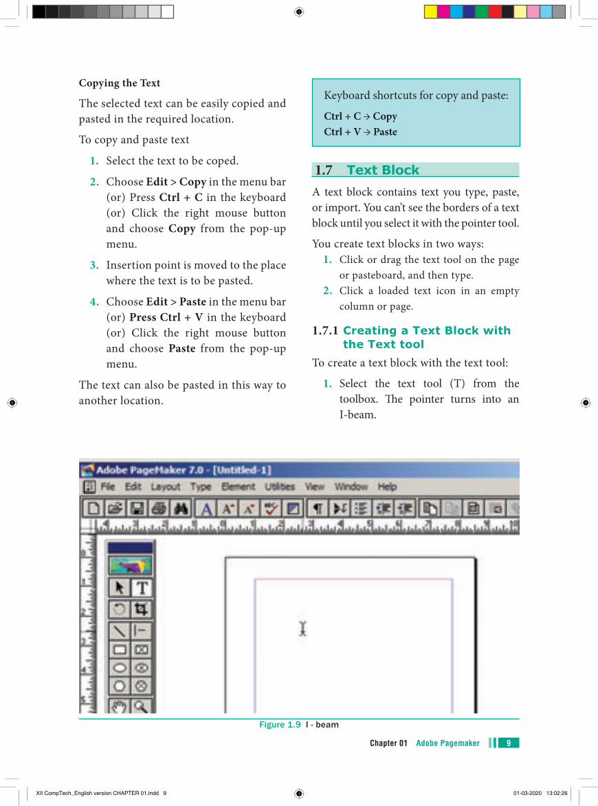
1. Select the text tool (T) from the toolbox. The pointer turns into an I-beam.
Figure 1.9 I - beam
XII CompTech_English version CHAPTER 01.indd 9 01-03-2020 13:02:26
Chapter 01 Adobe Pagemaker10
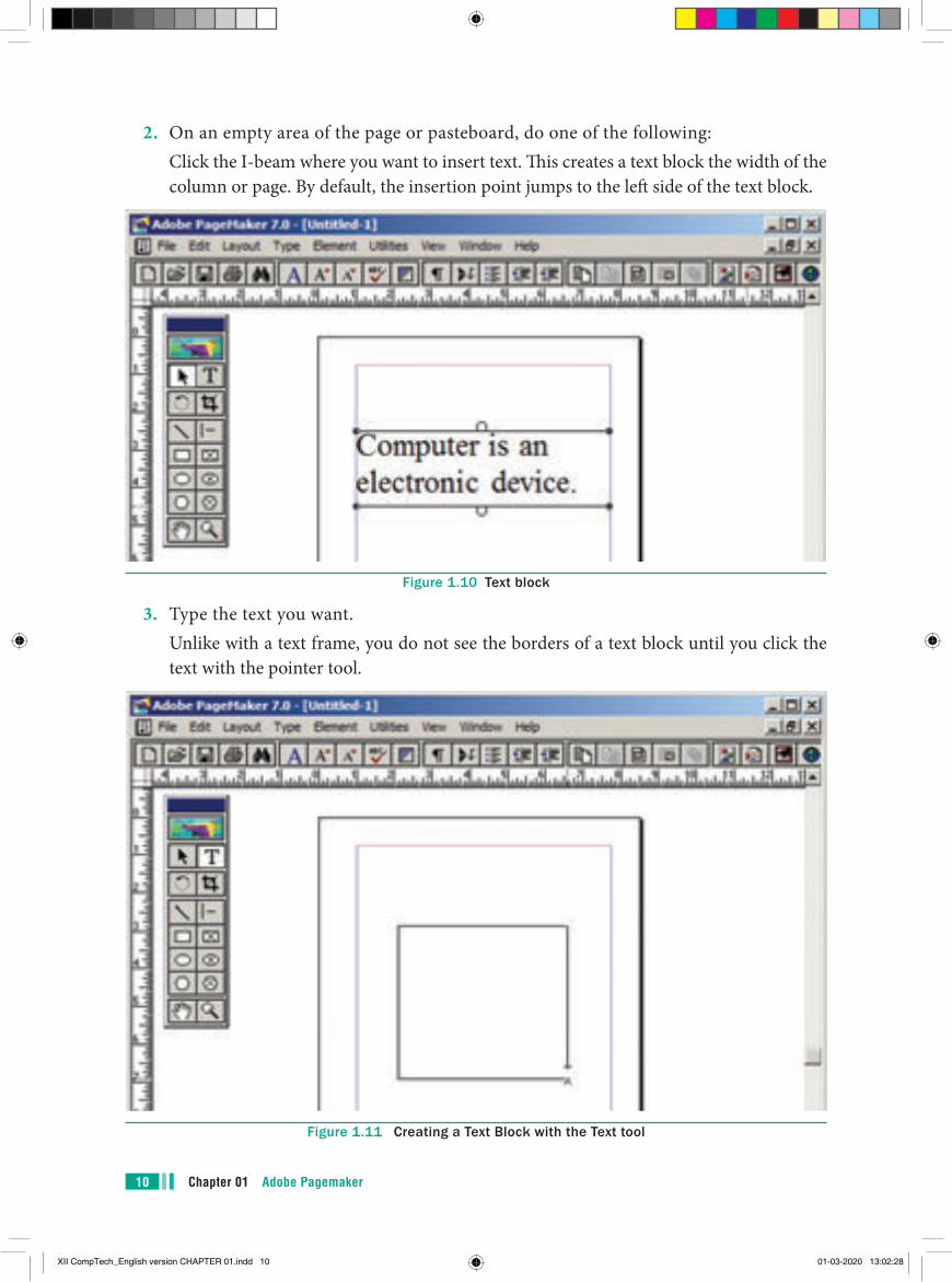
2. On an empty area of the page or pasteboard, do one of the following: Click the I-beam where you want to insert text. This creates a text block the width of the
column or page. By default, the insertion point jumps to the left side of the text block.
Figure 1.10 Text block
3. Type the text you want. Unlike with a text frame, you do not see the borders of a text block until you click the
text with the pointer tool.
Figure 1.11 Creating a Text Block with the Text tool
XII CompTech_English version CHAPTER 01.indd 10 01-03-2020 13:02:28
11Chapter 01 Adobe Pagemaker
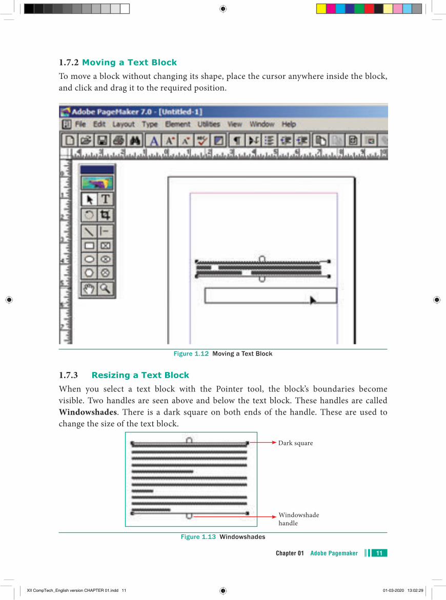
1.7.2 Moving a Text BlockTo move a block without changing its shape, place the cursor anywhere inside the block, and click and drag it to the required position.
Figure 1.12 Moving a Text Block
1.7.3 Resizing a Text BlockWhen you select a text block with the Pointer tool, the block’s boundaries become visible. Two handles are seen above and below the text block. These handles are called Windowshades. There is a dark square on both ends of the handle. These are used to change the size of the text block.
Dark square
Windowshade handle
Figure 1.13 Windowshades
XII CompTech_English version CHAPTER 01.indd 11 01-03-2020 13:02:29
Chapter 01 Adobe Pagemaker12
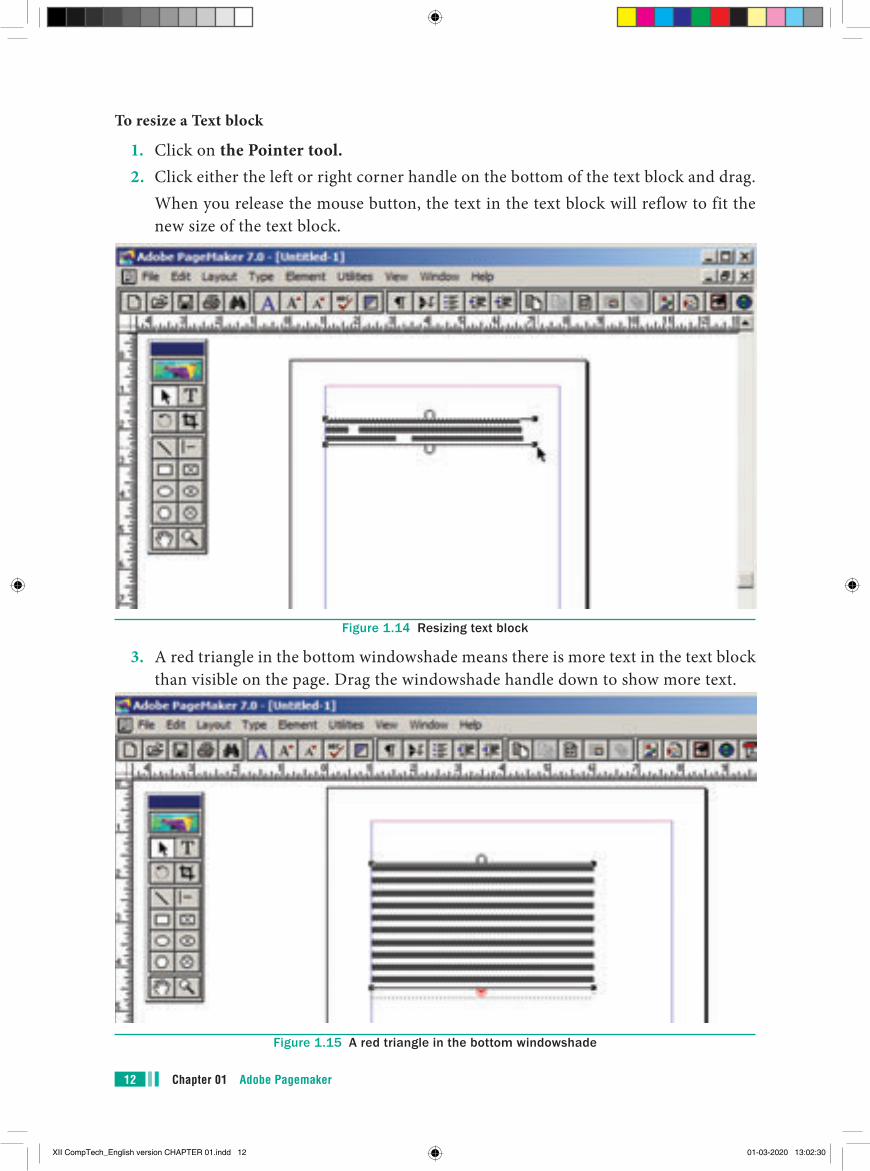
To resize a Text block
1. Click on the Pointer tool.2. Click either the left or right corner handle on the bottom of the text block and drag. When you release the mouse button, the text in the text block will reflow to fit the
new size of the text block.
Figure 1.14 Resizing text block
3. A red triangle in the bottom windowshade means there is more text in the text block than visible on the page. Drag the windowshade handle down to show more text.
Figure 1.15 A red triangle in the bottom windowshade
XII CompTech_English version CHAPTER 01.indd 12 01-03-2020 13:02:30
13Chapter 01 Adobe Pagemaker
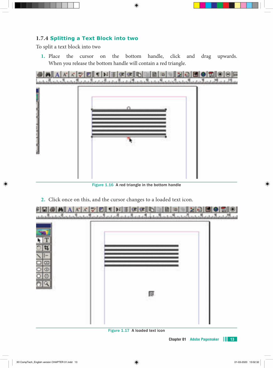
1.7.4 Splitting a Text Block into twoTo split a text block into two
1. Place the cursor on the bottom handle, click and drag upwards. When you release the bottom handle will contain a red triangle.
Figure 1.16 A red triangle in the bottom handle
2. Click once on this, and the cursor changes to a loaded text icon.
Figure 1.17 A loaded text icon
XII CompTech_English version CHAPTER 01.indd 13 01-03-2020 13:02:32
Chapter 01 Adobe Pagemaker14
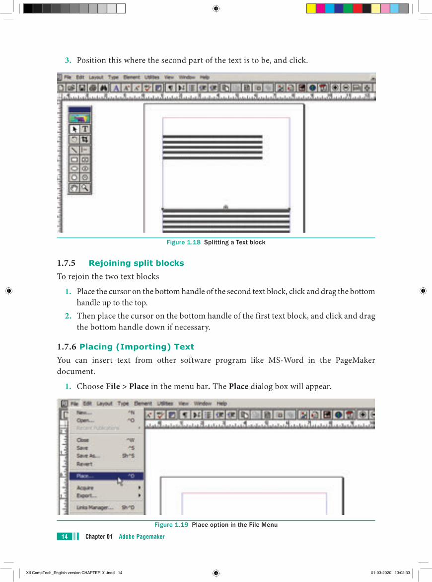
3. Position this where the second part of the text is to be, and click.
Figure 1.18 Splitting a Text block
1.7.5 Rejoining split blocksTo rejoin the two text blocks
1. Place the cursor on the bottom handle of the second text block, click and drag the bottom handle up to the top.
2. Then place the cursor on the bottom handle of the first text block, and click and drag the bottom handle down if necessary.
1.7.6 Placing (Importing) TextYou can insert text from other software program like MS-Word in the PageMaker document.
1. Choose File > Place in the menu bar. The Place dialog box will appear.
Figure 1.19 Place option in the File Menu
XII CompTech_English version CHAPTER 01.indd 14 01-03-2020 13:02:33
15Chapter 01 Adobe Pagemaker
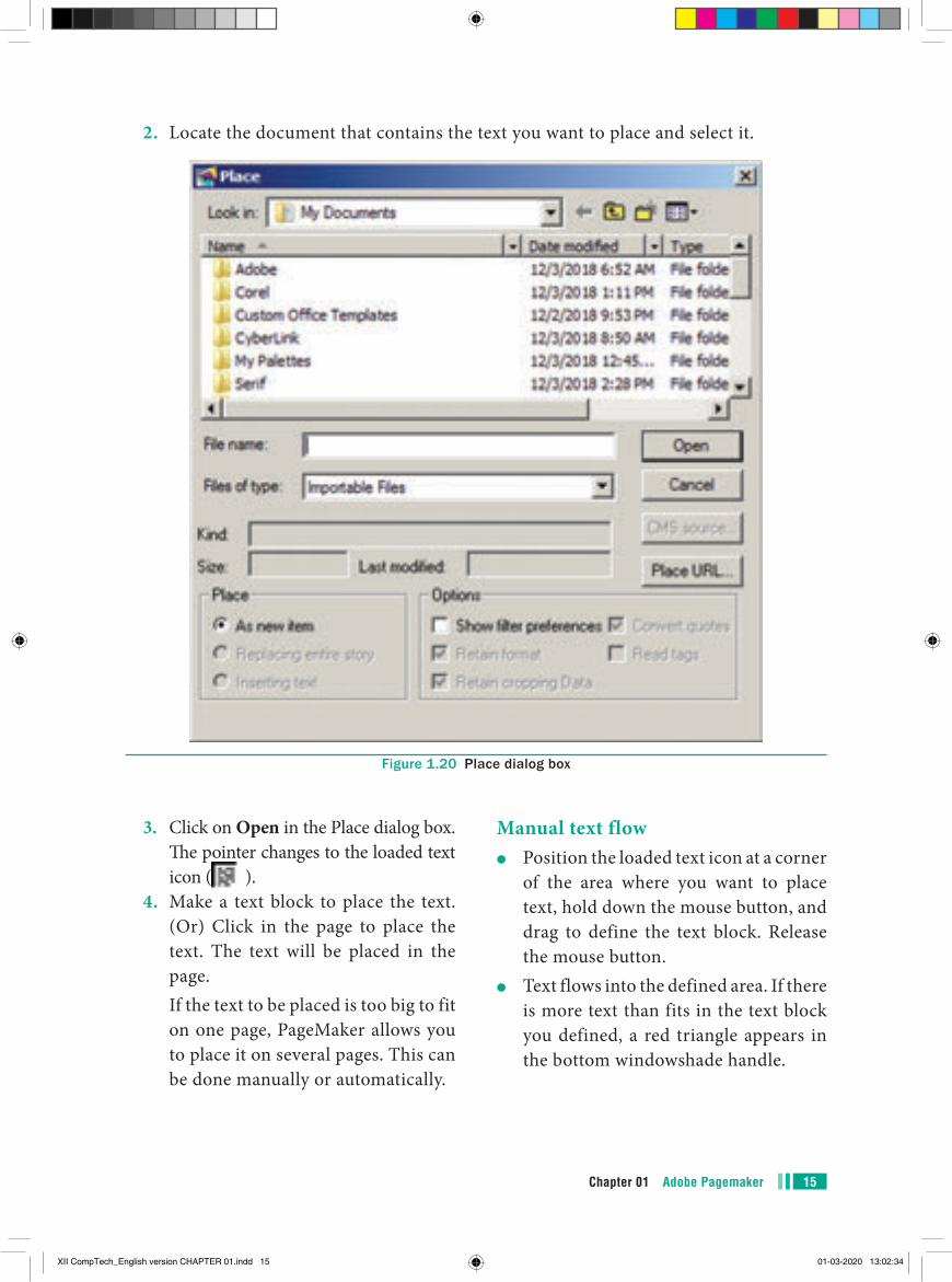
2. Locate the document that contains the text you want to place and select it.
Figure 1.20 Place dialog box
3. Click on Open in the Place dialog box.The pointer changes to the loaded text icon ( ).
4. Make a text block to place the text. (Or) Click in the page to place the text. The text will be placed in the page.
If the text to be placed is too big to fit on one page, PageMaker allows you to place it on several pages. This can be done manually or automatically.
Manual text flow●● Position the loaded text icon at a corner
of the area where you want to place text, hold down the mouse button, and drag to define the text block. Release the mouse button.
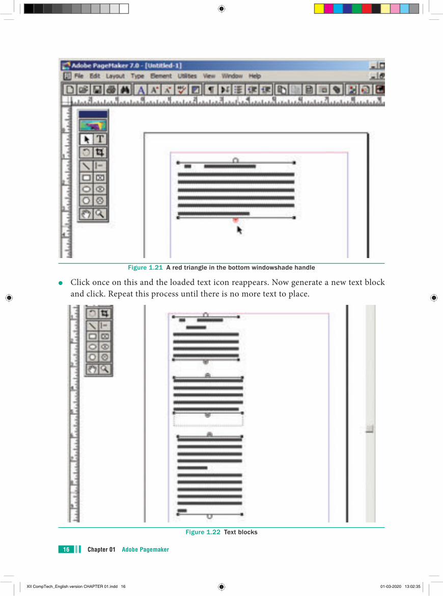
●● Text flows into the defined area. If there is more text than fits in the text block you defined, a red triangle appears in the bottom windowshade handle.
XII CompTech_English version CHAPTER 01.indd 15 01-03-2020 13:02:34
Chapter 01 Adobe Pagemaker16
Figure 1.21 A red triangle in the bottom windowshade handle
●● Click once on this and the loaded text icon reappears. Now generate a new text block and click. Repeat this process until there is no more text to place.
Figure 1.22 Text blocks
XII CompTech_English version CHAPTER 01.indd 16 01-03-2020 13:02:35
17Chapter 01 Adobe Pagemaker
Similarly if you want to place the text in a page, position the loaded text icon at the top of the page and click. Text flows into the page. If there is more text than fits in the page, a red triangle appears in the bottom windowshade handle.
Click once on this and the loaded text icon reappears. Now generate a new page (or pages) by selecting Layout > Insert Pages in the menu bar. Place the loaded text icon at the top of the next page and click. Repeat this process until there is no more text to place.
Automatic text flowBefore importing the text, first select Layout > Autoflow in the menu bar. Then you should import the text. Now the loaded text icon looks different - it contains a squiggly arrow( ).
Place the loaded text icon at the top of the page and click. But now the text will automatically flow on to the succeeding pages, creating new ones, if necessary.
1.8 Understanding storyA PageMaker story is similar to a newspaper article. The front page of a newspaper may contain several independent articles, some of which continue on other pages. In PageMaker, several stories may appear on the same publication page and continue elsewhere in the publication.
1.9 Threading text blocksAll text in PageMaker resides inside containers called text blocks.
A Text block can be connected to other text block so that the text in one text block can flow into another text block.
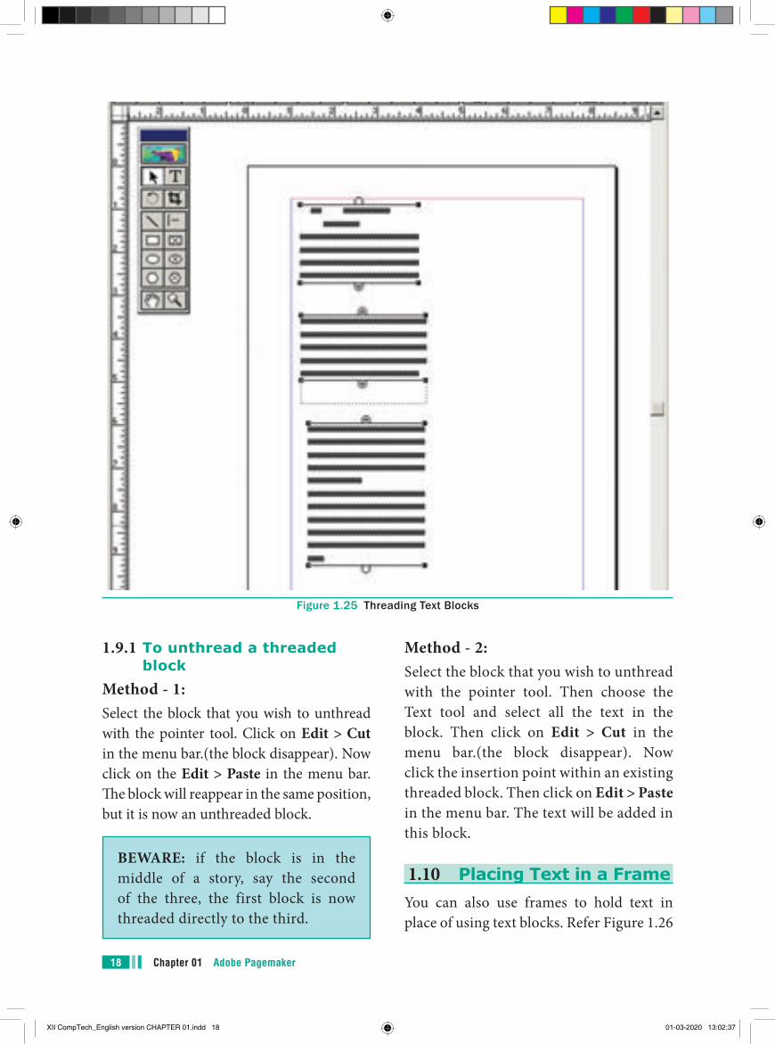
Text blocks that are connected in this way are threaded. The process of connecting text among Text blocks is called threading text. Text that flows through one or more threaded blocks is called a story.
Once you have a loaded text icon, you can use one of three text-flow options to place text in text blocks.
To cancel a loaded text icon, click the pointer tool in the toolbox; no text is deleted.
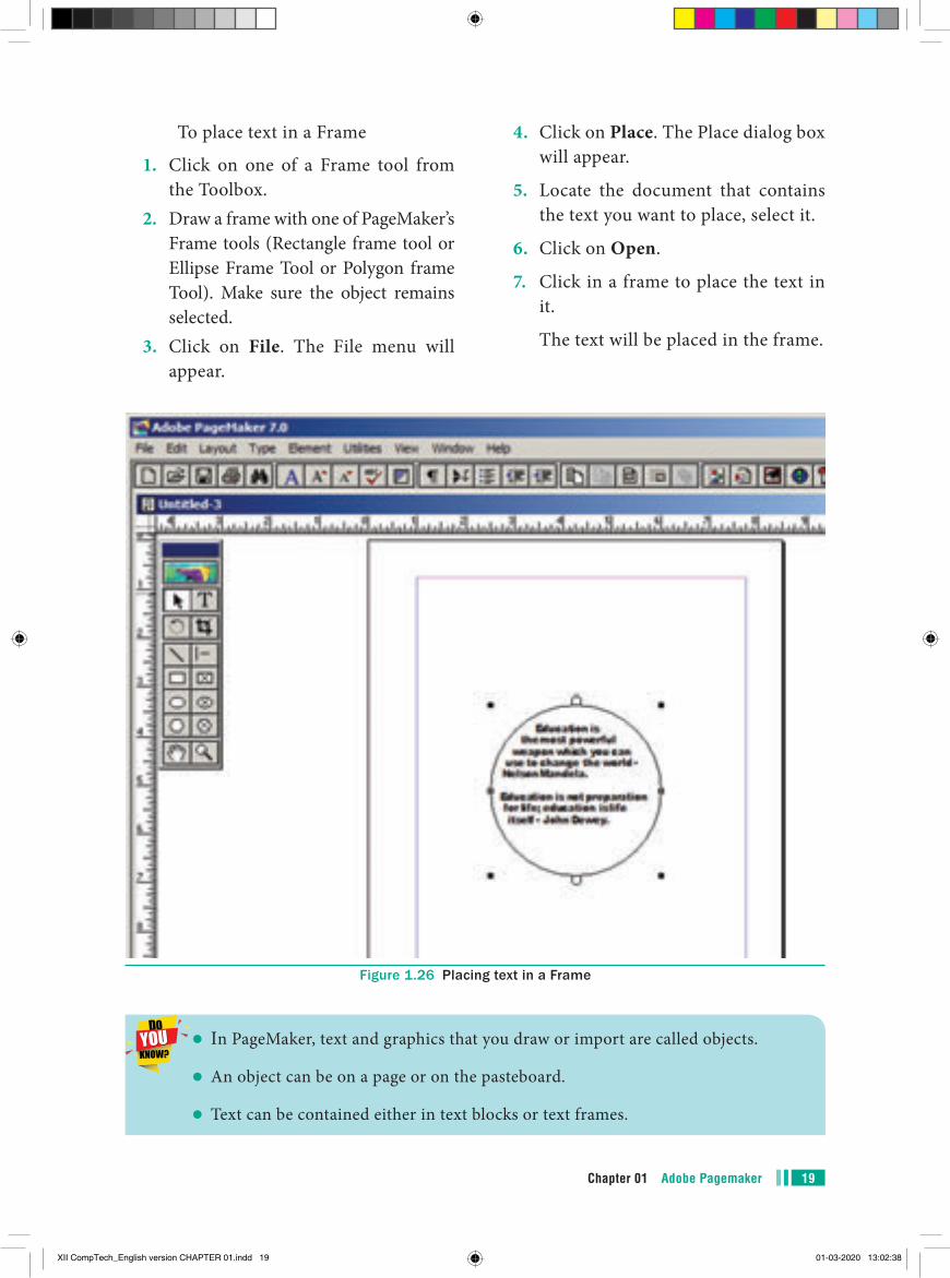
A threaded text block can be identified by a plus sign in its top and/or bottom handles. Refer Figure 1.23-Fig 1.25
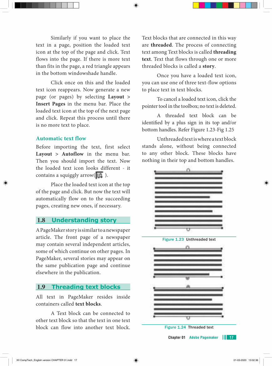
Unthreaded text is where a text block stands alone, without being connected to any other block. These blocks have nothing in their top and bottom handles.
Figure 1.23 Unthreaded text
Figure 1.24 Threaded text
XII CompTech_English version CHAPTER 01.indd 17 01-03-2020 13:02:36
Chapter 01 Adobe Pagemaker18
1.9.1 To unthread a threaded block
Method - 1:Select the block that you wish to unthread with the pointer tool. Click on Edit > Cut in the menu bar.(the block disappear). Now click on the Edit > Paste in the menu bar. The block will reappear in the same position, but it is now an unthreaded block.
BEWARE: if the block is in the middle of a story, say the second of the three, the first block is now threaded directly to the third.
Method - 2: Select the block that you wish to unthread with the pointer tool. Then choose the Text tool and select all the text in the block. Then click on Edit > Cut in the menu bar.(the block disappear). Now click the insertion point within an existing threaded block. Then click on Edit > Paste in the menu bar. The text will be added in this block.
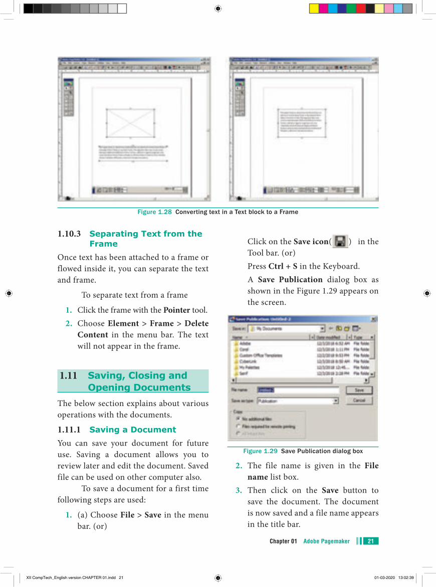
1.10 Placing Text in a FrameYou can also use frames to hold text in place of using text blocks. Refer Figure 1.26
Figure 1.25 Threading Text Blocks
XII CompTech_English version CHAPTER 01.indd 18 01-03-2020 13:02:37
19Chapter 01 Adobe Pagemaker
To place text in a Frame
1. Click on one of a Frame tool from the Toolbox.
2. Draw a frame with one of PageMaker’s Frame tools (Rectangle frame tool or Ellipse Frame Tool or Polygon frame Tool). Make sure the object remains selected.
3. Click on File. The File menu will appear.
4. Click on Place. The Place dialog box will appear.
5. Locate the document that contains the text you want to place, select it.
6. Click on Open.
7. Click in a frame to place the text in it.
The text will be placed in the frame.
Figure 1.26 Placing text in a Frame
In PageMaker, text and graphics that you draw or import are called objects.
An object can be on a page or on the pasteboard.
Text can be contained either in text blocks or text frames.
XII CompTech_English version CHAPTER 01.indd 19 01-03-2020 13:02:38

Chapter 01 Adobe Pagemaker20
After created text in a text block, if you want to convert it to a frame. You can do this by using these steps.
1. Draw the frame of your choice using one of the PageMaker’s Frame tool.
2. Select the text block you want to insert in the frame.
1.10.1 Linking Frames containing Text
A single frame may not be large enough to hold an entire story when you are using a large amount of text, you can link frames together so that an entire story is visible.
To link Frames containing text
1. Draw a second frame with the Frame tool of your choice.
2. Click the first frame to select it.3. Click on the red triangle to load the
text icon.4. Click the second frame. PageMaker
flows the text into the second frame.
Figure 1.27 Linking Frames containingText
3. Click the frame while pressing the Shift key. Now both elements will be selected.
4. Choose Element > Frame > Attach Content on the Menu bar.
5. Now the text appears in the frame. Refer Figure 1.28
1.10.2 Converting text in a Text block to a Frame
XII CompTech_English version CHAPTER 01.indd 20 01-03-2020 13:02:38
21Chapter 01 Adobe Pagemaker
Click on the Save icon( ) in the Tool bar. (or)
Press Ctrl + S in the Keyboard. A Save Publication dialog box as
shown in the Figure 1.29 appears on the screen.
Figure 1.29 Save Publication dialog box
2. The file name is given in the File name list box.
3. Then click on the Save button to save the document. The document is now saved and a file name appears in the title bar.
1.10.3 Separating Text from the Frame
Once text has been attached to a frame or flowed inside it, you can separate the text and frame.
To separate text from a frame
1. Click the frame with the Pointer tool.2. Choose Element > Frame > Delete
Content in the menu bar. The text will not appear in the frame.
1.11 Saving, Closing and Opening Documents
The below section explains about various operations with the documents.
1.11.1 Saving a DocumentYou can save your document for future use. Saving a document allows you to review later and edit the document. Saved file can be used on other computer also.
To save a document for a first time following steps are used:
1. (a) Choose File > Save in the menu bar. (or)
Figure 1.28 Converting text in a Text block to a Frame
XII CompTech_English version CHAPTER 01.indd 21 01-03-2020 13:02:39
Chapter 01 Adobe Pagemaker22
Once a file is saved under a name, to save it again the name need not be entered again. The file can be saved simply by selecting the File > Save command or by clicking the Save button (or) clicking Ctrl + S in the keyboard.
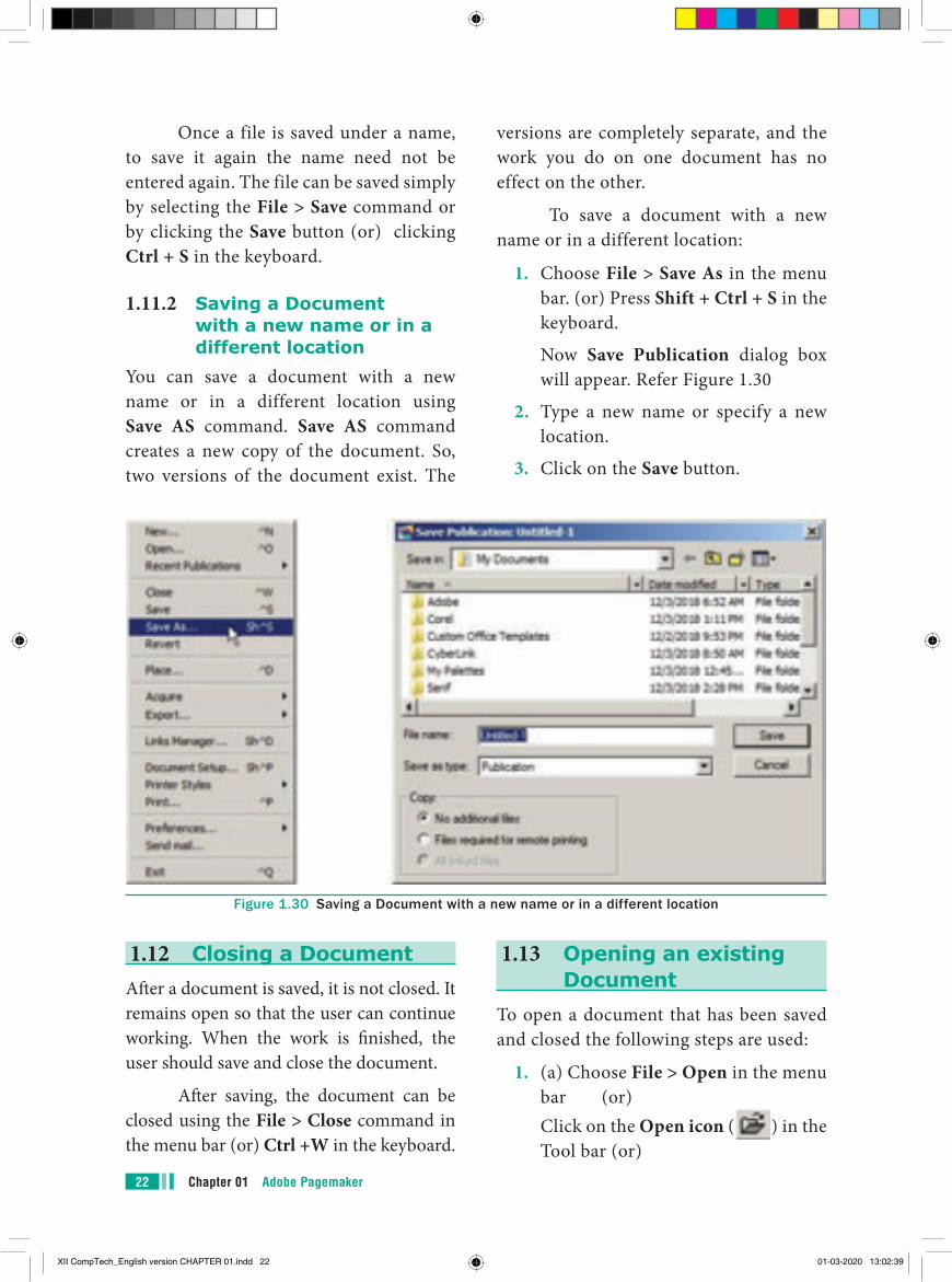
1.11.2 Saving a Document with a new name or in a different location
You can save a document with a new name or in a different location using Save AS command. Save AS command creates a new copy of the document. So, two versions of the document exist. The
versions are completely separate, and the work you do on one document has no effect on the other.
To save a document with a new name or in a different location:
1. Choose File > Save As in the menu bar. (or) Press Shift + Ctrl + S in the keyboard.
Now Save Publication dialog box will appear. Refer Figure 1.30
2. Type a new name or specify a new location.
3. Click on the Save button.
Figure 1.30 Saving a Document with a new name or in a different location
1.12 Closing a DocumentAfter a document is saved, it is not closed. It remains open so that the user can continue working. When the work is finished, the user should save and close the document.
After saving, the document can be closed using the File > Close command in the menu bar (or) Ctrl +W in the keyboard.
1.13 Opening an existing Document
To open a document that has been saved and closed the following steps are used:
1. (a) Choose File > Open in the menu bar (or)
Click on the Open icon ( ) in the Tool bar (or)
XII CompTech_English version CHAPTER 01.indd 22 01-03-2020 13:02:39
23Chapter 01 Adobe Pagemaker
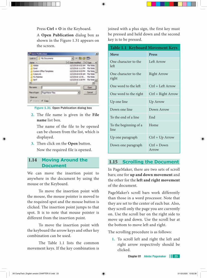
Press Ctrl + O in the Keyboard. A Open Publication dialog box as
shown in the Figure 1.31 appears on the screen.
Figure 1.31 Open Publication dialog box
2. The file name is given in the File name list box.
The name of the file to be opened can be chosen from the list, which is displayed.
3. Then click on the Open button. Now the required file is opened.
1.14 Moving Around the Document
We can move the insertion point to anywhere in the document by using the mouse or the Keyboard.
To move the insertion point with the mouse, the mouse pointer is moved to the required spot and the mouse button is clicked. The insertion point jumps to that spot. It is to note that mouse pointer is different from the insertion point.
To move the insertion point with the keyboard the arrow keys and other key combination can be used.
The Table 1.1 lists the common movement keys. If the key combination is
joined with a plus sign, the first key must be pressed and held down and the second key is to be pressed.
Table 1.1 Keyboard Movement KeysMove Press
One character to the left
Left Arrow
One character to the right
Right Arrow
One word to the left Ctrl + Left Arrow
One word to the right Ctrl + Right Arrow
Up one line Up Arrow
Down one line Down Arrow
To the end of a line End
To the beginning of a line
Home
Up one paragraph Ctrl + Up Arrow
Down one paragraph Ctrl + Down Arrow
1.15 Scrolling the DocumentIn PageMaker, there are two sets of scroll bars; one for up and down movement and the other for the left and right movement of the document.
PageMaker’s scroll bars work differently than those in a word processor. Note that they are set to the center of each bar. Also, they scroll only the page you are currently on. Use the scroll bar on the right side to move up and down. Use the scroll bar at the bottom to move left and right.
The scrolling procedure is as follows:
1. To scroll left and right the left and right arrow respectively should be clicked.
XII CompTech_English version CHAPTER 01.indd 23 01-03-2020 13:02:39
Chapter 01 Adobe Pagemaker24
2. To scroll up and down the up and down arrow respectively should be clicked.
3. To scroll a relative distance in the document the scroll box should be drawn up or down.
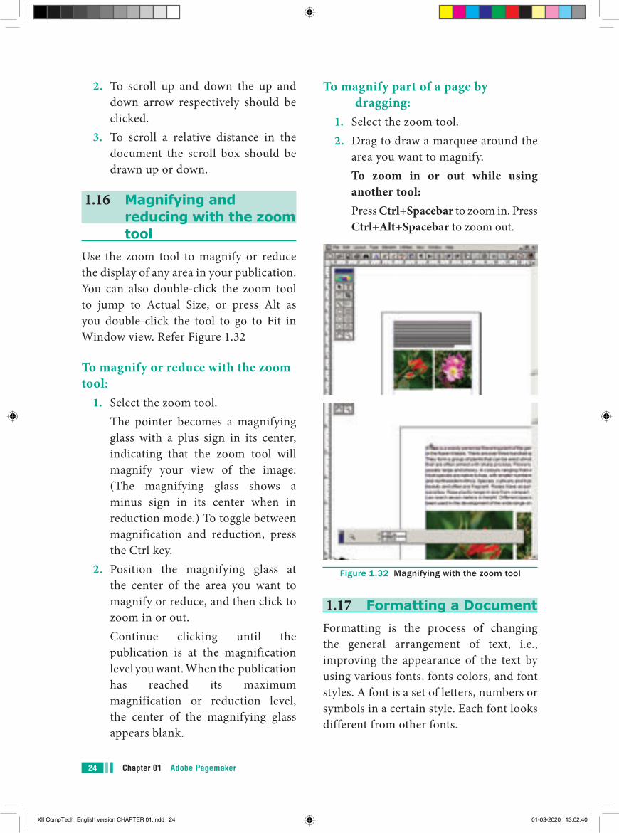
1.16 Magnifying and reducing with the zoom tool
Use the zoom tool to magnify or reduce the display of any area in your publication. You can also double-click the zoom tool to jump to Actual Size, or press Alt as you double-click the tool to go to Fit in Window view. Refer Figure 1.32
To magnify or reduce with the zoom tool:
1. Select the zoom tool. The pointer becomes a magnifying
glass with a plus sign in its center, indicating that the zoom tool will magnify your view of the image. (The magnifying glass shows a minus sign in its center when in reduction mode.) To toggle between magnification and reduction, press the Ctrl key.
2. Position the magnifying glass at the center of the area you want to magnify or reduce, and then click to zoom in or out.
Continue clicking until the publication is at the magnification level you want. When the publication has reached its maximum magnification or reduction level, the center of the magnifying glass appears blank.
To magnify part of a page by dragging:
1. Select the zoom tool.2. Drag to draw a marquee around the
area you want to magnify. To zoom in or out while using
another tool: Press Ctrl+Spacebar to zoom in. Press
Ctrl+Alt+Spacebar to zoom out.
Figure 1.32 Magnifying with the zoom tool
1.17 Formatting a DocumentFormatting is the process of changing the general arrangement of text, i.e., improving the appearance of the text by using various fonts, fonts colors, and font styles. A font is a set of letters, numbers or symbols in a certain style. Each font looks different from other fonts.
XII CompTech_English version CHAPTER 01.indd 24 01-03-2020 13:02:40
25Chapter 01 Adobe Pagemaker
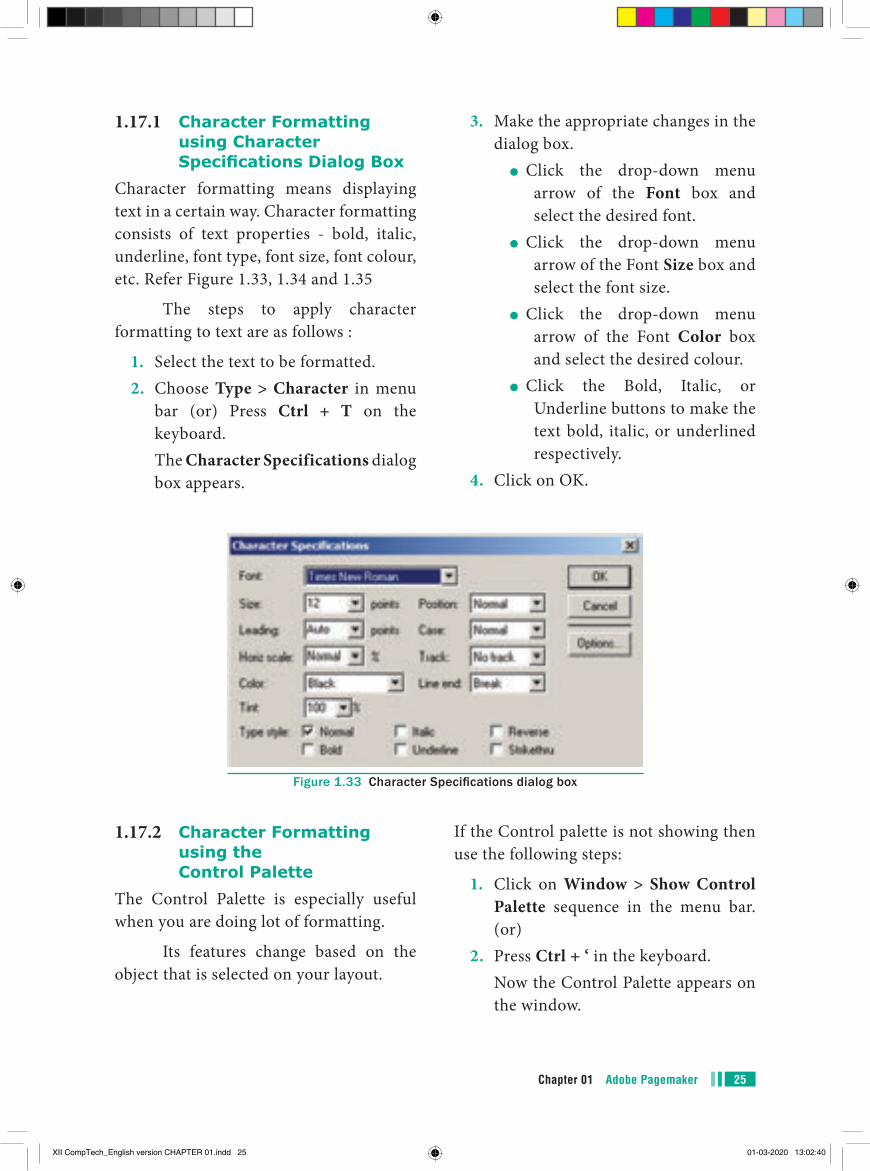
1.17.1 Character Formatting using Character Specifications Dialog Box
Character formatting means displaying text in a certain way. Character formatting consists of text properties - bold, italic, underline, font type, font size, font colour, etc. Refer Figure 1.33, 1.34 and 1.35
The steps to apply character formatting to text are as follows :
1. Select the text to be formatted.2. Choose Type > Character in menu
bar (or) Press Ctrl + T on the keyboard.
The Character Specifications dialog box appears.
3. Make the appropriate changes in the dialog box.
●● Click the drop-down menu arrow of the Font box and select the desired font.
●● Click the drop-down menu arrow of the Font Size box and select the font size.
●● Click the drop-down menu arrow of the Font Color box and select the desired colour.
●● Click the Bold, Italic, or Underline buttons to make the text bold, italic, or underlined respectively.
4. Click on OK.
Figure 1.33 Character Specifications dialog box
1.17.2 Character Formatting using the Control Palette
The Control Palette is especially useful when you are doing lot of formatting.
Its features change based on the object that is selected on your layout.
If the Control palette is not showing then use the following steps:
1. Click on Window > Show Control Palette sequence in the menu bar. (or)
2. Press Ctrl + ‘ in the keyboard. Now the Control Palette appears on
the window.
XII CompTech_English version CHAPTER 01.indd 25 01-03-2020 13:02:40
Chapter 01 Adobe Pagemaker26
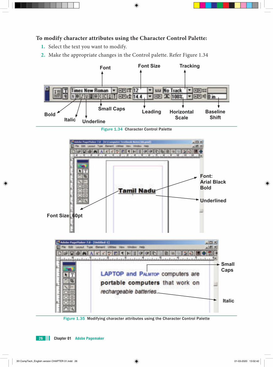
To modify character attributes using the Character Control Palette:1. Select the text you want to modify.2. Make the appropriate changes in the Control palette. Refer Figure 1.34
Bold
Font
Italic
Small Caps
Font Size
Underline
Leading Horizontal Scale
Tracking
Baseline Shift
Figure 1.34 Character Control Palette
Figure 1.35 Modifying character attributes using the Character Control Palette
Italic
Font Size: 60pt
Font: Arial Black Bold
Underlined
Small Caps
XII CompTech_English version CHAPTER 01.indd 26 01-03-2020 13:02:42
27Chapter 01 Adobe Pagemaker
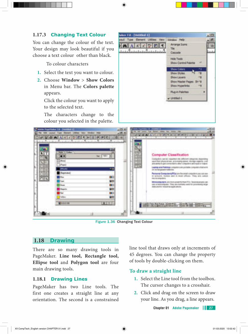
1.17.3 Changing Text ColourYou can change the colour of the text. Your design may look beautiful if you choose a text colour other than black.
To colour characters
1. Select the text you want to colour.2. Choose Window > Show Colors
in Menu bar. The Colors palette appears.
Click the colour you want to apply to the selected text.
The characters change to the colour you selected in the palette.
Figure 1.36 Changing Text Colour
1.18 DrawingThere are so many drawing tools in PageMaker. Line tool, Rectangle tool, Ellipse tool and Polygon tool are four main drawing tools.
1.18.1 Drawing LinesPageMaker has two Line tools. The first one creates a straight line at any orientation. The second is a constrained
line tool that draws only at increments of 45 degrees. You can change the property of tools by double-clicking on them.
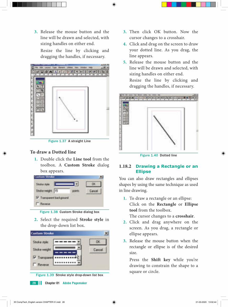
To draw a straight line1. Select the Line tool from the toolbox.
The cursor changes to a crosshair.2. Click and drag on the screen to draw
your line. As you drag, a line appears.
XII CompTech_English version CHAPTER 01.indd 27 01-03-2020 13:02:42
Chapter 01 Adobe Pagemaker28
3. Release the mouse button and the line will be drawn and selected, with sizing handles on either end.
Resize the line by clicking and dragging the handles, if necessary.
Figure 1.37 A straight Line
To draw a Dotted line1. Double click the Line tool from the
toolbox. A Custom Stroke dialog box appears.
Figure 1.38 Custom Stroke dialog box
2. Select the required Stroke style in the drop-down list box.
Figure 1.39 Stroke style drop-down list box
3. Then click OK button. Now the cursor changes to a crosshair.
4. Click and drag on the screen to draw your dotted line. As you drag, the line appears.
5. Release the mouse button and the line will be drawn and selected, with sizing handles on either end.
Resize the line by clicking and dragging the handles, if necessary.
Figure 1.40 Dotted line
1.18.2 Drawing a Rectangle or an Ellipse
You can also draw rectangles and ellipses shapes by using the same technique as used in line drawing.
1. To draw a rectangle or an ellipse: Click on the Rectangle or Ellipse
tool from the toolbox. The cursor changes to a crosshair.2. Click and drag anywhere on the
screen. As you drag, a rectangle or ellipse appears.
3. Release the mouse button when the rectangle or ellipse is of the desired size.
Press the Shift key while you’re drawing to constrain the shape to a square or circle.
XII CompTech_English version CHAPTER 01.indd 28 01-03-2020 13:02:44
29Chapter 01 Adobe Pagemaker
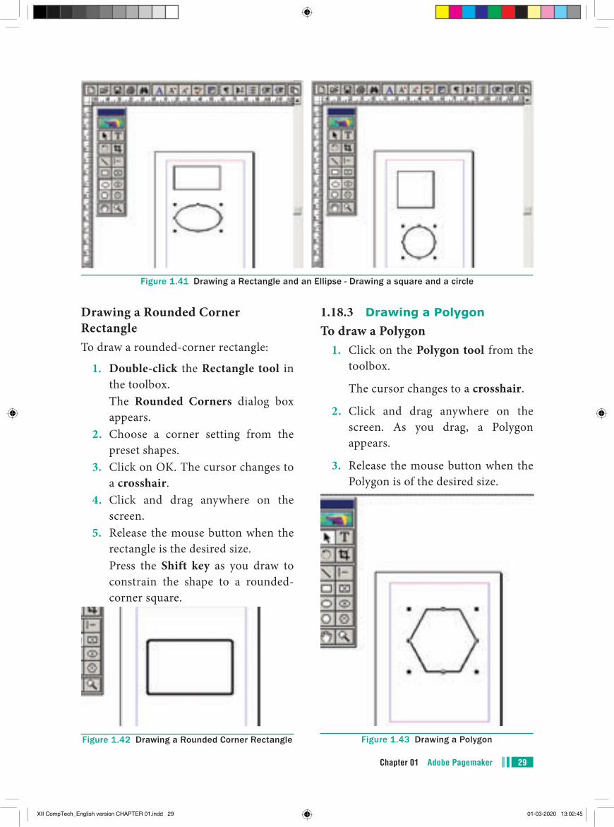
Figure 1.41 Drawing a Rectangle and an Ellipse - Drawing a square and a circle
Drawing a Rounded Corner RectangleTo draw a rounded-corner rectangle:
1. Double-click the Rectangle tool in the toolbox.
The Rounded Corners dialog box appears.
2. Choose a corner setting from the preset shapes.
3. Click on OK. The cursor changes to a crosshair.
4. Click and drag anywhere on the screen.
5. Release the mouse button when the rectangle is the desired size.
Press the Shift key as you draw to constrain the shape to a rounded-corner square.
Figure 1.42 Drawing a Rounded Corner Rectangle
1.18.3 Drawing a PolygonTo draw a Polygon
1. Click on the Polygon tool from the toolbox.
The cursor changes to a crosshair.
2. Click and drag anywhere on the screen. As you drag, a Polygon appears.
3. Release the mouse button when the Polygon is of the desired size.
Figure 1.43 Drawing a Polygon
XII CompTech_English version CHAPTER 01.indd 29 01-03-2020 13:02:45
Chapter 01 Adobe Pagemaker30
1.18.4 Drawing a Star using Polygon tool
To draw a Star1. Click on the Polygon tool from the
toolbox. The cursor changes to a crosshair.2. Click and drag anywhere on the
screen. As you drag, a Polygon appears.
3. Release the mouse button when the Polygon is of the desired size.
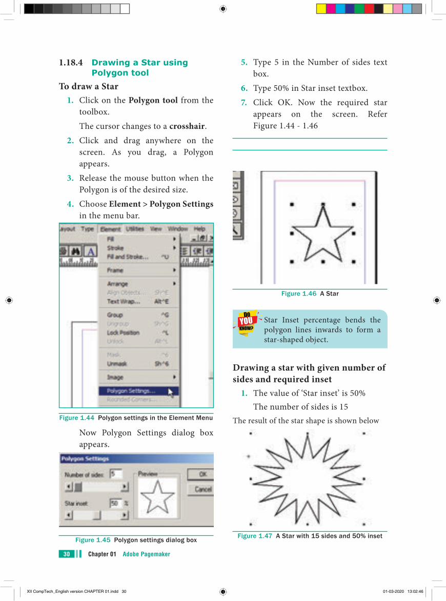
4. Choose Element > Polygon Settings in the menu bar.
Figure 1.44 Polygon settings in the Element Menu
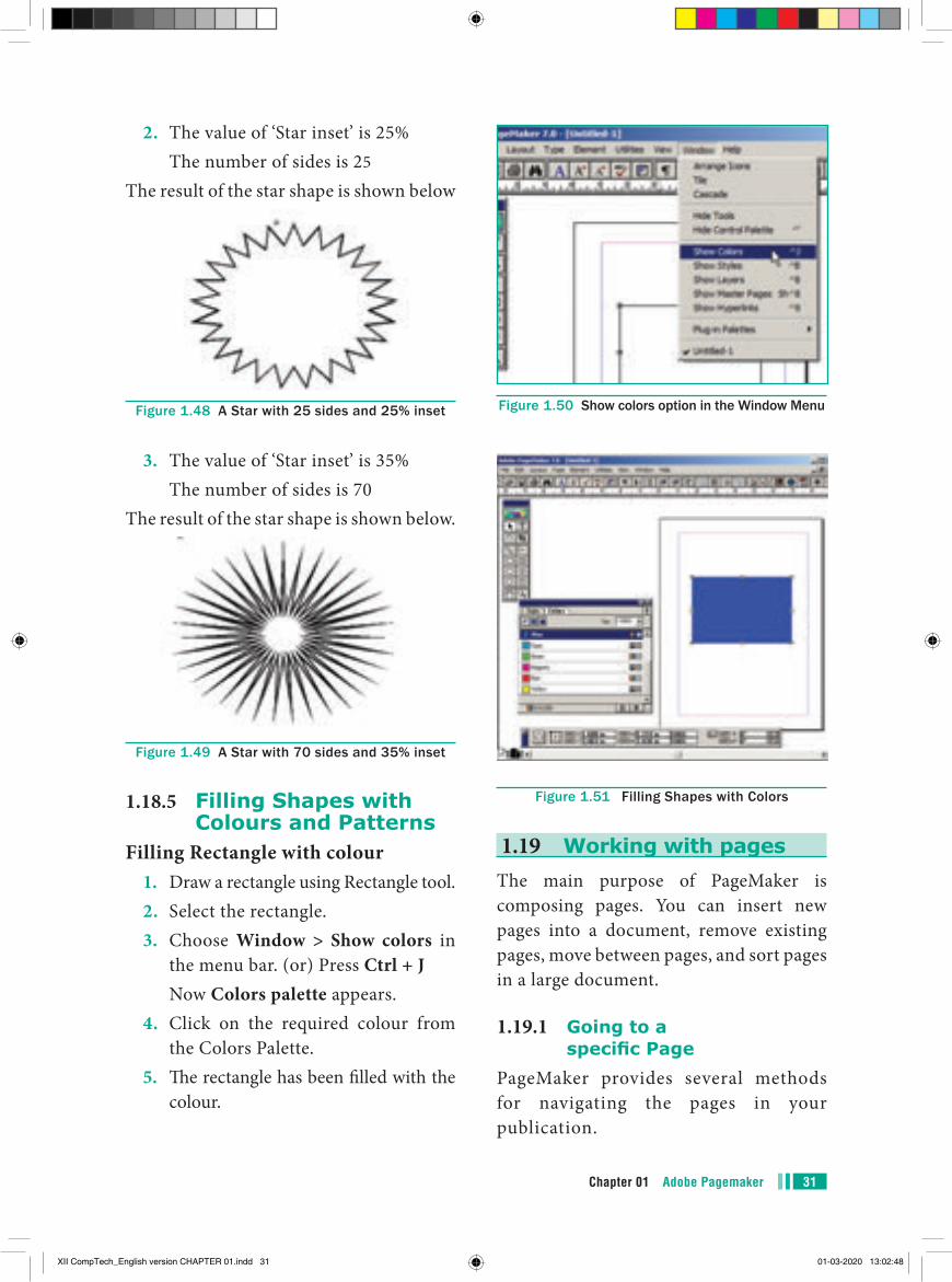
Now Polygon Settings dialog box appears.
Figure 1.45 Polygon settings dialog box
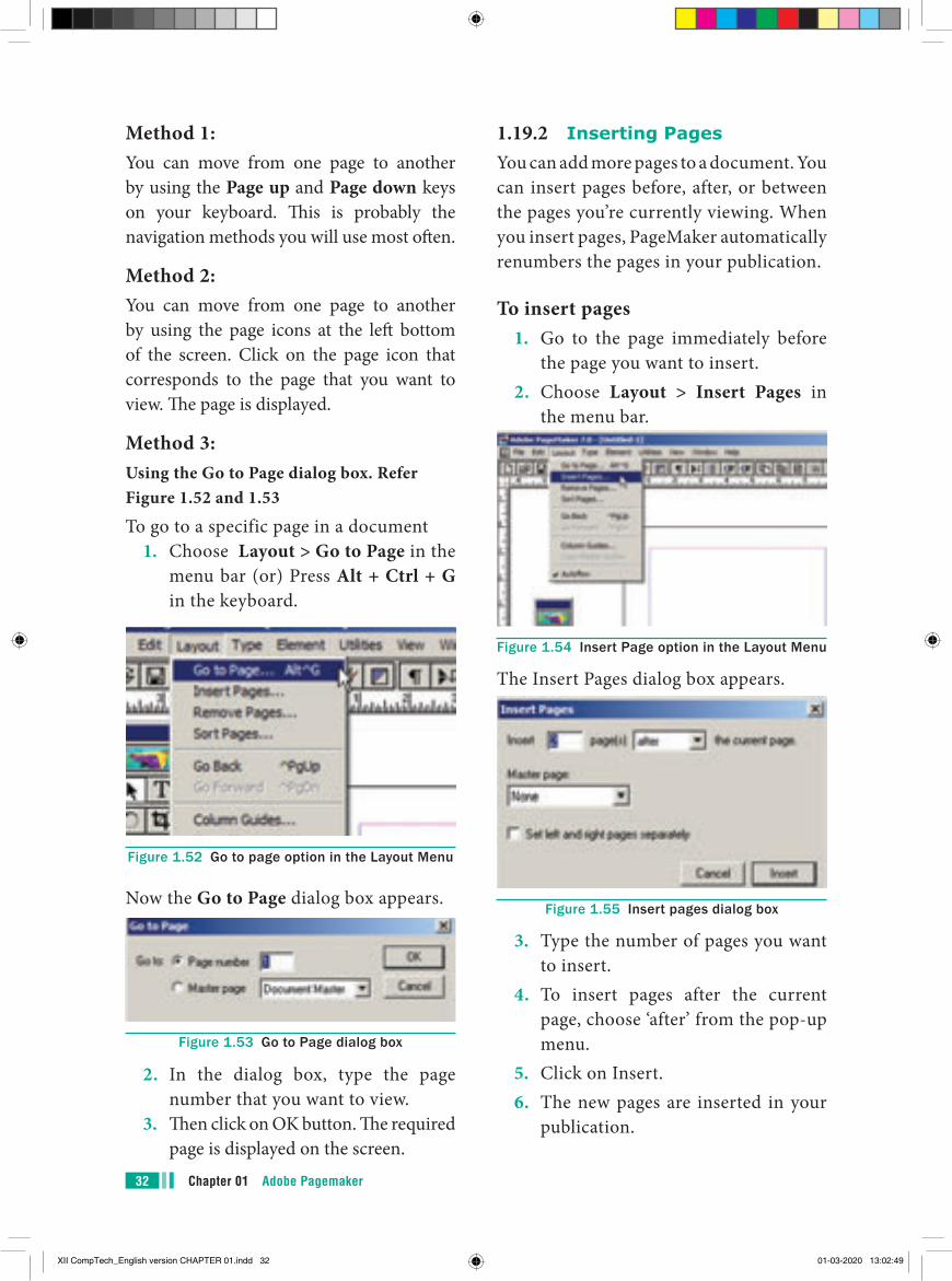
5. Type 5 in the Number of sides text box.
6. Type 50% in Star inset textbox. 7. Click OK. Now the required star
appears on the screen. Refer Figure 1.44 - 1.46
Figure 1.46 A Star
Star Inset percentage bends the polygon lines inwards to form a star-shaped object.
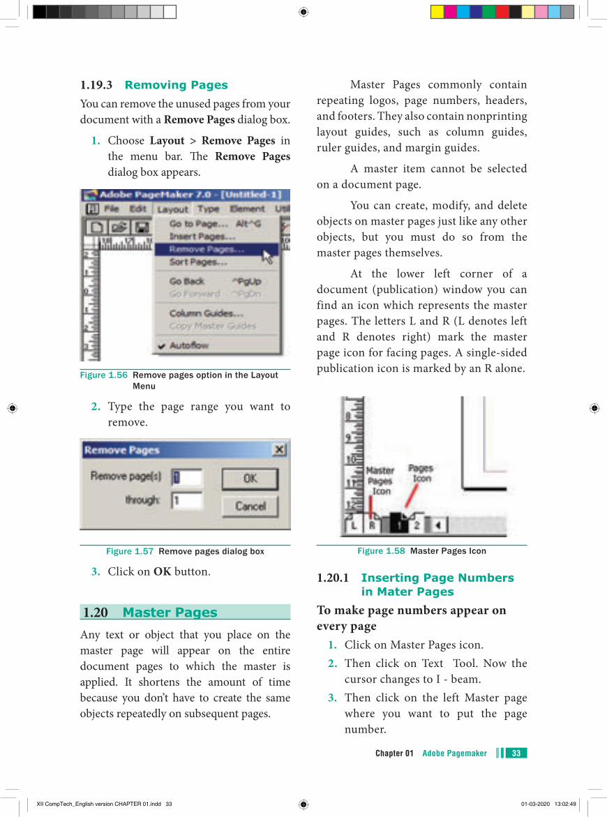
Drawing a star with given number of sides and required inset
1. The value of ‘Star inset’ is 50% The number of sides is 15
The result of the star shape is shown below
Figure 1.47 A Star with 15 sides and 50% inset
XII CompTech_English version CHAPTER 01.indd 30 01-03-2020 13:02:46
31Chapter 01 Adobe Pagemaker
2. The value of ‘Star inset’ is 25% The number of sides is 25
The result of the star shape is shown below
Figure 1.48 A Star with 25 sides and 25% inset
3. The value of ‘Star inset’ is 35% The number of sides is 70
The result of the star shape is shown below.
Figure 1.49 A Star with 70 sides and 35% inset
1.18.5 Filling Shapes with Colours and Patterns
Filling Rectangle with colour1. Draw a rectangle using Rectangle tool.2. Select the rectangle.3. Choose Window > Show colors in
the menu bar. (or) Press Ctrl + J Now Colors palette appears.4. Click on the required colour from
the Colors Palette.5. The rectangle has been filled with the
colour.
Figure 1.50 Show colors option in the Window Menu
Figure 1.51 Filling Shapes with Colors
1.19 Working with pagesThe main purpose of PageMaker is composing pages. You can insert new pages into a document, remove existing pages, move between pages, and sort pages in a large document.
1.19.1 Going to a specific Page
PageMaker provides several methods for navigating the pages in your publication.
XII CompTech_English version CHAPTER 01.indd 31 01-03-2020 13:02:48
Chapter 01 Adobe Pagemaker32
Method 1:You can move from one page to another by using the Page up and Page down keys on your keyboard. This is probably the navigation methods you will use most often.
Method 2:You can move from one page to another by using the page icons at the left bottom of the screen. Click on the page icon that corresponds to the page that you want to view. The page is displayed.
Method 3:Using the Go to Page dialog box. Refer Figure 1.52 and 1.53
To go to a specific page in a document1. Choose Layout > Go to Page in the
menu bar (or) Press Alt + Ctrl + G in the keyboard.
Figure 1.52 Go to page option in the Layout Menu
Now the Go to Page dialog box appears.
Figure 1.53 Go to Page dialog box
2. In the dialog box, type the page number that you want to view.
3. Then click on OK button. The required page is displayed on the screen.
1.19.2 Inserting PagesYou can add more pages to a document. You can insert pages before, after, or between the pages you’re currently viewing. When you insert pages, PageMaker automatically renumbers the pages in your publication.
To insert pages1. Go to the page immediately before
the page you want to insert.2. Choose Layout > Insert Pages in
the menu bar.
Figure 1.54 Insert Page option in the Layout Menu
The Insert Pages dialog box appears.
Figure 1.55 Insert pages dialog box
3. Type the number of pages you want to insert.
4. To insert pages after the current page, choose ‘after’ from the pop-up menu.
5. Click on Insert.6. The new pages are inserted in your
publication.
XII CompTech_English version CHAPTER 01.indd 32 01-03-2020 13:02:49
33Chapter 01 Adobe Pagemaker
1.19.3 Removing PagesYou can remove the unused pages from your document with a Remove Pages dialog box.
1. Choose Layout > Remove Pages in the menu bar. The Remove Pages dialog box appears.
Figure 1.56 Remove pages option in the Layout Menu
2. Type the page range you want to remove.
Figure 1.57 Remove pages dialog box
3. Click on OK button.
1.20 Master PagesAny text or object that you place on the master page will appear on the entire document pages to which the master is applied. It shortens the amount of time because you don’t have to create the same objects repeatedly on subsequent pages.
Master Pages commonly contain repeating logos, page numbers, headers, and footers. They also contain nonprinting layout guides, such as column guides, ruler guides, and margin guides.
A master item cannot be selected on a document page.
You can create, modify, and delete objects on master pages just like any other objects, but you must do so from the master pages themselves.
At the lower left corner of a document (publication) window you can find an icon which represents the master pages. The letters L and R (L denotes left and R denotes right) mark the master page icon for facing pages. A single-sided publication icon is marked by an R alone.
Figure 1.58 Master Pages Icon
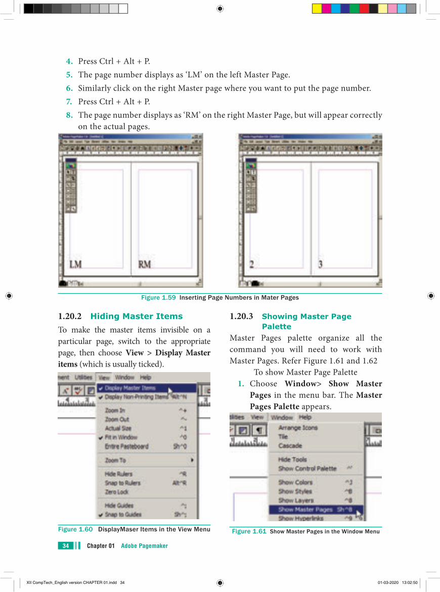
1.20.1 Inserting Page Numbers in Mater Pages
To make page numbers appear on every page
1. Click on Master Pages icon.2. Then click on Text Tool. Now the
cursor changes to I - beam.3. Then click on the left Master page
where you want to put the page number.
XII CompTech_English version CHAPTER 01.indd 33 01-03-2020 13:02:49
Chapter 01 Adobe Pagemaker34
4. Press Ctrl + Alt + P.5. The page number displays as ‘LM’ on the left Master Page.6. Similarly click on the right Master page where you want to put the page number.7. Press Ctrl + Alt + P.8. The page number displays as ‘RM’ on the right Master Page, but will appear correctly
on the actual pages.
Figure 1.59 Inserting Page Numbers in Mater Pages
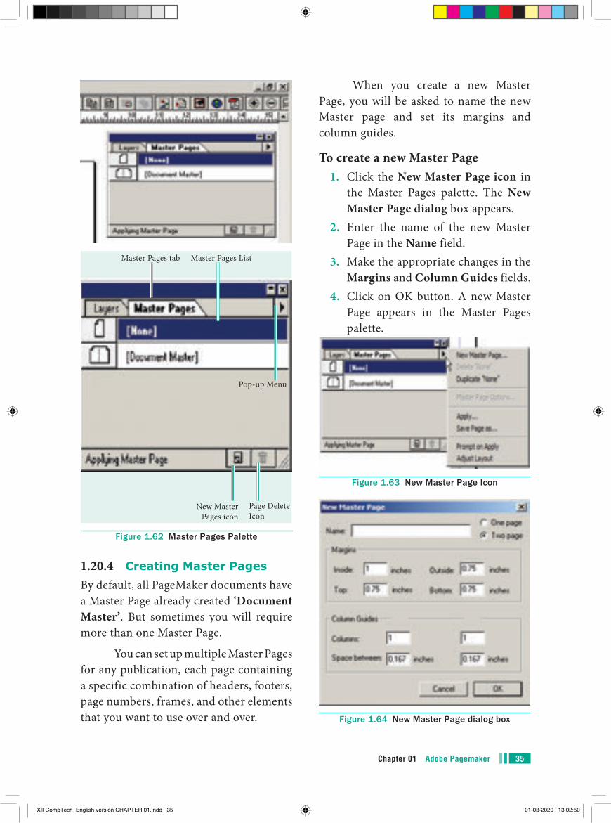
1.20.2 Hiding Master ItemsTo make the master items invisible on a particular page, switch to the appropriate page, then choose View > Display Master items (which is usually ticked).
Figure 1.60 DisplayMaser Items in the View Menu
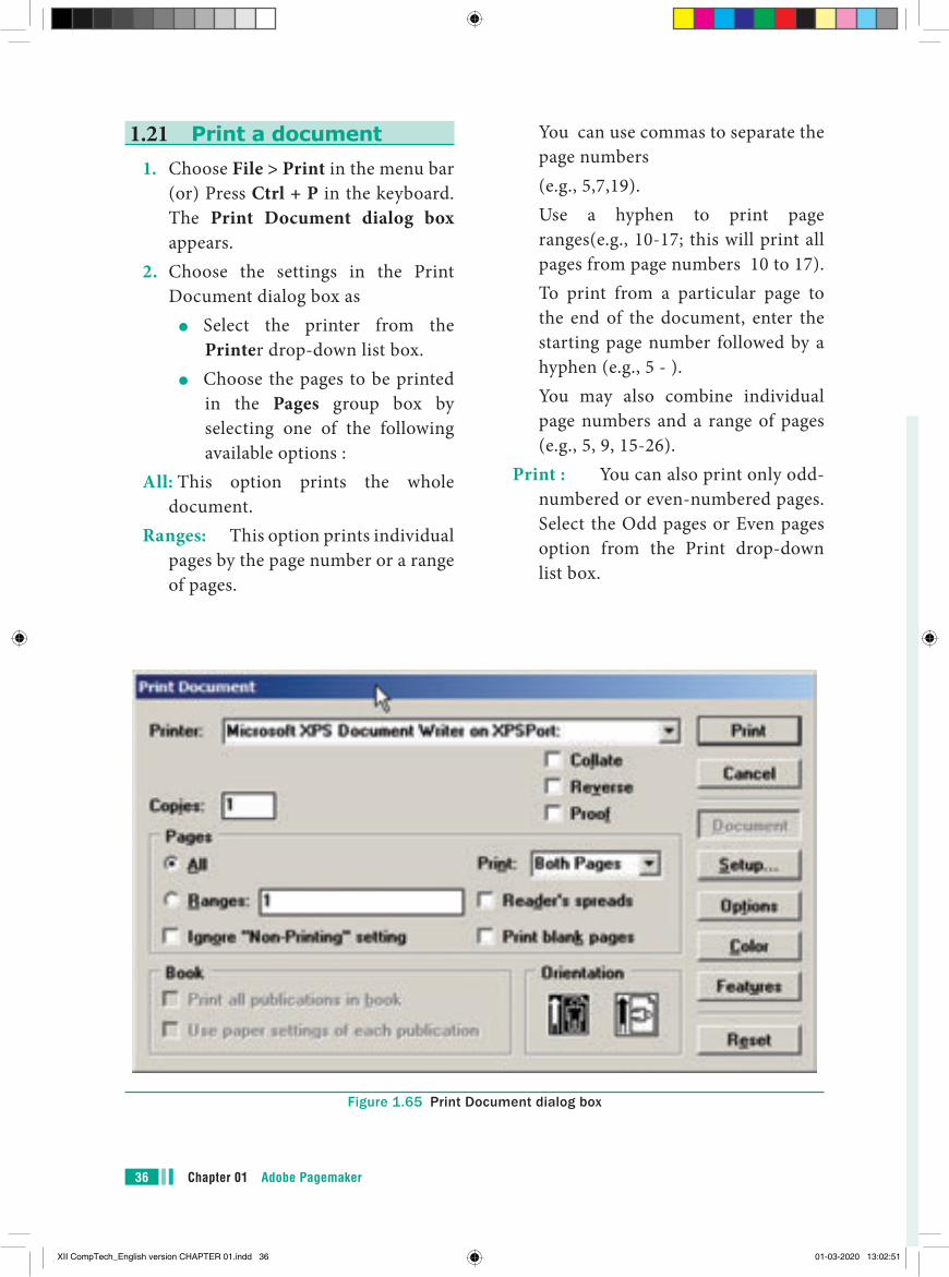
1.20.3 Showing Master Page Palette
Master Pages palette organize all the command you will need to work with Master Pages. Refer Figure 1.61 and 1.62
To show Master Page Palette1. Choose Window> Show Master
Pages in the menu bar. The Master Pages Palette appears.
Figure 1.61 Show Master Pages in the Window Menu
XII CompTech_English version CHAPTER 01.indd 34 01-03-2020 13:02:50
35Chapter 01 Adobe Pagemaker
Page Delete Icon
New Master Pages icon
Master Pages tab Master Pages List
Pop-up Menu
Figure 1.62 Master Pages Palette
1.20.4 Creating Master PagesBy default, all PageMaker documents have a Master Page already created ‘Document Master’. But sometimes you will require more than one Master Page.
You can set up multiple Master Pages for any publication, each page containing a specific combination of headers, footers, page numbers, frames, and other elements that you want to use over and over.
When you create a new Master Page, you will be asked to name the new Master page and set its margins and column guides.
To create a new Master Page1. Click the New Master Page icon in
the Master Pages palette. The New Master Page dialog box appears.
2. Enter the name of the new Master Page in the Name field.
3. Make the appropriate changes in the Margins and Column Guides fields.
4. Click on OK button. A new Master Page appears in the Master Pages palette.
Figure 1.63 New Master Page Icon
Figure 1.64 New Master Page dialog box
XII CompTech_English version CHAPTER 01.indd 35 01-03-2020 13:02:50
Chapter 01 Adobe Pagemaker36
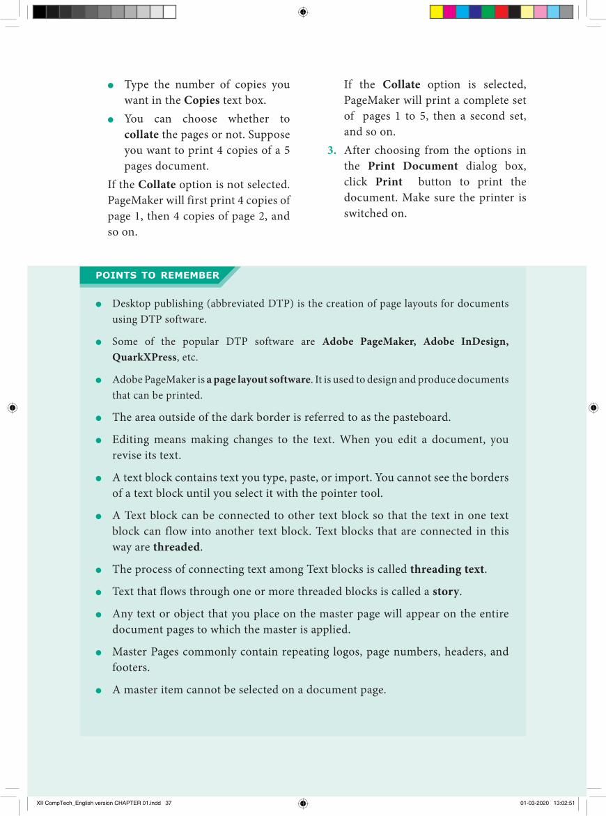
1.21 Print a document1. Choose File > Print in the menu bar
(or) Press Ctrl + P in the keyboard.The Print Document dialog box appears.
2. Choose the settings in the Print Document dialog box as
●● Select the printer from the Printer drop-down list box.
●● Choose the pages to be printed in the Pages group box by selecting one of the following available options :
All: This option prints the whole document.
Ranges: This option prints individual pages by the page number or a range of pages.
You can use commas to separate the page numbers
(e.g., 5,7,19). Use a hyphen to print page
ranges(e.g., 10-17; this will print all pages from page numbers 10 to 17).
To print from a particular page to the end of the document, enter the starting page number followed by a hyphen (e.g., 5 - ).
You may also combine individual page numbers and a range of pages (e.g., 5, 9, 15-26).
Print : You can also print only odd-numbered or even-numbered pages. Select the Odd pages or Even pages option from the Print drop-down list box.
Figure 1.65 Print Document dialog box
XII CompTech_English version CHAPTER 01.indd 36 01-03-2020 13:02:51
37Chapter 01 Adobe Pagemaker
●● Type the number of copies you want in the Copies text box.
●● You can choose whether to collate the pages or not. Suppose you want to print 4 copies of a 5 pages document.
If the Collate option is not selected. PageMaker will first print 4 copies of page 1, then 4 copies of page 2, and so on.
If the Collate option is selected, PageMaker will print a complete set of pages 1 to 5, then a second set, and so on.
3. After choosing from the options in the Print Document dialog box, click Print button to print the document. Make sure the printer is switched on.
●● Desktop publishing (abbreviated DTP) is the creation of page layouts for documents using DTP software.
●● Some of the popular DTP software are Adobe PageMaker, Adobe InDesign, QuarkXPress, etc.
●● Adobe PageMaker is a page layout software. It is used to design and produce documents that can be printed.
●● The area outside of the dark border is referred to as the pasteboard.
●● Editing means making changes to the text. When you edit a document, you revise its text.
●● A text block contains text you type, paste, or import. You cannot see the borders of a text block until you select it with the pointer tool.
●● A Text block can be connected to other text block so that the text in one text block can flow into another text block. Text blocks that are connected in this way are threaded.
●● The process of connecting text among Text blocks is called threading text.
●● Text that flows through one or more threaded blocks is called a story.
●● Any text or object that you place on the master page will appear on the entire document pages to which the master is applied.
●● Master Pages commonly contain repeating logos, page numbers, headers, and footers.
●● A master item cannot be selected on a document page.
points to remember
XII CompTech_English version CHAPTER 01.indd 37 01-03-2020 13:02:51

Chapter 01 Adobe Pagemaker38
Header Text that is repeated at the top of each page
Footer Text that is repeated at the bottom of each page
Symbol A sign or a special character that can be inserted in a PageMaker document
Margins Th e amount of space between the text and the edge of the page on all four sides
Orientation Th e direction(along the height or along the width) in which the page is being printed
Menu A list of commands
Editing Making changes to the text
Undo Reversing the last command
Redo Reversing the Undo command
Part IChoose the correct answer
1. DTP stan ds for ______________ (a) Desktop Publishing (b) Desktop Publication (c) Doctor To Patient (d) Desktop Printer2. ____________ is a DTP software. (a) Lotus 1-2-3 (b) PageMaker (c) Maya (d) Flash3. Which menu contains the New
option? (a) File menu (b) Edit menu (c) Layout menu (d) Type menu
EVALUATION EVALUATION
4. In PageMaker Window, the area outside of the dark border is referred to as _________.
(a) page (b) pasteboard (c) blackboard (d) dashboard5. Shortcut to close a document in
PageMaker is ______________ (a) Ctrl + A (b) Ctrl + B (c) Ctrl + C (d) Ctrl + W6. A __________ tool is used for
magnifying the particular portion of the area.
(a) Text tool (b) Line tool (c) Zoom tool (d) Hand tool
XII CompTech_English version CHAPTER 01.indd 38 01-03-2020 13:02:51
39Chapter 01 Adobe Pagemaker
7. _________ tool is used for drawing boxes.
(a) Line (b) Ellipse (c) Rectangle (d) Text8. Place option is present in
_____________ menu. (a) File (b) Edit (c) Layout (d) Window9. To select an entire document using
the keyboard, press ___________ (a) Ctrl + A (b) Ctrl + B (c) Ctrl + C (d) Ctrl + D10. Character formatting consists
of which of the following text properties?
(a) Bold (b) Italic (c) Underline (d) All of these11. Which tool lets you edit text? (a) Text tool (b) Type tool (c) Crop tool (d) Hand tool12. Shortcut to print a document in
Pagemaker is ___________ (a) Ctrl + A (b) Ctrl + P (c) Ctrl + C (d) Ctrl + V
13. Adobe PageMaker is a ___________ software.
14. ________ Bar is the topmost part of the PageMaker window.
15. _________ is the process of moving up and down or left and right through the document window.
16. ________ tool is used to draw a circle.
17. The Insert pages option is available on clicking the _________ menu.
18. Match the following. Cut - (i) Ctrl + Z Copy - (ii) Ctrl + V Paste - (iii) Ctrl + X Undo - (v) Ctrl + C
19 Choose the odd man out. i. Adobe PageMaker, QuarkXPress,
Adobe InDesign, Audacity ii. File, Edit, Layout, Type, Zipiii. Pointer Tool, Line tool, Hide Tool,
Hand Tooliv. Bold, Italic, Portrait, Underline
20. Choose the correct statement. i. (a) Text can be selected using mouse
only. (b) Text can be selected using mouse
or the keyboard. ii. (a) DTP is an abbreviation for
Desktop publishing. (b) DTP is an abbreviation for
Desktop publication.
21 Choose the correct pair (a) Edit and Cut (b) Edit and New (c) Undo and Copy (d) Undo and Redo
XII CompTech_English version CHAPTER 01.indd 39 01-03-2020 13:02:51
Chapter 01 Adobe Pagemaker40
Part - II Short Answers
1. What is desktop publishing?2. Give some examples of DTP software.3. Write the steps to open PageMaker.4. How do you create a New document in PageMaker?5. What is a Pasteboard in PageMaker?6. Write about the Menu bar of PageMaker.7. Differentiate Ellipse tool from Ellipse frame tool.8. What is text editing?9. What is text block?10. What is threading text blocks?11. What is threading text?12. How do you insert a page in PageMaker?
Part - IIIExplain in Brief Answer
1. What is PageMaker? Explain its uses.2. Mention three tools in PageMaker and write their keyboard shortcuts.3. Write the use of any three tools in PageMaker along with symbols.4. How do you rejoin split blocks?5. How do you link frames containing text?6. What is the use of Master Page?7. How to you insert page numbers in Master pages?
Part - IVExplain in detail
1. Explain the tools in PageMaker toolbox.2. Write the steps to place the text in a frame.3. How can you convert text in a text block to a frame?4. Write the steps to draw a star using polygon tool?
XII CompTech_English version CHAPTER 01.indd 40 01-03-2020 13:02:51
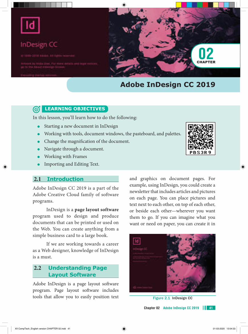
2.1 IntroductionAdobe InDesign CC 2019 is a part of the Adobe Creative Cloud family of software programs.
InDesign is a page layout software program used to design and produce documents that can be printed or used on the Web. You can create anything from a simple business card to a large book.
If we are working towards a career as a Web designer, knowledge of InDesign is a must.
2.2 Understanding Page Layout Software
Adobe InDesign is a page layout software program. Page layout software includes tools that allow you to easily position text
Adobe InDesign CC 2019
LEARNING OBJECTIVES
In this lesson, you’ll learn how to do the following:
●● Starting a new document in InDesign●● Working with tools, document windows, the pasteboard, and palettes.●● Change the magnification of the document.●● Navigate through a document.●● Working with Frames●● Importing and Editing Text.
02CHAPTER
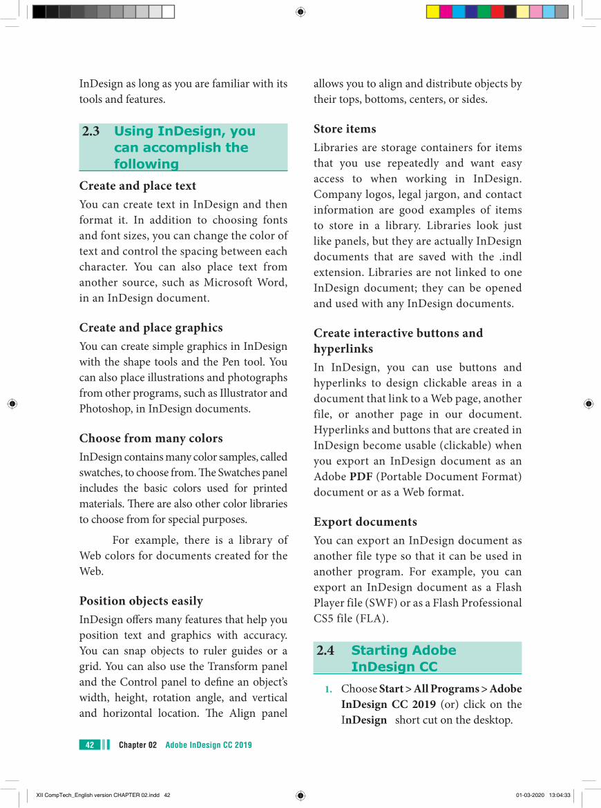
and graphics on document pages. For example, using InDesign, you could create a newsletter that includes articles and pictures on each page. You can place pictures and text next to each other, on top of each other, or beside each other—wherever you want them to go. If you can imagine what you want or need on paper, you can create it in
Figure 2.1 InDesign CC
41Chapter 02 Adobe InDesign CC 2019
XII CompTech_English version CHAPTER 02.indd 41 01-03-2020 13:04:33
Chapter 02 Adobe InDesign CC 201942
allows you to align and distribute objects by their tops, bottoms, centers, or sides.
Store itemsLibraries are storage containers for items that you use repeatedly and want easy access to when working in InDesign. Company logos, legal jargon, and contact information are good examples of items to store in a library. Libraries look just like panels, but they are actually InDesign documents that are saved with the .indl extension. Libraries are not linked to one InDesign document; they can be opened and used with any InDesign documents.
Create interactive buttons and hyperlinksIn InDesign, you can use buttons and hyperlinks to design clickable areas in a document that link to a Web page, another file, or another page in our document. Hyperlinks and buttons that are created in InDesign become usable (clickable) when you export an InDesign document as an Adobe PDF (Portable Document Format) document or as a Web format.
Export documentsYou can export an InDesign document as another file type so that it can be used in another program. For example, you can export an InDesign document as a Flash Player file (SWF) or as a Flash Professional CS5 file (FLA).
2.4 Starting Adobe InDesign CC
1. Choose Start > All Programs > Adobe InDesign CC 2019 (or) click on the InDesign short cut on the desktop.
InDesign as long as you are familiar with its tools and features.
2.3 Using InDesign, you can accomplish the following
Create and place textYou can create text in InDesign and then format it. In addition to choosing fonts and font sizes, you can change the color of text and control the spacing between each character. You can also place text from another source, such as Microsoft Word, in an InDesign document.
Create and place graphicsYou can create simple graphics in InDesign with the shape tools and the Pen tool. You can also place illustrations and photographs from other programs, such as Illustrator and Photoshop, in InDesign documents.
Choose from many colorsInDesign contains many color samples, called swatches, to choose from. The Swatches panel includes the basic colors used for printed materials. There are also other color libraries to choose from for special purposes.
For example, there is a library of Web colors for documents created for the Web.
Position objects easilyInDesign offers many features that help you position text and graphics with accuracy. You can snap objects to ruler guides or a grid. You can also use the Transform panel and the Control panel to define an object’s width, height, rotation angle, and vertical and horizontal location. The Align panel
XII CompTech_English version CHAPTER 02.indd 42 01-03-2020 13:04:33
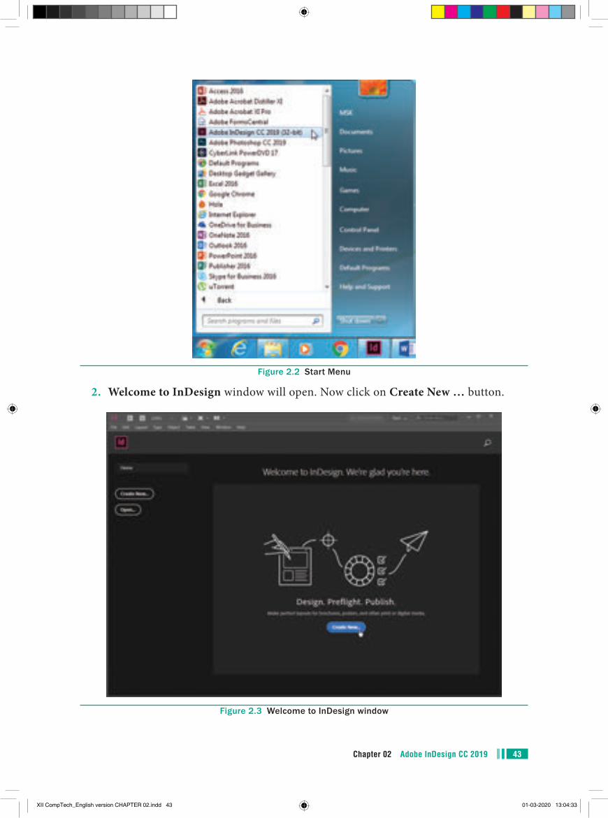
43Chapter 02 Adobe InDesign CC 2019
Figure 2.2 Start Menu
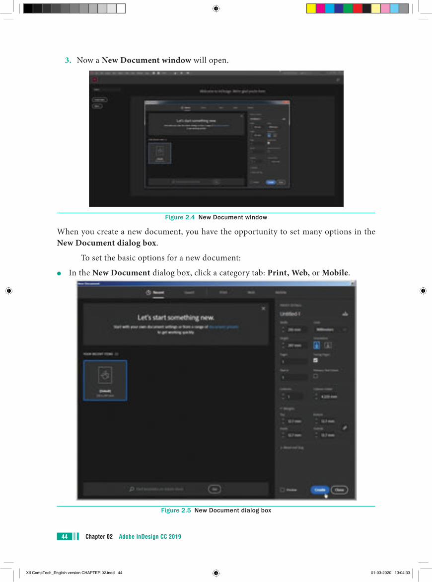
2. Welcome to InDesign window will open. Now click on Create New … button.
Figure 2.3 Welcome to InDesign window
XII CompTech_English version CHAPTER 02.indd 43 01-03-2020 13:04:33
Chapter 02 Adobe InDesign CC 201944
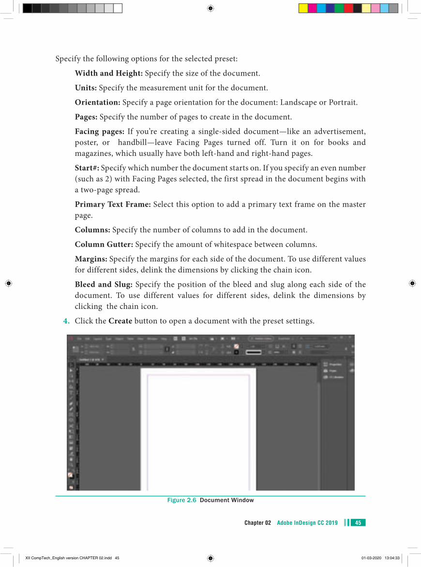
3. Now a New Document window will open.
Figure 2.4 New Document window
When you create a new document, you have the opportunity to set many options in the New Document dialog box.
To set the basic options for a new document:
●● In the New Document dialog box, click a category tab: Print, Web, or Mobile.
Figure 2.5 New Document dialog box
XII CompTech_English version CHAPTER 02.indd 44 01-03-2020 13:04:33
45Chapter 02 Adobe InDesign CC 2019
Specify the following options for the selected preset:
Width and Height: Specify the size of the document.
Units: Specify the measurement unit for the document.
Orientation: Specify a page orientation for the document: Landscape or Portrait.
Pages: Specify the number of pages to create in the document.
Facing pages: If you’re creating a single-sided document—like an advertisement, poster, or handbill—leave Facing Pages turned off. Turn it on for books and magazines, which usually have both left-hand and right-hand pages.
Start#: Specify which number the document starts on. If you specify an even number (such as 2) with Facing Pages selected, the first spread in the document begins with a two-page spread.
Primary Text Frame: Select this option to add a primary text frame on the master page.
Columns: Specify the number of columns to add in the document.
Column Gutter: Specify the amount of whitespace between columns.
Margins: Specify the margins for each side of the document. To use different values for different sides, delink the dimensions by clicking the chain icon.
Bleed and Slug: Specify the position of the bleed and slug along each side of the document. To use different values for different sides, delink the dimensions by clicking the chain icon.
4. Click the Create button to open a document with the preset settings.
Figure 2.6 Document Window
XII CompTech_English version CHAPTER 02.indd 45 01-03-2020 13:04:33
Chapter 02 Adobe InDesign CC 201946
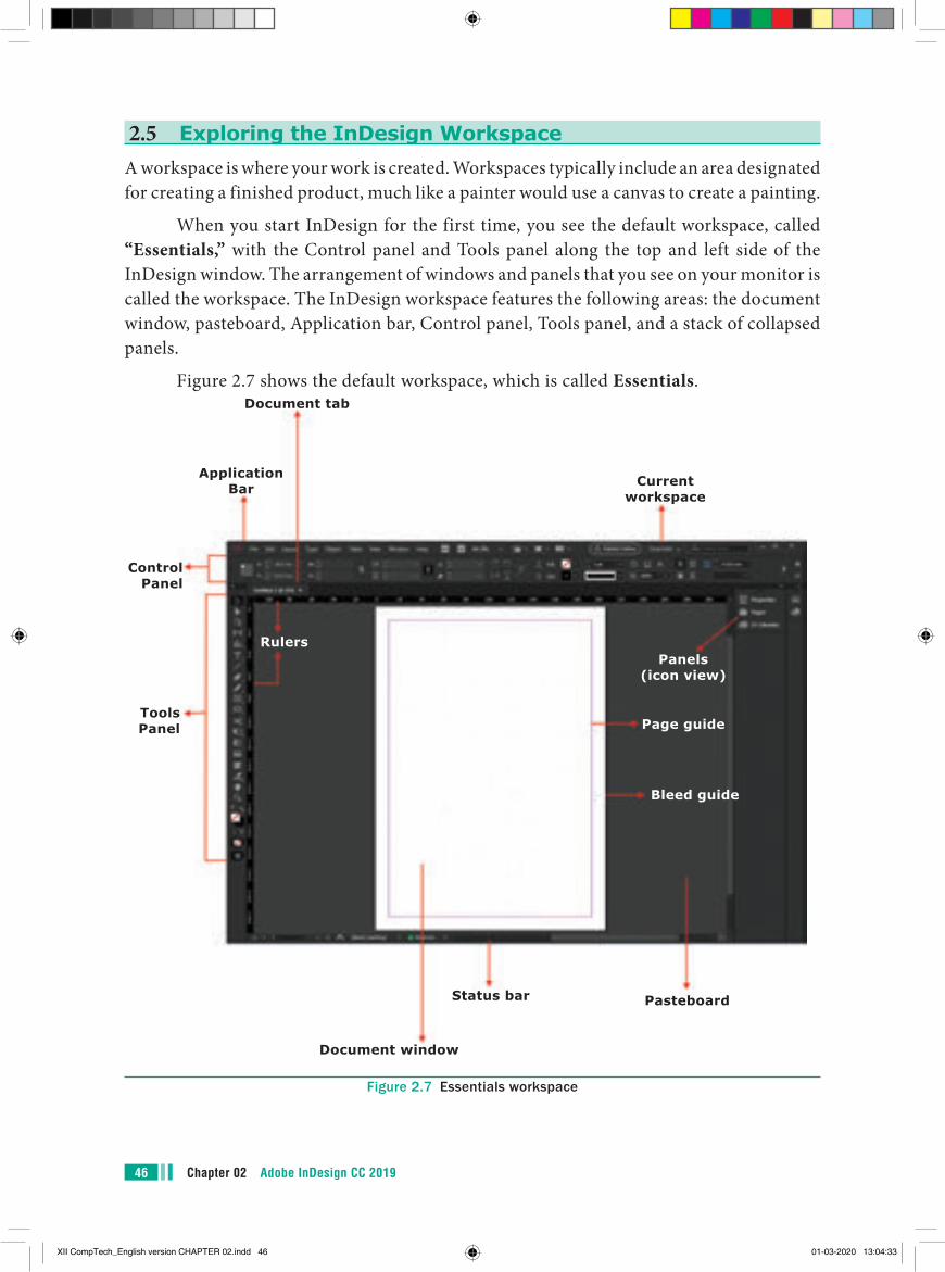
2.5 Exploring the InDesign WorkspaceA workspace is where your work is created. Workspaces typically include an area designated for creating a finished product, much like a painter would use a canvas to create a painting.
When you start InDesign for the first time, you see the default workspace, called “Essentials,” with the Control panel and Tools panel along the top and left side of the InDesign window. The arrangement of windows and panels that you see on your monitor is called the workspace. The InDesign workspace features the following areas: the document window, pasteboard, Application bar, Control panel, Tools panel, and a stack of collapsed panels.
Figure 2.7 shows the default workspace, which is called Essentials.
Application Bar
Control Panel
Rulers
Tools Panel
Document window
PasteboardStatus bar
Page guide
Bleed guide
Panels (icon view)
Document tab
Current workspace
Figure 2.7 Essentials workspace
XII CompTech_English version CHAPTER 02.indd 46 01-03-2020 13:04:33
47Chapter 02 Adobe InDesign CC 2019
InDesign CC 2019 offers a number of predefined workspaces that are customized for different types of tasks. Each workspace in InDesign is designed so that panels with similar functions are grouped together. For example, the Typography workspace shows the many type- and typography-based panels that are useful for working with type. You can switch from one workspace to another by clicking Window on the application bar, pointing to Workspace, and then choosing a workspace.
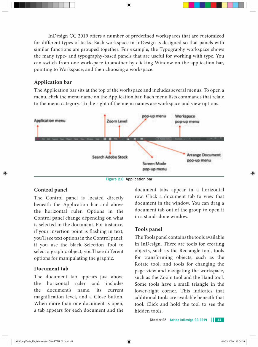
Application barThe Application bar sits at the top of the workspace and includes several menus. To open a menu, click the menu name on the Application bar. Each menu lists commands that relate to the menu category. To the right of the menu names are workspace and view options.
Figure 2.8 Application bar
Control panelThe Control panel is located directly beneath the Application bar and above the horizontal ruler. Options in the Control panel change depending on what is selected in the document. For instance, if your insertion point is flashing in text, you’ll see text options in the Control panel; if you use the black Selection Tool to select a graphic object, you’ll see different options for manipulating the graphic.
Document tabThe document tab appears just above the horizontal ruler and includes the document’s name, its current magnification level, and a Close button. When more than one document is open, a tab appears for each document and the
document tabs appear in a horizontal row. Click a document tab to view that document in the window. You can drag a document tab out of the group to open it in a stand-alone window.
Tools panelThe Tools panel contains the tools available in InDesign. There are tools for creating objects, such as the Rectangle tool, tools for transforming objects, such as the Rotate tool, and tools for changing the page view and navigating the workspace, such as the Zoom tool and the Hand tool. Some tools have a small triangle in the lower-right corner. This indicates that additional tools are available beneath that tool. Click and hold the tool to see the hidden tools.
XII CompTech_English version CHAPTER 02.indd 47 01-03-2020 13:04:33
Chapter 02 Adobe InDesign CC 201948
2.6 Naming and Saving a Document
Saving your work is very important so that you don’t lose anything that you’ve created.
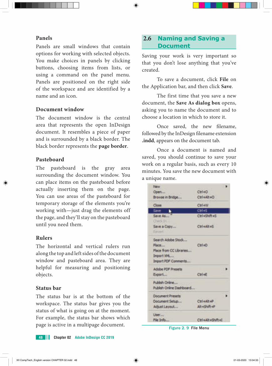
To save a document, click File on the Application bar, and then click Save.
The first time that you save a new document, the Save As dialog box opens, asking you to name the document and to choose a location in which to store it.
Once saved, the new filename, followed by the InDesign filename extension .indd, appears on the document tab.
Once a document is named and saved, you should continue to save your work on a regular basis, such as every 10 minutes. You save the new document with a unique name.
Figure 2. 9 File Menu
PanelsPanels are small windows that contain options for working with selected objects. You make choices in panels by clicking buttons, choosing items from lists, or using a command on the panel menu. Panels are positioned on the right side of the workspace and are identified by a name and an icon.
Document windowThe document window is the central area that represents the open InDesign document. It resembles a piece of paper and is surrounded by a black border. The black border represents the page border.
PasteboardThe pasteboard is the gray area surrounding the document window. You can place items on the pasteboard before actually inserting them on the page. You can use areas of the pasteboard for temporary storage of the elements you’re working with—just drag the elements off the page, and they’ll stay on the pasteboard until you need them.
RulersThe horizontal and vertical rulers run along the top and left sides of the document window and pasteboard area. They are helpful for measuring and positioning objects.
Status barThe status bar is at the bottom of the workspace. The status bar gives you the status of what is going on at the moment. For example, the status bar shows which page is active in a multipage document.
XII CompTech_English version CHAPTER 02.indd 48 01-03-2020 13:04:33
49Chapter 02 Adobe InDesign CC 2019
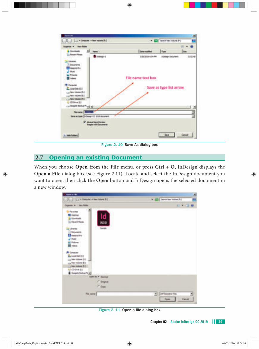
2.7 Opening an existing DocumentWhen you choose Open from the File menu, or press Ctrl + O, InDesign displays the Open a File dialog box (see Figure 2.11). Locate and select the InDesign document you want to open, then click the Open button and InDesign opens the selected document in a new window.
Figure 2. 11 Open a file dialog box
Figure 2. 10 Save As dialog box
XII CompTech_English version CHAPTER 02.indd 49 01-03-2020 13:04:34
Chapter 02 Adobe InDesign CC 201950
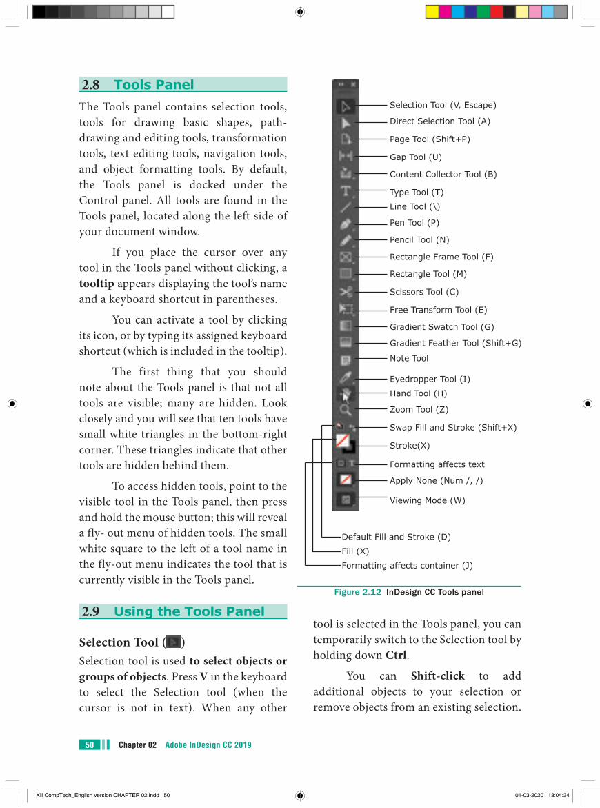
2.8 Tools PanelThe Tools panel contains selection tools, tools for drawing basic shapes, path-drawing and editing tools, transformation tools, text editing tools, navigation tools, and object formatting tools. By default, the Tools panel is docked under the Control panel. All tools are found in the Tools panel, located along the left side of your document window.
If you place the cursor over any tool in the Tools panel without clicking, a tooltip appears displaying the tool’s name and a keyboard shortcut in parentheses.
You can activate a tool by clicking its icon, or by typing its assigned keyboard shortcut (which is included in the tooltip).
The first thing that you should note about the Tools panel is that not all tools are visible; many are hidden. Look closely and you will see that ten tools have small white triangles in the bottom-right corner. These triangles indicate that other tools are hidden behind them.
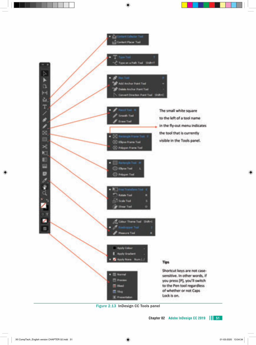
To access hidden tools, point to the visible tool in the Tools panel, then press and hold the mouse button; this will reveal a fly- out menu of hidden tools. The small white square to the left of a tool name in the fly-out menu indicates the tool that is currently visible in the Tools panel.
2.9 Using the Tools Panel
Selection Tool ( )Selection tool is used to select objects or groups of objects. Press V in the keyboard to select the Selection tool (when the cursor is not in text). When any other
Selection Tool (V, Escape)
Direct Selection Tool (A)
Page Tool (Shift+P)
Gap Tool (U)
Content Collector Tool (B)
Type Tool (T)
Line Tool (\)
Pen Tool (P)
Pencil Tool (N)
Rectangle Frame Tool (F)
Rectangle Tool (M)
Scissors Tool (C)
Free Transform Tool (E)
Gradient Swatch Tool (G)
Gradient Feather Tool (Shift+G)
Note Tool
Eyedropper Tool (I)
Hand Tool (H)
Zoom Tool (Z)
Swap Fill and Stroke (Shift+X)
Stroke(X)
Formatting affects text
Apply None (Num /, /)
Viewing Mode (W)
Default Fill and Stroke (D)
Fill (X)
Formatting affects container (J)
Figure 2.12 InDesign CC Tools panel
tool is selected in the Tools panel, you can temporarily switch to the Selection tool by holding down Ctrl.
You can Shift-click to add additional objects to your selection or remove objects from an existing selection.
XII CompTech_English version CHAPTER 02.indd 50 01-03-2020 13:04:34
51Chapter 02 Adobe InDesign CC 2019
Figure 2.13 InDesign CC Tools panel
XII CompTech_English version CHAPTER 02.indd 51 01-03-2020 13:04:34
Chapter 02 Adobe InDesign CC 201952
one or more points on a path of a single object.
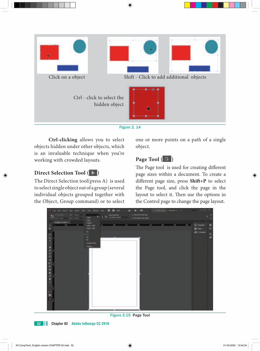
Page Tool ( )Th e Page tool is used for creating diff erent page sizes within a document. To create a diff erent page size, press Shift +P to select the Page tool, and click the page in the layout to select it. Th en use the options in the Control page to change the page layout.
Ctrl-clicking allows you to select objects hidden under other objects, which is an invaluable technique when you’re working with crowded layouts.
Direct Selection Tool ( )The Direct Selection tool(press A) is used to select single object out of a group (several individual objects grouped together with the Object, Group command) or to select
Ctrl - click to select the hidden object
Click on a object Shift - Click to add additional objects
Figure 2. 14
Figure 2.15 Page Tool
XII CompTech_English version CHAPTER 02.indd 52 01-03-2020 13:04:34
53Chapter 02 Adobe InDesign CC 2019
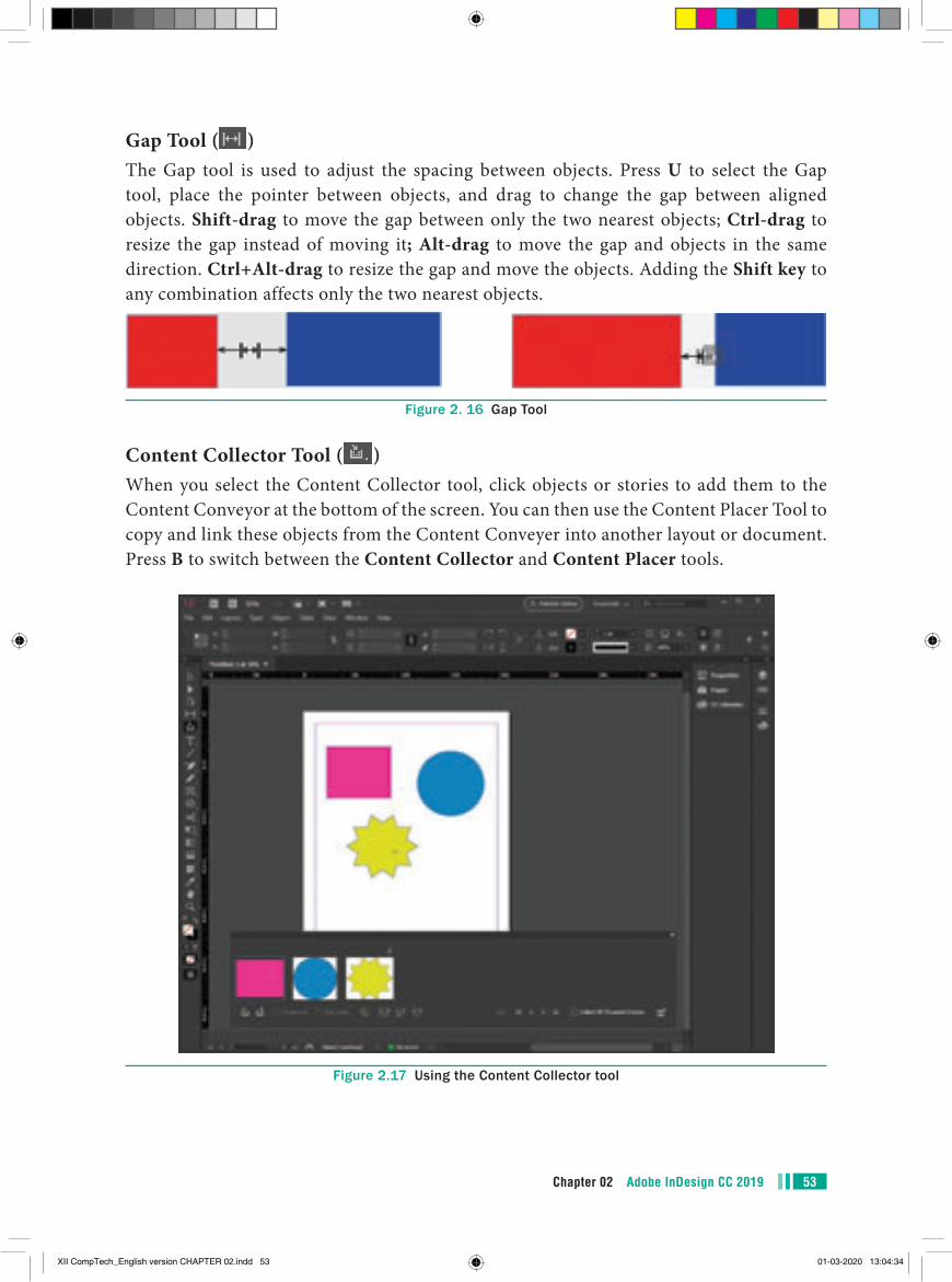
Gap Tool ( )The Gap tool is used to adjust the spacing between objects. Press U to select the Gap tool, place the pointer between objects, and drag to change the gap between aligned objects. Shift-drag to move the gap between only the two nearest objects; Ctrl-drag to resize the gap instead of moving it; Alt-drag to move the gap and objects in the same direction. Ctrl+Alt-drag to resize the gap and move the objects. Adding the Shift key to any combination affects only the two nearest objects.
Figure 2. 16 Gap Tool
Content Collector Tool ( )When you select the Content Collector tool, click objects or stories to add them to the Content Conveyor at the bottom of the screen. You can then use the Content Placer Tool to copy and link these objects from the Content Conveyer into another layout or document. Press B to switch between the Content Collector and Content Placer tools.
Figure 2.17 Using the Content Collector tool
XII CompTech_English version CHAPTER 02.indd 53 01-03-2020 13:04:34
Chapter 02 Adobe InDesign CC 201954
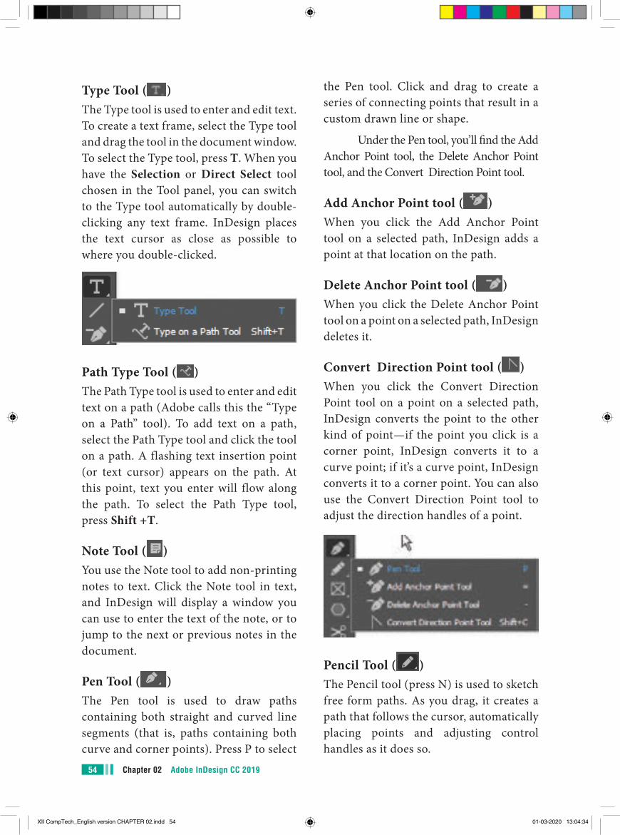
the Pen tool. Click and drag to create a series of connecting points that result in a custom drawn line or shape.
Under the Pen tool, you’ll find the Add Anchor Point tool, the Delete Anchor Point tool, and the Convert Direction Point tool.
Add Anchor Point tool ( )When you click the Add Anchor Point tool on a selected path, InDesign adds a point at that location on the path.
Delete Anchor Point tool ( )When you click the Delete Anchor Point tool on a point on a selected path, InDesign deletes it.
Convert Direction Point tool ( )When you click the Convert Direction Point tool on a point on a selected path, InDesign converts the point to the other kind of point—if the point you click is a corner point, InDesign converts it to a curve point; if it’s a curve point, InDesign converts it to a corner point. You can also use the Convert Direction Point tool to adjust the direction handles of a point.
Pencil Tool ( )The Pencil tool (press N) is used to sketch free form paths. As you drag, it creates a path that follows the cursor, automatically placing points and adjusting control handles as it does so.
Type Tool ( )The Type tool is used to enter and edit text. To create a text frame, select the Type tool and drag the tool in the document window. To select the Type tool, press T. When you have the Selection or Direct Select tool chosen in the Tool panel, you can switch to the Type tool automatically by double-clicking any text frame. InDesign places the text cursor as close as possible to where you double-clicked.
Path Type Tool ( )The Path Type tool is used to enter and edit text on a path (Adobe calls this the “Type on a Path” tool). To add text on a path, select the Path Type tool and click the tool on a path. A flashing text insertion point (or text cursor) appears on the path. At this point, text you enter will flow along the path. To select the Path Type tool, press Shift +T.
Note Tool ( )You use the Note tool to add non-printing notes to text. Click the Note tool in text, and InDesign will display a window you can use to enter the text of the note, or to jump to the next or previous notes in the document.
Pen Tool ( )The Pen tool is used to draw paths containing both straight and curved line segments (that is, paths containing both curve and corner points). Press P to select
XII CompTech_English version CHAPTER 02.indd 54 01-03-2020 13:04:34
55Chapter 02 Adobe InDesign CC 2019
the line segments and points where you dragged the Eraser tool.
Line Tool ( )The Line tool is used to draw straight lines—paths containing two corner points. If you hold down Shift as you drag the Line tool, the lines you draw will be constrained to 0-, 45-, and 90-degree angles. Press \ (backslash) to select the Line tool.
Ellipse Tool ( )The Ellipse tool draws ovals and circles. To draw an oval, click and drag. To draw a circle, press the Shift key while dragging.
Rectangle Tool ( )The Rectangle tool draws both rectangles and squares. To draw a rectangle, click and drag. To constrain that rectangle to a square, press the Shift key while dragging (be sure to keep it pressed until you release the mouse button).
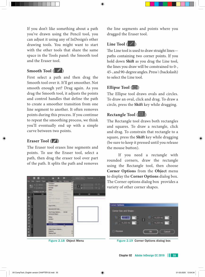
If you need a rectangle with rounded corners, draw the rectangle using the Rectangle tool, then choose Corner Options from the Object menu to display the Corner Options dialog box. The Corner options dialog box provides a variety of other corner shapes.
If you don’t like something about a path you’ve drawn using the Pencil tool, you can adjust it using any of InDesign’s other drawing tools. You might want to start with the other tools that share the same space in the Tools panel: the Smooth tool and the Eraser tool.
Smooth Tool ( )First select a path and then drag the Smooth tool over it. It’ll get smoother. Not smooth enough yet? Drag again. As you drag the Smooth tool, it adjusts the points and control handles that define the path to create a smoother transition from one line segment to another. It often removes points during this process. If you continue to repeat the smoothing process, we think you’ll eventually end up with a simple curve between two points.
Eraser Tool ( )The Eraser tool erases line segments and points. To use the Eraser tool, select a path, then drag the eraser tool over part of the path. It splits the path and removes
Figure 2.18 Object Menu Figure 2.19 Corner Options dialog box
XII CompTech_English version CHAPTER 02.indd 55 01-03-2020 13:04:34
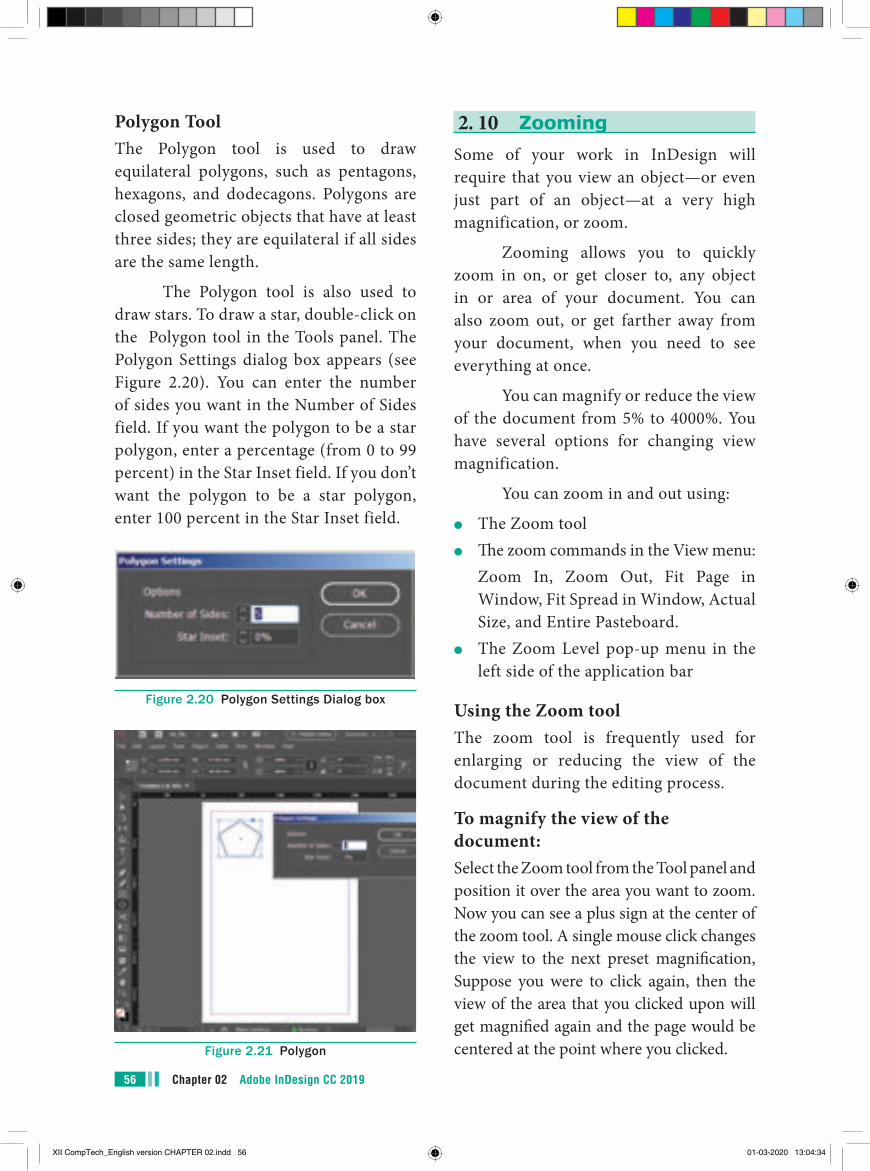
Chapter 02 Adobe InDesign CC 201956
2. 10 ZoomingSome of your work in InDesign will require that you view an object—or even just part of an object—at a very high magnification, or zoom.
Zooming allows you to quickly zoom in on, or get closer to, any object in or area of your document. You can also zoom out, or get farther away from your document, when you need to see everything at once.
You can magnify or reduce the view of the document from 5% to 4000%. You have several options for changing view magnification.
You can zoom in and out using:
●● The Zoom tool●● The zoom commands in the View menu:
Zoom In, Zoom Out, Fit Page in Window, Fit Spread in Window, Actual Size, and Entire Pasteboard.
●● The Zoom Level pop-up menu in the left side of the application bar
Using the Zoom toolThe zoom tool is frequently used for enlarging or reducing the view of the document during the editing process.
To magnify the view of the document:Select the Zoom tool from the Tool panel and position it over the area you want to zoom. Now you can see a plus sign at the center of the zoom tool. A single mouse click changes the view to the next preset magnification, Suppose you were to click again, then the view of the area that you clicked upon will get magnified again and the page would be centered at the point where you clicked.
Polygon ToolThe Polygon tool is used to draw equilateral polygons, such as pentagons, hexagons, and dodecagons. Polygons are closed geometric objects that have at least three sides; they are equilateral if all sides are the same length.
The Polygon tool is also used to draw stars. To draw a star, double-click on the Polygon tool in the Tools panel. The Polygon Settings dialog box appears (see Figure 2.20). You can enter the number of sides you want in the Number of Sides field. If you want the polygon to be a star polygon, enter a percentage (from 0 to 99 percent) in the Star Inset field. If you don’t want the polygon to be a star polygon, enter 100 percent in the Star Inset field.
Figure 2.20 Polygon Settings Dialog box
Figure 2.21 Polygon
XII CompTech_English version CHAPTER 02.indd 56 01-03-2020 13:04:34
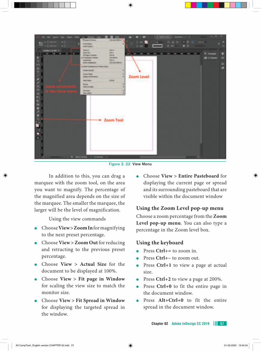
57Chapter 02 Adobe InDesign CC 2019
●● Choose View > Entire Pasteboard for displaying the current page or spread and its surrounding pasteboard that are visible within the document window
Using the Zoom Level pop-up menuChoose a zoom percentage from the Zoom Level pop-up menu. You can also type a percentage in the Zoom level box.
Using the keyboard●● Press Ctrl+= to zoom in.●● Press Ctrl+– to zoom out.●● Press Ctrl+1 to view a page at actual
size.●● Press Ctrl+2 to view a page at 200%.●● Press Ctrl+0 to fit the entire page in
the document window.●● Press Alt+Ctrl+0 to fit the entire
spread in the document window.
In addition to this, you can drag a marquee with the zoom tool, on the area you want to magnify. The percentage of the magnified area depends on the size of the marquee. The smaller the marquee, the larger will be the level of magnification.
Using the view commands
●● Choose View > Zoom In for magnifying to the next preset percentage.
●● Choose View > Zoom Out for reducing and retracting to the previous preset percentage.
●● Choose View > Actual Size for the document to be displayed at 100%.
●● Choose View > Fit page in Window for scaling the view size to match the monitor size.
●● Choose View > Fit Spread in Window for displaying the targeted spread in the window.
Figure 2. 22 View Menu
XII CompTech_English version CHAPTER 02.indd 57 01-03-2020 13:04:34
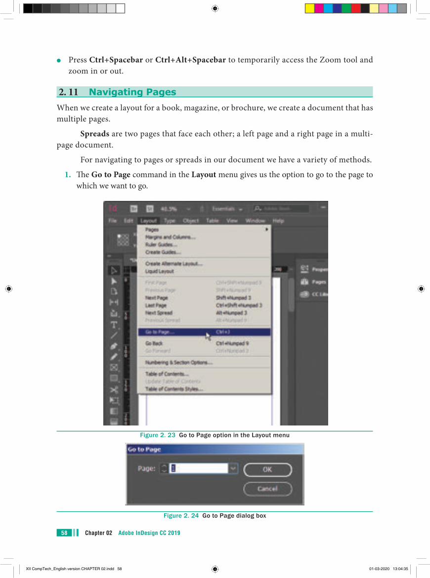
Chapter 02 Adobe InDesign CC 201958
●● Press Ctrl+Spacebar or Ctrl+Alt+Spacebar to temporarily access the Zoom tool and zoom in or out.
2. 11 Navigating PagesWhen we create a layout for a book, magazine, or brochure, we create a document that has multiple pages.
Spreads are two pages that face each other; a left page and a right page in a multi-page document.
For navigating to pages or spreads in our document we have a variety of methods.
1. The Go to Page command in the Layout menu gives us the option to go to the page to which we want to go.
Figure 2. 23 Go to Page option in the Layout menu
Figure 2. 24 Go to Page dialog box
XII CompTech_English version CHAPTER 02.indd 58 01-03-2020 13:04:35
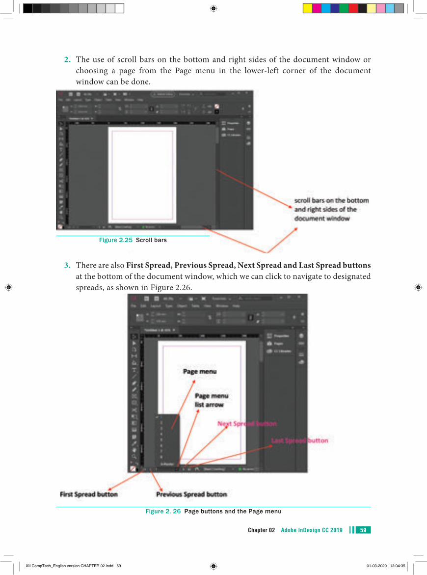
59Chapter 02 Adobe InDesign CC 2019
2. The use of scroll bars on the bottom and right sides of the document window or choosing a page from the Page menu in the lower-left corner of the document window can be done.
3. There are also First Spread, Previous Spread, Next Spread and Last Spread buttons at the bottom of the document window, which we can click to navigate to designated spreads, as shown in Figure 2.26.
Figure 2. 26 Page buttons and the Page menu
Figure 2.25 Scroll bars
XII CompTech_English version CHAPTER 02.indd 59 01-03-2020 13:04:35
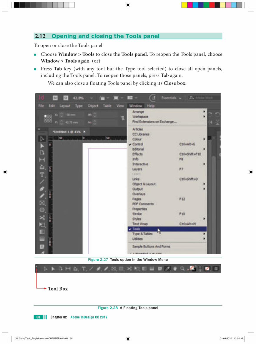
Chapter 02 Adobe InDesign CC 201960
2.12 Opening and closing the Tools panelTo open or close the Tools panel
●● Choose Window > Tools to close the Tools panel. To reopen the Tools panel, choose Window > Tools again. (or)
●● Press Tab key (with any tool but the Type tool selected) to close all open panels, including the Tools panel. To reopen those panels, press Tab again.
We can also close a floating Tools panel by clicking its Close box.
Figure 2.27 Tools option in the Window Menu
Figure 2.28 A Floating Tools panel
Tool Box
XII CompTech_English version CHAPTER 02.indd 60 01-03-2020 13:04:35
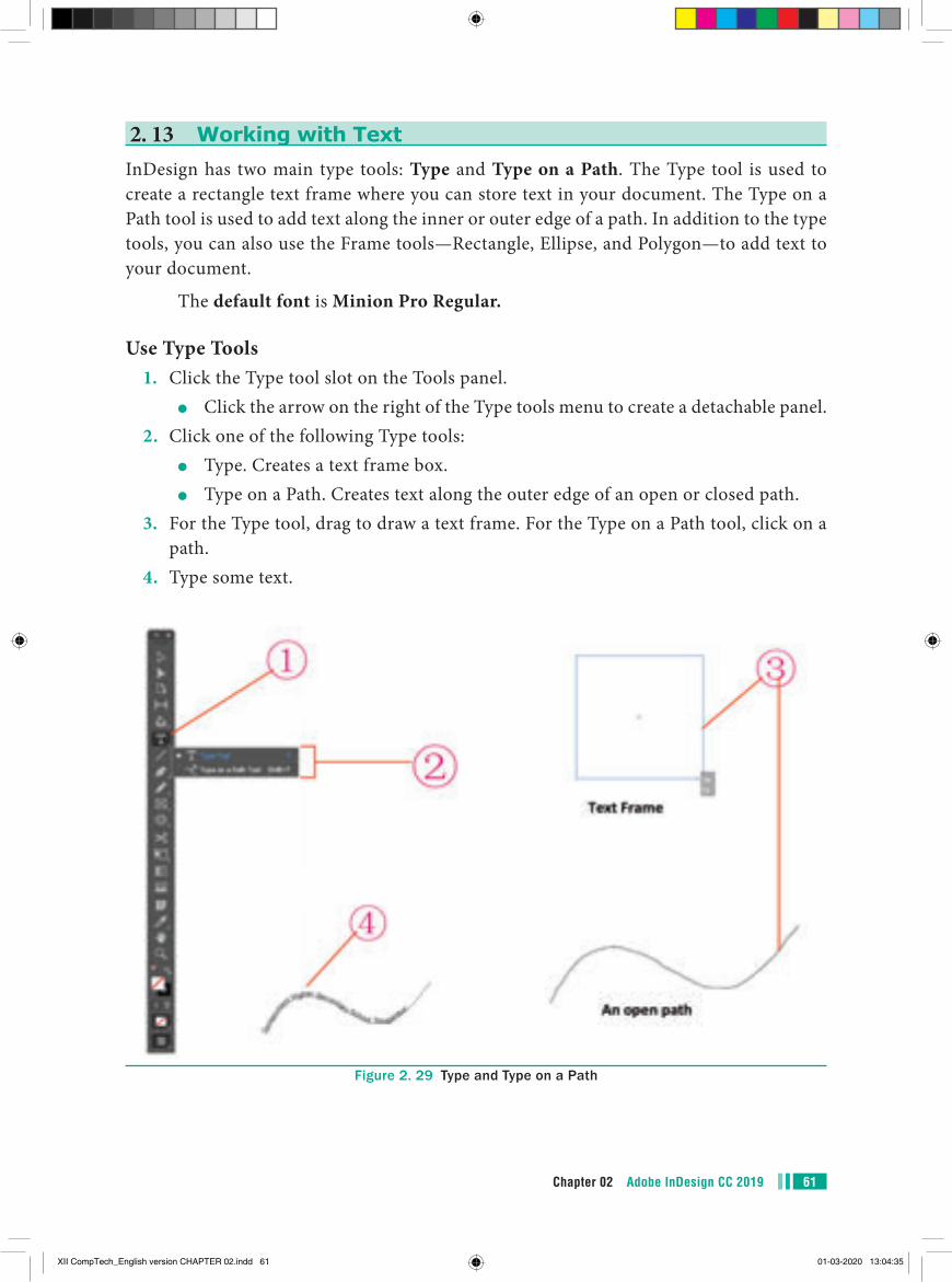
61Chapter 02 Adobe InDesign CC 2019
2. 13 Working with TextInDesign has two main type tools: Type and Type on a Path. The Type tool is used to create a rectangle text frame where you can store text in your document. The Type on a Path tool is used to add text along the inner or outer edge of a path. In addition to the type tools, you can also use the Frame tools—Rectangle, Ellipse, and Polygon—to add text to your document.
The default font is Minion Pro Regular.
Use Type Tools1. Click the Type tool slot on the Tools panel.
●● Click the arrow on the right of the Type tools menu to create a detachable panel.2. Click one of the following Type tools:
●● Type. Creates a text frame box.●● Type on a Path. Creates text along the outer edge of an open or closed path.
3. For the Type tool, drag to draw a text frame. For the Type on a Path tool, click on a path.
4. Type some text.
Figure 2. 29 Type and Type on a Path
XII CompTech_English version CHAPTER 02.indd 61 01-03-2020 13:04:35
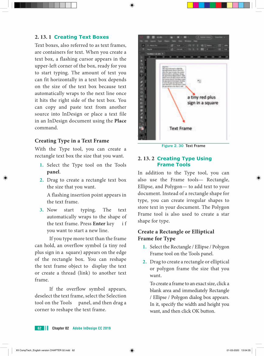
Chapter 02 Adobe InDesign CC 201962
Figure 2. 30 Text Frame
2. 13. 2 Creating Type Using Frame Tools
In addition to the Type tool, you can also use the Frame tools— Rectangle, Ellipse, and Polygon— to add text to your document. Instead of a rectangle shape for type, you can create irregular shapes to store text in your document. The Polygon Frame tool is also used to create a star shape for type.
Create a Rectangle or Elliptical Frame for Type
1. Select the Rectangle / Ellipse / Polygon Frame tool on the Tools panel.
2. Drag to create a rectangle or elliptical or polygon frame the size that you want.
To create a frame to an exact size, click a blank area and immediately Rectangle / Ellipse / Polygon dialog box appears. In it, specify the width and height you want, and then click OK button.
2. 13. 1 Creating Text BoxesText boxes, also referred to as text frames, are containers for text. When you create a text box, a flashing cursor appears in the upper-left corner of the box, ready for you to start typing. The amount of text you can fit horizontally in a text box depends on the size of the text box because text automatically wraps to the next line once it hits the right side of the text box. You can copy and paste text from another source into InDesign or place a text file in an InDesign document using the Place command.
Creating Type in a Text FrameWith the Type tool, you can create a rectangle text box the size that you want.
1. Select the Type tool on the Tools panel.
2. Drag to create a rectangle text box the size that you want.
A flashing insertion point appears in the text frame.
3. Now start typing. The text automatically wraps to the shape of the text frame. Press Enter key i f you want to start a new line.
If you type more text than the frame can hold, an overflow symbol (a tiny red plus sign in a square) appears on the edge of the rectangle box. You can reshape the text frame object to display the text or create a thread (link) to another text frame.
If the overflow symbol appears, deselect the text frame, select the Selection tool on the Tools panel, and then drag a corner to reshape the text frame.
XII CompTech_English version CHAPTER 02.indd 62 01-03-2020 13:04:35
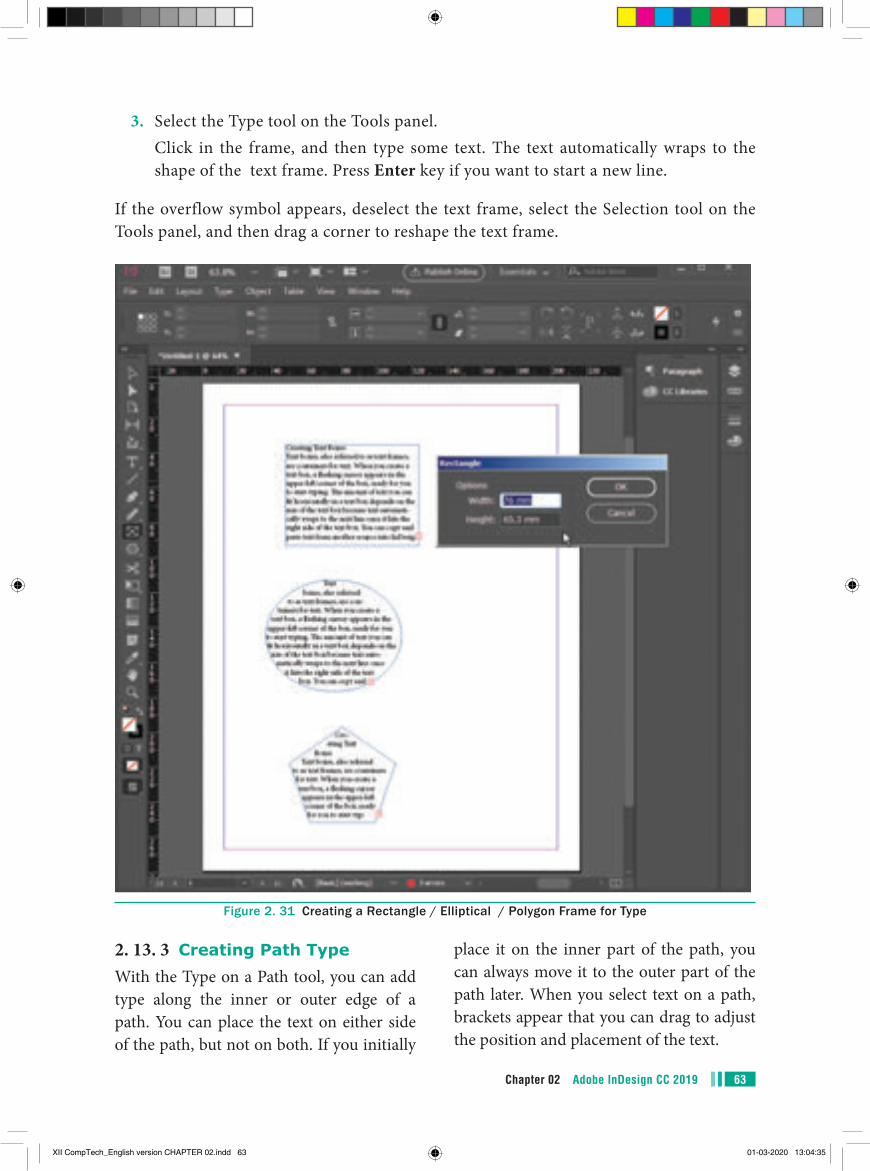
63Chapter 02 Adobe InDesign CC 2019
3. Select the Type tool on the Tools panel. Click in the frame, and then type some text. The text automatically wraps to the
shape of the text frame. Press Enter key if you want to start a new line.
If the overflow symbol appears, deselect the text frame, select the Selection tool on the Tools panel, and then drag a corner to reshape the text frame.
Figure 2. 31 Creating a Rectangle / Elliptical / Polygon Frame for Type
2. 13. 3 Creating Path TypeWith the Type on a Path tool, you can add type along the inner or outer edge of a path. You can place the text on either side of the path, but not on both. If you initially
place it on the inner part of the path, you can always move it to the outer part of the path later. When you select text on a path, brackets appear that you can drag to adjust the position and placement of the text.
XII CompTech_English version CHAPTER 02.indd 63 01-03-2020 13:04:35
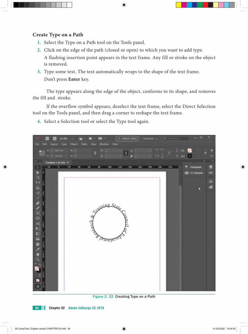
Chapter 02 Adobe InDesign CC 201964
Create Type on a Path1. Select the Type on a Path tool on the Tools panel.2. Click on the edge of the path (closed or open) to which you want to add type. A flashing insertion point appears in the text frame. Any fill or stroke on the object
is removed.3. Type some text. The text automatically wraps to the shape of the text frame. Don’t press Enter key.
The type appears along the edge of the object, conforms to its shape, and removes the fill and stroke.
If the overflow symbol appears, deselect the text frame, select the Direct Selection tool on the Tools panel, and then drag a corner to reshape the text frame.
4. Select a Selection tool or select the Type tool again.
State Council of Educational Res
earc
h &
Training.
Figure 2. 32 Creating Type on a Path
XII CompTech_English version CHAPTER 02.indd 64 01-03-2020 13:04:35
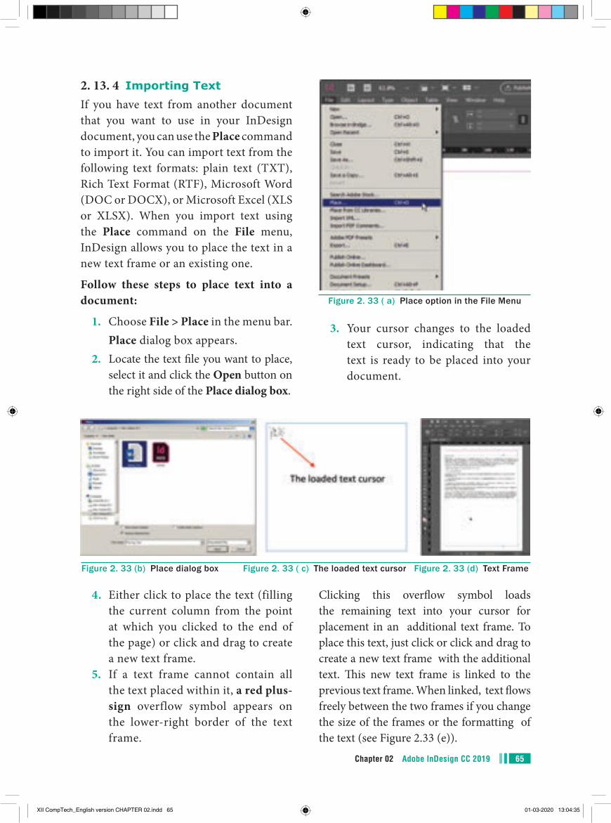
65Chapter 02 Adobe InDesign CC 2019
2. 13. 4 Importing TextIf you have text from another document that you want to use in your InDesign document, you can use the Place command to import it. You can import text from the following text formats: plain text (TXT), Rich Text Format (RTF), Microsoft Word (DOC or DOCX), or Microsoft Excel (XLS or XLSX). When you import text using the Place command on the File menu, InDesign allows you to place the text in a new text frame or an existing one.
Follow these steps to place text into a document:
1. Choose File > Place in the menu bar. Place dialog box appears.2. Locate the text file you want to place,
select it and click the Open button on the right side of the Place dialog box.
Figure 2. 33 ( a) Place option in the File Menu
Figure 2. 33 (b) Place dialog box Figure 2. 33 ( c) The loaded text cursor Figure 2. 33 (d) Text Frame
4. Either click to place the text (filling the current column from the point at which you clicked to the end of the page) or click and drag to create a new text frame.
5. If a text frame cannot contain all the text placed within it, a red plus-sign overflow symbol appears on the lower-right border of the text frame.
Clicking this overflow symbol loads the remaining text into your cursor for placement in an additional text frame. To place this text, just click or click and drag to create a new text frame with the additional text. This new text frame is linked to the previous text frame. When linked, text flows freely between the two frames if you change the size of the frames or the formatting of the text (see Figure 2.33 (e)).
3. Your cursor changes to the loaded text cursor, indicating that the text is ready to be placed into your document.
XII CompTech_English version CHAPTER 02.indd 65 01-03-2020 13:04:35
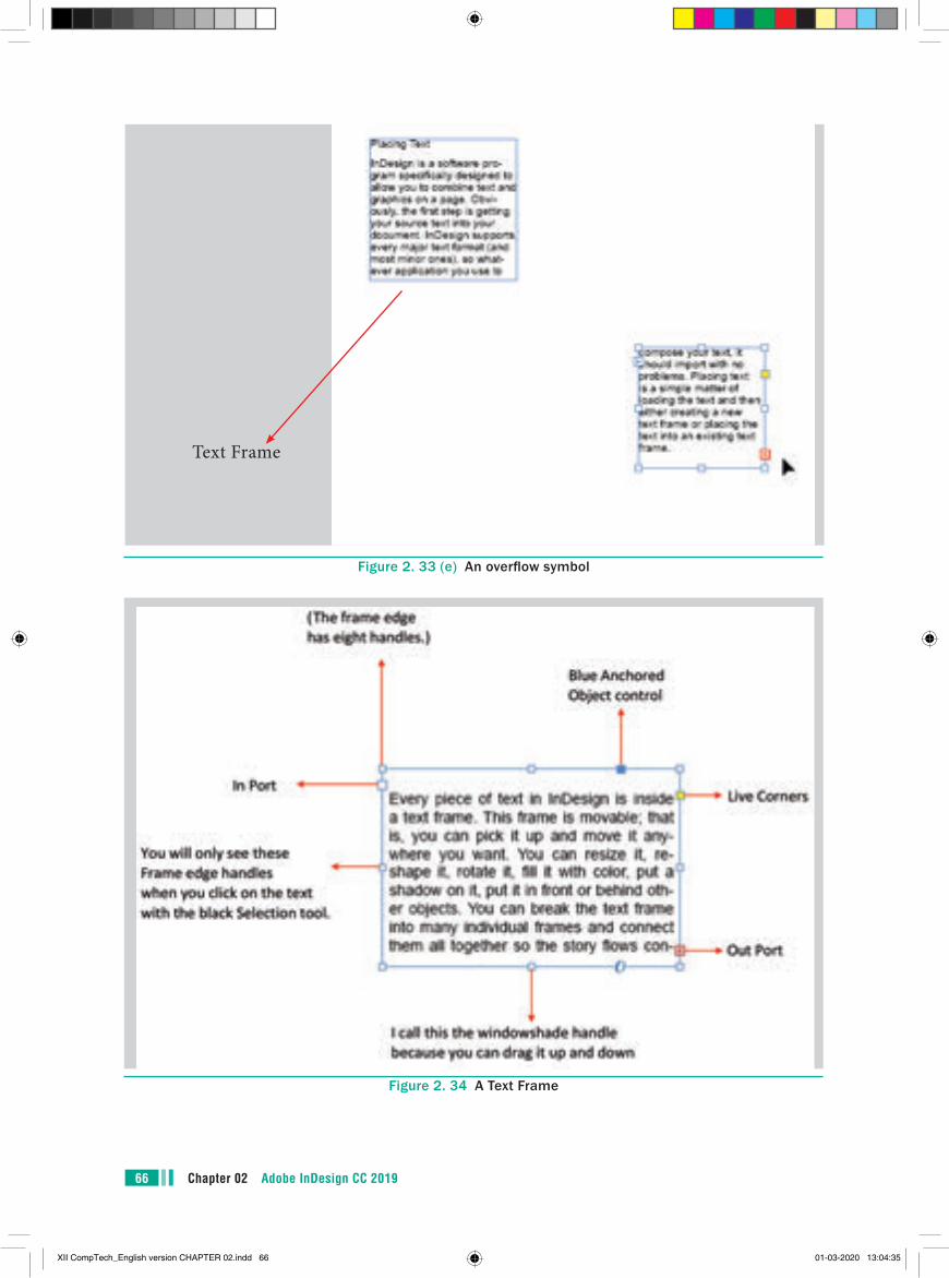
Chapter 02 Adobe InDesign CC 201966
Text Frame
Figure 2. 33 (e) An overflow symbol
Figure 2. 34 A Text Frame
XII CompTech_English version CHAPTER 02.indd 66 01-03-2020 13:04:35
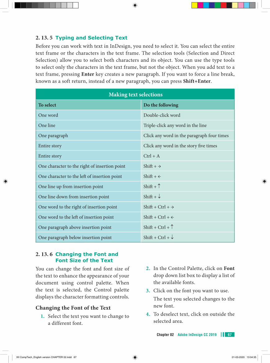
67Chapter 02 Adobe InDesign CC 2019
2. 13. 5 Typing and Selecting TextBefore you can work with text in InDesign, you need to select it. You can select the entire text frame or the characters in the text frame. The selection tools (Selection and Direct Selection) allow you to select both characters and its object. You can use the type tools to select only the characters in the text frame, but not the object. When you add text to a text frame, pressing Enter key creates a new paragraph. If you want to force a line break, known as a soft return, instead of a new paragraph, you can press Shift+Enter.
Making text selections
To select Do the following
One word Double-click word
One line Triple-click any word in the line
One paragraph Click any word in the paragraph four times
Entire story Click any word in the story five times
Entire story Ctrl + A
One character to the right of insertion point Shift + →
One character to the left of insertion point Shift + ←
One line up from insertion point Shift + ↑
One line down from insertion point Shift + ↓
One word to the right of insertion point Shift + Ctrl + →
One word to the left of insertion point Shift + Ctrl + ←
One paragraph above insertion point Shift + Ctrl + ↑
One paragraph below insertion point Shift + Ctrl + ↓
2. 13. 6 Changing the Font and Font Size of the Text
You can change the font and font size of the text to enhance the appearance of your document using control palette. When the text is selected, the Control palette displays the character formatting controls.
Changing the Font of the Text1. Select the text you want to change to
a different font.
2. In the Control Palette, click on Font drop down list box to display a list of the available fonts.
3. Click on the font you want to use. The text you selected changes to the
new font.4. To deselect text, click on outside the
selected area.
XII CompTech_English version CHAPTER 02.indd 67 01-03-2020 13:04:35
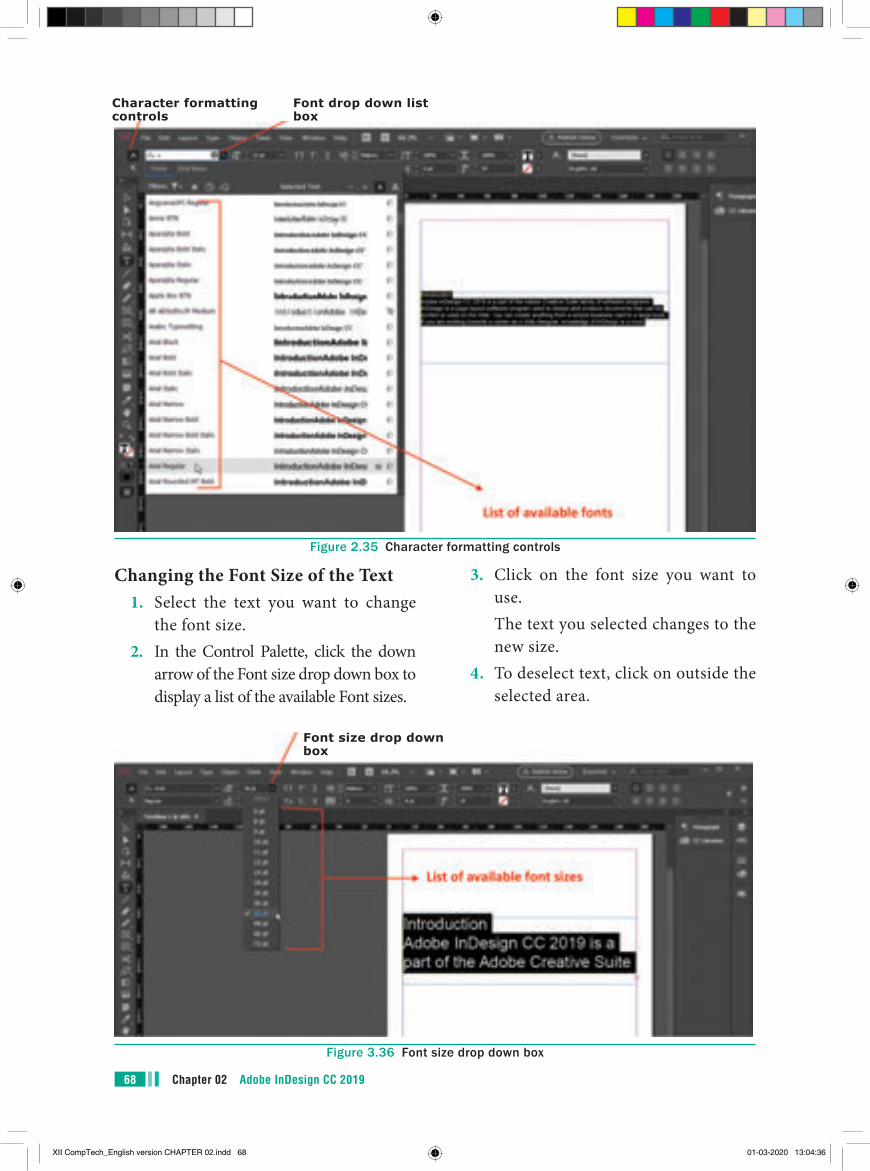
Chapter 02 Adobe InDesign CC 201968
Character formatting controls
Font drop down list box
Font size drop down box
Figure 2.35 Character formatting controls
Changing the Font Size of the Text1. Select the text you want to change
the font size.2. In the Control Palette, click the down
arrow of the Font size drop down box to display a list of the available Font sizes.
3. Click on the font size you want to use.
The text you selected changes to the new size.
4. To deselect text, click on outside the selected area.
Figure 3.36 Font size drop down box
XII CompTech_English version CHAPTER 02.indd 68 01-03-2020 13:04:36
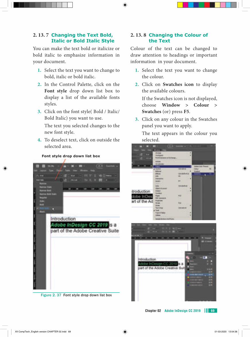
69Chapter 02 Adobe InDesign CC 2019
2. 13. 8 Changing the Colour of the Text
Colour of the text can be changed to draw attention to headings or important information in your document.
1. Select the text you want to change the colour.
2. Click on Swatches icon to display the available colours.
If the Swatches icon is not displayed, choose Window > Colour > Swatches (or) press F5.
3. Click on any colour in the Swatches panel you want to apply.
The text appears in the colour you selected.
2. 13. 7 Changing the Text Bold, Italic or Bold Italic Style
You can make the text bold or italicize or bold italic to emphasize information in your document.
1. Select the text you want to change to bold, italic or bold italic.
2. In the Control Palette, click on the Font style drop down list box to display a list of the available fonts styles.
3. Click on the font style( Bold / Italic/ Bold Italic) you want to use.
The text you selected changes to the new font style.
4. To deselect text, click on outside the selected area.
Font style drop down list box
Figure 2. 37 Font style drop down list box
XII CompTech_English version CHAPTER 02.indd 69 01-03-2020 13:04:36
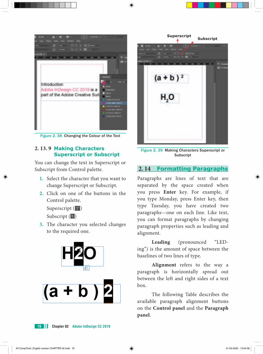
Chapter 02 Adobe InDesign CC 201970
SuperscriptSubscript
Figure 2. 39 Making Characters Superscript or Subscript
2. 14 Formatting ParagraphsParagraphs are lines of text that are separated by the space created when you press Enter key. For example, if you type Monday, press Enter key, then type Tuesday, you have created two paragraphs—one on each line. Like text, you can format paragraphs by changing paragraph properties such as leading and alignment.
Leading (pronounced “LED-ing”) is the amount of space between the baselines of two lines of type.
Alignment refers to the way a paragraph is horizontally spread out between the left and right sides of a text box.
The following Table describes the available paragraph alignment buttons on the Control panel and the Paragraph panel.
Figure 2. 38 Changing the Colour of the Text
2. 13. 9 Making Characters Superscript or Subscript
You can change the text in Superscript or Subscript from Control palette.
1. Select the character that you want to change Superscript or Subscript.
2. Click on one of the buttons in the Control palette.
Superscript ( ) Subscript ( )3. The character you selected changes
to the required one.
XII CompTech_English version CHAPTER 02.indd 70 01-03-2020 13:04:36
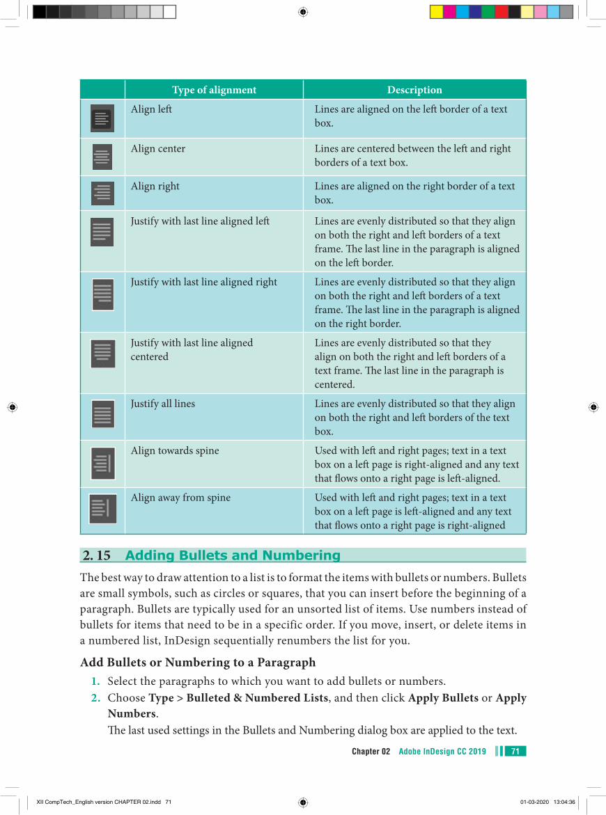
71Chapter 02 Adobe InDesign CC 2019
Type of alignment Description
Align left Lines are aligned on the left border of a text box.
Align center Lines are centered between the left and right borders of a text box.
Align right Lines are aligned on the right border of a text box.
Justify with last line aligned left Lines are evenly distributed so that they align on both the right and left borders of a text frame. The last line in the paragraph is aligned on the left border.
Justify with last line aligned right Lines are evenly distributed so that they align on both the right and left borders of a text frame. The last line in the paragraph is aligned on the right border.
Justify with last line aligned centered
Lines are evenly distributed so that they align on both the right and left borders of a text frame. The last line in the paragraph is centered.
Justify all lines Lines are evenly distributed so that they align on both the right and left borders of the text box.
Align towards spine Used with left and right pages; text in a text box on a left page is right-aligned and any text that flows onto a right page is left-aligned.
Align away from spine Used with left and right pages; text in a text box on a left page is left-aligned and any text that flows onto a right page is right-aligned
2. 15 Adding Bullets and NumberingThe best way to draw attention to a list is to format the items with bullets or numbers. Bullets are small symbols, such as circles or squares, that you can insert before the beginning of a paragraph. Bullets are typically used for an unsorted list of items. Use numbers instead of bullets for items that need to be in a specific order. If you move, insert, or delete items in a numbered list, InDesign sequentially renumbers the list for you.
Add Bullets or Numbering to a Paragraph1. Select the paragraphs to which you want to add bullets or numbers.2. Choose Type > Bulleted & Numbered Lists, and then click Apply Bullets or Apply
Numbers. The last used settings in the Bullets and Numbering dialog box are applied to the text.
XII CompTech_English version CHAPTER 02.indd 71 01-03-2020 13:04:36
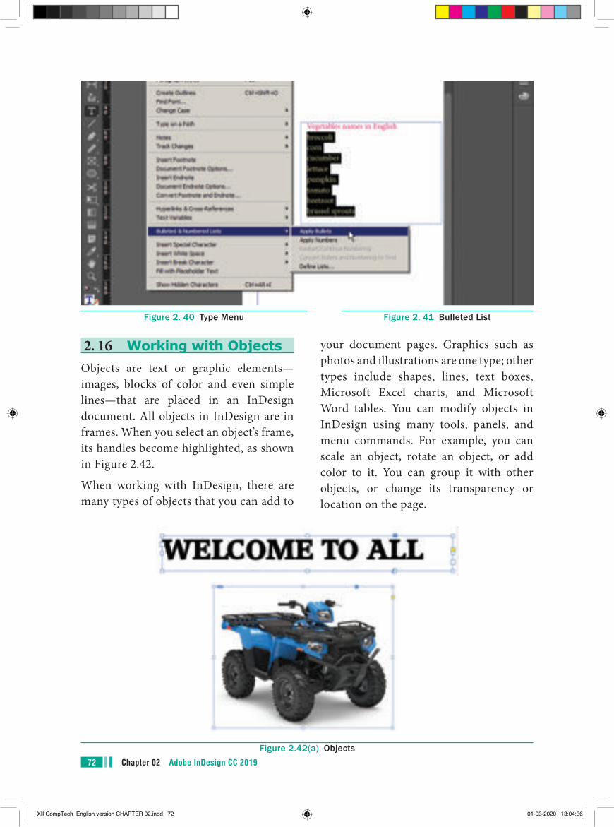
Chapter 02 Adobe InDesign CC 201972
your document pages. Graphics such as photos and illustrations are one type; other types include shapes, lines, text boxes, Microsoft Excel charts, and Microsoft Word tables. You can modify objects in InDesign using many tools, panels, and menu commands. For example, you can scale an object, rotate an object, or add color to it. You can group it with other objects, or change its transparency or location on the page.
2. 16 Working with ObjectsObjects are text or graphic elements—images, blocks of color and even simple lines—that are placed in an InDesign document. All objects in InDesign are in frames. When you select an object’s frame, its handles become highlighted, as shown in Figure 2.42.
When working with InDesign, there are many types of objects that you can add to
Figure 2. 40 Type Menu Figure 2. 41 Bulleted List
Figure 2.42(a) Objects
XII CompTech_English version CHAPTER 02.indd 72 01-03-2020 13:04:36
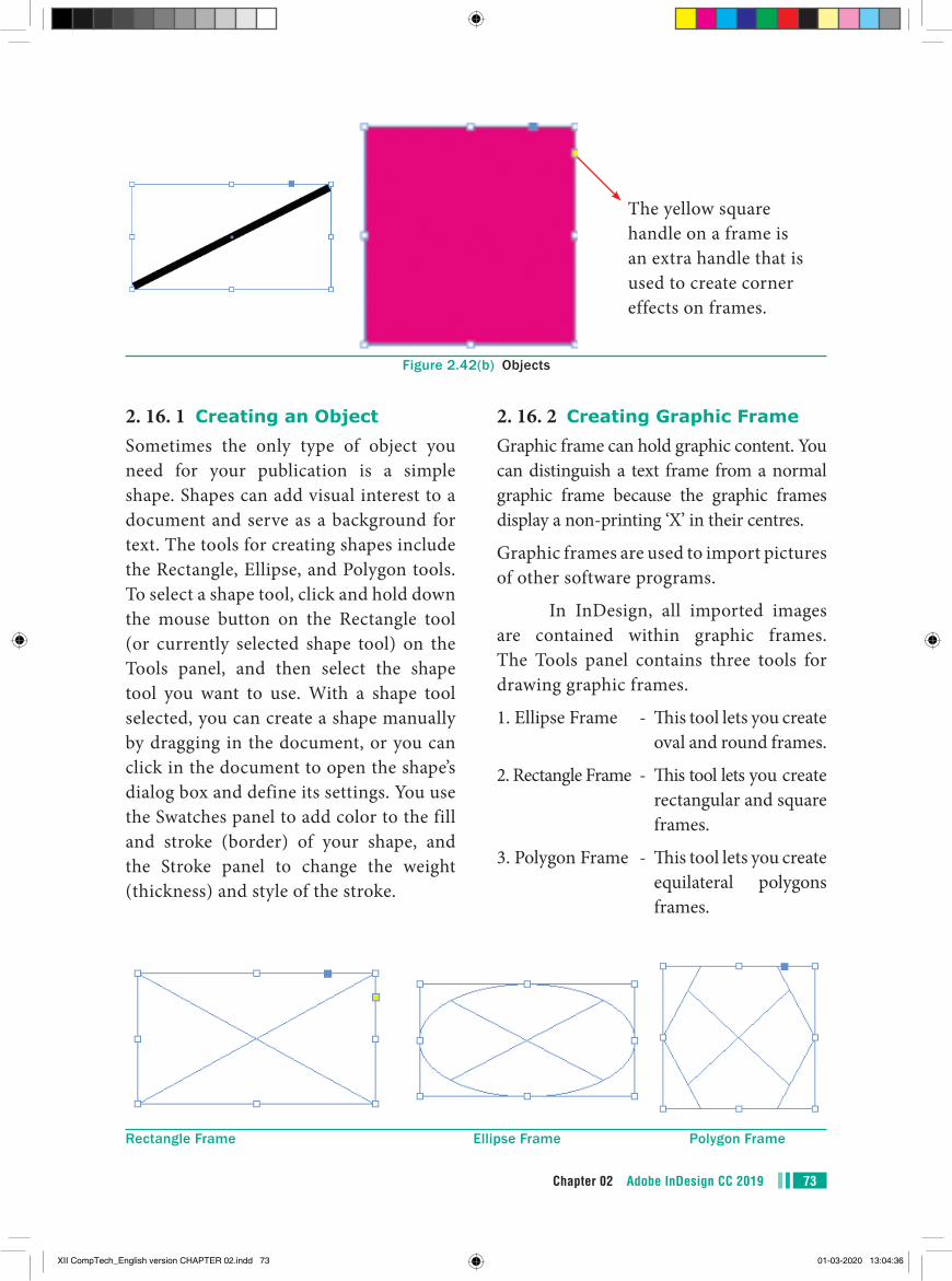
73Chapter 02 Adobe InDesign CC 2019
2. 16. 2 Creating Graphic FrameGraphic frame can hold graphic content. You can distinguish a text frame from a normal graphic frame because the graphic frames display a non-printing ‘X’ in their centres.
Graphic frames are used to import pictures of other software programs.
In InDesign, all imported images are contained within graphic frames. The Tools panel contains three tools for drawing graphic frames.
1. Ellipse Frame - This tool lets you create oval and round frames.
2. Rectangle Frame - This tool lets you create rectangular and square frames.
3. Polygon Frame - This tool lets you create equilateral polygons frames.
2. 16. 1 Creating an ObjectSometimes the only type of object you need for your publication is a simple shape. Shapes can add visual interest to a document and serve as a background for text. The tools for creating shapes include the Rectangle, Ellipse, and Polygon tools. To select a shape tool, click and hold down the mouse button on the Rectangle tool (or currently selected shape tool) on the Tools panel, and then select the shape tool you want to use. With a shape tool selected, you can create a shape manually by dragging in the document, or you can click in the document to open the shape’s dialog box and define its settings. You use the Swatches panel to add color to the fill and stroke (border) of your shape, and the Stroke panel to change the weight (thickness) and style of the stroke.
Figure 2.42(b) Objects
Rectangle Frame Ellipse Frame Polygon Frame
The yellow square handle on a frame is an extra handle that is used to create corner effects on frames.
XII CompTech_English version CHAPTER 02.indd 73 01-03-2020 13:04:36
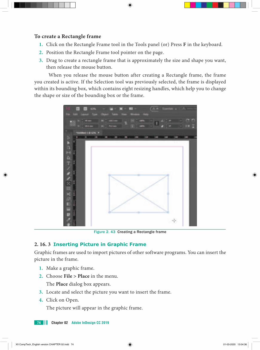
Chapter 02 Adobe InDesign CC 201974
To create a Rectangle frame1. Click on the Rectangle Frame tool in the Tools panel (or) Press F in the keyboard.2. Position the Rectangle Frame tool pointer on the page.3. Drag to create a rectangle frame that is approximately the size and shape you want,
then release the mouse button.When you release the mouse button after creating a Rectangle frame, the frame
you created is active. If the Selection tool was previously selected, the frame is displayed within its bounding box, which contains eight resizing handles, which help you to change the shape or size of the bounding box or the frame.
Figure 2. 43 Creating a Rectangle frame
2. 16. 3 Inserting Picture in Graphic FrameGraphic frames are used to import pictures of other software programs. You can insert the picture in the frame.
1. Make a graphic frame.2. Choose File > Place in the menu. The Place dialog box appears.3. Locate and select the picture you want to insert the frame.4. Click on Open. The picture will appear in the graphic frame.
XII CompTech_English version CHAPTER 02.indd 74 01-03-2020 13:04:36
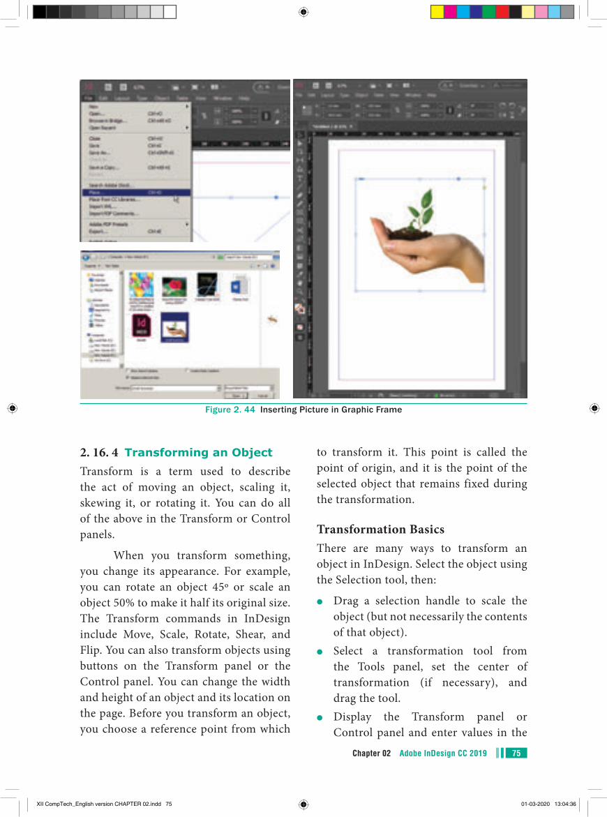
75Chapter 02 Adobe InDesign CC 2019
to transform it. This point is called the point of origin, and it is the point of the selected object that remains fixed during the transformation.
Transformation BasicsThere are many ways to transform an object in InDesign. Select the object using the Selection tool, then:
●● Drag a selection handle to scale the object (but not necessarily the contents of that object).
●● Select a transformation tool from the Tools panel, set the center of transformation (if necessary), and drag the tool.
●● Display the Transform panel or Control panel and enter values in the
2. 16. 4 Transforming an ObjectTransform is a term used to describe the act of moving an object, scaling it, skewing it, or rotating it. You can do all of the above in the Transform or Control panels.
When you transform something, you change its appearance. For example, you can rotate an object 45º or scale an object 50% to make it half its original size. The Transform commands in InDesign include Move, Scale, Rotate, Shear, and Flip. You can also transform objects using buttons on the Transform panel or the Control panel. You can change the width and height of an object and its location on the page. Before you transform an object, you choose a reference point from which
Figure 2. 44 Inserting Picture in Graphic Frame
XII CompTech_English version CHAPTER 02.indd 75 01-03-2020 13:04:36
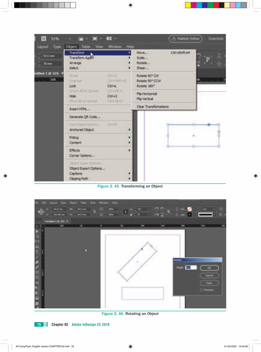
Chapter 02 Adobe InDesign CC 201976
Figure 2. 46 Rotating an Object
Figure 2. 45 Transforming an Object
XII CompTech_English version CHAPTER 02.indd 76 01-03-2020 13:04:36
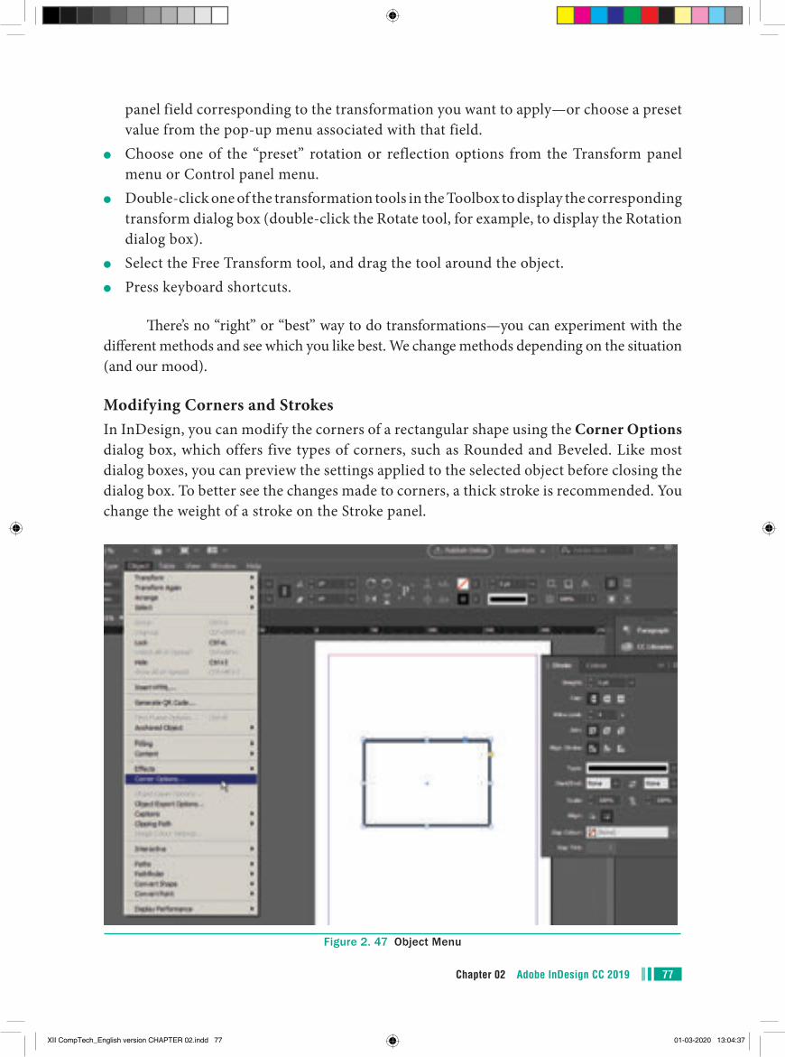
77Chapter 02 Adobe InDesign CC 2019
panel field corresponding to the transformation you want to apply—or choose a preset value from the pop-up menu associated with that field.
●● Choose one of the “preset” rotation or reflection options from the Transform panel menu or Control panel menu.
●● Double-click one of the transformation tools in the Toolbox to display the corresponding transform dialog box (double-click the Rotate tool, for example, to display the Rotation dialog box).
●● Select the Free Transform tool, and drag the tool around the object.●● Press keyboard shortcuts.
There’s no “right” or “best” way to do transformations—you can experiment with the different methods and see which you like best. We change methods depending on the situation (and our mood).
Modifying Corners and StrokesIn InDesign, you can modify the corners of a rectangular shape using the Corner Options dialog box, which offers five types of corners, such as Rounded and Beveled. Like most dialog boxes, you can preview the settings applied to the selected object before closing the dialog box. To better see the changes made to corners, a thick stroke is recommended. You change the weight of a stroke on the Stroke panel.
Figure 2. 47 Object Menu
XII CompTech_English version CHAPTER 02.indd 77 01-03-2020 13:04:37
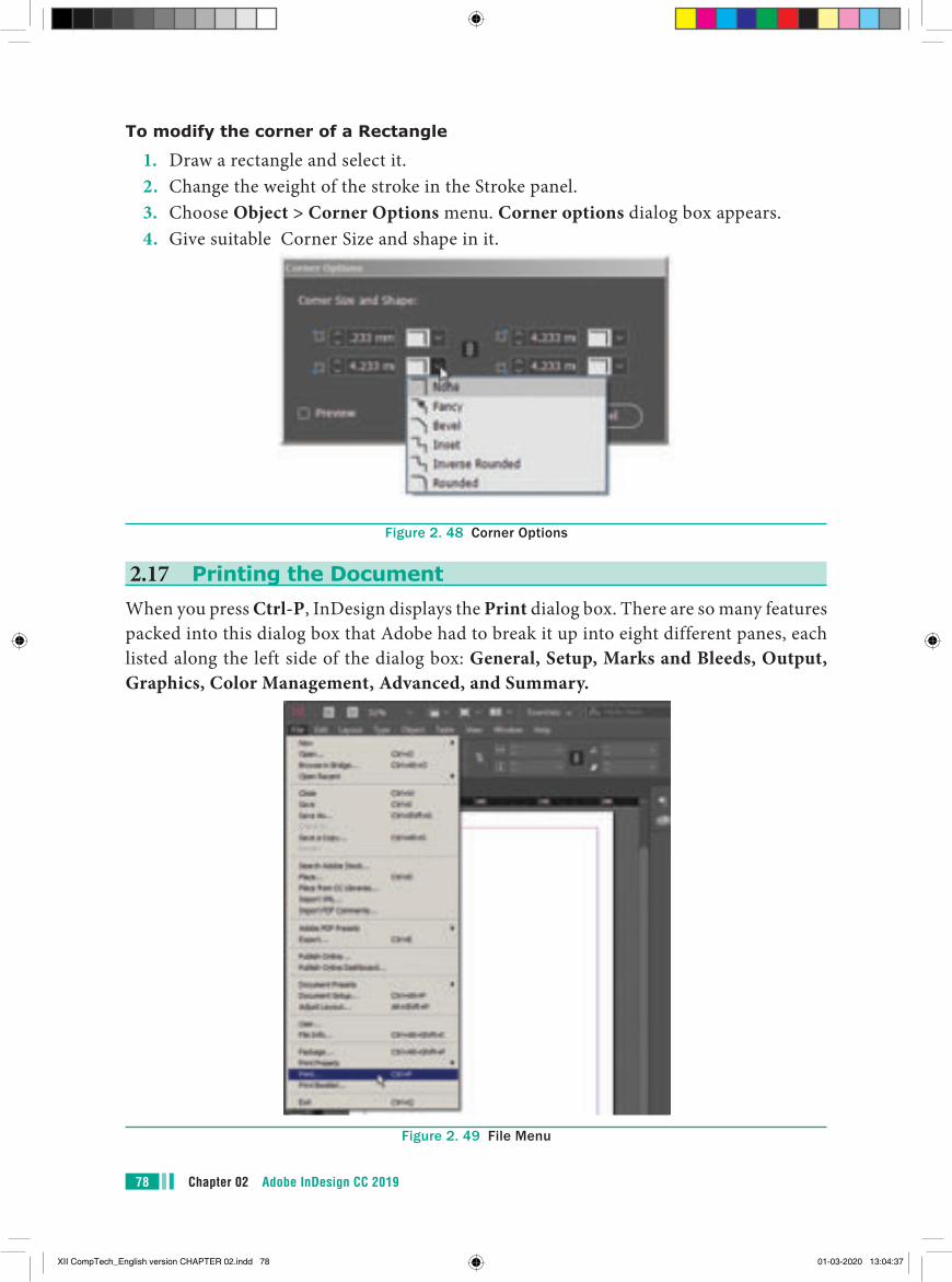
Chapter 02 Adobe InDesign CC 201978
To modify the corner of a Rectangle
1. Draw a rectangle and select it.2. Change the weight of the stroke in the Stroke panel.3. Choose Object > Corner Options menu. Corner options dialog box appears.4. Give suitable Corner Size and shape in it.
Figure 2. 48 Corner Options
2.17 Printing the DocumentWhen you press Ctrl-P, InDesign displays the Print dialog box. There are so many features packed into this dialog box that Adobe had to break it up into eight different panes, each listed along the left side of the dialog box: General, Setup, Marks and Bleeds, Output, Graphics, Color Management, Advanced, and Summary.
Figure 2. 49 File Menu
XII CompTech_English version CHAPTER 02.indd 78 01-03-2020 13:04:37
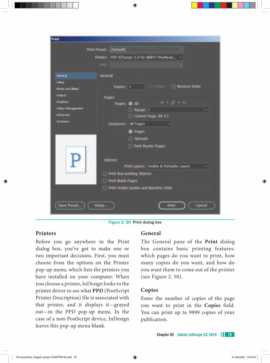
79Chapter 02 Adobe InDesign CC 2019
Figure 2. 50 Print dialog box
PrintersBefore you go anywhere in the Print dialog box, you’ve got to make one or two important decisions. First, you must choose from the options on the Printer pop-up menu, which lists the printers you have installed on your computer. When you choose a printer, InDesign looks to the printer driver to see what PPD (PostScript Printer Description) file is associated with that printer, and it displays it—grayed out—in the PPD pop-up menu. In the case of a non-PostScript device, InDesign leaves this pop-up menu blank.
GeneralThe General pane of the Print dialog box contains basic printing features: which pages do you want to print, how many copies do you want, and how do you want them to come out of the printer (see Figure 2. 50).
CopiesEnter the number of copies of the page you want to print in the Copies field. You can print up to 9999 copies of your publication.
XII CompTech_English version CHAPTER 02.indd 79 01-03-2020 13:04:37
Chapter 02 Adobe InDesign CC 201980
CollateWhen you turn on the Collate option, InDesign prints the range of pages you’ve specified, in order, for each copy of the publication you print. This makes for much slower printing. When you print multiple copies of a page, your printer only needs to process each page once (and then prints multiple copies of the page using the same image); when you turn on the Collate option, your printer must process each page once for every copy of the print job.
Reverse OrderWhen you print a multipage document, do you want the first page to come out first or last? Turning on the Reverse Order check box tells InDesign to print the last page first, then print “backwards” to the first page. You’ll want to turn this on if your pages come out of the laser printer face up.
Page RangesTurn on the All Pages option to print all of the pages in the publication. To print a range of pages, turn on the Range option. Enter the page range in the Range field as shown in the following Table.
To print Enter Example
A continuous range of pages
first page - last page
12-21
Up to a specific page
- last page -5
From a page to the end of the document
first page - 5-
Non-contiguous pages
page, page 1, 3
Mixed page ranges
page, range -3, 6-9, 12, 15-
Pages by section section:page Sec1:1, Sec2:5
SequenceTo print even and odd pages, select the All Pages option from the Sequence pop-up menu; to print even pages, select Even Pages Only; and to print odd pages select Odd Pages Only. These choices affect all page ranges, including page ranges you’ve entered in the Range field.
Print Master PagesSometimes you need to print your master pages instead of your document pages. No problem: Just turn on the Print Master Pages check box. When you do this, you cannot specify page ranges—InDesign prints all the master pages in the document.
Print Blank PagesWhat happens when you print a three-page document that has nothing on page 2? By default, only pages 1 and 3 print out. If you want the blank page 2 to print, too, you’d better turn on the Print Blank Pages check box.
PrintFinally press the Print button to print the document
The Control panel has two buttons that allow you to switch between formatting characters and
formatting paragraphs. The two buttons are at the far left side of the panel. The Letter “A” button is the Character Formatting Controls button. Click this button to display options for formatting characters, such as Font Size, Superscript, and All Caps, on the left side of the Control panel. The ¶ button is the Paragraph Formatting Controls button. Click this button to display options for formatting paragraphs, such as alignment and indentation, on the left side of the Control panel.
XII CompTech_English version CHAPTER 02.indd 80 01-03-2020 13:04:37
●● An indent is a blank space between text and its margin or frame border.●● A drop cap is a design element in which the first letter or letters of a paragraph are
increased in size to create a visual effect.●● A spread is a collection of pages designed to be viewed together. The simplest type of
spread is a two-page spread, such as the one that you are viewing right now as you read this book.
●● Continuous text that occupies one or more frames is called a story.●● Every piece of text in InDesign is inside a text frame. This frame is movable; that
is, you can pick it up and move it anywhere you want. You can resize it, reshape it, rotate it, fill it with color, put a shadow on it, put it in front or behind other objects. You can break the text frame into many individual frames and connect them all together so the story flows continuously through the individual pieces.
points to remember
●● InDesign is a page layout software program used to design and produce documents that can be printed or used on the Web.
●● A workspace is where your work is created. Workspaces typically include an area designated for creating a finished product, much like a painter would use a canvas to create a painting.
●● The default workspace in InDesign is called Essentials.●● Panels are small windows that contain options for working with selected objects.●● The document window is the central area that represents the open InDesign document.●● The pasteboard is the gray area surrounding the document window. You can place
items on the pasteboard before actually inserting them on the page.●● The status bar is at the bottom of the workspace. The status bar gives you the status of
what is going on at the moment.●● If you place the cursor over any tool in the Tools panel without clicking, a tooltip
appears displaying the tool’s name and a keyboard shortcut in parentheses.●● The Page tool is used for creating different page sizes within a document.●● Zooming allows you to quickly zoom in on, or get closer to, any object in your document.●● The view commands in InDesign are Zoom In, Zoom Out, Actual Size, Fit page in
Window, Fit Spread in Window, Entire Pasteboard.●● Transform is a term used to describe the act of moving an object, scaling it, skewing it,
or rotating it. You can do all of the above in the Transform or Control panels.
81Chapter 02 Adobe InDesign CC 2019
XII CompTech_English version CHAPTER 02.indd 81 01-03-2020 13:04:37
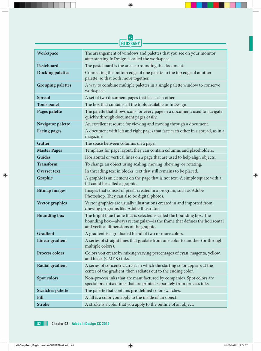
Workspace The arrangement of windows and palettes that you see on your monitor
after starting InDesign is called the workspace.Pasteboard The pasteboard is the area surrounding the document.Docking palettes Connecting the bottom edge of one palette to the top edge of another
palette, so that both move together.Grouping palettes A way to combine multiple palettes in a single palette window to conserve
workspace. Spread A set of two document pages that face each other.Tools panel The box that contains all the tools available in InDesign.Pages palette The palette that shows icons for every page in a document; used to navigate
quickly through document pages easily.Navigator palette An excellent resource for viewing and moving through a document.Facing pages A document with left and right pages that face each other in a spread, as in a
magazine.Gutter The space between columns on a page.Master Pages Templates for page layout; they can contain columns and placeholders. Guides Horizontal or vertical lines on a page that are used to help align objects. Transform To change an object using scaling, moving, skewing, or rotating. Overset text In threading text in blocks, text that still remains to be placed.Graphic A graphic is an element on the page that is not text. A simple square with a
fill could be called a graphic.Bitmap images Images that consist of pixels created in a program, such as Adobe
Photoshop. They can also be digital photos.Vector graphics Vector graphics are usually illustrations created in and imported from
drawing programs like Adobe Illustrator.Bounding box The bright blue frame that is selected is called the bounding box. The
bounding box—always rectangular—is the frame that defines the horizontal and vertical dimensions of the graphic.
Gradient A gradient is a graduated blend of two or more colors.Linear gradient A series of straight lines that gradate from one color to another (or through
multiple colors).Process colors Colors you create by mixing varying percentages of cyan, magenta, yellow,
and black (CMYK) inks.Radial gradient A series of concentric circles in which the starting color appears at the
center of the gradient, then radiates out to the ending color.Spot colors Non-process inks that are manufactured by companies. Spot colors are
special pre-mixed inks that are printed separately from process inks.Swatches palette The palette that contains pre-defined color swatches.Fill A fill is a color you apply to the inside of an object.Stroke A stroke is a color that you apply to the outline of an object.
Chapter 02 Adobe InDesign CC 201982
XII CompTech_English version CHAPTER 02.indd 82 01-03-2020 13:04:37
Part - II. Choose the correct answer.
1. Continuous text that occupies one or more frames is called a
a) Story b) Paragraph c) Object d) Palette2. Every piece of text in InDesign is inside
a a) text frame b) shape c) clipboard d) None of the above3. The area surrounding the document is
called a) pasteboard b) white-space c) empty area d) vacuum4. A set of two document pages that face
each other can be termed as a) Spread b) folder c) File d) frame5. __________ is the box that contains all
the tools available in InDesign. a) Tools panel b) Control panel c) Container d) None6. The space between columns on a page
is called a) Gutter b) vacuum c) empty area d) Interstellar7. __________ is an element on the page
that is not text. a) Graphic b) Vector c) Scalar d) Everything must be
text8. ______ images consist of pixels created
in a program such as Adobe Photoshop. a) Bitmap b) JPEG c) PNG d) All of these
EVALUATION EVALUATION
9. A _________ is a graduated blend of two or more colors.
a) Gradient b) Color Mix c) Color Palette d) none10. Non-process inks that are manufactured by
companies are called as a) Spot colors b) Color Dye c) Color Styles d) Laser ink11. A color you apply to the inside of an
object is called a) Fill b) Stroke
c) Paint d) In-Color12. A _________ is a color that you apply
to the outline of an object. a) Stroke b) Fill
c) Out-Color d) Paint
13. Match the view commands with corresponding use.
i. Zoom In (a) for the document to be displayed at 100%
ii. Zoom Out (b) for magnifying to the next preset percentage
iii. Actual Size (c) for displaying the targeted spread in the window
iv. Fit page in Window
(d) for reducing and retracting to the previous preset percentage
v. Fit Spread in Window
(e) for scaling the view size to match the monitor size
83Chapter 02 Adobe InDesign CC 2019
XII CompTech_English version CHAPTER 02.indd 83 01-03-2020 13:04:37
Part - IIAnswer the following questions. (2 Marks)
1. What type of software is Adobe InDesign?2. How many types of orientation are available by default? What are they?3. What is a workspace in Abode InDesign?4. What is an ‘Essential’ in InDesign document window?5. What is a pasteboard in InDesign?6. When does a tooltip appear?7. What is the use of page tool?8. What is Zooming? 9. Write the steps for opening and closing the tools panel.10. Write the steps to add bullets or numbering to a paragraph.
Part - IIIAnswer the following questions. (3 Marks)
1. Explain briefly about Tools Panel.2. Write about any 3 tools found in the tools panel.3. What are the view commands in InDesign? 4. Write all the keyboard shortcuts for functions associated with zooming.5. How can you make characters superscript or subscript?6. Explain briefly how you can create an object.7. How many graphic frames are found in Tools panel? What are they?
Part - IVAnswer the following questions. (5 Marks)
1. Write the steps to create a new document in InDesign.2. Write a short note on: (i) Application bar (ii) Document tab (iii) Tools panel3. Write the steps to create type on a path.4. Write the steps to place text into a document.5. How can you insert picture in a graphic frame? Write the steps.
Student Activity1. Make an attractive birthday card for your friend using Adobe InDesign.
2. Try to make a page consisting of all the names of your lessons and decorate it using Adobe InDesign.
Chapter 02 Adobe InDesign CC 201984
XII CompTech_English version CHAPTER 02.indd 84 01-03-2020 13:04:37
About CorelDRAWCorelDraw (styled CorelDRAW) is a vector graphics application. It is developed and marketed by Corel Corporation. Corel Corporation is a Canadian software company. The latest
CorelDRAW 2018
LEARNING OBJECTIVES
In this section, you’ll learn about
●● Vector graphics and Bitmaps ●● CorelDRAW 2018●● Creating a New Document●● Exploring the toolbox ●● Drawing Shapes
●● Using the Color Palette ●● Resizing shapes of objects ●● Rotating Objects●● Saving a Drawing ●● Closing Document Files
03CHAPTER
version of CorelDRAW is CorelDraw Graphics Suite 2018. It was released in April 10, 2018.
CorelDraw is a versatile graphics application for creating high quality vector illustrations, logo designs, and page layouts.
FIg. 3.1 Corel DRAW 2018
85Chapter 03 CorelDRAW 2018
XII CompTech_English version CHAPTER 03.indd 85 01-03-2020 13:05:05
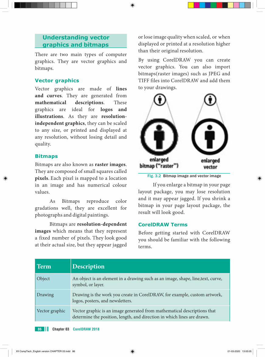
Chapter 03 CorelDRAW 201886
or lose image quality when scaled, or when displayed or printed at a resolution higher than their original resolution.
By using CorelDRAW you can create vector graphics. You can also import bitmaps(raster images) such as JPEG and TIFF files into CorelDRAW and add them to your drawings.
FIg. 3.2 Bitmap image and vector image
If you enlarge a bitmap in your page layout package, you may lose resolution and it may appear jagged. If you shrink a bitmap in your page layout package, the result will look good.
CorelDRAW TermsBefore getting started with CorelDRAW you should be familiar with the following terms.
Understanding vector graphics and bitmaps
There are two main types of computer graphics. They are vector graphics and bitmaps.
Vector graphicsVector graphics are made of lines and curves. They are generated from mathematical descriptions. These graphics are ideal for logos and illustrations. As they are resolution- independent graphics, they can be scaled to any size, or printed and displayed at any resolution, without losing detail and quality.
BitmapsBitmaps are also known as raster images. They are composed of small squares called pixels. Each pixel is mapped to a location in an image and has numerical colour values.
As Bitmaps reproduce color gradations well, they are excellent for photographs and digital paintings.
Bitmaps are resolution-dependent images which means that they represent a fixed number of pixels. They look good at their actual size, but they appear jagged
Term Description
Object An object is an element in a drawing such as an image, shape, line,text, curve, symbol, or layer.
Drawing Drawing is the work you create in CorelDRAW, for example, custom artwork, logos, posters, and newsletters.
Vector graphic Vector graphic is an image generated from mathematical descriptions that determine the position, length, and direction in which lines are drawn.
XII CompTech_English version CHAPTER 03.indd 86 01-03-2020 13:05:05
87Chapter 03 CorelDRAW 2018
Bitmap Bitmap is an image composed of grids of pixels or dots.
Docker Docker is a window that contains available commands and settings relevant to a specific tool or task.
Flyout Flyout is a button that opens a group of related tools or menu items.
List box List box is a list of options that drops down when a user clicks the down arrow button.
Artistic text An Artistic text is a type of text to which you can apply special effects, such as shadows.
Paragraph text Paragraph text is a type of text to which you can apply formatting options, and which can be edited in large blocks.
Combo boxes Combo (short for combination) is a num box with a clickable selection button for access to preset values. You can either a specific value in a combo box by typing or choose a value from the selector.
Spinners These are similar to combo boxes, in that they can be used to specify values by typing or using mouse actions.
Pop-up menus To access pop-up menu commands and options, click your right mouse button on any given point.
Starting CorelDRAW 2018You can start CorelDRAW 2018 directly from your computer’s desktop or from Windows Start Menu.
Using the Start Menu
1. Choose Start > All Programs > CorelDRAW Graphics Suite 2018 > CorelDRAW 2018.
2. The CorelDRAW 2018 - Welcome Screen window will appear.
Using the Shortcut
1. First, locate the CorelDRAW 2018 shortcut icon. This is a colourful balloon shaped icon with CorelDRAW 2018 written beneath it.
2. When you find it, position the mouse over the CorelDRAW 2018 icon and double click to open the CorelDRAW 2018.
The CorelDRAW 2018 - Welcome Screen window will appear.
FIg. 3.3 Corel DRAW 2018 icon
XII CompTech_English version CHAPTER 03.indd 87 01-03-2020 13:05:05
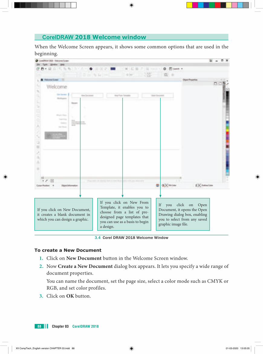
Chapter 03 CorelDRAW 201888
CorelDRAW 2018 Welcome windowWhen the Welcome Screen appears, it shows some common options that are used in the beginning.
If you click on New Document, it creates a blank document in which you can design a graphic.
If you click on New From Template, it enables you to choose from a list of pre-designed page templates that you can use as a basis to begin a design.
If you click on Open Document, it opens the Open Drawing dialog box, enabling you to select from any saved graphic image file.
3.4 Corel DRAW 2018 Welcome Window
To create a New Document
1. Click on New Document button in the Welcome Screen window.2. Now Create a New Document dialog box appears. It lets you specify a wide range of
document properties. You can name the document, set the page size, select a color mode such as CMYK or
RGB, and set color profiles.3. Click on OK button.
XII CompTech_English version CHAPTER 03.indd 88 01-03-2020 13:05:05
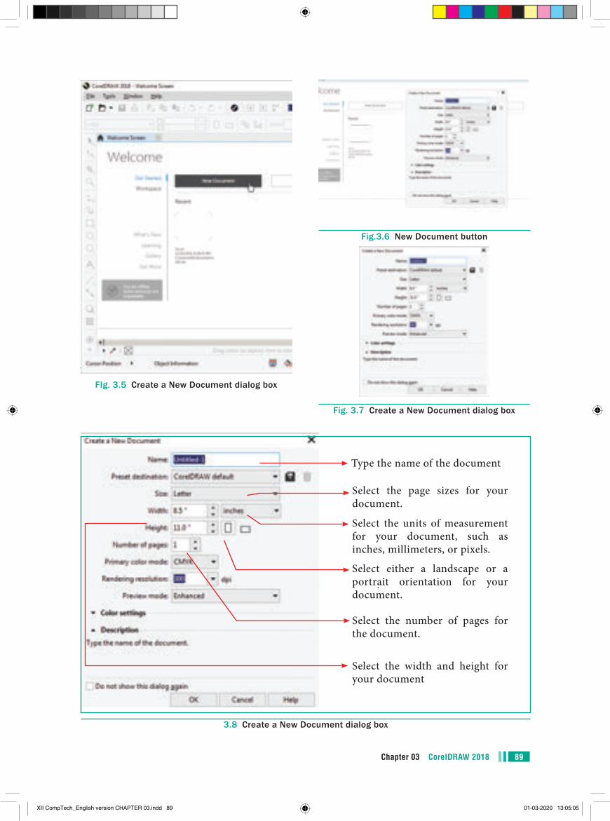
89Chapter 03 CorelDRAW 2018
FIg. 3.5 Create a New Document dialog box
3.8 Create a New Document dialog box
Type the name of the document
Select the page sizes for your document.
Select the units of measurement for your document, such as inches, millimeters, or pixels.
Select either a landscape or a portrait orientation for your document.
Select the number of pages for the document.
Select the width and height for your document
Fig.3.6 New Document button
Fig. 3.7 Create a New Document dialog box
XII CompTech_English version CHAPTER 03.indd 89 01-03-2020 13:05:05
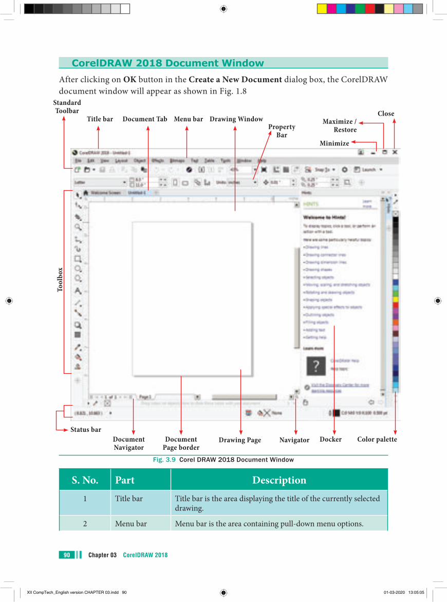
Chapter 03 CorelDRAW 201890
CorelDRAW 2018 Document WindowAfter clicking on OK button in the Create a New Document dialog box, the CorelDRAW document window will appear as shown in Fig. 1.8
Title bar Maximize / Restore
Minimize
CloseDocument Tab Menu bar Drawing Window
Property Bar
Standard Toolbar
Tool
box
Status barDocument Navigator
Document Page border
Drawing Page Navigator Docker Color palette
Fig. 3.9 Corel DRAW 2018 Document Window
S. No. Part Description1 Title bar Title bar is the area displaying the title of the currently selected
drawing.
2 Menu bar Menu bar is the area containing pull-down menu options.
XII CompTech_English version CHAPTER 03.indd 90 01-03-2020 13:05:05
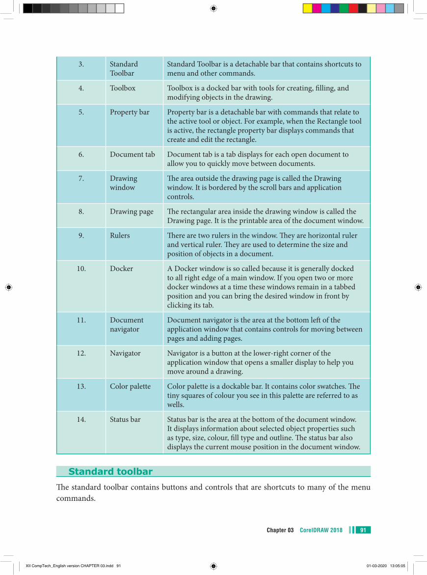
91Chapter 03 CorelDRAW 2018
3. Standard Toolbar
Standard Toolbar is a detachable bar that contains shortcuts to menu and other commands.
4. Toolbox Toolbox is a docked bar with tools for creating, filling, and modifying objects in the drawing.
5. Property bar Property bar is a detachable bar with commands that relate to the active tool or object. For example, when the Rectangle tool is active, the rectangle property bar displays commands that create and edit the rectangle.
6. Document tab Document tab is a tab displays for each open document to allow you to quickly move between documents.
7. Drawing window
The area outside the drawing page is called the Drawing window. It is bordered by the scroll bars and application controls.
8. Drawing page The rectangular area inside the drawing window is called the Drawing page. It is the printable area of the document window.
9. Rulers There are two rulers in the window. They are horizontal ruler and vertical ruler. They are used to determine the size and position of objects in a document.
10. Docker A Docker window is so called because it is generally docked to all right edge of a main window. If you open two or more docker windows at a time these windows remain in a tabbed position and you can bring the desired window in front by clicking its tab.
11. Document navigator
Document navigator is the area at the bottom left of the application window that contains controls for moving between pages and adding pages.
12. Navigator Navigator is a button at the lower-right corner of the application window that opens a smaller display to help you move around a drawing.
13. Color palette Color palette is a dockable bar. It contains color swatches. The tiny squares of colour you see in this palette are referred to as wells.
14. Status bar Status bar is the area at the bottom of the document window. It displays information about selected object properties such as type, size, colour, fill type and outline. The status bar also displays the current mouse position in the document window.
Standard toolbarThe standard toolbar contains buttons and controls that are shortcuts to many of the menu commands.
XII CompTech_English version CHAPTER 03.indd 91 01-03-2020 13:05:05
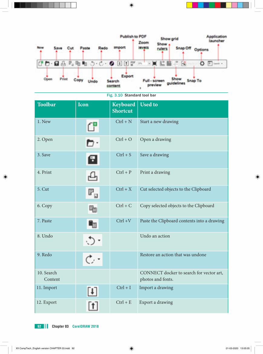
Chapter 03 CorelDRAW 201892
Fig. 3.10 Standard tool bar
Toolbar Icon Keyboard Shortcut
Used to
1. New Ctrl + N Start a new drawing
2. Open Ctrl + O Open a drawing
3. Save Ctrl + S Save a drawing
4. Print Ctrl + P Print a drawing
5. Cut Ctrl + X Cut selected objects to the Clipboard
6. Copy Ctrl + C Copy selected objects to the Clipboard
7. Paste Ctrl +V Paste the Clipboard contents into a drawing
8. Undo Undo an action
9. Redo Restore an action that was undone
10. Search Content
CONNECT docker to search for vector art, photos and fonts.
11. Import Ctrl + I Import a drawing
12. Export Ctrl + E Export a drawing
XII CompTech_English version CHAPTER 03.indd 92 01-03-2020 13:05:05
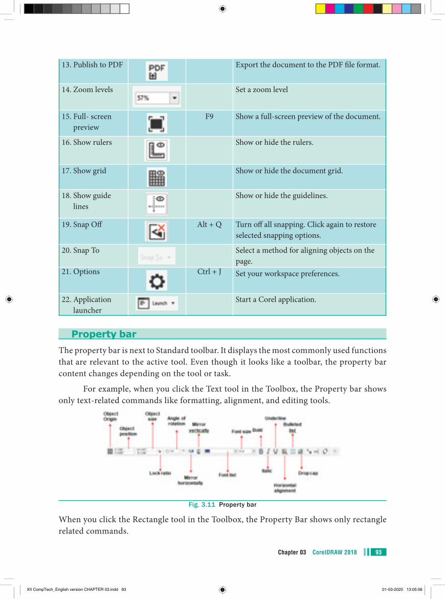
93Chapter 03 CorelDRAW 2018
13. Publish to PDF Export the document to the PDF file format.
14. Zoom levels Set a zoom level
15. Full- screen preview
F9 Show a full-screen preview of the document.
16. Show rulers Show or hide the rulers.
17. Show grid Show or hide the document grid.
18. Show guide lines
Show or hide the guidelines.
19. Snap Off Alt + Q Turn off all snapping. Click again to restore selected snapping options.
20. Snap To Select a method for aligning objects on the page.
21. Options Ctrl + J Set your workspace preferences.
22. Application launcher
Start a Corel application.
Property barThe property bar is next to Standard toolbar. It displays the most commonly used functions that are relevant to the active tool. Even though it looks like a toolbar, the property bar content changes depending on the tool or task.
For example, when you click the Text tool in the Toolbox, the Property bar shows only text-related commands like formatting, alignment, and editing tools.
Fig. 3.11 Property bar
When you click the Rectangle tool in the Toolbox, the Property Bar shows only rectangle related commands.
XII CompTech_English version CHAPTER 03.indd 93 01-03-2020 13:05:06
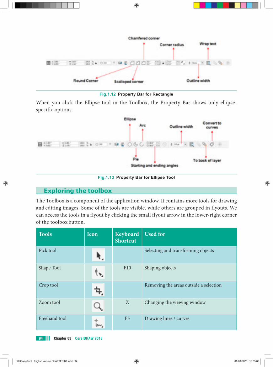
Chapter 03 CorelDRAW 201894
Fig.1.12 Property Bar for Rectangle
When you click the Ellipse tool in the Toolbox, the Property Bar shows only ellipse-specific options.
Fig.1.13 Property Bar for Ellipse Tool
Exploring the toolboxThe Toolbox is a component of the application window. It contains more tools for drawing and editing images. Some of the tools are visible, while others are grouped in flyouts. We can access the tools in a flyout by clicking the small flyout arrow in the lower-right corner of the toolbox button.
Tools Icon Keyboard Shortcut
Used for
Pick tool Selecting and transforming objects
Shape Tool F10 Shaping objects
Crop tool Removing the areas outside a selection
Zoom tool Z Changing the viewing window
Freehand tool F5 Drawing lines / curves
XII CompTech_English version CHAPTER 03.indd 94 01-03-2020 13:05:06

95Chapter 03 CorelDRAW 2018
Artistic Media tool I Adding artistic brush, spray, and calligraphic effects
Rectangle tool F6 Drawing rectangles / squares
Ellipse tool F7 Drawing ellipses / circles
Polygon tool Y Drawing polygons
Text tool F8 Adding Artistic and Paragraph text Parallel
Dimension tool Drawing slanted dimension lines
Straight-Line Connector tool
Drawing a straight line to connect two objects
Drop shadow tool Applying shadows behind or below objects
Transparency tool Setting transparency for a selected object
Color Eyedrop per tool
Selecting a fill from an object
Smart Fill tool Setting fill attributes
Flyout
Flyout Arrow
Fig.1.14 Flyout Menu and Flyout Arrow
XII CompTech_English version CHAPTER 03.indd 95 01-03-2020 13:05:06
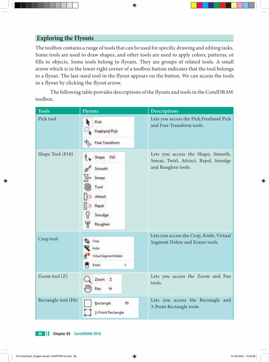
Chapter 03 CorelDRAW 201896
Tools Flyouts DescriptionsPick tool Lets you access the Pick,Freehand Pick
and Free Transform tools.
Shape Tool (F10) Lets you access the Shape, Smooth, Smear, Twirl, Attract, Repel, Smudge and Roughen tools.
Crop toolLets you access the Crop, Knife, Virtual Segment Delete and Eraser tools.
Zoom tool (Z) Lets you access the Zoom and Pan tools.
Rectangle tool (F6) Lets you access the Rectangle and 3-Point Rectangle tools
Exploring the FlyoutsThe toolbox contains a range of tools that can be used for specific drawing and editing tasks. Some tools are used to draw shapes, and other tools are used to apply colors, patterns, or fills to objects. Some tools belong to flyouts. They are groups of related tools. A small arrow which is in the lower right corner of a toolbox button indicates that the tool belongs to a flyout. The last-used tool in the flyout appears on the button. We can access the tools in a flyout by clicking the flyout arrow.
The following table provides descriptions of the flyouts and tools in the CorelDRAW toolbox.
XII CompTech_English version CHAPTER 03.indd 96 01-03-2020 13:05:06
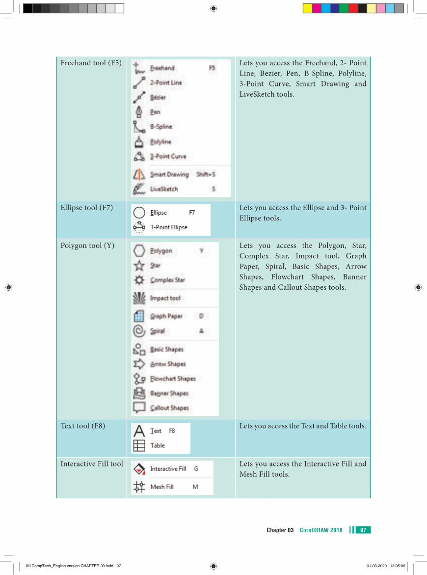
97Chapter 03 CorelDRAW 2018
Freehand tool (F5) Lets you access the Freehand, 2- Point Line, Bezier, Pen, B-Spline, Polyline, 3-Point Curve, Smart Drawing and LiveSketch tools.
Ellipse tool (F7) Lets you access the Ellipse and 3- Point Ellipse tools.
Polygon tool (Y) Lets you access the Polygon, Star, Complex Star, Impact tool, Graph Paper, Spiral, Basic Shapes, Arrow Shapes, Flowchart Shapes, Banner Shapes and Callout Shapes tools.
Text tool (F8) Lets you access the Text and Table tools.
Interactive Fill tool Lets you access the Interactive Fill and Mesh Fill tools.
XII CompTech_English version CHAPTER 03.indd 97 01-03-2020 13:05:06
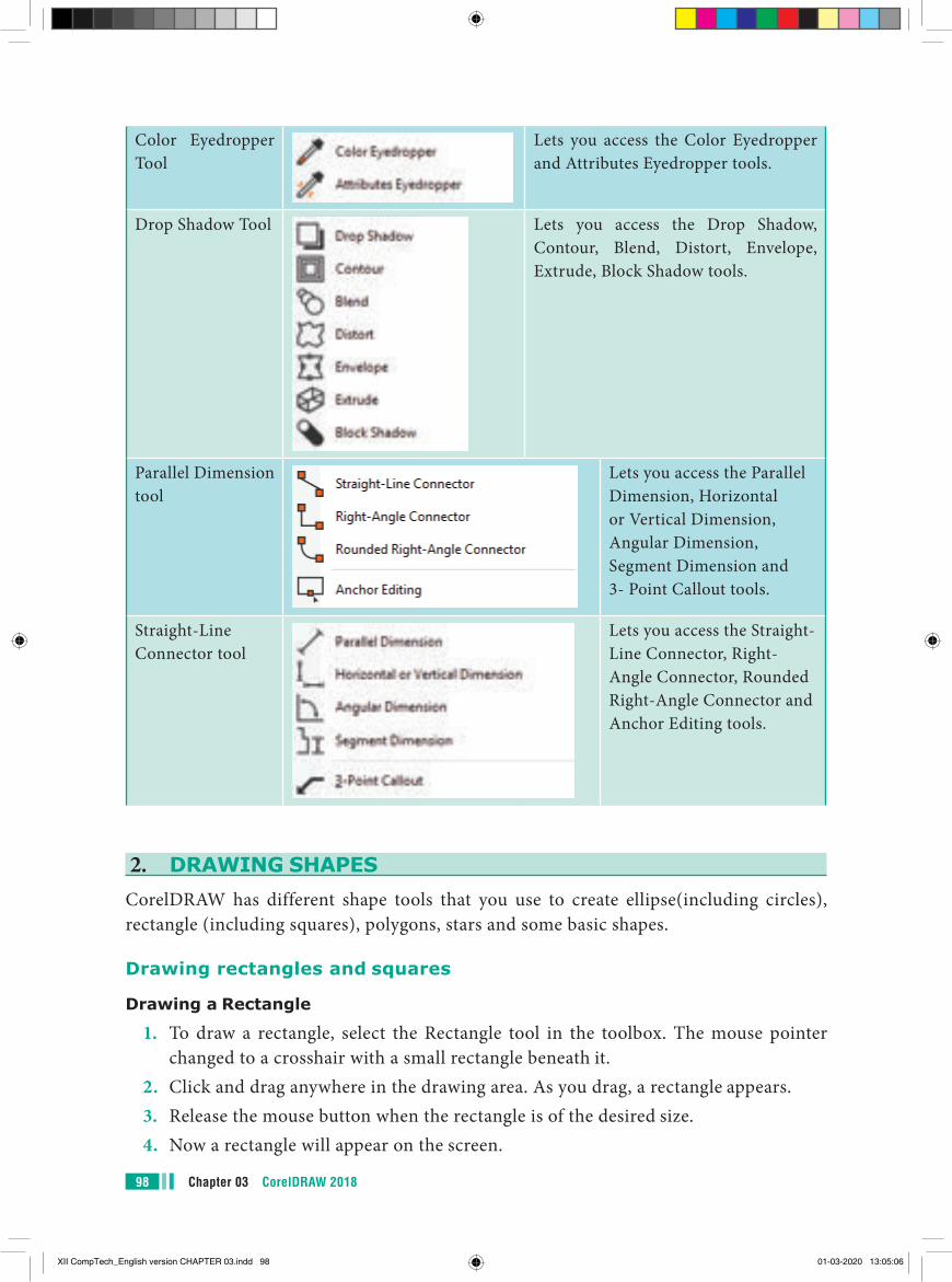
Chapter 03 CorelDRAW 201898
Color Eyedropper Tool
Lets you access the Color Eyedropper and Attributes Eyedropper tools.
Drop Shadow Tool Lets you access the Drop Shadow, Contour, Blend, Distort, Envelope, Extrude, Block Shadow tools.
Parallel Dimension tool
Lets you access the Parallel Dimension, Horizontal or Vertical Dimension, Angular Dimension, Segment Dimension and 3- Point Callout tools.
Straight-Line Connector tool
Lets you access the Straight-Line Connector, Right-Angle Connector, Rounded Right-Angle Connector and Anchor Editing tools.
2. DRAWING SHAPESCorelDRAW has different shape tools that you use to create ellipse(including circles), rectangle (including squares), polygons, stars and some basic shapes.
Drawing rectangles and squares
Drawing a Rectangle
1. To draw a rectangle, select the Rectangle tool in the toolbox. The mouse pointer changed to a crosshair with a small rectangle beneath it.
2. Click and drag anywhere in the drawing area. As you drag, a rectangle appears.3. Release the mouse button when the rectangle is of the desired size.4. Now a rectangle will appear on the screen.
XII CompTech_English version CHAPTER 03.indd 98 01-03-2020 13:05:06
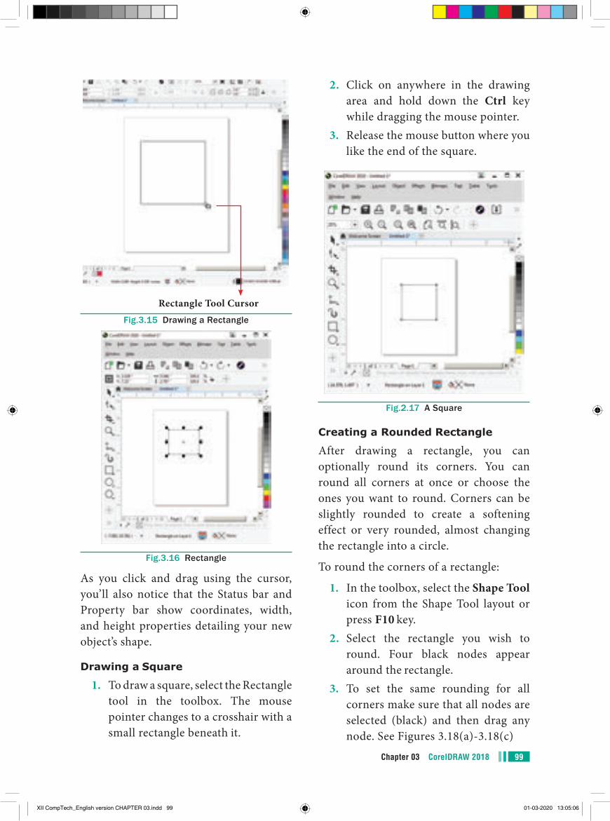
99Chapter 03 CorelDRAW 2018
2. Click on anywhere in the drawing area and hold down the Ctrl key while dragging the mouse pointer.
3. Release the mouse button where you like the end of the square.
Fig.2.17 A Square
Creating a Rounded Rectangle
After drawing a rectangle, you can optionally round its corners. You can round all corners at once or choose the ones you want to round. Corners can be slightly rounded to create a softening effect or very rounded, almost changing the rectangle into a circle.
To round the corners of a rectangle:
1. In the toolbox, select the Shape Tool icon from the Shape Tool layout or press F10 key.
2. Select the rectangle you wish to round. Four black nodes appear around the rectangle.
3. To set the same rounding for all corners make sure that all nodes are selected (black) and then drag any node. See Figures 3.18(a)-3.18(c)
Rectangle Tool CursorFig.3.15 Drawing a Rectangle
Fig.3.16 Rectangle
As you click and drag using the cursor, you’ll also notice that the Status bar and Property bar show coordinates, width, and height properties detailing your new object’s shape.
Drawing a Square
1. To draw a square, select the Rectangle tool in the toolbox. The mouse pointer changes to a crosshair with a small rectangle beneath it.
XII CompTech_English version CHAPTER 03.indd 99 01-03-2020 13:05:06
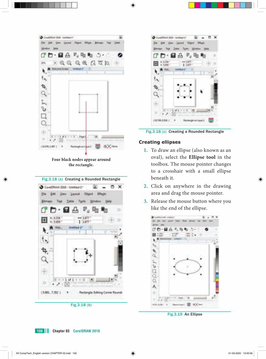
Chapter 03 CorelDRAW 2018100
Fig.3.18 (c) Creating a Rounded Rectangle
Creating ellipses
1. To draw an ellipse (also known as an oval), select the Ellipse tool in the toolbox. The mouse pointer changes to a crosshair with a small ellipse beneath it.
2. Click on anywhere in the drawing area and drag the mouse pointer.
3. Release the mouse button where you like the end of the ellipse.
Fig.3.19 An Ellipse
Four black nodes appear around the rectangle.
Fig.3.18 (a) Creating a Rounded Rectangle
Fig.3.18 (b)
XII CompTech_English version CHAPTER 03.indd 100 01-03-2020 13:05:06
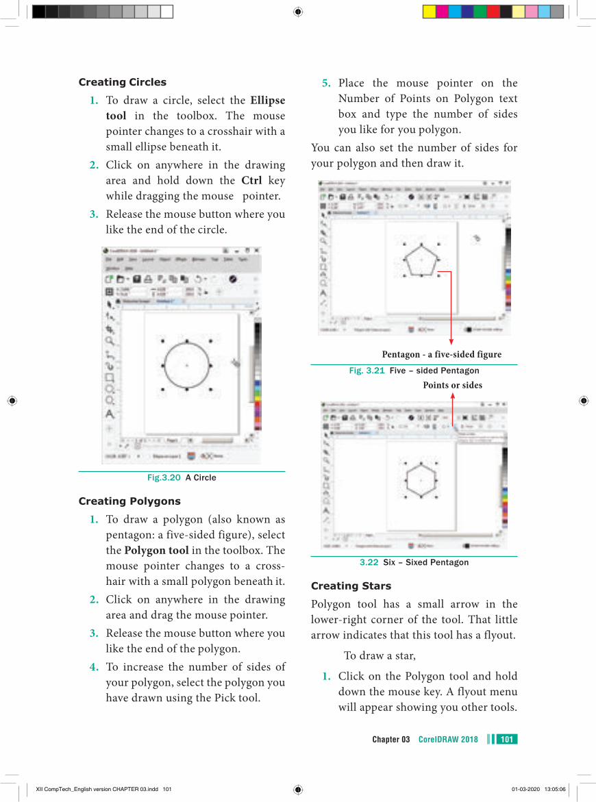
101Chapter 03 CorelDRAW 2018
5. Place the mouse pointer on the Number of Points on Polygon text box and type the number of sides you like for you polygon.
You can also set the number of sides for your polygon and then draw it.
Pentagon - a five-sided figureFig. 3.21 Five – sided Pentagon
Points or sides
3.22 Six – Sixed Pentagon
Creating Stars
Polygon tool has a small arrow in the lower-right corner of the tool. That little arrow indicates that this tool has a flyout.
To draw a star,
1. Click on the Polygon tool and hold down the mouse key. A flyout menu will appear showing you other tools.
Creating Circles
1. To draw a circle, select the Ellipse tool in the toolbox. The mouse pointer changes to a crosshair with a small ellipse beneath it.
2. Click on anywhere in the drawing area and hold down the Ctrl key while dragging the mouse pointer.
3. Release the mouse button where you like the end of the circle.
Fig.3.20 A Circle
Creating Polygons
1. To draw a polygon (also known as pentagon: a five-sided figure), select the Polygon tool in the toolbox. The mouse pointer changes to a cross-hair with a small polygon beneath it.
2. Click on anywhere in the drawing area and drag the mouse pointer.
3. Release the mouse button where you like the end of the polygon.
4. To increase the number of sides of your polygon, select the polygon you have drawn using the Pick tool.
XII CompTech_English version CHAPTER 03.indd 101 01-03-2020 13:05:06
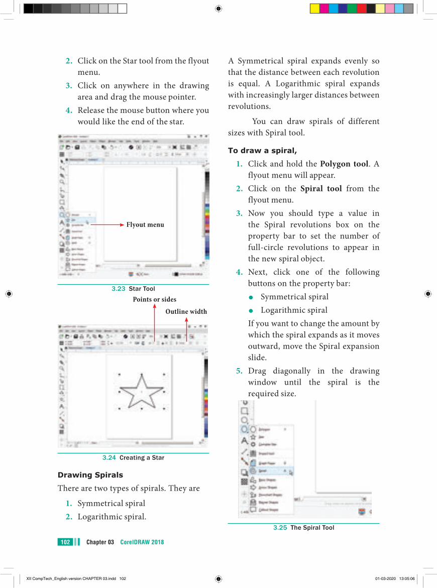
Chapter 03 CorelDRAW 2018102
A Symmetrical spiral expands evenly so that the distance between each revolution is equal. A Logarithmic spiral expands with increasingly larger distances between revolutions.
You can draw spirals of different sizes with Spiral tool.
To draw a spiral,
1. Click and hold the Polygon tool. A flyout menu will appear.
2. Click on the Spiral tool from the flyout menu.
3. Now you should type a value in the Spiral revolutions box on the property bar to set the number of full-circle revolutions to appear in the new spiral object.
4. Next, click one of the following buttons on the property bar:
●● Symmetrical spiral●● Logarithmic spiral
If you want to change the amount by which the spiral expands as it moves outward, move the Spiral expansion slide.
5. Drag diagonally in the drawing window until the spiral is the required size.
3.25 The Spiral Tool
2. Click on the Star tool from the flyout menu.
3. Click on anywhere in the drawing area and drag the mouse pointer.
4. Release the mouse button where you would like the end of the star.
Flyout menu
3.23 Star Tool
Outline width
Points or sides
3.24 Creating a Star
Drawing Spirals
There are two types of spirals. They are
1. Symmetrical spiral2. Logarithmic spiral.
XII CompTech_English version CHAPTER 03.indd 102 01-03-2020 13:05:06
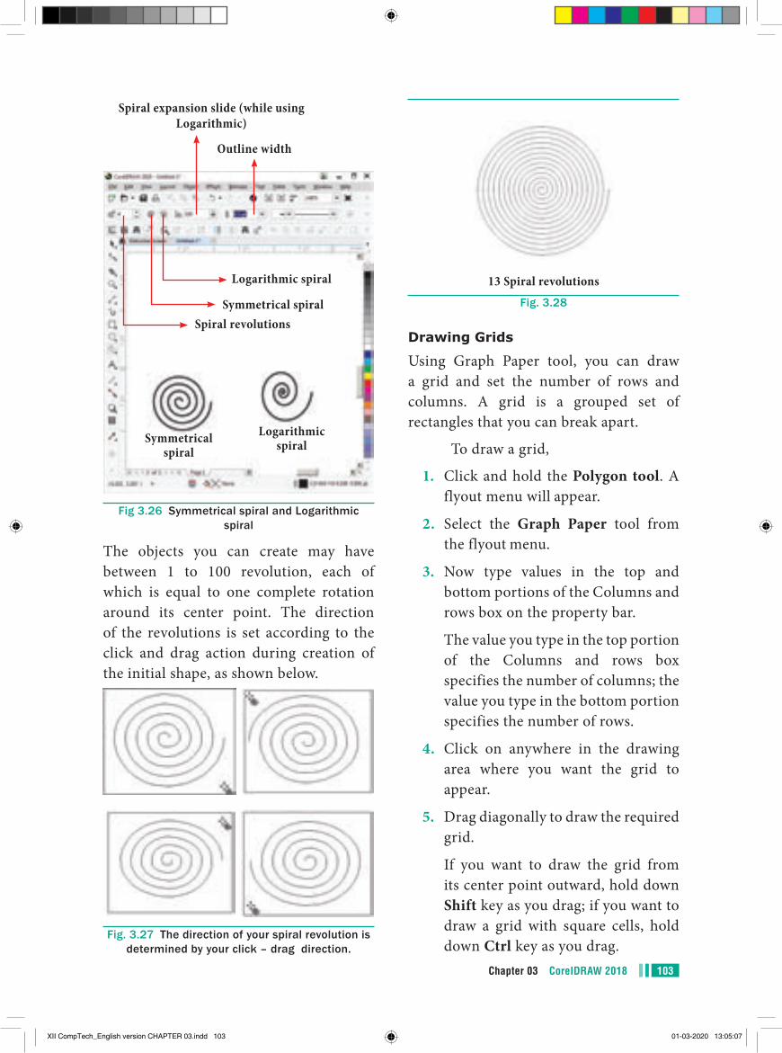
103Chapter 03 CorelDRAW 2018
Logarithmic spiralSymmetrical
spiral
Logarithmic spiral
Symmetrical spiral
Spiral expansion slide (while using Logarithmic)
Outline width
Spiral revolutions
Fig 3.26 Symmetrical spiral and Logarithmic spiral
The objects you can create may have between 1 to 100 revolution, each of which is equal to one complete rotation around its center point. The direction of the revolutions is set according to the click and drag action during creation of the initial shape, as shown below.
Fig. 3.27 The direction of your spiral revolution is determined by your click – drag direction.
13 Spiral revolutionsFig. 3.28
Drawing Grids
Using Graph Paper tool, you can draw a grid and set the number of rows and columns. A grid is a grouped set of rectangles that you can break apart.
To draw a grid,
1. Click and hold the Polygon tool. A flyout menu will appear.
2. Select the Graph Paper tool from the flyout menu.
3. Now type values in the top and bottom portions of the Columns and rows box on the property bar.
The value you type in the top portion of the Columns and rows box specifies the number of columns; the value you type in the bottom portion specifies the number of rows.
4. Click on anywhere in the drawing area where you want the grid to appear.
5. Drag diagonally to draw the required grid.
If you want to draw the grid from its center point outward, hold down Shift key as you drag; if you want to draw a grid with square cells, hold down Ctrl key as you drag.
XII CompTech_English version CHAPTER 03.indd 103 01-03-2020 13:05:07
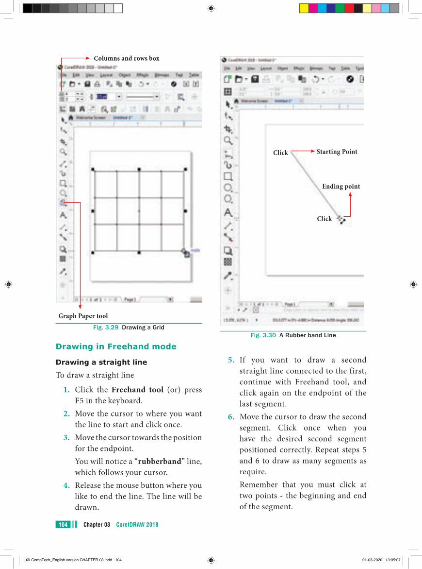
Chapter 03 CorelDRAW 2018104
Columns and rows box
Graph Paper toolFig. 3.29 Drawing a Grid
Drawing in Freehand mode
Drawing a straight line
To draw a straight line
1. Click the Freehand tool (or) press F5 in the keyboard.
2. Move the cursor to where you want the line to start and click once.
3. Move the cursor towards the position for the endpoint.
You will notice a “rubberband” line, which follows your cursor.
4. Release the mouse button where you like to end the line. The line will be drawn.
Ending point
Click
Click
Starting Point
Fig. 3.30 A Rubber band Line
5. If you want to draw a second straight line connected to the first, continue with Freehand tool, and click again on the endpoint of the last segment.
6. Move the cursor to draw the second segment. Click once when you have the desired second segment positioned correctly. Repeat steps 5 and 6 to draw as many segments as require.
Remember that you must click at two points - the beginning and end of the segment.
XII CompTech_English version CHAPTER 03.indd 104 01-03-2020 13:05:07
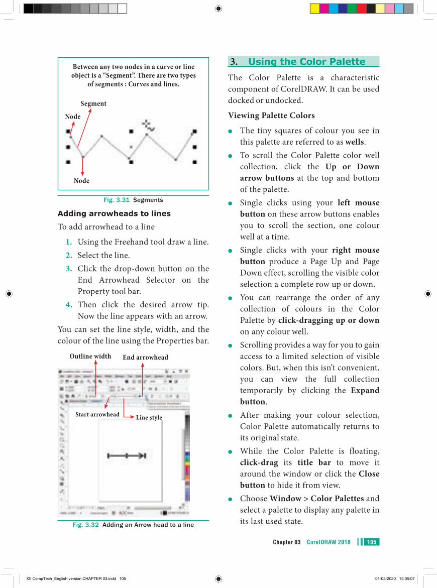
105Chapter 03 CorelDRAW 2018
Between any two nodes in a curve or line object is a “Segment”. There are two types
of segments : Curves and lines.
Segment
Node
Node
Fig. 3.31 Segments
Adding arrowheads to lines
To add arrowhead to a line
1. Using the Freehand tool draw a line.2. Select the line.3. Click the drop-down button on the
End Arrowhead Selector on the Property tool bar.
4. Then click the desired arrow tip. Now the line appears with an arrow.
You can set the line style, width, and the colour of the line using the Properties bar.
End arrowhead
Line styleStart arrowhead
Outline width
Fig. 3.32 Adding an Arrow head to a line
3. Using the Color PaletteThe Color Palette is a characteristic component of CorelDRAW. It can be used docked or undocked.
Viewing Palette Colors
●● The tiny squares of colour you see in this palette are referred to as wells.
●● To scroll the Color Palette color well collection, click the Up or Down arrow buttons at the top and bottom of the palette.
●● Single clicks using your left mouse button on these arrow buttons enables you to scroll the section, one colour well at a time.
●● Single clicks with your right mouse button produce a Page Up and Page Down effect, scrolling the visible color selection a complete row up or down.
●● You can rearrange the order of any collection of colours in the Color Palette by click-dragging up or down on any colour well.
●● Scrolling provides a way for you to gain access to a limited selection of visible colors. But, when this isn’t convenient, you can view the full collection temporarily by clicking the Expand button.
●● After making your colour selection, Color Palette automatically returns to its original state.
●● While the Color Palette is floating, click-drag its title bar to move it around the window or click the Close button to hide it from view.
●● Choose Window > Color Palettes and select a palette to display any palette in its last used state.
XII CompTech_English version CHAPTER 03.indd 105 01-03-2020 13:05:07
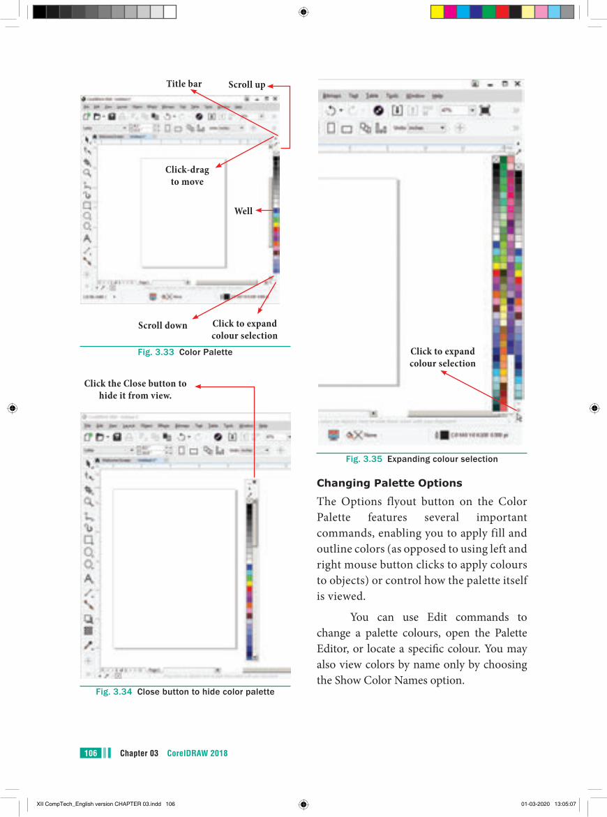
Chapter 03 CorelDRAW 2018106
Title bar
Well
Scroll down
Click-drag to move
Scroll up
Click to expand colour selection
Fig. 3.33 Color Palette
Click the Close button to hide it from view.
Fig. 3.34 Close button to hide color palette
Click to expand colour selection
Fig. 3.35 Expanding colour selection
Changing Palette Options
The Options flyout button on the Color Palette features several important commands, enabling you to apply fill and outline colors (as opposed to using left and right mouse button clicks to apply colours to objects) or control how the palette itself is viewed.
You can use Edit commands to change a palette colours, open the Palette Editor, or locate a specific colour. You may also view colors by name only by choosing the Show Color Names option.
XII CompTech_English version CHAPTER 03.indd 106 01-03-2020 13:05:07
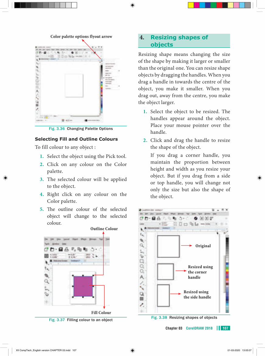
107Chapter 03 CorelDRAW 2018
Color palette options flyout arrow
Fig. 3.36 Changing Palette Options
Selecting Fill and Outline Colours
To fill colour to any object :
1. Select the object using the Pick tool.2. Click on any colour on the Color
palette.3. The selected colour will be applied
to the object.4. Right click on any colour on the
Color palette.5. The outline colour of the selected
object will change to the selected colour.
Outline Colour
Fill ColourFig. 3.37 Filling colour to an object
4. Resizing shapes of objects
Resizing shape means changing the size of the shape by making it larger or smaller than the original one. You can resize shape objects by dragging the handles. When you drag a handle in towards the centre of the object, you make it smaller. When you drag out, away from the centre, you make the object larger.
1. Select the object to be resized. The handles appear around the object. Place your mouse pointer over the handle.
2. Click and drag the handle to resize the shape of the object.
If you drag a corner handle, you maintain the proportion between height and width as you resize your object. But if you drag from a side or top handle, you will change not only the size but also the shape of the object.
Original
Resized using the corner handle
Resized using the side handle
Fig. 3.38 Resizing shapes of objects
XII CompTech_English version CHAPTER 03.indd 107 01-03-2020 13:05:07
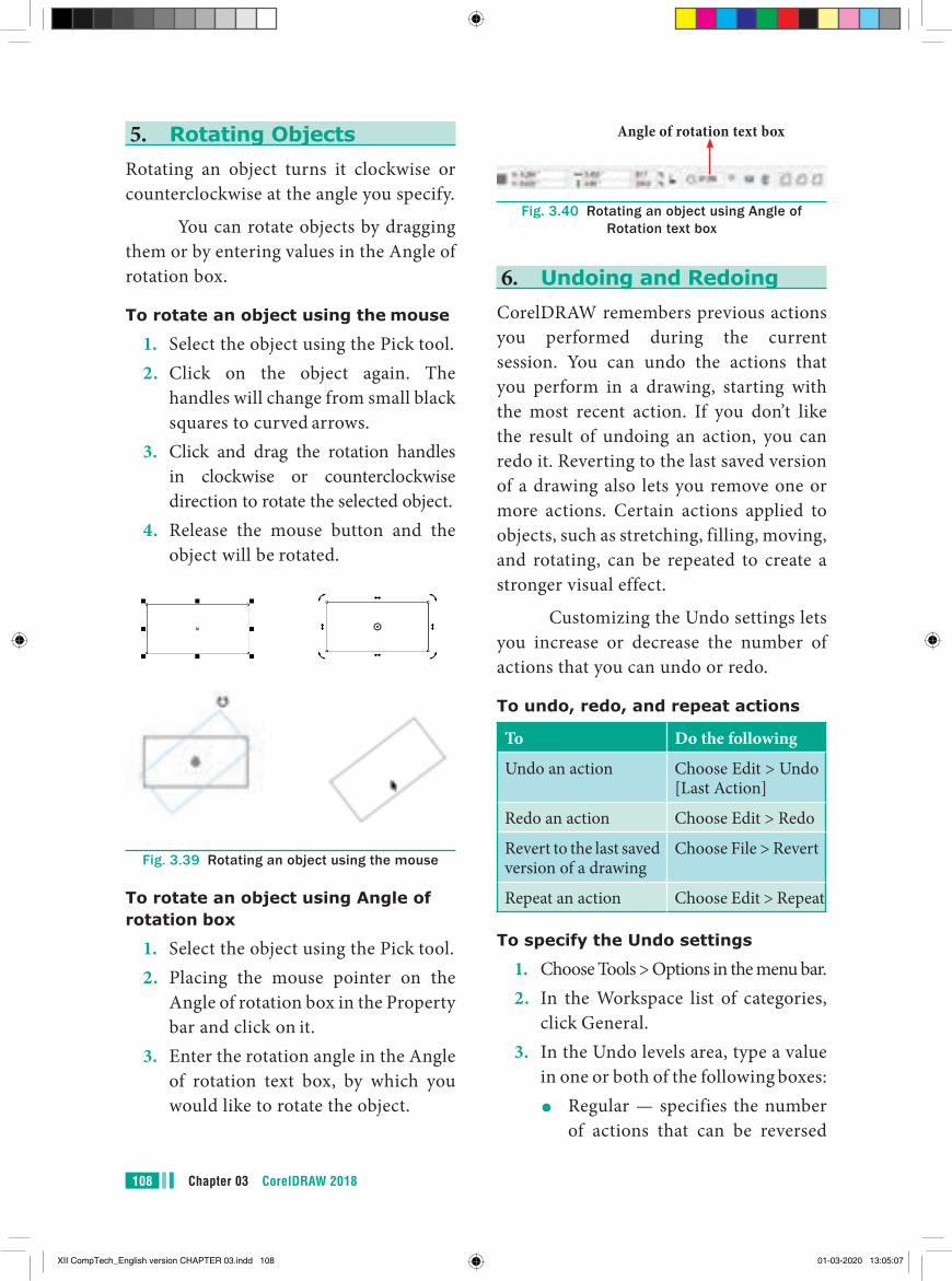
Chapter 03 CorelDRAW 2018108
Angle of rotation text box
Fig. 3.40 Rotating an object using Angle of Rotation text box
6. Undoing and RedoingCorelDRAW remembers previous actions you performed during the current session. You can undo the actions that you perform in a drawing, starting with the most recent action. If you don’t like the result of undoing an action, you can redo it. Reverting to the last saved version of a drawing also lets you remove one or more actions. Certain actions applied to objects, such as stretching, filling, moving, and rotating, can be repeated to create a stronger visual effect.
Customizing the Undo settings lets you increase or decrease the number of actions that you can undo or redo.
To undo, redo, and repeat actions
To Do the following
Undo an action Choose Edit > Undo [Last Action]
Redo an action Choose Edit > Redo
Revert to the last saved version of a drawing
Choose File > Revert
Repeat an action Choose Edit > Repeat
To specify the Undo settings
1. Choose Tools > Options in the menu bar.2. In the Workspace list of categories,
click General.3. In the Undo levels area, type a value
in one or both of the following boxes:●● Regular — specifies the number
of actions that can be reversed
5. Rotating ObjectsRotating an object turns it clockwise or counterclockwise at the angle you specify.
You can rotate objects by dragging them or by entering values in the Angle of rotation box.
To rotate an object using the mouse
1. Select the object using the Pick tool.2. Click on the object again. The
handles will change from small black squares to curved arrows.
3. Click and drag the rotation handles in clockwise or counterclockwise direction to rotate the selected object.
4. Release the mouse button and the object will be rotated.
Fig. 3.39 Rotating an object using the mouse
To rotate an object using Angle of rotation box
1. Select the object using the Pick tool.2. Placing the mouse pointer on the
Angle of rotation box in the Property bar and click on it.
3. Enter the rotation angle in the Angle of rotation text box, by which you would like to rotate the object.
XII CompTech_English version CHAPTER 03.indd 108 01-03-2020 13:05:07
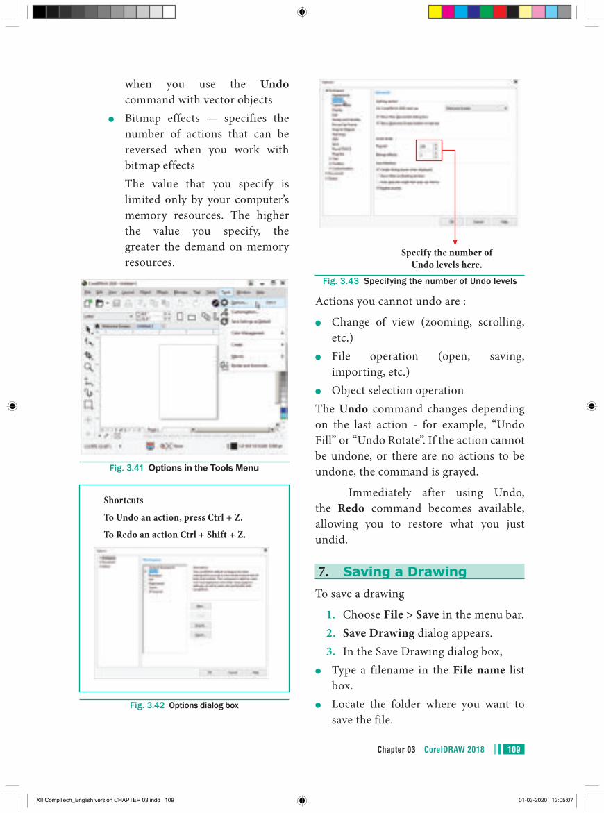
109Chapter 03 CorelDRAW 2018
when you use the Undo command with vector objects
●● Bitmap effects — specifies the number of actions that can be reversed when you work with bitmap effects
The value that you specify is limited only by your computer’s memory resources. The higher the value you specify, the greater the demand on memory resources.
Fig. 3.41 Options in the Tools Menu
Shortcuts
To Undo an action, press Ctrl + Z.
To Redo an action Ctrl + Shift + Z.
Fig. 3.42 Options dialog box
Specify the number of Undo levels here.
Fig. 3.43 Specifying the number of Undo levels
Actions you cannot undo are :
●● Change of view (zooming, scrolling, etc.)
●● File operation (open, saving, importing, etc.)
●● Object selection operationThe Undo command changes depending on the last action - for example, “Undo Fill” or “Undo Rotate”. If the action cannot be undone, or there are no actions to be undone, the command is grayed.
Immediately after using Undo, the Redo command becomes available, allowing you to restore what you just undid.
7. Saving a DrawingTo save a drawing
1. Choose File > Save in the menu bar.2. Save Drawing dialog appears.3. In the Save Drawing dialog box,
●● Type a filename in the File name list box.
●● Locate the folder where you want to save the file.
XII CompTech_English version CHAPTER 03.indd 109 01-03-2020 13:05:07
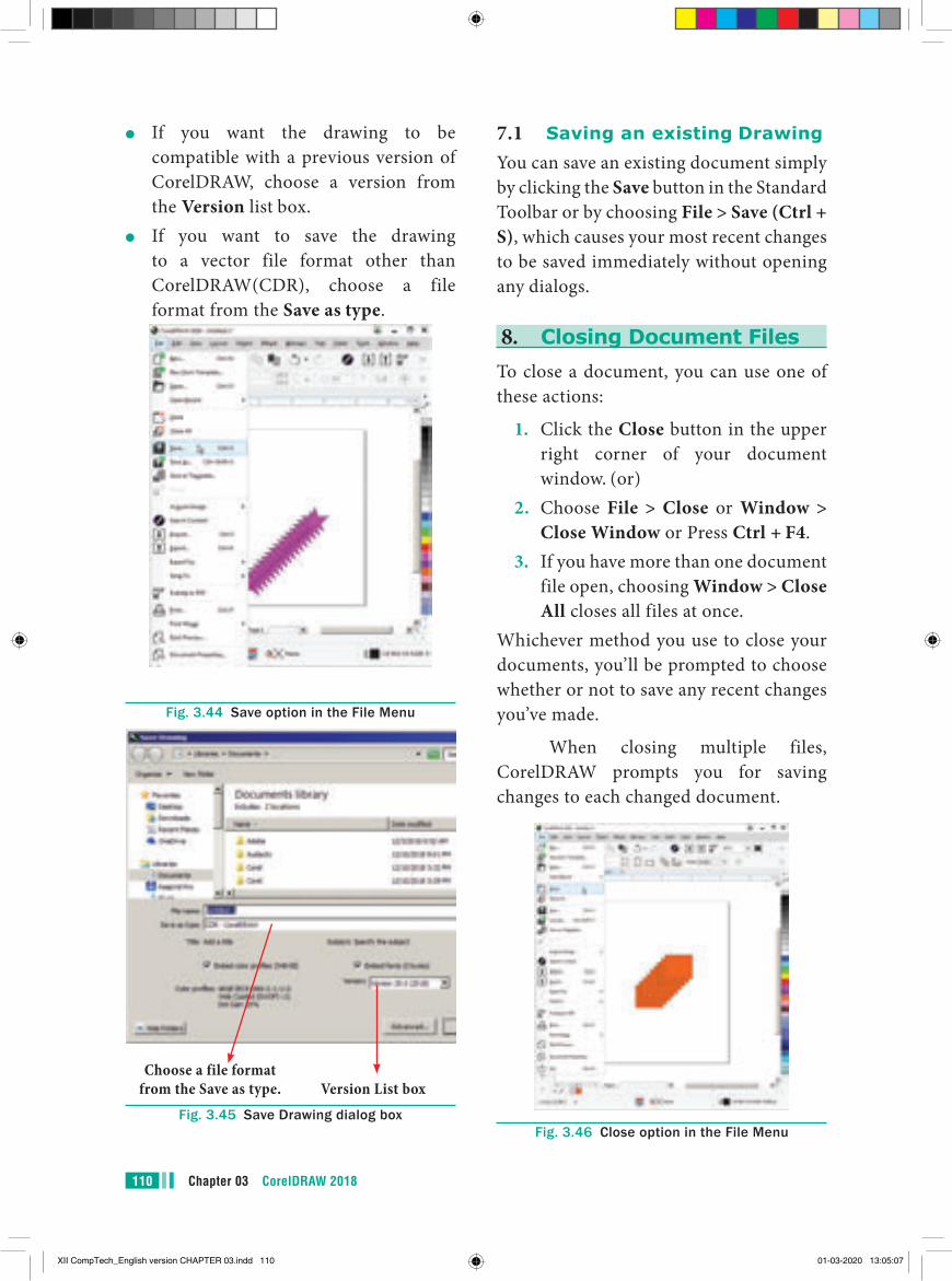
Chapter 03 CorelDRAW 2018110
7.1 Saving an existing DrawingYou can save an existing document simply by clicking the Save button in the Standard Toolbar or by choosing File > Save (Ctrl + S), which causes your most recent changes to be saved immediately without opening any dialogs.
8. Closing Document FilesTo close a document, you can use one of these actions:
1. Click the Close button in the upper right corner of your document window. (or)
2. Choose File > Close or Window > Close Window or Press Ctrl + F4.
3. If you have more than one document file open, choosing Window > Close All closes all files at once.
Whichever method you use to close your documents, you’ll be prompted to choose whether or not to save any recent changes you’ve made.
When closing multiple files, CorelDRAW prompts you for saving changes to each changed document.
Fig. 3.46 Close option in the File Menu
●● If you want the drawing to be compatible with a previous version of CorelDRAW, choose a version from the Version list box.
●● If you want to save the drawing to a vector file format other than CorelDRAW(CDR), choose a file format from the Save as type.
Fig. 3.44 Save option in the File Menu
Version List boxChoose a file format
from the Save as type.Fig. 3.45 Save Drawing dialog box
XII CompTech_English version CHAPTER 03.indd 110 01-03-2020 13:05:07
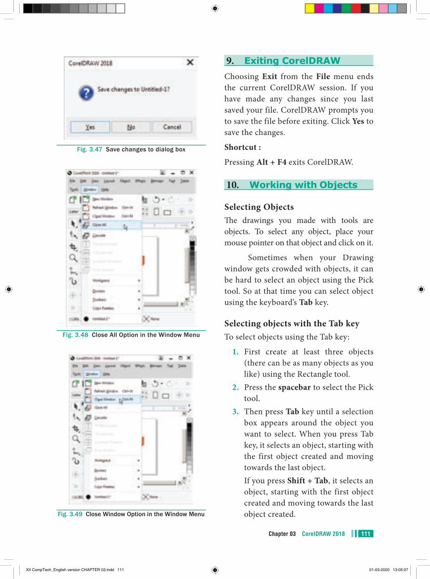
111Chapter 03 CorelDRAW 2018
Fig. 3.47 Save changes to dialog box
Fig. 3.48 Close All Option in the Window Menu
Fig. 3.49 Close Window Option in the Window Menu
9. Exiting CorelDRAWChoosing Exit from the File menu ends the current CorelDRAW session. If you have made any changes since you last saved your file. CorelDRAW prompts you to save the file before exiting. Click Yes to save the changes.
Shortcut :
Pressing Alt + F4 exits CorelDRAW.
10. Working with Objects
Selecting ObjectsThe drawings you made with tools are objects. To select any object, place your mouse pointer on that object and click on it.
Sometimes when your Drawing window gets crowded with objects, it can be hard to select an object using the Pick tool. So at that time you can select object using the keyboard’s Tab key.
Selecting objects with the Tab keyTo select objects using the Tab key:
1. First create at least three objects (there can be as many objects as you like) using the Rectangle tool.
2. Press the spacebar to select the Pick tool.
3. Then press Tab key until a selection box appears around the object you want to select. When you press Tab key, it selects an object, starting with the first object created and moving towards the last object.
If you press Shift + Tab, it selects an object, starting with the first object created and moving towards the last object created.
XII CompTech_English version CHAPTER 03.indd 111 01-03-2020 13:05:07
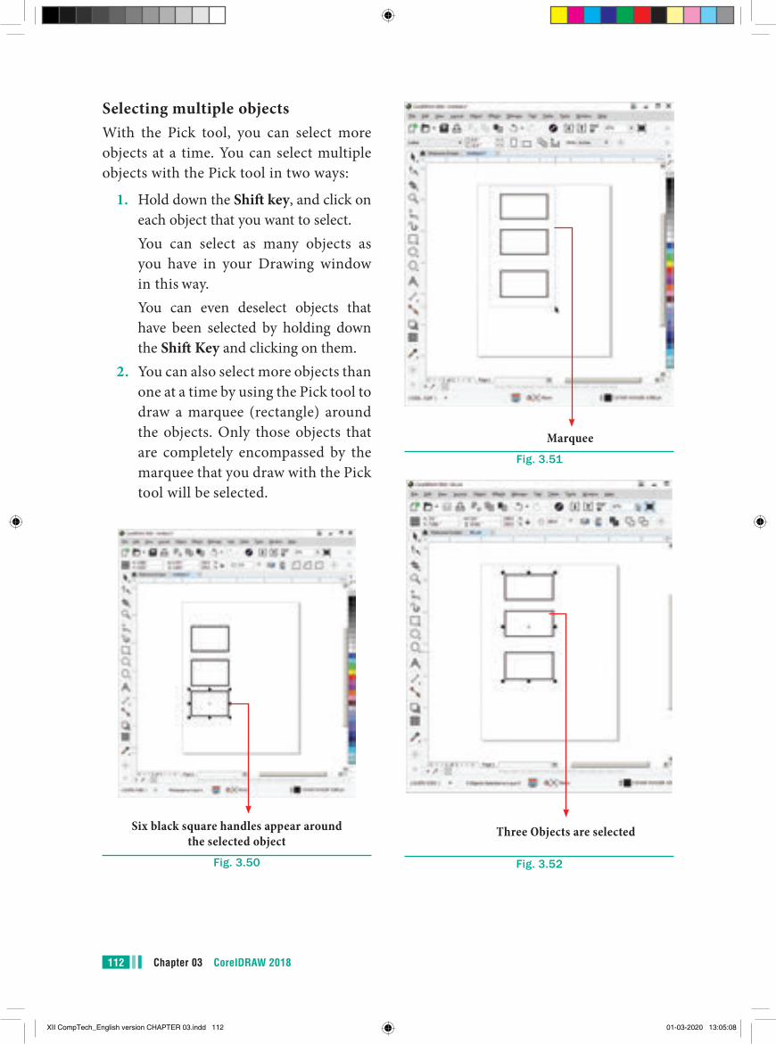
Chapter 03 CorelDRAW 2018112
MarqueeFig. 3.51
Three Objects are selected
Fig. 3.52
Selecting multiple objectsWith the Pick tool, you can select more objects at a time. You can select multiple objects with the Pick tool in two ways:
1. Hold down the Shift key, and click on each object that you want to select.
You can select as many objects as you have in your Drawing window in this way.
You can even deselect objects that have been selected by holding down the Shift Key and clicking on them.
2. You can also select more objects than one at a time by using the Pick tool to draw a marquee (rectangle) around the objects. Only those objects that are completely encompassed by the marquee that you draw with the Pick tool will be selected.
Six black square handles appear around the selected object
Fig. 3.50
XII CompTech_English version CHAPTER 03.indd 112 01-03-2020 13:05:08
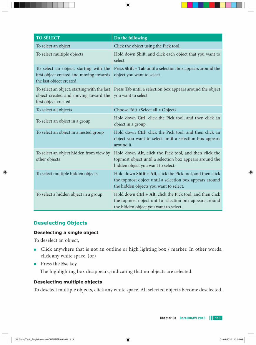
113Chapter 03 CorelDRAW 2018
TO SELECT Do the following
To select an object Click the object using the Pick tool.
To select multiple objects Hold down Shift, and click each object that you want to select.
To select an object, starting with the first object created and moving towards the last object created
Press Shift + Tab until a selection box appears around the object you want to select.
To select an object, starting with the last object created and moving toward the first object created
Press Tab until a selection box appears around the object you want to select.
To select all objects Choose Edit >Select all > Objects
To select an object in a groupHold down Ctrl, click the Pick tool, and then click an object in a group.
To select an object in a nested group Hold down Ctrl, click the Pick tool, and then click an object you want to select until a selection box appears around it.
To select an object hidden from view by other objects
Hold down Alt, click the Pick tool, and then click the topmost object until a selection box appears around the hidden object you want to select.
To select multiple hidden objects Hold down Shift + Alt, click the Pick tool, and then click the topmost object until a selection box appears around the hidden objects you want to select.
To select a hidden object in a group Hold down Ctrl + Alt, click the Pick tool, and then click the topmost object until a selection box appears around the hidden object you want to select.
Deselecting Objects
Deselecting a single object
To deselect an object,
●● Click anywhere that is not an outline or high lighting box / marker. In other words, click any white space. (or)
●● Press the Esc key.The highlighting box disappears, indicating that no objects are selected.
Deselecting multiple objects
To deselect multiple objects, click any white space. All selected objects become deselected.
XII CompTech_English version CHAPTER 03.indd 113 01-03-2020 13:05:08
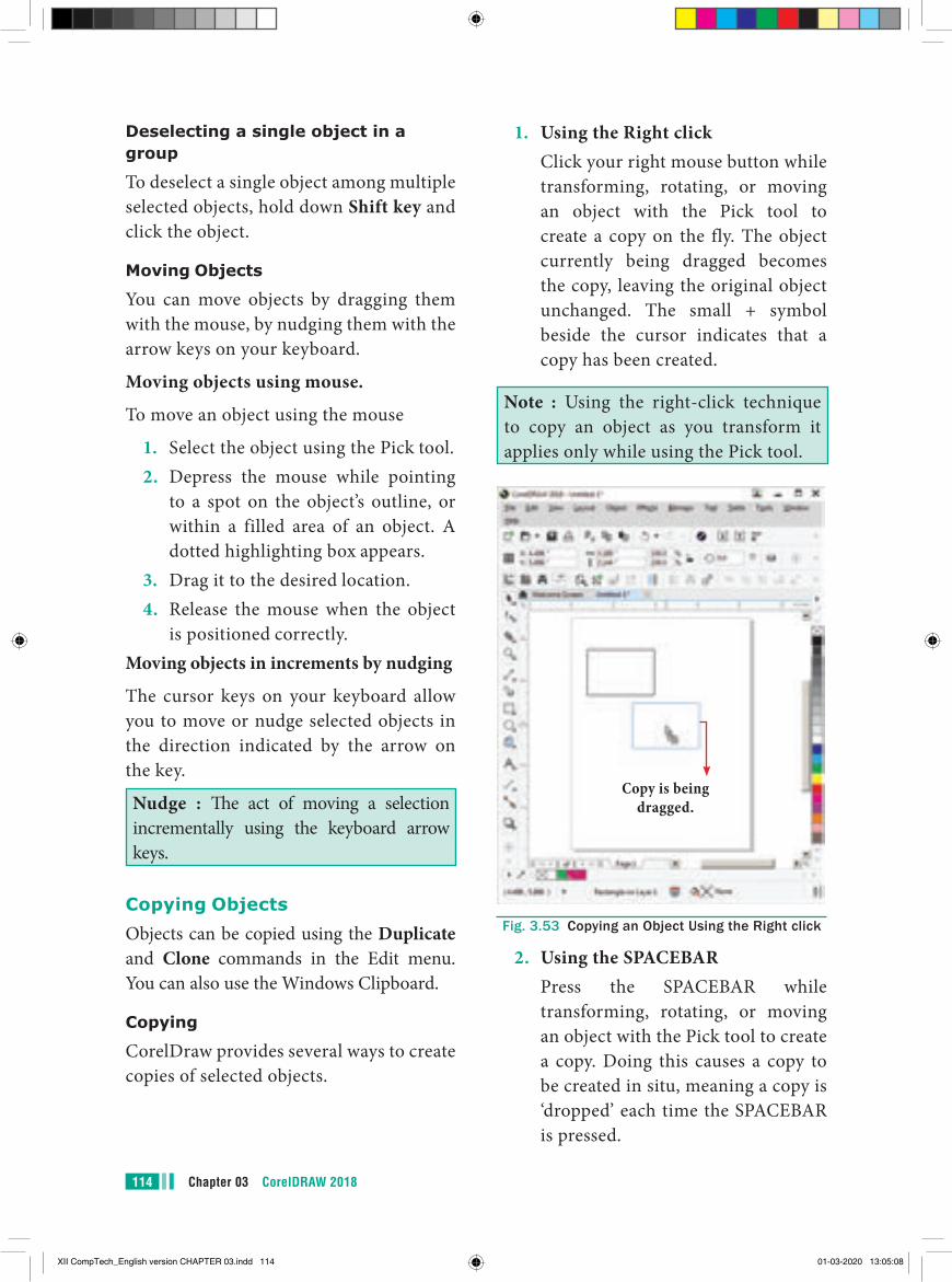
Chapter 03 CorelDRAW 2018114
1. Using the Right click Click your right mouse button while
transforming, rotating, or moving an object with the Pick tool to create a copy on the fly. The object currently being dragged becomes the copy, leaving the original object unchanged. The small + symbol beside the cursor indicates that a copy has been created.
Note : Using the right-click technique to copy an object as you transform it applies only while using the Pick tool.
Copy is being dragged.
Fig. 3.53 Copying an Object Using the Right click
2. Using the SPACEBAR Press the SPACEBAR while
transforming, rotating, or moving an object with the Pick tool to create a copy. Doing this causes a copy to be created in situ, meaning a copy is ‘dropped’ each time the SPACEBAR is pressed.
Deselecting a single object in a group
To deselect a single object among multiple selected objects, hold down Shift key and click the object.
Moving Objects
You can move objects by dragging them with the mouse, by nudging them with the arrow keys on your keyboard.
Moving objects using mouse.
To move an object using the mouse
1. Select the object using the Pick tool.2. Depress the mouse while pointing
to a spot on the object’s outline, or within a filled area of an object. A dotted highlighting box appears.
3. Drag it to the desired location.4. Release the mouse when the object
is positioned correctly.Moving objects in increments by nudging
The cursor keys on your keyboard allow you to move or nudge selected objects in the direction indicated by the arrow on the key.
Nudge : The act of moving a selection incrementally using the keyboard arrow keys.
Copying ObjectsObjects can be copied using the Duplicate and Clone commands in the Edit menu. You can also use the Windows Clipboard.
Copying
CorelDraw provides several ways to create copies of selected objects.
XII CompTech_English version CHAPTER 03.indd 114 01-03-2020 13:05:08
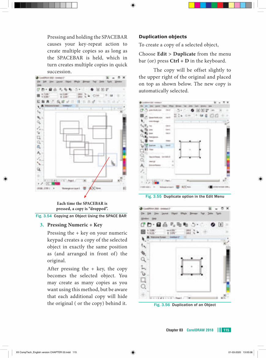
115Chapter 03 CorelDRAW 2018
Duplication objects
To create a copy of a selected object,
Choose Edit > Duplicate from the menu bar (or) press Ctrl + D in the keyboard.
The copy will be offset slightly to the upper right of the original and placed on top as shown below. The new copy is automatically selected.
Fig. 3.55 Duplicate option in the Edit Menu
Fig. 3.56 Duplication of an Object
Pressing and holding the SPACEBAR causes your key-repeat action to create multiple copies so as long as the SPACEBAR is held, which in turn creates multiple copies in quick succession.
Each time the SPACEBAR is pressed, a copy is “dropped”.
Fig. 3.54 Copying an Object Using the SPACE BAR
3. Pressing Numeric + Key Pressing the + key on your numeric
keypad creates a copy of the selected object in exactly the same position as (and arranged in front of) the original.
After pressing the + key, the copy becomes the selected object. You may create as many copies as you want using this method, but be aware that each additional copy will hide the original ( or the copy) behind it.
XII CompTech_English version CHAPTER 03.indd 115 01-03-2020 13:05:08
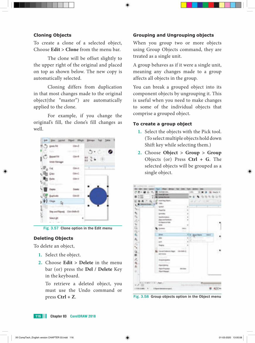
Chapter 03 CorelDRAW 2018116
Grouping and Ungrouping objects
When you group two or more objects using Group Objects command, they are treated as a single unit.
A group behaves as if it were a single unit, meaning any changes made to a group affects all objects in the group.
You can break a grouped object into its component objects by ungrouping it. This is useful when you need to make changes to some of the individual objects that comprise a grouped object.
To create a group object
1. Select the objects with the Pick tool. (To select multiple objects hold down Shift key while selecting them.)
2. Choose Object > Group > Group Objects (or) Press Ctrl + G. The selected objects will be grouped as a single object.
Fig. 3.58 Group objects option in the Object menu
Cloning Objects
To create a clone of a selected object, Choose Edit > Clone from the menu bar.
The clone will be offset slightly to the upper right of the original and placed on top as shown below. The new copy is automatically selected.
Cloning differs from duplication in that most changes made to the original object(the “master”) are automatically applied to the clone.
For example, if you change the original’s fill, the clone’s fill changes as well.
Fig. 3.57 Clone option in the Edit menu
Deleting Objects
To delete an object,
1. Select the object.2. Choose Edit > Delete in the menu
bar (or) press the Del / Delete Key in the keyboard.
To retrieve a deleted object, you must use the Undo command or press Ctrl + Z.
XII CompTech_English version CHAPTER 03.indd 116 01-03-2020 13:05:08
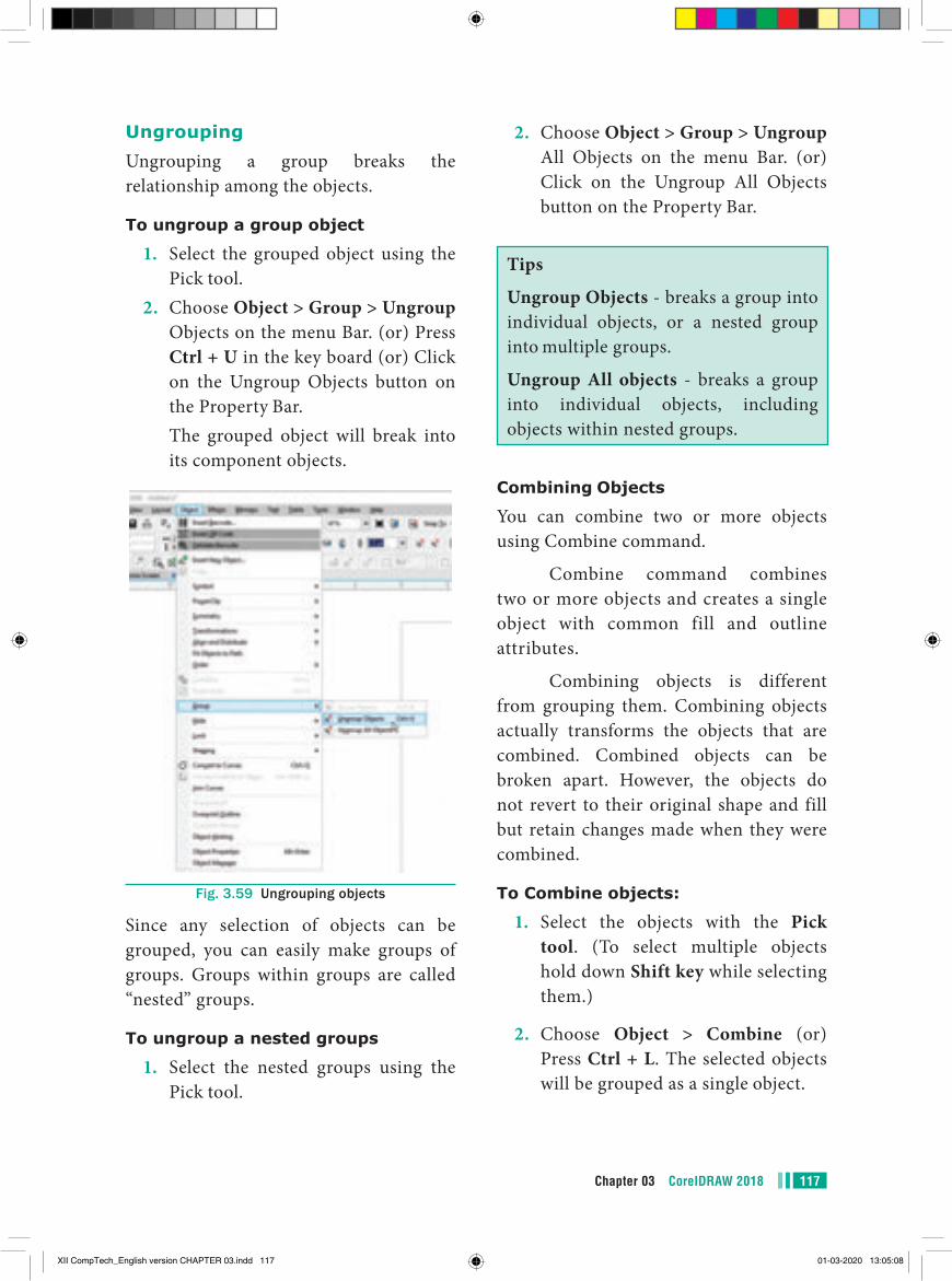
117Chapter 03 CorelDRAW 2018
UngroupingUngrouping a group breaks the relationship among the objects.
To ungroup a group object
1. Select the grouped object using the Pick tool.
2. Choose Object > Group > Ungroup Objects on the menu Bar. (or) Press Ctrl + U in the key board (or) Click on the Ungroup Objects button on the Property Bar.
The grouped object will break into its component objects.
Fig. 3.59 Ungrouping objects
Since any selection of objects can be grouped, you can easily make groups of groups. Groups within groups are called “nested” groups.
To ungroup a nested groups
1. Select the nested groups using the Pick tool.
2. Choose Object > Group > Ungroup All Objects on the menu Bar. (or) Click on the Ungroup All Objects button on the Property Bar.
Tips
Ungroup Objects - breaks a group into individual objects, or a nested group into multiple groups.
Ungroup All objects - breaks a group into individual objects, including objects within nested groups.
Combining Objects
You can combine two or more objects using Combine command.
Combine command combines two or more objects and creates a single object with common fill and outline attributes.
Combining objects is different from grouping them. Combining objects actually transforms the objects that are combined. Combined objects can be broken apart. However, the objects do not revert to their original shape and fill but retain changes made when they were combined.
To Combine objects:
1. Select the objects with the Pick tool. (To select multiple objects hold down Shift key while selecting them.)
2. Choose Object > Combine (or) Press Ctrl + L. The selected objects will be grouped as a single object.
XII CompTech_English version CHAPTER 03.indd 117 01-03-2020 13:05:08
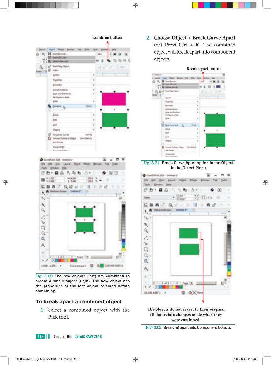
Chapter 03 CorelDRAW 2018118
Combine button
Fig. 3.60 The two objects (left) are combined to create a single object (right). The new object has the properties of the last object selected before combining.
To break apart a combined object
1. Select a combined object with the Pick tool.
2. Choose Object > Break Curve Apart (or) Press Ctrl + K. The combined object will break apart into component objects.
Break apart button
Fig. 3.61 Break Curve Apart option in the Object in the Object Menu
The objects do not revert to their original fill but retain changes made when they
were combined.Fig. 3.62 Breaking apart into Component Objects
XII CompTech_English version CHAPTER 03.indd 118 01-03-2020 13:05:08

119Chapter 03 CorelDRAW 2018
Fig. 3.64 The welded object takes on the properties of the object you selected last.
11. Working with TextCorelDRAW defines text in two ways : Artistic text and Paragraph text. You can enter text directly on the document page or through a text box. Paragraph text is better suited for long blocks of text whereas Artistic text offers you more freedom to assign artistic effects to letters.
Adding Artistic text
Artistic Text is used to create short pieces of text anywhere on the page. You can apply special effects and transformations to that text. If you are creating special effects with the text (for example, fitting it to a path, or blending and extruding it), you must enter it as Artistic text.
To add the Artistic text
1. Click the Text tool. The mouse pointer changes to a crosshair with a small ‘A’ beneath it.
Welding objectsBy welding you can create irregular shapes. The welded objects take on the outline and fill of the object that was selected last. Welded objects can revert to their original individual objects only by using the Undo button.
To weld objects using Property Bar
1. Select the objects with the Pick tool by holding the Shift key.
2. Choose Object > Shaping > Weld in the menu bar (or) Click on Weld button on the Property bar.
3. The objects will be welded and will become a single outline object.
If the marquee selected the objects when welding using the Property Bar, the welded object assumes the outline and the fill properties of the bottom-most selected object. If you use multiple selection, the welded object takes on the properties of the object you selected last.
Weld Button
Fig. 3.63 Weld option in the object Menu
XII CompTech_English version CHAPTER 03.indd 119 01-03-2020 13:05:08
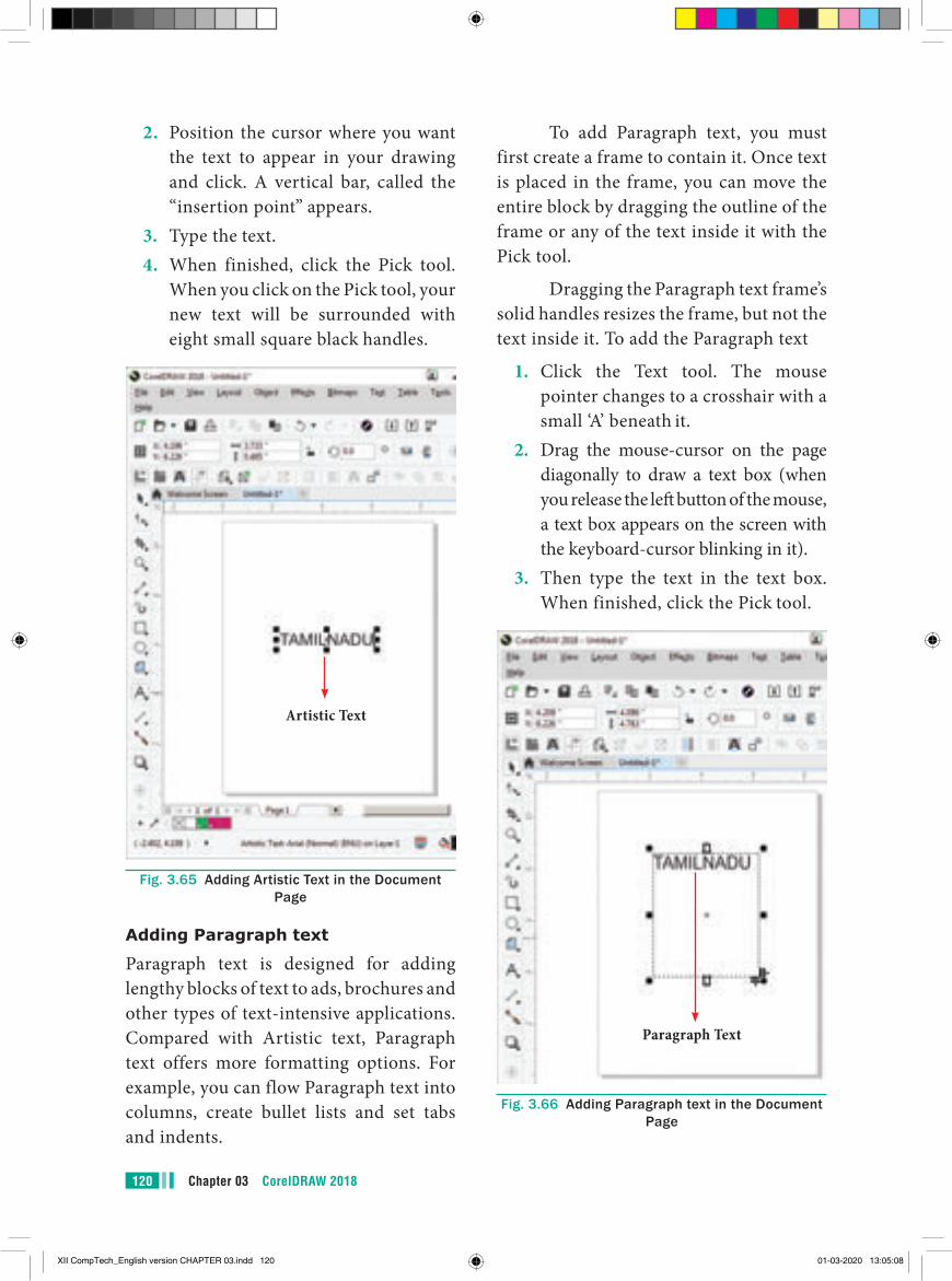
Chapter 03 CorelDRAW 2018120
To add Paragraph text, you must first create a frame to contain it. Once text is placed in the frame, you can move the entire block by dragging the outline of the frame or any of the text inside it with the Pick tool.
Dragging the Paragraph text frame’s solid handles resizes the frame, but not the text inside it. To add the Paragraph text
1. Click the Text tool. The mouse pointer changes to a crosshair with a small ‘A’ beneath it.
2. Drag the mouse-cursor on the page diagonally to draw a text box (when you release the left button of the mouse, a text box appears on the screen with the keyboard-cursor blinking in it).
3. Then type the text in the text box. When finished, click the Pick tool.
Paragraph Text
Fig. 3.66 Adding Paragraph text in the Document Page
2. Position the cursor where you want the text to appear in your drawing and click. A vertical bar, called the “insertion point” appears.
3. Type the text.4. When finished, click the Pick tool.
When you click on the Pick tool, your new text will be surrounded with eight small square black handles.
Artistic Text
Fig. 3.65 Adding Artistic Text in the Document Page
Adding Paragraph text
Paragraph text is designed for adding lengthy blocks of text to ads, brochures and other types of text-intensive applications. Compared with Artistic text, Paragraph text offers more formatting options. For example, you can flow Paragraph text into columns, create bullet lists and set tabs and indents.
XII CompTech_English version CHAPTER 03.indd 120 01-03-2020 13:05:08
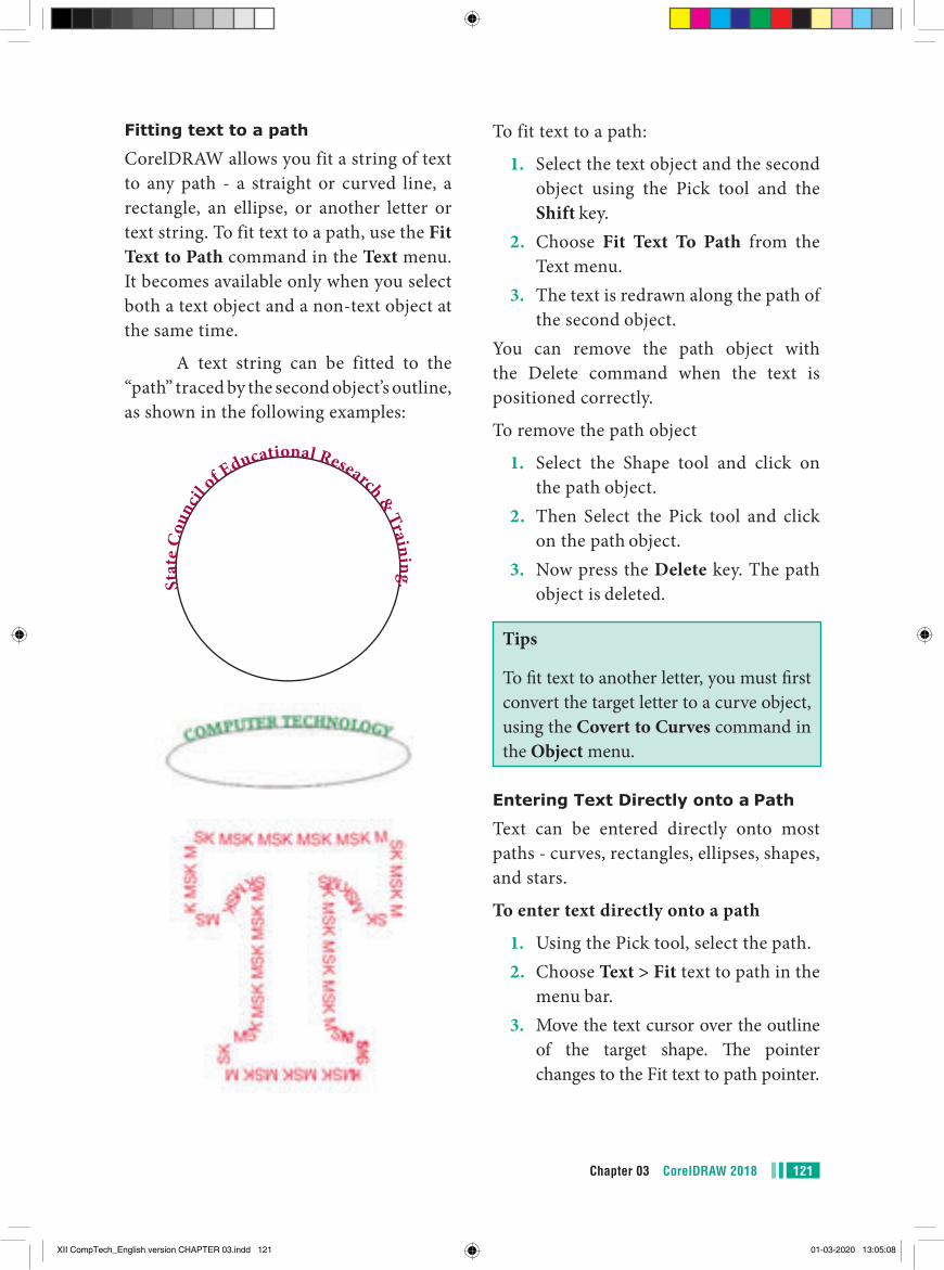
121Chapter 03 CorelDRAW 2018
To fit text to a path:
1. Select the text object and the second object using the Pick tool and the Shift key.
2. Choose Fit Text To Path from the Text menu.
3. The text is redrawn along the path of the second object.
You can remove the path object with the Delete command when the text is positioned correctly.
To remove the path object
1. Select the Shape tool and click on the path object.
2. Then Select the Pick tool and click on the path object.
3. Now press the Delete key. The path object is deleted.
Tips
To fit text to another letter, you must first convert the target letter to a curve object, using the Covert to Curves command in the Object menu.
Entering Text Directly onto a Path
Text can be entered directly onto most paths - curves, rectangles, ellipses, shapes, and stars.
To enter text directly onto a path
1. Using the Pick tool, select the path.2. Choose Text > Fit text to path in the
menu bar.3. Move the text cursor over the outline
of the target shape. The pointer changes to the Fit text to path pointer.
Fitting text to a path
CorelDRAW allows you fit a string of text to any path - a straight or curved line, a rectangle, an ellipse, or another letter or text string. To fit text to a path, use the Fit Text to Path command in the Text menu. It becomes available only when you select both a text object and a non-text object at the same time.
A text string can be fitted to the “path” traced by the second object’s outline, as shown in the following examples:
Stat
e C
ounc
il of E
ducational Research & Traini ng.
XII CompTech_English version CHAPTER 03.indd 121 01-03-2020 13:05:08
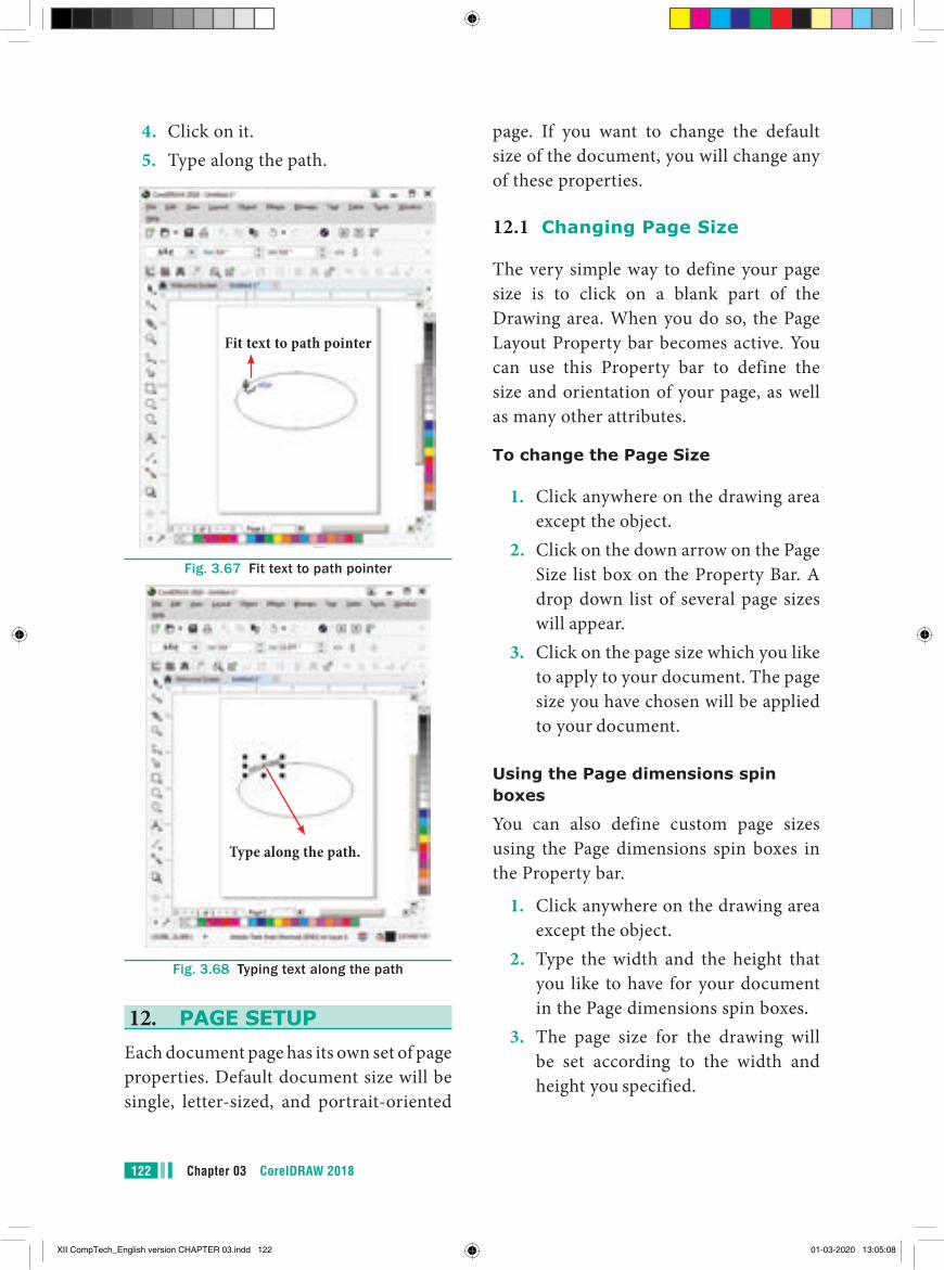
Chapter 03 CorelDRAW 2018122
page. If you want to change the default size of the document, you will change any of these properties.
12.1 Changing Page Size
The very simple way to define your page size is to click on a blank part of the Drawing area. When you do so, the Page Layout Property bar becomes active. You can use this Property bar to define the size and orientation of your page, as well as many other attributes.
To change the Page Size
1. Click anywhere on the drawing area except the object.
2. Click on the down arrow on the Page Size list box on the Property Bar. A drop down list of several page sizes will appear.
3. Click on the page size which you like to apply to your document. The page size you have chosen will be applied to your document.
Using the Page dimensions spin boxes
You can also define custom page sizes using the Page dimensions spin boxes in the Property bar.
1. Click anywhere on the drawing area except the object.
2. Type the width and the height that you like to have for your document in the Page dimensions spin boxes.
3. The page size for the drawing will be set according to the width and height you specified.
4. Click on it.5. Type along the path.
Fit text to path pointer
Fig. 3.67 Fit text to path pointer
Type along the path.
Fig. 3.68 Typing text along the path
12. PAGE SETUPEach document page has its own set of page properties. Default document size will be single, letter-sized, and portrait-oriented
XII CompTech_English version CHAPTER 03.indd 122 01-03-2020 13:05:08
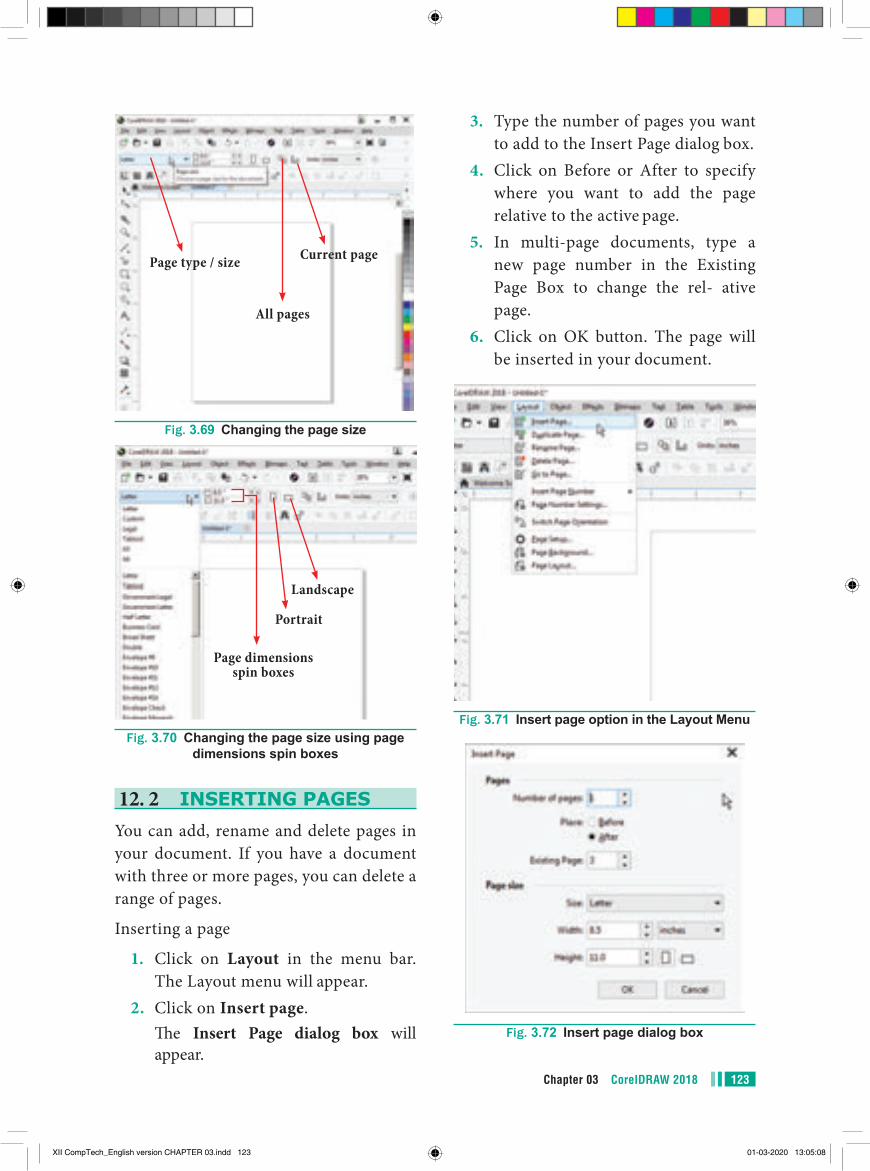
123Chapter 03 CorelDRAW 2018
Page type / size Current page
All pages
Fig. 3.69 Changing the page size
Landscape
Portrait
Page dimensions spin boxes
Fig. 3.70 Changing the page size using page dimensions spin boxes
12. 2 INSERTING PAGESYou can add, rename and delete pages in your document. If you have a document with three or more pages, you can delete a range of pages.
Inserting a page
1. Click on Layout in the menu bar. The Layout menu will appear.
2. Click on Insert page. The Insert Page dialog box will
appear.
3. Type the number of pages you want to add to the Insert Page dialog box.
4. Click on Before or After to specify where you want to add the page relative to the active page.
5. In multi-page documents, type a new page number in the Existing Page Box to change the rel- ative page.
6. Click on OK button. The page will be inserted in your document.
Fig. 3.71 Insert page option in the Layout Menu
Fig. 3.72 Insert page dialog box
XII CompTech_English version CHAPTER 03.indd 123 01-03-2020 13:05:08
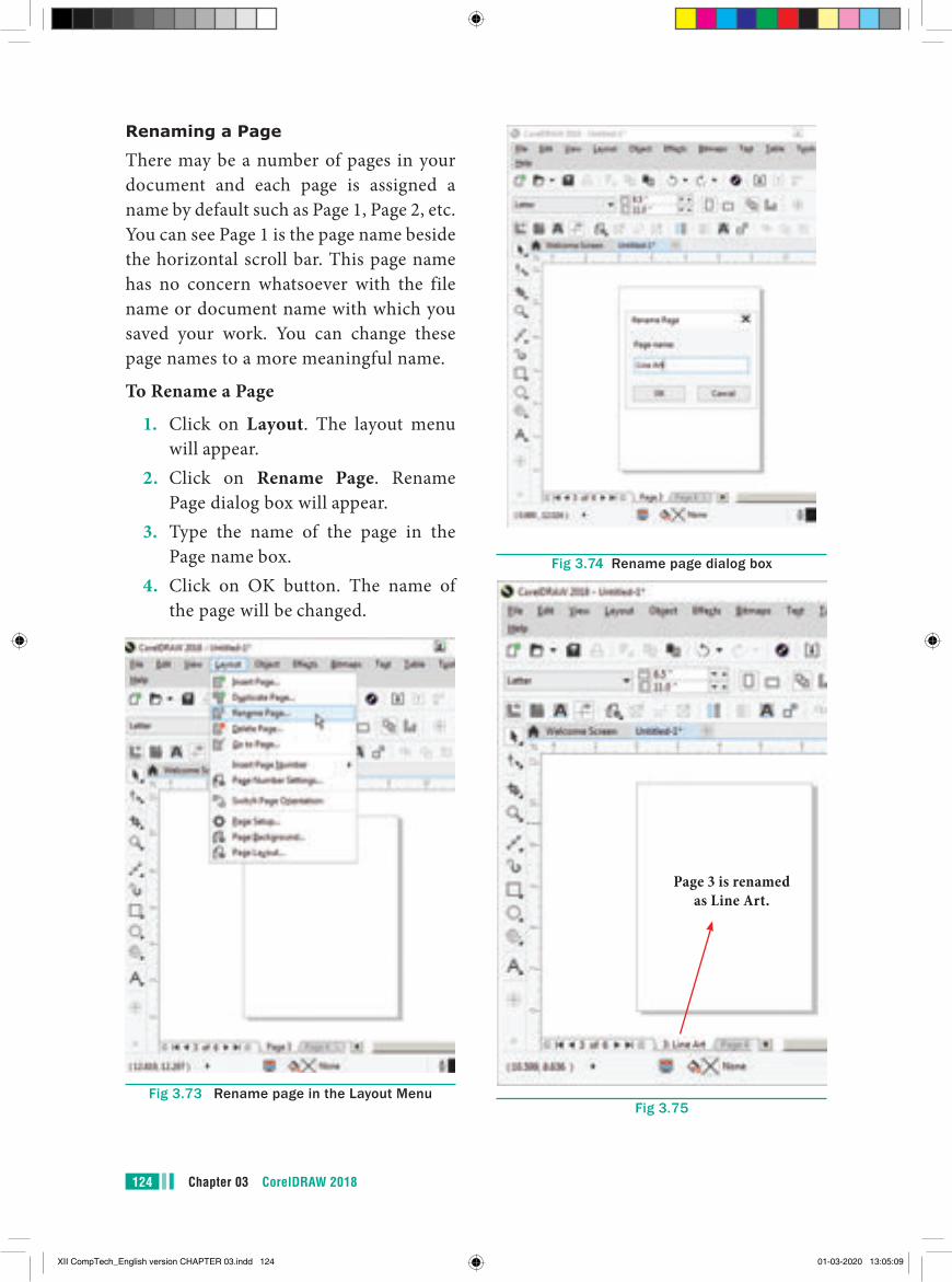
Chapter 03 CorelDRAW 2018124
Fig 3.74 Rename page dialog box
Page 3 is renamed as Line Art.
Fig 3.75
Renaming a Page
There may be a number of pages in your document and each page is assigned a name by default such as Page 1, Page 2, etc. You can see Page 1 is the page name beside the horizontal scroll bar. This page name has no concern whatsoever with the file name or document name with which you saved your work. You can change these page names to a more meaningful name.
To Rename a Page
1. Click on Layout. The layout menu will appear.
2. Click on Rename Page. Rename Page dialog box will appear.
3. Type the name of the page in the Page name box.
4. Click on OK button. The name of the page will be changed.
Fig 3.73 Rename page in the Layout Menu
XII CompTech_English version CHAPTER 03.indd 124 01-03-2020 13:05:09
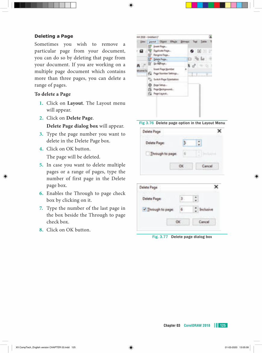
125Chapter 03 CorelDRAW 2018
FIg 3.76 Delete page option in the Layout Menu
Fig. 3.77 Delete page dialog box
Deleting a Page
Sometimes you wish to remove a particular page from your document, you can do so by deleting that page from your document. If you are working on a multiple page document which contains more than three pages, you can delete a range of pages.
To delete a Page
1. Click on Layout. The Layout menu will appear.
2. Click on Delete Page. Delete Page dialog box will appear.3. Type the page number you want to
delete in the Delete Page box.4. Click on OK button. The page will be deleted.5. In case you want to delete multiple
pages or a range of pages, type the number of first page in the Delete page box.
6. Enables the Through to page check box by clicking on it.
7. Type the number of the last page in the box beside the Through to page check box.
8. Click on OK button.
XII CompTech_English version CHAPTER 03.indd 125 01-03-2020 13:05:09
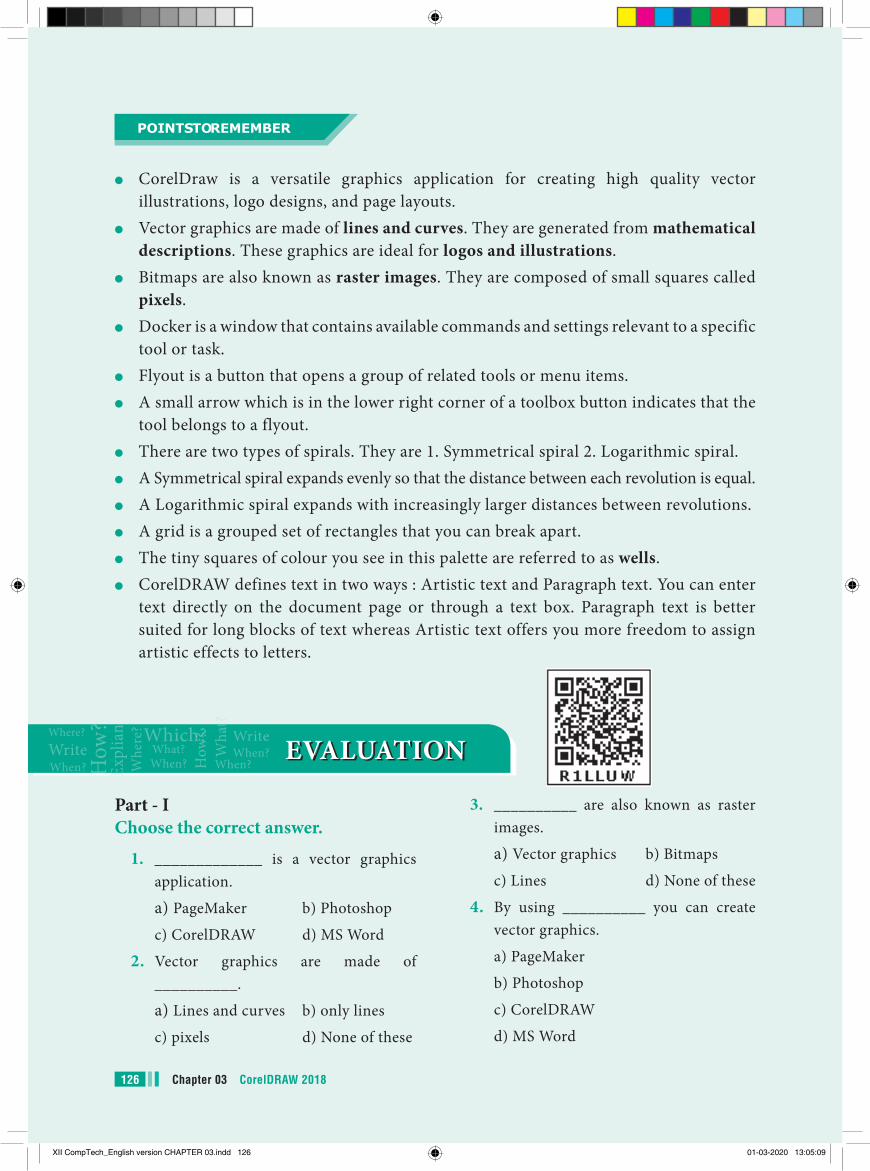
Chapter 03 CorelDRAW 2018126
3. __________ are also known as raster images.
a) Vector graphics b) Bitmaps
c) Lines d) None of these
4. By using __________ you can create vector graphics.
a) PageMaker
b) Photoshop
c) CorelDRAW
d) MS Word
Part - IChoose the correct answer.
1. _____________ is a vector graphics application.
a) PageMaker b) Photoshop
c) CorelDRAW d) MS Word
2. Vector graphics are made of __________.
a) Lines and curves b) only lines
c) pixels d) None of these
EVALUATION EVALUATION
●● CorelDraw is a versatile graphics application for creating high quality vector illustrations, logo designs, and page layouts.
●● Vector graphics are made of lines and curves. They are generated from mathematical descriptions. These graphics are ideal for logos and illustrations.
●● Bitmaps are also known as raster images. They are composed of small squares called pixels.
●● Docker is a window that contains available commands and settings relevant to a specific tool or task.
●● Flyout is a button that opens a group of related tools or menu items.●● A small arrow which is in the lower right corner of a toolbox button indicates that the
tool belongs to a flyout.●● There are two types of spirals. They are 1. Symmetrical spiral 2. Logarithmic spiral. ●● A Symmetrical spiral expands evenly so that the distance between each revolution is equal.●● A Logarithmic spiral expands with increasingly larger distances between revolutions.●● A grid is a grouped set of rectangles that you can break apart.●● The tiny squares of colour you see in this palette are referred to as wells.●● CorelDRAW defines text in two ways : Artistic text and Paragraph text. You can enter
text directly on the document page or through a text box. Paragraph text is better suited for long blocks of text whereas Artistic text offers you more freedom to assign artistic effects to letters.
POINTS TO REMEMBER
XII CompTech_English version CHAPTER 03.indd 126 01-03-2020 13:05:09
127Chapter 03 CorelDRAW 2018
14. To break apart a combined object, press __________
a) Ctrl + K b) Ctrl + C
c) Ctrl + S d) Ctrl +A
15. To combine two or more objects press _________
a) Ctrl + D b) Ctrl + L
c) Ctrl + S d) Ctrl +A
Part - II Answer the following Questions
(2 Marks)
1. What is CorelDRAW used for?2. Write the steps to create a New
Document in CorelDRAW.3. What is a docker in CorelDRAW?4. Write the steps to start CorelDRAW.5. What is an object in CorelDRAW?6. What is a property bar in
CorelDRAW?7. Why is a ruler used for in
CorelDRAW?8. Why is an artistic Media tool used in
CoreDRAW?9. Write the steps to group objects.10. Write the steps to ungroup a grouped
object.
Part - III Answer the following Questions
(3 Marks)
1. What are the differences between Vector graphics and bitmaps?
2. Write the steps to draw a rectangle in CorelDRAW.
3. Write the steps to draw a circle in CorelDRAW.
4. What are the two types of spirals? Explain.
5. ___________ is next to Standard tool bar.
a) Property bar
b) Title bar
c) Menu bar
d) status bar
6. Which tool is used to select an object?
a) Shape tool b) Zoom tool c) Pick tool
d) Crop tool
7. Which tool is used to draw a circle?
a) Shape tool b) Ellipse tool c) Rectangle tool
d) Crop tool
8. How many types of Spirals are there?
a) 5 b) 3 c) 2 d) 7
9. _________ key is used to select the Freehand tool.
a) F2 b) F3 c) F4 d) F5
10. To close a document in CorelDRAW, press _________
a) Ctrl + F4 b) Ctrl + F3
c) Shift + F4 d) Ctrl + F2
11. To exit CorelDraw, press ____________
a) Ctrl + F4 b) Ctrl + F3
c) Shift + F4 d) Alt + F4
12. ___________ key is used to deselect a single object.
a) Esc b) Ctrl
c) Shift d) Delete
13. _________ key combination is used to create a duplicate of a selected object.
a) Ctrl + D b) Ctrl + C
c) Ctrl + S d) Ctrl +A
XII CompTech_English version CHAPTER 03.indd 127 01-03-2020 13:05:09
Chapter 03 CorelDRAW 2018128
5. Flyout of which tool has star tool in it? What is that tool’s keyboard shortcut?
6. To correct your mistake in CorelDRAW what should you do? What is the keyboard shortcut to do it?
7. What do you do to convert a line into an arrow?
8. How will you assign a fill colour and outline colour to an object?
9. How to create duplication objects and Cloning objects? Write the difference between them.
10. What do you achieve by welding objects? Write the steps to weld objects.
Part - IVAnswer the following Questions
(5 Marks)1. Write the steps to draw a spiral.2. Write the steps to draw a polygon.3. How to create a star in CorelDRAW?4. Write the steps to draw a grid.5. Brief about Fitting text to a path.
Student Activities1. Design a collage of photos you have in a creative way using CorelDRAW.2. Create a newspaper advertisement for a product of your interest using
CorelDRAW.
XII CompTech_English version CHAPTER 03.indd 128 01-03-2020 13:05:09
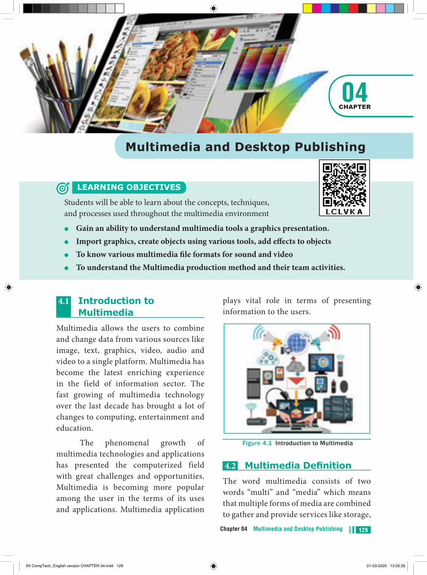
129Chapter 04 Multimedia and Desktop Publishing
plays vital role in terms of presenting information to the users.
Figure 4.1 Introduction to Multimedia
4.2 Multimedia DefinitionThe word multimedia consists of two words “multi” and “media” which means that multiple forms of media are combined to gather and provide services like storage,
4.1 Introduction to Multimedia
Multimedia allows the users to combine and change data from various sources like image, text, graphics, video, audio and video to a single platform. Multimedia has become the latest enriching experience in the field of information sector. The fast growing of multimedia technology over the last decade has brought a lot of changes to computing, entertainment and education.
The phenomenal growth of multimedia technologies and applications has presented the computerized field with great challenges and opportunities. Multimedia is becoming more popular among the user in the terms of its uses and applications. Multimedia application
Multimedia and Desktop Publishing
LEARNING OBJECTIVES
Students will be able to learn about the concepts, techniques, and processes used throughout the multimedia environment
●● Gain an ability to understand multimedia tools a graphics presentation.●● Import graphics, create objects using various tools, add effects to objects●● To know various multimedia file formats for sound and video●● To understand the Multimedia production method and their team activities.
04CHAPTER
XII CompTech_English version CHAPTER 04.indd 129 01-03-2020 13:05:35
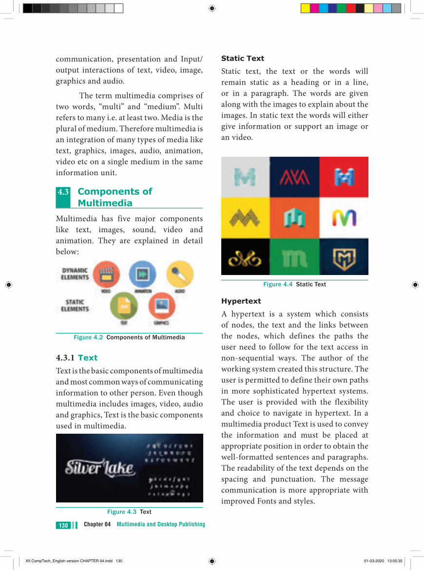
Chapter 04 Multimedia and Desktop Publishing130
communication, presentation and Input/output interactions of text, video, image, graphics and audio.
The term multimedia comprises of two words, “multi” and “medium”. Multi refers to many i.e. at least two. Media is the plural of medium. Therefore multimedia is an integration of many types of media like text, graphics, images, audio, animation, video etc on a single medium in the same information unit.
4.3 Components of Multimedia
Multimedia has five major components like text, images, sound, video and animation. They are explained in detail below:
Figure 4.2 Components of Multimedia
4.3.1 TextText is the basic components of multimedia and most common ways of communicating information to other person. Even though multimedia includes images, video, audio and graphics, Text is the basic components used in multimedia.
Figure 4.3 Text
Static Text
Static text, the text or the words will remain static as a heading or in a line, or in a paragraph. The words are given along with the images to explain about the images. In static text the words will either give information or support an image or an video.
Figure 4.4 Static Text
Hypertext
A hypertext is a system which consists of nodes, the text and the links between the nodes, which defines the paths the user need to follow for the text access in non-sequential ways. The author of the working system created this structure. The user is permitted to define their own paths in more sophisticated hypertext systems. The user is provided with the flexibility and choice to navigate in hypertext. In a multimedia product Text is used to convey the information and must be placed at appropriate position in order to obtain the well-formatted sentences and paragraphs. The readability of the text depends on the spacing and punctuation. The message communication is more appropriate with improved Fonts and styles.
XII CompTech_English version CHAPTER 04.indd 130 01-03-2020 13:05:35
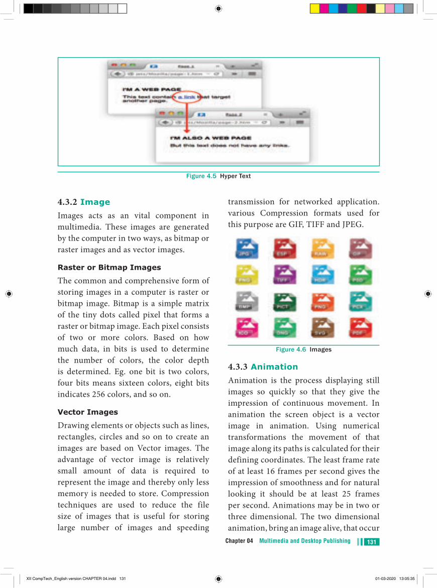
131Chapter 04 Multimedia and Desktop Publishing
4.3.2 ImageImages acts as an vital component in multimedia. These images are generated by the computer in two ways, as bitmap or raster images and as vector images.
Raster or Bitmap Images
The common and comprehensive form of storing images in a computer is raster or bitmap image. Bitmap is a simple matrix of the tiny dots called pixel that forms a raster or bitmap image. Each pixel consists of two or more colors. Based on how much data, in bits is used to determine the number of colors, the color depth is determined. Eg. one bit is two colors, four bits means sixteen colors, eight bits indicates 256 colors, and so on.
Vector Images
Drawing elements or objects such as lines, rectangles, circles and so on to create an images are based on Vector images. The advantage of vector image is relatively small amount of data is required to represent the image and thereby only less memory is needed to store. Compression techniques are used to reduce the file size of images that is useful for storing large number of images and speeding
transmission for networked application. various Compression formats used for this purpose are GIF, TIFF and JPEG.
Figure 4.6 Images
4.3.3 AnimationAnimation is the process displaying still images so quickly so that they give the impression of continuous movement. In animation the screen object is a vector image in animation. Using numerical transformations the movement of that image along its paths is calculated for their defining coordinates. The least frame rate of at least 16 frames per second gives the impression of smoothness and for natural looking it should be at least 25 frames per second. Animations may be in two or three dimensional. The two dimensional animation, bring an image alive, that occur
Figure 4.5 Hyper Text
XII CompTech_English version CHAPTER 04.indd 131 01-03-2020 13:05:35
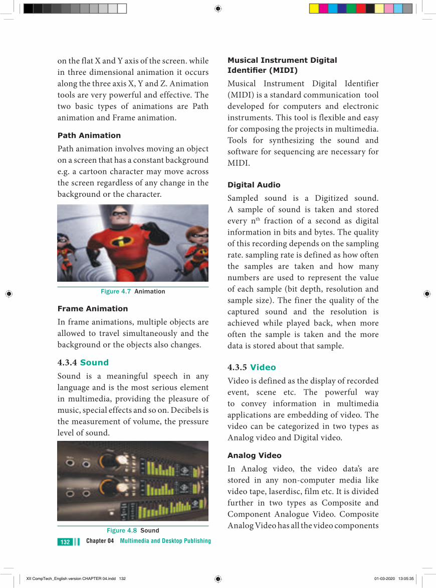
Chapter 04 Multimedia and Desktop Publishing132
on the flat X and Y axis of the screen. while in three dimensional animation it occurs along the three axis X, Y and Z. Animation tools are very powerful and effective. The two basic types of animations are Path animation and Frame animation.
Path Animation
Path animation involves moving an object on a screen that has a constant background e.g. a cartoon character may move across the screen regardless of any change in the background or the character.
Figure 4.7 Animation
Frame Animation
In frame animations, multiple objects are allowed to travel simultaneously and the background or the objects also changes.
4.3.4 SoundSound is a meaningful speech in any language and is the most serious element in multimedia, providing the pleasure of music, special effects and so on. Decibels is the measurement of volume, the pressure level of sound.
Figure 4.8 Sound
Musical Instrument Digital Identifier (MIDI)
Musical Instrument Digital Identifier (MIDI) is a standard communication tool developed for computers and electronic instruments. This tool is flexible and easy for composing the projects in multimedia. Tools for synthesizing the sound and software for sequencing are necessary for MIDI.
Digital Audio
Sampled sound is a Digitized sound. A sample of sound is taken and stored every nth fraction of a second as digital information in bits and bytes. The quality of this recording depends on the sampling rate. sampling rate is defined as how often the samples are taken and how many numbers are used to represent the value of each sample (bit depth, resolution and sample size). The finer the quality of the captured sound and the resolution is achieved while played back, when more often the sample is taken and the more data is stored about that sample.
4.3.5 VideoVideo is defined as the display of recorded event, scene etc. The powerful way to convey information in multimedia applications are embedding of video. The video can be categorized in two types as Analog video and Digital video.
Analog Video
In Analog video, the video data’s are stored in any non-computer media like video tape, laserdisc, film etc. It is divided further in two types as Composite and Component Analogue Video. Composite Analog Video has all the video components
XII CompTech_English version CHAPTER 04.indd 132 01-03-2020 13:05:35

133Chapter 04 Multimedia and Desktop Publishing
like brightness, color, and synchronization combined into one signal. Due to the combining of the video components, the quality of the composite video resulted in color blending, low clarity and high generational loss. This recording format was used for customer analog video recording tape formats such as Betamax and VHS.
4.4 File Formats for Multimedia
The following is an outline of current file formats used for the production and delivery of multimedia data.
4.4.1 Text Formats
RTF
Rich Text Format is the primary file format introduced in 1987 by Microsoft with the specification of their published products and for cross-platform documents interchange.
Plain text
Plain text files can be opened, read, and edited with most text editors. commonly used are Notepad (Windows), Gedit or nano (Unix, Linux), TextEdit (Mac OS X) and so on. Other computer programs are also capable of reading and importing plain text. Plain text is the original and popular way of conveying an e-mail.
4.4.2 Image Formats TIFF (Tagged Image File Format)
This format is common in desktop publishing world (high quality output), and is supported by almost all software packages. Recent versions of TIFF allows
image compression, and the format is comfortable for moving large files between computers.
BMP (Bitmap)
Initially this format is in use with Windows 3.1. It is quite large and uncompressed and hence BMP is used for the high-resolution or large images.
DIB (Device Independent Bitmap)
This format which is similar to BMP, allows the files to be displayed on a variety of devices.
GIF (Graphics Interchange Format)
GIF is a compressed image format. Most of the computer color images and backgrounds are GIF files. This file format is best suitable for graphics that uses only limited colors, and it is the most popular format used for online color photos. 13-bit Color look up table is used by the GIF format to identify its color values. This format is supported widely.
JPEG (Joint Photographic Experts Group)
JPEG was designed to attain maximum image compression. It uses lossy compression technique, where a compression method is referred that loses some of the data required for the image reconstruction. It works good with photographs, naturalistic artwork, and similar material but functions less on lettering, live drawings or simple cartoons.
TGA (Tagra)
It is the first popular format for high-resolution images. TGA is supported by Most of the video-capture boards.
XII CompTech_English version CHAPTER 04.indd 133 01-03-2020 13:05:35
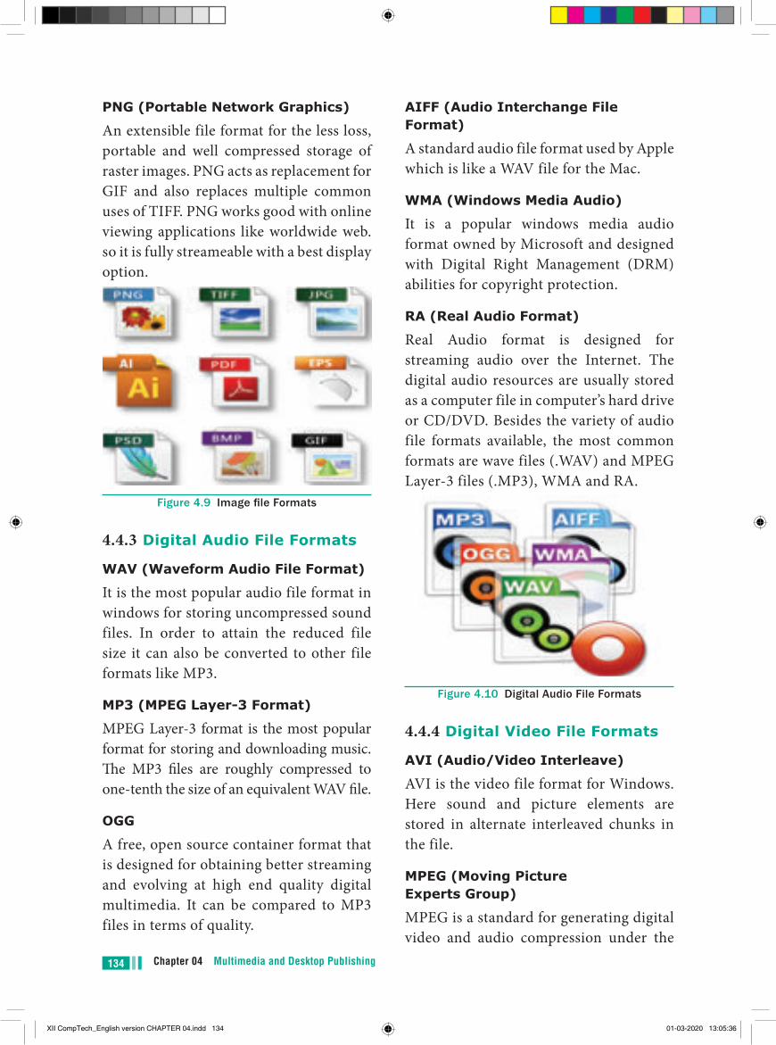
Chapter 04 Multimedia and Desktop Publishing134
PNG (Portable Network Graphics)
An extensible file format for the less loss, portable and well compressed storage of raster images. PNG acts as replacement for GIF and also replaces multiple common uses of TIFF. PNG works good with online viewing applications like worldwide web. so it is fully streameable with a best display option.
Figure 4.9 Image file Formats
4.4.3 Digital Audio File Formats
WAV (Waveform Audio File Format)
It is the most popular audio file format in windows for storing uncompressed sound files. In order to attain the reduced file size it can also be converted to other file formats like MP3.
MP3 (MPEG Layer-3 Format)
MPEG Layer-3 format is the most popular format for storing and downloading music. The MP3 files are roughly compressed to one-tenth the size of an equivalent WAV file.
OGG
A free, open source container format that is designed for obtaining better streaming and evolving at high end quality digital multimedia. It can be compared to MP3 files in terms of quality.
AIFF (Audio Interchange File Format)
A standard audio file format used by Apple which is like a WAV file for the Mac.
WMA (Windows Media Audio)
It is a popular windows media audio format owned by Microsoft and designed with Digital Right Management (DRM) abilities for copyright protection.
RA (Real Audio Format)
Real Audio format is designed for streaming audio over the Internet. The digital audio resources are usually stored as a computer file in computer’s hard drive or CD/DVD. Besides the variety of audio file formats available, the most common formats are wave files (.WAV) and MPEG Layer-3 files (.MP3), WMA and RA.
Figure 4.10 Digital Audio File Formats
4.4.4 Digital Video File Formats
AVI (Audio/Video Interleave)
AVI is the video file format for Windows. Here sound and picture elements are stored in alternate interleaved chunks in the file.
MPEG (Moving Picture Experts Group)
MPEG is a standard for generating digital video and audio compression under the
XII CompTech_English version CHAPTER 04.indd 134 01-03-2020 13:05:36
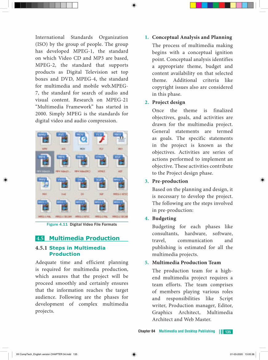
135Chapter 04 Multimedia and Desktop Publishing
International Standards Organization (ISO) by the group of people. The group has developed MPEG-1, the standard on which Video CD and MP3 are based, MPEG-2, the standard that supports products as Digital Television set top boxes and DVD, MPEG-4, the standard for multimedia and mobile web.MPEG-7, the standard for search of audio and visual content. Research on MPEG-21 “Multimedia Framework” has started in 2000. Simply MPEG is the standards for digital video and audio compression.
Figure 4.11 Digital Video File Formats
4.5 Multimedia Production4.5.1 Steps in Multimedia
ProductionAdequate time and efficient planning is required for multimedia production, which assures that the project will be proceed smoothly and certainly ensures that the information reaches the target audience. Following are the phases for development of complex multimedia projects.
1. Conceptual Analysis and Planning The process of multimedia making
begins with a conceptual ignition point. Conceptual analysis identifies a appropriate theme, budget and content availability on that selected theme. Additional criteria like copyright issues also are considered in this phase.
2. Project design Once the theme is finalized
objectives, goals, and activities are drawn for the multimedia project. General statements are termed as goals. The specific statements in the project is known as the objectives. Activities are series of actions performed to implement an objective. These activities contribute to the Project design phase.
3. Pre-production Based on the planning and design, it
is necessary to develop the project. The following are the steps involved in pre-production:
4. Budgeting Budgeting for each phases like
consultants, hardware, software, travel, communication and publishing is estimated for all the multimedia projects.
5. Multimedia Production Team The production team for a high-
end multimedia project requires a team efforts. The team comprises of members playing various roles and responsibilities like Script writer, Production manager, Editor, Graphics Architect, Multimedia Architect and Web Master.
XII CompTech_English version CHAPTER 04.indd 135 01-03-2020 13:05:36
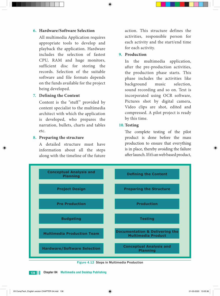
Chapter 04 Multimedia and Desktop Publishing136
6. Hardware/Software Selection All multimedia Application requires
appropriate tools to develop and playback the application. Hardware includes the selection of fastest CPU, RAM and huge monitors, sufficient disc for storing the records. Selection of the suitable software and file formats depends on the funds available for the project being developed.
7. Defining the Content Content is the “stuff ” provided by
content specialist to the multimedia architect with which the application is developed, who prepares the narration, bullets, charts and tables etc.
8. Preparing the structure A detailed structure must have
information about all the steps along with the timeline of the future
action. This structure defines the activities, responsible person for each activity and the start/end time for each activity.
9. Production In the multimedia application,
after the pre-production activities, the production phase starts. This phase includes the activities like background music selection, sound recording and so on. Text is incorporated using OCR software, Pictures shot by digital camera, Video clips are shot, edited and compressed. A pilot project is ready by this time.
10. Testing The complete testing of the pilot
product is done before the mass production to ensure that everything is in place, thereby avoiding the failure after launch. If it’s an web based product,
Figure 4.12 Steps in Multimedia Production
Conceptual Analysis and Planning
Conceptual Analysis and Planning
Defining the Content
Preparing the StructureProject Design
Pre Production Production
Testing
Documentation & Delivering the Multimedia Product
Budgeting
Multimedia Production Team
Hardware/Software Selection
XII CompTech_English version CHAPTER 04.indd 136 01-03-2020 13:05:36
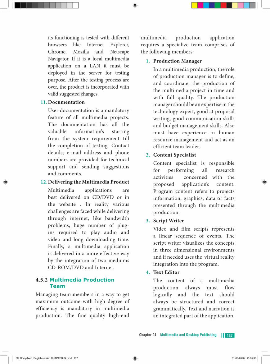
137Chapter 04 Multimedia and Desktop Publishing
its functioning is tested with different browsers like Internet Explorer, Chrome, Mozilla and Netscape Navigator. If it is a local multimedia application on a LAN it must be deployed in the server for testing purpose. After the testing process are over, the product is incorporated with valid suggested changes.
11. Documentation User documentation is a mandatory
feature of all multimedia projects. The documentation has all the valuable information’s starting from the system requirement till the completion of testing. Contact details, e-mail address and phone numbers are provided for technical support and sending suggestions and comments.
12. Delivering the Multimedia Product Multimedia applications are
best delivered on CD/DVD or in the website . In reality various challenges are faced while delivering through internet, like bandwidth problems, huge number of plug-ins required to play audio and video and long downloading time. Finally, a multimedia application is delivered in a more effective way by the integration of two mediums CD-ROM/DVD and Internet.
4.5.2 Multimedia Production Team
Managing team members in a way to get maximum outcome with high degree of efficiency is mandatory in multimedia production. The fine quality high-end
multimedia production application requires a specialize team comprises of the following members:
1. Production Manager In a multimedia production, the role
of production manager is to define, and coordinate, the production of the multimedia project in time and with full quality. The production manager should be an expertise in the technology expert, good at proposal writing, good communication skills and budget management skills. Also must have experience in human resource management and act as an efficient team leader.
2. Content Specialist Content specialist is responsible
for performing all research activities concerned with the proposed application’s content. Program content refers to projects information, graphics, data or facts presented through the multimedia production.
3. Script Writer Video and film scripts represents
a linear sequence of events. The script writer visualizes the concepts in three dimensional environments and if needed uses the virtual reality integration into the program.
4. Text Editor The content of a multimedia
production always must flow logically and the text should always be structured and correct grammatically. Text and narration is an integrated part of the application.
XII CompTech_English version CHAPTER 04.indd 137 01-03-2020 13:05:36
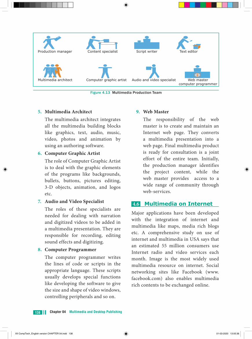
Chapter 04 Multimedia and Desktop Publishing138
5. Multimedia Architect The multimedia architect integrates
all the multimedia building blocks like graphics, text, audio, music, video, photos and animation by using an authoring software.
6. Computer Graphic Artist The role of Computer Graphic Artist
is to deal with the graphic elements of the programs like backgrounds, bullets, buttons, pictures editing, 3-D objects, animation, and logos etc.
7. Audio and Video Specialist The roles of these specialists are
needed for dealing with narration and digitized videos to be added in a multimedia presentation. They are responsible for recording, editing sound effects and digitizing.
8. Computer Programmer The computer programmer writes
the lines of code or scripts in the appropriate language. These scripts usually develops special functions like developing the software to give the size and shape of video windows, controlling peripherals and so on.
9. Web Master The responsibility of the web
master is to create and maintain an Internet web page. They converts a multimedia presentation into a web page. Final multimedia product is ready for consultation is a joint effort of the entire team. Initially, the production manager identifies the project content, while the web master provides access to a wide range of community through web-services.
4.6 Multimedia on Internet Major applications have been developed with the integration of internet and multimedia like maps, media rich blogs etc. A comprehensive study on use of internet and multimedia in USA says that an estimated 55 million consumers use Internet radio and video services each month. Image is the most widely used multimedia resource on internet. Social networking sites like Facebook (www.facebook.com) also enables multimedia rich contents to be exchanged online.
Figure 4.13 Multimedia Production Team
Production manager Content specialist Script writer Text editor
Web mastercomputer programmer
Audio and video specialistComputer graphic artistMultimedia architect
XII CompTech_English version CHAPTER 04.indd 138 01-03-2020 13:05:36

139Chapter 04 Multimedia and Desktop Publishing
Figure 4.14 Multimedia on Internet
4.7 Applications of Multimedia
Multimedia is the most fast growing area in the field of information technology. A Multimedia is an application which has in its use collection of multiple media sources like text, images, sound/audio, animation and video on a single platform. Predominantly, Entertainment and Education are the fields where multimedia is used in majority.
1. Education Multimedia plays an vital role in
offering an excellent alternative method to traditional teaching by allowing the students to explore and learn various concepts through animation. Students, teachers and the parents enjoy this multimedia mode of learning and multimedia learning materials. Many educators accepts multimedia introduces new ways of thinking in the classroom. Multimedia based teaching and learning system named as MODULO at GMU in Germany developed is a web-based environment that aims to
provide students with flexible and decentralized learning environment based on their educational background.
In India, multimedia is used in different ways for teaching and learning like e-learning, distance learning, virtual learning and so on. EDUSAT (Education Satellite) is launched in India for serving the educational sector of the country for emulating virtual classroom in an effective manner.
2. Entertainment The remarkable advancement in the
entertainment industry is due to the Multimedia Technology mainly. This technology is needed in all mode of entertainment like radio, TV, online gaming, video on demand etc.
Video on demand or movies on demand is a service that provides movies to television sets on an individual basis at homes. Movies are stored in a central server and transmitted through a communication network. A
XII CompTech_English version CHAPTER 04.indd 139 01-03-2020 13:05:36
Chapter 04 Multimedia and Desktop Publishing140
set-top box connected to the communication network converts the digital information to analog signals and inputs it to the television set.
3. Business Systems Business applications for
multimedia include presentations, training, internet protocols and so on. The marketing and advertising agencies are using animation techniques for sales promotion. Multimedia is used very commonly for building employee ID. High resolution projectors are common for multimedia presentations on the road. Cell phones and personal digital assistants with Bluetooth and Wi-Fi communication technology makes multimedia communication for business more efficiently.
4. Medical Services Medical services are grown drastically
with the development of multimedia. Medical Students practices surgery methods via simulation prior to actual surgery. Tiny digital cameras are inserted in human body and it displays the inner scene of the body. In this way the medical practitioners were able to see the inner part without dissecting it.
5. Public Places Multimedia is available in many
public places like trade shows, libraries, railway stations, museums, malls, airports, banks, hotels and exhibitions in the form of kiosks. It provides information to the customers and helps them. The information presented in kiosk are
enriched with animation, video, still pictures, graphics, diagrams, maps, audio and text. Banks uses kiosks in the form of ATM machines.
6. Multimedia Conferencing Multimedia conferencing or video-
conferencing is a system that performs face-to-face interactions among participating users, located far from each other, as if they were sitting and discussing in a single room.
4.8 Libraries, Information Centers and Archives
The primary function of library is to organize, collect, preserve, and disseminate information to users. Several techniques and technologies are in use for handling the information more effectively. Multimedia technology is adopted by the libraries in various functions like multimedia kiosks, user orientation programs etc. Following is the brief account of multimedia technology applications in libraries.
1. Multimedia Kiosk Kiosk is a free-standing furnished
equipped multimedia computer that allow users to retrieve information via a touch screen. It is commonly used in airports and other public locations to provide directions and few mandatory information’s. In an library, Kiosk is usually located near the entrance of the library, used for displaying announcements, reading lists, comments and suggestions from library users and other information’s about operations and programs of the library.
XII CompTech_English version CHAPTER 04.indd 140 01-03-2020 13:05:36
141Chapter 04 Multimedia and Desktop Publishing
2. Webcasting and Video Conferencing
The live telecast of real time programs through internet is known as Webcasting. Video conferencing is the process of conducting conference between more than two participants at different sites by using computer networks to transmit audio and video data.
3. User Orientation Program The role of multimedia plays an
vital role in training the librarians in schools, colleges and universities due to its interactivity. Hence, it is used in depth subject training to their faculties.
4. In-house Production of Multimedia Resources and E-publishing
Many libraries produce multimedia resources in-house, to serve the
parent organization. Introduction of CD/DVD and their writers has solved few of the problems of libraries in storing or achieving the materials. Multimedia tools along with CD-writers is made possible to publish information from different sources in a most easy to use and acceptable form to library users.
5. Digital Multimedia Libraries Information’s are available in
digital formats that include digital books, scanned images, graphics and digitized audio-visual clips etc. Initially digital library projects were based only on textual data, later it was on all other media elements like images, audio and video recordings were also integrated under the collection of digital library.
●● Multimedia allows the users to combine and change data from various sources like image, text, graphics, video, audio and video to a single platform.
●● Multimedia has five major components like text, images, sound, video and animation.●● Static text, the text or the words will remain static as a heading or in a line, or in a paragraph.●● A hypertext is a system which consists of nodes, the text and the links between the nodes,
which defines the paths the user need to follow for the text access in non-sequential ways.●● Images acts as an vital component in multimedia. These images are generated by the
computer in two ways, as bitmap or raster images and as vector images.●● Animation is the process displaying still images so quickly so that they give the impression
of continuous movement. In animation the screen object is a vector image in animation.●● Sound is a meaningful speech in any language and is the most serious element in multimedia,
providing the pleasure of music, special effects and so on.●● Musical Instrument Digital Identifier (MIDI) is a standard communication tool developed
for computers and electronic instruments.●● video can be categorized in two types as Analog video and Digital video.
points to remember
XII CompTech_English version CHAPTER 04.indd 141 01-03-2020 13:05:36
Chapter 04 Multimedia and Desktop Publishing142
Multimedia Multimedia allows the users to combine and change data from various sources like image, text, graphics, video, audio and video to a single platform.
Raster or Bitmap Images The common and comprehensive form of storing images in a computer is raster or bitmap image.
Vector Images I is relatively small amount of data is required to represent the image and thereby only less memory is needed to store.
Animation Animation is the process displaying still images so quickly so that they give the impression of continuous movement. In animation the screen object is a vector image in animation.
Path Animation Path animation involves moving an object on a screen that has a constant background e.g. a cartoon character may move across the screen regardless of any change in the background or the character.
Musical Instrument Digital Identifier (MIDI)
Musical Instrument Digital Identifier (MIDI) is a standard communication tool developed for computers and electronic instruments.
XII CompTech_English version CHAPTER 04.indd 142 01-03-2020 13:05:36
143Chapter 04 Multimedia and Desktop Publishing
EVALUATION EVALUATION
Part - I Choose the correct answer
1. ________ refers to any type of application that involves more than one type of media such as text, graphics video animation and sound
a) an executable file b) desktop publishing c) multimedia d) hypertext2. one of the disadvantages of the
multimedia is its __ a) cost b) adaptability c) usability d) relativity3. expand JPEG a) joint photo experts gross b) joint photographic experts group c) joint processor experts group d) joint photographic expression
group4. you need hardware, software and __
to make multimedia a) network b) compact disk drive c) good idea d) programming knowledge5. match the following by choosing the
right one 1. Text – TGA 2. Image – MIDI
3. Sound – MPEG 4. Video – RTF a. 1, 2, 3, 4 b. 2, 3, 4, 1 c. 4, 1, 2, 3 d. 3, 4, 1, 26. find the odd one on the following
which is not an image format a) TIFF b) BMP c) RTF d) JPEG7. ___ is the process displaying
still images they give continuous movement
a) Text formats b) Sound c) MP3 d) Animation8. The live telecasting of real time
program through Internet is known as ____
a) web casting b) web hosting c) data manipulation d) none of the above9. GIF use _______ color look up table a) 8 bit b) 8 KB c) 8 MB d) 8 GB10. RTF file format was introduced by
______ a) TCS b) Microsoft c) A pple d) IBM
XII CompTech_English version CHAPTER 04.indd 143 01-03-2020 13:05:36
Chapter 04 Multimedia and Desktop Publishing144
Part - II Short Answers 1. Define Multimedia and their features 2. List out Multimedia Components
3. Classify the TEXT component in multimedia
4. Classify the IMAGE component in multimedia
5. Define Animation and their features 6. List out image file formats 7. List out audio file formats 8. List out video file formats 9. Define Multimedia Production 10. List out Multimedia Production
team members
Part - IIIExplain in Brief Answer
1. Briefly explain about Multimedia Components
2. Describe the features and techniques of animation
3. Write roles and responsibilities of Production team members
4. Describe the various file formats in multimedia
5. Explain animation industry and their scope
Part - IVExplain in detail
1. Explain in detail Process of Multimedia
2. Explain in detail Techniques of Animation
3. Explore the opportunities Animation filed movie industry
4. Explain in detail about production team Roles and Responsibilities
5. Explain about different file formats in multimedia files
XII CompTech_English version CHAPTER 04.indd 144 01-03-2020 13:05:36
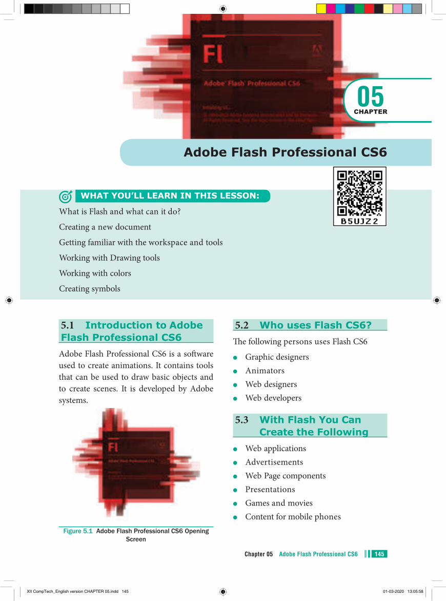
5.1 Introduction to Adobe Flash Professional CS6
Adobe Flash Professional CS6 is a software used to create animations. It contains tools that can be used to draw basic objects and to create scenes. It is developed by Adobe systems.
Figure 5.1 Adobe Flash Professional CS6 Opening Screen
Adobe Flash Professional CS6
WHAT YOU’LL LEARN IN THIS LESSON:
What is Flash and what can it do?
Creating a new document
Getting familiar with the workspace and tools
Working with Drawing tools
Working with colors
Creating symbols
05CHAPTER
5.2 Who uses Flash CS6?The following persons uses Flash CS6
●● Graphic designers●● Animators●● Web designers●● Web developers
5.3 With Flash You Can Create the Following
●● Web applications●● Advertisements●● Web Page components●● Presentations●● Games and movies●● Content for mobile phones
145Chapter 05 Adobe Flash Professional CS6
XII CompTech_English version CHAPTER 05.indd 145 01-03-2020 13:05:58
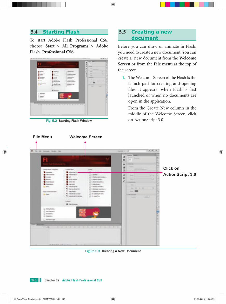
Chapter 05 Adobe Flash Professional CS6146
5.4 Starting FlashTo start Adobe Flash Professional CS6, choose Start > All Programs > Adobe Flash Professional CS6.
Fig. 5.2 Starting Flash Window
5.5 Creating a new document
Before you can draw or animate in Flash, you need to create a new document. You can create a new document from the Welcome Screen or from the File menu at the top of the screen.
1. The Welcome Screen of the Flash is the launch pad for creating and opening files. It appears when Flash is first launched or when no documents are open in the application.
From the Create New column in the middle of the Welcome Screen, click on ActionScript 3.0.
File Menu Welcome Screen
Click onActionScript 3.0
Figure 5.3 Creating a New Document
XII CompTech_English version CHAPTER 05.indd 146 01-03-2020 13:05:59
147Chapter 05 Adobe Flash Professional CS6
Fig. 5.5 New Document Dialog box
2. From the File menu, choose File > New to create a new document.
Fig. 5.4 File Menu
Fig. 5.6 Essentials Workspace
In Flash, ActionScript is the underlying programming language for Flash animations. The current version of ActionScript is 3.0
The New Document dialog box appears. Under the General tab, choose ActionScript 3.0., and press OK to create a new document.
Now, your workspace appears as shown in following figure.
XII CompTech_English version CHAPTER 05.indd 147 01-03-2020 13:05:59
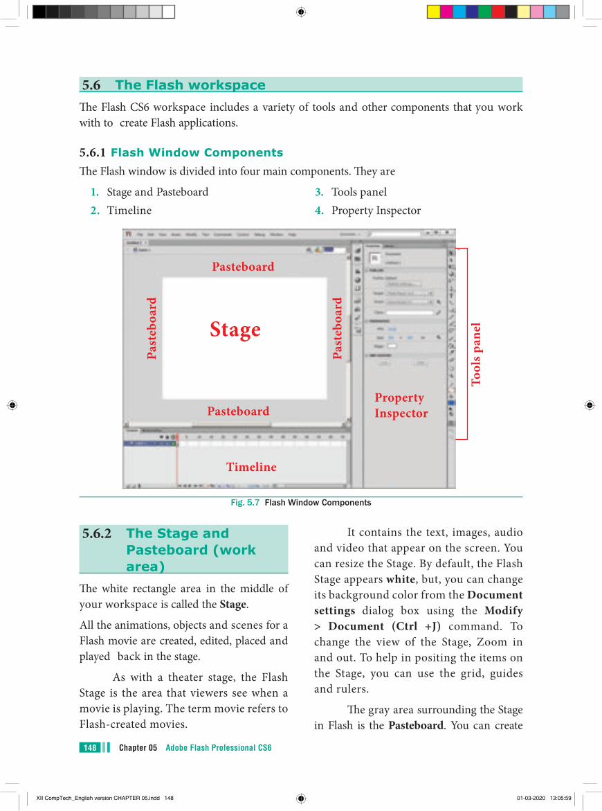
Chapter 05 Adobe Flash Professional CS6148
5.6 The Flash workspaceThe Flash CS6 workspace includes a variety of tools and other components that you work with to create Flash applications.
5.6.1 Flash Window ComponentsThe Flash window is divided into four main components. They are
1. Stage and Pasteboard2. Timeline
3. Tools panel4. Property Inspector
Pasteboard
Past
eboa
rd
Past
eboa
rdStage
Property Inspector
TimelineTo
ols p
anel
Pasteboard
Fig. 5.7 Flash Window Components
5.6.2 The Stage and Pasteboard (work area)
The white rectangle area in the middle of your workspace is called the Stage.
All the animations, objects and scenes for a Flash movie are created, edited, placed and played back in the stage.
As with a theater stage, the Flash Stage is the area that viewers see when a movie is playing. The term movie refers to Flash-created movies.
It contains the text, images, audio and video that appear on the screen. You can resize the Stage. By default, the Flash Stage appears white, but, you can change its background color from the Document settings dialog box using the Modify > Document (Ctrl +J) command. To change the view of the Stage, Zoom in and out. To help in positing the items on the Stage, you can use the grid, guides and rulers.
The gray area surrounding the Stage in Flash is the Pasteboard. You can create
XII CompTech_English version CHAPTER 05.indd 148 01-03-2020 13:05:59
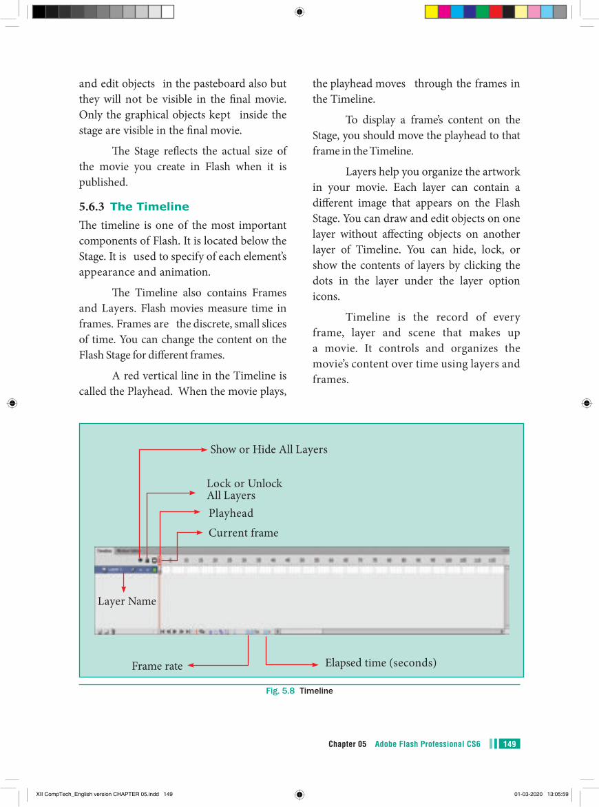
149Chapter 05 Adobe Flash Professional CS6
the playhead moves through the frames in the Timeline.
To display a frame’s content on the Stage, you should move the playhead to that frame in the Timeline.
Layers help you organize the artwork in your movie. Each layer can contain a different image that appears on the Flash Stage. You can draw and edit objects on one layer without affecting objects on another layer of Timeline. You can hide, lock, or show the contents of layers by clicking the dots in the layer under the layer option icons.
Timeline is the record of every frame, layer and scene that makes up a movie. It controls and organizes the movie’s content over time using layers and frames.
and edit objects in the pasteboard also but they will not be visible in the final movie. Only the graphical objects kept inside the stage are visible in the final movie.
The Stage reflects the actual size of the movie you create in Flash when it is published.
5.6.3 The TimelineThe timeline is one of the most important components of Flash. It is located below the Stage. It is used to specify of each element’s appearance and animation.
The Timeline also contains Frames and Layers. Flash movies measure time in frames. Frames are the discrete, small slices of time. You can change the content on the Flash Stage for different frames.
A red vertical line in the Timeline is called the Playhead. When the movie plays,
Fig. 5.8 Timeline
Show or Hide All Layers
Frame rate Elapsed time (seconds)
Layer Name
Current frame
Playhead
Lock or Unlock All Layers
XII CompTech_English version CHAPTER 05.indd 149 01-03-2020 13:05:59
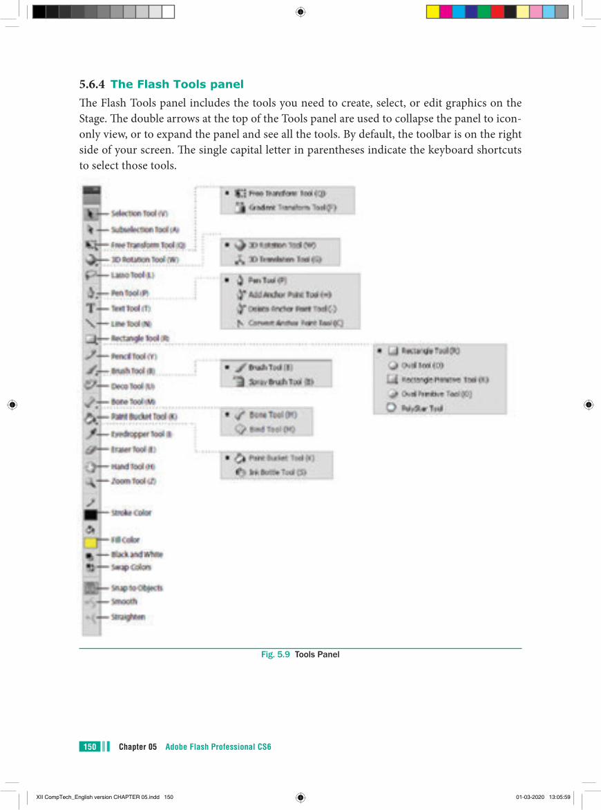
Chapter 05 Adobe Flash Professional CS6150
5.6.4 The Flash Tools panelThe Flash Tools panel includes the tools you need to create, select, or edit graphics on the Stage. The double arrows at the top of the Tools panel are used to collapse the panel to icon-only view, or to expand the panel and see all the tools. By default, the toolbar is on the right side of your screen. The single capital letter in parentheses indicate the keyboard shortcuts to select those tools.
Fig. 5.9 Tools Panel
XII CompTech_English version CHAPTER 05.indd 150 01-03-2020 13:05:59
151Chapter 05 Adobe Flash Professional CS6
3D Rotation Tool (W)It is used to create 3D effects by rotating movie clips in 3D space on the Stage.
3D Translation Tool (G)It is used to create 3D effects by moving movie clips in 3D space on the Stage. The 3D Rotation and the 3D Translation tools are grouped within one icon on the Tools panel.
Lasso Tool (L)It is used to select objects or parts of objects by drawing a freehand.
Pen Tool (P)It is used to draw lines and curves by creating a series of dots, known as anchor points, that are automatically connected. Other tools used to add, delete, and convert the anchor points created by the Pen tool are grouped with the Pen tool.
Text Tool (T)It is used to create and edit text.
Line Tool (N)It is used to draw straight lines. You can draw vertical, horizontal, and 45° diagonal lines by pressing and holding Shift key while drawing the line.
Rectangle Tool(R)It is used to draw rectangular shapes. Press and hold Shift key to draw a perfect square.
Oval Tool (O)It is used to draw oval shapes. Press and hold Shift key to draw a perfect circle.
Using the Tools PanelThe Tools panel contains a collection of tools. When you move the mouse pointer on a tool, its name appears.
Some tools in the Tools panel have additional options that allow you to modify their use. For example, the Brush tool has options for changing the size and shape of the brush head. When the tool is selected, the options are available in the Options area of the Tools panel.
Selection Tool (V)This tool is used to select an object or parts of an object, such as the stroke or fill, and to reshape and reposition objects. The options for the Selection tool are Snap to Objects (aligns objects), Smooth (smooths lines), and Straighten (straightens lines).
Subselection Tool (A)This tool is used to select, drag, and reshape an object. We know that vector graphics are composed of lines and curves (each of which is a segment) connected by anchor points. When you select an object with this tool, it displays the anchor points and allows you to use them to edit the object.
Free Transform Tool (Q)It is used to rotate, scale, skew, and distort objects.
Gradient Transform Tool (F)It is used to transform a gradient fill by adjusting the size, direction, or center of the fill. The Free and Gradient Transform tools are grouped within one icon on the Tools panel. To see the menu containing grouped tools, click and hold the tool icon until the menu opens.
XII CompTech_English version CHAPTER 05.indd 151 01-03-2020 13:05:59
Chapter 05 Adobe Flash Professional CS6152
Bind ToolIt is used to adjust the relationships among individual bones. The Bone and Bind tools are grouped together.
Paint Bucket Tool (K)It is used to fill enclosed areas of a drawing with color.
Ink Bottle Tool (S)It is used to apply line colors and thickness to the stroke of an object. The Paint Bucket and Ink Bottle are grouped together.
Eyedropper Tool (I)It is used to select stroke, fill, and text attributes so they can be copied from one object to another.
Eraser Tool (E)It is used to erase lines and fills.
Hand Tool (H)It is used to move the Stage around the Pasteboard by dragging the Stage.
Zoom Tool (Z)It is used to change the magnification of an area of the Stage. Clicking an area of the Stage zooms in and holding down Alt Key and clicking zooms out.
Stroke Color ToolIt is used to set the stroke color of drawn objects.
Fill Color ToolIt is used to set the fill color of drawn objects.
Black and White ToolIt is used to set the stroke color to black and the fill color to white.
Swap Colors ToolIt is used to swap the stroke and fill colors.
Primitive Rectangle and Oval (R)It is used to draw objects with properties, such as corner radius or inner radius, that can be changed using the Properties panel.
PolyStar ToolIt is used to draw polygons and stars. The Rectangle, Oval, Primitive, and PolyStar tools are grouped within one tool on the Tools panel.
Pencil Tool (Y)It is used to draw freehand lines and shapes. The Pencil Mode option displays a menu with the following commands:
Straighten (draws straight lines), Smooth (draws smooth curved lines), and Ink (draws freehand with no modification).
Brush Tool (B)It is used to draw (paint) with brush-like strokes.
Spray Brush ToolIt is used to spray colors and patterns onto objects. Dots are the default pattern for the spray. However, you can use a graphic symbol, such as a flag, to create a pattern.
The Brush and Spray Brush tools are grouped together.
Deco Tool (U)It is used to turn graphic shapes into geometric patterns or to create kaleidoscopic like effects.
Bone Tool (M)It is used to animate objects that have joints. For example you could use a series of linked objects, such as arms and legs to create character animations.
XII CompTech_English version CHAPTER 05.indd 152 01-03-2020 13:05:59
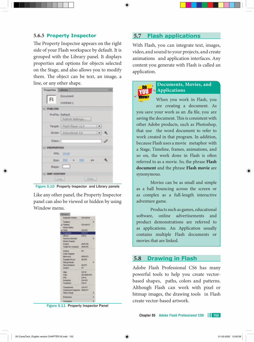
153Chapter 05 Adobe Flash Professional CS6
5.7 Flash applicationsWith Flash, you can integrate text, images, video, and sound to your projects, and create animations and application interfaces. Any content you generate with Flash is called an application.
When you work in Flash, you are creating a document. As
you save your work as an .fla file, you are saving the document. This is consistent with other Adobe products, such as Photoshop, that use the word document to refer to work created in that program. In addition, because Flash uses a movie metaphor with a Stage, Timeline, frames, animations, and so on, the work done in Flash is often referred to as a movie. So, the phrase Flash document and the phrase Flash movie are synonymous.
Movies can be as small and simple as a ball bouncing across the screen or as complex as a full-length interactive adventure game.
Products such as games, educational software, online advertisements and product demonstrations are referred to as applications. An Application usually contains multiple Flash documents or movies that are linked.
Documents, Movies, and Applications
5.8 Drawing in FlashAdobe Flash Professional CS6 has many powerful tools to help you create vector-based shapes, paths, colors and patterns. Although Flash can work with pixel or bitmap images, the drawing tools in Flash create vector-based artwork.
5.6.5 Property InspectorThe Property Inspector appears on the right side of your Flash workspace by default. It is grouped with the Library panel. It displays properties and options for objects selected on the Stage, and also allows you to modify them. The object can be text, an image, a line, or any other shape.
Figure 5.10 Property Inspector and Library panels
Like any other panel, the Property Inspector panel can also be viewed or hidden by using Window menu.
Figure 5.11 Property Inspector Panel
XII CompTech_English version CHAPTER 05.indd 153 01-03-2020 13:05:59
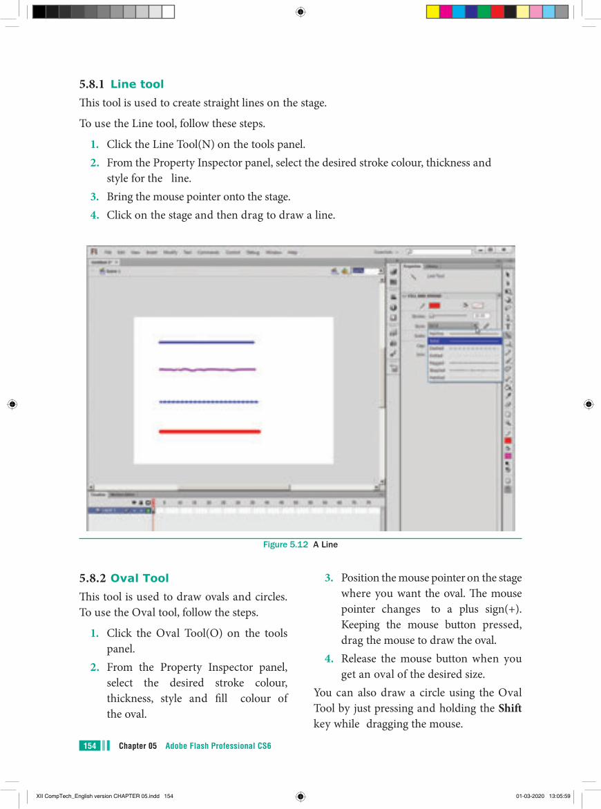
Chapter 05 Adobe Flash Professional CS6154
5.8.1 Line toolThis tool is used to create straight lines on the stage.
To use the Line tool, follow these steps.
1. Click the Line Tool(N) on the tools panel.2. From the Property Inspector panel, select the desired stroke colour, thickness and
style for the line.3. Bring the mouse pointer onto the stage.4. Click on the stage and then drag to draw a line.
Figure 5.12 A Line
5.8.2 Oval ToolThis tool is used to draw ovals and circles. To use the Oval tool, follow the steps.
1. Click the Oval Tool(O) on the tools panel.
2. From the Property Inspector panel, select the desired stroke colour, thickness, style and fill colour of the oval.
3. Position the mouse pointer on the stage where you want the oval. The mouse pointer changes to a plus sign(+). Keeping the mouse button pressed, drag the mouse to draw the oval.
4. Release the mouse button when you get an oval of the desired size.
You can also draw a circle using the Oval Tool by just pressing and holding the Shift key while dragging the mouse.
XII CompTech_English version CHAPTER 05.indd 154 01-03-2020 13:05:59
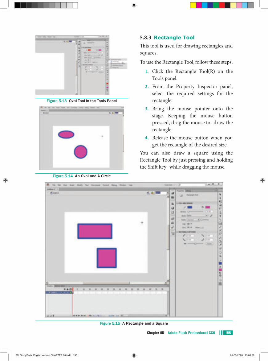
155Chapter 05 Adobe Flash Professional CS6
Figure 5.13 Oval Tool in the Tools Panel
Figure 5.14 An Oval and A Circle
5.8.3 Rectangle ToolThis tool is used for drawing rectangles and squares.
To use the Rectangle Tool, follow these steps.
1. Click the Rectangle Tool(R) on the Tools panel.
2. From the Property Inspector panel, select the required settings for the rectangle.
3. Bring the mouse pointer onto the stage. Keeping the mouse button pressed, drag the mouse to draw the rectangle.
4. Release the mouse button when you get the rectangle of the desired size.
You can also draw a square using the Rectangle Tool by just pressing and holding the Shift key while dragging the mouse.
Figure 5.15 A Rectangle and a Square
XII CompTech_English version CHAPTER 05.indd 155 01-03-2020 13:05:59
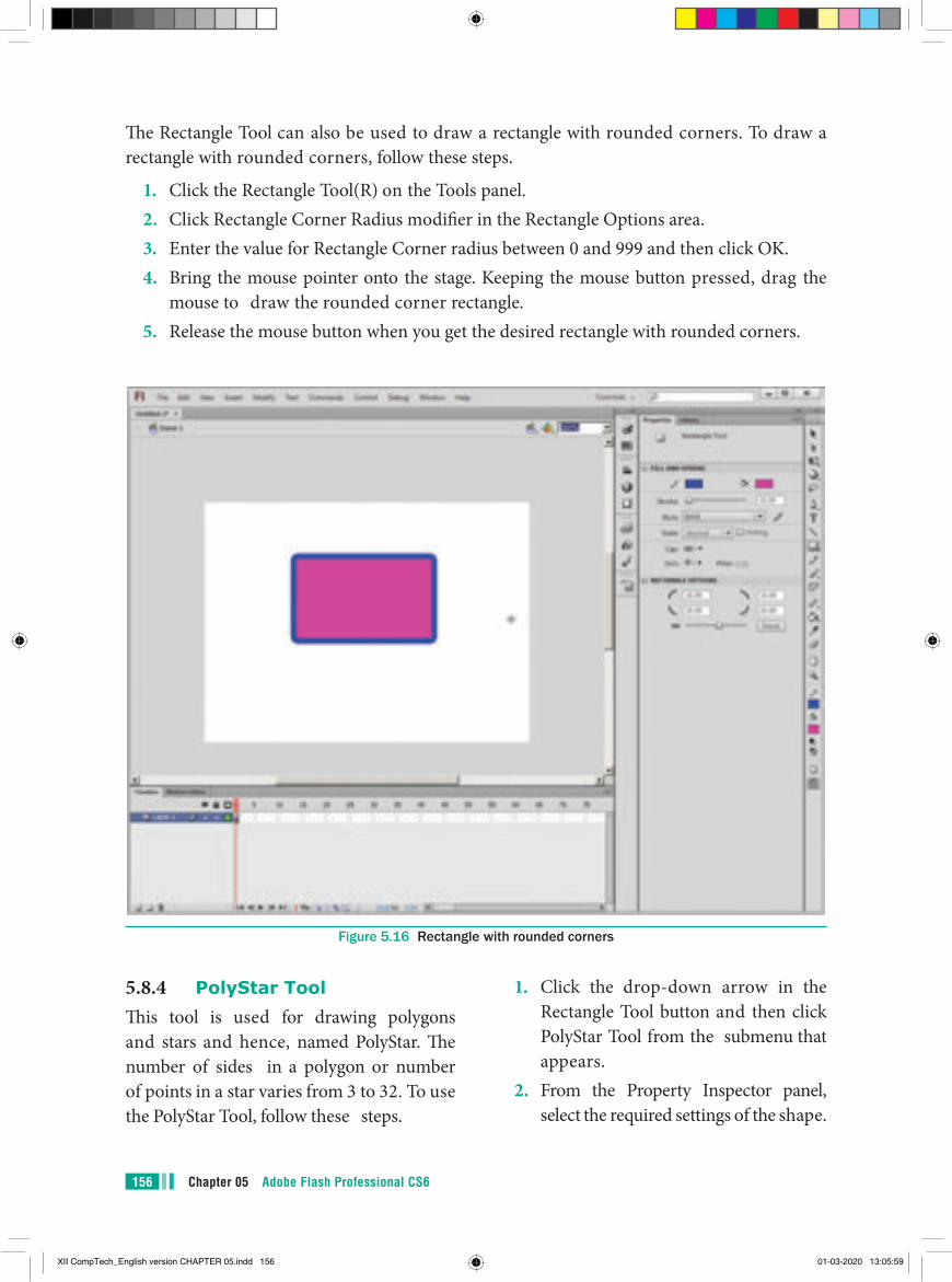
Chapter 05 Adobe Flash Professional CS6156
The Rectangle Tool can also be used to draw a rectangle with rounded corners. To draw a rectangle with rounded corners, follow these steps.
1. Click the Rectangle Tool(R) on the Tools panel.2. Click Rectangle Corner Radius modifier in the Rectangle Options area.3. Enter the value for Rectangle Corner radius between 0 and 999 and then click OK.4. Bring the mouse pointer onto the stage. Keeping the mouse button pressed, drag the
mouse to draw the rounded corner rectangle.5. Release the mouse button when you get the desired rectangle with rounded corners.
Figure 5.16 Rectangle with rounded corners
5.8.4 PolyStar ToolThis tool is used for drawing polygons and stars and hence, named PolyStar. The number of sides in a polygon or number of points in a star varies from 3 to 32. To use the PolyStar Tool, follow these steps.
1. Click the drop-down arrow in the Rectangle Tool button and then click PolyStar Tool from the submenu that appears.
2. From the Property Inspector panel, select the required settings of the shape.
XII CompTech_English version CHAPTER 05.indd 156 01-03-2020 13:05:59

157Chapter 05 Adobe Flash Professional CS6
Figure 5.17 PolyStar Tool in the Tools panel
Figure 5.18 Polygon
3. Click the Options button in the Property Inspector panel. The Tool Settings dialog box appears.
a) Click polygon or star from Style drop-down list box.
b) Enter the value between 3 and 32 to specify the number of sides of a polygon or points of a star.
c) If star option is selected from the Style list box, then specify a value
between 0 and 1 in the Star point size text box. The value 0 means that star will be created with maximum depth and value 1 means that star will be created with minimum depth.
d) Click OK button.4. Click on the stage and then drag to
draw the desired shape.
XII CompTech_English version CHAPTER 05.indd 157 01-03-2020 13:06:00
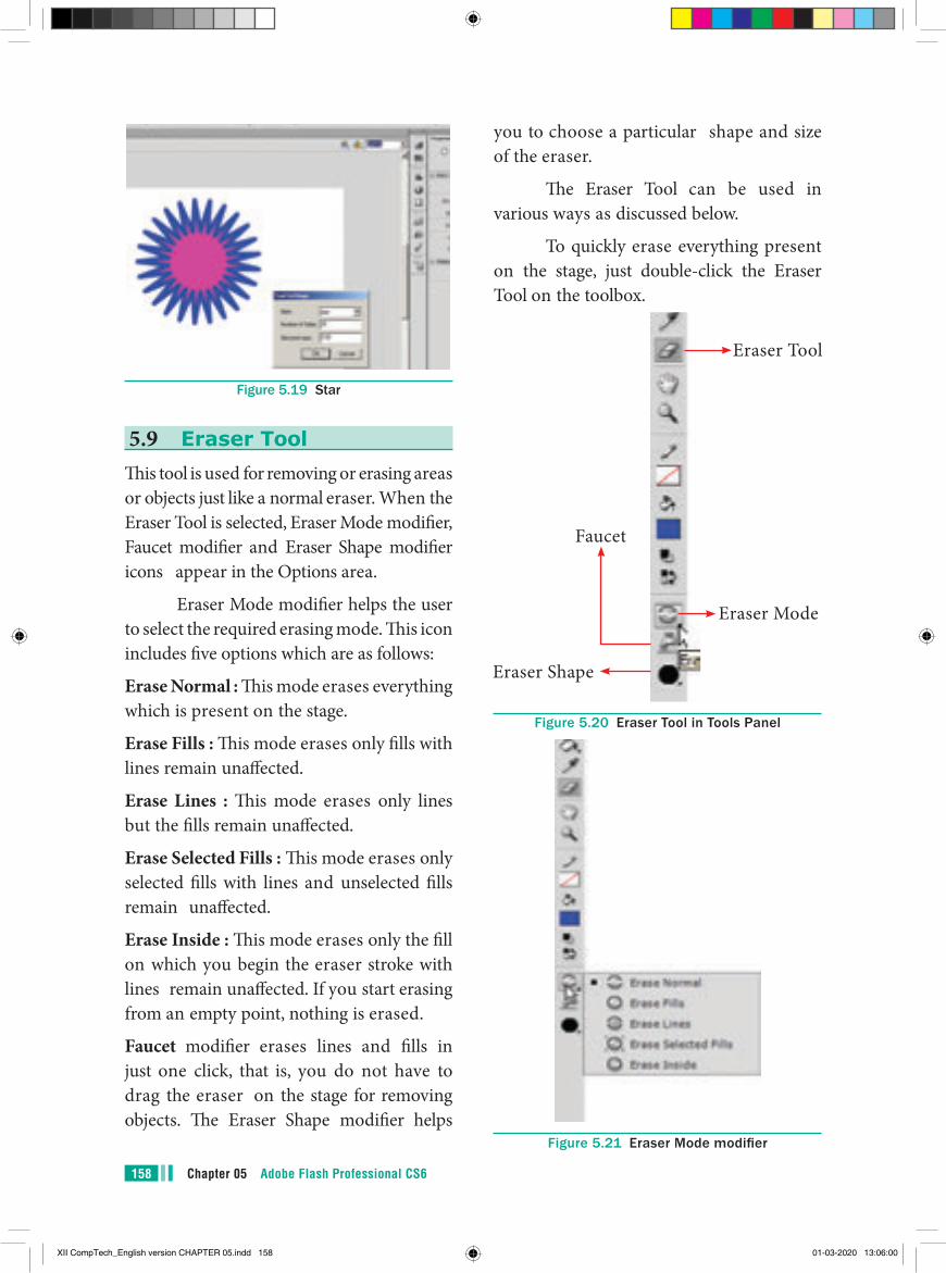
Chapter 05 Adobe Flash Professional CS6158
Figure 5.19 Star
5.9 Eraser ToolThis tool is used for removing or erasing areas or objects just like a normal eraser. When the Eraser Tool is selected, Eraser Mode modifier, Faucet modifier and Eraser Shape modifier icons appear in the Options area.
Eraser Mode modifier helps the user to select the required erasing mode. This icon includes five options which are as follows:
Erase Normal : This mode erases everything which is present on the stage.
Erase Fills : This mode erases only fills with lines remain unaffected.
Erase Lines : This mode erases only lines but the fills remain unaffected.
Erase Selected Fills : This mode erases only selected fills with lines and unselected fills remain unaffected.
Erase Inside : This mode erases only the fill on which you begin the eraser stroke with lines remain unaffected. If you start erasing from an empty point, nothing is erased.
Faucet modifier erases lines and fills in just one click, that is, you do not have to drag the eraser on the stage for removing objects. The Eraser Shape modifier helps
you to choose a particular shape and size of the eraser.
The Eraser Tool can be used in various ways as discussed below.
To quickly erase everything present on the stage, just double-click the Eraser Tool on the toolbox.
Eraser Shape
Faucet
Eraser Tool
Eraser Mode
Figure 5.20 Eraser Tool in Tools Panel
Figure 5.21 Eraser Mode modifier
XII CompTech_English version CHAPTER 05.indd 158 01-03-2020 13:06:00
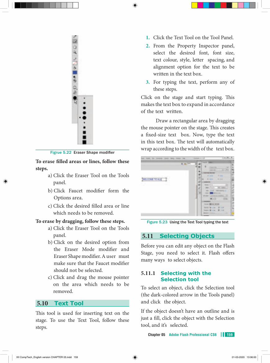
159Chapter 05 Adobe Flash Professional CS6
1. Click the Text Tool on the Tool Panel.2. From the Property Inspector panel,
select the desired font, font size, text colour, style, letter spacing, and alignment option for the text to be written in the text box.
3. For typing the text, perform any of these steps.
Click on the stage and start typing. This makes the text box to expand in accordance of the text written.
Draw a rectangular area by dragging the mouse pointer on the stage. This creates a fixed-size text box. Now, type the text in this text box. The text will automatically wrap according to the width of the text box.
Figure 5.23 Using the Text Tool typing the text
5.11 Selecting ObjectsBefore you can edit any object on the Flash Stage, you need to select it. Flash offers many ways to select objects.
5.11.1 Selecting with the Selection tool
To select an object, click the Selection tool (the dark-colored arrow in the Tools panel) and click the object.
If the object doesn’t have an outline and is just a fill, click the object with the Selection tool, and it’s selected.
Figrue 5.22 Eraser Shape modifier
To erase filled areas or lines, follow these steps.
a) Click the Eraser Tool on the Tools panel.
b) Click Faucet modifier form the Options area.
c) Click the desired filled area or line which needs to be removed.
To erase by dragging, follow these steps. a) Click the Eraser Tool on the Tools
panel. b) Click on the desired option from
the Eraser Mode modifier and Eraser Shape modifier. A user must make sure that the Faucet modifier should not be selected.
c) Click and drag the mouse pointer on the area which needs to be removed.
5.10 Text ToolThis tool is used for inserting text on the stage. To use the Text Tool, follow these steps.
XII CompTech_English version CHAPTER 05.indd 159 01-03-2020 13:06:00
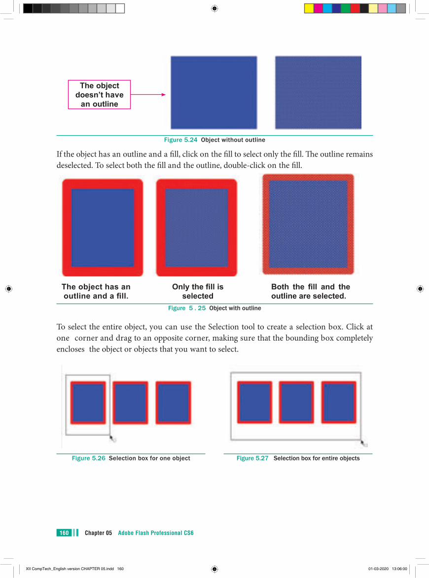
Chapter 05 Adobe Flash Professional CS6160
The object doesn’t have
an outline
Figure 5.24 Object without outline
If the object has an outline and a fill, click on the fill to select only the fill. The outline remains deselected. To select both the fill and the outline, double-click on the fill.
The object has an outline and a fill.
Only the fill is selected
Both the fill and the outline are selected.
Figure 5 . 25 Object with outline
To select the entire object, you can use the Selection tool to create a selection box. Click at one corner and drag to an opposite corner, making sure that the bounding box completely encloses the object or objects that you want to select.
Figure 5.26 Selection box for one object Figure 5.27 Selection box for entire objects
XII CompTech_English version CHAPTER 05.indd 160 01-03-2020 13:06:00
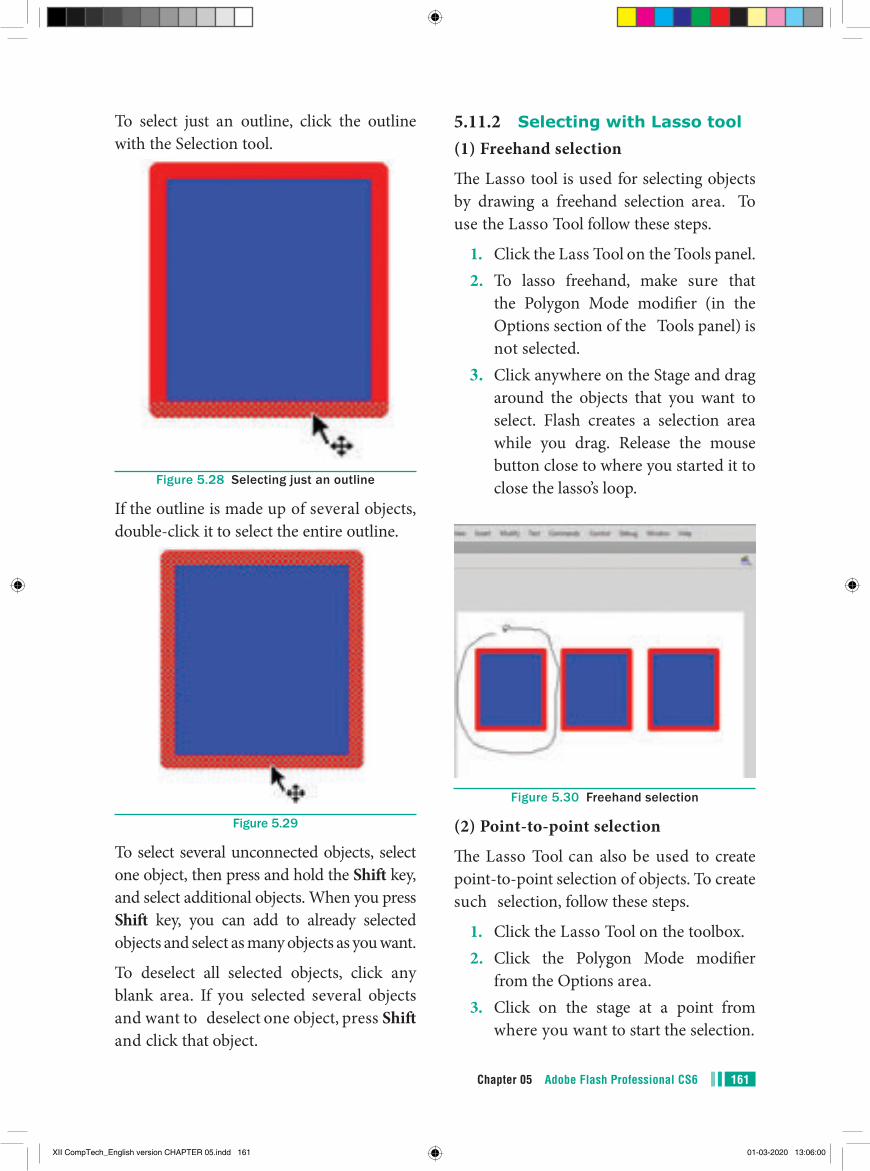
161Chapter 05 Adobe Flash Professional CS6
To select just an outline, click the outline with the Selection tool.
Figure 5.28 Selecting just an outline
If the outline is made up of several objects, double-click it to select the entire outline.
Figure 5.29
To select several unconnected objects, select one object, then press and hold the Shift key, and select additional objects. When you press Shift key, you can add to already selected objects and select as many objects as you want.
To deselect all selected objects, click any blank area. If you selected several objects and want to deselect one object, press Shift and click that object.
5.11.2 Selecting with Lasso tool(1) Freehand selection
The Lasso tool is used for selecting objects by drawing a freehand selection area. To use the Lasso Tool follow these steps.
1. Click the Lass Tool on the Tools panel.2. To lasso freehand, make sure that
the Polygon Mode modifier (in the Options section of the Tools panel) is not selected.
3. Click anywhere on the Stage and drag around the objects that you want to select. Flash creates a selection area while you drag. Release the mouse button close to where you started it to close the lasso’s loop.
Figure 5.30 Freehand selection
(2) Point-to-point selection
The Lasso Tool can also be used to create point-to-point selection of objects. To create such selection, follow these steps.
1. Click the Lasso Tool on the toolbox.2. Click the Polygon Mode modifier
from the Options area.3. Click on the stage at a point from
where you want to start the selection.
XII CompTech_English version CHAPTER 05.indd 161 01-03-2020 13:06:00
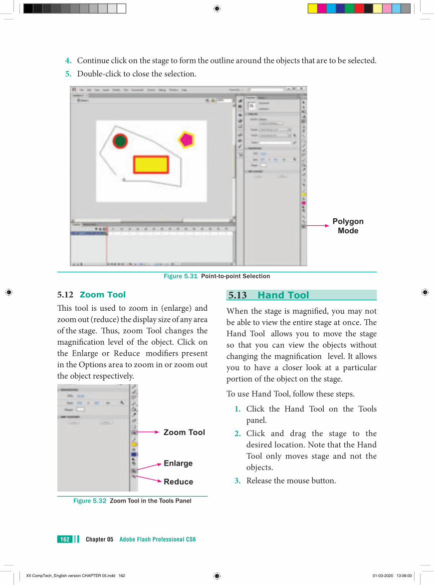
Chapter 05 Adobe Flash Professional CS6162
4. Continue click on the stage to form the outline around the objects that are to be selected.5. Double-click to close the selection.
Polygon Mode
Figure 5.31 Point-to-point Selection
5.12 Zoom ToolThis tool is used to zoom in (enlarge) and zoom out (reduce) the display size of any area of the stage. Thus, zoom Tool changes the magnification level of the object. Click on the Enlarge or Reduce modifiers present in the Options area to zoom in or zoom out the object respectively.
Zoom Tool
Enlarge
Reduce
Figure 5.32 Zoom Tool in the Tools Panel
5.13 Hand ToolWhen the stage is magnified, you may not be able to view the entire stage at once. The Hand Tool allows you to move the stage so that you can view the objects without changing the magnification level. It allows you to have a closer look at a particular portion of the object on the stage.
To use Hand Tool, follow these steps.
1. Click the Hand Tool on the Tools panel.
2. Click and drag the stage to the desired location. Note that the Hand Tool only moves stage and not the objects.
3. Release the mouse button.
XII CompTech_English version CHAPTER 05.indd 162 01-03-2020 13:06:00
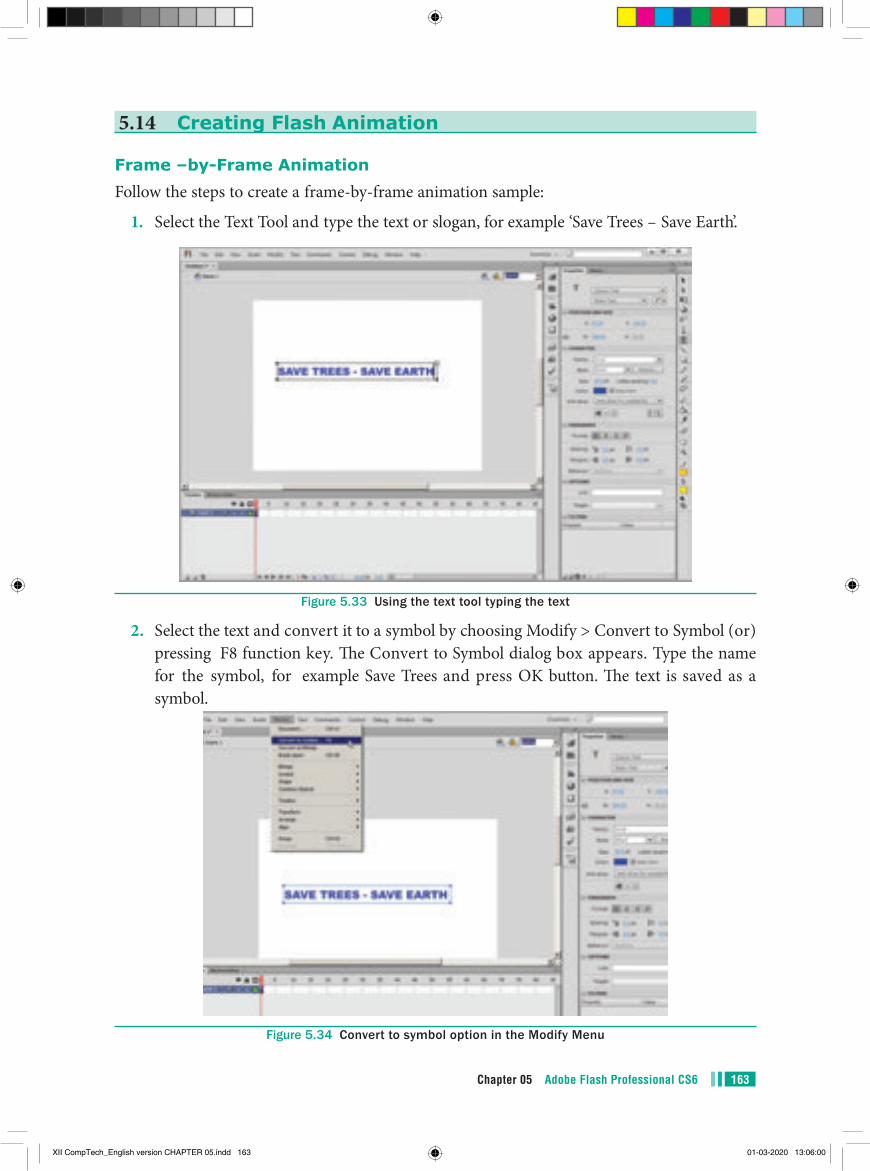
163Chapter 05 Adobe Flash Professional CS6
5.14 Creating Flash Animation
Frame –by-Frame AnimationFollow the steps to create a frame-by-frame animation sample:
1. Select the Text Tool and type the text or slogan, for example ‘Save Trees – Save Earth’.
Figure 5.33 Using the text tool typing the text
2. Select the text and convert it to a symbol by choosing Modify > Convert to Symbol (or) pressing F8 function key. The Convert to Symbol dialog box appears. Type the name for the symbol, for example Save Trees and press OK button. The text is saved as a symbol.
Figure 5.34 Convert to symbol option in the Modify Menu
XII CompTech_English version CHAPTER 05.indd 163 01-03-2020 13:06:00
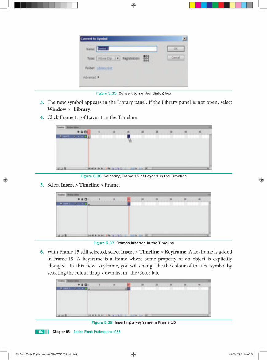
Chapter 05 Adobe Flash Professional CS6164
Figure 5.35 Convert to symbol dialog box
3. The new symbol appears in the Library panel. If the Library panel is not open, select Window > Library.
4. Click Frame 15 of Layer 1 in the Timeline.
Figure 5.36 Selecting Frame 15 of Layer 1 in the Timeline
5. Select Insert > Timeline > Frame.
Figure 5.37 Frames inserted in the Timeline
6. With Frame 15 still selected, select Insert > Timeline > Keyframe. A keyframe is added in Frame 15. A keyframe is a frame where some property of an object is explicitly changed. In this new keyframe, you will change the the colour of the text symbol by selecting the colour drop-down list in the Color tab.
Figure 5.38 Inserting a keyframe in Frame 15
XII CompTech_English version CHAPTER 05.indd 164 01-03-2020 13:06:00
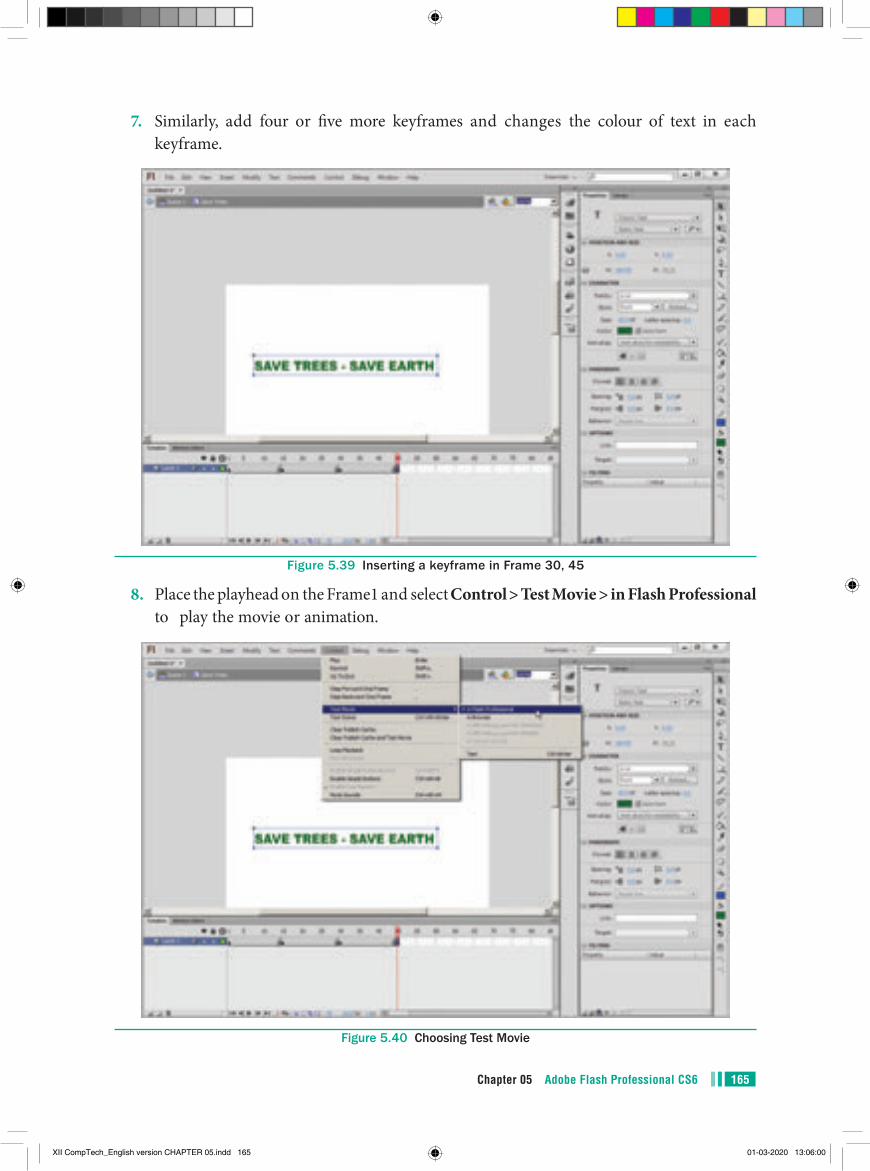
165Chapter 05 Adobe Flash Professional CS6
7. Similarly, add four or five more keyframes and changes the colour of text in each keyframe.
Figure 5.39 Inserting a keyframe in Frame 30, 45
8. Place the playhead on the Frame1 and select Control > Test Movie > in Flash Professional to play the movie or animation.
Figure 5.40 Choosing Test Movie
XII CompTech_English version CHAPTER 05.indd 165 01-03-2020 13:06:00
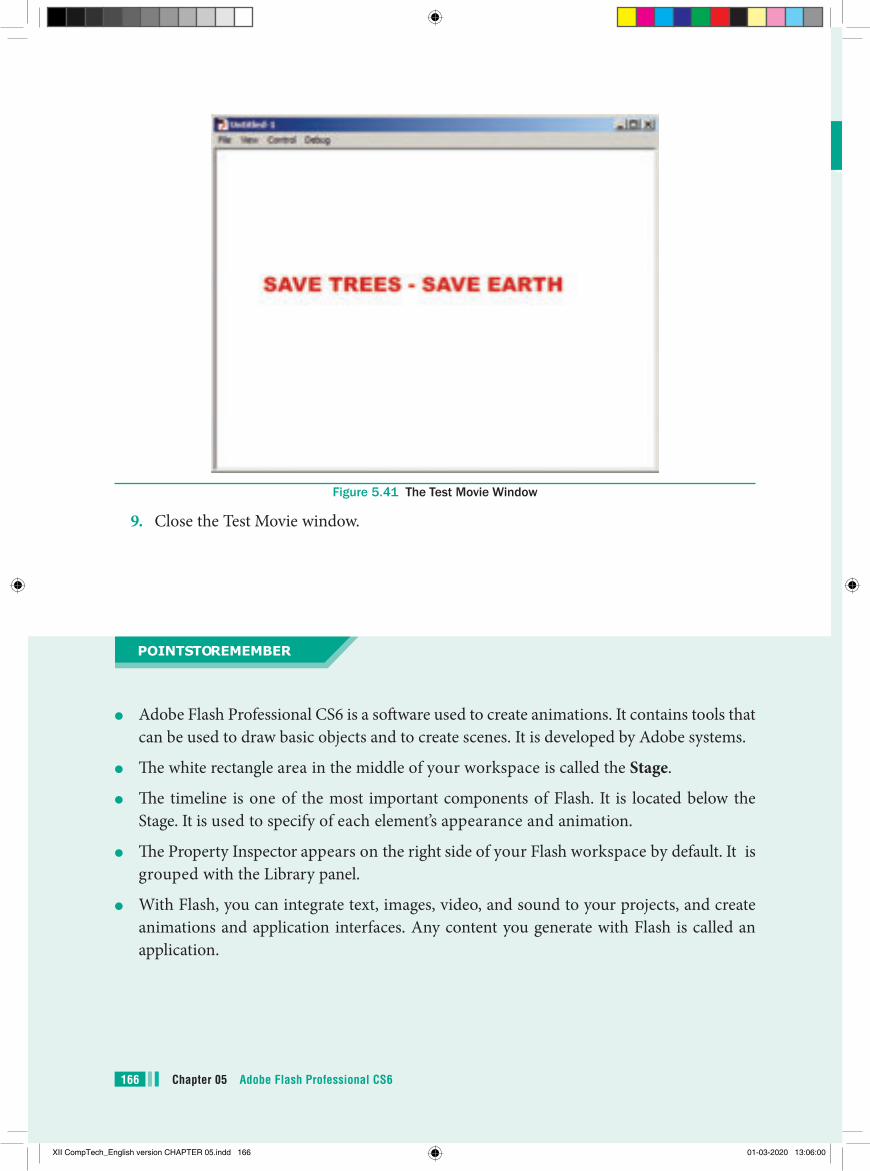
Figure 5.41 The Test Movie Window
9. Close the Test Movie window.
points to remember
●● Adobe Flash Professional CS6 is a software used to create animations. It contains tools that can be used to draw basic objects and to create scenes. It is developed by Adobe systems.
●● The white rectangle area in the middle of your workspace is called the Stage.
●● The timeline is one of the most important components of Flash. It is located below the Stage. It is used to specify of each element’s appearance and animation.
●● The Property Inspector appears on the right side of your Flash workspace by default. It is grouped with the Library panel.
●● With Flash, you can integrate text, images, video, and sound to your projects, and create animations and application interfaces. Any content you generate with Flash is called an application.
Chapter 05 Adobe Flash Professional CS6166
XII CompTech_English version CHAPTER 05.indd 166 01-03-2020 13:06:00
6. You can create attractive looking advertising banners with
(a) Access (b) Word (c) Flash (d) Excel7. Th e default fi le name extension for
Flash fi le is (a) .shw (b) .doc (c) .xls (d) .fl a8. Any content you generate with Flash is
called (a) A graphic (b) An interface (c) An animation (d) An application9. Th e tool used to draw brush-like
strokes as is you were painting is known as
(a) Brush Tool (b) Lasso Tool (c) Text Tool (d) Zoom Tool
10. Which of the following tools is not part of the other shape tools grouped together in the Tools panel?
(a) Rectangle Tool
(b) Oval Tool
(c) Line Tool
(d) PolyStar Tool
Part - IChoose the correct answer
1. What can you create with the Adobe Flash program?
a) Animations b) Web applications c) Games d) All of the above2. Th e ________ is the large white
rectangle in the center of Flash’s workspace?
a) Stage b) Timeline c) Screen d) Properties3. How to create a new Flash document? a) Choose Insert>New b) Press Ctrl+W c) Choose File>New d) Press Ctrl+D4. Th e default stage color is white but it
can be changed by choosing selecting diff erent color on the Document Properties dialog box?
a) Modify>Document Properties b) Modify>Document c) Edit>Document d) Edit>Document Properties5. Flash fi les are also called (a) Flash Guides (b) Flash Movies (c) Flash Rulers (d) Flash Timeline
EVALUATION EVALUATION
167Chapter 05 Adobe Flash Professional CS6
XII CompTech_English version CHAPTER 05.indd 167 01-03-2020 13:06:00
Part - IIAnswer the following questions (2 Marks)
1. What is Flash?2. Write steps to start Adobe Professional
Flash CS 6?3. What is the purpose of Timeline?
Part - IIIAnswer the following questions (3 Marks)
1. Name tools used to do the following: (a). Draw lines (b). Draw free hand drawing (c.) Erase what we have drawn2. Differentiate between Zoom Tool and
Hand Tool.
Part - IVAnswer the following questions (5 Marks)
1. Explain the components used in Flash Window.
2. Describe some of the tools displayed in Tools Panel.
11. How to draw a perfect circle using the Oval Tool?
(a) Press and hold down the Ctrl key. (b) Press and hold down the Alt key. (c) Press and hold down the P key. (d) Press and hold down the Shift key.12. Which tool magnifies a particular area
of a drawing? (a) The Free Transform Tool (b) The Rectangle tool (c) The Zoom tool (d) The Selection tool
II Fill in the blanks.1. …………… tool is used to create
straight line on the stage.2. A circle can be drawn using the Oval
Tool by pressing and holding the …………… key.
3. You can also draw a square using the …………… Tool.
4. …………… Tool used for erasing objects just like a normal eraser.
5. File created in Flash automatically gets the …………… extension.
Chapter 05 Adobe Flash Professional CS6168
XII CompTech_English version CHAPTER 05.indd 168 01-03-2020 13:06:00
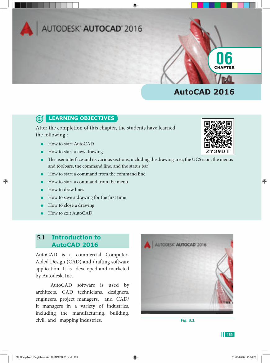
5.1 Introduction to AutoCAD 2016
AutoCAD is a commercial Computer-Aided Design (CAD) and drafting software application. It is developed and marketed by Autodesk, Inc.
AutoCAD software is used by architects, CAD technicians, designers, engineers, project managers, and CAD/It managers in a variety of industries, including the manufacturing, building, civil, and mapping industries.
AutoCAD 2016
LEARNING OBJECTIVES
After the completion of this chapter, the students have learned the following :
●● How to start AutoCAD●● How to start a new drawing●● The user interface and its various sections, including the drawing area, the UCS icon, the menus
and toolbars, the command line, and the status bar●● How to start a command from the command line●● How to start a command from the menu●● How to draw lines●● How to save a drawing for the first time●● How to close a drawing●● How to exit AutoCAD
06CHAPTER
Fig. 6.1
169
XII CompTech_English version CHAPTER 06.indd 169 01-03-2020 13:06:29
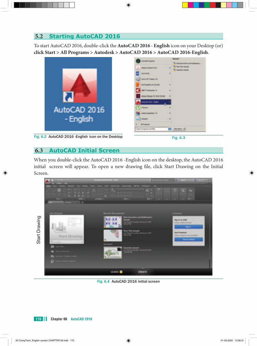
Chapter 06 AutoCAD 2016170
5.2 Starting AutoCAD 2016To start AutoCAD 2016, double-click the AutoCAD 2016 - English icon on your Desktop (or) click Start > All Programs > Autodesk > AutoCAD 2016 > AutoCAD 2016-English.
Fig. 6.2 AutoCAD 2016 -English icon on the Desktop Fig. 6.3
6.3 AutoCAD Initial ScreenWhen you double-click the AutoCAD 2016 -English icon on the desktop, the AutoCAD 2016 initial screen will appear. To open a new drawing file, click Start Drawing on the Initial Screen.
Fig. 6.4 AutoCAD 2016 initial screen
Star
t Dra
win
g
XII CompTech_English version CHAPTER 06.indd 170 01-03-2020 13:06:31
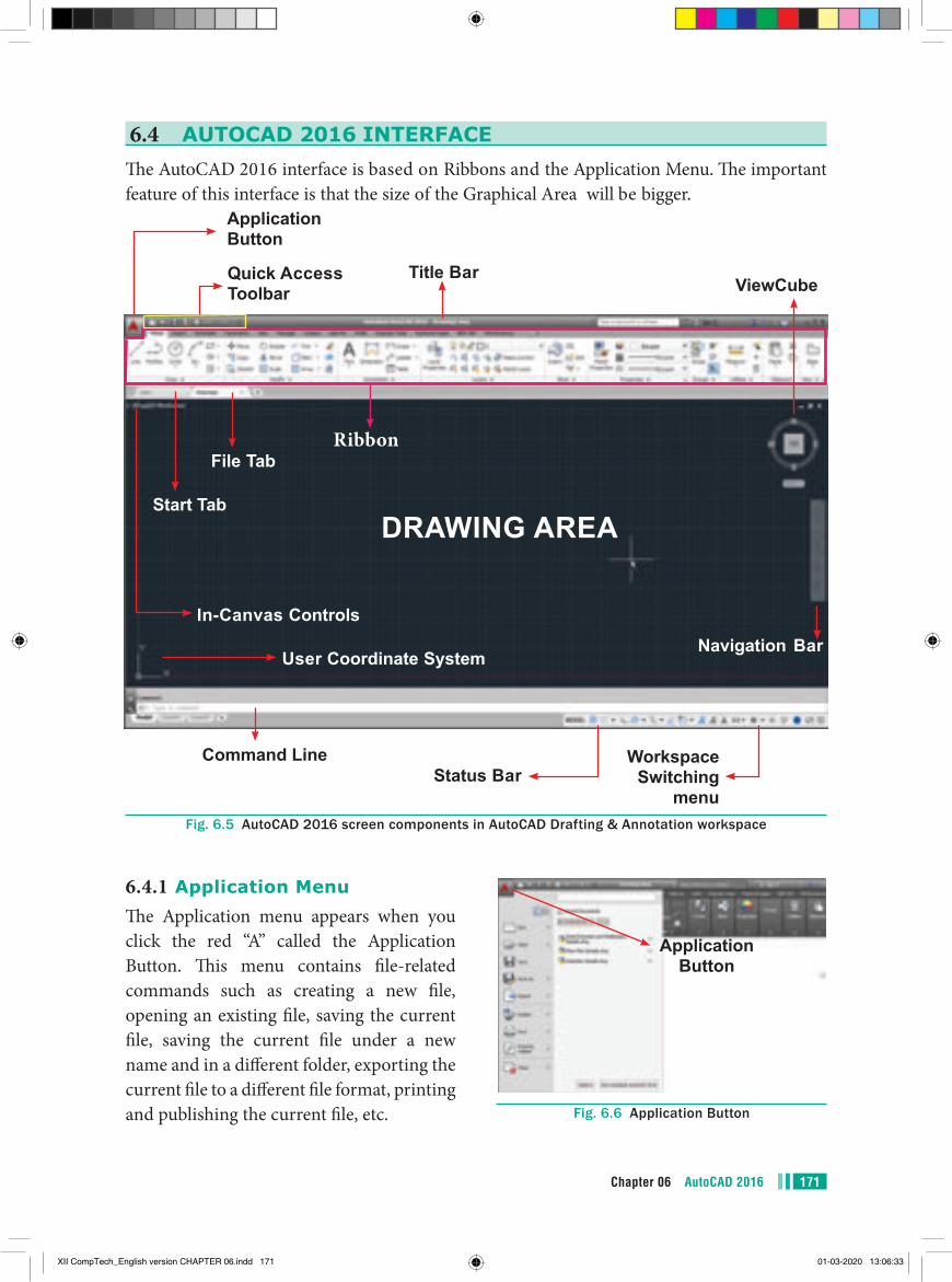
171Chapter 06 AutoCAD 2016
6.4 AUTOCAD 2016 INTERFACEThe AutoCAD 2016 interface is based on Ribbons and the Application Menu. The important feature of this interface is that the size of the Graphical Area will be bigger.
Ribbon
DRAWING AREA
In-Canvas Controls
Start Tab
File Tab
Title BarQuick Access Toolbar
Application Button
ViewCube
Navigation Bar
Workspace Switching
menuStatus Bar
User Coordinate System
Command Line
Fig. 6.5 AutoCAD 2016 screen components in AutoCAD Drafting & Annotation workspace
6.4.1 Application MenuThe Application menu appears when you click the red “A” called the Application Button. This menu contains file-related commands such as creating a new file, opening an existing file, saving the current file, saving the current file under a new name and in a different folder, exporting the current file to a different file format, printing and publishing the current file, etc.
Application Button
Fig. 6.6 Application Button
XII CompTech_English version CHAPTER 06.indd 171 01-03-2020 13:06:33
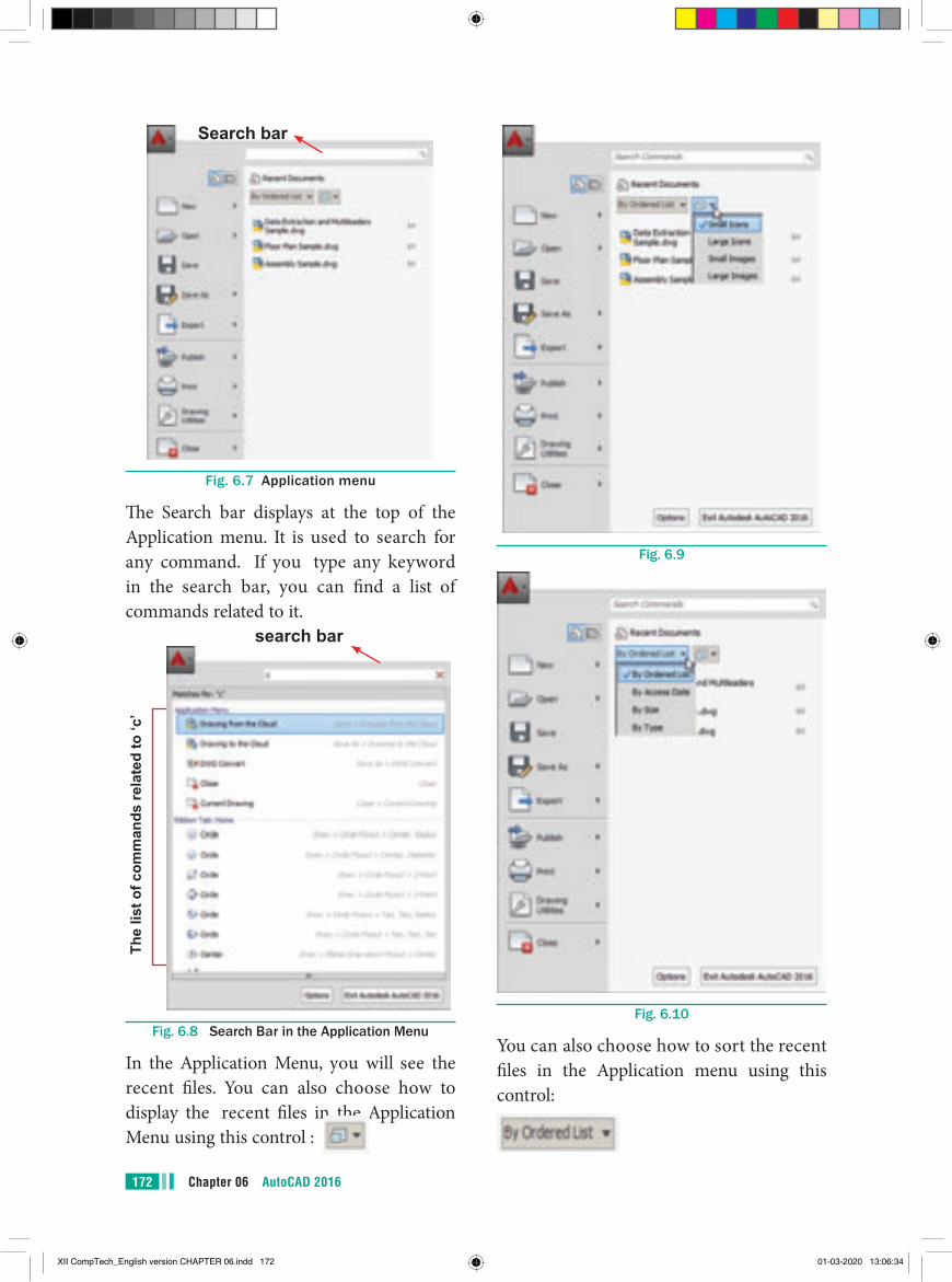
Chapter 06 AutoCAD 2016172
Search bar
Fig. 6.7 Application menu
The Search bar displays at the top of the Application menu. It is used to search for any command. If you type any keyword in the search bar, you can find a list of commands related to it.
The
list o
f com
man
ds re
late
d to
‘c’
search bar
Fig. 6.8 Search Bar in the Application Menu
In the Application Menu, you will see the recent files. You can also choose how to display the recent files in the Application Menu using this control :
Fig. 6.9
Fig. 6.10
You can also choose how to sort the recent files in the Application menu using this control:
XII CompTech_English version CHAPTER 06.indd 172 01-03-2020 13:06:34
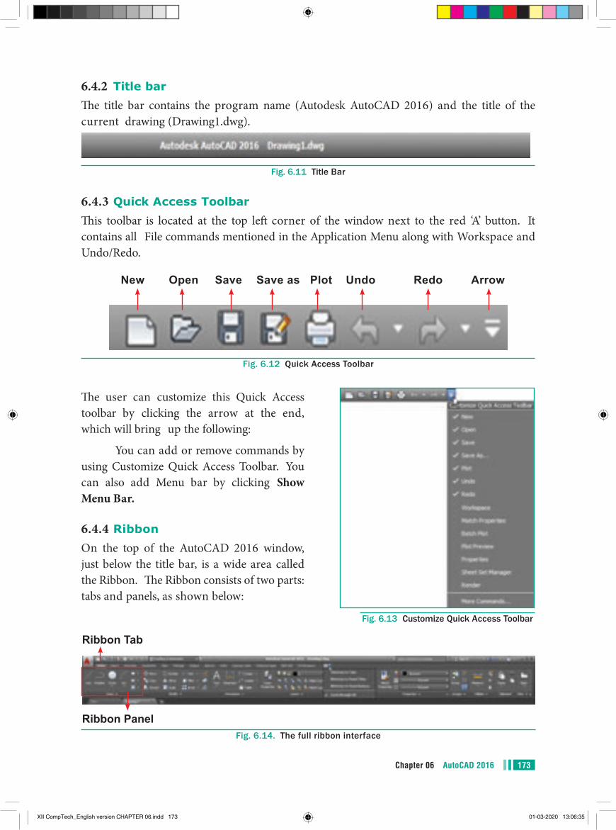
173Chapter 06 AutoCAD 2016
6.4.2 Title barThe title bar contains the program name (Autodesk AutoCAD 2016) and the title of the current drawing (Drawing1.dwg).
Fig. 6.11 Title Bar
6.4.3 Quick Access ToolbarThis toolbar is located at the top left corner of the window next to the red ‘A’ button. It contains all File commands mentioned in the Application Menu along with Workspace and Undo/Redo.
New Open Save Save as Plot Undo Redo Arrow
Fig. 6.12 Quick Access Toolbar
The user can customize this Quick Access toolbar by clicking the arrow at the end, which will bring up the following:
You can add or remove commands by using Customize Quick Access Toolbar. You can also add Menu bar by clicking Show Menu Bar.
6.4.4 RibbonOn the top of the AutoCAD 2016 window, just below the title bar, is a wide area called the Ribbon. The Ribbon consists of two parts: tabs and panels, as shown below:
Fig. 6.13 Customize Quick Access Toolbar
Ribbon Tab
Ribbon PanelFig. 6.14. The full ribbon interface
XII CompTech_English version CHAPTER 06.indd 173 01-03-2020 13:06:35
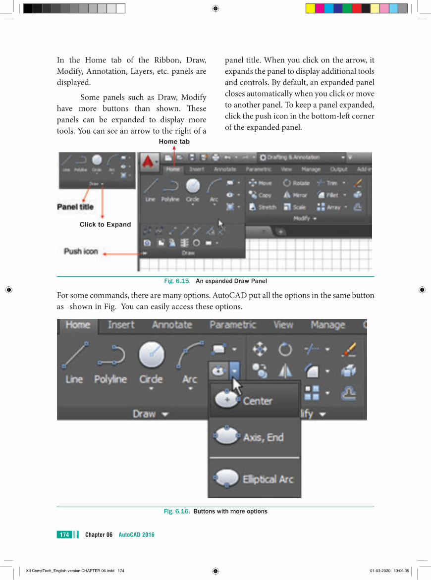
Chapter 06 AutoCAD 2016174
In the Home tab of the Ribbon, Draw, Modify, Annotation, Layers, etc. panels are displayed.
Some panels such as Draw, Modify have more buttons than shown. These panels can be expanded to display more tools. You can see an arrow to the right of a
panel title. When you click on the arrow, it expands the panel to display additional tools and controls. By default, an expanded panel closes automatically when you click or move to another panel. To keep a panel expanded, click the push icon in the bottom-left corner of the expanded panel.
Click to Expand
Home tab
Fig. 6.15. An expanded Draw Panel
For some commands, there are many options. AutoCAD put all the options in the same button as shown in Fig. You can easily access these options.
Fig. 6.16. Buttons with more options
XII CompTech_English version CHAPTER 06.indd 174 01-03-2020 13:06:35
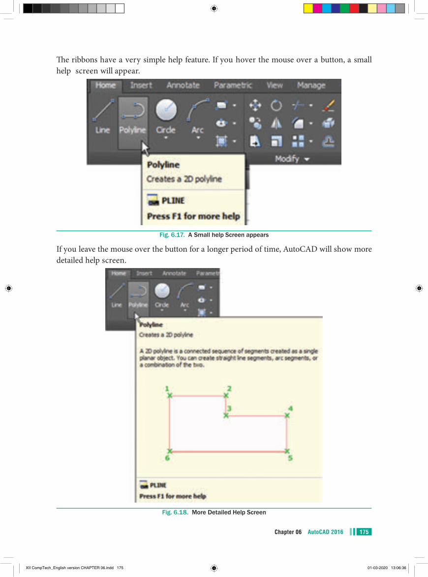
175Chapter 06 AutoCAD 2016
The ribbons have a very simple help feature. If you hover the mouse over a button, a small help screen will appear.
Fig. 6.17. A Small help Screen appears
If you leave the mouse over the button for a longer period of time, AutoCAD will show more detailed help screen.
Fig. 6.18. More Detailed Help Screen
XII CompTech_English version CHAPTER 06.indd 175 01-03-2020 13:06:36
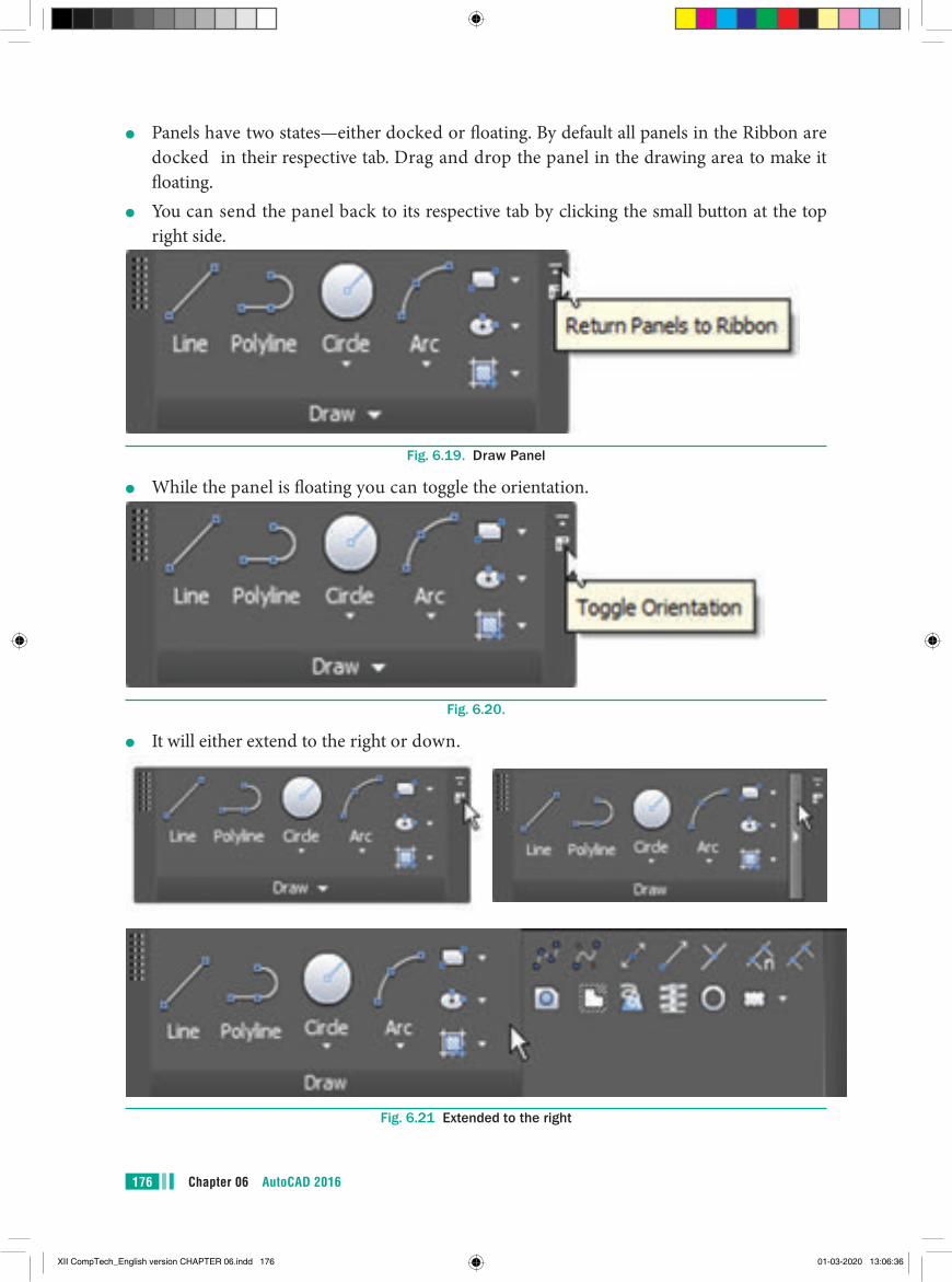
Chapter 06 AutoCAD 2016176
●● Panels have two states—either docked or floating. By default all panels in the Ribbon are docked in their respective tab. Drag and drop the panel in the drawing area to make it floating.
●● You can send the panel back to its respective tab by clicking the small button at the top right side.
Fig. 6.19. Draw Panel
●● While the panel is floating you can toggle the orientation.
Fig. 6.20.
●● It will either extend to the right or down.
Fig. 6.21 Extended to the right
XII CompTech_English version CHAPTER 06.indd 176 01-03-2020 13:06:36
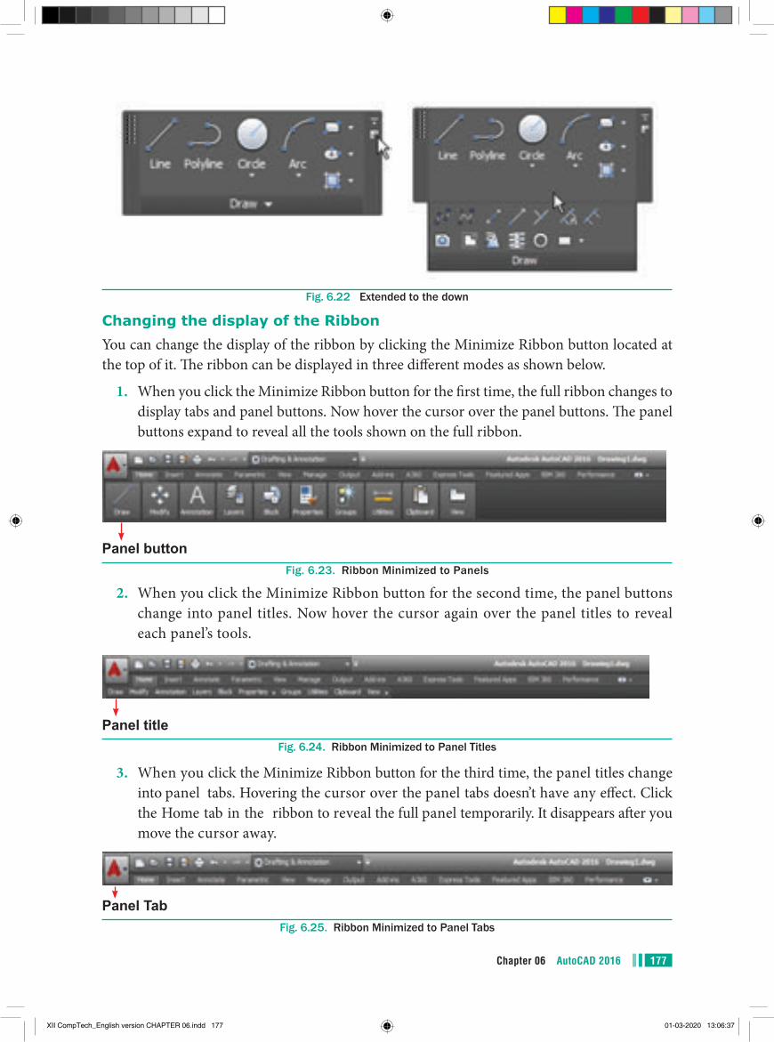
177Chapter 06 AutoCAD 2016
Fig. 6.22 Extended to the down
Changing the display of the RibbonYou can change the display of the ribbon by clicking the Minimize Ribbon button located at the top of it. The ribbon can be displayed in three different modes as shown below.
1. When you click the Minimize Ribbon button for the first time, the full ribbon changes to display tabs and panel buttons. Now hover the cursor over the panel buttons. The panel buttons expand to reveal all the tools shown on the full ribbon.
Panel buttonFig. 6.23. Ribbon Minimized to Panels
2. When you click the Minimize Ribbon button for the second time, the panel buttons change into panel titles. Now hover the cursor again over the panel titles to reveal each panel’s tools.
Panel titleFig. 6.24. Ribbon Minimized to Panel Titles
3. When you click the Minimize Ribbon button for the third time, the panel titles change into panel tabs. Hovering the cursor over the panel tabs doesn’t have any effect. Click the Home tab in the ribbon to reveal the full panel temporarily. It disappears after you move the cursor away.
Panel TabFig. 6.25. Ribbon Minimized to Panel Tabs
XII CompTech_English version CHAPTER 06.indd 177 01-03-2020 13:06:37
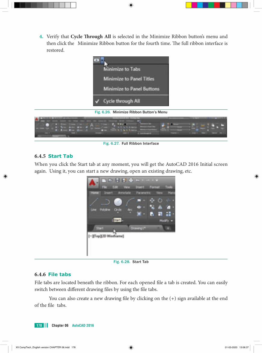
Chapter 06 AutoCAD 2016178
4. Verify that Cycle Through All is selected in the Minimize Ribbon button’s menu and then click the Minimize Ribbon button for the fourth time. The full ribbon interface is restored.
Fig. 6.26. Minimize Ribbon Button’s Menu
Fig. 6.27. Full Ribbon Interface
6.4.5 Start TabWhen you click the Start tab at any moment, you will get the AutoCAD 2016 Initial screen again. Using it, you can start a new drawing, open an existing drawing, etc.
Fig. 6.28. Start Tab
6.4.6 File tabsFile tabs are located beneath the ribbon. For each opened file a tab is created. You can easily switch between different drawing files by using the file tabs.
You can also create a new drawing file by clicking on the (+) sign available at the end of the file tabs.
XII CompTech_English version CHAPTER 06.indd 178 01-03-2020 13:06:37
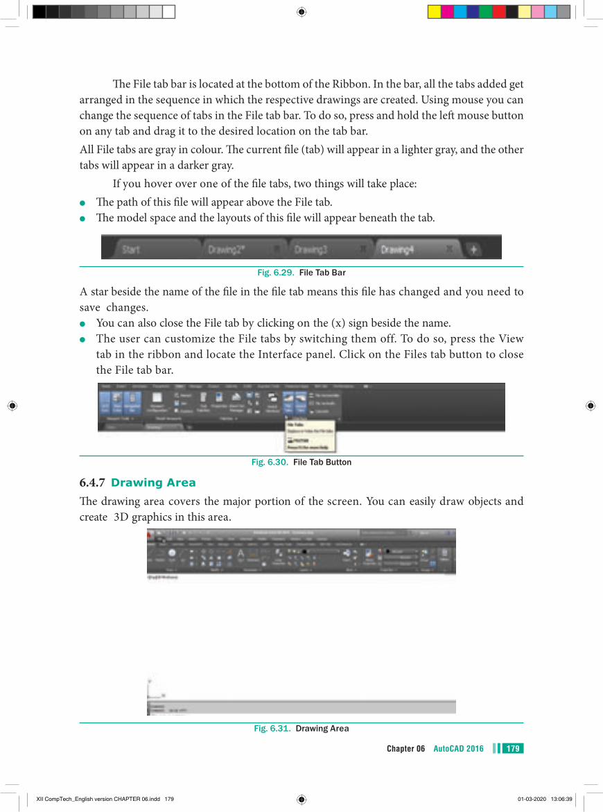
179Chapter 06 AutoCAD 2016
The File tab bar is located at the bottom of the Ribbon. In the bar, all the tabs added get arranged in the sequence in which the respective drawings are created. Using mouse you can change the sequence of tabs in the File tab bar. To do so, press and hold the left mouse button on any tab and drag it to the desired location on the tab bar.All File tabs are gray in colour. The current file (tab) will appear in a lighter gray, and the other tabs will appear in a darker gray.
If you hover over one of the file tabs, two things will take place:●● The path of this file will appear above the File tab.●● The model space and the layouts of this file will appear beneath the tab.
Fig. 6.29. File Tab Bar
A star beside the name of the file in the file tab means this file has changed and you need to save changes.
●● You can also close the File tab by clicking on the (x) sign beside the name.●● The user can customize the File tabs by switching them off. To do so, press the View
tab in the ribbon and locate the Interface panel. Click on the Files tab button to close the File tab bar.
Fig. 6.30. File Tab Button
6.4.7 Drawing AreaThe drawing area covers the major portion of the screen. You can easily draw objects and create 3D graphics in this area.
Fig. 6.31. Drawing Area
XII CompTech_English version CHAPTER 06.indd 179 01-03-2020 13:06:39
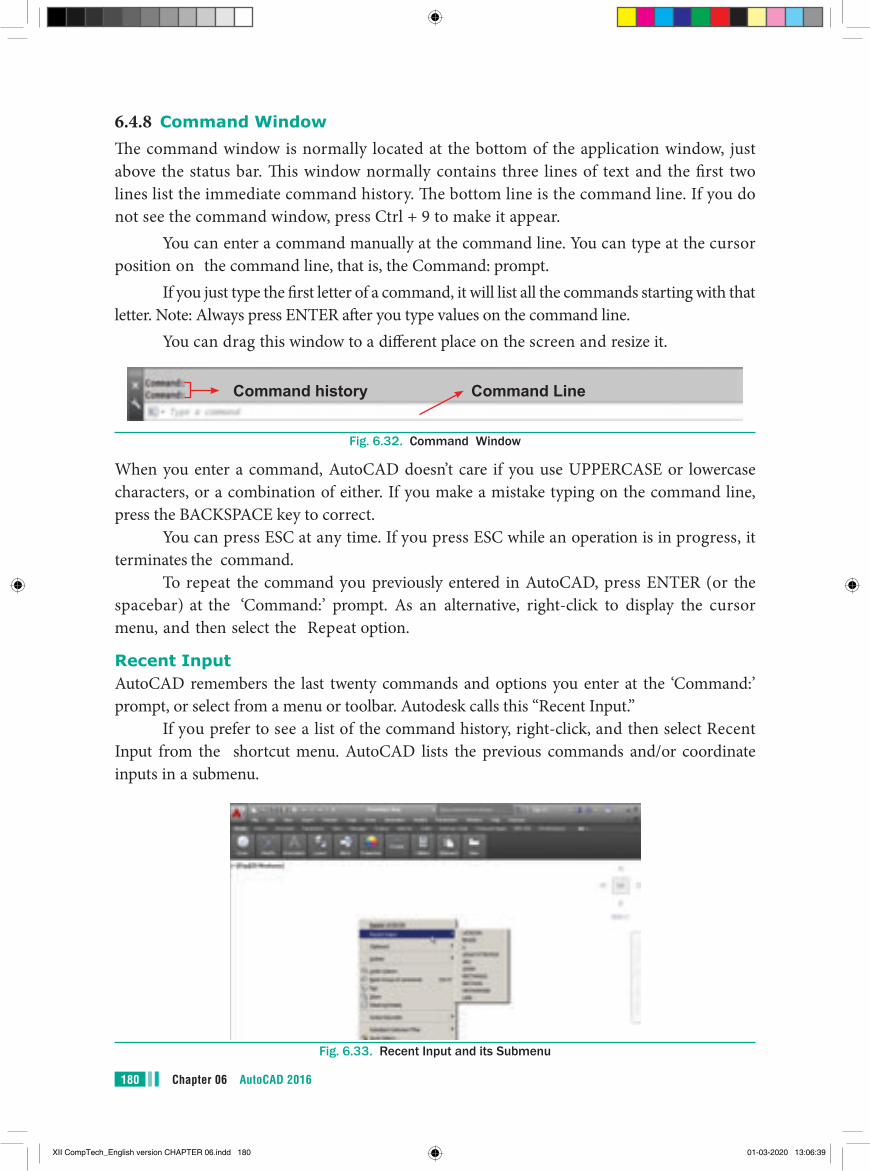
Chapter 06 AutoCAD 2016180
6.4.8 Command WindowThe command window is normally located at the bottom of the application window, just above the status bar. This window normally contains three lines of text and the first two lines list the immediate command history. The bottom line is the command line. If you do not see the command window, press Ctrl + 9 to make it appear.
You can enter a command manually at the command line. You can type at the cursor position on the command line, that is, the Command: prompt.
If you just type the first letter of a command, it will list all the commands starting with that letter. Note: Always press ENTER after you type values on the command line.
You can drag this window to a different place on the screen and resize it.
Command history Command Line
Fig. 6.32. Command Window
When you enter a command, AutoCAD doesn’t care if you use UPPERCASE or lowercase characters, or a combination of either. If you make a mistake typing on the command line, press the BACKSPACE key to correct.
You can press ESC at any time. If you press ESC while an operation is in progress, it terminates the command.
To repeat the command you previously entered in AutoCAD, press ENTER (or the spacebar) at the ‘Command:’ prompt. As an alternative, right-click to display the cursor menu, and then select the Repeat option.
Recent InputAutoCAD remembers the last twenty commands and options you enter at the ‘Command:’ prompt, or select from a menu or toolbar. Autodesk calls this “Recent Input.”
If you prefer to see a list of the command history, right-click, and then select Recent Input from the shortcut menu. AutoCAD lists the previous commands and/or coordinate inputs in a submenu.
Fig. 6.33. Recent Input and its Submenu
XII CompTech_English version CHAPTER 06.indd 180 01-03-2020 13:06:39
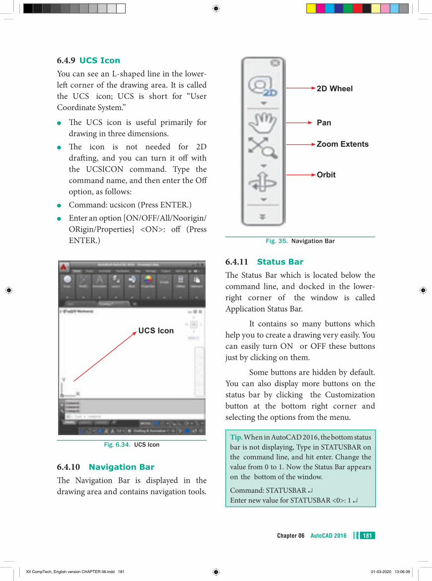
181Chapter 06 AutoCAD 2016
2D Wheel
Zoom Extents
Orbit
Pan
Fig. 35. Navigation Bar
6.4.11 Status BarThe Status Bar which is located below the command line, and docked in the lower-right corner of the window is called Application Status Bar.
It contains so many buttons which help you to create a drawing very easily. You can easily turn ON or OFF these buttons just by clicking on them.
Some buttons are hidden by default. You can also display more buttons on the status bar by clicking the Customization button at the bottom right corner and selecting the options from the menu.
Tip. When in AutoCAD 2016, the bottom status bar is not displaying, Type in STATUSBAR on the command line, and hit enter. Change the value from 0 to 1. Now the Status Bar appears on the bottom of the window.
Command: STATUSBAR Enter new value for STATUSBAR <0>: 1
6.4.9 UCS IconYou can see an L-shaped line in the lower-left corner of the drawing area. It is called the UCS icon; UCS is short for “User Coordinate System.”
●● The UCS icon is useful primarily for drawing in three dimensions.
●● The icon is not needed for 2D drafting, and you can turn it off with the UCSICON command. Type the command name, and then enter the Off option, as follows:
●● Command: ucsicon (Press ENTER.)●● Enter an option [ON/OFF/All/Noorigin/
ORigin/Properties] <ON>: off (Press ENTER.)
UCS Icon
Fig. 6.34. UCS Icon
6.4.10 Navigation BarThe Navigation Bar is displayed in the drawing area and contains navigation tools.
XII CompTech_English version CHAPTER 06.indd 181 01-03-2020 13:06:39
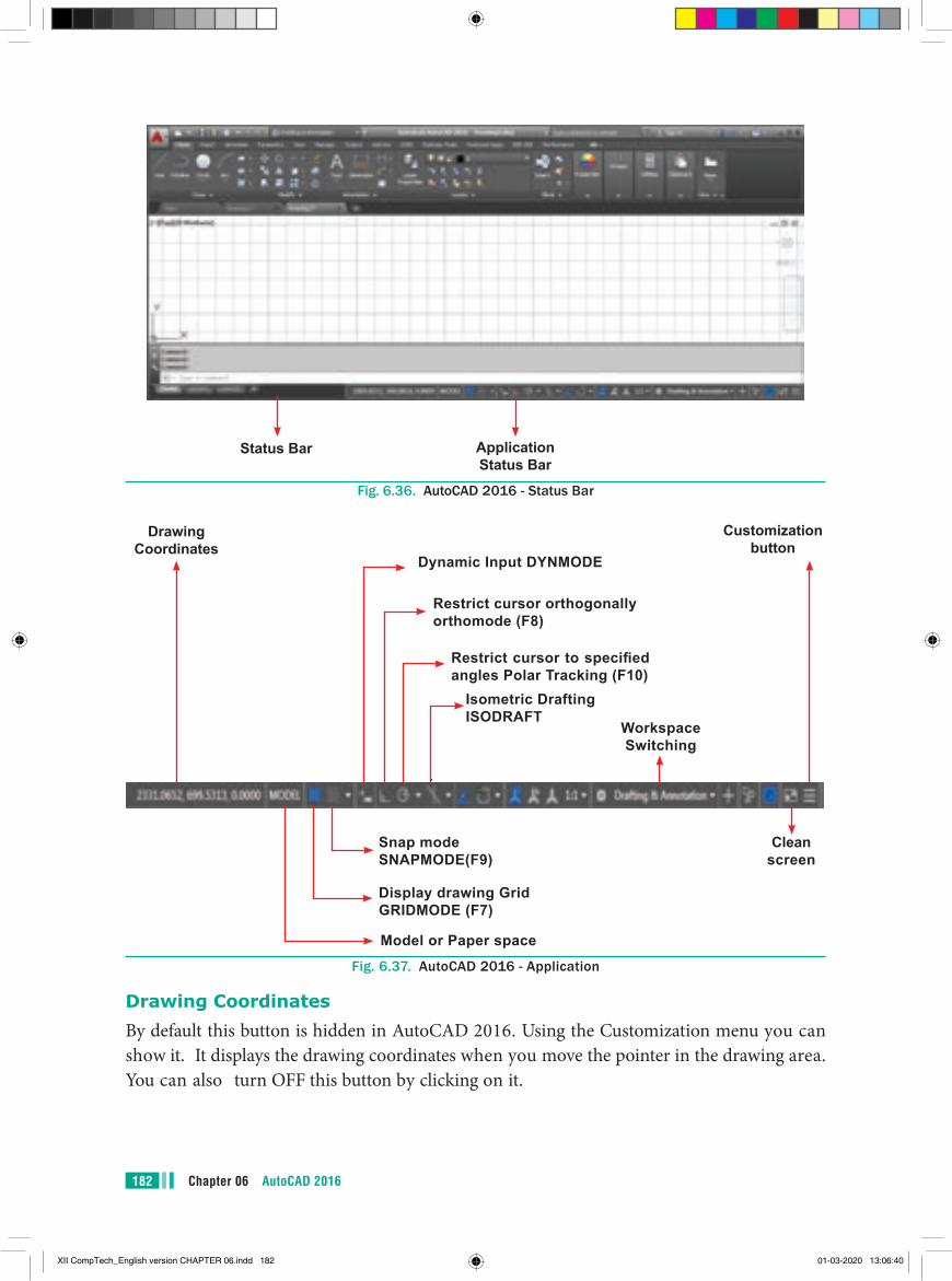
Chapter 06 AutoCAD 2016182
Status Bar Application Status Bar
Fig. 6.36. AutoCAD 2016 - Status Bar
Clean screen
Workspace Switching
Isometric Drafting ISODRAFT
Customization button
Drawing Coordinates
Restrict cursor to specified angles Polar Tracking (F10)
Restrict cursor orthogonally orthomode (F8)
Dynamic Input DYNMODE
Snap mode SNAPMODE(F9)
Display drawing Grid GRIDMODE (F7)
Model or Paper space
Fig. 6.37. AutoCAD 2016 - Application
Drawing CoordinatesBy default this button is hidden in AutoCAD 2016. Using the Customization menu you can show it. It displays the drawing coordinates when you move the pointer in the drawing area. You can also turn OFF this button by clicking on it.
XII CompTech_English version CHAPTER 06.indd 182 01-03-2020 13:06:40
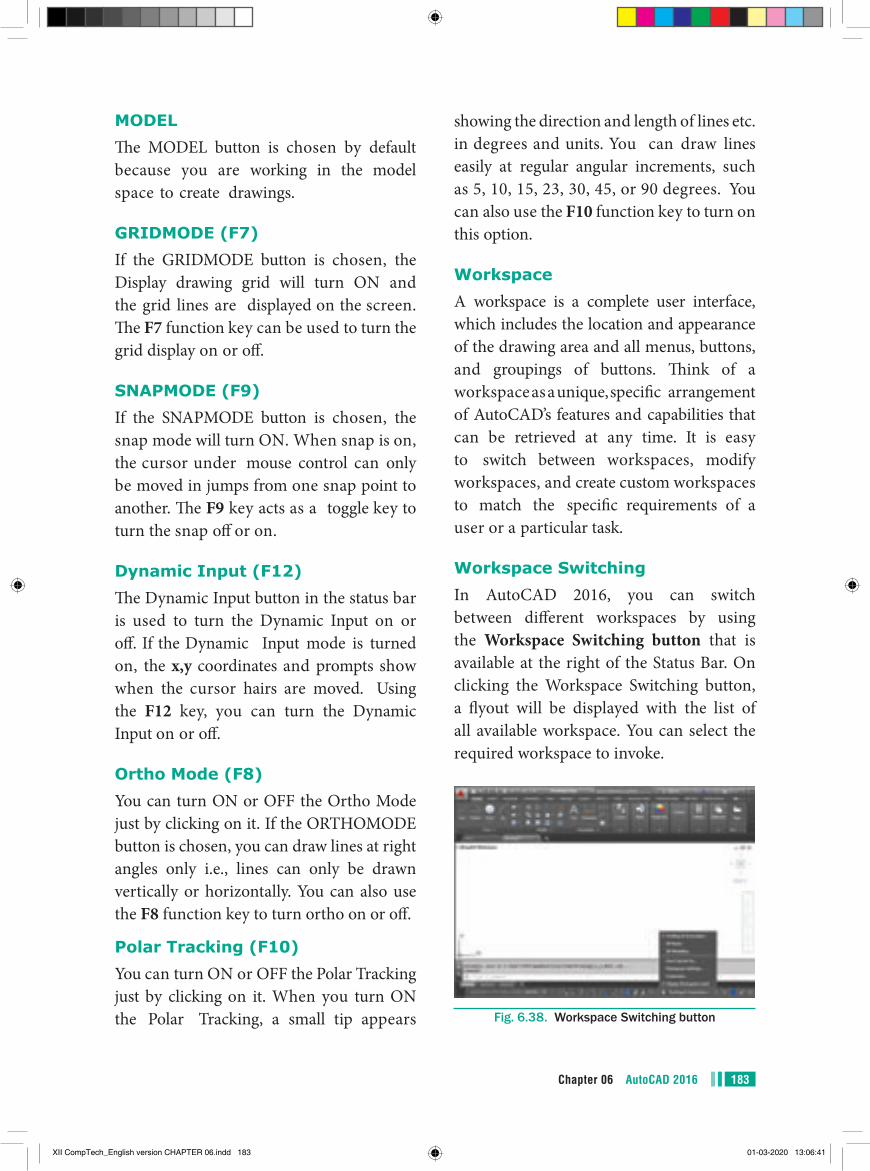
183Chapter 06 AutoCAD 2016
showing the direction and length of lines etc. in degrees and units. You can draw lines easily at regular angular increments, such as 5, 10, 15, 23, 30, 45, or 90 degrees. You can also use the F10 function key to turn on this option.
WorkspaceA workspace is a complete user interface, which includes the location and appearance of the drawing area and all menus, buttons, and groupings of buttons. Think of a workspace as a unique, specific arrangement of AutoCAD’s features and capabilities that can be retrieved at any time. It is easy to switch between workspaces, modify workspaces, and create custom workspaces to match the specific requirements of a user or a particular task.
Workspace SwitchingIn AutoCAD 2016, you can switch between different workspaces by using the Workspace Switching button that is available at the right of the Status Bar. On clicking the Workspace Switching button, a flyout will be displayed with the list of all available workspace. You can select the required workspace to invoke.
Fig. 6.38. Workspace Switching button
MODELThe MODEL button is chosen by default because you are working in the model space to create drawings.
GRIDMODE (F7)If the GRIDMODE button is chosen, the Display drawing grid will turn ON and the grid lines are displayed on the screen. The F7 function key can be used to turn the grid display on or off.
SNAPMODE (F9)If the SNAPMODE button is chosen, the snap mode will turn ON. When snap is on, the cursor under mouse control can only be moved in jumps from one snap point to another. The F9 key acts as a toggle key to turn the snap off or on.
Dynamic Input (F12)The Dynamic Input button in the status bar is used to turn the Dynamic Input on or off. If the Dynamic Input mode is turned on, the x,y coordinates and prompts show when the cursor hairs are moved. Using the F12 key, you can turn the Dynamic Input on or off.
Ortho Mode (F8)You can turn ON or OFF the Ortho Mode just by clicking on it. If the ORTHOMODE button is chosen, you can draw lines at right angles only i.e., lines can only be drawn vertically or horizontally. You can also use the F8 function key to turn ortho on or off.
Polar Tracking (F10)You can turn ON or OFF the Polar Tracking just by clicking on it. When you turn ON the Polar Tracking, a small tip appears
XII CompTech_English version CHAPTER 06.indd 183 01-03-2020 13:06:41
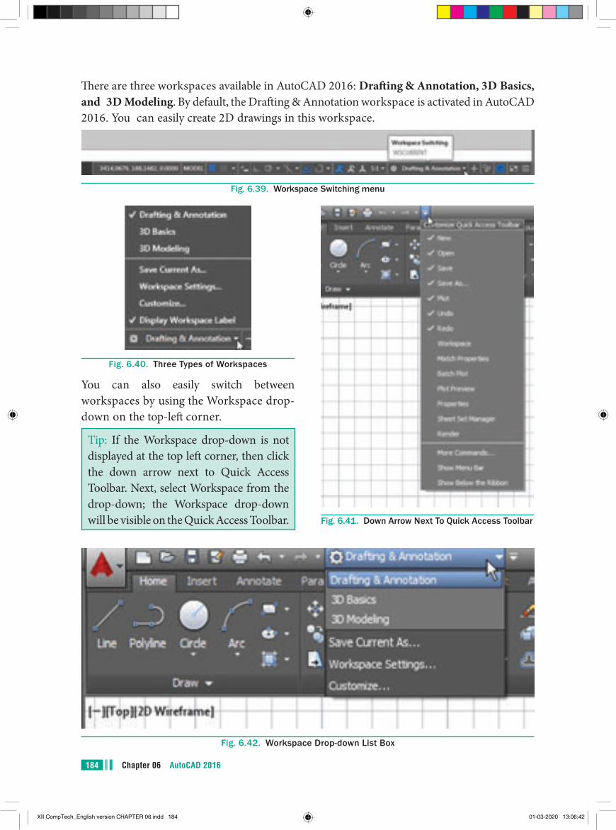
Chapter 06 AutoCAD 2016184
There are three workspaces available in AutoCAD 2016: Drafting & Annotation, 3D Basics, and 3D Modeling. By default, the Drafting & Annotation workspace is activated in AutoCAD 2016. You can easily create 2D drawings in this workspace.
Fig. 6.39. Workspace Switching menu
Fig. 6.40. Three Types of Workspaces
You can also easily switch between workspaces by using the Workspace drop-down on the top-left corner.
Tip: If the Workspace drop-down is not displayed at the top left corner, then click the down arrow next to Quick Access Toolbar. Next, select Workspace from the drop-down; the Workspace drop-down will be visible on the Quick Access Toolbar. Fig. 6.41. Down Arrow Next To Quick Access Toolbar
Fig. 6.42. Workspace Drop-down List Box
XII CompTech_English version CHAPTER 06.indd 184 01-03-2020 13:06:42
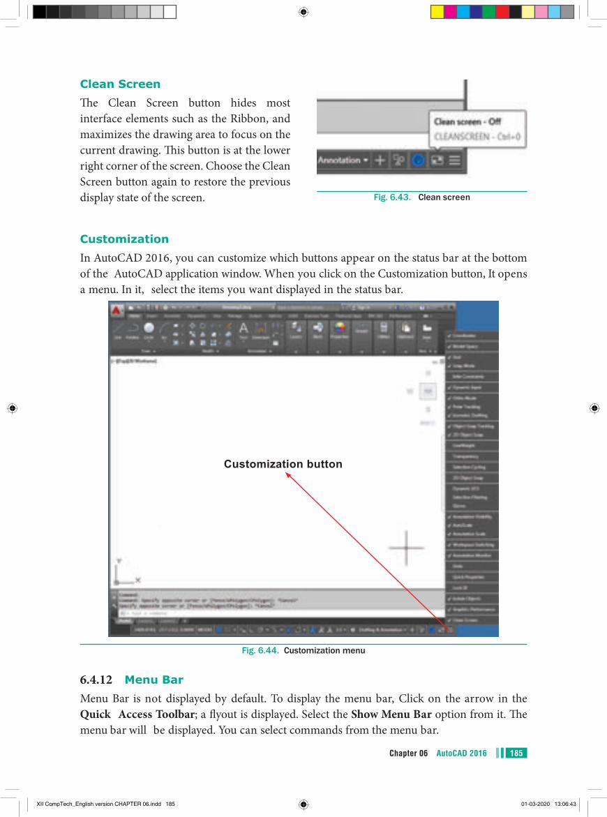
185Chapter 06 AutoCAD 2016
Clean ScreenThe Clean Screen button hides most interface elements such as the Ribbon, and maximizes the drawing area to focus on the current drawing. This button is at the lower right corner of the screen. Choose the Clean Screen button again to restore the previous display state of the screen. Fig. 6.43. Clean screen
CustomizationIn AutoCAD 2016, you can customize which buttons appear on the status bar at the bottom of the AutoCAD application window. When you click on the Customization button, It opens a menu. In it, select the items you want displayed in the status bar.
Customization button
Fig. 6.44. Customization menu
6.4.12 Menu BarMenu Bar is not displayed by default. To display the menu bar, Click on the arrow in the Quick Access Toolbar; a flyout is displayed. Select the Show Menu Bar option from it. The menu bar will be displayed. You can select commands from the menu bar.
XII CompTech_English version CHAPTER 06.indd 185 01-03-2020 13:06:43
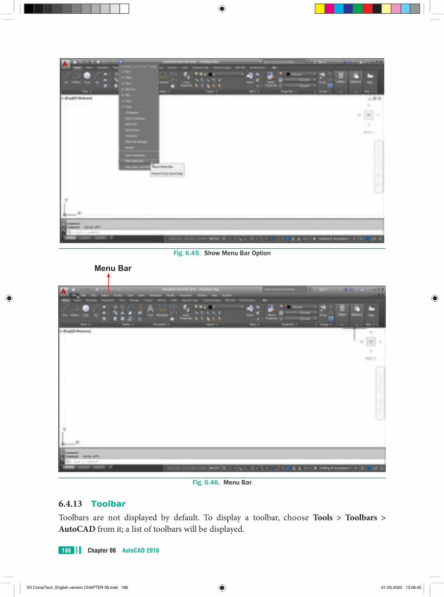
Chapter 06 AutoCAD 2016186
Fig. 6.45. Show Menu Bar Option
Menu Bar
Fig. 6.46. Menu Bar
6.4.13 ToolbarToolbars are not displayed by default. To display a toolbar, choose Tools > Toolbars > AutoCAD from it; a list of toolbars will be displayed.
XII CompTech_English version CHAPTER 06.indd 186 01-03-2020 13:06:45
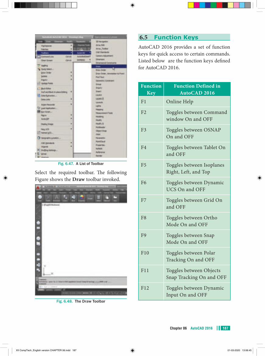
187Chapter 06 AutoCAD 2016
Fig. 6.47. A List of Toolbar
Select the required toolbar. The following Figure shows the Draw toolbar invoked.
Fig. 6.48. The Draw Toolbar
6.5 Function KeysAutoCAD 2016 provides a set of function keys for quick access to certain commands. Listed below are the function keys defined for AutoCAD 2016.
Function Key
Function Defined in AutoCAD 2016
F1 Online Help
F2 Toggles between Command window On and OFF
F3 Toggles between OSNAP On and OFF
F4 Toggles between Tablet On and OFF
F5 Toggles between Isoplanes Right, Left, and Top
F6 Toggles between Dynamic UCS On and OFF
F7 Toggles between Grid On and OFF
F8 Toggles between Ortho Mode On and OFF
F9 Toggles between Snap Mode On and OFF
F10 Toggles between Polar Tracking On and OFF
F11 Toggles between Objects Snap Tracking On and OFF
F12 Toggles between Dynamic Input On and OFF
XII CompTech_English version CHAPTER 06.indd 187 01-03-2020 13:06:45
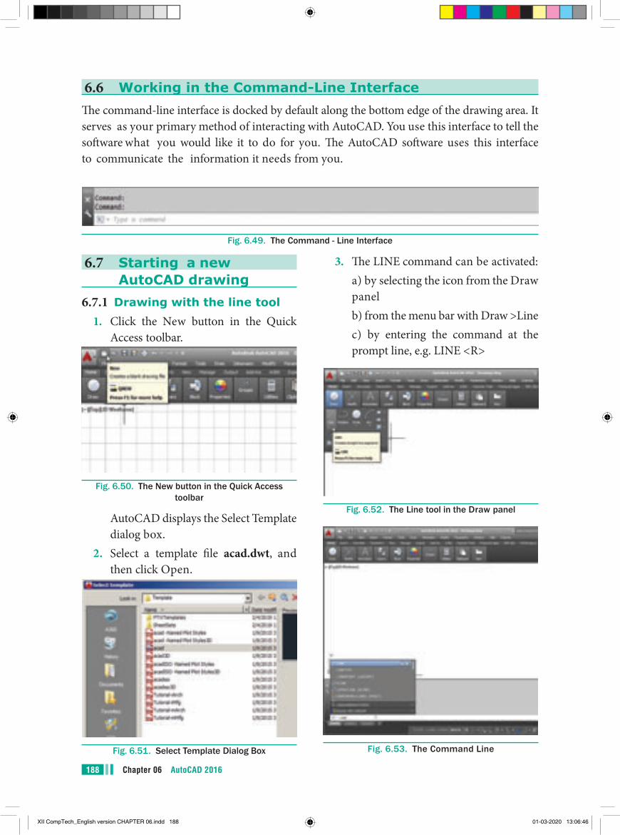
Chapter 06 AutoCAD 2016188
6.6 Working in the Command-Line InterfaceThe command-line interface is docked by default along the bottom edge of the drawing area. It serves as your primary method of interacting with AutoCAD. You use this interface to tell the software what you would like it to do for you. The AutoCAD software uses this interface to communicate the information it needs from you.
Fig. 6.49. The Command - Line Interface
6.7 Starting a new AutoCAD drawing
6.7.1 Drawing with the line tool1. Click the New button in the Quick
Access toolbar.
Fig. 6.50. The New button in the Quick Access toolbar
AutoCAD displays the Select Template dialog box.
2. Select a template file acad.dwt, and then click Open.
Fig. 6.51. Select Template Dialog Box
3. The LINE command can be activated: a) by selecting the icon from the Draw
panel b) from the menu bar with Draw >Line c) by entering the command at the
prompt line, e.g. LINE <R>
Fig. 6.52. The Line tool in the Draw panel
Fig. 6.53. The Command Line
XII CompTech_English version CHAPTER 06.indd 188 01-03-2020 13:06:46
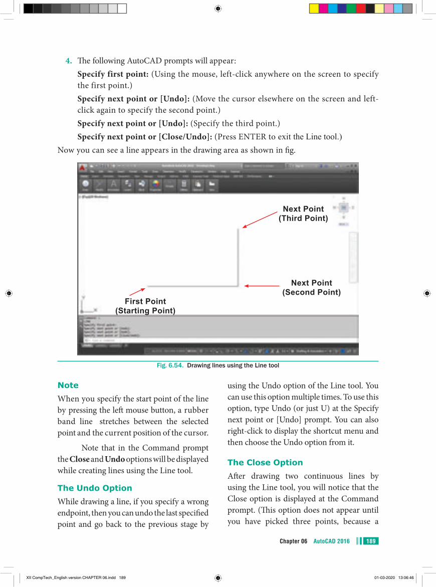
189Chapter 06 AutoCAD 2016
4. The following AutoCAD prompts will appear: Specify first point: (Using the mouse, left-click anywhere on the screen to specify
the first point.) Specify next point or [Undo]: (Move the cursor elsewhere on the screen and left-
click again to specify the second point.) Specify next point or [Undo]: (Specify the third point.) Specify next point or [Close/Undo]: (Press ENTER to exit the Line tool.)
Now you can see a line appears in the drawing area as shown in fig.
First Point (Starting Point)
Next Point (Third Point)
Next Point (Second Point)
Fig. 6.54. Drawing lines using the Line tool
NoteWhen you specify the start point of the line by pressing the left mouse button, a rubber band line stretches between the selected point and the current position of the cursor.
Note that in the Command prompt the Close and Undo options will be displayed while creating lines using the Line tool.
The Undo OptionWhile drawing a line, if you specify a wrong endpoint, then you can undo the last specified point and go back to the previous stage by
using the Undo option of the Line tool. You can use this option multiple times. To use this option, type Undo (or just U) at the Specify next point or [Undo] prompt. You can also right-click to display the shortcut menu and then choose the Undo option from it.
The Close OptionAfter drawing two continuous lines by using the Line tool, you will notice that the Close option is displayed at the Command prompt. (This option does not appear until you have picked three points, because a
XII CompTech_English version CHAPTER 06.indd 189 01-03-2020 13:06:46
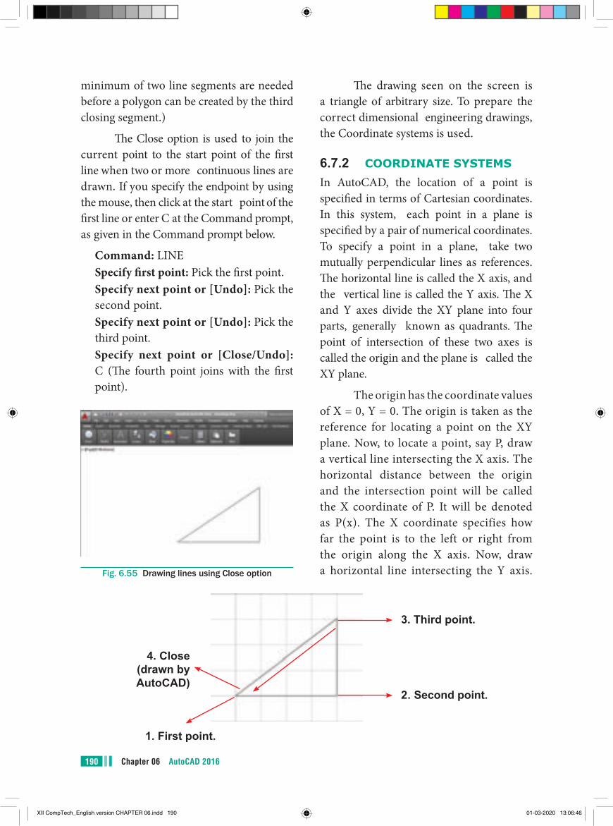
Chapter 06 AutoCAD 2016190
The drawing seen on the screen is a triangle of arbitrary size. To prepare the correct dimensional engineering drawings, the Coordinate systems is used.
6.7.2 COORDINATE SYSTEMSIn AutoCAD, the location of a point is specified in terms of Cartesian coordinates. In this system, each point in a plane is specified by a pair of numerical coordinates. To specify a point in a plane, take two mutually perpendicular lines as references. The horizontal line is called the X axis, and the vertical line is called the Y axis. The X and Y axes divide the XY plane into four parts, generally known as quadrants. The point of intersection of these two axes is called the origin and the plane is called the XY plane.
The origin has the coordinate values of X = 0, Y = 0. The origin is taken as the reference for locating a point on the XY plane. Now, to locate a point, say P, draw a vertical line intersecting the X axis. The horizontal distance between the origin and the intersection point will be called the X coordinate of P. It will be denoted as P(x). The X coordinate specifies how far the point is to the left or right from the origin along the X axis. Now, draw a horizontal line intersecting the Y axis.
minimum of two line segments are needed before a polygon can be created by the third closing segment.)
The Close option is used to join the current point to the start point of the first line when two or more continuous lines are drawn. If you specify the endpoint by using the mouse, then click at the start point of the first line or enter C at the Command prompt, as given in the Command prompt below.
Command: LINE Specify first point: Pick the first point. Specify next point or [Undo]: Pick the
second point. Specify next point or [Undo]: Pick the
third point. Specify next point or [Close/Undo]:
C (The fourth point joins with the first point).
Fig. 6.55 Drawing lines using Close option
2. Second point.
1. First point.
4. Close (drawn by AutoCAD)
3. Third point.
XII CompTech_English version CHAPTER 06.indd 190 01-03-2020 13:06:46
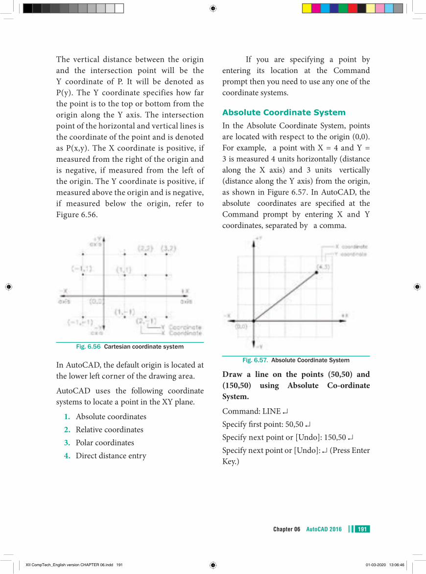
191Chapter 06 AutoCAD 2016
If you are specifying a point by entering its location at the Command prompt then you need to use any one of the coordinate systems.
Absolute Coordinate SystemIn the Absolute Coordinate System, points are located with respect to the origin (0,0). For example, a point with X = 4 and Y = 3 is measured 4 units horizontally (distance along the X axis) and 3 units vertically (distance along the Y axis) from the origin, as shown in Figure 6.57. In AutoCAD, the absolute coordinates are specified at the Command prompt by entering X and Y coordinates, separated by a comma.
Fig. 6.57. Absolute Coordinate System
Draw a line on the points (50,50) and (150,50) using Absolute Co-ordinate System.
Command: LINE ↵Specify first point: 50,50 ↵Specify next point or [Undo]: 150,50 ↵Specify next point or [Undo]: ↵ (Press Enter Key.)
The vertical distance between the origin and the intersection point will be the Y coordinate of P. It will be denoted as P(y). The Y coordinate specifies how far the point is to the top or bottom from the origin along the Y axis. The intersection point of the horizontal and vertical lines is the coordinate of the point and is denoted as P(x,y). The X coordinate is positive, if measured from the right of the origin and is negative, if measured from the left of the origin. The Y coordinate is positive, if measured above the origin and is negative, if measured below the origin, refer to Figure 6.56.
Fig. 6.56 Cartesian coordinate system
In AutoCAD, the default origin is located at the lower left corner of the drawing area.
AutoCAD uses the following coordinate systems to locate a point in the XY plane.
1. Absolute coordinates2. Relative coordinates3. Polar coordinates4. Direct distance entry
XII CompTech_English version CHAPTER 06.indd 191 01-03-2020 13:06:46
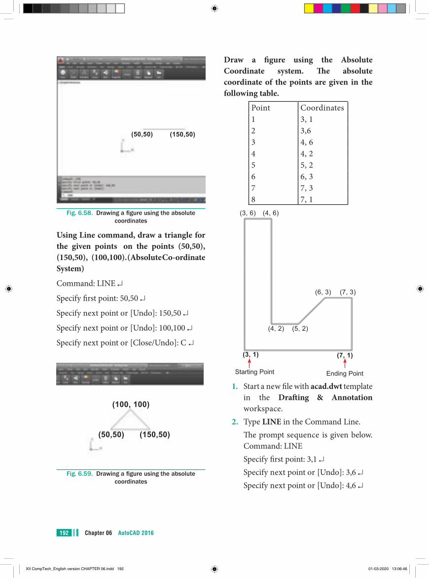
Chapter 06 AutoCAD 2016192
(150,50)(50,50)
Fig. 6.58. Drawing a figure using the absolute coordinates
Using Line command, draw a triangle for the given points on the points (50,50), (150,50), (100,100). (Absolute Co-ordinate System)
Command: LINE ↵
Specify first point: 50,50 ↵
Specify next point or [Undo]: 150,50 ↵
Specify next point or [Undo]: 100,100 ↵
Specify next point or [Close/Undo]: C ↵
(100, 100)
(50,50) (150,50)
Fig. 6.59. Drawing a figure using the absolute coordinates
Draw a figure using the Absolute Coordinate system. The absolute coordinate of the points are given in the following table.
Point Coordinates1 3, 12 3,63 4, 64 4, 25 5, 26 6, 37 7, 38 7, 1
(3, 6) (4, 6)
(6, 3) (7, 3)
(4, 2) (5, 2)
(3, 1) (7, 1)
Starting Point Ending Point
1. Start a new file with acad.dwt template in the Drafting & Annotation workspace.
2. Type LINE in the Command Line. The prompt sequence is given below.
Command: LINE Specify first point: 3,1 ↵ Specify next point or [Undo]: 3,6 ↵ Specify next point or [Undo]: 4,6 ↵
XII CompTech_English version CHAPTER 06.indd 192 01-03-2020 13:06:46
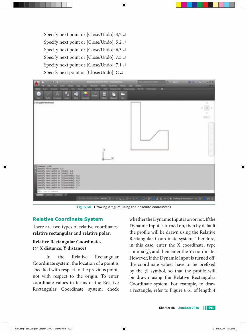
193Chapter 06 AutoCAD 2016
Specify next point or [Close/Undo]: 4,2 ↵ Specify next point or [Close/Undo]: 5,2 ↵ Specify next point or [Close/Undo]: 6,3 ↵ Specify next point or [Close/Undo]: 7,3 ↵ Specify next point or [Close/Undo]: 7,1 ↵ Specify next point or [Close/Undo]: C ↵
Fig. 6.60. Drawing a figure using the absolute coordinates
Relative Coordinate SystemThere are two types of relative coordinates: relative rectangular and relative polar.
Relative Rectangular Coordinates (@ X distance, Y distance)
In the Relative Rectangular Coordinate system, the location of a point is specified with respect to the previous point, not with respect to the origin. To enter coordinate values in terms of the Relative Rectangular Coordinate system, check
whether the Dynamic Input is on or not. If the Dynamic Input is turned on, then by default the profile will be drawn using the Relative Rectangular Coordinate system. Therefore, in this case, enter the X coordinate, type comma (,), and then enter the Y coordinate. However, if the Dynamic Input is turned off, the coordinate values have to be prefixed by the @ symbol, so that the profile will be drawn using the Relative Rectangular Coordinate system. For example, to draw a rectangle, refer to Figure 6.61 of length 4
XII CompTech_English version CHAPTER 06.indd 193 01-03-2020 13:06:46
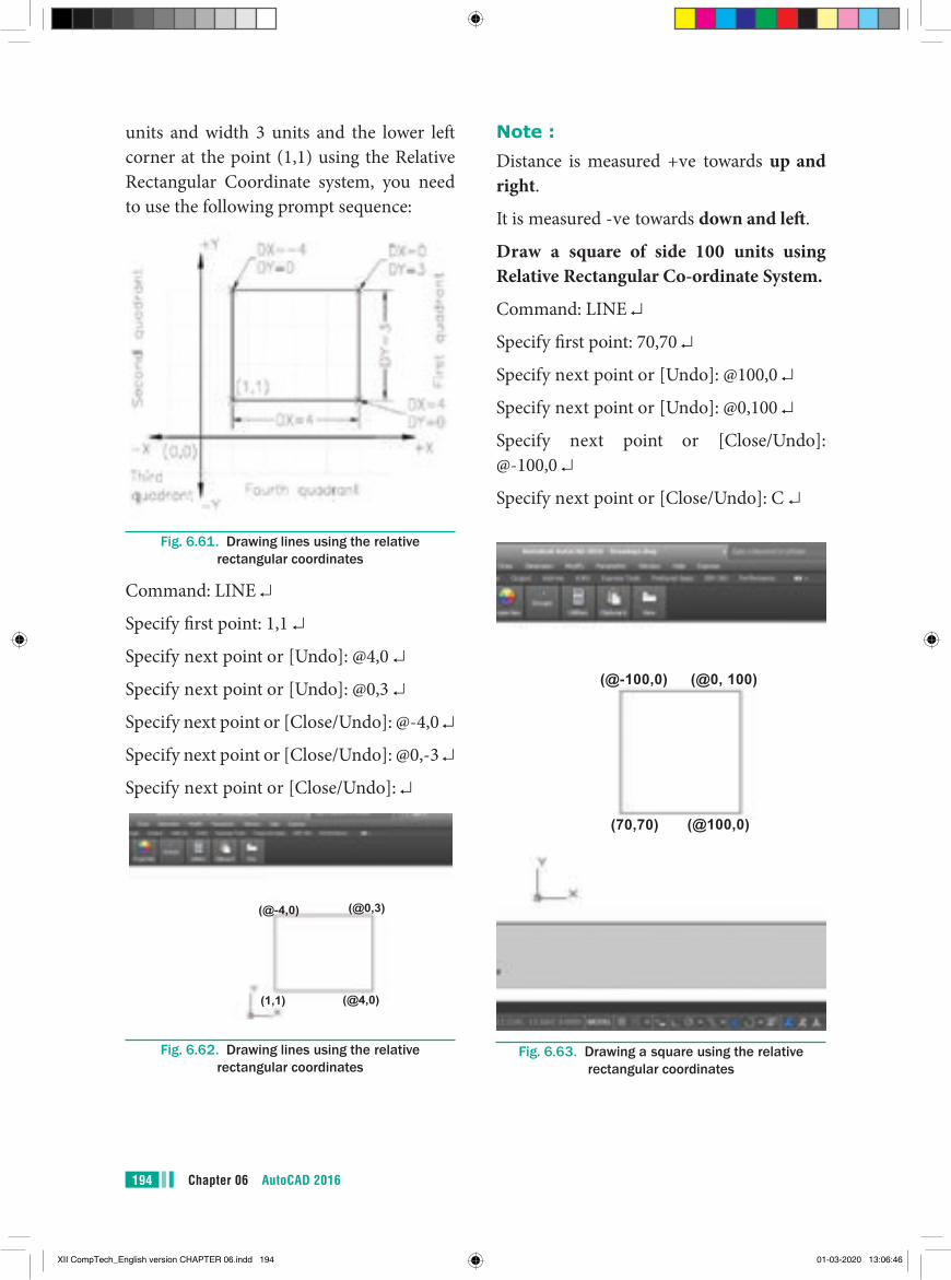
Chapter 06 AutoCAD 2016194
units and width 3 units and the lower left corner at the point (1,1) using the Relative Rectangular Coordinate system, you need to use the following prompt sequence:
Fig. 6.61. Drawing lines using the relative rectangular coordinates
Command: LINE ↵
Specify first point: 1,1 ↵
Specify next point or [Undo]: @4,0 ↵
Specify next point or [Undo]: @0,3 ↵
Specify next point or [Close/Undo]: @-4,0 ↵
Specify next point or [Close/Undo]: @0,-3 ↵
Specify next point or [Close/Undo]: ↵
(@0,3)(@-4,0)
(@4,0)(1,1)
Fig. 6.62. Drawing lines using the relative rectangular coordinates
Note :Distance is measured +ve towards up and right.
It is measured -ve towards down and left.
Draw a square of side 100 units using Relative Rectangular Co-ordinate System.
Command: LINE ↵
Specify first point: 70,70 ↵
Specify next point or [Undo]: @100,0 ↵
Specify next point or [Undo]: @0,100 ↵
Specify next point or [Close/Undo]: @-100,0 ↵
Specify next point or [Close/Undo]: C ↵
(@-100,0) (@0, 100)
(70,70) (@100,0)
Fig. 6.63. Drawing a square using the relative rectangular coordinates
XII CompTech_English version CHAPTER 06.indd 194 01-03-2020 13:06:46
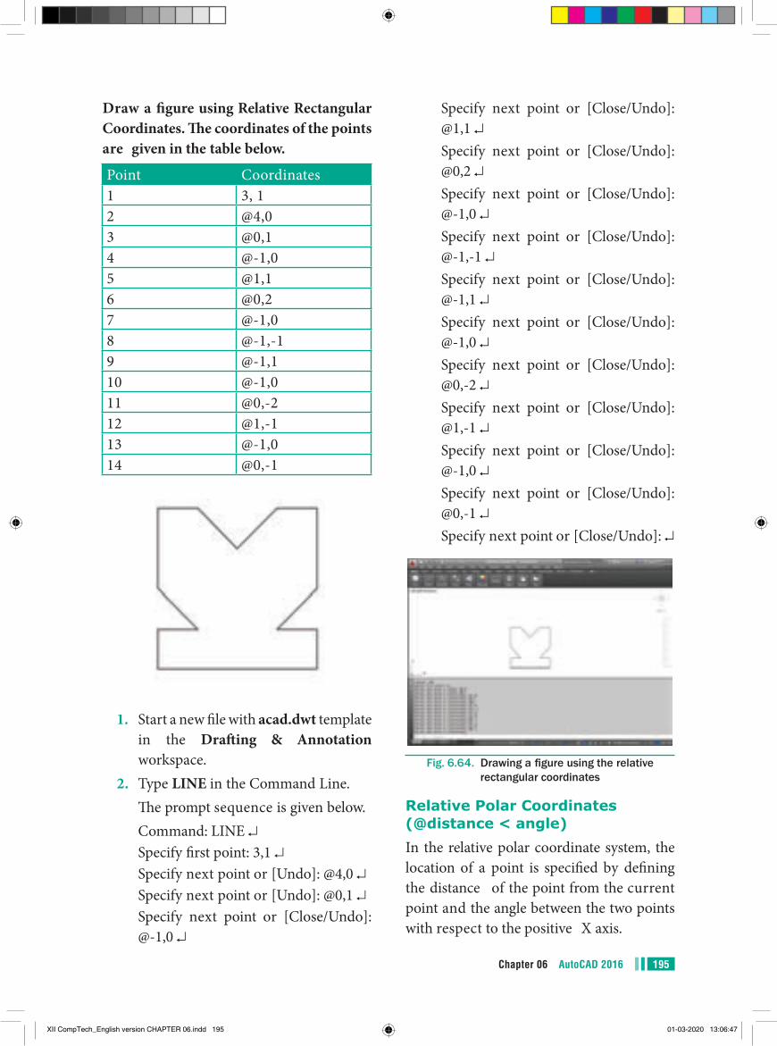
195Chapter 06 AutoCAD 2016
Draw a figure using Relative Rectangular Coordinates. The coordinates of the points are given in the table below.
Point Coordinates1 3, 12 @4,03 @0,14 @-1,05 @1,16 @0,27 @-1,08 @-1,-19 @-1,110 @-1,011 @0,-212 @1,-113 @-1,014 @0,-1
1. Start a new file with acad.dwt template in the Drafting & Annotation workspace.
2. Type LINE in the Command Line. The prompt sequence is given below. Command: LINE ↵ Specify first point: 3,1 ↵ Specify next point or [Undo]: @4,0 ↵ Specify next point or [Undo]: @0,1 ↵ Specify next point or [Close/Undo]:
@-1,0 ↵
Specify next point or [Close/Undo]: @1,1 ↵
Specify next point or [Close/Undo]: @0,2 ↵
Specify next point or [Close/Undo]: @-1,0 ↵
Specify next point or [Close/Undo]: @-1,-1 ↵
Specify next point or [Close/Undo]: @-1,1 ↵
Specify next point or [Close/Undo]: @-1,0 ↵
Specify next point or [Close/Undo]: @0,-2 ↵
Specify next point or [Close/Undo]: @1,-1 ↵
Specify next point or [Close/Undo]: @-1,0 ↵
Specify next point or [Close/Undo]: @0,-1 ↵
Specify next point or [Close/Undo]: ↵
Fig. 6.64. Drawing a figure using the relative rectangular coordinates
Relative Polar Coordinates (@distance < angle)In the relative polar coordinate system, the location of a point is specified by defining the distance of the point from the current point and the angle between the two points with respect to the positive X axis.
XII CompTech_English version CHAPTER 06.indd 195 01-03-2020 13:06:47
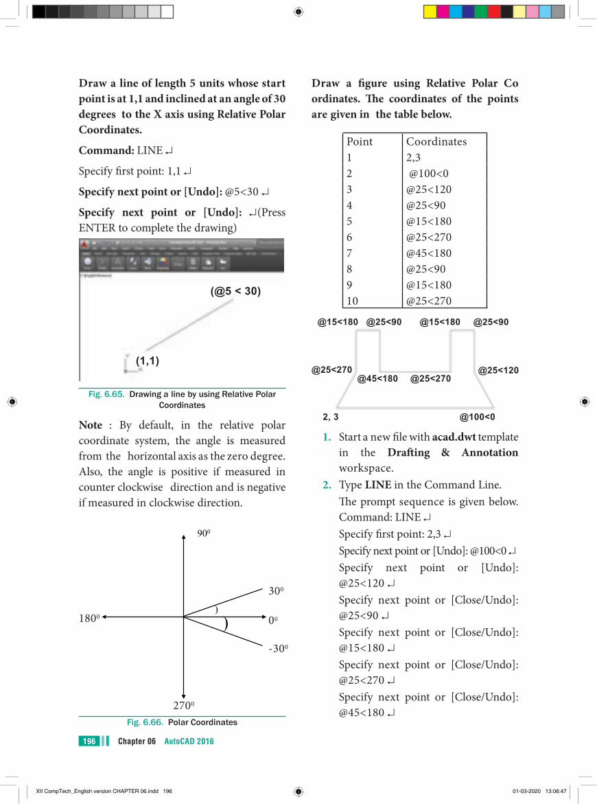
Chapter 06 AutoCAD 2016196
Draw a figure using Relative Polar Co ordinates. The coordinates of the points are given in the table below.
Point Coordinates1 2,32 @100<03 @25<1204 @25<905 @15<1806 @25<2707 @45<1808 @25<909 @15<18010 @25<270
@15<180
@25<270
@25<90
@45<180
@15<180
@25<270
@25<90
@25<120
2, 3 @100<0
1. Start a new file with acad.dwt template in the Drafting & Annotation workspace.
2. Type LINE in the Command Line. The prompt sequence is given below.
Command: LINE ↵ Specify first point: 2,3 ↵ Specify next point or [Undo]: @100<0 ↵ Specify next point or [Undo]:
@25<120 ↵ Specify next point or [Close/Undo]:
@25<90 ↵ Specify next point or [Close/Undo]:
@15<180 ↵ Specify next point or [Close/Undo]:
@25<270 ↵ Specify next point or [Close/Undo]:
@45<180 ↵
Draw a line of length 5 units whose start point is at 1,1 and inclined at an angle of 30 degrees to the X axis using Relative Polar Coordinates.
Command: LINE ↵
Specify first point: 1,1 ↵
Specify next point or [Undo]: @5<30 ↵
Specify next point or [Undo]: ↵(Press ENTER to complete the drawing)
(@5 < 30)
(1,1)
Fig. 6.65. Drawing a line by using Relative Polar Coordinates
Note : By default, in the relative polar coordinate system, the angle is measured from the horizontal axis as the zero degree. Also, the angle is positive if measured in counter clockwise direction and is negative if measured in clockwise direction.
1800
900
) )
300
00
-300
2700
Fig. 6.66. Polar Coordinates
XII CompTech_English version CHAPTER 06.indd 196 01-03-2020 13:06:47
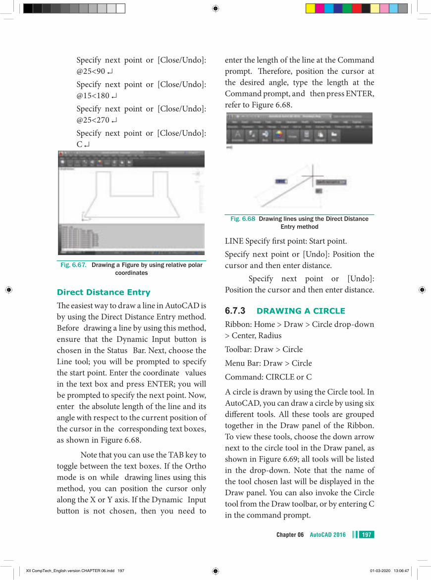
197Chapter 06 AutoCAD 2016
enter the length of the line at the Command prompt. Therefore, position the cursor at the desired angle, type the length at the Command prompt, and then press ENTER, refer to Figure 6.68.
Fig. 6.68 Drawing lines using the Direct Distance Entry method
LINE Specify first point: Start point.Specify next point or [Undo]: Position the cursor and then enter distance.
Specify next point or [Undo]: Position the cursor and then enter distance.
6.7.3 DRAWING A CIRCLERibbon: Home > Draw > Circle drop-down > Center, RadiusToolbar: Draw > CircleMenu Bar: Draw > CircleCommand: CIRCLE or C
A circle is drawn by using the Circle tool. In AutoCAD, you can draw a circle by using six different tools. All these tools are grouped together in the Draw panel of the Ribbon. To view these tools, choose the down arrow next to the circle tool in the Draw panel, as shown in Figure 6.69; all tools will be listed in the drop-down. Note that the name of the tool chosen last will be displayed in the Draw panel. You can also invoke the Circle tool from the Draw toolbar, or by entering C in the command prompt.
Specify next point or [Close/Undo]: @25<90 ↵
Specify next point or [Close/Undo]: @15<180 ↵
Specify next point or [Close/Undo]: @25<270 ↵
Specify next point or [Close/Undo]: C ↵
Fig. 6.67. Drawing a Figure by using relative polar coordinates
Direct Distance EntryThe easiest way to draw a line in AutoCAD is by using the Direct Distance Entry method. Before drawing a line by using this method, ensure that the Dynamic Input button is chosen in the Status Bar. Next, choose the Line tool; you will be prompted to specify the start point. Enter the coordinate values in the text box and press ENTER; you will be prompted to specify the next point. Now, enter the absolute length of the line and its angle with respect to the current position of the cursor in the corresponding text boxes, as shown in Figure 6.68.
Note that you can use the TAB key to toggle between the text boxes. If the Ortho mode is on while drawing lines using this method, you can position the cursor only along the X or Y axis. If the Dynamic Input button is not chosen, then you need to
XII CompTech_English version CHAPTER 06.indd 197 01-03-2020 13:06:47
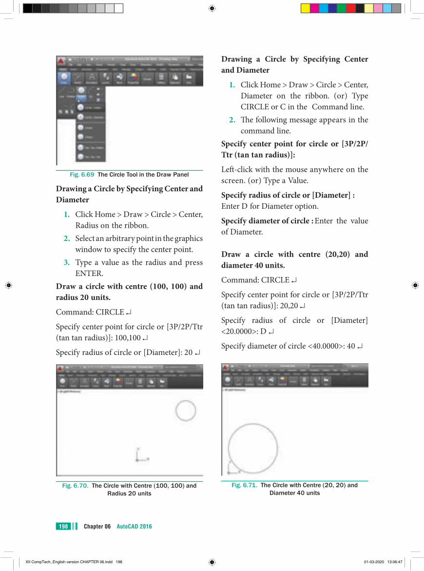
Chapter 06 AutoCAD 2016198
Drawing a Circle by Specifying Center and Diameter
1. Click Home > Draw > Circle > Center, Diameter on the ribbon. (or) Type CIRCLE or C in the Command line.
2. The following message appears in the command line.
Specify center point for circle or [3P/2P/Ttr (tan tan radius)]:
Left-click with the mouse anywhere on the screen. (or) Type a Value.
Specify radius of circle or [Diameter] : Enter D for Diameter option.
Specify diameter of circle : Enter the value of Diameter.
Draw a circle with centre (20,20) and diameter 40 units.
Command: CIRCLE ↵
Specify center point for circle or [3P/2P/Ttr (tan tan radius)]: 20,20 ↵
Specify radius of circle or [Diameter] <20.0000>: D ↵
Specify diameter of circle <40.0000>: 40 ↵
Fig. 6.71. The Circle with Centre (20, 20) and Diameter 40 units
Fig. 6.69 The Circle Tool in the Draw Panel
Drawing a Circle by Specifying Center and Diameter
1. Click Home > Draw > Circle > Center, Radius on the ribbon.
2. Select an arbitrary point in the graphics window to specify the center point.
3. Type a value as the radius and press ENTER.
Draw a circle with centre (100, 100) and radius 20 units.
Command: CIRCLE ↵
Specify center point for circle or [3P/2P/Ttr (tan tan radius)]: 100,100 ↵
Specify radius of circle or [Diameter]: 20 ↵
Fig. 6.70. The Circle with Centre (100, 100) and Radius 20 units
XII CompTech_English version CHAPTER 06.indd 198 01-03-2020 13:06:47
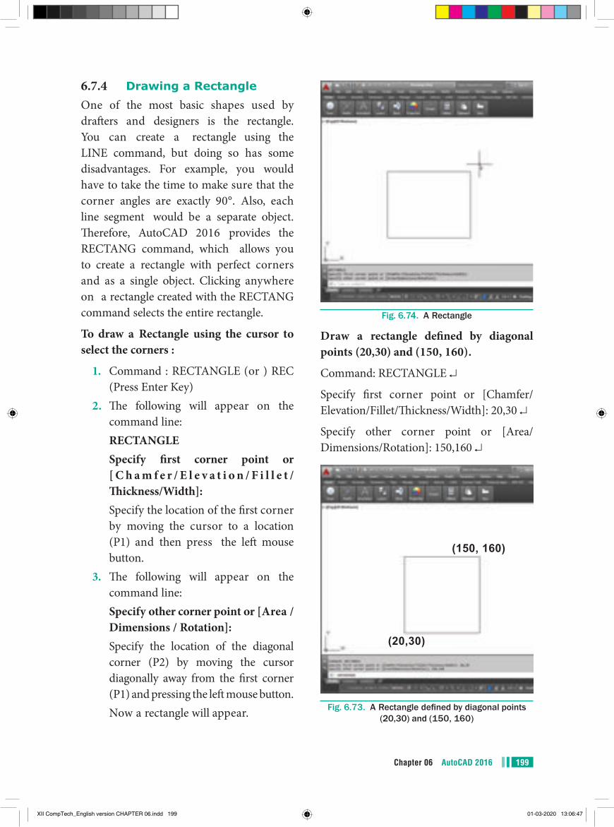
199Chapter 06 AutoCAD 2016
6.7.4 Drawing a RectangleOne of the most basic shapes used by drafters and designers is the rectangle. You can create a rectangle using the LINE command, but doing so has some disadvantages. For example, you would have to take the time to make sure that the corner angles are exactly 90°. Also, each line segment would be a separate object. Therefore, AutoCAD 2016 provides the RECTANG command, which allows you to create a rectangle with perfect corners and as a single object. Clicking anywhere on a rectangle created with the RECTANG command selects the entire rectangle.
To draw a Rectangle using the cursor to select the corners :
1. Command : RECTANGLE (or ) REC (Press Enter Key)
2. The following will appear on the command line:
RECTANGLE Specify first corner point or
[ C h a m f e r / E l e v a t i o n / F i l l e t /Thickness/Width]:
Specify the location of the first corner by moving the cursor to a location (P1) and then press the left mouse button.
3. The following will appear on the command line:
Specify other corner point or [Area / Dimensions / Rotation]:
Specify the location of the diagonal corner (P2) by moving the cursor diagonally away from the first corner (P1) and pressing the left mouse button.
Now a rectangle will appear.
Fig. 6.74. A Rectangle
Draw a rectangle defined by diagonal points (20,30) and (150, 160).
Command: RECTANGLE ↵
Specify first corner point or [Chamfer/Elevation/Fillet/Thickness/Width]: 20,30 ↵
Specify other corner point or [Area/Dimensions/Rotation]: 150,160 ↵
(150, 160)
(20,30)
Fig. 6.73. A Rectangle defined by diagonal points (20,30) and (150, 160)
XII CompTech_English version CHAPTER 06.indd 199 01-03-2020 13:06:47
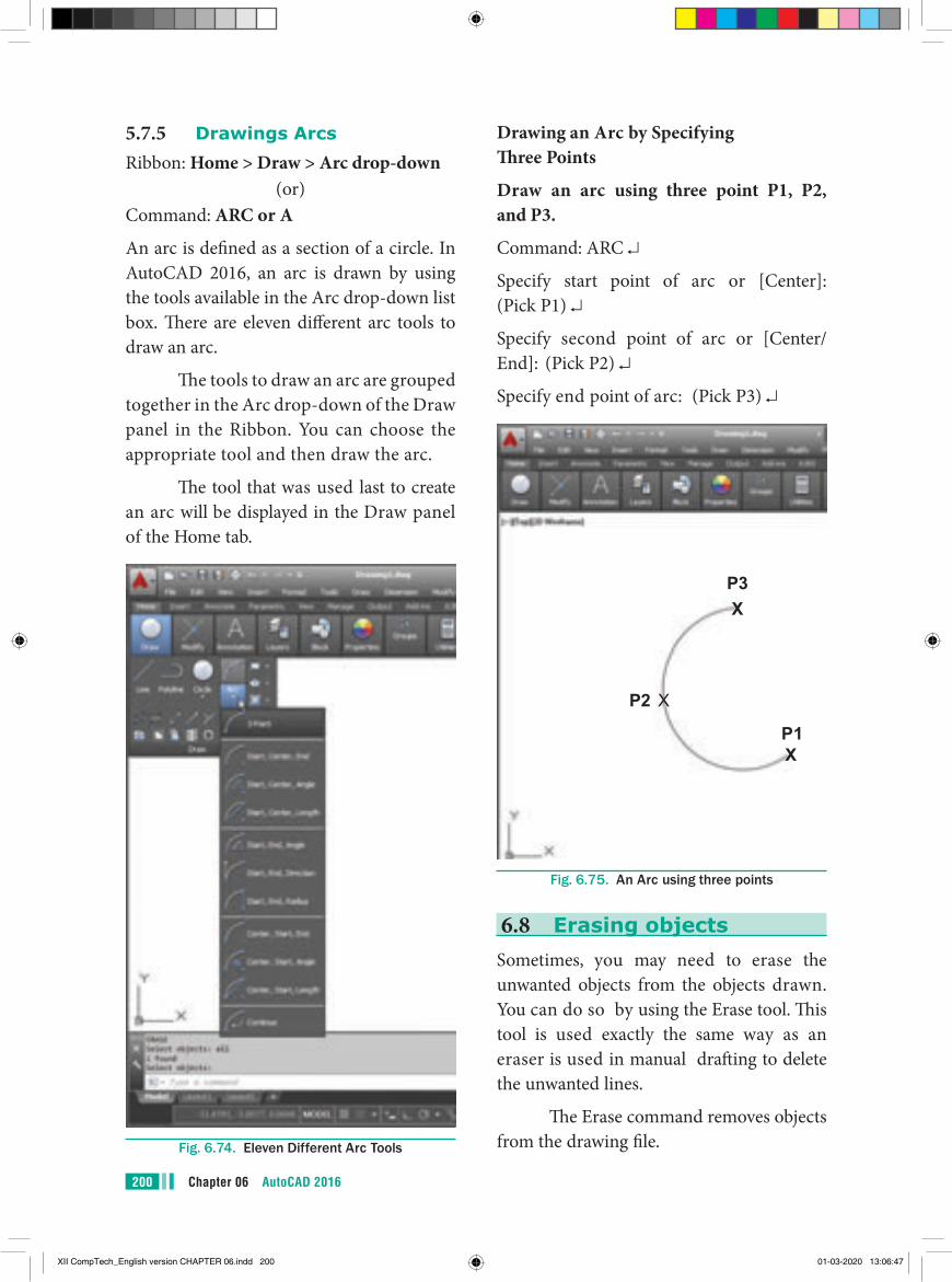
Chapter 06 AutoCAD 2016200
5.7.5 Drawings ArcsRibbon: Home > Draw > Arc drop-down
(or)Command: ARC or A
An arc is defined as a section of a circle. In AutoCAD 2016, an arc is drawn by using the tools available in the Arc drop-down list box. There are eleven different arc tools to draw an arc.
The tools to draw an arc are grouped together in the Arc drop-down of the Draw panel in the Ribbon. You can choose the appropriate tool and then draw the arc.
The tool that was used last to create an arc will be displayed in the Draw panel of the Home tab.
Fig. 6.74. Eleven Different Arc Tools
Drawing an Arc by Specifying Three Points
Draw an arc using three point P1, P2, and P3.
Command: ARC ↵
Specify start point of arc or [Center]: (Pick P1) ↵
Specify second point of arc or [Center/End]: (Pick P2) ↵
Specify end point of arc: (Pick P3) ↵
P3X
P2 X
XP1
Fig. 6.75. An Arc using three points
6.8 Erasing objectsSometimes, you may need to erase the unwanted objects from the objects drawn. You can do so by using the Erase tool. This tool is used exactly the same way as an eraser is used in manual drafting to delete the unwanted lines.
The Erase command removes objects from the drawing file.
XII CompTech_English version CHAPTER 06.indd 200 01-03-2020 13:06:47
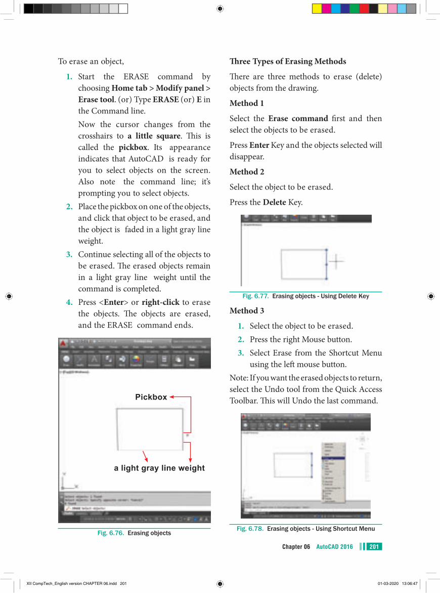
201Chapter 06 AutoCAD 2016
To erase an object,
1. Start the ERASE command by choosing Home tab > Modify panel > Erase tool. (or) Type ERASE (or) E in the Command line.
Now the cursor changes from the crosshairs to a little square. This is called the pickbox. Its appearance indicates that AutoCAD is ready for you to select objects on the screen. Also note the command line; it’s prompting you to select objects.
2. Place the pickbox on one of the objects, and click that object to be erased, and the object is faded in a light gray line weight.
3. Continue selecting all of the objects to be erased. The erased objects remain in a light gray line weight until the command is completed.
4. Press <Enter> or right-click to erase the objects. The objects are erased, and the ERASE command ends.
Pickbox
a light gray line weight
Fig. 6.76. Erasing objects
Three Types of Erasing Methods
There are three methods to erase (delete) objects from the drawing.
Method 1
Select the Erase command first and then select the objects to be erased.
Press Enter Key and the objects selected will disappear.
Method 2
Select the object to be erased.
Press the Delete Key.
Fig. 6.77. Erasing objects - Using Delete Key
Method 3
1. Select the object to be erased.2. Press the right Mouse button.3. Select Erase from the Shortcut Menu
using the left mouse button.Note: If you want the erased objects to return, select the Undo tool from the Quick Access Toolbar. This will Undo the last command.
Fig. 6.78. Erasing objects - Using Shortcut Menu
XII CompTech_English version CHAPTER 06.indd 201 01-03-2020 13:06:47
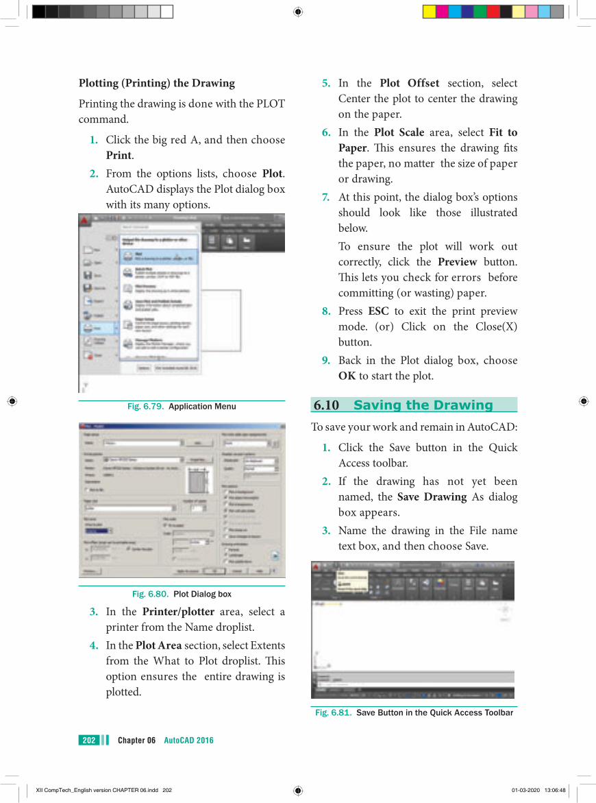
Chapter 06 AutoCAD 2016202
5. In the Plot Offset section, select Center the plot to center the drawing on the paper.
6. In the Plot Scale area, select Fit to Paper. This ensures the drawing fits the paper, no matter the size of paper or drawing.
7. At this point, the dialog box’s options should look like those illustrated below.
To ensure the plot will work out correctly, click the Preview button. This lets you check for errors before committing (or wasting) paper.
8. Press ESC to exit the print preview mode. (or) Click on the Close(X) button.
9. Back in the Plot dialog box, choose OK to start the plot.
6.10 Saving the DrawingTo save your work and remain in AutoCAD:
1. Click the Save button in the Quick Access toolbar.
2. If the drawing has not yet been named, the Save Drawing As dialog box appears.
3. Name the drawing in the File name text box, and then choose Save.
Fig. 6.81. Save Button in the Quick Access Toolbar
Plotting (Printing) the Drawing
Printing the drawing is done with the PLOT command.
1. Click the big red A, and then choose Print.
2. From the options lists, choose Plot. AutoCAD displays the Plot dialog box with its many options.
Fig. 6.79. Application Menu
Fig. 6.80. Plot Dialog box
3. In the Printer/plotter area, select a printer from the Name droplist.
4. In the Plot Area section, select Extents from the What to Plot droplist. This option ensures the entire drawing is plotted.
XII CompTech_English version CHAPTER 06.indd 202 01-03-2020 13:06:48
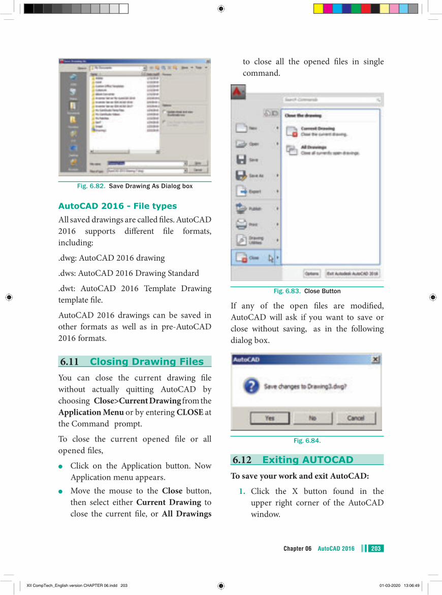
203Chapter 06 AutoCAD 2016
to close all the opened files in single command.
Fig. 6.83. Close Button
If any of the open files are modified, AutoCAD will ask if you want to save or close without saving, as in the following dialog box.
Fig. 6.84.
6.12 Exiting AUTOCADTo save your work and exit AutoCAD:
1. Click the X button found in the upper right corner of the AutoCAD window.
Fig. 6.82. Save Drawing As Dialog box
AutoCAD 2016 - File typesAll saved drawings are called files. AutoCAD 2016 supports different file formats, including:
.dwg: AutoCAD 2016 drawing
.dws: AutoCAD 2016 Drawing Standard
.dwt: AutoCAD 2016 Template Drawing template file.
AutoCAD 2016 drawings can be saved in other formats as well as in pre-AutoCAD 2016 formats.
6.11 Closing Drawing FilesYou can close the current drawing file without actually quitting AutoCAD by choosing Close>Current Drawing from the Application Menu or by entering CLOSE at the Command prompt.
To close the current opened file or all opened files,
●● Click on the Application button. Now Application menu appears.
●● Move the mouse to the Close button, then select either Current Drawing to close the current file, or All Drawings
XII CompTech_English version CHAPTER 06.indd 203 01-03-2020 13:06:49
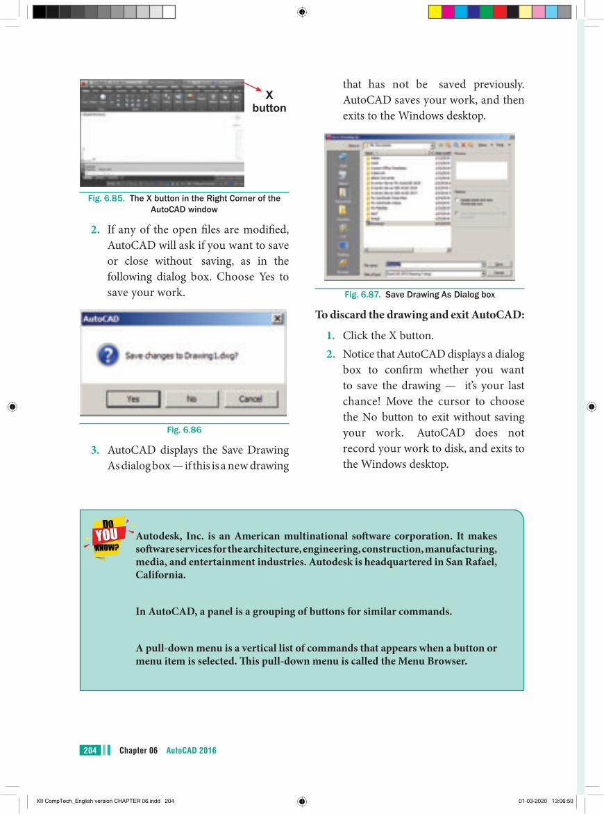
204 Chapter 06 AutoCAD 2016
that has not be saved previously. AutoCAD saves your work, and then exits to the Windows desktop.
Fig. 6.87. Save Drawing As Dialog box
To discard the drawing and exit AutoCAD:
1. Click the X button.2. Notice that AutoCAD displays a dialog
box to confirm whether you want to save the drawing — it’s your last chance! Move the cursor to choose the No button to exit without saving your work. AutoCAD does not record your work to disk, and exits to the Windows desktop.
X button
Fig. 6.85. The X button in the Right Corner of the AutoCAD window
2. If any of the open files are modified, AutoCAD will ask if you want to save or close without saving, as in the following dialog box. Choose Yes to save your work.
Fig. 6.86
3. AutoCAD displays the Save Drawing As dialog box — if this is a new drawing
Autodesk, Inc. is an American multinational software corporation. It makes software services for the architecture, engineering, construction, manufacturing, media, and entertainment industries. Autodesk is headquartered in San Rafael, California.
In AutoCAD, a panel is a grouping of buttons for similar commands.
A pull-down menu is a vertical list of commands that appears when a button or menu item is selected. This pull-down menu is called the Menu Browser.
XII CompTech_English version CHAPTER 06.indd 204 01-03-2020 13:06:50
205Chapter 05 AutoCAD 2016
●● AutoCAD is a commercial computer-aided design (CAD) and drafting software application. It is developed and marketed by Autodesk.
●● The drawing area covers the major portion of the screen. In this area, you can draw the objects.
●● The command window at the bottom of the drawing area has the Command prompt where you can enter the commands.
●● A workspace is defined as a customized arrangement of Ribbon, toolbars, menus, and window palettes in the AutoCAD environment.
●● The LINE draw commands can be activated:a) by selecting the icon from the Draw panelb) from the menu bar with Draw >Linec) by entering the command at the prompt line, e.g. LINE <R>
●● After drawing two continuous lines by using the Line tool, the Close option is displayed at the Command prompt. The Close option is used to join the current point to the start point of the first line when two or more continuous lines are drawn. To choose the Close option, type the letter C at the Command prompt and press ENTER.
●● While drawing a line, if you specify a wrong endpoint, then you can undo the last specified point and go back to the previous stage by using the Undo option of the Line tool. To use this option, enter U at the Command prompt and press ENTER.
●● To cancel or exit a command, press the ESC (Escape) key on the keyboard.●● The ERASE command can be activated:
a with the ERASE icon from the Modify toolbarb) from the menu bar with Modify >Erasec) by entering ERASE <R> at the command line.
points to remember
Left-click Press the left-hand button of the mouse.
Click Same meaning as left-click .
Double-click Press the left-hand button of the mouse twice.
Right-click Press the Right-hand button of the mouse – has the same result as pressing the Return key of the keyboard.
Drag Move the cursor on to an object and, holding down the right-hand button of the mouse, pull the object to a new position.
XII CompTech_English version CHAPTER 06.indd 205 01-03-2020 13:06:50
Chapter 06 AutoCAD 2016206
EVALUATION EVALUATION
Part - IChoose the correct answer.
1. AutoCAD is a _________soft ware application.
(a) DTP (b) computer-aided design (CAD)
and drafting (c) Text Editing (d) Video Editing2. AutoCAD 2016 is developed and
marketed by _________ (a) Microsoft Corporation (b) Adobe Inc. (c) Autodesk, Inc. (d) Sun Microsystems, Inc
3. The _________menu appears when you click the red “A” Button.
(a) Application
(b) Edit
(c) Layout
(d) Window
4. Th e _________bar displays at the top of the Application menu.
(a) Menu
(b) Search
(c) Toolbar
(d) Title
Enter Type the letters or numbers which follow at the keyboard.
Pick Move the cursor on to an item on screen and press the left -hand button of the mouse.
Return Press the Enter key of the keyboard. Th is key may also marked with a left facing arrow (↵). In most cases (but not always) has the same result as a right-click.
Dialog box A window appearing in the AutoCAD window in which settings may be made.
Drop-down menu A menu appearing when one of the names in the menu bars is clicked.
Tooltip Th e name of a tool appearing when the cursor is placed over a tool icon from a toolbar.
Prompts Text appearing in the command window when a tool is selected which advise the operator as to which operation is required.
Object A part of a drawing which can be treated as a single object. For example a line constructed with the Line tool is an object; a rectangle constructed with the Polyline tool is an object; an arc constructed with the Arc tool is an object.
XII CompTech_English version CHAPTER 06.indd 206 01-03-2020 13:06:50
207Chapter 06 AutoCAD 2016
using the RECTANG command? Why might you choose one command instead of the other?
8. How do you terminate a command in progress in AutoCAD?
9. In which Ribbon control panel are the Arc and Circle buttons found?
10. After you enter the ERASE command, what does AutoCAD ask you to do?
11. When a file has not yet been saved for the first time, what appears when you pick either Save or Save As... from the Application Menu bar?
12. What is the quickest way to open a file in AutoCAD?
13. How do you exit AutoCAD?
Part - IIIAnswer the following Questions
(3 Marks)
1. List the three Create Objects commands.
2. How can you enter commands such as LINE, CIRCLE, and ERASE quickly at the keyboard?
3. Explain the use of the LINE Undo option.
4. Briefly describe the following methods of producing circles.
a. centre and radius b. centre and diameter
Part - IVAnswer the following Questions
(5 Marks)1. Write about AutoCAD Interface.2. Write briefly about Command window.3. Write about the rectangle object and the
steps to draw a rectangle in AutoCAD.
5. If you do not see the command window, press _________to make it appear.
(a) Ctrl +1
(b) Ctrl + 9
(c) Ctrl + 8
(d) Ctrl + 7
6. UCS is short for (a) User Coordinate System
(b) User Currency System
(c) User Control System
(d) User Computer System
7. The _________function key can be used to turn the grid display on or off.
(a) F1
(b) F2
(c) F3
(d) F7
Part - II Answer the following Questions
(2 Marks)
1. How do you start AutoCAD?2. How do you hide all the buttons on
the Ribbon?3. What appears when you rest the
pointer on a button on the Ribbon?4. How do you get rid of the UCS icon?5 Which Function key turns the OSNAP
feature on and off?6. What is a fast method of closing a
polygon when you are using the LINE command?
7. What are the practical differences between creating a rectangle using the LINE command and creating it
XII CompTech_English version CHAPTER 06.indd 207 01-03-2020 13:06:50
COMPUTER TECHNOLOGYPractical
z_XII CompTech_English version Practicals.indd 208 01-03-2020 13:07:27
209
1. Open Pagemaker 7.0 and create a new document layout which includes the following setup options:
� Page size – A4. � Number of Pages – 4. � Margins 1.25 inches- top, and .75 inches - all other sides.
2. Type the following text: HAPPINESS Happiness is often confused with fun, good living, and riches. Sometimes fun is
equated with happiness. Fun is what we experience while doing an activity, whereas happiness is a residual and long-lasting feeling. The path to happiness is long and full of challenges. Happiness requires life-long pursuit.
3. Set the heading ‘HAPPINESS’ in 18 points, Arial font, bold and alignment centre.
4. Format the paragraph as follows: (a) Font – Arial
(b) Font size – 12
(c) Alignment – Justified
(d) Leading – 20
5. Save the document as ‘happiness’.
PageMaker-Page Formatting
AIM
To create a new document using thedefault given options.
01EXERCISE
12th STD - Computer Technology - Practical
Practicals
z_XII CompTech_English version Practicals.indd 209 01-03-2020 13:07:27
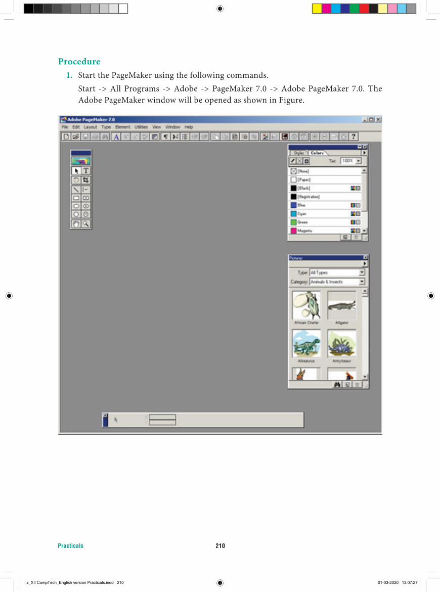
Practicals 210
Procedure1. Start the PageMaker using the following commands. Start -> All Programs -> Adobe -> PageMaker 7.0 -> Adobe PageMaker 7.0. The
Adobe PageMaker window will be opened as shown in Figure.
z_XII CompTech_English version Practicals.indd 210 01-03-2020 13:07:27
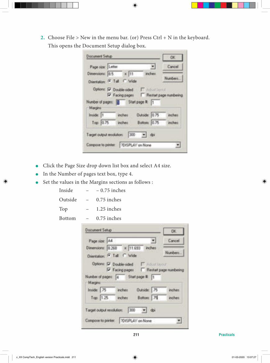
Practicals211
2. Choose File > New in the menu bar. (or) Press Ctrl + N in the keyboard. This opens the Document Setup dialog box.
� Click the Page Size drop down list box and select A4 size. � In the Number of pages text box, type 4. � Set the values in the Margins sections as follows :
Inside – – 0.75 inches
Outside – 0.75 inches
Top – 1.25 inches
Bottom – 0.75 inches
z_XII CompTech_English version Practicals.indd 211 01-03-2020 13:07:27
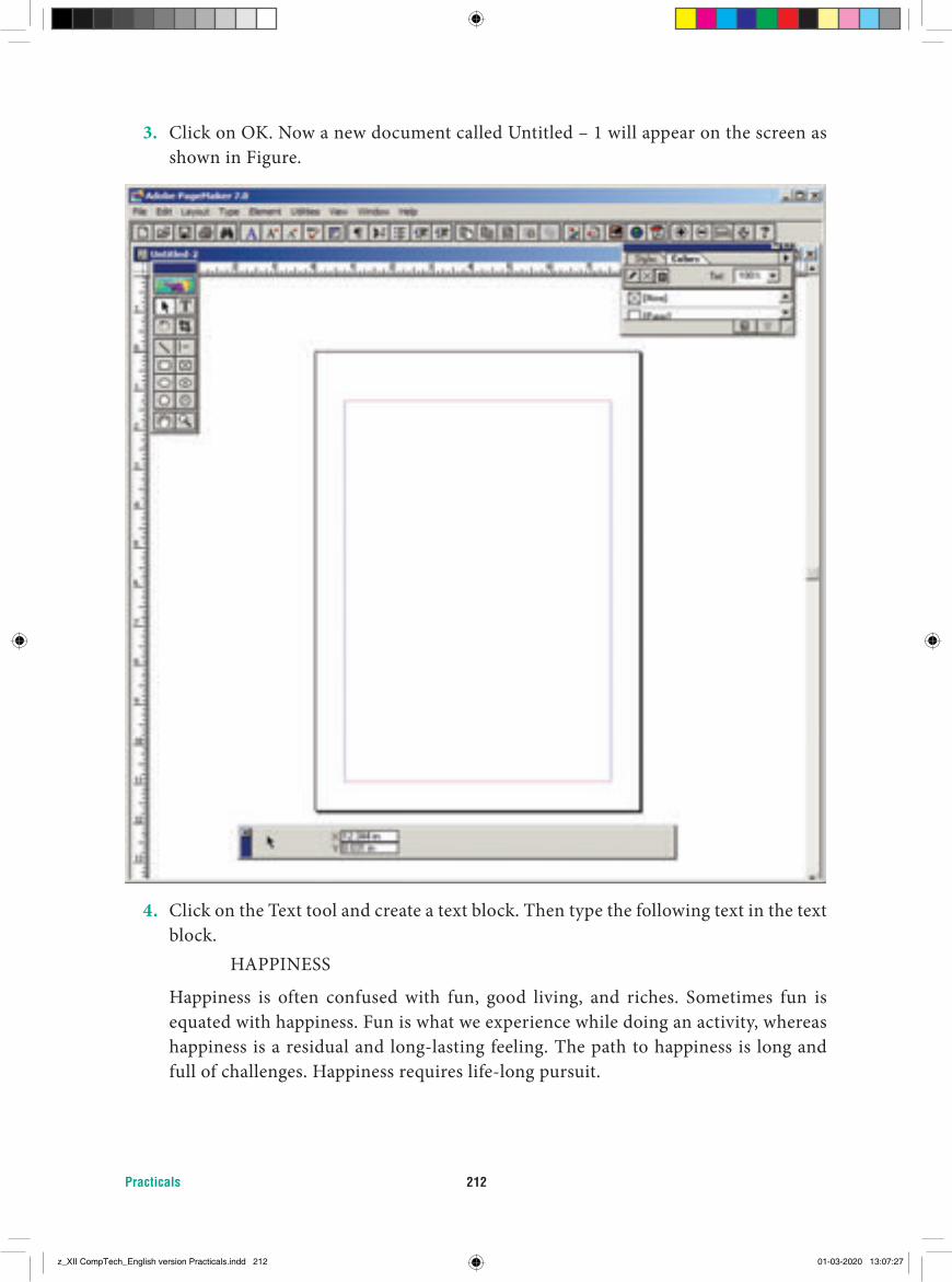
Practicals 212
3. Click on OK. Now a new document called Untitled – 1 will appear on the screen as shown in Figure.
4. Click on the Text tool and create a text block. Then type the following text in the text block.
HAPPINESS
Happiness is often confused with fun, good living, and riches. Sometimes fun is equated with happiness. Fun is what we experience while doing an activity, whereas happiness is a residual and long-lasting feeling. The path to happiness is long and full of challenges. Happiness requires life-long pursuit.
z_XII CompTech_English version Practicals.indd 212 01-03-2020 13:07:27
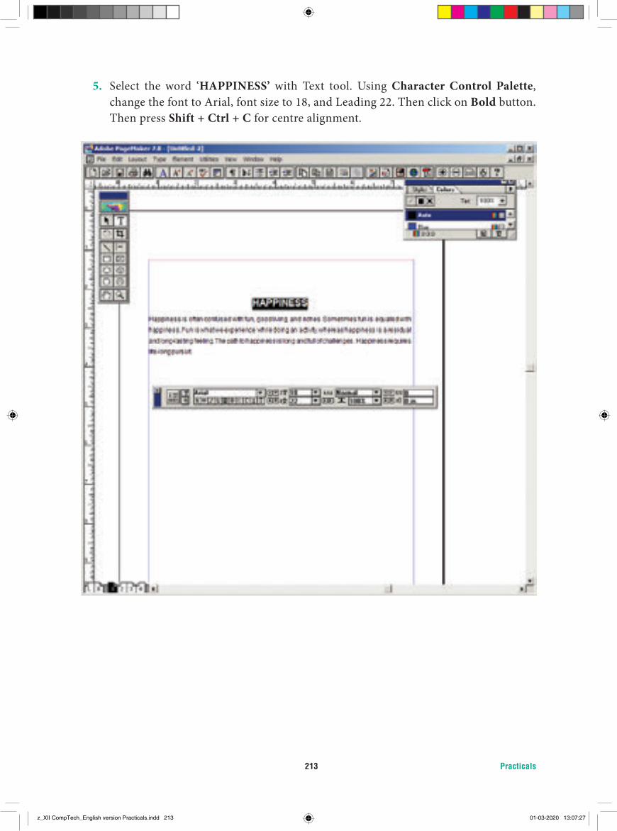
Practicals213
5. Select the word ‘HAPPINESS’ with Text tool. Using Character Control Palette, change the font to Arial, font size to 18, and Leading 22. Then click on Bold button. Then press Shift + Ctrl + C for centre alignment.
z_XII CompTech_English version Practicals.indd 213 01-03-2020 13:07:27
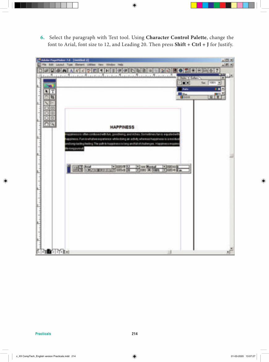
Practicals 214
6. Select the paragraph with Text tool. Using Character Control Palette, change the font to Arial, font size to 12, and Leading 20. Then press Shift + Ctrl + J for Justify.
z_XII CompTech_English version Practicals.indd 214 01-03-2020 13:07:27
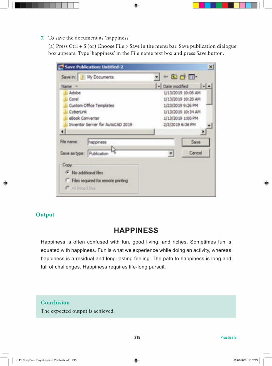
Practicals215
7. To save the document as ‘happiness’ (a) Press Ctrl + S (or) Choose File > Save in the menu bar. Save publication dialogue
box appears. Type ‘happiness’ in the File name text box and press Save button.
Output
HAPPINESSHappiness is often confused with fun, good living, and riches. Sometimes fun is
equated with happiness. Fun is what we experience while doing an activity, whereas
happiness is a residual and long-lasting feeling. The path to happiness is long and
full of challenges. Happiness requires life-long pursuit.
ConclusionThe expected output is achieved.
z_XII CompTech_English version Practicals.indd 215 01-03-2020 13:07:27
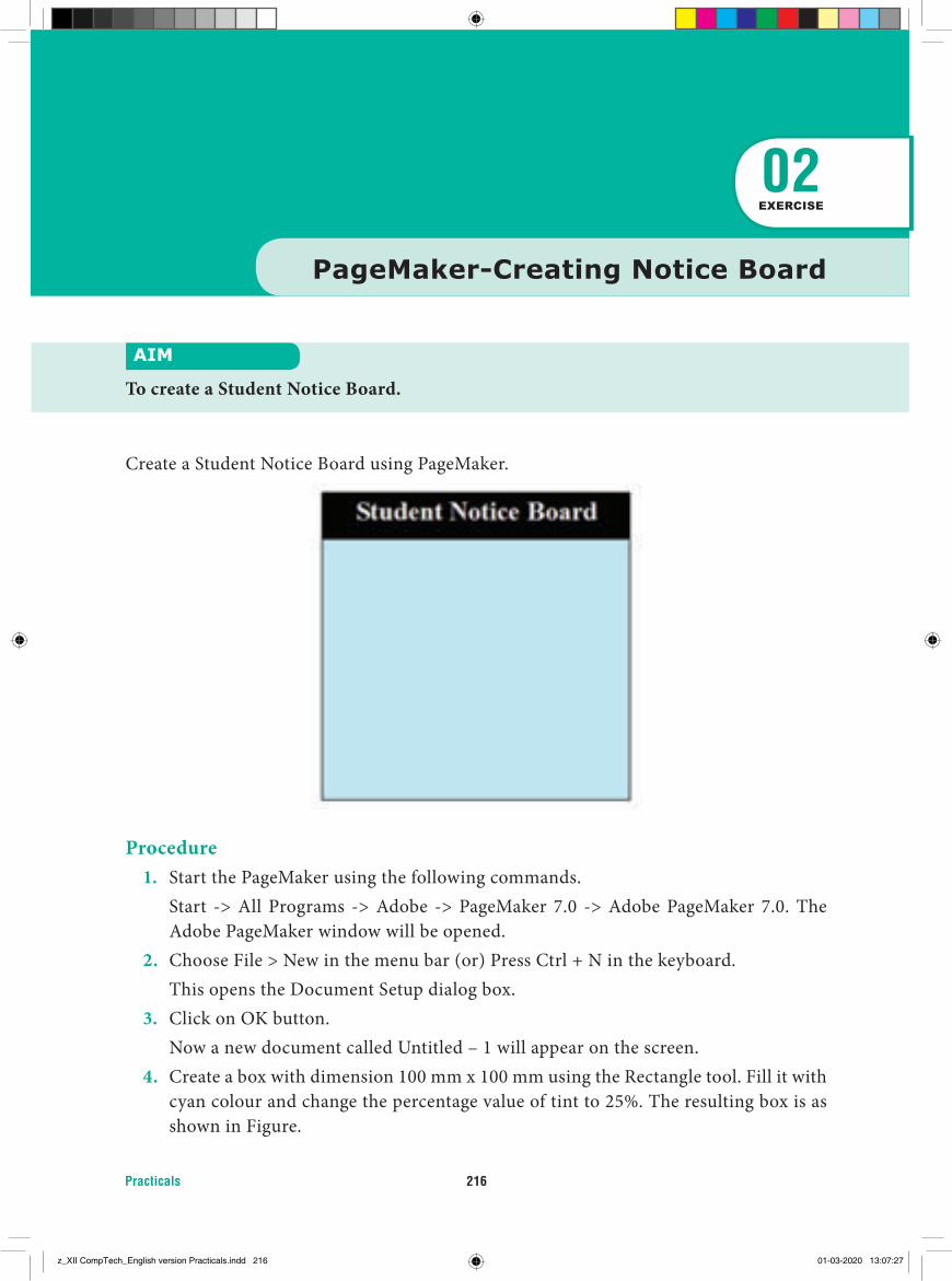
Practicals 216
Procedure1. Start the PageMaker using the following commands. Start -> All Programs -> Adobe -> PageMaker 7.0 -> Adobe PageMaker 7.0. The
Adobe PageMaker window will be opened.2. Choose File > New in the menu bar (or) Press Ctrl + N in the keyboard. This opens the Document Setup dialog box.3. Click on OK button. Now a new document called Untitled – 1 will appear on the screen.4. Create a box with dimension 100 mm x 100 mm using the Rectangle tool. Fill it with
cyan colour and change the percentage value of tint to 25%. The resulting box is as shown in Figure.
PageMaker-Creating Notice Board
AIM
To create a Student Notice Board.
02EXERCISE
Create a Student Notice Board using PageMaker.
z_XII CompTech_English version Practicals.indd 216 01-03-2020 13:07:27
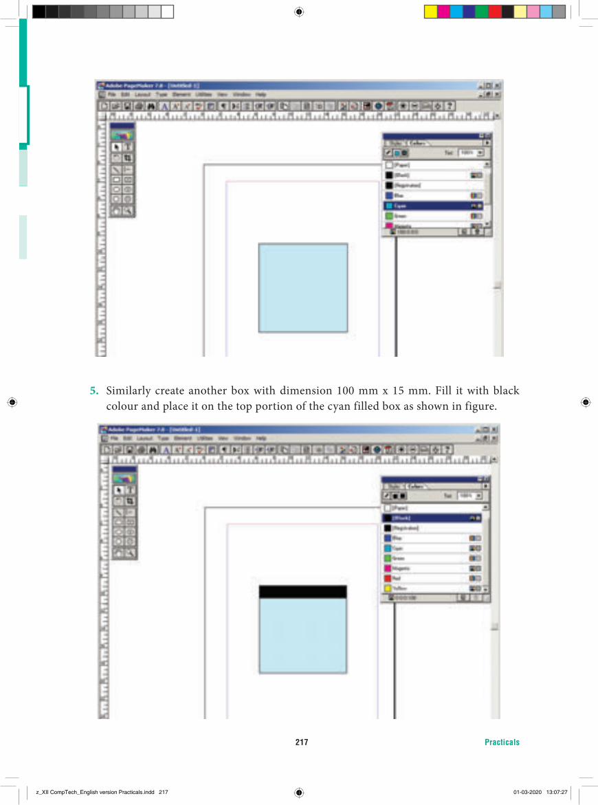
Practicals217
5. Similarly create another box with dimension 100 mm x 15 mm. Fill it with black colour and place it on the top portion of the cyan filled box as shown in figure.
z_XII CompTech_English version Practicals.indd 217 01-03-2020 13:07:27
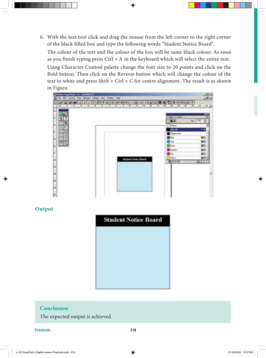
Practicals 218
6. With the text tool click and drag the mouse from the left corner to the right corner of the black filled box and type the following words “Student Notice Board”.
The colour of the text and the colour of the box will be same black colour. As soon as you finish typing press Ctrl + A in the keyboard which will select the entire text.
Using Character Control palette change the font size to 20 points and click on the Bold button. Then click on the Reverse button which will change the colour of the text to white and press Shift + Ctrl + C for centre alignment. The result is as shown in Figure.
Output
ConclusionThe expected output is achieved.
z_XII CompTech_English version Practicals.indd 218 01-03-2020 13:07:28
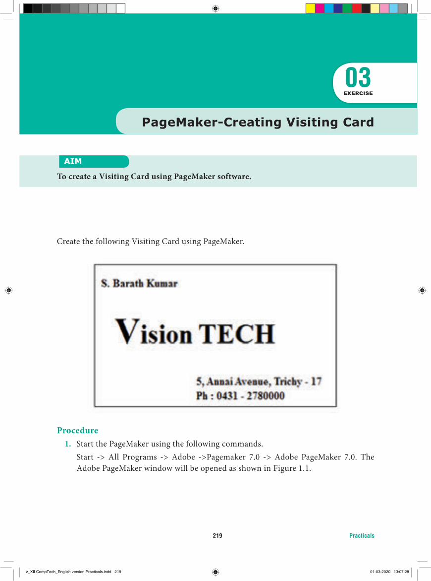
Practicals219
Create the following Visiting Card using PageMaker.
Procedure1. Start the PageMaker using the following commands. Start -> All Programs -> Adobe ->Pagemaker 7.0 -> Adobe PageMaker 7.0. The
Adobe PageMaker window will be opened as shown in Figure 1.1.
PageMaker-Creating Visiting Card
AIM
To create a Visiting Card using PageMaker software.
03EXERCISE
z_XII CompTech_English version Practicals.indd 219 01-03-2020 13:07:28
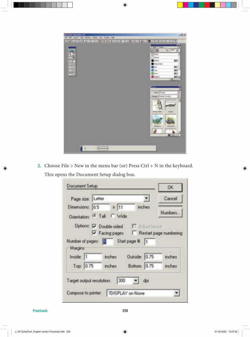
Practicals 220
2. Choose File > New in the menu bar (or) Press Ctrl + N in the keyboard.
This opens the Document Setup dialog box.
z_XII CompTech_English version Practicals.indd 220 01-03-2020 13:07:28
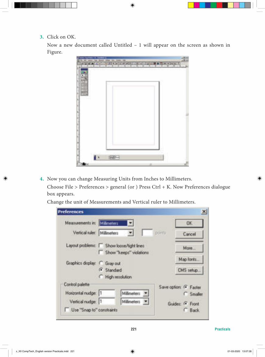
Practicals221
3. Click on OK. Now a new document called Untitled – 1 will appear on the screen as shown in
Figure.
4. Now you can change Measuring Units from Inches to Millimeters. Choose File > Preferences > general (or ) Press Ctrl + K. Now Preferences dialogue
box appears. Change the unit of Measurements and Vertical ruler to Millimeters.
z_XII CompTech_English version Practicals.indd 221 01-03-2020 13:07:28
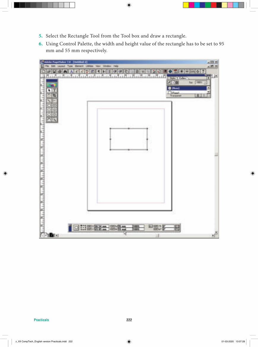
Practicals 222
5. Select the Rectangle Tool from the Tool box and draw a rectangle.6. Using Control Palette, the width and height value of the rectangle has to be set to 95
mm and 55 mm respectively.
z_XII CompTech_English version Practicals.indd 222 01-03-2020 13:07:28
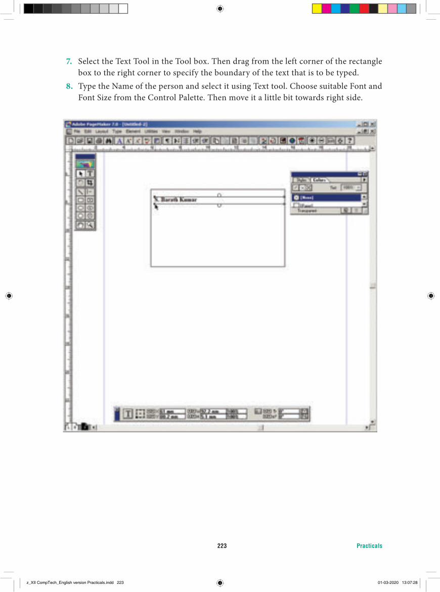
Practicals223
7. Select the Text Tool in the Tool box. Then drag from the left corner of the rectangle box to the right corner to specify the boundary of the text that is to be typed.
8. Type the Name of the person and select it using Text tool. Choose suitable Font and Font Size from the Control Palette. Then move it a little bit towards right side.
z_XII CompTech_English version Practicals.indd 223 01-03-2020 13:07:28
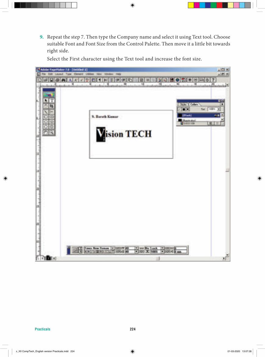
Practicals 224
9. Repeat the step 7. Then type the Company name and select it using Text tool. Choose suitable Font and Font Size from the Control Palette. Then move it a little bit towards right side.
Select the First character using the Text tool and increase the font size.
z_XII CompTech_English version Practicals.indd 224 01-03-2020 13:07:28
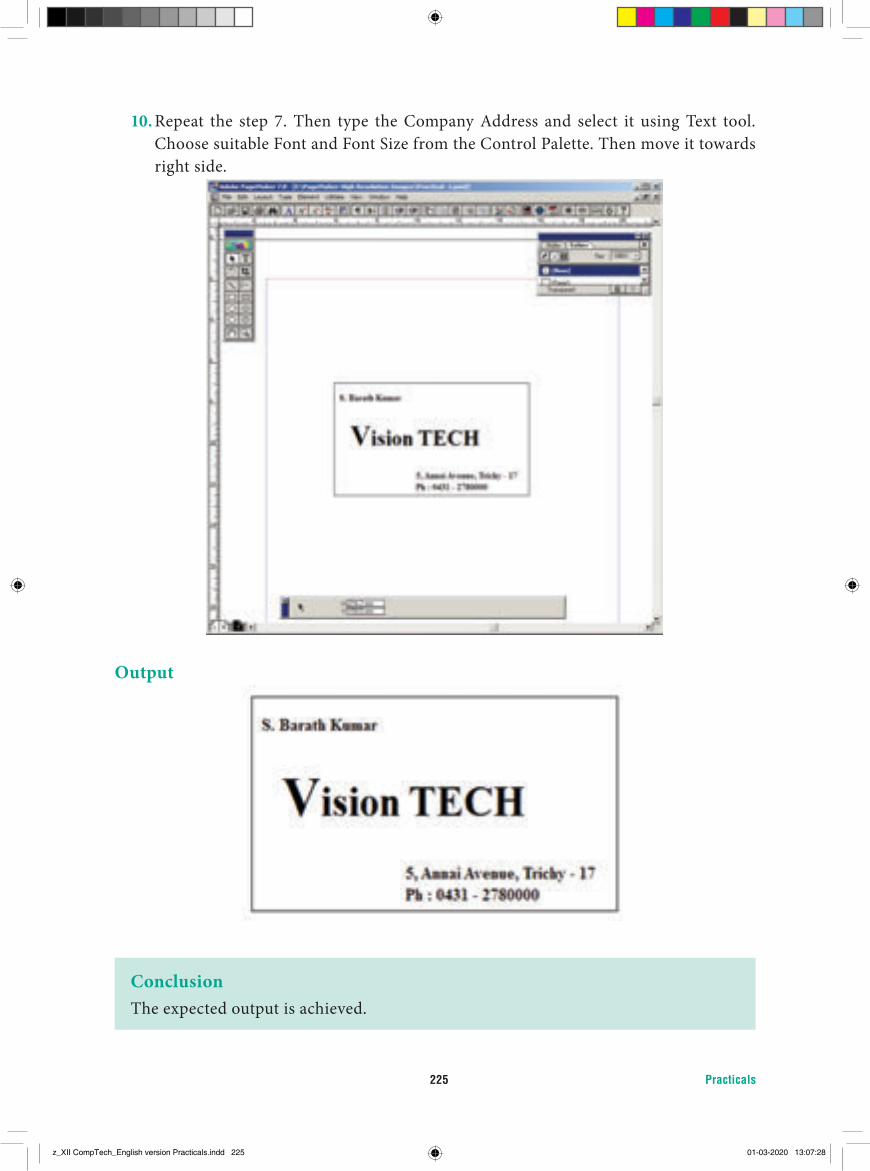
Practicals225
10. Repeat the step 7. Then type the Company Address and select it using Text tool. Choose suitable Font and Font Size from the Control Palette. Then move it towards right side.
Output
ConclusionThe expected output is achieved.
z_XII CompTech_English version Practicals.indd 225 01-03-2020 13:07:28
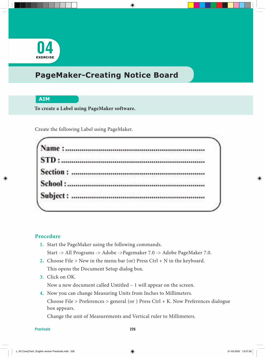
Practicals 226
Procedure1. Start the PageMaker using the following commands. Start -> All Programs -> Adobe ->Pagemaker 7.0 -> Adobe PageMaker 7.0.2. Choose File > New in the menu bar (or) Press Ctrl + N in the keyboard. This opens the Document Setup dialog box.3. Click on OK. Now a new document called Untitled – 1 will appear on the screen.4. Now you can change Measuring Units from Inches to Millimeters. Choose File > Preferences > general (or ) Press Ctrl + K. Now Preferences dialogue
box appears. Change the unit of Measurements and Vertical ruler to Millimeters.
PageMaker-Creating Notice Board
AIM
To create a Label using PageMaker software.
04EXERCISE
Create the following Label using PageMaker.
z_XII CompTech_English version Practicals.indd 226 01-03-2020 13:07:28
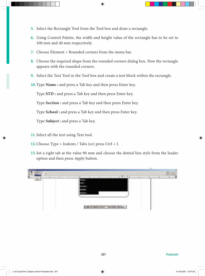
Practicals227
5. Select the Rectangle Tool from the Tool box and draw a rectangle.
6. Using Control Palette, the width and height value of the rectangle has to be set to 100 mm and 40 mm respectively.
7. Choose Element > Rounded corners from the menu bar.
8. Choose the required shape from the rounded corners dialog box. Now the rectangle appears with the rounded corners.
9. Select the Text Tool in the Tool box and create a text block within the rectangle.
10. Type Name : and press a Tab key and then press Enter key.
Type STD : and press a Tab key and then press Enter key.
Type Section : and press a Tab key and then press Enter key.
Type School : and press a Tab key and then press Enter key.
Type Subject : and press a Tab key.
11. Select all the text using Text tool.
12. Choose Type > Indents / Tabs (or) press Ctrl + I.
13. Set a right tab at the value 90 mm and choose the dotted line style from the leader option and then press Apply button.
z_XII CompTech_English version Practicals.indd 227 01-03-2020 13:07:28
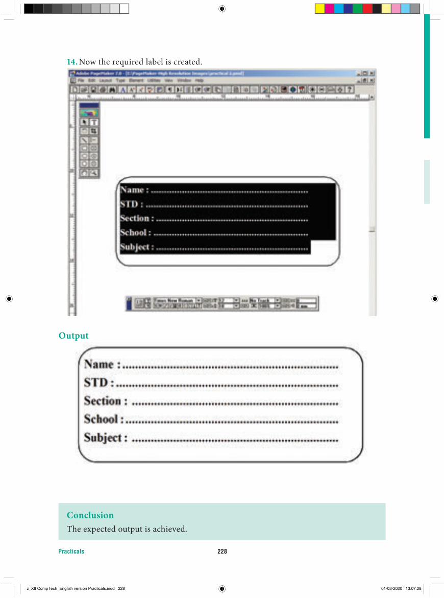
Practicals 228
14. Now the required label is created.
Output
ConclusionThe expected output is achieved.
z_XII CompTech_English version Practicals.indd 228 01-03-2020 13:07:28
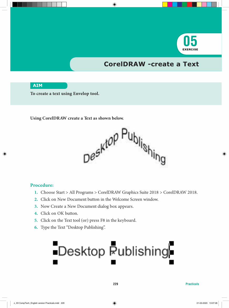
Practicals229
Using CorelDRAW create a Text as shown below.
Procedure:1. Choose Start > All Programs > CorelDRAW Graphics Suite 2018 > CorelDRAW 2018.2. Click on New Document button in the Welcome Screen window.3. Now Create a New Document dialog box appears.4. Click on OK button.5. Click on the Text tool (or) press F8 in the keyboard.6. Type the Text “Desktop Publishing”.
AIM
To create a text using Envelop tool.
05EXERCISE
CorelDRAW -create a Text
z_XII CompTech_English version Practicals.indd 229 01-03-2020 13:07:28
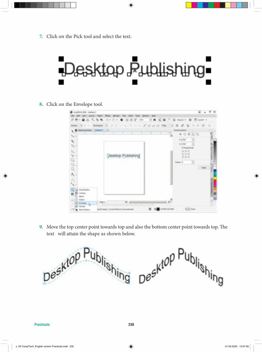
Practicals 230
7. Click on the Pick tool and select the text.
8. Click on the Envelope tool.
9. Move the top center point towards top and also the bottom center point towards top. The text will attain the shape as shown below.
z_XII CompTech_English version Practicals.indd 230 01-03-2020 13:07:28
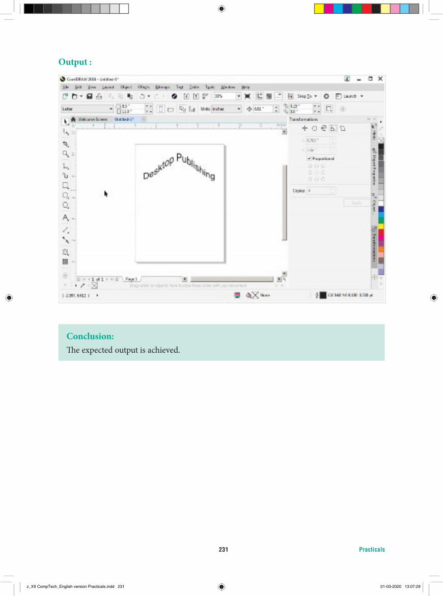
Practicals231
Output :
Conclusion:The expected output is achieved.
z_XII CompTech_English version Practicals.indd 231 01-03-2020 13:07:29
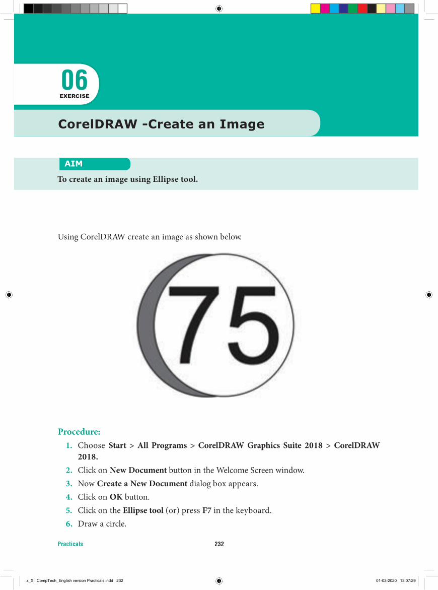
Practicals 232
CorelDRAW -Create an Image
AIM
To create an image using Ellipse tool.
06EXERCISE
Using CorelDRAW create an image as shown below.
Procedure:1. Choose Start > All Programs > CorelDRAW Graphics Suite 2018 > CorelDRAW
2018.2. Click on New Document button in the Welcome Screen window.3. Now Create a New Document dialog box appears.4. Click on OK button.5. Click on the Ellipse tool (or) press F7 in the keyboard.6. Draw a circle.
z_XII CompTech_English version Practicals.indd 232 01-03-2020 13:07:29
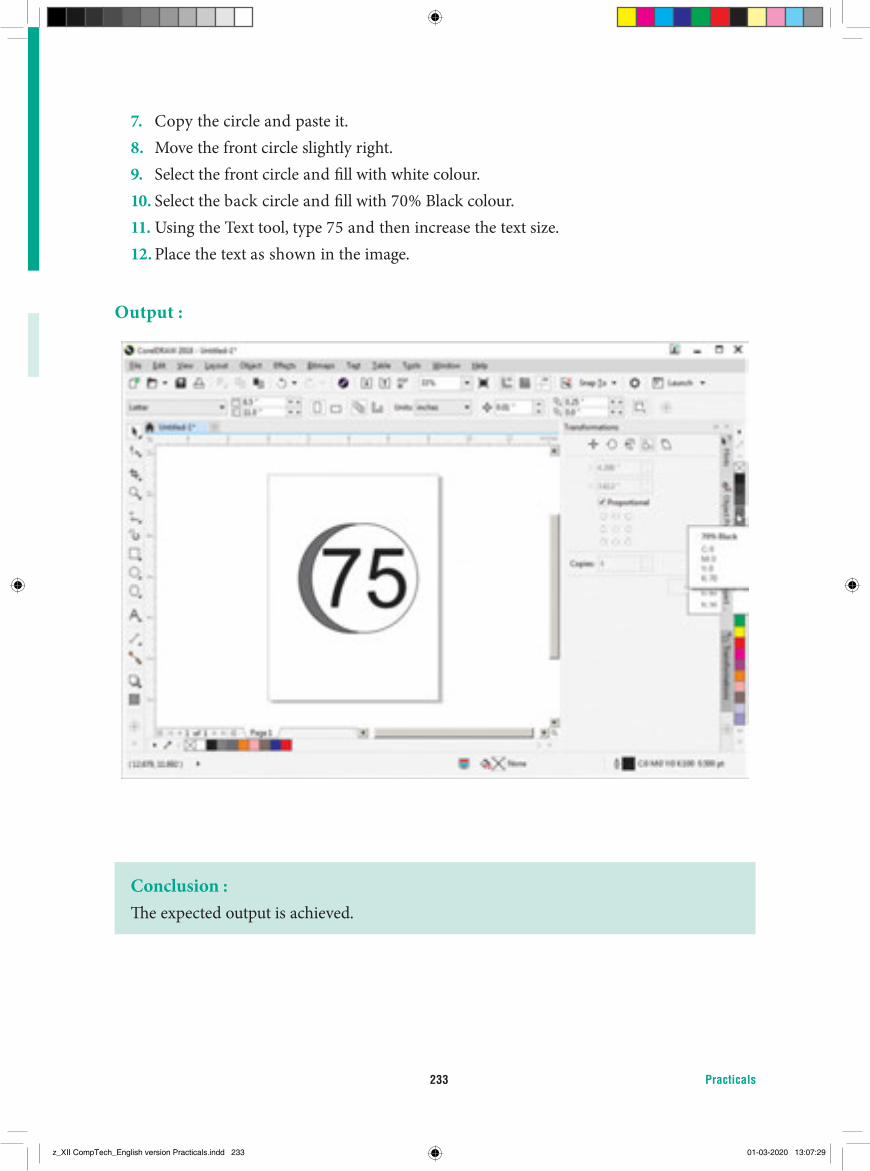
Practicals233
7. Copy the circle and paste it.8. Move the front circle slightly right.9. Select the front circle and fill with white colour.10. Select the back circle and fill with 70% Black colour.11. Using the Text tool, type 75 and then increase the text size.12. Place the text as shown in the image.
Output :
Conclusion :The expected output is achieved.
z_XII CompTech_English version Practicals.indd 233 01-03-2020 13:07:29
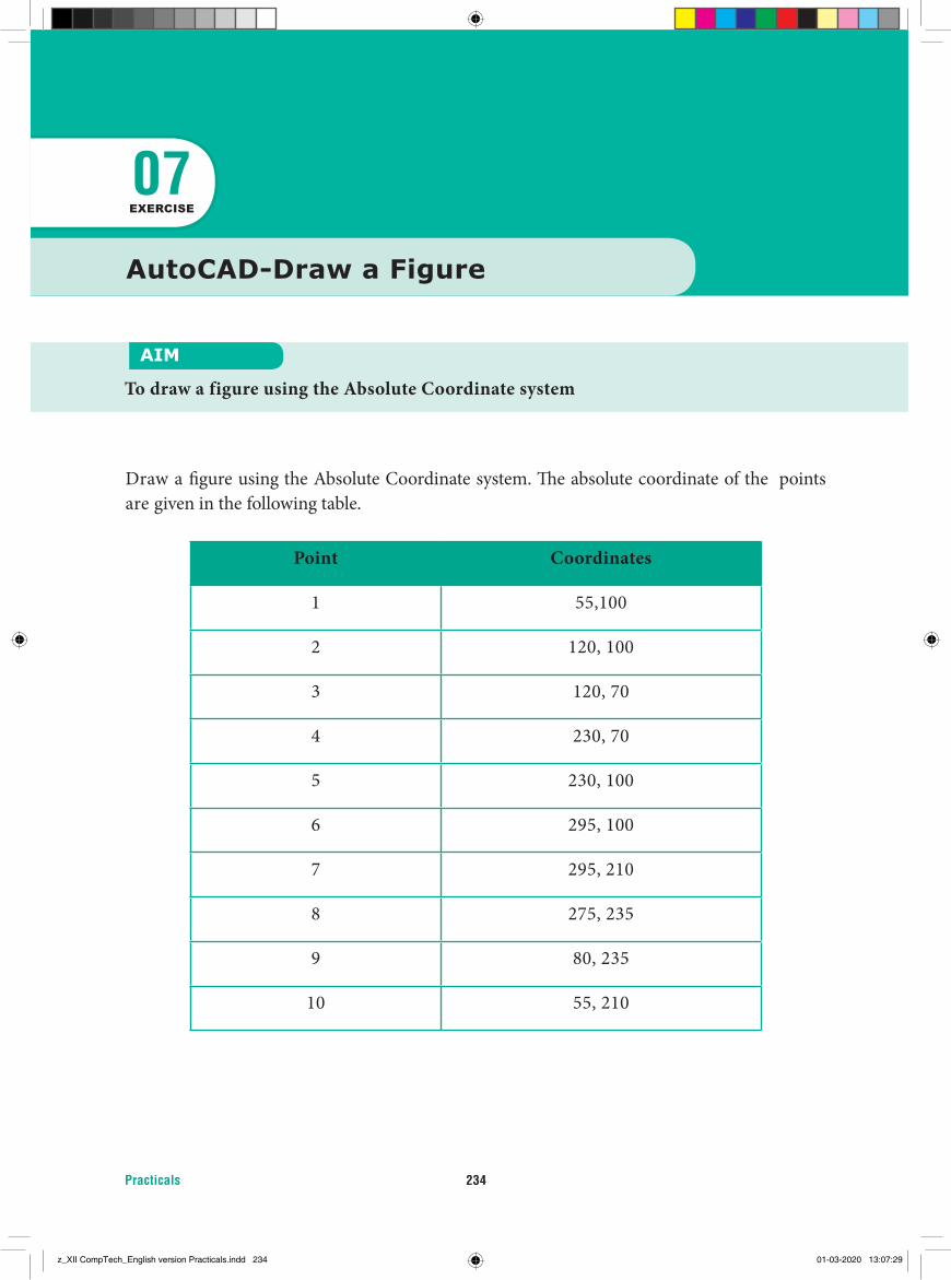
Practicals 234
AutoCAD-Draw a Figure
AIM
To draw a figure using the Absolute Coordinate system
07EXERCISE
Draw a fi gure using the Absolute Coordinate system. Th e absolute coordinate of the points are given in the following table.
Point Coordinates
1 55,100
2 120, 100
3 120, 70
4 230, 70
5 230, 100
6 295, 100
7 295, 210
8 275, 235
9 80, 235
10 55, 210
z_XII CompTech_English version Practicals.indd 234 01-03-2020 13:07:29
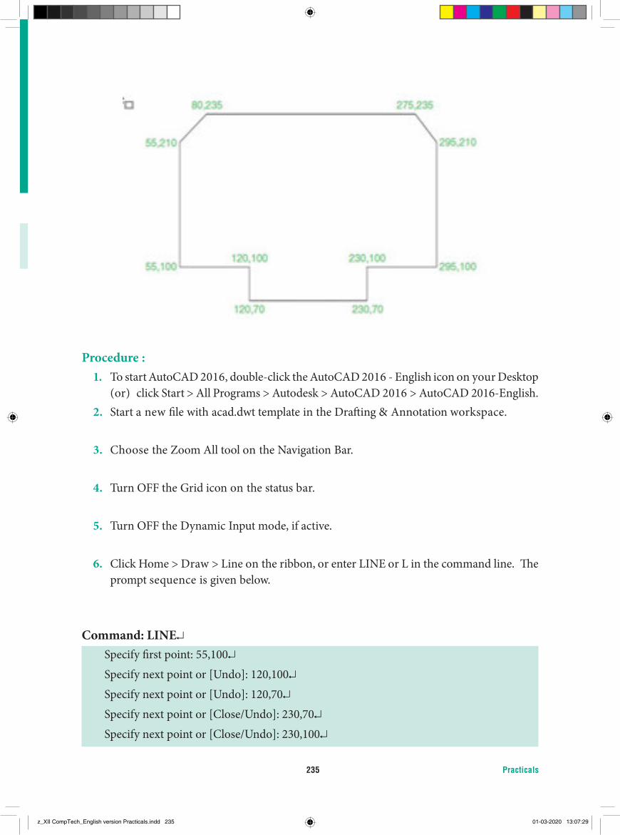
Practicals235
Procedure :1. To start AutoCAD 2016, double-click the AutoCAD 2016 - English icon on your Desktop
(or) click Start > All Programs > Autodesk > AutoCAD 2016 > AutoCAD 2016-English.2. Start a new file with acad.dwt template in the Drafting & Annotation workspace.
3. Choose the Zoom All tool on the Navigation Bar.
4. Turn OFF the Grid icon on the status bar.
5. Turn OFF the Dynamic Input mode, if active.
6. Click Home > Draw > Line on the ribbon, or enter LINE or L in the command line. The prompt sequence is given below.
Command: LINE↵Specify first point: 55,100↵Specify next point or [Undo]: 120,100↵Specify next point or [Undo]: 120,70↵Specify next point or [Close/Undo]: 230,70↵Specify next point or [Close/Undo]: 230,100↵
z_XII CompTech_English version Practicals.indd 235 01-03-2020 13:07:29
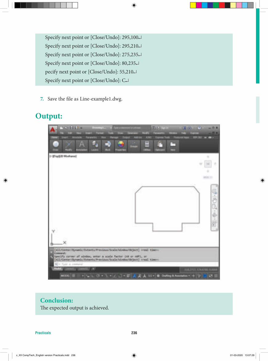
Practicals 236
Specify next point or [Close/Undo]: 295,100↵Specify next point or [Close/Undo]: 295,210↵Specify next point or [Close/Undo]: 275,235↵Specify next point or [Close/Undo]: 80,235↵pecify next point or [Close/Undo]: 55,210↵Specify next point or [Close/Undo]: C↵
7. Save the fi le as Line-example1.dwg.
Output:
Conclusion:Th e expected output is achieved.
z_XII CompTech_English version Practicals.indd 236 01-03-2020 13:07:29

Practicals237
Draw a fi gure using Relative Rectangular Coordinates. Th e coordinates of the points are given in the table below.
Point Coordinates
1 100,100
2 @50,0
3 @0,20
4 @100,0
5 @0,-20
6 @50,0
7 @0, 120
8 @-50,0
9 @0,-20
10 @-100,0
11 @0,20
12 @-50,0
AIM
To draw a fi gure using the Relative Rectangular Coordinates
08EXERCISE
AutoCAD-Draw a fi gure using Relative Rectangular Coordinates
z_XII CompTech_English version Practicals.indd 237 01-03-2020 13:07:29
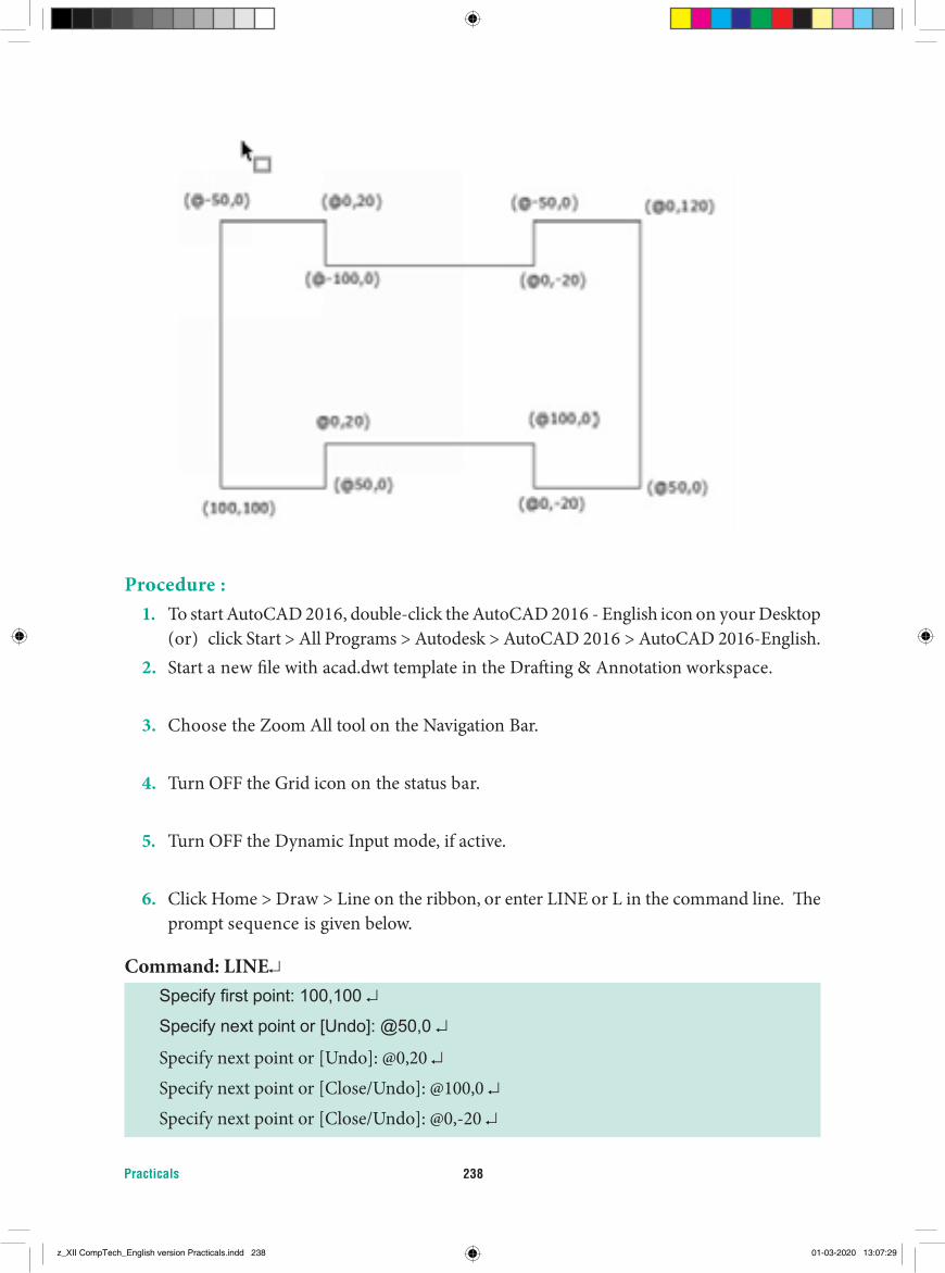
Practicals 238
Procedure :1. To start AutoCAD 2016, double-click the AutoCAD 2016 - English icon on your Desktop
(or) click Start > All Programs > Autodesk > AutoCAD 2016 > AutoCAD 2016-English.2. Start a new file with acad.dwt template in the Drafting & Annotation workspace.
3. Choose the Zoom All tool on the Navigation Bar.
4. Turn OFF the Grid icon on the status bar.
5. Turn OFF the Dynamic Input mode, if active.
6. Click Home > Draw > Line on the ribbon, or enter LINE or L in the command line. The prompt sequence is given below.
Command: LINE↵Specify first point: 100,100 ↵
Specify next point or [Undo]: @50,0 ↵
Specify next point or [Undo]: @0,20 ↵Specify next point or [Close/Undo]: @100,0 ↵Specify next point or [Close/Undo]: @0,-20 ↵
z_XII CompTech_English version Practicals.indd 238 01-03-2020 13:07:29
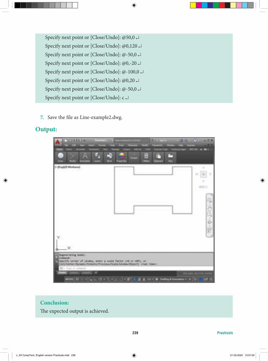
Practicals239
Specify next point or [Close/Undo]: @50,0 ↵Specify next point or [Close/Undo]: @0,120 ↵Specify next point or [Close/Undo]: @-50,0 ↵Specify next point or [Close/Undo]: @0,-20 ↵Specify next point or [Close/Undo]: @-100,0 ↵Specify next point or [Close/Undo]: @0,20 ↵Specify next point or [Close/Undo]: @-50,0 ↵Specify next point or [Close/Undo]: c ↵
7. Save the fi le as Line-example2.dwg.
Output:
Conclusion:Th e expected output is achieved.
z_XII CompTech_English version Practicals.indd 239 01-03-2020 13:07:29
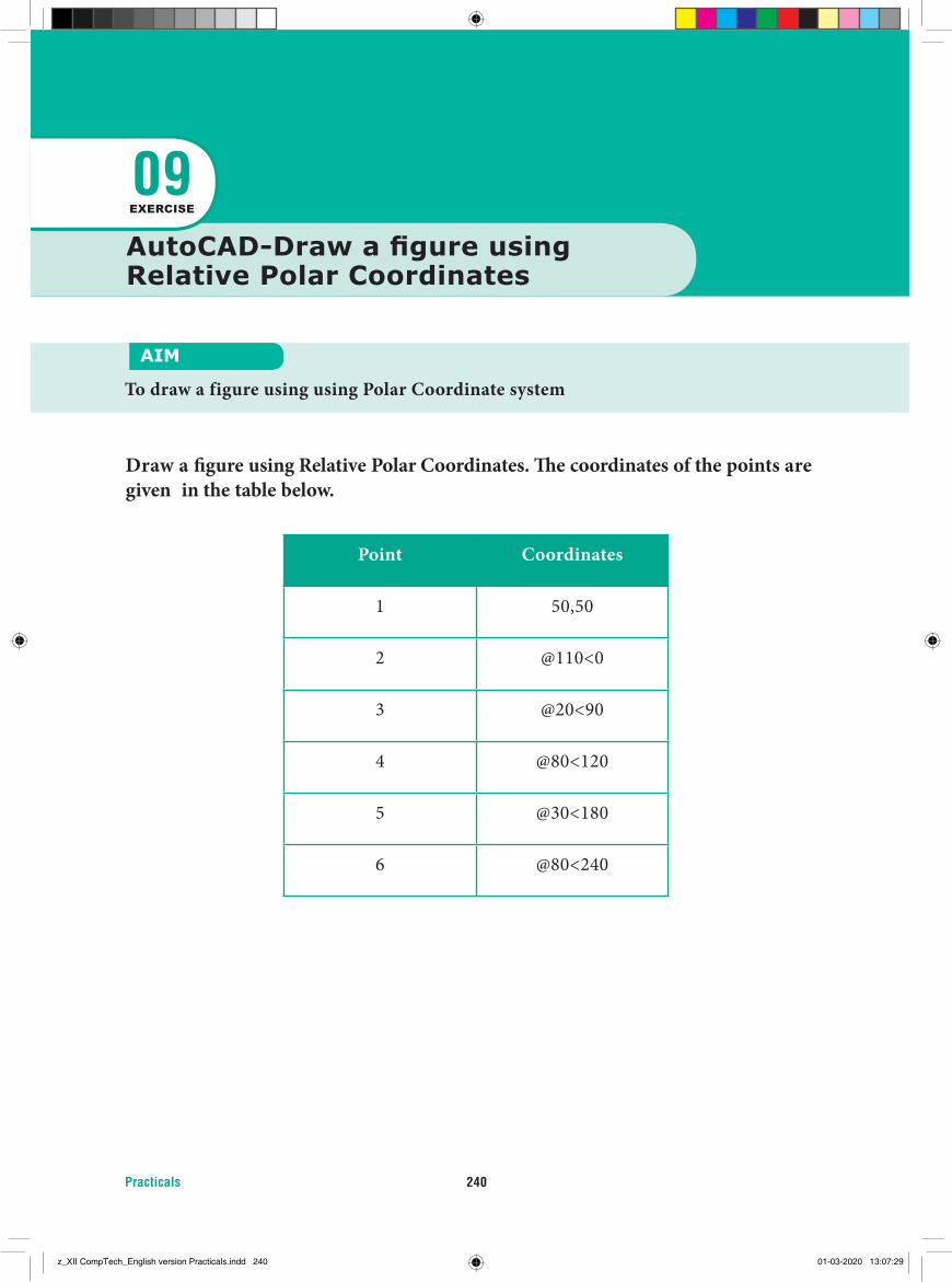
Practicals 240
Draw a fi gure using Relative Polar Coordinates. Th e coordinates of the points are given in the table below.
Point Coordinates
1 50,50
2 @110<0
3 @20<90
4 @80<120
5 @30<180
6 @80<240
AutoCAD-Draw a fi gure using Relative Polar Coordinates
AIM
To draw a figure using using Polar Coordinate system
09EXERCISE
z_XII CompTech_English version Practicals.indd 240 01-03-2020 13:07:29
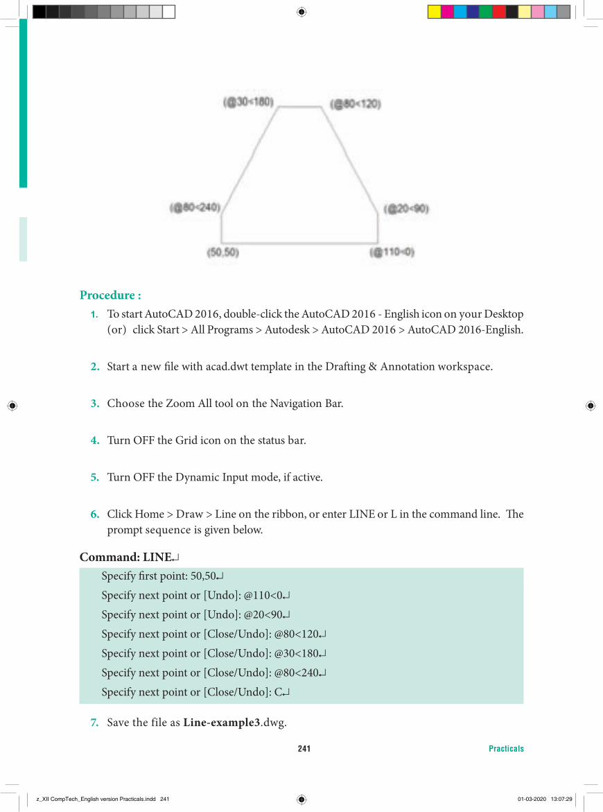
Practicals241
Procedure :1. To start AutoCAD 2016, double-click the AutoCAD 2016 - English icon on your Desktop
(or) click Start > All Programs > Autodesk > AutoCAD 2016 > AutoCAD 2016-English.
2. Start a new fi le with acad.dwt template in the Draft ing & Annotation workspace.
3. Choose the Zoom All tool on the Navigation Bar.
4. Turn OFF the Grid icon on the status bar.
5. Turn OFF the Dynamic Input mode, if active.
6. Click Home > Draw > Line on the ribbon, or enter LINE or L in the command line. Th e prompt sequence is given below.
Command: LINE↵Specify fi rst point: 50,50↵Specify next point or [Undo]: @110<0↵Specify next point or [Undo]: @20<90↵Specify next point or [Close/Undo]: @80<120↵Specify next point or [Close/Undo]: @30<180↵Specify next point or [Close/Undo]: @80<240↵Specify next point or [Close/Undo]: C↵
7. Save the file as Line-example3.dwg.
z_XII CompTech_English version Practicals.indd 241 01-03-2020 13:07:29
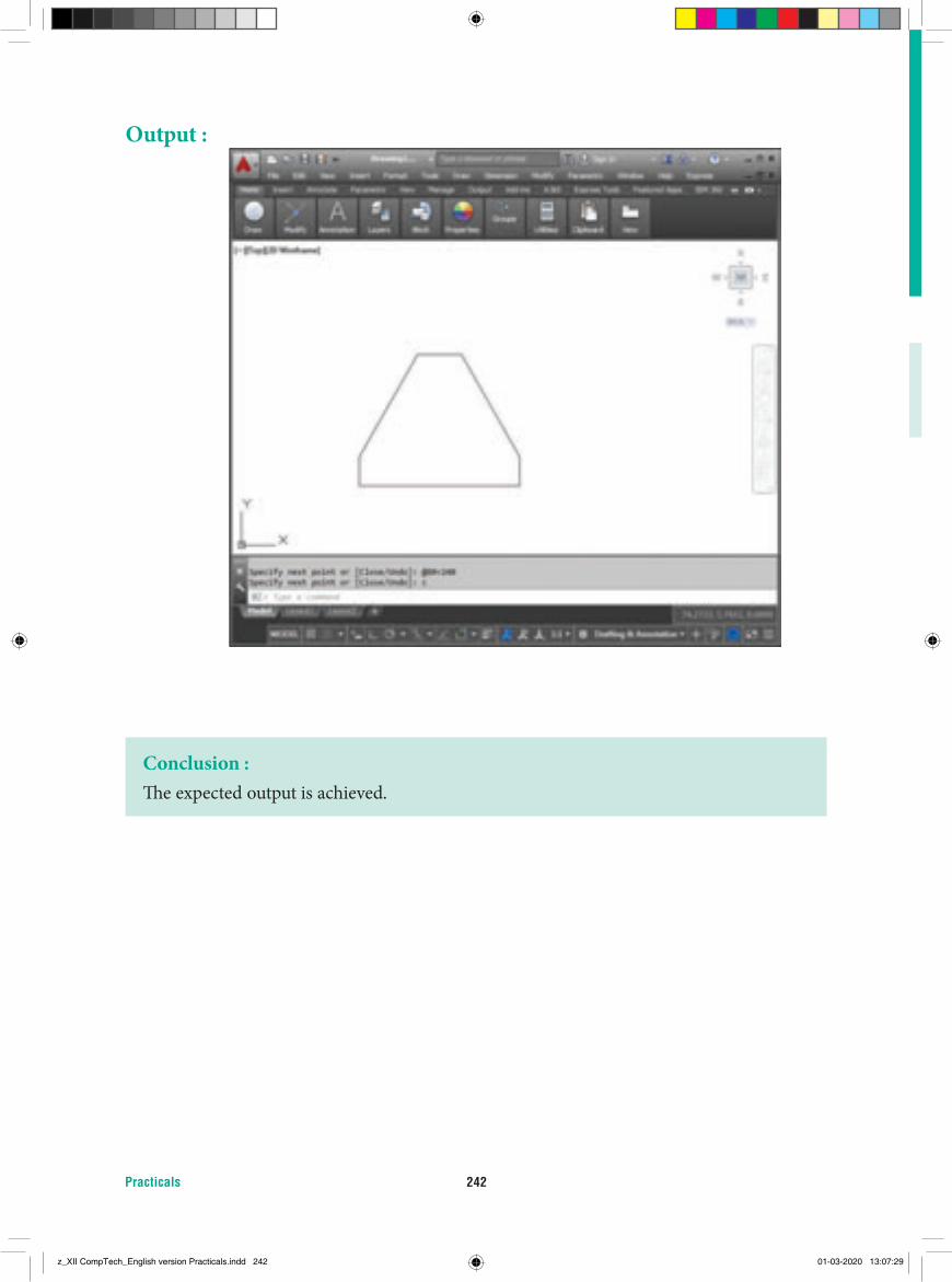
Practicals 242
Output :
Conclusion :Th e expected output is achieved.
z_XII CompTech_English version Practicals.indd 242 01-03-2020 13:07:29
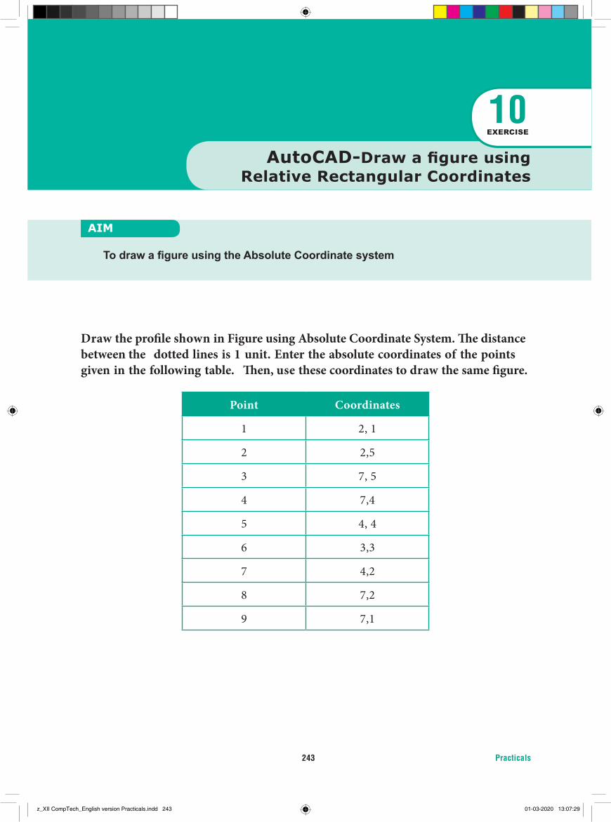
Practicals243
Draw the profi le shown in Figure using Absolute Coordinate System. Th e distance between the dotted lines is 1 unit. Enter the absolute coordinates of the points given in the following table. Th en, use these coordinates to draw the same fi gure.
Point Coordinates
1 2, 1
2 2,5
3 7, 5
4 7,4
5 4, 4
6 3,3
7 4,2
8 7,2
9 7,1
AIM
To draw a fi gure using the Absolute Coordinate system
10EXERCISE
AutoCAD-Draw a fi gure using Relative Rectangular Coordinates
z_XII CompTech_English version Practicals.indd 243 01-03-2020 13:07:29
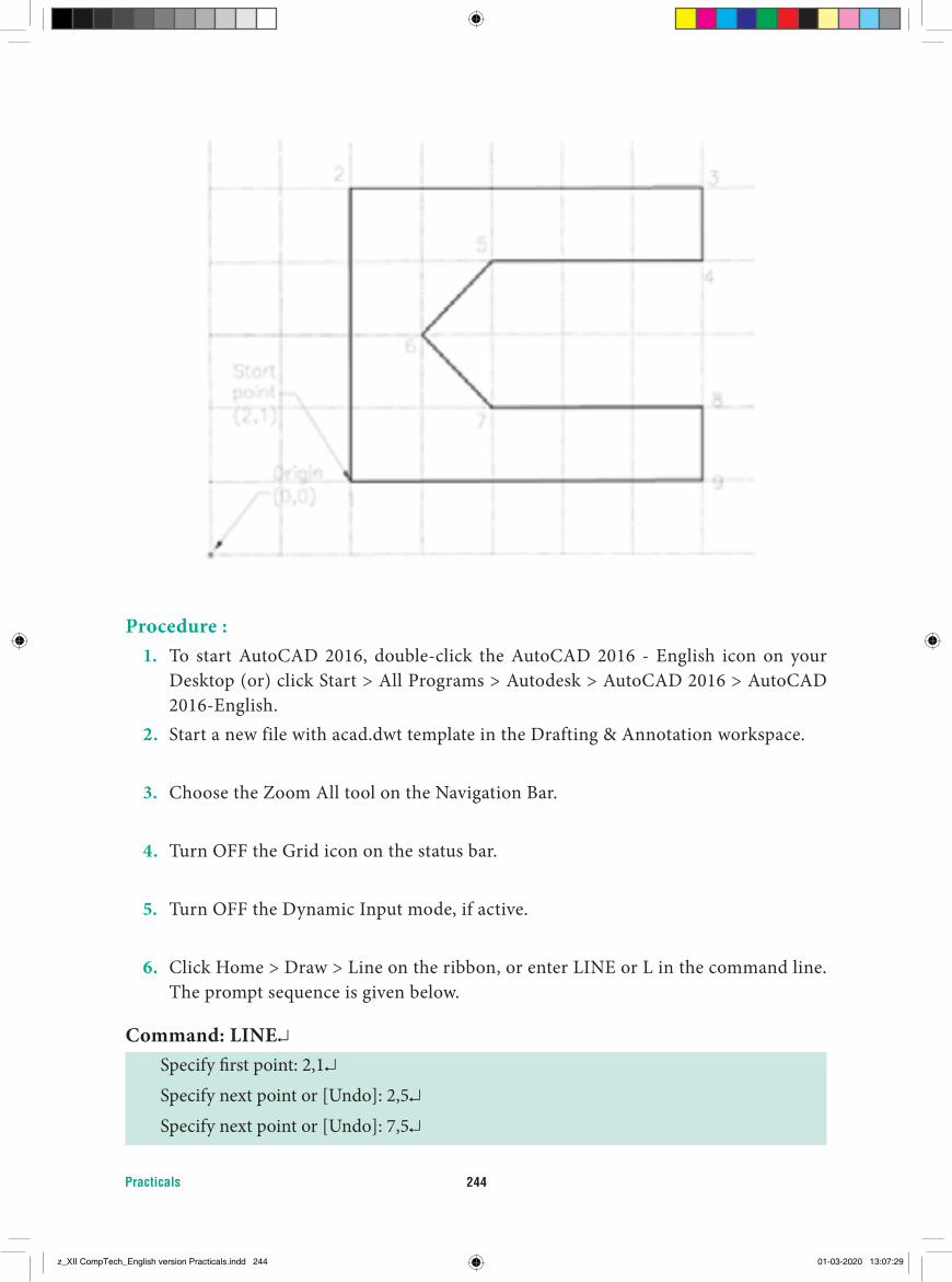
Practicals 244
Procedure :1. To start AutoCAD 2016, double-click the AutoCAD 2016 - English icon on your
Desktop (or) click Start > All Programs > Autodesk > AutoCAD 2016 > AutoCAD 2016-English.
2. Start a new file with acad.dwt template in the Drafting & Annotation workspace.
3. Choose the Zoom All tool on the Navigation Bar.
4. Turn OFF the Grid icon on the status bar.
5. Turn OFF the Dynamic Input mode, if active. 6. Click Home > Draw > Line on the ribbon, or enter LINE or L in the command line.
The prompt sequence is given below.
Command: LINE↵Specify first point: 2,1↵Specify next point or [Undo]: 2,5↵Specify next point or [Undo]: 7,5↵
z_XII CompTech_English version Practicals.indd 244 01-03-2020 13:07:29
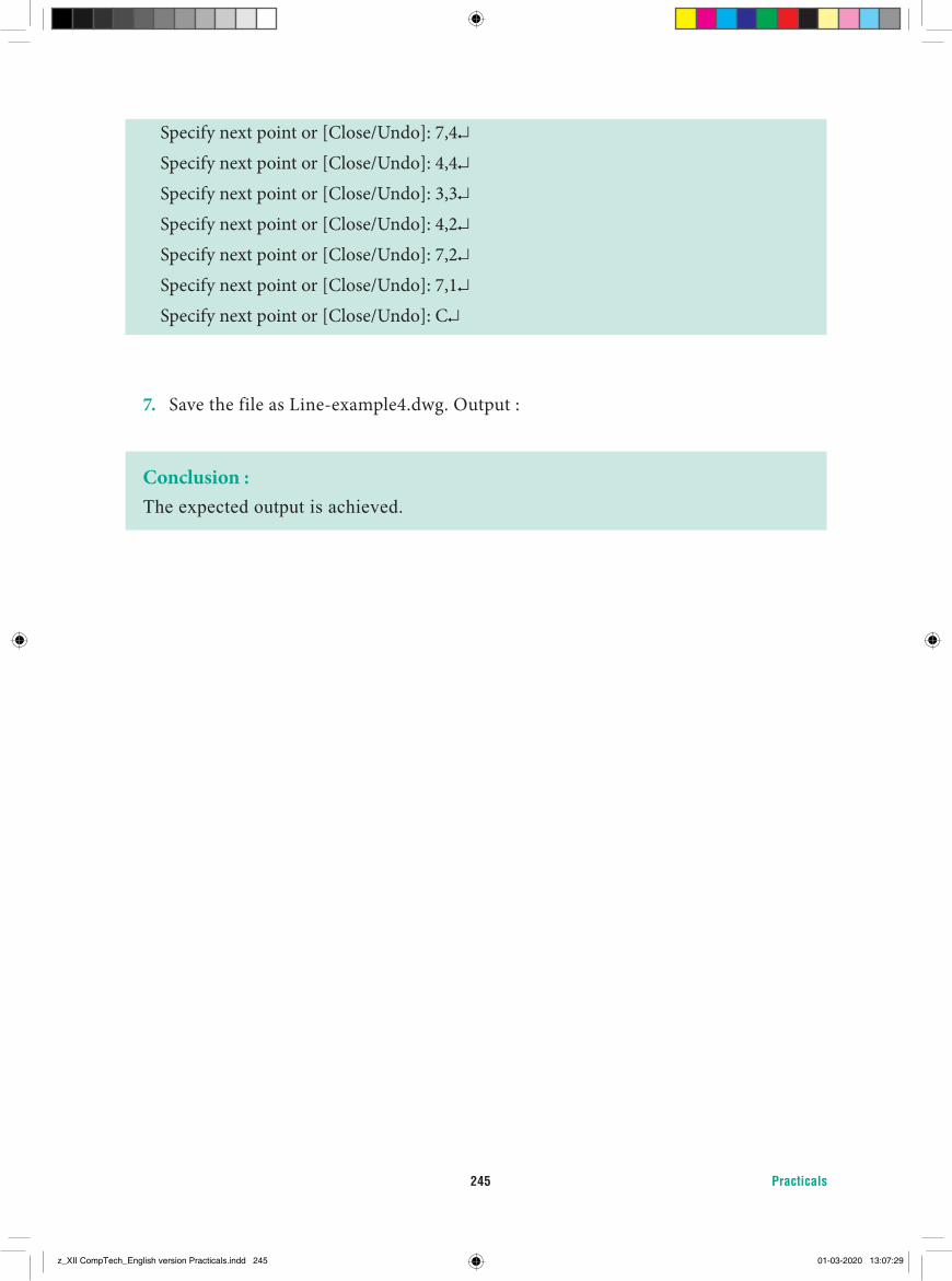
Practicals245
Specify next point or [Close/Undo]: 7,4↵Specify next point or [Close/Undo]: 4,4↵Specify next point or [Close/Undo]: 3,3↵Specify next point or [Close/Undo]: 4,2↵Specify next point or [Close/Undo]: 7,2↵Specify next point or [Close/Undo]: 7,1↵Specify next point or [Close/Undo]: C↵
7. Save the file as Line-example4.dwg. Output :
Conclusion :The expected output is achieved.
z_XII CompTech_English version Practicals.indd 245 01-03-2020 13:07:29

Higher Secondary Class XII Computer Technology - Theory & Practicals
List of Authors and Reviewers
Domain Experts Mrs. Sasikala Associate Professor Queen Mary’s CollegeChennai.
Mr. AmuthanProfessor & Associate Dean (Automomy & Accreditation),Dept. of Computer Science & Engineering,Pondicherry Engineering College, Pillaichavady, Pudhucherry.
ReviewerMr. M. MuraliTechnology Consultant,Cognizant Technology,Thuraippakam,Chennai.
This book has been printed on 80 G.S.M. Elegant Maplitho paper.
Printed by offset at:
Academic Co-ordinatorU. AarthiB.T.Assistant,Govt. Girls Higher Secondary School,Madurantagam, Kanchipuram
Adviser & Expert Dr. P. Kumar Joint Director (Syllabus),State Council of Education Research and Training Tamilnadu,Chennai 600 006,
Content WritersMr M. Sivakumar PGT, GHSS Sirugambur, Trichy.
Mrs T. Murugambal PGT, GHSS Somarasanpettai, Trichy.
Mrs. Balapriya HOD, ICAT Design & Multimedia College, Mylapore, Chennai.
Mrs. Alagappan Head of Academics ICAT Design & Multimedia College, Mylapore, Chennai
Dr.(Mrs) H Vidhya PGT D.A.V.Boys Senior Secondary School. Gopalapuram,Chennai
Art and Design Team
Layout Designing and IllustrationArokiam FelixBlackBird Designs & PrintsChennai.
Wrapper DesignKathir Arumugam
QCRajesh ThangappanManohar Radhakrishnan Arun Kamaraj
CoordinationRamesh Munisamy
QR Code Management Team
J.F. Paul Edwin Roy B.T. Asst., PUMS Rakkipatti, Veerapandi, Salem.
A. Devi Jesintha B.T. Asst., Government High School, N.M. Kovil, Vellore.
M. Saravanan B.T. Asst., Government Girls Higher Secondary School, Puthupalayam, Vazhapadi, Salem.
246
z_XII CompTech_English version Practicals.indd 246 01-03-2020 13:07:29

247
NOTES
z_XII CompTech_English version Practicals.indd 247 01-03-2020 13:07:29

NOTES
248
z_XII CompTech_English version Practicals.indd 248 01-03-2020 13:07:29

249
NOTES
z_XII CompTech_English version Practicals.indd 249 01-03-2020 13:07:29
NOTES
250
z_XII CompTech_English version Practicals.indd 250 01-03-2020 13:07:29