compendium print a4.cdr - iei
TRANSCRIPT

Mr S L Garg, FIEPresident, IEI
3R&D under Grant-in-aid Scheme
I am glad to learn that the R&D Committee of the Institution of Engineers (India) in an attempt to boost the interest of the students in Research and Development took the initiative for bringing out a compendium containing the outcome of the projects carried on by the students of various colleges under the sponsorship of The Institution of Engineers(India).
To encourage R&D activities is pertinent to and in sync with the priorities of a developing economy like ours which is aspiring to be a global force to reckon with in the days ahead. The Institution of Engineers(India), one of the largest multi-disciplinary professional body for the engineers have been serving to the nation for past 91 years. Keeping view of the importance of R&D activities, IEI initiated a drive to encourage students for Research activity in 2001.
I am happy that the effort that started in 2001 has resulted in a pool of project outcomes which are being collated and published for benefit of the engineering fraternity. I am looking forward to more such publications in future.

4 R&D under Grant-in-aid Scheme
Considering the importance of R&D in the development of the Nation for betterment of the mankind in general, The Institution of Engineers (India), during 2001, took the initiative to provide R&D grant to the students with the aim to inculcate within them the passion for R&D. With the above objective in view the stress was given on the UG students for R&D grant. What was started with a humble sum of Rs 5 lacs in 2001 is today stand at Rs 50 lac for supporting student projects from UG, PG, and Phd students.
I am extremely happy to bring to you the first ever compendium of the projects funded by the IEI. It is my great pleasure that a collection of the outcome of some the interesting projects are being documented and presented before you. I hope this will be extremely useful to the students who wish to pursue research. The outcome of various projects can also be utilized by the Industries and this will be enable to explore new talents from within this students.
I wish in future also such publications will be brought out by the Institution for benefit of the engineering community.
I am extremely happy to know that Research and Development Committee of The Institution of Engineers (India), is publishing a compendium on the projects completed by the students and funded by the IEI.
The Institution of Engineers (India) has been recognized as a Scientific & Industrial Research Organization by the Department of Scientific & Industrial Research , Ministry of Science & Technology , Govt. of India. Accordingly IEI has since 2001 stressed the need for R&D activities. As part of their program the IEI is sponsoring project proposals received from students pursuing UG, PG and PhD courses. Committee for Advancement of Technology and Engineering(CATE) being the apex body empowered by the Council for dissemination of knowledge through technical activities and also promoting the R&D activities proposed that a collection of the outcome of the projects completed by the students be published as a compendium.
It is a matter of great satisfaction and pleasure that RDC is publishing the compendium which will act as reference for the student intending to carry on research in future.
I wish similar compendium will now become a regular feature and every year a compendium containing the outcome of the completed project will be published.
Prof (Dr) N R Bandyopadhyay, FIE
Mr P Chaturvedi, FIE
President
Mr S L Garg, FIE
R&D Committee
Mr P Chaturvedi, FIE-Chairman
Prof (Dr) N R Bandyopadhyay, FIE
Dr R K Dave, FIE
Dr K P Tripathi, FIE
Mr J P Barnwal, FIE
Dr U Chandrasekhar, FIE
Editor
Maj Gen (Retd) R K Sanan, VSM, FIE
Associate Editor
Mr S Chakraverty, MIE
Special Contribution
Technical Department, IEI
Compilation & Layout
Mr S Bagchi, Ms S Ghosh
Cover Design
Mr T Biswas
The Institution of Engineers (India)
as a body accepts no responsibility
for statements made by individuals.
Reprints of any portion of the
publication may be made provided
that reference thereto be quoted
Publication Office
8 Gokhale Road, Kolkata 700 020
Ph : 2223-8311/14-16/33-34
Fax : (033) 2223-8345
email : [email protected]
web : http//www.ieindia.org
Publisher
Maj Gen (Retd) R K Sanan, VSM
for The Institution of Engineers (India)
8 Gokhale Road, Kolkata 700 020
Printer
M/s Albatross Graphic Solution Pvt. Ltd.,
512B, Ground Floor, Jodhpur Park, Kolkata 700 068
Compendium on R&D Projects under Grant-in-Aid Scheme
Title Page No.
Wind Cum Hydro Turbine Installation on a Single 7 Arrangement to Generate Electricity
Feasibility Study on Development of Rubber Band, Powered MAV 8for Indoor Flight Trials
Human Powered Vehicle-velomobile 9
Development of Biodiesel Production Technology using 10Ultrasonic Cavitation
Study on Seismic Retrofitting of Reinforced Concrete 11Beams with External Reinforcement
Automatic Over Speed Detector with Online Traffic 12 Crime Management System
Detection of Bone Cracks Using X Ray Images 13
Wireless Energy Meter Reading Transmitting System 14
Mobile Remote Controller for PC 15
Recovery of Acids(sulfuric/nitric Acid) from Industrial 16Waste Water
Wear Behavior and Coupled Field Analysis of ALSICP/Aluminium 17Metal Matrix Composites
A.U.R.A – Advanced Utility Robotic Arm 18
Process Design for Drying Areca Nuts by Solvent Extraction 19
Solar Powered Unmanned Aerial Vehicle ( SPUAV) for 20Disaster Management
Mini Thermal Power Plant 21
Low Cost 12-lead ECG Signal Acquisition, Display and Storage 22with Telemetric Capability
Solar Thermal Power Plant by using Solar Concentrator 23
Biosorption of Heavy Metals (Cadmium, Mercury, Nickel, 25Zinc and Chromium) using Sugar Beet Pulp
Evaluation of Surface Roughness by Optical Technique 26 using Ruby Laser Beam
Bio-sorption of Heavy Metals by Coconut Coir in a Bio-reactor 27
Differential Ventilation of Lungs 28
Robust Anticollusion Code for Multimedia Fingerprinting 29
All Terrain Autonomous Fire Fighting Robot 30
Development of Solar Water Heater using Heat Pipe & 31Vaccum Technology
Web GIS for Real Estate 32
Rear-lamp Vehicle Detection and Tracking in Night 33Conditions to Prevent Accidents
Cellular Radio Wave Propogation Modeling and Analysis using GIS 34
Blood Infusion Warmer Cum Needle Dislodgement Sensor 35
Convertible Tricopter for Defense and Surveillance Purpose 36
Design and Development of Complete Traffic Solution at Vehicular 37and Junction Levels using RFIDS
Jet Noise Reduction using Perforated Tabs 38
Preparation of Chitosan Fibre 39
Capacity Building in Design and Development of Ornithopter 40
Low Cost Synthesis of Silicon Nanocrystals for 41Efficiency Enhancement of Photovoltic Solar Cell
Green Robot 42
Volume 1, September 2012
Student Guide Institute
Maninderjit Singh Anu Singla, Chitkara Institute of Engineering Mohammad Aarit Associate Professor, and Technology, Jaskaran Singh Chawla Electrical Engg Dept, Chandigarh – Patiala National Kashish Gupta Chitkara Institute of Engineering Highway,Saurabh Kumar and Technology, Vill: Jhansla, Tehsil, Rajpura.Email: [email protected] Rajpura, Punjab Dist Patiala 140401
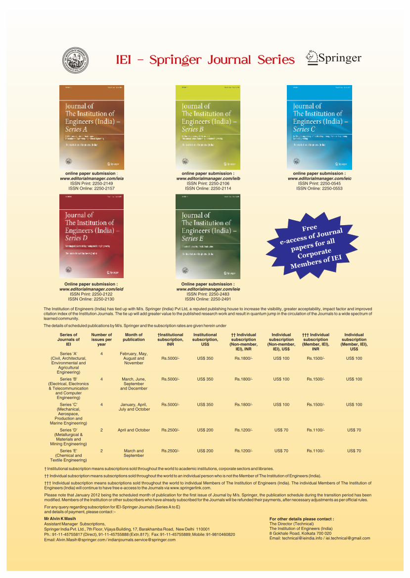
The use of renewable energy sources for producing electric power can be harnessed by using innovative technology. One such approach is the use of Dual Rotor generator for the production of electricity. It can be used in combining wind and hydro sources (to form a wind-hydro system), in which one rotor of the generator is rotated by the wind turbine and the other by the hydro turbine in opposite directions to produce a relatively higher output. The project presented here is based on combining these two energy resources in a single arrangement with a primary objective of simultaneously utilizing the energy of Wind and Water to produce electricity.
The project also aims at eliminating the problems which are associated with these two sources of electricity generation. For example, the project includes an in-stream hydro turbine which can be applied directly in a running stream of water and does not require a dam construction eliminates all the complexities associated with the dam. It also uses a vertical axis wind turbine which can rotate irrespective of the direction of wind, thus problems caused due to unsuitable wind directions are also eliminated. It also removes the uncertainty that is caused by intermittent winds and water shortages. The project has an advantage over the idea of integrating wind and solar power resources as they both are dependent on the climatic conditions depending on the wind velocity and the sun. Unlike this water in the streams is mostly available and does not pose many problems unless there is an acute water scarcity.
The main components comprising the project are: i) Wind Turbine, ii) Hydro Turbine, iii) Dual Rotor Generator, iv) Supporting Structure.
The project has been divided into four phases. The first phase includes the construction of the wind turbine and checking its smooth rotation and stability. The second phase includes the construction of hydro turbine. The third phase includes working on dual rotor generator. The fourth phase comprises of making a proper supporting structure and joining all the individual components which were made. The final system is then ready for testing and yield the expected results.
After the successful completion of the project and results obtained after testing the model, a few inferences that can be drawn are: 1) The output of the dual rotor generator is higher than ordinary generator. The output is less if only wind turbine rotates but it increases when both the turbine rotate simultaneously. Thus by combining the two we got a higher output, 2) The wind turbine and the hydro turbines can be successfully installed on a single arrangement to generate electricity and the model can be successfully implemented in areas which have the suitable topology of wind and hydro sources, 3) Dual rotor generator can be used in wind farms, 4) The cost of construction was less, 5) The model was simple and environmental friendly, 6) No problem of relocation.
The system described in the project successfully combines a maximum exploitation of the two energy sources i.e. wind and hydro. Therefore for regions having topographically suitable sites it is proposed that an analysis be made of the technical and economic feasibility of the installation of such a project. Improvement can be made in the design portion of the Wind and hydro turbines which make them suitable for running at low wind and water speeds. Also a research can be carried out in the design and manufacturing of the dual rotor generator which makes them capable of producing higher outputs at low rpm. At the present level this design and specification work is out of the scope of our knowledge and undergraduate study level and further research is required. Within a nutshell it can be said that for promoting clean and renewable energy such systems represent an enormous yet barely explored potential.
Rs 15,000/- (FY -2011-12)
INFERENCES DRAWN FROM THE PROJECT
CONCLUSION
IEI GRANT-IN-AID
7R&D under Grant-in-aid Scheme
Student Guide Institute
Anurag Joshi Dr K Venkatesh Sri Bhagawan Mahaveer Jain Email: [email protected] Director & CTO College of EngineeringM: 0962030880 Sri Bhagawan Mahaveer Jain Deptt of Mechanical Engg
College of Engineering Jain Global CampusEmail: [email protected] PO: Jakkasandra, Tal:Kanakpura, M: 9845358417 Ramanagaram 562112
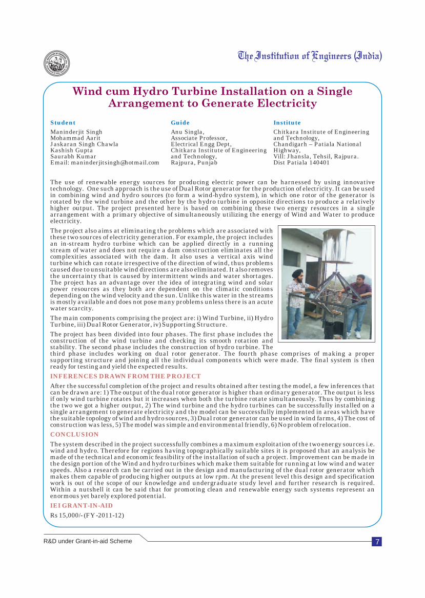
Aircraft design has been of interest for over a century. Military and civil aircrafts, which fly at Reynolds numbers of 10 and above, have usually been studied. The flowbehavior over airfoils in this range of Reynolds number is well understood. The aerodynamics in the Reynolds number range below that of commercial aircraft has gained attention from the research community over the last few years. Micro Air Vehicles (MAVs) emerged in the early 1990's and have been evolving rapidly ever since. Due to their size they posed some new and quite unique challenges in the areas of aerodynamics, equipment integration and the design approach itself. As systems, they are also relatively cheap compared to normal sized aircraft and therefore attracted a great deal of attention not only from companies but also from universities around the world. MAVs are being built primarily for close reconnaissance missions, but as market research has shown there are also other possible applications, both military and civilian, such as situational awareness, data relay or air sampling. These may also include surveillance missions, detection of chemical or biological agents, and placement of acoustic sensors on the outside of a building during a hostage rescue and other search and rescue operations. Micro air vehicles (MAV's) are the smallest class of unmanned air vehicles (UAV's). Current MAV's generally have maximum dimensions of less than 300 mm which fly at approximately 15 m/s, and have low aspect ratio range of 1 to 2. MAVs seem to be very 'adaptable' platforms – their airframe is very easy to redesign. Once the pieces of equipment are integrated it is very easy to change the geometry of the wings with no need for major changes in the other elements of the structure. Slight changes of a mission profile might call for a slightly different battery size or motor characteristics but nevertheless this is a relatively easy task, compared to a full-size aircraft where the structure is designed for tackling in-flight loads rather than handling and landing stresses. Birds are found to fly in range of 200000-300000 Reynolds numbers. The study of aerodynamics of the flow over the wing of these birds and insects is another aspect of MAV development. The Figure shows the difference in size and the range of Reynolds number of a Boeing 747, a Cessna 210, a Pheasant, a MAV and a butterfly.
The final planform selected for the development of the current MAV is an inverse zimmerman planform with an undercambered profile. The above selection was done on analysis based optimization approach where different parameters like lift, drag and lift to drag ratio were tabulated and compared. The developed MAV has following specifications with respect to its characteristics.
Wing area : 0.0251 m2Aspect Ratio : 1.59(CL/CD)max : 3 at 13 degree AoAMinimum thrust needed : 0.333 NMaximum thrust needed : 1.06 NCruise velocity : 11.65 m/sStall velocity : 10.35 m/s
After study of various parameters such as size, planform, profiles and avionics following conclusions were made :
lThe most suitable planform for the MAV is inverse zimmerman planfrom.
lAn undercambered profile for the inverse zimmerman planform is the most appropriate one as it performs the best with repect to the factors like lift, drag and lift to drag ratio.
lThe developed 200 mm wingspan MAV is capable of housing some payload for various applications.
Rs 20,000/- (FY -2010-11)
INFERENCES DRAWN FROM THE PROJECT
CONCLUSION
IEI GRANT-IN-AID
8 R&D under Grant-in-aid Scheme
Student Guide Institute
Adarsh KR K N Shashishekar Shirdi Sai Engg CollegeEngineering College Anekal Asst Professor Sai Leo Nagar, PO: Samandhur, Bangalore, Karnataka Deptt of Mech Engg Anekal,Email: [email protected] Shirdi Sai Engg College Bangalore 562106, M: 09886716841 Email : [email protected] Karnataka
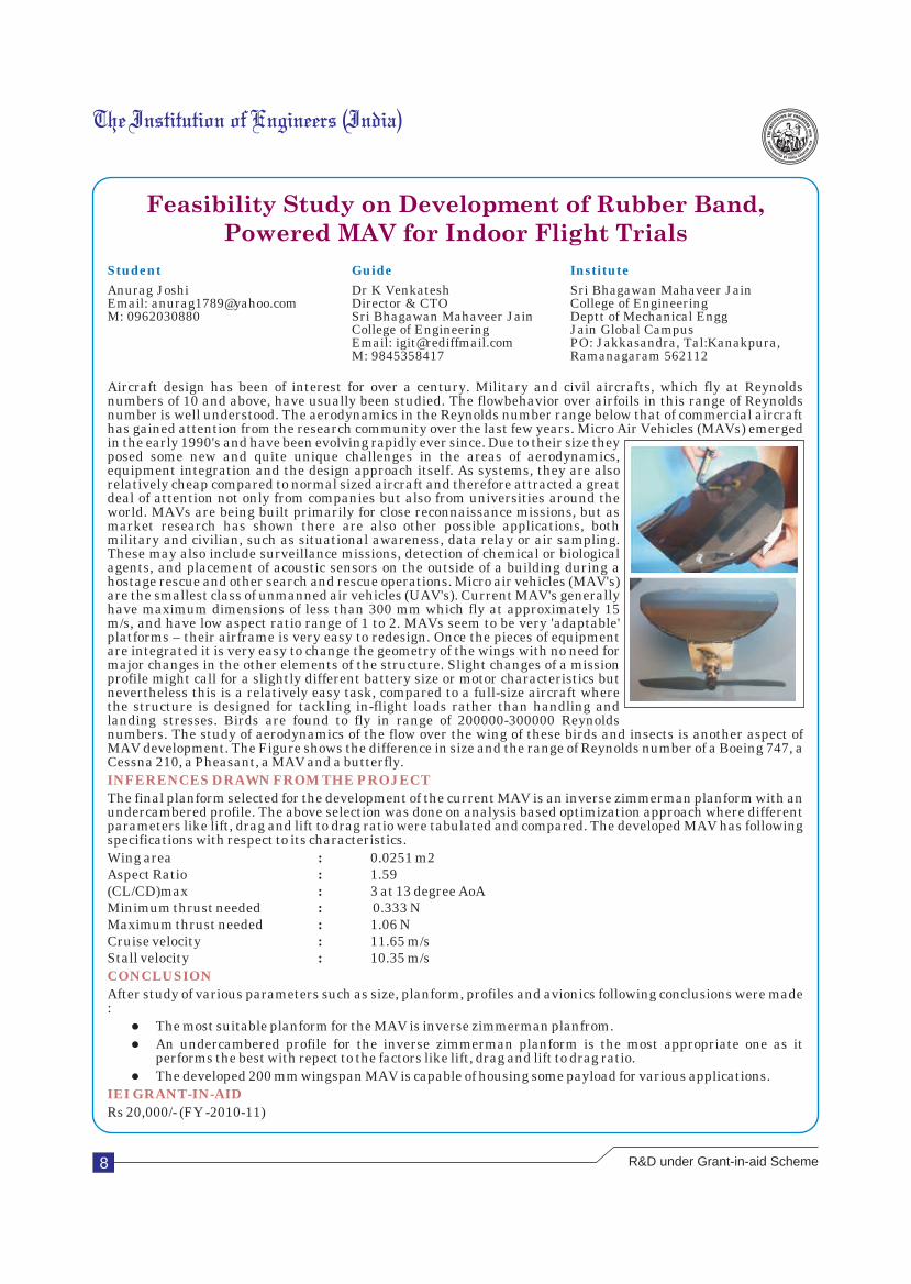
A velomobile is generally defined as a human powered vehicle equipped with a partially or fully enclosed fairing. This fairing provides both improved aerodynamic properties and protection for the user fluctuating weather conditions. These vehicles allow users to ride in all-weather conditions with improved comfort over a recumbent trike, recumbent bicycle or standard bicycle. Velomobile can also be adapted to allow for increased storage over that which is found in any other type of bicycle. This allows for a user to be able to commute daily, to and from work, with all their necessary supplies without relying upon an automobile. However, as more weight is added to the velomobile it may become difficult for a user to surmount simple obstacles, such as hills or steep driveways. For this reason, small motor assists can be incorporated into the design of the velomobile to assist a user in physically demanding situations. Overall, a velomobile is intended to supplement a user's need to depend on an automobile for daily commuting to and from work, and around town.
lIt is the coolest vehicle in the world. There is an additional safety that comes from riding an 'eye popping' enclosed recumbent cycle in all traffic conditions. Safety comes first.
lThere is no need for registration and insurance. It is legal on all roads, sidewalks and bike paths. Bicycle rules apply.
lEarn income from local vendors using your velomobile as a moving advertisement platform. Take advantage of our national ad agency network.
lIt is a low maintenance ride. Say goodbye to expensive vehicle tune-ups and upkeep.
lParking is easy, convenient and secure.
lPedal is fully recumbent position. Be nice to your lower back and harness your body's more powerful muscle group.
lEnjoy the aerodynamics of a fully enclosed fairing. Keep warm in the winter months and ride topless in the warmer seasons. Enjoy the stability of a trike design in slippery road conditions. Put an end to dangerous slips and falls.
Transportation has a very important influence on the future of society. Cycling as transportation is recognized as beneficial and sustainable means of transportation and is increasingly included in transportation policies in nations around the world. If proper designing and adaptation is done, velomobile will be the future means of transport as fossil fuels are at extinct. The designed structure of our velomobile helps it to be more aerodynamically stable by overcoming aerodynamic drag. Also seat and pedal arrangements of our velomobile makes rider to feel comfortable while riding. The concept of the velomobile can thus play an important role to offset the unsustainable transportation patterns in the post-modern world and its development as a technology of transportation is a unique opportunity to be seized.
Rs 80,000/- (FY -2010-11)
INFERENCES DRAWN FROM THE PROJECT
CONCLUSION
IEI GRANT-IN-AID
“If we knew what it was we were doing, it would not be called research, would it?”
Albert Einstein
9R&D under Grant-in-aid Scheme
10
Development of Biodiesel Production Technology
using Ultrasonic CavitationStudent Guide Institute
Ankur Gupta, Deepak Kumar, Dr S S Kachhwaha Delhi College of Engineering Jayant Ramachandran Assistant Professor Bawana Road, Delhi 42Delhi College of Engineering Delhi College of Engineering Bawana Road, Delhi 42 Email: [email protected]: [email protected],[email protected],[email protected]
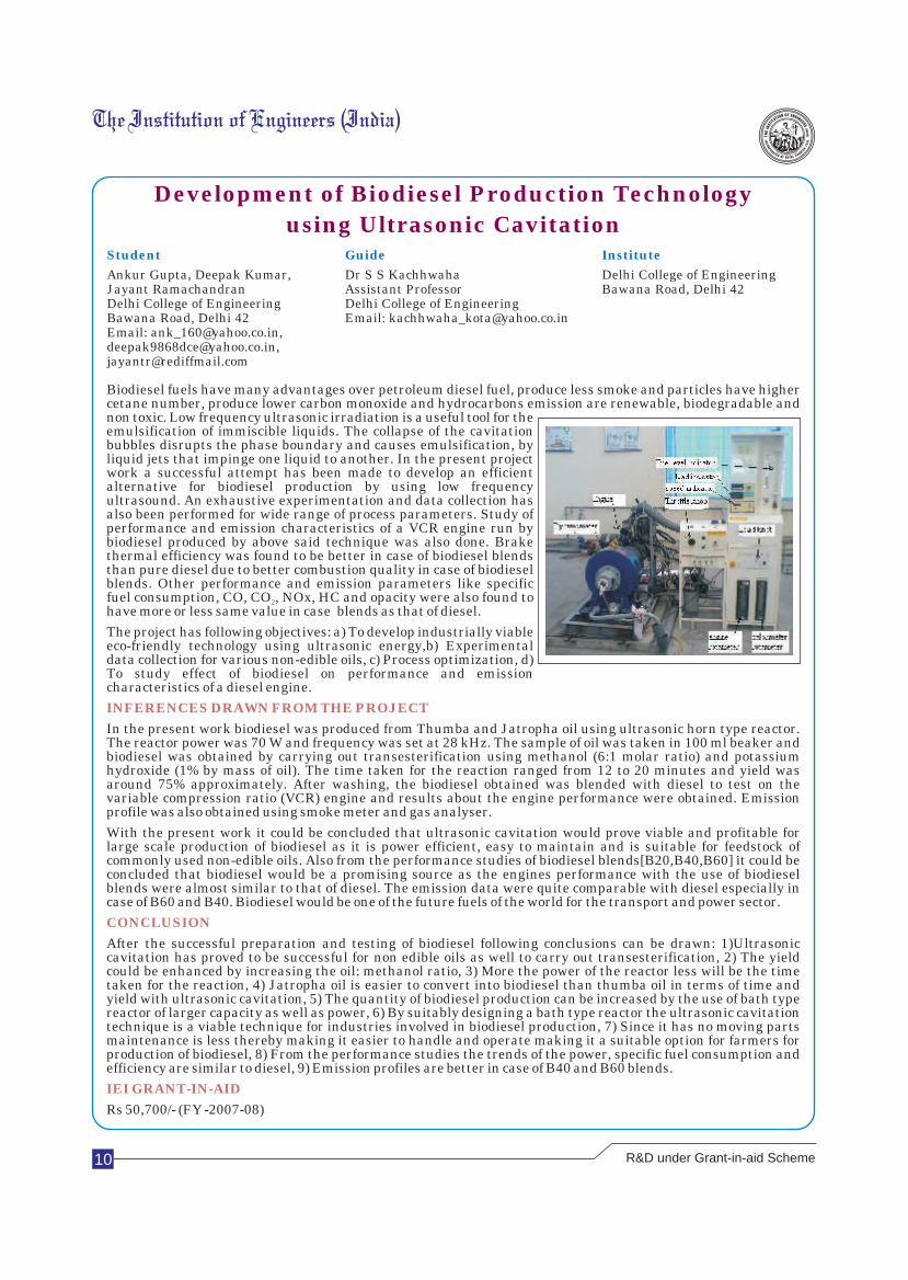
Biodiesel fuels have many advantages over petroleum diesel fuel, produce less smoke and particles have higher cetane number, produce lower carbon monoxide and hydrocarbons emission are renewable, biodegradable and non toxic. Low frequency ultrasonic irradiation is a useful tool for the emulsification of immiscible liquids. The collapse of the cavitation bubbles disrupts the phase boundary and causes emulsification, by liquid jets that impinge one liquid to another. In the present project work a successful attempt has been made to develop an efficient alternative for biodiesel production by using low frequency ultrasound. An exhaustive experimentation and data collection has also been performed for wide range of process parameters. Study of performance and emission characteristics of a VCR engine run by biodiesel produced by above said technique was also done. Brake thermal efficiency was found to be better in case of biodiesel blends than pure diesel due to better combustion quality in case of biodiesel blends. Other performance and emission parameters like specific fuel consumption, CO, CO , NOx, HC and opacity were also found to 2
have more or less same value in case blends as that of diesel.
The project has following objectives: a) To develop industrially viable eco-friendly technology using ultrasonic energy,b) Experimental data collection for various non-edible oils, c) Process optimization, d) To study effect of biodiesel on performance and emission characteristics of a diesel engine.
In the present work biodiesel was produced from Thumba and Jatropha oil using ultrasonic horn type reactor. The reactor power was 70 W and frequency was set at 28 kHz. The sample of oil was taken in 100 ml beaker and biodiesel was obtained by carrying out transesterification using methanol (6:1 molar ratio) and potassium hydroxide (1% by mass of oil). The time taken for the reaction ranged from 12 to 20 minutes and yield was around 75% approximately. After washing, the biodiesel obtained was blended with diesel to test on the variable compression ratio (VCR) engine and results about the engine performance were obtained. Emission profile was also obtained using smoke meter and gas analyser.
With the present work it could be concluded that ultrasonic cavitation would prove viable and profitable for large scale production of biodiesel as it is power efficient, easy to maintain and is suitable for feedstock of commonly used non-edible oils. Also from the performance studies of biodiesel blends[B20,B40,B60] it could be concluded that biodiesel would be a promising source as the engines performance with the use of biodiesel blends were almost similar to that of diesel. The emission data were quite comparable with diesel especially in case of B60 and B40. Biodiesel would be one of the future fuels of the world for the transport and power sector.
After the successful preparation and testing of biodiesel following conclusions can be drawn: 1)Ultrasonic cavitation has proved to be successful for non edible oils as well to carry out transesterification, 2) The yield could be enhanced by increasing the oil: methanol ratio, 3) More the power of the reactor less will be the time taken for the reaction, 4) Jatropha oil is easier to convert into biodiesel than thumba oil in terms of time and yield with ultrasonic cavitation, 5) The quantity of biodiesel production can be increased by the use of bath type reactor of larger capacity as well as power, 6) By suitably designing a bath type reactor the ultrasonic cavitation technique is a viable technique for industries involved in biodiesel production, 7) Since it has no moving parts maintenance is less thereby making it easier to handle and operate making it a suitable option for farmers for production of biodiesel, 8) From the performance studies the trends of the power, specific fuel consumption and efficiency are similar to diesel, 9) Emission profiles are better in case of B40 and B60 blends.
Rs 50,700/- (FY -2007-08)
INFERENCES DRAWN FROM THE PROJECT
CONCLUSION
IEI GRANT-IN-AID
R&D under Grant-in-aid Scheme
Retrofitting is important due to many reasons, such as to make the structure fit for additional loading requirements, to safeguard non-engineered buildings, to update the buildings to current seismic codes, etc. Existing retrofitting methods such as span shortening, steel bracing, section enlargement, bonded steel plating, external post-tensioning, strengthening with Fibre Reinforced Polymer (FRP) composite sheets posses certain demerits, such as high cost, need of sophisticated instruments, increase in the sectional area, surface preparation, de-bonding failures, low benefit-cost ratio and high maintenance. The proposed technique of keeping reinforcements externally at soffit level has many advantages, such as speed, simplicity, minimal disruption to use during installation, use of less expensive and readily available materials, less surface preparation, negligible increase in the self weight and no appreciable reduction in head room.
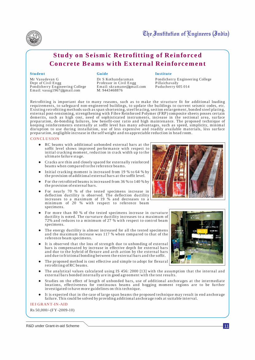
lRC beams with additional unbonded external bars at the soffit level shows improved performance with respect to initial cracking moment, reduction in crack width up to the ultimate failure stage.
lCracks are thin and closely spaced for externally reinforced beams when compared to the reference beams.
lInitial cracking moment is increased from 19 % to 64 % by the provision of additional external bars at the soffit level.
lFor the retrofitted beams is increased from 36 % to 140 % by the provision of external bars.
lFor nearly 70 % of the tested specimens increase in deflection ductility is observed. The deflection ductility increases to a maximum of 19 % and decreases to a minimum of 20 % with respect to reference beam specimens.
lFor more than 80 % of the tested specimens increase in curvature ductility is noted. The curvature ductility increases to a maximum of 72% and reduces to a minimum of 27 % with respect to control beam specimens.
lThe energy ductility is almost increased for all the tested specimens and the maximum increase was 117 % when compared to that of the reference beam specimens.
lIt is observed that the loss of strength due to unbonding of external bars is compensated by increase in effective depth for external bars and due to the hybrid of flexure and arch action by the external bars and due to frictional bonding between the external bars and the soffit.
lThe proposed method is cost effective and simple to adopt for flexural retrofitting of RC beams.
lThe analytical values calculated using IS 456: 2000 [13] with the assumption that the internal and external bars bonded internally are in good agreement with the test results.
lStudies on the effect of length of unbonded bars, use of additional anchorages at the intermediate locations, effectiveness for continuous beams and hogging moment regions are to be further investigated to have more guidelines on this technique.
lIt is expected that in the case of large span beams the proposed technique may result in end anchorage failure. This could be solved by providing additional anchorage rods at suitable interval.
Rs 50,000/- (FY -2009-10)
CONCLUSION
IEI GRANT-IN-AID
11
Study on Seismic Retrofitting of Reinforced
Concrete Beams with External Reinforcement
Student Guide Institute
Mr Vasudevan G Dr S Kothandaraman Pondicherry Engineering Dept of Civil Engg Professor in Civil Engg Pillaichavady Pondicherry Engineering College Email: [email protected] Puducherry 605 014Email: [email protected] M: 9443468876
College
R&D under Grant-in-aid Scheme
The Institution of Engineers (India)
12
Automatic Over Speed Detector with OnlineTraffic Crime Management System
Student Guide Institute
M Sinthu Raja, Ms R Ahila, M E, (Ph.D) Dr.Sivanthi Aditanar College of A Hariharan, Assistant Professor/CSE, EngineeringP Thiruvadisamy Email: [email protected] Tiruchendur 628215
M: 9486453814 Ph: 04639 (242482)
In the present Scenario, the rapid infrastructure development of roadways is the backbone of any country's growth. Using roadways each and every part of the country is connected contributing to high economical growth. Some of the examples of rapid infrastructural development are laying four way lanes throughout the country. Similarly the rate of traffic crimes increases rapidly which acts a major challenge to the life of public. Cities witness increasing traffic congestions due to overruling of traffic rules as well as the authorities are not equipped properly to control the crimes. These have lead to the increase in the number of accidents every year. The government introduces a number of schemes such as laying one way highways, but the numbers of accidents not seem to be diminished. There are some cases such as changing the vehicle parts without getting permissions which cannot be predicted easily. The traffic authorities produce licenses and Registration Copies with government seals, but some produce fake copies which cannot be differentiated by the authorities. We mainly focus on the identification of licenses and Registration Copies within the country. Every license and Registration Copy will have a file number which addresses the owner of the document, the Regional Transport Office where the owner has obtained the permission. The license will be endorsed when the person commits the errors. The Registration Copy also has the details such as personal details of the owner, vehicle details (body and engine details), tax details, hire agreements, etc. The person who is not the owner of the vehicle can drive the vehicle by having the Registration Copies whereas the same is not possible with the license. Once the details are changed, the documents should be modified and approved by the corresponding authority which on violation leads to the impose of fines. Also over speeding the vehicle within the city limit as well as in the national highway which leads to high and terrible accidents, which can be controlled through integrating the LPR with the OTCMS. The last one is the communication between the authorities in case of emergency. Communication is more important in the field of crime control systems. Proper communication can decline the number of major problems by half by identifying in the initial stage. In our Web based OTCMS, change in owner of vehicle is made very easy by modifying it online only by the corresponding Regional Transport Authorities.
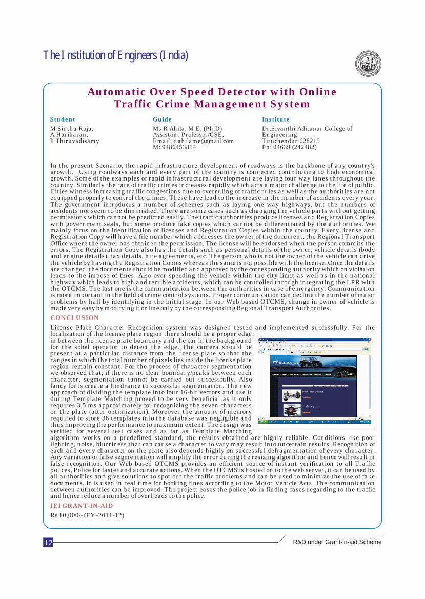
License Plate Character Recognition system was designed tested and implemented successfully. For the localization of the license plate region there should be a proper edge in between the license plate boundary and the car in the background for the sobel operator to detect the edge. The camera should be present at a particular distance from the license plate so that the ranges in which the total number of pixels lies inside the license plate region remain constant. For the process of character segmentation we observed that, if there is no clear boundary/peaks between each character, segmentation cannot be carried out successfully. Also fancy fonts create a hindrance to successful segmentation. The new approach of dividing the template into four 16-bit vectors and use it during Template Matching proved to be very beneficial as it only requires 3.5 ms approximately for recognizing the seven characters on the plate (after optimization). Moreover the amount of memory required to store 36 templates into the database was negligible and thus improving the performance to maximum extent. The design was verified for several test cases and as far as Template Matching algorithm works on a predefined standard, the results obtained are highly reliable. Conditions like poor lighting, noise, blurriness that can cause a character to vary may result into uncertain results. Recognition of each and every character on the plate also depends highly on successful defragmentation of every character. Any variation or false segmentation will amplify the error during the resizing algorithm and hence will result in false recognition. Our Web based OTCMS provides an efficient source of instant verification to all Traffic polices, Police for faster and accurate actions. When the OTCMS is hosted on to the web server, it can be used by all authorities and give solutions to spot out the traffic problems and can be used to minimize the use of fake documents. It is used in real time for booking fines according to the Motor Vehicle Acts. The communication between authorities can be improved. The project eases the police job in finding cases regarding to the traffic and hence reduce a number of overheads to the police.
Rs 10,000/- (FY -2011-12)
CONCLUSION
IEI GRANT-IN-AID
R&D under Grant-in-aid Scheme
The Institution of Engineers (India)
13
Detection of Bone Cracks using X Ray Images
Student Guide Institute
Ponnammal S, Dr G Wiselin Jiji Dr Sivanthi Aditanar College of Ramyam, Selvalakshmi P, Professor & Head EngineeringVijimalar V Department of Computer Science Tiruchendur 628215Email:[email protected] and Engineering Ph: 04639 (242482)
Email: [email protected]
In human physiology, a human body consists of 206 bones. Bone is made up of calcium rich hard tissues surrounded by soft tissues. Cracks are discontinuities in the calcium rich bone matrix. When a human bone gets hurted, the soft tissues around the affected portion will be damaged and there may be possibility for the occurrence of crack in the bone. Types of cracks in bone are:
ØSimple : does not pierces the skin.
ØCompound : pierces the skin.
ØComplete : breaks in two or more pieces.
ØIncomplete : cracks and does not separate.
ØComminuted : cracks into many pieces.
ØImpacted : bones driven into each other.
ØStress fracture is an invisible hairline break.
Even though the cracks in the bone can be identified by doctors through naked eye, the goal is to identify the crack in a more accurate way within a short duration using our proposed method.
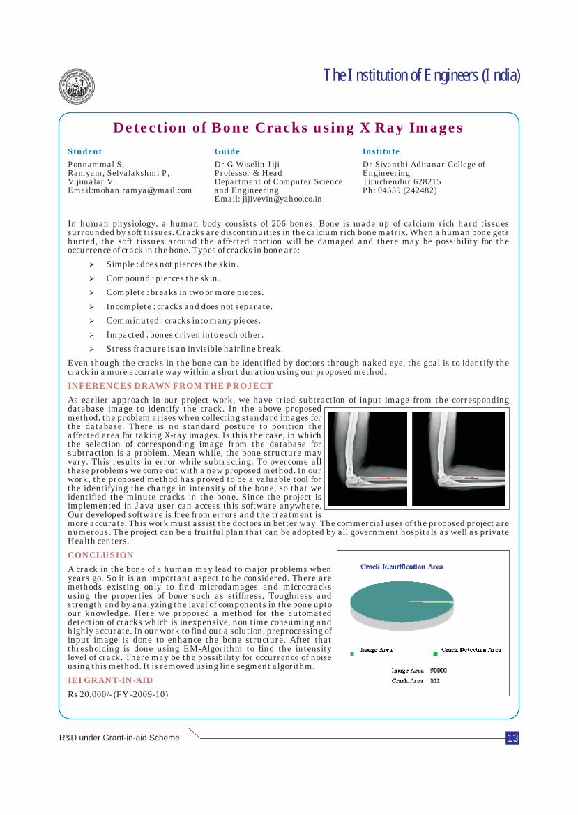
As earlier approach in our project work, we have tried subtraction of input image from the corresponding database image to identify the crack. In the above proposed method, the problem arises when collecting standard images for the database. There is no standard posture to position the affected area for taking X-ray images. Is this the case, in which the selection of corresponding image from the database for subtraction is a problem. Mean while, the bone structure may vary. This results in error while subtracting. To overcome all these problems we come out with a new proposed method. In our work, the proposed method has proved to be a valuable tool for the identifying the change in intensity of the bone, so that we identified the minute cracks in the bone. Since the project is implemented in Java user can access this software anywhere. Our developed software is free from errors and the treatment is more accurate. This work must assist the doctors in better way. The commercial uses of the proposed project are numerous. The project can be a fruitful plan that can be adopted by all government hospitals as well as private Health centers.
A crack in the bone of a human may lead to major problems when years go. So it is an important aspect to be considered. There are methods existing only to find microdamages and microcracks using the properties of bone such as stiffness, Toughness and strength and by analyzing the level of components in the bone upto our knowledge. Here we proposed a method for the automated detection of cracks which is inexpensive, non time consuming and highly accurate. In our work to find out a solution, preprocessing of input image is done to enhance the bone structure. After that thresholding is done using EM-Algorithm to find the intensity level of crack. There may be the possibility for occurrence of noise using this method. It is removed using line segment algorithm.
Rs 20,000/- (FY -2009-10)
INFERENCES DRAWN FROM THE PROJECT
CONCLUSION
IEI GRANT-IN-AID
R&D under Grant-in-aid Scheme
14
Wireless Energy Meter ReadingTransmitting System
Student Guide Institute
R Tarun Kumar Dr C K Babulal, Ph D Thiagarajar College of K S Vishnu Kumar Asst professor Madurai 625 015P Prabhu Department of Electrical and
Electronics Engineering
Engineering
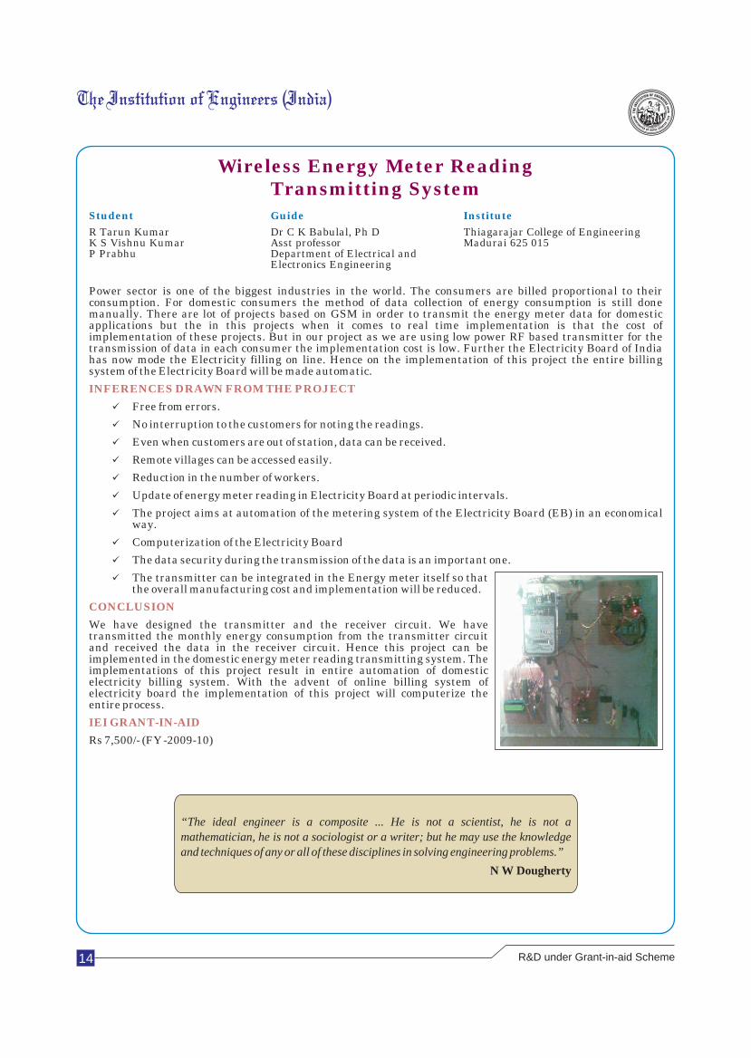
Power sector is one of the biggest industries in the world. The consumers are billed proportional to their consumption. For domestic consumers the method of data collection of energy consumption is still done manually. There are lot of projects based on GSM in order to transmit the energy meter data for domestic applications but the in this projects when it comes to real time implementation is that the cost of implementation of these projects. But in our project as we are using low power RF based transmitter for the transmission of data in each consumer the implementation cost is low. Further the Electricity Board of India has now mode the Electricity filling on line. Hence on the implementation of this project the entire billing system of the Electricity Board will be made automatic.
üFree from errors.
üNo interruption to the customers for noting the readings.
üEven when customers are out of station, data can be received.
üRemote villages can be accessed easily.
üReduction in the number of workers.
üUpdate of energy meter reading in Electricity Board at periodic intervals.
üThe project aims at automation of the metering system of the Electricity Board (EB) in an economical way.
üComputerization of the Electricity Board
üThe data security during the transmission of the data is an important one.
üThe transmitter can be integrated in the Energy meter itself so that the overall manufacturing cost and implementation will be reduced.
We have designed the transmitter and the receiver circuit. We have transmitted the monthly energy consumption from the transmitter circuit and received the data in the receiver circuit. Hence this project can be implemented in the domestic energy meter reading transmitting system. The implementations of this project result in entire automation of domestic electricity billing system. With the advent of online billing system of electricity board the implementation of this project will computerize the entire process.
Rs 7,500/- (FY -2009-10)
INFERENCES DRAWN FROM THE PROJECT
CONCLUSION
IEI GRANT-IN-AID
“The ideal engineer is a composite ... He is not a scientist, he is not a mathematician, he is not a sociologist or a writer; but he may use the knowledge and techniques of any or all of these disciplines in solving engineering problems.”
N W Dougherty
R&D under Grant-in-aid Scheme
15
Mobile Remote Controller for PC
Student Guide Institute
Jesline Jacob Ms Anila Davis Sahrdaya College OfEmail: [email protected] Assistant Professor Engineering & Technology,M: 9447994386 Department of Computer Science Kodakara, Thrissur 680684
and EngineeringEmail: [email protected]: 9947094980
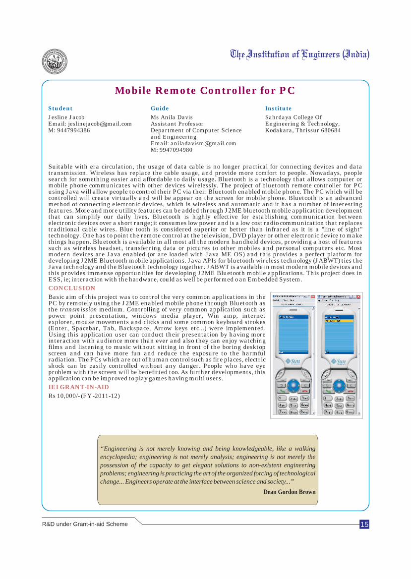
Suitable with era circulation, the usage of data cable is no longer practical for connecting devices and data transmission. Wireless has replace the cable usage, and provide more comfort to people. Nowadays, people search for something easier and affordable to daily usage. Bluetooth is a technology that allows computer or mobile phone communicates with other devices wirelessly. The project of bluetooth remote controller for PC using Java will allow people to control their PC via their Bluetooth enabled mobile phone. The PC which will be controlled will create virtually and will be appear on the screen for mobile phone. Bluetooth is an advanced method of connecting electronic devices, which is wireless and automatic and it has a number of interesting features. More and more utility features can be added through J2ME bluetooth mobile application development that can simplify our daily lives. Bluetooth is highly effective for establishing communication between electronic devices over a short range; it consumes low power and is a low cost radio communication that replaces traditional cable wires. Blue tooth is considered superior or better than infrared as it is a "line of sight" technology. One has to point the remote control at the television, DVD player or other electronic device to make things happen. Bluetooth is available in all most all the modern handheld devices, providing a host of features such as wireless headset, transferring data or pictures to other mobiles and personal computers etc. Most modern devices are Java enabled (or are loaded with Java ME OS) and this provides a perfect platform for developing J2ME Bluetooth mobile applications. Java APIs for bluetooth wireless technology (JABWT) ties the Java technology and the Bluetooth technology together. JABWT is available in most modern mobile devices and this provides immense opportunities for developing J2ME Bluetooth mobile applications. This project does in ESS, ie; interaction with the hardware, could as well be performed o an Embedded System.
Basic aim of this project was to control the very common applications in the PC by remotely using the J2ME enabled mobile phone through Bluetooth as the transmission medium. Controlling of very common application such as power point presentation, windows media player, Win amp, internet explorer, mouse movements and clicks and some common keyboard strokes (Enter, Spacebar, Tab, Backspace, Arrow keys etc...) were implemented. Using this application user can conduct their presentation by having more interaction with audience more than ever and also they can enjoy watching films and listening to music without sitting in front of the boring desktop screen and can have more fun and reduce the exposure to the harmful radiation. The PCs which are out of human control such as fire places, electric shock can be easily controlled without any danger. People who have eye problem with the screen will be benefitted too. As further developments, this application can be improved to play games having multi users.
Rs 10,000/- (FY -2011-12)
CONCLUSION
IEI GRANT-IN-AID
“Engineering is not merely knowing and being knowledgeable, like a walking encyclopedia; engineering is not merely analysis; engineering is not merely the possession of the capacity to get elegant solutions to non-existent engineering
problems; engineering is practicing the art of the organized forcing of technological
change... Engineers operate at the interface between science and society...”
Dean Gordon Brown
R&D under Grant-in-aid Scheme

16
Recovery of Acids(Sulfuric/Nitric Acid)
from Industrial Waste Water
Student Guide Institute
Karan Katkar Mr N YGhare, Assistant Professor Shram Sadhana Bombay Trust'sEmail: [email protected] Department of Chemical Engineering, College of Engineering &
Email: [email protected] Technology,Bambhori, M: 09922411072 Jalgaon 425001 (MS)
Phone No (0257) 2258393
Various industries generate acidic wastewater during different operations. The discharge of acidic wastewater without treatment is a potential cause of environmental pollution due to its high acid content. Most of these acids are corrosive, toxic, harmful to skin, cause respiratory diseases, digestive track problems etc. As steel became available in the mid-nineteenth century, extensive metalworking industries grew up, requiring large amounts of clean, descaled metal. Most companies cleaned their own steel and a metalworking shop would usually have a cleaning house where the raw material was laboriously dipped in acid contained in a wooden vat, then rinsed with required amount of water, and finally oiled or limed to prevent rusting of the clean surface, of course waste solutions and rinse water were simply poured into the nearest stream or river. To this day, many metalworking shops still call their pickling facilities “cleaning houses”. Most early picklers used sulphuric acid-it was cheap, readily available, easy to handle and did not make much fume or smell in use. As time passed, the wish to get more production and better quality led to various improvements in the process such as mechanical handling on racks, heating the acid, use of inhibitors, use of acid-brick lined tanks etc. The system remained, however, essentially batch pickling in Sulphuric Acid. The huge increase in demand for strip-steel for automobiles and cans eventually led to the development of continuous strip picklers, in which the uncoiled strip was drawn continuously through tubs of hot sulphuric acid. Early lines processed several narrow strips at speeds of 5 to 10 metre per minute (mpm) were obtained with the successive coils being held together with mechanical clips, but, in time speeds of upto 40mpm were obtained with welding of each other to the next accumulators or looping pits were added to keep the pickler on stream while the welding was taking place. In the early 1960 a major change in high speed pickling technology took place the introduction of hydrochloric (muriatic) acid pickling. Some special picklers had used hydrochloric acid previously, especially if a high quality surface was needed, but the expense, corrosiveness and fuming problems made this acid unattractive.
1. This technology has a very wide application area and can prove to be one of the best technology for the society. The recovery of sulfuric acid will lead to environmental protection.
2. The acidic waste water after treatment can be used for agricultural purpose as the total dissolved solids and acidity in waste water will be negligible.
3. The population residing near the industry generating the acidic waste water will live fearlessly.
4. The industry will be an example of environmentally friendly industry.
In the project the analysis of spent pickle liquor(SPL) from the steel industry and recovery of sulfuric acid by evaporation method was carried out. The wastewater sample was collected from steel industry in Jalgaon. The treatment & disposal of spent industrial process wastewater, particularly acid containing wastewater, has been a long standing problem in many industries. They are beyond the tolerance limits of Indian standards. It is necessary to treat SPL and then can be discharged into common stream. The SPL was analyzed and results show that sulfuric acid was present in the SPL. Also the percentage of sulfuric acid in SPL varies between 20-50.In our sample the percentage of sulfuric acid in SPL was 25.Advantage of the process is that the sulfuric acid recovered can be reused in the pickling process.
Rs 30,000/-(FY -2009-10)
INFERENCES DRAWN FROM THE PROJECT
CONCLUSION
IEI GRANT-IN-AID
“Technology innovation is starting to explode and having open-source material out
there really helps this explosion. You get students and researchers involved and you
get people coming through and building start ups based on open source products.”
Tim Berners-Lee
R&D under Grant-in-aid Scheme
17
Wear Behavior and Coupled Field Analysis of AL /
SICP Aluminium Metal Matrix Composites
Student Guide Institute
C Sabarinathan Dr V Duraisamy Hindusthan College of EngineeringEmail: [email protected] Principal, HCET & Technology, M: 09842205450 Email: Othakkalmandapam
M: 09442268510 Coimbatore 641 [email protected]
The ever-increasing demand for light weight, fuel efficiency and comfort in automobile industries has lead to the development of advanced materials along with optimized design. MMCs are widely used in industries, as they have excellent mechanical properties and wear resistance. Particulate-reinforced composites cost less than fiber reinforced composites owing to the lower cost of fibers and manufacturing cost. In addition to improved physical and mechanical properties, particulate-reinforced composites are generally isotropic and they can be processed through conventional methods used for metals. Thus, the silicon carbide reinforced aluminium composites are increasingly used as substitute materials for cylinder heads, liners, pistons, brake rotors and calibers in automobile industry. The addition of low volume fraction of Si C particle (up to 8%) to Al–Si alloys significantly reduced the wear rate and the wear resistance has been found to increase with percentage of reinforcement.
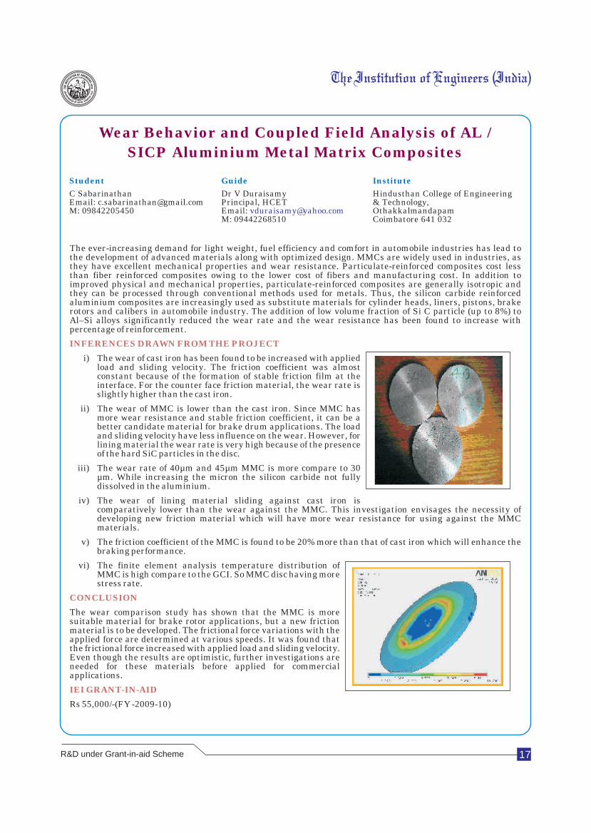
i) The wear of cast iron has been found to be increased with applied load and sliding velocity. The friction coefficient was almost constant because of the formation of stable friction film at the interface. For the counter face friction material, the wear rate is slightly higher than the cast iron.
ii) The wear of MMC is lower than the cast iron. Since MMC has more wear resistance and stable friction coefficient, it can be a better candidate material for brake drum applications. The load and sliding velocity have less influence on the wear. However, for lining material the wear rate is very high because of the presence of the hard SiC particles in the disc.
iii) The wear rate of 40µm and 45µm MMC is more compare to 30 µm. While increasing the micron the silicon carbide not fully dissolved in the aluminium.
iv) The wear of lining material sliding against cast iron is comparatively lower than the wear against the MMC. This investigation envisages the necessity of developing new friction material which will have more wear resistance for using against the MMC materials.
v) The friction coefficient of the MMC is found to be 20% more than that of cast iron which will enhance the braking performance.
vi) The finite element analysis temperature distribution of MMC is high compare to the GCI. So MMC disc having more stress rate.
The wear comparison study has shown that the MMC is more suitable material for brake rotor applications, but a new friction material is to be developed. The frictional force variations with the applied force are determined at various speeds. It was found that the frictional force increased with applied load and sliding velocity. Even though the results are optimistic, further investigations are needed for these materials before applied for commercial applications.
Rs 55,000/-(FY -2009-10)
INFERENCES DRAWN FROM THE PROJECT
CONCLUSION
IEI GRANT-IN-AID
R&D under Grant-in-aid Scheme
18
A.U.R.A
Advanced Utility Robotic Arm
Student Guide Institute
Amal R Agrawal Dr Sanjay National Institute of TechnologyPradeep G Kudva Professor Jamshedpur-831014Ketan Goyal Mechanical Eng Dept. Email: [email protected] NIT Jamshedpur
Email: [email protected]
Prosthetic arm was first implemented by Reinhold Reiter, a physics student at Munich University in May 1945. The report of Reiter's work, in German medical newspaper, described a yoelectric prosthetic arm designed for the amputee factory worker. A prototype was demonstrated at the Honnover export fair in 1945. The research leading to this device was supported by the Bavarian Red Cross and private source. Pudlusky was Reiter's business manager for the project. Development of the system was terminated due to the lack of funds after the German currency reform in 1948. The idea behind the control system was to amplify the myoelectric signal from a contracting muscle in order to control a wooden hand, which was modified to be actuated by an electric solenoid. Reiter used single muscle site in the residual limb. Control of opening and closing motion was derived from using =two different rhythms of contraction'. This scheme of using the signal from a single muscle to control two motions was later to be known as =three state control'. Reiter's work was not alone in being overlooked in the early development of myoelectric control. The myoelectric signal has been used to monitor lookout alertness as early as 1947 and by 1957 to control respirators for polio victims. Indeed, it has been investigated as a possible control source for prosthesis as early as 1949, with encouraging results.
In the late 1950s and early 1960s, research again started in myoelectric control system. This work occurred independently and almost simultaneously in the USSR, the United Kingdom, the USA, Europe and Canada. It was aided greatly by the availability of transistors, without which a truly portable myoelectric prosthesis was not practical.
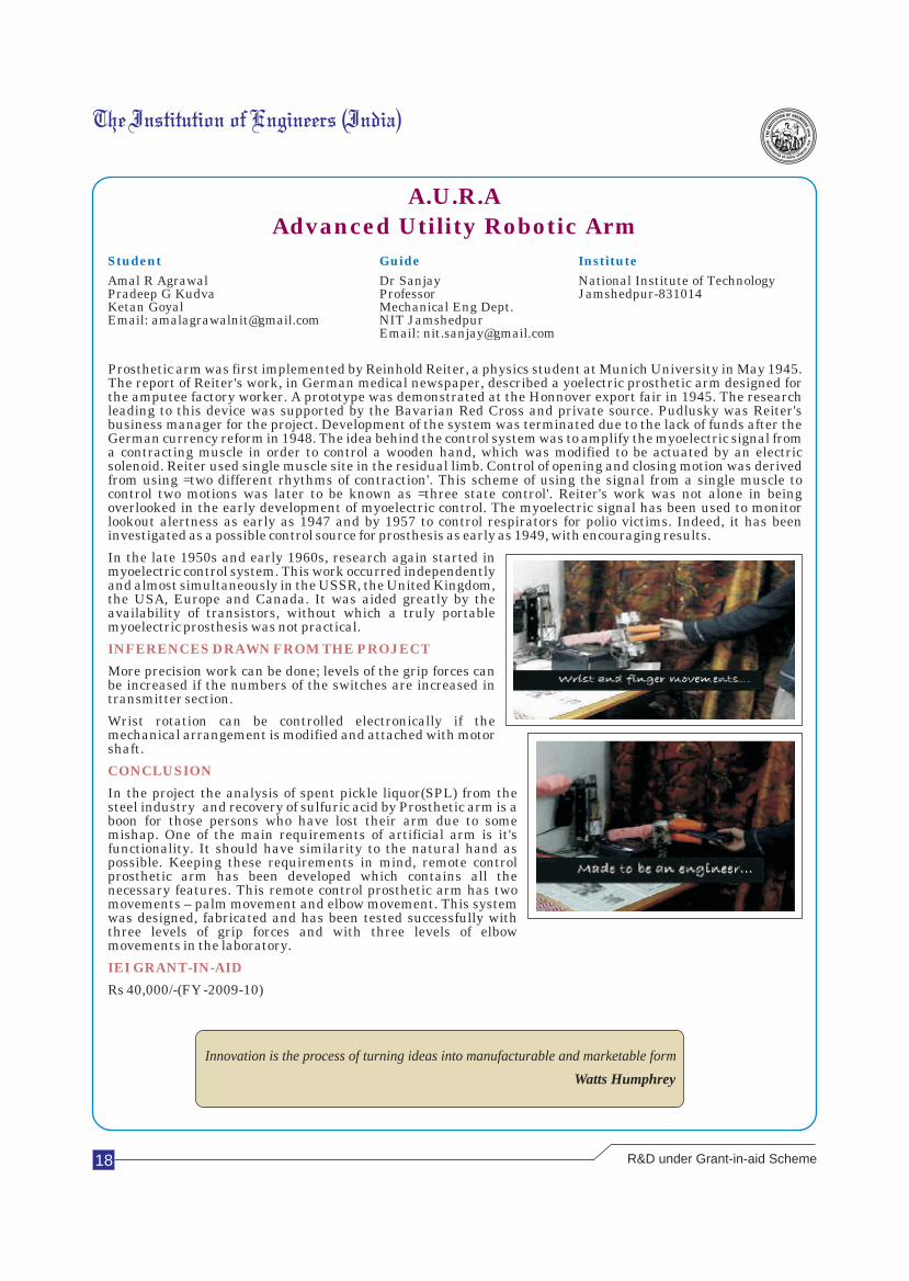
More precision work can be done; levels of the grip forces can be increased if the numbers of the switches are increased in transmitter section.
Wrist rotation can be controlled electronically if the mechanical arrangement is modified and attached with motor shaft.
In the project the analysis of spent pickle liquor(SPL) from the steel industry and recovery of sulfuric acid by Prosthetic arm is a boon for those persons who have lost their arm due to some mishap. One of the main requirements of artificial arm is it's functionality. It should have similarity to the natural hand as possible. Keeping these requirements in mind, remote control prosthetic arm has been developed which contains all the necessary features. This remote control prosthetic arm has two movements – palm movement and elbow movement. This system was designed, fabricated and has been tested successfully with three levels of grip forces and with three levels of elbow movements in the laboratory.
Rs 40,000/-(FY -2009-10)
INFERENCES DRAWN FROM THE PROJECT
CONCLUSION
IEI GRANT-IN-AID
Innovation is the process of turning ideas into manufacturable and marketable form
Watts Humphrey
R&D under Grant-in-aid Scheme
19
Process Design for Drying Areca
Nuts by Solvent Extraction
Student Guide Institute
Miss Neha Madhusudan Bhide Prof Mrs Sailaja P Sinhgad College of Engineering,Email: [email protected] Department of Biotechnology Vadgaon(BK), OFF Singhad RoadM: 9881100673 Sinhgad College of Engineering, Pune Pune
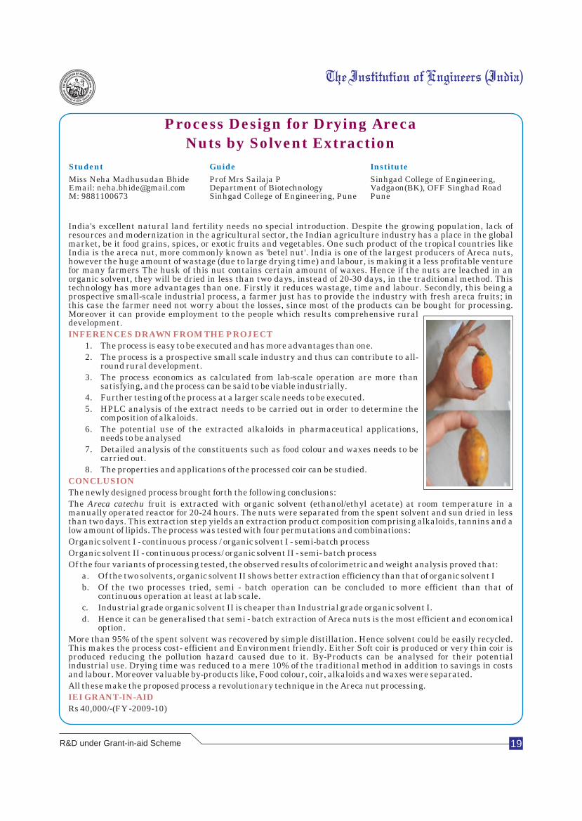
India's excellent natural land fertility needs no special introduction. Despite the growing population, lack of resources and modernization in the agricultural sector, the Indian agriculture industry has a place in the global market, be it food grains, spices, or exotic fruits and vegetables. One such product of the tropical countries like India is the areca nut, more commonly known as 'betel nut'. India is one of the largest producers of Areca nuts, however the huge amount of wastage (due to large drying time) and labour, is making it a less profitable venture for many farmers The husk of this nut contains certain amount of waxes. Hence if the nuts are leached in an organic solvent, they will be dried in less than two days, instead of 20-30 days, in the traditional method. This technology has more advantages than one. Firstly it reduces wastage, time and labour. Secondly, this being a prospective small-scale industrial process, a farmer just has to provide the industry with fresh areca fruits; in this case the farmer need not worry about the losses, since most of the products can be bought for processing. Moreover it can provide employment to the people which results comprehensive rural development.
1. The process is easy to be executed and has more advantages than one.
2. The process is a prospective small scale industry and thus can contribute to all-round rural development.
3. The process economics as calculated from lab-scale operation are more than satisfying, and the process can be said to be viable industrially.
4. Further testing of the process at a larger scale needs to be executed.
5. HPLC analysis of the extract needs to be carried out in order to determine the composition of alkaloids.
6. The potential use of the extracted alkaloids in pharmaceutical applications, needs to be analysed
7. Detailed analysis of the constituents such as food colour and waxes needs to be carried out.
8. The properties and applications of the processed coir can be studied.
The newly designed process brought forth the following conclusions:
The Areca catechu fruit is extracted with organic solvent (ethanol/ethyl acetate) at room temperature in a manually operated reactor for 20-24 hours. The nuts were separated from the spent solvent and sun dried in less than two days. This extraction step yields an extraction product composition comprising alkaloids, tannins and a low amount of lipids. The process was tested with four permutations and combinations:
Organic solvent I - continuous process / organic solvent I - semi-batch process
Organic solvent II - continuous process/ organic solvent II - semi- batch process
Of the four variants of processing tested, the observed results of colorimetric and weight analysis proved that:
a. Of the two solvents, organic solvent II shows better extraction efficiency than that of organic solvent I
b. Of the two processes tried, semi - batch operation can be concluded to more efficient than that of continuous operation at least at lab scale.
c. Industrial grade organic solvent II is cheaper than Industrial grade organic solvent I.
d. Hence it can be generalised that semi - batch extraction of Areca nuts is the most efficient and economical option.
More than 95% of the spent solvent was recovered by simple distillation. Hence solvent could be easily recycled. This makes the process cost- efficient and Environment friendly. Either Soft coir is produced or very thin coir is produced reducing the pollution hazard caused due to it. By-Products can be analysed for their potential industrial use. Drying time was reduced to a mere 10% of the traditional method in addition to savings in costs and labour. Moreover valuable by-products like, Food colour, coir, alkaloids and waxes were separated.
All these make the proposed process a revolutionary technique in the Areca nut processing.
Rs 40,000/-(FY -2009-10)
INFERENCES DRAWN FROM THE PROJECT
CONCLUSION
IEI GRANT-IN-AID
R&D under Grant-in-aid Scheme
20
Solar Powered Unmanned Aerial Vehicle
(SPUAV) for Disaster Management
Student Guide Institute
Shyam Sundar Adhikari Pruthviraj U National Institute of TechnologySandeep Hari Asst Professor Karnataka, SurathkalShrikanth D M Department of Applied Mechanics Srinivasnagar 575 025 Vinyas Rai & Hydraulics Mangalore
Email: [email protected]: 9343352497
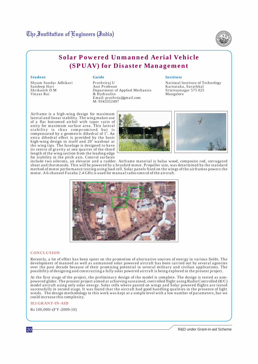
Airframe is a high-wing design for maximum lateral and linear stability. The wing makes use of a flat bottomed airfoil with taper ratio of unity for maximum surface area. This lateral stability is thus compromised but is
0compensated by a geometric dihedral of 1 . An extra dihedral effect is provided by the basic
0high-wing design in itself and 20 washout at the wing tips. The fuselage is designed to have its centre of gravity at one quarter of the chord length of the wing section from the leading edge for stability in the pitch axis. Control surfaces include two ailerons, an elevator and a rudder. Airframe material is balsa wood, composite rod, corrugated sheet and thermocole. This will be powered by a brushed motor. Propeller size, was determined by the standard method of motor performance testing using load cell. Solar panels fixed on the wings of the airframes powers the motor. A 6-channel Futaba 2.4 GHz is used for manual radio control of the aircraft.
CONCLUSION
IEI GRANT-IN-AID
Recently, a lot of effort has been spent on the promotion of alternative sources of energy in various fields. The development of manned as well as unmanned solar powered aircraft has been carried out by several agencies over the past decade because of their promising potential in several military and civilian applications. The possibility of designing and constructing a fully solar powered aircraft is being explored in the present project.
At the first stage of the project, the preliminary design of the model is complete. The design is tested as non-powered glider. The present project aimed at achieving sustained, controlled flight using Radio Controlled (R/C) model aircraft using only solar energy. Solar cells where pasted on wings and Solar powered flights are tested successfully in second stage. It was found that the aircraft had good handling qualities in the presence of light winds. The design methodology in this work was kept at a simple level with a low number of parameters, but we could increase this complexity.
Rs 100,000/-(FY -2009-10)
R&D under Grant-in-aid Scheme
21
Mini Thermal Power Plant
Student Guide Institute
Basavaraj S, Abhijit Deb, Mr KMaghalengam Shirdi Sai Engineering CollegeEmail: [email protected] Sr Lecturer, Mechanical Engg Dept Sai Leo Nagar, Samundhur Post M: 9035740900 Email: [email protected] Anekal, Bengaluru 562106
M: 09842544361
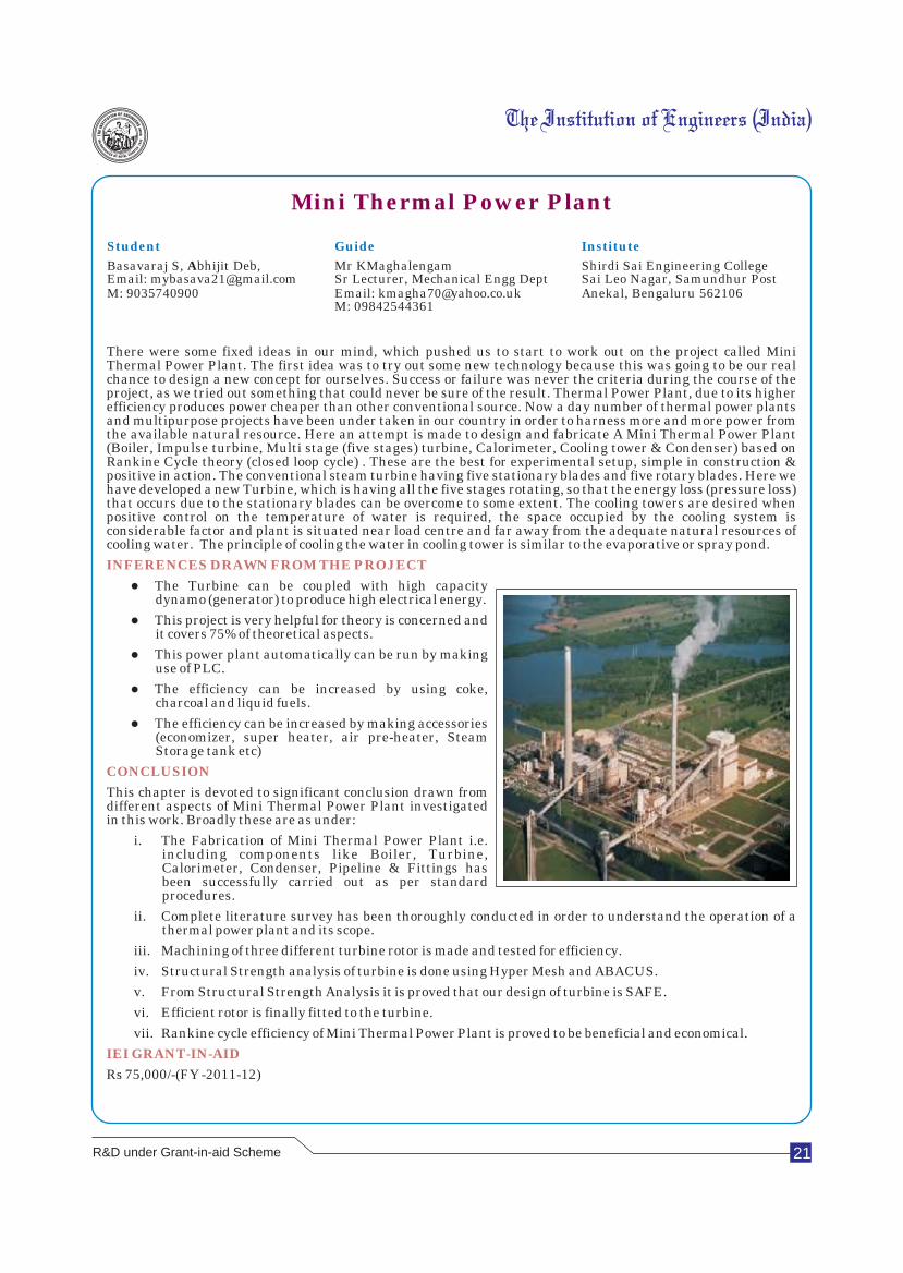
There were some fixed ideas in our mind, which pushed us to start to work out on the project called Mini Thermal Power Plant. The first idea was to try out some new technology because this was going to be our real chance to design a new concept for ourselves. Success or failure was never the criteria during the course of the project, as we tried out something that could never be sure of the result. Thermal Power Plant, due to its higher efficiency produces power cheaper than other conventional source. Now a day number of thermal power plants and multipurpose projects have been under taken in our country in order to harness more and more power from the available natural resource. Here an attempt is made to design and fabricate A Mini Thermal Power Plant (Boiler, Impulse turbine, Multi stage (five stages) turbine, Calorimeter, Cooling tower & Condenser) based on Rankine Cycle theory (closed loop cycle) . These are the best for experimental setup, simple in construction & positive in action. The conventional steam turbine having five stationary blades and five rotary blades. Here we have developed a new Turbine, which is having all the five stages rotating, so that the energy loss (pressure loss) that occurs due to the stationary blades can be overcome to some extent. The cooling towers are desired when positive control on the temperature of water is required, the space occupied by the cooling system is considerable factor and plant is situated near load centre and far away from the adequate natural resources of cooling water. The principle of cooling the water in cooling tower is similar to the evaporative or spray pond.
lThe Turbine can be coupled with high capacity dynamo (generator) to produce high electrical energy.
lThis project is very helpful for theory is concerned and it covers 75% of theoretical aspects.
lThis power plant automatically can be run by making use of PLC.
lThe efficiency can be increased by using coke, charcoal and liquid fuels.
lThe efficiency can be increased by making accessories (economizer, super heater, air pre-heater, Steam Storage tank etc)
This chapter is devoted to significant conclusion drawn from different aspects of Mini Thermal Power Plant investigated in this work. Broadly these are as under:
i. The Fabrication of Mini Thermal Power Plant i.e. including components like Boiler, Turbine, Calorimeter, Condenser, Pipeline & Fittings has been successfully carried out as per standard procedures.
ii. Complete literature survey has been thoroughly conducted in order to understand the operation of a thermal power plant and its scope.
iii. Machining of three different turbine rotor is made and tested for efficiency.
iv. Structural Strength analysis of turbine is done using Hyper Mesh and ABACUS.
v. From Structural Strength Analysis it is proved that our design of turbine is SAFE.
vi. Efficient rotor is finally fitted to the turbine.
vii. Rankine cycle efficiency of Mini Thermal Power Plant is proved to be beneficial and economical.
Rs 75,000/-(FY -2011-12)
INFERENCES DRAWN FROM THE PROJECT
CONCLUSION
IEI GRANT-IN-AID
R&D under Grant-in-aid Scheme
22
Low Cost 12-lead ECG Signal Acquisition ,
Display and Storage with Telemetric Capability
Student Guide Institute
Awdhesh Kumar Singh Surekha K S, Associate Professor Army Institute of TechnologyEmail: [email protected] Electronics & Telecommunication Deptt Dighi, Pune 411015M: 09028789728 Email: [email protected]
M: 9422356483
There exists a demand for low-cost wearable ECG systems as current implementations are complex to use, high in cost and inaccessible to the vast majority of people. The system design aims to provide solutions to the problems encountered in acquiring from the body, as well as providing remote transmission, of ECG data through Telemetry. Two separate devices have been constructed to achieve the overall goal. A remote device is attached to the person being monitored. The remote device acquires the raw ECG data from the Leads which are placed in predefined areas of the body. The necessary filter requirements (for ECG frequency band selection) and formatting of filtered ECG data (for transmission) both occur in the ARM microcontroller which is present in the mobile unit. The data is transmitted wirelessly using a low-cost RF transceiver. A second data acquisition unit is connected to COM port of a P.C. The unit has a second transceiver to receive and decode the data received from the remote unit. The data is then transmitted via the COM to the PC for display. A user friendly graphical interface (GUI) was constructed using Matlab/VB. The GUI allows for the monitoring of real time ECG data. One GSM modem is attached to the system. An SMS is sent to the concerned doctor during any fluctuations in the ECG Signal. The report provides a theoretical section on the 12-Lead ECG as well as how the heart generates the ECG signal. The design is then dissected into various models which are discussed individually. A separate section is provided on the integration of these modules.
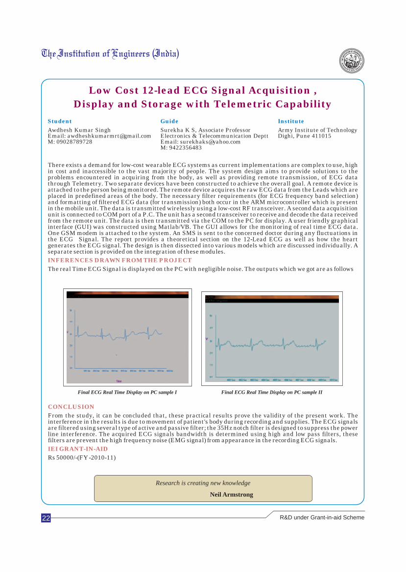
The real Time ECG Signal is displayed on the PC with negligible noise. The outputs which we got are as follows
INFERENCES DRAWN FROM THE PROJECT
CONCLUSION
IEI GRANT-IN-AID
From the study, it can be concluded that, these practical results prove the validity of the present work. The interference in the results is due to movement of patient's body during recording and supplies. The ECG signals are filtered using several type of active and passive filter; the 35Hz notch filter is designed to suppress the power line interference. The acquired ECG signals bandwidth is determined using high and low pass filters, these filters are prevent the high frequency noise (EMG signal) from appearance in the recording ECG signals.
Rs 50000/-(FY -2010-11)
Final ECG Real Time Display on PC sample I Final ECG Real Time Display on PC sample II
R&D under Grant-in-aid Scheme
Research is creating new knowledge
Neil Armstrong

23
Solar Thermal Power Plant by
using Solar Concentrator
Student Guide Institute
Madhumanchi Naveena Prof Pradeep B Jyoti Shirdi Sai Engineering CollegeProf and Head, Dept of EEE Sai Leo Nagar, Samundhur Post Email:[email protected] Anekal, Bengaluru 562106
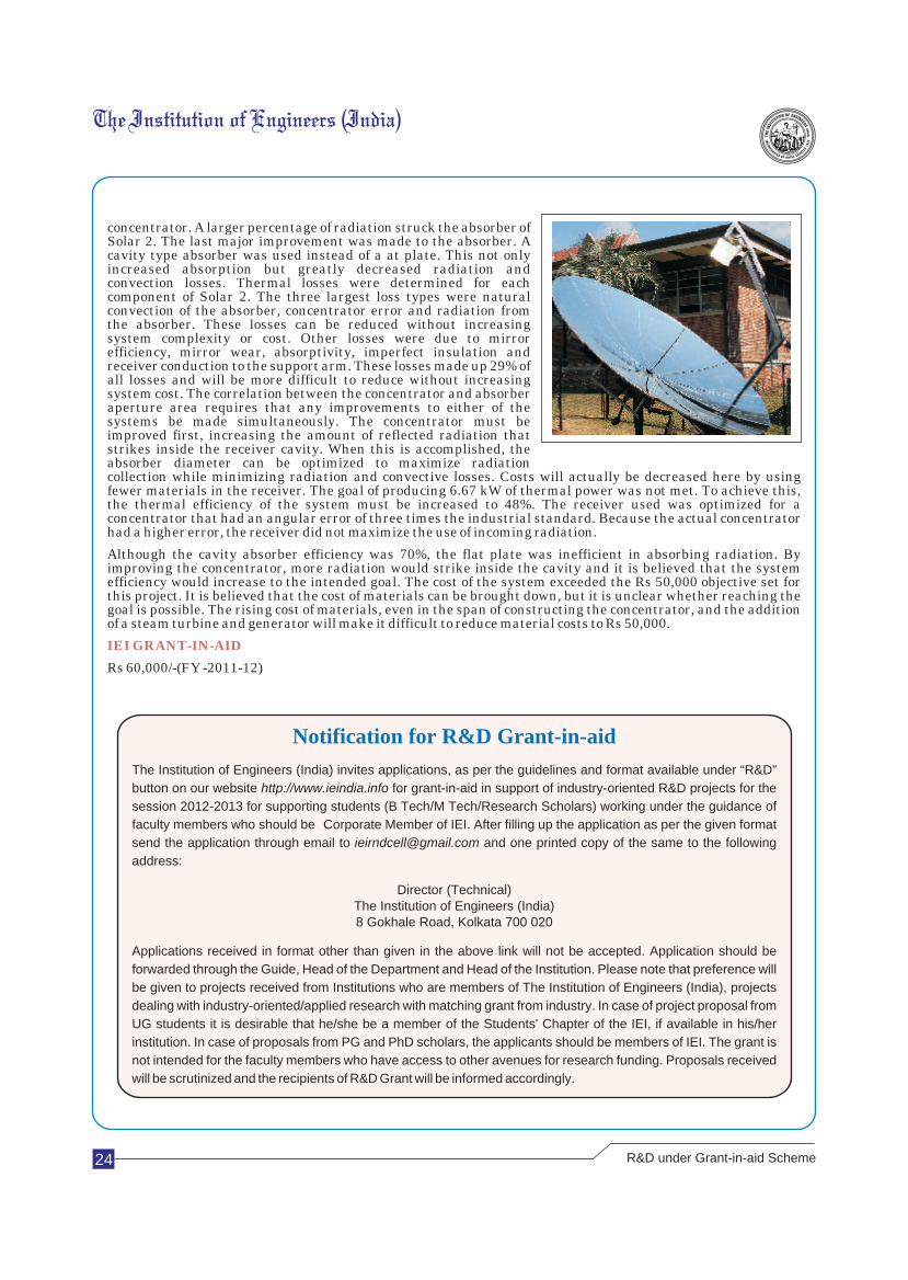
The world is dependent upon energy. People's energy use directly correlates to their grade of health care, life expectancy and education. These are important factors that determine a person's quality of life. One quantitative measure of life quality is the Human Development Index (HDI). The HDI combines life expectancy, literacy, education and GDP per capita for different countries. Electricity allows people access to refrigeration for food and medicine, energy for cooking and cleaning water, and allows people to read and study at night when there is little work that can be done outside. A small amount of electricity can dramatically change the life of a person who has had none. It is estimated that the power requirement for basic healthy functioning in rural communities is about 0.08 kWh/day/person. This is less than 1% of an average person's usage in the United States, yet many people can not afford or do not have access to even this small amount.Nearly two billion people live in rural areas without access to electrical grids. Developing an infrastructure in these remote areas is usually not feasible due to the extreme distance from existing electric grids. Building new power plants in these areas is not cost effective due to the relatively low electricity consumption. Economical, small-scale, distributed energy systems can fulfill the need and renewable energy is ideally suited for this purpose. Many under-developed areas around the world receive large amounts of sunlight. Northern Africa and Central Asia receive as much as 7.5 kWh/m2/day. There is great opportunity to use solar power to provide basic energy needs in these regions. The two most prominent solar energy technologies are photovoltaic (PV) and concentrated solar power (CSP). PV systems are beneficial because they can be scaled to any size, but they are costly and solely produce electricity. CSP systems can provide electricity as well as thermal power. This thermal power can be efficiently used for cooking, water distillation and absorption refrigeration cycles. The drawback to these systems is that the most efficient solar thermal systems currently have an installation cost of $10,000/kW. An economic CSP system could provide rural areas with electricity and energy needs to dramatically improve their quality of life. This project is a continuation of work performed at the Sustainable Energy Science and Engineering Center (SESEC) to build an economic CSP system. The first system built at SESEC constantly provided roughly 2.5 kW of thermal energy. 6.67 kW is the minimum input power required for a micro-steam turbine to produce 1 kW of electrical power. The goal of this project is to provide at least 6.67 kW of thermal power at an installation cost of $1,000. The system must be easy enough to be constructed and maintained by non-technical personnel.
i. Improve concentrator geometry. This will make the largest difference in system efficiency.
ii. Decrease cavity aperture size. With an improved concentrator, the absorber radius should be decreased to take advantage of the improved optical efficiency. This will decrease radiation and convection.
iii. Eliminate the at plate absorber. Use only the cavity absorber and insulate all other surfaces on the receiver.
iv. Add a pump. A water pump will allow for steady steam production.
v. Correct tracking system. Program safety procedures to keep tracking system from moving when clouds block sunlight.
vi. Increase boiler support. By stiffening the receiver arm, the tracking will err less in the morning and evening.
vii. Add steam turbine. The system is now ready to test with a micro-steam turbine.
2A 14 m parabolic dish concentrator, nicknamed Solar 2, was built at SESEC. The system used a cavity type receiver with 10 kg of sodium nitrate to act as heat storage. The goal of the system was to provide 6.67 kW of thermal energy, enough to provide 1 kW of electricity with a micro-steam turbine. Many improvements were made from the first concentrator system built at SESEC, which provided only 1 kW of thermal energy. The concentrator, mirror and receiver were all redesigned to increase thermal conversion efficiency. The gross thermal efficiency of the system at a cavity angle of 53 degrees was 39%. This was a 333% increase from the first system assembled at SESEC, Solar 1. Efficiency was improved in multiple areas from Solar 1. First, the mirror efficiency was increased to possibly double that of Solar 1. The second major improvement was made to the
INFERENCES DRAWN FROM THE PROJECT
CONCLUSION
R&D under Grant-in-aid Scheme
24
concentrator. A larger percentage of radiation struck the absorber of Solar 2. The last major improvement was made to the absorber. A cavity type absorber was used instead of a at plate. This not only increased absorption but greatly decreased radiation and convection losses. Thermal losses were determined for each component of Solar 2. The three largest loss types were natural convection of the absorber, concentrator error and radiation from the absorber. These losses can be reduced without increasing system complexity or cost. Other losses were due to mirror efficiency, mirror wear, absorptivity, imperfect insulation and receiver conduction to the support arm. These losses made up 29% of all losses and will be more difficult to reduce without increasing system cost. The correlation between the concentrator and absorber aperture area requires that any improvements to either of the systems be made simultaneously. The concentrator must be improved first, increasing the amount of reflected radiation that strikes inside the receiver cavity. When this is accomplished, the absorber diameter can be optimized to maximize radiation collection while minimizing radiation and convective losses. Costs will actually be decreased here by using fewer materials in the receiver. The goal of producing 6.67 kW of thermal power was not met. To achieve this, the thermal efficiency of the system must be increased to 48%. The receiver used was optimized for a concentrator that had an angular error of three times the industrial standard. Because the actual concentrator had a higher error, the receiver did not maximize the use of incoming radiation.
Although the cavity absorber efficiency was 70%, the flat plate was inefficient in absorbing radiation. By improving the concentrator, more radiation would strike inside the cavity and it is believed that the system efficiency would increase to the intended goal. The cost of the system exceeded the Rs 50,000 objective set for this project. It is believed that the cost of materials can be brought down, but it is unclear whether reaching the goal is possible. The rising cost of materials, even in the span of constructing the concentrator, and the addition of a steam turbine and generator will make it difficult to reduce material costs to Rs 50,000.
Rs 60,000/-(FY -2011-12)
IEI GRANT-IN-AID
R&D under Grant-in-aid Scheme
The Institution of Engineers (India) invites applications, as per the guidelines and format available under “R&D” button on our website http://www.ieindia.info for grant-in-aid in support of industry-oriented R&D projects for the session 2012-2013 for supporting students (B Tech/M Tech/Research Scholars) working under the guidance of faculty members who should be Corporate Member of IEI. After filling up the application as per the given format send the application through email to [email protected] and one printed copy of the same to the following address:
Director (Technical)The Institution of Engineers (India)8 Gokhale Road, Kolkata 700 020
Applications received in format other than given in the above link will not be accepted. Application should be forwarded through the Guide, Head of the Department and Head of the Institution. Please note that preference will be given to projects received from Institutions who are members of The Institution of Engineers (India), projects dealing with industry-oriented/applied research with matching grant from industry. In case of project proposal from UG students it is desirable that he/she be a member of the Students' Chapter of the IEI, if available in his/her institution. In case of proposals from PG and PhD scholars, the applicants should be members of IEI. The grant is not intended for the faculty members who have access to other avenues for research funding. Proposals received will be scrutinized and the recipients of R&D Grant will be informed accordingly.
Notification for R&D Grant-in-aid
25
Biosorption of Heavy Metals (Cadmium, Mercury, Nickel,
Zinc and Chromium) using Sugar Beet Pulp
Student Guide Institute
Ms Nishtha Gupta Dr Anand Prem Rajan, Ph D, Email:[email protected] Division of Environmental Biotechnology School of Bio Sciences and M: 09952584769 Email: [email protected] Technology
M: 09486336444 Vellore 632014
Professor VIT University
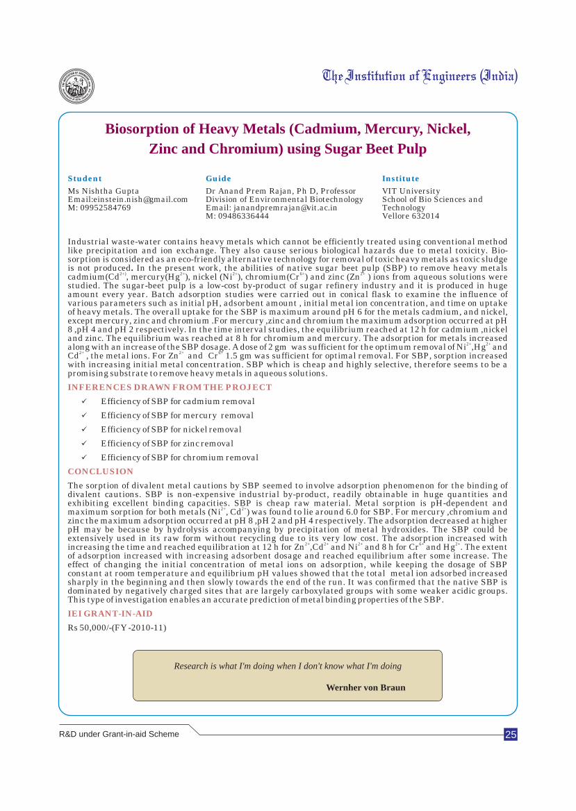
Industrial waste-water contains heavy metals which cannot be efficiently treated using conventional method like precipitation and ion exchange. They also cause serious biological hazards due to metal toxicity. Bio-sorption is considered as an eco-friendly alternative technology for removal of toxic heavy metals as toxic sludge is not produced. In the present work, the abilities of native sugar beet pulp (SBP) to remove heavy metals
2+) 2+ 2+ 6+ 2+cadmium(Cd , mercury(Hg ), nickel (Ni ), chromium(Cr ) and zinc (Zn ) ions from aqueous solutions were studied. The sugar-beet pulp is a low-cost by-product of sugar refinery industry and it is produced in huge amount every year. Batch adsorption studies were carried out in conical flask to examine the influence of various parameters such as initial pH, adsorbent amount , initial metal ion concentration, and time on uptake of heavy metals. The overall uptake for the SBP is maximum around pH 6 for the metals cadmium, and nickel, except mercury, zinc and chromium .For mercury ,zinc and chromium the maximum adsorption occurred at pH 8 ,pH 4 and pH 2 respectively. In the time interval studies, the equilibrium reached at 12 h for cadmium ,nickel and zinc. The equilibrium was reached at 8 h for chromium and mercury. The adsorption for metals increased
2+ 2+along with an increase of the SBP dosage. A dose of 2 gm was sufficient for the optimum removal of Ni ,Hg and 2+ 2+ 6+Cd , the metal ions. For Zn and Cr 1.5 gm was sufficient for optimal removal. For SBP, sorption increased
with increasing initial metal concentration. SBP which is cheap and highly selective, therefore seems to be a promising substrate to remove heavy metals in aqueous solutions.
üEfficiency of SBP for cadmium removal
üEfficiency of SBP for mercury removal
üEfficiency of SBP for nickel removal
üEfficiency of SBP for zinc removal
üEfficiency of SBP for chromium removal
The sorption of divalent metal cautions by SBP seemed to involve adsorption phenomenon for the binding of divalent cautions. SBP is non-expensive industrial by-product, readily obtainable in huge quantities and exhibiting excellent binding capacities. SBP is cheap raw material. Metal sorption is pH-dependent and
2+ 2+maximum sorption for both metals (Ni , Cd ) was found to lie around 6.0 for SBP. For mercury ,chromium and zinc the maximum adsorption occurred at pH 8 ,pH 2 and pH 4 respectively. The adsorption decreased at higher pH may be because by hydrolysis accompanying by precipitation of metal hydroxides. The SBP could be extensively used in its raw form without recycling due to its very low cost. The adsorption increased with
2+ 2+ 2+ 6+ 2+increasing the time and reached equilibration at 12 h for Zn ,Cd and Ni and 8 h for Cr and Hg . The extent of adsorption increased with increasing adsorbent dosage and reached equilibrium after some increase. The effect of changing the initial concentration of metal ions on adsorption, while keeping the dosage of SBP constant at room temperature and equilibrium pH values showed that the total metal ion adsorbed increased sharply in the beginning and then slowly towards the end of the run. It was confirmed that the native SBP is dominated by negatively charged sites that are largely carboxylated groups with some weaker acidic groups. This type of investigation enables an accurate prediction of metal binding properties of the SBP.
Rs 50,000/-(FY -2010-11)
INFERENCES DRAWN FROM THE PROJECT
CONCLUSION
IEI GRANT-IN-AID
Research is what I'm doing when I don't know what I'm doing
Wernher von Braun
R&D under Grant-in-aid Scheme
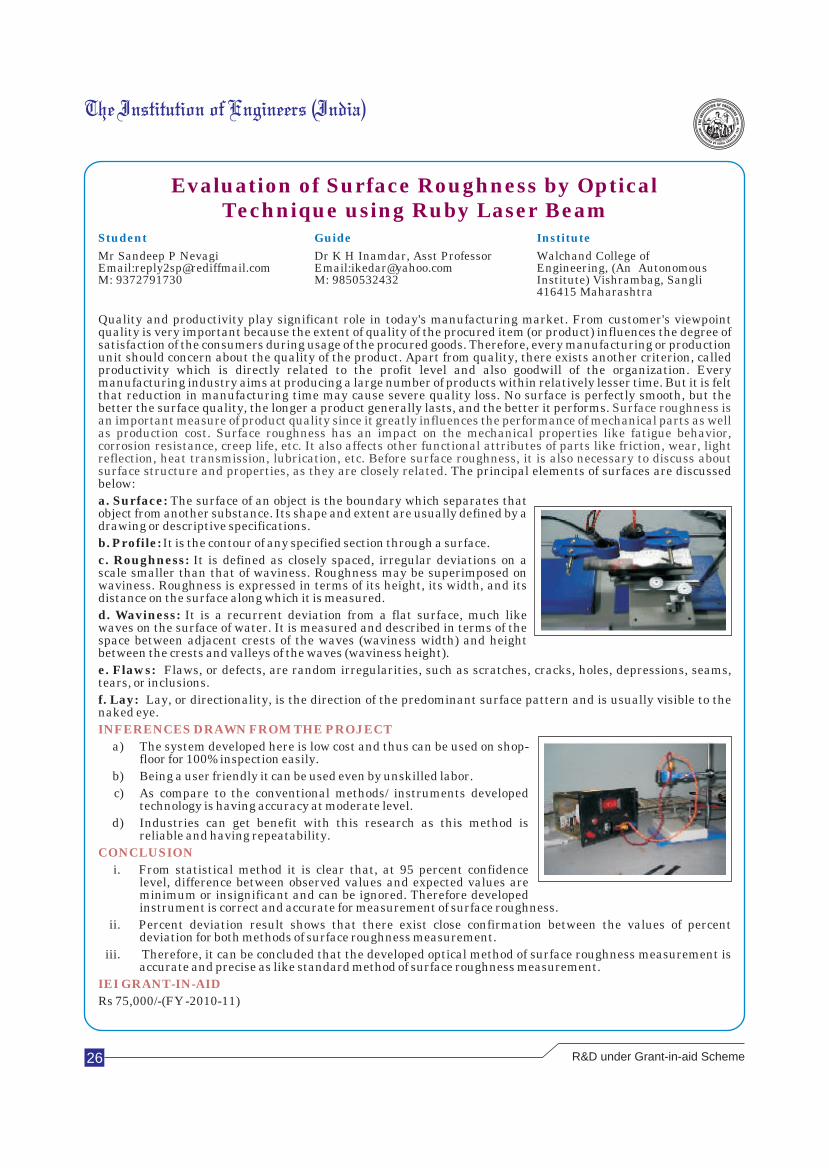
26
Evaluation of Surface Roughness by OpticalTechnique using Ruby Laser Beam
Student Guide Institute
Mr Sandeep P Nevagi Dr K H Inamdar, Asst Professor Walchand College of Email:[email protected] Email:[email protected] Engineering, (An Autonomous M: 9372791730 M: 9850532432 Institute) Vishrambag, Sangli
416415 Maharashtra
Quality and productivity play significant role in today's manufacturing market. From customer's viewpoint quality is very important because the extent of quality of the procured item (or product) influences the degree of satisfaction of the consumers during usage of the procured goods. Therefore, every manufacturing or production unit should concern about the quality of the product. Apart from quality, there exists another criterion, called productivity which is directly related to the profit level and also goodwill of the organization. Every manufacturing industry aims at producing a large number of products within relatively lesser time. But it is felt that reduction in manufacturing time may cause severe quality loss. No surface is perfectly smooth, but the better the surface quality, the longer a product generally lasts, and the better it performs.
The principal elements of surfaces are discussed below:
a. Surface: The surface of an object is the boundary which separates that object from another substance. Its shape and extent are usually defined by a drawing or descriptive specifications.
b. Profile: It is the contour of any specified section through a surface.
c. Roughness: It is defined as closely spaced, irregular deviations on a scale smaller than that of waviness. Roughness may be superimposed on waviness. Roughness is expressed in terms of its height, its width, and its distance on the surface along which it is measured.
d. Waviness: It is a recurrent deviation from a flat surface, much like waves on the surface of water. It is measured and described in terms of the space between adjacent crests of the waves (waviness width) and height between the crests and valleys of the waves (waviness height).
e. Flaws: Flaws, or defects, are random irregularities, such as scratches, cracks, holes, depressions, seams, tears, or inclusions.
f. Lay: Lay, or directionality, is the direction of the predominant surface pattern and is usually visible to the naked eye.
a) The system developed here is low cost and thus can be used on shop-floor for 100% inspection easily.
b) Being a user friendly it can be used even by unskilled labor.
c) As compare to the conventional methods/ instruments developed technology is having accuracy at moderate level.
d) Industries can get benefit with this research as this method is reliable and having repeatability.
i. From statistical method it is clear that, at 95 percent confidence level, difference between observed values and expected values are minimum or insignificant and can be ignored. Therefore developed instrument is correct and accurate for measurement of surface roughness.
ii. Percent deviation result shows that there exist close confirmation between the values of percent deviation for both methods of surface roughness measurement.
iii. Therefore, it can be concluded that the developed optical method of surface roughness measurement is accurate and precise as like standard method of surface roughness measurement.
Rs 75,000/-(FY -2010-11)
Surface roughness is an important measure of product quality since it greatly influences the performance of mechanical parts as well as production cost. Surface roughness has an impact on the mechanical properties like fatigue behavior, corrosion resistance, creep life, etc. It also affects other functional attributes of parts like friction, wear, light reflection, heat transmission, lubrication, etc. Before surface roughness, it is also necessary to discuss about surface structure and properties, as they are closely related.
INFERENCES DRAWN FROM THE PROJECT
CONCLUSION
IEI GRANT-IN-AID
R&D under Grant-in-aid Scheme
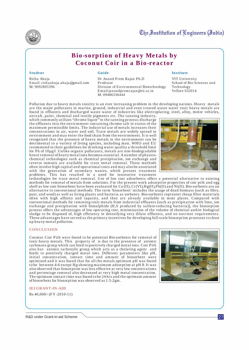
27
Bio-sorption of Heavy Metals byCoconut Coir in a Bio-reactor
Student Guide Institute
Richa Ahuja Dr Anand Prem Rajan Ph.D VIT UniversityEmail: [email protected] Professor School of Bio Sciences and M: 9092805396 Division of Environmental Biotechnology Technology
Email:[email protected] Vellore 632014M: 09486336444
Pollution due to heavy metals toxicity is an ever increasing problem in the developing nations. Heavy metals are the major pollutants in marine, ground, industrial and even treated waste water toxic heavy metals are found in effluents and discharged waste water of industries like electroplating, steel, alloy, motor vehicles, aircraft, paint, chemical and textile pigments etc. The tanning industry, which commonly utilizes “chrome liquor” in the tanning process; discharge the effluents into the environment containing chrome salt in excess of the maximum permissible limits. The industrial use of metals increases their concentrations in air, water and soil. Trace metals are widely spread in environment and may enter the food chain from the environment. It is well recognized that the presence of heavy metals in the environment can be detrimental to a variety of living species, including man. WHO and EU recommend in their guidelines for drinking water quality a threshold limit for Pb of 10µg/l. Unlike organic pollutants, metals are non-biodegradable hence removal of heavy metal ions becomes essential. A number of physico-chemical technologies such as chemical precipitation, ion exchange and reverse osmosis are available for trace metal removal. These methods often involve high capital and operational costs and may also be associated with the generation of secondary wastes, which present treatment problems. This has resulted in a need for innovative treatment technologies for trace metal removal. Use of low cost adsorbents offers a potential alternative to existing methods for removal of metals from solutions. For the present work adsorptive properties of coir ptih and egg shell as low cost biosorbent have been evaluated for Co (II), Cr(VI),Hg(II),Pb(II) and Ni(II). Bio-sorbents are an alternative to conventional methods. The term 'biosorbent' includes the usage of dead biomass (such as fibre, peat, and wool) as well as living plants and bacteria as sorbents. Bio-sorbents represent cheap filter materials often with high affinity and capacity, and they are already available in most places. Compared with conventional methods for removing toxic metals from industrial effluents [such as precipitation with lime, ion exchange and precipitation with biosulphide (H S produced by sulfate-reducing bacteria)], the biosorption 2
process offers the advantages of low operating cost, minimization of the volume of chemical and/or biological sludge to be disposed of, high efficiency in detoxifying very dilute effluents, and no nutrient requirements. These advantages have served as the primary incentives for developing full-scale biosorption processes to clean up heavy-metal pollution.
Coconut Coir Pith were found to be potential Bio-sorbents for removal of toxic heavy metals. This property of is due to the presence of anionic carbonate group which can bind to positively charged metal ions. Coir Pith also has anionic carboxylic group which acts as a chelating agent and binds to positively charged metal ions. Different parameters like pH, initial concentration, contact time and amount of biosorbent were optimized and it was found that for all the metals optimum pH was found to be between 4-6 except Hg showing maximum adsorption at pH 8. It was also observed that biosorption was less effective at very low concentrations and percentage removal also decreased at very high metal concentration. The optimum contact time was found to be 24 hrs and the optimum amount of biosorbent for biosorption was observed as 1.5-2gm.
Rs 40,000/- (FY -2010-11)
CONCLUSION
IEI GRANT-IN-AID
R&D under Grant-in-aid Scheme
28
Differential Ventilation of Lungs
Student Guide Institute
Dileep K Kumar Ms Remya George Sahrdaya College of Engg & Email: [email protected] Asst Professor, Deptt TechnologyM: 9496838938 of Biomedical Engg Kodakara, Thrissur 680684
The primary function of the respiratory system is to supply the blood with oxygen in order to deliver oxygen to all parts of the body The respiratory system does this through breathing. Breathing is the process that moves air in and out of the lungs. Aerobic organisms require oxygen to release energy via respiration in the form of the metabolism of energy rich molecules such as glucose. Breathing is only one process that delivers oxygen to where it is needed in the body and removes carbon dioxide. Respiration is achieved through the mouth, nose, trachea, lungs and diaphragm. Oxygen enters the respiratory system through the mouth and the nose. The oxygen then passes through the larynx and the trachea which is a tube that enters the chest cavity. In the chest cavity, the trachea splits into two smaller tubes called the bronchi. Each bronchus then divides again forming the bronchial tubes. The bronchial tubes lead directly into the lungs where they divide into many smaller tubes which connect to tiny sacs called alveoli. The inhaled oxygen passes into the alveoli and then diffuses through the capillaries into the arterial blood. Meanwhile, the waste-rich blood from the veins releases ins carbon dioxide into the alveoli. The carbon dioxide follows the same path out of the lungs when you exhale. Normal breathing rate is 12-14/ minute. The tidal volume in man is about 500 ml. The volume of air breathed in and out during normal effortless respiration is called tidal volume. Some people who have lost all ability to breathe on their own may need to use ventilators. A medical ventilator may be defined as any machine designed to mechanically move breathable air into and out of lungs, to provide the mechanism of breathing for a patient who is physically unable to breathe, or breathing insufficiently. There will be people with asymmetric lung disease. By chance if they need the assistance of ventilator there will be some inequality in the amount of air entering to the normal lungs as well as to the asymmetric lung. This problem will lead to the collapse of the diseased lung. A solution for this problem is by the approach of providing differential ventilation to the lung.
The project on the topic differential ventilation of lung has been completed successfully. The product developed can be commercialized as an enhanced safety system to the normal ventilator machine. With the help of this product, normal ventilation can be provided to individuals with symmetric lungs and differential ventilation to those with asymmetric lung disease. The system measures the instantaneous pressure to each lung separately during ventilation to detect any change in volume of air supplied to each lung. This condition which is usually caused by asymmetric lung disease can be overcome by the product by differentially providing ventilation to each lung, ensuring an equalized volume of air to both lungs, thereby reducing the risk of collapsing of the asymmetric lung. The requirement of an X-ray or other imaging techniques to initially determine the asymmetric lung disease is also reduced.
The product can be improved by incorporating Spirometry which can help in determining the exact tidal volume of an individual and supplying the appropriate volumes of air to the lungs. A microphone can be added to the system to acquire the lung sound parameters. This product can be implemented in the Intensive Care Units of hospital. It can serve as an option between the ventilator and the patient. This can aid patients with Asymmetric lung disease. In future we can develop an automatic version of the product with the above features.
Differential ventilation is used in patients with severe respiratory failure caused by asymmetric lung disease. The aim is to prevent the dangerous ventilation perfusion inequality induced in the cases by standard mechanical ventilation. The product provides a distribution of equal amount of ventilation to both the lungs, thereby reducing the risk of collapsing of the asymmetric lung.
Rs 10,000/-(FY -2011-12)
INFERENCES DRAWN FROM THE PROJECT
CONCLUSION
IEI GRANT-IN-AID
Scientific research is one of the most exciting and rewarding of occupations
Frederick Sanger
R&D under Grant-in-aid Scheme
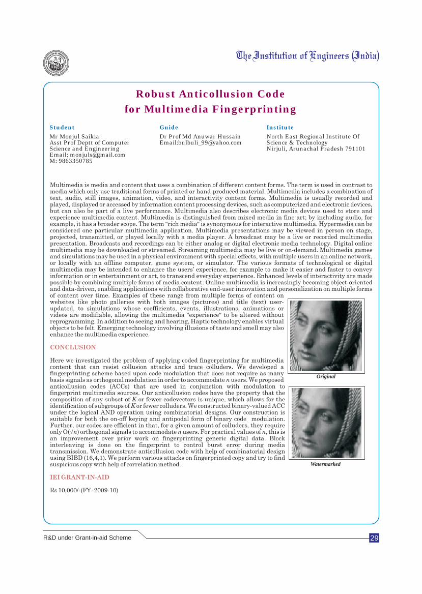
29
Robust Anticollusion Code
for Multimedia Fingerprinting
Student Guide Institute
Mr Monjul SaikiaAsst Prof Deptt of Computer Email:[email protected] Science & TechnologyScience and Engineering Nirjuli, Arunachal Pradesh 791101Email: [email protected]: 9863350785
Dr Prof Md Anuwar Hussain North East Regional Institute Of
Watermarked
Original
R&D under Grant-in-aid Scheme
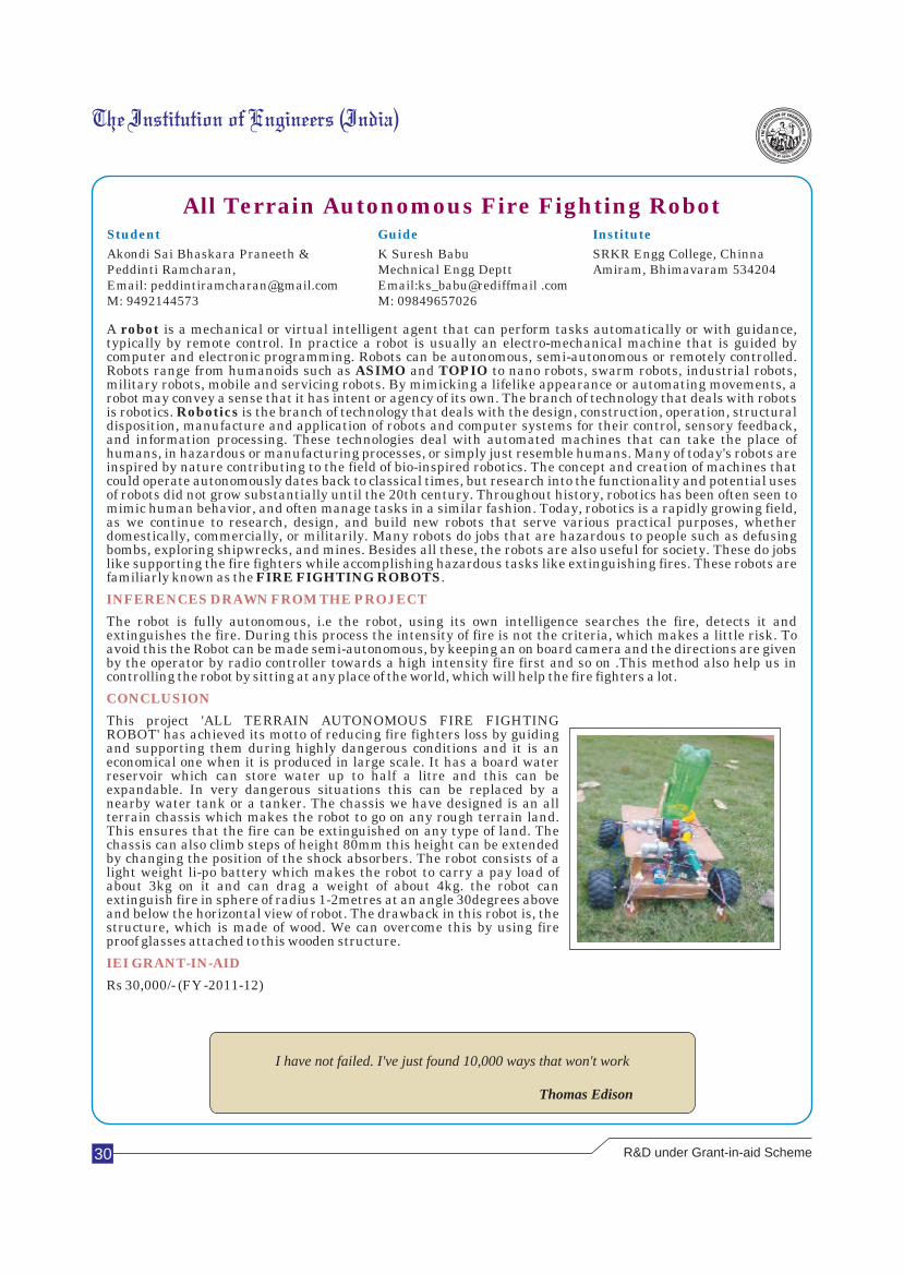
30
All Terrain Autonomous Fire Fighting RobotStudent Guide Institute
Akondi Sai Bhaskara Praneeth &Peddinti Ramcharan, Mechnical Engg Deptt Amiram, Bhimavaram 534204Email: [email protected] Email:ks_babu@rediffmail .comM: 9492144573 M: 09849657026
K Suresh Babu SRKR Engg College, Chinna
A robot is a mechanical or virtual intelligent agent that can perform tasks automatically or with guidance, typically by remote control. In practice a robot is usually an electro-mechanical machine that is guided by computer and electronic programming. Robots can be autonomous, semi-autonomous or remotely controlled. Robots range from humanoids such as ASIMO and TOPIO to nano robots, swarm robots, industrial robots, military robots, mobile and servicing robots. By mimicking a lifelike appearance or automating movements, a robot may convey a sense that it has intent or agency of its own. The branch of technology that deals with robots is robotics. Robotics is the branch of technology that deals with the design, construction, operation, structural disposition, manufacture and application of robots and computer systems for their control, sensory feedback, and information processing. These technologies deal with automated machines that can take the place of humans, in hazardous or manufacturing processes, or simply just resemble humans. Many of today's robots are inspired by nature contributing to the field of bio-inspired robotics. The concept and creation of machines that could operate autonomously dates back to classical times, but research into the functionality and potential uses of robots did not grow substantially until the 20th century. Throughout history, robotics has been often seen to mimic human behavior, and often manage tasks in a similar fashion. Today, robotics is a rapidly growing field, as we continue to research, design, and build new robots that serve various practical purposes, whether domestically, commercially, or militarily. Many robots do jobs that are hazardous to people such as defusing bombs, exploring shipwrecks, and mines. Besides all these, the robots are also useful for society. These do jobs like supporting the fire fighters while accomplishing hazardous tasks like extinguishing fires. These robots are familiarly known as the FIRE FIGHTING ROBOTS.
The robot is fully autonomous, i.e the robot, using its own intelligence searches the fire, detects it and extinguishes the fire. During this process the intensity of fire is not the criteria, which makes a little risk. To avoid this the Robot can be made semi-autonomous, by keeping an on board camera and the directions are given by the operator by radio controller towards a high intensity fire first and so on .This method also help us in controlling the robot by sitting at any place of the world, which will help the fire fighters a lot.
This project 'ALL TERRAIN AUTONOMOUS FIRE FIGHTING ROBOT' has achieved its motto of reducing fire fighters loss by guiding and supporting them during highly dangerous conditions and it is an economical one when it is produced in large scale. It has a board water reservoir which can store water up to half a litre and this can be expandable. In very dangerous situations this can be replaced by a nearby water tank or a tanker. The chassis we have designed is an all terrain chassis which makes the robot to go on any rough terrain land. This ensures that the fire can be extinguished on any type of land. The chassis can also climb steps of height 80mm this height can be extended by changing the position of the shock absorbers. The robot consists of a light weight li-po battery which makes the robot to carry a pay load of about 3kg on it and can drag a weight of about 4kg. the robot can extinguish fire in sphere of radius 1-2metres at an angle 30degrees above and below the horizontal view of robot. The drawback in this robot is, the structure, which is made of wood. We can overcome this by using fire proof glasses attached to this wooden structure.
Rs 30,000/- (FY -2011-12)
INFERENCES DRAWN FROM THE PROJECT
CONCLUSION
IEI GRANT-IN-AID
I have not failed. I've just found 10,000 ways that won't work
Thomas Edison
R&D under Grant-in-aid Scheme
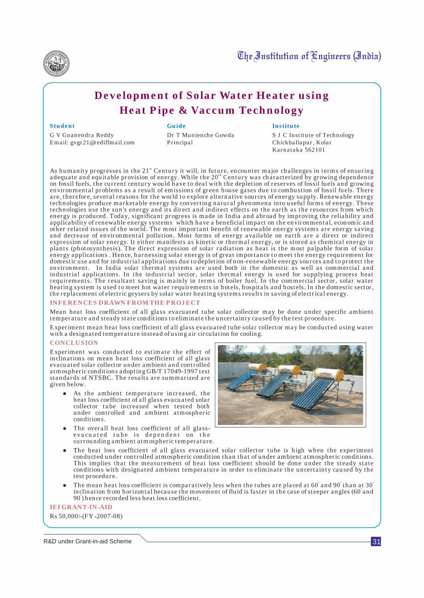
31
Development of Solar Water Heater using
Heat Pipe & Vaccum Technology
Student Guide Institute
G V Gnanendra Reddy Dr T Munienche Gowda S J C Institute of TechnologyEmail: [email protected] Principal Chickballapur, Kolar
Karnataka 562101
stAs humanity progresses in the 21 Century it will, in future, encounter major challenges in terms of ensuring thadequate and equitable provision of energy. While the 20 Century was characterized by growing dependence
on fossil fuels, the current century would have to deal with the depletion of reserves of fossil fuels and growing environmental problems as a result of emissions of green house gases due to combustion of fossil fuels. There are, therefore, several reasons for the world to explore alternative sources of energy supply. Renewable energy technologies produce marketable energy by converting natural phenomena into useful forms of energy. These technologies use the sun's energy and its direct and indirect effects on the earth as the resources from which energy is produced. Today, significant progress is made in India and abroad by improving the reliability and applicability of renewable energy systems which have a beneficial impact on the environmental, economic and other related issues of the world. The most important benefit of renewable energy systems are energy saving and decrease of environmental pollution. Most forms of energy available on earth are a direct or indirect expression of solar energy. It either manifests as kinetic or thermal energy, or is stored as chemical energy in plants (photosynthesis). The direct expression of solar radiation as heat is the most palpable form of solar energy applications . Hence, harnessing solar energy is of great importance to meet the energy requirement for domestic use and for industrial applications due to depletion of non-renewable energy sources and to protect the environment. In India solar thermal systems are used both in the domestic as well as commercial and industrial applications. In the industrial sector, solar thermal energy is used for supplying process heat requirements. The resultant saving is mainly in terms of boiler fuel. In the commercial sector, solar water heating system is used to meet hot water requirements in hotels, hospitals and hostels. In the domestic sector, the replacement of electric geysers by solar water heating systems results in saving of electrical energy.
Mean heat loss coefficient of all glass evacuated tube solar collector may be done under specific ambient temperature and steady state conditions to eliminate the uncertainty caused by the test procedure.
Experiment mean heat loss coefficient of all glass evacuated tube solar collector may be conducted using water with a designated temperature instead of using air circulation for cooling.
Experiment was conducted to estimate the effect of inclinations on mean heat loss coefficient of all glass evacuated solar collector under ambient and controlled atmospheric conditions adopting GB/T 17049-1997 test standards of NTSBC. The results are summarized are given below.
lAs the ambient temperature increased, the heat loss coefficient of all glass evacuated solar collector tube increased when tested both under controlled and ambient atmospheric conditions.
lThe overall heat loss coefficient of all glass-evacuated tube is dependent on the surrounding ambient atmospheric temperature.
lThe heat loss coefficient of all glass evacuated solar collector tube is high when the experiment conducted under controlled atmospheric condition than that of under ambient atmospheric conditions. This implies that the measurement of heat loss coefficient should be done under the steady state conditions with designated ambient temperature in order to eliminate the uncertainty caused by the test procedure.
º º ºlThe mean heat loss coefficient is comparatively less when the tubes are placed at 60 and 90 than at 30
º inclination from horizontal because the movement of fluid is faster in the case of steeper angles (60 and º90 ) hence recorded less heat loss coefficient.
Rs 50,000/-(FY -2007-08)
INFERENCES DRAWN FROM THE PROJECT
CONCLUSION
IEI GRANT-IN-AID
R&D under Grant-in-aid Scheme
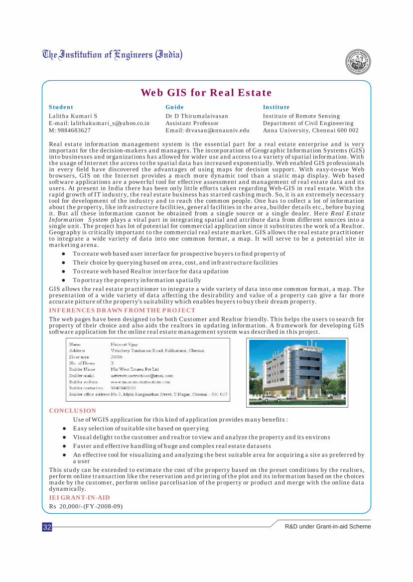
32
Web GIS for Real EstateStudent Guide Institute
Lalitha Kumari S Dr D Thirumalaivasan Institute of Remote Sensing E-mail: [email protected] Assistant Professor Department of Civil EngineeringM: 9884683627 Email: [email protected] Anna University, Chennai 600 002
Real estate information management system is the essential part for a real estate enterprise and is very important for the decision-makers and managers. The incorporation of Geographic Information Systems (GIS) into businesses and organizations has allowed for wider use and access to a variety of spatial information. With the usage of Internet the access to the spatial data has increased exponentially. Web enabled GIS professionals in every field have discovered the advantages of using maps for decision support. With easy-to-use Web browsers, GIS on the Internet provides a much more dynamic tool than a static map display. Web based software applications are a powerful tool for effective assessment and management of real estate data and its users. At present in India there has been only little efforts taken regarding Web-GIS in real estate. With the rapid growth of IT industry, the real estate business has started cashing much. So, it is an extremely necessary tool for development of the industry and to reach the common people. One has to collect a lot of information about the property, like infrastructure facilities, general facilities in the area, builder details etc., before buying it. But all these information cannot be obtained from a single source or a single dealer. Here Real Estate Information System plays a vital part in integrating spatial and attribute data from different sources into a single unit. The project has lot of potential for commercial application since it substitutes the work of a Realtor. Geography is critically important to the commercial real estate market. GIS allows the real estate practitioner to integrate a wide variety of data into one common format, a map. It will serve to be a potential site in marketing arena.
lTo create web based user interface for prospective buyers to find property of
lTheir choice by querying based on area, cost, and infrastructure facilities
lTo create web based Realtor interface for data updation
lTo portray the property information spatially
GIS allows the real estate practitioner to integrate a wide variety of data into one common format, a map. The presentation of a wide variety of data affecting the desirability and value of a property can give a far more accurate picture of the property's suitability which enables buyers to buy their dream property.
The web pages have been designed to be both Customer and Realtor friendly. This helps the users to search for property of their choice and also aids the realtors in updating information. A framework for developing GIS software application for the online real estate management system was described in this project.
INFERENCES DRAWN FROM THE PROJECT
CONCLUSION
IEI GRANT-IN-AID
Use of WGIS application for this kind of application provides many benefits :
lEasy selection of suitable site based on querying
lVisual delight to the customer and realtor to view and analyze the property and its environs
lFaster and effective handling of huge and complex real estate datasets
lAn effective tool for visualizing and analyzing the best suitable area for acquiring a site as preferred by a user
This study can be extended to estimate the cost of the property based on the preset conditions by the realtors, perform online transaction like the reservation and printing of the plot and its information based on the choices made by the customer, perform online parcelisation of the property or product and merge with the online data dynamically.
Rs 20,000/- (FY -2008-09)
R&D under Grant-in-aid Scheme
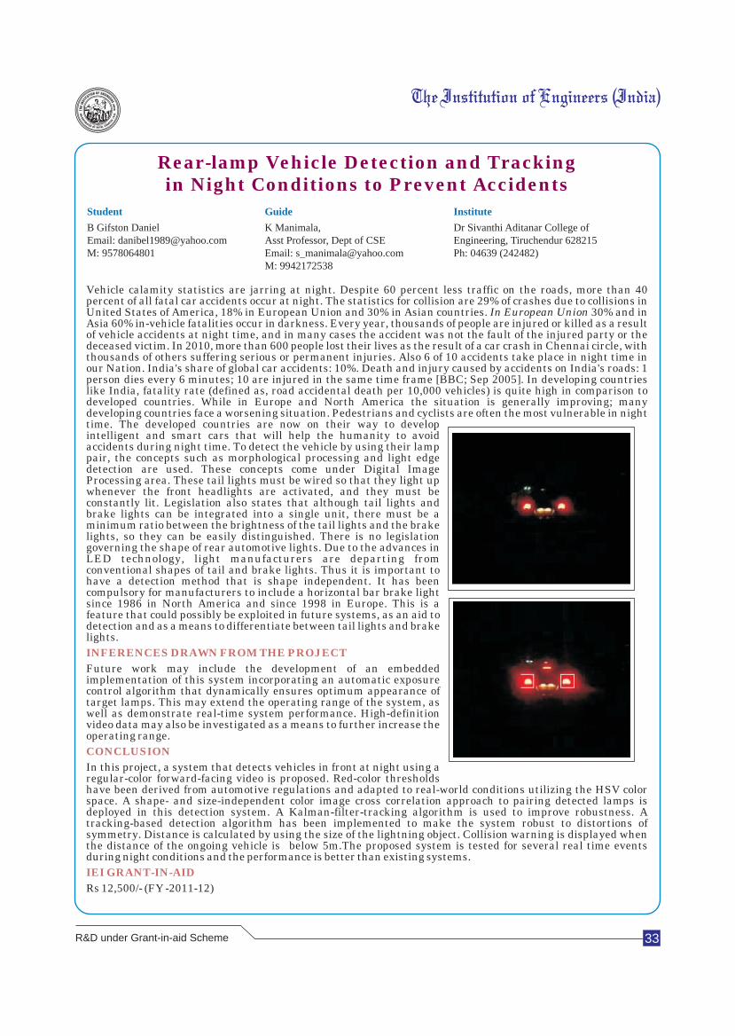
33
Rear-lamp Vehicle Detection and Trackingin Night Conditions to Prevent Accidents
Student Guide Institute
B Gifston Daniel K Manimala, Dr Sivanthi Aditanar College ofEmail: [email protected] Asst Professor, Dept of CSE Engineering, Tiruchendur 628215M: 9578064801 Email: [email protected] Ph: 04639 (242482)
M: 9942172538
Vehicle calamity statistics are jarring at night. Despite 60 percent less traffic on the roads, more than 40 percent of all fatal car accidents occur at night. The statistics for collision are 29% of crashes due to collisions in United States of America, 18% in European Union and 30% in Asian countries. In European Union 30% and in Asia 60% in-vehicle fatalities occur in darkness. Every year, thousands of people are injured or killed as a result of vehicle accidents at night time, and in many cases the accident was not the fault of the injured party or the deceased victim. In 2010, more than 600 people lost their lives as the result of a car crash in Chennai circle, with thousands of others suffering serious or permanent injuries. Also 6 of 10 accidents take place in night time in our Nation. India's share of global car accidents: 10%. Death and injury caused by accidents on India's roads: 1 person dies every 6 minutes; 10 are injured in the same time frame [BBC; Sep 2005]. In developing countries like India, fatality rate (defined as, road accidental death per 10,000 vehicles) is quite high in comparison to developed countries. While in Europe and North America the situation is generally improving; many developing countries face a worsening situation. Pedestrians and cyclists are often the most vulnerable in night time. The developed countries are now on their way to develop intelligent and smart cars that will help the humanity to avoid accidents during night time. To detect the vehicle by using their lamp pair, the concepts such as morphological processing and light edge detection are used. These concepts come under Digital Image Processing area. These tail lights must be wired so that they light up whenever the front headlights are activated, and they must be constantly lit. Legislation also states that although tail lights and brake lights can be integrated into a single unit, there must be a minimum ratio between the brightness of the tail lights and the brake lights, so they can be easily distinguished. There is no legislation governing the shape of rear automotive lights. Due to the advances in LED technology, light manufacturers are departing from conventional shapes of tail and brake lights. Thus it is important to have a detection method that is shape independent. It has been compulsory for manufacturers to include a horizontal bar brake light since 1986 in North America and since 1998 in Europe. This is a feature that could possibly be exploited in future systems, as an aid to detection and as a means to differentiate between tail lights and brake lights.
Future work may include the development of an embedded implementation of this system incorporating an automatic exposure control algorithm that dynamically ensures optimum appearance of target lamps. This may extend the operating range of the system, as well as demonstrate real-time system performance. High-definition video data may also be investigated as a means to further increase the operating range.
In this project, a system that detects vehicles in front at night using a regular-color forward-facing video is proposed. Red-color thresholds have been derived from automotive regulations and adapted to real-world conditions utilizing the HSV color space. A shape- and size-independent color image cross correlation approach to pairing detected lamps is deployed in this detection system. A Kalman-filter-tracking algorithm is used to improve robustness. A tracking-based detection algorithm has been implemented to make the system robust to distortions of symmetry. Distance is calculated by using the size of the lightning object. Collision warning is displayed when the distance of the ongoing vehicle is below 5m.The proposed system is tested for several real time events during night conditions and the performance is better than existing systems.
Rs 12,500/- (FY -2011-12)
INFERENCES DRAWN FROM THE PROJECT
CONCLUSION
IEI GRANT-IN-AID
R&D under Grant-in-aid Scheme
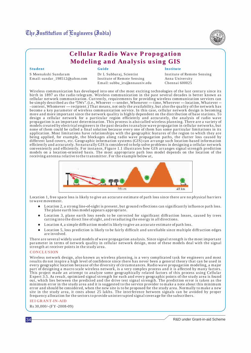
34
Cellular Radio Wave PropogationModeling and Analysis using GIS
Student Guide Institute
S Meenakshi Sundaram Dr L Subbaraj, Scientist Institute of Remote SensingEmail: [email protected] Institute of Remote Sensing Anna University
Email: [email protected] Chennai 600025
Wireless communication has developed into one of the most exciting technologies of the last century since its birth in 1897 as the radio telegram. Wireless communication in the past several decades is better known as cellular network communication. Currently, requirements for providing wireless communication services can be simply described as the “5Ws”. (i.e., Whoever --- sender, Whenever --- time, Wherever --- location, Whatever --- content, Whomever --- recipient.) That means, not only the availability, but also the quality of the network has become a key parameter of wireless communication service. In this case, cellular network design is becoming more and more important since the network quality is highly dependent on the distribution of base stations. To design a cellular network for a particular region efficiently and accurately, the analysis of radio wave propagation is an important determination. This process is also called wireless planning. There are a variety of models created by electrical engineers in the past decades to analyze wave propagation in cellular networks, but none of them could be called a final solution because every one of them has some particular limitations in its application. Most limitations have relationships with the geographic features of the region to which they are being applied, for example, the blockages along radio wave propagation paths, the clutter loss caused by different land covers, etc. Geographic information systems (GIS) can arrange such location-based information efficiently and accurately. So naturally GIS is considered to help solve problems in designing a cellular network conveniently and efficiently. For instance, Figure 1.1 illustrates how GIS arranges signal strength prediction models on a location-oriented basis. The most appropriate path loss model depends on the location of the receiving antenna relative to the transmitter. For the example below at,
Location 1, free space loss is likely to give an accurate estimate of path loss since there are no physical barriers to wave movement.
lLocation 2, a strong line-of-sight is present, but ground reflections can significantly influence path loss. The plane earth loss model appears appropriate.
lLocation 3, plane earth loss needs to be corrected for significant diffraction losses, caused by trees cutting into the direct line of sight, and reradiating the energy in all directions.
lLocation 4, a simple diffraction model is likely to give an accurate estimate of path loss.
lLocation 5, loss prediction is likely to be fairly difficult and unreliable since multiple diffraction edges are involved.
There are several widely used models of wave propagation analysis. Since signal strength is the most important parameter in terms of network quality in cellular network design, most of these models deal with the signal strength at receiver points in the study area.
Wireless network design, also known as wireless planning, is a very complicated task for engineers and most results do not inspire a high level of confidence since there has never been a general theory that can be used in every geographic location because of the diversity of circumstances. Radio wave propagation modeling, a major part of designing a macro scale wireless network, is a very complex process and it is affected by many factors. This project made an attempt to analyze some geographically related factors of this process using Cellular Expert 3.5. As result, optimized signal strength for each and every geographic points of the study area is found out, which lies between the predicted and the drive test signal strength. The prediction error is taken as the minimum error in the study area and it is suggested to the service provider to make a note about this minimum error and should be considered, when the new site is to be proposed for the study area. Normally to make a new site in the study area, it costs about 25 lakhs. The interference between signals can be avoided by proper frequency allocation for the sectors to provide uninterrupted signal coverage for the subscribers.
Rs 30,000/- (FY -2008-09)
CONCLUSION
IEI GRANT-IN-AID
R&D under Grant-in-aid Scheme
35
Blood Infusion Warmer Cum Needle
Dislodgement Sensor
Student Guide Institute
Anitta Vincent Mrs Jisha P, Asst Prof Sahrdaya COET, Kodakara,Email: [email protected] Email: [email protected] Kerala 680684M: 94446392086 M: 9846060160
Blood transfusion is the process of receiving blood products into one's circulation intravenously. This project proposes a dual function unit which can be used for blood transfusion. The functions performed are blood warming and sensing and altering of needle dislodgement, if any. Blood Infusion Warmer is an advanced device which is aimed to warm the blood prior to transfusion therapy with use of latest technology in place of earlier, insufficient , conventional methods i,e, hot bath. The main concept behind this project is use of temperature difference signal for proportional hearing of the cold blood. This difference is of 2 temperatures, 1) of patient body and 2) of blood bag. The needle dislodgement sensor detects and alerts the dislodgement of needle from the patient which may occur due to many reasons. We used tactile switch method to detect the needle dislodgement. The normal body temperature of human body is 37.5 deg Celcius. The blood stored at lower temperature to lower the metabolic rate and bacterial growth. Now, if it is directly infused in the patient body, it leads to a life-threatening situation due to adverse reaction of normal blood and transfused blood named as 'Hypothermia'. The result is shearing blood cells, slow metabolism due to hypodynamia, spasm of blood vessel, arthrosis ache, stomach ache, platelet dysfunction, increase in blood viscocity, disturbed CVS function. To avoid it, blood infusion warmer is used. This device heats the blood of the blood bag till it equals to the body temperature by detecting the temperature difference between both. Thus it is very needy instrument in operation theatres, I.C.Us or in the environment which needs transfusion therapy to prevent mishaps related with low temperature blood transfusion. Many cases, where the needle attached to the patient being dislodged, has been reported. This can be very fatal., if left unattended for a longer time. Dislodgement may occur even if the needles were taped securely and were plainly visible. Usually, the dislodgement comes to the notice of nurses only when they see the blood dripping onto the floor beneath the patient. By the time, a good volume of blood will be lost. The patient may fall unconscious. If 50% blood loss occurs, the resuscitation efforts will probably be unsuccessful and the blood pressure of the patient will be unobtainable, even though a carotid pulse is present. Some patients will rotate their arms while asleep, rubbing the needle against either their body or the chair. This is often occurs with enough force to pull out even a taped needle. For this reason we do not allow blankets or sheets to cover the needle insertion sites. Other patients will pick at the tape or the needles themselves, even while awake. Rarely another patient or staff member or piece of equipment will become entangled with the blood lines. Often the blood pools initially against the clothed body of the patient, or between the patient and the chair, and it is not until enough blood has been absorbed by the clothing and the chair that is is actually seen dripping. This points to the need for a needle dislodgement sensor which can detect and alter the needle dislodgement.
With the use of pic microcontroller we made a blood warmer cum needle dislodgement sensor which is of great significance in blood transfusion. The warmer heats the blood prior to infusion, approximately to a temperature of 37 degree Celsius and the needle dislodgement sensor accurately alert needle dislodgement if any. Thus our project is successful in producing an integrated unit for blood infusion. The system can assist nurses and person incharge by providing control drip rate.
Important conclusions of our project are listed below. One object of the project is to provide an efficient, portable, blood warming or cooling device in which the amount of heat transferred to or from the blood rapidly varies in response to blood temperature so that a nearly constant discharge temperature is maintained. An important aspect this is that it can automatically and efficiently respond to decreased fluid temperature, yet gently coasts into the desired temperature. Another object is provide a transfusion warmer which greatly reduces the possibility of thermal overshoot. The possibility of development of air bubbles is eliminated by providing continuous flow of blood. The dislodgement sensor is an efficient unit which saves the patient from the fatal needle dislodgement and blood loss.
Rs 30,000/- (FY -2011-12)
INFERENCES DRAWN FROM THE PROJECT
CONCLUSION
IEI GRANT-IN-AID
R&D under Grant-in-aid Scheme
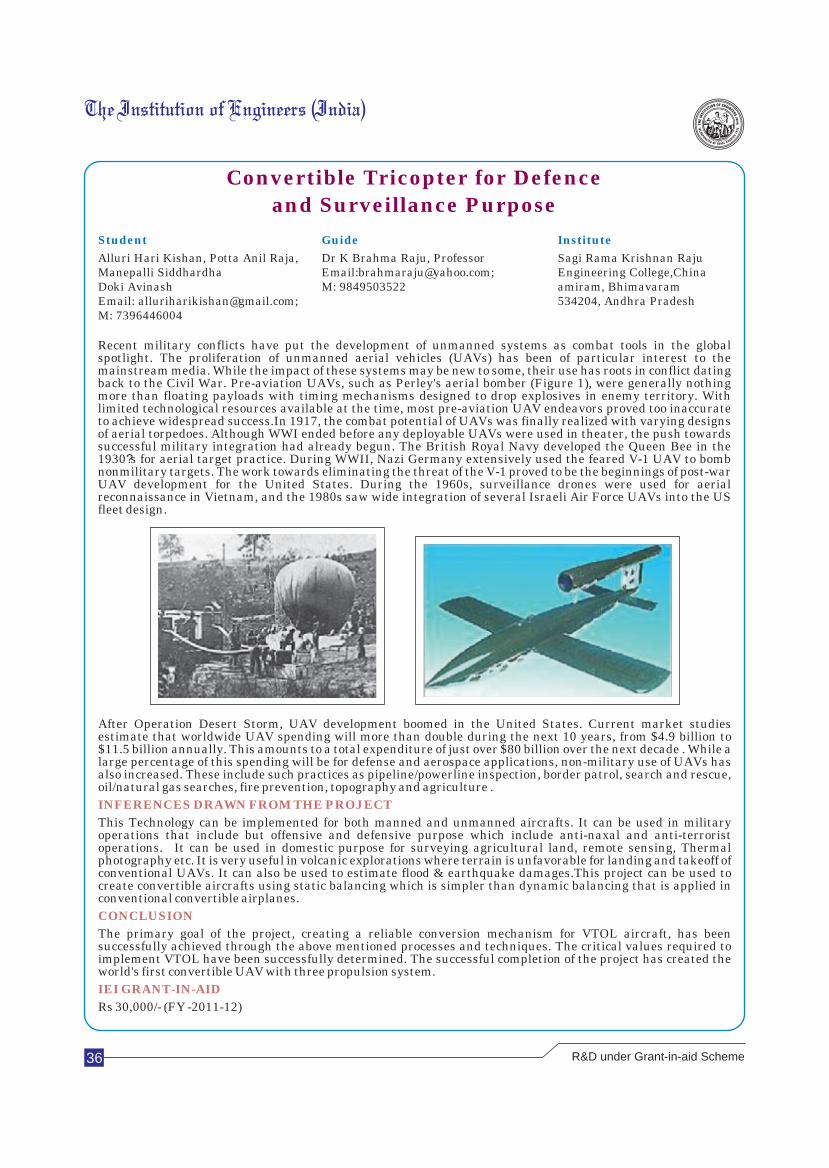
36
Convertible Tricopter for Defence
and Surveillance Purpose
Student Guide Institute
Alluri Hari Kishan, Potta Anil Raja, Dr K Brahma Raju, Professor Sagi Rama Krishnan RajuManepalli Siddhardha Email:[email protected]; Engineering College,China Doki Avinash M: 9849503522 amiram, BhimavaramEmail: [email protected]; 534204, Andhra PradeshM: 7396446004
Recent military conflicts have put the development of unmanned systems as combat tools in the global spotlight. The proliferation of unmanned aerial vehicles (UAVs) has been of particular interest to the mainstream media. While the impact of these systems may be new to some, their use has roots in conflict dating back to the Civil War. Pre-aviation UAVs, such as Perley's aerial bomber (Figure 1), were generally nothing more than floating payloads with timing mechanisms designed to drop explosives in enemy territory. With limited technological resources available at the time, most pre-aviation UAV endeavors proved too inaccurate to achieve widespread success.In 1917, the combat potential of UAVs was finally realized with varying designs of aerial torpedoes. Although WWI ended before any deployable UAVs were used in theater, the push towards successful military integration had already begun. The British Royal Navy developed the Queen Bee in the 1930?s for aerial target practice. During WWII, Nazi Germany extensively used the feared V-1 UAV to bomb nonmilitary targets. The work towards eliminating the threat of the V-1 proved to be the beginnings of post-war UAV development for the United States. During the 1960s, surveillance drones were used for aerial reconnaissance in Vietnam, and the 1980s saw wide integration of several Israeli Air Force UAVs into the US fleet design.
After Operation Desert Storm, UAV development boomed in the United States. Current market studies estimate that worldwide UAV spending will more than double during the next 10 years, from $4.9 billion to $11.5 billion annually. This amounts to a total expenditure of just over $80 billion over the next decade . While a large percentage of this spending will be for defense and aerospace applications, non-military use of UAVs has also increased. These include such practices as pipeline/powerline inspection, border patrol, search and rescue, oil/natural gas searches, fire prevention, topography and agriculture .
This Technology can be implemented for both manned and unmanned aircrafts. It can be used in military operations that include but offensive and defensive purpose which include anti-naxal and anti-terrorist operations. It can be used in domestic purpose for surveying agricultural land, remote sensing, Thermal photography etc. It is very useful in volcanic explorations where terrain is unfavorable for landing and takeoff of conventional UAVs. It can also be used to estimate flood & earthquake damages.This project can be used to create convertible aircrafts using static balancing which is simpler than dynamic balancing that is applied in conventional convertible airplanes.
The primary goal of the project, creating a reliable conversion mechanism for VTOL aircraft, has been successfully achieved through the above mentioned processes and techniques. The critical values required to implement VTOL have been successfully determined. The successful completion of the project has created the world's first convertible UAV with three propulsion system.
Rs 30,000/- (FY -2011-12)
INFERENCES DRAWN FROM THE PROJECT
CONCLUSION
IEI GRANT-IN-AID
R&D under Grant-in-aid Scheme

Innovation distinguishes between a leader and a follower
Steve Jobs
37
Design and Development of Complete Traffic Solutionat Vehicular and Junction Levels using RFIDS
Student Guide Institute
A N Khaleel Ahmed Dr K G Srinivasa M S Ramaiah Institute of TechnologySunil Nirmal Kumar (Student) #16549th Main, A Block, 2nd StageRajajinagar, Bangalore 560010
An optimized traffic system is of high importance in the existing traffic situations where, the density of traffic on the roads is steadily increasing. The problems faced by commuters and traffic personnel alike are an imminent one. The existing infrastructure or the roads do not support the cause of ensuring smooth traffic at all times of the day. As a result, daily activities are either stalled or delayed and emergency vehicles find it a challenge to reach destinations on time. The existing traffic control system is static and it does not have automated response to the real time traffic load. The time per signal for the roads leading to a junction is predefined and any changes with regard to it are not dynamic and have to be initiated by the traffic personnel. A significant setback is the non-existence of an active system to clear traffic for passage of emergency vehicles delaying them considerably. The proposed system considers the density on the road and allots time per road, based on density. The objectives of the system are a) Optimization of traffic flow by synchronization, b) Tracking motion of every vehicle within the city limits, c) Ensuring faster passage for emergency vehicles like ambulances, fire engines etc. and d) To plan for corrective action during traffic jams and unexpected situations. In the present traffic system, traffic flow is not smooth due to various factors like Pre-fixed timings at every junction irrespective of real time load. However the cycle duration is dependent on the time of the day . Single traffic personnel placed at every junction is forced to multitask by ensuring traffic flow and spotting those who bend traffic rules simultaneously. There is no support for providing a fast passageway for emergency vehicles. Though they have sirens, vehicles ahead seldom pave way. Especially in traffic jams, the time taken to get through is considerably increased. The proposed system tracks motion of every vehicle within city limits, gives a faster passage for emergency vehicles, and plans corrective actions during jams and other such situations. Also, the proposed system takes into account the real-time load of traffic at each junction, and allocates time for each road in the junction, that facilitates a free flow thus saving commuters time at each junction.
1. A centralized control for computer generated routing for vehicles
2. Improving security while data transfer
3. Extend functionality to identify traffic offenders
4. Deploying the application into an atom powered system, equipped with a visual display, mouse and keyboard
In the present traffic system, traffic flow is not smooth due to various factors like
1. Pre-fixed timings at every junction irrespective of real time load.
2. Single traffic personnel placed at every junction is forced to multitask by traffic flow and spotting those who bend traffic rules simultaneously.
These hold ups also lead to various problems on a day to day basis. In contrast to these, the proposed system has various benefits that include:
1. Taking into account the real-time load of traffic at each junction, properly allocating time for each road that facilitates a free flow thus saving commuters time at each junction.
‘2. Ensuring 24 hour flow of traffic by catering to the needs of commuters by saving their time on road as well as the personnel who can ensure that immaculate traffic sense prevails.
3. Ensures a faster passage to emergency vehicles like fire engines, ambulances
Thus the proposed system is dynamic and caters to the needs of commuters.
Rs 50,000/- (FY -2011-12)
INFERENCES DRAWN FROM THE PROJECT
CONCLUSION
IEI GRANT-IN-AID
R&D under Grant-in-aid Scheme
38
Jet Noise Reduction using Perforated Tabs
Student Guide Institute
Fayaaz Hussain G,Md Mohiudeen Bikash Kumar Mondal KCG College of Technology Nawaz A, Afthab Shaban Naseer Email: [email protected] Rajiv Gandhi Salai, Old Email: [email protected] M: 9884191078 Mahabalipuram Rd, KarapakkamM: 9789812310 Chennai 600097, Tamilnadu
Aircraft noise is one of the major contributors of noise pollution to the environment. The growth of air transportation has been leaps and bounds and thus the focus on aircraft noise has been heightened. Aircraft noise is mainly due to three components: aerodynamic noise, engine and other mechanical noise and noise from aircraft systems. The last two components are found to be less important when compared to aerodynamic noise. Jet noise falls under the category of aerodynamic noise which is the focus of this project. Jet noise is caused by turbulent mixing of exhaust jet with the ambient air. Jet noise has been estimated to be directly proportional to the eighth power of velocity by Lighthill. This implies that by reducing the velocity of the exhaust jet, significant noise could be reduced. But this also would involve thrust loss as it is directly proportional to the square of the exit velocity. Thus a compromise has to be made between the two. A reduction in noise levels can be achieved if the mixing rate is accelerated or if the velocity of the exhaust jet with respect to the atmosphere is reduced. As said before, reducing the velocity and cause thrust loss. This initiated us to look into various options for accelerating mixing of jets. Tabs have been studied extensively from mixing enhancement point of view. Aeroacoustic studies of tabs are very little in literature barring a few works. Tabs were dubbed as 'super mixers' and since mixing enhancement and jet noise were found to be linked together it was decided to initiate aero acoustic studies on tabs. Since tabs protrude into the flow, blocking the effective area of the nozzle thrust loss is always associated with it. In order to minimize thrust loss, it was decided to use perforated tabs so tabs the effective area blockage is reduced thus predicting the thrust loss to be less. The main aim of this project is study of aero acoustic of jets used from a convergent nozzle of exist diameter 30.16mm with perforated tabs fixed at the nozzle exit for the purpose of jet noise reduction.
Future work can be carried out for detailed studies on the flow field and nose field of the jet with other configurations. The following are the proposed future work to be carried out.
1. Thrust measurements to be carried out to evaluated the thrust penalty.
2. Effects of variation of perforation size on the acoustic far-field.
3. Effect of penetration on the acoustic far field.
4. Flow field visualization to better understand the relation between the flow field changes and noise field.
Acoustic characteristics of both subsonic and supersonic jets of an axisymmertic jet for a mach number range of 0.8 to 1.5 were studies. Several characteristics were recognised in the acoustic spectra. The obtained spectra were found to match the spectra calculated by Tam. The influence of ordinary triangular tabs and perforated triangular tabs on the acoustic field were studies. SPL and OASPL spectra were plotted. It was found that the tabs reduced the low frequency noise in both subsonic and supersonic jets with a penalty in high frequency region the penalty being less or nil in supersonic jets. Overall
0noise levels increased in the subsonic regime except for angles greater than 150 . Overall noise levels decreased in the 0supersonic regime for all angles. The reduction was found to be much more for angles greater than 145 .
Rs 53,000/- (FY -2011-12)
INFERENCES DRAWN FROM THE PROJECT
CONCLUSION
IEI GRANT-IN-AID
A problem well stated is a problem half solved
Charles F. Kettering
R&D under Grant-in-aid Scheme

39
Preparation of Chitosan Fibre
Student Guide Institute
Rupesh Ranjan/Dharmesh Mehta Prof S K Laga, Selection Grade Lecturer D K T E Society's Textile & EnggRishabh Ahuja/Karan Shah Textile Chemistry Institute, P O Box 130, Email: [email protected] Email: [email protected] "Rajwada”, Ichalkaranji 416 115
At the start of the third millennium the world population was approx 6 billion which is expected to rise to 10 stbillion by the middle of 21 century. The exponential increase in population increases the demand on food,
energy, water, resources and effects a corresponding increase in environmental pollution and a depletion of finite resources (fossil fuels). Since 1930's the research & development into synthetic chemicals products has afforded a significant improvement in the quality of life and availability of products for consumption. Wallace Carothers & DuPont have developed a first synthetic polyamide, nylon in 1935; Whinfield, Dickson, Birtwhistle and Ritchie advanced the early research of carothers, creating the first polymer fibre called terylene (based on polyethylene terepthalate) in 1941 manufactured by Imperial Chemical Industries; DuPont followed this up with the invention of Decron in 1946. Other synthetic fibres were also developed, including polyurethane (Bayer, 1937), acrylic (DuPont, 1944), polypropylene and high density polyethylene (both Banks & Hogan, 1951).The main problem with synthetic polymers are that they are non degradable and non renewable. Oil and petroleum are non renewable resources at the current rate of consumption; these fossil fuels are only expected to last for another 50-60 years. The energy information administration projects that world conventional oil production will peak somewhere between 2021 and 2112, depending on the annual production growth rate (0-3%) and resource estimates (2248-3896 billion barrels). For the expected USGS case (3003 billion barrels) the peak will be somewhere between 2030 and 2075 this means that the raw material for fibres will change.Of even more concern is the ability of polymeric fibres to remain unchanged in the environment as such polymers don't degrades very readily, which has exacerbated the already existing ecological and environmental problems of waste building. Landfills are decreasing in numbers making less space available to discard waste. Landfill space in U.K is decreasing and in the US alone, the number of landfills drops from 8000 to 2314 between 1988-1998. Many governments, in response, have established laws to encourage recycling; some governments has enforced stricter “take back” rules requiring manufacturers to take back some packing and products at the end of their life.Chitin and chitosan are known biodegradable natural polymers based on polysaccarides, which are extracted from various animals and plants. Chitin exists widely in cell walls of some microorganisms such as fungi, molds and yeasts and in the cuticular and exoskeletons of invertebrates such as crustaceans, mollusks, crabs, shrimps, lobster, squid and insects (for example beetles) . Chitosan exists naturally only in a few species of fungi. Chitin and chitosan consist of 2-acetamido-2-deoxy-β-D-glucose and 2-amino-2-deoxy-β-D- glucose as repeating units respectively. Chitin is chemically identical to cellulose except that secondary hydroxyl group on the alpha carbon atom of the cellulose molecule is substituted with acetoamide groups.
lSpinnability and drawability are controlled by concentration of chitosan and degree of deacetylation. Chitosan with degree of deacetylation > 80% can produce good spinnable and drawable fibre with good strength.
l4% polymer concentration produces good quality of chitosan fibre.
l20% sodium hydroxide is observed as efficient of effective coagulating and regenerating agent.
lDeaeration for period of 24 hours of chitosan solution completely removes air bubbles.
lX-Ray diffraction studies shows that chitosan fibre has 28-47.5% crystallinity.0
lDSC studies confirms that this fibre has glass transition temperature of 65.13 C and melting point of 0131.47 C.
lResults of FTIR studies confirms that chitosan fibre is identical to cellulose but has amine group present in it.
lThis fibre can be easily dyed at room temperature with acid, basic, direct, reactive, sulphur dyes while 0disperse dyes gives deep shades even at 60 C.
Rs 40,000/-( FY 2009-10)
CONCLUSION
IEI GRANT-IN-AID
R&D under Grant-in-aid Scheme
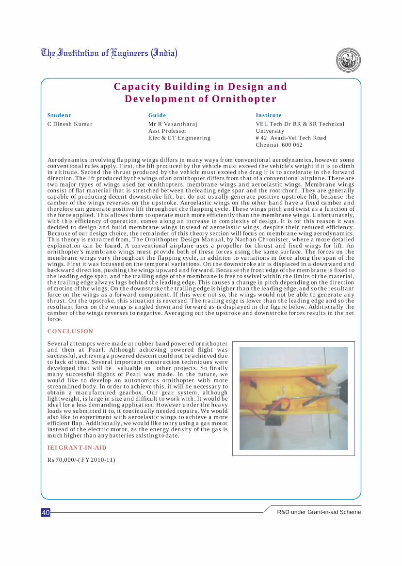
40
Capacity Building in Design and Development of Ornithopter
Student Guide Institute
C Dinesh Kumar Mr R Vasantharaj VEL Tech Dr RR & SR TechnicalAsst Professor UniversityElec & ET Engineering # 42 Avadi-Vel Tech Road
Chennai 600 062
Aerodynamics involving flapping wings differs in many ways from conventional aerodynamics, however some conventional rules apply. First, the lift produced by the vehicle must exceed the vehicle's weight if it is to climb in altitude. Second the thrust produced by the vehicle must exceed the drag if is to accelerate in the forward direction. The lift produced by the wings of an ornithopter differs from that of a conventional airplane. There are two major types of wings used for ornithopters, membrane wings and aeroelastic wings. Membrane wings consist of flat material that is stretched between theleading edge spar and the root chord. They are generally capable of producing decent downstroke lift, but do not usually generate positive upstroke lift, because the camber of the wings reverses on the upstroke. Aeroelastic wings on the other hand have a fixed camber and therefore can generate positive lift throughout the flapping cycle. These wings pitch and twist as a function of the force applied. This allows them to operate much more efficiently than the membrane wings. Unfortunately, with this efficiency of operation, comes along an increase in complexity of design. It is for this reason it was decided to design and build membrane wings instead of aeroelastic wings, despite their reduced efficiency. Because of our design choice, the remainder of this theory section will focus on membrane wing aerodynamics. This theory is extracted from, The Ornithopter Design Manual, by Nathan Chronister, where a more detailed explanation can be found. A conventional airplane uses a propeller for thrust and fixed wings for lift. An ornithopter's membrane wings must provide both of these forces using the same surface. The forces on the membrane wings vary throughout the flapping cycle, in addition to variations in force along the span of the wings. First it was focussed on the temporal variations. On the downstroke air is displaced in a downward and backward direction, pushing the wings upward and forward. Because the front edge of the membrane is fixed to the leading edge spar, and the trailing edge of the membrane is free to swivel within the limits of the material, the trailing edge always lags behind the leading edge. This causes a change in pitch depending on the direction of motion of the wings. On the downstroke the trailing edge is higher than the leading edge, and so the resultant force on the wings as a forward component. If this were not so, the wings would not be able to generate any thrust. On the upstroke, this situation is reversed. The trailing edge is lower than the leading edge and so the resultant force on the wings is angled down and forward as is displayed in the figure below. Additionally the camber of the wings reverses to negative. Averaging out the upstroke and downstroke forces results in the net force.
Several attempts were made at rubber band powered ornithopter and then at Pearl. Although achieving powered flight was successful, achieving a powered descent could not be achieved due to lack of time. Several important construction techniques were developed that will be valuable on other projects. So finally many successful flights of Pearl was made. In the future, we would like to develop an autonomous ornithopter with more streamlined body. In order to achieve this, it will be necessary to obtain a manufactured gearbox. Our gear system, although lightweight, is large in size and difficult to work with. It would be ideal for a less demanding application. However under the heavy loads we submitted it to, it continually needed repairs. We would also like to experiment with aeroelastic wings to achieve a more efficient flap. Additionally, we would like to try using a gas motor instead of the electric motor, as the energy density of the gas is much higher than any batteries existing to date.
Rs 70,000/-( FY 2010-11)
CONCLUSION
IEI GRANT-IN-AID
R&D under Grant-in-aid Scheme
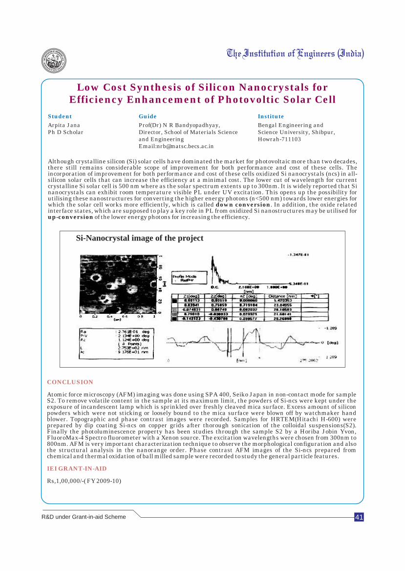
Low Cost Synthesis of Silicon Nanocrystals for Efficiency Enhancement of Photovoltic Solar Cell
Student Guide Institute
Arpita Jana Prof(Dr) N R Bandyopadhyay, Bengal Engineering and Ph D Scholar Director, School of Materials Science Science University, Shibpur,
and Engineering Howrah-711103Email:[email protected]
Although crystalline silicon (Si) solar cells have dominated the market for photovoltaic more than two decades, there still remains considerable scope of improvement for both performance and cost of these cells. The incorporation of improvement for both performance and cost of these cells oxidized Si nanocrystals (ncs) in all-silicon solar cells that can increase the efficiency at a minimal cost. The lower cut of wavelength for current crystalline Si solar cell is 500 nm where as the solar spectrum extents up to 300nm. It is widely reported that Si nanocrystals can exhibit room temperature visible PL under UV excitation. This opens up the possibility for utilising these nanostructures for converting the higher energy photons (n<500 nm) towards lower energies for which the solar cell works more efficiently, which is called down conversion. In addition, the oxide related interface states, which are supposed to play a key role in PL from oxidized Si nanostructures may be utilised for up-conversion of the lower energy photons for increasing the efficiency.
CONCLUSION
IEI GRANT-IN-AID
Atomic force microscopy (AFM) imaging was done using SPA 400, Seiko Japan in non-contact mode for sample S2. To remove volatile content in the sample at its maximum limit, the powders of Si-ncs were kept under the exposure of incandescent lamp which is sprinkled over freshly cleaved mica surface. Excess amount of silicon powders which were not sticking or loosely bound to the mica surface were blown off by watchmaker hand blower. Topographic and phase contrast images were recorded. Samples for HRTEM(Hitachi H-600) were prepared by dip coating Si-ncs on copper grids after thorough sonication of the colloidal suspensions(S2). Finally the photoluminescence property has been studies through the sample S2 by a Horiba Jobin Yvon, FluoroMax-4 Spectro fluorometer with a Xenon source. The excitation wavelengths were chosen from 300nm to 800nm. AFM is very important characterization technique to observe the morphological configuration and also the structural analysis in the nanorange order. Phase contrast AFM images of the Si-ncs prepared from chemical and thermal oxidation of ball milled sample were recorded to study the general particle features.
Rs,1,00,000/-( FY 2009-10)
41R&D under Grant-in-aid Scheme
Si-Nanocrystal image of the project
Scientific research is one of the most exciting and rewarding of occupations
Frederick Sanger
Student Guide Institute
S Rajeswaran, P Jothi Vasanthan, Dr V Anbumalar, Velammal College Of Engg. &C Sivakumar Email: [email protected] Technology,Viraganoor, MaduraiEmail: [email protected] M: 9486485148 625009M: 8870482441
During the Stone Age, ancient people used simple tools such as spears, nets and various other traps to catch their prey. Mesopotamians invented the wooden plough around 3000 BCE, and by 2800 BCE. They had learned how to make bronze tools. The use of animals has been prominent in agriculture those days. The use of animals in farming and the continued use of tools increased in size of many farms. This allowed farmers to cultivate more land. The caschrom was invented during the middle ages to till the land. By pushing the foot peg into the ground and pulling the handle backwards, a farmer could tear up the soil and flip the dirt to either side. The Agricultural Revolution lasted from about 1750-1900 when farming in America changed drastically. The main cause of the Agricultural Revolution was the introduction of machines. A well-known machine introduced during this time was Eli Whitney's cotton gin, one of the first machines used in agriculture. This machine was able to quickly separate cottonseed from cotton fibres, creating upto fifty pounds cleaned cotton a day, the equivalent of hundreds of man-hours. As the first major machine of agricultural revolution, the cotton gin led the way to the modern agricultural machines. The system farmers used to plant crops evolved greatly during this time period. At first, the United State Department of Agriculture (USDA) worked only to increase productivity on farms, but starting in the 1880s, work was also done to improve the quality and health standards of these farms. The research done by the USDA today helps to create robots and other technological improvements for American farms. During nineteenth and twentieth centuries, some of the modern agricultural machines, such as lawnmower and the tractor were invented and put to use worldwide. The idea of robotic agriculture is not a new one. Many robotic engineers and research people have invented variety of robots in field of agriculture. In this project, the purpose of robot in agricultural field is different from other robot. The approach of this robot is to dig the soil and perform the planting operation in the perspective view and with the help of various gear arrangement, cutter all the movements of the robotic system which are operated by remote controlled motor system.
To achieve our desired target, we have tested our robot under artificially made working conditions, The following results are obtained from our test. It can give depth of about 20 cm. We used ordinary DC motors of different rpm for each operation. For a prototype, it is sufficient to perform all such operations with these motors. As a result we had moved the vehicle from one place to the destination, then hole is made in the required place, which is further placed the sapling in the hold and finally refilled the hole made with the soil to complete the final phase of our operation.
It has been observed that many robotic technologies have been introduced in our country, it has not been implemented in case of agricultural field. Many people left the agricultural work and concentrate over other business. If this leads in our country we will face a desert land soon so we have to go beyond a working system for agriculture without any harm to the field of vegetation. To make our country a vegetative land with less human power, the 'GREEN ROBOT' technology should be systemized.
Rs 90,000/-( FY 2011-12)
INFERENCES DRAWN FROM THE PROJECT
CONCLUSION
IEI GRANT-IN-AID