comparison of selected enterprise architecture modeling
TRANSCRIPT

Comparison of selected enterprise architecture modeling techniques from the perspective of IT services
Jan Buriánek1[0000-0002-9106-5621]
1 Department of Information Technologies, Faculty of Informatics and Statistics, University of Economics and Business, Prague [email protected]
Abstract. Focus of this paper is set on a mutual comparison of selected popular enterprise architecture modeling techniques from the perspective of IT services. Particular frameworks and notations in focus are ArchiMate, Unified Architec-ture Framework, SoaML, NATO Architecture Framework and Unified Modeling Language. To compare and evaluate these techniques, a method presented by Framework for Evaluating BPM/ISM Techniques has been utilized. This method suggests evaluating modeling techniques by their breadth (typical modeling goals) and depth (modeling perspectives). For further comprehension, the 4+1 View Model of Architecture has been used to evaluate selected notations from logical, process, development, physical and use case points of view. Furthermore, notations used by the techniques in focus have been analyzed and compared with standard ISO 20000 used as a reference point. According to the methods used, Unified Architecture Framework was classified as the most versatile and com-prehensive enterprise architecture modeling technique among researched frame-works and notations.
Keywords: Conceptual modeling, Enterprise architecture, IT service, Modeling notation, Framework for Evaluating BPM/ISM Techniques, 4+1 View Model of Architecture, UML, SoaML, UAF, ArchiMate, NAF, SLA.
1 Introduction
The ability to analyze and maintain arrangement of an organization is an essential mat-ter of successful enterprise operation. Architecture description languages (ADLs) are being the key aspect of enterprise modeling and thus proper enterprise change manage-ment. In terms of enterprise architecture and IT service management, many such ADLs and related frameworks has emerged.
The objective of this research is to examine and evaluate architecture description languages in context of their ability to describe an architecture of an IT service and collaboration among multiple IT services.
Research conducted in the area of IT service support in architectural frameworks often suffers from inconsistent terminology in IT services [1]. This paper bridges this gap by comparing each relevant term to the terms defined in the ISO 20000 standard.
Presented frameworks and notations has been selected using following criteria:
Copyright © 2021 for this paper by its authors. Use permitted under Creative Commons License Attribution 4.0 International (CC BY 4.0)
172
1. Must be an architecture description language (ADL) 2. Must be either general purpose, or must not be domain specific in other than an IT
service area 3. Its specification must be issued as a stable release 4. Its specification must be accessible in its entirety 5. There must be documented practical applications available
Originally, more than 200 ADLs were identified, with a very significant narrowing of the sample already when the second rule was applied. Among the reduced ones are i.e., StratusML, which focuses on cloud applications [2], ABACUS, which deals with the analysis of complex systems and their simulation [3], or SQUID, which focuses on DevOps design [4].
After applying all the criteria, the following set of frameworks and notations were selected: Unified Modeling Language, ArchiMate, SoaML, Unified Architecture Framework, and NATO Architecture Framework.
Using the above aspects, the research question can be formulated as follows: Given the selection criteria, which of the ADLs is the most convenient for use in the context of IT service and IT services collaboration?
The paper is structured as follows. First, the research methods are introduced, the next section presents the evaluated notations and frameworks, the fourth section pre-sents the results, and finally the results are summarized and discussed.
2 Methods used
Selected enterprise architecture modeling techniques are compared and evaluated by Framework for Evaluating BPM/ISM Techniques proposed by Giaglis [5]. Framework defines three evaluation variables:
• modeling goals typically addressed by the modeling technique (Breadth), • modeling perspectives covered by the modeling technique (Depth), and • typical projects to which the technique can be fitted (Fit).
Typical modeling goals (Breadth) are associated with typical steps to system analysis and design: to support human understanding and human to human communication, to support process improvement, to support process development, to support process exe-cution and to support process management. Each of these typical goals render a set of requirements a modeling technique must possess.
On the other hand, Depth variable depicts modeling perspectives: functional – what is being performed, behavioral – when and how it is performed, organizational – where and by whom it is performed and informational – what data are produced or manipu-lated by the performance.
Combination of these two criteria forms the third – Fit.
173
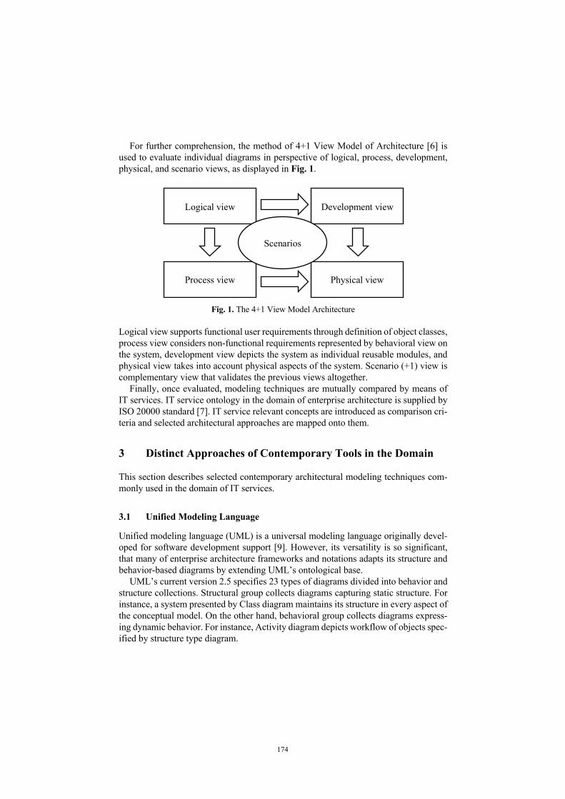
For further comprehension, the method of 4+1 View Model of Architecture [6] is used to evaluate individual diagrams in perspective of logical, process, development, physical, and scenario views, as displayed in Fig. 1.
Fig. 1. The 4+1 View Model Architecture
Logical view supports functional user requirements through definition of object classes, process view considers non-functional requirements represented by behavioral view on the system, development view depicts the system as individual reusable modules, and physical view takes into account physical aspects of the system. Scenario (+1) view is complementary view that validates the previous views altogether.
Finally, once evaluated, modeling techniques are mutually compared by means of IT services. IT service ontology in the domain of enterprise architecture is supplied by ISO 20000 standard [7]. IT service relevant concepts are introduced as comparison cri-teria and selected architectural approaches are mapped onto them.
3 Distinct Approaches of Contemporary Tools in the Domain
This section describes selected contemporary architectural modeling techniques com-monly used in the domain of IT services.
3.1 Unified Modeling Language
Unified modeling language (UML) is a universal modeling language originally devel-oped for software development support [9]. However, its versatility is so significant, that many of enterprise architecture frameworks and notations adapts its structure and behavior-based diagrams by extending UML’s ontological base.
UML’s current version 2.5 specifies 23 types of diagrams divided into behavior and structure collections. Structural group collects diagrams capturing static structure. For instance, a system presented by Class diagram maintains its structure in every aspect of the conceptual model. On the other hand, behavioral group collects diagrams express-ing dynamic behavior. For instance, Activity diagram depicts workflow of objects spec-ified by structure type diagram.
Logical view Development view
Physical view Process view
Scenarios
174

Broad versatility of its basic structural and behavioral modeling notations allows to adapt the modeling ontology to create conceptual models far from its original purpose [10]. Due to UML notation’s rigid foundations and native natural extensibility, many of enterprise-level architecture frameworks and notations build on top of its universal structure and behavior conceptual diagrams (for instance, SoaML extends structure Collaboration Use diagram to picture Service Contract diagram, or dynamic Sequence diagram to draw mutual choreography of its participants). Even some software-devel-opment specific UML’s diagrams are extensions of its more versatile predecessors (for instance Communication diagram is a modification of Sequence diagram).
In terms of depicting services alongside with the way of their collaboration, UML specifies a set of composite structure diagrams. Both Internal structure diagram and Collaboration Use diagram might be further modified and adapted to use service-ori-ented ontology as in case of SoaML’s Service Contract diagram.
3.2 ArchiMate
ArchiMate (in its current version 3.1) [11] is an enterprise ADL used by The Open Group Architecture Framework (TOGAF). Since ArchiMate is a tool (although its cur-rent specification presents a group of conceptual extensions), its structure and princi-ples are in accordance with the TOGAF architecture framework. TOGAF is a universal enterprise architecture framework originally developed on the US Department of De-fense Technical Architecture Framework for Information Management (TAFIM). As such, TOGAF defines a set of architecture principles respected throughout the frame-work. ArchiMate structure is based on a separation of externally dependent layers [12].
ArchiMate metamodel introduces Strategy, Business layer, Application layer, Tech-nology layer, Physical layer, and Implementation & migration layer. Although aspects of alignment of particular elements among individual layers might still be a matter of research [13], abstraction layers are interconnected by mutual interface – every layer serves as a service to its neighbor. All layers also share mutual aspects describing either structure or behavior. Structure is further distinguished by being
• active – elements which are causing behavior (e.g., actor), and • passive – elements that serve as a resource for behavioral performance.
Business layer introduces concept of service as described in the introductory section of this article. ArchiMate defines a business layer metamodel depicting a universal con-ception of service-driven business architecture. The metamodel defines following con-cepts:
• Business service – a wrapper representing business behavior, aggregates business functions and processes,
• Business event – a trigger of business requests, and • Business interface – an external interface provided to the environment.
175
3.3 SoaML
SoaML is a service-based architecture framework built on Service Oriented Architec-ture (SOA). SoaML is specified by its metamodel and SoaML UML profile. SoaML supports SOA in three basic approaches:
• Service contract based – interoperability among participants, ports and capabilities • Service interface based – depicts relationships among service interfaces, roles and
capabilities • Simple interface based – allows to define a one-directional anonymous relationship
between a service and its participant [14].
According to [15], SoaML definition of service is “value delivered to another through a well-defined interface and available to a community”. To apply this definition, ontol-ogy has to be defined to fulfill the need for specifying a service’s interface and the value generator / consumer.
Interface-based approach of capturing collaboration of SOA services is dependent on the external interface of both service and the participant. The most significant dif-ference between simple interface and service interface concepts is that the latter is in-tended to communicate with other interfaces in both directions through defined proto-col, whereas simple interface is used while communication protocol is unnecessary, or even undesirable. Such situation may arise when a service participant does not require to know about its service caller, making it anonymous. Interface-based services archi-tecture may be depicted by UML Component diagram.
Contract-based approach is focused rather on value exchange among the service par-ticipants. Participant is a universal role which covers any service stakeholder – provider or consumer (e.g., individuals, groups, or software components). Capturing an interop-erability (choreography) among providers and consumers (participants) is enabled by adapting the UML Sequence diagram. SOA ontology is universal enough to assign these roles to any consumers / providers (e.g., dealers and manufacturers). Collabora-tion among participants may be put by UML Collaboration diagram. SoaML capabili-ties can be viewed as packages and thus be depicted as UML Package diagram.
3.4 Unified Architecture Framework
Unified Architecture Framework (UAF) [16] is an adaptation (or rather extension) of SysML notation in UML profile. Unlike SoaML, UAF is not service-oriented, but is intended to describe enterprise architecture as a whole. UAF adapts vast enterprise ar-chitecture ontology covering the complex agenda of managing strategy, missions, and technology transitions. UAF implements capabilities of NAF, which itself is an exten-sion of British Ministry of Defense Architecture Framework (MoDAF) and implements its capabilities in SysML.
Since the scope of UAF is too broad and majority of its ontology does not concern description of services, further presentation’s focus is set on the UAF::Services module.
Ontology of UAF::Services extension “shows Service Specifications and required and provided service levels of these specifications required to exhibit a Capability or to
176
support an Operational Activity” [16]. Referred UAF specification documents all in-troduced service stereotypes. Brief overview of the service collaboration relevant con-cepts alongside with recommended SysML diagram notations follows:
• Taxonomy (typically bdd, ibd): ─ ServiceSpecification – container for service-oriented constraints as ServiceInter-
face, ServicePort, list of capabilities, policies, and states. • Structure (typically bdd, ibd):
─ ServiceMethod – references service interface alongside with its parameters and measurable elements. Its behavior is specified in ServiceFunction.
─ ServiceParameter – is a measurable element which represents input or output of ServiceFunction.
─ ServicePort – an external contact point referenced to a service interface. ─ ServiceSpecificationRole – describes a role of service specification in context of
whole-part abstraction by another service specification. • Connectivity (typically bdd, ibd):
─ ServiceConnector – path between two service specifications (via their service ports).
─ ServiceInterface – interface interconnecting the service method to an external port.
• Processes (typically act, bdd): ─ ServiceFunction – descriptor of service behavior through ServiceSpecification.
• State (typically stm): ─ ServiceStatesDesctiption – extension of State Machine diagram depicting how a
service through ServiceSpecification behaves during its life cycle. • Interaction scenarios (typically sd):
─ ServiceMessage – communication medium used among service methods. • Constraints (typically bdd, par):
─ ServicePolicy – a constraint used to manage usage of service through Ser-viceSepcification.
Briefly put, UAF deals with services in an abstract, yet complete manner, where every service attribute is covered by ServiceSpecification wrapper. Its behavior is captured by service method and its functions, and mutual service interoperability is depicted by dedicated service interface (ServicePort), while performing in a particular ServiceSpec-ificationRole communicating through ServiceConnector channel using ServiceMes-sage.
3.5 NATO Architecture Framework
Since NATO Architecture Framework (NAF) is based on the same predecessor as UAF (MoDAF), those two share the basic principles and practices. NAF specification [17] aims not only at military use, but also for business enterprise architecture. The frame-work is divided into three parts:
• definitions of concepts,
177

• methodology on architecture development and architecture project management, and • viewpoints – metamodel with conventions how to represent enterprise architecture.
Viewpoints are further divided into Concept, Logical, Service, Physical resource, and Architecture metadata components. In NAF’s terminology, meaning of service is brought past IT discipline and is defined as “a unit of work through which a provider provides a useful result to a consumer”. However, this broad conception of service is intended to support SOA applications without specifying their physical implementa-tion.
Formal representation of separate viewpoints is rather recommended than strictly set. NAF service viewpoints use mainly UML diagrams (UML Class diagram, UML Component diagram, UML State machine diagram, UML Activity diagram and UML Sequence diagram) as the expression tool, but in some cases tabular, or textual repre-sentation is also possible.
4 Results
As presented in the methodology section, research towards evaluation of selected IT service-related modeling techniques has been conducted.
Table 1 displays the results of depth analysis conducted by Framework for Evaluat-ing BPM/ISM Techniques.
178

Table 1. Modeling perspectives (Depth) of selected modeling techniques
Functional Behavioral Organizational Informational ArchiMate Yes Limited Yes Yes SoaML Yes No Limited Limited UAF Yes Limited Yes Yes NAF Yes Yes Yes Yes UML Yes Yes Limited Yes
Table 2 presents all the evaluation variables together.
Table 2. Taxonomy of selected modeling techniques
Modeling goals and objectives (Breadth)
Understanding & Communication
Process Improvement
Process Management
Process Development
Process Execution
Mod
elin
g pe
rspe
ctiv
es (D
epth
)
Func
tiona
l
NAF (UML)
(SoaML)
NAF (UML)
(SoaML)
NAF UAF
ArchiMate UAF NAF
SoaML UML
ArchiMate UAF NAF
SoaML UML
Beh
avio
ral
(NAF) (NAF) NAF UAF (NAF) NAF
UAF
Org
aniz
atio
nal
ArchiMate NAF UAF
SoaML
ArchiMate NAF UAF
(SoaML)
ArchiMate NAF UAF
ArchiMate NAF UAF
(UML)
–
Info
rmat
iona
l
ArchiMate UAF NAF UML
(SoaML)
ArchiMate UAF NAF UML
(SoaML)
ArchiMate UAF NAF UML
(SoaML)
ArchiMate UAF NAF UML
(SoaML)
ArchiMate UAF NAF UML
SoaML
Results of UAF 4+1 View Model analysis is displayed in Table 3. Since UAF uses SysML notation as its recommended implementation, SysML is used as a baseline for comparison.
179
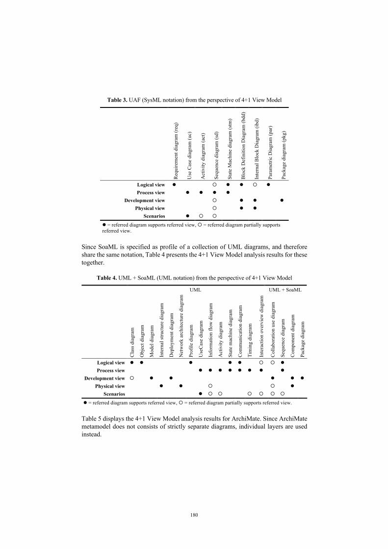
Table 3. UAF (SysML notation) from the perspective of 4+1 View Model
Req
uire
men
t dia
gram
(req
)
Use
Cas
e di
agra
m (u
c)
Act
ivity
dia
gram
(act
)
Sequ
ence
dia
gram
(sd)
Stat
e M
achi
ne d
iagr
am (s
tm)
Blo
ck D
efin
ition
Dia
gram
(bdd
)
Inte
rnal
Blo
ck D
iagr
am (i
bd)
Para
met
ric D
iagr
am (p
ar)
Pack
age
diag
ram
(pkg
)
Logical view l ¡ l l ¡ l Process view l l l l
Development view ¡ l l l Physical view ¡ l l
Scenarios l ¡ ¡ l = referred diagram supports referred view, ¡ = referred diagram partially supports referred view.
Since SoaML is specified as profile of a collection of UML diagrams, and therefore share the same notation, Table 4 presents the 4+1 View Model analysis results for these together.
Table 4. UML + SoaML (UML notation) from the perspective of 4+1 View Model
UML UML + SoaML
Cla
ss d
iagr
am
Obj
ect d
iagr
am
Mod
el d
iagr
am
Inte
rnal
stru
ctur
e di
agra
m
Dep
loym
ent d
iagr
am
Net
wor
k ar
chite
ctur
e di
agra
m
Prof
ile d
iagr
am
Use
Cas
e di
agra
m
Info
rmat
ion
flow
dia
gram
Act
ivity
dia
gram
Stat
e m
achi
ne d
iagr
am
Com
mun
icat
ion
diag
ram
Tim
ing
diag
ram
Inte
ract
ion
over
view
dia
gram
Col
labo
ratio
n us
e di
agra
m
Sequ
ence
dia
gram
Com
pone
nt d
iagr
am
Pack
age
diag
ram
Logical view l l l l l ¡ ¡ l
Process view l l l l l l l l
Development view ¡ l l l l l Physical view l l ¡ ¡ l
Scenarios l ¡ ¡ ¡ ¡ ¡ ¡
l = referred diagram supports referred view, ¡ = referred diagram partially supports referred view.
Table 5 displays the 4+1 View Model analysis results for ArchiMate. Since ArchiMate metamodel does not consists of strictly separate diagrams, individual layers are used instead.
180
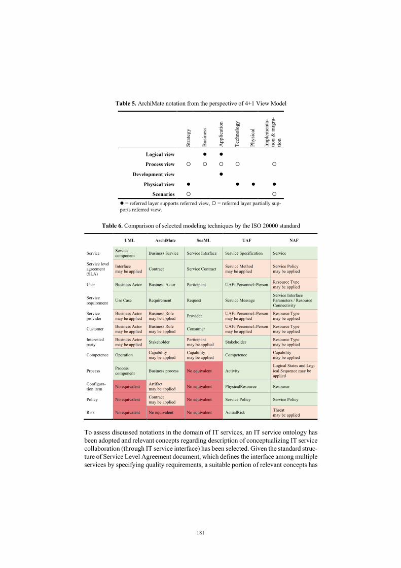
Table 5. ArchiMate notation from the perspective of 4+1 View Model
Stra
tegy
Bus
ines
s
App
licat
ion
Tech
nolo
gy
Phys
ical
Impl
emen
ta-
tion
& m
igra
-tio
n
Logical view l l
Process view ¡ ¡ ¡ ¡ ¡
Development view l
Physical view l l l l
Scenarios ¡ ¡
l = referred layer supports referred view, ¡ = referred layer partially sup-ports referred view.
Table 6. Comparison of selected modeling techniques by the ISO 20000 standard
UML ArchiMate SoaML UAF NAF
Service Service component Business Service Service Interface Service Specification Service
Service level agreement (SLA)
Interface may be applied Contract Service Contract Service Method
may be applied Service Policy may be applied
User Business Actor Business Actor Participant UAF::Personnel::Person Resource Type may be applied
Service requirement Use Case Requirement Request Service Message
Service Interface Parameters / Resource Connectivity
Service provider
Business Actor may be applied
Business Role may be applied Provider UAF::Personnel::Person
may be applied Resource Type may be applied
Customer Business Actor may be applied
Business Role may be applied Consumer UAF::Personnel::Person
may be applied Resource Type may be applied
Interested party
Business Actor may be applied Stakeholder Participant
may be applied Stakeholder Resource Type may be applied
Competence Operation Capability may be applied
Capability may be applied Competence Capability
may be applied
Process Process component Business process No equivalent Activity
Logical States and Log-ical Sequence may be applied
Configura-tion item No equivalent Artifact
may be applied No equivalent PhysicalResource Resource
Policy No equivalent Contract may be applied No equivalent Service Policy Service Policy
Risk No equivalent No equivalent No equivalent ActualRisk Threat may be applied
To assess discussed notations in the domain of IT services, an IT service ontology has been adopted and relevant concepts regarding description of conceptualizing IT service collaboration (through IT service interface) has been selected. Given the standard struc-ture of Service Level Agreement document, which defines the interface among multiple services by specifying quality requirements, a suitable portion of relevant concepts has
181

been extracted and set as a schema to assess selected service architecture notations. Every of the selected concepts is defined in [7].
Table 6 summarizes result of the mapping. Three levels of concept correspondence have been established. Those fields that are marked green have an overlapping meaning with the given concept. Orange marked fields are not explicitly included in the nota-tion’s ontology, however there is another concept that extends the searched meaning. Finally, red marked fields indicate unfeasibility of expressing the concept in the given notation without using a standard predefined stereotype.
5 Discussion and Concluding Remarks
This article summarized an overview of popular enterprise architecture modeling tech-niques regarding domain of IT services. Selected techniques have been analyzed and compared using Framework for Evaluating BPM/ISM Techniques and 4+1 View Model of Architecture. Finally, concepts of selected notations have been compared to an IT service ontology derived from ISO 20000 standard and the result has been pre-sented.
Research confirmed that UML, although according to definition presented by ISO/IEC/IEEE 42010 [18] classified as ADL, is too general for the purpose of service-related clarification. However, its universal specifications might still be adopted to Composite structure and Collaboration diagrams. Moreover, UML is often used as a basis for domain specific models by other ADLs and enterprise architecture frame-works.
Although ArchiMate notation covers the whole domain of enterprise architecture as seen by TOGAF, it is not strictly service-oriented and therefore some service-related concepts have to be derived.
Unlike ArchiMate, SoaML is notation based on service-oriented architecture. How-ever, SoaML does not cover related aspects like risk and configuration management.
UAF and NAF are based on a common predecessor, and although their purpose and terminology differs, their capabilities are very alike. Given the result, NAF is presented more like a set of general recommendations and it cannot be treated as a strict IT governance framework. Although due to their versatility, UAF may be regarded as the most convenient of the presented notations in the domain.
References
1. Jamjoom, M.M., Alghamdi, A.S., Ahmad, I.: Service oriented architecture support in vari-ous architecture frameworks: a brief review. In: Proceedings of the World Congress on En-gineering and Computer Science. pp. 1338–1343. , San Francisco, USA (2012)
2. Hamdaqa, M., Tahvildari, L.: Stratus ML: A Layered Cloud Modeling Framework. In: 2015 IEEE International Conference on Cloud Engineering. pp. 96–105. IEEE, Tempe, AZ, USA (2015)
3. Dunsire, K., O’Neill, T., Denford, M., Leaney, J.: The ABACUS Architectural Approach to Computer-Based System and Enterprise Evolution. In: 12th IEEE International Conference
182
and Workshops on the Engineering of Computer-Based Systems (ECBS’05). pp. 62–69. IEEE, Greenbelt, MD, USA (2005)
4. Di Nitto, E., Jamshidi, P., Guerriero, M., Spais, I., Tamburri, D.A.: A software architecture framework for quality-aware DevOps. In: Proceedings of the 2nd International Workshop on Quality-Aware DevOps. pp. 12–17. ACM, Saarbrücken Germany (2016)
5. Giaglis, G.M.: A Taxonomy of Business Process Modeling and Information Systems Mod-eling Techniques. International Journal of Flexible Manufacturing Systems. 13, 209–228 (2001). https://doi.org/10.1023/A:1011139719773
6. Kruchten, P.: The 4+1 View Model of architecture. IEEE Softw. 12, 42–50 (1995). https://doi.org/10.1109/52.469759
7. International Organization for Standardization: ISO/IEC 20000-1:2018, https://www.iso.org/standard/70636.html, (2018)
8. Guizzardi, G.: Ontological foundations for structural conceptual models. Enschede : Univer-sity of Twente. Centre for telematics and information technology ;, Enschede; Telematics instituut (2005)
9. Object Management Group: OMG® Unified Modeling Language®. (2017) 10. Kluza, K., Wiśniewski, P., Jobczyk, K., Ligęza, A., (Mroczek), A.S.: Comparison of Se-
lected Modeling Notations for Process, Decision and System Modeling. Presented at the 2017 Federated Conference on Computer Science and Information Systems September 24 (2017)
11. The Open Group: ArchiMate® 3.1 Specification. Van Haren Publishing (2019) 12. The Open Group: The TOGAF® Standard, Version 9.2. Van Haren Publishing (2018) 13. Řepa, V., Svatoš, O.: Alignment of Business and Application Layers of ArchiMate. In: Joint
Proceedings of the BIR 2018 Short Papers, Workshops and Doctoral Consortium. pp. 57–69. CEUR-WS (2018)
14. Elvesæter, B., Berre, A.-J., Sadovykh, A.: SPECIFYING SERVICES USING THE SERVICE ORIENTED ARCHITECTURE MODELING LANGUAGE (SOAML) - A base-line for Specification of Cloud-based Services: In: Proceedings of the 1st International Con-ference on Cloud Computing and Services Science. pp. 276–285. SciTePress - Science and and Technology Publications, Noordwijkerhout, Netherlands (2011)
15. Object Management Group: Service oriented architecture Modeling Language (SoaML) Specification. (2012)
16. Object Management Group: Unified Architecture Framework Profile (UAFP). (2017) 17. NATO: NATO ARCHITECTURE FRAMEWORK Version 4, (2018) 18. International Organization for Standardization: ISO/IEC/IEEE 42010:2011,
https://www.iso.org/standard/50508.html, (2011)
183