comparison of optical and tactile coordinate measuring
TRANSCRIPT
Comparison of optical and tactile Coordinate Measuring
Machines in a production environment
Bachelor’s thesis
HAMK RIIHIMÄKI
Mechanical Engineering and Production Technology
Spring 2018
Vladimir Kupriyanov
ABSTRACT Name of degree programme Mechanical Engineering and Production Technology Campus RIIHIMÄKI Author Vladimir Kupriyanov Year 2018 Subject Comparison of optical and tactile Coordinate Measuring machines in a production environment Supervisor(s) Timo Kärppä ABSTRACT
The reason for the writing of this thesis is to compare two different ways of quality control – optical and tactile coordinate measurement machines. To find out their advantages and disadvantages, strengths and weaknesses, to compare accuracy and work opportunities with a scanned material. To answer the question – how using of 3D-Scanner in a production environment can improve the quality of machined products. To define if utilizing of 3D-Scanner can improve the quality of casted and welded parts. To research if a tactile coordinate measurement machine can be replaced by an optical CMM in the sphere of quality control.
Keywords 3D- Scanning, tactile CMM, optical CMM, Quality Control, Measurements Pages 50 pages
CONTENTS
1 INTRODUCTION ........................................................................................................... 1
2 JORMET OY .................................................................................................................. 2
3 TACTILE COORDINATE MEASUREMENT MACHINE ...................................................... 3
3.1 General information about tactile CMM ............................................................ 3 3.2 Bridge CMM ........................................................................................................ 6 3.3 Horizontal Arm .................................................................................................... 7 3.4 Gantry CMM ........................................................................................................ 8 3.3 Conslusion ........................................................................................................... 9
4 OPTICAL COORDINATE MEASURING MACHINE WITH BLUE-LIGHT TECHNOLOGY ... 10
4.1 General information about otical CMM with blue light technology ................ 10 4.2 3 in 1 system ...................................................................................................... 12 4.3 Triangulation ..................................................................................................... 12 4.4 Blue light technology ......................................................................................... 13 4.5 GOM Inspect software ...................................................................................... 13 4.6 Reverse engineering .......................................................................................... 16 4.7 ATOS ScanBox .................................................................................................... 17 4.8 Conclusion ......................................................................................................... 18
5 ALTERNATIVE TYPES OF COORDINATE MEASUREMENT MACHINES ........................ 19
5.1 Portable measuring arms ..................................................................................... 19 5.2 3D laser scanner ................................................................................................ 21 5.3 Laser tracker systems ........................................................................................ 23 5.4 Laser stations..................................................................................................... 25 5.5 Multisensor and optical systems ....................................................................... 27 5.6 White light scanner systems ............................................................................. 29 5.7 Micrometer, caliper, dial gauges ....................................................................... 31
6 USING OF THE 3D-SCANNER IN A PRODUCTION ENVIRONMENT ............................. 35
6.1 Case I. Scanning of big planet carrier ................................................................ 35 6.2 Case II. Keskinivel, comparison of a rough and a machined parts .................... 40 6.3 Case III. Comparison of pillar before and after welding ................................... 44
7 CONCLUSION ............................................................................................................. 47
REFERENCES .................................................................................................................... 48
USED TERMS
3D – is a geometric setting, which requires three parameters to determine the position of an element. Alignment – is the process of aligning of a part to a required coordinate system. CAD – computer-aided design, is the use of a workstation to promote creation, analysis, modification or optimisation of a design. Casting – is a production process, which has the following principle: a liquid material is put into a mold, which has a hollow cavity of the needed shape and then material hardens. CMM – coordinate measuring machine, is a measuring device, which measures the geometry of the physical object by taking separate points on the surface with a touch probe or by using an optical method. Mesh – the collection of faces, edges and vertices, which define the surface of a polyhedral object in 3D computer graphics. Measurement – is the process of comparison of characteristics of an object with other objects. Point cloud – is a set of data points in a 3-dimensions coordinate system. Tolerance – is the permissible deviation from the standard.
1
1 INTRODUCTION
Size is one of many features which defines each object. Consequently, everything that is produced has its dimensions. However, even with modern machines, it is impossible to produce parts with entirely accurate measurements, which were assigned by a designer before production, and to overcome this problem, special allowances, which are called tolerances, were invented. Therefore, special equipment which can inspect dimensions, geometry or either both of them were created and are still in use. Scientific researchers have led to reaching a high level of measurements from such primitive technique as the length in between elbow and the tip of the middle finger till high-accurate method as 3D Robotic Scanning CMM. Unfortunately, some engineering companies do not assume the significance of exact measurements and that their products can have defects, engineering flaws, wrong dimensions, which can lead to financial severe or, what is more critical, credibility loses. In the modern competitive world, it is necessary to show to customers, that every piece, which is produced by a company has a high level of quality and satisfies to all standards. To deal with this problem, big manufacturing companies started buying their measurement machines to check dimensions inside of their company or, if a company does not have such number of products, which must be checked, ordering such service from other third-party companies. According to Hexagon AB (2017) research nearly all companies, which has their measurement machines, use an expensive type of measuring equipment - a tactile CMM (coordinate measuring machine) to check parameters of products, on the ground that these devices were bought in the early 2000th when they did not have any competitors in the measurement world, which can provide the same accuracy. However, nowadays, the new type of coordinate measuring machine, which uses an optical method of collecting of information, and is called 3D-Scanner can be contraposed and compared with a tactile CMM. The reason of writing of this thesis work is to find out differences in between of two ways of quality control – a tactile CMM (which is represented by HEXAGON dea brown&sharpe) and an optical CMM (which is presented by GOM Compact Scan) and to define if 3D-Scanner can replace the tactile CMM. To answer the question - how utilizing of an optical CMM with blue light technology in Jormet Oy can improve the quality of machined, casted and welded objects? It is needed to find out advantages and disadvantages of these methods during an inspection of parts and compare results which will get after inspection. Such important parameters as:
2
Accuracy; The ability to work with checked surfaces; Comparison of a scanned surface with a nominal CAD file; Time which is spent per part; Usability of software; Abilities of software (ATOS, GOM Inspect, PC-DMIS); Possibilities of reverse engineering; Portability; Visual presentation; Maintenance and calibration of machines; Consumable materials; Price;
Must be considered while writing thesis work. This thesis work is written based on Jormet Oy production.
2 JORMET OY
Jormet Oy is a manufacturing company, which produces high-quality welded and machined structures as well as machining of casting with more than 40 years of experience. Service abilities cover the whole production line from an acquisition of material to the surface-treated results. Jormet Oy is located in Joroinen, South Savo.
Figure 1. Jormet Oy logo (Jormet Oy, 2013)
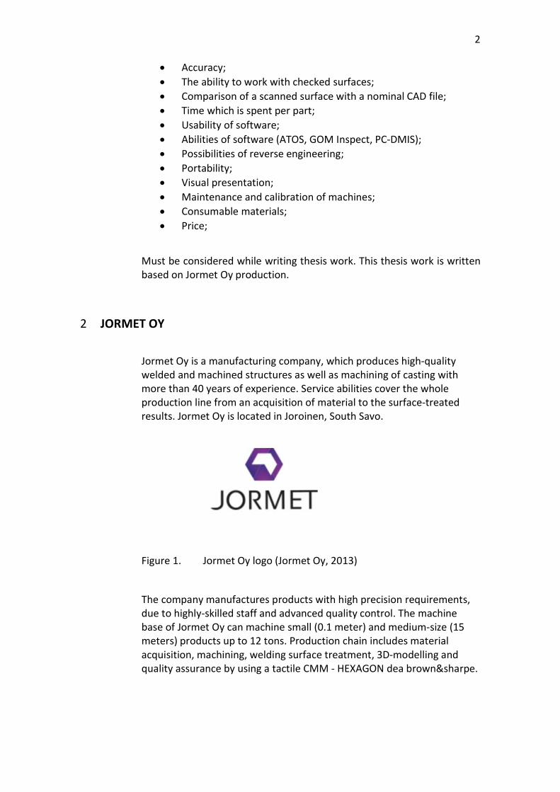
The company manufactures products with high precision requirements, due to highly-skilled staff and advanced quality control. The machine base of Jormet Oy can machine small (0.1 meter) and medium-size (15 meters) products up to 12 tons. Production chain includes material acquisition, machining, welding surface treatment, 3D-modelling and quality assurance by using a tactile CMM - HEXAGON dea brown&sharpe.
3
Figure 2. Jormet manufacturing facility (Jormet Oy, 2010)
Jormet Oy complies with a certified ISO 9001: 2008 quality management system and all welding operations are certified and done according to the ISO3834-2 2005 standard. The company produces high-quality products according to customer's manufacturing and material specifications. In order to ensure that every product that is manufactured meets requirements, tactile CMM is used e.g. (Jormet Oy, 2016).
3 TACTILE COORDINATE MEASUREMENT MACHINE
3.1 General information about tactile CMM
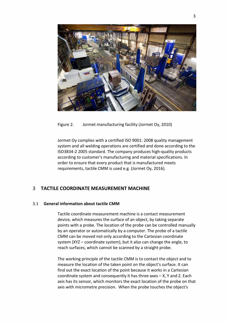
Tactile coordinate measurement machine is a contact measurement device, which measures the surface of an object, by taking separate points with a probe. The location of the probe can be controlled manually by an operator or automatically by a computer. The probe of a tactile CMM can be moved not only according to the Cartesian coordinate system (XYZ – coordinate system), but it also can change the angle, to reach surfaces, which cannot be scanned by a straight probe. The working principle of the tactile CMM is to contact the object and to measure the location of the taken point on the object’s surface. It can find out the exact location of the point because it works in a Cartesian coordinate system and consequently it has three axes – X, Y and Z. Each axis has its sensor, which monitors the exact location of the probe on that axis with micrometre precision. When the probe touches the object's
4
surface, the tactile CMM collects data from all three sensors and creates a "point cloud" which describes the needed surface of the object.
Figure 3. Tactile CMM working principle (engineering.com, 2016)
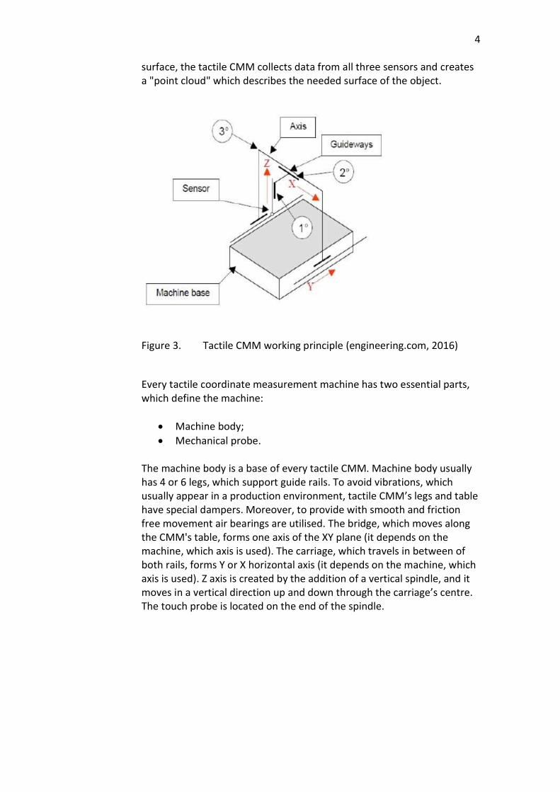
Every tactile coordinate measurement machine has two essential parts, which define the machine:
Machine body; Mechanical probe.
The machine body is a base of every tactile CMM. Machine body usually has 4 or 6 legs, which support guide rails. To avoid vibrations, which usually appear in a production environment, tactile CMM’s legs and table have special dampers. Moreover, to provide with smooth and friction free movement air bearings are utilised. The bridge, which moves along the CMM's table, forms one axis of the XY plane (it depends on the machine, which axis is used). The carriage, which travels in between of both rails, forms Y or X horizontal axis (it depends on the machine, which axis is used). Z axis is created by the addition of a vertical spindle, and it moves in a vertical direction up and down through the carriage’s centre. The touch probe is located on the end of the spindle.
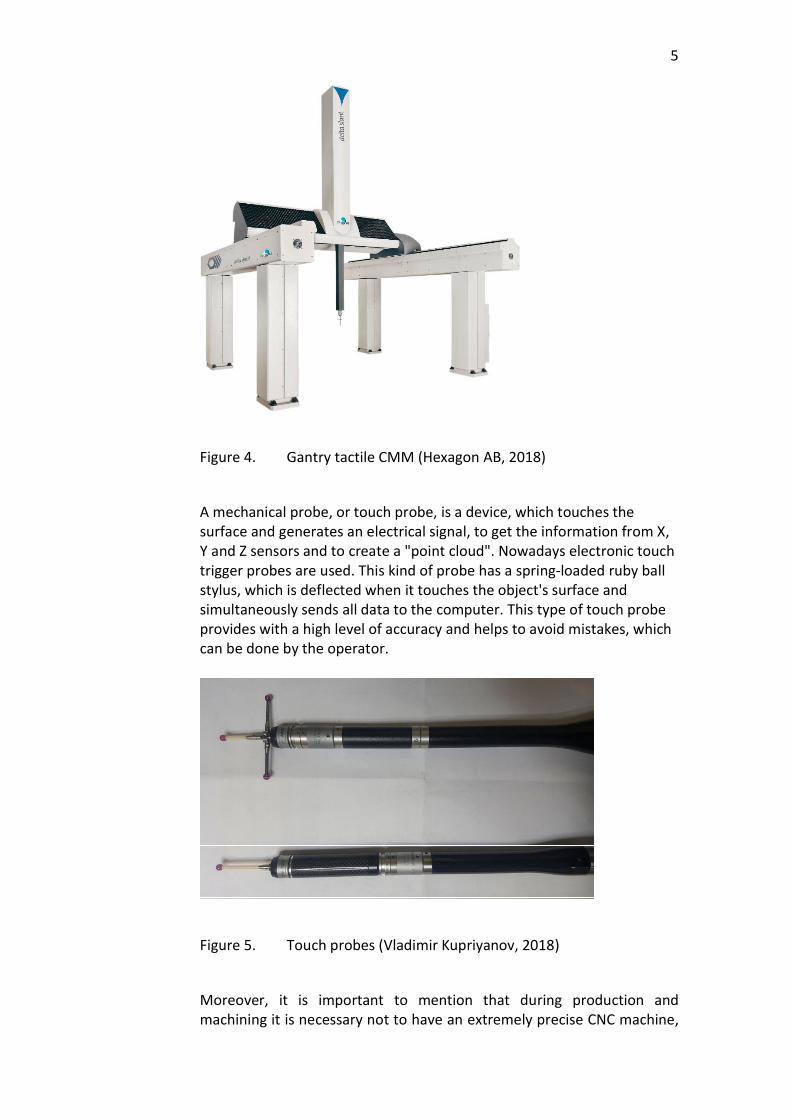
5
Figure 4. Gantry tactile CMM (Hexagon AB, 2018)
A mechanical probe, or touch probe, is a device, which touches the surface and generates an electrical signal, to get the information from X, Y and Z sensors and to create a "point cloud". Nowadays electronic touch trigger probes are used. This kind of probe has a spring-loaded ruby ball stylus, which is deflected when it touches the object's surface and simultaneously sends all data to the computer. This type of touch probe provides with a high level of accuracy and helps to avoid mistakes, which can be done by the operator.
Figure 5. Touch probes (Vladimir Kupriyanov, 2018)
Moreover, it is important to mention that during production and machining it is necessary not to have an extremely precise CNC machine,
6
which can manufacture all dimensions with its tolerances at ones, but it must be a CNC machine which can repeat its errors constantly. If the CNC machine can repeat its errors, it is much easier for a person, who is responsible for quality control to define ready part's faults and to give this information to the operator of a CNC machine, to improve dimensions (if part has some serious faults and machining is necessary again) and provide to customer a part with required parameters. There is a wide range of tactile CMM types. They have different forms, sizes and accuracy. Next types of a tactile coordinate measurement machine are utilised by mostly all engineering companies.
3.2 Bridge CMM
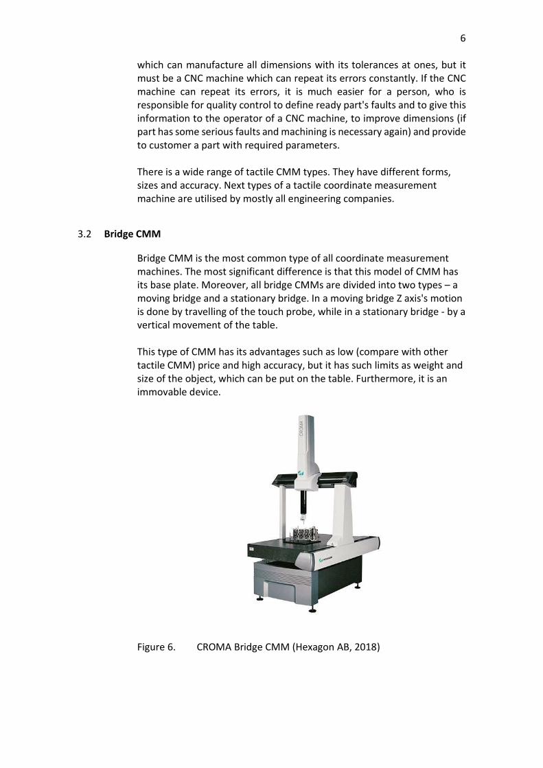
Bridge CMM is the most common type of all coordinate measurement machines. The most significant difference is that this model of CMM has its base plate. Moreover, all bridge CMMs are divided into two types – a moving bridge and a stationary bridge. In a moving bridge Z axis's motion is done by travelling of the touch probe, while in a stationary bridge - by a vertical movement of the table. This type of CMM has its advantages such as low (compare with other tactile CMM) price and high accuracy, but it has such limits as weight and size of the object, which can be put on the table. Furthermore, it is an immovable device.
Figure 6. CROMA Bridge CMM (Hexagon AB, 2018)
7
3.3 Horizontal Arm
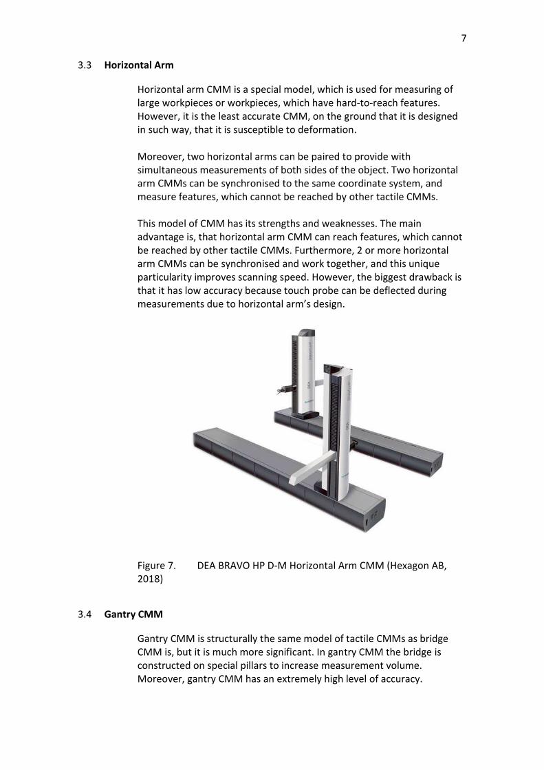
Horizontal arm CMM is a special model, which is used for measuring of large workpieces or workpieces, which have hard-to-reach features. However, it is the least accurate CMM, on the ground that it is designed in such way, that it is susceptible to deformation. Moreover, two horizontal arms can be paired to provide with simultaneous measurements of both sides of the object. Two horizontal arm CMMs can be synchronised to the same coordinate system, and measure features, which cannot be reached by other tactile CMMs. This model of CMM has its strengths and weaknesses. The main advantage is, that horizontal arm CMM can reach features, which cannot be reached by other tactile CMMs. Furthermore, 2 or more horizontal arm CMMs can be synchronised and work together, and this unique particularity improves scanning speed. However, the biggest drawback is that it has low accuracy because touch probe can be deflected during measurements due to horizontal arm’s design.
Figure 7. DEA BRAVO HP D-M Horizontal Arm CMM (Hexagon AB, 2018)
3.4 Gantry CMM
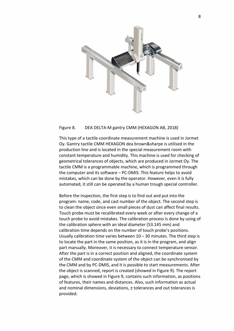
Gantry CMM is structurally the same model of tactile CMMs as bridge CMM is, but it is much more significant. In gantry CMM the bridge is constructed on special pillars to increase measurement volume. Moreover, gantry CMM has an extremely high level of accuracy.
8
Figure 8. DEA DELTA-M gantry CMM (HEXAGON AB, 2018)
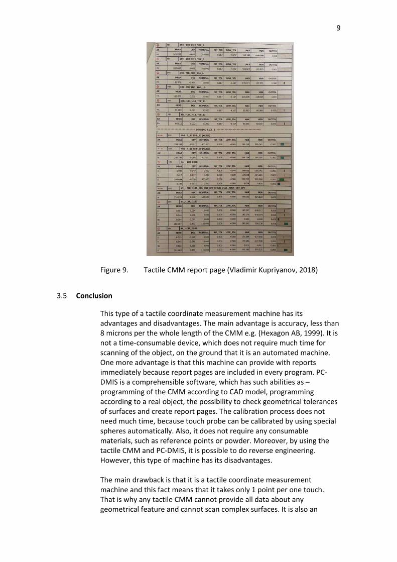
This type of a tactile coordinate measurement machine is used in Jormet Oy. Gantry tactile CMM HEXAGON dea brown&sharpe is utilised in the production line and is located in the special measurement room with constant temperature and humidity. This machine is used for checking of geometrical tolerances of objects, which are produced in Jormet Oy. The tactile CMM is a programmable machine, which is programmed through the computer and its software – PC-DMIS. This feature helps to avoid mistakes, which can be done by the operator. However, even it is fully automated, it still can be operated by a human trough special controller. Before the inspection, the first step is to find out and put into the program: name, code, and cast number of the object. The second step is to clean the object since even small pieces of dust can affect final results. Touch probe must be recalibrated every week or after every change of a touch probe to avoid mistakes. The calibration process is done by using of the calibration sphere with an ideal diameter (53.145 mm) and calibration time depends on the number of touch probe’s positions. Usually calibration time varies between 10 – 30 minutes. The third step is to locate the part in the same position, as it is in the program, and align part manually. Moreover, it is necessary to connect temperature sensor. After the part is in a correct position and aligned, the coordinate system of the CMM and coordinate system of the object can be synchronised by the CMM and by PC-DMIS, and it is possible to start measurements. After the object is scanned, report is created (showed in Figure 9). The report page, which is showed in Figure 9, contains such information, as positions of features, their names and distances. Also, such information as actual and nominal dimensions, deviations, ± tolerances and out tolerances is provided.
9
Figure 9. Tactile CMM report page (Vladimir Kupriyanov, 2018)
3.5 Conclusion
This type of a tactile coordinate measurement machine has its advantages and disadvantages. The main advantage is accuracy, less than 8 microns per the whole length of the CMM e.g. (Hexagon AB, 1999). It is not a time-consumable device, which does not require much time for scanning of the object, on the ground that it is an automated machine. One more advantage is that this machine can provide with reports immediately because report pages are included in every program. PC-DMIS is a comprehensible software, which has such abilities as – programming of the CMM according to CAD model, programming according to a real object, the possibility to check geometrical tolerances of surfaces and create report pages. The calibration process does not need much time, because touch probe can be calibrated by using special spheres automatically. Also, it does not require any consumable materials, such as reference points or powder. Moreover, by using the tactile CMM and PC-DMIS, it is possible to do reverse engineering. However, this type of machine has its disadvantages. The main drawback is that it is a tactile coordinate measurement machine and this fact means that it takes only 1 point per one touch. That is why any tactile CMM cannot provide all data about any geometrical feature and cannot scan complex surfaces. It is also an
10
immovable device. Consequently, it is not portable. Report pages contain only digits (actual and real dimensions, ±tolerances, and mistakes) and through PC-DMIS it is impossible to compare a real model with CAD model or 2 scanned models (for example before and after welding). It is necessary to mention that gantry CMM is an extremely expensive measuring device, because of its price (about 450.000€) and the price of measurement room with all equipment (climate and humidity control systems). Comparison with the optical Blue-light CMM: Advantages:
Accuracy; Does not have any consumable materials; Automated; Fast scanning; Can scan reflective surfaces.
Disadvantages:
Not a portable device; Cannot scan complex surfaces; Cannot take more than 1 point per scan; The software cannot provide visual inspection and comparison; Expensive; Requires a special measurement room, due to its size; Requires special alignment, before inspection.
4 OPTICAL CMM WITH BLUE LIGHT TECHNOLOGY
4.1 General information about optical CMM with blue light technology
Optical CMM with Blue Light technology is a contactless type of coordinate measurement machines, which provides a complete and detailed picture of the surface by taking more than 7 million points (e.g. GOM GmbH, 2018) per one scan by utilising of cameras and projector with blue light technology. During scanning, it receives rapid and precise three-dimensional data with a high resolution. To make precise measurements 3D-Scanners need reference points, which can be consumable – stickers and non-consumable – magnetic. Furthermore, some of optical CMMs with blue light technology cannot scan reflective surfaces and deal with this drawback white powder is utilised. Not all 3D-Scanners can be used in a production environment. To overcome this problem, GOM ATOS III Triple Scan with its software – GOM Inspect was chosen as a competitor to HEXAGON dea brown&sharpe.
11
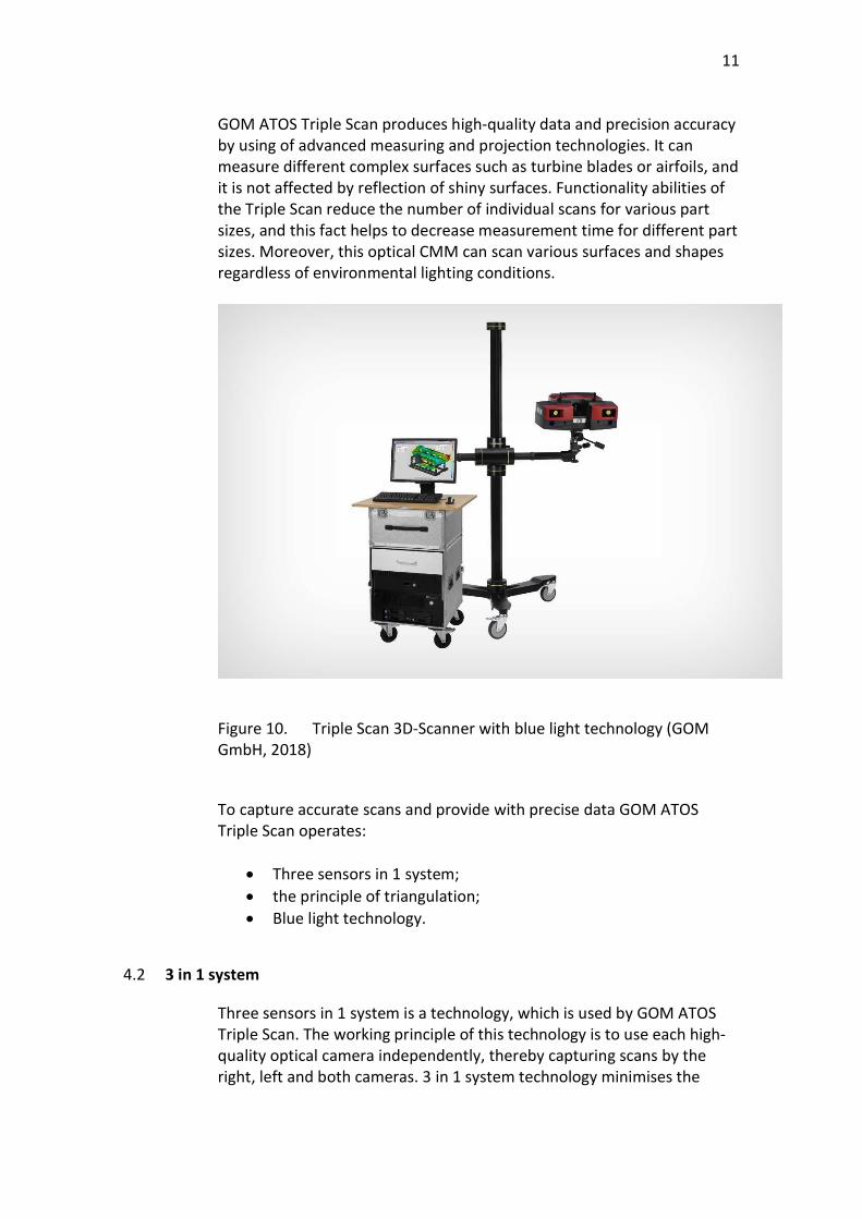
GOM ATOS Triple Scan produces high-quality data and precision accuracy by using of advanced measuring and projection technologies. It can measure different complex surfaces such as turbine blades or airfoils, and it is not affected by reflection of shiny surfaces. Functionality abilities of the Triple Scan reduce the number of individual scans for various part sizes, and this fact helps to decrease measurement time for different part sizes. Moreover, this optical CMM can scan various surfaces and shapes regardless of environmental lighting conditions.
Figure 10. Triple Scan 3D-Scanner with blue light technology (GOM GmbH, 2018)
To capture accurate scans and provide with precise data GOM ATOS Triple Scan operates:
Three sensors in 1 system; the principle of triangulation; Blue light technology.
4.2 3 in 1 system
Three sensors in 1 system is a technology, which is used by GOM ATOS Triple Scan. The working principle of this technology is to use each high-quality optical camera independently, thereby capturing scans by the right, left and both cameras. 3 in 1 system technology minimises the
12
number of scans by maximising data collection. Consequently, it reduces the measurement time.
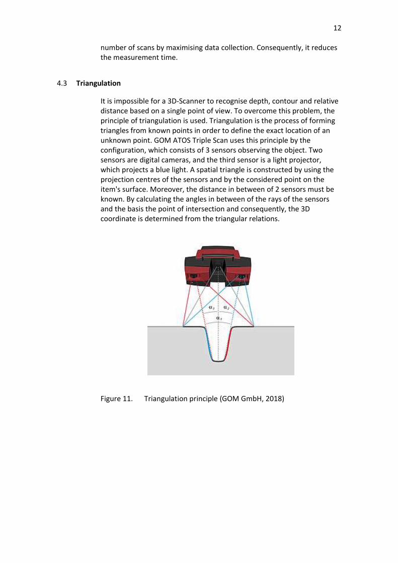
4.3 Triangulation
It is impossible for a 3D-Scanner to recognise depth, contour and relative distance based on a single point of view. To overcome this problem, the principle of triangulation is used. Triangulation is the process of forming triangles from known points in order to define the exact location of an unknown point. GOM ATOS Triple Scan uses this principle by the configuration, which consists of 3 sensors observing the object. Two sensors are digital cameras, and the third sensor is a light projector, which projects a blue light. A spatial triangle is constructed by using the projection centres of the sensors and by the considered point on the item's surface. Moreover, the distance in between of 2 sensors must be known. By calculating the angles in between of the rays of the sensors and the basis the point of intersection and consequently, the 3D coordinate is determined from the triangular relations.
Figure 11. Triangulation principle (GOM GmbH, 2018)
13
4.4 Blue light technology
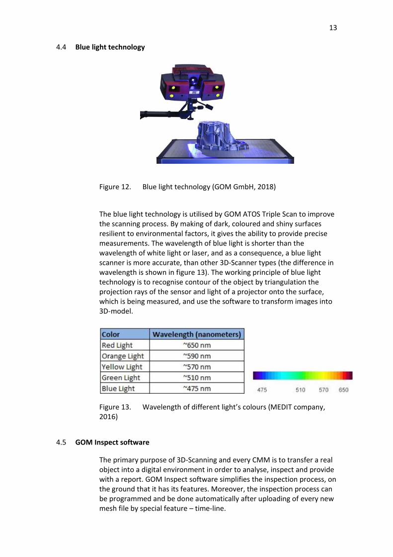
Figure 12. Blue light technology (GOM GmbH, 2018)
The blue light technology is utilised by GOM ATOS Triple Scan to improve the scanning process. By making of dark, coloured and shiny surfaces resilient to environmental factors, it gives the ability to provide precise measurements. The wavelength of blue light is shorter than the wavelength of white light or laser, and as a consequence, a blue light scanner is more accurate, than other 3D-Scanner types (the difference in wavelength is shown in figure 13). The working principle of blue light technology is to recognise contour of the object by triangulation the projection rays of the sensor and light of a projector onto the surface, which is being measured, and use the software to transform images into 3D-model.
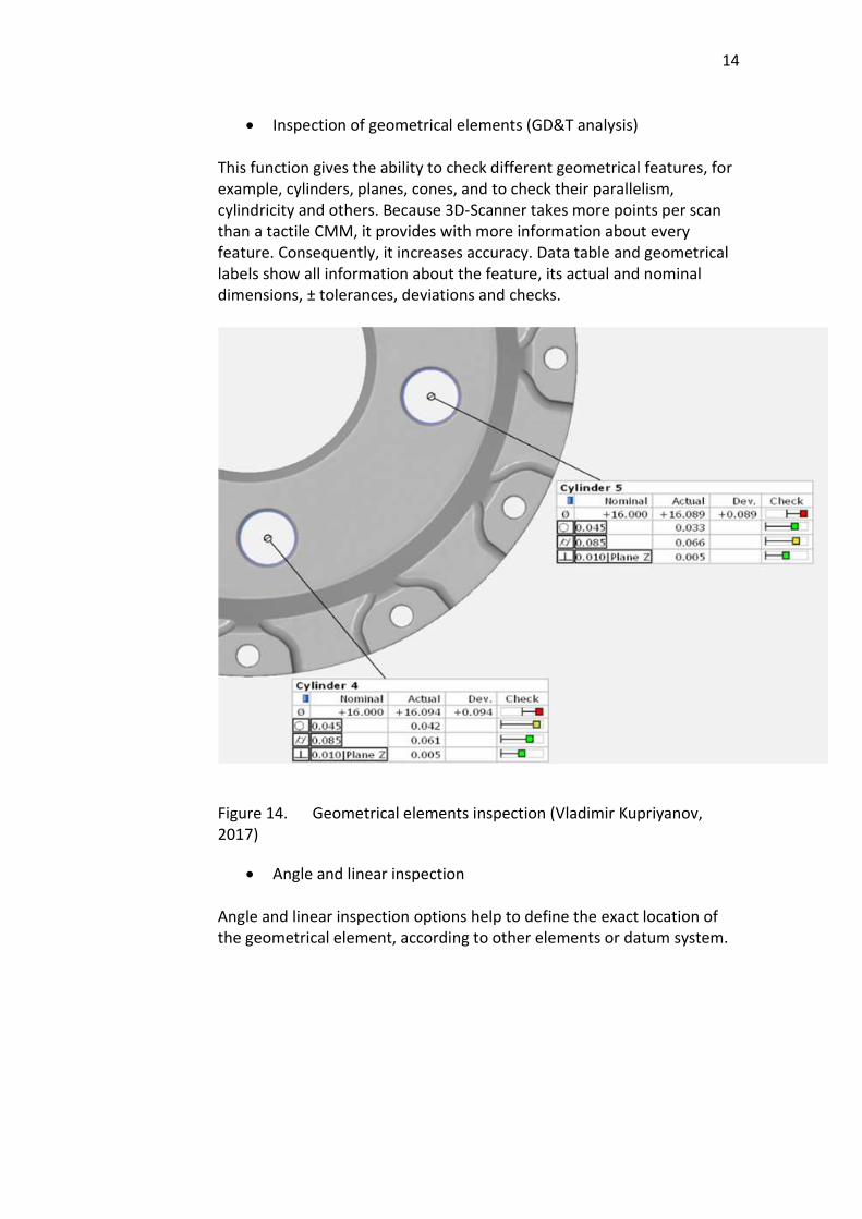
Figure 13. Wavelength of different light’s colours (MEDIT company, 2016)
4.5 GOM Inspect software
The primary purpose of 3D-Scanning and every CMM is to transfer a real object into a digital environment in order to analyse, inspect and provide with a report. GOM Inspect software simplifies the inspection process, on the ground that it has its features. Moreover, the inspection process can be programmed and be done automatically after uploading of every new mesh file by special feature – time-line.
14
Inspection of geometrical elements (GD&T analysis)
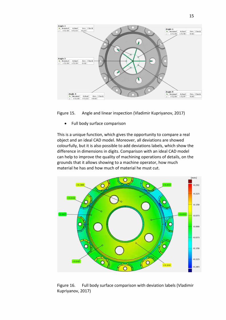
This function gives the ability to check different geometrical features, for example, cylinders, planes, cones, and to check their parallelism, cylindricity and others. Because 3D-Scanner takes more points per scan than a tactile CMM, it provides with more information about every feature. Consequently, it increases accuracy. Data table and geometrical labels show all information about the feature, its actual and nominal dimensions, ± tolerances, deviations and checks.
Figure 14. Geometrical elements inspection (Vladimir Kupriyanov, 2017)
Angle and linear inspection Angle and linear inspection options help to define the exact location of the geometrical element, according to other elements or datum system.
15
Figure 15. Angle and linear inspection (Vladimir Kupriyanov, 2017)
Full body surface comparison This is a unique function, which gives the opportunity to compare a real object and an ideal CAD model. Moreover, all deviations are showed colourfully, but it is also possible to add deviations labels, which show the difference in dimensions in digits. Comparison with an ideal CAD model can help to improve the quality of machining operations of details, on the grounds that it allows showing to a machine operator, how much material he has and how much of material he must cut.
Figure 16. Full body surface comparison with deviation labels (Vladimir Kupriyanov, 2017)
16
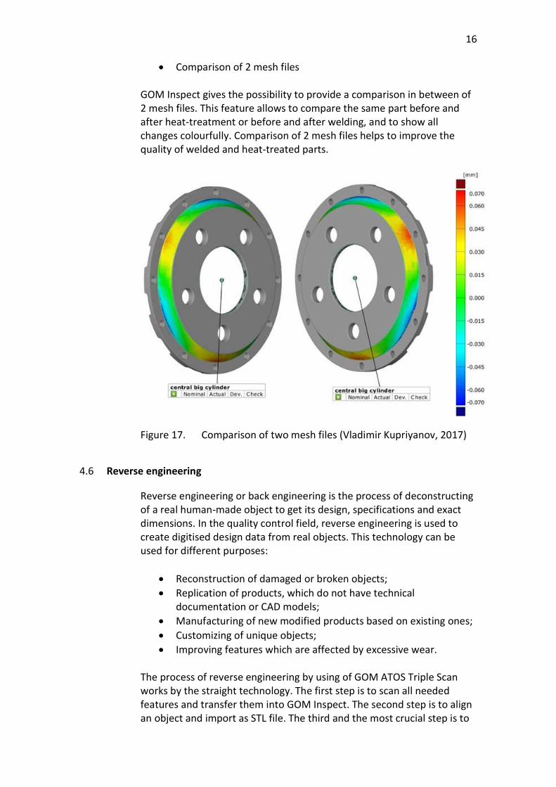
Comparison of 2 mesh files GOM Inspect gives the possibility to provide a comparison in between of 2 mesh files. This feature allows to compare the same part before and after heat-treatment or before and after welding, and to show all changes colourfully. Comparison of 2 mesh files helps to improve the quality of welded and heat-treated parts.
Figure 17. Comparison of two mesh files (Vladimir Kupriyanov, 2017)
4.6 Reverse engineering
Reverse engineering or back engineering is the process of deconstructing of a real human-made object to get its design, specifications and exact dimensions. In the quality control field, reverse engineering is used to create digitised design data from real objects. This technology can be used for different purposes:
Reconstruction of damaged or broken objects; Replication of products, which do not have technical
documentation or CAD models; Manufacturing of new modified products based on existing ones; Customizing of unique objects; Improving features which are affected by excessive wear.
The process of reverse engineering by using of GOM ATOS Triple Scan works by the straight technology. The first step is to scan all needed features and transfer them into GOM Inspect. The second step is to align an object and import as STL file. The third and the most crucial step is to
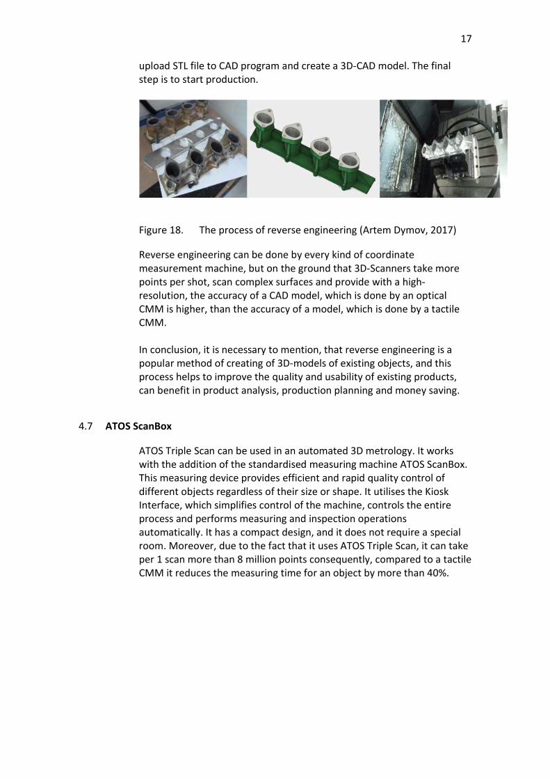
17
upload STL file to CAD program and create a 3D-CAD model. The final step is to start production.
Figure 18. The process of reverse engineering (Artem Dymov, 2017)
Reverse engineering can be done by every kind of coordinate measurement machine, but on the ground that 3D-Scanners take more points per shot, scan complex surfaces and provide with a high-resolution, the accuracy of a CAD model, which is done by an optical CMM is higher, than the accuracy of a model, which is done by a tactile CMM. In conclusion, it is necessary to mention, that reverse engineering is a popular method of creating of 3D-models of existing objects, and this process helps to improve the quality and usability of existing products, can benefit in product analysis, production planning and money saving.
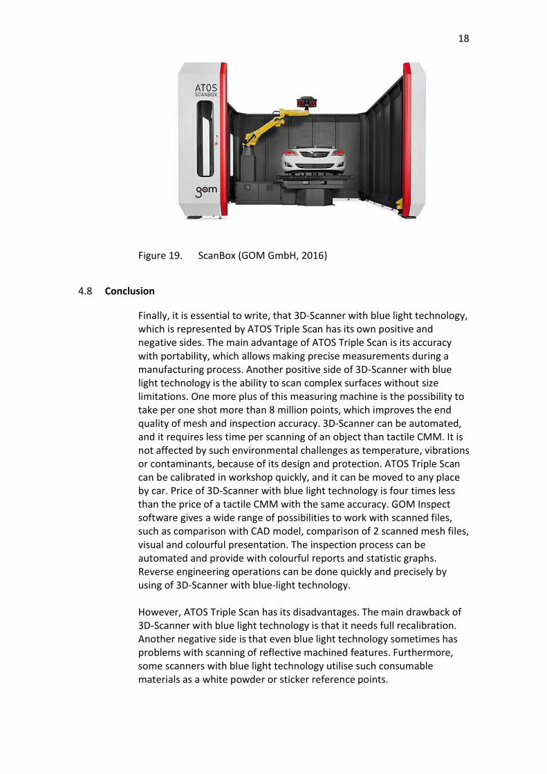
4.7 ATOS ScanBox
ATOS Triple Scan can be used in an automated 3D metrology. It works with the addition of the standardised measuring machine ATOS ScanBox. This measuring device provides efficient and rapid quality control of different objects regardless of their size or shape. It utilises the Kiosk Interface, which simplifies control of the machine, controls the entire process and performs measuring and inspection operations automatically. It has a compact design, and it does not require a special room. Moreover, due to the fact that it uses ATOS Triple Scan, it can take per 1 scan more than 8 million points consequently, compared to a tactile CMM it reduces the measuring time for an object by more than 40%.
18
Figure 19. ScanBox (GOM GmbH, 2016)
4.8 Conclusion
Finally, it is essential to write, that 3D-Scanner with blue light technology, which is represented by ATOS Triple Scan has its own positive and negative sides. The main advantage of ATOS Triple Scan is its accuracy with portability, which allows making precise measurements during a manufacturing process. Another positive side of 3D-Scanner with blue light technology is the ability to scan complex surfaces without size limitations. One more plus of this measuring machine is the possibility to take per one shot more than 8 million points, which improves the end quality of mesh and inspection accuracy. 3D-Scanner can be automated, and it requires less time per scanning of an object than tactile CMM. It is not affected by such environmental challenges as temperature, vibrations or contaminants, because of its design and protection. ATOS Triple Scan can be calibrated in workshop quickly, and it can be moved to any place by car. Price of 3D-Scanner with blue light technology is four times less than the price of a tactile CMM with the same accuracy. GOM Inspect software gives a wide range of possibilities to work with scanned files, such as comparison with CAD model, comparison of 2 scanned mesh files, visual and colourful presentation. The inspection process can be automated and provide with colourful reports and statistic graphs. Reverse engineering operations can be done quickly and precisely by using of 3D-Scanner with blue-light technology. However, ATOS Triple Scan has its disadvantages. The main drawback of 3D-Scanner with blue light technology is that it needs full recalibration. Another negative side is that even blue light technology sometimes has problems with scanning of reflective machined features. Furthermore, some scanners with blue light technology utilise such consumable materials as a white powder or sticker reference points.
19
Comparison with the tactile CMM: Advantages:
Ability to scan complex surfaces; No size limits; Price; Portability; Fast and straightforward calibration process; Protected against environmental challenges; Take per one scan more than 8 million points; Fast scanning process; User-friendly interface; Highly-functional software; A simple process of reverse engineering; Does not require a measurement room.
Disadvantages:
It needs full recalibration every year; Requires additional consumable materials.
5 ALTERNATIVE TYPES OF MEASURING MACHINES
Except for these two types of coordinate measuring machines (an optical and a tactile CMMs) other models of measuring devices which work by different technologies exist. On the ground that different types of CMMs are designed to be used in a specific production environment, they have their aims, design and limitations. In such production environment, as Jormet Oy has, following types of measuring equipment can be used.
5.1 Portable Measuring Arms
Portable arm coordinate measuring machine is an all-purpose measurement device, which can be used nearly everywhere in a manufacturing environment, from in-process inspection to assembly checks, on the ground that this type of CMM has the ability to digitise and analyse products straight at a production line, due to its flexibility and portability. Through that fact, that portable measuring arm is a measurement device, it is sensitive to an environment. Because it has the possibility to be used during the production process in a wide range of industries, it must be protected against such challenges of manufacturing field as
20
contaminants, dust, temperature and vibration. Such modern technologies as:
Carbon fibre (to solve the problem of temperature), Sensory feedback (to alert if unit vibrates), Wireless technologies (to transfer data without any cables, which
can be damaged), Battery (to improve portability and remove wires)
are used to deal with these challenges and make the scanning process more accurate and comfortable. Portable arm CMM uses a laser scanner to improve its portability. It can work with integrated or external scanner. The main difference in between of these scanner's types is that integrated scanner is a laser line scanner and it is a suitable solution for products which are relatively equal in colour and reflectivity, while external laser scanner uses flying dot technology of laser scanning and this technology is the best solution for parts, that have difference in between colour and reflectivity. Moreover, this type of CMM takes multiple shots continuously, and it has special types of software, which helps to inspect such products as gears, tubes and composites. In conclusion, it is necessary to write, that portable arm CMM is protected against manufacturing environment, damages and can be utilised in different environmental conditions. It can scan reflective surfaces and provide with real-time results using the suitable software. Moreover, it is a non-contact type of measurement machine, and it can scan complex surfaces. Comparison with the optical Blue-light CMM: Advantages:
Protected against contaminants and dust; Can scan reflective surfaces.
Disadvantages: Accuracy; Low resolution.
Comparison with the tactile CMM:
Advantages:
Can scan complex surfaces; Contactless;
21
Portable; Protected against vibrations; Takes more than 100000 points per scan; Consumes less energy.
Disadvantages: Accuracy.
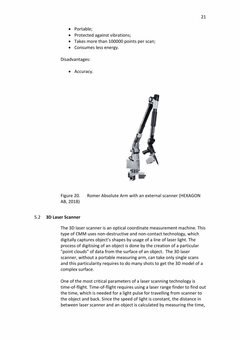
Figure 20. Romer Absolute Arm with an external scanner (HEXAGON AB, 2018)
5.2 3D Laser Scanner
The 3D laser scanner is an optical coordinate measurement machine. This type of CMM uses non-destructive and non-contact technology, which digitally captures object’s shapes by usage of a line of laser light. The process of digitising of an object is done by the creation of a particular "point clouds" of data from the surface of an object. The 3D laser scanner, without a portable measuring arm, can take only single scans and this particularity requires to do many shots to get the 3D model of a complex surface. One of the most critical parameters of a laser scanning technology is time-of-flight. Time-of-flight requires using a laser range finder to find out the time, which is needed for a light pulse for travelling from scanner to the object and back. Since the speed of light is constant, the distance in between laser scanner and an object is calculated by measuring the time,
22
which is taken by the laser light pulse to return to the scanner. To calculate the time, following formula is used.
∗ (1)
Consequently, the accuracy of 3D laser scanner depends on the accuracy of its chronometer. Another important feature, which is used by 3D laser scanner is triangulation. Some laser scanners combine laser and a special camera which follows the laser dots projected on a scanned surface. Triangulation technology helps to measure the distance, and therefore dimensions, more precise, however, it decreases scanning area. After the scanning process is started, scanned points must be aligned automatically by software and construct 3D-model of a surface. It can be done both while the scanning process is going or after the process is finished. Finally, it is important to mention, that such type of an optical coordinate measurement machine as 3D laser scanner has its advantages and disadvantages while comparing with the tactile CMM or the optical CMM with Blue-light technology. The main advantage is a low price: it is much cheaper than other devices. One more positive side is that this device is portable, and it can scan huge areas even with a complicated shape, that is why it can be used in a manufacturing environment for different purposes. Furthermore, laser optical CMM can scan reflective surfaces, and the scanning process is not time-consumable. Comparison with the optical Blue-light CMM: Advantages:
Can scan reflective surfaces.
Disadvantages: Accuracy; Low resolution.
Comparison with the tactile CMM: Advantages:
Can scan complex surfaces; Contactless; Portable;
23
Takes more than 100000 points per scan; Consumes less energy.
Disadvantages: Accuracy.
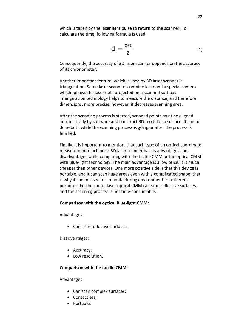
Figure 21. HP Laser Scanner (HEXAGON AB, 2018)
5.3 Laser Tracker Systems
Laser tracker system is a special measurement device, which measures an object by using a spherical coordinate system. It means that scanner registers any scanned point by the radial distance and by the zenith and the azimuth angles. The radial distance between a point and the tracker can be measured by an interferometer (IFM), by an absolute distance meter (ADM) or by both of them. However, nowadays, all modern laser trackers are produced with an ADM system or combination of an IFM and an ADM. The zenith and the azimuth angles are set by two angular encoders. The principle of working of an IFM system is that it sends two laser beams, the direction of the first one is to travel to the interferometer, while the second is sent directly to the target device on a surface, which should be measured. The two lasers collide inside of the interferometer, and this collision causes a cyclic change (which is ¼ of the laser wavelength) whenever the distance in between the measured surface and laser tracker is changed. By calculating the number of cyclic changes, the laser tracker measures the exact distance travelled by the laser. ADM system uses a semiconductor laser to produce infrared light, which is sent directly to the target device on an object, and then reflected back to the scanner. The infrared light is converted into electrical signal, which is analysed by the scanner to find out time-of-flight.
24
The advantage of an ADM system is that it can measure the distance in between of the scanner and an object automatically, and the ability to continue measurement if the laser beam has been broken. The IFM system has the opportunity to make quick shots, but if a laser beam is broken, it is needed to start scanning from a previously known position. Nowadays laser tracker systems are used in a wide range of industries. It is used in aerospace industry to inspect parts, assemblies, matrix and machine tools. Laser trackers are widely spread in the automotive industry, on the ground that they check assemblies, dimensions of parts and alignment of components. Tracker also can make deformation and dynamic measurements. They are utilised by companies, which produces huge parts, machines, long pipes, products which cannot be measured by tactile CMM due to its size limitations. Finally, it is required to mention that laser tracker system has its own positive and negative sides, compared to the tactile CMM and the optical Blue-light CMM. The main advantage is that laser tracker can scan and inspect parts with complex shape with good accuracy without size limitations, due to ADM and IFM systems. It is portable and provides high-speed scanning. The main drawback is that laser scanner does not take much data per 1 scan and still it does not have as high accuracy as tactile or optical Blue-light coordinate measurement machines have. Comparison with the optical Blue-light CMM: Advantages:
Can scan reflective surfaces; Does not have size limitations.
Disadvantages: Accuracy; Low resolution.
Comparison with the tactile CMM: Advantages:
Can scan complex surfaces; Contactless; Portable; Takes more than 10000 points per scan; Consumes less energy; Does not have size limitations; Is not time-consuming.
25
Disadvantages:
Accuracy.
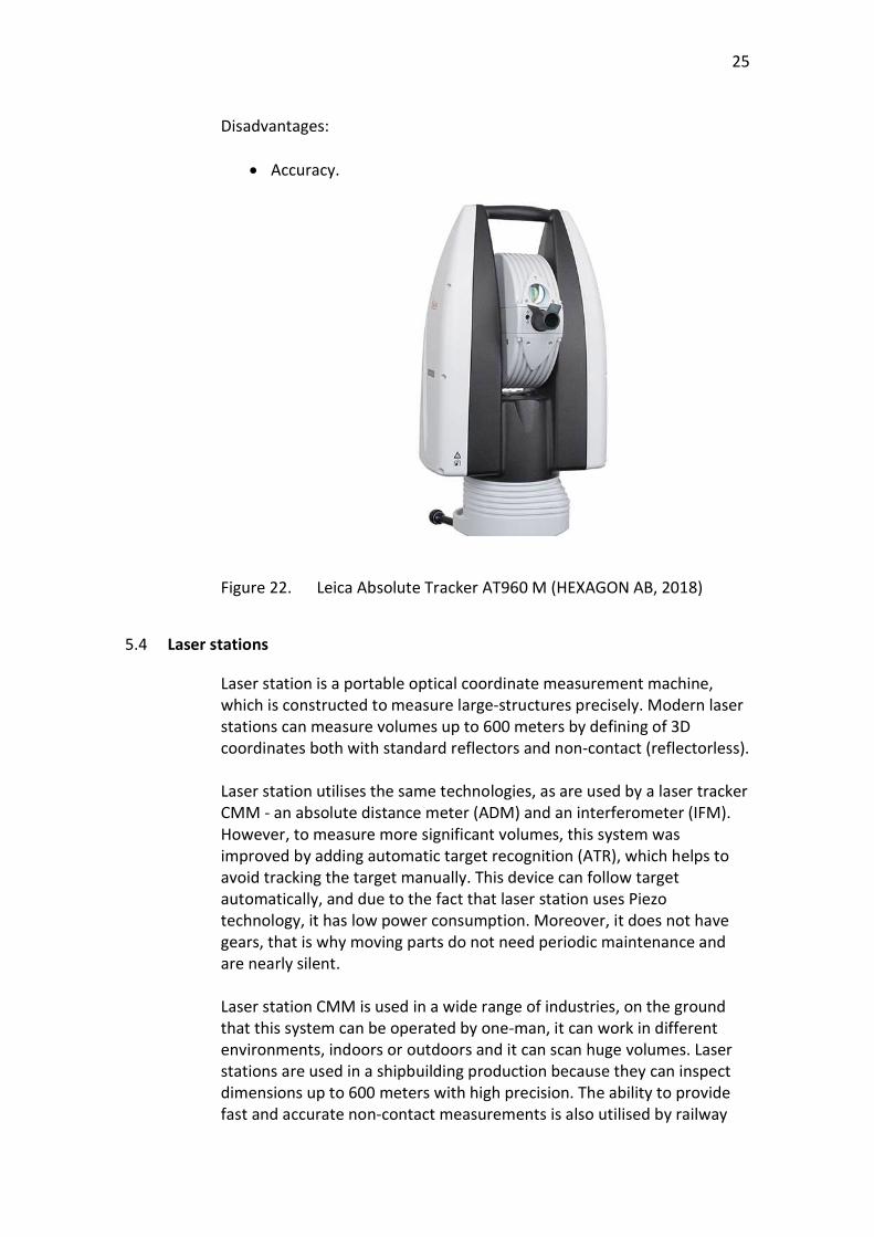
Figure 22. Leica Absolute Tracker AT960 M (HEXAGON AB, 2018)
5.4 Laser stations
Laser station is a portable optical coordinate measurement machine, which is constructed to measure large-structures precisely. Modern laser stations can measure volumes up to 600 meters by defining of 3D coordinates both with standard reflectors and non-contact (reflectorless). Laser station utilises the same technologies, as are used by a laser tracker CMM - an absolute distance meter (ADM) and an interferometer (IFM). However, to measure more significant volumes, this system was improved by adding automatic target recognition (ATR), which helps to avoid tracking the target manually. This device can follow target automatically, and due to the fact that laser station uses Piezo technology, it has low power consumption. Moreover, it does not have gears, that is why moving parts do not need periodic maintenance and are nearly silent. Laser station CMM is used in a wide range of industries, on the ground that this system can be operated by one-man, it can work in different environments, indoors or outdoors and it can scan huge volumes. Laser stations are used in a shipbuilding production because they can inspect dimensions up to 600 meters with high precision. The ability to provide fast and accurate non-contact measurements is also utilised by railway
26
manufacturers. Power generation industry uses flexibility and precision of laser stations in order to check wind generators, nuclear reactors and solar mirror fields. Eventually, it is important to write that Laser station CMM has its own positive and negative sides comparing with a tactile CMM and optical Blue-light CMM. The most significant advantage of laser station is that this device can measure enormously considerable volumes in a different environment. It is a portable and flexible device, which can be used indoors or outdoors. Moreover, laser station CMM can be operated by one person and provide with fast, non-contact measurements. However, the main disadvantage is its accuracy and inability to measure small products. Comparison with the optical Blue-light CMM: Advantages:
Can scan reflective surfaces; Does not have any size limits (up to 600 m); Protected against environment;
Disadvantages: Accuracy; Cannot scan small products; Low resolution.
Comparison with the tactile CMM: Advantages:
Can scan complex surfaces; Contactless; Does not have any size limits (up to 600 m); Portable; Takes more than 10000 points per scan; Consumes less energy.
Disadvantages:
Accuracy; Cannot scan small products.
27
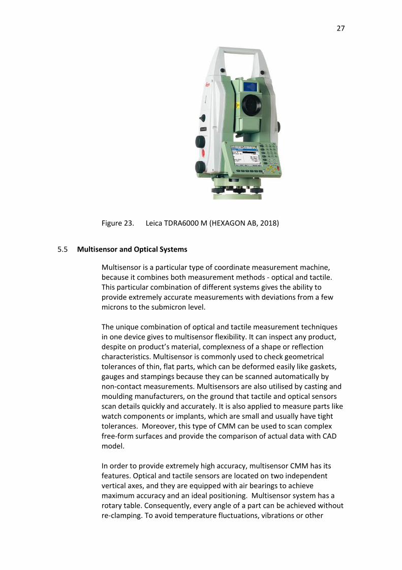
Figure 23. Leica TDRA6000 M (HEXAGON AB, 2018)
5.5 Multisensor and Optical Systems
Multisensor is a particular type of coordinate measurement machine, because it combines both measurement methods - optical and tactile. This particular combination of different systems gives the ability to provide extremely accurate measurements with deviations from a few microns to the submicron level. The unique combination of optical and tactile measurement techniques in one device gives to multisensor flexibility. It can inspect any product, despite on product’s material, complexness of a shape or reflection characteristics. Multisensor is commonly used to check geometrical tolerances of thin, flat parts, which can be deformed easily like gaskets, gauges and stampings because they can be scanned automatically by non-contact measurements. Multisensors are also utilised by casting and moulding manufacturers, on the ground that tactile and optical sensors scan details quickly and accurately. It is also applied to measure parts like watch components or implants, which are small and usually have tight tolerances. Moreover, this type of CMM can be used to scan complex free-form surfaces and provide the comparison of actual data with CAD model.
In order to provide extremely high accuracy, multisensor CMM has its features. Optical and tactile sensors are located on two independent vertical axes, and they are equipped with air bearings to achieve maximum accuracy and an ideal positioning. Multisensor system has a rotary table. Consequently, every angle of a part can be achieved without re-clamping. To avoid temperature fluctuations, vibrations or other
28
factors, which can affect measurement results, granite base and a special machine body with integrated damping systems are used. In conclusion, it is important to mention that multisensor is a unique type of coordinate measuring machine, which combines two different measurement systems – tactile and optical. Consequently, by using this device, it is possible to avoid negative sides of tactile and optical measurement systems and utilise only their strengths. By using the optical sensor, it is possible to provide measurements of small items, which can be deformed by tactile sensor. For ideal measurements of geometrical elements, like cones, cylinders or surfaces, the tactile system can be used. Furthermore, optical sensor increases measurement speed, while touch probe can deal with such negative aspect as reflection. Comparison with the optical Blue-light CMM: Advantages:
Accuracy; Does not require any additional consumable materials (no
reference points or powder); Can scan reflective surfaces; Is automated system.
Disadvantages: Not a portable device; Cannot scan medium or large size volumes.
Comparison with the tactile CMM:
Advantages: Accuracy; Has the ability to scan complex shapes; Can take more points per one scan, by using an optical sensor; Can provide faster scanning, by using an optical sensor.
Disadvantages: Cannot scan medium or large size volumes.
29
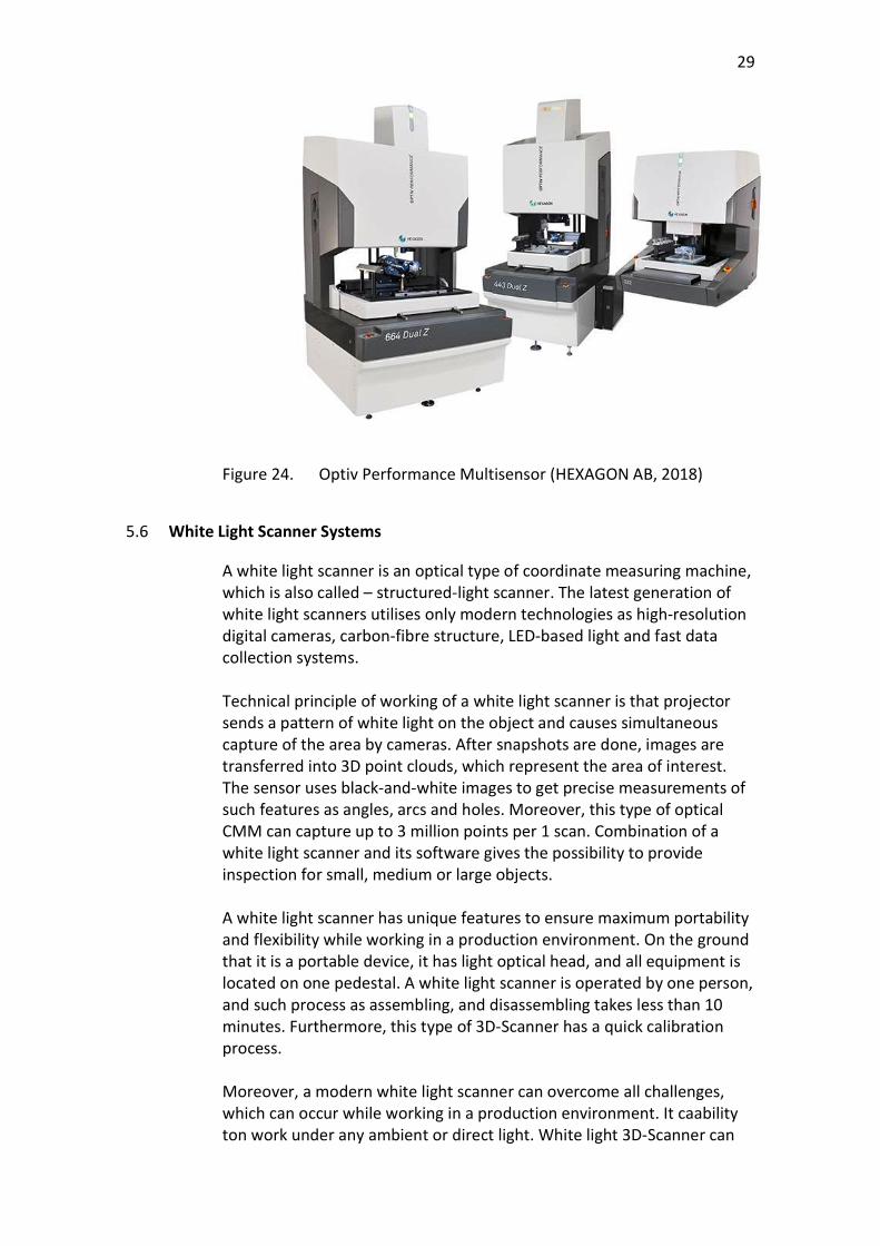
Figure 24. Optiv Performance Multisensor (HEXAGON AB, 2018)
5.6 White Light Scanner Systems
A white light scanner is an optical type of coordinate measuring machine, which is also called – structured-light scanner. The latest generation of white light scanners utilises only modern technologies as high-resolution digital cameras, carbon-fibre structure, LED-based light and fast data collection systems. Technical principle of working of a white light scanner is that projector sends a pattern of white light on the object and causes simultaneous capture of the area by cameras. After snapshots are done, images are transferred into 3D point clouds, which represent the area of interest. The sensor uses black-and-white images to get precise measurements of such features as angles, arcs and holes. Moreover, this type of optical CMM can capture up to 3 million points per 1 scan. Combination of a white light scanner and its software gives the possibility to provide inspection for small, medium or large objects. A white light scanner has unique features to ensure maximum portability and flexibility while working in a production environment. On the ground that it is a portable device, it has light optical head, and all equipment is located on one pedestal. A white light scanner is operated by one person, and such process as assembling, and disassembling takes less than 10 minutes. Furthermore, this type of 3D-Scanner has a quick calibration process. Moreover, a modern white light scanner can overcome all challenges, which can occur while working in a production environment. It caability ton work under any ambient or direct light. White light 3D-Scanner can
30
measure and digitise different finishing technologies and materials. It is not affected by machinery vibrations and temperature changes.
Finally, it is needed to mention, that white light scanner is a unique type of optical coordinate measurement machine. It is a portable system, which can be used for measurements, digitising and inspections. This is another type of evolution of an optical CMM, and this fact clearly describes, that accurate, contactless and portable devices are more appropriate for manufacturers than massive and immovable tactile CMM. Comparison with the optical Blue-light CMM:
Advantages:
LED-based light gives the possibility to provide measurements in
different light conditions; Fast calibration process.
Disadvantages: Accuracy.
Comparison with the tactile CMM: Advantages:
Portability; The ability to scan complex surfaces; The possibility to take per 1 scan more than 2 million points; Contactless scanning method; Quick calibration process.
Disadvantages: Accuracy.
31
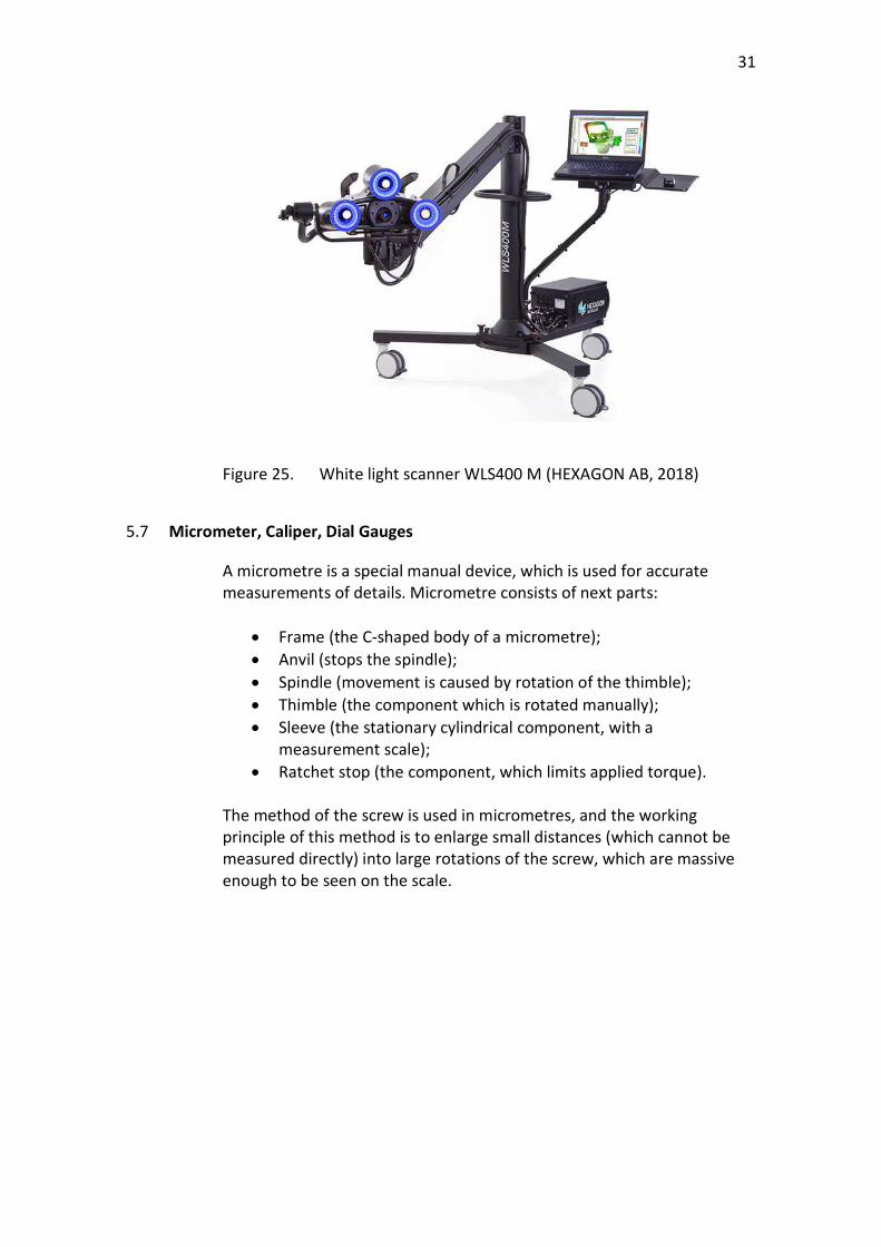
Figure 25. White light scanner WLS400 M (HEXAGON AB, 2018)
5.7 Micrometer, Caliper, Dial Gauges
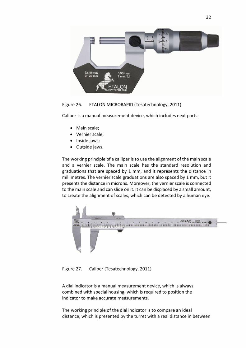
A micrometre is a special manual device, which is used for accurate measurements of details. Micrometre consists of next parts:
Frame (the C-shaped body of a micrometre); Anvil (stops the spindle); Spindle (movement is caused by rotation of the thimble); Thimble (the component which is rotated manually); Sleeve (the stationary cylindrical component, with a
measurement scale); Ratchet stop (the component, which limits applied torque).
The method of the screw is used in micrometres, and the working principle of this method is to enlarge small distances (which cannot be measured directly) into large rotations of the screw, which are massive enough to be seen on the scale.
32
Figure 26. ETALON MICRORAPID (Tesatechnology, 2011)
Caliper is a manual measurement device, which includes next parts: Main scale; Vernier scale; Inside jaws; Outside jaws.
The working principle of a calliper is to use the alignment of the main scale and a vernier scale. The main scale has the standard resolution and graduations that are spaced by 1 mm, and it represents the distance in millimetres. The vernier scale graduations are also spaced by 1 mm, but it presents the distance in microns. Moreover, the vernier scale is connected to the main scale and can slide on it. It can be displaced by a small amount, to create the alignment of scales, which can be detected by a human eye.
Figure 27. Caliper (Tesatechnology, 2011)
A dial indicator is a manual measurement device, which is always combined with special housing, which is required to position the indicator to make accurate measurements. The working principle of the dial indicator is to compare an ideal distance, which is presented by the turret with a real distance in between
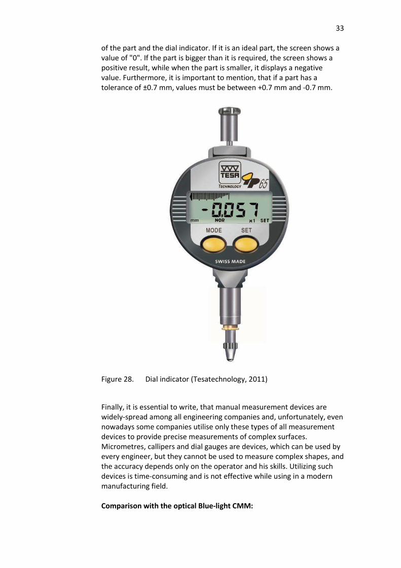
33
of the part and the dial indicator. If it is an ideal part, the screen shows a value of "0". If the part is bigger than it is required, the screen shows a positive result, while when the part is smaller, it displays a negative value. Furthermore, it is important to mention, that if a part has a tolerance of ±0.7 mm, values must be between +0.7 mm and -0.7 mm.
Figure 28. Dial indicator (Tesatechnology, 2011)
Finally, it is essential to write, that manual measurement devices are widely-spread among all engineering companies and, unfortunately, even nowadays some companies utilise only these types of all measurement devices to provide precise measurements of complex surfaces. Micrometres, callipers and dial gauges are devices, which can be used by every engineer, but they cannot be used to measure complex shapes, and the accuracy depends only on the operator and his skills. Utilizing such devices is time-consuming and is not effective while using in a modern manufacturing field. Comparison with the optical Blue-light CMM:
34
Advantages: Every engineer can operate with it; Cheap; Does not require any power supply; Light weight; Portability.
Disadvantages: Cannot scan complex surfaces; Cannot scan huge volumes; Accuracy depends on the operator’s skills; Time-consuming; Cannot be automated; Cannot provide with visual reports.
Comparison with the tactile CMM: Advantages:
Every engineer can operate with it; Cheap; Does not require any power supply; Light weight.
Disadvantages:
Cannot scan huge volumes; Accuracy depends on the operator’s skills; Time-consuming; Cannot be automated; Cannot provide with visual reports.
6 SCANNING CASES JORMET OY
The scanner was brought to Jormet Oy on week 11.2018 and stayed in Jormet for five days, until the middle of week 12.2018. It is important to mention that the process of package and delivery of 3D-Scanner is a simple operation, which does not require some particular vehicle and more than one person. Time of installation of 3D-Scanner is about 15 minutes and time of heating of lenses and projector before calibration is 30 minutes. The calibration process is needed after every switching on of the scanner and time, which is usually spent for calibration is 10 minutes. This fact proofs portability of 3D-Scanner.
35
During the time, when 3D-Scanner was in Jormet Oy, 3 cases with specific objectives were done: Case I. Scanning of Big planet carrier.
The aim of this case is to find out if 3D-Scanner can work in a production environment, provide fast measurements and reports.
Case II. Scanning of casted part -Keskinivel, before machining. The reason of this case if to define if an optical CMM can scan a part before machining and scanner’s software can compare scanned mesh with nominal CAD model to find out machining allowances.
Case III. Scanning of a pillar before and after welding. The goal of this case is to determine if 3D-scanner can scan the part before and after welding (heat-treatment) and scanner’s software can find out changes in dimensions.
6.1 Case I. Scanning of Big Planet Carrier
After changing of lenses, part was lifted and put to 3 special supports on CMM’s scanning table. Due to the fact that planet carrier has many machined and, consequently, polished and shiny parts, two cans of powder were used. Such tremendous amount of powder was used to get excellent scans with smooth surfaces without any reflections. Furthermore, for such big area as the planet carrier has, more than 150 reference points were used, and the process of putting and removing of reference points took nearly 2 hours. It describes that such kind of reference points as stickers is not a suitable solution for a real production environment, due to time-consuming and one-time use (this cause colossal material consumption). The new problem appeared, when it was realised that due to the CMM’s scanning table has deep lines, scanner support’s wheels fall into these holes. This problem describes that such surface is not suitable for a normal moving of 3D-Scanner with this kind of support. It was solved by putting a rubber carpet.
The scanning process took more than 7 hours in sum for both sides, and it is twice more than usually is taken by CMM per full part. The reason for such colossal time consuming was the fact, which ATOS Compact Scan with big lenses and proper camera support, scans in a maximum 1.2x0.9 meter. On the ground that HAMK University of Applied Sciences does not have this support, the maximum area of scanning can be only 0.6x0.9 meter. Furthermore, scanning time of every new part takes more time, than that one that has already been scanned before. This happens
36
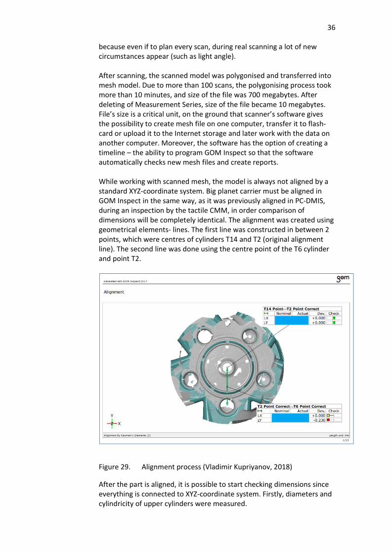
because even if to plan every scan, during real scanning a lot of new circumstances appear (such as light angle). After scanning, the scanned model was polygonised and transferred into mesh model. Due to more than 100 scans, the polygonising process took more than 10 minutes, and size of the file was 700 megabytes. After deleting of Measurement Series, size of the file became 10 megabytes. File’s size is a critical unit, on the ground that scanner’s software gives the possibility to create mesh file on one computer, transfer it to flash-card or upload it to the Internet storage and later work with the data on another computer. Moreover, the software has the option of creating a timeline – the ability to program GOM Inspect so that the software automatically checks new mesh files and create reports. While working with scanned mesh, the model is always not aligned by a standard XYZ-coordinate system. Big planet carrier must be aligned in GOM Inspect in the same way, as it was previously aligned in PC-DMIS, during an inspection by the tactile CMM, in order comparison of dimensions will be completely identical. The alignment was created using geometrical elements- lines. The first line was constructed in between 2 points, which were centres of cylinders T14 and T2 (original alignment line). The second line was done using the centre point of the T6 cylinder and point T2.
Figure 29. Alignment process (Vladimir Kupriyanov, 2018)
After the part is aligned, it is possible to start checking dimensions since everything is connected to XYZ-coordinate system. Firstly, diameters and cylindricity of upper cylinders were measured.
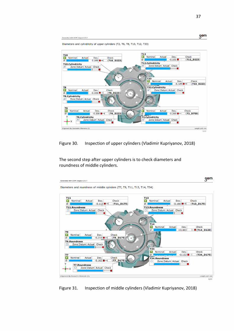
37
Figure 30. Inspection of upper cylinders (Vladimir Kupriyanov, 2018)
The second step after upper cylinders is to check diameters and roundness of middle cylinders.
Figure 31. Inspection of middle cylinders (Vladimir Kupriyanov, 2018)
38
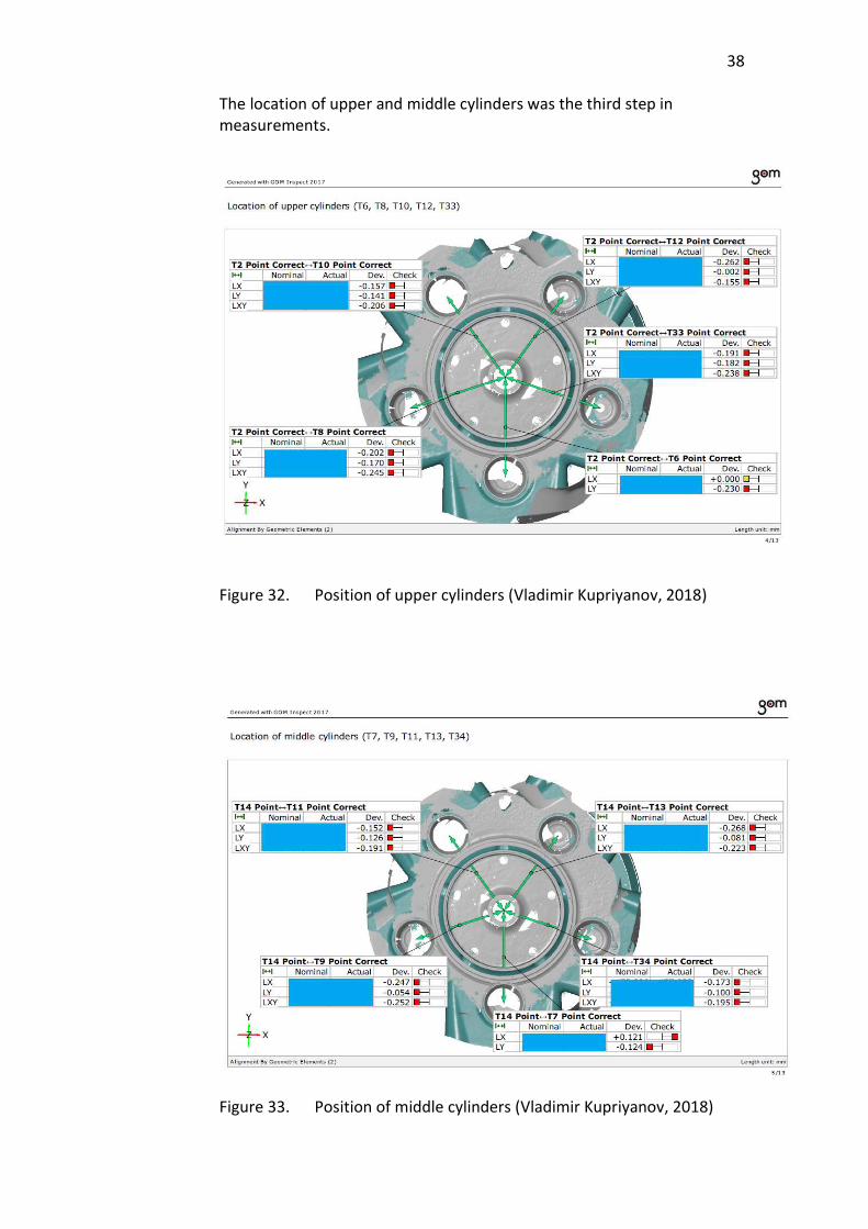
The location of upper and middle cylinders was the third step in measurements.
Figure 32. Position of upper cylinders (Vladimir Kupriyanov, 2018)
Figure 33. Position of middle cylinders (Vladimir Kupriyanov, 2018)
39
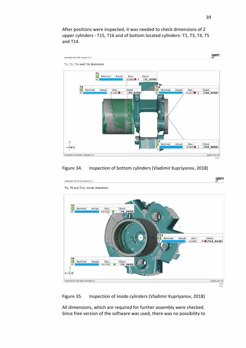
After positions were inspected, it was needed to check dimensions of 2 upper cylinders - T15, T16 and of bottom located cylinders- T1, T3, T4, T5 and T14.
Figure 34. Inspection of bottom cylinders (Vladimir Kupriyanov, 2018)
Figure 35. Inspection of inside cylinders (Vladimir Kupriyanov, 2018)
All dimensions, which are required for further assembly were checked. Since free version of the software was used, there was no possibility to
40
put information table which contains all dimensions - nominal, actual, plus/minus tolerances, deviations and checks. Also, as it was written previously, in the Professional version of the software there is an opportunity to create a timeline, so all the same parts will be checked automatically, and the program will create the data-changing diagram of every chosen element. After results were collected, they clearly showed that scanner was not in proper shape, so that is why it did not give correct results. There were particular reasons for such a bad condition. Air filters which were in scanner had not been replaced during previous years, while they must be changed every year to avoid overheating. Big lenses, which were used during scanning were from different sets - one was new and other was three years old. Moreover, it is necessary to mention, that scanner had not been hard calibrated during previous years, while it should be calibrated in this way every year. In conclusion, it is important to mention that during scanning and inspection of the big planet carrier it was proved, that when 3D-Scanner is in the proper condition, it can work as good as tactile coordinate measurement machine. The tolerance of the 3D-Scanner can be equal to the tactile CMM (up to 10 microns e.g. GOM GmbH, 2018), and Professional version of GOM Inspect software can provide with all data about the scanned part, and it even gives the opportunity to check the same part later. Moreover, in GOM Inspect software it is possible to compare mesh file with a CAD model, which helps to find and show deviations colourfully and visually.
6.2 Case II. Keskinivel, comparison of a rough part (scanned mesh) and a machined detail (CAD-model).
Keskinivel is a middle joint, which is utilised in forest machinery. Dimensions and positions of every hole are essential values, which have tight tolerances. Nevertheless, machining of a casted part is a complicated process, which requires high skills of the machine operator, due to the fact that keskinivel has holes both horizontal and vertical directions. The main reason of scanning of a keskinivel is that after scanning, GOM Inspect software gives the possibility to compare scanned part (mesh) and ideal CAD model, what gives the opportunity to find out machining allowances and to inspect a rough part if it has correct dimensions. This kind of operation can help to save production time because, before machining, the software can visually show cutting allowances. Furthermore, even after the part is machined, but some mistakes in values were found during geometry and dimensions checking, such type of inspection can show if still there is enough material to repair a part.
41
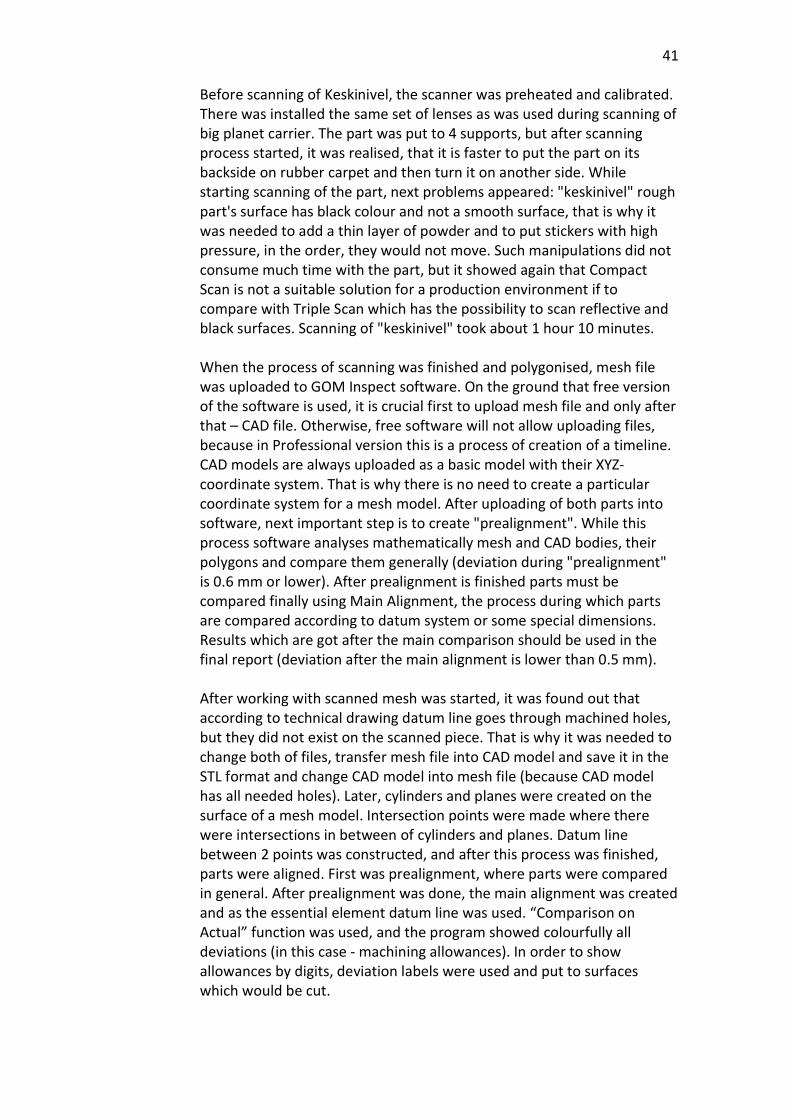
Before scanning of Keskinivel, the scanner was preheated and calibrated. There was installed the same set of lenses as was used during scanning of big planet carrier. The part was put to 4 supports, but after scanning process started, it was realised, that it is faster to put the part on its backside on rubber carpet and then turn it on another side. While starting scanning of the part, next problems appeared: "keskinivel" rough part's surface has black colour and not a smooth surface, that is why it was needed to add a thin layer of powder and to put stickers with high pressure, in the order, they would not move. Such manipulations did not consume much time with the part, but it showed again that Compact Scan is not a suitable solution for a production environment if to compare with Triple Scan which has the possibility to scan reflective and black surfaces. Scanning of "keskinivel" took about 1 hour 10 minutes. When the process of scanning was finished and polygonised, mesh file was uploaded to GOM Inspect software. On the ground that free version of the software is used, it is crucial first to upload mesh file and only after that – CAD file. Otherwise, free software will not allow uploading files, because in Professional version this is a process of creation of a timeline. CAD models are always uploaded as a basic model with their XYZ-coordinate system. That is why there is no need to create a particular coordinate system for a mesh model. After uploading of both parts into software, next important step is to create "prealignment". While this process software analyses mathematically mesh and CAD bodies, their polygons and compare them generally (deviation during "prealignment" is 0.6 mm or lower). After prealignment is finished parts must be compared finally using Main Alignment, the process during which parts are compared according to datum system or some special dimensions. Results which are got after the main comparison should be used in the final report (deviation after the main alignment is lower than 0.5 mm). After working with scanned mesh was started, it was found out that according to technical drawing datum line goes through machined holes, but they did not exist on the scanned piece. That is why it was needed to change both of files, transfer mesh file into CAD model and save it in the STL format and change CAD model into mesh file (because CAD model has all needed holes). Later, cylinders and planes were created on the surface of a mesh model. Intersection points were made where there were intersections in between of cylinders and planes. Datum line between 2 points was constructed, and after this process was finished, parts were aligned. First was prealignment, where parts were compared in general. After prealignment was done, the main alignment was created and as the essential element datum line was used. “Comparison on Actual” function was used, and the program showed colourfully all deviations (in this case - machining allowances). In order to show allowances by digits, deviation labels were used and put to surfaces which would be cut.
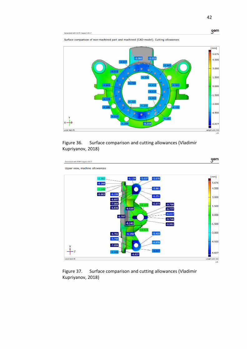
42
Figure 36. Surface comparison and cutting allowances (Vladimir Kupriyanov, 2018)
Figure 37. Surface comparison and cutting allowances (Vladimir Kupriyanov, 2018)
43
Figure 38. Surface comparison and cutting allowances (Vladimir Kupriyanov, 2018)
Figure 39. Surface comparison and cutting allowances (Vladimir Kupriyanov, 2018)
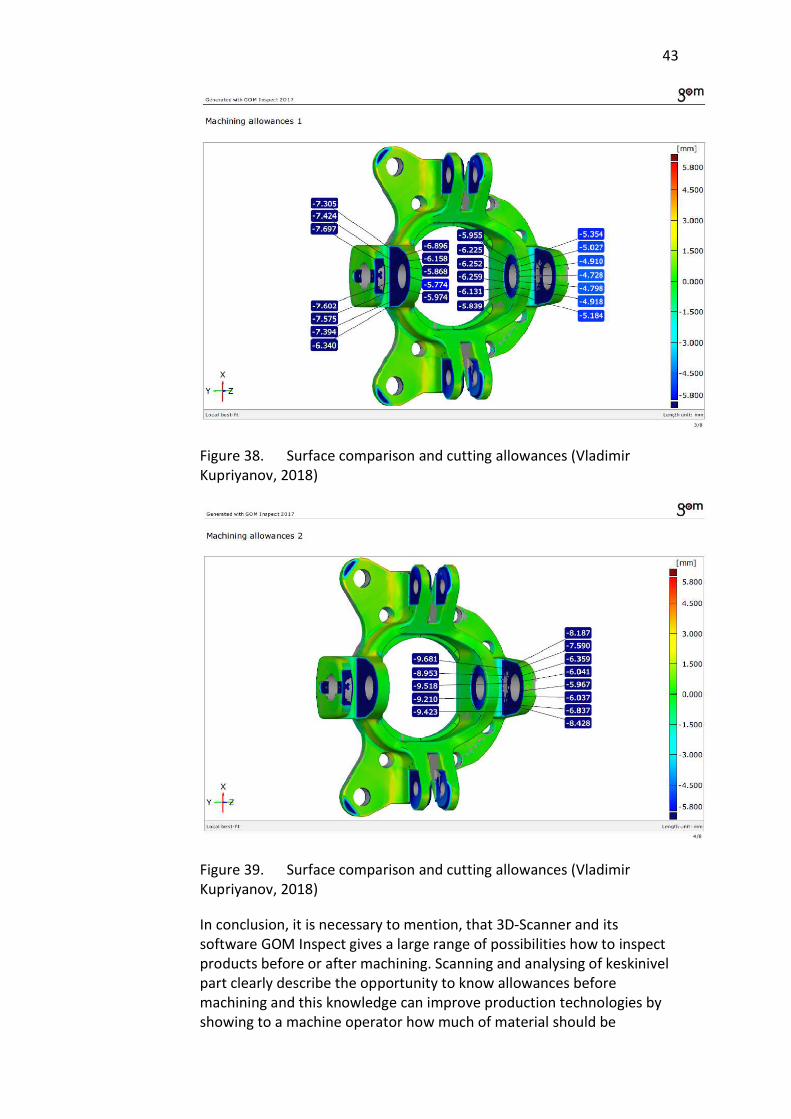
In conclusion, it is necessary to mention, that 3D-Scanner and its software GOM Inspect gives a large range of possibilities how to inspect products before or after machining. Scanning and analysing of keskinivel part clearly describe the opportunity to know allowances before machining and this knowledge can improve production technologies by showing to a machine operator how much of material should be
44
removed. Moreover, before machining this technology can show if the casted material has correct dimensions and shape and to prove that casted part can be used for machining. Such kind of operation can also improve the quality machined parts and can decrease the machining time.
6.3 Case III. Comparison of pillar before and after MIG welding.
Comparison of 2 scans of the same part, before and after welding was one of the most important reasons why 3D- Scanner came to Jormet Oy. If to compare 3D- Scanner with the tactile CMM, tactile coordinate measurement machine can also measure parts before and after welding, but it cannot compare parts in the same way, as GOM Inspect. The tactile CMM can scan part, but CMM's software is not able to use scan, which was done before, as a zero reference, while GOM Inspect can compare 2 (or more) scans and show deviations and differences in geometries visually. First scanning of pillar took about 50 minutes. Due to the fact that pillar has huge surface areas, which are machined, it is needed to use powder to scan part. Furthermore, because pillar’s surface, which is not machined, is an extremely bumpy, force have to be applied to connect reference points, and this situation describes that sticker reference point is not a suitable solution for a production environment. While scanning of the same piece before and after MIG welding, it was essential to scan product’s part, which is not affected by welding, to align scans during comparison correctly. Changing in the geometry, which is caused by welding and temperature, has to be represented as the movement of the cylinder, which is located in the front side of the pillar. As a zero reference two cylinders and one plane on a machined side were chosen, on the ground that these surfaces were not affected by temperature and during an inspection of 2 mesh files, they were aligned by these surfaces. After creation of a zero reference, the left side was scanned to connect the front cylinder to zero references. In the end, the cylinder was scanned, and the mesh was polygonised. While scanning of the pillar, it was lying first on one side and then it was turned over to scan another side. The same scanning operations were repeated with pillar after MIG-welding. In Professional version of GOM Inspect software there is the possibility to upload two mesh files and after alignment process to compare them. Since free version of GOM Inspect software was used, to compare both files, it was needed to transfer one file into a CAD model. Mesh, which was got after MIG welding was chosen to be transferred into a CAD model. As a consequence, before mesh was transferred into CAD, the
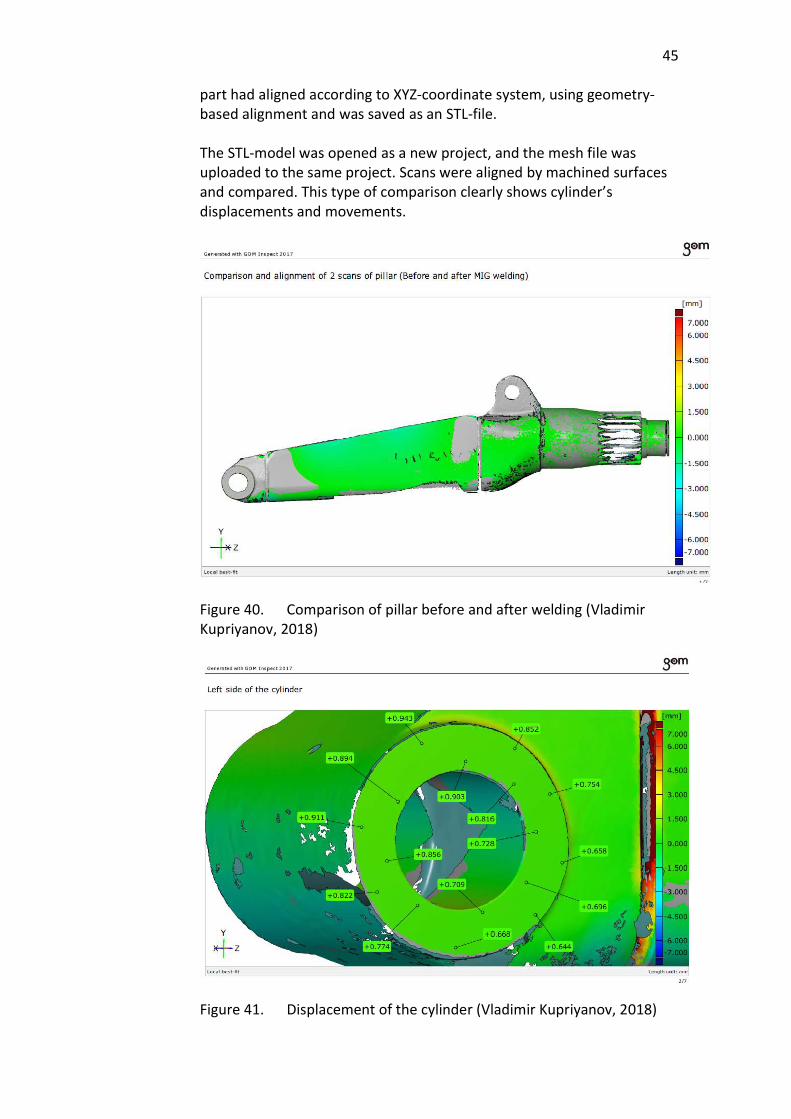
45
part had aligned according to XYZ-coordinate system, using geometry-based alignment and was saved as an STL-file. The STL-model was opened as a new project, and the mesh file was uploaded to the same project. Scans were aligned by machined surfaces and compared. This type of comparison clearly shows cylinder’s displacements and movements.
Figure 40. Comparison of pillar before and after welding (Vladimir Kupriyanov, 2018)
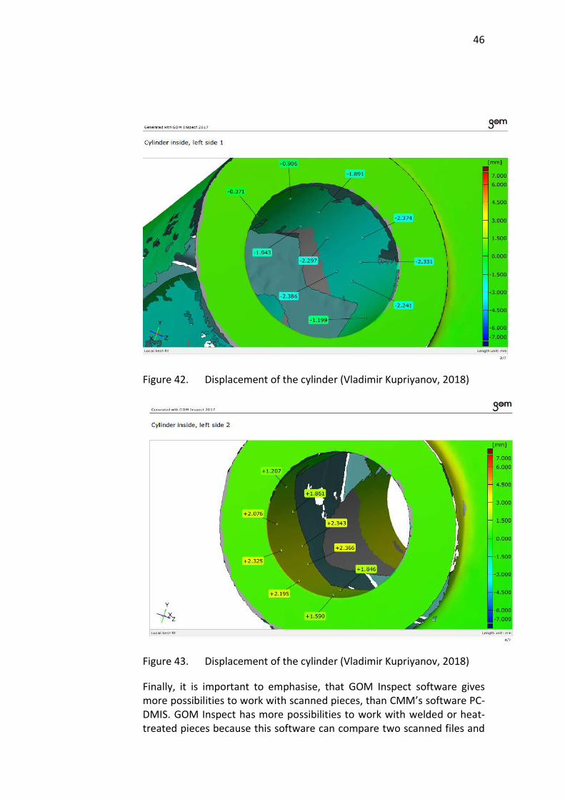
Figure 41. Displacement of the cylinder (Vladimir Kupriyanov, 2018)
46
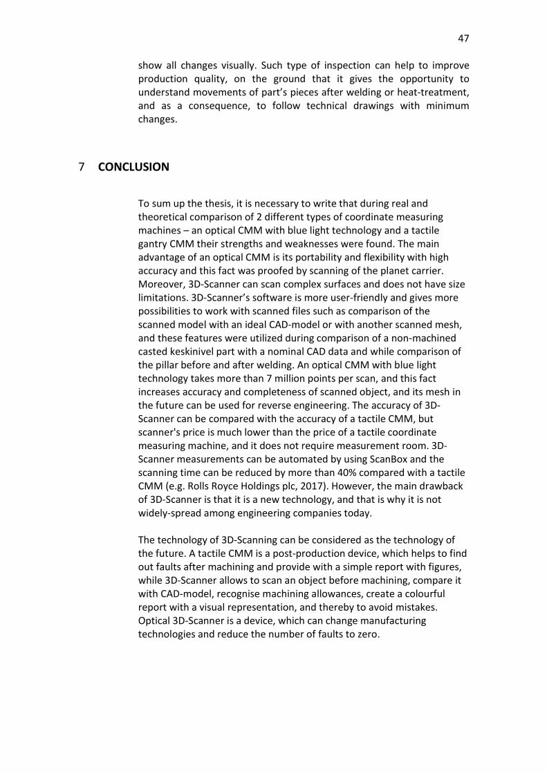
Figure 42. Displacement of the cylinder (Vladimir Kupriyanov, 2018)
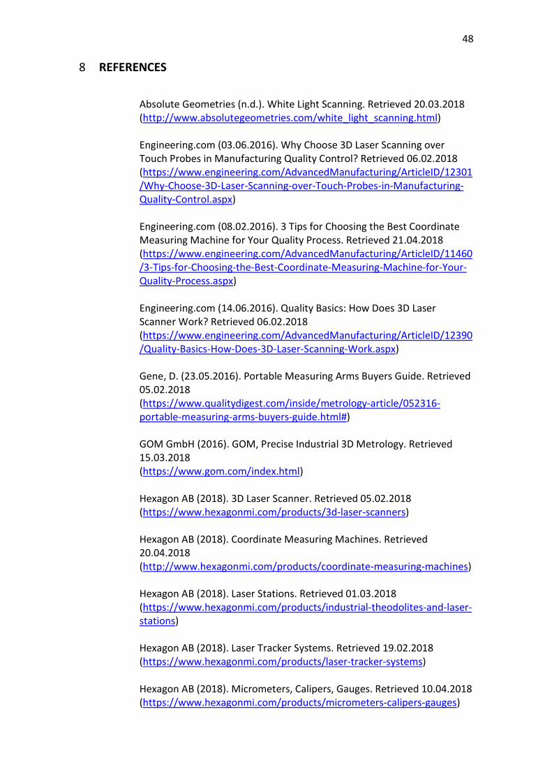
Figure 43. Displacement of the cylinder (Vladimir Kupriyanov, 2018)
Finally, it is important to emphasise, that GOM Inspect software gives more possibilities to work with scanned pieces, than CMM’s software PC-DMIS. GOM Inspect has more possibilities to work with welded or heat-treated pieces because this software can compare two scanned files and
47
show all changes visually. Such type of inspection can help to improve production quality, on the ground that it gives the opportunity to understand movements of part’s pieces after welding or heat-treatment, and as a consequence, to follow technical drawings with minimum changes.
7 CONCLUSION
To sum up the thesis, it is necessary to write that during real and theoretical comparison of 2 different types of coordinate measuring machines – an optical CMM with blue light technology and a tactile gantry CMM their strengths and weaknesses were found. The main advantage of an optical CMM is its portability and flexibility with high accuracy and this fact was proofed by scanning of the planet carrier. Moreover, 3D-Scanner can scan complex surfaces and does not have size limitations. 3D-Scanner’s software is more user-friendly and gives more possibilities to work with scanned files such as comparison of the scanned model with an ideal CAD-model or with another scanned mesh, and these features were utilized during comparison of a non-machined casted keskinivel part with a nominal CAD data and while comparison of the pillar before and after welding. An optical CMM with blue light technology takes more than 7 million points per scan, and this fact increases accuracy and completeness of scanned object, and its mesh in the future can be used for reverse engineering. The accuracy of 3D-Scanner can be compared with the accuracy of a tactile CMM, but scanner's price is much lower than the price of a tactile coordinate measuring machine, and it does not require measurement room. 3D-Scanner measurements can be automated by using ScanBox and the scanning time can be reduced by more than 40% compared with a tactile CMM (e.g. Rolls Royce Holdings plc, 2017). However, the main drawback of 3D-Scanner is that it is a new technology, and that is why it is not widely-spread among engineering companies today. The technology of 3D-Scanning can be considered as the technology of the future. A tactile CMM is a post-production device, which helps to find out faults after machining and provide with a simple report with figures, while 3D-Scanner allows to scan an object before machining, compare it with CAD-model, recognise machining allowances, create a colourful report with a visual representation, and thereby to avoid mistakes. Optical 3D-Scanner is a device, which can change manufacturing technologies and reduce the number of faults to zero.
48
8 REFERENCES
Absolute Geometries (n.d.). White Light Scanning. Retrieved 20.03.2018 (http://www.absolutegeometries.com/white_light_scanning.html) Engineering.com (03.06.2016). Why Choose 3D Laser Scanning over Touch Probes in Manufacturing Quality Control? Retrieved 06.02.2018 (https://www.engineering.com/AdvancedManufacturing/ArticleID/12301/Why-Choose-3D-Laser-Scanning-over-Touch-Probes-in-Manufacturing-Quality-Control.aspx) Engineering.com (08.02.2016). 3 Tips for Choosing the Best Coordinate Measuring Machine for Your Quality Process. Retrieved 21.04.2018 (https://www.engineering.com/AdvancedManufacturing/ArticleID/11460/3-Tips-for-Choosing-the-Best-Coordinate-Measuring-Machine-for-Your-Quality-Process.aspx) Engineering.com (14.06.2016). Quality Basics: How Does 3D Laser Scanner Work? Retrieved 06.02.2018 (https://www.engineering.com/AdvancedManufacturing/ArticleID/12390/Quality-Basics-How-Does-3D-Laser-Scanning-Work.aspx) Gene, D. (23.05.2016). Portable Measuring Arms Buyers Guide. Retrieved 05.02.2018 (https://www.qualitydigest.com/inside/metrology-article/052316-portable-measuring-arms-buyers-guide.html#) GOM GmbH (2016). GOM, Precise Industrial 3D Metrology. Retrieved 15.03.2018 (https://www.gom.com/index.html) Hexagon AB (2018). 3D Laser Scanner. Retrieved 05.02.2018 (https://www.hexagonmi.com/products/3d-laser-scanners) Hexagon AB (2018). Coordinate Measuring Machines. Retrieved 20.04.2018 (http://www.hexagonmi.com/products/coordinate-measuring-machines) Hexagon AB (2018). Laser Stations. Retrieved 01.03.2018 (https://www.hexagonmi.com/products/industrial-theodolites-and-laser-stations) Hexagon AB (2018). Laser Tracker Systems. Retrieved 19.02.2018 (https://www.hexagonmi.com/products/laser-tracker-systems) Hexagon AB (2018). Micrometers, Calipers, Gauges. Retrieved 10.04.2018 (https://www.hexagonmi.com/products/micrometers-calipers-gauges)
49
Hexagon AB (2018). Multisensor & Optical Systems. Retrieved 15.03.2018 (https://www.hexagonmi.com/products/multisensor-and-optical-systems) Hexagon AB (2018). Portable Measuring Arms. Retrieved 05.02.2018 (https://www.hexagonmi.com/products/portable-measuring-arms) Hexagon AB (2018). White Light Scanner Systems. Retrieved 20.03.2018 (https://www.hexagonmi.com/products/white-light-scanner-systems) LaserDesign (n.d.). 3D-Scanning Technology – Hard Work That Looks Like “Magic”. Retrieved 07.02.2018 (https://www.laserdesign.com/what-is-3d-scanning) Leica Geosystems (n.d.). Leica Geosystem Laser Station. Retrieved 01.03.2018 (https://metrology.leica-geosystems.com/en/Leica-TDRA6000_78485.htm) MEDIT company (n.d.). Why using blue light 3D Scanner. Retrieved 05.04.2018 (http://blog.meditcompany.com/medit/blog/2017/7/28/why-using-blue-light) NPD-Solutions (2016). What is Reverse Engineering? Retrieved 16.03.2018 (http://www.npd-solutions.com/reverse-engineering.html) NSGroup (2018). Jormet Oy. Retrieved 15.05.2018 (http://www.nsgroup.fi/liiketoiminta-alueet/jormet) Srinivas, K.R. (01.09.2017). Blue Light Optical Scanning for High Resolution 3D Measurement. Retrieved 10.03.2018 (https://www.qualitymag.com/articles/94202-blue-light-optical-scanning-for-high-resolution-3d-measurement) Tesatechnology (n.d.). Calipers. Retrieved 11.04.2018 (http://www.tesatechnology.com/en-gb/products/calipers-f19171.htm#.WxRGRkiFO70) Tesatechnology (n.d.). Electronic and Analogue Gauges. Retrieved 12.04.2018 (http://www.tesatechnology.com/en-gb/products/electronic-and-analogue-dial-gauges-f19176.htm#.WxRGnEiFO70)

50
Tesatechnology (n.d.). Micrometers. Retrieved 11.04.2018 (http://www.tesatechnology.com/en-gb/products/external-micrometers-f19172.htm#.WxRGc0iFO70) Wright, I. (26.10.2016). Laser Trackers – From Inspection to Manufacturing. Retrieved 26.02.2018 (https://www.engineering.com/AdvancedManufacturing/ArticleID/13499/Laser-Trackers-From-Inspection-to-Manufacturing.aspx)