cold compaction of an array of cylindrical fibres
TRANSCRIPT
*Corresponding author. Tel.: #44-01223-332650; fax: 0044-1223-332662.E-mail address: [email protected] (N.A. Fleck).
International Journal of Mechanical Sciences 43 (2001) 715}742
Cold compaction of an array of cylindrical "bres
I. Sridhar!, N.A. Fleck!,*, A.R. Akisanya"
!Department of Engineering, University of Cambridge, Trumpington Street, Cambridge, CB2 1PZ, UK"Department of Engineering, University of Aberdeen, Aberdeen, AB24 3UE, UK
Received 9 August 1999; received in revised form 25 February 2000
Abstract
The biaxial compaction of a square array of circular cylinders is studied using slip-line "eld, upper boundand "nite element methods. Densi"cation is assumed to occur by plastic deformation at the contacts. It isfound that contact}contact interaction has a softening e!ect on the local indentation pressure at eachcontact. The yield surfaces resulting from hydrostatic and closed-die compaction are constructed at variousstages of densi"cation: the size and shape of the yield surface depend upon the loading history and upon therelative density of the compact. The "nite element predictions suggest the formation of a vertex at the loadingpoint for the entire densi"cation process in the case of isostatic compaction. On the other hand, a vertex atthe loading point is formed only for a relative density D)0.85 in the case of closed-die compaction. ( 2000Elsevier Science Ltd. All rights reserved.
Keywords: Powder compaction; Yield surface; Slip-line "eld method; Upper bound methods; Finite element method
1. Introduction
Powder compaction is a popular net shape forming operation for small, high volume engineeringparts. Powder metallurgy materials include refractory metals, superalloys, particle and "bre-reinforced composites, ferrous alloys and cermets. The ability to control accurately the size,composition and morphology of the microstructure is a major advantage of the powder route. Coldcompaction followed by sintering avoids the segregation and excessive grain growth associatedwith casting. When the operating temperature is less than 0.3 times the absolute melting point ofthe metal, rate-independent plasticity is the dominant mechanism of densi"cation. At highertemperatures densi"cation is assisted by creep and di!usional #ow.
0020-7403/01/$ - see front matter ( 2000 Elsevier Science Ltd. All rights reserved.PII: S 0 0 2 0 - 7 4 0 3 ( 0 0 ) 0 0 0 3 7 - 0
The starting powder for a compaction process typically consists of randomly oriented looseparticles with a wide range of particle size and shape. Three di!erent stages of powder compactionmay be identi"ed as follows. Stage 0 is the initial rearrangement of powder particles. For equi-sizedspherical particles, this initial rearrangement results in a relative density of about 0.64 [1], wherethe relative density is de"ned as the ratio of the average density of the powder to that of the fullydense solid. In the second stage, Stage I, particles indent each other at isolated necks, leavinga network of inter-connected porosity. Densi"cation occurs by the mutual indentation of particlesin contact, with the continuous growth of interparticle necks. Helle et al. [2] argue that thisgeometrical description prevails up to a relative density of about 0.9. In the "nal stage (Stage II), therelative density is greater than 0.9, and the interparticle necks have grown until the porositypinches o! into isolated voids. The compact at this stage is modelled as a porous solid anddensi"cation is controlled by the shape, size and distribution of the pores.
Doraivelu et al. [3] have summarised the macroscopic yield surfaces from several Stage I andStage II powder compaction models by adopting the following quadratic form:
f1(D)p2
m#f
2(D)p2
e"p2
Y, (1)
where f1
and f2
are functions of relative density D, pm
is the mean stress, pe
is the von Misese!ective stress, and p
Yis the uniaxial yield strength of the matrix. Brown and Abou-Chedid [4]
have measured the isodensity curves in stress space for copper and iron powders compacted underbiaxial and triaxial states of stress. They observed a lack of correspondence between the isodensitycurves and the yield surface of the form given by Doraivelu et al. [3]. This discrepancy between theyield functions of form (1) and various experimental data implies that the yield behaviour ofa powder aggregate does not depend on density alone, but also depends upon the loading path. Inan anisotropic model for Stage I compaction of spherical particles, Fleck [5] has estimated thedistribution of contacts and the variation of the size of the contacts in terms of a second-ordertensor B
ij, which is closely related to the macroscopic strain E
ij. The macroscopic yield surface
depends upon the loading path used for the compaction, and a vertex is observed at the loadingpoint. Storakers et al. [6] have extended this approach for powder composites undergoing powerlaw visco-plastic compaction. Akisanya et al. [7] have measured the sensitivity of the yield surfaceshape to the deformation path by conducting triaxial tests on copper powder. The observed yieldsurface is elongated along the loading direction with a vertex at the loading point for closed-diecompaction, and lends support to the models of Fleck [5] and Storakers et al. [6].
An accurate prediction of powder compaction in Stages I and II requires a knowledge of thecontact pressure between individual particles, and of the number of contacts Z per particle. Earlystudies of Stage I cold compaction of powder particles assumed a constant contact pressure, but anincreasing number of contacts during the initial stages of densi"cation. Helle et al. [2] usedPrandtl's punch solution of an in"nite solid and Fleck et al. [8] used the solution given by Green[9] for the plastic yielding of a metal junction under combined shear and pressure. But compres-sion experiments on single spherical metal particles reveal that the mean pressure at the neckbetween two particles falls with increasing neck size [10,11]. With increasing compaction, theplastic zone at each contact interacts with those of neighbouring contacts or with the free surface ofthe particles [12,13] and gives rise to reduced contact pressures.
Next, consider the evolution of co-ordination number Z with relative density, D. A denserandom packing of aligned, monosized cylindrical particles typically has a starting relative density
716 I. Sridhar et al. / International Journal of Mechanical Sciences 43 (2001) 715}742
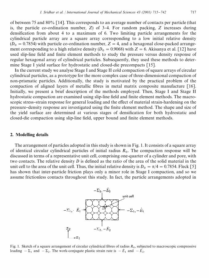
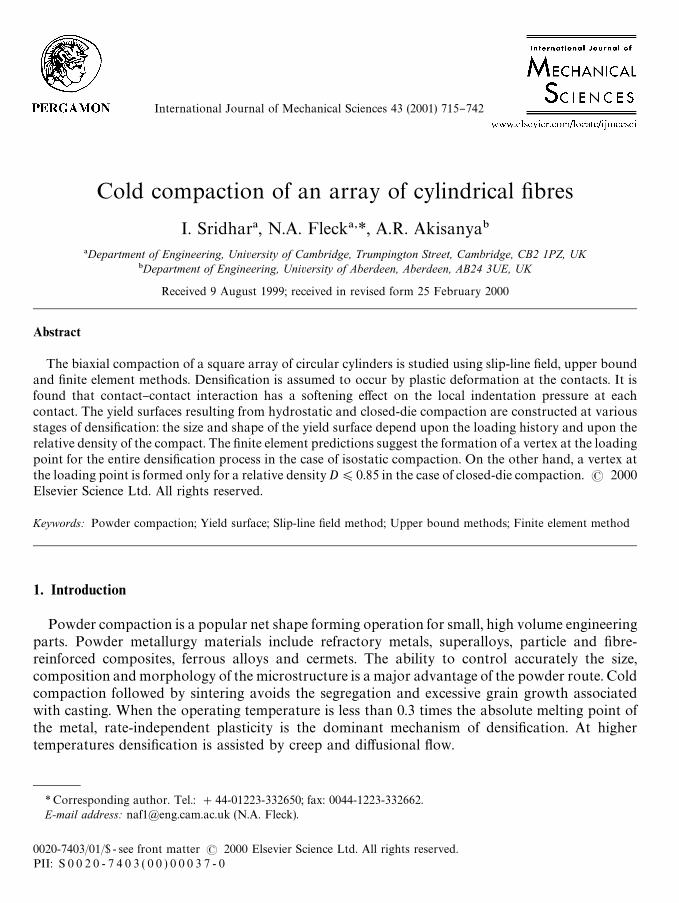
Fig. 1. Sketch of a square arrangement of circular cylindrical "bres of radius R0, subjected to macroscopic compressive
loading !&1
and !&2. The work-conjugate plastic strain rate is !EQ
1and !EQ
2.
of between 75 and 80% [14]. This corresponds to an average number of contacts per particle (thatis, the particle co-ordination number, Z) of 3}4. For random packing, Z increases duringdensi"cation from about 4 to a maximum of 6. Two limiting particle arrangements for thecylindrical particle array are a square array corresponding to a low initial relative density(D
0"0.7854) with particle co-ordination number, Z"4, and a hexagonal close-packed arrange-
ment corresponding to a high relative density (D0"0.9068) with Z"6. Akisanya et al. [12] have
used slip-line "eld and "nite element methods to study the pressure versus density response ofregular hexagonal array of cylindrical particles. Subsequently, they used these methods to deter-mine Stage I yield surface for hydrostatic and closed-die precompacts [15].
In the current study we analyse Stage I and Stage II cold compaction of square arrays of circularcylindrical particles, as a prototype for the more complex case of three-dimensional compaction ofnon-prismatic particles. Additionally, the study is motivated by the practical problem of thecompaction of aligned layers of metallic "bres in metal matrix composite manufacture [16].Initially, we present a brief description of the methods employed. Then, Stage I and Stage IIhydrostatic compaction are examined using slip-line "eld and "nite element methods. The macro-scopic stress}strain response for general loading and the e!ect of material strain-hardening on thepressure}density response are investigated using the "nite element method. The shape and size ofthe yield surface are determined at various stages of densi"cation for both hydrostatic andclosed-die compaction using slip-line "eld, upper bound and "nite element methods.
2. Modelling details
The arrangement of particles adopted in this study is shown in Fig. 1. It consists of a square arrayof identical circular cylindrical particles of initial radius R
0. The compaction response will be
discussed in terms of a representative unit cell, comprising one-quarter of a cylinder and pore, withtwo contacts. The relative density D is de"ned as the ratio of the area of the solid material in theunit cell to the area of the unit cell. Thus, the initial relative density is D
0"p/4"0.7854. Fleck [5]
has shown that inter-particle friction plays only a minor role in Stage I compaction, and so weassume frictionless contacts throughout this study. In fact, the particle arrangements adopted in
I. Sridhar et al. / International Journal of Mechanical Sciences 43 (2001) 715}742 717

1ABAQUS, HKS Inc., RI, USA.
this study automatically result in zero shear traction at contacts. Additionally, the contacts areassumed to possess zero cohesive (tensile) strength; these assumptions are reasonable for thepractical problem of the cold compaction of lubricated metallic powders.
As for the case of compaction of spherical particles, the compaction process of cylindricalparticles can be divided into Stages I and II. During the initial stage (Stage I), the individualcylindrical particles are still recognisable and plastic deformation is localised near the contacts. Inthe later stages of densi"cation the plastic "elds from neighbouring contacts interact and the poresare cusped in shape: this stage is the interaction stage. In the "nal stages of densi"cation (Stage II)the pores formed between the contacting particles are surrounded by a zone of plasticallydeforming material. At this stage the geometry is modelled as an array of pores which shrink in sizeas densi"cation progresses.
2.1. Finite element analysis
Since the cylindrical particles are allowed to slide freely past each other, the deformation can bemodelled by considering the indentation of a long cylinder by a smooth #at punch. The problem isto obtain the macroscopic Cauchy stress (&
1, &
2) for the square arrangement of identical cylin-
drical particles subjected to a plane strain deformation state, characterised by the logarithmicstrain measures (E
1,E
2), in terms of the Cartesian axes (x
1, x
2) shown in Fig. 1.
The "nite element package ABAQUS1 is used for the numerical calculations for the entirecompaction process (Stages I and II); a "nite strain version of J2 #ow theory is used to describe theconstitutive response of the matrix. Unless otherwise stated, the governing stress}strain response ofthe cylindrical particles is assumed to be an elastic-perfectly plastic solid with a yield strain of 10~4and a Poisson's ratio of l"0.3. As the "nite element results will be compared with rigid, ideallyplastic slip-line "eld and upper bound solutions, we have chosen a small value of yield strain in FEanalysis. Preliminary calculations con"rm that the compaction results are insensitive to the choiceof yield strain.
The assumed symmetry with respect to both geometry and loading implies that it is adequate tomodel only one-quarter of a particle, as shown in Fig. 2. The mesh in Fig. 2 consists of 1448quadratic and 884 triangular plane strain-reduced integration elements. The vertical and horizon-tal symmetry boundaries of the unit cell are subjected to displacement boundary conditions inwhich elements are allowed to slide freely along the boundary with zero shear traction. In order tosimulate plane strain compaction, normal displacements are imposed along the top and right-handside of the representative unit cell using frictionless interface elements. The curved surface of theparticle is traction-free.
The evolution of the contact width parameters (a1, a
2), the centre distances between the
neighbouring particles (b1, b
2) and the total reaction force at each contact is determined as
a function of the macroscopic strain (E1, E
2), see Fig. 3(a). The macroscopic response of
the aggregate is given by the average state of stress and strain in the representative unit cell.We note that the macroscopic logarithmic strain is related to the particle spacings (2b
1, 2b
2) and
718 I. Sridhar et al. / International Journal of Mechanical Sciences 43 (2001) 715}742
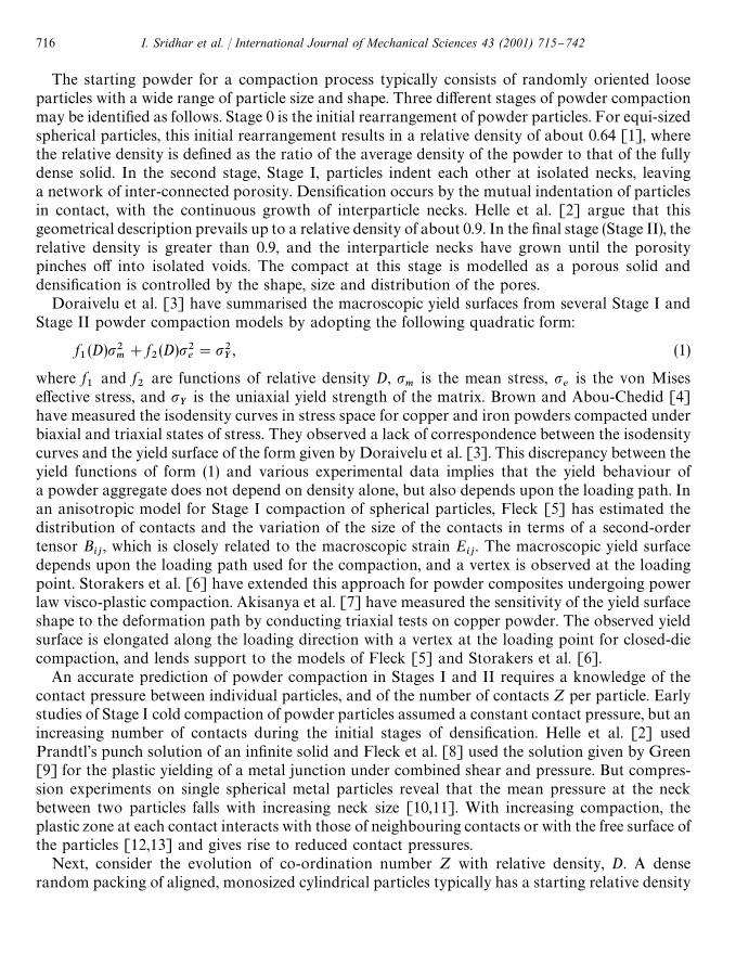
Fig. 2. Finite element mesh of a unit cell of the square array showing the boundary conditions and loading.
Fig. 3. Assumed particle geometry for: (a) Stage I compaction; and (b) Stage II compaction, for slip-line "eld and upperbound methods. The free surface of the particles are assumed to have a uniform radius of curvature R in Stage I, whereasthe voids are taken to be square with a side length s in Stage II.
to the radius of the undeformed particle R0
by
E1"lnA
b1
R0B, (2)
E2"lnA
b2
R0B (3)
I. Sridhar et al. / International Journal of Mechanical Sciences 43 (2001) 715}742 719
and the relative density D is related directly to the strain state (E1, E
2) by
lnADD
0B"!(E
1#E
2) (4)
where D0
is the initial relative density, as de"ned previously. The total reaction force at eachcontact is divided by the contact width to obtain the mean contact pressures p
1and p
2. By
equilibrium, the macroscopic stresses are related to the inter-particle contact pressure p1
and p2
atthe contacts along the x
1and x
2axes by
&1"!A
a1
b2Bp1 , (5)
&2"!A
a2
b1Bp2 . (6)
2.2. Approximate geometric relations for slip-line xeld and upper bound methods
The slip-line and upper bound methods assume a rigid, ideally plastic material response. In orderto specify the evolution of contact size between particles, as a function of macroscopic strain,a number of additional geometrical assumptions are required as follows.
Stage I: When the square array of particles are subjected to macroscopic loading, the particlecentres approach each other and "nite contacts form between the particles. Deformation iscon"ned to the regions of the contact during the early stages of compaction. As the powderparticles are compacted further the plastic "eld interacts between the contacts and the particle's freesurface; material is extruded from beneath the contacts into the adjacent voids. The extrudedmaterial from the contact is assumed to be distributed uniformly over the free surface of the particleso that the free surface of the particle has a radius R'R
0. In this way, the contacts grow as the
relative density increases. This assumption also ensures that the pores in the powder structureremain cusped in shape.
A typical deformed shape of a particle under applied macroscopic strain state (E1, E
2) is
illustrated in Fig. 3(a). The contacts appear as #at faces on each particle. The local deformation ofa particle is characterised by the contact widths 2a
1and 2a
2and by the centre distance between the
particles 2b1
and 2b2
along x1- and x
2-directions, respectively. The contact widths are related to
the current particle radius R by the following equations:
a21#b2
1"R2, (7)
a22#b2
2"R2. (8)
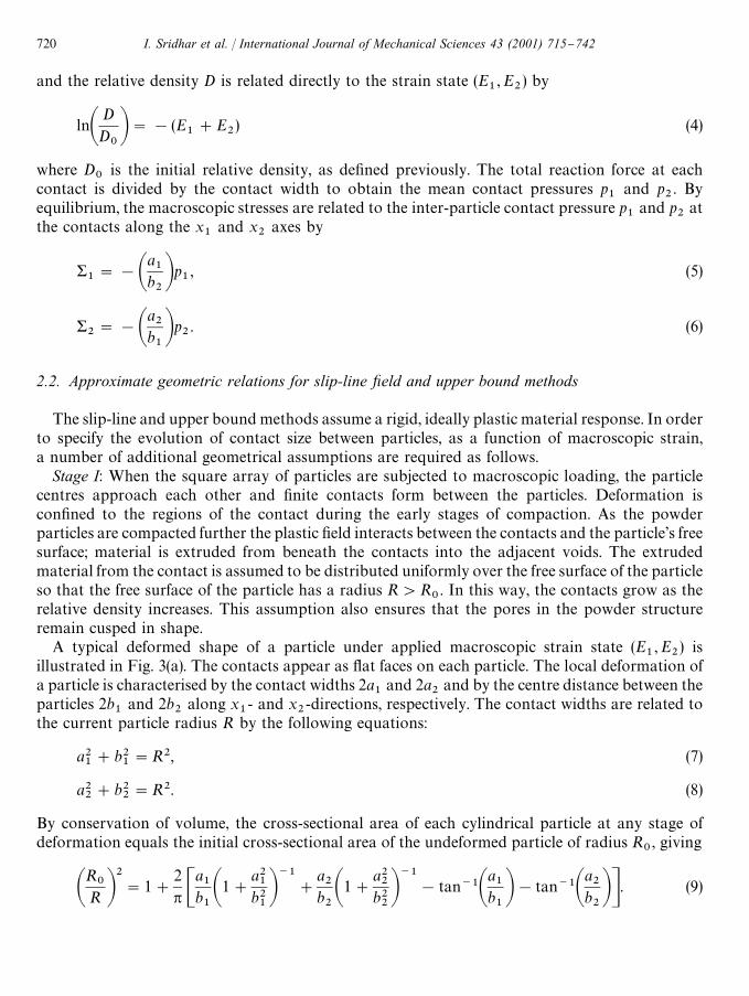
By conservation of volume, the cross-sectional area of each cylindrical particle at any stage ofdeformation equals the initial cross-sectional area of the undeformed particle of radius R
0, giving
AR
0R B
2"1#
2p C
a1
b1A1#
a21
b21B~1
#
a2
b2A1#
a22
b22B~1
!tan~1Aa1
b1B!tan~1A
a2
b2BD. (9)
720 I. Sridhar et al. / International Journal of Mechanical Sciences 43 (2001) 715}742

The relative density D can therefore be shown to be
D"
12 A
a1
b2
#
a2
b1B#
12 A1#
a21
b21B1@2
A1#a22
b22B1@2
Cp2!tan~1A
a1
b1B!tan~1A
a2
b2BD. (10)
The center spacings 2b1
and 2b2
evolve with macroscopic strain (E1,E
2) according to relations (2)
and (3). We now have a complete set of relations (2), (3), (7)}(10) in order to obtain the geometricparameters (a
1, a
2, b
1, b
2,R,D) as a function of the macroscopic strain (E
1,E
2), initial particle
radius R0
and initial relative density D0. Expression (4) for D is mathematically identical to Eq. (10)
since both are statements of conservation of mass. The connection (5) and (6) between themacroscopic stress (&
1, &
2) and the average contact pressures (p
1, p
2) apply also for the slip-line
"eld and upper bound methods.Stage II: In Stage II densi"cation, plastic deformation occurs in the vicinity of each pore, and the
pore is treated as a square of side length s in order to simplify the slip-line "eld and upper boundanalysis, see Fig. 3(b). An expression for relative density can be easily deduced from conservation ofmass and is given by
D"1!12 A1!
a1
b2BA1!
a2
b1B. (11)
3. Hydrostatic compaction
In this section, we study the evolution of contact size, mean contact pressure and the macro-scopic pressure for the hydrostatic compaction of a square array of cylindrical particles using the"nite element and slip-line "eld methods. When the macroscopic stress is hydrostatic, we may write&1"&
2"&
m, and symmetry dictates that only 1
8of a representative particle needs to be
considered.
3.1. Contact size evolution
For hydrostatic compaction the contact widths are of equal size a1"a
2"a and b
1"b
2"b.
In the "nite element (FE) calculations, the contact widths are measured from the deformed shape ofthe particle and the relative density D is calculated directly from the macroscopic strain via relation(4). The computed variation of relative density D with the contact size a/b is shown in Fig. 4.
The approximate geometrical relation (10) is used in the slip-line "eld (and upper boundcalculations) in order to relate D to a/b, giving for Stage I hydrostatic compaction,
D"
ab#A1#
a2
b2B Cp4!tan~1A
abBD. (12)
In Stage II, the size s of square pore is related to the contact size a by
ab"1!
1
J2
sb
(13)
I. Sridhar et al. / International Journal of Mechanical Sciences 43 (2001) 715}742 721
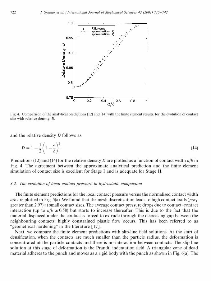
Fig. 4. Comparison of the analytical predictions (12) and (14) with the "nite element results, for the evolution of contactsize with relative density, D.
and the relative density D follows as
D"1!12 A1!
abB
2. (14)
Predictions (12) and (14) for the relative density D are plotted as a function of contact width a/b inFig. 4. The agreement between the approximate analytical prediction and the "nite elementsimulation of contact size is excellent for Stage I and is adequate for Stage II.
3.2. The evolution of local contact pressure in hydrostatic compaction
The "nite element predictions for the local contact pressure versus the normalised contact widtha/b are plotted in Fig. 5(a). We found that the mesh discretization leads to high contact loads (p/p
Ygreater than 2.97) at small contact sizes. The average contact pressure drops due to contact}contactinteraction (up to a/bK0.58) but starts to increase thereafter. This is due to the fact that thematerial displaced under the contact is forced to extrude through the decreasing gap between theneighbouring contacts: highly constrained plastic #ow occurs. This has been referred to as`geometrical hardeninga in the literature [17].
Next, we compare the "nite element predictions with slip-line "eld solutions. At the start ofdensi"cation, when the contacts are much smaller than the particle radius, the deformation isconcentrated at the particle contacts and there is no interaction between contacts. The slip-linesolution at this stage of deformation is the Prandtl indentation "eld. A triangular zone of deadmaterial adheres to the punch and moves as a rigid body with the punch as shown in Fig. 6(a). The
722 I. Sridhar et al. / International Journal of Mechanical Sciences 43 (2001) 715}742

Fig. 5. (a) The mean contact pressure at the contacts versus the normalised contact width a/b for hydrostatic compactionof a square array of particles. Predictions are compared from the "nite element (F.E.) method and from the slip-line "eld(s.l.f.) method. (b) The normalised hydrostatic pressure &
m/p
Yversus the relative density. Slip-line "eld (s.l.f.) solutions are
shown for a hexagonal array and a square array.
uniform pressure on the punch is given by Prandtl's solution p"[(2#p)/J3]pY"2.97p
Y, where
p is the local pressure at each contact and pY
is the uniaxial yield strength.As densi"cation proceeds, the contact size increases, the distance between neighbouring contacts
decreases and the contacts begin to interact when the contact size is no longer small compared tothe distance between the contacts. A typical slip-line "eld displaying such interaction is shown inFig. 6(b). This "eld is similar to the one given by Johnson [18] for the forging of a cylindrical bar byV-shaped anvils. A triangular zone of dead material is attached to the punch surface and the nets oforthogonal slip lines originating from the punch corner intersect the axis of symmetry at 453. Thematerial in the centre of the indented cylinder is rigid while that on the outer side of the slip linesmoves as a rigid body outward along the axis of symmetry. The uniform pressure on the punchsurface is evaluated using the Hencky equations [19] and the condition that the net force on thezone of dead material along the axis of symmetry between neighbouring punches is zero. Thepressure p is given by p"p
Yf (a/b) for the case of contact}contact interaction, where f is a dimen-
sionless function of a/b. The interaction between contacts results in a net softening of themacroscopic compaction response. Gampala et al. [20] and Mesavoric and Fleck [21] have alsoobserved softening during the initial stages of inelastic blunting of isolated contacts. This softeningis attributed to the "nite deformation e!ects and to the interaction of the plastic zone with the freesurface of the spherical particle.
The transition from the case of isolated contacts to that of contact}contact interaction occurswhen the slip-line "eld of Fig. 6(b) provides a value of p/p
Yequal to the Prandtl value of 2.97. Based
on this condition, the transition occurs at a value of a/b"0.11. The slip-line "eld is admissibleprovided the angle between the outermost slip-line emanating from the corner of the punch andthe stress-free particle surface is greater than or equal to 453 [22]. For the present geometry,
I. Sridhar et al. / International Journal of Mechanical Sciences 43 (2001) 715}742 723
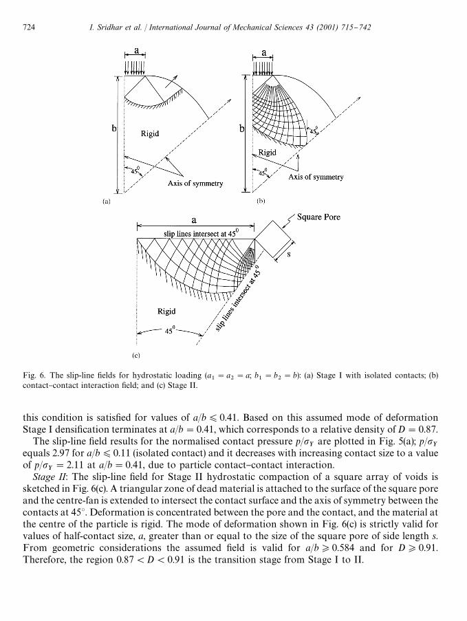
Fig. 6. The slip-line "elds for hydrostatic loading (a1"a
2"a; b
1"b
2"b): (a) Stage I with isolated contacts; (b)
contact}contact interaction "eld; and (c) Stage II.
this condition is satis"ed for values of a/b)0.41. Based on this assumed mode of deformationStage I densi"cation terminates at a/b"0.41, which corresponds to a relative density of D"0.87.
The slip-line "eld results for the normalised contact pressure p/pY
are plotted in Fig. 5(a); p/pY
equals 2.97 for a/b)0.11 (isolated contact) and it decreases with increasing contact size to a valueof p/p
Y"2.11 at a/b"0.41, due to particle contact}contact interaction.
Stage II: The slip-line "eld for Stage II hydrostatic compaction of a square array of voids issketched in Fig. 6(c). A triangular zone of dead material is attached to the surface of the square poreand the centre-fan is extended to intersect the contact surface and the axis of symmetry between thecontacts at 453. Deformation is concentrated between the pore and the contact, and the material atthe centre of the particle is rigid. The mode of deformation shown in Fig. 6(c) is strictly valid forvalues of half-contact size, a, greater than or equal to the size of the square pore of side length s.From geometric considerations the assumed "eld is valid for a/b*0.584 and for D*0.91.Therefore, the region 0.87(D(0.91 is the transition stage from Stage I to II.
724 I. Sridhar et al. / International Journal of Mechanical Sciences 43 (2001) 715}742
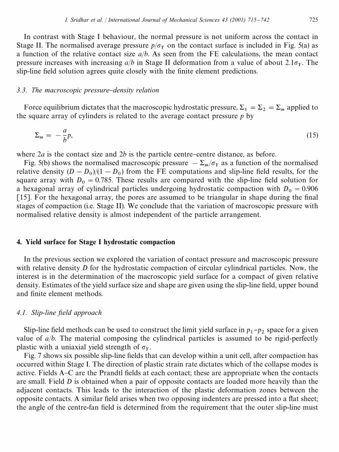
In contrast with Stage I behaviour, the normal pressure is not uniform across the contact inStage II. The normalised average pressure p/p
Yon the contact surface is included in Fig. 5(a) as
a function of the relative contact size a/b. As seen from the FE calculations, the mean contactpressure increases with increasing a/b in Stage II deformation from a value of about 2.1p
Y. The
slip-line "eld solution agrees quite closely with the "nite element predictions.
3.3. The macroscopic pressure}density relation
Force equilibrium dictates that the macroscopic hydrostatic pressure, &1"&
2"&
mapplied to
the square array of cylinders is related to the average contact pressure p by
&m"!
abp, (15)
where 2a is the contact size and 2b is the particle centre}centre distance, as before.Fig. 5(b) shows the normalised macroscopic pressure !&
m/p
Yas a function of the normalised
relative density (D!D0)/(1!D
0) from the FE computations and slip-line "eld results, for the
square array with D0"0.785. These results are compared with the slip-line "eld solution for
a hexagonal array of cylindrical particles undergoing hydrostatic compaction with D0"0.906
[15]. For the hexagonal array, the pores are assumed to be triangular in shape during the "nalstages of compaction (i.e. Stage II). We conclude that the variation of macroscopic pressure withnormalised relative density is almost independent of the particle arrangement.
4. Yield surface for Stage I hydrostatic compaction
In the previous section we explored the variation of contact pressure and macroscopic pressurewith relative density D for the hydrostatic compaction of circular cylindrical particles. Now, theinterest is in the determination of the macroscopic yield surface for a compact of given relativedensity. Estimates of the yield surface size and shape are given using the slip-line "eld, upper boundand "nite element methods.
4.1. Slip-line xeld approach
Slip-line "eld methods can be used to construct the limit yield surface in p1}p
2space for a given
value of a/b. The material composing the cylindrical particles is assumed to be rigid-perfectlyplastic with a uniaxial yield strength of p
Y.
Fig. 7 shows six possible slip-line "elds that can develop within a unit cell, after compaction hasoccurred within Stage I. The direction of plastic strain rate dictates which of the collapse modes isactive. Fields A}C are the Prandtl "elds at each contact; these are appropriate when the contactsare small. Field D is obtained when a pair of opposite contacts are loaded more heavily than theadjacent contacts. This leads to the interaction of the plastic deformation zones between theopposite contacts. A similar "eld arises when two opposing indenters are pressed into a #at sheet;the angle of the centre-fan "eld is determined from the requirement that the outer slip-line must
I. Sridhar et al. / International Journal of Mechanical Sciences 43 (2001) 715}742 725
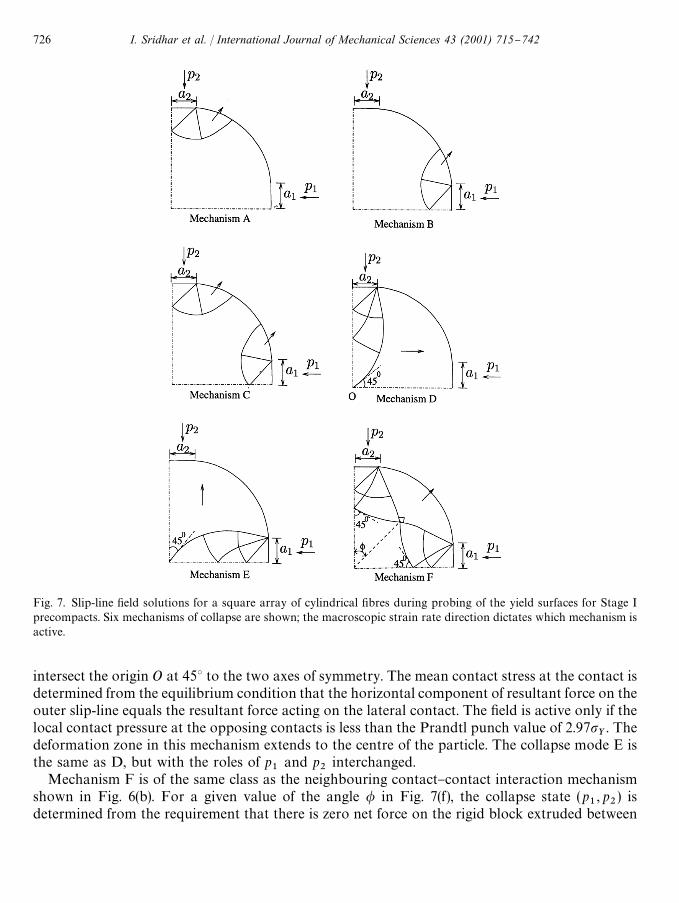
Fig. 7. Slip-line "eld solutions for a square array of cylindrical "bres during probing of the yield surfaces for Stage Iprecompacts. Six mechanisms of collapse are shown; the macroscopic strain rate direction dictates which mechanism isactive.
intersect the origin O at 453 to the two axes of symmetry. The mean contact stress at the contact isdetermined from the equilibrium condition that the horizontal component of resultant force on theouter slip-line equals the resultant force acting on the lateral contact. The "eld is active only if thelocal contact pressure at the opposing contacts is less than the Prandtl punch value of 2.97p
Y. The
deformation zone in this mechanism extends to the centre of the particle. The collapse mode E isthe same as D, but with the roles of p
1and p
2interchanged.
Mechanism F is of the same class as the neighbouring contact}contact interaction mechanismshown in Fig. 6(b). For a given value of the angle / in Fig. 7(f), the collapse state (p
1, p
2) is
determined from the requirement that there is zero net force on the rigid block extruded between
726 I. Sridhar et al. / International Journal of Mechanical Sciences 43 (2001) 715}742

Fig. 8. Yield surfaces by the slip-line "eld method for: (a) isostatic precompacts; and (b) closed-die precompacts of relativedensities D"0.8 and 0.85. The letters B, D, E and F denote the operative mechanisms of deformation at each segment ofthe surfaces.
the contacts. There is a limited range of validity for the angle / and therefore a limited range ofpossible values of p
1and p
2associated with this "eld for a precompact of given contact widths. For
example, mechanism F is only valid when / is in the range 333)/)573 for a hydrostaticprecompact of relative density D"0.85.
For each mechanism a limit surface is constructed in stress space by identifying the combinationsof p
1and p
2required to activate that particular "eld. The yield surface is then obtained by the inner
envelope of the limit surfaces for the individual mechanisms.Fig. 8(a) shows the resulting yield surface for the hydrostatic precompacts of relative densities 0.8
and 0.85. The contact pressures p1
and p2
have been normalised by the uniaxial yield strength ofthe material p
Y. For the relative densities considered, the Prandtl punch solution A gives a collapse
pressure p2
which is higher than that given by mechanism D and so mechanism A lies outside thelimit surface and is discounted. Apart from mechanism F, which is the neighbouring con-tact}contact interaction mechanism, all the other "elds produce straight lines in stress space. Byusing relations (5) and (6) this local yield surface can be readily converted to the macroscopic yieldsurface (&
1, &
2). The resulting macroscopic yield surfaces are shown in Fig. 9a for D"0.8 and in
Fig. 9b for D"0.85. As the contacts are assumed to be cohesionless the lines &1"0 and &
2"0
form additional boundaries of the yield surface: tensile macroscopic stresses cannot be supportedby the particle aggregate. The data points on the x- and y-axis correspond to the yield strength ofthe compact under uniaxial free compression parallel to these axes.
4.2. Upper bound method
When the upper bound method is applied to rigid, ideally plastic solids, the assumed deforma-tion state consists of rigid regions, sliding relative to each other. The component of material
I. Sridhar et al. / International Journal of Mechanical Sciences 43 (2001) 715}742 727
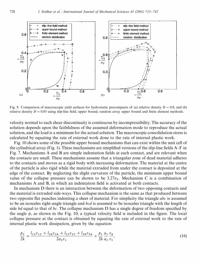
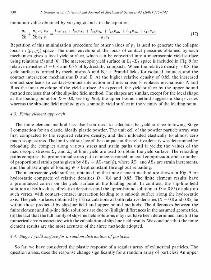
Fig. 9. Comparison of macroscopic yield surfaces for hydrostatic precompacts of: (a) relative density D"0.8; and (b)relative density D"0.85 using slip-line "eld, upper bound, random array upper bound and "nite element methods.
velocity normal to each shear discontinuity is continuous by incompressibility. The accuracy of thesolution depends upon the faithfulness of the assumed deformation mode to reproduce the actualsolution, and the load is a minimum for the actual solution. The macroscopic consolidation stress iscalculated by equating the rate of external work done to the rate of internal plastic work.
Fig. 10 shows some of the possible upper bound mechanisms that can exist within the unit cell ofthe cylindrical array (Fig. 1). These mechanisms are simpli"ed versions of the slip-line "elds A}F inFig. 7. Mechanisms A and B are simple indentation "elds at each contact, and are relevant whenthe contacts are small. These mechanisms assume that a triangular zone of dead material adheresto the contacts and moves as a rigid body with increasing deformation. The material at the centreof the particle is also rigid while the material extruded from under the contact is deposited at theedge of the contact. By neglecting the slight curvature of the particle, the minimum upper boundvalue of the collapse pressure can be shown to be 3.27p
Y. Mechanism C is a combination of
mechanisms A and B, in which an indentation "eld is activated at both contacts.In mechanism D there is an interaction between the deformation of two opposing contacts and
the material is extruded side-ways. This collapse mechanism is the same as that produced betweentwo opposite #at punches indenting a sheet of material. For simplicity the triangle abc is assumedto be an isosceles right-angle triangle and bcd is assumed to be isosceles triangle with the length ofside bd equal to that of bc. The collapse mechanism D has a single degree of freedom speci"ed bythe angle /, as shown in the Fig. 10; a typical velocity "eld is included in the "gure. The localcollapse pressure at the contact is obtained by equating the rate of external work to the rate ofinternal plastic work dissipation, given by the equation
p2
2k"
l12
v12
#l24
v24
#l23
v23
#l34
v34
2a2v1
#
p1
2ka1
a2
v4
v1
, (16)
728 I. Sridhar et al. / International Journal of Mechanical Sciences 43 (2001) 715}742
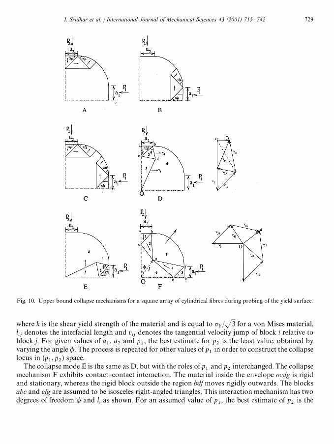
Fig. 10. Upper bound collapse mechanisms for a square array of cylindrical "bres during probing of the yield surface.
where k is the shear yield strength of the material and is equal to pY/J3 for a von Mises material,
lij
denotes the interfacial length and vij
denotes the tangential velocity jump of block i relative toblock j. For given values of a
1, a
2and p
1, the best estimate for p
2is the least value, obtained by
varying the angle /. The process is repeated for other values of p1
in order to construct the collapselocus in (p
1, p
2) space.
The collapse mode E is the same as D, but with the roles of p1
and p2
interchanged. The collapsemechanism F exhibits contact}contact interaction. The material inside the envelope ocdg is rigidand stationary, whereas the rigid block outside the region bdf moves rigidly outwards. The blocksabc and efg are assumed to be isosceles right-angled triangles. This interaction mechanism has twodegrees of freedom / and l, as shown. For an assumed value of p
1, the best estimate of p
2is the
I. Sridhar et al. / International Journal of Mechanical Sciences 43 (2001) 715}742 729
minimum value obtained by varying / and l in the equation
p1
2k#
p2
2ka2
a1
v2
v1
"
l12
v12
#l25
v25
#l26
v26
#l46
v46
#l34
v34
#l45
v45
a1v1
. (17)
Repetition of this minimisation procedure for other values of p1
is used to generate the collapselocus in (p
1, p
2) space. The inner envelope of the locus of contact pressures obtained by each
mechanism gives a local yield surface, which can be converted into a macroscopic yield surfaceusing relations (5) and (6). The macroscopic yield surface in &
1}&
2space is included in Fig. 9 for
relative densities D"0.8 and 0.85 of hydrostatic compacts. When the relative density is 0.8, theyield surface is formed by mechanisms A and B, i.e. Prandtl "elds for isolated contacts, and thecontact interaction mechanisms D and E. At the higher relative density of 0.85, the increasedcontact size leads to contact}contact interaction and mechanism F replaces mechanisms A andB as the inner envelope of the yield surface. As expected, the yield surface by the upper boundmethod encloses that of the slip-line "eld method. The shapes are similar, except for the local shapeat the loading point for D"0.8, see Fig. 9(a); the upper bound method suggests a sharp vertexwhereas the slip-line "eld method gives a smooth yield surface in the vicinity of the loading point.
4.3. Finite element approach
The "nite element method has also been used to calculate the yield surface following StageI compaction for an elastic, ideally plastic powder. The unit cell of the powder particle array was"rst compacted to the required relative density, and then unloaded elastically to almost zeromacroscopic stress. The limit yield surface of the compact at this relative density was determined byreloading the compact along various stress and strain paths until it yields; the values of themacroscopic stresses &
1and &
2at limit yield are used to obtain the yield surface. The reloading
paths comprise the proportional stress path of unconstrained uniaxial compression, and a numberof proportional strain paths given by dE
1"dE
2tan(t), where dE
1and dE
2are strain increments,
and the phase angle of loading t is kept constant throughout reloading.The macroscopic yield surfaces obtained by the "nite element method are shown in Fig. 9 for
hydrostatic compacts of relative densities D"0.8 and 0.85. The "nite element results havea pronounced corner on the yield surface at the loading point. In contrast, the slip-line "eldsolution at both values of relative densities (and the upper-bound solution at D"0.85) display nosuch vertex, with contact}contact interaction leading to a smooth surface along the hydrostaticaxis. The yield surfaces obtained by FE calculations at both relative densities (D"0.8 and 0.85) liewithin those predicted by slip-line "eld and upper bound methods. The di!erences between the"nite element and slip-line "eld solutions are due to (i) slight di!erences in the assumed geometries,(ii) the fact that the full family of slip-line "eld solutions may not have been determined, and (iii) thenumerical errors associated with the calculation of slip-line "eld results. We conclude that the "niteelement results are the most accurate of the three methods adopted.
4.4. Stage I yield surface for a random distribution of particles
So far, we have considered the plastic response of a regular array of cylindrical particles. Thequestion arises, does the response change signi"cantly for a random array of particles? An upper
730 I. Sridhar et al. / International Journal of Mechanical Sciences 43 (2001) 715}742
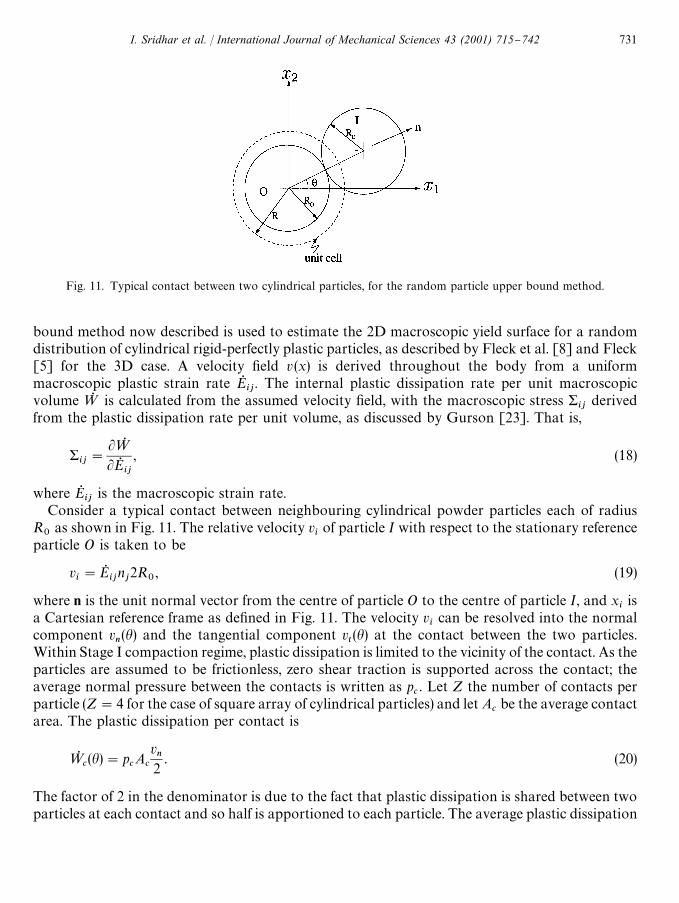
Fig. 11. Typical contact between two cylindrical particles, for the random particle upper bound method.
bound method now described is used to estimate the 2D macroscopic yield surface for a randomdistribution of cylindrical rigid-perfectly plastic particles, as described by Fleck et al. [8] and Fleck[5] for the 3D case. A velocity "eld v (x) is derived throughout the body from a uniformmacroscopic plastic strain rate EQ
ij. The internal plastic dissipation rate per unit macroscopic
volume=Q is calculated from the assumed velocity "eld, with the macroscopic stress &ij
derivedfrom the plastic dissipation rate per unit volume, as discussed by Gurson [23]. That is,
&ij"
L=QLEQ
ij
, (18)
where EQij
is the macroscopic strain rate.Consider a typical contact between neighbouring cylindrical powder particles each of radius
R0
as shown in Fig. 11. The relative velocity viof particle I with respect to the stationary reference
particle O is taken to be
vi"EQ
ijnj2R
0, (19)
where n is the unit normal vector from the centre of particle O to the centre of particle I, and xiis
a Cartesian reference frame as de"ned in Fig. 11. The velocity vican be resolved into the normal
component vn(h) and the tangential component v
t(h) at the contact between the two particles.
Within Stage I compaction regime, plastic dissipation is limited to the vicinity of the contact. As theparticles are assumed to be frictionless, zero shear traction is supported across the contact; theaverage normal pressure between the contacts is written as p
c. Let Z the number of contacts per
particle (Z"4 for the case of square array of cylindrical particles) and let Acbe the average contact
area. The plastic dissipation per contact is
=Qc(h)"p
cA
c
vn2
. (20)
The factor of 2 in the denominator is due to the fact that plastic dissipation is shared between twoparticles at each contact and so half is apportioned to each particle. The average plastic dissipation
I. Sridhar et al. / International Journal of Mechanical Sciences 43 (2001) 715}742 731
per particle is
=Qp"
12pR
0PS0
Z=Qcds, (21)
where the integration is carried out over the surface area of particle O. The plastic dissipation perunit macroscopic volume=Q is obtained by multiplying the average plastic dissipation per particleby D/<
p, where <
pis the volume of each particle. Thus,
=Q "D
2pR0PS0
Z=Qc
pR20
ds (22)
"
2Dp P
p@2
0
ZpcA
c<n
2pR20
dh. (23)
Recall that the relative density D for an isostatically pre-compacted specimen is related to thenormalised contact width a/b by Eq. (12). The assumed collapse mechanism is the slip-line "eld forStage I hydrostatic compaction as described in Section 3.2. The collapse pressure is given bypc"p
Yf (a/b), where f is a dimensionless function of a/b. For a/b(0.11, the Prandtl "eld solution
pertains for the isolated contact and f,2.97. When a/b exceeds 0.11, contact}contact interactionoccurs and f drops in value.
For a given macroscopic strain rate (EQ1, EQ
2), the normal component of velocity v
nis given by
vn(h)"(EQ
1cos2 h#EQ
2sin2 h)2R
0. (24)
Analytical expressions for the yield surface follows by substituting Eq. (24) into Eq. (23) and thenevaluating Eq. (18).
For the case EQ1(0 and EQ
2(0, the macroscopic stresses are given by
&1"&
2"!
12
ZpcA
cD
pR0
. (25)
Upon introducing the loading angle hc,tan~1(J!EQ
1/EQ
2), the macroscopic stresses are given by
&1"!
Dp
ZpcA
c2pR
0
(p!2hc!sin 2h
c), (26)
&2"!
Dp
ZpcA
c2pR
0
(p!2hc#sin 2h
c) (27)
for EQ1'0 and EQ
2(0, and by
&1"!
Dp
ZpcA
c2pR
0
(2hc#sin 2h
c), (28)
&2"!
Dp
ZpcA
c2pR
0
(2hc!sin 2h
c) (29)
732 I. Sridhar et al. / International Journal of Mechanical Sciences 43 (2001) 715}742
for EQ1(0 and EQ
2'0. The assumption of zero cohesive strength between particles leads directly
to the result &1"&
2"0 for both EQ
1'0 and EQ
2'0.
Eq. (25) shows that for a wide range of strain rate directions (EQ1(0 and EQ
2(0) the macro-
scopic stress lies at a vertex on the hydrostatic stress axis, labelled < in Fig. 9(a). In this "gure, thecurve OX< is represented by Eqs. (26) and (27) and the curve O=< is represented by Eqs. (28) and(29). The yield surface is almost #at on each side of the vertex, and can be represented to fairaccuracy by the maximum stress criterion
Max(&1, &
2)"!
12
ZpcA
cD
pR0
. (30)
Gurson [23] has shown that the macroscopic strain rate EQij
is normal to the yield surface '(&)when the yield surface is calculated by such an upper bound approximation. Thus, the strain ratevector with components (EQ
1, EQ
2) is normal to the yield surface. Consequently, plastic #ow in the
vicinity of the vertex is closely aligned with the direction of the largest principal stress with little orno straining in the other directions. That is, if &
1or &
2is the stress causing yielding, the plastic
strain rate is almost uniaxial. However, when yield occurs at the vertex with &1"&
2, the direction
of plastic #ow can range from nearly uniaxial straining to purely hydrostatic deformation. We notefrom Fig. 9(a) that the shape of the yield surface near the vertex for a random distribution ofparticles is in close agreement with that derived for a square array of particles by the slip-line "eld,upper bound and "nite element methods.
4.5. Yield surface for Stage II hydrostatic compaction
At high relative densities the powder structure can be idealised as a homogeneous compressibleelastic}plastic solid with a uniform distribution of cusp-shaped voids. In this section, we constructyield surfaces resulting from hydrostatic compaction to a relative density of 0.95 and 0.98;predictions are compared from the slip-line "eld method, "nite element computations andGurson's 2D yield surface for the collapse of a circular cylindrical shell [23].
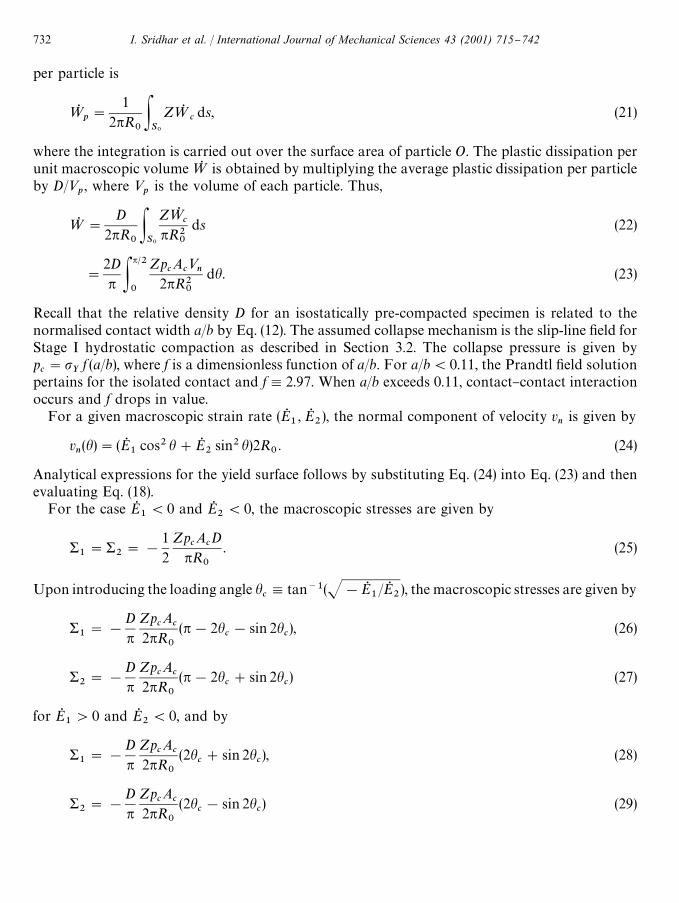
The slip-line "elds that exist upon general straining of a unit cell of the hydrostatic precompact inStage II are shown in Fig. 12. The cusp-shaped void is modelled as a square pore to simplify theslip-line "eld solutions. The "elds G and H are obtained when opposing contacts are loaded moreheavily than the neighbouring contacts. This leads to plastic zone interactions between opposingcontacts and are similar to the "eld arising in the forging of a thin sheet with two opposingindenters. The angle of the centre-fan "eld is determined from the requirement that the outerslip-line must intersect the particle centre at 453.
Mechanisms I and J are produced when the plastic zone under a contact interacts with thefree surface of the adjacent square pore. The angle of the centre-fan is "xed by the conditionthat it intersects the centre of the contact surface at 453. The average contact pressure p
2is
determined from the requirement that the net force on the rigid block attached to the square poreis zero.
Mechanism K is the same as the "eld shown in Fig. 6(c) for Stage II compaction of thesquare array of particles and is associated with probing along the hydrostatic strain-pathEQ1"EQ
2.
I. Sridhar et al. / International Journal of Mechanical Sciences 43 (2001) 715}742 733
Fig. 12. Slip-line "elds for a square array of cylinders during the probing of hydrostatic precompacts (a1"a
2"a), in
Stage II.
The yield surface from the above slip-line "eld solutions is compared with that obtained by the"nite element method in Fig. 13 for the hydrostatically precompacted specimens of relativedensities 0.95 and 0.98. For both values of relative densities, the agreement between the twomethods is close despite the fact that a square cylindrical pore is assumed in the slip-line "eldcalculations and a four-sided cusped pore is developed within the "nite element simulation. Inaddition, the Gurson [23] yield surface for circular cylindrical voids is displayed in Fig. 13. Gurson[23] has obtained a yield function of the following form for plane strain deformation of a circular
734 I. Sridhar et al. / International Journal of Mechanical Sciences 43 (2001) 715}742
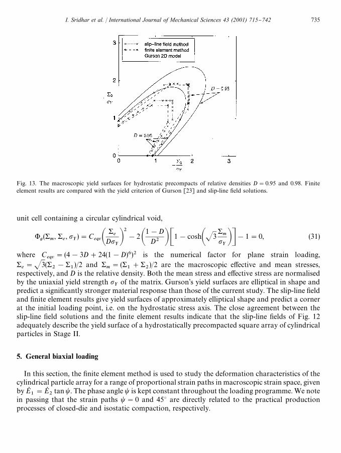
Fig. 13. The macroscopic yield surfaces for hydrostatic precompacts of relative densities D"0.95 and 0.98. Finiteelement results are compared with the yield criterion of Gurson [23] and slip-line "eld solutions.
unit cell containing a circular cylindrical void,
'g(&
m, &
e, p
Y)"C
eqvA&e
DpYB2!2 A
1!DD2 BC1!coshAJ3
&m
pYBD!1"0, (31)
where Ceqv
"(4!3D#24(1!D)6)2 is the numerical factor for plane strain loading,&e"J3(&
2!&
1)/2 and &
m"(&
1#&
2)/2 are the macroscopic e!ective and mean stresses,
respectively, and D is the relative density. Both the mean stress and e!ective stress are normalisedby the uniaxial yield strength p
Yof the matrix. Gurson's yield surfaces are elliptical in shape and
predict a signi"cantly stronger material response than those of the current study. The slip-line "eldand "nite element results give yield surfaces of approximately elliptical shape and predict a cornerat the initial loading point, i.e. on the hydrostatic stress axis. The close agreement between theslip-line "eld solutions and the "nite element results indicate that the slip-line "elds of Fig. 12adequately describe the yield surface of a hydrostatically precompacted square array of cylindricalparticles in Stage II.
5. General biaxial loading
In this section, the "nite element method is used to study the deformation characteristics of thecylindrical particle array for a range of proportional strain paths in macroscopic strain space, givenby EQ
1"EQ
2tant. The phase angle t is kept constant throughout the loading programme. We note
in passing that the strain paths t"0 and 453 are directly related to the practical productionprocesses of closed-die and isostatic compaction, respectively.
I. Sridhar et al. / International Journal of Mechanical Sciences 43 (2001) 715}742 735
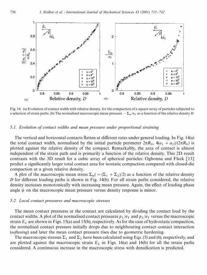
Fig. 14. (a) Evolution of contact width with relative density, for the compaction of a square array of particles subjected toa selection of strain paths. (b) The normalised macroscopic mean pressure!&
m/p
Yas a function of the relative density D.
5.1. Evolution of contact widths and mean pressure under proportional straining
The vertical and horizontal contacts #atten at di!erent rates under general loading. In Fig. 14(a)the total contact width, normalised by the initial particle perimeter 2pR
0, 4(a
1#a
2)/(2pR
0) is
plotted against the relative density of the compact. Remarkably, the area of contact is almostindependent of the strain path and is primarily a function of the relative density. This 2D resultcontrasts with the 3D result for a cubic array of spherical particles: Ogbonna and Fleck [13]predict a signi"cantly larger total contact area for isostatic compaction compared with closed-diecompaction at a given relative density.
A plot of the macroscopic mean stress &m("(&
1#&
2)/2) as a function of the relative density
D for di!erent loading paths is shown in Fig. 14(b). For all strain paths considered, the relativedensity increases monotonically with increasing mean pressure. Again, the e!ect of loading phaseangle t on the macroscopic mean pressure versus density response is minor.
5.2. Local contact pressures and macroscopic stresses
The mean contact pressures at the contact are calculated by dividing the contact load by thecontact widths. A plot of the normalised contact pressures p
1/p
Yand p
2/p
Yversus the macroscopic
strain E2
are shown in Figs. 15(a) and 15(b), respectively. As for the case of hydrostatic compaction,the normalised contact pressure initially drops due to neighbouring contact}contact interaction(softening) and later the mean contact pressure rises due to geometric hardening.
The macroscopic stresses &1
and &2
have been calculated using Eqs. (5) and (6), respectively, andare plotted against the macroscopic strain E
2in Figs. 16(a) and 16(b) for all the strain paths
considered. A continuous increase in the macroscopic stress with densi"cation is predicted.
736 I. Sridhar et al. / International Journal of Mechanical Sciences 43 (2001) 715}742
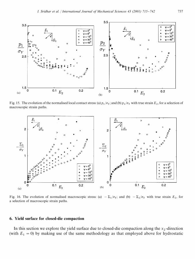
Fig. 15. The evolution of the normalised local contact stress: (a) p1/p
Y; and (b) p
2/p
Ywith true strain E
2, for a selection of
macroscopic strain paths.
Fig. 16. The evolution of normalised macroscopic stress: (a) !&1/p
Y; and (b) !&
2/p
Ywith true strain E
2, for
a selection of macroscopic strain paths.
6. Yield surface for closed-die compaction
In this section we explore the yield surface due to closed-die compaction along the x2-direction
(with E1"0) by making use of the same methodology as that employed above for hydrostatic
I. Sridhar et al. / International Journal of Mechanical Sciences 43 (2001) 715}742 737
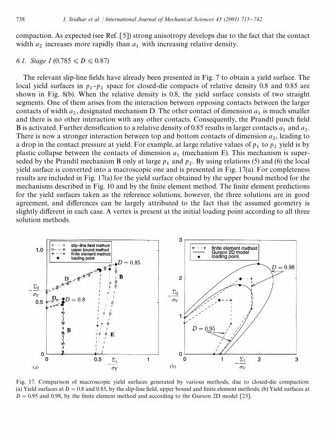
Fig. 17. Comparison of macroscopic yield surfaces generated by various methods, due to closed-die compaction:(a) Yield surfaces at D"0.8 and 0.85, by the slip-line "eld, upper bound and "nite element methods; (b) Yield surfaces atD"0.95 and 0.98, by the "nite element method and according to the Gurson 2D model [23].
compaction. As expected (see Ref. [5]) strong anisotropy develops due to the fact that the contactwidth a
2increases more rapidly than a
1with increasing relative density.
6.1. Stage I (0.785)D)0.87)
The relevant slip-line "elds have already been presented in Fig. 7 to obtain a yield surface. Thelocal yield surfaces in p
1}p
2space for closed-die compacts of relative density 0.8 and 0.85 are
shown in Fig. 8(b). When the relative density is 0.8, the yield surface consists of two straightsegments. One of them arises from the interaction between opposing contacts between the largercontacts of width a
2, designated mechanism D. The other contact of dimension a
1is much smaller
and there is no other interaction with any other contacts. Consequently, the Prandtl punch "eldB is activated. Further densi"cation to a relative density of 0.85 results in larger contacts a
1and a
2.
There is now a stronger interaction between top and bottom contacts of dimension a2, leading to
a drop in the contact pressure at yield. For example, at large relative values of p1
to p2
yield is byplastic collapse between the contacts of dimension a
1(mechanism E). This mechanism is super-
seded by the Prandtl mechanism B only at large p1
and p2. By using relations (5) and (6) the local
yield surface is converted into a macroscopic one and is presented in Fig. 17(a). For completenessresults are included in Fig. 17(a) for the yield surface obtained by the upper bound method for themechanisms described in Fig. 10 and by the "nite element method. The "nite element predictionsfor the yield surfaces taken as the reference solutions; however, the three solutions are in goodagreement, and di!erences can be largely attributed to the fact that the assumed geometry isslightly di!erent in each case. A vertex is present at the initial loading point according to all threesolution methods.
738 I. Sridhar et al. / International Journal of Mechanical Sciences 43 (2001) 715}742
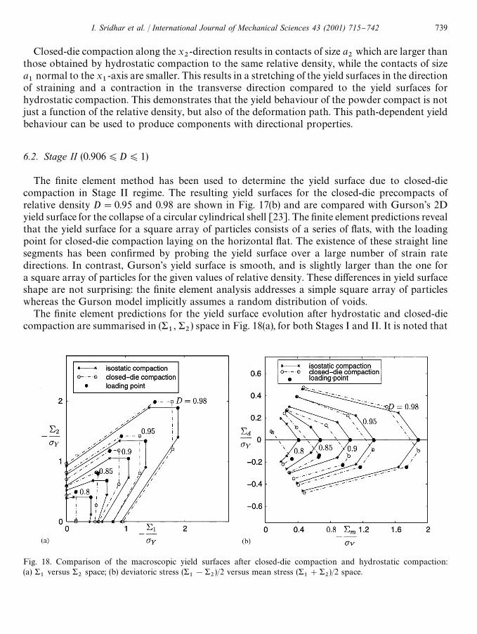
Fig. 18. Comparison of the macroscopic yield surfaces after closed-die compaction and hydrostatic compaction:(a) &
1versus &
2space; (b) deviatoric stress (&
1!&
2)/2 versus mean stress (&
1#&
2)/2 space.
Closed-die compaction along the x2-direction results in contacts of size a
2which are larger than
those obtained by hydrostatic compaction to the same relative density, while the contacts of sizea1
normal to the x1-axis are smaller. This results in a stretching of the yield surfaces in the direction
of straining and a contraction in the transverse direction compared to the yield surfaces forhydrostatic compaction. This demonstrates that the yield behaviour of the powder compact is notjust a function of the relative density, but also of the deformation path. This path-dependent yieldbehaviour can be used to produce components with directional properties.
6.2. Stage II (0.906)D)1)
The "nite element method has been used to determine the yield surface due to closed-diecompaction in Stage II regime. The resulting yield surfaces for the closed-die precompacts ofrelative density D"0.95 and 0.98 are shown in Fig. 17(b) and are compared with Gurson's 2Dyield surface for the collapse of a circular cylindrical shell [23]. The "nite element predictions revealthat the yield surface for a square array of particles consists of a series of #ats, with the loadingpoint for closed-die compaction laying on the horizontal #at. The existence of these straight linesegments has been con"rmed by probing the yield surface over a large number of strain ratedirections. In contrast, Gurson's yield surface is smooth, and is slightly larger than the one fora square array of particles for the given values of relative density. These di!erences in yield surfaceshape are not surprising: the "nite element analysis addresses a simple square array of particleswhereas the Gurson model implicitly assumes a random distribution of voids.
The "nite element predictions for the yield surface evolution after hydrostatic and closed-diecompaction are summarised in (&
1, &
2) space in Fig. 18(a), for both Stages I and II. It is noted that
I. Sridhar et al. / International Journal of Mechanical Sciences 43 (2001) 715}742 739

with progressive densi"cation the degree of anisotropy associated with closed-die compactiondecreases. It is instructive to replot these yield surfaces using axes of mean stress, &
m"(&
1#&
2)/2
and deviatoric stress, &d"(&
1!&
2)/2, see Fig. 18(b). The shape of the resulting yield surfaces may
be approximated by a quadratic function of deviatoric and mean stress, in support of severalphenomenologicalmodels as reviewed by Doraivelu et al. [3]. The path dependence of yield surfaceshape is again evident, with the yield surface rotated along the direction of the loading vector.
7. The signi5cance of strain hardening
Finally, the e!ect of strain hardening is explored for both hydrostatic and closed-die compactionof the square array of cylindrical particles. The matrix is taken as an isotropic hardening J2 #owtheory solid, with a uniaxial stress}strain law given by
eeY
"
ppY
for p)pY,
(32)
"AppYB1@N
for p'pY.
Here, pY
is the initial yield stress corresponding to a yield strain eY"p
Y/E, where E is Young's
modulus. The strain-hardening exponent N is assumed to be in the range 0)N)1, with N"0describing an elastic-perfectly plastic solid. In the simulations, the yield strain e
Yis chosen to be
equal to 10~4, and Poisson's ratio l"0.3. The FE mesh of Fig. 2 is used for the computations withthe displacements u
1and u
2speci"ed in order to give the required strain path.
The normalised macroscopic stress &2
versus the relative density D for various values of strainhardening exponent N, is shown in Fig. 19 for both hydrostatic and closed-die compaction. Weconclude that the compressibility of the array decreases with increasing value of the strain-hardening exponent N for both hydrostatic and closed-die compaction. Also for all values ofN considered, the value of the macroscopic stress &
2required to attain a given density is higher for
closed-die compaction than for hydrostatic compaction. Similar observations have been made byAkisanya and Cocks [15] in their FE work on the compaction of a hexagonal array of cylindricalparticles.
8. Concluding remarks
Consider "rst the case of hydrostatic compaction. The results of slip-line "eld and "nite elementcalculations indicate that the interaction of plastic deformation between contacts in#uences thepressure}density response of a regular square array of cylindrical particles. With increasingdensi"cation the local contact pressure decreases from the Prandtl punch solution due to con-tact}contact interaction. This observation is in agreement with the "ndings of Ogbonna and Fleck[13] for a cubic array of spherical particles, and the "ndings of Akisanya et al. [12] for a hexagonalarray of cylindrical particles.
Slip-line "eld, upper bound, "nite element and random array upper bound methods have beenemployed to study the yield surface evolution under hydrostatic and closed-die compaction. The
740 I. Sridhar et al. / International Journal of Mechanical Sciences 43 (2001) 715}742
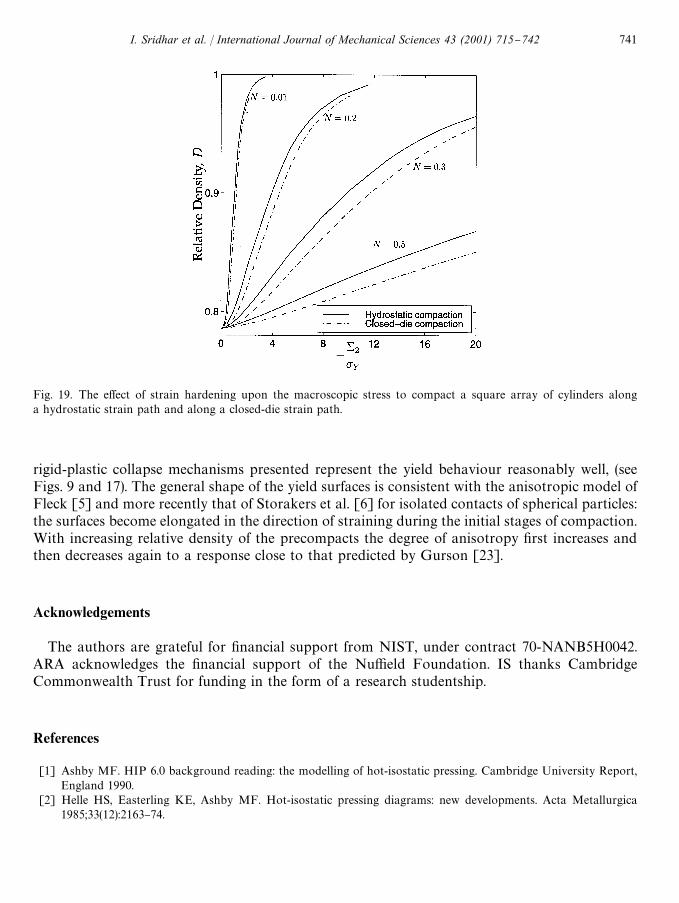
Fig. 19. The e!ect of strain hardening upon the macroscopic stress to compact a square array of cylinders alonga hydrostatic strain path and along a closed-die strain path.
rigid-plastic collapse mechanisms presented represent the yield behaviour reasonably well, (seeFigs. 9 and 17). The general shape of the yield surfaces is consistent with the anisotropic model ofFleck [5] and more recently that of Storakers et al. [6] for isolated contacts of spherical particles:the surfaces become elongated in the direction of straining during the initial stages of compaction.With increasing relative density of the precompacts the degree of anisotropy "rst increases andthen decreases again to a response close to that predicted by Gurson [23].
Acknowledgements
The authors are grateful for "nancial support from NIST, under contract 70-NANB5H0042.ARA acknowledges the "nancial support of the Nu$eld Foundation. IS thanks CambridgeCommonwealth Trust for funding in the form of a research studentship.
References
[1] Ashby MF. HIP 6.0 background reading: the modelling of hot-isostatic pressing. Cambridge University Report,England 1990.
[2] Helle HS, Easterling KE, Ashby MF. Hot-isostatic pressing diagrams: new developments. Acta Metallurgica1985;33(12):2163}74.
I. Sridhar et al. / International Journal of Mechanical Sciences 43 (2001) 715}742 741
[3] Doraivelu SM, Gegel HL, Gunasekhara JS, Malas JC, Morgan JT. A new yield function for compressible P/Mmaterials. International Journal of Mechanical Sciences 1984;26(9-10):527}35.
[4] Brown BS, Abou-Chedid G. Yield behaviour of metal powder assemblages. Journal of Mechanics and Physics ofSolids 1994;42(3):383}99.
[5] Fleck NA. On the cold compaction of powders. Journal of Mechanics and Physics of Solids 1995;43(9):1409}31.[6] Storakers B, Fleck NA, McMeeking RM. The viscoelastic compaction of composite powders. Journal of Mechanics
and Physics of Solids 1999;47(4):785}815.[7] Akisanya AR, Cocks ACF, Fleck NA. The yield behaviour of metal powders. International Journal of Mechanical
Sciences 1997;39(12):1315}24.[8] Fleck NA, Kuhn LT, McMeeking RM. Yielding of metal powder bonded by isolated contacts. Journal of
Mechanics and Physics of Solids 1992;40:1139}62.[9] Green AP. The plastic yielding of metal junctions due to combined shear and pressure. Journal of Mechanics and
Physics of Solids 1954;2:197}211.[10] Laptev AM, Ul'yanov AN. Deformation of spherical particles during the densi"cation of an idealized porous
material I-Investigation of kinematic characteristics. Soviet Powder Metallurgy and Metal Ceramics1984;23(4):183}6.
[11] Timothy SP, Pearson JM, Hutchings IM. The contact pressure distribution during plastic compression of leadspheres. International Journal of Mechanical Sciences 1987;29(10-11):713}9.
[12] Akisanya AR, Cocks ACF, Fleck NA. Hydrostatic compaction of cylindrical particles. Journal of Mechanics andPhysics of Solids 1994;42(7):1067}85.
[13] Ogbonna N, Fleck NA. Compaction of an array of spherical particles. Acta Metallurgica et Materialia1995;43(2):603}20.
[14] Kunze JM, Wadley HNG. The densi"cation of metal coated powders. Acta Metallurgica et Materialia1997;45(5):1851}65.
[15] Akisanya AR, Cocks ACF. Stage I compaction of cylindrical particles under non-hydrostatic loading. Journal ofMechanics and Physics of Solids 1995;43(4):605}36.
[16] Wadley HNG, Davison TS, Kunze JM. Densi"cation of metal coated "bres by elastic}plastic contact deformation.Composites B: Engineering 1997;28B(3):233}42.
[17] Fischmeister HF, Arzt E. Densi"cation of powders by particle deformation. Powder Metallurgy 1983;26(2):82}8.[18] Johnson W. Indentation and forging and the action of Nasmyth's anvil. Engineer 1958;205:348}50.[19] Johnson W, Mellor PB. Engineering plasticity. New York: Van Nostrand Reinhold Company Limited, 1973.[20] Gampala R, Elzey DM, Wadley HNG. Plastic deformation of asperities during consolidation of plasma sprayed
metal matrix composite monotape. Acta Metallurgica et Materialia 1994;42(8):3209}21.[21] Mesarovic SD, Fleck NA. Frictionless indentation of dissimilar elastic}plastic spheres. International Journal of
Solids and Structures; 37(46-47):7071}91.[22] Johnson W, Sowerby R, Haddow JB. Plane-strain slip-line "elds: theory and bibliography. London: Edward
Arnold (Publishers) Ltd., 1970.[23] Gurson AL. Continuum theory of ductile rupture by void nucleation and growth: Part 1 * Yield Criterion and
#ow rules for porous ductile media. Transactions of ASME Journal of Engineering Materials Technology1977;99(1):2}15.
742 I. Sridhar et al. / International Journal of Mechanical Sciences 43 (2001) 715}742