co-processing of etp sludge of acc madukkarai - update
TRANSCRIPT
Recent Research in Science and Technology 2011, 3(9): 92-104 ISSN: 2076-5061 www.scholarjournals.org
www.recent-science.com
92
RRST-Enviornmental Science
Co-processing of ETP Sludge of ACC Madukkarai Bundela Pusppendra. S.1*, Parlikar Ulhas2, Gautam S.P.3 1Regional Office, Madhya Pradesh Pollution Control Board, Vijay Nagar Jabalpur (M.P.) India 2Director, Alternative Fuel and Raw Materials, ACC Mumbai 3Central Pollution Control Board, New Delhi
Article Info
Abstract
Article History
M/S Ford India private Limited, it is one of the leading vehicles manufactures generated large amount chemical sludge and oil wastes during its manufacturing operations. The hazardous waste generates from ford company was co-processed during the trial burn conducted at ACC Madukkarai cement works. Co-processing of ETP- sludge the cement kiln is the most scientific and environmentally sound manner without influencing emissions on partial replacement of traditional fuel. Co-processing in cement kiln ranks higher in the waste management hierarchy, when compared to other disposal options such as incineration and landfill, Co-processing does not leave behind any residue that might have harmful impacts on the environment. Thus it is an ecologically sustainable solution for waste management. All the results are under permissible limit as per Central Pollution Control Board for the common hazardous waste incinerators.
Received : 13-04-2011
Revised : 05-10-2011 Accepted : 05-10-2011
*Corresponding Author
Tel : +9107614042780
Fax : +9107614042780 Email:
©ScholarJournals, SSR Key Words: Clinker, Cement, Heat, Hazardous waste, Disposal
Introduction
India is the second fastest growing major economy in the world, with a GDP growth rate around 8%. Due to the boom in the economy and enhanced industrial growth, the management of wastes generated, is posing a very serious threat to the society from the health, safety and environmental viewpoint. The generation rate of hazardous wastes in the country, as per the official records, is estimated to be about 4 million tons per annum and that of the Municipal Solid Waste (MSW) is about 40 million tons per annum. There are also numerous non-hazardous wastes from agricultural activities and industries, the generation rate of which is about 400 million tons per annum. Proper measures and guidelines are required for the management of these huge quantities of wastes, whether it be for their disposal or for their gainful utilization. Co-processing refers to the use of waste materials in industrial processes as alternative fuels and raw materials (AFR) to recover energy and material from them. Due to the high temperature and long residence time in cement kiln all types of wastes can be effectively disposed without any harmful emissions [1]. Co-processing is a more environmentally friendly and sustainable method of waste disposal as compared to land filling and incineration because of reduced emissions and no residue after the treatment. The purpose of co-processing trial is to demonstrate that the kiln is able to co-process hazardous waste in an environmentally safe and sound manner. The emission monitoring results of the trial burn forms a basis, to demonstrate that co-processing is an environmentally sound, effective waste disposal/recovery technology, to the authorities and other stakeholders associated with the activity. The co-processing trial is carried out in three phases, namely, pre co-processing, co-processing and post coprocessing, in order to
monitor the kiln stack emission before, during and after the coprocessing of the waste material. All concerned stakeholders are informed about the trial in advance [2-3]. During the co-processing trial burn of Chemical ETP Sludge waste from Ford India Private Limited conducted from 22nd to 26th June, 2008 at ACC Madukkarai Cement Works, an experienced team comprising of senior officials from ACC and representatives from Ford India Private Limited were involved.
Materials and Methods Plant, Kiln and Control System Description
ACC Madukkarai Works was established in 1934 as a semi wet process with 5 kilns and a clinkerization capacity of 1200 tones per day. The inception of single kiln based on Semi wet process was in 1989 with capacity of 1500 TPD. Currently the plant has kiln with a capacity of 2400 TPD. The plant is located in the Coimbatore district of Tamil Nadu. The two mines namely Madukkarai and Walayar serve as the limestone source for the plant and other major raw material components include clay, sandstone, blue dust and bauxite [4]. The flow sheet for the manufacturing of clinker (intermediate product) is attached as figure 1 and 2. Cement Production Process in Brief
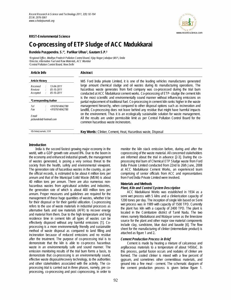
Cement is made by heating a mixture of calcareous and argillaceous materials to a temperature of about 1450oC. In this process, partial fusion occurs and nodules of clinker are formed. The cooled clinker is mixed with a few percent of gypsum, and sometimes other cementitious materials, and ground into a fine meal - cement. The schematic diagram of the cement production process is given below figure 1.
Bundela Pusppendra et al./Rec Res Sci Tech 2011, 3(9): 92-104
93
Figure 1. Schematic Diagram of Cement Production Process
The main components of clinker are lime (CaO), silica (SiO2), alumina (Al2O3) and iron oxide (Fe2O3). The first stage in the industrial process of cement manufacture is the quarrying of raw materials. To obtain the proper composition of the raw mix, corrective ingredients normally have to be added to the quarried raw materials. Examples of corrective materials are sand, bauxite and iron ore; which compensate for deficiencies of silica, alumina and iron oxide, respectively. After pre-blending, the chemically balanced raw mix passes through the mill feed system, to the 300 tons per hour roller mill. The mill is fed with hot gases from the kiln to dry the raw mix to less than 1% humidity. The dried material is then conveyed to the blending silo where continuous homogenization ensures the correct raw meal composition. The clinker production is
performed in a dry suspension pre-heater cement kiln equipped with a pre-calciner. The kiln rotates with a speed of 2.4 rounds per minute, is 3.75 meter in diameter and 55 meter long. It has a two string pre-heater tower (4 stages and 2 stages respectively) and produces approximately 2400 tones of the intermediate product - clinker - per day. The clinker is cooled in a grate cooler, 20.57 meter long and 2.45 meter wide. The maximum feeding capacity is 160 tons of raw meal per hour to the second stage cyclone from the top. The main burner is a Duflox, usually fired with 3 tons of coal per hour. After the clinkerisation process the material is sent to the cement mill where the mineral component such as fly ash and gypsum are added to produce Portland Pozzolona cement [5].
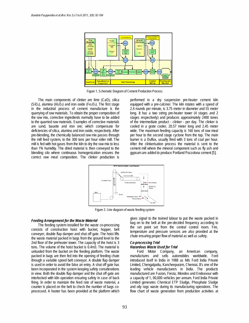
Figure 2. Line diagram of waste feeding system
Feeding Arrangement for the Waste Material The feeding system installed for the waste co-processing
consists of construction hoist with bucket, hopper, belt conveyer, double flap damper and shut off gate. The hoist lifts the waste material packed in bags from the ground level to the 2nd floor of the preheater tower. The capacity of the hoist is 3 tons. The volume of the hoist bucket is 0.4m3. The material is unloaded from the bucket on the feeding platform. The waste packed in bags are then fed into the opening of feeding chute through a variable speed belt conveyor. A double flap damper is used in order to avoid the false air entry. A shut off gate has been incorporated in the system keeping safety considerations in view. Both the double flap damper and the shut off gate are interlocked with kiln operation ensuring safety in case of back firing. In order to maintain the feed rate of waste material, a counter is placed on the belt to check the number of bags co-processed. A hooter has been provided at the platform which
gives signal to the trained labour to put the waste packed in bag on to the belt at the pre-decided frequency according to the set point set from the central control room. Fire, temperature and pressure sensors are also provided at the chute ensuring proper flow of material as well as safety.
Co-processing Trial Hazardous Waste Used for Trial
Ford Motor Company, an American company, manufactures and sells automobiles worldwide. Ford introduced itself in India in 1988 as M/s Ford India Private Limited, Chengalpattu, Kancheepuram, Chennai. It’s one of the leading vehicle manufacturers in India. The products manufactured are Fusion, Fiesta, Mondeo and Endeavour with a capacity of 1, 00,000 vehicles per annum. Ford India Private Limited generates Chemical ETP Sludge, Phosphate Sludge and oily rags waste during its manufacturing operations. The flow chart of waste generation from production activities at
Bundela Pusppendra et al./Rec Res Sci Tech 2011, 3(9): 92-104
94
Ford India Private Limited is attached as respectively. Ford’s authorization for transportation and disposal of hazardous waste from Tamil Nadu Pollution Control Board is attached.
The following hazardous waste from Ford was co-processed during the trial burn conducted at ACC Madukkarai Cement Works from 22nd to 26th June 2008. Ford had forwarded the sample of the Chemical ETP Sludge waste to ACC for the evaluation of co-processing feasibility. The waste was analyzed at the R&D of ACC Limited located at Thane. The analysis result of the Chemical ETP Sludge is attached.
Based on the analysis, ACC confirmed to Ford that the Chemical ETP Sludge waste can be disposed by co-processing at cement kiln in ACC Madukkarai Works.
Receipt of Chemical ETP Sludge Waste from Ford for Trial Ford India Private Limited delivered 86.49 tons of
Chemical ETP Sludge waste for trial purpose. Total material was delivered in four trucks, bearing the following details in table-1:
Table 1. Transportation Details of Chemical ETP Sludge
Truck No. Quantity (MT) Received On TN21 AY 6031 24.52 28th Feb. 08 TN21 AZ 7745 18.10 28th Feb. 08 TN21AX 2011 22.00 20th Mar. 08 TN21 AY 0213 21.87 02nd Jun. 08
Hazardous Waste Storage and Handling Hazardous Waste Storage and Handling at Ford India
The Chemical ETP Sludge was stored in HDPE bags (approx. weight 12.5 kg) in Ford’s hazardous waste storage shed. The waste was transported to ACC Madukkarai Works by State Pollution Control Board authorized transporter.
Temporary Hazardous Waste Storage Shed at ACC Madukkarai Works
The Chemical ETP Sludge was stored in two containers (40 Feet long) having a ventilation window and the separation was made with in the containers in order to avoid mixing of waste. Boards displaying precautionary measures, safety signs and waste specific workplace labels for handling hazardous waste material were displayed at strategic locations. Fire extinguishers - both dry & CO2 type - were available near the storage container. Risk Assessment Procedure (RAP) and Safety Manual were prepared by ACC safety team in association with Ford India safety team for Chemical ETP Sludge before transportation of waste from Ford India to Madukkarai Works. The RAP and workplace label for Chemical ETP Sludge waste are attached.
Both the containers were located at a distance of 150 -200 m away from the bucket loading point.
Hazardous Waste Handling at ACC Madukkarai Cement Works
The unloading operation was performed at ACC Madukkarai by four persons equipped with personal protective gear. The bagged wastes were unloaded manually and stored at designated sites in the container. The workers & supervisors were trained in handling and safety aspects of hazardous waste well in advance of the trial burn. Concerned personnel were also trained on precautions to be undertaken, emergency measures, potential spill abatement, proper use and upkeep of PPEs, etc. At the time of feeding the bags were loaded on Trolley to transport the material form the containers to the hoist. The entire unloading and storage operation were carried out under the supervision of AFR Coordinator of ACC Madukkarai [6].
Standard Operating procedure for the waste material Following are the SOP implemented during the Co
processing Trial 1. The Truck containing the waste from Ford India Private
Limited, entered the premises of ACC Madukkarai Works through the weigh bridge, where the weight was recoded. The truck then moved towards the temporary storage area.
2. The concerned officer (AFR Coordinator) was informed by the security. The concerned officer checked the manifest related to transportation of waste.
3. Waste was unloaded from the truck with the help of laborers in presence of security guards, safety officer and kept in storage containers separately.
4. The weight of the material was recorded in the log book.
5. Empty truck was again weighed to check on the net weight of the material received.
6. The net weight of the truck was also recorded in the log book.
7. For co processing, the waste material packed in bags was loaded into the trolley
(Dedicated for transporting the Hazardous waste) with the help of labor and transported to the ground floor of the pre heater (near to the bucket of construction hoist) under the vigilance of guard and AFR coordinator.
8. Separate register was maintained for keeping the records of the material flow for the waste.
9. The waste was fed in the bucket and was lifted to the 2nd floor having the feeding arrangement to the Kiln inlet.
10. The bucket was tilted to towards the conveyor belt. 11. The labor after receiving the signal from hooter
(frequency of the hooter can be controlled from the CCR) put the bag containing waste on the belt conveyor and the bags enters in the kiln inlet through a chute.
Outline of Monitoring Plan during Co-processing Trial The purpose of the co-processing trial is to demonstrate
that the kiln is able to coprocess hazardous waste in an environmentally friendly manner. The emission monitoring results from the trial burn serves as a basis to demonstrate the environmentally sound performance of co-processing to the authorities and other stakeholders in the waste disposal activity.
Bundela Pusppendra et al./Rec Res Sci Tech 2011, 3(9): 92-104
95
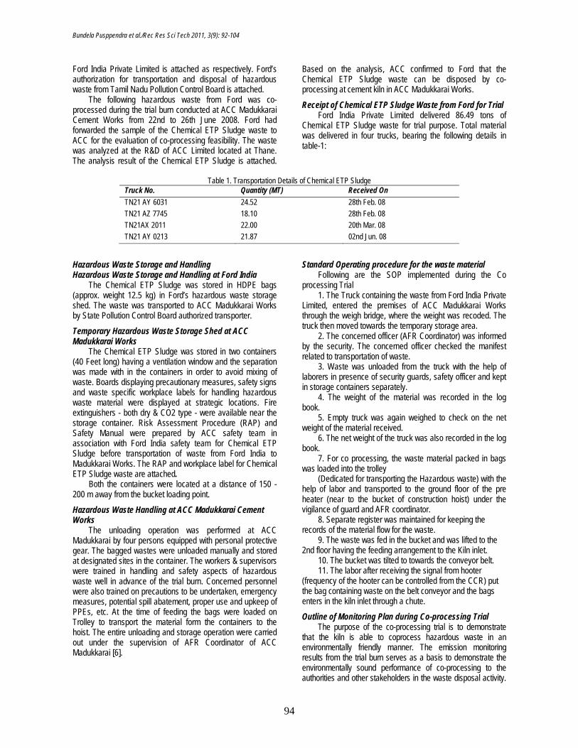
The co-processing trial of Chemical ETP Sludge waste from Ford, which was conducted between 22nd to 26th June, 2008 was carried out in three phases (namely, Pre Co-processing, Co-processing and Post Coprocessing) and was as per the Holcim
EMR Guidelines. There was a kiln stabilization period with conventional fuel for a span of 24 hours before the start of the trial. Table 2 provides the list of emission parameters which were monitored during each phase of the trial.
Table 2. Emission Monitoring during Each Phase of the Co-processing Trial
S. No Parameter Method No. of Sample
Frequency
1. Particulate Matter USEPA (5/17) 3 Once in each shift 2. SO2 USEPA (6A/B) 3 Once in each shift 3. HCl, HF USEPA 26 (ion
chromatography) 3 Once in each shift
4. HBr USEPA 26 (ion chromatography)
3 Once in each shift
5. NOx Instrumental (electro-chemical sensor)
3 Once in each shift
6. Hg (particulate & gaseous) USEPA 101 A (cold vapour AAS)
3 Once in each shift
7. Metals (particulate & gaseous) - Antimony, Arsenic, Cadmium, Chromium, Cobalt, Copper, Lead, Manganese, Nickel, Thallium, Vanadium, Zinc.
USEPA 29 (IP-MS) 3 Once in each shift
8. Dioxins & Furans (I-TEF)* USEPA 23A 3 Once in each shift 9. TOC / Total Hydrocarbon
(continuous monitoring for 24 hours)
USEPA Method 25 A 1 Once over a period of 24 hours
10. Benzene NIOSH 1503 3 Once in each shift 11. PAH (particulate & gaseous) TO13 1 Once in each phase 12. NH3 Indo phenol 3 Once in each shift
*Sampling by SGS India & testing by SGS Institute for Applied Chromatography, Belgium, accredited to ISO 17025 by Beltest. Hourly samples of all raw materials (lime stone, bauxite &
iron ore), raw meal, kiln coal, calciner coal, clinker and Chemical ETP Sludge waste were collected and one
composite sample on daily basis was made. The parameters that were analyzed in all the samples mentioned above are listed in Table 3, 4 and 5.
Table 3. Analysis Parameters for Raw Meal and Coal Samples
S. No Parameter Method No. of Sample 1 Antimony, Arsenic, Cadmium, Chromium,
Cobalt, Copper, Lead, Manganese, Nickel, Thallium, Vanadium, Mercury, Zinc.
Microwave digestion & AAS/ICP MS/APHA
1
2 Total Organic Carbon NCEA-C-1282 1
Table 4. Analysis Parameters for Clinker Samples S. No Parameter Method No. of Sample 1 Antimony, Arsenic, Cadmium, Chromium,
Cobalt, Copper, Lead, Manganese, Nickel, Thallium, Vanadium, Mercury, Zinc
Microwave digestion & AAS/ICP MS/APHA
1
Table 5. Analysis Parameters for Chemical ETP Sludge Samples
S. No Parameter Method No. of Sample 1. Antimony, Arsenic, Cadmium, Chromium, Cobalt, Copper,
Lead, Manganese, Nickel, Thallium, Vanadium, Mercury, Zinc.
Microwave digestion & AAS/ICP MS/APHA
1
2. Gross Calorific Value By Bomb Calorimeter 1 3. Ultimate Analysis (C, H2, N2, O2) By CHNSO Analyzer 1 4. Proximate Analysis (Moisture, Ash, Volatile Matter, Fixed
Carbon) By Thermo Gravimetric Analyzer
1
5. Total Organic Carbon NCEA-C-1282 1 6. Total Petroleum Hydrocarbon EPA 1664 1 7. Organo Chlorine Compound AOAC 8270 C 1 8. VOCs & Semi VOCs ASTM 3686 1 9. PCBs EPA 8082 1 10. PCPs EPA 8270C 1
Bundela Pusppendra et al./Rec Res Sci Tech 2011, 3(9): 92-104
96
Summary of Co-processing Trial Schedule The schedule for the co-processing trial of Chemical ETP
Sludge waste from Ford at ACC Madukkarai Cement works was given in table 6.
The co-processing trial burn was conducted in the presence of representatives from ACC, Ford and SGS. The team for trial burn was as mentioned below.
Table 6. Summary of Co-processing Trial Schedule
S. No. Date Phase From To
1. 22nd Jun 08 23rd Jun 08 Pre Co processing Phase for Chemical ETP Sludge 2. 24th Jun 08 25th Jun 08 During Co processing Phase With Chemical ETP Sludge 3. 25th Jun 08 26th Jun 08 Post Co processing Phase for Chemical ETP Sludge
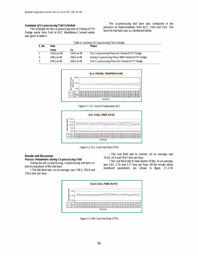
Figure 2.1. SLC Vessel Temperature (0C)
Figure 2.2. SLC Coal Feed Rate (TPH)
Results and Discussion Process Parameters during Co-processing Trial
During the pre co-processing, co-processing and post co-processing phase of the trial burn:
• The kiln feed rate, on an average, was 158.5, 156.6 and 156.6 tons per hour.
• The coal feed rate to calciner, on an average, was 10.34, 10.4 and 10.61 tons per hour.
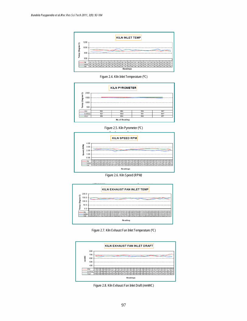
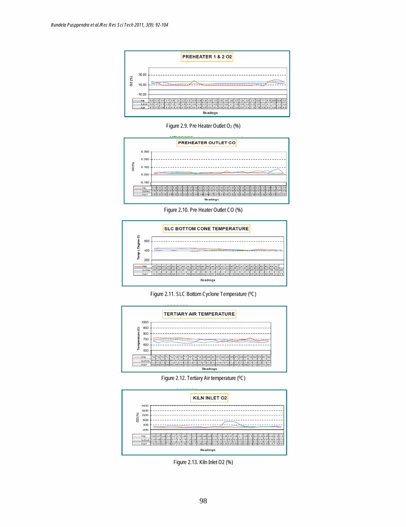
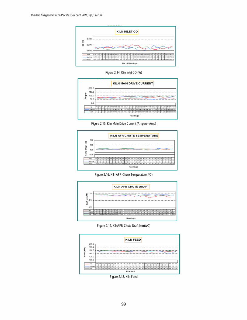
• The coal feed rate to main burner of kiln, on an average, was 2.81, 2.74 and 2.71 tons per hour. All the results above monitored parameters are shown in figure 2.1-2.18.
Figure 2.3. Kiln Coal Feed Rate (TPH)
Bundela Pusppendra et al./Rec Res Sci Tech 2011, 3(9): 92-104
97
Figure 2.4. Kiln Inlet Temperature (0C)
Figure 2.5. Kiln Pyrometer (0C)
Figure 2.6. Kiln Speed (RPM)
Figure 2.7. Kiln Exhaust Fan Inlet Temperature (0C)
Figure 2.8. Kiln Exhaust Fan Inlet Draft (mmWC)
Bundela Pusppendra et al./Rec Res Sci Tech 2011, 3(9): 92-104
98
Figure 2.9. Pre Heater Outlet O2 (%)
Figure 2.10. Pre Heater Outlet CO (%)
Figure 2.11. SLC Bottom Cyclone Temperature (0C)
Figure 2.12. Tertiary Air temperature (0C)
Figure 2.13. Kiln Inlet O2 (%)
Bundela Pusppendra et al./Rec Res Sci Tech 2011, 3(9): 92-104
99
Figure 2.14. Kiln inlet CO (%)
Figure 2.15. Kiln Main Drive Current (Ampere- Amp)
Figure 2.16. Kiln AFR Chute Temperature (0C)
Figure 2.17. KilnAFR Chute Draft (mmWC)
Figure 2.18. Kiln Feed
Bundela Pusppendra et al./Rec Res Sci Tech 2011, 3(9): 92-104
100
Table 7. Sampling Conditions & Stack Parameters during Co-processing Trial Operation mode Unit Average Reading Stack diameter [m] 2.6 Cross section area [m2] 5.312 Pressure [mmHg] 720 Gas temperature [°C] 134 Moisture [vol-%] 20.6 Oxygen content [vol-%] 10.4 Carbon dioxide content [vol-%] 16.2 Carbon Monoxide [mg/Nm3] 541.8 Exhaust gas velocity [m/s] 22.5 Exhaust gas volume (Stack conditions) [m3/h] 430245 Exhaust gas volume (Normal, wet) [m3 n,wet/h] 297677 Exhaust gas volume (Normal, dry) [m3 n,dry/h] 236356
During the period of the co-processing trial, there were
some disturbances in the process, which was rectified by taking kiln stoppages. On investigation, it was discovered that the disturbances were not due to waste co-processing in kiln, but due to some other process related technical issues. Computer printouts of the hourly process chart of Kiln 3 sections were taken during the entire period of the co-processing trial.
The following parameters were monitored: 1. SLC Vessel Temperature(0C) 2. SLC Coal Feed Rate (tons per hour - TPH) 3. Kiln Coal Feed Rate (tons per hour - TPH) 4. Kiln Inlet Temperature (0C) 5. Kiln Pyrometer (0C) 6. Kiln Speed (revolutions per minute - RPM) 7. Kiln Exhaust Fan Inlet Temperature (0C) 8. Kiln Exhaust Fan Inlet Draft (mmWC) 9. Pre Heater Outlet O2 (%) 10. Pre Heater Outlet CO (%) 11. SLC Bottom Cyclone Temperature (0C) 12. Tertiary Air Temperature (0C) 13. Kiln Inlet O2 (%) 14. Kiln Inlet CO (%)
15. Kiln Main Drive Current (Ampere - Amp) 16. AFR Chute Temperature (0C) 17. AFR Chute Draft (mmWC) 18. Kiln Feed
Sampling Conditions during Co-processing Trials The sampling conditions and the stack parameters for
Madukkarai Kiln 3 were estimated during the trial and are shown in table 7.
Results of Emission Monitoring during Co-processing Trial
The detailed results of the monitoring carried out during the co-processing trial are provided in the report submitted by SGS and is attached at the end of this report.
The summary of the results are elaborated below. It is to be noted that the results
are the average values for the number of samples collected at the time of emission monitoring during the trial.
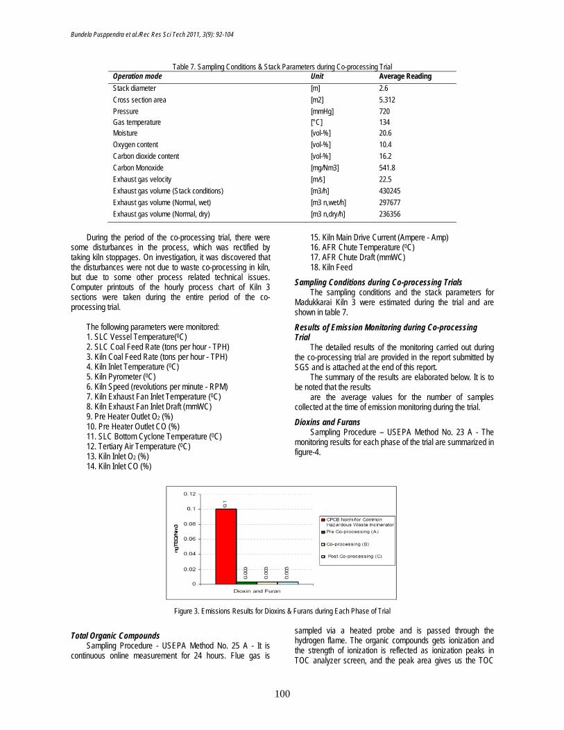
Dioxins and Furans Sampling Procedure – USEPA Method No. 23 A - The
monitoring results for each phase of the trial are summarized in figure-4.
Figure 3. Emissions Results for Dioxins & Furans during Each Phase of Trial
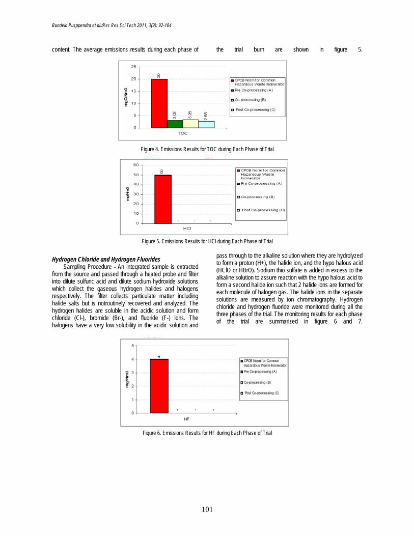
Total Organic Compounds Sampling Procedure - USEPA Method No. 25 A - It is
continuous online measurement for 24 hours. Flue gas is
sampled via a heated probe and is passed through the hydrogen flame. The organic compounds gets ionization and the strength of ionization is reflected as ionization peaks in TOC analyzer screen, and the peak area gives us the TOC
Bundela Pusppendra et al./Rec Res Sci Tech 2011, 3(9): 92-104
101
content. The average emissions results during each phase of the trial burn are shown in figure 5.
Figure 4. Emissions Results for TOC during Each Phase of Trial
Figure 5. Emissions Results for HCl during Each Phase of Trial
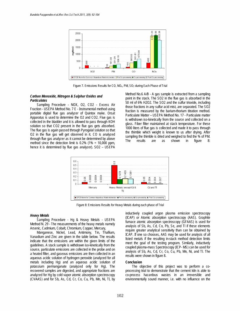
Hydrogen Chloride and Hydrogen Fluorides Sampling Procedure - An integrated sample is extracted
from the source and passed through a heated probe and filter into dilute sulfuric acid and dilute sodium hydroxide solutions which collect the gaseous hydrogen halides and halogens respectively. The filter collects particulate matter including halide salts but is notroutinely recovered and analyzed. The hydrogen halides are soluble in the acidic solution and form chloride (Cl-), bromide (Br-), and fluoride (F-) ions. The halogens have a very low solubility in the acidic solution and
pass through to the alkaline solution where they are hydrolyzed to form a proton (H+), the halide ion, and the hypo halous acid (HClO or HBrO). Sodium thio sulfate is added in excess to the alkaline solution to assure reaction with the hypo halous acid to form a second halide ion such that 2 halide ions are formed for each molecule of halogen gas. The halide ions in the separate solutions are measured by ion chromatography. Hydrogen chloride and hydrogen fluoride were monitored during all the three phases of the trial. The monitoring results for each phase of the trial are summarized in figure 6 and 7.
Figure 6. Emissions Results for HF during Each Phase of Trial
Bundela Pusppendra et al./Rec Res Sci Tech 2011, 3(9): 92-104
102
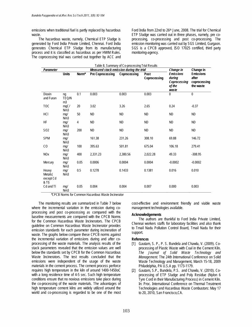
Figure 7. Emissions Results for CO, NOx, PM, SO2 during Each Phase of Trial
Carbon Monoxide, Nitrogen & Sulphur Oxides and Particulates
Sampling Procedure - NOX, O2, CO2 - Excess Air Fraction - USEPA Method No. 7 E - Instrumental method using portable digital flue gas analyzer of Quintox make. Orsat Apparatus is used to determine the O2 and CO2. Flue gas is collected in the bladder and it is allowed to pass through KOH solution so that CO2 present in the flue gas gets absorbed. The flue gas is again passed through Pyrogalal solution so that O2 in the flue gas will get observed in it. CO is analyzed through flue gas analyzer as it cannot be determined by above method since the detection limit is 0.2% (1% = 10,000 ppm, hence it is determined by flue gas analyzer). SO2 – USEPA
Method No.6 A/B - A gas sample is extracted from a sampling point in the stack. The SO2 in the flue gas is absorbed in the 50 ml of 6% H2O2. The SO2 and the sulfur trioxide, including those fractions in any sulfur acid mist, are separated. The SO2 fraction is measured by the barium-thorium titration method. Particulate Matter – USEPA Method No. 17 - Particulate matter is withdrawn iso-kinetically from the source and collected on a glass. Fiber filter maintained at stack temperature. For these 1000 liters of flue gas is collected and made it to pass through the thimble which weight is known to us after drying. After sampling the thimble is dried and weighed to find the % of PM. The results are as shown in figure 8:
Figure 8: Emissions Results for Heavy Metals during each phase of Trial
Heavy Metals Sampling Procedure - Hg & Heavy Metals - USEPA
Method N. 29 - The measurements of the heavy metals namely Arsenic, Cadmium, Cobalt, Chromium, Copper, Mercury,
Manganese, Nickel, Lead, Antimony, Tin, Thallium, Vanadium and Zinc are given in the table below. The results indicate that the emissions are within the given limits of the guidelines. A stack sample is withdrawn iso-kinetically from the source, particulate emissions are collected in the probe and on a heated filter, and gaseous emissions are then collected in an aqueous acidic solution of hydrogen peroxide (analyzed for all metals including Hg) and an aqueous acidic solution of potassium permanganate (analyzed only for Hg). The recovered samples are digested, and appropriate fractions are analyzed for Hg by cold vapor atomic absorption spectroscopy (CVAAS) and for Sb, As, Cd, Cr, Co, Cu, Pb, Mn, Ni, Tl, by
inductively coupled argon plasma emission spectroscopy (ICAP) or Atomic absorption spectroscopy (AAS). Graphite furnace atomic absorption spectroscopy (GFAAS) is used for analysis of Sb, As, Cd, Co, Pb, Se, and Tl if these elements require greater analytical sensitivity than can be obtained by ICAP. If one so chooses, AAS may be used for analysis of all listed metals if the resulting in-stack method detection limits meet the goal of the testing program. Similarly, inductively coupled plasma-mass Spectroscopy (ICP- MS) can be used for analysis of Sb, As, Cd, Cr, Co, Cu, Pb, Mn, Ni, and Tl. The results were shown in figure 8.
Conclusion The objective of this project was to perform a co-
processing trial to demonstrate that the cement kiln is able to co-process hazardous wastes in an irreversible and environmentally sound manner, i.e. with no influence on the
Bundela Pusppendra et al./Rec Res Sci Tech 2011, 3(9): 92-104
103
emissions when traditional fuel is partly replaced by hazardous waste.
The hazardous waste, namely, Chemical ETP Sludge is generated by Ford India Private Limited, Chennai. Ford India generates Chemical ETP Sludge from its manufacturing process and it is classified as hazardous as per HWM Rules. The coprocessing trial was carried out together by ACC and
Ford India from 22nd to 26th June, 2008. The trial for Chemical ETP Sludge was carried out in three phases, namely, pre co-processing, co-processing and post co-processing. The emission monitoring was carried out by SGS Limited, Gurgaon. SGS is a CPCB approved, ISO 17025 certified, third party monitoring-agency.
Table 8. Summary of Co-processing Trial Results
Parameter Measured stack emission during the trial Change in Emissions during Coprocessing of the waste
Change in Emissions after coprocessing the waste
Units Norm* Pre Coprocessing Coprocessing Post Coprocessing
Dioxin and Furan
ng TEQ/Nm3
0.1 0.003 0.003 0.003 0 0
TOC mgC/ Nm3
20 3.02 3.26 2.65 0.24 -0.37
HCl mg/ Nm3
50 ND ND ND ND ND
HF mg/ Nm3
4 ND ND ND ND ND
SO2 mg/ Nm3
200 ND ND ND ND ND
SPM mg/ Nm3
161.38 231.26 308.10 69.88 146.72
CO mg/ Nm3
100 395.63 501.81 675.04 106.18 279.41
NOx mg/ Nm3
400 2,331.23 2,380.56 2,022.28 49.33 -308.95
Mercury mg/ Nm3
0.05 0.0006 0.0004 0.0004 -0.0002 -0.0002
Heavy Metals( except Cd & Tl)
mg/ Nm3
0.5 0.1278 0.1433 0.1381 0.016 0.010
Cd and Tl mg/ Nm3
0.05 0.004 0.004 0.007 0.000 0.003
*CPCB Norms for Common Hazardous Waste Incinerator The monitoring results are summarized in Table 7 below
where the incremental variation in the emission during co-processing and post co-processing as compared with the baseline measurements are compared with the CPCB Norms for the Common Hazardous Waste Incinerators. The CPCB guideline on Common Hazardous Waste Incinerator provides emission standards for each parameter during incineration of waste. The graphs below compare these CPCB norms against the incremental variation of emissions during and after co-processing of the waste materials. The analysis results of the stack parameters revealed that the emission values are well below the standards set by CPCB for the Common Hazardous Waste Incinerators. The test results concluded that the emissions were independent of the usage of the waste materials in the cement process. The cement process perforce requires high temperature in the kiln of around 1400-1450oC with a long residence time of 4-5 sec. Such high temperature conditions ensure that no noxious emissions take place during the co-processing of the waste materials. The advantages of high temperature cement kilns are widely utilized around the world and co-processing is regarded to be one of the most
cost-effective and environment friendly and viable waste management technologies available.
Acknowledgements The authors are thankful to Ford India Private Limited,
Chennai workers staffs for laboratory facilities and also thank to Tmail Nadu Pollution Control Board, Tmail Nadu for their support. References [1] Gautam, S. P., P. S. Bundela and Chawla, V. (2009). Co-
processing of Plastic Waste with Coal in the Cement Kiln. The Journal of Solid Waste Technology and Management. The 24th International Conference on Solid Waste Technology and Management, March 15-18, 2009 Philadelphia, PA U.S.A pp. 1173-1179.
[2] Gautam, S.P., Bundela, P.S. and Chawla, V. (2010). Co-processing of ETP Sludge and Poly Residue (Nylon 6 Tyre Cord in their Manufacturing Process) in Cement Kiln. In: Proc. International Conference on Thermal Treatment Technologies and Hazardous Waste Combustors: May 17 to 20, 2010, San Francisco,CA.
Bundela Pusppendra et al./Rec Res Sci Tech 2011, 3(9): 92-104
104
[3] Bundela, P. S., Chakrawarty, M. and Gautam, S.P. (2010). Co-Processing Trial of Spent Carbon at Acc Wadi Cement Works Karnataka. American J. Environ. Sci. 6(4): 371-378.
[4] Bundela P. S., Chakrawarty, M. and Gautam, S.P. (2010). Co-Processing Trial of Water Treatment Plant Sludge at Acc Wadi Cement Works Karnataka, Inter. J. Acad. Res. 2(6).65-72.
[5] Bundela, P. S., Chakrawarty, M. and Gautam, S.P. (2010). Co-Processing Trial of ETP Bio Solid at ACC Wadi Cement Works Karnataka Australian J. Appl. Sci. 5(4):68-78.
[6] Bundela, P.S., Kapoor, A. and Jain, R.K. (2010) Co-processing of lime sludge of gelatin industry inCement kiln,EJEAFChe.9(9):1502-1506.