clip electronic - amplifier for installation onto mounting rails
TRANSCRIPT

A0114-6.3 en
Clip ElectronicAmplifier for installationonto mounting rails
Clip IGIndustrial amplifier incast housing
Operating manual
3Clip
HBMA0114-6.3 en
Contents Page
Safety instructions 4 . . . . . . . . . . . . . . . . . . . . . . . . . . . . . . . . . . . . . . . . . . . . . . .
1 Application 7 . . . . . . . . . . . . . . . . . . . . . . . . . . . . . . . . . . . . . . . . . . . . . . . . . .
2 Mounting / Dismounting 8 . . . . . . . . . . . . . . . . . . . . . . . . . . . . . . . . . . . . . .
3 Connection 9 . . . . . . . . . . . . . . . . . . . . . . . . . . . . . . . . . . . . . . . . . . . . . . . . . . 3.1 Measuring amplifiers AE101, AE301, AE501 10 . . . . . . . . . . . . . . . 3.2 GR201, EM201, EM201K2, TS101 additional units 12 . . . . . . . . . . . . 3.3 NT101A, NT102A Power supply 14 . . . . . . . . . . . . . . . . . . . . . . . . . .
4 Setup 15 . . . . . . . . . . . . . . . . . . . . . . . . . . . . . . . . . . . . . . . . . . . . . . . . . . . . . . 4.1 AE101 Measuring amplifiers 15 . . . . . . . . . . . . . . . . . . . . . . . . . . . . . 4.2 AE301 Measuring amplifier 18 . . . . . . . . . . . . . . . . . . . . . . . . . . . . . . 4.3 AE501 Measuring amplifier 22 . . . . . . . . . . . . . . . . . . . . . . . . . . . . . . 4.4 GR201 Double limit-value switch 25 . . . . . . . . . . . . . . . . . . . . . . . . . . 4.5 EM201 / EM201K2 Output stage 28 . . . . . . . . . . . . . . . . . . . . . . . . . .
5 TS101 Automatic tare and store unit 30 . . . . . . . . . . . . . . . . . . . . . . . . . . 5.1 General 30 . . . . . . . . . . . . . . . . . . . . . . . . . . . . . . . . . . . . . . . . . . . . . . . 5.2 Function 30 . . . . . . . . . . . . . . . . . . . . . . . . . . . . . . . . . . . . . . . . . . . . . . .
5.2.1 Taring 30 . . . . . . . . . . . . . . . . . . . . . . . . . . . . . . . . . . . . . . . . . 5.2.2 Store unit 31 . . . . . . . . . . . . . . . . . . . . . . . . . . . . . . . . . . . . . .
5.3 Connection 33 . . . . . . . . . . . . . . . . . . . . . . . . . . . . . . . . . . . . . . . . . . . . 5.3.1 Voltage supply 34 . . . . . . . . . . . . . . . . . . . . . . . . . . . . . . . . . . 5.3.2 Inputs / Outputs 34 . . . . . . . . . . . . . . . . . . . . . . . . . . . . . . . . . 5.3.3 Control inputs / Control output 34 . . . . . . . . . . . . . . . . . . . .
5.4 Adjustment 36 . . . . . . . . . . . . . . . . . . . . . . . . . . . . . . . . . . . . . . . . . . . . 5.4.1 Factory setup 36 . . . . . . . . . . . . . . . . . . . . . . . . . . . . . . . . . . . 5.4.2 Tare unit adjustment 36 . . . . . . . . . . . . . . . . . . . . . . . . . . . . . 5.4.3 Store unit adjustment 38 . . . . . . . . . . . . . . . . . . . . . . . . . . . .
5.5 Zero-point balance 40 . . . . . . . . . . . . . . . . . . . . . . . . . . . . . . . . . . . . . . 5.6 Component position diagram 41 . . . . . . . . . . . . . . . . . . . . . . . . . . . . .
6 Safety barriers 42 . . . . . . . . . . . . . . . . . . . . . . . . . . . . . . . . . . . . . . . . . . . . . .
7 CLIP IG 42 . . . . . . . . . . . . . . . . . . . . . . . . . . . . . . . . . . . . . . . . . . . . . . . . . . . . .
8 Dimensions 43 . . . . . . . . . . . . . . . . . . . . . . . . . . . . . . . . . . . . . . . . . . . . . . . . .
9 Specifications 45 . . . . . . . . . . . . . . . . . . . . . . . . . . . . . . . . . . . . . . . . . . . . . .
10 Accessories 51 . . . . . . . . . . . . . . . . . . . . . . . . . . . . . . . . . . . . . . . . . . . . . . . .
11 Copy of Declaration of Conformity 52 . . . . . . . . . . . . . . . . . . . . . . . . . . . .
4 Clip
HBM A0114-6.3 en
Safety instructions
The NT101A and NT102A Power Supplies Conform to Protection Class I. The
other Clip components correspond to Protection Class III (Symbol III )
when they are operated with safety extra-low voltage (SELV circuits).In order to ensure sufficient immunity from disturbance only use Greenlinescreening (see HBM‘s special publication ”Greenline” Screening Concept,electromagnetic compatibility of measuring cable, G36.35.0)
Appropriate useThe Clip Electronic with the connected transducers may be used for measure-ment and directly related control and regulation tasks, only. Any other use isnot appropriate.To ensure safe operation, the Clip Electronic may only be used according tothe specifications given in this manual. When using the transducer, the legaland safety regulations for the respective application must also be observed.The same applies if accessories are used.
General dangers in the case of non-observance of the safetyinstructionsThe Clip Electronic complies with the state of the art and is operationally reli-able. If the device is used and operated inappropriately by untrained person-nel, residual dangers might develop.Any person charged with device installation, operation, maintenance or repairmust in any case have read and understood the operating manual and thesafety instructions, in particular.
Conditions on siteProtect the device from moisture or atmospheric influences such as rain,snow, etc.
Maintenance and cleaningThe Clip Electronic are maintenance-free. Please note the following pointswhen cleaning the housing:
• Remove the mains plug from the socket before cleaning.
• Clean the housing with a soft, slightly damp (not wet!) cloth. Never use sol-vents, since they may damage the labelling on the front panel.
• When cleaning, please ensure that no liquid finds its way into the device oronto the contacts.
5Clip
HBMA0114-6.3 en
Residual dangersThe Clip Electronic scope of performance and supply covers part of the mea-suring-technology, only. The plant designer/constructor/operator must in addi-tion design, realize and take responsibility for the measuring-system’s safetysuch that potential residual dangers are minimized. The respective regulationsmust in any case be observed. Residual dangers regarding the measuringsystem must be specified explicitly.If there is any risk of remaining dangers when working with the, it is pointedout in this introduction by means of the following symbols:
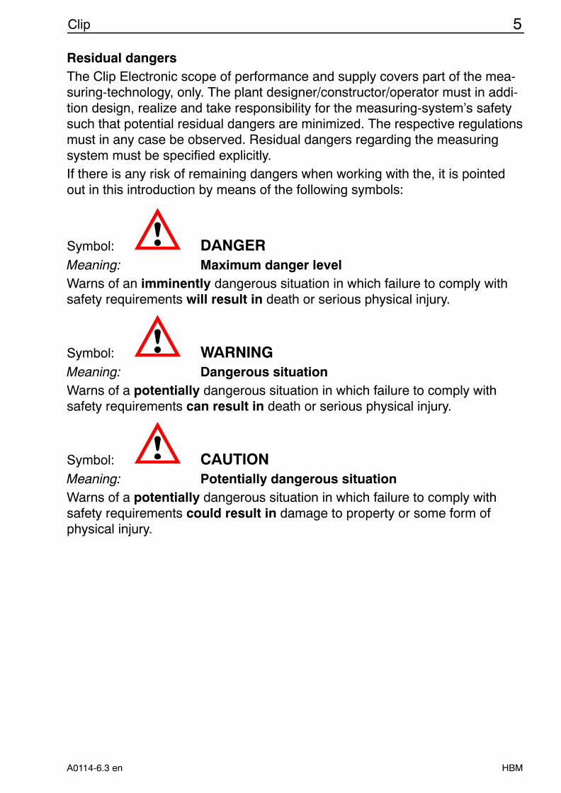
Symbol: DANGERMeaning: Maximum danger levelWarns of an imminently dangerous situation in which failure to comply withsafety requirements will result in death or serious physical injury.
Symbol: WARNINGMeaning: Dangerous situationWarns of a potentially dangerous situation in which failure to comply withsafety requirements can result in death or serious physical injury.
Symbol: CAUTIONMeaning: Potentially dangerous situationWarns of a potentially dangerous situation in which failure to comply withsafety requirements could result in damage to property or some form ofphysical injury.
6 Clip
HBM A0114-6.3 en
Symbols for using advices and helpful information:
Symbol: NOTEMeans that important information about the product or its handling is beinggiven.
Symbol: Meaning: CE markThe CE mark enables the manufacturer to guarantee that the product com-plies with the requirements of the relevant EC directives (see Declaration ofConformity at the end of this document).
Safe operationDo only quit error messages if the reason for the error has been eliminatedand there is no more danger.
Reconstruction and modificationsHBM’s express consent is required for modifications regarding the Clip Elec-tronic construction and safety. HBM does not take responsibility for damageresulting from unauthorized modifications.In particular, repair and soldering works on the boards are prohibited. If com-plete componentry is replaced use original HBM components, only.
Qualified personnelThe device may be used by qualified personnel, only; the technical data andthe special safety regulations must in any case be observed. When using thedevice, the legal and safety regulations for the respective application mustalso be observed. The same applies if accessories are used.Qualified personnel means: personnel familiar with the installation, mounting,start-up and operation of the product, and trained according to their job.Maintenance and repair work on an open device with the power on shouldonly be undertaken by trained personnel who are aware of the above-men-tioned dangers.
7Clip
HBMA0114-6.3 en
1 Application
The measuring amplifiers are suitable for the measurement of mechanicalquantities such as force, weight, torque, pressure, displacement, strain andacceleration. Appropriate transducers complying with the international stan-dards can be connected to the measuring amplifiers.Transducers can be operated in potentially explosive areas, if safety barriersare used.The individual CLIP components can be arranged as desired and are wired byterminals. Switches and potentiometers for adjustment have been provided onthe circuit boards. The accuracy class is 0.1.
The following units are available:• AE101 (DC), AE301/301S6/301S7 (600 Hz CF), AE501 (4.8 kHz CF),
Measuring amplifier
• GR201 Double limit-value switch
• EM201, EM201K2 Output-stage modules with current output
• NT101A, NT102A Power supply units
• TS101 Automatic Tare and Store Unit
8 Clip
HBM A0114-6.3 en
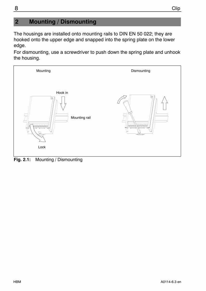
2 Mounting / Dismounting
The housings are installed onto mounting rails to DIN EN 50 022; they arehooked onto the upper edge and snapped into the spring plate on the loweredge.For dismounting, use a screwdriver to push down the spring plate and unhookthe housing.
Hook in
Lock
Mounting rail
Mounting Dismounting
Fig. 2.1: Mounting / Dismounting
9Clip
HBMA0114-6.3 en
3 Connection
Use the 12-pin terminal strip to connect the transducers, to wire the moduleswith each other and to connect the voltage supply. Individual wires can beclamped in a range of 0.13 mm2 ... 1.5 mm2. If two conductor lines are to beconnected to one terminal, e.g. with internal and external connections, theconductor cross-sections must be matched accordingly. End sleeves (withoutplastics hoop, length: 10 mm) should be used to connect the cores to the ter-minals. Cores with or without end sleeves must not be tin-plated. When con-necting the lines, measures should be taken to prevent electrostatic dis-charge.The subsequent figures give the respective connection diagrams that areprinted onto the housing cover.
NOTEThe Clip modules have been designed for installation in closed metallichousings (e. g. control cabinet); they can also be operated without anyadditional housings.The transducer connection lines and the analog signal lines (inputs andoutputs) have to be screened.At the control cabinet, the screening must lie on a screen rail.Supply lines and lines connected to the GR201 relay contacts must bescreened if the cable length exceeds 30 m or if the cables are routed out-side closed buildings.
NOTEOnly after tightening the clamping screws (ensure good contact) will theoutput signal be available on the terminals.
10 Clip
HBM A0114-6.3 en
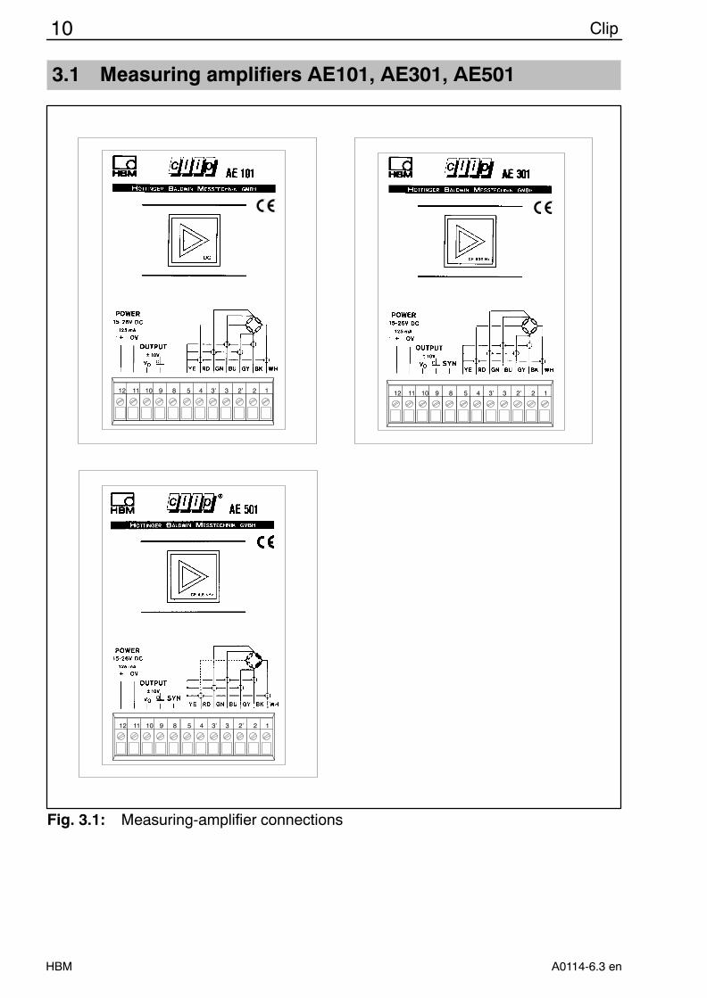
3.1 Measuring amplifiers AE101, AE301, AE501
11 11 11 11 11 11 11 11 11 11 11 11
122’33’4589101112
11 11 11 11 11 11 11 11 11 11 11 11
122’33’4589101112
11 11 11 11 11 11 11 11 11 11 11 11
122’33’4589101112
Fig. 3.1: Measuring-amplifier connections
11Clip
HBMA0114-6.3 en
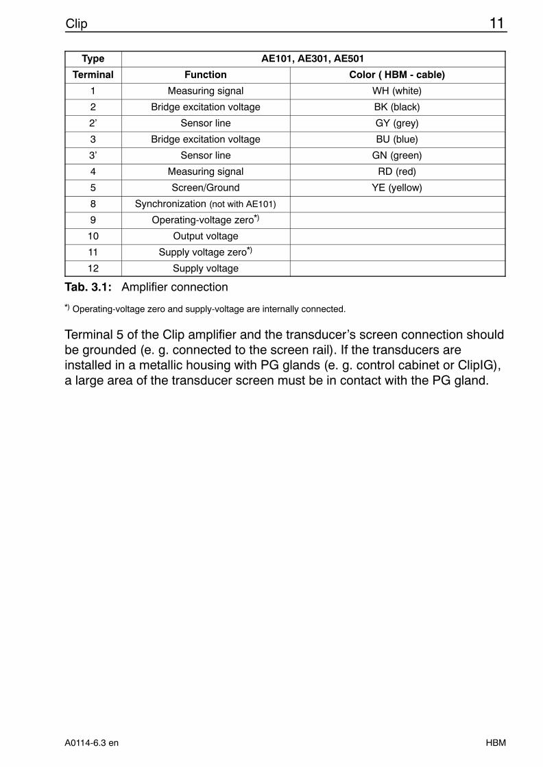
Type AE101, AE301, AE501
Terminal Function Color ( HBM - cable)
1 Measuring signal WH (white)
2 Bridge excitation voltage BK (black)
2’ Sensor line GY (grey)
3 Bridge excitation voltage BU (blue)
3’ Sensor line GN (green)
4 Measuring signal RD (red)
5 Screen/Ground YE (yellow)
8 Synchronization (not with AE101)
9 Operating-voltage zero*)
10 Output voltage
11 Supply voltage zero*)
12 Supply voltage
Tab. 3.1: Amplifier connection
*) Operating-voltage zero and supply-voltage are internally connected.
Terminal 5 of the Clip amplifier and the transducer’s screen connection shouldbe grounded (e. g. connected to the screen rail). If the transducers areinstalled in a metallic housing with PG glands (e. g. control cabinet or ClipIG),a large area of the transducer screen must be in contact with the PG gland.
12 Clip
HBM A0114-6.3 en
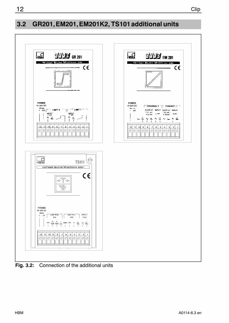
3.2 GR201,EM201,EM201K2, TS101additional units
11 11 11 11 11 11 11 11 11 11 11 11
123456789101112
11 11 11 11 11 11 11 11 11 11 11 11
123456789101112
11 11 11 11 11 11 11 11 11 11 11 11
123456789101112
Fig. 3.2: Connection of the additional units
13Clip
HBMA0114-6.3 en
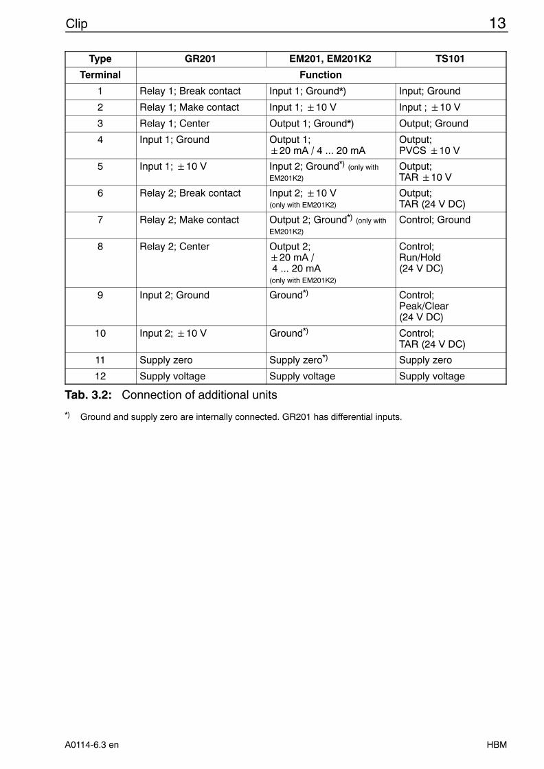
Type GR201 EM201, EM201K2 TS101
Terminal Function
1 Relay 1; Break contact Input 1; Ground*) Input; Ground
2 Relay 1; Make contact Input 1; 10 V Input ; 10 V
3 Relay 1; Center Output 1; Ground*) Output; Ground
4 Input 1; Ground Output 1; 20 mA / 4 ... 20 mA
Output;PVCS 10 V
5 Input 1; 10 V Input 2; Ground*) (only with
EM201K2)
Output;TAR 10 V
6 Relay 2; Break contact Input 2; 10 V(only with EM201K2)
Output;TAR (24 V DC)
7 Relay 2; Make contact Output 2; Ground*) (only with
EM201K2)
Control; Ground
8 Relay 2; Center Output 2; 20 mA / 4 ... 20 mA(only with EM201K2)
Control;Run/Hold(24 V DC)
9 Input 2; Ground Ground*) Control;Peak/Clear(24 V DC)
10 Input 2; 10 V Ground*) Control;TAR (24 V DC)
11 Supply zero Supply zero*) Supply zero
12 Supply voltage Supply voltage Supply voltage
Tab. 3.2: Connection of additional units
*) Ground and supply zero are internally connected. GR201 has differential inputs.
14 Clip
HBM A0114-6.3 en
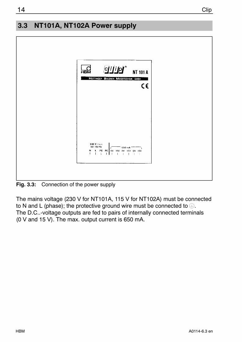
3.3 NT101A, NT102A Power supply
Fig. 3.3: Connection of the power supply
The mains voltage (230 V for NT101A, 115 V for NT102A) must be connectedto N and L (phase); the protective ground wire must be connected to .The D.C..-voltage outputs are fed to pairs of internally connected terminals(0 V and 15 V). The max. output current is 650 mA.
15Clip
HBMA0114-6.3 en
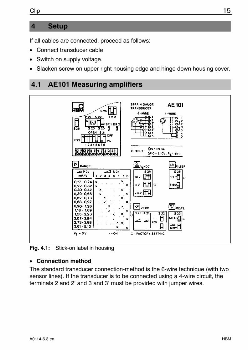
4 Setup
If all cables are connected, proceed as follows:
• Connect transducer cable
• Switch on supply voltage.
• Slacken screw on upper right housing edge and hinge down housing cover.
4.1 AE101 Measuring amplifiers
Fig. 4.1: Stick-on label in housing
• Connection methodThe standard transducer connection-method is the 6-wire technique (with twosensor lines). If the transducer is to be connected using a 4-wire circuit, theterminals 2 and 2’ and 3 and 3’ must be provided with jumper wires.
16 Clip
HBM A0114-6.3 en
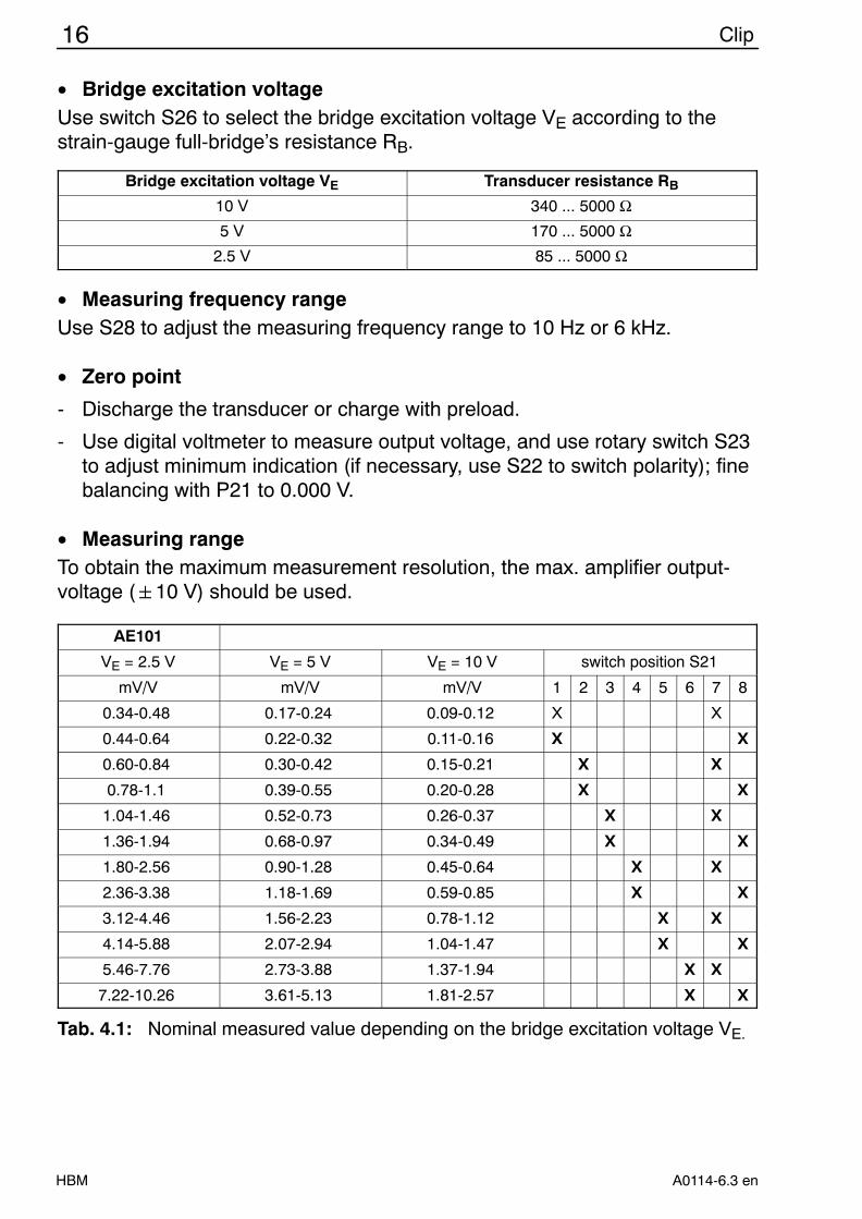
• Bridge excitation voltageUse switch S26 to select the bridge excitation voltage VE according to thestrain-gauge full-bridge’s resistance RB.
Bridge excitation voltage VE Transducer resistance RB
10 V 340 ... 5000 Ω5 V 170 ... 5000 Ω
2.5 V 85 ... 5000 Ω
• Measuring frequency rangeUse S28 to adjust the measuring frequency range to 10 Hz or 6 kHz.
• Zero point
- Discharge the transducer or charge with preload.
- Use digital voltmeter to measure output voltage, and use rotary switch S23to adjust minimum indication (if necessary, use S22 to switch polarity); finebalancing with P21 to 0.000 V.
• Measuring rangeTo obtain the maximum measurement resolution, the max. amplifier output-voltage (10 V) should be used.
AE101
VE = 2.5 V VE = 5 V VE = 10 V switch position S21
mV/V mV/V mV/V 1 2 3 4 5 6 7 8
0.34-0.48 0.17-0.24 0.09-0.12 X X
0.44-0.64 0.22-0.32 0.11-0.16 X X
0.60-0.84 0.30-0.42 0.15-0.21 X X
0.78-1.1 0.39-0.55 0.20-0.28 X X
1.04-1.46 0.52-0.73 0.26-0.37 X X
1.36-1.94 0.68-0.97 0.34-0.49 X X
1.80-2.56 0.90-1.28 0.45-0.64 X X
2.36-3.38 1.18-1.69 0.59-0.85 X X
3.12-4.46 1.56-2.23 0.78-1.12 X X
4.14-5.88 2.07-2.94 1.04-1.47 X X
5.46-7.76 2.73-3.88 1.37-1.94 X X
7.22-10.26 3.61-5.13 1.81-2.57 X X
Tab. 4.1: Nominal measured value depending on the bridge excitation voltage VE.
17Clip
HBMA0114-6.3 en
Part loadNominal load
•10 V
Measuring range in V• Sensitivity in mVV Nominal measurement
value (Range) in mVV
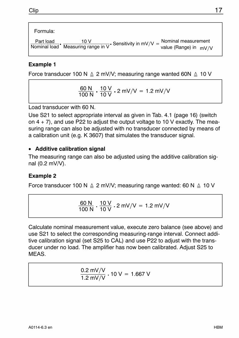
Formula:
Example 1
Force transducer 100 N 2 mV/V; measuring range wanted 60N 10 V
60 N100 N
•10 V10 V
• 2 mVV 1.2 mVV
Load transducer with 60 N.Use S21 to select appropriate interval as given in Tab. 4.1 (page 16) (switchon 4 + 7), and use P22 to adjust the output voltage to 10 V exactly. The mea-suring range can also be adjusted with no transducer connected by means ofa calibration unit (e.g. K 3607) that simulates the transducer signal.
• Additive calibration signalThe measuring range can also be adjusted using the additive calibration sig-nal (0.2 mV/V).
Example 2
Force transducer 100 N 2 mV/V; measuring range wanted: 60 N 10 V
60 N100 N
•10 V10 V
• 2 mVV 1.2 mVV
Calculate nominal measurement value, execute zero balance (see above) anduse S21 to select the corresponding measuring-range interval. Connect addi-tive calibration signal (set S25 to CAL) and use P22 to adjust with the trans-ducer under no load. The amplifier has now been calibrated. Adjust S25 toMEAS.
0.2 mVV1.2 mVV
• 10 V 1.667 V
18 Clip
HBM A0114-6.3 en
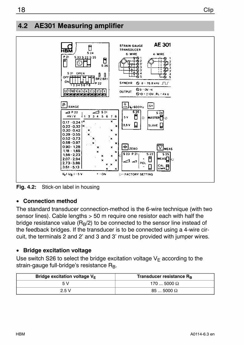
4.2 AE301 Measuring amplifier
Fig. 4.2: Stick-on label in housing
• Connection methodThe standard transducer connection-method is the 6-wire technique (with twosensor lines). Cable lengths > 50 m require one resistor each with half thebridge resistance value (RB/2) to be connected to the sensor line instead ofthe feedback bridges. If the transducer is to be connected using a 4-wire cir-cuit, the terminals 2 and 2’ and 3 and 3’ must be provided with jumper wires.
• Bridge excitation voltageUse switch S26 to select the bridge excitation voltage VE according to thestrain-gauge full-bridge’s resistance RB.
Bridge excitation voltage VE Transducer resistance RB
5 V 170 ... 5000 Ω2.5 V 85 ... 5000 Ω
19Clip
HBMA0114-6.3 en
• Measuring frequency rangeThe measuring frequency range is 10 Hz.
• Zero point
- Discharge the transducer or charge with preload.
- Use digital voltmeter to measure output voltage, and use rotary switch S23to adjust minimum indication (if necessary, use S22 to switch polarity); finebalancing with P21 to 0.000 V.
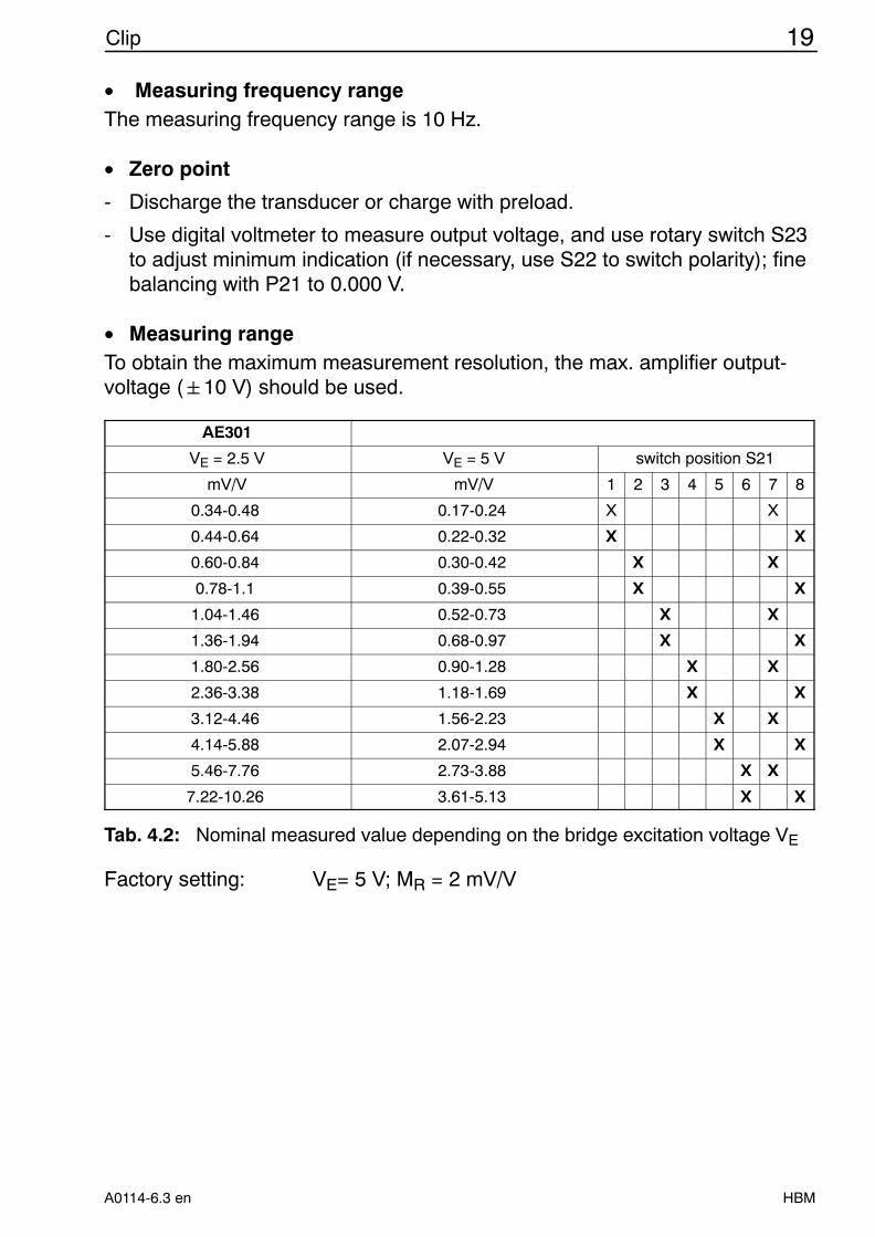
• Measuring rangeTo obtain the maximum measurement resolution, the max. amplifier output-voltage (10 V) should be used.
AE301
VE = 2.5 V VE = 5 V switch position S21
mV/V mV/V 1 2 3 4 5 6 7 8
0.34-0.48 0.17-0.24 X X
0.44-0.64 0.22-0.32 X X
0.60-0.84 0.30-0.42 X X
0.78-1.1 0.39-0.55 X X
1.04-1.46 0.52-0.73 X X
1.36-1.94 0.68-0.97 X X
1.80-2.56 0.90-1.28 X X
2.36-3.38 1.18-1.69 X X
3.12-4.46 1.56-2.23 X X
4.14-5.88 2.07-2.94 X X
5.46-7.76 2.73-3.88 X X
7.22-10.26 3.61-5.13 X X
Tab. 4.2: Nominal measured value depending on the bridge excitation voltage VE
Factory setting: VE= 5 V; MR = 2 mV/V
20 Clip
HBM A0114-6.3 en
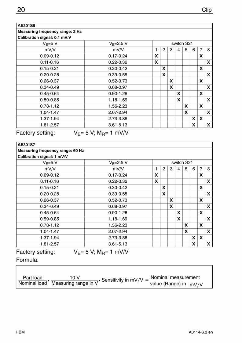
AE301S6Measuring frequency range: 2 HzCalibration signal: 0.1 mV/V
VE=5 V VE=2.5 V switch S21mV/V mV/V 1 2 3 4 5 6 7 8
0.09-0.12 0.17-0.24 X X0.11-0.16 0.22-0.32 X X0.15-0.21 0.30-0.42 X X0.20-0.28 0.39-0.55 X X0.26-0.37 0.52-0.73 X X0.34-0.49 0.68-0.97 X X0.45-0.64 0.90-1.28 X X0.59-0.85 1.18-1.69 X X0.78-1.12 1.56-2.23 X X1.04-1.47 2.07-2.94 X X1.37-1.94 2.73-3.88 X X1.81-2.57 3.61-5.13 X X
Factory setting: VE= 5 V; MR= 1 mV/V
AE301S7Measuring frequency range: 60 HzCalibration signal: 1 mV/V
VE=5 V VE=2.5 V switch S21mV/V mV/V 1 2 3 4 5 6 7 8
0.09-0.12 0.17-0.24 X X0.11-0.16 0.22-0.32 X X0.15-0.21 0.30-0.42 X X0.20-0.28 0.39-0.55 X X0.26-0.37 0.52-0.73 X X0.34-0.49 0.68-0.97 X X0.45-0.64 0.90-1.28 X X0.59-0.85 1.18-1.69 X X0.78-1.12 1.56-2.23 X X1.04-1.47 2.07-2.94 X X1.37-1.94 2.73-3.88 X X1.81-2.57 3.61-5.13 X X
Factory setting: VE= 5 V; MR= 1 mV/VFormula:
Part loadNominal load
•10 V
Measuring range in V• Sensitivity in mVV Nominal measurement
value (Range) in mVV
21Clip
HBMA0114-6.3 en
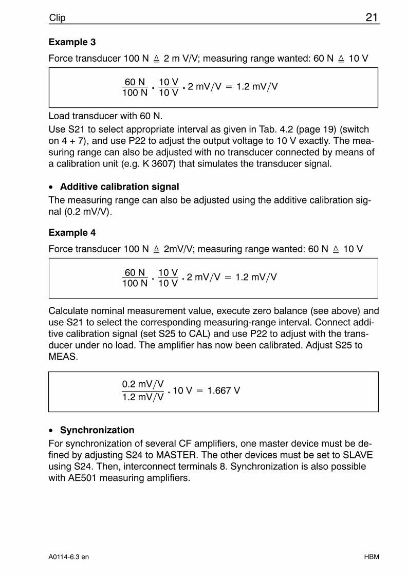
Example 3
Force transducer 100 N 2 m V/V; measuring range wanted: 60 N 10 V
60 N100 N
•10 V10 V
• 2 mVV 1.2 mVV
Load transducer with 60 N.Use S21 to select appropriate interval as given in Tab. 4.2 (page 19) (switchon 4 + 7), and use P22 to adjust the output voltage to 10 V exactly. The mea-suring range can also be adjusted with no transducer connected by means ofa calibration unit (e.g. K 3607) that simulates the transducer signal.
• Additive calibration signalThe measuring range can also be adjusted using the additive calibration sig-nal (0.2 mV/V).
Example 4
Force transducer 100 N 2mV/V; measuring range wanted: 60 N 10 V
60 N100 N
•10 V10 V
• 2 mVV 1.2 mVV
Calculate nominal measurement value, execute zero balance (see above) anduse S21 to select the corresponding measuring-range interval. Connect addi-tive calibration signal (set S25 to CAL) and use P22 to adjust with the trans-ducer under no load. The amplifier has now been calibrated. Adjust S25 toMEAS.
0.2 mVV1.2 mVV
• 10 V 1.667 V
• SynchronizationFor synchronization of several CF amplifiers, one master device must be de-fined by adjusting S24 to MASTER. The other devices must be set to SLAVEusing S24. Then, interconnect terminals 8. Synchronization is also possiblewith AE501 measuring amplifiers.
22 Clip
HBM A0114-6.3 en
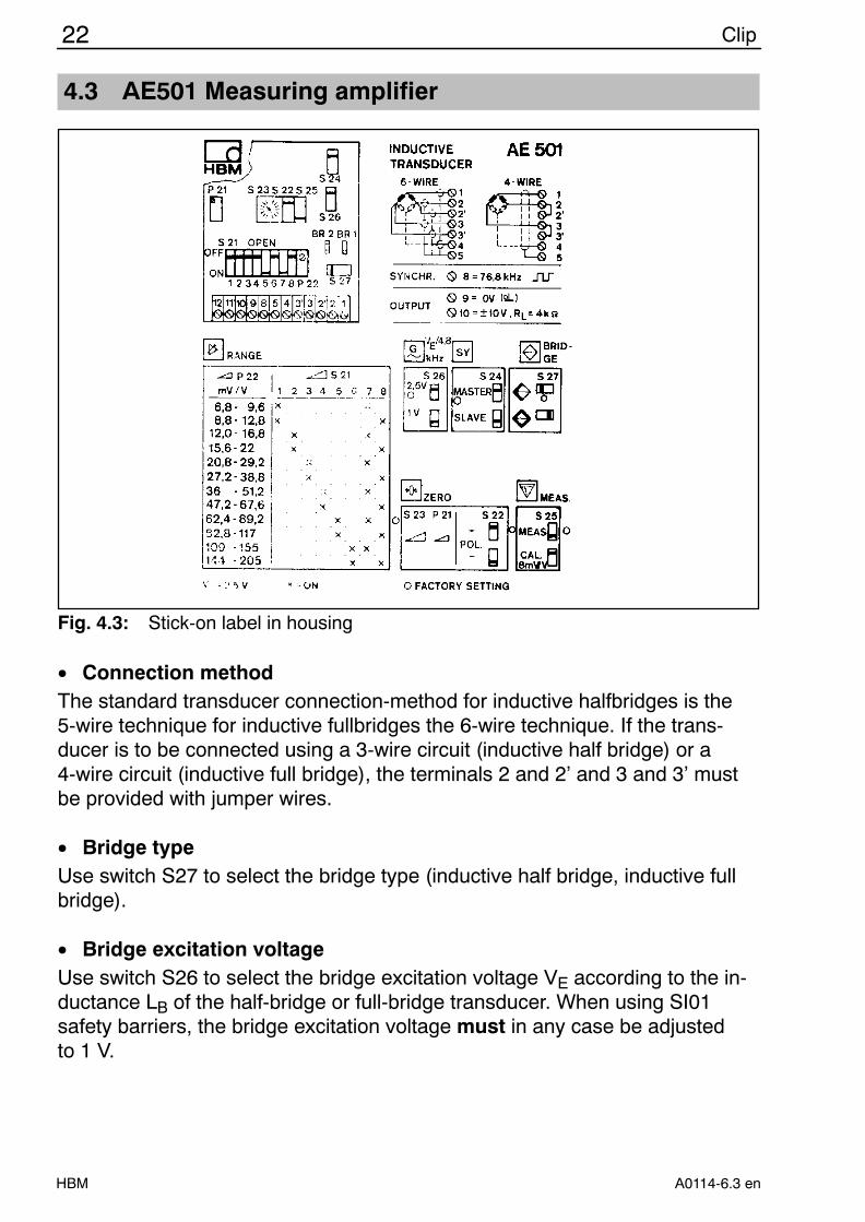
4.3 AE501 Measuring amplifier
Fig. 4.3: Stick-on label in housing
• Connection methodThe standard transducer connection-method for inductive halfbridges is the5-wire technique for inductive fullbridges the 6-wire technique. If the trans-ducer is to be connected using a 3-wire circuit (inductive half bridge) or a4-wire circuit (inductive full bridge), the terminals 2 and 2’ and 3 and 3’ mustbe provided with jumper wires.
• Bridge typeUse switch S27 to select the bridge type (inductive half bridge, inductive fullbridge).
• Bridge excitation voltageUse switch S26 to select the bridge excitation voltage VE according to the in-ductance LB of the half-bridge or full-bridge transducer. When using SI01safety barriers, the bridge excitation voltage must in any case be adjusted to 1 V.
23Clip
HBMA0114-6.3 en
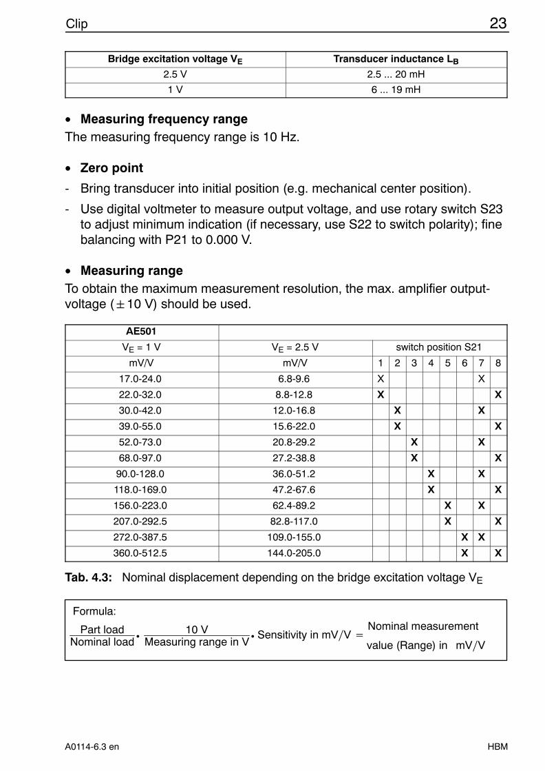
Bridge excitation voltage VE Transducer inductance LB
2.5 V 2.5 ... 20 mH
1 V 6 ... 19 mH
• Measuring frequency rangeThe measuring frequency range is 10 Hz.
• Zero point
- Bring transducer into initial position (e.g. mechanical center position).
- Use digital voltmeter to measure output voltage, and use rotary switch S23to adjust minimum indication (if necessary, use S22 to switch polarity); finebalancing with P21 to 0.000 V.
• Measuring rangeTo obtain the maximum measurement resolution, the max. amplifier output-voltage (10 V) should be used.
AE501
VE = 1 V VE = 2.5 V switch position S21
mV/V mV/V 1 2 3 4 5 6 7 8
17.0-24.0 6.8-9.6 X X
22.0-32.0 8.8-12.8 X X
30.0-42.0 12.0-16.8 X X
39.0-55.0 15.6-22.0 X X
52.0-73.0 20.8-29.2 X X
68.0-97.0 27.2-38.8 X X
90.0-128.0 36.0-51.2 X X
118.0-169.0 47.2-67.6 X X
156.0-223.0 62.4-89.2 X X
207.0-292.5 82.8-117.0 X X
272.0-387.5 109.0-155.0 X X
360.0-512.5 144.0-205.0 X X
Tab. 4.3: Nominal displacement depending on the bridge excitation voltage VE
Part loadNominal load
•10 V
Measuring range in V• Sensitivity in mVV
Nominal measurement
value (Range) in mVV
Formula:
24 Clip
HBM A0114-6.3 en
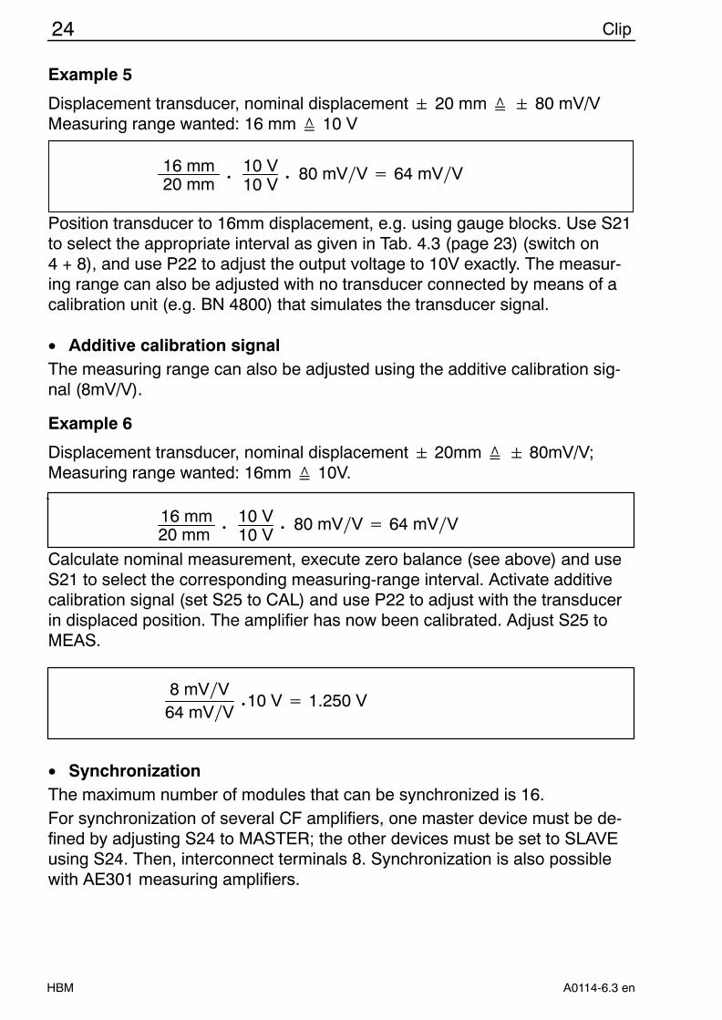
Example 5
Displacement transducer, nominal displacement 20 mm 80 mV/VMeasuring range wanted: 16 mm 10 V
16 mm20 mm
•10 V10 V
• 80 mVV 64 mVV
Position transducer to 16mm displacement, e.g. using gauge blocks. Use S21to select the appropriate interval as given in Tab. 4.3 (page 23) (switch on4 + 8), and use P22 to adjust the output voltage to 10V exactly. The measur-ing range can also be adjusted with no transducer connected by means of acalibration unit (e.g. BN 4800) that simulates the transducer signal.
• Additive calibration signalThe measuring range can also be adjusted using the additive calibration sig-nal (8mV/V).
Example 6
Displacement transducer, nominal displacement 20mm 80mV/V;Measuring range wanted: 16mm 10V.
16 mm20 mm
•10 V10 V
• 80 mVV 64 mVV
Calculate nominal measurement, execute zero balance (see above) and useS21 to select the corresponding measuring-range interval. Activate additivecalibration signal (set S25 to CAL) and use P22 to adjust with the transducerin displaced position. The amplifier has now been calibrated. Adjust S25 toMEAS.
8 mVV64 mVV
• 10 V 1.250 V
• SynchronizationThe maximum number of modules that can be synchronized is 16.For synchronization of several CF amplifiers, one master device must be de-fined by adjusting S24 to MASTER; the other devices must be set to SLAVEusing S24. Then, interconnect terminals 8. Synchronization is also possiblewith AE301 measuring amplifiers.
25Clip
HBMA0114-6.3 en
4.4 GR201 Double limit-value switch
M 4
M 3
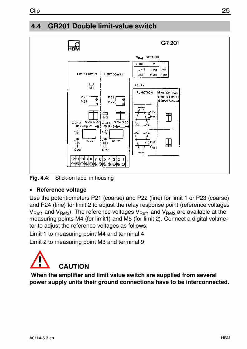
Fig. 4.4: Stick-on label in housing
• Reference voltageUse the potentiometers P21 (coarse) and P22 (fine) for limit 1 or P23 (coarse)and P24 (fine) for limit 2 to adjust the relay response point (reference voltagesVRef1 and VRef2). The reference voltages VRef1 and VRef2 are available at themeasuring points M4 (for limit1) and M5 (for limit 2). Connect a digital voltme-ter to adjust the reference voltages as follows:Limit 1 to measuring point M4 and terminal 4Limit 2 to measuring point M3 and terminal 9
CAUTION When the amplifier and limit value switch are supplied from severalpower supply units their ground connections have to be interconnected.
26 Clip
HBM A0114-6.3 en
• Switching directionThere are two possible switching directions.
1. S23/24 and S27/28 in upper positionThe make contact (terminal 2 or 7) closes upon exceeding of reference volt-age VRef and opens upon falling below reference voltage VRef minus the hys-teresis voltage VHys.
Contactopen
Contactclosed
VRef
VHys
VI
Contactopen
t
Fig. 4.5: GR201 Switching behavior, S23/24 and S27/28 in upper position
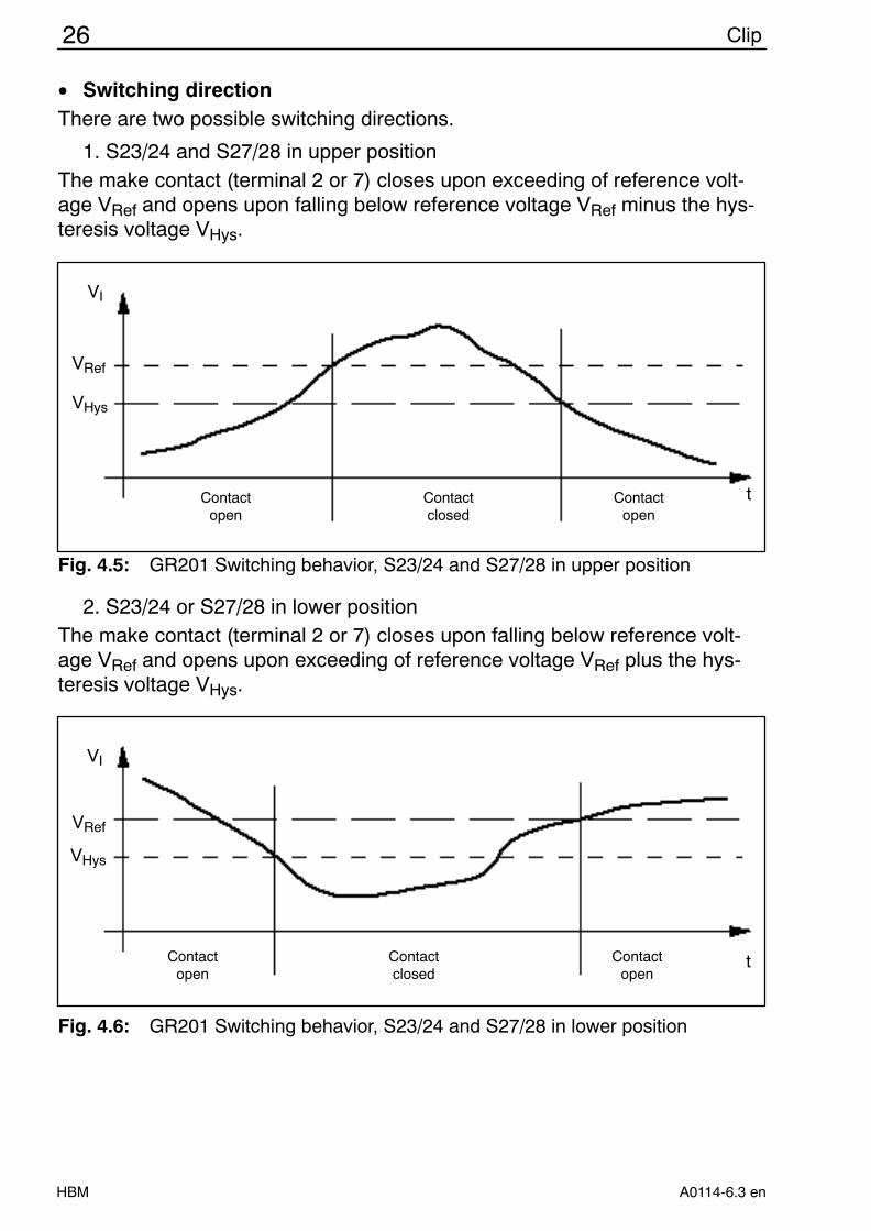
2. S23/24 or S27/28 in lower position
The make contact (terminal 2 or 7) closes upon falling below reference volt-age VRef and opens upon exceeding of reference voltage VRef plus the hys-teresis voltage VHys.
VRef
VHys
VI
Contactopen
Contactclosed
Contactopen
t
Fig. 4.6: GR201 Switching behavior, S23/24 and S27/28 in lower position
27Clip
HBMA0114-6.3 en
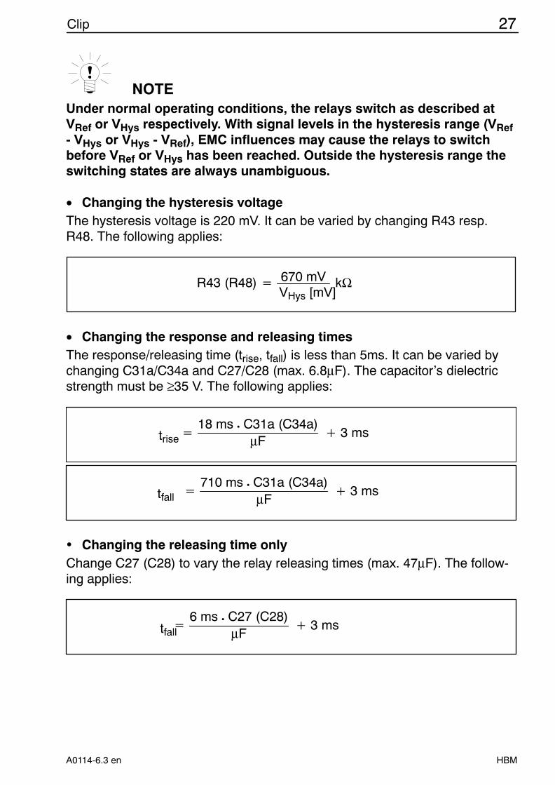
NOTEUnder normal operating conditions, the relays switch as described atVRef or VHys respectively. With signal levels in the hysteresis range (VRef- VHys or VHys - VRef), EMC influences may cause the relays to switchbefore VRef or VHys has been reached. Outside the hysteresis range theswitching states are always unambiguous.
• Changing the hysteresis voltageThe hysteresis voltage is 220 mV. It can be varied by changing R43 resp.R48. The following applies:
R43 (R48) 670 mV kΩVHys [mV]
• Changing the response and releasing timesThe response/releasing time (trise, tfall) is less than 5ms. It can be varied bychanging C31a/C34a and C27/C28 (max. 6.8µF). The capacitor’s dielectricstrength must be ≥35 V. The following applies:
18 ms • C31a (C34a)µF
3 mstrise
710 ms • C31a (C34a)µF
3 mstfall
w Changing the releasing time onlyChange C27 (C28) to vary the relay releasing times (max. 47µF). The follow-ing applies:
6 ms • C27 (C28)µF
3 mstfall
28 Clip
HBM A0114-6.3 en
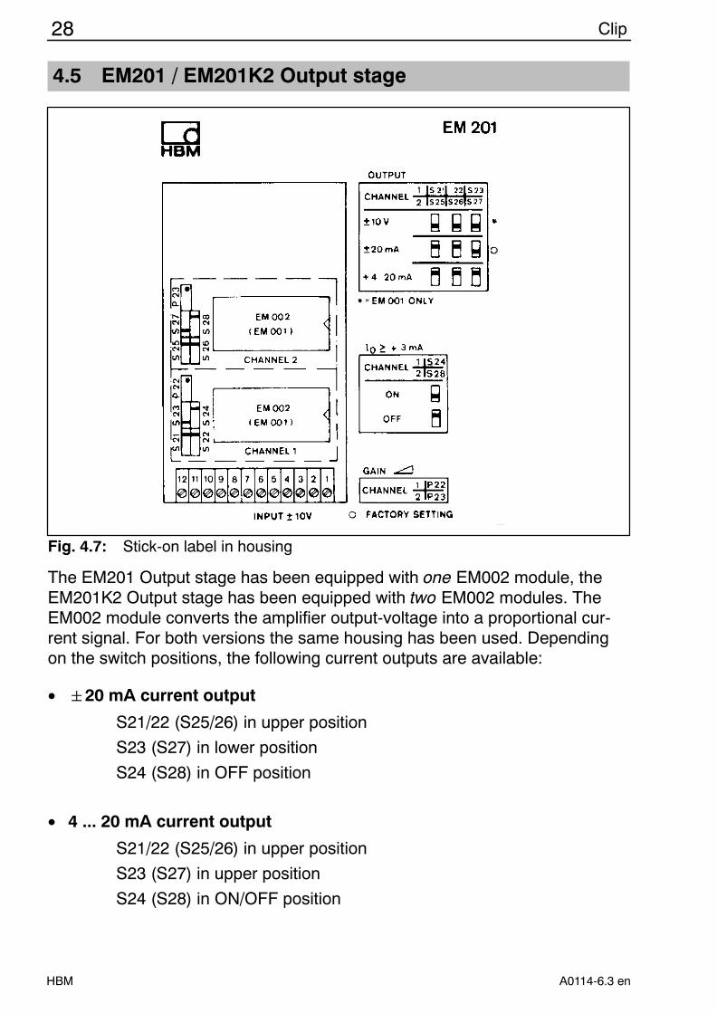
4.5 EM201 / EM201K2 Output stage
Fig. 4.7: Stick-on label in housing
The EM201 Output stage has been equipped with one EM002 module, theEM201K2 Output stage has been equipped with two EM002 modules. TheEM002 module converts the amplifier output-voltage into a proportional cur-rent signal. For both versions the same housing has been used. Dependingon the switch positions, the following current outputs are available:
• 20 mA current output
S21/22 (S25/26) in upper position
S23 (S27) in lower position
S24 (S28) in OFF position
• 4 ... 20 mA current output
S21/22 (S25/26) in upper position
S23 (S27) in upper position
S24 (S28) in ON/OFF position
29Clip
HBMA0114-6.3 en
With S24 (S28) ON, the minimum output current is 3 mA. Even with negativeinput voltages, this value will not be fallen below. Consequently, a followingdevice that monitors an interruption of cable, for example, will not respond er-roneously, or an externally supplied following device will be supplied continu-ously.
• GainUse P22 (P23) to adjust the gain for both output stages in the range of 0.9 ... 1.1 Instead of the EM002 module, the EM001 module can also beused. It makes available an additional 10 V/20 mA voltage output. A sepa-rate zero balance is also possible.
• Zero balanceSince a zero balance is not provided in the EM002 module, the zero point hasto be adjust on the amplifier.
30 Clip
HBM A0114-6.3 en
5 TS101 Automatic tare and store unit
5.1 General
The TS101 automatic tare and store unit is an additional Clip electronics mod-ule for further signal processing. The TS101 enables signals supplied by anamplifier connected in series to be tared and stored.
5.2 Function
The TS101 enables the below functions to be activated at the same time:
D tare and save a current value or a peak value (Minimum value or maximumvalue or peak-to-peak-value or envelope curve)
or
D save minimum value and maximum value (no taring)
5.2.1 Taring
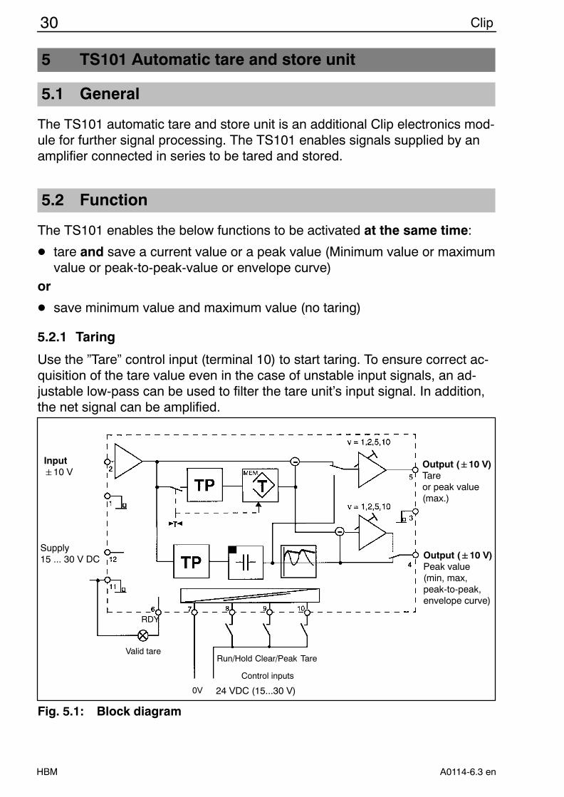
Use the ”Tare” control input (terminal 10) to start taring. To ensure correct ac-quisition of the tare value even in the case of unstable input signals, an ad-justable low-pass can be used to filter the tare unit’s input signal. In addition,the net signal can be amplified.
Input10 V
Control inputs
RDY
0V 24 VDC (15...30 V)
Valid tareClear/Peak TareRun/Hold
Output ("10 V)Tareor peak value(max.)
Output ("10 V)Peak value(min, max, peak-to-peak,envelope curve)
Supply15 ... 30 V DC
Fig. 5.1: Block diagram
31Clip
HBMA0114-6.3 en
5.2.2 Store unit
Upon storage, you can select as input signal for the store unit either the ampli-fier signal (gross signal) or the tare unit’s output signal (net signal, not ampli-fied). The selected input signal as well can be filtered and amplified. Use ter-minals 8 and 9 to control the store unit’s operating mode (current value/peakvalue) and the Run/Hold function. With the ”High” level the control output(RDY) signals a valid tare value.
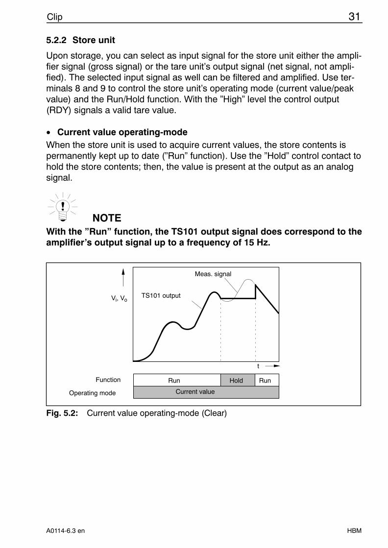
• Current value operating-modeWhen the store unit is used to acquire current values, the store contents ispermanently kept up to date (”Run” function). Use the ”Hold” control contact tohold the store contents; then, the value is present at the output as an analogsignal.
NOTEWith the ”Run” function, the TS101 output signal does correspond to theamplifier’s output signal up to a frequency of 15 Hz.
TS101 output
Meas. signal
t
Hold
Vi, Vo
Run RunFunction
Operating mode Current value
Fig. 5.2: Current value operating-mode (Clear)
32 Clip
HBM A0114-6.3 en
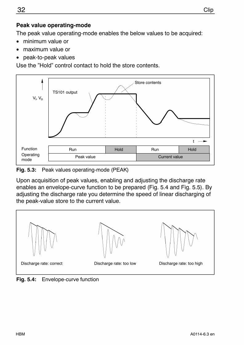
Peak value operating-modeThe peak value operating-mode enables the below values to be acquired:• minimum value or• maximum value or• peak-to-peak valuesUse the ”Hold” control contact to hold the store contents.
Store contents
TS101 output
t
Vi, Vo
HoldRun RunFunctionOperatingmode
Peak value Current value
Hold
Fig. 5.3: Peak values operating-mode (PEAK)
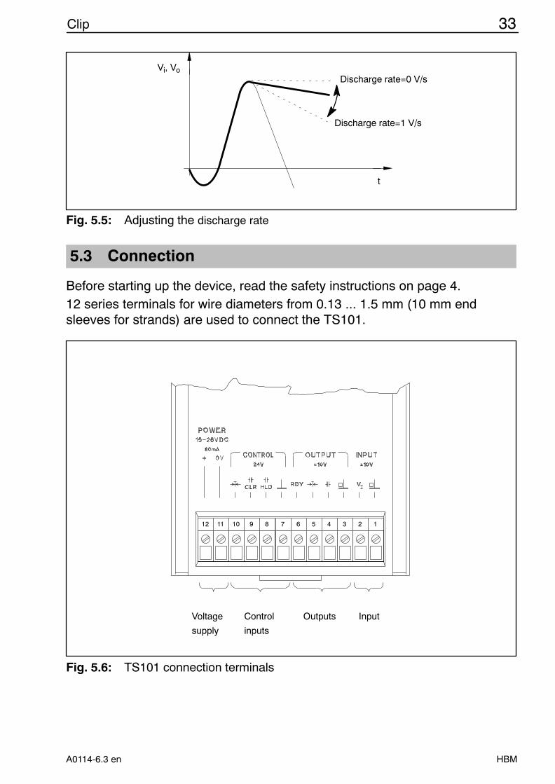
Upon acquisition of peak values, enabling and adjusting the discharge rateenables an envelope-curve function to be prepared (Fig. 5.4 and Fig. 5.5). Byadjusting the discharge rate you determine the speed of linear discharging ofthe peak-value store to the current value.
Discharge rate: too highDischarge rate: too lowDischarge rate: correct
Fig. 5.4: Envelope-curve function
33Clip
HBMA0114-6.3 en
Discharge rate=0 V/s
Discharge rate=1 V/s
t
Vi, Vo
Fig. 5.5: Adjusting the discharge rate
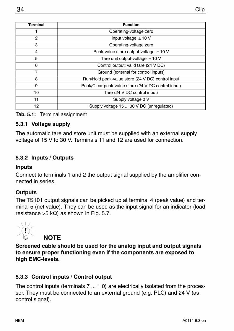
5.3 Connection
Before starting up the device, read the safety instructions on page 4.12 series terminals for wire diameters from 0.13 ... 1.5 mm (10 mm endsleeves for strands) are used to connect the TS101.
11
12
11
11
11
10
11
9
11
8
11
7
11
6
11
5
11
4
11
3
11
2
11
1
InputOutputsControl
inputs
Voltage
supply
Fig. 5.6: TS101 connection terminals
34 Clip
HBM A0114-6.3 en
Terminal Function
1 Operating-voltage zero
2 Input voltage 10 V
3 Operating-voltage zero
4 Peak-value store output-voltage 10 V
5 Tare unit output-voltage 10 V
6 Control output: valid tare (24 V DC)
7 Ground (external for control inputs)
8 Run/Hold peak-value store (24 V DC) control input
9 Peak/Clear peak-value store (24 V DC control input)
10 Tare (24 V DC control input)
11 Supply voltage 0 V
12 Supply voltage 15 ... 30 V DC (unregulated)
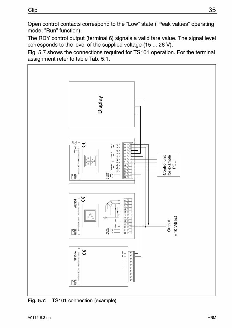
Tab. 5.1: Terminal assignment
5.3.1 Voltage supply
The automatic tare and store unit must be supplied with an external supplyvoltage of 15 V to 30 V. Terminals 11 and 12 are used for connection.
5.3.2 Inputs / Outputs
InputsConnect to terminals 1 and 2 the output signal supplied by the amplifier con-nected in series.
OutputsThe TS101 output signals can be picked up at terminal 4 (peak value) and ter-minal 5 (net value). They can be used as the input signal for an indicator (loadresistance >5 kΩ) as shown in Fig. 5.7.
NOTEScreened cable should be used for the analog input and output signalsto ensure proper functioning even if the components are exposed tohigh EMC-levels.
5.3.3 Control inputs / Control output
The control inputs (terminals 7 ... 1 0) are electrically isolated from the proces-sor. They must be connected to an external ground (e.g. PLC) and 24 V (ascontrol signal).
35Clip
HBMA0114-6.3 en
Open control contacts correspond to the ”Low” state (”Peak values” operatingmode; ”Run” function).The RDY control output (terminal 6) signals a valid tare value. The signal levelcorresponds to the level of the supplied voltage (15 ... 26 V).Fig. 5.7 shows the connections required for TS101 operation. For the terminalassignment refer to table Tab. 5.1.
111111111111111111111111
111111111111111111111111
Out
put
12
34
56
78
910
1112
2’3’
12
45
89
1011
123
10
V/5
kΩ
Fig. 5.7: TS101 connection (example)
36 Clip
HBM A0114-6.3 en
5.4 Adjustment
5.4.1 Factory setup
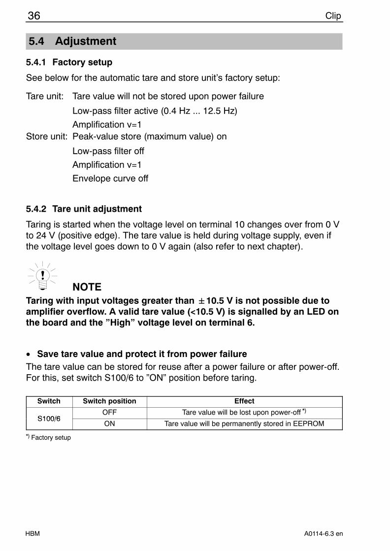
See below for the automatic tare and store unit’s factory setup:
Tare unit: Tare value will not be stored upon power failure
Low-pass filter active (0.4 Hz ... 12.5 Hz)
Amplification v=1Store unit: Peak-value store (maximum value) on
Low-pass filter off
Amplification v=1
Envelope curve off
5.4.2 Tare unit adjustment
Taring is started when the voltage level on terminal 10 changes over from 0 Vto 24 V (positive edge). The tare value is held during voltage supply, even ifthe voltage level goes down to 0 V again (also refer to next chapter).
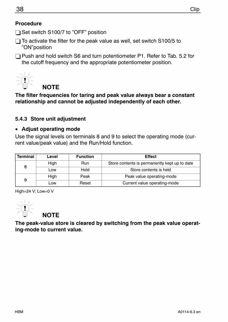
NOTETaring with input voltages greater than "10.5 V is not possible due toamplifier overflow. A valid tare value (<10.5 V) is signalled by an LED onthe board and the ”High” voltage level on terminal 6.
• Save tare value and protect it from power failureThe tare value can be stored for reuse after a power failure or after power-off.For this, set switch S100/6 to ”ON” position before taring.
Switch Switch position Effect
S100/6OFF Tare value will be lost upon power-off *)
S100/6ON Tare value will be permanently stored in EEPROM
*) Factory setup
37Clip
HBMA0114-6.3 en
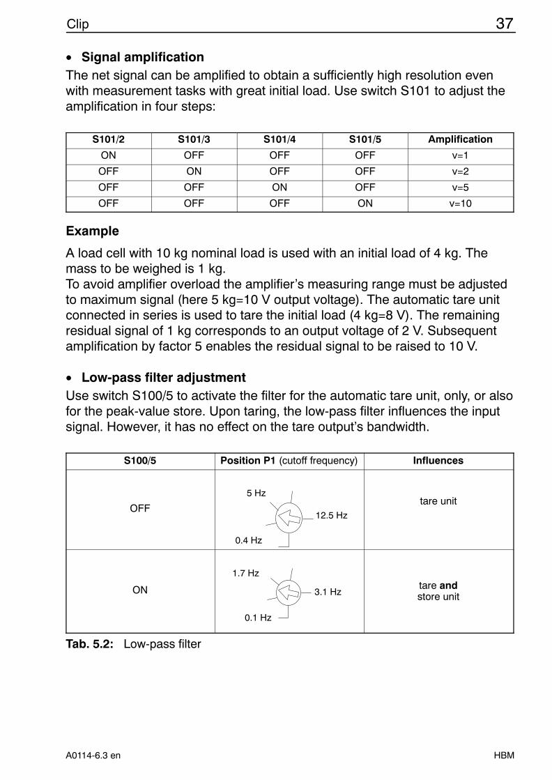
• Signal amplificationThe net signal can be amplified to obtain a sufficiently high resolution evenwith measurement tasks with great initial load. Use switch S101 to adjust theamplification in four steps:
S101/2 S101/3 S101/4 S101/5 Amplification
ON OFF OFF OFF v=1
OFF ON OFF OFF v=2
OFF OFF ON OFF v=5
OFF OFF OFF ON v=10
Example
A load cell with 10 kg nominal load is used with an initial load of 4 kg. Themass to be weighed is 1 kg.To avoid amplifier overload the amplifier’s measuring range must be adjustedto maximum signal (here 5 kg=10 V output voltage). The automatic tare unitconnected in series is used to tare the initial load (4 kg=8 V). The remainingresidual signal of 1 kg corresponds to an output voltage of 2 V. Subsequentamplification by factor 5 enables the residual signal to be raised to 10 V.
• Low-pass filter adjustmentUse switch S100/5 to activate the filter for the automatic tare unit, only, or alsofor the peak-value store. Upon taring, the low-pass filter influences the inputsignal. However, it has no effect on the tare output’s bandwidth.
S100/5 Position P1 (cutoff frequency) Influences
OFF
0.4 Hz
12.5 Hz
5 Hztare unit
ON
0.1 Hz
3.1 Hz
1.7 Hztare andstore unit
Tab. 5.2: Low-pass filter
38 Clip
HBM A0114-6.3 en
Procedure
−Set switch S100/7 to ”OFF” position
−To activate the filter for the peak value as well, set switch S100/5 to”ON”position
−Push and hold switch S6 and turn potentiometer P1. Refer to Tab. 5.2 forthe cutoff frequency and the appropriate potentiometer position.
NOTEThe filter frequencies for taring and peak value always bear a constantrelationship and cannot be adjusted independently of each other.
5.4.3 Store unit adjustment
• Adjust operating modeUse the signal levels on terminals 8 and 9 to select the operating mode (cur-rent value/peak value) and the Run/Hold function.
Terminal Level Function Effect
8High Run Store contents is permanently kept up to date
8Low Hold Store contents is held
9High Peak Peak value operating-mode
9Low Reset Current value operating-mode
High=24 V; Low=0 V
NOTEThe peak-value store is cleared by switching from the peak value operat-ing-mode to current value.
39Clip
HBMA0114-6.3 en
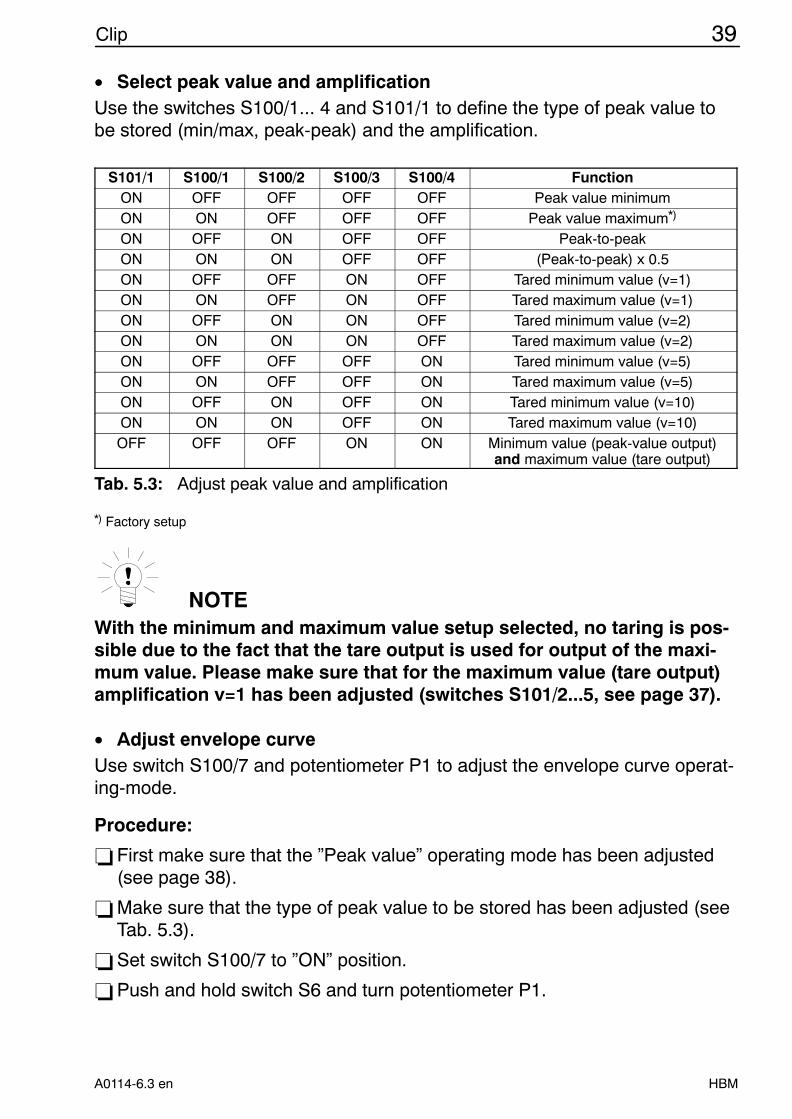
• Select peak value and amplificationUse the switches S100/1... 4 and S101/1 to define the type of peak value tobe stored (min/max, peak-peak) and the amplification.
S101/1 S100/1 S100/2 S100/3 S100/4 FunctionON OFF OFF OFF OFF Peak value minimumON ON OFF OFF OFF Peak value maximum*)
ON OFF ON OFF OFF Peak-to-peakON ON ON OFF OFF (Peak-to-peak) x 0.5ON OFF OFF ON OFF Tared minimum value (v=1)ON ON OFF ON OFF Tared maximum value (v=1)ON OFF ON ON OFF Tared minimum value (v=2)ON ON ON ON OFF Tared maximum value (v=2)ON OFF OFF OFF ON Tared minimum value (v=5)ON ON OFF OFF ON Tared maximum value (v=5)ON OFF ON OFF ON Tared minimum value (v=10)ON ON ON OFF ON Tared maximum value (v=10)OFF OFF OFF ON ON Minimum value (peak-value output)
and maximum value (tare output)
Tab. 5.3: Adjust peak value and amplification
*) Factory setup
NOTEWith the minimum and maximum value setup selected, no taring is pos-sible due to the fact that the tare output is used for output of the maxi-mum value. Please make sure that for the maximum value (tare output)amplification v=1 has been adjusted (switches S101/2...5, see page 37).
• Adjust envelope curveUse switch S100/7 and potentiometer P1 to adjust the envelope curve operat-ing-mode.
Procedure:
−First make sure that the ”Peak value” operating mode has been adjusted(see page 38).
−Make sure that the type of peak value to be stored has been adjusted (seeTab. 5.3).
−Set switch S100/7 to ”ON” position.
−Push and hold switch S6 and turn potentiometer P1.
40 Clip
HBM A0114-6.3 en
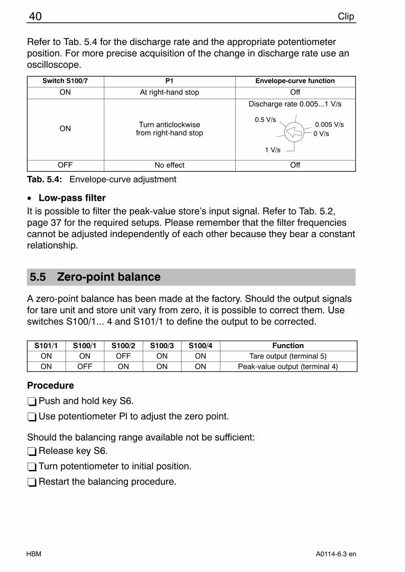
Refer to Tab. 5.4 for the discharge rate and the appropriate potentiometerposition. For more precise acquisition of the change in discharge rate use anoscilloscope.
Switch S100/7 P1 Envelope-curve function
ON At right-hand stop Off
ON Turn anticlockwisefrom right-hand stop
Discharge rate 0.005...1 V/s
1 V/s
0 V/s0.005 V/s
0.5 V/s
OFF No effect Off
Tab. 5.4: Envelope-curve adjustment
• Low-pass filterIt is possible to filter the peak-value store’s input signal. Refer to Tab. 5.2,page 37 for the required setups. Please remember that the filter frequenciescannot be adjusted independently of each other because they bear a constantrelationship.
5.5 Zero-point balance
A zero-point balance has been made at the factory. Should the output signalsfor tare unit and store unit vary from zero, it is possible to correct them. Useswitches S100/1... 4 and S101/1 to define the output to be corrected.
S101/1 S100/1 S100/2 S100/3 S100/4 FunctionON ON OFF ON ON Tare output (terminal 5)ON OFF ON ON ON Peak-value output (terminal 4)
Procedure
−Push and hold key S6.
−Use potentiometer Pl to adjust the zero point.
Should the balancing range available not be sufficient:−Release key S6.
−Turn potentiometer to initial position.
−Restart the balancing procedure.
41Clip
HBMA0114-6.3 en
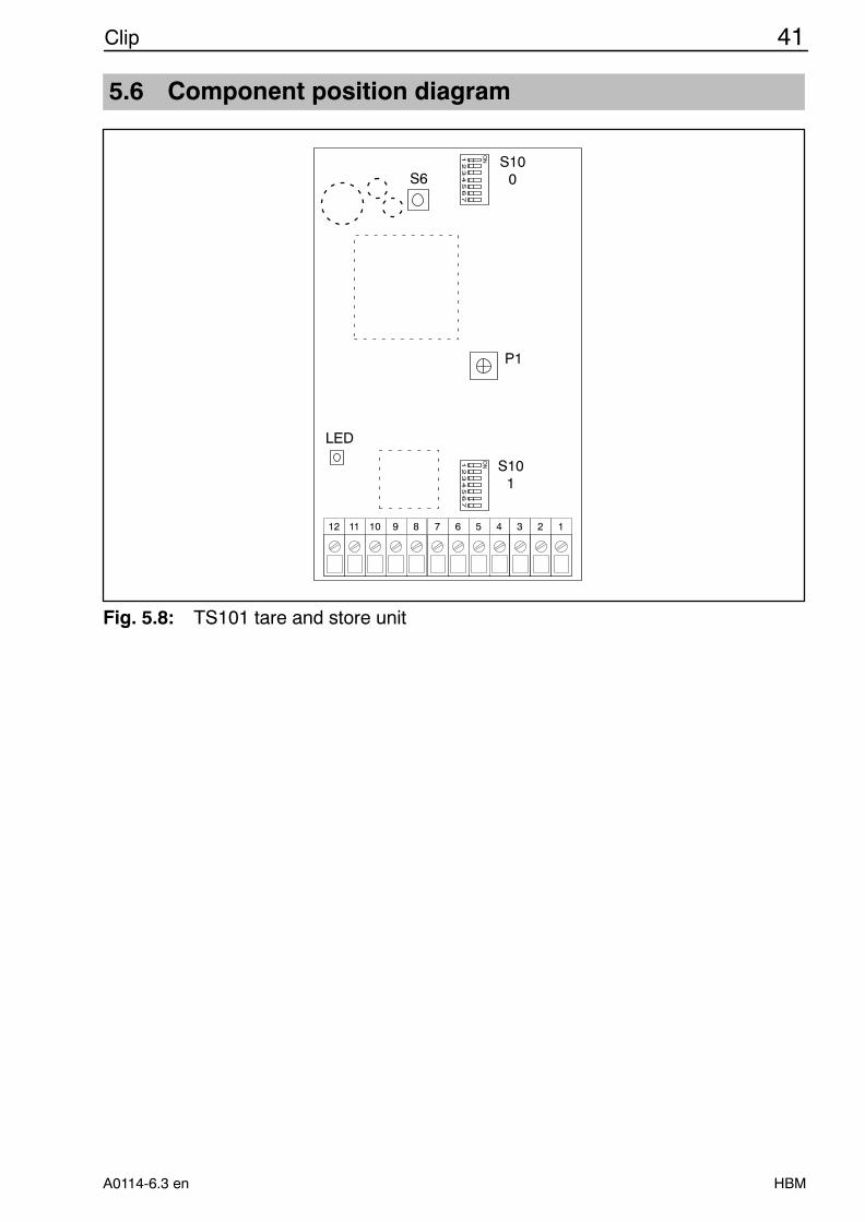
5.6 Component position diagram
11
12
11
11
11
10
11
9
11
8
11
7
11
6
11
5
11
4
11
3
11
2
11
1
S100
S101
P1
LED
S6
Fig. 5.8: TS101 tare and store unit
42 Clip
HBM A0114-6.3 en
6 Safety barriers
Connect HBM safety barriers to obtain intrinsically safe measuring circuits[EEx ia] IIC. A test certificate is required for transducers used in such applica-tions.
Measuring amplifier Safety barrier
AE101 SD01A
AE301 SD01A
Due to the safety barriers’ high internal resistance, the bridge excitation volt-age VE must be reduced according to the transducer resistance RB or thetransducer inductance LB respectively. Refer to the below table to obtain theminimum permissible transducer resistance.
Measuring amplifier VE RB (minimum)*), LB
AE101 10 V not permissible
5 V 320 Ω2.5 V 130 Ω
AE301 5 V 320 Ω2.5 V 130 Ω
*) With longer cables the supply-line resistance must be added.
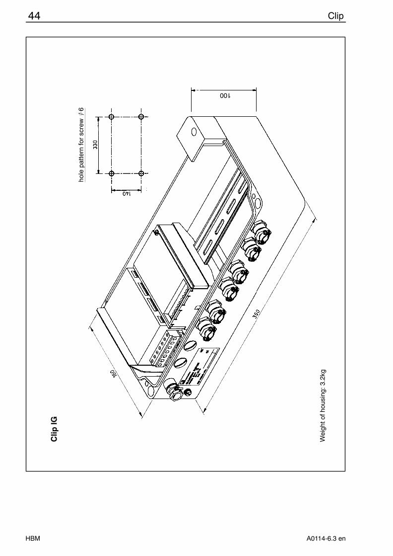
7 CLIP IG
For use in industrial environments, the CLIP modules can be installed in analuminium-die-cast wall housing. The degree of protection is IP65. The hous-ing enables max. 4 modules incl. power supply unit to be inserted; it is alsopossible to insert two measuring amplifiers with safety barriers.The wall-housing version is particularly suitable for rough environments. It isprotected from electromagnetic interference in the surroundings.The CLIP IG devices are mounted at the factory and wired internally.All combinations are available on request.
Attached to CLIP IG devices accessory bags 2-9278.0339 are delivered in-cluding a standard set of earthing bushes, end sleeves for strands (0.5 mm2,10mm long) and non-buckling bushes that fit HBM cables of type
KAB8/00-2/2/2 (6 x 0.14 mm2) orOrder No. 4-3301.0082, blue (6 x 0.14 mm2) or
4-3301.0071, gray (6 x 0.14 mm2)
43Clip
HBMA0114-6.3 en
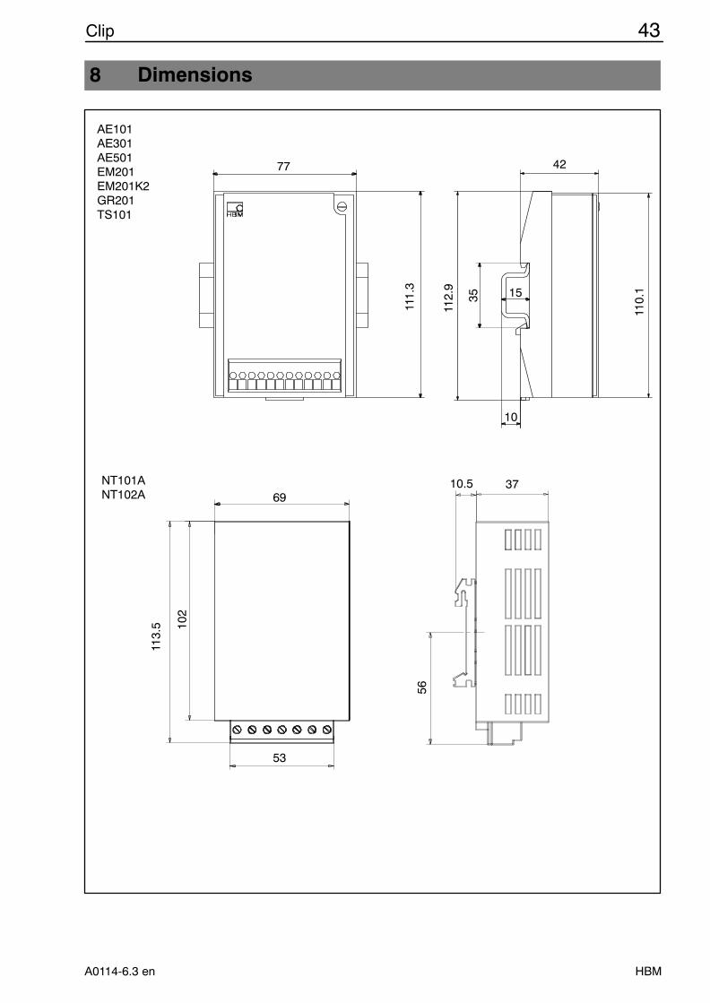
8 Dimensions
AE101AE301AE501EM201EM201K2GR201TS101
NT101ANT102A
15
42
10
77
111.
3
112.
9
35
110.
1
69
113.
5 102
53
10.5 37
56
44 Clip
HBM A0114-6.3 en
Clip
IG
100
hole
pat
tern
for
scre
w /
6
Wei
ght o
f hou
sing
: 3.2
kg
45Clip
HBMA0114-6.3 en
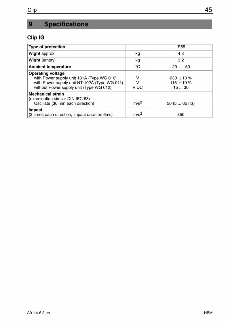
9 Specifications
Clip IG
Type of protection IP65
Wight approx. kg 4.3
Wight (empty) kg 3.2
Ambient temperature °C -20 ... +50
Operating voltagewith Power supply unit 101A (Type WG 010)with Power supply unit NT 102A (Type WG 011)without Power supply unit (Type WG 012)
VV
V DC
230 10 %115 10 %
15 ... 30
Mechanical strain (examination similar DIN IEC 68)
Oscillate (30 min each direction) m/s2 50 (5 ... 65 Hz)
Impact (3 times each direction, impact duration 6ms) m/s2 350
46 Clip
HBM A0114-6.3 en
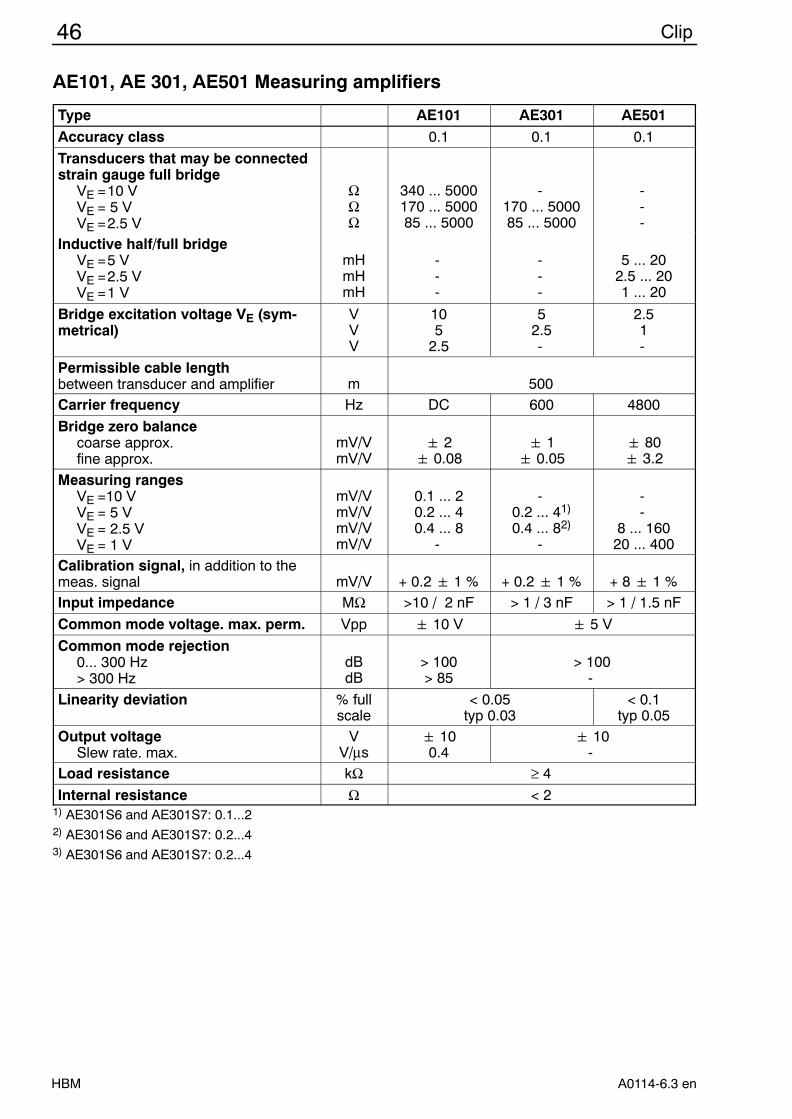
AE101, AE 301, AE501 Measuring amplifiers
Type AE101 AE301 AE501Accuracy class 0.1 0.1 0.1
Transducers that may be connectedstrain gauge full bridge
VE =10 VVE = 5 VVE =2.5 V
ΩΩΩ
340 ... 5000170 ... 500085 ... 5000
-170 ... 500085 ... 5000
---
Inductive half/full bridgeVE =5 VVE =2.5 VVE =1 V
mHmHmH
---
---
5 ... 202.5 ... 201 ... 20
Bridge excitation voltage VE (sym-metrical)
VVV
105
2.5
52.5-
2.51-
Permissible cable length between transducer and amplifier m 500Carrier frequency Hz DC 600 4800
Bridge zero balancecoarse approx.fine approx.
mV/VmV/V
2 0.08
1 0.05
80 3.2
Measuring rangesVE =10 VVE = 5 VVE = 2.5 VVE = 1 V
mV/VmV/VmV/VmV/V
0.1 ... 20.2 ... 40.4 ... 8
-
-0.2 ... 41)
0.4 ... 82)
-
--
8 ... 16020 ... 400
Calibration signal, in addition to themeas. signal mV/V + 0.2 1 % + 0.2 1 % + 8 1 %Input impedance MΩ >10 / 2 nF > 1 / 3 nF > 1 / 1.5 nF
Common mode voltage. max. perm. Vpp 10 V 5 V
Common mode rejection0... 300 Hz> 300 Hz
dBdB
> 100> 85
> 100-
Linearity deviation % fullscale
< 0.05typ 0.03
< 0.1typ 0.05
Output voltageSlew rate. max.
VV/µs
100.4
10-
Load resistance kΩ ≥ 4
Internal resistance Ω < 21) AE301S6 and AE301S7: 0.1...22) AE301S6 and AE301S7: 0.2...43) AE301S6 and AE301S7: 0.2...4
47Clip
HBMA0114-6.3 en
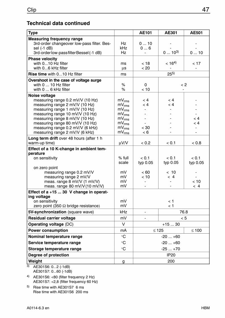
Technical data continued
Type AE101 AE301 AE501Measuring frequency range
3rd-order changeover low-pass filter. Bes-sel (-1 dB)3rd-order low-passfilterBessel(-1 dB)
HzkHzHz
0 ... 100 ... 6
-
--
0 ... 103)
--
0 ... 10
Phase velocitywith 0...10 Hz filterwith 0...6 kHz filter
ms µs
< 18< 20
< 164)
-< 17
-
Rise time with 0...10 Hz filter ms 255)
Overshoot in the case of voltage surgewith 0 ... 10 Hz filterwith 0 ... 6 kHz filter
%%
0< 10
< 2-
Noise voltagemeasuring range 0.2 mV/V (10 Hz)measuring range 2 mV/V (10 Hz)measuring range 1 mV/V (10 Hz)measuring range 10 mV/V (10 Hz)measuring range 8 mV/V (10 Hz)measuring range 80 mV/V (10 Hz)measuring range 0.2 mV/V (6 kHz)measuring range 2 mV/V (6 kHz)
mVrmsmVrmsmVrmsmVrmsmVrmsmVrmsmVrmsmVrms
< 4< 4----
< 30< 6
< 4< 4------
----
< 4< 4--
Long term drift over 48 hours (after 1 hwarm-up time) µV/V < 0.2 < 0.1 < 0.8Effect of a 10 K-change in ambient tem-perature
on sensitivity % fullscale
< 0.1 typ 0.05
< 0.1typ 0.05
< 0.1 typ 0.05
on zero pointmeasuring range 0.2 mV/Vmeasuring range 2 mV/Vmeas. range 8 mV/V (1 mV/V)meas. range 80 mV/V(10 mV/V)
mVmVmVmV
< 60< 10
--
< 10< 4
--
--
< 10< 4
Effect of a +15 ... 30 V change in operat-ing voltage
on sensitivityzero point (350 Ω bridge resistance)
mVmV
< 1< 1
5V-synchronization (square wave) kHz - 76.8
Residual carrier voltage mV - < 5
Operating voltage (DC) V +15 ... 30
Power consumption mA ≤ 125 ≤ 100
Nominal temperature range °C -20 ... +60
Service temperature range °C -20 ... +60
Storage temperature range °C -25 ... +70
Degree of protection IP20
Weight g 2003) AE301S6: 0...2 (-1dB)
AE301S7: 0...60 (-1dB)4) AE301S6: <80 (filter frequency 2 Hz)
AE301S7: <2,8 (filter frequency 60 Hz)5) Rise time with AE301S7 6 ms
Rise time with AE301S6 200 ms
48 Clip
HBM A0114-6.3 en
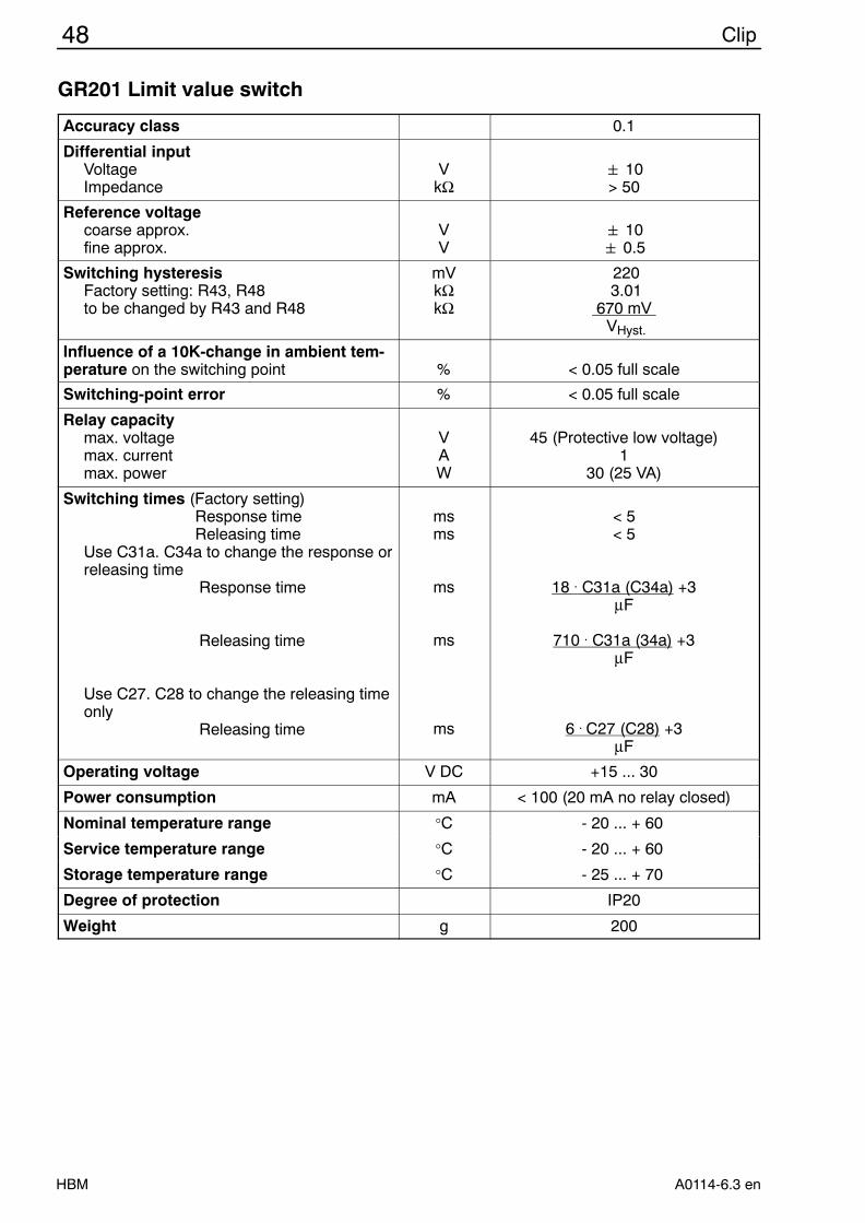
GR201 Limit value switch
Accuracy class 0.1
Differential inputVoltageImpedance
VkΩ
10> 50
Reference voltagecoarse approx.fine approx.
VV
10 0.5
Switching hysteresisFactory setting: R43, R48to be changed by R43 and R48
mVkΩkΩ
220 3.01
670 mV VHyst.
Influence of a 10K-change in ambient tem-perature on the switching point % < 0.05 full scale
Switching-point error % < 0.05 full scale
Relay capacitymax. voltagemax. currentmax. power
VAW
45 (Protective low voltage)1
30 (25 VA)
Switching times (Factory setting)Response timeReleasing time
Use C31a. C34a to change the response orreleasing time
Response time
Releasing time
Use C27. C28 to change the releasing timeonly
Releasing time
msms
ms
ms
ms
< 5< 5
18 . C31a (C34a) +3µF
710 . C31a (34a) +3µF
6 . C27 (C28) +3µF
Operating voltage V DC +15 ... 30
Power consumption mA < 100 (20 mA no relay closed)
Nominal temperature range °C - 20 ... + 60
Service temperature range °C - 20 ... + 60
Storage temperature range °C - 25 ... + 70
Degree of protection IP20
Weight g 200
49Clip
HBMA0114-6.3 en
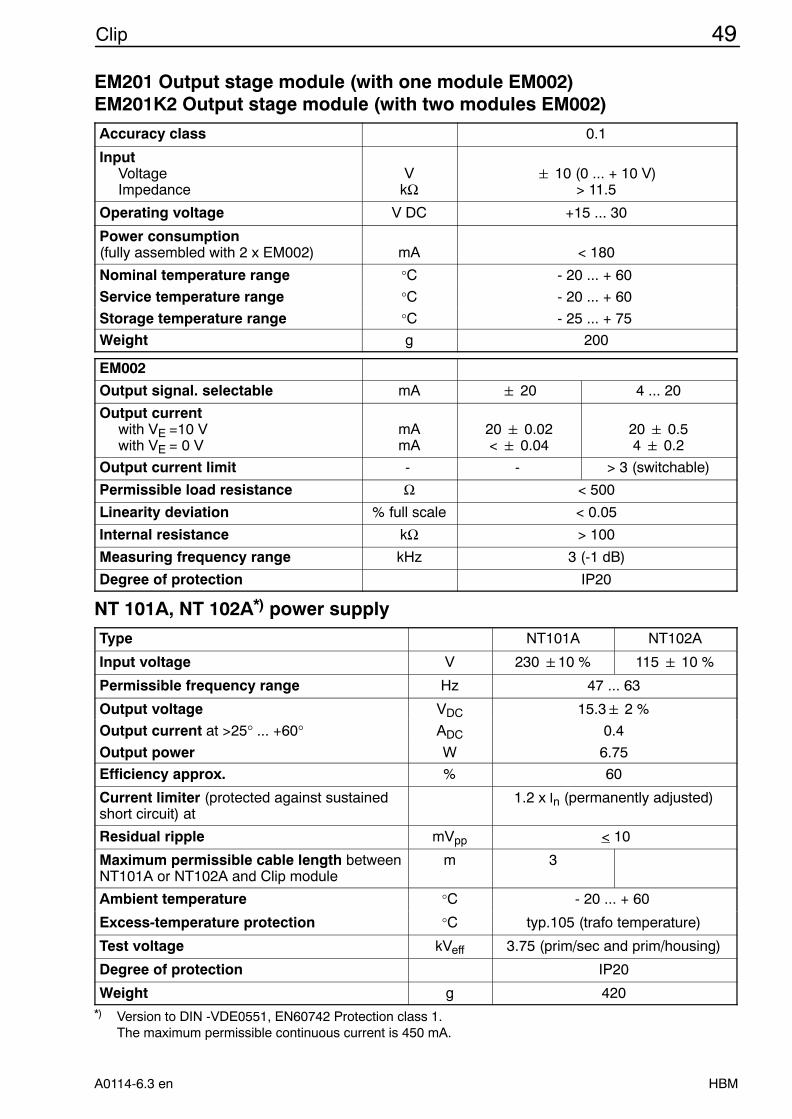
EM201 Output stage module (with one module EM002)EM201K2 Output stage module (with two modules EM002)
Accuracy class 0.1
InputVoltageImpedance
VkΩ
10 (0 ... + 10 V)> 11.5
Operating voltage V DC +15 ... 30
Power consumption(fully assembled with 2 x EM002) mA < 180
Nominal temperature range °C - 20 ... + 60
Service temperature range °C - 20 ... + 60
Storage temperature range °C - 25 ... + 75
Weight g 200
EM002
Output signal. selectable mA 20 4 ... 20
Output currentwith VE =10 Vwith VE = 0 V
mAmA
20 0.02< 0.04
20 0.54 0.2
Output current limit - - > 3 (switchable)
Permissible load resistance Ω < 500
Linearity deviation % full scale < 0.05
Internal resistance kΩ > 100
Measuring frequency range kHz 3 (-1 dB)
Degree of protection IP20
NT 101A, NT 102A*) power supply
Type NT101A NT102A
Input voltage V 230 10 % 115 10 %
Permissible frequency range Hz 47 ... 63
Output voltage VDC 15.3 2 %
Output current at >25° ... +60° ADC 0.4
Output power W 6.75
Efficiency approx. % 60
Current limiter (protected against sustainedshort circuit) at
1.2 x In (permanently adjusted)
Residual ripple mVpp < 10
Maximum permissible cable length betweenNT101A or NT102A and Clip module
m 3
Ambient temperature °C - 20 ... + 60
Excess-temperature protection °C typ.105 (trafo temperature)
Test voltage kVeff 3.75 (prim/sec and prim/housing)
Degree of protection IP20
Weight g 420*) Version to DIN -VDE0551, EN60742 Protection class 1.
The maximum permissible continuous current is 450 mA.
50 Clip
HBM A0114-6.3 en
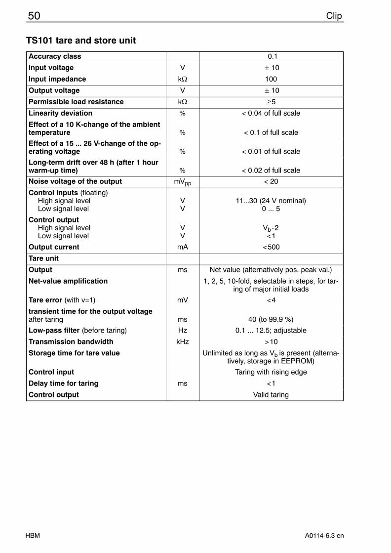
TS101 tare and store unit
Accuracy class 0.1
Input voltage V 10
Input impedance kΩ 100
Output voltage V 10
Permissible load resistance kΩ ≥5
Linearity deviation % < 0.04 of full scale
Effect of a 10 K-change of the ambienttemperature % < 0.1 of full scale
Effect of a 15 ... 26 V-change of the op-erating voltage % < 0.01 of full scale
Long-term drift over 48 h (after 1 hourwarm-up time) % < 0.02 of full scale
Noise voltage of the output mVpp < 20
Control inputs (floating)High signal levelLow signal level
VV
11...30 (24 V nominal)0 ... 5
Control outputHigh signal levelLow signal level
VV
Vb-2<1
Output current mA <500
Tare unit
Output ms Net value (alternatively pos. peak val.)
Net-value amplification 1, 2, 5, 10-fold, selectable in steps, for tar-ing of major initial loads
Tare error (with v=1) mV <4
transient time for the output voltageafter taring ms 40 (to 99.9 %)
Low-pass filter (before taring) Hz 0.1 ... 12.5; adjustable
Transmission bandwidth kHz >10
Storage time for tare value Unlimited as long as Vb is present (alterna-tively, storage in EEPROM)
Control input Taring with rising edge
Delay time for taring ms <1
Control output Valid taring
51Clip
HBMA0114-6.3 en
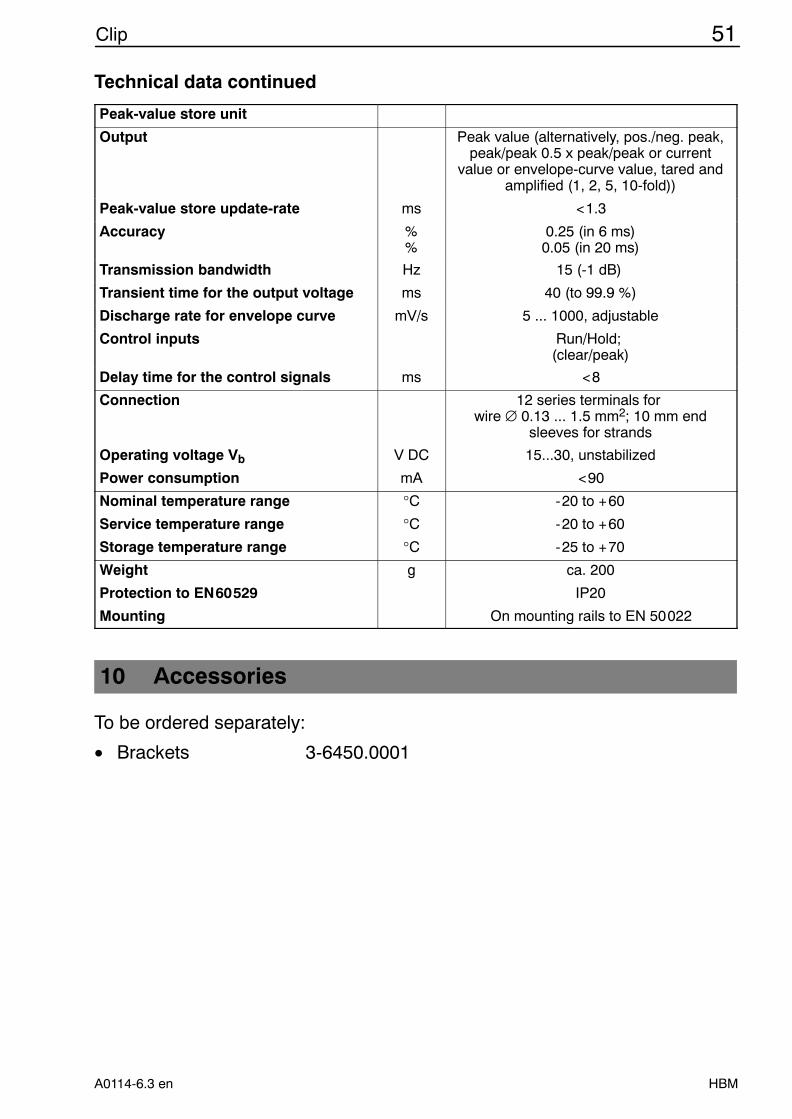
Technical data continued
Peak-value store unit
Output Peak value (alternatively, pos./neg. peak,peak/peak 0.5 x peak/peak or current
value or envelope-curve value, tared andamplified (1, 2, 5, 10-fold))
Peak-value store update-rate ms <1.3
Accuracy %%
0.25 (in 6 ms)0.05 (in 20 ms)
Transmission bandwidth Hz 15 (-1 dB)
Transient time for the output voltage ms 40 (to 99.9 %)
Discharge rate for envelope curve mV/s 5 ... 1000, adjustable
Control inputs Run/Hold; (clear/peak)
Delay time for the control signals ms <8
Connection 12 series terminals for wire ∅ 0.13 ... 1.5 mm2; 10 mm end
sleeves for strands
Operating voltage Vb V DC 15...30, unstabilized
Power consumption mA <90
Nominal temperature range °C -20 to +60
Service temperature range °C -20 to +60
Storage temperature range °C -25 to +70
Weight g ca. 200
Protection to EN60529 IP20
Mounting On mounting rails to EN 50022
10 Accessories
To be ordered separately:
• Brackets 3-6450.0001