clearing & grubbing - village of amanda
TRANSCRIPT
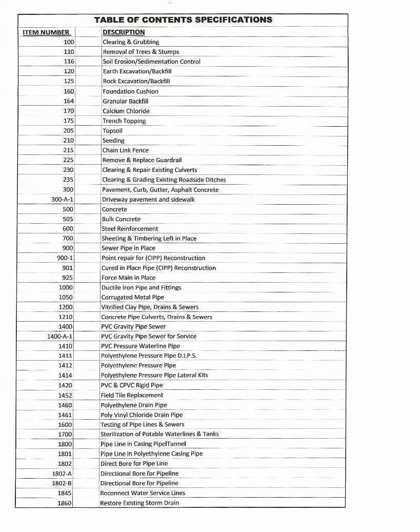
TABLE OF CONTENTS SPECIFICATIONSITEM NUMBER DESCRIPTION
100 Clearing & Grubbing
110 Removal of Trees & Stumps
116 Soil Erosion/Sedimentation Control
120 Earth Excavation/Backfill
125 Rock Excavation/Backfill
160 Foundation Cushion
164 Granular Backfill
170 Calcium Chloride
175 Trench Topping
205 Topsoil
210 Seeding
215 Chain Link Fence
225 Remove & Replace Guardrail
230 Clearing & Repair Existing Culverts
235 Clearing & Grading Existing Roadside Ditches
300 Pavement, Curb, Gutter, Asphalt Concrete
300-A-1 Driveway pavement and sidewalk
500 Concrete
505 Bulk Concrete
600 Steel Reinforcement
700 Sheeting & Timbering Left in Place
900 Sewer Pipe in Place
900-1 Point repair for (CIPP) Reconstruction
901 Cured in Place Pipe (ClPP) Reconstruction
925 Force Main in Place
1000 Ductile Iron Pipe and Fittings
1050 Corrugated Metal Pipe
1200 Vitrified Clay Pipe, Drains & Sewers
1210 Concrete Pipe Culverts, Drains & Sewers
1400 PVCGravity Pipe Sewer
1400-A-1 PVCGravity Pipe Sewer for Service
1410 PVC Pressure Waterline Pipe
1411 Polyethylene Pressure Pipe D.I.P.S.
1412 Polyethylene Pressure Pipe
1414 Polyethylene Pressure Pipe Lateral Kits
1420 PVC& CPVC Rigid Pipe
1452 Field Tile Replacement
1460 Polyethylene Drain Pipe
1461 Poly Vinyl Chloride Drain Pipe
1600 Testing of Pipe Lines & Sewers
1700 Sterilization of Potable Waterlines & Tanks
1800 Pipe Line in Casing PipelTunnel
1801 Pipe Line in Polyethylene Casing Pipe
1802 Direct Bore for Pipe Line
1802-A Directional Bore for Pipeline
1802-B Directional Bore for Pipeline
1845 Reconnect Water Service Lines
1860 Restore Existing Storm Drain
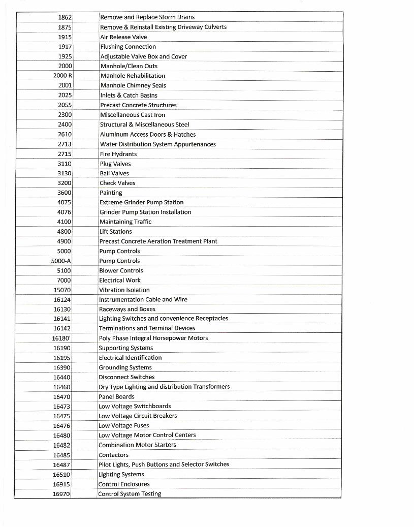
1862 Remove and Replace Storm Drains
1875 Remove & Reinstall Existing Driveway Culverts
1915 Air Release Valve
1917 Flushing Connection
1925 Adjustable Valve Box and Cover
2000 Manhole/Clean Outs
2000 R Manhole Rehabilitation
2001 Manhole Chimney Seals
2025 Inlets & Catch Basins
2055 Precast Concrete Structures
2300 Miscellaneous Cast Iron
2400 Structural & Miscellaneous Steel
2610 Aluminum Access Doors & Hatches
2713 Water Distribution System Appurtenances
2715 Fire Hydrants
3110 Plug Valves
3130 Ball Valves
3200 Check Valves
3600 Painting
4075 Extreme Grinder Pump Station
4076 Grinder Pump Station Installation
4100 Maintaining Traffic
4800 Lift Stations
4900 Precast Concrete Aeration Treatment Plant
5000 Pump Controls
5000-A Pump Controls
5100 Blower Controls
7000 Electrical Work
15070 Vibration Isolation
16124 Instrumentation Cable and Wire
16130 Raceways and Boxes
16141 Lighting Switches and convenience Receptacles
16142 Terminations and Terminal Devices
16180' Poly Phase Integral Horsepower Motors
16190 Supporting Systems
16195 Electrical Identification
16390 Grounding Systems
16440 Disconnect Switches
16460 Dry Type Lighting and distribution Transformers
16470 Panel Boards
16473 Low Voltage Switchboards
16475 Low Voltage Circuit Breakers
16476 Low Voltage Fuses
16480 Low Voltage Motor Control Centers
16482 Combination Motor Starters
16485 Contactors
16487 Pilot Lights, Push Buttons and Selector Switches
16510 Lighting Systems
16915 Control Enclosures
16970 Control System Testing

100-1
CLEARING & GRUBBING
Item 100 DESCRIPTION - (Sec. 01)
A. Scope: Furnish all labor, materials, equipment and incidentals required to perform all clearing, grubbing, scalping, and removal of trees and stumps as shown and specified.
B. Related Work and/or Materials to be Performed and/or Furnished and Included for
Payment in this Item are:
1. Removal of Trees and Stumps - Item 110 2. Earth Excavation and Backfill - Item 120
C. Coordination:
1. Work under this section shall meet the requirements of Item 201 of The
State of Ohio Department of Transportation Construction and Material Specifications.
2. Wherever requirements conflict, this section shall govern. QUALITY ASSURANCE - (Sec. 02) Codes and Standards: Observe state and local laws and code requirements for the hauling and disposing of trees, shrubs, stumps, roots, rubbish, debris and other matter. JOB CONDITION - (Sec. 03)
A. Protection:
1. Protect streets, roads, adjacent property and other works and structures throughout the entire project.
2. Return to original condition, satisfactory to the Representative damaged facilities caused by the Contractor's operations.
3. Protect trees, shrubs and grassed areas which are to remain by using fences, barricades, wrapping or other methods as shown, specified or reviewed by the Representative.
4. Do not permit equipment, stockpiles, etc. within tree branch spread, except as indicated on the plans.
5. Do not remove trees unless shown or specified.
B. Salvage:
1. Unless specified elsewhere carefully remove items to be salvaged and stored on premises in a location acceptable to the Representative, all in accordance with recommendations of specialists recognized in the work involved.
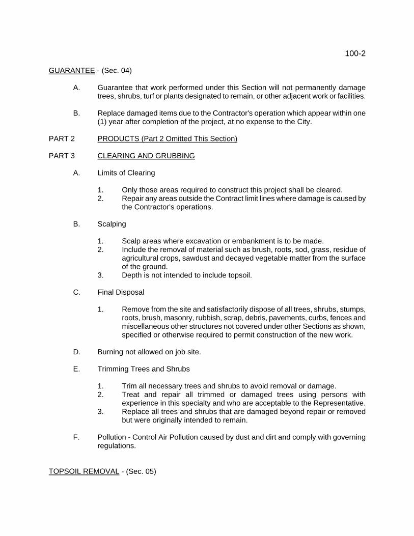
100-2 GUARANTEE - (Sec. 04)
A. Guarantee that work performed under this Section will not permanently damage trees, shrubs, turf or plants designated to remain, or other adjacent work or facilities.
B. Replace damaged items due to the Contractor's operation which appear within one
(1) year after completion of the project, at no expense to the City. PART 2 PRODUCTS (Part 2 Omitted This Section) PART 3 CLEARING AND GRUBBING
A. Limits of Clearing
1. Only those areas required to construct this project shall be cleared. 2. Repair any areas outside the Contract limit lines where damage is caused by
the Contractor's operations.
B. Scalping
1. Scalp areas where excavation or embankment is to be made. 2. Include the removal of material such as brush, roots, sod, grass, residue of
agricultural crops, sawdust and decayed vegetable matter from the surface of the ground.
3. Depth is not intended to include topsoil.
C. Final Disposal
1. Remove from the site and satisfactorily dispose of all trees, shrubs, stumps, roots, brush, masonry, rubbish, scrap, debris, pavements, curbs, fences and miscellaneous other structures not covered under other Sections as shown, specified or otherwise required to permit construction of the new work.
D. Burning not allowed on job site.
E. Trimming Trees and Shrubs
1. Trim all necessary trees and shrubs to avoid removal or damage. 2. Treat and repair all trimmed or damaged trees using persons with
experience in this specialty and who are acceptable to the Representative. 3. Replace all trees and shrubs that are damaged beyond repair or removed
but were originally intended to remain.
F. Pollution - Control Air Pollution caused by dust and dirt and comply with governing regulations.
TOPSOIL REMOVAL - (Sec. 05)
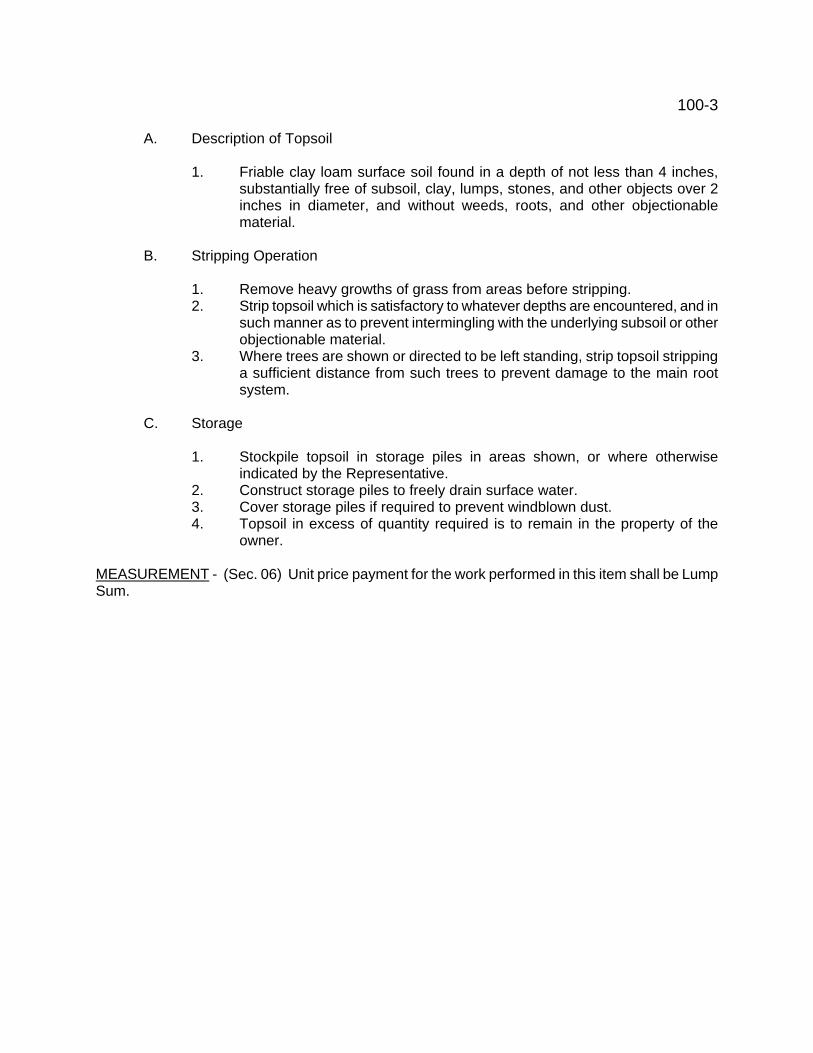
100-3
A. Description of Topsoil
1. Friable clay loam surface soil found in a depth of not less than 4 inches, substantially free of subsoil, clay, lumps, stones, and other objects over 2 inches in diameter, and without weeds, roots, and other objectionable material.
B. Stripping Operation
1. Remove heavy growths of grass from areas before stripping. 2. Strip topsoil which is satisfactory to whatever depths are encountered, and in
such manner as to prevent intermingling with the underlying subsoil or other objectionable material.
3. Where trees are shown or directed to be left standing, strip topsoil stripping a sufficient distance from such trees to prevent damage to the main root system.
C. Storage
1. Stockpile topsoil in storage piles in areas shown, or where otherwise
indicated by the Representative. 2. Construct storage piles to freely drain surface water. 3. Cover storage piles if required to prevent windblown dust. 4. Topsoil in excess of quantity required is to remain in the property of the
owner. MEASUREMENT - (Sec. 06) Unit price payment for the work performed in this item shall be Lump Sum.
110-1 REMOVAL OF TREES AND/OR STUMPS ITEM 110 PART 1 - GENERAL WORK INCLUDED: (Sec. 01) Remove trees and/or stumps as indicated on the Drawings and dispose of all debris. RELATED WORK: (Sec. 02) Furnished/paid for in this Item (as applicable):
Earth Excavation/Backfill Item 120 Furnished/paid for in respective Item (as applicable):
Granular Backfill Item 164 DESCRIPTION: (Sec.03) Remove trees and stumps eight inches and over in diameter under the various classifications as follows:
8" to 12" in diameter Item 110A Over 12" to 24" in diameter Item 110B Over 24" in diameter Item 110C
MEASUREMENT/PAYMENT: (Sec. 04) Included with Clearing. PART 2 - PRODUCTS Not required PART 3 - EXECUTION REMOVAL: (Sec. 05) Remove trees and stumps from the site in their entirety. Dispose of all debris off the site of the work. Blasting of stumps will not be permitted except with special permission of the Owner and the Resident Representative, and then only under such regulations as they may prescribe. This permission does not relieve the Contractor of full responsibility for his operations. Completely fill any hole that is left open as called for under backfilling in Item 120, Earth Excavation and Backfill, or as directed by the Resident Representative. Should the use of gravel backfill be directed, it shall meet the requirements of Item 164, Granular Backfill.
116-1 SOIL EROSION/SEDIMENTATION CONTROL ITEM 116 PART 1 - GENERAL WORK INCLUDED: (Sec. 01) Furnish all labor, materials and equipment necessary to implement soil erosion and sedimentation controls at the construction site as indicated on the Drawings and specified. RELATED WORK: (Sec. 02) Furnished/paid for in this Item:
Topsoil (temporary) Item 205 Seeding (temporary) Item 210
Furnished/paid for in respective Item: (as applicable)
Clearing and Grubbing Item 100 Earth Excavation and Backfill Item 120 Calcium Chloride Item 170 Trench Topping Item 175 Topsoil Item 205 Seeding Item 210
DESCRIPTION: (Sec. 03) The Contractor shall prepare and submit to the Owner an erosion control plan which outlines the procedures he proposes to perform for erosion and sedimentation control. Soil erosion and sedimentation control measures shall be implemented prior to commencement of earth moving activities. The plan shall be strictly adhered to, and the Contractor shall maintain, in good condition, all erosion and sediment control measures until permanent soil cover has been established, at which time they are to be removed as authorized by the Engineer. Details of typical erosion control measures are indicated on the Detail Drawings. REFERENCES: (Sec. 04) ODOT - Ohio Department of Transportation, Construction and Material Specifications. SUBMITTALS: (Sec. 05) Erosion Control Plan. MEASUREMENT/PAYMENT: (Sec. 06) Lump sum payment will be made. Payment shall be included with the Item for pipe installation. WARRANTY: (Sec. 07) See General Conditions. PART 2 - PRODUCTS
116-2 MATERIALS: (Sec. 08) Silt Barrier: Bales - hay, straw, See Drawings. Rock Barrier: ODOT Item 601, Type C. without filter. Seed/Mulch: ODOT Item 659. Filter Fabric: ODOT 712.09, Type C, (Class 3). PART 3 - EXECUTION PREPARATION: (Sec. 09) Since each construction site is different, soil erosion and sedimentation control is site specific. The Contractor shall regard the specifications and regulations noted herein, as a minimum standard. This shall be adjusted to the specific site as a result of field investigations. During the course of construction, adjustments may be made if necessary to adapt to changing conditions, complaints, advice from regulatory agencies, or directions from the Engineer. INSTALLATION/APPLICATION: (Sec. 10) Soil Erosion and Sedimentation Control: If work on this project is suspended for any reason, the Contractor shall maintain the soil erosion and sedimentation control facilities in good condition during the suspension of work. Also, when seasonal conditions permit and the suspension of work is expected to exceed a period of one month, the Contractor shall place topsoil, fine grade, seed, fertilize and mulch all disturbed areas left exposed when work is stopped, as specified herein. The Contractor shall construct filter barriers as required or as directed by the Engineer to prevent sediment carrying runoff from entering any drainage channel, storm water conveyance facility or natural waterway. Filter barriers shall be constructed of straw bales, rock or geotextile filter fabric as indicated on the Drawings. The Contractor shall instruct all vehicles to remove soil and loose material from their wheels and undercarriages when leaving the work area. The Contractor shall remove all soil, miscellaneous debris, or other material spilled, dumped, or otherwise deposited on public streets, highways, sidewalks or other public thoroughfares by vehicles in transit to and from the work area. Construction in Street Areas (paved): The Contractor shall backfill all trenches and place a minimum 4 inch thick layer of compacted crushed stone on all trenches at the end of each workday. All excess excavated material shall be removed from the street area and stockpiled or disposed of as approved by the Engineer. Stockpiling of excavated material in street gutter lines will not be permitted. The Contractor shall sweep street areas adjacent to construction at the end of each workday. Construction in Vegetated Areas: The Contractor shall backfill and rough grade all trenches at the

116-3 end of each workday and dispose of or stockpile all excess excavated materials as approved by the Engineer. Within five days after a manhole to manhole section of pipe has been completed, the Contractor shall place topsoil, fine grade, seed, fertilize, and mulch all areas disturbed by activities associated with the construction of that section of pipe. When working adjacent to a waterway, the Contractor shall maintain a buffer zone of undisturbed vegetation between the work area and the waterway. If a buffer zone cannot be maintained or is inadequate, the Contractor shall install filter barriers to prevent runoff carrying sediment from entering the waterway. Fine Grading and Seeding: The Contractor shall place topsoil, to a minimum depth of 4 inches, on those areas which have been disturbed by work in this Contract. The topsoil shall be raked and trimmed to true lines, free from unsightly variations, humps, or ridges. Seed, fertilize and mulch. Stream Crossing: The Contractor shall place a siltation barrier along the stream banks from work limit to work limit. This barrier shall be of Hay Bales or Plastic Filter Fabric, approved with the Contractors erosion control plan. The Contractor shall be responsible for the control of siltation and erosion. The Contractor shall not disturb or uproot trees or vegetation outside the work limits as shown on the drawings. Siltation water shall not be allowed to enter the stream at anytime. The area of the stream crossings shall be graded and generally restored immediately after the crossing is complete. If Contractor proposes to employ other construction methods, his construction method of soil erosion and sedimentation control shall be submitted to the Engineer for review and approval. Maintenance: Silt fences and filter barriers shall be inspected immediately after each rainfall and at least daily during prolonged rainfall. Any required repairs shall be made immediately. Should the fabric on a silt fence or filter barrier decompose or become ineffective prior to the end of the expected usable life and the barrier is still necessary, the fabric shall be replaced promptly. Sediment deposits should be removed after each storm event. They must be removed when deposits reach approximately one-half the height of the barrier. Any sediment deposits remaining in place after the silt fence or filter barrier is no longer required shall be dressed to conform with the existing grade, prepared and seeded.
120-1 EARTH EXCAVATION/BACKFILL ITEM 120 PART 1 - GENERAL WORK INCLUDED: (Sec. 01) Perform all earth excavations, backfill and related work for pipe lines, manholes and/or structures as indicated on the Drawings and specified. RELATED WORK: (Sec. 02) Furnished/paid for in respective Item: (as applicable)
Removal Trees/Stumps (over 8" diameter) Item 110 Rock Excavation/Backfill Item 125 Foundation Cushion Item 160 Granular Backfill Item 164 Bulk Concrete Item 505
DESCRIPTION: (Sec. 03) All materials encountered below the ground surface, natural and/or manmade, including removal and disposal of pavement and sidewalk, except Rock Excavation and Backfill, Item 125, are included in this Item. Pipe line - Clear construction area of topsoil, brush, shrubs, stumps and trees less than eight inches in diameter. Structures - Clear construction area of topsoil, brush, shrubs, stumps, trees and debris, unless included for payment elsewhere. Excavate, by open cut method, and backfill as required for the proper construction/installation of the proposed work. REFERENCES: (Sec. 04)
ASTM D698 - Moisture Density Relations of Soils and Soil - Aggregate Mixtures D1556 - Density of Soil in Place by the Sand-Cone Method D4253, D4254 - Relative Density of Cohesion less Soils
SUBMITTAL: (Sec. 05) Three copies of compaction testing records, if compaction testing specified. SITE CONDITIONS: (Sec.06) Elevations of existing ground are believed to be reasonably accurate but are not purported to be absolutely so. Contractor shall satisfy self if more accurate information desired. PAYMENT: (Sec. 07) Lump Sum. PART 2 - PRODUCTS MATERIALS: (Sec. 08) Excavated earthen materials, when specifically directed to be used, shall be clean and free of foreign and organic material and contain no rocks larger than three inches.
120-2 Borrow - ODOT Item 203 Foundation Cushion - Item 160 Granular Backfill - Item 165 Bulk Concrete - Item 505 PART 3 - EXECUTION INSPECTION: (Sec. 09) Inspect site and determine conditions that may effect the proper execution of the work. Soil data in the Specifications or indicated on the Drawings, if any, may be supplemented with own investigation to determine soil conditions that will be encountered. INSTALLATION/APPLICATION: (Sec. 10) Pipeline Evacuation/Backfill Limit length of trench opened at any one time to that length required for efficient construction and public convenience. No more than 50 feet of trench shall be opened in advance of the completed work. Do not open new trenches when completed trenches need backfilling or labor is required to restore driving or walking surfaces to a safe condition. If safety cages are used, the bottom of the safety cage shall at all times be above the top of the pipe in order not to disturb the pipe bedding or pipe line when the cage is moved forward. Excavation limits shall not exceed those indicated on the Drawings, except as noted herein. Additional authorized foundation material, Foundation Cushion or Bulk Concrete, required to fill over-excavated areas shall be paid for in the applicable item stipulated in the proposal, if unit price Contract. Additional Authorized Excavation: If materials encountered at bearing depth are not suitable for support, or it is necessary to increase the excavation limits, additional excavation outside the original excavation limits may be authorized by the Resident Representative and paid for in Item 120. Unauthorized Excavation: Excavation carried outside the authorized excavation limits, and all excavation or other work resulting from slides, cave-ins, swells or upheaval, which is made without authorization of the Resident Representative, shall be at the Contractor's expense. Unauthorized excavations shall be refilled with compacted Foundation Cushion or Bulk Concrete if directed by the Resident Representative, at no cost to the Owner. Storage of Excavated Materials: If conditions permit, excavated material may be stored along the line of work. If streets and roads where traffic conditions make it necessary to keep open as much of the roadway as possible, immediate backfill of the excavation shall be required after pipeline
120-3 construction, with no storage of excavated material along the line of work permitted. Do not obstruct walkways, driveways, emergency equipment or utility controls with stored material. Maintain natural and man-made drainage free of obstruction or provide adequate temporary drainage. Temporary Backfill: If the excavation is left open for an unreasonable length of time, as determined by the Owner, Contractor shall refill such excavation and place temporary paving in walkways and roadways at his own expense. Temporary backfill and paving shall remain in place until construction is ready to proceed. Backfilling: Backfill trenches below pavements, drives, curbs, gutters, walks and berms, or as directed by Resident Representative, as specified and paid for in Item 164, Granular Backfill, if unit price Contract.
If stated on drawings, in Special Provisions, or ordered by the Owner, suitable excavated earthen materials may be saved as backfill in lieu of Granular Backfill at no additional cost. Jetting of trenches containing Granular Backfill is permitted in lieu of mechanical compaction. Jetting of Trenches shall be completed as soon as practical after backfilling. An injection pipe under water pressure shall be injected into backfill to within one foot of pipe bedding, or structure footing, and maintained until backfill refuses water. Injection pipe to be then moved to the next location. Maximum spaces between jetting penetration shall be four foot staggered centers. Holes left by removing injection pipe shall be flushed full with granular material. Mechanical compaction or jetting of backfill outside the limits of pavements, berms, curb/gutters and walks is not required, unless indicated on Drawings, except as follows: Within the Right-of-Way limits of state and/or federal highways, compact to 90 percent of maximum dry density. Earth backfill shall be temporarily mounded over the trench to allow for settlement. Contractor shall maintain trenches and backfill to provide natural or man made drainage free of obstructions. Ponding of water shall not be permitted. Adequate temporary drainage shall be provided by the Contractor. Prior to final grading and seeding, all excess materials over trenches shall be removed and the work areas restored to original contours, or as indicated on the Drawings. Earth backfill material shall be furnished and placed at no additional cost. Structure Excavation and Backfill Excavation: Unless noted otherwise on the Drawings, place foundation of structure directly on undisturbed soil; final trimming of the bottom of the excavation shall be done just prior to placing forms and/or reinforcing steel. Excavation dimensions shall be no greater than necessary for building the structure, supporting the walls of the excavation and accommodating the necessary dewatering equipment. Excavation Limits: Dimensions shall not exceed those indicated on the Drawings, except as noted herein. Additional Authorized Excavation: If the materials encountered at bearing depth are not suitable for support, additional excavation may be authorized by the Resident Representative. Additional authorized concrete, foundation materials, and excavation outside the excavation limits shall be paid for in the applicable Item stipulated in the proposal. If lump sum contract, price for additional
120-4 work shall be determined prior to performing such work. Unauthorized Excavation: Excavation carried outside the excavation limits indicated on the Drawings, and all excavation or other work resulting from slides, cave-ins, swelling or upheaval, which is made without authorization of the Resident Representative, shall be made at the Contractor's expense. Unauthorized excavation shall be refilled with Foundation Cushion or Bulk Concrete if directed by the Resident Representative, at no cost to the Owner. Storage for Excavated Materials: Store excavated material suitable for use as backfill material or site fill in a stockpile, the location of which will not place dangerous loadings on the walls of the excavation. Do not obstruct walkways, driveways, roadways, emergency equipment or utility controls with stored material. Maintain natural and man-made drainage free of obstruction or provide adequate temporary drainage at no additional cost to Owner. Backfilling: Backfill shall be earth from the excavated stockpile unless otherwise noted on the Drawings. Backfill shall be free of topsoil, foreign and organic material, rocks larger than three inches in any dimensions, and frozen material. Do not begin backfilling operation until the structure has attained adequate strength and is complete enough to resist without damage the stresses caused by backfilling. It is the Contractor's responsibility to determine the proper time to begin the backfilling operation and to properly brace the structure to prevent damage. Place backfill and compact as specified under Backfilling, Page 120-3. ADDITIONAL WORK REQUIRED: (Sec. 11) Perform the following work as required during performance of this Item for both pipe line and structure excavation. Pavement Removal: Whenever the removal of pavements other than gravel or surface treated types is required, outline the area to be removed with vertical saw kerfs in straight lines to limit breakage. Excavation and Disposition of Surface Materials: Carefully remove pavement, walkways, topsoil and other surface material, separate and store for future re-use. Any damaged or deficient material, due to Contractor's operations, shall be replaced with new material by the Contractor at no cost to the Owner. Dispose of damaged material off the site. No extra compensation will be allowed for the removal and storage of materials which are to be re-used.
Disposal of Excess Excavated Material: Incorporate suitable excess excavated material as much as possible in grading where directed by the Resident Representative. Haul any excess materials from excavations, not required in, nor suitable for backfill or repaving, to such locations as the Owner may select, provided such haul does not exceed five miles over an approved route. If the Owner does not designate where such surplus materials are to be disposed of, they become the property of the Contractor and he shall dispose of them off the site at his own expense. The surfaces of all spoil areas shall be left smooth, level, or evenly sloped for proper drainage, and free from stones, rubbish or other debris. Sheeting and Shoring: It is the Contractor's responsibility to furnish, install and maintain wood sheeting, steel sheet piling, shoring, planking and bracing, whether or not indicated on the Drawings, to prevent earth movement which could damage the construction, adjacent structures and/or property, obstruct surface drainage channels or waterways, or otherwise impair or delay the work or endanger human life. Remove the sheeting, shoring and bracing during the backfilling unless otherwise noted on the Drawings or directed in writing, by the Resident Representative. For

120-5 unit price proposals when indicated on the Drawings or directed in writing, by the Resident Representative, wood sheeting or steel sheet piling shall be left in place. Payment for such sheeting or piling shall be made under the respective Item. Sheeting, shoring and bracing left in place by the Contractor for his own convenience will be at his expense. All sheeting or piling left in place shall be cut off at least two feet below final finish grade. Wood sheeting and steel sheet piling to be removed shall not be withdrawn until the backfilling is substantially complete. As backfilling progresses to the elevation of bracing, remove the braces. Take care to prevent movement of the walls of the excavation during withdrawal of sheeting and piling. Immediately fill voids left by sheeting or piling withdrawal by hydraulic flushing of granular material into the voids. Removal of Water: Water will not be permitted to enter or flow through a pipeline or conduit during installation without written permission of Resident Representative or Owner. Watertight plugs shall be installed at effluent ends of all sanitary sewer lines. Plugs to be removed by Contractor after final testing and acceptance by Owner. The method of water removal including site dewatering is the Contractor's choice, but the method chosen shall operate adequately to maintain groundwater table one foot below a structure's lowest subgrade or invert of pipe. The method chosen shall provide for the disposal of all water removed from the excavations in a manner which prevents injury or health impairment to the public, damage to public or private property or any portion of the construction completed or in progress. Public inconvenience shall be minimized, payment shall be included with the cost for storm or sanitary pipe, no separate payment will be made for dewatering. Protection of Existing Facilities: provide temporary support and adequate protection and maintenance of all existing underground and surface structures, pipe lines and utilities encountered during excavation as provided in the General Conditions. Restore all disturbed underground and surface structures, pipelines and utilities to the original condition. Maintain the flow of water or sewage in existing pipes, ditches and channels which are encountered during construction. Borrow: Additional material used for backfill, grading and embankment which is obtained from within the site shall not be classified as Borrow. For unit price proposals, additional material obtained off the site shall be specified and paid for in Item 150, Borrow. Traffic Maintenance: Place and maintain temporary pavement surface over excavations made in roadways and driveways in a manner which will eliminate hazards. Provide the Owner and Resident Representative with the name, address and telephone number of the emergency maintenance service. Provide emergency maintenance services 24 hours per day, including weekends and holidays. If the emergency maintenance service cannot be contacted or if repairs are not promptly made, the Owner shall notify the Contractor and will make the necessary repairs at the Contractor's expense. Trench Topping and/or Calcium Chloride, if required, shall be as specified and paid for in their respective Items. Tunneling: Tunneling in lieu of open cutting for pipe line trenches will be permitted under trees and utility lines for a length not to exceed fifteen feet. If tunneling is substituted for open cut under this Item, measurement shall be made as specified for open cut method. FIELD QUALITY CONTROL: (Sec. 12) If specifically called for in Special Provisions, standard compaction tests, performed in accordance with chart below, shall be made by a qualified soils technician to assure that the backfill is properly compacted. Copies of all test records shall be given to the Resident Representative.
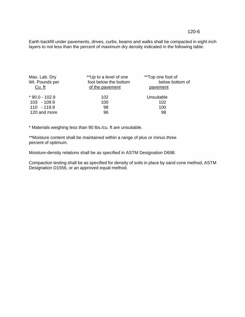
120-6 Earth backfill under pavements, drives, curbs, beams and walks shall be compacted in eight inch layers to not less than the percent of maximum dry density indicated in the following table. Max. Lab. Dry **Up to a level of one **Top one foot of Wt. Pounds per foot below the bottom below bottom of Cu. ft of the pavement pavement * 90.0 - 102.9 102 Unsuitable 103 - 109.9 100 102 110 - 119.9 98 100 120 and more 96 98
* Materials weighing less than 90 lbs./cu. ft are unsuitable. **Moisture content shall be maintained within a range of plus or minus three percent of optimum. Moisture-density relations shall be as specified in ASTM Designation D698. Compaction testing shall be as specified for density of soils in place by sand cone method, ASTM Designation D1556, or an approved equal method.
125-1 ROCK EXCAVATION AND BACKFILL
ITEM 125
WORK INCLUDED: (Sec. 01) Perform all rock excavation, backfill and related work for pipelines and structures as shown on the Drawings and specified herein DESCRIPTION: (Sec. 02) All rock or shale materials encountered below the ground surface. Contractor my supplement the soil data, if any as contained in the Specifications or shown on the Drawings, with investigations of his own, to determine the soil conditions which will be encountered in performing the work in this Item. Elevations of the existing ground shown on the Drawings are believed to be reasonably accurate but are not purported to be absolutely so. Contractor shall satisfy himself if more accurate ground elevations are desired. ROCK AND SHALE EXCAVATION: (Sec. 03) Where rock or shale is encountered the trench shall be excavated to a depth of 0.5 feet below the invert of the pipe. The additional excavation shall be filled with granular, bedding material. Payment will be at the contract unit price bid for rock excavation and backfill. USE OF EXPLOSIVES: (Sec. 04) When and if it is necessary, for the prosecution of the work to be done under this Contract, to resort to blasting with explosives, the Contractor shall use the highest degree of care and adequate protective measures so as not to endanger life, completed portions of the Contract project, and all other property, both public and private. Before conducting any blasting operations, the Contractor shall furnish the Engineer, in writing, a schedule of intended blasting operations and he shall give the Engineer prior written notification of any changes in such schedule. The use, handling, storage and transportation of explosives shall conform and be in accordance with the applicable requirements and/or provisions: (a) of the latest revision of “Bulletin No. 202, Specific Safety Requirements Relating to Building and Construction Work”, issued by the Department of Industrial Relations and the Industrial Commission of the State of Ohio; (b) of the Ohio Explosive Laws, Section 3743.01 – 3743.26 of the Ohio Revised Code and amendments thereto; (c) of local regulations, and (d) as specified herein. All blasting operations shall be covered by public liability and property damage insurance as elsewhere specified herein. Except in the case of continuous tunnel operations, all blasting shall be conducted during daylight hours only with provision that when required by the Engineer, blasting shall be limited to certain daylight hours. All firing shall be done by electrical means only. The Contractor shall make suitable provisions to prevent the scattering of broken rock, earth, stones or other material during blasting operations. DRILLING AND BLASTING IN ROCK CUTS: (Sec.05) Where rock is encountered and excavation requires drilling and blasting, all necessary precautions shall be exercised to preserve the rock in the finished trench in a natural undamaged condition, with the surfaces remaining reasonably straight and clean. The Contractor shall pre-split rock and shale along proposed alignments. The contractor shall drill 2 ½ to 3 inch (63 mm to 76 mm) nominal diameter holes, spaced not more than 3 feet (0.9 m) center to center along the required alignment. No hole shall deviate more than one half foot (152 mm) at any place from the plane of specified respite location.
125-2 Before placing the charge, each hole shall be tested for its entire length to ascertain the possible presence of any obstruction. No loading will be permitted until the hole is free of all obstructions for its entire depth. All necessary precaution shall be exercised so that the placing of the charge will not cause caving of material from the walls of the hole. The charges and procedures for the blasting to be used for each hole shall be submitted to the Engineer for review. A pre blast survey shall also be preformed by the Contractor at no additional cost to the Owner. Contractor shall provide necessary insurance at no additional cost to the Owner. The cost of all material, labor and equipment necessary for pre-splitting and other work included herein shall be made as a part of the lump sum payment for the plant, pump station piping. Trenches shall be backfilled with granular materials to the top of the excavated rock. Prior to final grading and seeding, all excess materials over trenches shall be removed and the work areas restored to original contours, or as shown on the drawings. Disposal of Excess Excavated Material: Incorporate suitable excess excavated material as much as possible in grading where directed by the Resident Representative. Haul any excess materials from excavations, not required in, nor suitable for backfill or repaving, to such locations as the Owner may select, provided such haul does not exceed two miles over an approved route. If the Owner does not designate where such surplus materials are to be disposed of, they become the property of the Contractor and he shall dispose of them off the site at his own expense. The surfaces of all spoil areas shall be left smooth, level or evenly sloped for proper drainage and free from stones, rubbish or other debris. PROTECTION AND RESTORATION OF PROPERTY; (Sec. 06) The Contractor shall be responsible for the preservation of all public and private property. The Contractor shall be responsible for all damage or injury to property during the prosecution of the work, resulting from any act, omission, neglect, or misconduct in his manner or method of executing the work, or at any time due to defective work or materials. Dust, mud, noise or other nuisance originating from any plant operations either inside or outside the right-of-way shall be controlled by the Contractor in accordance with local ordinances and regulations at the sole expense of the Contractor. When or where any direct or indirect damage or injury is done to public or private property by or on account of any act, omission, neglect, or misconduct in the execution of the work, or in consequence of the non-execution thereof by the Contractor, he shall restore, at his own expense, such property to a condition similar or equal to that existing before such damage or injury was done, by repairing, rebuilding or otherwise restoring as may be directed by the Engineer, or he shall make good such damage or injury in an acceptable manner. PAYMENT: (Sec. 07) Included with excavation related to wastewater treatment plant and sewer.
160-1 FOUNDATION CUSHION ITEM 160 PART 1 - GENERAL WORK INCLUDED: (Sec. 01) Furnish and place Foundation Cushion material as indicated on the Drawings and specified. RELATED WORK: (Sec. 02) Furnished/paid for in this Item:
Earth Excavation and Backfill Item 120 DESCRIPTION: (Sec. 03) Place Foundation Cushion material in locations indicated on the Drawings or directed by the Resident Representative. Foundation Cushion may also be used, with the permission of the Resident Representative, to level up firm topsoil before placing concrete foundations, or as fill below portions of the structure which have been undermined by excavation. QUALITY ASSURANCE: (Sec. 04) Materials shall be new. REFERENCES: (Sec. 05)
ODOT - Ohio Department of Transportation, Construction and Material Specifications
SUBMITTALS: (Sec. 06) Delivery weight slips to Resident Representative. PAYMENT: (Sec. 07) Included with excavation related to wastewater treatment plant and sewers. WARRANTY: (Sec. 08) See General Conditions. PART 2 - PRODUCTS MATERIALS: (Sec. 09) Crushed gravel or crushed limestone, meeting gradation requirements of ODOT Item 304. PART 3 - EXECUTION INSTALLATION: (Sec. 10) Place Foundation Cushion in loose layers not exceeding eight inches. Compact with mechanical equipment in accordance with ODOT Item 304.
164 GRANULAR BACKFILL ITEM 164 PART 1 - GENERAL WORK INCLUDED: (Sec. 01) Furnish and place Granular Backfill as indicated on the drawings and specified. RELATED WORK: (Sec. 02) Furnished/paid for in this Item: Earth Excavation and Backfill Item 120 Furnished/paid for in respective Items: Rock Excavation and Backfill Item 125 Pavement Replacement Item 300 Polyethylene Pressure Pipe DIPS Item 1411 Polyethylene Pressure Pipe Item 1412 Installation for Polyethylene Drain Pipe Item 1460 Pipe bedding material will not be considered as granular backfill. DESCRIPTION: (Sec. 03) Granular Backfill material shall be used as backfill in trenches under pavements, gravel driveways, berms, curbs, gutters and sidewalks, where the pipe line is within 5 feet of the edge of pavement shall be included for payment with the Item for pipe installation. Areas where rock has been excavated, and other areas as may be specifically indicated or as otherwise directed by the Resident Representative will be paid for under, Additional Granular Backfill Item 164. QUALITY ASSURANCE: (Sec. 04) Material shall be sound, hard, free of deleterious materials, having reasonably uniform moisture content at or near optimum for compaction. As specified in Item 603.02 of the ODOT Construction and Material Specification. Samples may be requested to determine acceptability. REFERENCES: (Sec. 05) AASHTO American Association of State highway Transportation Officials ODOT Ohio Department of Transportation, Construction and Materials Specifications. SUBMITTALS: (Sec. 06) Gradation Certification PAYMENT: (Sec. 07) Payment shall be the number of cubic yards placed within the pay limits of the trench or excavation shown on the drawings, unless included for payment with another Item.
CALCIUM CHLORIDE ITEM 170 PART 1 - GENERAL WORK INCLUDED: (Sec. 01) Furnish and apply calcium chloride as indicated on the Drawings and specified. DESCRIPTION: (Sec. 02) Apply calcium chloride to the surface of the backfilled trenches or trench topping as directed by the Owner or the Resident Representative. QUALITY ASSURANCE: (Sec. 03) Material shall be new. REFERENCES: (Sec. 04)
ASTM - American Society for Testing and Materials SUBMITTALS: (Sec. 05) None required. UNIT PRICE PROPOSAL: (Sec. 06) For unit price proposal, payment shall be per ton. WARRANTY: (Sec. 07) See General Conditions. PART 2 - PRODUCTS MATERIALS: (Sec. 08) Calcium chloride shall meet the requirements of ASTM D-98. PART 3 - EXECUTION INSTALLATION: (Sec. 09) Apply calcium chloride at the rate of one pound per square yard with an approved type spreader on the larger trenches. Hand spreading may be used when the width of cut pavement is less than the width of the spreader, or the trench is short. Do not apply calcium chloride to areas to be seeded. Calcium chloride used outside the pay limits as indicated on the Drawings, shall be furnished and placed by the Contractor at no expense to the Owner.
TRENCH TOPPING ITEM 175 WORK INCLUDED: (Sec. 01) Furnish, properly place, roll and maintain the trench topping as shown on the Drawings or as directed. MATERIALS: (Sec. 02) The crushed stone or crushed slag to be used as trench topping shall be crusher run material having a maximum size of two inches. It is intended that trench topping under this Item shall be used only where directed by the Resident Representative when required by traffic conditions. PLACEMENT: (Sec. 03) Furnish and place the trench topping over the full width of the excavated space to a depth of eleven inches with crushed stone or crushed slag conforming to the above specifications. Roll or tamp the crushed stone or crushed slag so that the finished surface of the trench topping will conform to adjacent surfaces. Treat the finished surface of the trench topping with calcium chloride, Item 170, if required to control dust. Repeat this treatment at subsequent periods as directed by the Resident Representative. Promptly refill any settlement or irregularities which occur in the trench topping with stone or slag and maintain until permanently resurfaced. No separate payment will be made for Maintenance of Trench. MEASUREMENT: (Sec. 04) The number of tons of trench topping to be paid for shall be the number of tons actually used in accordance with these Specifications, within the pay limits for pavement, as shown on the Drawings. Whenever trench topping is required, the entire width of disturbed pavement shall be filled with trench toping for a depth of eight inches. All such trench topping outside the pay limits for paving shall be furnished and placed by the Contractor at no expense to the Owner. Whenever all the trench topping delivered is placed within the pay limits, certified weight slips shall be delivered to the Resident Representative at the end of each day. Whenever part of the delivered is placed outside the pay limits as defined above, the actual volume of trench topping placed within the specified pay limits shall be determined. to determine the number of tons so placed, the actual weight of a cubic yard of dry material shall be measured by ascertaining the volume and weight in a truck body; if that, or some similar method cannot be used, then a cubic yard of crushed stone shall be assumed to weigh 2,700 pounds and a cubic yard of crushed slag shall be assumed to weigh 2,000 pounds.
205-1 TOPSOIL ITEM 205 WORK INCLUDED: (Sec. 01) Reclaim and/or procure, haul and place topsoil over the areas wherever required for the proper completion of the work. RELATED WORK: (Sec. 02) Furnished/paid for in respective Item (as applicable)
Seeding Item 210 DESCRIPTION: (Sec. 03) In general, the areas requiring topsoil for sewers, storm drains and water line construction shall be calculated within the pay limits of the trench, and the construction area around lift and booster pump stations. Plant construction shall require topsoil over the construction area and where fill has been added. MEASUREMENT/PAYMENT: (Sec. 04) Measurement for payment shall be the number of cubic yards of topsoil actually placed according to the specified areas and grades. PART 2 - PRODUCTS MATERIALS: (Sec. 05) The material shall consist of loose, friable, loamy topsoil without admixture of subsoil or refuse. for topsoil to be considered loamy, that fraction passing the Number 10 sieve shall contain not more than 40 percent clay. Acceptable topsoil shall contain not less than five percent nor more than 20 percent organic matter as determined by loss on ignition of the samples oven dried to constant weight at 212 degrees Fahrenheit. Use such suitable topsoil as may be encountered in the excavations, and which is stockpiled for the purpose. In case suitable topsoil is not available in sufficient quantity from excavations, obtain topsoil from such other areas of the site as shall be designated, or if none is designated, obtain elsewhere. The reclaiming, hauling, and procurement, if necessary, shall be included in this Item. PART 3 - EXECUTION PREPARATION OF SUBGRADE: (Sec. 06) Immediately prior to the placing of topsoil, complete the subgrade within the area to be covered with topsoil and bring the subgrade to the lines parallel to the proposed finished grade. Clear the subgrade of rock or other foreign material three inches or greater in any diameter. Rake or scarify the surface of the subgrade to a minimum depth of one inch. PLACING: (Sec. 07) Place topsoil three (3”) inches in thickness before compaction unless indicated otherwise on the Drawing or in the proposal. Rake the area, remove all lumps and stones three inches and over and roll with a light roller to secure smoothness to the lines and grades indicated on the Drawings. Repair any settling or erosion which may occur before the completion of the Contract in a satisfactory manner. Restore areas outside of the permanent rights-of-way and where the natural surface has been disturbed for the convenience of the Contractor to its original condition and if topsoil is required, it shall be done at the Contractor's expense.
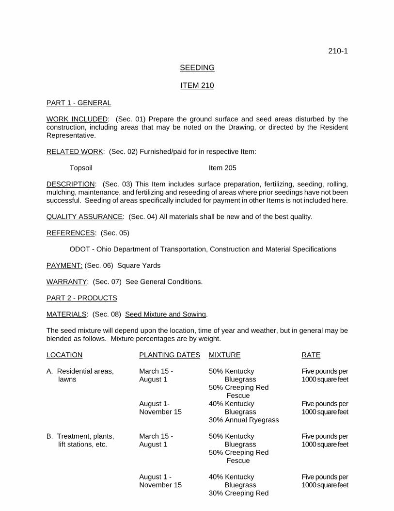
210-1 SEEDING ITEM 210 PART 1 - GENERAL WORK INCLUDED: (Sec. 01) Prepare the ground surface and seed areas disturbed by the construction, including areas that may be noted on the Drawing, or directed by the Resident Representative. RELATED WORK: (Sec. 02) Furnished/paid for in respective Item:
Topsoil Item 205 DESCRIPTION: (Sec. 03) This Item includes surface preparation, fertilizing, seeding, rolling, mulching, maintenance, and fertilizing and reseeding of areas where prior seedings have not been successful. Seeding of areas specifically included for payment in other Items is not included here. QUALITY ASSURANCE: (Sec. 04) All materials shall be new and of the best quality. REFERENCES: (Sec. 05)
ODOT - Ohio Department of Transportation, Construction and Material Specifications PAYMENT: (Sec. 06) Square Yards WARRANTY: (Sec. 07) See General Conditions. PART 2 - PRODUCTS MATERIALS: (Sec. 08) Seed Mixture and Sowing. The seed mixture will depend upon the location, time of year and weather, but in general may be blended as follows. Mixture percentages are by weight. LOCATION PLANTING DATES MIXTURE RATE A. Residential areas, March 15 - 50% Kentucky Five pounds per lawns August 1 Bluegrass 1000 square feet
50% Creeping Red Fescue
August 1- 40% Kentucky Five pounds per November 15 Bluegrass 1000 square feet
30% Annual Ryegrass B. Treatment, plants, March 15 - 50% Kentucky Five pounds per lift stations, etc. August 1 Bluegrass 1000 square feet
50% Creeping Red Fescue
August 1 - 40% Kentucky Five pounds per
November 15 Bluegrass 1000 square feet 30% Creeping Red
210-2
Fescue 30% Annual Ryegrass
C. Mowed slopes March 15 - 70% Kentucky Five pounds per 3:1 and flatter November 15 31 Fescue 1000 square feet
30% Kentucky Bluegrass
D. Slopes 2-1/2:1 March 15 - 50% Crown Vetch One pound per and steeper September 1 50% Annual Ryegrass E. Inside slopes of March 15 - 100% Kentucky 31 Four pounds per reservoirs and lagoons November 15 Fescue 1000 square feet under water all or part of the time Starter Fertilizer: Liquid or granular, 18-24-5 formula. Mulch: Wheat or oats straw, free of weed seeds. Emulsion: Asphalt, ODOT 702.04, non-toxic to plants, will not change in transportation or storage. PART 3 - EXECUTION SURFACE PREPARATION AND FERTILIZING: (Sec. 09) Work the surface of the topsoil into a fine seedbed. Remove rubbish, twigs, pieces of bark, and all stones three-quarters inch in diameter and larger. Apply starter fertilizer, applied at rate recommended by the manufacturer. Work granular fertilizer into seedbed to a depth of about one inch. Sow seed immediately after preparation of seedbed. Blend seed mixtures thoroughly and sow dry or hydraulically over prepared areas at the prescribed rate. Rake seed to one-quarter inch depth and roll with roller. Rolling may be omitted, with the permission of the Resident Representative, when such a procedure would be detrimental to the seeded area. MULCHING: (Sec. 10) Immediately after seeding and rolling, apply straw mulch at rate of 100 pounds per thousand square feet. Wet straw down to prevent loss of mulch by wind. Tie straw mulch in place on slopes where erosion will be a problem. The Contractor may, at his option, apply emulsion at a rate of 120 gallons per acre, instead of wetting the mulch. The Contractor may, at his option, substitute yarn and biodegradable paper erosion control fabric with uniform openings. The fabric shall be protected during outdoor storage and installed according to manufacturer's instructions. MAINTENANCE: (Sec. 11) The Contractor is responsible for watering and cutting grass in residential areas and seeded areas of treatment plants and lift stations until the final estimate is paid. Owner will furnish water at the nearest available place at no cost to the Contractor. The Contractor shall furnish pipe and hoses as required. Restore areas outside of the permanent rights-of-way and where the natural surface has been disturbed for the convenience of the Contractor to its original condition and if seeding is required, it

210-3 shall be done at the Contractor's expense. If at any time before the expiration of the Contract Bond (usually one year after date that final payment is made) any part of the seeded area is not in good condition, the Contractor shall fertilize and reseed as often as necessary to get a good stand of grass.
215-1 CHAIN LINK FENCE ITEM 215 PART 1 - GENERAL WORK INCLUDED: (Sec. 01) Furnish and install Chain Link Fence as indicated on the Drawings and specified. RELATED WORK: (Sec. 02) Furnished/paid for in this Item:
Earth Excavation and Backfill Item 120 Concrete Item 500
DESCRIPTION: (Sec. 03) Perform all excavation, install posts, top rails, bracing, chain link fabric, barbed wire, supporting arms, gates, concrete and all accessories. QUALITY ASSURANCE: (Sec. 04) Materials shall be new and of the best quality. Provide chain link fences and gates as complete units controlled by a single source including necessary erection accessories, fittings and fastenings. REFERENCES: (Sec. 05)
ASTM - American Society for Testing and Materials SUBMITTALS: (Sec. 06) Shop Drawings - See General Conditions. Provide five sets Shop Drawings for record purposes only, with manufacturer's technical data for material sizes, weights, gauges, finish, post and rail shapes and installation instructions. MEASUREMENT/PAYMENT: (Sec. 07) Payment will be made per lineal foot, for fence complete in place, including gates and all accessories. WARRANTY: (Sec. 08) See General Conditions. PART 2 - PRODUCTS ACCEPTABLE MANUFACTURERS: (Sec. 09):
Allied Tube and Conduit Corp. Anchor Fence, Inc. Colorguard Corp. David Walker Corp. Dominion Fence and Wire Prod. United States Steel
215-2
Merchants Metal or equal.
MATERIALS: (Sec. 10) Fabric: Nine gauge wire, two inch mesh knuckled at one selvage and twisted at the other (72 inch height), knuckled at both selvages (60 inch height). Fabric shall be 72 inch unless otherwise noted. Fabric Finish, galvanized, ASTM A 392, Class 2, minimum 2.0 ounce zinc per square foot of surface, or aluminized, ASTM A 491, Class 2, minimum 0.40 ounce aluminum per square foot of surface. Framework: Galvanized steel, ASTM A 120 or A 123, with not less than 1.8 ounce zinc per square foot of surface, or pipe manufactured from high strength steel conforming to ASTM A 569, triple coated with 1.0 ounce zinc per square foot, 30 micrograms chromate per square inch and .5 mils clear cross-linked polyurethane. Hardware and Accessories: Galvanized, ASTM A 153, with zinc weights per Table I. Line Posts: To 8 foot fabric height, 2.375 inch O.D. steel pipe, 3.65 pounds per lineal foot or 2.375 inch O.D. high strength steel pipe, 3.12 pounds per lineal foot, or 2.25 inch by 1.875 inch "C" section or "H" section, 2.64 pounds per lineal foot. Over 8 foot fabric height, 2.875 inch O.D. steel pipe, 5.79 pounds per lineal foot or 2.875 inch O.D. high strength steel pipe, 4.64 pounds per lineal foot, or 2.25 inch by 1.875 inch "C" section or "H" section, 3.26 pounds per lineal foot. End Corner, Pull Posts: 2.875 inch O.D. steel pipe, 5.79 pounds per lineal foot, 2.875 inch O.D. high strength steel pipe, 4.64 pounds per lineal foot, 2.50 inch by 2.50 inch square steel tubing, 5.10 pounds per lineal foot, 3.50 inch by 3.50 inch roll formed sections, 4.85 pounds per lineal foot. Gate Posts: Same shape as End, Corner, and Pull Posts, sized to support gate. PART 3 - EXECUTION INSTALLATION: (Sec.10) Install fence in accordance with manufacturer's instructions at locations indicated on the Drawings. Maximum line post spacing shall be 10'-0". All post shall be securely anchored a minimum of three feet deep in concrete. In general the fabric shall be not more than one inch above the finished ground line. Installation shall meet requirements of ASTM F-567.

225-1 REMOVE AND REPLACE GUARD RAIL
ITEM 225
WORK INCLUDED: (Sec. 01) Furnish all labor, materials and equipment necessary to remove and replace existing guard rail as shown on the Drawings and specified herein. REFERENCED ITEMS: (Sec. 02) Items of work and/or materials to be performed and/or furnished and included for payment in this Item are:
Earth Excavation and Backfill Item 120 Applicable portions of the latest revision of the following specifications shall be included as part of this Specification:
SCDOT - South Carolina Department of Transportation DESCRIPTION: (Sec. 03) Where existing guard rail interferes with the installation of the new sanitary sewer, remove and replace the existing guard rail. Before removal, the Contractor and Resident Representative shall inspect and note the limits of the guard rail and post spacing. Existing guard rail, posts, etc., shall be carefully removed and stored adjacent to the site. Upon completion of the new construction and approval by the Resident Representative, the existing rail and posts shall be installed in their original location. Any posts broken during removal shall be replaced with new posts. All work and materials shall be in accordance with the latest Guard Rail item, of the SCDOT specifications.
230 - 1 CLEANING AND REPAIR EXISTING CULVERTS ITEM 230 PART 1 - GENERAL WORK INCLUDED: (Sec. 01) Furnish all labor, material and equipment necessary to clean and repair the existing culvert of all silt and debris. RELATED WORK: (Sec. 02) Furnished and paid for in this Item. Earth Excavation and Backfill Item 120 Granular Backfill Item 164 LSM Item Special #3 Seeding Item 210 Bulk Concrete Item 505 Corrugated Metal Pipe Item 1050 Concrete Pipe Culverts Item 1210 Polyethylene Drain Pipe Item 1460 DESCRIPTION: (Sec. 03) The work consists of locating each culvert shown on the drawings within the roadway right of way. Cleaning said pipe by high pressure jetting, or a method approved by the engineer and repairing the pipe as necessary. QUALITY ASSURANCE; (Sec. 04) Materials shall be new and of the best quality. REFERENCES: (Sec. 05)
ASTM American Society for Testing and Materials SCDOT South Carolina Department of Transportation, Construction and Material
Specifications. SUBMITTALS: (Sec. 06) Shop Drawings - See General Conditions. Provide five (5) sets for record purposes only. DELIVERY, STORAGE, HANDLING: (Sec. 07) Handle, unload pipe in accordance with the approved practice specified by the manufacturer. MEASUREMENT/PAYMENT: (Sec. 08) Lump Sum, unless otherwise shown Pipe specifically included in other items shall not be included for payment in this Item.
235 - 1 CLEANING AND GRADING EXISTING ROADSIDE DITCHES ITEM 235 PART 1 - GENERAL WORK INCLUDED: (Sec. 01) Furnish all labor, material and equipment necessary to clean and regrade the roadside ditch flowline, roadside slope and back slope. RELATED WORK: (Sec. 02) Furnished and paid for in this Item.
Clearing Item 100 Earth Excavation and Backfill Item 120 Seeding Item 210
DESCRIPTION: (Sec. 03) The work consists of locating the existing ditch line. Regarding the existing flowline to drain or to the grade shown on the drawings. The roadside slope shall not exceed 3:1 and the backslope shall not exceed 2:1. Ditches shall be reshaped and seeded & mulched. QUALITY ASSURANCE; (Sec. 04) Materials shall be new and of the best quality. REFERENCES: (Sec. 05)
ASTM American Society for Testing and Materials SCDOT South Carolina Department of Transportation, Construction and
Material Specifications. SUBMITTALS: (Sec. 06) N/A. DELIVERY, STORAGE, HANDLING: (Sec. 07) N/A. MEASUREMENT/PAYMENT: (Sec. 08) Lump Sum, unless otherwise requested.
300-1 PAVEMENT, CURB, GUTTER, SIDEWALK ITEM 300 PART 1 - GENERAL WORK INCLUDED: (Sec. 01) Furnish all labor, materials and equipment necessary to construct all pavement, curb, gutter, sidewalk and related work as indicated on the Drawings and specified. DESCRIPTION: (Sec. 02) New work shall be indicated on the Drawings, using material and course thickness as specified hereinafter. Restoring/replacement work shall be performed with material similar to existing, as indicated on the Drawings, using material and course thickness as specified hereinafter. QUALITY ASSURANCE: (Sec. 03) All materials shall be new and of the best quality. REFERENCES: (Sec. 04) ODOT - Ohio Department of Transportation, Construction and Material Specifications. ASTM - American Society for Testing and materials. DELIVERY, STORAGE, HANDLING: (Sec. 05) Bituminous material shall be heated and delivered to job site within the temperature range specified in ODOT 702.00. Bituminous material shall not be used while foaming. Aggregate shall be fed to the cold elevator in proper proportions and at a rate to permit correct and uniform control of heating and drying. Concrete may be mixed in a central mix plant, or in truck mixers, of an approved type. Ready-mix concrete shall be mixed and delivered in accordance with ODOT 499.04
(a) Mixed concrete from the central mixer shall be transported in truck mixers or truck agitators.
Concrete shall be delivered to the work site and discharge completed within one hour after the combining of the water and the cement. If approved set-retarding (ODOT) 705.12, Type B) or a water-reducing and set-retarding (ODOT 705.12, Type D) admixture is used at the Contractor's expense, complete discharge within 90 minutes of the combining of the water and the cement.
300-2 PAYMENT: (Sec. 06) As specified. For unit price proposals payment for Prime and Tack Coats used in conjunction with asphalt concrete is included with the asphalt concrete. For unit price proposals for resurfacing, payment for Tack Coats, pothole and crack repair is included with the unit price bid for resurfacing. The method of repair shall be approved by the engineer. WARRANTY: (Sec. 07) See General Conditions. PART 2 - PRODUCTS MATERIALS: (Sec. 08) Materials shall conform to the latest ODOT specifications as follows:
Subbase - Item 310 Aggregate - Item 304
Berm/shoulder - Item 617
Portland Cement Concrete Base - Item 305
Reinforced Portland Cement Concrete Pavement - Item 451
Plain Portland Cement Concrete Pavement - Item 452
Asphalt Concrete Intermediate Course - Item 402
Asphalt Concrete Surface Course - Item 404
Prime Coat Item 408 Bituminous material - MC-30 or MC-70 Cover aggregate - per Item
Tack Coat - Item 407, SS-1 emulsion Cover aggregate - per Item
Seal Coat - Item 409
300-3
Bituminous material - MWS 90 (RS-2 when temperature 900+)
Cover aggregate per Item First course - No. 67 size Surface course - No. 9 size
Bituminous Cold Mix - Item 405
Curb/Gutter - Concrete, Item 609
Sidewalk - Concrete, Item 499, Class C
Parking Blocks - precast concrete approximately seven inches high, six feet
long. Anchor with steel rods, one-half inch diameter by fifteen long.
Paint (striping) - Item 621
Expansion material - three-quarter inch premolded asphalt plank. PART 3 - EXECUTION INSTALLATION: (SEC. 09) Installation/construction methods shall conform to the latest ODOT specifications. Preparation of Subgrade Prior to placing pavement base or sidewalk, blade, and compact subgrade to the proper elevation indicated on the Drawings. Compact in accordance with ODOT Specifications Item 203. Include the cost of Patch existing pavement using straight lines cut perpendicular of parallel to line of traffic where possible. Subbase Construct a ten inch thick subbase, consisting of two compacted five inch courses, in accordance with ODOT Specifications Item 310. Aggregate Base Construct a six inch or nine inch thick aggregate base course in accordance with ODOT Specifications Item 304. Slag material not permitted. Construct shoulders as indicated on the Drawings using material specified in ODOT Specifications Item 617. Portland Cement Concrete Base

300-4 Construct an eight inch concrete base in accordance with ODOT Specifications Item 305. Moisten subgrade before placing concrete. Place expansion material at interface between new and existing concrete base. Portland Cement Concrete Pavement Construct six inch or eight inch thick reinforced concrete pavement in accordance with ODOT Specifications, Item 451. Reinforcing steel shall be as indicated on the Drawings. Place six inch or eight inch plain concrete pavement in accordance with ODOT Specifications Item 452. Place expansion material and discontinue reinforcing at interface between new and existing pavement. Use high early strength Portland cement, ASTM C-150, Type III or IIIA, with entrained air at locations requiring quick opening to traffic as directed by the Owner. Any extra payment for use of high strength cement shall be agreed upon between the Contractor and the Owner prior to its use. Asphalt Concrete Pavement Construct one and one-half inch thick pavement in one course (402). Construct three inch thick asphalt concrete pavement in two equal thickness courses. The first course shall be in accordance with ODOT Specifications Item 402 and the surface course shall be in accordance with ODOT Specifications Item 404. When asphalt concrete is placed over concrete base apply Tack Coat over the concrete base at the rate of 0.1 gallons per square yard of surface in accordance with ODOT Specifications Item 407. When asphalt concrete is placed over aggregate base apply Prime Coat at the rate of 0.4 gallons per square yard of surface in accordance with ODOT Specifications Item 408. Apply Tack Coat between asphalt concrete courses at the rate of 0.1 gallons per square yard in accordance with ODOT Specifications Item 407. Material consistency and application rates for prime and tack coats may be varied to suit weather conditions, with the approval of the Resident Representative. For unit price proposals no payment for Prime Coat will be made if prime coat is included in another Item. Apply tack coat to edges of existing curbs, pavements, gutters, manhole castings, etc., prior to placing asphalt concrete. Seal and sand all finished joints. Seal Coat First course shall consist of applying bituminous material at rate of 0.35 gallons per square yard followed immediately with cover coat of 20-22 pounds of aggregate. Second course shall consist of 0.35 gallons per square yard followed immediately by cover

300-5 coat of 23-25 pounds per square yard. Prime Coat Apply prime coat in accordance with ODOT Specifications Item 408, at rate of 0.4 gallons per square yard. Coat with sand if traffic will be allowed to run on surface prior to pavement surface application. Material consistency and application rates for prime coat may be varied to suite weather conditions with the approval of the Resident Representative. For unit price proposals no payment for Prime Coat will be made if prime coat is included in another Item. Temporary Bituminous Payment Furnish, place and maintain a temporary bituminous pavement in accordance with ODOT Specifications Item 405 wherever directed by the Resident Representative. Remove a sufficient amount of existing aggregate so that a minimum thickness of two inches of temporary pavement may be placed. Maintain temporary paving until permanent pavement is placed. Curbs/Gutters Construct new or replacement concrete curbs or integral concrete curbs and gutters in accordance with ODOT Specifications Item 609. New curbs or integral curbs and gutters shall be constructed as indicated on the Drawings; replacement curbs or integral curbs and gutters shall match existing shape and dimensions. This Item also includes the removal and disposal of existing concrete material. Concrete Sidewalk Construct sidewalks as indicated on the Drawings using concrete in accordance with ODOT Specifications Item 499. Width of sidewalks shall be four feet for new installations or shall match width of existing sidewalks for replacement installations. Place transverse crack control joints at approximately five foot intervals. Place one-half inch expansion joint material at intervals not to exceed forty feet, at tee intersections, 90o bends in sidewalk and at intersections with structures. Finish all edges with one-quarter inch radius. Surface shall have wood float finish. This Item also includes the removal and disposal of existing sidewalk material, if not included with excavation Item 120. Parking Blocks Furnish and place precast concrete parking blocks where indicated on the Drawings. Paint Striping All paint striping shall be included with the surface pavement item of which it is a part.
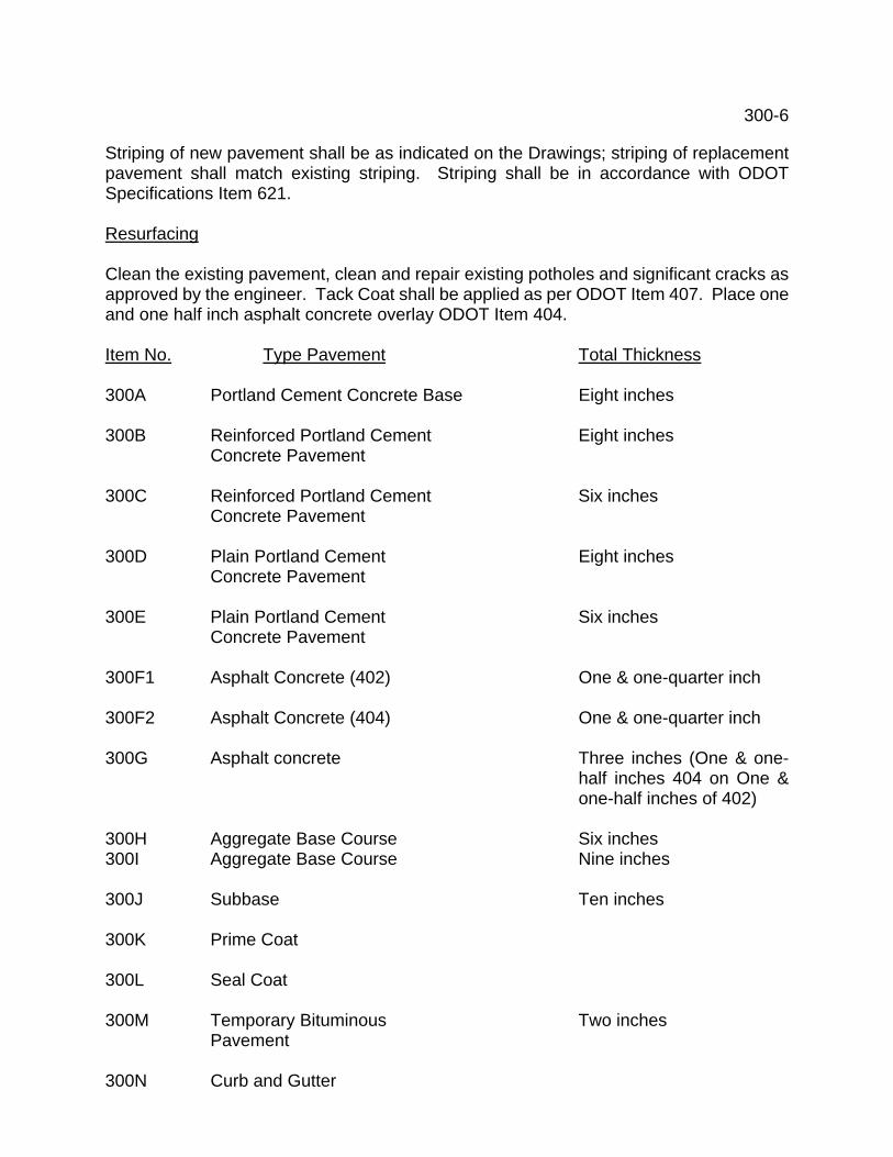
300-6 Striping of new pavement shall be as indicated on the Drawings; striping of replacement pavement shall match existing striping. Striping shall be in accordance with ODOT Specifications Item 621. Resurfacing Clean the existing pavement, clean and repair existing potholes and significant cracks as approved by the engineer. Tack Coat shall be applied as per ODOT Item 407. Place one and one half inch asphalt concrete overlay ODOT Item 404. Item No. Type Pavement Total Thickness 300A Portland Cement Concrete Base Eight inches 300B Reinforced Portland Cement Eight inches
Concrete Pavement 300C Reinforced Portland Cement Six inches
Concrete Pavement 300D Plain Portland Cement Eight inches
Concrete Pavement 300E Plain Portland Cement Six inches
Concrete Pavement 300F1 Asphalt Concrete (402) One & one-quarter inch 300F2 Asphalt Concrete (404) One & one-quarter inch 300G Asphalt concrete Three inches (One & one-
half inches 404 on One & one-half inches of 402)
300H Aggregate Base Course Six inches 300I Aggregate Base Course Nine inches 300J Subbase Ten inches 300K Prime Coat 300L Seal Coat 300M Temporary Bituminous Two inches
Pavement 300N Curb and Gutter

300-7 300P Concrete Sidewalk Four inches 300Q Parking Blocks 300R Resurfacing One & one half inches
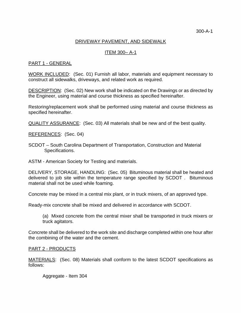
300-A-1 DRIVEWAY PAVEMENT, AND SIDEWALK ITEM 300– A-1 PART 1 - GENERAL WORK INCLUDED: (Sec. 01) Furnish all labor, materials and equipment necessary to construct all sidewalks, driveways, and related work as required. DESCRIPTION: (Sec. 02) New work shall be indicated on the Drawings or as directed by the Engineer, using material and course thickness as specified hereinafter. Restoring/replacement work shall be performed using material and course thickness as specified hereinafter. QUALITY ASSURANCE: (Sec. 03) All materials shall be new and of the best quality. REFERENCES: (Sec. 04) SCDOT – South Carolina Department of Transportation, Construction and Material Specifications. ASTM - American Society for Testing and materials. DELIVERY, STORAGE, HANDLING: (Sec. 05) Bituminous material shall be heated and delivered to job site within the temperature range specified by SCDOT . Bituminous material shall not be used while foaming. Concrete may be mixed in a central mix plant, or in truck mixers, of an approved type. Ready-mix concrete shall be mixed and delivered in accordance with SCDOT.
(a) Mixed concrete from the central mixer shall be transported in truck mixers or truck agitators.
Concrete shall be delivered to the work site and discharge completed within one hour after the combining of the water and the cement. PART 2 - PRODUCTS MATERIALS: (Sec. 08) Materials shall conform to the latest SCDOT specifications as follows:
Aggregate - Item 304
300-A-2
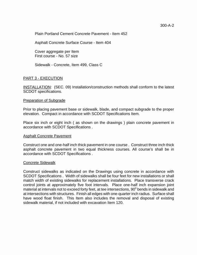
Plain Portland Cement Concrete Pavement - Item 452
Asphalt Concrete Surface Course - Item 404
Cover aggregate per Item First course - No. 57 size Sidewalk - Concrete, Item 499, Class C
PART 3 - EXECUTION INSTALLATION: (SEC. 09) Installation/construction methods shall conform to the latest SCDOT specifications. Preparation of Subgrade Prior to placing pavement base or sidewalk, blade, and compact subgrade to the proper elevation. Compact in accordance with SCDOT Specifications Item. Place six inch or eight inch ( as shown on the drawings ) plain concrete pavement in accordance with SCDOT Specifications . Asphalt Concrete Pavement Construct one and one-half inch thick pavement in one course . Construct three inch thick asphalt concrete pavement in two equal thickness courses. All course’s shall be in accordance with SCDOT Specifications . Concrete Sidewalk Construct sidewalks as indicated on the Drawings using concrete in accordance with SCDOT Specifications . Width of sidewalks shall be four feet for new installations or shall match width of existing sidewalks for replacement installations. Place transverse crack control joints at approximately five foot intervals. Place one-half inch expansion joint material at intervals not to exceed forty feet, at tee intersections, 90o bends in sidewalk and at intersections with structures. Finish all edges with one-quarter inch radius. Surface shall have wood float finish. This Item also includes the removal and disposal of existing sidewalk material, if not included with excavation Item 120.
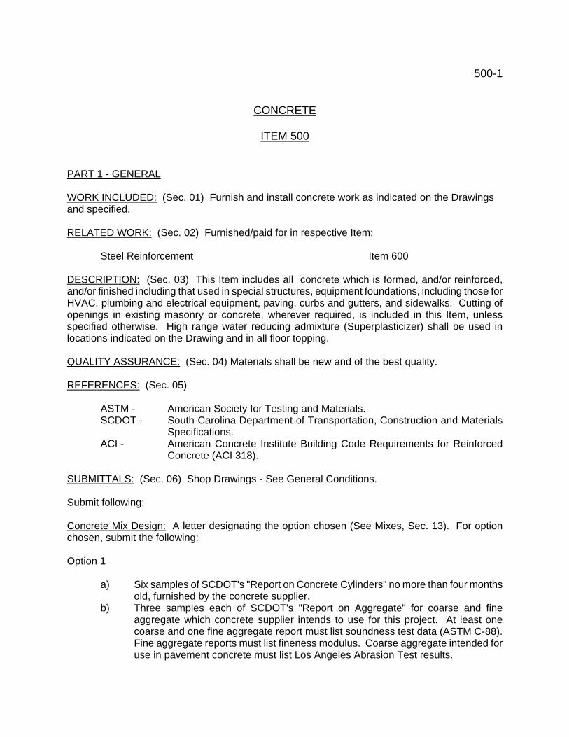
500-1 CONCRETE ITEM 500 PART 1 - GENERAL WORK INCLUDED: (Sec. 01) Furnish and install concrete work as indicated on the Drawings and specified. RELATED WORK: (Sec. 02) Furnished/paid for in respective Item:
Steel Reinforcement Item 600 DESCRIPTION: (Sec. 03) This Item includes all concrete which is formed, and/or reinforced, and/or finished including that used in special structures, equipment foundations, including those for HVAC, plumbing and electrical equipment, paving, curbs and gutters, and sidewalks. Cutting of openings in existing masonry or concrete, wherever required, is included in this Item, unless specified otherwise. High range water reducing admixture (Superplasticizer) shall be used in locations indicated on the Drawing and in all floor topping. QUALITY ASSURANCE: (Sec. 04) Materials shall be new and of the best quality. REFERENCES: (Sec. 05)
ASTM - American Society for Testing and Materials. SCDOT - South Carolina Department of Transportation, Construction and Materials
Specifications. ACI - American Concrete Institute Building Code Requirements for Reinforced
Concrete (ACI 318). SUBMITTALS: (Sec. 06) Shop Drawings - See General Conditions. Submit following: Concrete Mix Design: A letter designating the option chosen (See Mixes, Sec. 13). For option chosen, submit the following: Option 1
a) Six samples of SCDOT's "Report on Concrete Cylinders" no more than four months old, furnished by the concrete supplier.
b) Three samples each of SCDOT's "Report on Aggregate" for coarse and fine aggregate which concrete supplier intends to use for this project. At least one coarse and one fine aggregate report must list soundness test data (ASTM C-88). Fine aggregate reports must list fineness modulus. Coarse aggregate intended for use in pavement concrete must list Los Angeles Abrasion Test results.
500-2
c) The type of cement and manufacturer's name; the manufacturer and product name of the air entraining agent and water reducing agent.
d) If SCDOT records for aggregate and/or cylinder breaks do not supply all of the required information the Contractor shall, through a qualified laboratory approved by the Engineer, meet the requirements for submittals under this option.
Option 2
a) Laboratory report listing ingredients and quantities contained in design mix. Include type and manufacturer of cement and the manufacturer and name of the air entraining agent and water reducing agent. Make and cure specimens of design mix in accordance with ASTM C-192. Report initial slump and slump after mixing for 15 minutes (placement slump).
b) Seven and 28 days cylinder break records of the design mix. c) Coarse and fine aggregate sieve analysis, specific gravity, soundness test (ASTM
C-88), and fineness modulus. Coarse aggregate intended for use in pavement must list Los Angeles Abrasion Test results.
d) A record of 30 consecutive 28-day strength tests from the concrete supplier's recent records. A strength test is defined as the average of two cylinders from the same sample and represent materials similar to those which will be used on the job.
High-Range Water Reducing Admixture.
Submit an adjusted mix design except finish floor topping. Submit type and name of manufacturer of the high-range water reducing admixture.
The cost of laboratory fees to meet the requirements of either option and the use of high-range water reducing admixture shall be borne by the Contractor. Waterstop: Name of manufacturer, shape, product number, physical and mechanical properties. Fiber reinforcement: Name of manufacturer, type, length, coating if fibers are polyester, and requirements for its use. DELIVERY, STORAGE, HANDLING: (Sec. 07) Batch, mix and deliver ready-mixed concrete according to the requirements of ASTM C-94. Notify Resident Representative of the supplier's name at least three weeks in advance of the date of the first pour, so that the batch plant and trucks may be inspected. Approval of the plant and trucks is necessary prior to delivering concrete to the job site. Do not exceed rated capacity of the ready mix truck. All concrete containing the high-range water reducing admixture shall have a maximum slump of 8 inches unless otherwise approved by the Resident Representative. The concrete shall arrive at the job site at a slump of 2 inches to 3 inches, be verified, then the high-range water reducing admixture added to increase the slump to the approved level. No water shall be added at the job site. The manufacturer shall furnish on site a qualified representative to advise on the proper procedures for using the admixture during the first pour.
500-3 PAYMENT: (Sec. 08) Included with excavation related to water / wastewater treatment plant, water and sewer lines. Unless otherwise requested. WARRANTY: (Sec. 09) See General Conditions. PAR 2 - PRODUCTS ACCEPTABLE MANUFACTURERS (Sec. 10) Joint Materials:
Williams Products, Inc. Construction Gaskets, Inc. or equal.
Floor Hardener:
L & M Construction Chemicals (Quartzplate) Euclid Chemical Co. (Surflex) Master Builders (Maximent) or equal.
Epoxy Bonding Agent
Sika Chemical Corp. (Sikadur) Euclid Chemical Co. (Euco Epoxy) L & M Construction Chemicals (Epobond) or equal.
Expansion Anchors: (self drilling)
Phillips Drill Co. (Red Head) Ramset Fastening Systems (Ramdrill) or equal.
Expansion Anchors: *(pre-drilled holes)
Hilti Fastening Systems, Inc. (Kwik-bolt) Ramset Fastening System (Trubolt Stud Anchor) or equal.
Expansion Joint Sealant:
Sika Chemical Corp. (Sikaflex 2c) A.C. Horn, Inc. (Daraseal-U) or equal.
Fiber Reinforcement:
500-4
Euclid Chemical Company Grace Construction Products or equal.
MATERIALS: (Sec. 11) Concrete:
1. Fine Aggregate - ASTM C-33 2. Coarse Aggregate - ASTM C-33 - SCDOT Size 57 3. Cement - Portland Cement - ASTM C-150 4. Water - clean and free of deleterious substances.
Admixtures:
1. Air Entraining Agent - ASTM C-260 2. Water Reducing Admixture - ASTM C-494 Type A, containing not over 1000 parts
per million (ppm) chloride ions. 3. High Range Water Reducing Admixture (Superplasticizer) - ASTM C-494 Type F,
containing not over 1000 parts per million (ppm) chloride ions. 4. Retarding Admixture - ASTM C-494, Type B, containing no chloride ions.
Specific addition of calcium chloride is prohibited. Add admixtures, except high range water reducing admixture (superplasticizer), at batch plant. Formwork Plywood, plywood faced and metal faced patented forms and No. 1 yellow pine sheathing acceptable. Damaged forms not permitted. Joint Materials Construction joints - six inch styrene-butadiene rubber (SBR) or neoprene dumbbell waterstop or serrated PVC waterstop and prefabricated fittings, or equal. Expansion joints - styrene-butadiene rubber (SBR) or neoprene or serrated PVC dumbbell waterstop with three-quarter inch inside diameter center bulb. Premolded joint filler - ASTM D-1752, Type I, II, III. Specific type indicated on Drawings. Floor Hardener - non-metallic shake-on type. Curing Compound - acrylic compound containing 30 percent solids. MIXES: (Sec. 12) Concrete shall conform to ACI Code. Compressive strength shall be f' c = 4000 psi, except finish floor topping. Admixtures shall be compatible with other ingredients in the concrete. Concrete shall not contain fly ash. All concrete shall contain water reducing admixture.
500-5 All concrete, except floor surfaces with floor hardener and certain finish floor topping applications, shall contain air entraining agent. Maximum water-cement ratio shall be 0.45. Concrete, using high-range water reducing admixture shall not have a reduction of cement content. It shall have a reduced amount of water. The amount of aggregates may be adjusted. The mix shall produce concrete that does not segregate when placed. Concrete, except Finish Floor Topping, shall be one of the following two options. Measure and proportion materials in accordance with the approved option. Should the proportions prove unsatisfactory, an improved mix shall be determined by a qualified laboratory at the Contractor's expense. Option 1: Concrete shall meet the requirements of SCDOT Specification, Class C, with water reducing admixture added. Concrete shall contain a minimum of 600 pounds cement per cubic yard. Option 2: A qualified testing laboratory, approved by the Engineer, shall design a concrete mix which exceeds the required compressive strength by the amount required on the basis of field experience of concrete supplier. Design mix strength and proportions shall conform to ACI 318-83, Section 4.3. The cement content shall be not less than 564 pounds per cubic yard. Concrete shall contain 6% entrained air. Slump shall not exceed four inches, except for concrete using high-range water reducing admixture. The cost of laboratory fees for work performed under Option 2 shall be borne by the Contractor. Finish Floor Topping Mix: Coarse aggregate shall be No. 67 size, fine aggregate shall be natural or manufactured sand. All topping shall contain high range water reducing admixture. Topping not subject to freezing (inside tanks and heated building) shall contain aggregate, and no air entraining admixture per cubic yard. All Topping at areas subject to freezing shall contain 564 pounds cement, 1810 pounds coarse aggregate, 1210 pounds fine aggregate, 6+2 percent air. Topping shall contain fiber reinforcing, either polypropylene or polyester fibers, 3/4 inches long, minimum 1-1/2 pounds per cubic yard, added to the batch plant. Polyester fibers shall be coated with an anti-static lubricant film to assure total dispersion. PART 3 - EXECUTION INSTALLATION: (Sec. 13) FORMWORK Conform to the requirements of SCDOT Specification’s. Form exposed circular tanks walls 25 feet or more in diameter from chords 24 inches in length or less. Form corbels at circular walls to true circular radius. Form unexposed circular walls with chords of length approved by the Resident Representative. Form equipment foundations to dimensions indicated on the Drawings or modify to conform to equipment manufacturer's requirements. The timing for removal of forms and bracing is the Contractor's responsibility. In case of failure or
500-6 distortion of all or part of the structure due to premature removal of forms or bracing, demolish and rebuild the failed or distorted portion at no cost to Owner. JOINTS Joints shall be located as indicated on the Drawings. Addition, deletion, or relocation of joints shall be made only with the approval of the Engineer. Construction requirements shall be governed by SCDOT Specifications, Item . Labyrinth, cellular and split type waterstops shall not be used, unless indicated. Construction Joints; Key all joints unless indicated otherwise. Make keyway continuous, with width equal to one-third of wall width and depth a minimum of one and one-half inches. Install as recommended by manufacturer. Expansion Joints: Construct expansion joints as indicated on the Drawings. Construct joints with clear width indicated on the Drawings. Premolded joint filler shall be fastened to one surface to maintain position. Seal top and sides of joint to a depth equal to one-half of the joint width with an elastomeric two-part polyurethane joint sealant. Sealant shall be non-sag consistency at vertical or overhead applications and self-leveling at horizontal applications, and shall conform to Federal Specifications TT-S00227E, Type 1 and 2, Class A. Provide preparation, primer, and bond-breaker tape or backer rod and apply sealant in strict accordance with manufacturer's directions. Slip Joints: Form adjacent concrete smooth and square, stop all reinforcing at the joint, and place heavy building paper at the interface to prevent bonding and permit movement. Corbel Slide Bearing Joints: Construct corbels as indicated on the Drawings. Floor Topping Joints: At exposed areas of buildings and structures provide crack control joints, sawed one inch deep within 24 hours after placing the topping or formed with preformed strips. Place joints equally spaced at approximate five foot intervals both longitudinally and transversely, adjust spaces to allow joints to occur at corners of equipment bases, pipe support bases, columns, etc., wherever practicable. Provided joints with one-half inch premolded joint filler at the perimeter of projecting equipment bases, pipe support bases, columns, etc. BUILT IN WORK: Set pipes, sleeves, anchor bolts, steps, castings, conduits, inserts, brick and stone anchors which are to be cast integrally with the concrete, at proper location and elevation prior to placing concrete. Pipes passing through slabs and walls, which do not utilize a casting for that purpose, shall pass through a galvanized steel pipe sleeve. Extend pipe sleeves in floors one and one-half inch above the finished floor surface. PLACING: Notify the Resident Representative at least 24 hours in advance of placing concrete. Place concrete in accordance with SCDOT Specifications, unless otherwise indicated on the Drawings. Do not place concrete which has been batched longer than one hour, nor add water at the job site beyond the total allowed by the proportioned design mix. Do not retemper or remix concrete.
500-7 Cold Weather: Heat water and concrete materials. Heat surfaces which will be in contract with fresh concrete to at least 500F. Protect surfaces from rapid moisture loss and maintain concrete at 500 or more during the curing period. Hot Weather: Use. cooled mix water. Use retarding admixture, if deemed necessary by the Contractor and approved by the Resident Representative. Erect sun shades and wind barriers, and spray forms, reinforcing and subgrade prior to placing concrete. Discharge concrete from truck as soon as possible. Finish as soon as practical. Maintain concrete at less than 900F during the curing period. FINISHING In general, finish concrete in accordance with SCDOT Specifications or as directed by the Resident Representative. No finish is required on surfaces not exposed to view other than removal of fins and mortaring of tie wire holes. Walls and Ceilings: Surfaces exposed to view, including tanks to twelve inches below the water line, shall have a rubbed finish. Grout cleaning may be substituted for a rubbed finish where surfaces are smooth and the permission of the Resident Representative is obtained. Finish Slab Surfaces: Finish to elevation and slope indicated on Drawings. Steel trowel finish interior slab surfaces. Wood float finish exterior walkway slab surfaces. Broom finish pavement surfaces. Concrete Steps: Apply anti-slip aggregate to walkway surface as recommended by aggregate manufacturer and wood float finish. FLOOR HARDENER: Apply floor hardener in accordance with manufacturer's recommendations where indicated on the Drawings. CURING AND LOADING Cure and load concrete in accordance with SCDOT Specifications , except where noted. Membrane curing, if used, shall be accomplished by applying an acrylic compound with a brush or roller at a maximum coverage of 300 square feet per gallon. PATCHING CONCRETE: Remove defective material to sound concrete or a minimum of one and one-half inches. Edges of repaired area shall be perpendicular to finish concrete surface. Thoroughly clean area with water and compressed air. Apply epoxy bonding agent according to manufacturer's directions. Patch with non-shrinking mortar of color, surface and texture to match surrounding concrete. Cure as directed by the mortar manufacturer. Fill openings left in existing concrete by removal of pipes and equipment in manner similar to that described above. Patches in tanks and channels shall be watertight. FINISH FLOOR TOPPING:
500-8 Place finish floor topping after equipment and foundations, pipe supports and other work is complete. Clean surface of structural slab with 10% muriatic acid solution and rinse with clean water. While floor is still damp apply a cement and water bonding coat with a stiff bristle brush. While bonding coat is wet place topping material and screen and finish with a steel trowel. Provide proper drainage by sloping floor topping surface. Floor topping shall be not less than two inches thick in any place. Cure and provide joints as specified herein. GROUTING: Set column base plates, other structural steel indicated on the Drawings and all major equipment mounted on a floor, pad, or foundation in at least one inch of non-shrink grout. Mix and place grout in accordance with manufacturer's instruction, completely filling the space below the equipment bed plate. Trim edge of grout neatly around the grouted item. Grout containing iron shall be cut back and surface finished with grout which does not contain iron. ANCHORAGE: Attach equipment and other items indicated on the Drawings to concrete by the following methods: Anchor Bolts: Wherever location can be determined before concrete is poured, anchor bolts shall be cast-in-place. Cast-in-place anchor bolts may, with permission of the Resident Representative, be set in pipe or patented anchor bolt sleeves having an inside diameter not greater than three times the bolt diameter. Straight anchor bolts require a large heavy washer be installed at the base of the bolt. Fill sleeves with non-shrink grout during equipment installation. Wherever location cannot be determined before concrete is poured, anchor bolts must be drilled and epoxy bonded in place. Drill hole with diamond core drill of adequate diameter to place bonding agent to a minimum depth equal to ten times the bolt diameter. Install and center bolt in hole. Fill space between anchor bolt and hole completely, according to manufacturer's directions, with 100 percent solids, two-component, epoxy resin system specifically recommended for grouting anchor bolts. Use a high viscosity gelled system for horizontal and overhead holes. Expansion Anchors: Expansion anchors may not be used to resist tension forces (except as noted below) nor in locations inside tanks or channels which contain liquids. Self drilling anchors or anchors with 360 degree gripping action in pre-drilled holes are acceptable. No expansion anchor using lead will be permitted. Set expansion anchors according to manufacturer's recommendations. Expansion anchors may be used in tension only where loads are light (conduits, small pipe lines, etc.) and where permitted by the Resident Representative. Malleable Iron Inserts: The use of malleable iron slotted or threaded inserts in concrete will be permitted provided the insert is capable of developing the full tension strength of the bolt with which it is used. FIELD QUALITY CONTROL: (Sec. 14) SAMPLING AND TESTING: Perform the following sampling and testing:
500-9 Concrete: The Contractor shall supply the concrete used for testing, mold the test cylinders in the presence of the Resident Representative, provide curing facilities on the site, protect and cure the test cylinders prior to their shipment to the testing laboratory, and transport the test cylinders to the testing laboratory. The Owner will furnish the cylinder molds and pay laboratory testing charges. Mold and cure three compressive strength test specimens, in accordance with ASTM C-31, from each one hundred cubic yards of concrete, or fraction thereof, placed each day. Test one cylinder at seven days and two cylinders at 28 days in accordance with ASTM C-39. Evaluation of the concrete by the Engineer will be made in accordance with ACI 318, Chapter 5. The average of three consecutive strength tests (a strength test is defined as the average strength of two cylinders from the same sample tested at 28 days) shall equal or exceed 4000 psi, and no individual strength test shall be less than 3500 psi. If these criteria are not met steps shall be taken to increase the average of subsequent test results. If any strength test falls below 3500 psi the Engineer will determine if the load carrying capacity of the structure has been reduced by an amount to impair proper functioning of the structure and, if proper functioning is in doubt, shall order a test of cores drilled from the suspect area by a testing laboratory approved by the Engineer. Three cores shall be taken for each deficient strength test and laboratory tested in accordance with ASTM C-42. If the concrete in the structure will be dry under service conditions test the cores dry; if the concrete will be more than superficially wet under service conditions, immerse the cores in water for 48 hours and test wet. The average strength of the three cores shall be at least 3400 psi and no single core strength shall be less than 3000 psi. The cost of drilling, transporting, protecting and testing of cores shall be paid for by the Contractor. The Engineer may order unacceptable concrete be removed and replaced (including reinforcing), strengthened by supplemental construction, or other action appropriate to the circumstances, all at no cost to the Owner. WATER LEAKAGE TESTS: Special Requirements for Potable Water Supply Reservoirs: Perform cleaning and sterilization prior to conducting tests. All Water-holding Structures: All water-holding structures shall be subjected to leakage tests after the concrete has been cured and obtained its design strength, and before backfill, brick facing, or other work which will cover the exposed faces of the walls is begun. Walls which are laterally restrained by suspended slabs shall not be tested until such slabs have obtained the specified design strength. All water-holding structures to be subjected to leakage tests shall be filled with water to the normal liquid level line. After the basin has been kept full for 48 hours, it will be assumed for the purposes of the test that the absorption of moisture by the concrete in the basin is complete. All valves and gates to the structure shall then be closed and the change in water surface measured for a 24-hour period. During the test period, all exposed portions of the structure shall be examined and all visible leaks or damp spots shall be marked; such leaks or damp spots shall be later patched or corrected in a manner acceptable to the Engineer. If the drop in water surface in the 24 hour period exceeds 1/10 of 1 percent of the normal volume of liquid contained in the water-holding structure, after accounting for evaporation and precipitation in open basins, the leakage shall be considered excessive.
500-10 Evaporation shall be determined by floating an evaporation pan in the structure during the test period. If the leakage is excessive, the water-holding structure shall be drained, all leaks previously marked shall be patched, and the necessary repairs made. The Contractor's method of repair shall be subject to the requirements of these Specifications and submitted for review by the Engineer. The water-holding structure shall then be refilled and again tested for leakage. This process shall be continued until the drop in water surface in a 24 hour period with the basin full is less than 1/10 of 1 percent of the volume of liquid held in the basin. All repairs of faulty workmanship and materials, and additional tests, shall be made by the Contractor in an acceptable manner, at no additional cost to the Owner. Both the correction for excessive leakage and the removal of the damp or wet spots on walls shall be required to pass the leakage test. The purpose of this test is to determine the integrity of the finished concrete. Therefore, all other equipment, i.e., stop gates, sluice gates, etc., or temporary bulkheads should be made watertight prior to the test. As an alternative, the Contractor could accurately measure the leakage through gates, valves, and bulkheads with methods acceptable to the Engineer. An assumed leakage based on the manufacturer's recommendations is not acceptable. CLEANUP: (Sec. 15) See General Conditions.
505 - 1
BULK CONCRETE ITEM 505 WORK INCLUDED: (Sec. 01) Furnish all labor, materials an equipment necessary to construct all Bulk Concrete work as shown on the Drawings and specified. REFERENCE ITEMS: (Sec. 02) Items in the Specifications, or portions thereof, which are applicable to this Item are:
Concrete Item 500 DESCRIPTION: (Sec. 03) Bulk Concrete, as defined for this Item, will contain no reinforcing and require no finishing or forms other than shut-offs. Use Bulk Concrete wherever noted on the Drawings or requested by the Resident Engineer. In general Bulk Concrete will be used for, but not necessarily confined to, backfill beneath structural slabs placed directly on earth, pipe encasement, and backfill outside of basement walls. No laboratory testing of concrete field samples will be required. PROPORTIONING: (Sec. 04) Use 376 pounds of cement per cubic yard and accordingly adjust the aggregate weights for Class C concrete, as specified in Item 499 of the Ohio Department of Transportation Construction and Material Specifications, to produce a full cubic yard measure. Slump range shall be two to six inches. No mix design is required. No entrained air or admixtures are required. BATCHING, MIXING, TRANSPORTING AND PLACING: (Sec. 05) Batching, mixing transporting and placing shall conform to the requirements of Item 500, Concrete. MEASUREMENT: (Sec.06) For unit price proposals the volume of Bulk Concrete measured for payment shall be by one of the following methods: 1. Volume between the structure lines and the excavation pay limits noted on the Drawings or
actual volume as measured, whichever is less. 2. Volume shown on delivery tickets where actual volume cannot be easily determined. No measurement for payment of Bulk Concrete beyond excavation pay limits noted on the Drawings will be made without authorization of the Resident Representative.
600-1 STEEL REINFORCEMENT ITEM 600 PART 1 - GENERAL WORK INCLUDED: (Sec. 01) Furnish and install Steel Reinforcement as indicated on the Drawings and specified. RELATED WORK: (Sec. 02) Furnished/paid for in respective Item:
Concrete Item 500 DESCRIPTION: (Sec. 03) Steel Reinforcement includes deformed bars, plain bars and welded wire fabric; their detailing, fabrication, storage and placing. Provide epoxy coated steel reinforcement and accessories where indicated on the Drawings. QUALITY ASSURANCE: (Sec. 04) Materials shall be new and of the best quality. REFERENCES: (Sec. 05)
ASTM - American Society for Testing and Materials ACI - American Concrete Institute
SUBMITTAL: (Sec. 06) Shop Drawings - See General Conditions. Submit reinforcing grade, details of hooks, bends and standard laps. Submit any deviations from the Contract Drawings. Placing Drawings and Bar Lists: Placing drawings shall be made to a minimum scale of one-quarter inch equals one foot. Show location, grade, quantity, size, length, bending details and weight of reinforcing. Bending details shall conform to ACI 315, Manual of Standard Practice for Detailing Reinforced Concrete Structures, and ACI 318, Building Code Requirements for Reinforced Concrete. Placing Drawings and bar lists need not be submitted for review but copies shall be furnished to the Resident Representative and also kept on file at the Contractor's field office prior to placing reinforcing. DELIVERY, STORAGE, HANDLING: (Sec. 07) Store all reinforcing steel off the ground on timber supports. Keep free of dirt, oil, grease, or avoidable rust. Store and handle epoxy coated reinforcing with non-abrasive accessories to avoid damage to the coating.
600-2 ALTERNATES/ALTERNATIVES: (Sec. 08) Equipment Substitution: If the Contractor desires to furnish equipment which requires different concrete configurations or dimensions from those indicated on the Drawings, and that equipment is approved by the Engineer, the Contractor shall submit for review concrete details to accommodate the substitute equipment. After revised concrete details have been reviewed submit placing drawings for review by the Engineer. PAYMENT: (Sec. 09) Included with excavation related to wastewater treatment plant and sewers. WARRANTY: (Sec. 10) See General Conditions. PART 2 - PRODUCTS MATERIALS: (Sec. 11) 1. ASTM - A-615 Deformed and Plain Billet - Steel Bars for Concrete Reinforcing,
Garde 60. 2. ASTM - A-616 Rail-Steel Deformed and Plain Bars for Concrete Reinforcing, Grade
60. 3. ASTM - A-617 Axle-Steel Deformed and Plain Bars for Concrete Reinforcing, Grade
60. 4. ASTM - A-185 Welded Steel Wire Fabric for Concrete Reinforcement. 5. ASTM - A-775 Epoxy Coating for reinforcing bars. 6. Reinforcing bar supports - precast mortar blocks or plastic or metal supports of adequate
strength and proper depth. Blocks shall be cast and properly cured for a minimum of seven days before use.
7. Wire bar supports - stainless steel or plastic tipped. 8. Epoxy coated reinforcing shall be supported and tied, and as specified herein. Use deformed bar reinforcing for size number 3 and larger. FABRICATION: (Sec. 12) Shape bent bars to dimensions indicated on the Drawings in accordance with the provisions of ACI 315, Manual of Standard Practice for Detailing Reinforced Concrete Structures, and ACI 318, Building Code Requirements for Reinforced Concrete. No shop or field welded reinforcing assemblies are permitted unless indicated otherwise on the Drawings. Epoxy coated reinforcing shall be bent cold. PART 3 - EXECUTION PREPARATION: (Sec. 13) Remove loose, scaling rust prior to placing steel reinforcement.
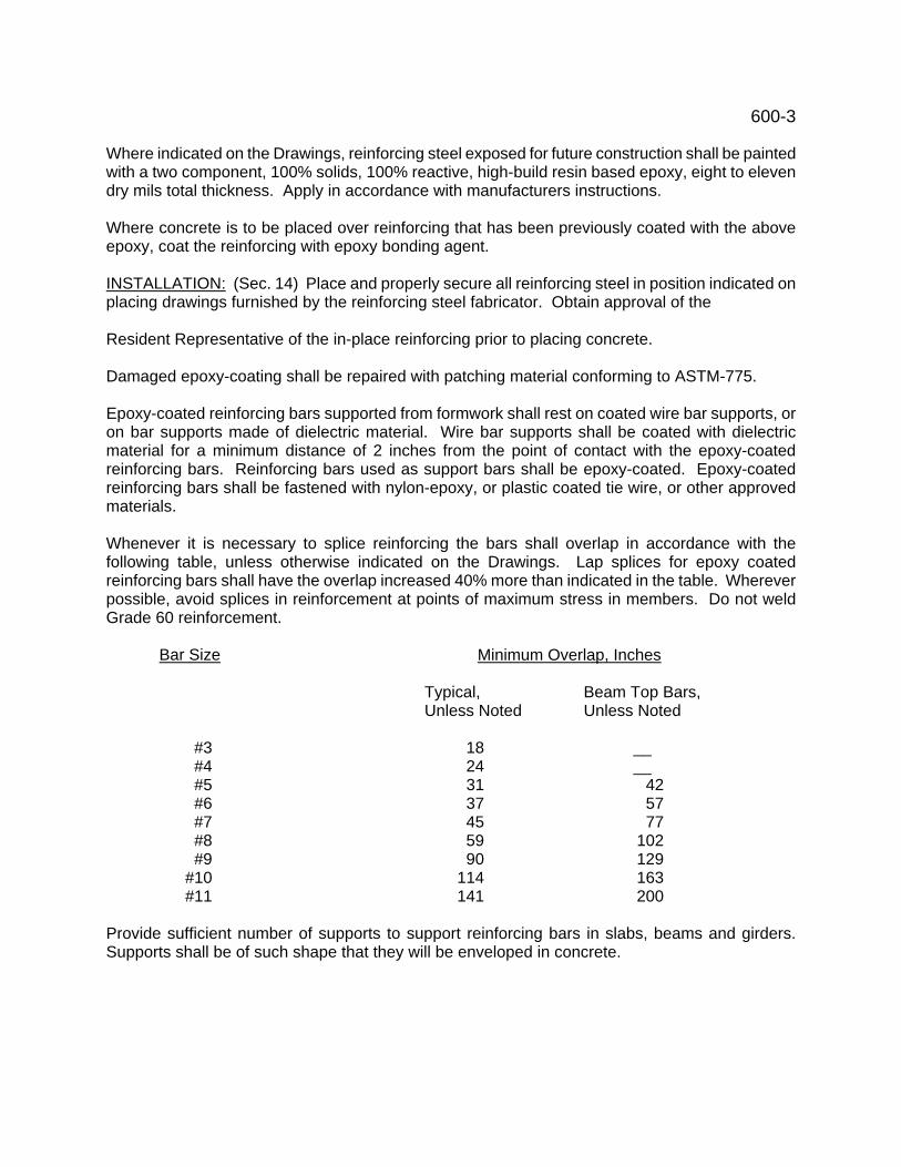
600-3 Where indicated on the Drawings, reinforcing steel exposed for future construction shall be painted with a two component, 100% solids, 100% reactive, high-build resin based epoxy, eight to eleven dry mils total thickness. Apply in accordance with manufacturers instructions. Where concrete is to be placed over reinforcing that has been previously coated with the above epoxy, coat the reinforcing with epoxy bonding agent. INSTALLATION: (Sec. 14) Place and properly secure all reinforcing steel in position indicated on placing drawings furnished by the reinforcing steel fabricator. Obtain approval of the Resident Representative of the in-place reinforcing prior to placing concrete. Damaged epoxy-coating shall be repaired with patching material conforming to ASTM-775. Epoxy-coated reinforcing bars supported from formwork shall rest on coated wire bar supports, or on bar supports made of dielectric material. Wire bar supports shall be coated with dielectric material for a minimum distance of 2 inches from the point of contact with the epoxy-coated reinforcing bars. Reinforcing bars used as support bars shall be epoxy-coated. Epoxy-coated reinforcing bars shall be fastened with nylon-epoxy, or plastic coated tie wire, or other approved materials. Whenever it is necessary to splice reinforcing the bars shall overlap in accordance with the following table, unless otherwise indicated on the Drawings. Lap splices for epoxy coated reinforcing bars shall have the overlap increased 40% more than indicated in the table. Wherever possible, avoid splices in reinforcement at points of maximum stress in members. Do not weld Grade 60 reinforcement.
Bar Size Minimum Overlap, Inches
Typical, Beam Top Bars, Unless Noted Unless Noted
#3 18 __ #4 24 __ #5 31 42 #6 37 57 #7 45 77 #8 59 102 #9 90 129 #10 114 163 #11 141 200 Provide sufficient number of supports to support reinforcing bars in slabs, beams and girders. Supports shall be of such shape that they will be enveloped in concrete.
700 - 1 SHEETING AND TIMBERING ITEM 700 PART 1 - GENERAL WORK INCLUDED: (Sec. 01) Furnish, install and leave in place, cut off as directed, such timber sheeting, bracing, and shoring for proper protection and support of adjacent structures, as indicated on the Drawings or as directed in writing by the Resident Representative. RELATED WORK: (Sec. 02) Furnished/paid for in this Item:
Earth Excavation/Backfill Item 120 DESCRIPTION: (Sec. 03) Include the furnishing and framing of all lumber, the furnishing of all spikes, mails, bolts and other fastenings, the excavation, the cutting off of sheeting and all necessary appurtenances. QUALITY ASSURANCE: (Sec. 04) All materials shall be good quality, sound. MEASUREMENT/PAYMENT: (Sec. 05) No measurement/payment will be made for wood sheeting or timbering removed or left in place which is specifically included in another Item, nor for any material left in place for the Contractor's convenience, nor for sheeting left in place without the direction of the Resident Representative, unless the Drawings specifically indicate that such material shall be left in place. PART 2 - PRODUCTS MATERIALS: (Sec. 06) Lumber for sheeting, sheet piling, plank floor, bracing and shoring must be merchantable stock of good quality hardwood, pine or fir lumber, sound, square-edged and free from unsound or loose knots and of such sizes, thickness, strength and quality as will fully protect the work and the workmen. PART 3 - EXECUTION INSTALLATION: (Sec. 07) Install and leave in place, all wood sheeting required to support the sides of the trench excavation below the elevation of the top of the pipe, wherever directed by the Resident Representative. Cut off where directed by the Resident Representative. No sheeting left in place shall extend within two feet of the surface. Remove shoring and bracing as the backfill reaches the elevation of the shoring and bracing. Remove such materials off the site.
900 - 1 SEWER PIPE IN PLACE ITEM 900 WORK INCLUDED: (Sec.01) Furnish all labor, Materials and equipment, and lay and join all sewer pipe which is necessary for the proper completion of the work, as shown on the Drawings and specified herein. REFERENCE ITEMS: (Sec. 02) Items of work and/or Materials to be performed and/or furnished and included for payment in this Item are:
Earth Excavation and Backfill Item 120 LSM Item Special #3 PVC Gravity Sewer Pipe Item 1400 Concrete Pipe Culverts, Drains and Sewers Item 1210 Testing of Pipe Lines and Sewers Item 1600
MATERIALS: (Sec. 03) All pipe and fittings furnished under this Item shall comply with the latest ASTM Specifications as shown below:
ASTM Service Reference Item Trunk and Lateral Sewers Specs. Connection Item Reinforced Concrete Pipe C-76 As selected from above 1210 PVC Gravity Pipe D-3034 PVC 1400 NOTE TO BIDDER: The Contractor shall specify the kind of pipe he proposes to furnish and indicate same on the Bid Schedule. INSTALLATION: (Sec. 04) All sewer pipe and fittings shall be installed as specified in the respective Item for the type of pipe selected. Contractor shall use care during installation to ensure that proper bedding procedures, and compaction of bedding, is performed. TESTING: (Sec. 05) The sewers constructed under this Item shall be tested as specified under the Item for Testing of Pipe Lines and Sewers. If PVC Gravity Sewer Pipe is installed, a deflection test as specified in Item 1400 shall be performed. PAYMENT: (Sec. 06) Per Linier Foot of pipe installed and measured.
900 I-1 POINT REPAIR FOR
(CIPP) RECONSTRUCTION
ITEM 900-I PART 1 - GENERAL WORK INCLUDED: (Sec. 01) Furnish and install PVC gravity pipe sewer and fittings as required and specified. RELATED WORK: (Sec. 02) Furnished/paid for in this Item: (as applicable) Soil Erosion/Sedimentation Control Item 116 Earth Excavation/Backfill Item 120 Sheeting and Timbering Item 700 PVC Sewer Pipe Item 1400 Testing of Pipe Lines and Sewers Item 1600 Furnished/paid for in respective Item: (as applicable) Rock Excavation and Backfill Item 125 Granular Backfill Item 165 LSM Item Special #3 Topsoil Item 205 Seeding Item 210 Pavement, Curbs, Gutters and Sidewalks Item 300 Bulk Concrete (as specified) Item 505 DESCRIPTION: (Sec. 03) Work in this Item consists generally of excavating for, and the proper point repair of the existing sewer, PVC gravity sewer pipe, fittings, testing the installation and associated work. QUALITY ASSURANCE: (Sec. 04) Materials shall be new and of their best quality. Materials shall be subject to inspection and approval upon delivery to job site. REFERENCES: (Sec. 05) ASTM - American Society for Testing and Materials SCDOT – South Carolina Department of Transportation SUBMITTALS: (Sec. 06) Shop Drawings - See General Conditions. Provide five (5) sets for record purposes only. Include pipe material, dimensions, joint/gasket details and
900 I-2 certification that materials conform to current, applicable standards. DELIVERY, STORAGE, HANDLING: (Sec. 07) Methods of handling, unloading and storage of pipe and fittings shall be in accordance with manufacturer's recommendations. ALTERNATES/ALTERNATIVES: (Sec. 08) Alternate pipe/fittings are not specified in this Item, but may be considered on a case by case basis. MEASUREMENT: (Sec. 09) EACH point repair shall be paid separately, and shall include all labor, material required to complete said repair. WARRANTY: (Sec. 10) See General Conditions. PART 2 - PRODUCTS MATERIALS: (Sec. 11 Pipe and fittings 4 inches through 15 inches diameter shall be solid wall ASTM Specification D-3034 SDR-35, ASTM F-789, or smooth interior/corrugated exterior, ASTM Specification F-949, or ASTM Specification F-794 as indicated on the Drawings. Pipe and fittings 18 inches and larger shall conform to ASTM Specification F-679, wall thickness T-1, or ASTM F-794. Pipe shall be furnished in standard manufactured lengths. Each length of pipe shall be marked with manufacturer's name, nominal diameter, and "hone" mark on the spigot end to indicate when the pipe is inserted to the "home" position. Joints shall be push-on type, with an elastomeric ring gasket compressed in an annular space between a bell end and spigot end of pipe, conforming to ASTM D-3212. Elastomeric ring gaskets shall conform to ASTM F-477 for low head application. Bedding material shall be Class 1-A material as per ASTM D-2321 PART 3 - EXECUTION INSPECTION: (Sec. 12) Inspect site and determine conditions that may effect the proper execution of the work. Pipe, fittings and specials shall be carefully examined by the Contractor and Resident Representative for effects just before laying. No pipe or fitting shall be used which is known to be defective. Pipe and fittings shall be thoroughly cleaned before being laid.
900 I-3 PREPARATION: (Sec. 13) Soil Erosion/Sedimentation control measures shall be implemented as required to prevent permanent damage to the construction site. INSTALLATION: (Sec. 14) Pipe and fittings shall be installed per ASTM D-2321 "Underground Installation of Flexible Thermoplastic Sewer Pipe". Use laser beam for establishing line and grade where necessary. The method used shall be as recommended by the manufacturer of the laser equipment and must be satisfactory to the Resident Representative. The laser beam shall not be of greater power than 2.5 milliwatts (0.0025). A continual visual check shall be provided by the laser equipment. The contractor shall not deviate from the required line of grade without the written consent of the Consulting Engineer. No pipe shall be laid until a sufficient length of trench as been properly prepared to permit laying at least one standard length of pipe at one time. Excavate and backfill as specified in the applicable Item for excavation and backfill, within the measurement limits indicated on the Drawings, except as modified by the section covering "Additional Authorized Excavation" in the Item for Earth Excavation/Backfill. Install pipe in well compacted bedding material, placed on undisturbed earth or well compacted foundation material. Uniformly support pipe throughout its length except for the bell holes required for the proper installation of the joints. The ends or shoulder of each pipe shall abut against the adjacent pipe in such manner that there will be not unevenness along the inverts. Pipe shall not be laid in water or on frozen trench bottom or, when in the opinion of the Resident Representative, trench conditions or weather are unsuitable for such work. Pipe delivered for installation shall be strung so as to minimize the entrance of foreign material. At the end of the day, and at such other times that work is not in progress, all openings in the pipe line shall be plugged. Joints of all pipe in the trench shall be completed before work is stopped. If water accumulates in the trench, the plugs shall remain in place until the trench is dewatered. CLEAN-UP: (Sec. 16) Clean-up of Site: Remove all surplus excavation, pipe, broken concrete, stones, and miscellaneous debris and dispose of off the site. Grading providing drainage shall be included. The clean-up and disposal of the cleared materials shall be done as soon as practical after laying of the sewer pipe and as the Resident Representative may direct. However, clean-up work shall not fall behind the pipe laying more than 800 feet. Should the Contractor not
900 I-4 keep his clean-up work within the aforementioned distance the Contractor shall be required to cease further pipe laying until such clean-up is accomplished. Cleaning of Pipe: After completion of the pipe installation, and prior to acceptance by the Owner, the Contractor shall, with the Owner and Resident representative, inspect the interior of the pipe. All foreign materials such as silt, gravel, debris, etc. shall be removed and disposed of off the site.
901-1
CURED IN PLACE PIPE (CIPP) RECONSTRUCTION
ITEM 901
GENERAL: (Sec. 1.0) This section includes all labor, materials, transportation and equipment necessary to rehabilitate by means of the cured in place pipe (CIPP) process, deteriorated sections of the existing sanitary sewers shown on the contract drawings. It is the intent of the section of this specification to provide for rehabilitating sanitary sewers by means of the cured in place pipe (CIPP) process. When complete, the cured in place pipe should: (Sec. 1.2)
1. Extend from one manhole to the next manhole in a continuous length;
2. Provide flow capacity equal to or greater than that of the existing pipe;
3. Yield three-dimensional, cross linking strength in tension, compression, and flexural modulus which is structurally sound;
4. Provide a service life which is supported by documented, independent test
analysis. REFERENCE SPECIFICATIONS: (Sec. 1.3) This specification references standard specifications which are made a part hereof by such reference and shall be the latest edition and revision thereof. All work accomplished must be in strict accordance with the referenced standards.
American Society for Testing and Materials ASTM F-1212-91 Standard Practice for Rehabilitation of Existing Pipelines ASTM D-638 Tensile Strength ASTM D-790 Flexural Strength ASTM D-790 Modulus of Elasticity ASTM D-732 Shear Strength ASTM D-695 Compressive Strength SCOPE OF WORK: (Sec. 1.4) The work shall include but is not limited to: A. Cleaning of existing designated pipe and televising and videotaping of the clean pipe
("before"). B. Insertion of liner into existing sewer mains without excavation. C. Cutting of the new cured in place pipe liner to re-establish user lateral connections
without excavation. D. Provision of by-pass pumping of flows around the pipelines affected by the lining
901-2
process. This by-pass system must be a leak-proof system. E. Televising and videotaping of reconstructed sewer line sections ("after"). QUALITY ASSURANCE: (Sec.. 1.5) Installation of the sewer cured in place pipe lining system shall be performed by an experienced contractor. The contractor shall provide evidence of CIPP experience. SUBMITTALS: (Sec. 1.6) Furnish the following: A. Manufacturers Literature and Data, including physical characteristics, application
and installation instructions, and recommendations for:
1. Flexible Liner Material 2. Line Design Thickness 3. Resin System
B. Procedure Report: A written report outlining the step-by-step procedures for the
execution of the relining operations (i.e., length,line obstructions, excavation, etc.) shall be submitted by the Contractor prior to the commencement of work. Any deviation from the pre-specified plan for the relining operation must be presented prior to execution.
C. Tests: Tests for compliance with this specification shall be made as specified herein
and according to the applicable ASTM specifications. A certificate of compliance with this specification shall be furnished by the manufacturer for all material furnished under this specification.
D. Independent Testing Report: A report listing independent testing of the CIPP
structural properties and the results of these tests. DESIGN (Sec. 2) GENERAL: (Sec. 2.1) The Contractor shall include the recommended tube thickness for each manhole to manhole section within the scope of work, and shall supply design calculations indicating how the tube thickness dimensions were obtained. Each tube shall be designed to withstand internal and/or external loads as dictated by site conditions. Design calculations shall be in strict accordance with ASTM F-1216-93-X.I. Assume pipe ovality 3% and water loading 50% of average depth. CAPACITY: (Sec. 2.2) The reconstructed pipe shall be designed such that the resulting capacity of the pipe is equal to or greater than that of the existing pipe. In order to maximize the capacity of the reconstructed pipe the inside diameter must be as large as possible, therefore increasing the effluent carrying area of the pipe. The chart below lists acceptable inside diameters of the reconstructed pipe.
901-3
ORIGINAL PIPE CURED-IN-PLACE PIPE I.D. AREA I.D. AREA % LOSS (Inches) (Sq. inches) (Inches) (Sq. inches) of Area 8 50.3 7.528 44.5 12 10 78.3 9.528 71.3 9 12 113.1 11.528 104.4 8 The contractor may require occasional deviation from this chart where unique circumstances warrant such an action. Final approval rests with the owner's engineer or contracting officer. SIZING: (Sec. 2.3) The tube shall be designed to a size that, when cured, will fit tightly against the internal circumference of the original conduit; this tight fit minimizes loss of original pipe size. Allowance for longitudinal and circumferential stretching of the tube during installation shall be made by the Contractor. The Contractor shall design the length of the tube to effectively carry out installation and sealing at end points. The contractor shall verify pipe dimensions shown on contract drawings before designing and reconstructing pipe. INSTALLATION: (Sec. 2.4) The tubes shall be designed to withstand negotiation of offsets, gaps, angles (not more than 900), and grades without damage to the tube during the installation process. Individual runs can be made over one or more manhole-to-manhole sections, as determined in the field by the Contractor. The tubes shall be inverted in accordance with ASTM F-1216-93. MATERIALS: (Sec. 3) The flow line shall be accessible from each manhole. TECHNICAL REQUIREMENTS: (Sec. 3.1) General: The liner shall be fabricated from materials which, when cured, will be chemically resistant to withstand internal exposure to sewage gases containing normal levels for domestic sewage of hydrogen sulfide, carbon monoxide, carbon dioxide, methane, traces of mercaptains, kerosene, saturation with moisture, dilute sulfuric acid, external exposure to soil bacteria, and any chemical attack which may be due to materials in the surrounding ground. Felt Content and Liner: The felt content shall be determined by the contractor and approved by the engineer for each line section. Thickness of cured liner to be as specified (-10%;+5%) and shall not include the thickness of the polyurethane inner liner. The polyurethane liner shall be 12-18 mils in thickness. Resin Content: The resin content of the liner shall be 85 percent by volume of the final vacuum impregnated felt tube. MATERIALS: (Sec. 3.2) General: All materials used in the installation process shall provide, after the curing process, the minimum mechanical properties listed herein All materials shall be approved prior to the installation into the existing piping. Any rejected

901-4 material shall be replaced with approved materials at the contractors expense. Resin: The polyester or vinylester resin shall be a resin for general chemical applications approved in advance of installation. Fillers and Pigments: The polyester resin used shall not contain fillers, except those required for viscosity control. Up to 5 percent by mass, thixotropic agent which will not interfere with visual inspection may be added for viscosity control. Resins may contain pigments, dyes, enhances, or colorants which will not interfere with viscosity control. Epoxy Resin: The use of epoxy resins compatible with the system to impregnate the liner may be permitted in some circumstances. The use of up to 40 percent by mass of suitable fillers may be permitted. The use of epoxy resin in any liner may be specified by the contractor, if conditions are deemed to warrant their use for approval. Reinforcing Material: The reinforcing material of the liner shall be of a needle interlocked terylene felt or other material as approved. Liners may be made of single or multiple layer construction where any layer must not be less than 1.5 mm thick. A suitable mechanical strengthener membrane or strips may be sandwiched in between layers where required to control longitudinal stretching. The minimum thickness of a bonded polyurethane membrane and inner liner, if used, shall be 0.25 mm + 5 percent and shall not affect the structural dimension requirements of the cured in place piping. Mechanical Properties: The cured in place pipe shall meet the following minimum strength requirements: Tensile Strength @ Yield 20 C 2,500 psi Flexural Strength 5,000 psi Flexural Modulus of Elasticity 300,000 psi Impact Strength 1.5 ft.-lb/in Shear Strength 7,000 psi Modulus of Elasticity-Long-Term 125,000 psi Hardness (Barcol) 33 Heat Distortion Temperature 70 C Minimum thickness of finished liner for 4" pipe = 3.0 mm Minimum thickness of finished liner for 6" pipe = 4.5 mm Minimum thickness of finished liner for 8", 10" and 12" pipe = 4.5 mm Finish: The finished lining shall be continuous over the entire length of an insertion run between two manholes and be as free as commercially practical from visual defects such as foreign inclusions, dry sports, pinholes and delamination. The lining shall be impervious and free of any leakage from the pipe to the surrounding ground or from the ground to the inside of the lined pipe. The inner surface shall be free of cracks and crazing with smooth finish and with an average of not over 2 pits per square foot, providing the pits are less than 3 mm diameter
901-5 and not over 1 mm deep and are covered with a sufficient resin to avoid exposure to the inner fabric. Some minor waviness that will not appreciably decrease the flow cross section or affect the flow characteristics or be the cause of a possible chokeage may be permissible if approved by the contracting officer. EXECUTION: (Sec. 4) Cured In Place Pipe Liner Installation: (Sec. 4.1) General: The contractor shall deliver the uncured resin impregnated liner to the site, provide all equipment required to install the liner into the conduit and cure it once in place. The liner shall be impregnated with resin not more than 24 hours before the proposed time of installation and stored out of direct sunlight in a closed container, and refrigerated to a temperature of less than 70 degrees F. The impregnated liner shall be transported to the site just prior to installation in a suitable light proof container. Liner Installation: The liner will be installed into the conduit from a suitable platform located above the manhole or other point of installation. All labor and material required for installation shall be included in the unit price. Cured In Place Pipe: The contractor shall supply a suitable heat source and water recirculation equipment capable of delivering hot water to the far end of the liner to quickly and uniformly raise the water temperature in the entire liner above the temperature required to commence the exothermic reaction of the resin, as determined by the catalyst system employed. The heat source shall be fitted with suitable monitors to gauge the temperature of the incoming and outgoing water supply to determine when uniform temperature is achieved throughout the length of the liner. Water temperature in the liner during the initial and post cure period shall not be less than 120 degrees F or more than 200 degrees F, or as specified by the resin supplier. Live steam shall not be permitted to enter the curing liner. In addition to the gauges on the incoming and outgoing water supply, there shall be thermo couples placed between the liner and the sewer pipe at the end of the liner being cured to accurately measure the liner temperature. The contractor shall submit, in writing, for approval, no less than 15 days prior to beginning work, his method of monitoring line curing temperatures. A record of the reading of the thermocouple shall be kept and presented for each section lined. PRIOR TO LINE INSTALLATION: (Sec. 4.2) The following procedures prior to liner installation shall be adhered to: Cleaning of Sewer Line: Prior to a cured in place lining of pipe or line so designated, it shall be the responsibility of the contractor to clean debris out of the sewer line in accordance with 7th edition dated July 1991, National Association of Sewer Contractor (NASSCO) Specification. This work shall be considered as a part of Cured In Place Pipe rehabilitation for the appropriate pipe size and required manhole. Definitions of light, medium, and heavy
901-6 pipe cleaning. Light cleaning - where it has been determined through a visual inspection that only small deposits of loose debris, 1 to 2 inches in depth, exists within the pipeline. Medium cleaning - where it has been determined through a visual inspection that medium deposits of loose debris, 2 to 4 inches in depth, exists within the pipeline. Heavy cleaning - where it has been determined through a visual inspection that heavy deposits of loose debris or root growth exists within the pipeline. Heavy equipment will be used to facilitate the removal of heavy deposits. Bypassing Sewage: The contractor shall bypass the sewage around the sections of sewer that are to be lined. The bypass shall be made by plugging an existing upstream manhole, if necessary, and pumping the sewage into a downstream manhole of capacity and size to handle the flow. At the end of each working day, temporary tie-in shall be made between the relined section and the existing system and the bypass plug removed, but only after relined section has been cured for the proper time limit. Line Obstructions: It shall be the responsibility of the contractor to clear the liner of obstructions and solids that will prevent the insertion of the liner. Pipe Repair: Any pipe repair required to reline the pipe shall be made by the contractor prior to relining. SERVICE CONNECTIONS: (Sec. 4.3) Opening of Service Connections: After the liner has been cured, all existing active services shall be reconnected, as directed by the owner. The recommendation of services shall be done, unless otherwise directed by the Contracting Office without excavation, from the interior of the pipeline by means of a television camera directed cutting device. Location of the service shall be from the pre-cured in place pipe inspection records and camera observation. The camera directed cutting device shall reestablish the service. The cost of testing for and re-connection service shall be included as a separate cost line item based upon unit cost per connection. VIDEO TAPING: ( Sec. 4.4) After the work on a delivery order is completed, the contractor shall supply a videotape or tapes showing the section of pipe being rehabilitated in its cleaned "before" condition and then followed by the "after" cured in place pipe lined condition. If in a section of rehabilitated pipe lateral connections are to be opened, the service connection reinstatements are to be recorded on video tape and they will be placed between the "before" and "after" on the final tape. The cost of this item shall be included in the cost line item for the cured in place pipe. Upon completion of installation work, the contractor shall restore the project area affected by his operation and perform any surface restoration in accordance with these
901-7 Specifications. The cost of this item shall be included in the cost line item for the cured in place pipe. EXPERIENCE, REFERENCES AND OTHER REQUIREMENTS: (Sec. 5.0) All bidders shall supply the following:
1. All applicable installation data as it relates to the method of installation and number of years experience of the installation crew.
2. A project installation list of all past projects in the State of Ohio having a scope equal
to or above the scope of the proposed project. Five years experience with a minimum of five projects similar to that of the proposed project is required.
3. A statement on the bid form which indicates that bidders have reviewed the entire
project site, and have taken into consideration access/restoration requirements that must be met in order to successfully complete the project.
PAYMENT: (Sec. 6.0) Payment for (CIPP) shall be a unit price per liner foot, said price shall include all work labor and material required to complete the work described in this specification.

925 - 1 FORCE MAIN IN PLACE ITEM 925 WORK INCLUDED: (Sec.01) Furnish all labor, Materials and equipment, and lay and join all sewer pipe which is necessary for the proper completion of the work, as shown on the Drawings and specified herein. REFERENCE ITEMS: (Sec. 02) Items of work and/or Materials to be performed and/or furnished and included for payment in this Item are:
Earth Excavation and Backfill Item 120 Granular Backfill Item 164 Polyethylene Pressure Pipe DIPS Item 1411 Polyethylene Pressure Pipe Item 1412 Testing of Pipe Lines and Sewers Item 1600
MATERIALS: (Sec. 03) All pipe and fittings furnished under this Item shall comply with the latest Specifications as shown below:
ASTM AWWA Reference Item Force Main Specs. Specs. Item Polyethylene Pressure Pipe DIPS AWWA C-906 1411 Polyethylene Pressure Pipe D-33501/F-714 AWWA C-901 1412 NOTE TO BIDDER: Pipe material must be as manufactured by Drisco pipe or equal. The Contractor shall specify the kind of pipe he proposes to furnish and indicate same on the Bid Schedule. INSTALLATION: (Sec. 04) All sewer Force Main and fittings shall be installed as specified in the respective Item for the type of pipe selected. Contractor shall use care during installation to ensure that proper bedding procedures, and compaction of bedding, is performed. TESTING: (Sec. 05) The Force Main constructed under this Item shall be tested as specified under the Item for Testing of Pipe Lines and Sewers and indicated on the General Notes. PAYMENT: (Sec. 06) The actual number of feet of Force Main installed in accordance with the specifications, measure along the axis after the pipe has been installed.
1000-1 DUCTILE IRON PIPE AND FITTINGS ITEM 1000 WORK INCLUDED: (Sec. 01) Furnish, install, connect, test and if required, sterilize all cast and/or ductile iron pipe, fittings and wall castings, including joint materials, coatings and linings as shown on the Drawings and specified herein. Earth excavation, backfill and bedding for buried pipe are included in this Item. The following, if required, shall be furnished and paid for in their respective Items.
Rock Excavation Item 125 Granular Backfill Item 164 Concrete Item 500
REFERENCE ITEMS: (Sec. 02) Work and/or materials to be performed and/or furnished in accordance with other Items but included for payment in this Item are:
Earth Excavation and Backfill Item 120 Sheeting and Timbering, Left in Place Item 700 Testing of Pipelines and Sewers Item 1600 Sterilization of Potable Water Lines and Tanks Item 1700
Applicable portions of the latest revision of the following specifications shall be included as a part of this Specification.
ANSI - American National Standards Institute ASTM - American Society for Testing and Materials AWWA - American Water Works Association ODOT - Ohio Department of Transportation, Construction and Materials
Specifications DESCRIPTION: (Sec. 03) This Item includes all cast and ductile iron pipe, fittings and wall castings, according to the designations listed below, together with joints and jointing materials, inside and outside protective coatings, couplings, expansion joints, drilling and tapping, testing and sterilization. Fittings are defined as any straight pipe three feet or less in length, bends, tees, laterals, filler pieces, reducers, reducing bends, etc., with or without bases, of whatever shape or dimensions, and any pipe of whatever length having two bells. Wall castings are defined as any special pipe as listed in the wall casting schedule, or marked as a wall casting on the Drawings. Yard piping is that pipe requiring excavation and terminating at the outside face of structure walls or at the bottom of floor slabs. Piping (structures) is that pipe requiring no excavation.
1000-2 DESIGNATION: (Sec. 04) The following designations correspond to the numbers stipulated in the proposal and indicate the materials required: ITEM UNIT DESCRIPTION 1000 L.F. Ductile Iron Pipe, includes pipe and fittings (Distribution Systems an
Force Mains) 1001 L.F. Ductile Iron Pipe, Cement Lined, includes pipe and fittings
(Distribution Systems) 1002 Ton Ductile Iron Pipe, M.J., includes pipe only (Yard Piping) 1003 Ton Ductile Iron Pipe, M.J., includes pipe only (Structures) 1004 Ton Cast or Ductile Iron Pipe Fittings, M.J., (Yard and Structures) 1005 Ton Ductile Iron Pipe, Flanged 1006 Ton Cast or Ductile Iron Pipe Fittings, Flanged 1007 Ton Ductile Iron Pipe, Glass Lined, includes fittings, (Yard) 1008 Ton Ductile Iron Pipe, Glass Lined, includes fittings (Structures) 1009 Ton Cast Iron Wall Castings Gray cast iron pipe is a suitable substitute for ductile iron pipe if approved by the Engineer and furnished at no additional cost. PIPE AND FITTINGS: (Sec. 05) Pipe and fittings shall comply with the following standards unless specified otherwise: Ductile iron pipe, AWWA C151. Rubber gasket joints for pipe with bell and spigot, push-on, or mechanical joints for all pressure classes, AWWA C111. Flanged pipe, with threaded flanges AWWA C115. Flange facing and drilling, ANSI B16.1 for 125 lb. rating and B16.2 for 250 lb. rating. Fittings for all types of joints and 125 lb. and 250 lb. pressure ratings, AWWA C110. Joint materials, AWWA C111. River crossing pipe, AWWA C151 with pipe, bell and gland made of ductile iron. Bolts and gaskets, AWWA C111. Locked mechanical joint pipe shall be rated for 250 psi water working pressure with wall thickness added to compensate for the locking ring groove. PROTECTIVE COATINGS AND LININGS: (Sec. .06) Coat the outside of all pipe and fittings and the inside of all pipe and fittings which are not cement lined with a coal-tar or asphalt base bituminous coating per AWWA C151. Clean castings of rust and foreign matter before coating. Wall castings to be inserted in concrete walls may be either uncoated or coated on their exterior; uncoated exteriors are preferred, but are not mandatory.
1000-3 Interior piping which is to be painted may be furnished with a prime coat of Tnemec 77 Chem Primer, Koppers Pug Primer or equal in lieu of coal-tar coating. Where shown on the Drawings, install cast iron pipe with an 8 mil polyethylene encasement, AWWA C105. Cement Lining: Cement line all pipe and fittings used for potable water distribution systems in strict conformity with AWWA C104 standard specifications for Cement-Mortar Lining for Cast Iron and Ductile Iron Pipe and Fittings for Water, standard thickness, unless otherwise specified. Apply bituminous seal coat inside after the lining has cured. Furnish with each shipment of cement mortar lined pipe two copies of a certification that all cement lining meets the requirements of AWWA C104. Cement lining shall not be used for force mains or lines located in water or wastewater treatment plants, or lift stations, unless specifically noted on the Drawings. Glass Lined Pipe: Where specified or shown on the Drawings, line the inside of pipe with SG-14, as manufactured by the Permutit Company, Paramus, NJ, SL-31 as manufactured by Ceramic Coating Company, Newport, KY, or equal, with a thickness of .008" - .012", a hardness of 400 on the Knoop scale or five to six on the Mohs scale, and a density of 2.5 to 3.0 grams per cubic centimeter. Hold field cutting to an absolute minimum. Spalling shall not occur more than one-eight inch from the cut, with no fish-scaling or crazing beyond this point. Follow the recommendations of the manufacturer when cutting pipe. Inspect each fitting or piece of pipe before installing to insure that there are no defects in the lining. Any piece having a break in the lining shall be rejected. Polypropylene Lining: Where shown on the Drawings furnish ductile iron pipe with polypropylene lining. Use only virgin polypropylene with the following physical properties:
Tensile Strength 4500-5200 psi Elongation 200% Specific Gravity 0.90 - 0.92
Minimum liner wall thickness shall be as follows:
1" and 1 1/2" pipe .150" 2" and 3" pipe .175" 4" pipe .210" 6" pipe .240" 8" and 10" pipe .285"
Provide flange sealing surfaces and 1/16" vent holes as recommended by the lining manufacturer. Face plates must remain in place during storage and handling; remove only for installation. Follow manufacturer recommendations for handling and installing.
1000-4 HANDLING AND INSTALLATION: (Sec. 07) Use suitable tools and equipment for the safe and convenient handling and laying of the pipe and fittings as described in the pamphlet "Guides for Installation of Ductile Iron Pipe and Gray Cast Iron Water Mains", published by the Ductile Iron Pipe Research Association. Unload pipe, fittings and accessories from cars or trucks with hoists or by skidding. Under no circumstances shall pipe be dropped. Do not skid nor roll against pipe already on the ground. Castings and lining must not be damaged; but, should slight damage occur to linings, repairs may be made at the site to the satisfaction of the Resident Representative. Just prior to installing any pipe or fittings, it shall be subject to inspection and approval by the Resident Representative. Use no broken, cracked, imperfectly coated, unsatisfactory or damaged pipe. Contractor is fully responsible for the material installed. Thoroughly clean all pipe and fittings before they are installed and keep clean until the work is completed. All pipe in buildings, tunnels and tanks shall be properly supported by cast iron, malleable iron, wrought iron or steel brackets or hangers, or by concrete piers, as shown on the Drawings, specified or as required. Lay buried pipe on bedding material. Use adequate means to prevent settlement. Bedding shall be gravel, crushed limestone or slag, No. 6, 67 or 68 gradation, per Table 703-1 of the ODOT Specifications, free from dirt and other deleterious materials, well tamped and laid on undisturbed earth or well tamped backfill. Uniformly support pipe throughout except bell holes are required for proper installation of the joints. Use no slag for bedding or backfill. Lay no pipe or fitting within six inches of solid rock or a boulder. When the pipes (new or existing) require cutting to fit in the lines, cut at right angles to the axis of the pipe leaving a smooth cut. No measurement will be made for the portion cut off if not installed. Wall Casting Option: In lieu of wall castings the Contractor may, if approved by the Engineer, provide and install modular mechanical type sealing assemblies. Seal assembly shall provide a watertight seal between the pipe and the sleeve and shall include a steel sleeve and seals of interlocking synthetic rubber links shaped to continuously fill the annular space between the pipe and the sleeve. Sleeves shall be provided with water stops at the center of the wall. Provide corrosion protected carbon steel bolts, nuts and pressure plates. Each assembly shall be sized as recommended by the manufacturer to fit the pipe and sleeve involved. JOINTS : (Sec. 08) Joints shall be as indicated on the Drawings. Mechanical Joints; Join all mechanical joint pipe and fittings using rubber or neoprene gaskets and cast iron (ASRM A-48) follower glands. Use tee head bolts and hex nuts of corten steel alloyed with copper (0.5%), nickel (0.5%) and chromium (1%). Clean the inside of the bell and the outside of the spigot by wire brushing just before making the joint to remove rust and foreign material. Bring the follower gland toward the pipe flange evenly. Tighten joint bolts with approved wrenches to the tension recommended by the pipe manufacturer.
1000-5 Whenever connections are made between cast iron mechanical joint pipe or fittings and pipe or fittings of other material, use an approved type of transition gasket in the mechanical joint. Push-On Joints: Join pipe with push-on joints with a rubber ring gasket inserted in the bell end. All rubber gaskets shall bear the identifying mark of the manufacturer, gasket size, and the year of manufacture. Rubber shall be all new natural or synthetic having the mechanical properties required for the service. Clean the inside of the bell and the outside of the spigot by wire brushing just before making the joint. Use lubricant recommended by the pipe manufacturer. Flanged Joints: Align connecting flanges so that no external force is required to bring them together. Use gaskets, bolts or studs, and nuts meeting the following specifications:
Bolts: ASTM A-307, Grade B with ANSI B18.2 Hexagon heads, ASNI B1.1 coarse thread series, Class 2A fit.
Studs: ASTM A-108, ANSI B1.1 coarse thread series, Class 2A fit. All studs and nuts used in wall castings, either flanged or mechanical joint in contract with a liquid, or underground shall be 304 stainless steel.
Nuts: ASTM A-307 ANSI B18.2 heavy hexagon dimension, ANSI B1.1 coarse thread series, Class 2B fit.
Cadmium plate bolts and nuts after the threads are cut. Cadmium plating, shall have a thickness of 0.0003 to .0005 inch.
Gaskets: Use full face or ring type red rubber gaskets, one sixteenth inch thick in all flanged joints, except that one-eighth inch thick gaskets may be used in runs of pipe over 30 feet in length.
Grooved Joints: Use grooved joints where shown on the Drawings. Pipe Joints shall be flexible unless noted as rigid, Victaulic Style 31, Gruvajoint by Aeroquip or equal. Bell and Spigot Joints Bell and spigot joints will not be permitted unless shown on the Drawings or required to make connections to existing piping. COUPLING: (Sec. 09) Couplings buried in the ground or submerged in water, sewage or sludge shall be Dresser Style 53, Rockwell 431 or equal; couplings installed on pipe exposed in buildings or above ground shall be Dresser Style 38, Rockwell 411 or equal, for cast iron pipe; Dresser Style 62, Rockwell 415, or equal shall be used to join cast iron and steel pipe. Middle rings of the couplings shall have a length of not less than seven inches, and a thickness of six inch to twelve inch pipe of not less than one-quarter inch, and for pipe fourteen inches in diameter and over, not less than five-sixteenths of an inch. After the installation of couplings that will be furied or submerged, paint the entire coupling, including all nuts and bolts, with two coats of coal tar enamel.
1000-6 EXPANSION JOINTS: (Sec. 10) Expansion joints, when called for on the Drawings shall have integral duck and rubber flanges, with individual solid steel ring reinforcement and a carcass of highest grade woven cotton or acceptable synthetic fiber. Joints shall be pipe line size, and meet working pressures, conditions and face to face measurements as designated. They shall be of an arch-type construction with the number of arches (corrugations) dependent on projected movement. Expansion joints shall be designed for the appropriate temperatures. Furnish split back-up (or retaining) rings. Furnish control units when movements are projected over and above allowables for the joint. all joints shall be finish-coated with Hypalon paint to prevent ozone attack. The joints shall be Style 500 (pressure) or Style 700 (vacuum or vacuum-pressure) manufactured by Mercer Rubber Co., Trenton, NJ, 204 or 206 by Garlock Packing Co., Palmyra, NY, or 4140 or 4150 by U.S. Rubber Co., or equal. DRILLING AND TAPPING: (Sec. 11) Drill and tap pipe and fittings to provide for drainage plugs, house service lines, air vents, or any other piping as required. Drill all holes accurately at right angles to the axis of any pipe, fitting, or face of plugs. Whenever the wall thickness of the pipe or fitting to be tapped is such that it will not permit enough threads equal to, or greater than, the normal engagement of American Standard Pipe Threads, furnish and install a piece of pipe or a fitting with cast-in-place boss suitable for drilling and taping or a cast iron tapped saddle. Include payment for saddle and installation (if required) in the unit price for the pipe. PIPE BUILT IN MASONRY: (Sec. 12) Where shown on the Drawings, or where necessary, support the pipe and fittings by masonry. Wherever openings in concrete are left during construction and pipes grouted in place, provide a keyway in the concrete and use a non-shrinking grout. PAINTING: (Sec. 13) All field painting of pipe and fittings (if required), except as specifically provided in this Item, shall be performed and paid for in Item 3600, Painting. MARKING: (Sec. 14) Mark all pipe and fittings in accordance with the applicable AWWA standard. Paint an identification number on each piece to agree with a Bill of Material and layout drawing furnished to the Resident Representative prior to the start of the pipe installation. The Contractor shall also keep a copy of the Bill of Material and layout drawing in his field office. SHOP DRAWINGS: (Sec. 15) Furnish the following to the Engineer for approval:
1. Class of pipe. 2. Pipe material specification. 3. Details of all flexible connections. 4. Location of all flexible connections not shown on the Drawings. 5. Details and specification for all joint accessories. 6. Any deviations from the Drawings and the reason for the deviation.
TESTING: (Sec. 16) Shop test each piece of pipe by hydrostatic pressure before shipment from the factory. Submit the manufactures certificate in duplicate stating that all pipe meets the requirements of these Specifications.
1000-7 After the complete line, or a reasonable portion thereof, has been installed, test in accordance with Item 1600, Testing Pipe Lines and Sewers. Backfill buried lines before testing. Make necessary repairs or replacements and retest the line until the requirements for tightness are net and the installation is satisfactory to the Resident Representative. STERILIZATION: (Sec. 17) After completion of the installation of potable water lines, flush and disinfect in accordance with Item 1700, Sterilization of Potable Water Lines and Tanks. CLEAN-UP: (Sec. 18) This Item, 1000, shall include surface clean up immediately following backfilling, removal of all surplus excavation, pipe broken concrete, stones, and all miscellaneous debris. Rough grade to provide drainage. PAYMENT: (Sec.19) Lineal Feet: The length of cast iron pipe line to be measured for payment shall be the total length of pipe, including fittings, bends, tees, crosses and required appurtenances, etc., actually placed in accordance with the Drawings, Specifications, or as required, and measured along the centerline of the pipes. Where existing pipe is cut and fittings or valves are installed in the existing pipe for connecting to a new main, the laying length of the new pipe, fittings and valves installed in the existing line shall be included in the length measured for payment, except where specifically included under other Items of the Specifications. Payment for pipe or fittings included in other Items, such as bridges and highway crossings, special crossings, or system connections, shall be included for payment in their respective Items. Weight: Include for payment in this Item, the number of tons actually placed in accordance with the Drawings, Specifications, or as required. Weight of individual pieces shall be taken from suppliers' shipping lists or invoices, except as limited below. Do not include weights of bolts, nuts, gaskets, follower rings, glands, lead, oakum, paint and other joint accessories. Flanged Cast Iron Fittings: Include for payment in this Item the weight of flanged fittings actually furnished and placed in accordance with the Drawings, and Specifications, as required. Cast Iron Wall Castings: Include for payment in this Item the total weight of wall castings, as defined herein, actually installed in the finished work in accordance with the Drawings. The total weight of the various categories of ductile or cast iron pipe, fittings etc., shall not exceed the sum of standard, weights by the following percentages:
Bell and spigot, mechanical joint or push-on pipe 2% Bell and spigot, mechanical joint or push-on fittings 10% Flanged pipe 5% Flanged pipe fittings 10% Wall casting 12%
Standard weights shall be those given in the Handbook, Ductile Iron Pipe, Cast Iron Pipe published by the Ductile Iron Pipe Research Association.

1000-8
1050-1 CORRUGATED METAL PIPE ITEM 1050 WORK INCLUDED: (Sec. 01) Furnish all labor, materials and equipment necessary to install corrugated metal pipe as indicated on the Drawings and specified herein. The following related work shall be furnished in this Item where applicable:
Earth Excavation and Backfill Item 120 Concrete Item 500 Testing of Pipe Lines and Sewers (if required) Item 1600
Rock excavation if required shall be performed in accordance with Item 125, Rock Excavation and Backfill and paid for in that Item if this is a unit price proposal. REFERENCE ITEMS: (Sec. 02) Applicable portions of the latest revision of the following Specifications shall be included as a part of this Specification.
SCDOT – South Carolina Department of Transportation, Construction and Material Specifications.
DESCRIPTION: (Sec. 03) Include all necessary earth excavation and backfill, coatings, linings, connection bands, concrete for joints and bedding if called for, to complete the work as specified and indicated on the Drawings. All pipe furnished in this Item shall comply with the SCDOT Specifications in so far as applicable. All pipe shall be galvanized. MATERIAL: (Sec. 04) All pipe 24 inches or less in diameter shall be fabricated from 16 gauge sheets. The gauge of metal of larger sized pipe shall be as indicated on the Drawings, or as called for in the proposal. Furnish pipe with bituminous coatings, linings and/or paved inverts where indicated or specified. Provide coated and lined pipe sections with two lifting lugs or brackets so that they may be handled without damaging the coating or the lining. Couplings: Make field connections between pipes with coupling bands as specified by the SCDOT Specifications. All coupling bands shall be galvanized, bituminous coated if specified, and shall insure the concentric alignment of the adjacent pipe sections. The bands shall be indexed into the inboard corrugations of the pipe and be a minimum width of 10-1/2 inches. Bands shall have a single harness consisting of two bolts through a strap-bar assembly. INSTALLATION: (Sec. 05) Lay corrugated metal pipe to specified lines and grades and with the ends poured in place at structures. The junction of corrugated metal pipe with vitrified clay, concrete, or other pipes, shall be encased in Class C concrete not less than four inches thick for a length of two feet.
1050-2 All earth excavation and backfill shall be performed as per Item 120, Earth Excavation and Backfill. Lay corrugated metal pipe in bedding, well tamped in six-inch layers, to the limits as indicated on the Drawings, uniformly supported throughout its entire length. Bedding material shall be gravel, crushed limestone # 57 gradation. Should the coating of any piece of pipe or band become damaged in a small area, it may be touched up with the same material as was used in the original coating provided the Resident Representative approves. The Contractor shall have on hand a supply of coating material which is the same as that applied at the time of the manufacture of the pipe or band. MEASUREMENT: (Sec. 06) For unit price proposals the length of the various sizes and types of corrugated metal pipe to be measured for payment under this Item shall be the actual length of each size and type of pipe furnished and placed in accordance with these Specifications, measured along the axis after the pipe and fittings have been connected in place. Included is the necessary earth excavation and backfill, coatings, connection bands, concrete for joints, bedding if called for, and the furnishing of all labor, materials, tools and appliances necessary to complete the work as specified or indicated on the Drawings.
1200-1 VITRIFIED CLAY PIPE DRAINS AND SEWERS ITEM 1200 WORK INCLUDED: (Sec. 01) Furnish all labor, materials and equipment and properly install vitrified clay pipe and fittings as shown on the Drawings and specified herein. REFERENCE ITEMS: (Sec. 02) Items of work and/or materials to be performed and/or furnished and included for payment in this Item are:
Earth excavation and Backfill Item 120 Granular Backfill Item 164 LSM Item Special #3 Concrete Item 500 Testing of Pipe Lines and Sewers Item 1600
Applicable portions of the latest revision of the following specifications shall be included as a part of these specifications:
ASTM American Society of Testing and Materials SCDOT South Carolina Department of Transportation
MATERIALS: (Sec. 03) Pipe and fittings shall conform to ASTM C700 Vitrified Clay Pipe, Extra Strength, Standard Strength, and Perforated. Pipe and fittings shall be extra strength unless otherwise specified. Compression joints shall conform to ASTM C425. Vitrified clay pipe and fittings with factory applied PVC collar, conforming to ASTM D-1784, Class 12454-B, or with factory applied fiberglass reinforced polyester collar may be furnished. Glazed or unglazed pipe may be furnished. Pipe between adjacent manholes shall be the same type. Old pipe or fittings previously used will not be allowed in the work. Pipe over six inch nominal inside diameter shall be provided in minimum four foot lengths, except to make closures. Bedding material shall conform to ASTM D-2321 CL- 1 . INSTALLATION: (Sec. 04) Methods of handling, unloading, cutting and joining pipe shall be in accordance with the manufacturer's recommendations. Pipe, fittings and specials shall be installed in accordance with ASTM C-12, "Standard Recommended Practice for Installing Vitrified Clay Pipe Lines." Pipe fittings and specials shall be carefully examined by the Contractor and Resident Representative for defects just before laying. No pipe or fitting shall be used which is known to be defective. Pipe and fittings shall be thoroughly cleaned before being laid.

1200-2 Excavation and backfill shall be done as specified in the applicable Item for Excavation and Backfill and within the measurement limits shown on the Drawings, except as modified by the section covering "Additional Authorized Excavation" in the Item for Earth Excavation and Backfill. Pipe shall be laid in well compacted bedding material. Pipe shall be uniformly supported throughout its length except for the bell holes required for the proper installation of the joints. The ends or shoulder of each pipe shall abut against the adjacent pipe in such manner that there will be no unevenness along the inverts. No pipe shall be paid in water or on frozen trench bottom, or when in the opinion of the Resident Representative the trench conditions or the weather are unsuitable for such work. Pipe delivered for the installation shall be strung so as to minimize the entrance of foreign material. At the end of the day, and at such other times that work is not in progress, all openings in the pipeline shall be plugged. Joints of all pipe in the trench shall be completed before work is stopped. If water accumulates in the trench, the plugs shall remain in place until the trench is dewatered. The Contractor shall use a laser beam for establishing line and grade. The method used shall be as recommended by the manufacturer of the laser equipment and must be satisfactory to the Resident Representative. The laser beam shall not be of greater power than 2.5 milliwatts (0.0025). The contractor shall provide reference points for line and grade in sufficient numbers to make possible the efficient use of the laser beam equipment. The Contractor shall not deviate from the required line or grade without the written consent of the Engineer. WYES, STACKS, SERVICE SEWER, AND RE-CONNECTIONS: (Sec. 06) Y branches, service stacks and house service sewers shall be 6 inches in diameter unless specifically shown or called for as a different size. Each Y branch shall consist of furnishing and placing a Y branch in the main sewer, straight pipe . A stack shall be used only when the centerline of the trunk or street sewer is more than four (4) feet below the expected elevation of the house service at the street sewer unless otherwise shown on the Drawings. Each standard service sewer shall consist of all earth excavation and backfill, granular bedding material, furnishing and installing all straight and curved pipe at the grade determined by the Resident Representative, (1.0% min.) from the Y branch or service stack to the property line, unless otherwise shown on the Drawings, or to the point of re-connection to an existing service sewer. Included shall be all joint materials, adapters if required, stoppers, location markers, testing and clean-up. Re-connection of existing service sewers shall consist of locating the existing service sewers, maintaining flow as required, all required earth excavation and backfill, bedding, disconnection of the existing service sewer from the existing trunk or street sewer, removal of existing service sewer as is necessary, securely plugging the discontinued service sewer when required, providing and installing adapters if connecting different types of pipe, and making a proper connection to the new
1200-3 service sewer. Y branches, service stacks and service sewer required for the proper completion of a re-connection shall be furnished and installed under this Item. The location of Y branches and service stacks shall be marked with a one-half inch diameter steel pin, 30 inches long. Ends of service sewers shall be marked by a precast concrete cylinder, 4 inches diameter x 30 inches long, with the top flush with the surface of the ground. Where curbs are available, the location of each service sewer shall be marked by a two inch cross cut into the top of the curb on the side of the street to be served by the service sewer. In all cases the open ends of Y branches, service stacks and pipes shall be securely closed with carefully fitted stoppers which will not move during field testing, and sealed to prevent the entrance of water, earth or other substance into the sewer. Approved plastic stoppers may be used if they fit properly into the bell. ABANDONING EXISTING SEWERS: (Sec. 07) Where existing sewer lines are encountered during construction and are shown on the Drawings or determined by the Resident Representative to be abandoned, all broken pipe within the excavation limits of the new construction shall be removed to permit proper placement of bedding and new pipe. At locations where the sewer to be abandoned falls outside of the excavation limits, broken and cracked pipe shall be removed back to a sound joint where a masonry plug shall be constructed of brick and mortar to completely seal the abandoned sewer from the infiltration of soil and water. The cost of abandoning existing sewers, including removal of broken and cracked pipe and installing plugs, shall be included in the unit price bid for installing new pipe. SHOP DRAWINGS: (Sec. 08) Submit five (5) sets of shop drawings as required of these Specifications. Included shall be pipe materials, dimensions, joint details and certification that materials conform to the applicable standards. FIELD TESTING: (Sec. 09) Test shall be infiltration, exfiltration or low pressure air test in accordance with the Item for Testing of Pipe Lines and Sewers. CLEAN-UP: (Sec. 10) This Item 1200, shall include surface clean-up, including removal of all surplus excavation, pipe, broken concrete, stones, and all miscellaneous debris. Rough grading providing drainage shall be included. The clean-up and disposal of the cleared materials shall be done as soon as practical after laying of the sewer pipe and as the Resident Representative may direct. However, clean-up work shall not fall behind the pipe laying more than 800 feet. Should the Contractor not keep his clean-up work within the aforementioned distance the Contractor shall be required to cease further pipe laying until such clean-up work is accomplished. CLEANING OF PIPE: (Sec. 11) After completion of the pipe installation, and prior to acceptance by the Owner, the Contractor shall, with the Owner or his representative, inspect the interior of the pipe. All foreign materials such as silt, gravel, debris, etc. shall be removed and disposed of off the site. MEASUREMENT/PAYMENT: Sec.(12) Measurement for payment shall be the number of linier

1200-4 feet ( laying length ) of pipe installed and measured.
1210-1 CONCRETE PIPE CULVERTS, DRAINS, AND SEWERS ITEM 1210 WORK INCLUDED: (Sec. 01) Furnish all labor, materials and equipment and properly install reinforced and non-reinforced concrete pipe and fittings as shown on the Drawings and specified herein. REFERENCE ITEMS: (Sec. 02) Items of work and/or materials to be performed and/or furnished and included for payment in this Item are:
Earth Excavation and Backfill Item 120 Testing of Pipe Lines and Sewers Item 1600
Applicable portions of the latest revision of the following specifications shall be included as a part of these specifications:
ASTM American Society for Testing and Materials SCDOT South Carolina Department of Transportation
MATERIALS: (Sec. 03) Non-Reinforced Concrete Pipe shall conform to the specification for concrete Sewer, Storm Drain and Culvert Pipe, ASTM Designation C-14. Maximum size shall be twelve inches. Reinforced Concrete Pipe shall conform to the specification for Reinforced Concrete Culvert, Storm Drain, and Sewer Pipe, ASTM Designation C76. Concrete Wall Pieces shall be fabricated in accordance with the layout requirements. Each pipe length shall have tongue and grooved ends formed on machined rings to insure accurate joint surfaces. Diameters of tongue and grooved surfaces shall not vary from the theoretical diameters by more than one sixteenth (1/16) inch. All reinforced concrete pipe shall be supplied in minimum lengths of six feet. Pipe using the "O" ring type joint shall be similarly formed but with a specially reinforced bell end. The reinforcing shall be adequate to meet all tensile stresses in the concrete caused by compressing the rubber "O" ring. Joints shall conform to ASTM C443. Reinforced Concrete Elliptical Pipe shall comply in all respects with ASTM Designation C507, and shall be horizontal elliptical (HE) or vertical elliptical (VE) of the class indicated on the Drawings or in the proposal. Lining for concrete pipe used in sanitary, or intercepting sewers, and when specified on the Drawings, shall be factory lined with a high-build, polyamide-cured, 2-Component coal tar epoxy coating, Military Specification, MIL-
1210-2 P23236. The lining compound shall be sprayed to obtain a continuous and relatively uniform and smooth lining with a minimum dry film thickness of 0.03 inches. The entire interior of the pipe, the interior and end of the bell and the outside and end of the tongue shall be coated. Surfaces to be coated shall be brushed with a stiff broom or brush and then air blown to remove all dust, dirt, loose sand and latent. No surface shall be coated until all grease, oil and other contaminants are entirely removed. All pipe shall be thoroughly dry before applying coating. Lining is not required for storm drains. Bedding material shall be gravel, crushed limestone or #57 gradation , free from dirt and other deleterious materials. INSTALLATION: (Sec.04) Methods of handling, unloading, cutting and joining pipe shall be in accordance with the manufacturer's recommendations. Pipe, fittings and specials shall be installed in accordance with the American Concrete Pipe Association. Pipe, fittings and specials shall be carefully examined by the Contractor and Resident Representative for defects just before laying. No pipe or fittings shall be used which is known to be defective. Pipe and fittings shall be thoroughly cleaned before being laid. Excavation and backfill shall be done as specified in the applicable Item for excavation and backfill and within the measurement limits shown on the Drawings, except as modified by the section covering "Additional Authorized Excavation" in the Item for Earth Excavation and Backfill. Pipe shall be laid in well compacted bedding material, placed on undisturbed earth or well compacted foundation material. Pipe shall be uniformly supported throughout its length except for the bell holes required for the proper installation of the joints. The ends or shoulder of each pipe shall abut against the adjacent pipe in such manner that there will be not unevenness along the inverts. No pipe shall be laid in water or on frozen trench bottom, or when in the opinion of the Resident Representative the trench conditions or the weather are unsuitable for such work. Pipe delivered for the installation shall be strung as to minimize the entrance of foreign material. At the end of the day, and at such other times that work is not in progress, all openings in the pipeline shall be plugged. Joints of all pipe in the trench shall be completed before work is stopped. If water accumulates in the trench, the plugs shall remain in place until the trench is dewatered. Pipe larger than 12 inches shall be "homed" by using a winch and held in place with this equipment until the succeeding length of pipe has been properly bedded and is in position
1210-3 to be jointed. The Contractor shall use a laser beam for establishing line and grade. The method used shall be as recommended by the manufacturer of the laser equipment and must be satisfactory to the Resident Representative. The laser beam shall not be of greater power than 2.5 milliwatts (0.0025). The continual visual check shall be provided by the laser equipment. The contractor shall provide reference points for line and grade in sufficient numbers to make possible the efficient use of the laser beam equipment. The Contractor shall not deviate from the required line or grade without the written consent of the Consulting Engineer. No pipe shall be laid until a sufficient length of trench has been properly prepared to permit laying at least one standard length of pipe at one time. Immediately before laying pipe using rubber gaskets, the gasket on the tongue of the pipe and the inside of the groove of the bell shall be thoroughly cleaned and coated with rubber cement, in accordance with the gasket manufacturer's recommendation. The pipe shall be lined up and the tongue end of the pipe forced into the grooved end of the previously laid pipe. The inside space shall be constant at all points, and shall not exceed 3/16" to 1/4" when the joint is completed. Whenever the standard type joint is used, the pipe bell shall be given a coat of Primer before applying any joint compound. The lower half of the bell end shall be filled with joint compound and an oakum or jute gasket of proper thickness shall be embedded in the compound. This gasket shall be about nine inches long and shall act as a spacer, to facilitate the invert line of the pipe being laid coinciding with that of the pipe previously placed in position. After the pipe being laid is pushed "home" the entire annular space shall be filled with compound and pointed up so as to be smooth. The exterior of the joint shall be thoroughly filled, and, if pipe with a bell is used, the small annular space is furnished, the jute or oakum space may be omitted if such omission is approved by the Resident Representative. After any piece of pipe is in its permanent position, care shall be taken to prevent its movement. In case any movement takes place, the joint shall be checked and re-caulked if necessary. Lifting holes shall not be permitted. JOINTS: (Sec.05) Concrete pipe shall have either Premium or Standard type joints, as specified and called for on the Drawings or in the proposal. Premium Type Joints shall be used on all sanitary or intercepting sewers, and on relief or other sewers, if specified. Premium joints shall be made with rubber gaskets, hex seal, Tylox, O-Ring, or equal. The type of joint shall be approved by the Engineer prior to the placing of the order for pipe by the Contractor. Gaskets shall be made of special composition rubber in accordance with ASTM
1210-4 Designation C443 with smooth surfaces free from all imperfections which shall assure a permanent, watertight seal. Gasket rubber shall meet the physical test requirements of ASTM C443. The rubber gaskets shall be installed in accordance with the manufacturer's recommendations. Standard Type Joints shall be made with bituminous products thoroughly mixed with asbestos and other mineral matter to a homogenous consistency which shall have a flash point of 3450 F. minimum, and shall not crack at a temperature of -100 F. The manufacturer's instructions shall be followed in using the material. SPECIAL PIPE: (Sec.06) Curves whenever required shall be made using radius pipe, in accordance with the curve data shown on the Drawings. Provisions shall be made for placing of house service connection stubs, etc., in the location shown on the Drawings, or where required. A precast service stub shall be installed in the mainline pipe where shown on the drawings, or required to receive house service connections and connections from intersecting sewers. Pipe’s from intersecting sewers shall be connected by installing a new manhole. CONCRETE CRADLE, ARCH OR ENCASEMENT: (Sec. 07) Concrete used to encase or support the pipe shall be paid for under the Bulk Concrete Item 505. Wherever Type A (Concrete) bedding or arch is used instead of granular material due to exceeding the measurement limits of the trench, no payment will be made for the concrete used. Concrete shall be as specified in the Item for Bulk Concrete. Care shall be taken to prevent flotation of the pipe. All Type A bedding shall be placed on undisturbed earth or well compacted backfill. WYES, STACKS, SERVICE SEWER, AND RECOMMENDATIONS: (Sec.08) Y branches, service stacks and house service sewers shall be 6 inches in diameter unless specifically shown or called for as a different size. Each Y branch shall consist of furnishing and placing a 450 elbow in the main sewer, straight pipe riser, elbow at the top of the stack, stoppers if required, concrete encasement, additional excavation, and location marker. A stack shall be used only when the centerline of the trunk or street sewer is more than four (4) feet below the expected elevation of the house service at the street sewer unless otherwise shown on the Drawings. Each standard service sewer shall consist of all earth excavation and backfill, granular bedding material, furnishing and installing all straight and curved pipe at the grade determined by the Resident Representative, ( 1.0% min.) from the Y branch or service stack to the property line, unless otherwise shown on the Drawings, or to the point of re-connection to an existing service sewer. Included shall be all joint materials, adapters if
1210-5 required, stoppers, location markers, testing can clean up. Re-connection of existing service sewers shall consist of locating the existing service sewers, maintaining flow as required, all required earth excavation and backfill, bedding, disconnection of the existing service sewer from the existing trunk or street sewer, removal of existing service sewer as is necessary, securely plugging the discontinued service sewer when required, providing and installing adapters if connecting different types of pipe, and making a proper connection to the new service sewer. Y branches, service stacks and service sewer required for the proper completion of a re-connection shall be furnished and installed under this Item. The location of Y branches and service stacks shall be marked with a one-half inch diameter steel pin, 30 inches long. Ends of service sewers shall be marked by a precast concrete cylinder, 4 inches diameter x 30 inches long, with top flush with the surface of the ground. Where curbs are available, the location of each service sewer shall be marked by a two inch cross cut into the top of the curb on the side of the street to be served by the service sewer. In all cases the open ends of Y branches, service stacks and pipes shall be securely closed with carefully fitted stoppers which will not move during field testing, and sealed to prevent the entrance of water, earth or other substance into the sewer. Approved plastic stoppers may be used if they fit properly into the bell. ABANDONING EXISTING SEWERS: (Sec. 09) Where existing sewer lines are encountered during construction and are shown on the Drawings or determined by the Resident Representative to be abandoned, all broken pipe within the excavation limits of the new construction shall be removed to permit proper placement of bedding and new pipe. At locations where the sewer is to be abandoned falls outside of the excavation limits, broken and cracked pipe shall be removed back to a sound joint where a masonry plug shall be constructed of brick and mortar to completely seal the abandoned sewer from the infiltration of soil and water. The cost of abandoning existing sewers, including removal of broken and cracked pipe and installing plugs, shall be included in the unit price bid for installing new pipe. SHOP DRAWINGS: (Sec.10) Submit five (5) sets of shop drawings as required of these specifications. Included shall be materials, dimensions, joint details and certification that materials conform to the applicable standards. FIELD TESTING: (Sec. 11) Upon completion of two manholes spans (approximately 800 feet to 1000 feet) the Contractor shall begin testing the first manhole span approximately 400 feet to 500 feet. Thereafter, testing shall be performed within 1000 feet of the pipe laying. Test shall be infiltration, exfiltration or low pressure air test in accordance with the Item for
1210-6 Testing of Pipe Lines and Sewers. CLEAN-UP (Sec. 12) This Item 1210, shall include surface clean-up, including removal of all surplus excavation, pipe, broken concrete, stones, and all miscellaneous debris. Rough grading providing drainage shall be included. The clean-up and disposal of the cleared materials shall be done as soon as practical after laying of the sewer pipe and as the Resident Representative may direct. However, clean-up work shall not fall behind the pipe laying more than 800 feet. Should the Contractor not keep his clean-up work within the aforementioned distance the Contractor shall be required to cease further pipe laying until such clean-up is accomplished. MEASUREMENT: (Sec. 13) The number of wye branches for standard service sewers or re-connection of existing service sewers, shall be the number actually installed in the completed work. The number of service stacks, length of service sewer, or re-connection of existing service sewers, shall be paid for under their respective Items. The laying length of concrete sewer pipe shall be the total number of lineal feet of each size actually furnished and placed, measured along the axis of the pipe after the pipe has been connected in place. The inside diameter of manholes and the length of special structures shall be deducted. No deductions shall be made for the length of fittings or specials in the sewer line.
1400-1 PVC GRAVITY PIPE SEWER ITEM 1400 PART 1 - GENERAL WORK INCLUDED: (Sec. 01) Furnish and install PVC gravity pipe sewer and fittings as indicated on the Drawings and specified. RELATED WORK: (Sec. 02) Furnished/paid for in this Item: (as applicable)
Soil Erosion/Sedimentation Control Item 116 Granular Backfill Item 164 Earth Excavation/Backfill Item 120 Sheeting and Timbering Item 700 Testing of Pipe Lines and Sewers Item 1600
Furnished/paid for in respective Item: (as applicable)
Rock Excavation and Backfill Item 125 Topsoil Item 205 Seeding Item 210 Pavement, Curbs, Gutters and Sidewalks Item 300 Bulk Concrete (as specified) Item 505
DESCRIPTION: (Sec. 03) Work in this Item consists generally of excavating for, and the proper installation of, PVC gravity sewer pipe, fittings, testing the installation and associated work. QUALITY ASSURANCE: (Sec. 04) Materials shall be new and of their best quality. Materials shall be subject to inspection and approval upon delivery to job site. REFERENCES: (Sec. 05)
ASTM - American Society for Testing and Materials ODOT - Ohio Department of Transportation
SUBMITTALS: (Sec. 06) Shop Drawings - See General Conditions. Provide two sets for record purposes only. Include pipe material, dimensions, joint/gasket details and certification that materials conform to current, applicable standards. DELIVERY, STORAGE, HANDLING: (Sec. 07) Methods of handling, unloading and storage of pipe and fittings shall be in accordance with manufacturer's recommendations. ALTERNATES/ALTERNATIVES: (Sec. 08) Alternate pipe/fittings are specified in this Item. See General notes on Drawings for specific type(s) to be installed.
1400-2 MEASUREMENT: (Sec. 09) The number of Y branches for standard service sewers of reconnection of existing service sewers, shall be the number actually installed in the completed work. The number of service stacks including WYE branches and inserta tees for standard service sewers, or reconnection of existing service sewer, shall be the number actually installed in the completed work. The number of reconnections of existing service sewers shall be the number actually installed, as described under Section 1400.14 in the completed work. The length of standard service sewer shall be the total number of lineal feet actually installed in the completed work as measured along the centerline of the standard service sewer from the connection point of the truck or street sewer and the service sewer, to the end of each standard service sewer as installed, or to the point of reconnection to an existing service sewer. The length of PVC sewer pipe shall be the total number of lineal feet of each size actually furnished and placed, measured along the axis of the pipe after the pipe has been connected in place. The inside diameter of manholes and the length of special structures shall be deducted. No deductions shall be made for the length of fittings or specials in the sewer line. WARRANTY: (Sec. 10) See General Conditions. PART 2 - PRODUCTS MATERIALS: (Sec. 11 Pipe and fittings 4 inches through 15 inches diameter shall be solid wall ASTM Specification D-3034 SDR-35, ASTM F-789, or smooth interior/corrugated exterior, ASTM Specification F-949, or ASTM Specification F-794 as indicated on the Drawings. Pipe and fittings 18 inches and larger shall conform to ASTM Specification F-679, wall thickness T-1, or ASTM F-794. Pipe shall be furnished in standard manufactured lengths. Each length of pipe shall be marked with manufacturer's name, nominal diameter, and "hone" mark on the spigot end to indicate when the pipe is inserted to the "home" position. Joints shall be push-on type, with an elastomeric ring gasket compressed in an annular space between a bell end and spigot end of pipe, conforming to ASTM D-3212. Elastomeric ring gaskets shall conform to ASTM F-477 for low head application. Bedding material shall be Class 1-A material as per ASTM D-2321 PART 3 - EXECUTION INSPECTION: (Sec. 12) Inspect site and determine conditions that may effect the proper execution of the work.

1400-3 Pipe, fittings and specials shall be carefully examined by the Contractor and Resident Representative for effects just before laying. No pipe or fitting shall be used which is known to be defective. Pipe and fittings shall be thoroughly cleaned before being laid. PREPARATION: (Sec. 13) Soil Erosion/Sedimentation control measures shall be implemented as required to prevent permanent damage to the construction site. INSTALLATION: (Sec. 14) Pipe and fittings shall be installed per ASTM D-2321 "Underground Installation of Flexible Thermoplastic Sewer Pipe". Use laser beam for establishing line and grade. The method used shall be as recommended by the manufacturer of the laser equipment and must be satisfactory to the Resident Representative. The laser beam shall not be of greater power than 2.5 milliwatts (0.0025). A continual visual check shall be provided by the laser equipment. The contractor shall not deviate from the required line of grade without the written consent of the Consulting Engineer. No pipe shall be laid until a sufficient length of trench as been properly prepared to permit laying at least one standard length of pipe at one time. Excavate and backfill as specified in the applicable Item for excavation and backfill, within the measurement limits indicated on the Drawings, except as modified by the section covering "Additional Authorized Excavation" in the Item for Earth Excavation/Backfill. Install pipe in well compacted bedding material, placed on undisturbed earth or well compacted foundation material. Uniformly support pipe throughout its length except for the bell holes required for the proper installation of the joints. The ends or shoulder of each pipe shall abut against the adjacent pipe in such manner that there will be not unevenness along the inverts. Pipe shall not be laid in water or on frozen trench bottom or, when in the opinion of the Resident Representative, trench conditions or weather are unsuitable for such work. Pipe delivered for installation shall be strung so as to minimize the entrance of foreign material. At the end of the day, and at such other times that work is not in progress, all openings in the pipe line shall be plugged. Joints of all pipe in the trench shall be completed before work is stopped. If water accumulates in the trench, the plugs shall remain in place until the trench is dewatered. Concrete Cradle, Arch or Encasement: Concrete used to encase or support the pipe shall be paid for in Item 505. Concrete used for the encasement of vertical drop pipes, tees and ells associated with drop manholes, and for encasement of service stacks, shall be included with the respective Item. Wherever Type A (Concrete) bedding or arch is used instead of granular material due to exceeding the measurement limits of the trench, no additional payment will be made for the concrete used. Concrete shall be as specified in the Item for Bulk Concrete. Care shall be taken to prevent flotation of the pipe. All type A bedding shall be placed on undisturbed earth or well compacted backfill.
1400-4 Wyes, Stacks, Service Sewer, and Reconnections: Y branches, service stacks and house service sewers shall be 6 inches in diameter unless specifically shown or called for as a different size. Each Y branch shall consist of furnishing and placing a Y branch in the main sewer, straight pipe riser, elbow at the top of the stack, stoppers, if required, concrete encasement, additional excavation, and location marker. A stack shall be used only when the centerline of the trunk or street sewer is more than four (4) feet below the expected elevation of the house service at the street sewer unless otherwise shown on the Drawings. Each standard service sewer shall consist of all earth excavation and backfill, granular bedding material, furnishing and installing all straight and curved pipe at the grade determined by the Resident Representative, (0.62% min.) from the Y branch or service stack to the property line, unless otherwise indicated on the Drawings, or to the point of reconnection to an existing service sewer. Included shall be all joint materials, adapters, stoppers, location markers, testing and clean-up. Reconnection of existing service sewers shall consist of locating the existing service sewer, maintaining flow as required, all required earth excavation and backfill, bedding, disconnecting the existing service sewer from the existing trunk or street sewer, removal of existing service sewer when required, securely plugging the discontinued service sewer when required, providing and installing adapters if connecting different type of pipe, and making a proper connection to the new service sewer. Y branches, service stacks and service sewer required for the proper completion of a reconnection shall be furnished and installed under this Item. The location of Y branches and service stacks and the ends of service sewers shall be marked with a one-half inch diameter steel pin, 30 inches long. Ends of service sewers shall be marked by a precast concrete cylinder, 4 inches diameter x 30 inches long, with the top flush with the surface of the ground. Where curbs are available, the location of each service sewer shall be marked by a two inch cross cut into the top of the curb on the side of the street to be served by the service sewer. In all cases the open ends of Y branches, service stacks and pipes shall be securely closed with carefully fitted stoppers which will not move during field testing, and sealed to prevent the entrance of water, earth or other substance into the sewer. Approved plastic stoppers may be used if they fit properly into the bell. Abandoning Existing Sewers: Where existing sewer lines are encountered during construction and are indicated on the Drawings or determined by the Resident Representative to be abandoned, all broken pipe within the excavation limits of the new construction shall be removed to permit proper placement of bedding and new pipe. At locations where the sewer to be abandoned falls outside of the excavation limits, broken and cracked pipe shall be removed back to a sound joint where a masonry plug shall be constructed of brick and mortar to completely seal the abandoned sewer from the infiltration of soil and water. The cost of abandoning existing sewers, including removal of broken and cracked pipe and installing plugs, shall be included in the price bid for installing new pipe.
1400-5 FIELD QUALITY CONTROL: (Sec. 15) Field Testing: Upon completion of two manhole spans (approximately 800 feet - 1000 feet) the Contractor shall begin testing the first manhole span (approximately 400 - 500 feet). Thereafter, testing shall be performed within 1000 feet of the pipe laying. Test shall be infiltration, exfiltration or low pressure air test in accordance with the Item for Testing of Pipe Lines and Sewers. In addition to the leakage test, after 30 days the contractor shall furnish all labor, Materials and equipment and perform a deflection test using a mandrel whose diameter is equal to 95% of the inside diameter of the pipe, manually pulled through the sewer line. The mandrel shall have a minimum of eight legs, and shall test for inside diameter dimensions 95% of those stated in ASTM D-3034. Deflection tests shall be made on all sections of sewer. Deflection of the pipe shall not exceed 5%. Any section of pipe not meeting the deflection test shall be uncovered and "re-rounded" by re-compacting the bedding Material, or by other means as required, or as directed by the Resident Representative, and the pipe retested until it meets requirements. CLEAN-UP: (Sec. 16) Clean-up of Site: Remove all surplus excavation, pipe, broken concrete, stones, and miscellaneous debris and dispose of off the site. Grading providing drainage shall be included. The clean-up and disposal of the cleared materials shall be done as soon as practical after laying of the sewer pipe and as the Resident Representative may direct. However, clean-up work shall not fall behind the pipe laying more than 800 feet. Should the Contractor not keep his clean-up work within the aforementioned distance the Contractor shall be required to cease further pipe laying until such clean-up is accomplished. Cleaning of Pipe: After completion of the pipe installation, and prior to acceptance by the Owner, the Contractor shall, with the Owner and Resident representative, inspect the interior of the pipe. All foreign materials such as silt, gravel, debris, etc. shall be removed and disposed of off the site.
1400-A-1
PVC GRAVITY PIPE SEWER for SERVICE LATERIALS AND ON LOT CONNECTION
ITEM 1400-A-1 PART 1 - GENERAL WORK INCLUDED: (Sec. 01) Furnish and install PVC gravity pipe sewer and fittings as indicated on the Drawings and specified. DESCRIPTION: (Sec. 02) Work in this Item consists generally of excavating for, and the proper installation of, PVC gravity service sewer pipe, fittings, testing the installation and associated work. QUALITY ASSURANCE: (Sec. 03) Materials shall be new and of their best quality. Materials shall be subject to inspection and approval upon delivery to job site. REFERENCES: (Sec. 04)
ASTM - American Society for Testing and Materials ODOT - Ohio Department of Transportation
SUBMITTALS: (Sec. 05) Shop Drawings - Provide to the Village Inspector two sets for record purposes only. Include pipe material, dimensions, joint/gasket details and certification that materials conform to current, applicable standards. DELIVERY, STORAGE, HANDLING: (Sec. 06) Methods of handling, unloading and storage of pipe and fittings shall be in accordance with manufacturer's recommendations. PART 2 - PRODUCTS MATERIALS: (Sec. 07) Pipe and fittings 4 inches through 6 inches diameter shall be solid wall ASTM Specification D-3034 SDR-35 Pipe shall be furnished in standard manufactured lengths. Each length of pipe shall be marked with manufacturer's name, nominal diameter, and "hone" mark on the spigot end to indicate when the pipe is inserted to the "home" position. Joints shall be push-on type, with an elastomeric ring gasket compressed in an annular space between a bell end and spigot end of pipe, conforming to ASTM D-3212. Elastomeric ring gaskets shall conform to ASTM F-477 for low head application. Bedding material shall be Class 1-A material as per ASTM D-2321 and placed 12” over the top of the pipe. PART 3 – EXECUTION
1400-A-2 INSPECTION: (Sec. 08) The Village shall be notified no less than 72 hours prior to the installation of the service lateral. The Village shall inspect the installation and testing of each service lateral. Any service lateral installed without the approval of the Village inspector will not be accepted. INSTALLATION: (Sec. 09) Pipe and fittings shall be installed per ASTM D-2321 "Underground Installation of Flexible Thermoplastic Sewer Pipe". Use laser beam for establishing line and grade. The method used shall be as recommended by the manufacturer of the laser equipment and must be satisfactory to the Village Inspector. The laser beam shall not be of greater power than 2.5 milliwatts (0.0025). A continual visual check shall be provided by the laser equipment. The contractor shall not deviate from the required minimum line of grade (0.62%) without the written consent of the Consulting Engineer. No pipe shall be laid until a sufficient length of trench as been properly prepared to permit laying at least one standard length of pipe at one time. Excavate and backfill within the measurement limits indicated on the Drawings. Install pipe in well compacted bedding material, placed on undisturbed earth or well compacted foundation material. Uniformly support pipe throughout its length except for the bell holes required for the proper installation of the joints. The ends or shoulder of each pipe shall abut against the adjacent pipe in such manner that there will be not unevenness along the inverts. Pipe shall not be laid in water or on frozen trench bottom or, when in the opinion of the Village Inspector, trench conditions or weather are unsuitable for such work. Pipe delivered for installation shall be strung so as to minimize the entrance of foreign material. At the end of the day, and at such other times that work is not in progress, all openings in the pipe line shall be plugged. Joints of all pipe in the trench shall be completed before work is stopped. If water accumulates in the trench, the plugs shall remain in place until the trench is dewatered. Service Sewer: House service sewers shall be 4 inches in diameter unless specifically shown or called for as a different size. Each Y branch be placed by the sewer contractor shall be marked by a 2” x 2” wide pole. Each standard service sewer shall consist of all earth excavation and backfill, granular bedding material, furnishing and installing all straight and curved pipe at the grade determined by the Village Inspector, (0.62% min.) from the Y branch or service stack or Grinder Pump to the soil pipe at the building, unless otherwise indicated on the Drawings, or to the point of reconnection to an existing service sewer. Included shall be all joint materials, adapters, stoppers, location markers, restoration, testing and clean-up. The contractor or property owner shall have each septic tank pumped by a qualified pumping contractor. The existing septic tank shall have the bottom broken out and be demolished. The excavation shall be filled with Granular Backfill (item 164).
1400-A-3 Abandoning Existing Sewers and Septic Systems: Where existing sewer lines and septic systems are to be abandoned, all broken pipe within the excavation limits of the new construction shall be removed to permit proper placement of bedding and new pipe. FIELD QUALITY CONTROL: (Sec. 10) Field Testing: Upon completion of service lateral installations, the Contractor shall be responsible for testing the pipe. Test shall be low pressure air test in accordance with the Item for Testing of Sanitary Sewer Services (Item 1600 A). CLEAN-UP: (Sec. 11) Clean-up of Site: Remove all surplus excavation, pipe, broken concrete, stones, and miscellaneous debris and dispose of off the site. Grading providing drainage shall be included. The clean-up and disposal of the cleared materials shall be done as soon as practical after laying of the sewer pipe and as the Village Inspector may direct.
1410-1 PVC PRESSURE PIPE ITEM 1410 PART 1 - GENERAL WORK INCLUDED: (Sec. 01) Furnish and install all PVC Pressure Pipe and fittings, with all appurtenances, as indicated on the Drawings and specified. RELATED WORK: (Sec. 02) Furnished/paid for in this Item:
Earth Excavation/Backfill Item 120 Granular Backfill Item 164 Testing of Pipe Lines and Sewers Item 1600 Sterilization of Potable Water Lines and Tank
(if required) Item 1700 Furnished/paid for in respective Item: (as applicable)
Rock Excavation and Backfill Item 125 Pavement, Curbs, Gutters and Sidewalks Item 300 Bulk Concrete Item 505
QUALITY ASSURANCE: (Sec. 03) All Materials shall be new and of the best quality. REFERENCES: (Sec. 04)
ASTM - American Society for Testing and Materials ODOT- Ohio Department of Transportation, Construction and Material Specifications
SUBMITTALS: (Sec. 05) Shop Drawings - See General Conditions. Provide two sets for record purposes only. DELIVERY, STORAGE, HANDLING: (Sec. 06) Use care in delivery, storage and handling of pipe and fittings; in accordance with the manufacturers instructions. MEASUREMENT/PAYMENT: (Sec. 07) The lengths of the varies sizes of pipe to be paid for in this Item shall be the lengths actually furnished and placed in accordance with these Specifications, measured along the axis after the pipe, fittings, and valves have been connected in place. Payment for the tees and bends (fitting) is included with the main line pipe. WARRANTY: (Sec. 08) See General Conditions PART 2 PRODUCTS MATERIALS: (Sec. 09) Pipe shall be listed in latest "Seal of Approval Listing", National Sanitation
1410-2 Foundation Laboratory, Ann Arbor, Michigan, and conform to the following:
ASTM D-1784 - rigid polyvinyl chloride compound ASTM D-2241 polyvinyl chloride (PVC) plastic pipe (SDR-PR) ASTM D-1869 rubber rings
Pipe and Fittings: Clean, virgin, National Sanitation Foundation approved 12454B (Type I, Grade 1) conforming to ASTM D-1784. Pressure Pipe Class 150 DR - 18. Pipe shall be marked with size, plastic pipe material designation, standard thermoplastic pipe dimension ration, reference to applicable ASTM or Commercial Standard, pressure rating, National Sanitation Foundation (NSF) approval, manufacturer's identification and date of manufacture. Thickness of pipe shall be uniform throughout length, including bell. The plain end of the pipe shall be marked in such a manner as to allow field checking of setting depth of the pipe in the bell or socket. Joints: Pipe shall have integral wall bell and spigot push-on type joints using a rubber ring gasket placed in an annular recess in the pipe or fitting socket. Details of the joint design and assembly shall be in accordance with the manufacturer's standard practice. Gaskets shall meet all applicable requirements of ASTM D-1869. Bedding Material shall be crushed gravel ODOT No. 8 gradation, or sand free from dirt and other deleterious materials. PART 3 - EXECUTION INSPECTION: (Sec. 10) Pipe and fittings shall be carefully examined by the Contractor and Resident Representative for defects before laying. No pipe or fitting shall be used which is known to be defective. INSTALLATION: (Sec. 11) Earth excavation and backfilling shall be performed in accordance with Item 120, within measurement limits indicated on the Drawings. Pipe and fittings shall be installed per ASTM designation D-2321 "Underground Installation of Flexible Thermoplastic Sewer Pipe. Methods of cutting and joining the pipe shall follow the approved practice specified by the pipe manufacturer. Pipe shall be installed with bedding as indicated on the Drawings, well tamped in 6 inch layers. The pipe shall be uniformly supported through its length. No pipe shall be laid within six inches of any rock, in water or on frozen trench bottom, or when in the opinion of the Resident Representative the trench conditions or the weather are unsuitable for such work. Concrete thrust blocking shall be installed wherever the pipe line changes direction as at tees, bends and crosses, changes size at reducers, dead end stops and at valves. (Item 505).
1410-3 FIELD QUALITY CONTROL: (Sec. 12) Testing: Lines shall be tested by the Contractor for the service to which they will be subjected, or as directed by the Resident Representative, as specified in Item 1600, Testing of Pipe Lines and Sewers. Sterilization: After completion of the installation of potable water lines, the pipe shall be sterilized as specified in Item 1700, Sterilization of Potable Water Lines and Tanks. CLEAN-UP: (Sec. 13) Remove excess materials and debris off site. Rough grade area to provide drainage, if required.
1411-1 POLYETHYLENE PRESSURE PIPE, D.I.P.S. ITEM 1411 PART 1 - GENERAL WORK INCLUDED: (Sec. 01) Furnish and install all Polyethylene Pressure Pipe, D.I.P.S. (Ductile Iron Pipe Size) and fittings, with all appurtenances, as indicated on the Drawings, in the General Notes, and specified herein. RELATED WORK: (Sec. 02) Furnished/paid for in this Item:
Earth Excavation/Backfill Item 120 Granular Backfill Item 164 Testing of Pipe Lines and Sewers Item 1600
Furnished/paid for in respective Item: (as applicable)
Rock Excavation and Backfill Item 125 Pavement, Curbs, Gutters and Sidewalks Item 300 Bulk Concrete Item 505
QUALITY ASSURANCE: (Sec. 03) All Materials shall be new and of the best quality. REFERENCES: (Sec. 04)
ASTM - American Society for Testing and Materials ODOT- Ohio Department of Transportation, Construction and Material Specifications AWWA - American Water Works Association
SUBMITTALS: (Sec. 05) Shop Drawings - See General Conditions. Provide four (4) sets for record purposes only. DELIVERY, STORAGE, HANDLING: (Sec. 06) Use care in delivery, storage and handling of pipe and fittings; in accordance with the manufacturers instructions. MEASUREMENT/PAYMENT: (Sec. 07) The lengths of the varies sizes of pipe to be paid for in this Item shall be the lengths actually furnished and placed in accordance with these Specifications, measured along the axis after the pipe, fittings, and valves have been connected in place. Payment for the tees and bends etc. (fitting) is included with the main line pipe. WARRANTY: (Sec. 08) See General Conditions PART 2 PRODUCTS MATERIALS: (Sec. 09) Pipe shall be listed in latest "Seal of Approval Listing", and conform to the following:
1411-2 AWWA C-906 Polyethylene Piping Systems Pipe and Fittings: Clean, virgin, material conforming to AWWA C-906. Pressure Pipe Class as shown on the drawings. Pipe shall be marked with size, pipe material designation applicable AWWA or Commercial Standard, pressure rating, manufacturer's identification and date of manufacture. Thickness of pipe shall be uniform throughout length. Joints: Pipe shall be connected by Butt Fusion or Electro Fusion weld. Details of the joint design and assembly shall be in accordance with the manufacturer's standard practice. Bedding Material shall bb ASTM D-2321 Class 1-A, or sand free from dirt and other deleterious materials, and placed in accordance with the detail shown on the drawings. PART 3 - EXECUTION INSPECTION: (Sec. 10) Pipe and fittings shall be carefully examined by the Contractor and Resident Representative for defects before laying. No pipe or fitting shall be used which is known to be defective. INSTALLATION: (Sec. 11) Earth excavation and backfilling Item 120 and Granular Backfilling Item 164 shall be performed in accordance, within measurement limits indicated on the Drawings and General Notes. Pipe and fittings shall be installed per AWWA designation C-906 Methods of cutting and joining the pipe shall follow the approved practice specified by the pipe manufacturer. Pipe shall be installed with bedding as indicated on the Drawings, well tamped in 6 inch layers. The pipe shall be uniformly supported through its length. No pipe shall be laid within six inches of any rock, in water or on frozen trench bottom, or when in the opinion of the Resident Representative the trench conditions or the weather are unsuitable for such work. Concrete thrust blocking shall be installed wherever the pipe line changes direction as at tees, bends and crosses, changes size at reducers, dead end stops and at valves. (Item 505). FIELD QUALITY CONTROL: (Sec. 12) Testing: Lines shall be tested by the Contractor for the service to which they will be subjected, or as directed by the Resident Representative, as specified in Item 1600, Testing of Pipe Lines and Sewers. CLEAN-UP: (Sec. 13) Remove excess materials and debris off site. Rough grade area to provide drainage, if required.
1412-1 POLYETHYLENE PRESSURE PIPE ITEM 1412 PART 1 - GENERAL WORK INCLUDED: (Sec. 01) Furnish and install all Polyethylene Pressure Pipe and fittings, with all appurtenances, as indicated on the Drawings, in the General Notes, and specified herein. RELATED WORK: (Sec. 02) Furnished/paid for in this Item:
Earth Excavation/Backfill Item 120 Granular Backfill Item 164 Testing of Pipe Lines and Sewers Item 1600
Furnished/paid for in respective Item: (as applicable)
Rock Excavation and Backfill Item 125 Pavement, Curbs, Gutters and Sidewalks Item 300 Bulk Concrete Item 505
QUALITY ASSURANCE: (Sec. 03) All Materials shall be new and of the best quality. REFERENCES: (Sec. 04)
ASTM - American Society for Testing and Materials SCDOT- South Carolina Department of Transportation, Construction and Material
Specifications SUBMITTALS: (Sec. 05) Shop Drawings - See General Conditions. Provide five (5) sets for record purposes only. DELIVERY, STORAGE, HANDLING: (Sec. 06) Use care in delivery, storage and handling of pipe and fittings; in accordance with the manufacturers instructions. MEASUREMENT/PAYMENT: (Sec. 07) The lengths of the varies sizes of pipe to be paid for in this Item shall be the lengths actually furnished and placed in accordance with these Specifications, measured along the axis after the pipe, fittings, and valves have been connected in place. Payment for the tees and bends etc. (fitting) is included with the main line pipe. WARRANTY: (Sec. 08) See General Conditions PART 2 PRODUCTS MATERIALS: (Sec. 09) Pipe shall be listed in latest "Seal of Approval Listing", and conform to the following:
ASTM D-3350 ASTM F-714
1412-2 AWWA C-901 Pipe and Fittings: Clean, virgin, material conforming to ASTM D-3350. Pressure Pipe Class 160, SDR-11, or as shown on the drawings. Pipe shall be marked with size, pipe material designation applicable ASTM or Commercial Standard, pressure rating, manufacturer's identification and date of manufacture. Thickness of pipe shall be uniform throughout length. Attention is called to the pipe size being nominal O.D. not I.D. Joints: Pipe shall be connected by Butt Fusion weld. Details of the joint design and assembly shall be in accordance with the manufacturer's standard practice. Bedding Material shall be crushed limestone #57 gradation, free from dirt and other deleterious materials, and placed in accordance with the detail shown on the drawings. PART 3 - EXECUTION INSPECTION: (Sec. 10) Pipe and fittings shall be carefully examined by the Contractor and Resident Representative for defects before laying. No pipe or fitting shall be used which is known to be defective. INSTALLATION: (Sec. 11) Earth excavation and backfilling Item 120 and Granular Backfilling Item 164 and special item #3 shall be performed in accordance, within measurement limits indicated on the Drawings and General Notes. Pipe and fittings shall be installed per ASTM designation ASTM D-3350 and F-714. Methods of cutting and joining the pipe shall follow the approved practice specified by the pipe manufacturer. Pipe shall be installed with bedding as indicated on the Drawings, well tamped in 6 inch layers. The pipe shall be uniformly supported through its length. No pipe shall be laid within six inches of any rock, in water or on frozen trench bottom, or when in the opinion of the Resident Representative the trench conditions or the weather are unsuitable for such work. Concrete thrust blocking shall be installed wherever the pipe line changes direction as at tees, bends and crosses, changes size at reducers, dead end stops and at valves. (Item 505). FIELD QUALITY CONTROL: (Sec. 12) Testing: Lines shall be tested by the Contractor for the service to which they will be subjected, or as directed by the Resident Representative, as specified in Item 1600, Testing of Pipe Lines and Sewers. CLEAN-UP: (Sec. 13) Remove excess materials and debris off site. Rough grade area to provide drainage, if required.
1414-1 POLYETHYLENE PRESSURE PIPE LATERIAL KITS ITEM 1414 PART 1 - GENERAL WORK INCLUDED: (Sec. 01) Furnish and install all SDR- 9 or11,HDPE Pressure Pipe and fittings, with all appurtenances, as indicated on the Drawings and specified. RELATED WORK: (Sec. 02) Furnished/paid for in this Item:
Earth Excavation/Backfill Item 120 Granular Backfill Item 164 LSM Item Special #3 Testing of Pipe Lines and Sewers Item 1600
Furnished/paid for in respective Item: (as applicable)
Rock Excavation and Backfill Item 125 Pavement, Curbs, Gutters and Sidewalks Item 300 Bulk Concrete Item 505
QUALITY ASSURANCE: (Sec. 03) All Materials shall be new and of the best quality. REFERENCES: (Sec. 04)
AWWA - American Water Work Association SCDOT- South Carolina Department of Transportation, Construction and Material
Specifications DESCRIPTION : (Sec. 05) These kits should feature all components commonly needed to connect an Environment One Series 2000 or Extreme Series grinder pump station or equal to the corporation stop/ or connection to a sewer main. The kit shall be designed to be used with SDR 9, or 11 HDPE Pipe, high density polyethylene pipe, and include compression fittings for fast, easy field installation. The curb stop assembly must integrate a robust ball valve curb stop from the Ford Meter Box Company or equal, and a swing check valve. Curb boxes shall be supplied in Arch pattern. SUBMITTALS: (Sec.06) Shop Drawings - See General Conditions. Provide five (5) sets for record purposes only. DELIVERY, STORAGE, HANDLING: (Sec. 07) Use care in delivery, storage and handling of pipe and fittings; in accordance with the manufacturers instructions. MEASUREMENT/PAYMENT: (Sec. 08) Payment shall be made for each lateral kit installed unless included as part of Grinder Pump Station Installation.

1414-2 Payment for the Valve Box and Cover is included with this Item.
1420-1 PVC AND CPVC RIGID PIPE (SCHEDULE 40 AND 80) ITEM 1420 WORK INCLUDED: (Sec. 01) Furnish all labor, material and equipment necessary to properly install polyvinyl chloride and/or chlorinated polyvinyl chloride rigid pipe as indicated on the Drawings and specified. RELATED WORK: (Sec. 02) Furnished/paid for in this Item:
Earth Excavation and Backfill Item 120 Testing of Pipe Lines and Sewers Item 1600 Sterilization of Potable Water Line and Tanks Item 1700
REFERENCES: (Sec. 03) Applicable portions of the latest revision of the following specifications shall be included as a part of these Specifications.
ASTM - American Society for Testing and Materials SCDOT - South Carolina Department of Transportation
DESCRIPTION: (Sec. 04) Include all PVC and/or CPVC pipe, fittings, couplings, valves, flanges, gaskets, earth excavation and backfill, and bedding required for the proper completion of the work as indicated on the Drawings and specified herein. Attention is called to the fact that piping is not necessarily indicated in complete detail on the Drawings, which are more or less schematic, but the Contractor shall do all piping work indicated or required for the proper operation of all equipment or services requiring such piping. MATERIALS: (Sec. 05) PVC and/or CPVC plastic pipe shall be listed in the latest "Seal of Approval Listing" of the National Sanitation Foundation Laboratory, Ann Arbor, Michigan and shall be suitable for the intended use. PVC Pipe shall be manufactured from PVC compound, 12454B, Type 1, Grade 1 as per ASTM D-1784. Pipe shall be plain end, rigid type, Schedule 40 or 80 as indicated on the Drawings and shall conform to ASTM D-1785. CPVC Pipe shall be Type 4, Grade 1, Chlorinated Polyvinyl Chloride (CPVC), cell classification: 23477-B, as per ASTM D-1784. Pipe shall be plain end, rigid type, minimum schedule 40 and manufactured in accordance with ASTM F-441. CPVC pipe shall have a design stress of 2000 psi, maximum service temperature of 210oF, and at 730F shall have physical properties and chemical resistances similar to PVC pipe. Fiberglass Reinforced CPVC Pipe shall be as the CPVC pipe above with a continuous
1420-2 strand E glass exterior reinforcement with a polyester compatible coupling agent applied by the supplier. The resin used in the matrix shall be an industrial grade isophthalic polyester with a known history of service in chemical environments, and shall contain an ultra violet resistant pigment. FITTINGS: (Sec. 06) Supply socket type fittings of same or similar materials as the pipe specified above and suitable for the type of service required. Use sufficient unions or flanged joints to make possible easy dismantling of the pipe lines. Solvent cement all connections as per manufacturers standards. No screwed fittings or connections will be allowed. VALVES: (Sec. 07) Manufacture valves from PVC compounds meeting the ASTM Classification 12454-B, or from CPVC compounds meeting the ASTM classification 23447-B. Ball shut-off valves shall have socket joint union ends, Viton O-Ring seals, and self-lubricating Teflon seats. The valve shall incorporate full port design so that the pressure drop through the valve is equal to the same length of schedule 80 pipe. The valve body shall rotate 3600. Ball check valves shall have socket joint union ends and Viton O-Ring seals. Check valves shall have the ability to operate in a horizontal or vertical position with full flow and minimum turbulence. Butterfly valves shall be wafer type or have flanged ends, Viton O-Ring shaft seals and seat, a 316 alloy stainless steel shaft, glass-filled Teflon bearings. Use level handle on valves five inch size and smaller and worm gear operator on valves six inch size and larger. INSTALLATION: (Sec. 08) Store, handle, and join all pipe and fittings in accordance with manufacturer's standards. Place all pipe to proper lines and grades or elevation and run true and plumb. Provide for drainage, expansion and contraction. Piping above grade shall be attached or supported as indicated on the Drawings or as directed. However, supports shall not exceed the maximum spacings tabulated in Section 1420.08. Exercise care to avoid clamping the pipe too rigidly such that axial movement due to normal expansion and contraction is prevented. Where pipes enter or pass though concrete walls or other sections, install a wall sleeve and properly caulk the pipes in place so as to form a watertight joint. Dimensions indicated on the Drawings are believed to be correct. However, the Contractor is required to verify dimensions and elevations of existing pipes, equipment and any other details that affect the pipe and installation requirements. Yard piping and piping between structures covered by this Specification are included in this Item unless specifically included in other Items.
1420-3 Install pipe and fittings below grade in accordance with approved practice specified by the pipe manufacturer. Underground lines shall be uniformly supported on a four inch deep layer of well tamped bedding. The bedding shall be crushed limestone No. 57 gradation per the SCDOT Specifications, free from dirt and other deleterious materials. Include payment for bedding in the price bid for the particular pipe involved. Include companion flanges and couplings required for the erection of pipe in this Item unless specifically included in other Items. Install piping in such a manner and at such times as will require a minimum of cutting and repairing of structures. In case cutting and repairing is necessary it shall be done only with the permission of the Resident Representative. All repairs shall match the original condition. The cost of cutting and patching for pipe work in this Item shall be included in the prices stipulated for this Item. The following piping practices shall be followed in the installation of piping under this Item insofar as they are applicable:
1.Use full lengths of pipe wherever possible; short lengths with couplings will not be permitted.
2.Cut pipe to exact length; no forcing or springing will be permitted. 3.Avoid tool marks. Remove burrs formed when cutting pipe by reaming. 4.Before installing any pipe, see that the interior is clean and free of cuttings and
foreign matter. 5.Exposed piping shall be neatly arranged with all lines straight and parallel to walls,
unless otherwise indicated. Install piping so that the entire system may be drained; with drain valves or stop and waste valves at all low points as required.
6.Install a liberal number of unions in pipe lines to facilitate dismantling. Provide unions at all piping connections to equipment, valves strainers, etc.. Flanges on equipment or valves will be considered as unions when connecting piping is provided with a companion flange.
7.Installed piping shall not interfere with the operation of doors, window, or equipment, encroach on passageways, aisles or equipment, nor interfere with the servicing or maintenance of equipment.
8.Provide galvanized pipe sleeves where pipes pass though concrete or masonry walls or floors. Sleeves through floors shall extend one inch above finished floor slabs.
9.When pipe (new or existing) requires cutting to fit into a line, the work shall be
done in an approved manner, leaving a smooth cut at right angles to the axis of the pipe.
HANGERS AND SUPPORTS: (Sec. 09) Provide and install required hangers and supports. Concrete supports shall be neatly constructed where indicated on the Drawings
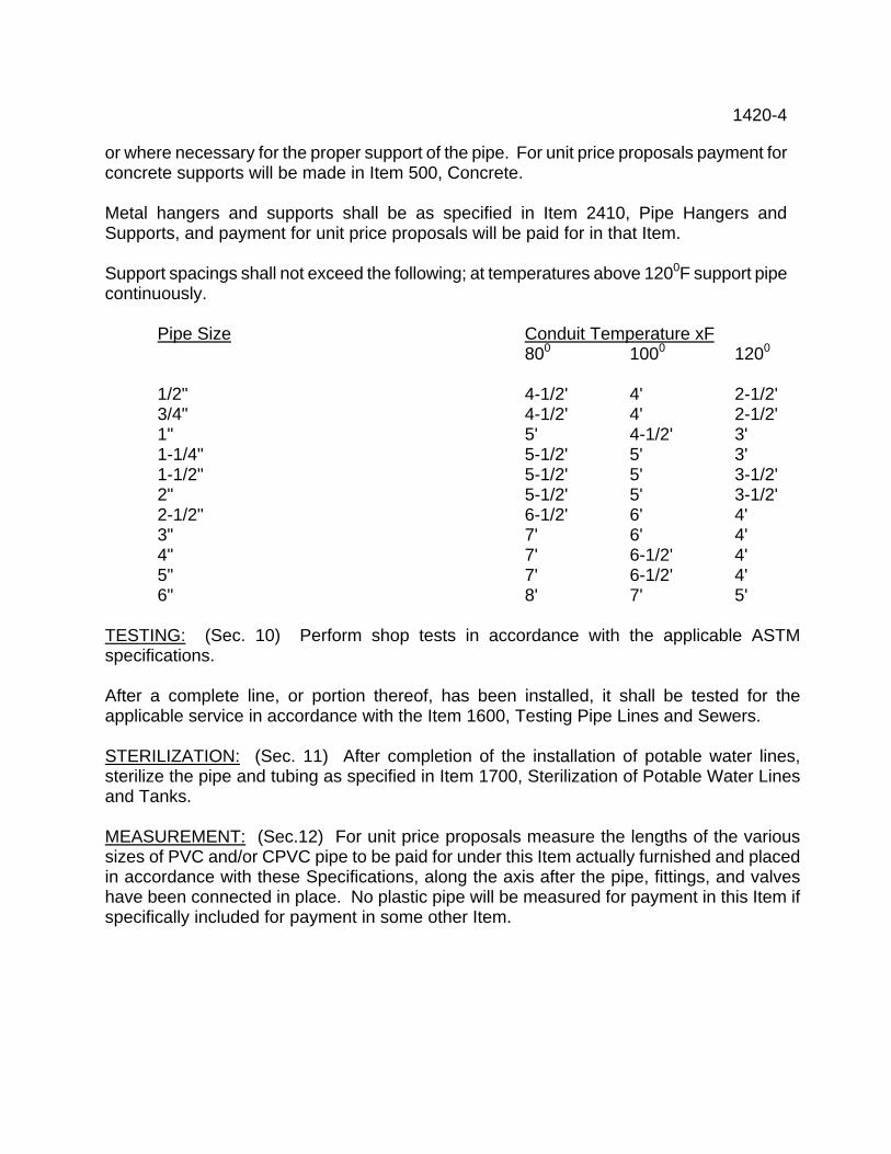
1420-4 or where necessary for the proper support of the pipe. For unit price proposals payment for concrete supports will be made in Item 500, Concrete. Metal hangers and supports shall be as specified in Item 2410, Pipe Hangers and Supports, and payment for unit price proposals will be paid for in that Item. Support spacings shall not exceed the following; at temperatures above 1200F support pipe continuously.
Pipe Size Conduit Temperature xF 800 1000 1200 1/2" 4-1/2' 4' 2-1/2' 3/4" 4-1/2' 4' 2-1/2' 1" 5' 4-1/2' 3' 1-1/4" 5-1/2' 5' 3' 1-1/2" 5-1/2' 5' 3-1/2' 2" 5-1/2' 5' 3-1/2' 2-1/2" 6-1/2' 6' 4' 3" 7' 6' 4' 4" 7' 6-1/2' 4' 5" 7' 6-1/2' 4' 6" 8' 7' 5'
TESTING: (Sec. 10) Perform shop tests in accordance with the applicable ASTM specifications. After a complete line, or portion thereof, has been installed, it shall be tested for the applicable service in accordance with the Item 1600, Testing Pipe Lines and Sewers. STERILIZATION: (Sec. 11) After completion of the installation of potable water lines, sterilize the pipe and tubing as specified in Item 1700, Sterilization of Potable Water Lines and Tanks. MEASUREMENT: (Sec.12) For unit price proposals measure the lengths of the various sizes of PVC and/or CPVC pipe to be paid for under this Item actually furnished and placed in accordance with these Specifications, along the axis after the pipe, fittings, and valves have been connected in place. No plastic pipe will be measured for payment in this Item if specifically included for payment in some other Item.
1452 - 1 FIELD TILE REPLACEMENT ITEM 1452 WORK INCLUDED: (Sec. 01) Furnish and install rigid polyethylene pipe to replace existing field tile removed or disturbed during construction as shown on the Drawings and specified herein. REFERENCE ITEMS: (Sec. 02) Items of work and/or Materials to be performed and/or furnished and included for payment in this Item are:
Earth Excavation and Backfill Item 120 Applicable portions of the latest revision of the following specifications shall be included as a part of these specifications:
ASTM D-1248 American Society for Testing and Materials MATERIAL; (Sec. 03) Pipe shall be minimum four inch diameter rigid polyethylene pipe, SDR-38, similar to that manufactured by Hancor, Inc., or equal. Couplings shall be minimum four inch diameter, for connecting new pipe to existing corrugated plastic tubing, similar to a split coupler manufactured by Hancor, Inc., or equal. INSTALLATION: (Sec. 04) Backfill main trench and compact to the elevation of the field tile to be restored. Install new pipe and connect to the existing field tile. New pipe shall be of equal diameter to existing pipe disturbed and of sufficient length to permit 18" to 24" of bearing on undisturbed earth at each end. Backfill over pipe to elevation of existing ground surface. MEASUREMENT / PAYMENT; ( Sec. 05 ) Payment shall be made for the number of linier feet of field tile places and measured for each size.
1460-1 POLYETHYLENE DRAIN PIPE ITEM 1460 PART 1 GENERAL WORK INCLUDED: (Sec. 01) Furnish all labor, material and equipment necessary to properly install high-density polyethylene drain pipe as indicated on the drawings and specified. RELATED WORK: (Sec. 02) Furnished/paid for in this Item: (as applicable)
Earth Excavation/Backfill Item 120 Granular Backfill Item 164 LSM Item Special #3
Furnish/paid for in respective Item: (as applicable)
Rock Excavation and Backfill Item 125 Topsoil Item 205 Seeding Item 210
DESCRIPTION: (Sec. 03) The work consists of earth excavation and backfill, Class 1-A bedding, the installation, cleanup, and testing of all pipe, fittings and specials and appurtenant work. QUALITY ASSURANCE: (Sec. 04) Materials shall be new and of the best quality. REFERENCES: (Sec. 05)
ASTM American Society for Testing and Materials SCDOT South Carolina Department of Transportation, Construction and
Material Specifications. SUBMITTALS: (Sec. 06) Shop Drawings - See General Conditions. Provide five ( 5 ) sets for record purposes only. DELIVERY, STORAGE, HANDLING: (Sec. 07) Handle, unload pipe in accordance with the approved practice specified by the manufacturer. MEASUREMENT/PAYMENT: (Sec. 08) Per lineal foot, each size, furnished and installed, measured along the axis of the pipe in place. No deduction will be made for the length of specials or fittings in the line.
1460-2 Polyethylene pipe specifically included in other Items shall not be included for payment in this Item. WARRANTY: (Sec. 09) See General Conditions PART 2 - PRODUCTS MATERIALS: (Sec. 10) Pipe: Pipe and specials shall be high-density polyethylene pipe N-12 and M-294-S as manufactured by Advanced Drain Systems Inc. or equal of the sizes, dimensions and series as indicated or specified. Pipe in this Item shall conform to ASTM F-405, the pipe and fittings shall be made of virgin polyethylene resins classified as Type III, Class C, Category 5, Grade P34 defined per ASTM D-1248 minimum Cell Class 315412C. Pipe shall be of virgin quality. The polyethylene resin shall also contain anti-oxidants and shall be stabilized against ultraviolet degradation to provide suitable protection during processing and subsequent weather exposure. Pipe shall be homogenous throughout and free of visible cracks, holes, foreign inclusions or other injurious defects. Pipe shall be marked at intervals of not more than five feet with pipe size, type of plastic material, manufacturers name and the ASTM designation. Fittings: Fittings shall be molded or fabricated from high density polyethylene. Fabricated fittings shall be made from polyethylene pipe and the pieces joined by thermal fusion. Joints: Join the pipe by push on or snap on joints. Bedding Material: Shall be ASTM D-2321 Class I-A. PART 3 - EXECUTION INSTALLATION: (Sec. 11) Before installing any pipe, a representative of the pipe manufacturer shall be present to instruct the workmen in the proper procedures for installing the pipe. Cut and join pipe in accordance with the manufacturer's instructions. Underground Installation: Use laser beam for establishing line and grade. The method used shall be as recommended by the manufacturer of the laser equipment and must be satisfactory to the Resident Representative. The laser beam shall not be of greater power than 2.5 milliwatts (0.0025). A continual visual check shall be provided by the laser equipment. The Contractor shall not deviate from the required line or grade without the written consent of the Consulting Engineer.
1460-3 Perform excavation and backfilling as specified in the applicable Item for excavation/backfill. Install pipe and fittings in accordance with the requirements of ASTM D-2321, "Recommended Practice for Underground Installation of Flexible Thermoplastic Sewer Pipe." Carefully examine pipe and fittings for defects just before laying and use no pipe or fittings known to be defective. Pipe and fittings shall be thoroughly cleaned before being laid and shall conform to the lines and grades indicated. Lay pipe in bedding as indicated on the Drawings. Uniformly support the pipe throughout its length. Place all bedding on undisturbed earth or well compacted backfill. After 30 days the contractor shall furnish all labor, materials and equipment and perform a deflection test using a mandrel whose diameter is equal to 95% of the inside diameter of the pipe, manually pulled through the sewer line. The mandrel shall have a minimum of eight legs, and shall test for inside diameter dimensions 95% of those stated in ASTM D-3034. Deflection tests shall be made on all sections of sewer. Deflection of the pipe shall not exceed 5%. Any section of pipe not meeting the deflection test shall be uncovered and "rerounded" by re-compacting the bedding material, or by other means as required, or as directed by the Resident Representative, and the pipe retested until it meets requirements. Store pipe delivered to the job site so as to minimize the entrance of foreign material. At the end of the day, and at such other times that work is not in progress, close all openings in the pipe line to prevent earth and other matter from entering. Complete joints of all pipe in the trench before work is stopped. If water accumulates in the trench, plugs shall remain in place until the trench is dewatered. FIELD QUALITY CONTROL: (Sec. 12) CLEAN UP: (Sec. 13) Surface clean-up shall immediately follow backfilling, including removal of all surplus excavation, pipe, broken concrete, stones an all miscellaneous debris. Rough grading providing drainage shall be included.
1461-1 POLYVINYLCHLORIDE DRAIN PIPE ITEM 1461 PART 1 GENERAL WORK INCLUDED: (Sec. 01) Furnish all labor, material and equipment necessary to properly install P.V.C. drain pipe as indicated on the drawings and specified. RELATED WORK: (Sec. 02) Furnished/paid for in this Item: (as applicable)
Earth Excavation/Backfill Item 120 Granular Backfill Item 164 LSM Item Special #3
Furnish/paid for in respective Item: (as applicable)
Rock Excavation and Backfill Item 125 Topsoil Item 205 Seeding Item 210
DESCRIPTION: (Sec. 03) The work consists of earth excavation, bedding, backfilling, the installation, cleanup, and testing of all pipe, fittings and specials and appurtenant work. QUALITY ASSURANCE: (Sec. 04) Materials shall be new and of the best quality. REFERENCES: (Sec. 05)
ASTM American Society for Testing and Materials SCDOT South Carolina Department of Transportation, Construction and Material
Specifications. SUBMITTALS: (Sec. 06) Shop Drawings - See General Conditions. Provide five (5) sets for record purposes only. DELIVERY, STORAGE, HANDLING: (Sec. 07) Handle, unload pipe in accordance with the approved practice specified by the manufacturer. MEASUREMENT/PAYMENT: (Sec. 08) Per lineal foot, each size, furnished and installed, measured along the axis of the pipe in place. No deduction will be made for the length of specials or fittings in the line. P.V.C. pipe specifically included in other Items shall not be included for payment in this Item. WARRANTY: (Sec. 09) See General Conditions
1461-2 PART 2 - PRODUCTS MATERIALS: (Sec. 10) Pipe: Pipe and specials shall be PVC. pipe of the sizes, dimensions and series as indicated or specified. Pipe in this Item shall conform to AASHTO M304M-91 the pipe and fittings shall be made of PVC resins. Pipe shall be of virgin quality. The PVC resin shall also contain anti-oxidants and shall contain inhibitors against ultraviolet degradation to provide suitable protection during processing and subsequent weather exposure. Pipe shall not be installed or used in anyway if the date of manufacture exceeds 1 year. Pipe shall be homogenous throughout and free of visible cracks, holes, foreign inclusions or other injurious defects. Pipe shall be marked at intervals of not more than five feet with pipe size, type of plastic material, manufacturers name and the AASHTO designation. Fittings: Fittings shall be molded or fabricated from PVC. Fabricated fittings shall be made from PVC pipe and the pieces joined by the manufactures recommendation. Joints: Join the pipe by push bell and or spigot configuration, pipe joint shall be in accordance with ASTM D-3212. Bedding Material: Shall be ASTM D-2321 Class I. PART 3 - EXECUTION INSTALLATION: (Sec. 11) Before installing any pipe, a representative of the pipe manufacturer shall be present to instruct the workmen in the proper procedures for installing the pipe. Cut and join pipe in accordance with the manufacturer's instructions. Underground Installation: Use laser beam for establishing line and grade. The method used shall be as recommended by the manufacturer of the laser equipment and must be satisfactory to the Resident Representative. The laser beam shall not be of greater power than 2.5 milliwatts (0.0025). A continual visual check shall be provided by the laser equipment. The Contractor shall not deviate from the required line or grade without the written consent of the Consulting Engineer. Perform excavation and backfilling as specified in the applicable Item for excavation/backfill. Install pipe and fittings in accordance with the requirements of ASTM D-2321, "Recommended Practice for Underground Installation of Flexible Thermoplastic Sewer Pipe." Carefully examine pipe and fittings for defects just before laying and use no pipe or fittings known to be defective. Pipe and fittings shall be thoroughly cleaned before being laid and shall conform to the lines and grades indicated.
1461-3 Lay pipe in bedding as indicated on the Drawings. Uniformly support the pipe throughout its length. Place all bedding on undisturbed earth or well compacted backfill. Haunching shall be installed as per the pipe manufacturers recommendation. After 30 days the contractor shall furnish all labor, materials and equipment and perform a deflection test using a mandrel whose diameter is equal to 95% of the inside diameter of the pipe, manually pulled through the sewer line. The mandrel shall have a minimum of eight legs, and shall test for inside diameter dimensions 95% of those stated in ASTM D-3034. Deflection test shall be made on all sections of sewer. Deflection of the pipe shall not exceed 5%. Any section of pipe not meeting the deflection test shall be uncovered and "rerounded" by re-compacting the bedding material, or by other means as required, or as directed by the Resident Representative, and the pipe retested until it meets requirements. Store pipe delivered to the job site so as to minimize the entrance of foreign material. At the end of the day, and at such other times that work is not in progress, close all openings in the pipe line to prevent earth and other matter from entering. Complete joints of all pipe in the trench before work is stopped. If water accumulates in the trench, plugs shall remain in place until the trench is dewatered. FIELD QUALITY CONTROL: (Sec. 12) CLEAN UP: (Sec. 13) Surface clean-up shall immediately follow backfilling, including removal of all surplus excavation, pipe, broken concrete, stones an all miscellaneous debris. Rough grading providing drainage shall be included.
1600-1 TESTING OF SANITARY SEWERS, WATERLINES AND FORCEMAINS ITEM 1600 WORK INCLUDED: (Sec. 01) Furnish all labor, material, equipment, water, air and services required to perform the tests as described herein. The Contractor shall make a complete record of tests to be attested by the Resident Representative. DESCRIPTION: (Sec. 02) Tests shall be performed for the various services as follows:
Section 1600.04 Testing of Sanitary Service Sewers and Storm Drain. Section 1600.05 Testing of Waterlines, Force Mains and Process Piping. Section 1600.06 Testing of Air, Fuel Gas and Plant Gas Lines. Section 1600.07 Testing of Plumbing System.
PROCEDURE: (Sec. 03) The testing equipment shall be approved by the Resident Representative. The Resident Representative will witness the tests and approve the pipe installation. This approval, however, does not relieve the Contractor of his responsibility for a tight and satisfactory installation if leaks are found or develop subsequently. Test service lines in accordance with the procedures specified in the applicable sections for the type of test being performed. Repair or replace any portion of the lines which does not meet the required test, and retest by the same method used in the original test until requirements are met. Protect gauges or delicate instruments installed in the lines against damage or excess pressure during the test. Asbestos-cement pipe shall have a retention period of 12 to 24 hours after being filled as specified in the Items for Asbestos-Cement Pipe Gravity Sewers or Pressure Pipe. Testing of portions of the installed pipe line or sewer may be waived by the Owner if in his judgment the testing is not essential. TESTING OF SANITARY SEWERS AND STORM DRAINS: (Sec. 04) No well points nor pumps which would have an effect on the ground water measurement shall be operating at the time of the test. Ground Water Pressure: Before initiating an infiltration, exfiltration or low pressure air test, determine the ground water pressure at the low end of the section to be tested. Provide a one-half inch capped nipple in the manhole at the top of the lowest pipe entering the manhole, for this purpose. Remove the cap and use an air jet to blow the mud and debris out of the nipple and
1600-2 provide a cavity for the ground water to enter. Attach a transparent plastic tube to the nipple and extend vertically in the manhole. Measure the water level in the tube in feet, from the invert of the pipe being tested. This figure divided by 2.3 will give the pounds per square inch of external pressure on the pipe due to the ground water. After the ground water pressure has been determined and recorded on the test report, remove the plastic tube and replace the cap. Type of Test: If the water in the plastic tube is observed to be at a level above the high point of the section being tested, an infiltration test shall be performed. If the level in the tube is lower than the high point of the section being tested, an exfiltration test shall be performed. A low pressure air test may be performed in lieu of an infiltration or exfiltration test. Infiltration Test: Test the sanitary or combined sewer system as the line is being installed. Install no more than four manhole to manhole reaches not to exceed 1200 lineal feet of pipe, whichever is less, before testing is performed. The Contractor shall conduct a test for lengths less than four reaches if requested. Perform this test after the branch and service sewers installed under the contract have been completed and the ends securely plugged. the permissible leakage for sewers tested by infiltration shall not exceed 100gal/day/inch of pipe diameter/mile of pipe. Furnish and install a 90 degree sharp crested V notched weir at the lower end of the section of the line to be tested. The weir shall be installed properly, securely, with edges sealed watertight. The resident Representative shall approve the installation. After the Contractor and Resident Representative have concurred that a maximum flow is being maintained through the weir, read the height of the flow above the crest of the weir by means of a hook gauge. The point of measurement shall be upstream from the weir a distance o 18 inches or three times the height of flow over the weir, whichever is greater. The infiltration flow indicated by the height of the flow above the crest of a 90 degree weir is as follows: flow level above crest of weir gal. per day ¼” 99 ½” 604 ¾” 1585 1” 3165 1-1/4” 5520 1-1/2” 8720 1-3/4” 12800 2” 17850 Determine the allowable infiltration rate as follows: 1 = 100 x LD 1 = 1000 x LD
1600-3 5280 (for sewers) 5280 (for storm drains 1 – Allowable infiltration L – Length of pipe in feet D – Diameter of pipe in inches If the measured flow exceeds the allowable flow, make the necessary repairs and retest until the infiltration rate is less that the allowable rate. If the ground water level is above any of the service sewers, add the LD of the service sewers to the LD of the main sewers. As an alternative to the weir method, the Contractor may use a plug with a two inch pipe attached thereto in the lower end of the section being tested. Collect the pipe discharge into a container of known volume, measure the flow accordingly and compare with the allowable infiltration rate. Storm drains shall be tested if requested by the Owner or Resident Representative based on his judgment of the workmanship and laying conditions. If required, perform an infiltration test for storm drains in the same manner as specified above except that the allowable infiltration rate shall be 1000 gallons per day (24 hours) per mile of pipe, per inch of pipe diameter. Exfiltration Test: Test the sanitary or combined sewer system by the exfiltration method for each reach of pipe between manholes after the service sewers attached thereto have been installed. The permissible leakage for sewers tested as described in this section shall not exceed 100 gal/day/inch of pipe diameter/mile of pipe. Plug all openings in the upstream manhole except opening to sewer being tested and plug downstream end of sewer being tested. Fill sewer and upstream manhole to a level three feet above top of the sewer or three feet above groundwater level whichever is higher and let stand for three hours to allow for absorption. Refill to original level. After two hours check drop in water level in upper manhole and calculate the loss in volume. Convert the exfiltration measured to a 24 hour basis and compare with allowable leakage as determined similar to the infiltration rate per formula above. If required, perform an exfiltration test for storm drains in the same manner as specified above except that the allowable exfiltration rate shall be 1000 gallons per day (24 hours) per inch of pipe diameter per mile of pipe and the absorption test will not be required. Low Pressure Air Test: After completing the backfill of a reach of service main with its connected service sewers, the Contractor shall conduct a low pressure air test using suitable equipment, preferably pneumatic plugs and a single control panel with approved gauges. Before proceeding with the test, seal test the pneumatic plugs by inserting one in each end of a length of pipe and inflating to 25 psig. Pressurize the sealed pipe to five psig. The plugs shall hold against this pressure without bracing and without movement of the plugs. If the plugs check out satisfactorily, insert a plug in each end of the main sewer at the manhole. Close the ends of the service sewers at the property line with pneumatic plugs or other suitable means. Brace plugs if necessary to insure against blowing out.
1600-4 Provide a pressure relief valve at the compressor set at ten pounds to protect the sewers from excessive pressure. Introduce low pressure air into the sealed sewer at the high end until the pressure registers four psig more than the ground water pressure. Hold this pressure in the sewer for at least two minutes to allow the air pressure to stabilize. After the stabilization period, set the pressure in the sewers at 3.5 psig more than the ground water pressure and shut off the air supply. The portion of the sewer being tested will be termed "acceptable" if the time required for the pressure to drop one pound is greater than the time shown in the following Table.
MINIMUM SPECIFIED TIME REQUIRED FOR A 1.0 PSIG PRESSURE DROP FOR SIZE AND LENGTH OF PIPE INDICATED FOR Q = 0.0015
Specification Time for Length(L) Shown(min:sec)
1 Pipe Diam-eter (in.)
2 Minimum Time (min: sec)
3 Length for Minimum Time (ft.)
4 Time Longer Length (sec.)
100ft.
150ft.
200ft.
250ft.
300ft
350ft.
400ft.
450ft.
4
3:46
597
.380L
3:46
3:46
3:46
3:46
3:46
3:46
3:46
3:46
6
5:40
398
.854L
5:40
5:40
5:40
5:40
5:40
5:40
5:42
6:24
8
7:34
298
1.520L
7:34
7:34
7:34
7:34
7:36
8:52
10:08
11:24
10
9:26
239
2.374L
9:26
9:26
9:26
9:53
11:52
13:51
15:49
17:48
12
11:20
199
3.418L
11:20
11:20
11:24
14:15
17:05
19:56
22:47
25:38
15
14:10
159
5.342L
14:10
14:10
17:48
22:15
26:42
31:09
35:36
40:04
18
17:00
133
7.692L
17:00
19:13
25:38
32:03
38:27
44:52
51:16
57:41
21
19:51
114
10.470L
19:50
26:10
34:54
43:37
52:21
61:00
69:48
78:31
24
22:40
99
13.674L
22:47
34:11
45:34
56:58
68:22
79:46
91:10
102:33
27
25:30
88
17.306L
28.51
43:16
57:41
72:07
86:32
100:57
115:22
129:48
30
28:20
80
21.366L
35:37
53:25
71:13
89:02
106:50
124:38
142:26
160:15
33
31:10
72
25:852L
43:05
64:38
86:10
107:43
129:16
150:43
172:21
193:53
36
34:00
66
30.768L
51:17
76:55
102:34
128:12
153:50
179:29
205:07
230:46
Chemical Grout: Leaks in sewers may be plugged by chemical grout provided the materials and methods to be used are approved by the Owner and the Engineer prior to start of repair work. Deflection Testing: In addition to the leakage test, after 30 days the contractor shall furnish all labor, materials and equipment and perform a deflection test using a mandrel whose
1600-5 diameter is equal to 95% of the inside diameter of the pipe, manually pulled through the sewer line. The mandrel shall have a minimum of eight legs, and shall test for inside diameter dimension 95% of those stated in ASTM D-3034. Deflection tests shall be made on all section of sewer. Deflection of the pipe shall not exceed 5%. Any section of pipe not meeting the deflection test shall be uncovered and “re-rounded” by re-compacting the bedding material, or by other means as required, or as directed by the Resident Representative, and the pipe retested until it meets requirements. Owner Inspection: The owner reserves the right to check the installation for alignment, grade and tightness by means of photography, television or other appropriate methods. Any portion of the sewer not conforming to the specifications for these requirements shall be repaired at the Contractor’s expense. The inspection will be at the Owner’s expense. TESTING OF WATER LINES, FIRE SUPPRESSION LINES, FORCE MAINS AND PROCESS PIPING: (Sec. 05) Description: Apply a hydrostatic pressure test and a leakage test to all force mains, water mains and process piping as specified herein and in accordance with AWWA C600. Pressure Test For Water Lines, and Force Mains: After the pipe has been installed and partially backfilled (if applicable) subject all newly installed pipe, or any valved section of it, unless otherwise specified, to a hydrostatic pressure test equal to 1-1/2 times the line working pressure (50% over the working pressure) but not less than 5.0 psig. The duration of each pressure test shall be at least 60 minutes. Pressure Tests For Fire Suppression Lines: All dedicated Fire Suppression Lines shall be hydrostatically tested to 200 psi, for a duration of not less than 2 hours, all testing shall be in accordance with the National Fire Protection Association NFPA requirements ( latest addition ) , Leakage test shall meet the requirement of NFPA, or the as determined by the formula included on page 1600-6 of this specification, which ever is more stringent. Slowly fill each valved section of pipe with water to the specified test pressure, measured at the point of lowest elevation, by means of a pump connected to the pipe in a satisfactory manner. Before applying the full test pressure, expel all air from the pipe. To accomplish this, make taps, if necessary, at the point of the highest elevation, and afterward tightly plug. Corporation cocks may be used.
1600-6 Carefully examine all exposed pipes, glands, fittings, valves, hydrants, joints, etc., during the pressure test. Where the joints are made with joint compound, re-caulk all such joints showing visible leaks until tight. Remove and replace all cracked or defective pipe, glands, fittings, valves, or hydrants discovered under this pressure test, and repeat the test until the installation is satisfactory to the Resident Representative. Leakage Test for Underground Lines: A leakage test shall be conducted after the pressure test has been satisfactorily completed. The Contractor shall furnish all required apparatus as specified above. Test at 50 pounds per square inch. Run the leakage test for a period of two hours. Measure the amount of water required to maintain the working pressure at 30 minute intervals during the test. Leakage is defined as the quantity of water that must be supplied into the newly installed pipe line, or any valved section thereof, necessary to maintain the specified leakage test pressure after the pipe has been filled with water and the air expelled. No installation using mechanical, push-on, bell and spigot or flanged joints will be accepted if the leakage is greater than L as determined by the formula: L = ND P 3700 L = the allowable leakage in gallons per hour N = the number of joints in the length of line being tested D = diameter of pipe, in inches P = the average test pressure in pounds per square inch gauge Method of Payment Payment to be included in the price of the various pipe, no separate payment will be made.
1700-1 STERILIZATION OF POTABLE WATER LINES AND TANKS ITEM 1700 WORK INCLUDED: (Sec. 01) Furnish all materials and equipment necessary to sterilize potable water lines and/or water tanks as specified herein. REFERENCE ITEMS: (Sec.02) Applicable portions of the latest revision of the following specification shall be included as a part of this specification.
AWWA American Water Works Association DESCRIPTION: (Sec.03) The sterilization of potable water lines and potable water storage tanks shall have the following designation:
Item 1700A - Sterilization of Potable Water Lines Item 1700B - Sterilization of Potable Water Storage Tanks (Steel) Item 1700C - Sterilization of Potable Water Storage Tanks (Concrete)
The Owner will furnish water for initial chlorination. If rechlorination is required the Contractor shall pay the Owner for additional water used at the current rate. STERILIZATION OF POTABLE WATER LINES: Item 1700A (Sec.04) The method to be used for sterilization shall comply with AWWA C 601, C 651, and the State of Ohio, Department of Health requirements. Use Sec. 5.2, Continuous Feed Method unless other methods are approved by the Owner and the Engineer. At the time of construction place calcium hypochlorite granules in the pipeline at the upstream end of the first section of pipe, at each branch main and at 500 foot intervals in accordance with Table 1 of AWWA C 601.
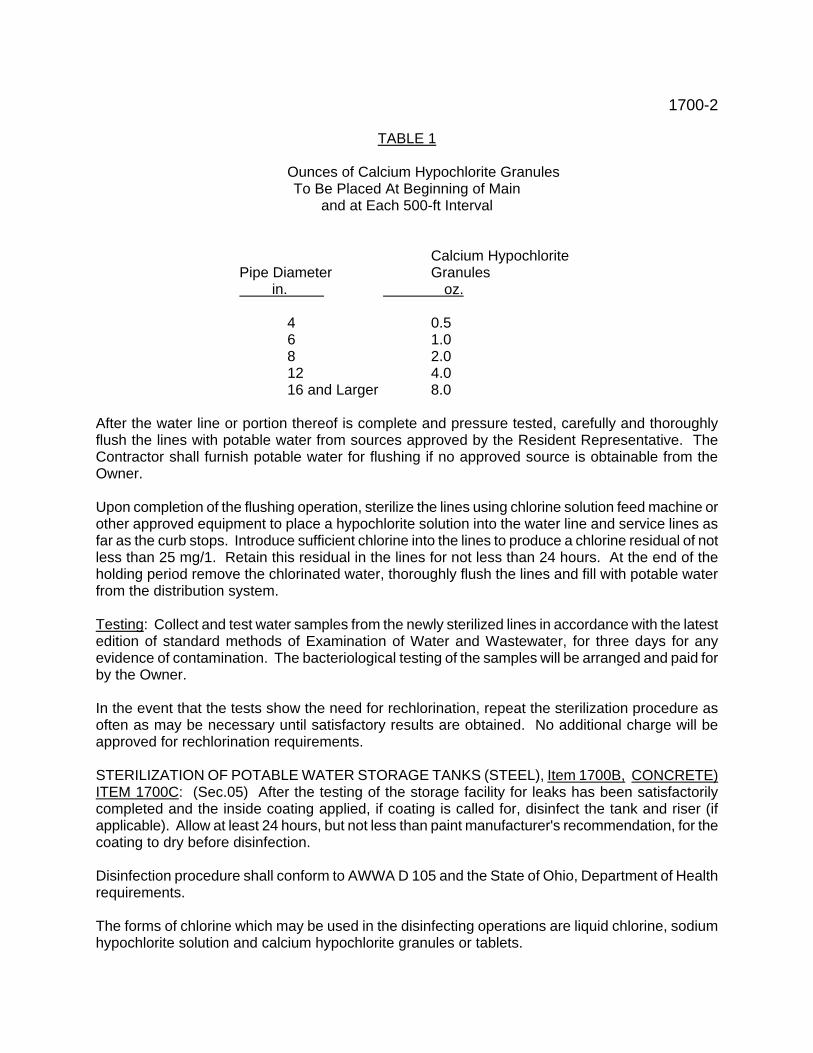
1700-2 TABLE 1
Ounces of Calcium Hypochlorite Granules To Be Placed At Beginning of Main and at Each 500-ft Interval
Calcium Hypochlorite Pipe Diameter Granules
in. oz. 4 0.5
6 1.0 8 2.0 12 4.0
16 and Larger 8.0 After the water line or portion thereof is complete and pressure tested, carefully and thoroughly flush the lines with potable water from sources approved by the Resident Representative. The Contractor shall furnish potable water for flushing if no approved source is obtainable from the Owner. Upon completion of the flushing operation, sterilize the lines using chlorine solution feed machine or other approved equipment to place a hypochlorite solution into the water line and service lines as far as the curb stops. Introduce sufficient chlorine into the lines to produce a chlorine residual of not less than 25 mg/1. Retain this residual in the lines for not less than 24 hours. At the end of the holding period remove the chlorinated water, thoroughly flush the lines and fill with potable water from the distribution system. Testing: Collect and test water samples from the newly sterilized lines in accordance with the latest edition of standard methods of Examination of Water and Wastewater, for three days for any evidence of contamination. The bacteriological testing of the samples will be arranged and paid for by the Owner. In the event that the tests show the need for rechlorination, repeat the sterilization procedure as often as may be necessary until satisfactory results are obtained. No additional charge will be approved for rechlorination requirements. STERILIZATION OF POTABLE WATER STORAGE TANKS (STEEL), Item 1700B, CONCRETE) ITEM 1700C: (Sec.05) After the testing of the storage facility for leaks has been satisfactorily completed and the inside coating applied, if coating is called for, disinfect the tank and riser (if applicable). Allow at least 24 hours, but not less than paint manufacturer's recommendation, for the coating to dry before disinfection. Disinfection procedure shall conform to AWWA D 105 and the State of Ohio, Department of Health requirements. The forms of chlorine which may be used in the disinfecting operations are liquid chlorine, sodium hypochlorite solution and calcium hypochlorite granules or tablets.
1700-3 The following three methods of chlorination are acceptable : Method No. 1: Fill storage facility to overflow level with potable water to which enough chlorine has been added to provide a free chlorine residual of not less than 10 mg/1 after six hours if the water has been uniformly chlorinated by gas feed or chemical pump, or 24 hours if chlorinated by sodium hypochlorite or calcium hypochlorite. Drain to waste and refill with potable water and test as specified herein after. Method No. 2: Apply a solution of 200 mg/1 available chlorine directly to all parts of the storage facility which will be in contact with water when the storage facility is filled to overflow elevation. The chlorine solution may be applied with suitable brushes or with spray equipment. The solution shall thoroughly coat all surfaces including inlet and outlet piping. Apply to separate drain piping such that when filled, available chlorine shall not be less than 10 mg/1. Surfaces disinfected shall remain in contact with the strong chlorine solution for at least 30 minutes. Purge drain pipe and fill storage facility to overflow. After successful testing the water may be released to the distribution system. Method No.3: Add water and chlorine to the storage facility in amounts to provide 50 mg/1 available chlorine when filled to 5% storage volume. Hold in storage facility for not less than six hours. Finish filling to piping. After successful testing water may be released to the distribution system. Testing: Before the tank is placed in operation, the Contractor shall collect and have tested samples of water therefrom in accordance with the latest edition of Standard Methods of Examination of Water and Waste Water, and secure approval of the State of Ohio Department of Health. The Owner will make the necessary arrangements, transport samples and pay for the bacteriological testing. In the event that the tests show the need for rechlorination, repeat the sterilization procedure as often as may be necessary until satisfactory results are obtained. No additional charge will be approved for rechlorination requirements.
1800 - 1
PIPE LINE IN CASING PIPE/TUNNEL
ITEM 1800
PART 1 – GENERAL WORK INCLUDED: (Sec. 01) Furnish and install boring-receiving pits, carrier pipe in a casing pipe or tunnel liner plates, test and, if required, sterilize the carrier pipe, as indicated on the Drawings and specified. RELATED WORK: (Sec. 02) Furnished/paid for in this Item: (as applicable) Earth Excavation/Backfill Item 120 Rock Excavation and Backfill Item 125 Concrete Item 500 Testing of Pipe Lines and Sewers Item 1600 Sterilization of Potable Water Lines and Tanks Item 1700 QUALITY ASSURANCE: (Sec. 03) Materials shall be new and of the best quality. REFERENCES: (Sec. 04) (as applicable) ASTM American Society for Testing and Materials AREA American Railway Engineering Association – Part 5, Pipe Line Crossing CE – 8 Specifications for Pipeline Occupancy for Railroad Company Property ODOT Ohio Department of Transportation, Construction and Materials
Specifications SUBMITTALS: (Sec. 05) Provide the following to Engineer:
a. Shop Drawings, as per General Conditions b. Drawings showing proposed skids and bulkheading, jacking
shield or boring arrangement. No work shall begin on the actual installation until all submittals have been received and approved by the proper reviewing authorities. MEASUREMENT/PAYMENT: (Sec. 06) Measurement/payment will be per lineal foot, measured along the centerline of the casing pipe or tunnel liner, not to exceed that indicated on the Drawings unless directed in writing by the Resident Representative. WARRANTY: (Sec, 07) See General Conditions
1800 - 2
PART 2 – PRODUCTS MATERIALS: (Sec. 08) Carrier Pipe as specified on the Drawings, and conform to its respective Item. Casing Pipe steel, ASTM A-53, Grade B, with smooth bore and smooth exterior, minimum yield of 35,000 psi. Size and wall thickness as indicated on the Drawings. Steel casing pipe shall conform to ASTM A-53, Grade B. Tunnel liner plates cold formed steel, minimum yield of 28,000 psi. minimum tensile of 45,000 psi, bituminous coated. Liner plates shall be fabricated to fit the cross section of the tunnel. All plates shall be connected to bolts on both the longitudinal and circumferential seams or joints, fabricated to permit complete erection from the inside of the tunnel. Grout holes two inches or larger in diameter shall be provided. They shall be plain or tapped, with tapped holes provided with a pipe plug screwed in place. Bolts and nuts shall conform to ASTM A-307, Grade A. Grout fill shall be 1:4 cement and mason sand. Sand fill shall be fine aggregate. Concrete shall conform to Item 500. Lubricant shall be bentonite or other approved materials. PART 3 – EXECUTION INSPECTION: (Sec. 09) The Contractor shall inspect the location of the work and familiarize himself with the conditions under which the work will be performed and with all necessary detail as to the orderly prosecution of the work. The omission of any details for the satisfactory installation of the work in its entirety not indicated on the Drawings or specified herein, shall not relieve the Contractor of full responsibility. PREPARATION: (Sec. 10) Contractor shall familiarize himself with all requirements of railroads, highways, local laws and ordinances. Installation shall conform to all requirements. Contractor shall provide necessary insurance at no additional cost to the Owner.
1800 - 3
INSTALLATION: (Sec 11) All jacking/boring or tunnel operations shall be performed on a continuous, 24 hour a day basis, if required by the respective Highway Department or Railroad Company. All excavation and backfill shall be performed for pits and for installation of casing pipe or tunnel liner plates. All sheeting, shoring and dewatering shall be performed as required to accomplish the proper installation of the boring-receiving pits, casing pipe or tunnel liner plates and carrier pipe. Water jetting not permitted. Casing Pipe: Casing pipe shall be installed by the jacking method. A suitable jacking pit shall be excavated and properly shored and braced and reaction bracing installed. A cradle of timber or concrete shall be built upon which the casing pipe shall be placed to the correct line and grade. No changes in line or grade will be permitted except with written permission of the Engineer. The end of the casing pipe shall be kept ahead of excavation unless the earth is too hard to permit such jacking. Boring inside the casing pipe will be permitted provided the Contractor has suitable equipment and proper boring arrangement at the head of the casing pipe. If the casing pipe comes in short lengths, the sections shall be welded circumferentially in a workmanlike manner. Welds shall be watertight and capable of withstanding the jacking pressure without distortion. Lubricant may be used on the outside of the casing pipe. Augers shall not be pulled once operation is started. Liner Plates: Liner plates shall be installed by the tunnel method, in accordance with the manufacturer’s recommendations and all applicable requirements of the Industrial Commission of the State of Ohio. Shafts shall be properly sheeted and shored to protect the work and adjacent structures. The shafts shall be located at the site of manholes or special structures wherever possible. The Contractor shall provide all supports necessary to prevent settlement of pavement, buildings, railroad tracks, or other superimposed loads. If the Resident Representative is of the opinion that sufficient supports have not been provided, he may recommend the furnishing and placing of additional bracing, sheeting or timbering, at the expense of the Contractor; but compliance with, or failure of, the Resident Representative to give such recommendations shall not release the Contractor from his responsibility for the sufficiency of such supports. All excavated materials shall be removed from the site of the work; not accumulation of spoil shall be permitted in or near tunnel shafts.
1800 - 4
Voids between the liner plates and the tunnel wall shall be force-grouted. The grout shall be forced through the grouting holes in the plates with such pressure that all voids will be completely filled. Void between liner plate and tunnel wall shall be kept to a minimum, and shall not exceed 1 inch to 2 inches. Grout plates shall be installed at a maximum of 5 foot staggered centers. Plates shall be placed 15 to 50 degrees off the top centerline. Grouting shall be performed upon the completion of the installation of a maximum of six feet of liner plates, or as directed by the Resident Representative. Grouting shall be done with a positive displacement grout pump. No air displacement pump will be permitted for use in grouting between earth and liner plate or in confined areas Carrier Pipe: The carrier pipe shall be installed using plastic centralizers to maintain clearance between the outside of the carrier pipe and the inside force of the casing pipe or liner plate. After the pipe is properly jointed, aligned and secured or braced in the casing pipe or liner plate, the entire space between the pipe and the inside of the casing pipe or liner plate shall be completely filled with sand or grout. It shall be carefully placed so that proper alignment and grade of the carrier pipe will be maintained. Sand or grout shall be used to fill voids as called for on the Drawings. Suitable bulkheads shall be provided at each end of the casing or tunnel. FIELD QUALITY CONTROL: (Sec. 12) Testing: Lines shall be tested by the Contractor for the service to which they will be subjected to, or as directed by the Resident Representative, as specified in Item 1600, Testing of Pipe Line and Sewers.
1801-1 PIPE LINE IN POLYETHELENE CASING PIPE ITEM 1801 PART 1 - GENERAL WORK INCLUDED: (Sec.01) Furnish and install boring-receiving pits, carrier pipe in a casing pipe as indicated on the Drawings and specified. RELATED WORK: (Sec. 02) Furnished/paid for in this Item: (as applicable)
Earth Excavation/Backfill Item 120 Rock Excavation and Backfill Item 125 Concrete Item 500 Testing of Pipe Lines and Sewers Item 1600
QUALITY ASSURANCE: (Sec.03) Materials shall be new and of the best quality. REFERENCES: (Sec. 04) (As applicable) ASTM - American Society for Testing and Materials ODOT - Ohio Department of Transportation, Construction and Materials
Specifications SUBMITTALS: (Sec. 05) Provide the following to Engineer: a. Shop Drawings, as per General Conditions No work shall begin on the actual installation until all submittals have been received and approved by the proper reviewing authorities MEASUREMENT/PAYMENT: (Sec. 06) Measurement/payment will be per lineal foot, measured along the centerline of the casing pipe not to exceed that indicated on the Drawings unless directed in writing by the Resident Representative. . WARRANTY: (Sec. 07) See General Conditions. PART 2 - PRODUCTS MATERIALS: (Sec. 08) Polyethylene Casing Pipe ASTM D-3350, F-714 SDR-9, with smooth bore and smooth exterior. Size and wall thickness as indicated on the Drawings. Grout holes two inches or larger in diameter shall be provided. They shall be plain or tapped, with tapped holes provided with a pipe plug screwed in place.
1801-2 Grout fill shall be 1:4 cement and mason sand. Sand fill shall be fine aggregate. Concrete shall conform to Item 500. Lubricant shall be bentonite or other approved materials. PART 3 - EXECUTION INSPECTION: (Sec. 09) The Contractor shall inspect the location of the work and familiarize himself with the conditions under which the work will be performed and with all necessary detail as to the orderly prosecution of the work. The omission of any details for the satisfactory installation of the work in its entirety not indicated on the Drawings or specified herein, shall not relieve the contractor of full responsibility. PREPARATION: (Sec. 10) Contractor shall familiarize himself with all requirements of ODOT and Logan County highways, local laws and ordinances. Installation shall conform to all requirements. Contractor shall provide necessary insurance at no additional cost to the Owner. INSTALLATION: (Sec. 11) All jacking/boring or tunnel operations shall be performed on a continuous, 24 hour a day basis, if required by the respective Highway Department. All excavation and backfill shall be performed for pits and for installation of casing pipe. All sheeting, shoring and dewatering shall be performed as required to accomplish the proper installation of the boring-receiving pits, casing pipe or tunnel liner plates and carrier pipe. Water jetting not permitted. Casing Pipe: Casing pipe shall be installed by the jacking or Directional Bore method. A suitable jacking pit shall be excavated and properly shored and braced, if required. No changes in line or grade will be permitted except with written permission of the Engineer. The end of the casing pipe shall be kept ahead of excavation unless the earth is too hard to permit such jacking. Boring inside the casing pipe will be permitted provided the Contractor has suitable equipment and proper boring arrangement at the head of the casing pipe. If the casing
1801-3 pipe comes in short lengths, the sections shall be welded circumferentially in a workmanlike manner. Welds shall be watertight and capable of withstanding the jacking pressure without distortion. Lubricant may be used on the outside of the casing pipe. Augers shall not be pulled once operation is started. Carrier Pipe: The carrier pipe shall be installed in plastic centralizers to maintain clearance between the outside of the carrier pipe and the inside wall of the casing pipe or liner plate, if called for on the drawings. After the pipe is properly jointed, aligned and secured or braced in the casing pipe or liner plate, the entire space between the pipe and the inside of the casing pipe or liner plate shall be completely filled with sand or grout. It shall be carefully placed so that proper alignment and grade of the carrier pipe will be maintained. Sand or grout shall be used to fill voids as called for on the Drawings. Suitable bulkheads shall be provided at each end of the casing or tunnel. FIELD QUALITY CONTROL: (Sec. 12) Testing: Lines shall be tested by the Contractor for the service to which they will be subjected to, or as directed by the Resident Representative, as specified in Item 1600, Testing of Pipe Lines and Sewers.
DIRECT BORE FOR PIPELINE
ITEM 1802
WORK INCLUDED: (Sec. 01) Furnish all labor, materials, and equipment necessary to install carrier pipe in bored hole by direct boring method, test and if required, sterilize the carrier pipe, as shown on the Drawings and specified herein. SUBMITTALS: (Sec. 02) Provide the following: To Engineer
a. Drawings showing proposed boring arrangement REFERENCE ITEMS: (Sec. 03) Items of work and/or Materials to be performed and/or furnished and included for payment in this Item are: Earth Excavation and Backfill Item 120 Rock Excavation and Backfill Item 125 Testing of Pipe Lines and Sewers Item 1600 Carrier pipe shall be as specified on the drawings and conform to its respective Item. MATERIALS: (Sec.03) Provide the following, as applicable. Carrier Pipe shall be as specified on the drawings Bored Hole shall be Free Bored Lubricant shall be bentonite or other approved material INSTALLATION: (Sec. 05) The Contractor shall inspect the location of the work and familiarize himself with the conditions under which the work will be performed and with all necessary detail as to the orderly prosecution of the work in its entirety not shown on the Drawings or specified herein, shall not relieve the Contractor of full responsibility. Contractor shall familiarize himself with all requirements of the Owner. Installation shall conform to all requirements. No changes in line or grade will be permitted except with written permission of the Engineer. Lubricant may be used on the outside of the carrier pipe. Augers shall not be pulled once operation is started. MEASUREMENT: (Sec. 06) The number of lineal feet of pipe line or sewer, in bored hole to be measured for payment under this Item shall be the actual length constructed, measured along the centerline of the carrier pipe, not to exceed that shown on the Drawings unless ordered in writing by the Resident Representative.
DIRECTIONAL BORE FOR PIPELINE
ITEM 1802
WORK INCLUDED: (Sec. 01) Furnish all labor, materials, and equipment necessary to install High Density Polyethylene Carrier Pipe in bored hole by direct boring method, test and if required, sterilize the carrier pipe, as shown on the Drawings and or specified herein. SUBMITTALS: (Sec. 02) Provide the following: To Engineer for review.
a. Drawings showing proposed boring arrangement. b. Work schedule. c. Maintenance of traffic plan ( if required ) d. Five sets of material shop drawings for, pipe, lubricants, fittings,
aggregate, ect. REFERENCE ITEMS: (Sec. 03) Items of work and/or Materials to be performed and/or furnished and included for payment in this Item are: Earth Excavation and Backfill. Item 120 Rock Excavation and Backfill. Item 125 Testing of Pipe Lines and Sewers. Item 1600 Sterilization of potable water lines. Item 1700 Carrier pipe shall be as shown on the drawings and conform to its respective Item. MATERIALS: (Sec.03) Provide the following. Carrier Pipe shall be as specified [ High Density Polyethylene Pipe, HDPE. AWWA C906 Ductile Iron Pipe Size, DIPS ] . Bored Hole shall be Free Bored Lubricant shall be bentonite or other approved material INSTALLATION: (Sec. 05) The Contractor shall inspect the location of the work and familiarize him or herself with the conditions under which the work will be performed and with all necessary detail as to the orderly prosecution of the work in its entirety. Conditions not shown on the Drawings or specified herein, shall not relieve the Contractor of full responsibility for the timely completion of the work. Butt Fusion in accordance with ASTM D 3261 shall be the only method acceptable for joining pipe. The contractor shall familiarize him or herself with all requirements of the Owner and all regulatory agencies, the Installation shall conform to all requirements. No changes in line or grade will be permitted except with written permission of the Engineer. Lubricant may be used on the outside of the carrier pipe.
Augers shall not be pulled once operation is started. The contractor shall provide stand-by containment and clean-up materials should a frac-out occur, the materials to be on site, and a written containment plan must be approved by the engineer prior to construction. After the installation is complete the new line shall be air tested in accordance with Item 1600. After 30 day’s of project completion the new line shall be deflection tested in accordance with Item 1600. MEASUREMENT: (Sec. 06) The number of lineal feet of pipe line or sewer, in bored hole to be measured for payment under this Item shall be the actual laying length constructed, measured along the centerline of the carrier pipe, not to exceed that shown on the Drawings unless ordered in writing by the Engineer EXTRA PAYMENT: ( Sec. 07) The contractor shall not request payment for lost time ( downtime) without written approval from the engineer.

DIRECTIONAL BORE FOR PIPELINE
ITEM 1802 - B
WORK INCLUDED: (Sec. 01) Furnish all labor, materials, and equipment necessary to install High Density Polyethylene Carrier Pipe in bored hole by direct boring method, test and if required, sterilize the carrier pipe, as shown on the Drawings and or specified herein. SUBMITTALS: (Sec. 02) Provide the following: To Engineer for review.
a. Work schedule. b. Maintenance of traffic plan ( if required ) c. Five sets of material shop drawings for, pipe, lubricants, fittings,
aggregate, ect. REFERENCE ITEMS: (Sec. 03) Items of work and/or Materials to be performed and/or furnished and included for payment in this Item are: Earth Excavation and Backfill. Item 120 Rock Excavation and Backfill. Item 125 Testing of Pipe Lines and Sewers. Item 1600 Sterilization of potable water lines. Item 1700 Carrier pipe shall be as specified herein, and conform to its respective Item. MATERIALS: (Sec.03) Provide the following. Carrier Pipe shall be as specified [ High Density Polyethylene Pipe, HDPE. AWWA C906 Ductile Iron Pipe Size, DIPS ] Size, 8”, Normal O.D. 9.050”, SDR 11, Minimum Wall Thickness 0.823”, Average I.D. 7.306”. Bored Hole shall be Free Bored Lubricant shall be bentonite or other approved material INSTALLATION: (Sec. 05) The Contractor shall inspect the location of the work and familiarize him or herself with the conditions under which the work will be performed and with all necessary detail as to the orderly prosecution of the work in its entirety. Conditions not shown on the Drawings or specified herein, shall not relieve the Contractor of full responsibility for the timely completion of the work. Butt Fusion in accordance with ASTM D 3261 shall be the only method acceptable for joining pipe. The contractor shall familiarize him or herself with all requirements of the Owner and all regulatory agencies, the Installation shall conform to all requirements. No changes in line or grade will be permitted except with written permission of the Engineer. Lubricant may be used on the outside of the carrier pipe.
Augers shall not be pulled once operation is started. After the installation is complete the new line shall be air tested in accordance with Item 1600. After 30 day’s of project completion the new line shall be deflection tested in accordance with Item 1600. MEASUREMENT: (Sec. 06) The number of lineal feet of pipe line or sewer, in bored hole to be measured for payment under this Item shall be the actual laying length constructed, measured along the centerline of the carrier pipe, not to exceed that shown on the Drawings unless ordered in writing by the Engineer EXTRA PAYMENT: ( Sec. 07) The contractor shall not request payment for lost time ( downtime) without written approval from the engineer.
1845-1 RECONNECT WATER SERVICE LINES ITEM 1845 WORK INCLUDED: (Sec. 01) Furnish all labor, materials and equipment necessary to relocate existing water service lines which interfere with the construction of the new sewer and/or storm drain as specified herein. REFERENCE ITEMS: (Sec. 02) Work and/or materials to be performed and/or furnished in accordance with other Items but included for payment in this Item are:
Earth Excavation and Backfill Item 120 Testing of Pipelines and Sewers Item 1600 Sterilization of Potable Water Lines and Tanks Item 1700
Applicable portions of the latest revision of the following specifications shall be included as a part of this Specification.
ASTM - American Society for Testing and Materials SCDOT - South Carolina Department of Transportation, Construction and
Materials Specifications. MATERIALS: (Sec. 03) Copper Pipe and Fittings: Type K, conforming to ASTM B-88 and B-251. H.D.P.E. Polyethylene Plastic Tubing: NSF approved, meeting or exceeding ASTM D-2239 or D- 2737 SDR 9, AWWA C-901equal to copper tube sizes. Plastic tubing shall be capable of maintaining a pressure of 300 psi at 73.40 F for 1000 hours. Maximum working pressure shall be 160 psi at 73.40 F. Pipe shall be marked with size, ASTM Specification Number, pressure rating, National Sanitation Foundation (NSF) approval, manufacturer's identification and date of manufacturer. Connections shall be cold flare or compression type. Fittings: Standard brass waterworks fittings. Bedding Material shall be gravel, crushed limestone No. 57 gradation per SCDOT Specifications, free from dirt and other deleterious materials.
1845-2 INSTALLATION: (Sec. 04) Prior to removal of the existing service line, notify the Owner, who will shut off the service line. Remove the existing service line as required to clear the new sewer and/or drain. Install new service line immediately after removal of the existing line, above or below the new sewer and/or drain as required. Provide a minimum 4'-0" of cover and a minimum clearance of 18 inches between the water line and new sanitary sewer/storm drain. Provide couplings or adapters as required to make connections to the existing water service line. After installation, test the line for tightness. After final approval by the Resident Representative and the water department, backfilling may be completed. Should the line show leaks during testing, repair any leaks and retest the line until water tightness is achieved. Relocate existing valves, corporation cocks and valve boxes encountered, if any, to clear the sewer and/or drain as directed by the Resident Representative. Dispose of existing materials removed off the site. MEASUEMENT / PAYMENT shall be made for the actual footage of water service line reconnected. The Contractor shall require the Water Company to locate all waterlines, and water service lines and take all precautions necessary to protect all existing utilities including water service lines. This Item does not release the Contractor of notifying the Water Company of damages prior to repair.
1860 - 1 RESTORE EXISTING STORM DRAIN ITEM 1860 WORK INCLUDED: (Sec. 01) Furnish all labor, materials, and equipment required to restore existing sewer and/or drain lines cut during construction as shown on the Drawings and Specified herein. REFERENCE ITEMS: (Sec. 02) Work and/or materials to be performed and/or furnished in accordance with other Items but included for payment in this Item are:
Earth Excavation and Backfill Item 120 Concrete Item 500 Polyethylene Item 1460
MATERIALS: (Sec. 03) Pipe 4" through 36" diameter shall be Polyethylene Storm Drain conforming to Item 1460, or Concrete Pipe conforming to item 1210, of the same size as the existing pipe. Use Class C concrete as specified in Item 500, Concrete, except that no aggregate larger than three-quarter inch shall be used. Include payment for Concrete in this Item. INSTALLATION: (Sec. 04) Construct bridges of the type and dimensions shown on the Drawings, located where shown or directed by the Resident Representative. Provide lengths so that the bearing on undisturbed earth is at least 12 inches. Backfill the main trench and compact to the elevation of the sewer to be restored. Place foot blocks on tamped undisturbed earth and install bridge. Carefully place and thoroughly tamp backfill under and around the bridge, so as to provide all possible support to the restored pipe line. Lay pipe to the proper grade and alignment. Make joints watertight. Junctions with existing pipe shall be made with concrete. Carefully place concrete, taking care that the pipe does not float or shift in position. MEASUREMENT / PAYMENT: ( Sec. 05 ) Payment shall be for the actual laying length ( linier feet ) of pipe restored.
1862-1 REMOVE AND REPLACE STORM DRAINS
ITEM 1862
WORK INCLUDED: (Sec. 01) Furnish all labor, materials and equipment necessary to remove existing storm drain pipe, inlets/catch basins and other appurtenances, if any, which are in the location of the new sanitary sewer/force main installation and install a new storm drain with inlets/catch basins and appurtenances adjacent to, and parallel to, the new sanitary sewer/force main location, as shown on the Drawings and specified herein. REFERENCE ITEMS: (Sec. 02) Items of work and/or materials to be performed and/or furnished and included for payment in this Item are: Pipe Excavation and Backfill Item 120 Granular Backfill Item 164 LSM Item Special #3 Polyethylene Drain Pipe Item 1460 Concrete Pipe Item 1210 Manholes Item 2000 Inlets and Catch Basins Item 2025 Miscellaneous Cast Iron Item 2300 MATERIALS: (Sec. 03) Materials incorporated in the work shall conform to the following:
• New pipe shall be Polyethylene Storm Drain Pipe conforming to item 1460, or Concrete Pipe conforming to item 1210
• Manholes, if any, shall conforming to Item 2000. • Inlets/catch basins shall be as shown on the Drawings and conforming to
Item 2025. INSTALLATION: (Sec. 04) Perform all earth excavation and backfill required to remove the existing storm drain and appurtenances and to install the new storm drain, inlets/catch basins and appurtenances. New storm drain shall be installed in the location, and to the depth and grade, shown on the Drawings. New inlets/catch basins and manholes shall be constructed in the same area where existing were removed, but over the new storm drain. Install pipe with bedding material in accordance with Item 1460, or 1210 Install new inlets/catch basins or manholes in accordance with Item 2000, or 2025. Rim elevations of inlets/catch basins and manholes shall be determined in the field at time of construction. Backfill storm drain trench from the top of the bedding material up to the bottom of the sanitary sewer/force main trench or roadway with granular backfill, Item 164, or Item Special #3. If under paved area, trench shall be backfilled with granular backfill up to the bottom of the pavement. If not under pavement, trench shall be backfilled with compacted earth material. Connect existing inlets/catch basins/ manholes, not disturbed, to new storm drain with type and size of pipe as existing. DISPOSAL OF MATERIALS: (Sec. 05) Existing castings removed shall remain the property of the Owner. Contractor shall deliver to the Owner’s storage yard.

1862-2 Materials removed, and which are not re-used, shall be disposed of off the site by the Contractor. MEASUREMENT / PAYMENT : ( Sec. 06 ) Payment shall be the actual laying length of pipe replaced ( linier feet ).

1875-1
REMOVE AND REINSTALL EXISTING DRIVEWAY CULVERTS
ITEM 1875
WORK INCLUDED: (Sec. 01) Furnish all labor, materials, and equipment necessary for removing, cleaning and reinstalling driveway culverts encountered along the routes of the sewer and/or drains including the necessary earth excavation and backfilling. REFERENCE ITEMS: (Sec. 02) Work and/or materials to be performed and/or furnished in accordance with other items, but included for payment in this Item are: Earth Excavation and Backfill Item 120 Granular Backfill Item 164 LSM Item Special #3 Corrugated Metal Pipe Item 1050 Concrete Pipe Item 1210 Polyethylene Drain Pipe Item 1460 DESCRIPTION: (Sec, 03) Carefully remove all driveway culverts within the measurement limits of the excavation for the project, and such others as may be directed by the Resident Representative, ahead of the excavation and store temporarily during the construction . After the construction has passed , clean the culvert pipes and reinstall in their original locations and backfill as called for. If the Resident Representative determines that any culvert pipe is in such condition that it cannot be cleaned and reinstalled because of collapse, corrosion or for any other reason, it shall be replaced with pipe as specified . MEASUREMENT: (Sec. 04) Use the actual number of driveway culverts removed and reinstalled within the trench measurement limits, or directed by the Resident Representative, in determining the quantity for payment. If the Resident Representative directs that an old culvert pipe cannot be reinstalled and a new pipe must be installed, such driveway location will not be considered a unit under this Item, and new pipe will be paid for as specified under it’s respective item.
1915- 1 AIR RELEASE VALVE ITEM 1915 PART 1 - GENERAL WORK INCLUDED: (Sec. 01) Furnish and install Air Release Valve, complete structure, and all piping and appurtenances inside the structure with access manhole as indicated on the Drawings and specified. RELATED WORK: (Sec. 02) Furnished/paid for in this Item:
Earth Excavation/Backfill Item 120 Granular Backfill Item 164 Polyethylene Pressure Pipe DIPS Item 1411 Polyethylene Pressure Pipe Item 1412 Testing of Pipe Lines and Sewers Item 1600 Manholes Item 2000 Precast Concrete Structures Item 2055
QUALITY ASSURANCE: (Sec. 03) All materials shall be new and of the best quality. SUBMITTALS: (Sec. 04) Shop Drawings - See General Conditions.
Air Release Valve MEASUREMENT/PAYMENT: (Sec. 05) Payment will be made per each. WARRANTY: (Sec. 06) See General Conditions. PART 2 - PRODUCTS MATERIALS: (Sec. 07)
Concrete, Item 500 Polyethylene Pressure Pipe/Fitting, Item 1411 & 1412 Precast Manhole, Item 2000 Manhole Steps, Steel Reinforced Polypropylene Manhole Casting, See Drawings Valves, Plug, PVC Type 1, Grade 1 Bedding material, #6 crushed limestone Precast Concrete Structure Item 2055
EQUIPMENT: (Sec. 08) Air Release Valve, shall be Val-Matic VM-48 or equal.
1915- 2
PART 3 - EXECUTION INSTALLATION: (Sec. 09) Perform all required excavation and backfill and install access manhole and air release valve complete, ready for operation. FIELD QUALITY CONTROL (Sec.10) Testing: Each installation shall be tested in conjunction with the adjacent portions of pressure line. Any installation not meeting testing requirements shall be repaired and retested until testing requirements are met.
1917-1 FLUSHING CONNECTION ITEM 1917 PART 1 - GENERAL WORK INCLUDED: (Sec. 01) Furnish and install In-Line or End-of-Line (Flushing Connection) or (Clean-out) in the locations, and as indicated, on the Drawings and specified. RELATED WORK: (Sec. 02) Furnished/paid for in this Item:
Earth Excavation/Backfill Item 120 Granular Backfill Item 164 LSM Item Special #3 Concrete Item 500 Polyethylene Pressure Pipe Item 1412 PVC and CPVC Rigid Pipe Item 1420 Testing of Pipe Lines and Sewers Item 1600 Ball valve with Adjustable Valve Box & Cover Item 3131
Furnished/paid for in respective Item:
Topsoil Item 205 Seeding Item 210 PVC Pressure Pipe Item 1410
DESCRIPTION (Sec. 03) Work in this Item generally includes the installation of the Flushing Connection(s) complete in place, including PVC enclosure, concrete collar, frame and cover, PVC riser pipe and fittings, couplings, nipples, plug valve, granular backfill, and bedding material. QUALITY ASSURANCE: (Sec. 04) Materials shall be new and of the best quality. REFERENCES: (Sec. 05)
AASHTO American Association of State Highway and Transportation Officials SCDOT South Carolina Department of Transportation, Construction and Material
Specifications. SUBMITTALS: (Sec. 06) Shop Drawings. Provide five (5) copies for reference purposes only, of the following:
Gate valve Frame/cover
1917-2
Corrugated PVC Pipe MEASUREMENT/PAYMENT: (Sec. 07) Per each, complete in place. WARRANTY: (Sec. 08) See General Conditions. PART 2 - PRODUCTS MATERIALS: (Sec. 09) Corrugated Polyethylene Drainage Pipe - heavy duty, conforming to AASHTO M-294. Bedding Material shall be crushed gravel SCDOT No. 57 gradation, free from dirt and other deleterious material. Additional material - See Related Work, above. PART 3 - EXECUTION INSTALLATION: (Sec. 10) Perform all required excavation/backfill and install all Materials indicated on the Drawings for a complete installation. FIELD QUALITY CONTROL: (Sec. 11) Testing - Test each installation in conjunction with adjacent portions of collector main. Any installation not meeting testing requirements shall be repaired and retested until requirements met.
ADJUSTABLE VALVE BOX AND COVER ITEM 1925 WORK INCLUDED: (Sec. 01) Furnish all the material and properly set in place at the location indicated on the Drawings, or as directed, all adjustable valve boxes and covers. DESCRIPTION: (Sec. 02) The boxes and covers shall be of cast iron and equal in all respects to the standard extension boxes and covers for valves three inches in size and large, as made by the Clow Corporation, Mueller Company, or equal. Base sections shall be of the proper size to fit the valve. All valve boxes and covers in traffic areas shall be heavy duty. SETTING: (Sec. 03) Set base sections so they do NOT rest on the valves. Provide at least two inches between the valve and the base section. Set valve boxes exactly plumb and the cover flush with the top of the upper section. In tamping and backfilling around the boxes, take special care to keep the box plumb and firmly supported to avoid settlement. Reset any box which is found out of plumb, or which is not firmly supported. EXTENSION STEMS: (Sec. 04) Unless otherwise indicated on the Drawings, whenever the operating nut of any valve is more than seven feet below the top of the valve box, furnish and install an extension stem. Furnish extension stem with a socket of the proper size to fit on the valve operating nut, securely attached to a rod not less than one inch in diameter, with a nut on top of the same size as the valve operating nut, so arranged that the upper nut will be centered in the box at an elevation about four feet below the box cover. PAINTING: (Sec. 05) Shop paint all adjustable valve boxes, covers, extension sections and stems, as specified for AWWA C-110 "Gray Iron and Ductile Iron Fittings" by the American Water Works Association. MEASUREMENT / PAYMENT: (Sec. 06 ) Payment shall be for each valve box and cover installed .
2000-1 MANHOLE/CLEAN OUTS ITEM 2000 PART 1 - GENERAL WORK INCLUDED: (Sec. 01) Furnish and install Manholes and drop attachments as indicated on the Drawings and specified. RELATED WORK: (Sec. 02) Furnished/paid for in this Item:
Earth Excavation/Backfill Item 120 Foundation Cushion Item 160 Granular Backfill Item 164 Concrete Item 500 Bulk Concrete Item 505 Steel Reinforcement Item 600
PVC Pressure Pipe Item 1410 Polyethylene Drain Pipe Item1460 Chimney Seals Item 2001 Furnished/paid for in respective Item: (as applicable)
Rock Excavation and Backfill Item 125 Pavement, Curb, Gutter, Sidewalks Item 300
QUALITY ASSURANCE: (Sec. 03) Materials shall be new and of the best quality. REFERENCES: (Sec.04)
ASTM - American Society for Testing and Materials SUBMITTALS: (Sec. 05) Shop Drawings for manhole, frame, cover, steps. MEASUREMENT/PAYMENT: (Sec. 06) Measurement for manholes will be the linier feet of manhole depth installed made from the invert of the outlet pipe, or riser tee section, vertically to the top of the manhole cover. Include riser tee sections and supporting concrete with manhole. Measurement for drop attachments will be made from the invert of the inlet pipe at the top of the drop attachment to the invert of the outlet pipe of the manhole. Measurement for Clean Outs will be for each complete installation. Measure for payment upon final completion and acceptance. WARRANTY: (Sec. 07) See General Conditions. PART 2 - PRODUCTS MATERIALS: (Sec. 08)
2000-2 Manhole - Precast, reinforced concrete, ASTM C-478, with eccentric cone sections. Concrete compressive strength f' c = 5000 psi. Frame-Cover Cast Iron –ASTM A-48, Class 30 B. Covers on intercepting or sanitary sewer, shall have words “SANITARY SEWER” or “SAN. SEWER” cast in raised letters; covers on storm drains shall have words “STORM DRAIN” cast in raised letters. Machine rim and covers to prevent rocking. Style indicated on Drawings. Steps - Aluminum, 6061-T6 alloy, ASTM B-221 or Steel Reinforced Polypropylene, style indicated on Drawings. Adjusting Rings – High density polyethylene (H.D.P.E.) by Ladteeh Inc. or equal. Adjusting rings to be sealed as recommended by the manufacturer. Joint Gaskets – Flexible rubber, ASTM C-443 (Sanitary Manholes Only). Resilient Connectors - ASTM C-923, for positive seal between connector and manhole wall and between connector and pipe. Concrete - Poured in Place, Item 500. Bulk Concrete - Concrete Collars, Item 505 Butyl Sealant - Flexible Butyl Resin Sealant ASTM C-990 by ConSeal or equal. Test Pipe - 1/2 inch diameter PVC, ASTM D-1785, Schedule 80, with cap. (Sanitary manholes only). Foundation Cushion - Item 160. MANHOLE TYPES: (Sec.09) Standard: Construct standard manholes of the size indicated on the Drawings, similar to standard manholes, except that, in order to obtain all possible headroom, place a reinforced concrete slab instead of cone section on top. Shallow: Construct shallow manholes as indicated on the Drawings, similar to standard manholes, except that, in order to obtain all possible headroom, place a reinforced concrete slab instead of cone section on top. Riser Tee: Construct riser tee manholes as indicated on the Drawings, similar to standard manholes, except that, precast concrete riser tee sections, supported with bulk concrete, shall be used for the base. Drop Attachments: Construct drop attachments of pipe encased in concrete and of the size indicated on the Drawings. The tee at the upper end of the drop pie shall have the same diameter as the incoming pipe unless indicated otherwise. The tee, the drop pipe, and the 90 degree ell, and the encasing concrete are considered a part of the drop attachment.
2000-3 CLEAN OUTS: (Sec. 10) PVC Pressure Pipe Item 1410 Concrete Class C Item 500 Manhole frame and cover Neenah R-1762 or equal PART 3 - EXECUTION INSPECTION: (Sec. 11) Inspect site and determine conditions that may effect the proper execution of the work. PREPARATION: (Sec.12) Clear site as required for the proper performance of the work. INSTALLATION: (Sec.13) Perform all earth excavation, to the limits indicated on the Drawings, for the proper installation of the manhole. Install manhole sections on precast concrete manhole base placed on six inch thickness of Foundation Cushion or poured-in-place monolithic concrete base, or, if specified and/or indicated on Drawing, precast manhole tee sections. Install true and plumb. Sanitary Manholes: Make all joints with gaskets; pipe connections with resilient connectors. Joints and pipe connections shall be watertight. Channel manhole bottom to depth indicated on the Drawings and to width equal to diameter of pipe. Provide smooth, clear, flow lines of formed concrete or pipe sections. Install test pipe, approximately twelve inches long, through manhole wall above one of the pipes entering the manhole, as indicated on Drawings, for measuring ground water head. Securely grout in place with capped end inside manhole. (Sanitary manholes only). Openings for pipes 18 inches and smaller entering above the top of the outlet pipe (drop attachments) may be cut in the field. Connect pipes over 18 inches in diameter entering the manhole above the top of the outlet pipe by a tee connection, precast with the barrel of the manhole. Adjust frame and cover to proper elevation with precast concrete rings. Final rim elevations of manholes shall be determined in the field at time of construction. Set casting in grout. Install steps wherever indicated on the Drawings, cast or grouted in place at a uniform spacing of not over 16 inches center to center. Add a non-shrinking agent to the grout. Support precast manhole tee sections with concrete as indicated on the Drawings. CLEAN-UP (Sec. 14) Upon completion of work, remove excess materials, debris, etc. off site. Put site in neat, orderly conditions.
2000 R - 1 MANHOLE REHABILITATION ITEM 2000 - R PART 1 - GENERAL WORK INCLUDED: (Sec. 01) Furnish all materials, equipment, and labor necessary to clean, plug, patch and seal all surfaces in the existing sanitary sewer manholes as specified. Patching shall include the repair of all steps, benches, and inverts as determined in the field by the Engineer and shown on drawings or described in the specifications. Also furnish all materials, equipment, and labor necessary to adjust manholes to grade where specified. RELATED WORK: (Sec. 02) Furnished/paid for in this Item:
Earth Excavation/Backfill Item 120 Foundation Cushion Item 160 Seeding Item 210 Concrete Item 500 Bulk Concrete Item 505 Steel Reinforcement Item 600 Manhole Frame and Covers / Steps Item 2000 Maintaining Traffic Item 4100
Furnished/paid for in respective Item: (as applicable)
Rock Excavation and Backfill Item 125 Granular Backfill Item 164 Pavement, Curb, Gutter, Sidewalks Item 300 Manhole Chimney Seals Item 2001
BYPASS PUMPING: (Sec. 03) Where necessary to complete the work, the Contractor shall be responsible for the bypassing and/or blocking of flow in the manholes and must have prior approval by the Engineer and Owner.
1. Bypass pumping of sewer and lateral flows during the construction period.
a. The Contractor shall bypass upstream sewage flow around the manholes designated for repair and convey the sewage to a downstream manhole or adjacent sewage system.
b. Provisions shall be made to maintain all existing services to prevent
sewage backflow into structures.
2000 R - 2
c. The Contractor shall be responsible for maintaining the integrity of the entire sewage bypass system and shall be wholly responsible for conveying the sewage out from and back into the sewage collection system. At no time shall sewage be allowed to leave the system.
d. If sewage should escape the system the Contractor shall contact the
Engineer and the Owner immediately.
e. Contractor shall be liable for all damages and fines resulting from Contractor's work or non-performance of work as specified.
f. The Contractor shall be responsible for any necessary power required
for bypass pumping. WATER SUPPLY: (Sec. 04) Contractor shall provide all water necessary for all manhole rehabilitation work. Contractor shall obtain all permits and meet all other requirements of local agencies if obtaining water from fire hydrants or other public or private water supply. Contractor shall provide for backflow prevention, and make arrangements with such agencies for billing purposes and pay all costs. TRAFFIC CONTROL: (Sec. 05) It shall be the Contractor's responsibility to supply traffic control as required by the local agencies having jurisdiction. DAMAGES: (Sec. 06) Should any structural damages occur as a result of the manhole rehabilitation process, the Contractor shall make all repairs prior to waterproofing to the satisfaction of the Engineer at no additional cost. If extensive damages occur, work shall be suspended until such time that all parties involved can meet to determine the cause and corrective measures necessary to minimize future damages while achieving the necessary cleaning results. PAYMENT: (Sec. 07) Payment for cleaning, plugging, patching, sealing, bypass pumping, traffic control, restoration, step repair and all other work and materials required for manhole rehabilitation with the exception of those Items paid for in their respective Items as shown in (Sec. 02) shall be for each manhole, as shown on the bid proposal sheet. Quantities of work shall be determined by the vertical depth measured at the center of each manhole from the lowest pipe invert to the top of the manhole casting.. Payment for the installation of chimney seals and extension, and frame and covers shall be based on the unit price as shown on the bid proposal sheet. Quantities of work shall be determined by the number of manhole covers. (Each) STORAGE OF EQUIPMENT AND MATERIAL: (Sec. 08) It shall be the Contractor's responsibility to find a suitable location to secure and store their equipment and material.
2000 R - 3 RESTORATION: (Sec. 09) It shall be the responsibility of the Contractor to restore the work site to its original condition. Disturbed lawn areas shall be seeded as determined by the Engineer. COORDINATION WITH ENGINEER: (Sec. 10) It is the intent of these specifications that any given manhole rehabilitation work be performed during regular working hours.
a. Regular working hours are defined as 7:00 AM to 6:00 PM Monday through Friday.
PART 2 - QUALITY ASSURANCE REFERENCE STANDARDS: (Sec. 11) Comply with the latest edition of the following:
1. ASTM C78, Test Method for Flexural Strength of Concrete. 2. ASTM C109, Test Method for Compressive Strength of Hydraulic Cement
Mortars. 3. ASTM C150, Specification for Portland Cement. 4. ASTM C157, Test Method for Length Change of Hardened Hydraulic Cement
Mortar and Concrete. 5. ASTM C348, Test Method for Flexural Strength of Hydraulic Cement Mortars. 6. ASTM C666, Test Method for Resistance of Concrete to Rapid Freezing and
Thawing. 7. ASTM C923, Resilient Connectors.
INSPECTION: (Sec. 12) Once all manholes have been sealed and the proper curing time for the waterproofing materials has elapsed, the manholes will be given a field inspection by the Engineer. All leakage problems discovered by this inspection shall be corrected by the Contractor within an agreed upon time to the satisfaction of the Engineer at no additional cost. PART 3 – SUBMITTALS CONTRACTOR SHALL SUBMIT THE FOLLOWING: (Sec. 13)
1. Shop Drawings, five (5) sets. a. Product data covering all materials of construction. b. Description of installation procedure and equipment proposed for use.
2. Proposed bypass pumping procedures and confined space entry plan.
3. Permits to work in public right of ways. PART 4 - SAFETY SAFETY PROCEDURES: (Sec. 14) The Contractor shall conduct all of his operations in
2000 R - 4 strict accordance with all applicable Federal, State, and Local safety codes and regulations, including all OSHA requirements. Attention is drawn, in particular, to the safe working requirements for confined space entry. The Contractor shall be fully responsible and obligated to maintain a safe work environment for all individuals in and around the work areas. The Contractor shall assume all responsibility for a safe working environment for his employees. PART 5 - PRODUCTS SEALING PRODUCTS AND MANUFACTURERS: (Sec.15) The materials shall comprise a system specifically recommended by the manufacturer for sanitary sewer manhole rehabilitation, and shall be manufactured by IPA Systems, Inc. (The Drycon System), Preco Industries, Ltd. or approved equals. Purpose IPA Systems, Inc. Preco Industries, Ltd. Plugging Ipanex-R or Octoplug Preco-Plug Patching Octocrete Preco-Patch Waterproofing Drycon Brush-Bond FRAMES AND COVERS: (Sec. 16) Material: The frames and covers shall be a bolt down watertight Frames and Cover (Neenah R-1916 Series) or approved equal. In the event that a watertight frame and cover is not required and directed by the Engineer the existing frame and cover may be replaced with a (Neenah R-1050 Frame and Cover or equal) Sizes: The Contractor shall measure the inside diameter of the manhole frame's lid recess and width of the bearing surface to properly size the manhole frame. MANHOLE STEPS: (Sec. 17) Steps shall be Neenah R-1980 polypropylene with 1/2" grade 60 steel reinforcement, M. A. Industries, Inc. Model PSI-P or approved equal. PART 6 - EXECUTION GENERAL: (Sec. 18) All work shall be in strict accordance with the manufacturer's specifications and recommendations including application of all bonding agents and surface stabilizers. When freezing temperatures are expected in the area, the Contractor shall provide, operate and maintain necessary equipment to provide the required heat in the manhole before repair work can be started. REPAIRING AND SEALING (Sec. 19) Surface Preparation: Prior to any other work inside of a manhole, all interior wall and invert surfaces shall be cleaned using a minimum of

2000 R - 5 2,000 psi water blast to remove all foreign matter. Water blast equipment shall be capable of providing up to 5,000 psi. If all deposits have not been removed as determined by the Engineer, then a solution of muriatic acid (hydrochloric acid) at a ratio of one part acid to ten parts water shall be applied by spraying from above the manhole. After the acid solution is used, it shall be washed completely off and the manhole allowed to dry. The mixing, application, and removal of the acid solution shall be done in strict accordance with the manufacturer's specifications and recommendations. All safety procedures applicable to the handling of this acid shall be strictly adhered to. All material resulting from cleaning operation shall be removed from the manhole being cleaned and disposed of by the Contractor in accordance with applicable regulations. Step Repair: Manhole step repair shall include replacing missing steps and others requiring replacement as determined by the Engineer. All steps shall be supplied by the Contractor. The Contractor shall remove the existing step where required, drill the necessary holes, and perform all other work to install the replacement steps. The metal portion of all steps shall be removed to a minimum depth of 2 inches (2") beneath the manhole interior wall surface and the remaining holes are to be patched prior to waterproofing. Bottom Repair: Bottom repair shall include the patching of the invert and bench areas in the manholes as directed by the Engineer. The flow channel shall be checked for leaks and then patched. If a vitrified clay invert exists, no coating is to be applied to the channel. All other channels shall be coated. If additional bench or invert repairs are identified and deemed necessary by the Engineer, the repair shall be made with no additional payment to the Contractor. The work shall be such as required to make surfaces smooth and provide smooth flow through the manhole. The invert shall have a depth through the manhole equal to approximately one-half (1/2) the diameter of the sewer pipes with the bench areas sloping upward toward the manhole walls at approximately one inch (1") per foot. Prior to patching, all loose and deteriorated material shall be removed and disposed of by the Contractor. Wall Repair to Stop Infiltration: Wall repair shall include the plugging and/or patching of all visible leaks, cracks, holes, voids, and deteriorated surfaces in the manholes as directed by the Engineer. Whenever heavy infiltration is present as determined by the Engineer, four (4) 5/8 inch diameter holes shall be drilled at intervals around the base of the manhole wall. Rubber hoses shall be inserted into these holes allowing enough hose to provide access for the water to seep into the manhole flow channel. All pressure leaks shall be sealed with the specified rapid setting plastic material (IPA IPANEX -R, Preco-Plug, or equal) that shall bond both mechanically and chemically to saturated surfaces and be capable of setting in approximately 45 seconds. Once the walls of the manhole have been rehabilitated, the hoses shall be removed and the holes shall be plugged with IPA IPANEX-R and Type I Portland cement. In cases where the manhole wall weeps slightly, a solution of IPA IPANEX-R, or approved equal, shall be applied to the wet areas by spray and Type I Portland cement shall be applied directly to the IPANEX-R and hand rubbed, then allowed to set in accordance with the manufacturer's specifications and recommendations.
2000 R - 6 Surface Stabilization (Where Necessary): Once all infiltration of water has been stopped, one (1) or two (2) coats of IPA DURIPAL, or approved equal, shall be applied to the entire manhole wall to stabilize the substrata. DURIPAL shall be applied to a clean, dry, sound surface and in accordance with the manufacturer's specifications (set time 20-30 minutes) and recommendations. Patching: Patching of manhole walls shall be required in areas where large voids exist (i.e., bricks missing in manhole walls, around steps, frames and pipes). All cracked or disintegrated material shall be removed from the area to be patched exposing a sound sub-base. IPA'S OCTOCRETE, or approved equal, shall be applied to a dampened surface. The chimney area of manholes shall be patched so that the top four (4) inches will accept a Cretex Chimney Seal, or further to accommodate extension where dictated by manhole configuration. OCTOCRETE patches shall be allowed to cure before continuing to the next steps (set time approximately 20 minutes). Surface Coats: Waterproofing of manhole walls shall include the application of a two coat waterproofing system in strict accordance with manufacturer's specifications and recommendations. The material shall be Drycon (IPA System, Inc.) Brush-Bond (Preco Industries, Ltd), or approved equal. The waterproofing for each coat shall be applied from invert to manhole frame base flange and applied to a saturated surface (1/16 " minimum thickness). The first coat shall be gray in color and the second coat shall be white (set-up time, 2-3 hours before second application). If the manhole is deeper than fifteen (15) feet, the portion below fifteen feet shall receive a third coat of sealant making this lower portion capable of withstanding a hydrostatic pressure of 45 psi. This third coat shall be an extra coat of white material, applied 72 hours after second coat.
2001 -1 MANHOLE CHIMNEY SEALS ITEM 2001 MANHOLE CHIMNEY SEALS A. Provide all manholes with a mechanical rubber chimney seal for the casting-to-manhole
cone section/slab joint.
1. Chimney seals shall be a flexible rubber sleeve extruded from a high grade rubber compound meeting applicable requirements of ASTM C923. The sleeve shall be double pleated with a minimum thickness of 3/16 inch, and shall expand not less that 2 inches vertically when installed. Top and bottom shall contain an integrally formed expansion band recess and multiple sealing fins. Any splices shall be hot vulcanized and shall withstand a 1800 bend with no visible separation.
2. Expansion bands for compressing the sleeve and extension against the manhole
surfaces shall be 16 gauge, minimum 1 3/4 inches wide, and stainless steel meeting the requirements of ASTM A240, Type 304. The expansion mechanism shall have the capacity to develop the pressure necessary to make a watertight seal and shall have a minimum adjustment range of not less than two (2) diameter inches.
B. Manufacturer:
1. Cretex Specialty Products or equal C All manholes shall be sealed between the cover frame and cone top prior to manhole
testing. 1. Chimney seals shall be installed to provide an interior flexible seal between the
manhole frames and adjusting feature, and cone sections. Chimney seals shall be installed in strict accordance with the manufacturer's instructions including use of butyl caulk on lower portion of seal. The installation of the chimney seal and extension shall include the preparation of the wall surfaces in the chimney area and the adjustment of the frame as required by the manufacturer's instructions. All manufacturer's warranties shall apply and not be voided.
2. Chimney seal extension shall be installed as required and directed by the Engineer.
MEASUREMENT OF PAYMENT Measurement of payment shall be for each manhole chimney seal assembly installed and include standard 8" and 10" wide seals, with 7" or 10" extensions as well as all hardware and labor to install.

2025 - 1 INLETS AND CATCH BASINS ITEM 2025 WORK INCLUDED: (Sec. 01) Furnish all labor, materials and equipment necessary to install the inlets and/or catch basins as shown on the Drawings, and as specified herein. REFERENCE ITEMS: (Sec. 02) Work and/or materials to be performed and/or furnished in accordance with other Items but included for payment in this Item are:
Earth Excavation and Backfill Item 120 Concrete Item 500 Steel Reinforcement Item 600 Miscellaneous Cast Iron Item 2300
Rock excavation, if required, shall be as specified in and paid for in Item 125. Backfill under pavement or sidewalks shall be granular backfill or LSM, performed and paid for in Item 164, or Special #3. MATERIALS: (Sec. 03) The inlets and/or catch basins shall be reinforced precast concrete conforming to the following: Concrete shall be minimum 5000 psi at 28 days, conforming to Item 500, Concrete. Steel Reinforcement shall conform to Item 600, Steel Reinforcement. Miscellaneous Cast Iron shall conform to Item 2300, Miscellaneous Cast Iron. Frames and grates shall be as shown on the Drawings. INSTALLATION: (Sec. 04) Excavate as required for proper installation. Install on undisturbed earth with a three inch sand or gravel pad. Set frame in a bed or mortar. Connect all pipes and grout in place. Final rim elevations of inlets and Catch Basins shall be determined in the field at time of construction. MEASUEMENT / PAYMENT: ( SEC. 05 ) Payment shall be for each inlet or catch basin installed as per plan after all pipes have been connected.
2055-1 PRECAST CONCRETE STRUCTURES ITEM 2055 PART 1 - GENERAL WORK INCLUDED: (Sec. 01) Furnish and install Precast Concrete Structures of the size and shape, and in the location(s) indicated on the Drawings and specified. RELATED WORK: (Sec. 02) Furnished/paid for in respective Item: (as applicable)
Miscellaneous Cast Iron Item 2300 Aluminum Access Doors and Hatches Item 2610
QUALITY ASSURANCE: (Sec. 03) All materials and equipment shall be new and of the best quality. REFERENCES: (Sec. 04)
ASTM American Society of Testing and Materials ODOT Ohio Department of Transportation, Construction and Materials Specifications
SUBMITTALS: (Sec. 05) Shop Drawings - See General Conditions. DELIVERY/STORAGE/HANDLING: (Sec. 06) Handle, transport and store precast items in a position consistent with their shape and design in order to avoid excessive stresses or damage. Secure all necessary permits required for affected governing bodies for transportation routes and methods. Inspect all precast items prior to unloading. Major damage during transit or handling, as determined by the Resident Representative, will be cause for rejection. Minor damage, such as spalls or chips, shall be repaired as specified in Item 2055. MEASUREMENT/PAYMENT: (Sec. 07) Lump sum payment will be made. WARRANTY: (Sec. 08) See General Conditions. PART 2 - PRODUCTS MATERIALS: (Sec. 09) Concrete - compression strength of 5000 psi at 28 days. Patching Concrete - Remove defective material to sound concrete or a minimum of one and one-half inches. Edges of repaired area shall be perpendicular to finish concrete surface. Thoroughly clean area with water and compressed air. Apply epoxy bonding agent such as Sikastix by Sika Chemical Corp. Euco Epoxy by Euclid Chemical Company, or equal, according to manufacturer's directions. Patch with non-shrinking mortar of color, surface and texture to match surrounding concrete. Cure as directed by the mortar manufacturer.
2055-2 Fill openings left in existing concrete by removal of pipes and equipment in manner similar to that described above. Patches in tanks and channels shall be watertight. Steel Reinforcement - Welded Steel Wire Fabric for Concrete Reinforcement - ASTM A-185, Deformed and Plain Billet Steel Bars for Concrete Reinforcing, Grade 60, ASTM A-615, or equal. Sand Cushion - Natural sand or sand manufactured from stone, gravel or air-cooled slag, ODOT 703.02 or 703.05. FABRICATION: (Sec. 10) Precast units shall be shop manufactured. Block out openings required for manhole castings, access hatches, pipes, etc. as indicated on the Drawings. Cast in place items that may be indicated on the Drawings, re: manhole steps. PART 3 - EXECUTION INSTALLATION: (Sec. 11) Perform earth excavation and backfill required for the installation of precast units. Install as indicated on the Drawings and in accordance with manufacturer's instructions. Unless otherwise indicated on the Drawings, set precast units on a four inch minimum thickness sand cushion, thoroughly compacted.
2300 - 1 MISCELLANEOUS CAST IRON ITEM 2300 WORK INCLUDED: (Sec. 01) Furnish and install iron castings as shown on the Drawings and specified herein, unless specifically included in other Items. REFERENCE ITEMS: (Sec. 02) Applicable portions of the latest revision of the following specifications shall be included as a part of this Specification:
ASTM - American Society for Testing and Materials. DESCRIPTION: (Sec. 03) In general, this Item includes cast iron brackets, manhole steps, toe pockets, manhole and inlet frames and covers, trench gratings and covers, floor boxes and other cast iron parts shown on the Drawings that are not included for payment in other Items. MATERIALS: (Sec. 04) Castings shall meet the requirements of ASTM A-48, Class 40, must be relatively smooth, free from blow holes and other defects, and conform to the dimensions on the Drawing. CLEANING: (Sec. 05) Wire brush or sandblast casting to remove dirt, rust and debris prior to placing in position. Do not use acid to clean castings. PLACING: (Sec. 06) Set casting in correct position noted on the Drawings. If casting is set in concrete, maintain correct position of casting until concrete has set. PAINTING: (Sec. 07) Shop apply one coat of bitumastic paint to all castings. Field painting shall be performed and paid for in accordance with Item 3600, Painting. SHOP DRAWINGS: (Sec. 08) Submit detail drawings of all iron castings required to complete the installation. PAYMENT: (Sec. 09) Included with other items.
2400- 1 STRUCTURAL AND MISCELLANEOUS STEEL ITEM 2400 WORK INCLUDED: (Sec. 01) Fabricate and erect all structural and miscellaneous steel as shown on the Drawings and specified herein, unless specifically included in other Items. REFERENCE ITEMS: (Sec. 02) Applicable portions of the latest revision of the following specifications shall be included as a part of this Specification:
AWA - American Welding Society ASTM -American Society for Testing and Materials AISC - Steel Construction Manual, by the American Institute of Steel Construction
DESCRIPTION: (Sec. 03) This Item includes detailing, fabricating and erecting of all structural steel building framing, lintels, crane system framing and rails and all miscellaneous steel parts shown on the Drawings and specified herein. The Item includes galvanizing, painting, or coating where noted on the Drawings. MATERIALS: (Sec. 04) Materials used for fabrication and erection shall conform to the following specifications unless otherwise noted on the Drawings:
1. Structural steel shapes - ASTM A-36 2. Steel pipe - ASTM A-501 or ASTM A-53, Type E or S, Grade B 3. Structural steel square or rectangular tubing ASTM A - 501 4. Steel plates and bars - ASTM A-36 5. High strength bolts, nuts and washers ASTM A-325 6. Bolts, nuts and washers other than high strength - ASTM A-307 7. Filler metal for welding - AISC Section 1.4 8. Steel stud shear connectors - ASTM A-108 9. Crane rails - Manufacturer's specifications
STRUCTURAL STEEL: (Sec. 05) Detail, fabricate and erect all structural steel including beams, columns, bracing, lintels, crane system supports and rails, and all other structural steel shown on the Drawings. Detailing: See Sec. 09, Shop Drawings ( Five (5) Sets. Detail special connections required as shown on the Drawings. Unless otherwise noted on the Drawings, beam attachments shall be framed beam connections, as shown in the AISC Manual of Steel Construction, welded or bolted using the maximum number of fastener rows. Use high strength bolts with minimum three quarter inch diameter for all structural framing connection except anchor bolts. Fabricate anchor bolts of carbon steel ASTM A-307. Show all welds on detail drawings. Shear connectors (S.C.) used on composite beam are indicated on the Drawing as (99 S.C.) with the number denoting the quantity of connectors to be welded to the top flange of the beam. Shear connectors shall be three quarters inch round studs, three inches long with hook or heads, end welded with automatically timed stud welding equipment in accordance with the recommendation of Nelson Stud Welding Division of Gregory Industries, Inc., Erico Products or equal. Fabrication and Erection: Fabricate and erect structural steel in accordance with AISC
2400- 2 Specifications for the Design, Fabrication and Erection of Structural Steel for Buildings. Proceed with fabrication only after obtaining approved shop drawings from the Engineer. Parts embedded in concrete shall not be painted or oiled, and shall be covered during transportation and storage. Remove rust and foreign material immediately prior to embedding parts in concrete. MISCELLANEOUS STEEL: (Sec. 06) Detail, fabricate as shown on the Drawings and erect all miscellaneous steel including troughs, weir plates, boxes, supports, brackets and hangers except those for pipe, and floor armor. Detailing: See Sec. 09, Shop Drawings. Detail all miscellaneous steel items showing sufficient dimensions and details to fabricate and erect the item, material sizes, bolt and slot locations, weld symbols and a listing of all materials required for field erection. Fabrication and Erection: Proceed with fabrication only after obtaining approved shop drawings from the Engineer. After fabrication galvanize miscellaneous metal parts noted on the Drawings. No welding of galvanized parts will be permitted. Erect miscellaneous steel in locations shown on the Drawings. Install steel floor armor of size and in locations noted on the Drawings. Clinch individual panels together into a continuous mat. Anchor armor to concrete base at 18 inch dimensions each way, with to of armor surface flush with surface of finished floor. Fill voids with concrete floor topping, Item 500, finished to about one sixteenth inch higher than finished floor elevation. Parts embedded in concrete shall not be painted or oiled, and shall be covered during transportation and storage. Remove rust and foreign material immediately prior to embedding parts in concrete. GALVANIZING: (Sec. 07) Galvanize stop gates, stop gate grooves, pipe sleeves and other parts so noted on the Drawings, or directed by the Engineer. No separate allowance will be made for galvanizing. Clean parts after fabrication by immersion in pickling liquors. Dip parts in hot zinc bath until metal has attained same temperature as bath. Apply galvanizing in accordance with ASTM S-123 to a coating weight of no less than two ounces per square foot of surface areas (3.4 mils thickness). Bolts and threaded fasteners used in conjunction with galvanized miscellaneous metal parts shall be galvanized in accordance with ASTM A-153. Cadmium plated bolts and threaded fasteners are an acceptable substitute for galvanized bolts. Use stainless steel bolts and threaded fasteners where noted on the Drawings. Take necessary precautions to prevent warping of fabricated parts during galvanizing. No warped parts will be accepted. Welding: Field welding of galvanized steel where required, and recoating of welded areas with zinc shall be performed in accordance with "Welding Zinc Coated Steel", published by the American Welding Society. The formation of a reservoir of molten zinc shall be eliminated by either of two methods. A groove maybe prepared such as a single or double bevel, oxygen cut or machined on the edge of the standing plate in a tee joint. Zinc may be removed from both faying surfaces by burning with an oxygen fuel gas torch or by shot blasting.

2400- 3 Finish welds shall be thoroughly cleaned by chipping and vigorous wire brushing and coated with 9 mils dry thickness total of zinc rich paint (over 90% zinc dust) or by zinc alloy repair sticks. If repair sticks are used area to be coated must be heated to 6000 F. PAINTING: (Sec. 08) Structural steel and miscellaneous steel not plated or galvanized at the point of manufacture or fabrication shall be shop painted in accordance with the requirements of Item 3600, Painting. Payment for shop coat is included in this Item. SHOP DRAWINGS: (Sec. 09) Submit to the Engineer for approval detailed fabrication and erection drawings containing sufficient dimensions and details to allow proper fabrication and erection of the structural and miscellaneous steel parts. MEASUREMENT: (Sec. 10) Measurement for payment shall be the number of pounds actually furnished and placed. In computing weight if not determined by weighing, one cubic foot of steel shall be assumed to weigh 490 pounds.
2610-1 ALUMINUM ACCESS DOORS AND HATCHES ITEM 2610 WORK INCLUDED: (Sec. 01) Furnish and install aluminum access doors and hatches as shown on the Drawings and specified herein. DESCRIPTION: (Sec. 02) Doors and hatches shall be as described below. Hardware shall be stainless steel or cadmium plated. Door and frame shall have factory mill finish. Apply bituminous coating to the exterior of the frame coming in contract with concrete. Aluminum, Watertight, Single or Double Lead Doors: Door leaf shall be one-quarter inch aluminum diamond pattern plate to withstand a live load of 300 lb/sq ft. unless noted otherwise on the Drawings. Channel frame shall be one-quarter inch aluminum with anchor flange around the perimeter. Equip each door leaf with a minimum of two heavy forged stainless steel hinges, stainless steel pins, compression type spring operators for easy operation, and an automatic hold-open arm with release handle to permit easy, one-hand release. Provide a snap lock with removable handle. Provide a one and one-half inch drainage coupling as shown on the Drawings. Connect detachable chains to the doors to provide a safety chain across the end openings when the door is open. Aluminum Roof Scuttle: Cover shall be aluminum, 11 gauge thickness with three inch beaded flange, neatly welded and glass fiber insulation one inch in thickness, fully covered and protected by metal liner of 18 gauge aluminum. Curb shall be 12 inches in height and 11 gauge aluminum, formed with a three and one-half inch flange with holes provided for securing to the roof deck. Equip curb with integral metal capflashing of same gauge and material as the curb, full welded at the corners for absolute weather tightness. Insulation on the exterior of the curb shall be rigid fiberboard one inch in thickness. Scuttle shall be completely assembled with heavy pintle hinges, compression spring operators enclosed in telescopic tubes, positive snap latch with turn handles and padlock hasps inside and outside, and neoprene draft seal. Equip cover with an automatic hold open arm, complete with handle to permit easy, one-hand release. Aluminum Access Doors: Door leaf shall be one-quarter inch aluminum diamond plate pattern, reinforced to withstand a live load of 150 lb./sq. ft. Frame shall be one-quarter inch extended aluminum with strap anchors. Provide cast steel hinges, hold open arms, and snap lock with removable handle. GUARANTEE: (Sec. 03) Manufacturer shall guarantee proper operation and against defects in material or workmanship for a period of five years. SHOP DRAWINGS: (Sec. 04) Submit Five (5) Sets for review manufacturer's name, model numbers, material types and thicknesses, and technical literature. MEASUEMENT / PAYMENT: ( Sec. 5 ) Payment shall be included with applicable structure unless otherwise called for.
2713-1 WATER DISTRIBUTION SYSTEM APPURTENANCES ITEM 2713 PART 1 - GENERAL DESCRIPTION: (Sec. 01) The work specified in this Section shall consist of furnishing and installing exterior valves, and accessories and connections to building services where required as indicated on the Contract Drawings. QUALITY ASSURANCE: (Sec. 02) Requirement of Regulatory Agencies - Material shall be approved by the Engineer. SUBMITTALS: (Sec. 03) The Contractors shall submit the manufacturer's certification that materials meet or exceed specification requirements. WORK SITE CONDITIONS: (Sec. 04) Indicated locations of existing facilities, utilities and systems are approximate. The Contractor shall make his own investigation and determination of exact locations and natures of existing facilities, utilities and systems. PART 2 - PRODUCTS CAST IRON COUPLINGS: (Sec. 05) Are to be used in coupling pipe of same or differing outside diameters. The coupling body and cam ring shall meet or exceed ASTM A536. Bolts and nuts shall be high strength steel national coarse, rolled thread, electro galvanized with dichromate seal. Gaskets shall be virgin SBR compound for water service. GATE VALVES: (Sec. 06) Are as follows: Related work furnished and paid for in this item: Adjustable Valve Box and Cover Item 1925
A. Gate valves shall be double-disc, parallel seat non-rising stem and shall be of the fully revolving disc design. Valves shall be designed for working pressure of 200 psi. The valve shall hold pressure equally well with the pressure applied from either side of the valve. The valve shall open counter clockwise. The valve shall be such as Mueller Resilient Seat or equal.
B. The Case and Bonnet
1. The case and bonnet shall be cast iron and shall be ample thickness to withstand strains due to temperature in addition to those incident to their position in the ground.
2. The case and bonnet shall be of cast iron with minimum wall thickness not less than specified in AWWA C-500.
3. Valves shall correspond to AWWA C-500 Class 250 unless otherwise
2713-2
specified.
C. Disc and Disc Seat Rings - Cast Iron Discs shall be accurately machined to receive bronze disc seat rings. The disc seat rings shall be rolled, peened or pressed into the disc to make a mechanical lock to secure the disc seat ring to the disc. When secured in place the disc seat ring surface shall be machined flat and smooth.
D. Valve Stem shall be made of maganese bronze or cast aluminum bronze. Valve Stem shall have a tensile strength of not less than 70,000 psi and yield strength of not less than 35,000 psi. The thrust collar shall be integral with smooth bearing surface contacting bronze bearing surfaces above and below the collar.
E. The valves shall be provided with "O" Rings as the dirt seal. The design of the Valve and Seal Plate shall be such that the Seal Plate can be fitted with new "O" Rings while the valve is under pressure in the fully open position.
F. Wedging shall be accomplished by a lower wedge bearing on a boss in the valve body and contacting an upper wedge containing the bronze stem nut. Wedging surfaces shall be bronze, or monel to iron.
G. Body Seat Rigs shall be made of bronze and shall be back faced to contact a machined seat in the body to make a pressure tight seal. The face in contact with the disc seat ring shall be flat with a smooth machined finish.
H. Roller and Guides the valve body shall be provided with integral cast guides to maintain the proper positioning of the gate assembly during opening and closing of the valve.
I. Bolts and Nuts used in the construction of the valves shall meet National Standards with respect to bolt heads, threads and nuts, and shall be hot-dip galvanized or cadmium.
J. Cast iron shall conform to ASTM A126, Class"B". It shall be uniform sound, tough, close grained and soft enough to be cut and drilled. Castings shall be smooth and free from lumps, core swells, scales, blisters, sand holes, cracks, shrinkage strains, cold shuts and defects and imperfections which may impair their strength or render the castings unsightly or otherwise unfit for use in construction. Plugging or filling will not be allowed.
K. Bronze castings other than stem material shall conform to ASTM B62. I. Steel used must be of first quality of open hearth steel and must have an ultimate
strength of not less than sixth thousand nor more than seventy thousand pounds per square inch, and an elastic limit of not less than one half the ultimate strength.
M. Paint the inside and outside of the valves, together with the working parts except those of bronze and machined faces, shall be covered with two coats of approved asphaltum paint.
CORPORATION STOPS: (Sec. 07) Shall conform to the latest AWWA Specifications for copper service pipe or HDPE, or approved equal. COPPER SERVICE PIPE: (Sec. 08) Shall be seamless tube type K or L conforming ASTM D88. Fittings shall be wrought copper and bronze flared or threaded type pressure fitting conforming to ASTM D88. HDPE SERVICE PIPE (Sec. 09) Shall be HDPE per ASTM D-2239 or D-2737 and D-1248 AWWA C-901.
2713-3 Waterline Service Pipe Directional Bore Method (Sec. 10) Material to be as shown on the drawings and as specified in Sec. 08 and 09 of this specification. Directional bore shall as specified in Item 1802 and paid for as specified therein. CONTRACTOR: (Sec. 11) Will furnish two valve wrenches to the Owner as supplied and manufactured by the valve manufacturer, and two wrenches for the curb valves. VALVES: (Sec. 12)
A. Valves shall be kept clean prior to installation. Heavy duty valve boxes shall be installed over valves, as specified in Item 1925.
B. Curb stops shall be installed as required by the Engineer and shown on the drawings.
C. Additional pipe fittings and transition couplings shall be furnished and installed where required to complete the installation of the water mains, when the line must deviate from the indicated alignment because of unforeseen obstruction.
PART - 3 CONNECTIONS WITH EXISTING WATER SERVICE LINES: (Sec. 13)
A. Connections with existing water services shall be made in accordance with the requirements of the City and the State of Ohio EPA requlations.
B. The Contractor shall maintain service in waterlines, service connections and the existing main at all times. This may require installing temporary service lines until the service connection can be made, tested and disinfected. Payment to be made under Item 1845.
2715-1 FIRE HYDRANTS ITEM 2715 PART 1 - GENERAL DESCRIPTION (Sec. 01) - The work specified in this Section shall consist of furnishing and installing Fire Hydrants as indicated. SUBMITTALS (Sec. 02)
A. The Contractor shall submit the manufacturer's catalog data Shop Drawing for approval.
B. The Contractor shall submit the manufacturer's certification that materials meet or exceed specification requirements.
PART 2 PRODUCTS CAST IRON: (Sec. 03) - Shall conform to ASTM A-126, Class B and shall be uniform, sound, tough, close-gained and soft enough to be satisfactorily cut and drilled. Castings shall be smooth without lumps, core swells, scales, blisters, and sand holes, cracks, shrinkage strains, cold shuts and other defects and imperfections which may impair their strength or render them unsightly or otherwise unfit for use in construction. Plugging or filling will not be allowed. PRODUCTS: (Sec. 04)
A. Fire hydrants shall be Mueller Company No. A-423. B. Fire hydrants shall be of the compression type, closing with pressure, hydrants shall
open counter clockwise. Work and materials shall be in compliance with AWWA C502.
C. Standard assembly of hydrant shall measure a minimum of 28 1/2 inches from ground line to top of operating nut. Maximum height shall not exceed 32 inches from finish grade.
DRAIN VALVES: (Sec. 05) - Shall consist of at least two openings. Drainage areas shall be of bronze or a combination of bronze and rubber. GROUND LINE CONNECTION: (Sec. 06) - Hydrants provided shall have a ground line breakaway feature to prevent damage to nozzle section in case of accident. Ground line connection shall be designed so as to allow rotation of the nozzle section to any degree with a total of 3600 ground line connection to consist of four segments which bolt together. Lower barrel shall be ductile iron with inside diameter not less than 7 inches. NOZZLES: (Sec. 06) - Fire hydrants shall have two 2 1/2 inch nozzles and one 4 1/2 inch pumper nozzle, "Mueller" type as follows:
A. The two 2 1/2 inch nozzles and one 4 1/2 inch nozzle shall be threaded to meet
2715-2
NFPA, Standard No. 194, titled "Screw Threads and Gaskets for Fire Hose Coupling".
B. Nozzle threads shall have a blunt start known as "Higbee Cut".
OPERATING STEM: (Sec. 07) - Shall be a two section square steel rod to conform to ASTM A-107 with a breakable coupling at the ground line. Breakable stem coupling shall be designed so as to readily break in case of accidents, yet shall be strong enough to withstand above normal operating torque. ANTI-FRICTION THRUST BEARING: (Sec. 08) - Shall be as recommended by manufacturer. MAIN VALVE: (Sec. 09) Opening for hydrants shall be 5 1/4 inches. Main valve rubber shall be solid molded type or synthetic rubber. Main valve seat shall be bronze and screwed into a bronze retainer ring. The main valve assembly shall be removable through the top of the hydrant using a small wrench which engages the top portion of the operating stem. CAPS: (Sec. 10) Nozzles shall be provided with cast iron caps screwed on and attached to the nozzle section by means of individual standard iron chains. OPERATING NUTS: (Sec. 11)
A. Pentagon Operating Nut of hydrant shall be Standard 1 1/2 inches point to flat. B. Dome Bonnets shall be cast iron.
BEDDING: (Sec. 12) Shall be stone or gravel conforming to the requirements of Ohio DOT Specifications Section 703, Type No. 67. PART 3 - EXECUTION FIRE HYDRANTS: (Sec. 13) Shall be installed in accordance with the manufacturer's recommendations and as indicated. Pumper nozzle shall face roadway. PAINTING: (Sec. 14) The inside, and outside of the hydrants, and the working parts except those of bronze, shall be covered with two coats of approved asphaltum paint. The asphaltum paint shall be applied to the ground line on the outside of the hydrant. Hydrants shall be covered with one coat of primer and two coats of approved paint above the ground line. The domes and the barbell of the hydrant shall match existing hydrant color standard. TESTING: (Sec. 15) Fire hydrants shall be tested for ease of operating and drainage parts shall be tested for speed and efficiency in draining the hydrant barrel. Fire hydrants shall be pressure tested at 200 psi using water or air pressure. Visual inspection shall be made of cast parts for sand holes, welds, and plugs, and those that are bad will be rejected. Direction of opening and size of operating nuts shall be checked. BACKFILLING, Excavation, and thrust blocks shall be as specified in Section 204. PART 4 - MEASUREMENT AND PAYMENT

2715-3 PAYMENT: (Sec. 16) None- Informational Specification.
3110-1 PLUG VALVES ITEM 3110 PART 1 - GENERAL WORK INCLUDED: (Sec.01) Furnish, install, test and adjust Plug Valve(s) as indicated on the Drawings and specified. Include operators, handwheels, floor stands, extension stems, wrenches, operating nuts, chains, stem guides, etc. RELATED WORK: (Sec. 02) Furnished/paid for in this Item:
Painting Item 3600 DESCRIPTION: (Sec. 03) For water, sewerage or sludge, use non-lubricated, eccentric valve with synthetic rubber faced plug. For gas service, use lubricated valve. Valve shall have limit stop that allows plug to rotate 900 from fully open to fully closed. Maximum working pressure 150 psi, test pressure 300 psi. Valve shall have minimum port area 80% of line size, suitable for applications involving throttling operation after long periods of inactivity. Valve shall be interchangeable with wedge gate valve. Drill flanges ANSI 125# standard drilling except that tapped holes may be used for four cap screws straddling the vertical centerline. Lubricated valves shall be designed to force lubricant over all seating surfaces with a minimum contamination of line fluids. QUALITY ASSURANCE: (Sec. 04) Materials shall be new and of the best quality. Subject one prototype operator of each model and torque rating to a shop torque test equal to or greater than twice the rated torque rating to a shop torque test equal to or greater than twice the rated torque. After testing, completely dismantle the operator and carefully examine for any evidence of damage. Upon request, furnish the purchaser with certified copies of reports describing the procedures and results of these tests for each model and torque rating of operator to be furnished. REFERENCES: (Sec. 05)
ANSI - American National Standards Institute AWWA - American Water Works Association
SUBMITTALS: (Sec. 06) Shop Drawings, Five (5) Sets.
3110-2 Five copies - operation, maintenance, lubrication instructions, parts lists, etc. MEASUREMENT/PAYMENT: (Sec. 07) Per each, including operators, handwheels, floor stands, all necessary accessories. WARRANTY: (Sec. 08) See General Conditions. PART 2 - PRODUCTS MATERIALS: (Sec. 09) Valve body, plug, and bonnet shall be cast iron, ASTM A126, Class B. Provide upper and lower stem bushings of non corrosive material and stem seals or compression packing or "O" rings. Seating surfaces of the body in contract with the plug face shall be not less than 90% nickel. ACCESSORIES: (Sec. 10) Provide the following as required: Valve Stand, Extension Stem: Valve stand shall be cast iron, floor mounted type. Mount operator for valve specified to have worm gear and wheel operation on the floor stand. Extension stem, Schedule 40 steel pipe, cold rolled steel or bronze with adjustable guide bearings so spaced that the ratio of the unsupported length of stem to the stem radius shall not exceed 200; however, in no case shall the distance between guides exceed then feet center to center. Thread and key or pin couplings to the stems. Provide bronze bushed stem guides adjustable in two directions. Measure length of extension stems from centerline of valve to top of supporting structure for floor stand or operating nut. Provide valves six feet or more above operating floor with a cross bar and chain, or a wheel and chain, as noted on the schedule. Measure length of chain from centerline of valve to five feet above floor. All bolts, nuts and washers shall be cadmium plated. OPERATORS: (Sec. 11) Proper sizing and assembly of valve operators to the valve is responsibility of the valve manufacturer. Furnish worm gear, traveling nut, electric, hydraulic, or pneumatic cylinder operators as indicated on the Drawings or in the Valve Schedule. The operating stem shall turn counterclockwise to open; clockwise to close. Torque: Supply operators with rated torque capability sufficient to seat, unseat, and rigidly hold in any intermediate position the valve plug it controls under the operating conditions specified. Equip all valves with adjustable mechanical stop-limiting devices to prevent over travel of the valve plug in the open and closed positions. Design operator housings, supports, and connections to the valve with a minimum safety factor of five, based on the ultimate strength, or three, based on the yield
3110-3 strength, of materials used. Gearing: Total enclose operators composed of worm gearing in a gear case, with worm gears of bronze and worms of hardened steel, operating in a lubricant. Operators of the traveling-nut type shall have threaded reach rods of steel and a bronze or ductile-iron nut with internal threads. Operators shall be enclosed. All gear operators or traveling-nut operators shall be self-locking, designed to transmit twice the required operator torque without damage to the faces of the gear teeth or the contact faces of the screw or nut. MANUAL Valves four inch and smaller shall be wrench operated and valves six inch and larger shall be worm gear or traveling nut operated as specified in the Valve Schedule. Valves and actuators for submerged and buried service shall have seals on all shafts, and gaskets on valve and actuator covers to prevent entry of water. Actuator mounting brackets shall be totally enclosed and shall have gasket seals. Provide stainless steel nuts, bolts, springs and washers for submerged and buried service. Totally enclose worm gear operators in a gear case suitable for running in oil with seals provided on all shafts. Furnish all shaft bearings with permanently lubricated bronze bearing bushings. Actuator shall clearly indicate valve position. Provide an adjustable stop to set closing torque. Construct the actuator housing of semi-steel. Zinc or cadmium plate all exposed nuts, bolts, and washers. CYLINDER Hydraulic or pneumatic double-acting cylinder actuators shall be suitable for operation on 50 to 80 psi cylinder supply. Furnish actuators of rack and gear type, enclosed suitable for running in oil with seals provided on all shafts, to prevent entry of dirt and water into the actuator. Furnish shaft bearings with permanently lubricated bronze bearing bushings. Actuator shall clearly indicate valve position. Provide an adjustable stop to set closing torque. Valve packing adjustment shall be accessible without removing the actuator from the valve. Construction of actuator housing shall be cast iron, ASTM, A126, Class B. Equip actuators with an operating nut to allow manual valve operation on supply failure. ELECTRIC ACTUATORS: Provide electric actuators for all valves, as noted on Schedule, or as indicated on the Drawings. Electric actuators shall conform to Item 3350. PART 3 - EXECUTION: PREPARATION: (Sec. 12)
3110-4 Shop Painting Shop paint all valves, extension stem, brackets, hand wheel, and other parts not brass or bronze, in accordance with AWWA C-500. Coat machined ferrous metal parts with shellac or heavy grease. INSTALLATION: (Sec. 13) Carefully and accurately install all plug valves to the elevation given. Install eccentric plug valves in pipe lines carrying sludge, slurries, suspended solids or drain lines with seat upstream when possible. Unless otherwise necessary for proper operation, or permitted by the Resident Representative, install all eccentric plug valves with shaft horizontal and the plug in the upper half of the valve body. Field painting shall be performed in accordance with Item 3600, Painting. ELECTRICAL: (Sec. 14) All motor starters, fusible safety switches, relays, limit switches, selector switches, push buttons, including lights and all other pilot devices necessary to form a complete operating electrical system for each mechanical item will be supplied, mounted and wired in this Item unless stated otherwise. All electrical equipment supplied in this Item shall conform to Item 7000, Electrical Work. Electric Wiring: The external conduit and wiring required for power supply to electrical equipment supplied in this Item will be supplied and installed in Item 7000, Electrical as indicated on the Drawings. All other wiring not indicated on the Drawings but necessary to provide a complete operating system shall be included in this Item. FIELD QUALITY CONTROL: (Sec. 15) Testing After the valves are set in place and ready to operate, test them under the working pressure and conditions specified in the Item for the lines in which they are installed. Make watertight or airtight any valve found to leak and, if found to be of faulty design or fabrication, satisfactorily repair or replace at not additional expense to the Owner. SCHEDULE: (Sec. 16) See Drawings for Plug Valve Schedule.
3130-1 BALL VALVES ITEM 3130 PART 1 - GENERAL WORK INCLUDED: (Sec.01) Furnish, install, test and adjust at the locations indicated on the Drawings or as directed, all ball valves as required or specified in the Ball Valve Schedule. RELATED WORK: (Sec.02) Furnished paid for in this Item: (as applicable)
Ductile Iron Pipe and Fittings Item 1000 PVC and CPVC Rigid Pipe Item 1420
DESCRIPTION: (Sec. 03) Ball valves shall be full port, tight shut-off, flanged end valves conforming to AWWA C507 complete with operators, hand wheels, floor stands, extension stems, wrenches, chains, stem guides etc.. Design pressure shall be 150 psi and test pressure 300 psi unless noted otherwise in the schedule. QUALITY ASSURANCE: (Sec. 04) All materials shall be new and of the best quality. REFERENCES: (Sec. 05)
AWWA - American Water Works Association ANSI - American National Standards Institute
SUBMITTALS: (Sec. 06) Shop Drawings - See General Conditions. Submit two copies for record purposes. Operating, Maintaining, lubricating, parts lists - See General Conditions. MEASUREMENT/PAYMENT: (Sec. 07) Payment per each. WARRANTY: (Sec. 08) See General Conditions. PART 2 - PRODUCTS MANUFACTURERS: (Sec. 09) Ball Valves: Pratt Williamette or equal
Ball Valves Two inches and smaller:
Powell 4204B Jamesbury A22BB or equal
3130-2 MATERIAL: (Sec. 10) Materials for valves 3 inches and larger shall be as specified in AWWA C507 and as mentioned below unless specifically noted otherwise in the Ball Valve Schedule.
Bodies - Cast iron ASTM A-126 C1 B, ductile iron or cast steel Plugs - Cast iron ASTM A-48 C1 35, ductile iron or cast steel Body Seats - Stainless steel Plug Seats - Stainless steel or rubber Bearings - Bronze or stainless steel Shafts - Stainless steel Seals - "O" Ring or compression packing
Drill flanges to ANSI standards. There shall be a hardness difference of at least 50 points on the Brinnell Hardness Scale between mating bearing surfaces. Seals shall be replaceable with valve under line pressure.
Ball valves 2" and smaller shall be of carbon steel construction with Buna seats and body seals. Bolts and nuts - cadmium plated. Gaskets - rubber. ACCESSORIES: (Sec. 11) Provide the following as required. Valve Stands and Extension Stems: Furnish valve stands and extension stems as indicated on the Valve Schedule. Valve stands shall be cast iron, floor mounted type; mount operators for valves specified to have worm gear and wheel operation on the floor stands. Provide extension stems of Schedule 40 steel pipe, cold rolled steel or bronze with adjustable guide bearings so spaced that the ratio of the unsupported length of stem to the stem radius shall not exceed 200, however, in no case shall the distance between guides exceed then feet center to center. Thread and key or pin couplings to the stems. Furnish bronze bushed stem guides adjustable in two directions. Measure length of extension stems from centerline of valve to top of supporting structure for floor stand or operating nut. OPERATORS: (Sec. 12) Properly sizing and assembly of valve operators to the valve is responsibility of the valve manufacturer. The rated torque capability of each operator shall be sufficient to seat, unseat, and rigidly hold in any intermediate position the valve plug it controls under operating conditions as indicated on the Drawings and/or in the Ball Valve Schedule. MANUAL OPERATORS: (Sec. 13) Valves four inches and smaller shall be wrench operated and valves six feet or more above the operating floor, with a cross bar and chain, or a wheel and chain, as noted in the schedule. Measure length of chain from centerline of valve to five feet above floor. Valves and actuators for submerged and buried service shall have seals on all shafts, and gaskets on valve and actuator covers to prevent entry of water. Actuator mounting brackets shall be totally
3130-3 enclosed and shall have gasket seals. Provide stainless steel nuts, bolts, springs for submerged and buried service. Totally enclose worm gear operators in a gear case suitable for running in oil with seals provided on all shafts. Furnish all shaft bearings with permanently lubricated bronze bearing bushings. Actuator shall clearly indicate valve position. Provide an adjustable stop to set closing torque. Construct the actuator housing of semi-steel. Zinc or cadmium plate all exposed nuts, bolts, and washers. ELECTRIC ACTUATORS: (Sec. 14) Provide electric actuators for all valves, as noted on Schedule, or as indicated on the Drawings. Electric actuators shall conform to Item 3350. CYLINDER OPERATORS: (Sec. 15) Hydraulic or pneumatic double-acting cylinder actuators shall be suitable for operation on 50 to 80 psi cylinder supply. Actuators shall be rack and gear type and shall be enclosed suitable for running in oil with seals provided on all shafts, to prevent entry of dirt and water into the actuator. Furnish shaft bearings with permanently lubricated bronze bearing bushings. Actuator shall clearly indicate valve position. Provide an adjustable stop to set closing torque. Valve packing adjustment shall be accessible without removing the actuator from the valve. Construction of actuator housing shall be semi-steel. Zinc or cadmium plate all exposed nuts, bolts, and washers. Equip actuators with an operating nut to allow manual valve operation on supply failure. PART 3 - EXECUTION PAINTING: (Sec. 16) Shop paint all valves, extension stems, brackets, handwheels, and other parts not brass or bronze, in accordance with AWWA C-507. Coat machined ferrous metal parts with shellac or heavy grease. INSTALLATION: (Sec. 17) Carefully and accurately install all ball valves in the location and to the elevation given. Use cadmium plated bolts, and nuts, and rubber gaskets, as specified in Item 1000, for attaching valves to pipe flanges. Where threaded connections are used install a union adjacent to the valve. FIELD QUALITY CONTROL: (Sec. 18) Field Painting: All field painting will be performed and paid for in accordance with Item 3600, Painting. Testing: Shop test in accordance with Section 13 of AWWA C507. After the valves are set in place and ready to operate, test them under the working pressure and conditions specified under the Item for the lines in which they are installed. Make watertight or airtight any valve found to leak and, if found to be of faulty design or fabrication, satisfactorily repair or replace at no additional expense to the Owner.
3200-1 CHECK VALVES ITEM 3200 PART 1 - GENERAL WORK INCLUDED: (Sec. 01) Furnish and install Check Valves as indicated on the Drawings and specified. RELATED WORK: (Sec. 02) Furnished/paid for in respective Item:
Painting (field) Item 3600 DESCRIPTION: (Sec. 03) Valve(s) shall be of the type and size indicated on the Drawings and/or in the Check Valve Schedule. QUALITY ASSURANCE: (Sec. 04) Materials shall be new and of the best quality. REFERENCES: (Sec. 05)
AWWA - American Water Works Association ANSI - American National Standards Institute
SUBMITTALS: (Sec. 06) Shop Drawings - Provide two sets for record purposes only. MEASUREMENT/PAYMENT: (Sec. 07) Payment per each shall be made. WARRANTY: (Sec. 08) See General Conditions. PART 2 - PRODUCTS MANUFACTURERS: (Sec. 09)
Clow Corporation American-Darling APCO Chapman Miller Valve Company or equal
MATERIALS/EQUIPMENT: (Sec. 10) Plain Swing Check Valves: Swing check valves shall conform to AWWA - C-508. Design closure assembly to close by gravity under no flow conditions in a horizontal position. Provide net flow areas when fully open of not less than pipe cross section. Furnish valves three inches and smaller with bronze body and disc and with screwed ends. Furnish valves four inches and larger with cast or ductile iron bodies and discs with bronze seats, rings, hinges, stud pins and nuts. Provide hinge shaft of stainless steel for sewage applications and of stainless steel or bronze for use in water lines. Equip with ANSI B 16.1 standard flanges or AWWA C-111 mechanical joint ends as required.
3200-2 Lever and Weight or Lever and Spring Swing Check Valves: Provide valves similar to plain swing check valves except equip with adjustable outside lever and weight or lever and spring as specified in the Schedule. Tilting Disc Check Valve: Valves shall be tilting disc type with a seating position angle of approximately 55o. Furnish valves four inches and larger with cast or ductile iron bodies, discs for valves four inches to ten inches of bronze and discs for valves larger than ten inches of cast iron with bronze seats. Seat rings and pivot pins shall be bronze, easily replaceable. Provide pivot pins and bushings of sufficiently different materials or hardness to prevent galling. Flow through areas must not be less than full pipe area. Center Guide Check Valves: Supply flanged (ANSI Standard) center guide check valves with ductile iron body, bronze plug and guides, renewable bronze seat and stainless steel spring. Provide guides on both inlet and outlet sides to prevent tilting of disc and to ensure proper seating when closed. Flow area through the valves shall not be less than pipe cross section. Flap Check Valves: Flap check valves three inches and smaller shall be rubber flapper swing check valves and shall have a heavily constructed cast iron body and cover. The body shall be long pattern design (not wafer), with integrally cast-on end flanges. The flapper shall be Buna N having an "O" ring seating edge and be internally reinforced with steel. Flapper to be captured between the body and the body cover in a manner to permit the flapper to flex from closed to full open position during flow through the valve. Flapper shall be easily removed without need to remove valve from line. Check valves to have full pipe size flow area. Seating surface to be on a 45o angle requiring the flapper to travel only 35o from closed to full open position for minimum head loss and non-slam closure. Buna N flapper shall have an elastic spring, molded internally, to assist the flapper to close against a slight head to prevent slamming. Materials of construction shall be certified in writing to conform to ASTM Specifications as follows:
Body and Cover - Cast iron, ASTM A 48, Class 30 Flapper - Buna N Exterior Paint - Phenolic primer, red oxide
Ends shall be ANSI standard flanges PART 3 - EXECUTION: INSTALLATION: (Sec. 11) Accurately install valves in locations and positions indicated on the Drawings. Check for proper operation and seating and adjust weights or springs for intended use. Exercise care in making screwed joints to ensure pipe does not interfere with disc operation. PAINTING: (Sec. 12) Shop coat all ferrous metal parts with a universal rust inhibitive primer. Field painting will be performed in Item 3600, Painting. FIELD QUALITY CONTROL: (Sec. 13) Testing: Field test all check valves with pipe lines in which installed, under pressure and conditions specified. Repair or replace valves found to leak.

PAINTING ITEM 3600 PART 1 - GENERAL WORK INCLUDED: (Sec. 01) Furnish and apply all protective coatings, linings, secondary containment systems, decorative and resinous flooding and other high performance finishes and paints as indicated on the drawings and specified. RELATED WORK: (Sec. 02) Furnished/paid for in this item (as applicable):
All labor, material, shipping, storage, testing and cleaning. All shop priming and factory pre-finishing. Furnished/paid for in respective items: (as applicable) Sterilization of Potable Waterlines and Tanks Item 1700
DESCRIPTION: (Sec. 3) Work in this item consists generally of preparing services and paint and/or coating surfaces. The word paint as applied in this item shall apply to all protective coatings required herein for the protection of materials from corrosive environments, weathering processes or for aesthetic or other reasons. EXCEPTIONS: (Sec. 4) Items not to be painted: Glazed CMV; Acoustical Glazed CMU, new and existing Face Brick. QUALITY ASSURANCE: (Sec. 5) Material shall be new and of the best quality. Materials shall be subject to inspectional and approval upon delivery to the job site.
• Applicator: shall document successful completion of no less than 10 similar projects within the last 5 years.
• Job Mock-Up
1. Minimum 50 sq. ft. application of each specified coating system on each type
of substrate. 2. Mock-ups will serve as standard for acceptance of work. 3. Leave approved mock-ups in place as part of completed project. 4. Manufacturer’s representative shall e available to advise applicator on proper
application techniques and procedures. REFERENCES: (Sec. 6)
• American Water Works Association (AWWA)
PAINTING 3600-2
1. AWWA D102 Good Painting Practice
• American Society for Testing and materials (ASTM)
1. ASTM 16, Terminology relating to paint, and related products 2. ASTM D 1308, Stain Resistance 3. ASTM E84, Surface Burning Characteristics of Building Materials 4. ASTM D 522, Conical Mandrel Elongation 5. ASTM D 2446, Freeze Thaw 6. ASTM D 2247, Humidity 7. ASTM D 3363, Hardness 8. ASTM E 308, Light Reflectance 9. ASTM B 117, Salt Spray 10. ASTM D 3359B, Adhesion 11. ASTM D 4263, Moisture in Concrete-Plastic Sheet Method 12. ASTM F 1869, Measuring Moisture Vapor Emission Rate of Concrete
Subfloor Using Anhydrous Calcium Chloride
• National Sanitation Foundation (NSF)
1. NSF Standard 61 Drinking Water System Components
• International Concrete Repair Institute (ICRI)
1. Guideline No. 03732 Selecting and Specifying Concrete Surface Preparation for Sealers, coatings, and Polymer Overlays
• Steel Structures Painting Council – Surface Preparation Standards
1. SSPC-SPI Solvent Cleaning
a. The removal of all oil, grease, dirt and other foreign matter from steel
surfaces by use of solvents. Solvent cleaning is generally accomplished by ire brushing and scraping the surface to remove all loose dirt, dust and other foreign matter. Rags, wetted with a solvent such as Xylene, are then wiped over the surface to remove grease, oil and other films. A thorough rinse or second solvent wipe is generally recommended to assure that the undesirable films have not been merely spread over the surface and that all other contaminants have been removed. An alternate to the use of solvent would be the use of “Great Lakes Cleaner” or Henkel Metalprep 79 followed by a thorough
PAINTING 3600-3
rinse.
2. SSPC-SP3 Power Tool Cleaning
a. The removal of all loose dirt, mill scale, rust and loose paint and other foreign matter with power tools such as grinders, impact hammers and power sanders. It is recommended that solvent cleaning (SSPC-SP1) be done prior to using power tools.
3. SSPC-SP6 Commercial Blast Cleaning
a. The removal of all mill scale, dirt, dust, oils, grease, and other foreign
matter from the steel surfaces to be coated. Also to include the removal of 66 2/3% of all old paint and rust per square inch. Commercial Blast Cleaning is generally accomplished by propelling sand grit, steel or iron pellets against the steel substrate by compressed air or by mechanical means. Obtain a 1.5 – 2.0 mil profile.
4. SSPC-SP10 Near White Blast Cleaning
a. The removal of all grease, oil dirt, rust, mill scale and other foreign
matter from the steel surface; also to include the removal of 95% of all old paint and rust per square inch. Obtain a 2.0 – 3.0 mil profile.
5. SSPC-SP11 Power Tool Cleaning to Bare Metal
a. Accomplishes the same level of cleanliness as SSPC-SP6 by using
special power tools.
6. SSPC-SP12 Ultra High Pressure Water Jetting
a. Uses 10,000 to 40,000 PSI water pressure to remove all existing coatings, loose rust and mill scale. It maintains the existing surface profile obtained through previous methods or preparation.
7. SSPC-SP13 Surface Preparation of Concrete
SUBMITTALS: (Sec. 7) All requests for substitution shall be made 10 days prior to the bid date of this project. Certificates: Manufacturer’s certified independent test reports confirming compliance with specific performance requirements as may be requested. All coating material savings shall be passed on the owner in the form of a contract dollar
PAINTING 3600-4 reduction. Colors: Two 5” x 7” samples of each selected color. Manufacturer’s color charts and color drawdowns shall be submitted to the Engineer at least 30 days prior to the scheduled application. The painting contractor shall coordinate the work so as to allow sufficient time for the coating materials to be delivered to the jobsite. OFF-SITE APPLICATION: (Sec. 8) The General Contractor shall be responsible for coordinating and assuring the compatibility of shop applied primers with the specified field applied coatings.
1. Cast-in Place Concrete 2. Precast Concrete 3. Concrete Unit Masonry 4. Structural Steel 5. Steel Joists 6. Metal Fabrication 7. Steel Doors and Frames 8. Gypsum Wallboard 9. Resinous and Epoxy Flooring 10. Painting 11. Mechanical Identification 12. Electrical Identification
PRODUCT DELIVERY, STORAGE, HANDLING: (Sec. 9)
• Deliver materials in factory-sealed containers with manufacturer’s labels intact and legible.
• Store products in protected areas at a temperature range of 35° - 110° F. Keep
containers sealed until ready for use. Do not use materials beyond manufacturer’s shelf life limits.
• Protect materials during handling and application to prevent damage or
contamination. ENVIRONMENTAL REQUIREMENTS: (Sec. 10)
• Apply coating only under the following prevailing conditions:
1. The air and surface temperatures are not below 50° F or above 120° F unless otherwise stated by the coating manufacturer.
PAINTING 3600-5
2. Relative humidity is not above 85% and the surface temperature is at least 5° F above the dew point.
3. Fast cure products may be applied at a minimum of 35° F.
• Protect all surfaces not to be coated.
SAFETY (Sec. 11):
• Submit to the client, current manufacturer’s product data sheets as well as Material Safety Data Sheets. Also have these documents available to your employees at the job site. These are considered working documents. Be familiar with them.
• Make sure your employees are aware of any hazards peculiar to the job site, as well
as locations of first aid stations, emergency phone numbers and evacuation routes.
• Report to a responsible person such as safety engineer, subcontracts administrator, etc. any condition which may pose a threat to the health and welfare of your employees.
• Keep your own working area clean and safe.
• Obey all job site rules and regulations.
PART 2 – PRODUCTS MANUFACTURERS: (Sec. 12)
• Tnemec Company Inc., represented by Ohio Coating Consultants, 1-800-890-7580.
• Sherwin-Williams, represented by Coatings Specification Consultant, 1-800-841-5488 (x5558353), Fax: 1-440-942-0881.
• Products specified are to establish a standard of quality. Equivalent materials of
other manufacturers may be substituted only with the written approval of the engineer. Requests for substitution shall include manufacturer’s literature for each product giving name, product number generic type, descriptive information, solids by volume, recommended dry film thickness and certified test reports showing the results to equal the performance criteria of the specified products listed herein. In addition, a list of 5 projects shall be submitted in which each product has been used and rendered a minimum of five years of satisfactory service.

PAINTING 3600-6
• Products for each specified function and system shall e of a single manufacturer. MATERIAL PREPARATION: (Sec. 13)
• Mix materials according to manufacturer’s latest printed instructions.
• Do not use materials beyond manufacturer’s stated pot or shelf life. PART 3 – EXECUTION PRE-WORK INSPECTION: (Sec. 14)
• Examine surfaces to be coated and report conditions that would adversely affect appearance or performance of coating the systems and which cannot be put into an acceptable condition by preparatory work specified in Paragraph 3.02.
• Do not proceed with surface preparation and application until surface is acceptable
or authorization to proceed is given by Engineer. SURFACE PREPARATION: (Sec. 15)
• General
1. Dislodge dirt, rust, plaster nibs, mortar spatter and other dry material by scraping or brushing. Remove dust and loose material by brushing, sweeping, vacuuming or blowing with compressed air.
2. Remove oil, wax and grease by scraping off heavy deposits and cleaning
with mineral spirits or a hot trisodium phosphate solution followed by a water rinse.
3. Verify that surfaces to be coated are dry, clean and free of dust, dirt, oil, wax
grease or other contaminants.
• Non-Submerged Concrete, masonry and Cement Stucco
1. Allow new concrete and masonry to cure 28 days. 2. Scrape and grind fins and protrusions flush with surface. 3. Patch holes and cracks flush with surface. 4. Rake mortar joints clean.
• Plaster
PAINTING 3600-7
1. Allow to cure for 28 days. 2. Remove nibs and other protrusions by scraping flush with surface. 3. Patch voids and cracks with spackling compound to match texture or surface.
• Gypsum Board
1. Sand joint compound smooth and flush with surface using fine grit
sandpaper. 2. Fill nicks, scratches, holes and uneven spots with spackling compound and
after dry, sand flush with surface.
• Non-Ferrous Metal
1. SSPC-SP1 Solvent cleaning to remove all contaminants or detergent wash/fines with “Add H2O” Hyperconcentrate.
• Ferrous Metal
1. Enclosed Steel: Remove loose rust, mill scale and other foreign matter by
(SSPC-SP2) Hand or (SSPC_SP3) Power Tool Cleaning. 2. Non-Submerged Steel, Architecturally Exposed: Steel Structures Painting
Council, SSPC-SP6 Commercial Blast Cleaning. 3. Submerged Steel: Steel Structures Painting Council, SSPC-SP10 Near White
Blast Cleaning. 4. Submerged shop primed steel with epoxy must be lightly abraded or
whipblasted. Tnemec 91H2O Hydrozinc does not require abrading or whip blasting.
• Galvanized Metal
1. Remove contaminants by SSPC-SP1 Solvent Cleaning, Detergent clan with
Great Lakes Laboratories Extra Muscle Cleaner. Lightly abrade for immersion service.
• Wood
1. Remove surface deposits of sap and pitch by scraping and cleaning with mineral
spirits. 2. Seal knots and itch pockets with a product manufactured for this specific
purpose. 3. Sand rough spots of smooth siding and finish woodwork. 4. After prime coat is dry, fill cracks and holes with a suitable wood filler or
spackling compound and when dry, sand flush with surface.
PAINTING 3600-8
• Concrete Floors and Submerged Concrete
1. Prepare per ICRI, International Concrete Repair Institute, guideline No. 03732 and SSPC-13 Surface Preparation of Concrete using the appropriate degree of preparation for the intended surface.
APPLICATION: (Sec. 16)
• Apply materials at specified film thickness by method recommended by manufacturer.
• First coat for porous masonry surfaces, concrete and dense masonry shall be
applied to completely fill voids and surface irregularities and eliminate all pinholes.
• Allow each coat to dry thoroughly before recoating. Follow manufacturer’s recommended recoat time.
• Cut edges clean and sharp where work joins other materials or colors.
• Make finish coats smooth, uniform in color, and free of brush marks, I runs, dry
spray, overspray and skipped or missed areas. INSPECTION: (Sec. 17)
• Request acceptance of each coat before applying succeeding coats. • Repair and touch-up all work that is not acceptable to the Engineer and request final
acceptance. CLEANING: (Sec. 18)
• Remove paint spatters from glass, plumbing fixtures and adjoining surfaces.
• Repair damage to coatings or surfaces caused by cleaning operations.
• Remove debris from job site and leave storage areas clean. PAINTING SCHEDULE: (Sec. 19)
• Surfaces not to be painted:
1. Face brick 2. Pre-finished wall panels, partitions and ceiling tile 3. Items with factory-applied final finish
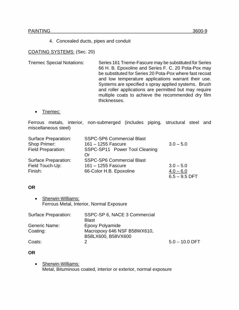
PAINTING 3600-9
4. Concealed ducts, pipes and conduit COATING SYSTEMS: (Sec. 20) Tnemec Special Notations: Series 161 Tneme-Fascure may be substituted for Series
66 H. B. Epoxoline and Series F. C. 20 Pota-Pox may be substituted for Series 20 Pota-Pox where fast recoat and low temperature applications warrant their use. Systems are specified s spray applied systems. Brush and roller applications are permitted but may require multiple coats to achieve the recommended dry film thicknesses.
• Tnemec:
Ferrous metals, interior, non-submerged (includes piping, structural steel and miscellaneous steel) Surface Preparation: SSPC-SP6 Commercial Blast Shop Primer: 161 – 1255 Fascure 3.0 – 5.0 Field Preparation: SSPC-SP11 Power Tool Cleaning Or Surface Preparation: SSPC-SP6 Commercial Blast Field Touch-Up: 161 – 1255 Fascure 3.0 – 5.0 Finish: 66-Color H.B. Epoxoline 4.0 – 6.0 6.5 – 9.5 DFT OR
• Sherwin-Williams: Ferrous Metal, Interior, Normal Exposure
Surface Preparation: SSPC-SP 6, NACE 3 Commercial Blast Generic Name: Epoxy Polyamide Coating: Macropoxy 646 NSF B58WX610, B58LX600, B58VX600 Coats: 2 5.0 – 10.0 DFT OR
• Sherwin-Williams: Metal, Bituminous coated, interior or exterior, normal exposure
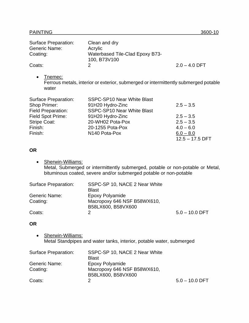
PAINTING 3600-10 Surface Preparation: Clean and dry Generic Name: Acrylic Coating: Waterbased Tile-Clad Epoxy B73-
100, B73V100 Coats: 2 2.0 – 4.0 DFT
• Tnemec: Ferrous metals, interior or exterior, submerged or intermittently submerged potable water
Surface Preparation: SSPC-SP10 Near White Blast Shop Primer: 91H20 Hydro-Zinc 2.5 – 3.5 Field Preparation: SSPC-SP10 Near White Blast Field Spot Prime: 91H20 Hydro-Zinc 2.5 – 3.5 Stripe Coat: 20-WH02 Pota-Pox 2.5 – 3.5 Finish: 20-1255 Pota-Pox 4.0 – 6.0 Finish: N140 Pota-Pox 6.0 – 8.0
12.5 – 17.5 DFT OR
• Sherwin-Williams: Metal, Submerged or intermittently submerged, potable or non-potable or Metal, bituminous coated, severe and/or submerged potable or non-potable
Surface Preparation: SSPC-SP 10, NACE 2 Near White Blast Generic Name: Epoxy Polyamide Coating: Macropoxy 646 NSF B58WX610, B58LX600, B58VX600 Coats: 2 5.0 – 10.0 DFT OR
• Sherwin-Williams: Metal Standpipes and water tanks, interior, potable water, submerged
Surface Preparation: SSPC-SP 10, NACE 2 Near White Blast Generic Name: Epoxy Polyamide Coating: Macropoxy 646 NSF B58WX610, B58LX600, B58VX600 Coats: 2 5.0 – 10.0 DFT
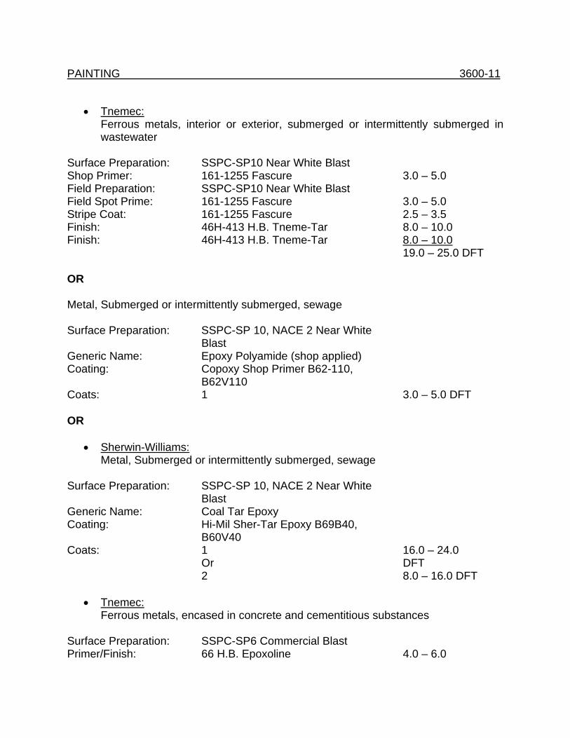
PAINTING 3600-11
• Tnemec: Ferrous metals, interior or exterior, submerged or intermittently submerged in wastewater
Surface Preparation: SSPC-SP10 Near White Blast Shop Primer: 161-1255 Fascure 3.0 – 5.0 Field Preparation: SSPC-SP10 Near White Blast Field Spot Prime: 161-1255 Fascure 3.0 – 5.0 Stripe Coat: 161-1255 Fascure 2.5 – 3.5 Finish: 46H-413 H.B. Tneme-Tar 8.0 – 10.0 Finish: 46H-413 H.B. Tneme-Tar 8.0 – 10.0 19.0 – 25.0 DFT OR Metal, Submerged or intermittently submerged, sewage Surface Preparation: SSPC-SP 10, NACE 2 Near White Blast Generic Name: Epoxy Polyamide (shop applied) Coating: Copoxy Shop Primer B62-110, B62V110 Coats: 1 3.0 – 5.0 DFT OR
• Sherwin-Williams: Metal, Submerged or intermittently submerged, sewage
Surface Preparation: SSPC-SP 10, NACE 2 Near White Blast Generic Name: Coal Tar Epoxy Coating: Hi-Mil Sher-Tar Epoxy B69B40, B60V40 Coats: 1 16.0 – 24.0 Or DFT 2 8.0 – 16.0 DFT
• Tnemec: Ferrous metals, encased in concrete and cementitious substances
Surface Preparation: SSPC-SP6 Commercial Blast Primer/Finish: 66 H.B. Epoxoline 4.0 – 6.0
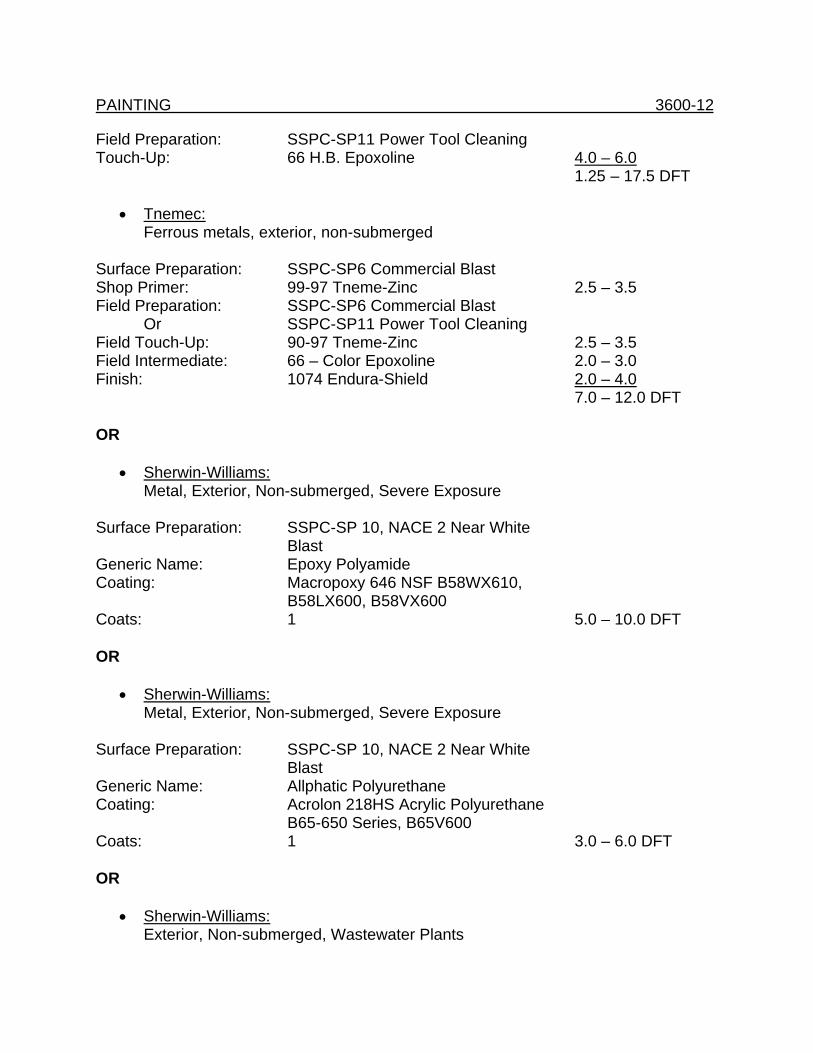
PAINTING 3600-12 Field Preparation: SSPC-SP11 Power Tool Cleaning Touch-Up: 66 H.B. Epoxoline 4.0 – 6.0
1.25 – 17.5 DFT
• Tnemec: Ferrous metals, exterior, non-submerged
Surface Preparation: SSPC-SP6 Commercial Blast Shop Primer: 99-97 Tneme-Zinc 2.5 – 3.5 Field Preparation: SSPC-SP6 Commercial Blast Or SSPC-SP11 Power Tool Cleaning Field Touch-Up: 90-97 Tneme-Zinc 2.5 – 3.5 Field Intermediate: 66 – Color Epoxoline 2.0 – 3.0 Finish: 1074 Endura-Shield 2.0 – 4.0 7.0 – 12.0 DFT OR
• Sherwin-Williams: Metal, Exterior, Non-submerged, Severe Exposure
Surface Preparation: SSPC-SP 10, NACE 2 Near White Blast Generic Name: Epoxy Polyamide Coating: Macropoxy 646 NSF B58WX610, B58LX600, B58VX600 Coats: 1 5.0 – 10.0 DFT OR
• Sherwin-Williams: Metal, Exterior, Non-submerged, Severe Exposure
Surface Preparation: SSPC-SP 10, NACE 2 Near White Blast Generic Name: Allphatic Polyurethane Coating: Acrolon 218HS Acrylic Polyurethane B65-650 Series, B65V600 Coats: 1 3.0 – 6.0 DFT OR
• Sherwin-Williams: Exterior, Non-submerged, Wastewater Plants
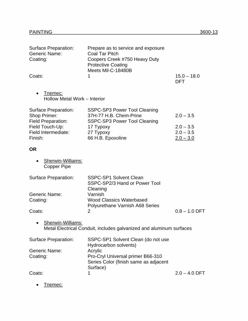
PAINTING 3600-13 Surface Preparation: Prepare as to service and exposure Generic Name: Coal Tar Pitch Coating: Coopers Creek #750 Heavy Duty Protective Coating Meets Mil-C-18480B Coats: 1 15.0 – 18.0 DFT
• Tnemec: Hollow Metal Work – Interior
Surface Preparation: SSPC-SP3 Power Tool Cleaning Shop Primer: 37H-77 H.B. Chem-Prine 2.0 – 3.5 Field Preparation: SSPC-SP3 Power Tool Cleaning Field Touch-Up: 17 Typoxy 2.0 – 3.5 Field Intermediate: 27 Typoxy 2.0 – 3.5 Finish: 66 H.B. Epoxoline 2.0 – 3.0 OR
• Sherwin-Williams: Copper Pipe
Surface Preparation: SSPC-SP1 Solvent Clean SSPC-SP2/3 Hand or Power Tool Cleaning Generic Name: Varnish Coating: Wood Classics Waterbased Polyurethane Varnish A68 Series Coats: 2 0.8 – 1.0 DFT
• Sherwin-Williams: Metal Electrical Conduit, includes galvanized and aluminum surfaces
Surface Preparation: SSPC-SP1 Solvent Clean (do not use Hydrocarbon solvents) Generic Name: Acrylic Coating: Pro-Cryl Universal primer B66-310 Series Color (finish same as adjacent Surface) Coats: 1 2.0 – 4.0 DFT
• Tnemec:
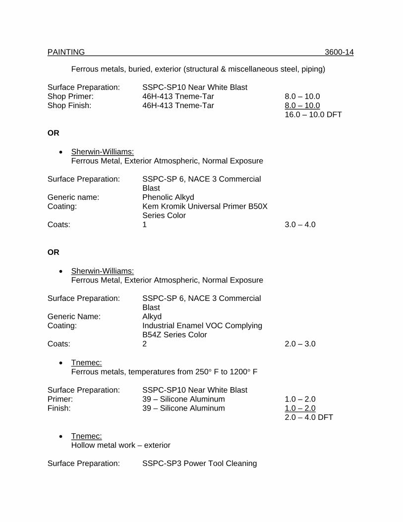
PAINTING 3600-14
Ferrous metals, buried, exterior (structural & miscellaneous steel, piping) Surface Preparation: SSPC-SP10 Near White Blast Shop Primer: 46H-413 Tneme-Tar 8.0 – 10.0 Shop Finish: 46H-413 Tneme-Tar 8.0 – 10.0 16.0 – 10.0 DFT OR
• Sherwin-Williams: Ferrous Metal, Exterior Atmospheric, Normal Exposure
Surface Preparation: SSPC-SP 6, NACE 3 Commercial Blast Generic name: Phenolic Alkyd Coating: Kem Kromik Universal Primer B50X Series Color Coats: 1 3.0 – 4.0 OR
• Sherwin-Williams: Ferrous Metal, Exterior Atmospheric, Normal Exposure
Surface Preparation: SSPC-SP 6, NACE 3 Commercial Blast Generic Name: Alkyd Coating: Industrial Enamel VOC Complying B54Z Series Color Coats: 2 2.0 – 3.0
• Tnemec: Ferrous metals, temperatures from 250° F to 1200° F
Surface Preparation: SSPC-SP10 Near White Blast Primer: 39 – Silicone Aluminum 1.0 – 2.0 Finish: 39 – Silicone Aluminum 1.0 – 2.0 2.0 – 4.0 DFT
• Tnemec: Hollow metal work – exterior
Surface Preparation: SSPC-SP3 Power Tool Cleaning
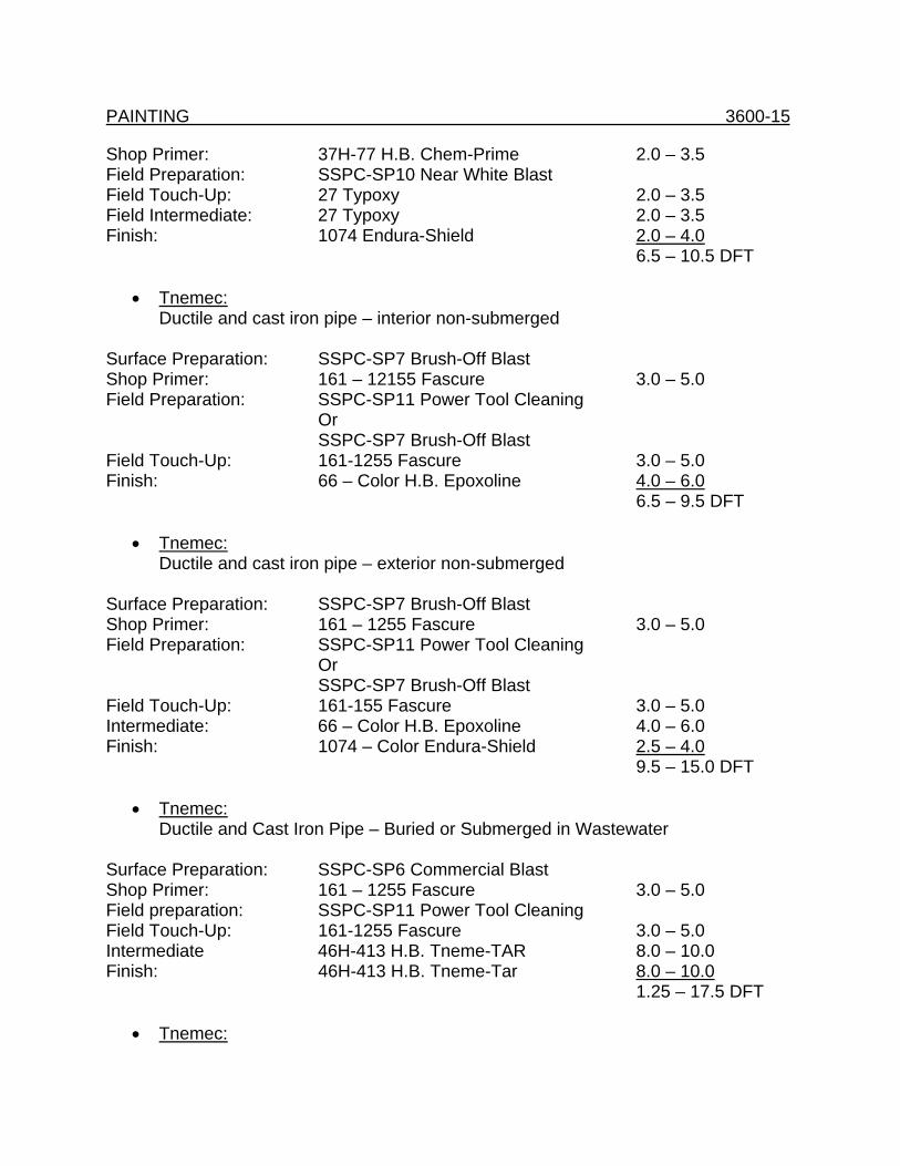
PAINTING 3600-15 Shop Primer: 37H-77 H.B. Chem-Prime 2.0 – 3.5 Field Preparation: SSPC-SP10 Near White Blast Field Touch-Up: 27 Typoxy 2.0 – 3.5 Field Intermediate: 27 Typoxy 2.0 – 3.5 Finish: 1074 Endura-Shield 2.0 – 4.0 6.5 – 10.5 DFT
• Tnemec: Ductile and cast iron pipe – interior non-submerged
Surface Preparation: SSPC-SP7 Brush-Off Blast Shop Primer: 161 – 12155 Fascure 3.0 – 5.0 Field Preparation: SSPC-SP11 Power Tool Cleaning Or SSPC-SP7 Brush-Off Blast Field Touch-Up: 161-1255 Fascure 3.0 – 5.0 Finish: 66 – Color H.B. Epoxoline 4.0 – 6.0 6.5 – 9.5 DFT
• Tnemec: Ductile and cast iron pipe – exterior non-submerged
Surface Preparation: SSPC-SP7 Brush-Off Blast Shop Primer: 161 – 1255 Fascure 3.0 – 5.0 Field Preparation: SSPC-SP11 Power Tool Cleaning Or SSPC-SP7 Brush-Off Blast Field Touch-Up: 161-155 Fascure 3.0 – 5.0 Intermediate: 66 – Color H.B. Epoxoline 4.0 – 6.0 Finish: 1074 – Color Endura-Shield 2.5 – 4.0 9.5 – 15.0 DFT
• Tnemec: Ductile and Cast Iron Pipe – Buried or Submerged in Wastewater
Surface Preparation: SSPC-SP6 Commercial Blast Shop Primer: 161 – 1255 Fascure 3.0 – 5.0 Field preparation: SSPC-SP11 Power Tool Cleaning Field Touch-Up: 161-1255 Fascure 3.0 – 5.0 Intermediate 46H-413 H.B. Tneme-TAR 8.0 – 10.0 Finish: 46H-413 H.B. Tneme-Tar 8.0 – 10.0 1.25 – 17.5 DFT
• Tnemec:
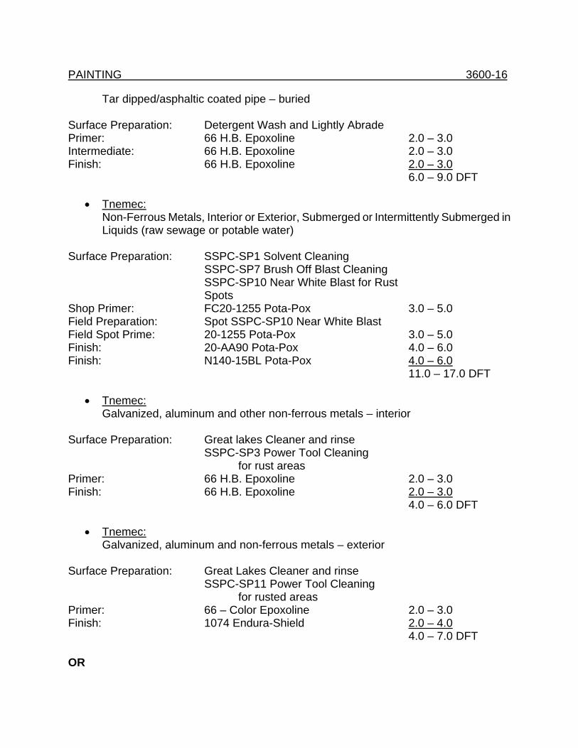
PAINTING 3600-16
Tar dipped/asphaltic coated pipe – buried Surface Preparation: Detergent Wash and Lightly Abrade Primer: 66 H.B. Epoxoline 2.0 – 3.0 Intermediate: 66 H.B. Epoxoline 2.0 – 3.0 Finish: 66 H.B. Epoxoline 2.0 – 3.0 6.0 – 9.0 DFT
• Tnemec: Non-Ferrous Metals, Interior or Exterior, Submerged or Intermittently Submerged in Liquids (raw sewage or potable water)
Surface Preparation: SSPC-SP1 Solvent Cleaning SSPC-SP7 Brush Off Blast Cleaning SSPC-SP10 Near White Blast for Rust Spots Shop Primer: FC20-1255 Pota-Pox 3.0 – 5.0 Field Preparation: Spot SSPC-SP10 Near White Blast Field Spot Prime: 20-1255 Pota-Pox 3.0 – 5.0 Finish: 20-AA90 Pota-Pox 4.0 – 6.0 Finish: N140-15BL Pota-Pox 4.0 – 6.0 11.0 – 17.0 DFT
• Tnemec: Galvanized, aluminum and other non-ferrous metals – interior
Surface Preparation: Great lakes Cleaner and rinse SSPC-SP3 Power Tool Cleaning for rust areas Primer: 66 H.B. Epoxoline 2.0 – 3.0 Finish: 66 H.B. Epoxoline 2.0 – 3.0 4.0 – 6.0 DFT
• Tnemec: Galvanized, aluminum and non-ferrous metals – exterior
Surface Preparation: Great Lakes Cleaner and rinse SSPC-SP11 Power Tool Cleaning for rusted areas Primer: 66 – Color Epoxoline 2.0 – 3.0 Finish: 1074 Endura-Shield 2.0 – 4.0 4.0 – 7.0 DFT OR
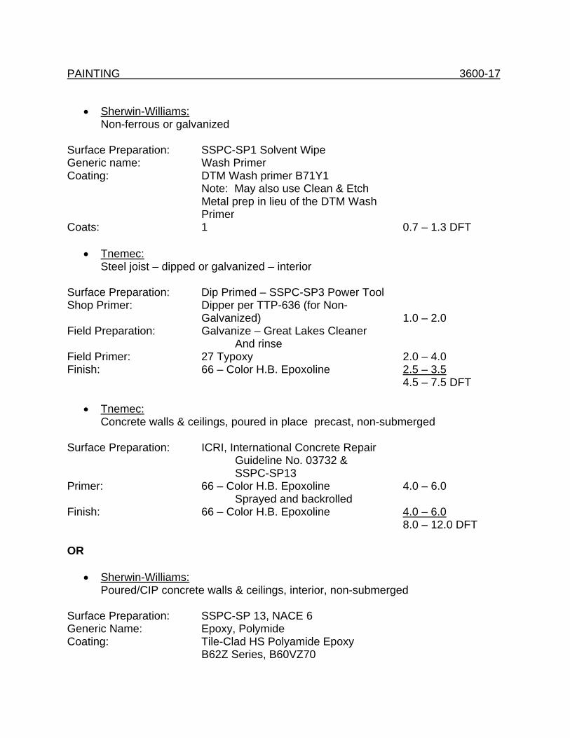
PAINTING 3600-17
• Sherwin-Williams: Non-ferrous or galvanized
Surface Preparation: SSPC-SP1 Solvent Wipe Generic name: Wash Primer Coating: DTM Wash primer B71Y1 Note: May also use Clean & Etch Metal prep in lieu of the DTM Wash Primer Coats: 1 0.7 – 1.3 DFT
• Tnemec: Steel joist – dipped or galvanized – interior
Surface Preparation: Dip Primed – SSPC-SP3 Power Tool Shop Primer: Dipper per TTP-636 (for Non-
Galvanized) 1.0 – 2.0 Field Preparation: Galvanize – Great Lakes Cleaner And rinse Field Primer: 27 Typoxy 2.0 – 4.0 Finish: 66 – Color H.B. Epoxoline 2.5 – 3.5 4.5 – 7.5 DFT
• Tnemec: Concrete walls & ceilings, poured in place precast, non-submerged
Surface Preparation: ICRI, International Concrete Repair Guideline No. 03732 & SSPC-SP13 Primer: 66 – Color H.B. Epoxoline 4.0 – 6.0 Sprayed and backrolled Finish: 66 – Color H.B. Epoxoline 4.0 – 6.0 8.0 – 12.0 DFT OR
• Sherwin-Williams: Poured/CIP concrete walls & ceilings, interior, non-submerged
Surface Preparation: SSPC-SP 13, NACE 6 Generic Name: Epoxy, Polymide Coating: Tile-Clad HS Polyamide Epoxy B62Z Series, B60VZ70
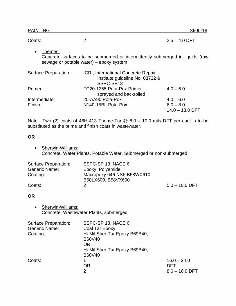
PAINTING 3600-18 Coats: 2 2.5 – 4.0 DFT
• Tnemec: Concrete surfaces to be submerged or intermittently submerged in liquids (raw sewage or potable water) – epoxy system
Surface Preparation: ICRI, International Concrete Repair Institute guideline No. 03732 & SSPC-SP13 Primer: FC20-1255 Pota-Pox Primer 4.0 – 6.0 sprayed and backrolled Intermediate: 20-AA90 Pota-Pox 4.0 – 6.0 Finish: N140-15BL Pota-Pox 6.0 – 8.0 14.0 – 18.0 DFT Note: Two (2) coats of 46H-413 Tneme-Tar @ 8.0 – 10.0 mils DFT per coat is to be substituted as the prime and finish coats in wastewater. OR
• Sherwin-Williams: Concrete, Water Plants, Potable Water, Submerged or non-submerged
Surface Preparation: SSPC-SP 13, NACE 6 Generic Name: Epoxy, Polyamide Coating: Macropoxy 646 NSF B58WX610, B58LX600, B58VX600 Coats: 2 5.0 – 10.0 DFT OR
• Sherwin-Williams: Concrete, Wastewater Plants, submerged
Surface Preparation: SSPC-SP 13, NACE 6 Generic Name: Coal Tar Epoxy Coating: Hi-Mil Sher-Tar Epoxy B69B40, B60V40 OR Hi-Mil Sher-Tar Epoxy B69B40, B60V40 Coats: 1 16.0 – 24.0 OR DFT 2 8.0 – 16.0 DFT
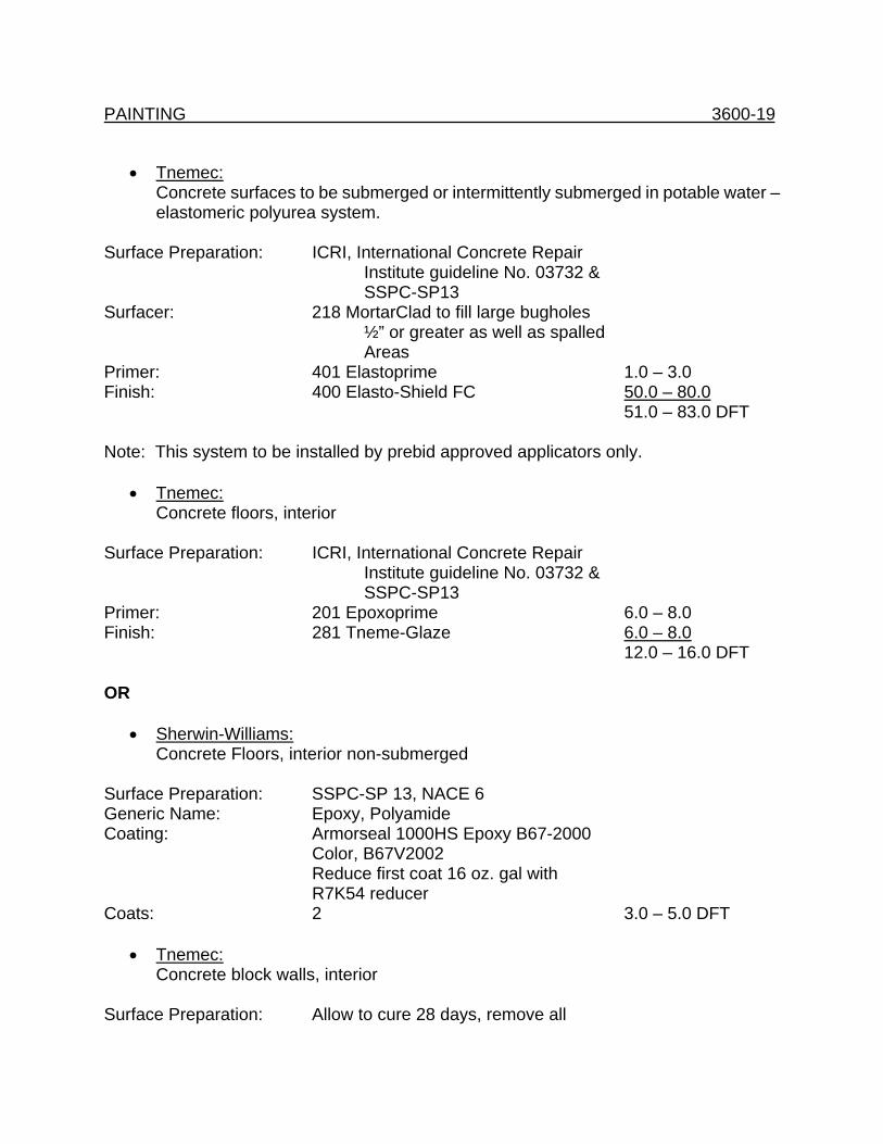
PAINTING 3600-19
• Tnemec: Concrete surfaces to be submerged or intermittently submerged in potable water – elastomeric polyurea system.
Surface Preparation: ICRI, International Concrete Repair Institute guideline No. 03732 & SSPC-SP13 Surfacer: 218 MortarClad to fill large bugholes ½” or greater as well as spalled Areas Primer: 401 Elastoprime 1.0 – 3.0 Finish: 400 Elasto-Shield FC 50.0 – 80.0 51.0 – 83.0 DFT Note: This system to be installed by prebid approved applicators only.
• Tnemec: Concrete floors, interior
Surface Preparation: ICRI, International Concrete Repair Institute guideline No. 03732 & SSPC-SP13 Primer: 201 Epoxoprime 6.0 – 8.0 Finish: 281 Tneme-Glaze 6.0 – 8.0 12.0 – 16.0 DFT OR
• Sherwin-Williams: Concrete Floors, interior non-submerged
Surface Preparation: SSPC-SP 13, NACE 6 Generic Name: Epoxy, Polyamide Coating: Armorseal 1000HS Epoxy B67-2000 Color, B67V2002 Reduce first coat 16 oz. gal with R7K54 reducer Coats: 2 3.0 – 5.0 DFT
• Tnemec: Concrete block walls, interior
Surface Preparation: Allow to cure 28 days, remove all
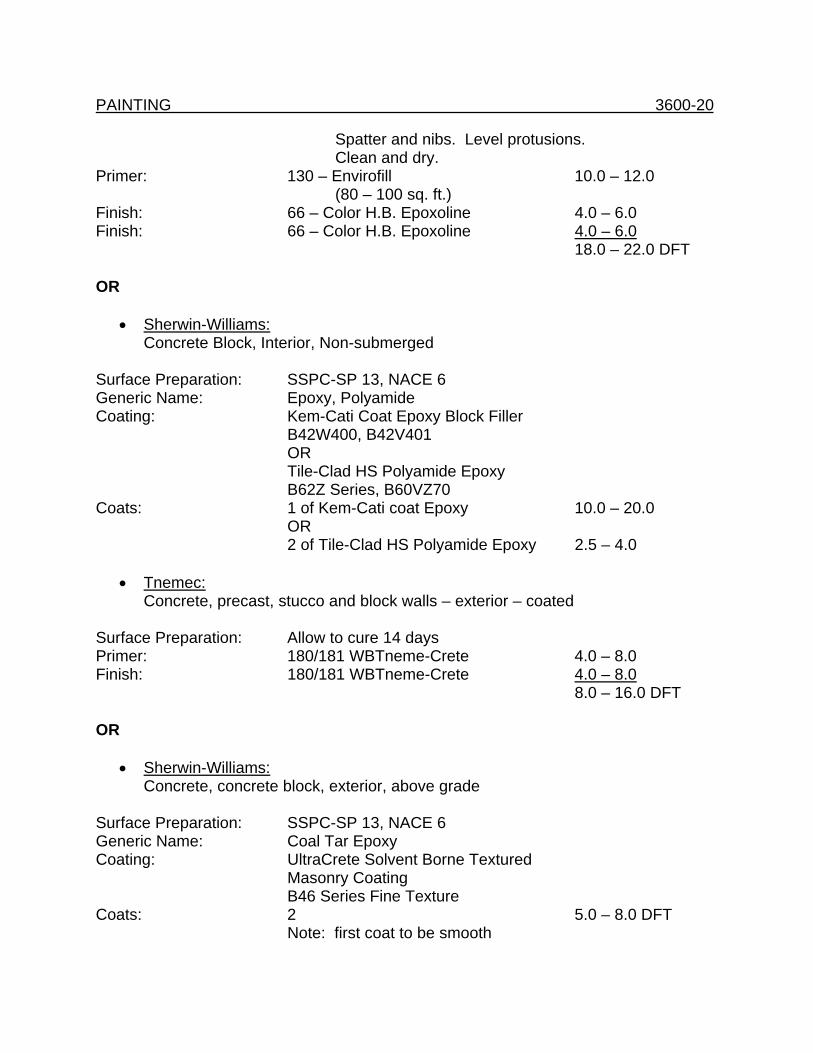
PAINTING 3600-20 Spatter and nibs. Level protusions. Clean and dry. Primer: 130 – Envirofill 10.0 – 12.0 (80 – 100 sq. ft.) Finish: 66 – Color H.B. Epoxoline 4.0 – 6.0 Finish: 66 – Color H.B. Epoxoline 4.0 – 6.0 18.0 – 22.0 DFT OR
• Sherwin-Williams: Concrete Block, Interior, Non-submerged
Surface Preparation: SSPC-SP 13, NACE 6 Generic Name: Epoxy, Polyamide Coating: Kem-Cati Coat Epoxy Block Filler B42W400, B42V401 OR Tile-Clad HS Polyamide Epoxy B62Z Series, B60VZ70 Coats: 1 of Kem-Cati coat Epoxy 10.0 – 20.0 OR 2 of Tile-Clad HS Polyamide Epoxy 2.5 – 4.0
• Tnemec: Concrete, precast, stucco and block walls – exterior – coated
Surface Preparation: Allow to cure 14 days Primer: 180/181 WBTneme-Crete 4.0 – 8.0 Finish: 180/181 WBTneme-Crete 4.0 – 8.0 8.0 – 16.0 DFT OR
• Sherwin-Williams: Concrete, concrete block, exterior, above grade
Surface Preparation: SSPC-SP 13, NACE 6 Generic Name: Coal Tar Epoxy Coating: UltraCrete Solvent Borne Textured Masonry Coating B46 Series Fine Texture Coats: 2 5.0 – 8.0 DFT Note: first coat to be smooth
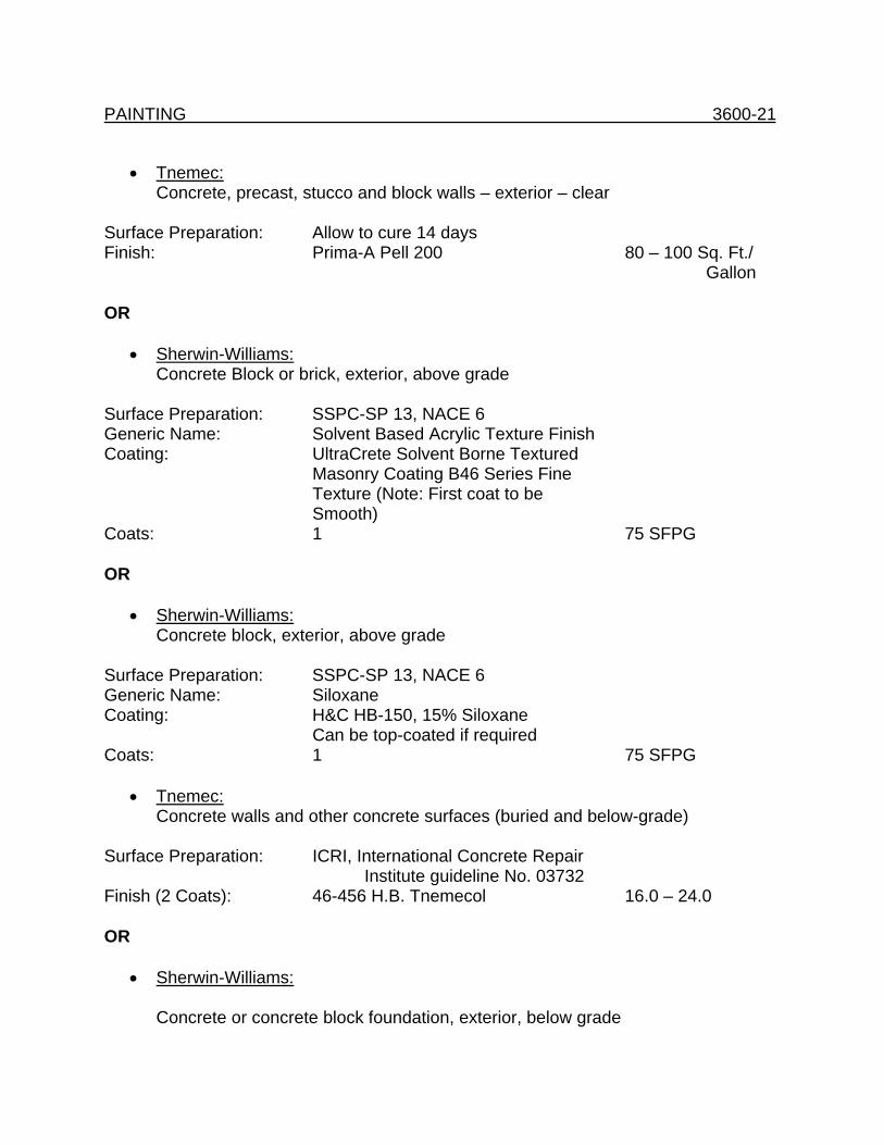
PAINTING 3600-21
• Tnemec: Concrete, precast, stucco and block walls – exterior – clear
Surface Preparation: Allow to cure 14 days Finish: Prima-A Pell 200 80 – 100 Sq. Ft./ Gallon OR
• Sherwin-Williams: Concrete Block or brick, exterior, above grade
Surface Preparation: SSPC-SP 13, NACE 6 Generic Name: Solvent Based Acrylic Texture Finish Coating: UltraCrete Solvent Borne Textured Masonry Coating B46 Series Fine Texture (Note: First coat to be Smooth) Coats: 1 75 SFPG OR
• Sherwin-Williams: Concrete block, exterior, above grade
Surface Preparation: SSPC-SP 13, NACE 6 Generic Name: Siloxane Coating: H&C HB-150, 15% Siloxane Can be top-coated if required Coats: 1 75 SFPG
• Tnemec: Concrete walls and other concrete surfaces (buried and below-grade)
Surface Preparation: ICRI, International Concrete Repair Institute guideline No. 03732 Finish (2 Coats): 46-456 H.B. Tnemecol 16.0 – 24.0 OR
• Sherwin-Williams:
Concrete or concrete block foundation, exterior, below grade
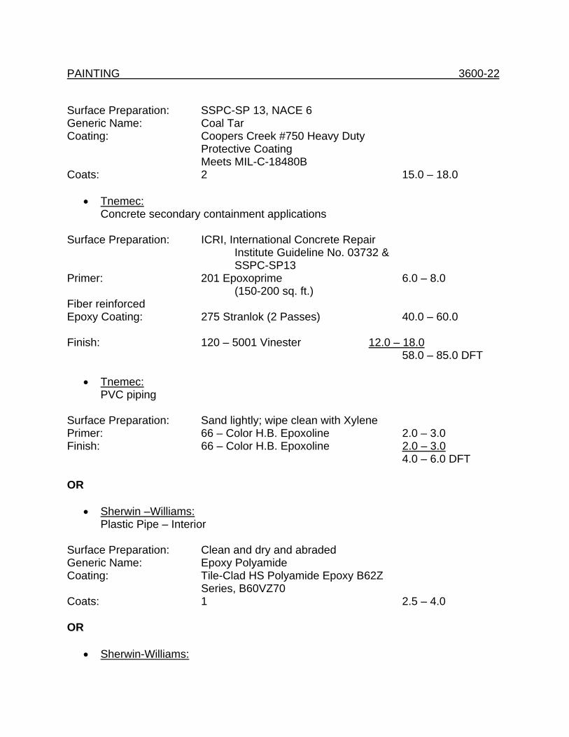
PAINTING 3600-22 Surface Preparation: SSPC-SP 13, NACE 6 Generic Name: Coal Tar Coating: Coopers Creek #750 Heavy Duty Protective Coating Meets MIL-C-18480B Coats: 2 15.0 – 18.0
• Tnemec: Concrete secondary containment applications
Surface Preparation: ICRI, International Concrete Repair Institute Guideline No. 03732 & SSPC-SP13 Primer: 201 Epoxoprime 6.0 – 8.0 (150-200 sq. ft.) Fiber reinforced Epoxy Coating: 275 Stranlok (2 Passes) 40.0 – 60.0 Finish: 120 – 5001 Vinester 12.0 – 18.0 58.0 – 85.0 DFT
• Tnemec: PVC piping
Surface Preparation: Sand lightly; wipe clean with Xylene Primer: 66 – Color H.B. Epoxoline 2.0 – 3.0 Finish: 66 – Color H.B. Epoxoline 2.0 – 3.0 4.0 – 6.0 DFT OR
• Sherwin –Williams: Plastic Pipe – Interior
Surface Preparation: Clean and dry and abraded Generic Name: Epoxy Polyamide Coating: Tile-Clad HS Polyamide Epoxy B62Z Series, B60VZ70 Coats: 1 2.5 – 4.0 OR
• Sherwin-Williams:
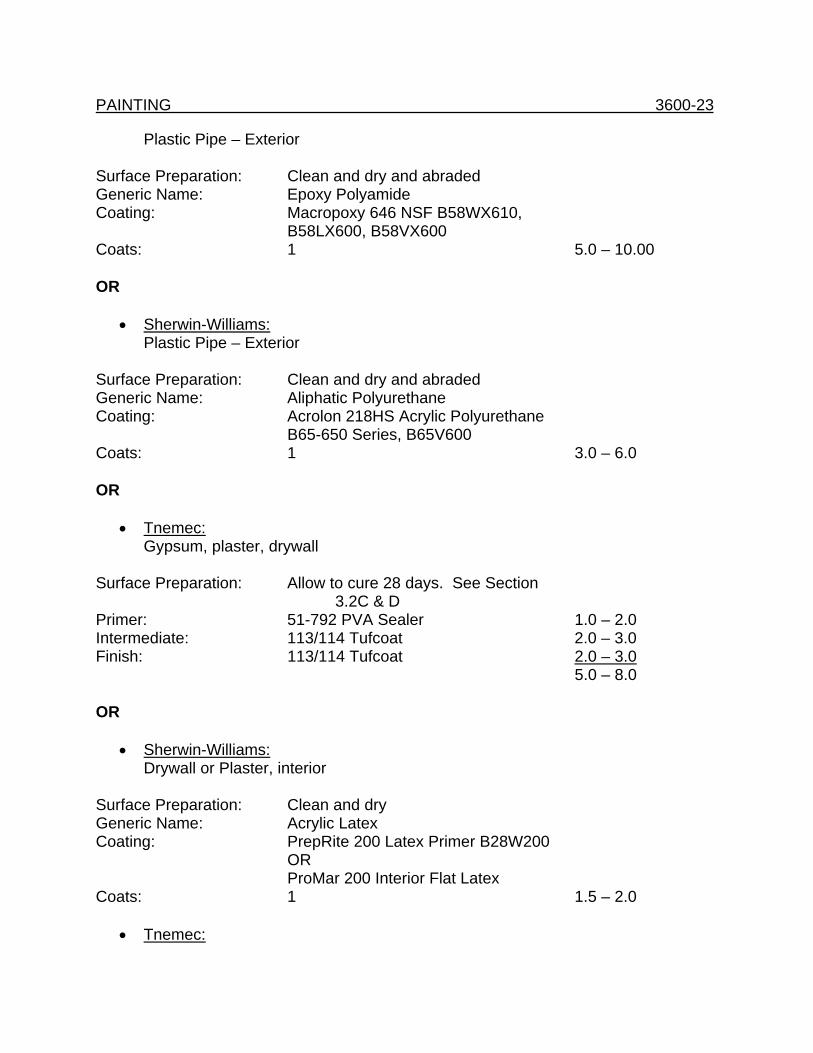
PAINTING 3600-23
Plastic Pipe – Exterior Surface Preparation: Clean and dry and abraded Generic Name: Epoxy Polyamide Coating: Macropoxy 646 NSF B58WX610, B58LX600, B58VX600 Coats: 1 5.0 – 10.00 OR
• Sherwin-Williams: Plastic Pipe – Exterior
Surface Preparation: Clean and dry and abraded Generic Name: Aliphatic Polyurethane Coating: Acrolon 218HS Acrylic Polyurethane B65-650 Series, B65V600 Coats: 1 3.0 – 6.0 OR
• Tnemec: Gypsum, plaster, drywall
Surface Preparation: Allow to cure 28 days. See Section 3.2C & D Primer: 51-792 PVA Sealer 1.0 – 2.0 Intermediate: 113/114 Tufcoat 2.0 – 3.0 Finish: 113/114 Tufcoat 2.0 – 3.0 5.0 – 8.0 OR
• Sherwin-Williams: Drywall or Plaster, interior
Surface Preparation: Clean and dry Generic Name: Acrylic Latex Coating: PrepRite 200 Latex Primer B28W200 OR ProMar 200 Interior Flat Latex Coats: 1 1.5 – 2.0
• Tnemec:
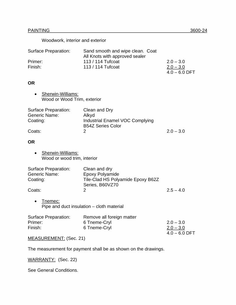
PAINTING 3600-24
Woodwork, interior and exterior Surface Preparation: Sand smooth and wipe clean. Coat All Knots with approved sealer Primer: 113 / 114 Tufcoat 2.0 – 3.0 Finish: 113 / 114 Tufcoat 2.0 – 3.0 4.0 – 6.0 DFT OR
• Sherwin-Williams: Wood or Wood Trim, exterior
Surface Preparation: Clean and Dry Generic Name: Alkyd Coating: Industrial Enamel VOC Complying B54Z Series Color Coats: 2 2.0 – 3.0 OR
• Sherwin-Williams: Wood or wood trim, interior
Surface Preparation: Clean and dry Generic Name: Epoxy Polyamide Coating: Tile-Clad HS Polyamide Epoxy B62Z Series, B60VZ70 Coats: 2 2.5 – 4.0
• Tnemec: Pipe and duct insulation – cloth material
Surface Preparation: Remove all foreign matter Primer: 6 Tneme-Cryl 2.0 – 3.0 Finish: 6 Tneme-Cryl 2.0 – 3.0 4.0 – 6.0 DFT MEASUREMENT: (Sec. 21) The measurement for payment shall be as shown on the drawings. WARRANTY: (Sec. 22) See General Conditions.
PAINTING 3600-25 CLEAN-UP: (Sec. 22) Clean-up of Site: Remove all surplus and miscellaneous debris and dispose of off the site. The clean-up and disposal of all excess materials shall be done as soon as practical or as the Resident Representative may direct. However, clean-up work shall not fall behind. Should the contractor not keep his clean-up work within an acceptable manner in the opinion of the Resident Representative the Contractor shall be required to cease further work until such clean-up is accomplished.
END OF SECTION
4075- 1
EXTREME GRINDER PUMP STATION
ITEM 4075 - E PART 1 – GENERAL WORK INCLUDED: (Sec. 01) Furnish Grinder Pump Station(s) as indicated on Drawings and specified. RELATED WORK: (Sec. 02) Furnished/paid for in this Item: Polyethylene Pressure Pipe ( DIPS ) Item 1411 Polyethylene Pressure Pipe Item 1412 Polyethylene lateral kits Item 1414 All freight and delivery costs, and unloading at the location designated by the Owner DESCRIPTION: (Sec. 03) Work generally includes furnishing complete factory built Grinder Pump Station(s), E One Extreme series - D,W,I, or G as indicated on the drawings, and as manufactured by Environment One, each consisting of grinder pump in a basin, pump removal system, shut-off valve, anti-siphon valve, and check valve assembly within the basin, remote electrical alarm and control panel model Sentry or Sentry-duplex and all necessary internal wiring and controls. Each pump unit shall also include 75 L.F of 240-V direct buried cable. Each unit shall also include a complete 1¼” H.D.P.E. SDR-11 service connection kit complete. The pumps shall be capable of delivering 07.5 -14.5 gpm against a rated total dynamic head of between 0 & 185 feet TDH. At zero head, the output shall be 14.5 gpm minimum. The pump(s) shall be capable of intermittent (3 minute minimum) operation at any head up to 150% of normal rated dynamic head. The pumps must be capable of operating at negative total dynamic heads of 150% below normal rated dynamic head without installation of in line restrictive piping or valving as to create a false apparent head. The electrical rating of each pump shall be 8 amperes, 1 phase, 240 volt, 60 hertz. QUALITY ASSURANCE: (Sec. 04) Material shall be new and of the best quality. FACTORY TEST: (Sec. 05) Each grinder pump shall be submerged and operated for 5 minutes (minimum). Included in this procedure will be the testing of all ancillary components such as, the anti-siphon valve, check valve, discharge line, level sensors, each unit’s controls, etc. All factory tests shall incorporate each of the above listed items. Actual appurtenances and controls which will be installed in the field, shall be particular to the tested pump only, a common set of appurtenances and controls for all pumps will not be acceptable. Certified test results shall be supplied showing the operation of each grinder pump at three different points on its curve, with the maximum pressure no less than 50 psi. Grinder pump shall be tested for water tightness up to 5 psig. The Engineer reserves the right to inspect such testing procedures with representatives of the Owner, at the named Grinder Pump Manufacturer’s facility.
4075- 2
REFERENCES: (Sec. 06) NEMA - National Electrical Manufacturers Association NEC- National Electric Code
ODOT- Ohio Department of Transportation, Construction and Material Specifications
SUBMITTALS: (Sec. 07) Shop Drawings – See General Conditions. Operating Instructions, Parts List, etc. – See General Conditions. Provide six sets. DELIVERY, STORAGE, HANDLING: (Sec. 08) Units shall be delivered to the job site, 100% completely assembled, ready for installation. Each unit shall have lifting eyes to facilitate unloading. Store in a dry, weatherproof location. Handle with care so as not to damage units. MEASUREMENT/PAYMENT: (Sec. 09) Payment per each, complete, delivered and stored. WARRANTY: (Sec. 10) See General Conditions. PART 2 – PRODUCTS MANUFACTURERS: (Sec.11) Environment/One, Schenectady, New York, Model As Shown On The Drawings. MATERIALS/EQUIPMENT: (Sec. 12) Pump: Semi-positive displacement grinder pump with integral, vertical rotor, motor driven, solids handling pump, progressing cavity type with mechanical seal. Rotor shall be through-hardened, highly polished, precipitation hardened stainless steel. Stator shall be a compounded ethylene propylene synthetic elastomer, suited for domestic wastewater service. Its physical properties shall include resistance to high tear and abrasion, grease, water and detergents, and have a temperature stability, good aging properties and outstanding wear resistance. Grinder The grinder shall be placed immediately below the pumping elements, be direct-driven by a single, one-piece motor shaft. The grinder impeller assembly shall be securely fastened to the pump motor shaft. The grinder will be of the rotating type with a
4075- 3
stationary hardened and ground chrome steel shredding ring spaced in accurate close in annual alignment of the driven impeller assembly, which shall carry two hardened type 400 series stainless steel cutter bars. This assembly shall be constructed so as to eliminate clogging and jamming under all normal operating conditions including starting. Sufficient vortex action shall be created to scour tank free of deposits or sludge banks which would impair the operation of the pump. These requirements shall be accomplished by the following, in conjunction with the pump:
1. The grinder shall be positioned in such a way that solids are fed in an upward flow direction.
2. The inlet shroud shall have a diameter no less than 5 inches. 3. At maximum flow the average inlet velocity must not exceed 0.2 feet per
second. 4. The impeller mechanism must rotate at a nominal speed of no greater
than 1800 rpm. The grinder shall be capable of reducing all components in normal domestic sewage, including a reasonable amount of “foreign objects”, such as paper, wood, plastic, glass, rubber and the like, to finely-divided particles which will pass freely through the passages of the pump and the 1-1/4 inch diameter discharge piping. Electric Motor The electric motor shall be a one rpm, 1725 rpm, 240 volt, 60 hertz, single phase, capacitor start, ball bearing, squirrel cage induction type with a low starting current not to exceed 36 amperes and high starting torque of 8.4 foot pounds. Inherent protection against running overloads or locked rotor conditions for the pump motor shall be provided by the use of an automatic0reset, integral thermal overload protector incorporated in the motor. Two overload thermal units shall be provided, one in each ungrounded motor lead. This motor protector combination shall have been specifically investigated and listed y Underwriters’ Laboratories, Inc., for the application. Mechanical Seal The core shall be provided with a mechanical shaft seal to prevent leakage between the motor and pump. The seal shall have a stationary ceramic seat and carbon rotating surface with faces precision lapped and held in position by a stainless steel spring. Tank The tank shall be provided with a mechanical shaft seal to prevent and shall have nominal wall thickness of 3/16 inch and a capacity as determined by the series. The tank shall be furnished with one PVC bolt on closet inlet flange to accept a six inch nominal PVC, D3034, SDR-35 pipe. Accessway The accessway shall be an integral extension of the FRP tank and shall be custom molded of fiberglass reinforced polyester resin and shall have a minimum wall thickness of 3/16 inch and a length of 4’-0”. It shall have an access opening at the top to accept a lockable domed fiberglass cover with skirt. The accessway shall include the following
4075- 4
factory installed items: Copper 1-1/4 inch male pipethread, and a two inch PVC internal vent for venting the tank. Internal wiring shall terminate in a sealed junction box, that is integral with the accessway the suitable for outdoor use. All seals shall be factory tested to ensure their watertight integrity. Provide two padlocks, with keys, for each installation, one for tank, one for control panel. Core Unit The Grinder pump shall have cartridge type easily removable core assemblies containing pump, motor, grinder, controls, check valve, anti-siphon valve and wiring. Unit shall have means for local disconnection of motor and alarm wiring, either internal disconnect switches or weatherproof plug/receptacle combinations. The watertight integrity of the core unit, including wiring and access cover, shall be established by 100% factory test at a minimum of 5 psig. The core unit shall have two lifting eyes provided in the top housing. All mechanical and electrical connections shall provide easy disconnect accessibility for core unit removal and installation. All maintenance tasks for the grinder pump station shall be possible without entry of the grinder pump station. Level Controls Wastewater level detection for controlling pump operation shall be accomplished by monitoring the pressure changes in an integral air-bell level sensor connected through air-tight tubing to a pressure switch. The level detection device shall have no moving parts in direct contact with the wastewater. Overflow sensing shall be accomplished by a separate air-bell sensor of the same type. Three pressure setpoints shall be provided,
1. to start pump operation, 2. to stop pump operation, and 3. to sense overflow condition (high-high level).
Each level control shall have its own built-in fail safe design which will prevent the entrance of moisture in case of switch diaphragm failure. The start/stop switch shall be internally connected to the integral motor run contactor. The high-high level switch shall be an isolated contact wired independently to an external alarm circuit, as indicated in the Electrical Drawings. Alarm/Disconnect Panel Sentry or Sentry-Duplex Panels with 75’ of 240-V cable as provided by Environment One. Corrosion Protection All materials exposed to wastewater shall have inherent corrosion protection: ie., cast iron, fiberglass, stainless steel, PVC.

4075- 5
4076- 1
GRINDER PUMP STATION INSTALLATION
ITEM 4076 PART 1 – GENERAL WORK INCLUDED: (Sec. 01) Provide all labor and equipment necessary to install Grinder Pump Station(s) in the locations indicated on the drawings or as directed by the Resident Representative. RELATED WORK: (Sec. 02) Furnished/paid for in this Item: Electrical Work at Grinder Pump & Installation Of Underground Cable Item 7000 PVC Pressure Pipe Item 1410
Polyethylene Pressure Pipe (DIPS) Item 1411 Polyethylene Pressure Pipe Item 1412 Polyethylene Pressure Pipe Lateral Kits Item 1414 Bulk Concrete Item 505 Granular Backfill Item 164 Earth Excavation/Backfill Item 120
Furnished/paid for in respective Item: Grinder pump supplied by others Item 4075 Topsoil Item 205
Seeding Item 210 Pavement, Curb, Gutter, Sidewalk Item 300 Electrical Work (Residential Load Center) Item 7000
DESCRIPTION: (Sec. 03) Work generally includes installing complete factory built Grinder Pump Station(s), each consisting of grinder pump in a basin, pump removal system, shut-off valve, anti-siphon valve, and check valve assembly within the basin, lateral kit remote electrical alarm and control panel and all necessary internal wiring and controls, including installation and connection of 240-V cable between the unit and the remote panel. QUALITY ASSURANCE: (Sec. 04) Material shall be new and of the best quality. Actual appurtenances and controls which will be installed in the field, shall be particular to the tested pump only, a common set of appurtenances and controls for all pumps will not be acceptable. The Engineer reserves the right to inspect such testing procedures with representatives of the Owner. REFERENCES: (Sec. 05) NEMA - National Electrical Manufacturers Association NEC- National Electric Code
4076- 2
SCDOT- South Carolina Department of Transportation, Construction and Material Specifications
SUBMITTALS: (Sec. 06) Shop Drawings – N/A. DELIVERY, STORAGE, HANDLING: (Sec. 07) Units shall be delivered to the installation site, 100% completely assembled, ready for installation from the storage location. Each unit shall have lifting eyes to facilitate unloading. Handle with care so as not to damage units. MEASUREMENT/PAYMENT: (Sec. 08) Payment per each, completely installed and tested . WARRANTY: (Sec. 09) See General Conditions. PART 2 – PRODUCTS MANUFACTURERS: (Sec.10) Environment/One, Schenectady, New York, Model as shown on the drawings. Bedding Material Angular crushed limestone – SCDOT No. 57 gradation (included in installation cost). PART 3 – EXECUTION INSPECTION: (Sec. 11) Contractor and Resident Representative shall inspect each location where grinder pump station(s) is to be installed. Final location to be determined in field. INSTALLATION: (Sec. 12) Perform earth excavation/backfill for the installation of grinder pump station, appurtenant piping, etc. Contractor shall be responsible for handling ground water to provide firm, dry subgrade for the structure, and shall guard against flotation or other damage result in from general water or flooding. The grinder pump units shall not be set into excavation until the installation procedures and excavation have been approved by the Resident Representative. A concrete anti-flotation collar, as indicated on the Drawings shall be required and shall be pre-cast to the grinder pump. A six inch minimum layer of aggregate shall be used as bedding material under each unit. The grinder pump shall be installed at a minimum depth of 4’-0” from grade to the top of the 1-1/4 inch discharge line. Finish grade shall be a minimum of six inches below the top of the accessway, and final grade shall slope away from the grinder unit. .
4076- 3
ELECTRICAL: (Sec. 13) Electric service from each remote panel location to each station shall be provided in this reference Item 7000. Electric service shall be placed in a separate trench, offset a minimum of 3 feet from the trench containing the service connection pipe, as far as practicable, in Item 7000. FIELD QUALITY CONTROL: (Sec. 14) The Contractor shall provide the services of qualified factory trained technician(s) who shall inspect the placement and wiring of each station, perform field tests as specific herein, and instruct the Owner’s personnel in the operation and maintenance of the equipment before the stations are accepted by the Owner. All equipment and materials, except water, necessary to perform testing shall be the responsibility of the named grinder pump manufacturer. This will include, as a minimum, a portable generator and ammeter. The Owner will be responsible to supply water for testing, as required. After the pump stations have been installed by the Contractor and the named grinder pump manufacturer, authorized factory trained technician(s) shall perform the following test on each station.
1. Fill the wet well with water to a depth sufficient to verify the high-high level alarm is operative.
2. Initiate pump operation to verify automatic “on/off” controls are operative. 3. Observe amperage readings to verify proper electrical conditions are met.
Station manufacturer shall provide:
1. Installation training – 3 Hr’s. 2. Service training – 3 Hr’s. 3. Start-up of stations – 2 Hr’s per Station.
CLEAN-UP: (Sec. 15) Upon the completion of each installation, the Contractor shall remove and dispose of all debris and excess materials, and put the site in a neat and orderly condition. Place topsoil and seed all disturbed area, as specified in their respective Item.
4100-1 MAINTAINING TRAFFIC ITEM 4100 PART 1 - GENERAL WORK INCLUDED: (Sec.01) Furnish all labor, materials and equipment to maintain and protect vehicular and pedestrian traffic and work as specified. DESCRIPTION: (Sec. 02) Work generally includes the installation and maintenance of all signs, barricades, lighting, and all traffic control and traffic control devices and watchmen, for the maintenance and control of traffic. REFERENCES: (Sec. 03)
SCDOT – South Carolina Department of Transportation MEASUREMENT/PAYMENT: (Sec. 04) Lump sum payment will be made. PART 2 - PRODUCTS EQUIPMENT: (Sec. 05) Signs, barrels, barricades and all other traffic control devices shall conform to the requirements of the "South Carolina Manual of Uniform Traffic Control Devices for Streets and Highways". PART 3 - EXECUTION INSTALLATION: (Sec. 06) Installation of all traffic control devices shall be in accordance with the " South Carolina Manual", given above. CLEAN-UP: (Sec. 07) Upon completion of all work, remove all temporary signs, barricades and other traffic control devices.
4800-1
LIFT STATION
ITEM 4800
WORK INCLUDED: (Sec. 01) Under this item, the contractor shall furnish all labor, materials, tools and equipment required to complete one (1) precast concrete lift station, valve box, piping, pumps, winch/tripod assembly for pump removal, and electrical controls shown on the drawings or specified herein.
Related Information - See Section 5200 furnished and paid for in this item. GENERAL: (Sec. 02) The lift stations specified herein shall be the product of one manufacturer offering single source responsibility. In general, the lift station shall be capable of pumping 200 gpm @ 107’of TDH.
1) Reinforcing Steel - Steel rebar shall be of equal quality or exceed ASTM-671 Grade 60 Standards. All welded-wire fabric mesh shall conform to ASTM C-185.
2) Wet Well - Shall be manhole -type construction conforming to ASTM concrete
specification C-478. Joints between the sections shall conform to ASTM specification C-443. Wet well ventilation may be either continuous or intermittent. Ventilation, if continuous, shall provide at least 12 complete air changes per hour; if intermittent, at least 3 0 complete air changes per hour. The fan shall be activated when the access lid is opened by a switch.
3) The pumps – Shall be three (3) phase. A single to three-phase electric power
converter shall be supplied as provided by Ronk Electrical Industries Inc., 106 East State Street, Nokomis Illinois, (217) 563-8333 or equivalent static converter. The Ronk unit shall be sized to handle 2-15 hp pumps. Each three-phase motor shall be supplied with three-phase power from an autotranspformer-capacitor type phase converter shall be rated for continuos operation, with individual sections capable of operating the motors independently or simultaneously at the motor service factor from a single-phase source.
DESCRIPTION: (Sec. 01) Pump controls shall include the furnishing of a control panel at the pump station as shown on the plans. CONTROL PANEL: (Sec. 02) The control panel shall include all of the features as described herein and shown on the drawings. All components shall be factory mounted, wired, inspected, and tested.
1) Control panel shall be designed for operation on voltage and phase as listed in the pump characteristics table.
2) Enclosures shall be NEMA 4X reinforced fiberglass. A locking hasp shall be
provided.
3) A main circuit breaker disconnect for disconnecting power to control panel shall be provided. The disconnect shall have thru door operator and have provisions for padlocking.
4800-2
4) An instantaneous adjustable magnetic trip type circuit breaker shall be provided for protection of each motor.
5) Sprecher and Schuh IEC magnetic connectors with ambient compensating overload
relays for each pump motor shall be provided. Auxiliary contacts shall be provided on the motor coil as necessary to meet the control requirements of this paragraph.
6) Provide 120 VAC, single phase, 10 ampere circuit breaker for individual protection
and disconnect means for 120 VAC non-control related loads. One circuit breaker shall be provided for each of the following loads:
A. External sodium lamp B. Thermostat and strip heaters. C. Internal panel light and control switch. D. Duplex GFI receptacle.
7) Provide a thermomagnetic circuit breaker for protection and disconnect of the control circuit.
8) Control circuitry shall be designed to start and stop the pups based on the wet well
liquid level, utilizing float controls. A lag pump shall start if the lead pump cannot keep up with inflow. Control shall automatically alternate the pumps on each successful pump-down cycle.
9) Provide hand-Off-Auto selector switches for each motor starter.
10) Low-level lockout float, to lock out both motors, regardless of whether operating in
manual or automatic mode. Low level lockout shall be latching, and shall reset via a push-button or upon the wet well reaching the “pump start” float elevation (whichever occurs first). Low level alarm shall include a red pilot light on the front of the panel door for alarm indication, and a normally open dray contract wired to the master terminal strip for remote monitoring.
11) The pumping station shall have built into the control panel an automatic telephone
dialer which will monitor the following conditions:
A. Power failure B. Pump failure C. Use of lag pump/high water alarm D. Unauthorized entry
12) The circuitry shall accept a normally-closed dry contact from each motor winding for
“winding overheat” monitoring. Each winding overheat contact shall energize an interposing relay, which shall energize a 2 second time delay relay via a normally-closed contact. This shall prevent false alarms due to race conditions between relays. If the winding overheat contact opens continuously for a two second time period, the alarm shall latch and lock out the over heated motor. Alarm shall also energize a red pilot light. Alarm shall be resettable via a push-button mounted on the front of the inside panel door. A.N.O. dry contact form each lockout circuitry shall be wired to the master terminal strip for remote monitoring. The dry contact shall not close until the two-second time period has expired.
4800-3
13) Provide a red alarm pilot light or pumps for “Pump Failure” indication. The alarm
light shall energize if the motor coil does not energize within 10 seconds after receiving the “pump start” signal. A battery back-up is required for alarm circuit and lights on pump station. A red beacon alarm light shall be provided on each pump control panel.
14) Provide a green pilot light for each motor, to indicate when a motor coil is energized.
Each pilot light shall be energized via an auxiliary motor contact.
15) Provide an elapsed time meter for each motor, measuring in hours and tenths of hours running time. Each elapsed time meter shall be energized via an auxiliary motor contact.
16) F.E. Control panel shall contain a percentage timer for automatic alternation of
pumps during continuous run situations to improve pump durability and eliminate excessive run time.
17) Provide a high-level float with a latching relay and red pilot light. High level alarm
shall be resettable via a push-button or upon the well level reaching the “pump stop” float elevation (whichever occurs first). Alarm circuitry shall include a N.O. dry contract wired to the master terminal strip for remote monitoring.
18) All pilot lights, push buttons, and selector switches shall be heavy duty, oil-tight type,
and shall be mounted on the front of the inside panel door. Pilot lamps shall be rated for a minimum 10,000 hour life. Each device shall be identified with a vinyl etched nameplate. Nameplates fastened with adhesive backing for interior mounting only. All nameplates used on exterior of panel shall be engraved plastic with S.S. screw.
19) Provide 250 watt heating strips, controlled via a thermostat to maintain an inside
temperature of 50-70 deg. F in control panels. Thermostat shall include visible temperature settings and shall be Dayton Model 2E173B, or equal. Strip heaters shall be model 1212 as manufactured by Vulcan, or equal. Silicone rubber/fiber glass stock heaters or cartridge type heaters are not acceptable.
20) Provide a fluorescent or incandescent light for interior panels illumination. Light
shall energize via a limit switch whenever the inside door is opened.
21) Provide a ground lug properly sized for termination of the ground wire.
22) Incoming and outgoing wire and cables shall be connected to a master numbered terminal strip.
23) A manual transfer switch and generator receptacle shall be provided as shown on
the plans.
24) A placard shall be affixed to the inside surface of the access door of the panels. The placard shall display the connection legend and the circuit schematic. The schematic shall identify each wire, junction and termination with respect to corresponding terminals and connections in the panel. Devices and connections associated with, but exterior to, the panel shall be shown in phantom and
4800-4
appropriately identified. The schematic may be a miniature plasticized copy of the connection schematic furnished, if suitable for display.
25) HAZARDOUS LOCATIONS – All junction boxes, conduit fittings and wiring provided
under this Contract for hazardous areas shall be approved by UL and NEC for Class I, Division 1, Group C & D locations. Installation shall be made by mechanics thoroughly experienced in this type of work, and workmanship shall be of the best quality and skill to assure maximum safety. Sealing fittings and explosion proof flexible conduits shall be properly installed at all required locations in accordance with Code regulations. Breathers and drains shall be installed at high and low points in the conduit run. Combination seal and drain fittings with breathers on drain will be acceptable.
26) Pump controls shall have phase and power surge protection.
27) An adjustable solid state time delay relay shall be provided in control circuitry to
delay pump starts in the event of a power failure. ANCHOR BOLTS: (Sec. 03) All anchorage parts, including anchor bolts, nuts, washers and gaskets, shall be provided herewith. Unless otherwise specified, anchor bolts shall be of stainless steel; shall be of a type, strength, diameter and length as recommended by the equipment manufacturer; and shall be set in accordance with certified shop drawings furnished by the equipment manufacturer, all as approved by the Engineer. POWER AND CONTROL WIRING: (Sec. 04) Power and control wiring shall include necessary conduit, wire, relays, switches and other devices to properly operate all equipment as specified, shown on the drawings or otherwise required. This item shall also include the connection and interwiring of equipment and devices that are not furnished under this item unless such connection and interwiring is specified as included under the other items. Connections and interwiring, size, type and quantity of conductors shall be in accordance with the instructions of the manufacturer of the equipment and devices. The Contractor shall assure that all connections are proper, secure and tight and all wire bundles are secure and properly supported. Refer to electrical and mechanical drawings for quantities and locations of the respective equipment and included field mounted devices to be hooked up to the respective equipment. MANUALS: (Sec. 05) Service manual shall be provided with each motor control panel and shall include, but not be limited to all drawings and wiring diagrams, service bulletins, and catalog literature. Three copies of each service manual shall be provided. Motor control panel shop drawings shall include but not be limited to the following:
1a) Installation schematics showing terminal-to-terminal connections between appurtenant equipment, wire and terminal strip numbering and field connections.
1b) Manufacturer’s specification sheets of installed equipment. 1c) Layout and outline drawings. 1d) Exterior and interior component layout details. 1e) Installation mounting provisions, fittings and dimensions. 1g) Typical and/or special installation drawings.
4800-5
2a) As-built wiring and connection drawings, schematics, etc., documenting all
modifications post shipment and installation of equipment. 2b) Complete parts lists for each piece of equipment. 2c) Catalog cuts, drawings, complete set of schematics, and written materials shall be
submitted in 3-ring binders on 8-1/2” x 11” sheets, or sheets folded for binding. Record “as-built” drawings on 24” x 36’ sheets of vellum 9for reproduction) shall be submitted after completion of work. Smaller drawings may be combined on these sheets.
MISCELLANEOUS SUPPORTS AND HARDWARE: (Sec 06) The Contractor shall furnish and install all the required miscellaneous steel supports for mounting of panels, fixtures, and conduit. All supports shall be galvanized steel unless otherwise noted. All fixtures and equipment shall be rigidly supported from the panel structure. All field cut ends of galvanized unistrut shall be painted with cold-galvanize. All bolts, brackets, and other miscellaneous mounting hardware shall be stainless steel. CLEANING AND FINISHING: (Sec. 07) After all tests have been completed and approved by the Engineer, the Contractor shall clean all fixtures and equipment leaving everything in working order at the completion of the work. INSTRUCTIONS: (Sec. 08) All operating instructions, connection diagrams, etc., furnished with the equipment shall be turned over tot the engineer. DEBRIS: (Sec. 09) All debris created by the execution of the electrical work shall be removed by the contractor. MINOR DETAILS: (Sec. 10) Minor details not specifically mentioned in these specifications nor shown on the job drawings, but necessary to secure a workmanlike job and proper operation, shall be provided by the Contractor without extra cost. Price Bid – ( Sec. 11) – Included with lift station
REMOTE SENSING DEVICES Remote sensing equipment compatible with standard telephone system lines shall be provided at the lift station. The sensing unit shall be capable of monitoring at least 4 conditions. The contractor, working with the telephone company, shall be responsible for installing the lines necessary as is outlined in Pump Co0ntrols Sec. 02-11. A sensaphone Model 4100 monitoring system as manufactured by Phonetics, Inc. 101 State Road, Media, PA at 215-565-8520 or approved equal shall be used.
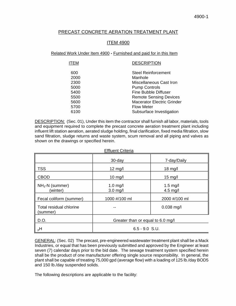
4900-1
PRECAST CONCRETE AERATION TREATMENT PLANT
ITEM 4900
Related Work Under Item 4900 - Furnished and paid for in this Item
ITEM DESCRIPTION
600 Steel Reinforcement 2000 Manhole 2300 Miscellaneous Cast Iron 5000 Pump Controls 5400 Fine Bubble Diffuser 5500 Remote Sensing Devices 5600 Macerator Electric Grinder 5700 Flow Meter 6100 Subsurface Investigation
DESCRIPTION: (Sec. 01), Under this item the contractor shall furnish all labor, materials, tools and equipment required to complete the precast concrete aeration treatment plant including influent lift station aeration, aerated sludge holding, final clarification, fixed media filtration, slow sand filtration, sludge returns and waste system, scum removal and all piping and valves as shown on the drawings or specified herein. Effluent Criteria
30-day 7-day/Daily TSS 12 mg/l 18 mg/l CBOD 10 mg/l 15 mg/l NH3-N (summer) (winter)
1.0 mg/l 3.0 mg/l
1.5 mg/l 4.5 mg/l
Fecal coliform (summer) 1000 #/100 ml 2000 #/100 ml Total residual chlorine (summer)
-- 0.038 mg/l
D.O. Greater than or equal to 6.0 mg/l pH 6.5 - 9.0 S.U.
GENERAL: (Sec. 02) The precast, pre-engineered wastewater treatment plant shall be a Mack Industries, or equal that has been previously submitted and approved by the Engineer at least seven (7) calendar days prior to the bid date. The sewage treatment system specified herein shall be the product of one manufacturer offering single source responsibility. In general, the plant shall be capable of treating 75,000 gpd (average flow) with a loading of 125 lb./day BOD5 and 150 lb./day suspended solids. The following descriptions are applicable to the facility:
4900-2
1) Materials - Poured-in-place concrete base pad shall be so designed to fully handle any
and all applicable loads pertaining to structure loadings, soil conditions, future expansion (if applicable) and structurally certified by a licensed structural engineer.
Reinforcing steel shall be designed following ACI-350 parameters to meet each individual job site application. Engineer shall include soil conditions, loading parameters and particular concerns of location in designs covering structures located in flood zones.
2) Slab Panels - Precast concrete wall panels and panels cap/walkways shall meet or exceed the following requirements and details.
All fabricated units shall be precast of 5,000 psi concrete. Vertical wall panels shall be 8Α thick and 13=-6≅ feet tall. Wall panel surfaces shall be smooth and free of air hole pockets. ΑWaffle wall≅ type wall panel will not be considered equal as they can be affected by frost heave on external surfaces and sludge accumulation on inner chamber walls. Wall panels shall be considered as independent structural members and not dependent upon each adjacent panel for support or rigidity.
The upper frame member shall serve as a combination walkway and tension/ compression stress band which holds structure watertight and erect. Precast concrete cap shall be so designed to resist any and all proposed internal and external live and dead loadings at the site.
Connection of cap to cap and cap to slab detail shall consist of structurally embedded steel members which are to be field joined and then sealed against corrosion by the manufacturer=s two-part sealing system.
Cap connections shall be so designed to allow for structural creep, expansion and contraction associated with changing differential loading and temperatures shall be transferred into the connection joints and allowed to move without cracking or spalling in these areas.
Vertical joints in panel walls shall receive similar preparation to be able to remain watertight through operational liquid level adjustments and freeze/thaw cycles.
Surface of cap walkway shall be furnished to enhance a non-slip surface and flat and
true to accept bolt down handrail and fencing as shown and dimensioned in the job plans 3) Tankage - Tanks and chambers shall be constructed of reinforced precast concrete with
a 5,000 psi, 28 day compressive strength. Walls shall be structurally sized to adequately function for their intended uses and shall withstand all required internal and external loading when full or empty. All walls and joints shall be watertight.
All reinforcing steel furnished under this item shall meet the requirements in the specification.
4) Piping - All air, return sludge, waste sludge, skimmers, and foam control piping shall be galvanized iron pipe, Schedule 40 with galvanized #150 malleable iron pipe fittings unless shown otherwise on the drawings. All influent and effluent piping shall be PVC unless shown otherwise on the drawings. All piping shall be adequately supported.
5) Grating - The individual tankage openings shall be covered by 14 gauge galvanized grip strut grating, capable of supporting a concentrated load of 220 LBS. and a maximum uniform loading of 56 LBS. per sq. ft. with a maximum deflection of 0.33 inches. The strength of the grating shall be increased as required to meet safety, building codes or other regulatory requirements at no additional cost to the Village of
4900-3
Caledonia.
6) Concrete - Cement shall be Type 3 Portland Cement. Coarse aggregate shall consist
of high grade limestone and organic-free, well graded sand. Use of super plasticizers and water-reducing agents shall be allowed in order to enhance workability and retain strength and acceptable w/c ratio provided strength requirements are not compromised.
Manufacturers shall be required to submit concrete mix designs for the engineer=s
approval along with manufacturing and technical paperwork covering additives and dosage rates. Engineer may at his discretion make a plant visitation to inspect the manufacturer=s facilities, testing area and quality control program.
7) Reinforcing Steel - Steel rebar shall be of equal quality or exceed ASTM-671 Grade 60 Standards. All welded-wire fabric mesh shall conform to ASTM C-185.
Manufacturer shall be required to supply the engineer with a complete set of as-build drawings and operation and maintenance materials after equipment has been installed. Any changes or modifications shall be reflected in this final set of drawings.
8) Aeration Chambers - The aeration chambers shall have a capacity of 75000 gallons. The capacity shall be provided in two parallel tanks and each shall be capable of independent operation. Concrete fillets shall be installed in the bottom of the aeration chamber parallel to the treatment flow to prevent disposition of solids.
A 45,000 gallon flow equalization tank shall also be constructed as a structurally integral part of a total 120,000 gallon capacity, dual compartment tank assembly. All material specifications cited in this section shall apply.
All necessary diffuser bars, drop pipes and air headers shall be installed in the aeration chamber. The air shall be supplied at the rate of 2600 cubic feet per minute per pound of BOD5 applied. The air comes in contact with the sewage by means of 1-1/4 inch plastic diffuser tubes with molded porous polyethene fine bubble diffuser tubes. These plastic tubes are 18 inches long and suspended on a quick coupling 1-1/4 inch galvanized air supply pipe drop. Each supply pipe drop shall have an easily accessible gate valve to regulate the air supply to the diffusers.
Please see Item 5400.
9) Final Clarifier Chambers - The mechanical clarifier chambers shall be designed to offer
effective settling conditions and a continuous return of sludge to the aeration chamber. Baffles shall be provided at the inlet to the final clarifiers to prevent turbulence and short circuiting. These baffles shall extend 6≅ above the liquid level and 5=-6≅ below the top of the inlet elbow. Two adjustable V- notch weirs shall be provided across the width of each chamber. One trough will serve as an adjustable outlet weir trough. This weirs shall be located approximately 12≅ from the end wall of chamber to offset the wall currents and be easily accessible for observation and maintenance. Each hopper shall be equipped with an air induced sludge lift that will return the settled material back to the head of the aeration chamber. The rate of return sludge shall be controlled by a 3/4Α valve on the air induction line.
A surface skimmer baffle trough constructed from aluminum provided across the width of each chamber to remove any excessive amount of grease, oil or floating solids that may be encountered in the final settling chamber. The skimmed material shall be returned to the aeration chambers by means of 2≅ galvanized pipes. The rate of return
4900-4
shall be controlled by a 3/4≅ valve on the air induction line.
Final clarifiers shall have a minimum surface area of 336 square feet each tank and the effluent weirs shall have a minimum length of 12 feet.
10) Sludge Holding Tanks - Sludge shall be pumped to each sludge chamber from the final clarifiers by means of the air lift sludge pumps. Parallel sludge chambers shall be provided. The contents of the sludge holding chambers shall be aerated with the amount of air to be regulated by gate valves on the air line from the main air header within sewage treatment plant. A 3≅ galvanized decanting device shall be located in each sludge holding chamber for the purpose of returning the top layer of liquid back to the aeration chambers. The decanting device shall be positioned manually by a winch and nylon rope assembly located on top of each sludge holding chamber. The flow through each decanting device shall be regulated by a gate valve located on the air line inside each chamber and shall be easily accessible from above the sludge chambers. The sludge holding chambers shall have a minimum capacity of 12,900 gallons each. Air shall be supplied in the amount of 30 cubic feet per minute per 1,000 cubic feet of capacity for each sludge chamber. Air diffusion shall be provided for each sludge chamber by coarse bubble diffusers. Sludge withdrawal lines shall be provided to facilitate off-site tank truck sludge disposal.
11) Chlorinator - The precast chlorine contact tank provided shall have sufficient capacity to provide at least a 15 minute retention time for the design peak flow of the tank. The chlorine contact tank shall have a minimum capacity of 5000 gallons. The chlorinator shall be capable of feeding at least 8 mg/l of design chlorine at peak flow. A dechlorinator shall be provided to maintain the chlorine residual at all times.
The chlorinator and dechlorinator shall consist of dry tablet units with a contact chamber. The chlorination and dechlorination units shall be constructed of fiberglass and shall automatically adjust the chlorine and sodium sulfite feed rate proportionally to wastewater flow. The mechanism shall be of the direct flow through type with no valves, poppets, diaphragms or strainers installed in the mechanism or in any portion of the inlet or discharge piping. All parts in the system that come into contact with the solution shall be chemically resistant plastic or other chemically resistant synthetic material. The units shall be connected to the inlet and outlet of the contact tank and shall have an outlet weir that increases the water depth and chlorine feed rate as the wastewater flow increases. The entire chlorinator and dechlorinator units shall be accessible and no electrical supplies, solutions, gas cylinder or pumps shall be required for chlorinator or dechlorinator operation.
The chlorine contact tank shall be properly baffled to prevent short circuiting. Baffles shall be arranged in the tank so that the flow pattern will be from side to side within the tank. The top of the chamber shall have galvanized open metal panels that provide for east access to the chlorinator effluent meter, and each area separated by the baffles for any visual observations or sampling that would be required. A typical chlorinator/dechlorinator unit is shown in #25 of this Item.
12) Effluent Weir - An aluminum 22.5 degree V-notch weir shall also be installed in the chlorine contact tank.
13) Flow Splitter - The precast concrete flow splitter shall be used to equally divide the flow to the parallel aeration chambers. The tank shall be 9=-0≅ long by 5=-0≅ wide with 6≅ thick walls. The tank shall be 5=-0≅ tall. Any ratio of flow division shall be possible with the use of adjustable aluminum slides. The floor of the tank shall be sloped towards the outlet weirs. Galvanized grating will cover the top of the tank.
14) Fixed Media Filtration Tanks - Three precast concrete fixed media tanks shall be
4900-5
provided. The tank shall be 17=-0≅ long by 9=-0≅ wide with 4≅ thick walls. The tank shall be 7=-8≅ tall and have a surface area of 120 sq.ft. each. One fixed media tank provided will serve as a backup with the other two tanks will be on line. The media will be placed 9≅ below the top water level in the settlement tank. Plastic Pyradeck or approved equal will be fashioned in a manner to support the weight of a person who might accidentally, or intentionally, wish to walk on it. The panels are molded in such a way to provide matching keys by which to locate adjacent panels. As panels are laid into position, the joints are secured with a solvent adhesive to provide an integrated deck surface. The peak flow ratio shall not exceed 0.42 gpm/ft2.
All Pyradeck is made in 1 ft. square panels, any size of tank can be decked with the material provided that the mesh slots are arranged to lie across the breadth of the tank. Trimming border panels enables the decking to fit within a desirable 1 1/4 Α clearance along the tank sides. Each Module of the assemblage used to form the deck shall be comprised of a self-supporting section, suitably framed, and shall be not more than 4= wide and 8= long, both dimensions overall. Each module shall be capable of withstanding an upthrust of 5.2 lbs / ft, and bear a weight of 220 lbs. distributed by a 9≅ x 1≅ board, 4= long.
The deck shall be constructed of material providing slot-shaped parallel apertures through which the treated water shall flow upwardly. The cross section of each slot-shaped aperture shall be triangular having walls with a semi-angle of not less than 20 degrees nor more than 25 degrees. The configuration of these slots shall be contained by a fabrication in material non-corrodible by normal sewage waters. The open area of the decking material shall not be less than 20% nor more than 50%. The distance between the sides of the parallel slots shall, at their closest proximity, not be less than 20/1000≅ nor more than 45/1000≅.
When mounted to form the deck of the fixed media clarifier, the assemblage within each module shall present an under surface so constructed that there is a continuous and unbroken profile of parallel triangular orifices presented to the oncoming water flow. All connecting or strengthening cross members of the assemblages of triangular parallel slots shall be positioned adjacent to the narrower orifices and on the operational upper surface of the deck when mounted in the clarification basin.
The frame work enclosing the media shall not exceed 1≅ depth and shall have a width no greater than its depth surrounding assembled modules along all edges.
Dewatering Lift Station- Provisions shall be made for periodic removal of captured suspended solids by backwashing or mechanical sludge collection equipment. A Barnes SE411 pump shall be provided in a manhole lift station to carry out the backwash cycle. Backwash water will be recycled through the treatment process via the equalization basin system. For the purpose of backwashing, each filter basin shall be designed not to exceed 600 GPM per sq.ft. based on average daily flow. Normal operating conditions shall not exceed 300 GPM per sq.ft.
15) Control Panel - A NEMA 4x control panel for control of the air blowers shall be provided for installation and mounting on the precast blower pad. This control panel shall include breakers, starters, timers, and etc. that are required to operate the four blowers. A NEMA 4x control panel for control of the flow equalization pumps shall be provided for installation and mounting on the top of the precast flow equalization chamber. This control panel shall include breakers, starters, timers, and etc. that are required to
4900-6
operate the two pumps. A NEMA 4x control panel for control of the dosing pumps shall be provided for installation and mounting on the top of the precast dosing tank. This control panel shall include breakers, starters, timers, and etc. that are required to operate the two pumps.
16) Surface Sand Filters - Two sand filters will be provided to allow one bed to dry while the other bed is being used. The filter are 25=-0≅ wide by 80=-0≅ long. The filters are sized to accommodate 30 gpd/sq.ft. with a maximum dosing area of 625 sq.ft. per dosing point.
The reinforced sand filter walls shall be 4=-0≅ tall, 4≅ thick. A protective inside waterproof coating may be required depending upon manufacturer's recommendations as determined by the engineer. Three layers of gravel shall be provided. Each layer shall be 3≅ thick. Above the gravel shall be 18≅ of filter sand corresponding to a uniformity coefficient of not greater than 3, and an effective size of 0.4 mm to 1.0 mm.
17) Dosing Chamber - A Dosing chamber will also be provided to hold enough water to dose one filter bed to a theoretical depth of 3 inches in a time period of less than ten minutes. The chamber will be a 7=-0≅ by 15=-0≅ tank 10=-4≅ deep. Two alternating pump shall be provided dose the sand filter beds. The pumps shall be capable of pumping 380 gpm at 17 ft. TDH. The dosing pumps shall be provided with all required check valves, gate valves and piping.
18) Materials - Materials to be utilized for the performance of work under this item shall be in accordance with Item 500.
19) Painting - All painting of items herein shall be performed in accordance with the manufacturer's recommendations as approved through shop drawings by the engineer.
20) Manufacturer - The manufacturer of this equipment shall have precast concrete aeration treatment plants of this type and size in successful operation in the field for a minimum of five years. If this requirement is not met by the manufacturer, the contractor shall provide a performance bond in the amount of 200 percent of the value of the bid price for this item and said bond shall remain in effect until two years after the date of substantial completion for this contract.
21) Installation - The precast concrete aeration treatment plant shall be installed in accordance with the manufacturer=s recommendations and at the locations shown on the drawing.
22) Field Service - A competent factory representative shall be provided for the purpose of final checkout, start-up and adjustment of the precast concrete aeration treatment plant provided under this item. In addition, this same representative shall spend at least two days solely training and instructing the operator in the operation and maintenance of this plant.
23) List of Spare Parts - For list of spare parts as supplied to the Village of Caledonia, please see Item 5800.
24) Influent Wet Well - Shall meet the specifications outlined in Item No. 4800 and the following example pump curve, or equal.
25) Chlorinator/Dechlorinator System - Typical unit as shown in this section, or equal. 26) Sludge Pump and Fixed Media pump information shown this section. 27) Flow Equalization Pump information shown this section. MEASUREMENT / PAYMENT: Payment shall be Lump Sum.
5000-1
PUMP CONTROLS
ITEM 5000 DESCRIPTION : (Sec. 01) Pump controls shall include the furnishing of control panels at the plant site and remote pump stations (2). The panels shall be provided for the influent pumping station, flow equalization, dosing, remote pump stations #1 and 2, and filtration tanks dewatering. CONTROL PANEL: (Sec. 02) Each control panel shall include all of the features as described herein and shown on the drawings. All components shall be factory mounted, wired, inspected, and tested.
1) Control panels shall be designed for operation on voltage and phase as listed in the pump characteristics table.
2) Enclosures shall be NEMA 4X reinforced fiberglass. A locking hasp shall be provided on the outside of the door.
3) A main circuit breaker disconnect for disconnecting power to control panel shall be provided at remote pump stations #1 and #2 only. The disconnect shall have thru door operator and have provisions for padlocking.
4) An instantaneous adjustable magnetic trip type circuit breakers shall be provided for protection of each motor.
5) Sprecher and Schuh IEC magnetic contractors with ambient compensating overload relays for each pump motor shall be provided. Auxiliary contacts shall be provided on the motor coil as necessary to meet the control requirements of this paragraph.
6) Provide two single phase, transformers, fused on all underground legs. One transformer shall be utilized for the control circuitry, and shall be sized for the largest control circuit loading plus an additional 25% extra capacity. The second transformer shall be sized and dedicated to 120 VAC non-control related loads (i.e.: heating strips, lights, GFI receptacle, etc). Transformers provided on 480 volt/3 phase service only.
7) Provide 120 VAC, single phase, 10 ampere circuit breakers for individual protection and disconnect means for 120 VAC non-control related loads. One circuit breaker shall be provided for each of the following loads:
A. Thermostat and strip heaters. B. Internal panel light and control switch. C. Duplex GFI receptacle .
8) Provide a thremomagnetic circuit breaker for protection and disconnect of
the control circuit. 9) Control circuitry shall be designed to start and stop the pumps based on the
wet well liquid level, utilizing float controls. A lag pump shall start if the lead pump cannot keep up with inflow. Control shall automatically alternate the pumps on each successful pump-down cycle.
10) Provide hand-Off-Auto selector switches for each motor starter.
5000-2
11) Low-level lockout float, to lock out both motors, regardless of whether operating in manual or automatic mode. Low level lockout shall be latching, and shall reset via a push-button or upon the wet well reaching the pump start float elevation (whichever occurs first). Low level alarm shall include a red pilot light on the front of the panel door for alarm indication, and a normally open dry contract wired to the master terminal strip for remote monitoring.
12) The two remote pumping stations and the influent pump station only shall have built into control panels an automatic telephone dialer which will monitor the following conditions: A. Power failure B. Pump failure C. Use of lag pump / high water alarm D. Unauthorized entry The dialer shall be a Phonetics Sensaphone Model 4100 with a battery back-up or equal. The dialer shall be capable of dialing out to four numbers.
13) The circuitry shall accept a normally-closed dry contact from each motor winding for winding overheat monitoring. Each winding overheat contact shall energize an interposing relay, which shall energize a 2 second time delay relay via a normally-closed contact. This shall prevent false alarms due to race conditions between relays. If the winding overheat contact opens continuously for a two second time period, the alarm shall latch and lock out the overheated motor. Each alarm shall also energize a red pilot light. Each alarm shall be resettable via a push-button mounted on the front of the inside panel door. A N.O. dry contact from each lockout circuitry shall be wired to the master terminal strip for remote monitoring. The dry contact shall not close until the two second time period has expired.
14) Provide a red alarm pilot light for each pump for Pump Failure indication. The alarm light shall energize if the motor coil does not energize within 10 seconds after receiving the pump start signal. A battery back-up is required for alarm circuit and lights on all pump stations. A red beacon alarm light shall be provided on each pump control panel.
15) Provide a green pilot light for each motor, to indicate when a motor coil is energized. Each pilot light shall be energized via an auxiliary motor contact.
16) Provide an elapsed time meter for each motor, measuring in hours and tenths of hours running time. Each elapsed time meter shall be energized via an auxiliary motor contact.
17) F.E. Control panel shall contain a percentage timer for automatic alternation of pumps during continuous run situations to improve pump durability and eliminate excessive run time.
18) Provide a high-level float with a latching relay and red pilot light. High level alarm shall be resettable via a push-button or upon the well level reaching the pump stop float elevation (whichever occurs first). Alarm circuitry shall include a N.O. dry contract wired to the master terminal strip for remote monitoring.
19) All pilot lights, push buttons, and selector switches shall be heavy duty, oil-tight type, and shall be mounted on the front of the inside panel door. Pilot
5000-3
lamps shall be rated for a minimum 10,000 hour life. Each device shall be identified with a vinyl etched nameplate. Nameplates fastened with adhesive backing for interior mounting only. All nameplates used on exterior of panel shall be engraved plastic with S.S. screws.
20) Provide two 250 watt heating strips wired in series, controlled via a thermostat to maintain an inside temperature of 50 - 70 deg. F. Thermostat shall include visible temperature settings and shall be Dayton Model 2E173B, or equal. Strip heaters shall be model 1212 as manufactured by Vulcan, or equal. Silicone rubber/fiberglass stock heaters or cartridge type heaters are not acceptable.
21) Provide a fluorescent or incandescent light for interior panel illumination. Light shall energize via a limit switch whenever the inside door is opened.
22) Provide a ground lug properly sized for termination of the ground wire. 23) Incoming and outgoing wire and cables shall be connected to a master
numbered terminal strip. 24) A manual transfer switch and generator receptacle shall be provided for the
remote pump stations only. The manual transfer switch shall be NEMA 3R constructed, and properly sized to match load requirements. Switch shall be racked and mounted to the side of pump station control panel. The switch shall be a class 3140 Square D or equal. The generator receptacle shall be mounted to the transfer switch in an accessible position and configuration to facilitate easy hookup to a trailer mounted generator. The contractor shall be responsible for confirming equipment types and sizes to insure proper hookup. Equipment shall be Crouse-Hinds, or an approved equal as required to match existing units.
25) A placard shall be affixed to the inside surface of the access door of the panel. The placard shall display the connection legend and the circuit schematic. The schematic shall identify each wire, junction and termination with respect to corresponding terminals and connections in the panel. Devices and connections associated with, but exterior to, the panel shall be shown in phantom and appropriately identified. The schematic may be a miniature plasticized copy of the connection schematic furnished, if suitable for display.
26) HAZARDOUS LOCATIONS - ( Pump stations , and Influent pump station wetwells). All junction boxes, conduit fittings and wiring provided under this Contract for hazardous areas shall be approved by UL and NEC for Class I, Division 1, Group C & D locations. Installation shall be made by mechanics thoroughly experienced in this type of work, and workmanship shall be of the best quality and skill to assure maximum safety. Sealing fittings and explosion proof flexible conduits shall be properly installed at all required locations in accordance with Code regulations. Breathers and drains shall be installed at all high and low points in the conduit run. Combination seal and drain fittings with breathers on drain will be acceptable.
27) Pump controls shall have phase and power surge protection. 28) An adjustable solid state time delay relay shall be provided in control
circuitry to delay pump starts in the event of a power failure. This is required on remote pump stations (2), and the influent pump station only.
ANCHOR BOLTS: (Sec. 03) All anchorage parts, including anchor bolts, nuts, washers
5000-4 and gaskets, shall be provided herewith. Unless otherwise specified, anchor bolts shall be of stainless steel; shall be of a type, strength, diameter and lengths as recommended by the equipment manufacturer; and shall be set in accordance with certified shop drawings furnished by the equipment manufacturer, all as approved by the Engineer. POWER AND CONTROL WIRING: (Sec. 04) Power and control wiring shall include necessary conduit, wire, relays, switches and other devices to properly operate all equipment as specified, shown on the drawings or otherwise required. This item shall also includes the connection and interwiring of equipment and devices that are not furnished under this item unless such connection and interwiring is specified as included under the other items. Connections and interwiring, size, type and quantity of conductors shall be in accordance with the instructions of the manufacturer of the equipment and devices. The Contractor is responsible for insuring that manufacturers meet requirements specified herein. The Contractor shall assure that all connections are proper, secure and tight and all wire bundles are secure and properly supported. Refer to electrical and mechanical drawings for quantities and locations of the respective equipment and included field mounted devices to be hooked up to the respective equipment. MANUALS: (Sec. 05) Service manuals shall be provided with each motor control panel and shall include, but not be limited to all drawings and wiring diagrams, service bulletins, and catalog literature. Three copies of each service manual shall be provided. Motor control panel shop drawings shall include but not be limited to the following:
1a) Installation schematics showing terminal-to-terminal connections between appurtenant equipment, wire and terminal strip numbering and field connections.
1b) Manufacturer s specification sheets of installed equipment. 1c) Layout and outline drawings. 1d) Exterior and interior component layout details. 1e) Installation mounting provisions, fittings and dimensions. 1f) Door and access panel mounting and latch provisions, fittings and
dimensions. 1g) Typical and/or special installation drawings. 1h) Detailed operational and instructional description of each component
contained in the schematic drawings.
All of the above data and drawings shall be submitted by the Contractor to the Engineer for review in accordance with the requirements for Shop Drawings.
Final data and drawings for the installed motor control shall be forwarded to the engineer and shall include, but not be limited to the following:
2a) As-built wiring and connection drawings, schematics, etc., documenting all
modifications post shipment and installation of equipment. 2b) Complete parts lists for each piece of equipment. 2c) List of spare parts as supplied to the Village of Caledonia. Please see Item
5800. 2d) Catalog cuts, drawings, complete set of schematics, and written materials
shall be submitted in 3-ring binders on 8-1/2 x 11 sheets, or sheets
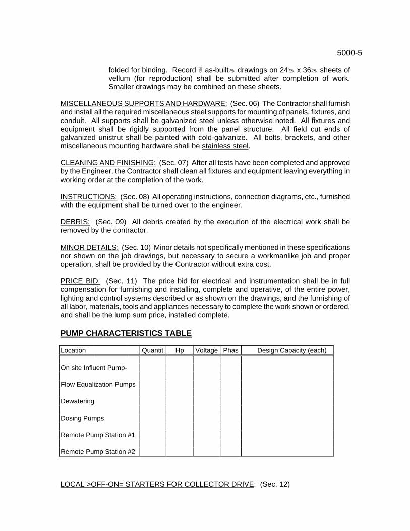
5000-5
folded for binding. Record as-built drawings on 24 x 36 sheets of vellum (for reproduction) shall be submitted after completion of work. Smaller drawings may be combined on these sheets.
MISCELLANEOUS SUPPORTS AND HARDWARE: (Sec. 06) The Contractor shall furnish and install all the required miscellaneous steel supports for mounting of panels, fixtures, and conduit. All supports shall be galvanized steel unless otherwise noted. All fixtures and equipment shall be rigidly supported from the panel structure. All field cut ends of galvanized unistrut shall be painted with cold-galvanize. All bolts, brackets, and other miscellaneous mounting hardware shall be stainless steel. CLEANING AND FINISHING: (Sec. 07) After all tests have been completed and approved by the Engineer, the Contractor shall clean all fixtures and equipment leaving everything in working order at the completion of the work. INSTRUCTIONS: (Sec. 08) All operating instructions, connection diagrams, etc., furnished with the equipment shall be turned over to the engineer. DEBRIS: (Sec. 09) All debris created by the execution of the electrical work shall be removed by the contractor. MINOR DETAILS: (Sec. 10) Minor details not specifically mentioned in these specifications nor shown on the job drawings, but necessary to secure a workmanlike job and proper operation, shall be provided by the Contractor without extra cost. PRICE BID: (Sec. 11) The price bid for electrical and instrumentation shall be in full compensation for furnishing and installing, complete and operative, of the entire power, lighting and control systems described or as shown on the drawings, and the furnishing of all labor, materials, tools and appliances necessary to complete the work shown or ordered, and shall be the lump sum price, installed complete. PUMP CHARACTERISTICS TABLE Location
Quantit Hp Voltage Phas Design Capacity (each)
On site Influent Pump-
Flow Equalization Pumps
Dewatering
Dosing Pumps
Remote Pump Station #1
Remote Pump Station #2 LOCAL >OFF-ON= STARTERS FOR COLLECTOR DRIVE: (Sec. 12)
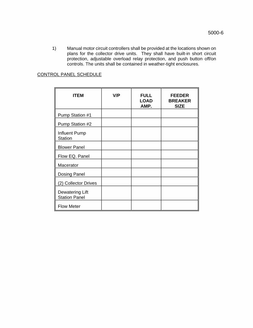
5000-6
1) Manual motor circuit controllers shall be provided at the locations shown on plans for the collector drive units. They shall have built-in short circuit protection, adjustable overload relay protection, and push button off/on controls. The units shall be contained in weather-tight enclosures.
CONTROL PANEL SCHEDULE
ITEM V/P FULL
LOAD AMP.
FEEDER BREAKER
SIZE Pump Station #1
Pump Station #2
Influent Pump Station
Blower Panel
Flow EQ. Panel
Macerator
Dosing Panel
(2) Collector Drives
Dewatering Lift Station Panel
Flow Meter
5000-A-1
PUMP CONTROLS
DESCRIPTION : (Sec. 01) Pump controls shall include the furnishing of a control panels at the pump station as shown on the plans. CONTROL PANEL: (Sec. 02) The control panel shall include all of the features as described herein and shown on the drawings. All components shall be factory mounted, wired, inspected, and tested.
1) Control panels shall be designed for operation on voltage and phase as listed in the pump characteristics table.
2) Enclosures shall be NEMA 4X reinforced fiberglass. A locking hasp shall be provided.
3) A main circuit breaker disconnect for disconnecting power to control panel shall be provided. The disconnect shall have thru door operator and have provisions for padlocking.
4) An instantaneous adjustable magnetic trip type circuit breakers shall be provided for protection of each motor.
5) Sprecher and Schuh IEC magnetic contractors with ambient compensating overload relays for each pump motor shall be provided. Auxiliary contacts shall be provided on the motor coil as necessary to meet the control requirements of this paragraph.
6) Provide 120 VAC, single phase, 10 ampere circuit breakers for individual protection and disconnect means for 120 VAC non-control related loads. One circuit breaker shall be provided for each of the following loads:
A. External sodium lamp B. Thermostat and strip heaters. C. Internal panel light and control switch. D. Duplex GFI receptacle .
7) Provide a thremomagnetic circuit breaker for protection and disconnect of the
control circuit.
8) Control circuitry shall be designed to start and stop the pumps based on the wet well liquid level, utilizing float controls. A lag pump shall start if the lead pump cannot keep up with inflow. Control shall automatically alternate the pumps on each successful pump-down cycle.
9) Provide hand-Off-Auto selector switches for each motor starter. 10) Low-level lockout float, to lock out both motors, regardless of whether operating in
manual or automatic mode. Low level lockout shall be latching, and shall reset via a push-button or upon the wet well reaching the �pump start� float elevation (whichever occurs first). Low level alarm shall include a red pilot light on the front of the panel door for alarm indication, and a normally open dry contract wired to the
master terminal strip for remote monitoring. 5000-A-2
11) The pumping station shall have built into control panel an automatic telephone dialer
which will monitor the following conditions:
A. Power failure B. Pump failure C. Use of lag pump / high water alarm D. Unauthorized entry
The dialer shall be a Phonetics Sensaphone Model 4100 with a battery back-up or equal. The dialer shall be capable of dialing out to four numbers.
12) The circuitry shall accept a normally-closed dry contact from each motor winding for �winding overheat� monitoring. Each winding overheat contact shall energize an interposing relay, which shall energize a 2 second time delay relay via a normally-closed contact. This shall prevent false alarms due to race conditions between relays. If the winding overheat contact opens continuously for a two second time period, the alarm shall latch and lock out the overheated motor. Alarm shall also energize a red pilot light. Alarm shall be resettable via a push-button mounted on the front of the inside panel door. A N.O. dry contact from each lockout circuitry shall be wired to the master terminal strip for remote monitoring. The dry contact shall not close until the two second time period has expired.
13) Provide a red alarm pilot light for pumps for �Pump Failure� indication. The alarm light shall energize if the motor coil does not energize within 10 seconds after receiving the �pump start� signal. A battery back-up is required for alarm circuit and lights on pump station. A red beacon alarm light shall be provided on each pump control panel.
14) Provide a green pilot light for each motor, to indicate when a motor coil is energized. Each pilot light shall be energized via an auxiliary motor contact.
15) Provide an elapsed time meter for each motor, measuring in hours and tenths of hours running time. Each elapsed time meter shall be energized via an auxiliary motor contact.
16) F.E. Control panel shall contain a percentage timer for automatic alternation of pumps during continuous run situations to improve pump durability and eliminate excessive run time.
17) Provide a high-level float with a latching relay and red pilot light. High level alarm shall be resettable via a push-button or upon the well level reaching the �pump stop� float elevation (whichever occurs first). Alarm circuitry shall include a N.O. dry contract wired to the master terminal strip for remote monitoring.
18) All pilot lights, push buttons, and selector switches shall be heavy duty, oil-tight type, and shall be mounted on the front of the inside panel door. Pilot lamps shall be rated for a minimum 10,000 hour life. Each device shall be identified with a vinyl etched nameplate. Nameplates fastened with adhesive backing for interior mounting only. All nameplates used on exterior of panel shall be engraved plastic with S.S. screws.
19) Provide 250 watt heating strips, controlled via a thermostat to maintain an inside temperature of 50 - 70 deg. F in control panels. Thermostat shall include visible temperature settings and shall be Dayton Model 2E173B, or equal. Strip heaters shall be model 1212 as manufactured by Vulcan, or equal. Silicone rubber/fiberglass
stock heaters or cartridge type heaters are not acceptable. 5000-A-3
20) Provide a fluorescent or incandescent light for interior panels illumination. Light shall
energize via a limit switch whenever the inside door is opened. 21) Provide a ground lug properly sized for termination of the ground wire. 22) Incoming and outgoing wire and cables shall be connected to a master numbered
terminal strip. 23) A manual transfer switch and generator receptacle shall be provided as shown on
the plans. 24) A placard shall be affixed to the inside surface of the access door of the panels. The
placard shall display the connection legend and the circuit schematic. The schematic shall identify each wire, junction and termination with respect to corresponding terminals and connections in the panel. Devices and connections associated with, but exterior to, the panel shall be shown in phantom and appropriately identified. The schematic may be a miniature plasticized copy of the connection schematic furnished, if suitable for display.
25) HAZARDOUS LOCATIONS - All junction boxes, conduit fittings and wiring provided under this Contract for hazardous areas shall be approved by UL and NEC for Class I, Division 1, Group C & D locations. Installation shall be made by mechanics thoroughly experienced in this type of work, and workmanship shall be of the best quality and skill to assure maximum safety. Sealing fittings and explosion proof flexible conduits shall be properly installed at all required locations in accordance with Code regulations. Breathers and drains shall be installed at all high and low points in the conduit run. Combination seal and drain fittings with breathers on drain will be acceptable.
26) Pump controls shall have phase and power surge protection. 27) An adjustable solid state time delay relay shall be provided in control circuitry to
delay pump starts in the event of a power failure. ANCHOR BOLTS: (Sec. 03) All anchorage parts, including anchor bolts, nuts, washers and gaskets, shall be provided herewith. Unless otherwise specified, anchor bolts shall be of stainless steel; shall be of a type, strength, diameter and lengths as recommended by the equipment manufacturer; and shall be set in accordance with certified shop drawings furnished by the equipment manufacturer, all as approved by the Engineer. POWER AND CONTROL WIRING: (Sec. 04) Power and control wiring shall include necessary conduit, wire, relays, switches and other devices to properly operate all equipment as specified, shown on the drawings or otherwise required. This item shall also includes the connection and interwiring of equipment and devices that are not furnished under this item unless such connection and interwiring is specified as included under the other items. Connections and interwiring, size, type and quantity of conductors shall be in accordance with the instructions of the manufacturer of the equipment and devices. The Contractor is responsible for insuring that manufacturers meet requirements specified herein. The Contractor shall assure that all connections are proper, secure and tight and all wire bundles are secure and properly supported. Refer to electrical and mechanical drawings for quantities and locations of the respective equipment and included field mounted devices to be hooked up to the respective equipment. MANUALS: (Sec. 05) Service manuals shall be provided with each motor control panel and shall
include, but not be limited to all drawings and wiring diagrams, service bulletins, and catalog
5000-A-4
literature. Three copies of each service manual shall be provided. Motor control panel shop drawings shall include but not be limited to the following:
1a) Installation schematics showing terminal-to-terminal connections between appurtenant equipment, wire and terminal strip numbering and field connections.
1b) Manufacturer�s specification sheets of installed equipment.
1c) Layout and outline drawings.
1d) Exterior and interior component layout details.
1e) Installation mounting provisions, fittings and dimensions.
1f) Door and access panel mounting and latch provisions, fittings and dimensions.
1g) Typical and/or special installation drawings.
1h) Detailed operational and instructional description of each component contained in the schematic drawings.
All of the above data and drawings shall be submitted by the Contractor to the Engineer for review in accordance with the requirements for Shop Drawings.
Final data and drawings for the installed motor control shall be forwarded to the engineer and shall include, but not be limited to the following: 2a) As-built wiring and connection drawings, schematics, etc., documenting all
modifications post shipment and installation of equipment.
2b) Complete parts lists for each piece of equipment.
2c) Catalog cuts, drawings, complete set of schematics, and written materials shall be submitted in 3-ring binders on 8-1/2� x 11� sheets, or sheets folded for binding. Record � as-built� drawings on 24� x 36� sheets of vellum (for reproduction) shall be submitted after completion of work. Smaller drawings may be combined on these sheets.
MISCELLANEOUS SUPPORTS AND HARDWARE: (Sec. 06) The Contractor shall furnish and install all the required miscellaneous steel supports for mounting of panels, fixtures, and conduit. All supports shall be galvanized steel unless otherwise noted. All fixtures and equipment shall be rigidly supported from the panel structure. All field cut ends of galvanized unistrut shall be painted with cold-galvanize. All bolts, brackets, and other miscellaneous mounting hardware shall be stainless steel.
5000-A-5
CLEANING AND FINISHING: (Sec. 07) After all tests have been completed and approved by the Engineer, the Contractor shall clean all fixtures and equipment leaving everything in working order at the completion of the work. INSTRUCTIONS: (Sec. 08) All operating instructions, connection diagrams, etc., furnished with the equipment shall be turned over to the engineer. DEBRIS: (Sec. 09) All debris created by the execution of the electrical work shall be removed by the contractor. MINOR DETAILS: (Sec. 10) Minor details not specifically mentioned in these specifications nor shown on the job drawings, but necessary to secure a workmanlike job and proper operation, shall be provided by the Contractor without extra cost. Price Bid - (Sec. 11) - Included with lift station
REMOTE SENSING DEVICES Remote sensing equipment compatible with standard telephone system lines shall be provided at the lift station. The sensing unit shall be capable of monitoring at least 4 conditions. The contractor, working with the telephone company, shall be responsible for installing the lines necessary as is outlined in Pump Controls Sec. 02-11. A sensaphone Model 4100 monitoring system as manufactured by Phonetics, Inc. 101 State Road, Media, PA 19063 at 215-565-8520 or approved equal shall be used.
5100-1
BLOWER CONTROLS
ITEM 5100 DESCRIPTION : (Sec. 01) Blower controls shall include the furnishing of blower control panels at the plant site. The panels shall be provided for all four blowers. BLOWER CONTROL PANEL: (Sec. 02) A control panel shall be supplied to operate the flow equalization and aeration system air blowers. The control panel shall be NEMA 4X and contain all components as required to properly protect, energize, time, and indicate alarm status as called for or indicated on the drawings.
1) Component enclosure shall have NEMA 4X rating with any components exposed on the exterior of the unit equally rated. A back panel shall be supplied to mount all components and gear via tapped holes for easy maintenance of components.
2) All components shall be arranged and spaced for field serviceability. All
wiring shall be clearly marked, labeled, or tagged to match electrical drawings which shall be laminated and attached to the inside of the enclosure.
3) Each motor shall have breakers, starters, overload relays, H-O-A switches,
elapsed time meters and run lights.
4) A phase failure relay and surge arrestor shall be designed into the control circuit. these components shall be as manufactured by Diversified Electronics and Square-D Electric.
5) Blowers shall be adjusted via solid state programmable timers. One timer
shall be supplied for each blower. Equipment shall be B.R.K. Industries or approved equal.
6) Each blower shall be wired through 3 position rotary selector switches
mounted on the outer door. Indicator lights shall be installed next to each H-O-A switch.
7) One non resettable elapsed time meter shall be supplied for each blower.
Meters shall be NEMA 4 rated and mounted on the exterior of the panel door.
8) Engraved name plates shall be supplied on the exterior door and fastened
by S.S. screws and sealed with silicone. Self sticking labels will not be permitted on exterior locations. Inner panel name plates of self sticking vinyl labels are acceptable.
9) The four centrifugal blower units shall be 460 volt, 3 phase, two at 15 Hp and
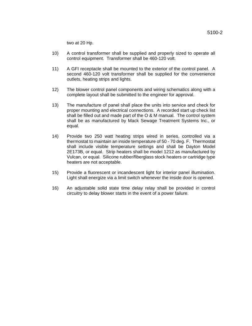
5100-2
two at 20 Hp.
10) A control transformer shall be supplied and properly sized to operate all control equipment. Transformer shall be 460-120 volt.
11) A GFI receptacle shall be mounted to the exterior of the control panel. A
second 460-120 volt transformer shall be supplied for the convenience outlets, heating strips and lights.
12) The blower control panel components and wiring schematics along with a
complete layout shall be submitted to the engineer for approval.
13) The manufacture of panel shall place the units into service and check for proper mounting and electrical connections. A recorded start up check list shall be filled out and made part of the O & M manual. The control system shall be as manufactured by Mack Sewage Treatment Systems Inc., or equal.
14) Provide two 250 watt heating strips wired in series, controlled via a thermostat to maintain an inside temperature of 50 - 70 deg. F. Thermostat shall include visible temperature settings and shall be Dayton Model 2E173B, or equal. Strip heaters shall be model 1212 as manufactured by Vulcan, or equal. Silicone rubber/fiberglass stock heaters or cartridge type heaters are not acceptable.
15) Provide a fluorescent or incandescent light for interior panel illumination.
Light shall energize via a limit switch whenever the inside door is opened.
16) An adjustable solid state time delay relay shall be provided in control circuitry to delay blower starts in the event of a power failure.
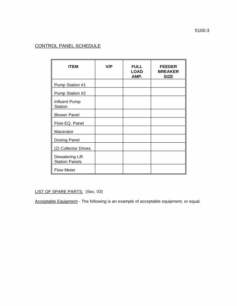
5100-3 CONTROL PANEL SCHEDULE
ITEM V/P FULL
LOAD AMP.
FEEDER BREAKER
SIZE Pump Station #1
Pump Station #2
Influent Pump Station
Blower Panel
Flow EQ. Panel
Macerator
Dosing Panel
(2) Collector Drives
Dewatering Lift Station Panels
Flow Meter
LIST OF SPARE PARTS: (Sec. 03) Acceptable Equipment - The following is an example of acceptable equipment, or equal.
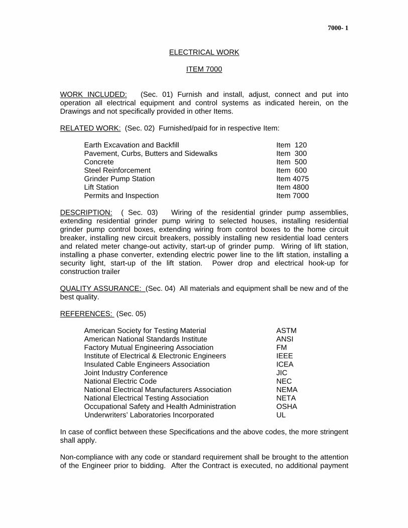
7000- 1
ELECTRICAL WORK
ITEM 7000 WORK INCLUDED: (Sec. 01) Furnish and install, adjust, connect and put into operation all electrical equipment and control systems as indicated herein, on the Drawings and not specifically provided in other Items. RELATED WORK: (Sec. 02) Furnished/paid for in respective Item: Earth Excavation and Backfill Item 120 Pavement, Curbs, Butters and Sidewalks Item 300 Concrete Item 500 Steel Reinforcement Item 600 Grinder Pump Station Item 4075 Lift Station Item 4800 Permits and Inspection Item 7000 DESCRIPTION: ( Sec. 03) Wiring of the residential grinder pump assemblies, extending residential grinder pump wiring to selected houses, installing residential grinder pump control boxes, extending wiring from control boxes to the home circuit breaker, installing new circuit breakers, possibly installing new residential load centers and related meter change-out activity, start-up of grinder pump. Wiring of lift station, installing a phase converter, extending electric power line to the lift station, installing a security light, start-up of the lift station. Power drop and electrical hook-up for construction trailer QUALITY ASSURANCE: (Sec. 04) All materials and equipment shall be new and of the best quality. REFERENCES: (Sec. 05) American Society for Testing Material ASTM American National Standards Institute ANSI Factory Mutual Engineering Association FM Institute of Electrical & Electronic Engineers IEEE Insulated Cable Engineers Association ICEA Joint Industry Conference JIC National Electric Code NEC National Electrical Manufacturers Association NEMA National Electrical Testing Association NETA Occupational Safety and Health Administration OSHA Underwriters’ Laboratories Incorporated UL In case of conflict between these Specifications and the above codes, the more stringent shall apply. Non-compliance with any code or standard requirement shall be brought to the attention of the Engineer prior to bidding. After the Contract is executed, no additional payment
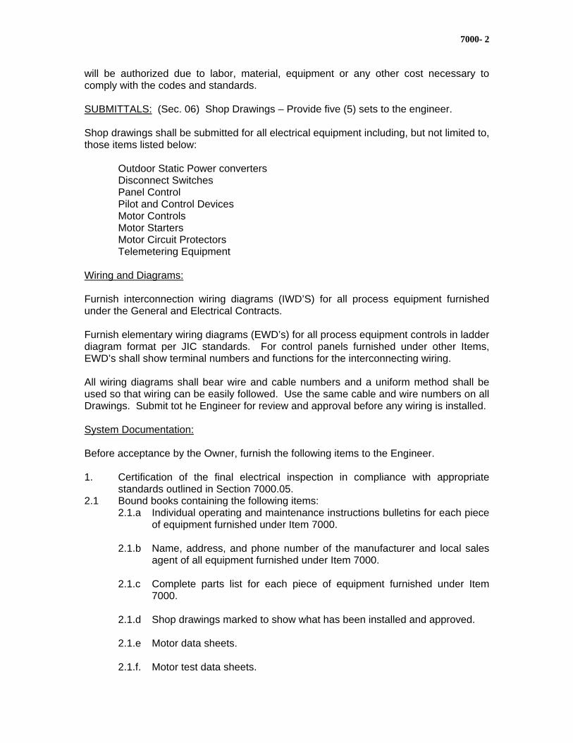
7000- 2
will be authorized due to labor, material, equipment or any other cost necessary to comply with the codes and standards. SUBMITTALS: (Sec. 06) Shop Drawings – Provide five (5) sets to the engineer. Shop drawings shall be submitted for all electrical equipment including, but not limited to, those items listed below: Outdoor Static Power converters Disconnect Switches Panel Control Pilot and Control Devices Motor Controls Motor Starters Motor Circuit Protectors Telemetering Equipment Wiring and Diagrams: Furnish interconnection wiring diagrams (IWD’S) for all process equipment furnished under the General and Electrical Contracts. Furnish elementary wiring diagrams (EWD’s) for all process equipment controls in ladder diagram format per JIC standards. For control panels furnished under other Items, EWD’s shall show terminal numbers and functions for the interconnecting wiring. All wiring diagrams shall bear wire and cable numbers and a uniform method shall be used so that wiring can be easily followed. Use the same cable and wire numbers on all Drawings. Submit tot he Engineer for review and approval before any wiring is installed. System Documentation: Before acceptance by the Owner, furnish the following items to the Engineer. 1. Certification of the final electrical inspection in compliance with appropriate
standards outlined in Section 7000.05. 2.1 Bound books containing the following items:
2.1.a Individual operating and maintenance instructions bulletins for each piece of equipment furnished under Item 7000.
2.1.b Name, address, and phone number of the manufacturer and local sales
agent of all equipment furnished under Item 7000. 2.1.c Complete parts list for each piece of equipment furnished under Item
7000. 2.1.d Shop drawings marked to show what has been installed and approved. 2.1.e Motor data sheets. 2.1.f. Motor test data sheets.
7000- 3
2.2 Books shall be a nominal 8 ½” x 11”, or 11” x 17’. 2.3 Three complete books containing information on the entire project. 3.1 Two sets of final “record” contract drawings. Drawings shall be marked with a
red ink ball point pen. Drawings and information required shall include but not be limited to the following: 3.1.b Power Distribution Schematics – show cable size and type, conduit size,
fuse size and type. 3.1.d Elementary Wiring Diagrams – show motor control wiring. 3.1.f One Line Diagrams – show equipment names, fuse sizes and types,
heater sizes, conduit and wire sizes, motor FLA and horsepower. STORAGE: (Sec. 07) Storage Options: 1. An on-site Temporary Storage Building (TSB) provided, installed, and owned by
the Contractor. The TSB must provide a controlled environment 24 hours a day for as long as equipment is being stored. The TSB must be heated/cooled to provide an inside temperature of 55 to 75º F. at a relative humidity of less than 55 %. Provide 25 footcandles of lighting. All power consumed shall be paid for by the Contractor. The engineer and Owner shall have access and inspection rights on two hours verbal notice to the Contractor. The TSB shall remain the property of the Contractor and shall be removed from the site at the completion of the Contract. The Site shall be restored to contract grading and seeding as though the TSB was never there.
2. An off site Equipment Storage Facility (ESF) which shall provide the same
environment as the TSB but which is located in the local community within a 25 miles radius of the construction site, and which the Contractor owns, leases, or rents for the duration of the Contract. Fire, damage, and theft insurance in the name of the Owner shall be provided to cover all stored equipment.
3. Factory storage can be provided if an agreement of all parties can be reached. PROJECT/SITE CONDITIONS: (Sec. 08) Electrical Service During Construction (Temporary): Maintain service including replacement of brakers to all residents. Any relocation of electrical equipment and controls to maintain adequate service shall be included in this Section. Temporary wire and equipment shall remain the property of the Contractor. Provide 24 hour on call emergency repair service for temporary equipment connected to process equipment.
7000- 4
The intent of this Specification is to assure continuous electrical power and control to all process flow equipment during the full course of construction. Any and all additional temporary wire required but not specifically mentioned by these Specifications shall be provided at no additional cost. Safety of operation shall be of prime concern and all requirements of the National Electrical Code shall be followed. Cooperation and Coordination with Other Trades: Study the Specifications and Drawings for the electrical work and investigate existing conditions in the field before submitting proposal. Become acquainted with the conditions under which the work of this section of the Specifications will be performed and accept all conditions as found. Coordinate with other trades on the project so that all trades install their work to avoid interference wit each other. All necessary adjustments to conform to structural and architectural conditions, duct work and piping interferences, etc., shall be included under this section of the specifications. Arrangements made among the trades which result in deviations from Drawings and Specifications are subject to the approval of the Engineer. Supply, mount and wire all motor starters, safety switches, relays, limit switches, pressure switches, pushbuttons, selector switches and other pilot devices necessary to form complete electrical systems for each mechanical item as indicated on the Drawings, unless noted otherwise. SEQUENCING/SCHEULING: (Sec. 09) See Special Provisions. MEASUREMENT/PAYMENT: (Sec. 10) Payment shall be for the actual number of actual service upgrades performed, unless otherwise called for in the bid document. WARRANTY: (Sec. 11) See General Conditions. PART 2 – PRODUCTS ACCEPTABLE MANUFACTURERS: (Sec. 12) PVC Coated Conduit Robroy Industries, “Plasti-Bond”
Republic Steel Company, “Galvite” Or equal. Power Cable
7000- 5
Okonite General Electric Or equal Terminal Lugs Burndy type Qiklug Penn-Union type VL Or equal Pilot Devices Allen-Bradley type 800t Square D Company Class 9001 type K Or equal Control Relays Allen-Bradley Bulletin 700 type HA Square D Company Class 8501 type KP Or equal Timing Relays Allen-Bradley Bulletin 700 type HR Automatic Timing and controls Co. 328 Square D Class 9050 type JCK Or equal Elapsed Time Totalizers Equal Signal Model HK Or equal Limit Switches Allen-Bradley Bulletin 820T Cutler-Hammer type E50 Or equal Electric Heat Tape Chemelex, Inc. auto-trace Eaton Control System Uni-therm Or equal Static Phase Converters Ronk Add-A-Phase Type 2K Or Equal Capacitors Sprague Cornell Dubilier Or equal Radio Telemetry Systems
7000- 6
Healy0Ruff Series 6400, Digitronix Or equal MATERIALS: CONDUIT, BOXES, AND FITTINGS: (Sec. 13) Conduit: Galvanized rigid steel, PVC coated rigid steel, electrical metallic tubing (EMT), flexible metallic conduit, or PVC conduit as specified, or as indicated on the Drawings. Minimum conduit size is ¾-inch, unless noted otherwise. Boxes: All boxes installed outdoors shall be waterproof NEMA 4, stainless steel or non-metallic type. All boxes installed where occasional submersion is encountered shall be watertight NEMA 6 enclosures. Provide steel barriers in junction or pullboxes to isolate conductors of different voltages such as 480V, 120V, ac, dc and instrumentation signal leads. The gauge of these barriers shall not be less than the gauge of the box required. Fittings: All fittings shall be cast con-ferrous metal or malleable iron coated with metallic zinc or cadmium after all machining has been completed. Covers shall be of the same material as the fittings to which they are attached and shall be screwed on with rubber or neoprene gaskets between the covers and fittings. UNDERGROUND CONDUIT: (Sec. 14) Underground Conduit: Use type 40 90ºC UL rated NEMA TC-2 rigid PVC plastic conduit as indicated on Drawings. WIRE AND CABLE: (Sec. 15) All wire and cable shall be new, stranded, and constructed with 600 volt insulation, unless noted otherwise. The minimum conductor size for power, control and lighting shall be #12 AWG unless otherwise noted. All wire size #8 AWG and smaller, in conduit, shall be copper with type THW or THHN insulation. All wire size #6AWGand XHHW insulation. Direct burial cable to Grinder/Pump Station shall be 60ºC Type UF. Flexible cords shall be type “SO” hard service cord, with green grounding conductor and with the number of conductors necessary for the extension of the wiring as indicated. GROUNDING: (Sec. 16) Ground rods shall be copper, ¾ inch by 10 feet, and have a drivehead. Grounding electrode conductors shall be 4/0 minimum, unless noted otherwise. Grounding equipment conductors shall be sized as indicated on the Drawings. Provide all control panels with an equipment grounding bus and a neutral bus. The neutral bus shall be electrically isolated from the panel enclosure and from the equipment grounding bus. DISTRIBUTION TRANSFORMERS: (Sec. 17) Single Phase Transformers .050EVA thru 15DVA: Control transformers shall have a voltage ratio of 240 x 480 volts primary and 120/240 volts secondary. No primary taps are required.
7000- 7
DISCONNECT SWITCHES: (Sec. 18) Switches shall be heavy-duty industrial type, fusible (FDS), unless noted otherwise. Switches shall be quick-make, quickbreak type, with mechanism and interlocking cover which normally cannot be opened when the switch is in the “on” position. Switch handle mechanism shall provide means of padlocking in the “on” or “off” position. Disconnect shall have means of bypassing the mechanically interlocked door and handle. Switches shall be equipped with fuse clips to receive Bussman Fusetron, Shawmut Trionic, or equal. Furnish with enclosures suitable for exposure involved; NEMA Type 4 steel or non-metallic for out-of-doors. PROTECTIVE DEVICES: (Sec. 19) Fuses: Provide all fuses of sixes as indicated on the Drawings adjacent to the switch symbol. All fuses shall be one-time cartridge type unless noted otherwise. Fuses shall be 250 volt or 600 volt for use on 120/240 volt and 600 volt for use on 2 7/480 volt systems. Fuses up to 600 amps shall be Class RD-1, current limiting. Motor Circuit Protectors (MCPS): Provide motor circuit protectors to provide adjustable magnetic protection for all 3 phase motor starters. Circuit Breakers (CB): Provide all circuit breakers of sizes as indicated on the Drawings or specified herein. All CB’s to be thermal-magnetic type with a minimum 10,000amp I.C. rating. PILOT AND CONTROL DEVICES: (Sec. 20) Furnish pilot and control devices where indicted on the Drawings in accordance with this section. Pilot Devices: Pushbuttons, selector switches, contact blocks and indicating lights shall be rated heavy duty and oiltight. All units shall be furnished with standard size legend plates with legends as indicated on the Drawings. Pushbuttons shall be momentary contact type unless noted otherwise. Pushbuttons shall be furnished complete with contact blocks as indicated on the Drawings. Selector switches shall have the number of positions, switching arrangement, number and type of contact blocks indicated on the Drawings. Contact blocks shall have a minimum continuous current rating of 10 amperes at 240 volts ac. Contact blocks shall have screw type connection terminals. Indicating lights shall be rated 120 volts, single phase, as push-to-test type unless otherwise noted. “Run” lights Shall be red and “ Fault” lights shall be amber. Color of other type lights shall be as indicated on the Drawings. Control Devices: Control relays shall be plug-in type with sockets. Sockets shall have screw terminals. Contacts shall be silver-cadmium, rated 10 amperes at 240 volts AC. Relays shall have three pole, double throw contacts (3PDT). Timing relays shall be solid state, plug-in type with screw terminal sockets. Each relay shall have 4 or more adjustable timing ranges, switch selectable, and 4 or more timing modes, switch selectable. Timing ranges shall allow from 0.05 seconds to 600 minutes
7000- 8
timing. Timing modes shall be ON delay, OFF delay, ONE SHOT, and REPEAT CYCLE. Output contacts shall be DPDT, rated 5 amps at 240 VAC. Timing setting shall be by dial thumbwheel switches. Elapsed time totalizer shall be a synchronous motor driven type with digital readout to indicate the total time a piece of equipment is energized. Totalizer shall have a minimum of six digit wheels including a 1/10 digit wheel to provide the range of time measured in hours unless noted otherwise, non-resettable and operate on 120 volt 60 hertz. Limit switches shall be heavy duty type with die cast aluminum alloy housings, double sealed, oil-tight housing, lifetime prelubricated bronze bearing surfaces, with heads that are field rotatable in 90x increments. Contracts shall have a minimum continuous current rating of 10 amperes at 240 volts ac. Contact blocks shall have screw type connection terminals. NEMA enclosure shall be NEMA 13 minimum or NEMA 4x outside and NEMA 7 for hazardous gas locations. Electric Heat Cable System: Furnish self-regulating electric heat cable as indicated on the Drawings. Furnish an electric adjustable ambient air sensing thermostat. The thermostat shall be SPDT type with external setpoint adjustment under tamper-proof cover in a watertight die cast NEMA 4 enclosure suitable for indoor and outdoor locations. Thermostat shall have a minimum rating of 20 amps at 480v and a range of 150 F to 1400 F. Insulation for pipes to be electrically heated shall be one-inch thick fiberglass insulation with a maximum “k” factor of .26 at a 50 degrees F differential temperature. MOTOR CONTROLS: (Sec. 21) Furnish motor control units with three overload heaters based on respective motor name plate currents and temperature rise, with proper allowance for capacitors when switched with motors. All electrical control devices shall be designed and rated for continuous operation. General purpose three phase starters shall be magnetic type, for across-the-line starting, not smaller than NEMA size 1. General purpose single phase starters shall be magnetic type with thermal overload protection. Branch circuit protection shall consist of heavy duty fused disconnect switches, Motor Circuit Protectors (MCP’s), or circuit breakers as indicated on the Drawings. Supply thermal overload relay (TOR) with one normally open contact isolated from the standard normally closed contact, only on 480 volts, 3 phase starters as noted on the Drawings. Overload relays shall be manual reset bimetallic type, Class 20, ambient compensated, provided with external reset mechanism as required. Furnish additional normally open or normally closed auxiliary contacts with motor starters to control such items as indicating lights, solenoid valves, and interlocks as indicated on the Drawings or required by the control scheme. POWER FACTOR CORRECTION CAPACITORS: (Sec. 22) Furnish power factor correction capacitors in sizes and locations as indicated on the Drawings. Capacitors shall be mounted in enclosures suitable for exposure involved, NEMA 12 for dust tight
7000- 9
and drip tight locations inside buildings, and weatherproof enclosures, protected against corrosion with zinc undercoating and high quality baked on outdoor enamel for outdoor applications or as indicated on the Drawings. Unit cells shall be industrial grade (motor run not acceptable) three phases, low loss polypropylene dielectric and metallized electrode construction. Cells shall contain a dielectric fluid that is environmentally acceptable. Each individual cell shall have its own dedicated current limiting fuse protection. In addition, a pressure activated circuit interrupter will assure against case rupture. Any loss of an individual cell fuse or operation of the circuit interrupter will be identified by externally mounted indicating lights. The complete capacitor assembly shall comply with National Electrical Code Article 460 and be UL listed. PART 3 – EXECUTION PREPARATION: PAINTING: (Sec. 23) All electrical enclosures shall undergo a phosphatizing prepainting treatment. All painting shall be with enamel which shall be baked for a durable hard finish. Inside surfaces shall be painted white for ease of visibility within. Finish paint color shall be ANSI No. 49 medium light gray. Remove any rust and touch up any scratches on all new electrical equipment. Use touch-up paint as supplied by manufacturer. INSTALLATION: (Sec. 24) The locations of equipment to which electrical connections are to be made are approximate as indicated on the Drawing. It shall be the Contractors responsibility to check shop drawings, relating to equipment requiring electrical connections and to determine the exact conduit “stubup” locations. Any workmanship or materials not meeting the requirements of the Specifications or Drawings shall be immediately replaced by the Contractor without cost to the Owner and to the satisfaction of the Engineer. ELECTRIC SERVICE: (Sec 25) The Owner shall contract electrical service from the Power Company for the electrical requirements indicated on the Drawings and specified in accordance with this Section. The Electrical Contractor shall be responsible to coordinate his work with the Power Company prior to the installation of his equipment and shall obtain and pay for any and all metering equipment as required by the Power Company. INSATLLATION OF EQUIPMENT: (Sec. 26) The General Contractor shall furnish and install all aggregate base courses, and/or concrete pads for all electrical control panels and equipment cabinets, as indicated on the Drawings. The Electrical Contractor shall be responsible for proper placing of conduit, anchor bolts and/or openings in equipment pads. Aggregate base courses shall include preparation of the subbase and installation of six inches of aggregate base as specified and paid for in Item 300, Pavement.
7000- 10
Excavation, concrete and steel reinforcement for equipment pads shall be as specified and paid for in Item 120, Earth Excavation and Backfill, Item 500, Concrete and Item 600, Steel Reinforcement respectively. Payment for aggregate base courses and concrete pads for electrical equipment shall be at the unit prices for the respective Items. CONDUIT, BOXES, AND FITTINGS: (Sec. 27) Conduit Installation: Each piece of conduit installed shall be free from defects, cut square, and have a cost of red lead applied to threads. Screw conduit connections tight with only incomplete threads exposed. Install conduits in accordance with governing code, made up with tight joints and properly graded to avoid low spots from forming water traps. Factory bent elbows or elbows bent with approved tools may be used. Limit the equivalent number of 90 degree bends in a single conduit run to the following: Runs in excess of 300 feet -------- EA. Runs of 300 feet to 201 feet -------- EA Runs of 200 feet to 101 feet -------- EA Runs of 100 feet and less -------- EA All conduit concealed in concrete shall be PVC type, except that at least eighteen inches of PVC coated rigid conduit shall be used above and below surface. Place conduits in center of slab where feasible before the concrete is poured, and avoid interference with reinforcing bars. Separate conduit by a minimum of two inches of concrete. Exercise care during installation to prevent the entrance of concrete, mortar, etc. Before wire or cable is pulled, thoroughly clean conduit and install insulated bushings. Paint breaks in the conduit protective coating. Conduit entering electrical equipment not having threaded hubs shall be fitted with double lock nuts and insulated bushings. One of the lock nuts shall be of sealing type. Sufficient conduit threads shall extend into the enclosure for installation of lock nuts and bushings. Box Installation: Solidly attach all electrical enclosures to structural members prior to installation of conduit. Set these devices true and plumb. Provide one-quarter inch space between walls and enclosures. Conduit boxes, required in masonry, shall be rigidly supported to prevent movement out of alignment during the placement or reinforcing, concrete, and/or mortar. Fittings Installation: Install conduit penetration through pads, slab on grade and walls below grade as described herein and as indicated on the Drawings. Install conduit penetrating concrete pad with PVC coated galvanized conduit, appropriate conduit sleeve and watertight pliable sealing compound. Compound type shall allow movement of pad only.
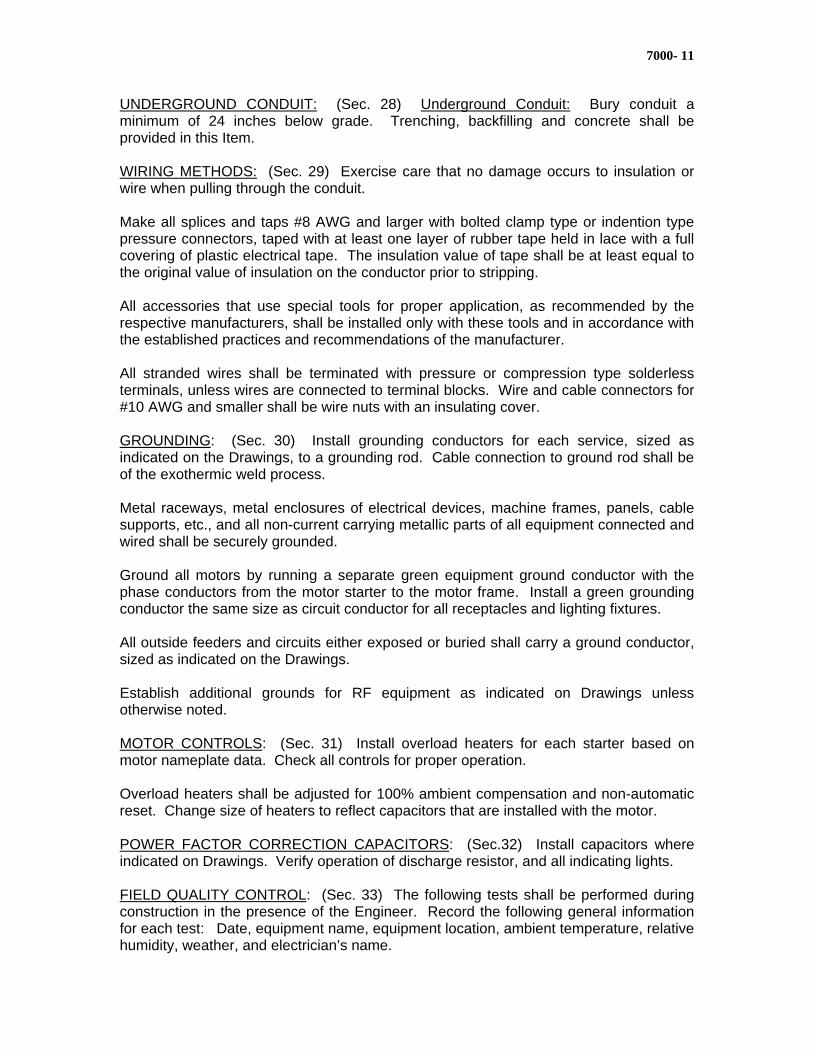
7000- 11
UNDERGROUND CONDUIT: (Sec. 28) Underground Conduit: Bury conduit a minimum of 24 inches below grade. Trenching, backfilling and concrete shall be provided in this Item. WIRING METHODS: (Sec. 29) Exercise care that no damage occurs to insulation or wire when pulling through the conduit. Make all splices and taps #8 AWG and larger with bolted clamp type or indention type pressure connectors, taped with at least one layer of rubber tape held in lace with a full covering of plastic electrical tape. The insulation value of tape shall be at least equal to the original value of insulation on the conductor prior to stripping. All accessories that use special tools for proper application, as recommended by the respective manufacturers, shall be installed only with these tools and in accordance with the established practices and recommendations of the manufacturer. All stranded wires shall be terminated with pressure or compression type solderless terminals, unless wires are connected to terminal blocks. Wire and cable connectors for #10 AWG and smaller shall be wire nuts with an insulating cover. GROUNDING: (Sec. 30) Install grounding conductors for each service, sized as indicated on the Drawings, to a grounding rod. Cable connection to ground rod shall be of the exothermic weld process. Metal raceways, metal enclosures of electrical devices, machine frames, panels, cable supports, etc., and all non-current carrying metallic parts of all equipment connected and wired shall be securely grounded. Ground all motors by running a separate green equipment ground conductor with the phase conductors from the motor starter to the motor frame. Install a green grounding conductor the same size as circuit conductor for all receptacles and lighting fixtures. All outside feeders and circuits either exposed or buried shall carry a ground conductor, sized as indicated on the Drawings. Establish additional grounds for RF equipment as indicated on Drawings unless otherwise noted. MOTOR CONTROLS: (Sec. 31) Install overload heaters for each starter based on motor nameplate data. Check all controls for proper operation. Overload heaters shall be adjusted for 100% ambient compensation and non-automatic reset. Change size of heaters to reflect capacitors that are installed with the motor. POWER FACTOR CORRECTION CAPACITORS: (Sec.32) Install capacitors where indicated on Drawings. Verify operation of discharge resistor, and all indicating lights. FIELD QUALITY CONTROL: (Sec. 33) The following tests shall be performed during construction in the presence of the Engineer. Record the following general information for each test: Date, equipment name, equipment location, ambient temperature, relative humidity, weather, and electrician’s name.
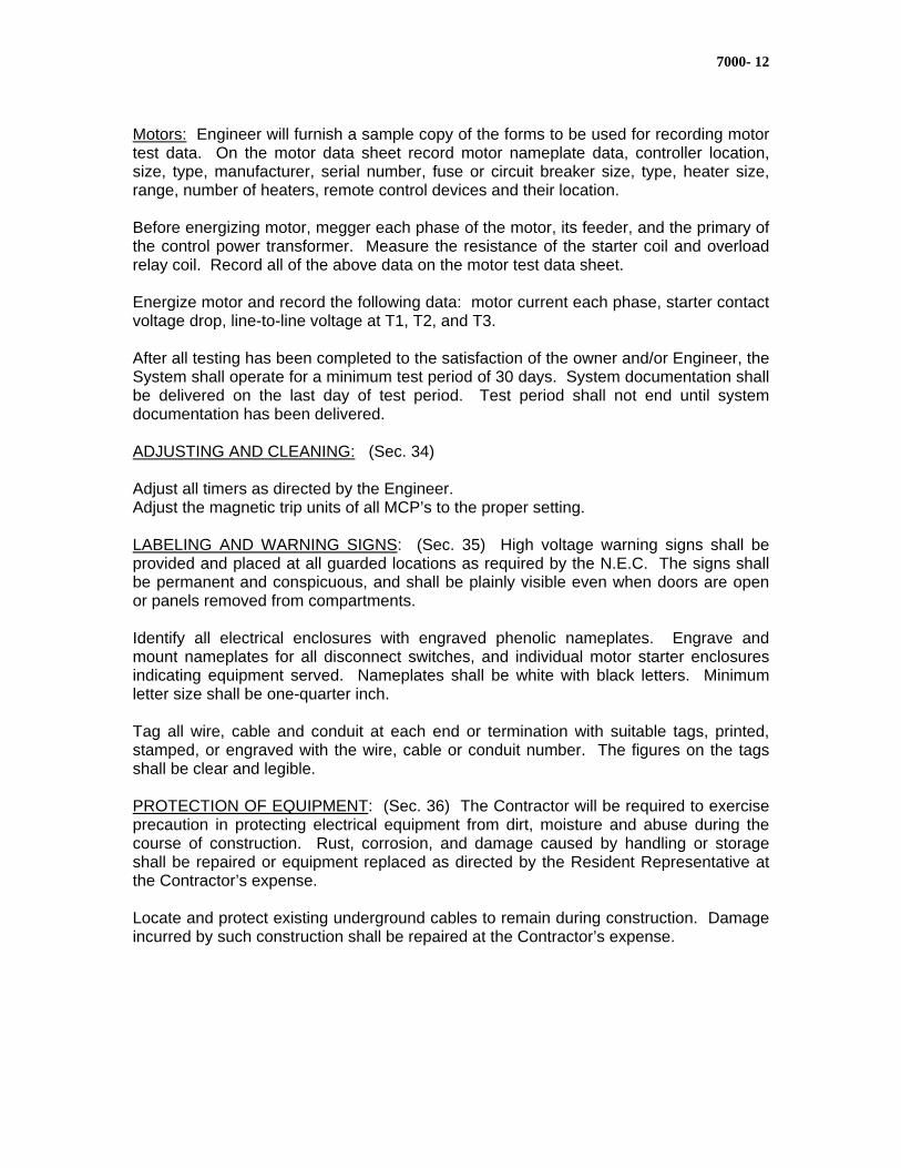
7000- 12
Motors: Engineer will furnish a sample copy of the forms to be used for recording motor test data. On the motor data sheet record motor nameplate data, controller location, size, type, manufacturer, serial number, fuse or circuit breaker size, type, heater size, range, number of heaters, remote control devices and their location. Before energizing motor, megger each phase of the motor, its feeder, and the primary of the control power transformer. Measure the resistance of the starter coil and overload relay coil. Record all of the above data on the motor test data sheet. Energize motor and record the following data: motor current each phase, starter contact voltage drop, line-to-line voltage at T1, T2, and T3. After all testing has been completed to the satisfaction of the owner and/or Engineer, the System shall operate for a minimum test period of 30 days. System documentation shall be delivered on the last day of test period. Test period shall not end until system documentation has been delivered. ADJUSTING AND CLEANING: (Sec. 34) Adjust all timers as directed by the Engineer. Adjust the magnetic trip units of all MCP’s to the proper setting. LABELING AND WARNING SIGNS: (Sec. 35) High voltage warning signs shall be provided and placed at all guarded locations as required by the N.E.C. The signs shall be permanent and conspicuous, and shall be plainly visible even when doors are open or panels removed from compartments. Identify all electrical enclosures with engraved phenolic nameplates. Engrave and mount nameplates for all disconnect switches, and individual motor starter enclosures indicating equipment served. Nameplates shall be white with black letters. Minimum letter size shall be one-quarter inch. Tag all wire, cable and conduit at each end or termination with suitable tags, printed, stamped, or engraved with the wire, cable or conduit number. The figures on the tags shall be clear and legible. PROTECTION OF EQUIPMENT: (Sec. 36) The Contractor will be required to exercise precaution in protecting electrical equipment from dirt, moisture and abuse during the course of construction. Rust, corrosion, and damage caused by handling or storage shall be repaired or equipment replaced as directed by the Resident Representative at the Contractor’s expense. Locate and protect existing underground cables to remain during construction. Damage incurred by such construction shall be repaired at the Contractor’s expense.
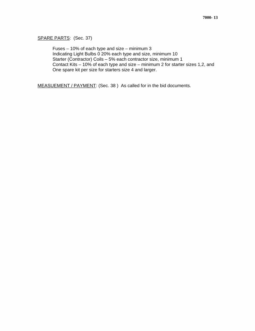
7000- 13
SPARE PARTS: (Sec. 37)
Fuses – 10% of each type and size – minimum 3 Indicating Light Bulbs 0 20% each type and size, minimum 10 Starter (Contractor) Coils – 5% each contractor size, minimum 1 Contact Kits – 10% of each type and size – minimum 2 for starter sizes 1,2, and One spare kit per size for starters size 4 and larger.
MEASUEMENT / PAYMENT: (Sec. 38 ) As called for in the bid documents.
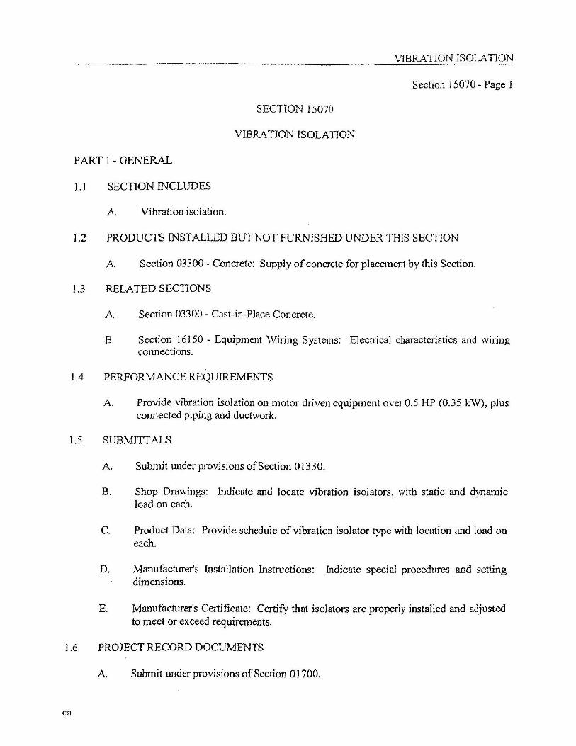
Page: 1
SECTION 16124
INSTRUMENTATION CABLE AND WIRE PART 1 -- GENERAL 1.01 SUMMARY
A. Furnish all labor, materials, equipment and incidentals required to provide instrumentation cable for use in raceways, conduit, cabinets, cable trays, panels and enclosures as shown on the Drawings, specified or required.
B. Related Sections:
1. Section 16130, Raceways and Boxes. 2. Section 16142, Terminations and Terminal Devices. 3. Section 16195, Electrical Identification. 4. Section 16390, Grounding Systems.
5. Section 16915, Control Enclosures.
6. Section 16970, Control System Testing
1.02 REFERENCES
A. Refer to Section 16000, General Provisions for Electrical Work, for additional requirements.
B. Reference Standards: Comply with applicable provisions and
recommendations of the following, except where otherwise shown or specified.
Page: 2
1. NEMA WC55, Instrumentation Cables and Thermocouple Wire.
2. UL 13, Power-Limited Circuit Cables. 3. NEC Article 725, Remote Control, Signaling, and Power-
Limited Circuits. 4. ASTM B3, Specification for Soft or Annealed Copper Wire. 5. ASTM B8, Specification for Concentric-Lay-Stranded Copper
Conductors, Hard, Medium-Hard, or Soft.
1.03 DEFINITIONS (Not Used) 1.04 SYSTEM DESCRIPTION (Not Used) 1.05 SUBMITTALS
A. Comply with Section 01300, Submittals, and provide the following: B. Product Data:
1. Manufacturer's Literature and Engineering Data.
C. Quality Assurance/Control Submittals:
1. Documentation indicating that the product was inspected by Manufacturer’s Quality Department and they certify that it complies with the test requirements of the applicable Industry.
2. Field Test Reports: Refer to paragraph 3.10.
1.06 QUALITY ASSURANCE (Not Used) 1.07 DELIVERY, STORAGE AND HANDLING:
A. No outside storage shall be allowed.
Page: 3
1.08 PROJECT/SITE CONDITIONS (Not Used) 1.09 SEQUENCING (Not Used) 1.10 SCHEDULING (Not Used) 1.11 WARRANTY (Not Used) 1.12 SYSTEM START-UP (Not Used) 1.13 OWNER'S INSTRUCTIONS (Not Used) 1.14 COMMISSIONING (Not Used) 1.15 MAINTENANCE (Not Used) PART 2 -- PRODUCTS 2.01 MANUFACTURERS
A. Belden Wire & Cable Company. B. Alpha Wire Company. C. Decoron Wire & Cable Company. D. Or equal.
2.02 EXISTING PRODUCTS (Not Used) 2.03 MATERIALS
A. Voltage for Instrumentation cable:
1. Shielded Instrumentation cable shall be rated 300 volts unless otherwise shown on the Drawings or specified.
2. 600 volt rated shielded instrumentation cable shall be
provided in 480 volt panels.
B. PLC Communication Cable:
1. Unless otherwise shown on the Drawings or specified, twinaxial instrumentation cables shall be 20 AWG, stranded, polyethylene insulated, and shielded.
Page: 4
2. Products and Manufacturers:
a. Programmable Logic Controller Data Highway (Allen-
Bradley Data Highway): Belden, Trade No. 9463; Allen-Bradley, Trade No. 1770-CD.
C. Single Pair Instrumentation Cable:
1. Unless otherwise shown on the Drawings or specified, single pair instrumentation cable shall be tinned copper, stranded, 16 AWG minimum, PVC insulated, and shielded.
D. Multi-paired Instrumentation Cable:
1. Unless otherwise shown on the Drawings or specified, multi-paired instrumentation cable shall be tinned copper, stranded, 18 AWG minimum, PVC insulated, and shielded.
E. Multi-conductor Cable:
1. Unless otherwise shown on Drawings or specified, multi-conductor cable shall be tinned copper, stranded, 18 AWG minimum, PVC insulated, and shielded.
2.04 MANUFACTURED UNITS (Not Used) 2.05 EQUIPMENT (Not Used) 2.06 COMPONENTS (Not Used) 2.07 ACCESSORIES (Not Used) 2.08 MIXES (Not Used) 2.09 FABRICATION (Not Used) 2.10 FINISHES (Not Used) 2.11 SOURCE QUALITY CONTROL (Not Used) PART 3 -- EXECUTION 3.01 ACCEPTABLE INSTALLERS (Not Used) 3.02 EXAMINATION (Not Used)
Page: 5
3.03 PREPARATION (Not Used) 3.04 ERECTION (Not Used) 3.05 INSTALLATION
A. Install and terminate vendor furnished cable in accordance with vendor equipment requirements and cable manufacturer's specific recommendations.
B. Unless otherwise shown or specified, instrumentation cable shall be
installed in a conduit system dedicated to instrumentation cable, with conduit fill meeting the requirements of Section 16130, Raceways & Boxes.
C. Where shown on the Drawing or specified in cabinets, panels, and
enclosures, shielded instrumentation cable shall be installed in accordance with Section 16915, Control Enclosures.
D. Terminations meeting the requirements of Section 16142,
Terminations and Terminal Devices, shall be provided for all conductors.
E. Instrumentation Grounding System: Refer to Section 16390,
Grounding Systems. F. Ground Shield on shielded cables at one end only and as
recommended by instrument manufacturer. G. Identification and color coding meeting the requirements of
Section 16195, Electrical Identification, shall be provided for all conductors.
3.06 APPLICATION (Not Used) 3.07 CONSTRUCTION (Not Used) 3.08 REPAIR/RESTORATION (Not Used) 3.09 RE-INSTALLATION (Not Used) 3.10 FIELD QUALITY CONTROL
A. Test shielded instrumentation cable shields with an ohmmeter for continuity along the full length of the cable and for shield continuity to ground.
Page: 6
B. Testing report sheets shall be maintained. Report sheets shall
identify each cable and conductor tested by its unique identification number and the circuit of which the cable and conductor is a part. Continuity shall be recorded. Test reports shall be signed by the tester, and submitted to the Engineer within ten (10) days of testing.
C. Defective new cables shall be replaced by the Contractor at
Contractor's expense for the full length of the cable.
D. All test equipment and material shall be provided by the Contractor. 3.11 ADJUSTING (Not Used) 3.12 CLEANING (Not Used) 3.13 DEMONSTRATION (Not Used) 3.14 PROTECTION (Not Used) 3.15 SCHEDULES (Not Used)
- END OF SECTION -
Section: 16130 Page: 1
SECTION 16130
RACEWAYS AND BOXES PART 1 GENERAL 1.01 SUMMARY
A. Furnish all labor, materials, equipment and incidentals to provide
conduit, boxes, covers and fittings in complete, coordinated and grounded raceway systems as shown on the Drawings, specified or required.
1. Rigid metal aluminum conduit and fittings shall be installed in
all conduit runs except where otherwise shown on the Drawings or specified if conduit is to be concealed in new concrete, then PVC conduit shall be used.
2. Unless otherwise shown on the Drawings or specified, all
wiring and cable shall be installed in conduit. B. Individual and multiple conduit runs are shown on the Drawings in
approximate locations. Not all conduit runs are shown on the Drawings. Conduit runs or portions thereof that are not shown shall be provided as detailed, specified or required.
C. The conduit schedule if included, is provided solely as quantitative
tabulation of wires/conduit and conduit size. Cable and conduit type shall be provided as specified in other Sections.
D. Related Sections:
1. Section 16915, Control Enclosures.
2. Section 15122, Mechanical Pipe Seals. 3. Section 15123, Wall and Floor Pipes and Pipe Sleeves. 4. Section 16190, Supporting Systems.
Section: 16130 Page: 2
5. Section 16195, Electrical Identification. 6. Section 16390, Grounding Systems.
1.02 REFERENCES
A. Refer to Section 16000, General Requirements for Electrical Work, for additional standards.
B. Reference Standards: Comply with applicable provisions and
recommendations of the following except where otherwise shown or specified:
1. UL 6, Rigid Metal Conduit. 2. UL 514B, Fittings for Conduit and Outlet Boxes. 3. ANSI C80.1, Rigid Steel Conduit - Zinc Coated (GCR). 4. UL 360, LiquidTight Flexible Steel Conduit.
1.03 DEFINITIONS
A. Conduit:
1. Single or multiple lengths or single or multiple runs of rigid galvanized steel, conduit.
2. Single or multiple runs of Liquid Tight Flexible steel conduit.
B. Pull Box: An access box, having exactly two points of connection to conduit, used for pulling wires through the conduit system.
C. Junction Box: An access box, having three or more points of
connection to conduit, used for pulling wires through the conduit systems.
D. Terminal Box: An access box, containing only terminal blocks,
subpanels and grounding provisions, used for terminating and connecting wires.
Section: 16130 Page: 3
E. Fittings: Conduit bodies and conduit accessories. 1.04 SYSTEM DESCRIPTION (Not Used) 1.05 SUBMITTALS
A. Comply with Section 01300, Submittals, and submit the following: B. Product Data:
1. Copies of manufacturer's material specifications and
dimensional and weight data, and technical information for products proposed for use.
2. Copies of manufacturer's catalog cuts, pictorial views with
corresponding identifying text and technical information for all materials proposed to be furnished.
3. Manufacturer's installation instructions and procedures
including cutting, threading, bending, assembly and support and any other operations that may be required in the course of installation.
a. Manufacturer's instructions and procedures shall not
conflict with the prohibitions of Part 3 of this Section.
C. Project Record Documents: Comply with Section 01780, Closeout Submittals.
1. The location of all conduits shall be shown on the Project
Record Documents. 1.06 QUALITY ASSURANCE (Not Used) 1.07 DELIVERY, STORAGE AND HANDLING (Not Used) 1.08 PROJECT/SITE CONDITIONS (Not Used) 1.09 SEQUENCING (Not Used) 1.10 SCHEDULING (Not Used) 1.11 WARRANTY (Not Used) 1.12 SYSTEM START-UP (Not Used) 1.13 OWNER'S INSTRUCTIONS (Not Used) 1.14 COMMISSIONING (Not Used) 1.15 MAINTENANCE (Not Used)
Section: 16130 Page: 4
PART 2 PRODUCTS 2.01 MANUFACTURERS
A. See paragraph 2.04 for manufacturers. 2.02 EXISTING PRODUCTS (Not Used) 2.03 MATERIALS (Not Used) 2.04 MANUFACTURED UNITS
A. Rigid Metal Conduit Systems:
1. Conduit, fittings and supporting systems shall be from one
manufacturer.
B. Metal Conduit:
1. RGS – Rigid Galvanized Steel. Hot-dipped galvanized steel (thick-wall) conduit shall be threaded and conform to UL 6 and ANSI C80.1.
2. EMT – Electrical Metal Tubing. Galvanized steel (thin-wall) conduit shall conform to UL 797 and ANSI C80.3.
3. FMC – Flexible Metal Conduit. Galvanized steel (flexible) conduit shall conform to UL.1.
4. LMC – Liquidtight Flexible Metal Conduit. Galvanized steel (flexible) conduit with liquid tight, non-metallic, sunlight resistant outer jacket shall conform to UL 360.
5. PRGS – Polyvinyl Chloride Cladded Hot-dipped steel (thick-wall) conduit.
Section: 16130 Page: 5
C. Non-Metal Conduit:
1. PVC – Polyvinyl Chloride Conduit
a. Schedule 40 (thin wall). b. Schedule 80 (thick wall).
2. Product and Manufacturers:
a. Appleton Electric. b. Crouse-Hinds. c. Or equal.
2. Shall not be smaller than 3/4-inch trade size. 3. Conduit nipples:
a. Close threaded nipples shall not be used.
4. Conduit elbows:
a. Factory made elbows shall be of the large radius type.
5. Standard couplings:
a. Split couplings shall not be used.
C. Metal Conduit Fittings:
1. All metal conduit fittings shall have galvanized finish.
2. Metal Conduit Bodies:
a. Products and Manufacturers:
1) Crouse-Hinds. 2) Or equal.
Section: 16130 Page: 6
b. Shall not be smaller than 3/4-inch trade size and shall be Form 8.
c. Shall be threaded hub type and shall provide for
minimum of three and a half full threads of engagement.
d. Bodies and covers shall be watertight assemblies. e. Bodies and covers shall be cast gray iron alloy or cast
malleable iron.
f. Bodies and covers shall have an interlocking, male-female "V" groove to ensure a positive fit and seal.
g. Cover fastening screws shall be captured 316
stainless steel. The screw head shall be hexagonal with a screwdriver slot.
3. Reducing couplings:
a. Products and Manufacturers:
1) Crouse-Hinds. 2) Or equal.
b. Shall have two female openings with PVC sleeves.
4. Rigid to flexible conduit connectors:
a. Products and Manufacturers:
1) Type 4Q by O-Z/Gedney. 2) Or equal.
b. Shall be malleable iron. c. Shall be UL listed and shall adapt flexible conduit to
rigid metal conduit.
Section: 16130 Page: 7
d. Shall have a grounding lug integrally cast with the gland nut on the connector.
e. Shall not be PVC-coated.
5. Watertight hubs:
a. Products and Manufacturers:
1) Crouse-Hinds Meyers Scru-tite. 2) Or equal.
b. Shall have a captive 'O' ring gasket impervious to corrosive, moisture and petroleum products.
c. Shall have an integrally cast grounding lug on the
locknut. d. Shall include an insulated throat.
6. Insulated grounding bushings:
a. Products and Manufacturers: 1) O-Z/Gedney.
2) Or equal.
b. Shall be threaded malleable iron with a mechanically electroplated finish and stainless steel screws.
c. Shall include an integrally molded phenolic insulation
surface with 150 degrees C rating. d. Shall include tin-plated copper saddle and spring clip
with plated steel clamping screw for conductor connection.
e. Shall not be PVC-coated.
7. Conduit plugs:
Section: 16130 Page: 8
a. Products and Manufacturers:
1) Crouse-Hinds.
2) O-Z/Gedney. 3) Or equal.
b. Shall be zinc plated malleable or cast iron. c. Shall have recessed or raised square head.
8. Expansion fittings:
a. Products and Manufacturers:
1) O-Z/Gedney. 2) Or equal.
b. Shall have bronze end couplings, neoprene outer jacket, stainless steel clamps and internal tinned copper braid bonding jumper with 316 stainless steel screws. Fittings shall be watertight, and corrosion-resistant.
9. Sealing Fittings: a. Product and Manufacturers:
1) Series EYSX by Crouse-Hinds. 2) Or equal.
b. Cast gray iron alloy or cast malleable iron bodies with zinc electroplate.
c. Ample opening with threaded closure for access to
conduit hub for making dam.
Section: 16130 Page: 9
d. Fitting shall be constructed to allow 40 percent cross-sectional fill.
e. Sealing fiber for forming the dam within the hub and
the sealing compound shall be approved for use with the fittings furnished.
D. Flexible Conduit:
1. For use in Non-hazardous and Class I, Division 2 Hazardous Areas: a. Products and Manufacturers:
1) Sealtite UA by Anaconda Metal Hose Division, Anaconda American Brass Company.
2) Liquatite Type L.A. by Electric-Flex Company.
3) Or equal.
b. Flexible conduit shall have galvanized steel core with
factory applied, smooth, abrasion-resistant, liquid tight, polyvinyl chloride cover.
E. Flexible Conduit Fittings:
1. Products and Manufacturers:
a. O-Z/Gedney Company. b. Or equal.
2. Flexible conduit fittings shall adapt the flexible conduit to standard threaded connections and shall have an insulated throat with inside diameter not less than that of the corresponding standard conduit size.
3. A grounding lug shall be cast integrally with the gland nut on
the connectors. 4. Fittings shall be malleable iron with galvanized finish.
Section: 16130 Page: 10
F. Outlet and Device Boxes for Switches and Receptacles:
1. Products and Manufacturers:
a. FD Series by Crouse-Hinds Company. b. Or equal.
2. Unless otherwise shown on the Drawings or specified, shall be designed for surface mounting.
3. Shall be cast gray iron alloy with electrogalvanized finish. 4. Shall have integrally cast hubs or brazed-on hubs, threaded
for joining to 3/4-inch minimum trade size rigid metal conduit. 5. Shall have integrally cast or brazed-on exterior mounting
feet. 6. Shall be single gang or multigang, at least 2-1/2 inches deep
and of a size to accommodate the devices required and provide extra wiring space. Multigang boxes shall be of the type that accept only single gang covers.
7. Shall be provided with single gang covers, even on
multigang boxes.
G. Outlet Boxes for Supporting Lighting Fixtures:
1. Products and Manufacturers:
a. Crouse-Hinds Company.
b. Or equal.
2. Unless otherwise shown on the Drawings or specified, shall be designed for surface mounting.
3. Shall be cast gray iron alloy with copper-free aluminum
finish. 4. Shall have integrally cast or brazed-on exterior mounting
feet.
Section: 16130 Page: 11
5. Shall be at least 3-inches deep and of a size to
accommodate the devices required.
H. Flexible Fixture Hangers:
1. Product and Manufacturers: a. Type AHG by Crouse-Hinds. b. Or equal.
2. Shall have malleable iron top section and removable malleable iron bottom fixture support assembly with electrogalvanizing and aluminum acrylic paint.
3. Shall have vapor-tight cushion to support fixture stem. 4. Shall have neoprene diaphragm to exclude moisture and dirt
from conduit system. 5. Shall be provided with manufacturer's neoprene gasket
between fixture hanger and box. 6. Shall provide an 8 degree swing from perpendicular in any
direction, before and after coating.
I. Cast Pull and Junction Boxes and Covers:
1. Products and Manufacturers:
a. Crouse-Hinds.
b. Or equal.
2. Shall be cast gray iron alloy. 3. Shall have external mounting lugs. 4. Shall be furnished with drilled and tapped conduit holes to
enable a minimum of three and one half full threads engagement, or watertight conduit hubs.

Section: 16130 Page: 12
5. Shall have watertight construction. 6. Shall have 316 stainless steel cover screws and hardware. 7. Shall be limited to 100 pounds in weight.
J. Terminal Boxes and Fabricated Pull and Junction Boxes:
1. Enclosures shall comply with Section 16913, Control
Eclosures. 2. Refer to the schedule in paragraph 3.15 of this Section for
required enclosure ratings and locations. 3. Shall be furnished with watertight conduit hubs for all conduit
entrances. 4. Where conduits enter a building below grade, boxes shall
have Crouse-Hinds Series ECD stainless steel drains, or equal.
5. Cast boxes shall not be used for terminal boxes unless
otherwise shown on the Drawings or specified. 6. Grounding Provisions:
a. Grounding per Section 16390, Grounding Systems,
shall be provided on cover and box.
7. Terminals in terminal boxes shall comply with Section 16142, Terminations and Terminal Devices.
K. Electrical Joint Compound:
1. Products and Manufacturers:
a. Kopr-Shield by Thomas & Betts Corporation. b. Or equal.
2. Compound shall be a blend of colloidal copper and rust inhibitors.
Section: 16130 Page: 13
3. Compound shall be conductive, provide corrosion protection, and have anti-seize properties.
4. Compound shall be UL listed for use on electrical cables in
cable connector assemblies or on bus bars rated for NEC applications up to 8kV and 90C.
2.05 EQUIPMENT (Not Used) 2.06 COMPONENTS (Not Used) 2.07 ACCESSORIES (Not Used) 2.08 MIXES (Not Used) 2.09 FABRICATION (Not Used) 2.10 FINISHES (Not Used) 2.11 SOURCE QUALITY CONTROL (Not Used) PART 3 EXECUTION 3.01 ACCEPTABLE INSTALLERS (Not Used) 3.02 EXAMINATION (Not Used) 3.03 PREPARATION (Not Used) 3.04 ERECTION (Not Used) 3.05 INSTALLATION
A. General:
1. Unless otherwise shown or specified, all wiring and cable shall be installed in conduit.
2. Products not specified in these specifications shall not be
used except as specifically accepted by the Engineer.
3. Installation shall be coordinated with piping, duct work, lighting fixtures and other systems and equipment and located clear of interference's and accessways.
B. Rigid Conduit:
Section: 16130 Page: 14
1. Rigid metal conduit and fittings shall be installed in all
conduit runs except where specifically shown otherwise. 2. Conduit Locations:
a. Conduit shall be exposed unless otherwise shown on
the Drawings or specified. b. Conduit where shown on the Drawings or specified to
be installed in poured concrete walls or slabs shall be in the center of the wall or slab for maximum concrete cover over the conduit.
c. Conduit shall be located to provide protection from
excessively high temperature. d. Conduit location shall allow for removal of other
conduit, pipe or equipment. e. Conduit installation shall be coordinated with piping,
duct work, lighting fixtures and other systems and equipment and located clear of interferences and accessways.
f. Unless otherwise shown on the Drawings or specified,
conduit shall be installed so that any water which may collect inside will drain to the nearest pull or junction box; Conduit shall not drain to any enclosure in which there are terminal blocks or device terminals.
3. Rigid metal conduit systems shall be electrically continuous
throughout and shall be grounded by bonding to AC ground bus bars, cable tray grounding conductors, or points of equipment ground conductor termination wherever such provisions are available.
4. Field Fabrication:
a. Conduit shall be cut square, threaded, reamed
smooth, cleaned and degreased.
1) Except for galvanized, field cut threads shall match factory cut threads.
5. Supporting:
a. Conduit supporting systems meeting requirements of Section 16190, Supporting Systems shall be provided.
6. Penetration of walls and floors for conduit: a. Openings for conduit shall be core-drilled through existing
walls and floors. b. Sleeves selected and installed in accordance with Section
15123, Walls and Floor Pipe and Pipe Sleeves, shall be provided for individual exposed conduit passing through new walls or slabs.
c. Individual conduit penetrations shall be sealed in conformance
with Section 15122, Mechanical Pipe Seals.
d. For sealing multiple conduit runs passing through walls or slabs, sealing devices shall be provided as shown on the Drawings.
7. Conduit entering environmentally controlled areas and any control panel shall have its interior sealed to prevent migration of corrosive gases through the conduit into the controlled environment. Sealant shall be Dow Corning 2001 or equal.
8. Identification meeting the requirements of Section 16195, Electrical
Identification, shall be provided for all conduit. 9. Expansion fittings:
a. Expansion fittings shall be installed where necessary to
compensate for thermal expansion and contraction. b. Expansion fittings shall be installed where conduits cross
structural expansion joints. Expansion fittings shall be installed no closer than 1 foot and no farther than 5 feet from the structural expansion joint.
c. Electrical joint compound shall be applied between jumper and
lug faces.
Section: 16130 Page: 15
d. Expansion fittings shall not be used to compensate for misalignment of conduit.
10. Unless otherwise shown or specified, conduit shall be terminated using the following:
a. Integrally cast or brazed on threaded hubs when provided on
cast boxes and conduit bodies.
b. Watertight hubs with grounding lugs on locknuts.
1) Grounding lugs in the same enclosure shall be bonded together.
2) Grounding lugs in the same enclosure shall be bonded
to the AC ground bus, if provided. 3) If an AC ground bus is not provided, grounding lugs in
the same enclosure shall be bonded to the enclosure grounding stud, if provided.
4) Bonding jumpers shall be 10 AWG minimum copper
cable. 5) Electrical joint compound shall be applied between the
mating surfaces of bonding and grounding connections.
c. Insulated grounding bushings with ground lugs for conduit transitions to cable tray and for stub-ups.
1) For conduit transitions to cable tray, insulated
grounding bushings shall be bonded to cable tray ground clamp using 10 AWG minimum copper cable.
a) Electrical joint compound shall be applied
between the mating surfaces of bonding and grounding connections.
2) For conduit stub-ups, insulated grounding bushings shall be bonded to AC ground busses with 10 AWG minimum copper cable.
Section: 16130 Page: 16
a) Electrical joint compound shall be applied between the mating surfaces of bonding and grounding connections.
3) For spare conduit stub-ups that are not inside cabinets, consoles, panels and enclosures, male plugs shall be installed in female couplings on the conduit stub-ups. Pull cords shall be embedded in duct sealing compound inside the stub-ups before plugs are installed.
C. Flexible Metal Conduit:
1. Unless otherwise shown or specified, flexible conduit and fittings shall be installed at all equipment subject to vibration or which requires movement for maintenance purposes including motors, operators, solenoids, lighting fixtures, limit switches and instruments.
2. Flexible conduit shall not be smaller than 3/4-inch trade size except
as follows:
a. 1/2-inch flexible conduit and fittings shall be allowed only if equipment will not accept 3/4-inch.
3. Flexible conduit shall be limited to a maximum length of 3 feet unless otherwise shown or specified.
4. Slack shall be provided to facilitate maintenance of the utilization
equipment. 5. A green insulated ground bonding jumper shall be connected across
the exterior of the flexible conduit between the fitting and the rigid-to-flex adapter.
a. Jumper shall be sized in accordance with NEC Table 250-95. b. Electrical joint compound shall be applied to the bonding
connections. c. A ground built-in to the flexible conduit does not satisfy the
requirement for bonding jumper.
Section: 16130 Page: 17
Section: 16130 Page: 18
6. Where flexible conduit fittings are installed for sheet metal penetrations, insulated grounding bushings shall be provided and shall be bonded together and to the enclosure grounding provisions.
D. Polyvinyl Chloride Cladded (PRGS)
1. Unless otherwise shown or specified, PRGS and fittings shall be installed at all Wetwells, Screen Rooms, corrosive environments, and all concrete embedded conduits in ceilings and walls adjacent to these areas.
E. PVC:
1. Unless otherwise shown or specified, PVC and fitting shall be
installed at all concrete encased duct banks or directly buried areas and as shown on the Contract Drawings.
2. Using cement for joints as recommended by manufacturer. Wipe conduit dry and clean before joining. Apply full even coat of cement to entire area inserted in fitting. Allow joint to cure for not less than 20 minutes. Where a PVC conduit run turns up to exit the slab, a RGS sweep shall be used. Pulling of wire, in PVC shall require a lubricant to reduce wear in the PVC bends.
F. Outlet and Device Boxes:
1. Outlet and device boxes and covers and flexible fixture hangers shall be provided as shown, specified or required.
2. Where required, supports meeting the requirements of Section
16190, Supporting Systems, shall be provided for mounting outlet and device boxes.
3. Outlet and device boxes shall contain no open holes. 4. Covers and flexible fixture hangers shall be installed using 316
stainless steel hardware. 5. Conduit entering blank cast outlet boxes for supporting lighting
fixtures shall be terminated in accordance with the requirements of this section.
6. Prior to joining to outlet and device boxes, conduit male threads
shall be coated with electrical joint compound.
Section: 16130 Page: 19
G. Pull and junction boxes:
1. A pull box shall be installed when the accumulated deflection of
bends in the conduit reaches 270 degrees. 2. Pull boxes shall be installed at intervals not exceeding 200 feet,
and where shown.
3. Pull boxes shall not contain terminations, except:
a. Pull boxes may contain bolted terminations meeting the requirements of Section 16142, Terminations and Terminal Devices.
4. Junction boxes shall not contain wire terminations, except:
a. Junction boxes may contain splice cap or bolted terminations meeting the requirements of Section 16142, Terminations and Terminal Devices.
5. Electrical joint compound shall be applied between the mating surfaces of grounding and bonding connections.
6. Identification meeting the requirements of Section 16195,
Electrical Identification, shall be provided for pull and junction boxes.
F. Terminal boxes:
1. Conduits shall not enter the top of terminal boxes.
2. Terminal blocks meeting the requirements of Section 16142, Terminations and Terminal Devices, shall be provided in terminal boxes.
3. Terminal boxes shall not contain splice cap wire terminations.
4. Terminal boxes shall not contain bolted wire terminations.
5. Grounding:
Section: 16130 Page: 20
a. Provide an AC ground bus bar and a bonding strap within the terminal box which comply with Section 16390, Grounding Systems.
b. The cover, subpanel, AC ground bus bar, bonding strap and enclosure of terminal boxes shall be connected together and shall be connected to the grounding system in accordance with Section 16390, Grounding Systems.
c. Shields shall not be grounded in terminal boxes.
d. Electrical joint compound shall be applied between the mating surfaces of grounding and bonding connections, except at terminal blocks.
e. Identification meeting the requirements of Section
16195, Electrical Identification, shall be provided for terminal boxes, terminal blocks, wires and wire terminations.
3.06 APPLICATION (Not Used) 3.07 CONSTRUCTION (Not Used) 3.08 REPAIR/RESTORATION (Not Used) 3.09 RE-INSTALLATION (Not Used) 3.10 FIELD QUALITY CONTROL (Not Used) 3.11 ADJUSTING (Not Used) 3.12 CLEANING (Not Used) 3.13 DEMONSTRATION (Not Used) 3.14 PROTECTION (Not Used) 3.15 SCHEDULES (Not Used)
+ + END OF SECTION + +
Page: 1
SECTION 16141
LIGHTING SWITCHES AND CONVENIENCE RECEPTACLES PART 1 GENERAL 1.01 SUMMARY
A. Furnish all labor, materials, equipment and incidentals required to provide convenience receptacles and switches for lighting and other systems as shown on the Drawings, specified, or required.
B. Related Sections:
1. Section 16130, Raceways and Boxes. 1.02 REFERENCES
A. Refer to Section 16000, General Provisions for Electrical Work, for additional standards.
B. Reference Standards:
1. NEMA WD 1, General Requirements for Wiring Devices. 2. UL 20, General-Use Snap Switches. 3. UL 894, Switches for Use in Hazardous (Classified)
Locations. 4. UL 1010, Receptacle-Plug Combinations for Use in
Hazardous (Classified) Locations. 1.03 DEFINITIONS (Not Used) 1.04 SYSTEM DESCRIPTION (Not Used)
Page: 2
1.05 SUBMITTALS
A. Comply with Section 01300, Submittals, and provide the following: B. Product Data:
1. Manufacturer's literature, specifications, engineering data
and technical information for all components furnished under this Section.
1.06 QUALITY ASSURANCE
A. Firms shall have minimum five (5) years experience in designing, manufacturing lighting switches and convenience receptacles of the type specified under this section.
1.07 DELIVERY, STORAGE, AND HANDLING (Not Used) 1.08 PROJECT/SITE CONDITIONS (Not Used) 1.09 SEQUENCING (Not Used) 1.10 SCHEDULE (Not Used) 1.11 WARRANTY (Not Used) 1.12 SYSTEM STARTUP (Not Used) 1.13 OWNERS INSTRUCTIONS (Not Used) 1.14 COMMISSIONING (Not Used) 1.15 MAINTENANCE (Not Used) PART 2 PRODUCTS 2.01 MANUFACTURERS
A. Non-Hazardous Areas:
1. Arrow-Hart, Inc.
2. Harvey Hubbell.
3. Bryant Electric.
Page: 3
B. Hazardous Areas:
1. Appleton Electric Co. 2. Crouse-Hinds Co. 3. Or equal.
2.02 EXISTING PRODUCTS (Not Used) 2.03 MATERIALS (Not Used) 2.04 MANUFACTURERS UNITS
A. Lighting Switches for Indoor Non-Hazardous Locations:
1. For Dry Indoor Areas:
a. Single pole AC toggle switch shall be quiet type 120-277 volt AC, 20 ampere, Ivory handle, specification grade, UL listed, with grounding screw and stainless steel cover plate.
b. Single pole 3-way AC toggle switch shall be quiet
type, 120-277 volt AC, 20 ampere, Ivory handle, specification grade, UL listed, with grounding screw and stainless steel cover plate.
c. Single pole 4-way AC toggle switch shall be quiet
type, 120-277 volt AC, 20 ampere, Ivory handle, specification grade, UL listed, with grounding screw and stainless steel cover plate.
d. Two pole toggle switches shall be quiet type 20
ampere, 120-277 volt AC, Ivory handle, specification grade, UL listed, with grounding screw and stainless steel cover plate.
e. Key operated toggle switches shall be 20 ampere,
120-277 volt AC, UL listed grounding screw and stainless steel cover plate.
2. Wet and Corrosive Areas:
Page: 4
a. Weather proof light switches shall comply with the
requirements of Part 2.04.A.1 above, except provide cover plate that is UL listed for wet and damp locations.
B. Convenience Receptacles for Non-Hazardous Locations:
1. Duplex grounding receptacle shall be corrosion resistant, two
pole, three wire, 125 volt AC, 20 ampere, UL listed, NEMA 5-20R with stainless steel cover plate.
2. Single grounding receptacle shall be corrosion resistant, two
pole, three wire, 125 volt AC, 20 ampere, UL listed NEMA 5-20R with stainless steel cover plate.
C. Receptacles for Hazardous Locations:
1. Material: Factory sealed receptacle suitable for installation in Class 1, Division 1 and 2, Group C hazardous locations and Class 2, Division 1 and 2, Group G hazardous locations. Copper-free aluminum receptacle and cover with cast gray iron alloy or cast malleable iron mounting box with zinc electroplate finish. Spring loaded receptacle cover to seal against neoprene gasket. Receptacle rated at 20 amperes, 125-250 volt AC, 2 wire, three pole. Provide matching plug for each receptacle.
2. Product and Manufacturer: Provide one of the following:
a. Series ENR series by Crouse-Hinds Company. b. Type ECP series by Appleton Electric Company. c. Or equal.
D. Light Switches for Hazardous Locations:
1. Materials: Factory sealed tumbler switch suitable for installation in Class 1, Group C hazardous locations. Cast gray iron alloy or cast malleable iron body and cover with zinc electroplate finish. Switch rated at 20 amperes, 120/277 volt AC.
Page: 5
2. Product and Manufacturer:
a. Series EDS by Crouse-Hinds Company. b. Type EDS by Appleton Electric Company. c. Or equal.
E. Ground Fault Circuit Interrupter Receptacle for Non-Hazardous Locations:
1. Shall be duplex, 20 Ampere, 125 volt AC, sensitivity of 5mA,
three wires, UL listed, weatherproof cover plates.
F. Ground Fault Circuit Interrupter for Hazardous Locations:
1. The ground fault circuit interrupter (GFCI) shall be 20 Ampere, 125 volt AC, three wires, a sensitivity of 5mA, and is UL listed. This unit is used in conjunction with receptacles for Hazardous Locations.
2. Material: Factory sealed chamber encloses the GFCI in an
enclosure with explosion-proof ground joints. The GFCI is suitable for installation in Class 1, Division 1 and 2, Group C hazardous locations and Class 2, Division 1 and 2, Group G hazardous locations. Copper-free aluminum cover with cast gray iron alloy or cast malleable iron mounting box with zinc electroplate finish. Stainless steel test and reset pushbuttons sealed with neoprene gaskets.
3. Product and Manufacturer: Provide one of the following:
a. Type GFS-1 by Crouse-Hinds Company.
b. Type GFS-1 by Appleton Electric Company. G. Surge Suppression Receptacles:
1. Duplex grounding, surge suppression receptacle, two pole, three wire, 125 volt AC, 20 ampere, capable of absorbing a transient surge 6,000 volts minimum. Receptacle to include power on indicator light and stainless steel cover plate.
Page: 6
a. Product and Manufacturer: Provide one of the following:
1) Cat. No. 5350S by Harvey Hubbell Inc. 2) Cat. No. 5380-GY by Leviton Manufacturing
Company. 3) Or equal.
H. Power Receptacles: 480 volt interlocked receptacle with enclosed safety switch service outlet: Provide service outlets, quantity as indicated on the drawings for portable equipment.
1. Material: Copper free aluminum enclosure with operating
handle NEMA 4, with gasketed hinged door. 2. Switch: Heavy duty, 3 pole, with visible blades, a quick
make a break mechanism with reinforced, positive pressure type blade and fuse clips. Switch shall be mechanically interlocked with the receptacle. the switch cannot be closed until the plug is fully inserted and the plug cannot be withdrawn or inserted and the plug cannot be withdrawn or inserted unless the switch is open.
3. Receptacle: Single ground receptacle, 3 wire, 4 pole, 600
volt, 60 amp. Provide two matching plugs.
a. Type WSR, and Type APJ plugs by Crouse-Hinds Company.
b. Or equal.
I. Special Receptacles:
1. Provide receptacles with number of poles, voltage, and current rating as shown on Drawings. Coordinate with equipment plugs. Provide matching plug for each receptacle.
2.05 EQUIPMENT (Not Used) 2.06 COMPONENTS (Not Used) 2.07 ACCESSORIES (Not Used) 2.08 MIXES (Not Used)
Page: 7
2.09 FABRICATION (Not Used) 2.10 FINISHES (Not Used) 2.11 SOURCE QUALITY CONTROL (Not Used) PART 3 EXECUTION 3.01 ACCEPTABLE INSTALLERS (Not Used) 3.02 EXAMINATION (Not Used) 3.03 PREPARATION (Not Used) 3.04 ERECTION (Not Used) 3.05 INSTALLATION
A. Lighting switches and convenience receptacles shall be provided as shown on the Drawing as specified or required.
B. Lighting switches and convenience receptacles shall be installed in
Outlet and Device Boxes meeting the requirements of Section 16130, Raceways and Boxes.
C. Lighting switches shall be mounted 4-feet 6-inches above finished
floor unless otherwise shown on the Drawing or specified. D. Convenience receptacles shall be mounted 4-feet 6-inches above
finished floor unless otherwise shown or specified. Convenience receptacles shall be mounted 18-inches above finished floor in office areas, control rooms, conference rooms and other finished areas unless otherwise shown on the Drawing or specified.
E. Convenience receptacles shall be mounted ground pole up. F. In non-hazardous locations, install lighting switches and
convenience devices in outlet or device boxes. G. In hazardous locations, install lighting switches and convenience
devices in rigid metallic conduit systems in conformance with NEC. Article 500, Hazardous Locations.
Page: 8
3.06 APPLICATION (Not Used) 3.07 CONSTRUCTION (Not Used) 3.08 REPAIR/RESTORATION (Not Used) 3.09 RE-INSTALLATION (Not Used) 3.10 FIELD QUALITY CONTROL (Not Used) 3.11 ADJUSTING (Not Used) 3.12 CLEANING (Not Used) 3.13 DEMONSTRATION (Not Used) 3.14 PROTECTION (Not Used) 3.15 SCHEDULES (Not Used)
+ + END OF SECTION + +
Page: 1
SECTION 16142
TERMINATIONS AND TERMINAL DEVICES PART 1 GENERAL 1.01 SUMMARY
A. Furnish all labor, materials, equipment, and incidentals required to provide conductor terminations, conductor terminals and terminal blocks for wire and cable with insulation rated 600 volts or less, and for bare copper wire and cable.
B. Related Sections:
1. Section 16130, Raceways and Boxes.
2. Section 16180, Polyphase Integral Horsepower Motors. 3. Section 16195, Electrical Identification.
1.02 REFERENCES
A. Refer to Section 16000, General Provisions for Electrical Work, for additional requirements.
B. Reference Standards: Comply with applicable provisions and
recommendations of the following except where otherwise shown or specified.
1. UL 486A-486E, Wire Connectors, Equipment Wiring
Terminals for Use with Aluminum and/or Copper Conductors.
2. UL 1059, Terminal Blocks. 3. UL 94, Test of Flammability of Plastic Materials for Parts in
Devices and Appliances.
Page: 2
4. IEEE 48, Test Procedures and Requirements for High
Voltage Alternating-Current Cable Terminations. 5. NETA, International Electrical Testing Association. 6. NEC Article 300, Wiring Methods.
1.03 DEFINITIONS
A. Conductor terminations: 1. Any points of connection as shown on the Drawings,
specified or required. 1.04 SYSTEM DESCRIPTION (Not Used) 1.05 SUBMITTALS
A. Comply with Section 01300, Submittals, and provide the following submittals:
B. Product Data:
1. Manufacturer's literature, specifications and dimensional
data for materials which are specified in this Section. 2. Data for the crimping tools required for use by Parts 2 and 3
of this Section shall be included. 1.06 QUALITY ASSURANCE
A. Qualifications:
1. Manufacturer Qualifications:
a. Manufacturer shall be experienced in manufacturing materials and equipment similar to that which is specified herein for at least five (5) years, with a record of successful in-service performance. When
Page: 3
requested by the Engineer, a list of installations in satisfactory operation shall be provided.
b. The equipment manufacturer shall be UL listed and
approved manufacturer. 1.07 DELIVERY, STORAGE AND HANDLING (Not Used) 1.08 PROJECT/SITE CONDITIONS (Not Used) 1.09 SEQUENCING (Not Used) 1.10 SCHEDULING (Not Used) 1.11 WARRANTY (Not Used) 1.12 SYSTEM START-UP (Not Used) 1.13 OWNER'S INSTRUCTIONS (Not Used) 1.14 COMMISSIONING (Not Used) 1.15 MAINTENANCE (Not Used) PART 2 PRODUCTS 2.01 MANUFACTURERS:
Refer to Paragraph 2.04. 2.02 EXISTING PRODUCTS (Not Used) 2.03 MATERIALS (Not Used) 2.04 MANUFACTURED UNITS
A. Conductor terminals:
1. For all field wire sizes 10 AWG and smaller that will be terminated in the control panels and enclosures and terminal boxes, conductor terminals shall be 600 volt rated, tin-plated copper, heat shrink pre-insulated locking fork terminals.
a. Product and Manufacturers:
Page: 4
1) 3M Electrical Products. 2) Krimpa-Seal National Standard Parts. 3) FTZ Industries.
2. For wire sizes 8 AWG through 4\0 AWG, conductor terminals shall be 600 volt rated, seamless, tin-plated copper, compression type terminals.
a. Product and Manufacturers:
1) Burndy.
3. For wire sizes 250 kcmil and larger, conductor terminals shall be tin-plated copper, long barrel compression type. Two compression indents shall be two hole mount type with provisions for two bolts for joining to apparatus terminal. a. Product and Manufacturer:
1) Burndy.
B. Terminal Blocks and Accessories:
1. Terminal Blocks:
a. Terminal blocks shall be bolt connecting, 600 volt rated, with hinged cover wings which hold the terminal nuts captive, with nickel-plated copper alloy metal parts, with folding wings that cover the live metal parts including the insulated cable lug in the crimping area for shock protection. The screws are secured against loosening by "concealed" captive spring loaded spacers.
1) For all analog field wiring (4-20 ma loops), for
loop-powered instruments, for motor circuits and for AC neutrals Terminal Block shall be Phoenix Cat. No. OTTA6-(0790433).
2) For 115 VAC power to instruments, for control
wiring to field devices such as limit switches,
Page: 5
for DC powered devices and for branch circuits Terminal Block shall be OTTA6-T-(0790446).
b. Fuse Terminal Block shall be 600 V rated Phoenix
Cat. No. UK10,3-HESI-(3004906).
1) One fuse of correct type and size for the application shall be provided with each fuse terminal block.
c. Din Rail Mounted Thermal - Magnetic Circuit Breaker:
1) Provide from one of the following:
a) Phoenix. b) Cutler-Hammer. c) Square D.
2. Terminal Block Mounting System:
a. Mounting Rail shall be unperforated, galvanized steel and yellow chromated, Phoenix Cat. No. NS35/7,5-(0801681).
b. Mounting Rail Standoff, if used, shall be Phoenix Cat.
No. BG/F-1201060. c. Partition Plate for visual and electrical separation of
terminal groups for terminal blocks type OTTA6 shall be Phoenix Cat. No. ATP-OTTA6-(0790475).
d. End Covers for type OTTA6 terminal blocks shall be
Phoenix Cat. No. D-OTTA6-(0790417). e. End Covers for type OTTA6-T terminal blocks shall be
Phoenix Cat. No. D-OTTA6-T-(0790459) f. End brackets for Mounting Rail shall be Phoenix
either plastic, single mounting screw Cat. No. E/NS 35N-(0800886); or aluminum, two mounting screws Cat. No. E/AL-NS35-(1201662).
Page: 6
g. End Clamp for use at end of groups of terminal blocks shall be Phoenix Cat. No. E/UK-(1201442).
3. Where required, the terminal block strips shall include Insertion Bridge (jumpers). Insertion Bridge is similar for OTTA-6 and OTTA6-T terminal blocks.
a. Insertion Bridge shall be Phoenix:
3 positions Cat. No. EB3-OTTA6-(3026036) 4 positions Cat. No. EB4-OTTA6-(3026049) 7 positions Cat. No. EB7-OTTA6-(3026052) 10 positions Cat. No. EB10-OTTA6-(0790420)
4. Where required, fuse terminal block strips shall include Insertion Bridge.
a. Insertion Bridge shall be Phoenix:
1-phase Cat. No. EB56-18-(3009299) 3-phase Cat. No. EB56-18/L1-L2-L3-(3009367)
5. Where required for interconnecting three fuse terminal blocks Connecting Pin shall be Phoenix Cat. No. VS-UK10,3-HESI-(3004537).
6. Screw Driver for terminal blocks shall be Phoenix Cat. No.
SZS 1, 0 x 6, 5 - (1205079). 7. Screw Driver for fuse terminal blocks shall be Phoenix
Cat. No. SZS 1, 0 x 4, 0 - (1205066).
8. Marking for Terminal Blocks shall be Phoenix Zack (Quick) Strip type ZB10. Identification for Terminal Blocks shall be per Section 16195, Electrical Identification.
C. Splice Caps: Splice caps shall be UL Listed copper alloy crimp barrel with insulating cap rated 600 volt. 1. Product and Manufacturer:
a. Buchanan: #2006S with #2007 cap or #2011S with
#2014 cap.
Page: 7
D. Electrical Joint Compound
1. Products and Manufacturers: a. Kopr-Shield by Thomas & Betts Corporation. b. Or equal.
2. Compound shall be a blend of colloidal copper and rust
inhibitors. 3. Compound shall be conductive, provide corrosion protection,
and have anti-seize properties. 4. Compound shall be UL listed for use on electrical cables in
cable connector assemblies or on bus bars rated for NEC applications up to 8kV and 90C.
2.05 EQUIPMENT (Not Used) 2.06 COMPONENTS (Not Used) 2.07 ACCESSORIES (Not Used) 2.08 MIXES (Not Used) 2.09 FABRICATION (Not Used) 2.10 FINISHES (Not Used) 2.11 SOURCE QUALITY CONTROL (Not Used) PART 3 EXECUTION 3.01 ACCEPTABLE INSTALLERS (Not Used) 3.02 EXAMINATION (Not Used) 3.03 PREPARATION (Not Used) 3.04 ERECTION (Not Used) 3.05 INSTALLATION
Page: 8
A. Conductor terminations and terminal devices shall be installed in conformance with the National Electrical Code and the requirements of this Section.
B. Identification meeting the requirements of Section 16195, Electrical
Identification, shall be provided for all conductor terminations and terminal blocks.
C. For wire sizes 22AWG through 10 AWG and rated 600 volts or less,
conductor terminations shall be provided for all field wires entering control panels and enclosures, and terminal boxes.
D. For bare copper ground conductors, conductor terminations shall
be provided at all points of connection, except cable tray grounding conductor shall be installed as specified in Section 16111, Cable Tray Systems.
E. Conductor terminations shall be provided as follows:
1. The number of conductor terminals plus the number of plug-
in jumpers connected at a terminal block screw shall be limited to a maximum of two.
2. The number of conductor terminals connected at a 120 volt
switch or receptacle terminal screw shall be limited to one.
3. The number of conductor terminals connected at a ground stud shall be limited to a maximum of two.
4. The number of conductor terminals connected at a
grounding bus bar screw shall be limited to one.
5. The number of conductor terminals connected at a subpanel grounding screw, grounding bushing screw, or equipment frame grounding screw shall be limited to a maximum of two.
6. Unless otherwise shown or specified, a conductor
termination consisting of a conductor terminal applied to a conductor and bolted to another conductor terminal shall be provided only at points of connection where equipment or fixtures are supplied by the manufacturer without terminals and with conductor leads. a. The conductor terminals shall be fastened together
using a correctly sized brass bolt and brass nut.
Page: 9
b. The number of conductor terminals connected together at bolted terminations shall be exactly two.
c. Bolted terminations shall only be installed in:
1) Motor terminal boxes, Refer to Section 16180.
2) Equipment or fixture housings. 3) The code-sized conduit body, pull box or
junction box nearest to the equipment or fixture.
d. Bolted terminations shall not be installed in terminal boxes.
e. Bolted terminations shall not be installed in control
panels and enclosures. f. For circuits of 120 volts AC or less bolted terminations
shall be insulated with one (1) half-wrap of Scotch 23 insulation under two (2) half-wraps of Scotch 33 tape.
7. Splice Caps:
a. A splice cap shall be installed only if all of the following conditions exist:
1) Circuit voltage is 120 volts or less. 2) Circuit current is 20 amps or less. 3) Wire size is 10 AWG or smaller. 4) Circuit is for non-emergency lighting or
receptacles.
b. A splice cap shall be installed only in code-sized conduit bodies, code-sized outlet and device boxes or code-sized junction boxes meeting the requirements of Section 16130, Raceways and Boxes.
c. A splice cap shall not be installed:
Page: 10
1) in pull or terminal boxes. 2) in motor terminal boxes. 3) in control panels or enclosures. 4) in lighting fixture housings.
d. Splice Caps shall be installed using only a correctly sized tool recommended by the splice cap manufacturer which is specifically designed for the sole purpose of installing splice caps.
e. The number of conductor terminations at a splice cap
shall be no less than three and no more than five.
F. Conductor Heat Shrink Sealed Terminals:
1. Conductor terminals shall be installed using only the following installation tools:
a. For wire sizes 10 AWG and smaller, the crimping tool
shall have a full cycle ratchet or other mechanism designed to prevent the tool from releasing until the proper compression force is reached. The tool shall also have color coded die nests to indicate the accommodated wire size range.
1) Products and Manufacturers:
a) 3-M Electrical Product Cat. No. TH.-450. b) Krimpa-Seal, National Standard Parts
Cat. No. R-45. c) FTZ Cat. No. 94130 or Cat. No. 94230.
b. For wire sizes 8 AWG and larger, the crimping tool shall be correctly sized for the applied conductor terminal.
1) Product and Manufacturer:
a) Hytool, MY or Hypress, Y39 by Burndy.
Page: 11
2. The number of conductor ends in each conductor terminal shall be limited to one.
3. Conductor terminals shall be sized to fit the screw size and
wire size.
G. Terminations for field installed conductors shall be limited to conductor terminals connected to terminal blocks, grounding bushings, ground bus bars or ground studs where field installed conductors enter:
1. Terminal boxes. 2. Control panels and enclosures.
H. Electrical Joint Compound shall be applied to all field installed conductors entering into:
1. Starter housings. 2. Transformers.
3. Control circuits in Substation. 4. Device boxes. 5. Panelboards. 6. Safety disconnect switches. 7. Motors. 8. Lighting fixtures. 9. OEM panels & enclosures.
3.06 APPLICATION (Not Used) 3.07 CONSTRUCTION (Not Used) 3.08 REPAIR/RESTORATION (Not Used) 3.09 RE-INSTALLATION (Not Used) 3.10 FIELD QUALITY CONTROL (Not Used) 3.11 ADJUSTING (Not Used)
Page: 12
3.12 CLEANING (Not Used) 3.13 DEMONSTRATION (Not Used) 3.14 PROTECTION (Not Used) 3.15 SCHEDULES (Not Used)
+ + END OF SECTION + +
Section: 16180 Page: 1
SECTION 16180
POLYPHASE INTEGRAL HORSEPOWER MOTORS PART 1 GENERAL 1.01 SUMMARY
A. Furnish all labor, materials, equipment and incidentals required to provide polyphase integral horsepower motors as shown on the Drawings, specified or required. This electric motor specification describes minimum requirements for motors furnished as part of driven equipment specified under other Sections.
1.02 REFERENCES
A. Refer to Section 16000, General Provisions for Electrical Work for additional requirements.
B. Reference Standards: Comply with applicable provisions and recommendations of the following except where otherwise shown or specified. 1. NEMA MG 1, Motors and Generators. 2. IEEE 43, Recommended Practice for Testing Insulation Resistance of Rotating Machinery.
3. IEEE 62, Guide for Making Dielectric Measurements in the
Field. 4. IEEE 112, Standard Test Procedure for Polyphase Induction
Motors and Generators. 5. Anti-Friction Bearing Manufacturers Association (AFBMA),
Standards.
Section: 16180 Page: 2
1.03 DEFINITIONS (Not Used) 1.04 SYSTEM DESCRIPTION
A. Maximum motor loading shall be in all cases equal to nameplate horsepower rating or less, exclusive of service factor and be verifiable from the submittal data of the driven machinery.
B. Minimum motor HP: The Contractor supplying the driven
machinery shall size motors to continuously carry the maximum load imposed through the full range for driven equipment operation; however, power ratings shall not be less than the specified values, when indicated in the specification. If the specified values are less than those required from the first criterion above, then the Contractor supplying the driven machinery shall provide greater capacity motors. In addition, increases in circuit breaker, magnetic starter, conductor, and conduit size capacities related to increased motor size shall also be provided at no additional cost to the Owner.
1.05 SUBMITTALS
A. Comply with Section 01300, Submittals, and provide the following submittals:
B. Submittals for motors shall accompany the submittals for the driven
equipment specified in other Sections. Submittals for motors that are not associated with equipment specified in other Sections shall be submitted under this Section.
C. Product Data:
1. Manufacturer's literature, illustrations, specifications and
engineering design data including dimensions, materials, size and weight, for each motor. Product Data shall be submitted in sufficient detail to permit an item-by-item comparison with the requirements of this Section.
2. Motor full-load power factor and maximum capacitor rating
when motor and capacitor are switched as a unit. 3. Motor inrush current at stated design point.
Section: 16180 Page: 3
4. Certified copies of factory routine test reports.
5. Motor 1st half cycle inrush current.
D. Shop Drawings: 1. Motor wiring diagrams including optional internal devices and
accessories and wire identification numbers. 2. Motor Data Sheet:
MOTOR EQUIP. NO. * PROJECT FILE NO.
1. Horsepower (if motor is
derated also indicate initial motor HP).
2. Voltage 3. Phase 4. Hertz 5. Type (sq. cage, sync., etc.) 6. Manufacturer 7. RPM - full load 8. Enclosure 9. Ambient temperature 10. Current - No Load 11. Current - Full load 12. Current - Locked rotor 13. Inrush current at stated
design point
14. NEMA frame size 15. Mounting (Horiz., vert.) 16. Insulation Class 17. Rotation 18. Bearing type 19. Duty cycle 20. Service factor 21. NEMA design 22. NEMA efficiency index code 23. KVA code 24. Special modifications 25. Inverter duty for VFD motors 26. P.F. Capacitor data Oversize conduit box Space heater (watts) 120 VAC Motor winding thermal switch 120 VAC
Section: 16180 Page: 4
* If data is for more than one motor, list equipment
numbers and quantity involved. E. Quality Assurance/Control Submittals:
1. Copy of Manufacturer's instructions for storage, handling and
installation. 2. Performance curves and data, for each motor, showing the
starting, accelerating, and running characteristics, including: Current in amperes, torque in pound-feet, output horsepower including initial HP if motor was derated, speed in revolutions per minute, and first half cycle inrush current at stated design point.
a. Motors up to 100 HP: performance curves and data
for typical motor. b. Motors above 100 HP: performance curves and data
for each individual motor. 3. Test data showing the percent efficiency and the power
factor at 100, 75 and 50 percent of full load as determined by IEEE Standard 112, Method B.
a. Motors up to 100 HP: test data for typical motor. b. Motors above 100 HP: complete initial test data for
each individual motor.
F. Maintenance and Operating Instructions: Shall be in accordance with the requirements of the driven equipment Specification Section.
G. Closeout Submittals:
1. Comply with Section 01720 and 01740, Closeout Submittals.
H. Field Test Reports: Refer to paragraph 3.10.
1.06 QUALITY ASSURANCE
Section: 16180 Page: 5
A. Qualifications:
1. Manufacturer Qualifications: Manufacturer shall be experienced in manufacturing materials and equipment similar to that which is specified herein for at least 5 years with a record of successful in-service performance. When requested by the Engineer, a list of installations in satisfactory operation shall be provided.
1.07 DELIVERY, STORAGE, AND HANDLING
A. Delivery: Upon delivery at the job site, the Contractor shall inspect the motor thoroughly for damage.
B. Handling: The motor shall be lifted in accordance with the
manufacturer's instruction. All necessary slings and spreader bars shall be provided by the Contractor. Under no circumstances shall the motor be lifted by using the shaft as an attachment point.
C. Storage: The motor should be installed as soon as possible. If
storage is required, the motor shall be stored under cover, inside, in a clean, dry and heated location. If storage is anticipated to be longer than two (2) months, the following additional steps shall be taken (in conformance to the manufacturer’s long-term storage procedures):
1. The motor space heaters shall be energized. 2. Motors with sleeve bearings shall have the oil reservoirs
filled to the proper level with the specified oil. 3. Motors with anti-friction bearings shall receive an initial
change of grease and then be re-greased every six (6) months.
4. The motor shaft braces shall be removed and the motor
shaft rotated every two (2) weeks. The shaft braces shall be replaced prior to relocation to the installation site. Under no circumstances shall the motor be lifted without the braces in place.
1.08 PROJECT/SITE CONDITIONS (Not Used)
Section: 16180 Page: 6
1.09 SEQUENCING (Not Used) 1.10 SCHEDULING (Not Used) 1.11 WARRANTY
A. Shall be in accordance with the requirements of the driven equipment Specification Section.
1.12 SYSTEM STARTUP (Not Used) 1.13 OWNER'S INSTRUCTIONS (Not Used) 1.14 COMMISSIONING (Not Used) 1.15 MAINTENANCE (Not Used) PART 2 PRODUCTS 2.01 MANUFACTURERS
A. U.S. Motors - "Corro-Duty". 2.02 EXISTING PRODUCTS (Not Used) 2.03 MATERIALS (Not Used)
2.04 MANUFACTURED UNITS
A. Motors:
1. Motors shall be Drive duty rated. 2. The motors horsepower rating shall be as indicated on the
Drawings. 3. Shall be squirrel cage type, continuous duty, 1800 RPM or
1200 RPM.
Section: 16180 Page: 7
4. Shall be NEMA Design B, normal starting torque. 5. Shall have a service Factor of 1.15 at 40 degrees C ambient
temperature. 6. Shall be 3 phase, 60 Hertz, with the following voltage
ratings:
a. 1 through 20 horsepower: 230/460 volts, unless shown on the Drawings or specified otherwise.
b. 25 through 400 horsepower: 460 volts.
7. Shall have the following construction:
a. Enclosures: 1) Shall be Totally Enclosed Fan Cooled (TEFC)
or Totally Enclosed Non Ventilated unless otherwise shown on the Drawings or specified:
a) Motors above 3HP shall be cooled by
means of a shaft-mounted external fan covered with removable guard.
b) Motors 3HP and below may be self
cooled. 2) Shall have machined ferrous metal fasteners,
castings, and weldments only; no aluminum, other non-ferrous metals, or light gauge sheet metals shall be permitted in motor cases, end bells and tie bolts.
b. Frames: Shall be cast iron for 182T frames and above or rolled steel for 143T and 145T frames.
c. Windings: Shall be all-copper; no aluminum windings
shall be permitted. d. Insulation:
1) Shall be nonhygroscopic.
Section: 16180 Page: 8
2) Shall be Class F materials and construction limited to Class B temperature rise. Motor insulation system shall be given a special varnish treatment for installation in atmospheres containing high concentrations of acid vapor, high relative humidity and excessive moisture. Insulation “U.S. Motors Insulife 2000”.
3) Windings and Rotor: Shall have an additional
coat of nonhygroscopic epoxy varnish.
e. Main Conduit/Terminal Box:
1) Shall be cast iron. 2) Shall be oversized to allow mounting of
auxiliary devices, and ample room for motor leads. Size shall accommodate conduits and wiring as indicated on the drawings. Contractor shall be responsible for coordination and proper installation.
3) Shall have lead positioning gasket. 4) Shall include a grounding stud connected
directly to motor frame. 5) Boxes shall be designed for rotation in 90E
steps to receive conduit from any of four positions.
f. Bearings: Shall be double shielded, vacuum degassed bearings with regreasable fill and corrosion resistant drain plugs. Bearing shall be replaceable.
g. Bearing Life: Shall have a minimum B-10 rating:
1) 15,000 hours for belt drive applications. 2) 100,000 hours for direct drive applications.
h. Shaft Slinger: Shall be neoprene.
Section: 16180 Page: 9
i. Paint: Shall be a standard factory paint. j. Nameplate: Shall be 316 stainless steel. Nameplate
data shall include:
1) Manufacturer. 2) Nema frame size.
3) Horsepower.
4) RPM.
5) Voltage.
6) Full load current.
7) Inrush current.
8) Hertz.
9) Service factor.
10) Nema design letter.
11) Nema efficiency index.
12) Date code.
13) Ambient temperature.
14) Duty cycle.
15) AFBMA bearing designation.
16) Phase.
17) Insulation class.
18) KVA code.
19) Enclosure type.
20) Connection diagram.
21) Rotation (if unidirectional).
Section: 16180 Page: 10
k. Additional Nameplate: Shall be 316 stainless steel.
Nameplate data shall include:
1) Initial horsepower if motor was derated.
l. Options and Accessories: See associated equipment. m. Bolts and fasteners: Shall be zinc or cadmium plated
for corrosion resistance. n. Construction: Shall be fully gasketed for corrosion
resistance. o. Motor Leads:
1) Shall be stranded copper with non-wicking, moisture-resistant insulation. Leads shall be permanently numbered corresponding to nameplate connection diagram.
2) Shall have solderless lug terminals with at least
two holes.
p. Low voltage motors shall have grounding lug in the conduit box. All terminations shall be provided for the installation.
q. Motor lead splicing:
1) No. 8 AWG and smaller shall use either split bolt or ring terminals with nut and bolt with lock washer. Ring terminals shall be Burndy Hydent type YAV or similar.
2) No. 6 AWG and larger shall use split bolts.
r. Space Heaters: When motor is for outdoor service
space heaters shall be included with leads wired out to conduit/terminal box.
8. Motors controlled by VFDs shall be inverter rated.
Section: 16180 Page: 11
2.05 EQUIPMENT (Not Used) 2.06 COMPONENTS (Not Used) 2.07 ACCESSORIES (Not Used) 2.08 MIXES (Not Used) 2.09 FABRICATION
A. All motors shall be completely factory assembled prior to shipment. 2.10 FINISHES
A. All metal surfaces shall be chemically cleaned and treated to provide a bond between the primer paint and the metal surfaces to prevent the entrance of moisture and the formation of rust under the paint film.
B. All interior and exterior surfaces shall be manufacturer’s standard
corrosion resistant paint.
2.11 SOURCE QUALITY CONTROL (Not Used) PART 3 EXECUTION 3.01 ACCEPTABLE INSTALLERS (Not Used) 3.02 EXAMINATION (Not Used) 3.03 PREPARATION (Not Used) 3.04 ERECTION (Not Used) 3.05 INSTALLATION
A. Motors shall be provided as shown on the Drawings, specified or required.
Section: 16180 Page: 12
B. It is Contractor's responsibility to verify with the Manufacturer if motor was derated and to obtain all technical motor data including inrush current at stated design point and motor's initial horsepower.
C. Motors shall be installed in compliance with the Specification
Section for the driven equipment. D. Motors which are not pre-assembled to driven equipment shall be
installed in conformance with motor manufacturer's instructions and driven equipment manufacturer's instructions.
E. Alignment tolerances shall be within the more stringent of the motor
manufacturer's requirements or the driven equipment manufacturer's requirements.
F. All motors shall be installed with orientation such that nameplates
are in full view. G. Damaged or non-legible nameplates shall be replaced. H. Motor overload heater selection shall be based on motor nameplate
data (Full Load Amp and Service Factor) and corrected for p.f. correction capacitors (where used).
I. Any and all shaft shipping braces shall be removed after the motor
is placed in its final location. J. The motor shall be mounted in accordance with the manufacturer's
instructions. Special care shall be taken to ensure that the motor shaft is level.
K. The Contractor shall install the motor coupling in accordance with
the coupling manufacturer's instruction. Under no circumstances shall the motor shaft be modified to accommodate the couple.
L. The motor shall be aligned axially with driven equipment. This
alignment shall be done and tolerance shall be maintained in accordance with the manufacturer's instruction.
3.06 APPLICATION (Not Used) 3.07 CONSTRUCTION (Not Used) 3.08 REPAIR/RESTORATION (Not Used) 3.09 REINSTALLATION (Not Used) 3.10 FIELD QUALITY CONTROL
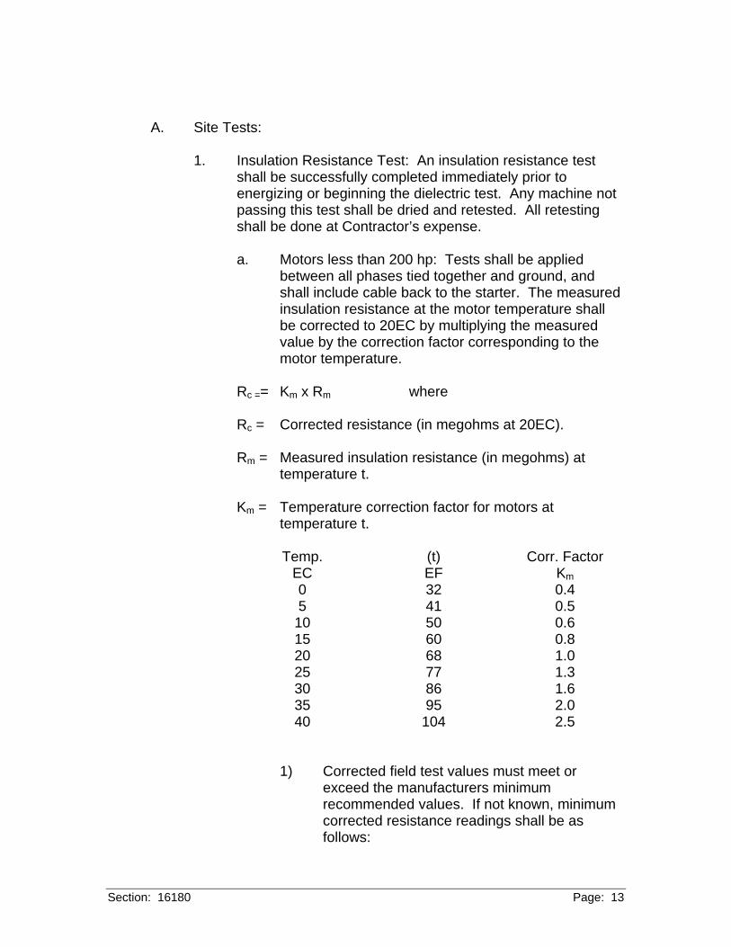
Section: 16180 Page: 13
A. Site Tests:
1. Insulation Resistance Test: An insulation resistance test shall be successfully completed immediately prior to energizing or beginning the dielectric test. Any machine not passing this test shall be dried and retested. All retesting shall be done at Contractor’s expense.
a. Motors less than 200 hp: Tests shall be applied
between all phases tied together and ground, and shall include cable back to the starter. The measured insulation resistance at the motor temperature shall be corrected to 20EC by multiplying the measured value by the correction factor corresponding to the motor temperature.
Rc == Km x Rm where
Rc = Corrected resistance (in megohms at 20EC). Rm = Measured insulation resistance (in megohms) at
temperature t. Km = Temperature correction factor for motors at
temperature t.
Temp. EC
(t) EF
Corr. Factor Km
0 32 0.4 5 41 0.5 10 50 0.6 15 60 0.8 20 68 1.0 25 77 1.3 30 86 1.6 35 95 2.0 40 104 2.5
1) Corrected field test values must meet or exceed the manufacturers minimum recommended values. If not known, minimum corrected resistance readings shall be as follows:
Section: 16180 Page: 14
Equipment
Test Voltage
Minimum Corrected Reading-megohms
480V 3ph Ind Motor 1000 20 120V Ind Motor 500 5
2) Tests must be held for one minute or until the
reading maintains a constant value for fifteen seconds.
b) Motors 200 hp and larger shall be given a polarization index test, 10 minute divided by 1 minute megohmmeter readings. This test method does not require temperature correction. The recommended minimum value shall be a 1.5 polarization index.
c) All test readings and ambient temperature at the time
of test shall be recorded, shall be signed by the tester and submitted to the Engineer within 10 days.
2. Final Acceptance: Final acceptance of rotating equipment cannot be made until the equipment is energized during test to ascertain that all design functions are satisfactorily performed. Testing shall include all remote control operation as well as local operation of all motor starters and actuation of all alarm and indication devices according to design specifications. All control circuits, automatic operations and interlocks must be tested by the Contractor for correct and positive operations.
B. Inspection:
1. Motors shall be checked for correct phase sequencing and
correct rotation in accordance with driven equipment manufacturer's startup procedures before energizing.
a. Motors up to 100 HP: Bumping motors will not be
permitted. Contractor shall use a battery-operated rotation testing instrument on motors to determine correct wiring sequence before power cables are connected.
b. Motors above 100 HP: Disconnect motor from driven
equipment and "Bump" motor to determine rotation.
Section: 16180 Page: 15
All permanent overload protective devices must be in place before connecting motor.
2. Motors shall be checked for damage, moisture, alignment,
freedom of rotation, proper lubrication, oil leaks, phase identification, and cleanliness before energizing.
C. Motors shall be energized in accordance with Section 01650,
Starting of Systems/Commissioning and Section 01660, Testing, Adjusting, and Balancing and the driven equipment specifications.
3.11 ADJUSTING
A. The Contractor shall fill any oil reservoir with the manufacturer's specified oil.
B. If the manufacturer requires that the anti-friction bearings receive
an initial change of grease, the Contractor shall perform such work. C. Motors which are supplied with provisions for fluid lubrication: The
Contractor must assure that the proper supply pressure is available.
D. The motor shaft shall be turned by hand to ensure there is free
rotation. E. The area around the external fan inlet shall be checked for loose
debris that could be drawing into the fan during operation. F. All external, factory-made, bolted joints should be checked for
looseness.
3.12 CLEANING
A. Any slushing compound on the shaft or other parts shall be removed using a petroleum-type solvent.
3.13 DEMONSTRATION (Not Used) 3.14 PROTECTION (Not Used) 3.15 SCHEDULES (Not Used)
+ + END OF SECTION + +
16190 Page: 1
SECTION 16190
SUPPORTING SYSTEMS PART 1 GENERAL 1.01 SUMMARY
A. Furnish all labor, materials, equipment and incidentals required to provide supporting systems for equipment, boxes, cabinets, consoles, panels, enclosures, conduit, cable tray, wireway, busway, and cablebus as shown on the Drawings, specified or required.
B. Related Sections:
1. Section 05050, Threaded Fasteners. 2. Section 05501, Anchor Bolts, Expansion Anchors and
Concrete Inserts. 3. Section 05502, Miscellaneous Metal Fabrications.
1.02 REFERENCES
A. Refer to Section 16000, General Provisions for Electrical Work, for additional standards.
B. Reference Standards:
1. ASTM A276, Stainless and Heat Resisting Steel Bars and Shapes.
1.03 DEFINITIONS (Not Used) 1.04 SYSTEM DESCRIPTION
16190 Page: 2
A. Design Loads: Supporting systems shall be suitable for the load imposed times a safety factor of 4.0.
1.05 SUBMITTALS
A. Comply with Section 01300, Submittals, and submit the following: B. Product Data:
1. Copies of manufacturer's specifications including material,
dimensional and weight data and load capacity for each supporting system component proposed for use.
1.06 QUALITY ASSURANCE (Not Used) 1.07 DELIVERY, STORAGE AND HANDLING (Not Used) 1.08 PROJECT/SITE CONDITIONS (Not Used) 1.09 SEQUENCING (Not Used) 1.10 SCHEDULE (Not Used) 1.11 WARRANTY (Not Used) 1.12 SYSTEM STARTUP (Not Used) 1.13 OWNER'S INSTRUCTIONS (Not Used) 1.14 COMMISSIONING (Not Used) 1.15 MAINTENANCE (Not Used) PART 2 PRODUCTS 2.01 MANUFACTURERS
A. B-Line. B. Or equal.
2.02 EXISTING PRODUCTS (Not Used)
16190 Page: 3
2.03 MATERIALS
A. Strut, Fittings and Accessories:
1. Shall meet applicable requirements of ASTM A276. 2. Unless otherwise shown or specified, strut shall be 316
stainless steel, 1-5/8 inches by 1-5/8 inches and 0.105 inch thick. Double struts shall be two pieces of this same strut, welded back-to-back at the factory.
3. Fittings, braces, brackets, hardware and accessories shall
be 316 stainless steel. 4. Strut nuts shall be spring captured 316 stainless steel. 5. Square and round washers shall be 316 stainless steel.
B. Hanger Rods:
1. Shall be all-thread 316 stainless steel. 2. Shall be minimum 3/8-inch diameter unless otherwise shown
on the Drawings or specified.
C. Beam Clamps for Attaching Threaded Rods or Bolts to Beam Flanges for Hanging Struts or Conduit Hangers:
1. Beam clamps shall be 316 stainless steel equipped with a
316 stainless steel square-head set screw and shall include a threaded hole sized for attaching the all-thread rod or threaded bolt as shown.
D. Miscellaneous Hardware:
1. Bolts, screws, and washers shall be 316 stainless steel.
2. Hex nuts:
a. Shall be 316 stainless steel. b. Shall include nylon inserts.
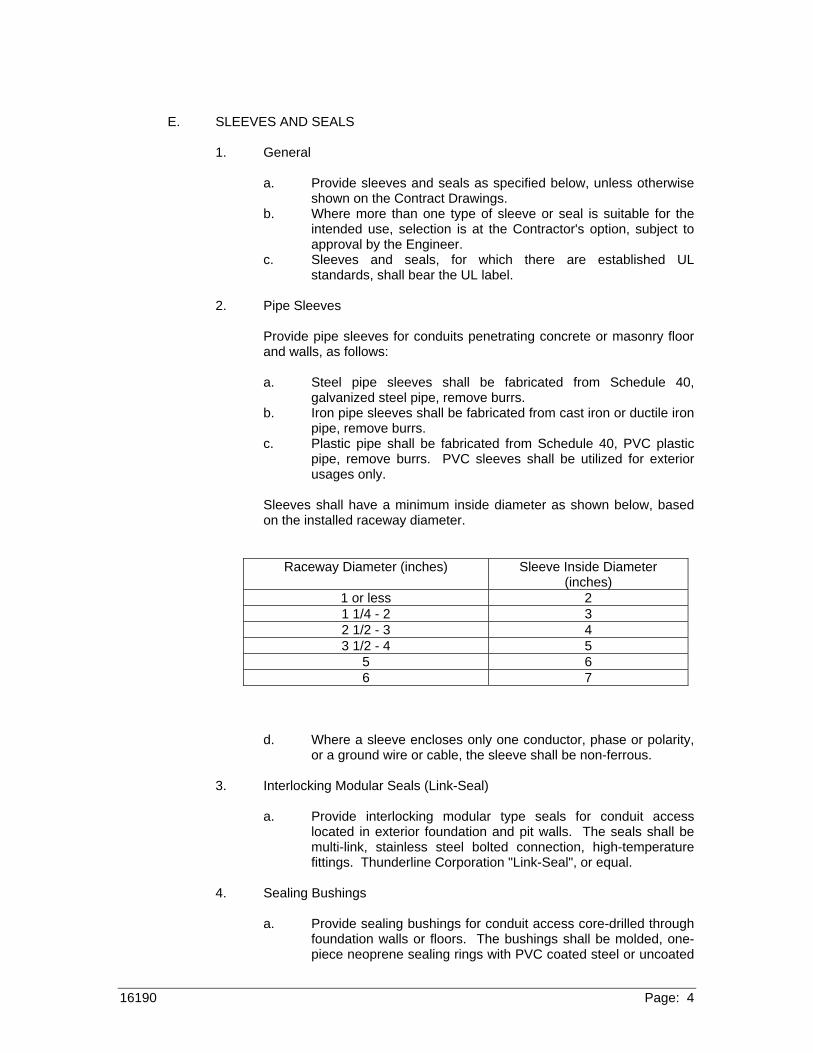
16190 Page: 4
E. SLEEVES AND SEALS
1. General
a. Provide sleeves and seals as specified below, unless otherwise shown on the Contract Drawings.
b. Where more than one type of sleeve or seal is suitable for the intended use, selection is at the Contractor's option, subject to approval by the Engineer.
c. Sleeves and seals, for which there are established UL standards, shall bear the UL label.
2. Pipe Sleeves
Provide pipe sleeves for conduits penetrating concrete or masonry floor
and walls, as follows:
a. Steel pipe sleeves shall be fabricated from Schedule 40, galvanized steel pipe, remove burrs.
b. Iron pipe sleeves shall be fabricated from cast iron or ductile iron pipe, remove burrs.
c. Plastic pipe shall be fabricated from Schedule 40, PVC plastic pipe, remove burrs. PVC sleeves shall be utilized for exterior usages only.
Sleeves shall have a minimum inside diameter as shown below, based
on the installed raceway diameter.
Raceway Diameter (inches) Sleeve Inside Diameter (inches)
1 or less 2 1 1/4 - 2 3 2 1/2 - 3 4 3 1/2 - 4 5
5 6 6 7
d. Where a sleeve encloses only one conductor, phase or polarity, or a ground wire or cable, the sleeve shall be non-ferrous.
3. Interlocking Modular Seals (Link-Seal)
a. Provide interlocking modular type seals for conduit access
located in exterior foundation and pit walls. The seals shall be multi-link, stainless steel bolted connection, high-temperature fittings. Thunderline Corporation "Link-Seal", or equal.
4. Sealing Bushings
a. Provide sealing bushings for conduit access core-drilled through
foundation walls or floors. The bushings shall be molded, one-piece neoprene sealing rings with PVC coated steel or uncoated
16190 Page: 5
aluminum pressure plates, stainless steel hex socket head cap screws and flat washers, O.Z. Gedney Co. Series 'CSM', or equal.
5. Fire Seals
a. Provide UL listed, 3 hour rating, silicone based foam, fire
resistive, water proof joint sealing system to prevent the passage of hot gases and fire.
6. Wall and Floor Seals
a. Provide watertight and pressure-tight wall and floor seals
suitable for sealing around conduit passing through exterior concrete floors and walls. Assembly shall include steel sleeves, galvanized malleable iron body, neoprene sealing grommets and rings, metal pressure rings, membrane clamp where required by foundation design and pressure clamps with Type 316 stainless steel cap screws, O.Z. Gedney Co. Type WSK/MC, or equal.
2.04 MANUFACTURED UNITS (Not Used) 2.05 EQUIPMENT (Not Used) 2.06 COMPONENTS (Not Used) 2.07 ACCESSORIES (Not Used) 2.08 MIXES (Not Used) 2.09 FABRICATION (Not Used) 2.10 FINISHES (Not Used) 2.11 FACTORY WITNESS TESTING (Not Used) PART 3 EXECUTION 3.01 ACCEPTABLE INSTALLERS (Not Used) 3.02 EXAMINATION
A. Items shall be inspected for damage upon delivery to the site. B. Damaged components shall not be installed.
3.03 PREPARATION (Not Used) 3.04 ERECTION (Not Used)
16190 Page: 6
3.05 INSTALLATION
A. Supporting systems shall be provided as shown on the Drawings, specified or required.
B. Equipment, boxes, cabinets, consoles, panels, enclosures, conduit,
cable tray, wireway, busway, and cablebus shall be installed on supporting systems as shown on the Drawings, specified or required.
C. Installation of supporting systems shall be coordinated with
equipment, cabinets, consoles, panels, enclosures, boxes, conduit, cable tray, wireway, busway, cablebus, piping, duct work, lighting fixtures and other systems and equipment and located clear of interferences and access-ways.
D. Anchor Bolts, Expansion Anchors and Concrete Inserts shall meet
the requirements of Section 05501, Anchor Bolts, Expansion Anchors and Concrete Inserts, and the additional requirements of this Section.
E. Threaded fasteners shall meet the requirements of Section 05050,
Threaded Fasteners. F. Miscellaneous metal fabrications shall meet the requirements of
Section 05502, Miscellaneous Metal Fabrications.
G. Mounting of Cabinets, Consoles, Panels, Enclosures and Boxes:
1. Unless otherwise specified or shown on the Drawings, floor mounted equipment, cabinets, consoles, panels, enclosures and boxes shall be installed on 3½-inch concrete equipment base with a 45 degree chamfered edge. The base shall extend 1 inches beyond outside dimensions of equipment, all sides.
2. A minimum ¼-inch space shall be provided between abutting
or near surfaces of cabinets, consoles, panels, enclosures or boxes and adjacent surfaces, including the surface on which they are mounted (except strut). Spacers made of 316 stainless steel shall be provided.
3. Equipment, enclosures, panels, and boxes shall not be
mounted directly to beams or columns. Struts shall first be
16190 Page: 7
mounted to beams or columns using beam clamps and equipment, enclosures, panels, and boxes shall be mounted to the struts.
H. Trapeze hanger systems shall be provided as shown, specified, or required.
I. Floor Standing Rack Assemblies or Vertical Wall Mounted Rack
Assemblies for Mounting Equipment or Enclosures Heavier than 150 pounds:
1. Shall be provided as shown, specified, or required. 2. Shall consist of struts, plates, brackets, connection fittings,
braces, bases, accessories, and hardware assembled in a rigid framework suitable for mounting of intended equipment.
3. Shall be equipped with brackets and bases for rigidly
mounting the framework to the ceiling, floor or wall or equipped with beam clamps, angle plates, washers, and bolts for fastening to beam flanges.
4. All materials of the rack assemblies and their anchors or
beam clamps shall be 316 stainless steel. 5. Bracing, clamping and anchoring of each rack shall be
sufficient to ensure rigidity of the rack with the intended equipment, enclosures, conduit, cable tray, busway, cablebus, or wireway installed. Racks shall not be deflected more than 1/8-inch by a 100 pound force applied at any point on the rack in any direction.
J. Drilling into beams or columns shall not be permitted except as authorized by the Engineer.
3.06 APPLICATION (Not Used) 3.07 CONSTRUCTION (Not Used) 3.08 REPAIR/RESTORATION (Not Used) 3.09 RE-INSTALLATION (Not Used) 3.10 FIELD QUALITY CONTROL
16190 Page: 8
A. Field Cutting: Cut edges of strut and hanger rod shall have corners rounded, edges beveled and burrs removed. If field cutting the strut is required, only clean, sharp, dedicated tools shall be used. Oil, shavings and other residue of cuttings shall be removed prior to installation.
3.11 ADJUSTING (Not Used) 3.12 CLEANING (Not Used) 3.13 DEMONSTRATION (Not Used) 3.14 PROTECTION (Not Used) 3.15 SCHEDULES (Not Used)
+ + END OF SECTION + +
Section: 16195 Page: 1
SECTION 16195
ELECTRICAL IDENTIFICATION PART 1 GENERAL 1.01 SUMMARY
A. Furnish all labor, materials, equipment, and incidentals to provide wire labels, wire color coding, terminal block labels, conduit identification, legend plates, nameplates and other identification for electrical apparatus as shown on the Drawings, specified and required.
1.02 REFERENCES
A. Refer to Section 16000, General Provisions for Electrical Work for additional requirements.
1.03 DEFINITIONS (Not Used) 1.04 SYSTEM DESCRIPTION (Not Used) 1.05 SUBMITTALS
A. Comply with Section 01300, Submittals, and provide the following:
B. Product Data:
1. Manufacturer's cut sheets, specifications, dimensions and technical data for all products proposed to be furnished under this Section.
C. Shop Drawings:
Section: 16195 Page: 2
1. The complete description and enumeration of proposed electrical identification and electrical identification devices shall be shown on the Shop Drawings for the associated equipment or systems.
D. Samples:
1. Nameplates: Samples of nameplates shall be submitted for the Engineer's selection of size and lettering style.
2. Wire Labels:
a. Samples of wire and cable labels shall be submitted
and shall include both applied and unapplied wire and cable label samples. These samples shall be used as quality standards for the wire and cable labeling required by this Section. These samples shall be of material specified in this Section and shall include wire and cable designators meeting the requirements of this Section.
E. Commissioning Documents:
1. Wiring diagrams annotated with wire numbers and terminal numbers shall be submitted prior to commissioning of associated equipment or systems.
F. Project Record Documents:
1. Submittals of Project Record Documents required by other Sections shall show final electrical identification and electrical identification devices.
1.06 QUALITY ASSURANCE (Not Used) 1.07 DELIVERY, STORAGE, AND HANDLING (Not Used) 1.08 PROJECT/SITE CONDITIONS (Not Used) 1.09 SEQUENCING (Not Used) 1.10 SCHEDULE
A. Permanent engraving and mounting of the nameplates shall be provided upon the conclusion of Operational Demonstration.
Section: 16195 Page: 3
1.11 WARRANTY (Not Used) 1.12 SYSTEM STARTUP (Not Used) 1.13 OWNER’S INSTRUCTIONS (Not Used) 1.14 COMMISSIONING (Not Used) 1.15 MAINTENANCE (Not Used) PART 2 PRODUCTS 2.01 MANUFACTURERS
A. See paragraph 2.04 for manufacturers.
2.02 EXISTING PRODUCTS (Not Used) 2.03 MATERIALS (Not Used) 2.04 MANUFACTURED UNITS
A. Engraved Identification Devices (Nameplates, Legend Plates and Instrument Tags):
1. Nameplates:
a. Laminated thermoset plastic, 1/16-inch thick,
engraved condensed block black lettering on white background, square corners, and beveled front edges.
b. Size: As required. c. Letter Size: Minimum 3/16-inch. d. Nameplates one-inch or less in height shall have one
mounting hole at each end. Nameplates greater than one-inch in height shall have mounting holes in all four corners.
Section: 16195 Page: 4
2. Legend Plates:
a. Legend Plates for pushbuttons, pilot lights, selector switches and other panel mounted devices shall be large size with dimensions of approximately 2-7/16 inches wide by 2-13/32 inches tall (Allen Bradley large automotive size), plastic, custom engraved with black letters on white background.
1) Standard size legend plates shall be provided
only where devices are mounted on motor control centers and spacing of the devices precludes the use of automotive size legend plates.
b. Lettering size and line weight shall be the same for all legend plates on the same panel or enclosure. Maximum size shall be 1/4-inch and minimum size shall be 1/8-inch.
3. Instrument Tags:
a. Laminated thermoset plastic, 1/8-inch thick, engraved condensed block black lettering on white background, rounded corners, beveled front and back edges. Secure with self-locking nylon strap. Provide hole in end of tag for attachment of strap.
b. Size: Minimum 2 inches by 4 inches. c. Letter Size: Minimum 3/16-inch.
B. Safety Signs and Voltage Markers:
1. Low voltage safety signs shall be pressure sensitive vinyl conforming to OSHA, shall be 5-inches by 3-1/2-inches and shall be worded "DANGER - 480 VOLTS".
a. Products and Manufacturers:
1) B-302-86060 by Brady.
Section: 16195 Page: 5
2) Or equal.
2. Low voltage markers shall be pressure sensitive vinyl or vinyl cloth with black lettering on orange background and shall be worded "120 VOLTS", "208 VOLTS", "120/208 VOLTS", or "240 VOLTS" as required.
a. Products and Manufacturers:
1) 442xx by Brady. 2) Or equal.
C. Wire Identification:
1. Heat Shrinkable Wire and Cable Labeling System:
a. White heat-shrinkable irradiated polyolefin shrink-on sleeves. Labels shall be thermal printed. Labels shall be at least 2 inches in width.
b. Products and Manufacturers:
1) B-341 PS-xxx-2W by Brady. 2) Or equal.
2. Wrap-Around Wire and Cable Labeling System:
a. Self laminating white/transparent self extinguishing vinyl strips. Length shall be sufficient to provide at least two and one half wraps. Labels shall be thermally printed. Labels shall be at least 2 inches in width.
b. Products and Manufacturers:
1) THT-XX-427 by Brady. 2) Or equal.
D. Detectable Underground Warning Tape:
Section: 16195 Page: 6
1. Shall be polyethylene or polyester with detectable metal core and polyester underlaminate.
2. Shall be two inches wide. 3. Shall be yellow or red with permanently imprinted black
lettering: "CAUTION - Buried Electric Line", repeated continuously over full length of tape.
4. Products and Manufacturers:
a. Indentoline by Brady. b. Or equal.
E. Thermal Printing System:
1. Printing system shall utilize a thermal transfer process to create non-smearing labels and markers.
2. Wire and Cable Markers:
a. Portable:
1) TLS2200 by Brady.
2) Or equal.
b. Desktop:
1) 200M by Brady. 2) Or equal.
3. Conduit Markers:
a. Portable:
1) Handimark by Brady.
2) Or equal.
b. Desktop:

Section: 16195 Page: 7
1) Labelizer PLUS by Brady.
2) Or equal.
2.05 EQUIPMENT (Not Used) 2.06 COMPONENTS (Not Used) 2.07 ACCESSORIES (Not Used) 2.08 MIXES (Not Used) 2.09 FABRICATION
A. Engraved Identification Devices (Nameplates, Annunciator Windows, Legend Plates and Instrument Tags):
1. All nameplate, annunciator window and legend plate text
shall remain preliminary and subject to change pending final review and acceptance of the nomenclature by the Engineer after commissioning. Temporary tags consisting of removable tape or other accepted material with the preliminary nomenclature legibly hand lettered shall be affixed to enclosures and cover plates to identify the enclosures and mounted components as required during assembly, factory testing, and start-up. Laminated plastic nameplates, windows and legend plates, shall not be engraved until after commissioning of the associated system and release of final engraving information by the Engineer.
2. Instrument Tags shall be engraved with the following
information as shown or specified and as reflected on conforming Shop Drawings.
a. Tag number. b. Instrument manufacturer. c. Instrument model number. d. Service (functional description of instrument). e. Range.
2.10 FINISHES (Not Used)
Section: 16195 Page: 8
2.11 SOURCE QUALITY CONTROL (Not Used) 2.12 FACTORY WITNESS TESTING (Not Used) PART 3 EXECUTION 3.01 ACCEPTABLE INSTALLERS (Not Used) 3.02 EXAMINATION (Not Used) 3.03 PREPARATION (Not Used) 3.04 ERECTION (Not Used) 3.05 INSTALLATION
A. Electrical identification shall be provided as shown, specified or required.
B. Engraved Identification Devices (Nameplates, Annunciator
Windows, Legend Plates and Instrument Tags):
1. Temporary tags shall be provided at all locations until after start-up and release of final engraving information by the Engineer.
2. Unless otherwise specified, permanent nameplates shall be
attached with a permanent adhesive and with stainless steel machine screws into drilled and tapped holes.
3. A nameplate with 1.5-inch letters shall be provided to identify
each console, cabinet, panel or enclosure as shown or specified.
4. Nameplates shall be provided for field mounted motor
starters, disconnect switches, manual starter switches, pushbutton stations, and similar equipment operating components and shall describe the motor or equipment function and the circuit number.
Section: 16195 Page: 9
5. Nameplates with 0.5-inch letters shall be provided to identify each junction and terminal box as shown or specified.
6. On switchgear, nameplates shall be furnished for all main
and feeder circuits including control fuses and also for all indicating lights and instruments.
a. A nameplate with 1.5-inch letters shall be provided
giving switchgear designation, voltage rating. ampere rating, short circuit rating, manufacturer's name, general order number and item number.
b. The individual door for each compartment shall be
identified with a nameplate giving item designation and circuit number as well as frame ampere size and appropriate trip rating.
7. Motor Control Centers:
a. A nameplate with 1.5-inch letters shall be provided giving motor control center designation.
b. The individual door for each unit compartment shall
be identified with a nameplate identifying the controlled equipment. Spare starters, spare breakers, blank (useable) spaces and unusable spaces shall be identified as applicable.
8. Except conduit, all other electrical appurtenances including but not limited to lighting panels, convenience outlets, fixtures and lighting switches, shall be provided with nameplates indicating the appropriate circuit breaker number(s).
9. Annunciators:
a. Temporary tags shall be provided at all annunciator
windows until after start-up and release of final engraving information by the Engineer.
10. Push Buttons:
a. Legend plates shall be provided for identification of
functions.
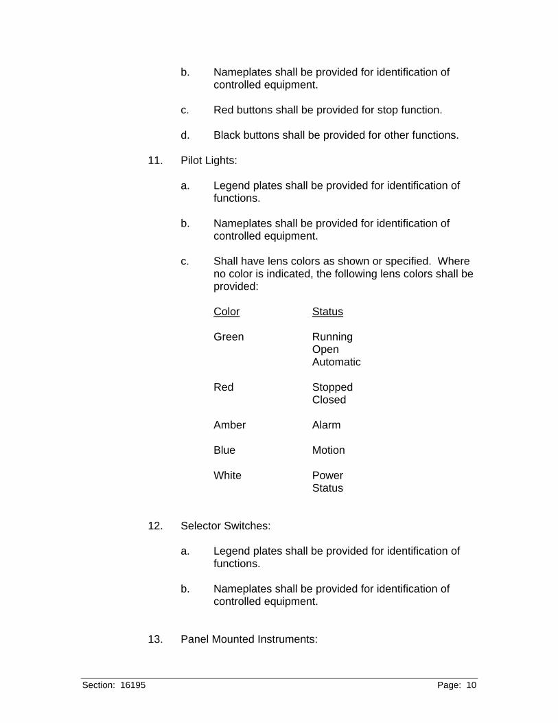
Section: 16195 Page: 10
b. Nameplates shall be provided for identification of controlled equipment.
c. Red buttons shall be provided for stop function. d. Black buttons shall be provided for other functions.
11. Pilot Lights:
a. Legend plates shall be provided for identification of
functions. b. Nameplates shall be provided for identification of
controlled equipment. c. Shall have lens colors as shown or specified. Where
no color is indicated, the following lens colors shall be provided:
Color Status Green Running Open Automatic Red Stopped Closed Amber Alarm
Blue Motion
White Power Status
12. Selector Switches:
a. Legend plates shall be provided for identification of functions.
b. Nameplates shall be provided for identification of
controlled equipment.
13. Panel Mounted Instruments:
Section: 16195 Page: 11
a. Nameplates shall be provided for identification of function.
14. Interiors of Cabinets, Consoles, Panels, Terminal Boxes and Other Enclosures:
a. Nameplates shall be provided for identification. b. Each item inside the cabinet, console, panel, terminal
box or enclosure shall be provided with a laminated plastic nameplate as shown on the conforming shop drawings. Nameplates shall be mounted with adhesive.
c. Interior items requiring nameplates include but are not
limited to:
1) Terminal blocks and strips. 2) Bus bars. 3) Relays. 4) Rear of face-mounted items. 5) Rear of door-mounted items. 6) Any interior mounted item which requires
identification when mounted externally.
d. Circuit Breaker Directory: 1) An engraved laminated plastic directory shall
provide a listing of function and load controlled for each circuit breaker within the panel used for power distribution.
15. Field Mounted Instruments:
a. Instruments which are not mounted on panels or other enclosures shall be provided with instrument tags.
C. Safety Signs and Voltage Markers:
Section: 16195 Page: 12
1. Safety signs and voltage markers shall be provided on and
around electrical equipment as specified and where shown.
a. Rigid safety signs shall be installed using stainless steel fasteners.
b. Surfaces shall be cleaned before application of
pressure sensitive signs and markers.
2. Cable tray safety signs shall be installed on both sides of cable trays at not more than 20 foot intervals. They shall be installed on the side rails of the tray as directed and accepted by the Engineer. a. Cable trays that contain conductors of greater than
208 volts but less than 600 volts shall be labeled with low voltage safety signs.
b. Cable trays that contain conductors of 120/208 volts
shall be labeled with low voltage markers. c. Cable trays that contain only instrument signal cables
shall not be labeled. d. Cable trays that contain intrinsically safe wiring or
cables shall be labeled per NEC 540-80. 3. Low voltage safety signs shall be mounted on all equipment
doors providing access to uninsulated 480 volt conductors (including terminal devices).
4. Low voltage markers shall be installed on each terminal box,
safety disconnect switch and panelboard installed, modified or relocated and containing 120/208 volt conductors.
D. Wire and Cable Identification:
1. Color coding of insulated conductors shall comply with Section 16123, Low Voltage Cable and Wire- 600 Volt and Below.
2. Wire and Cable Labels shall be provided as follows:
Section: 16195 Page: 13
a. New, rerouted, or revised wire or cable shall be labeled.
b. All insulated conductors shall be labeled. c. Bare (uninsulated) conductors shall not be labeled
unless otherwise shown or specified. d. Wire and cable terminations shall be labeled.
1) Wire labels shall be applied between half an inch and one inch of the completed termination
2) Cable labels shall be applied between half an
inch and one inch of cable breakout into individual conductors.
a) Individual conductors in a cable shall be
labeled after the breakout as specified for wires.
e. Wire or cable exiting cabinets, consoles, panels, terminal boxes and enclosures shall be labeled.
1) Wires or cables shall be labeled within two
inches of the entrance to the conduit.
f. Wire or cable in junction boxes and pull boxes shall be labeled
1) Wires or cables shall be labeled within two
inches of the entrance to the conduit.
g. Wire and cable installed without termination in electrical manholes shall be labeled.
1) Wire and cable shall have wrap-around labels
applied within one foot of exiting the manhole.
3. Wire and Cable Identification System:
a. Wire and Cable labels shall be imprinted with an
identifying designator.
Section: 16195 Page: 14
1) Wire and cable extending between two devices
or items and which does not undergo a change of function shall be identified by a single unique designator as specified below.
b. Field Wiring:
1) Field wiring designators shall be derived from the layout of the interconnecting drawings. Interconnecting drawings are specified in Section 16000, General Requirements for Electrical Work.
2) The wire or cable designator shall consist of:
a) The three left-most characters shall
consist of the Contract Number under which the wiring is installed.
b) The fourth character from the left shall
be an asterisk (*), a plus sign (+) or a hyphen (-). No other punctuation symbol shall be used in a wire designator.
c) The fifth through the seventh character
shall correspond to the sheet number of the interconnecting drawings on which the wire is shown.
(1) Where a wire or cable is shown
on multiple sheets its designator shall be based on the first sheet on which it is shown.
d) The eighth through the tenth character
from the left shall be alphanumeric and make the wire designator unique.
c. Cabinet, Console, Panel and Enclosure Wiring, Internal: 1) New Cabinets, Consoles, Panels and
Enclosures:
Section: 16195 Page: 15
a) Wire and cable located inside cabinets,
consoles, panels, or enclosures shall have designators
2) Modified Cabinets, Consoles, Panels and Enclosures:
a) New or rerouted wire or cable in existing
cabinets, consoles, panels or enclosures, shall be labeled as shown on the Drawings or shall be assigned a ten character designator which is equivalent to a field wire designator.
E. Terminal Strip Labeling:
1. The panel side of the terminal shall be labeled to match the panel wire number.
2. The field side of the terminal shall be labeled to match the
field wire number. The terminal number shall not include the contract number.
F. Underground Warning Tape:
1. Shall be installed in accordance with Section 16117,
Concrete-Encased Duct Banks. 3.06 APPLICATION (Not Used) 3.07 CONSTRUCTION (Not Used) 3.08 REPAIR/RESTORATION (Not Used) 3.09 RE-INSTALLATION (Not Used) 3.10 FIELD QUALITY CONTROL (Not Used) 3.11 ADJUSTING (Not Used) 3.12 CLEANING (Not Used) 3.13 DEMONSTRATION (Not Used) 3.14 PROTECTION (Not Used) 3.15 SCHEDULES (Not Used)
+ + END OF SECTION + +
Section: 16390 Page: 1
SECTION 16390
GROUNDING SYSTEMS PART 1 GENERAL 1.01 SUMMARY
A. Furnish all labor, materials, equipment and incidentals required to provide a complete grounding system for the electrical and instrumentation system as shown on the Drawings, specified or required.
B. Related Sections:
1. Section 16915, Control Enclosures. 2. Section 16111, Cable Tray Systems. 3. Section 16123, Low-voltage Wire and Cable 600 Volt and
Below. 4. Section 16142, Terminations and Terminal Devices. 5. Section 16670, Lightning Protection Systems.
1.02 REFERENCES
A. Refer to Section 16000, General Requirements for Electrical Work. for administrative and procedural requirements, for additional standards.
B. Reference Standards:
1. Refer to Section 16000, General Requirements for Electrical Work, for additional standards.
Section: 16390 Page: 2
2. UL 467, Grounding and Bonding Equipment. 3. UL 96, Lightning Protection Components. 4. UL 486 A, Wire Connectors and Soldering Lugs for Use with
Copper Conductors. 1.03 DEFINITIONS
A. Grounding Electrode Conductor: The conductor used to connect the grounding electrodes to the equipment grounding conductor and/or to the grounded conductor of the circuit at the source of a separately derived system.
B. Grounding Conductor: A conductor used to connect equipment or
the grounded circuit of a wiring system to a grounding electrode or electrodes.
C. Equipment Grounding Conductor: The conductor used to connect
the non current-carrying metal parts of equipment, raceways, and other enclosures to the system grounded conductor and/or the grounding electrode conductor at the service equipment or at the source of a separately derived system.
D. Shield Ground: An isolated grounded conductor or terminal used
for grounding the shield on shielded instrumentation signal cables. E. Instrumentation System Ground: An isolated grounded conductor
or terminal used for grounding the D.C. power systems of the various electronic instruments and signal loops of the instrumentation systems.
1.04 SYSTEM DESCRIPTION (Not Used) 1.05 SUBMITTALS
A. Comply with Section 01300, Submittals, and provide the following: B. Product Data:
Section: 16390 Page: 3
1. Manufacturer's Specifications, Technical Data, Dimensional Data, and installation instructions for components proposed for use under this Section.
C. Test Records: Written records of all tests within ten (10) days after the test are performed.
1.06 QUALITY ASSURANCE (Not Used) 1.07 DELIVERY, STORAGE AND HANDLING (Not Used) 1.08 PROJECT/SITE CONDITIONS
A. Existing conditions shall be field measured and verified and shown on Shop Drawings.
1.09 SEQUENCING (Not Used) 1.10 SCHEDULING (Not Used) 1.11 WARRANTY (Not Used) 1.12 SYSTEM STARTUP (Not Used) 1.13 OWNER'S INSTRUCTIONS (Not Used) 1.14 COMMISSIONING (Not Used) 1.15 MAINTENANCE (Not Used) PART 2 PRODUCTS 2.01 MANUFACTURERS
A. Burndy / Framatome Connectors International. B. O.Z./Gedney/General Signal Corp/SPX Corporation. C. Cadweld®, Erico Products, Inc. D. Copperweld, Joslyn.
Section: 16390 Page: 4
E. Thomas and Betts Corp.
2.02 EXISTING PRODUCTS (Not Used) 2.03 MATERIALS
A. Grounding Conductors:
1. Material: Annealed, insulated, stranded copper, meeting the requirements of Section 16123, Low-voltage Wire and Cable 600 Volt and Below, size as specified or as shown on the Drawings.
2. Grounding conductors shall be bare or insulated (green) as
defined in Part 3, unless shown on the Drawings or specified otherwise.
B. Ground Rods:
1. Shall be copper-clad rigid steel rods, ¾-inch diameter, 10 feet long.
C. Grounding Electrode Conductor Connectors:
1. Mechanical connectors shall be copper alloy castings, designed specifically for the items to be connected, and shall be assembled with Durium or silicon bronze bolts, nuts and washers.
2. Welded connections shall be made by exothermic process
utilizing molds, cartridges and hardware designed specifically for the type of connection to be made.
D. Ground Clamps
1. Ground clamps shall be malleable iron, hot dip or mechanically galvanized and shall be assembled with zinc plated steel screws.
2.04 MANUFACTURED UNITS (Not Used)
Section: 16390 Page: 5
2.05 EQUIPMENT (Not Used) 2.06 COMPONENTS (Not Used) 2.07 ACCESSORIES (Not Used) 2.08 MIXES (Not Used) 2.09 FABRICATION (Not Used) 2.10 FINISHES (Not Used) 2.11 SOURCE QUALITY CONTROL (Not Used) PART 3 EXECUTION 3.01 ACCEPTABLE INSTALLERS (Not Used) 3.02 EXAMINATION (Not Used) 3.03 PREPARATION (Not Used) 3.04 ERECTION (Not Used) 3.05 INSTALLATION
A. A complete grounding system for the electrical and instrumentation systems shall be provided as shown, specified or required.
B. KOPR-SHIELD® by Thomas and Betts Corporation, or equal shall
be applied between the mating surfaces of grounding and bonding connections.
C. Grounding Electrode System:
1. Ground rods shall be installed in the quantity, location and
arrangement shown on the Drawings. 2. Multiple ground rod configuration shall not be closer than
10 feet center to center. 3. Multiple ground rods shall be connected with a continuous
grounding electrode conductor size 4/0 AWG bare copper, unless otherwise shown on the Drawings or specified.
4. Connections between the ground rods and the grounding
electrode conductors shall be made using exothermically welded connections.
Section: 16390 Page: 6
5. The Engineer shall be notified at least 24 hours in advance
of driving the ground rods. 6. If any ground rod does not penetrate to the required depth of
the rod, the Engineer will make a determination whether to:
a. Cut off rod at that point, or b. Pull out rod and relocate to a new location.
D. AC Electrical Systems Grounding:
1. The center tap of all single phase 120/240 volt systems shall be connected to the Main Grounding Electrode System per NEC Article 250, regarding separately derived systems.
2. The neutral taps of all 3 phase, 4 wire "wye" connected
transformers shall be connected to the main grounding electrode system, per the NEC Article 250, regarding separately derived systems.
E. Building Structure Grounding:
1. Existing Building Structure grounding system to be reused.
F. Equipment Grounding:
1. An insulated (green) ground conductor shall be run in all raceways and cable trays except as follows:
a. When a loop powered instrument does not have a
manufacturer's ground terminal, and that loop is the only content of the raceway or cable tray, the ground conductor may be omitted.
b. When the equipment manufacturer furnishes an
interconnecting cable between items of equipment, and one of the wires in the cable is a designated ground, an additional ground conductor is not required.
Section: 16390 Page: 7
c. When a multi-conductor cable includes a designated equipment grounding conductor, an additional equipment grounding conductor is not required.
2. The equipment ground conductor shall not be smaller than 12 AWG except as follows:
a. As otherwise shown on the Drawings. b. Instrumentation equipment may be grounded using a
green insulated 14 AWG or 16 AWG conductor when current carrying conductors are sized 14 AWG or 16 AWG respectively, in accordance with Section 16123, Low - Voltage Wire and Cable 600 Volts and Below.
c. Where a smaller power or control conductor is
authorized under Section 16123, Low Voltage Wire and Cable 600 Volts and Below, the ground conductor shall be the same size as the largest phase conductor.
3. The equipment ground conductor shall be connected to equipment by means of lug compressed on the conductor end to meet the requirements of Section 16142, Terminations and Terminal Devices. a. Lug shall be bolted to equipment frame using holes or
terminals provided on equipment specifically for grounding. Hold-down bolts shall not be used.
b. Where grounding provisions are not included, suitable
holes shall be drilled in locations designated by the Engineer.
4. The equipment ground conductor shall be connected to motors by bolting directly to motor frames, not to sole plates or supporting structures.
5. The equipment ground conductor shall be connected to
metallic piping systems by means of copper clamps. 6. All bolted surfaces shall be cleaned to a bare metal
condition.
Section: 16390 Page: 8
7. All exposed equipment grounding conductor terminations shall be coated with oxide resistant compound or grease.
G. Instrumentation Grounding System:
1. Ground all instrumentation equipment as defined below. 2. A separate grounding electrode system shall be installed for
instrumentation grounding system as shown on the Drawings.
3. The instrumentation grounding system shall be comprised of
the shield ground and the signal ground. See Paragraph 1.03, Definitions.
4. The instrumentation grounding electrode system shall
consist of three (3) ground rods connected together with a continuous grounding electrode conductor and the free end of this conductor connected to the main grounding electrode system.
5. The shield ground conductor and the signal ground
conductor shall each be connected to a separate ground rod of the Instrumentation Grounding Electrode System. These two rods shall be the rods furthest away from the free end of the grounding electrode conductor.
6. The shield ground conductor and the signal ground
conductor shall terminate in an Instrumentation Systems Ground Terminal box. This terminal box shall contain isolated tin plated copper bus bars for each ground system. All instrumentation system ground conductors shall originate from this terminal box, and shall not be daisy chained.
7. Shields shall be grounded at one end only, as recommended
by instrument manufacturer. 8. Instrumentation grounding system typical details are shown
on the Drawings.
H. Subassembly Grounding:
1. All electrical and control subassemblies containing ground terminals, ground lugs, or specific recommendations by their manufacturer for grounding, shall be grounded by means of
Section: 16390 Page: 9
a separate ground lug, or ground terminal strip. Such grounds shall be single home runs only to avoid the possibility of equipment becoming ungrounded if other equipment in the same ground circuit is removed for service.
2. All metal cabinet doors, sub-panels, and other separable
parts of cabinets to which equipment (including indicators and actuators) may be mounted, shall be grounded by a bonding strap, in the same fashion as described in Subparagraph 1, above.
a. Each hinged metal door shall be bonded to remainder
of enclosure with a bonding strap connected to a welded stud on the door and a stud or bus in the enclosure.
b. Bonding strap shall be tinned copper flat braid, with
end terminals properly sized for the braid and stud or bus.
3. Not more than three (3) wires shall be terminated on a ground stud.
4. A copper ground bus shall be installed in any cabinet that
requires more than three (3) wires for grounding of the cabinets and subassemblies.
a. Bus bar shall be tin plated copper and shall have
minimum dimensions of 1-1/2 inch wide, 3/8-inch thick and 3 inches long. Bus bar shall be drilled and tapped for minimum 10-24 screws with holes spaced to avoid terminal overlap and located no closer than 1/4-inch to edge of bar. Bus bars shall have a minimum of 20 percent spare taps and shall be plated after fabrication. All taps shall be supplied with 10-24 x 1/2-inch 316 stainless steel slotted round head screws. Bus bars shall be mounted as shown with 3/8-inch 316 stainless steel slotted hex-head bolts, hex nuts and lock-washers.
3.06 APPLICATION (Not Used) 3.07 CONSTRUCTION (Not Used) 3.08 REPAIR/RESTORATION (Not Used) 3.09 RE-INSTALLATION (Not Used)
Section: 16390 Page: 10
3.10 FIELD QUALITY CONTROL
A. Each grounding electrode system shall be tested independently for continuity and for resistance to ground using an electrical ground resistance tester.
1. Ground test shall be performed only after two days of dry
weather. Dry weather is defined as 0.0-inch of precipitation in a 48 hour period.
2. A hand-cranked or motor-driven ground test set by Biddle or
equal shall be used. 3. Test shall be conducted prior to covering the top ends of the
ground rods and of any buried grounding electrode conductors.
4. Resistance to ground for each grounding electrode system
shall be 5 ohm or less. Additional ground rods shall be driven at Engineer's discretion as required to meet the 5 ohm maximum resistance at no additional cost to the Owner.
5. Tests shall conform to the requirements of Section 01750,
Starting and Adjusting. 6. Main grounding electrode system and the instrumentation
grounding electrode system shall not be connected together until after testing is complete and results are satisfactory to the Engineer.
B. All tests shall be witnessed by the Engineer. The Engineer shall be notified at least 24 hours in advance of testing.
C. Ground testing report sheets identifying station, structure,
equipment, or instrumentation ground tested and indicating satisfactory ground resistance measurement shall be maintained. Test reports shall be signed by the tester, initialed by the Engineer, and sent to the Engineer within ten (10) days.
3.11 ADJUSTING (Not Used) 3.12 CLEANING (Not Used) 3.13 DEMONSTRATION (Not Used) 3.14 PROTECTION (Not Used)

Section: 16390 Page: 11
3.15 SCHEDULES (Not Used)
+ + END OF SECTION + +
Section: 16440 Page: 1 of 6
SECTION 16440
DISCONNECT SWITCHES PART 1 GENERAL 1.01 SUMMARY
A. Furnish all labor, materials, equipment and incidentals required to provide disconnect switches as shown on the Drawings or required.
B. Related Sections:
1. Section 16476, Low Voltage Fuses.
1.02 REFERENCES
A. Refer to specification Section 16000, General Requirements for Electrical Work, for additional standards.
B. Reference Standards: Comply with applicable requirements and
provisions of the following: 1. UL 98 - Enclosed and Dead Front Switches. 2. NEMA KS 1 - Enclosed Switches. 3. NEMA 250 - Enclosures for Electrical Equipment. 4. Federal Specification WS-865C.
1.03 DEFINITIONS (Not Used) 1.04 SYSTEM DESCRIPTION (Not Used) 1.05 SUBMITTALS
Section: 16440 Page: 2 of 6
A. Comply with Section 01300, Submittals. B. Product Data:
1. Copies of manufacturer's cut sheets, specifications,
dimensions and technical information for all components furnished under this Section.
1.06 QUALITY ASSURANCE (Not Used) 1.07 DELIVERY, STORAGE AND HANDLING (Not Used) 1.08 PROJECT/SITE CONDITIONS (Not Used) 1.09 SEQUENCING (Not Used) 1.10 SCHEDULING (Not Used) 1.11 WARRANTY (Not Used) 1.12 SYSTEM STARTUP (Not Used) 1.13 OWNER'S INSTRUCTIONS (Not Used) 1.14 COMMISSIONING (Not Used) 1.15 MAINTENANCE (Not Used) PART 2 PRODUCTS 2.01 MANUFACTURERS A. Non-Hazardous Areas:
A. Square D. B. Cutler-Hammer. C. Or equal.
B. Hazardous Areas:
A. Square D. B. Cutler-Hammer. C. Or equal.
Section: 16440 Page: 3 of 6
2.02 FABRICATION (Not Used) 2.03 MATERIALS (Not Used) 2.04 MANUFACTURED UNITS
A. Switch Mechanism:
1. Switches shall be horsepower rated, heavy-duty, single throw, 3 pole, sized as required or as indicated on the Drawings.
2. Switches shall be fused or unfused as indicated on the
Drawings.
3. All switches shall have switch blades which are visible when the switch is OFF and the cover is open.
4. Lugs shall be front removable and UL Listed for 75 degrees
C copper conductors. 5. All switches shall have all copper current carrying parts. 6. Switch operating mechanism shall be quick-make, quick-
break such that, during normal operation of the switch, the operation of the contacts shall not be capable of being restrained by the operating handle after the closing or opening action of the contacts has started.
7. Provisions for padlocking the switch in the OFF position with
at least three padlocks shall be provided. 8. The handle position shall travel at least 90 degrees between
the OFF and ON positions to clearly distinguish and indicate handle position.
9. All switches shall have a dual cover interlock mechanism to
prevent unintentional opening of the switch cover when the switch is ON and prevent turning the switch ON when the cover is open. The cover interlock mechanism shall have an externally operated override but the override shall not permanently disable the interlock mechanism.
10. No aluminum lugs or pads shall be used.
Section: 16440 Page: 4 of 6
11. Provide one normally open auxiliary contact rated 10 amp at 120vac with provisions for one additional field installable normally open contact in each disconnect switch.
B. Switch Enclosures for Non-Hazardous Locations:
1. The enclosure shall be NEMA 4X unless indicated otherwise on the Drawings or in Section 16000, General Requirements for Electrical Work.
2. The enclosure shall have ON and OFF markings stamped
into the cover. 4. The operating handle shall be provided with a dual colored,
red/black position indication. 5. The unit shall be a Square D, Class 3110 or equal.
C. Switch Enclosures for Hazardous Locations:
1. The enclosure shall be NEMA 7/9 for use in Class I, Division
I and II, Group C and D, and Class II, Division I and II, Group E, F, and G as defined in NEC Article 500 and indicated on the Drawings.
2. The enclosure shall be finished with gray baked enamel on
copper free cast aluminum alloy. 3. The enclosure shall have ON and OFF cast into the cover.
4. The enclosure shall be provided with threaded conduit
openings in both endwalls.
5. The enclosure shall be furnished with a breather and drain kit to allow their use in outdoor applications.
6. The cover sealing means for switches rated through 200
amperes shall be type 316 stainless steel bolts.
7. The unit shall be a Square D, Class 3110 or equal. 2.05 EQUIPMENT (Not Used)
Section: 16440 Page: 5 of 6
2.06 COMPONENTS (Not Used) 2.07 ACCESSORIES (Not Used) 2.08 MIXES (Not Used) 2.09 FABRICATION (Not Used) 2.10 FINISHES (Not Used) 2.11 SOURCE QUALITY CONTROL (Not Used) PART 3 EXECUTION 3.01 ACCEPTABLE INSTALLERS (Not Used) 3.02 EXAMINATION (Not Used) 3.03 PREPARATION (Not Used) 3.04 ERECTION (Not Used) 3.05 INSTALLATION
A. Disconnect switches shall be provided as shown on the Drawings, specified and required.
B. Supports meeting the requirements of Section 16190, Support
Systems, shall be provided. C. Identification meeting the requirements of Section 16195, Electrical
Identification, shall be provided. D. Grounding within the switch shall comply with Section 16390,
Grounding Systems. 3.06 APPLICATION (Not Used) 3.07 CONSTRUCTION (Not Used) 3.08 REPAIR/RESTORATION (Not Used) 3.09 RE-INSTALLATION (Not Used) 3.10 FIELD QUALITY CONTROL (Not Used) 3.11 ADJUSTING (Not Used) 3.12 CLEANING (Not Used) 3.13 DEMONSTRATION (Not Used) 3.14 PROTECTION (Not Used) 3.15 SCHEDULES (Not Used)

Section: 16440 Page: 6 of 6
+ + END OF SECTION + +
Section: 16460 Page: 1 of 5
SECTION 16460
DRY TYPE LIGHTING AND DISTRIBUTION TRANSFORMERS PART 1 GENERAL 1.01 SUMMARY
A. Furnish all labor, materials, equipment and incidentals required to provide dry type transformers as shown on the Drawings or specified.
B. This Section applies to general purpose transformers that range in
size between 3 kVA and 75 kVA in size. This Section does not apply to control power transformers or power distribution transformers.
C. Related Sections:
1. Section 16130, Raceways and Boxes.
2. Section 16190, Supporting Systems.
3. Section 16390, Grounding Systems.
1.02 REFERENCES
A. Refer to Section 16000, General Requirements for electrical Work, for additional standards.
B. Reference Standards: Comply with applicable provisions and
recommendations of the following:
1 NEMA ST20, Dry-Type Transformers for General
Applications.
Section: 16460 Page: 2 of 5
2. UL 1561, Dry-Type General Purpose and Power Transformers.
1.03 DEFINITIONS (Not Used) 1.04 SYSTEM DESCRIPTION (Not Used) 1.05 SUBMITTALS
A. Comply with Section 01300, Submittals. B. Product Data:
1. Manufacturer's specifications, dimensional and technical
information and installation instructions for transformers proposed for use.
C. Maintenance and Operating Instructions.
1. Comply with Section 01730, Maintenance and Operating Instructions.
1.06 QUALITY ASSURANCE (Not Used) 1.07 DELIVERY, STORAGE, AND HANDLING (Not Used) 1.08 PROJECT/SITE CONDITIONS (Not Used) 1.09 SEQUENCING (Not Used) 1.10 SCHEDULING (Not Used) 1.11 WARRANTY (Not Used) 1.12 SYSTEM STARTUP (Not Used) 1.13 OWNER’S INSTRUCTIONS (Not Used) 1.14 COMMISSIONING (Not Used) 1.15 MAINTENANCE (Not Used) PART 2 PRODUCTS 2.01 MANUFACTURERS
Section: 16460 Page: 3 of 5
A. Cutler-Hammer. B. Square D. C. Sola/Hevi-Duty. D. General Electric Co.
2.02 EXISTING PRODUCTS (Not Used) 2.03 MATERIALS (Not Used) 2.04 MANUFACTURED UNITS
A. General:
1. Type: General purpose, dry type, with vacuum-pressure impregnated coils encapsulated in epoxy.
2. Rating:
a. Refer to the Drawings for kVA, primary voltage and
connection, secondary voltage and connection, number of phases, and "K" factor.
3. Windings shall be tin plated copper wire. 4. Shall include vibration dampeners between the core and
enclosure to minimize and isolate sound transmission.
5. Shall include an electrostatic shield between the windings grounded to the transformer case to attenuate and isolate source line noise.
6. Winding temperature rise shall be 115 degrees C above a 40
degrees C ambient with minimum of 185 degrees C insulation system.
7. Taps: 4 full capacity taps on primary windings at 2.5 percent
intervals above and below nominal voltage.
2.05 EQUIPMENT (Not Used)
Section: 16460 Page: 4 of 5
2.06 COMPONENTS (Not Used) 2.07 ACCESSORIES (Not Used) 2.08 MIXES (Not Used) 2.09 FABRICATION (Not Used) 2.10 FINISHES (Not Used) 2.11 SOURCE QUALITY CONTROL (Not Used) PART 3 EXECUTION 3.01 ACCEPTABLE INSTALLERS (Not Used) 3.02 EXAMINATION (Not Used) 3.03 PREPARATION (Not Used) 3.04 ERECTION (Not Used) 3.05 INSTALLATION
A. Install transformers on walls or floors or suspended from ceiling, as shown on the Drawings.
B. Mount transformers with vibration isolators so that the vibrations
are not transmitted to the structural parts of the building or to other equipment.
C. Ground the transformer secondary windings and the enclosure in
accordance with Section 16390, Grounding System. D. Adjust tap settings to provide proper voltage at panelboards with
mean average loads energized and operating. E. Tighten all fastening bolts on the electrical connections, mounting
and cover assemblies, per manufacturers published torque-tightening valves.
3.06 APPLICATION (Not Used) 3.07 CONSTRUCTION (Not Used) 3.08 REPAIR/RESTORATION (Not Used) 3.09 RE-INSTALLATION (Not Used) 3.10 FIELD QUALITY CONTROL (Not Used)

Section: 16460 Page: 5 of 5
3.11 ADJUSTING (Not Used) 3.12 CLEANING (Not Used) 3.13 DEMONSTRATION (Not Used) 3.14 PROTECTION (Not Used) 3.15 SCHEDULES (Not Used)
+ + END OF SECTION + +
Section: 16470 Page: 1 of 9
SECTION 16470
PANELBOARDS PART 1 GENERAL 1.01 SUMMARY
A. Furnish all labor, materials, equipment and incidentals required to provide lighting and distribution panelboards as shown on the Drawings, specified, or required.
1.02 REFERENCES
A. Refer to Section 16000, General Provisions For Electrical Work, for additional standards.
B. Reference Standards:
1. UL 50, Enclosures for Electrical Equipment. 2. UL 67, Panelboards. 3. UL 486A, Wire Connectors and Soldering Lugs for Use with
Copper Conductors. 4. NEMA PB1, Panelboards.
1.03 DEFINITIONS (Not Used) 1.04 SYSTEM DESCRIPTION (Not Used) 1.05 SUBMITTALS
A. Comply with Section 01300, Submittals, and provide the following:
Section: 16470 Page: 2 of 9
B. Product Data:
1. Manufacturers' specifications and technical data, cut sheets and dimensions for all components, materials and equipment proposed for use.
C. Shop Drawings:
1. Provide directories.
D. Maintenance and Operating Instructions:
1. Comply with Section 01730, Maintenance & Operation Instructions and provide the following: a. Supplier Data. b. Warranty and Guarantees. c. Electrical Diagrams.
1.06 QUALITY ASSURANCE
A. Listing and Labeling: Provide products specified in this Section that are U.L. listed and labeled.
1.07 DELIVERY, STORAGE, AND HANDLING
A. No outside storage shall be allowed. 1.08 PROJECT/SITE CONDITIONS (Not Used) 1.09 SEQUENCING (Not Used) 1.10 SCHEDULING (Not Used) 1.11 WARRANTY (Not Used) 1.12 SYSTEM STARTUP (Not Used) 1.13 OWNER’S INSTRUCTIONS (Not Used) 1.14 COMMISSIONING (Not Used) 1.15 MAINTENANCE (Not Used)
Section: 16470 Page: 3 of 9
PART 2 PRODUCTS 2.01 MANUFACTURERS
A. Lighting Panels:
1. 120/208 Volt AC, 3 phase, 4 wire. 2. Square D Type Class 1630, Type NQOD.
3. Pow-R-Line, Type C, PRL2a by Cutler-Hammer.
4. Or equal.
B. Panelboards:
1. 480/277 Volt AC, 3 phase, 4 wire. 2. Power Style QED, by Square D. 3. Pow-R-Line, Type PRL4B by Cutler-Hammer. 3. Or equal.
C. Power Monitoring Equipment:
1. Allen-Bradley.
2.02 EXISTING PRODUCTS (Not Used) 2.03 MATERIALS (Not Used)
2.04 MANUFACTURED UNITS
A. Lighting Panels
1. Rating: Voltage rating, current rating, number of phases, number of wires, and number of poles shall be as indicated on the Drawings.
Section: 16470 Page: 4 of 9
4. Circuit Breakers shall meet the requirements of Section
16475, Circuit Breakers and Section 16011, Short Circuit/Coordination Study.
5. Circuit breaker interrupting capacities:
a. Lighting Panels rated 240 V AC or less shall have
short-circuit ratings as shown on the Drawings, but not less than 10,000 amperes RMS symmetrical.
5. Bus Bars: Tin plated copper. All lighting panels shall have a
ground bus bar with a current rating equal to 50 percent of the phase bus bar rating unless shown on the Drawings or specified otherwise. Lighting panels shall have a solid neutral bus bar insulated from ground and with current rating equal to 200 percent of the phase bus bar rating.
6. Lighting panels shall have main lugs only or main circuit
breaker as shown on the Drawings. 7. Lighting panels shall be constructed to allow for phase
sequencing of branch circuits. 8. Enclosure rating shall be as shown on the Drawings.
Provide locking enclosures with three sets of keys (min.). 9. Provide an as-built typewritten directory card with plastic
cover installed in a metal frame on back of door; the feeder size shall be indicated.
B. Panelboards:
1. Rating: Voltage rating, current rating, number of phases,
number of wires, and number of poles shall be as indicated on the Drawings.
2. Circuit Breakers shall meet the requirements of Section
16475, Circuit Breakers and Section 16011, Short Circuit/Coordination Study.
3. Fuses shall meet the requirements of Section 16476, Low
Voltage Fuses and Section 16011, Short Circuit/Coordination Study.
4. Circuit breaker-interrupting capacities:
Section: 16470 Page: 5 of 9
a. Panelboards rated 480/277 VAC shall have short-
circuit ratings as shown on the Drawings, but not less than 50,000 Short circuit current rating RMS symmetrical.
5. Bus Bars: Tin plated copper. All panelboards shall have a
ground bus bar with a current rating equal to 50 percent of the phase bus bar rating unless shown on the Drawings or specified otherwise. Panelboards shall have a solid neutral bus bar insulated from ground and with current rating equal to 200 percent of the phase bus bar rating.
6. Panelboards shall have main lugs only or main circuit
breaker as shown on the Drawings. 7. Enclosure rating shall be as shown on the Drawings.
Provide locking enclosures with three sets of keys (min.). 8. Provide an as-built typewritten directory card with plastic
cover installed in a metal frame on back of door; the feeder size shall be indicated.
9. The Main Circuit Breaker shall have the following
time/current response adjustments: Long Time Pickup, Long Time Delay, Short Time Pickup, Short Time Delay and Instantaneous settings.
10. A Transient Voltage Surge Suppressor (TVSS) shall be
installed on each panelboard indicated to have TVSS. TVSS shall comply with Section 16671, Transient Voltage Surge Suppression Devices.
11. Panelboards shall have bolt-in type, heavy-duty, quick-make,
quick-break, single and multi-pole circuit breakers or fuses. Panelboards shall be provided with toggle handles that indicate ON/OFF status.
10. Provide 1 inch high by 3 inch engraved laminated (gravoply)
nameplates for each circuit including the Main Breaker. 11. Circuit breaker/fuse handle locks shall be provided.
12. Fusible switches shall be UL Listed when equipped with field
installable accessories: Compression lugs, copper mechanical lugs, and electrical interlocks. Fusible switch
Section: 16470 Page: 6 of 9
units shall be equipped with all required mounting brackets and guides.
2.05 EQUIPMENT (Not Used) 2.06 COMPONENTS (Not Used) 2.07 ACCESSORIES
A. Power Monitoring Equipment:
1. Power monitoring equipment shall consist of a set of current transformers, termination blocks, programmable power monitor unit, a display unit and associated communication cables. Microprocessor based monitoring device shall provide complete electrical metering in one package. The device shall include self-contained potential transformers and self-protected internal fuses.
2. The Power Monitoring Equipment provides metering of
frequency, voltage, current, and power. It also provides calculated information such energy consumption, power factor, total harmonic distortion, Watts, KVAR’s, KVA, Watt- Hours, and Watt Demand.
3. Power Supply ratings for the unit is120/240 VAC. 4. Voltage input V1, V2, V3 shall be rated for 600 volt.
5. Communication shall be Ethernet and be compatible with
Allen Bradley Ethernet protocol and Allen Bradley Control Logix processor.
6. Power monitor display unit shall be a capable of being
remotely mounted from the power-monitoring module. Power monitor display shall be located in a separate wall mount enclosure within 6 feet of the power monitor. Provide communication cable between display and power monitor.
7. PC programming and configuration software shall be
provided along with any programming cable for connection between the PC and the power monitor.
8. Power Monitor unit shall be comprised of three units: Allen
Bradley Power Monitor 3000 Model 1404-M505A-ENT Type.
Section: 16470 Page: 7 of 9
Power Monitor 3000 Display Module shall be Allen Bradley 1040DMA Type. The Starter Kit shall be 1803-SKCT12 including three Current Transformers, one 8-point shorting terminal block and one 3-pole fuse holder with fuses.
2.08 MIXES (Not Used) 2.09 FABRICATION (Not Used) 2.10 FINISHES (Not Used) 2.11 SOURCE QUALITY CONTROL (Not Used) PART 3 EXECUTION 3.01 ACCEPTABLE INSTALLERS (Not Used) 3.02 EXAMINATION (Not Used) 3.03 PREPARATION (Not Used) 3.04 ERECTION (Not Used) 3.05 INSTALLATION
A. Install panelboards in conformance with the National Electrical Code and these additional requirements.
B. Mounting:
1. Install panelboards at locations shown on Drawings. 2. Panelboards shall be installed and supported in accordance
with Section 16190, Supporting Systems. C. Connect loads to panelboards in accordance with the schedule on
the Drawings. D. Conduits entering the panelboards shall be terminated using
grounding bushing. All grounding bushing shall be bonded together and bonded to the equipment ground bus bar in the panelboard.
E. Conduit shall not enter the top of panelboards.
Section: 16470 Page: 8 of 9
F. Tighten electrical connectors and terminals, including grounding
connections, according to manufacturer’s published torque-tightening values. Where manufacturer’s torque values are not indicated, use those specified in UL 486A, Wire Connectors and Soldering Lugs of Use with Copper Conductors.
G. Provide nameplates in accordance with Section 16195, Electrical
Identification. 3.06 APPLICATION (Not Used) 3.07 CONSTRUCTION (Not Used) 3.08 REPAIR/RESTORATION (Not Used) 3.09 RE-INSTALLATION (Not Used) 3.10 FIELD QUALITY CONTROL
A. Balancing Loads: After Substantial Completion, conduct load-balancing measurements and make circuit changes as follows:
1. Perform measurements during period of normal working load
as advised by the Engineer. 2. Perform load-balancing circuit changes outside normal
occupancy/working schedule of the facility. Make special arrangements with Owner to avoid disrupting critical 24-hour services such as fax machines and on-line data processing, computing, transmitting, and receiving equipment.
3. Recheck loads after circuit changes during normal load
period. Record all load readings before and after changes and submit test records.
4. Tolerance: Difference exceeding 20 percent between phase
loads, with a panelboard, is not acceptable. Rebalance and recheck as required to meet this minimum requirement.
5. Any changes must be documented in record documents.
B. Verify all circuits with directory. Update the directory as required. 3.11 ADJUSTING
Section: 16470 Page: 9 of 9
A. Comply with Section 01650, Starting of Systems/Commissioning and Section 01660, Testing, Adjusting, and Balancing.
3.12 CLEANING (Not Used) 3.13 DEMONSTRATION (Not Used) 3.14 PROTECTION (Not Used) 3.15 SCHEDULES (Not Used)
+ + END OF SECTION + +
Section: 16473 Page: 1 of 10
SECTION 16473
LOW VOLTAGE SWITCHBOARDS PART 1 GENERAL 1.01 SUMMARY
A. Furnish all labor, materials, equipment and incidentals required to provide low voltage switchboards, complete with fusible bolted pressure switches and bus tie circuit breaker, as shown, specified or required.
B. Related Sections:
1. Section 16011, Short Circuit and Coordination Study. 2. Section 16475, Circuit Breakers.
1.02 REFERENCES
A. Refer to Section 16000, General Provisions for Electrical Work, for additional requirements.
B. Reference Standards: Comply with provisions and
recommendations of the following except where otherwise shown or specified: 1. UL 891, Deadfront Switchboards. 2. NEMA PB 2, Deadfront Distribution Switchboards. 3. NEMA PB 2.1, Proper Handling, Installation, Operation and
Maintenance of Deadfront Switchboards Rated 600 Volts or Less.
4. ANSI C39.1, Requirements for Electrical Analog Indicating
Instruments.
Section: 16473 Page: 2 of 10
5. ANSI/IEEE C57.13, Requirements for Instrument
Transformers. 1.03 DEFINITIONS (Not Used) 1.04 SYSTEM DESCRIPTION (Not Used) 1.05 SUBMITTALS
A. Comply with Section 01300, Submittals, and provide the following: B. Product Data:
1. Copies of manufacturer's catalog-cut sheets, specifications
and technical information including material specifications, dimensional and weight data, load current capacity, short-circuit capacity (bracing), assembly details and installation instructions for each switchboard proposed for use.
C. Shop Drawings:
1. Shop Drawings shall indicate front and side enclosure elevations with overall dimensions shown, conduit entrance locations and requirements, nameplate schedule, single line diagrams, schematic diagrams, equipment schedule, and switchboard instrument details. Assembly ratings including voltage, continuous current, and short-circuit rating, and major component ratings including voltage, continuous current, interrupting ratings, cable terminal sizes shall also be included.
2. Where applicable, the following additional information shall
be submitted: busway connection, connection details between close-coupled, assemblies, composite floor plan of close-coupled assemblies, key interlock scheme drawing and sequence of operations.
D. Quality Assurance/Control Submittals: 1. Test Reports: Inspection and test reports generated from
the Factory Test.
Section: 16473 Page: 3 of 10
2. Final as-built drawings and information, including master drawing index, front view elevation, side view elevation, floor plan, single line, schematic diagrams, wiring diagrams, nameplate schedule, component list, conduit entry/exit locations. Assembly ratings including voltage, continuous current, and short-circuit rating, and major component ratings including voltage, continuous current, interrupting ratings, cable terminal sizes shall also be included.
3. Where applicable, the following additional information shall
be submitted: busway connection, connection details between close-coupled, assemblies, composite floor plan of close-coupled assemblies, key interlock scheme drawing and sequence of operations.
E. Field test results: Refer to paragraph 3.10. 1.06 QUALITY ASSURANCE
A. The Low Voltage Switchboard shall be UL Labeled. B. Manufacturer Qualifications: Firm shall be experienced in
manufacturing materials and equipment similar to that which is specified herein for at least five (5) years, with a record of successful in-service performance.
1.07 DELIVERY, STORAGE, AND HANDLING
A. Comply with Section 01620, Storage and Protection. B. Storage shall be in an indoor, dry, and heated area, and shall be
per all manufacturers’ recommendations. 1.08 PROJECT/SITE CONDITIONS (Not Used) 1.09 SEQUENCING (Not Used) 1.10 SCHEDULING (Not Used) 1.11 WARRANTY (Not Used) 1.12 SYSTEM STARTUP (Not Used) 1.13 OWNER’S INSTRUCTION
Section: 16473 Page: 4 of 10
A. Comply with Section 01735, Personnel Training B. Where circuit breakers with adjustable microprocessor trips or
where microprocessor based metering is included in the switchboard, provide two, one hour training sessions for Electrical Maintenance Personnel. If there are no microprocessor based trip or metering devices in the switchboard, training is not required.
C. The training session, if required in paragraph B above shall be
conducted by a manufacturer's qualified representative. The training program shall consist of instruction on the operation of the circuit breakers, metering, trip units, and all other major components within the assembly.
1.14 COMMISSIONING (Not Used) 1.15 MAINTENANCE (Not Used) PART 2 PRODUCTS 2.01 MANUFACTURERS
A. Cutter-Hammer. B. Square D. C. General Electric.
2.02 EXISTING PRODUCTS (Not Used) 2.03 MATERIALS (Not Used) 2.04 MANUFACTURED UNITS
A. Construction:
1. The switchboard shall consist of the required number of vertical sections bolted together to form a rigid assembly.
Section: 16473 Page: 5 of 10
The sides and rear shall be covered with removable bolt-on covers. All edges of front covers or hinged front panels shall be formed. Provide adequate ventilation within the enclosure.
2. All sections of the switchboard shall be rear aligned with
depth as shown on the Drawings. All protective devices shall be group mounted. Devices shall be front removable and load connections front accessible enabling the switchboard to be mounted against a wall.
3. The assembly shall be provided with adequate lifting means.
B. Bus:
1. All bus bars shall be tin-plated copper. Main horizontal bus bars shall be mounted with all three phases arranged in the same vertical plane. Bus sizing shall be based on NEMA standard temperature rise criteria of 65 degrees C over a 40 degrees C ambient (outside the enclosure).
2. Provide a full capacity neutral bus where a neutral bus is
indicated on the Drawings. 3. A tin plated copper ground bus (minimum 1/4 x 2 inch), shall
be furnished firmly secured to each vertical section structure and shall extend the entire length of the switchboard.
4. All hardware used on conductors shall be high-tensile
strength and zinc-plated. All bus joints shall be provided with conical spring-type washers.
C. Wiring/Terminations:
1. Small wiring, necessary fuse blocks, and terminal blocks within the switchboard shall be furnished as required. Control components mounted within the assembly, such as fuse blocks, relays, pushbuttons, switches, etc., shall be suitably marked for identification corresponding to appropriate designations on manufacturer's wiring diagrams.
2. Mechanical-type terminals shall be provided for all line and
load terminations suitable for copper cable rated for 75 degrees C.
Section: 16473 Page: 6 of 10
3. Lugs shall be provided within the incoming line section for connection of the main grounding conductor. Additional lugs for connection of other grounding conductors shall be provided as required.
4. All control wire shall be bundled and secured with nylon ties.
All current transformer secondary leads shall first be connected to conveniently accessible shorting-type terminal blocks before connecting to any other device. All groups of control wires leaving the switchboard shall be provided with terminals blocks with suitable numbering strips. Provide wire markers at each end of all control wiring.
D. Enclosures:
1. NEMA 1A Enclosure.
2.05. EQUIPMENT (Not Used) 2.06 COMPONENTS
A. All protective devices shall comply with Section 16475, Circuit Breakers.
2.07 ACCESSORIES
A. Miscellaneous Devices:
1. Provide shunt trips, bell alarms, auxiliary switches, key interlocks and all other miscellaneous devices as shown on the contract Drawings.
2. Control power transformers with primary and secondary
protection shall be provided as required for proper operation of the equipment.
B. Customer Metering:
1. Provide a separate customer metering compartment with front hinged door and include the following:
Section: 16473 Page: 7 of 10
a. Voltmeters, ammeters, switches, and other devices as
shown on the Drawings. b. Current transformers for each ammeter. Current
transformers shall be as shown on Drawings with burden and accuracy to support connected meters and relays as required by ANSI/IEEE C57.13. Current transformers shall be wired to shorting-type terminal blocks.
c. Fused potential taps as the potential source for
metering.
2. Microprocessor-Based Metering System.
a. Microprocessor based monitoring device shall provide complete electrical metering in one package. The device shall include self-contained potential transformers and self-protected internal fuses. The device shall include the following direct reading metered values:
1) AC Ampere: Phase A
Phase B Phase C
2) AC Voltage:
Phase A-B Phase A – Neutral Phase B-C Phase B – Neutral Phase C-A Phase C – Neutral
3) Watts. 4) Vars.
5) Power Factor.
6) Frequency.
7) Watt Demand.
8) Watt Hours.
Section: 16473 Page: 8 of 10
b. Mount device in metering compartment door. Provide laminated plastic nameplate for each device identifying service.
2.08 MIXES (Not Used) 2.09 FABRICATION (Not Used) 2.10 FINISHES (Not Used) 2.11 SOURCE QUALITY CONTROL
A. Factory Testing: Prior to shipment certified copies of test results shall be submitted.
B. The switchboard shall be completely assembled, wired, adjusted,
and tested at the factory. After assembly, the complete switchboard shall be tested for operation under simulated service conditions to assure the accuracy of the wiring and the functioning of all equipment. The main circuits shall be given a dielectric test of 2200 volts for one (1) minute between live parts and ground, and between opposite polarities. The wiring and control circuits shall be given a dielectric test of 1500 volts for one (1) minute between live parts and ground. All tests shall be in accordance with the latest applicable version of ANSI and NEMA standards for switchboards.
PART 3 EXECUTION 3.01 ACCEPTABLE INSTALLERS (Not Used) 3.02 EXAMINATION (Not Used) 3.03 PREPARATION (Not Used) 3.04 ERECTION (Not Used) 3.05 INSTALLATION
A. Install equipment in conformance with Manufacturers’ recommendation.
Section: 16473 Page: 9 of 10
B. The assembly shall be set on housekeeping pad. 3.06 APPLICATION (Not Used) 3.07 CONSTRUCTION (Not Used) 3.08 REPAIR/RESTORATION (Not Used) 3.09 RE-INSTALLATION (Not Used) 3.10 FIELD QUALITY CONTROL
A. Inspect completed installation for physical damage, proper alignment, anchorage, and grounding.
B. Measure, using a Megger, the insulation resistance of each bus
section phase-to-phase and phase-to-ground for one minute each, at minimum test voltage of 1000 VDC; minimum acceptable value for insulation resistance is 1 megohms. NOTE: Refer to manufacturer's literature for specific testing procedures.
C. Check tightness of accessible bolted bus joints using calibrated
torque wrench per manufacturer's recommended torque values. D. Physically test key interlock systems to check for proper
functionality. E. Test ground fault systems using built in testing means. F. Document all tests performed in A through E above. Submit results
to the Engineer within 10 days after completion of the tests. 3.11 ADJUSTING
A. The Contractor shall perform field adjustments of the protective devices as required to place the equipment in final operating condition. The settings shall be in accordance with the approved short-circuit study, protective device evaluation study, and protective device coordination study developed per Section 16011, Short Circuit and Coordination Study, and shall be carried out by the Contractor at no additional cost to the Owner.
3.12 CLEANING (Not Used) 3.13 DEMONSTRATION (Not Used)
Section: 16473 Page: 10 of 10
3.14 PROTECTION (Not Used) 3.15 SCHEDULES (Not Used)
+ + END OF SECTION + +
Section: 16475 Page: 1 of 10
SECTION 16475
LOW VOLTAGE CIRCUIT BREAKERS PART 1 GENERAL 1.01 SUMMARY
A. Furnish all labor, materials, equipment and incidentals required to provide circuit breakers as shown on the Drawings, or specified.
B. Related Sections:
1. Section 16011, Short Circuit and Coordination Study. 2. Section 16130, Raceways and Boxes.
3. Section 16195, Electrical Identification.
4. Section 16915, Control Enclosures.
1.02 REFERENCES
A. Refer to Section 16000, General Provisions for Electrical Work, for additional standards.
B. Reference Standards:
1. Federal Specifications W-C-375BGEN. 2. UL 489, Molded-Case Circuit Breakers and Circuit Breaker
Enclosures. 3. UL 1087, Molded-Case Switches. 4. UL 1558, Metal-Enclosed Low-Voltage Power Circuit
Breaker Switchgear.
Section: 16475 Page: 2 of 10
5. IEEE C37.20,1, Metal-Enclosed Low-Voltage Power Breaker Switchgear.
6. IEEE C37.13, Low-Voltage AC Power Circuit Breakers Used
In Enclosures. 7. ANSI-C37.17, Trip Device for AC and General Purpose DC
Low-Voltage Power Circuit Breaker. 8. IEEE C37.90, Relay and Relay Systems Associated with
Electric Power Apparatus. 9. ANSI C39.1, Requirements for Electrical Analog Indicating
Instruments. 10. NEMA SG-5, Switchgear Assemblies. 11. NEMA SG-3, Low-voltage Power Circuit Breakers. 12. NEMA 250, Enclosures for Electrical Equipment. 13. NEMA AB1, Molded Case Circuit Breaker. 14. ANSI C37.50, Switchgear Low-Voltage AC Power Circuit
Breakers Used in Enclosures - Test Procedure. 15. ANSI C37.51, Switchgear-Enclosed Low-Voltage AC Circuit
Breaker Switchgear Assembly. 1.03 DEFINITIONS (Not Used) 1.04 SYSTEM DESCRIPTION (Not Used) 1.05 SUBMITTALS
A. Comply with Section 01300, Submittals, and provide the following submittals:
1. Submit copies of manufacturers cut sheets, specifications
and technical data for circuit breakers being supplied under this Section.
2. Factory Acceptance Test Value.
Section: 16475 Page: 3 of 10
1.06 QUALITY ASSURANCE (Not Used) 1.07 DELIVERY, STORAGE, AND HANDLING
A. No outside storage shall be allowed 1.08 PROJECT/SITE CONDITIONS (Not Used) 1.09 SEQUENCING (Not Used) 1.10 SCHEDULING (Not Used) 1.11 WARRANTY (Not Used) 1.12 SYSTEM STARTUP
A. Pre-startup meeting with the Engineer is mandatory. Contractor will not energize the system without the Engineer’s acknowledgement.
1.13 OWNER’S INSTRUCTION (Not Used) 1.14 COMMISSIONING (Not Used) 1.15 MAINTENANCE (Not Used) PART 2 PRODUCTS 2.01 MANUFACTURERS
A. Cutler-Hammer-Westinghouse. B. Square D. C. General Electric
2.02 EXISTING PRODUCTS (Not Used) 2.03 MATERIALS (Not Used)
Section: 16475 Page: 4
2.04 MANUFACTURED UNITS
A. Molded-Case Circuit Breakers:
1. Circuit Breakers shall be of the following types:
a. Circuit breakers shall have a minimum symmetrical interrupting capacity as indicated on the Drawings.
b. Circuit breakers 150-, 250- ampere frame and below
shall be Cutler-Hammer type Series C with thermal-magnetic trip units and inverse time-current characteristics.
c. Circuit breakers 400- ampere through 1200-ampere
frame shall be Cutler-Hammer type Series C with microprocessor-based RMS 310 sensing trip units.
1) Each molded case circuit breaker
microprocessor-based tripping system shall consist of three (3) current sensors, a trip unit and a flux-transfer shunt trip. The trip unit shall use microprocessor-based technology to provide the adjustable time-current protection functions. True RMS sensing circuit protection shall be achieved by analyzing the secondary current signals received from the circuit breaker current sensors, and initiating trip signals to the circuit breaker trip actuators when predetermined trip levels and time-delay settings are reached.
2) Interchangeable ratings plugs shall establish
the continuous trip ratings of each circuit breaker. Rating plugs shall be fixed or adjustable as indicated. Rating plugs shall be Interlocked so they are not interchangeable between frames, and interlocked such that a breaker cannot be closed and latched with the rating plug removed.
3) System coordination shall be provided by the
following microprocessor-based time-current curve shaping adjustments (as shown on the drawings):
Section: 16475 Page: 5
a) Adjustable long time setting (set by
adjusting the rating plug) and delay.
b) Adjustable short time setting and delay with selective curve shaping.
c) Adjustable instantaneous setting.
d) Adjustable ground fault setting and
delay.
4) The microprocessor-based trip unit shall have both powered and unpowered thermal memory to provide protection against cumulative overheating should a number of overload conditions occur in quick succession.
5) When the adjustable instantaneous setting is
omitted, the trip unit shall be provided with an Instantaneous override.
6) Where internal ground fault protection is
specified, adjustable settings shall not exceed 1200 amperes. Provide neutral ground fault sensor for four-wire loads.
d. Circuit Breakers installed in existing panelboards or
motor control centers shall be manufactured by the panelboard or MCC equipment manufacturer, if available, and shall be fully compatible with that equipment.
2. Unless otherwise shown on the Drawings or specified all circuit breakers shall be bolt-on type.
3. Breakers shall be operated by a toggle type handle and shall
have a quick-make, quick-break over-center switching mechanism that is mechanically trip free from the handle.
4. Terminals shall be listed with Underwriters' Laboratories
suitable for use with copper cable.
Section: 16475 Page: 6
5. Circuit breakers shall be completely enclosed in a molded case listed with Underwriters' Laboratories, Inc., and meet the appropriate classifications of Federal Specifications W-C-375B/GEN.
6. Circuit breaker frame sizes, trip types and breaker
interrupting ratings are shown on the Drawings. 7. Circuit breakers for panelboards rated 240 V AC or less shall
have short-circuit ratings as shown on the Drawings, but not less than 10,000-amperes RMS symmetrical.
8. Circuit breakers for panelboards rated 480 V AC shall have
short-circuit ratings as shown on the Drawings , but not less than 14,000-amperes RMS symmetrical.
B. Molded-Case Circuit Breaker Switch Enclosures:
1. NEMA rating shall be as indicated in Section 16000, General Requirements for Electrical Work or as indicated on the Drawings.
2. Material and manufacturers shall be as indicated in Section
16915, Control Enclosures. 3. Nameplate shall be per requirements of Section 16195,
Electrical Identification.
C. Power Circuit Breakers: 1. Main protective devices shall be draw-out low-voltage power
circuit breakers. Frame ratings shall be 800, 1600, 2000, 3200, 4000, or 5000 amperes. All breakers shall be UL listed for application in their intended enclosures for 100% of their continuous ampere rating.
2. Breakers shall be manually operated (MO) as indicated on
the Drawings. 3. All circuit breakers shall have a minimum symmetrical
interrupting capacity of 42,000 amperes. To assure a fully selective system, all circuit breakers shall have 30-cycle short-time withstand ratings equal to their symmetrical interrupting ratings, regardless of whether equipped with instantaneous trip protection or not.
Section: 16475 Page: 7
2.05 EQUIPMENT (Not Used) 2.06 COMPONENTS (Not Used) 2.07 ACCESSORIES
A. Provide shunt trips, bell alarms and auxiliary switches as shown on the Drawings.
2.08 MIXES (Not Used) 2.09 FABRICATION (Not Used) 2.10 FINISHES (Not Used) 2.11 SOURCE QUALITY CONTROL:
A. Unit shall be UL listed. PART 3 EXECUTION 3.01 ACCEPTABLE INSTALLERS (Not Used) 3.02 EXAMINATION (Not Used) 3.03 PREPARATION (Not Used) 3.04 ERECTION (Not Used) 3.05 INSTALLATION
A. Install circuit breakers where shown on the Drawings. B. Comply with manufacturers instructions.
3.06 APPLICATION (Not Used) 3.07 CONSTRUCTION (Not Used)
Section: 16475 Page: 8
3.08 REPAIR/RESTORATION (Not Used) 3.09 RE-INSTALLATION (Not Used) 3.10 FIELD QUALITY CONTROL
A. Field Tests shall not be performed until pre-startup meeting with the Engineer is convened.
B. Circuit Breakers shall be field tested according to the original
manufacturer standard testing procedures. List of start-up procedures as follows:
1. Molded Case Circuit Breakers:
a. Visual and Mechanical Inspections:
1) Verify proper nameplate data to drawings and specifications.
2) Visually inspect the case, covers, operating
handle and trip setting per Power System Study.
3) Visually inspect the connections of line and
load conductors. 4) Check mechanical operation by manual closing
and tripping. 5) Perform an infrared thermal scan on the
panelboard during normal loading conditions to help confirm the integrity of bus and cable connections.
b. Electrical Tests:
1) Measure insulation resistance at the appropriate test value, each phase to ground, between phases and across open contacts of each phase.
2) Measure contact resistance for each phase.
Section: 16475 Page: 9
3) Perform secondary current injection test of the overcurrent trip devices with solid state trip devices.
OPTION: Verify proper shunt trip operation, if applicable, from any external protective or control devices.
3.11 ADJUSTING
A. Adjust trips on adjustable circuit breakers in conformance with recommendations of Section 16011, Short Circuit/Coordination Study, and as directed by the Engineer.
3.12 CLEANING (Not Used) 3.13 DEMONSTRATION (Not Used) 3.14 PROTECTION (Not Used) 3.15 SCHEDULES (Not Used)
+ + END OF SECTION + +
Section: 16476 Page 1 of 4
SECTION 16476
LOW VOLTAGE FUSES PART 1 GENERAL 1.01 SUMMARY
A. Furnish all labor, materials, equipment and incidentals to provide Low Voltage Fuses as shown on the Drawings or required.
B. Related Sections:
1. Section 16011, Short Circuit/Coordination Study.
1.02 REFERENCES
A. Refer to Section 16000, General Requirements for Electrical Work, for additional standards.
B. Reference Standards:
1. NEMA FU 1-86, Low Voltage Cartridge Fuses.
1.03 DEFINITIONS (Not Used) 1.04 SYSTEM DESCRIPTION (Not Used) 1.05 SUBMITTALS
A. Comply with Section 01300, Submittals, and provide the following:
B. Product Data:
1. Copies of manufacturer's catalog cut sheets, specifications, dimensions, capacity data, and technical information
Section: 16476 Page 2 of 4
including material specifications and dimensional data for each type and rating of fuse proposed for use.
2. Coordination curves for each size, type and rating of each
type fuse.
C. Project Record Documents:
1. Data for the actually installed fuses shall be incorporated on record drawings.
1.06 QUALITY ASSURANCE (Not Used) 1.07 DELIVERY, STORAGE, AND HANDLING (Not Used) 1.08 PROJECT/SITE CONDITIONS (Not Used) 1.09 SEQUENCING (Not Used) 1.10 SCHEDULING (Not Used) 1.11 WARRANTY (Not Used) 1.12 SYSTEM STARTUP (Not Used) 1.13 OWNER’S INSTRUCTION (Not Used) 1.14 COMMISSIONING (Not Used) 1.15 MAINTENANCE
A. Comply with Section 01750, Repair Parts and Maintenance Materials, and provide one replacement fuse for each five or less of each type and rating installed under this Contract.
PART 2 PRODUCTS 2.01 MANUFACTURERS
A. Cooper Bussman, Industrial Division. B. Or Approved Equal.
Section: 16476 Page 3 of 4
2.02 EXISTING PRODUCTS (Not Used) 2.03 MANUFACTURED UNITS
A. Fuses, 600 Volt and less:
1. Main Service: Class L, fast acting. Motor Branch Circuits: Class RK5, dual-element, time delay. Other Branch Circuits: Class RK1, fast acting.
2. Interrupting Capacities (UL Listed): Determined by Section
16011, Short-Circuit/Coordination Study. 3. Coordination:
a. Coordinated for installation in existing and new
equipment. b. Properly coordinated for size, type and rating as
required for equipment and circuits to be protected.
B. Special fuses, if required, are specified in sections of respective equipment in which they are to be installed.
2.04 MATERIALS (Not Used) 2.05 EQUIPMENT (Not Used) 2.06 COMPONENTS (Not Used) 2.07 ACCESSORIES (Not Used) 2.08 MIXES (Not Used) 2.09 FABRICATION (Not Used) 2.10 FINISHES (Not Used) 2.11 SOURCE QUALITY CONTROL (Not Used) PART 3 EXECUTION 3.01 ACCEPTABLE INSTALLERS (Not Used) 3.02 EXAMINATION (Not Used)
Section: 16476 Page 4 of 4
3.03 PREPARATION (Not Used) 3.04 ERECTION (Not Used) 3.05 INSTALLATION
A. Equipment manufacturers' instructions regarding type, size and
ratings of fuses required for protection of manufacturer's equipment shall be strictly followed.
B. Install fuses so fuse ratings are readable without removing fuse.
3.06 APPLICATION (Not Used) 3.07 CONSTRUCTION (Not Used) 3.08 REPAIR/RESTORATION (Not Used) 3.09 RE-INSTALLATION (Not Used) 3.10 FIELD QUALITY CONTROL
A. Size, type and rating of each fuse shall be verified with respect to the circuit, the load, and available fault current as determined by Section 16011, Short Circuit/Coordination Study.
3.11 ADJUSTING (Not Used) 3.12 CLEANING (Not Used) 3.13 DEMONSTRATION (Not Used) 3.14 PROTECTION (Not Used) 3.15 SCHEDULES (Not Used)
+ + END OF SECTION + +

Section: 16480 Page 1 of 11
SECTION 16480
LOW VOLTAGE MOTOR CONTROL CENTERS PART 1 GENERAL 1.01 SUMMARY
A. Furnish all labor, materials, equipment and incidentals required to provide Low Voltage Motor Control Centers as shown on the Drawings or specified.
B. Related Sections:
1. Section 03300, Cast-in-Place Concrete.
2. Section 05501, Anchor Bolts, Expansion Anchors and Concrete Inserts.
3. Section 16123, Low Voltage Wire and Cable – 600 Volt and
Below.
4. Section 16142, Terminations and Terminal Devices.
5. Section 16195, Electrical Identification.
6. Section 16475, Circuit Breakers.
7. Section 16476, Low Voltage Fuses.
8. Section 16482, Combination Motor Starters.
9. Section 16487, Pilot Lights, Push Buttons and Selector Switches.
1.02 REFERENCES
Section: 16480 Page 2 of 11
A. Refer to Section 16000, General Provisions for Electrical Work, for additional standards.
B. Reference Standards: Comply with applicable provisions and
recommendations of the following except where otherwise shown or specified:
1. UL 845, Motor Control Centers. 2. NEMA ICS 2-322, AC General Purpose Motor Control
Centers. 1.03 DEFINITIONS (Not Used) 1.04 SYSTEM DESCRIPTION (Not Used) 1.05 SUBMITTALS
A. Comply with Section 01300, Submittals, and provide the following submittals:
B. Product Data:
1. Manufacturers specifications, cut sheets, dimensions and
technical data for all components, materials and equipment proposed for use.
2. Manufacturer's installation instructions. 3. Manufacturer's list of recommended repair parts.
C. Shop Drawings:
1. Wiring diagrams and component and unit layout drawings for motor control centers proposed for use. Drawings shall include custom individual wiring diagrams for each unit and complete component and material lists.
D. Maintenance and Operating Instructions:
1. Comply with Section 01730, Maintenance and Operation Instructions.
Section: 16480 Page 3 of 11
E. Instruction of Operating Personnel:
1. Comply with Section 01735, Personnel Training.
F. Closeout Submittals:
1. Comply with Section 01780, Closeout Submittals. 2. Submit Record Drawings.
a. Record drawings shall reflect as-built conditions including all field modifications after the equipment has left the factory.
1.06 QUALITY ASSURANCE (Not Used) 1.07 DELIVERY, STORAGE, AND HANDLING
A. Comply with Section 01610, Transportation and Handling of Materials and Equipment.
B. Motor Control Centers shall be stored in dry, covered,
environmentally controlled area.
C. Contractor shall supply temporary heating to units to prevent condensation.
1.08 PROJECT/SITE CONDITIONS
A. Installing Contractor to verify equipment proposed shall fit into the available space.
1.09 SEQUENCING (Not Used) 1.10 SCHEDULING (Not Used) 1.11 WARRANTY (Not Used) 1.12 SYSTEM STARTUP (Not Used) 1.13 OWNER’S INSTRUCTION
Section: 16480 Page 4 of 11
A. Conduct training as specified in Section 01735, Personnel Training,
in the following sessions.
1. Electrical Maintenance Personnel - two sessions of four hour duration.
1.14 COMMISSIONING
A. Commissioning shall be witnessed by the Engineer. B. The Engineer shall be notified at least 24 hours in advance of
testing. C. Perform MCC dry testing with leads to motors disconnected at
MCC terminals. Tests shall include operating all pilot control devices to prove proper circuit functioning.
1.15 MAINTENANCE
A. Comply with Section 01750, Repair Parts and Maintenance Materials.
B. Provide manufacturer’s recommended repair parts. C. In addition to manufacturer’s recommended repair parts provide the
following repair parts for each motor control center:
1. One coil for each size and type of starter supplied.
2. Three contact replacement kits for each size and type of starter supplied.
PART 2 PRODUCTS 2.01 MANUFACTURERS
Section: 16480 Page 5 of 11
A. Motor Control Centers:
1. Allen-Bradley. 2. Square D Co. 3. Cutler-Hammer.
2.02 EXISTING PRODUCTS
A. Coordinate with existing equipment when supplying partial motor control centers.
B. Provide like manufacturers products. C. Provide equal or greater interrupting capacities. Refer to Section
16011, Short-Circuit/Coordination Study for minimum requirements. 2.03 MATERIALS (Not Used) 2.04 MANUFACTURED UNITS
A. General: The layout of the motor control center shall be as shown on the Drawings.
1. Service: 480 volts, 3 phase, 60 Hz, 3 or 4 wire as shown on
the Drawings. 2. Wiring: NEMA Class IIS, Type B. 3. Enclosure: NEMA 12, without bottom plates.
B. Construction:
1. Totally enclosed structure, dead front, consisting of 20-inch deep (nominal), 20-inch, 25-inch or 30-inch wide, 90-inch high vertical sections bolted together as shown on the Drawings to form a unit assembly.
Section: 16480 Page 6 of 11
2. Vertical sections shall have side sheets extending the full height and depth of the section.
3. Removable lifting angles for each shipping section. 4. Two removable floor sills for mounting. 5. Horizontal wireways top and bottom shall be a minimum of
six inches high, isolated from the horizontal bus and readily accessible from the front of the section.
a. Wireway openings between sections shall have
rounded corners and rolled edges. 6. Isolated full height vertical wireways with cable supports,
accessible through hinged front doors, for each vertical section.
a. The wireway shall be separate from each
compartment and shall remain intact when the compartment is removed.
7. All metal non-conducting parts electrically continuous. 8. Incoming sections shall have busway stub connectors as
shown or as required. 9. Provide nameplates with MCC designation and master
nameplate in accordance with Section 16195, Electrical Identification.
C. Bus System:
1. Rating: Ratings shall be as shown on the Drawings and shall comply with Section 16011, Short-Circuit/Coordination Study.
2. All bus bars shall be tin plated solid copper. 3. Main Horizontal Bus:
a. Continuous, edge mounted, and isolated from wireways and working areas.
Section: 16480 Page 7 of 11
b. 600 ampere continuous minimum rating; unless shown otherwise on the Drawings.
c. The bus shall be mounted in the vertical center of the
MCC to provide easy access and even heat distribution.
d. The bus shall be supported, braced, and isolated by a
high strength, non-tracking, glass filled polyester material.
e. Splice points shall at least two bolts up to 1200 amp,
and four bolts for 1600 amp and above. 4. Vertical Bus:
a. Continuous, and isolated by a glass polyester barrier. b. 600 ampere continuous minimum rating and at least
equal to the full load rating of all installed units in that particular stack.
5. Neutral Bus where shown on the Drawings: Isolated from
structure and with 100 percent of phase bus capacity unless shown on the Drawings or specified otherwise, continuous through control center.
6. Grounding Bus: Minimum rating of 50 percent of phase bus
capacity unless shown on the Drawings or specified otherwise, mounted across the bottom and running the full length of the motor control center.
7. Bus bar connections easily accessible from the front of the
MCC using common tools. 8. Bus bars shall be braced to withstand short circuit currents
of 42,000 amperes minimum unless otherwise shown on the Drawings, or as required for system coordination by Section 16011, Short Circuit Coordination Study.
D. Unit Compartments:
Section: 16480 Page 8 of 11
1. Provide individual front door for each unit compartment. The door shall be fastened to the stationary structure, not the unit itself so that the door can be closed when the unit is removed.
2. Starter and feeder-unit doors shall be interlocked
mechanically with the unit disconnect device to prevent unintentional opening of the door while energized and unintentional application of power while the door is open. Provide provision for releasing the interlock for intentional access and application of power by authorized personnel.
3. Provide padlocking arrangement permitting locking of the
disconnect device in the OFF position with the door closed or open.
4. Starter to meet the applicable requirements of Section
16482, Combination Motor Starters.
a. Minimum starter size shall be NEMA size 1. b. IEC or dual rated IEC/NEMA rated devices are not
permitted.
5. Starter units shall be drawout type in Sizes through NEMA
Size 5. 6. Motor horsepowers shown are preliminary. Coordinate
starter overload heaters with the actual nameplate data of the equipment installed.
7. Provide auxiliary contacts, relays, timers as and all other
control devices as required for the control functions specified or shown on the Drawings.
a. Control components and devices shall comply with
applicable requirements of Section 16487, Pilot Lights, Push Buttons and Selector Switched.
8. All starter devices, including spare contacts shall be wired to
numbered terminal blocks. 9. Terminal blocks for field connections to unit compartments
shall be plug-in/pull apart type. All terminals shall be fully
Section: 16480 Page 9 of 11
accessible from the front. Terminals shall not be mounted in the rear of the vertical wireway.
10. Circuit Breakers shall meet the requirements of Section
16475, Circuit Breakers.
a. Thermal-magnetic circuit breakers shall be provided for branch and feeder circuits and for motor starter circuits. Motor circuit protectors (magnetic-only circuit breakers) shall not be provided for any circuits.
11. All wires shall be numbered at each termination and junction of the wire. All numbers shall be visible and readable from the front of the unit.
12. All compartments shall be equipped as indicated on the
Drawings.
a. Blank compartments and unused space shall have bus covers.
b. Provide shutters for each compartment that
automatically open when the unit is inserted and automatically close when the unit is removed.
2.04 MATERIALS (Not Used) 2.05 EQUIPMENT (Not Used) 2.06 COMPONENTS (Not Used) 2.07 ACCESSORIES (Not Used) 2.08 MIXES (Not Used) 2.09 FABRICATION (Not Used) 2.10 FINISHES
A. Surfaces shall be painted manufacturer's standard color and finish. B. All unpainted parts shall be plated for corrosion protection.
2.11 SOURCE QUALITY CONTROL
A. Factory Testing:
Section: 16480 Page 10 of 11
1. Fully assemble and test each motor control center prior to
shipping. 2. As a minimum, test all motor starter control circuits for
proper wiring and control functions. 3. Operation of the motor control centers with motor loads
attached is not required for this test. PART 3 EXECUTION 3.01 ACCEPTABLE INSTALLERS (Not Used) 3.02 EXAMINATION (Not Used) 3.03 PREPARATION (Not Used) 3.04 ERECTION (Not Used) 3.05 INSTALLATION
A. Install on 3-1/2-inch raised concrete base at location shown on the Drawings.
1. Provide anchoring per manufacturer's recommendations.
2. Concrete pad shall extend 1 inch with ¾” chamfers beyond
the outline of the enclosure and shall have chamfered edges.
B. Bundle circuits together within enclosures and identify with durable
tags. Label all wires at all terminations. C. Tighten motor-control center bus joint, electrical connector, and
terminal bolts according to manufacturer’s published torque-tightening values. Where manufacturer’s torque values are not indicated, use those specified in UL 486A, Wire Connections and Soldering Lugs for Use with Copper Conductors.
Section: 16480 Page 11 of 11
3.06 APPLICATION (Not Used) 3.07 CONSTRUCTION (Not Used) 3.08 REPAIR/RESTORATION (Not Used) 3.09 RE-INSTALLATION (Not Used) 3.10 FIELD QUALITY CONTROL
A. Inspection and Testing shall be witnessed by the Engineer. The Engineer shall be notified at least 24 hours in advance of testing.
B. Using a torque wrench, test each bus connection and tighten to
manufacturer's specifications. C. Using actual motor nameplate data, adjust the overload relay
settings, circuit breaker settings, and setpoints of all adjustable devices in the MCC.
D. Perform field wire tests of Section 16123, Low Voltage Wire &
Cable – 600 Volt and below, prior to testing of MCC. E. Perform MCC dry testing with leads to motors disconnected at
MCC terminals. Tests shall include operating all pilot control devices to prove proper circuit functioning.
3.11 ADJUSTING (Not Used) 3.12 CLEANING (Not Used) 3.13 DEMONSTRATION (Not Used) 3.14 PROTECTION (Not Used) 3.15 SCHEDULE (Not Used)
+ + END OF SECTION + +
Section: 16482 Page 1 of 6
SECTION 16482
COMBINATION MOTOR STARTERS PART 1 GENERAL 1.01 SUMMARY
A. Furnish all labor, materials, equipment and incidentals required to provide 600 volt rated combination motor starters as shown on the Drawing, specified, or required.
B. Related Sections:
1. Section 16130, Raceways and Boxes.
2. Section 16190, Supporting Systems.
3. Section 16195, Electrical Identification. 4. Section 16390, Grounding Systems. 5. Section 16430, Control Panels and Enclosures. 6. Section 16440, Disconnect Switches. 7. Section 16475, Circuit Breakers. 8. Section 16915, Control Enclosures.
9. Section 16487, Pilot Lights, Push Buttons and Selector
Switches. 1.02 REFERENCES
A. Refer to Section 16000, General Provisions for Electrical Work, for additional requirements.
Section: 16482 Page 2 of 6
B. Reference Standards:
1. NEMA ICS 2, Industrial Control, Devices, Controllers and Assemblies.
2. NEMA AB 1, Molded Case Circuit Breakers. 3. NEMA ICS 6, Enclosures for Industrial Controls and
Systems. 4. NEMA 250, Enclosures for Electrical Equipment (1000 Volts
Maximum). 5. UL 508, Industrial Control Equipment. 6. NEMA KS 1, Enclosed Switches.
1.03 DEFINITIONS (Not Used) 1.04 SYSTEM DESCRIPTION (Not Used) 1.05 SUBMITTALS
A. Comply with Section 01300, Submittals, and provide the following submittals:
B. Product Data: Manufacturers' specifications and technical data, cut
sheets and dimensions for all components, materials and equipment proposed for use.
1.06 QUALITY ASSURANCE
A. Qualifications:
1. Manufacturer Qualifications: Manufacturer shall be experienced in manufacturing materials and equipment similar to that which is specified herein for at least five (5) years, with a record of successful in-service performance. When requested by the Engineer, a list of installations in satisfactory operation shall be provided.
1.07 DELIVERY, STORAGE AND HANDLING
Section: 16482 Page 3 of 6
A. No outside storage shall be allowed. 1.08 PROJECT/SITE CONDITIONS (Not Used) 1.09 SEQUENCING (Not Used) 1.10 SCHEDULE (Not Used) 1.11 WARRANTY (Not Used) 1.12 SYSTEMS START-UP (Not Used) 1.13 OWNER'S INSTRUCTIONS (Not Used) 1.14 COMMISSIONING (Not Used) 1.15 MAINTENANCE (Not Used) PART 2 PRODUCTS 2.01 MANUFACTURERS
A. Square D. B. Allen-Bradley.
2.02 EXISTING PRODUCTS (Not Used) 2.03 MATERIALS (Not Used) 2.04 MANUFACTURER UNITS
A. Unit Assembly: Three phase combination motor starter shall consist of a circuit breaker or fuses as detailed below, and magnetic starter assembled in enclosure.
1. Disconnect Operating Handle: Shall have position indication
and provisions for padlocking in the "OFF" position with a minimum of two 5/16 inch shackle padlocks.
2. Circuit Breaker: Shall meet the requirements of Section
16475, Circuit Breakers.
Section: 16482 Page: 4 of 6
3. Fusible Disconnect Switch: Shall meet the requirements of
Section 16440, Disconnect Switches. 4. Starter: Shall be 600 volt, horsepower rated, 3-pole, full
voltage, single speed, electrically operated with three integral ambient compensated thermal overloads.
a. Coil: Shall be 120 volt, 60 Hz. b. Auxiliary Contacts: Shall provide one - 1 N.O. and
one - 1 N.C. contacts unless otherwise shown on the Drawings or specified.
c. Overload Relays: Shall be three pole eutectic alloy
type, manually resetable from outside the enclosure. Heaters shall be sized per NEC. Overload relay shall be furnished with a normally open isolated contact to indicate when overload relay is tripped.
5. Control Power Transformer: Shall have capacity for the connected component load. Shall have 120 volt secondary, two primary fuses, one secondary fuse and the other secondary leg grounded.
6. Enclosure:
a. NEMA rating shall be as indicated in Section 16000,
General Requirements for Electrical Work or as indicated on the Drawings.
b. Material and manufacturers shall be as indicated in
Section 16915, Control Enclosures. c. Nameplate shall be per requirements of Section
16195, Electrical Identification. d. Pushbuttons, Pilot Lights, and Selector Switches will
meet the requirements of Section 16487, Pushbuttons, Pilot Lights, and Selector Switches. Pilot Lights, Pushbuttons and Selector Switches shall be provided as specified or shown on the Drawings.
2.05 EQUIPMENT (Not Used) 2.06 COMPONENTS (Not Used)
Section: 16482 Page: 5 of 6
2.07 ACCESSORIES
A. KOPR-SHIELD by Thomas and Betts Corporation, or equal shall be applied between the mating surfaces of grounding and bonding connections, except at terminal blocks.
2.08 MIXES (Not Used) 2.09 FABRICATION (Not Used) 2.10 FINISHES (Not Used) 2.11 SOURCE QUALITY CONTROL
A. Unit shall be UL listed. PART 3 EXECUTION 3.01 ACCEPTABLE INSTALLERS (Not Used) 3.02 EXAMINATION (Not Used) 3.03 PREPARATION (Not Used) 3.04 ERECTION (Not used) 3.05 INSTALLATION
A. Securely fasten equipment to walls or other surfaces on which they are mounted. Supporting systems shall meet requirements of Section 16190, Supporting Systems.
B. Grounding:
1. Conduits entering combination motor starters shall be
terminated in accordance with Section 16130, Raceways and Boxes.
Section: 16482 Page: 6 of 6
2. Grounding shall meet requirements of Section 16390, Grounding Systems.
C. Final overload selection for motor starters: the Contractor shall furnish and replace all overload heaters as necessary to correspond with final selection based on actual current of motor furnished, regardless if the motor is derated on the nameplate.
3.06 APPLICATION (Not Used) 3.07 CONSTRUCTION (Not Used) 3.08 REPAIR/RESTORATION (Not Used) 3.09 RE-INSTALLATION (Not Used) 3.10 FIELD QUALITY CONTROL (Not Used) 3.11 ADJUSTING (Not Used) 3.12 CLEANING (Not Used) 3.13 DEMONSTRATION (Not Used) 3.14 PROTECTION (Not Used) 3.15 SCHEDULES (Not Used)
+ + END OF SECTION + +
Section: 16485 Page: 1 of 5
SECTION 16485
CONTACTORS PART 1 GENERAL 1.01 SUMMARY
A. Furnish all labor, materials, equipment and incidentals required to provide contactors for non-motor loads as shown on the Drawings, specified or required.
B. Related Sections:
1. Section 16390, Grounding Systems. 1.02 REFERENCES
A. Refer to Section 16000, General Provisions for Electrical Work, for additional standards.
B. Reference Standards: Comply with applicable provisions and
recommendations of the following:
1. NEMA ICS 2, Industrial Control and Systems: Controllers, Contactors, and Overload Relays, Rated Not More Than 2000 Volts AC or 750 Volts DC.
2. NEMA ICS 6, Industrial Control and Systems: Enclosures.
1.03 DEFINITIONS (Not Used) 1.04 SYSTEM DESCRIPTION (Not Used) 1.05 SUBMITTALS
Section: 16485 Page: 2 of 5
A. Comply with Section 01300, Submittals, and provide the following: B. Product Data:
1. Manufacturers' specifications and technical data, cut sheets
and dimensions for all components, materials and equipment proposed for use.
1.06 QUALITY ASSURANCE (Not Used) 1.07 DELIVERY, STORAGE AND HANDLING (Not Used) 1.08 PROJECT/SITE CONDITIONS (Not Used) 1.09 SEQUENCING (Not Used) 1.10 SCHEDULING (Not Used) 1.11 WARRANTY (Not Used) 1.12 SYSTEM STARTUP (Not Used) 1.13 OWNER’S INSTRUCTIONS (Not Used) 1.14 COMMISSIONING (Not Used) 1.15 MAINTENANCE (Not Used) PART 2 PRODUCTS 2.01 MANUFACTURERS
A. Allen –Bradley. B. Cutler-Hammer. C. Square D Company. D. General Electric.
2.02 EXISTING PRODUCTS (Not Used) 2.03 MATERIALS (Not Used) 2.04 MANUFACTURERS UNITS
Section: 16485 Page: 3 of 5
A. Non-motor Load Contactor:
1. Type:
a. Shall be single coil, electrically operated, mechanically held or held with a permanent magnet.
b. Shall be 600 volt, industrial, heavy-duty, suitable for
continuous duty with all types of non-motor loads. c. Shall have the number of poles and ampere rating as
shown on the Drawings or required. d. Shall be single or double throw as shown on the
Drawings or required.
2. Main Contacts:
a. Shall be silver alloy. b. Shall be removable.
3. Coil Voltage:
a. Shall be 120 volts, obtained from external lighting circuit source if equipment source is equal to or less than 150 volts, line to ground.
b. Shall be 120 volts, obtained from integral control
power transformer with all ungrounded legs fused, if equipment source is greater than 150 volts.
4. Accessories:
a. Coil clearing contacts shall be provided.
5. Enclosures:
a. NEMA rating shall be as indicated in Section 16000, General Requirements for Electrical Work or as indicated on the Drawings.
Section: 16485 Page: 4 of 5
b. Provide control devices meeting the requirements of Section 16487, Pilot Lights, Push Buttons and Selector Switches, as specified or shown on the Drawings.
c. Miscellaneous hardware shall be 316 stainless steel.
2.05 EQUIPMENT (Not Used) 2.06 COMPONENTS (Not Used) 2.07 ACCESSORIES (Not Used) 2.08 MIXES (Not Used) 2.09 FABRICATION (Not Used) 2.10 FINISHES (Not Used) 2.11 SOURCE QUALITY CONTROL (Not Used) PART 3 EXECUTION 3.01 ACCEPTABLE INSTALLERS (Not Used) 3.02 EXAMINATION (Not Used) 3.03 PREPARATION (Not Used) 3.04 ERECTION (Not Used) 3.05 INSTALLATION
A. Contactors shall be provided as shown on the Drawings and specified.
B. Provide grounding per Section 16390, Grounding Systems.
3.06 APPLICATION (Not Used) 3.07 CONSTRUCTION (Not Used) 3.08 REPAIR/RESTORATION (Not Used) 3.09 RE-INSTALLATION (Not Used) 3.10 FIELD QUALITY CONTROL (Not Used) 3.11 ADJUSTING (Not Used) 3.12 CLEANING (Not Used) 3.13 DEMONSTRATION (Not Used)
Section: 16485 Page: 5 of 5
3.14 PROTECTION (Not Used) 3.15 SCHEDULES (Not Used)
+ + END OF SECTION + +
Section: 16487 Page 1 of 5
SECTION 16487
PILOT LIGHTS, PUSH BUTTONS AND SELECTOR SWITCHES PART 1 GENERAL 1.01 SUMMARY
A. Furnish all labor, materials, equipment and incidentals required to provide pilot lights, push buttons and selector switches as shown on the Drawings, specified or required.
B. Related Sections:
1. Specific details for portions of the Work under this Section are included in the Drawings.
2. Section 16195, Electrical Identification.
1.02 REFERENCES
A. Refer to Section 16000, General Provisions for Electrical Work, for additional requirements.
B. Reference Standard: Comply with applicable provisions and
recommendations of the following except where otherwise shown or specified:
1. NEMA Standard ICS2, Industrial Control and Systems
Controllers. 1.03 DEFINITIONS (Not Used) 1.04 SYSTEM DESCRIPTION (Not Used) 1.05 SUBMITTALS
Section: 16487 Page 2 of 5
A. Comply with Section 01300, Submittals, and provide the following: B. Product Data:
1. Manufacturer's literature, engineering design data, and
technical specifications. 1.06 QUALITY ASSURANCE (Not Used) 1.07 DELIVERY, STORAGE AND HANDLING:
A. Outside storage shall not be allowed. 1.08 PROJECT/SITE CONDITIONS (Not Used) 1.09 SEQUENCING (Not Used) 1.10 SCHEDULING (Not Used) 1.11 WARRANTY (Not Used) 1.12 SYSTEM START-UP (Not Used) 1.13 OWNER'S INSTRUCTIONS (Not Used) 1.14 COMMISSIONING (Not Used) 1.15 MAINTENANCE (Not Used) PART 2 PRODUCTS 2.01 MANUFACTURERS
A. Allen-Bradley.
2.02 EXISTING PRODUCTS (Not Used) 2.03 MATERIALS (Not Used)
2.04 MANUFACTURED UNITS
Section: 16487 Page 3 of 5
A. Pushbuttons:
1. Shall be round, heavy-duty corrosion resistant, rated NEMA
4/4X for corrosive areas. 2. Shall be explosion proof type for classified areas, rated
NEMA 7 or NEMA 9 as indicated on the Drawings or specified.
3. Start/Stop push buttons, flush, shall be as indicated on the
Drawings or specified. 4. Emergency pushbuttons shall be jumbo size, mushroom
head, maintained. 5. Buttons color shall be as shown on the Drawings or specified
and shall meet the requirements of Section 16195, Electrical Identification.
6. Products and Manufacturers:
a. Allen-Bradley Bulletin 800H Series for corrosive and
classified areas.
B. Pilot Lights:
1. Shall be heavy duty corrosion resistant for non-classified
locations, rated NEMA 4/4X for corrosive areas. 2. Shall be explosion proof type for classified areas, rated
NEMA 7 or NEMA 9 as indicated on the Drawings or specified.
3. Shall be push-to-test type with 6 volt lamp and integral
120-6 volt transformer. 4. Lens colors shall be as shown on the Drawings or specified
and shall meet the requirements of Section 16195, Electrical Identification.
5. Products and Manufacturers:
a. Allen-Bradley Bulletin 800H series for corrosive and
classified areas.
Section: 16487 Page 4 of 5
C. Selector Switches:
1. Shall be heavy duty corrosion resistant for non-classified
locations, rated NEMA 4/4X for corrosive areas. 2. Shall be explosion proof type for classified areas, rated
NEMA 7 or NEMA 9 as indicated on the Drawings or specified.
3. Shall have 1 N.O. and 1 N.C. contact blocks minimum.
Contact blocks shall be rated for 10 AMP. 4. Operator color shall be as shown on the Drawings or
specified and shall meet the requirements of Section 16195, Electrical Identification.
5. Products and Manufacturers:
a. Allen-Bradley Bulletin 800H series switch for corrosive
and classified areas.
D. Legend Plates/Name Plates: Shall meet requirements of Section 16195, Electrical Identification.
2.05 EQUIPMENT (Not Used) 2.06 COMPONENTS (Not Used) 2.07 ACCESSORIES (Not Used) 2.08 MIXES (Not Used) 2.09 FABRICATION (Not Used) 2.10 FINISHES (Not Used) 2.11 SOURCE QUALITY CONTROL
A. Unit shall be UL Listed. PART 3 EXECUTION
Section: 16487 Page 5 of 5
3.01 ACCEPTABLE INSTALLERS (Not Used) 3.02 EXAMINATION (Not Used) 3.03 PREPARATION (Not Used) 3.04 ERECTION (Not Used) 3.05 INSTALLATION
A. Pilot lights, pushbuttons and selector switches shall be provided as shown on the Drawings and specified.
B. Items shall be installed in accordance with the manufacturer's
instructions. C. Mounting holes in panels and enclosures shall be made using only
appropriate hydraulic or hand operated knockout punches like Greenlee, or equal. Sawed holes and filed keyways shall not be allowed.
3.06 APPLICATION (Not Used) 3.07 CONSTRUCTION (Not Used) 3.08 REPAIR/RESTORATION (Not Used) 3.09 RE-INSTALLATION (Not Used) 3.10 FIELD QUALITY CONTROL (Not Used) 3.11 ADJUSTING (Not Used) 3.12 CLEANING (Not Used) 3.13 DEMONSTRATION (Not Used) 3.14 PROTECTION (Not Used) 3.15 SCHEDULES (Not Used)
+ + END OF SECTION + +
Section: 16510 Page: 1 of 6
SECTION 16510
LIGHTING SYSTEMS PART 1 GENERAL 1.01 SUMMARY
A. Furnish all labor, materials, equipment and incidentals required to provide lighting systems, as shown, specified or required.
1.02 REFERENCES
A. Refer to Section 16000, General Provisions for Electrical Work. B. Reference Standards: Comply with provisions and
recommendations of the following except where otherwise shown or specified:
1. NEC Article 410, Lighting Fixtures, Lamp holders, Lamps,
and Receptacles. 2. UL 844, Electric Lighting Fixtures for Use in Hazardous
(Classified) Locations. 3. UL 1570, Fluorescent Lighting Fixtures.
4. UL 1571, Incandescent Lighting Fixtures. 5. UL 1572, High Intensity Discharge Lighting Fixtures.
1.03 DEFINITIONS (Not Used) 1.04 SYSTEM DESCRIPTION

Section: 16510 Page: 2 of 6
A. Fixtures to be complete with supports, ballasts, lamps and incidentals as required including disconnecting and lowering hangers, stanchions, poles, standards and brackets where shown and/or specified in the Lighting Fixture Schedule.
1.05 SUBMITTALS
A. Comply with Section 01300, Submittals, and provide the following: B. Product Data: Manufacturer's literature, specifications, engineering
data and technical information for all components furnished under this Section.
1.06 QUALITY ASSURANCE (Not Used) 1.07 DELIVERY, STORAGE, AND HANDLING (Not Used) 1.08 PROJECT/SITE CONDITIONS (Not Used) 1.09 SEQUENCING (Not Used) 1.10 SCHEDULING (Not Used) 1.11 WARRANTY (Not Used) 1.12 SYSTEM STARTUP (Not Used) 1.13 OWNER’S INSTRUCTION (Not Used) 1.14 COMMISSIONING
A. New lamps shall be installed in all fixtures at the time of substantial completion.
1.15 MAINTENANCE (Not Used) PART 2 PRODUCTS
Section: 16510 Page: 3 of 6
2.01 MANUFACTURERS
A. As noted on the Lighting Fixture Schedule or equal. A witnessed bench test comparison of construction and performance qualities of listed fixtures and substitutions will be required in order to determine equality or better of the proposed substitute.
2.02 EXISTING PRODUCTS (Not Used) 2.03 MATERIALS (Not Used) 2.04 MANUFACTURED UNITS
A. Lighting Fixture Schedule:-See Drawings.
2.05 EQUIPMENT (Not Used) 2.06 COMPONENTS
A. Lamps:
1. Fluorescent: Type F32T8, 3500 K 90 LPW (minimum initially), 84 CRI (minimum), 4 feet straight.
2. High Intensity Discharge:
a. High Pressure Sodium: Clear. b. Metal Halide: Clear.
3. Incandescent: Inside frosted, 3000-hour minimum rated average life, 11 LPW (minimum initially).
B. Ballasts:
Section: 16510 Page: 4 of 6
1. Fluorescent: High power factor 0.98 (min), energy efficient, high frequency (>20K Hz), electronic, reduced harmonics type, equipped with thermal protectors (Type "P" ballast), compatible with lamps installed. Ballasts shall operate as a parallel circuit allowing remaining lamp(s) to maintain full light output if one or more lamps fail. Ballasts shall tolerate sustained open circuit and short circuit output conditions without damage to the ballasts. Ballasts shall be Magnetek "Triad" Type B232I120RH, B432I120RH, or equal.
2. High Intensity Discharge:
a. HPS Types:
1) High power factor, constant wattage, autotransformer with l ine starting current the same or less than operating current. 2) Low temperature - minus 40 degrees C reliable lamp
starting.
b. Metal Halide (MH) Types:
1) High power factor, constant wattage, autotransformer with l ine starting current the same or less than operating current. 2) Low temperature - minus 20 degrees C reliable lamp
starting.
3. Ballasts shall have "C" sound rating (minimum) and be ETL/CBM certified. 4. All ballasts to be capable of operating on power systems having up to 7
percent harmonic distortion factor present on the power lines. 5. Ballasts to have special features as specified in lighting fixture schedule.
2.07 ACCESSORIES (Not Used) 2.08 MIXES (Not Used) 2.09 FABRICATION (Not Used) 2.10 FINISHES (Not Used) 2.11 SOURCE QUALITY CONTROL (Not Used)
Section: 16510 Page: 5 of 6
PART 3 EXECUTION 3.01 ACCEPTABLE INSTALLERS (Not Used) 3.02 EXAMINATION (Not Used) 3.03 PREPARATION (Not Used) 3.04 ERECTION (Not Used) 3.05 INSTALLATION
A. General: Fixture mounting heights and locations indicated on the Drawings are approximate and are subject to revision in the field where necessary to clear conflicts and obstructions.
B. Suspended Fixtures:
1. Pendant mount using 1/2-inch conduit stems. 2. Ground to outlet box. 3. Attach mounting to building structure with expansion anchors. 4. Conduit and associated hardware used to support fixture shall not be used
for wiring.
C. Surface Mounted Fixtures: Attach to appropriate outlet box using suitable fixture studs or swivel stem hangers.
D. Fixtures mounted in dropped ceiling grids shall be independently supported from
building's structural system and not rely on any portion of the grid or its support systems.
E. Mounting Heights: Mounting heights or locations (if designated on the Drawings)
are to bottom of the fixture or to centerline of device unless otherwise noted. F. Install in accordance with manufacturers recommendations. G. Fixtures shall not be used to support any portion of suspended ceilings. H. Recessed fixtures are to be supported at all four corners.
Section: 16510 Page: 6 of 6
I. All fixtures are to be mounted straight, plumb and true to building lines.
3.06 APPLICATION (Not Used) 3.07 CONSTRUCTION (Not Used) 3.08 REPAIR/RESTORATION (Not Used) 3.09 RE-INSTALLATION (Not Used) 3.10 FIELD QUALITY CONTROL (Not Used) 3.11 ADJUSTING (Not Used) 3.12 CLEANING (Not Used) 3.13 DEMONSTRATION (Not Used) 3.14 PROTECTION (Not Used) 3.15 SCHEDULES (Not Used)
+ + END OF SECTION + +
SECTION 16915
CONTROL ENCLOSURES PART 1 GENERAL 1.01 SCOPE A. The work covered by this section of the specifications consists of furnishing
all labor, equipment, and materials required for the enclosures that will be incorporated into the work.
1.02 RELATED SECTIONS and REFERENCES A. SECTION 01300 - SUBMITTALS B. SECTION 16124 - CONTROL, SIGNAL, AND COMMUNICATION WIRING C. SECTION 16125 – DATA CABLE D. SECTION 16903 - PROGRAMMABLE CONTROLLER SYSTEMS
E. SECTION 16970 - CONTROL SYSTEM TESTING F. UL 508, Industrial Control Equipment. 1.03 SUBMITTALS A. Submit under provisions of Section 01300 and this paragraph. B. Submit product data:
1. Material list of items proposed to be provided under this section.
2. Manufacturer's product data and other related information to prove
Section: 16915 Page: 1 of 6
compliance with specified requirements. 3. Shop drawings in sufficient detail to show fabrication, installation, and
interface of the work of this section with that of other sections and other trades.
4. Interconnect wiring diagrams, panel layouts, dimensional diagrams,
and schematic wiring diagrams for all enclosures. Drawings shall show wiring for mounting, process and input/output connections, communication, power, grounding, etc.
5. Manufacturer's recommended installation procedures. C. Shop Drawing Submittal Schedule:
1. For initial review, within forty-five (45) days of the notice to proceed.
2. Revised, for use during Factory Test.
3. Revised, for use during Commissioning and Field Test.
4. Final, after Substantial Completion but before Final Payment. D. Submittal format for contractor generated information:
1. For all submittals except Final, drawings shall be minimum size 11 x 17 inches, and descriptive literature shall be minimum size 8-1/2 x 11 inches.
2. For Final, one (1) mylar and three (3) paper sets of all drawings of size
24 x 36 inches. If all drawings have been prepared electronically with CAD software, one (1) set of drawing files in AutoCAD 2006 file format on CDROM disks and three (3) sets of 11 x 17 inch paper drawings can be submitted in lieu of the 24 x 36 inch drawing requirements.
1.04 QUALIFICATIONS A. Manufacturer: Company specializing in manufacturing the Products specified
in this section with minimum three years documented experience, and with authorized technical service facilities within 100 miles of Project.
1.05 DELIVERY, STORAGE, AND HANDLING A. Deliver, store, protect and handle products to site under provisions of Section
01600.
Section: 16915 Page: 2 of 6
B. Store products in clean, dry area; maintain temperature within limits
acceptable to the manufacturer. PART 2 PRODUCTS 2.01 MATERIALS A. Shall conform to the following requirements. Configuration and quantities of
devices shall be as specified or shown on the drawings. Should additional appurtenances be required, but not specifically indicated here or elsewhere, in order to effect the intent of the contract documents, such appurtenances shall be provided.
B. To minimize maintenance problems, all enclosures of the same type shall be
provided by the same manufacturer. 2.02 MANUFACTURER REFERENCES A. The system described and shown by the Contract Documents has been
designed around the manufacturers identified. The equipment from these manufacturers must be used is the base bid. Substitutions to the listed manufacturers must be identified in the bid documents.
2.03 SLC AND RTU ENCLOSURES A. Shall be of the type listed herein meeting the specifications noted.
1. All enclosures shall be single or double door, as shown on the Drawings, with a removable backpanel and sufficient structural reinforcement to insure rigidity during shipment, installation, and operation without distortion to the shape of the enclosure.
a. All enclosures shall be rated accordingly with the NEMA rating
of the area in which the enclosure is to be mounted. Painted steel panels shall be painted with paint color as selected by the
Section: 16915 Page: 3 of 6
Owner.
b. Single door enclosures shall be suitable for wall mounting. Double door enclosures shall be free standing.
2. Each enclosure shall be properly sized so that panel layout and
equipment spacing shall be sufficient for device removal and maintenance without disassembly of adjacent devices. A minimum of 20% spare backpanel space shall be provided. In addition, ample space shall be provided for training wires and cables.
a. The drawings show recommended panel face layouts for
several enclosures. All devices required for proper display of information shall be installed whether shown or not.
b. Enclosures located outdoors and visible to the general public
shall have a power on pilot light and a communications failure pilot light inside the panel. The face of these panels shall be plain.
3. All enclosure penetrations for conduit shall only be through the bottom
of the enclosure and made to maintain the NEMA rating of the enclosure.
4. All outdoor enclosures shall be padlockable. All hardware shall be
stainless steel. The owner will provide padlocks and keys.
5. Freeze protection shall be provided for enclosures as scheduled. The protection shall be properly sized for each enclosure and be thermostatically controlled.
6. Condensation protection shall be provided for PLC enclosures as
scheduled. The protection shall be properly sized for the enclosure and be humidistatically controlled.
7. All field and panel wiring shall be terminated at terminals within the
enclosure. AC wiring shall be segregated from DC signals within the enclosure, with analog wires right justified within the panel. Separate terminal blocks shall be provided for analog and discrete signals. Terminals shall be Allen-Bradley catalog No 1492, or equal. Each PLC or RTU enclosure shall include an orange convenience duplex receptacle clearly labeled "FOR COMPUTER EQUIPMENT ONLY" mounted inside the enclosure. This orange receptacle shall be sourced by the same supply that feeds the PLC/SLC power supplies.
8. Enclosures shall be Hoffman, Electromate, Hammond, or equal.
Section: 16915 Page: 4 of 6

2.04 TERMINATION CABINETS A. All interior termination cabinets shall be NEMA 1, galvanized steel with hinged
door, lock, and interior backpanel. B. Cabinets shall include separate terminal blocks for for all conductors, plus
20% spares. Terminals shall be Allen-Bradley catalog No 1492, or equal. C. Termination cabinets shall be sized as required for the application as shown
on the Drawings and spare terminals specified. D. Termination cabinets shall be Hoffman, Electromate, or equal PART 3 EXECUTION 3.01 INSTALLATION A. Install in accordance with published manufacturer's instructions and standard
trade practices. B. Do not install products until major construction is complete and building
interior is enclosed and heated. C. Connect input and output devices as indicated. 3.02 FIELD QUALITY CONTROL A. Field inspection, commissioning, and testing will be performed under
provisions of Section 16970. B. Perform operational testing on control systems to verify proper operation and
field wiring connections.
Section: 16915 Page: 5 of 6
Section: 16915 Page: 6 of 6
PART 4 SPECIAL PROVISIONS 4.01 ENCLOSURE SCHEDULE A. This subpart is intended to assist the contractor with coordinating the
locations and NEMA ratings of significant control enclosures that are specified as part of this section. The contractor shall not assume that this schedule is complete. Any inconsistencies found in the schedule by the contractor shall be brought to the attention of the engineer immediately upon discovery. Enclosure size shall be as required by the application. Contractor shall field verify panel locations and sizes prior to fabrication and installation. The abbreviations in the schedule under "Protection" refer to condensate protection or Air Conditioned specified within this specification section to be located in the enclosure and are as follows: CP = condensate protection; AC = Air Conditioned.
B. Enclosure Schedule: See Next Sheet.
++END OF SECTION++
SECTION 16970
CONTROL SYSTEM TESTING PART 1 GENERAL
1.01 SCOPE A. The work covered by this Section of the specifications consists of furnishing
all labor, equipment, and materials in connection with the testing of the plant control system, consisting of the PLC system, the operator interface system, the primary devices, and all control enclosures and wire/cable.
1.02 RELATED SECTIONS
A. SECTION 01300 - SUBMITTALS B. SECTION 16903 - PROGRAMMABLE CONTROLLER SYSTEM C. SECTION 16910 - PRIMARY DEVICES D. SECTION 16915 - CONTROL ENCLOSURES E. SECTION 16918 - CONTROL, SIGNAL, AND COMMUNICATION WIRING
1.03 SUBMITTALS A. Submit under provisions of Section 01300 and this paragraph. B. Test Procedure Submittal Schedule:
1. Factory test: minimum thirty (30) days prior to scheduled test.
2. Commissioning: minimum thirty (30) days prior to scheduled test.
Section: 16970 Page: 1 of 5
C. Submittal format: 1. For all submittals, three (3) complete sets of hard print-out in binders of
all proposed test procedures. PART 2 PRODUCTS NONE PART 3 EXECUTION 3.01 FACTORY TEST REQUIREMENTS A. Factory testing of the PLC and Operator Interface Systems shall be
performed by the Contractor in the presence of the Engineer and Owner prior to the software testing and installation of the plant control system. The purpose of the test is to demonstrate that all hardware and communications perform as intended by the specifications and Drawings.
1. Scheduling - The Contractor shall formally schedule the factory test
with the Engineer a minimum of thirty (30) days prior to the proposed test date. Included with this notification shall be the proposed hardware checkout test procedures for the Engineer to review. These procedures shall include all steps proposed by the Contractor to prove that the intent of the factory test is accomplished.
a. Test Suspension - If the Contractor schedules a factory test,
and in the opinion of the Engineer and Owner after on-site inspection, the hardware is not ready to be factory tested, the Owner shall suspend the factory test until the Contractor corrects all deficiencies.
2. Location - The factory test shall be held at the facilities of the
Contractor or his subcontractor.
3. Costs - The Contractor shall be responsible for all costs associated with the factory test, except the direct costs of attendance by the Engineer and Owner.
Section: 16970 Page: 2 of 5
a. Owner Reimbursed Costs - Should the factory test be
suspended for reasons outlined in this Section, the Contractor shall reimburse the Owner for all costs incurred by the Owner associated with the Owner's and the Owner's Engineers' attendance at the factory test.
4. Personnel - The Contractor shall provide all personnel and equipment
necessary to properly perform the hardware checkout at the factory test. The hardware checkout testing period shall continue until the Contractor and Engineer/Owner have mutually agreed that the test results are acceptable.
5. Factory Test Procedures - Shall include, but not be limited to, the
following:
a. Hardware Checkout - The Contractor shall prove that all systems are constructed in accordance with all specifications and codes. The Contractor shall prove that each PLC input point is recognized from the terminal strip into the processor's memory, and each PLC output is energized at the terminal strip from the PLC's memory. All addressing and power settings shall be set prior to the commencement of the test and verified during the test. All necessary programming terminals, signal generators, and multimeters shall be provided by the Contractor at no additional cost to the Owner.
b. Communication Testing - The Contractor shall prove that all
components shall communicate with all other components, to the extent that all hardware is proven to work and is reliable. All necessary multimeters, signal generators, communication testing specific software, and programming terminals used for the test shall be provided by the Contractor at no additional cost to the Owner.
c. Software Testing – All control software developed for the PLC
and operator interface systems will be proven as part of the factory test by the Engineer and Owner. The Contractor shall permit the use of the equipment identified under the subparagraph Hardware Checkout.
6. Software testing will commence immediately upon the conclusion of
the hardware checkout and communications testing.
7. Factory Test Duration - It is anticipated that the factory test will take five consecutive days (Monday through Friday) to complete. These
Section: 16970 Page: 3 of 5
five days are expected to consist of one day for hardware checkout and communications testing, and four days for software testing. In the event that deficiencies in the hardware checkout or communications testing are found that in the opinion of the Owner and Engineer cause the software testing to be delayed, the Owner reserves the right to invoke the provisions of the Test Suspension paragraph of this Section or extend the factory test beyond the scheduled five test days at no additional cost to the Owner.
3.02 COMMISSIONING A. Commissioning of the PLC system shall be performed by the Contractor in
the presence of the Engineer and Owner. The purpose of the commissioning effort is to demonstrate that all systems and components are installed and function as intended by the specifications and Drawings.
1. Scheduling - The Contractor shall formally schedule the commissioning
with the Engineer a minimum of thirty (30) days prior to the proposed commissioning date. Included with this notification shall be the proposed hardware commissioning procedures for the Engineer to review. These procedures shall include all steps proposed by the Contractor to prove that the intent of the commissioning is accomplished and steps to temporarily suspend commissioning should the number of deficiencies becomes excessive.
a. Commissioning cannot begin until all required hardware,
primary devices, required software, and necessary documentation is in place.
2. Field inputs to each PLC shall be activated at the field device and the
signal verified in the memory of the PLC. This function is the field equivalent to Factory Test Procedures - Hardware Checkout and Communications Testing. In addition, each wiring circuit shall be tested for continuity, short circuits, and ground faults.
3. Final calibration of all instrumentation shall be performed during the
commissioning effort. All power supplies shall be adjusted to their final settings. The Contractor shall complete a calibration certificate for each instrument installed under this contract. The certificate shall be signed by the Contractor's field technician and indicate values tested, expected values, actual values obtained, and accuracy. Completed certificates shall be submitted to the Engineer for record purposes.
4. The Contractor shall supply all necessary personnel to perform the
Section: 16970 Page: 4 of 5
Section: 16970 Page: 5 of 5
commissioning. The Owner and Engineer will only act as observers to verify the completeness of the commissioning.
3.03 FIELD TESTING A. Field testing of the PLC system will be performed by the Engineer and Owner
after the installation and commissioning of the PLC system by the Contractor. The purpose of the test is to demonstrate that all hardware and software performs as intended by the design of the PLC system.
1. Scheduling - The field test will begin after the acceptable conclusion of
the installation and commissioning effort. The Engineer will notify the Contractor in writing of the actual field test commencement date.
2. Contractor Involvement - The Contractor shall provide the services of
one field technician for a period of two consecutive weeks, beginning at the start of the field test. This field technician need not be on site, but must be available on site within 24 hours of notification of the Contractor's designated representative. The field technician's services during the field test shall not exceed four 8-hour days. The field technician shall report directly to the Engineer and be under his direction during this time. The duties of the field technician shall include, but not be limited to redirection of radio antennas, recalibration of field devices, monitoring process values, troubleshooting control circuits, and tracing field wiring. Any time spent by the Contractor resolving commissioning issues shall not be considered part of this involvement.
3. Field Test Suspension - In the event the field test is suspended for any
reason, the Owner reserves the right to notify the Contractor of such, and reschedule the unused availability and field time of the Contractor's field technician.
3.04 TESTING ACCESSORIES A. The Contractor shall be responsible for supplying all required and necessary
equipment to properly conduct the testing and commissioning required by this Section.
++END OF SECTION++