characterization and permeation properties of zsm-5 tubular membranes
TRANSCRIPT
Reactors, Kinetics, and Catalysis
Characterization and Permeation Properties of ZSM-5 Tubular Membranes
Joaquin Coronas, John L. Falconer, and Richard D. Noble Dept. of Chemical Engineering, University of Colorado, Boulder, CO 80309
ZSM-5 zeolite membranes with reproducible properties were prepared by in-situ v n - thesis on porous a - and y -alumina tubular supports and Characterized by XRD, SEM and electron microprobe analysis. Single-gas permeances for H,, CH,, N,, CO,, n- butane, and i-butane increase over some temperature range, but some gases exhibit maxima or minima. The highest ideal selectivities at room temperature are 299 for N,/SF,, 392 for H,/n-butane, and 2,820 for H,/i-butane. These membranes can sepa- rate n-butane/i-butane, H,/n-butane and H,/i-butane mixtures. All n-butane/i-butane separation selectivities have maxima as a jknction of temperature and are higher than ideal selectivities because n-butane inhibits i-butane permeation. Thus, separation is not by size selectivity, but is due to pore blocking. Temperature dependencies of single-gas permeances and separation selectivities depend strongly on the location of zeolite crys- tals and the location is determined by preparation procedure. Ideal selectivities also depend strongly on the preparation procedure. When the zeolite forms a continuous layer on the inside surface of the support tubes, pure i-butane permeates faster than pure n-butane so that the single-gas permeances are not determined just by molecular size. The i-butane permeance also increases much more with temperature than the n-butane permeance. The permeation behavior may be the result of permeation through nonze- olitic pores in parallel with zeolite pores. When zeolite ciystals are dispersed throughout the pores of a -alumina supports, permeances are lower and gas permeation and separa- tion properties are quite different. Ideal selectivities are lower, pure n-butane permeates faster than i-butane, and the permeances increase much less with temperature. Separa- tion selectivities are lower but can be maintained to higher temperatures.
Introduction In recent years zeolite membranes have been prepared by
in situ synthesis, and these membranes were able to separate mixtures or they had high ideal selectivities (ratios of single- gas permeances) (Funke et al., 1996a; Jia et al., 1994; Bai et al, 1995; Giroir-Fendler et al., 1996; Nishiyama et al., 1995; Vroon et al., 1996; Kapteijn et al., 1995; Bakker et al., 1996; Kusakabe et al., 1996; Yan et al., 1995). Because the zeolite pores are of molecular size, both molecular sieving and selec- tive adsorption can be important for separations. Zeolite membranes have been used to separate organic vapors with similar boiling points or with the same molecular weight, in- cluding n-butane/i-butane mixtures.
Most zeolite membranes have been prepared on flat sur- faces (disks) (Nishiyama et al., 1995; Vroon et al., 1996; Kapteijn, et al., 1995; Bakker et al., 1996; Yan et al., 1995;
AIChE Journal July 1997
Tsikoyiannis and Haag, 1992; Geus et al., 1992; Jia et al., 1993; Myatt et al., 1992; Sano et al., 1992a, b; Matsukata et al., 1994; Vroon, 19951, though several laboratories have pre- pared membranes on tubes (Jia et al., 1994; Bai et al., 1995; Giroir-Fendler et al., 1996; Kusakabe et al., 1996; Masuda et al., 1994). Silicalite, which is a pure silica zeolite with pores of approximately 0.55-nm diameter, is the zeolite that has been prepared most often as a membrane. The structure of ZSMJ zeolite is similar to silicalite, but ZSMJ has Al incor- porated into the structure. ZSMJ membranes have been prepared on flat disks (Yan et al., 1995) and ZSM-5 films have been prepared on tubes (Masuda et al., 1994). A few studies have reported preparation of other types of zeolite membranes such as zeolite A (Myatt et al., 19921, SAF'O-5 (Sano, 1992a), ferrierite (Matsukata et al., 1994), and mor-
Vol. 43, No. 7 1797
denite (Nishiyama et al., 1995). In most studies, y-alumina, a-alumina, or stainless-steel porous supports were used. In the current study, we compare ZSMJ membranes prepared on y- and a-alumina supports for different preparation methods, and Si/Al ratios in the synthesis gel as low as 100 were used. Studies that analyzed the gels that remained after silicalite synthesis on alumina supports have observed that the alkaline gels can dissolve the alumina support (Gem et al., 1992; Kovalchick et al., 19971. Since this aluminum could be incorporated into the zeolite, many of the studies report- ing silicalite synthesis may have prepared ZSMJ, perhaps with low Al contents.
An important factor during zeolite membrane preparation is the method of contacting the synthesis solution with the support. For example, to grow silicalite/ZSM-5 films on flat surfaces Tsikoyiannis and Haag (1992) placed a presoaked Vycor disk vertically in an autoclave, and Sano et al. (1992b) placed a Teflon slab vertically. Geus et al. (1992) placed flat porous supports ( a-alumina, clay, and calcium-stabilized zir- conia) on the bottom of the autoclave, and Vroon et al. (1996) and Jia et al. (1993) used similar procedures with ceramic porous disks. In contrast, Yan et al. (1995) prepared a ZSM-5 membrane on the bottom face of an a-alumina disk that was placed horizontally at the top of the synthesis solution. To prepare membranes on tubular supports, Jia et al. (1994) put the synthesis gel only on the inside of the tube and plugged both ends with Teflon caps so that the silicalite layer grew on the inner wall of a y-alumina support. Masuda et al. (1994) inhibited growth of zeolite crystals on the inner surface of a ceramic filter by sealing both ends of the tube with an inor- ganic adhesive. Kusakabe et al. (1996), using fundamentally the same procedure as Geus et al. (1992), formed a zeolite membrane on both the inner and outer surfaces of the a- alumina support tube. One of the objectives of the current study is to determine if changing the preparation procedure (the method of contacting the gel with the support) changes the membrane properties, including its ability to separate mixtures of organic molecules.
For the ZSM-5 membranes prepared by Yan et al. (19951, the Si/Al ratio was 600 in the gel, and they reported n- butane/-butane ideal selectivities as high as 31. Masuda et al. (1994) reported the growth of a dense ZSM-5 zeolite film, using a gel with a Si/Al ratio of 71, on the outer surface of an alumina ceramic filter, but they did not perform gas-permea- tion measurements to verify membrane formation. A second objective of our study was to prepare ZSM-5 zeolite mem- branes reproducibly on tubular supports, because tubular membranes lend themselves better to scale-up than do planar membranes. Preparing membranes as continuous films on the interior surface of tubes is more difficult than on the surface of a disk, however, because keeping the concentrations of reagents constant along the length of the support is more difficult during the synthesis. Another objective was to pre- pare membranes that have zeolites with high Al content, be- cause they have the potential for ion exchange, which can potentially improve their separations and catalytic applica- tions. We synthesized ZSMJ membranes on tubular sup- ports using the same gel composition (Si/' = 600) reported by Yan et al. (1995) for their preparation on disks, and a gel with a lower Si/M ratio of 100 was also used.
The current study shows that the procedure used to con-
tact the synthesis gel with the support controls where the ZSMJ crystals are deposited in tubular supports, and thus controls the permeation and separation behavior of the mem- brane. We compare a method where a small amount of gel contacts only the inside surface of the tube to methods where a larger amount of gel is used, the gel surrounds the tube, and the outside of the tube is covered with Teflon tape. Al- though the synthesis procedure appears to be most impor- tant, the support also has an effect. We demonstrate that our ZSM-5 membranes have high permeances and high separa- tion selectivities, and that they have been synthesized with a relatively high concentration of Al incorporated into the ZSM-5 layer. These separation selectivities are not due to molecular sieving, however, but are the result of interactions between molecules, and the ability of one molecule to ex- clude another from entering the membrane pores.
Experimental Methods Zeolite membrane preparation
Zeolite ZSM-5 membranes were prepared by in siru syn- thesis from gels on to two types of asymmetric porous alu- mina tubes. One support had an inner layer of y-alumina with 5-nm-diameter pores and 0.70-cm ID ( U S Filter). The other support had an inner layer of a-alumina with 200-nm- diameter pores and 0.65-cm ID (Golden Technologies). To avoid bypass during permeance measurements, the ends of 4.7-cm-long tubular supports were sealed with a glazing com- pound (GL 61 lA, Duncan), which was calcined at increasing temperatures with a final hold at 1,000 K for approximately 2 h. This high temperature may have increased the pore size of the y-alumina support.
Two gels were used for ZSMS synthesis. A clear gel, which was prepared by the procedure of Yan et al. (19951, had a Si/Al atomic ratio of 600. Its molar composition was TPAOH: SO,: H,O: NaOH: Al,O, = 1:6:571:4:0.005, where TPAOH is tetrapropylammonium hydroxide. The pH of the gel was 11.6. The silica and alumina sources were tetraethylorthosili- cate (TJZOS) and A1 foil, respectively. The second gel, with a Si/Al ratio of 100, was a modification of the silicalite gel of Grose and Flanigen (1997). Addition of a relatively large quantity of Al to the original silicalite gel increased its viscos- ity and instability (phase separation), and the membrane syn- thesis did not work. The modified gel's molar composition was TPAOH: SiO,: H,O: NaOH: Na,A,O, - 3H,O = 1:21:987:3:0.105. A solution was made with NaOH, I M TPAOH, Na, Al,O, * 3H,O, and approximately one-fourth of the distilled water. This solution was added in aliquots of approximately 5 mL over a period of 3 h to a solution of Aerosil300 (fumed silica with a BET area of 300 m2/g and an average particle size of 7 nm) and the remaining distilled wa- ter. The gel was then aged while stirring for three days, after which it was cloudy and thin, and had a pH of 11.1.
Three procedures were used to synthesize ZSM-5 mem- branes:
1. One end of the wet support tube was wrapped with Teflon tape and plugged with a Teflon cap, and about 2 mL of the synthesis gel were used to fill the inside of the tubular support. The other end was then wrapped with tape and plugged with a Teflon cap. The tube was placed vertically in a Teflon-lined autoclave. This is the procedure used by Jia et
July 1997 Vol. 43, No. 7 AIChE Journal 1798
Table 1. Synthesis Conditions and Properties of Membranes M1 to M8
Alumina S i / !
Synthesis Zeolite/ Time per Support Layer (h) Weight Gain
Membrane Support inGel Procedure 1st 2nd 3rd (mug) _. .~
M1 y 100 (1) 15 8 - 15 M2 Y 100 (1) 15 8 - 14 ~ ~~
M3 y 100 (1) 15 8 - 12 M4 a 100 (1) 15 8 15 24 M5 a 100 (1) 17 8 15 33 M6 y 600 (2) 17 8 - 13 M7 a 100 (3) 24 18 - 38 M8 a 600 (2) 17 8 - 23
al. (1994). Approximately 1 mL of water was also placed in the autoclave.
2. The outer wall of the dry tube was wrapped with four layers of commercial Teflon tape, the tube was placed verti- cally in the autoclave, and Teflon spacers held the tube in place. About 10-12 mL of the synthesis gel were poured over the tube. The ends of the tube were not plugged, and the top of the gel was approximately 2-3 mm above the top of the tube.
3. This procedure was the same as procedure 2, except that the autoclave was turned horizontal and rotated during the synthesis.
All synthesis was conducted at 443 K, and the synthesis times are listed in Table 1. The synthesis was repeated until an uncalcined membrane was impermeable to N, for a 138- kPa pressure drop at room temperature. Since the template (TPAOH) filled the zeolite pores during synthesis and thus blocked gas permeation, a membrane with no defects should be impermeable. Normally, the membranes were imperme- able after the second synthesis for y-alumina supports, and after the second or third synthesis for a-alumina. With pro- cedure 1, homogeneous synthesis competes with synthesis on the support, so that zeolite also formed at the bottom of the tube. During this synthesis, water can permeate through the porous support, and the reactants can precipitate onto the inside wall of the support, where the zeolite is synthesized. Thus, the viscosity of the solution and the pore diameter of the support affect the synthesis. Procedure 2 used clear solu- tions that could easily pass through the support during proce- dure 1, so that a larger number of synthesis cycles are re- quired to achieve an impermeable membrane before calcina- tion. Procedure 3 is similar to that on a flat support located at the bottom of an autoclave (Vroon et al., 1996; Geus et al., 1992; Jia et al., 19931, since both synthesis and precipitation help the zeolite layer growth. Also, the concentration of the gel is the same along the length of the tube. The membrane was wrapped with Teflon tape in procedures 2 and 3 to avoid zeolite growth on the other surface of the support. This tape also protected the glazing on the outside surface, since it could dissolve in the highly basic solution (pH > 11).
After the zeolite synthesis was complete, the membrane was calcined in air to remove the TPAOH template from the pores. The calcination procedure was carried out in a com- puter-controlled muffle furnace with heating and cooling rates of 0.01 K/s and 0.05 K/s, respectively. The membrane was held at a maximum temperature of 753 K for 8 h and then stored at room temperature under vacuum.
Membrane chracterizaton X-ray diffraction (XRD) analysis was carried out on one of
the ZSMJ composite membranes and on some of the ZSM-5 powder that formed in the solution during synthesis of the membranes. A Scintag PAD-V diffractometer with Cu K a radiation was used. Some membranes were broken and then analyzed by SEM (IS1-SX-30) operating at 30 kV. The Si, Al, and Na concentrations in a cross section of one of the mem- branes were measured by electron-probe microanalysis (EPMA) with a JEOL JXA-8600 Superprobe.
Permeation measurements The N, and SF, permeation rates at room temperature
were used as an indication of the membrane quality. Single- gas permeation rates were also measured over a range of temperatures for H,, n-C4Hlo, i-C4Hio9 N,, CO,, and CH,. The membrane was sealed in a stainless-steel module by sili- cone O-rings (Funke et al., 1996a; Jia et al., 1994; Bai et al., 1995), and the pressure drop from feed to permeate side was 138 kPa. The ratio of permeances of two single gases is re- ferred to as the ideal selectivity.
A similar module was used for separation of gas mixtures. Gas flow rates were controlled by Tylan mass flow con- trollers, and the pressure drop was 138 kPa or less. No sweep gas was used. The permeate and the retentate were analyzed on-line by an HP 5890 gas chromatograph with a TC detector and a packed column [0.1% Alltech AT-lo00 on Graph-GC, 80/100, 8 ft (2.4 m)x 1/8 in. (3.2 mm), SSI. The separation selectivities for the mixtures are the ratios of permeances, and the log-mean, partial pressure drops were used in the calculations. The 50/50 mixtures used were n-butane/i- butane, H,/n-butane and H,/i-butane, and the total feed flow rates were 39 - 41 cmyrnin at standard conditions.
Results Membrane preparation and chracteriization
The permeation and separation properties of eight mem- branes (Ml-M8) were studied in detail. Table 1 lists the types of alumina support, the Si/Al atomic ratio in the starting gel, the preparation procedure, the synthesis time for each layer, and the weight gain of the calcined membrane. At least two layers were grown on each membrane, and the small weight gains in Table 1 correspond to 1-4% of the total membrane weight. If the zeolite crystals (density of about 1.8 g/mL) were assumed to be uniformly deposited on the inside surface of the support tube, a weight gain of 15 mg/g of support corre- sponds to a zeolite layer thickness of approximately 45 pm.
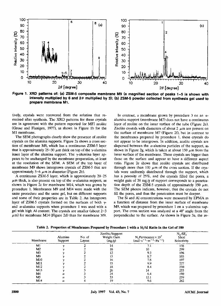
X-ray diffraction of one membrane verified that a zeolite formed. Figure l a shows the XRD pattern of membrane M9 (Table 2), which has similar properties to membranes M1 and M2 and was made on y-alumina with a gel with a Si/Al ratio of 100 using procedure 1. This pattern shows the presence of both ZSMJ (peaks 1-5) and alumina phases (peaks 6-9). Because the ZSMJ layer was only 1.5% of the total weight of the composite membrane, the XRD signals in Figure l a from ZSMJ are small compared to those from the y-alumina support. For membranes M1 and M7, which were made with a gel with a Si/Al ratio of 100 on y- and a-alumina, respec-
AIChE Journal July 1997 Vol. 43, No. 7 1799
90 n 80 K - 70 *g 60 2 50 $ 40 3 30
10
0
x c
- .- c IY 20
n 80 R 70
*g 60 2 50 $ 40 + 30
10
0
x c
9)
- .- +
IY 20
28 [degree] 28 [degree] Figure 1. XRD patterns of: (a) Z S M d composite membrane M 9 (a magnified section of peaks 1-5 is shown with
intensity multiplied by 6 and 28 multiplied by 3); (b) ZSM-5 powder collected from synthesis gel used to prepare membrane M1.
tively, crystals were recovered from the solution that re- mained after synthesis. The XRD patterns for these crystals are in agreement with the pattern reported for MFI zeolite (Grose and Flanigen, 19771, as shown in Figure l b for the M1 membrane.
The SEM photographs clearly show the presence of zeolite crystals on the alumina supports. Figure 2a shows a cross sec- tion of membrane M9, which has a continuous ZSMJ layer that is approximately 25-30 p m thick on top of the y-alumina inner layer of the alumina support. The y-alumina layer ap- pears to be unchanged by the membrane preparation, at least at the resolution of the SEM. A SEM of the top layer of membrane M9 shows intergrown crystals of ZSM-5 that are approximately 5-6 p m in diameter (Figure 2b).
A continuous ZSM-5 layer, which is approximately 20-25 p m thick, is also present on top of the a-alumina support, as shown in Figure 2c for membrane M14, which was grown by procedure 1. Membranes M9 and M14 were made with the same procedure and the same gel, but on different supports and some of their properties are in Table 2. An intergrown layer of ZSMJ crystals formed on the surfaces of both y- and a-alumina supports when procedure 1 was used with a gel with high Al content. The crystals are smaller (about 2-3 pm) for membrane M14 (Figure 2d) than for membrane M9.
In contrast, a membrane grown by procedure 3 on an a- alumina support (membrane M7) does not have a continuous layer of zeolite on the inner surface of the tube (Figure 2e). Zeolite crystals with diameters of about 2 p m are present on the surface of membrane M7 (Figure 2f), but in contrast to the membranes prepared by procedure 1, these crystals do not appear to be intergrown. In addition, zeolite crystals are dispersed between the a-alumina particles of the support, as shown in Figure 2g, which is taken at about 150 pm from the inner surface of the membrane. These crystals are bigger than those on the surface and appear to have a different aspect ratio. Figure 2e shows that zeolite crystals are distributed through more than 100 p m of the cross section. If the crys- tals were uniformly distributed through the support, which has a porosity of 25%, and the crystals filled the pores, a weight gain of 38 mg/g of support corresponds to a penetra- tion depth of the ZSMJ crystals of approximately 350 pm. The SEM photos indicate, however, that the crystals do not fill the pores, and thus the penetration must be deeper.
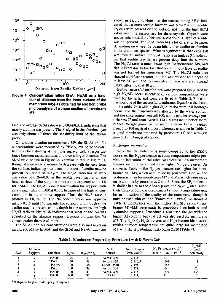
The Si and Al concentrations were measured by EPMA as a function of distance from the inner surface of membrane M9, which was prepared by procedure 1 on a y-alumina sup- port. The cross section was analyzed at a 40" angle from the perpendicular to the surface. As shown in Figure 3a, the av-
Table 2. Properties of Membranes Prepared by Procedure 1 with a Si/AI Ratio in the Gel of 100
Alumina No. of Weight Gain N,Permeance x lo7 Ideal Membrane Support Layers (mug) (mole s- '- m- - Pa- ') Selectivity
M1 Y 2 14 7.1 138 M2 Y 2 16 10 299
Zeolite/Support N,/SF6
M3 M9 M10 M11 M12 M13 M4 M5 M14
12 15 16 15 18 26 24 33 19
9.3 8.7 7.8 9.9 8.4
14 6.4
12.1 9.6
196 103 197 227 230 253 190 259 262
July 1997 Vol. 43, No. 7 AIChE Journal 1800
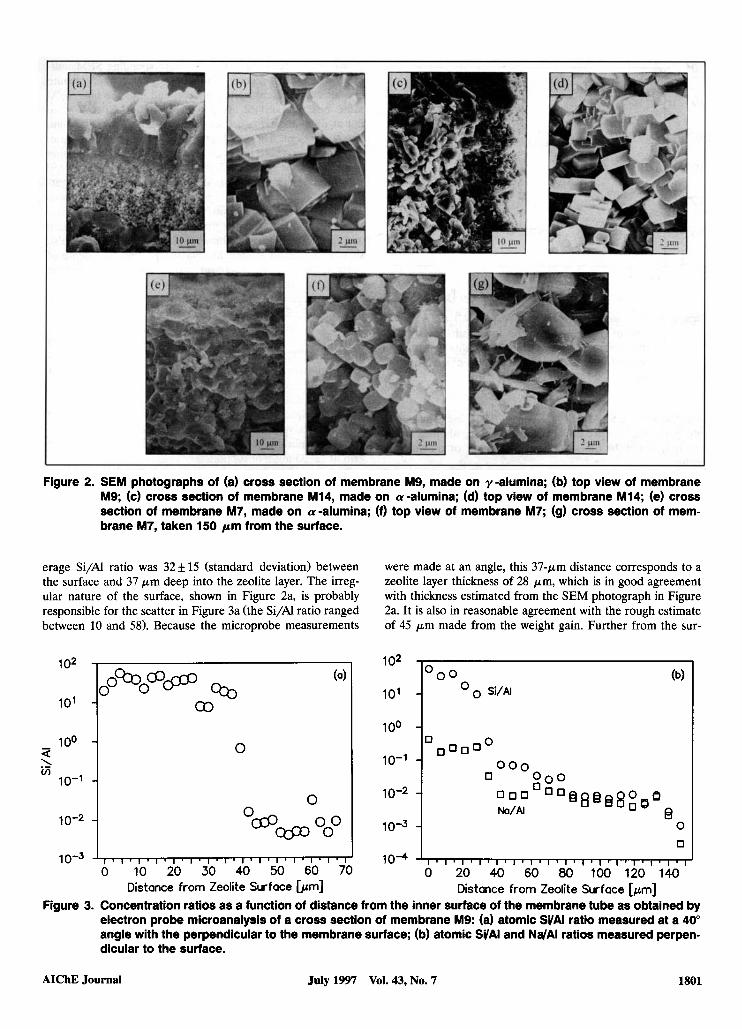
Figure 2. SEM photographs of (a) cross section of membrane M9, made on y-alumina; (b) top view of membrane M9; (c) cross section of membrane M14, made on a-alumina; (d) top view of membrane M14; (e) cross section of membrane M7, made on a-alumina; (f) top view of membrane M7; (9) cross section of mem- brane M7, taken 150 pm from the surface.
10-3
erage Si/AI ratio was 32f 15 (standard deviation) between the surface and 37 p m deep into the zeolite layer. The irreg- ular nature of the surface, shown in Figure 2a, is probably responsible for the scatter in Figure 3a (the Si/Al ratio ranged between 10 and 58). Because the microprobe measurements
~ ~ l ~ l . l . l ~ l . l ~ l . l ~ l ~ l ~ l ~ l ~ l ~ ~
were made at an angle, this 37-pm distance corresponds to a zeolite layer thickness of 28 pm, which is in good agreement with thickness estimated from the SEM photograph in Figure 2a. It is also in reasonable agreement with the rough estimate of 45 p m made from the weight gain. Further from the sur-
102
10'
100
lo-'
10-2
a h v)
0 100 -I
0 10-2 1 10-3 -
0 10-4 I I . I - 1 . 1 I I . , ' I I " I I I I I . 1 I I I I I I
0 20 40 60 80 100 120 140 Distance from Zeolite Surface [pm]
Figure 3. Concentration ratios as a function of distance from the inner surface of the membrane tube as obtained by electron probe microanalysis of a cross section of membrane M9: (a) atomic SVAl ratio measured at a 40" angle with the perpendicular to the membrane surface; (b) atomic SVAl and NdAI ratios measured perpen- dicular to the surface.
AIChE Journal July 1997 Vol. 43, No. 7 1801
1 00
lo-'
10-2
10-3
I 0 I
O o o
O O O O1
10-4 I' 0 100 200
Distance from Zeolite Surface [pm]
Figure 4. Concentration ratios (SVAI, NdAl) as a func- tion of distance from the inner surface of the membrane tube as obtained by electron probe microanalysis of a cross section of membrane M7.
face, the average Si/Al ratio was 0.008 kO.001, indicating that mostly alumina was present. The Si signal in the alumina layer was only about 10 times the sensitivity limit of the micro- probe.
On another location on membrane M9, the Si, Al, and Na concentrations were measured by EPMA, but perpendicular to the surface starting at the inner surface, with a larger dis- tance between measurements, and over a larger distance. The Si/Al ratio, shown in Figure 3b is similar to that in Figure 3a, though it appears to continue to decrease with distance from the surface, indicating that a small amount of zeolite may be present to a depth of 140 pm. The Na/Al ratio has an aver- age value of 0.26&0.07 in the zeolite layer that is on the inner surface of the support; this ratio is expected to be 1.0 for ZSMJ. The Na/Al is much lower within the support, with an average value of 0.006 + 0.001, because of the high Al con- centration in the alumina support. Thus, the Na/Si ratio is plotted in Figure 3b. The Na concentration was approxi- mately 0.5% until 140 p m into the support, and though some zeolite may be present to this depth in the support, the high Na/Si ratio in Figure 3b indicates that most of the Na was adsorbed on the alumina support. Beyond 140 pm, the Na concentration decreased more.
The Si, Al, and Na concentrations were also measured on membrane M7 by EPMA, and the Si/Al and Na/' ratios are
shown in Figure 4. Note that the corresponding SEM indi- cated that a cross-section location was picked where zeolite crystals were present on the surface, and thus the high Si/Al ratios near the surface are for these crystals. Crystals were not at other locations because a continuous layer of zeolite was not present. The Si/N ratio has a lot of scatter because, depending on where the beam hits, either zeolite or alumina is the dominant species. What is significant is that even 150 p m from the surface, the Si/AI ratio is as high as 0.4, indicat- ing that zeolite crystals are present deep into the support. The Na/Al ratio is much lower than for membrane M9, and this is likely due to the fact that a continuous layer of zeolite was not formed for membrane M7. The Na/' ratio also showed significant scatter, but Na was present to a depth of at least 200 pm, and its concentration was scattered around 0.03% after the first 40 pm.
Before successful membranes were prepared (as judged by high N,/SF, ideal selectivities), various compositions were tried for the gels, and some are listed in Table 3. For com- parison, one of the successful membranes (Run 5 ) is also listed in this table. Gels with higher Si/' ratios were less homoge- neous, and their viscosity was affected by the water content and the silica source. Aerosil300, with a smaller average par- ticle size (7 nm) than Aerosil 130 (16 nm) made better mem- branes. Weight gains for the membranes in Table 3 ranged from 7 to 100 mg/g of support, whereas, as shown in Table 2, a good membrane prepared by procedure (1) had a weight gain of 12-33 mg/g of support.
Single-gas permeation Since the N, molecule is small compared to the ZSMJ
pore size, the N, permeance at room temperature might pro- vide an indication of the effective thickness of a membrane; thinner membranes should have higher N, perrneances. As shown in Table 4, the N, permeances are higher for mem- branes Ml-M5, which were made by procedure 1 on a- and y-alumina, than for membranes M7 and M8, which were made on a-alumina by procedures 2 and 3. Since the SF, molecule is similar in size to the ZSMJ pores, the N,/SF6 ideal selec- tivity (ratio of pure-gas permeances) at room temperature may be an indication of the quality of the membrane, though it must be used with caution (Funke et al., 1997a). As shown in Table 4, membranes with the highest N2/SF6 ratios (mem- branes M1-M5) were made by procedure 1 on both a- and y-alumina supports. Procedure 1 also used the gel with the higher Al content, but that gel was also used for membrane M7. The N,/SF6, H,/n-butane, and H,/i-butane ideal selec- tivities at room temperature are quite large for membrane M1, with the H,/i-butane ratio being 2,820 (Table 4).
Table 3. Membranes Prepared by Procedure 1 with Different Gels
N,/SFf, Alumina SiO, NO. of Layers N, Permeance X lo7 Ideal
Run Support Template Si/Al H,O/SiO, Source (Wt. Gain)* (mol. s- '.m- '.Pa- ' ) Selectivity 1 Y TPAOH 25 47 Aerosil300 2 (7) 63 2 2 (I TPABr 50 38 Aerosil 130 3 (101) 0.04 2 3 (I TPABr 100 38 Ludox HS40 2 (9) 0.7 2 4 Y TPABr 100 38 Aerosil 130 7 (31) 66 20 5 Y TPAOH 100 47 Aerosil300 2 (15) 5.9 138 6 Y TPAOH 600 95 TEOS 5 (14) 11 3
*Milligrams (mg) of zeolite per g of support.
1802 July 1997 Vol. 43, No. 7 AIChE Journal
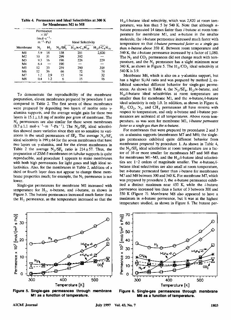
Table 4. Permeances and Ideal Selectivities at 300 K for Membranes M1 to MS
Permeance
(mol. s-' * m -'.Pa) Ideal Selectivitv
x lo7
= 70 - a v) 60- 0
Membrane
P
M1 M2 M3 M4 M5 M6 M7 M8
N € - 50- 'I U 40-
2 30- b
X
8 20- C
10: i a n ,
N? Hz _ _ ~ 5.9 18
10 31 9.3 16 6.4 -
12 33 12 36 1.2 2.9 0.4 1.2
138 299 196 190 259 66 15 6
20 1 392 228
290 72 14 15
-
2,820
229
318 74 32 16
-
-
To demonstrate the reproducibility of the membrane preparation, eleven membranes prepared by procedure 1 are compared in Table 2. The first seven of these membranes were prepared by depositing two layers of zeolite onto y- alumina supports, and the average weight gain for these two layers is 15.1 f 1.8 mg of zeolite per gram of membrane. The N, permeances are also similar for these seven membranes (8.7f 1.1 mol.~C'.m-~.Pa- ') . The N,/SF, ideal selectivi- ties showed more variation since they are so sensitive to vari- ations in the small permeances of SF,. The average N,/SF, ideal selectivity is 199 f 64 for the seven membranes that have two layers on y-alumina, and for the eleven membranes in Table 2 the average N,/SF, ratio is 214It57. Thus, the preparation of ZSM-5 membranes on tubular supports is quite reproducible, and procedure 1 appears to make membranes with both high permeances for light gases and high ideal se- lectivities. Also, for the membranes in Table 2, addition of a third or fourth layer does not appear to change these mem- brane properties much; for example, the N, permeance is not lower.
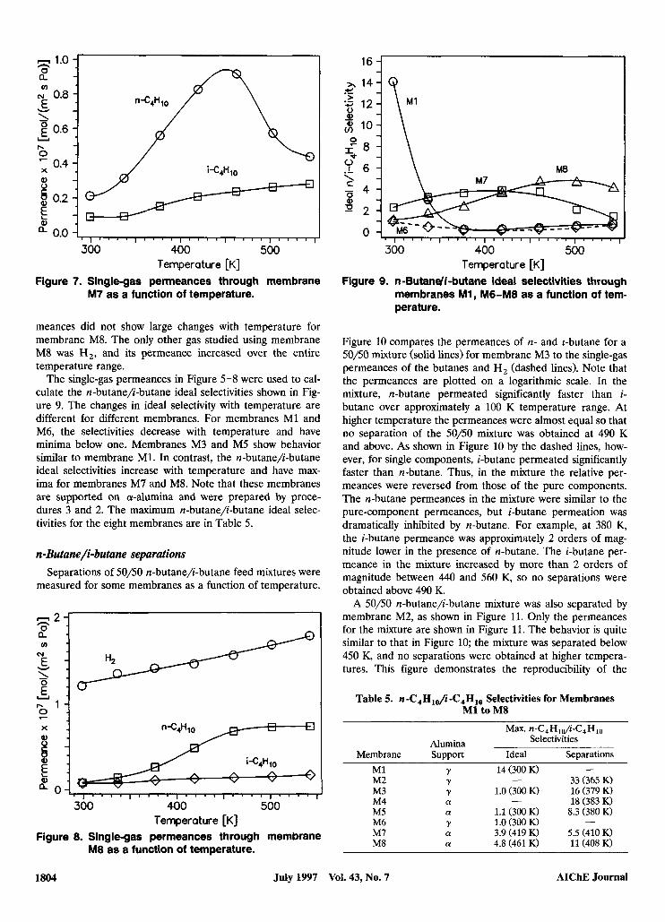
Single-gas permeances for membrane M1 increased with temperature for H,, n-butane, and i-butane, as shown in Figure 5. The butane permeances increased much faster than the H, permeance, as the temperature increased so that the
= a v) 30 € 'I
0
N
W
Y 2 20 b
2 8 10 X
C 0 Q)
E a 0
1 I
300 400 500
Figure 5. Single-gas permeances through membrane Temperature [K]
M1 as a function of temperature.
H,/i-butane ideal selectivity, which was 2,820 at room tem- perature, was less than 5 by 540 K. Note that although n- butane permeated 14 times faster than i-butane at room tem- perature for membrane M1, and n-butane in the smaller molecule, the i-butane permeance increased much faster with temperature so that i-butane permeated faster as a single gas than n-butane above 350 K. Between room temperature and 540 K, the i-butane permeance increased by a factor of 1,080. The N, and CO, permeances did not change much with tem- perature, and the N, permeance has a slight minimum near 340 K, as shown in Figure 5. The H,/CO, ideal selectivity at 540 K is 3.9.
Membrane M6, which is also on a y-alumina support, but has a higher Si/Al ratio and was prepared by method 2, ex- hibited somewhat different behavior for single-gas perme- ances. As shown in Table 4, the N,/SF,, H,/n-butane, and H ,/i-butane ideal selectivities at room temperature are smaller than for membrane M1, and the n-butane/i-butane ideal selectivity is only 1.0. In addition, as shown in Figure 6, H,, CO,, N,, and CH, permeances all have minima with respect to temperature, and only n-butane and i-butane per- meances are activated at all temperatures. Above room tem- perature, as was seen for membrane M1, i-butane permeates faster as a single gas than the n-butane.
For membranes that were prepared by procedures 2 and 3 on a-alumina supports (membranes M7 and M8), the single- gas permeances exhibited quite different behavior from membranes prepared by procedure 1. As shown in Table 4, the N,/SF, ideal selectivities at room temperature are a fac- tor of 10 or more smaller for membranes M7 and M8 than for membranes Ml-M5, and the H,/i-butane ideal selectivi- ties are 1-2 orders of magnitude smaller. The n-butane/i- butane ideal selectivities are also small at room temperature, but n-butane permeated faster than i-butane for membranes M7 and M8 between 300 and 540 K. For membrane M7, which was prepared by procedure 3, the n-butane permeance exhib- ited a distinct maximum near 450 K, while the i-butane permeance increased less than a factor of 3 between 300 and 550 K (Figure 7). Membrane M8 also appeared to have a maximum in n-butane permeance, but it was at the highest temperature studied, as shown in Figure 8. The butane per-
v , I ' " ' I ' " ' I ' " ' I ' " ' I " ' '
300 400 500
Figure 6. Single-gas permeances through membrane Temperature [K]
M6 as a function of temperature.
AIChE Journal July 1997 Vol. 43, No. 7 1803
1.0 1 - 0. a N 0.8 E 'I
v)
W
0.6
' 0.4 U
l-
X Q)
2 8 0.2
a 0.0 i
300 400 500 Temperature [K]
Figure 7. Single-gas permeances through membrane M7 as a function of temperature.
meances did not show large changes with temperature for membrane M8. The only other gas studied using membrane M8 was H,, and its permeance increased over the entire temperature range.
The single-gas permeances in Figure 5-8 were used to cal- culate the n-butane/-butane ideal selectivities shown in Fig- ure 9. The changes in ideal selectivity with temperature are different for different membranes. For membranes M1 and M6, the selectivities decrease with temperature and have minima below one. Membranes M3 and M5 show behavior similar to membrane M1. In contrast, the n-butane/i-butane ideal selectivities increase with temperature and have max- ima for membranes M7 and M8. Note that these membranes are supported on a-alumina and were prepared by proce- dures 3 and 2. The maximum n-butane/i-butane ideal selec- tivities for the eight membranes are in Table 5.
n-Butane/i-butane separations Separations of 50/50 n-butane)-butane feed mixtures were
measured for some membranes as a function of temperature.
300 400 500
Figure 8. Single-gas permeances through membrane Temperature [K]
M8 as a function of temperature.
5 \ .- Y 6 - l \ M8
n
300 400 500 Temperature [K]
Figure 9. n-Butandi-butane ideal selectivities through membranes Mi, M6-M8 as a function of tem- perature.
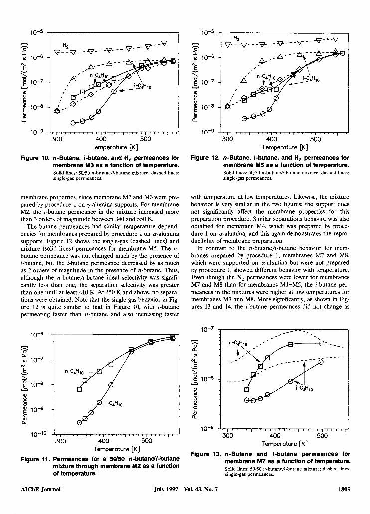
Figure 10 compares the permeances of n- and r-butane for a 50/50 mixture (solid lines) for membrane M3 to the single-gas permeances of the butanes and H, (dashed lines). Note that the permeances are plotted on a logarithmic scale. In the mixture, n-butane permeated significantly faster than i- butane over approximately a 100 K temperature range. At higher temperature the permeances were almost equal so that no separation of the 50/50 mixture was obtained at 490 K and above. As shown in Figure 10 by the dashed lines, how- ever, for single components, i-butane permeated significantly faster than n-butane. Thus, in the mixture the relative per- meances were reversed from those of the pure components. The n-butane permeances in the mixture were similar to the pure-component permeances, but i-butane permeation was dramatically inhibited by n-butane. For example, at 380 K, the i-butane permeance was approximately 2 orders of mag- nitude lower in the presence of n-butane. The i-butane per- meance in the mixture increased by more than 2 orders of magnitude between 440 and 560 K, so no separations were obtained above 490 K.
A 50/50 n-butane/i-butane mixture was also separated by membrane M2, as shown in Figure 11. Only the permeances for the mixture are shown in Figure 11. The behavior is quite similar to that in Figure 10; the mixture was separated below 450 K, and no separations were obtained at higher tempera- tures. This figure demonstrates the reproducibility of the
Table 5. n - C 4 H l ~ i - C 4 H ~ ~ Selectivities for Membranes M1 to MS
M a . n-C,H,p/ii-C,H,o Selectivities Alumina
Membrane Support Ideal Separations
- 33 (365 K) M1 Y M2 Y
16 (379 K) - 18 (383 K)
M3 Y M4 ff M5 (I 1.1 (300 K) 8.3 (380 K) M6 Y M7 ff 3.9 (419 K) 5.5 (410 K) M8 a 4.8 (461 K) 11 (408 K)
14 (300 K) -
1.0 (300 K)
1 .O (300 K) -
1804 July 1997 Vol. 43, No. 7 AIChE Journal
10-5 I I n n 0 a 0 10-6
N € ‘I W
f 10-7 Y
Q, 0 C 0
10-8 b a
300 400 500 Temperature [K]
Figure 10. n-Butane, i-butane, and H, permeances for membrane M3 as a function of temperature. Solid lines: 50/50 n-butane/i-butane mixture; dashed lines: single-gas permeances.
membrane properties, since membrane M2 and M3 were pre- pared by procedure 1 on y-alumina supports. For membrane M2, the i-butane permeance in the mixture increased more than 3 orders of magnitude between 340 and 550 K.
The butane permeances had similar temperature depend- encies for membranes prepared by procedure 1 on a-alumina supports. Figure 12 shows the single-gas (dashed lines) and mixture (solid lines) permeances for membrane M5. The n- butane permeance was not changed much by the presence of i-butane, but the i-butane permeance decreased by as much as 2 orders of magnitude in the presence of n-butane. Thus, although the n-butane/i-butane ideal selectivity was signifi- cantly less than one, the separation selectivity was greater than one until at least 410 K. At 450 K and above, no separa- tions were obtained. Note that the single-gas behavior in Fig- ure 12 is quite similar to that in Figure 10, with i-butane permeating faster than n-butane and also increasing faster
10‘6
n 0 a h
v) 10-7
€ ‘I.
hl
W
g 10” Y
10-10 -1 300 400 500
Temperature [K]
Figure 11. Permeances for a 5U50 n-butandi-butane mixture through membrane M2 as a function of temperature.
10-5 I
n n
2 v) 10-6
cy
W E ‘I
10-7 Y
Q, Y b 2 10“ L
b a
300 400 500 Temperature [K]
Figure 12. ndutane, i-butane, and H, permeances for membrane M5 as a function of temperature. Solid lines: Sop0 n-butane/i-butane mixture; dashed lines: single-gas permeances.
with temperature at low temperatures. Likewise, the mixture behavior is very similar in the two figures; the support does not significantly affect the membrane properties for this preparation procedure. Similar separations behavior was also obtained for membrane M4, which was prepared by proce- dure 1 on a-alumina, and this again demonstrates the repro- ducibility of membrane preparation.
In contrast to the n-butane/i-butane behavior for mem- branes prepared by procedure 1, membranes M7 and M8, which were supported on a-alumina but were not prepared by procedure 1, showed different behavior with temperature. Even though the N, permeances were lower for membranes M7 and M8 than for membranes M1-M5, the i-butane per- meances in the mixtures were higher at low temperatures for membranes M7 and M8. More significantly, as shown in Fig- ures 13 and 14, the i-butane permeances did not change as
n n 0
v)
a N E v
10-7
1 g 10-8 Y
10-9 300 400 500
Temperature [K]
Figure 13. n-Butane and i-butane permeances for membrane M7 as a function of temperature. Solid lines: 50/50 n-butane/i-butane mixture; dashed lines: single-gas permeances.
AIChE Journal July 1997 Vol. 43, No. 7 1805
10-7 1
fn N
W E '1 g 10-8 :
i
Y
9) 0 C 0 9)
9) a
10-9 I 1 300 400 500
Temperature [K]
Figure 14. n-Butane and i-butane permeances for membrane M8 as a function of temperature. Solid lines: 50/50 n-butane/i-butane mixture; dashed lines: single-gas permeances.
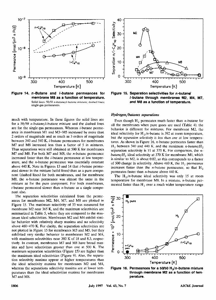
much with temperature. In these figures the solid lines are for a 50/50 n-butane/i-butane mixture and the dashed lines are for the single-gas permeances. Whereas i-butane perme- ance in membranes M1 and M3-M5 increased by more than 2 orders of magnitude and as much as 3 orders of magnitude between 340 and 540 K, i-butane permeances for membranes M7 and M8 increased less than a factor of 5 in mixtures. Thus separations were still obtained at 500 K for membranes M7 and M8. For both M7 and M8, the n-butane permeance increased faster than the i-butane permeance at low temper- ature, and the n-butane permeance was essentially constant above 440 K. Note in Figures 13 and 14 that i-butane perme- ated slower in the mixture (solid lines) than as a pure compo- nent (dashed lines) for both membranes, and for membrane M8, the n-butane permeance was almost the same in the mixture as for the pure component. For both membranes, i-butane permeated slower than n-butane as a single compo- nent also.
The separation selectivities calculated from the perme- ances for membranes M2, M4, M7, and M8 are plotted in Figure 15. The maximum selectivity of 33 was measured for membrane M2 near 365 K, and the maximum selectivities are summarized in Table 5, where they are compared to the max- imum ideal selectivities. Membranes M2 and M4 exhibit simi- lar behavior with relatively sharp maxima and no selectivity above 460-470 K. For clarity, the separation selectivities are not plotted in Figure 15 for membranes M3 and M5, but they exhibited very similar behavior to membranes M2 and M4, with maximum selectivities near 380 K of 18 and 8.3, respec- tively. In contrast, membranes M7 and M8 have broad max- ima and have selectivities greater than one at 500 K. The maximum separation selectivities (Figure 15) are higher than the maximum ideal selectivities (Figure 9). Also, the separa- tion selectivity maxima appear at higher temperatures than the ideal selectivity maxima for membranes M2 and M4, whereas the separations selectivity maxima are at lower tem- peratures than the ideal selectivities maxima for membranes M7 and M8.
> .- v) 3301 A
p
300 400 500 Temperature [K]
Figure 15. Separation selectivities for n-butand i-butane through membranes M2, M4, M7, and M8 as a function of temperature.
Hydrogen/butanes separations Even though H, permeates much faster than n-butane for
all the membranes when pure gases are used (Table 4), the behavior is different for mixtures. For membrane M2, the ideal selectivity for H,/n-butane is 392 at room temperature, but the separation selectivity is less than one at low tempera- tures. As shown in Figure 16, n-butane permeates faster than H, between 340 and 440 K, and the maximum n-butane/H, separation selectivity is 11 at 370 K. For comparison, the n- butane/H, ideal selectivity at 370 K for membrane M1, which is similar to M2, is about 0.02, so this corresponds to a factor of 500 change in selectivity. Above 410 K, the H, permeance increases faster than the n-butane permeance, so that H, permeates faster than n-butane above 440 K.
The H,/n-butane ideal selectivity was only 15 at room temperature for membrane M8. In a mixture, n-butane per- meated faster than H, over a much wider temperature range
7 30 a
E
E
9
v)
N
W
2 20 Y
b
300 400 500 Temperature [K]
Figure 16. Permeances for a 5 W O HJn-butane mixture through membrane M2 as a function of tem- perature.
1806 July 1997 Vol. 43, No. 7 AIChE Journal
nC4H10 c 300 400 500
Temperature [K]
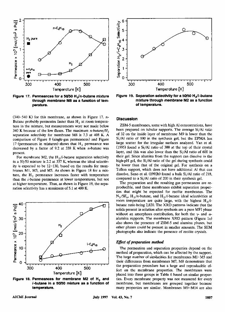
Figure 17. Permeances for a 5U50 Hdn-butane mixture through membrane M8 as a function of tem- perature.
(340-540 K) for this membrane, as shown in Figure 17. n- Butane probably permeates faster than H, at room tempera- ture in the mixture, but measurements were not made below 340 K because of the low fluxes. The maximum n-butane/H, separation selectivity for membrane M8 is 7.3 at 408 K. A comparison of Figure 8 (single-gas permeances) and Figure 17 (permeances in mixtures) shows that H, permeance was decreased by a factor of 9.2 at 338 K when n-butane was present.
For membrane M2, the H,/i-butane separation selectivity in a 50/50 mixture is 2.2 at 337 K, whereas the ideal selectiv- ity is expected to be 12-130, based on the results for mem- branes M1, M3, and M5. As shown in Figure 18 for a mix- ture, the H, permeance increases faster with temperature than the i-butane permeance at lower temperatures, but not at higher temperature. Thus, as shown in Figure 19, the sepa- ration selectivity has a maximum of 5.1 at 480 K.
n 40 n 0 a
E z301 20 / I
300 400 500 Temperature [K]
Figure 18. Permeances for membrane M2 of H, and i-butane in a 5U50 mixture as a function of temperature.
Temperature [K]
Figure 19. Separation selectivity for a 5U50 Hdi-butane mixture through membrane M2 as a function of temperature.
Discussion ZSMJ membranes, some with high Al concentrations, have
been prepared on tubular supports. The average Si/Al ratio of 32 on the inside layer of membrane M9 is lower than the Si/Al ratio of 100 in the synthesis gel, but the EPMA has large scatter for the irregular surfaces analyzed. Yan et al. (1995) found a Si/Al ratio of 300 at the top of their crystal layer, and this was also lower than the Si/Al ratio of 600 in their gel. Since alumina from the support can dissolve in the high-pH gel, the Si/Al ratio of the gel during synthesis could be lower than that of the original gel. For synthesis on a Teflon support, which does not have additional Al that can dissolve, Sano et al. (1992b) found a bulk Si/Al ratio of 218, compared to a Si/Al ratio of 200 in their synthesis gel.
The preparation and the resulting gas permeances are re- producible, and these membranes exhibit separation proper- ties that might be expected for zeolite membranes. The N,/SF,, H,/n-butane, and H,/i-butane ideal selectivities at room temperature are quite large, with the highest H2/i- butane ratio being 2,820. The XRD patterns indicate that the solids present in solution after synthesis are a pure MFI phase without an amorphous contribution, for both the y- and a- alumina supports. The membrane XRD pattern (Figure la) also shows the presence of ZSMJ and alumina phases, but other phases could be present in smaller amounts. The SEM photographs also indicate the presence of zeolite crystals.
Efect of preparation method The permeation and separation properties depend on the
method of preparation, which can be affected by the support. The large number of similarities for membranes M1-M5 and their differences from membranes M7, M8 demonstrate that the preparation procedure has a large and reproducible ef- fect on the membrane properties. The membranes were placed into three groups in Table 6 based on similar proper- ties. Every membrane property was not measured for every membrane, but membranes are grouped together because many properties are similar. Membranes M9-Ml4 are also
AIChE Journal July 1997 Vol. 43, No. 7 1807
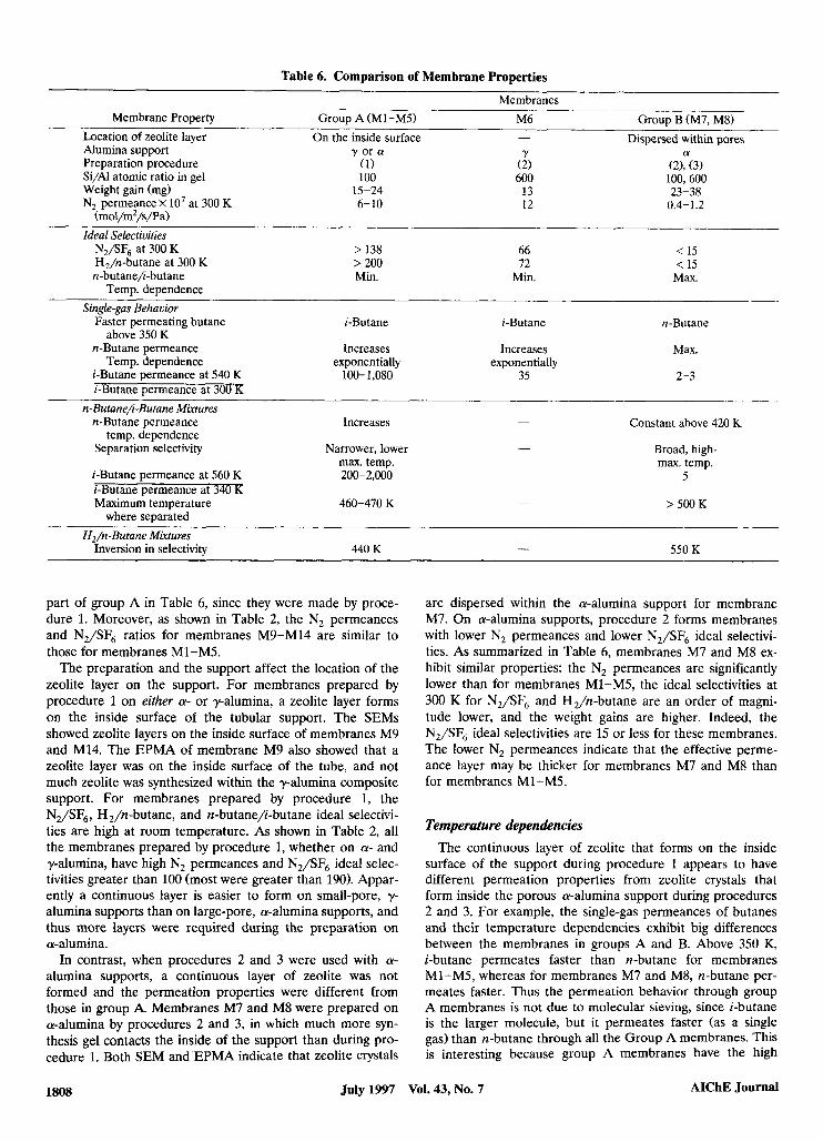
Table 6. Comparison of Membrane Properties
Membranes ___._
Membrane Property Group A (Ml-M5) M6 Group B (M7, M8)- Dispersed within pores Location of zeolite layer On the inside surface -
Alumina support y or a Y a Preparation procedure (1) (2) (2), (3) Si/Al atomic ratio in gel 100 600 100,600 Weight gain (mg) 15-24 13 23-38 N, permeance x lo7 at 300 K 6-10 12 0.4-1.2
(mol/mz/s/Pa) Ideal Selectivities
N,/SF, at 300 K > 138 66 < 15 H,/n-butane at 300 K > 200 72 < 15 n-butane/i-butane Min. Min. Max.
Temp. dependence Single-gas Behavior
Faster permeating butane i-Butane i-Butane n-Butane
n-Butane permeance Increases Increases Max. above 350 K
Temp. dependence exponentially exponentially i-Butane permeance at 540 K 100- 1,080 35 2-3 i-Butane permeance at 300 K
n-ButanekButane Miwtures
temp. dependence Constant above 420 K n-Butane permeance Increases -
Separation selectivity Narrower, lower - Broad, high- m a . temp. m a . temp.
i-Butane permeance at 560 K 200-2,000 5
Maximum temperature 460-470 K - i-Butane permeance at 340 K
> 500 K where separated
H,/n-Butane Miwtures 550 K - Inversion in selectivity 440 K
part of group A in Table 6, since they were made by proce- dure 1. Moreover, as shown in Table 2, the N, permeances and N,/SF6 ratios for membranes M9-Ml4 are similar to those for membranes M1-M5.
The preparation and the support affect the location of the zeolite layer on the support. For membranes prepared by procedure 1 on either a- or y-alumina, a zeolite layer forms on the inside surface of the tubular support. The SEMs showed zeolite layers on the inside surface of membranes M9 and M14. The EPMA of membrane M9 also showed that a zeolite layer was on the inside surface of the tube, and not much zeolite was synthesized within the y-alumina composite support. For membranes prepared by procedure 1, the N2/SF6, H,/n-butane, and n-butane/i-butane ideal selectivi- ties are high at room temperature. As shown in Table 2, all the membranes prepared by procedure 1, whether on a- and y-alumina, have high N, permeances and N,/SF6 ideal selec- tivities greater than 100 (most were greater than 190). Appar- ently a continuous layer is easier to form on small-pore, y- alumina supports than on large-pore, a-alumina supports, and thus more layers were required during the preparation on a-alumina.
In contrast, when procedures 2 and 3 were used with a- alumina supports, a continuous layer of zeolite was not formed and the permeation properties were different from those in group A. Membranes M7 and M8 were prepared on a-alumina by procedures 2 and 3, in which much more syn- thesis gel contacts the inside of the support than during pro- cedure 1. Both SEM and EPMA indicate that zeolite crystals
are dispersed within the a-alumina support for membrane M7. On a-alumina supports, procedure 2 forms membranes with lower N, permeances and lower N,/SF6 ideal selectivi- ties. As summarized in Table 6, membranes M7 and M8 ex- hibit similar properties: the N, permeances are significantly lower than for membranes M1-M5, the ideal selectivities at 300 K for N,/SF, and H,/n-butane are an order of magni- tude lower, and the weight gains are higher. Indeed, the N,/SF6 ideal selectivities are 15 or less for these membranes. The lower N, permeances indicate that the effective perme- ance layer may be thicker for membranes M7 and M8 than for membranes M1-M5.
Temperature dependencies The continuous layer of zeolite that forms on the inside
surface of the support during procedure 1 appears to have different permeation properties from zeolite crystals that form inside the porous a-alumina support during procedures 2 and 3. For example, the single-gas permeances of butanes and their temperature dependencies exhibit big differences between the membranes in groups A and B. Above 350 K, i-butane permeates faster than n-butane for membranes M1-M5, whereas for membranes M7 and M8, n-butane per- meates faster. Thus the permeation behavior through group A membranes is not due to molecular sieving, since i-butane is the larger molecule, but it permeates faster (as a single gas) than n-butane through all the Group A membranes. This is interesting because group A membranes have the high
July 1997 Vol. 43, No. 7 AIChE Journal 1808
N,/SF6 ideal selectivities at room temperature. In contrast, group B membranes exhibit n-butane/i-butane behavior that
n-butane/i-butane ideal selectivities are similar for mem- branes M6 and M3 and M5, with i-butane permeating faster
is consistent with molecular sieving, but their N,/SF6 ideal selectivities are low.
Each group of membranes has permeances that exhibit dramatically different dependencies on temperatye, and thus different preparation procedures and the resulting differ- ences in the zeolite layer have a dramatic influence on the permeation properties. The ratio of the i-butane permeance at 540 K to that at 300 K is approximately 100 for membrane M3 and M5 and greater than 1,000 for membrane M1, but this ratio is only 2-3 for membranes M7 and M8. In addition, the n-butane/i-butane ideal selectivities decrease with tem- perature and have minima for membrane Ml-M5, but ideal selectivities increase with temperature and have maxima for membranes M7 and M8. The temperature dependence of the n-butane permeance is also different for the two groups of membranes; maxima in permeances are seen for the group B membranes.
As summarized in Table 6, the behavior of mixtures is also different for the two groups of membranes. As shown in Fig- ure 15, the n-butane/-butane separation selectivities for membranes M2 and M4 have maxima at low temperature and the maxima are relatively sharp. Similar separation selectivi- ties and maxima at low temperatures were obtained for mem- branes M3 and M5. In contrast, membranes M7 and M8 have broader maxima and at higher temperatures (Figure 15). The change in i-butane permeance with temperature, in mixtures with n-butane, is much larger for the membranes in group A, as shown in Table 6. In addition, the temperature where the n-butane/H , separation selectivity drops below one differs by more than 100 K for these two groups of membranes.
Bai et al. (1995) observed permeance behavior for a sili- calite membrane, supported on y-alumina and prepared by procedure 1, that was similar to membranes Ml-M5. At room temperature, the N,/SF,, H,/n-butane, and n-butane/i- butane ideal selectivities were high, and above 350 K, i-butane
than n-butane above 350 K. The change in i-butane perme- ance with temperature is also between the changes measured for groups A and B. Although all the permeation properties are not the same, the large number of similarities for mem- brane M6 and group A indicates that the zeolite layer of membrane M6 is probably mostly on the inner surface of the support. Note that membranes M6 and M8 were prepared by the same procedure and with the same Si/Al ratio in the gel, but they are on different supports and exhibit significantly different behavior. The differences in permeation properties do not correlate with the Si/Al ratio in the gel; membranes M7 and M8 have different Si/Al ratios in their gels but simi- lar permeation properties. As shown in Table 2 for procedure 1, higher weight gains
were obtained when three layers were synthesized instead of two, but the weight gain does not correlate with N, perme- ance. Membranes M4 and M5, which have three layers on a-alumina, have higher weight gains than membranes M1-M3, which have two layers on y-alumina. The support does not appear to be important for procedure 1, since mem- brane M13, which has three layers on y-alumina, has a bigger weight gain than membrane M12, which has two layers on y-alumina. Similarly, membranes M4 and M13 are on differ- ent supports, but both had three layers and they have similar weight gains. For procedure 2 the support may make a differ- ence since membrane M8 on a-alumina had a higher weight gain than membrane M6 on y-alumina, and both have two layers. Kusakabe et al. (1996) reported that the zeolite mem- brane thickness increased and the permeance decreased with an increase in the gel volume. Procedures 2 and 3 used a starting gel volume that was 5-6 times larger than in proce- dure 1, but no correlation was seen between gel volume and weight gain.
permeated faster than n-butane. The H, permeance of 34 X Parallel pathways for permeation lo-’ mol/(m2.s.Pa) for the silicalite membrane was also al- most the Same as the H Z permeances for membranes (Table 2). The n-butane/i-butane ideal selectivity also de- creased with temperature for the silicalite membrane. SEM showed that the silicalite membrane was formed as a contin- uous layer on the inside surface of the y-alumina support.
The large ideal selectivities for N,/SF6 and H,/butanes indicate that our ZSMJ membranes have few defects. The n-butane/i-butane separation selectivities, though as high as 33, are not as high as those reported in studies, and indicate that our tubular membranes may have trans- port through nonzeolitic pores than some zeolite membranes
Role of the support Although the preparation procedure has a major influence
on the membrane properties, and both supports yielded the same type membrane for procedure 1, the support makes a difference for procedure 2. Membrane M6 is listed in a sepa- rate column in Table 6 because it was prepared by procedure 2, but on a y-alumina support. This membrane has a high N, permeance and lower weight gain, like group A membranes, and i-butane permeates faster than n-butane above 350 K, as it does for group A membranes. The 5-nm-diameter pores of the y-alumina layer apparently are a more effective barrier against the penetration of the synthesis gel than the 200-nm- diameter pores of the a-alumina supports. Membrane M6’s ideal selectivities at room temperature for N,/SF6 and for H,/n-butane are in between those for groups A and B. The
bn flat disis. This transport may be through intercrystalline regions (grain boundaries), but they must have small diame- ters to yield the high selectivities measured. The differences in our ZSM-5 membranes prepared by different methods also implies that all the permeation is not through zeolite crystals. Otherwise, the permeation and separation properties would be expected to be similar for ZSM-5 for both types of prepa- ration, though it is possible that different preparations result in different crystal orientations. Apparently, the amounts of gas permeating through the nonzeolitic pores is different for group A and B membranes.
One possible explanation for the high permeances of small molecules in group A membranes is that the intercrystalline regions are sufficiently small that H, and N, can permeate, but SF, and butanes cannot. For group B membranes, the intercrystalline region may be different because the zeolite crystals are in the a-alumina pores and some of the parallel
AIChE Journal July 1997 Vol. 43, No. 7 1809
pathways are the spaces between the crystals and the alu- mina. If the intercrystalline regions consist of pores smaller than the zeolite pores, and if their sizes increase with tem- perature, then butane permeances would be expected to increase much faster with temperature than the H, perme- ances in group A membranes. This small size increase would allow butanes to fit through these pores, but not significantly increase the N, or H, permeances.
In contrast, permeances do not increase much with tem- perature for group B membranes, perhaps because the inter- crystalline regions are smaller. Thus, the i-butane permeance increased a factor of 100 to 1,000 for group A membranes, whereas the i-butane permeances only increased a factor of 2-3 in group B membranes over the same temperature range. As a result, separation of butane isomers is possible at low temperatures for group A membranes, but the selectivity is lost at a much lower temperature than for group B mem- branes. The presence of these small intercrystalline regions would explain why the high ideal selectivities (N,/SF,, H,/butanes) at room temperature do not necessarily indi- cate the ability to separate butane at elevated temperature. This proposed model does not explain, however, why i-butane permeates faster than n-butane in group A membranes, whereas the reverse is observed for group B membranes.
An alternative explanation for the differences between the two groups is that the group B membranes, which have lower permeances, are thicker. Then, if most of the transport for group B membranes is through intercrystalline regions, the group B membranes have a more tortuous pathway than the thinner group A membranes. That is, transport through a ze- olite is not necessary for a difference in single-gas perme- ances of butanes, and group B membranes separate butanes better at higher temperature because of their more tortuous pathway. Shah et al. (1993) reported that the diffusivities are the same for n-butane and i-butane in single-crystal mem- branes of silicalite, so that a difference in permeances might not be expected in our zeolite membrane. Vroon (1995), how-
ever, observed differences in zeolite crystals, with n-butane permeating faster.
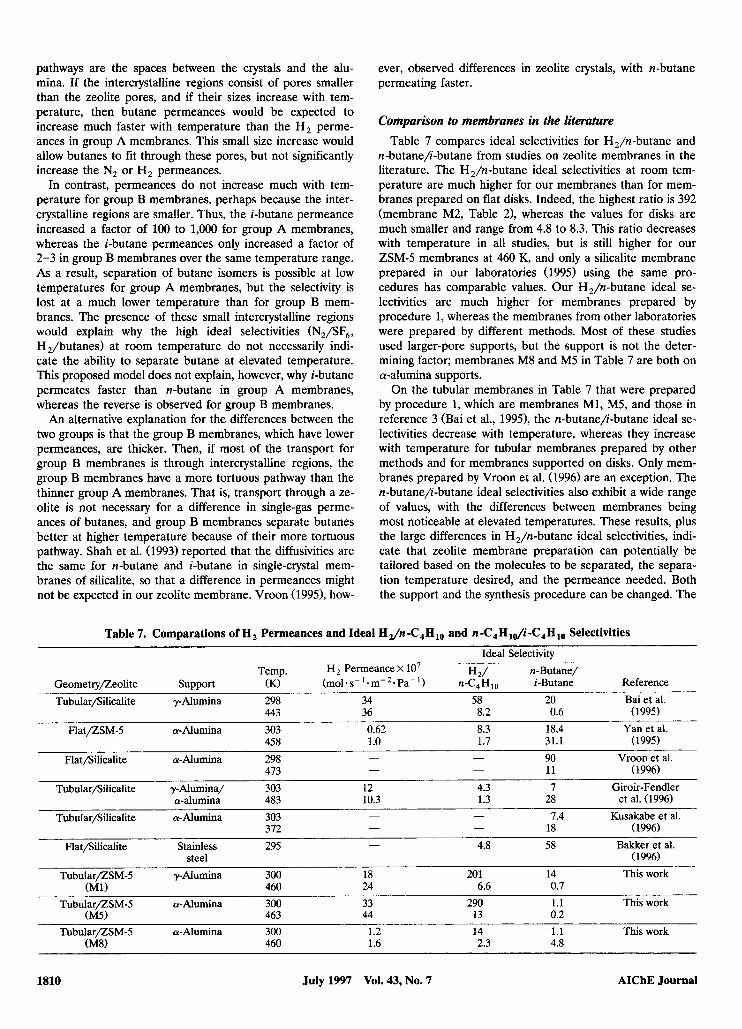
Comparison to membranes in the literature Table 7 compares ideal selectivities for H,/n-butane and
n-butane/i-butane from studies on zeolite membranes in the literature. The H,/n-butane ideal selectivities at room tem- perature are much higher for our membranes than for mem- branes prepared on flat disks. Indeed, the highest ratio is 392 (membrane M2, Table 21, whereas the values for disks are much smaller and range from 4.8 to 8.3. This ratio decreases with temperature in all studies, but is still higher for our ZSMJ membranes at 460 K, and only a silicalite membrane prepared in our laboratories (1995) using the same pro- cedures has comparable values. Our H,/n-butane ideal se- lectivities are much higher for membranes prepared by procedure 1, whereas the membranes from other laboratories were prepared by different methods. Most of these studies used larger-pore supports, but the support is not the deter- mining factor; membranes M8 and M5 in Table 7 are both on a-alumina supports.
On the tubular membranes in Table 7 that were prepared by procedure 1, which are membranes M1, M5, and those in reference 3 (Bai et al., 1995), the n-butane/i-butane ideal se- lectivities decrease with temperature, whereas they increase with temperature for tubular membranes prepared by other methods and for membranes supported on disks. Only mem- branes prepared by Vroon et al. (1996) are an exception. The n-butane/i-butane ideal selectivities also exhibit a wide range of values, with the differences between membranes being most noticeable at elevated temperatures. These results, plus the large differences in H,/n-butane ideal selectivities, indi- cate that zeolite membrane preparation can potentially be tailored based on the molecules to be separated, the separa- tion temperature desired, and the permeance needed. Both the support and the synthesis procedure can be changed. The
Table 7. Comparations of H, Permeances and Ideal Hz/n-C,H,, and n-C4Hl~i -C4Hlo Selectivities Ideal Selectivity
n-Butane/ Reference Geometryfleolite Support (K) (rnol*s-'-m-*-Pa-') n-C,H,, i-Butane
Tubularfiilicalite y-Alumina 298 34 58 20 Bai et al. 443 36 8.2 0.6 (1995)
FlatflSM-5 a-Alumina 303 0.62 8.3 18.4 Yan et al. 458 1.0 1.7 31.1 (1995)
- 11 (1996) Flatfiilicalite a-Alumina 298
473
H 2/ Temp. H, Permeance x lo7
- - 90 Vroon et al. -
Tubularfiilicalite y-Alumina/ 303 12 4.3 I Giroir-Fendler
- - 7.4 Kusakabe et al. - - 18 (1996)
Tubularfiilicalite a-Alumina 303 372
steel ( 1996)
28 et al. (1996) a-alumina 483 10.3 1.3
Flatfiilicalite Stainless 295 - 4.8 58 Bakker et al.
TubularflSM-5 y Alumina 300 18 201 14 This work
TubularflSM-5 a-Alumina 300 33 290 1.1 This work
Tubul~/ZSM-5 a-Alumina 300 1.2 14 1.1 This work
(MI) 460 24 6.6 0.7
(M5) 463 44 13 0.2
(M8) 460 1.6 2.3 4.8
1810 July 1997 Vol. 43, No. 7 AIChE Journal
H, permeances vary by almost 2 orders of magnitude in Table 7, and higher permeance may be more desirable than higher selectivity in some applications. Note that Table 7 contains both silicalite and Z S M J zeolite membranes, but Al may be incorporated into the silicalite membranes prepared on alu- mina supports (Geus et al., 1992) to form Z S M J membranes with higher Si/AI ratios. Only the silicalite membranes pre- pared on stainless-steel supports are unlikely to contain Al.
Membrane M8 was prepared with same gel composition used by Yan et al. (19951, and both membranes are on a- alumina supports, but Yan et al. used a flat support, and thus contact with the gel was done differently. Their best mem- brane had a maximum ideal selectivity for n-butane/i-butane of 31 at 458 K, whereas membrane M8 only had a selectivity of 4.8 at 461 K. The H, permeances and the H,/n-butane ratios are within a factor of 2. Thus, membranes prepared by procedure 2 appear to be closer to those in the literature than membranes prepared by procedure 1.
Temperature dependence of single gases As reported in previous studies on silicalite membranes (Bai
et al., 1995; Bakker et al., 1996), many of the lighter-gas per- meances exhibit minima as a function of temperature, whereas other studies (Giroir-Fendler et al., 1996) observed that N, and H, permeances decrease when the temperature increases. As seen in Figure 5, N, permeance has a minimum for membrane M1, and permeances increase with tempera- ture for all the other gases. For membrane M7, H,, CH,, CO,, and N, all have minima. For both membranes, n-butane permeates faster than i-butane at room temperature, but i- butane permeates faster above about 350 K for membrane M1. This behavior is different from that reported by others (Giroir-Fendler et al., 1996; Vroon et al., 1996; Bakker et al., 1996; Kusakabe et al., 1996; Geus et al., 1992), and is oppo- site to what is expected for a molecular sieving separations. It was also observed on a silicalite membrane prepared by pro- cedure 1 in our laboratory (Bai et al., 1995).
Bakker et al. (1996) observed that n-butane had a maxi- mum permeance at 418 K for silicalite on stainless steel. Giroir-Fendler et al. (1996) and Vroon et al. (1996) also ob- served maxima in n-butane single-gas permeances for sili- calite membranes on a-alumina at 483 and 438 K, respec- tively. Permeance is expected to be proportional to both the concentration of adsorbed hydrocarbon and its diffusion co- efficient (Vroon et al., 1996; Bakker et al., 1996). They ex- plained the butane dependence on temperature as follows. At low temperatures, strong adsorption dominates, the concentration of hydrocarbon is constant, and permeance in- creases with temperature because of the increased mobility of the molecules. Adsorption becomes weaker at higher tem- peratures, however, so that the increase in mobility eventu- ally is compensated by a decrease in occupancy and the per- meance decreases. The maximum in permeance for n-butane was concluded to result because its heat of adsorption ( Q ) is larger than its diffusional activation energy (ED) (Bakker et al., 1996). Similar to these studies, we observed maxima in permeances for n-butane for membranes M7 and M8. Bakker et al. (1996) reported that i-butane permeance always in- creased with increasing temperature over the temperature range studied because the increase in mobility is much larger
than the decrease in occupancy ( E D >> Q). This is the behav- ior observed for our membranes M1, M2, M4, and M6, how- ever, for both n-butane and i-butane.
Comparison of single gases to mixtures As shown in Figures 10 and 12, n-butane effectively blocks
the permeation of i-butane in a mixture for group A mem- branes. Thus, even for group A membranes, for which pure i-butane permeates faster than pure n-butane, n-butane per- meates faster in a mixture. At some temperatures in Figures 10 and 12, n-butane decreases the permeance of i-butane by more than 2 orders of magnitude. Thus, the separation of n-butane/i-butane mixtures is not due to the differences in sizes (molecular sieving), but must be related to the ability of molecules to enter the membrane pores. This large effect is not expected based on heats of adsorption, however, which are similar for the butanes on silicalite (Vroon, 1995). A com- bination of preferential adsorption and pore blocking (steric hindrance) at the external surface, and preferential packing in the pores by n-butane may be effective in preventing i- butane from entering the pores. Similar effects have been ob- served for larger organics (Funke et al., 1996a,b, 1997b) and large separation selectivities were obtained, even though the ideal selectivities were close to one. For group B membranes (Figures 13 and 14), i-butane also permeates more slowly in a mixture with n-butane than when pure, but the effect is much smaller.
Similarly, when used as single gases, H, permeated faster than n-butane for all the membranes at room temperature. For mixtures, the behavior was quite different because n-butane adsorbed in the zeolite pores and inhibited H, per- meation at lower temperatures. This behavior is not surpris- ing since n-butane adsorbs more strongly than H,. When the temperature increases, n-butane desorbs from the ZSM-5 pores, and H, begins to permeate faster than n-butane. The temperature where the H, permeance becomes higher is much lower for membrane M2 (440 K) than for membrane M8 (550 K), but membrane M2 has a much higher H,/n- butane ideal selectivity at room temperature. Kapteijn et al. (1995) reported similar behavior for a silicalite membrane on a stainless-steel support, with the H, permeance becoming higher than the n-butane permeance at 480 K. Giroir- Fendler et al. (1996) also saw that n-butane blocked H, per- meance at low temperatures, and that H, permeance be- came larger than n-butane at 530 K for a silicalite mem- brane. The separation selectivity is higher for H,/i-butane than for H,/n-butane, even though the reverse would be ex- pected based on single-gas permeances. These large effects demonstrate the strong interactions present between molecules in mixtures, and thus separation behavior cannot be readily predicted based on single-gas permeances.
Conclusions Z S M J zeolite membranes with high aluminum concen-
trations (Si/Al = 30) can be synthesized reproducibly onto a- and y-alumina tubular supports.
The location of the zeolite membrane and its perme- ation and separation properties depend strongly on the preparation procedure. The type of alumina support has a
AIChE Journal July 1997 Vol. 43, No. 7 1811
smaller influence on the permeation behavior, and no effect of the Si/A ratio was observed.
A preparation procedure that uses a small amount of synthesis gel, which only contacts the inner surface of the tubular support, forms a continuous layer of intergrown zeo- lite crystals on the inner wall of either y- or a-alumina sup- ports. These membranes have high permeances for light gases and higher ideal selectivities at 300 K than most zeolite mem- branes reported previously.
Membranes with a continuous layer of zeolite crystals exhibit unusual permeation behavior, different from that re- ported previously for ZSM-5 membranes. Over a wide tem- perature range i-butane permeates faster than n-butane and the permeances have a strong dependence on temperature. Gases probably permeate both through the zeolite pores and through intercrystalline regions (grain boundaries).
A synthesis procedure that exposes the support to more synthesis gel forms a membrane with zeolite crystals dis- persed within the pores of the a-alumina. These membranes have lower permeances, lower ideal selectivities at 300 K, and their permeances change much less with temperature.
Both types of membranes separate n-butane/i-butane mixtures, and the selectivity is a strong function of tempera- ture. The highest separation selectivity was 33. Separation is not by molecular sieving, and instead is due to the ability of n-butane to block i-butane. Thus n-butane preferentially permeates in a n-butane/i-butane mixture, even when it is the slower permeating species as a single gas. Preferential adsorption, pore blocking, or preferential packing in the pores could be responsible. Separation selectivity cannot be pre- dicted based on single-gas permeances because of the large interactions between molecules.
Acknowledgments One of the authors (J. C.) thanks NATO for a postdoctoral fellow-
ship. We are grateful to Golden Technologies of Golden, Colorado, for the donation of the alumina supports used in this study.
Literature Cited Bai, C., M. D. Jia, J. L. Falconer, and R. D. Noble, “Preparation and
Separation Properties of Silicalite Composite Membranes,” .I. Memb. Sci., 105, 79 (1995).
Bakker, W. J. W., K. Kapteijn, J. Poppe, and J. A. Moulijn, “Per- meation Characteristics of a Metal-supported Silicalite-1 Zeolite Membrane,”J. Memb. Sci., 117, 57 (1996).
Funke, H. H., K. R. Fender, K. M. Green, J. L. Wilwerding, B. A. Sweitzer, J. L. Falconer, and R. D. Noble, “Influence of Adsorbed Molecules on the Permeation Properties of Silicalite Membranes,” J . Memb. Sci. (1997a).
Funke, H. H., A. M. Argo, J. L. Falconer, and R. D. Noble, “Sep- arations of Cyclic, Branched, and Linear Hydrocarbon Mixtures through Silicalite Membranes,” 2nd. Eng. Chem. Res., 36, 137 (1997b).
Funke, H. H., M. G. Kovalchick, J. L. Falconer, and R. D. Noble, “Separation of Hydrocarbon Isomer Vapors with Silicalite Zeolite Membranes,” Znd. Eng. Chem. Res., 35, 1575 (1996a).
Funke, H. H., A. M. Argo, C. D. Baertsch, J. L. Falconer, and R. D. Noble, “Separations of Close-Boiling Hydrocarbons with Silicalite Zeolite Membranes,”J. Chem. SOC. Farad. Trans., 92,2499 (1996b).
Geus, E. R., M. J. den Exter, and H. van Bekkum, “Synthesis and Characterization of Zeolite (MFI) Membranes on Porous Ceramic Supports,” J . Chem. SOC. Farad. Trans., 88, 3101 (1992).
Giroir-Fendler, A., J. Peureux, H. Mozzanega, and J. A. Dalmon, “Characterization of a Zeolite Membrane for Catalytic Membrane Reactor Application,” Stud. Surf. Sci. Cataf., 111, 127 (1996).
Grose, R. W., and E. M. Flanigen, “Crystalline Silica,” US. Patent No. 4,061,724 (1977).
Jia, M. D., B. Chen, R. D. Noble, and J. L. Falconer, “Ceramic- Zeolite Composite Membranes and their Application for Separa- tion of Vapor/Gas Mixtures,” J . Memb. Sci., 90, 1 (1994).
Jia, M. D., K. V. Peinemann, and R. D. Behling, “Ceramic Zeolite Composite Membranes. Preparation, Characterization and Gas Permeation,’’ J . Memb. Sci., 82, 15 (1993).
Kapteijn, F., W. J. W. Bakker, J. van de Graaf, G. Zheng, J. Poppe, and J. A. Moulijn, “Permeation and Separation Behavior of a Sili- calite-1 Membrane,” Cataf. Today, 25, 213 (1995).
Kovalchick, M., J. Poshusta, R. D. Noble, and J. L. Falconer, in preparation (1997).
Kusakabe, K., S. Yoneshige, A. Murata, and S. Morooka, “Mor- phology and Gas Permeance of ZSM-5-Type Zeolite Membrane Formed on a Porous a-Alumina Support Tube,” J . Memb. Sci., 116, 39 (1996).
Masuda, T., A. Sato, H. Hara, M. Kouono, and K. Hashimoto, “Pre- paration of a Dense ZSM-5 Zeolite Film on the Outer Surface of an Alumina Ceramic Filter,” Appl. Catal., 111, 143 (1994).
Matsukata, M., N. Nishiyama, and K. Ueyama, “Zeolitic Membrane Synthesized on a Porous Alumina Support,” J . Chem. Soc., Chem. Commun., 339 (1994).
Myatt, G. J., P. M. Budd, C. Price, and S. W. Cam, “Synthesis of a Zeolite NaA Membrane,”J. Muter. Chem., 2, 1103 (1992).
Nishiyama, N., K. Ueyama, and M. Matsukata, “A Defect-free Mor- denite Membrane Synthesized by Vapor-phase Transport Method,” J . Chem. Soc., Chem. Commun., 1967 (1995).
Sano, T., Y. Kiyozumi, K. Maeda, M. Toba, S. Niwa, and F. Mizukami, “Synthesis and Characterization of Polycrystalline SAPO-5 Film,” J . Mof. Catal., 77, L19 (1992a).
Sano, T., F. Mizukami, H. Takaya, T. Mouri, and M. Watanabe, “Growth Process of ZSM-5 Zeolite Film,” Buff. Chem. SOC. Jpn., 65, 146 (1992b).
Shah, D. B., S. Chokchai-acha, and D. T. Hayhurst, “Measurements of Transport Rates of C4 Hydrocarbons across a Single-Crystal Sil- icalite Membrane,” J . Chem. Soc. Farad. Trans., 89, 3161 (1993).
Tsikoyiannis, J. G., and W. 0. Haag, “Synthesis and Characteriza- tion of a Pure Zeolitic Membrane,” Zeolites, 12, 126 (1992).
Vroon, Z. A. E. P., K. Keizer, M. J. Gilde, H. Verweij, and A. J. Burggraaf, “Transport of Alkanes Through Ceramic Thin Zeolite MFI Membranes,”J. Memb. Sci., 113, 293 (1996).
Vroon, Z. A. E. P., “Synthesis and Transport Studies of Thin Ce- ramic Supported Zeolite (MFI) Membranes,” PhD Thesis, Univ. of Twente, Twente, The Netherlands (1995).
Yan, Y., M. E. Davis, and G. R. Gavalas, “Preparation of Zeolite ZSM-5 Membranes by In-Situ Crystallization on Porous a-A1203,” 2nd. Eng. Chem. Res., 34, 1652 (1995).
Manuscript receizd Oct. 28, 1996, and revision receiwd Feb. 14, 1997.
1812 July 1997 Vol. 43, No. 7 AIChE Journal