chapter 9-asphalt layers - coto coto
TRANSCRIPT

Standard Specifications for Road
and Bridge Works for South
African Road Authorities
Draft Standard (DS)
CHAPTER 9: ASPHALT LAYERS
October 2020
P er mi s s i o n i s g r a nt e d t o f r e e l y c o p y, p r i n t a n d d i s t r i bu t e
t h i s Dr a f t S tan d a r d d o c um en t f o r i n d u s t r y u s e .
COTOSouth Africa
Committee of Transport
Officials
COTOSouth Africa
Committee of Transport
Officials

FOREWORD
Compiled under the auspices of the:
Committee of Transport Officials (COTO)
Roads Coordinating Body (RCB)
Road Materials Committee (RMC) – a subcommittee of RCB
Published by:
The South African National Roads Agency SOC Limited
PO Box 415, Pretoria, 0001
Disclaimer of liability:
The document with its Chapters is provided as a Draft Standard (DS) without any warranty of any kind, expressed or implied. No warranty or representation is made, either expressed or implied, with respect to fitness of use and no responsibility will be accepted by the Committee or the authors for any losses, damages or claims of any kind, including, without limitation, direct, indirect, special, incidental, consequential or any other loss or damages that may arise from the use of the document.
All rights reserved:
No part of this Draft Standard document may be modified or amended without permission and approval of the Committee of Transport Officials (COTO). Permission is granted to freely copy, print and distribute this Draft Standard document for use by industry.
Existing publication:
The new COTO Standard Specifications for Road and Bridge Works for South African Road Authorities was approved by COTO on 18 August 2020 as a Draft Standard (DS) and will be replacing the COLTO Standard Specifications for Road and Bridge Works for State Road Authorities (1998 Edition).
Existing contracts and tenders in the design phases based on the COLTO Standard Specifications (1998 Edition) will remain unaffected but will be phased out during the next 6 months and the COTO Standard Specifications (2020 Edition) will be mandatory for use in procurement documents advertised as from 1 March 2021.
Document versions:
Draft Standard (DS). The Draft Standard will be implemented in industry for a period of two (2) years, during which written comments may be submitted to the COTO subcommittee. Draft Standards (DS) have full legal standing.
Final Standard (FS). After the two-year period, comments received are reviewed and where appropriate, incorporated by the COTO subcommittee. The document is converted to a Final Standard (FS) and submitted by the Roads Coordinating Body (RCB) to COTO for approval as a final standard. This Final Standard is implemented in industry for a period of five (5) years, after which it may again be reviewed. Final Standards (FS) have full legal standing.
Comments:
Comments on the Draft Standard Chapters should be provided in writing on the Excel spreadsheet provided on the websites mentioned below and e-mailed to [email protected] .
Please note:
This document and its various Chapters will only be available in electronic format.
The Draft Standard (DS) Chapters will be made available for download on the South African National Roads Agency SOC Ltd (SANRAL) and Department of Transport websites.
August 2020 version replaced with October 2020 version due to amendments to Chapters.

TABLE OF CONTENTS
CHAPTER 9: ASPHALT LAYERS............................................................................................................................ 9-1
9.1 ASPHALT LAYERS ............................................................................................................................................ 9-1
PART A: SPECIFICATIONS .............................................................................................................................................................................. 9-1
PART B: LABOUR ENHANCEMENT ............................................................................................................................................................... 9-20
PART C: MEASUREMENT AND PAYMENT .................................................................................................................................................. 9-22
PART D: GUARANTEES AND COMPLIANCE CERTIFICATES ...................................................................................................................... 9-28
DRAFT STANDARD (DS) OCTOBER 2020 9-1
CHAPTER 9: ASPHALT LAYERS
9.1 ASPHALT LAYERS
CONTENTS
PART A: SPECIFICATIONS
A9.1.1 SCOPE
A9.1.2 DEFINITIONS
A9.1.3 GENERAL
A9.1.4 DESIGN BY CONTRACTOR / PERFORMANCE BASED SYSTEMS
A9.1.5 MATERIALS
A9.1.6 CONSTRUCTION EQUIPMENT
A9.1.7 EXECUTION OF THE WORKS
A9.1.8 WORKMANSHIP
PART B: LABOUR ENHANCEMENT
PART C: MEASUREMENT AND PAYMENT
PART D: GUARANTEES AND COMPLIANCE CERTIFICATES
A9.1 ASPHALT LAYERS
PART A: SPECIFICATIONS
A9.1.1 SCOPE
This Chapter covers the following work:
All work in connection with the construction of asphalt base and surfacing layers in accordance with current good practice and any other specific work as may be prescribed. It includes the:
- Design of the specified mix type, procuring and furnishing of aggregate, active fillers and bituminous binder, mixing at a central mixing plant, transport, placement and compaction of the product.
- Widening of asphalt bases and surfacing, placing of asphalt in restricted areas and placing asphalt reinforcing where specified - Recycling of asphalt by reprocessing reclaimed asphaltic materials, adding new aggregate, bituminous binders and rejuvenating agents to
obtain an asphalt mix which will comply in all respects with the standard final product requirements for a particular mix as specified. - General provisions and requirements of Chapter 9 shall apply throughout to recycled asphalt, except where explicitly specified otherwise in
the Contract Documentation.
Asphalt layers constructed utilising certified products with, or without, extended performance guarantees, are covered in Part D of this Chapter.
A9.1.2 DEFINITIONS
Asphalt mix types - a mixture of aggregate, with or without active filler, and an appropriate bituminous binder proportioned in such a manner as to produce a final product conforming to all the relevant mix, and or, performance properties as specified. Asphalt mixes are classified into two fundamental mix types and may incorporate either standard, homogenous modified or non-homogenous (bitumen-rubber) bitumen.
a) Sand skeletal mixes - where the loads on the layer are carried by a continuous matrix of the finer aggregate fraction. There is no meaningful contact between the individual coarse aggregate particles and only provide bulk while not compromising the continuity of the finer fraction. Examples include: - Semi-gap graded asphalt (AS), as further defined in Sabita Manual 35; Design and Use of Asphalt in Road Pavements - Gap-graded asphalt (AG), as further defined in Sabita Manual 35; Design and Use of Asphalt in Road Pavements - Fine/medium continuously graded asphalt mixes (AC), as further defined in Sabita Manual 35; Design and Use of Asphalt in Road
Pavements - Bitumen-rubber gap-graded (BRAGG), as further defined in Sabita Manual 19; Guidelines for the design, manufacture and
construction of bitumen rubber asphalt wearing courses
DRAFT STANDARD (DS) OCTOBER 2020 9-2
b) Stone skeletal mixes - where a continuous matrix (skeleton) of coarse aggregates carries the imposed loads. In dense mixes the spaces between the coarse aggregate fractions are filled by the finer aggregate fractions to an extent that assures that the skeleton is not dilated, and contact between the coarser aggregate particles is maintained. In porous mixes, the spaces between the coarse aggregates are void. Examples include: - Coarse continuously graded (AC), as further defined in Sabita Manual 35; Design and Use of Asphalt in Road Pavements - Stone mastic (SMA), as further defined in Sabita Manual 35; Design and Use of Asphalt in Road Pavements - Ultra-thin friction course (UTFC) - High modulus base (EME), as further defined in Sabita Manual 33; Design Procedure for High Modulus Asphalt (EME) - Porous (AP), as further defined in Sabita Manual 17; Design of Porous Asphalt Mixes - Bitumen-rubber gap graded (BRAGG), as further defined in Sabita Manual 19; Guidelines for the Design, Manufacture and
Construction of Bitumen-Rubber Asphalt Surfacings. - Bitumen-rubber open graded (BRAOG). as further defined in Sabita Manual 17; Design of Porous Asphalt Mixes - Proprietary mixes, such as UTFC, which have been independently certified as fit-for-purpose.
The particular mix type, and or, any additional requirements, shall be as specified in the Contract Documentation.
Asphalt mixes - produced by any of the methods below:
- Hot mix asphalt (HMA) – asphalt produced in the traditional manner at mixing and placing temperatures appropriate to the inherent rheological properties of the binder incorporated.
- Warm mix asphalt (WMA) – as per a standard hot mix asphalt type and requirements, with the exception that an appropriate agent is introduced to enable mixing and placement of the specific product at reduced temperatures.
- Cold mix asphalt (CA) – asphalt, generally including a proprietary agent that has been pre-mixed in a mixing plant, packaged and stored for future applications at ambient temperatures. The specific mix, performance and application requirements of such mixes are not prescribed in this Chapter but shall be as specified in Chapter 8, or in the Contract Documentation. Cold mix products may also be prescribed as being fit for purpose for specific applications as certified by an approved independent certification agency.
- Recycled asphalt – as per any standard asphalt mix type, with the exception that a proportion of the mix, as may be prescribed or otherwise, shall consist of asphalt reclaimed from existing layers and appropriately processed and included in the mixture together with an approved rejuvenating agent if required.
- Certified asphalt mixes - asphalt mixes, such as UTFC or cold-mix products that have been certified as being fit for purpose for the required functional, and or, structural properties as required. Such Certification Agency may be Agrément SA, or any other accredited facility, as approved by the Employer. Such products may be constructed with, or without, extended performance guarantees, and shall be constructed as prescribed in Part D, or any other Chapter of these specifications.
Aggregate - granular material of natural, manufactured or recycled origin used in the manufacture of asphaltic products to the specific grade/class as defined in these specifications and the latest published version of SANS 1083, or as may be specifically specified in the Contract Documentation:
- Course aggregate – all aggregate > 5,0 mm as further defined in the latest SANS 1083 specification for the specific class of aggregate
and nominal maximum particle size as specified.
- Nominal maximum particle size (NMPS) – designated as one sieve size larger than the largest sieve to retain a minimum of 15
percent of the aggregate particles as defined in SANS 1083.
- Fine aggregate – all aggregate fractions ≤ 5,0 mm > 0,075 mm and which may consist of clean material derived from crushing
competent parent rock, or naturally occurring sand conforming to good practice and any further specified requirements.
- Filler – material predominantly < 0,075 mm which may consist of natural rock flour, extracted bag-house fines, or a manufactured active
filler such as hydrated lime or cement. - Reclaimed asphalt (RA) – asphalt that has been appropriately milled off existing pavement layers, as well as asphalt discarded at the
mixing plant that is crushed, screened and tested in accordance with the requirements contained in the latest version of TRH 21: Use of Reclaimed Asphalt in the Production of Asphalt.
Bitumen - a black viscous mixture of hydrocarbons obtained as a residue from crude oil distillation and processed according to specific grade
requirements.
Cellulose fibre - a constituent, either loose or in pellet form, introduced at manufacturing stage to prevent drain-down of the binder during storage, transporting and placing of mixes such as Stone Mix Asphalt (SMA).
Bond coat - an appropriate bituminous product applied to an existing surface, (prime, spray seal, asphalt, or concrete pavement surface), in order to ensure adequate bonding with the underlying substrate layer.
Prime coat - an appropriate low viscosity bituminous product applied in a single application for the purposes of sealing and protecting the surface of granular or cemented base layers. The general requirements relevant to these products are covered in Chapter 8 of this document.
A9.1.3 GENERAL
A9.1.3.1 Nominal mix proportions and application rates
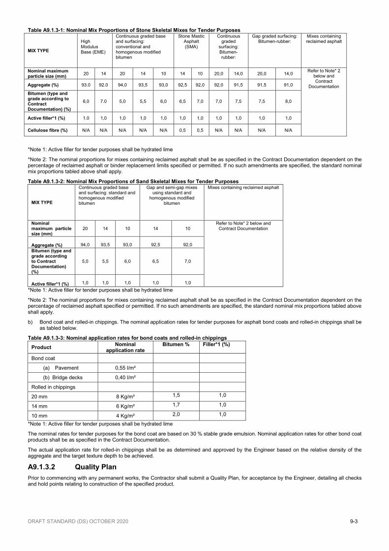
a) Mix composition. The mix proportions of bituminous binder, combined aggregates and filler for the various mix types, as well as bond coat and rolled-in chip applications, as listed in Tables A9.1.3-1 to A9.1.3-3 below, are nominal, and shall only be used for tendering purposes. The proportions actually used shall be as determined during the mix design, trial section and assessment requirements as specified in Clause A9.1.3.3. Any approved variation to these nominal mix proportions, and or, application rates shall be subject to an adjustment in payment, calculated in accordance with Clause C1.1.4 of Chapter 1 and relevant to the applicable variation rates tendered for each component as listed under Measurement and Payment.
DRAFT STANDARD (DS) OCTOBER 2020 9-3
Table A9.1.3-1: Nominal Mix Proportions of Stone Skeletal Mixes for Tender Purposes
MIX TYPE
High Modulus Base (EME)
Continuous graded base and surfacing: conventional and homogenous modified bitumen
Stone Mastic Asphalt (SMA)
Continuous graded
surfacing: Bitumen- rubber:
Gap graded surfacing: Bitumen-rubber:
Mixes containing reclaimed asphalt
Nominal maximum particle size (mm)
20 14 20 14 10 14 10 20,0 14,0 20,0 14,0 Refer to Note* 2
below and Contract
Documentation Aggregate (%) 93.0 92.0 94,0 93,5 93,0 92,5 92,0 92,0 91,5 91,5 91,0
Bitumen (type and grade according to Contract Documentation) (%)
6,0 7.0 5,0 5,5 6,0 6,5 7,0 7,0 7,5 7,5 8,0
Active filler*1 (%) 1.0 1,0 1,0 1,0 1,0 1,0 1,0 1,0 1,0 1,0 1,0
Cellulose fibre (%) N/A N/A N/A N/A N/A 0,5 0,5 N/A N/A N/A N/A
*Note 1: Active filler for tender purposes shall be hydrated lime
*Note 2: The nominal proportions for mixes containing reclaimed asphalt shall be as specified in the Contract Documentation dependent on the percentage of reclaimed asphalt or binder replacement limits specified or permitted. If no such amendments are specified, the standard nominal mix proportions tabled above shall apply.
Table A9.1.3-2: Nominal Mix Proportions of Sand Skeletal Mixes for Tender Purposes
MIX TYPE
Continuous graded base and surfacing: standard and homogenous modified bitumen
Gap and semi-gap mixes using standard and
homogenous modified bitumen
Mixes containing reclaimed asphalt
Nominal maximum particle size (mm)
20
14
10
14
10
Refer to Note* 2 below and Contract Documentation
Aggregate (%)
94,0
93,5
93,0
92,5
92,0
Bitumen (type and grade according to Contract Documentation) (%)
5,0
5,5
6,0
6,5
7,0
Active filler*1 (%)
1,0
1,0
1,0
1,0
1,0
*Note 1: Active filler for tender purposes shall be hydrated lime
*Note 2: The nominal proportions for mixes containing reclaimed asphalt shall be as specified in the Contract Documentation dependent on the percentage of reclaimed asphalt specified or permitted. If no such amendments are specified, the standard nominal mix proportions tabled above shall apply.
b) Bond coat and rolled-in chippings. The nominal application rates for tender purposes for asphalt bond coats and rolled-in chippings shall be as tabled below.
Table A9.1.3-3: Nominal application rates for bond coats and rolled-in chippings
Product Nominal
application rate Bitumen % Filler*1 (%)
Bond coat
(a) Pavement 0,55 l/m²
(b) Bridge decks 0,40 l/m²
Rolled in chippings
20 mm 8 Kg/m² 1,5 1,0
14 mm 6 Kg/m² 1,7 1,0
10 mm 4 Kg/m² 2,0 1,0
*Note 1: Active filler for tender purposes shall be hydrated lime
The nominal rates for tender purposes for the bond coat are based on 30 % stable grade emulsion. Nominal application rates for other bond coat products shall be as specified in the Contract Documentation.
The actual application rate for rolled-in chippings shall be as determined and approved by the Engineer based on the relative density of the aggregate and the target texture depth to be achieved.
A9.1.3.2 Quality Plan
Prior to commencing with any permanent works, the Contractor shall submit a Quality Plan, for acceptance by the Engineer, detailing all checks and hold points relating to construction of the specified product.
DRAFT STANDARD (DS) OCTOBER 2020 9-4
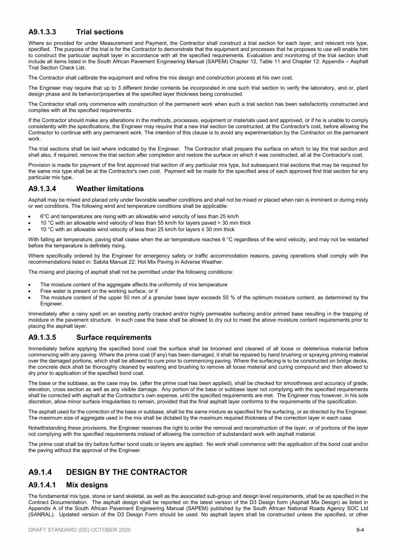
A9.1.3.3 Trial sections
Where so provided for under Measurement and Payment, the Contractor shall construct a trial section for each layer, and relevant mix type, specified. The purpose of the trial is for the Contractor to demonstrate that the equipment and processes that he proposes to use will enable him to construct the particular asphalt layer in accordance with all the specified requirements. Evaluation and monitoring of the trial section shall include all items listed in the South African Pavement Engineering Manual (SAPEM) Chapter 12, Table 11 and Chapter 12: Appendix – Asphalt Trial Section Check List.
The Contractor shall calibrate the equipment and refine the mix design and construction process at his own cost.
The Engineer may require that up to 3 different binder contents be incorporated in one such trial section to verify the laboratory, and or, plant design phase and its behavior/properties at the specified layer thickness being constructed.
The Contractor shall only commence with construction of the permanent work when such a trial section has been satisfactorily constructed and complies with all the specified requirements.
If the Contractor should make any alterations in the methods, processes, equipment or materials used and approved, or if he is unable to comply consistently with the specifications, the Engineer may require that a new trial section be constructed, at the Contractor's cost, before allowing the Contractor to continue with any permanent work. The intention of this clause is to avoid any experimentation by the Contractor on the permanent work.
The trial sections shall be laid where indicated by the Engineer. The Contractor shall prepare the surface on which to lay the trial section and shall also, if required, remove the trial section after completion and restore the surface on which it was constructed, all at the Contractor's cost.
Provision is made for payment of the first approved trial section of any particular mix type, but subsequent trial sections that may be required for the same mix type shall be at the Contractor's own cost. Payment will be made for the specified area of each approved first trial section for any particular mix type.
A9.1.3.4 Weather limitations
Asphalt may be mixed and placed only under favorable weather conditions and shall not be mixed or placed when rain is imminent or during misty or wet conditions. The following wind and temperature conditions shall be applicable:
• 6°C and temperatures are rising with an allowable wind velocity of less than 25 km/h
• 10 °C with an allowable wind velocity of less than 55 km/h for layers paved > 30 mm thick
• 10 °C with an allowable wind velocity of less than 25 km/h for layers ≤ 30 mm thick
With falling air temperature, paving shall cease when the air temperature reaches 6 °C regardless of the wind velocity, and may not be restarted before the temperature is definitely rising.
Where specifically ordered by the Engineer for emergency safety or traffic accommodation reasons, paving operations shall comply with the recommendations listed in: Sabita Manual 22: Hot Mix Paving in Adverse Weather.
The mixing and placing of asphalt shall not be permitted under the following conditions:
• The moisture content of the aggregate affects the uniformity of mix temperature
• Free water is present on the working surface, or if
• The moisture content of the upper 50 mm of a granular base layer exceeds 50 % of the optimum moisture content, as determined by the Engineer.
Immediately after a rainy spell on an existing partly cracked and/or highly permeable surfacing and/or primed base resulting in the trapping of moisture in the pavement structure. In such case the base shall be allowed to dry out to meet the above moisture content requirements prior to placing the asphalt layer.
A9.1.3.5 Surface requirements
Immediately before applying the specified bond coat the surface shall be broomed and cleaned of all loose or deleterious material before commencing with any paving. Where the prime coat (if any) has been damaged, it shall be repaired by hand brushing or spraying priming material over the damaged portions, which shall be allowed to cure prior to commencing paving. Where the surfacing is to be constructed on bridge decks, the concrete deck shall be thoroughly cleaned by washing and brushing to remove all loose material and curing compound and then allowed to dry prior to application of the specified bond coat.
The base or the subbase, as the case may be, (after the prime coat has been applied), shall be checked for smoothness and accuracy of grade, elevation, cross section as well as any visible damage. Any portion of the base or subbase layer not complying with the specified requirements shall be corrected with asphalt at the Contractor’s own expense, until the specified requirements are met. The Engineer may however, in his sole discretion, allow minor surface irregularities to remain, provided that the final asphalt layer conforms to the requirements of the specification.
The asphalt used for the correction of the base or subbase, shall be the same mixture as specified for the surfacing, or as directed by the Engineer. The maximum size of aggregate used in the mix shall be dictated by the maximum required thickness of the correction layer in each case.
Notwithstanding these provisions, the Engineer reserves the right to order the removal and reconstruction of the layer, or of portions of the layer not complying with the specified requirements instead of allowing the correction of substandard work with asphalt material.
The prime coat shall be dry before further bond coats or layers are applied. No work shall commence with the application of the bond coat and/or the paving without the approval of the Engineer.
A9.1.4 DESIGN BY THE CONTRACTOR
A9.1.4.1 Mix designs
The fundamental mix type, stone or sand skeletal, as well as the associated sub-group and design level requirements, shall be as specified in the Contract Documentation. The asphalt design shall be reported on the latest version of the D3 Design form (Asphalt Mix Design) as listed in Appendix A of the South African Pavement Engineering Manual (SAPEM) published by the South African National Roads Agency SOC Ltd (SANRAL). Updated version of the D3 Design Form should be used. No asphalt layers shall be constructed unless the specified, or other
DRAFT STANDARD (DS) OCTOBER 2020 9-5
appropriate and accepted, mix design process has been carried out by the Contractor and submitted to the Engineer on the above form for assessment and approval.
A9.1.4.2 Mix design requirements
Unless otherwise specifically approved, the mix design methodology to be followed, appropriate mix volumetric properties, as well as all other relevant performance property criteria, shall conform to the relevant listed requirements as contained in the latest published version, at the time of tender, of the appropriate Sabita Manuals, for the following specific mix types as listed.
• Stone skeletal mixes: - Continuous graded mixes: The latest version of Sabita Manual 35; Design and Use of Asphalt in Road Pavements. The design
processes may consist of up to four levels as appropriate for the mix type as specified and relevant to the expected performance demands/risks. The level of design required shall be as stated in the Contract Documentation. The final mix proportions and properties shall conform to the requirements as tabled in Sabita Manual 35 for the specific mix type and design level prescribed.
- Stone mastic asphalt (SMA) mixes: The latest version of Sabita Manual 35, Appendix B - High Modulus Asphalt (EME) mixes: The latest version of Sabita Manual 33: Design Procedure for High Modulus Asphalt (EME) for the
specific class prescribed. - Gap and continuously graded asphalt mixes incorporating bitumen-rubber: The latest version of Sabita Manual 19: Guidelines for the
Design, Manufacture and Construction of Bitumen-Rubber Asphalt Surfacings. - Porous asphalt mixes: The latest version of Sabita Manual 17: Design of Porous Asphalt Mixes.
• Sand skeletal mixes - Continuous, semi-gap and gap graded mixes: The latest version of Sabita Manual 35 - Continuous and gap graded mixes incorporating bitumen-rubber: The latest version of Sabita Manual 19: Guidelines for the Design,
Manufacture and Construction of Bitumen-Rubber Asphalt Surfacings.
• Any other specific mix types shall be designed in accordance with the Contract Documentation requirements.
• Independently certified as being fit for the intended purpose, such as Agrément SA, or any other independent certification authority as approved by the Engineer.
In all instances the mix properties shall conform to the latest requirements as listed in the relevant publications above for the mix type, class and design level specified.
The following shall, in all instances, be indicated in the Contract Documentation:
- Mix type (stone or sand skeletal mix) - Specific mix type within the above categories - Level of design required, as appropriate for the specific mix type specified - Nominal maximum particle size (NMPS) of the aggregate - Binder type - Nominal layer thickness
Where the incorporation of warm mix asphalt technology has been prescribed in the Contract Documentation, provision has been made in Part C: Measurement and Payment, for any extra over/under rate as may be applicable. WMA technology may be used provided that the performance criteria of HMA is met and the only change is the mixing and placement temperature ranges.
Asphalt designed and constructed under performance based systems with, or without, extended guarantee periods shall be treated as prescribed in Part D of these specifications, or as otherwise stated in the Contract Documentation.
Before any asphalt is placed on the road, the Engineer shall review and accept the mix design. In the case of performance based specifications, the Engineer reserves the right to have any proposed asphalt mix design independently verified. The approval process shall be as follows:
- The Contractor shall prepare and submit a proposed laboratory design mix with test results at four different binder contents. The design mix shall be submitted on the prescribed design form D3 with all relevant testing completed.
- Samples of all proposed components shall be submitted together with the laboratory design mix results to enable the Engineer to carry out check design testing if required. The above design and its components shall be submitted to the Engineer at least two weeks before it is intended to commence with any asphalt production.
- After initial approval is obtained for the laboratory design mix, a plant mix at varying binder contents, approximately 0,3 % above and below the expected target binder content. The quantity of asphalt at each point shall not be less than 20 tons. The purpose of the plant mix is for the Contractor to prove that the laboratory design mix can be produced successfully and meets all the specified mix properties. The Engineer may conduct any necessary confirmation testing on the plant mixes. The plant mixes shall not be placed on the road. During the production of the plant mix, the Engineer shall be afforded the opportunity to inspect the asphalt plant.
- After the plant mix is approved, permission shall be given for laying a trial section at varying binder contents in accordance with the requirements of Clause A9.1.3.3 of these specifications. The Engineer may require that the mix be further assessed by any additional test methods, the cost of which will be borne by the Employer. Mass production of asphalt shall only commence after approval of the trial section, which shall be given within a maximum of ten calendar days.
- Final grading and mix proportions will be approved by the Engineer after three days of full production.
A9.1.4.3 Changes to mix components
The Engineer shall instruct the Contractor at any time to halt his paving process and to review the whole, or part, of the above process should:
• the specified asphalt mix properties not be met
• a consistent asphalt mix is not being produced.
• a change of any aggregate properties is identified
A9.1.4.4 Mix design period
As different design methodologies or levels have minimum time periods for completion, assessment and approval, the Contractor shall ensure that he commences the specified design processes for the specific mix type and design level timeously to ensure that there are no delays to his construction program. The minimum time that shall be allowed for in the construction program is:
Sabita Manual 35: Level 1: 6 weeks
Sabita Manual 35: Level 2: 10 weeks
Sabita Manual 35: Level 3: 12 weeks
DRAFT STANDARD (DS) OCTOBER 2020 9-6
Sabita Manual 17 (Porous asphalt): 8 weeks
Sabita Manual 19 (Bitumen-rubber mixes): 8 weeks
Sabita Manual 33 (EME): 12 weeks
The Engineer may permit the commencement of construction of asphalt layers prior to the full asphalt mix design protocols, as specified, being submitted for formal acceptance. In such instances the Contractor shall prove that historical mix design data obtained by an accredited testing laboratory meets all the specified mix design properties, and that the relative properties of the current individual mix constituents to be incorporated are essentially similar to those utilised at the time of the original design. Any such concession shall, however, not absolve the Contractor of any obligations with respect to submitting a current valid mix design for evaluation and acceptance, and constructing asphalt layers that conform in all respects to the specified requirements.
A9.1.4.5 Cost of designs
Provision has been made under Measurement and Payment for the costs associated with producing, for each mix, and or, binder type specified, a single laboratory mix design followed by plant mix verification confirming conformance to the particular design method and product properties specified. Any changes to individual components, or properties of a mix, even after initial acceptance has been given, shall require that a new mix design process be undertaken, with any extension of time and cost implications for re-design and trial section at the cost of the Contractor.
If, however the Engineer issues an instruction to change any component, or mix type, for whatever reason, the Contractor shall, in such instances be entitled to claim the cost for additional designs and time at the relevant rates tendered and as approved by the Engineer.
A9.1.5 MATERIALS
A9.1.5.1 General
The Contractor shall, as often as necessary, and in accordance with his approved quality plan, test and control the materials produced by himself, or any materials received by him from suppliers, to ensure that the materials are uniform and always comply with the specified requirements. Refer to the latest version of Sabita Manual 5: Guidelines for the manufacture and construction of hot mix asphalt.
Sufficient aggregate and bituminous binder for a minimum of 3 days production shall be separately stockpiled/stored and tested for conformance and uniformity prior to use. The test results shall be made available to the Engineer on request.
A9.1.5.2 Bituminous binders for asphalt mixes
The binder type to be used in a specified mix shall be as prescribed in the Contract Documentation. The specific properties relating to each binder type/class are not specified here but shall conform to the relevant requirements/ product properties as listed in the latest version of the appropriate publications below, or as may be specifically stated in the Contract Documentation.
- Penetration grade: Conventional bitumen of standard grades and properties as specified in SANS 4001-BT1 - Performance grade: As specified in SATS 3208 – which covers standard bitumen or modified bitumen - Homogenous modified binders: Penetration grade bitumen modified with appropriate polymers to achieve the specific class and relevant
properties as listed in the latest version of Technical Guideline (TG1) - (Modified Binders for Road Construction) as published by the SABITA or Performance Grade as specified in the Contract Documentation.
- Non-homogeneous modified binders (bitumen-rubber): A blend of penetration grade bitumen, rubber crumbs and any extender oils to achieve the specific class/grade and relevant properties as listed in the latest version of TG1 (Modified Binders for Road Construction –as published by SABITA) or Performance Grade as specified in the Contract Documentation.
- Bitumen emulsion: A mixture of normal penetration grade bitumen which has been suitably emulsified with water to achieve the specific class/grade as specified. The relevant requirements and properties pertaining to a specific class/grade shall be as listed in SANS BT4001-BT4 to BT6.
- Modified bitumen emulsion: A mixture of conventional bitumen and appropriate polymer that has been suitably emulsified with water to achieve the specific class/grade and properties as listed in the latest version of Technical Guideline TG1 (Modified Binders for Road Construction) as published by the SABITA
Notwithstanding initial conformance of any modified bituminous binder property as may be specified, such products shall be blended, transported, stored and utilized in accordance with all the accepted best practice guidelines/requirements as published in the latest versions of the SA Asphalt Academy and/or, South African Bitumen Association Guideline documents as relevant for that particular product.
If the Engineer suspects that bitumen or asphalt has been overheated, he may order that the bitumen, or the bitumen recovered from the asphalt, be subjected to the n-Heptane-Xylene (Spot Test) as described in AASHTO-T102. Recovery of the binder from the mixed asphalt for use in the Spot Test shall be carried out in accordance with SANS 3001-AS25. Any bitumen having an n-Heptane-Xylene equivalent in excess of 36, or in excess of the manufacturers test result on the dispatched stock, shall be considered to have been overheated and shall be rejected unless proven otherwise.
A9.1.5.3 Bitumen bond coat
Unless otherwise specified in the Contract Documentation, the bond coat shall consist of a stable grade bituminous emulsion diluted to have a 30 % net bitumen content. The use of polymer modified emulsions, or any other product as may be certified as fit for the specific purpose, shall be as specified in Part D of these specifications or in the Contract Documentation.
A9.1.5.4 Aggregates
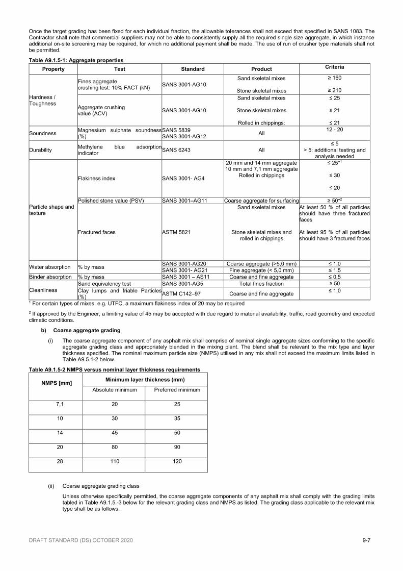
a) Aggregate properties
Aggregate shall consist of hard material derived from the crushing of solid rock or boulders. Coarse and fine aggregate shall be clean and free from decomposed materials, vegetable matter or any other deleterious substances, and shall meet the requirements listed in Table A9.1.5-1 below unless otherwise specifically stated in the Contract Documentation. All aggregates shall be handled and stockpiled in a manner that will prevent contamination, segregation or degradation.
Asphalt mixes shall be manufactured using individual single size coarse aggregates fractions and crushed fine aggregates complying with the latest version of SANS 1083 and appropriately blended to conform to the target grading as determined by the selected design methodology. The use of natural sands shall only be permitted if approved by the Engineer and shall be limited to a maximum of 7 % by mass for continuously graded mixes. For stone mastic asphalt mixes all aggregate fractions in excess of 2,0 mm shall consist of individual nominal single size fractions.
DRAFT STANDARD (DS) OCTOBER 2020 9-7
Once the target grading has been fixed for each individual fraction, the allowable tolerances shall not exceed that specified in SANS 1083. The Contractor shall note that commercial suppliers may not be able to consistently supply all the required single size aggregate, in which instance additional on-site screening may be required, for which no additional payment shall be made. The use of run of crusher type materials shall not be permitted.
Table A9.1.5-1: Aggregate properties
Property Test Standard Product Criteria
Hardness / Toughness
Fines aggregate crushing test: 10% FACT (kN)
SANS 3001-AG10 Sand skeletal mixes
Stone skeletal mixes
≥ 160
≥ 210
Aggregate crushing value (ACV)
SANS 3001-AG10
Sand skeletal mixes
Stone skeletal mixes
Rolled in chippings:
≤ 25
≤ 21
≤ 21
Soundness Magnesium sulphate soundness (%)
SANS 5839 SANS 3001-AG12
All 12 - 20
Durability Methylene blue adsorption indicator
SANS 6243 All ≤ 5
> 5: additional testing and analysis needed
Particle shape and texture
Flakiness index SANS 3001- AG4
20 mm and 14 mm aggregate 10 mm and 7,1 mm aggregate
Rolled in chippings
≤ 25*1
≤ 30
≤ 20
Polished stone value (PSV) SANS 3001–AG11 Coarse aggregate for surfacing ≥ 50*2
Fractured faces ASTM 5821
Sand skeletal mixes
Stone skeletal mixes and rolled in chippings
At least 50 % of all particles should have three fractured faces At least 95 % of all particles should have 3 fractured faces
Water absorption % by mass SANS 3001-AG20 Coarse aggregate (>5,0 mm) ≤ 1,0
SANS 3001- AG21 Fine aggregate (< 5,0 mm) ≤ 1,5
Binder absorption % by mass SANS 3001 – AS11 Coarse and fine aggregate ≤ 0,5
Cleanliness
Sand equivalency test SANS 3001-AG5 Total fines fraction ≥ 50
Clay lumps and friable Particles (%)
ASTM C142–97 Coarse and fine aggregate ≤ 1,0
1 For certain types of mixes, e.g. UTFC, a maximum flakiness index of 20 may be required
2 If approved by the Engineer, a limiting value of 45 may be accepted with due regard to material availability, traffic, road geometry and expected climatic conditions.
b) Coarse aggregate grading
(i) The coarse aggregate component of any asphalt mix shall comprise of nominal single aggregate sizes conforming to the specific aggregate grading class and appropriately blended in the mixing plant. The blend shall be relevant to the mix type and layer thickness specified. The nominal maximum particle size (NMPS) utilised in any mix shall not exceed the maximum limits listed in Table A9.5.1-2 below.
Table A9.1.5-2 NMPS versus nominal layer thickness requirements
NMPS [mm] Minimum layer thickness (mm))
Absolute minimum Preferred minimum
7,1 20 25
10 30 35
14 45 50
20 80 90
28 110 120
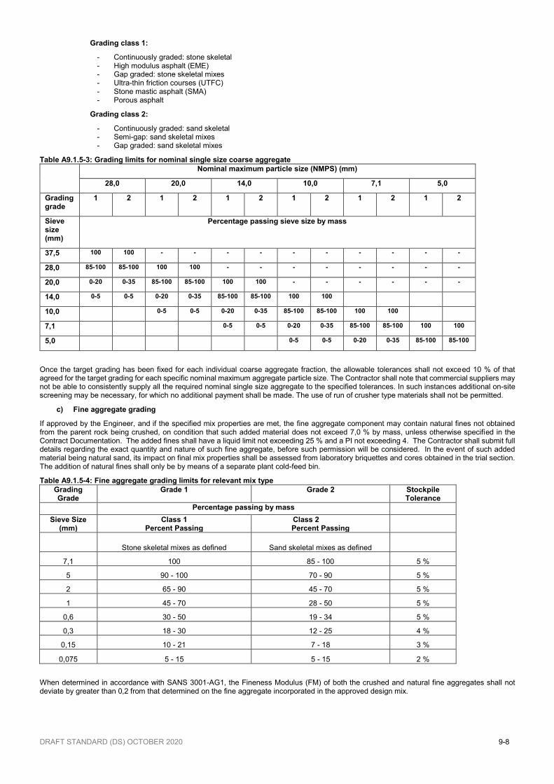
(ii) Coarse aggregate grading class
Unless otherwise specifically permitted, the coarse aggregate components of any asphalt mix shall comply with the grading limits tabled in Table A9.1.5.-3 below for the relevant grading class and NMPS as listed. The grading class applicable to the relevant mix type shall be as follows:
DRAFT STANDARD (DS) OCTOBER 2020 9-8
Grading class 1:
- Continuously graded: stone skeletal - High modulus asphalt (EME) - Gap graded: stone skeletal mixes - Ultra-thin friction courses (UTFC) - Stone mastic asphalt (SMA) - Porous asphalt
Grading class 2:
- Continuously graded: sand skeletal - Semi-gap: sand skeletal mixes - Gap graded: sand skeletal mixes
Table A9.1.5-3: Grading limits for nominal single size coarse aggregate
Nominal maximum particle size (NMPS) (mm)
28,0 20,0 14,0 10,0 7,1 5,0
Grading grade
1 2 1 2 1 2 1 2 1 2 1 2
Sieve size (mm)
Percentage passing sieve size by mass
37,5 100 100 - - - - - - - - - -
28,0 85-100 85-100 100 100 - - - - - - - -
20,0 0-20 0-35 85-100 85-100 100 100 - - - - - -
14,0 0-5 0-5 0-20 0-35 85-100 85-100 100 100
10,0 0-5 0-5 0-20 0-35 85-100 85-100 100 100
7,1 0-5 0-5 0-20 0-35 85-100 85-100 100 100
5,0 0-5 0-5 0-20 0-35 85-100 85-100
Once the target grading has been fixed for each individual coarse aggregate fraction, the allowable tolerances shall not exceed 10 % of that agreed for the target grading for each specific nominal maximum aggregate particle size. The Contractor shall note that commercial suppliers may not be able to consistently supply all the required nominal single size aggregate to the specified tolerances. In such instances additional on-site screening may be necessary, for which no additional payment shall be made. The use of run of crusher type materials shall not be permitted.
c) Fine aggregate grading
If approved by the Engineer, and if the specified mix properties are met, the fine aggregate component may contain natural fines not obtained from the parent rock being crushed, on condition that such added material does not exceed 7,0 % by mass, unless otherwise specified in the Contract Documentation. The added fines shall have a liquid limit not exceeding 25 % and a PI not exceeding 4. The Contractor shall submit full details regarding the exact quantity and nature of such fine aggregate, before such permission will be considered. In the event of such added material being natural sand, its impact on final mix properties shall be assessed from laboratory briquettes and cores obtained in the trial section. The addition of natural fines shall only be by means of a separate plant cold-feed bin.
Table A9.1.5-4: Fine aggregate grading limits for relevant mix type
Grading Grade
Grade 1 Grade 2 Stockpile Tolerance
Percentage passing by mass
Sieve Size (mm)
Class 1 Percent Passing
Class 2 Percent Passing
Stone skeletal mixes as defined Sand skeletal mixes as defined
7,1 100 85 - 100 5 %
5 90 - 100 70 - 90 5 %
2 65 - 90 45 - 70 5 %
1 45 - 70 28 - 50 5 %
0,6 30 - 50 19 - 34 5 %
0,3 18 - 30 12 - 25 4 %
0,15 10 - 21 7 - 18 3 %
0,075 5 - 15 5 - 15 2 %
When determined in accordance with SANS 3001-AG1, the Fineness Modulus (FM) of both the crushed and natural fine aggregates shall not deviate by greater than 0,2 from that determined on the fine aggregate incorporated in the approved design mix.
DRAFT STANDARD (DS) OCTOBER 2020 9-9
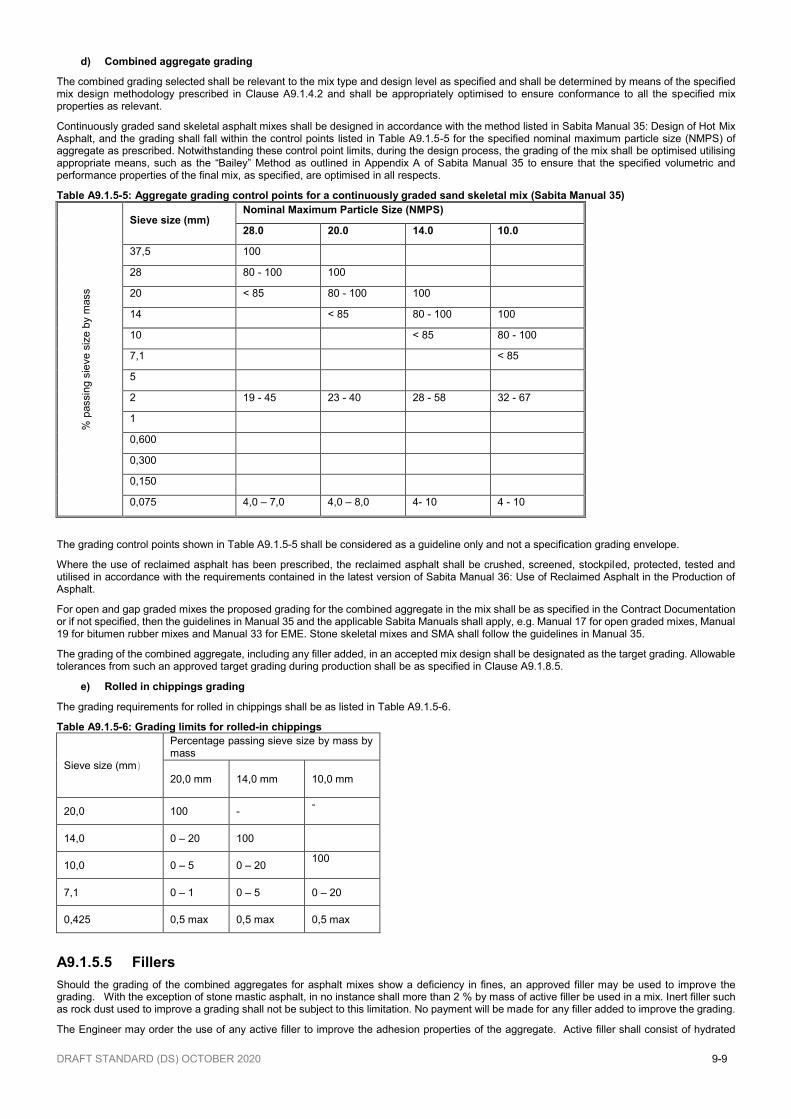
d) Combined aggregate grading
The combined grading selected shall be relevant to the mix type and design level as specified and shall be determined by means of the specified mix design methodology prescribed in Clause A9.1.4.2 and shall be appropriately optimised to ensure conformance to all the specified mix properties as relevant.
Continuously graded sand skeletal asphalt mixes shall be designed in accordance with the method listed in Sabita Manual 35: Design of Hot Mix Asphalt, and the grading shall fall within the control points listed in Table A9.1.5-5 for the specified nominal maximum particle size (NMPS) of aggregate as prescribed. Notwithstanding these control point limits, during the design process, the grading of the mix shall be optimised utilising appropriate means, such as the “Bailey” Method as outlined in Appendix A of Sabita Manual 35 to ensure that the specified volumetric and performance properties of the final mix, as specified, are optimised in all respects.
Table A9.1.5-5: Aggregate grading control points for a continuously graded sand skeletal mix (Sabita Manual 35)
% p
assin
g s
ieve s
ize b
y m
ass
Sieve size (mm) Nominal Maximum Particle Size (NMPS)
28.0 20.0 14.0 10.0
37,5 100
28 80 - 100 100
20 < 85 80 - 100 100
14 < 85 80 - 100 100
10 < 85 80 - 100
7,1 < 85
5
2 19 - 45 23 - 40 28 - 58 32 - 67
1
0,600
0,300
0,150
0,075 4,0 – 7,0 4,0 – 8,0 4- 10 4 - 10
The grading control points shown in Table A9.1.5-5 shall be considered as a guideline only and not a specification grading envelope.
Where the use of reclaimed asphalt has been prescribed, the reclaimed asphalt shall be crushed, screened, stockpiled, protected, tested and utilised in accordance with the requirements contained in the latest version of Sabita Manual 36: Use of Reclaimed Asphalt in the Production of Asphalt.
For open and gap graded mixes the proposed grading for the combined aggregate in the mix shall be as specified in the Contract Documentation or if not specified, then the guidelines in Manual 35 and the applicable Sabita Manuals shall apply, e.g. Manual 17 for open graded mixes, Manual 19 for bitumen rubber mixes and Manual 33 for EME. Stone skeletal mixes and SMA shall follow the guidelines in Manual 35.
The grading of the combined aggregate, including any filler added, in an accepted mix design shall be designated as the target grading. Allowable tolerances from such an approved target grading during production shall be as specified in Clause A9.1.8.5.
e) Rolled in chippings grading
The grading requirements for rolled in chippings shall be as listed in Table A9.1.5-6.
Table A9.1.5-6: Grading limits for rolled-in chippings
Sieve size (mm)
Percentage passing sieve size by mass by mass
20,0 mm 14,0 mm
10,0 mm
20,0 100 - -
14,0 0 – 20 100
10,0 0 – 5 0 – 20 100
7,1 0 – 1 0 – 5 0 – 20
0,425 0,5 max 0,5 max 0,5 max
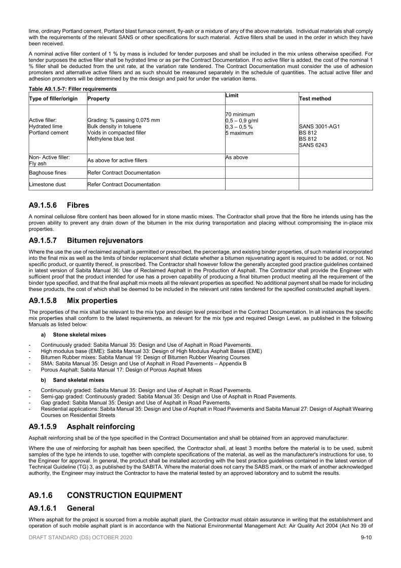
A9.1.5.5 Fillers
Should the grading of the combined aggregates for asphalt mixes show a deficiency in fines, an approved filler may be used to improve the grading. With the exception of stone mastic asphalt, in no instance shall more than 2 % by mass of active filler be used in a mix. Inert filler such as rock dust used to improve a grading shall not be subject to this limitation. No payment will be made for any filler added to improve the grading.
The Engineer may order the use of any active filler to improve the adhesion properties of the aggregate. Active filler shall consist of hydrated
DRAFT STANDARD (DS) OCTOBER 2020 9-10
lime, ordinary Portland cement, Portland blast furnace cement, fly-ash or a mixture of any of the above materials. Individual materials shall comply with the requirements of the relevant SANS or other specifications for such material. Active fillers shall be used in the order in which they have been received.
A nominal active filler content of 1 % by mass is included for tender purposes and shall be included in the mix unless otherwise specified. For tender purposes the active filler shall be hydrated lime or as per the Contract Documentation. If no active filler is added, the cost of the nominal 1 % filler shall be deducted from the unit rate, at the variation rate tendered. The Contract Documentation must consider the use of adhesion promoters and alternative active fillers and as such should be measured separately in the schedule of quantities. The actual active filler and adhesion promoters will be determined by the mix design and paid for under the variation items.
Table A9.1.5-7: Filler requirements
Type of filler/origin Property Limit
Test method
Active filler: Hydrated lime Portland cement
Grading: % passing 0,075 mm Bulk density in toluene Voids in compacted filler Methylene blue test
70 minimum 0,5 – 0,9 g/ml 0,3 – 0,5 % 5 maximum
SANS 3001-AG1 BS 812 BS 812 SANS 6243
Non- Active filler: Fly ash
As above for active fillers As above
Baghouse fines Refer Contract Documentation
Limestone dust Refer Contract Documentation
A9.1.5.6 Fibres
A nominal cellulose fibre content has been allowed for in stone mastic mixes. The Contractor shall prove that the fibre he intends using has the proven ability to prevent any drain down of the bitumen in the mix during transportation and placing without compromising the in-place mix properties.
A9.1.5.7 Bitumen rejuvenators
Where the use the use of reclaimed asphalt is permitted or prescribed, the percentage, and existing binder properties, of such material incorporated into the final mix as well as the limits of binder replacement shall dictate whether a bitumen rejuvenating agent is required to be added, or not. No specific product, or quantity thereof, is prescribed. The Contractor shall however follow the generally accepted good practice guidelines contained in latest version of Sabita Manual 36: Use of Reclaimed Asphalt in the Production of Asphalt. The Contractor shall provide the Engineer with sufficient proof that the product intended for use has a proven capability of producing a final bitumen product meeting all the requirement of the binder type specified, and that the final asphalt mix meets all the relevant properties as specified. No additional payment shall be made for including these products, the cost of which shall be deemed to be included in the relevant unit rates tendered for the specified constructed asphalt layers.
A9.1.5.8 Mix properties
The properties of the mix shall be relevant to the mix type and design level prescribed in the Contract Documentation. In all instances the specific mix properties shall conform to the latest requirements, as relevant for the mix type and required Design Level, as published in the following Manuals as listed below:
a) Stone skeletal mixes
- Continuously graded: Sabita Manual 35: Design and Use of Asphalt in Road Pavements. - High modulus base (EME): Sabita Manual 33: Design of High Modulus Asphalt Bases (EME) - Bitumen Rubber mixes: Sabita Manual 19: Design of Bitumen Rubber Wearing Courses - SMA: Sabita Manual 35: Design and Use of Asphalt in Road Pavements – Appendix B - Porous Asphalt: Sabita Manual 17: Design of Porous Asphalt Mixes
b) Sand skeletal mixes
- Continuously graded: Sabita Manual 35: Design and Use of Asphalt in Road Pavements. - Semi-gap graded: Continuously graded: Sabita Manual 35: Design and Use of Asphalt in Road Pavements. - Gap graded: Sabita Manual 35: Design and Use of Asphalt in Road Pavements. - Residential applications: Sabita Manual 35: Design and Use of Asphalt in Road Pavements and Sabita Manual 27: Design of Asphalt Wearing
Courses on Residential Streets
A9.1.5.9 Asphalt reinforcing
Asphalt reinforcing shall be of the type specified in the Contract Documentation and shall be obtained from an approved manufacturer.
Where the use of reinforcing for asphalt has been specified, the Contractor shall, at least 3 months before the material is to be used, submit samples of the type he intends to use, together with complete specifications of the material, as well as the manufacturer's instructions for use, to the Engineer for approval. In general, the product shall be installed according with the best practice guidelines contained in the latest version of Technical Guideline (TG) 3, as published by the SABITA. Where the material does not carry the SABS mark, or the mark of another acknowledged authority, the Engineer may instruct the Contractor to have the material tested by an approved laboratory and to submit the results.
A9.1.6 CONSTRUCTION EQUIPMENT
A9.1.6.1 General
Where asphalt for the project is sourced from a mobile asphalt plant, the Contractor must obtain assurance in writing that the establishment and operation of such mobile asphalt plant is in accordance with the National Environmental Management Act: Air Quality Act 2004 (Act No 39 of
DRAFT STANDARD (DS) OCTOBER 2020 9-11
2004) and the National Environmental Management Act, 1998. These items to also be included in the regular site audit protocol to ensure ongoing compliance.
All plant shall be so designed and operated as to produce a mixture complying with the requirements of this specification. The plant and equipment used shall be of adequate rated capacity and be in good working order. Obsolete or worn-out plant shall not be permitted on site. Mobile plant with hydraulic or petroleum product oil leaks shall be immediately repaired or removed from site.
Prior to the start of the work the Contractor shall supply the Engineer, on request, with copies of the manufacturer's handbooks and copies of check lists prepared in terms of ISO 9002, where applicable, pertaining to the mixing and paving plants, containing details of the correct settings and adjustments of the plant.
Any alteration which has been, or is being effected to any constructional plant, and which does not comply with the specifications of the manufacturer, shall be brought to the notice of the Engineer.
A9.1.6.2 Mixing plant
Asphalt shall be mixed by means of an approved mixing plant of proven suitability for producing a mixture complying with all the requirements of the specifications.
The heating system of the binder storage tanks shall be so designed that the binder will not be degraded during storing, heating and production. A circulating system for the binder shall be provided which shall be of adequate size to ensure the proper and continuous circulation between storage tanks and mixer during the entire operating period.
Binder storage tanks shall be fitted with thermometers designed to provide a continuous record of the temperature of the binder in the tank. Copies of these records shall be supplied to the Engineer on a daily basis.
The binder content of the mix shall be controlled within the tolerances specified, either by weighing or by volumetric measurements. The system shall be controlled by the cold feeding of each aggregate fraction, and filler, by mass, by means of a load cell or other devices regulating the feed automatically. Suitable dust collecting equipment shall be fitted to prevent pollution of the atmosphere in accordance with the provisions of the latest laws and relevant regulations.
Where more than 10 % (drum mixers) or 15 % (batch mixes) of reclaimed asphalt is to be utilised in the mix, the mixing plant shall be of such a design and configuration as to produce a recycled mix containing the prescribed, or selected, percentage of reclaimed asphalt without any premature ageing of the mix occurring. In general, the requirements for appropriate mixing plants to be used for recycling shall be as recommended in the latest version of Sabita Manual 36: Use of Reclaimed Asphalt in the Production of Asphalt.
A9.1.6.3 Paver
The mixture shall be laid by an approved type of self-propelled mechanical spreader and finisher fitted with automatic electronic screeds, capable of paving to the required widths, thickness, profile, camber or cross-fall without causing segregation, dragging, tearing, or other surface defects. Where leveling beams on multiple skids or sliding beams are used they shall be at least 12,0 m long, or as specified in the Contract Documentation.
A9.1.6.4 Chip spreader
The chip spreader shall straddle the full width being paved and shall be used for spreading the rolled in chippings. Such a mechanical spreader shall be self-propelled and be able to follow immediately behind the paver.
When coated chippings are spread by hand in restricted areas, special care shall be taken to prevent bunching of the chippings.
A9.1.6.5 Rollers
Compaction shall be done by means of approved flat steel-wheeled, vibratory or pneumatic-tyre rollers. The frequency as well as the amplitude of vibratory rollers shall be adjustable. Vibratory rollers shall be used only where there is no danger of damage being done to the asphalt, and to the smoothness of the layer, bridge decks, or other layers. It will be indicated in the Contract Documentation whether any vibratory compaction equipment may be used on bridge decks, and what the constraining parameters will be. The rollers shall be self-propelled and in good working condition, free from back lash, and without any oil leaks. Rollers shall be equipped with adjustable scrapers to keep the drums clean and with efficient, fully functioning means of keeping the wheels wet to prevent mixes from sticking to the rollers. Approved release agents may be used on roller wheels but the use of petroleum products for this purpose shall not be permitted. The mass and tyre pressures shall be such so as to ensure compaction complying with the specifications for surface finish and compaction.
The required type, and number, of rollers to be utilized shall be appropriate to the mix type being paved and rate of paving which shall be as determined during the trial section. The Contractor shall take adequate precautions to eliminate any pick-up of the paved mat. For open-graded asphalt and/or stone-mastic asphalt, only flat steel-wheeled rollers shall be used.
A9.1.6.6 Binder distributors
The bituminous binder bond coat shall be applied either by means of a “self-tacking” paver or by an approved binder distributor as follows:
Comply with SANS 3001-BT20 and shall be covered by a valid certificate of compliance with SANS 3001-BT20, not older than 12 months, issued by an accredited testing organisation;
Not have any fuel, oil or binder leaks;
Have a straight and clean spray bar, all the spray heads of which shall be of the same type which open simultaneously and shall not leak when closed;
Have its spray heads all spraying at the same angle to the spray bar and the height adjusted to the correct level so as to obtain the required overlapping. The uneven application of binder shall be unacceptable;
Have its sieve undamaged and clean;
Be under the direct control of an operator approved by the Engineer on the grounds of a reference, in writing or a certificate of competence signed by a representative of a road authority;
Be fitted with a suitable cut-off spray-head (end nozzles) or fishplates to prevent over spraying onto gravel shoulders or staining of concrete elements on the edge of the surfacing of the road.
Be capable of spraying the binder at the specified applications rates and to the satisfaction of the Engineer. The pump of the distributor shall be
DRAFT STANDARD (DS) OCTOBER 2020 9-12
capable of delivering the binder at the spray bar nozzles at the correct pressure to obtain the specified application rates, irrespective of the viscosity properties of the prescribed binder and the number of nozzles open.
Fitted with a suitable valve or other access gate for taking of samples of the binder for testing purposes.
Hand sprayers, other than in restricted areas, shall only be permitted if so approved by the Engineer.
A9.1.6.7 Vehicles
The asphalt shall be transported from the mixing plant to the spreader in tip trucks that are in good condition having no oil leaks. They shall have tight, clean smooth beds and sides that have been treated to prevent adhesion of the mixture to the truck bodies. A thin film of soapy water, vegetable oil or approved release agents may be used to prevent adhesion but petroleum products shall not be used for this purpose. The truck bins shall be designed to tip asphalt into the paver’s hopper without spillage.
To minimize temperature loss, all vehicles used for transporting asphalt to the site shall be fitted with appropriate bin covers. Where the expected transport, and or, storage time of the asphalt is expected to exceed one hour in the truck, the use of thermal asphalt covers (canvas covers not acceptable) shall be obligatory.
A9.1.6.8 Material transfer vehicle
Where so specified, and provision thereof is included under Measurement and Payment, asphalt shall be transferred from the haul trucks into the paver hopper by means of a materials storage and transfer vehicle and no material shall be tipped directly from the truck into the paver with the exception of paving in restricted areas.
The materials storage and transfer vehicle shall be capable of storing and transferring the asphalt from truck to paver to ensure continuous paving. It shall contain an anti-segregation auger that remixes the asphalt just prior to delivery to the paver hopper in order to ensure a mix of uniform temperature.
A9.1.6.9 Mass-measuring device for asphalt mixes
Where payment per ton is specified, the Contractor shall keep available, at the mixing plant or on the site, a suitable calibrated mass-measuring device for measuring the mass of asphalt being delivered. The device shall be provided with a means of electronically recording and printing the type of mix, the mass, the time and the date. The printed data shall be submitted to the Engineer.
A9.1.6.10 Milling machine
Where so required and scheduled, the Contractor shall provide a suitably sized milling machine to mill off existing asphalt on bridge decks and or to mill an appropriate keyway at the approaches to bridge structures. The size of the milling machine shall be such as to allow milling adjacent to bridge nosings and any joints without damaging them.
A9.1.7 EXECUTION OF THE WORKS
A9.1.7.1 Production of the mixture
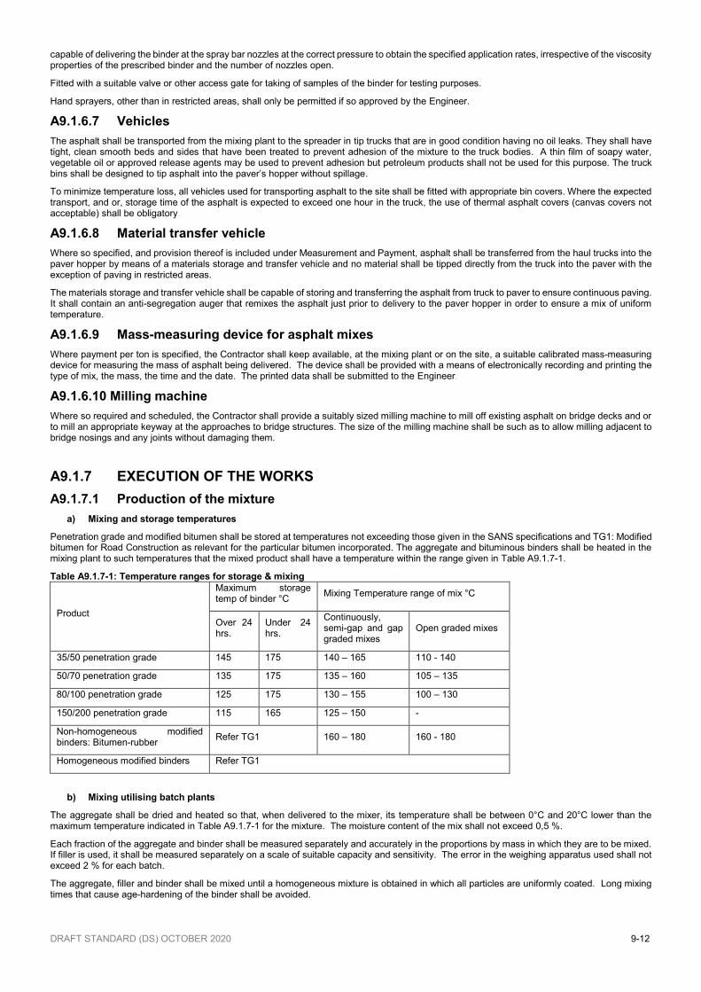
a) Mixing and storage temperatures
Penetration grade and modified bitumen shall be stored at temperatures not exceeding those given in the SANS specifications and TG1: Modified bitumen for Road Construction as relevant for the particular bitumen incorporated. The aggregate and bituminous binders shall be heated in the mixing plant to such temperatures that the mixed product shall have a temperature within the range given in Table A9.1.7-1.
Table A9.1.7-1: Temperature ranges for storage & mixing
Product
Maximum storage temp of binder °C
Mixing Temperature range of mix °C
Over 24 hrs.
Under 24 hrs.
Continuously, semi-gap and gap graded mixes
Open graded mixes
35/50 penetration grade 145 175 140 – 165 110 - 140
50/70 penetration grade 135 175 135 – 160 105 – 135
80/100 penetration grade 125 175 130 – 155 100 – 130
150/200 penetration grade 115 165 125 – 150 -
Non-homogeneous modified binders: Bitumen-rubber
Refer TG1 160 – 180 160 - 180
Homogeneous modified binders Refer TG1
b) Mixing utilising batch plants
The aggregate shall be dried and heated so that, when delivered to the mixer, its temperature shall be between 0°C and 20°C lower than the maximum temperature indicated in Table A9.1.7-1 for the mixture. The moisture content of the mix shall not exceed 0,5 %.
Each fraction of the aggregate and binder shall be measured separately and accurately in the proportions by mass in which they are to be mixed. If filler is used, it shall be measured separately on a scale of suitable capacity and sensitivity. The error in the weighing apparatus used shall not exceed 2 % for each batch.
The aggregate, filler and binder shall be mixed until a homogeneous mixture is obtained in which all particles are uniformly coated. Long mixing times that cause age-hardening of the binder shall be avoided.
DRAFT STANDARD (DS) OCTOBER 2020 9-13
c) Mixing utilising drum plants
The aggregate and filler shall be accurately proportioned and conveyed into the drum-mixing unit. The calibrated amount of binder shall be added to the aggregates at the correct position so that no hardening of the binder shall take place. A homogeneous mixture and uniform coating of binder shall be achieved and the moisture content of the asphalt mixture shall not exceed 0,5 % when tested in accordance with SANS 3001-AS23. Once the final mix temperature has been agreed upon it may not be altered without the prior consent of the Engineer.
Pre-blending of aggregate fractions shall not be permitted and the Contractor shall ensure that sufficient cold-feed bins are installed to accommodate each individual aggregate fraction, including the filler.
d) Producing small quantities of asphalt
A small quantity of asphalt shall be a quantity of less than 10 tons of a specified composition to be specially produced on occasion. For a small quantity of asphalt of less than 10 tons extra payment will be made if its use has been instructed by the Engineer, in writing and where, in the opinion of the Engineer it is necessary, and shall be:
- In accordance with the approved working programme of the Contractor, and/or - For the safety of the work or the travelling public on account of weather conditions or abnormal traffic conditions. No extra payment will be made where small quantities of asphalt are required in consequence of the negligence of the Contractor or of poor workmanship, or bad planning, done by the Contractor, or because he did not execute the works in accordance with his approved programme.
A9.1.7.2 Producing pre-coated chippings
Aggregate for pre-coated chippings shall be coated using the nominal percentage bitumen as listed in Table A9.1.3-8 ± 0,3 % by mass for the relevant nominal maximum size specified. Unless otherwise approved, the grade of bitumen used to coat the chippings shall be 50/70 penetration-grade. One per cent by mass of active filler, lime, shall be added to the mixture.
The aggregate shall be dried and fed into the approved batching plant at a temperature of between 130°C and 185°C followed by the bitumen at a temperature not exceeding 175°C and filler. Immediately after the aggregate has been coated and discharged from the mixer it shall be allowed to cool to below 90°C before dowsing with water.
Coated chippings shall be stockpiled in heaps not exceeding 1,0 m in height and protected if necessary to prevent temperatures from exceeding 60°C during storage.
A9.1.7.3 Storing the asphalt mix
Mixing shall not be allowed to take place more than four hours before paving begins unless provision has been made for storage in approved silos which are capable of maintaining the temperature of the mix uniform throughout. Storage will not be permitted for a period longer than 8 hours after mixing, unless otherwise approved by the Engineer. Open-graded mixes and stone-mastic asphalt shall not be stored or mixed ahead of paving operations but shall be laid directly following mixing.
A9.1.7.4 Transporting of asphalt
The mixture shall be transported from the mixing plant to the works in trucks complying with the requirements of Clause A9.1.6.7. Deliveries shall be made so that paving and rolling of all the mixtures prepared for a day’s production, can be completed during daylight hours, unless artificial lighting, as approved by the Engineer, is provided. Any asphalt that has become cold or wet due to rain, or any other cause, shall be rejected. Hauling over asphalt that has not cooled to ambient temperature shall not be permitted.
A9.1.7.5 Bond coat
In all instances, unless otherwise, specified, a bond coat shall be applied to the surface to be paved. Concrete curbing and channeling, as well as any other adjacent structure or completed pavement shall be protected against staining by bitumen being sprayed or asphalt being placed. Where any bitumen is to be sprayed, all such work shall be completely covered with polyethylene sheeting at least 0,25 mm thick, specially reinforced paper, or other approved material adequately secured to prevent the sheeting from lifting during windy conditions. Any permanent work stained by bitumen shall be broken down and replaced, unless all such bitumen is completely removed so as not to show any stains. Painting over stained work is strictly prohibited.
Unless otherwise specified in the Contract Documentation, the bond coat shall consist of a stable-grade bituminous emulsion, diluted to have a 30 % net bitumen content, and shall be applied at a nominal rate of 0,55 (l/m²), or as directed by the Engineer. For bridge decks the bond coat shall be applied to the surface at a nominal rate of 0,4 (l/m²). The bond coat shall not be applied more than 24 hours before the paving is to commence and shall be fully cured prior to paving.
Before a new layer is placed adjacent to an existing layer, except in the case of open-graded or stone mastic mixes, the cut edge of the existing layer shall be hand painted with a bond coat of bituminous material of the same type used for the substrate bond coat. The bond coat shall fully coat the vertical face of the joint.
The use of hand-operated equipment for the application of bond coats, other than in restricted areas, shall be at the sole discretion of the Engineer, and his approval shall be timeously obtained.
A9.1.7.6 Placing the asphalt
The mixture shall be delivered to the paver in such a manner that the paving will be as continuous as possible with minimal stopping. Any lengthy delay in supply resulting in the asphalt mat cooling to below the appropriate compaction temperatures shall require that a construction joint be formed prior to recommencing with the paving operation.
The temperature of the mixture shall be controlled by measuring in a random pattern in the truck immediately before emptying and shall not be more than 10°C below the minimum mixing temperature, or above the maximum mixing temperature specified in Table A9.1.7-1. The adjustment of the screed, tamping bars. Feed- screws, hopper feed, etc., shall be checked frequently to ensure uniform spreading of the mix. If segregation or tearing occurs, the paving operations shall immediately be suspended until the cause is determined and corrected.
The addition or removal of material behind the paver shall not be allowed and the paver shall be capable of spreading the mixture to the levels that will provide the specified compacted thickness
Only minimal hand-working of the gap graded asphalt shall be permitted after discharge from the paver and before rolling and shall only be carried out with wooden spreaders. Workmen shall not be permitted to walk on un-compacted open graded asphalt.
Unless otherwise approved, paving shall commence at the bottom of the grades and the lower edges of super-elevated curves where the grades
DRAFT STANDARD (DS) OCTOBER 2020 9-14
are steeper than 5 %.
Paving widths shall be so planned that longitudinal joints do not coincide with joints in lower layers of asphalt base, paver laid crushed stone bases or within the wheel paths of a lane.
Continuity of placing is especially important for open graded asphalt. Cutting of longitudinal joints shall be avoided when paving open-graded asphalt but where cutting is essential, only saw cutting shall be permitted. The existing layer edge shall be heated by approved means in order to ensure adequate longitudinal bonding of the asphalt between the two lanes.
Unless otherwise specified in the Contract Documentation the paver shall be equipped to provide automatic control of levels and cross section.
The mixer capacity and the operating speed of the paver shall be so coordinated so as to ensure continuous laying and thus avoid intermittent stopping of the paver.
Paving shall cease when rain starts falling or when the surfaces to be paved are visibly wet.
In all cases, including leveling courses, the paver shall be provided with approved skid beams with electronically controlled equipment that can ensure a constant cross-fall and can even out local irregularities.
Asphalt shall be placed in restricted areas with the aid of smaller specially equipped pavers, hand tools or other approved equipment. All the requirements with respect to temperature, mix composition, uniformity, in-place properties etc. shall remain applicable but layer thickness and control shall be such that the requirements for compaction and surface tolerances can still be achieved.
A9.1.7.7 Compaction
The compaction requirements for each mix type shall be in accordance with the requirements listed in the relevant Sabita Manuals as listed in Clause A9.4.2 for the specific mix type prescribed. The sequence of rollers used in compaction shall be at the discretion of the Contractor provided that the completed pavement shall meet the required compaction, profile, and surface texture as specified. The paved layer shall be compacted as soon as possible after it has been laid by a combination of vibratory, static steel-wheeled and or pneumatic-tyre rollers in a sequence determined and approved during the laying of trial sections. Rolling shall commence, and be continued, only for so long as it is effective and does not have any detrimental effect.
Only steel-wheel rollers (non-vibratory) shall be permitted for the compaction of stone mastic asphalt as well as semi-open and open-graded mixtures, although rubber tyre rollers may be on standby if required. During rolling the roller wheels shall be kept moist with only sufficient water or an approved release agent to avoid picking up the material. The use of petroleum products or excesses of releasing agents (soap) to prevent pick-up shall not be permitted. The use of vibratory rollers shall not be permitted on bridge decks.
Rolling shall commence from the edges of the paved mat and progress towards the center. On areas of super elevated curves, or where the cross-fall exceeds 2 %, rolling shall commence on the low side and progress to the higher side, uniformly lapping each preceding track. During breakdown-rolling the rollers shall move at a slow but uniform speed (not to exceed 5,0 km/h) with the drive roller nearest the paver, unless otherwise specified on account of steep gradients.
Except for mixtures using warm mix asphalt technology, no movement of the asphalt layer shall occur under steel wheel rollers once the asphalt temperature has dropped to below 100°C.
For thin layer asphalt (less than 30 mm) the compaction requirements shall be in accordance with the method statement as assessed and approved in the accepted trial sections.
For open graded (Porous) asphalt the degree of compaction can be controlled indirectly by means of in-situ permeability tests calibrated during the trial section and by visual evaluation of the aggregate to prevent crushing.
The Contractor shall utilize an appropriate and calibrated nuclear gauge for process control during compaction operations. Notwithstanding this requirement, the acceptance control carried out to determine compaction shall still be based on cores taken from the compacted layer where the layer thickness is appropriate.
A9.1.7.8 Applying rolled-in chippings
The size of pre-coated chippings used shall be as specified in the Contract Documentation. Unless specifically approved by the Engineer, the chippings shall be laid by a mechanical spreader that straddles the paved width and follows immediately behind the paver. The chippings shall be spread to give a uniform texture free from clusters and open patches. Unless otherwise specified in the Contract Documentation, the final surface texture shall not be less than 0,8 mm and shall be demonstrated as being achievable in the trial section, as described in Clause A9.1.3.3. Measurement of texture depth shall be in accordance SANS 3001-BT11, or by means of instrumentally measurements as described and specified in Clause A20.1.5.5 of Chapter 20 “Tests on pavements”.
In restricted areas the Contractor may use hand tools for spreading chippings, in which instance the rate of application and requirements for evenness of the spread chippings shall remain applicable.
A9.1.7.9 Cutting of joints
All joints between adjacent sections of the work shall be formed by cutting back the edges of the paved layer in a straight line, either parallel or at right angles to the centerline, by a minimum of the width of the layer thickness being paved. Joints shall be neat and shall have the same texture and compaction level as the adjacent asphalt layer.
All joints shall be delineated by means of chalk lines prior to cutting. For sand skeleton mixes, such as semi-gap and fine continuously graded mixes, a cutting wheel may be utilized only if the layer is less than 50 mm in thickness and was paved within 24hours. For all other mix types, layers in excess of 50mm, or that have been left for longer than 24hours, the joints shall be formed either by means of saw cutting, using carborandum blades, or by an appropriate milling machine. All material emanating from preparing the joint shall be removed and transported to an approved site for possible recycling or other appropriate use or disposal. No payment for any such removed asphalt shall be made.
On completion of preparing the joint, the adjacent surface shall be inspected to ascertain that there has been no damage caused to the adjacent layer. Any identified damage shall be appropriately repaired prior to commencement of paving any adjacent asphalt layer.
Whenever the paving operation ceases due to lack of supply of mix, and the temperature of the mat has reduced to below the appropriate compaction temperature, the Contractor shall form a proper transverse construction joint as specified.
Unless otherwise provided for, joints in the final layer of the surfacing shall correspond with the intended lane markings. Joints in lower layers shall be offset by not less than 150 mm from either side of the edges of any underlying substrate joint.

DRAFT STANDARD (DS) OCTOBER 2020 9-15
The allowable tolerances for joints shall be as specified in Clause A9.1.8.3.
A9.1.7.10 Treatment of joints for traffic accommodation
Where it is necessary to accommodate public traffic during paving operations and the difference in level between the new work and the existing road surface exceeds 25 mm, joints shall be treated as follows:
Transverse steps at the end of a day’s work shall be tapered off at a slope of 1 vertical to 20 horizontal (1:20) to tie in with the existing surface. The tapered section shall be removed before surfacing is recommenced and a joint formed in accordance with Clause A9.1.7.7.
Longitudinal joints exposed to traffic shall be provided with a taper of compacted asphalt layer over the full length of the exposed joint. The width of the taper shall be at least 5 times the layer thickness. The tapered section shall be removed before surfacing is recommenced and a joint formed in accordance with Clause A9.1.7.7.
All costs involved in the provision and removal of these temporary ramps shall be deemed to be included in the rates tendered for the relevant asphalt pay item.
A9.1.7.11 Surfacing of bridge decks
The type and nominal thickness of the surfacing shall be as specified in the Contract Documentation.
Before commencing with the construction of the surfacing, the actual levels of the bridge deck shall be determined by means of accurate leveling. The levels and grades to which the surfacing is to be constructed shall be as shown on the drawings or as indicated by the Engineer. If the levels of the concrete deck, as constructed by the Contractor deviate by more than the specified tolerances from the specified levels, he shall construct a leveling layer at his own cost. The nominal mean maximum particle size of the aggregate in the leveling layer shall be 10 mm.
A9.1.7.12 Asphalt temperature before opening to traffic
Newly paved asphalt shall not be opened to traffic until its surface temperature, as measured using a digital thermometer, has decreased to 50oC or less.
A9.1.8 WORKMANSHIP
The onus shall be on the Contractor to consistently construct all elements conforming to the specifications and within allowable tolerances. The Engineer shall continuously monitor the quality and consistency of work produced by means of visual inspection as well as by appropriate testing and evaluation of results.
Measurement, testing, and evaluation of all individual components and constructed products shall be in accordance with the methods prescribed in this Chapter or in Chapter 20 as relevant.
A9.1.8.1 Dimensional tolerances – new construction
The completed sections of asphalt base and surfacing shall comply with the requirements for grade, width, thickness and cross section as stated below.
a) Level and grade
The level tolerances shall be as follows:
H90 ± 15 mm
Hmax ± 20 mm
Deviation from the specified longitudinal grade due to deviations from the specified levels shall not exceed the values given in Table A9.1.8-1.
Table A9.1.8-1: Maximum Deviation from Specified Grade
Length of deviation of grade (m) Maximum variation from specified grade (%)
2 0,354
5 0,224
10 0,158
20 0,112
30 0,091
In the case of surfacing bridge decks, the difference in level between the new asphalt and any existing adjacent bridge joint or nosing shall not exceed 3,0 mm
b) Width
The average width of both asphalt base and surfacing shall be at least equal to that shown on the drawings and nowhere shall the outer edge of the layer be inside the lines shown on the drawings by more than 15 mm for both asphalt base and asphalt surfacing layers.
c) Thickness
The thickness tolerances shall be as listed in Table A9.1.8-2.
Table A9.1.8-2: Thickness Tolerances
Allowable Tolerances Asphalt Base (mm) Asphalt Surfacing (mm)
D 90 15 5
D Maximum 20 8
D Average 5 2
DRAFT STANDARD (DS) OCTOBER 2020 9-16
Thickness shall be determined from carefully controlled levels taken before and after construction in exactly the same position and/or from cores drilled from the completed layer.
d) Cross section
When tested with a 3,0 m straight edge laid at right angles to the road centerline the surface shall not deviate from the bottom of the straight-edge by more than 6,0 mm for freeways and more than 10 mm for other roads.
At any transverse section the difference in level between any two points shall not vary from that computed from the cross section shown on the drawings by more than 15 mm for freeways and 20 mm for other roads.
A9.1.8.2 Dimensional tolerances – overlays
Where asphalt is being placed for the purposes of rehabilitation or overlays, the following requirements shall be applicable, as relevant:
a) When the overlay is constructed to specified levels on a layer that has also been constructed or milled to specified levels by the Contractor, all the tolerance requirements of Clause A9.1.8.1 shall be applicable.
b) When the overlay is constructed to specified levels on an existing layer, or on a layer which has been constructed or milled by the Contractor, but which has not been constructed, or milled, to specified levels, all the tolerance requirements of Clause A9.1.8.1 shall be applicable, except for Clause A9.1.8.1c), which relates to thickness.
c) When the overlay is not constructed to specified levels, the following tolerances shall apply:
The outer edges of the overlay shall nowhere be more than 15 mm inside or outside the lines shown on the drawings, or existing surface, and shall be parallel to the road centre line.
The minimum thickness shall be the specified nominal thickness.
The maximum thickness shall be the specified nominal thickness + 10 mm.
In the case of surfacing bridge decks, the difference in level between the new asphalt and any existing adjacent bridge joint or nosing shall not exceed 3,0 mm
A9.1.8.3 Construction joints
All joints shall be cut back by at least the minimum of the layer thickness constructed. When measured with a 3,0 m straight edge at 10 m intervals longitudinally, and at 1,0 m intervals transversely, the level of the outer edge of the layer constructed shall not deviate by more than 2,0 mm from the level plane on 80 % of the measurements. In no instance shall the difference in level differ by more than 4,0 mm on base layers and 3,0 mm on surfacing layers. If these requirements are not met, the Contractor shall recut the joints, at his cost, in order to meet this specification.
A9.1.8.4 Surface regularity
a) Measured using inertial laser profilometers
For the lanes and surfaced shoulders wider than 2,0 m of the through road as well as interchange ramps and cross roads, the roughness of the surfacing will be determined by using an inertial laser profilometer as specified in Chapter 20, and capable of producing a Class 1 vertical measurement resolution, and a Class 3 longitudinal sampling distance as defined in ASTM standard (E950-09).
Surface shoulders less than 2,0 m wide, will be assessed according to measurements obtained from the adjacent trafficked lane.
The inertial laser profilometer shall be used to record the longitudinal profile in both wheel tracks (which shall be 1,75 m apart) of each traffic lane or shoulder wider than 2,0 m, as determent according to the final line markings that will be applied after construction. Should the two tracks not be measured simultaneously during the same pass, then procedures shall be implemented to ensure that the longitudinal profile data recorded for the two wheel tracks are at the same longitudinal profile data recorded for the two wheel tracks are at the same longitudinal location on the road.
The measured longitudinal profiles will then be processed using the Quarter-Car simulation model with parameter values as defined in ASTM standard (E1170-97) for Ride Meter-Vehicle Mounted. The simulated suspension mentioned will then be linearly accumulated and divided by the length to yield 100 m IRI (International Roughness Index) values in units of mm/m or m/km for each wheel track. The last 50 m, and the joining first 50 m of adjacent sections will be evaluated as a 100 m section in the direction of vehicle travel. For each measured land the left and the right 100m IRI values from the three runs will then be averaged to produce the Average IRI as follows:
Run1 IRI100m Ave = (100m IRI Left wheel track + 100m IRIRight wheel track) / 2
Run2 IRI100m Ave = (100m IRI Left wheel track + 100m IRIRight wheel track) / 2
Run3 IRI100m Ave = (100m IRI Left wheel track + 100m IRIRight wheel track) / 2
Average IRI100m = (Run1 IRI 100m Ave + Run2 IRI 100m Ave + Run3 IRI 100m Ave) / 3
The Average IRI100m values is then evaluated and judged according to Table A9.1.8-3 to determine whether the 100m section needs corrective work or payment adjustments.
The applicable Full Payment Bracket in Table A9.1.8-1 (Where value = 1.000) for the measured lanes and shoulders will be determined as follows:
Calculate the applicable Target IRI100m Ave for full payment as follows: Target IRI100m Ave = greater of 1.05 or [IRI100m Ave * {1-(NAT/100)}]
Where:
IRIb Ave = Average IRI100m before the construction of the asphalt surfacing as determined from:
The Average IRI100m , as calculated from the network roughness measurements performed by Employer not more than 12 months prior to commencement of the contract, or
The Average IRI100m as calculated from the measurements performed as part of the assessment of the base as per Clause A5.3.8.5c) of Chapter 5 for granular bases.
NAT = Total New Asphalt Surface Thickness (measured in mm) applied over a section as part of this contract. For example, should 40 mm AC be applied followed by 18 mm UTFC, then NAT = 58 mm.
DRAFT STANDARD (DS) OCTOBER 2020 9-17
Using the Target IRI100m Ave calculated under 1 above, find the matching Target IRI100m Ave range in the first column of Table A9.1.8-3 into which the value fits. Then read horizontally to the relevant Payment Bracket column in which the unit value (1.000) appears, as indicated by the highlighted cells in the Table. The values in this column shall then be applied as the payment adjustment factors for the contract or section. For example, should the Target IRI100m Ave be 1.33, then the Payment Bracket will be No 4.
Should the Total New Asphalt Thickness (NAT) vary over the contract length, then a Payment Bracket will need to be calculated for each of these uniform NAT sections.
Any adjustment in the payment for asphalt surfacing will be made by multiplying the full payment value for each 100 m section, (for all the relevant payment items for this work) by the payment adjustment factor derived from Table A9.1.8-3. The payment adjustment shall apply to the total asphalt layer width placed during a single pass by the paver over the 100 m sections in question.
Surfaced shoulders less than 2,0 m wide will be assumed to have the same roughness measurements as the adjacent lane and the quantity of material in the shoulder shall be added to the quantity of material of the adjacent lane for determination of the payment adjustment factor.
On sections where the Average IRI100m is worse than the cut-off value listed in Table A9.1.8-3 the section is rejected and corrective work shall be necessary.
Any corrective work required shall be made by the removal, through milling of the total asphalt layer width placed during a single pass of the paver over the 100 m section in question, followed by reinstatement. Corrective work shall not commence until the Engineer has approved the Contractor’s method statement. If the Contractor proposes any other corrective procedure, he shall apply to the Engineer for the Employer’s approval of his proposal. Corrective work shall be done at the Contractor’s expense and shall be completed prior to determining pavement thickness. After completion of the corrective work, the 100 m sections shall be re-evaluated according to the abovementioned procedure.
The longitudinal profile and the 100 m International Roughness Index (IRI) values shall be determined using a profilometer furnished and operated by the Contractor or on his behalf in the presence of the Engineer. Prior to using the inertial laser profilometer it shall have successfully completed a validation trial against the Instrument of Reference (Face Dipstick®) used by the Employer.
As an absolute minimum, measurements shall be provided to the Engineer after 10 %, 50 % and 100 % of the surfacing area of the project has been completed. The Contractor will be paid for these measurements under the relevant payment item in the Part C: Measurement and Payment. No additional payment will be made to the Contractor for additional measurements and analysis of profiles.
Table A9.1.8-3: Payment adjustment factors for asphalt surfacings
Target 𝐈𝐑𝐈𝟏𝟎𝟎𝐦 𝐀𝐯𝐞 (m/km)
PAYMENT ADJUSTMENT FACTORS
Payment Bracket 1
Payment Bracket 2
Payment Bracket 3
Payment Bracket 4
Payment Bracket 5
Payment Bracket 6
Payment Bracket 7
Payment Bracket 8
< 0,80 1,050 1,050 1,050 1,050 1,050 1,050 1,050 1,050
0,81 to 0,90 1,025 1,050 1,050 1,050 1,050 1,050 1,050 1,050
0,91 to 1,00 1,010 1,025 1,050 1,050 1,050 1,050 1,050 1,050
1,01 to 1,10 1,000 1,010 1,025 1,050 1,050 1,050 1,050 1,050
1,11 to 1,20 0,990 1,000 1,010 1,025 1,050 1,050 1,050 1,050
1,21 to 1,30 0,975 0,990 1,000 1,010 1,025 1,050 1,050 1,050
1,31 to 1,40 0,955 0,975 0,990 1,000 1,010 1,025 1,050 1,050
1,41 to 1,50 0,930 0,955 0,975 0,990 1,000 1,010 1,025 1,050
1,51 to 1,60 0,900 0,930 0,955 0,975 0,990 1,000 1,010 1,025
1,61 to 1,70 0,865 0,900 0,930 0,955 0,975 0,990 1,000 1,010
1,71 to 1,80 Reject 0,865 0,900 0,930 0,955 0,975 0,990 1,000
1,81 to 1,90 Reject Reject 0,865 0,900 0,930 0,955 0,975 0,990
1,91 to 2,00 Reject Reject Reject 0,865 0,900 0,930 0,955 0,975
2,01 to 2,10 Reject Reject Reject Reject 0,865 0,900 0,930 0,955
2,11 to 2,20 Reject Reject Reject Reject Reject 0,865 0,900 0,930
2,21 to 2,30 Reject Reject Reject Reject Reject Reject 0,865 0,900
2,31 to 2,40 Reject Reject Reject Reject Reject Reject Reject 0,865
> 2,41 Reject Reject Reject Reject Reject Reject Reject Reject
On all road sections and in areas where the use of a profilometer is not possible, the rolling straight-edge, or 3,0 m, specification, as indicated below, shall apply.
b) Using a rolling straight-edge.
When the number of surface irregularities measured in accordance with Chapter 20 shall not exceed those given below (applicable to base and surfacing)
(i) Average number of irregularities per 100 m equal to or exceeding the specified value when taken over 300 m – 600 m lengths:
Freeways (3,0 mm irregularities)
Asphalt with rolled-in chippings 5
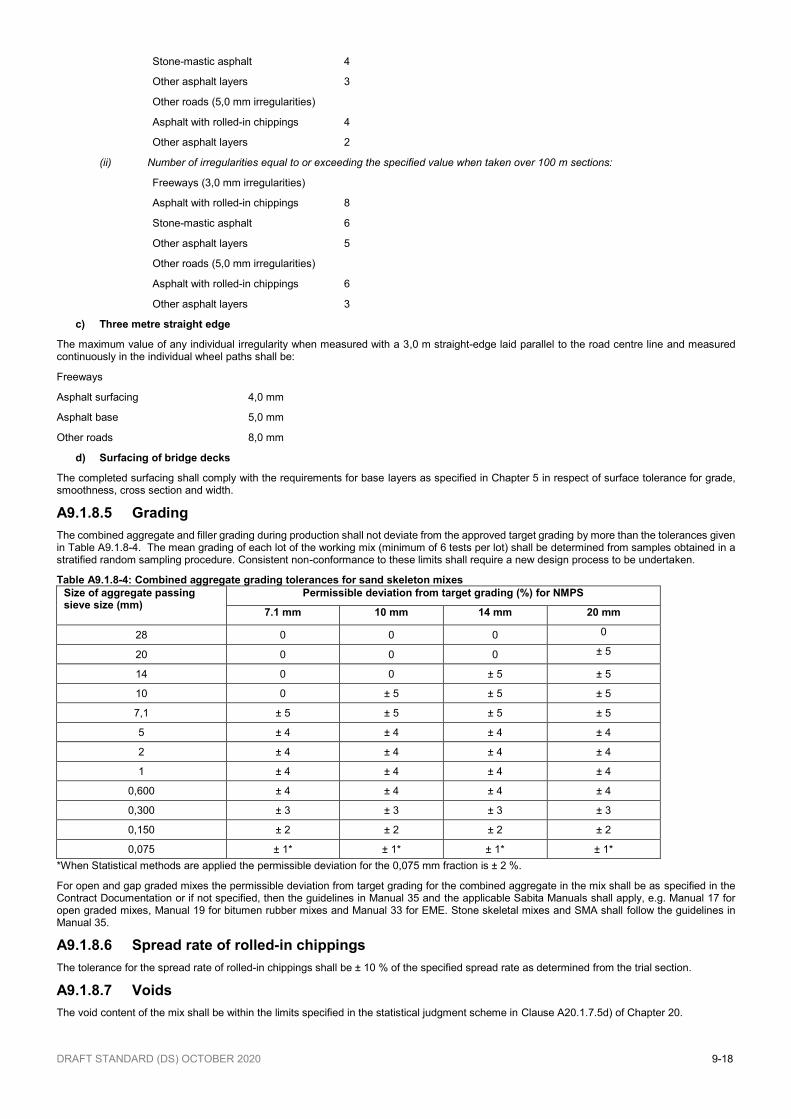
DRAFT STANDARD (DS) OCTOBER 2020 9-18
Stone-mastic asphalt 4
Other asphalt layers 3
Other roads (5,0 mm irregularities)
Asphalt with rolled-in chippings 4
Other asphalt layers 2
(ii) Number of irregularities equal to or exceeding the specified value when taken over 100 m sections:
Freeways (3,0 mm irregularities)
Asphalt with rolled-in chippings 8
Stone-mastic asphalt 6
Other asphalt layers 5
Other roads (5,0 mm irregularities)
Asphalt with rolled-in chippings 6
Other asphalt layers 3
c) Three metre straight edge
The maximum value of any individual irregularity when measured with a 3,0 m straight-edge laid parallel to the road centre line and measured continuously in the individual wheel paths shall be:
Freeways
Asphalt surfacing 4,0 mm
Asphalt base 5,0 mm
Other roads 8,0 mm
d) Surfacing of bridge decks
The completed surfacing shall comply with the requirements for base layers as specified in Chapter 5 in respect of surface tolerance for grade, smoothness, cross section and width.
A9.1.8.5 Grading
The combined aggregate and filler grading during production shall not deviate from the approved target grading by more than the tolerances given in Table A9.1.8-4. The mean grading of each lot of the working mix (minimum of 6 tests per lot) shall be determined from samples obtained in a stratified random sampling procedure. Consistent non-conformance to these limits shall require a new design process to be undertaken.
Table A9.1.8-4: Combined aggregate grading tolerances for sand skeleton mixes
Size of aggregate passing sieve size (mm)
Permissible deviation from target grading (%) for NMPS
7.1 mm 10 mm 14 mm 20 mm
28 0 0 0 0
20 0 0 0 ± 5
14 0 0 ± 5 ± 5
10 0 ± 5 ± 5 ± 5
7,1 ± 5 ± 5 ± 5 ± 5
5 ± 4 ± 4 ± 4 ± 4
2 ± 4 ± 4 ± 4 ± 4
1 ± 4 ± 4 ± 4 ± 4
0,600 ± 4 ± 4 ± 4 ± 4
0,300 ± 3 ± 3 ± 3 ± 3
0,150 ± 2 ± 2 ± 2 ± 2
0,075 ± 1* ± 1* ± 1* ± 1*
*When Statistical methods are applied the permissible deviation for the 0,075 mm fraction is ± 2 %.
For open and gap graded mixes the permissible deviation from target grading for the combined aggregate in the mix shall be as specified in the Contract Documentation or if not specified, then the guidelines in Manual 35 and the applicable Sabita Manuals shall apply, e.g. Manual 17 for open graded mixes, Manual 19 for bitumen rubber mixes and Manual 33 for EME. Stone skeletal mixes and SMA shall follow the guidelines in Manual 35.
A9.1.8.6 Spread rate of rolled-in chippings
The tolerance for the spread rate of rolled-in chippings shall be ± 10 % of the specified spread rate as determined from the trial section.
A9.1.8.7 Voids
The void content of the mix shall be within the limits specified in the statistical judgment scheme in Clause A20.1.7.5d) of Chapter 20.
DRAFT STANDARD (DS) OCTOBER 2020 9-19
A9.1.8.8 Sampling
a) Component and mix sampling
Sampling of aggregates, bitumen and manufactured asphalt mix for testing shall be in accordance with the relevant methods prescribed in TMH 5: Sampling Methods for Road Construction Materials.
b) Coring of completed layers
If required in the Contract Documentation, the Contractor shall provide suitable coring machines capable of cutting 100 mm or 150 mm diameter cores from the completed asphalt layers. The Contractor will be paid in accordance with item C9.1.13 for cutting cores ordered by the Engineer. The cost of extracting cores for process control shall be included in the Contractor's prices for the construction of asphalt pavement layers and will not be paid for separately. The coring equipment, traffic accommodation requirements and associated procedures must be approved by the Engineer.
Should the Contractor does not adhere to the approved program, the Engineer may temporarily suspend the paving operations.
All core holes shall be neatly repaired with asphalt and compacted to the specified density. Wherever possible the cores shall be filled with the same mix as used for the layer tested.
A suitable coring machine shall be available on a daily basis when asphalt paving is taking place. Cores shall only be drilled when the road temperature is 20°C or less. Core holes shall be filled with hot mix asphalt and compacted, all within 24 hours of the core being drilled. Cores shall be extracted within 48 hours after the paving has been completed and supplied to the Engineer.
c) Routine inspection and tests
Routine inspection and tests will be carried out by the Engineer to determine the quality of the materials and workmanship for compliance with the requirements of this Chapter.
Test results and measurements shall be assessed in accordance with the provisions of this chapter as well as the applicable statistical judgment principles specified in Clause A20.1.7 of Chapter 20.
Notwithstanding the requirements specified above, during assessment of the trial section, and during normal production, cores shall be regularly extracted from the compacted layer immediately adjacent to the longitudinal joint after trimming of the edge. If the asphalt in this area indicates a compaction level below that specified, then that area of lot shall be assessed as a separate lot to confirm full compliance with the required compaction over the full width of the mat.
The Contractor shall keep accurate records of:
- The position where every truckload of asphalt is paved (stake value, lane, date and time). - The temperatures of the asphalt in the trucks both at the mixing plant and at the paving equipment immediately prior to discharging the load
into the paver. - The truck and load number from which test samples are taken. All samples taken shall be appropriately labelled and submitted to the
Engineer for further testing and assessment.

DRAFT STANDARD (DS) OCTOBER 2020 9-20
B9.1 ASPHALT LAYERS
PART B: LABOUR ENHANCEMENT
CONTENTS
B9.1.1 SCOPE
B9.1.2 DEFINITIONS
B9.1.3 GENERAL
B9.1.4 DESIGN BY CONTRACTOR / PERFORMANCE BASED SYSTEMS
B9.1.5 MATERIALS
B9.1.6 CONSTRUCTION EQUIPMENT
B9.1.7 EXECUTION OF THE WORKS
B9.1.8 WORKMANSHIP
B9.1.1 SCOPE
This Section covers the labour enhancement activities associated with the placing of asphalt layers as specified in Part A.
B9.1.2 DEFINITIONS
Definitions as provided in A9.1.2 shall apply.
B9.1.3 GENERAL
Any activity specified in Part A, where hand work is given as an alternative, shall be executed in such a way as to optimise labour.
B9.1.4 DESIGN BY CONTRACTOR/PERFORMANCE BASED SYSTEMS
The provisions of Part A shall apply.
B9.1.5 MATERIALS
The provisions of Part A shall apply.
B9.1.6 CONSTRUCTION EQUIPMENT
The use of light equipment shall be evaluated during trial sections.
B9.1.7 EXECUTION OF THE WORKS
The scope for labour enhancement associated with asphalt surfacing, may be the preparation activities (sweeping, watering and protection of kerbs and roadside furniture) and the placing of the asphalt in appropriate areas, such as driveways, parking areas, sidewalks and lower order streets.
The mixing and supply of the various mix-types (HMA, WMA, recycled and reclaimed) will be in accordance with the specifications in Part A.
Certified asphalt mix-types must be manufactured, supplied and placed as determined by the certification agency
The Contractor shall prepare and submit a method statement of how the work will be executed. At least the following aspects must be dealt with:
a) Construction Equipment
- Tools and guides required to achieve the specified dimensions and tolerances (thickness, surface regularity, compaction)
- Roller Type
- Protection Wear
b) Work Force
- Size of the workforce
- Required skill levels

DRAFT STANDARD (DS) OCTOBER 2020 9-21
c) Execution of the Works
- Spreading technique
- Rolling pattern
- Jointing
B9.1.8 WORKMANSHIP
The provisions of Part A shall apply.
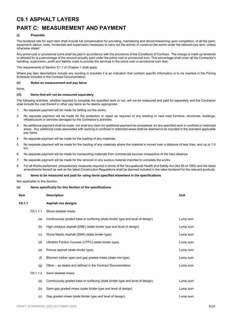
DRAFT STANDARD (DS) OCTOBER 2020 9-22
C9.1 ASPHALT LAYERS
PART C: MEASUREMENT AND PAYMENT
(i) Preamble
The tendered rate for each item shall include full compensation for providing, maintaining and decommissioning upon completion, of all the plant, equipment, labour, tools, incidentals and supervision necessary to carry out the activity or construct the works under the relevant pay item, unless otherwise stated.
Any prime cost or provisional sums shall be paid in accordance with the provisions of the Conditions of Contract. The charge or mark-up tendered or allowed for is a percentage of the amount actually paid under the prime cost or provisional sum. This percentage shall cover all the Contractor’s handling, supervision, profit and liability costs to provide the services in the prime cost or provisional sum item.
The requirements of Section C1.1 of Chapter 1 shall apply.
Where pay item descriptions include any wording in brackets it is an indication that contract specific information is to be inserted in the Pricing Schedule included in the Contract Documentation.
(ii) Notes on measurement and pay Items
None.
(iii) Items that will not be measured separately
The following activities, whether required to complete the specified work or not, will not be measured and paid for separately and the Contractor shall include the cost thereof in other pay items as he deems appropriate:
1. No separate payment will be made for setting out the works.
2. No separate payment will be made for the protection or repair as required of any existing or new road furniture, structures, buildings, infrastructure or services damaged by the Contractor’s activities.
3. No additional payment shall be made, nor shall any claim for additional payment be considered, for any specified work in confined or restricted areas. Any additional costs associated with working in confined or restricted areas shall be deemed to be included in the standard applicable pay items.
4. No separate payment will be made for the loading of any materials.
5. No separate payment will be made for the hauling of any materials where the material is moved over a distance of less than, and up to 1,0 km.
6. No separate payment will be made for transporting materials from commercial sources irrespective of the haul distance.
7. No separate payment will be made for the removal or any surplus material imported to complete the works.
8. For all Works performed, precautionary measures required in terms of the Occupational Health and Safety Act (Act 85 of 1993) and the latest amendments thereof as well as the latest Construction Regulations shall be deemed included in the rates tendered for the relevant products.
(iv) Items to be measured and paid for using items specified elsewhere in the specifications
Not applicable to this Section.
(v) Items specifically for this Section of the specifications
Item Description Unit
C9.1.1 Asphalt mix designs
C9.1.1.1 Stone skeletal mixes:
(a) Continuously graded base or surfacing (state binder type and level of design). Lump sum
(b) High modulus asphalt (EME) (state binder type and level of design) Lump sum
(c) Stone Mastic Asphalt (SMA) (state binder type) Lump sum
(d) Ultrathin Friction Courses (UTFC) (state binder type). Lump sum
(e) Porous asphalt (state binder type). Lump sum
(f) Bitumen rubber open and gap graded mixes (state mix type) Lump sum
(g) Other – as stated and defined in the Contract Documentation Lump sum
C9.1.1.2 Sand skeletal mixes:
(a) Continuously graded base or surfacing (state binder type and level of design). Lump sum
(b) Semi-gap graded mixes (state binder type and level of design) Lump sum
(c) Gap graded mixes (state binder type and level of design). Lump sum
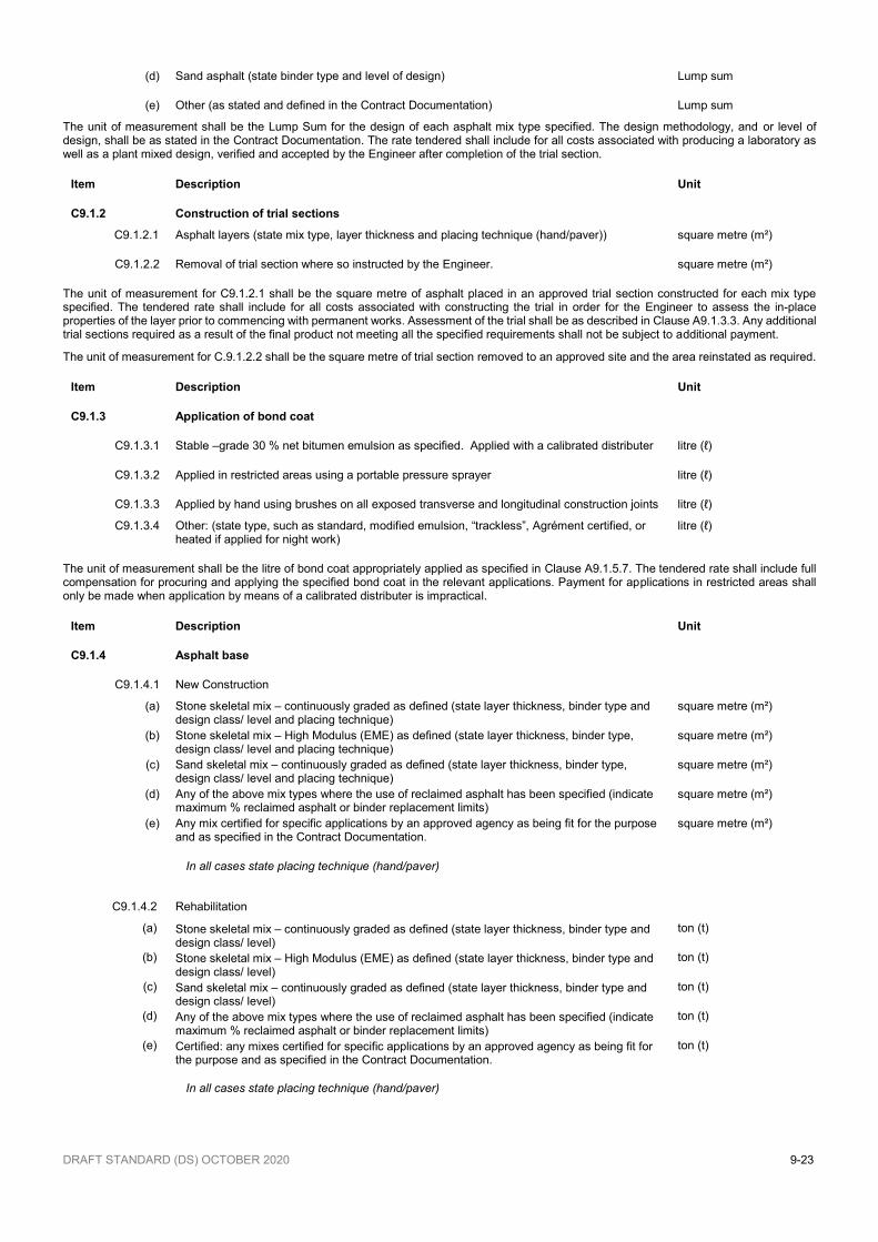
DRAFT STANDARD (DS) OCTOBER 2020 9-23
(d) Sand asphalt (state binder type and level of design) Lump sum
(e) Other (as stated and defined in the Contract Documentation) Lump sum
The unit of measurement shall be the Lump Sum for the design of each asphalt mix type specified. The design methodology, and or level of design, shall be as stated in the Contract Documentation. The rate tendered shall include for all costs associated with producing a laboratory as well as a plant mixed design, verified and accepted by the Engineer after completion of the trial section.
Item Description Unit
C9.1.2 Construction of trial sections
C9.1.2.1 Asphalt layers (state mix type, layer thickness and placing technique (hand/paver))
square metre (m²)
C9.1.2.2 Removal of trial section where so instructed by the Engineer. square metre (m²)
The unit of measurement for C9.1.2.1 shall be the square metre of asphalt placed in an approved trial section constructed for each mix type specified. The tendered rate shall include for all costs associated with constructing the trial in order for the Engineer to assess the in-place properties of the layer prior to commencing with permanent works. Assessment of the trial shall be as described in Clause A9.1.3.3. Any additional trial sections required as a result of the final product not meeting all the specified requirements shall not be subject to additional payment.
The unit of measurement for C.9.1.2.2 shall be the square metre of trial section removed to an approved site and the area reinstated as required.
Item Description Unit
C9.1.3 Application of bond coat
C9.1.3.1 Stable –grade 30 % net bitumen emulsion as specified. Applied with a calibrated distributer litre (ℓ)
C9.1.3.2 Applied in restricted areas using a portable pressure sprayer litre (ℓ)
C9.1.3.3 Applied by hand using brushes on all exposed transverse and longitudinal construction joints litre (ℓ)
C9.1.3.4 Other: (state type, such as standard, modified emulsion, “trackless”, Agrément certified, or heated if applied for night work)
litre (ℓ)
The unit of measurement shall be the litre of bond coat appropriately applied as specified in Clause A9.1.5.7. The tendered rate shall include full compensation for procuring and applying the specified bond coat in the relevant applications. Payment for applications in restricted areas shall only be made when application by means of a calibrated distributer is impractical.
Item Description Unit
C9.1.4 Asphalt base
C9.1.4.1 New Construction
(a) Stone skeletal mix – continuously graded as defined (state layer thickness, binder type and design class/ level and placing technique)
square metre (m²)
(b) Stone skeletal mix – High Modulus (EME) as defined (state layer thickness, binder type, design class/ level and placing technique)
square metre (m²)
(c) Sand skeletal mix – continuously graded as defined (state layer thickness, binder type, design class/ level and placing technique)
square metre (m²)
(d) Any of the above mix types where the use of reclaimed asphalt has been specified (indicate maximum % reclaimed asphalt or binder replacement limits)
square metre (m²)
(e) Any mix certified for specific applications by an approved agency as being fit for the purpose and as specified in the Contract Documentation.
square metre (m²)
In all cases state placing technique (hand/paver)
C9.1.4.2 Rehabilitation
(a) Stone skeletal mix – continuously graded as defined (state layer thickness, binder type and design class/ level)
ton (t)
(b) Stone skeletal mix – High Modulus (EME) as defined (state layer thickness, binder type and design class/ level)
ton (t)
(c) Sand skeletal mix – continuously graded as defined (state layer thickness, binder type and design class/ level)
ton (t)
(d) Any of the above mix types where the use of reclaimed asphalt has been specified (indicate maximum % reclaimed asphalt or binder replacement limits)
ton (t)
(e) Certified: any mixes certified for specific applications by an approved agency as being fit for the purpose and as specified in the Contract Documentation.
ton (t)
In all cases state placing technique (hand/paver)
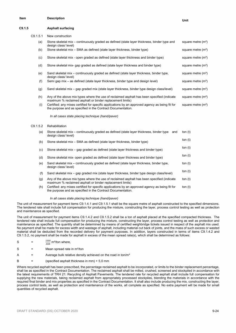
DRAFT STANDARD (DS) OCTOBER 2020 9-24
Item Description Unit
C9.1.5 Asphalt surfacing
C9.1.5.1 New construction
(a) Stone skeletal mix – continuously graded as defined (state layer thickness, binder type and design class/ level)
square metre (m²)
(b) Stone skeletal mix – SMA as defined (state layer thickness, binder type) square metre (m²)
(c) Stone skeletal mix - open graded as defined (state layer thickness and binder type) square metre (m²)
(d) Stone skeletal mix- gap graded as defined (state layer thickness and binder type) square metre (m²)
(e) Sand skeletal mix – continuously graded as defined (state layer thickness, binder type, design class/ level)
square metre (m²)
(f) Semi gap mix – as defined (state layer thickness, binder type and design level) square metre (m²)
(g) Sand skeletal mix – gap graded mix (state layer thickness, binder type design class/level) square metre (m²)
(h) Any of the above mix types where the use of reclaimed asphalt has been specified (indicate maximum % reclaimed asphalt or binder replacement limits)
square metre (m²)
(i) Certified: any mixes certified for specific applications by an approved agency as being fit for the purpose and as specified in the Contract Documentation.
square metre (m²)
In all cases state placing technique (hand/paver)
C9.1.5.2 Rehabilitation
(a) Stone skeletal mix – continuously graded as defined (state layer thickness, binder type and design class/ level)
ton (t)
(b) Stone skeletal mix – SMA as defined (state layer thickness, binder type) ton (t)
(c) Stone skeletal mix – gap graded as defined (state layer thickness and binder type) ton (t)
(d) Stone skeletal mix- open graded as defined (state layer thickness and binder type) ton (t)
(e) Sand skeletal mix – continuously graded as defined (state layer thickness, binder type, design class/ level)
ton (t)
(f) Sand skeletal mix – gap graded mix (state layer thickness, binder type design class/level) ton (t)
(g) Any of the above mix types where the use of reclaimed asphalt has been specified (indicate maximum % reclaimed asphalt or binder replacement limits)
ton (t)
(h) Certified: any mixes certified for specific applications by an approved agency as being fit for the purpose and as specified in the Contract Documentation.
ton (t)
In all cases state placing technique (hand/paver)
The unit of measurement for payment items C9.1.4.1 and C9.1.5.1 shall be the square metre of asphalt constructed to the specified dimensions. The tendered rate shall include full compensation for producing the mixture, constructing the layer, process control testing as well as protection and maintenance as specified.
The unit of measurement for payment items C9.1.4.2 and C9.1.5.2 shall be a ton of asphalt placed at the specified compacted thickness. The tendered rate shall include full compensation for producing the mixture, constructing the layer, process control testing as well as protection and maintenance as specified. The quantity shall be determined by means of certified weighbridge tickets issued in respect of the asphalt mix used. No payment shall be made for excess width and wastage of asphalt, including material cut back of joints, and the mass of such excess or wasted material shall be deducted from the recorded delivery for payment purposes. In addition, layers constructed in terms of items C9.1.4.2 and C9.1.5.2, no payment shall be made for asphalt in excess of the mean spread rate(s), which shall be determined as follows:
S = 1000
AXB m²/ton where,
S = Mean spread rate in m²/ton
A = Average bulk relative density achieved on the road in ton/m³
B = (specified asphalt thickness in mm) + 5,0 mm
Where recycled asphalt has been prescribed, the percentage reclaimed asphalt to be incorporated, or limits to the binder replacement percentage, shall be as specified in the Contract Documentation. The reclaimed asphalt shall be milled, crushed, screened and stockpiled in accordance with the latest requirements of TRH 21: Recycling of Asphalt Pavements. The tendered rate for recycled asphalt shall include full compensation for supplying the new materials, taking reclaimed asphalt from appropriately processed stockpiles, blending the materials in accordance with the required final binder and mix properties as specified in the Contract Documentation. It shall also include producing the mix, constructing the layer, process control tests, as well as protection and maintenance of the works, all complete as specified. No extra payment will be made for small quantities of recycled asphalt.
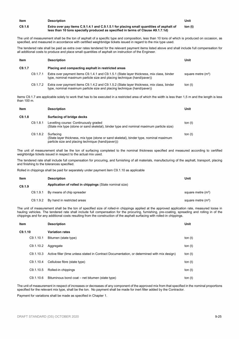
DRAFT STANDARD (DS) OCTOBER 2020 9-25
Item Description Unit
C9.1.6 Extra over pay items C.9.1.4.1 and C.9.1.5.1 for placing small quantities of asphalt of less than 10 tons specially produced as specified in terms of Clause A9.1.7.1d)
ton (t)
The unit of measurement shall be the ton of asphalt of a specific type and composition, less than 10 tons of which is produced on occasion, as specified, and measured in accordance with certified weighbridge tickets issued in regard to the mix type used.
The tendered rate shall be paid as extra over rates tendered for the relevant payment items listed above and shall include full compensation for all additional costs to produce and place small quantities of asphalt on instruction of the Engineer.
Item Description Unit
C9.1.7 Placing and compacting asphalt in restricted areas
C9.1.7.1 Extra over payment items C9.1.4.1 and C9.1.5.1 (State layer thickness, mix class, binder type, nominal maximum particle size and placing technique (hand/paver))
square metre (m²)
C9.1.7.2 Extra over payment items C9.1.4.2 and C9.1.5.2 (State layer thickness, mix class, binder type, nominal maximum particle size and placing technique (hand/paver))
ton (t)
Items C9.1.7 are applicable solely to work that has to be executed in a restricted area of which the width is less than 1,5 m and the length is less than 100 m.
Item Description Unit
C9.1.8 Surfacing of bridge decks
C9.1.8.1 Levelling course: Continuously graded (State mix type (stone or sand skeletal), binder type and nominal maximum particle size)
ton (t)
C9.1.8.2 Surfacing (State layer thickness, mix type (stone or sand skeletal), binder type, nominal maximum particle size and placing technique (hand/paver)))
ton (t)
The unit of measurement shall be the ton of surfacing completed to the nominal thickness specified and measured according to certified weighbridge tickets issued in respect to the actual mix used.
The tendered rate shall include full compensation for procuring, and furnishing of all materials, manufacturing of the asphalt, transport, placing and finishing to the tolerances specified.
Rolled in chippings shall be paid for separately under payment item C9.1.10 as applicable
Item Description Unit
C9.1.9 Application of rolled in chippings (State nominal size)
C9.1.9.1 By means of chip spreader square metre (m²)
C9.1.9.2 By hand in restricted areas square metre (m²)
The unit of measurement shall be the ton of specified size of rolled-in chippings applied at the approved application rate, measured loose in hauling vehicles. The tendered rate shall include full compensation for the procuring, furnishing, pre-coating, spreading and rolling in of the chippings and for any additional costs resulting from the construction of the asphalt surfacing with rolled-in chippings.
Item Description Unit
C9.1.10 Variation rates
C9.1.10.1 Bitumen (state type) ton (t)
C9.1.10.2 Aggregate ton (t)
C9.1.10.3 Active filler (lime unless stated in Contract Documentation, or determined with mix design)
ton (t)
C9.1.10.4 Cellulose fibre (state type) ton (t)
C9.1.10.5 Rolled-in chippings ton (t)
C9.1.10.6 Bituminous bond coat – net bitumen (state type) ton (t)
The unit of measurement in respect of increases or decreases of any component of the approved mix from that specified in the nominal proportions specified for the relevant mix type, shall be the ton. No payment shall be made for inert filler added by the Contractor.
Payment for variations shall be made as specified in Chapter 1.
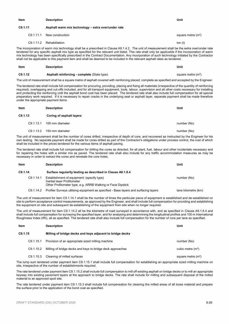
DRAFT STANDARD (DS) OCTOBER 2020 9-26
Item Description Unit
C9.1.11 Asphalt warm mix technology – extra over/under rate
C9.1.11.1 New construction square metre (m²)
C9.1.11.2 Rehabilitation ton (t)
The incorporation of warm mix technology shall be a prescribed in Clause A9.1.4.2. The unit of measurement shall be the extra over/under rate tendered for any specific asphalt mix type as specified for the relevant unit listed. This rate shall only be applicable if the incorporation of warm mix technology has been specifically prescribed in the Contract Documentation. Any incorporation of such technology initiated by the Contractor shall not be applicable to this payment item and shall be deemed to be included in the relevant asphalt rates as tendered.
Item Description Unit
C9.1.12 Asphalt reinforcing - complete (State type) square metre (m²)
The unit of measurement shall be a square metre of asphalt covered with reinforcing placed, complete as specified and accepted by the Engineer.
The tendered rate shall include full compensation for procuring, providing, placing and fixing all materials (irrespective of the quantity of reinforcing required), overlapping and cut-offs included, and for all transport equipment, tools, labour, supervision and all other costs necessary for installing and protecting the reinforcing until the asphalt bond coat has been placed. The tendered rate shall also include full compensation for all special preparatory work required. If it is necessary to repair cracks in the underlying seal or asphalt layer, separate payment shall be made therefore under the appropriate payment items.
Item Description Unit
C9.1.13 Coring of asphalt layers
C9.1.13.1 100 mm diameter number (No)
C9.1.13.2 150 mm diameter number (No)
The unit of measurement shall be the number of cores drilled, irrespective of depth of core, and recovered as instructed by the Engineer for his own testing. No separate payment shall be made for cores drilled as part of the Contractor's obligations under process control, the cost of which shall be included in the prices tendered for the various items of asphalt paving.
The tendered rate shall include full compensation for drilling the cores as directed, for all plant, fuel, labour and other incidentals necessary and for repairing the holes with a similar mix as paved. The tendered rate shall also include for any traffic accommodation measures as may be necessary in order to extract the cores and reinstate the core holes.
Item Description Unit
C9.1.14 Surface regularity testing as described in Clause A9.1.8.4
C9.1.14.1 Establishment of equipment: (specify type) Inertial laser Profilometer Other Profilometer type, e.g. ARRB Walking or Face Dipstick
number (No)
C9.1.14.2 Profiler Surveys utilising equipment as specified - Base layers and surfacing layers lane kilometre (km)
The unit of measurement for item C9.1.14.1 shall be the number of times the particular piece of equipment is established and de-established on site to perform acceptance control measurements, as approved by the Engineer, and shall include full compensation for providing and establishing the equipment on site and subsequent de-establishing of the equipment from site when no longer required.
The unit of measurement for item C9.1.14.2 all be the kilometre of road surveyed in accordance with, and as specified in Clause A9.1.8.4 and shall include full compensation for surveying the specified layer, and for analysing and determining the longitudinal profiles and 100 m International Roughness Index (IRI), all as specified. The tendered rate shall also include full compensation for the number of runs per lane as specified.
Item Description Unit
C9.1.15 Milling of bridge decks and keys adjacent to bridge decks
C9.1.15.1 Provision of an appropriate sized milling machine number (No)
C9.1.15.2 Milling of bridge decks and keys to bridge deck approaches cubic metre (m³)
C9.1.15.3 Cleaning of milled surfaces square metre (m²)
The lump sum tendered under payment item C9.1.15.1 shall include full compensation for establishing an appropriate sized milling machine on site, irrespective of the number of establishments required.
The rate tendered under payment item C9.1.15.2 shall include full compensation to mill off existing asphalt on bridge decks or to mill an appropriate keyway into existing pavement layers at the approach to bridge decks. The rate shall include for milling and subsequent disposal of the milled material to an approved spoil site.
The rate tendered under payment item C9.1.15.3 shall include full compensation for cleaning the milled areas of all loose material and prepare the surface prior to the application of the bond coat as specified.

DRAFT STANDARD (DS) OCTOBER 2020 9-27
Item Description Unit
C9.1.16 Work undertaken in accordance with a Product Performance Guarantee System
C9.1.16.1 Provision of a Performance Guarantee Lump sum
C9.1.16.2 Construction of pavement layer (indicate layer/s) square metre (m²)
The tendered lump sum under payment item C9.1.16.1 shall include full compensation for the cost of appointing a competent designer, carrying out additional tests and for the provision of a bank guarantee in respect of the road pavement structure the value of 10 % of the Contract Value, valid for the period prescribed in the Contract Documentation.
The tenderer shall, with his tender, provide documentation to confirm that a design performance guarantee as required shall be provided by an acceptable financial institution should the tender be successful. The performance guarantee as required shall be submitted to the Employer by the successful Contractor before signing of the contract including the applicable date of commencement of validity of the guarantee stated to be from the Taking-over Certificate and its estimated date.
The guarantee shall be prepared in accordance with the format provided in the Contract Documentation. The terms and conditions applicable to the release of the performance guarantee shall be as described in Clause D9.1.3 in Part D of this Chapter.
The tendered lump sum shall not be subject to Contract Price Adjustment and shall become payable once the Contractor has submitted and the Employer has accepted the guarantee.
The rate tendered under payment item C9.1.16.2 shall include all costs associated with constructing the relevant pavement layers, all as specified in the Contract Documentation.
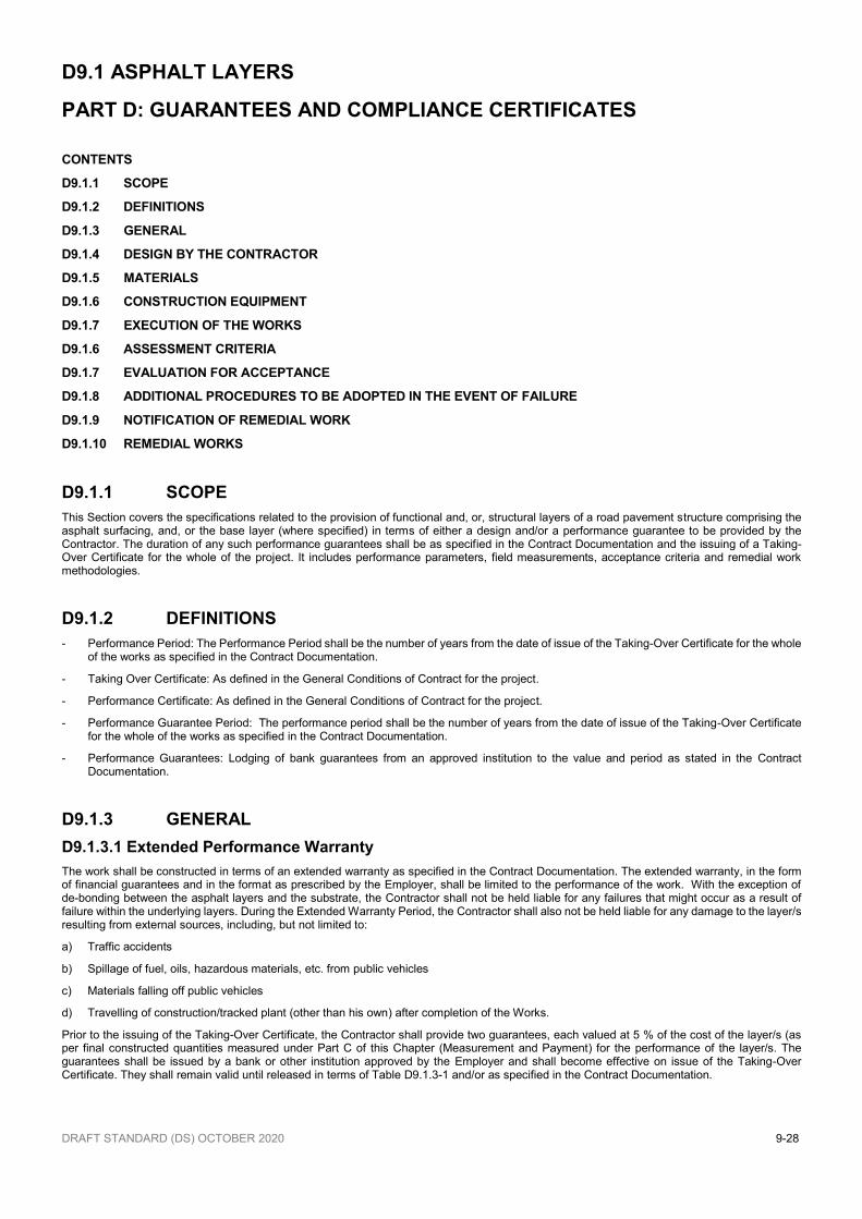
DRAFT STANDARD (DS) OCTOBER 2020 9-28
D9.1 ASPHALT LAYERS
PART D: GUARANTEES AND COMPLIANCE CERTIFICATES
CONTENTS
D9.1.1 SCOPE
D9.1.2 DEFINITIONS
D9.1.3 GENERAL
D9.1.4 DESIGN BY THE CONTRACTOR
D9.1.5 MATERIALS
D9.1.6 CONSTRUCTION EQUIPMENT
D9.1.7 EXECUTION OF THE WORKS
D9.1.6 ASSESSMENT CRITERIA
D9.1.7 EVALUATION FOR ACCEPTANCE
D9.1.8 ADDITIONAL PROCEDURES TO BE ADOPTED IN THE EVENT OF FAILURE
D9.1.9 NOTIFICATION OF REMEDIAL WORK
D9.1.10 REMEDIAL WORKS
D9.1.1 SCOPE
This Section covers the specifications related to the provision of functional and, or, structural layers of a road pavement structure comprising the asphalt surfacing, and, or the base layer (where specified) in terms of either a design and/or a performance guarantee to be provided by the Contractor. The duration of any such performance guarantees shall be as specified in the Contract Documentation and the issuing of a Taking-Over Certificate for the whole of the project. It includes performance parameters, field measurements, acceptance criteria and remedial work methodologies.
D9.1.2 DEFINITIONS
- Performance Period: The Performance Period shall be the number of years from the date of issue of the Taking-Over Certificate for the whole of the works as specified in the Contract Documentation.
- Taking Over Certificate: As defined in the General Conditions of Contract for the project.
- Performance Certificate: As defined in the General Conditions of Contract for the project.
- Performance Guarantee Period: The performance period shall be the number of years from the date of issue of the Taking-Over Certificate for the whole of the works as specified in the Contract Documentation.
- Performance Guarantees: Lodging of bank guarantees from an approved institution to the value and period as stated in the Contract Documentation.
D9.1.3 GENERAL
D9.1.3.1 Extended Performance Warranty
The work shall be constructed in terms of an extended warranty as specified in the Contract Documentation. The extended warranty, in the form of financial guarantees and in the format as prescribed by the Employer, shall be limited to the performance of the work. With the exception of de-bonding between the asphalt layers and the substrate, the Contractor shall not be held liable for any failures that might occur as a result of failure within the underlying layers. During the Extended Warranty Period, the Contractor shall also not be held liable for any damage to the layer/s resulting from external sources, including, but not limited to:
a) Traffic accidents
b) Spillage of fuel, oils, hazardous materials, etc. from public vehicles
c) Materials falling off public vehicles
d) Travelling of construction/tracked plant (other than his own) after completion of the Works.
Prior to the issuing of the Taking-Over Certificate, the Contractor shall provide two guarantees, each valued at 5 % of the cost of the layer/s (as per final constructed quantities measured under Part C of this Chapter (Measurement and Payment) for the performance of the layer/s. The guarantees shall be issued by a bank or other institution approved by the Employer and shall become effective on issue of the Taking-Over Certificate. They shall remain valid until released in terms of Table D9.1.3-1 and/or as specified in the Contract Documentation.

DRAFT STANDARD (DS) OCTOBER 2020 9-29
The program for the release of the guarantees shall be as follows:
Table D9.1.3-1: Program of release of guarantees
Time Activity
Completion of Works and issue of the Taking-Over Certificate Provision of two guarantees (5 % & 5 %)
Payment of 50% of retention (as per the relevant GCC)
Acceptable performance of Works one year after issuing of the Taking-Over Certificate
Payment of balance of retention to be released upon issuing of Performance Certificate (as defined in the
GCC relevant to the Project)
Acceptable performance of layers (number of years as defined in the Contract Documentation) after issuing of the Taking-Over Certificate
Release of 1st guarantee (5%)
Acceptable performance of layers (number of years as defined in the Contract Documentation) after issuing of the Taking-Over Certificate
Release of 2nd guarantee (5%)
D9.1.3.2 Quality Plan
Prior to commencing with any permanent works, the Contractor shall submit a Quality Plan, for acceptance by the Engineer, detailing all checks and hold points relating to construction of the specified product.
D9.1.3.3 Nominal mix proportions
The Contractor shall determine the mix proportions based on his design/s. No variations to his nominal proportions shall be payable under this Section.
D9.1.3.4 Trial sections
Prior to executing any permanent work, the Contractor shall conduct trial sections as described in Part A of this Chapter for the necessary approvals. No additional payment shall be made for such trial sections.
D9.1.3.5 Weather limitations
Unless so specifically stated in Form E1: Quality Assurance and approved by the Engineer, the weather limitations as specified in Part A shall be applicable in all instances.
D9.1.3.6 Moisture
The requirements with respect to moisture as specified in Clause A9.3.5 shall be applicable in all instances.
D9.1.3.7 Surface preparation and requirements
Unless so specifically stated in Form E1: Quality Assurance and approved by the Engineer, the requirements for surface preparation as specified in Part A of this Chapter shall be applicable in all instances.
D9.1.4 DESIGN BY CONTRACTOR
It shall be the Contractor’s responsibility to ensure that the information provided in the Contract Documentation is sufficient in order to carry out his own assessment of the condition of the road. The contract may carry out additional testing/assessment, after approval by the relevant road authority, in order to ensure that there is sufficient information for him to carry out an appropriate design in order for its performance to comply with the specified criteria.
In the event that a design is specified, the Contractor shall ensure that he has sufficient information to assess and accept the specified design and to ensure it shall perform to the specified criteria.
In order to achieve the design, or acceptance, of the specified design, the Contractor shall appoint a competent designer. The Contractor shall take full responsibility for the performance of the designer and no separate payment shall be made for any costs thereof, or for any additional testing deemed necessary.
D9.1.5 MATERIALS
Unless contrary to the requirements of a certified proprietary product, the constituents shall comply with the following requirements:
D9.1.5.1 Bond coat/s The bond/s coat shall be as stated by the tenderer (Form E1: Quality Assurance) which shall include the proposed application rate, as well as the type and proposed percentage modifier (if any). The bond coat/s shall be applied in a continuous spray and application by means of hand spray shall not be permitted. Where a self-priming paver is not used, the tack coat shall have such properties as to not be picked up by construction (or other) traffic during the paving operation.
D9.1.5.2 Bituminous binders a) Unless specifically stated in Form E1, the type of binder utilised in the mix shall conform to the relevant requirements for the selected binder
as specified in Part A of this Chapter. Should the Contractor wish to use a binder with properties different from those specified in Part A, further details regarding the composition, test methods and acceptance criteria for such binder shall be included in the tender under Form E1: Quality Assurance.

DRAFT STANDARD (DS) OCTOBER 2020 9-30
b) The type and percentage of anti-stripping agent (if applicable) shall be as stated in Form E1: Quality Assurance.
D9.1.5.3 Aggregates a) The aggregates to be utilised in the mix shall comply in all respects with the relevant and appropriate requirements as specified in Part A of
this Chapter. Any deviation or amendments from these requirements shall be stated in Form E1: Quality Assurance. b) The several aggregate fractions for the mixture shall be sized, graded and combined in such proportions that the resulting composite blend
consistently meets the required performance criteria.
D9.1.5.4 Composition of mix The composition of the mix or mixes shall be as proposed by the tenderer in Form E1: Quality Assurance No adjustment of compensation shall be made should the actual mix proportions used in the works vary from that nominated by the Contractor on Form E1: Quality Assurance. The Contractor shall submit to the Engineer his design for the asphalt mixes within thirty (30) days of the date of the Letter of Acceptance. The target binder content, filler content and aggregate grading shall be subject to the tolerances given in Part A of this Chapter as relevant. All production and application shall be carried out in terms of the details included under Form E1: Quality Assurance.
D9.1.6 CONSTRUCTION EQUIPMENT
D9.1.6.1 Mixing plant Unless specifically stated in Form E1: Quality Assurance, all mixing plant utilized shall comply with the relevant requirements as listed in Part A of this Chapter.
D9.1.6.2 Paving equipment Unless specifically stated in Form E1: Quality Assurance, all paving and compaction equipment utilised shall comply with the relevant requirements as listed in Part A of this Chapter.
D9.1.7 EXECUTION OF THE WORKS
Unless specifically stated on Form E1: Quality Assurance the work shall be carried in accordance with all the relevant requirements as specified in Part A of this Chapter in all respects. The application rate for the bond coat shall be nominated by the Contractor for a specific area, taking account of:
- The results of sand-patch tests. - The traffic counts for that area. - The percentage of heavy vehicles. - The dryness of the existing surfacing. - Thickness of the layer being constructed
No adjustment in compensation shall apply should the actual tack coat application be higher or lower than that nominated by the Contractor.
At the approaches to exposed bridge joints the Contractor shall mill out the existing asphalt base or surfacing on the abutment side to a depth of
15 mm (or as may otherwise be prescribed) and for a distance of at least 5,0 m. The asphalt surfacing shall be placed to form a smooth transition towards the bridge joint.
D9.1.8 QUALITY OF MATERIALS AND WORKMANSHIP
D9.1.8.1 Contractor’s obligation.
Specifications regarding workmanship as detailed in Part A of this Chapter for asphalt layers shall apply. In the event that there is a variation to the workmanship requirements and conditions of construction, the Contractor shall clearly state this in his tender document. Failure to do this shall result in the Contractor having to comply with all the workmanship requirements as stated in Part A.
The Contractor shall be required to submit his detailed Quality Assurance Plan to the Engineer for approval within ten (10) days of the date of the Letter of Acceptance. Once it has been approved, the Contractor shall not deviate from it without prior written agreement with the Engineer. The onus rests with the Contractor to produce work which conforms in quality to the Quality Assurance Plan, the specifications and requirements herein, and to other relevant specifications and standards defined in the submitted and accepted tender (e.g. in Form E1: Quality Assurance) The Engineer shall, however, conduct such tests as he may deem applicable and shall retain all rights as determined in the relevant Conditions of Contract related to bad workmanship and to unacceptable materials. This shall also be applicable to the accepted layers (or design) and related specifications.
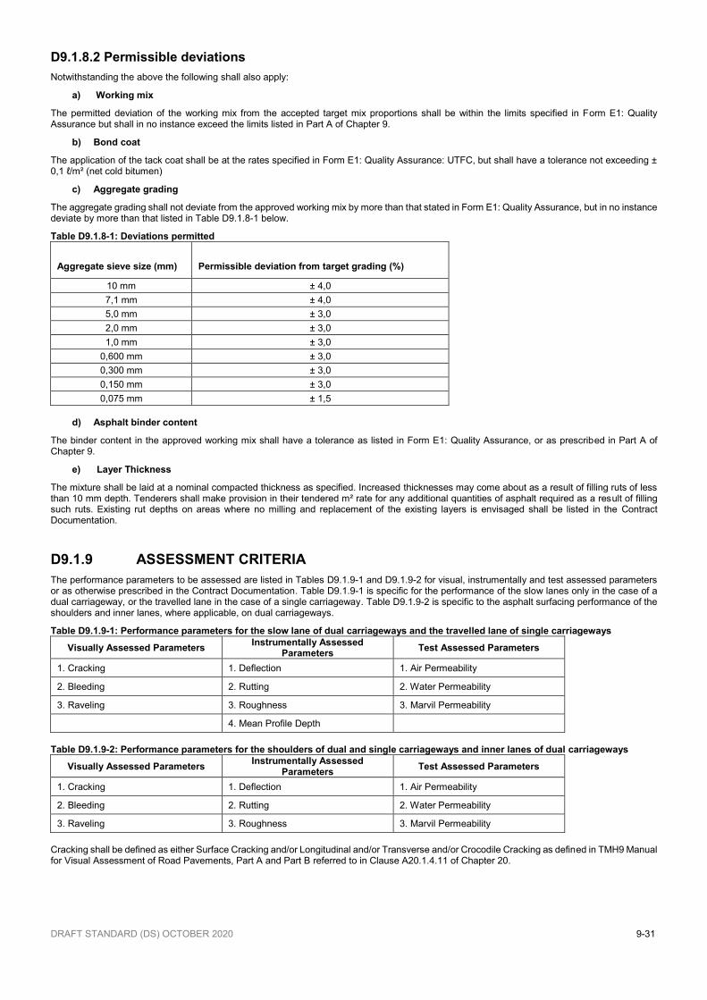
DRAFT STANDARD (DS) OCTOBER 2020 9-31
D9.1.8.2 Permissible deviations
Notwithstanding the above the following shall also apply:
a) Working mix
The permitted deviation of the working mix from the accepted target mix proportions shall be within the limits specified in Form E1: Quality Assurance but shall in no instance exceed the limits listed in Part A of Chapter 9.
b) Bond coat
The application of the tack coat shall be at the rates specified in Form E1: Quality Assurance: UTFC, but shall have a tolerance not exceeding ± 0,1 ℓ/m² (net cold bitumen)
c) Aggregate grading
The aggregate grading shall not deviate from the approved working mix by more than that stated in Form E1: Quality Assurance, but in no instance deviate by more than that listed in Table D9.1.8-1 below.
Table D9.1.8-1: Deviations permitted
Aggregate sieve size (mm) Permissible deviation from target grading (%)
10 mm ± 4,0
7,1 mm ± 4,0
5,0 mm ± 3,0
2,0 mm ± 3,0
1,0 mm ± 3,0
0,600 mm ± 3,0
0,300 mm ± 3,0
0,150 mm ± 3,0
0,075 mm ± 1,5
d) Asphalt binder content
The binder content in the approved working mix shall have a tolerance as listed in Form E1: Quality Assurance, or as prescribed in Part A of Chapter 9.
e) Layer Thickness
The mixture shall be laid at a nominal compacted thickness as specified. Increased thicknesses may come about as a result of filling ruts of less than 10 mm depth. Tenderers shall make provision in their tendered m² rate for any additional quantities of asphalt required as a result of filling such ruts. Existing rut depths on areas where no milling and replacement of the existing layers is envisaged shall be listed in the Contract Documentation.
D9.1.9 ASSESSMENT CRITERIA
The performance parameters to be assessed are listed in Tables D9.1.9-1 and D9.1.9-2 for visual, instrumentally and test assessed parameters or as otherwise prescribed in the Contract Documentation. Table D9.1.9-1 is specific for the performance of the slow lanes only in the case of a dual carriageway, or the travelled lane in the case of a single carriageway. Table D9.1.9-2 is specific to the asphalt surfacing performance of the shoulders and inner lanes, where applicable, on dual carriageways.
Table D9.1.9-1: Performance parameters for the slow lane of dual carriageways and the travelled lane of single carriageways
Visually Assessed Parameters Instrumentally Assessed
Parameters Test Assessed Parameters
1. Cracking 1. Deflection 1. Air Permeability
2. Bleeding 2. Rutting 2. Water Permeability
3. Raveling 3. Roughness 3. Marvil Permeability
4. Mean Profile Depth
Table D9.1.9-2: Performance parameters for the shoulders of dual and single carriageways and inner lanes of dual carriageways
Visually Assessed Parameters Instrumentally Assessed
Parameters Test Assessed Parameters
1. Cracking 1. Deflection 1. Air Permeability
2. Bleeding 2. Rutting 2. Water Permeability
3. Raveling 3. Roughness 3. Marvil Permeability
Cracking shall be defined as either Surface Cracking and/or Longitudinal and/or Transverse and/or Crocodile Cracking as defined in TMH9 Manual for Visual Assessment of Road Pavements, Part A and Part B referred to in Clause A20.1.4.11 of Chapter 20.
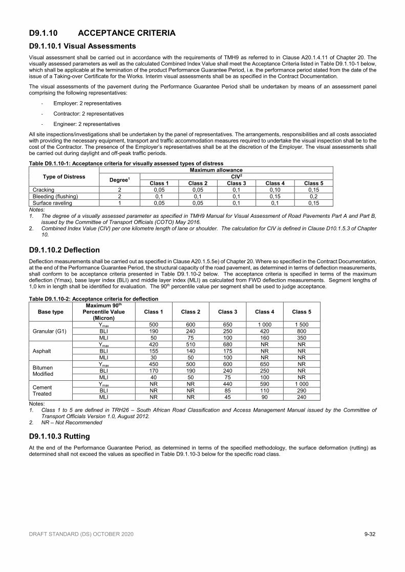
DRAFT STANDARD (DS) OCTOBER 2020 9-32
D9.1.10 ACCEPTANCE CRITERIA
D9.1.10.1 Visual Assessments
Visual assessment shall be carried out in accordance with the requirements of TMH9 as referred to in Clause A20.1.4.11 of Chapter 20. The visually assessed parameters as well as the calculated Combined Index Value shall meet the Acceptance Criteria listed in Table D9.1.10-1 below, which shall be applicable at the termination of the product Performance Guarantee Period, i.e. the performance period stated from the date of the issue of a Taking-over Certificate for the Works. Interim visual assessments shall be as specified in the Contract Documentation.
The visual assessments of the pavement during the Performance Guarantee Period shall be undertaken by means of an assessment panel comprising the following representatives:
- Employer: 2 representatives
- Contractor: 2 representatives
- Engineer: 2 representatives
All site inspections/investigations shall be undertaken by the panel of representatives. The arrangements, responsibilities and all costs associated with providing the necessary equipment, transport and traffic accommodation measures required to undertake the visual inspection shall be to the cost of the Contractor. The presence of the Employer’s representatives shall be at the discretion of the Employer. The visual assessments shall be carried out during daylight and off-peak traffic periods.
Table D9.1.10-1: Acceptance criteria for visually assessed types of distress
Type of Distress
Maximum allowance
Degree1 CIV2
Class 1 Class 2 Class 3 Class 4 Class 5
Cracking 2 0,05 0,05 0,1 0,10 0,15
Bleeding (flushing) 2 0,1 0,1 0,1 0,15 0,2
Surface raveling 1 0,05 0,05 0,1 0,1 0,15
Notes: 1. The degree of a visually assessed parameter as specified in TMH9 Manual for Visual Assessment of Road Pavements Part A and Part B,
issued by the Committee of Transport Officials (COTO) May 2016. 2. Combined Index Value (CIV) per one kilometre length of lane or shoulder. The calculation for CIV is defined in Clause D10.1.5.3 of Chapter
10.
D9.1.10.2 Deflection
Deflection measurements shall be carried out as specified in Clause A20.1.5.5e) of Chapter 20. Where so specified in the Contract Documentation, at the end of the Performance Guarantee Period, the structural capacity of the road pavement, as determined in terms of deflection measurements, shall conform to be acceptance criteria presented in Table D9.1.10-2 below. The acceptance criteria is specified in terms of the maximum deflection (Ymax), base layer index (BLI) and middle layer index (MLI) as calculated from FWD deflection measurements. Segment lengths of 1,0 km in length shall be identified for evaluation. The 90th percentile value per segment shall be used to judge acceptance. Table D9.1.10-2: Acceptance criteria for deflection
Base type Maximum 90th
Percentile Value (Micron)
Class 1 Class 2 Class 3 Class 4 Class 5
Granular (G1)
Ymax 500 600 650 1 000 1 500
BLI 190 240 250 420 800
MLI 50 75 100 160 350
Asphalt
Ymax 420 510 680 NR NR
BLI 155 140 175 NR NR
MLI 30 50 100 NR NR
Bitumen Modified
Ymax 450 500 600 650 NR
BLI 170 190 240 250 NR
MLI 40 50 75 100 NR
Cement Treated
Ymax NR NR 440 590 1 000
BLI NR NR 85 110 290
MLI NR NR 45 90 240
Notes: 1. Class 1 to 5 are defined in TRH26 – South African Road Classification and Access Management Manual issued by the Committee of
Transport Officials Version 1.0, August 2012. 2. NR – Not Recommended
D9.1.10.3 Rutting
At the end of the Performance Guarantee Period, as determined in terms of the specified methodology, the surface deformation (rutting) as determined shall not exceed the values as specified in Table D9.1.10-3 below for the specific road class.
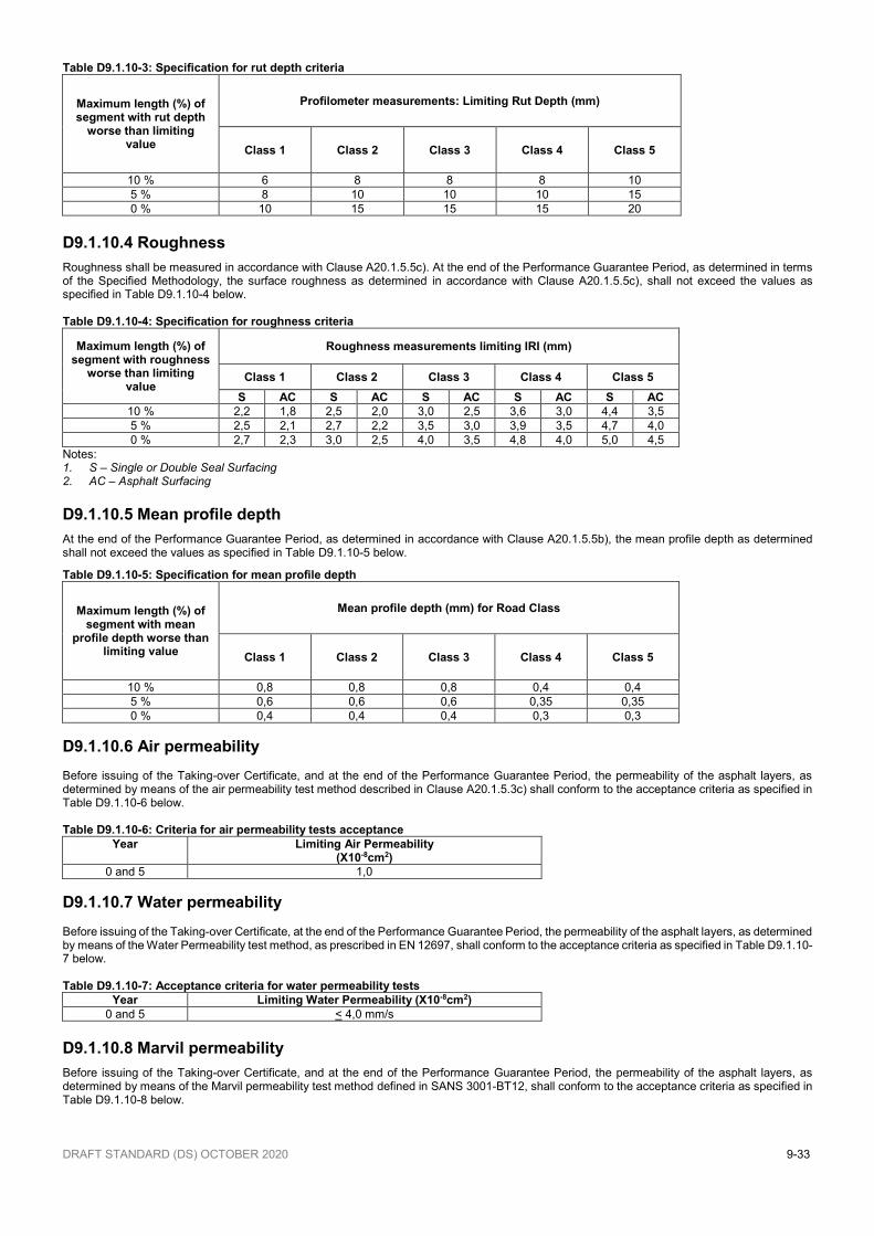
DRAFT STANDARD (DS) OCTOBER 2020 9-33
Table D9.1.10-3: Specification for rut depth criteria
Maximum length (%) of segment with rut depth
worse than limiting value
Profilometer measurements: Limiting Rut Depth (mm)
Class 1 Class 2 Class 3 Class 4 Class 5
10 % 6 8 8 8 10
5 % 8 10 10 10 15
0 % 10 15 15 15 20
D9.1.10.4 Roughness
Roughness shall be measured in accordance with Clause A20.1.5.5c). At the end of the Performance Guarantee Period, as determined in terms of the Specified Methodology, the surface roughness as determined in accordance with Clause A20.1.5.5c), shall not exceed the values as specified in Table D9.1.10-4 below. Table D9.1.10-4: Specification for roughness criteria
Maximum length (%) of segment with roughness
worse than limiting value
Roughness measurements limiting IRI (mm)
Class 1 Class 2 Class 3 Class 4 Class 5
S AC S AC S AC S AC S AC
10 % 2,2 1,8 2,5 2,0 3,0 2,5 3,6 3,0 4,4 3,5
5 % 2,5 2,1 2,7 2,2 3,5 3,0 3,9 3,5 4,7 4,0
0 % 2,7 2,3 3,0 2,5 4,0 3,5 4,8 4,0 5,0 4,5
Notes: 1. S – Single or Double Seal Surfacing 2. AC – Asphalt Surfacing
D9.1.10.5 Mean profile depth
At the end of the Performance Guarantee Period, as determined in accordance with Clause A20.1.5.5b), the mean profile depth as determined shall not exceed the values as specified in Table D9.1.10-5 below.
Table D9.1.10-5: Specification for mean profile depth
Maximum length (%) of segment with mean
profile depth worse than limiting value
Mean profile depth (mm) for Road Class
Class 1 Class 2 Class 3 Class 4 Class 5
10 % 0,8 0,8 0,8 0,4 0,4
5 % 0,6 0,6 0,6 0,35 0,35
0 % 0,4 0,4 0,4 0,3 0,3
D9.1.10.6 Air permeability Before issuing of the Taking-over Certificate, and at the end of the Performance Guarantee Period, the permeability of the asphalt layers, as determined by means of the air permeability test method described in Clause A20.1.5.3c) shall conform to the acceptance criteria as specified in Table D9.1.10-6 below. Table D9.1.10-6: Criteria for air permeability tests acceptance
Year Limiting Air Permeability (X10-8cm2)
0 and 5 1,0
D9.1.10.7 Water permeability Before issuing of the Taking-over Certificate, at the end of the Performance Guarantee Period, the permeability of the asphalt layers, as determined by means of the Water Permeability test method, as prescribed in EN 12697, shall conform to the acceptance criteria as specified in Table D9.1.10-7 below. Table D9.1.10-7: Acceptance criteria for water permeability tests
Year Limiting Water Permeability (X10-8cm2)
0 and 5 < 4,0 mm/s
D9.1.10.8 Marvil permeability
Before issuing of the Taking-over Certificate, and at the end of the Performance Guarantee Period, the permeability of the asphalt layers, as determined by means of the Marvil permeability test method defined in SANS 3001-BT12, shall conform to the acceptance criteria as specified in Table D9.1.10-8 below.
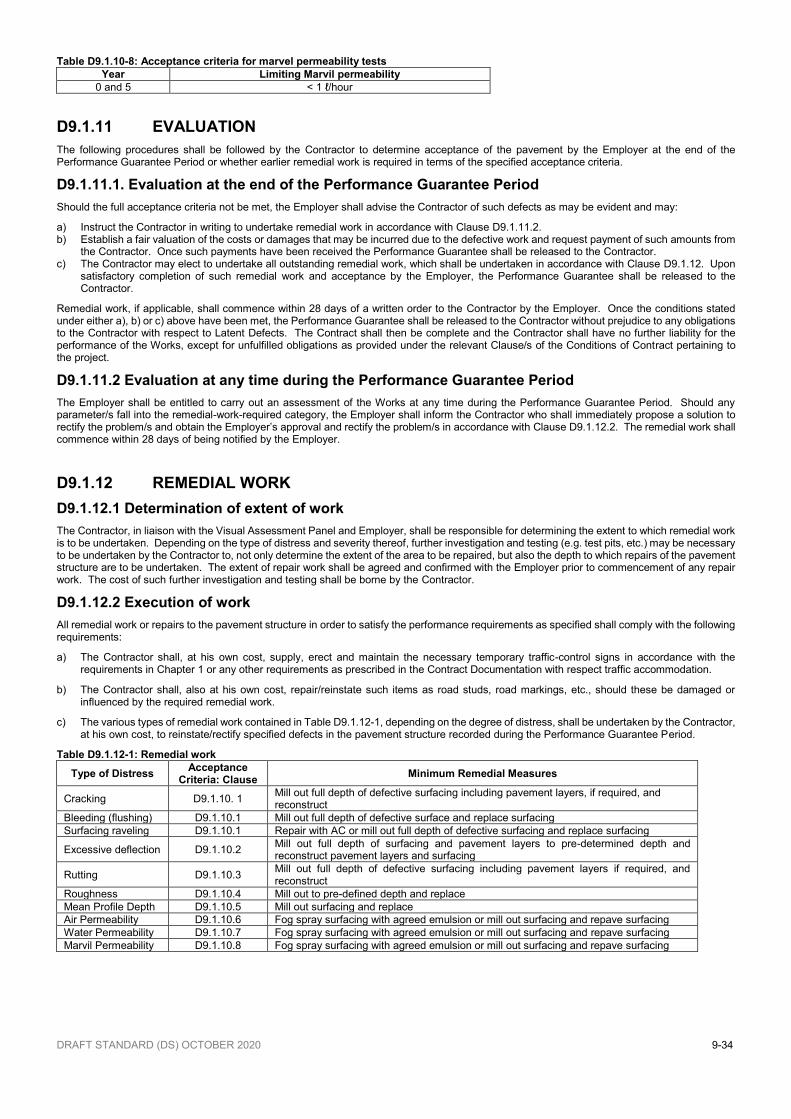
DRAFT STANDARD (DS) OCTOBER 2020 9-34
Table D9.1.10-8: Acceptance criteria for marvel permeability tests
Year Limiting Marvil permeability
0 and 5 < 1 ℓ/hour
D9.1.11 EVALUATION
The following procedures shall be followed by the Contractor to determine acceptance of the pavement by the Employer at the end of the Performance Guarantee Period or whether earlier remedial work is required in terms of the specified acceptance criteria.
D9.1.11.1. Evaluation at the end of the Performance Guarantee Period
Should the full acceptance criteria not be met, the Employer shall advise the Contractor of such defects as may be evident and may:
a) Instruct the Contractor in writing to undertake remedial work in accordance with Clause D9.1.11.2. b) Establish a fair valuation of the costs or damages that may be incurred due to the defective work and request payment of such amounts from
the Contractor. Once such payments have been received the Performance Guarantee shall be released to the Contractor. c) The Contractor may elect to undertake all outstanding remedial work, which shall be undertaken in accordance with Clause D9.1.12. Upon
satisfactory completion of such remedial work and acceptance by the Employer, the Performance Guarantee shall be released to the Contractor.
Remedial work, if applicable, shall commence within 28 days of a written order to the Contractor by the Employer. Once the conditions stated under either a), b) or c) above have been met, the Performance Guarantee shall be released to the Contractor without prejudice to any obligations to the Contractor with respect to Latent Defects. The Contract shall then be complete and the Contractor shall have no further liability for the performance of the Works, except for unfulfilled obligations as provided under the relevant Clause/s of the Conditions of Contract pertaining to the project.
D9.1.11.2 Evaluation at any time during the Performance Guarantee Period
The Employer shall be entitled to carry out an assessment of the Works at any time during the Performance Guarantee Period. Should any parameter/s fall into the remedial-work-required category, the Employer shall inform the Contractor who shall immediately propose a solution to rectify the problem/s and obtain the Employer’s approval and rectify the problem/s in accordance with Clause D9.1.12.2. The remedial work shall commence within 28 days of being notified by the Employer.
D9.1.12 REMEDIAL WORK
D9.1.12.1 Determination of extent of work
The Contractor, in liaison with the Visual Assessment Panel and Employer, shall be responsible for determining the extent to which remedial work is to be undertaken. Depending on the type of distress and severity thereof, further investigation and testing (e.g. test pits, etc.) may be necessary to be undertaken by the Contractor to, not only determine the extent of the area to be repaired, but also the depth to which repairs of the pavement structure are to be undertaken. The extent of repair work shall be agreed and confirmed with the Employer prior to commencement of any repair work. The cost of such further investigation and testing shall be borne by the Contractor.
D9.1.12.2 Execution of work
All remedial work or repairs to the pavement structure in order to satisfy the performance requirements as specified shall comply with the following requirements:
a) The Contractor shall, at his own cost, supply, erect and maintain the necessary temporary traffic-control signs in accordance with the requirements in Chapter 1 or any other requirements as prescribed in the Contract Documentation with respect traffic accommodation.
b) The Contractor shall, also at his own cost, repair/reinstate such items as road studs, road markings, etc., should these be damaged or influenced by the required remedial work.
c) The various types of remedial work contained in Table D9.1.12-1, depending on the degree of distress, shall be undertaken by the Contractor, at his own cost, to reinstate/rectify specified defects in the pavement structure recorded during the Performance Guarantee Period.
Table D9.1.12-1: Remedial work
Type of Distress Acceptance
Criteria: Clause Minimum Remedial Measures
Cracking D9.1.10. 1 Mill out full depth of defective surfacing including pavement layers, if required, and reconstruct
Bleeding (flushing) D9.1.10.1 Mill out full depth of defective surface and replace surfacing
Surfacing raveling D9.1.10.1 Repair with AC or mill out full depth of defective surfacing and replace surfacing
Excessive deflection D9.1.10.2 Mill out full depth of surfacing and pavement layers to pre-determined depth and reconstruct pavement layers and surfacing
Rutting D9.1.10.3 Mill out full depth of defective surfacing including pavement layers if required, and reconstruct
Roughness D9.1.10.4 Mill out to pre-defined depth and replace
Mean Profile Depth D9.1.10.5 Mill out surfacing and replace
Air Permeability D9.1.10.6 Fog spray surfacing with agreed emulsion or mill out surfacing and repave surfacing
Water Permeability D9.1.10.7 Fog spray surfacing with agreed emulsion or mill out surfacing and repave surfacing
Marvil Permeability D9.1.10.8 Fog spray surfacing with agreed emulsion or mill out surfacing and repave surfacing