chapter 2 entity relationship model
TRANSCRIPT

Chapter 2
ENTITY RELATIONSHIP MODEL
What is Database Design Process?
What are Basic Concepts of E-R Model?
What is Entity and Attribute?
What are Unary, Binary and Ternary Relationships?
What is Degree and Cardinality?
What are E-R Modeling Notations?
What is the difference between Specialization and Generalization?
What is Aggregation?
What are the steps in E-R Modeling?
Key points :
Entity, types of attributes, relationship set, keys, domain, null, weak entity set,
cardinality, degree, specialization, generalization, aggregation,
2.1 INTRODUCTION
Data model is used to describe data, data relationship and constraints on data. A number
of different data models have proposed. They can broadly be classified into two
categories:
Object-based logical models.
Record-based logical models.
The object-based model can be defined as a collection of conceptual tools for describing
data, data relationships, and data constraints. The record-based model describes the data
structures and access techniques of a DBMS. There are various different object-based
models. Some of the more popular ones are:
The entity-relationship model
The binary model
The infological model
The semantic model
Of these, the most widely used one is the Entity-Relationship Model. It has gained
acceptance as the ideal data model for database design. This model was introduced by
Peter Chen in 1976, and since then it has been reformed by several persons. The entity –
relationship model (E R Model) is based on a perception of real world that is made up
of a collection objects or entities and the relationship among these.
Conceptual Model
Before going to explaining the entity-relationship model, we will briefly discuss database
design. Database design involves designing the conceptual design model of the database.
The conceptual model reflects the entities and their relationships, based on the data
processing needs of the organization. This can be considered equivalent to the conceptual
level.
The conceptual model is a communication tool between the various users of the data. It
is developed without any concern for physical representation. The conceptual model is
used to organize, visualize, plan and communicate ideas. It is independent of the database
management system. Before actually implementing the database, the conceptual model
is designed. At this stage, requirements of all the users are considered to decide upon the
actual data to be stored in the system. This conceptual model is then mapped to the DBMS
that is actually to be used.
Data analysis is the first step in designing a conceptual model. Data analysis begins with
collecting information about the data. This usually involves using a questionnaire or a
similar method to obtain a list of data that the organization needs. Existing forms, bills,
reports are starting points for data collection. The data analysis involves identifying
entities, their attributes, and the relationships between attributes. The E-R Model is a way
to form and represent the conceptual model of database design
2.2 Basic concepts of E-R Model:
An entity relationship diagram is a graphical representation of an organisation's data
storage requirements. Entity relationship diagrams are abstractions of the real world
which simplify the problem to be solved while retaining its essential features.
Entity relationship diagrams are used to:
identify the data that must be captured, stored and retrieved in order to support
the business
activities performed by an organisation; and
identify the data required to derive and report on the performance measures, that
an organisation should be monitoring.
Entity relationship diagrams have three different components:
1) ENTITIES
2) ATTRIBUTES
3) RELATIONSHIPS
2.2.1 Entity :
Entities are the people, places, things, events and concepts of interest to an organisation.
In short, anything which an organisation needs to store data about. Entity can be
concrete like employee, book, project, publisher etc. and can be abstract or a concept
for example title, job, company etc. which have no physical existence. Entity set
represents collection of things. For example, an EMPLOYEE entity set might represent
a collection of all the employees that work for an organisation. Individual members
(employees) of the collection are called instance of the EMPLOYEE entity set.
2.2.2 Attribute:
Properties or characteristics possessed by an entity are called as attributes. Attributes
are same for each entity set but their values may differ from each other. For example,
EMPLOYEE entity set has attributes name, age, empid and salary but the values of
these attributes may be different for each employee in the entity set.
2.2.2.1Domain The set of possible values for an attribute is called the domain of the attribute.
Example:
– The domain of attribute marital status is just the four values: single, married,
divorced, widowed.
– The domain of the attribute month is the twelve values ranging from January to
December.
- The domain of attribute empid of EMPLOYEE entity set consist of only positive
integers.
2.2.2.2 Key attribute The attribute (or combination of attributes) that is unique for every entity instance
– E.g the account number of an account, the employee id of an employee etc.
2.2.2.3 Simple Vs composite attribute
Simple attribute: An attribute that cannot be divided into simpler components is called
simple attribute. E.g age of an employee, pub-id of a book title of a book entity.
Composite attribute: An attribute that can be split into components is called composite
attrbute. E.g Date of joining of the employee can be split into day, month and year
2.2.2.4 Single Vs Multi-valued Attribute
Single valued : Attributes that can take on only a single value for each entity instance
are called single valued attribute. E.g. age of employee, pubid of a publisher \
Multi-valued: Attributes that can take many values for each entity instance are called
multi-valued attributes. E.g. skill set of employee
2.2.2.5 Stored Vs Derived attribute
Stored Attribute: Attribute that need to be stored permanently. E.g. name of an
employee
Derived Attribute: Attribute that can be calculated based on other attributes. E.g. :
years of service of employee can be calculated from date of joining and current date
2.2.2.6 Regular Vs. Weak entity type
Regular Entity: Entity that has its own key attribute. It is also called independent entity
because it does not dependent on any other entity for existence. E.g.: Employee,
student, customer, policy holder etc.
Weak entity: Entity that depends on other entity for its existence and doesn’t have key
attribute of its own. It is also called dependent entity because its existence depends on
the existence of another entity. E.g. : spouse of employee, the spouse data is identified
with the help of the employee id to which it is related.
2.2.4 Null Values
Null value of an attribute is considered if that attribute does not have a value for a
particular entity. A null value is a value that is unavailable, unassigned, unknown, or
inapplicable. A null value is not the same as zero or a space, because zero is a number,
and a space is a character. For example, in ‘phone_no’ attribute is having Null value
then it means the value may not be applicable.
2.2.5 Keys A key is a single attributer or a combination of attributes whose values uniquely identify each
tuple in that relation. In other words, no tow entities in an entity set are allowed to have exactly
the same value for all attributes. A key allows us to identify a set of attributes that are suffice to
distinguish relationships from each others.
2.2.5.1 Superkey
An attribute, or group of attributes, that is sufficient to distinguish every tuple in the
relation from every other one. Each super key is called a candidate key
2.2.5.2 Candidate key
A candidate key is any set of one or more columns whose combined value is unique
through out that table. Since a null value is not guaranteed to be unique, no component
of a candidate key is allowed to be null. There can be number of candidate keys in a
table.
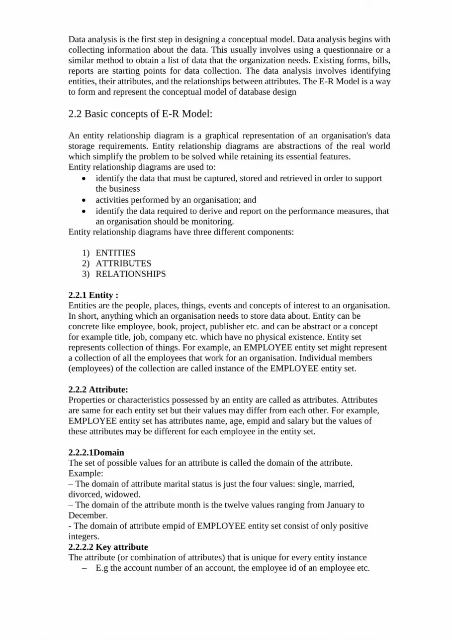
2.2.5.3 Primary key The primary key of any table is any candidate key of that table which the database
designer arbitrarily designates as primary. The primary key may be selected for
convenience, comprehension, performance or any other reasons. Every entity must have
a primary key. The primary key is an attribute or combination of attributes that uniquely
identifies an instance of the entity. In other words, no two instances of an entity may
have the same value for the primary key. Sometimes it is useful to use more than one
attribute to form a primary key. When a primary key for an entity is made up of more
than one attribute the key is called a composite key. The terms composite key is also
used to describe primary keys that contain multiple attributes. When dealing with a
composite primary key it is important to understand that it is the combination of values
for all attributes that must be unique. It is not necessary for each attribute in the key to
be unique. For example, the entity ENROLLMENT has a composite primary key
comprised of the attributes STUDENT_ID and COURSE_ID. Each instance of
ENROLLMENT must contain a unique combination of values for StudentID and
CourseID. However, there can be duplications of StudentID or CourseID. So, it is
possible for many instances of ENROLLMENT to have the value MIS100 for
CourseID, but each of those instances must contain different values for StudentID.
Figure 2.1 Primary key
2.2.5.4 Alternate key
The alternate keys of any table are simply those candidate keys which are not currently
selected as the primary key.
2.2.5.5 Foreign key
A foreign key is a set of attribute(s) whose values are required to match values of a
candidate key in the same or another table. A foreign key is a copy of the whole of its
parent candidate key i.e if the candidate key is composite, then so is the foreign key
•Foreign key values do not (usually) have to be unique
•Foreign keys can also be null
•A composite foreign key cannot have some attribute(s) null and others non-null

figure 2.2 foreign key
2.2.6 Relationship
A relationship type between two entity types defines the set of all associations between
these entity types. Each instance of the relationship between members of these entity
types is called a relationship instance. For example:
EMPLOYEEs work in a DEPARTMENT
LAWYERs advise CLIENTs
EQUIPMENT is allocated to PROJECTs
TRUCK is a type of VEHICLE
2.2.6.1 Degree of a Relationship
The degree of a relationship is the number of entities associated with the relationship.
• One - Unary
• Two - Binary
• Three - Ternary
A unary or recursive binary relationship occurs when an entity is related to itself. An
example might be "some employees are married to other employees".
Binary relationship association between two entities is the most common type in the
real world.
A ternary relationship involves three entities and is used when a binary relationship is
inadequate. Many modeling approaches recognize only binary relationships. Ternary or
n-ary relationships are decomposed into two or more binary relationships.
E.g.: employee manager-of employee is unary
employee works-for department is binary
customer purchase item, shop keeper is a ternary relationship
2.2.6.2 Cardinality and Connectivity
The connectivity of a relationship describes the mapping of associated entity instances
in the relationship. The values of connectivity are "one" or "many". The cardinality of a
relationship is the actual number of related occurences for each of the two entities. The
basic types of connectivity for relations are: one-to-one, one-to-many, and many-to-
many.
Relationships can have different connectivity
– one-to-one (1:1)
– one-to-many (1:N)
– many-to- One (M:1)
– many-to-many (M:N)
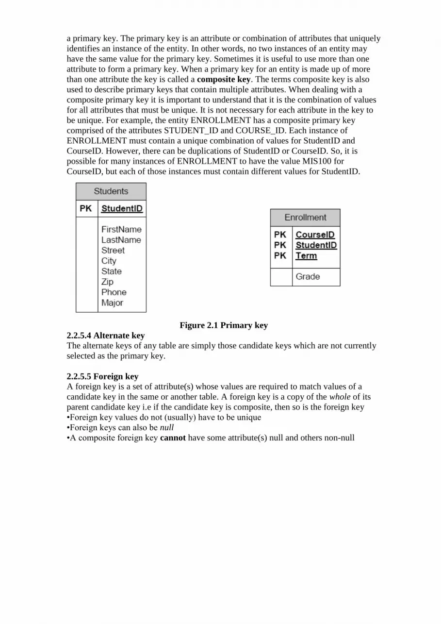
One-toOone (1:1) relationship: A one-to-one (1:1) relationship is when at most one
instance of a entity A is associated with one instance of entity B. For example, "each
employee in the company has been assigned his own office”. For each employee there
exists a unique office and for each office there exists a unique employee.
Figure 2.3 One to One: One instance of entity type Person is related to one instance of
the entity type Chair.
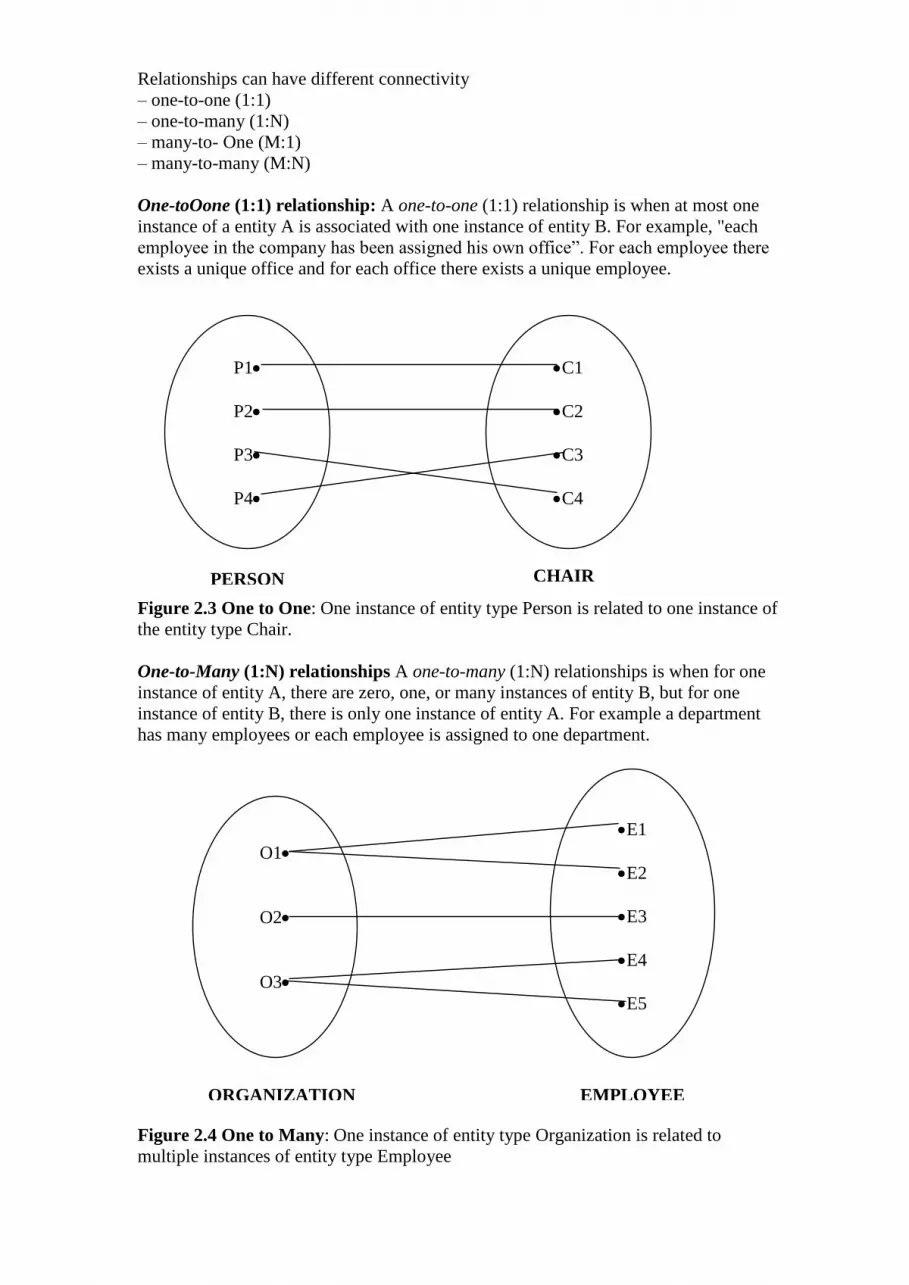
One-to-Many (1:N) relationships A one-to-many (1:N) relationships is when for one
instance of entity A, there are zero, one, or many instances of entity B, but for one
instance of entity B, there is only one instance of entity A. For example a department
has many employees or each employee is assigned to one department.
Figure 2.4 One to Many: One instance of entity type Organization is related to
multiple instances of entity type Employee
PERSON CHAIR
O1
O2
O3
E1
E2
E3
E4
E5
ORGANIZATION EMPLOYEE
P1
P2
P3
P4
C1
C2
C3
C4
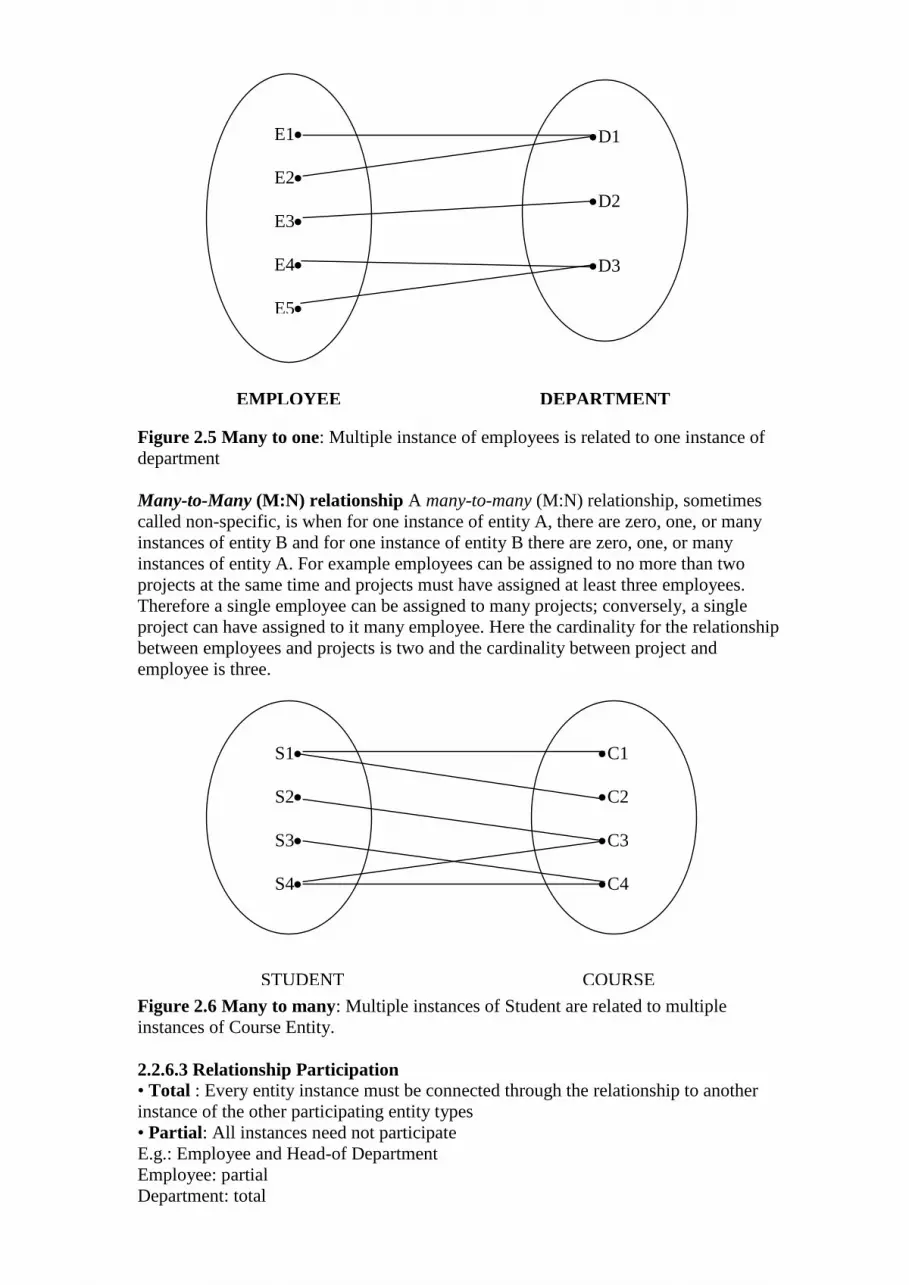
Figure 2.5 Many to one: Multiple instance of employees is related to one instance of
department
Many-to-Many (M:N) relationship A many-to-many (M:N) relationship, sometimes
called non-specific, is when for one instance of entity A, there are zero, one, or many
instances of entity B and for one instance of entity B there are zero, one, or many
instances of entity A. For example employees can be assigned to no more than two
projects at the same time and projects must have assigned at least three employees.
Therefore a single employee can be assigned to many projects; conversely, a single
project can have assigned to it many employee. Here the cardinality for the relationship
between employees and projects is two and the cardinality between project and
employee is three.
Figure 2.6 Many to many: Multiple instances of Student are related to multiple
instances of Course Entity.
2.2.6.3 Relationship Participation
• Total : Every entity instance must be connected through the relationship to another
instance of the other participating entity types
• Partial: All instances need not participate
E.g.: Employee and Head-of Department
Employee: partial
Department: total
D1
D2
D3
E1
E2
E3
E4
E5
S1
S2
S3
S4
C1
C2
C3
C4
EMPLOYEE DEPARTMENT
STUDENT COURSE

All employees will not be head-of some department. So only few instances of employee
entity participate in the above relationship. But each department will be headed by some
employee. So department entity’s participation is total and employee entity’s
participation is partial in the above relationship
2.2.6.4 Existence
Existence denotes whether the existence of an entity instance is dependent upon the
existence of another, related, entity instance. The existence of an entity in a relationship
is defined as either mandatory or optional.
Mandatory :If an instance of an entity must always occur for an entity to be included in
a relationship, then it is mandatory. An example of mandatory existence is the statement
"every project must be managed by a single department".
Optional : If the instance of the entity is not required, it is optional. An example of
optional existence is the statement, "employees may be assigned to work on projects".
2. 3 ERD Modeling Notations:
Figure 2. 7 ER Modeling Notations
2. 4 Entity-Relationship Diagram: E-R Model describes data and identifies
relationship between them. E-R model is represented by E-R Diagram. In the following
sections, E-R model is explained along with their representation in E-R diagram
2.4.1 Attributes: Properties or characteristics possessed by an entity
Figure 2.8: Type of attributes
Employee
E#
Name
DOB Address
Street
Floor
Building
Skills
Age
Key attribute
Composite
Attribute
Derived
attribute
Multi valued
attribute
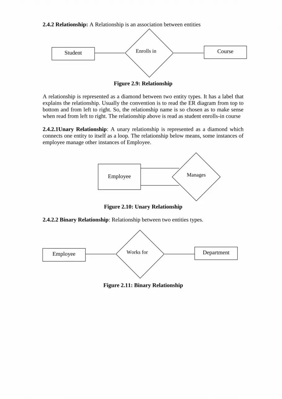
2.4.2 Relationship: A Relationship is an association between entities
Figure 2.9: Relationship
A relationship is represented as a diamond between two entity types. It has a label that
explains the relationship. Usually the convention is to read the ER diagram from top to
bottom and from left to right. So, the relationship name is so chosen as to make sense
when read from left to right. The relationship above is read as student enrolls-in course
2.4.2.1Unary Relationship: A unary relationship is represented as a diamond which
connects one entity to itself as a loop. The relationship below means, some instances of
employee manage other instances of Employee.
Figure 2.10: Unary Relationship
2.4.2.2 Binary Relationship: Relationship between two entities types.
Figure 2.11: Binary Relationship
Student Course
Enrolls in
Manages Employee
Employee Department
Works for
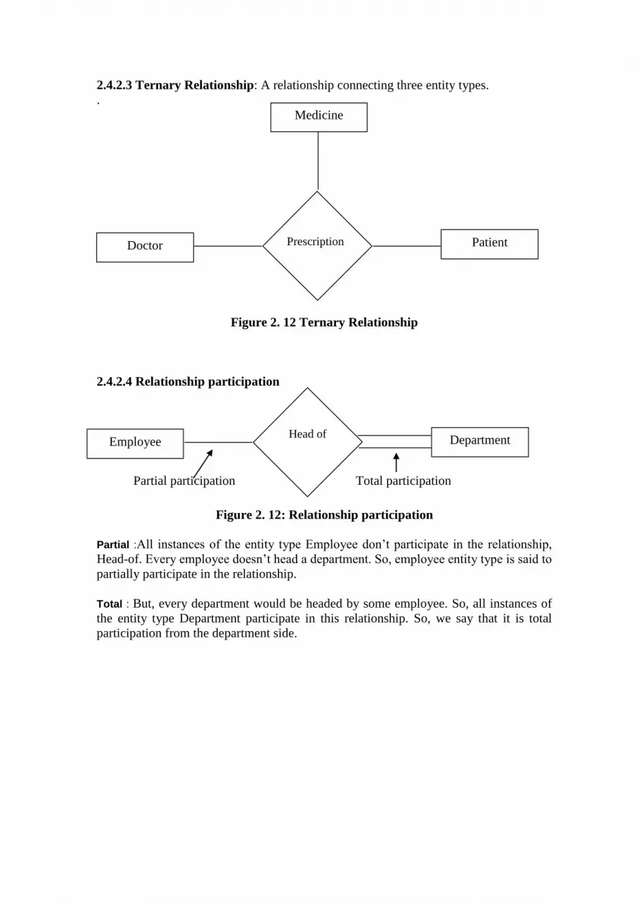
2.4.2.3 Ternary Relationship: A relationship connecting three entity types.
.
Figure 2. 12 Ternary Relationship
2.4.2.4 Relationship participation
Figure 2. 12: Relationship participation
Partial :All instances of the entity type Employee don’t participate in the relationship,
Head-of. Every employee doesn’t head a department. So, employee entity type is said to
partially participate in the relationship.
Total : But, every department would be headed by some employee. So, all instances of
the entity type Department participate in this relationship. So, we say that it is total
participation from the department side.
Doctor Patient
Prescription
Medicine
Employee Department
Head of
Partial participation Total participation

2.4.2.5 Attribute of a relationship: These attributes best describe the relationship
rather than any individual entity
Figure 2. 13: Relationship attributes
2.4.2.6 Weak Entity: Entity that depends on other entity for its existence and doesn’t
have key attribute of its own is called Weak Entity.
Figure 2. 14: Weak Entity
The dependant entity is represented by a double lined rectangle and the identifying
relationship by a double lined diamond . the identifying relationship is the one which
relates the weak entity with the strong entity on which it depends.
2.4.2.7 Types of Relationships :Cardinality
An entity may be associated with one, none, or many occurrences of another entity. In
ER diagrams, the types of relationships are represented as follows;
Doctor Patient
Prescription
Medicine
No. of Days Dosage
Has Dependents Employee

Figure 2. 15: Cardinality
Represents zero and represents one.
Dashed line between entity box and relationship box represents optional
existence
Solid line between entity box and relationship box represents mandatory
existence
A crow foot represents many type of relationship
Represents minimum of one and maximum of one existence of entity
instances in a relationship
A is associated with a minimum of zero Bs and a maximum of 1 B.
Figure 2. 16(a): Minimum of 0 and maximum of 1 relationship
A is associated with a minimum of 1B and a maximum of 1 B
Figure 2. 16(b): Minimum of 1 and maximum of 1 relationship
A is associated with a minimum of 0 B and maximum of that is any number greater
than 1.
A
R B
A
R B

Figure 2. 16(c ) :Minimum of 0 and maximum of >1 relationship
A is associated with a minimum of 1 B and maximum of that is any number greater
than 1.
Figure 2. 16(d): Minimum of 1 and maximum of >1 relationship
A is associated with more than one B.
Figure 2. 16(e): Always more than 1 relationship
Relationships can also differ in terms of their cardinality. Maximum cardinality
refers to the maximum number of instances of one entity that can be associated
with a single instance of a related entity. Minimum cardinality refers to the
minimum number of instances of one entity that must be associated with a single
instance of a related entity. The following examples of binary relationships
illustrate the concept of maximum cardinality . If one CUSTOMER can be
related to only one ACCOUNT and one ACCOUNT can be related to only a
single CUSTOMER, the cardinality of the CUSTOMER-ACCOUNT relationship
is one-to-one (1:1).
Figure 2. 17: one-to-one (1:1) relationship
If an ADVISOR can be related to one or more STUDENTS, but a STUDENT can
be related to only a single ADVISOR, the cardinality is one-to-many (1:N).
A
R B
A
R B
A
R B
Customer
Have Account

Figure 2. 18: one-to-many (1:N) relationship
Finally, the cardinality of the relationship is many-to-many (M:N) if a single
STUDENT can be related to zero or more COURSES and a single COURSE can
be related to zero or more STUDENTS.
Figure 2. 19: many -to-many (M:N) relationship
2.5 Extended E-R Features
2.5.1 Superclass and Subclass: Certain instances of an entity class can include attributes
that are not needed in other instances of the same entity class. In these cases, it is useful
to use a superclass/subclass structure. This structure is also called a generalization/
specialization hierarchy.
i) Subclass: A subgroup an entity type which has attributes that are distinct from those
in other subgroups
ii) Superclass: An generic entity type that has a relationship with one or more
subclasses
iii)Inheritance
Subclass entities inherit values of all attributes of the superclass
An instance of a subclass is also an instance of the superclass
2.5.2 Specialization : Specialization is the process of defining a set of subclasses of an
entity type; this entity type is called the superclass of the specialization. The set of
subclasses that form a specialization is defined on the basis of some distinguishing
characteristics of the entities in the superclass.
Consider an entity set EMPLOYEE with attributes Name, Employeeid, Address,
Birthdate, Jobtype. An Employee may be further classified as one of the following
SECERATRY
ENGINEER
TEHCNICIAN
Each of these employee types is described by a set of attributes that includes all the
attributes of entity set employee plus possibly additional attributes. For example,
SECERATRY entities my be described further by the attribute TypingSpeed, whereas
TECHNICIAN entities may be described further by the attribute Tgrade and ENGINEER
entities may be described by EngType. The processof designating subgroupings within
an entity set is called specialization. The specialization of EMPLOYEE allow us to
Advisor
Advise Student
Student
Take Course
distinguish among EMPLOYEES according to whether they are SECERATRY,
TECHNICIAN or ENGINEER.
We call each of these subgrouping a subclass of the EMPLOYEE entity type, and the
EMPLOYEE entity type is called the superclass for each of these subclasses. In terms of
E-R diagram, specialization is depicted by a triangle component labeled ISA. The label
ISA stands for “is a” and represents, for example, that a customer “is a” person. The ISA
relationship can also be referred as superclass-subclass relationship.
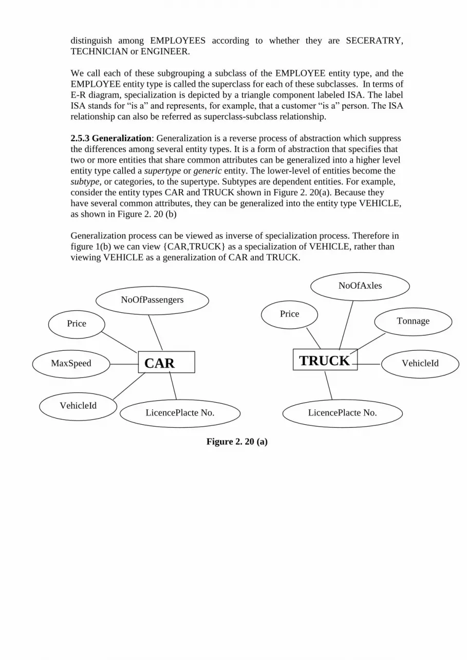
2.5.3 Generalization: Generalization is a reverse process of abstraction which suppress
the differences among several entity types. It is a form of abstraction that specifies that
two or more entities that share common attributes can be generalized into a higher level
entity type called a supertype or generic entity. The lower-level of entities become the
subtype, or categories, to the supertype. Subtypes are dependent entities. For example,
consider the entity types CAR and TRUCK shown in Figure 2. 20(a). Because they
have several common attributes, they can be generalized into the entity type VEHICLE,
as shown in Figure 2. 20 (b)
Generalization process can be viewed as inverse of specialization process. Therefore in
figure 1(b) we can view {CAR,TRUCK} as a specialization of VEHICLE, rather than
viewing VEHICLE as a generalization of CAR and TRUCK.
Figure 2. 20 (a)
CAR
LicencePlacte No. VehicleId
MaxSpeed
NoOfPassengers
Price
TRUCK
K
LicencePlacte No.
VehicleId
Tonnage
NoOfAxles
Price

Figure 2. 20(b)
2.5.4 Constraints and characteristics of Specialization : To model an enterprise more
accurately, the database designer may choose to place certain constraints on a particular
specialization. These constraints could be of various types.
2.5.4.1 Condition-defined Vs User-defined constraint In some specialization we can determine exactly the entities that will members of each
subclass by placing a condition on the value of some attribute of the superclass. Such
subclasses are called condition-defined. When we don not have a condition for
determining membership in a subclass, the subclass is called user-defined
Condition-defined: In condition defined lower-level entity sets, membership is
evaluated on the basis of whether or not an entity satisfies an explicit condition or
predicate. For example, if the EMPLOYEE entity type has an attribute JobType, as
shown in Figure 2. 21 we can specify the condition of membership in the SECRETARY
subclass by the condition (JobType=’Secretary’), which we call the defining predicate
of the subclass. The condition is a constraint specifying that exactly those entities of the
EMPLOYEE entity type whose attribute value for JobType is ‘Secretary’ belong to the
subclass. This type of specialization is also called attribute-defined.
NoOfAxle
s
VEHICLE
LicencePlacteNo VehicleId
Price
CAR TRUCK
ISA
NoOfPasseng
ers
MaxSpeed Tonnage

Figure 2. 21: Condition defined constraint
User-defined:. Membership in such a subclass is determined by the database users
when they apply the operation to add an entity to the subclass therefore the membership
is specified individually for each entity by the user, not by any condition that may be
evaluated automatically. For instance, let us assume that, after 3 months of
employment, the employees of a software company are assigned to one of four work
team. We therefore represent the teams as four lower-level entity sets of the higher-
level employee entity set. A given employee is not assigned to a specific team entity
automatically on the basis of an explicit defining condition. Instead, the user in charge
of this decision makes the team assignment on an individual basis. This assignment is
implemented by an operation that adds an entity to an entity set.
2.5.4.2 Disjoint V/S Overlapping constraint :
A second type of constraint relates to whether or not entities may belong to more than
one lower-level entity set within a single generalization. The lower-level entity sets may
be one of the following:
Disjoint: In a disjoint hierarchy, an entity instance can be in only one subtype. For
example, the entity EMPLOYEE, may have two subtypes, CLASSIFIED and WAGES.
An employee may be one type or the other but not both. Figure 2. 22 (a) shows disjoint
and Figure 2. 22 (b) overlapping generalization hierarchy
EngType
EMPLOYEE
Address Employeei
d
Birthdate
Name JobType
SECRETARY TECHNICIAN ENGINEER
ISA
TypingSpee
d TGrade

Figure 2. 22 (a) Disjoint generalization
.
Overlapping: An overlapping category is when an entity instance may be in two or
more subtypes. An example would be a person who works for a university could also be
a student at that same university.
Overlapping in lower-level entity set is the default case. We can denote disjointedness
constraint in an E-R diagram by adding the word disjoint next to the triangle symbol.
2.5.4.3 Completeness constraint The third constraint on specialization is called the completeness constraint, which may
be total or partial.
Figure 2. 22(b) Overlapping generalization
2.5.4.4 Total v/s Partial Spcialization
Total Specialization: A total specialization constraint specifies that every entity in the
superclass must be a member of least one subclass in the specialization. For example, if
every employee must be either an HOURLY_EMPLOYEE or a
PERSON
FACULTY STAFF STUDENT
ISA
EMPLOYEE
CLASSIFIED WAGES
ISA
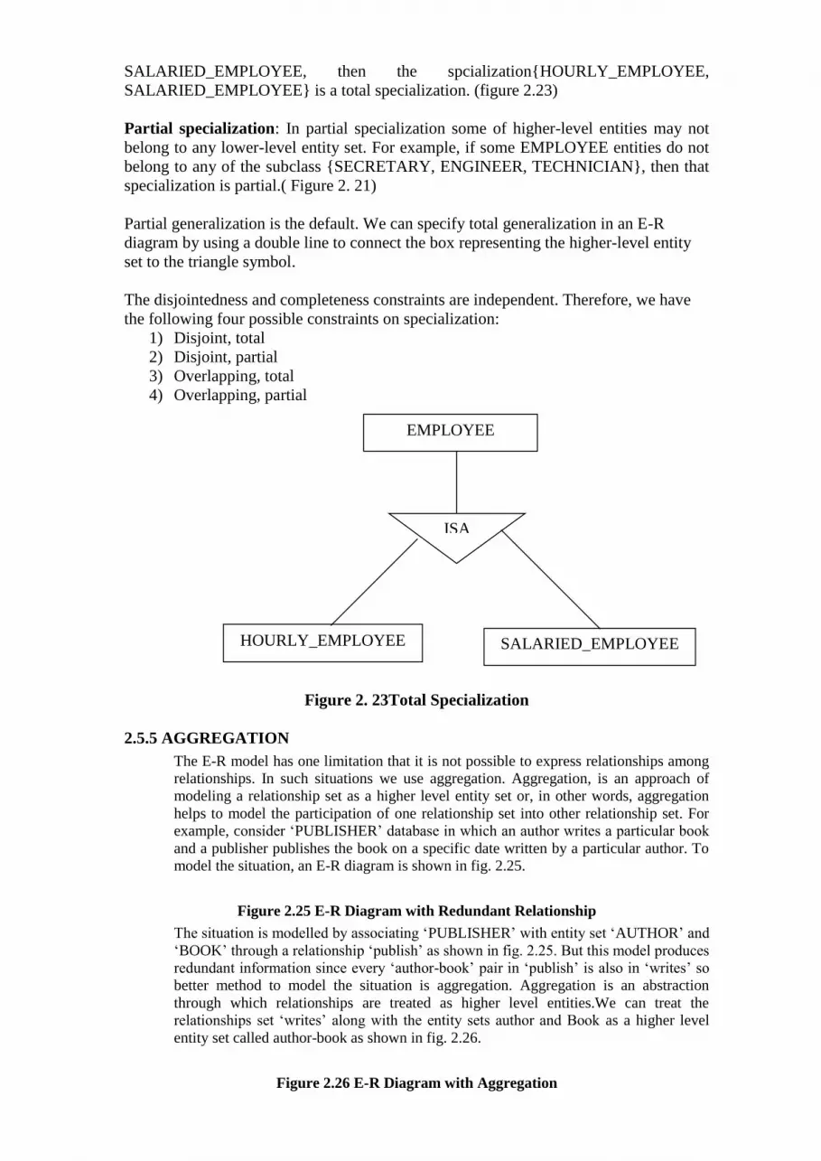
SALARIED_EMPLOYEE, then the spcialization{HOURLY_EMPLOYEE,
SALARIED_EMPLOYEE} is a total specialization. (figure 2.23)
Partial specialization: In partial specialization some of higher-level entities may not
belong to any lower-level entity set. For example, if some EMPLOYEE entities do not
belong to any of the subclass {SECRETARY, ENGINEER, TECHNICIAN}, then that
specialization is partial.( Figure 2. 21)
Partial generalization is the default. We can specify total generalization in an E-R
diagram by using a double line to connect the box representing the higher-level entity
set to the triangle symbol.
The disjointedness and completeness constraints are independent. Therefore, we have
the following four possible constraints on specialization:
1) Disjoint, total
2) Disjoint, partial
3) Overlapping, total
4) Overlapping, partial
Figure 2. 23Total Specialization
2.5.5 AGGREGATION
The E-R model has one limitation that it is not possible to express relationships among
relationships. In such situations we use aggregation. Aggregation, is an approach of
modeling a relationship set as a higher level entity set or, in other words, aggregation
helps to model the participation of one relationship set into other relationship set. For
example, consider ‘PUBLISHER’ database in which an author writes a particular book
and a publisher publishes the book on a specific date written by a particular author. To
model the situation, an E-R diagram is shown in fig. 2.25.
Figure 2.25 E-R Diagram with Redundant Relationship
The situation is modelled by associating ‘PUBLISHER’ with entity set ‘AUTHOR’ and
‘BOOK’ through a relationship ‘publish’ as shown in fig. 2.25. But this model produces
redundant information since every ‘author-book’ pair in ‘publish’ is also in ‘writes’ so
better method to model the situation is aggregation. Aggregation is an abstraction
through which relationships are treated as higher level entities.We can treat the
relationships set ‘writes’ along with the entity sets author and Book as a higher level
entity set called author-book as shown in fig. 2.26.
Figure 2.26 E-R Diagram with Aggregation
EMPLOYEE
HOURLY_EMPLOYEE SALARIED_EMPLOYEE
ISA
So, Aggregation allow us to indicate that a relationship set participates in another
relationship set. Aggregation is depicted by a rectangle as shown in fig. 2.26. ‘Writes’
relationship can be represented as a ternary relationship involving publisher, author and
Book. But it is not correct as ‘publish’ and ‘writes’ are two different relationships having
different attributes, as ‘publish’ has the attribute ‘pub_date’ which specifies the date of
publication and ‘writes’ has the attribute ‘from’ which specifies the time since the author
is writing a particular book.
2.6 Steps in ER Modeling
Step 1: Identify the Entities
Step 2: Find the relationships
Step 3: Identify the key attributes
Step 4: Identify other relevant attributes
Step 5: Draw complete E-R diagram with all attributes including Primary Key
Case Study 1 : ER Model For a college Database
Assumptions :
• A college contains many departments
• Each department can offer any number of courses
• Many instructors can work in a department
• An instructor can work only in one department
• For each department there is a Head
• An instructor can be head of only one department
• Each instructor can take any number of courses
• A course can be taken by only one instructor
• A student can enroll for any number of courses
• Each course can have any number of students
Step 1: Identify the Entities
• DEPARTMENT
• STUDENT
• COURSE
• INSTRUCTOR
Step 2: Find the relationships
• One course is enrolled by multiple students and one student enrolls for multiple
courses,
hence the cardinality between course and student is Many to Many.
• The department offers many courses and each course belongs to only one department,
hence the cardinality between department and course is One to Many.
• One department has multiple instructors and one instructor belongs to one and only
one
department , hence the cardinality between department and instructor is one to Many.
• Each department there is a “Head of department” and one instructor is “Head of
department “,hence the cardinality is one to one .
• One course is taught by only one instructor, but the instructor teaches many courses,
hence the cardinality between course and instructor is many to one.
Step 3: Identify the key attributes
• Deptname is the key attribute for the Entity “Department”, as it identifies the
Department uniquely.
• Course# (CourseId) is the key attribute for “Course” Entity.
• Student# (Student Number) is the key attribute for “Student” Entity.
• Instructor Name is the key attribute for “Instructor” Entity.
Step 4: Identify other relevant attributes
• For the department entity, the relevant attribute is location
• For course entity, course name,duration,prerequisite
• For instructor entity, room#, telephone#
• For student entity, student name, date of birth
Step 5: Draw complete E-R diagram with all attributes including Primary Key
Figure 2.26
Case Study2– Banking Business Scenario
Assumptions :
• There are multiple banks and each bank has many branches. Each branch has multiple
customers
• Customers have various types of accounts
• Some Customers also had taken different types of loans from these bank branches
• One customer can have multiple accounts and Loans
Step 1: Identify the Entities
• BANK
• BRANCH
• LOAN
• ACCOUNT
• CUSTOMER
Step 2: Find the relationships
• One Bank has many branches and each branch belongs to only one bank, hence the
cardinality between Bank and Branch is One to Many.
• One Branch offers many loans and each loan is associated with one branch, hence the
cardinality between Branch and Loan is One to Many.
• One Branch maintains multiple accounts and each account is associated to one and
only one Branch, hence the cardinality between Branch and Account is One to Many
• One Loan can be availed by multiple customers, and each Customer can avail multiple
loans, hence the cardinality between Loan and Customer is Many to Many.
• One Customer can hold multiple accounts, and each Account can be held by multiple
Customers, hence the cardinality between Customer and Account is Many to Many
Step 3: Identify the key attributes
• BankCode (Bank Code) is the key attribute for the Entity “Bank”, as it identifies the
bank
uniquely.
• Branch# (Branch Number) is the key attribute for “Branch” Entity.
• Customer# (Customer Number) is the key attribute for “Customer” Entity.
• Loan# (Loan Number) is the key attribute for “Loan” Entity.
• Account No (Account Number) is the key attribute for “Account” Entity.
Step 4: Identify other relevant attributes
• For the “Bank” Entity, the relevant attributes other than “BankCode” would be
“Name”
and “Address”.
• For the “Branch” Entity, the relevant attributes other than “Branch#” would be
“Name”
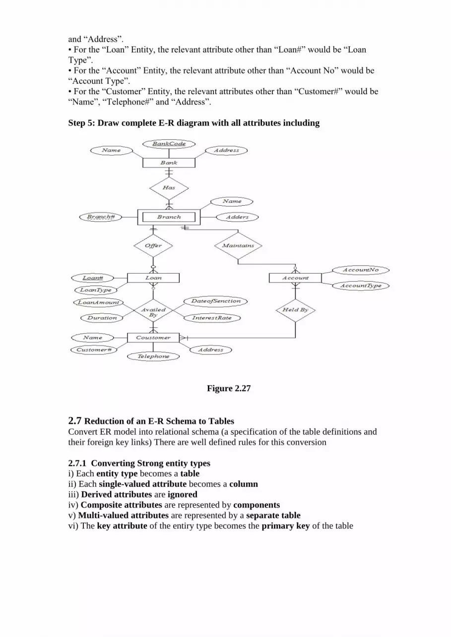
and “Address”.
• For the “Loan” Entity, the relevant attribute other than “Loan#” would be “Loan
Type”.
• For the “Account” Entity, the relevant attribute other than “Account No” would be
“Account Type”.
• For the “Customer” Entity, the relevant attributes other than “Customer#” would be
“Name”, “Telephone#” and “Address”.
Step 5: Draw complete E-R diagram with all attributes including
Figure 2.27
2.7 Reduction of an E-R Schema to Tables
Convert ER model into relational schema (a specification of the table definitions and
their foreign key links) There are well defined rules for this conversion
2.7.1 Converting Strong entity types
i) Each entity type becomes a table
ii) Each single-valued attribute becomes a column
iii) Derived attributes are ignored
iv) Composite attributes are represented by components
v) Multi-valued attributes are represented by a separate table
vi) The key attribute of the entiry type becomes the primary key of the table
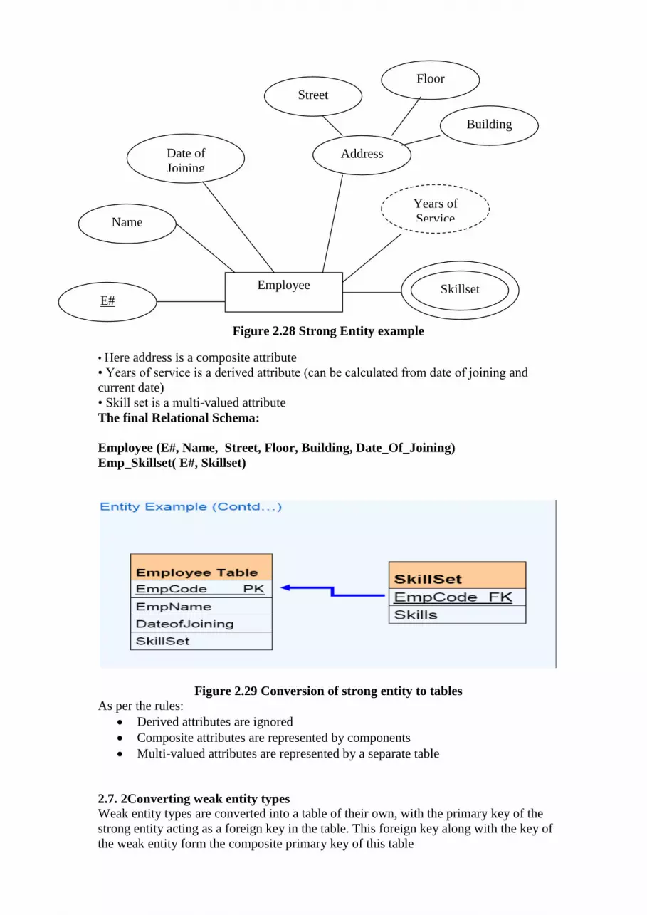
Figure 2.28 Strong Entity example
• Here address is a composite attribute
• Years of service is a derived attribute (can be calculated from date of joining and
current date)
• Skill set is a multi-valued attribute
The final Relational Schema:
Employee (E#, Name, Street, Floor, Building, Date_Of_Joining)
Emp_Skillset( E#, Skillset)
Figure 2.29 Conversion of strong entity to tables
As per the rules:
Derived attributes are ignored
Composite attributes are represented by components
Multi-valued attributes are represented by a separate table
2.7. 2Converting weak entity types
Weak entity types are converted into a table of their own, with the primary key of the
strong entity acting as a foreign key in the table. This foreign key along with the key of
the weak entity form the composite primary key of this table
Employee
E#
Name
Date of
Joining Address
Street
Floor
Building
Skillset
Years of
Service
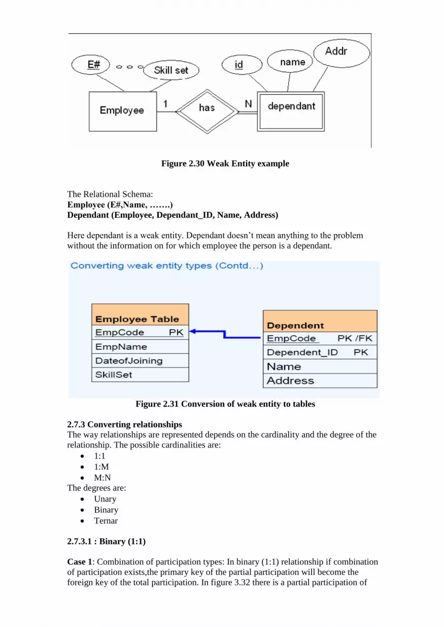
Figure 2.30 Weak Entity example
The Relational Schema:
Employee (E#,Name, …….)
Dependant (Employee, Dependant_ID, Name, Address)
Here dependant is a weak entity. Dependant doesn’t mean anything to the problem
without the information on for which employee the person is a dependant.
Figure 2.31 Conversion of weak entity to tables
2.7.3 Converting relationships
The way relationships are represented depends on the cardinality and the degree of the
relationship. The possible cardinalities are:
1:1
1:M
M:N
The degrees are:
Unary
Binary
Ternar
2.7.3.1 : Binary (1:1)
Case 1: Combination of participation types: In binary (1:1) relationship if combination
of participation exists,the primary key of the partial participation will become the
foreign key of the total participation. In figure 3.32 there is a partial participation of

Employee entity in the relationship HeadOf , because only one Employee can become
head of the department. But there is a total participation of Department entity because
every Department must have a head of department. Therefore the relational schema
would be
Employee(E#, Name………….)
Department (Dept#, Name,………., Head)
Figure 2.32 Binary (1:1) Combination of Participation type
Figure 2.33 Conversion of total and partial participation to tables
Case 2: Uniform participation type: If both the entities take uniform participation in the
Binary (1:1) relationship the primary key of either of the participants can become a
foreign key in the other.

Figrure 2.34 Binary (1:1) Uniform participation
Figure 2.35 Conversion of Uniform participation to tables
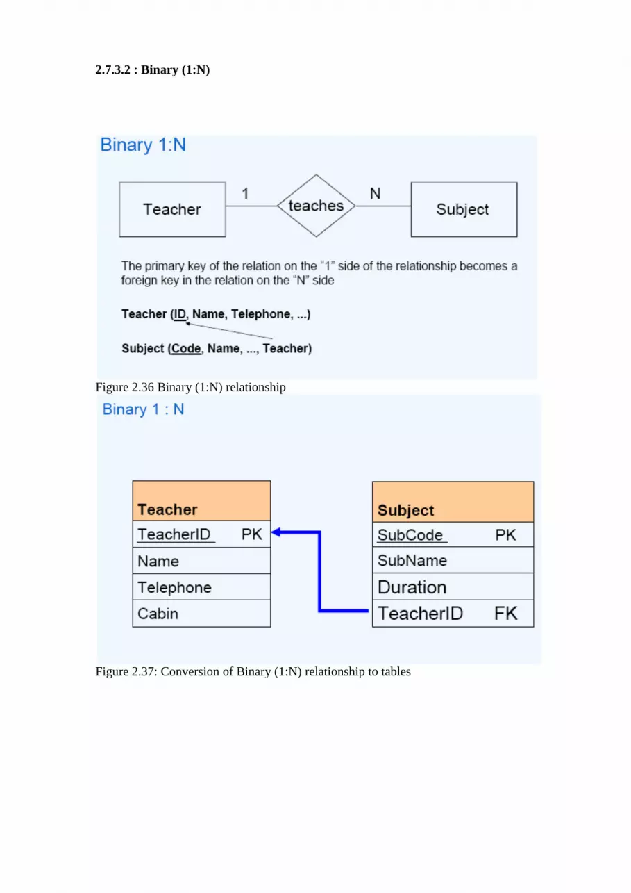
2.7.3.2 : Binary (1:N)
Figure 2.36 Binary (1:N) relationship
Figure 2.37: Conversion of Binary (1:N) relationship to tables
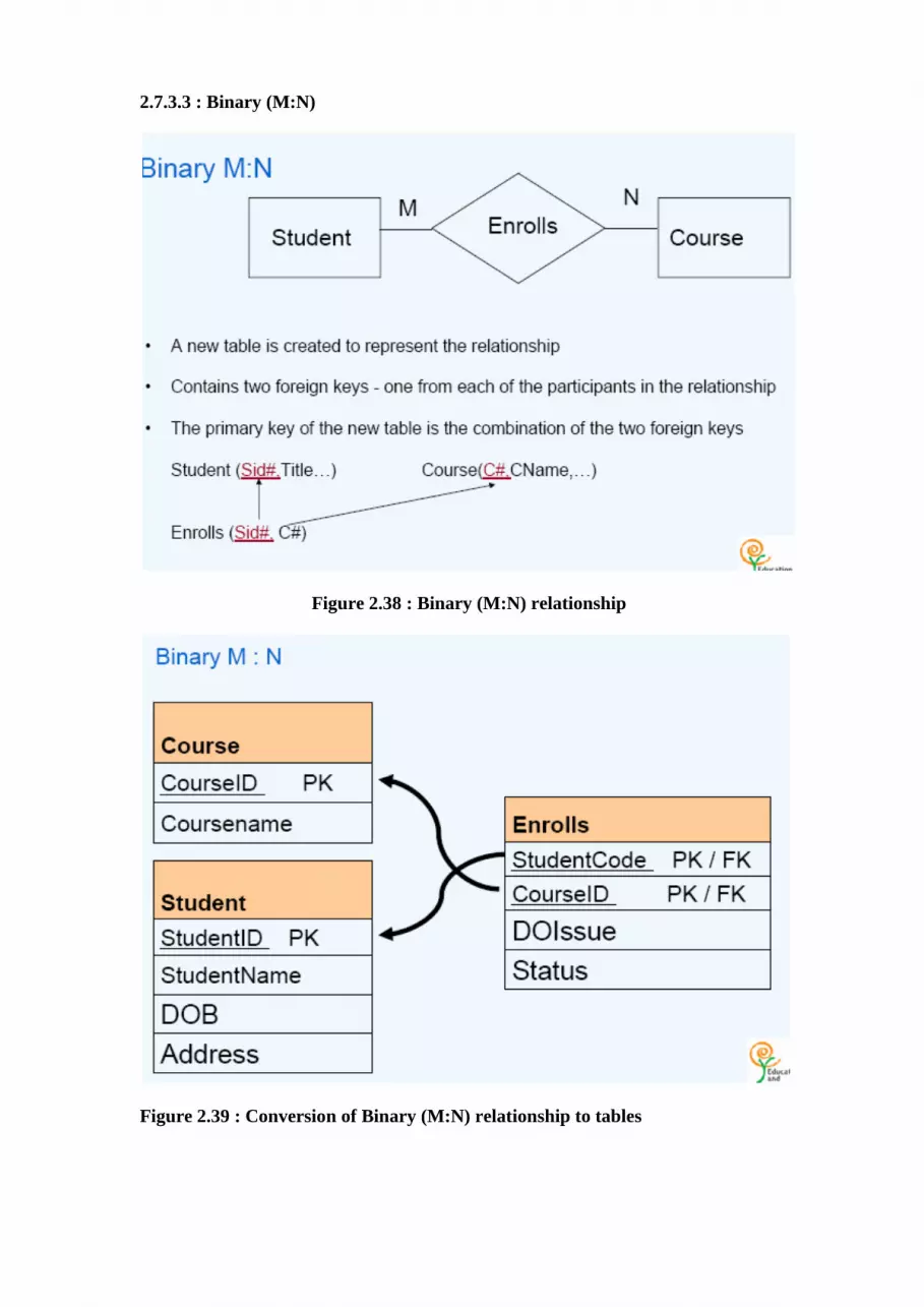
2.7.3.3 : Binary (M:N)
Figure 2.38 : Binary (M:N) relationship
Figure 2.39 : Conversion of Binary (M:N) relationship to tables

2.7.3.4 Unary (1:1)
Figure 2.40 Unary (1:1) Relationship
Figure 2.41 Conversion of Unary (1:1) Relationship to table
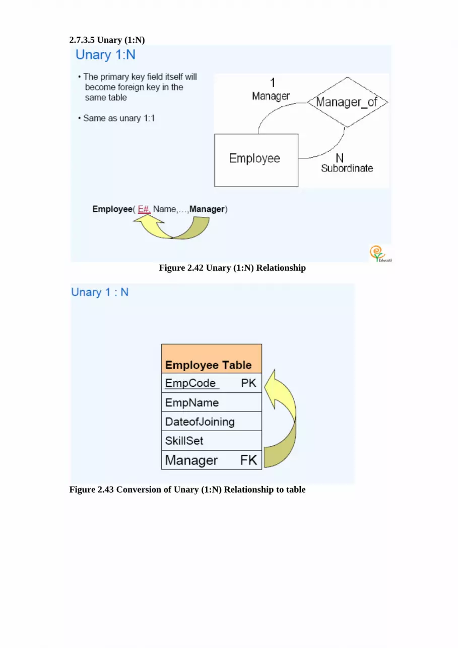
2.7.3.5 Unary (1:N)
Figure 2.42 Unary (1:N) Relationship
Figure 2.43 Conversion of Unary (1:N) Relationship to table
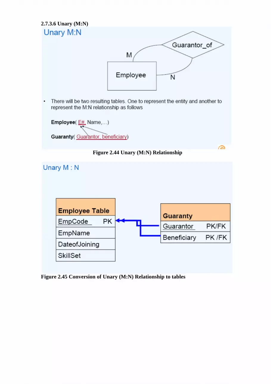
2.7.3.6 Unary (M:N)
Figure 2.44 Unary (M:N) Relationship
Figure 2.45 Conversion of Unary (M:N) Relationship to tables

2.7.3.7 Ternary Relationship
Figure 2.46 Ternary Relationship
Figure 2.47 Conversion of Ternary Relationship to table
2.7.4Converting specialization
Generalization is concept of representing entity sets in the form of hierarchy. Higher
level entity set is represented by table containing attribute common to lower level entity
set. Lower level entity set is represented by table containing column as primary key of
higher level entity set and a specialized attribute corresponding to that lower level entity
set.

Figure 2.48 Specialization
EMPLOYEE HOURL_EMPLOYEE
E# PK E# PK
Ename NoOfHrs
DOB
Address SALARAIED_EMPLOYEE
E# PK
BasicSal
Figure 2.49 Conversion of specialization to table
2.7.5 Converting Aggregation
If an aggregated entity set combines two entity sets with one relationship and this
aggregated entity set is related with one more entity than
Each entity set is represented by one table
The relationship between aggregated entity set is represented by one table, and
the final table structure depends upon the relationship between the tables.
The relationship between aggregated entity set and related entity is represented
by one table, containing primary key from each table.
2.7.6 Deriving Logical Schema for Banking Application
1) Each Entity represented in the E-R model can be defined as a table in the relational
scheme. All the attributes of the Entity will become columns of the table.
Example: Let us consider the CUSTOMER Entity of the banking database scenario.
We can translate this Entity to a “CUSTOMER” table with the following columns.
• CUSTOMER Customer#,Name,Telephone#,Address)
Example: Similarly a “Bank” table can be created with Bank Bankcode, Name and
Address columns
• BANK (BankCode, Name, Address)
EMPLOYEE
HOURLY_EMPLOYEE SALARIED_EMPLOYEE
ISA
E# Ename
Address DOB
NoOfHrs BasicSal

2) Weak Entity types are converted into a table of their own, with the primary key of
the strong Entity acting as a foreign key in the table. This Foreign key along with the
key of the Weak Entity form the composite primary key of this table.
Example: As per this guideline, a “Branch” table can be created with the
following structure.
• BRANCH (BankCode, Branch#, Name, Address)
3) Each relationship can be defined as separate table in relational schema. Key
attributes of participating entities will become key attribute of the Relationship.
Example: We can define Loan_Detail table with Loan# and Customer# together as
primary key with other relevant attributes like DateOfSanction, InterestRate,
LoanAmount, Duration etc.
• LOAN_DETAILS (Loan#, Customer#, DateofSanction, InterestRate,
LoanAmount, Duration)
Participating entities: The entities which are joined by the relation. In a Many to Many
relationship, it is necessary to create separate tables for participating entities and
relationships. In the banking application we have Customer and Loan Entities have a
Many to Many relationship. Hence one should create separate tables for
CUSTOMER
LOANS
LOAN_DETAILS.

SUMMARY
E-R Model is a conceptual data model used in mapping requirements of initial phase
into database design.
Conceptual model reflects the entities and their relationships, based on the data
processing needs of the organization
Entities are the people, places, things, events and concepts of interest to an organization
Properties or characteristics possessed by an entity are called as attributes
The set of possible values for an attribute is called the domain of the attribute
The attribute (or combination of attributes) that is unique for every entity instance is
called key attribute.
Entity that depends on other entity for its existence and doesn’t have key
attribute of its own is called Weak Entity Set.
Attributes that can take many values for each entity instance are called multi-valued
attributes
Null value of an attribute is considered if that attribute does not have a value for a
particular entity
A Primary key uniquely identifies an entity in entity set. Keys that are eligible to
become primary key are called candidate Keys and the superset of candidate key is
called superkey.
A foreign key is a set of attribute(s) whose values are required to match values of a
candidate key in the same or another table
Relationship is the association between entities.
The degree of a relationship is the number of entities associated with the relationship.
Descriptive attribute is an attribute of a relationship exists between different entity
sets.
Mapping constraint specifies the association of entities in an entity set with other
entity set.
Participation constraint imposes constraints on participation of entities in the
specified relationship.
Specialization is the process of defining a set of subclasses of an entity type. It is a top
down approach.
Generalization is a reverse process of abstraction, which suppresses the differences
among several entity types. It is a bottom up approach.
Aggregation is an abstract concept for building composite objects from their
components.
REVIEW QUESTIONS
Q.1 Explain following with appropriate example:
(i) Entity set
(ii) Key constraints
(iii) Participation constraints
(iv) Class hierarchy
(v) Aggregation
(vi) Weak entity set
Q.2. Draw an E-R diagram that captures following information related to airport:
(i) Every airplane has a registration number and each airplane is of specific model.
(ii) The airport accommodates a number of airplane models, and each model is
identified by a model number and has a capacity and weight.
(iii) A number of technicians work at airport who have eid, name, address, phone
number and salary of each technician. Each technician is an expert of one or more
plane models.

(iv) The airport has a number of tests that are used periodically to ensure that
airplanes are still worth. Each test has test number, a name and maximum
possible score.
Q.3. Any weak entity set can be converted to strong entity set by simply adding appropriate
attribute. Why, then, do we have weak entity sets?
Q.4. Discuss the naming conventions and symbols used in E-R diagram?
Q.5. Design a generalization specialization hierarchy for a motor vehicle sales company. The
company sell Motorcycles, Cars, Vans and Buses. Justify the placement of attribute at
each level of hierarchy. Explain why they should not be placed at higher or lower level?
Q.6. Design an E-R diagram that capture the following information about publisher-house
(i) Every publisher has a publisher-id, name, mainoffice, phone number.
(ii) Book have book-id, bname, subject, price and edition number.
(iii) Author has author-id, name, specialized area, qualification.
(iv) A publisher can publish many books. Similarly a book is published by only a
single publisher. Joint venture of publisher is restricted.
(v) A publisher can hire the author to write the book or gave a job to the author.
Author write many books not restricted to a single publisher.
(vi) Royalty given to each author is also recorded with the accordance of publisher.
Q.7 In a university database, information on the following is to be
kept.
[Raj. Univ., 1998]
Faculty (name, dept, title, office, ext, email)
Staff (name, dept, job, ext, email)
Graduate (id, name, address, prev-degree, enrolled program)
Undergraduate (id, name, address, year, major)
Teaching—Assistant (id, name, quarter, course)
Course (id, title, day, hour, room)
Reader (id, name, quarter, course, hour)
Review-section (course-id, TA, day, hour, room)
The following constraints apply:
Professors have a teaching assistant (TA) for each course they teach, TA must be a
graduate student. TA’s hold review section for some course several reader can be
assigned to one course or review section. All students, TA and reader attend the course.
Develop an E-R diagram for above specification.
Q.8 With the help of suitable example explain:
(i) Key constraints. [Raj. Univ., 1998, 2005]
(ii) Strong and weak entity set [Raj. Univ., 1998, 2005]
(iii) Participation constraints [Raj. Univ., 2003]
(iv) Class Hierarchies [Raj. Univ., 2003]
(v) Aggregation [Raj. Univ., 2003, 2005]
(vi) Distributed database [Raj. Univ., 2005]
(vii) Cardinality [Raj. Univ., 2005]
(viii) Candidate key [Raj. Univ., 2005]
Q.9 A software company manages a number of software projects. The company is organized
into many departments. Each department has unique id, name and manager. The company
has many employees. The company keeps track of id-number, name birth date, address,
joining date, leaving date, salary and department. An employee can be assigned many
software projects. Each project has unique id, name and machine. A project may be
jointly executed by more than one department. But all employee of a given department
may not be assigned to projects handled by the department. Each project has a project

leader. Similarly projects are supervised by a group leader. Some of departments are non
technical. Draw an E-R diagram for above description. [Raj. Univ., 1999]
Q.10 A database is being constructed to keep track of teams and games of sports league. A
team has number of players, not all of whom participates in each game. It is desire to
keep track of all players participating in each game for each team, the position they played
in that game, and result of game. Design an E-R diagram. [Raj. Univ., 2002]
Q.11 Create an E-R diagram for each of following:
(i) Each company operates four departments and each department belong to one
company.
(ii) Each department employs one or more employee and each employee works for
one department.
(iii) Each of employees in part (ii) may or may not have one or more dependents and
each dependent belongs to employee.
(iv) Represent all E-R diagrams described in (i) (ii) and (iii) as single E-R
diagram.
[Raj. Univ., 2004]
Q.12 What is the role of E-R model in Database design? Draw an E-R diagram for bank
management system. [Raj. Univ., 2005]