database design i: the entity-relationship model
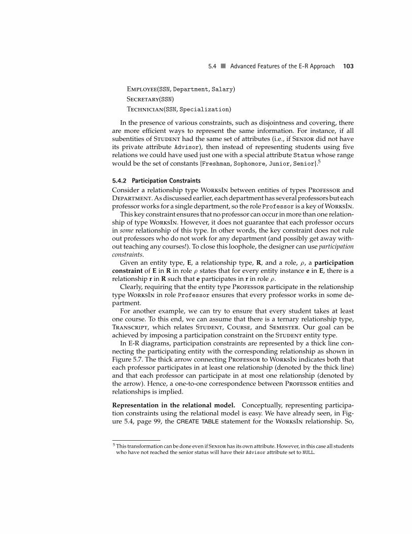
TRANSCRIPT
Chapter 5Database Design I: The Entity-Relationship Model
Now that the Specification Document for the Student Registration System has beenapproved by the university registrar, we are ready to begin designing the databaseportion of the system. In Chapter 12, we will discuss the complete design processfor an entire transaction processing application, including the final product of thatprocess, the Design Document. Here we discuss the database portion of the design,of which the final product is the complete (compilable) set of CREATE statementsthat declare the database schema—tables, indices, domains, assertions, and soforth. We present the complete database design for the Student Registration Systemin Section 5.7.
The key issue in database design is to accurately model the appropriate aspectsof a large enterprise as a relational database that can be efficiently accessed andupdated by a large number of concurrently executing transactions in (perhaps) anumber of distinct applications, some of which might also include decision supportqueries. As in other engineering disciplines, the design process can be facilitatedif it is performed according to some specific methodology and can be evaluatedaccording to some objective criteria.
In this chapter, we present a popular methodology for designing relational data-bases, the entity-relationship (E-R) approach, introduced by [Chen 1976]. Databasedesign will be revisited in Chapter 8, where we present the relational normalizationtheory, which provides objective criteria for evaluating alternative designs.
It should be noted that many of the mechanisms underlying both the E-R ap-proach and the relational normalization theory have been captured in computerprograms, thereby relieving the designer of some routine aspects of carrying out adesign. Still, this job requires a good deal of creativity, technical expertise, experi-ence, and understanding of fundamental database design principles.
5.1 CONCEPTUAL MODELING WITH THE E-R APPROACH
To quash one very common misconception, we emphasize that the E-R approachis not a relative, a derivative, or a generalization of the relational data model. Infact, it is not a data model at all but a design methodology, which can be applied (but
89
90 Chapter 5 Database Design I: The Entity-Relationship Model
is not limited) to the relational model. The term “relationship” refers to one of thetwo main components of the methodology rather than to the relational data model.
The two main components of the E-R approach are the concepts of entity andrelationship. Entities model the objects that are involved in an enterprise—for ex-ample, the students, professors, and courses in a university. Relationships modelthe connections among the entities—for example, professors teach courses. In ad-dition, integrity constraints on the entities and relationships form an importantpart of an E-R specification, much as they do in the relational model. For example,a professor can teach only one course at a given time on a given day.
An entity-relationship (E-R) diagram (peek ahead at Figure 5.1, page 92, andFigure 5.3, page 96) is a graphical representation of the entities, relationships, andconstraints that make up a given design. As in other visually oriented designmethodologies, it provides a graphical summary of the design that is extremelyuseful to the designer, not only in validating the correctness of the design but alsoin discussing it with colleagues and in explaining it to the programmers who will beusing it. Unfortunately, there is no standard drawing convention for E-R diagrams,and hence there is a good deal of variation among database texts in many aspectsof this approach.
After the enterprise has been modeled with E-R diagrams (in any of their fla-vors), there are straightforward ways of converting these diagrams into sets ofCREATE TABLE statements. Unfortunately, this conversion process does not yield aunique schema, especially in the presence of constraints, because some constraintsthat can be indicated in the E-R diagrams have no direct counterparts in SQL. Theseand related issues will be discussed in due time.
The creative part of the E-R methodology is deciding what entities, relationships,and constraints to use in modeling the enterprise. The simple examples we caninclude in a text might make these decisions look easy, but in practice designersmust combine a detailed understanding of the workings of the enterprise with aconsiderable amount of technical knowledge, judgment, and experience.
An important advantage of the methodology is that the designer can focus oncomplete and accurate modeling of the enterprise, without (initially) worryingabout efficiently executing the required queries and updates against the final data-base. Later, when the E-R diagrams are to be converted to CREATE TABLE statements,the designer can add efficiency considerations to the final table designs using nor-malization theory (Chapter 8) and other techniques to be discussed later in thischapter and in Chapter 13.
5.2 ENTITIES AND ENTITY TYPES
The first step in the E-R approach is to select the entities that will be used to modelthe enterprise. An entity is quite similar to an object, (see Appendix Section A.1.1)except that an entity does not have methods. It might be a concrete object in the realworld, such as John Doe, the Cadillac parked at 123 Main Street, or the Empire StateBuilding, or it might be an abstract object, such as the CitiBank account 123456789,the database course CS305, or the Computer Science Department at SUNY StonyBrook.
5.2 Entities and Entity Types 91
Similar entities are aggregated into entity types. For instance, John Doe, MaryDoe, Joe Blow, and Ann White might be aggregated into the entity type Personbased on the fact that these entities represent humans. John Doe and Joe Blowmight also belong to the entity type Student because in our sample database ofChapter 4 these objects presumably represented students. Similarly, Mary Doe andAnn White might be classified as members of the entity type Professor.
Other examples of entity types include
CS305, MGT315, and EE101, entities of type Course
Alf and E.T., entities of type SpaceAlien
CIA, FBI, and IRS, entities of type GovernmentAgency
Attributes. As with relations (and objects), entities are described using attributes.Every attribute of an entity specifies a particular property of that entity. For in-stance, the Name attribute of a Person entity normally specifies a string of charactersthat denotes the real-world name of the person represented by that database en-tity. Similarly, the Age attribute specifies the number of times the Earth had circledaround the Sun since the moment that real-world person was born.
All of our examples of entity types have been semantic in nature; that is, theentity type consists of a semantically related set of entities. For example, it is usuallypointless to classify people, cars, and paper clips in one entity type because theyhave little in common in a typical enterprise modeling. More useful is classifyingsemantically similar entities in one entity type, since such entities are likely to haveuseful common attributes that describe them. For example, in any enterprise peoplehave many common attributes, such as Name, Age, and Address. Classification intoentity types allows us to associate these attributes with the entity type instead ofwith the entities themselves.
Of course, different entity types have different sets of attributes. For instance, thePaperClip entity type might have attributes Size and Price, while Course mighthave attributes CrsName, CrsCode, Credits, and Description.
Domains. As in the relational model, the domain of an attribute specifies theset from which its value can be drawn. Unlike the relational model, however, E-Rattributes can be set-valued. This means that the value of an attribute can be a set ofvalues from the corresponding domain rather than a single value. For example, anentity type Person might have set-valued attributes ChildrenNames and Hobbies.
The inability to express set-valued attributes conveniently was one of the majorcriticisms of the relational data model that motivated the development of the object-oriented data model. However, the use of set-valued attributes in the E-R modelis just a matter of convenience. Relations (as defined in Chapter 4) can be used tomodel entities with set-valued attributes with some extra effort.
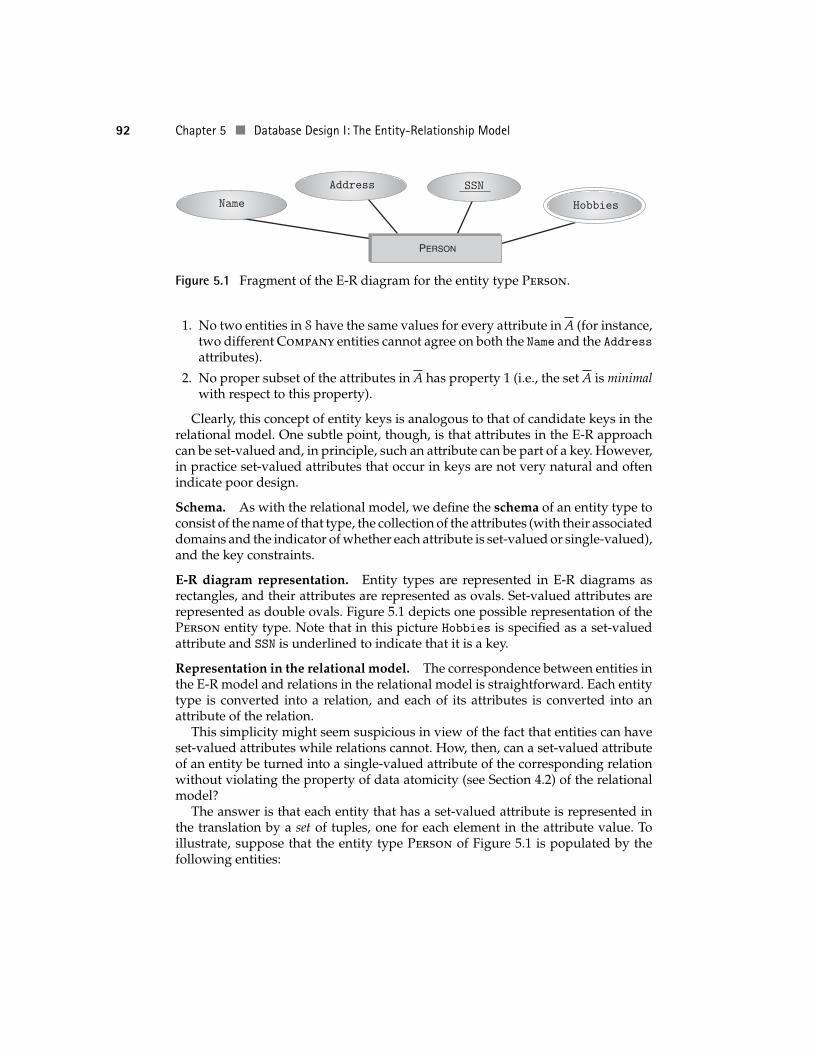
Keys. As with the relational model, it is useful to introduce the key constraintsassociated with entity types. A key constraint on an entity type, S, is a set ofattributes, A, of S such that
92 Chapter 5 Database Design I: The Entity-Relationship Model
Name
Address SSN
Hobbies
PERSON
Figure 5.1 Fragment of the E-R diagram for the entity type Person.
1. No two entities in S have the same values for every attribute in A (for instance,two different Company entities cannot agree on both the Name and the Addressattributes).
2. No proper subset of the attributes in A has property 1 (i.e., the set A is minimalwith respect to this property).
Clearly, this concept of entity keys is analogous to that of candidate keys in therelational model. One subtle point, though, is that attributes in the E-R approachcan be set-valued and, in principle, such an attribute can be part of a key. However,in practice set-valued attributes that occur in keys are not very natural and oftenindicate poor design.
Schema. As with the relational model, we define the schema of an entity type toconsist of the name of that type, the collection of the attributes (with their associateddomains and the indicator of whether each attribute is set-valued or single-valued),and the key constraints.
E-R diagram representation. Entity types are represented in E-R diagrams asrectangles, and their attributes are represented as ovals. Set-valued attributes arerepresented as double ovals. Figure 5.1 depicts one possible representation of thePerson entity type. Note that in this picture Hobbies is specified as a set-valuedattribute and SSN is underlined to indicate that it is a key.
Representation in the relational model. The correspondence between entities inthe E-R model and relations in the relational model is straightforward. Each entitytype is converted into a relation, and each of its attributes is converted into anattribute of the relation.
This simplicity might seem suspicious in view of the fact that entities can haveset-valued attributes while relations cannot. How, then, can a set-valued attributeof an entity be turned into a single-valued attribute of the corresponding relationwithout violating the property of data atomicity (see Section 4.2) of the relationalmodel?
The answer is that each entity that has a set-valued attribute is represented inthe translation by a set of tuples, one for each element in the attribute value. Toillustrate, suppose that the entity type Person of Figure 5.1 is populated by thefollowing entities:
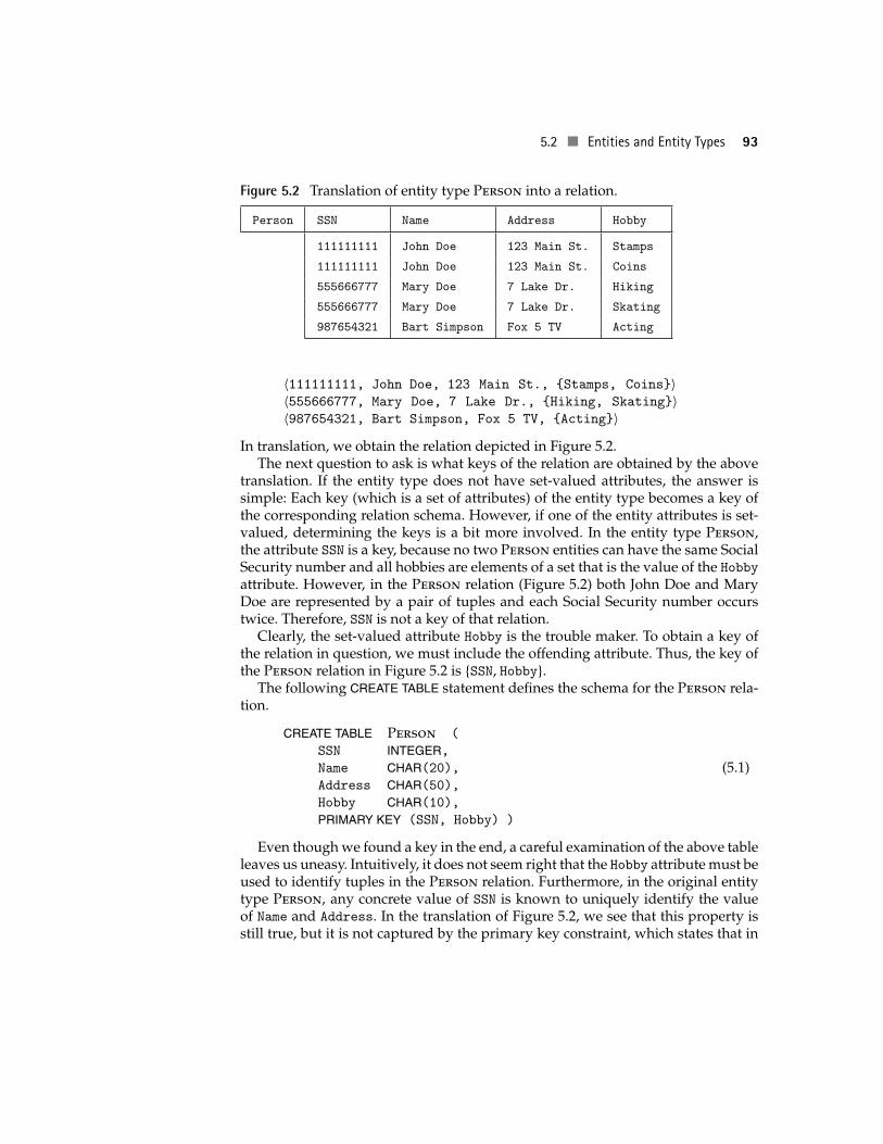
5.2 Entities and Entity Types 93
Figure 5.2 Translation of entity type Person into a relation.
Person SSN Name Address Hobby
111111111 John Doe 123 Main St. Stamps
111111111 John Doe 123 Main St. Coins
555666777 Mary Doe 7 Lake Dr. Hiking
555666777 Mary Doe 7 Lake Dr. Skating
987654321 Bart Simpson Fox 5 TV Acting
〈111111111, John Doe, 123 Main St., {Stamps, Coins}〉〈555666777, Mary Doe, 7 Lake Dr., {Hiking, Skating}〉〈987654321, Bart Simpson, Fox 5 TV, {Acting}〉
In translation, we obtain the relation depicted in Figure 5.2.The next question to ask is what keys of the relation are obtained by the above
translation. If the entity type does not have set-valued attributes, the answer issimple: Each key (which is a set of attributes) of the entity type becomes a key ofthe corresponding relation schema. However, if one of the entity attributes is set-valued, determining the keys is a bit more involved. In the entity type Person,the attribute SSN is a key, because no two Person entities can have the same SocialSecurity number and all hobbies are elements of a set that is the value of the Hobbyattribute. However, in the Person relation (Figure 5.2) both John Doe and MaryDoe are represented by a pair of tuples and each Social Security number occurstwice. Therefore, SSN is not a key of that relation.
Clearly, the set-valued attribute Hobby is the trouble maker. To obtain a key ofthe relation in question, we must include the offending attribute. Thus, the key ofthe Person relation in Figure 5.2 is {SSN, Hobby}.
The following CREATE TABLE statement defines the schema for the Person rela-tion.
CREATE TABLE Person (
SSN INTEGER,Name CHAR(20), (5.1)Address CHAR(50),Hobby CHAR(10),PRIMARY KEY (SSN, Hobby) )
Even though we found a key in the end, a careful examination of the above tableleaves us uneasy. Intuitively, it does not seem right that the Hobby attribute must beused to identify tuples in the Person relation. Furthermore, in the original entitytype Person, any concrete value of SSN is known to uniquely identify the valueof Name and Address. In the translation of Figure 5.2, we see that this property isstill true, but it is not captured by the primary key constraint, which states that in
94 Chapter 5 Database Design I: The Entity-Relationship Model
order to uniquely determine a tuple, we must specify the value of both SSN andHobby. In contrast, in the entity type Person the value of Hobby is not required todetermine the value of Name and Address. This important constraint has been lostin the translation!
The preceding example is the first indication that the E-R approach alone is nota sufficient tool for guaranteeing good relational design. Chapter 8 will provide ahost of objective criteria that can help the database designer evaluate the relationalschema obtained by converting E-R diagrams into relations. In particular, the prob-lem with the relation in Figure 5.2 is that it is not in a certain “normal form” definedin Chapter 8. That chapter proceeds to develop algorithms that can automaticallyrectify the problem by splitting such offending relations into smaller relations thatare in a desired normal form.
5.3 RELATIONSHIPS AND RELATIONSHIP TYPES
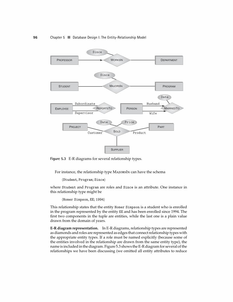
The E-R approach makes a sharp distinction between the entities themselves andthe mechanism that relates them to each other. This mechanism is called relation-ships. Just as entities are classified into entity types, relationships that relate thesame types of entities and that have the same meaning are grouped into relation-ship types.1
For instance, Student entities are related to Program entities via relationshipsof type MajorsIn. Likewise, Professor entities are related to the departments theywork for via relationships of type WorksIn.
Once again, we emphasize that the concept of relationship in the E-R approach isdistinct from the concept of relation in the relational data model. Relationships arejust one of the modeling tools in the arsenal of the E-R approach. When it comesto implementation, both entities and relationships are represented as relations (i.e.,tables) in the DBMS.
Attributes and roles. Like entities, relationships can have attributes. For instance,the relationship MajorsIn might have an attribute Since, which indicates the datethe student was admitted into the corresponding major. The WorksIn relationshipmight have the attribute Since to indicate the start date of employment.
Attributes do not provide a complete description of relationships. Consider theentity type Employee and the relationship ReportsTo, which relates employees toother employees. The first type of employee is the subordinate while the second isthe boss. Thus, if we just say that 〈John, Bill〉 is a relationship of type ReportsTo,we still do not know who reports to whom.
Splitting the Employee entity type into Subordinate and Supervisor doesnot help, because ReportsTo might represent the entire chain of reporting in acorporate hierarchy, making some employees subordinates and supervisors at thesame time.
1 When there is a danger of confusion between relationships and entities on the one hand and relation-ship types and entity types on the other, we use the terms “relationship instance” and “entity instance”instead of “relationship” and “entity,” respectively.
5.3 Relationships and Relationship Types 95
The solution is to recognize that the various entity types participating in a rela-tionship type play different roles in that relationship. For each such participatingentity type, we define a role and give that role a name (for example, Subordinate).A role is similar to an attribute, but instead of specifying some property of the re-lationship it specifies in what way an entity type participates in the relationship.Both roles and attributes are part of the schema of the relationship type.
For example, the relationship type WorksIn has two roles, Professor andDepartment. The Professor role identifies the Professor entity involved in aWorksIn relationship, and the Department role identifies the corresponding De-partment entity in the relationship. Similarly, the relationship type MajorsIn hastwo roles: Student and Program.
When all of the entities involved in a relationship belong to distinct entitytypes (as in WorksIn and MajorsIn), it is not necessary to explicitly indicate theroles, because we can always adopt some convention, such as naming the rolesafter the corresponding entity types (which is typical in practice).2 However, suchsimplification is not possible when some of the entities involved are drawn fromthe same entity type, as is the case with the ReportsTo relationship. Here, wehave to explicitly indicate the roles, for example, Subordinate and Supervisor.Figure 5.3 shows several examples of relationships, including those where rolesmust be named explicitly.
To summarize, a schema of a relationship type includes
A list of attributes along with their corresponding domains. An attribute can besingle-valued or set-valued.
A list of roles along with their corresponding entity types. Unlike attributes, rolesare always single-valued.
A set of constraints, to be described later. (In Figure 5.3, constraints are repre-sented as arrows, which will be explained later.)
The number of roles engaged in a relationship type is called the degree of the type.
We can now define the concept of a relationship more precisely. A relationshiptype R of degree n is defined by its attributes A1, . . . , Ak and roles R1, . . . , Rn. Therelationships populating R are defined to be tuples of the form
〈e1, e2, . . . , en; a1, a2, . . . , ak〉where e1, . . . , en are entities that are values of the roles R1, . . . , Rn, respectively(these are the entities involved in the relationship) and a1, a2, . . . , ak are values of theattributes A1, . . . , Ak, respectively. We assume that all of the values of the attributesin the relationship are in their respective domains as defined in the relationship typeand all of the entities are of the correct entity types as defined in their respectiveroles.
2 To avoid confusion, we use different fonts to distinguish entity types from the roles they play in variousrelationships.
96 Chapter 5 Database Design I: The Entity-Relationship Model
Since
Since
Husband
Wife
ProductCustomer
Subordinate
Supervisor
Date
Date Price
PERSONEMPLOYEE
STUDENT PROGRAM
PARTPROJECT
SUPPLIER
PROFESSOR DEPARTMENT
MAJORSIN
WORKSIN
REPORTSTO MARRIEDTO
SOLD
Figure 5.3 E-R diagrams for several relationship types.
For instance, the relationship type MajorsIn can have the schema
〈Student, Program; Since〉where Student and Program are roles and Since is an attribute. One instance inthis relationship type might be
〈Homer Simpson, EE; 1994〉This relationship states that the entity Homer Simpson is a student who is enrolledin the program represented by the entity EE and has been enrolled since 1994. Thefirst two components in the tuple are entities, while the last one is a plain valuedrawn from the domain of years.
E-R diagram representation. In E-R diagrams, relationship types are representedas diamonds and roles are represented as edges that connect relationship types withthe appropriate entity types. If a role must be named explicitly (because some ofthe entities involved in the relationship are drawn from the same entity type), thename is included in the diagram. Figure 5.3 shows the E-R diagram for several of therelationships we have been discussing (we omitted all entity attributes to reduce
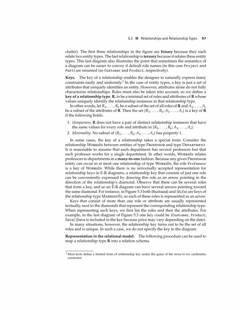
5.3 Relationships and Relationship Types 97
clutter). The first three relationships in the figure are binary because they eachrelate two entity types. The last relationship is ternary because it relates three entitytypes. This last diagram also illustrates the point that sometimes the semantics ofa diagram can be easier to convey if default role names (in this case Project andPart) are renamed (as Customer and Product, respectively).
Keys. The key of a relationship enables the designer to naturally express manyconstraints easily and uniformly.3 In the case of entity types, a key is just a set ofattributes that uniquely identifies an entity. However, attributes alone do not fullycharacterize relationships. Roles must also be taken into account, so we define akey of a relationship type, R, to be a minimal set of roles and attributes of R whosevalues uniquely identify the relationship instances in that relationship type.
In other words, let R1, . . . , Rk be a subset of the set of all roles of R and A1, . . . , Asbe a subset of the attributes of R. Then the set {R1, . . . , Rk; A1, . . . , As} is a key of Rif the following holds.
1. Uniqueness. R does not have a pair of distinct relationship instances that havethe same values for every role and attribute in {R1, . . . , Rk; A1, . . . , As}.
2. Minimality. No subset of {R1, . . . , Rk; A1, . . . , As} has property 1.
In some cases, the key of a relationship takes a special form. Consider therelationship WorksIn between entities of type Professor and type Department.It is reasonable to assume that each department has several professors but thateach professor works for a single department. In other words, WorksIn relatesprofessors to departments in a many-to-one fashion. Because any given Professorentity can occur in at most one relationship of type WorksIn, the role Professor
is a key of WorksIn. While there is no universally accepted representation forrelationship keys in E-R diagrams, a relationship key that consists of just one rolecan be conveniently expressed by drawing this role as an arrow pointing in thedirection of the relationship’s diamond. Observe that there can be several rolesthat form a key, and so an E-R diagram can have several arrows pointing towardthe same diamond. For instance, in Figure 5.3 both {Husband} and {Wife} are keys ofthe relationship type MarriedTo, so each of these roles is represented as an arrow.
Keys that consist of more than one role or attribute are usually representedtextually, next to the diamonds that represent the corresponding relationship type.When representing such keys, we first list the roles and then the attributes. Forexample, in the last diagram of Figure 5.3 one key could be {Customer, Product;Date} (Date is included in the key because price may vary depending on the date).
In many situations, however, the relationship key turns out to be the set of allroles and is unique. In such a case, we do not specify the key in the diagram.
Representation in the relational model. The following procedure can be used tomap a relationship type R into a relation schema.
3 Most texts define a limited form of relationship key under the guise of the many-to-one cardinalityconstraint.
98 Chapter 5 Database Design I: The Entity-Relationship Model
Attributes of the relation schema. The attributes of the relation schema are1. The attributes of R itself2. For each role in R, the primary key of the associated entity type
Note that we use the primary key of the entity type, not the primary key of therelation schema constructed out of that entity type, because the goal is to identifythe entity involved in the relationship. Thus, for example, in the case of a roleassociated with the entity type Person we use SSN and omit Hobby.
Candidate keys of the relation schema. In most cases, the keys of the relation schemaare obtained by direct translation from the keys of R itself. That is, if a role, R,of R belongs to the key of R then the attributes of the primary key, K, of theentity associated with R must belong to the candidate key of the relation schemaderived from R.
A slight problem arises when R has set-valued attributes. In that case, weresort to an earlier trick that was used for converting entity keys into relationkeys: All set-valued attributes must be included in the candidate key of therelation (see the Person entity-to-relation translation) whether or not they areincluded in the key of R. Note that roles are always single-valued, so this specialtreatment of set-valued attributes does not apply to the roles.
Foreign key constraints of the relation schema. Because, in the E-R model, a rolealways refers to some entity (which is mapped to a relation), roles translate intoforeign key constraints. The foreign keys of the relation schema correspondingto R are constructed as follows.
For each role in R, the primary key of the associated entity type(which is among the attributes of the relation schema correspondingto R) becomes a foreign key that references the relation obtained fromthat entity type.
The only problem might be that the primary key of the entity type (e.g., SSN)need not be the primary key of the corresponding relation (e.g., {SSN, Hobby}),as we saw in the case of the Person entity type. Such problems are eliminatedby the relational normalization theory of Chapter 8.
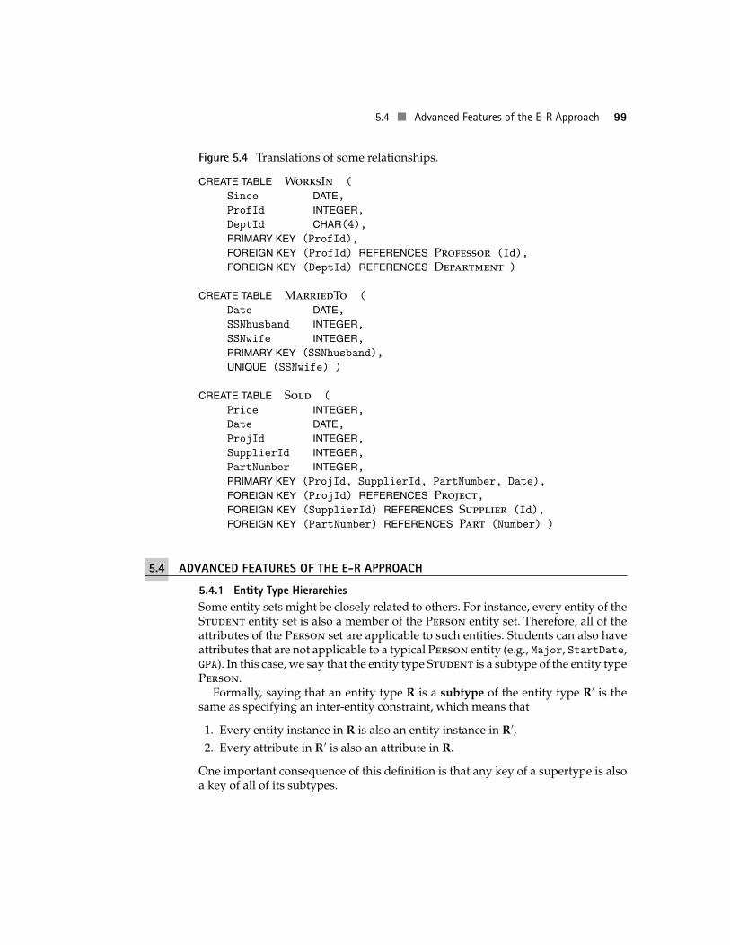
Figure 5.4 shows the CREATE TABLE commands that define the schemas corre-sponding to some of the relationships in Figure 5.3. Observe that, in the MarriedTorelation, we did not define the foreign key constraint because, although SSNhus-
band and SSNwife clearly reference the SSN attribute of the Person relation, SSN isnot a candidate key for that relation, as explained earlier. The UNIQUE constraint inthe schema guarantees that SSNwife is unique in any instance of the table and ishence a candidate key.
Note that when E-R diagrams are translated into tables, some of these tablesdescribe entities and others describe relationships. Thus, the first E-R diagram ofFigure 5.3 translates into three tables: one to describe the entity type of professors,one to describe the entity type of departments, and one to describe the relationshiptype that describes professors working for various departments.
5.4 Advanced Features of the E-R Approach 99
Figure 5.4 Translations of some relationships.
CREATE TABLE WorksIn (
Since DATE,ProfId INTEGER,DeptId CHAR(4),PRIMARY KEY (ProfId),
FOREIGN KEY (ProfId) REFERENCES Professor (Id),
FOREIGN KEY (DeptId) REFERENCES Department )
CREATE TABLE MarriedTo (
Date DATE,SSNhusband INTEGER,SSNwife INTEGER,PRIMARY KEY (SSNhusband),
UNIQUE (SSNwife) )
CREATE TABLE Sold (
Price INTEGER,Date DATE,ProjId INTEGER,SupplierId INTEGER,PartNumber INTEGER,PRIMARY KEY (ProjId, SupplierId, PartNumber, Date),
FOREIGN KEY (ProjId) REFERENCES Project,FOREIGN KEY (SupplierId) REFERENCES Supplier (Id),
FOREIGN KEY (PartNumber) REFERENCES Part (Number) )
5.4 ADVANCED FEATURES OF THE E-R APPROACH
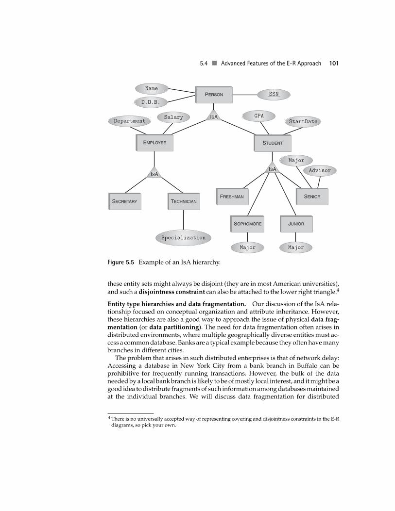
5.4.1 Entity Type HierarchiesSome entity sets might be closely related to others. For instance, every entity of theStudent entity set is also a member of the Person entity set. Therefore, all of theattributes of the Person set are applicable to such entities. Students can also haveattributes that are not applicable to a typical Person entity (e.g., Major, StartDate,GPA). In this case, we say that the entity type Student is a subtype of the entity typePerson.
Formally, saying that an entity type R is a subtype of the entity type R′ is thesame as specifying an inter-entity constraint, which means that
1. Every entity instance in R is also an entity instance in R′,2. Every attribute in R′ is also an attribute in R.
One important consequence of this definition is that any key of a supertype is alsoa key of all of its subtypes.
100 Chapter 5 Database Design I: The Entity-Relationship Model
Note that subtyping is not only a constraint but also a relationship. It can berepresented as a relationship with roles Sub(type) and Super(type) and is oftencalled the IsA relationship. Thus, the names of the roles in the IsA relationship arefixed, but the ranges of these roles depend on the entity types that are related byeach particular IsA relationship.
For instance, in the IsA relationship type that relates Student and Person therange of Sub is Student and the range of Super is Person. A particular instanceof this relationship could be 〈Homer Simpson, Homer Simpson〉, which states thatHomer Simpson is a student and a person. Note that the two entities involved inIsA are always identical.
So what is so useful about the IsA relationship? The answer lies in the factthat subtype constraints introduce a classification hierarchy in the E-R model.For instance, Freshman is a subtype of Student, which in turn is a subtype ofPerson. This property is transitive, which means that Freshman is also a subtypeof Person. The transitive property gives us a way to draw E-R diagrams in a moreconcise and readable manner. Because of property 2 of subtyping, every attributeof Person is also an attribute of Student and, by transitivity, is also an attribute ofFreshman. This phenomenon is often expressed by saying that Student inheritsattributes from Person and that Freshman inherits attributes from both Personand Student.
Note that the inherited attributes (SSN, Name, etc.) are not specified explicitlyfor the entity types Student and Freshman, and yet they are considered validattributes because of the IsA relationship. In addition to the inherited attributes,Student and Freshman might have attributes of their own, which their corre-sponding supertypes might not have. Figure 5.5 illustrates this idea. As Studentis a subtype of Person, this entity type inherits all of the attributes specified forPerson, and so there is no need to repeat the attributes Name and D.O.B. (date ofbirth) for the Student type. Similarly, Freshman, Sophomore, and so forth, aresubtypes of Student, and so we do not need to copy the attributes of Student andPerson over to these subtypes. Transitivity has the potential of greatly simplifyingan E-R diagram. The Employee branch of the IsA tree provides another exampleof attribute inheritance. The relationship Employee IsA Person represents the factthat every Employee entity has attributes Department and Salary. In addition, itstates that every Employee entity is also a Person entity and, as such, also has theattributes Name, SSN, and so forth.
Note that each IsA triangle in Figure 5.5 represents several relationship types. Forinstance, the upper triangle represents the relationship types Student IsA Personand Employee IsA Person. Although this notation makes the representation of theIsA relationship different from the representation of other kinds of relationships,it is used because there are a number of constraints associated with entity typehierarchies that can be naturally represented using such notation.
For instance, the union of the entities that belong to the entity types Freshman,Sophomore, Junior, and Senior might be equal to the set of entities of typeStudent (for example, in a four-year college). This constraint, called the coveringconstraint, can be handily attached to the lower right IsA triangle. In addition,
5.4 Advanced Features of the E-R Approach 101
NameSSN
GPA
Major
Major
Specialization
Major
Advisor
StartDateDepartmentSalary
D.O.B.
JUNIOR
ISA
ISAISA
SOPHOMORE
PERSON
STUDENTEMPLOYEE
SECRETARY TECHNICIANFRESHMAN SENIOR
Figure 5.5 Example of an IsA hierarchy.
these entity sets might always be disjoint (they are in most American universities),and such a disjointness constraint can also be attached to the lower right triangle.4
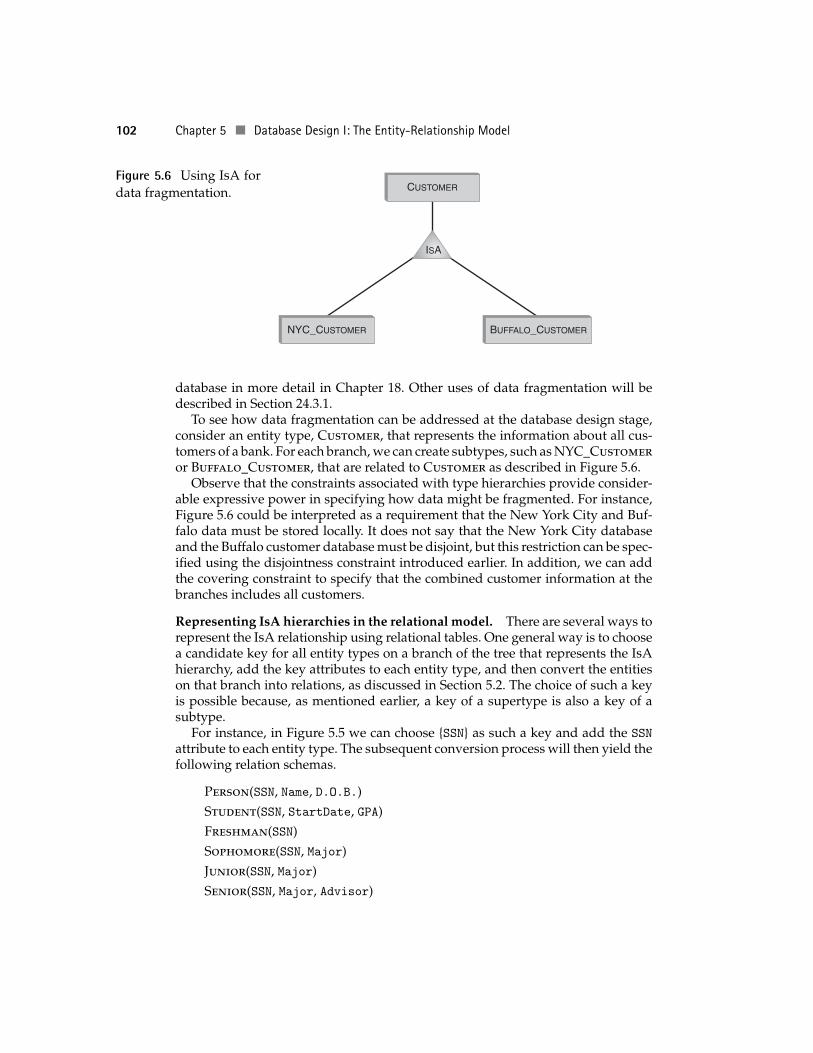
Entity type hierarchies and data fragmentation. Our discussion of the IsA rela-tionship focused on conceptual organization and attribute inheritance. However,these hierarchies are also a good way to approach the issue of physical data frag-mentation (or data partitioning). The need for data fragmentation often arises indistributed environments, where multiple geographically diverse entities must ac-cess a common database. Banks are a typical example because they often have manybranches in different cities.
The problem that arises in such distributed enterprises is that of network delay:Accessing a database in New York City from a bank branch in Buffalo can beprohibitive for frequently running transactions. However, the bulk of the dataneeded by a local bank branch is likely to be of mostly local interest, and it might be agood idea to distribute fragments of such information among databases maintainedat the individual branches. We will discuss data fragmentation for distributed
4 There is no universally accepted way of representing covering and disjointness constraints in the E-Rdiagrams, so pick your own.
102 Chapter 5 Database Design I: The Entity-Relationship Model
Figure 5.6 Using IsA fordata fragmentation. CUSTOMER
NYC_CUSTOMER BUFFALO_CUSTOMER
ISA
database in more detail in Chapter 18. Other uses of data fragmentation will bedescribed in Section 24.3.1.
To see how data fragmentation can be addressed at the database design stage,consider an entity type, Customer, that represents the information about all cus-tomers of a bank. For each branch, we can create subtypes, such as NYC_Customeror Buffalo_Customer, that are related to Customer as described in Figure 5.6.
Observe that the constraints associated with type hierarchies provide consider-able expressive power in specifying how data might be fragmented. For instance,Figure 5.6 could be interpreted as a requirement that the New York City and Buf-falo data must be stored locally. It does not say that the New York City databaseand the Buffalo customer database must be disjoint, but this restriction can be spec-ified using the disjointness constraint introduced earlier. In addition, we can addthe covering constraint to specify that the combined customer information at thebranches includes all customers.
Representing IsA hierarchies in the relational model. There are several ways torepresent the IsA relationship using relational tables. One general way is to choosea candidate key for all entity types on a branch of the tree that represents the IsAhierarchy, add the key attributes to each entity type, and then convert the entitieson that branch into relations, as discussed in Section 5.2. The choice of such a keyis possible because, as mentioned earlier, a key of a supertype is also a key of asubtype.
For instance, in Figure 5.5 we can choose {SSN} as such a key and add the SSN
attribute to each entity type. The subsequent conversion process will then yield thefollowing relation schemas.
Person(SSN, Name, D.O.B.)Student(SSN, StartDate, GPA)Freshman(SSN)Sophomore(SSN, Major)Junior(SSN, Major)Senior(SSN, Major, Advisor)
5.4 Advanced Features of the E-R Approach 103
Employee(SSN, Department, Salary)Secretary(SSN)Technician(SSN, Specialization)
In the presence of various constraints, such as disjointness and covering, thereare more efficient ways to represent the same information. For instance, if allsubentities of Student had the same set of attributes (i.e., if Senior did not haveits private attribute Advisor), then instead of representing students using fiverelations we could have used just one with a special attribute Status whose rangewould be the set of constants {Freshman, Sophomore, Junior, Senior}.5
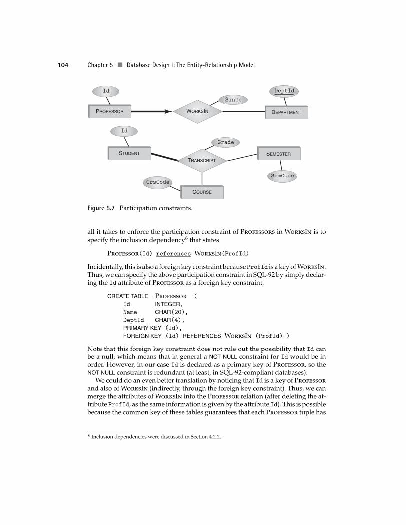
5.4.2 Participation ConstraintsConsider a relationship type WorksIn between entities of types Professor andDepartment. As discussed earlier, each department has several professors but eachprofessor works for a single department, so the role Professor is a key of WorksIn.
This key constraint ensures that no professor can occur in more than one relation-ship of type WorksIn. However, it does not guarantee that each professor occursin some relationship of this type. In other words, the key constraint does not ruleout professors who do not work for any department (and possibly get away with-out teaching any courses!). To close this loophole, the designer can use participationconstraints.
Given an entity type, E, a relationship type, R, and a role, ρ, a participationconstraint of E in R in role ρ states that for every entity instance e in E, there is arelationship r in R such that e participates in r in role ρ.
Clearly, requiring that the entity type Professor participate in the relationshiptype WorksIn in role Professor ensures that every professor works in some de-partment.
For another example, we can try to ensure that every student takes at leastone course. To this end, we can assume that there is a ternary relationship type,Transcript, which relates Student, Course, and Semester. Our goal can beachieved by imposing a participation constraint on the Student entity type.
In E-R diagrams, participation constraints are represented by a thick line con-necting the participating entity with the corresponding relationship as shown inFigure 5.7. The thick arrow connecting Professor to WorksIn indicates both thateach professor participates in at least one relationship (denoted by the thick line)and that each professor can participate in at most one relationship (denoted bythe arrow). Hence, a one-to-one correspondence between Professor entities andrelationships is implied.
Representation in the relational model. Conceptually, representing participa-tion constraints using the relational model is easy. We have already seen, in Fig-ure 5.4, page 99, the CREATE TABLE statement for the WorksIn relationship. So,
5 This transformation can be done even if Senior has its own attribute. However, in this case all studentswho have not reached the senior status will have their Advisor attribute set to NULL.
104 Chapter 5 Database Design I: The Entity-Relationship Model
Id
Grade
Since
DeptId
COURSE
SEMESTER
DEPARTMENT
STUDENT
PROFESSOR WORKSIN
TRANSCRIPT
SemCodeCrsCode
Id
Figure 5.7 Participation constraints.
all it takes to enforce the participation constraint of Professors in WorksIn is tospecify the inclusion dependency6 that states
Professor(Id) references WorksIn(ProfId)
Incidentally, this is also a foreign key constraint becauseProfId is a key of WorksIn.Thus, we can specify the above participation constraint in SQL-92 by simply declar-ing the Id attribute of Professor as a foreign key constraint.
CREATE TABLE Professor (
Id INTEGER,Name CHAR(20),DeptId CHAR(4),PRIMARY KEY (Id),
FOREIGN KEY (Id) REFERENCES WorksIn (ProfId) )
Note that this foreign key constraint does not rule out the possibility that Id canbe a null, which means that in general a NOT NULL constraint for Id would be inorder. However, in our case Id is declared as a primary key of Professor, so theNOT NULL constraint is redundant (at least, in SQL-92-compliant databases).
We could do an even better translation by noticing that Id is a key of Professorand also of WorksIn (indirectly, through the foreign key constraint). Thus, we canmerge the attributes of WorksIn into the Professor relation (after deleting the at-tribute ProfId, as the same information is given by the attribute Id). This is possiblebecause the common key of these tables guarantees that each Professor tuple has
6 Inclusion dependencies were discussed in Section 4.2.2.
5.4 Advanced Features of the E-R Approach 105
exactly one corresponding WorksIn tuple, so no redundancy is created by concate-nating such related tuples. This yields the table ProfessorMergedWithWorksIn:
CREATE TABLE ProfessorMergedWithWorksIn (
Id INTEGER,Name CHAR(20),DeptId CHAR(4),Since DATE,PRIMARY KEY (Id)
FOREIGN KEY DeptId REFERENCES Department )
Although conceptually representation of participation constraints in the rela-tional model amounts to nothing more than specifying an inclusion dependency,the actual representation in SQL-92 is not always as simple as in the previous ex-ample. The reason is that not all inclusion dependencies are foreign key constraints(see Section 4.2.2), and their expression in SQL-92 requires heavy machinery, suchas assertions or triggers, which can have a negative effect on performance.
An example of this situation is the constraint on the participation of Student inthe Transcript relationship, depicted in Figure 5.7. The translation of Transcriptto SQL-92 is
CREATE TABLE Transcript (
StudId INTEGER,CrsCode CHAR(6),Semester CHAR(6),Grade CHAR(1),PRIMARY KEY (StudId, CrsCode, Semester),
FOREIGN KEY (StudId) REFERENCES Student (Id),
FOREIGN KEY (CrsCode) REFERENCES Course (CrsCode),
FOREIGN KEY (Semester) REFERENCES Semesters (SemCode))
As before, the foreign key constraints specified for the Transcript table do notguarantee that every student takes a course. To ensure that every student par-ticipates in some Transcript relationship, the Student relation must have aninclusion dependency of the form
Student(Id) references Transcript(StudId)
However, since StudId is not a candidate key in Transcript, this inclusion depen-dency cannot be represented by foreign key constraints. In Chapter 4, we illustratedhow inclusion dependencies can be defined using the CREATE ASSERTION statement(see (4.4) on page 75).
Unfortunately, verifying general assertions is often significantly more costlythan verifying foreign key constraints, so the use of constraints such as (4.4) shouldbe carefully weighed against the potential overhead. For instance, if it is deter-mined that including such an assertion slows down crucial database operations,the designer might opt for checking the inclusion dependency as part of a separate,periodically run transaction rather than one run in real time.
106 Chapter 5 Database Design I: The Entity-Relationship Model
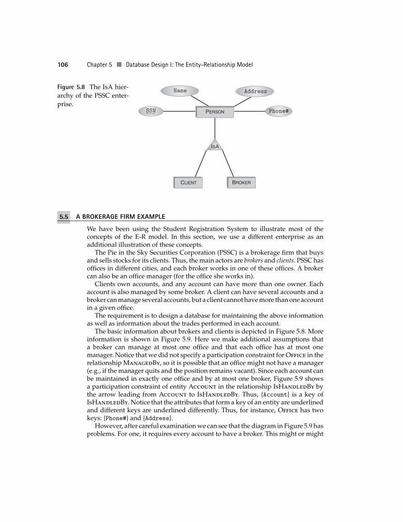
Figure 5.8 The IsA hier-archy of the PSSC enter-prise.
Name Address
PERSON
CLIENT BROKER
ISA
Phone#SSN
5.5 A BROKERAGE FIRM EXAMPLE
We have been using the Student Registration System to illustrate most of theconcepts of the E-R model. In this section, we use a different enterprise as anadditional illustration of these concepts.
The Pie in the Sky Securities Corporation (PSSC) is a brokerage firm that buysand sells stocks for its clients. Thus, the main actors are brokers and clients. PSSC hasoffices in different cities, and each broker works in one of these offices. A brokercan also be an office manager (for the office she works in).
Clients own accounts, and any account can have more than one owner. Eachaccount is also managed by some broker. A client can have several accounts and abroker can manage several accounts, but a client cannot have more than one accountin a given office.
The requirement is to design a database for maintaining the above informationas well as information about the trades performed in each account.
The basic information about brokers and clients is depicted in Figure 5.8. Moreinformation is shown in Figure 5.9. Here we make additional assumptions thata broker can manage at most one office and that each office has at most onemanager. Notice that we did not specify a participation constraint for Office in therelationship ManagedBy, so it is possible that an office might not have a manager(e.g., if the manager quits and the position remains vacant). Since each account canbe maintained in exactly one office and by at most one broker, Figure 5.9 showsa participation constraint of entity Account in the relationship IsHandledBy bythe arrow leading from Account to IsHandledBy. Thus, {Account} is a key ofIsHandledBy. Notice that the attributes that form a key of an entity are underlinedand different keys are underlined differently. Thus, for instance, Office has twokeys: {Phone#} and {Address}.
However, after careful examination we can see that the diagram in Figure 5.9 hasproblems. For one, it requires every account to have a broker. This might or might
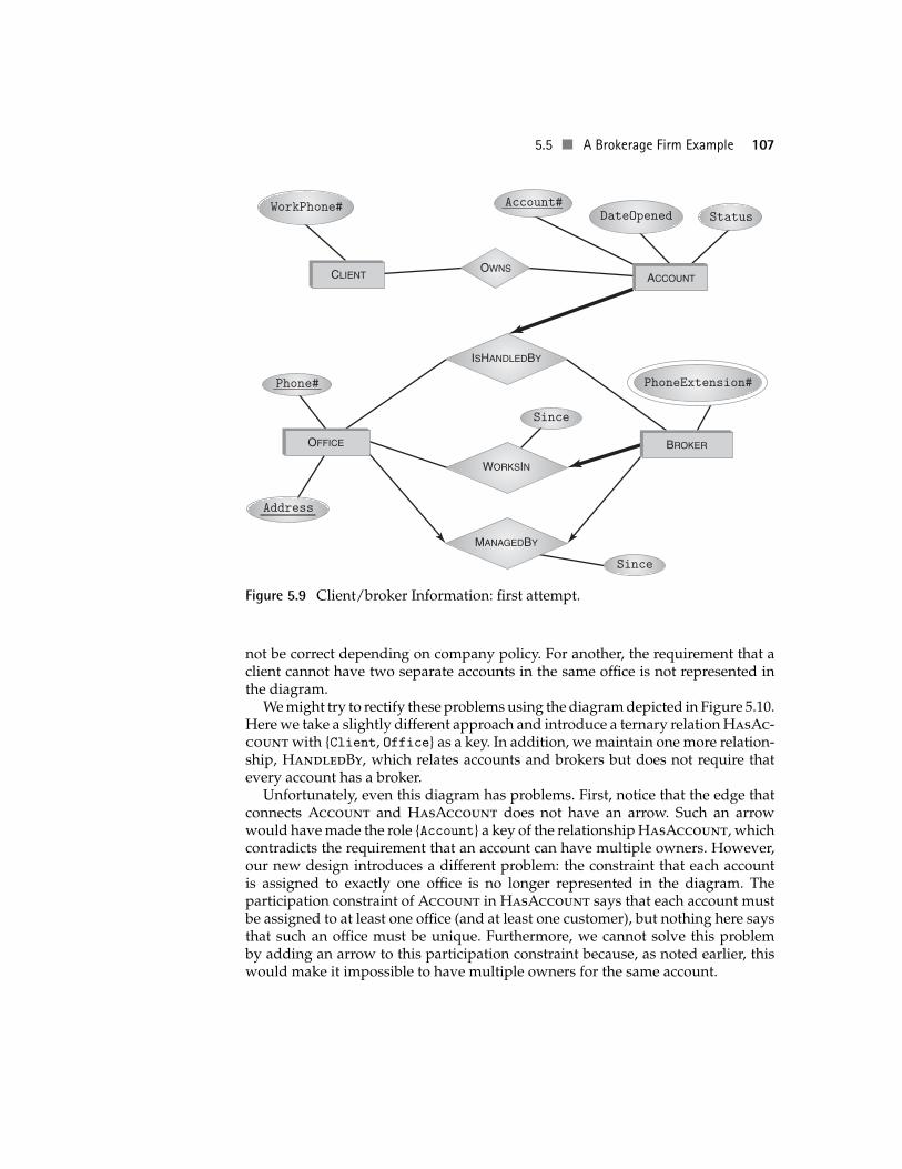
5.5 A Brokerage Firm Example 107
StatusAccount#
Address
DateOpenedWorkPhone#
Since
Phone#
Since
BROKER
ACCOUNTCLIENT
OFFICE
WORKSIN
ISHANDLEDBY
MANAGEDBY
PhoneExtension#
OWNS
Figure 5.9 Client/broker Information: first attempt.
not be correct depending on company policy. For another, the requirement that aclient cannot have two separate accounts in the same office is not represented inthe diagram.
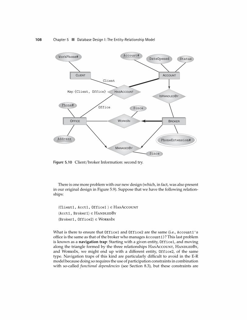
We might try to rectify these problems using the diagram depicted in Figure 5.10.Here we take a slightly different approach and introduce a ternary relation HasAc-count with {Client, Office} as a key. In addition, we maintain one more relation-ship, HandledBy, which relates accounts and brokers but does not require thatevery account has a broker.
Unfortunately, even this diagram has problems. First, notice that the edge thatconnects Account and HasAccount does not have an arrow. Such an arrowwould have made the role {Account} a key of the relationship HasAccount, whichcontradicts the requirement that an account can have multiple owners. However,our new design introduces a different problem: the constraint that each accountis assigned to exactly one office is no longer represented in the diagram. Theparticipation constraint of Account in HasAccount says that each account mustbe assigned to at least one office (and at least one customer), but nothing here saysthat such an office must be unique. Furthermore, we cannot solve this problemby adding an arrow to this participation constraint because, as noted earlier, thiswould make it impossible to have multiple owners for the same account.
108 Chapter 5 Database Design I: The Entity-Relationship Model
StatusAccount#
Address
DateOpenedWorkPhone#
Since
Since
Phone#
BROKER
ACCOUNTCLIENT
OFFICE WORKSIN
MANAGEDBY
HASACCOUNT
ISHANDLEDBY
PhoneExtension#
Key: {Client, Office}
Office
Client
Figure 5.10 Client/broker Information: second try.
There is one more problem with our new design (which, in fact, was also presentin our original design in Figure 5.9). Suppose that we have the following relation-ships:
〈Client1, Acct1, Office1 〉 ∈ HasAccount
〈Acct1, Broker1〉 ∈ HandledBy
〈Broker1, Office2〉 ∈ WorksIn
What is there to ensure that Office1 and Office2 are the same (i.e., Account1’soffice is the same as that of the broker who manages Account1)? This last problemis known as a navigation trap: Starting with a given entity, Office1, and movingalong the triangle formed by the three relationships HasAccount, HandledBy,and WorksIn, we might end up with a different entity, Office2, of the sametype. Navigation traps of this kind are particularly difficult to avoid in the E-Rmodel because doing so requires the use of participation constraints in combinationwith so-called functional dependencies (see Section 8.3), but these constraints are
5.5 A Brokerage Firm Example 109
Time
Date
Status
Id
PricePerShare
PricePerShare
CompanyName
StockSymbol
NumberOfShares
TRANSACTION
STOCK
ACCOUNT
Account#
Amount
DateOpened
TRADE
POSITION
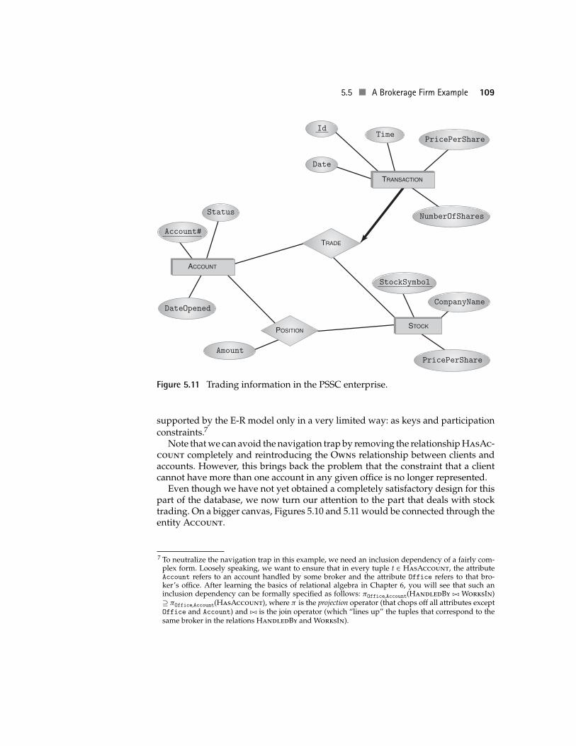
Figure 5.11 Trading information in the PSSC enterprise.
supported by the E-R model only in a very limited way: as keys and participationconstraints.7
Note that we can avoid the navigation trap by removing the relationship HasAc-count completely and reintroducing the Owns relationship between clients andaccounts. However, this brings back the problem that the constraint that a clientcannot have more than one account in any given office is no longer represented.
Even though we have not yet obtained a completely satisfactory design for thispart of the database, we now turn our attention to the part that deals with stocktrading. On a bigger canvas, Figures 5.10 and 5.11 would be connected through theentity Account.
7 To neutralize the navigation trap in this example, we need an inclusion dependency of a fairly com-plex form. Loosely speaking, we want to ensure that in every tuple t ∈ HasAccount, the attributeAccount refers to an account handled by some broker and the attribute Office refers to that bro-ker’s office. After learning the basics of relational algebra in Chapter 6, you will see that such aninclusion dependency can be formally specified as follows: πOffice,Account(HandledBy �� WorksIn)⊇ πOffice,Account(HasAccount), where π is the projection operator (that chops off all attributes exceptOffice and Account) and �� is the join operator (which “lines up” the tuples that correspond to thesame broker in the relations HandledBy and WorksIn).
110 Chapter 5 Database Design I: The Entity-Relationship Model
Trading information is specified using three entities, Account, Stock, andTransaction. These entities are linked through the relationship Position, whichrelates stocks with the accounts they are held in, and the relationship Trade, whichrepresents the actual buying and selling of stocks. This information is depicted inFigure 5.11.
Notice that the roleTransaction is a key of the relationship Trade and that trans-actions do not exist outside of Trade relationships. These constraints are expressedin Figure 5.11 using a thick arrow, which specifies the one-to-one correspondencebetween Transaction entities and Trade relationships.
5.6 LIMITATIONS OF THE E-R APPROACH
You have now seen two case studies of the use of the entity-relationship modelfor database design. If E-R design still does not seem completely clear to you, youare in good company. Although we have discussed several concepts that mightprovide general guidance in organizing enterprise data, applying these conceptsin any concrete situation is still a mix of experience, art, and black magic. There isconsiderable freedom in deciding whether a particular datum should be an entity,a relationship, or an attribute. Furthermore, even after these issues are settledthe various relationships that exist among entities can be expressed in differentways. This section discusses some of the dilemmas that often confront a databasedesigner.
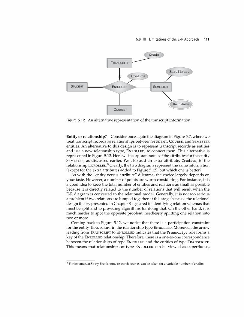
Entity or attribute? In Figure 5.7, semesters are represented as entities. However,we could as well make Transcript into a binary (rather than ternary) relation andturn Semester into one of its attributes. The obvious question is which representa-tion is best (and in which case).
To some extent, the decision of whether a particular datum should be repre-sented as an entity or an attribute is a matter of taste. Beyond that, the representationmight depend on whether the datum has an internal structure of its own. If the da-tum has no internal data structure, keeping it as a separate entity makes the E-Rdiagram more complex and, more important, adds an extra relation to your data-base schema when you convert the diagram into the relational model. On the otherhand, if the datum has attributes of its own, it is possible that these attributes cannotbe represented if the datum itself is demoted to the status of an attribute.
For instance, in Figure 5.7 the entity type Semester does not have its ownattributes, so representing the semester information as an entity appears to beoverkill. However, it is entirely possible that the Requirements Document mightstate that the following additional information must be available for each semester:Start_date, End_date, Holidays, Enrollment. In such a case, the semester infor-mation cannot be an attribute of the Transcript relationship, as there would thenbe no place to specify the information about the key dates and the enrollment asso-ciated with semesters (e.g., the total enrollment in the university during a semesteris not an attribute of any particular transcript relationship).
5.6 Limitations of the E-R Approach 111
TRANSCRIPT
COURSE
SEMESTERSTUDENT ENROLLED
Holidays
Grade
Credits
Enrollment
Figure 5.12 An alternative representation of the transcript information.
Entity or relationship? Consider once again the diagram in Figure 5.7, where wetreat transcript records as relationships between Student, Course, and Semesterentities. An alternative to this design is to represent transcript records as entitiesand use a new relationship type, Enrolled, to connect them. This alternative isrepresented in Figure 5.12. Here we incorporate some of the attributes for the entitySemester, as discussed earlier. We also add an extra attribute, Credits, to therelationship Enrolled.8 Clearly, the two diagrams represent the same information(except for the extra attributes added to Figure 5.12), but which one is better?
As with the “entity versus attribute” dilemma, the choice largely depends onyour taste. However, a number of points are worth considering. For instance, it isa good idea to keep the total number of entities and relations as small as possiblebecause it is directly related to the number of relations that will result when theE-R diagram is converted to the relational model. Generally, it is not too seriousa problem if two relations are lumped together at this stage because the relationaldesign theory presented in Chapter 8 is geared to identifying relation schemas thatmust be split and to providing algorithms for doing that. On the other hand, it ismuch harder to spot the opposite problem: needlessly splitting one relation intotwo or more.
Coming back to Figure 5.12, we notice that there is a participation constraintfor the entity Transcript in the relationship type Enrolled. Moreover, the arrowleading from Transcript to Enrolled indicates that the Transcript role forms akey of the Enrolled relationship. Therefore, there is a one-to-one correspondencebetween the relationships of type Enrolled and the entities of type Transcript.This means that relationships of type Enrolled can be viewed as superfluous,
8 For instance, at Stony Brook some research courses can be taken for a variable number of credits.
112 Chapter 5 Database Design I: The Entity-Relationship Model
because Transcript entities can be used instead to relate the entities of types Stu-dent, Course, and Semester. All that is required (in order not to lose information)is to transfer the proper attributes of Enrolled to Transcript after converting thelatter into a relationship.
As a result of this discussion, we have the following rule:
Consider a relationship type, R, that relates the entity types E1, . . . , En,and suppose that E1 is attached to R via a role that (by itself) forms a keyof R, and that a participation constraint exists between E1 and R. Thenit might be possible to collapse E1 and R into a new relationship typethat involves only the entity types E2, . . . , En.
Note that this rule is only an indication that E1 can be collapsed into R, not aguarantee that this is possible. For instance, E1 might be involved in some otherrelationship, R′. In that case, collapsing E1 into R leaves an edge that connects tworelationship types, R and R′, which is not allowed by the construction rules forE-R diagrams. Such is the situation of the Broker and Account entities in Fig-ure 5.10: The above rule suggests that Broker can be collapsed into WorksIn andAccount can be collapsed into HandledBy. However, both Broker and Accountare involved in two different relationships, and each such collapse leaves us with adiagram where two relationships, WorksIn and HandledBy or HasAccount andHandledBy, are directly connected by an edge. On the other hand, the Transac-tion entity type in Figure 5.11 can be collapsed into the Trade relationship type.
Information loss. We have seen examples where the arity of a relationship mightchange by demoting an entity to an attribute or by collapsing an entity into arelationship. In all of these cases, however, the transformations obviously preservethe diagrams’ information content. Now we are going to discuss some typicalsituations where seemingly innocuous transformations cause information loss;that is, they lead to diagrams with subtly different information content.
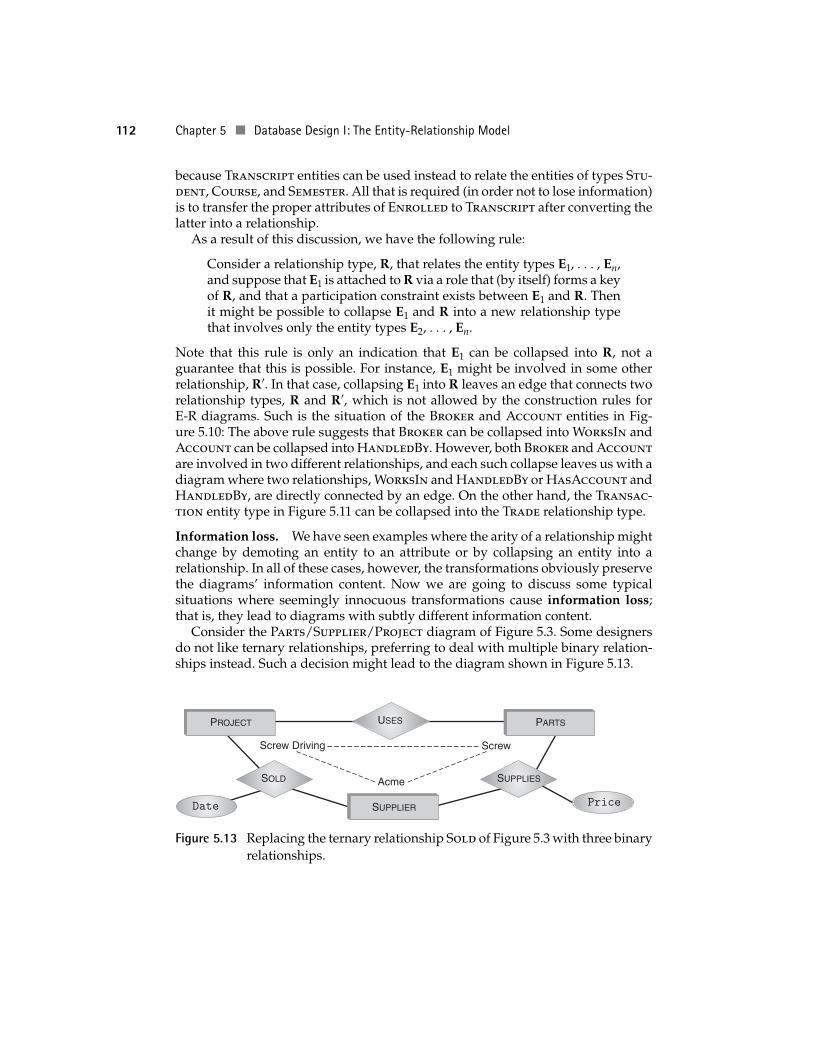
Consider the Parts/Supplier/Project diagram of Figure 5.3. Some designersdo not like ternary relationships, preferring to deal with multiple binary relation-ships instead. Such a decision might lead to the diagram shown in Figure 5.13.
SUPPLIER
PROJECT PARTS
SUPPLIESSOLD
USES
Screw Driving Screw
Acme
PriceDate
Figure 5.13 Replacing the ternary relationship Sold of Figure 5.3 with three binaryrelationships.
5.6 Limitations of the E-R Approach 113
Although superficially the new diagram seems equivalent to the original, thereare several subtle differences. First, the new design introduces a navigation trap ofthe kind we saw in the stock trading example: It is possible that a supplier, Acme,sells “Screw” and that Acme has sold something to project “Screw Driving.” It iseven possible that the screw driving project uses screws of the kind Acme sells.However, from the relationships represented in the diagram it is not possible toconclude that it was Acme who sold these screws to the project. All we can tell isthat Acme might have done so.
The other problem with the new design is that the price attribute is now associ-ated with the relationship Supplies. This implies that a supplier has a fixed price foreach item regardless of the project to which that item is sold. In contrast, the originaldesign in Figure 5.3, page 96, supports different pricing for different projects (e.g.,based on quantity). Similarly, the new design allows only one transaction betweenany supplier and project on any given day because each transaction is representedas a triple 〈p, s; d〉, so there is no way to distinguish among different transactionsbetween the same parties on the same day. The original design, on the other hand,allows several such deals, provided that different parts are involved.
Having realized the danger of introducing navigation traps, we might be in-clined to use higher-degree relationships whenever possible. For instance, in Fig-ure 5.10 we might want to try eliminating the navigation trap caused by the re-lationships HasAccount, WorksIn, and HandledBy by collapsing these threerelationships into one. However, this transformation introduces more problemsthan it solves. For instance, if this transformation keeps the arrow that connectsBroker and WorksIn, we unwittingly introduce the constraint that a broker canhave at most one account and at most one client. If we do not keep this arrow, welose the constraint that each broker is assigned to exactly one office. This trans-formation also makes it impossible to have brokers who have no accounts andaccounts that have no brokers.
E-R and object databases. Although we will not discuss object databases untilChapter 16, we briefly mention here that some of the difficult issues involved intranslating E-R diagrams into schemas become easier for object databases.
In Section 5.2, we discussed the issues involved in representing entities withset-valued attributes in a relational database. The objects stored in an objectdatabase can have set-valued attributes, so the representation of such entitiesin the schema of the object database is considerably easier.
In Section 5.4, we discussed the issues involved in representing the IsA relation-ship in a relational database. Object databases allow a direct representation ofthe IsA relationship within the schema, so, again, representation of such rela-tionships is considerably easier.
From these examples, it should be apparent that not only is it generally easier totranslate E-R diagrams into schemas for object databases than into schemas for
114 Chapter 5 Database Design I: The Entity-Relationship Model
COURSE
STUDENT
FACULTY
CLASSROOM
CLASSTRANSCRIPT
TEACHES
TAUGHTIN
REQUIRES
Grade
Year
Seats
Textbook
MaxEnrollment
ClassTime
Enrollment
SemesterSectionNo
EnforcedSince
Prereq
Course
ClassroomId
Name
Name
Address
Address
Password
Password
DeptId
DeptId
CrsCode
CrsNameCreditHours
Id
Id
ISA
SemestersOffered
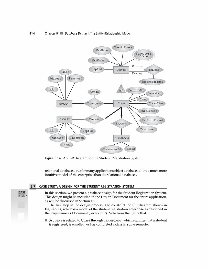
Figure 5.14 An E-R diagram for the Student Registration System.
relational databases, but for many applications object databases allow a much moreintuitive model of the enterprise than do relational databases.
5.7 CASE STUDY: A DESIGN FOR THE STUDENT REGISTRATION SYSTEM
CASESTUDY
In this section, we present a database design for the Student Registration System.This design might be included in the Design Document for the entire application,as will be discussed in Section 12.1.
The first step in the design process is to construct the E-R diagram shown inFigure 5.14, which is a model of the student registration enterprise as described inthe Requirements Document (Section 3.2). Note from the figure that
Student is related to Class through Transcript, which signifies that a studentis registered, is enrolled, or has completed a class in some semester.
5.7 Case Study: A Design for the Student Registration System 115
Faculty is related to Class through Teaches, meaning that a faculty memberteaches a class in some semester and every class is taught by exactly one faculty
CASESTUDY
member.
Course is related to Course through the relationship Requires; that is, a coursecan be a prerequisite for another course in some semester. The attribute En-
forcedSince specifies the date when the prerequisite became in force.
Class is related to Classroom through TaughtIn; that is, a class is taught in aclassroom in some semester.
A class (i.e., a particular offering of a course) uses at most one textbook, becausethe attribute Textbook is not part of the key of the entity Class. In Section 8.12,we will remove this restriction and discuss the impact of this decision on thesystem design.
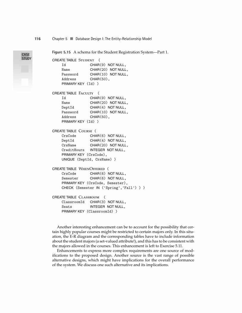
On the basis of this E-R diagram and the list of integrity constraints given in theRequirements Document in Section 3.2.4, the next step is to produce the schemashown in Figures 5.15 and 5.16. The translation was done in a straightforwardmanner using the techniques described so far in this chapter. Note that tables werenot created to correspond to the Teaches and TaughtIn relationships because bothhave only roles, no attributes, and both are many-to-one. Therefore, the informationabout these relationships can be stored in the Class table—the tuple correspondingto each class in the Class table contains the ClasssroomId of the room where it istaught and the InstructorId of the faculty member who teaches it.
Note that some of the integrity constraints specified in the Requirements Doc-ument are checked within CREATE TABLE statements (specifically constraints 1, 3,5, and 6 from Section 3.2.4). In the complete schema design, other integrity con-straints are checked with separate CREATE ASSERTION statements and with onetrigger. However, this part of the design requires SQL constructs that we have notyet discussed, and so we will complete the schema design in Section 12.6 after wecover these constructs.
We selected this particular design for inclusion in the book because it is straight-forward and transparent. In practice, such a design might be a starting point for anumber of enhancements whose goal is to capture more features and increase theefficiency of the final implementation.
Let us discuss a few possible enhancements and alternatives. Consider coursedependencies. One obvious omission in our schema is the corequisite relationshipand all of the constraints entailed by it. More subtly, university curricula change allthe time: New courses are introduced, old courses are removed, and prerequisitedependencies between courses evolve in time. Thus, the Requires relationshipin Figure 5.14 might need two additional attributes, Start and End, to designatethe period when the prerequisite relationship is effective. Even more interestingis the possibility that a particular prerequisite relationship might exist at differenttimes. For instance, course A might be a prerequisite for course B between 1985and 1990 and again between 1999 and the present. Modeling this situation is left toExercise 5.10.
116 Chapter 5 Database Design I: The Entity-Relationship Model
Figure 5.15 A schema for the Student Registration System—Part 1.CASESTUDY CREATE TABLE Student (
Id CHAR(9) NOT NULL,Name CHAR(20) NOT NULL,Password CHAR(10) NOT NULL,Address CHAR(50),PRIMARY KEY (Id) )
CREATE TABLE Faculty (
Id CHAR(9) NOT NULL,Name CHAR(20) NOT NULL,DeptId CHAR(4) NOT NULL,Password CHAR(10) NOT NULL,Address CHAR(50),PRIMARY KEY (Id) )
CREATE TABLE Course (
CrsCode CHAR(6) NOT NULL,DeptId CHAR(4) NOT NULL,CrsName CHAR(20) NOT NULL,CreditHours INTEGER NOT NULL,PRIMARY KEY (CrsCode),
UNIQUE (DeptId, CrsName) )
CREATE TABLE WhenOffered (
CrsCode CHAR(6) NOT NULL,Semester CHAR(6) NOT NULL,PRIMARY KEY (CrsCode, Semester),
CHECK (Semester IN (’Spring’,’Fall’) ) )
CREATE TABLE Classroom (
ClassroomId CHAR(3) NOT NULL,Seats INTEGER NOT NULL,PRIMARY KEY (ClassroomId) )
Another interesting enhancement can be to account for the possibility that cer-tain highly popular courses might be restricted to certain majors only. In this situ-ation, the E-R diagram and the corresponding tables have to include informationabout the student majors (a set-valued attribute!), and this has to be consistent withthe majors allowed in the courses. This enhancement is left to Exercise 5.11.
Enhancements to express more complex requirements are one source of mod-ifications to the proposed design. Another source is the vast range of possiblealternative designs, which might have implications for the overall performanceof the system. We discuss one such alternative and its implications.

5.7 Case Study: A Design for the Student Registration System 117
Figure 5.16 A schema for the Student Registration System—Part 2.CASESTUDYCREATE TABLE Requires (
CrsCode CHAR(6) NOT NULL,PrereqCrsCode CHAR(6) NOT NULL,EnforcedSince DATE NOT NULL,PRIMARY KEY (CrsCode, PrereqCrsCode),
FOREIGN KEY (CrsCode) REFERENCES Course(CrsCode),FOREIGN KEY (PrereqCrsCode) REFERENCES Course(CrsCode) )
CREATE TABLE Class (
CrsCode CHAR(6) NOT NULL,SectionNo INTEGER NOT NULL,Semester CHAR(6) NOT NULL,Year INTEGER NOT NULL,Textbook CHAR(50),ClassTime CHAR(5),Enrollment INTEGER,MaxEnrollment INTEGER,ClassroomId CHAR(3),InstructorId CHAR(9),PRIMARY KEY (CrsCode,SectionNo,Semester,Year),
CONSTRAINT TimeConflictUNIQUE (InstructorId,Semester,Year,ClassTime),
CONSTRAINT ClassroomConflictUNIQUE (ClassroomId,Semester,Year,ClassTime),
CONSTRAINT EnrollmentCHECK (Enrollment <= MaxEnrollment AND Enrollment >= 0),
FOREIGN KEY (CrsCode) REFERENCES Course(CrsCode),FOREIGN KEY (ClassroomId) REFERENCES Classroom(ClassroomId),
FOREIGN KEY (CrsCode, Semester)
REFERENCES WhenOffered(CrsCode, Semester),
FOREIGN KEY (InstructorId) REFERENCES Faculty(Id) )
CREATE TABLE Transcript (
StudId CHAR(9) NOT NULL,CrsCode CHAR(6) NOT NULL,SectionNo INTEGER NOT NULL,Semester CHAR(6) NOT NULL,Year INTEGER NOT NULL,Grade CHAR(1),PRIMARY KEY (StudId,CrsCode,SectionNo,Semester,Year),
FOREIGN KEY (StudId) REFERENCES Student(Id),FOREIGN KEY (CrsCode,SectionNo,Semester,Year)
REFERENCES Class(CrsCode,SectionNo,Semester,Year),CHECK (Grade IN (’A’,’B’,’C’,’D’,’F’,’I’) ),
CHECK (Semester IN (’Spring’,’Fall’) ) )
118 Chapter 5 Database Design I: The Entity-Relationship Model
Consider the attribute SemestersOffered of entity Course. Because it is a set-CASESTUDY valued attribute, we translate it using a separate table, WhenOffered. We chose
this particular design because we saw that it leads to a particularly easy way toexpress the constraint that the semester when any particular class is taught mustbe one of the semesters when that course is offered. For instance, it should not bepossible for course CS305 to be offered only in spring semesters but for a certainclass of this course to be taught in fall 2000. However, this should be allowed ifCS305 is offered in both spring and fall semesters.
In our design, this requirement is expressed simply as a foreign key constraintin relation Class.
FOREIGN KEY (CrsCode, Semester)
REFERENCES WhenOffered(CrsCode, Semester)
This constraint says that if a class of course with code crscode is offered during asemester, sem, then 〈 csrcode, sem 〉 should be a tuple in the relation WhenOffered;that is, sem must be one of the allowed semesters for the course.
Despite the simplicity of this design, one might feel that creating a separate rela-tion for such a trivial piece of information is unacceptable overhead. Such a separaterelation requires an extra operation for certain queries, additional storage require-ments, and the like.9 An alternative is to define a new SQL domain (introduced inChapter 4), which contains just three values:
CREATE DOMAIN Semesters CHAR(6)CHECK ( VALUE IN (’Spring’, ’Fall’, ’Both’) )
The set-valued attribute SemestersOffered of the entity Course is now single-valued, but it ranges over the domain Semesters. The advantage is that the trans-lation into the relational model is more straightforward and there is no need forthe extra relation WhenOffered. However, it is now more difficult to specify theconstraint that a class can be taught only in the semesters when the correspondingcourse is offered. Details are left to Exercise 5.12.
Finally, let us consider the possible alternatives for representing the current andthe next semesters, as is required by some transactions specified in the Require-ments Document in Section 3.2. In fact, our design has no obvious way to representthis information. One simple way to tell which semester is current or next is to cre-ate a separate relation to store this information. However, this would not be a gooddesign because every reference to the current or to the next semester would requirea relatively expensive database query. The right way to do this type of thing is to usethe function CURRENT_DATE provided by SQL and the function EXTRACT to extractparticular fields from that date. For instance,
EXTRACT(YEAR FROM CURRENT_DATE)
9 In our particular case, none of these disadvantages seems to apply because, in all likelihood, therelation WhenOffered will be mostly used to verify the above foreign key constraint and having aseparate relation for course-semester pairs is a very efficient way to check this constraint.
5.9 Exercises 119
EXTRACT(MONTHS FROM CURRENT_DATE)CASESTUDYreturns the numeric values of the current year and month. This should be suffi-
cient to determine whether any given semester is current or next.
5.8 BIBLIOGRAPHIC NOTES
The entity-relationship approach was introduced in [Chen 1976]. Since then it hasreceived considerable attention and various extensions have been proposed (see,for example, research papers in [Spaccapietra 1987]). Conceptual design using theE-R model has also been advanced significantly. The reader is referred to [Teorey1992, Batini et al. 1992, Thalheim 1992] for comprehensive coverage.
More recently, a new design methodology called Unified Modeling Language(UML) was developed and has been gaining popularity [Booch et al. 1999]. UMLborrows many ideas from the E-R model, but extends it in the direction of object-oriented modeling. In particular, it provides means to model not only the structureof the data but also the behavioral aspects of programs and how complex appli-cations are to be deployed in complex computing environments. A succinct intro-duction to UML can be found in [Fowler and Scott 1999].
A number of tools exist to help the database designer with E-R and UML mod-eling. These tools guide the user through the process of specifying the diagrams,attributes, constraints, and so forth. When all is done, they map the conceptualmodel into relational tables. Such tools include ERwin from Computer Associates,ER/Studio from Embarcadero Technologies, and Rational Rose from Rational Soft-ware. In addition, DBMS vendors provide their own design tools, such as OracleDesigner from Oracle Corporation and PowerDesigner from Sybase.
5.9 EXERCISES
5.1 Suppose that you decide to convert IsA hierarchies into the relational modelby adding a new attribute (such as Status in the case of Student entities,as described in Section 5.4.1 on page 103). What kind of problems exist ifsubentities are not disjoint (e.g., if a secretary can also be a technician)?What problems exist if the covering constraint does not hold (e.g., if someemployees are not classified as either secretary or technician)?
5.2 Construct your own example of an E-R diagram whose direct translation intothe relational model has an anomaly similar to that of the Person entity (seethe discussion regarding Figures 5.1 and 5.2).
5.3 Represent the IsA hierarchy in Figure 5.5 in the relational model. For each IsArelationship discuss your choice of the representation technique (i.e., eitherthe technique where each entity in the hierarchy is represented by a separaterelation or the one where the entity and its subentities are in the same relationand are distinguished using a new attribute). Discuss the circumstances
120 Chapter 5 Database Design I: The Entity-Relationship Model
when an alternative representation (to the one you have chosen) would bebetter.
5.4 Translate the brokerage example of Section 5.5 into an SQL-92 schema. Usethe necessary SQL-92 machinery to express all of the constraints specified inthe E-R model.
5.5 Identify the navigation traps present in the diagram of Figure 5.9.
5.6 Consider the following database schema:Supplier(SName, ItemName, Price)—supplier SName sells item ItemName atPrice
Customer(CName, Address)—customer CName lives at Address.Order(CName, SName, ItemName, Qty)—customer CName has ordered Qty ofitem ItemName from supplier SName.Item(ItemName, Description)—information about items.
a. Draw the E-R diagram from which the above schema might have beenderived. Specify the keys.
b. Suppose now that you want to add the following constraint to thisdiagram: Every item is supplied by some supplier. Modify the diagram toaccommodate this constraint. Also show how this new diagram can betranslated back to the relational model.
5.7 Use the E-R approach to model the operations of your local communitylibrary. The library has books, CDs, tapes, and so forth, which are lentto library patrons. The latter have accounts, addresses, and so forth. If aloaned item is overdue, it accumulates penalty. However, some patronsare minors, so they must have sponsoring patrons who are responsible forpaying penalties (or replacing a book in case of a loss).
5.8 Design the E-R diagram for a real estate brokerage firm. The firm keeps trackof the houses for sale, and it has customers looking to buy a house. A housefor sale can be listed with this firm or with a different one. Being “listed” witha firm means that the house owner has a contract with an agent who worksfor that firm. Each house on the market has price, address, owner, and list ofcharacteristics, such as the number of bedrooms, bathrooms, type of heating,appliances, size of garage, and the like. This list can be different for differenthouses, and some attributes can be present for some houses but missing forothers. Likewise, each customer has preferences that are expressed in thesame terms (the number of bedrooms, bathrooms, etc.). Apart from thesepreferences customers specify the price range of houses they are interested in.
5.9 A supermarket chain is interested in building a decision support systemwith which they can analyze the sales of different products in differentsupermarkets at different times. Each supermarket is in a city, which is in astate, which is in a region. Time can be measured in days, months, quarters,
5.9 Exercises 121
and years. Products have names and categories (produce, canned goods,etc.). Design an E-R diagram for this application.
5.10 Modify the E-R diagram for the Student Registration Schema in Figure 5.14to include corequisite and prerequisite relationships that exist over multipleperiods of time. Each period begins in a certain semester and year and endsin a certain semester and year, or it continues into the present. Modify thetranslation into the relational model appropriately.
5.11 Modify the E-R diagram for the Student Registration System in Figure 5.14to include information about the student majors and the majors allowed incourses. A student can have several majors (which are codes of the variousprograms in the university, such as CSE, ISE, MUS, ECO). A course can also haveseveral admissible majors, or the list of admissible majors can be empty. Inthe latter case, anyone is admitted into the course. Express the constraint thatsays that a course with restrictions on majors can have only those studentswho hold one of the allowed majors.
Alas, in full generality this constraint can be expressed only as an SQLassertion (introduced in Section 4.3) that uses features to be discussed in Sec-tion 6.2. However, it is possible to express this constraint under the followingsimplifying assumption: When a student registers for a course, she must statethe major for which the course is going to be taken.
Modify the schema to reflect this simplifying assumption and then expressthe aforesaid integrity constraint.
5.12 Make the necessary modifications to the schema of the Student RegistrationSystem to reflect the design that uses the SQL domain Semesters, as dis-cussed at the end of Section 5.7. Express the constraint that a class can betaught only during the semesters in which the corresponding course is of-fered. For instance, if the value of the attribute SemestersOffered for thecourse CS305 is Both, then the corresponding classes can be taught in thespring and the fall semesters. However, if the value of that attribute is Springthen these classes can be taught only in the spring.
5.13 Design an E-R model for the following enterprise. Various organizationsmake business deals with various other organizations. (For simplicity, letus assume that there are only two parties to each deal.) When negotiating(and signing) a deal, each organization is represented by a lawyer. Thesame organization can have deals with many other organizations and itmight use different lawyers in each case. Lawyers and organizations havevarious attributes, like address and name. They also have their own uniqueattributes, such as specialization and fee in case of a lawyer and budget incase of an organization.
Show how information loss can occur if a relationship of degree higherthan two is split into binary relationship. Discuss assumption under whichsuch a split does not lead to a loss of information.