chapter 1-3 revised
TRANSCRIPT
Page | 1
CHAPTER 1
THE PROBLEM AND ITS BACKGROUND
1.1 INTRODUCTION
Computer has greatly affected the lives of many people due to its numerous uses. It appears
to be an inseparable part of life to many people in these days. Together with the growing use of
computer is the consciousness of the people who use it with its associated peripherals. These
peripherals are the one that gives extra features to the offered functionalities of a computer which
are being enhanced by other sensible individuals. These enhancement or improvements had made
computer more user-friendly for the user. In line with this, the interfacing of the peripherals with the
computer was improved making computer simpler and easier to use. The main idea of this research
is related to some peripherals of a computer which are the flash memory devices specifically the
USB flash drive. This accessible device comprises of two USB ports, one for input and another for
output. Embedded microcontroller is used to allow communication between the two USB flash drives.
The goal of this research is to make transferring data faster and more convenient as it would no
longer entail the use of computer.
1.2 BACKGROUND OF THE STUDY
Most people would like to make backup copies of files to ensure security or any other
reasons. This is where flash memory devices come in. As Cory Janssen mentioned in his article
“Flash Memory”, it is a type of electronic memory which is used for easy and fast information storage
in computers, digital cameras, mobile phones and other electronic gadgets. It is used more like a
hard drive than as RAM and can be electrically removed and reprogrammed. The two main types of
Page | 2
a flash memory is the NAND and NOR logic gates. This study focuses on the NAND type which is
used in memory cards and USB flash drives.
According to usb.org website, Universal Serial Bus (USB) flash drives are portable memory
drives where you can store data using medium devices such as computers then save it in a several
hosts. Data from USB flash drive can only be read and transferred by a computer or laptop into
another USB flash drive. In today’s world, USB flash drives have been the most commonly used data
storage since they are extremely convenient to have around. The data stored in the USB drive can
last for a long period of time even after power in the computer has been turned off with the drive in
it. In this reason, it has made using USB drive a convenient way for transferring data between a
computer or laptop and a means of providing backup copies for personal needs. In order to transfer
file using a USB flash drive, one need to plug in the device into the USB port of the computer or
laptop, then the operating system will automatically recognize it as a removable drive.
Nowadays, carrying a laptop in order to transfer data from a flash drive to another flash drive
is not practical since people want all devices to be handy. In using USB flash drives, user will not be
able to share files between two USB flash drives if he is away from computer. The necessity of laptop
and computer to transfer a file wastes time and power. Time is wasted on booting in the computer
or laptop just to transfer a certain file from a flash drive to another. When operated, computers
consume a lot of power. Since USB flash drive has been widely used, the proponents used USB as
their interface in transferring data. Aside from that, it is easy to use and very accessible. This study
has been made for data transferring using USB independent from computer. It shows how data is
transferred to the USB mass storage device without the use of a computer. It can be done by making
a system which will serve as an alternative to a computer. This system should do the same roles as
a computer does in data transferring. The prototype will serve as the bridge between two USB flash
Page | 3
drives that will undergo data transferring. The bridge is a microcontroller based device that will handle
the data transfer and any processes that will be needed. According to www.usbmadesimple.com, all
communications on this bus are initiated by the host. Then microcontroller will enable the USB host
controller to communicate with the USB flash drive. The role of the crystal oscillator is to give the
basic system clock signal. The microcontroller will have a crystal oscillator having its clock set to high
in order for data transferring to be fast. The device supports all USB Flash devices formatted with
FAT32 file system. According to Tim Fisher in his article at pcsupport.about.com, FAT32 stands for
"File Allocation Table," which keeps track of all the files and helps the computer locate them on the
disk.
1.3 OBJECTIVES
The main objective is to construct a prototype that will automatically transfer file from USB
flash drive with another with the use of microcontroller as the bridge. In line with the general objective
of this project, the following specific objectives are:
To develop a device that will perform the data transfer between the USB flash drives.
To design a program that will perform file transfer between the USB flash drives.
To integrate USB host controller to the embedded microcontroller.
To automatically create a default folder in the receiver.
1.4 SIGNIFICANCE OF THE STUDY
In today’s world, Universal Serial Bus (USB) flash drives have been the most commonly used
data storage since they are extremely convenient to have around. Data from USB flash drive can
only be read by a computer or laptop and transfer it from one USB flash drive to another .The problem
Page | 4
is, if you may not have a laptop or computer, you are unable to transfer important files in a convenient
way. As a solution to this problem, a mini-transfer device can be made to be a medium for the
transmission of data between the USB flash drives.
To the users
These days, not most of us can afford to buy laptops or tablets that has the capability of
transferring data. In this environment, it is risky to bring laptops for thieves are everywhere. So with
the utilization of this tool, no laptop will be needed for the sake of data transfer increasing one’s
safety. So instead of buying laptop in order to have something portable in transferring data, you will
just bring this unique and more portable tool without any hassle.
To the community
The portability and user-friendliness of this tool makes it influential to do data transfer. With
the use of this tool, the owner may optimize power for its consumption will only happen once the
device is being used.
To the environment
This tool is battery operated. AC power supply will not be needed therefore transferring data
can take place anywhere and anytime you want. This will decrease the consumption of power since
you will not use a laptop or computer anymore. In short, it will save time and power in transferring
data from one USB flash drive to another because booting the computer or the use of laptop has
been eliminated.
Page | 5
To the industry
With some improvements with this device, it can be integrated with other electronic devices
such as pocket wi-fi, usb broadband, and other portable devices. The device can also be
manufactured since it is affordable enough to be bought by the public.
1.5 SCOPE AND LIMITATIONS
The researchers formulated the scope and limitations of this project to identify the
boundaries of the study:
Scope
The device will be able to transfer files from one USB flash drive to another flash drive.
There are two ports available; one USB port for transmitter and another for receiver.
A folder in the receiving flash drive will automatically be created where the files that have
been transferred can be found.
The transfer rate of this device will depend on the host controller to be used.
There will be a multi-colored LED to indicate the condition of the device. The blue light would
indicate that the device is powered on. The LED will turn blinking green when the receiving
flash drive is on process and it will turn stable green if the transferring of data is finished.
Otherwise, when the LED turned red after placing the USB flash drive in the input port and
the other flash drive in the destination port, it means that there is an error either the receiving
flash drive is full or the file is too large.
Page | 6
Limitations
File selection can only be made by placing the files you want to transfer in the folder of the
input.
High capacity devices such as external hard drive cannot be processed by the device due
to the large amount of memory to read/manage.
Only the files in the dedicated folder of the transmitting drive will be transferred.
The maximum size that the device can transfer is 8 GB.
Page | 7
CHAPTER 2
THEORETICAL FRAMEWORK / DESIGN CONCEPT
2.1REVIEW OF RELATED STUDIES
2.1.1 Data Duplication Method and System Used Between USB Devices
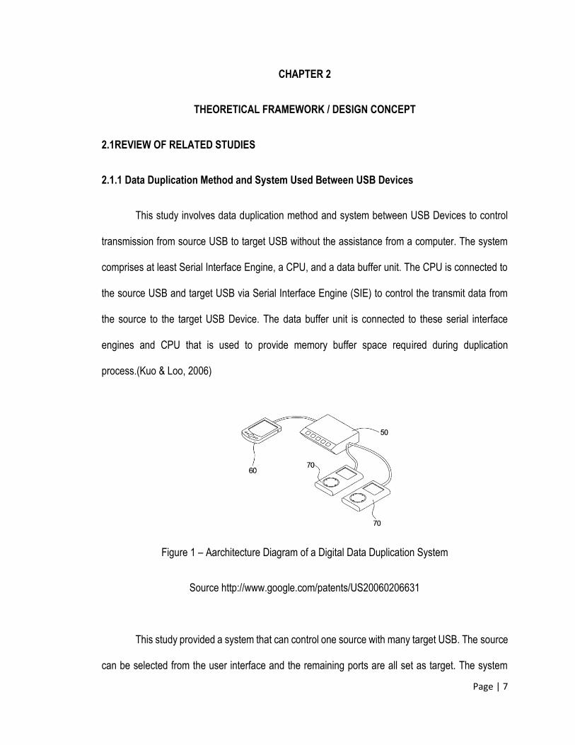
This study involves data duplication method and system between USB Devices to control
transmission from source USB to target USB without the assistance from a computer. The system
comprises at least Serial Interface Engine, a CPU, and a data buffer unit. The CPU is connected to
the source USB and target USB via Serial Interface Engine (SIE) to control the transmit data from
the source to the target USB Device. The data buffer unit is connected to these serial interface
engines and CPU that is used to provide memory buffer space required during duplication
process.(Kuo & Loo, 2006)
Figure 1 – Aarchitecture Diagram of a Digital Data Duplication System
Source http://www.google.com/patents/US20060206631
This study provided a system that can control one source with many target USB. The source
can be selected from the user interface and the remaining ports are all set as target. The system
Page | 8
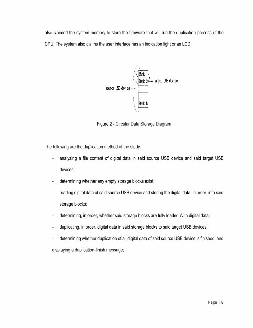
also claimed the system memory to store the firmware that will run the duplication process of the
CPU. The system also claims the user interface has an indication light or an LCD.
Figure 2 - Circular Data Storage Diagram
The following are the duplication method of the study:
- analyzing a file content of digital data in said source USB device and said target USB
devices;
- determining whether any empty storage blocks exist;
- reading digital data of said source USB device and storing the digital data, in order, into said
storage blocks;
- determining, in order, whether said storage blocks are fully loaded With digital data;
- duplicating, in order, digital data in said storage blocks to said target USB devices;
- determining whether duplication of all digital data of said source USB device is finished; and
displaying a duplication-finish message;
Page | 9
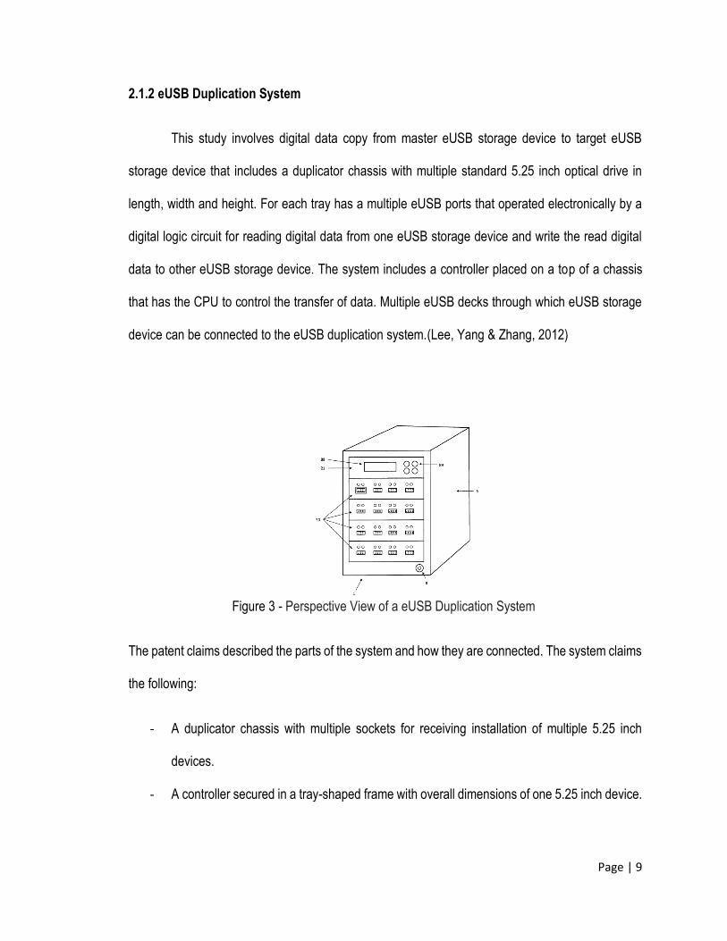
2.1.2 eUSB Duplication System
This study involves digital data copy from master eUSB storage device to target eUSB
storage device that includes a duplicator chassis with multiple standard 5.25 inch optical drive in
length, width and height. For each tray has a multiple eUSB ports that operated electronically by a
digital logic circuit for reading digital data from one eUSB storage device and write the read digital
data to other eUSB storage device. The system includes a controller placed on a top of a chassis
that has the CPU to control the transfer of data. Multiple eUSB decks through which eUSB storage
device can be connected to the eUSB duplication system.(Lee, Yang & Zhang, 2012)
Figure 3 - Perspective View of a eUSB Duplication System
The patent claims described the parts of the system and how they are connected. The system claims
the following:
- A duplicator chassis with multiple sockets for receiving installation of multiple 5.25 inch
devices.
- A controller secured in a tray-shaped frame with overall dimensions of one 5.25 inch device.
Page | 10
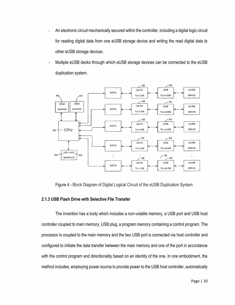
- An electronic circuit mechanically secured within the controller, including a digital logic circuit
for reading digital data from one eUSB storage device and writing the read digital data to
other eUSB storage devices.
- Multiple eUSB decks through which eUSB storage devices can be connected to the eUSB
duplication system.
Figure 4 - Block Diagram of Digital Logical Circuit of the eUSB Duplication System
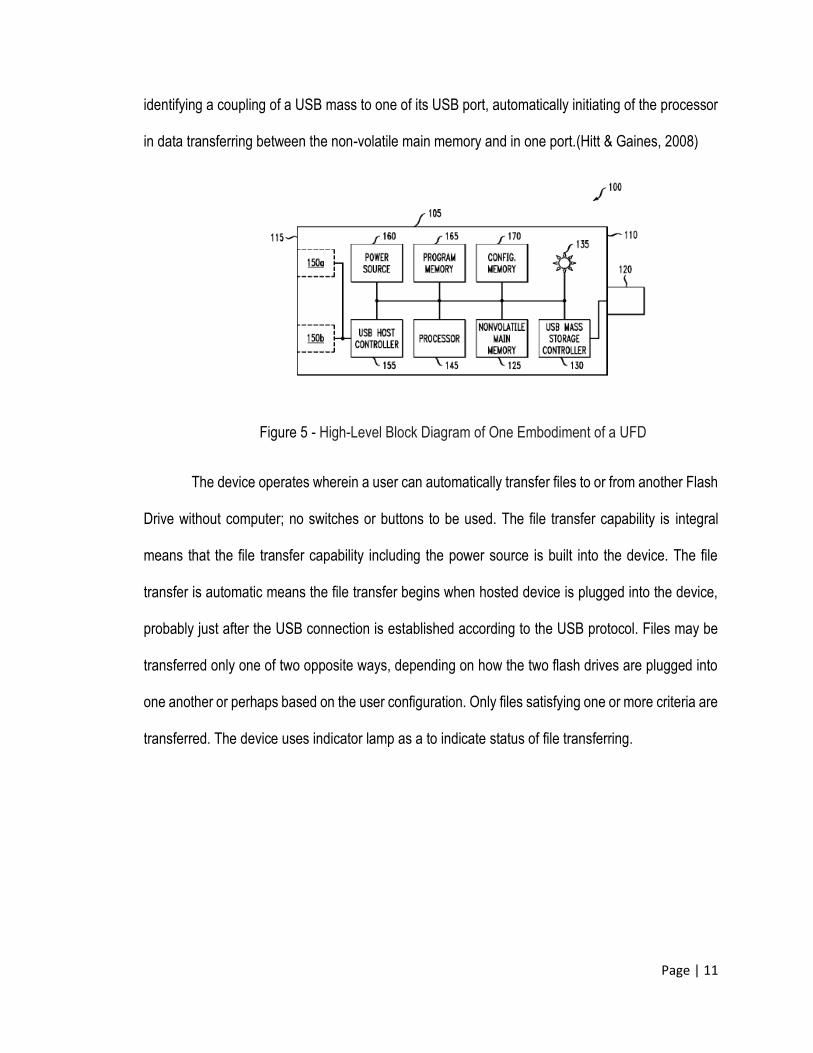
2.1.3 USB Flash Drive with Selective File Transfer
The invention has a body which includes a non-volatile memory, a USB port and USB host
controller coupled to main memory, USB plug, a program memory containing a control program. The
processor is coupled to the main memory and the two USB port is connected via host controller and
configured to initiate the data transfer between the main memory and one of the port in accordance
with the control program and directionality based on an identity of the one. In one embodiment, the
method includes, employing power source to provide power to the USB host controller, automatically
Page | 11
identifying a coupling of a USB mass to one of its USB port, automatically initiating of the processor
in data transferring between the non-volatile main memory and in one port.(Hitt & Gaines, 2008)
Figure 5 - High-Level Block Diagram of One Embodiment of a UFD
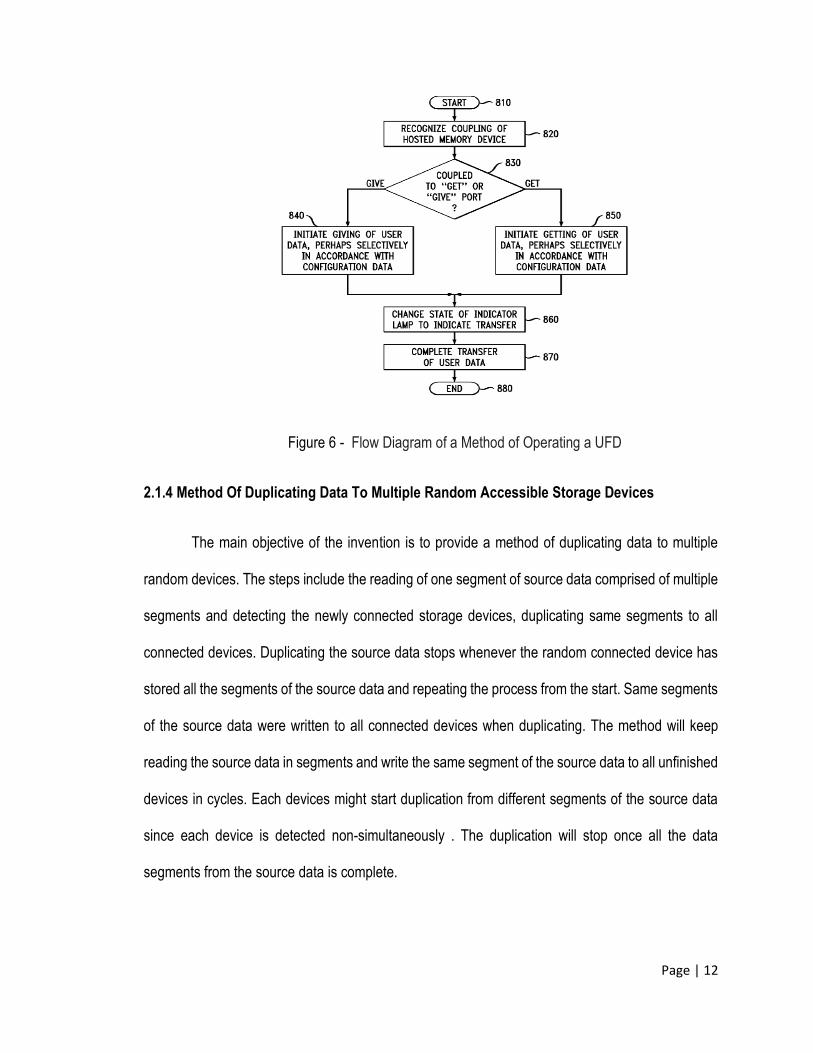
The device operates wherein a user can automatically transfer files to or from another Flash
Drive without computer; no switches or buttons to be used. The file transfer capability is integral
means that the file transfer capability including the power source is built into the device. The file
transfer is automatic means the file transfer begins when hosted device is plugged into the device,
probably just after the USB connection is established according to the USB protocol. Files may be
transferred only one of two opposite ways, depending on how the two flash drives are plugged into
one another or perhaps based on the user configuration. Only files satisfying one or more criteria are
transferred. The device uses indicator lamp as a to indicate status of file transferring.
Page | 12
Figure 6 - Flow Diagram of a Method of Operating a UFD
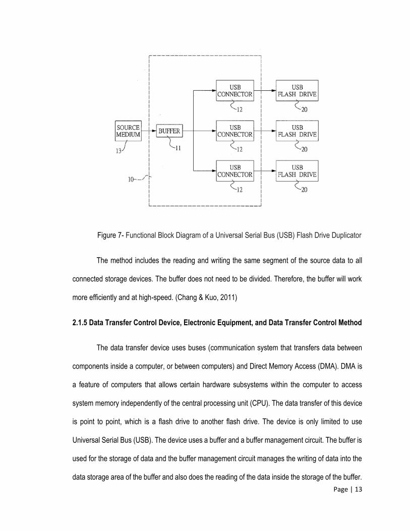
2.1.4 Method Of Duplicating Data To Multiple Random Accessible Storage Devices
The main objective of the invention is to provide a method of duplicating data to multiple
random devices. The steps include the reading of one segment of source data comprised of multiple
segments and detecting the newly connected storage devices, duplicating same segments to all
connected devices. Duplicating the source data stops whenever the random connected device has
stored all the segments of the source data and repeating the process from the start. Same segments
of the source data were written to all connected devices when duplicating. The method will keep
reading the source data in segments and write the same segment of the source data to all unfinished
devices in cycles. Each devices might start duplication from different segments of the source data
since each device is detected non-simultaneously . The duplication will stop once all the data
segments from the source data is complete.
Page | 13
Figure 7- Functional Block Diagram of a Universal Serial Bus (USB) Flash Drive Duplicator
The method includes the reading and writing the same segment of the source data to all
connected storage devices. The buffer does not need to be divided. Therefore, the buffer will work
more efficiently and at high-speed. (Chang & Kuo, 2011)
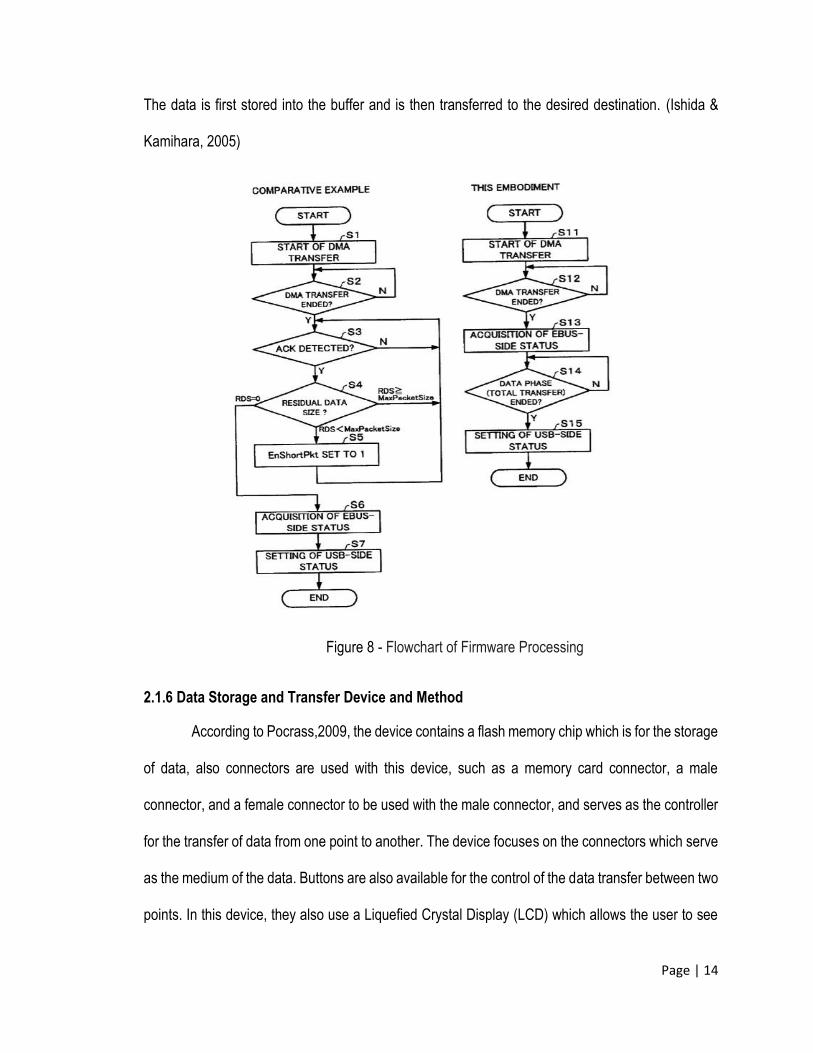
2.1.5 Data Transfer Control Device, Electronic Equipment, and Data Transfer Control Method
The data transfer device uses buses (communication system that transfers data between
components inside a computer, or between computers) and Direct Memory Access (DMA). DMA is
a feature of computers that allows certain hardware subsystems within the computer to access
system memory independently of the central processing unit (CPU). The data transfer of this device
is point to point, which is a flash drive to another flash drive. The device is only limited to use
Universal Serial Bus (USB). The device uses a buffer and a buffer management circuit. The buffer is
used for the storage of data and the buffer management circuit manages the writing of data into the
data storage area of the buffer and also does the reading of the data inside the storage of the buffer.
Page | 14
The data is first stored into the buffer and is then transferred to the desired destination. (Ishida &
Kamihara, 2005)
Figure 8 - Flowchart of Firmware Processing
2.1.6 Data Storage and Transfer Device and Method
According to Pocrass,2009, the device contains a flash memory chip which is for the storage
of data, also connectors are used with this device, such as a memory card connector, a male
connector, and a female connector to be used with the male connector, and serves as the controller
for the transfer of data from one point to another. The device focuses on the connectors which serve
as the medium of the data. Buttons are also available for the control of the data transfer between two
points. In this device, they also use a Liquefied Crystal Display (LCD) which allows the user to see
Page | 15
the progress of the data that is currently transferring. The device uses the method of transferring
data within a data storage and transfer device. The device provides a data storage and transfer
device having both characteristics of a flash memory chip for storing data, a memory card connector,
a male and female connector configured to mate with each other, inserts a memory card into the
card connector, and allowing the data to pass to or from the memory card from or to at least 1 device.
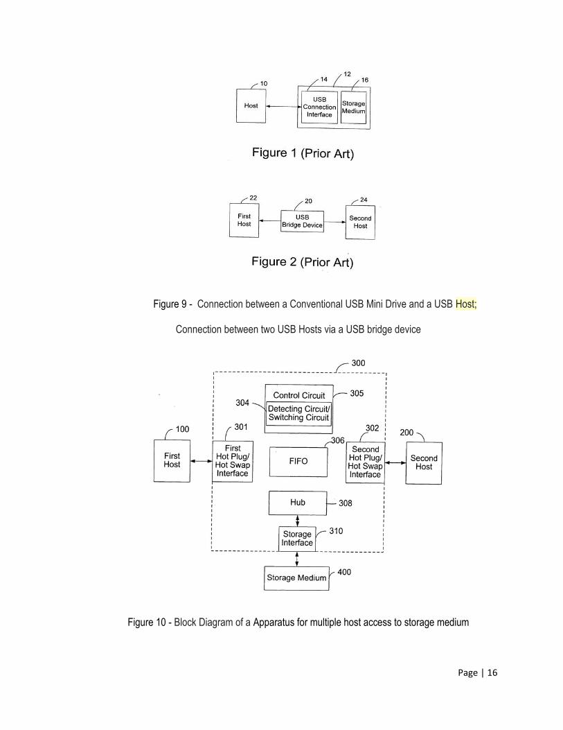
2.1.7 Apparatus for Multiple Host Access to Storage Medium
The device is created for multiple host access to a storage medium, involving a hot plug/ hot
swap to tie up with the first host, a second hot plug/hot swap interface for incorporating the second
host; storage medium and a control circuit to be able to access and manage the storage medium
from the first host and second host. The device is capable of detecting which interface will access
the storage. The input of the device is limited to a Universal Serial Bus (USB) both the input and the
output. The data transfer of the said device is only point to point, or from one source to one
destination only. After selecting which interface is the source, the device will automatically switch the
function of the other interface to a destination flash drive, so that it will passively receive the data to
be transferred. The capacity of the device is also limited, even though it has its plug-and-play feature
and is easy to manage and carry. USB bridge device is shaped as a long cable, which may be a
hindrance and can cause inconvenience to the user to carry around. This object/device is intended
to eliminate the hindrance of having the inconvenience of carrying a USB bridge, though it only
supports USB flash drives, it can accommodate multiple host access to a storage medium, it has a
detachable cable which is suitable to carry around which is advantageous for the user. (Lu,2005)
Page | 16
Figure 9 - Connection between a Conventional USB Mini Drive and a USB Host;
Connection between two USB Hosts via a USB bridge device
Figure 10 - Block Diagram of a Apparatus for multiple host access to storage medium
Page | 17
2.2 REVIEW OF RELATED LITERATURE
2.2.1 USB Communication
Craig Peacock from his blog “USB in a Nutshell” defines USB as a host centric bus.
Therefore a USB communication comes between a host and a device. Universal Serial Bus needs a
USB host, which will act as a master, to communicate to a USB Device/Peripheral like Mass Storage
Devices wherein it will act as a slave. The USB HOST initiates all transaction; bus transfers; establish
enumeration; endpoint communication, and etc.
To access files in a flash drive, Jan Axelson indicated from his book about the considerations
of the system that the host must have. He stated that the system must have USB host-controller
(hardware), mass storage driver firmware (software) and the support for file systems. File systems
on the other hand defines how data are organized in the flash drive. Popular file systems for
embedded systems include FAT16 and FAT32. Then according to him, the embedded system can
then store and read files in off-the-shelf USB storage devices.
In addition, Jan Axelson also stated that embedded hosts must have the following
responsibilities: a) Detect Devices: On power-up, hubs make the host aware of all attached USB
devices. b) Provide Power: The host provides power to all devices on power-up or attachment and
works with the devices to conserve power when possible. c) Manage Traffic on the Bus: The host
manages the flow of data on the bus. d) Handle Error Checking: When transmitting data, the host
adds error-checking bits. When receiving data, the host uses received error-checking bits to detect
errors. And lastly, e) Exchange Data with Peripherals: All of the above tasks support the host’s main
job, which is to exchange data with peripherals.
Page | 18
Yingbo Hu and Ralph Moore provided a complete part of a Host-Controller. A USB host
requires a USB host controller and USB host software. The latter is layered from the bottom up as
follows: (1) USB host controller driver, (2) USB host stack, and (3) USB class driver. The first layer
controls the USB host controller – i.e. it reads and writes registers in the controller and it transfers
data. The second layer implements the USB protocol and thus controls connected USB devices. The
third layer is device-aware and communicates with and controls the actual device (e.g. disk drive,
HID human interface device, CDC communication device, etc.) One USB host stack can support
multiple class drivers, simultaneously. In an embedded system there usually is only one USB host
controller.
2.2.2 USB Protocol
According to USB 2.0 Specification, up to 127 USB devices can be connected to one USB
host via up to 6 layers of cascaded hubs. For embedded systems, it is very unusual to have more
than one hub. In most cases, one USB device connects directly to one USB host with no hub.
USB hard drives and flash drives are block storage devices. In that, they read, write and
erase in blocks of data and not in streams of data. All USB drives support the logical block addressing
that specifies block of storage capabilities numbered sequentially to read or write to.
Axelson’s research identifies that before reading and writing to files on flash drive, the USB
Host must receive and execute four commands. A) USB hosts learn about attached devices by
sending a series of requests in a process called enumeration. B) The device returns a series of data
structures called descriptors, which describe the device's functions and capabilities. C) A flash drive
sends descriptors that tell the host that the device belongs to USB's mass storage class. D) The host
then knows it can use mass-storage protocols to communicate with the device.
Page | 19
The Computer Solution LTD’s website said that a typical transaction will consist of a number
of packets - a token indicating the type of data that the Host is sending or requiring, the data and in
some cases an acknowledgement. Each packet is preceded by a sync field and followed by an end
of packet marker.
These transactions are used to provide four basic data transfer mechanisms
Control - used by the Host to send commands or query parameters. Packet lengths are 8
bytes for Low speed, 8-64 for Full and 64 for High Speed devices.
Interrupt - badly named it is in fact a polled message from the Host which has to request
specific data of the device. Used by devices which will be sending small amounts of data
(e.g. mice or keyboards)?
Bulk - used by devices to send or receive data in quantity such as a printer. Variable length
blocks of data are sent or requested by the Host (max length is 64-byte- full speed, 512 -
high speed), are verified with a CRC and their receipt is acknowledged. This mechanism is
not used by time critical peripherals as it takes whatever bandwidth is left by the other
mechanisms.
Isochronous - used for devices that stream data in real time without any error recovery such
as audio channels. For them losing some data occasionally is better than the glitch resulting
from a re-transmit. Packet sizes can be up to 1024 bytes.
Then according to Kim Otten of Microchip Technology Inc, from the four transfer types
supported by USB, the most suitable for large data transfer is Bulk. The bulk utilizes the bandwidth
allocation efficiently, in that it depends on the amount of other traffic that is on the bus. This means,
Page | 20
the bulk transfer always utilize the remaining bandwidth in a frame after Control, Interrupt and
Isochronous transfers are complete.
2.2.3 BUS Speed and Throughput
The USB 2.0 specification defines three bus speeds: high speed at 480 megabits/sec., full
speed at 12 megabits/sec., and low speed at 1.5 megabits/sec. A USB mass storage device must
support full speed, high speed, or both.
These speeds don’t mean that this will be the transfer rate of data. It’s a big no, because the
bandwidth allocates all the four transfer types. Among the four transfer types, isochronous and
interrupt devices requests has the highest priority being allocated for about 90 percent of the frame.
Control and Bulk will then guaranteed at least 10 percent with control taking priority which has
requests the device’s descriptors, which are data structures that contain information about a device’s
capabilities and requirements.
According to Jan Axelson, all bus traffic is to or from device endpoints. An endpoint serves
as a buffer for received data or data waiting to transmit. Typically an endpoint is a block of data
memory or a register in the device controller.
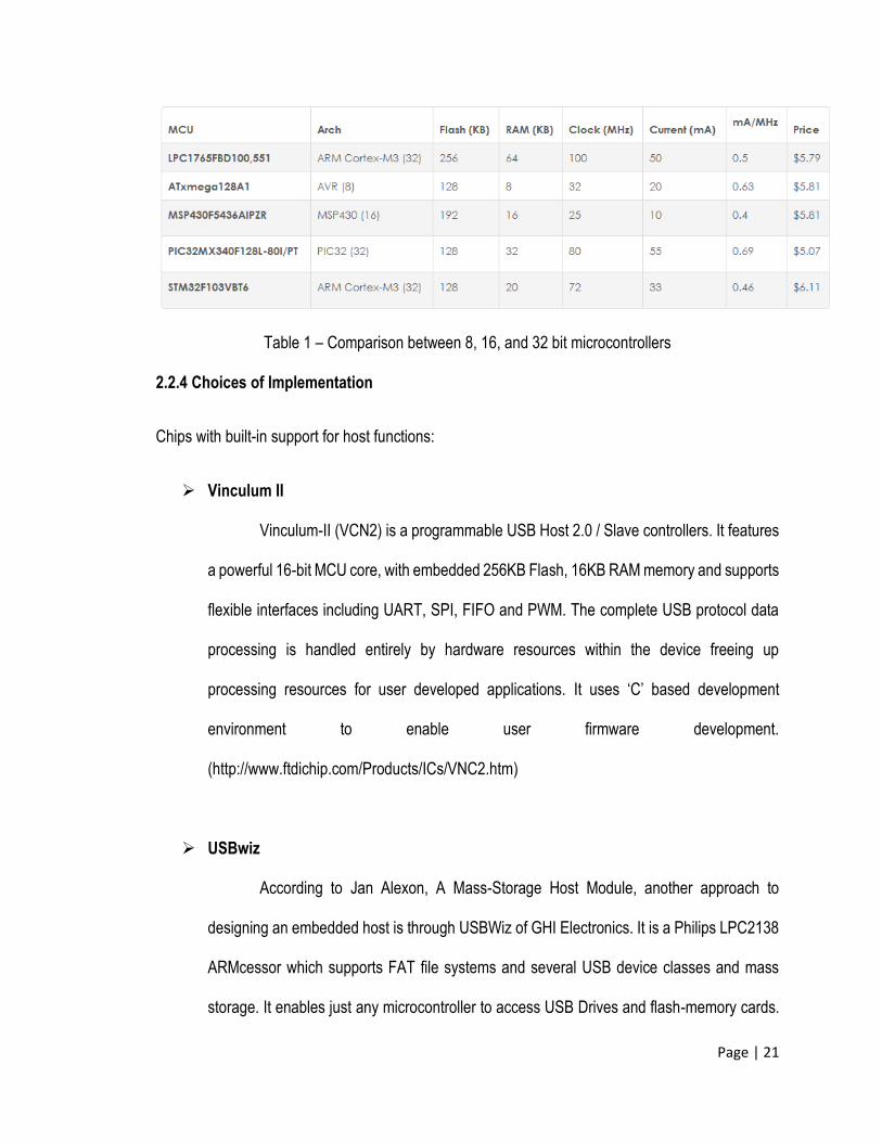
According to a case study made by the researchers of CoActionOS Website
(http://www.coactionos.com), they illustrated that 32-bit microcontroller architectures can boost
performance as compared to 8-bit and 16-bit microcontrollers without a cost increase. The case
study offered a simple comparison between several microcontroller architectures (8-bit, 16-bit, and
32-bit) of the same package (QFP100) and roughly the same price. The following table shows the
comparison which were simplified in order to give a rough idea of the relative value of each
microcontroller.
Page | 21
Table 1 – Comparison between 8, 16, and 32 bit microcontrollers
2.2.4 Choices of Implementation
Chips with built-in support for host functions:
Vinculum II
Vinculum-II (VCN2) is a programmable USB Host 2.0 / Slave controllers. It features
a powerful 16-bit MCU core, with embedded 256KB Flash, 16KB RAM memory and supports
flexible interfaces including UART, SPI, FIFO and PWM. The complete USB protocol data
processing is handled entirely by hardware resources within the device freeing up
processing resources for user developed applications. It uses ‘C’ based development
environment to enable user firmware development.
(http://www.ftdichip.com/Products/ICs/VNC2.htm)
USBwiz
According to Jan Alexon, A Mass-Storage Host Module, another approach to
designing an embedded host is through USBWiz of GHI Electronics. It is a Philips LPC2138
ARMcessor which supports FAT file systems and several USB device classes and mass
storage. It enables just any microcontroller to access USB Drives and flash-memory cards.
Page | 22
Microcontrollers can communicate with the USBWiz using asynchronous serial interface,
SPI or an IC bus. It responds to commands sent in text mode, ANSI text or in framed mode,
and binary values.
Microcontrollers with USB host ports:
Cypress Semiconductor
Cypress’s host controllers have the versatility of USB to a design. It has a single
and dual role host or peripheral controllers. It allows any design of USB ports to have both
device and host capabilities. Its high performance USB host controllers are used in
embedded applications such as PDAs, Set-top Boxes, Personal Media Players and
Automotive Infotainment. (http://www.cypress.com/?id=186&source=header)
Microchip Technology PIC24 and PIC32 series
Both PIC24 and PIC32 has the USB On-The-Go (OTG) features which allow
embedded devices to become hosts to other USB devices without the use of PC. It allows a
design to be used as either an embedded host or peripheral. USB can now be implemented
in a 16-bit system. It has USB hosting options, using a FAT file system library and process
for developing a custom class driver and an application that acts as a host to a simple USB
device. (Microchip Technology Inc.)
Page | 23
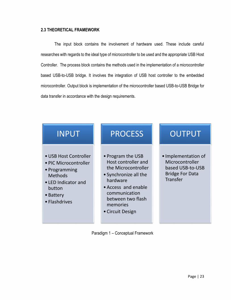
2.3 THEORETICAL FRAMEWORK
The input block contains the involvement of hardware used. These include careful
researches with regards to the ideal type of microcontroller to be used and the appropriate USB Host
Controller. The process block contains the methods used in the implementation of a microcontroller
based USB-to-USB bridge. It involves the integration of USB host controller to the embedded
microcontroller. Output block is implementation of the microcontroller based USB-to-USB Bridge for
data transfer in accordance with the design requirements.
Paradigm 1 – Conceptual Framework
INPUT
•USB Host Controller
•PIC Microcontroller
•Programming Methods
• LED Indicator and button
•Battery
• Flashdrives
PROCESS
•Program the USB Host controller and the Microcontroller
• Synchronize all the hardware
•Access and enable communication between two flash memories
•Circuit Design
OUTPUT
• Implementation of Microcontroller based USB-to-USB Bridge For Data Transfer
Page | 24
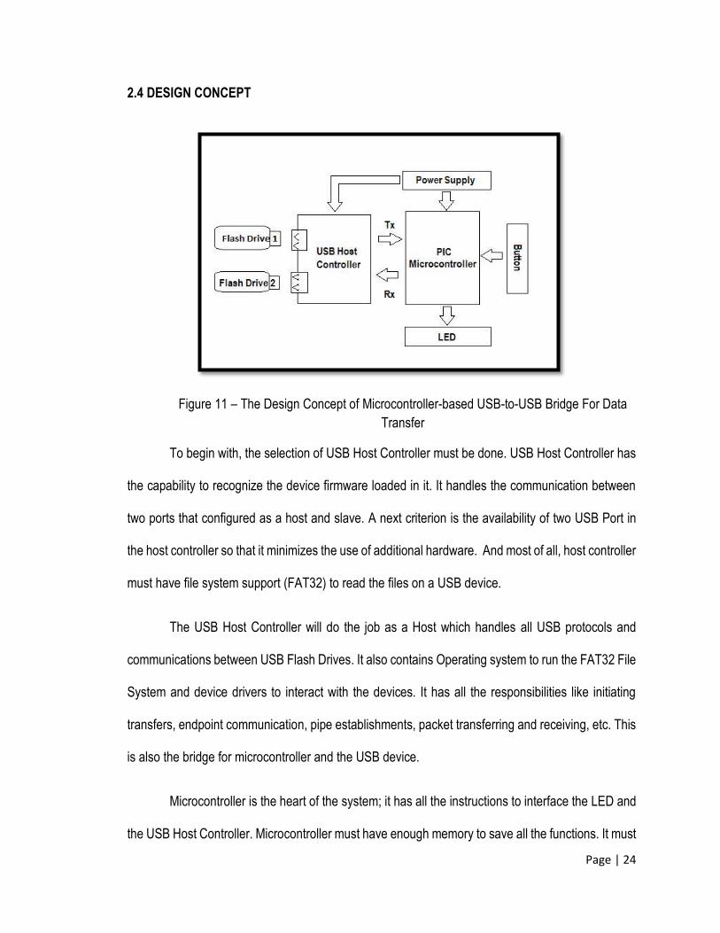
2.4 DESIGN CONCEPT
Figure 11 – The Design Concept of Microcontroller-based USB-to-USB Bridge For Data
Transfer
To begin with, the selection of USB Host Controller must be done. USB Host Controller has
the capability to recognize the device firmware loaded in it. It handles the communication between
two ports that configured as a host and slave. A next criterion is the availability of two USB Port in
the host controller so that it minimizes the use of additional hardware. And most of all, host controller
must have file system support (FAT32) to read the files on a USB device.
The USB Host Controller will do the job as a Host which handles all USB protocols and
communications between USB Flash Drives. It also contains Operating system to run the FAT32 File
System and device drivers to interact with the devices. It has all the responsibilities like initiating
transfers, endpoint communication, pipe establishments, packet transferring and receiving, etc. This
is also the bridge for microcontroller and the USB device.
Microcontroller is the heart of the system; it has all the instructions to interface the LED and
the USB Host Controller. Microcontroller must have enough memory to save all the functions. It must
Page | 25
have a TXD and RXD pins so that embedded host controller can instruct what to do. And it must
have enough I/O ports to interface all the hardware to be connected from it. Microcontroller has the
ability to consume less power to run many instructions.
Aside from that, the microcontroller must be programmed necessary instructions. The device
must power up the two flash drives via vbus and ground. Every flash drive requires 200mA each. A
5V power supply is required to provide 200mA at USB Ports, 25mA at USB Host Controller and
25mA at the microcontroller. The clock is also important to provide higher baud rate which makes
the performance of the system improve. USB Host controller and microcontroller have RTS/CTS
Handshake simulations to allow communication via UART.
The design also includes multi-colored LED consisting of green, red, and blue color. It will
serve as indicators and are powered at the pins of the microcontroller. This will indicate the transfer
of file and successful access of the file system.
The proponents will use the C compiler for the microcontroller programming and Simulation
and development tools. The said devices define roles for the completion of this design.
Page | 26
CHAPTER 3
OPERATIONAL FRAMEWORK
This chapter is divided into four (4) main parts. This includes the Project Design, Project
Development, Testing Procedure, and Implementation. The Project Design comprises Chassis
Design, System Design, and Communication Design. Next is the Project Development involves the
conceptualization of the prototype and planning its implementation. Next is the Testing Procedure
which evaluates the capacity of the device and its functionality. Another is the Implementation
wherein the execution of the device is discussed. Constraint Analysis and Technical Standards were
also added in this chapter.
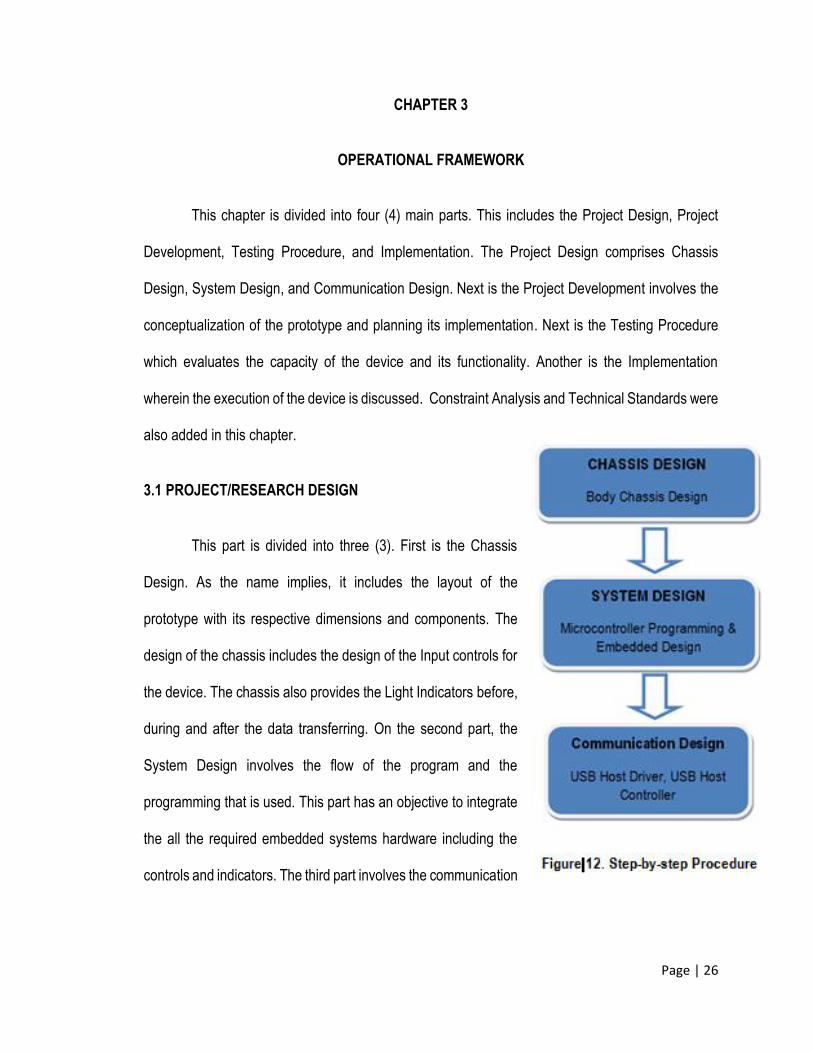
3.1 PROJECT/RESEARCH DESIGN
This part is divided into three (3). First is the Chassis
Design. As the name implies, it includes the layout of the
prototype with its respective dimensions and components. The
design of the chassis includes the design of the Input controls for
the device. The chassis also provides the Light Indicators before,
during and after the data transferring. On the second part, the
System Design involves the flow of the program and the
programming that is used. This part has an objective to integrate
the all the required embedded systems hardware including the
controls and indicators. The third part involves the communication
Page | 27
for the Mass Storage Devices. USB communication strongly suggests the use of a host which
composed of a USB Host Driver (Software) and USB Host Controller (Hardware).
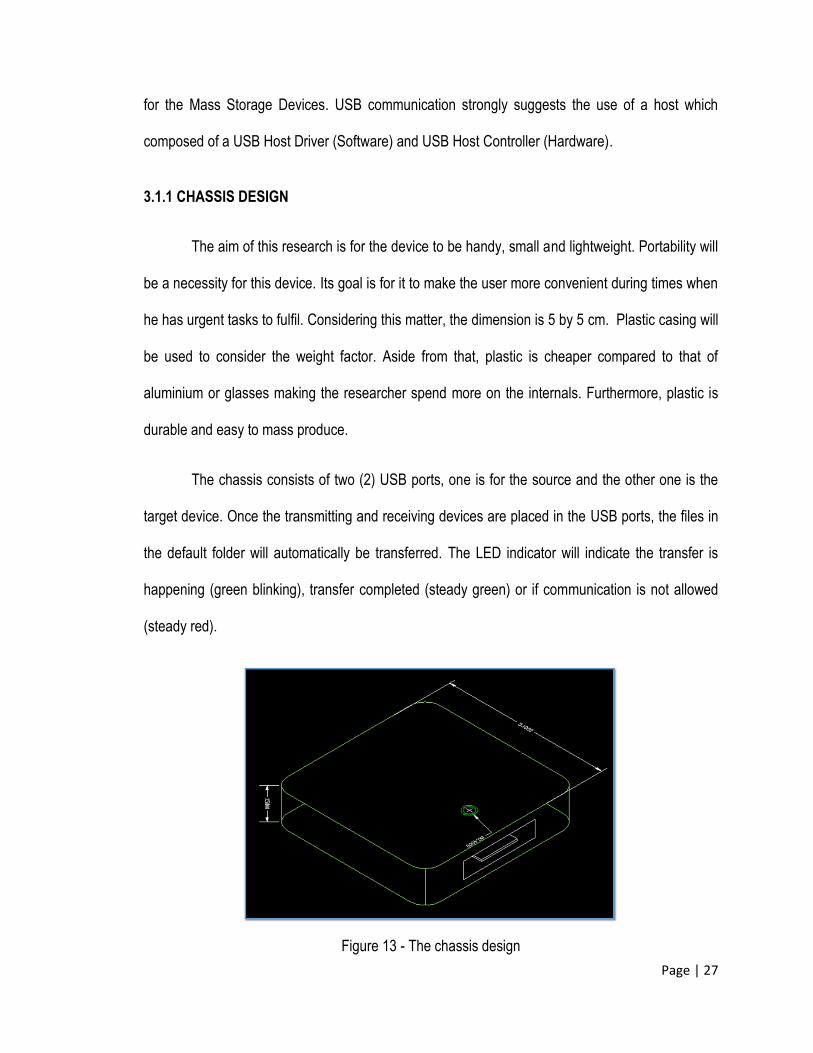
3.1.1 CHASSIS DESIGN
The aim of this research is for the device to be handy, small and lightweight. Portability will
be a necessity for this device. Its goal is for it to make the user more convenient during times when
he has urgent tasks to fulfil. Considering this matter, the dimension is 5 by 5 cm. Plastic casing will
be used to consider the weight factor. Aside from that, plastic is cheaper compared to that of
aluminium or glasses making the researcher spend more on the internals. Furthermore, plastic is
durable and easy to mass produce.
The chassis consists of two (2) USB ports, one is for the source and the other one is the
target device. Once the transmitting and receiving devices are placed in the USB ports, the files in
the default folder will automatically be transferred. The LED indicator will indicate the transfer is
happening (green blinking), transfer completed (steady green) or if communication is not allowed
(steady red).
Figure 13 - The chassis design
Page | 28
3.1.2 SYSTEM DESIGN
The system design includes the system architecture, flowchart, and algorithm. It simply
discusses the processes that the system undergoes and how it is implemented.
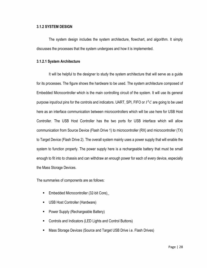
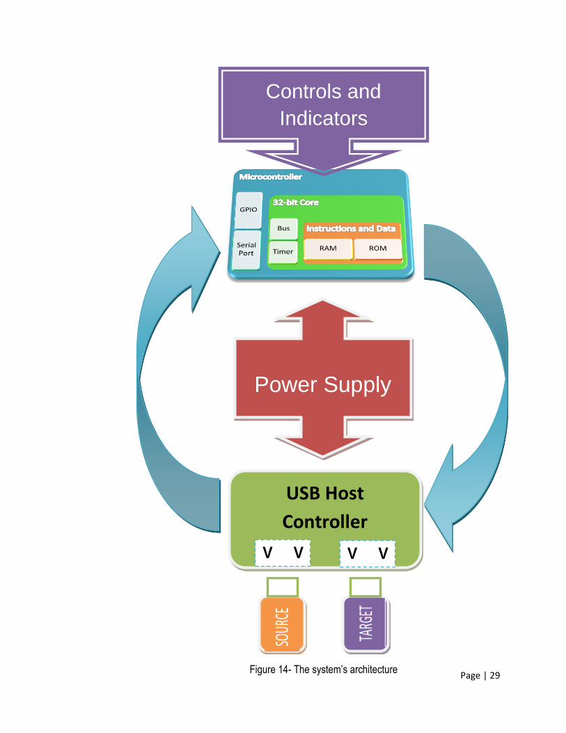
3.1.2.1 System Architecture
It will be helpful to the designer to study the system architecture that will serve as a guide
for its processes. The figure shows the hardware to be used. The system architecture composed of
Embedded Microcontroller which is the main controlling circuit of the system. It will use its general
purpose input/out pins for the controls and indicators. UART, SPI, FIFO or 𝐼2𝐶 are going to be used
here as an interface communication between microcontrollers which will be use here for USB Host
Controller. The USB Host Controller has the two ports for USB interface which will allow
communication from Source Device (Flash Drive 1) to microcontroller (RX) and microcontroller (TX)
to Target Device (Flash Drive 2). The overall system mainly uses a power supply that will enable the
system to function properly. The power supply here is a rechargeable battery that must be small
enough to fit into to chassis and can withdraw an enough power for each of every device, especially
the Mass Storage Devices.
The summaries of components are as follows:
Embedded Microcontroller (32-bit Core)_
USB Host Controller (Hardware)
Power Supply (Rechargeable Battery)
Controls and Indicators (LED Lights and Control Buttons)
Mass Storage Devices (Source and Target USB Drive i.e. Flash Drives)
Page | 29
Controls and
Indicators
Power Supply
USB Host
Controller V V
V V
Figure 14- The system’s architecture
Page | 30
START
Insert flash drive to be copied
to the source USB port
Insert receiving flash drive to
the destination port
Green
LED
blinking ?
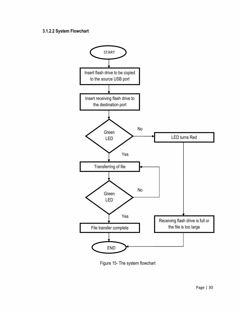
3.1.2.2 System Flowchart
Figure 15- The system flowchart
Yes
Yes
No
No
File transfer complete
Transferring of file
END
Receiving flash drive is full or
the file is too large
Green
LED
steady?
LED turns Red
Page | 31
3.1.2.3 Algorithm:
1. Start
2. Insert flash drive to be copied to the source USB port
3. Insert the receiving flash drive to the destination port
4. Green LED is blinking while transferring files from the source flash drive to the destination
flash drive. LED turns Red if the transfer is not allowed i.e. error, destination storage is full.
5. LED stops blinking and the LED turns steady green when transferring of data is complete.
6. Stop.
3.1.3 COMMUNICATION DESIGN
In this part of the study involves the communication between embedded microcontrollers
and the USB Host Controller. Wherein the microcontroller enables transmit and receive of the data
from the USB Host Controller. The USB Host Controller on the other hand handles the protocol
between the two USB mass storage devices. The said two embedded devices were both
microcontrollers so that the communication between the microcontrollers will be needed in this part.
According to Jan Axelson, communications between microcontrollers can be
establish by using its serial communication ports like UART, USART, FIFO, SPI or the I2C. According
to Microchip Technology Inc, Serial Peripheral Interface is a synchronous serial bus and operates in
full duplex mode. It is a synchronous protocol that allows a master device to initiate communication
with a slave device . It allows serial communication between two or more devices at a high speed.
Using SPI, the two microcontrollers can communicate in master/slave mode. PIC32 microcontroller
operates in master mode and the Vinculum II USB host controller acts as the slave.
Page | 32
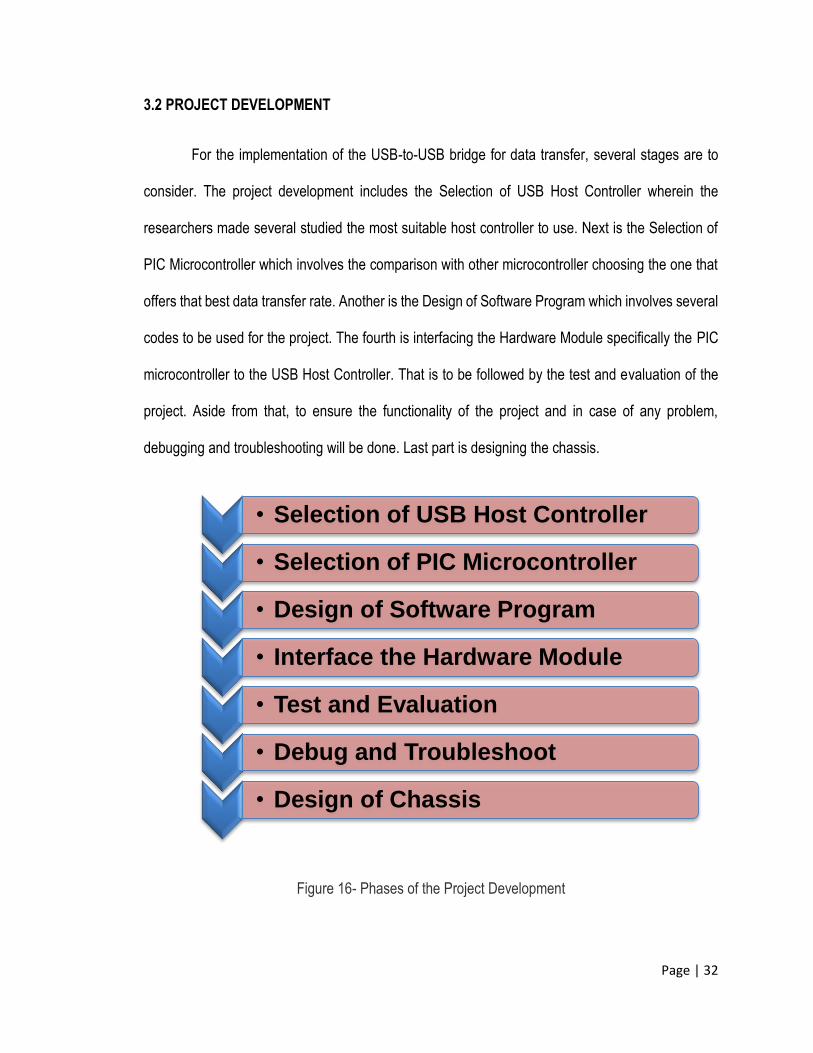
3.2 PROJECT DEVELOPMENT
For the implementation of the USB-to-USB bridge for data transfer, several stages are to
consider. The project development includes the Selection of USB Host Controller wherein the
researchers made several studied the most suitable host controller to use. Next is the Selection of
PIC Microcontroller which involves the comparison with other microcontroller choosing the one that
offers that best data transfer rate. Another is the Design of Software Program which involves several
codes to be used for the project. The fourth is interfacing the Hardware Module specifically the PIC
microcontroller to the USB Host Controller. That is to be followed by the test and evaluation of the
project. Aside from that, to ensure the functionality of the project and in case of any problem,
debugging and troubleshooting will be done. Last part is designing the chassis.
Figure 16- Phases of the Project Development
• Selection of USB Host Controller
• Selection of PIC Microcontroller
• Design of Software Program
• Interface the Hardware Module
• Test and Evaluation
• Debug and Troubleshoot
• Design of Chassis
Page | 33
3.2.1 Selection of USB Host Controller
There are few host controller modules in the internet but the criterion must have two USB
ports available. The host controller recognizes the input peripheral as host or slave according to
firmware loaded in it. The sub module physically interfaces with the USB flash drives and is
responsible for converting raw data and information to their proper NRZI encoding as specified by
the USB technical specifications. It handles all types of transfer between source destinations. The
researchers have selected a USB Host controller which has two independent USB 2.0 low
speed/high speed USB Host ports. Individual ports can be configured as host or slave.
FTDI’s 2nd generation of USB Host/ Slave controllers, Vinculum II (VNC2), was selected as
the USB Host Controller. It features dual USB 2.0 Host controller in a single IC with a powerful 16-
bit MCU core. It has embedded 256KB Flash and 16KB RAM memory. VNC2 can handle complete
USB protocol data processing with a capability to encapsulate USB device classes by handling the
USB Host Interface and data transfer functions . It has built-in Serial Peripheral Interfaces which is
used to interface with the PIC microcontroller. It is fully programmable and supports ‘C’ based
programming for firmware development. VNC2 provides a cost effective solution for USB host
applications.
Page | 34
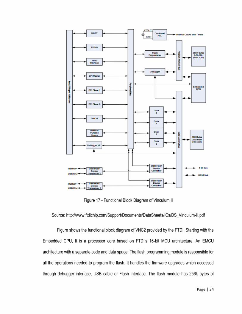
Figure 17 - Functional Block Diagram of Vinculum II
Source: http://www.ftdichip.com/Support/Documents/DataSheets/ICs/DS_Vinculum-II.pdf
Figure shows the functional block diagram of VNC2 provided by the FTDI. Starting with the
Embedded CPU, It is a processor core based on FTDI’s 16-bit MCU architecture. An EMCU
architecture with a separate code and data space. The flash programming module is responsible for
all the operations needed to program the flash. It handles the firmware upgrades which accessed
through debugger interface, USB cable or Flash interface. The flash module has 256k bytes of
Page | 35
embedded flash (E-Flash) memory. Input/ Output Multiplexer Module is where the peripheral
interfaces were connected. It allows the user to programmer to select which peripherals are
connected to the I/O pins. The peripheral DMA Modules transfer data to and from an I/O device. It
transmits or receives data from memory to an I/O address space. It can also copy data from memory
to another location. DMA is automatically controlled by the CPU. VNC2 has two USB transceivers in
which the physical USB interface is connected. It supports USB 1.1 and USB 2.0 standards with low-
speed and full-speed USB data rates. Each output driver +3.3V level control signaling. The USB
Host/ Device Controllers handles the parallel-to-serial and serial-to-parallel conversion of the USB
physical layer. The clock is provided by a 12MHz Oscillator cell. It generates a 12 MHz reference
clock input to the Clock Multiplier PLL from an external 12 MHz crystal.
3.2.2 Selection of PIC Microcontroller
According to a case study made by the researchers of CoActionOS Website
(http://www.coactionos.com), they illustrated that 32-bit microcontroller architectures can boost
performance as compared to 8-bit and 16-bit microcontrollers without a cost increase. The case
study offered a simple comparison between several microcontroller architectures (8-bit, 16-bit, and
32-bit) of the same package (QFP100) and roughly the same price. The following table shows the
comparison which were simplified in order to give a rough idea of the relative value of each
microcontroller.
Page | 36
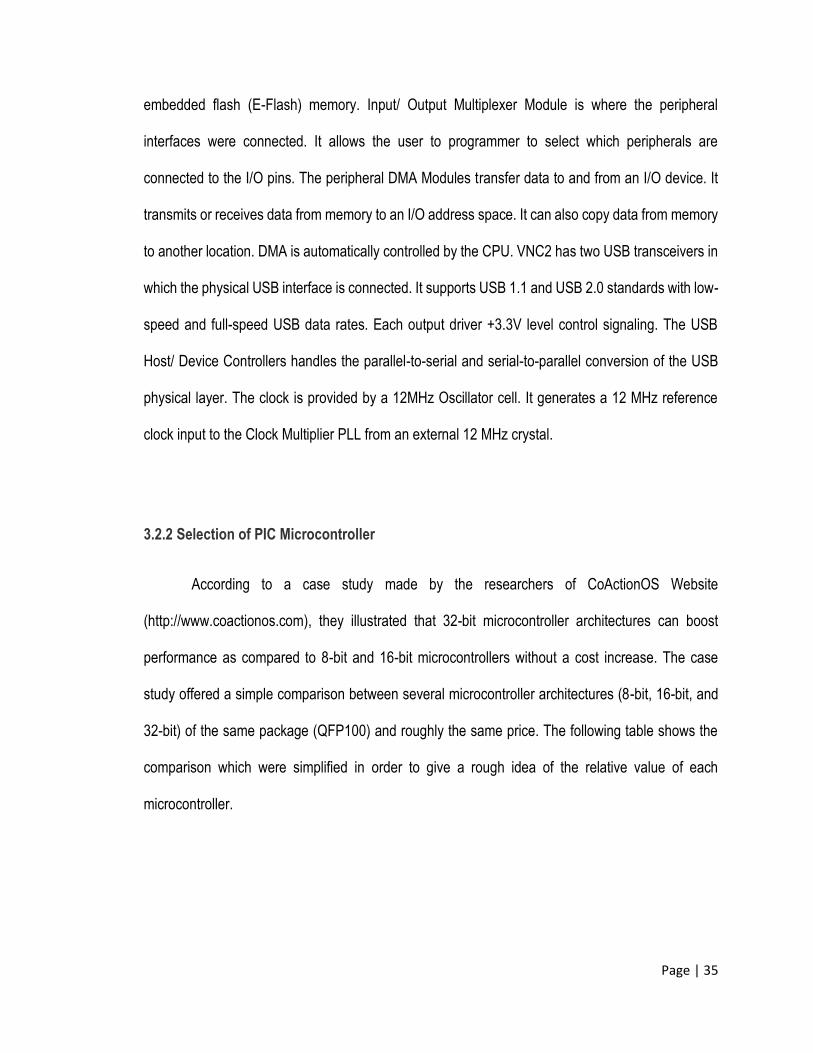
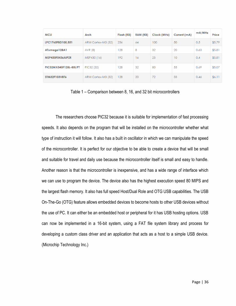
Table 1 – Comparison between 8, 16, and 32 bit microcontrollers
The researchers choose PIC32 because it is suitable for implementation of fast processing
speeds. It also depends on the program that will be installed on the microcontroller whether what
type of instruction it will follow. It also has a built in oscillator in which we can manipulate the speed
of the microcontroller. It is perfect for our objective to be able to create a device that will be small
and suitable for travel and daily use because the microcontroller itself is small and easy to handle.
Another reason is that the microcontroller is inexpensive, and has a wide range of interface which
we can use to program the device. The device also has the highest execution speed 80 MIPS and
the largest flash memory. It also has full speed Host/Dual Role and OTG USB capabilities. The USB
On-The-Go (OTG) feature allows embedded devices to become hosts to other USB devices without
the use of PC. It can either be an embedded host or peripheral for it has USB hosting options. USB
can now be implemented in a 16-bit system, using a FAT file system library and process for
developing a custom class driver and an application that acts as a host to a simple USB device.
(Microchip Technology Inc.)
Page | 37
3.2.3 Design of Software Program
The development of the project involves the programming of the microcontrollers. A USB
device stack is the software necessary to drive the USB device peripheral hardware on a
microcontroller (MCU) or other device (Alan Ott, Signal 11 Software). Typically, USB peripheral
hardware only supports the transaction level and below of the USB protocol. Enumeration and
transfers are left to the firmware or software to implement.
USB device hardware initialization
USB interrupt handling
Management of the serial interface engine SIE
Management of endpoints
Fragmentation and reassembly of control transfers
Handling and sending standard setup requests
Enumeration
Microchips Application Note “USB Embedded Host Stack Programmer’s Guide” by Bud
Caldwell of the Microchip Technology Inc describes how to use the USB embedded host stack
firmware when a sample application is not available to perform the desired task.
Page | 38
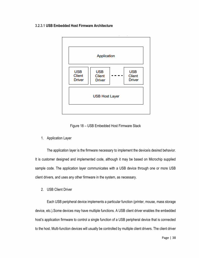
3.2.3.1 USB Embedded Host Firmware Architecture
Figure 18 – USB Embedded Host Firmware Stack
1. Application Layer
The application layer is the firmware necessary to implement the deviceís desired behavior.
It is customer designed and implemented code, although it may be based on Microchip supplied
sample code. The application layer communicates with a USB device through one or more USB
client drivers, and uses any other firmware in the system, as necessary.
2. USB Client Driver
Each USB peripheral device implements a particular function (printer, mouse, mass storage
device, etc.).Some devices may have multiple functions. A USB client driver enables the embedded
host’s application firmware to control a single function of a USB peripheral device that is connected
to the host. Multi-function devices will usually be controlled by multiple client drivers. The client driver
Page | 39
should model the function in an abstract way, so that the host application does not need to
comprehend the details of how the device works.
3. USB Host Layer
The host layer provides an abstraction of the USB, supplying the following services:
Performs device identification
Performs device enumeration
Manages client drivers
Provides a simple interface to communicate with a USB peripheral device
When first connected to the bus, the host layer will read the descriptors (data structures defined
by the USB 2.0 and its associated supplements) from the device to determine what type of device it
is and what function(s) it supports. Then, it will check the TPL to see if the device can be supported.
If it can be, the host layer will initialize the appropriate client driver (or drivers).
3.2.3.2 Implementing an Embedded Host’s Firmware
This section describes the steps necessary to design and implement the firmware for an
embedded USB host using the Microchip framework.
Implementing the Main Application
Using MPLAB IDE, create a new application for the supported microcontroller. (Refer to the
MPLAB IDE online help for instructions on how to create a project.) Implement and test any
application-specific non-USB functionality desired.
Page | 40
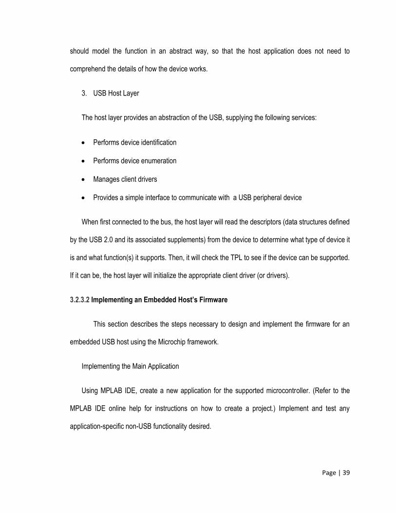
To support the USB FW stack, the applicationís main function must call USBInitialize, once
before any other USB activity takes place. After USBInitialize has been called, the application must
call USBTasks in its main loop.
Figure 19 – An Example of the Main Application Routine
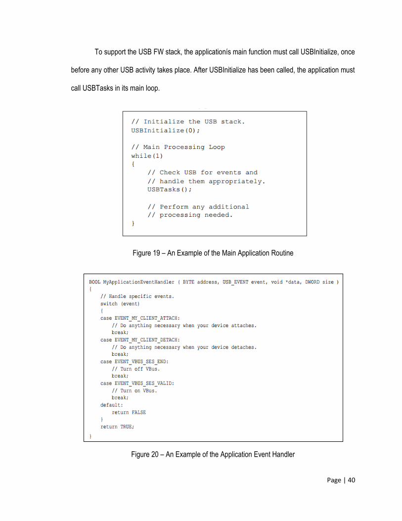
Figure 20 – An Example of the Application Event Handler
Page | 41
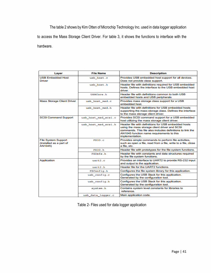
The table 2 shows by Kim Otten of Microchip Technology Inc. used in data logger application
to access the Mass Storage Client Driver. For table 3, it shows the functions to interface with the
hardware.
Table 2- Files used for data logger application
Page | 42
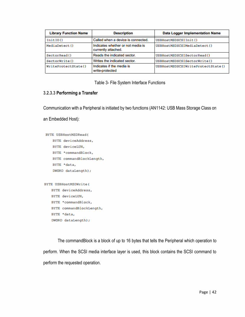
Table 3- File System Interface Functions
3.2.3.3 Performing a Transfer
Communication with a Peripheral is initiated by two functions (AN1142: USB Mass Storage Class on
an Embedded Host):
The commandBlock is a block of up to 16 bytes that tells the Peripheral which operation to
perform. When the SCSI media interface layer is used, this block contains the SCSI command to
perform the requested operation.
Page | 43
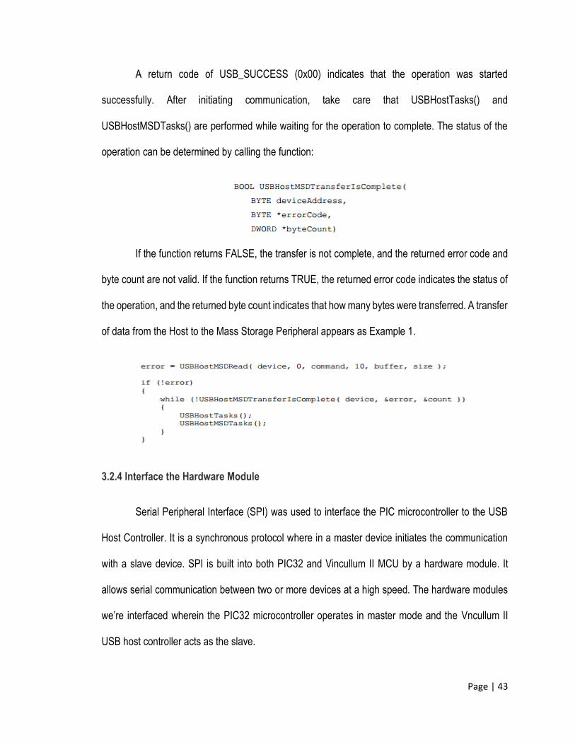
A return code of USB_SUCCESS (0x00) indicates that the operation was started
successfully. After initiating communication, take care that USBHostTasks() and
USBHostMSDTasks() are performed while waiting for the operation to complete. The status of the
operation can be determined by calling the function:
If the function returns FALSE, the transfer is not complete, and the returned error code and
byte count are not valid. If the function returns TRUE, the returned error code indicates the status of
the operation, and the returned byte count indicates that how many bytes were transferred. A transfer
of data from the Host to the Mass Storage Peripheral appears as Example 1.
3.2.4 Interface the Hardware Module
Serial Peripheral Interface (SPI) was used to interface the PIC microcontroller to the USB
Host Controller. It is a synchronous protocol where in a master device initiates the communication
with a slave device. SPI is built into both PIC32 and Vincullum II MCU by a hardware module. It
allows serial communication between two or more devices at a high speed. The hardware modules
we’re interfaced wherein the PIC32 microcontroller operates in master mode and the Vncullum II
USB host controller acts as the slave.

Page | 44
Figure 21 –SPI Communication
Souces: http://www.ftdichip.com/Support/Documents/DataSheets/ICs/DS_Vinculum-II.pdf- August 26, 2013
Communication between microcontrollers as presented by the block diagram involves the
use of SPI ports. It has four wire ports and specifies the logic signals namely: SCLK which is the
serial clock, MOSI (master output, slave input), MISO (master input, slave output) and SS (slave
select). First, the master (PIC32) configures the clock (SCLK) with frequency equal or less than to
the maximum frequency of the slave supports. VNC2 operating in slave mode has an SPI maximum
clock of 24MHz. The clock signal is only provided by the master for synchronization. It controls the
transferring of data, when it will change and valid to be read. The SS signal will control when a device
is accessed. It indicates that the PIC32 wishes to start a data exchange with the VNC2. The SS
signal is low when SPI is active and the slave will listen for clock and data signal. Since SPI is
synchronous, it has a clock pulse along with the data. Data is always exchanged between the
devices. Operating in full duplex mode, MOSI and MISO pins will be used here as the way of data
Page | 45
exchange between them. Each device has two data lines, one for input from slave going to master
(MISO) and one for output from master going to slave (MOSI).
3.2.4.5 Testing Procedure and Evaluation
The hardware to be use in this device must be properly selected to meet the requirements
of the device and function properly. Selection of USB Host Controller will be the stepping stone for
this project. This means it will handle the provision of USB communication protocol for the USB
Slaves. Series of test and evaluation will be implemented to assure the functionality of the device.
On the first test, the file transferred from the source to destination should have the same content.
Another evaluation is the accuracy of the file. The desired output must be the same from the source
and it must not be corrupted. Speed of the file transferring is also assessed; the desired throughput
must match with the device. There will be three sets of files to be transfer: Small, Medium and Large
Files. The average speed for these sets will be recorded respectively. The effective throughput is
from 32 to 280 Mbps, specification of USB 2.0 Hi-Speed.
3.2.4.6 Implementation
USB Host Controller: There are many host controller modules in the internet but the criterion
must have two USB ports available. The host controller recognizes the input peripheral as host or
slave according to firmware loaded in it. The sub module physically interfaces with the USB flash
drives and is responsible for converting raw data and information to their proper NRZI encoding as
specified by the USB technical specifications. It handles all types of transfer between source
destinations. We have USB Host controller which has two independent USB 2.0 low speed/high
speed USB Host ports. Individual ports can be configured as host or slave.
Page | 46
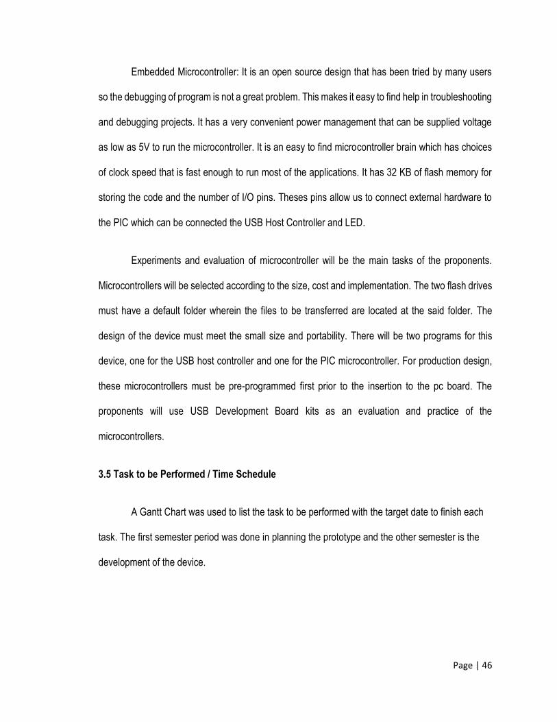
Embedded Microcontroller: It is an open source design that has been tried by many users
so the debugging of program is not a great problem. This makes it easy to find help in troubleshooting
and debugging projects. It has a very convenient power management that can be supplied voltage
as low as 5V to run the microcontroller. It is an easy to find microcontroller brain which has choices
of clock speed that is fast enough to run most of the applications. It has 32 KB of flash memory for
storing the code and the number of I/O pins. Theses pins allow us to connect external hardware to
the PIC which can be connected the USB Host Controller and LED.
Experiments and evaluation of microcontroller will be the main tasks of the proponents.
Microcontrollers will be selected according to the size, cost and implementation. The two flash drives
must have a default folder wherein the files to be transferred are located at the said folder. The
design of the device must meet the small size and portability. There will be two programs for this
device, one for the USB host controller and one for the PIC microcontroller. For production design,
these microcontrollers must be pre-programmed first prior to the insertion to the pc board. The
proponents will use USB Development Board kits as an evaluation and practice of the
microcontrollers.
3.5 Task to be Performed / Time Schedule
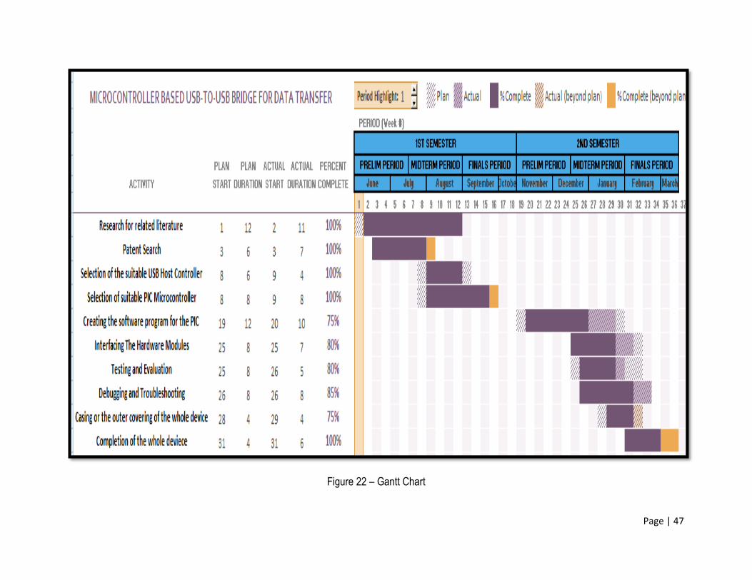
A Gantt Chart was used to list the task to be performed with the target date to finish each
task. The first semester period was done in planning the prototype and the other semester is the
development of the device.
Page | 47
Figure 22 – Gantt Chart
Page | 48
3.5 CONSTRAINTS ANALYSIS
3.5.1 Hardware Constraints
One of the constraints in hardware design includes the addition of hardware controllers that would
cause the device chassis to become possibly big. Since Vincullum II involves two USB port needed for the
bridge, the proponents had decided to use it. Other host controller has only one USB port which would require
using another host controller which is not ideal since the chassis would become bigger.
3.5.2 Financial Constraints
In making the design project, finance is a great factor. LCD display for file selection has been
considered but due to its expense, the researchers decided to not use one anymore. Since the only function
of the prototype is to transfer file, it would be impractical to spend a lot of money for a simple function. One
of the researcher’s goals is to have device price lower than that of a laptop or anything that can transfer file.
3.5.3 Physical Dimension and Weight
The bridge has a limit on its dimension. The researchers had set a maximum dimensions for width,
length and height of the prototype. That is 5cm by 5cm by 3cm. The prototype must also be lightweight.
3.6 TRADE-OFFS
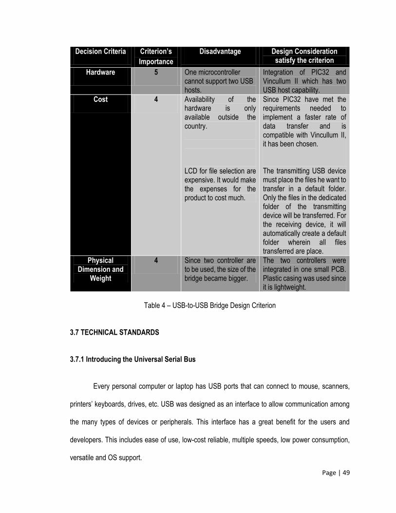
Based on the constraints considered above, several decision on the criteria are made. The
importance of each criterion are scaled from 0 to 5 having 5 as the highest importance. The following are
listed and ranked below.
Page | 49
Decision Criteria Criterion’s
Importance
Disadvantage Design Consideration satisfy the criterion
Hardware 5 One microcontroller cannot support two USB hosts.
Integration of PIC32 and Vincullum II which has two USB host capability.
Cost 4 Availability of the hardware is only available outside the country.
LCD for file selection are expensive. It would make the expenses for the product to cost much.
Since PIC32 have met the requirements needed to implement a faster rate of data transfer and is compatible with Vincullum II, it has been chosen.
The transmitting USB device must place the files he want to transfer in a default folder. Only the files in the dedicated folder of the transmitting device will be transferred. For the receiving device, it will automatically create a default folder wherein all files transferred are place.
Physical Dimension and
Weight
4 Since two controller are to be used, the size of the bridge became bigger.
The two controllers were integrated in one small PCB. Plastic casing was used since it is lightweight.
Table 4 – USB-to-USB Bridge Design Criterion
3.7 TECHNICAL STANDARDS
3.7.1 Introducing the Universal Serial Bus
Every personal computer or laptop has USB ports that can connect to mouse, scanners,
printers’ keyboards, drives, etc. USB was designed as an interface to allow communication among
the many types of devices or peripherals. This interface has a great benefit for the users and
developers. This includes ease of use, low-cost reliable, multiple speeds, low power consumption,
versatile and OS support.
Page | 50
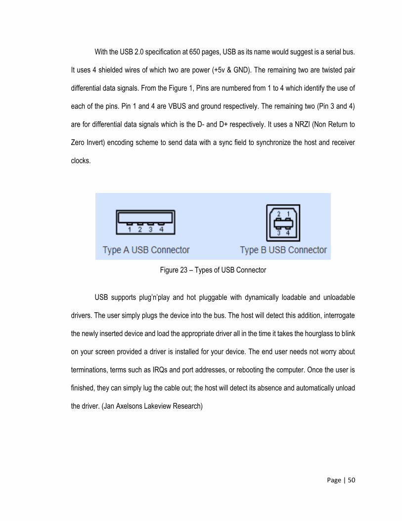
With the USB 2.0 specification at 650 pages, USB as its name would suggest is a serial bus.
It uses 4 shielded wires of which two are power (+5v & GND). The remaining two are twisted pair
differential data signals. From the Figure 1, Pins are numbered from 1 to 4 which identify the use of
each of the pins. Pin 1 and 4 are VBUS and ground respectively. The remaining two (Pin 3 and 4)
are for differential data signals which is the D- and D+ respectively. It uses a NRZI (Non Return to
Zero Invert) encoding scheme to send data with a sync field to synchronize the host and receiver
clocks.
Figure 23 – Types of USB Connector
USB supports plug’n’play and hot pluggable with dynamically loadable and unloadable
drivers. The user simply plugs the device into the bus. The host will detect this addition, interrogate
the newly inserted device and load the appropriate driver all in the time it takes the hourglass to blink
on your screen provided a driver is installed for your device. The end user needs not worry about
terminations, terms such as IRQs and port addresses, or rebooting the computer. Once the user is
finished, they can simply lug the cable out; the host will detect its absence and automatically unload
the driver. (Jan Axelsons Lakeview Research)
Page | 51
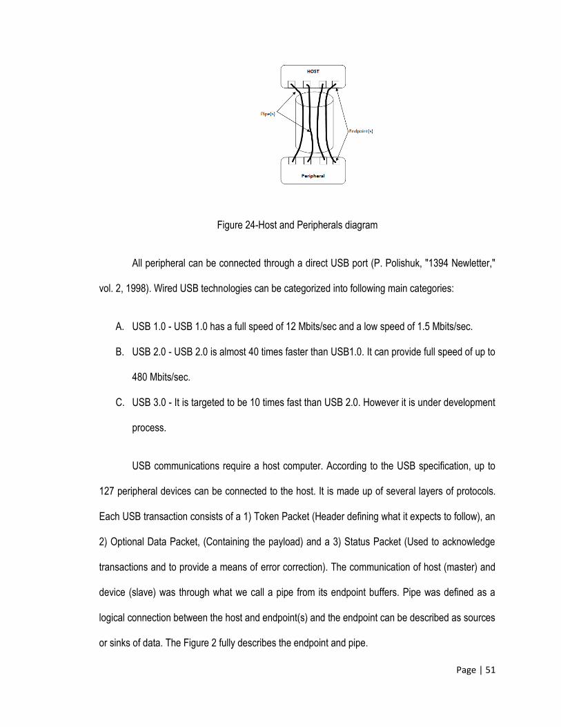
Figure 24-Host and Peripherals diagram
All peripheral can be connected through a direct USB port (P. Polishuk, "1394 Newletter,"
vol. 2, 1998). Wired USB technologies can be categorized into following main categories:
A. USB 1.0 - USB 1.0 has a full speed of 12 Mbits/sec and a low speed of 1.5 Mbits/sec.
B. USB 2.0 - USB 2.0 is almost 40 times faster than USB1.0. It can provide full speed of up to
480 Mbits/sec.
C. USB 3.0 - It is targeted to be 10 times fast than USB 2.0. However it is under development
process.
USB communications require a host computer. According to the USB specification, up to
127 peripheral devices can be connected to the host. It is made up of several layers of protocols.
Each USB transaction consists of a 1) Token Packet (Header defining what it expects to follow), an
2) Optional Data Packet, (Containing the payload) and a 3) Status Packet (Used to acknowledge
transactions and to provide a means of error correction). The communication of host (master) and
device (slave) was through what we call a pipe from its endpoint buffers. Pipe was defined as a
logical connection between the host and endpoint(s) and the endpoint can be described as sources
or sinks of data. The Figure 2 fully describes the endpoint and pipe.
Page | 52
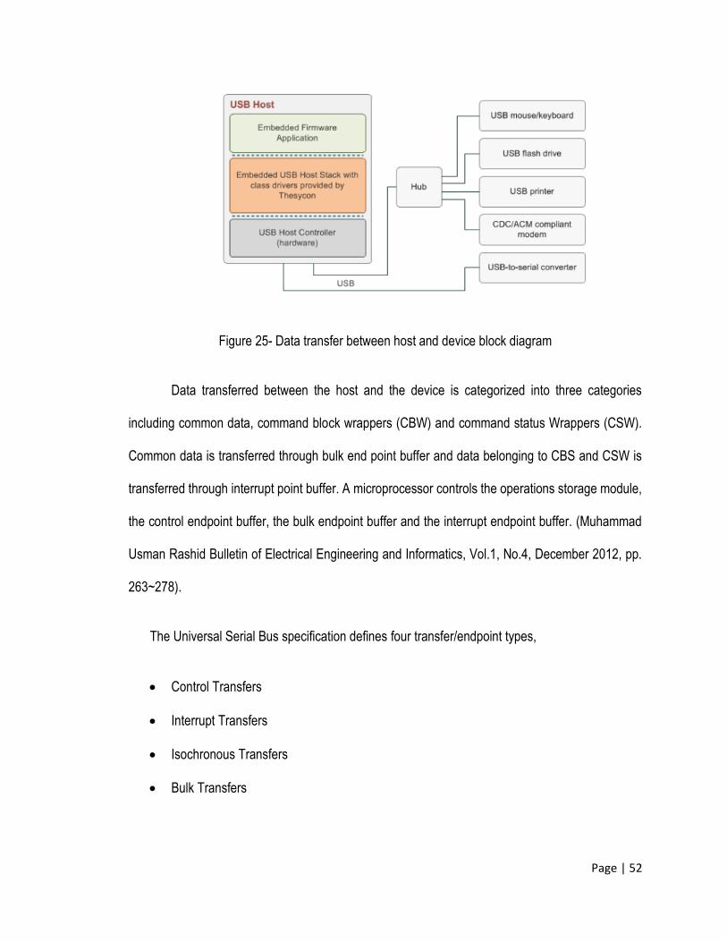
Figure 25- Data transfer between host and device block diagram
Data transferred between the host and the device is categorized into three categories
including common data, command block wrappers (CBW) and command status Wrappers (CSW).
Common data is transferred through bulk end point buffer and data belonging to CBS and CSW is
transferred through interrupt point buffer. A microprocessor controls the operations storage module,
the control endpoint buffer, the bulk endpoint buffer and the interrupt endpoint buffer. (Muhammad
Usman Rashid Bulletin of Electrical Engineering and Informatics, Vol.1, No.4, December 2012, pp.
263~278).
The Universal Serial Bus specification defines four transfer/endpoint types,
Control Transfers
Interrupt Transfers
Isochronous Transfers
Bulk Transfers
Page | 53
All USB devices have a hierarchy of descriptors which describe to the host information such as
what the device is, who makes it, what version of USB it supports, how many ways it can be
configured, the number of endpoints and their types etc.
The more common USB descriptors are
Device Descriptors
Configuration Descriptors
Interface Descriptors
Endpoint Descriptors
String Descriptors
3.7.2 Accessing Flash Drives
Mass-storage devices typically store information in files. A file system defines how the files
are organized in the storage media.
WHEN TO USE A STORAGE DEVICE
If the device has a Universal Serial Bus (USB) interface, any PC or other USB host can
access the storage media. Another option for some systems is to add USB host-controller hardware
and mass-storage firmware. The embedded system can then store and read files in off-the-shelf USB
storage devices.
Page | 54
CONSIDERATIONS
Mass-storage firmware is complex. If the device firmware needs to create, read, or write to
files and directories on its own (not via the USB interface), the firmware must also support a
file system.
USB mass-storage devices transfer data using bulk transfers.
A storage device should have one mass-storage master at a time. The master, or mass-
storage host, is the computer that reads and writes to the storage media. Devices that
support two masters can have a manual or electronic switch to enable one master at a time,
or a device can use firmware protocols to inform the host when the media’s contents have
changed.
REQUIREMENTS
Devices
Devices that create, read, or write to files and directories on their own (not via a USB host)
must implement a file system. A file is a named collection of data. A directory structure provides an
index to the files. Popular file systems for embedded systems include FAT16 and FAT32. An
embedded system that accesses flash-memory cards or hard drives must have a microcontroller or
other CPU or intelligent hardware to manage communications with the cards or drives. USB hard
drives and flash drives are block storage devices.
Page | 55
Embedded Hosts
A microcontroller or other CPU or intelligent hardware to manage the embedded system’s
operation. A USB host controller, which can be embedded in a microcontroller chip or on a separate
chip that interfaces to the CPU, microcontroller, or other intelligent hardware. The hardware or
firmware in an embedded USB mass-storage host must provide the following functions:
1. Issue USB requests and initiate other events on the bus to identify attached devices and
manage traffic and power on the bus.
2. Issue USB mass-storage requests that ask for status information or specify actions for the
device to perform.
3. Issue SCSI commands in USB transfers. The commands read and write blocks of data in
the storage media, request status information, and control the device operation.
4. Support a file system to access files in the media.
SELECTING MEDIA TYPES
For many devices, flash memory is a good choice for storage media. Flash-memory cards are
physically small, can store moderate amounts of data, and manage the low-level protocols for
accessing the memory. Some cards require only a few port pins to access. Flash memory consumes
less power than other media types.
Drive Mechanism
Flash memory resides in chips. Accessing flash memory requires no moving parts.
Page | 56
Addressing Methods
*All USB drives and other drives of recent vintage support logical block addressing
(LBA).With LBA, blocks of storage capability are numbered sequentially beginning at zero. All blocks
have the same size, again typically 512 bytes. The logical block address is often referred to as a
sector address because the block size equals the capacity of a sector in a hard drive.
*To access the media, software specifies the logical block address to read or write to. For flash
drives, the drive’s controller translates each LBA to a block, page, and column in the memory array.
Reading and Writing Considerations
1. Write Protection: The storage media drive mechanism, circuits, or a manual switch can
permit or forbid writing to the media. Higher-level software in the mass-storage master can
also control access to data on a storage device.
2. Erasing: The flash memory used in storage devices must be read and written in pages and
erased in blocks.
3. Security: Some media types have built-in copy-protection capabilities.
Removable Media and Devices
*Removable Media: In a drive with removable media, users can easily insert and remove
media in the drive. CD/DVD drives and memory-card reader has removable media while Hard drives
and flash drives have non-removable media because you can’t easily remove the hard disk from its
drive or the flash memory from its circuit board.
*If a device or card is removed while the host is writing to the media, the device and host
should detect the removal and handle it as gracefully as possible.
Page | 57
MASS STORAGE REQUIREMENTS
An interface descriptor with the class code = 08h (mass storage).
A bulk IN endpoint and a bulk OUT endpoint that belong to the mass-storage interface.
A serial number stored in a string descriptor.
Storage media.
The ability to access the storage media’s contents using logical block addressing.
Support for the USB mass-storage class’s protocol for receiving and responding to
commands required for the mass-storage interface’s subclass and peripheral device type.
(Source: Axelson, Jan. USB Mass Storage: Designing and Programming Devices and Embedded
Host, 2006 Lakeview Research LLC Madison, WI, Independent Publishers Group)
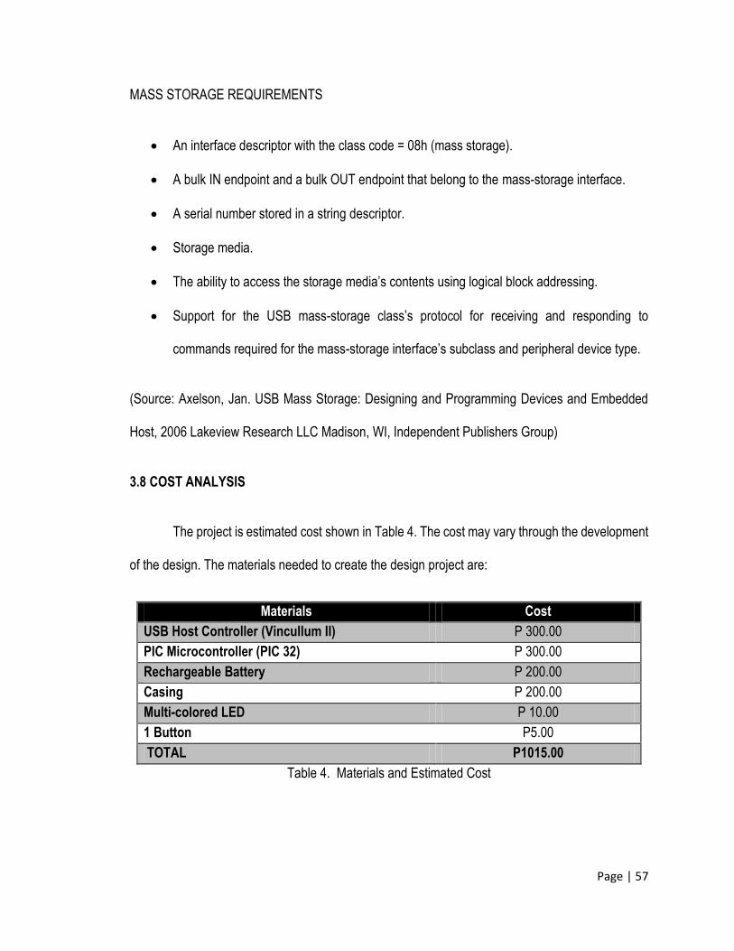
3.8 COST ANALYSIS
The project is estimated cost shown in Table 4. The cost may vary through the development
of the design. The materials needed to create the design project are:
Materials Cost
USB Host Controller (Vincullum II) P 300.00
PIC Microcontroller (PIC 32) P 300.00
Rechargeable Battery P 200.00
Casing P 200.00
Multi-colored LED P 10.00
1 Button P5.00
TOTAL P1015.00
Table 4. Materials and Estimated Cost
Page | 58
ELECTRONIC SOURCES
1. Blanchard, R. (2007, Martch 8). What is the Life Cycle of a USB Flash Drive?. Retrieved July 1, 2013 from http://www.getusb.info/what-is-the-life-cycle-of-a-usb-flash-drive/
2. Janssen, C. (n.d.). Flash Memory. Retrieved July 1, 2013 from http://www.techopedia.com/definition/24481/flash-memory
3. Fisher, T. (n.d.) Flash Drive. Retrieved July 3, 2013 from http://pcsupport.about.com/od/termsag/g/flashdrive.htm
4. Fleming, G. (2013). What Is a Flash Drive. Retrieved July 1, 2013 from http://homeworktips.about.com/od/computertips/qt/flashdrive.htm
5. Gurley, C. (2005, July). What is a USB Flash Drive?. Retrieved July 3, 2013 from http://bama.ua.edu/~gurle001/tutorial.htm
6. Moving or Saving your Data with a USB Flash Drive (n.d.). Retrieved July 3, 2013 from http://www.yulelog.com/USB.htm
7. Radhika S. (2013, April 29). The USB Drive. Yanko Design. Retrieved June 28, 2013 from http://www.yankodesign.com/2013/04/29/the-usb-drive/
8. Sawant, T. & Deshmukh, S. (2013). USB To USB Data Transfer Without PC. International Journal of Electronics Communication and Computer Engineering, Volume 4, Retrieved June 28, 2013 from http://www.ijecce.org/Download/conference/REACT/20_Final.pdf
9. Tan, K. (n.d.). 10 Tools to Protect Computer from Infected USB Flash Drives. Retrieved July 3, 2013 from http://www.hongkiat.com/blog/tools-to-protect-computer-from-infected-usb-drives/
10. Transferring files onto a USB flash drive. Retrieved July 3, 2013 from http://kb.sandisk.com/app/answers/detail/a_id/104/~/transferring-files-onto-a-usb-flash-drive
11. USB Flash Drive. (n.d.) Retrieved July 3, 2013 from http://www.allmemorycards.com/usb-flash-drive.htm
12. USB On-The-Go and Embedded Host (n.d.) Retrieved July 3, 2013 from http://www.usb.org/developers/onthego/
13. USB Made Simple: Part 1 – Introduction to USB Retrieved July 4, 2013 from http://www.usbmadesimple.co.uk/ums_1.htm
14. A Small Case Study: 8-bit, 16-bit, and 32-bit Microcontroller Architectures. Retrieved September 21, 2013 from http://www.coactionos.com/embedded-design/40-8-vs-16-vs-32-bit-microcontrollers.html
Page | 59
PATENTS
1. Kuo, C. & Loo, K.(2006). U.S. Patent No. 11/074,793. Retrieved August 24, 2013, from http://appft1.uspto.gov/netacgi/nphParser?Sect1=PTO1&Sect2=HITOFF&d=PG01&p=1&u=/netahtml/PTO/srchnum.html&r=1&f=G&l=50&s1=20060206631.PGNR.
2. Lee, J., Yao, J., & Zhang A. X.(2012). U.S. Patent No. 13/099,886. Retrieved August 24, 2013, from http://appft1.uspto.gov/netacgi/nphParser?Sect1=PTO1&Sect2=HITOFF&d=PG01&p=1&u= /netahtml/PTO/srchnum.html&r=1&f=G&l=50&s1=20120281347.PGNR.
3. Hitt, D., & Gaines, C. (2008). International Patent No. PCT/US2007/084066. Retrieved August 24, 2013, from http://patentscope.wipo.int/search/en/WO2008143693.
4. Chang, S.W., & Kuo, L.H. (2011). U.S. Patent No. 12/592,089. Retrieved August 24, 2013, from https://www.google.com/patents/US20110119428?dq=Method+Of+Duplicating+Data+To+Multiple+Random+Accessible+Storage+Devices&hl=en&sa=X&ei=ijY9UoSLcKyiAe_1IDgBw&ved=0CDkQ6AEwAA
5. Ishida, T., & Kamahira, Y. (2005). European Patent No. EP20020010402. Retrieved August 25, 2013, from http://worldwide.espacenet.com/publicationDetails/biblio?CC=EP&NR=1260908B1& KC=B1&F T=D.
6. Pocrass, A. (2007). European Patent No. EP20060734237. Retrieved August 25, 2013, from http://worldwide.espacenet.com/publicationDetails/biblio?CC=EP&NR=1851669A2&KC=A2&FT=D
7. Lu, W.C., (2005). U.S. Patent No. 10/822,784. Retrieved August 25, 2013, from http://appft1.uspto.gov/netacgi/nphParser?Sect1=PTO1&Sect2=HITOFF&d=PG01&p=1&u=/netahtml/PTO/ srchnum.html&r=1&f=G&l=50&s1=20050060490.PGNR.
Page | 60
NON-ELECTRONIC SOURCE
1. Axelson, J. (2002 January). No Power Supply Required: Powering USB Devices. Circuit Cellar, pp. 26-30.
2. Bachiochi, J. (2002, June). Smart Media File Storage. Circuit Cellar, pp. 70-75.
3. Bachiochi, J. (2008, October). Get Started with PIC USB Connectivity. Circuit Cellar, pp. 24-33.
4. Cantrell, T. (2001, September). Get Bluetruth. Circuit Cellar, pp. 74-78.
5. Eady, F. (2001 October). The Basics of USB. Circuit Cellar, pp. 48-53.
6. Eady, F. (2010 August). Taking USB Downstream. Nuts and Volts, pp. 54-59.
7. Frenzel, L. (2008, August). Ten Things You May Not Know About Bluetooth: Making Wireless Everywhere Movement Come True. Nuts and Volts, 76-78.
8. Hyde, J. (2007, July). Flash Drive Connection. Circuit Cellar, pp. 59-67.
9. Lemieux, J. (2010 September). Making the SD-USB Connection. Nuts and Volts, pp. 12.
10. Morley M. & Parker, C. (2013). Understanding Computers: Today and Tomorrow: Today and Tomorrow. United States of America: Cengage Learning Education, Ltd.
11. Takefuji, Y. (2008, April). Programmable Power: Build a Simple USB DAC. Circuit Cellar, pp. 35-38.
12. Vermaat, S. (2009). Discovering Computers. United States of America: Cengage Learning, Inc.
13. Axelson, J. (2009). USB Complete Developer’s Guide 4th Edition. Misconsin, United states of America.Lakeview Research LLC.