ch 4 oscillator updated
TRANSCRIPT
EMT 212/4 : Analogue Electronic II
Objectives Describe the basic concept of an oscillator
Discuss the basic principles of operation of an oscillator
Analyze the operation of RC and LC oscillators
Describe the operation of the basic relaxation oscillator circuits
Introduction Oscillator is an electronic circuit that generates a periodic waveform on its output without an external signal source. It is used to convert dc to ac.
Oscillators are circuits that produce a continuous signal of some type without the need of an input.
These signals serve a variety of purposes.
Communications systems, digital systems (including computers), and test equipment make use of oscillators
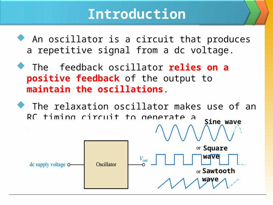
Introduction An oscillator is a circuit that produces a repetitive signal from a dc voltage.
The feedback oscillator relies on a positive feedback of the output to maintain the oscillations.
The relaxation oscillator makes use of an RC timing circuit to generate a nonsinusoidal signal such as square waveSine wave
Square wave
Sawtooth wave
Types of oscillators1. RC oscillators
Wien Bridge Phase-Shift
2. LC oscillators Hartley Colpitts Crystal
3. Unijunction / relaxation oscillators
Feedback Oscillator Principles
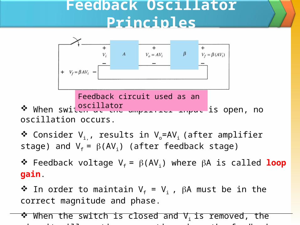
When switch at the amplifier input is open, no oscillation occurs. Consider Vi,, results in Vo=AVi (after amplifier stage) and Vf = (AVi) (after feedback stage) Feedback voltage Vf = (AVi) where A is called loop gain. In order to maintain Vf = Vi , A must be in the correct magnitude and phase. When the switch is closed and Vi is removed, the circuit will continue operating since the feedback voltage is sufficient to drive the amplifier and feedback circuit, resulting in proper input voltage to sustain the loop operation.
Feedback circuit used as an oscillator
Basic principles for oscillation
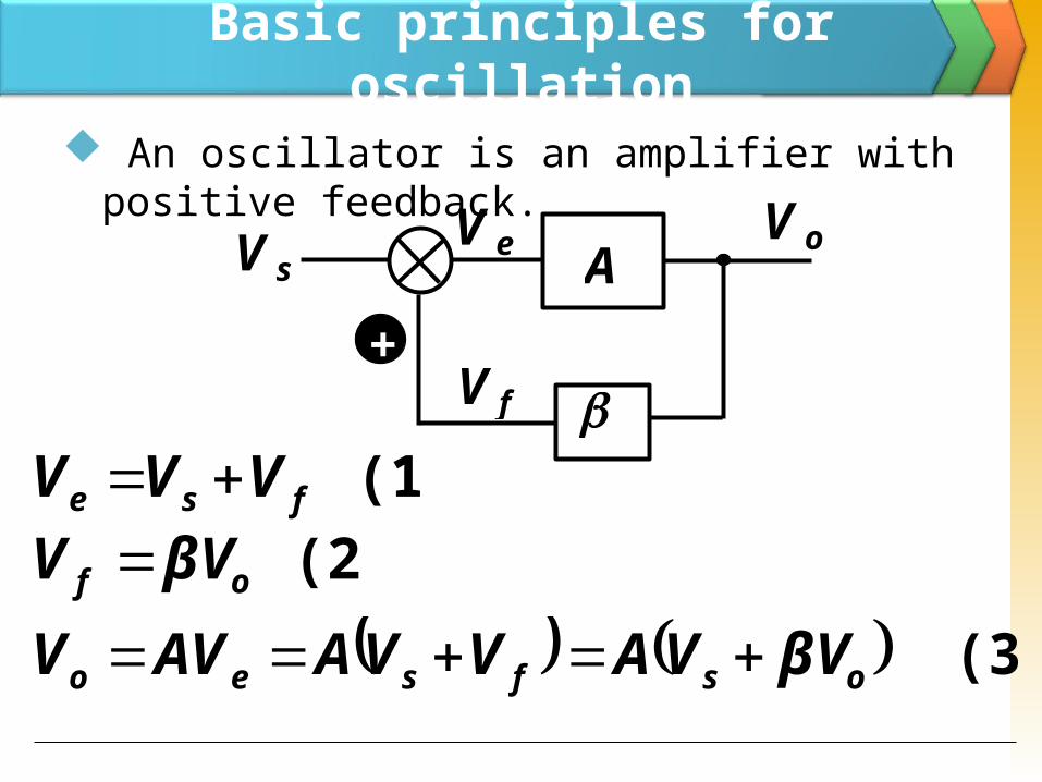
An oscillator is an amplifier with positive feedback.
A
V e
V f
V sV o
+
(1) fse VVV (2) of βVV
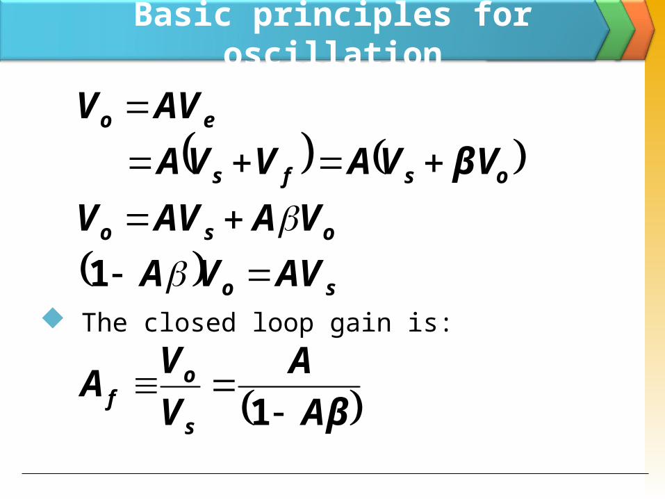
(3) osfseo βVVAVVAAVV
Basic principles for oscillation
The closed loop gain is:
osfs
eo
βVVAVVAAVV
oso VAAVV
so AVVA 1
AβA
VVAs
of
1
Basic principles for oscillation
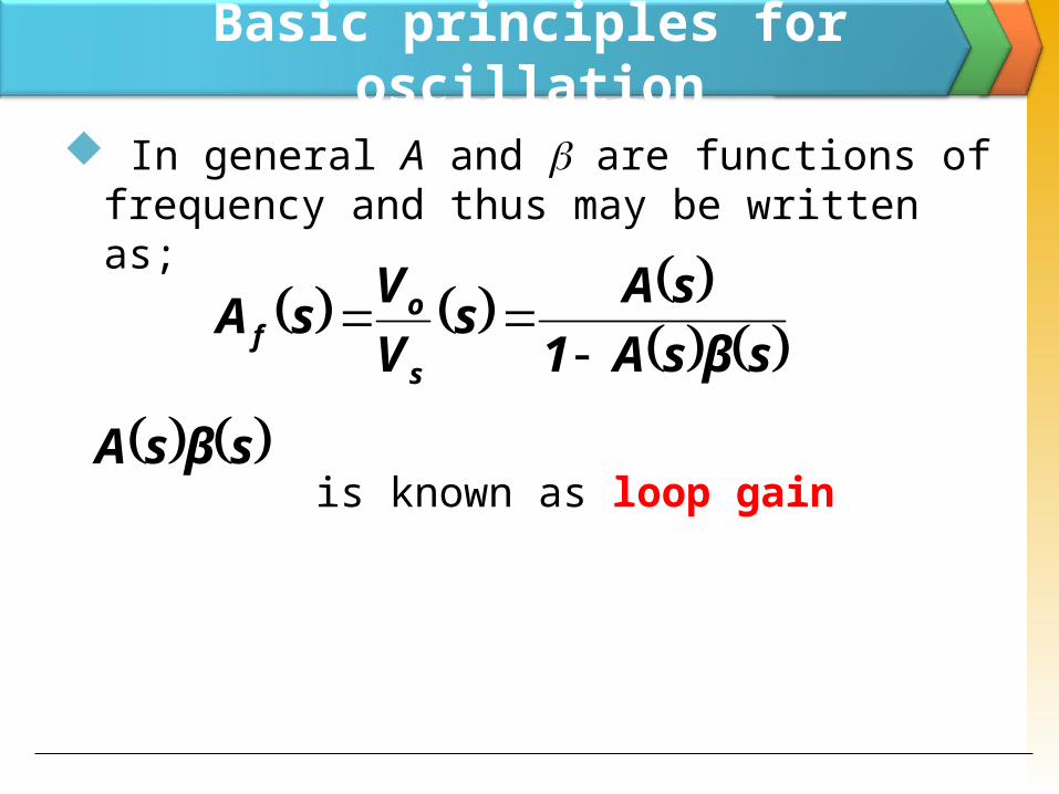
In general A and are functions of frequency and thus may be written as;
is known as loop gain
sβsA1sAs
VVsAs
of
sβsA
Basic principles for oscillation
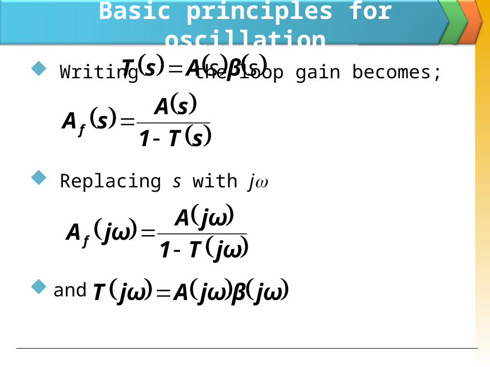
Writing the loop gain becomes;
Replacing s with j
and
ss βAsT
sT1sAsA f
jωT1jωAjωA f
jωβjωAjωT
Basic principles for oscillation
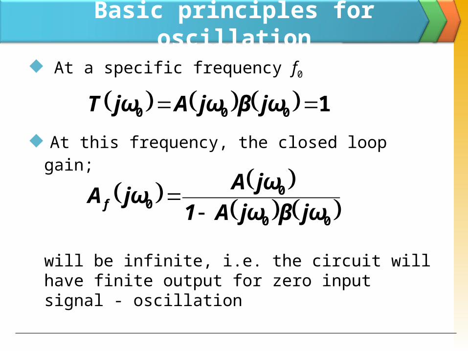
At a specific frequency f0
At this frequency, the closed loop gain;
will be infinite, i.e. the circuit will have finite output for zero input signal - oscillation
1000 jωβjωAjωT
00
00 jωβjωA1
jωAjωA f
Basic principles for oscillation
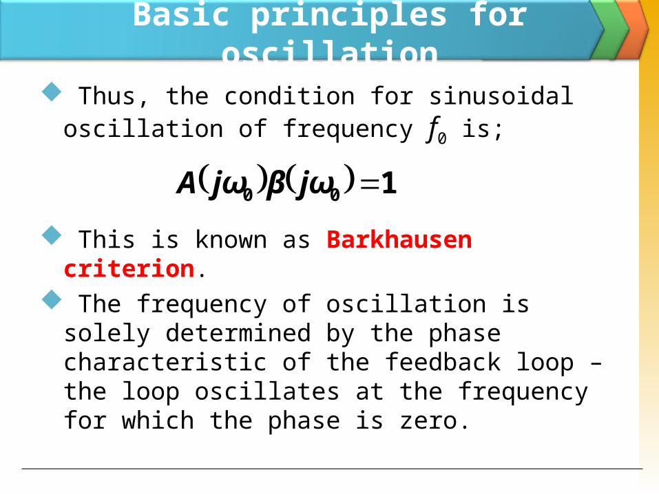
Thus, the condition for sinusoidal oscillation of frequency f0 is;
This is known as Barkhausen criterion.
The frequency of oscillation is solely determined by the phase characteristic of the feedback loop – the loop oscillates at the frequency for which the phase is zero.
100 jωβjωA
Basic principles for oscillation
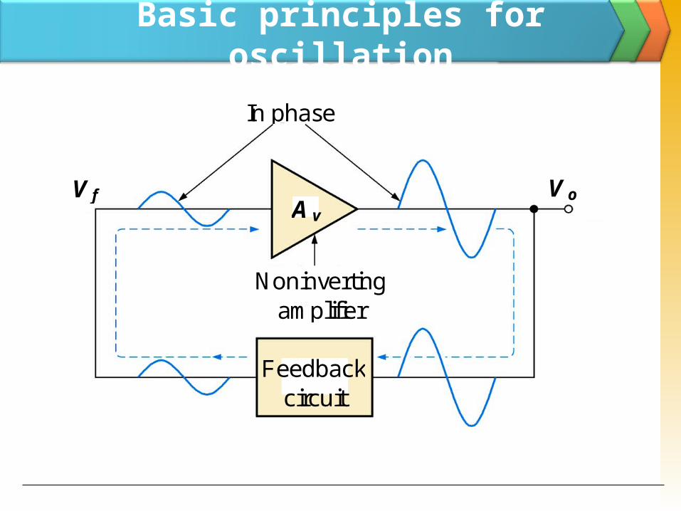
The feedback oscillator is widely used for generation of sine wave signals.
The positive (in phase) feedback arrangement maintains the oscillations.
The feedback gain must be kept to unity to keep the output from distorting.
Basic principles for oscillationIn phase
Noninverting am plifier
V f V oA v
Feedback circuit
Design Criteria for Oscillators
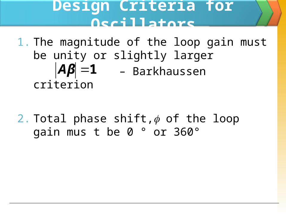
1. The magnitude of the loop gain must be unity or slightly larger
– Barkhaussen criterion
2. Total phase shift, of the loop gain mus t be 0 ° or 360°
1Aβ
RC Oscillators RC feedback oscillators are generally limited to frequencies of 1 MHz or less.
The types of RC oscillators that we will discuss are the Wien-bridge and the phase-shift
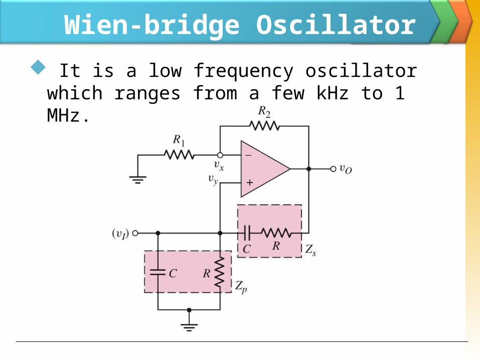
Wien-bridge Oscillator It is a low frequency oscillator which ranges from a few kHz to 1 MHz.
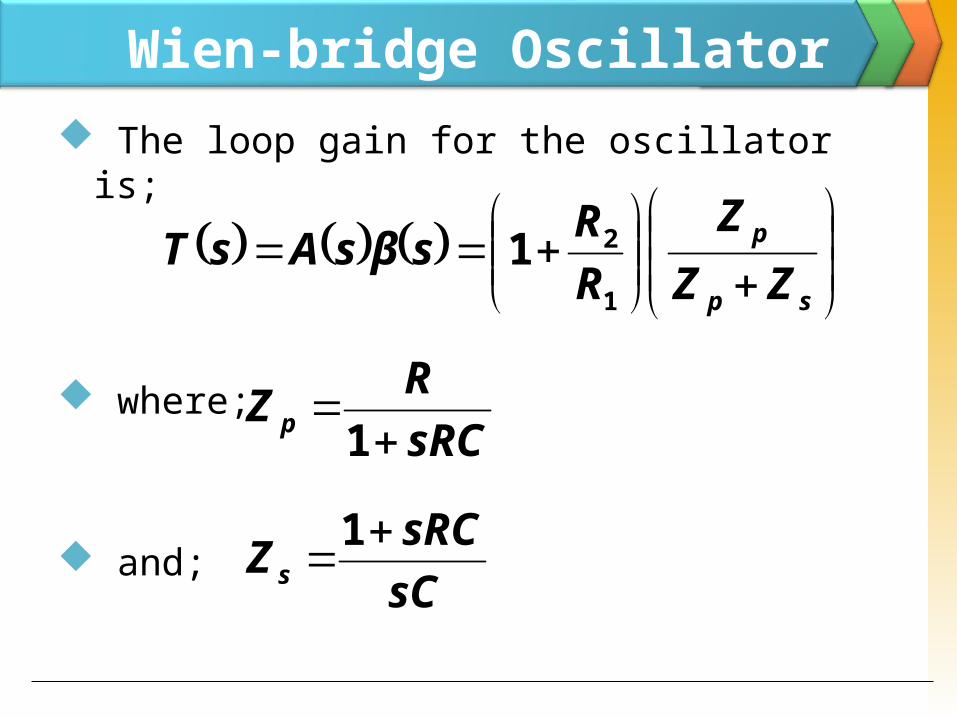
Wien-bridge Oscillator The loop gain for the oscillator is;
where;
and;
sp
p
ZZZ
RRsβsAsT1
21
sRCRZ p
1
sCsRCZ s
1
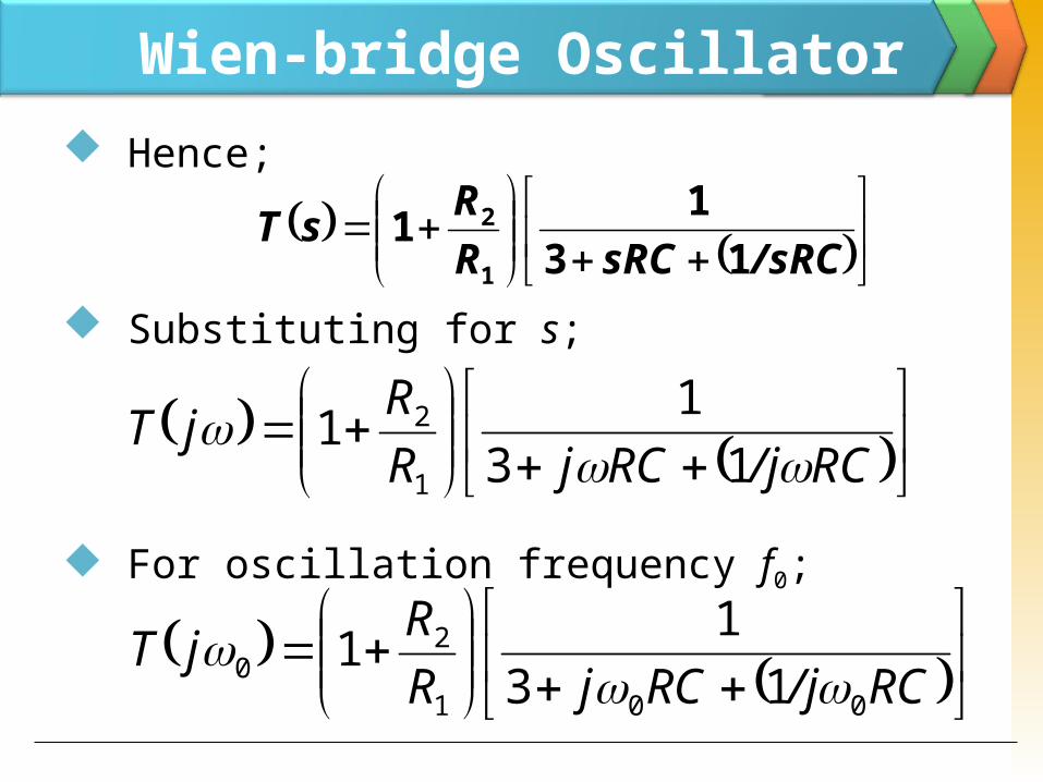
Wien-bridge Oscillator Hence;
Substituting for s;
For oscillation frequency f0;
RC/jRCjRRjT
001
20 13
11
/sRCsRCRRsT 13
111
2
RC/jRCjRRjT
13
111
2
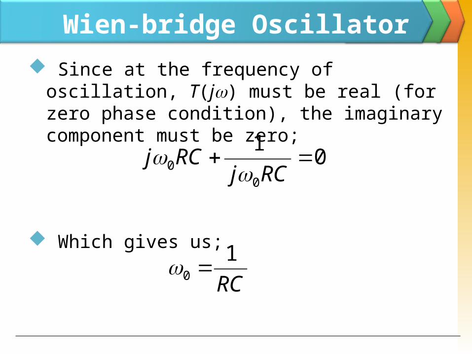
Wien-bridge Oscillator Since at the frequency of oscillation, T(j) must be real (for zero phase condition), the imaginary component must be zero;
Which gives us;
010
0 RCj
RCj
RC1
0
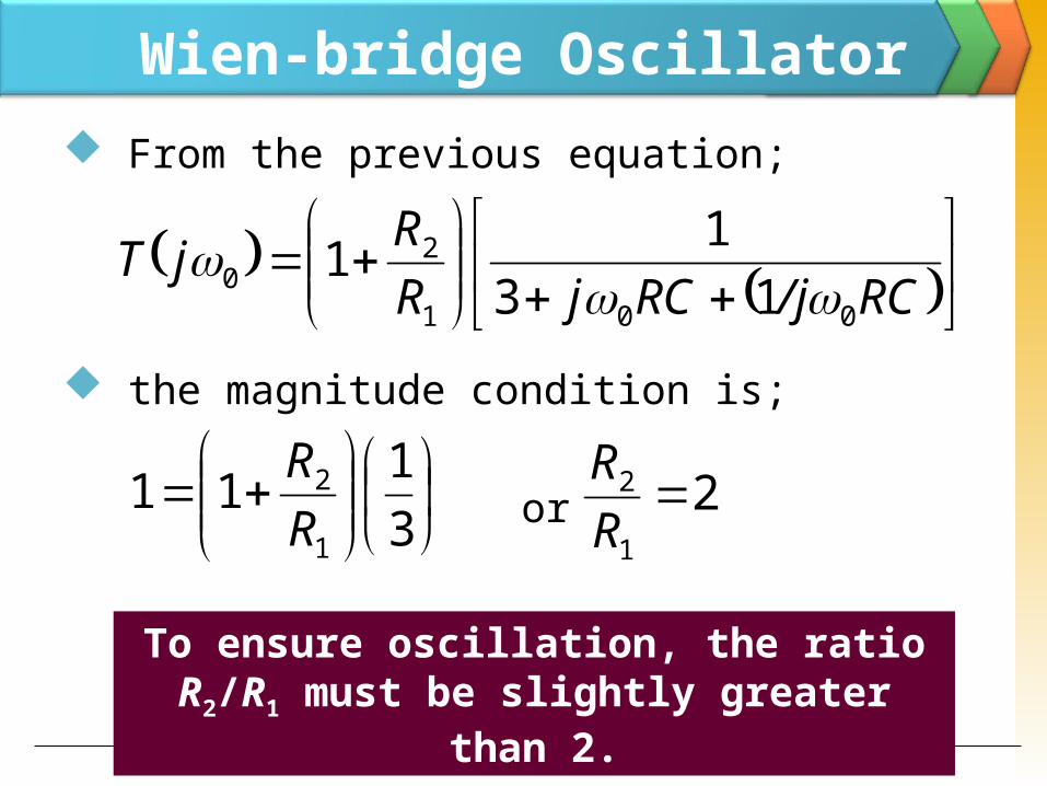
Wien-bridge Oscillator From the previous equation;
the magnitude condition is;
or
3
1111
2RR
RC/jRCjRRjT
001
20 13
11
21
2 RR
To ensure oscillation, the ratio R2/R1 must be slightly greater
than 2.
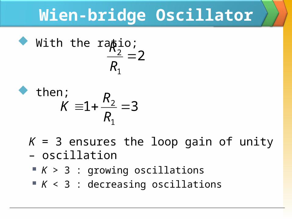
Wien-bridge Oscillator With the ratio;
then;
K = 3 ensures the loop gain of unity – oscillation K > 3 : growing oscillations K < 3 : decreasing oscillations
21
2 RR
311
2 RRK
Phase-Shift Oscillator
.C C C
R R
R
R f
+
V o0 V
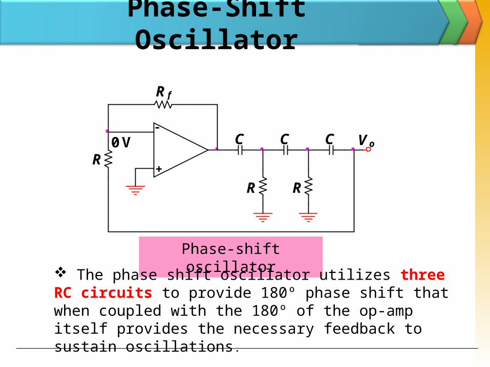
Phase-shift oscillator The phase shift oscillator utilizes three
RC circuits to provide 180º phase shift that when coupled with the 180º of the op-amp itself provides the necessary feedback to sustain oscillations.
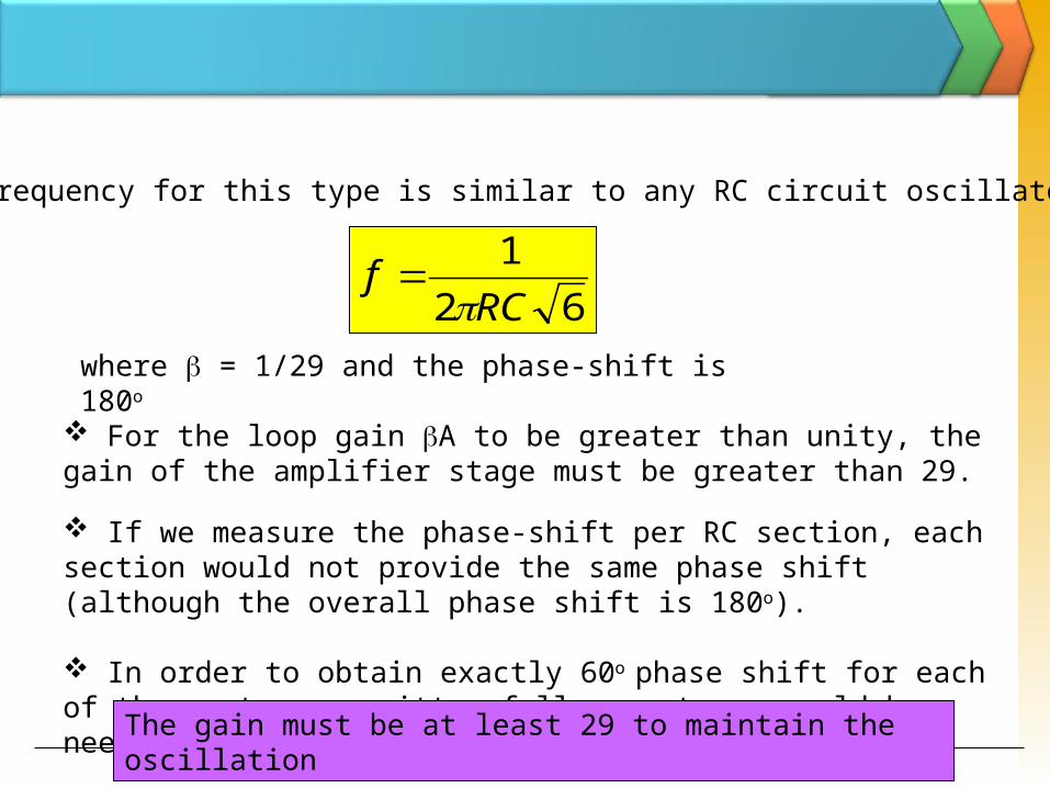
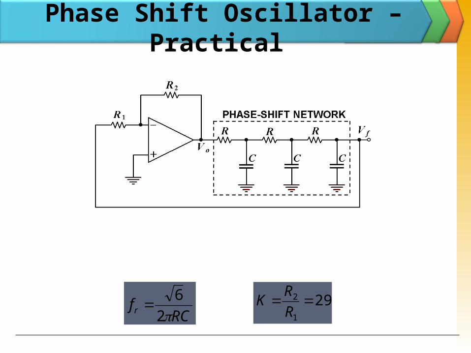
The frequency for this type is similar to any RC circuit oscillator :
621
RCf
where = 1/29 and the phase-shift is 180o
For the loop gain A to be greater than unity, the gain of the amplifier stage must be greater than 29. If we measure the phase-shift per RC section, each section would not provide the same phase shift (although the overall phase shift is 180o).
In order to obtain exactly 60o phase shift for each of three stages, emitter follower stages would be needed for each RC section.The gain must be at least 29 to maintain the
oscillation
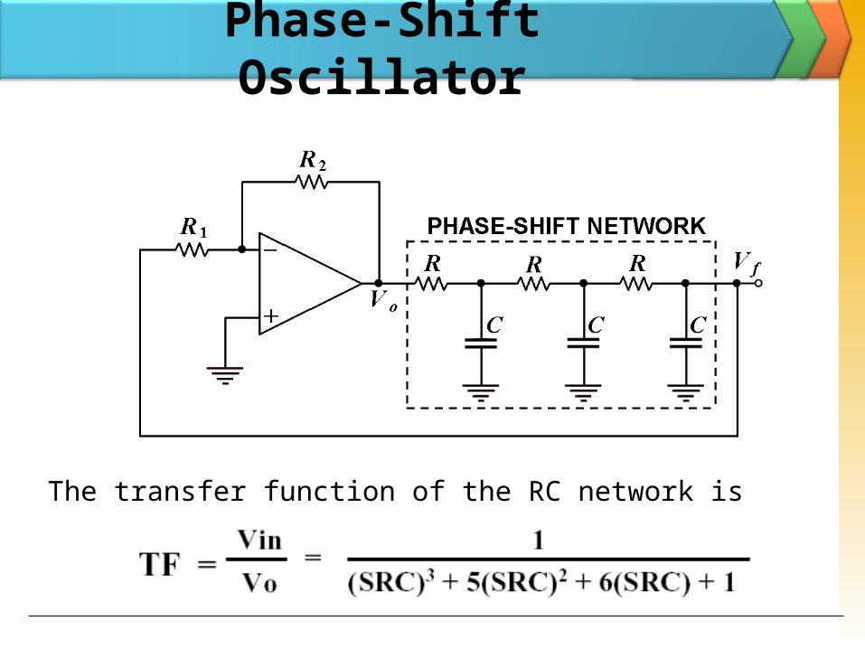
The transfer function of the RC network is
Phase-Shift Oscillator
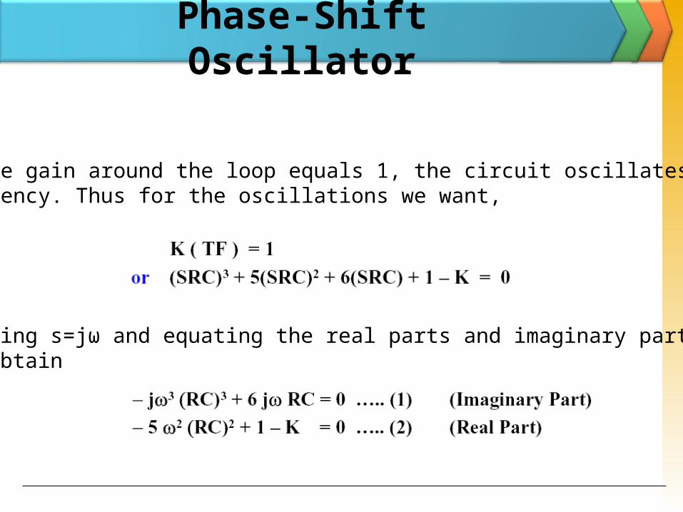
If the gain around the loop equals 1, the circuit oscillates at thisfrequency. Thus for the oscillations we want,
Putting s=jω and equating the real parts and imaginary parts,we obtain
Phase-Shift Oscillator
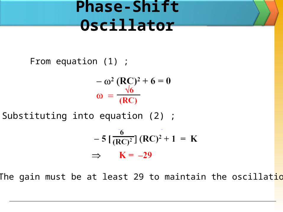
From equation (1) ;
Substituting into equation (2) ;
# The gain must be at least 29 to maintain the oscillations.
Phase-Shift Oscillator
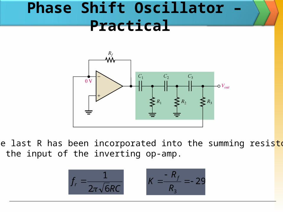
Phase Shift Oscillator – Practical
RCfr 2
6 29
1
2 RRK
Phase Shift Oscillator – Practical
RCfr 62
1
293
RR
K f
The last R has been incorporated into the summing resistors at the input of the inverting op-amp.
LC Oscillators Use transistors and LC tuned circuits or crystals in their feedback network.
For hundreds of kHz to hundreds of MHz frequency range.
Examine Colpitts, Hartley and crystal oscillator.
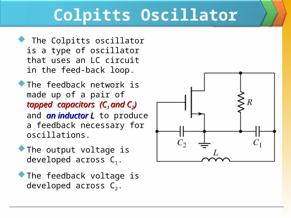
Colpitts Oscillator The Colpitts oscillator is a type of oscillator that uses an LC circuit in the feed-back loop.
The feedback network is made up of a pair of tappedtapped capacitorscapacitors (C(C1 1 and Cand C22)) and an inductor Lan inductor L to produce a feedback necessary for oscillations.
The output voltage is developed across C1.
The feedback voltage is developed across C2.
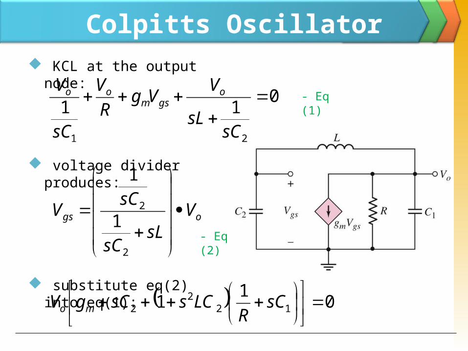
Colpitts Oscillator KCL at the output node:
voltage divider produces:
substitute eq(2) into eq(1):
01121
sCsL
VVgRV
sC
V ogsm
oo
ogs VsL
sC
sCV
2
21
1
011 122
2
sC
RLCssCgV mo
- Eq (1)
- Eq (2)
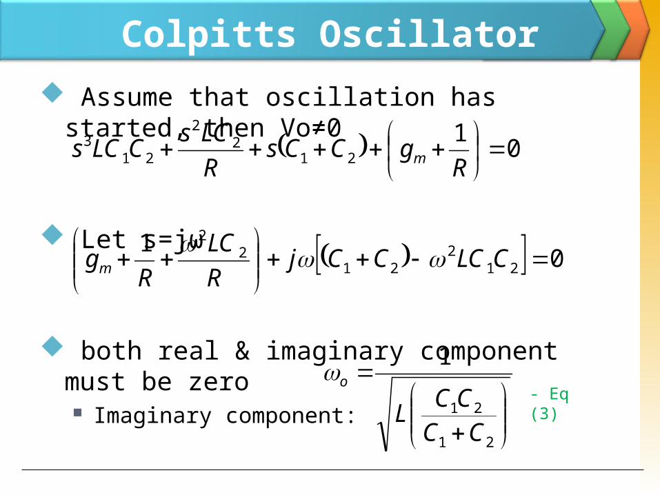
Colpitts Oscillator Assume that oscillation has started, then Vo≠0
Let s=jω
both real & imaginary component must be zero Imaginary component:
0121
22
213
RgCCs
RLCsCLCs m
0121
221
22
CLCCCj
RLC
Rgm
21
21
1
CCCCL
o- Eq (3)
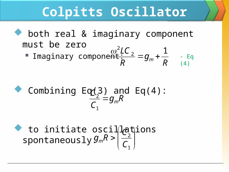
Colpitts Oscillator both real & imaginary component must be zero Imaginary component:
Combining Eq(3) and Eq(4):
to initiate oscillations spontaneously:
Rg
RLC
m12
2
RgCC
m1
2
1
2CCRgm
- Eq (4)
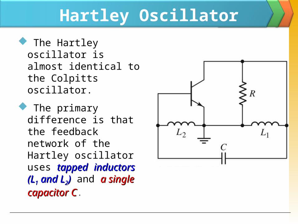
Hartley Oscillator The Hartley oscillator is almost identical to the Colpitts oscillator.
The primary difference is that the feedback network of the Hartley oscillator uses tappedtapped inductors inductors (L(L11 and L and L22)) and a single a single capacitor Ccapacitor C.
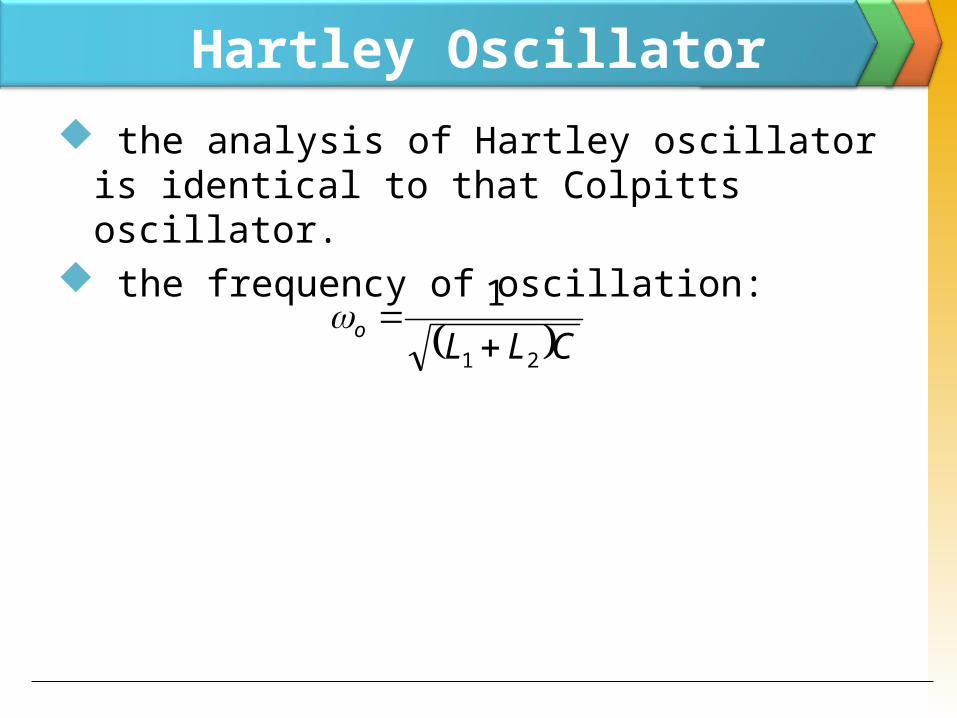
Hartley Oscillator the analysis of Hartley oscillator is identical to that Colpitts oscillator.
the frequency of oscillation: CLLo
21
1
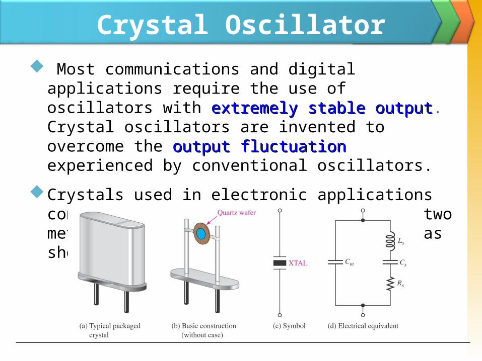
Crystal Oscillator Most communications and digital applications require the use of oscillators with extremely stable outputextremely stable output. Crystal oscillators are invented to overcome the output fluctuationoutput fluctuation experienced by conventional oscillators.
Crystals used in electronic applications consist of a quartz wafer held between two metal plates and housed in a a package as shown in Fig. 9 (a) and (b).
Crystal Oscillator Piezoelectric Effect
The quartz crystal is made of silicon oxide (SiO2) and exhibits a property called the piezoelectricpiezoelectric
When a changing an alternating voltage is applied across the crystal, it vibrates at the frequency of the applied voltage. In the other word, the frequency of the applied ac voltage is equal to the natural resonant frequency of the crystal.
The thinner the crystal, higher its frequency of vibration. This phenomenon is called piezoelectric effect.
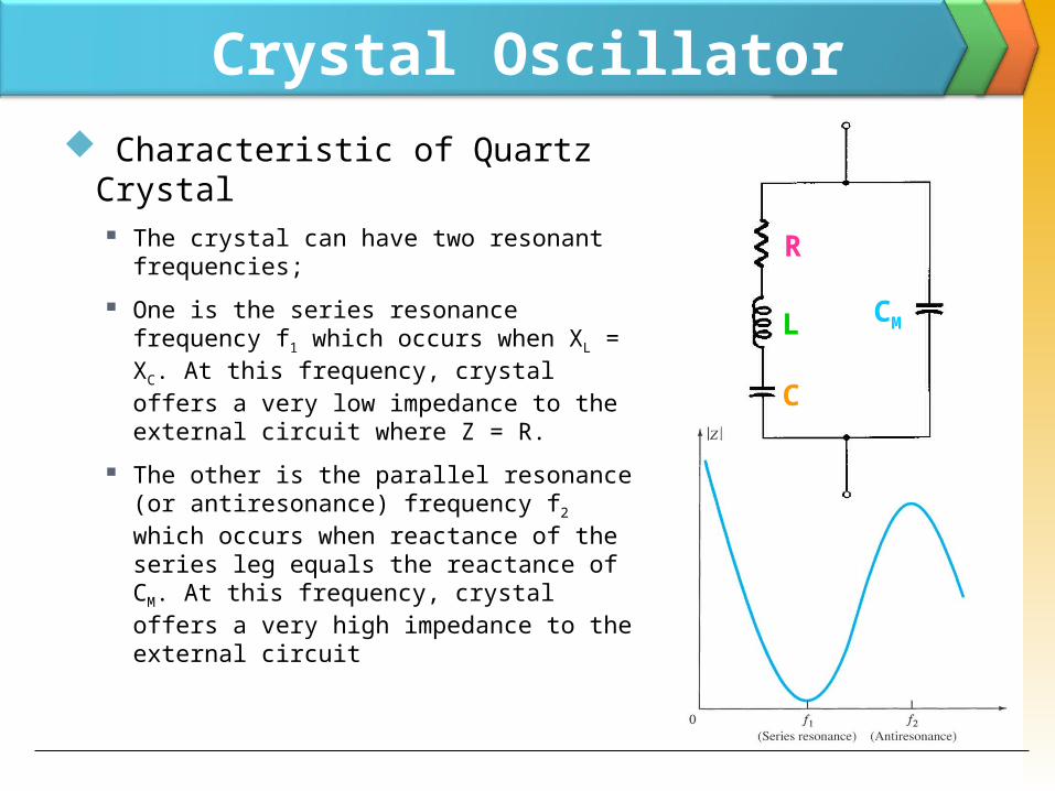
Crystal Oscillator Characteristic of Quartz Crystal
The crystal can have two resonant frequencies;
One is the series resonance frequency f1 which occurs when XL = XC. At this frequency, crystal offers a very low impedance to the external circuit where Z = R.
The other is the parallel resonance (or antiresonance) frequency f2 which occurs when reactance of the series leg equals the reactance of CM. At this frequency, crystal offers a very high impedance to the external circuit
R
L
C
CM
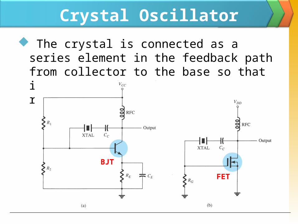
Crystal Oscillator The crystal is connected as a series element in the feedback path from collector to the base so that it is excited in the series-resonance mode
BJTFET
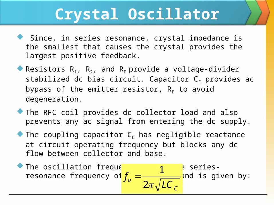
Crystal Oscillator Since, in series resonance, crystal impedance is
the smallest that causes the crystal provides the largest positive feedback.
Resistors R1, R2, and RE provide a voltage-divider stabilized dc bias circuit. Capacitor CE provides ac bypass of the emitter resistor, RE to avoid degeneration.
The RFC coil provides dc collector load and also prevents any ac signal from entering the dc supply.
The coupling capacitor CC has negligible reactance at circuit operating frequency but blocks any dc flow between collector and base.
The oscillation frequency equals the series-resonance frequency of the crystal and is given by:
Co LC
f21
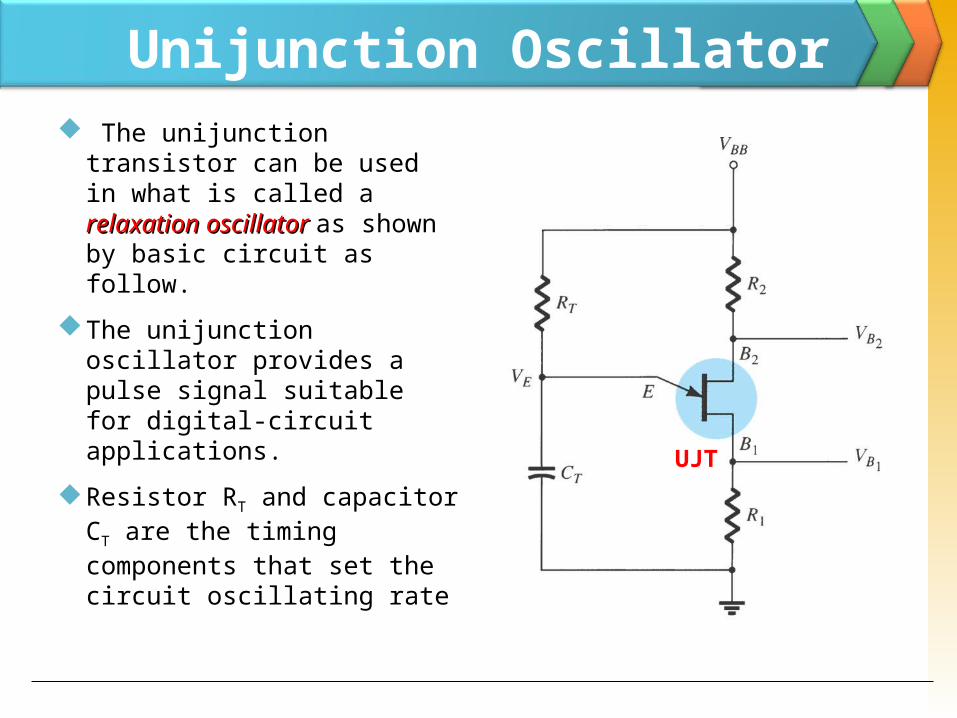
Unijunction Oscillator The unijunction transistor can be used in what is called a relaxation oscillatorrelaxation oscillator as shown by basic circuit as follow.
The unijunction oscillator provides a pulse signal suitable for digital-circuit applications.
Resistor RT and capacitor CT are the timing components that set the circuit oscillating rate
UJT
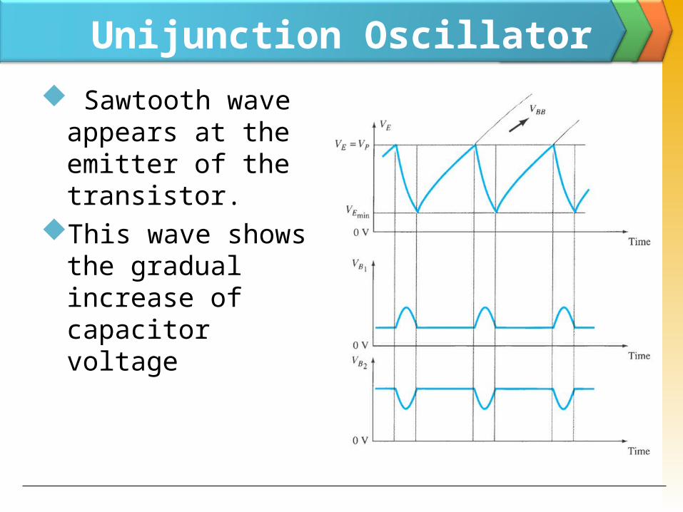
Unijunction Oscillator Sawtooth wave appears at the emitter of the transistor.
This wave shows the gradual increase of capacitor voltage
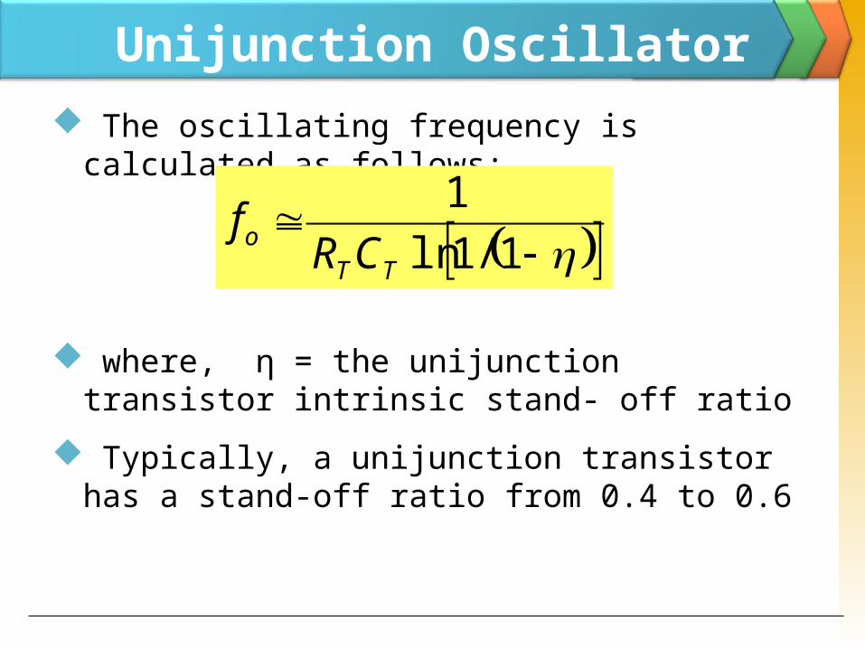
Unijunction Oscillator The oscillating frequency is calculated as follows:
where, η = the unijunction transistor intrinsic stand- off ratio
Typically, a unijunction transistor has a stand-off ratio from 0.4 to 0.6
1/1ln
1TT
o CRf