cellular network formation of hydrophobic alkanethiol capped gold nanoparticles on mica surface...
TRANSCRIPT

Cellular network formation of hydrophobic alkanethiol capped goldnanoparticles on mica surface mediated by water islands
Neena S. John,1,a� Gargi Raina,2 Ashutosh Sharma,3,b� and Giridhar U. Kulkarni1,c�
1Chemistry and Physics of Materials Unit, DST Unit on Nanoscience and CSIR Centre of Excellence inChemistry, Jawaharlal Nehru Centre for Advanced Scientific Research, Jakkur P.O.,Bangalore 560064, India2School of Electrical Sciences, Vellore Institute of Technology, Vellore 632014, India3Department of Chemical Engineering, Indian Institute of Technology, Kanpur 208016, India
�Received 25 June 2010; accepted 11 August 2010; published online 7 September 2010�
Dendritic and cellular networks of nanoparticles are known to form commonly either by randomdiffusion-limited aggregation or by solvent evaporation dynamics. Using alkanethiol capped goldnanoparticles deposited on mica imaged under ambient and controlled water vapor conditions byatomic force microscope and in situ scanning electron microscope, respectively, we show a thirdmechanism in action. The cellular network consisting of open and closed polygons is formed by thenucleation and lateral growth of adsorbed water islands, the contact lines of which push therandomly distributed hydrophobic nanoparticles along the growth directions, eventually leading tothe polygonal structure formation as the boundaries of the growing islands meet. Such nanoparticledisplacement has been possible due to the weakly adhering nature of the hydrophilic substrate, mica.These results demonstrate an important but hitherto neglected effect of adsorbed water in thestructure formation on hydrophilic substrates and provide a facile tool for the fabrication ofnanoparticle networks without specific particle or substrate modifications and without a tight controlon particle deposition conditions during the solvent evaporation. © 2010 American Institute ofPhysics. �doi:10.1063/1.3484941�
I. INTRODUCTION
Stability, aggregation, and pattern formation in nanopar-ticles on surfaces are of interest in both scientific and tech-nological research. Particles are usually coated with passivat-ing molecules to prevent against surface modification andagglomeration upon removal of the dispersing medium in theambient. In the recent years, the use of self-assembling mol-ecules to cap nanoparticles enabled direct assembly of par-ticles as against simple aggregation. For instance, monodis-persed metal1–3 and semiconductor4 nanocrystals have beencoated with a variety of molecules, such as alkanethiols,alkylamines, and fatty acids, and biomolecules, such asDNA, etc.,5 and programed assemblies have been obtained inone, two, and three dimensions. By coating with polymericligands, giant clusters of nanocrystals of definite nuclearityhave also been obtained.6 The research in this area has alsobeen motivated by the fascinating electrical, optical, andmagnetic properties exhibited by nanocrystal assembliesconstituting metals, semiconductors, or binary alloys thatfind applications in nanodevices.7–9 The simplest method ofobtaining mesoscalar arrays is by the spontaneous aggrega-tion of particles either reversibly or irreversibly to form cel-lular networks or dendrimeric assemblies. Such irreversiblekinetic aggregation of colloids has been observed in sootparticles, citrate stabilized gold nanocrystals in aqueous me-dium coagulated by adding pyridine, and also on surfaces
when the dispersion medium is allowed to evaporate, leavingbehind the nanoparticles. The spontaneous aggregation ofnanoparticles on surfaces when the solvent is allowed toevaporate has been utilized to get various nanostructures inthe form of rings and other shapes.10 The mechanism in theabove case was explained by the Marangoni convection, asalso is the case of pattern formation by an evaporating sol-vent drop on a soluble polymer layer.11 Moriarty et al.12 re-ported the formation of cellular networks of Au nanocrystalscapped with alkanethiols when spin coated with a toluenesolution of the nanocrystals on a silicon surface. Extensiveexperiments involving the dewetting of thin films and simu-lations have provided important insights into the mechanismunderlying the formation of such networks mediated by theformation, growth, and coalescence of holes in the solventlayer carrying the particles.13–19 Fractal and tessellationanalyses of the patterns and nanoparticle distribution havealso aided the understanding of growth mechanisms.12,20–24
For describing the scale invariance of the geometrical ar-rangement of the particles in a cluster, fractal dimension is afrequently used parameter in the theoretical as well as theexperimental investigations. Experimentally, direct particlesize analyses from transmission electron microscope �TEM�and atomic force microscope �AFM�/scanning tunneling mi-croscope images and indirect analyses from optical as well asneutron scattering measurements are the usual methods fordetermining the fractal dimension.
While earlier studies have focused on the role of solventevaporation in obtaining different nanoparticle assemblies onsurfaces, we show here that the nucleation and growth of
a�Electronic mail: [email protected]�Electronic mail: [email protected]�Electronic mail: [email protected].
THE JOURNAL OF CHEMICAL PHYSICS 133, 094704 �2010�
0021-9606/2010/133�9�/094704/7/$30.00 © 2010 American Institute of Physics133, 094704-1
Author complimentary copy. Redistribution subject to AIP license or copyright, see http://jcp.aip.org/jcp/copyright.jsp
adsorbed water microdomains on the substrate play an im-portant role in the formation of hydrophobic nanoparticlenetworks on hydrophilic substrates. Although it is knownthat water vapor adsorbed on hydrophilic mica shows fasci-nating dynamics and order,25 its role in pattern formation ofnanoparticles has not been appreciated. In order to examinethe role of adsorbed/condensed water islands in the forma-tion of network, we report in situ experiments on the aggre-gation of thiol capped Au nanoparticles on mica with theintroduction of water vapor in the vacuum chamber of afield-emission scanning electron microscope �SEM�. We alsocompare these results to a more common, but less controlled,experimental protocol where the particle aggregation is in-duced under the ambient conditions and observed by AFM.Under the ambient conditions, we track the particle aggrega-tive patterns at various time intervals and could thus analyzedifferent stages of pattern formation. We show that relativelybig isolated clusters of nanoparticles deposited by solventevaporation are gradually transformed first to branched net-works and then to a closed polygonal network as the timeprogresses. Further, by examining the size dependent mobili-ties of nanoparticle clusters, we suggest that the networkstructure is not caused by a simple random diffusion-limitedgrowth, but that the presence of water plays an active role inthe network formation. Tesellation and fractal analyses havebeen performed on the network structures. Understanding themechanisms involved in the condensation and growth ofnanoparticle aggregates should provide more control andflexibility in the organization of nanoparticles for specificapplications.
II. EXPERIMENTAL METHODS
Au nanoparticles capped with dodecanethiol were pre-pared following the method of Brust et al.26 Briefly, 1 ml�25 mM� HAuCl4 in 10 ml water was phase transferred to thetoluene by vigorously shaking it with 220 mg of tetraocty-lammonium bromide in toluene layer, followed by the addi-tion of 82 �l of dodecanethiol and reduction with 10 ml of0.2M sodium borohydride in water. The nanocrystals werepurified by repeated precipitation with excess methanol andredispersed in toluene for further use. Transmission electronmicroscopic measurements were carried out with aJEOL-3010 TEM operating at 300 kV. Samples for TEMwere prepared by evaporating a drop of toluene solution on aholey carbon copper grid.
AFM characterization was performed using CP-II AFMsetup �Veeco Metrology, Santa Barbara�. The imaging wasdone in noncontact ac mode using a Si cantilever with aresonant frequency of 270 Hz under ambient conditions�relative humidity of �40%�. 10 �l of the dilute dispersion�ten times the dilution of the original solution� of the par-ticles in toluene was drop cast on a mica surface for AFMstudies. The mica surface was freshly cleaved before thedeposition of particles so that the surface is free of any waterfilm or foreign particles and thereafter stored in ambient forspontaneous evaporation of the solvent.
High resolution scanning electron microscopy was pre-formed using a field-emission SEM �Nova NanoSEM600,
FEI, The Netherlands� operating at 0.5–1 kV beam voltage.In the high vacuum mode, through-lens detector was em-ployed, while in low vacuum mode, a helix detector wasemployed to obtain high resolution images. In order to studythe influence of water film on the organization of particles onmica, water vapor �0.4–0.9 Torr� was introduced into theSEM chamber for several minutes, in the “environmentallow vacuum mode.” Images were captured while the vaporwas on or off.
III. RESULTS
With the mica surface being hydrophilic, it hosts waterin the form of islands when exposed to ambient conditions,as described in several studies.27–29 Thus, the nanoparticleson the mica surface is actually an intricate three-phase sys-tem of substrate-adsorbed water islands-air with nanopar-ticles where the aggregation of nanoparticles produces an-other microphase. Here, the organization of nanoparticlesshould be determined not only by their interactions with thesubstrate but also by the morphology and dynamics of waterislands. Further, interactions with the adsorbed water alsodepend on the particle surface hydrophobicity, which couldbe modified by a hydrophobic ligand. In this context, waterinsoluble hydrophobic nanoparticles showing little adhesionto hydrophilic mica are preferred because their aggregationcould be easily directed by the three-phase contact lines ofwater islands that could push particles without engulfingthem.
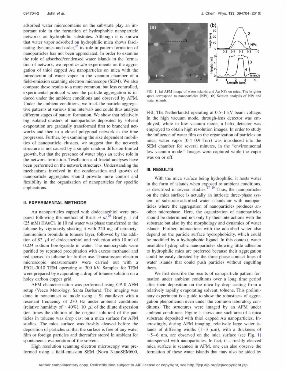
We first describe the results of nanoparticle pattern for-mation under ambient conditions over a long time periodafter their deposition on the mica by drop casting from arelatively rapidly evaporating solvent, toluene. This prelimi-nary experiment is a guide to show the robustness of aggre-gation phenomenon even under the common laboratory con-ditions. The structures were imaged by an AFM underambient conditions. Figure 1 shows one such area of a micasubstrate deposited with thiol capped Au nanoparticles. In-terestingly, during AFM imaging, relatively large water is-lands of differing widths �1–3 �m�, with a thickness of�5–6 nm, are observed on the mica surface �see Fig. 1�interspersed with nanoparticles. In fact, if a freshly cleavedmica surface is scanned in AFM, one can also observe theformation of these water islands that may also be aided by
FIG. 1. �a� AFM image of water islands and Au NPs on mica. The brighterspots correspond to nanoparticles �NPs�. �b� Section analysis of NPs andwater islands.
094704-2 John et al. J. Chem. Phys. 133, 094704 �2010�
Author complimentary copy. Redistribution subject to AIP license or copyright, see http://jcp.aip.org/jcp/copyright.jsp

the condensation of water from nanometric AFM tip to thesurface by capillary action.28 Section analysis of the nano-particles on the mica surface gives the height variation in therange of tens of nanometers, while the diameters are in therange of hundreds of nanometers, indicating that these arenearly two-dimensional �2D� aggregates of nanoparticles�Fig. 1�b��. The mean individual particle size estimated fromTEM analysis is �3 nm.30 Hence, solvent evaporation upondeposition on mica leads to the aggregated nanoparticle clus-ters. From the AFM height profile analysis, hundreds ofnanoparticles are present in an aggregated cluster.
The formation of nanoparticle aggregates on the surfacefollowing solvent evaporation is a commonly observed phe-nomenon and may arise due to the solvent dewettingmechanisms.31 However, the particle aggregation observed inthis study may have a contribution from water islands aswell.
The mobile nature of Au nanoparticles over the micasurface is confirmed from the AFM images captured within a15 min interval, as shown in Fig. 2. The water islands seen inFig. 1 formed via condensation from the AFM tip must have
evaporated in the course of time, leaving a molecularly thinwater layer on the mica surface28 that is not visible in thegiven z-range of the AFM image. Figure 2�a� shows an areaselected for nanomanipulation comprising of comparativelysmaller aggregates widely separated from each other by anaverage distance of 200 nm. Although the height profiles ofvery small aggregates correspond to the diameter of an indi-vidual particle �see the height profile of feature “a”�, thelateral dimensions �28–45 nm� are larger than the verticalheight. The figure also shows some bigger features wherediameters are several times higher than the individual nano-particles. Thus, the diameters of features b–e are in the rangeof 50–90 nm, with heights in the range of 5–8 nm �see Fig.2�a��. The height profiles of bigger aggregates, “d” and “e,”are also shown in Fig. 2�a�. The number of nanoparticleswithin an aggregate also scales with the aggregate size.30
However, aggregates with diameters in the range of 28–45nm show a dispersion in the number of particles they con-tain, which might be arising from the original particle sizedistribution. These aggregates contain only a monolayer ofparticles, while larger diameter aggregates contain almost abilayer or multilayers of nanoparticles. The formation ofspherical aggregates randomly distributed shows that the di-rective nature of the thiols to form an assembly has vanishedin this case.
We tried to push the aggregate with the AFM tip�marked as e in Fig. 2�a�� in the lateral direction �indicatedby the arrow in Fig. 2�a��. In Fig. 2�b�, we show the result ofnanomanipulation, which reveals that the parent aggregate esplit into two other features: e2 and e3. We observe that theparent aggregate has retained some amount of material�marked as e1 in Fig. 2�b��. All the three aggregates, e1, e2,and e3, seem to lie in the direction along which nanomanipu-lation was carried out �see the dotted line in the figure�. Asimple calculation gives the volume of daughter aggregatesas �12 304 nm3, which is slightly larger than the parentaggregate, �11 608 nm3. This may be because of the addi-tion of some nanocrystals in the path of manipulation, fromeither the surface or the tip itself, or the breaking cluster mayhave become slightly more porous.
We have calculated the displacement of the aggregates inthe image frames given in Figs. 2�a� and 2�b�, captured in aninterval of a few minutes, to examine their mobile nature.Almost 30 aggregates from two successively captured AFMimages have been analyzed to arrive at the plot of mobility ofaggregates. In Fig. 3, the vectorial �x,y� displacements ofaggregates of various sizes are presented. The volumes werecalculated from the measured diameter and height values as-suming a spherical cap shape. Interestingly, there is no trendin the displacement with the cluster size. In particular, a largedispersion in the displacement is observed for aggregates ofsmaller sizes. Medium sized aggregates are not found tomove a whole lot, while a relatively large aggregate seems tohave been displaced considerably.
When the sample was kept undisturbed in a dust freeenvironment but still in ambient for several weeks, we ob-served a progressive aggregation of nanoparticles. The AFMimages shown in Fig. 4 are a typical illustration of the ag-gregation process in its different stages. After 3 weeks of
FIG. 2. �a� AFM topography of dodecanethiol capped Au nanoparticles asdeposited on a freshly cleaved mica surface. The particle marked a repre-sents an individual particle whose z profile is shown along side, with z=2.8 nm. The particles marked b–f are bigger aggregates, the z profile of dand e are shown, with z=8 and 5.2 nm. Aggregate e with a black arrowshows the direction in which it was laterally pushed using the nanomanipu-lation utility. �b� AFM image showing the status after nanomanipulation.Aggregate e got split into e1, e2, and e3 �lying on dotted line� and theircorresponding height profiles are given.
094704-3 Cellular network of nanoparticles on mica J. Chem. Phys. 133, 094704 �2010�
Author complimentary copy. Redistribution subject to AIP license or copyright, see http://jcp.aip.org/jcp/copyright.jsp

exposure to ambient, particle aggregation leading tobranched chain structures is seen by AFM imaging �Fig.4�a��. The formation of a cellular network nanostructure isclearly observed. Intense bright spots in the image corre-spond to dense aggregates. Figure 4�b� gives the AFM imageof the sample captured after a few more days of exposure toambient, showing a fully developed network structure. Thecell-to-cell distance is in the range of 1–1.6 �m. A cross- sectional profile taken across the polygon side �Fig. 5�a��
shows the height to be 15 nm, indicating that the brighterspots consist of multilayers of nanoparticles. A height varia-tion of 5–25 nm is observed for less bright spots to intensebright spots corresponding to a monolayer and multilayers ofAu nanoparticles, respectively. The larger aggregates seen inFig. 4�a� become relatively immobile, but the individualnanoparticles continue to diffuse to complete the polygonalsides, leading to the closed network structure in Fig. 4�b�.Gold nanoparticles coated with dodecanethiol are hydropho-bic and thus should readily diffuse on the hydrophilic micasurface, which may also be covered by a monolayer or apartial monolayer of water. This is also evident from the easeof displacing the clusters in our nanomanipulation experi-ments where the particles exhibited negligible adhesion tothe substrate.
The nature of the cellular networks formed by nanopar-ticles has been examined in detail. A statistical analysis ofthe tessellation was performed.32 Figure 5�a� is a representa-tion of how the polygons have been drawn over the networkfor the analysis. Several large area AFM images were con-sidered for this purpose. The tessellation analysis gives ahistogram of polygon sidedness distribution with a meanvalue of 5.4, as shown in Fig. 5�b�. The value is slightly lessthan 6, which is expected for a stable network and might bean indication of the network coarsening.32
In order to examine the role of water islands in the for-mation of network, in situ experiments were performed inthe vacuum chamber of a field-emission SEM with gradualintroduction of water vapor. Thiol capped Au nanoparticleswere deposited on a freshly cleaved mica surface, which wasthen immediately introduced into the vacuum chamber. TheSEM image in Fig. 6�a� shows the presence of already ag-gregated particles left by the vaporization of toluene. Subse-
FIG. 3. A plot of the vectorial �x,y� displacement of the aggregates withvarious volumes. The displacement was calculated from the Cartesian coor-dinates of the aggregates with respect to the aggregate “f” �shown in Fig.2�a��, taken as the origin. Aggregate f, being a larger aggregate, is assumedto be immobile and aggregate e is not considered. The size of the circularsymbols is depicted to increase with volume.
FIG. 4. AFM topography of the different stages of the growth of thiolcapped Au NPs on the mica surface. �a� The intermediate stage before theclosing of the branches to form polygonal network. �b� The cellular networkformed from the nanoparticles.
FIG. 5. �a� The tessellation analysis of the cellular network. The black linesdrawn over the network show the way in which the polygon distribution wasobtained. The z profile taken along a line �dotted line� through the side of apolygon is also given. �b� A histogram showing the distribution of polygonsidedness in the cellular network. A log normal fit to the distribution givesthe mean polygon sidedness as 5.4.
094704-4 John et al. J. Chem. Phys. 133, 094704 �2010�
Author complimentary copy. Redistribution subject to AIP license or copyright, see http://jcp.aip.org/jcp/copyright.jsp

quently, water vapor was introduced into the chamber andwithin a few minutes, we observed signatures of the forma-tion of network, as can be seen in Fig. 6�b�. This indicatesthat water islands play a major role in the network formationas discussed later. The particle aggregates did not assembleuntil the water vapor was introduced.
We have also examined the fractal dimension of the net-work using the lake-filling model,33 available with the fractalanalysis software utility of CP-II AFM. The perimeter length,L, and area, A, of the fractal aggregate are related by L���=�D�AD�/2, where � is a constant, � is the yardstick length�length of a pixel�, and D� is the fractal dimension. With amoderate z threshold of 11.2 nm and neglecting lakes witharea smaller than 30�2, we could obtain isolated lakes, as
shown in Fig. 7. A plot of log L versus log A showed astraight-line behavior with a slope of 0.84. The fractal di-mension in 2D calculated as 2� slope is 1.68. Consistentvalues �error bar is �0.08� were obtained for images cap-tured from other regions of the sample.
The stability of the cellular network of nanoparticles onmica was examined by heating the substrate to 230 °C for 1h. Subsequent AFM imaging showed that the network struc-ture is only partially altered, but not completely destroyed.However, the particles surprisingly now appear to be ratheruniform in size �8 nm in height�, as shown in Fig. 8. Evi-dently, the retraction of water islands on heating does notexert enough pull to at least the weakly adhering bottomlayer of particles to destroy the polygonal outlines. It is ex-pected that the random mobility of the particles, especially atthis elevated temperature, can affect the polygonal shapes.
IV. DISCUSSION
Au nanoparticle networks obtained on the mica surfaceare morphologically similar to the observations on siliconsurfaces.12,24 However, the network obtained here under am-bient conditions slowly evolves over a long period of time,and hence intermediate stages of aggregation could be cap-tured. In addition, the network is composed of multilayers ofparticles. Several mechanisms have been suggested in litera-ture for explaining the aggregation of nanocrystals formedunder different experimental conditions. In some cases, theaggregation may be because of the random Brownian move-ment, the collisions and capture of the particles resulting inaggregation. However, in our case, we see a large dispersionin the movement of aggregates with similar size in a timeinterval of a few minutes �see Fig. 3� without any clear sizedependence. Also, in situ SEM studies show that a similarpattern of aggregation and network formation can take placein a highly humid atmosphere within minutes �see Fig. 6�—thus ruling out random diffusion-limited growth as a mecha-nism. Initial solvent evaporation and dewetting induced par-ticle aggregation has also been proposed in the case of a thinspin coated layer of Au particles on Si substrate.18,19 Theparticle network formation in this case occurs by the forma-tion of growing holes in the evaporating thin layer. The re-tracting three-phase contact line and the liquid carries par-ticles with it. Eventually, the merging of holes leads to acellular network of particles. In this process, the networkstructures form immediately during the solvent deposition
FIG. 6. FESEM images of Au NP network formation on mica monitored insitu in a vacuum chamber while introducing water vapor. �a� Thiol cappedAu NPs just after the deposition on mica and before the introduction ofwater vapor. �b� After a few minutes of introducing water vapor in thechamber.
FIG. 7. Fractal analysis of the cellular network performed using the utilitysoftware of CP-II, based on a lake-filling algorithm. The image shows thefilling of lakes depending on the z and area threshold one chooses. A log-logplot of perimeter of the lakes having non-neighbor lakes against the area ofthe lakes gives a straight line. The fractal dimension determined from theslope is 1.68.
FIG. 8. Tapping mode AFM images of Au NP network on mica after heat-ing. �a� Topography. �b� Phase image.
094704-5 Cellular network of nanoparticles on mica J. Chem. Phys. 133, 094704 �2010�
Author complimentary copy. Redistribution subject to AIP license or copyright, see http://jcp.aip.org/jcp/copyright.jsp

process itself. In the case of controlled pattern formationdemonstrated by directing the solvent dewetting mediated bysolvent meniscus or substrate modifications,14,15 the type ofnanoparticle assembly formed depends on the local evapora-tion time, contact line dynamics, and particle adhesion to thesubstrate vis-à-vis to the expanding contact line. Both thetheory and experimental aspects of pattern formation duringsolvent evaporation are now fairly well understood,13 wherethe basic physics is already captured by the formation,growth, and coalescence of holes in unstable thin films.
However, in the system studied here, the solvent evapo-ration initially produces randomly distributed nanoparticleclusters, rather than the final cellular network, which resultsslowly under relatively dry ambient conditions or very rap-idly by nucleation and growth of induced water islands. Thisclearly argues for an active role of adsorbed water in theevolution of hydrophobic particle network on the mica sur-face. With the mica being hydrophilic, “icelike” water is-lands form on the surface �Fig. 1�a��. There are various re-ports on adsorbed water and the structure and dynamics of itsthin films.25,27,28 Water adsorbed on mica forms icelike waterislands when exposed to a humid environment. In a detailedstudy, Salmeron and co-workers27,28 identified two phases ofwater structures on mica—phase II, being the ice islandswith boundaries resembling polygonal sides in a relative hu-midity of 20%–40%. With the relative humidity in our casebeing 40%, these islands with polygonal boundaries form onmica either upon exposure to ambient water or in controlledvapor atmosphere or facilitated by AFM scanning. We thuspropose a nucleation/condensation and subsequent liquid is-land growth as the mechanism of particle displacement andthe network formation of thiol capped Au nanoparticles onmica. Initially, the particles drop cast on the fresh mica sur-face form randomly distributed larger aggregates due to theslow evaporation and dewetting of toluene. AFM and SEMimages show the presence of isolated aggregates just afterdeposition �Figs. 2�a� and 6�a��. The network formation isinduced in a second step by exposing to water vapor and thusby nucleation and growth of water islands, the boundaries�contact lines� of which push particles along the growth di-rections and loosen the large aggregates, thus eventuallyforming a network structure as the boundaries of growingislands meet each other �Figs. 4 and 6�b��. The resultant net-work structures closely resemble the polygonal boundaries ofthe water islands that support the suggested mechanism. Re-cently, there has been a report of the fractal aggregatesformed by citrate stabilized Au nanoparticles on the micasurface, but mediated by the dissolution of a preadsorbedpolyelectrolyte/surfactant film following the wetting ofmica.34 Here, we show that such a network can also be ob-tained on mica by the spontaneous aggregation and redistri-bution engendered by the growth of adsorbed water islands.Interestingly, this mechanism has both similarities and con-trasts with the mechanism of network formation by thenucleation and growth of holes in a particle laden evaporat-ing solvent film. In our case, it is the three-phase contact lineof nucleated and growing water islands that pushes �ratherthan pulls� the particles to complete the polygonal networkformation. The advancing water island boundary now serves
a similar role as in the nanomanipulation with AFM dis-cussed earlier. Clearly, the selection of one of these two com-peting mechanisms should depend on the method of initialparticle deposition and the effectiveness of the three-phaseline to either push or pull a particle cluster along. The latterdepends on the adhesion of a particle to the substrate vis-à-vis to the advancing or retracting contact line and particlesolubility in the carrier liquid medium. Thus, one of the im-plications of this work is that different methods of initialparticle deposition and different surface properties of the par-ticle and substrate, e.g., hydrophobicity and adhesion, mayproduce different outcomes. In any case, in those systemswhere the initial solvent evaporative step fails to produce anetwork structure, the long time equilibrium limit under hu-mid conditions can transform them to a cellular network.
Our estimation of the fractal dimension of network as1.68�0.08 is close to the value obtained for the diffusion-limited aggregation process. There are especially two classesof aggregation reported for gold colloid in aqueousmedium—diffusion-limited aggregation �DLA� with fractaldimension �D�=1.75 and reaction-limited aggregation �RLA�with a D=2.05. In DLA, the rapid aggregation of nanopar-ticles is controlled by the diffusion of the particles, while inRLA, a slower rate of aggregation is controlled by the reac-tion conditions rather than diffusion. From a controlled studyof gold colloid coagulation by pyridine addition, Weitz etal.35 expressed the limits for the irreversible kinetic aggrega-tion of gold colloids as 1.75�D�2.05. The growing waterislands forces the particle aggregates to diffuse along theboundaries. When the repulsive interactions between themare overcome, further aggregation results in fractal networks.
V. CONCLUSIONS
We have investigated the cellular network formation ofthiol capped gold nanocrystals on the mica surface by AFMand by SEM, both in ambient conditions and by deliberateintroduction of water vapor. Aggregates of nanocrystals ini-tially form on the mica surface during solvent dewettingwhen the nanocrystal dispersion is drop cast on the surface.These large aggregates evolve into a complete cellular net-work with time under ambient conditions. In contrast to thecellular network reported in literature that form either be-cause of solvent dewetting or spinodal decomposition, thenetwork formation in our case is engendered by the growthof adsorbed water islands. A tessellation analysis has shownthat the network evolves continuously. We attribute the net-work formation to the nucleation and growth of water is-lands; the boundaries of which can readily push the hydro-phobic thiol capped nanocrystal aggregates along the growthdirections. The final meeting of the contact lines produces aclosed network. The role of water islands in network forma-tion is supported by in situ SEM studies wherein the forma-tion of network is observed within a few minutes after theintroduction of water vapor into the chamber. The nanocrys-tal network is found to be partially stable to heat. The fractaldimension of the network has been calculated by applyinglake-filling model to AFM data and the value is 1.68, similarto a diffusion-limited-like aggregation process.
094704-6 John et al. J. Chem. Phys. 133, 094704 �2010�
Author complimentary copy. Redistribution subject to AIP license or copyright, see http://jcp.aip.org/jcp/copyright.jsp

ACKNOWLEDGMENTS
The authors thank Veeco India Nano Laboratory for pro-viding the AFM facility. This work was supported by DSTgrants to G.U.K. and A.S. �DST-IRHPA�. N. R. Selvi is ac-knowledged for the technical help with SEM.
1 M. Brust, M. Walker, D. Bethell, D. J. Schiffrin, and R. Whyman, Chem.Commun. �Cambridge� 1994, 801.
2 S. Sun and C. B. Murray, J. Appl. Phys. 85, 4325 �1999�.3 L. O. Brown and J. E. Hutchison, J. Phys. Chem. B 105, 8911 �2001�.4 C. B. Murray, C. R. Kagan, and M. G. Bawendi, Science 270, 1335�1995�.
5 A. P. Alivisatos, K. P. Johnsson, X. Peng, T. E. Wilson, C. J. Loweth, M.P. Burchez, Jr., and P. G. Schultz, Nature �London� 382, 609 �1996�.
6 P. J. Thomas, G. U. Kulkarni, and C. N. R. Rao, J. Phys. Chem. B 105,2515 �2001�.
7 C. T. Black, C. B. Murray, R. L. Sandstrom, and S. Sun, Science 290,1131 �2000�.
8 C. N. R. Rao, P. J. Thomas, and G. U. Kulkarni, Nanocrystals: Synthesis,Properties and Applications, Springer Series in Materials Science Vol. 95�Springer-Verlag, Berlin, 2007�.
9 R. Muszynski, B. Seger, and P. V. Kamat, J. Phys. Chem. C 112, 5263�2008�; J. D. Le, Y. Pinto, N. C. Seeman, K. Musier-Forsyth, T. A. Taton,and R. A. Kiehl, Nano Lett. 4, 2343 �2004�.
10 M. Maillard, L. Motte, A. T. Ngo, and M. P. Pileni, J. Phys. Chem. B104, 11871 �2000�.
11 M. Gonuguntla and A. Sharma, Langmuir 20, 3456 �2004�.12 J. N. O’Shea, M. A. Philips, M. D. R. Taylor, P. Moriarty, M. Brust, and
V. R. Dhanak, Appl. Phys. Lett. 81, 5039 �2002�.13 G. Reiter, Phys. Rev. Lett. 68, 75 �1992�; Langmuir 9, 1344 �1993�; A.
Sharma and G. Reiter, J. Colloid Interface Sci. 178, 383 �1996�; A.Sharma and R. Khanna, Phys. Rev. Lett. 81, 3463 �1998�; A. Sharma,Langmuir 14, 4915 �1998�; A. S. Padmakar, K. Kargupta, and A.Sharma, J. Chem. Phys. 110, 1735 �1999�; U. Thiele, M. Mertig, and W.Pompe, Phys. Rev. Lett. 80, 2869 �1998�; R. V. Craster and O. K. Matar,Rev. Mod. Phys. 81, 1131 �2009�.
14 E. Pauliac-Vaujour and P. Moriarty, J. Phys. Chem. C 111, 16255 �2007�.15 C. P. Martin, M. O. Blunt, E. Pauliac-Vaujour, A. Stannard, P. Moriarty,
I. Vancea, and U. Thiele, Phys. Rev. Lett. 99, 116103 �2007�.16 M. O. Blunt, C. P. Martin, M. Ahola-Tuomi, E. Pauliac-Vaujour, P. Sharp,
P. Nativo, M. Brust, and P. J. Moriarty, Nat. Nanotechnol. 2, 167 �2007�.17 A. Stannard, C. P. Martin, E. Pauliac-Vaujour, P. Moriarty, U. Thiele, J.
Phys. Chem. C 112, 15195 �2008�.18 E. Rabani, D. R. Reichman, P. L. Geissler, and L. E. Brus, Nature �Lon-
don� 426, 271 �2003�.19 P. Siepmann, C. P. Martin, I. Vancea, P. J. Moriarty, and N. Krasnogor,
Nano Lett. 7, 1985 �2007�.20 D. A. Weitz and M. Oliveria, Phys. Rev. Lett. 52, 1433 �1984�.21 R. Seshadri, G. N. Subbanna, V. Vijayakrishnan, G. U. Kulkarni, G.
Ananthakrishna, and C. N. R. Rao, J. Phys. Chem. 99, 5639 �1995�.22 J. J. Benkoski, R. L. Jones, J. F. Douglas, and A. Karim, Langmuir 23,
3530 �2007�.23 P. Moriarty, M. D. R. Taylor, and M. Brust, Phys. Rev. Lett. 89, 248303
�2002�.24 C. P. Martin, M. O. Blunt, and P. Moriarty, Nano Lett. 4, 2389 �2004�.25 M. Elbaum and S. G. Lipson, Phys. Rev. Lett. 72, 3562 �1994�; S. G.
Lipson, Phys. Scr., T 67, 63 �1996�; N. Samid-Merzel, S. G. Lipson, andD. S. Tannhauser, Phys. Rev. E 57, 2906 �1998�.
26 M. Brust, M. Walker, D. Bethell, D. J. Schiffrin, and R. Whyman, J.Chem. Soc., Chem. Commun. 1994, 801.
27 J. Hu, X.-D. Xiao, D. F. Ogletree, and M. Salmeron, Surf. Sci. 344, 221�1995�.
28 L. Xu, A. Lio, J. Hu, D. F. Ogletree, and M. Salmeron, J. Phys. Chem. B102, 540 �1998�.
29 P. B. Miranda, L. Xu, Y. R. Shen, and M. Salmeron, Phys. Rev. Lett. 81,5876 �1998�.
30 See supplementary material at http://dx.doi.org/10.1063/1.3484941 forTEM, UV data, and a plot of the nanoparticles with aggregate size.
31 K. J. Mutch, V. Koutsos, and P. J. Camp, Langmuir 22, 5611 �2006�.32 D. Weaire and N. Rivier, Contemp. Phys. 25, 59 �1984�.33 J. M. Gómez-Rodríguez, A. M. Baró, and R. C. Salvareeza, J. Vac. Sci.
Technol. B 9, 495 �1991�.34 F. Zhao and J. Xu, Colloid Polym. Sci. 285, 113 �2006�.35 D. A. Weitz, J. S. Huang, M. Y. Lin, and J. Sung, Phys. Rev. Lett. 54,
1416 �1985�.
094704-7 Cellular network of nanoparticles on mica J. Chem. Phys. 133, 094704 �2010�
Author complimentary copy. Redistribution subject to AIP license or copyright, see http://jcp.aip.org/jcp/copyright.jsp